708709-0 indoor ah ii - lajoie cvac · 3 figure 1. unit dimensions 1. air handler specifications...
TRANSCRIPT
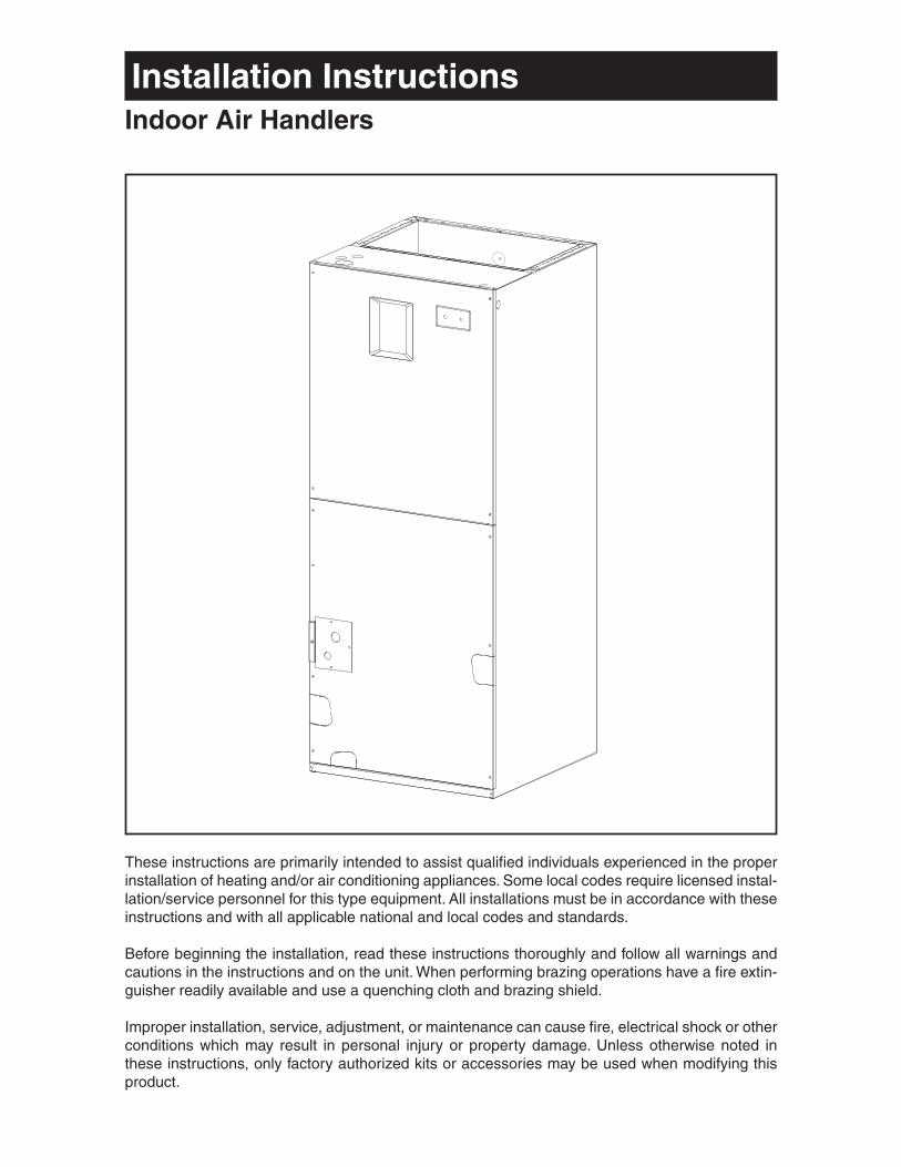
Installation InstructionsIndoor Air Handlers
These instructions are primarily intended to assist qualifi ed individuals experienced in the proper installation of heating and/or air conditioning appliances. Some local codes require licensed instal-lation/service personnel for this type equipment. All installations must be in accordance with these instructions and with all applicable national and local codes and standards.
Before beginning the installation, read these instructions thoroughly and follow all warnings and cautions in the instructions and on the unit. When performing brazing operations have a fi re extin-guisher readily available and use a quenching cloth and brazing shield.
Improper installation, service, adjustment, or maintenance can cause fi re, electrical shock or other conditions which may result in personal injury or property damage. Unless otherwise noted in these instructions, only factory authorized kits or accessories may be used when modifying this product.
2
Table of Contents
1. Air Handler Specifi cations ................................................................................................... 3-4Unit Dimensions .................................................................................................................... 3
2. Installation Requirements ....................................................................................................... 4Minimum Ampacity and Maximum Overcurrent Protection ................................................... 4
3. Air Ducts, Filters, Horizontal Applications ............................................................................ 5
4. Verify Pressurization ............................................................................................................... 8
5. Refrigerant Line Connections ................................................................................................ 8
6. Electrical Wiring ..................................................................................................................... 12
7. Start-up and Adjustment ....................................................................................................... 13
8. Optional Humidistat (Variable Speed Only) ......................................................................... 15
9. Care and Maintenance........................................................................................................... 16
3Figure 1. Unit Dimensions
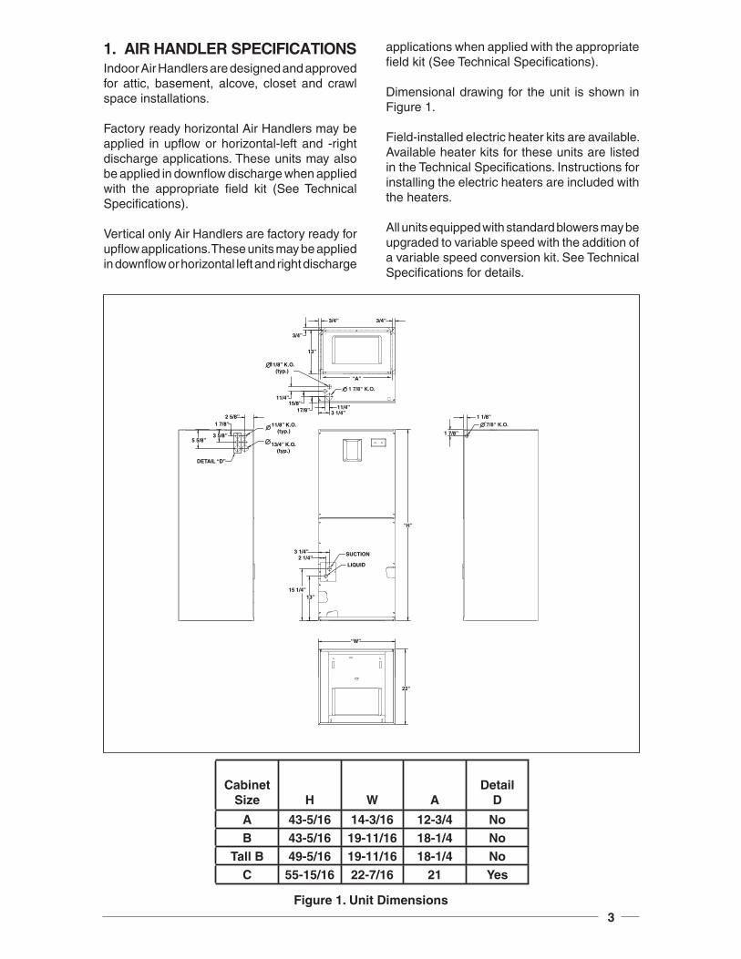
1. AIR HANDLER SPECIFICATIONSIndoor Air Handlers are designed and approved for attic, basement, alcove, closet and crawl space installations.
Factory ready horizontal Air Handlers may be applied in upfl ow or horizontal-left and -right discharge applications. These units may also be applied in downfl ow discharge when applied with the appropriate fi eld kit (See Technical Specifi cations).
Vertical only Air Handlers are factory ready for upfl ow applications. These units may be applied in downfl ow or horizontal left and right discharge
applications when applied with the appropriate fi eld kit (See Technical Specifi cations).
Dimensional drawing for the unit is shown in Figure 1.
Field-installed electric heater kits are available. Available heater kits for these units are listed in the Technical Specifi cations. Instructions for installing the electric heaters are included with the heaters.
All units equipped with standard blowers may be upgraded to variable speed with the addition of a variable speed conversion kit. See Technical Specifi cations for details.
3/4”
3/4”
3/4”
13”
1 7/8" K.O.
11/8” K.O.(typ.)
11/4”15/8”
17/8” 11/4”3 1/4”
2 5/8”
11/8” K.O.(typ.)
13/4” K.O.(typ.)
1 7/8”
3 5/8”5 5/8”
DETAIL “D”
3 1/4”2 1/4”
15 1/4”13”
SUCTION
LIQUID
“W”
1 1/8”
1 7/8”
7/8" K.O.
“H”
22"
“A”
CabinetSize H W A
DetailD
A 43-5/16 14-3/16 12-3/4 NoB 43-5/16 19-11/16 18-1/4 No
Tall B 49-5/16 19-11/16 18-1/4 NoC 55-15/16 22-7/16 21 Yes
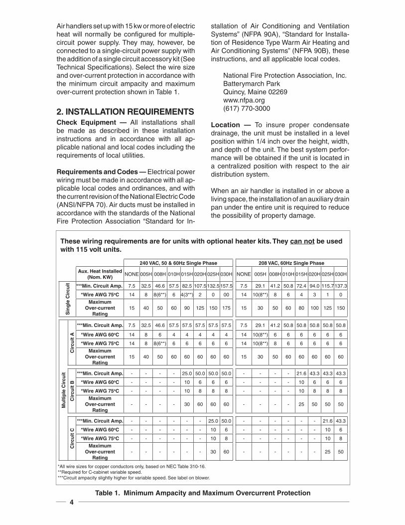
4Table 1. Minimum Ampacity and Maximum Overcurrent Protection
These wiring requirements are for units with optional heater kits. They can not be used with 115 volt units.
Air handlers set up with 15 kw or more of electric heat will normally be confi gured for multiple-circuit power supply. They may, however, be connected to a single-circuit power supply with the addition of a single circuit accessory kit (See Technical Specifi cations). Select the wire size and over-current protection in accordance with the minimum circuit ampacity and maximum over-current protection shown in Table 1.
2. INSTALLATION REQUIREMENTSCheck Equipment — All installations shall be made as described in these installation instructions and in accordance with all ap-plicable national and local codes including the requirements of local utilities.
Requirements and Codes — Electrical power wiring must be made in accordance with all ap-plicable local codes and ordinances, and with the current revision of the National Electric Code (ANSI/NFPA 70). Air ducts must be installed in accordance with the standards of the National Fire Protection Association “Standard for In-
stallation of Air Conditioning and Ventilation Systems” (NFPA 90A), “Standard for Installa-tion of Residence Type Warm Air Heating and Air Conditioning Systems” (NFPA 90B), these instructions, and all applicable local codes.
National Fire Protection Association, Inc.Batterymarch ParkQuincy, Maine 02269www.nfpa.org(617) 770-3000
Location — To insure proper condensate drainage, the unit must be installed in a level position within 1/4 inch over the height, width, and depth of the unit. The best system perfor-mance will be obtained if the unit is located in a centralized position with respect to the air distribution system.
When an air handler is installed in or above a living space, the installation of an auxiliary drain pan under the entire unit is required to reduce the possibility of property damage.
240 VAC, 50 & 60Hz Single Phase 208 VAC, 60Hz Single Phase
Aux. Heat Installed (Nom. KW)
NONE 005H 008H 010H 015H 020H 025H 030H NONE 005H 008H 010H 015H 020H 025H 030H
Sin
gle
Cir
cuit ***Min. Circuit Amp. 7.5 32.5 46.6 57.5 82.5 107.5132.5157.5 7.5 29.1 41.2 50.8 72.4 94.0 115.7137.3
*Wire AWG 75oC 14 8 8(6**) 6 4(3**) 2 0 00 14 10(8**) 8 6 4 3 1 0
Maximum Over-current
Rating15 40 50 60 90 125 150 175 15 30 50 60 80 100 125 150
Mu
ltip
le C
ircu
it
Cir
cuit
A
***Min. Circuit Amp. 7.5 32.5 46.6 57.5 57.5 57.5 57.5 57.5 7.5 29.1 41.2 50.8 50.8 50.8 50.8 50.8
*Wire AWG 60oC 14 8 6 4 4 4 4 4 14 10(8**) 6 6 6 6 6 6
*Wire AWG 75oC 14 8 8(6**) 6 6 6 6 6 14 10(8**) 8 6 6 6 6 6
Maximum Over-current
Rating15 40 50 60 60 60 60 60 15 30 50 60 60 60 60 60
Cir
cuit
B
***Min. Circuit Amp. - - - - 25.0 50.0 50.0 50.0 - - - - 21.6 43.3 43.3 43.3
*Wire AWG 60oC - - - - 10 6 6 6 - - - - 10 6 6 6
*Wire AWG 75oC - - - - 10 8 8 8 - - - - 10 8 8 8
Maximum Over-current
Rating- - - - 30 60 60 60 - - - - 25 50 50 50
Cir
cuit
C
***Min. Circuit Amp. - - - - - - 25.0 50.0 - - - - - - 21.6 43.3
*Wire AWG 60oC - - - - - - 10 6 - - - - - - 10 6
*Wire AWG 75oC - - - - - - 10 8 - - - - - - 10 8
Maximum Over-current
Rating- - - - - - 30 60 - - - - - - 25 50
*All wire sizes for copper conductors only, based on NEC Table 310-16.**Required for C-cabinet variable speed.***Circuit ampacity slightly higher for variable speed. See label on blower.
5
All servicing and cleaning of the air handler can be done from the front. Adequate horizontal clearances should be provided to allow for service and care of the unit. A minimum 24 inch clearance at the front of the unit is recommended. These units are suitable for attic, closet, crawl space or alcove installation at zero clearance from combustibles.
Condensate Drain — The condensate pan has primary and secondary drain connections. The connections have 3/4 inch female pipe threads.
All condensate drains should be a minimum of 3/4 inch PVC pipe or equivalent. The drain should maintain a minimum horizontal slope in the direction of discharge of not less than 1 inch vertical for every 10 feet of horizontal.
If the air handler is located in or above a living space where damage may result from conden-sate overfl ow, an auxiliary drain pan shall be installed under the unit. A separate drain line should extend from the pan to a conspicuous point and serve as an alarm indicating that the primary drain is restricted. As an alternative to a separate drain line, an approved water level indicator or fl oat switch device should be used to shut down the unit in the event water is detected in the auxiliary pan.
Install a 5 inch trap in the condensate drain line as close to the coil as possible. Make sure that the top of the trap is below the bottom of the drain pan to prevent the condensate from overfl owing the drain pan. Prime the trap with water. Insulate the drain if it is located in an unconditioned space, and test the condensate line for leaks. Consult local codes for additional restrictions or precautions.
NOTE: There must be only one trap in the drain line. Using more than one trap may prevent drainage.
IMPORTANT:The plastic drain pan must be level or slightly sloped toward the drain lines.
3. AIR DUCTS, FILTERS, HORIZONTAL APPLICATIONS
Air ducts should be installed in accordance with the standards of the National Fire Protection
Association “Standard for Installation of Air Conditioning and Ventilation Systems” (NFPA 90A), “Standard for Installation of Residence Type Warm Air Heating and Air Conditioning Systems” (NFPA 90B), these instructions, and all applicable local codes.
Use transition fi ttings if the supply and/or return air openings of the unit do not match the duct openings. These transitions should be dimen-sioned in accordance with standard practice as specifi ed in the ASHRAE recommendations for duct transitions.
Flexible connectors should be used between the unit and the ductwork to prevent transmission of vibration from the unit to the structure. If electric heater kits are installed, heat resistant material must be used for the fl exible connector at the supply air end of the unit.
Air Filter Installation — The fi lter may be lo-cated in the return air duct system or installed into the air handler fi lter track located in the bottom of the unit.
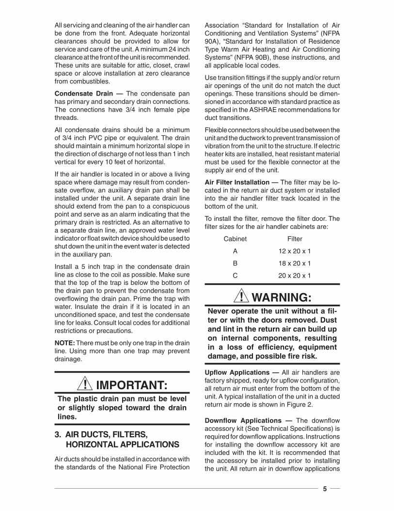
To install the fi lter, remove the fi lter door. The fi lter sizes for the air handler cabinets are:
Cabinet Filter
A 12 x 20 x 1
B 18 x 20 x 1
C 20 x 20 x 1
WARNING:Never operate the unit without a fi l-ter or with the doors removed. Dust and lint in the return air can build up on internal components, resulting in a loss of effi ciency, equipment damage, and possible fi re risk.
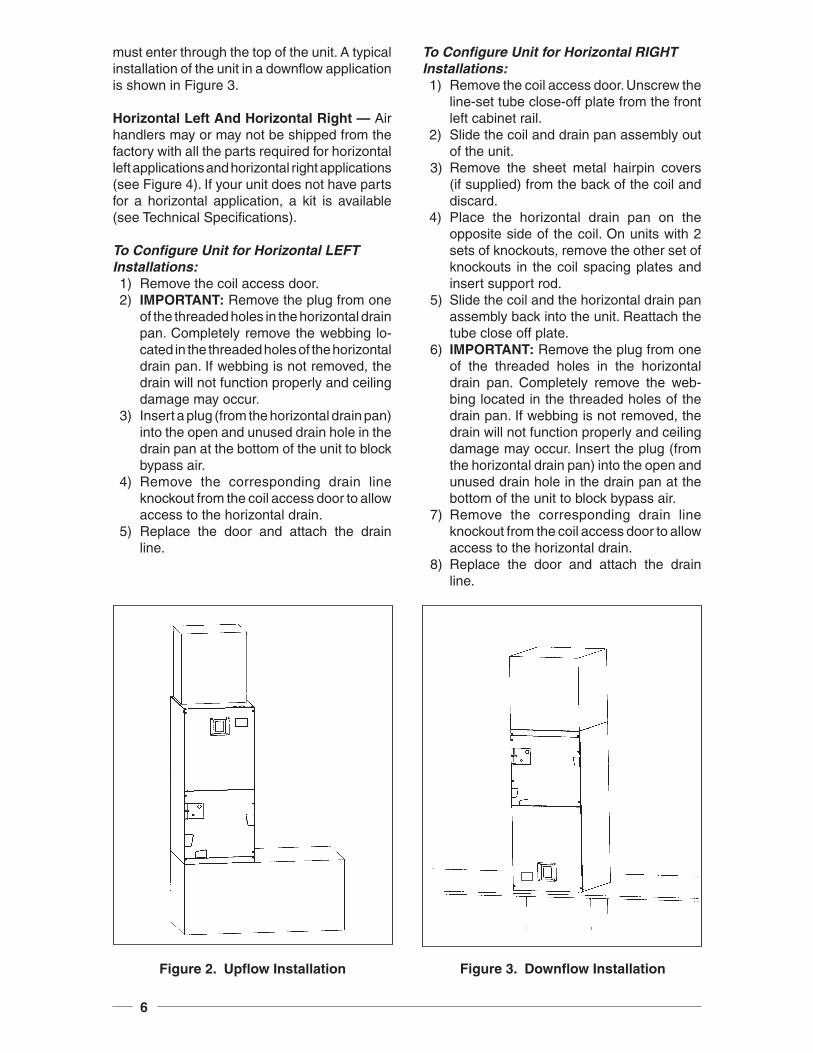
Upfl ow Applications — All air handlers are factory shipped, ready for upfl ow confi guration, all return air must enter from the bottom of the unit. A typical installation of the unit in a ducted return air mode is shown in Figure 2.
Downfl ow Applications — The downfl ow accessory kit (See Technical Specifi cations) is required for downfl ow applications. Instructions for installing the downfl ow accessory kit are included with the kit. It is recommended that the accessory be installed prior to installing the unit. All return air in downfl ow applications
6
must enter through the top of the unit. A typical installation of the unit in a downfl ow application is shown in Figure 3.
Horizontal Left And Horizontal Right — Air handlers may or may not be shipped from the factory with all the parts required for horizontal left applications and horizontal right applications (see Figure 4). If your unit does not have parts for a horizontal application, a kit is available (see Technical Specifi cations).
To Confi gure Unit for Horizontal LEFT Installations: 1) Remove the coil access door. 2) IMPORTANT: Remove the plug from one
of the threaded holes in the horizontal drain pan. Completely remove the webbing lo-cated in the threaded holes of the horizontal drain pan. If webbing is not removed, the drain will not function properly and ceiling damage may occur.
3) Insert a plug (from the horizontal drain pan) into the open and unused drain hole in the drain pan at the bottom of the unit to block bypass air.
4) Remove the corresponding drain line knockout from the coil access door to allow access to the horizontal drain.
5) Replace the door and attach the drain line.
To Confi gure Unit for Horizontal RIGHT Installations: 1) Remove the coil access door. Unscrew the
line-set tube close-off plate from the front left cabinet rail.
2) Slide the coil and drain pan assembly out of the unit.
3) Remove the sheet metal hairpin covers (if supplied) from the back of the coil and discard.
4) Place the horizontal drain pan on the opposite side of the coil. On units with 2 sets of knockouts, remove the other set of knockouts in the coil spacing plates and insert support rod.
5) Slide the coil and the horizontal drain pan assembly back into the unit. Reattach the tube close off plate.
6) IMPORTANT: Remove the plug from one of the threaded holes in the horizontal drain pan. Completely remove the web-bing located in the threaded holes of the drain pan. If webbing is not removed, the drain will not function properly and ceiling damage may occur. Insert the plug (from the horizontal drain pan) into the open and unused drain hole in the drain pan at the bottom of the unit to block bypass air.
7) Remove the corresponding drain line knockout from the coil access door to allow access to the horizontal drain.
8) Replace the door and attach the drain line.
Figure 3. Downfl ow InstallationFigure 2. Upfl ow Installation
7
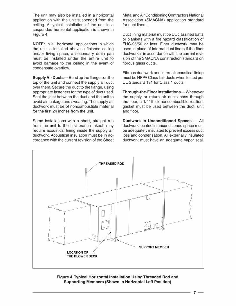
The unit may also be installed in a horizontal application with the unit suspended from the ceiling. A typical installation of the unit in a suspended horizontal application is shown in Figure 4.
NOTE: In all horizontal applications in which the unit is installed above a fi nished ceiling and/or living space, a secondary drain pan must be installed under the entire unit to avoid damage to the ceiling in the event of condensate overfl ow.
Supply Air Ducts — Bend up the fl anges on the top of the unit and connect the supply air duct over them. Secure the duct to the fl ange, using appropriate fasteners for the type of duct used. Seal the joint between the duct and the unit to avoid air leakage and sweating. The supply air ductwork must be of noncombustible material for the fi rst 24 inches from the unit.
Some installations with a short, straight run from the unit to the fi rst branch takeoff may require acoustical lining inside the supply air ductwork. Acoustical insulation must be in ac-cordance with the current revision of the Sheet
Metal and Air Conditioning Contractors National Association (SMACNA) application standard for duct liners.
Duct lining material must be UL classifi ed batts or blankets with a fi re hazard classifi cation of FHC-25/50 or less. Fiber ductwork may be used in place of internal duct liners if the fi ber ductwork is in accordance with the current revi-sion of the SMACNA construction standard on fi brous glass ducts.
Fibrous ductwork and internal acoustical lining must be NFPA Class I air ducts when tested per UL Standard 181 for Class 1 ducts.
Through-the-Floor Installations — Whenever the supply or return air ducts pass through the fl oor, a 1/4” thick noncombustible resilient gasket must be used between the duct, unit and fl oor.
Ductwork in Unconditioned Spaces — All ductwork located in unconditioned space must be adequately insulated to prevent excess duct loss and condensation. All externally insulated ductwork must have an adequate vapor seal.
Figure 4. Typical Horizontal Installation Using Threaded Rod and Supporting Members (Shown in Horizontal Left Position)
THREADED ROD
LOCATION OFTHE BLOWER DECK
SUPPORT MEMBER
8
Consult your Distributor for the recommended type and thickness of insulation for your area as required by local codes.
4. VERIFY PRESSURIZATION
WARNING:
This coil is pressurized with Nitro-gen. Pressure must be relieved in order to prevent the potential of an injury or fatality from the cap during the removal process. Avoid direct face exposure or contact with valve when gas is escaping. Always ensure adequate ventilation is present during the depressurization process. Any uncertainties should be addressed before proceeding.
VERIFY PRESSURIZATION:
- Test by depressing Schrader valve and listen for escaping gas
- If no pressure is found, test coil for leak- If no leak is found, install coil- If leak is found, clearly mark leak
location and return coil to your dis- tributor for processing
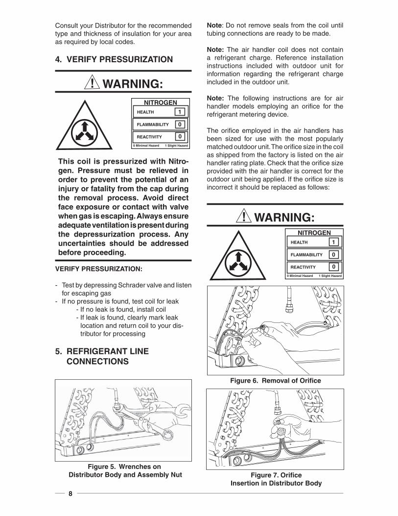
5. REFRIGERANT LINE CONNECTIONS
Note: Do not remove seals from the coil until tubing connections are ready to be made.
Note: The air handler coil does not contain a refrigerant charge. Reference installation instructions included with outdoor unit for information regarding the refrigerant charge included in the outdoor unit.
Note: The following instructions are for air handler models employing an orifi ce for the refrigerant metering device.
The orifi ce employed in the air handlers has been sized for use with the most popularly matched outdoor unit. The orifi ce size in the coil as shipped from the factory is listed on the air handler rating plate. Check that the orifi ce size provided with the air handler is correct for the outdoor unit being applied. If the orifi ce size is incorrect it should be replaced as follows:
WARNING:
Figure 5. Wrenches on Distributor Body and Assembly Nut Figure 7. Orifi ce
Insertion in Distributor Body
Figure 6. Removal of Orifi ce
NITROGENHEALTH
FLAMMABILITY
REACTIVITY
0 Minimal Hazard 1 Slight Hazard
1
0
0
NITROGENHEALTH
FLAMMABILITY
REACTIVITY
0 Minimal Hazard 1 Slight Hazard
1
0
0
9
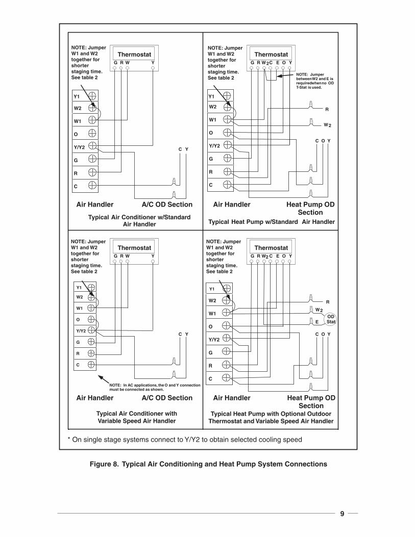
Figure 8. Typical Air Conditioning and Heat Pump System Connections
G R W2 C E O Y
Thermostat
ODStat
O Y
R
C
Air Handler Heat Pump ODSection
G R W
Thermostat
YC
Air Handler A/C OD Section
Y
NOTE: In AC applications, the O and Y connectionmust be connected as shown.
G R W
Thermostat
YC
Air Handler A/C OD Section
Y
Typical Air Conditioner w/StandardAir Handler
G R W2C E O Y
Thermostat
O Y
R
C
Air Handler Heat Pump ODSection
Typical Heat Pump w/Standard Air Handler
W2
NOTE: Jumperbetween W2 and E isrequired when no ODT-Stat is used.
W2
E
Typical Air Conditioner withVariable Speed Air Handler
Typical Heat Pump with Optional Outdoor Thermostat and Variable Speed Air Handler
NOTE: Jumper W1 and W2 together for shorter staging time. See table 2
W2
W1
O
Y/Y2
G
R
C
W2
W1
O
Y/Y2
G
R
C
W2
W1
O
Y/Y2
G
R
C
W2
W1
O
Y/Y2
G
R
C
Y1 Y1
Y1 Y1
NOTE: Jumper W1 and W2 together for shorter staging time. See table 2
NOTE: Jumper W1 and W2 together for shorter staging time. See table 2
NOTE: Jumper W1 and W2 together for shorter staging time. See table 2
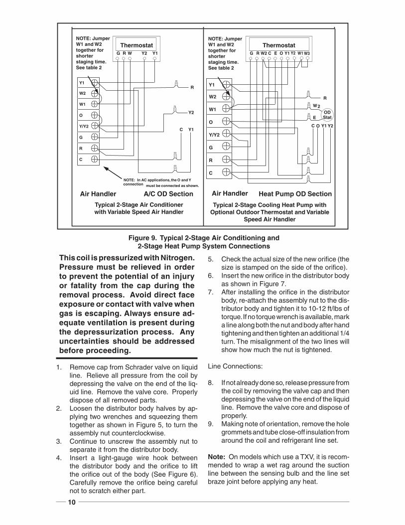
* On single stage systems connect to Y/Y2 to obtain selected cooling speed
10
Figure 9. Typical 2-Stage Air Conditioning and2-Stage Heat Pump System Connections
G R W2 C E O Y1
Thermostat
ODStat
O Y1
R
C
Air Handler Heat Pump OD Section
G R W
Thermostat
Y1C
Air Handler A/C OD Section
Y1
NOTE: In AC applications, the O and Y connection must be connected as shown.
W2
E
Typical 2-Stage Air Conditioner with Variable Speed Air Handler
Typical 2-Stage Cooling Heat Pump with Optional Outdoor Thermostat and Variable
Speed Air Handler
W2
W1
O
Y/Y2
G
R
C
W2
W1
O
Y/Y2
G
R
C
Y2
Y2
Y2
Y2
W1 W3
RY1 Y1
NOTE: Jumper W1 and W2 together for shorter staging time. See table 2
NOTE: Jumper W1 and W2 together for shorter staging time. See table 2
This coil is pressurized with Nitrogen. Pressure must be relieved in order to prevent the potential of an injury or fatality from the cap during the removal process. Avoid direct face exposure or contact with valve when gas is escaping. Always ensure ad-equate ventilation is present during the depressurization process. Any uncertainties should be addressed before proceeding.
1. Remove cap from Schrader valve on liquid line. Relieve all pressure from the coil by depressing the valve on the end of the liq-uid line. Remove the valve core. Properly dispose of all removed parts.
2. Loosen the distributor body halves by ap-plying two wrenches and squeezing them together as shown in Figure 5, to turn the assembly nut counterclockwise.
3. Continue to unscrew the assembly nut to separate it from the distributor body.
4. Insert a light-gauge wire hook between the distributor body and the orifi ce to lift the orifi ce out of the body (See Figure 6). Carefully remove the orifi ce being careful not to scratch either part.
5. Check the actual size of the new orifi ce (the size is stamped on the side of the orifi ce).
6. Insert the new orifi ce in the distributor body as shown in Figure 7.
7. After installing the orifi ce in the distributor body, re-attach the assembly nut to the dis-tributor body and tighten it to 10-12 ft/lbs of torque. If no torque wrench is available, mark a line along both the nut and body after hand tightening and then tighten an additional 1/4 turn. The misalignment of the two lines will show how much the nut is tightened.
Line Connections:
8. If not already done so, release pressure from the coil by removing the valve cap and then depressing the valve on the end of the liquid line. Remove the valve core and dispose of properly.
9. Making note of orientation, remove the hole grommets and tube close-off insulation from around the coil and refrigerant line set.
Note: On models which use a TXV, it is recom-mended to wrap a wet rag around the suction line between the sensing bulb and the line set braze joint before applying any heat.
11
10. Unbraze and remove the cap on the suction line. Unbraze and remove the valve core holder on the liquid line.
11. Cut the line set tubing to the proper length. Be sure that the tubing has been sized in accordance with the outdoor unit speci-fi cations.
12. Inspect both refrigerant lines. The ends of the lines must be round, clean, and free of any burrs.
13. Place grommets in proper orientation onto line set with suffi cient distance to braze joint as to not damage the grommets.
14. Insert the line set tubes into the coil tube stubs until they bottom out.
Note: On models which use a TXV, it is recom-mended to wrap a wet rag around the suction line between the sensing bulb and the line set braze joint before applying any heat.
15. Braze the individual connections with dry nitrogen fl owing through the joints to elimi-nate internal oxidation and scaling.
16. Replace grommets and insulation. Check the assembly for leaks.
17. Properly dispose of all removed parts.
Note: On horizontal or downfl ow applications of models with the TXVs, to ensure proper perfor-mance, the sensing bulb must be re-positioned so it is in the 4 o’clock or 8 o’clock position on the suction tube after fi nal orientation of the air handler.
WARNING:To avoid the risk of electric shock, personal injury or death, disconnect all electrical power to the unit before performing any maintenance or ser-vice. The unit may have more than one electrical power supply.
Table 2. Heating Element Logic
Control Signal Operation Board Action
W1 only
On
Stage 1 Heat on instantlyHeat blower on after 3 second delayStage 3 & 5 Heat on after 1 minute delayStage 2 Heat on after 2 minute delayStage 4 & 6 Heat on after 3 minute delay
Off Heat stages off instantlyBlower off after 15 second delay
W1 & W2
On
Stage 1 Heat on instantlyHeat blower on after 3 second delayStage 3 & 5 Heat on after 10 second delayStage 2 Heat on after 20 second delayStage 4 & 6 Heat on after 30 second delay
Off Heat stages off instantlyBlower off after 15 second delay
W1 & Y/Y2
On
Stage 1 Heat on instantlyCool blower on after 3 second delayStage 3 & 5 Heat on after 1 minute delayStage 2 Heat on after 2 minute delayStage 4 & 6 Heat on after 3 minute delay
OffHeat stages & Cool blower off instantlyHeat blower energizes and then turns off after 15 second delay
W1, W2 & Y/Y2
On
Stage 1 Heat on instantlyCool blower on after 3 second delayStage 3 & 5 Heat on after 10 second delayStage 2 Heat on after 20 second delayStage 4 & 6 Heat on after 30 second delay
OffHeat stages and Cool blower off instantlyHeat blower energizes and then turns off after 15 second delay
12
6. ELECTRICAL WIRING
General — Electrical power wiring must be made in accordance with all applicable local codes and ordinances, and with the current revi-sion of the National Electric Code (ANSI/NFPA 70). If any of the original wire as supplied with the unit must be replaced, it must be replaced with wire material having the same gauge and temperature rating. Disconnection means: a means to disconnect the appliance must be incorporated in the fi xed wiring.
Line Voltage — Before proceeding with the electrical connections, make certain that the voltage, frequency, and phase of the supply source are the same as those specifi ed on the rating plate. Also, verify that the service provided by the utility is suffi cient to handle the additional load imposed by this equipment.
See the unit wiring label for proper high and low voltage wiring. Make all electrical connections in accordance with the National Electric Code and any applicable local codes or ordinances.
Use a separate branch electrical circuit for this unit. A disconnecting means must be located within sight of, and readily accessible to, the unit. When electric heat packages with circuit breakers are fi eld-installed, the circuit breaker may be used as a disconnecting means in most applications. Reference the NEC and Local Codes for Disconnect requirements.
208/240 volt units are shipped from the fac-tory wired for 240 volt transformer operation. For 208 volt operation, remove the lead from the transformer terminal marked 240v and connect it to the terminal marked 208v. For maximum ampacity and overcurrent protection, see Table 1.
Provide power supply (or supplies) for the unit in accordance with Table 1, the unit wiring diagram and the unit rating plate.
When a heater kit is installed: Connnect the 2 wire plug of the air handler with the mating 2 wire plug of the heater kit. Connect the line voltage leads to the circuit breaker or terminal block provided. Connect the heater kit plug with the mating receptacle on the air handler control board. When installing a 25 kw or 30 kw heater kit, follow the instructions provided with the kit for proper installation.
When a heater kit is not installed: Remove the 2 wire plug of the air handler by cutting the wires and discarding the plug. Strip the ends of the 2 air handler wires and connect to the line-voltage leads with the 2 wire nuts provided.
Use copper wire only for the line voltage power supply to this unit. Aluminum supply wire may be used if a heater kit is installed. Use UL listed conduit and a conduit connector for connecting the supply wires to the unit and for obtaining proper grounding. Grounding may also be ac-complished by using the grounding lug provided in the control box. Field supplied bushings for the power supply cables must be added to support and protect the power supply cables.
HEATING ELEMENT LOGIC
The control board in the air handler controls the timing sequence of the elements. Depending on the thermostat connection, there are 2 timing sequence variations that can be chosen. See table 2 for element sequence timing. The board also is equipped with a 3 second blower on delay and a 15 second blower off delay.
WARNING:The unit cabinet must have an uninter-rupted and unbroken electrical ground to minimize the risk of personal injury if an electrical fault should occur. This ground may consist of electrical wire or approved conduit when installed in accordance with existing national or local codes.
Low Voltage — Install the grommet, which is packed with the unit, in the hole for low-voltage wires. When the low voltage wires are positioned in this grommet, the grommet will prevent chafi ng and/or shorting of the low voltage leads. Connect the low-voltage wiring to the thermostat and the outdoor unit and the appropriate screw terminal located on the control board.
NOTE: Where local codes require that the thermostat wiring must be routed through a conduit or raceway, splices can be made inside the unit; however, all wiring mustbe NEC Class 1 and must be separated from incoming power leads.
13
IMPORTANT! On variable speed models when the unit is used in an air conditioning system, connect the “O” terminal to the “Y” terminal. See Figure 8 & 9.
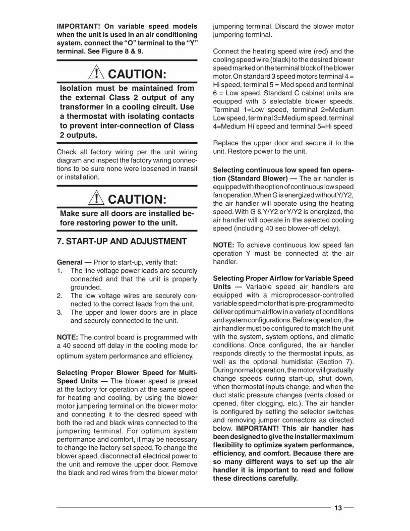
CAUTION:Isolation must be maintained from the external Class 2 output of any transformer in a cooling circuit. Use a thermostat with isolating contacts to prevent inter-connection of Class 2 outputs.
Check all factory wiring per the unit wiring diagram and inspect the factory wiring connec-tions to be sure none were loosened in transit or installation.
CAUTION:Make sure all doors are installed be-fore restoring power to the unit.
7. START-UP AND ADJUSTMENT
General — Prior to start-up, verify that:1. The line voltage power leads are securely
connected and that the unit is properly grounded.
2. The low voltage wires are securely con-nected to the correct leads from the unit.
3. The upper and lower doors are in place and securely connected to the unit.
NOTE: The control board is programmed with a 40 second off delay in the cooling mode for
optimum system performance and effi ciency.
Selecting Proper Blower Speed for Multi-Speed Units — The blower speed is preset at the factory for operation at the same speed for heating and cooling, by using the blower motor jumpering terminal on the blower motor and connecting it to the desired speed with both the red and black wires connected to the jumpering terminal. For optimum system performance and comfort, it may be necessary to change the factory set speed. To change the blower speed, disconnect all electrical power to the unit and remove the upper door. Remove the black and red wires from the blower motor
jumpering terminal. Discard the blower motor jumpering terminal.
Connect the heating speed wire (red) and the cooling speed wire (black) to the desired blower speed marked on the terminal block of the blower motor. On standard 3 speed motors terminal 4 = Hi speed, terminal 5 = Med speed and terminal 6 = Low speed. Standard C cabinet units are equipped with 5 selectable blower speeds. Terminal 1=Low speed, terminal 2=Medium Low speed, terminal 3=Medium speed, terminal 4=Medium Hi speed and terminal 5=Hi speed
Replace the upper door and secure it to the unit. Restore power to the unit.
Selecting continuous low speed fan opera-tion (Standard Blower) — The air handler is equipped with the option of continuous low speed fan operation. When G is energized without Y/Y2, the air handler will operate using the heating speed. With G & Y/Y2 or Y/Y2 is energized, the air handler will operate in the selected cooling speed (including 40 sec blower-off delay).
NOTE: To achieve continuous low speed fan operation Y must be connected at the air handler.
Selecting Proper Airfl ow for Variable Speed Units — Variable speed air handlers are equipped with a microprocessor-controlled variable speed motor that is pre-programmed to deliver optimum airfl ow in a variety of conditions and system confi gurations. Before operation, the air handler must be confi gured to match the unit with the system, system options, and climatic conditions. Once confi gured, the air handler responds directly to the thermostat inputs, as well as the optional humidistat (Section 7). During normal operation, the motor will gradually change speeds during start-up, shut down, when thermostat inputs change, and when the duct static pressure changes (vents closed or opened, fi lter clogging, etc.). The air handler is confi gured by setting the selector switches and removing jumper connectors as directed below. IMPORTANT! This air handler has been designed to give the installer maximum fl exibility to optimize system performance, effi ciency, and comfort. Because there are so many different ways to set up the air handler it is important to read and follow these directions carefully.
14
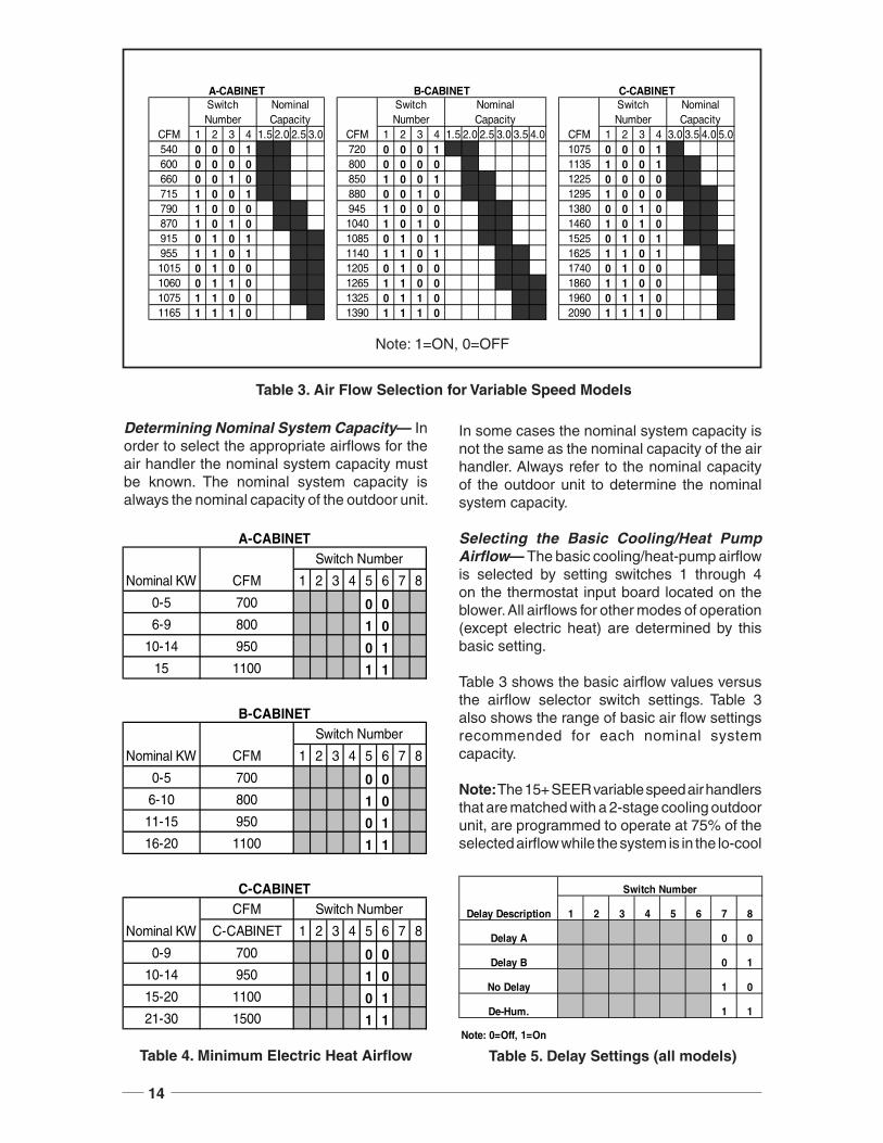
Determining Nominal System Capacity— In order to select the appropriate airfl ows for the air handler the nominal system capacity must be known. The nominal system capacity is always the nominal capacity of the outdoor unit.
Table 3. Air Flow Selection for Variable Speed Models
In some cases the nominal system capacity is not the same as the nominal capacity of the air handler. Always refer to the nominal capacity of the outdoor unit to determine the nominal system capacity.
Selecting the Basic Cooling/Heat Pump Airfl ow— The basic cooling/heat-pump airfl ow is selected by setting switches 1 through 4 on the thermostat input board located on the blower. All airfl ows for other modes of operation (except electric heat) are determined by this basic setting.
Table 3 shows the basic airfl ow values versus the airfl ow selector switch settings. Table 3 also shows the range of basic air fl ow settings recommended for each nominal system capacity.
Note: The 15+ SEER variable speed air handlers that are matched with a 2-stage cooling outdoor unit, are programmed to operate at 75% of the selected airfl ow while the system is in the lo-cool
Table 4. Minimum Electric Heat Airfl ow Table 5. Delay Settings (all models)
1 2 3 4 1.5 2.0 2.5 3.0 1 2 3 4 1.5 2.0 2.5 3.0 3.5 4.0 1 2 3 4 3.0 3.5 4.0 5.0540 0 0 0 1 720 0 0 0 1 1075 0 0 0 1600 0 0 0 0 800 0 0 0 0 1135 1 0 0 1660 0 0 1 0 850 1 0 0 1 1225 0 0 0 0715 1 0 0 1 880 0 0 1 0 1295 1 0 0 0790 1 0 0 0 945 1 0 0 0 1380 0 0 1 0870 1 0 1 0 1040 1 0 1 0 1460 1 0 1 0915 0 1 0 1 1085 0 1 0 1 1525 0 1 0 1955 1 1 0 1 1140 1 1 0 1 1625 1 1 0 11015 0 1 0 0 1205 0 1 0 0 1740 0 1 0 01060 0 1 1 0 1265 1 1 0 0 1860 1 1 0 01075 1 1 0 0 1325 0 1 1 0 1960 0 1 1 01165 1 1 1 0 1390 1 1 1 0 2090 1 1 1 0
Nominal Capacity
Switch Number
Nominal Capacity
CFM
Switch Number
CFM
Switch Number
Nominal Capacity
CFM
A-CABINET B-CABINET C-CABINET
Note: 1=ON, 0=OFF
1 2 3 4 5 6 7 8
0-5 700 0 06-9 800 1 0
10-14 950 0 115 1100 1 1
1 2 3 4 5 6 7 8
0-5 700 0 06-10 800 1 011-15 950 0 116-20 1100 1 1
CFM
C-CABINET 1 2 3 4 5 6 7 8
0-9 700 0 010-14 950 1 015-20 1100 0 121-30 1500 1 1
C-CABINET
Nominal KW
Switch Number
B-CABINET
Nominal KW CFM
Switch Number
A-CABINET
Nominal KW CFM
Switch Number
1 2 3 4 5 6 7 8
Delay A 0 0
Delay B 0 1
No Delay 1 0
De-Hum. 1 1
Note: 0=Off, 1=On
Delay Description
Switch Number
15
mode and 100% of the selected airfl ow while in hi-cool mode.
NOTE: The CFM values listed in the tables are not dependent on duct static pressure. The motor automatically compensates for changes in duct static pressure (within the limits of the motor).
For maximum capacity and energy effi ciency, select an airfl ow at or near the top of the range for that nominal capacity. For maximum dehumidifi cation, select an airfl ow near the middle or bottom of the range for that nominal capacity. Additional information on humidity control can be found in the sections labeled “Humidistat” and “Delay Setting”.
NOTE: If coil icing is observed, the basic cooling/heat-pump airfl ow selected may be too low. Double-check to be sure the setting selected is within the range shown in Table3. Also check to be sure the system is properly charged (see outdoor unit Installation Instructions). If icing continues to occur, raise the selected airfl ow one or two steps.
When operating in the heat pump mode, a higher basic airfl ow setting will increase the energy effi ciency and capacity but will also decrease the supply air temperature.
Selecting the Minimum Electric Heat Airfl ow— The minimum electric heat airfl ow is selected by setting switches 5 and 6. Selecting the minimum electric heat airfl ow sets the minimum air fl ow that will be produced whenever electric heater kits are used. When the electric heater kits are energized along with a heat pump, the airfl ow may be higher depending on the basic cooling/heat-pump airfl ow setting.
Reference Table 4 for recommended minimum electric heat airfl ow settings. The minimum electric heat airfl ow setting may be set higher, but must never be set lower than the setting shown in Table 4.
Selecting the Delay Profi le— The delay profi le is selected by setting switches 7 and 8 (see Table 5). Delay profi le selection controls the start-up and shut-down characteristics of the air handler. By varying the start-up and shut-down characteristics of the air handler the system can be optimized for energy effi ciency, humidity control, and comfort.
Select “Delay A” or “Delay B” for highest energy effi ciency. “Delay A” has a two-step “on” delay. The blower will begin operation at 31% airfl ow for 30 seconds. The second step operation is 75% airfl ow for 30 seconds. After the two-step “on” delay has been completed, the blower operation will be 100% until the thermostat has been satisfi ed. “Delay A” also provides a 60 second “off” delay at 50% airfl ow.
“Delay B” has a single step 30 second “on” delay at 50% airfl ow. “Delay B” also provides a 90 second “off” delay at 50% airfl ow. Select the delay profi le which is most suited to the application.
The “De-Hum.” delay profi le may be used when humidity control is desired without the use of the optional humidistat. If the “De-Hum.” delay profi le is selected, the air handler will run at 75% airfl ow for the fi rst 10 minutes of each cooling cycle. If the “De-Hum.” delay profi le is selected, the basic cooling/heat-pump speed should be selected at or near the top of the range for that nominal capacity (see Table 3).
8. OPTIONAL HUMIDISTAT (Variable Speed Only)The optional humidistat may be installed in the return air duct to provide excellent humidity control when needed and maximum system capacity and energy effi ciency when humidity levels are normal. The humidistat senses when humidity in the return air stream is above a preset level (fi eld adjustable) and sends a signal to the motor to reduce the airfl ow so that more moisture may be removed until the humidity level drops. The air handler is pre-programmed for humidistat operation. Remove jumper connector installed between the two terminals marked “HUM” on the circuit board.
Note: The 15+ SEER air handlers that are matched with a 2-stage cooling outdoor unit and the humidistat is installed will not drop below 75% of the selected blower speed when the system is operating in lo-cool mode and the humidistat opens.
Installation— Install the humidistat in the return air duct as directed in the installation instructions included with the kit. Wire the humidistat through the low-voltage wire entrance in the air handler (Figure 1) to the quick-connect terminals marked “HUM”. Wire the humidistat to open on rise in humidity.

7087090 (Replaces 708493A) Specifi cations and illustrations subject to change
without notice and without incurring obligations. Printed in U.S.A. (02/07)
¢708709F¤
INSTALLER: PLEASE LEAVE THESE INSTALLATION INSTRUCTIONS
WITH THE HOMEOWNER
9. CARE AND MAINTENANCEGeneral — For continued high performance, and to minimize the risk of equipment failure, it is essential that periodic maintenance be per-formed on this equipment. The ability to properly perform maintenance on this equipment requires certain mechanical skills and tools. If you do not possess these skills, contact your dealer for maintenance. Consult your local dealer as to the availability of a maintenance contract.
Do not store any of the following on, or in contact with, the unit: Rags, brooms, vacuum cleaners, or other cleaning tools, spray or aerosol cans, soap powders, bleaches, waxes, cleaning compounds, plastics or plastic containers, paper bags or other paper products, gasoline, kerosene, cigarette lighter fl uid, dry cleaning fl uids, paint thinners, or other volatile fl uids.
Proper maintenance is most important to achieve the best performance from an air handler. At a minimum, this maintenance should include the following items.
1. Inspect and clean or replace the air fi lter at the beginning of each heating and cooling season, or more frequently as required.
2. Inspect the cooling coil, drain pan, and condensate drain at the beginning of each cooling season for cleanliness. Clean these components as necessary using a mild detergent and water. Flush the coil, drain pan, and condensate drain after cleaning to remove all detergent. Use caution when cleaning these components so that the insulation does not become wet.
3. Inspect the blower motor and wheel for cleanliness at the beginning of each heat-ing and cooling season. Clean the motor as necessary.
4. Inspect electrical connections for tightness at the beginning of each heating and cooling season. Service as necessary.
WARNING:Use caution when removing parts from this unit. Personal injury can result from sharp metal edges pres-ent in all equipment of sheet metal construction.