7 undulators - elettra sincrotrone trieste machine... · 224 fermi@elettra chapter 7 - undulators...
TRANSCRIPT
Chapter 7 - Undulators
223Conceptual Design Report
7 Undulators
Synopsis
The FERMI undulators are based on PPM arrays, a choice dictated mostly by the need to provide variable polarization. The present design is based on a remanent field Br=1.2 T, which allows to choose material grades with close to the maximum available coercitivity. High coercitivity makes the material highly resistant to radiation, a feature of paramount importance for its long lifetime. The undulator coefficient K must be greater than 1 in order to provide sufficient FEL gain. The minimum acceptable gap height is 10 mm, dictated by residual gas pressure and energy losses induced by resistive wall wakefields in the undulator vacuum chambers.
The modulators for both FEL-1 and FEL-2 have fixed, linear polarization. They must be tunable in the 240-360 nm range, a requirement that can be satisfied by a wide range of period lengths among which the shortest acceptable, ~ 10 cm, is favoured for FERMI. The first stage radiator and the second stage modulator for FEL-2 are also designed for fixed, linear polarization.
All the other undulators are of the variable polarization type, based on the widely used APPLE-II (Advanced Planar Polarized Light Emitter) configuration, the most efficient one for this application. All polarizations are tunable over the full design tuning ranges of 100 to 40 nm and 40 to 10 nm of FEL-1 and FEL-2 respectively. Because no analytical expression is known for the field amplitude as a function of the geometrical parameters of such devices, a semi-empirical formula is used derived by fitting the results of 3D magnetostatic calculations performed on a number of different special cases.
224 FERMI@Elettra
Chapter 7 - Undulators
Detailed design of all undulators is in progress to include various higher order effects such as those due to the finite anisotropic permeability of the magnetic material and the precise magnet block shape and dimension.
Undulator alignment techniques have been studied in detail since misaligned individual undulator magnets can both modify the magnetic field, depending on the sign and magnitude of the roll-off coefficients, and distort the ideal trajectory, governed by the undulators focusing properties. Based on the request that, at nominal FEL performance, the relative difference in field strength between neighboring individual undulator magnets must be less than ± 0.2%, a worst case tolerance of up to ~200 µm has been set on their misalignments; this corresponds to a relative field change of less than 0.1%. Dedicated correction coils at both ends of each individual undulator magnet compensate the residual random magnetic field errors as well as the misalignment effects. Undulator focusing has been computed by 3D numerical tracking of the beam in the undulator field, and trajectory corrections, by beam-based alignment (BBA) techniques complemented by spontaneous radiation observations, have been simulated. It has been found that misalignements of up to 100 µm can be satisfactorily corrected. It can also be envisaged, given the rather comfortable tolerances on the trajectory straigthness, to correct the effects of the Earth magnetic field by ad-hoc shimming of individual undulators.
The undulator mechanical design is strongly influenced by the experience gained with the construction of the Apple II undulators installed on the ELETTRA storage ring. The undulator rests on a rigid C-shaped frame (“carriage”) supported at each end by a post equipped with a vertical guide on which two (upper and lower) stainless steel backing beams can slide up and down. Each backing beam, supporting one (longitudinally) movable and one fixed aluminium beam to which the magnet arrays are attached, can be displaced vertically by two synchronized motors to adjust the undulator gap aperture. Two additional motors driving the moveable aluminium beam move the magnet array longitudinally (in “phase”). Gap height, longitudinal shifts and magnet vertical position are measured by absolute encoders with better than 1 µµm resolution. The carriage in turn rests on a platform remotely moveable in the horizontal plane for fine-aligning the whole structure. The main design tolerances are: 10 µm rms on planarity and parallelism of the backing beams and 5 µm rms on gap height.
As concerns the thermal stability, considering the tolerable relative difference in field strength between neighboring individual undulator magnets, the change of the undulator peak magnetic field with temperature and the thermal expansion of its support structure, one concludes that the ambient temperature, averaged over a time interval of a few hours, determined by the thermal inertia of the device, must be stable to within ± 0.7ºC.
Aluminium has been chosen as the undulator vacuum chambers material because of its lightness, ease of fabrication and good electrical properties. The material specific outgassing, the most important parameter limiting the ultimate pressure, is kept low by following scrupulous cleaning and assembling procedures. A simulation of the system vacuum behaviour indicates that a maximum average pressure below 5·10-7 mbar can be easily reached provided strict construction, assembly and maintenance prescriptions are followed. Such a value is much lower than what is required to meet the conservative limits set on outgassing, bremsstrahlung production and carbon compounds deposition on the vacuum chamber inner walls. More detailed simulations will be performed following completion of detailed design of all components.
The undulator region optics is designed so that the average betatron function in each plane can range from 7 to 11 m, satisfying the design aim of a moderate focusing strength. The radiator optics uses a sequence of three standard FODO cells. The maximum quadrupole gradient is 10 T/m, including a 20%
Chapter 7 - Undulators
225Conceptual Design Report
margin. The matching of the FODO lattice, with the undulator gaps closed, was done using MAD in which the undulator is described by an uncoupled 6*6 transfer matrix, computed using Racetrack in both the 100 nm and 40 nm photon wavelength configurations and for three representative polarizations: horizontal, circular and vertical.
Special attention has been given to the problem of wakefields generated in the narrow gap undulator vacuum chamber which can increase the bunch energy spread. Since one finds that transverse wake effects can be neglected, the main concern is the longitudinal wake driven by the resistive wall (RW) of the chamber, by the impedances of cavity-like objects and by the roughness of the chamber inner surface. To minimize the effect of resistive wakefields a rectangular (or elongated elliptical) aluminium chamber is chosen. As far as surface roughness is concerned, computations were carried out in the worst case of a circular perfectly conducting chamber with diameter equal to the chamber inner gap and a sinusoidal surface corrugation with longitudinal periodicity λs and amplitude ho. The tolerable roughness value parameter is found to be (λs/ho)>>200, compatible with that obtainable with careful but standard machining techniques and surface treatments. Resonant wakefields have not yet been considered; in any case, the detailed chamber design will be such as to avoid the presence of high Q resonator-like structures.
Finally, the consequences of trajectory position errors in the undulators have been studied and, in the worst case of FEL operation at the (10 nm) shortest design wavelength, a tolerance has been set of ± 10 µm rms, with respect to a straight line, over the whole undulator length. It has also been checked, as mentioned above, that beam-based alignment procedures allow reaching the specified goal. An additional bunch-to-bunch feedback system is also foreseen to keep the beam on the optimized trajectory during FEL operation.
7.1 Magnet TechnologyAs mentioned in Chapter 4, the final radiators are required to provide variable polarization, while for the modulators and the intermediate radiators fixed linear polarization is envisaged. Amongst the various known technologies, pure permanent magnet (PPM) structures offer a number of advantages: simpler and more accurate design, reduced interaction with external magnetic field sources (including the earth magnetic field) and more straightforward applicability of error compensation techniques based on magnet sorting, swapping and shimming.
The so called hybrid undulator uses ferromagnetic poles to channel the flux generated by the permanent magnets, and can provide a higher field in the range of parameters considered here. However, this only applies to the fixed polarization case, since no practical variably polarized hybrid undulator exists. Therefore, the advantage of this more efficient solution, namely a reduction of the total undulator length, would affect only a fraction of the total magnetic structure. For these reasons the FERMI@Elettra undulators will be based exclusively on PPM arrays.

22� FERMI@Elettra
Chapter 7 - Undulators
7.2 Design ConstraintsThe resonance condition for FEL radiation to be produced is:
, 7.2.1
λ being the radiation wavelength, λ0 the undulator period length and γ the electron relativistic factor. Note that, having defined the deflection parameter K in terms of its rms value, the above relation holds for any field polarization. At 1.2 GeV electron energy the resonance condition can be written in practical units as
. 7.2.2
The deflection parameter must be greater than 1 in order to provide sufficient FEL gain. This implies that, for the shortest FEL wavelength of 10 nm (FEL-2), the corresponding undulator period must be shorter than ~55 mm. On the other hand, the shortest acceptable period length is determined by the required tuning range (100 to 40 nm for FEL-1 and 40 to 10 nm for FEL-2) and by the smallest allowed magnetic gap. Considerations on the maximum allowable residual gas pressure in the chamber and the energy loss induced by resistive wall wakefields in undulator vacuum chambers of different shapes and materials (see Section 7.10 and 7.11) lead to an acceptable minimum gap of 10 mm.
The most widely used magnetic material for applications in insertion devices is NdFeB, a sintered alloy produced in different “grades” characterized by different remanent field (BR) and intrinsic coercivity (HCI) values. Typically the strongest grades, with the highest remanence, have a lower intrinsic coercivity and viceversa. The table below shows indicative ranges of these two quantities for commercially available materials:
Table 7.2.1: Typical remanence and intrinsic coercivity for NdFeB.
Typical Br (T) Typical HCJ (kOe)
1.4 ÷ 1.5 11 ÷ 16
1.3 ÷ 1.4 12 ÷ 24
1.2 ÷ 1.3 17 ÷ 33
1.1 ÷ 1.2 22 ÷ 36
In terms of efficiency of magnetic field generation a high remanence is preferred, since the peak undulator field is proportional to this quantity (see eq. 7.3.5 below). However, in a high radiation environment like that of a linac-based FEL, resistance to radiation (scattered electrons and associated electromagnetic cascade) is of paramount importance in order to guarantee a sufficiently long lifetime of the permanent magnets. The exact mechanism of radiation damage depends on the nature of the radiation (electrons, neutrons, X-rays, γ-rays) but the result of excessive exposure is the same, namely
Chapter 7 - Undulators
227Conceptual Design Report
permanent demagnetisation. Several studies exist on the subject [1], showing that high intrinsic coercivity also implies increased hardness against demagnetization; a tradeoff therefore exists between top field and radiation resistance. The present design is based on a remanent field Br=1.2 T, which allows choosing material grades with close to the maximum available HCJ.
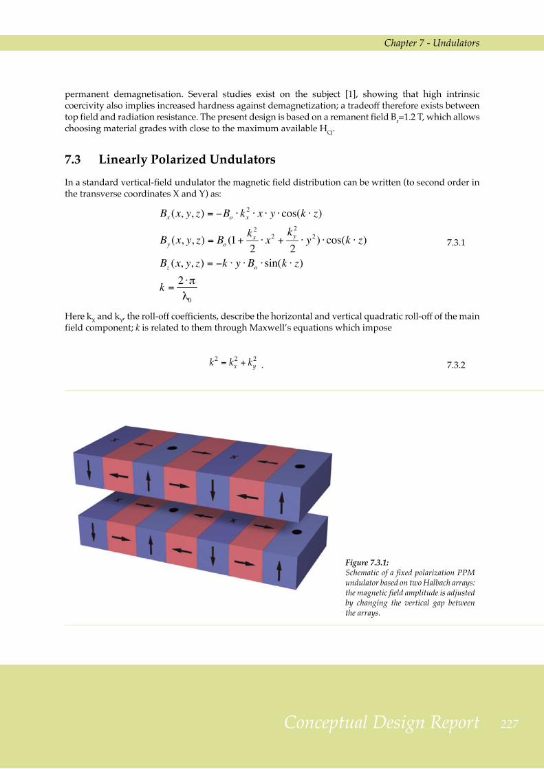
7.3 Linearly Polarized UndulatorsIn a standard vertical-field undulator the magnetic field distribution can be written (to second order in the transverse coordinates X and Y) as:
7.3.1
Here kX and kY, the roll-off coefficients, describe the horizontal and vertical quadratic roll-off of the main field component; k is related to them through Maxwell’s equations which impose
. 7.3.2
Figure 7.3.1: Schematic of a fixed polarization PPM undulator based on two Halbach arrays: the magnetic field amplitude is adjusted by changing the vertical gap between the arrays.
22� FERMI@Elettra
Chapter 7 - Undulators
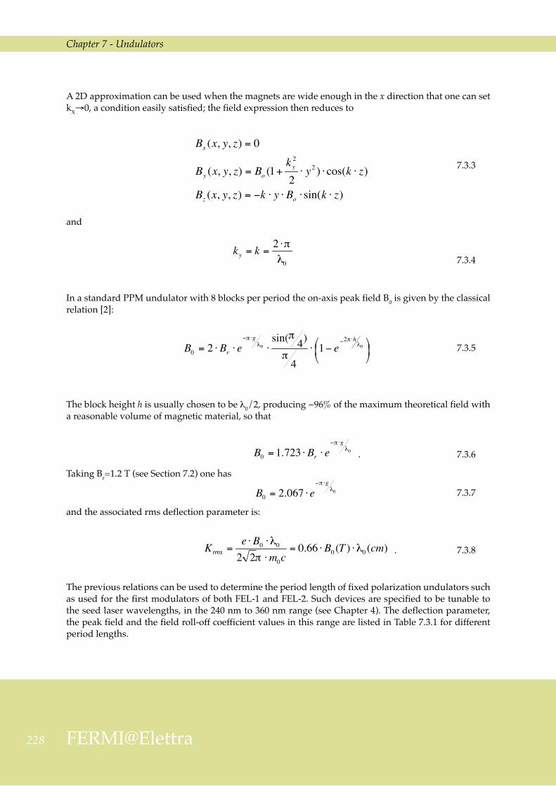
A 2D approximation can be used when the magnets are wide enough in the x direction that one can set kX→0, a condition easily satisfied; the field expression then reduces to
7.3.3
and
7.3.4
In a standard PPM undulator with 8 blocks per period the on-axis peak field B0 is given by the classical relation [2]:
7.3.5
The block height h is usually chosen to be λ0/2, producing ~96% of the maximum theoretical field with a reasonable volume of magnetic material, so that
. 7.3.6
Taking Br=1.2 T (see Section 7.2) one has
7.3.7
and the associated rms deflection parameter is:
. 7.3.8
The previous relations can be used to determine the period length of fixed polarization undulators such as used for the first modulators of both FEL-1 and FEL-2. Such devices are specified to be tunable to the seed laser wavelengths, in the 240 nm to 360 nm range (see Chapter 4). The deflection parameter, the peak field and the field roll-off coefficient values in this range are listed in Table 7.3.1 for different period lengths.
Chapter 7 - Undulators
229Conceptual Design Report
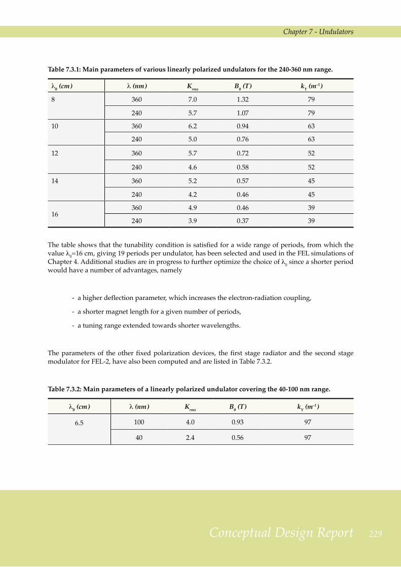
Table 7.3.1: Main parameters of various linearly polarized undulators for the 240-360 nm range.
λ0 (cm) λ (nm) Krms B0 (T) kY (m-1)
8 360 7.0 1.32 79
240 5.7 1.07 79
10 360 6.2 0.94 63
240 5.0 0.76 63
12 360 5.7 0.72 52
240 4.6 0.58 52
14 360 5.2 0.57 45
240 4.2 0.46 45
16360 4.9 0.46 39
240 3.9 0.37 39
The table shows that the tunability condition is satisfied for a wide range of periods, from which the value λ0=16 cm, giving 19 periods per undulator, has been selected and used in the FEL simulations of Chapter 4. Additional studies are in progress to further optimize the choice of λ0 since a shorter period would have a number of advantages, namely
- a higher deflection parameter, which increases the electron-radiation coupling,
- a shorter magnet length for a given number of periods,
- a tuning range extended towards shorter wavelengths.
The parameters of the other fixed polarization devices, the first stage radiator and the second stage modulator for FEL-2, have also been computed and are listed in Table 7.3.2.
Table 7.3.2: Main parameters of a linearly polarized undulator covering the 40-100 nm range.
λ0 (cm) λ (nm) Krms B0 (T) kY (m-1)
6.5 100 4.0 0.93 97
40 2.4 0.56 97
230 FERMI@Elettra
Chapter 7 - Undulators
Note that equation (7.3.5) relies on the approximation that the magnetic material has unit permeability, meaning that fields produced by individual magnet blocks can be linearly superimposed. The final detailed magnetic design therefore needs further work to take into account various other effects due to the finite width and the dimensional tolerances of the magnet blocks, the actual anisotropic permeability of the magnetic material and to magnetic field harmonics affecting the emission wavelength. Based on our experience, including such effects is expected to require only slight adjustments of the period length and/or of the gap width.
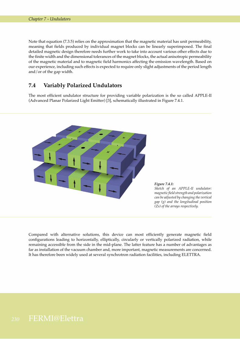
7.4 Variably Polarized UndulatorsThe most efficient undulator structure for providing variable polarization is the so called APPLE-II (Advanced Planar Polarized Light Emitter) [3], schematically illustrated in Figure 7.4.1.
Figure 7.4.1: Sketch of an APPLE-II undulator: magnetic field strength and polarization can be adjusted by changing the vertical gap (g) and the longitudinal position (Zs) of the arrays respectively.
Compared with alternative solutions, this device can most efficiently generate magnetic field configurations leading to horizontally, elliptically, circularly or vertically polarized radiation, while remaining accessible from the side in the mid-plane. The latter feature has a number of advantages as far as installation of the vacuum chamber and, more important, magnetic measurements are concerned. It has therefore been widely used at several synchrotron radiation facilities, including ELETTRA.

Chapter 7 - Undulators
231Conceptual Design Report
Like in the case of linear polarization vertical field undulators, the magnetic field can be written, to second order in the transverse coordinates X and Y, as
7.4.1
where:
7.4.2
For APPLE type undulators there is no analytical expression of B0 as a function of the device geometrical parameters. However, a semi-empirical formula is obtained (as suggested in Ref. [4]) fitting the results of 3D magnetostatic calculations performed on different magnet configurations; it has the following general form
, 7.4.3
Figure 7.4.2: An Apple-II undulator during assembly.

232 FERMI@Elettra
Chapter 7 - Undulators
often used to describe the field versus gap aperture dependence and as a help in choosing a starting set of parameters for numerical calculations. An important shortcut is provided by the principle of “scale invariance”, stating that, no matter what the configuration of a collection of unit-permeability magnetic blocks is, the magnetic field they generate is unchanged if their linear dimensions and their separation distances are all simultaneously scaled by the same factor [1].
This scaling procedure is applicable to FERMI, given the design and the foreseen range of parameters of the undulators. The height (h) and the width (w) of each block and the blocks horizontal separation (s) have therefore been parametrized as
. 7.4.4
The resulting coefficients appearing in Eq. (7.4.3), for the three main polarization modes (horizontal, circular and vertical), are listed in Table 7.4.1.
Table 7.4.1: Coefficients to be used in eq. (7.4.3) for various polarization modes.
Polarization Fitting coefficients
Horizontal a = 1.76 b = 2.77 c = - 0.37
Circular a = 1.54 b = 4.46 c = 0.43
Vertical a = 2.22 b = 5.19 c = 0.88
These coefficients are then used to determine the (approximate) period length of the final radiators so that the desired tuning range (100 to 40 nm for FEL-1 and 40 to 10 nm for FEL-2) is covered for all polarizations, namely λ0 = ~6.5 cm for FEL-1 and λ0 = ~5.0 cm for FEL-2. Pending more detailed calculations, and taking into account details such as the earlier mentioned non-unit permeability, the above approximate values have been used throughout this report. The corresponding sets of main undulator parameters, computed for two radiation wavelengths and three main polarization configurations, are listed in Tables 7.4.2 and 7.4.3.
Table 7.4.2: Parameters of FEL-1 radiator (λ0 = 6.5 cm) at both extremes of its tuning range in the three main polarization modes.
λ (nm) Krms BX0 (T) BY0 (T) kX (m-1) kY (m-1) kX’ (m-1) kY’ (m-1)
100 - H 4.0 0 0.93 55 87 - -
100 - C “ 0.66 0.66 55 79 147 · i 177
100 - V “ 0.93 0 - - 161 · i 189
40 - H 2.4 0 0.56 14 96 - -
40 - C “ 0.40 0.40 27 93 116 · i 151
40 - V “ 0.56 0 - - 124 · i 157
H = horizontal, C = circular, V = vertical polarization
Chapter 7 - Undulators
233Conceptual Design Report
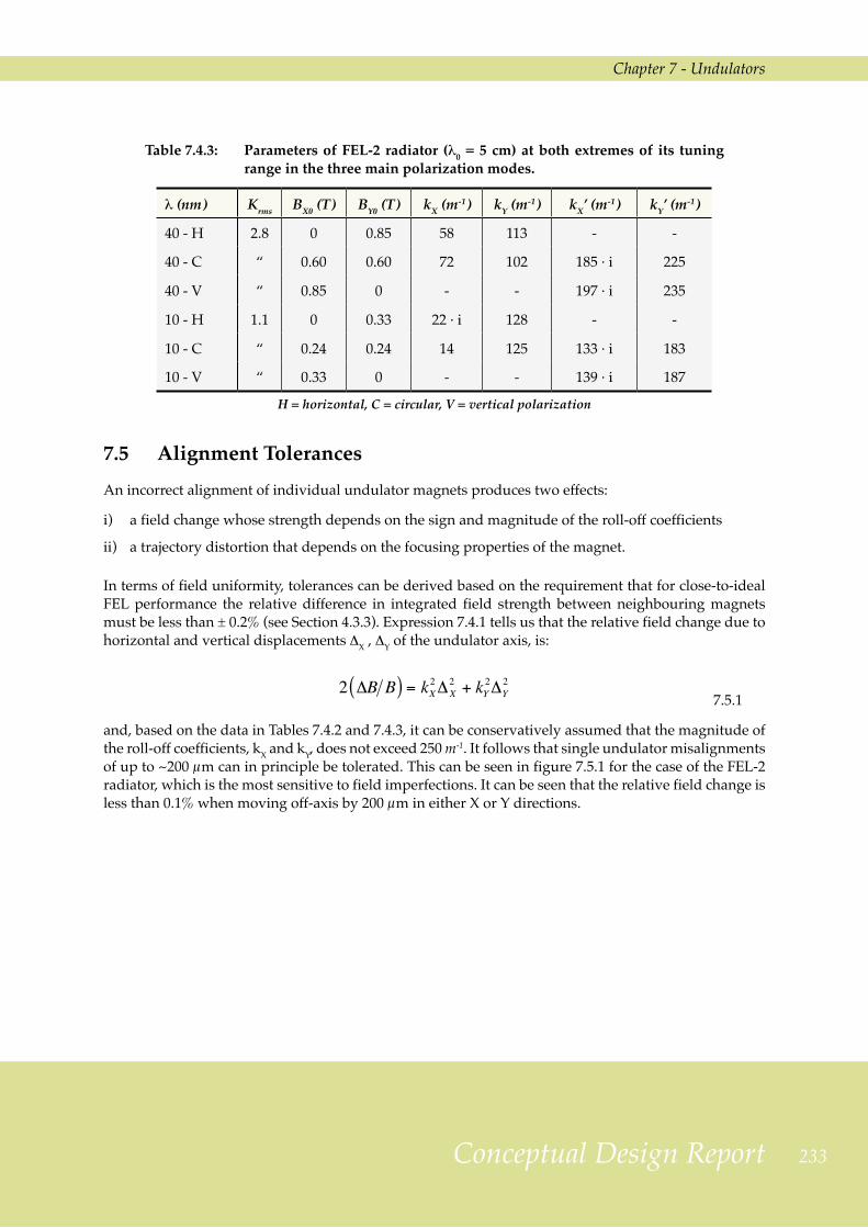
Table 7.4.3: Parameters of FEL-2 radiator (λ0 = 5 cm) at both extremes of its tuning range in the three main polarization modes.
λ (nm) Krms BX0 (T) BY0 (T) kX (m-1) kY (m-1) kX’ (m-1) kY’ (m-1)
40 - H 2.8 0 0.85 58 113 - -
40 - C “ 0.60 0.60 72 102 185 · i 225
40 - V “ 0.85 0 - - 197 · i 235
10 - H 1.1 0 0.33 22 · i 128 - -
10 - C “ 0.24 0.24 14 125 133 · i 183
10 - V “ 0.33 0 - - 139 · i 187
H = horizontal, C = circular, V = vertical polarization
7.5 Alignment TolerancesAn incorrect alignment of individual undulator magnets produces two effects:
i) a field change whose strength depends on the sign and magnitude of the roll-off coefficients
ii) a trajectory distortion that depends on the focusing properties of the magnet.
In terms of field uniformity, tolerances can be derived based on the requirement that for close-to-ideal FEL performance the relative difference in integrated field strength between neighbouring magnets must be less than ± 0.2% (see Section 4.3.3). Expression 7.4.1 tells us that the relative field change due to horizontal and vertical displacements ∆X , ∆Y of the undulator axis, is:
7.5.1
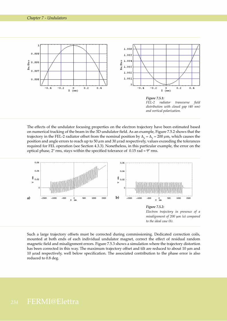
and, based on the data in Tables 7.4.2 and 7.4.3, it can be conservatively assumed that the magnitude of the roll-off coefficients, kX and kY, does not exceed 250 m-1. It follows that single undulator misalignments of up to ~200 µm can in principle be tolerated. This can be seen in figure 7.5.1 for the case of the FEL-2 radiator, which is the most sensitive to field imperfections. It can be seen that the relative field change is less than 0.1% when moving off-axis by 200 µm in either X or Y directions.
234 FERMI@Elettra
Chapter 7 - Undulators
Figure 7.5.1: FEL-2 radiator transverse field distribution with closed gap (40 nm) and vertical polarization.
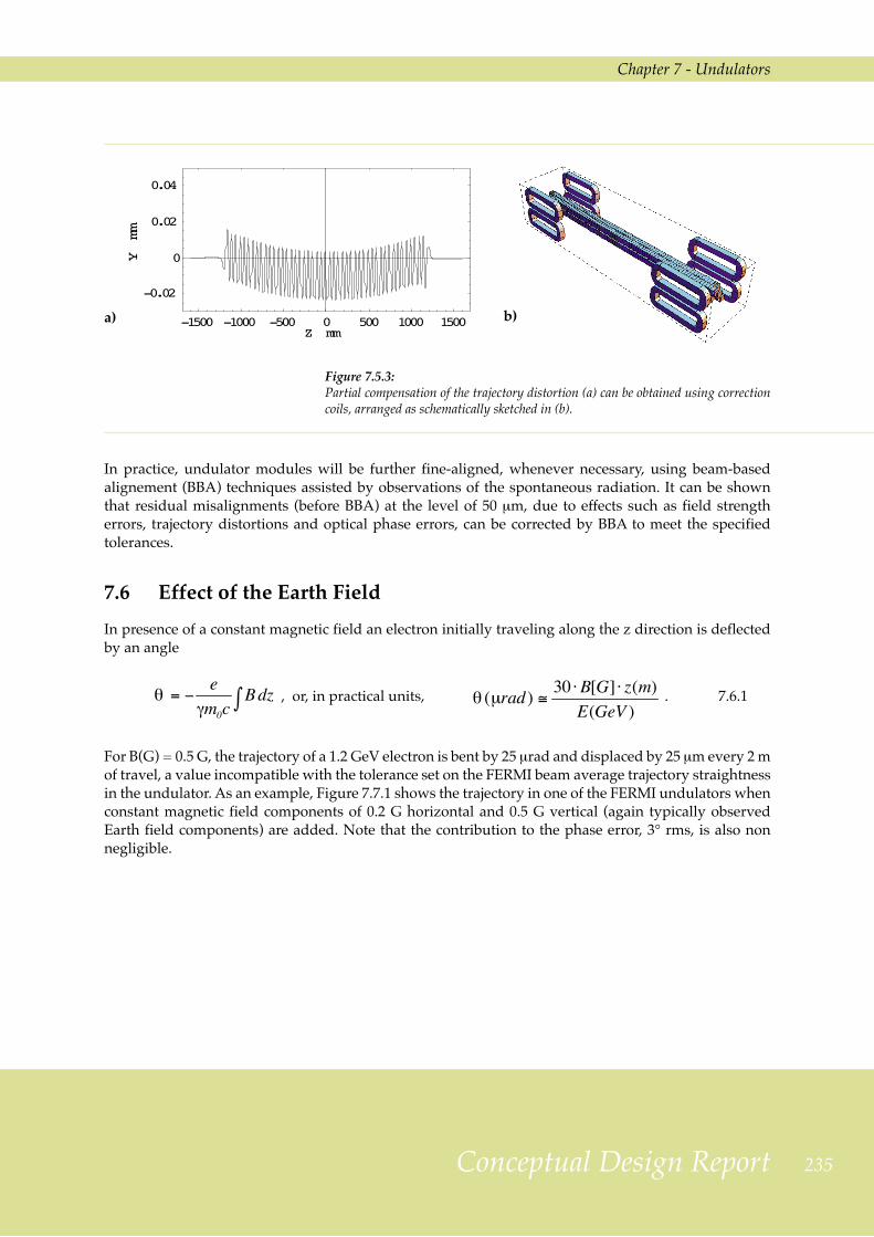
The effects of the undulator focusing properties on the electron trajectory have been estimated based on numerical tracking of the beam in the 3D undulator field. As an example, Figure 7.5.2 shows that the trajectory in the FEL-2 radiator offset from the nominal position by ∆X = ∆Y = 200 µm, which causes the position and angle errors to reach up to 50 µm and 30 µrad respectively, values exceeding the tolerances required for FEL operation (see Section 4.3.3). Nonetheless, in this particular example, the error on the optical phase, 2º rms, stays within the specified tolerance of 0.15 rad ≈ 9º rms.
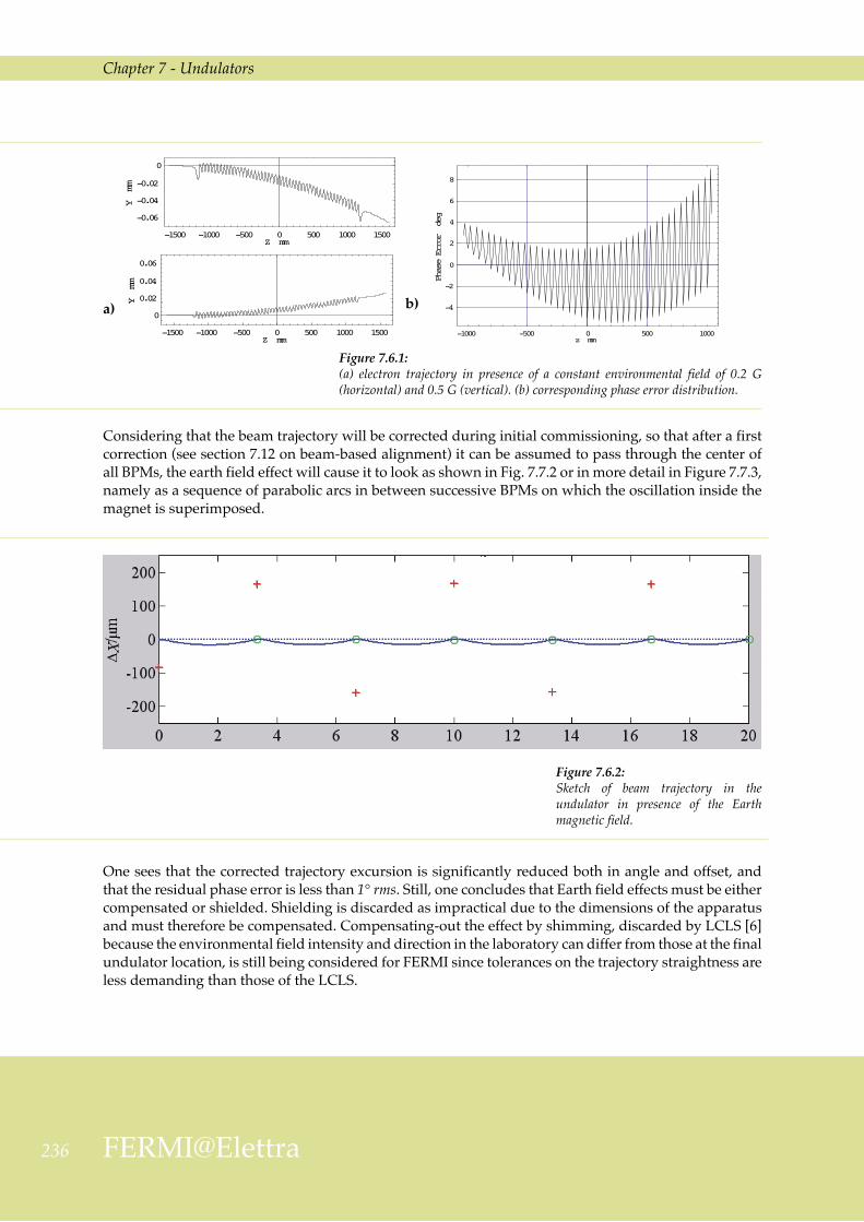
Such a large trajectory offsets must be corrected during commissioning. Dedicated correction coils, mounted at both ends of each individual undulator magnet, correct the effect of residual random magnetic field and misalignment errors. Figure 7.5.3 shows a simulation where the trajectory distortion has been corrected in this way. The maximum trajectory offset and tilt are reduced to about 10 µm and 10 µrad respectively, well below specification. The associated contribution to the phase error is also reduced to 0.8 deg.
a) b)
Figure 7.5.2: Electron trajectory in presence of a misalignment of 200 µm (a) compared to the ideal case (b).
Chapter 7 - Undulators
235Conceptual Design Report
In practice, undulator modules will be further fine-aligned, whenever necessary, using beam-based alignement (BBA) techniques assisted by observations of the spontaneous radiation. It can be shown that residual misalignments (before BBA) at the level of 50 µm, due to effects such as field strength errors, trajectory distortions and optical phase errors, can be corrected by BBA to meet the specified tolerances.
7.6 Effect of the Earth FieldIn presence of a constant magnetic field an electron initially traveling along the z direction is deflected by an angle
, or, in practical units, . 7.6.1
For B(G) = 0.5 G, the trajectory of a 1.2 GeV electron is bent by 25 µrad and displaced by 25 µm every 2 m of travel, a value incompatible with the tolerance set on the FERMI beam average trajectory straightness in the undulator. As an example, Figure 7.7.1 shows the trajectory in one of the FERMI undulators when constant magnetic field components of 0.2 G horizontal and 0.5 G vertical (again typically observed Earth field components) are added. Note that the contribution to the phase error, 3° rms, is also non negligible.
Figure 7.5.3: Partial compensation of the trajectory distortion (a) can be obtained using correction coils, arranged as schematically sketched in (b).
a) b)
23� FERMI@Elettra
Chapter 7 - Undulators
Considering that the beam trajectory will be corrected during initial commissioning, so that after a first correction (see section 7.12 on beam-based alignment) it can be assumed to pass through the center of all BPMs, the earth field effect will cause it to look as shown in Fig. 7.7.2 or in more detail in Figure 7.7.3, namely as a sequence of parabolic arcs in between successive BPMs on which the oscillation inside the magnet is superimposed.
Figure 7.6.1: (a) electron trajectory in presence of a constant environmental field of 0.2 G (horizontal) and 0.5 G (vertical). (b) corresponding phase error distribution.
a) b)
One sees that the corrected trajectory excursion is significantly reduced both in angle and offset, and that the residual phase error is less than 1° rms. Still, one concludes that Earth field effects must be either compensated or shielded. Shielding is discarded as impractical due to the dimensions of the apparatus and must therefore be compensated. Compensating-out the effect by shimming, discarded by LCLS [6] because the environmental field intensity and direction in the laboratory can differ from those at the final undulator location, is still being considered for FERMI since tolerances on the trajectory straightness are less demanding than those of the LCLS.
Figure 7.6.2: Sketch of beam trajectory in the undulator in presence of the Earth magnetic field.

Chapter 7 - Undulators
237Conceptual Design Report
7.7 Mechanical Design Considerations The undulator mechanical design is based on the experience gained with the construction of the Apple II undulators installed in the ELETTRA storage ring [7-11]. The main differences of the present FERMI design with respect to the one implemented in ELETTRA are the magnet length (2.5 m in FERMI, against 2 m in ELETTRA) and the tighter specifications on the gap height and on the electron-photon phasing. The new requirements will be met by suitably modifying the existing design.
The magnet main supporting structure (“carriage”) is made of rectangular steel tubes welded together to form a rigid C-type frame. The carriage is supported by two vertical posts, one at each end. Each of two stainless steel backing beams (upper and lower ), movable up and down on rails fastened to the main support posts, carries one longitudinally movable and one fixed aluminium beam, on each of which a magnet array is fixed. The undulator gap is changed by moving the backing beams up and down, driven by a pair of synchronized motors. The relative longitudinal position of the two aluminium beams carrying the magnet arrays (“phase”), also driven by two (upper and lower) synchronized motors, determines the radiation polarization. Finally, the carriage is mounted on a horizontally movable platform for the fine alignment of the whole structure. Undulator gap height, longitudinal (phase) shifts and carriage transverse positions are all measured using absolute encoders with better than 1 µm resolution.
Figure 7.6.3: Beam trajectory (a) and phase error (b) inside an undulator section, in presence of the Earth field and assuming that the corrected trajectory goes through the center of the BPMs mounted at both ends of the section itself.
a) b)
23� FERMI@Elettra
Chapter 7 - Undulators
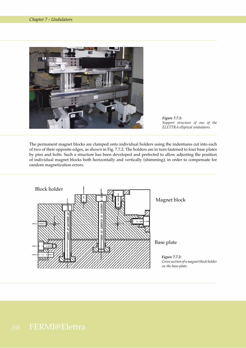
The permanent magnet blocks are clamped onto individual holders using the indentures cut into each of two of their opposite edges, as shown in Fig. 7.7.2. The holders are in turn fastened to four base plates by pins and bolts. Such a structure has been developed and perfected to allow adjusting the position of individual magnet blocks both horizontally and vertically (shimming), in order to compensate for random magnetization errors.
Figure 7.7.1: Support structure of one of the ELETTRA elliptical undulators.
Figure 7.7.2: Cross section of a magnet block holder on the base-plate.
Block holder
Magnet block
Base plate

Chapter 7 - Undulators
239Conceptual Design Report
A design study of the assembly is in progress, aimed at guaranteeing the following mechanical tolerances:
i) planarity and parallelism of each backing beam: 10 µm
ii) maximum magnetic gap error: 30 µm
iii) gap and phase positioning accuracy: 5 µm
iv) beam axis adjustable in the horizontal and vertical directions to within 5 µm
Such tolerances must be met at all gap and phase values in the presence of the strong magnetic forces that change in magnitude and direction as the undulator is tuned to different wavelengths or polarizations. As an example, Figure 7.7.3 shows the strength of forces acting on the individual arrays and on the backing beam of the FEL-1 radiator as functions of gap height and phase. Forces acting on the FEL-2 variable polarization device are smaller due to the smaller size of its magnetic blocks.
Figure 7.7.3: Magnetic forces on the FEL-1 radiator as a function of gap and phase: horizontal (a), longitudinal (b) and vertical (c) force components on the movable array; vertical force on the upper/lower backing beam (d).
a)
b)
c)
d)
240 FERMI@Elettra
Chapter 7 - Undulators
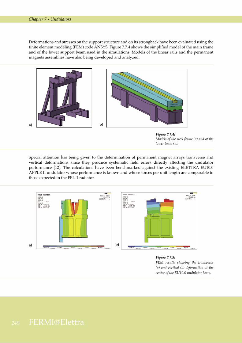
Deformations and stresses on the support structure and on its strongback have been evaluated using the finite element modeling (FEM) code ANSYS. Figure 7.7.4 shows the simplified model of the main frame and of the lower support beam used in the simulations. Models of the linear rails and the permanent magnets assemblies have also being developed and analyzed.
Figure 7.7.4: Models of the steel frame (a) and of the lower beam (b).
Special attention has being given to the determination of permanent magnet arrays transverse and vertical deformations since they produce systematic field errors directly affecting the undulator performance [12]. The calculations have been benchmarked against the existing ELETTRA EU10.0 APPLE II undulator whose performance is known and whose forces per unit length are comparable to those expected in the FEL-1 radiator.
a) b)
Figure 7.7.5: FEM results showing the transverse (a) and vertical (b) deformation at the center of the EU10.0 undulator beam.
a) b)

Chapter 7 - Undulators
241Conceptual Design Report
The FEM calculations were carried out on EU10.0 in the minimum gap and zero phase configuration, in which the horizontal and vertical forces are both close to their maximum. The results, shown in Figures 7.7.5, 7.7.6 and 7.7.7, are in good agreement with measurements recently performed on the same device [13]. The study proved specially useful in finding the position of the gap encoders most effective in preventing carriage deformations from spoiling the accuracy of the gap height measurement. In this respect, the alternative of having the encoders supported on a separate frame is also being evaluated.
Figure 7.7.6: Deformation of complete beam of the EU10.0 undulator.
Figure 7.7.7: Transverse (a) and vertical (b) displacements of the support frame.
a) b)

242 FERMI@Elettra
Chapter 7 - Undulators
7.8 Thermal Stability RequirementsThe main effect of unavoidable ambient temperature fluctuations is a change of the peak magnetic field due to reversible magnetization losses in the permanent magnet material. The corresponding temperature coefficient for NdFeB is typically ∆Br/Br = 0.15%/ºC.
For the FEL to operate (see Section 4.3.3), the relative difference in field strength between neighboring individual undulator magnets is specified to be less than ± 0.2%. Therefore, were thermal changes of the magnetic blocks the only source of field variation, the undulator average temperature would be required to stay within ± 1.3 ºC.
However, there are other factors to consider. Thermal expansion of the undulator support structure changes the transverse distance between the two linear permanent magnet arrays, fastened to a common steel backing beam (“horizontal gap”), and the undulator (vertical) gap height. Sensitivity coefficients can be evaluated from basic magnetic field expressions (see Section 7.4 and 7.5) showing , as an example, that the FEL-2 radiator, having the shortest period, is the most sensitive to gap height variations when operating in the vertical polarization mode, the ∆B/B change reaching up to 10%/mm.
A similar effect is found when changing the horizontal block separation (∆B/B~8%/mm); gap height and block separation stability of the order of 20 µm are required to fulfill the ± 0.2% tolerance criterion mentioned above. A conservative estimate of the deformation of a carefully engineered support structure indicates that an average temperature change of less than 1ºC is needed to keep the error on both the horizontal and the vertical gap within less than 15 µm.
Adding up the two effects and accounting for the thermal inertia of the device, one concludes that the average ambient temperature must be stable to within ± 0.7 °C, averaged over time intervals of a few hours.
7.9 Magnetic Optics in the Radiator RegionThe radiator is a sequence of 3 FODO cells, with an undulator in each of the straights. Matching of the FODO lattice with the undulators gaps in their “closed” position was done with MAD, in which the undulator is introduced as an uncoupled 6x6 transfer matrix computed using RACETRACK. The calculations are done for the 100 nm and the 40 nm photon wavelength (FEL 1 covered range) configurations, and for three representative polarizations, horizontal, circular and vertical.
The constraints taken into consideration in designing the optics are:
1) average betatron functions in the 7 to 11 m range in both planes, with maxima less than ~13 m and minima not less than ~5 m (see Chapter 4). When varying the polarization and/or the wavelength of the FEL output, the quadrupoles must therefore compensate for variations of the transport optics due to the change in the undulator focusing properties.
2) integrated quadrupole strength small enough for quadrupole misalignments and magnetic errors not to dominate trajectory errors ;
3) a maximum quadrupole field gradient small enough for hysteresis effects not to significantly affect reproducibility of the various different optics needed in operation;
6) quadrupole physical dimensions compatible with the straight section space reserved for diagnostics devices, corrector magnets, and other needed instrumentation.

Chapter 7 - Undulators
243Conceptual Design Report
A matched FODO lattice with phase advances in the range of 40 o to 60o in either plane has been shown to nicely meet all requirements, in particular that of rather low beta excursions along the channel, combined with sufficiently low maximum beta values.
Table 7.9.1 lists the strengths and phase advances of the 0.15 m long, FODO cell quadrupoles, called QR1 and QR2, in the fully open undulator gaps configuration and for three different polarizations (see also Section 7.7). The quadrupole specified top gradient of 10 T/m includes a 20% margin. The maximum betatron function stays within 12.5 m. The open gap optics has the highest and closest to each other phase advances compared to all other operational configurations; this because as gaps are closed and undulator effects become stronger, the lattice behaves less and less like a pure FODO and the phase advance difference between the two planes tends to grow. The effect is most evident for the circular and vertical polarizations at a photon wavelength of 100 nm, where the defocusing quadrupoles change to focusing.
Table 7.9.1: Radiator quadrupole strengths [m-2] – magnetic length 0.15 m.
Polarization QR1 QR2 Beta phases Racetrack & Mad phases
Open und. defocussing
-1. 964
focussing
1. 964
Φx = 58o
Φy = 58o
Φx = 58o
Φy = 58o
H – 40nm defocussing
-1.381
focussing
1.524
Φx = 48o
Φy = 47.8o
Φx = 48o
Φy = 48o
C – 40nm defocussing
-1.274
focussing
1.625
Φx = 48.2o
Φy = 47.6o
Φx = 48o
Φy = 48o
V – 40nm defocussing
-1.161
focussing
1.798
Φx = 49.7o
Φy = 48.5o
Φx = 49.2o
Φy = 49.2o
H – 100nm defocussing
-0.457
focussing
0.717
Φx = 41.5o
Φy = 42.4o
Φx = 42o
Φy = 42.2o
C – 100nm focussing
0.013
focussing
1.317
Φx = 46o
Φy = 42.6o
Φx = 45.7o
Φy = 41.9o
V – 100nm focussing
1.448
focussing
1.474
Φx = 52.9o
Φy = 44o
Φx = 49.9o
Φy = 46.5o
H = horizontal, C = circular, V = vertical polarization
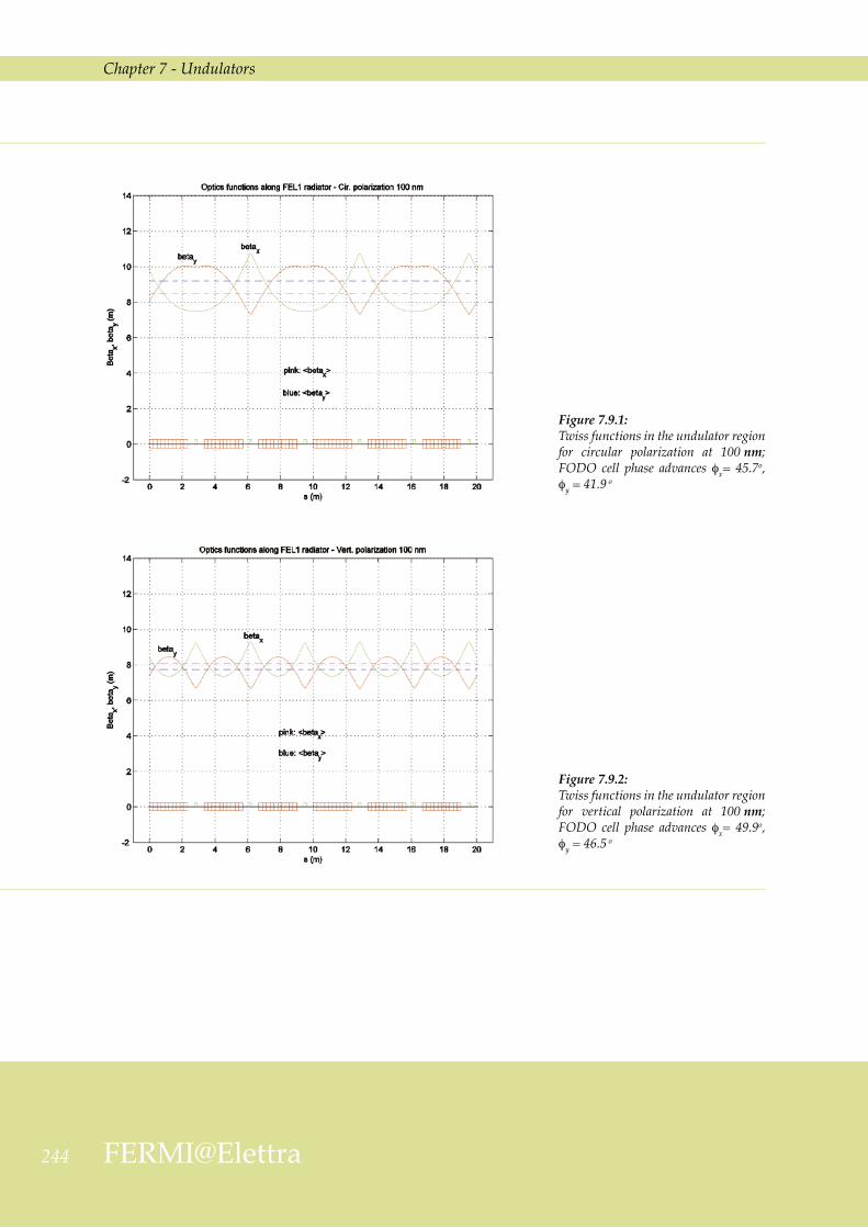
As an example, Figures 7.9.1 and 7.9.2 show the behaviour of the Twiss functions in the undulator region for the last two configurations of Table 7.9.1, namely, circular and vertical polarization and 100 nm wavelength.
244 FERMI@Elettra
Chapter 7 - Undulators
Figure 7.9.1: Twiss functions in the undulator region for circular polarization at 100 nm; FODO cell phase advances φx= 45.7o, φy = 41.9 o
Figure 7.9.2: Twiss functions in the undulator region for vertical polarization at 100 nm; FODO cell phase advances φx= 49.9o, φy = 4�.5 o
Chapter 7 - Undulators
245Conceptual Design Report
7.10 Undulator Vacuum SystemThe undulator vacuum system is designed to fit the minimum undulator gap (10 mm); it is built in modules, each consisting of a diagnostics section followed by an undulator vacuum chamber. The diagnostics section hosts all instrumentation for beam diagnostics and alignment as well as the vacuum diagnostics and pumping system instrumentation.
The design complies with the following general guidelines.
- The chamber material electrical resistivity and roughness must be low enough for the resistive wall and the roughness impedance to be kept within specified, acceptable limits (see below) [14].
- The material atomic number must be low and the vacuum chamber capable of surviving at least one direct hit by the full current, full energy, accidentally mis-steered bunch [14].
- Cost and ease of fabrication must be taken into account.
While the mechanical properties of copper, aluminium, titanium, and stainless steel are all suitable for HV vacuum chamber applications, copper and aluminium are preferred because of their superior electrical characteristics. For FERMI, aluminium has been chosen because of its lightness and ease of fabrication combined with good, if not best, electrical properties [15-18].
The average pressure in the undulator vacuum chamber is specified not to exceed 5·10-7 mbar.
7.10.1 Description
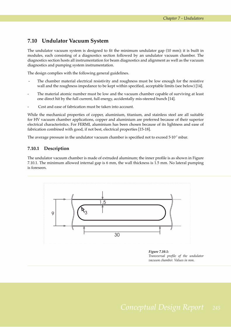
The undulator vacuum chamber is made of extruded aluminum; the inner profile is as shown in Figure 7.10.1. The minimum allowed internal gap is 6 mm, the wall thickness is 1.5 mm. No lateral pumping is foreseen.
Figure 7.10.1: Transversal profile of the undulator vacuum chamber. Values in mm.

24� FERMI@Elettra
Chapter 7 - Undulators
The surface roughness is specified to be < 0.5 µm rms [16], a conservative value considering what is achieved using state of the art extrusion and surface polishing processes [21]. Preliminary calculations of the effects of the roughness impedance predict, assuming the vacuum chamber cross section is circular with 3 mm radius, a maximum tolerable roughness of <~ 250 nm; this is not too far from the above specification given the worst case assumption made on the chamber shape. Further R&D, both to validate the applied theory and to improve the surface properties, is in progress.
The transition vacuum chamber between two undulator modules is built of the same material and has the same internal shape as that of the undulator in order to avoid wakefield producing discontinuities. A bellow allows to easily connect two adjacent modules and to compensate small length variations due to thermal excursions, particularly during bakeout. The bellow is directly welded to the vacuum chamber in order to save space for diagnostics instrumentation. Its detailed design will be defined so as to minimize geometrical wakefield effects.
A box (Figure 7.10.2), surrounding a vacuum chamber section with pumping slots, carries four flanges to which pumps and auxiliary vacuum instrumentation or other components such as pressure gauges, residual gas analyzer, vacuum valves or beam diagnostics instrumentation can be connected. Care is taken to ensure that the pumping slots do not significantly contribute to wakefield amplitudes.
Each chamber is equipped with at least a 20 l/s sputter ion pump (SIP) in order to ensure the design operating vacuum pressure also in presence of possible small leaks. Because of the relatively high starting and working pressures, triode pumps are foreseen. Note that the obtainable final pressure is conductance limited, as discussed in Section 7.10.2.
In order to minimize discontinuities occurring between each pair of coupled vacuum chambers, flat flanges and VAT-like seals are specified.
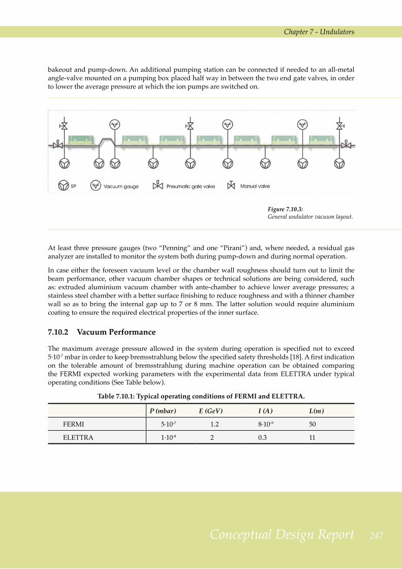
The general undulator vacuum layout is presented in figure 7.10.3. Only two all-metal gate valves are used, one at the beginning and one at the end of the undulator chain vacuum system. They are equipped with RF contacts and with a side flange to connect the system to the pumping station used during
Figure 7.10.2: Sketch of top view and side view of the pumping box.
Chapter 7 - Undulators
247Conceptual Design Report
bakeout and pump-down. An additional pumping station can be connected if needed to an all-metal angle-valve mounted on a pumping box placed half way in between the two end gate valves, in order to lower the average pressure at which the ion pumps are switched on.
Figure 7.10.3: General undulator vacuum layout.
At least three pressure gauges (two “Penning” and one “Pirani”) and, where needed, a residual gas analyzer are installed to monitor the system both during pump-down and during normal operation.
In case either the foreseen vacuum level or the chamber wall roughness should turn out to limit the beam performance, other vacuum chamber shapes or technical solutions are being considered, such as: extruded aluminium vacuum chamber with ante-chamber to achieve lower average pressures; a stainless steel chamber with a better surface finishing to reduce roughness and with a thinner chamber wall so as to bring the internal gap up to 7 or 8 mm. The latter solution would require aluminium coating to ensure the required electrical properties of the inner surface.
7.10.2 Vacuum Performance
The maximum average pressure allowed in the system during operation is specified not to exceed 5·10-7 mbar in order to keep bremsstrahlung below the specified safety thresholds [18]. A first indication on the tolerable amount of bremsstrahlung during machine operation can be obtained comparing the FERMI expected working parameters with the experimental data from ELETTRA under typical operating conditions (See Table below).
Table 7.10.1: Typical operating conditions of FERMI and ELETTRA.
P (mbar) E (GeV) I (A) L(m)
FERMI 5·10-7 1.2 8·10-9 50
ELETTRA 1·10-8 2 0.3 11

24� FERMI@Elettra
Chapter 7 - Undulators
The ratio of the total dose rate at a conventional reference distance of ten meters from the end of the straight sections was calculated using the following formula [25]:
7.10.1
where E is the electron energy [MeV], I the average electron current [e-/s], L the straight section length [m], p the average pressure ,patm the atmospheric pressure (1013 mbar).
The result is:
. 7.10.2
The very low ratio is due to the fact that, while the peak currents of the two accelerators are comparable, the FERMI repetition rate and consequently its average current are several orders of magnitude lower than that of the LCLS. Similar results can also be drawn from experience at FLASH [23].
While more detailed calculations are in progress for radiation protection purposes, the undulator vacuum chamber design average pressure of 5x10⁻⁷ is expected to be more than adequate as far as production of bremsstrahlung is concerned.
In order to evaluate the effect of photon induced desorption due to incoherent synchrotron radiation, more detailed knowledge of the photon distribution along the undulator vacuum chamber than at present available is necessary. Nevertheless, first indications can be obtained from comparing FERMI’s parameters to those of LCLS, although undulator types and chamber material and shape are different. For FERMI, the electron beam average power of ≤ 12 W at 10 Hz repetition rate is 150 times lower than the maximum average power of LCLS (1.8 kW) [14]; the FEL radiation peak power is also about 35 times lower for FERMI. On the other hand, the LCLS calculated average pressure increase due to photon induced desorption in the copper chamber is in the range of 10-9 mbar with a desorption yield (molecules desorbed per incident photon) of Cu about one order of magnitude lower than that of aluminium [24]. From the above data one therefore expects the desorption induced pressure rise in the FERMI undulator chamber to be lower than that computed for LCLS by at least one order of magnitude and therefore negligible compared to the design average pressure.
Concerning the possibility of carbon contamination of the surface, at FLASH - where the vacuum specification for the undulator vacuum chambers requires the residual gas pressure for masses > 45 amu to be not higher than 10-3 of the total pressure - no carbon contamination is observed [23]. A similar specification is also foreseen for FERMI so that no significant contamination is expected.
Chapter 7 - Undulators
249Conceptual Design Report
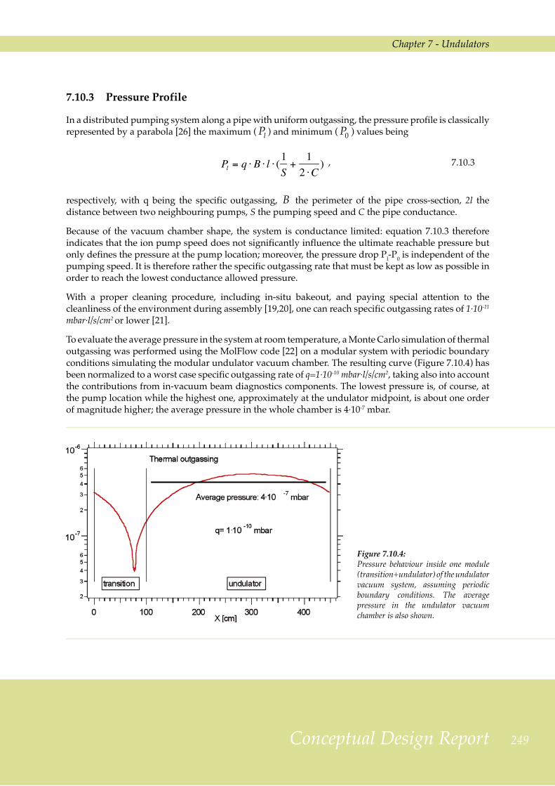
7.10.3 Pressure Profile
In a distributed pumping system along a pipe with uniform outgassing, the pressure profile is classically represented by a parabola [26] the maximum ( Pl ) and minimum ( P0 ) values being
, 7.10.3
respectively, with q being the specific outgassing, B the perimeter of the pipe cross-section, 2l the distance between two neighbouring pumps, S the pumping speed and C the pipe conductance.
Because of the vacuum chamber shape, the system is conductance limited: equation 7.10.3 therefore indicates that the ion pump speed does not significantly influence the ultimate reachable pressure but only defines the pressure at the pump location; moreover, the pressure drop Pl-P0 is independent of the pumping speed. It is therefore rather the specific outgassing rate that must be kept as low as possible in order to reach the lowest conductance allowed pressure.
With a proper cleaning procedure, including in-situ bakeout, and paying special attention to the cleanliness of the environment during assembly [19,20], one can reach specific outgassing rates of 1·10-11 mbar·l/s/cm2 or lower [21].
To evaluate the average pressure in the system at room temperature, a Monte Carlo simulation of thermal outgassing was performed using the MolFlow code [22] on a modular system with periodic boundary conditions simulating the modular undulator vacuum chamber. The resulting curve (Figure 7.10.4) has been normalized to a worst case specific outgassing rate of q=1·10-10 mbar·l/s/cm2, taking also into account the contributions from in-vacuum beam diagnostics components. The lowest pressure is, of course, at the pump location while the highest one, approximately at the undulator midpoint, is about one order of magnitude higher; the average pressure in the whole chamber is 4·10-7 mbar.
Figure 7.10.4: Pressure behaviour inside one module (transition+undulator) of the undulator vacuum system, assuming periodic boundary conditions. The average pressure in the undulator vacuum chamber is also shown.
250 FERMI@Elettra
Chapter 7 - Undulators
7.10.4 Conclusion
In conclusion, aluminium has been chosen as the undulator vacuum system material, because of its lightness, ease of fabrication and good electrical properties. The material specific outgassing, the most important parameter limiting the ultimate pressure, is kept low by following scrupulous cleaning and assembling procedures. A simulation of the system vacuum behaviour indicates that a maximum average pressure below 5·10-7 mbar can be easily achieved provided strict construction, assembly and maintenance prescriptions are followed.
More detailed simulations will be performed following completion of the detailed design of all components.
Structural and thermal properties of the vacuum chamber including mechanical stress and consequences of possible beam losses are being studied further.
7.11 Wakefields in the Undulator Vacuum ChamberSince the effects of transverse wakes in the undulator vacuum chambers can be neglected, the main concern is the longitudinal wakes which may blow-up the electron bunch energy spread and consequently degrade the quality of the FEL radiation. They may originate from:
- the resistive wall (RW) effect due to the finite conductivity of the chamber walls,
- the impedance of cavity-like objects,
- the roughness of the chamber inner surface.
The treatment of RW wakefields and of their effect on the FEL performance follows the approach of references [27-30]. Wake functions driven by the wall resistivity are obtained in the time dependent (AC) approximation by numerically computing the inverse Fourier transform of the AC impedance. The very high frequency components in the wake function spectrum acting back on the electron beam degrade the final FEL beam quality by blowing up the electron bunch energy spread.
The theory presented in ref. [27,29] has been applied to both round and parallel-plate geometries, and to aluminium and copper vacuum chambers. The round chambers have an inner radius of 6 mm , while the parallel plate chamber gap is 10 mm. The induced electron bunch energy spread has been evaluated for both the medium and the long bunch case, as described in Chapter 5 of this report.
The theory of surface roughness in a circular chamber, on which the calculations of this study are based, may be found in ref. [31]. The theory of parallel plates [32] is less well established; the overall wakefield is computed by adding up the various excited modes that can propagate through the chamber itself. In the limit of two infinite parallel plates there must be a continuous spectrum of modes that, when added up, tends to cancel the overall effect [7]. Consequently, the induced energy spread is expected to be no larger than for a circular chamber with a radius comparable to the parallel plate separation.
Chapter 7 - Undulators
251Conceptual Design Report
7.11.1 The Resistive Wall Wakefields
This Section provides an overview of the effects of RW induced, AC (time dependent) wakefields . More details are given in ref. [33.]
The interaction between the electron beam and the vacuum chamber is generally described by a coupling impedance and varies according to the wave number k of the excited electromagnetic modes that can propagate inside the chamber. The impedance is computed using an RLC parallel circuit to model the chamber response.
The key parameter is the AC conductivity of the chamber wall:
, 7.11.1
the DC conductivity, σ, and the electron relaxation time, τ , being given in table 7.11.1.
Table 7.11.1: DC conductivity and relaxation time for Al and Cu.
aluminium copper
σ [Ω-1m-1] 4.22×10⁷ 6.45×10⁷
τ [s] 8.00×10⁻¹⁵ 2.70×10⁻¹⁴
The normalized AC longitudinal coupling impedance of a circular chamber can be written as
7.11.2
and that of a parallel plates chamber as
7.11.3
where is a function whose inverse imaginary part gives the skin depth [30], namely
, 7.11.4
where a denotes the radius of the circular chamber or the half-gap of the parallel plate and Z0 ≈ 377 Ω the vacuum impedance.
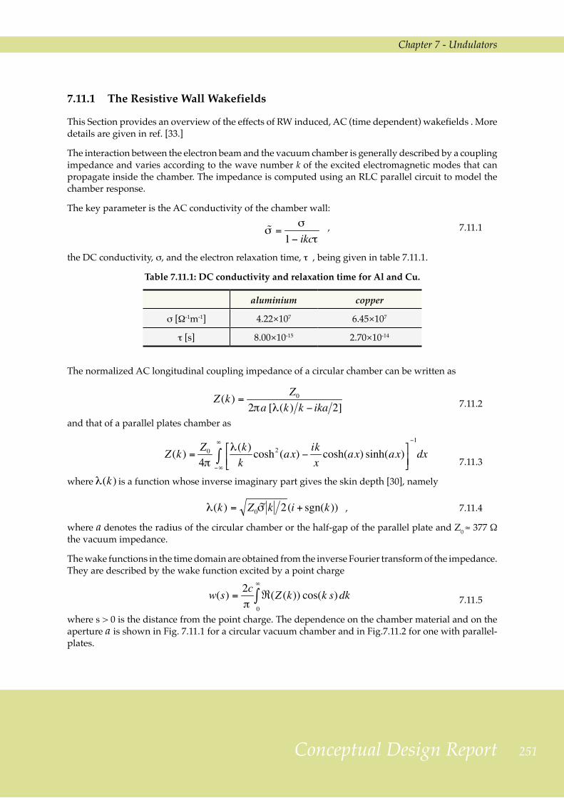
The wake functions in the time domain are obtained from the inverse Fourier transform of the impedance. They are described by the wake function excited by a point charge
7.11.5
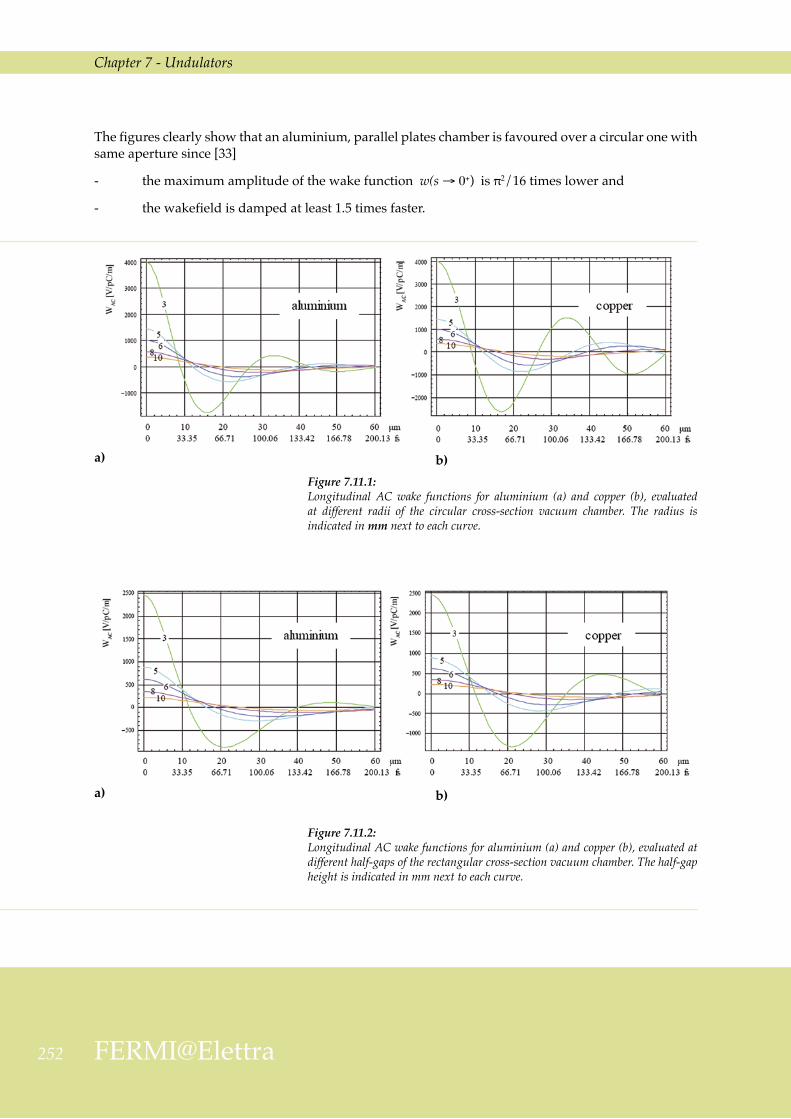
where s > 0 is the distance from the point charge. The dependence on the chamber material and on the aperture a is shown in Fig. 7.11.1 for a circular vacuum chamber and in Fig.7.11.2 for one with parallel-plates.
252 FERMI@Elettra
Chapter 7 - Undulators
The figures clearly show that an aluminium, parallel plates chamber is favoured over a circular one with same aperture since [33]
- the maximum amplitude of the wake function w(s →0+) is π2/16 times lower and
- the wakefield is damped at least 1.5 times faster.
Figure 7.11.1: Longitudinal AC wake functions for aluminium (a) and copper (b), evaluated at different radii of the circular cross-section vacuum chamber. The radius is indicated in mm next to each curve.
a) b)
Figure 7.11.2: Longitudinal AC wake functions for aluminium (a) and copper (b), evaluated at different half-gaps of the rectangular cross-section vacuum chamber. The half-gap height is indicated in mm next to each curve.
a) b)

Chapter 7 - Undulators
253Conceptual Design Report
The effect of the longitudinal resistive wall wakefield is to induce an energy spread which is correlated with the longitudinal position inside the bunch. This correlated energy modulation follows closely the shape of the wake functions, and, consequently, the choice of the chamber aperture is crucial for the FEL efficiency.
The induced energy spread, for the medium bunch case with a total bunch charge Q = 0.8 nC and for the long bunch with Q = 1 nC have been computed; the resulting bunch profiles are shown in Chapter 5.
The first step in calculating the energy spread is to compute the wake potential, defined as the convolution of the wake function with the electron bunch linear current density distribution ρ(s), namely
, 7.11.6
with the sign convention that positive values indicate energy gain for a particle located at a distance s behind the leading point charge. With this convention, the energy spread is given by
7.11.7
The AC wake functions were convoluted by binning the charge distribution in 5 µm bins. The results for two cases (a = 3 and 5 mm), are shown in Fig. 7.11.3 for the medium bunch and in Fig. 7.11.4 for the long bunch case.
It is to be noted that, apart from rather large amplitude oscillations at the head and the tail of the bunch, in the worst case of a 3 mm radius circular chamber the residual absolute energy variation at the bunch core is - 10 keV/m for the medium bunch case and 5 kV/m for the long bunch case. The aluminium chamber clearly offers a flatter bunch core and lower amplitude oscillations near the bunch head and tail. As far as the chamber shape is concerned, the overall average energy loss suffered in a parallel plate chamber is slightly less than that in a circular cross-section with same aperture.

254 FERMI@Elettra
Chapter 7 - Undulators
Figure 7.11.3: Induced energy spread in the medium bunch passing through a circular (a, c) and a parallel-plates vacuum chamber (b, d), for a = 3 (a, b) and a = 5 mm (c, d), taking aluminium (red) and copper (blue) for the wall material.
a) b)
Figure 7.11.4: Induced energy spread in the long bunch passing through a circular (a, c) and a parallel-plates vacuum chamber (b, d), for a = 3 mm (a, b) and a = 5 mm (c, d), taking aluminium (red) and copper (blue) for the wall material.
c) d)
a) b)
c) d)
Chapter 7 - Undulators
255Conceptual Design Report
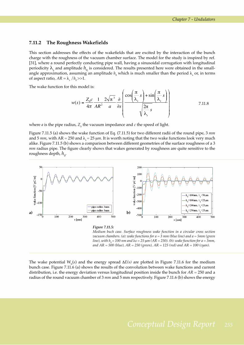
7.11.2 The Roughness Wakefields
This section addresses the effects of the wakefields that are excited by the interaction of the bunch charge with the roughness of the vacuum chamber surface. The model for the study is inspired by ref. [31], where a round perfectly conducting pipe wall, having a sinusoidal corrugation with longitudinal periodicity λs and amplitude h0, is considered. The results presented here were obtained in the small-angle approximation, assuming an amplitude h0 which is much smaller than the period λs or, in terms of aspect ratio, AR =λs /h0 >>1.
The wake function for this model is:
7.11.8
where a is the pipe radius, Z0 the vacuum impedance and c the speed of light.
Figure 7.11.5 (a) shows the wake function of Eq. (7.11.5) for two different radii of the round pipe, 3 mm and 5 mm, with AR = 250 and λs = 25 µm. It is worth noting that the two wake functions look very much alike. Figure 7.11.5 (b) shows a comparison between different geometries of the surface roughness of a 3 mm radius pipe. The figure clearly shows that wakes generated by roughness are quite sensitive to the roughness depth, h0.
Figure 7.11.5: Medium buch case. Surface roughness wake function in a circular cross section vacuum chambers. (a): wake functions for a = 3 mm (blue line) and a = 5mm (green line), with h0 = 100 nm and λs = 25 µm (AR = 250). (b): wake function for a = 3mm, and AR = 500 (blue), AR = 250 (green), AR = 125 (red) and AR = 100 (cyan).
a) b)
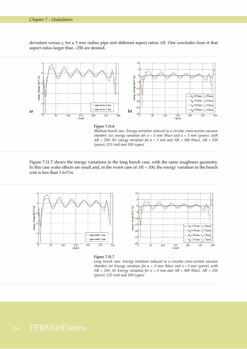
The wake potential Wb(s) and the energy spread ∆E(s) are plotted in Figure 7.11.6 for the medium bunch case. Figure 7.11.6 (a) shows the results of the convolution between wake functions and current distribution, i.e. the energy deviation versus longitudinal position inside the bunch for AR = 250 and a radius of the round vacuum chamber of 3 mm and 5 mm respectively. Figure 7.11.6 (b) shows the energy
25� FERMI@Elettra
Chapter 7 - Undulators
deviation versus s, for a 3 mm radius pipe and different aspect ratios AR. One concludes from it that aspect ratios larger than ~250 are desired.
Figure 7.11.6 Medium bunch case. Energy variation induced in a circular cross-section vacuum chamber. (a): energy variation for a = 3 mm (blue) and a = 5 mm (green), with AR = 250. (b): energy variation for a = 3 mm and AR = 500 (blue), AR = 250 (green), 125 (red) and 100 (cyan).
Figure 7.11.7 shows the energy variations in the long bunch case, with the same roughness geometry. In this case wake effects are small and, in the worst case of AR = 100, the energy variation in the bunch core is less than 1 keV/m.
Figure 7.11.7 Long bunch case. Energy variation induced in a circular cross-section vacuum chamber. (a) Energy variation for a = 3 mm (blue) and a = 5 mm (green), with AR = 250. (b) Energy variation for a = 3 mm and AR = 500 (blue), AR = 250 (green), 125 (red) and 100 (cyan).
a) b)
Chapter 7 - Undulators
257Conceptual Design Report
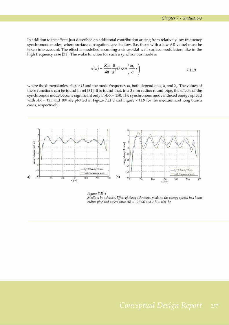
In addition to the effects just described an additional contribution arising from relatively low frequency synchronous modes, where surface corrugations are shallow, (i.e. those with a low AR value) must be taken into account. The effect is modelled assuming a sinusoidal wall surface modulation, like in the high frequency case [31]. The wake function for such a synchronous mode is
7.11.9
where the dimensionless factor U and the mode frequency ω0 both depend on a, h0 and λs. The values of these functions can be found in ref [31]. It is found that, in a 3 mm radius round pipe, the effects of the synchronous mode become significant only if AR<~ 150. The synchronous mode induced energy spread with AR = 125 and 100 are plotted in Figure 7.11.8 and Figure 7.11.9 for the medium and long bunch cases, respectively.
Figure 7.11.8 Medium bunch case. Effect of the synchronous mode on the energy spread in a 3mm radius pipe and aspect ratio AR = 125 (a) and AR = 100 (b).
a) b)
25� FERMI@Elettra
Chapter 7 - Undulators
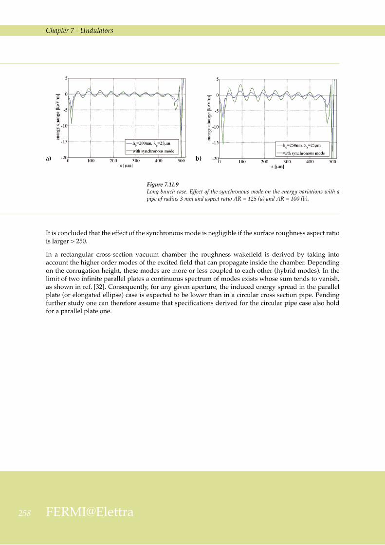
Figure 7.11.9 Long bunch case. Effect of the synchronous mode on the energy variations with a pipe of radius 3 mm and aspect ratio AR = 125 (a) and AR = 100 (b).
a) b)
It is concluded that the effect of the synchronous mode is negligible if the surface roughness aspect ratio is larger > 250.
In a rectangular cross-section vacuum chamber the roughness wakefield is derived by taking into account the higher order modes of the excited field that can propagate inside the chamber. Depending on the corrugation height, these modes are more or less coupled to each other (hybrid modes). In the limit of two infinite parallel plates a continuous spectrum of modes exists whose sum tends to vanish, as shown in ref. [32]. Consequently, for any given aperture, the induced energy spread in the parallel plate (or elongated ellipse) case is expected to be lower than in a circular cross section pipe. Pending further study one can therefore assume that specifications derived for the circular pipe case also hold for a parallel plate one.
Chapter 7 - Undulators
259Conceptual Design Report
7.12 Alignment and Trajectory Control 7.12.1 Introduction
In the absence of magnetic perturbations and misalignments, the average electron beam trajectory in the undulator is a straight line on which a very small amplitude oscillation is superimposed. In this ideal situation slippage-free transverse overlap of the electron and the radiation beams is guaranteed. In a real situation, misalignment of magnetic elements, the finite resolution and misalignment of the BPMs and undulator magnetic field errors all contribute to distorting the ideal beam trajectory.
The goal of undulator magnets and quadrupoles alignment procedures is to keep the trajectory distortion in the undulator region below the tolerance specified for successful FEL operation; namely, according to simulations [34], within < 10 µm in the most critical case of FEL operation at 10 nm wavelength, the lowest end of the foreseen operating range.
Such a tight tolerance is mainly dictated by the phase error due to slippage between the electron bunch and FEL radiation, occurring when the electron trajectory strays from a straight line [35].
The phase error accumulated over a length l by an electron entering the undulator at an angle x' with respect to the undulator axis is
7.12.1
where kr is the radiation wave vector and ∆s the path length difference between FEL photons and the electron beam. In addition, a field error on the jth undulator pole imparts a further angular kick to the beam that one can write
7.12.2
Assuming that during the initial commissioning the beam is steered through the center of all BPMs, the residual trajectory errors are due to the BPMs finite resolution and misalignment. In a simple model in which the focusing and defocusing actions of the undulator are neglected, the average phase error per section introduced by N undulator pole magnetic errors and by the inaccuracy of the trajectory correction is [35] :
,
(7.12.3)
where rBPM and are the corresponding BPM resolution and misalignment, kr is the radiation wave number, λu the undulator period, θ the kick due to a pole error, Ψ the pole roll angle error, K the undulator parameter, γthe electron beam Lorentz factor and the overall inaccuracy of the position measurements. The mean values of magnetic pole field and roll angle errors are assumed to be independent of the pole location. The same assumption is made for the the inaccuracy of the BPMs.
2�0 FERMI@Elettra
Chapter 7 - Undulators
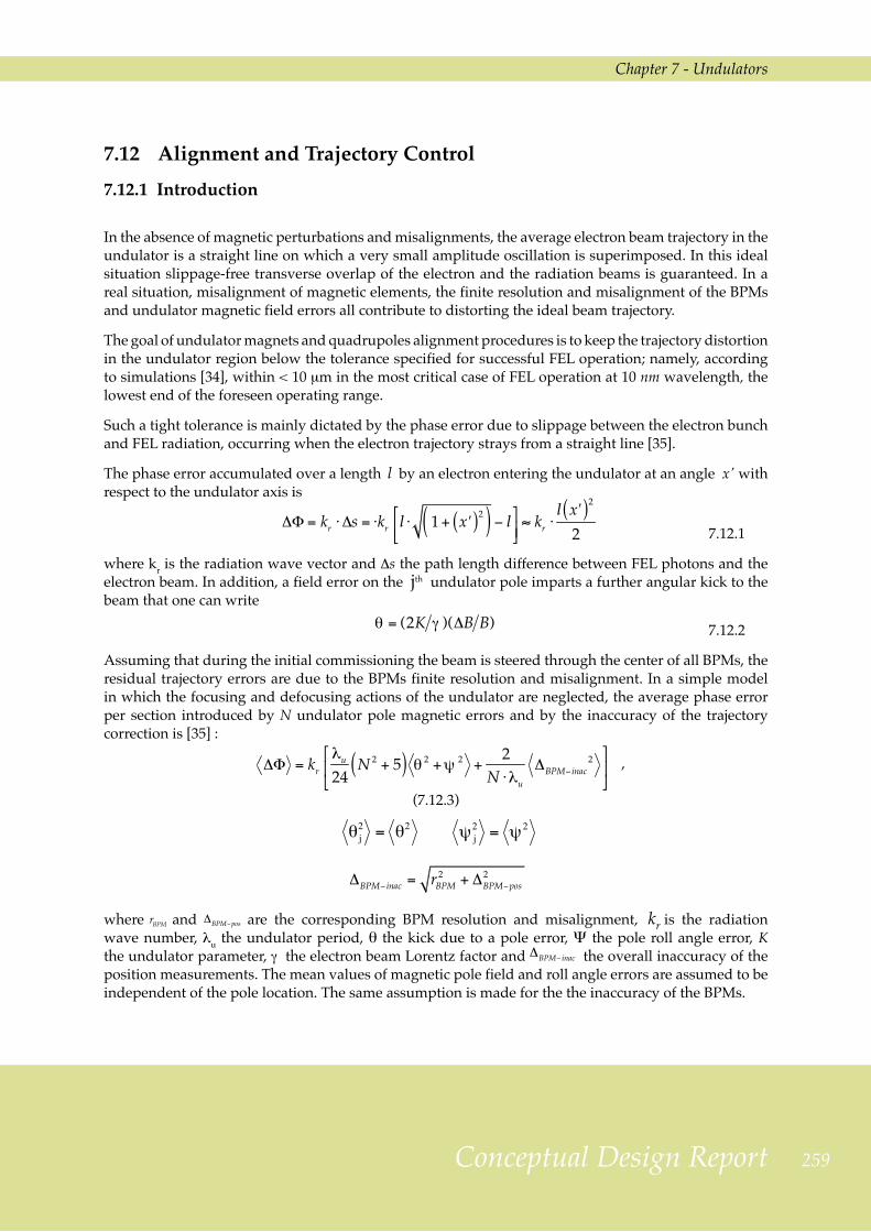
To proceed, one uses the model of a N/2 periods undulator sketched in Figure 7.12.1, in which a BPM plus a corrector are placed next to both the magnet ends. Quadrupoles in between undulators are not explicitly considered because their misalignment simply changes the required initial steering corrections. Straight lengths are also not shown for simplicity.
Figure 7.12.1: Simplified model of an undulator with N/2 periods. A BPM and a corrector placed next to each of its ends are indicated.
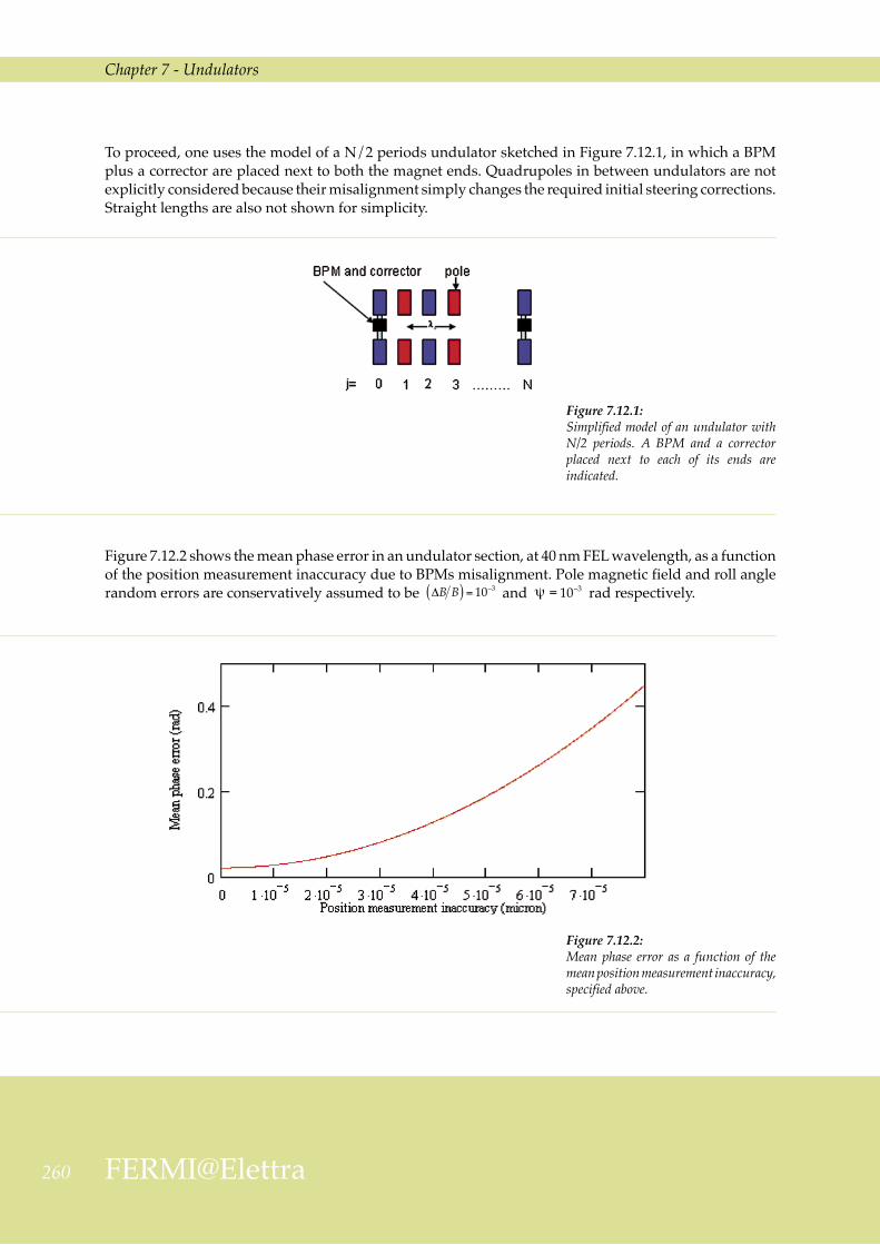
Figure 7.12.2: Mean phase error as a function of the mean position measurement inaccuracy, specified above.
Figure 7.12.2 shows the mean phase error in an undulator section, at 40 nm FEL wavelength, as a function of the position measurement inaccuracy due to BPMs misalignment. Pole magnetic field and roll angle random errors are conservatively assumed to be and rad respectively.

Chapter 7 - Undulators
2�1Conceptual Design Report
Figure 7.12.2 indicates that the tolerable absolute rms trajectory position error must be less than 50 µm if the accumulated phase error is to be less than the 0.2 rad generally accepted value, verified by simulations [34].
As concerns the achievable accuracies, one notes that mechanical and electrical centers of a stripline type BPM can only be made to coincide to within ~100 µm, while the achievable rms error on the position of the BPM mechanical center with respect to the ideal straight line trajectory is also of the order of 100 µm (see 13.4.3), giving an overall BPM expected rms position error of ~140 µm. Even using cavity type BPMs, whose mechanical and electrical centers can be made to coincide to within a few µm, conventional mechanical alignment errors would still be of the order of 100 µm. One therefore concludes that the 50 µm specification mentioned above cannot be met by conventional equipment and surveying techniques.
The FERMI alignment strategy is therefore to still use stripline beam position monitors but, in order to reduce the electron trajectory distortions to within the specified tolerance, to complement state-of-the-art mechanical alignments with the trial and error, beam-based alignment (BBA) technique pioneered at Stanford on the SLC [36], and now foreseen, in somewhat different forms, by all FEL projects under development [37, 38]. In this section it is shown that BBA meets FERMI’s electron trajectory straightness specification.
The procedure foreseen for FERMI, described in more detail in the following section, is the same as for LCLS. Quadrupoles and BPMs are pre-assembled in such a way that they can be considered, alignment-wise, a single item. A set of BPM readings is taken at three different energies, numerically analyzed and used to physically correct the quadrupole magnet transverse position and to adjust the BPM position nominal calibration. By repeating the procedure several times the incoming electron beam position and angle at the undulator entrance can be adjusted to meet the desired tolerance.
7.12.2 Beam-based Alignment Procedure Details
The technique of beam based alignment is well described in [39]. The goal is to determine the position of the centers of the BPMs with respect to a straight line to better than a few µm and force the electron trajectory through them.
BPMs and quadrupoles in between undulator sections are pre-assembled on a girder before installation in the tunnel and supported independently from the undulators; lattice quadrupoles are mounted on movers and equipped with dipole correctors. BPM readings being only relative, there is no need for very accurate BPM position fiducialization since their true position error, obtained through the BBA procedure and the algorithm devised for the LCLS [37], can be allowed for by software corrections of their calibration. Gross trajectory corrections are obtained by physically displacing the quadrupoles using their movers. Fine adjustments, with better than 1 µm resolution, are made using the dipole correctors instead.
It is expected that the basic procedure will need to be repeated approximately once a month with the undulator gaps wide open. Assuming the initial conditions at the undulator entrance remain the same, further perturbations of the ideal trajectory when the gaps are closed can only come from the quadrupole field errors, their residual misalignments or from the earth magnetic field.
Simulations of the whole procedure were carried out for a standard magnetic lattice, using random sets of BPM readings at 1.2 GeV, 900 MeV, and 600 MeV. All magnet settings and the electron beam
2�2 FERMI@Elettra
Chapter 7 - Undulators
launching angle and position at the entrance of the undulator were assumed to be energy independent. Quadrupole and BPM misalignments were computed, the necessary corrections applied and the launching parameters adjusted accordingly. The process was repeated at least 3 times.
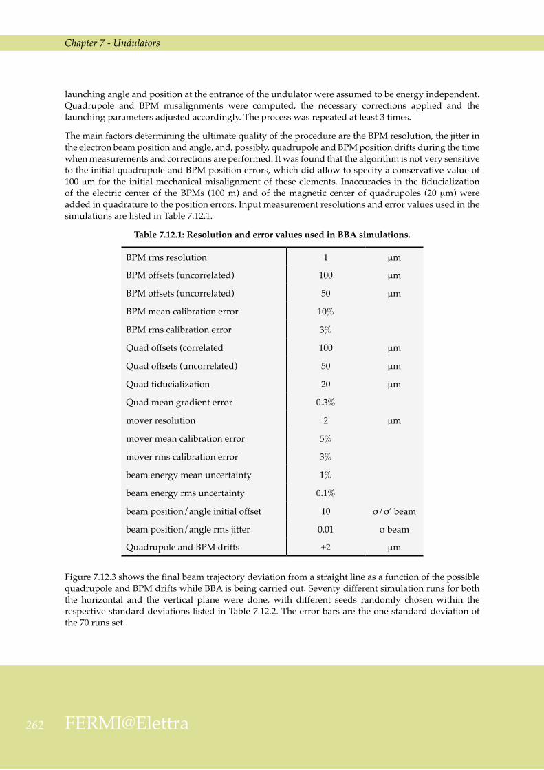
The main factors determining the ultimate quality of the procedure are the BPM resolution, the jitter in the electron beam position and angle, and, possibly, quadrupole and BPM position drifts during the time when measurements and corrections are performed. It was found that the algorithm is not very sensitive to the initial quadrupole and BPM position errors, which did allow to specify a conservative value of 100 µm for the initial mechanical misalignment of these elements. Inaccuracies in the fiducialization of the electric center of the BPMs (100 m) and of the magnetic center of quadrupoles (20 µm) were added in quadrature to the position errors. Input measurement resolutions and error values used in the simulations are listed in Table 7.12.1.
Table 7.12.1: Resolution and error values used in BBA simulations.
BPM rms resolution 1 µm
BPM offsets (uncorrelated) 100 µm
BPM offsets (uncorrelated) 50 µm
BPM mean calibration error 10%
BPM rms calibration error 3%
Quad offsets (correlated 100 µm
Quad offsets (uncorrelated) 50 µm
Quad fiducialization 20 µm
Quad mean gradient error 0.3%
mover resolution 2 µm
mover mean calibration error 5%
mover rms calibration error 3%
beam energy mean uncertainty 1%
beam energy rms uncertainty 0.1%
beam position/angle initial offset 10 σ/σ’ beam
beam position/angle rms jitter 0.01 σ beam
Quadrupole and BPM drifts ±2 µm
Figure 7.12.3 shows the final beam trajectory deviation from a straight line as a function of the possible quadrupole and BPM drifts while BBA is being carried out. Seventy different simulation runs for both the horizontal and the vertical plane were done, with different seeds randomly chosen within the respective standard deviations listed in Table 7.12.2. The error bars are the one standard deviation of the 70 runs set.

Chapter 7 - Undulators
2�3Conceptual Design Report
Figure 7.12.3 shows that, in order to meet the tolerances demanded by FEL operation at 10 nm, the maximum tolerable drifts should stay within ± 2 µm.
Figure 7.12.4 shows the final beam trajectory deviation at the end of the BBA procedure, as a function of the BPM resolution, the beam launching angle and position jitters during BBA operation. In order to achieve the stated goal, a BPM resolution of ≤ 1 µm is needed. The resolution of a stripline BPM is 20 µm for a single measurement. Averaging the BPM readouts over a large number of pulses improves the resolution of the measurements. The beam position random error shown in the figures is the standard deviation of the mean of 400 measurements. This number of measurements reduces the statistical error on the determination of the launch angle and position to ~1% for a single shot jitter of 20% of the beam size and angular spread. This is sufficient to achieve the BBA goal. In addition, feedback systems will be implemented to bring the average of multiple beam position and angle jitter measurements within 1% of the design beam size and angular spread.
Figure 7.12.3: Horizontal (a) and vertical (b) final trajectory deviation as a function of the maximum drifts of quadrupoles and BPMs during the BBA procedure. The probability of each drift is taken to be uniform in the range: ± (assumed maximum absolute drift value).
a) b)

2�4 FERMI@Elettra
Chapter 7 - Undulators
7.12.3 Earth Magnetic Field Effects
The results reported above were obtained without considering the earth’s magnetic field. When the earth field is included in the simulations the trajectory is scalloped in a sequence of parabolic arcs in between quadrupoles (see Section 7.6). In order to quantify the distortions a simulation was performed, with the undulator field switched off and in the ideal case of perfect alignement. The value of the sagitta of the parabolic arcs was found to be 17 µm in the horizontal plane, corresponding to an rms trajectory deviation in an undulator magnet of 5 µm. By tuning and shimming the undulator one can reduce the distortion due to the Earth’s field to the order of ~1 µm; since the distortion adds in quadrature with all other effects, its contribution is negligible.
7.12.4 Conclusion
The consequences of deviations from the ideal trajectory in the undulators have been studied. It is found that FEL operation at the 10 nm shortest design wavelength, requires the electron trajectory in the undulators to be a straight line to within 10 µm rms with respect to the undulator magnetic axis and over the whole undulator length. In this section it has been shown that beam-based alignment procedures allow reaching the this goal.
Figure 7.12.4: Horizontal (a) and vertical (b) rms final trajectory as a function of BPM resolution. The two curves are for two
different beam jitter values. The jitter is in percentage of the beam transverse dimension.
a) b)

Chapter 7 - Undulators
2�5Conceptual Design Report
7.13 References
[1] X. M. Marechal, T. Shintake, AIP Conf. Proc. 705 (2004) p. 282.
[2] K. Halbach, Physical and optical properties of rare earth cobalt magnets, Nucl. Instrum. and Methods 187 (1981) p. 109.
[3] S. Sasaki, Analyses for a planar variably-polarizing undulator, Nucl. Instrum. and Methods A347 (1994) p. 83.
[4] P. Elleaume, J. Chavanne, B. Faatz, Design considerations for a 1 A SASE undulators, Nucl. Instrum. and Methods A455 (2000) p. 503.
[5] S. Sasaki, Modeling and measurement of µ-metal shielding effect on the magnetic performanc of an LCLS undulator, proc. 28th International Free Electron Laser Conference 2006, p. 718.
[6] Z. Wolf, Introduction to the LCLS undulator tuning, Technical Note LCLS-TN-04-7.
[7] B. Diviacco et al., Construction of Elliptical Undulators for ELETTRA, Proc. 1998 European Particle Acclerator Conference, p.2216.
[8] B. Diviacco et al., Development of Elliptical Undulators for ELETTRA, Proc. 1999 Particle Acclerator Conference, p.2680.
[9] B. Diviacco et al., Development of Elliptical Undulators for ELETTRA, Proc. 2000 European Particle Acclerator Conference, p.2322.
[10] B. Diviacco et al., New insertion Devices for ELETTRA, Proc. 2001 Particle Acclerator Conference, p.2468.
[11] B. Diviacco et al., Design, Construction and Field Characterization of a Variable Polarization Undulator for SOLEIL, Proc. 2005 Particle Acclerator Conference, p.4242.
[12] M. Musardo, B. Diviacco, Magnetic field errors induced by deflection of the undulator support structure, Sincrotrone Trieste technical note, in preparation.
[13] D. La Civita et al., Misure di deformazione meccanica dell’ondulatore elicoidale EU10.0, Sincrotrone Trieste Technical Note ST/M-TN-06/08.
[14] LCLS Conceptual Design Report, SLAC–R–593, April 2002, UC-414.
[15] Dean R. Walters, LCLS Vacuum chamber review, April 20, 2006.
[16] Tesla Technical Design Report, part II, chapter 9.
[17] Soon-Hong Lee et al., Magnetic properties of undulator vacuum chamber materials for the Linac Coherent Light Source, proc. 27th International Free Electron Laser Conference 2005, p. 383.
[18] Dean R. Walters, Argonne National Laboratory, private communication.
[19] U. Hahn et al., Design and performance of the VUV FEL at the TESLA test facility at DESY, Nucl. Instr. And Meth. A 445 (2000), p. 442-447.
[20] U. Hahn, J. Pfluger, M. Ruter, P.K. den Hartog, M. Erdmann, E.M. Trakhtenberg, G. Wiemerslage, S. Xu, The vacuum chambers for the VUV SASE FEL at the TESLA test facility (TTF FEL) at DESY, proceedings of the 1999 Particle Accelerator Conference, New York, 1999.

2�� FERMI@Elettra
Chapter 7 - Undulators
[21] Yoshio Saito, Materials and processing of vacuum components for the high-intensity proton beam accelerator, Vacuum 73 (2004) p. 181.
[22] R. Kersevan, MolFlow User’s Guide, Sincrotrone Trieste Technical Note ST/M-91/17.
[23] U. Hahn, DESY, private communication.
[24] A. Mathewson, CERN, Workshop on Vacuum for Future Synchrotron Radiation Sources, Orsay, April 1996.
[25] G. Tromba, A. Rindi, Gas Bremsstrahlung from electron storage rings: a Monte Carlo evaluation and some useful formulae, Nucl. Instrum. and Methods A 292 (1990) p. 700.
[26] A. Roth, Vacuum Technology, North-Holland.
[27] A. Wu Chao, Physics of Collective Beam Instabilities in High Energy Accelerators, 1993.
[28] H. Henke and O. Napoly, Wake Fields between two Parallel Plates, CERN/LEP-RF/89-71 CLIC Note 103, 1989.
[29] K. L.F. Bane and G. Stupakov, Resistive Wall Wakefield in the LCLS Undulator Beam Pipe, SLAC-PUB-10707.
[30] K. L.F. Bane, The Short Range Resistive Wall Wakefields, SLAC/AP-87, June 1991.
[31] G. Stupakov, Surface Roughness Impedance, SLAC-PUB-8743, December 2000.
[32] K. L.F. Bane and Gennady Stupakov, Impedance of a rectangular beam tube with small corrugations, Phys. Rev. S.T. 6, 024401 (2003).
[33] P. Craievich and C. Bontoiu, Longitudinal Resistive Wall Wakefields in the Vacuum Chamber of the FERMI FEL1 Undulator, Internal note ST/F-TN-06/17, October 2006.
[34] W.Fawley et al., FERMI@Elettra FEL Design Technical Optimization Final Report, Sincrotrone Trieste Technical Note ST/F-TN-06/16, LBNL-61333.
[35] P. Emma, Phase Slip in an Undulator with Pole and BPM Errors, Proc. 2001 Particle Acclerator Conference, p. 2742.
[36] C.E.Adolphsen, Beam Based technique for the SLC Linac, SLAC-PUB-4902 (1989).
[37] Bessy FEL Technical Design Report, March 2004.
[38] SCCS X-FEL Conceptual Design Report, May 2005.
[39] LCLS Conceptual Design Report, SLAC–R–593, April 2002, UC-414, Section 8.12.

Conceptual Design Report
Table of Contents
7 Undulators............................................................................................................................................................................................................................................................................................. 2237.1 MagnetTechnology............................................................................................................................................................................................................................................2257.2 DesignConstraints..............................................................................................................................................................................................................................................2267.3 LinearlyPolarizedUndulators......................................................................................................................................................................................................2277.4 VariablyPolarizedUndulators......................................................................................................................................................................................................2307.5 AlignmentTolerances.....................................................................................................................................................................................................................................2337.6 EffectoftheEarthField...............................................................................................................................................................................................................................2357.7 MechanicalDesignConsiderations.......................................................................................................................................................................................2377.8 ThermalStabilityRequirements..................................................................................................................................................................................................2427.9 MagneticOpticsintheRadiatorRegion......................................................................................................................................................................2427.10 UndulatorVacuumSystem..................................................................................................................................................................................................................245
7.10.1 Description...............................................................................................................................................................................................................................................................2457.10.2 VacuumPerformance............................................................................................................................................................................................................................2477.10.3 PressureProfile.................................................................................................................................................................................................................................................2497.10.4 Conclusion................................................................................................................................................................................................................................................................250
7.11 WakefieldsintheUndulatorVacuumChamber............................................................................................................................................2507.11.1 TheResistiveWallWakefields...............................................................................................................................................................................................2517.11.2 TheRoughnessWakefields.........................................................................................................................................................................................................255
7.12 AlignmentandTrajectoryControl..........................................................................................................................................................................................2597.12.1 Introduction............................................................................................................................................................................................................................................................2597.12.2 Beam-basedAlignmentProcedureDetails.....................................................................................................................................................2617.12.3 EarthMagneticFieldEffects.....................................................................................................................................................................................................2647.12.4 Conclusion................................................................................................................................................................................................................................................................264
7.13 References............................................................................................................................................................................................................................................................................265
8 Photon Beam Transport and Diagnostics.................................................................................................................................................................................. 2678.1 Introduction......................................................................................................................................................................................................................................................................2688.2 DifferencesbetweenFELandSynchrotronRadiation.........................................................................................................................268
8.2.1 PulsedStructure..............................................................................................................................................................................................................................................2698.2.2 HighPowers..........................................................................................................................................................................................................................................................2718.2.3 Coherence...................................................................................................................................................................................................................................................................2738.2.4 BeamSplittersandFilters..............................................................................................................................................................................................................273
8.3 OpticalSystemsbeforetheBeamlines..............................................................................................................................................................................2748.3.1 AbsorptionCellandI0Monitor..........................................................................................................................................................................................2748.3.2 X-raySlits....................................................................................................................................................................................................................................................................2758.3.3 FirstMirrors............................................................................................................................................................................................................................................................2768.3.4 TimeArrivalMonitor............................................................................................................................................................................................................................276
8.4 BeamlineDesign......................................................................................................................................................................................................................................................2778.4.1 SourceLongitudinalShiftCompensation........................................................................................................................................................2778.4.2 FEL1-2SwitchingMirrorChamber............................................................................................................................................................................2778.4.3 Monochromators...........................................................................................................................................................................................................................................278
Table of Contents