69268440 direttive eurocargo my2015-en 2nd edibb.iveco.com/body builder instructions/uk and... ·...
TRANSCRIPT

ME
DI
UM
R
AN
GE
B O D Y B U I L D E R S
I N S T R U C T I O N S
I S S U E 2 0 1 6
M Y 2 0 1 5 D I E S E L - C N G

IVECO S.p.A
Homologation, Technical Application & Regulation
Lungo Stura Lazio, 49
10156 Torino (TO) - Italy
www.iveco.com
Printed 692.68.440 – 2nd Ed. 03/2016
Images and text: IVECO S.p.A. 2016
All rights reserved.

EUROCARGO MY2015 ‒ BODYBUILDER INSTRUCTIONSGUIDELINES FOR TRANSFORMATION AND VERSIONS
UPDATE DATA5
– Printed 692.68.440 – 2 Ed. - Base 03/2016
GUIDELINES FOR TRANSFORMATION AND VERSIONS
UPDATE DATA
Section Description Page Revision date

6EUROCARGO MY2015 ‒ BODYBUILDER INSTRUCTIONSGUIDELINES FOR TRANSFORMATION AND VERSIONS
INTRODUCTION
– Printed 692.68.440 – 2 Ed. - Base 03/2016
INTRODUCTION
This publication provides information, features and instructions for transformation and fitting of the vehicle; considering the type ofcontent, it is meant for qualities and specialised staff.
The Body builder is manager of the project and its execution, and must assure compliance with what is set forth in this publicationand in the laws in forth.
Any modification, transformation or fitting not described in this manual and not expressly authorized will re-lieve IVECO of any liability and the warranty, if present, will immediately be null and void.
The same applies to individual assemblies and components; those described in this manual have been deliber-ated, approved and tested by IVECO and are part of normal production. The adoption of any type of unit thatis not approved (e.g. PTO, tyres, horns, etc.) shall relieve IVECO of any responsibility.
IVECO is available to provide information on the implementation of the interventions and to provide instructions for any cases andsituations not covered in this publication.
Before performing any operation, it is necessary to:
verify that you have the manuals for the vehicle model on which you are about to work; ensure that all the safety devices (goggles, helmet, gloves, shoes, etc.), as well as the equipment used for work, lifting and trans-
port, is available and working; ensure that the vehicle is placed in safe conditions.
At the end of the operation, the operational, efficiency and safety conditions set by IVECO must be restored. Contact the Servicenetwork for vehicle calibration if necessary.
Data and information contained in this publication may be outdated as a result of changes adopted by IVECO, at any time, for tech-nical or commercial reasons or due to the need to adapt the vehicle to new legal requirements.
In the event of discordance between the information herein and the actual vehicle, please contact the Product Manager operatingon the market before performing any interventions.
SYMBOLS - WARNINGS
Danger for personsFailure to comply with these prescriptions can result in the risk of serious injury.
Risk of serious damage to the vehiclePartial or complete non observance of these prescriptions can lead to serious damages to the vehicle and can sometimes result in theguarantee being voided.
General dangerIncludes the dangers of both above described signals.
Environmental protectionIndicates correct behaviour in order that vehicle use is as environmentally friendly as possible.
NOTE Indicates an additional explanation for a piece of information.

- Printed 692.68.440 – 2 Ed. - Base 03/2016
GENERAL
INFORMATION 1
CHASSIS
INTERVENTIONS 2
APPLICATIONS OF
SUPERSTRUCTURES 3
POWER
TAKE-OFFS 4
ELECTRONIC
SUB-SYSTEMS 5
ADBLUE AND
SCRT SYSTEM 6
CNG -
NATURAL POWER A

INDEX OF SECTIONS
- Printed 692.68.440 – 2 Ed. - Base 03/2016

- Printed 692.68.440 – 2 Ed. - Base 03/2016
SECTION 1
GENERAL
INFORMATION

- Printed 692.68.440 – 2 Ed. - Base 03/2016

EUROCARGO MY2015 ‒ BODYBUILDER INSTRUCTIONSGENERAL INFORMATION
Contents3
– Printed 692.68.440 – 2 Ed. - Base 03/2016
Contents
1.1 SCOPE OF THE GUIDELINES . . . . . . . . . . . . . 5
1.2 TECHNICAL DOCUMENTATION AVAILABLEELECTRONICALLY . . . . . . . . . . . . . . . . . . . . . . . 5
1.3 IVECO AUTHORISATION . . . . . . . . . . . . . . . 5
1.4 AUTHORISATION REQUEST . . . . . . . . . . . . . 6
1.5 RESPONSIBILITIES . . . . . . . . . . . . . . . . . . . . 6
1.6 LEGISLATIVE REQUIREMENTS . . . . . . . . . . . . 6
1.7 MULTI-STAGE APPROVAL - COLLABORATION(only for EU countries, Switzerland and Turkey) . . . . . 6
1.8 GUARANTEES . . . . . . . . . . . . . . . . . . . . . . 7
1.9 QUALITY SYSTEM MANAGEMENT . . . . . . . . . . 8
1.10 ACCIDENT PREVENTION . . . . . . . . . . . . . . 8
1.11 CHOICE OF MATERIALS TO USE: ECOLOGY- RECYCLING . . . . . . . . . . . . . . . . . . . . . . . . . . 8
1.12 VEHICLE MANAGEMENT ON THE PART OFBODYBUILDER . . . . . . . . . . . . . . . . . . . . . . . . . 9
Acceptance of chassis . . . . . . . . . . . . . . . . . . . . 9
Maintenance . . . . . . . . . . . . . . . . . . . . . . . . . 9
Delivery of the vehicle to the final customer . . . . . 9
1.13 VEHICLE NAMES . . . . . . . . . . . . . . . . . . . 10
Type approval name . . . . . . . . . . . . . . . . . . . . 10
1.14 TRADEMARKS AND SYMBOLS . . . . . . . . . . 11
1.15 DIMENSIONS AND GROUND . . . . . . . . . . 11
General information . . . . . . . . . . . . . . . . . . . . 11
Determination of the centre of gravity of thesuperstructure and the payload . . . . . . . . . . . . . 11
Respect of the permitted masses . . . . . . . . . . . . 15
1.16 INSTRUCTIONS FOR PROPERFUNCTIONING OF THE VEHICLE PARTS ANDACCESSIBILITY . . . . . . . . . . . . . . . . . . . . . . . . 15
Exhaust system accessibility (only versions withdiesel) . . . . . . . . . . . . . . . . . . . . . . . . . . . . 17
Distance from muffler . . . . . . . . . . . . . . . . . . 18
1.17 GENERAL REGULATION FOR THEPREVENTION OF FIRE RISK . . . . . . . . . . . . . . . . 18
1.18 CONVENTIONS . . . . . . . . . . . . . . . . . . . 18

4EUROCARGO MY2015 ‒ BODYBUILDER INSTRUCTIONSGENERAL INFORMATION
– Printed 692.68.440 – 2 Ed. - Base 03/2016

EUROCARGO MY2015 ‒ BODYBUILDER INSTRUCTIONSGENERAL INFORMATION
1.1 SCOPE OF THE GUIDELINES5
– Printed 692.68.440 – 2 Ed. - Base 03/2016
GENERAL INFORMATION
1.1 SCOPE OF THE GUIDELINES
The scope of this publication is to provide information, features and instructions for fitting and transformation of the originalIVECO vehicle in order to ensure its functionality, safety and reliability.
These Guidelines also aim to indicate to Bodybuilders:
the quality level to be obtained; obligations regarding the safety of operations; obligations regarding the objective responsibility of the product.
It should be noted that the collaboration with IVECO is based on the assumption that the Bodybuilder uses the maximum of theirtechnical and organisational skills and that operations are technically and perfectly complete. As outlined below, the topic is extens-ive and we can only provide the rules and minimum precautions that can allow development of the technical initiative.
Faults or defects caused by total or partial failure to comply with these Guidelines are not covered by the guarantee on the chassisor relative mechanical units.
1.2 TECHNICAL DOCUMENTATION AVAILABLE ELECTRONICALLY
On the website www.ibb.iveco.com the following technical documentation is available:
Directives for transformation and fitting of vehicles; technical specifications; truck diagrams; tractor diagrams; chassis diagrams; other range-specific data.
Requests to access the site must be made exclusively at www.ibb.iveco.com.
1.3 IVECO AUTHORISATION
Modifications or outfittings included in these Directives and carried out in compliance with the instructions provided do not requirea specific authorisation.
However, notwithstanding instructions, IVECO's authorisation must always be requested when the following operations are to becarried out:
particular changes to the wheelbase; work on the braking system; modifications to the steering system: modifications to the stabiliser bars and suspensions; modifications to the cab, cab mounts, locking and tilting devices; modifications to intake, engine exhaust and SCR components; applications of retarders; power take-off applications; variations in tyre measurements; modifications to hook organisms (hooks, fifth wheels).

6EUROCARGO MY2015 ‒ BODYBUILDER INSTRUCTIONSGENERAL INFORMATION
1.4 AUTHORISATION REQUEST
– Printed 692.68.440 – 2 Ed. - Base 03/2016
1.4 AUTHORISATION REQUEST
Authorisation requests, when necessary, must be sent to the responsible IVECO Departments on the market.
The Bodybuilder must provide vehicle data (cab, wheelbase, overhang, chassis No.) and adequate documentation (drawings, cal-culations, technical report, etc.) showing the realisation, use and operating conditions of the vehicle. The drawings should evidenceeverything that differs from these instructions.
The Bodybuilder will be responsible for obtaining final approval from the competent authority for completed operations.
1.5 RESPONSIBILITIES
The authorisations issued by IVECO are exclusively related to the technical/conceptual feasibility of the modification and/or fitting.
The Bodybuilder is therefore responsible for:
the design; the choice of materials; the implementation; the compliance of the design and implementation to any specific indications provided by IVECO and the laws in force in the
countries where the vehicle is destined; effects on functionality, safety, reliability and, in general, good behaviour of the vehicle; the supply of spare parts for a minimum period of 10 years starting from the last fitting of an order and for all pieces and
components that are installed.
1.6 LEGISLATIVE REQUIREMENTS
The Bodybuilder must verify that the final product is compliant, without exception, to all applicable legal requirements, on the muni-cipal/autonomous/national level of each State in which it is registered and/or will circulate (Highway code, Official Regulations, etc.)and on the international level (European Union Directives, ONU/Geneva ECE Regulations, etc.). It is also necessary to comply withall requirements for accident prevention, instructions for assistance, the environment, etc.
The regulations on accident prevention or the legal indications cited in these Guidelines may be considered the most important, butare not meant in any way to replace or eliminate the obligation and responsibility of the Bodybuilder to stay properly informed.
For this reason, IVECO shall not be held liable for any consequences due to errors caused by insufficient knowledge or incorrectinterpretation of the legal provisions in force.
1.7 MULTI-STAGE APPROVAL - COLLABORATION (only for EU countries, Switzerland andTurkey)
Attachment XVII of Directive 2007/46/EC concerns Multi-stage approval.
This procedure requires that each manufacturer is responsible for the approval and compliance of the production of systems, com-ponents and "separate technical units" produced by the same or applied to the vehicle.
The manufacturer of the vehicle is defined as first-stage manufacturer, while the bodybuilder is defined as Second-stage manufactureror that of the next stage.

EUROCARGO MY2015 ‒ BODYBUILDER INSTRUCTIONSGENERAL INFORMATION
1.8 GUARANTEES7
– Printed 692.68.440 – 2 Ed. - Base 03/2016
191319 Figure 1
1. IVECO 2. Authorised workshop upon Dealer order
3. Bodybuilder 4. Customer
Based on this Directive, IVECO (main vehicle manufacturer) and a Bodybuilder intending to launch the multi-stage approval processmust sign a specific Collaboration Contract, called Technical Agreement, which sets out the content and reciprocal obligations indetail.
Consequently:
1. IVECO has the responsibility of providing, in the agreed form, the approval documents (EC/ECE approvals) and the technicalinformation necessary for the proper implementation of the fitting and/or transformation (manuals, drawings, specifications);
2. the Bodybuilder has the following responsibilities: the design and implementation of modifications to the basic vehicle received from IVECO, reattainment of approvals of systems already approved in a previous stage when, due to changes on the basic vehicle the
approvals need to be updated, compliance with national/international laws and in particular the laws of the destination country, for all changes made, presentation of the changes made to a technical service, for evaluation, appropriate documentation of the changes made, in order to give objective evidence of compliance to the aforemen-
tioned provisions of law (e.g. approval documents/test reports).
Before signing the Technical Agreement IVECO reserves the right to visit the Bodybuilder, in order to verify qualifications to carryout the fittings and/or processing for which the above collaboration is requested.
The contents of the Technical Agreement can be evaluated in detail upon request to the Manager for relations with the Bodybuilderfor the single Market.
1.8 GUARANTEES
The guarantee that the work has been performed to standard must be given by the Bodybuilder who made the superstructure ormodifications to the chassis, in full compliance with the instructions in these Guidelines.
IVECO reserves the right to void the guarantee on the vehicle, if:
unauthorised fittings or transformations have been carried out; a chassis not suitable for the fitting or intended use has been used; the standards, specifications and instructions, provided by IVECO for proper execution of the work, have not been respected; original spare parts or components made available by IVECO for specific operations have not been used; safety regulations have not been respected; the vehicle is used for purposes other than those for which it was designed.

8EUROCARGO MY2015 ‒ BODYBUILDER INSTRUCTIONSGENERAL INFORMATION
1.9 QUALITY SYSTEM MANAGEMENT
– Printed 692.68.440 – 2 Ed. - Base 03/2016
1.9 QUALITY SYSTEM MANAGEMENT
IVECO has always promoted the training and development of a Quality System for Bodybuilders.
This requirement is not only due to regulations on product liability, but also to the increasingly higher quality level demands, neworganizational forms in various sectors and the search for more advanced levels of efficiency.
IVECO therefore considers it appropriate for Bodybuilders to be equipped with:
organizational charts for roles and responsibilities; quality objectives and indicators; design technical documentation; process documentation, including controls; plan for product improvement, also obtained through corrective actions; post-sales assistance; training and qualification of staff.
The availability of ISO 9001 certification, even though not required, is considered very important by IVECO.
1.10 ACCIDENT PREVENTION
Do not allow unauthorised personnel to intervene or operate on the vehicle.
It is forbidden to use the vehicle with safety devices that have been tampered with or are damaged.
Structures and devices installed on the vehicles must comply with the applicable regulations foraccident prevention, and with safety regulations required in the individual countries where thevehicles are used.
All precautions dictated by technical knowledge must be taken to avoid damage and functional defects.
Compliance with these requirements must be overseen by the manufacturer of the structures and devices.
Seats, coatings, gaskets, protective panels, etc., may pose a fire hazard when exposed to an in-tense heat source. Remove them before working with welding and with flames.
1.11 CHOICE OF MATERIALS TO USE: ECOLOGY - RECYCLING
In the study and design phase, the choice of materials to be used by be made carefully, even from the ecological and recycling pointof view.
To this regard, please note that:
it is forbidden to use materials that are harmful to health, or at least which may pose a risk, such as those containing asbestos,lead, halogen additives, fluorocarbons, cadmium, mercury, hexavalent chromium, etc.;
it is advisable to use materials whose processing produces limited waste quantities and allows easy recycling after first use; in synthetic materials of the composite type, it is advisable to use components that are compatible with each other, allowing
use with the possible addition of other recovery components. Prepare the required markings in accordance with the regula-tions in force;
the batteries contain substances that are very dangerous for the environment. To replace the batteries it is possible to go tothe Service Network, equipped for disposal in accordance with the nature and the law.
To comply with Directive 2000/53 EC (ELVs), IVECO prohibits the in-vehicle installation of com-ponents that contain lead, mercury, cadmium and hexavalent chromium; exceptions are madein cases allowed by Annex II of the above Directive.
EUROCARGO MY2015 ‒ BODYBUILDER INSTRUCTIONSGENERAL INFORMATION
1.12 VEHICLE MANAGEMENT ON THE PART OF BODYBUILDER9
– Printed 692.68.440 – 2 Ed. - Base 03/2016
1.12 VEHICLE MANAGEMENT ON THE PART OF BODYBUILDER
Acceptance of chassis
The Bodybuilder receiving a chassis/vehicle from IVECO or from a Dealer must perform a preliminary check, notifying of any miss-ing accessories or damage attributable to the transporter.
Maintenance
To preserve the chassis/vehicle in its full efficiency, even while parking in the warehouse, maintenance operations may be necessarywithin a predetermined time.
The expenses for carrying out these operations are borne by the owner of the vehicle in that moment (Bodybuilder, Dealer orCustomer).
In case of long periods of vehicle inactivity, it is advisable to disconnect the negative pole of thebattery to maintain optimal charging status.
Delivery of the vehicle to the final customer
Before delivering the vehicle, the Body builder must:
calibrate its production (vehicle and/or equipment) and verify functionality and safety; carry out the controls indicated in the Pre-Delivery Inspection (PDI) list available from the IVECO network, for the items be-
ing worked on (obviously the other items of the PDI will be the responsibility of the Dealer, such as the guarantee pamphlet); check alignment, toe-in and height of the front suspensions on the basis of IVECO reference values; adjust the headlamps according to the instructions provided in the "Use and Maintenance Manual"; measure the battery voltage with a digital multimeter (2 digit decimal), keeping in mind that:
1. optimal value is equal to 12.5 V,2. between 12.1 V and 12.49 V the battery should be put under a slow charge,3. with values less than 12.1 V the battery should be replaced.
Note The batteries must be maintained at regular intervals (refer to IVECO Std 20-1812 and/or IVECO Std 20-1804) until delivery ofthe vehicle to the Customer/Dealer to avoid problems of insufficient charging, short circuit or corrosion.
IVECO reserves the right to nullify the guarantee on the battery if the prescribed maintenance procedures are not respected.
carry out a functional road test (in case of vehicle transformation). Any defects or problems should be notified to the IVECOAssistance Service to verify conditions for inclusion in the PDI costs;
prepare and deliver to the final Customer the necessary instructions for service and maintenance of the fitting and any addedunits;
on a designated plate, note down the characteristic data of the additional assemblies and the precautions to be taken whenthey are in operation;
provide confirmation that the operations carried out comply with the indications of the vehicle Manufacturer and legal re-quirements;
draw up a guarantee covering the changes made.

10EUROCARGO MY2015 ‒ BODYBUILDER INSTRUCTIONSGENERAL INFORMATION
1.13 VEHICLE NAMES
– Printed 692.68.440 – 2 Ed. - Base 03/2016
1.13 VEHICLE NAMES
The commercial name of IVECO vehicles (for example EUROCARGO 120-190) does not match the type approval name. Acomplete example is provided below.
Type approval name
EUROCARGO MLC 120E 19 /P
EUROCARGO ‒ Vehicle name MLC ‒ Cab type
MLC Short cab
MLL Long cab
MLD Double cab
120 ‒ Gross mass - GVW Cabs (no/10 = weight in t)60 4x2 trucks
65 4x2 trucks
75 4x2 trucks
80 4x2 trucks
90 4x2 trucks
100 4x2 trucks
110 4x2 - 4x4 trucks
120 4x2 trucks
140 4x2 trucks
150 4x2 - 4x4 trucks
160 4x2 trucks
180 4x2 trucks
190 4x2 trucks
E ‒ Range codeE Standard chassis height
EL Optimal chassis height
19 ‒ Engine power (no. x 10 = power in HP) / P ‒ Version
– Rear mechanical suspension
P Rear air suspension
FP Front and rear pneumatic suspensions
R Towing vehicles
D Dual cab (6+1) with mechanical suspension
D/P Dual cab (6+1) with rear air suspension
K Tipping body pre-fitting
DK Twin cab with tipping body pre-fitting
EUROCARGO MY2015 ‒ BODYBUILDER INSTRUCTIONSGENERAL INFORMATION
1.14 TRADEMARKS AND SYMBOLS11
– Printed 692.68.440 – 2 Ed. - Base 03/2016
1.14 TRADEMARKS AND SYMBOLS
Trademarks, symbols and names may not be altered or moved from their original placement, as the originality of the vehicle imagemust be protected.
The application of transformation or fitting trademarks must be authorised. Their placement should not be in the immediate vicinityof the IVECO trademark and symbols.
IVECO reserves the right to withdraw trademarks and symbols if the fitting or transformation present features that do not complywith requirements; the Bodybuilder assumes full responsibility for the entire vehicle.
Instructions for additional units
For additional units, the Bodybuilder must provide all necessary maintenance instructions upon vehicle delivery.
All the units that make up the same order must be equipped with components of the same brand, model and quality.
1.15 DIMENSIONS AND GROUND
General information
The dimensions and masses of vehicles allowed on the axles are shown in the drawings, the technical descriptions and, more gener-ally, on the documents on the official IVECO website. Defects refer to vehicles in their standard versions; the use of special equip-ment may lead to changes on the masses and their distribution on the axles.
Weighing of the chassis
It should be noted that variations are possible on the masses of the order of 5%.
For this reason, before carrying out the fitting, it is a good idea to determine the mass of the cab vehicle and its distribution on theaxles.
Vehicle adaptability
The vehicle adaptability limits for each model are mainly defined as:
distribution of mass on the axles; width of mirrors adopted; rear under-run protection device position.
The positioning of lights and rear-view mirrors, normally set for widths of 2550 mm, is also suitable for special superstructures,2600 mm wide (e.g. mini-vans).
Determination of the centre of gravity of the superstructure and the payload
Positioning on the longitudinal plane
To determine the position of the centre of gravity of the superstructure and the payload, you can proceed according to the ex-amples given below.
On the technical documentation for each model (cab version diagram), you can see the positions allowed by the vehicle in thestandard version. The masses and the positioning of the individual components of the vehicle are shown on the chassis and weightallocation diagram.

12EUROCARGO MY2015 ‒ BODYBUILDER INSTRUCTIONSGENERAL INFORMATION
1.15 DIMENSIONS AND GROUND
– Printed 692.68.440 – 2 Ed. - Base 03/2016
231172 Figure 2
Example to determine the placement of the centre of gravity of the payload plus superstructure (Vehicle with 2 axles;vehicles with 3 axles having equal loads on two rear axles)W = Payload plus superstructureW1 = Measurement of payload on front axleW2 = Measurement of payload on rear axle (or tandem)
L1 = Distance of centre of gravity from the centre line of therear axle (or tandem centre line)
L = Actual wheelbase
Note For vehicles with three or more axes, with variable ratio of the distribution of the masses on the two rear axles depending on theload, the "virtual" value of the wheelbase and the centre line between the axles must be determined for the respective load condi-tion realized, using the instructions on the vehicle cab diagram.
This way, in particular version outfits (e.g. cranes on the rear overhang), the correct positioning can be determined for the centre ofgravity of the equipment and the payload, depending on the load carried (see Chapter 3.8).
For the purposes of breakdown of the payload on the axes, it should be considered that this is evenly distributed, except in cases inwhich the shape of the load surface leads to a different load distribution.
For equipment, the centre of gravity is obvious considered for its actual position.
In the realisation of the superstructure or containers, automatic loading and unloading of the goods transported must be providedto avoid excessive variations of the distribution and/or excessive loads on the axles, providing information for users if necessary.
The Bodybuilder should also provide a suitable anchoring systems for the load on the superstructure, so that transport can occur inmaximum security.
231173 Figure 3
Even distribution of load Uneven distribution of load

EUROCARGO MY2015 ‒ BODYBUILDER INSTRUCTIONSGENERAL INFORMATION
1.15 DIMENSIONS AND GROUND13
– Printed 692.68.440 – 2 Ed. - Base 03/2016
231174 Figure 4
Even distribution of load Uneven distribution of load (attention to loads on axlesand minimum ratio)
Height of centre of gravity
For the cab version and no-load vehicle, the value of the height of the centre of gravity is shown on the specific technical docu-mentation for each model (cab version diagram).
For the vehicle complete with super structure and full load, this height must comply with the maximum values allowed by nationalor international standards, in particular, Directives ECE 13 on longitudinal stability and ECE 111 on lateral stability while driving.
The following cases should be distinguished:
1. fixed loads,2. mobile loads;3. loads that result in increased aerodynamic actions.
1. Fixed loads
231175 Figure 5
Control at full loadHv = Vehicle centre of gravity height (loaded)Hs = Height of payload centre of gravity from the groundHt = Complete full-load vehicle centre of gravity height
Wv = Vehicle tare weightWs = PayloadWt = Complete vehicle ground at full load

14EUROCARGO MY2015 ‒ BODYBUILDER INSTRUCTIONSGENERAL INFORMATION
1.15 DIMENSIONS AND GROUND
– Printed 692.68.440 – 2 Ed. - Base 03/2016
For any inspections with the vehicle set up without payload you can proceed similarly, assuming Ws is only the tare weight of thesuperstructure (considering for Hv a value appropriate for the load and between the no-load cab version trim and the full-loadtrim).
2. Mobile loads
In the versions where the load can be moved laterally while cornering (e.g.: suspended loads, liquid transport, animal transport,etc..) high lateral dynamic forces may be generated which may jeopardise the stability of the vehicle.
With reference to the indications of the regulation ECE 111, special attention should therefore be paid to:
defining the height of the fitted vehicle's centre of gravity and at full load; assessing the dynamic forces and the lateral displacement of the centre of gravity; considering (for liquids) the density; prescribing the implementation of adequate precautions for driving.
Any cases where evaluation is difficult should be submitted to IVECO for approval.
3. Loads that result in increased aerodynamic actions
In outfits characterised by high vertical and surface development (e.g.: advertising panelling), the hight of the centre of thrust, de-termined in the case of cross-wind, must be evaluated very carefully.
Even with the low centre of gravity, a vehicle fitting that has a high surface area may not providesufficient lateral stability and may be exposed to the danger of tilting.
Special attention must therefore be paid:
in defining the height of the fitted vehicle's centre of gravity and at full load, in assessing the aerodynamic forces, prescribing the implementation of adequate precautions for driving.
Any cases where evaluation is difficult should be submitted to IVECO for approval.
implementation of stabiliser bars
The application of additional or reinforced stabiliser bars, where available, reinforcing the springs or rubber elastic elements (inaccordance with the procedure outlined in Section 2.7), may allow higher values of the centre of gravity of the payload, to be de-termined from time to time. The operation must be carried out after a careful evaluation of the features of the outfit, the wheel-base and the subdivision of lateral forces on the suspension, and should generally concern both the front and the rear. However,it should be kept in mind that in many cases it is advisable to carry out the operation only on the rear axle; acting on the front axlewould give the driver an incorrect sensation of greater stability, making it actually harder to perceive the safety limit. Interventionson the front axle can be made in the presence of concentrated loads behind the cab (e.g. cranes) or superstructures with high ri-gidity (e.g. vans).
Exceeding the limits
In the case of special transport with a high centre of gravity height (e.g., transport of machinery, indivisible loads, etc.), from a tech-nical standpoint it is possible to exceed the values shown in the table, provided that the driving is adjusted appropriately (e.g. re-duced speed, gradual variations of the trajectory of travel, etc.).

EUROCARGO MY2015 ‒ BODYBUILDER INSTRUCTIONSGENERAL INFORMATION
1.16 INSTRUCTIONS FOR PROPER FUNCTIONING OF THE VEHICLE PARTS AND ACCESSIBILITY15
– Printed 692.68.440 – 2 Ed. - Base 03/2016
Respect of the permitted masses
All the limits shown on IVECO documentation must be respected. It is particularly important to evaluate the maximum ground onthe front axle in any load condition, in order to ensure the necessary steering features in all road surface conditions.
Special attention must therefore be paid to vehicles with concentrated load on the rear overhang (e.g.: cranes, tail lifts, central axletrailers) and vehicles with a short wheelbase and high centre of gravity height (e.g. silo vehicles, concrete mixers).
Note In the positioning of the auxiliary bodies and superstructure, a proper load distribution in the transverse direction must be ensured.A variation on the nominal load may be permitted for each wheel (50% load on the corresponding axle) of ± 4% (e.g.: load allowedon the axle 10,000 kg; allowed for each wheel side from 4,800 to 5,200 kg) in compliance with what is permitted by the tyres,without affecting the braking and driving stability characteristics of the vehicle.
Unless otherwise specified individual vehicles, the minimum values of the mass on the front axle must be:
– 20% of the actual mass of the vehicle, if the load is evenly distributed,
– 25% of the actual mass of the vehicle, if the load is concentrated on the rear overhang.
Actual mass is meant to include any vertical load resulting from the trailer.
The rear overhang of the superstructure must be realized in observance of the admissible axle loads, the minimum required loadon the front axle, the length limits, positioning of the tow hook and under-run protection, provided for by the various Standards.
Variations on permitted masses
Special exemptions from the maximum permissible masses may be granted for specific uses, for which, however, there are preciselimits for use and reinforcements to be made to parts of the vehicle.
These exceptions, if they exceed the limits of the law, must be authorised by the Administrative Authority.
In the authorisation request, you must indicate:
type of vehicle, wheelbase, chassis number, intended use; division of the tare weight on the axles (in fitted vehicles, e.g.: crane with flatbed), with the position of the payload centre of
gravity; any proposals for strengthening the parts of the vehicle.
The permitted reduction of mass on vehicles (derating), can lead to interventions on some parts, such as suspension and brakes,and may require a new calibration for the braking correction operation; in these cases the necessary indications may be provided.
1.16 INSTRUCTIONS FOR PROPER FUNCTIONING OF THE VEHICLE PARTS AND ACCESS-IBILITY
In carrying out the transformations and applying any type of equipment, there should be no alteration to what enables the properfunctioning of the vehicle units and parts under various working conditions.
For example:
free access must be guaranteed to the places requiring inspection, or periodic controls (e.g. battery, access to the air suspen-sion compressor assembly) and, in the case of enclosed superstructures (e.g. camper, vans), special compartments and doorsshould be provided;
it must be guaranteed the free tipping of the cab and the possibility of operating the relevant pump; in Figure 1-6 are shownthe longitudinal space and the rotation radius of the available cabs, as well as the angle that the bar inserted in the pump musthave without obstacles in relation to the upper limit of the subframe;

16EUROCARGO MY2015 ‒ BODYBUILDER INSTRUCTIONSGENERAL INFORMATION
1.16 INSTRUCTIONS FOR PROPER FUNCTIONING OF THE VEHICLE PARTS AND ACCESSIBILITY
– Printed 692.68.440 – 2 Ed. - Base 03/2016
231176 Figure 6
1. Possible fitting size limit A. Right-hand side view
it must still be possible to disassemble the assemblies for maintenance interventions or assistance (e.g. battery replacement;removal of the DPF/silencer assembly, see Figure 8);
in outfittings which include the tipping of the side boards, consider the size of the most protruding parts of the vehicle, in or-der to avoid limitations to tipping or damage to the parts. These dimensions are indicated on the Bodybuilders diagrams andare available from www.ibb.iveco.com.
conditions should not be affected regarding cooling (front grille, radiator, air passages, cooling etc.), fuel supply (pump position-ing, filters, pipe diameter, etc.) and engine air intake;
in the case of closed outfittings (campers, mobile shops, vans) sufficient ventilation of the brakes and sufficient aeration of thebattery case and the DPF/muffler assembly must be guaranteed by means of openings or windows in the panelling in front;
the soundproofing panels must not be altered or moved so as not to affect the approved sound emission limits. If any open-ings need to be made (e.g. for the passage of pipes or added sections), they must be thoroughly closed, using fireproof andsoundproofing materials equivalent to the original materials used;
in the placement of fenders and wheel arches, free shaking of the rear wheels must be guaranteed, even under the conditionsof use with chains. It must also be guaranteed enough space for the lifting axle tyres;
for any elements supplied loose (e.g. spare wheel, chocks), the bodybuilder must position and fasten them in an accessible andsecure way, in compliance to any national regulations.

EUROCARGO MY2015 ‒ BODYBUILDER INSTRUCTIONSGENERAL INFORMATION
1.16 INSTRUCTIONS FOR PROPER FUNCTIONING OF THE VEHICLE PARTS AND ACCESSIBILITY17
– Printed 692.68.440 – 2 Ed. - Base 03/2016
Exhaust system accessibility (only versions with diesel)
In any outfitting, but particularly with full bodies (e.g. buses, campers, mobile-shops and motorhomes), access to the exhaust system(muffler) must be guaranteed for maintenance or replacement operations.
218354 Figure 7
A = 275 mm
B = 335 mm
C= 435 mm
Openings, hatches or doors must be made allowing for the removal/refitting of the muffler screw cap for access to the compart-ment where the particulate ceramic filter is fitted (see Figure 7).
218353 Figure 8
Above and to the side of the muffler, for its entire length, outfitting must be kept at a minimum distance of 80 mm (see Figure8). This is so as to allow any vertical and transversal movements which may be necessary in the event the silencer needs to be re-moved from below (bearing in mind that the mass to be moved is approximately 120 kg).
To make the indications described easier to carry out, the two heat guards which were originally positionedon the muffler, can be removed providing that the outfitting of the muffler is still guaranteed.
Remember that the temperature of the silencer surface can reach 250 °C in certain cases.

18EUROCARGO MY2015 ‒ BODYBUILDER INSTRUCTIONSGENERAL INFORMATION
1.17 GENERAL REGULATION FOR THE PREVENTION OF FIRE RISK
– Printed 692.68.440 – 2 Ed. - Base 03/2016
Distance from muffler
Assemblies or parts made using flammable material must never be fitted near the vehicle's ex-haust system.
Bear in mind that:
synthetic materials must never be exposed to temperatures exceeding 70°C; adequate protections must be implemented ifhigher temperatures are expected (thermal shielding).The factory mounted fuel tank is made from materials belonging to this class and therefore, if fitting in a position that is notoriginal, particular attention must be exercised.
the minimum distance between the muffler and cab rear wall, gearbox and braking system components must be at least 50mm.
the minimum distance between the exhaust pipe and brake pipes, wiring, spare wheel must be at least 200 mm; this value maydrop to 80 mm if using protections.
1.17 GENERAL REGULATION FOR THE PREVENTION OF FIRE RISK
Particular attention must be paid to prevent the spillage of hydraulic fluids or inflammable liquids above components which maybecome hot or overheated.
Therefore, when pipes must be inevitably installed near the engine, exhaust system, catalytic converter or turbocharger, suitableinsulating shields or protective plates must be provided.
1.18 CONVENTIONS
91473 Figure 9
In these Guidelines the following conventions are adopted:
Wheelbase: distance between the centre lines of the firststeering axle and the first rear axle (engine or not).
Rear overhang: distance between the centre line of the lastaxle and the rear extremity of the chassis side members.
Dimensions A, B and t of the chassis section: see the pictureon the side.

- Printed 692.68.440 – 2 Ed. - Base 03/2016
SECTION 2
CHASSIS
INTERVENTIONS

- Printed 692.68.440 – 2 Ed. - Base 03/2016

EUROCARGO MY2015 ‒ BODYBUILDER INSTRUCTIONSCHASSIS INTERVENTIONS
Contents3
– Printed 692.68.440 – 2 Ed. - Base 03/2016
Contents
2.1 GENERAL CHASSIS MODIFICATIONSTANDARDS . . . . . . . . . . . . . . . . . . . . . . . . . . . 5
Preventive measures . . . . . . . . . . . . . . . . . . . . 5
Characteristics of the material used in chassismodifications . . . . . . . . . . . . . . . . . . . . . . . . . 6
Stresses on the chassis . . . . . . . . . . . . . . . . . . . 7
2.2 DRILLS ON THE CHASSIS . . . . . . . . . . . . . . . 7
Hole position and size . . . . . . . . . . . . . . . . . . . 8
Screws and nuts . . . . . . . . . . . . . . . . . . . . . . . 8
Welds . . . . . . . . . . . . . . . . . . . . . . . . . . . . . 9
Sealing holes by welding . . . . . . . . . . . . . . . . . 11
2.3 RUST AND PAINT PROTECTION . . . . . . . . . 11
Original vehicle parts . . . . . . . . . . . . . . . . . . . 11
Added or modified parts . . . . . . . . . . . . . . . . . 13
Precautions . . . . . . . . . . . . . . . . . . . . . . . . . 14
2.4 WHEELBASE MODIFICATION . . . . . . . . . . . 15
General information . . . . . . . . . . . . . . . . . . . . 15
Authorisation . . . . . . . . . . . . . . . . . . . . . . . . 15
Effects on steering . . . . . . . . . . . . . . . . . . . . . 15
Effects on braking . . . . . . . . . . . . . . . . . . . . . 16
Intervention procedure . . . . . . . . . . . . . . . . . . 16
Checking chassis stress . . . . . . . . . . . . . . . . . . 17
Cross members . . . . . . . . . . . . . . . . . . . . . . 17
Gearbox modifications . . . . . . . . . . . . . . . . . . 17
2.5 REAR OVERHANG MODIFICATION . . . . . . . 18
General information . . . . . . . . . . . . . . . . . . . . 18
Authorisation . . . . . . . . . . . . . . . . . . . . . . . . 18
Chassis Shortening . . . . . . . . . . . . . . . . . . . . 18
Elongation . . . . . . . . . . . . . . . . . . . . . . . . . . 18
2.6 INSTALLING THE TOW HOOK . . . . . . . . . . 20
General information . . . . . . . . . . . . . . . . . . . . 20
Precautions for Installation . . . . . . . . . . . . . . . 20
Towing hooks for conventional trailers . . . . . . . . 22
Drawbar coupling for centre axle trailers . . . . . . . 22
Rear crossbar in lowered position . . . . . . . . . . . 28
2.7 ASSEMBLING AN ADDITIONAL AXLE . . . . . . 33
General information . . . . . . . . . . . . . . . . . . . . 33
Reinforcements on the chassis . . . . . . . . . . . . . 33
Added axle . . . . . . . . . . . . . . . . . . . . . . . . . 34
Steering axles . . . . . . . . . . . . . . . . . . . . . . . . 35
Suspension . . . . . . . . . . . . . . . . . . . . . . . . . 36
Stabiliser bars . . . . . . . . . . . . . . . . . . . . . . . . 36
Attachments to the chassis . . . . . . . . . . . . . . . 36
Brake system . . . . . . . . . . . . . . . . . . . . . . . . 36
Lifting device . . . . . . . . . . . . . . . . . . . . . . . . 37
2.8 GEARBOX MODIFICATION . . . . . . . . . . . . 37
Lengths allowed . . . . . . . . . . . . . . . . . . . . . . 38
Positioning the sections . . . . . . . . . . . . . . . . . 40
2.9 MODIFYING THE ENGINE AIR INTAKE ANDEXHAUST SYSTEMS . . . . . . . . . . . . . . . . . . . . . 43
Intake . . . . . . . . . . . . . . . . . . . . . . . . . . . . 43
Engine exhaust . . . . . . . . . . . . . . . . . . . . . . . 44
2.10 WORK ON THE ENGINE COOLINGSYSTEM . . . . . . . . . . . . . . . . . . . . . . . . . . . . . 44
2.11 INSTALLING AN ADDITIONAL HEATINGSYSTEM . . . . . . . . . . . . . . . . . . . . . . . . . . . . . 45
2.12 INSTALLING AN AIR CONDITIONINGSYSTEM . . . . . . . . . . . . . . . . . . . . . . . . . . . . . 46
2.13 WORK ON THE CAB . . . . . . . . . . . . . . . . 46
General information . . . . . . . . . . . . . . . . . . . . 46
Work on the roof . . . . . . . . . . . . . . . . . . . . . 47
Spoiler or top-sleeper installation . . . . . . . . . . . 47
Realization of sleeper cabs . . . . . . . . . . . . . . . . 47
Protection of occupants . . . . . . . . . . . . . . . . . 48
2.14 CHANGING TYRE SIZE . . . . . . . . . . . . . . . 49
2.15 WORK ON THE BRAKING SYSTEM . . . . . . 50
General information . . . . . . . . . . . . . . . . . . . . 50
Brake pipes . . . . . . . . . . . . . . . . . . . . . . . . . 50
Electronic braking control device . . . . . . . . . . . . 53
Withdrawing air from the cooling system . . . . . . 53
2.16 ELECTRICAL SYSTEM: CURRENTINTERVENTIONS AND DRAWS . . . . . . . . . . . . . 54

4EUROCARGO MY2015 ‒ BODYBUILDER INSTRUCTIONSCHASSIS INTERVENTIONS
Contents
– Printed 692.68.440 – 2 Ed. - Base 03/2016
2.17 PART RELOCATION AND ANCHORAGE OFADDITIONAL UNITS AND EQUIPMENT . . . . . . . . 54
Converting the suspension from mechanical topneumatic (for example, for shop van fitting) . . . . 54
Horn . . . . . . . . . . . . . . . . . . . . . . . . . . . . . 54
Spare wheel holder . . . . . . . . . . . . . . . . . . . . 54
Additional fuel tank (only diesel vehicles) . . . . . . . 55
Moving to the opposite side member (only dieselvehicles) . . . . . . . . . . . . . . . . . . . . . . . . . . . 56
Chassis with free right side (only dieselvehicles) . . . . . . . . . . . . . . . . . . . . . . . . . . . 56
2.18 TRANSPORT OF HAZARDOUS MATERIALS -ADR (only diesel vehicles) . . . . . . . . . . . . . . . . . . 57
2.19 INSTALLING A RETARDER . . . . . . . . . . . . 58
a) Electromagnetic retarder . . . . . . . . . . . . . . . 58
b) Hydraulic retarder . . . . . . . . . . . . . . . . . . . 61
2.20 REAR UNDER-RUN PROTECTION(RUP) . . . . . . . . . . . . . . . . . . . . . . . . . . . . . . . 61
2.21 REAR MUD GUARDS AND WHEELARCHES . . . . . . . . . . . . . . . . . . . . . . . . . . . . . 61
2.22 RAIN FLAP . . . . . . . . . . . . . . . . . . . . . . . 62
2.23 SIDE PROTECTIONS . . . . . . . . . . . . . . . . 62
2.24 FRONT UNDER-RUN PROTECTION(FUP) . . . . . . . . . . . . . . . . . . . . . . . . . . . . . . . 64
2.25 REAR-VIEW MIRRORS . . . . . . . . . . . . . . . . 64

EUROCARGO MY2015 ‒ BODYBUILDER INSTRUCTIONSCHASSIS INTERVENTIONS
2.1 GENERAL CHASSIS MODIFICATION STANDARDS5
– Printed 692.68.440 – 2 Ed. - Base 03/2016
CHASSIS INTERVENTIONS
2.1 GENERAL CHASSIS MODIFICATION STANDARDS
Keep in mind that:
weldings on the supporting structures of the chassis are absolutely forbidden (except as prescribed in Para-graph"Weldings" ( Page 9) and in Chapters 2.4 ( Page 15), and 2.5 ( Page 18));
no holes may be drilled into the side members (with exception to what is stated in Paragraphs "Weldings"( Page 9) and "3.3 Choosing the type of connection" ( Page 11));
for cases where modifications to nailed unions are allowed, the nails may be replaced with flanged head screws or with hexhead screws classed 8.8 with the next higher class diameter and nuts fitted with an anti-unscrewing system. Screws larger thanM14 may not be used (maximum hole diameter of 15 mm), unless otherwise specified;
for cases where unions that require screws are restored, the suitability of these screws must be checked before being re-used, and they must be tightened to the appropriate torque;
As regards remounting safety components, it is prohibited to re-use the same screws and tight-ening must be done at the specified torque (contact the Service Network for the value).
for cases involving remounting of safety components where nails are replaced by screws, the union must be checked againafter about 500 - 1000 km of travel.
Preventive measures
During operations involving welding, drilling, grinding or cutting carried out near brake pipesor electric cables, the battery must always be disconnected to prevent any damage to the elec-tronic control units. Furthermore, all precautions must be taken to protect the aforementionedpipes and cables, removing them if necessary (observe the indications provided in Chapters 2.15and 5.7).
91444 Figure 1

6EUROCARGO MY2015 ‒ BODYBUILDER INSTRUCTIONSCHASSIS INTERVENTIONS
2.1 GENERAL CHASSIS MODIFICATION STANDARDS
– Printed 692.68.440 – 2 Ed. - Base 03/2016
Precautions for alternators and electric/electronic components
In order to avoid damage to the rectifier diode, the battery must never be disconnected (or the isolator switch opened) while theengine is running.
In cases where the vehicle must be started by towing (strongly discouraged), make sure that the battery is charged and connectedso as to ensure minimum supply voltage to the engine ECU.
Recharge the battery only after disconnecting it from the vehicle circuit. In cases where the engine must be started-up with ex-ternal charging equipment, be sure to avoid using the "start" function (if these devices feature this function) in order to avoid peakcurrents that may damage electric and electronic components.
Start-up must be performed only via an external battery trolley, making sure that polarity is respected.
Earth connection
The original earth connections of the vehicle should never be altered; in cases where these connections must be moved or newconnections added, use the holes present on the chassis to the extent possible, taking care to:
mechanically remove - either by filing and/or with a suitable chemical based solution - the paint on both the chassis and ter-minal side, thus creating a contact surface free of indentations and edges;
paint the area between the terminal and metal surface with a suitable high conductivity paint. connect to earth within 5 minutes after application of the paint.
For ground connections at the signal level (e.g. sensors or devices with low absorption), absolutely never use standardised IVECOM1 points (ground connection of the batteries), M2 or M8 (grounding the starter motor, depending on the position of the guide)and connect the signal cable ground on points separate from the power cables and wires that serve as radio frequency screens.
Avoid earth connections between devices in a concatenated fashion for electronic equipment; install individual earth connections ofoptimal length (favour the shortest routes).
Braking and electrical systems
For additional details on the braking and electrical systems see Chapters 2.15 ( Page 50) and 5.7 .
Characteristics of the material used in chassis modifications
For chassis modifications on the vehicle (all models and wheelbases) and for applications of reinforcements on the side members,the material used must correspond to the original chassis material in terms of quality and thickness (see Tables 2.1 and 2.2).
If it is not possible to procure materials of the thickness indicated, materials having immediately higher standard thickness may beemployed.
Table 2.1 - Material to be used in chassis modifications
Name of steel Breaking strength[N/mm2]
Yield stress[N/mm2] Elongation
IVECO Fe E420
530 420 21%Europe S420MC
Germany QStE420TM
Table 2.2 - Chassis side members sections
Model A x B[mm]
Wheelbase [mm]
2790 3105 3330 3690 4185 4455 4815
Thickness t [mm]
60E, 65E, 75E,80EL
172.5x65 4 4 4 4 4 4 5
80E, 90E, 100E 195x65 4 4 4 4 5 5 5

EUROCARGO MY2015 ‒ BODYBUILDER INSTRUCTIONSCHASSIS INTERVENTIONS
2.2 DRILLS ON THE CHASSIS7
– Printed 692.68.440 – 2 Ed. - Base 03/2016
Model A x B[mm]
Wheelbase [mm]
3105 3330 3690 4185 4455 4590 4815 5175 5670 6210 6570
Thickness t [mm]
110EL, 120EL 195.5x65 5 5 5 6 6 – 6 – – – –
120E 240x70 5 – 5 5 6 – 6 6.7 6.7 – 6.7
140E
240x70
5
–
5 5
6 –
6
6.7
6.7
–
6.7
150E5 6 6 6.7 7.7 7.7
160E
180EL262.5x80 – – 6 7.7 – 7.7 7.7 7.7 7.7 7.7 7.7
190EL
Model A x B[mm]
Thickness t [mm]
3240 3690 3915 4150
Wheelbase [mm]
110EW240x70
6 6 6 6
150EW 6 6 6 6
Stresses on the chassis
The following stress value in static conditions cannot be exceeded for any reason whatsoever:
Note Static stress σ allowed on chassis: 120 N/mm2
In any case, respect any more restrictive limits placed by national standards.
Welding causes material property deterioration; therefore, when checking stresses in thermally altered zones, a resistance reduc-tion of 15% must be accounted for.
2.2 DRILLS ON THE CHASSIS
Installation of auxiliary equipment onto the chassis must be done using the factory drilled holes whenever possible.
It is strictly forbidden to drill holes into the side member flaps, with exception to what is indic-ated in Chapter 3.3 - Paragraph "Choosing the type of connection".
When new holes must be made for specific applications (installation of shelves, corner shelves, etc.), these must be drilled into theupright rib of the side member and must be thoroughly de-burred and bored.
8EUROCARGO MY2015 ‒ BODYBUILDER INSTRUCTIONSCHASSIS INTERVENTIONS
2.2 DRILLS ON THE CHASSIS
– Printed 692.68.440 – 2 Ed. - Base 03/2016
Hole position and size
The new holes must not be drilled into the areas subjected to greater stresses (such as spring supports) or where the side membersection varies.
Hole diameter must be suited to sheet metal thickness but cannot exceed 15 mm (unless otherwise stated). The distance of theaxis of the holes from the internal edge of the side member must not be less than 30 mm; in the same way, the axes of holes mustnot be less than 45 mm from each other or from other existing holes.
The holes must be offset as in Figure 2.
The original hole layout must be maintained when moving spring supports or crossbars.
218331 Figure 2
Screws and nuts
We generally recommend the use of the same type and class of screws and nuts as those employed for similar anchorages on theoriginal vehicle (see Table 2.3).
Table 2.3 - Screws resistance classes
Resistance class Use Breaking strength[N/mm2]
Yield stress[N/mm2]
8.8Intermediate resistance screws (crossbars, shear
resistant plates, brackets)800 640
10.9High resistance screws (springs supports, stabiliser
bars and shock absorbers)1000 900
Screws classed 8.8 and 10.9 must be well cleaned and, for applications using a screw with a diameter of ≤ 6 mm; we recommendprotection FeZnNi 7 IV.
Screw treatment allowed is Geomet or zinc coating. Geomet treated screws are discouraged when using them in welding opera-tions.
Use flange headed screws and nuts if there is sufficient space.
Use nuts with an anti-unscrewing system and keep in mind that the tightening torque must be applied to the nut.

EUROCARGO MY2015 ‒ BODYBUILDER INSTRUCTIONSCHASSIS INTERVENTIONS
2.2 DRILLS ON THE CHASSIS9
– Printed 692.68.440 – 2 Ed. - Base 03/2016
Welds
When welding, drilling, milling and cutting near brake hoses and electrical wires, be sure to ad-opt appropriate precautions for their protection; disconnect these parts if necessary (respectthe prescriptions in Chapters 2.15 and 5.7).
Welds are allowed:
in side member unions for elongations or trimming; in the application of corner reinforcements in the area involved in the side member modification, as hereafter specified (see).
Figure 3).
91448 Figure 3
The following instructions must be respected when performing electric arc welding and in order to protect electrical componentsand ECUs:
before disconnecting the power cables ensure there are no active electric users; if an electric circuit breaker (main switch) is present, wait for it to complete the cycle; disconnect the negative pole from the battery; disconnect the positive pole of the battery without connecting it to earth; do NOT short-circuit the negative pole; disconnect all ECU connectors, proceed with caution and do not touch the ECU connector pins; disconnect the ECU from the vehicle for welds close to the ECU; connect the welder earth directly to the weld piece; protect the plastic pipes from heat and disconnect them if necessary; protect the surfaces of the leaf and air springs against any weld splashes when welds are performed nearby; avoid touching the spring leafs with the electrodes or pliers.

10EUROCARGO MY2015 ‒ BODYBUILDER INSTRUCTIONSCHASSIS INTERVENTIONS
2.2 DRILLS ON THE CHASSIS
– Printed 692.68.440 – 2 Ed. - Base 03/2016
Weld operations
Thoroughly remove paint and rust from the chassis where welds will be made, as well as all parts that will be covered by rein-forcements.
Cut the side members with a skewed or vertical cut. The side members must not be cut at the points where the chassis con-tour and width changes or where stress is greater (e.g. spring mounts). The cutting line must not go through the holes on theside member (see Figure 4).
91446 Figure 4
Make a 60 degree bevel cut on the internal part of the side member of the parts to be joined, along the entire length of theweld area (see Figure 5).
91447 Figure 5
Arc weld the area with multiple steps and use base electrodes that are thoroughly dried.Avoid power overloads; the welds must be free of marginal incisions and slag.
Start from the opposite end and weld as in the previous item. Let the side members cool slowly and in a uniform fashion. No cooling with air jets, water or other means is allowed. Grind off the excess material. Mount steel corner reinforcements that have the same characteristics as the chassis; the minimum indicative sizes are shown in
Figure 3.Reinforcement anchorage must regard only the vertical rib of the side member and can be realised with a weld bead, staples,bolts or nails (even Huck nails).Area and length of the weld bead, number and distribution of staples, number of nails of bolts must be adequate to transmitthe bending and shearing moments.
Once work is complete, use anti-rust protection (see Paragraph"Added or Modified Parts" ( Page 13)).

EUROCARGO MY2015 ‒ BODYBUILDER INSTRUCTIONSCHASSIS INTERVENTIONS
2.3 RUST AND PAINT PROTECTION11
– Printed 692.68.440 – 2 Ed. - Base 03/2016
Sealing holes by welding
When making new holes, if they are too close to the existing holes (see Figure 2), the existing holes can be welded closed.
Good results are obtained by:
chamfering the outer edge of the hole; applying a copper plate on the inner edge of the side member to hold the welding material; welding the side member on both sides with elimination of all residual material.
Holes of 20 mm diameter can be sealed off by using chamfered washers welded on both sides.
2.3 RUST AND PAINT PROTECTION
Note All components mounted on the chassis must be painted in compliance with IVECO Standard 18-1600 Colour IC444 RAL 7021 -70/80 gloss.
Original vehicle parts
The following tables show, respectively, the classes of coating and protection required for the original vehicle components, theprotections required for the parts not painted or in aluminium and treatments required for the painted parts.
Table 2.4 - Class of protection - IVECO Standard 18 - 1600 (Prospectus I)Class Part requirements Examples of parts involved
A Parts in direct contact with atmospheric agents
Bodywork - Rear-view mirrors - Windscreen wipers -Metallic structured sun visors - Metallic bumpers -Cab hook lock - Door stop device -Bodywork fastening elements (screws, bolts, nuts, washers), etc.
BB2 Parts in direct contact with atmospheric agents that mainly have
structural characteristics, in clear sight
Chassis and relative parts, including its fastenersParts below the radiator grille (class B)External cab ramps
B1 Only for rear axles and front axles
C Parts in direct contact with atmospheric agents, not in clear view Engine and relative parts
D Parts not in direct contact with atmospheric agentsPedals - Seat coverings - Fastening elements - etc.,mounted inside the cab
Table 2.5 - Unpainted aluminium parts - IVECO Standard 18 - 1600 (Table IV)
Type of protection IVECOstandard
Classes
A B - B1 - B2 C D
Stainless steel (1) 18-0506 – – – –
Geomet (2)
GEO 321-8
18-1101
yes –
– –
GEO 500-8
GEO 321-8 PM
GEO 321-8 PML
GEO 321-8 PL
GEO 500-8 PL
GEO 321-5
– yesGEO 500-5
GEO 321-5 PM
GEO 321-5 PML
12EUROCARGO MY2015 ‒ BODYBUILDER INSTRUCTIONSCHASSIS INTERVENTIONS
2.3 RUST AND PAINT PROTECTION
– Printed 692.68.440 – 2 Ed. - Base 03/2016
Type of protection IVECOstandard
Classes
A B - B1 - B2 C D
Geomet (2)GEO 321-5 PL
18-1101 –yes
Class B1wheel studs
– –GEO 500-5 PL
Zinc coating (3)
Fe/Zn 12 II
18-1102
– – yes yesFe/Zn 7 IV
Fe/Zn 12 IV– – yes yes
Fe/Zn 7 IV LUB
Fe/Zn 7 IV S– yes yes yes
Fe/Zn 12 IV S
Alloy Zn-NiFe/Zn Ni 7 VII S
FIAT 9.57409 – yes yes yesFe/Zn Ni 7 IV
AluminiumAnode oxidation 18-1148 yes
yes yes yesPainting See Table III yes
(1) Coupling with other materials must not cause the "battery effect".(2) Coatings free from chromium salts.(3) Coatings free of hexavalent chromium.
Table 2.6 - Painted parts - IVECO Standard 18 - 1600 (Prospectus III)
Cycle phase descriptionClasses
A B (8) B1 (5) B2 C D
MECHANICAL SURFACECLEANING (1)
Sand/shot blasting –
yes (*) – yes (*) yes (*) yes (*)Brushingyes (*)
Sandpapering
PRE-TREATMENT
Iron phosphating(only for non-precoated ferrous materials)
–yes (*) – yes (*) yes (*) yes (*)
Zinc phosphating (**) yes
CATAPHORETIC PAINTING
High thickness (30-40 μm) yes (2)
yes (*)
(6)–
yes (*)
(6) yes (*)
(6) (9)
yes (*)
(6)Medium thickness (20-30 μm) yes (3)
Acrylic finishing (>35 μm) – –
RUST PREVENTERBi-component (30-40 μm)
–yes – yes yes (*)
(9)yes (*)
Single-component (30-40 μm) – yes –
ANTIROCK PRIMER Single (130 °C) or bicomponent (30-40 μm) yes (3) – – – – –
VARNISH
Single (130 °C) or bicomponent (30-40 μm) yesyes (*) –
– yes (*)yes (*)
(7)Powders (40-110 μm) yes (4)
Low temperature single-component (30-40 μm) – – yes
(1)This operation must be performed when dealing with cutting burr, oxidation, weld slag, or laser-cut surfaces.(2) Two-layer bodywork cycle.(3)Three-layer bodywork cycle.(4) In alternative to single and bi-component paint only for particular bodywork (windscreen wipers, rear-view mirrors, etc.).(5) Only rear/front axles.

EUROCARGO MY2015 ‒ BODYBUILDER INSTRUCTIONSCHASSIS INTERVENTIONS
2.3 RUST AND PAINT PROTECTION13
– Printed 692.68.440 – 2 Ed. - Base 03/2016
(6) Excluding parts that cannot be immersed in pre-treatment baths or undergo painting because of compromised functionality (e.g.: mech-anical parts).(7) Only if the colour is defined in a drawing according to I.C.(8) For fuel tanks in ferrous or pre-coated sheets.(9) Only parts to mount on the engine.(*) Alternative products and cycles for the same phase under the condition of comparability with the part to treat.(**) Specific phosphates must be used for zinc coated or aluminium sheets.
Added or modified parts
All vehicle parts (body, chassis, equipment, etc.) that are add-ons or subjected to modifications must be protected against oxidationand corrosion.
Areas free of protection on ferrous materials are not accepted.
Tables 2.7 and 2.8 indicate the minimal treatment that modified or added components must receive when it is not possible to haveprotection that is similar to that of original components. Different treatment is allowed if it ensures similar oxidation and corrosionprotection.
Do not used powder varnish directly after degreasing has been performed.
Lightweight alloy, copper and brass parts must be protected.
Table 2.7 - Painted modified parts or add-ons
Cycle phase descriptionClass
A - B -D (1)
Mechanical surface cleaning(including elimination of burrs/oxidation and cleaning of cut parts)
Brushing/sandpapering/sand blasting
Pre-treatment Degreasing
Rust preventer Bi-component (30-40 μm) (2)
Varnish Bi-component (30-40 μm) (3)
(1) Modifications on rear axles, from axles and engine (classes B1 and C) not allowed(2) Preferably epoxy(3) Preferably polyurethane
Table 2.8 - Unpainted or aluminium modified parts or add-ons
Type of protectionClass
A - B (1) D
Stainless steelyes
–
Geomet –
Zinc coating (1) – yes
(1) Free from hexavalent chromium

14EUROCARGO MY2015 ‒ BODYBUILDER INSTRUCTIONSCHASSIS INTERVENTIONS
2.3 RUST AND PAINT PROTECTION
– Printed 692.68.440 – 2 Ed. - Base 03/2016
Precautions
a) On the vehicle
Appropriate precautions must be taken to protect parts on which paint could be harmful to the conservation and operationthereof:
hoses for pneumatic and hydraulic systems in rubber or plastic, with particular reference to the braking system; gaskets, rubber or plastic parts; drive shaft and PTO flanges; radiators; suspension, hydraulic/pneumatic cylinder stems; air vent valve (mechanical assembly, air tank, thermostarter preheat tanks, etc.) fuel sediment filter (only diesel versions); plates, codes.
If painting is required after wheels are removed, it is necessary to:
Protect the wheel rim mounting surfaces on the hubs and the contact areas of the locking lugs/wheel studs; ensure adequate protection of brake discs.
The electronic components and modules must be removed.
b) On engines and their electric and electronic components
Appropriate precautions must be taken to protect:
engine wiring and ground contacts; the sensor/actuator side connectors and wiring side; the sensors/actuators on the flywheel and on the flywheel rpm sensor mounting bracket; pipes (plastic and metal) of the fuel circuit; complete diesel filter base (only versions with diesel); the ECU and its base; the entire internal part of the sound-proof cover (injectors, rails, pipes); the common rail pump and its control valve; the vehicle electric pump; tank containers; the front V-belts and relative pulleys; the power steering pump and relative pipes.
Note When painting is complete and before oven drying (max. temperature 80 °C), the parts that risk heat damage must either beremoved or protected.

EUROCARGO MY2015 ‒ BODYBUILDER INSTRUCTIONSCHASSIS INTERVENTIONS
2.4 WHEELBASE MODIFICATION15
– Printed 692.68.440 – 2 Ed. - Base 03/2016
2.4 WHEELBASE MODIFICATION
General information
Note Any wheelbase modifications that regard the electric circuits and/or relocation of the electric/electronic components requires IVECOapproval and must be carried out in compliance with chapter 5.7 instructions.
Usually, wheelbase modification must be performed on the standard wheelbase that is closest to the target value.
If the dimensions of the superstructure are suitable, it is best to use wheelbases in standard production; because this allows the useof original drive shafts and pre-defined crossbar positions and existing "datasets" for ESP and AEBS (see Section 5 - Chapter 5.8 -Paragraph " Safety electronical devices ( Page 55)").
Nevertheless, IVECO must issue its authorisation for wheelbases below the minimum or maximum approved standard sizes on themarket.
Authorisation
Wheelbase variation in the 4x2 versions is allowed without IVECO authorisation only when:
a) for extensions
another one of the lengths available in production for the vehicle model is to be created; the thickness of the side member to be extended does not differ from that of the standard side members taken as reference,
or differs (downwards) by just one "step" (see Table 2.2); number, type and position of the crossbars, the existing circuits and systems on the series chassis corresponding to this length
are replicated.
b) for shortenings
another one of the lengths available in production for the vehicle model is to be created; number, type and position of the crossbars, the existing circuits and systems on the series chassis corresponding to this length
are replicated.
For the 4x4 versions, variation in the wheelbase is only allowed with specific approval.
The workshop that performs the transformation must provide sufficient guarantees in terms of technology and inspections (quali-fied personnel, appropriate operational processes, etc.).
Note The operations must be performed in compliance with these directives, taking into account the suitable adjustments and adapta-tions, as well as all required precautions (e.g.: check whether the ECUs must be reparameterized, exhaust pipe adjusted, observ-ance of minimum tare weight on the rear axle, etc.) provided for on the corresponding original wheelbases.
Effects on steering
Generally speaking, extending the wheelbase will have a negative effect on steering.
When required by standard, the maximum thresholds for cornering path, steering wheel force and relative time to negotiatecurves should not be exceeded (e.g.: ECE Regulation of EC Directive in force).
Table 2.9 lists the maximum wheelbase elongation values allowed for the vehicle with series steering, maximum load and tyres.
Longer wheelbases require approval and technical solutions must be adopted to improve steering, such as reduction of maximumload on the front axle or the implementation of a caster trail with a restricted set of values.
The installation of an additional pump must also be authorised, while successive installations require the participation of the special-ised Company.

16EUROCARGO MY2015 ‒ BODYBUILDER INSTRUCTIONSCHASSIS INTERVENTIONS
2.4 WHEELBASE MODIFICATION
– Printed 692.68.440 – 2 Ed. - Base 03/2016
Table 2.9 - Wheelbase lengthening with standard steeringModel Maximum Wheelbase [mm]
60E, 65E, 75E, 80EL 80E, 90E, 100E, 110EL, 120EL 5670
120E, 130E, 140E, 150E, 160E 6570
180E, 190EL 6700
110EW, 150EW 4500
Effects on braking
Generally speaking, shortening the wheelbase will have a negative effect on braking.
Contact the IVECO Department - Homologation & Technical Application to find out at what conditions (brake cylinders, minimumtare, theoretically admissible loads, tyres, height of centre of gravity) transformation can be allowed.
Modifications to the wheelbase of vehicles equipped with electronic braking control, grip andstability systems involves updating the setting parameters of the relative control units throughIVECO teleservices.
The possible wheelbases are between 2690 mm and 7100 mm; lengths which are greater orlesser than this are not covered by the necessary “datasets” and therefore cannot be authorised.
Intervention procedure
Proceed as follows to obtain good results:
position the vehicle so that the chassis is perfectly horizontal, use appropriate trestles; detach the drive shafts, braking system hoses, cables and all other equipment that may interfere with proper work execution; identify the reference points on the frame (e.g: guide holes, suspension supports); mark the reference points with a slight punch mark on the top flaps on both side members, after having verified that the con-
junction line is at a perfect right angle with the longitudinal axle of the vehicle; if moving the suspension supports, identify the new position using the previously determined references; make sure that the new measurements are identical on both the right and left sides; the diagonal check, for lengths of at least
1500 mm must not yield deviations of over 2 mm; make the new holes using as jig - if any other tools are unavailable - the supports and gusset plates of the crossbars; secure the supports and crossbars using nails or screws; if using screws, bore the holes and use calibrated screws class 10.9
with anti-unscrewing nuts; if size allows, flanged head screws may be employed; if cutting the frame (to be carried out according to indications of the second item in "Welding Operations" - Paragraph "Weld-
ing" ( Page 9)) mark a second line of reference points so that the work area is set between the two lines (plan for a dis-tance of at least 1500 mm upon work completed). Carry over the points relative to the cutting area between the two lines;proceed as instructed in Paragraph "Welding" ( Page 9);
before welding, check that the side members and any added parts are perfectly aligned and perform the check measure-ments on both sides and along the diagonal line, as previously indicated. Apply the reinforcements as in Paragraph "Welding"( Page 9).

EUROCARGO MY2015 ‒ BODYBUILDER INSTRUCTIONSCHASSIS INTERVENTIONS
2.4 WHEELBASE MODIFICATION17
– Printed 692.68.440 – 2 Ed. - Base 03/2016
Additional information
Protect the surfaces against oxidation as in Paragraph "Added or modified parts" ( Page 13). Restore the braking and electrical systems as according to Chapters 2.15 ( Page 50) and 5.7 . Follow the instructions in Chapter 2.8 ( Page 37) for interventions on the transmission.
Checking chassis stress
With regard to wheelbase elongation, aside from local reinforcement in the joint area of the side members, the Bodybuilder mustalso account for reinforcements - along the entire contour of the wheelbase - until achieving area strength modulus equal toIVECO values for the same wheelbase or for the next admissible greater length. In alternative, for cases allowed by local standards,larger counter-frame profiles can be adopted.
The Bodybuilder must make sure that the stress limits prescribed by national standards are respected. These stresses must notbe greater than those or the original wheelbase frame, assuming an evenly distributed load and considering the frame as a beampositioned in place of the suspension supports.
When an elongation is performed starting from the longest original wheelbase, the reinforcements adopted must account forwheelbase elongation, type of chassis produced and vehicle use.
Cross members
The need to apply one or more crossbars is subject to the amount of elongation, the positioning of the gearbox, the welding area,the points of application of forces arising from the superstructure, and the conditions of use of the vehicle.
Any additional cross members must have the same characteristics of those already mounted on the frame (bending and torsionstrength, material quality, connection to side members, etc.). Figure 6 shows an example. In any case an additional crossbar must beinstalled for elongations exceeding 600 mm.
The distance between the two cross members must generally be within 1000 ÷ 1200 mm.
The minimum distance between the cross members, especially for "heavy duty use" must not be less than 600 mm; this restrictionexcluded "lightweight" cross member that acts as transmission and suspension supports.
91449 Figure 6
Gearbox modifications
See Chapter 2.8 ( Page 37) for checks of modifications allowed.

18EUROCARGO MY2015 ‒ BODYBUILDER INSTRUCTIONSCHASSIS INTERVENTIONS
2.5 REAR OVERHANG MODIFICATION
– Printed 692.68.440 – 2 Ed. - Base 03/2016
2.5 REAR OVERHANG MODIFICATION
General information
When modifying the rear overhang it is necessary to take note of the variations that this modification inflicts on distribution ofaxle loads, in compliance with loads established by IVECO (see Chapter 1.15 ( Page 11)). Limits set by national law must alsobe respected, as well as maximum distances from the rear structural edge and distance from ground, defined for towing hook andunder-run protection. The distance from the tip of the frame to the rear edge of the superstructure must, as a rule, not exceed350 ÷ 400 mm.
If it is necessary to move the rear crossbar fixed using screws, it is necessary to maintain the same type of union as in the series(number of screws, dimensions, strength class).
If a drawbar shall be attached, it is necessary to leave sufficient space (approx. 350 mm) between the rear crossbar and thatnearest, for any drawbar assembly/disassembly operations.
If all works are performed in a professional manner and according to the instructions contained herein, the original towing capacitymay remain the same.
In all cases, the parties performing the work shall be liable thereof.
Authorisation
Rear chassis elongation as well as shortening to the shortest value for each model of the series does not require authorisation ifperformed in compliance with the instructions provided herein.
Note If you need to adjust the length of the electrical circuits, see Chapter 5, "Special instructions for electronic subsystems”.
Chassis Shortening
The last crossbar must be moved forward when shortening the rear overhang of the chassis.
When the rear crossbar is too close to another crossbar, the latter can be eliminated if it plays no role in suspension support.
Elongation
The possible solutions on the basis of the extensions are shown in Figures 7 and 8.
Cuts can be of straight type. The minimum dimensions of the reinforcements to apply in the area of modification are shown inFigure 3.
The solution for elongations greater than 300 ÷ 350 mm is shown in Figure 7. In this case, the corner reinforcements, which alsoserve as junction between cross member and frame, must have the same width and thickness of the original gusset plate. The unionbetween the cross member and plate, originally performed using nails, can be done with screws class 8.8 having the next largestscale diameter and anti-unscrewing nuts.
When the connection between the cross member and the gusset plate is carried out with welding, the gusset plate can be connec-ted to the reinforcement using welding (see Figure 7).
The solution for extensions exceeding 350 mm is shown in Figure 8.

EUROCARGO MY2015 ‒ BODYBUILDER INSTRUCTIONSCHASSIS INTERVENTIONS
2.5 REAR OVERHANG MODIFICATION19
– Printed 692.68.440 – 2 Ed. - Base 03/2016
91454 Figure 7
1. Added part 2. Reinforcing profile
3. Reinforcing profile (alternative solution) 4. Original rear cross member
91455 Figure 8
1. Added part 2. Reinforcing profile
3. Original rear cross member 4. Any additional cross member
When the elongation is rather large, the need of an additional crossbar must be evaluated on a case to case basis in order to ensureproper torsional strength of the frame. The insertion of an extra crossbar having characteristics similar to the series is necessary,however, when two cross members are spaced more than 1200 mm apart.

20EUROCARGO MY2015 ‒ BODYBUILDER INSTRUCTIONSCHASSIS INTERVENTIONS
2.6 INSTALLING THE TOW HOOK
– Printed 692.68.440 – 2 Ed. - Base 03/2016
2.6 INSTALLING THE TOW HOOK
General information
The application of a towing hook is possible without authorisations:
on vehicles with the specifically prescribed crossbar (opt. 6151) for inertia trailers; on vehicles originally equipped with opt. 430 for adaptation to towing a trailer.
The installation on vehicles to which the drawbar coupling is not originally provided must be authorized by IVECO.
For trailers with one or more close axles (central axle trailers), taking into account the stresses to which the rear crossbar is sub-jected, particularly due to the dynamic vertical loads, keep in mind the precautions given in Paragraph "Towing hook for centre axletrailers" ( Page 22).
Precautions for Installation
The towing hook must be suited for the loads allowed and must be of a type approved by national standards.
Given their importance related to safety, the drawbar couplings must not undergo modifica-tions.
In addition to the requirements of the hook manufacturer, it is necessary to respect the limitations imposed by the Regulations on:
clearances required for the coupling of the brakes and electrical system; distance between the hook pin axis and the rear edge of the superstructure (see Figure 9).
In the European Community (UN-ECE Regulation No. 55), this will normally be about 420 mm, but values are allowed up to 550mm if an appropriate mechanism is adopted for safe operation of the hand lever. For even higher values it is advisable to consultthe aforementioned Regulation.

EUROCARGO MY2015 ‒ BODYBUILDER INSTRUCTIONSCHASSIS INTERVENTIONS
2.6 INSTALLING THE TOW HOOK21
– Printed 692.68.440 – 2 Ed. - Base 03/2016
196787 Figure 9
1. Free field for towing hooks 2. Free field for coupling hooks according to standard DIN74058 ESC-152
In cases where the connection flange of the drawbar coupling does not have holes suitable to those on the existing rear crossbar ofthe vehicle, the latter may be authorised for modification upon application of adequate reinforcements.
The Bodybuilder has the duty of realising and installing the superstructure so as to allow coupling connection and checks withoutimpairment or hazard of sort.
The trailer drawbar must be guaranteed freedom of movement.

22EUROCARGO MY2015 ‒ BODYBUILDER INSTRUCTIONSCHASSIS INTERVENTIONS
2.6 INSTALLING THE TOW HOOK
– Printed 692.68.440 – 2 Ed. - Base 03/2016
Towing hooks for conventional trailers
According to Directive 94/20/CE, both for the choice of the hook and for the application of any reinforcements to the rear cross-bar, it is important to take into account the action of the horizontal forces generated by the masses of the tractor and trailer, basedon the following formula:
D = 9.81 (T • R) / (T + R)
D = representative value of drawbar class [kN]
T = maximum mass of the tractor [t]
R = maximum mass of trailer with mobile vertical drawbar [t]
Drawbar coupling for centre axle trailers
Centre axle trailers are defined as those that have the drawbar rigidly connected to the chassis and the axle (or more close axles)placed at half the length of the same chassis.
Compared to the articulated drawbars, the rigid drawbar acts on the drawbar coupling with the increase of the static vertical loadsand, in the braking phase or in the oscillations caused by the road surface, the increase of the dynamic vertical loads. By means ofthe hook, these loads lead to increases in the torsion of the rear crossbar of the vehicle, as well as push-ups on the overhang.
The use of central axle trailers therefore requires the use of suitable tow hooks and appropriate reinforcement to the tractorchassis (see Table 2.10).
The values of the towed weights and vertical loads allowed are listed on the technical documents of the drawbar coupling manufac-turer and on the part manufacture plate (see DIN 74051 and 74052).
Towing hooks that bear special approvals and with values greater than those listed in the above standards may be used. However,these towing hooks may pose restrictions in relation to the type of trailer used (e.g. drawbar length); In addition, the drawbar mayrequire reinforcement for the towing vehicle as well as larger subframe profile section.
For mechanical coupling devices for trailers with a central axle, refer to the following formulas:
DC = g (T • C) / (T + C)
V = a • C (X2 / L2)
DC = representative value of drawbar class [kN]. This is defined as the determination of the theoretical reference value for hori-zontal load between tractor and trailer
g = acceleration of gravity [m/s2]
T = maximum weight of the towing vehicle [kg]
R = maximum weight of the trailer [kg]
S = vertical static load on trailer drawbar that, in static conditions, is transmitted to the coupling point. S ≤ 0.1 • R ≤ 1000 [kg]
C = sum of maximum axial loads of the centre axle trailer at full load. It is equal to the maximum mass of the trailer decreased bythe vertical static load (C = R - S)
V = value of the theoretical dynamic vertical load between vehicle and trailer [kN]
a = vertical acceleration in the area of the drawbar coupling/hook. in function of the rear tractor suspension, use the followingvalues:
a = 1.8 m/s2 of air suspension a = 2.4 m/s2 for other types of suspension
X = length of the load bed [m], (see Figure 10)
L = theoretical drawbar length, distance between the centre of the drawbar eye and the centre line of the trailer axles [m], (seeFigure 10)
X2 / L2 ≥ 1 if the result is less than the unit, use the value 1

EUROCARGO MY2015 ‒ BODYBUILDER INSTRUCTIONSCHASSIS INTERVENTIONS
2.6 INSTALLING THE TOW HOOK23
– Printed 692.68.440 – 2 Ed. - Base 03/2016
193864 Figure 10
X. Length of the trailer load bed L. Theoretical drawbar length
If you wish to use the tow with a vehicle not originally designed (and in compliance with the limits established by IVECO for eachmodel), only original rear crossbars which have already been hole punched can be mounted. Towable masses and the bearablevertical loads can be defined based on the size of the hole.
To tow centre-axle trailers the vehicle must have an adequate connection between the chassis and the subframe and, in particular,in the area that goes from the rear end of the overhang to the front support of the rear suspension, longitudinal and transversesealing plates need to be provided.
Moreover, in the case of long rear overhangs and depending on the masses to be towed, it may be necessary to adopt sections ofthe subframe having a larger size than those normally provided (and indicated in Table 2.10).
Table 2.10 - Longitudinal sections of the subframe for centre axle trailers
Models
Profilechassis
AxB[mm]
S
[mm]
Wheel-base
[mm]
Over-hangrear.[mm]
R = Maximum weight of the trailer [kg]S = Vertical static load on the trailer hook [kg]
R≤4500 R≤6500 R≤9500 R≤10500 R≤12000 R≤14000 R≤16000 R≤18000
S≤ 450 S≤ 650 S≤ 950 S≤ 1000 S≤ 1000 S≤ 1000 S≤ 1000 S≤ 1000
Section modulus Wx [cm3] for longitudinal sections of the subframewith yield point of the material equal to 360 N/mm2
75E
172.5x65
4
2790 1313 16 16 16 16
3105 1313 16 16 16 16
33301830
16 25 39 39
3690 18 25 44 44
4185 2145 36 57 70 70
4455 2280 44 63 78 78
5 4815 2505 39 63 78 78
75EP4
2790 1313 25 39 57 57
3105 1313 33 44 57 57
33301830
57 70 84 84
3690 57 78 84 84
4185 2145 78 85 100 100
4455 2280 78 95 112 112
5 4815 2505 78 85 112 112
80E 195x65 4
3105 1313 16 16 16 16
33301830
16 16 34 34
3690 16 24 44 44

24EUROCARGO MY2015 ‒ BODYBUILDER INSTRUCTIONSCHASSIS INTERVENTIONS
2.6 INSTALLING THE TOW HOOK
– Printed 692.68.440 – 2 Ed. - Base 03/2016
Models
Profilechassis
AxB[mm]
S
[mm]
Wheel-base
[mm]
Over-hangrear.[mm]
R = Maximum weight of the trailer [kg]S = Vertical static load on the trailer hook [kg]
R≤4500 R≤6500 R≤9500 R≤10500 R≤12000 R≤14000 R≤16000 R≤18000
S≤ 450 S≤ 650 S≤ 950 S≤ 1000 S≤ 1000 S≤ 1000 S≤ 1000 S≤ 1000
Section modulus Wx [cm3] for longitudinal sections of the subframewith yield point of the material equal to 360 N/mm2
80E
195x65
5
4185 2145 16 19 57 57
4455 2280 19 39 63 70
4815 2505 32 57 78 85
80EP
4
3105 1313 18 39 57 57
33301830
44 63 85 85
3690 63 78 100 100
5
4185 2145 57 78 100 100
4455 2280 78 85 100 112
4815 2505 78 100 120 120
90E
195x65
4
3105 1313 16 16 16 16
33301830
16 18 38 38
3690 16 25 49 49
5
4185 2145 18 36 50 63
4455 2280 18 44 70 70
4815 2505 44 63 85 85
90EP
4
3105 1313 16 49 63 63
33301830
63 78 95 100
3690 70 85 100 100
5
4185 2145 70 85 100 100
4455 2280 85 100 112 125
4815 2505 85 112 130 130
100E
195x65
4
2790 1313 16 16 16 16
3105 1313 16 16 16 16
33301830
16 29 44 44
3690 18 44 57 57
5
4185 2145 25 50 70 70
4455 2280 44 57 78 78
4815 2505 57 78 100 100
100EP
4
2790 1313 63 70 78 78
3105 1313 49 57 70 70
33301830
70 85 100 100
3690 85 100 112 112
5
4185 2145 85 100 125 125
4455 2280 100 100 130 130
4815 2505 100 124 135 135
120E 240x705
3105 1313 16 16 16 16 16 16
3690 1740 16 16 16 16 16 16
4185 2055 16 16 40 45 45 45
6 4455 2190 16 16 16 16 16 16

EUROCARGO MY2015 ‒ BODYBUILDER INSTRUCTIONSCHASSIS INTERVENTIONS
2.6 INSTALLING THE TOW HOOK25
– Printed 692.68.440 – 2 Ed. - Base 03/2016
Models
Profilechassis
AxB[mm]
S
[mm]
Wheel-base
[mm]
Over-hangrear.[mm]
R = Maximum weight of the trailer [kg]S = Vertical static load on the trailer hook [kg]
R≤4500 R≤6500 R≤9500 R≤10500 R≤12000 R≤14000 R≤16000 R≤18000
S≤ 450 S≤ 650 S≤ 950 S≤ 1000 S≤ 1000 S≤ 1000 S≤ 1000 S≤ 1000
Section modulus Wx [cm3] for longitudinal sections of the subframewith yield point of the material equal to 360 N/mm2
120E
240x70
6 4815 2460 18 25 63 63 63 63
6.7
5175 2685 18 21 63 80 80 80
5670 3000 29 63 100 115 115 115
6570 3500 85 112 135 135 135 135
120EP
5
3105 1313 16 16 16 16 16 16
3690 1740 39 63 85 85 85 85
4185 2055 70 85 115 115 115 115
64455 2190 44 70 100 100 100 100
4815 2460 70 100 130 130 130 130
6.7
5175 2685 70 100 130 133 133 133
5670 3000 112 130 150 170 170 170
6570 3500 135 170 210 210 210 210
140E
240x70
5
3105 1313 16 16 16 16 16 16
3690 1740 16 16 16 16 16 16
4185 2055 16 20 44 49 49 49
64455 2190 16 18 29 44 44 44
4815 2460 21 44 78 78 78 78
6.7
5175 2685 29 63 85 85 85 85
5670 3000 70 85 130 130 130 130
6570 3605 130 133 170 170 170 170
140EP
5
3105 1313 16 16 29 44 44 44
3690 1740 29 63 85 85 85 85
4185 2055 78 100 130 130 130 13
64455 2190 78 100 130 130 130 130
4815 2460 100 130 150 150 150 150
6.7
5175 2685 100 130 150 150 150 150
5670 3000 130 150 190 190 190 190
6570 3605 170 190 215 2300 230 230
150E
240x70
5 3105 1313 16 16 16 16 16 16 16
6
3690 1740 16 16 16 16 16 16 16
4185 2055 16 16 25 35 35 35 35
4455 2190 16 16 50 57 57 57 57
6.74815 2460 16 29 78 78 78 78 78
5175 2685 39 78 100 100 100 100 100
7.75670 3000 50 78 115 115 115 115 115
6570 3605 112 130 150 170 170 170 170
150EP
5 3105 1313 16 16 16 16 16 16 16
63690 1740 16 35 57 57 57 57 57
4185 2055 57 85 100 100 100 100 100

26EUROCARGO MY2015 ‒ BODYBUILDER INSTRUCTIONSCHASSIS INTERVENTIONS
2.6 INSTALLING THE TOW HOOK
– Printed 692.68.440 – 2 Ed. - Base 03/2016
Models
Profilechassis
AxB[mm]
S
[mm]
Wheel-base
[mm]
Over-hangrear.[mm]
R = Maximum weight of the trailer [kg]S = Vertical static load on the trailer hook [kg]
R≤4500 R≤6500 R≤9500 R≤10500 R≤12000 R≤14000 R≤16000 R≤18000
S≤ 450 S≤ 650 S≤ 950 S≤ 1000 S≤ 1000 S≤ 1000 S≤ 1000 S≤ 1000
Section modulus Wx [cm3] for longitudinal sections of the subframewith yield point of the material equal to 360 N/mm2
150EP 240x70
6 4455 2190 70 100 125 125 125 125 125
6.74815 2460 85 100 135 135 135 135 135
5175 2685 112 130 150 150 150 150 150
7.75670 3000 112 130 170 170 170 170 170
6570 3605 150 170 230 230 230 230 230
160E
240x70
5 3105 1313 16 16 16 16 16 16 16
6
3690 1740 16 16 16 16 16 16 16
4185 2055 16 16 16 16 16 16 16
4455 2190 16 16 25 35 35 35 35
6.74815 2460 16 25 57 57 57 57 57
5175 2685 16 57 85 85 85 85 85
7.75670 3000 33 78 115 115 115 115 115
6570 3605 112 130 183 183 183 183 183
160EP
5 3105 1313 16 16 16 16 16 16 16
6
3690 1740 16 16 25 35 35 35 35
4185 2055 44 70 85 85 85 85 85
4455 2190 57 85 100 100 100 100 100
6.74815 2460 70 85 130 130 130 130 130
5175 2685 100 130 150 150 150 150 150
7.75670 3000 100 130 183 183 183 183 183
6570 3605 170 172 230 230 230 230 230
180E
262.5x80(in line
217.5x80)
6 3690 1133 16 16 16 16 16 16 16 16
7.7
4185 1313 16 16 16 16 16 16 16 16
4590 1650 16 16 16 16 16 16 16 16
4815 1853 16 16 16 16 16 18 18 18
5175 2123 16 16 16 16 16 57 57 57
5670 2235 16 18 35 35 35 78 78 78
6210 2235 16 16 16 16 16 63 63 63
6590 2775 70 78 100 100 100 150 150 150
180EP
6 3690 1133 16 16 16 16 16 16 16 16
7.7
4185 1313 16 16 16 16 16 16 16 16
4590 1650 16 16 18 18 18 63 63 63
4815 1853 16 18 35 49 49 110 110 110
5175 2123 35 49 78 78 78 133 133 133
5670 2235 57 78 100 100 100 133 133 133
6210 2235 57 57 85 85 85 115 115 115
6590 2775 130 130 150 150 150 211 211 211
190E262.5x80(in line
217.5x80)
6 3690 1133 16 16 16 16 16 16 16 16
7.7 4185 1313 16 16 16 16 16 16 16 16

EUROCARGO MY2015 ‒ BODYBUILDER INSTRUCTIONSCHASSIS INTERVENTIONS
2.6 INSTALLING THE TOW HOOK27
– Printed 692.68.440 – 2 Ed. - Base 03/2016
Models
Profilechassis
AxB[mm]
S
[mm]
Wheel-base
[mm]
Over-hangrear.[mm]
R = Maximum weight of the trailer [kg]S = Vertical static load on the trailer hook [kg]
R≤4500 R≤6500 R≤9500 R≤10500 R≤12000 R≤14000 R≤16000 R≤18000
S≤ 450 S≤ 650 S≤ 950 S≤ 1000 S≤ 1000 S≤ 1000 S≤ 1000 S≤ 1000
Section modulus Wx [cm3] for longitudinal sections of the subframewith yield point of the material equal to 360 N/mm2
190E
262.5x80(in line
217.5x80)
7.7
4590 1650 16 16 16 16 16 16 16 16
4815 1853 16 16 16 16 16 18 18 18
5175 2123 16 18 35 35 35 57 57 57
5670 2235 16 18 49 57 57 78 78 78
6210 2235 16 18 35 35 35 63 63 63
6590 2775 70 85 115 115 115 150 150 150
190EP
6 3690 1133 16 16 16 16 16 16 16 16
7.7
4185 1313 16 16 16 16 16 16 16 16
4590 1650 16 16 35 35 35 63 63 63
4815 1853 35 49 78 78 78 110 110 110
5175 2123 70 85 115 115 115 133 133 133
5670 2235 70 85 115 115 115 133 133 133
6210 2235 78 78 100 100 100 115 115 115
6590 2775 130 135 170 170 170 211 211 211
Note See Table 3.2 (profile dimensions).
102183 Figure 11
LU = Rear overhangLV = Length of the reinforcement parts placed in front of the
centre line of the rear axleLH = Length of the reinforcement parts placed behind the
centre line of the rear axle
1. Combined reinforcement 2. Shear resistant connections 3. Longitudinal subframe section 4. Vertical static load on the drawbar coupling
Use sections with a greater section modulus if the superstructure requires it. Check from time to time the need to install a suitabletowing crossbeam and a suitable hook.

28EUROCARGO MY2015 ‒ BODYBUILDER INSTRUCTIONSCHASSIS INTERVENTIONS
2.6 INSTALLING THE TOW HOOK
– Printed 692.68.440 – 2 Ed. - Base 03/2016
Table 2.11 - Solutions with combined reinforcement sectionsA B C D
R0.2 (N/mm2) (1) 320 320 360 360
Maximum reduction of the section height [mm] 40 60 100 120
LV (see figure 2.11) 0.5 LU 0.5 LU 0.8 LU 0.85 LU
LH (see figure 2.11) 0.6 LU 0.6 LU 0.95 LU 1.0 LU
Example of combined sections in alternative to C 250x80x8 [mm] 210x80x8 190x80x8 150x50x8 + angle 130x50x8 + angle
Actual reduction in height [mm] 40 52 92 104
The possibility of interrupting the combined reinforcement continuity is limited to special cases and must be authorized. Similarly,when the application of the external reinforcement angle (solutions C and D, see Section 3 - Figure 24), presents difficulties (e.g.presence of suspension supports, or of the coupling brackets of the air spring) and the recess to perform could reduce excessivethe resistance capacity of the section, the solution must be submitted for approval with the proposed reinforcements.
Rear crossbar in lowered position
When the drawbar coupling must be lowered from its original position, IVECO may issue an authorisation to lower the originaldrawbar or install an additional drawbar, which is the same as the original, in a lowered positioned.
Figures 12 and 13 show the respective realisation examples.
Connection of the drawbar in its new position must be performed in the same way and using screws of the same type (diameterand resistance class) in relation to the original connection.
Anti-unscrewing systems must be used in the connections.
192343 Figure 12
1. Original rear cross member. 2. Gusset plate
3. Overturned gusset plate 4. Connecting corner

EUROCARGO MY2015 ‒ BODYBUILDER INSTRUCTIONSCHASSIS INTERVENTIONS
2.6 INSTALLING THE TOW HOOK29
– Printed 692.68.440 – 2 Ed. - Base 03/2016
The outer corners should have a thickness of not less than that of the side members of the vehicle, they should extend in lengthfor a distance of at least 2.5 times the height of the side member itself (min. 600 mm) and should use a material with the minimumrequirements set out in Chapter 3.3 - Paragraph "Choosing the type of connection" ( Page 11). The fastening to the vertical ribof the side members must be done with all the union screws of the crossbar to the chassis of the vehicle, integrating them withothers whose number and positioning consider the greater time transmitted. In principle, in the lowerings equivalent to the heightof the side member, an increase in the number of screws equal to about 40% is predicted.
In applying a supplementary crossbar (see Figure 13) a central coupling plate must be provided, of thickness suited to that of thecrossbars.
192344 Figure 13
1. Original rear cross member. 2. Connecting plate or angle 3. Coupling plate
4. Connecting plate 5. C-profile (same dimensions as chassis) 6. Space for rear spring retainer
The movements between the drawbar and the vehicle established by regulations in force must be ensured.

30EUROCARGO MY2015 ‒ BODYBUILDER INSTRUCTIONSCHASSIS INTERVENTIONS
2.6 INSTALLING THE TOW HOOK
– Printed 692.68.440 – 2 Ed. - Base 03/2016
If the local legal regulations provide it, after construction the vehicle must be presented for the required checks.
Figure 13 shows an example of a lowered supplementary crossbar.
In cases where this solution is chosen on vehicles with short rear overhangs, the external connection angle must be made accordingto the solution proposed therein. If, after lowering the rear crossbar, the shelves of the guards need to be changed, there mustbe a method of fastening, resistance and rigidity equivalent to the original. Verify compliance with the standards for positioning thelights.
Tow beam in a lowered and forward position (close coupling) for centre axle trailers
Vehicles that, to tow centre axle trailers, must adopt a two beam in a lowered and forward position (close to the rear housings ofthe rear suspension or air springs), do not require special chassis reinforcement.
The bodybuilder must provide an adequate tow beam and use a suitable drawbar coupling.
The positioning of the hook must be made in order to allow all relative movement between the tractor and the trailer drawbar inthe various conditions of use, subject to the necessary safety margins and compliance with any regulations or legal requirements.
Since in these cases the normal version of the under-run protection bar can not be used, the Bodybuilder will be responsible forinvestigations on possible exceptions permitted or to be taken on the specific solutions (e.g.. tilting bumper beam).
Standard crossbar reinforcements
In cases where it is necessary to reinforce the standard crossbar and there are no originally reinforced crossbars, you will have toresort to the application of:
C-profile within the crossbar an adequate reinforcement even of the connections of the same to the side members of thevehicle;
C profile within the crossbar with connection to the vertical rib of the side member or to the next crossbar of the chassis if itis located in close proximity, according to Figure 14;
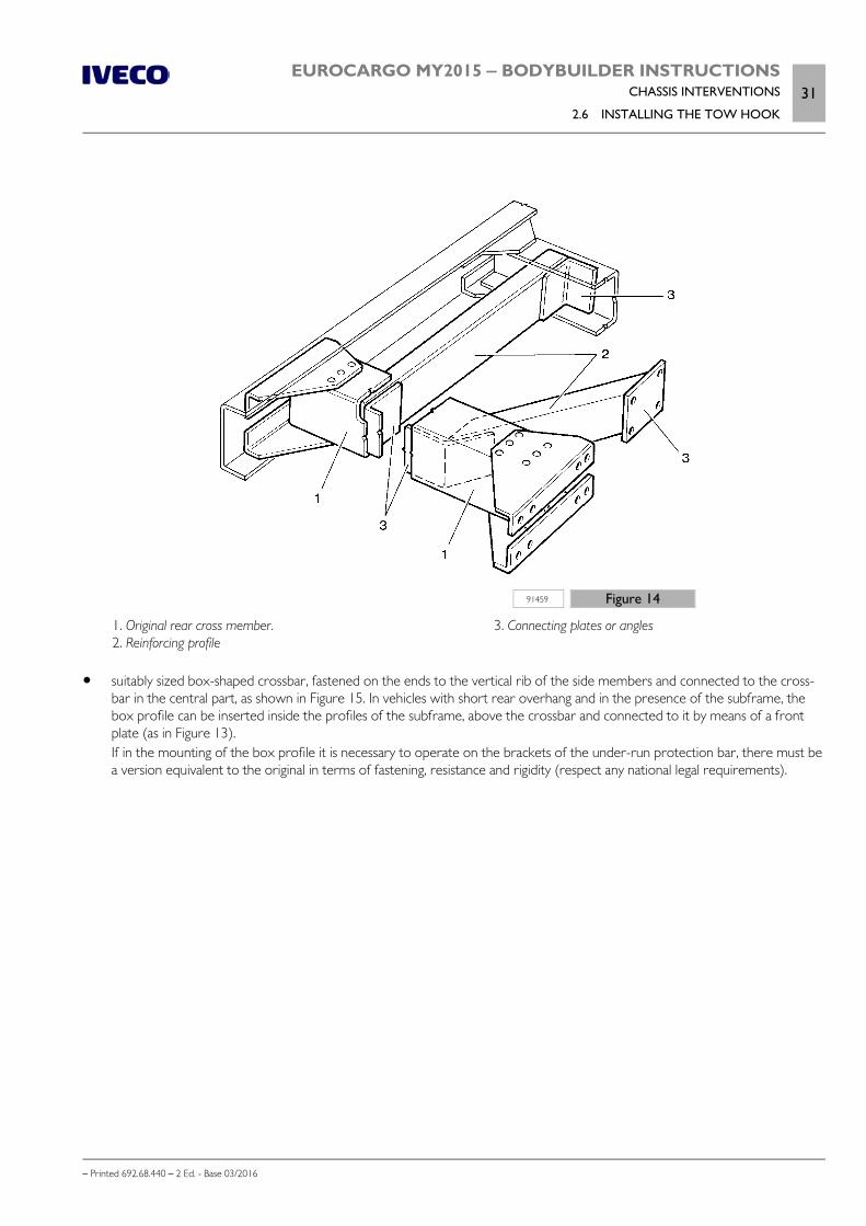
EUROCARGO MY2015 ‒ BODYBUILDER INSTRUCTIONSCHASSIS INTERVENTIONS
2.6 INSTALLING THE TOW HOOK31
– Printed 692.68.440 – 2 Ed. - Base 03/2016
91459 Figure 14
1. Original rear cross member. 2. Reinforcing profile
3. Connecting plates or angles
suitably sized box-shaped crossbar, fastened on the ends to the vertical rib of the side members and connected to the cross-bar in the central part, as shown in Figure 15. In vehicles with short rear overhang and in the presence of the subframe, thebox profile can be inserted inside the profiles of the subframe, above the crossbar and connected to it by means of a frontplate (as in Figure 13).If in the mounting of the box profile it is necessary to operate on the brackets of the under-run protection bar, there must bea version equivalent to the original in terms of fastening, resistance and rigidity (respect any national legal requirements).

32EUROCARGO MY2015 ‒ BODYBUILDER INSTRUCTIONSCHASSIS INTERVENTIONS
2.6 INSTALLING THE TOW HOOK
– Printed 692.68.440 – 2 Ed. - Base 03/2016
91460 Figure 15
1. Original rear cross member. 2. Box profile
3. Connecting plate 4. Coupling plate
Observations on payload
Static load on the drawbar coupling must not surpass the load allowed on the rear axle or axles of the vehicle. Furthermore, theminimum front axle load must be respected as indicated in Chapter 1.15 ( Page 11).
Increase of tow weight
As regards tow vehicles, IVECO may evaluate - in certain cases and for particular applications - the possibility to authorise greatertow weights than those normally allowed.
These authorisations include the towing conditions and, when necessary, provide the instructions relevant to any vehicle modifica-tions or work required: standard crossbar reinforcements (see Figure 13), or installation of a reinforced crossbar when available, oradjustments to the braking system.
The drawbar coupling must be suited for the new use, and its connection flange must coincide with that of the crossbar.
Fix the crossbar to the chassis by using flanged head screws and nuts or hex head screws of 8.8 min. class.
Use anti-unscrewing systems.
Plates
Some countries require a plate to be applied on the towing device, which must list maximum tow load and maximum vertical loadallowed.
If not already mounted, the Bodybuilder shall see to its manufacture and installation.
EUROCARGO MY2015 ‒ BODYBUILDER INSTRUCTIONSCHASSIS INTERVENTIONS
2.7 ASSEMBLING AN ADDITIONAL AXLE33
– Printed 692.68.440 – 2 Ed. - Base 03/2016
2.7 ASSEMBLING AN ADDITIONAL AXLE
The installation of an additional axle includes the perfect integration with the braking system,pneumatic system, wiring and electronic systems: therefore approval by IVECO is necessary.The request of technical information at the axle manufacturer and suppliers of plants and sys-tems involved in the transformation is the responsibility of the bodybuilder, as well as perform-ing the functional and approval tests.
The granting of the authorisation to install an additional axle and the passing of the approvaltests do not exempt the Bodybuilder from full responsibility for processing.
The additional axle on vehicles equipped with electronic braking control, grip and stabilitysystems involves updating the setting parameters of the relative control units through IVECOteleservices.
General information
On some models of the EuroCargo range, it may be possible to apply an additional axle and consequently increase the gross vehicleweight.
For its implementation, the mass limits and conditions imposed by IVECO must be respected, as well as all other conditions reques-ted by national laws and the necessity to ensure driving safety and proper vehicle function.
In this context due to the GVW increase, this includes the need to verify, the adequacy of the FUP (Front Underrun Protection)and RUP (Rear Underrun Protection) type to the new situation and their possible replacement (see Chapters 2.20 ( Page 61)and 2.24 ( Page 64)).
Any application diagrams sent to IVECO - Technical Application to be examined and authorised must show indications regardingconnection of the axle to the chassis, as well as information on reinforcement and on changes to be made on the chassis; diagramsregarding modifications to systems must also be provided.
With regard to modifications to the chassis, in addition to complying with the indications in the previous paragraphs, it is necessaryto consider the increase in stress due to the increase in the permitted load and the different conditions of operating dynamic stress.
The transformed frame must, in the corresponding sections, not be subjected to bending loads no greater than on the frame of theoriginal vehicle.
Reinforcements on the chassis
Figure 16 shows several examples of possible solutions.
The reinforcements must concern the entire length of the chassis, up to the cab.

34EUROCARGO MY2015 ‒ BODYBUILDER INSTRUCTIONSCHASSIS INTERVENTIONS
2.7 ASSEMBLING AN ADDITIONAL AXLE
– Printed 692.68.440 – 2 Ed. - Base 03/2016
192346 Figure 16
1. Bracket 2. Plate
In the case of a subframe reinforcement, the anchors provided on the chassis may be used (if in existence), otherwise they shouldbe made according to the indications in Chapter 3.1 - Paragraph "Sizing of profiles" ( Page 5) and subsequent paragraphs.
We recommend creating a cut-resistant joint in the area of the rear overhang and for about half of the wheelbase length (andalways for lengths of at least 2 m from the front axle) (see Figure 16).
Note Reinforcement plates may not be mounted directly onto the side member flaps via holes filled with welding material. Negativeeffects on the strength of the original sections, due to incorrect welding, should be avoided.
Added axle
For the installation of a rear or central third axle the following changes are mandatory:
use of suitable brake cylinders on the axle for the parking brake; adjustment of the brake system.
It is necessary that, of the two ABS solenoid valves on the axle, one handles the right wheels of the engine axle and of the addedaxle and the other one the left wheels.
a) rear
Installing a rear axle behind a drive axle involves extending the chassis overhang (see Figure 17), to be carried out according to theindications provided in the Paragraph "Extension" ( Page 18), notwithstanding the need for reinforcements as indicated in theParagraph "Reinforcements on the chassis" ( Page 33).
For vehicles with a tapered frame, the adaptation of the section of the new overhang to the rest of the sections of the chassis canbe a useful solution for containment of the stresses caused by transformation.

EUROCARGO MY2015 ‒ BODYBUILDER INSTRUCTIONSCHASSIS INTERVENTIONS
2.7 ASSEMBLING AN ADDITIONAL AXLE35
– Printed 692.68.440 – 2 Ed. - Base 03/2016
231177 Figure 17
1. Added supplementary axle 2. Lengthening of the overhang 3. Reinforcements for modification of the chassis
4. Connections 5. Reinforcing profile
b) central
Fitting an axle in front of the drive axle can require a reduction of the rear overhang (see Figure 18), to be carried out according tothe Paragraph "Shortening" ( Page 18) in order to respect the permitted technical load.
Special attention must be paid to avoiding possible interference between the added axle and the drive shaft.
231178 Figure 18
1. Added supplementary axle 2. Reinforcing profile
3. Connections 4. Shortening (if necessary) of the rear overhang
Steering axles
Steering axles can be installed in both the centre position and the rear position and be either the self-steering or controlled steeringtype; they must be built and installed in order to ensure the necessary safety for functionality and driving.
Self-steering axles must be equipped with a device that keeps them in place while reversing, which can be activated from thedriver's seat.
The application of a controlled steering axle, obtained through the original device of the vehicle's steering system, requiresauthorisation from IVECO upon presentation of the supplementary system diagram.

36EUROCARGO MY2015 ‒ BODYBUILDER INSTRUCTIONSCHASSIS INTERVENTIONS
2.7 ASSEMBLING AN ADDITIONAL AXLE
– Printed 692.68.440 – 2 Ed. - Base 03/2016
Suspension
The construction quality of all the components must be ensured (axle, suspension, brake assemblies, systems etc.) in order to guar-antee the driving safety and the correct functioning of the vehicle.
Particular attention must be paid to the realization of the suspension, given its importance in the vehicle's road handling.
The type of suspension to be realized may be mechanical leaf spring, air spring or mixed; its execution must not compromise thevehicle's handling or its components in terms of driving stability, comfort, cornering performance and transmission working angle(with the relative space restrictions in the event of an additional intermediate axle).
Implementation of a compensated type suspension is recommended (particularly for off-road vehicles), both total and partial, tomaintain constant the load distribution on two rear axles and to ensure that both axles are in condition to react to static and dy-namic loads established in the original design, and in conditions imposed by the relevant Standards (e.g. difference in axle levels).
If there is a suspension independent of that of the engine axle, in principle rigidity characteristics can be adopted, proportional tothose of the original rear suspension, in the ratio of the static loads on the two axles.
Parabolic suspension
Interventions are generally not allowed on this type of suspension.
Exception is made for outfits or special uses for which, in order to increase suspension rigidity, the application of rubber elasticelements may be authorised.
In special cases and only after IVECO approval, the addition of supplemental sheets on the parabolic springs may be allowed; thismust be carried out by a specialised spring manufacturer.
Stabiliser bars
In the case of an additional axle with air suspension, it might be necessary, depending on the solution adopted, to provide a stabiliserbar, particularly when there is a superstructure with high centre of gravity.
Similar stability measures should be adopted for mixed suspensions on added rear axles.
Attachments to the chassis
The connections for the added axle to the chassis must be able to react directly on all the longitudinal and transversal forceswithout transmitting them to the engine axle.
In the points of application of forces (spring supports, brackets for air springs, etc.), suitable crossbars or adequate reinforcementsto the chassis must be provided.
It is important to remember to create the correct orthogonality and alignment of the added axle, respectively, with the longitudinalaxle of the vehicle and with the drive wheel axle.
Check the special equipment available on the market.
Brake system
Note Considering the importance for the active safety of the vehicle, extreme care must be given to the braking system in both designand implementation.
The same type of braking units, pipes and couplings as on the original vehicle must be used on the added axle; in particular, thebraking unit must be of the type that equips the front axle.
For connection between the fixed parts (chassis) and the axle, it is advisable to use flexible pipes.
Direct connection is allowed between the braking section of the added axle and that of the engine axle.
Verify that the capacity of the air tank is suitable to the dimensions of the new added brake cylinders and, if necessary, mount anadditional air tank.
We recommend activating the parting brake on the added axle as well.

EUROCARGO MY2015 ‒ BODYBUILDER INSTRUCTIONSCHASSIS INTERVENTIONS
2.8 GEARBOX MODIFICATION37
– Printed 692.68.440 – 2 Ed. - Base 03/2016
Keeping in mind the different gross vehicle mass determined with the intervention, the braking torque must be adjusted to the newstatic and dynamic loads in order achieve even distribution of braking among the axles.
The total braking capacity of the modified vehicle must be proportional to that of the original vehicle and the performance of thesystem (service, emergency and parking) must continue in any case to comply with national standards.
Note After processing, the vehicle must be presented to the competent authorities for approval verifications (an individual test or ap-proval of that type).
The documentation on the braking to be presented to the approval body (e.g. curves of adhesion and compatibility, distribution,decelerations, heat behaviour, response time, etc.) must be provided by the person carrying out the work or the Manufacturer orthe added axle.
Technical documentation with the features of the system and the braking capacities of the original vehicle is available on request.
Note For general indications on the braking system, follow what is set forth in Chapter 2.15.
Note With regard to the electrical system, follow the indications in Chapter 5.7.
Lifting device
The added axle may be equipped with a lifting device and may be used, in special cases and if national laws allow it, for the purposeof increasing grip of the engine axle in specific situations (starting on hills, slippery, snowy or icy roads).
For the device in question, the following conditions must exist:
implementation depends on issuance by IVECO of the relative permit, on which the maximum permissible load on the over-loaded axle is indicated;
the use is limited to short sections of the route and the speed limit set in the specific authorisation.
Some national laws allow the use of the lifting device even in normal driving conditions, as long as the max approved load set forthe engine axle and the allowed speed limit are not exceeded.
In this case it is a good idea to remember the indications in Chapter 1.15 ( Page 11) with regard to the positioning of the centreof gravity of the superstructure plus payload.
Note After processing, the vehicle must be presented to the competent authorities for approval verifications (an individual test or ap-proval of that type).
For service and maintenance operations on the added groups, use operating modes and intervention times consistent with theprovisions set for the original vehicle and shown on its documentation.
2.8 GEARBOX MODIFICATION
Gearbox adjustment, following wheelbase modification, must be done using the gearbox diagram of a similar range vehicle havingalmost the same wheelbase.
The maximum tilt values of the standard propeller shaft must be respected, even for interventions on the rear engine axle andsuspensions.
Contact the IVECO Technical Application for any difficulties; and send them a diagram with the length and tilt of the new transmis-sion for a constant-velocity check.
The technical specifications in the gearbox Manufacturer manual must be used for correct production and installation of the sec-tions.
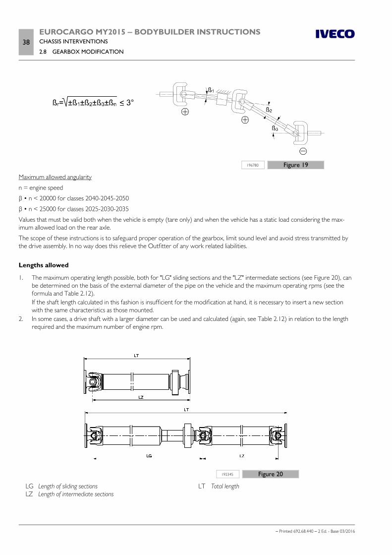
38EUROCARGO MY2015 ‒ BODYBUILDER INSTRUCTIONSCHASSIS INTERVENTIONS
2.8 GEARBOX MODIFICATION
– Printed 692.68.440 – 2 Ed. - Base 03/2016
196780 Figure 19
Maximum allowed angularity
n = engine speed
β • n < 20000 for classes 2040-2045-2050
β • n < 25000 for classes 2025-2030-2035
Values that must be valid both when the vehicle is empty (tare only) and when the vehicle has a static load considering the max-imum allowed load on the rear axle.
The scope of these instructions is to safeguard proper operation of the gearbox, limit sound level and avoid stress transmitted bythe drive assembly. In no way does this relieve the Outfitter of any work related liabilities.
Lengths allowed
1. The maximum operating length possible, both for "LG" sliding sections and the "LZ" intermediate sections (see Figure 20), canbe determined on the basis of the external diameter of the pipe on the vehicle and the maximum operating rpms (see theformula and Table 2.12).If the shaft length calculated in this fashion is insufficient for the modification at hand, it is necessary to insert a new sectionwith the same characteristics as those mounted.
2. In some cases, a drive shaft with a larger diameter can be used and calculated (again, see Table 2.12) in relation to the lengthrequired and the maximum number of engine rpm.
192345 Figure 20
LG Length of sliding sections LZ Length of intermediate sections
LT Total length

EUROCARGO MY2015 ‒ BODYBUILDER INSTRUCTIONSCHASSIS INTERVENTIONS
2.8 GEARBOX MODIFICATION39
– Printed 692.68.440 – 2 Ed. - Base 03/2016
For sliding shafts, the length LG must be evaluated between the universal joint centres and with the sliding stem in the intermediateposition. Always check both stems LG and LZ.
The maximum number of engine rpm must be calculated with the following formula:
nG = nmax / (iG + iV)
nG maximum engine speed [rpm]
nmax engine speed [rpm] at maximum output power, see Table 2-12
iG gear ratio at highest speed, see Table 2-12
iV minimum transfer box ratio, 0.95 for EuroCargo 4x4 and equal to 1 if missing or for shafts upstream of the transfer box
Table 2.12 - Engine speed [rpm] at maximum output power and gear ratioEngine Power [hp - kW] nMAX [rpm] Gearbox iG
4 cy
linde
rs
F4AFE411E 160 - 118 22006S700 0.79
6AS700 0.79
F4AFE411F 190 - 137 2200
6S700 0.79
6AS700 0.79
S2500 0.74
F4AFE411C 210 - 152 2500
6S800 0.78
6AS800 0.78
9S -75 0.73
S2500 0.74
6 cy
linde
rs
F4AFE611A 220 - 162 2500
6S800 0.78
6AS800 0.78
9S -75 0.73
12AS1210 0.813
S2500 0.74
S3000 0.73
F4AFE611E 250 - 185 2500
6S800 0.78
6AS800 0.78
9S -75 0.73
12AS1210 0.813
S3000 0.73
F4AFE611C 280 - 206 2500
6S1000 0.78
6AS1000 0.78
9S1110 0.78
12AS1210 0.813
S3000 0.73
F4AFE611D 320 - 235 2500
9S1110 0.78
12AS1210 0.813
S3000 0.73
F4GFE601A 204 - 150 2700
9S -75 0.73
S2500 0.74
S3000 0.73

40EUROCARGO MY2015 ‒ BODYBUILDER INSTRUCTIONSCHASSIS INTERVENTIONS
2.8 GEARBOX MODIFICATION
– Printed 692.68.440 – 2 Ed. - Base 03/2016
Note Following the modification, the axle shaft crosspiece forks must not be turned from their original position.
Pipe thickness
Pipe thickness depends on the torque that the original shaft must transmit, as well as on the specifications of the transmission line(engine torque, power train ratio, drive axle loads).
If using a pipe with a greater diameter than the original, thickness should in theory be reduced until it reaches the same torsionalcapacity; nevertheless, the dimensions of the fork male-end, need for adaptor rings, and the dimensions of pipes on the marketmust also be taken into account.
Hence, the pipe thickness must be established on a case to case basis in relation to the dimensions of the driver shaft (e.g. cardanjoint size), in concert with the drive shaft Manufacturer authorised shops.
Minimum operating length (from flange to flange) must be at least 800 mm for sliding shafts and 700 mm for intermediate shafts.
Table 2.13 - Maximum possible lengths
Dimensionsof thehook
outer diameterx thickness
[mm]
Maximum propeller shaft speed [rpm]
2500 2700 2900 3300 3800
Maximum possible lengths LG to LZ [mm]
2030 90 x 3 2060 1960 1900 1760 1635
2035 100 x 3 2170 2100 2000 1850 1710
2040 120 x 3 2420 2350 2220 2070 1850
2045 120 x 4 2420 2360 2220 2070 1900
Note The maximum lengths obtainable that are indicated above refer to original shafts; plan for shorter lengths (-10%) for sectionsobtained after machining.
Positioning the sections
The transmissions that comprise several sections, each axle must be of approximately the same length. In general, between an inter-mediate shaft and a sliding shaft (see Figure 21) the difference in length must not exceed 600 mm, while between two intermediateshafts, this difference must not exceed 400 mm. As regards sliding shafts, there must be a minimum margin of 25 mm betweenminimum operating length and maximum sealing length; on opening, there must be a covering between the shaft and the sleeve ofapproximately 2 times the diameter of the grooved shaft.

EUROCARGO MY2015 ‒ BODYBUILDER INSTRUCTIONSCHASSIS INTERVENTIONS
2.8 GEARBOX MODIFICATION41
– Printed 692.68.440 – 2 Ed. - Base 03/2016
91451 Figure 21
1. Drive shaft, clutch, gearbox 2. Intermediate shaft 3. Intermediate shaft bearing 4. Sliding shaft 5. Rear axle casing tilt (static load)
6. Rear axle casing tilt (max compression) 7. Rear axle casing tilt (no load) 8. Intermediate shaft, sliding articulated shaft and rear axle
casing axis must have the same tilt.
The intermediate shaft and the axle casing axle must be aligned.
Their tilt may vary up to 1° in regards to that of the engine-clutch-gearbox axle; which may be obtained by placing a wedgebetween the axle casing and the spring, or by means of adjusting the rear axle reaction bars.
The inclination of the rear axle casing must be no more than 5.5° from the horizontal plane.
When in vehicle loading conditions, the flange of the rear axle is lower than that of the gearbox housing flange, it is necessary tomake the inclination of the rear axle housing and the intermediate shaft greater than that of the engine-gearbox axle. Vice versa,when in vehicle loading conditions, if the flange of the rear axle is higher than that of the gearbox housing flange, it is necessary tomake the incline of the axle housing and the intermediate shaft less than that of the engine-gearbox axle.
When wheelbase lengthening is substantial, it may be necessary to mount an additional intermediate section, as indicated in Figure22. In this case, make sure that the engine-gearbox axle, the second intermediate shaft and the axle casing axis when in static loadare all aligned with the same tilt.

42EUROCARGO MY2015 ‒ BODYBUILDER INSTRUCTIONSCHASSIS INTERVENTIONS
2.8 GEARBOX MODIFICATION
– Printed 692.68.440 – 2 Ed. - Base 03/2016
91452 Figure 22
1. Drive shaft, clutch, gearbox 2. First intermediate shaft 3. Intermediate shaft bearing 4. Second intermediate shaft 5. Sliding shaft
6. Rear axle casing tilt (static load) 7. Rear axle casing tilt (max compression) 8. Rear axle casing tilt (no load) 9. Gearbox, second intermediate shaft, sliding articulated
shaft and axle casing axis must have the same tilt.
The application of the elastic supports must be made using a support plate of at least 5 mm thick (see Figure 23), connected to thecross members with the same characteristics as those envisaged by IVECO.
In modifying the wheelbase, it is better to plan for removal of intermediate shafts when shaft length is less than approximately 800mm.
91453 Figure 23
1. Intermediate shaft 2. Support plate
3. Rest plate 4. Intermediate shaft bearing
The considerations made up to this point are valid for vehicles with separate gearboxes.
Furthermore, the wheelbase on these vehicles may not be reduced beyond the shortest value for the series (e.g. tipper truck).
We recommend using original IVECO gearboxes; if this is not possible, the use of raw steel pipes with a yield load of at least 420N/mm2 (42 kg/mm2) may be used.

EUROCARGO MY2015 ‒ BODYBUILDER INSTRUCTIONSCHASSIS INTERVENTIONS
2.9 MODIFYING THE ENGINE AIR INTAKE AND EXHAUST SYSTEMS43
– Printed 692.68.440 – 2 Ed. - Base 03/2016
The universal joints may not be modified.
For every transformation of the transmission, of any of its parts, a thorough dynamic balancing must be performed on each sectionmodified.
Given that the transmission is an important part of the vehicle in terms on safety, we stronglyrecommend that all modifications made to it stand up to maximum safety standards. Therefore,all modifications should be made only by highly specialised Companies that are qualified by thetransmission Manufacturer.
2.9 MODIFYING THE ENGINE AIR INTAKE AND EXHAUST SYSTEMS
Note The characteristics of the engine air intake and exhaust systems must not be modified. Modifications, if authorised by IVECO, mustnot vary the original intake vacuum and exhaust back pressure values.
Table 2.14 - Maximum intake and exhaust pressure, at normal operating conditions and full load
Engine Model Engine codeExhaust
counter-pressure [kPa]Intake vacuum [kPa]
TECTOR 4 CYLINDERS
F4AFE411E*C 15 4.3
F4AFE411F*C 15 4.3
F4AFE411C*C 15 4.3
TECTOR 6 CYLINDERS
F4AFE611A*C 26 5
F4AFE611E*C 26 5
F4AFE611C*C 26 5
F4AFE611D*C 26 5
F4GFE601A*J 16 2.5
Intake
The air intake must be mounted as to avoid intake of hot air from the engine compartment, or dust and water.
The intake compartment must be sealed airtight and fitted with rubber gaskets that prevent hot air recirculation. The gaskets mustbe of high quality as to support a steady temperature of 100 ºC, with short durations of 120 ºC, without undergoing visible de-formations or deteriorations. The compartment must keep airflow sections efficient for the entire circuit.
The holes that must be made in the box part of the van must have an area of about twice that of the cross-section of the pipeupstream of the filter; these openings (e.g. grille holes) must have minimal dimensions to prevent possible clogging.
The following are not allowed:
alterations or replacement of the original air filter with one of lower capacity; modifications to the silencer body; interventions on equipment (injection pump, control valve, injectors, etc.) that may compromise good engine performance
and affect exhaust gas emissions. change the succession Humidity sensor → Brakes air→ Blow by in the segment between air filter and turbine
Lastly, it is necessary to check if new system approval is required in relation to specific national standards (sound level, smokiness).

44EUROCARGO MY2015 ‒ BODYBUILDER INSTRUCTIONSCHASSIS INTERVENTIONS
2.10 WORK ON THE ENGINE COOLING SYSTEM
– Printed 692.68.440 – 2 Ed. - Base 03/2016
Engine exhaust
Given the compact nature of the “Hi-e SCR” system and the optimal layout of its assemblies on the chassis, any modifications tothe exhaust pipe extension are to be limited and realised in consideration of not only the Note at the beginning of the Chapter andTable 2.14, but also the indications in Section 6 page 9.
Vertical exhaust
To realise a vertical exhaust which is different from the one which may be installed as first equipment, it is recommended that thefollowing points are provided for:
a considerable distance from the air intake conveyor; the simplest possible pipe route (curvatures with radii of no less than 2.5 times the outer diameter, passage sections no smal-
ler than those of the original solution, absence of throttling); suitable distances (min. 150 mm) from electrical systems and plastic pipes (shorter distances progressively require plate guards,
thermal insulators or the replacement of plastic pipes with steel ones); a support structure for the vertical part fastened to the vehicle chassis and braced, if necessary; a flexible pipe between the part of the exhaust connected to the engine and the part rigidly fastened to the chassis; a solution that prevents water entering from the top of the pipe (e.g. curvature).
2.10 WORK ON THE ENGINE COOLING SYSTEM
The good operating conditions of the original system must not be altered, especially for what concerns the free surface of the radi-ator and pipes (dimension and layout).
If modifications must be made to the cab or full bodywork installed (buses, campers, mobile-shops, etc.) which require work to thecooling system, keep in mind that:
the effective area for airflow towards the radiator must not be less than that expected for vehicles with standard cabs andmust be protected via deflectors and/or conveyors installed in front of the radiator assembly;
maximum outflow of hot air from the engine compartment must be guaranteed using appropriate deflectors and/or extract-ors;
fan performance must not be modified; any modifications of the water piping must not compromise complete filling of the circuit (done with a steady flow and
without any backflow from the intake until the circuit is filled) and regular water flow; in addition, these modifications must notalter maximum water stabilisation temperature, even in the most demanding conditions of use;
pipe layout must be done so as to avoid the formation of air pockets (e.g. eliminating siphoning bends or installing requiredvents) that may make water circulation difficult;
check that water pump activation at engine start-up and successive operation during idling is immediate (accelerate a fewtimes), even when circuit is not pressurised. During checks make sure that the water pump supply pressure, with engine attop speed and no load, is less than 1 bar.
To check the operation of the cooling circuit we must account for the water supply, bleed and circulation proceeding as follows:
open the supply valve of the heating system and the heater bleed valves; fill the circuit while the engine is off with a flow rate of 8 - 10 l/min, until water seeps from the overflow vent; one bled, close the heater bleed valves; start the engine and run idle for 5 minutes, successively check to see that the water level in the supply tank has not dropped
below minimum level; gradually rev the engine, checking that average pressure in the water pump outlet pipes steadily increases without and discon-
tinuities; keep accelerating the engine until the thermostat opens, causing air bubbles to pass through transparent pipes installed
between: engine output and radiator; water supply tank and water pump;

EUROCARGO MY2015 ‒ BODYBUILDER INSTRUCTIONSCHASSIS INTERVENTIONS
2.11 INSTALLING AN ADDITIONAL HEATING SYSTEM45
– Printed 692.68.440 – 2 Ed. - Base 03/2016
engine bleed and water supply tank; check, after the thermostat has be open for 15 minutes, that there are no more bubbles in the circuit; check that, with thermostat open and engine running idle, that average pressure in the water pump outlet pipe is greater than
500 mm water column.
2.11 INSTALLING AN ADDITIONAL HEATING SYSTEM
We recommend using IVECO type heating systems whenever it is necessary to install an additional heating system.
On vehicles where IVECO does not employ these heaters, installation must be done in compliance with the instructions issued bythe equipment Manufacturer (installation of heaters, pipes, electric system, etc.) and in relation to the following indications.
The additional heating system must respect all national standards on the subject (e.g. tests, specific installations for the transport ofhazardous materials, etc.). It must avoid the use of vehicle equipment that requires certified approval whenever such equipmentmay cause a negative impact on performance.
In addition, be sure to:
care for the proper operation of all other vehicle systems (e.g.: engine cooling system); check that the battery capacity and alternator power are sufficient for increased current draw (see Chapter 5.7 ) and install a
protection fuse on the new circuit; to draw off the fuel, connect the fuel supply system to an auxiliary tank. Direct connection to the vehicle tank is allowed under
the condition that it occurs independently from the engine fuel supply, and the new circuit must be perfectly airtight; route piping and wiring layout (and installation of brackets and flexible fittings) in relation to the spaces available and the influ-
ence of heat on the chassis parts. Avoid any exposed parts that may be dangerous, and adopt suitable guards when necessary.
The system must allow easy access and prompt maintenance.
The Bodybuilder must provide all necessary maintenance instructions.
a) Water heaters
When the original vehicle heating and engine cooling circuits are involved (see Chapter 2.10 ( Page 44)), the following must bedone to ensure good system operation and safety of the original system:
carefully define the connection points between the additional and original systems, in agreement with IVECO, if necessary.The added pipes must be made of brass or other alloy resistant to the corrosive action of coolant, the coupling sleeves mustrespect the requirements put forth by the standard IVECO 18-0400;
plan for a rational layout of pipes, avoiding bottlenecks and siphoning bends; install venting valves (bleed points) to allow proper system filling; allow complete circuit discharge, also by installing any additional plugs; adopt, when necessary, suitable protections to limit heat loss.
b) Air heaters (only diesel versions)
As regards these heaters and for direct cab installation, be particularly cautious with the exhausts (to avoid combustion gasses frombeing trapped in the vehicle) and correct distribution of hot air (in order to avoid direct flow).

46EUROCARGO MY2015 ‒ BODYBUILDER INSTRUCTIONSCHASSIS INTERVENTIONS
2.12 INSTALLING AN AIR CONDITIONING SYSTEM
– Printed 692.68.440 – 2 Ed. - Base 03/2016
2.12 INSTALLING AN AIR CONDITIONING SYSTEM
We recommend using original IVECO units for the installation of an air conditioning system.
When this is not possible, aside from complying with the specific requirements provided by the manufacturer of the equipment, itis necessary to:
maintain good performance of the vehicle parts that may be involved in the intervention; check that the battery capacity and alternator power are sufficient for increased current draw (see Chapter 5.7 - Paragraph
"Additional equipment" ) and install a protection fuse on the new circuit; plan the compressor installation modes with IVECO, if installed on the engine; route piping and wiring layout (and installation of brackets and flexible fittings) in relation to the spaces available and the influ-
ence of heat on the chassis parts; avoid layouts and installations where exposure may be dangerous when the vehicle is moving; fit suitable guards when neces-
sary; the system must allow easy access and ensure prompt maintenance.
The Bodybuilder must provide all necessary maintenance instructions upon vehicle delivery.
In addition, in function of the type of system:
a) cab installed system:
condenser installation must not cause negative effects on the engine cooling characteristics (reduction of exposed radiator-engine area);
condenser installation must not be coupled with the engine radiator, but placed in its own specific compartment with properventilation;
installation of the evaporator unit and of the bellow inside the cab (in cases where not provided directly from IVECO) mustbe planned as not to negatively impact control functions and access to equipment;
b) cab roof-installed systems :
it is necessary to verify that the mass of the equipment does not exceed the weight allowed by the cab; in addition, the Body-builder must define the structural reinforcements to apply to the cab roof in relation to the unit's weight and type of interven-tion performed;
contact IVECO or specific applications that involve an unoriginal compressor (e.g. fridge).
Note that in relation to Directive 2006/40/EC on the emissions of air conditioning systems formotor vehicles, the use of fluorinated GHG with overall heating potential over 150 in compar-ison to CO2 is prohibited.
2.13 WORK ON THE CAB
General information
All interventions on the steering cab must be authorised by IVECO in advance.
The modifications must not hinder operation of the control devices located in the area of the modification (e.g. pedals, switches,pipes, etc.) nor alter the strength of load-bearing elements (frames, reinforcement profiles, etc.). Care must be taken when dealingwith operations that regard the engine cooling and air intake pipelines.
In relation to variation of cab weight, it is necessary to consider the position of the load in order to respect division of allowed axleloads (see Chapter 1.15 ( Page 11)).
As regards operations that entail the removal of internal sound barriers or protective panels (panelling, cladding) be sure to re-move only the minimum amount possible; restore the protections as intended in the original design along with their original func-tionality.

EUROCARGO MY2015 ‒ BODYBUILDER INSTRUCTIONSCHASSIS INTERVENTIONS
2.13 WORK ON THE CAB47
– Printed 692.68.440 – 2 Ed. - Base 03/2016
Cab installation of controls and equipment (PTO engage switch, external operator cylinder control, etc.) is allowed as long as:
installation is rational, performed in good detail and easy to access by the driver; the proper safety, control and signalling devices called for by national law are installed.
Make sure that pipe and cable installation is performed properly also in function of cab tilting; adopt the necessary retainers and besure to plan for appropriate distances from the engine, heat sources and moving parts.
Each structural modification must bear protection against corrosion (see Chapter 2.3 ( Page 11)).
The use of zinc coated sheet metal is recommended on both ends of newly inserted sheet metal on cut bodywork in order toavoid ferrous corrosion of the welds (I.S. 18-1317 class ZNT/F/10/2S or I.S. 18-1318 class ZNT/10/2S); both surfaces must un-dergo protective treatment.
Install gaskets with care and apply sealant to areas in need of protection.
Make sure that the seals are water, dust and smoke tight.
The Bodybuilder must check that the chassis, after its structural modifications, complies with the standards in force for what con-cerns both internal and external structure.
Work on the roof
Any cab modifications performed to create specific configurations must be done with care in order to protect the resistance andmaintain cab functionality and protections intact.
In any applications or units or equipment on the roof, make sure that the mass of the equipment does not exceed that permittedby the cab. These limits can be provided on request, depending on the version.
Spoiler or top-sleeper installation
The installation must be performed by using the specially crafted fixing points on the cab roof sides and using support devices ofappropriate sizes.
If the national standards require it, these installations must be controlled by relevant authorities.
Realization of sleeper cabs
The transformation of the standard cab to a special cab or sleeper cab (special vehicles, public use, fire brigade, etc.) can be author-ised by IVECO after the evaluation of the suitability of use of the suspension, tipping and locking systems to operate correctly evenunder the new conditions.
In general solutions can be used that are equivalent to those provided by IVECO for the same applications.
To contribute to maintain the rigidity of the cab, it is recommended to keep the rear structure as much as possible unchanged.
It should be noted, however, that the transformation needs new approval tests (seats, seat belts, etc..) and that the relative costswill be at total charge of the body builder.
The increase of the cab weight, requires appropriate interventions on the suspension, the tipping device and on the rear coupling;
1. The definition of an appropriate suspension system requires: respect the cab structure provided in the standard vehicle; prevent that the added weight causes serious damage to the original parts of the cab and on the relative suspension parts; ensure the normal oscillations along the vertical, longitudinal and transverse plane.
2. for the tipping it might be necessary to install a cylinder of higher capacity (with adequate supports) or an extra cylinder, veri-fying compliance with the minimum distances to the nearly arranged parts.The areas affected by the thrust of such cylinders must be protected by an excessive concentration of stresses and thereforemust be provided: the rear-most possible installation of the lifting points; suitable coupling zones, both on the cab bottom and on the chassis.

48EUROCARGO MY2015 ‒ BODYBUILDER INSTRUCTIONSCHASSIS INTERVENTIONS
2.13 WORK ON THE CAB
– Printed 692.68.440 – 2 Ed. - Base 03/2016
If during the tipping, the cabin exceeds the upper equilibrium point, make sure the added hydraulic system allows to keepit in the limit switch position or otherwise, apply a safety rope.
3. The original coupling device includes a safety lock and an indicator that shows the successful activation: it is suggested to keepthis solution unchanged.
If the transformed cab does not have the possibility of tipping, in addition to acting on the suspension as seen above, a movablebonnet, hatches or panels need to be provided for the inspection and maintenance of the underlying parts.
In order to facilitate interventions in the workshop it is recommended the installation of a rear coupling point for the lifting or thepossibility to apply safety bar.
In the change of the cab can be included the engine air intake and the filter. The use of original elements already provided for sim-ilar fittings, can be a good solution and allow the compliance with legislative regulations.
Note that the cab transformation operations affect the good behaviour and the safety of thevehicle (suspension, tipping manoeuvre) and therefore must be designed and carried out withextreme care.
Protection of occupants
Airbags, safety belt fittings, the positioning of reels and pre-tension devices and anchorage of seats are all an integral part of passivesafety.
Any modification of these components may compromise the protection of persons on-board and compliance with legal require-ments.
Airbag
Work or component installations must not be carried out in areas that may inhibit the correct operation of the airbags.
Consequently, the following must be avoided:
modifications to the front structure of the vehicle, floor, firewall, sides and dashboard fixture points; alterations in the airbag control unit installation area (located under the floor between the front seats) and points involved in
the system of sensors and related wiring harness; modifications to the steering column; replacements or installations of seats a different “H” point compared to the original versions.
Since the safety of an electronic system configuration of the vehicle does not need to bechanged, the Airbag system cannot be installed as "retrofit" or, vice versa, must not beeliminated.
Anchorage of safety belts
Work in the body areas where there are seat belt fittings may affect the function/operation of these devices.
It is therefore the responsibility of the Body builder to comply with regulations concerning:
mounting and tightening torques choice of seat belts other than original versions; uniform operation between original seat belts and seats that may have a different configuration to the originals.

EUROCARGO MY2015 ‒ BODYBUILDER INSTRUCTIONSCHASSIS INTERVENTIONS
2.14 CHANGING TYRE SIZE49
– Printed 692.68.440 – 2 Ed. - Base 03/2016
seats
Moving the seats or mounting additional seats (e.g. in a cat. N1 van) are only allowed on vehicles already fitted at origin with supple-mentary fittings and already provided with alternative type approval.
Any other solution is implemented under to total responsibility of the body builder as regards installation and final test procedures(destructive).
2.14 CHANGING TYRE SIZE
Replacing the tyres with others of a different size or load bearing capacity compared to the spe-cifications recorded during vehicle type approval requires IVECO certification and verification ofwhether the electronic management of the braking system requires reprogramming.
The vehicle must successively be presented to the competent Body that will inspect the new tyres and the vehicle documents.
Mounting larger tyres:
always requires a size check in relation to mechanical components, wheel arches, etc., in the various dynamic, steering andvehicle shaking conditions;
may entail rim replacement with the consequential need to verify the spare tyre holder modification; may affect distance from ground of the rear under-run protection device and, in this case, a check on standard compliance is
required; if necessary the support brackets must be replaced with appropriate and approved counterparts (see Chapter 2.20( Page 61));
requires the need to check compliance of the limit transverse contour allowed in relation to the various standards.
Prescriptions
Note Replacing tyres with others of different external diameter affects vehicle performance (e.g.: speed, max. vehicle ramp slope, towload, braking force, etc.); therefore the IVECO Body Controller (speedometer, tachograph and speed limiter) must undergo recalib-ration at an authorised IVECO workshop.
Tyres of different size and type of structure cannot be mounted on the same axle.
The tyre load bearing capacity and the relative reference speed must be suitable to the vehicle's performance.
Mounting tyres with lower load bearing capacity or reference speed entails a reduction of allowed loads; on the other hand,mounting tyres with greater load bearing capacity does not automatically entail an increase of load allowed on the axles.
The dimensions and load bearing capacity of the tyres are established by international and national standards (ETRTO, DIN, CUNA,etc.) and are listed in the manuals of their respective Manufacturers.
Particular performance values may be put forth by national standards for special uses, fire-protection, winter services, airport tanktrucks, buses, etc.
If vehicle configuration requires the wheels to be removed, make sure that the contact surfacesbetween rim and connection flange are clean and free of corrosion when remounting the wheels.In addition, tighten the wheel studs at the tightening torque according to the IVECO standard(see the following Table).

50EUROCARGO MY2015 ‒ BODYBUILDER INSTRUCTIONSCHASSIS INTERVENTIONS
2.15 WORK ON THE BRAKING SYSTEM
– Printed 692.68.440 – 2 Ed. - Base 03/2016
Table 2.15 - Wheel tightening torque according to IVECO STD 17-9219CONNECTING ELEMENTS
Thread
TIGHTENING
CODE Name CLASSTorque [Nm]
FEATURES “S” (*)
Min Max
1 Front and rear wheel mounting Nut M18x1.5 II 335 410 “S”
2 Front and rear wheel mounting Nut M20x1.5 II 540 440 “S”
3 Front and rear wheel mounting Nut M22x1.5 – 580 650 “S”
(*) Characteristic “S”: safety tightening (see IVECO std. 19-0405).
If using brackets to mount aesthetic studs positioned between the rim / lug or stud, or if usingrims thicker than the original, geometric mounting functionality must be ensured through ap-propriate lengths of stud threading in the locking hole.
2.15 WORK ON THE BRAKING SYSTEM
General information
No changes are allowed to the regulating unit, distributor, brake cylinders, valves, etc., sincethey are safety components.
Any changes to the braking system (modification of pipes, installation of additional operatingcylinders etc.) requires the authorisation of IVECO.
Note For new units, it is advisable to prefer the same brands as those fitted to the original vehicle.
If the national standards provide it, the vehicle must be presented to the competent authority for inspection.
In the case of displacement of control valves, dryer, etc., restore the same type of installation originally provided, ensuring the cor-rect functionality; interventions on the dryer must also not affect the conditions of cooling air coming from the compressor.
Brake pipes
Note In the case of changes to the cantilever, the brake lines involved should preferably be replaced with new pipes and in one piece; ifthis is not possible, the couplings to be used must be of the same type as the original ones.
We would like to underline the dangers related to the full or partial painting of the pipes; there-fore, during the intervention, the pipes must be properly masked.
When replacing, it is necessary to comply with the minimum internal dimensions of the existing pipes.
The characteristics and the material of the new pipes must match those originally used on the vehicle.
The installation must be carried out so that the system is adequately protected.
For the supply of materials and their installation it is advisable to contact a Service Centre or Authorised Workshop.
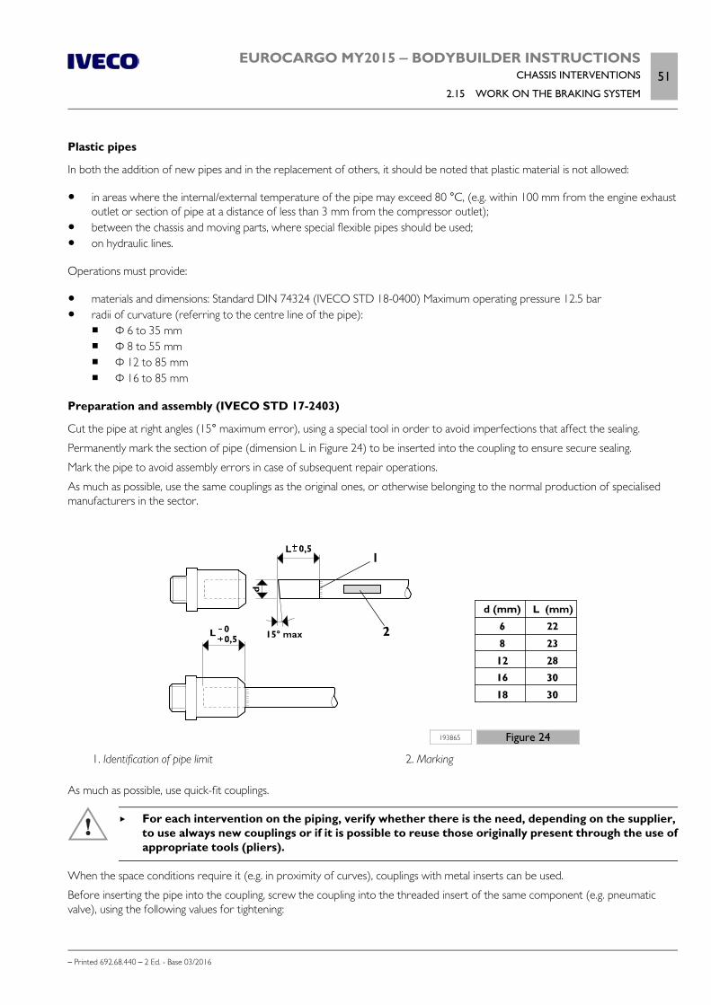
EUROCARGO MY2015 ‒ BODYBUILDER INSTRUCTIONSCHASSIS INTERVENTIONS
2.15 WORK ON THE BRAKING SYSTEM51
– Printed 692.68.440 – 2 Ed. - Base 03/2016
Plastic pipes
In both the addition of new pipes and in the replacement of others, it should be noted that plastic material is not allowed:
in areas where the internal/external temperature of the pipe may exceed 80 °C, (e.g. within 100 mm from the engine exhaustoutlet or section of pipe at a distance of less than 3 mm from the compressor outlet);
between the chassis and moving parts, where special flexible pipes should be used; on hydraulic lines.
Operations must provide:
materials and dimensions: Standard DIN 74324 (IVECO STD 18-0400) Maximum operating pressure 12.5 bar radii of curvature (referring to the centre line of the pipe):
Φ 6 to 35 mm Φ 8 to 55 mm Φ 12 to 85 mm Φ 16 to 85 mm
Preparation and assembly (IVECO STD 17-2403)
Cut the pipe at right angles (15° maximum error), using a special tool in order to avoid imperfections that affect the sealing.
Permanently mark the section of pipe (dimension L in Figure 24) to be inserted into the coupling to ensure secure sealing.
Mark the pipe to avoid assembly errors in case of subsequent repair operations.
As much as possible, use the same couplings as the original ones, or otherwise belonging to the normal production of specialisedmanufacturers in the sector.
193865 Figure 24
1. Identification of pipe limit 2. Marking
As much as possible, use quick-fit couplings.
For each intervention on the piping, verify whether there is the need, depending on the supplier,to use always new couplings or if it is possible to reuse those originally present through the use ofappropriate tools (pliers).
When the space conditions require it (e.g. in proximity of curves), couplings with metal inserts can be used.
Before inserting the pipe into the coupling, screw the coupling into the threaded insert of the same component (e.g. pneumaticvalve), using the following values for tightening:

52EUROCARGO MY2015 ‒ BODYBUILDER INSTRUCTIONSCHASSIS INTERVENTIONS
2.15 WORK ON THE BRAKING SYSTEM
– Printed 692.68.440 – 2 Ed. - Base 03/2016
Thread Tightening torque [Nm ± 10%]
M12 x 1.5 mm 20
M14 x 1.5 mm 24
M16 x 1.5 mm 30
M22 x 1.5 mm 34
Insert the pipe into the coupling for the previously marked stretch of length L, using a force of between 30 and 120 N, dependingon the size of the tube.
The replacement of components (valves, etc..) is made possible because the engagement and coupling allow an internal rotationduring the operation of unscrewing and screwing.
Vehicle pipe installation
Before use, the new pipes must be thoroughly cleaned inside, for example by blowing air with a compressor.
The pipes must be fixed to the frame with elements which envelop the pipe completely and which may be metal withrubber/plastic protection or be made of plastic material.
Provide appropriate distances between one fastening element and the other: generally, max. 500 mm for plastic pipes and max.600 mm for metal pipes can be considered.
In order to avoid deformations and tensions at the time of closure of the couplings for the plastic pipes, it is necessary to take careof the line and the accommodation of the fastening elements, rubbing should be avoided with the fixed parts of the vehicle andmeet the necessary safety distances from moving parts and heat sources.
In passing the pipes through the chassis (side members or crossbars), take precautions to avoid damage. One solution would be touse a coupling passing directly through or at an angle, or a rubber protective eyelet, as shown in Figure 25.
193866 Figure 25
1. Pipe 2. Through-coupling
3. Chassis 4. Rubber protection
After each intervention is on the system or equipment, brake efficiency should be checked.
Bring the pressure to its maximum level on the air system. Check for leaks in the areas affectedby the intervention.

EUROCARGO MY2015 ‒ BODYBUILDER INSTRUCTIONSCHASSIS INTERVENTIONS
2.15 WORK ON THE BRAKING SYSTEM53
– Printed 692.68.440 – 2 Ed. - Base 03/2016
To ensure that the connections have been properly made, the air tank corresponding to an axle can be emptied; the pressure con-trol on the in-vehicle indicator and the verification, by operating the brake pedal, on the remaining braking section(s), allow suchverification.
Hydraulic circuits must have the normal air bleed operation.
Electronic braking control device
In case of changes to the wheelbase, the original position for ABS modulators must be maintained relative to the axis rear wheels.
The wiring between the sensors on the rear axle and the control unit, as well as between the control unit and the modulators,must be adjusted using new cables or extension cables with appropriate connectors.
The brake piping upstream of the modulators must also be adequate.
Withdrawing air from the cooling system
In vehicles with a pneumatic brake system it is possible to withdraw a small amount of air from the tank in the auxiliary circuit. Thiswithdrawal should only occur through a limited return valve, which can avoid the lowering of the pressure below the threshold of8.5 bar in the operating brake circuit and the auxiliary circuit.
Take the air directly from the 4-way safety valve (exit 24) of the braking system.
196783 Figure 26
If you require larger quantities of air you have to assemble an additional tank.

54EUROCARGO MY2015 ‒ BODYBUILDER INSTRUCTIONSCHASSIS INTERVENTIONS
2.16 ELECTRICAL SYSTEM: CURRENT INTERVENTIONS AND DRAWS
– Printed 692.68.440 – 2 Ed. - Base 03/2016
In this case, however, it is necessary to ensure that the standard compressor is able to fill the tank within the specified time, other-wise you will need to install a higher capacity compressor.
If air tanks are added to the air suspension (connection 25, Air Drying Unit), the APU regeneration volume must be checked.
2.16 ELECTRICAL SYSTEM: CURRENT INTERVENTIONS AND DRAWS
Note For information on work on the electrical system, refer to what is described in Section 5 - Chapter 5.7 .
2.17 PART RELOCATION AND ANCHORAGE OF ADDITIONAL UNITS AND EQUIPMENT
The movement of units (batteries, compressors, spare wheel, fuel and urea tanks, etc.) to allow the installation of equipment isallowed on the condition that:
the functionality of the unit is not compromised; the original type of connection is restored; the new placement and distribution of mass is compatible with that originally established (see ch. 1.15 ( Page 11)).
To minimise torsional stress on the chassis of the vehicle it is advisable to perform the installation in correspondence with a cross-bar, especially in the case of high mass units.
Depending on the use of the vehicle, applications should always provide a sufficient margin in their height from the ground.
The holes to be drilled for the new arrangements should be made on the rib of the side member, according to the regulationsgiven in Chapter 2.2 ( Page 7) and taking care to use the existing holes as much as possible.
Converting the suspension from mechanical to pneumatic (for example, for shop van fitting)
This type of transformation is generally authorised on the rear axle. Other solutions proposed by Bodybuilders may be taken intoconsideration.
The bodybuilder that intents to perform the intervention must present a detailed documentation to IVECO in order to obtain atechnical approval.
In case of installation of not original components, it is noted that any approval is issued on the basis of a specially planned evaluationof their characteristics and without the contribution of specific tests, unlike when use of components of first use.
Therefore, for this particular type of transformation, IVECO shall be relieved from any liability that may be attributed to the newcomponent.
Horn
The displacement of the horn obligates the body builder for a new approval. Also in the new position, the device must ensure theacoustic performance set by the regulations and must be adequately protected from exposure of weathering and/or soiling. IVECOreserves the right to void the warranty on the moved component.
Spare wheel holder
For chassis cabs not supplied with a spare wheel holder, or in cases where it is necessary to move the spare wheel, a special sup-port must be made that allows rapid extraction and meets a minimum exit angle of 7°.
To secure the spare wheel with a support applied to the rib of the side member, we recommend the application of a local rein-forcement plate arranged inside the side member itself and sized depending on both the mass of the wheel and the presence orabsence of other reinforcements on the side member.

EUROCARGO MY2015 ‒ BODYBUILDER INSTRUCTIONSCHASSIS INTERVENTIONS
2.17 PART RELOCATION AND ANCHORAGE OF ADDITIONAL UNITS AND EQUIPMENT55
– Printed 692.68.440 – 2 Ed. - Base 03/2016
Additional fuel tank (only diesel vehicles)
If filling the fuel tank is hindered by a superstructure, the tank support brackets can be placed lower down, with a displacement of adrilling module (45 mm).
When necessary to change the autonomy compared to the standard configuration, it is possible to:
replace (both for capacity increase and decrease) the tank with another tank envisaged for the series; add an additional tank, chosen if possible from the standard ones and compatible with available space.
If the addition is made on the same side of the chassis, the two tanks can be connected with a flexible hose (at least in part) and fuelcan always be drawn from the original tank (Figure 27 A).
When instead the additional tank is positioned on the opposite side of the chassis compared to the original, it is advisable to imple-ment a scheme like the one in Figure 27 B, where the implementation of a diverter allows to alternatively use the two tanks.
196784 Figure 27
The chosen solution must be implemented in compliance with specific regulations.
The piping additions must ensure prefect sealing, have technical features and internal dimensions not less than those provided for inthe original system and be properly clamped.
Note We highlight the need to:
- implement or realise a new measurement system that always provides correct information on the actual quantity of fuel in thetanks;
- use a specific indicator instrument and separate from the original.
Moving the fuel tank (only diesel vehicles)
Moving the position is permitted providing that the absolute minimum pressure at the BP/AP pump inlet is 500 mbar.
On MLC and MLL cab vehicles without the option 75435 "Moving assemblies backwards", horizontal repositioning is possible when,compared to the original position, it involves a maximum extension of 500 mm of each return and delivery pipe .
For greater extensions, up to a maximum of 1000 mm, the standard fuel prefilter is to be replaced with a different type able tocreate a lower drop in pressure on the line.

56EUROCARGO MY2015 ‒ BODYBUILDER INSTRUCTIONSCHASSIS INTERVENTIONS
2.17 PART RELOCATION AND ANCHORAGE OF ADDITIONAL UNITS AND EQUIPMENT
– Printed 692.68.440 – 2 Ed. - Base 03/2016
Moving to the opposite side member (only diesel vehicles)
218902 Figure 28
The fuel tank can be moved to the left side member providing a minimum distance of 200 mm from the DPF/muffler housing ismaintained. This distance can only be reduced to 80 mm if appropriate heat shields (highlighted in red in Figure 28) are used, whichare of the same type as those used to protect the front section of the DPF/muffler.
Chassis with free right side (only diesel vehicles)
If the right side of the chassis, between the front mud guard and the rear wheels, must be free of all suspended assemblies, youmay:
request (where possible) opt 75501 for the air filter to be moved in front of the front axle; reposition the fuel tank on the left side of the chassis; reposition the urea tank on the basis of the possibilities indicated in the Chapter 6.4 ( Page 8), page 9 and the following.
Figure 2.29 shows some of the possible positions, especially for the urea tank.
218401 Figure 29
1. Fuel tank (new position) 2. Urea tank behind the cab (standard position, forward)
3. Urea tank on the left side between the fuel tank and thespare wheel (alternative position)

EUROCARGO MY2015 ‒ BODYBUILDER INSTRUCTIONSCHASSIS INTERVENTIONS
2.18 TRANSPORT OF HAZARDOUS MATERIALS - ADR (only diesel vehicles)57
– Printed 692.68.440 – 2 Ed. - Base 03/2016
2.18 TRANSPORT OF HAZARDOUS MATERIALS - ADR (only diesel vehicles)
Depending on the specific ECE/TRANS/WP.15/213 document and its national implementations, dangerous goods are classifiedunder "Explosives", "Flammable Liquids", "Gas", "Hydrogen" and must be transported on a specially crafted vehicle. The type of pre-paration is specific according to the above categories (see end of paragraph).
IVECO does not provide versions fully prepared for the ADR, although production vehicles do already comply for some electricalparts, mechanical components and materials inside the cab. The Bodybuilder, upon request, is given a "declaration" containing detailsof the sections in the ECE document that have already been complied with by the vehicle up from the origin.
A higher level of compliance can be obtained through the optional 2342 (ADR preparation) which brings the vehicle to have:
specific digital tachograph (to select within two versions) specific electric switch (only in cab or both on chassis and in cab) emergency switch protected electrical connections wiring protected with polyamide conduit ADR approval plate instructions on functioning
Note that with this option, the centralised closing of the doors can be activated only if the ADR transport is not running; Otherwisethe doors can be closed only with the normal keys.
What is still missing for the complete adjustment of the vehicle to the specific type of goods to be transported remains in charge ofthe body builder.
For example: the realization of vehicles for the transport of category "OX - Peroxides" materials, for which the regulations requirethat the windows of the rear wall of the cab have specific characteristics and so their frames. Since this is not within the content ofthe ADR preparation given by IVECO, when ordering the vehicle must be chosen the optional 00741 "Without rear glazing”.
Note The complete transformation must still be authorised by the authorities responsible for the relative tests.
By way of example, below is some information concluded by the Regulation ECE/TRANS/WP.15/213 on the topic.
Electric systemConductors suitably insulated and protected in ducts, protected from shock, stones, heat, etc.Circuits protected from overvoltage with appropriate connections for use in hazardous environments, with fuses or automaticcircuit breakers.Main power switch (excluding the tachograph, powered directly from the battery with suitable safety devices) placed near thebatteries, with direct or remote control in the cab and outside.
BrakingCompliance with specific EC Directives.Obligation of the anti-lock system (ABS) and a device for slowing down, in the cases provided by law.
Cab protectionUse of fire-resistant materials, according to ISO 3795, with a burn rate not exceeding 100 mm/min; otherwise adoption of aprotective wall between the cab compartment and transport.
Exhaust systemSuitable insulation for the components that reach temperatures above 200° C and cannot be moved in front of the protectivewall.Exhaust outlet facing towards the outer side; in the event of transport of explosives, the ends must be equipped with a sparkarrester device.
Fuel tankLocation protected from shocks; in case of spills or leaks, the fluid should flow directly on the ground.
Independent heater

58EUROCARGO MY2015 ‒ BODYBUILDER INSTRUCTIONSCHASSIS INTERVENTIONS
2.19 INSTALLING A RETARDER
– Printed 692.68.440 – 2 Ed. - Base 03/2016
Safe with regard to protection against the fire; placed in front of the rear cab panel, at least 80 cm from the ground, withprotection of the heated parts.
Speed limiterCompliant with the ECE Directives in force.
EquipmentAt least two fire extinguishers and two portable lamps, independent from the vehicle's electrical system, whose operation cannot cause the combustion of the transported goods.
3rd axleElectric lifting device arranged outside of the chassis, in a waterproof box.
2.19 INSTALLING A RETARDER
At the first equipment: upon request, most ranges of vehicles may be equipped with an electromagnetic retarder on the gear-box. Vehicles with automatic gearbox S3000 R are fitted as standard with a hydraulic retarder built into the gearbox.
"Post sales": The application of an electro-magnetic retarder is only possible following approval by IVECO and, provided thechosen unit is compatible with the characteristics of the vehicle and what has already been approved by IVECO.
In this case the choice of the retarder brake can be made according to the formula:
204640 Figure 30
ip = rear axle ratio
Cf = Maximum braking torque [Nm]
R' = radius under load of the used tyre [m]
GVW = Gross Vehicle Weight [kg]
The installation of the brake must be carried out by the Manufacturer in their authorized service centres, in accordance withChapters 2.2 ( Page 7), 2.8 ( Page 37), 5.7 of these Directives.
a) Electromagnetic retarder
The perfect integration of the retarder with the electrical and electronic systems of the vehiclecan only be performed using specific "datasets": therefore approval by IVECO is always neces-sary.
"Post sales" installation may cause the appearance of signals indicating a defect of the braking system to appear on the dashboard.
To prevent this fault, it is essential that the vehicle is equipped with the SWI control unit (Steering Wheel Interface) and that theelectrical connection between the retarder and SWI is carried out according to the diagrams present in the IVECO AssistanceService manuals.

EUROCARGO MY2015 ‒ BODYBUILDER INSTRUCTIONSCHASSIS INTERVENTIONS
2.19 INSTALLING A RETARDER59
– Printed 692.68.440 – 2 Ed. - Base 03/2016
242102 Figure 31

60EUROCARGO MY2015 ‒ BODYBUILDER INSTRUCTIONSCHASSIS INTERVENTIONS
2.19 INSTALLING A RETARDER
– Printed 692.68.440 – 2 Ed. - Base 03/2016
Table 2.16 - Electromagnetic retarderType Component Connector / Connection Description
Control unit A-86024 X-86024_1 X-86024_2 Electric retarder control unit
Control unit A-86116X-86116_A_0 X-86116_B_0X-86116_C_0 X-86116_D_0X-86116_E_0 X-86116_F_0
Body Computer multiplex control unit
Control unit A-86123X-86123_A_0 X-86123_C_0
X-86123_D_0Multiplex control unit for interfacing with steering shaft (SWI)
Control unit A-86132 X-86132_X1 X-86132_X3 VCM (Vehicle Control Module) control unit
Battery BAT-20000 Starter battery
Fuse F-70000_1 6 fuse holder (30 A)
Fuse F-70000_5 6 fuse holder (30 A)
Energy source G-DPT Chassis positive control valve
Energy source G-POS Positive pin
Ground GND-mb Ground point
Ground GND-mc1 Ground point
Ground GND-mc3 Ground point
Ground GND-mm1 Ground point
Ground GND-mm9 Ground point
Relay K-25111 Contactor assembly for retarder control
Switch S-52048 Switch for retarder cut-off from brake pedal
Switch SW-54033_dx 6-function steering column switch unit
Connector X-75000 X-75000 Interconnection control unit
Connector X-D X-D_0 Bulkhead connector D
Connector X-JC2 X-JC2 Branching connector
Connector X-JC3 X-JC3 Branching connector
Connector X-ST100 X-ST100 Gearbox bridle
Connector X-ST121 X-ST121 Chassis cable / retarder relay cable interconnection
Connector X-ST125/1 X-ST125/1 A-EBS cab cable interconnection
Connector X-ST14/1 X-ST14/1 Basic cab cable/Allison transmission cab control cable interconnection
Connector X-ST22 X-ST22 Cable interconnection on overall basic cab
Connector X-ST80 X-ST80Connection for reverse gear activation switchStart-up prevention with gears engagedSignalling low gears engaged
Connector X-ST81 X-ST81Overall basic cab cable / cab cable for steering column switch interconnec-tion
Connector X-ST83 X-ST83Overall basic cab cable / cab cable for steering column switch interconnec-tion
Solenoid Y -85100 Electromagnet unit for electric retarder
EUROCARGO MY2015 ‒ BODYBUILDER INSTRUCTIONSCHASSIS INTERVENTIONS
2.20 REAR UNDER-RUN PROTECTION (RUP)61
– Printed 692.68.440 – 2 Ed. - Base 03/2016
b) Hydraulic retarder
Cooling of the unit is obtained by the connection to the relative engine system.
In the case of heavy-duty use, which could lead to the maximum temperature of the circulating coolant being exceeded, there mustbe a separate system.
In the case of the installation of additional heat exchangers, the dimensions must be defined by the Manufacturer of the retarderand the positioning must not alter the functionality of the original cooling system.
Example of calculation of max braking torque
A vehicle ML120E18R / P is considered, with axle ratio 4.88 and tyres 265/70R19.5.
From data:
1. 1. ip = 4.882. R’ = 0.401 m3. GVW = 12,000 kg
we obtain:
Cf = (12,000 • 0.401) / 4.88 = 986 Nm
Therefore, a retarder can be applied which transmits a maximum braking torque of 1000 Nm.
2.20 REAR UNDER-RUN PROTECTION (RUP)
The maximum distance between the rear under-run protection device (RUP = Rear Underrun Protection) and the rear-mostpoint of the superstructure is 400 mm, less the deformation observed in the approval phase (on average 10 mm).
If the changes on the chassis require the adaptation of the rear overhang, the under-run protection must be placed by performingthe same connection to the chassis as provided in the original version.
In the transformation of the vehicle or in the application of special equipment (e.g. rear tail lifts), it may be necessary to modify thestructure of the under-run. The intervention shall not change the resistance characteristics and the original rigidity.
The compliance of the modified device with standards in force must be demonstrated to the competent authorities by appropriatedocumentation or test certificates.
Note On vehicles with a GVW higher than 14 tons it is necessary to use a rear under-run protection similar to the one of vehicles withGVW 18 tons, or choose for the opt 4667 provided for vehicles which use a 3rd axis.
2.21 REAR MUD GUARDS AND WHEEL ARCHES
On cab version vehicles without rear fenders, the Bodybuilder must implement solutions equal to those provided by IVECO.
For the realisation of the fenders, the wheel arch boxes and the shaping of the superstructure, keep in mind that:
the free shaking of the wheels must be ensured even in the conditions of use with chains; any indications on limit values can berequested via the Support Service;
the width of the fender must be greater than the maximum dimensions occupied by the tyres, within the limits set by theregulations;
the support structure of the fender must have adequate strength and be able to limit the vibrations; the connection may be made on the vertical rib of the side members of the vehicle (only using the existing holes) or directly
under the applied superstructure (see Figure 31).
The first and the second point are also to be considered in the implementation of wheel arches.

62EUROCARGO MY2015 ‒ BODYBUILDER INSTRUCTIONSCHASSIS INTERVENTIONS
2.22 RAIN FLAP
– Printed 692.68.440 – 2 Ed. - Base 03/2016
91472 Figure 32
2.22 RAIN FLAP
In cases where legislation requires it and if not present yet, it is necessary to ensure that the complete vehicle is equipped withsuitable rain flaps. For installation, it is necessary to comply with the distances required by the laws in force.
2.23 SIDE PROTECTIONS
In some countries, regulations (national or EC) require the application of side protections. Compliance with the characteristicsrequested must be endured by the Bodybuilder that completes the vehicle.
In permanently applied superstructures (e.g. fixed bodies, vans) side protection can be applied on the basis of their structure (e.g.backbone of the floor beams), while for mobile superstructures (e.g. tipping bodies, interchangeable equipment, hook lifts) theconnection can be made by means of suitable supports on the subframe or directly on the chassis. In the latter case, use the existingholes on the vertical rib of the side member as much as possible, in compliance with Chapter 2.2 ( Page 7).
In implementing the outer protection, as required by the regulations (e.g. EC Directive), it is permitted to use either a single sectionwith a surface extending in the vertical longitudinal sections, with pre-set dimensions and distances between them.
The protection must be connected to the support structures in order to be quickly removed or reversed in case of maintenanceor repair of the units behind them
Special attention should be paid to ensure the distances established by the Regulations in relation to the various parts of the vehicle.
Figure 32 shows:
a side protection solution in case of a fixed body, made in compliance with the relevant EC Directives, an example of a support for fixing the combined lateral protection and the mudguard for the rear wheels, suitable for mobile
superstructures.

EUROCARGO MY2015 ‒ BODYBUILDER INSTRUCTIONSCHASSIS INTERVENTIONS
2.23 SIDE PROTECTIONS63
– Printed 692.68.440 – 2 Ed. - Base 03/2016
231179 Figure 33
A With the lower part of the superstructure over 1300 mmfrom the ground, or with the width of the superstructurebelow the external tyre dimension.
B Permissible sag under the test load: ≤ 30 mm on therear part (last 250 mm of the device); ≤ 150 mm onthe remaining parts
C Support for fixing the combined lateral protection and themudguard for the rear wheels

64EUROCARGO MY2015 ‒ BODYBUILDER INSTRUCTIONSCHASSIS INTERVENTIONS
2.24 FRONT UNDER-RUN PROTECTION (FUP)
– Printed 692.68.440 – 2 Ed. - Base 03/2016
2.24 FRONT UNDER-RUN PROTECTION (FUP)
For the front under-run protection bar (FUP = Front Underrun Protection) are provided different fixing positions to the chassis.So it is possible to comply with the EC 2000/40 Directive even with the new vehicle setting after the fitting, the new loads on theaxes and/or the use of any different tyres.
On vehicles 120E with added third axle it is necessary to use the front under-run protection of the vehicle 140E.
On the vehicles 150E, 180E and 190EL the first entrance step in the cab is fixed to the FUP; the change of its position leads to thereplacement of the fixing bracket of the step in order to keep its position unchanged with respect to the cab.
2.25 REAR-VIEW MIRRORS
The table shows the main dimensions of the arms of the approved rear-view mirrors according to the maximum width of the com-plete vehicle and the position of the driver.
Table 2.17 - Arms for approved rear-view mirrors
Vehicle width
Arms dimensions a x b x c (mm)
Left-hand drive Right-hand drive
Driving side Passenger side Driving side Passenger side
2300 ÷ 2450 152 x 793 x 151 154 x 793 x 158 154 x 793 x 158 152 x 793 x 151
2400 ÷ 2500 209 x 793 x 209 211 x 793 x 214 211 x 793 x 214 209 x 793 x 209
2500 ÷ 2600310 x 793 x 303 304 x 793 x 310 304 x 793 x 310 310 x 793 x 303
209 x 793 x 209 211 x 793 x 214 211 x 793 x 214 209 x 793 x 209
131013 Figure 34

- Printed 692.68.440 – 2 Ed. - Base 03/2016
SECTION 3
APPLICATIONS OF
SUPERSTRUCTURES

- Printed 692.68.440 – 2 Ed. - Base 03/2016

EUROCARGO MY2015 ‒ BODYBUILDER INSTRUCTIONSAPPLICATIONS OF SUPERSTRUCTURES
Contents3
– Printed 692.68.440 – 2 Ed. - Base 03/2016
Contents
3.1 CONSTRUCTION OF THE SUBFRAME . . . . . . 5
Material . . . . . . . . . . . . . . . . . . . . . . . . . . . . 5
Sizing of profiles . . . . . . . . . . . . . . . . . . . . . . . 5
Aluminium subframe . . . . . . . . . . . . . . . . . . . . 6
3.2 ELEMENTS MAKING UP THE SUBFRAME . . . . . 7
Longitudinal profiles . . . . . . . . . . . . . . . . . . . . . 7
Cross members . . . . . . . . . . . . . . . . . . . . . . . 9
3.3 CONNECTION BETWEEN CHASSIS ANDSUBFRAME . . . . . . . . . . . . . . . . . . . . . . . . . . . 11
Choosing the type of connection . . . . . . . . . . . . 11
Connection characteristics . . . . . . . . . . . . . . . 12
Connection with brackets . . . . . . . . . . . . . . . . 13
Connections with greater elasticity . . . . . . . . . . 15
Connections with clevis fasteners or clamps . . . . . 15
Connection with longitudinal and transversesealing plates (rigid junction) . . . . . . . . . . . . . . 16
Mixed connection . . . . . . . . . . . . . . . . . . . . . 17
3.4 CONTAINER APPLICATION . . . . . . . . . . . . 18
Fixed bodies . . . . . . . . . . . . . . . . . . . . . . . . 18
Tipping bodies . . . . . . . . . . . . . . . . . . . . . . . 20
Heavy-duty services . . . . . . . . . . . . . . . . . . . . 21
Light-duty services . . . . . . . . . . . . . . . . . . . . . 22
Roll off containers . . . . . . . . . . . . . . . . . . . . . 23
3.5 TRACTOR FOR SEMI-TRAILER . . . . . . . . . . . 24
3.6 TRANSPORT OF INSEPARABLE MATERIALS(TRAILER TRUCKS) . . . . . . . . . . . . . . . . . . . . . 24
3.7 INSTALLATION OF TANKS AND LOOSEMATERIAL CONTAINERS . . . . . . . . . . . . . . . . . 24
3.8 INSTALLING A CRANE . . . . . . . . . . . . . . . . 26
Crane behind cab . . . . . . . . . . . . . . . . . . . . . 28
Crane at rear overhang . . . . . . . . . . . . . . . . . . 32
Removable cranes . . . . . . . . . . . . . . . . . . . . . 34
3.9 INSTALLATION OF TAIL LIFTS . . . . . . . . . . . 35
Base configuration for tail lifts . . . . . . . . . . . . . . 39
VEHH configuration for tail lifts . . . . . . . . . . . . 40
3.10 INTERCHANGEABLE OUTFITS . . . . . . . . . . 41
3.11 CONSTRUCTION OF BOX TRUCKBODIES . . . . . . . . . . . . . . . . . . . . . . . . . . . . . 41
3.12 TILT BEDS (BREAKDOWN RECOVERY). . . . . . . . . . . . . . . . . . . . . . . . . . . . . . . . . . . 42
3.13 VEHICLES FOR COUNCIL, FIRE SERVICEAND SPECIAL USES . . . . . . . . . . . . . . . . . . . . . 42
3.14 FRONT INSTALLATION OF SNOWPLOUGH ATTACHMENTS . . . . . . . . . . . . . . . . . 43
3.15 APPLICATION OF A WINCH . . . . . . . . . . . 43
3.16 CONCRETE MIXER INSTALLATION . . . . . . 44

4EUROCARGO MY2015 ‒ BODYBUILDER INSTRUCTIONSAPPLICATIONS OF SUPERSTRUCTURES
– Printed 692.68.440 – 2 Ed. - Base 03/2016

EUROCARGO MY2015 ‒ BODYBUILDER INSTRUCTIONSAPPLICATIONS OF SUPERSTRUCTURES
3.1 CONSTRUCTION OF THE SUBFRAME5
– Printed 692.68.440 – 2 Ed. - Base 03/2016
APPLICATIONS OF SUPERSTRUCTURES
NOTE The specific instructions below are integrated into the requirements stated in Section 1 "GENERAL INFORMATION" in thegeneral rules.
3.1 CONSTRUCTION OF THE SUBFRAME
The purpose of the subframe is to ensure a uniform load distribution on the vehicle chassis and the necessary cooperation with itto the effects of resistance and stiffness, depending on the vehicle's specific use.
Material
In general, if the stresses on the subframe are not high, the material for its realisation may have characteristics inferior to those ofthe chassis, notwithstanding the need to have good characteristics of weldability and limits that are not lower than the values (1)shown in Table 3.1.
In cases where the stress limits require it (e.g. for crane applications), or if you want to avoid high section height, materials withsuperior mechanical characteristics may be used. You should, however, keep in mind that the reduction of the time of inertia ofthe reinforcing section involves bending and higher stresses on the main chassis.
Following are the characteristics of certain materials which were taken into account in some of the applications stated below.
Table 3.1 - Material to be used for the construction of superstructures Std IVECO 15-2110 and 15-2812
Name of steel Breaking strength[N/mm2]
Yield stress[N/mm2] Elongation
IVECO Fe 360D
360 (1) 235 (1) 25% (1)EUROPE S235J2G3
GERMANY ST37-3N
U.K. 40D
IVECO Fe E420
530 420 21%EUROPE S420MC
GERMANY QStE420TM
U.K. 50F45
IVECO Fe 510D
520 360 22%EUROPE S355J2G3
GERMANY ST52-3N
U.K. 50D
Sizing of profiles
The following table shows the values of resistance modulus Wx for C section profiles recommended by IVECO.
The indicated value Wx refers to the actual section and takes into account the radii of curvature of the section (can be calculatedwith good approximation by multiplying the value obtained by 0.95 considering the section composed of simple rectangles). Profilesof different section may be used in lieu of those specified, provided that resistance modulus Wx and inertia time Jx of the new Csection are not of a lesser value.
Table 3.2 - Profile dimensions
Section modulus Wx
[cm3]Recommended C profile
[mm]
16 ≤ W ≤ 19 80 X 50 X 4 80 X 60 X 4 80 X 50 X 5
20 ≤ W ≤ 23 80 X 60 X 5

6EUROCARGO MY2015 ‒ BODYBUILDER INSTRUCTIONSAPPLICATIONS OF SUPERSTRUCTURES
3.1 CONSTRUCTION OF THE SUBFRAME
– Printed 692.68.440 – 2 Ed. - Base 03/2016
Section modulus Wx
[cm3]Recommended C profile
[mm]
24 ≤ W ≤ 26 80 X 60 X 6
27 ≤ W ≤ 30 80 X 60 X 7 100 X 50 X 5
31 ≤ W ≤ 33 80 X 60 X 8 100 X 60 X 5
34 ≤ W ≤ 36 100 X 60 X 6
37 ≤ W ≤ 41 100 X 60 X 7
42 ≤ W ≤ 45 80 X 80 X 8 100 X 60 X 8
46 ≤ W ≤ 52 120 X 60 X 6 120 X 60 X 7
53 ≤ W ≤ 58 120 X 60 X 8
59 ≤ W ≤ 65 140 X 60 X 7 120 X 70 X 7
66 ≤ W ≤ 72 140 X 60 X 8 120 X 80 X 8
73 ≤ W≤ 79 160 X 60 X 7
80 ≤ W≤ 88 180 X 60 X 8
89 ≤ W≤ 93 160 X 70 X 7 180 X 60 X 7 140 X 80 X 8
94 ≤ W≤ 104 180 X 60 X 8
105 ≤ W≤ 122 200 X 80 X 6 200 X 60 X 8 180 X 70 X 7
123 ≤ W≤ 126 220 X 60 X 7
127 ≤ W≤ 141 220 X 60 X 8
142 ≤ W≤ 160 200 X 80 X 8 240 X 60 X 8
161 ≤ W≤ 178 220 X 80 X 8 240 X 70 X 8
179 ≤ W≤ 201 250 X 80 X 7 260 X 70 X 8
202 ≤ W≤ 220 250 X 80 X 8 260 X 80 X 8
221 ≤ W≤ 224 220 X 80 X 8 280 X 70 X 8
225 ≤ W≤ 245 250 X 100 X 8 280 X 80 X 8
246 ≤ W ≤ 286 280 X 100 X 8
290 ≤ W ≤ 316 300 X 80 X 8
316 ≤ W ≤ 380 340 X 100 X 8
440 380 X 100 X 8
480 400 X 100 X 8
While the form of resistance represents a decisive value for the stress of the material, the moment of inertia is important mainlyfor the flexural hardness and for the quota of the bending moment to be taken, depending on the connection used.
Aluminium subframe
When using materials with different characteristics from those of steel (e.g. aluminium), the size and structure of the subframemust be appropriately adjusted.
1. When the contribution of the subframe is mainly that of providing a uniform distribution of load and the chassis has the funda-mental task of resistance, aluminium longitudinal profiles having dimensions similar to those indicated for the steel can be used.Typical examples are fixed bodies, vans and tanks, provided that the supports are continuous and close-up or in the immedi-ate vicinity of the suspension mounts. An exception is made in cases where high stresses on the chassis require relatively largesections of the steel reinforcement, cut-resistant links.
2. When the subframe is prompted to make a contribution in terms of strength and hardness (e.g. superstructures with highconcentrated loads, tipping bodies, cranes, centre axle trailers, etc..), the use of aluminium is generally not recommended andshould be authorised from time to time by IVECO.

EUROCARGO MY2015 ‒ BODYBUILDER INSTRUCTIONSAPPLICATIONS OF SUPERSTRUCTURES
3.2 ELEMENTS MAKING UP THE SUBFRAME7
– Printed 692.68.440 – 2 Ed. - Base 03/2016
Please note that in defining the minimum size of the reinforcement profiles in addition to the limit of the allowable stress foraluminium, reference must be made to the different Elastic Modulus with respect to steel (approx. 7,000 kg/mm2against 21,000kg/mm2for steel) which involves greater dimensioning of the profiles.
Similarly, when the connection between the chassis and subframe is such as to ensure the transmission of the shear stresses (con-nection with plates), in checking the stresses at the two ends of the individual section, it is necessary to define the new neutral axisfor this, on the basis of the different elastic modulus of two materials.
The collaboration requirement for aluminium means, in short, large and not very convenient dimensions.
3.2 ELEMENTS MAKING UP THE SUBFRAME
Longitudinal profiles
The side members of the added structure must be continuous, extended as much as possible toward the front of the vehicle andtowards the rear area of the front spring support; in addition, they must rest on the chassis and not on the brackets.
In order to achieve a gradual reduction of the resistant section, the front ends of the profile must be tapered in height with anangle not exceeding 30°, or another form of equivalent tapering (see Figure 1); the front end in contact with the chassis must beproperly coupled, with min. radius of 5 mm.
91136 Figure 1
In cases in which the components of the cab rear suspension do not allow the passage of the profile in the entire section, this canbe realised as in Figure 2. If, due to construction, there are high bending moments on the front of the chassis (e.g. in the case ofa crane with the working range on the front of the vehicle), the profile of the subframe must be dimensioned to cope with suchforces.
91137 Figure 2

8EUROCARGO MY2015 ‒ BODYBUILDER INSTRUCTIONSAPPLICATIONS OF SUPERSTRUCTURES
3.2 ELEMENTS MAKING UP THE SUBFRAME
– Printed 692.68.440 – 2 Ed. - Base 03/2016
The possibility of building a subframe with a different width from that of the vehicle chassis is permitted only in special cases (e.g.interchangeable equipment with sliding systems on rollers, where the mechanical or hydraulic devices are unified). In these cases,precautions must be taken to achieve a correct transmission of forces between the structure of the subframe and the vertical ribof the chassis. This can be achieved by inserting an intermediate profile suitably adapted to the side member, or by applying anadequately stiffened connecting bracket.
The shape of the profile section is defined taking into account the function of the subframe and the type of overlying structure.Open C profiles are advisable when the subframe needs to adapt elastically to the vehicle chassis and box sections when you re-quire greater rigidity of the assembly.
Care should be taken to achieve a gradual transition from the box section to the open section, as in the examples in Figure 3.
193867 Figure 3
1. Normal boxed profiles 2. Gradual passage from the boxed section to the open
section
3. 15 mm lintel (width of the wing of the profile)

EUROCARGO MY2015 ‒ BODYBUILDER INSTRUCTIONSAPPLICATIONS OF SUPERSTRUCTURES
3.2 ELEMENTS MAKING UP THE SUBFRAME9
– Printed 692.68.440 – 2 Ed. - Base 03/2016
It is necessary to create continuity of support between the profiles of the subframe and those of the chassis; if this is not obtained,the continuity can be restored by means of interposition of strips of sheet metal or light alloy.
If there is to be a rubber undercrawl element we recommend characteristics and thicknesses similar to those used for normalproduction (hardness 80 Shore, max thickness 3 mm). Its use can prevent abrasive actions that can cause corrosion in the joiningbetween materials of different composition (e.g. aluminium and steel).
The dimensions prescribed for the side members of the various types of superstructures are the recommended minimum valuesand, as a rule, are valid for vehicles with wheelbases and rear overhangs provided as standard (see Tables from 3.4 to 3.9, 3.11, 3.13and 3.15). In all cases similar profiles can be used, but with moments of inertia and resistance that are not lower. These values canbe obtained from the technical documentation of the profile manufacturers.
Cross members
A sufficient number of crossbars, possibly to be placed in correspondence with the fastening clamps to the chassis, must brace thetwo sections of the subframe.
The crossbars may be open section (e.g. C), or closed section where you would want to impart greater stiffness.
218332 Figure 4
In their connection, suitable gusset plates as shown in Figure 4 mustbe used to give adequate resistance to the connection.
218333 Figure 5
When you want to achieve greater stiffness in the connection, thiscan be done as shown in Figure 5.
Stiffening of the subframe
For some superstructures (e.g. tipping bodies, concrete mixers, cranes on rear overhang, superstructures with high centre of grav-ity), the subframe should be stiff in the back.
This can be achieved by increasing the scope of stiffness to obtain:
boxing the longitudinal sections in the rear area; adopting closed section crossbars (see Figure 6); applying cross diagonals (see Figure 7); applying a torsion-resistant longitudinal element (see Figure 8).
In general the use of boxed longitudinal sections should be avoided in the front part of the subframe.

10EUROCARGO MY2015 ‒ BODYBUILDER INSTRUCTIONSAPPLICATIONS OF SUPERSTRUCTURES
3.2 ELEMENTS MAKING UP THE SUBFRAME
– Printed 692.68.440 – 2 Ed. - Base 03/2016
166684 Figure 6
193869 Figure 7
1 Subframe 2. Diagonals

EUROCARGO MY2015 ‒ BODYBUILDER INSTRUCTIONSAPPLICATIONS OF SUPERSTRUCTURES
3.3 CONNECTION BETWEEN CHASSIS AND SUBFRAME11
– Printed 692.68.440 – 2 Ed. - Base 03/2016
193870 Figure 8
1. Subframe 2. Box profile
Self-supporting superstructures with subframe functions
The interposition of a subframe (longitudinal and transverse) can be omitted in the case of installation of self-supporting super-structures (e.g. vans, tanks), or when the underlying structure of the equipment to be installed already has the subframe conforma-tion.
3.3 CONNECTION BETWEEN CHASSIS AND SUBFRAME
Choosing the type of connection
The choice of the type of connection to be used, if not provided by IVECO originally, is very important for the purposes of contri-bution of the subframe in terms of strength and rigidity.
It can be elastic (brackets or clamps) or rigid, resistant to shear stress (plates sealed longitudinally and transversally); the choice mustbe made according to the type of superstructure to be applied (see Chapters 3.4 to 3.16), by evaluating the stresses that the addedequipment transmits to the chassis, both in static and dynamic conditions. Number, size and construction of the anchors, reasonablyallocated in the length of the subframe, must be such as to ensure a good connection between the chassis and the subframe.
The screws and the clamps must have material strength class of not less than 8.8, and the nuts must be fitted with systems thatprevent unscrewing. The first anchor should be positioned, if possible, at a distance of about 250÷350 mm from the front end ofthe subframe.
The elements for the original connection already existing on the vehicle chassis must be preferred.
The respect of the distance indicated above for the first anchoring must be ensured especially in the presence of superstructureswith concentrated loads behind the cab (e.g. crane, front body tilting cylinder, etc..), in order to improve the magnitude of thechassis stresses and contribute more to the stability. Provide additional connections if necessary.
If you have to install a superstructure with features different from those for which the chassis was designed (e.g. a tipping body on achassis built for a fixed body) suitable connections must be provided (e.g. replacement of brackets with shear resistant plates in therear area of the chassis).
In anchoring the structure to the chassis, welding must not be performed on the vehicle chassis,nor may holes be drilled into its wings.

12EUROCARGO MY2015 ‒ BODYBUILDER INSTRUCTIONSAPPLICATIONS OF SUPERSTRUCTURES
3.3 CONNECTION BETWEEN CHASSIS AND SUBFRAME
– Printed 692.68.440 – 2 Ed. - Base 03/2016
Note In order to improve the longitudinal and transverse containment of the connection, holes are permitted on the wings of the sidemembers only in the rear end of the same, in a section that is no longer than 150 mm and without weakening the anchoring ofany crossbars (see Figure 14).
Alternatively, use the connection in Figure 13, using the screws that connect the rear crossbar to the chassis.
Connection characteristics
Elastic connections (see Figures 10, 11 and 12) allow limited movement between the chassis and the subframe; these connectionsmake it possible to consider parallel cooperation of the two resistant sections, where each assumes a share of the bending momentproportional to its moment of inertia.
In the rigid connections (see Figure 13), a single resistant section can be considered for the two profiles, on the condition that thenumber and distribution of the connections are such as to withstand the consequent cutting forces.
The possibility of establishing a single resistant section between the chassis and the subframe allows you to achieve greater resistantcapacity compared to the connections with brackets or clamps, obtaining the following benefits:
lower height of the subframe profile to equal bending moment acting on the section; greater bending moment allowed, equal to the dimensions of the subframe profile, further increase in the resistance capacity if materials with high mechanical properties are adopted for the subframe.
Subframe dimension
In case of elastic connection between chassis and subframe the bending moment Mf must be subdivided proportionately betweenchassis and subframe at the moments of inertia of the sections:
204635 Figure 9
Mf = static bending moment generated by the superstructure [Nmm]
Mc = proportional share of the static bending moment M f applied to the subframe [Nmm]
Mt = proportional share of the static bending moment M f applied to the chassis [Nmm]
Ic = moment of inertia of the section of the subframe [mm4]
It = moment of inertia of the section of the chassis [mm4]
σc = maximum static stress applied to the subframe [N/mm2]
σt = maximum static stress applied to the chassis [N/mm2]
Wc = section modulus of the section of the subframe [mm3]
Wt = section modulus of the section of the chassis [mm3]

EUROCARGO MY2015 ‒ BODYBUILDER INSTRUCTIONSAPPLICATIONS OF SUPERSTRUCTURES
3.3 CONNECTION BETWEEN CHASSIS AND SUBFRAME13
– Printed 692.68.440 – 2 Ed. - Base 03/2016
σamm = maximum static stress allowed on chassis [N/mm2] see chapter 2.1, Paragraph "Stresses on the chassis" ( Page 7)
Example of stress calculation in case of elastic connection with the chassis
We consider two C sections with the following dimensions:
chassis: 250 x 70 x 5 mm
subframe: 140 x 70 x 7 mm
and stressed in a section given by the maximum bending moment M f equal to 15,000 Nm, perpendicular applied to the plane con-taining the rib of the side member.
From the calculation are obtained the following values:
chassis It = 1,545 cm4 Wt = 123 cm3
subframe Ic = 522 cm4 Wc = 74 cm3
Applying the formulas will be obtained:
Mt = M f x [I t / (I c + I t )] = 8,500 x [588 / (588 + 183)] = 11,200 Nm
Mc = M f x [I c / (I c + I t )] = 8,500 x [183 / (588 + 183)] = 3,790 Nm
and then:
σ t = M t / W t = 91 N/mm 2
σ c = M c / W c = 51 N/mm 2
Connection with brackets
Some examples of achievements of this type of connection, are shown in Figure 10.

14EUROCARGO MY2015 ‒ BODYBUILDER INSTRUCTIONSAPPLICATIONS OF SUPERSTRUCTURES
3.3 CONNECTION BETWEEN CHASSIS AND SUBFRAME
– Printed 692.68.440 – 2 Ed. - Base 03/2016
193871 Figure 10
1. Subframe 2. Chassis 3. Shims
A. Leave 1÷2 mm before the closure
For the elasticity of the connection it is necessary that, before the closure of the clamping screws the distance between the brack-ets of the chassis and the subframe is 1 ÷ 2 mm; greater distances should be reduced by means of suitable spacers. At the closureof the screws, brackets must be brought into contact.
The adoption of screws of a suitable length promotes the elasticity of the connection.
The brackets must be fixed to the rib of the side members of the vehicle by means of screws or nails.
In order to better contain the loads in the transverse direction, the brackets are normally applied so that there is a slight protrusionperpendicular to the upper edge of the chassis. If instead the brackets must be applied exactly to the wire, the side guide for thesuperstructure must be assured with other devices (e.g. using guide plates connected only to the subframe, or only to the vehiclechassis, see Figure 13). When the front connection is elastic (see Figure 11), the lateral containment must be assured even in condi-tions of maximum torsion of the chassis (e.g. off-road applications).
In the event in which the vehicle chassis is already equipped with brackets for the attachment of a body of a type established byIVECO, these brackets must be used for this purpose. For the brackets applied to the subframe or to the superstructure, resist-ance characteristics not less than those originally mounted on the vehicle should be provided (see Table 2.1 and Table 3.1).

EUROCARGO MY2015 ‒ BODYBUILDER INSTRUCTIONSAPPLICATIONS OF SUPERSTRUCTURES
3.3 CONNECTION BETWEEN CHASSIS AND SUBFRAME15
– Printed 692.68.440 – 2 Ed. - Base 03/2016
Connections with greater elasticity
When the connection needs greater flexibility (e.g. vehicles with high stiffness of the superstructure such as vans, tanks, etc., usedon winding roads or in poor conditions, vehicles for special use, etc.), hardware of the type indicated in Figure 11 should be adop-ted in the area behind the driver's cab. Brackets accompanied by rubber plugs (1) or coil springs (2) should be used.
193872 Figure 11
1. Rubber block 2. Coil spring
In the case of superstructures that generate high bending and twisting moments (e.g. a crane behind the cab), the subframe mustbe properly sized to support them.
The elastic element characteristics should be suited to the stiffness of the superstructure, the wheelbase and the type vehicle use(irregular road conditions).
Using rubber plugs, use materials that ensure good elasticity over time; provide adequate instructions for the periodic control andeventual restoration of the torque.
If necessary, the total capacity of the connection can be restored by installing cut-resistant hardware in the rear suspension area.
In versions where the vehicle is lifted by hydraulic stabilisers (e.g. cranes, aerial work platforms), limit the collapse of the elastic ele-ment (30 ÷ 40 mm) to ensure sufficient cooperation of the subframe and avoid excessive bending moments on the original chassis.
Connections with clevis fasteners or clamps
Figure 12 shows the main constructions of this type.
In this case the bodybuilder must interpose a spacer (preferably metal) between the wings of the two side members and in corres-pondence to the clevis fasteners, in order to avoid the bending of the wings under the pull of the clevis fasteners.
In order to drive and better contain the transverse direction of the structure added to the chassis, this type of fixing can be com-pleted with the addition of plates welded to the subframe as shown in Figure 13.
The characteristics of this connection advise against a general integral use on the vehicle; in any case, to give the added structure thesuitable containment in the longitudinal direction as well as adequate stiffness, it is necessary to integrate the fastening to the rearpart with longitudinal and transverse sealing plates.
For this purpose, it is also possible to use connections by means of screws at the rear end of the chassis as shown in Figure 14.

16EUROCARGO MY2015 ‒ BODYBUILDER INSTRUCTIONSAPPLICATIONS OF SUPERSTRUCTURES
3.3 CONNECTION BETWEEN CHASSIS AND SUBFRAME
– Printed 692.68.440 – 2 Ed. - Base 03/2016
193873 Figure 12
1. Chassis 2. Subframe 3. Clevis fasteners
4. Closure with anti-unscrewing system 5. Spacers 6. Guide plates (if necessary)
Connection with longitudinal and transverse sealing plates (rigid junction)
The type of mounting shown in Figure 13, made with plates that are welded or bolted to the subframe and fixed with nails orscrews to the vehicle chassis, ensures a good capacity for reacting to longitudinal and transverse thrusts and the greatest contri-bution to the stiffness of the assembly.
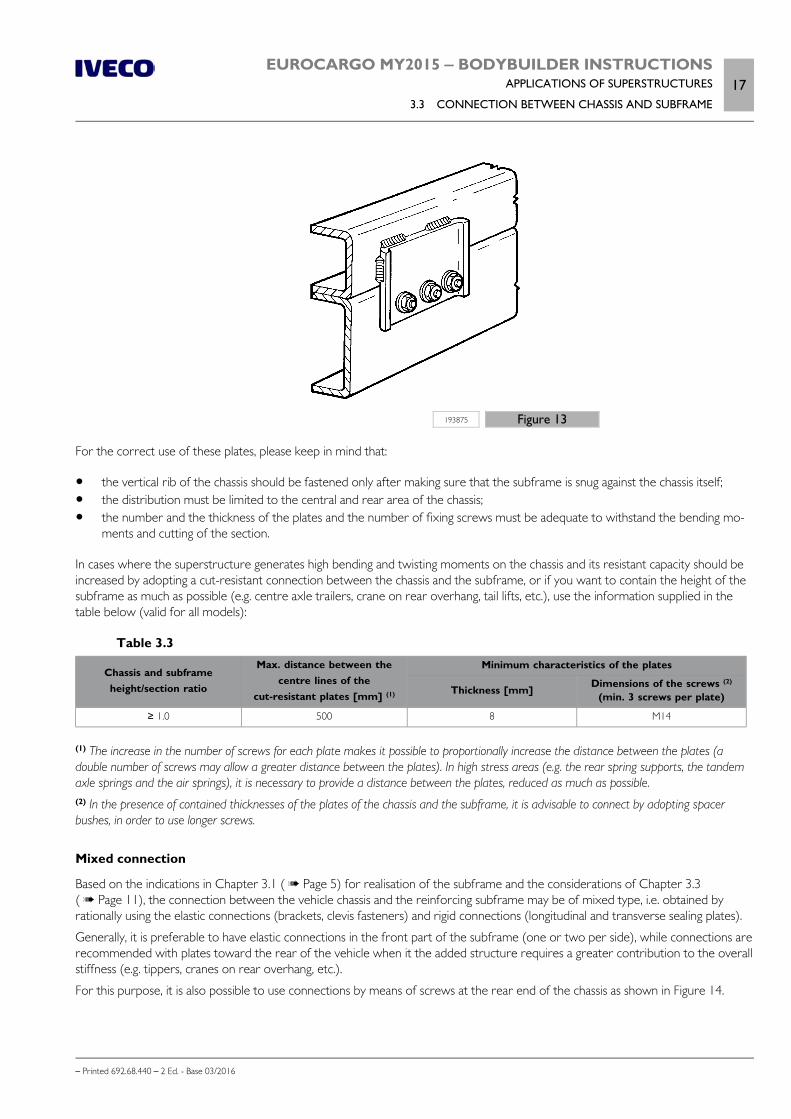
EUROCARGO MY2015 ‒ BODYBUILDER INSTRUCTIONSAPPLICATIONS OF SUPERSTRUCTURES
3.3 CONNECTION BETWEEN CHASSIS AND SUBFRAME17
– Printed 692.68.440 – 2 Ed. - Base 03/2016
193875 Figure 13
For the correct use of these plates, please keep in mind that:
the vertical rib of the chassis should be fastened only after making sure that the subframe is snug against the chassis itself; the distribution must be limited to the central and rear area of the chassis; the number and the thickness of the plates and the number of fixing screws must be adequate to withstand the bending mo-
ments and cutting of the section.
In cases where the superstructure generates high bending and twisting moments on the chassis and its resistant capacity should beincreased by adopting a cut-resistant connection between the chassis and the subframe, or if you want to contain the height of thesubframe as much as possible (e.g. centre axle trailers, crane on rear overhang, tail lifts, etc.), use the information supplied in thetable below (valid for all models):
Table 3.3
Chassis and subframeheight/section ratio
Max. distance between thecentre lines of the
cut-resistant plates [mm] (1)
Minimum characteristics of the plates
Thickness [mm] Dimensions of the screws (2)
(min. 3 screws per plate)
≥ 1.0 500 8 M14
(1) The increase in the number of screws for each plate makes it possible to proportionally increase the distance between the plates (adouble number of screws may allow a greater distance between the plates). In high stress areas (e.g. the rear spring supports, the tandemaxle springs and the air springs), it is necessary to provide a distance between the plates, reduced as much as possible.(2) In the presence of contained thicknesses of the plates of the chassis and the subframe, it is advisable to connect by adopting spacerbushes, in order to use longer screws.
Mixed connection
Based on the indications in Chapter 3.1 ( Page 5) for realisation of the subframe and the considerations of Chapter 3.3( Page 11), the connection between the vehicle chassis and the reinforcing subframe may be of mixed type, i.e. obtained byrationally using the elastic connections (brackets, clevis fasteners) and rigid connections (longitudinal and transverse sealing plates).
Generally, it is preferable to have elastic connections in the front part of the subframe (one or two per side), while connections arerecommended with plates toward the rear of the vehicle when it the added structure requires a greater contribution to the overallstiffness (e.g. tippers, cranes on rear overhang, etc.).
For this purpose, it is also possible to use connections by means of screws at the rear end of the chassis as shown in Figure 14.

18EUROCARGO MY2015 ‒ BODYBUILDER INSTRUCTIONSAPPLICATIONS OF SUPERSTRUCTURES
3.4 CONTAINER APPLICATION
– Printed 692.68.440 – 2 Ed. - Base 03/2016
193874 Figure 14
1. Subframe 2. Chassis
3. Clevis fasteners 4. Hardware for longitudinal and transverse containment
3.4 CONTAINER APPLICATION
Dimensions and centres of gravity
Check the correct load distribution and in particular, respect the indications regarding the height of the centre of gravity asprovided in Section 1 using suitable construction precautions and ensure that the transported load has maximum stability whilerunning.
Fixed bodies
The application on normal cab vehicles, valid only for road services, is normally made through a support structure consisting oflongitudinal and transverse profiles. The minimum Approximate sizes of the longitudinal sections are shown in Table 3.4.
Table 3.4
Model Wheelbase [mm] Section modulus Wx [cm3]of the minimum reinforcement section
60E, 65E, 75E, 80EL up to 3690 21
60E, 65E, 75E, 80EL and 3690 26
80E, 90E, 100E up to 3690 26
80E, 90E, 100E and 3690 36
110EL(1), 120EL(1), 120E, 140E, 150E, 160E up to 3690 40
110EL(1), 120EL(1), 120E, 140E, 150E, 160E and 3690 46
180E, 190EL all 57
Note For the dimensions of the profiles see Table 3.2.
Fastening is achieved through specially crafted brackets along the vertical rib of the side members; if such connections have notalready been specified by IVECO, they must be made according to the instructions in Paragraph "Connection with brackets"( Page 13). To achieve adequate longitudinal containment, in the case of connections with brackets or clamps it is good practiceto provide a rigid connection on the end of the rear overhang (one per side), obtained with screws or plates on the upper flange ofthe side member (see Figures 13 and 14).
In no other case should new holes be made on the wings of the main side members.
In cases in which the body uses elevated supports above the subframe (e.g. crossbars), it is necessary to suitably stiffen such sup-ports, to contain the longitudinal thrusts, as shown in Figure 15.

EUROCARGO MY2015 ‒ BODYBUILDER INSTRUCTIONSAPPLICATIONS OF SUPERSTRUCTURES
3.4 CONTAINER APPLICATION19
– Printed 692.68.440 – 2 Ed. - Base 03/2016
The front wall of the body must have the necessary strength and toughness to support the forces generated by the transportedload, in the case of sudden and high decelerations.
231180 Figure 15
1. Subframe 2. Brackets
3. Containment elements
For special equipment where a reinforcing section of moderate height is needed, the structure of the subframe can be integratedby brackets for the anchorage of the bodywork so as to affect the height across the section of the reinforcing longitudinal profile(see Figure 16).
In these cases, the rear wheel arches can be inserted into the equipment crankcase.
200445 Figure 16
In the case of self-supporting superstructures having the support backbone with the function of the subframe, the application of thepreviously indicated reinforcing profiles can be omitted.

20EUROCARGO MY2015 ‒ BODYBUILDER INSTRUCTIONSAPPLICATIONS OF SUPERSTRUCTURES
3.4 CONTAINER APPLICATION
– Printed 692.68.440 – 2 Ed. - Base 03/2016
Tipping bodies
The use of tipper bodies, rear and three sided, generally subjects the chassis to considerable stress.
Therefore, please observe the following indications.
1. The use of a stabilizer bar on all IVECO models for which it is an optional, is recommended.2. The subframe must be:
suitable for the type of vehicle and conditions of use, with appropriately sized crossbars and side members, with the rear end stiffened with boxing and crossbraces (see Figure 6 and Figure 7). The connections to the chassis must
be elastic (brackets or supports) at the front end, whereas the rear section requires stiff connections (cleat plates) (seeFigure 13) to allow the additional structure to contribute more effectively towards the rigidity of the assembly. Omegashelves can be used on vehicles on where these are originally fitted.
3. The rear tipping hinge must be fitted on the subframe; its position must be as near as possible to the rear support of therear suspension. In order not to affect the stability of the vehicle during tipping and to not excessively increase the stress onthe chassis, it must be respected the distances indicated in Figure 17. If for technical reasons this cannot be achieved, smallincreases may be permitted provided a higher strength subframe is used, in order to increase the rigidity of the rear end.Where long bodies are needed to transport large volumes, it is advisable to lengthen the wheelbase of the vehicle.
4. Great care must be given to the positioning of the lifting device both in terms of providing support of adequate strength andin order to correctly position the mountings. In any case, it is advisable to place the ram to the front of the centre of gravity ofthe body and payload so as to reduce the extent of the localized load.
5. In rear tipping it is recommended that a stabiliser is fitted to guide the container, particularly when the lifting cylinder is locatedbehind the cab.
6. The lifting device hinge must be mounted on the subframe. The useful volume in the body must conform with the maximumpermissible load on the axles, to the density of the material to be transported (a density mass of approximately 1600 kg/m3 isto be used for excavated material). In the case of transporting freight with a low density, the useful volume may be increasedwithin the limits established for the maximum height of the centre of gravity of the payload (plus the fixtures).
7. The bodybuilder must ensure the functioning and safety of all parts of the vehicle (e.g. the positioning of lights, drawbar coup-ling, etc.) and ensure that, following the addition of the structure, vehicle stability is guaranteed during tipping operations.
Note In vehicles equipped with air suspensions, the air springs must be completely discharged during the tipping operations. Also arrangefor a data plate which highlights these indications.

EUROCARGO MY2015 ‒ BODYBUILDER INSTRUCTIONSAPPLICATIONS OF SUPERSTRUCTURES
3.4 CONTAINER APPLICATION21
– Printed 692.68.440 – 2 Ed. - Base 03/2016
231181 Figure 17
1. Subframe 2. Brackets 3. Plates 4. Joint cover
A.Mechanical suspensions B. Air suspensions
Heavy-duty services
Table 3.5 shows which vehicles may be ordered for heavy-duty services and the indications for the main sections of the subframe.
For its dimensions, depending on the section modulus Wx, see table 3.2.
In the event of tippable superstructure assembly on vehicle chassis already equipped with brackets, replace them with longitudinaland transverse seal plates, in the segment between the front engine axle suspension support and the rear chassis end or apply addi-tional plates
Special attention must be paid to ensure adequate stability to the vehicle during the rear tipping of the body.
For vehicles that are transformed even through two rear axles, is prescribed that:
the box section for the longitudinal reinforcement section (see Figure 3.3) involves the segment between the rear wire andapprox. 1300 mm in front of the centre line of the two axles;
the diagonal cross bracings involve the area between the centre line of the double axle and the rear end of the chassis; the tipping support is to be positioned no more than 1400 mm from the centre line of the double axle.
Table 3.5
Model Wheel base (mm) Section modulus Wx [cm3] of the minimum section bar of the subframe(Yield point of the material used = 360 N/mm2)
60K, 65K, 75K T T 39
80K, 90K, 100K T T 46

22EUROCARGO MY2015 ‒ BODYBUILDER INSTRUCTIONSAPPLICATIONS OF SUPERSTRUCTURES
3.4 CONTAINER APPLICATION
– Printed 692.68.440 – 2 Ed. - Base 03/2016
Model Wheel base (mm) Section modulus Wx [cm3] of the minimum section bar of the subframe(Yield point of the material used = 360 N/mm2)
120K T T 45
140K T T 53
150K, 160K T T 89
180K3690 89
4815 105
Note For the dimensions of the profiles see Table 3.2.
Light-duty services
For these applications, we recommend using models with short wheelbases. The sections to be used are given in Table 3.6. It isunderstood that the vehicle must be used for light duty on roads which are in a good condition, to transport freight with a lowvolumetric mass.
In addition to respecting the general specifications indicated above, in order to give the vehicles the required rigidity and stability,the following must be observed:
carefully check the chassis specifications (suspension, chassis, number of axles) so as to select a vehicle suitable for the bodyand its intended use;
the rear end of the subframe must be stiffened using box-type sections, crossbraces, cleat plates etc.; the tipping supports must be placed as near as possible to the rear supports of the rear suspension; in cases of vehicles with a wheelbase greater than the short wheelbase envisaged, stiffen the rear tipping support so as to
contain sag and ensure good side stability during operation; the tipping angle should be between 35° and 45° and the usershould be informed that tipping should be done on as flat a surface as possible;
use the most rigid rear suspension available and the rear stabilizer bar; when parabolic rear springs are used, the rigidity can beincreased using flexible parts rubber elements which operate at static load;
for vehicles with rear air suspension, discharge the air from the springs during the tipping operation to allow the vehicle thegreatest stability of the suspensions while the material is descending; It is important that this operation takes place automaticallyusing the load lifting control whereas the resetting can be combined with the body lowering control;
Table 3.6
Model Section modulus Wx [cm3] of the minimum section bar of the subframe(Yield point of the material used = 360 N/mm2)
60E, 65E, 75E, 80EL 26
80E, 90E, 100E 39
110EL, 120EL 57
120E 31
140E 46
150E, 160E 46
180E, 190EL 69
Note For the dimensions of the profiles see Table 3.2.
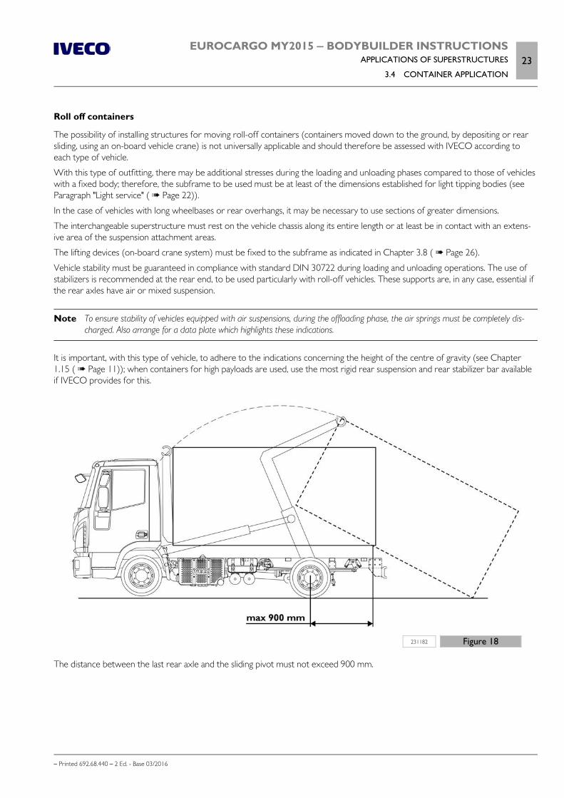
EUROCARGO MY2015 ‒ BODYBUILDER INSTRUCTIONSAPPLICATIONS OF SUPERSTRUCTURES
3.4 CONTAINER APPLICATION23
– Printed 692.68.440 – 2 Ed. - Base 03/2016
Roll off containers
The possibility of installing structures for moving roll-off containers (containers moved down to the ground, by depositing or rearsliding, using an on-board vehicle crane) is not universally applicable and should therefore be assessed with IVECO according toeach type of vehicle.
With this type of outfitting, there may be additional stresses during the loading and unloading phases compared to those of vehicleswith a fixed body; therefore, the subframe to be used must be at least of the dimensions established for light tipping bodies (seeParagraph "Light service" ( Page 22)).
In the case of vehicles with long wheelbases or rear overhangs, it may be necessary to use sections of greater dimensions.
The interchangeable superstructure must rest on the vehicle chassis along its entire length or at least be in contact with an extens-ive area of the suspension attachment areas.
The lifting devices (on-board crane system) must be fixed to the subframe as indicated in Chapter 3.8 ( Page 26).
Vehicle stability must be guaranteed in compliance with standard DIN 30722 during loading and unloading operations. The use ofstabilizers is recommended at the rear end, to be used particularly with roll-off vehicles. These supports are, in any case, essential ifthe rear axles have air or mixed suspension.
Note To ensure stability of vehicles equipped with air suspensions, during the offloading phase, the air springs must be completely dis-charged. Also arrange for a data plate which highlights these indications.
It is important, with this type of vehicle, to adhere to the indications concerning the height of the centre of gravity (see Chapter1.15 ( Page 11)); when containers for high payloads are used, use the most rigid rear suspension and rear stabilizer bar availableif IVECO provides for this.
231182 Figure 18
The distance between the last rear axle and the sliding pivot must not exceed 900 mm.
24EUROCARGO MY2015 ‒ BODYBUILDER INSTRUCTIONSAPPLICATIONS OF SUPERSTRUCTURES
3.5 TRACTOR FOR SEMI-TRAILER
– Printed 692.68.440 – 2 Ed. - Base 03/2016
3.5 TRACTOR FOR SEMI-TRAILER
The Eurocargo range does not include a version designed to tow trailers.
Conversion from a cab vehicle (in category N2 or N3) to a tractor is a complex task and includes work which, as indicated inChapter 1.3, requires specific IVECO authorisation.
This authorisation provides the technical specifications (structure, articulation, braking, electric system, etc.) that the Bodybuildermust observe, as well as the indications regarding the permitted masses and precautions for use.
3.6 TRANSPORT OF INSEPARABLE MATERIALS (TRAILER TRUCKS)
Not provided.
3.7 INSTALLATION OF TANKS AND LOOSE MATERIAL CONTAINERS
a) Installation with a subframe
The installation of tanks and containers is carried out, as a rule, using a suitable subframe.
The Approximate dimensions of the section to be used for the subframe are shown in Table 3.7.
Table 3.7 - Installation of tanks
Model Section modulus Wx [cm3] of the minimum section bar of the subframe(Yield point of the material used = 360 N/mm2)
60E, 65E, 75E, 80EL 46
80E, 90E, 100E, 110EL, 120EL 57
120E, 140E, 150E, 160E 89
180E, 190E 99
Note For the dimensions of the profiles see Table 3.2.
The assembly of tanks, or stiff torsional structures in general, must ensure sufficient and gradual flexibility of the chassis, in order toavoid high stress areas.
The use of flexible parts is recommended for the connections between the cistern body and the subframe (see Figure 19) in thefront part and rigid supports resistant to the longitudinal and transverse forces towards the rear part.

EUROCARGO MY2015 ‒ BODYBUILDER INSTRUCTIONSAPPLICATIONS OF SUPERSTRUCTURES
3.7 INSTALLATION OF TANKS AND LOOSE MATERIAL CONTAINERS25
– Printed 692.68.440 – 2 Ed. - Base 03/2016
193895 Figure 19
As previously mentioned, the stiff connections positioned in correspondence with the rear suspension mounts are more suitablefor transmitting forces directly to the suspension elements; elastic connections are to be arranged near the front suspension rearmount.
If this is not carried out, use suitably oversized longitudinal reinforcement sections with respect to those shown in Table 3.7.
When defining elastic connections, consider the rigidity of the chassis in the area where the connections are to be applied and thetype of functions for which the vehicle is intended.
b) Installation without a subframe
The installation of tanks directly on the chassis is possible under the following conditions:
the distance between the various rests must be established according to the load to be transmitted (approximately no morethan 1 m);
the rests must be made to uniformly distribute the load on a suitably wide surface and with bracing to contain longitudinal andtransverse forces.
anchoring must be sufficiently extended in width (approximately 600 mm) and arranged near suspension mounts (maximumdistance 400 mm).Specifically, the front anchoring flexibility must be suited to contain the necessary torsional movements of the chassis;
other anchoring solutions must be authorised by IVECO.

26EUROCARGO MY2015 ‒ BODYBUILDER INSTRUCTIONSAPPLICATIONS OF SUPERSTRUCTURES
3.8 INSTALLING A CRANE
– Printed 692.68.440 – 2 Ed. - Base 03/2016
193896 Figure 20
A suitable subframe which ensures good distribution of load and suitable torsional rigidity for the chassis-subframe assembly mustbe ensured by means of shear resistant connections when two or more separate containers are applied on the vehicle. A goodsolution consists in a stiff connection which joins the containers.
The maximum volume, the degree of filling of the container and the volumetric mass of the transported goods must be definedin observance of the axle weight limits. In the case of tanks and single containers made with separate compartments, the minimumratio between front axle weight and total fully loaded weight as well as the maximum loads on axles must be respected in all condi-tions of load (see Chapter 1.15 ( Page 11)).
In consideration of the type of outfit, the use of vehicles equipped with stabilizer bars is recommended and particular attentionshould be paid to limiting, as far as possible, the height of the overall centre of gravity (see Chapter 1.15 ( Page 11)); use of avehicle with stabilizer bars is recommended.
In tanks and containers for liquids, transverse and longitudinal partitions are to be used. In fact, if these are not completely full, thedynamic thrust which the liquid generates while the vehicle is in motion could negatively influence the vehicle's handling and resist-ance. Similarly, avoid dynamic loads on coupling devices for trailers and semi-trailers.
Follow the safety laws in force for containers intended to carry flammable liquids (see Chapter 2.18 ( Page 57)).
3.8 INSTALLING A CRANE
The selection of the crane must be made with due consideration to its characteristics and in relation to the performance of thevehicle.
The positioning of the crane and of the payload must be done within the load limits permitted for the vehicle. Installation of thecrane must be carried out in compliance with statutory requirements, national standards (e.g. CUNA, DIN) and international stand-ards (e.g. ISO, CEN) and verifying those required for the vehicle.
In order to ensure stability while the crane is operating, the stabilisers (hydraulic if possible)must be used and be in contact with the ground.

EUROCARGO MY2015 ‒ BODYBUILDER INSTRUCTIONSAPPLICATIONS OF SUPERSTRUCTURES
3.8 INSTALLING A CRANE27
– Printed 692.68.440 – 2 Ed. - Base 03/2016
In the case of vehicles equipped with air suspension, lifting with stabilisers should only be per-formed with the bellows inflated. This precaution is required to prevent the bellows from de-taching from the corresponding plates.
As a general rule, the installation of a crane requires the use of a suitable subframe, the construction of which must take into ac-count the general specifications (see Chapter 3.1 ( Page 5)), and with the dimensions of the sections given in Tables 3.8, 3.9 and3.11.
In those cases where no specific subframe is required (cases indicated with the letter A in the aforesaid tables) it is still necessary toprovide a suitable mounting base for the crane on the chassis (the length of the sections must be at least 2.5 times the width of thebase structure of the crane) in order to distribute the load and the stresses which develop during crane operation.
If the vehicle outfitting requires the use of a section with section modulus greater than that required for the crane (e.g. tipper), thissection may also be considered for the crane.
Special cases, whose MG value falls within the areas designated by letter "E" in the mentioned Table (or for higher values) must bechecked individually each time and must receive specific authorisation from IVECO.
200448 Figure 21
F = mass applied to crane extremity [kg]
L = horizontal distance between the load application point F and vehicle centre line [m]
P = mass of the crane at its centre of gravity [kg]
l = horizontal distance between centre of gravity of crane and vehicle centre line [m]
The Bodybuilder must, case by case, check the vehicle stability and take all necessary precau-tions for its correct and safe use. The crane manufacturer and the Bodybuilder are responsiblefor defining the type and number of stabilisers as well as selecting the subframe on the basis ofthe maximum static moment and the position of the crane.

28EUROCARGO MY2015 ‒ BODYBUILDER INSTRUCTIONSAPPLICATIONS OF SUPERSTRUCTURES
3.8 INSTALLING A CRANE
– Printed 692.68.440 – 2 Ed. - Base 03/2016
Crane behind cab
To arrange appropriate spaces behind the cab for the installation of the crane and the stabilisers, it is recommended that option75435 "Crane withdrawal" is considered.
The fastening of the reinforcement sections to the chassis must be carried out using the standard brackets (see Figure 22), sup-plementing them, if necessary, with other fasteners of elastic type (brackets or clamps) in order to keep the flexural and torsionalcharacteristics of the chassis as unchanged as possible.
The dimensions of the reinforcement sections to be used for this type of connection are shown in Table 3.8.
On vehicles for road use only, shearing resistant connections may be used for fastening the subframe to reduce the subframe sec-tion height (see Figure 3.23). The minimum reinforcement section dimensions for all these applications are given in Table 3.9.
The implementation of constant diameter sections for the entire length of the vehicle is recommended; section diameter reduc-tions (always gradual) are possible in the areas in which the bending moment induced by the crane assumed values correspondingto the boxes marked "A" in Tables 3.8 and 3.9.as possible.
The section of the crane subframe (see Figure 23) can be integrated towards the rear end with that envisaged for another possiblesuperstructure; the length "LV" must in no case be less than 35% of the wheelbase if the superstructure section diameter is smaller.
231183 Figure 22
1. Reinforcing profile 2. Connections
3. Crane connections 4. Stabilisers
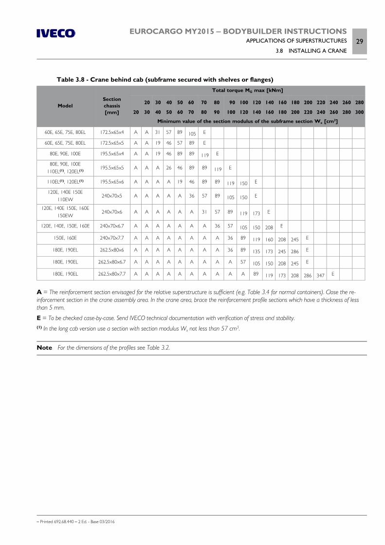
EUROCARGO MY2015 ‒ BODYBUILDER INSTRUCTIONSAPPLICATIONS OF SUPERSTRUCTURES
3.8 INSTALLING A CRANE29
– Printed 692.68.440 – 2 Ed. - Base 03/2016
Table 3.8 - Crane behind cab (subframe secured with shelves or flanges)
ModelSectionchassis[mm]
Total torque MG max [kNm]
20
20
30
30
40
40
50
50
60
60
70
70
80
80
90
90
100
100
120
120
140
140
160
160
180
180
200
200
220
220
240
240
260
260
280
280
300
Minimum value of the section modulus of the subframe section Wx [cm3]
60E, 65E, 75E, 80EL 172.5x65x4 A A 31 57 89 105 E
60E, 65E, 75E, 80EL 172.5x65x5 A A 19 46 57 89 E
80E, 90E, 100E 195.5x65x4 A A 19 46 89 89 119 E
80E, 90E, 100E110EL(1), 120EL(1)
195.5x65x5 A A A 26 46 89 89 119 E
110EL(1), 120EL(1) 195.5x65x6 A A A A 19 46 89 89 119 150 E
120E, 140E 150E110EW
240x70x5 A A A A A 36 57 89 105 150 E
120E, 140E 150E, 160E150EW
240x70x6 A A A A A A 31 57 89 119 173 E
120E, 140E, 150E, 160E 240x70x6.7 A A A A A A A 36 57 105 150 208 E
150E, 160E 240x70x7.7 A A A A A A A A 36 89 119 160 208 245 E
180E, 190EL 262.5x80x6 A A A A A A A A 36 89 135 173 245 286 E
180E, 190EL 262.5x80x6.7 A A A A A A A A A 57 105 150 208 245 E
180E, 190EL 262.5x80x7.7 A A A A A A A A A A 89 119 173 208 286 347 E
A = The reinforcement section envisaged for the relative superstructure is sufficient (e.g. Table 3.4 for normal containers). Close the re-inforcement section in the crane assembly area. In the crane area, brace the reinforcement profile sections which have a thickness of lessthan 5 mm.
E = To be checked case-by-case. Send IVECO technical documentation with verification of stress and stability.(1) In the long cab version use a section with section modulus Wx not less than 57 cm3.
Note For the dimensions of the profiles see Table 3.2.

30EUROCARGO MY2015 ‒ BODYBUILDER INSTRUCTIONSAPPLICATIONS OF SUPERSTRUCTURES
3.8 INSTALLING A CRANE
– Printed 692.68.440 – 2 Ed. - Base 03/2016
193899 Figure 23
Elastic connections between chassis and subframe may be needed to avoid excessive constraint on the chassis torsional movementfor application of crane on off-road vehicles on the front and middle parts (see Figure 11). In these cases, the crane is practicallyconnected to the subframe only, the dimensions of the longitudinal sections must therefore be suited to withstand the momentinduced when the crane is used.
The vehicle elements arranged behind the cab (e.g.: the gearbox controls, air filter, cab tilt locking device etc.) must be arranged toensure functionality; moving certain units such as battery boxes, fuel tanks etc. is allowed providing that the original connection typeis restored.
The body or equipment must normally be retracted to arrange the crane behind the cab.
In the specific case of tipping equipment, particular attention must be paid to arranging the mounts of the lifting device and thetipper rear hinges which must be as retracted as possible.
Table 3.9 - Cranes mounted behind cab (subframe secured with shear resistant plates)
ModelChassissection[mm]
Total torque MG max [kNm]
20
20
30
30
40
40
50
50
60
60
70
70
80
80
90
90
100
100
120
120
140
140
160
160
180
180
200
200
220
220
240
240
260
260
280
280
300
Minimum value of the section modulus of the subframe section Wx [cm3] (1)
60E, 65E, 75E, 80EL 172.5x65x4 A A A 31 46 57 89 105 119 E
60E, 65E, 75E, 80EL 172.5x65x5 A A A A 31 46 57 57 89 E
80E, 90E, 100E 195.5x65x4 A A A A 31 46 57 89 105 E
80E, 90E, 100E110EL(1), 120EL(1)
195.5x65x5 A A A A A 31 46 57 89 105 E
110EL(1), 120EL(1) 195.5x65x6 A A A A 19 36 46 57 89 E
120E, 140E, 150E110EW
240x70x5 A A A A A A A 21 36 89 105 E
120E, 140E 150E, 160E150EW
240x70x6 A A A A A A A A 31 57 89 E

EUROCARGO MY2015 ‒ BODYBUILDER INSTRUCTIONSAPPLICATIONS OF SUPERSTRUCTURES
3.8 INSTALLING A CRANE31
– Printed 692.68.440 – 2 Ed. - Base 03/2016
ModelChassissection[mm]
Total torque MG max [kNm]
20
20
30
30
40
40
50
50
60
60
70
70
80
80
90
90
100
100
120
120
140
140
160
160
180
180
200
200
220
220
240
240
260
260
280
280
300
Minimum value of the section modulus of the subframe section Wx [cm3] (1)
120E, 140E, 150E, 160E 240x70x6.7 A A A A A A A A 21 46 89 105 E
150E, 160E 240x70x7.7 A A A A A A A A 21 36 46 89 119 135 E
180E, 190EL 262.5x80x6 A A A A A A A A 21 31 57 89 105 135 173 208 245 E
180E, 190EL 262.5x80x6.7 A A A A A A A A A 21 46 89 89 135 150 173 208 245 E
180E, 190EL 262.5x80x7.7 A A A A A A A A A 21 36 89 89 135 150 173 208 245 E
A = The reinforcement section envisaged for the relative superstructure is sufficient (e.g. Table 3.4 for normal containers). Close the re-inforcement section in the crane assembly area. In the crane area, brace the reinforcement profile sections which have a thickness of lessthan 5 mm.
E = To be checked case-by-case. Send IVECO technical documentation with verification of stress and stability.(1) In the long cab version use a section with section modulus Wx not less than 57 cm3.
Note For the dimensions of the profiles see Table 3.2.
Should it be necessary to reduce the height of the subframe section (using shear resistant connections between the chassis andsubframe), combined sections may be used in place of the channel section as indicated in Table 3.10, on condition that the wingwidth and thickness are not less than those of the section recommended by IVECO (Table 3.9). The possibility of using materialswith superior mechanical characteristics requires verification of the total moment of resistance of the chassis plus subframe.
Since reducing the height of the section also reduces the torsional resistance, in the crane support area, the Bodybuilder musttake the necessary measures so as to ensure adequate torsional rigidity of the subframe: for this reason it is recommended thatsections with a height of less than 120 mm are not used. However, since such arrangements limit the torsional capacity of thevehicle chassis, their realization must be provided only for road use.
Table 3.10 - Crane behind cab (solutions with combined reinforcement sections)A B C D
R0.2 (N/mm2) (1) 320 320 360 360
Maximum reduction of the section height [mm] 40 60 100 120
LV (see figure 3.21)0.25 LH
or LA
0.35 LH
or LA
0.55 LH
or LA
0.60 LH
or LA
Example of combined sections in alternative to C 250x80x8 [mm] 210x80x8 190x80x8150x50x8 +
angle130x50x8 +
angle
Actual reduction in height [mm] 40 52 92 104

32EUROCARGO MY2015 ‒ BODYBUILDER INSTRUCTIONSAPPLICATIONS OF SUPERSTRUCTURES
3.8 INSTALLING A CRANE
– Printed 692.68.440 – 2 Ed. - Base 03/2016
204633 Figure 24
1. Normal boxed profiles 2. Gradual passage from the boxed section to the open
section
3. Special combined sections (connecting bracketchassis/subframe with thickness equal to section of thesubframe)
Crane at rear overhang
The subframe should extend for the entire length of the vehicle to the rear part of the cab; The dimensions of the longitudinalsections are shown in Table 3.11.
Considering the particular distribution of weights on the vehicle (load concentrated on overhang) and to ensure the necessarytorsional rigidity for good performance on the road and during the working phase of the crane, the subframe must be suitablystiffened in relation to the crane capacity. Therefore, the use of (see Chapter 3.2 ( Page 7)) box sections and brace assembliesmust be adopted in the areas of the rear suspension and for the entire rear overhang (measurement LV) - see Figure 25.
The passage between box section s and open sections must be well fitted as shown in Figure 3.3.
Shear resistant connections (a sufficient number of plates spaced at a maximum distance of 700 mm) must be used in the boxsection for fastening to the chassis, given that elastic fastenings are used on the front end. Check that the ratio between front axleand rear axle weight respects the limit defined for each vehicle under any load condition (see Chapter 1.15 ( Page 11)).
Considering that the necessary subframe rigidity depends on various factors (e.g. crane capacity, resting surface dimensioning,vehicle tare weight, chassis overhang), instructions valid for all situations cannot be given. For this reason bodybuilders shall, ifnecessary, proceed also by testing the vehicle's stability. If the test results show that rigidity is insufficient, the bodybuilder will adoptsuitable precautions so as to obtain correct realisation.
The rear overhang of the crane (measurement LU see Figure 25) must be limited to the extent possible (never exceed 50% of thewheelbase) to maintain good vehicle drive characteristics and acceptable stress regimes for the chassis.

EUROCARGO MY2015 ‒ BODYBUILDER INSTRUCTIONSAPPLICATIONS OF SUPERSTRUCTURES
3.8 INSTALLING A CRANE33
– Printed 692.68.440 – 2 Ed. - Base 03/2016
For vehicles with additional liftable rear axle, the minimum load on the front axle must be tested with the rear axle raised (in coun-tries where travelling with the vehicle in this condition is allowed) (see Chapter 1.15 ( Page 11)). The axle must be loweredwhile travelling if the minimum required value is not obtained.
231184 Figure 25
1. Subframe on the entire body length 2. Plates 3. Brackets
4. Crane connections 5. Stabilisers 6. Connecting corner
Table 3.11 - Crane at rear overhang (subframe secured with shear resistant plates)
ModelsChassissection[mm]
Total torque MG max [kNm]
20
20
30
30
40
40
50
50
60
60
70
70
80
80
90
90
100
100
120
120
140
140
160
160
180
180
200
200
220
220
240
240
260
260
280
280
300
Minimum value of the section modulus of the subframe section Wx [cm3]
60E, 65E, 75E, 80EL 172.5x65x4 A A A 23 32 57 110 110 135 E
60E, 65E, 75E, 80EL 172 5x65x5 A A A A 23 32 57 71 110 E
80E, 90E, 100E 195.5x65x4 A A A A 23 42 71 110 110 E
80E, 90E, 100E110EL(1), 120EL(1)
195.5x65x5 A A A A A 23 32 57 71 110 E
110EL(1), 120EL(1) 195.5x65x6 A A A A A 32 42 57 71 110 135 E
120E, 140E, 150E110EW
240x70x5 A A A A A A A A 23 71 110 E
120E, 140E, 150E; 160E150EW
240x70x6 A A A A A A A A 23 42 71 110 135 E
120E, 140E, 150E, 160E 240x70x6.7 A A A A A A A A 23 32 57 71 110 135
150E, 160E 240x70x7.7 A A A A A A A A 23 32 57 57 110 135 173 E
180E, 190EL 262.5x80x6 A A A A A A 23 23 23 42 71 110 173 222 246 246 E
180E, 190EL 262.5x80x6.7 A A A A A A A 23 23 42 57 110 135 173 222 246 E

34EUROCARGO MY2015 ‒ BODYBUILDER INSTRUCTIONSAPPLICATIONS OF SUPERSTRUCTURES
3.8 INSTALLING A CRANE
– Printed 692.68.440 – 2 Ed. - Base 03/2016
ModelsChassissection[mm]
Total torque MG max [kNm]
20
20
30
30
40
40
50
50
60
60
70
70
80
80
90
90
100
100
120
120
140
140
160
160
180
180
200
200
220
220
240
240
260
260
280
280
300
Minimum value of the section modulus of the subframe section Wx [cm3]
180E, 190EL 262.5x80x7.7 A A A A A A A A 23 32 42 71 110 135 173 222 222 246 E
A = The reinforcement section envisaged for the relative superstructure is sufficient (e.g. Table 3.4 for normal containers). In the cranearea, brace the reinforcement profile sections which have a thickness of less than 5 mm.
E = To be checked case-by-case. Send IVECO technical documentation with verification of stress and stability.(1) In the long cab version use a section with section modulus Wx not less than 57 cm3.
Note For the dimensions of the profiles see Table 3.2.
Should it be necessary to reduce the height of the subframe box section (using shear-resistant connections between the chassis andsubframe), combined sections may be used instead of the channel section as indicated in Table 3.12, provided that the width of thewing and thickness are not less than those of the section recommended by IVECO (Table 3.11). The possibility of using materialswith superior mechanical characteristics requires verification of the total moment of resistance of the chassis plus subframe.
Since reducing the height of the section also reduces the torsional resistance, in the crane support area, the Bodybuilder musttake the necessary measures so as to ensure adequate torsional rigidity of the subframe: for this reason it is recommended thatsections with a height of less than 120 mm are not used. However, since such arrangements limit the torsional capacity of thevehicle chassis, their realization must be provided only for road use.
Table 3.12 - Crane mounted on rear overhang (solutions with combined section reinforcement struc-tures)
B C D
R0.2 (N/mm2) (1) 320 360 360
Maximum reduction in section height [mm] 20 60 120
LV (see Figure 3.24) 0.60 LG 0.65 LG
Example of combined section structure used as alternative to a single 250x80x8 [mm] channelsection
200x80x8160x80x8 +
corner section140x80x8 +
corner section
Effective reduction in height [mm] 12 52 64
Removable cranes
The installation of removable cranes on the rear overhang may be carried out according to the specifications of the previous para-graph provided the type of fixing used between the crane and the subframe does not cause additional stress to the vehicle chassis.
Since the vehicle may be used with or without the crane (where permitted), it is recommended that the position of the payload ismarked on the superstructure.
If the vehicle retains its ability to tow a trailer, all regulations concerning the proper coupling of the vehicle must be observed.

EUROCARGO MY2015 ‒ BODYBUILDER INSTRUCTIONSAPPLICATIONS OF SUPERSTRUCTURES
3.9 INSTALLATION OF TAIL LIFTS35
– Printed 692.68.440 – 2 Ed. - Base 03/2016
3.9 INSTALLATION OF TAIL LIFTS
Note The installation of tail lifts must be carried out with due regard for the maximum permissible weights on the rear axles of thevehicle and of the minimum load established for the front axle (see Chapter 1.15 ( Page 11)). If this is not possible, the rearoverhang will have to be reduced.
The tail lift must be fastened with a structure that ensures appropriate weight distribution, especially in the case of specific outfitswith no subframe (e.g. box truck bodies, pick-up bodies with cross-members).
The dimensions of the sections to be used can be defined:
using Table 3.13 in the case of standard overhangs and stresses induced by the normally available tail lifts; using the indications provided in Figure 24, in the case of other overhangs and/or particular tail lifts (as for example, those with
a vertical rest position). .
In any event, particularly in those specific uses where there is not a suitable subframe, the fixing for the tail lift must be provided bya structure which enables the distribution of the stress on the chassis.
To ensure the necessary strength and rigidity, and especially in the case of overhangs exceeding 1500 mm, the connection betweenthe chassis and the subframe must be made using shear-resistant plates (spaced no further than 700 mm from one another) in thearea of the rear overhang, and must continue up to the front support of the rear suspension (see Figure 26).
Procedure for calculating the chassis bending moment during loading of tail lift
204638 Figure 26
WTL = Weight of tail lift
WL = Tail lift capacity
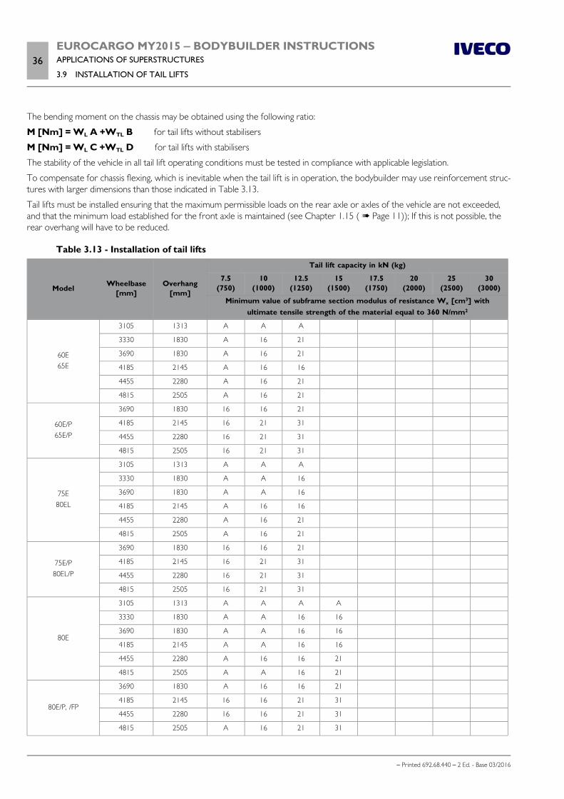
36EUROCARGO MY2015 ‒ BODYBUILDER INSTRUCTIONSAPPLICATIONS OF SUPERSTRUCTURES
3.9 INSTALLATION OF TAIL LIFTS
– Printed 692.68.440 – 2 Ed. - Base 03/2016
The bending moment on the chassis may be obtained using the following ratio:
M [Nm] = WL A +WTL B for tail lifts without stabilisers
M [Nm] = WL C +WTL D for tail lifts with stabilisers
The stability of the vehicle in all tail lift operating conditions must be tested in compliance with applicable legislation.
To compensate for chassis flexing, which is inevitable when the tail lift is in operation, the bodybuilder may use reinforcement struc-tures with larger dimensions than those indicated in Table 3.13.
Tail lifts must be installed ensuring that the maximum permissible loads on the rear axle or axles of the vehicle are not exceeded,and that the minimum load established for the front axle is maintained (see Chapter 1.15 ( Page 11)); If this is not possible, therear overhang will have to be reduced.
Table 3.13 - Installation of tail lifts
Model Wheelbase[mm]
Overhang[mm]
Tail lift capacity in kN (kg)
7.5(750)
10(1000)
12.5(1250)
15(1500)
17.5(1750)
20(2000)
25(2500)
30(3000)
Minimum value of subframe section modulus of resistance Wx [cm3] withultimate tensile strength of the material equal to 360 N/mm2
60E65E
3105 1313 A A A
3330 1830 A 16 21
3690 1830 A 16 21
4185 2145 A 16 16
4455 2280 A 16 21
4815 2505 A 16 21
60E/P65E/P
3690 1830 16 16 21
4185 2145 16 21 31
4455 2280 16 21 31
4815 2505 16 21 31
75E80EL
3105 1313 A A A
3330 1830 A A 16
3690 1830 A A 16
4185 2145 A 16 16
4455 2280 A 16 21
4815 2505 A 16 21
75E/P80EL/P
3690 1830 16 16 21
4185 2145 16 21 31
4455 2280 16 21 31
4815 2505 16 21 31
80E
3105 1313 A A A A
3330 1830 A A 16 16
3690 1830 A A 16 16
4185 2145 A A 16 16
4455 2280 A 16 16 21
4815 2505 A A 16 21
80E/P, /FP
3690 1830 A 16 16 21
4185 2145 16 16 21 31
4455 2280 16 16 21 31
4815 2505 A 16 21 31

EUROCARGO MY2015 ‒ BODYBUILDER INSTRUCTIONSAPPLICATIONS OF SUPERSTRUCTURES
3.9 INSTALLATION OF TAIL LIFTS37
– Printed 692.68.440 – 2 Ed. - Base 03/2016
Model Wheelbase[mm]
Overhang[mm]
Tail lift capacity in kN (kg)
7.5(750)
10(1000)
12.5(1250)
15(1500)
17.5(1750)
20(2000)
25(2500)
30(3000)
Minimum value of subframe section modulus of resistance Wx [cm3] withultimate tensile strength of the material equal to 360 N/mm2
90E100E
3105 1313 A A A A
3330 1830 A A A A
3690 1830 A A 16 16
4185 2145 A A A 16
4455 2280 A A 16 16
4815 2505 A A 16 21
90E/P, /FP100E/P, /FP
3690 1830 A 16 16 21
4185 2145 A 16 16 21
4455 2280 A 16 16 21
4815 2505 A 16 21 31
110EL120EL
3105 1313 A A A A
3330 1830 A A A A
3690 1830 A A A A
4185 2145 A A A 16
4455 2280 A A 16 16
4815 2505 A A 16 21
110EL/P120EL/P
3690 1830 A 16 16 21
4185 2145 A 16 16 21
4455 2280 A 16 16 21
4815 2505 A 16 21 31
120E
3105 1313 A A A A A A
3690 1740 A A A A A A
4185 2055 A A A A A A
4455 2190 A A A A A 16
4815 2460 A A A A 16 21
5175 2685 A A A A 16 21
5670 3000 A A A A 16 21
6570 2735 A A A 21 31 31
120E/P, /FP
4185 2055 A A A A 16 16
4455 2190 A A A A 16 21
4815 2460 A A A 16 16 21
5175 2685 A A 16 16 21 31
5670 3000 A A 16 16 21 31
6570 2735 A 16 21 31 31 46
140E
3105 1313 A A A A A A
3690 1740 A A A A A A
4185 2055 A A A A A A
4455 2190 A A A A A 16
4815 2460 A A A A 16 21
5175 2685 A A A A A A

38EUROCARGO MY2015 ‒ BODYBUILDER INSTRUCTIONSAPPLICATIONS OF SUPERSTRUCTURES
3.9 INSTALLATION OF TAIL LIFTS
– Printed 692.68.440 – 2 Ed. - Base 03/2016
Model Wheelbase[mm]
Overhang[mm]
Tail lift capacity in kN (kg)
7.5(750)
10(1000)
12.5(1250)
15(1500)
17.5(1750)
20(2000)
25(2500)
30(3000)
Minimum value of subframe section modulus of resistance Wx [cm3] withultimate tensile strength of the material equal to 360 N/mm2
140E5670 3000 A A A A A 21
6570 2736 A A A A 21 31
140E/P, /FP
4185 2055 A A A A 16 16
4455 2190 A A A A 21 21
4815 2460 A A A 16 21 21
5175 2685 A A A 16 16 21
5670 3000 A A A 16 21 31
6570 2735 A A 21 21 31 46
150E160E
3105 1313 A A A A A A
3690 1740 A A A A A A
4185 2055 A A A A A A
4455 2190 A A A A A A
4815 2460 A A A A A A
5175 2685 A A A A A A
5670 3000 A A A A A 21
6570 2735 A A A A 21 31
150E/P, /FP160E/P, /FP
4185 2055 A A A A A 16
4455 2190 A A A 16 16 21
4815 2460 A A A 16 16 21
5175 2685 A A A 16 16 21
5670 3000 A A A 16 21 21
6570 2735 A A 16 21 36 46
180E190EL
3690 1133 A A A A A A A
4185 1313 A A A A A A A
4590 1650 A A A A A A A
4815 1853 A A A A A A A
5175 2123 A A A A A A A
5670 2235 A A A A A A 31 57
6210 2235 A A A A A A 31 57
6570 2775 A A A A A A 31 57
180E/P190EL/P
3690 1133 A A A A A A A
4185 1313 A A A A A A A
4590 1650 A A A A A A A
4815 1853 A A A A A A A
5175 2123 A A A A A A A
5870 2235 A A A A A A 21 57
6210 2235 A A A A A A 21 57
6570 2775 A A A A A A 21 57
A = The reinforcement section envisaged for the relative superstructure is sufficient (e.g. Table 3.4 for normal containers).

EUROCARGO MY2015 ‒ BODYBUILDER INSTRUCTIONSAPPLICATIONS OF SUPERSTRUCTURES
3.9 INSTALLATION OF TAIL LIFTS39
– Printed 692.68.440 – 2 Ed. - Base 03/2016
Note For the dimensions of the profiles see Table 3.2.
Should it be necessary to reduce the height of the subframe (using shear-resistant connections between the chassis and subframe),combined sections may be used instead of the channel section (see Table 3.14), provided that the width of the wing and the thick-ness are not less than the corresponding dimensions of the section indicated in Table 3.13.
The possibility of using materials with superior mechanical characteristics requires verification of the total moment of resistance ofthe chassis plus subframe.
Table 3.14 - Installation of tail lifts (solutions with combined section reinforcement structures)A B C D
R0.2 (N/mm2) 320 320 360 360
Maximum reduction in section height [mm] 40 60 100 120
LV (see Figure 3.26) 0.50 LU 0.60 LU 0.80 LU 0.85 LU
LH (see Figure 3.26) 0.60 LU 0.65 LU 0.95 LU 1.00 LU
Example of combined section structure used as alternative to a single 250x80x8[mm] channel section
210x80x8 190x80x8150x50x8 +
corner section130x50x8 +
corner section
Effective reduction in height [mm] 40 52 92 104
Carefully assess any variations in the stability and attitude of the vehicle caused by suspensioncompression and chassis flexing during all stages in the operation of the tail lift. Always evaluatewhether using stabilisers is advisable even if their use is not rendered necessary by the stressessustained by the chassis.
The stabilisers, preferably hydraulically operated, are to be attached to the platform's supporting structures and must be used dur-ing all loading procedures with the tail lift.
When installing electro-hydraulic tail lifts, ensure that the capacity of the batteries and the power of the alternator are adequate(see Chapter 5.7 ).
In the case of vehicles with liftable third axle, the use of a tail lift when the third axle is lifted is only permitted using stabilisers.
The bodybuilder will be responsible for any modification to the under-run protection cross member, or for installing a differenttype (see Chapter 2.20 ( Page 61)), for preserving visibility of the rear lights, for the overhang angles, and for the positioning ofthe drawbar coupling as provided by the respective national requirements.
Base configuration for tail lifts
A base configuration (opt. 4113) for the installation of tail lifts is available on EUROCARGO models (see also Chapter 5.4 - Para-graph "Base configuration" ( Page 29)).
The base configuration consists of the following:
specific wiring connected to connector D of bulkhead connector and located under front grille; specific switch on dashboard for activating tail lifts (see Figure 27); connection to instrument cluster for activation of tail lift warning light (see Figure 27).

40EUROCARGO MY2015 ‒ BODYBUILDER INSTRUCTIONSAPPLICATIONS OF SUPERSTRUCTURES
3.9 INSTALLATION OF TAIL LIFTS
– Printed 692.68.440 – 2 Ed. - Base 03/2016
218356 Figure 27
1. Warning light 2. Activation switch
Before operating the tail lift, press the switch (2) on the central module of the dashboard.
The red warning light (1) on the cluster switches on to indicate that the tail lift is open and the vehicle cannot be set in motion.After completing the operation and closing the tail lift correctly, the driver must press the switch (2) again to deactivate the systemand enable engine start.
VEHH configuration for tail lifts
To attain compliance with the VEHH standard (defined by the VEHH association of European tail lift manufacturers), the VEHHconfiguration (opt. 75182) is also available (see also Chapter 5.4 - Paragraph "VEHH Configuration" ( Page 32)).
This solution offers cost advantages for bodybuilders as no modification is necessary to the electrical system.
The VEHH configuration consists of the following:
temporary rear under-run bar. This consists of a simple bar with side marker lights, tail lights and a licence plate mount whichthe bodybuilder must remove and replace with a definitive under-run bar with its own specific fasteners (see Figure 28);
specific rear light wiring for connection to definitive under-run bar; specific wiring with 7-pin DIN 72585 connector situated on right hand side member at end of rear overhang; specific switch on dashboard for activating tail lift and tail lift indicator lamp (as per opt. 4113).
Note Opt. 75182 is only available together with opt. 169 (without RUP).
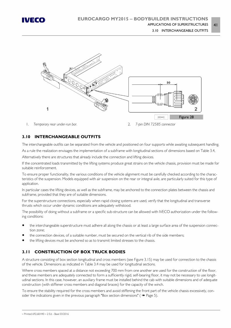
EUROCARGO MY2015 ‒ BODYBUILDER INSTRUCTIONSAPPLICATIONS OF SUPERSTRUCTURES
3.10 INTERCHANGEABLE OUTFITS41
– Printed 692.68.440 – 2 Ed. - Base 03/2016
200442 Figure 28
1. Temporary rear under-run bar. 2. 7-pin DIN 72585 connector
3.10 INTERCHANGEABLE OUTFITS
The interchangeable outfits can be separated from the vehicle and positioned on four supports while awaiting subsequent handling.
As a rule the realization envisages the implementation of a subframe with longitudinal sections of dimensions based on Table 3.4,
Alternatively there are structures that already include the connection and lifting devices.
If the concentrated loads transmitted by the lifting systems produce great strains on the vehicle chassis, provision must be made forsuitable reinforcement.
To ensure proper functionality, the various conditions of the vehicle alignment must be carefully checked according to the charac-teristics of the suspension. Models equipped with air suspension on the rear or integral axle, are particularly suited for this type ofapplication.
In particular cases the lifting devices, as well as the subframe, may be anchored to the connection plates between the chassis andsubframe, provided that they are of suitable dimensions.
For the superstructure connections, especially when rapid closing systems are used, verify that the longitudinal and transversethrusts which occur under dynamic conditions are adequately withstood.
The possibility of doing without a subframe or a specific sub-structure can be allowed with IVECO authorization under the follow-ing conditions:
the interchangeable superstructure must adhere all along the chassis or at least a large surface area of the suspension connec-tion zone;
the connection devices, of a suitable number, must be secured on the vertical rib of the side members; the lifting devices must be anchored so as to transmit limited stresses to the chassis.
3.11 CONSTRUCTION OF BOX TRUCK BODIES
A structure consisting of box section longitudinal and cross members (see Figure 3.15) may be used for connection to the chassisof the vehicle. Dimensions as indicated in Table 3.4 may be used for longitudinal sections.
Where cross members spaced at a distance not exceeding 700 mm from one another are used for the construction of the floor,and these members are adequately connected to form a sufficiently rigid, self-bearing floor, it may not be necessary to use longit-udinal sections. In this case, however, an auxiliary frame must be installed behind the cab with suitable dimensions and of adequateconstruction (with stiffener cross members and diagonal braces) for the capacity of the winch.
To ensure the stability required for the cross members and avoid stiffening the front part of the vehicle chassis excessively, con-sider the indications given in the previous paragraph "Box section dimensions" ( Page 5).

42EUROCARGO MY2015 ‒ BODYBUILDER INSTRUCTIONSAPPLICATIONS OF SUPERSTRUCTURES
3.12 TILT BEDS (BREAKDOWN RECOVERY)
– Printed 692.68.440 – 2 Ed. - Base 03/2016
3.12 TILT BEDS (BREAKDOWN RECOVERY)
Using a tilt bed typically subjects the chassis to considerable stress. The vehicle used should therefore be included in those specific-ally indicated for this application. These vehicles are listed in Table 3.5 together with the characteristics of the subframe profile tobe made.
Where a very long bed is necessary, it is preferable to use a vehicle that already has a sufficiently long wheelbase rather than createa long overhang.
The subframe must be suitably sized and stiffened at the rear with boxing and diagonal crossbraces (see Figure 5 and Figure 6).
Connections to the chassis must be elastic (brackets or supports) at the front end and stiff at the rear end (cleat plates, see Figure13) to allow the additional structure to contribute more effectively towards the rigidity of the assembly.
The rear tilt pivot must be installed on the subframe, and must be situated longitudinally as close as possible to the rear suspensionmount. To prevent the risk of the tilt bed compromising vehicle stability when operating and to avoid excessively increasing thestress sustained by the chassis, the distance between the tilt pivot and the rear suspension mount must comply with the specifica-tions given in Figure 17. Should this not be possible, the subframe profiles must be larger than normal and additional stiffening mustbe applied to the rear.
The position of the lift system must be defined with particular attention to protect the structural integrity of the rams and permit aprecise and practically location for the mountings. The recommended position is in front of the centre of gravity of the flatbed plusthe useful load, in order to reduce the size of the localised load.
The tow truck must not tow with a "forked" lifting device if the flatbed does not have a ground(counter-weight or other vehicle, in full compliance with the maximum permissible load on therear axle) which allows the optimal distribution of the loads on the axles to be maintained and,therefore, to prevent severe damage to the rear suspensions.
The bodybuilder must equip the vehicle appropriately to ensure stability during bed tilting manoeuvres.
All equipment and structures must comply with any applicable national legislation.
3.13 VEHICLES FOR COUNCIL, FIRE SERVICE AND SPECIAL USES
The outfitting of vehicles for municipal use (compactor trucks, road rollers; road cleaning vehicles) in many cases require:
the realization of a particularly robust subframe towards the rear and elastic type connections to the chassis towards the frontof the vehicle;
shortening of the rear overhang of the chassis.When very short overhangs are necessary, the chassis may be shortened immediately downstream of the rear spring support(or after the bar coupling in the case of air suspension), thus keeping intact the connection to the chassis of the crossbar ap-plied therein;
the vertical placement of the exhaust, behind the cab; the implementation of rear suspension with greater rigidity or realized with asymmetric springs; a new arrangement of the rear lights.
Do not use the reversing light switch, mounted on the gearbox, to activate functions thatrequire increased reliability and safety levels, (e.g. engine stop during reverse, on vehicles forurban waste collection from the personnel present on the rear footboards).

EUROCARGO MY2015 ‒ BODYBUILDER INSTRUCTIONSAPPLICATIONS OF SUPERSTRUCTURES
3.14 FRONT INSTALLATION OF SNOW PLOUGH ATTACHMENTS43
– Printed 692.68.440 – 2 Ed. - Base 03/2016
3.14 FRONT INSTALLATION OF SNOW PLOUGH ATTACHMENTS
The application of a snowplough attachment (blade or ploughshare) to the front part of the vehicle must be carried out using asuitable support structure, appropriately anchored to the core of the chassis side members and in observance of the prescriptionscontained in Chapter 2.2 ( Page 7).
Resistant structures which make use of struts or tie rods that act on the leaf spring and/or on relative supports is strictly prohibited.
It being understood that all the national prescriptions and standards that regulate the application of the aforesaid attachments mustbe observed, the possibility of using the original parts on the vehicle front (e.g. tow hook, footboard for cleaning the windscreen)must be safeguarded; otherwise the Bodybuilder must consider equivalent systems, in observance of the safety prescriptions.
Since in using the vehicle as a snowplough it must be ballasted and the maximum speed must be limited to 40 km/h, upon requestan increase in the maximum permitted load on the axle may be granted, up to the attainment of another value approved byIVECO.
Observance of the required load must be documented and guaranteed by the company that carries out the installation.
3.15 APPLICATION OF A WINCH
The application of a winch on the vehicle can be carried out at the following points:
on the front part of the chassis (frontal); on the chassis of the vehicle, behind the cab; between the side members of the vehicle, in a central or lateral position; on the rear part of the chassis.
The installation must be carried out so as not to alter the correct functioning of the vehicle's assemblies and components, in ob-servance of the maximum permitted axle limits and following the instructions of the winch manufacturer. The fastening of the idlermembers and assembly, must be carried out in observance of Chapter 2.2 ( Page 7), ensuring that the connection areas are notonly reinforced locally (see Chapter 2.17 ( Page 54)), according to the pull of the winch cable and particularly its transverse com-ponent, when the traction is oblique.
The installation of a winch in the area behind the cab must allow for the insertion of an auxiliary frame, of suitable dimensions andstructure (crossbars and diagonals for stiffening) for the winch capacity.
In the event of winches:
hydraulically controlled: previously installed hydraulic pumps can be used for other services (tipping bodies, cranes, etc.); mechanical: for transmission of the control it is necessary to follow the indications contained in Chapter 4.1 ( Page 5) and
4.2 ( Page 7); with worm screw control: the dimensioning of the drive parts must take into account the low efficiency of controls of this
type; electric: these are used for low power applications of brief duration, given the limited capacity of the vehicle battery and al-
ternator.
Observe the safety regulations.

44EUROCARGO MY2015 ‒ BODYBUILDER INSTRUCTIONSAPPLICATIONS OF SUPERSTRUCTURES
3.16 CONCRETE MIXER INSTALLATION
– Printed 692.68.440 – 2 Ed. - Base 03/2016
3.16 CONCRETE MIXER INSTALLATION
Concrete mixer applications may only be constructed on vehicles that are suitable for this application and indicated in Table 3.15,which provides the minimum specifications of the reinforcement sections and the effective capacity of the drum. The maximumpermissible weights for these vehicles may not be exceeded.
For the actual installation, besides observing the prescriptions imposed by the national Standards, the following also applies:
The concrete mixer must be equipped with a continuous steel subframe, in order to distribute concentrated loads as much aspossible. The chassis members may consist of sections which, while ensuring the same section modulus (Wx) and a moment ofinertia (Jx) not less than the values given in Table 3.15, make it possible to lower the centre of gravity of the added structure(e.g. box sections, or sections with upper wing turned outwards, see Figure 29);
Table 3.15 - Minimum dimensions of the subframe profile
ModelsApproximate capacity of
the drum [m3]Section modulus Wx [cm3] of the minimum reinforcement section
with a yield point of the material used = 360 N/mm2
140EK, 150EK, 160EK 3 ÷ 3.5 83
180EK 4 ÷ 5 92
Note For the dimensions of the profiles see Table 3.2.
91486 Figure 29
1. Chassis 2. Reinforcement section with normal channel
3. Reinforcement section with upturned upper wing 4. Relative drum positions
the subframe must be reinforced (e.g. crossbar, cross brace at rear part - see Chapter 3.2 - Paragraph "Crossbars"( Page 9)) to reduce stress on the vehicle chassis caused by the forces generated during vehicle operation (due to thespecific geometric configuration of the structure);
the connections (see Chapter 3.3 ( Page 11)) must only involve the two chassis and be realized so as to guarantee secureanchoring. For vehicles not originally equipped with plates, the use of plates is recommended for transverse and longitudinalcontainment, while the use of elastic connections should be limited to the front end of the subframe (see Figures 11 and 30);

EUROCARGO MY2015 ‒ BODYBUILDER INSTRUCTIONSAPPLICATIONS OF SUPERSTRUCTURES
3.16 CONCRETE MIXER INSTALLATION45
– Printed 692.68.440 – 2 Ed. - Base 03/2016
231185 Figure 30
1. Subframe 2. Brackets
3. Plates
The centre of gravity of the concrete mixing unit must be as close as possible to the front axle of the vehicle, without ofcourse exceeding the maximum permissible load on the axle itself.
Note To guarantee vehicle stability (particularly when cornering and on terrain with a transverse incline), the surging of the mass insidethe drum - during mixing drum operation - and the consequent transverse displacement of its centre of gravity must be taken intoaccount.
The additional motor for the mixing drum control requires a suitable suspension system.
Specific solutions concerning power take-offs (PTO), independent from the clutch and suitable for concrete mixer outfits, in addi-tion to the indications for the programming of the control apparatus, are contained in Section 4 ( Page 5).

46EUROCARGO MY2015 ‒ BODYBUILDER INSTRUCTIONSAPPLICATIONS OF SUPERSTRUCTURES
– Printed 692.68.440 – 2 Ed. - Base 03/2016

- Printed 692.68.440 – 2 Ed. - Base 03/2016
SECTION 4
POWER
TAKE-OFFS

- Printed 692.68.440 – 2 Ed. - Base 03/2016

EUROCARGO MY2015 ‒ BODYBUILDER INSTRUCTIONSPOWER TAKE-OFFS
Contents3
– Printed 692.68.440 – 2 Ed. - Base 03/2016
Contents
4.1 GENERAL SPECIFICATIONS . . . . . . . . . . . . . 5
Type of use . . . . . . . . . . . . . . . . . . . . . . . . . . 5
PTO transmission . . . . . . . . . . . . . . . . . . . . . . 6
4.2 PTO FROM GEARBOX . . . . . . . . . . . . . . . . . 7
4.3 POWER TAKE-OFF FROM TRANSFERBOX . . . . . . . . . . . . . . . . . . . . . . . . . . . . . . . . 8
4.4 POWER TAKE-OFF FROM DRIVE LINE . . . . . . 9
4.5 POWER TAKE-OFF FROM ENGINE . . . . . . . . . 9
Torque PTO from the front of the engine . . . . . . . 9
Torque PTO from the rear of the engine . . . . . . . 12
4.6 PTO MANAGEMENT . . . . . . . . . . . . . . . . . 13
Principles . . . . . . . . . . . . . . . . . . . . . . . . . . 14
Definitions . . . . . . . . . . . . . . . . . . . . . . . . . 15
PTO mode 0 (driving mode) . . . . . . . . . . . . . . 15
PTO modes 1, 2, 3 (configurable) . . . . . . . . . . . 16
4.7 STANDARD CONFIGURATIONS . . . . . . . . . 20
Conditions for activating/deactivating PTO . . . . . . 20
Intermediate engine speed regulator . . . . . . . . . . 22
Allison gearbox . . . . . . . . . . . . . . . . . . . . . . . 23
PTO use with vehicle in motion . . . . . . . . . . . . 23
Modifying stored intermediate engine speed valueNRES . . . . . . . . . . . . . . . . . . . . . . . . . . . . . . 24
Adjusting minimum rpm value . . . . . . . . . . . . . . 24
4.8 EM (EXPANSION MODULE) . . . . . . . . . . . . 24
Connections . . . . . . . . . . . . . . . . . . . . . . . . 26

4EUROCARGO MY2015 ‒ BODYBUILDER INSTRUCTIONSPOWER TAKE-OFFS
– Printed 692.68.440 – 2 Ed. - Base 03/2016

EUROCARGO MY2015 ‒ BODYBUILDER INSTRUCTIONSPOWER TAKE-OFFS
4.1 GENERAL SPECIFICATIONS5
– Printed 692.68.440 – 2 Ed. - Base 03/2016
POWER TAKE-OFFS
4.1 GENERAL SPECIFICATIONS
Different types of power take-offs (PTO) for motion withdrawal can be mounted for operating auxiliary units. Depending on thetype of use and performance required, the application can be fitted to:
the gearbox; the driveline; the front of the engine; the rear of the engine.
The characteristics and performances are given in the paragraphs which follow and in the relevant documentation which will besupplied upon request.
For the definition of the power necessary for the apparatus to be controlled, particularly when the values requested are high, theabsorbed power should also be considered during the drive transmission phase (5 to 10% for the mechanical transmissions, beltsand gears, and greater values for the hydraulic controls).
The choice of transmission ratio for the power take-off should be made so that the absorption of power occurs in a flexible engineoperating range; low speeds (below 1000 rpm) must be avoided to prevent irregular running.
The available power can be calculated in relation to the power take-off speed and the established torque.
P [HP] = M n i / 7023
P [kW] = M n i / 9550
P = Available power
M = Torque permitted for the power take-off
n =Engine revolutions per minute
i = Transmission ratio = PT output rpm / engine rpm
Type of use
The maximum torque take-off values indicated are with reference to continuous usage up to 60 seconds
Torque take-off values exceeding the maximum values indicated for occasional, limited usage (less than 30 s), must be approved ona case by case basis in relation to the type of application.
In the case of continuous usage exceeding 60 seconds, where the function is comparable to that of a stationary motor, the necessityof reducing torque take-off in relation to other, peripheral conditions (such as engine and transmission cooling necessities) mustalso be evaluated.
In the case of continuous usage which may lead to high oil temperatures, it is advisable to contact the PTO supplier to determinewhether the installation of a dedicated external oil circuit kit is necessary.
The scheduled take-off values are also applicable for uses which do not involve large variations of torque either in frequency ormagnitude.
In other cases, to avoid overload (e.g hydraulic pumps, compressors) it may be necessary to include the application of devices suchas clutches or safety valves.
During prolonged use, the gearbox oil temperature must not exceed 110 °C and the water tem-perature must not exceed 100 °C.
Not all types of power take-offs are suitable for continuous use; always follow the specific instruc-tions for the power take-off during operation (working times, breaks etc.).

6EUROCARGO MY2015 ‒ BODYBUILDER INSTRUCTIONSPOWER TAKE-OFFS
4.1 GENERAL SPECIFICATIONS
– Printed 692.68.440 – 2 Ed. - Base 03/2016
PTO transmission
In full compliance of the Manufacturer's transmission specifications, the kinematic forces from the power take-off to the relevantapparatus should be carefully considered (angles, rpm, moment) during the design phase as well as the dynamic behaviour in theinstallation phase.
This means that:
the dimensions should take into consideration the forces which might occur under maximum power and torque conditions; to obtain good kinetic forces, angles equal to the value of the ends of the shafts must be created (see Figure 1)and these val-
ues must not exceed 7°; solution Z is preferred to solution W due to the lower loads on the bearings of the power take-off and the equipment being
driven. When it is necessary to obtain a different transmission line with spatial inclinations according to angle φ (as shown inFigure 2), it is important to remember that the kinetic forces of the assembly can only be ensured if the intermediate sectionhas forks offset by the same angle φ and if equal conditions are respected between the angles at the extremities Χ1 and Χ2.
For transmissions employing multiple sections, please refer to the indications provided in Chapter 2.8 ( Page 37).
192350 Figure 1
Solution Z Solution W
91523 Figure 2
Electric system
On EUROCARGO Euro 6 vehicles, all PTOs - including any PTOs installed after purchase - are managed solely by the EM. There-fore vehicle order shall contain related OPT 4572.
The electrical and electronic VCM / EM systems (see Figure 1 - Section 5) provide innovative methods and processes for the con-trol of power take-offs, which are able to significantly improve safety and reliability. To activate, connect the PTO control switch topin connector 61071.
Pneumatic system

EUROCARGO MY2015 ‒ BODYBUILDER INSTRUCTIONSPOWER TAKE-OFFS
4.2 PTO FROM GEARBOX7
– Printed 692.68.440 – 2 Ed. - Base 03/2016
See the description in Chapter 2.15 ( Page 50).
4.2 PTO FROM GEARBOX
Drive may be taken from the layshaft via flanges or fittings located to the rear side or lower part of the gearbox.
Table 4.1 shows available torque levels and the ratios between output rpm and engine rpm for the different types of IVECO op-tional gearbox/PTO combinations.
IVECO must authorize high torque take-offs for sporadic use, according to the type of use.
The PTO must normally be used with the vehicle at a standstill and must be engaged and released with the clutch disengaged so asto avoid excessive stress on synchronisers.
When the PTO is used with the vehicle in motion, no gearshift must be carried out.
For gearboxes with a torque converter, the same power take-offs used on the mechanical gearboxes can be used; Note however,that when engine speed is lower than approximately 60% of the maximum value, the converter system is in the hydraulic operatingphase and that during this phase, depending on the absorbed power the power take-off rpm may fluctuate even if engine rpm isconstant.
Transmission PTO data
The following table shows the possible types of PTO.
The installation of a PTO post vehicle production requires the reprogramming of gearbox electronic control unit and the Expan-sion Module (EM), as well as interventions on the wiring system. Therefore, before proceeding, please carefully read Chapter 4.6“PTO Management” ( Page 13).
Re-programming of the electronic control units must be carried out in accordance with the instructions in the IVECO technicalmanual using exclusively the diagnostic instrument (available from IVECO dealers and authorised IVECO service centres), providingthe information regarding the specific PTO requirements.
Table 4.1 - PTOs on gearbox tested by IVECO
Gearbox PTO type Fitting position:Direction of
rotationTransmission ratios TORQUE (Nm)
6S7006AS700
NL/4C RH rear Anticlockwise 0.73 350
88Z/5 RH rear Anticlockwise 0.97 450
NL/1C (1) Centre rear Clockwise 0.57 600
6S8006AS800
NH/4C RH rear Anticlockwise 0.67 350
88ZI RH rear Anticlockwise 0.962 450
6S10006AS1000
NH/4C RH rear Anticlockwise 0.67 350
88ZI RH rear Anticlockwise 0.962 450
NH/1C Centre rear Clockwise 0.53 1000
6S1005+
PTO (2)
NL/10 Upper rear Anticlockwise 1.70 320
NL/10 Upper rear Anticlockwise 1.19 480
9S -75 TO
NH/4C RH rear Anticlockwise 1.08 430
N75/10C RH rear Anticlockwise 1.27 410
NH/1C Centre rear Clockwise 0.85 600
9S -1110
NH/4C Lower rear Anticlockwise 1.24 430
N109/10 Upper rear Anticlockwise 1.45 500
NH/1C Centre rear Clockwise 0.97 800
12AS -1210
NH4C Lower rear Anticlockwise 1.10 430
NH1C Centre rear Clockwise 1.22 800
NM AS/10C Rear right Anticlockwise 1.80 510

8EUROCARGO MY2015 ‒ BODYBUILDER INSTRUCTIONSPOWER TAKE-OFFS
4.3 POWER TAKE-OFF FROM TRANSFER BOX
– Printed 692.68.440 – 2 Ed. - Base 03/2016
Gearbox PTO type Fitting position:Direction of
rotationTransmission ratios TORQUE (Nm)
S2500P96A1 RH lateral Anticlockwise 0.985 270
P96A2 RH lateral Anticlockwise 1.264 250
S3000 17A1 LH lateral Anticlockwise 0.93 600
(*) Available torque with PTO at 1500 rpm(1) Sporadic operation < 1 hour of service
Direct application of pumps
In the case of pumps or other equipment applied directly on the power take-off without intermediate shafts, after ensuring thatthe dimensions of the pump or accessory leave an adequate safety margin with the chassis and powertrain unit, it is also necessaryto verify that the static and dynamic torques exerted by the mass of the pump and by the PTO are compatible with the structuralcharacteristics of the walls of the gearbox.
Furthermore, the value of the additional masses must be verified with regard to the inertial effects in order to avoid the inductionof resonance conditions in the engine unit within the field of operational engine.
Observe values in Table 4.1 for torque take-offs
4.3 POWER TAKE-OFF FROM TRANSFER BOX
On vehicles with all-wheel drive (4x4), PTOs may be installed on the transfer box.
The required take-off speed may be selected by engaging the appropriate gear.
Utilization is only envisaged for stationary vehicles (transfer box in neutral).
Note In the case of continuous usage which may lead to high oil temperatures, it is advisable to contact the PTO supplier to determinewhether the installation of a dedicated external oil circuit kit or a supplementary lubrication pump is necessary.
The maximum permissible take-off torque values are given as follows:
Table 4.2Transfer box type Max. torque [Nm] demand from transfer box Output type
TC 850 (1) 500flange Φ est. 90 mm4 holes Φ 8.1 mm
(1) Request optional power take-off. Installation of the PTO requires the replacement of internal components of the transfer box.
Note Only PTOs tested by IVECO may be installed.
EUROCARGO MY2015 ‒ BODYBUILDER INSTRUCTIONSPOWER TAKE-OFFS
4.4 POWER TAKE-OFF FROM DRIVE LINE9
– Printed 692.68.440 – 2 Ed. - Base 03/2016
4.4 POWER TAKE-OFF FROM DRIVE LINE
The authorisation for the application of a power take-off on the drive line downstream of the gearbox is issued after examinationof the complete documentation presented to the IVECO.
The power and torque values will be evaluated as each occasion arises on the basis of the conditions of use.
In general, the following should be noted:
The PTO engagement /disengagement must be performed with the gearbox in neutral. During engagement and disengage-ment the torque absorption by the Bodybuilder must be reduced to 0 Nm;
the power take-off rpm is dependent on the gear selected; the power take-off must be located immediately downstream of the gearbox; for vehicles with the drive line in two or more
sections, the power take-off may also be fitted at the flexible support between the first and second sections (respect the in-dications given in Chapter 2.8 ( Page 37));
the angles of the drive line on the horizontal plane and vertical plane must be kept as close as possible to the original values; masses and rigidity added to the drive line must not provoke a loss of balance or abnormal vibrations or damage the transmis-
sion drive line (from engine to axle) either during vehicle movement or during operation with the power take-off; the power take-off must be fixed to the chassis with its own suspension.
The transmission is an important part for the safety of the vehicle, and as such any interventionon the transmission must only be carried out by specialist companies approved by the manufac-turer.
Note Any intervention on the driveshaft carried out without prior authorisation from IVECO will immediately invalidate the warranty.
Note The power take-offs on the line of the universal joint cannot be used in conjunction with EuroTronic transmissions.
4.5 POWER TAKE-OFF FROM ENGINE
In general the use of these power take-offs is planned for apparatus applications requiring a continuous power supply.
Torque PTO from the front of the engine
The drive take-off from the front of the crankshaft occurs, for limited torque values to be drawn off (for example: air conditioningunits), by drive belt transmission; the use of coupling shafts is normally reserved for take-offs of a greater magnitude (e.g: municipaluse).
These uses, when not specifically planned, require significant modifications to the front part of the vehicle (modifications to theradiator, cab, bumpers etc.). Particular attention must therefore be paid:
to the system comprising additional masses and relative rigidity which must be flexibly disengaged from the crankshaft withregard to the torsional and flexural effects;
to the additional mass values and relative moments of inertia and to the distance of the centre of gravity of the masses fromthe centre line of the crankshaft main bearing carrier which must be kept to a minimum;
to avoiding a reduction in the radiator cooling capacity; to restoring the rigidity and resistance characteristics of the modified elements (crossbar, bumper, etc.); to avoid exceeding, during extended use, temperatures of the engine cooling fluid of over 100°C and engine oil temperature
(measured on the main duct of the pressure switch area) of 120 °C. If this is not possible, additional heat exchangers are re-quired.
Table 4.3 shows the values to be referred to for the pick up.
On the front part of the engine there is a pulley with 2 races from where power can be picked up.

10EUROCARGO MY2015 ‒ BODYBUILDER INSTRUCTIONSPOWER TAKE-OFFS
4.5 POWER TAKE-OFF FROM ENGINE
– Printed 692.68.440 – 2 Ed. - Base 03/2016
The position of the pick up and the size of the pulley is indicated in the following Figure.
91605 Figure 3
A Front section of the engine 1. Pulley for drive pick up

EUROCARGO MY2015 ‒ BODYBUILDER INSTRUCTIONSPOWER TAKE-OFFS
4.5 POWER TAKE-OFF FROM ENGINE11
– Printed 692.68.440 – 2 Ed. - Base 03/2016
91606 Figure 4
Table 4.3 - PTO on front part of engine
Engine nmaxMax. torque available
[Nm]
Maximum moment ofinertia
[kgm2] (1)
Maximum flexural moment[Nm] (2)
Tector4 cylinders 2500 400 0.015 100
6 cylinders 2500 400 0.015 100
(1) Maximum moment of inertia of rigidly fixed additional masses.(2) Maximum flexural moment due to radial forces relative to axis of first main bearing. The maximum flexural moment may be multipliedby the factor indicated in the table in relation to the angular position between the additional radial forces and the axis of the cylinders (zerois the top dead centre position with clockwise rotation).
Multiplication factor Angular position
1 225 ÷ 15
2 15 ÷ 60
3 60 ÷ 105

12EUROCARGO MY2015 ‒ BODYBUILDER INSTRUCTIONSPOWER TAKE-OFFS
4.5 POWER TAKE-OFF FROM ENGINE
– Printed 692.68.440 – 2 Ed. - Base 03/2016
Multiplication factor Angular position
4 105 ÷ 65
3 165 ÷ 210
2 210 ÷ 225
Torque PTO from the rear of the engine
Multipower PTO on engine fly-wheel
Certain models with a mechanical transmission (150E to 190EL with power outputs from 280 to 320 HP and 4x4) may beequipped with the optional IVECO Multipower PTO, which is capable of handling higher torques than other PTO types. This unit isfitted on the rear part of the engine and takes drive from the flywheel and is independent of the vehicle clutch drive; it is suitablefor use with the vehicle running and/or at a standstill (e.g. municipal applications, concrete mixers etc.).
Some precautions:
the PTO must be engaged only with the engine at a standstill (The Expansion Module offers a configuration that a safetydevice prevents engagement with the engine running in any case);
the unit may be disengaged with the engine running but only if the output torque is nil; the during engine must be started when no torque is being taken from shall be absorbed/consumed by the PTO.
To guarantee correct engagement, the static moment of connected units must not exceed 35Nm. According to the version of the connected units, it may be necessary to consider a clutchengageable by load (weight) in the transmission.
The main technical and dimensional characteristics are given in Figure 5 and in Table 4.4.
91524 Figure 5

EUROCARGO MY2015 ‒ BODYBUILDER INSTRUCTIONSPOWER TAKE-OFFS
4.6 PTO MANAGEMENT13
– Printed 692.68.440 – 2 Ed. - Base 03/2016
Table 4.4 - Technical specificationsRatio revolutions - rpm 1.29
Max. torque available 900 Nm
Output flange ISO 7646-120 x 8 x 10
Control pneumatic
Direction of rotation as engine
Weight 70 kg
Oil capacity 2 litres
Note When the PTO is engaged while the vehicle is being driven, always bear in mind that, depending on the multiplication ratio of thePTO itself (see Table 4.4), the pumps of connected assemblies may reach high rotational speeds (for example: an engine speed of1800 rpm corresponds to a pump speed of 2400 rpm).
4.6 PTO MANAGEMENT
Interventions that are carried out which do not comply with the following indications, may causeserious damage to the on-board systems (not covered by the contractual warranty) and couldcompromise the safety, reliability and correct functioning of the vehicle.
The ECUs illustrated in figure 6 are situated on the right hand side of the dashboard (lower part), in front of the passenger seat.
130574 Figure 6
1. ABS 2. VCM

14EUROCARGO MY2015 ‒ BODYBUILDER INSTRUCTIONSPOWER TAKE-OFFS
4.6 PTO MANAGEMENT
– Printed 692.68.440 – 2 Ed. - Base 03/2016
130574 Figure 6
3. ECAS 4. EM
5. Central locking
The EM ECU (where installed) manages the PTOs.
Principles
PTOs are activated electrically by means of a solenoid and the PTO engagement is checked by the PTO feedback signal. Configur-ing PTO modes involves programming the following ECUs: expansion module (EM) and vehicle control module (VCM).
The EM is able to drive up to three physical PTOs and controls their activation and the deactivation individually.
The PTO management functionality significantly simplifies conversion as it includes a number of safety and check functions.
The following two conditions must be met to permit activation of a PTO:
1. PTO is mechanically engaged;2. a PTO mode associated with the PTO must be recalled. See later for the definition of PTO mode.
Actions 1. and 2. may be performed with two separate commands (in the sequence 1. - 2.), or with a single command from thePTO switches on the central island console in the cab.
Generally, a PTO may be engaged with an electric command (which activates a solenoid valve).
Use the signals available on the Bodybuilder connectors (such as park brake engaged, vehiclestopped signal, reverse not engaged signal) to ensure correct PTO management and preventthe risk of drivetrain damage. These signals may only be acquired from Bodybuilder connectors.

EUROCARGO MY2015 ‒ BODYBUILDER INSTRUCTIONSPOWER TAKE-OFFS
4.6 PTO MANAGEMENT15
– Printed 692.68.440 – 2 Ed. - Base 03/2016
Definitions
Multiplex
This term describes the set of two control units: IVECO Body Controller (IBC3) and Chassis Electronic Module (MET).
They are connected to the other electronic systems (EDC, VCM, ECAS etc.) in the vehicle.
Information and messages are exchanged by means of Bus CAN lines.
PTO switch (PTOsw x, x = 1, 2, 3)
Located in the middle of the dashboard, used to request an action associated with a given PTO (e.g. depending on EM program-ming, PTO engage/disengage).
Since the EM and VCM are able to control up to three PTOs, there might be up to three switches (from PTOsw1 to PTOsw3)Each switch is connected to connector 61071 (pins 18, 19, 20).
Connector 61071
More detailed information is given in Chapter 5.2 ( Page 10).
PTO Mode x (x = 1, 2, 3)
After receipt of a request from a PTO switch via the respective input of connector 61071, a PTO mode implements a set of para-meters to ensure correct PTO operation.
The PTO Mode offers the possibility of requesting physical activation of the PTO. Possible selections: Yes/No (described below).
It is possible to activate up to three PTO modes simultaneously.
Physical PTO Activation
The physical activation of the PTO is an integral part of the PTO Mode and includes a set of parameters for mechanical engage-ment of a PTO.
Various parameter sets are available for the different PTOs (depending on the engine and transmission) These guarantee PTOengagement is compliant with the specific requirements.
The physical activation of the PTO can be customised by IVECO Service upon request It is stored in the EM control unit, as is theselection if intermediate speed control is requested from the VCM control.
PTO mode 0 (driving mode)
In this mode the vehicle can travel at a permitted maximum speed of up to 25 km/h in which, by pressing the RES button (CCcontrols) on the steering column switch, an intermediate engine speed of 900 rpm activates. It is possible to set a new intermediateengine speed value from those stored by the driver by pressing and holding the RES button for more than 5 seconds; In this case,reprogramming by IVECO Service is not necessary.
Note Above 25 Km/h, the speed regulator is activated automatically.
The max. number of rpm obtainable with the SET + and SET- buttons (CC controls) is identical for all modes (PTO mode 0, PTOmodes 1, 2 and 3) and can be configured via E.A.SY. only for PTO modes 1, 2 and 3.
The settings indicated in Table 4.5 cannot be modified for PTO mode 0 (driving mode).
Table 4.5Button Function
RES / OFFActivate/deactivate intermediate engine speed. The factory intermediate engine speedsetting is 900 rpm, which may be altered by the driver.
SET+ / SET- Increase/reduce active intermediate engine speed setting
16EUROCARGO MY2015 ‒ BODYBUILDER INSTRUCTIONSPOWER TAKE-OFFS
4.6 PTO MANAGEMENT
– Printed 692.68.440 – 2 Ed. - Base 03/2016
Button Function
Accelerator pedal Active
Max. rpm possible with SET+ button or accelerator pedal NLL(1) ÷ maximum rpm permitted by engine
Torque delivered Maximum specific engine torque
Conditions for deactivating intermediate engine speed function
Operation of the brake or clutch pedal CC Off activated engine brake operated lntarder operated PTO mode 0 deactivation speed 'NEUTRAL' not selected (automatic transmissions)
(1) NLL = rpm at idle speed.
PTO modes 1, 2, 3 (configurable)
Three different and independent PTO maps can be programmed by IVECO Service. Since the engine can only operate with onePTO mode at a time, the following priorities have been set:
PTO mode 3: high priority; PTO mode 2: medium priority; PTO mode 1: low priority; PTO mode 0: driving mode.
Note The Bodybuilder must observe this order of priority when managing the outfitting and interface outfitting. This is so as to avoidadditional costs for subsequent modifications to the wiring or reprogramming.
The following table shows the parameters making up a PTO mode. These parameters can only be programmed using an E.A.SY.diagnostics station at IVECO Service.
Table 4.6Parameter Possible values
Max. rpm possible with SET + button NSET_max (9) NLL ÷ Nmax (2)
Max. rpm possible with the accelerator pedal Nmax_acc
Engine rpm increment with SET + button 250 rpm for each second button is pressed
Engine rpm decrement with SET - button As above
Torque limiting (3) See table
Overspeed regulator curve gradient "High Idle" curve: vertical by default
Usage of CC buttons (RES / OFF / SET + / SET-) Active / inactive
Storing intermediate engine speed setting Steady (E.A.SY.)/spare (driver) (8)
"TIP" function. for SET + / SET- buttons (4) Active / inactive
PTO mode deactivated with brake or clutch (independently for each mode) (5) Active / inactive
Accelerator pedal Active / inactive
Recalling stored intermediate engine speed setting with RES after activation of PTOmode (7)
Active / inactive
Minimum rpm possible with SET - button. NSET _min (9) > 500 rpm
PTO mode deactivated from parking brake (6) Active / inactive
Vehicle speed limit above which PTO mode is deactivated (intermediate engine speedvZDR_max)
between 2 Km/h and 95 Km/h (programmable)

EUROCARGO MY2015 ‒ BODYBUILDER INSTRUCTIONSPOWER TAKE-OFFS
4.6 PTO MANAGEMENT17
– Printed 692.68.440 – 2 Ed. - Base 03/2016
Parameter Possible values
Permissible PTO speed range (1) NLL - Maximum rpm possible (2)
Abbreviations:
NLL minimum number of rpm
Nmax maximum number of rpm
N RES Stored intermediate engine speed value recalled by pressing RESUME or by activating a PTO mode
NSET_max maximum rpm obtainable with the SET+ button. This value is identical for all PTO modes
NSET_min minimum rpm value settable with SET - button
Nmax_acc max. rpm possible with accelerator pedal(1) Speed given refers to crankshaft, not PTO. The corresponding speed of the PTO must be calculated by multiplying by the gear reductionratio of the PTO.(2) The following rules apply for setting the intermediate engine speed value:
the value may never be set below NLL
the value may never exceed Nmax
In general, the following situation exists: NLL ≤ NSET _min ≤ Nres and Nres ≤ NSET_max ≤ Nmax. If this latter difference is not verified, theengine speed will be limited to Nmax.
(3) See following paragraph.(4) The "TIP" function (pressing briefly on the rocker button) allows the driver to gradually adjust the intermediate engine speed regulator orthe speed regulator setting speed, briefly pressing (< 1 sec) button SET + / SET-. The intermediate engine speed regulator can be activatedat speeds < 25 km/h; while pressing at speeds > 25 km/h activates the speed control. The variation for the intermediate engine speedregulator is 20 rpm for each "TIP" whereas for the speed regulator, it is 1 km/h for each TIP.(5) Active - PTO mode deactivates when service brake or clutch is operated
Disabled - PTO mode does not deactivate when the service brake or clutch is operated.
In PTO mode 0, the PTO mode is deactivated when service brake or clutch is operated.(6) Active - PTO mode deactivates when parking brake or clutch is operated
Disabled - PTO mode does not deactivate when parking brake or clutch is operated.
In PTO mode 0, the PTO mode is not deactivated when the parking brake is operated.(7) Active - engine speed automatically adjusts to NRES value set for the specific PTO mode.
Disabled - engine speed remains at previous value. Press RES button to set speed to NRES
(8) See paragraph "Modifying stored intermediate engine speed value NRES"(9) Values settable for PTO modes 1, 2 and 3 only.
Changes to the torque curve, maximum rotation speed and steepness of the maximum rotation speed lim-iter
For mechanical power take-off protection, it is possible to limit:
engine torque delivery as a protection against overload; engine rpm, as a protection against over-speed.
This is qualitatively shown by the diagram in Figure 7 by means of a toque/engine rpm curve (defined by 16 points), a horizontalsection (representing torque limitation) and a sloping section (representing over-rev adjustment).
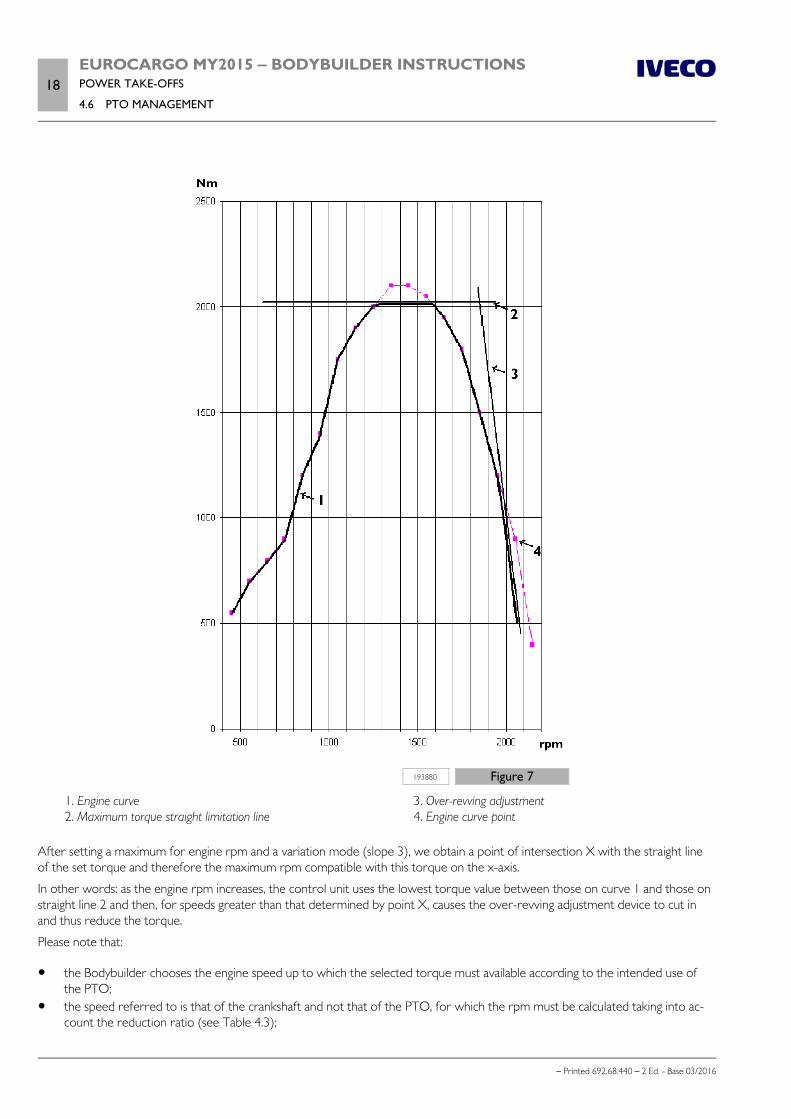
18EUROCARGO MY2015 ‒ BODYBUILDER INSTRUCTIONSPOWER TAKE-OFFS
4.6 PTO MANAGEMENT
– Printed 692.68.440 – 2 Ed. - Base 03/2016
193880 Figure 7
1. Engine curve 2. Maximum torque straight limitation line
3. Over-revving adjustment 4. Engine curve point
After setting a maximum for engine rpm and a variation mode (slope 3), we obtain a point of intersection X with the straight lineof the set torque and therefore the maximum rpm compatible with this torque on the x-axis.
In other words: as the engine rpm increases, the control unit uses the lowest torque value between those on curve 1 and those onstraight line 2 and then, for speeds greater than that determined by point X, causes the over-revving adjustment device to cut inand thus reduce the torque.
Please note that:
the Bodybuilder chooses the engine speed up to which the selected torque must available according to the intended use ofthe PTO;
the speed referred to is that of the crankshaft and not that of the PTO, for which the rpm must be calculated taking into ac-count the reduction ratio (see Table 4.3);

EUROCARGO MY2015 ‒ BODYBUILDER INSTRUCTIONSPOWER TAKE-OFFS
4.6 PTO MANAGEMENT19
– Printed 692.68.440 – 2 Ed. - Base 03/2016
the limitations (torque, intersection point and curve gradient) may be selected independently of one another; It is, however,advisable to set a combination;
these parameters may only be activated by IVECO.
193881 Figure 8
We will take a look at the example in Figure 8:
max. engine torque 600 Nm; standard power take-off operation is specified at 900 rpm; engine rpm must not exceed 1100 rpm; rpm must be calculated for all over-revving rpm regulator gradients; variable over-revving rpm regulator curve gradient: 0 - 0.2 rpm/Nm.
The corresponding power at 1100 rpm and a torque of 600 Nm gives (see equations in Chapters 4-1 ( Page 5)):
P = (600 x 1100) / 9550 = 69 kW = 94 HP
The overrevving regulator curve (gradient) depends on the specific application.
With stationary operation, a steep overrevving rpm adjustment curve is therefore generally sufficient, while in driving mode thismay give rise to rapid load changes (which could be a problem).
Therefore:
with regulator at 0.05 rpm/Nm (curve C in Figure 8), a torque of 600 Nm is available up to 1100 - (0.05 x 600) = 1070 rpm; with regulator at 0.1 rpm/Nm (curve B), the torque is available up to 1040 rpm; with regulator at 0.2 rpm/Nm (curve A), the torque is available up to 980 rpm.

20EUROCARGO MY2015 ‒ BODYBUILDER INSTRUCTIONSPOWER TAKE-OFFS
4.7 STANDARD CONFIGURATIONS
– Printed 692.68.440 – 2 Ed. - Base 03/2016
4.7 STANDARD CONFIGURATIONS
The following table contains the factory settings.
Table 4.7PTO Mode
Mode 0 Mode 1 Mode 2 Mode 3
Activation from 21-pin connector 61071No activation
necessaryPins 18 and 17
connectedPins 19 and 17
connectedPins 20 and 17
connected
Max. torque Max. engine torque Max. engine torque Max. engine torque Max. engine torque
Max. rpm possible with SET + button. NSET_max Maximum speed according to the maximum speed of the engine
Max. number of rpm value settable with SET - button. NSET_min Minimum speed according to the number of engine revs NLL default
Overspeed regulator curve gradientDependent on
rated curve0 rpm/Nm 0 rpm/Nm 0 rpm/Nm
Accelerator pedal Active Active Active disabled
Usage of CC buttons (RES / OFF / SET + / SET-) Active Active Active Disabled
Stored engine speed, NRES 900 rpm 900 rpm 1100 rpm 1300 rpm
Maximum vehicle speed above which PTO is deactivated vZDR_max 25 km/h 35 km/h 35 km/h 35 km/h
PTO mode disabled from brake or clutch Active Disabled Disabled Active
Recalling stored intermediate engine speed setting with RES afteractivation of PTO mode
Active Disabled Disabled Disabled
PTO mode deactivated from parking brake Active Active Active Active
PTO mode deactivated from engine brake Active Active Active Active
Note The rpm increment/decrement with the SET + / SET - buttons is 250 rpm
Conditions for activating/deactivating PTO
The conditions described below can be modified by the IVECO Service Network.
1) No PTO installed or PTO pre-installationOnly the engine speed programming is requested by the VCM.
The switches select the three speed modes.
Table 4.8PTO SW 1 PTO Mode 1 900 [tr/min]
PTO SW 2 PTO Mode 2 1100 [tr/min]
PTO SW 3 PTO Mode 3 1300 [tr/min]
2) PTO MultipowerOnly the engine speed programming is requested by the VCM.
The switches select the three speed modes (see Table 4-8).
Activation conditionsEngine status OFF
Pressure switch ST91 - pin closed
Vehicle status stationary
Coolant temperature < 120 [°C]

EUROCARGO MY2015 ‒ BODYBUILDER INSTRUCTIONSPOWER TAKE-OFFS
4.7 STANDARD CONFIGURATIONS21
– Printed 692.68.440 – 2 Ed. - Base 03/2016
Deactivation conditionsVehicle status not stationary (PTO3)
Vehicle speed > 25 [km/h]
Coolant temperature > 120 [°C]
3) PTO manual gearbox with electric engagement Activation conditions
Engine status ON
Clutch pedal state pressed
Vehicle status stationary
Coolant temperature < 120 [°C]
Deactivation conditionsEngine status OFF
Vehicle status not stationary (PTO3)
Vehicle speed > 25 [Km/h] (PTO1, PTO2)
Coolant temperature > 120 [°C]
4) PTO 1, 2 Allison gearbox Activation conditions
Engine status ON (500 < rpm < 900)
Gearbox status neutral
Vehicle status stationary or crawling speed (0 < v < 2 [Km/h])
Coolant temperature < 120 [°C]
Deactivation conditionsEngine status OFF
Vehicle speed > 20 [km/h]
Coolant temperature > 120 [°C]
5) PTO Transfer box Activation conditions
Clutch status not pressed
Engine status ON
Vehicle status stationary
Coolant temperature < 120 [°C]
Deactivation conditionsEngine status OFF
Coolant temperature > 120 [°C]

22EUROCARGO MY2015 ‒ BODYBUILDER INSTRUCTIONSPOWER TAKE-OFFS
4.7 STANDARD CONFIGURATIONS
– Printed 692.68.440 – 2 Ed. - Base 03/2016
Intermediate engine speed regulator
Maximum number of intermediate engine speed regulator speed setting possible with SET + button, N SET _ max
The maximum possible value for the intermediate engine speed regulator (CC) settable with the SET+ button is configurable. Thislimit is identical for all PTO modes (driving mode 0, PTO modes 1, 2 and 3).
TIP function
As already seen in Note (4) of Table 4.6, the TIP function, namely pressing and releasing (< 1 second) of the SET + / SET- button,allows a gradual variation of the intermediate engine speed regulator, or the speed control setting.
The intermediate engine speed regulator may be activated at speeds < V0 km/h (max. speed for PTO mode).
With speeds > V0 km/h, the speed regulator is activated.
For each "TIP", the variation for the intermediate engine speed regulator is 20 rpm while for the speed regulator, it is 1 km/h.
Pressing and holding the SET+ and SET- buttons for longer (>1 sec.) adjusts the intermediate engine speed or the speed control ismodified in a continuous manner. The effective rpm or the effective speed value at the time the SET + and SET are released aresaved as new requested values.
The TIP function for the SET+ and SET- buttons may be disabled. This configuration is applicable to all PTO modes simultaneously(driving mode PTO 0, PTO mode 1, 2 and 3). Disabling the TIP function limits the functionality of the speed regulator. Only use thisconfiguration after assessing the situation thoroughly.
Note This function is intended for setting hydraulic units.
Increase/decrease rpm value with SET+/SET-
Pressing and holding the SET+/SET- buttons for more than 1 sec. and disabling the “TIP” function (the “TIP” function is automatic-ally disabled by pressing and holding the SET+/SET- buttons) modifies the setting value for the intermediate engine speed regulator,as a result, the modification rate (engine rpm increment/decrement per second). The time interval necessary for this modification iscalculated with the following formula:
time required [s] = difference in rpm per second [rpm/s] / rpm increment per second [rpm/s/s]
Example: the intermediate engine speed setting must be increased from 800 rpm to 1800 rpm with button SET+. The difference inrpm is 1000 rpm, therefore:
with a modification rate of 250 rpm/s, the interval necessary is 1000/250 = 4 s.
Accelerator pedal enabled/disabled
In normal driving mode (PTO mode 0), the accelerator pedal is always enabled. In PTO modes 1, 2 and 3, the accelerator pedalmay be disabled. In this mode, the PTO speed regulator function of the engine ignores the accelerator pedal. If the acceleratorpedal is active in these modes, the engine speed may be increased using the pedal up to the maximum Nmax rpm value in effect.

EUROCARGO MY2015 ‒ BODYBUILDER INSTRUCTIONSPOWER TAKE-OFFS
4.7 STANDARD CONFIGURATIONS23
– Printed 692.68.440 – 2 Ed. - Base 03/2016
Allison gearbox
With the Allison gearbox power take-off engagement is coordinated by the gearbox control unit and the Expansion Module con-trol unit and is activated as follows:
PTO activation request (the gearbox control unit verifies that the internal conditions necessary for performing the operationsafely are met: engine speed <900 rpm and transmission output speed <250 rpm);
solenoid valve activation by the control unit for PTO engagement; If the PTO and handbrake are engaged at the same time, the gearbox automatically shifts to neutral and the PTO is activated
in mode PTO2 (the relay of the relay carrier plate of the gearbox control unit, on the rear wall of the cab is powered); verification of safe PTO operating conditions (transmission output speed <300 rpm).
Before activating the PTO, the transmission control unit verifies a number of different parameters (engine speed <900 rpm andtransmission output speed <250 rpm). If all the internal transmission conditions required are met, the Allison transmission controlunit automatically engages the PTO. Any limitations applicable for the active PTO mode (final speed, maximum torque etc.) are alsovalid during the entire engagement process.
PTO use with vehicle in motion
If no limitations are required (e.g. torque limiting, max. rpm etc.) while a PTO is engaged, it is not necessary to activate a PTOmode.
In this case, the engine power available for driving the vehicle is reduced (as part of the power is absorbed by the superstructure),which may lead to difficulties when setting off from a standstill. In certain specific applications (concrete mixer, refuse collectionetc.), this problem may be resolved by increasing the idle speed value (”low idle”).
If limitations are necessary (e.g. torque limiting, max. rpm etc.), a PTO mode must be activated.
Especially with the vehicle in motion, always bear in mind that activating a PTO mode also re-calls the stored intermediate engine speed, which may result in unrequested vehicle accelera-tion. The bodybuilder must ensure the safety of the vehicle during operation.
Engagement or disengagement depend on the type of PTO used and on the Bodybuilder requirements.
For example: vehicle driving (up to max. 30 km/h) with increased engine speed and PTO engaged.
Certain applications (tipper beds, concrete mixers, refuse collection etc.) also require higher engine speeds for manoeuvring. Thismay be achieved as follows:
storing intermediate engine speed settingNRES number
fixed programming
Intermediate engine speed setting NRES
numberdefined by bodybuilder
Intermediate speed disengagement deactivating with clutch or brake
accelerator pedal Active
CC buttons: disabled
In this case, engine speed may still be controlled solely from the accelerator pedal, between the stored intermediate engine speedvalue NRES and the maximum rpm value Nmax. When vZDR_max is reached, the intermediate engine speed regulator and the increasedengine speed function are deactivated.

24EUROCARGO MY2015 ‒ BODYBUILDER INSTRUCTIONSPOWER TAKE-OFFS
4.8 EM (EXPANSION MODULE)
– Printed 692.68.440 – 2 Ed. - Base 03/2016
Modifying stored intermediate engine speed value NRES
The intermediate engine speed value may be set individually for each PTO mode. There are two different methods for setting thisvalue:
1. Fixed programming (E.A.SY.)This method is not available for PTO mode 0 (driving mode); modification is only possible by reprogramming with E.A.SY. atIVECO Service.
2. Free programming (by the driver)Adjust the intermediate engine speed setting as follows: activate the PTO mode for which you intend to modify the intermediate engine speed setting set the desired rpm value with the SET+ / SET- buttons press and hold CC Resume for more than 5 seconds
Adjusting minimum rpm value
The procedure for setting the idle speed consists of three steps and may only be performed with a warm engine:
1. Enabling idle speed adjustmentWith the engine running at idle speed: press the service brake (and hold until the adjustment procedure is complete); press and hold the RES button for more than 3 seconds and then release it; the engine speed immediately adjusts to idle.
2. Adjusting idle speed rpm value
Press the CC SET+ or CC SET- buttons to adjust the idle speed value in steps of 20 rpm.
3. Storing the idle speed rpm valuePress and hold CC RES again (for more than 3 seconds).
Idle speed control is only possible in PTO modes in which the CC buttons are active or if inter-mediate engine speed control is deactivated with the brake or clutch.
4.8 EM (EXPANSION MODULE)
The optional 4572, EM (Expansion Module), is available for EUROCARGO Euro 6; Furthermore the optional 0384 offers a CANopen interface for Bodybuilder in addition.
The EM control unit is used for the electronic management of the PTO and for special applications indicated by the EN1501 stand-ard for waste collection vehicles (opt. 6821); As an option it provides a CANopen interface with special gateways for Bodybuilder,in accordance with standard CiA 413 Truck Gateway.
The wiring diagram for the Expansion Module hardware is shown in Figure 9, and the block diagram of the hardware structure isshown in Figure 10.

EUROCARGO MY2015 ‒ BODYBUILDER INSTRUCTIONSPOWER TAKE-OFFS
4.8 EM (EXPANSION MODULE)25
– Printed 692.68.440 – 2 Ed. - Base 03/2016
204641 Figure 9
1. PTO switch 2. EM control unit 3. Instrument panel 4. PTO solenoid valve control
5. PTO Pressure switch resp. Bodybuilder PTO engagementconsent
6. PTO return signal 7. Total/rear PTO 8. Lateral PTO

26EUROCARGO MY2015 ‒ BODYBUILDER INSTRUCTIONSPOWER TAKE-OFFS
4.8 EM (EXPANSION MODULE)
– Printed 692.68.440 – 2 Ed. - Base 03/2016
204642 Figure 10
To ensure PTO activation and representation on the display of the dashboard, the connections on ST91, ST92 and ST93 must beused as indicated in Tables 4.9 and 4.10.
The predefined conditions set for the EUROCARGO Euro 6 are described in Chapter 4.7 ( Page 20).
Connections
Table 4.9 - PTO mode requestPTO 1 Connector 61071 - pin 18
PTO 2 Connector 61071 - pin 19
PTO 3 Connector 61071 - pin 20
To carry out request, close the pins on ground of pin 17.
Table 4.10 - IN / OUT: ST91, ST92, ST93Pin 1 PTO feed-back
Pin 2 PTO actuator (solenoid valve control)
Pin 3Pressure switch (PTO Multipower)
or consent to PTO engagement external Bodybuilder
Pin 4 Ground

- Printed 692.68.440 – 2 Ed. - Base 03/2016
SECTION 5
ELECTRONIC
SUB-SYSTEMS

- Printed 692.68.440 – 2 Ed. - Base 03/2016

EUROCARGO MY2015 ‒ BODYBUILDER INSTRUCTIONSELECTRONIC SUB-SYSTEMS
Contents3
– Printed 692.68.440 – 2 Ed. - Base 03/2016
Contents
5.1 ELECTRONIC SYSTEMS . . . . . . . . . . . . . . . . 5
Position of electronic control units . . . . . . . . . . . 5
5.2 BODYBUILDER CONNECTORS . . . . . . . . . . 10
CONNECTORS IN CAB . . . . . . . . . . . . . . . . 11
CONNECTORS ON CHASSIS . . . . . . . . . . . . . 24
TRAILER CONNECTORS . . . . . . . . . . . . . . . . 26
5.3 FMS (FLEET MANAGEMENT SYSTEM) . . . . . . 28
5.4 CONFIGURATIONS FOR TAIL LIFTS . . . . . . . 29
Base configuration . . . . . . . . . . . . . . . . . . . . . 29
Base configuration with additional ECAS remotecontrol (opt. 4115) . . . . . . . . . . . . . . . . . . . . 31
VEHH configuration (opt. 75182) . . . . . . . . . . . 32
5.5 OPERATOR’S FOOTBOARD . . . . . . . . . . . . 34
5.6 ELECTRICAL CIRCUIT MODIFICATIONS . . . . 35
General information . . . . . . . . . . . . . . . . . . . . 35
Wiring harness length . . . . . . . . . . . . . . . . . . . 35
Disconnecting electronic control units . . . . . . . . 35
Repositioning electronic control units . . . . . . . . . 36
5.7 ELECTRICAL SYSTEM: OPERATIONS . . . . . . . 36
General information . . . . . . . . . . . . . . . . . . . . 36
Precautions for work on the system . . . . . . . . . . 36
Precautions for work on the chassis . . . . . . . . . . 37
Ground points . . . . . . . . . . . . . . . . . . . . . . . 37
Electromagnetic comparability . . . . . . . . . . . . . 40
Reception/transmission systems . . . . . . . . . . . . 41
5.8 ADDITIONAL EQUIPMENT . . . . . . . . . . . . . 44
Additional batteries . . . . . . . . . . . . . . . . . . . . 44
Additional alternators . . . . . . . . . . . . . . . . . . . 45
Additional electrical units . . . . . . . . . . . . . . . . 46
Drawing current . . . . . . . . . . . . . . . . . . . . . . 47
Additional circuits . . . . . . . . . . . . . . . . . . . . . 52
Modifying wheelbase and overhang . . . . . . . . . . . 53
Side Marker Lamp installation . . . . . . . . . . . . . . 53
5.9 SPECIFICATIONS FOR VERSIONS FROM"COWLED" . . . . . . . . . . . . . . . . . . . . . . . . . . . 55
Electronic safety devices . . . . . . . . . . . . . . . . . 55

4EUROCARGO MY2015 ‒ BODYBUILDER INSTRUCTIONSELECTRONIC SUB-SYSTEMS
– Printed 692.68.440 – 2 Ed. - Base 03/2016

EUROCARGO MY2015 ‒ BODYBUILDER INSTRUCTIONSELECTRONIC SUB-SYSTEMS
5.1 ELECTRONIC SYSTEMS5
– Printed 692.68.440 – 2 Ed. - Base 03/2016
ELECTRONIC SUB-SYSTEMS
5.1 ELECTRONIC SYSTEMS
The innovative Multiplex electronic system (or "Easy Mux" on the Eurocargo) electronically manages and controls the vehicle sub-systems via CAN lines.
For a better understanding of this system, the location (see Figure 1) and the functions of the main control units installed on thevehicle are provided below.
It is not permitted to connect devices or electrical circuits directly to the control units. Only theconnectors or special interfaces listed in Chapter 5.2 may be used.
Position of electronic control units
228119 Figure 1
1. EBS Electronic Brake System 2. VCM Vehicle Control Module
3. ECAS Electronic Control Air Suspension (Electronicallycontrolled air suspension)

6EUROCARGO MY2015 ‒ BODYBUILDER INSTRUCTIONSELECTRONIC SUB-SYSTEMS
5.1 ELECTRONIC SYSTEMS
– Printed 692.68.440 – 2 Ed. - Base 03/2016
228119 Figure 1
4. EM Expansion Module 5. Central locking 6. IBC3 IVECO Body Controller 7. IC Instrument Cluster (Instrument panel) 8. Chassis Electronic Module MET 9. Allison Transmission control unit 10. Airbag ECU 11. DDM Drive Door Module 12. EDC Engine Diesel Control
13. Steering Shaft ECU 14. Radar ACC Adaptive Cruise Control (Adaptive speed
control) / AEBS Autonomous Emergency Braking System(Independent emergency braking system)
15. LDWS Lane Departure Warning System (Lane changewarning system)
16. PDM Passenger Door Module 17. UTP Unified Telematic Platform (Unified telematic plat-
form)
IVECO Body Controller (IBC3)
The Body Controller is the central control unit for the vehicle, and, together with the MET control unit, constitutes the Easy Muxsystem.
The two control units communicate with each other through the CAN line to process the signals (input and output), crucial for theinteraction between the vehicle's individual systems.

EUROCARGO MY2015 ‒ BODYBUILDER INSTRUCTIONSELECTRONIC SUB-SYSTEMS
5.1 ELECTRONIC SYSTEMS7
– Printed 692.68.440 – 2 Ed. - Base 03/2016
The Body Controller is located in the cab, below the dashboard in front of the passenger seat. The fuses and relays and also housedhere.
197232 Figure 2
Bulkhead coupling (passage of electrical wiring)
The subsystems fitted on the chassis are connected to the control units in the cab via the "bulkhead connector" which is the inter-face for the electric connectors.
The bulkhead connector is located under the hood.

8EUROCARGO MY2015 ‒ BODYBUILDER INSTRUCTIONSELECTRONIC SUB-SYSTEMS
5.1 ELECTRONIC SYSTEMS
– Printed 692.68.440 – 2 Ed. - Base 03/2016
228988 Figure 3
Chassis Electronic Module (MET)
The Electronic Chassis Module (MET) transmits and receives information to and from all the components and sensors located onthe chassis (e.g. lighting devices, brake system sensors, differential lock sensors, etc.)
Information is transmitted via the Body Controller to the respective recipient vehicle systems.
The MET is situated inside the left hand chassis side member, in the battery housing area.

EUROCARGO MY2015 ‒ BODYBUILDER INSTRUCTIONSELECTRONIC SUB-SYSTEMS
5.1 ELECTRONIC SYSTEMS9
– Printed 692.68.440 – 2 Ed. - Base 03/2016
108904 Figure 4
Expansion Module (EM)
The EM (Expansion Module) control unit, located in the cab control unit compartment (passenger side), controls the power take-offs and makes it possible to carry out complex applications such as:
control of the transmission (gearbox) from external sources (TC1 message); control of the engine from external sources such as engine speed requests and limits, vehicle speed limit, start up and engine
stop; safety rules for waste collection applications; optimisation of the brake system for waste collection applications; control of additional lights; interface with CAN_open network.
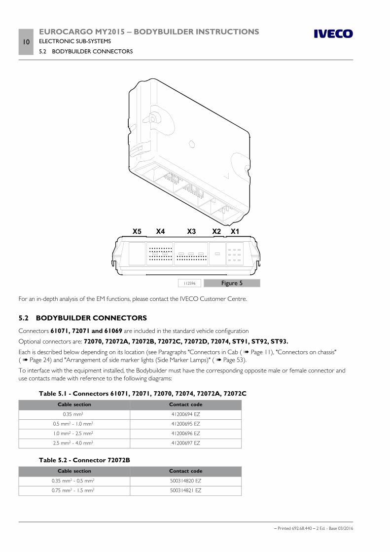
10EUROCARGO MY2015 ‒ BODYBUILDER INSTRUCTIONSELECTRONIC SUB-SYSTEMS
5.2 BODYBUILDER CONNECTORS
– Printed 692.68.440 – 2 Ed. - Base 03/2016
112596 Figure 5
For an in-depth analysis of the EM functions, please contact the IVECO Customer Centre.
5.2 BODYBUILDER CONNECTORS
Connectors 61071, 72071 and 61069 are included in the standard vehicle configuration
Optional connectors are: 72070, 72072A, 72072B, 72072C, 72072D, 72074, ST91, ST92, ST93.
Each is described below depending on its location (see Paragraphs "Connectors in Cab ( Page 11), "Connectors on chassis"( Page 24) and "Arrangement of side marker lights (Side Marker Lamps)" ( Page 53).
To interface with the equipment installed, the Bodybuilder must have the corresponding opposite male or female connector anduse contacts made with reference to the following diagrams:
Table 5.1 - Connectors 61071, 72071, 72070, 72074, 72072A, 72072CCable section Contact code
0.35 mm2 41200694 EZ
0.5 mm2 - 1.0 mm2 41200695 EZ
1.0 mm2 - 2.5 mm2 41200696 EZ
2.5 mm2 - 4.0 mm2 41200697 EZ
Table 5.2 - Connector 72072BCable section Contact code
0.35 mm2 - 0.5 mm2 500314820 EZ
0.75 mm2 - 1.5 mm2 500314821 EZ

EUROCARGO MY2015 ‒ BODYBUILDER INSTRUCTIONSELECTRONIC SUB-SYSTEMS
5.2 BODYBUILDER CONNECTORS11
– Printed 692.68.440 – 2 Ed. - Base 03/2016
Table 5.3 - Connectors ST91, ST92, ST93, 61069Cable section Contact code
0.35 mm2 - 0.5 mm2 9845 7375 EZ
0.75 mm2 - 1.5 mm2 9843 5370 EZ
CONNECTORS IN CAB
The following connectors are located inside the cab (see Figure 6):
61071 (standard connector for bodybuilder) 72071 (standard connector for bodybuilder) 72074 (Automatic Transmission) 72070 (FMS) 72072A (EM) 72072B (EM) 72072C (EM)
These connectors are housed in the lower dashboard, partly on the driver side and partly on the passenger side.
Connector 72070 (FMS - Fleet Management System) is housed in one of the DIN format compartments situated on the crossmember above the driver's side of the windscreen.
237360 Figure 6

12EUROCARGO MY2015 ‒ BODYBUILDER INSTRUCTIONSELECTRONIC SUB-SYSTEMS
5.2 BODYBUILDER CONNECTORS
– Printed 692.68.440 – 2 Ed. - Base 03/2016
Standard connector 61071: 21 pin, brown
200434 Figure 7
A.41200685 Counterpart to be coupled (female) B. 504163549 Existing part on vehicle (male)
Table 5.4 - Basic functions of connector 61071
Pin DescriptionWirecode
Max.Load
Connected to Remarks
1 Engine Start 8892 10 mA VCM X3-27Ground = start engine(signal must be permanently active till engine starter runs)Open wire = no action
2 Engine stop 0151 10 mA VCM X3-26Ground = stop engine(short activation sufficient to stop engine);Open wire = no action
3 Service brake 1165 200 mA VCM X1-130 V = service brake not pressed+24 V = service brake pressed
4 Vehicle standstill 5515 200 mA IBC3 E-150 V = vehicle standstill+24 V = vehicle moving
5 Parking brake 6656 200 mA VCM X1-100 V = not engaged+24V = engaged
6 Not connected
7 Vehicle speed 5540 10 mA 40011-B7 Pulse signal (1)
8 Engine status 7778 200 mA IBC3 E-14Engine status output0 V = engine stopped < 100 rpm+24 V = engine running > 400 rpm
9 Gearbox neutral 8050 200 mAVCM X1-07EM X1-07
0 V = neutral not engaged+24 V = neutral engagedInput driven by EM, when installedElse input driven by VCM
10 Reverse gear 2268 200 mA IBC3 E-160 V = reverse gear not engaged+24 V = reverse gear engaged
11 K15 8871 5 A IBC3 B-01K15(after fuse)
12 CC Set+ 8156 10 mA VCM X3-33Input signal (2)
Open wire = Set + not activatedGround = Set+ activated
13 CC Set- 8157 10 mA VCM X3-32Input signal (2)
Open wire = Set - not activatedGround = Set - activated
14 Reserved 8154 10 mA VCM X3-30

EUROCARGO MY2015 ‒ BODYBUILDER INSTRUCTIONSELECTRONIC SUB-SYSTEMS
5.2 BODYBUILDER CONNECTORS13
– Printed 692.68.440 – 2 Ed. - Base 03/2016
Pin DescriptionWirecode
Max.Load
Connected to Remarks
15Cruise ControlOFF/Resume
8155 10 mA VCM X3-31Input signal (3)
Open circuit = OFF / RES not activatedConnected to Ground = OFF/ Resume activated
16 CC Driver/BB 0152 10 mA VCM X3-49CC activation by Driver or Bodybuilder (BB)Open wire = CC controlled by driverConnected to ground = CC controlled by Bodybuilder (BB)
17 Ground 0000 10 A Wiring Ground
18 PTO 1 sw 0131 10 mAVCM X3-47
EM X3-5
Input signal (4)
Open wire = PTO mode 1 not activatedGround = PTO mode 1 activatedInput driven by EM, when installedElse input driven by VCM
19 PTO 2 sw 0132 10 mAVCM X3-46
EM X3-6
Input signal (4)
Open wire = PTO mode 2 not activatedGround = PTO mode 2 activatedInput driven by EM, when installedElse input driven by VCM
20 PTO 3 sw 0123 10 mAVCM X3-45
EM X3-7
Input signal (4)
Open wire = PTO mode 3 not activatedGround = PTO mode 3 activatedInput driven by EM, when installedElse input driven by VCM
21 K30 7772 10 A IBC3 B-09 K30 (after fuse) (5)
(1) Table 5.5 - Tachograph B7 SignalParameter Min Typ Max Unit Remarks
Voltage Ulow 1,5 V I = 1 mA
Voltage Uhigh 5,5 V I = -1 mA
Frequency <1,6 kHz Square wave
Pulse duration 0,64 2 4 ms
The Tachograph B7 output provides the speed pulse according to ISO16844-2.

14EUROCARGO MY2015 ‒ BODYBUILDER INSTRUCTIONSELECTRONIC SUB-SYSTEMS
5.2 BODYBUILDER CONNECTORS
– Printed 692.68.440 – 2 Ed. - Base 03/2016
191314 Figure 8
Speed pulse output signal (terminal B7) form + the timing diagram of the speed pulse output versus the motion sensor speed signal(terminal B3) mounted on gearbox resp. transfer box.
a: Max. 40 μs delay ± 10 μs jitter.(2) Input monitored only when 61071/pin 16 CC Driver/Bodybuilder is connected to ground, otherwise input is ignored.(3) when the intermediate speed control is activated, the CC Resume function is activated
If the intermediate speed control is active, the CC OFF function is activated
The function switches between CC OFF and CC Resume at each subsequent activation(4) The cyclical passage between int. inputs PTO _ x must be not faster than 500ms. Switching faster may ignore the request. Inputwill activate physical PTO - when configured - and VCM intermediate Speed Control Mode 1,2,3 On contemporaneous activationsof PTO 1,2,3 inputs the VCM intermediate Speed Control Mode is assigned by means of prioritization: PTO_3 - highest priority,PTO_2 - medium priority, PTO_1 - lowest priority
CAUTION: The Deactivation of a physical PTO is only allowed in load-free conditions. Therefore the deactivation of a physical station-ary/non stationary PTO device during driving operation and/or with a gear engaged is not permitted as in such a case the connection to thePTO is not load-free. If the PTO is nevertheless deactivated, this may result in malfunctions and the PTO and/or gearbox may be damaged.(5) Up to 10 A can be used in combination with the chassis connector CiA 72072D / Pin 1.
Standard connector 72071: 9 pin, yellow
200435 Figure 9
A.41200681 Corresponding opposite connector to becoupled (male)
B. 504163547 Existing part on vehicle (female)

EUROCARGO MY2015 ‒ BODYBUILDER INSTRUCTIONSELECTRONIC SUB-SYSTEMS
5.2 BODYBUILDER CONNECTORS15
– Printed 692.68.440 – 2 Ed. - Base 03/2016
Table 5.6 - Basic functions of connector 72071
Pin DescriptionWirecode
Max.Load
Connected to Remarks
1 2nd speed-limiter 8223 10 mA VCM X3-132nd speed limiter activationOpen wire = not activated+24V = engaged
2 Reserved
3 Clutch status 9963 200 mA VCM X1-12Open circuit = clutch not activatedConnected to ground = clutch activated
4 PTS 5542 200 mA VCM X1-14
PTS = Programmable Threshold Speed (1)
Programmable threshold (rpm or vehicle speed)+24 V = limit exceeded0 V = limit not exceeded
5 Emergency lights 1113 10 mA IBC3 E-04Input signal (2)
Connected to ground = onOpen circuit = off
6 Reserved
7 Reserved
8 Engine speed signal 5587 10 mA ECM 1-34 Pulse signal (3)
9 External lights 3333 5 A IBC3 E-240 V = lights off+24 V = lights on (parking, low and high beam)
(1) VCM default vehicle speed is 6 Km/h
The value cannot be modified by the Assistance Service with E.A.S.Y. in the presence of the following options:
OPT 06821 (EN1501) Certain Refurbishing Near Market requests for RCV (pls contact IVECO Bodybuilders market responsible)
(2) The hazard lights are supported only during K! 5 ON.(3) Not available for vehicles with CNG engines.
Table 5.7 - Engine speed signalParameter Min Typ Max Unit Notes
Voltage Ulow 0 1.5 V
Voltage Uhigh Ubat - 2 Ubat V
Duty cycle 50 %
Pulse duration 0.64 2 4 ms
The engine speed signal provides six impulses per camshaft revolution, namely three pulses for every turn of the crankshaft (seeFigure 10).

16EUROCARGO MY2015 ‒ BODYBUILDER INSTRUCTIONSELECTRONIC SUB-SYSTEMS
5.2 BODYBUILDER CONNECTORS
– Printed 692.68.440 – 2 Ed. - Base 03/2016
237367 Figure 10
A.Top Dead Centre a. 120° crankshaft = 60° camshaft
b. Complete crankshaft rotation (360°) c. complete camshaft rotation (360°)
When the signal is not available, contact the IVECO Assistance Service.
Optional connector 72070D: 12 pin, blue
A B
190413 Figure 11
A.41118264 Counterpart to be coupled (female) B. 41118266 Existing part on vehicle (male)
Table 5.8 - Basic functions of connector 72070
Pin DescriptionWirecode
Max.Load
Connected to Remarks
1 Ground 0001 5 A
2 Reserved
3 Voltage reducer 7770Pin 4 voltage
reducer
4 Ground 0001
5 Reserved
6 CAN H Tachograph C5FMS CAN HFMS = Fleet Management System
7 Reserved
8 Reserved
9 CAN L Tachograph C7 FMS CAN L
10 K15 8879 Radio A4
11 K15 8879 Radio A4

EUROCARGO MY2015 ‒ BODYBUILDER INSTRUCTIONSELECTRONIC SUB-SYSTEMS
5.2 BODYBUILDER CONNECTORS17
– Printed 692.68.440 – 2 Ed. - Base 03/2016
Pin DescriptionWirecode
Max.Load
Connected to Remarks
12 K30 7772 IBC3 B-9
FMS CAN line is enabled with option 14569.
For further information please see Chapter 5.3 ( Page 28)
Optional connector 72072A: 6 pin, blue
A B190414 Figure 12
A.41118323 Counterpart to be coupled (female) B. 41118304 Existing part on vehicle (male)
Only available with OPT 4572 (EM-light) or OPT 0384 (EM-full) installed.
Table 5.9 - Basic functions of connector 72072A
Pin DescriptionWirecode
Max.Load
Connected to Remarks
1 Reserved
2Request gearbox in
neutralGearbox activation
6983 500 mA EM X4-05
Only with automatic gearboxIndicated that Driver requested Neutral gear & Neutral gear beingphysically engagedGround = ONOpen circuit = OFF
3 Bodybuilder Enable 0991
Loadbetween10 mAand 1A (1)
EM X3-17
This must be activated by the Bodybuilder when the version isoperating. Otherwise some Bodybuilder functions will not besupported
Neutral shift for automatic gearboxes Safe State activation by BB EMCY (ST14B/2) CANOpen controls under Firewall monitoring
Ground = active, low side Switch
4Signal for vehicle withCAN fully operational
9089 10 A (2)
Relay wiring:Activated via EMX4-04 and VCM
X1-07
Allows Bodybuilder the supervision of “Vehicle CAN fully opera-tional" information (3)
+24 V = ON, vehicle CAN systems are operationalGround = OFF at least one system is not operational
5 Reserved
6 Reserved
(1) During the K15 OFF phase, the input will not be activated so as to avoid an increase in the sleep current(2) Up to 10A can be used in combination with CiA cab connector 72072C / Pin 1(3) Allows the Bodybuilder to check the “Vehicle with CAN fully operational" information. It shows at the same time:
IVN (In Vehicle Network) communication w/o timeouts and

18EUROCARGO MY2015 ‒ BODYBUILDER INSTRUCTIONSELECTRONIC SUB-SYSTEMS
5.2 BODYBUILDER CONNECTORS
– Printed 692.68.440 – 2 Ed. - Base 03/2016
Bodybuilder interface application running
Note The output signal is filtered each second to avoid temporary interference. Output remains off for ~5 sec after the phase K15 ON.The Bodybuilder must check this delay at each cycle, otherwise wiring problems cannot be safely identified.
The IVN CAN communication of following systems are monitored via Timeout detection:
Vehicle Control module Brake system ECAS (when installed) Automatic gearbox (when installed) Body Controller System Tachograph
Detailed information for each system is available via CANopen – see EMCY 0x1014 object.
Optional connector 72072B: 20 pin, black
A B
190415 Figure 13
A.500314809 Existing part on vehicle (male) B. 500314816 Counterpart to be coupled (female)
Only available with OPT 0384 (EM-full) installed.
Table 5.10 - Basic functions of connector 72072B
Pin DescriptionWirecode
Max.Load
Connected to Remarks
1Gearbox in neutral
request signal0992 10 mA (1) EM X3-18 Not supported on Eurocargo Euro VI and Allison 2500 gearbox.
2Bodybuilder emergency
signal0993 10 mA (1) EM X3-19
Input to activate the Vehicle StoppedState values, only with Body-builder Enable (72072A/pin 2) also activatedList of configurable signals (2)
Ground = active, low side switch
3External stop brakerequest (EN1501)
0994 10 mA (1) EM X3-20Only supported with opt 6821 (3)
Input to activate the Stopping brake (V<2km/h)Ground = active, low side switch
4Stop brake signal return
(EN1501)0995 10 mA EM X3-21
reserved for IVECO exclusivelyOnly supported with OPT 6821Input to monitor the stop brake pressureGround = active, low side switch
5Stepper swt req.
(EN1501)0996 10 mA (1) EM X4-06
Only supported with opt 6821 (4)
Input to activate the Refuse stepper switchGround = active, low side switchn.a. when ABS-HSA (OPT 14861) installed

EUROCARGO MY2015 ‒ BODYBUILDER INSTRUCTIONSELECTRONIC SUB-SYSTEMS
5.2 BODYBUILDER CONNECTORS19
– Printed 692.68.440 – 2 Ed. - Base 03/2016
Pin DescriptionWirecode
Max.Load
Connected to Remarks
6LMM (Light
Management Module)Right direction light
6985 1.5 A EM X1-03Right turn signal light0 V = not engaged+24V = engaged
7LMM (Light
Management Module)Left direction light
6986 1.5 A EM X1-08Left turn signal light0 V = not engaged+24V = engaged
8Warning sound
indicator (EN1501)6987 1 A EM X4-01
reserved for IVECO exclusivelyOnly supported with OPT 6821Output EN1501 Warning sound indicator0 V = not engaged+24V = engaged
9 Keep EM alive 6988 1 A EM X4-020 V = not engaged+24V = engaged
10Brake diagnostics lamp
EN15016989 1 A EM X4-03
Only supported w/ opt 6821Output EN1501 Reverse protections Brake active0 V = not engaged+24V = engagedafter K15 active for 2 sec (w/o brake activated)n.a. when ABS-HSA (OPT 14861) installed
11Brake engaged
(EN1501)6990 1 A EM X4-21
reserved for IVECO exclusivelyOnly supported with OPT 6821Output EN1501 Solenoid Brake0 V = not engaged+24V = engaged
12Gearbox in neutralrequest (EN1501)
6991 1 A EM X4-22 Not supported on Eurocargo Euro VI
13Chassis ready (acc.
EN1501)6992 1 A EM X4-23
Indicates Chassis Information ready (acc. EN1501)for adjustment contact IVECO CS organisation0 V = Off- Frame not ready+24 V = On - Frame ready
14Low accelerator pedal
idle switch6993 1 A EM X4-31
Indicate that Accelerator pedal idle switch0 V = OFF - low idle switch not active+ 24 V = ON - low idle switch active
15"At least one PTO is
engaged"6994 1 A EM X4-32
Indicates at least one PTO is engagedSignal based on PTO feedback signal/s0 V = OFF - no PTO engaged+ 24 V = ON - at least one PTO engaged
16 Bodybuilder fluid level 59810-32 V,0-500
Ohm (1)
EM X4-14Analogue input for IC display of Bodybuilder fluid level (5)
when enabled CANopen 0x6167 n.a.
17 Bodybuilder pressure 59820-32 V,0-500
Ohm (1)
EM X4-15Analogue input for IC display of Bodybuilder pressure (5)
when enabled CANopen 0x6167 n.a.
18Bodybuilder Thermal
Temperature5983
0-32 V,0-500
Ohm (1)
EM X4-29Analogue input for IC display of Bodybuilder temperature (5)
when enabled CANopen 0x6167 n.a.
19 ReGen inhibit 59910-2000Hz(1)
EM X4-16reserved for IVECO exclusivelyused by IVECO for Cummins application
20 ReGen force 59920-2000Hz(1)
EM X4-38reserved for IVECO exclusivelyused by IVECO for Cummins application

20EUROCARGO MY2015 ‒ BODYBUILDER INSTRUCTIONSELECTRONIC SUB-SYSTEMS
5.2 BODYBUILDER CONNECTORS
– Printed 692.68.440 – 2 Ed. - Base 03/2016
(1) During the K15 OFF phase, the input will not be activated so as to avoid an increase in the sleep current.(2) Requirements for Functional Safety
In case of an emergency inside the Bodybuilder application, IVECO offers the activation of the Bodybuilder Emergency input. When inputactivated the vehicle enters - depending on configuration - autonomously in a Vehicle StoppedState. IVECO offers a set of pre-configuredStoppedState settings to satisfy Bodybuilders application specific needs; for details please contact IVECO.
This feature is only available when the Bodybuilder application is in operation and not during normal vehicle driving. Therefore, theBodybuilder enable input (ST 72072A, pin 3) will be simultaneously switched to ground; otherwise no other action will be initiated..
Please note that the Vehicle Stopped State values are transmitted via CAN to the other vehicle subsystems. Therefore, this featurerequires that the "Vehicle CAN fully operational" output is active.
When the "Vehicle CAN fully operational" output is not active then the Bodybuilder application does not have to implement actions (orrather reactions) which rely on the EM nor on the entire IVECO Bodybuilder interface functioning properly (as for instance the CAN-open gateway). The Bodybuilder is responsible for initiating measures that make sure that the Safe State of its application is enteredautonomously.When the application specifies that the Bodybuilder also requests a recovery strategy while the "Vehicle in full CAN option" output ispassive, contact IVECO if support is requested to complete the design specifications of this recovery strategy.
All the signals listed below are transmitted as one entire package - it is not possible to exclude any of them. The values of the ‘Vehicle Stopped State’ signals are transmitted immediately after activation of Bodybuilder Emergency and shall
remain active until: K15 is switched off or the CANopen NMT ‘Start Node’ command is received or The CANopen NMT ‘Start all nodes’ command is received The CANopen NMT "Start via HW input" command is configured and the signal is reactivated
Note During this ‘StoppedState’ phase the affected CANopen signals received on BB-CAN are ignored.
(3) The stopping brake can only be activated with vehicle speed less than 2 km/h. On EBS vehicles a new Stopping Brake request isserviced only when engine is running. When Stopping brake being active the engine could be stopped and Stopping brake remainsengaged.
The Stopping brake is only supported during K15 ON phase, switching off K15 disable the function on ABS vehicles. On vehicleswith EBS brake system the Bodybuilder automatically deactivates the stop brake request when K15 is switched off.(4) The refuse packer Step swt input, as well as the CAN open object 0x6148 (Refuse packet step switch) activate the followingactions on occupied stepper switch as described in Standard Fpr EN 1501-1:2010 date: 2010-02, Chpt 5.11.3.3.1 – Provisions forfootboard(s) occupied:
speed limiting reversing of rear loaded RCV. Reversing protection by means of:
brake activation in case of reversing; torque limit set to 0% (only low idle governor) in case of reversing; inhibiting reverse gear on automatic gearboxes when this is engaged, only when the Bodybuilder Enable input
(72072A/03) is connected to ground by the Bodybuilder.
Requirements for Functional Safety
The vehicle shall not be obliged to meet all DIN EN1501-1 safety requirements. The Bodybuilder has the responsibility that the final applic-ation corresponds to the Safety standards as described in EN1501. In particular the overriding safety devices EN1501-1 described in theStandard Fpr EN1501-1:2010 dated: 2010-02; Chapter 5.11.3.3.2 including reset management in the event of function failures or trafficemergencies must be managed by the Bodybuilder (see EN1501-1 chapter 5.11.3.3.2).(5) It is possible to display vehicle load information on the Instrument Panel, but only for comfort functions. The functionality is perdefault disabled, for enabling please contact IVECO Customer Services. When wiring is added to the input(s), the relative CAN-

EUROCARGO MY2015 ‒ BODYBUILDER INSTRUCTIONSELECTRONIC SUB-SYSTEMS
5.2 BODYBUILDER CONNECTORS21
– Printed 692.68.440 – 2 Ed. - Base 03/2016
open objects on the vehicle load information are no longer available. The trailer load information via ISO11992-3 is not supportedon the Euro 6 range.
196799 Figure 14
This function allows the driver to also set alarm thresholds for each type of load from the second menu screen of the display onthe instrument panel.
Optional connector 72072C: 9 pin, yellow
A B190412 Figure 15
A.41200681 Counterpart to be coupled (female) B. 41020340 Existing part on vehicle (male)
Only available with OPT 0384 (EM-full) installed.
Table 5.11 - Basic functions of connector 72072C
Pin DescriptionWirecode
Max.Load
Connected to Remarks
1 K30 7796 10 A (1) K30 Protected by fuse 10 A
2 Ground 0000 Ground
3CO (CANopen)
operational0975 0.5 A EM X4-28
LSO (Low Side Output), activated in the case of CO initiated(typically ~3 seconds after K15 ON)for adjustment contact IVECO CSOpen circuit = CANopen not operational0 V = CANopen operational
4 Bodybuilder CAN CAN H EM X4-17 CANopen Truckgateway, see CIA 413
5 CAN Gnd 0999 EM X4-09 HF Ground (High Frequency),capacitive coupled
6 Bodybuilder CAN CAN L EM X4-19 CANopen Truckgateway, see CIA 413
7 Reserved
8 Reserved
9 Reserved
(1) 10 A can be used in combination with "Vehicle CAN fully operational" signal, connector 72072A pin 4

22EUROCARGO MY2015 ‒ BODYBUILDER INSTRUCTIONSELECTRONIC SUB-SYSTEMS
5.2 BODYBUILDER CONNECTORS
– Printed 692.68.440 – 2 Ed. - Base 03/2016
Optional connector 72074: 12 pin, grey
A B
190413 Figure 16
A.41118329 Counterpart to be coupled (female) B. 41118310 Existing part on vehicle (male)
Table 5.12 - Basic functions of connector 72074 (Allison automatic gearbox)
Pin DescriptionWirecode
Max.Load
Connected to Remarks
1Neutral indicator for
Extra PTO0147 500 mA ALL 45
Gearbox in neutral.Ground for neutral engaged.This output function is activated by the TCM when Neutral isattained and a programmable combination of engine speed andtransmission output speed has been detected.
2 Multi-state switch 4123 15 mA ALL 23
Limitation 1st gear and inhibition reverse gearOpen wire = function active+24V = function not engagedGround = function activeThis function is normally enabled with an operator-controlledmomentary switch.When the function is enabled, the transmission is limited to oper-ation in only Neutral and/or in the (selectable*) range of reducedforward gears.Operator requests to upshift beyond the maximum* gear range orto shift into Reverse are ignored by the TCM.If the function is enabled with Reverse selected on the shift se-lector, the transmission will shift to Neutral.If the function is enabled in a forward drive range higher than themaximum specified gear range*, the TCM will invoke preselectdownshifts until the specified gear range is attained.The function is disabled when the enabling switch is released.
3 Gear range inhibition 0259 ALL 42

EUROCARGO MY2015 ‒ BODYBUILDER INSTRUCTIONSELECTRONIC SUB-SYSTEMS
5.2 BODYBUILDER CONNECTORS23
– Printed 692.68.440 – 2 Ed. - Base 03/2016
Pin DescriptionWirecode
Max.Load
Connected to Remarks
4 PTO active 8131 15 mA ALL 43
For special applications - Input from PTO switch .Open wire = inactive+24V = activeGround = inactiveEnabling this function alerts the TCM that PTO operation has beenrequested by the operator.When the input function is enabled, the TCM disrupts the “modu-lated main pressure” feature in the transmission, resulting in trans-mission operation at full main pressure.When the function is enabled and all of the following conditionsexist, the TCM activates Output Function G (PTO Enable Output).Required operating conditions for enabling of this function are:
accelerator position is "low"; engine speed and output speed are within Customer Modifi-
able Constant limits.
5 PTO control 8333 500 mA ALL 30
For special applications - 24V output to activate the PTOThis output function is activated when use of the PTO has beenrequested and all operating conditions required to enable the PTOhave been satisfied.
6 PTO 2 control 6164 ALL 50
7 Relay control 5146 ALL 2
8Activation "Pump Pack"signal (only with Allison
3000 gearbox)5145 ALL 17
9 Automatic neutral signal 0258 5 mA ALL 1
For special applications - Logic mode "and" mode with pin 8Open wire = function inactive+24 V = function inactiveValue close to digital ground = function activeThe TCM determines this function enable request to be valid onlyafter receiving two separate input signals.When properly integrated into the vehicle system, the enabledfunction automatically commands the gearbox to engage neutralwhen an additional brake is actuated.
10 Digital ground 0000 ALL 3It must be used as return for ”closed on digital ground” inputs.Do not connect to the battery negative or to other grounds.
11 Range indicator 0103 500 mA ALL 13Gearbox: ground for neutral not engagedThis output function is activated by the TCM when the specifiedgear (or gears) is being commanded by the TCM
12Gearbox speedindicator output
8039 15 mA ALL 5
Contact Customer Service for any modifications.

24EUROCARGO MY2015 ‒ BODYBUILDER INSTRUCTIONSELECTRONIC SUB-SYSTEMS
5.2 BODYBUILDER CONNECTORS
– Printed 692.68.440 – 2 Ed. - Base 03/2016
CONNECTORS ON CHASSIS
The following connectors (all black) are located on the frame:
61069 (SML) - see Paragraph "Arrangement of side marker lights (Side Marker Lamps)" ( Page 53) 72072D (EM) ST91 (PTO 1) ST92 (PTO 2) ST93 (PTO 3)
200433 Figure 17
Optional connector 72072D: 7 pin, black
A B190417 Figure 18
A.504111928 Counterpart to be coupled (female) B. 41118387 Existing part on vehicle (male)
Only available with OPT 0384 (EM-full) installed.
Table 5.13 - Basic functions of connector 72072D
Pin DescriptionWirecode
Max.Load
Connected to Remarks
1 K30 7795 10 A K30 Protected by fuse 10A (1)
2 Ground 0000 Ground
3 CO enable (CANopen) 0975 0.5 A EM X4-28
LSO (Low Side Output), activated in the case of CO initiated(typically ~3 seconds after K15 ON)for adjustment contact IVECO CSOpen circuit = CANopen not operational0 V = CANopen operational
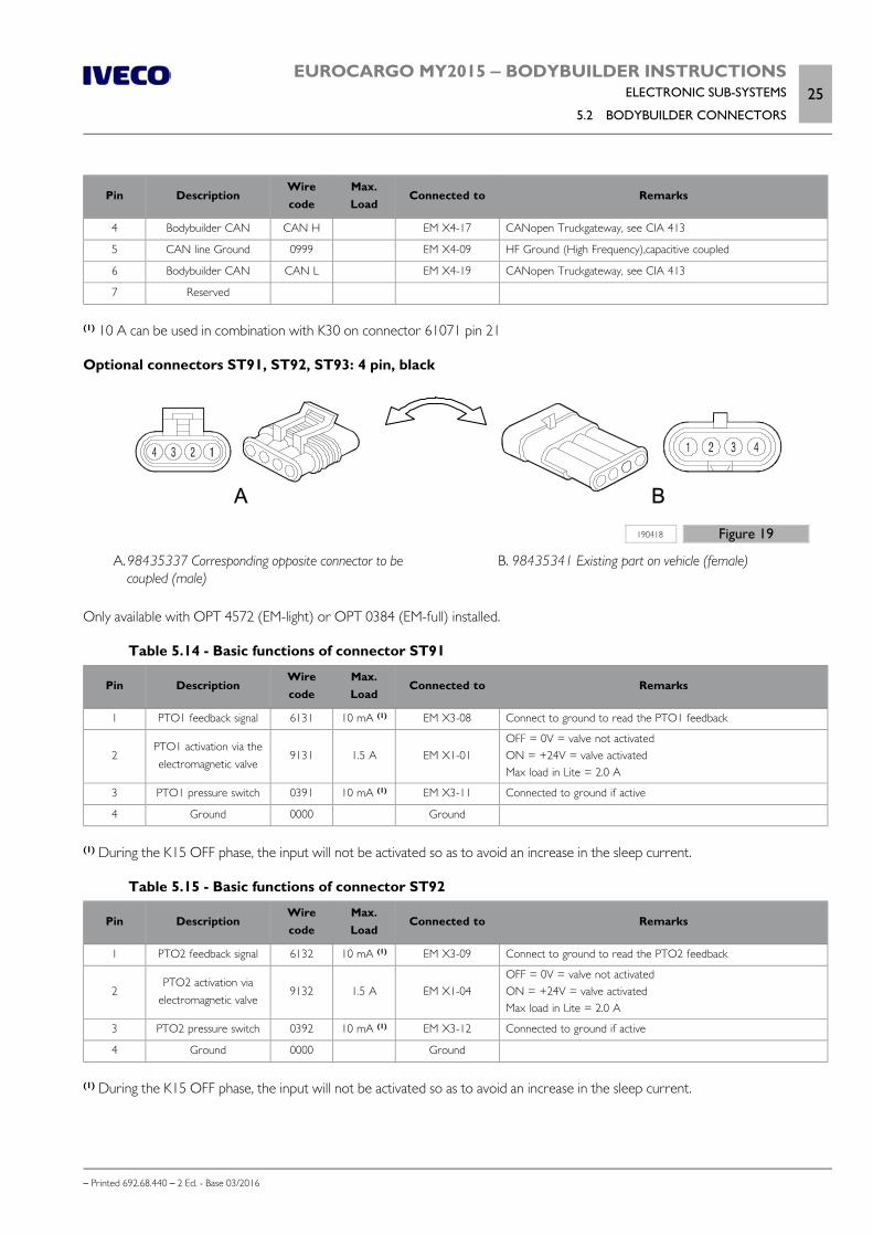
EUROCARGO MY2015 ‒ BODYBUILDER INSTRUCTIONSELECTRONIC SUB-SYSTEMS
5.2 BODYBUILDER CONNECTORS25
– Printed 692.68.440 – 2 Ed. - Base 03/2016
Pin DescriptionWirecode
Max.Load
Connected to Remarks
4 Bodybuilder CAN CAN H EM X4-17 CANopen Truckgateway, see CIA 413
5 CAN line Ground 0999 EM X4-09 HF Ground (High Frequency),capacitive coupled
6 Bodybuilder CAN CAN L EM X4-19 CANopen Truckgateway, see CIA 413
7 Reserved
(1) 10 A can be used in combination with K30 on connector 61071 pin 21
Optional connectors ST91, ST92, ST93: 4 pin, black
A B
190418 Figure 19
A.98435337 Corresponding opposite connector to becoupled (male)
B. 98435341 Existing part on vehicle (female)
Only available with OPT 4572 (EM-light) or OPT 0384 (EM-full) installed.
Table 5.14 - Basic functions of connector ST91
Pin DescriptionWirecode
Max.Load
Connected to Remarks
1 PTO1 feedback signal 6131 10 mA (1) EM X3-08 Connect to ground to read the PTO1 feedback
2PTO1 activation via theelectromagnetic valve
9131 1.5 A EM X1-01OFF = 0V = valve not activatedON = +24V = valve activatedMax load in Lite = 2.0 A
3 PTO1 pressure switch 0391 10 mA (1) EM X3-11 Connected to ground if active
4 Ground 0000 Ground
(1) During the K15 OFF phase, the input will not be activated so as to avoid an increase in the sleep current.
Table 5.15 - Basic functions of connector ST92
Pin DescriptionWirecode
Max.Load
Connected to Remarks
1 PTO2 feedback signal 6132 10 mA (1) EM X3-09 Connect to ground to read the PTO2 feedback
2PTO2 activation via
electromagnetic valve9132 1.5 A EM X1-04
OFF = 0V = valve not activatedON = +24V = valve activatedMax load in Lite = 2.0 A
3 PTO2 pressure switch 0392 10 mA (1) EM X3-12 Connected to ground if active
4 Ground 0000 Ground
(1) During the K15 OFF phase, the input will not be activated so as to avoid an increase in the sleep current.
26EUROCARGO MY2015 ‒ BODYBUILDER INSTRUCTIONSELECTRONIC SUB-SYSTEMS
5.2 BODYBUILDER CONNECTORS
– Printed 692.68.440 – 2 Ed. - Base 03/2016
Table 5.16 - Basic functions of connector ST93
Pin DescriptionWirecode
Max.Load
Connected to Remarks
1 PTO3 feedback signal 6133 10 mA (1) EM X3-10 Connect to ground to read the PTO3 feedback
2PTO3 activation via
electromagnetic valve9123 1.5 A EM X1-06
OFF= 0V =valve not activatedON = +24V = valve activatedMax load in Lite = 2.0 A
3 PTO3 pressure switch 0393 10 mA (1) EM X3-16 Connected to ground if active
4 Ground 0000 Ground
(1) During the K15 OFF phase, the input will not be activated so as to avoid an increase in the sleep current.
TRAILER CONNECTORS
If an adjustment of the tow vehicle with continuous braking is necessary, use two 7-pin connectors (72000 and 72001) or alternat-ively a single 15 pin connector ISO (72010) on the last crossbeam of the chassis.
If the trailer is designed for a 12 Volt supply, an optional connector with 13 pins (72016) must be used.
Trailer connector: 7-pin
113252 Figure 20
Table 5.17 - Basic functions of the 7 pin connector (72000) for the trailer
Pin DescriptionWirecode
Max.Load
Connected to Remarks
1 Ground 0000 11 A Ground
2Daylight runninglights/right trailer
clearance light3331 6 A MET-A06
3 Left trailer indicator 1180 6 A MET-C04
4 Trailer stop lights 1179 6 A MET-A02
5 Right trailer indicator 1185 6 A MET-B03
6Daylight runninglights/left trailerclearance light
3332 6 A MET-A07
7 Spare –

EUROCARGO MY2015 ‒ BODYBUILDER INSTRUCTIONSELECTRONIC SUB-SYSTEMS
5.2 BODYBUILDER CONNECTORS27
– Printed 692.68.440 – 2 Ed. - Base 03/2016
Table 5.18 - Basic functions of the 7 pin connector (72001) for the trailer
Pin DescriptionWirecode
Max.Load
Connected to Remarks
1 Ground 0000 11 A Ground
2Power supply +15 for
trailer8869 11 A MET-C01
3 Trailer reverse light 2226 6 A IBC3-A09
4 Spare –
5 Spare –
6 Spare –
7 Trailer rear fog light 2283 6 A MET-B1
Trailer connector: 15-pin
113251 Figure 21
Table 5.19 - Basic functions of the 15 pin connector (72010) for the trailer
Pin DescriptionWirecode
Max.Load
Connected to Remarks
1 Left trailer indicator 1180 6 A MET-C04
2 Right trailer indicator 1185 6 A MET-B03
3 Trailer rear fog light 2283 6 A MET-B01
4 Ground 0000 11 A Ground
5Daylight runninglights/left trailerclearance light
3332 6 A MET-A07
6Daylight runninglights/right trailer
clearance light3331 6 A MET-A08
7 Trailer stop lights 1179 6 A MET-A02
8 Trailer reverse light 2226 6 A IBC3-A09
9 Spare –
10 Spare –
11 Spare –
12 Spare –
13 Spare –
14 Spare –

28EUROCARGO MY2015 ‒ BODYBUILDER INSTRUCTIONSELECTRONIC SUB-SYSTEMS
5.3 FMS (FLEET MANAGEMENT SYSTEM)
– Printed 692.68.440 – 2 Ed. - Base 03/2016
Pin DescriptionWirecode
Max.Load
Connected to Remarks
15 Spare –
Table 5.20 - Basic functions of connector (72016) to 13 pin for trailer powered at 12 Volt
Pin DescriptionWirecode
Max.Load
Connected to Remarks
1 Left trailer indicator 1180 6 A MET-C04
2 Trailer rear fog light 2283 6 A MET-B01
3 Ground 0000 11 A Ground
4 Right trailer indicator 1185 6 A MET-B03
5Daylight runninglights/right trailer
clearance light3331 6 A MET-A07
6 Trailer stop lights 1117 6 A MET-A02
7Daylight runninglights/left trailerclearance light
3332 6 A MET-A08
8 Trailer reverse light 2226 6 A IBC3-A09
9 Spare –
10 Spare –
11 Spare –
12 Spare –
13 Spare –
5.3 FMS (FLEET MANAGEMENT SYSTEM)
For the management of a fleet it is necessary that each vehicle provides a set of information on its operation, the movements madeand the driving style of the driver.
The main information can be displayed directly on the radio screen, if this is the type designed for such purpose.
If the vehicle does not have such a solution, detailed information about:
rpm, engine torque, water and oil temperature; mileage, type of route and driving times; consumption, speed and braking; loads on axles (if provided);
they can be acquired by means of an electronic device or personal computer connected to the CAN line.
The format of this information complies with the FMS standard on the Company website: www.fms-standard.com.
The connection to the CAN line is possible by means of the optional 14569, which consists of:
a green connector (FMS), housed in one of the DIN coating cases above the windscreen; A bridle, which connects the connector to connector 72070; a resistor which is used to terminate the CAN line.
To use the CAN FMS it is necessary to unplug the resistor and use the green connector; obviously the telematic device to be inser-ted must be compatible with the CAN FMS termination.

EUROCARGO MY2015 ‒ BODYBUILDER INSTRUCTIONSELECTRONIC SUB-SYSTEMS
5.4 CONFIGURATIONS FOR TAIL LIFTS29
– Printed 692.68.440 – 2 Ed. - Base 03/2016
Note If the vehicle is not equipped with the optional 14569, it is mandatory that the necessary modifications to the electrical system andsoftware upgrades are made at an authorised IVECO Service Centre.
Table 5.21 - Characteristics of the CAN line
Physical levelUnshielded twisted pair cable compliant with ISO std. 11898 (SAE J1929/11).Termination of internal bus to cable with 120 Ω resistor.
Data link level CAN 2.0B, 250 Kbit/s Format identifier and multi-packet message management compliant with SAE J1929/21.
Application level Messages and parameters compliant with SAE J1939/71.
The information that can be retrieved contains the message "FMS Standard Interface" and identifies the version that is supported.This message is not present if you have installed an interface that does not support this standard.
The telematic devices connected to the FMS connector, wanting to use the Remote Tachograph Download Data functionality mustbe set to use the "source address" F0; if you do not operate in this way, on the message "error 13", relative to problems on theCAN network, could appear on the tachograph.
5.4 CONFIGURATIONS FOR TAIL LIFTS
Base configuration
Vehicles with the base configuration (opt. 4113) are equipped with specific wiring between the instrument cluster and the bulkheadconnector, and with a switch on the dashboard. Pressing the switch closes the electrical circuit connected to the tail lift. An indicatorlamp illuminates on the instrument cluster when the switch is pressed, and engine start is inhibited until the switch is pressed again(see Chapter 3.9 - Paragraph "Base configuration for tail lifts" ( Page 39)).
To complete the electrical wiring to the tail lift, refer to the diagram in Figure 22.
The tail lift anchoring kit (option 6229), should preferably be used together with this configuration.

30EUROCARGO MY2015 ‒ BODYBUILDER INSTRUCTIONSELECTRONIC SUB-SYSTEMS
5.4 CONFIGURATIONS FOR TAIL LIFTS
– Printed 692.68.440 – 2 Ed. - Base 03/2016
200437 Figure 22
25550 Contactor for preventing start-up with tail lift engaged25551 Contactor for tail lift indicator lamp inserted50003 Electronic instrument panel for instrument and warning
lights display
52219 Switch for activating tail lift52502 Key-controlled switch for services with start-up70000 Fuse holder 686116 Body Computer multiplex control unit86132 VCM (Vehicle Control Module) control unit

EUROCARGO MY2015 ‒ BODYBUILDER INSTRUCTIONSELECTRONIC SUB-SYSTEMS
5.4 CONFIGURATIONS FOR TAIL LIFTS31
– Printed 692.68.440 – 2 Ed. - Base 03/2016
Base configuration with additional ECAS remote control (opt. 4115)
Vehicles with air suspension (/P and /FP) may be equipped with an ECAS remote control unit in addition to the remote control unitprovided as standard. This option (opt. 4115, for use solely together with opt. 4113 described previously) consists of specific wiringand a supplementary remote control unit which may be connected in the vicinity of the tail lift.
When the switch to activate the rear lift is pressed, the standard remote control unit is disabled and the supplementary unit only isenabled. The original state is restored when the switch is pressed again.
200438 Figure 23
25546 ECAS contactor from box (power supply)25547 ECAS contactor from box (mass)25548 ECAS contactor from box (clock)
25549 ECAS contactor from box (data)85160 Chassis settings adjuster86023 Vehicle raising-lowering control unit

32EUROCARGO MY2015 ‒ BODYBUILDER INSTRUCTIONSELECTRONIC SUB-SYSTEMS
5.4 CONFIGURATIONS FOR TAIL LIFTS
– Printed 692.68.440 – 2 Ed. - Base 03/2016
VEHH configuration (opt. 75182)
To attain compliance with the VEHH standard (defined by the VEHH association of European tail lift manufacturers), opt. 75182 isalso available (see Chapter 3.9 - "VEHH configuration for tail lifts" ( Page 40)).
Refer to the following diagrams for the VEHH configuration without and with ECAS.
VEHH tail lift without ECAS
200439 Figure 24
25550 Contactor for preventing start-up with tail lift engaged25571 Contactor for VEHH tail lift control50003 Electronic instrument panel for instrument and warning
lights display
52219 Switch for activating tail lift52502 Key-controlled switch for services with start-up70000 Fuse holder 686116 Body Computer multiplex control unit86132 VCM (Vehicle Control Module) control unit

EUROCARGO MY2015 ‒ BODYBUILDER INSTRUCTIONSELECTRONIC SUB-SYSTEMS
5.4 CONFIGURATIONS FOR TAIL LIFTS33
– Printed 692.68.440 – 2 Ed. - Base 03/2016
VEHH tail lift with ECAS
200440 Figure 25
25550 Contactor for preventing start-up with tail lift engaged25551 Contactor for tail lift indicator lamp25571 Contactor for VEHH tail lift control25573 ECAS contactor with VEHH tail lift engaged50003 Electronic instrument panel for instrument and warning
lights display
52219 Switch for activating tail lift52502 Key-controlled switch for services with start-up70000 Fuse holder 686116 Body Computer multiplex control unit86132 VCM (Vehicle Control Module) control unit

34EUROCARGO MY2015 ‒ BODYBUILDER INSTRUCTIONSELECTRONIC SUB-SYSTEMS
5.5 OPERATOR’S FOOTBOARD
– Printed 692.68.440 – 2 Ed. - Base 03/2016
5.5 OPERATOR’S FOOTBOARD
For refuse collection vehicle, the standard EN 1501 imposes safety requirements of the operation and protection from accidents(e.g. locking in the load compartment or accidental fall of the containers off the vehicle, retracting of the vehicle, etc.).
Now therefore, if the fitting also provides a footboard to host an operator at the outside, so as the operation can only be activatedin its presence it is necessary to prepare the electrical system according to the diagram of Figure 26.
200441 Figure 26
22050 Bell (EN1501 in operation)25139 Maintenance contactor EN150153620 Switch (parking brake engaged)58740 Parking brake engaged signal warning light61011 Container for a 3 A diode70000 Fuse holder 6
72071 Cab 9-pole connector for fitters72072 DMI/EM control unit interfacing connector78065 Solenoid valve EN1501 (parking brake activation)86126 EM (Expansion Module) control unit86132 VCM (Vehicle Control Module) control unit A Footboard switch (body builder supply)

EUROCARGO MY2015 ‒ BODYBUILDER INSTRUCTIONSELECTRONIC SUB-SYSTEMS
5.6 ELECTRICAL CIRCUIT MODIFICATIONS35
– Printed 692.68.440 – 2 Ed. - Base 03/2016
5.6 ELECTRICAL CIRCUIT MODIFICATIONS
CAN line wires and electric/electronic devices must not be modified.
Any modifications on the electrical system will reduce quality and safety characteristics.
Bodybuilders must use genuine IVECO spare parts if changes to the electrical system are inevit-able.
IVECO cannot be liable for system malfunctioning if the instructions contained in this chapterare not followed.
General information
The instructions provided in Chapter 2.1 - Paragraph "Special precautions" ( Page 5) also refer to Multiplex system wiring.
The connectors and the respective terminals cannot be modified. Avoid connecting and disconnecting the chassis control unit con-nectors for more than three times to prevent damaging the gel which ensures tightness of the connections.
Wiring harness length
The CAN line and the electrical wires form a single wiring harness. Consequently, it is not possible to replace only the CAN line orthe electrical wiring where the electrical system is formed by both types of wires.
The wire length (CAN line + electrical wires) may not be correct when repositioning Multiplex system electronic control units.
1. If the length is excessive, fold the wires without forming rings as this could cause undesired electromagnetic effects. The wiringwhich is very stiff and for this reason, it must be replaced with shorter wiring when it cannot be folded.
2. If the wiring length is not sufficient it must be replaced.
Only use genuine IVECO spare parts (contact the IVECO service network).
The CAN line cannot be changed. All modifications are expressly forbidden.
IVECO can be consulted in particularly difficult cases by sending a diagram of the chassis dimensions and the new position of theelectronic control units.
Disconnecting electronic control units
Follow the instructions below carefully before disconnecting an electronic control unit:
turn the ignition key to OFF and remove it; switch off the additional heaters and wait for the end of the cooling down cycle (the warning light of the corresponding key
will go out); open the TGC (Main Current Contactor); isolate the battery by disconnecting the battery cables: disconnect the negative terminal first followed by the positive terminal; disconnect the control unit.
36EUROCARGO MY2015 ‒ BODYBUILDER INSTRUCTIONSELECTRONIC SUB-SYSTEMS
5.7 ELECTRICAL SYSTEM: OPERATIONS
– Printed 692.68.440 – 2 Ed. - Base 03/2016
Repositioning electronic control units
IVECO recommends avoiding modifications which entail the repositioning of the electronic control units. However, if repositioningis unavoidable, follow the instructions below:
the electronic control units must be positioned on the chassis or in the cab and secured with a fastening similar to the originalone (i.e. bracket);
in order to avoid any malfunctions the electronic control units must not be turned in relation to the chassis and must maintainthe original orientation (e.g. to avoid water ingress).
electronic control units must not be fitted on the subframe; the cover must always be refitted; avoid subjecting electronic control units to knocks from debris and stones from the road when travelling.
5.7 ELECTRICAL SYSTEM: OPERATIONS
General information
Vehicles are set to function normally with a 24 V electrical system.
The chassis represents the grounding (it acts as a current return conductor between the components located on it and the bat-tery power source/alternator) and it is connected to the negative pole of the battery and components, if an isolated return is notprovided for this.
When installing additional equipment or additional circuits, the following indications must be taken into account and, depending onthe complexity of the operation, there must be proper documentation (e.g. wiring diagram) to match that of the vehicle.
The use of cables and connections with colours/codes identical to those used on the original vehicle makes installation correct andfacilitates any repair work.
Note For more detailed information regarding the electrical system of the vehicle, please refer to the specific Repair Manual, print603.95.624 (EUROCARGO 6-10 t Euro 6) and print 603.95.633 (EUROCARGO 12-18 t Euro 6).
These are available through the Assistance Network and can also be requested from sales bodies.
Precautions for work on the system
Operations which do not comply with the indications specified by IVECO may cause damage toon-board systems (control units, wiring, sensors, etc.), and affect the correct operation of thevehicle and driving safety; they can also cause significant damage (e.g. short circuits with fire anddestruction of the vehicle) which is not covered by warranty.
Before removing any electrical/electronic equipment, disconnect in sequence the ground cable from the battery negative pole andthen the positive cable.
To prevent damage to the vehicle's electrical system, follow the following instructions:
The cables must have suitable sectioning for the type of load and the position of the load in the vehicle. The power cables (+ direct) must be:
individually intubated in conduits of suitable diameter and not together with other cables for signal and negative; placed at least 100 mm (reference value = 150 mm) from high heat sources (turbine, engine, exhaust manifold, etc.); placed at least 50 mm from containers of chemical agents (batteries, etc.); placed at least 50 mm from moving parts.
The path of the cables must be defined with brackets and clamps dedicated and reconciled, to avoid hanging parts and to beable to restore the same installation after repairs or interventions.
The passage of cables through holes and on the edges of metal sheets must be protected by cable gaskets in addition to thecorrugated tube.
EUROCARGO MY2015 ‒ BODYBUILDER INSTRUCTIONSELECTRONIC SUB-SYSTEMS
5.7 ELECTRICAL SYSTEM: OPERATIONS37
– Printed 692.68.440 – 2 Ed. - Base 03/2016
It is not possible to specially drill the chassis to allow the cables path. The corrugated tubing must protect the entire cable and be connected (with heat shrinking or taping) to the rubber caps on
the terminals. All the positive terminals and cable terminals must be protected by rubber caps (for hermetic in areas exposed to weathering
or with possible stagnation of water).
Use fuses with the prescribed capacity for the specific function, and do not under any circumstances use higher capacity fuses.
Restore the original condition of the wiring (paths, protections, strips) completely avoiding the cable to come in contact with metal-lic surfaces that can impact the integrity
Precautions for work on the chassis
For work on the chassis, to protect the electrical system, its equipment and ground connections, respect the precautions shown inChapter 2.1 - Paragraph "Special Precautions" ( Page 5) and Chapter 2.3 - Paragraph "Welding" ( Page 9).
In cases where the application of additional devices requires it, the installation of protective diodes for inductive current spikes mustbe provided for.
The ground signal from the analogue sensors must be wired exclusively on the specific receiver; additional ground connections maydistort the output signal from this sensor.
The cable bundles for low signal intensity electronic components must be arranged parallel to the metal plane of reference, thatis adherent to the chassis/cab structure, in order to minimise parasitic capacities; space the path of the cable bundle added to theexisting one as much as possible.
The added systems must be connected to the ground of the system with the utmost care (see Paragraph "Ground points"( Page 37)); the related wiring harnesses should not be coupled to the electronic circuits that already exist on the vehicle inorder to avoid electromagnetic interference.
Ensure that the wiring of the electronic devices (length, type of conductor, dislocation, strips, cable shielding connection, etc..) com-ply with the original IVECO provision.
Carefully restore the original system after any operations.
Ground points
The original earth connections of the vehicle should never be altered; in cases where these connections must be moved or newconnections added, use the holes present on the chassis to the extent possible, taking care to:
mechanically remove - either by filing and/or with a suitable chemical based solution - the paint on both the chassis and ter-minal side, thus creating a contact surface free of indentations and edges;
paint the area between the terminal and metal surface with a suitable high conductivity paint connect to earth within 5 minutes after application of the paint.
As regards the signal related ground connections (e.g. sensors or low-absorption devices), do not use the standardized points Un-der no circumstances use standardized points for engine ground connection and chassis ground connection.
Additional signal grounds must be positioned at different points from the power ground.
38EUROCARGO MY2015 ‒ BODYBUILDER INSTRUCTIONSELECTRONIC SUB-SYSTEMS
5.7 ELECTRICAL SYSTEM: OPERATIONS
– Printed 692.68.440 – 2 Ed. - Base 03/2016
191316 Figure 27
1. Ground connections: (A) connection is correct; (B) connec-tion is incorrect
2. Correct cable fastening to the ground point using: (A)screw, (B) cable terminal, (C) washer, (D) nut
3. Cable connected to ground
228111 Figure 28
MC1 Cab interior left side groundMM1 Left chassis side member groundMM2 Front right side member frame groundMM3 Cab interior right side groundMM4 Cab interior right side groundMM5 Cab interior left side ground
MM6 Roof panel groundMM9 Front left chassis side member groundMM10 Rear left chassis side member groundMM13 Rear right chassis side member groundMT1 Front left chassis side member ground

EUROCARGO MY2015 ‒ BODYBUILDER INSTRUCTIONSELECTRONIC SUB-SYSTEMS
5.7 ELECTRICAL SYSTEM: OPERATIONS39
– Printed 692.68.440 – 2 Ed. - Base 03/2016
MT2 Left chassis side member ground T1/T2 Attachment points for the cab/chassis equipotentialitybraided cable
The negative conductors connected to a system grounding point must be as short as possible and must be connected in a "star"configuration (Figure 29), and they must be tightened in an orderly and adequate manner.
As far as electronic components are concerned, the following instructions should be followed:
electronic control units must be connected to the system ground when equipped with metal housings the negative cables of the electronic control units are to be connected to a system ground point, connected to the negative
terminal of the battery; the analogue grounds (sensors), while not being connected to the system ground/negative terminal of the battery, are to have
good conductivity. Consequently, particular care should be given to terminal parasitic resistances: oxidation, scratches, etc the metal braid of the shielded circuits must be in electrical contact only at the control unit side to which the signal is to be
sent In the presence of junction connectors (Figure 30), the unshielded section d, near to them, should be as short as possible; The cables must be routed in such a way as to be parallel to the reference plane, as close as possible to the chassis/body.
191317 Figure 29
"STELLA” connections of various negatives with the system ground
191318 Figure 30
Shielding by means of a metal braid of a cable leading to an electronic component
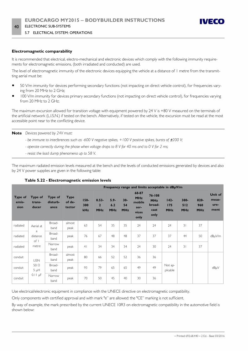
40EUROCARGO MY2015 ‒ BODYBUILDER INSTRUCTIONSELECTRONIC SUB-SYSTEMS
5.7 ELECTRICAL SYSTEM: OPERATIONS
– Printed 692.68.440 – 2 Ed. - Base 03/2016
Electromagnetic comparability
It is recommended that electrical, electro-mechanical and electronic devices which comply with the following immunity require-ments for electromagnetic emissions, (both irradiated and conducted) are used.
The level of electromagnetic immunity of the electronic devices equipping the vehicle at a distance of 1 metre from the transmit-ting aerial must be:
50 V/m immunity for devices performing secondary functions (not impacting on direct vehicle control), for frequencies vary-ing from 20 MHz to 2 GHz;
100 V/m immunity for devices primary secondary functions (not impacting on direct vehicle control), for frequencies varyingfrom 20 MHz to 2 GHz;
The maximum excursion allowed for transition voltage with equipment powered by 24 V is +80 V measured on the terminals ofthe artificial network (L.I.S.N.) if tested on the bench. Alternatively, if tested on the vehicle, the excursion must be read at the mostaccessible point near to the conflicting device.
Note Devices powered by 24V must:
- be immune to interferences such as -600 V negative spikes, +100 V positive spikes, bursts of ±200 V;
- operate correctly during the phase when voltage drops to 8 V for 40 ms and to 0 V for 2 ms;
- resist the load dump phenomena up to 58 V.
The maximum radiated emission levels measured at the bench and the levels of conducted emissions generated by devices and alsoby 24 V power supplies are given in the following table:
Table 5.22 - Electromagnetic emission levels
Type ofemis-sion
Type oftrans-ducer
Type ofdisturb-
ance
Typeof de-tector
Frequency range and limits acceptable in dBμV/m
Unit ofmeas-ure-
ment
150-300kHz
0.53-2
MHz
5.9-6.2
MHz
30-54
MHz
68-87MHz
mobileser-vicesonly
76-108MHz
broad-castonly
142-175
MHz
380-512
MHz
820-960
MHz
radiated Aerial ata
distanceof 1
metre
Broad-band
almostpeak
63 54 35 35 24 24 24 31 37
dBμV/mradiatedBroad-band
peak 76 67 48 48 37 37 37 44 50
radiatedNarrow
bandpeak 41 34 34 34 24 30 24 31 37
conduitLISN50 Ω5 μH
0.11 μF
Broad-band
almostpeak
80 66 52 52 36 36
Not ap-plicable
dBμVconduitBroad-band
peak 93 79 65 65 49 49
conduitNarrow
bandpeak 70 50 45 40 30 36
Use electrical/electronic equipment in compliance with the UNECE directive on electromagnetic compatibility.
Only components with certified approval and with mark "e” are allowed: the "CE” marking is not sufficient.
By way of example, the mark prescribed by the current UNECE 10R3 on electromagnetic compatibility in the automotive field isshown below:

EUROCARGO MY2015 ‒ BODYBUILDER INSTRUCTIONSELECTRONIC SUB-SYSTEMS
5.7 ELECTRICAL SYSTEM: OPERATIONS41
– Printed 692.68.440 – 2 Ed. - Base 03/2016
191312 Figure 31
a ≥ 6 mm
The values in the table are only to be considered respected if the device comes form "IVECO Spare Parts” or it has been certifiedas per the international standards ISO, CISPR, VDE etc.
Whenever equipment is used which runs on mains power (220 V AC) for its primary or secondary source of power, it must bechecked to ensure that its characteristics are in line with IEC regulations.
Reception/transmission systems
The most frequent applications include:
amateur receiver-transmitter units for CB (City Band) and 2 m bands; receiver-transmitter units for cellular telephones and TETRA/TETRAPOL; GPS receiver and satellite navigation units.
If devices are fitted which could interact with the electronic systems already present (retarders,additional heaters, power take-offs, air conditioners, automatic gearboxes, telematics and speedlimiters) contact IVECO to optimize the application.
General instructions
1. The equipment must be approved according to the law and be of a fixed nature (not potable).The use of non approved transmitters or supplementary amplifiers could seriously impede the correct functioning of theelectrical/electronic devices normally supplied, with negative effects for the safety of the vehicle and/or the driver.
2. The system already provided on the vehicle must be used to power the transmitters and they must be connected to terminalK30 of the connector ST40 (and K15 where necessary) via a supplementary fuse.Any additional power lines must be created respecting the correct sizing of cables and protection.
3. The coaxial antenna cable must be positioned taking care to: use a low loss, top quality product with the same impedance as the transmitter and the antenna (see Figure 33): in order to avoid interference and malfunctioning, create a path (the shortest possible) which maintains a suitable dis-
tance (min. 50 mm) from pre-existing cabling or from other cables (radio, amplifiers and other electronic equipment),keeping the minimum distance from the metal structure of the cab and using existing holes in the sheet metal;
do not shorten or lengthen; avoid unnecessary tangles, tension, folds and crushing.4. Outside the cab, the antenna must be installed on the vehicle on a metal base with a wide surface; it must also be fitted as ver-
tically as possible with the connection cable pointing downwards and, in any case, following the manufacturer's fitting instruc-tions and warnings (see Figure 32).Installation on the centre of the roof is to be considered the best by far, as the grounding is proportional in all directions.The equipment and two-way radios inside the passenger compartment should be placed in the slot of the crossbar fittedabove the windscreen on the driver's side.
5. The quality of the antenna, the mounting position and a perfect connection to the vehicle structure (ground) are factors offundamental importance to guarantee the best performance of the transmitter equipment.

42EUROCARGO MY2015 ‒ BODYBUILDER INSTRUCTIONSELECTRONIC SUB-SYSTEMS
5.7 ELECTRICAL SYSTEM: OPERATIONS
– Printed 692.68.440 – 2 Ed. - Base 03/2016
98915 Figure 32
1. Antenna support 2. Gasket 3. Fixed joint cover
4. Fastening screw M6x8.5 (tighten to a tightening torque of2 Nm)
5. Antenna 6. Roof panel 7. Antenna extension cable
99349 Figure 33
1. Antenna connector 2. Ground wire 3. Insulator 4. Signal wire 5. Condenser (100 pF) 6. Cable RG 58 (characteristic impedance = 50 Ω) 7. Clamp 8. Protection cap
9. Connector (N.C. SO - 239) transreceiver side 10. Test executed sticker 11. The 100 pF condenser must be soldered on the lower pin
and crimped to the ground braid 12. The lower pin must be soldered to the core conductor of
the cable 13. Nut
Power for the equipment, when the voltage required is different to that for the system, must be obtained using a suitable DC/DC12-24V converter if not already provided. The power cables must be as short as possible, avoiding any twists (coils) and maintainingthe minimum distance from the reference plane.
Some specific instructions are given below for each type of equipment.

EUROCARGO MY2015 ‒ BODYBUILDER INSTRUCTIONSELECTRONIC SUB-SYSTEMS
5.7 ELECTRICAL SYSTEM: OPERATIONS43
– Printed 692.68.440 – 2 Ed. - Base 03/2016
Amateur equipment for CB (27 MHz) and 2 m band (144 MHz)
The transmitter part must be installed in a separate area from the vehicle's electrical components; if the transmission is impulsive itmust be at a distance of least 1 meter away from other devices.
The ROS value (Stationary Wave Ratio) must be as close as possible to the unit (the recommended value is 1.5), while themaximum acceptable value must never be greater than 2.
The ANTENNA GAIN values must be as high as possible and guarantee a sufficient level of spatial uniformity, characterisedby deviations in relation to the average value to the order of 1.5 dB in the typical CB band (26.965-27.405 MHz).
The IRRADIATED FIELD in cab value must be as low as possible, and however < 1V/m.In any case, limits set by the applicable European Directive must never be exceeded.
To determine whether the system is functioning well and to check that the antenna is calibrated, it is suggested that the followinginformation is taken into account:
1. if the ROS (Stationary Wave Ratio) is higher on the lower channels than on the higher ones, the antenna should belengthened;
2. if the ROS (Stationary Wave Ratio) is higher on the higher channels than on the lower ones, the antenna should be shortened;
After having calibrated the antenna, it is advisable to re-check the ROS (Stationary Wave Ratio) value on al the channels.
Equipment for GSM/PCS/UMTS cellular phones and TETRA/TETRAPOL
Install the transmitting part in a flat, dry area, separate from the electronic components of the vehicle, away from humidity andvibrations. If the transmission is impulsive it must be at a distance of at least 1 meter away from other devices.
The ROS value (Stationary Wave Ratio) must be as close as possible to the unit (the recommended value is 1.5), while themaximum acceptable value must never be greater than 2.
The ANTENNA GAIN values must be as high as possible and guarantee a sufficient level of spatial uniformity, characterisedby deviations in relation to the average value to the order of 1.5 dB in the 380-460 MHz band and 870-960 MHz and 2 dB inthe 1710-2000 MHz band.
The IRRADIATED FIELD in cab value must be as low as possible, and however < 1V/m.In any case, limits set by the applicable European Directive must never be exceeded.
An optimum position for the antenna would be the front of the cab roof, at a distance of not less than 30 cm from other antennas.
GPS reception and satellite navigation equipment
Install the transmitting part in a flat, dry area, separate from the electronic components of the vehicle, away from humidity andvibrations. If the transmission is impulsive it must be at a distance of at least 1 meter away from other devices.
The GPS antenna must be installed so as to have the maximum visibility possible of the sky.
In fact, as the signals received from the satellite are at very low power (approximately 136 dBm), almost any obstacle can influencethe quality and performance of the receiver.
The following should therefore be guaranteed:
an absolute minimum angle of vision of the sky of 90°; a distance no less than 30 cm from any other antenna; a horizontal position and never underneath any metal which makes up part of the cab structure.
Moreover:
the ROS value (Stationary Wave Ratio) must be as close as possible to the unit (the recommended value is 1.5), while themaximum must never be greater than 2 in the GPS frequency range (1575.42 ± 1.023 MHz).

44EUROCARGO MY2015 ‒ BODYBUILDER INSTRUCTIONSELECTRONIC SUB-SYSTEMS
5.8 ADDITIONAL EQUIPMENT
– Printed 692.68.440 – 2 Ed. - Base 03/2016
the ANTENNA GAIN values must be as high as possible and guarantee a sufficient level of spatial uniformity, characterised bydeviations in relation to the average value to the order of 1.5 dB in the 1575.42 ± 1.023 MHz band.
5.8 ADDITIONAL EQUIPMENT
The vehicle system is set up to supply the necessary power to the equipment provided, for each of which, as part of their function,the specific protection is assured as well as the correct dimensioning of cables.
The installation of additional equipment must include suitable protections and should not overload the vehicle system.
The connection of the added users to ground must be made with an adequately sectioned cable, as short as possible and made toallow for any movements of the added equipment with respect to the chassis of the vehicle.
The connection of the added users to ground must be made with an adequately sectioned cable, as short as possible and made toallow for any movements of the added equipment with respect to the chassis of the vehicle. Having the need for higher capacitybatteries, due to added loads, it is appropriate to request the optional with increased batteries and alternators.
In any case, when increasing battery capacity, it is advisable not to exceed 20-30% of the maximum values provided as optional byIVECO, so as not to damage some of the components (e.g. starter motor). When higher capacities are necessary, use additionalbatteries, making the necessary provisions for recharging as indicated below.
Additional batteries
The installation of additional electrical equipment or high absorption equipment (e.g. engines operated frequently or used for longperiods with thermal motor off, as in the case of tail lifts), could require power that the basic vehicle system cannot provide. Inthese cases, additional batteries of suitable capacity must be adopted.
The insertion of additional batteries in the vehicle circuit should include an adequate recharge system, using an alternator with morepower or adopting and additional alternator with a separate recharge system, integrated with that of the vehicle. In this case it isnecessary to provide additional batteries with a capacity equal to those originally fitted (170 Ah / opt. 220 Ah) for correct chargingof all the batteries.
In case of installation of additional batteries, it is possible to use:
1. recombination batteries (AGM or gel);2. traditional batteries.
In both cases it is necessary to adequately separate the batteries from the environment of the vehicle occupants by means of anappropriate container that ensures sealing in case of:
emission of vapours (for example, in the event of a fault in the alternator voltage regulator); explosion of the battery; Leakage of liquid electrolyte, even in case of tilting.
If type 1 batteries are used, it is necessary to place a breather towards the outside of the housing compartment.
If type 2 batteries are used, it is necessary to use batteries equipped with:
cover with a system that emits gas towards the outside, equipped with a tube for spraying acid spray outwards; flame arrestor system by means of porous pad.
It is also necessary to ensure that the evacuation of gas is located far from possible spark trigger points, from mechan-ical/electric/electronic parts, placing the exhaust outlet so as to avoid generating vacuum inside the battery housing compartment.
Ground connection of the additional battery must be made using a cable (the shortest possible)of adequate section.

EUROCARGO MY2015 ‒ BODYBUILDER INSTRUCTIONSELECTRONIC SUB-SYSTEMS
5.8 ADDITIONAL EQUIPMENT45
– Printed 692.68.440 – 2 Ed. - Base 03/2016
196796 Figure 34
1. Standard batteries 2. Additional batteries 3. Alternator with built-in regulator 4. Starter motor
5. Ignition switch 6. Contactor switches 7. IVECO Body Controller 8. Instrument panel
All the lines downstream of all batteries are to be adequately protected, under any fault condi-tion. Failure to ensure adequate protection may pose a fire hazard and a danger to persons.
Additional alternators
The installation of additional batteries involves the verification of the ability of the alternator to charge. If the results of this verific-ation are negative, an alternator with more power must be used, or an additional alternator must be adopted; in this case, connec-tion must be made as indicated in the following Figure.

46EUROCARGO MY2015 ‒ BODYBUILDER INSTRUCTIONSELECTRONIC SUB-SYSTEMS
5.8 ADDITIONAL EQUIPMENT
– Printed 692.68.440 – 2 Ed. - Base 03/2016
196797 Figure 35
1. Standard alternator 2. Supplementary alternator 3. To the batteries 4. Signal K15 from connector ST14A/pin 11
5. Front Frame Computer 6. Body Computer 7. Instrument panel 8. No battery charging warning light or led
The installation of additional equipment must include suitable protections and should not overload the vehicle system.
The additional alternators must be the type with Zener diode rectifiers to avoid damaging electric/electronic equipment due toaccidental battery disengagement. Each alternator must also have a light or LED indicating low battery charge.
The additional alternator must have electrical features identical to those of the standard alternator and the cables must be correctlysized.
If you need to modify the system in a way other than described in this manual (for example, adding batteries in parallel), it is neces-sary to share the operation with IVECO.
Additional electrical units
Particular attention must be paid when installing cooling units that use a second alternator, mounted on the engine (additional gen-erator), as a power source.
These generators provide, depending on the number of turns, a voltage of the order of 270 ÷ 540 V which goes through the wir-ing to the cooling unit installed on the vehicle.
There is a clear danger of any crosstalk (electromagnetic interference between adjacent cables) that can be generated between theaforementioned cable and the wiring already present on the vehicle.
In these cases it is necessary to use cables with high insulation, adopting a preferential path, though not in the vicinity of the standardvehicle wiring.
For these units, respect the electromagnetic emissions levels mentioned above.
In case of a standard alternator malfunction (e.g. low voltage, no signal) on the dashboard, an error message will be reported.
A possible additional alternator cannot be connected to the Multiplex and therefore in case of malfunction, the Multiplex is not ableto detect which alternator is not operating properly.

EUROCARGO MY2015 ‒ BODYBUILDER INSTRUCTIONSELECTRONIC SUB-SYSTEMS
5.8 ADDITIONAL EQUIPMENT47
– Printed 692.68.440 – 2 Ed. - Base 03/2016
Drawing current
The current draw is related to the battery capacity.
If the engine is stopped the current draw from the battery reduces the capacity to restart the engine.
Note If the battery is charged less than 50% the engine start may be seriously compromised.
For the correct operation of the vehicle it is important to ensure that:
with engine stopped, the supply is limited to 10% of the nominal battery capacity; with the engine running, the supply of another 20% of the nominal battery capacity is possible.
In the following the detail:
Table 5.23 - Maximum samples permitted with engine not running
battery capacity [Ah]supply for 1 continuous
hour [A]supply for 2 continuous
hours [A]supply for 5 continuous
hours [A]supply for 10
continuous hours [A]
110 9.9 5.0 2.0 1.0
143 12.9 6.4 2.6 1.3
170 15.3 7.7 3.1 1.5
Battery level status
It is approximately derivable by the following table, where there is a direct link "open circuit voltage of the battery ← → level”:
Table 5.24battery voltage [V] charge level
<12.2 <50%
12.3 50%
12.4 65%
12.5 75%
> 12.6 >90%
Note To check the level it is necessary to accurately measure the voltage with the battery terminals disconnected and possibly at leastone hour after turning off the engine.
The loss of capacity due to a current draw when the motor is stopped must be recovered in the shortest possible time.
To this effect, it is considered that, in case of a vehicle with standard equipment, without additional electrical loads, with 70 A al-ternator and 110 Ah battery, circulating with typical urban mission, the capacity is recovered as follows:
Table 5.25outgoing charge level [%] working hours [h] recovered capacity [%]
65
1 20
2 25
3 28
75
1 13
2 16
3 18

48EUROCARGO MY2015 ‒ BODYBUILDER INSTRUCTIONSELECTRONIC SUB-SYSTEMS
5.8 ADDITIONAL EQUIPMENT
– Printed 692.68.440 – 2 Ed. - Base 03/2016
The table does not take into account the drawing of the auxiliaries additions to the electrical system which, by taking a current de-pending on the user, removes current in order to charge the battery.
It is reasonable to estimate that according to the table below, relating to important characteristics of the joining between alternatorand vehicular mission, it is necessary to ensure a current margin equal to:
20% of the battery capacity for missions from 1 to 3 hours 15% of the battery capacity for missions from 3 to 5 hours 10% of the battery capacity for missions from to 5 hours
This means that a long mission allows to recharge slower and therefore a greater margin for auxiliaries, while short missions requirehigher current charging or lower auxiliary loads.
Table 5.26Engine /Mission
4 cylinders /Door To Door
4 cylinders /Urban Distribution
6 cylinders /One Day Delivery
AlternatorsBosch70 A
Bosch90 A
∆Bosch70 A
Bosch90 A
∆Bosch70 A
Bosch90 A
∆
Total available potential (80 °C) [A] 55 71 16 60 77 17 58 73 15
Potential for recharge and opt (without vehicleconsumption) [A]
41 56 15 42 59 17 42 58 16
Max supply at idle speed (80 °C) [A] 47 58 11 47 57 10 40 47 7
Total available potential: is the hourly current that the alternator can provide if always used at maximum current available to therelative rotating speeds (that is the sum of the max. currents on the mission in an hour)
Potential for recharge and optional: is the available potential from which was removed the actual vehicular consumption
Available potential at idle mode: is the maximum available current at idle speed
Example 1
Vehicle with 143 Ah battery and 70 A alternator, “Door To Door” missions lower at three hours of engine running:
the available potential is ~55 A and the available potential for recharge and optional is ~41 A with engine running for at least 3 hours requires the 20% of 143 = ~28 A for the recharge the maximum continuous permit for the optional is given with 41 – 28 = 13 A
Example 2
Vehicle with 170 Ah battery and 70 A alternator, “Urban Distribution” missions of approximately four hours of engine running
the available potential is ~60 A and the available potential for recharge and optional is ~42 A with engine running for at least 4 hours requires the 15% of 170 = ~26 A for the recharge the maximum continuous permit for the optional is given with 42 – 26 = 16 A
For the vehicle use and absorption with engine stopped higher than the recommended ones, it is necessary to have extra batteries.
The high electric load supply (e.g. tail lifts), when the use is frequently (greater than 10 drives a day), requires the use of batterieswith min. capacity of 143 Ah and an increased alternator of 90 A.

EUROCARGO MY2015 ‒ BODYBUILDER INSTRUCTIONSELECTRONIC SUB-SYSTEMS
5.8 ADDITIONAL EQUIPMENT49
– Printed 692.68.440 – 2 Ed. - Base 03/2016
Current withdrawal points
On EUROCARGO it is not possible to connect additional electrical systems directly to the positive battery pole, as this pole is en-gaged by cables going to the fuse box.
It is also not permitted to draw current from the bulkheads, from the side light systems and from the additional fuse box (pointsA-A highlighted in figure 36).
Note The fuse holder, placed on the side of the battery casing, must not be changed or moved.
The current drawing is possible from:
1. cable box;2. connector 61071;3. main current switch;4. main power contactor (if installed).
1 2 3 4 5
204639 Figure 36
1. Cable box 2. Additional fuse box
A. Current draw points not to be used
1. Cable box
204637 Figure 37
M1. Power supply outlet for starter motor M2. Power supply outlet DGC / TGC / Batt.
M3. Fuse box power supply outlet

50EUROCARGO MY2015 ‒ BODYBUILDER INSTRUCTIONSELECTRONIC SUB-SYSTEMS
5.8 ADDITIONAL EQUIPMENT
– Printed 692.68.440 – 2 Ed. - Base 03/2016
204637 Figure 37
M4. Outlet at Grid Heater relay M5. Bodybuilder power supply outlet
The current draw can be performed with the specific terminal M5 specially crafted in the terminal board.
2. 21-pin connector 61071 (brown)
From the 21-pin connector 61071, placed in the electric control unit compartment (under the panel on the passenger side), it ispossible to draw current from the pins 11 and 21.
Such current draw is protected by two fuses:
Table 5.27FUSE MAXIMUM LOAD DESCRIPTION
F9 6 A K30 (pin 21)
F15 6 A K15 (pin 11)
For further information please see Chapter 5.2 ( Page 10).
3. Main current switch (DGC)
It is generally located on the battery casing and functions automatically. It is a two-pole switch that disconnects the battery from thechassis, allowing the operation of the tachograph, body computer, cooling unit, bed module and instrument panel.
For special modifications (e.g. transport of fuel, transport of dangerous substances) it may be necessary to use a safety switch thatisolates the batteries and the alternator from the rest of the system.
Specific solutions must be authorised by IVECO.
Note It is permissible to connect in parallel with the output of the diverter (max. 100 A).
4. Main power contactor (TGC option)
When the vehicle is equipped with the TGC optional, the draw may be made on the appropriate pin.
In this case you need to remove the protective plastic from the free pin and connect the draw terminal directly to the threadedscrew (positive pole), locking it with a suitable nut; the chassis constitutes the return.
To make two or more current draws, interpose a suitable spacer between the draw terminals.
Always protect the cables with a special corrugated pipe and always replace the protective plastic.

EUROCARGO MY2015 ‒ BODYBUILDER INSTRUCTIONSELECTRONIC SUB-SYSTEMS
5.8 ADDITIONAL EQUIPMENT51
– Printed 692.68.440 – 2 Ed. - Base 03/2016
Note Before drawing any current, read Chapter 5.2 carefully. The drawn current may not exceed the maximum load value as indicatedin the Chapter.
Maxifuse and Megafuse fuses
At IVECO Parts there are five fuse holder kids available, to protect high absorption draws.
Their positioning must be always performed as close as possible to the draw terminal on the batteries.
191313 Figure 38
A. Maxifuse B. Battery case
C. Megafuse
Table 5.28 - Maxifuse
CapacityReference number of IVECO electrical kit
accessoriesFusebox body design number Cable cross-section
KIT 40 A 4104 0110 KZ 500317518 10 mm²
KIT 60 A 4104 0111 KZ 500317518 10 mm²
Table 5.29 - Megafuse
CapacityReference number of IVECO electrical kit
accessoriesFusebox body design number Cable cross-section
KIT 100 A 4104 0112 KZ 500315861 25 mm²
KIT 125 A 4104 0113 KZ 500315861 35 mm²
KIT 100 A 4104 0114 KZ 500315861 50 mm²
The fuse must be fastened to the chassis with a tightening torque of 2 ± 0.2 Nm.

52EUROCARGO MY2015 ‒ BODYBUILDER INSTRUCTIONSELECTRONIC SUB-SYSTEMS
5.8 ADDITIONAL EQUIPMENT
– Printed 692.68.440 – 2 Ed. - Base 03/2016
Voltage reducer
The electrical system of the vehicle is prepared for the power supply of 12V devices. In the cab there is a connection with a voltagereducer (from 24 V a 12 V).
Do not power the unit directly by taking 12 V voltage from a single battery.
The voltage reducer is arranged for a maximum current absorption of 20 A at a temperature of30°C (measured in the device compartment on the upper cross member). Therefore, it mustnot be used if other devices indicate higher absorption.
Additional circuits
The additional circuits must be separated from the vehicle and protected by means of a specific fuse
As already seen in chapter 5.7(→ page 38) Paragraph "Precautions for work on the system", the used cables must be:
of appropriate sizes and equipped with good original insulation; connected to the original system by means of tin joints equivalent to the original ones, protected with sheaths (not PVC) or
intubated in polyamide conduits of type 6; installed protections from shock, heat, rubbing with other components (in particular with the sharp edges of the bodywork); secured separately with insulated cable clamps (e.g. made of nylon) and at adequate intervals (approx. 200 mm).
The passage through crossbars and/or sections must provide special fairleads or protections; it is not possible to drill the chassisand/or the bodywork
In case of external panels, use a specific sealant both on the cable and on the panel to prevent water, dust and fumes from infiltrat-ing.
Where possible it shall also be provided a different cable path that transfers interference signals with high absorbed intensity (e.g.electric motor, solenoid valves) and low absorbed intensity susceptible signals (e.g. sensors); for both must be remained a position-ing as close as possible to the metallic structure of the vehicle.
Plug and terminal connections must be protected, resistant to weathering, and executed using components of the same type asthose utilised originally on the vehicle.
Use cables and fuses with the characteristics shown in the following table in accordance with the current draw:
Table 5.30- Use of cables and fuses according to the current drawnMax. continuous current (1) (A) Cable cross-section (mm2) Fuse capacity (2) (A)
0 ÷ 4 0,5 5
4 - 8 1 10
8 ÷ 16 2,5 20
16 - 25 4 30
25 - 33 6 40
33 ÷ 40 10 50
40 - 60 16 70
60 - 80 25 100
80 ÷ 100 35 125
100 - 140 50 150
(1) For uses of more than 30 seconds.(2) Depending on the position and therefore the temperature that may be reached in the housing, choose fuses that can be loadedto up to 70%- 80% of their maximum capacity.

EUROCARGO MY2015 ‒ BODYBUILDER INSTRUCTIONSELECTRONIC SUB-SYSTEMS
5.8 ADDITIONAL EQUIPMENT53
– Printed 692.68.440 – 2 Ed. - Base 03/2016
Note The fuse must be connected as close as possible to the current take-off point.
Precautions
Incorrect installation of electrical accessories may affect occupant safety and cause severe damage to the vehicle.Contact IVECO if you have any questions.
Avoid coupling with signal transmission cables (e.g. ABS), for which a preferential path has been defined for electromagneticrequirements (EMI).It should be noted that when grouping several cables together, in order to compensate for lower heat dispersal capacity, thecurrent intensity must be reduced with respect to the nominal value of a single cable.
In vehicles with frequent engine start-ups, with limited current drawn and engine rotations (e.g.vehicles with refrigerationchambers), provide for periodic battery charging to maintain efficiency.
Plug and terminal connections must be protected, resistant to weathering, and executed using components of the same typeas those utilised originally on the vehicle.
In the event that a component has to be installed just next to the route of a cable belonging to the original system, make surethat its remains integral and avoid any cuts.
Any damage caused by failure to comply with procedure is not covered by warranty.
Modifying wheelbase and overhang
Should it be necessary to lengthen the wires on the chassis owing to the new dimensions of wheelbase and overhang, a watertightjunction box must be used which has the same characteristics as those used on the standard vehicle. The electrical componentsused such as wires, connectors, terminal blocks, conduits etc. must be of the same type as those used originally and must be cor-rectly fitted.
Side Marker Lamp installation
EC regulations require that vehicles are provided with side and clearance lights when the total length exceeds 6 m.
The installation of the side lights must be performed on the additional structures (containers, vans, etc.), while the electric powersupply must be obtained by the specific connector 61069 on the chassis (see Figure 39).
Note It is not possible to draw current from side marker lights.

54EUROCARGO MY2015 ‒ BODYBUILDER INSTRUCTIONSELECTRONIC SUB-SYSTEMS
5.8 ADDITIONAL EQUIPMENT
– Printed 692.68.440 – 2 Ed. - Base 03/2016
200436 Figure 39
Table 5.31 - Basic functions of connector 61069
Pin DescriptionWirecode
Max.Load
Connected to Remarks
1 Ground 0000 10 A Ground
2Side lightsleft sides
3332 5 A MET P-A07+24V = Daylight running lights on signal, when: (1)
K15 OFF and parking lights onK15 ON and parking/high beam/low beam lights on
3Side lightsright sides
3331 5 A MET P-A08+24V = Daylight running lights on signal, when: (2)
K15 OFF and parking lights onK15 ON and parking/high beam/low beam lights on
4 K15 8869 10 A MET P-C01 K15
(1) If the maximum current is exceeded:
The output signal is deactivated A MUX 0x26D55 FMI 0x06 error is generated The interior lights of the vehicle switch off together with the left side lights and right tail lights
The error and the output signal are reset at the next K15 cycle.
If the behaviour is not acceptable, the Bodybuilder must limit the maximum current, for example with the addition of a fuse on thebodybuilder wiring.(2) If the maximum current is exceeded:
The output signal is deactivated A MUX 0x26D51 FMI 0x06 error is generated
EUROCARGO MY2015 ‒ BODYBUILDER INSTRUCTIONSELECTRONIC SUB-SYSTEMS
5.9 SPECIFICATIONS FOR VERSIONS FROM "COWLED"55
– Printed 692.68.440 – 2 Ed. - Base 03/2016
The interior lights of the vehicle switch off together with the side lights and both tail lights (the rear fog light may still be on)
The error and the output signal are reset at the next K15 cycle.
If the behaviour is not acceptable, the Bodybuilder must limit the maximum current, for example with the addition of a fuse on thebodybuilder wiring.
5.9 SPECIFICATIONS FOR VERSIONS FROM "COWLED"
In the realisation of a specific cab interior, such as Camper or Bus outfitting, it is essential that the OBD socket (On Board Dia-gnosis, code 72069) is retained in the set position for trucks or in the near vicinity.
This position corresponds to the dashboard centre distance, below the air vent on the passenger side and behind trim panel.
We underline the need to ensure maximum accessibility and appropriate information in this regard.
Electronic safety devices
Note It is recommended that the following information supplements the operator's manual with regard to the detail of the system char-acteristics described, the operating systems and limitations.
1) AEBS (Advanced Emergency Braking System)
AEBS emergency braking system measures the distances from the preceding vehicle and, if they are lower than a safety threshold, itis able to activate braking with the greatest intensity possible.
The system receives measurement data from a radar installed in the middle of the front bumper.
Not available for 4x4 vehicles, AEBS is supplied standard on vehicles with PPT above 8 tons and air suspensions; for all the others(PTT less than or equal to 8 tons, vehicles with mechanical suspensions, cowl versions) it is optional and can be supplied only incombination with EVSC (Enhanced Vehicle Safety Control, an evolution of the known ESP).
Since the device carries out essential processing procedures for safety, installation and calibra-tion procedures are needed which can only be performed by IVECO during the first equipment:Post-sales installation is not permitted.
To respect the operating conditions provided by the design, operators are reminded that the following must not be modified:
the shape of the bracket securing the radar; the position of the radar (orientation, inclination of ±3°on the horizontal reference with the vehicle outfitted); the area in front of the output cone of the radio waves, which must be free of any obstacles; the material, the shape and the dimensions of the protective cover, which must be those provided by the manufacturer (see
the diagrams in Figure 40 and Figure 41); the integrity of the protection cover (no painting, tape, etc).
Changes to one or more than one of these parameters requires specific authorisation from IVECO as well as new deliberation andcalibration of the device; any financial cost will be charged to the Bodybuilder.
Please note that the radar may be secured further ahead (max 100 mm) along the longitudinal axis of the vehicle if the vibrationalbehaviour remains unchanged compared to the orgiastic position.
The radar must be recalibrated if the original geometry of the radio wave output cone is notmaintained.

56EUROCARGO MY2015 ‒ BODYBUILDER INSTRUCTIONSELECTRONIC SUB-SYSTEMS
5.9 SPECIFICATIONS FOR VERSIONS FROM "COWLED"
– Printed 692.68.440 – 2 Ed. - Base 03/2016
The output cone of the radio waves may be altered:
by damage to the radar fastening bracket or damage behind the tubular cross beam (for example, impacts, collisions); by poor refitting of the bumpers after they have been removed or replaced; by excessive vibrations of the bumpers, if a bumper other than standard bumpers are used.
Note Recalibration can only be carried out by the IVECO Customer Service
To avoid unnecessary braking, the AEBS system must be deactivated when the area in frontof the radar cannot be kept completely free (roller bench tests, vehicle towing, use of snowploughs, etc.).
Below are the diagrams showing the only possible positions of the radar protection cover on the bumper once outfitting operationshave been completed.
These diagrams refer to the plastic cover, the only one supplied with the cowl vehicle.
231370 Figure 40

EUROCARGO MY2015 ‒ BODYBUILDER INSTRUCTIONSELECTRONIC SUB-SYSTEMS
5.9 SPECIFICATIONS FOR VERSIONS FROM "COWLED"57
– Printed 692.68.440 – 2 Ed. - Base 03/2016
231371 Figure 41
The dimensions must be strictly observed.
231171 Figure 42
Table 5.32 - ACC / AEBS radar control unit pin-outPin Function Cable colour code
1 Power supply +15 8879
2 Power supply +15 8879
3 Spare −
4 can h line Gn
5 Spare −
6 Spare −
7 can l line Wh
8 Ground 0000

58EUROCARGO MY2015 ‒ BODYBUILDER INSTRUCTIONSELECTRONIC SUB-SYSTEMS
5.9 SPECIFICATIONS FOR VERSIONS FROM "COWLED"
– Printed 692.68.440 – 2 Ed. - Base 03/2016
2) LDWS (Lane Departure Warning System)
The lane departure warning system (LDWS) monitors the vehicle's position with respect to the lane dividing strips and, in the caseof an involuntary deviation from the theoretical direction, it activates a specific acoustic signal.
The system uses the images from a camera/sensor positioned at the centre of the dashboard and affixed on the inside of the wind-screen (see Figure 46).
The acoustic signal may be emitted by the cluster (basic version) or from the speaker on the side of the lane which has been ex-ceeded (optional version).
On cowl vehicles:
the camera and speaker are supplied as individual parts in a dedicated kit; the installation of an "aftermarket" radio requires the port of the camera mute function to be connected according to the
diagram in Figure 47; installation of a 12V radio requires use of a device to adjust it to the 24V of the camera; camera programming, calibration and testing, as well as the acoustic signal programming is only to be done by the IVECO As-
sistance Service.
Note If the windscreen is replaced, camera calibration and verification of all the operating parameters of the system must be carried outagain (only at the IVECO Assistance Service. This service is will be charged).
Camera positioning
The inclination of the camera, set by the operating specifications, must be strictly observed,even in the case of outfittings which include a windscreen with an inclination which is differentfrom normal production.
For correct operation (“artificial view”), the camera must be positioned on the windscreen so that:
the vertical axis is on the centre line of the vehicle, with a tolerance of ± 10 mm;
233489 Figure 43
the lens is at a height "x" from the ground (Fig. 43) established during the design and planning stage (mm 1810 - 1850 - 1990 -2010 - 2050 - 2290), with a possible tolerance of +/- 50 mm.The installation height selected must be used when programming the camera.If the camera has to be positioned at a different height, approval must be received from IVECO and specific programmingmust be carried out.
the rotation angles around the reference axis (see Figure 44) have the following values:

EUROCARGO MY2015 ‒ BODYBUILDER INSTRUCTIONSELECTRONIC SUB-SYSTEMS
5.9 SPECIFICATIONS FOR VERSIONS FROM "COWLED"59
– Printed 692.68.440 – 2 Ed. - Base 03/2016
compared to axis x: -2° ≤ roll angle ≤ 2°,compared to axis y: -8.5° ≤ pitch angle ≤ 0.5°,compared to axis z: -2° ≤ yaw angle ≤ 2°.
233491 Figure 44
In particular, with regards to the pitch angle, please note that:
the electronic control unit of the LDWS device (1) must be installed with the "bracket" element (2), whose front side is tiltedby 14° from the vertical plane
239351 Figure 45
1. LDWS device electronic control unit 2. Bracket (P/N: 5801908439)
the presence of the bracket means that the inclination of the windscreen (α) in relation to the horizontal plane is between 71°and 80°
If, due to construction needs of the cab, the inclination of the windscreen exceeds 80°, a spacer must be positioned betweenthe bracket and the windscreen. The shape of the spacer must allow the camera pitch angle to be maintained within the limitsindicated above (from -8.5 ° to 0.5 °) and therefore at angle β to remain between 10° and 19°.

60EUROCARGO MY2015 ‒ BODYBUILDER INSTRUCTIONSELECTRONIC SUB-SYSTEMS
5.9 SPECIFICATIONS FOR VERSIONS FROM "COWLED"
– Printed 692.68.440 – 2 Ed. - Base 03/2016
239352 Figure 46
A. Windscreen inclination (α) between 71° and 80° B. Windscreen inclination (α) greater than 80°
1. Bracket 2. Windscreen 3. Spacer
Precautions
To avoid the effects of condensation on the camera lens, ensure that there is sufficient air circulation in the space between the lensand windscreen. The support provided by IVECO includes ventilation channels which are covered by a flow of air from the base ofthe windscreen: these channels must never be obstructed.
Pin - Out
224577 Figure 47
Table 5.33 - LDWS Pin-OutPin Function Cable colour code
1 Power supply +15 8879
2 Ground 0000
3 Power supply +15 8879

EUROCARGO MY2015 ‒ BODYBUILDER INSTRUCTIONSELECTRONIC SUB-SYSTEMS
5.9 SPECIFICATIONS FOR VERSIONS FROM "COWLED"61
– Printed 692.68.440 – 2 Ed. - Base 03/2016
Pin Function Cable colour code
4 CAN line H - VDB White
5 CAN line L - VDB Green
6 – –
7 – –
8 Signal from the switch for the deactivation of the LDWS system 8896
9 – –
10 – –
11 Deactivated LDWS system signalling warning light negative 6700
12 "Mute" signal from the LDWS control unit to radio 1632
13 Positive for left speaker 1286
14 Negative for left speaker 1288
15 Positive for right speaker 1284
16 Negative for right speaker 1283

62EUROCARGO MY2015 ‒ BODYBUILDER INSTRUCTIONSELECTRONIC SUB-SYSTEMS
– Printed 692.68.440 – 2 Ed. - Base 03/2016

- Printed 692.68.440 – 2 Ed. - Base 03/2016
SECTION 6
ADBLUE AND
SCRT SYSTEM

- Printed 692.68.440 – 2 Ed. - Base 03/2016

EUROCARGO MY2015 ‒ BODYBUILDER INSTRUCTIONSADBLUE AND SCRT SYSTEM (only diesel versions)
Contents3
– Printed 692.68.440 – 2 Ed. - Base 03/2016
Contents
6.1 GENERAL INFORMATION . . . . . . . . . . . . . . 5
6.2 THE NITROGEN OXIDE CATALYTICREDUCTION PRINCIPLE . . . . . . . . . . . . . . . . . . . 5
6.3 INSTRUCTIONS . . . . . . . . . . . . . . . . . . . . . 6
Materials . . . . . . . . . . . . . . . . . . . . . . . . . . . . 6
AdBlue tank . . . . . . . . . . . . . . . . . . . . . . . . . . 6
6.4 MOVING ADBLUE SYSTEMCOMPONENTS . . . . . . . . . . . . . . . . . . . . . . . . . 8
Moving the tank . . . . . . . . . . . . . . . . . . . . . . . 9
Moving the muffler . . . . . . . . . . . . . . . . . . . . 10
Interventions on the wiring and AdBlue and waterpipes . . . . . . . . . . . . . . . . . . . . . . . . . . . . . 11

4EUROCARGO MY2015 ‒ BODYBUILDER INSTRUCTIONSADBLUE AND SCRT SYSTEM (only diesel versions)
– Printed 692.68.440 – 2 Ed. - Base 03/2016

EUROCARGO MY2015 ‒ BODYBUILDER INSTRUCTIONSADBLUE AND SCRT SYSTEM (only diesel versions)
6.1 GENERAL INFORMATION5
– Printed 692.68.440 – 2 Ed. - Base 03/2016
ADBLUE AND SCRT SYSTEM (only diesel versions)
6.1 GENERAL INFORMATION
To comply with Euro VI requirements on engine gas emissions, Iveco has developed the "Hi-e SCR" (High-efficiency Selective Cata-lytic Reduction) system, consisting of the combined action of a diesel particulate filter (DPF) and post-treatment of exhaust gases(SCR).
This post-treatment requires the use of an additive, commercially known as AdBlue (urea solution+water).
6.2 THE NITROGEN OXIDE CATALYTIC REDUCTION PRINCIPLE
The additive AdBlue, is sent from a dedicated reservoir by means of a SM (Supply Module) to a DM (Dosing Module) which injectsAdBlue into the exhaust pipe. The mixture of exhaust gas and additive is then fed to the catalytic converter and chemically trans-forms NOX into nitrogen and water, harmless to the environment.
Main components of SCRT system
208930 Figure 1
1. Diesel Oxidation Catalyst 2. Diesel Particulate Filter 3. Selective Catalytic Reduction 4. Clean Up Catalyst 5. Dosing Module
6. Temperature sensors 7. DPF Δp sensors 8. NOx sensors 9. NH3 Sensor 10. Mixer
DOC (Diesel Oxidation Catalyst): to oxidise the exhaust gas components through the use of oxygen
DPF (Diesel Particulate Filter): to eliminate the particulate before the SCR through passive regeneration.
SCR (Selective Catalytic Reduction): to reduce the NOx through the injection of AdBlue.
CUC (Clean Up Catalyst): to eliminate the ammonia residue (NH3) so as to satisfy legal requirements.

6EUROCARGO MY2015 ‒ BODYBUILDER INSTRUCTIONSADBLUE AND SCRT SYSTEM (only diesel versions)
6.3 INSTRUCTIONS
– Printed 692.68.440 – 2 Ed. - Base 03/2016
6.3 INSTRUCTIONS
The following instructions are intended for the AdBlue injection system of the Bosch Denoxtronic 2.2 type.
If changes are made to the chassis which involve this system, the following procedure must be followed under all circumstances:
all post-treatment components must be installed under extremely clean conditions; the protection caps of the SM, DM and the AdBlue pipe bundle may only be removed just before assembly; the SM and DM fittings must be handled with care; the SM and DM fastening screws must be tightened to the torque specified in the relevant assembly diagrams; the following disassembly/assembly sequence on the SM and DM must be respected so as to prevent the AdBlue coming into
contact with the electrical connectors:(disassembly) AdBlue fittings - water fittings - electrical connectors(assembly) electrical connectors - water fittings - AdBlue fittings;
the seal of the DM flange on the ATS side must be replaced each time the DM is disassembled (the seal may only be usedonce);
the "after-run" phase must not be interrupted using the battery manual switch or the ADR switch (the AdBlue pipes mustalways be emptied to prevent any crystallization or damage from freezing);
the DM screw threads must be treated with a sealant paste as specified on the assembly diagrams however, the DM and theinside of the exhaust silencer must not be contaminated with the sealant.
Materials
a) Since the AdBlue solution may be corrosive for ferrous steels, any specifically shaped tanks must be made out of the followingmaterial and with IVECO authorization:
Molybdenum austenitic chromium-nickel steel in compliance with DIN EN 10088 Polyethylene HD Polypropylene HD Polyfluoroethelene Polyvinylidene fluoride Perfluoroalkoxy Polyisobutylene Titanium Viton
b) Plastic material can contain additives to simplify the printing process or to improve some characteristics of the material: there-fore it is necessary to check that these additives do not combine with the urea and contaminate the solution.
AdBlue tank
Note The fuel and AdBlue level sensors are specific to the type of tank to which they are connected. Therefore, the tank and sensorcannot be modified independently of each other.
Use only the standard tank in order to respect the constraints highlighted in the Note. if this is not the case, different shapes andany modifications to the brackets (specific) securing to the chassis must be authorized by IVECO.

EUROCARGO MY2015 ‒ BODYBUILDER INSTRUCTIONSADBLUE AND SCRT SYSTEM (only diesel versions)
6.3 INSTRUCTIONS7
– Printed 692.68.440 – 2 Ed. - Base 03/2016
225524 Figure 2
At the end of any operations which involve the tank, make sure that:
the tank ventilation pipe is not closed; the tank contains at least 5 litres of AdBlue to ensure the dosing module is cooled; the tank does not contain more than 85% of AdBlue (corresponding to the maximum reading of the level sensor) with re-
spect to the tank total volume, so as to guarantee enough room for AdBlue to expand during freezing at temperatures below-11 °C.
AdBlue fluid level gauge control
125528 Figure 3
A. Heater sensorB. With heating (opt. 08277)1. AdBlue breather2. AdBlue intake pipe connector3. AdBlue return pipe connector
4. Float5. NTC sensor6. Connector for engine cooling hot fluid intake7. AdBlue liquid heating coil8. Connector for engine cooling hot fluid outlet

8EUROCARGO MY2015 ‒ BODYBUILDER INSTRUCTIONSADBLUE AND SCRT SYSTEM (only diesel versions)
6.4 MOVING ADBLUE SYSTEM COMPONENTS
– Printed 692.68.440 – 2 Ed. - Base 03/2016
6.4 MOVING ADBLUE SYSTEM COMPONENTS
In order to comply with Euro VI requirements, the positioning of the main components of the AdBlue system has been optimised.
196794 Figure 4
1. Pumping module (SM) 2. Dosing module (DM)
A. Water inlet/outlet fittings B. AdBlue intake and return coupling C. AdBlue pressure line fitting to DM D. AdBlue delivery union E. Electrical connector
In particular, the SM (Pumping module) and the DM (Dosing module) have been inserted into the AdBlue tank and silencer re-spectively (see figure 4), giving benefits in terms of space and reduced length of pipes (better pressure stability).

EUROCARGO MY2015 ‒ BODYBUILDER INSTRUCTIONSADBLUE AND SCRT SYSTEM (only diesel versions)
6.4 MOVING ADBLUE SYSTEM COMPONENTS9
– Printed 692.68.440 – 2 Ed. - Base 03/2016
218702 Figure 5
1 AdBlue delivery union 2 Pump module top retaining axle
Figure 5 shows the essential distances which define the standard position of the aforementioned components.
With optional 75435, these can be fitted in a rear position during vehicle production.
Moving the tank
vertically:
The AdBlue tank can be moved provided that the new height of the SM module to which it is secured continues to respect theconditions outlined in Figure 6.
The position of the DM module is subject to that of the silencer/muffler assembly.
horizontally:
The AdBlue tank can be moved provided that the pipe between the SM and DM does not exceed 3000 mm in length.

10EUROCARGO MY2015 ‒ BODYBUILDER INSTRUCTIONSADBLUE AND SCRT SYSTEM (only diesel versions)
6.4 MOVING ADBLUE SYSTEM COMPONENTS
– Printed 692.68.440 – 2 Ed. - Base 03/2016
189106 Figure 6
1. AdBlue tank 2. Pumping module (SM) 3. Dosing module (DM) 4. Siphon
A < 1000 mm B < 1000 mm C > 0 S ≥ 10 mm
Note The dimension (A) is to be considered as fixed as the SM is integrated into the AdBlue tank.
In the diagram shown in the Figure 6, it can be seen that the pipes provide an adequate siphoning system in order to prevent anydamage due to possible AdBlue freezing.
The siphon should have an internal collection volume of 12 cm3 and is to be located below the reference distance of the DM (forexample S = 10 mm).
Moving the muffler
vertically:
Height increases of up to 100 mm are permitted compared to the original installation distance.
Since sufficient air circulation around the muffler must be ensured, there must be a distance of at least 80 mm between its uppersurface and the superstructure.
horizontally:
Retractions are permitted which do not involve changes in the original trend of the exhaust gas temperature in the pipes connect-ing to the engine.
The subsequent lengthening of this pipe must be carried out at the centre so as not to change the position of the sensors.
The new pipe must be installed ensuring that there is no loss of gas temperature exceeding 15° C between each end (relating toT ambient = 25°C, engine speed = 1200 rpm and engine at full load). There must also be suitable cladding since the better the insula-tion, the greater possibility there is for muffler retraction.

EUROCARGO MY2015 ‒ BODYBUILDER INSTRUCTIONSADBLUE AND SCRT SYSTEM (only diesel versions)
6.4 MOVING ADBLUE SYSTEM COMPONENTS11
– Printed 692.68.440 – 2 Ed. - Base 03/2016
218901 Figure 7
1. material in HTS fibre glass 2. ceramic fibre
3. external covering S. total thickness of insulating material [mm]
Figure 7 shows the structure of the material to be used for insulation. The essential features of this are:
stability at temperature: 550°C heat conductivity at 500°C: 0.125W/mK
Interventions on the wiring and AdBlue and water pipes
a) With regards to the electrical wiring please note that:
it is only possible to lengthen cables relating to the temperature, AdBlue heater and AdBlue level sensors it is not permitted to alter the length of the NOx sensor cable. (If it is absolutely impossible to keep these cables unchanged,
IVECO must be contacted and the indications provided must be followed).
b) With regards to the pipes for the AdBlue and heating water:
only operations to lengthen and shorten the pipes are allowed and bends are not permitted.
Note In order to limit the loss of load, only one lengthened stretch is allowed per pipe. The maximum permitted length for the pipesbetween the pumping module and the dosing module is 3000 mm.
The pipes may be modified using specific equipment and fittings; for the most appropriate choice and to obtain them, please con-tact IVECO Customer Service.
189107 Figure 8
1. NW6 fitting (Part41283741) for Ad-Blue pipes
2. Fitting NW10 (Part41283747) for waterpipes
To change the length of the pipes, (ref 8.8x1.4 - PAWD- 0.2 mm -PA/PUR for AdBlue and ref. 13x1.5 - PA12PHL-Y -TFT for water) itis necessary to:
have the specific fittings of the type indicated in the Figure 8; mark the delivery and return pipes before separating them to
ensure there is no confusion during subsequent reassembly; cut the pipes with the appropriate pipe cutting clippers in order
to ensure an accurate cutting area; insert the fittings into the cut parts of the pipe making use of
specific tools (pliers, drift, spindle to enlarge the pipe and collar.See Figure 9).

12EUROCARGO MY2015 ‒ BODYBUILDER INSTRUCTIONSADBLUE AND SCRT SYSTEM (only diesel versions)
6.4 MOVING ADBLUE SYSTEM COMPONENTS
– Printed 692.68.440 – 2 Ed. - Base 03/2016
It is compulsory to work in a completely dust-free environment to prevent dust from reachingthe injectors and subsequently clogging them.
Pipe assembly tools
189108 Figure 9
1. Plastic pipe mounting pliers (Part 99387101) 2a. Clamping jaws for AdBlue pipe (Part 99387102) 2b. Clamping jaws for water pipes (Dis. 99387103) 3a. Support for fitting NW6 for AdBlue pipes (Part.
99387104)
3b. Support for fitting NW10 for water pipes (Part.99387105)
4. Pipe widening spindle for AdBlue pipes (Part 99387106)

- Printed 692.68.440 – 2 Ed. - Base 03/2016
APPENDIX A
CNG -
NATURAL POWER

- Printed 692.68.440 – 2 Ed. - Base 03/2016

EUROCARGO MY2015 ‒ BODYBUILDER INSTRUCTIONSCNG - NATURAL POWER
Contents3
– Printed 692.68.440 – 2 Ed. - Base 03/2016
Contents
A.1 GENERAL INFORMATION . . . . . . . . . . . . . . 5
A.2 MAIN SAFETY REGULATIONS . . . . . . . . . . . . 5
During refuelling operations . . . . . . . . . . . . . . . . 5
In the event of gas leaks . . . . . . . . . . . . . . . . . . 6
In the event of a fire . . . . . . . . . . . . . . . . . . . . 6
A.3 GENERAL SPECIFICATIONS . . . . . . . . . . . . . 6
Shut-off / check valve . . . . . . . . . . . . . . . . . . . . 7
Shut-off and safety valves . . . . . . . . . . . . . . . . . . 7
gas pipes . . . . . . . . . . . . . . . . . . . . . . . . . . . . 7
Repainting outfitted chassis . . . . . . . . . . . . . . . . 7
A.4 EMPTYING THE GAS SYSTEM . . . . . . . . . . . . 8
a) Partial discharge . . . . . . . . . . . . . . . . . . . . . . 9
b) Full discharge . . . . . . . . . . . . . . . . . . . . . . . 9
Restore the unions after pipe disconnection . . . . . 11
Operating temperatures on the system . . . . . . . . 12
A.5 PTO MANAGEMENT . . . . . . . . . . . . . . . . . 13
Installation of the power take-off (PTO) . . . . . . . 13
Torque limitations and engine speed . . . . . . . . . 13
A.6 CONNECTORS FOR BODYBUILDERS . . . . . 15

4EUROCARGO MY2015 ‒ BODYBUILDER INSTRUCTIONSCNG - NATURAL POWER
– Printed 692.68.440 – 2 Ed. - Base 03/2016

EUROCARGO MY2015 ‒ BODYBUILDER INSTRUCTIONSCNG - NATURAL POWER
A.1 GENERAL INFORMATION5
– Printed 692.68.440 – 2 Ed. - Base 03/2016
CNG - NATURAL POWER
A.1 GENERAL INFORMATION
Note The indications provided in the Appendix do not exclude the need to consult those of the "Use and Maintenance Manual"and the"Repair Manual".
Any further information must be requested from IVECO Assistance Service.
Natural gas is a mixture of methane (main component), ethane, propane, carbon dioxide and nitrogen.
For the fuel used in motor vehicles this mixture is compressed in designated cylinders, from which the name CNG originates(Compressed Natural Gas).
The Eurocargo CNG versions differ from the others due to the specific solutions applied to some engine components, particularlyfor the electronic management, the presence of the gas cylinders on the chassis and the relative pipes.
The increased technical complexity must therefore be taken into account for both the study and the implementation of the con-version.
The characteristics of highly flammable compressed gas do not permit the outfitting or conver-sion of vehicles for fire fighting applications or for use in potentially critical environments (air-ports, refineries, etc.).
Note IVECO designs, approves and constructs CNG vehicles which comply fully with the Regulation ECE 110 currently in force.
Interventions on the engine power supply system which:
a) use components other than original components (even if type-approved as Independent Technical Unit) or
b) modify the original architecture (movements or additions of cylinders, type of fixing, etc.)
require the re-approval of the vehicle.
In this case the designated Authority may require the complete documentation (calculations, diagrams, test reports) which certifyconformity to Regulation ECE 110 for all modifications made to the original system.
The financial cost involved in reapproving a vehicle are borne by the Body builder.
A.2 MAIN SAFETY REGULATIONS
During refuelling operations
Do not smoke or generate naked flames. Keep the vehicle blocked, switch the engine off and remove the ignition key from the ignition. Wear protective gloves, to avoid any symptoms of freezing due to the small spillage of gas during rapid decompression (from
200 bar to atmospheric pressure). Keep suitable fire extinguishers to hand: appropriate for fire class C.
6EUROCARGO MY2015 ‒ BODYBUILDER INSTRUCTIONSCNG - NATURAL POWER
A.3 GENERAL SPECIFICATIONS
– Printed 692.68.440 – 2 Ed. - Base 03/2016
In the event of gas leaks
The gas leak creates EXPLOSION conditions; The cause must therefore be identified as quicklyas possible.
Close the shut-off valves on the cylinders. Disconnect the electrical circuit master power switch of the vehicle. Prevent access to the surrounding area and ensure that non-authorised persons move away. Immediately notify the competent authorities and request urgent action.
In the event of a fire
Do not put out the emerging flame; cool down the burning object if necessary BURNING GAS LEAK = CONTROLLED GAS
Close the gas cylinder cocks and the cocks on the filling risers and tanks. Disconnect the electrical circuit master power switch of the vehicle. Do not attempt to extinguish the flame and focus on cooling the object involved. If the flame continues, use extinguishers and immediately inform the local FIRE SERVICE.
A.3 GENERAL SPECIFICATIONS
Note If the wheelbase is to be lengthened or shortened from a type-approved length to a type-approved length, authorisationfrom IVECO is not necessary if the gas system remains unchanged in terms of the layout and position on the chassis; How-ever, authorisation is necessary if one of the possible type-approved configurations for the lay-out is adopted.
Before performing any work, close the solenoid valves of the cylinders, start the engine and wait for it to stop due to lack ofgas in the pipes. On vehicles with dual fuel supply, start the engine and wait for the activation of the petrol "Recovery Mode"phase.
Ensure that the parts are clean, making sure that no sludge or foreign bodies can be introduced during handling. Pay particular attention to the direction of installation of electrical connections. All threaded connections must be tightened to a suitable torque for the first equipment special component.
The components of the fuel system cannot be overhauled but MUST be replaced when they areinefficient.
Washers, conical washers, self-locking nuts and gaskets are of a special type and contribute tothe tightening efficiency via a deformation: Before refitting, these parts MUST be replaced.

EUROCARGO MY2015 ‒ BODYBUILDER INSTRUCTIONSCNG - NATURAL POWER
A.3 GENERAL SPECIFICATIONS7
– Printed 692.68.440 – 2 Ed. - Base 03/2016
Shut-off / check valve
Upstream of the system there is a manual shut-off valve to prevent the flow of gas when the engine is off.
This valve must always be closed before working on downstream components (for example: pressure reducer, engine).
Shut-off and safety valves
Each cylinder is fitted with a valve assembly consisting of the following devices:
manual closure for maintenance and shut-off; one-way solenoid valve controlled by the ignition key, to interrupt the flow into the cylinder: so the load must be carried out
with non-powered valves. the flow limiter which intervenes in the event of a sudden change in pressure, limiting the outward flow of gas from the cylin-
ders (for example, if a pipe breaks); the fuse plate which, in the event of fire, melts at 110 ± 10°C and allows the gas to escape directly outwards, preventing an
explosion of the cylinder.
Note The valves are not interchangeable.
After doing any work on the high-pressure system, a HYDRAULIC PRESSURE TEST (300 bar)must be carried out at the IVECO Assistance Service. A Test Certificate is issued following apositive result.
gas pipes
For reasons of safety, both when outfitting and during maintenance, it is prohibited to use thegas pipes as supports for other pipes.
In some situations of limited space, there is provision for fastening some electric cables to the CNG pipes (with straps) as long asthese straps only serve as a guide and not as a support.
During the operations, it is necessary to ensure that the pipes do not get damaged and remain free of scratches, cuts or buckling. Ifneeded, provide adequate protection.
Note In the gas pipe passage through a side member of the chassis, ensure that the rubber bulkhead fits perfectly and is coaxial to thehole on the chassis itself.
Repainting outfitted chassis
The following must be protected from paint:
the stainless steel pipes of the methane supply system; the pipe connection fittings; the hose from the pressure reducer to the rail on the engine; the solenoid valves and the relative coils on the gas cylinders; the gas system pressure reducer; the identification plates.

8EUROCARGO MY2015 ‒ BODYBUILDER INSTRUCTIONSCNG - NATURAL POWER
A.4 EMPTYING THE GAS SYSTEM
– Printed 692.68.440 – 2 Ed. - Base 03/2016
A.4 EMPTYING THE GAS SYSTEM
Before performing any significant welding operations on the vehicle or servicing the engine, thegas system must be subject to "ventilation" (emptying). Emptying operations must be carriedout with the engine off, outdoors and at least 5 metres from any potential sources of flame.
Usually is sufficient to partially empty the systems, namely, only the pipes; However, to operate in conditions of greater safety, it isadvisable that entire system is emptied, including the cylinders.
242464 Figure 1
1. Guard 2. Cylinder shut-off and safety solenoid valve 3. Ventilation valve
4. Filler neck on ventilation valve 5. Pressure gauge

EUROCARGO MY2015 ‒ BODYBUILDER INSTRUCTIONSCNG - NATURAL POWER
A.4 EMPTYING THE GAS SYSTEM9
– Printed 692.68.440 – 2 Ed. - Base 03/2016
a) Partial discharge
This operation only guarantees ventilation of the system downstream of the gas cylinders.
Prepare a rubber hose compatible with the gas and of a suitable diameter for coupling with the filler neck (4, Figure 4) on theventilation valve (3, Figure 1).
Leave one end of the rubber hose at least 5 m from the cylinders and from any possible sources of flame; position the otherend near the ventilation valve.
Cut off power supply by turning off the remote control circuit breaker. Disconnect the battery cables and electrically connect the vehicle "to ground". Check that all cocks of the solenoid valves (2, Figure 1) on the cylinders are closed. Insert the rubber hose (compatible with the gas) on the filler neck (4, Figure 4) of the ventilation valve (3, Figure 1) leaving the
other end of the pipe at least 5 metres from cylinders and from any possible sources of flame. Slowly open the ventilation valve (3, Figure 1), to prevent sudden gas decompression and subsequent effects (freezing). After a few minutes, check that the pressure gauge (5, Figure 1) shows a zero pressure throughout the system.
b) Full discharge
Fully discharging the system involves, after the partial discharge, ventilation of the cylinders by extracting the mobile equipment ofeach shut-off valve as described below.
Before performing this operation, act as follows:
Perform the partial emptying operations described in the previous paragraph. Remove the guard (1, Figure 1) from each cylinder assembly. Close the ventilation valve (3, Figure 1). Check that all cocks of the solenoid valves (2, Figure 1) on the cylinders are closed.
242460 Figure 2
Disconnect the electrical connection from the coil. Unscrew the external nut of the coil (1) with its O-Ring (2).

10EUROCARGO MY2015 ‒ BODYBUILDER INSTRUCTIONSCNG - NATURAL POWER
A.4 EMPTYING THE GAS SYSTEM
– Printed 692.68.440 – 2 Ed. - Base 03/2016
242461 Figure 3
Using a screwdriver (1), block rotation of the threaded pin (4) and then using a wrench (2) remove the nut (3) securing thecoil (5).
Remove the coil (5) from the shaft (6).
242462 Figure 4
Extract the circlip (4).
There is a small amount of highly pressurised gas in the valve. In order to lower the pressureslowly, unscrew the ring nut (2) of the coil shaft (1).
If there is no pressure, fully remove the coil shaft (1) with its O-Ring.

EUROCARGO MY2015 ‒ BODYBUILDER INSTRUCTIONSCNG - NATURAL POWER
A.4 EMPTYING THE GAS SYSTEM11
– Printed 692.68.440 – 2 Ed. - Base 03/2016
143851 Figure 5
Remove the piston (3) with the shutter (4) and the spring (2) from the coil shaft (1). Screw the empty coil shaft back on with its O-Ring and tighten the ring nut to 28 Nm. Repeat the operations above on all the cylinder shut-off valves. Partially open the valve cocks (2) on the cylinders (see Figure 1).
This allows the pressurised gas to enter the pipes which were previously emptied: take max-imum care.
Slowly open the ventilation valve (3, Figure 1).
After emptying, ensure that the engine cannot be started.
Restore the unions after pipe disconnection
Check intactness of unions and ferrules. Insert the end of the pipe into the union seat. To avoid pre-tensioning, always check the alignment of the end of the pipe with
the union. Fit and manually screw in the nut of the union until the two sealing caps are packed. Mark the position of the nut with respect
to the union body in this point. Tighten with the wrenches, turning the nut by half turn. This wedges the second ferrule under the first one, tensioning the
sealing assembly. Fit the securing brackets, making sure not to stress the pipe.
Before restoring system operation, perform the HYDRAULIC PRESSURE TEST at an IVECOAssistance Service centre.
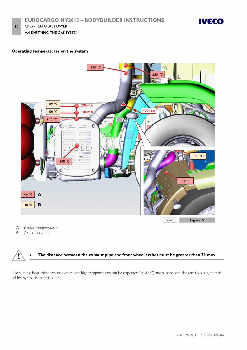
12EUROCARGO MY2015 ‒ BODYBUILDER INSTRUCTIONSCNG - NATURAL POWER
A.4 EMPTYING THE GAS SYSTEM
– Printed 692.68.440 – 2 Ed. - Base 03/2016
Operating temperatures on the system
242463 Figure 6
A Contact temperatures B. Air temperatures
The distance between the exhaust pipe and front wheel arches must be greater than 30 mm.
Use suitable heat-shield screens whenever high temperatures can be expected (> 70°C) and subsequent dangers to pipes, electriccables, synthetic materials, etc.

EUROCARGO MY2015 ‒ BODYBUILDER INSTRUCTIONSCNG - NATURAL POWER
A.5 PTO MANAGEMENT13
– Printed 692.68.440 – 2 Ed. - Base 03/2016
A.5 PTO MANAGEMENT
Installation of the power take-off (PTO)
The PTO available for diesel engines are also suitable for CNG engines, with the exception of the PTO Multipower on flywheel.
However, even if torque can be drawn from the transmission and from the front side of the engine, torque drawn from the gear-box is the most appropriate. Instructions for this as provided in Chapter 4.2 ( Page 7) are valid.
Keep in mind that the PTO models for CNG tested by IVECO are those of the following Table.
Table A.1 - PTO on gearbox tested by IVECO
Gearbox PTO type (opt. no.) Fitting positionDirection of
rotationTransmission ratios TORQUE (Nm)
9S 75 TO
5047 Rear right Anticlockwise 0.92 410
5205 Central rear Clockwise 0.62 600
5210 Lower rear Anticlockwise 0.79 430
S2500 14978 Left side Anticlockwise 0.82 270
S3000 14979 Left side Anticlockwise 0.93 600
Torque limitations and engine speed
Normally the operating engine torque with PTO must not exceed that which the same engine is able to provide withoutturbocharging. This way the engine can react quickly to any change in the torque requirements.
238076 Figure 7
Therefore, for CNG engines, three operating zones with PTO are defined (see following page).
Note that the specified torque and the rotation speed (discussed in this chapter) refer to the clutch / engine output.

14EUROCARGO MY2015 ‒ BODYBUILDER INSTRUCTIONSCNG - NATURAL POWER
A.5 PTO MANAGEMENT
– Printed 692.68.440 – 2 Ed. - Base 03/2016
If installed PTO has its own transmission ratio (as occurs in most cases), the torque to the PTO can be calculated by multiplying theengine output torque values by the transmission ratio, while the rotation speed to the PTO can be calculated by dividing the valuescoming from the engine by the transmission ratio.
a) Normal operation (green zone)
From 1150 rpm to 1600 rpm
From 0 Nm to 375 Nm of PTO torque
The engine is in "rpm configurable 1, 2 or 3" mode with the engine speed set at between 1150 rpm and 1600 rpm.
The vehicle is stationary, the gearbox is in neutral, driving is not possible, the accelerator pedal is deactivated.
The PTO load is the only load that is applied to the engine.
The PTO load can be applied immediately after the first 0.7 seconds from activation of the configurable engine speed set point.
b) Operation with full load (blue zone)
From 1250 rpm to 1600 rpm
from 375 Nm to 650 Nm
The engine is in "rpm configurable 1, 2 or 3" mode with the engine speed set at between 1250 rpm and 1600 rpm.
The vehicle is stationary, the gearbox is in neutral, driving is not possible, the accelerator pedal is deactivated.
The PTO load is the only load that is applied to the engine.
The PTO load can be applied after the first 0.9 seconds from activation of the configurable engine speed set point.
In this zone the PTO control requires "smooth start" and "uniform operation".
Smooth start:The outfitting must not increase the PTO torque any faster than 50 Nm/s to prevent the engine from stalling. This means thatthe complete torque (650 Nm) cannot be reached before 13 seconds.
Uniform operation:outfitting must avoid any significant variation in the PTO torque; It is the responsibility of the bodybuilder to ensure there areno rpm oscillations exceeding ± 50 rpm and engine speed accelerations do not exceed ± 100 rpm/s.
149749 Figure 8

EUROCARGO MY2015 ‒ BODYBUILDER INSTRUCTIONSCNG - NATURAL POWER
A.6 CONNECTORS FOR BODYBUILDERS15
– Printed 692.68.440 – 2 Ed. - Base 03/2016
If these limits are exceeded, engine malfunction and the overheating of the catalytic converter will lead to the risk of fire. IVECOcannot be considered responsible for any damage caused by insufficient PTO torque in "PTO operation with full load" (blue zone).
C) Operation when driving (orange/yellow zone)
From 780 rpm to 2900 rpm
From 0 Nm to 300 Nm of PTO torque
From 0 kW at 35 kW PTO Power
The engine is operating in "PTO mode 1, 2 or 3" without set engine speed, with the exception of a minimum engine speed ofbetween 780 and 850 rpm.
An engine speed limit can be applied, but not less than 2000 rpm.
The vehicle can also be driven with PTO engaged, the accelerator pedal is activated.
The PTO load is applied in addition to the normal engine load.
The PTO load can be applied after the first 0.7 seconds from the minimum engine speed being reached.
With a torque request exceeding 150 Nm, a "smooth start" function is required (in addition to all the above conditions) to preventthe engine from stalling. The outfitting must not increase the PTO torque any faster than 50 Nm/s.
A.6 CONNECTORS FOR BODYBUILDERS
Note The basic functions of the bodybuilder connectors are the same as described in Section 5 - Chapter 5.2 ( Page 10) for dieselengine vehicles.

- Printed 692.68.440 – 2 Ed. - Base 03/2016