65405130 jfe 582 instruction manual
TRANSCRIPT

JFE-582Echo Sounder
INSTRUCTIONMANUAL

General Information i
General Information
Thank you for purchasing the Japan Radio Co., Ltd. JFE-582 Echo-Sounder. The JFE-582
conforms to the IMO (International Maritime Organization) performance standards,
enabling sea floor displays and depth displays.
¡Before attempting to poerate this equipment, read this instruction manual thoroughlyto ensure correct and safe operation in accordance with the warning instructions andoperation procedures.
¡You are strongly recommended to store this instruction manual carefully for futurereference.In the event that you have an operational problem or malfunction, this manual willprovide useful instructions.

ii General Information
Before You Begin iii
Failure to observe a warning indication, leading to
incorrect handling, may result in death or serious
injury to the operator.
Failure to observe a caution indication, leading to
incorrect handling, may result in injury to the
operator, or physical damage to the equipment.
Before You BeginSymbols Used In This Manual
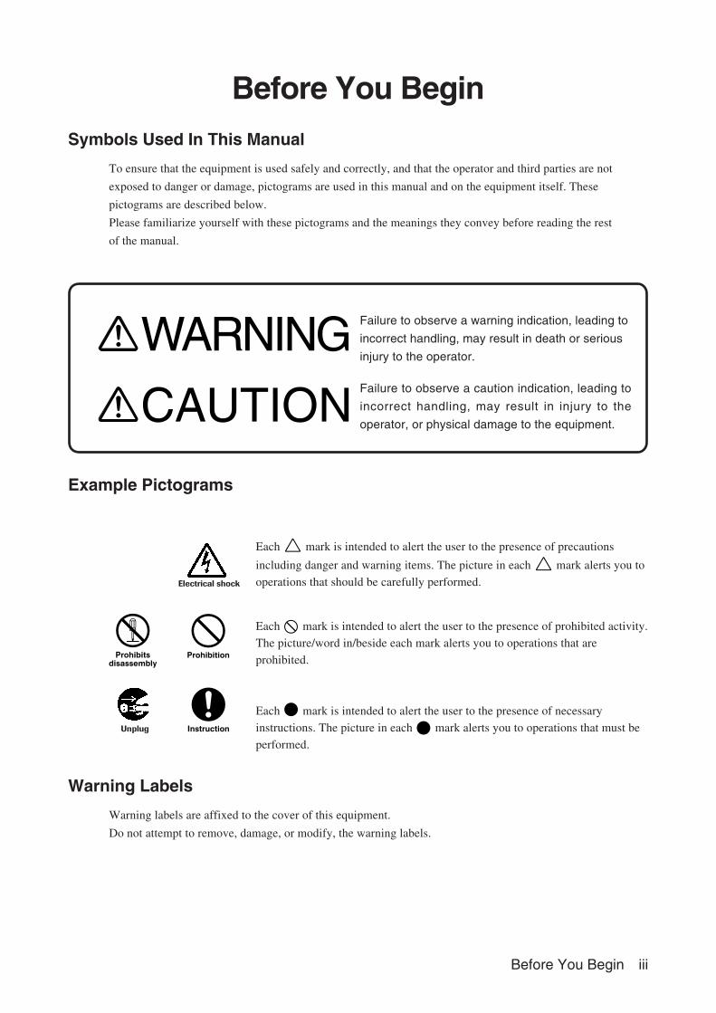
To ensure that the equipment is used safely and correctly, and that the operator and third parties are not
exposed to danger or damage, pictograms are used in this manual and on the equipment itself. These
pictograms are described below.
Please familiarize yourself with these pictograms and the meanings they convey before reading the rest
of the manual.
Example Pictograms
Each mark is intended to alert the user to the presence of precautions
including danger and warning items. The picture in each mark alerts you to
operations that should be carefully performed.
Each mark is intended to alert the user to the presence of prohibited activity.
The picture/word in/beside each mark alerts you to operations that are
prohibited.
Each mark is intended to alert the user to the presence of necessary
instructions. The picture in each mark alerts you to operations that must be
performed.
Warning Labels
Warning labels are affixed to the cover of this equipment.
Do not attempt to remove, damage, or modify, the warning labels.
WARNING
CAUTION
iv Usage Hints
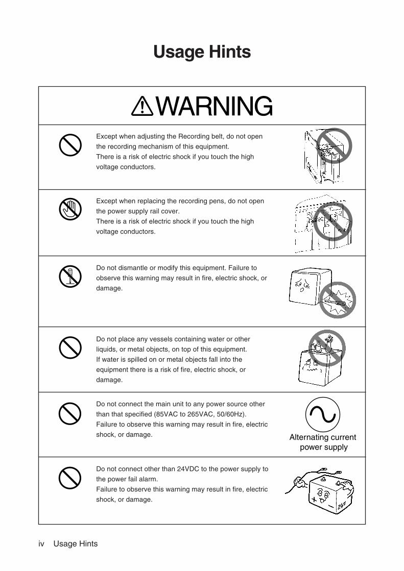
Except when adjusting the Recording belt, do not open
the recording mechanism of this equipment.
There is a risk of electric shock if you touch the high
voltage conductors.
Except when replacing the recording pens, do not open
the power supply rail cover.
There is a risk of electric shock if you touch the high
voltage conductors.
Do not dismantle or modify this equipment. Failure to
observe this warning may result in fire, electric shock, or
damage.
Do not place any vessels containing water or other
liquids, or metal objects, on top of this equipment.
If water is spilled on or metal objects fall into the
equipment there is a risk of fire, electric shock, or
damage.
Do not connect the main unit to any power source other
than that specified (85VAC to 265VAC, 50/60Hz).
Failure to observe this warning may result in fire, electric
shock, or damage.
Do not connect other than 24VDC to the power supply to
the power fail alarm.
Failure to observe this warning may result in fire, electric
shock, or damage.
Usage Hints
Alternating current power supply
WARNING
Usage Hints v
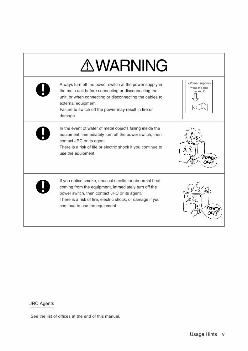
Always turn off the power switch at the power supply in
the main unit before connecting or disconnecting the
unit, or when connecting or disconnecting the cables to
external equipment.
Failure to switch off the power may result in fire or
damage.
In the event of water of metal objects falling inside the
equipment, immediately turn off the power switch, then
contact JRC or its agent.
There is a risk of file or electric shock if you continue to
use the equipment.
If you notice smoke, unusual smells, or abnormal heat
coming from the equipment, immediately turn off the
power switch, then contact JRC or its agent.
There is a risk of fire, electric shock, or damage if you
continue to use the equipment.
JRC Agents
See the list of offices at the end of this manual.
<Power supply>Press the side
marked O.
WARNING
vi Usage Hints
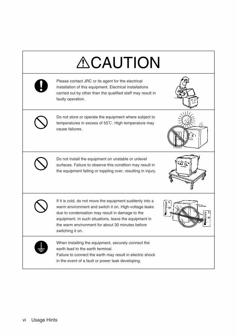
Please contact JRC or its agent for the electrical
installation of this equipment. Electrical installations
carried out by other than the qualified staff may result in
faulty operation.
Do not store or operate the equipment where subject to
temperatures in excess of 55℃. High temperature may
cause failures.
Do not install the equipment on unstable or unlevel
surfaces. Failure to observe this condition may result in
the equipment falling or toppling over, resulting in injury.
If it is cold, do not move the equipment suddenly into a
warm environment and switch it on. High-voltage leaks
due to condensation may result in damage to the
equipment. In such situations, leave the equipment in
the warm environment for about 30 minutes before
switching it on.
When installing the equipment, securely connect the
earth lead to the earth terminal.
Failure to connect the earth may result in electric shock
in the event of a fault or power leak developing.
CAUTION
Usage Hints vii
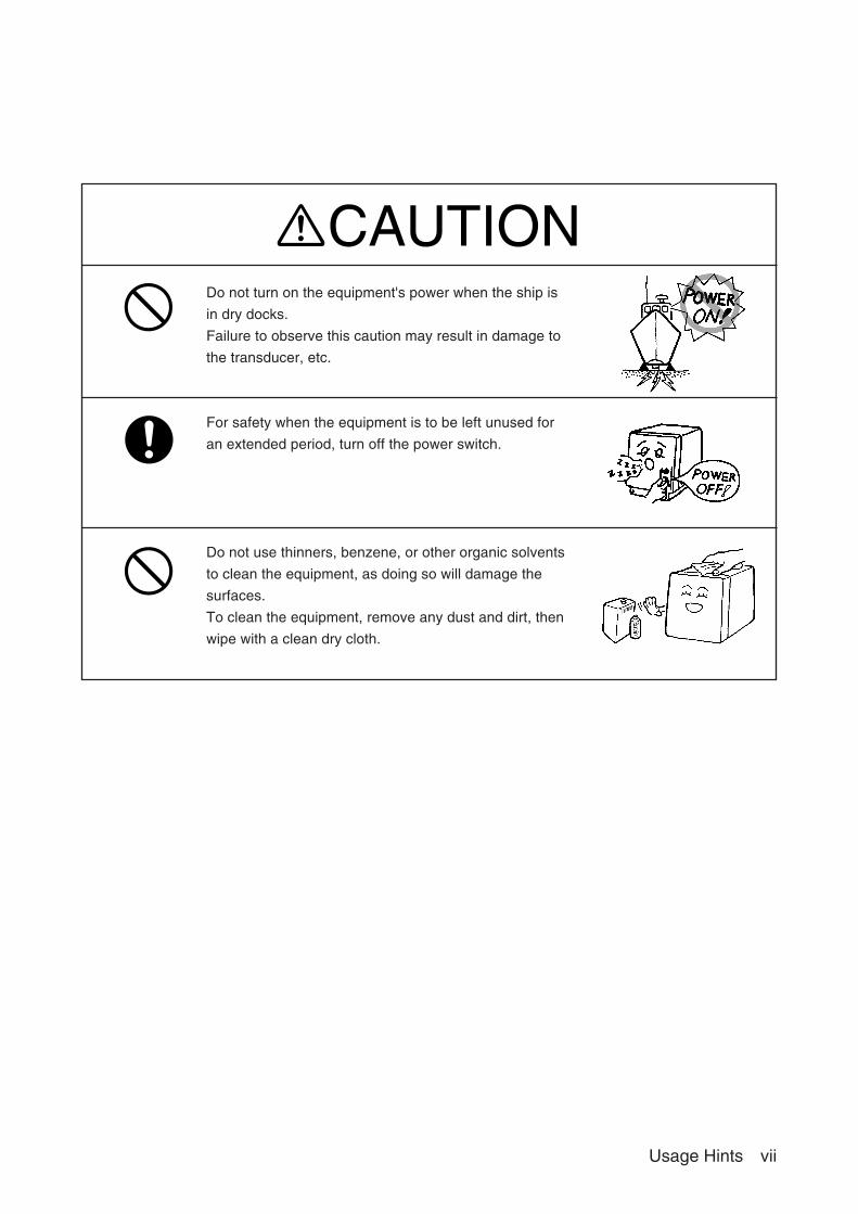
CAUTIONDo not turn on the equipment's power when the ship is
in dry docks.
Failure to observe this caution may result in damage to
the transducer, etc.
For safety when the equipment is to be left unused for
an extended period, turn off the power switch.
Do not use thinners, benzene, or other organic solvents
to clean the equipment, as doing so will damage the
surfaces.
To clean the equipment, remove any dust and dirt, then
wipe with a clean dry cloth.
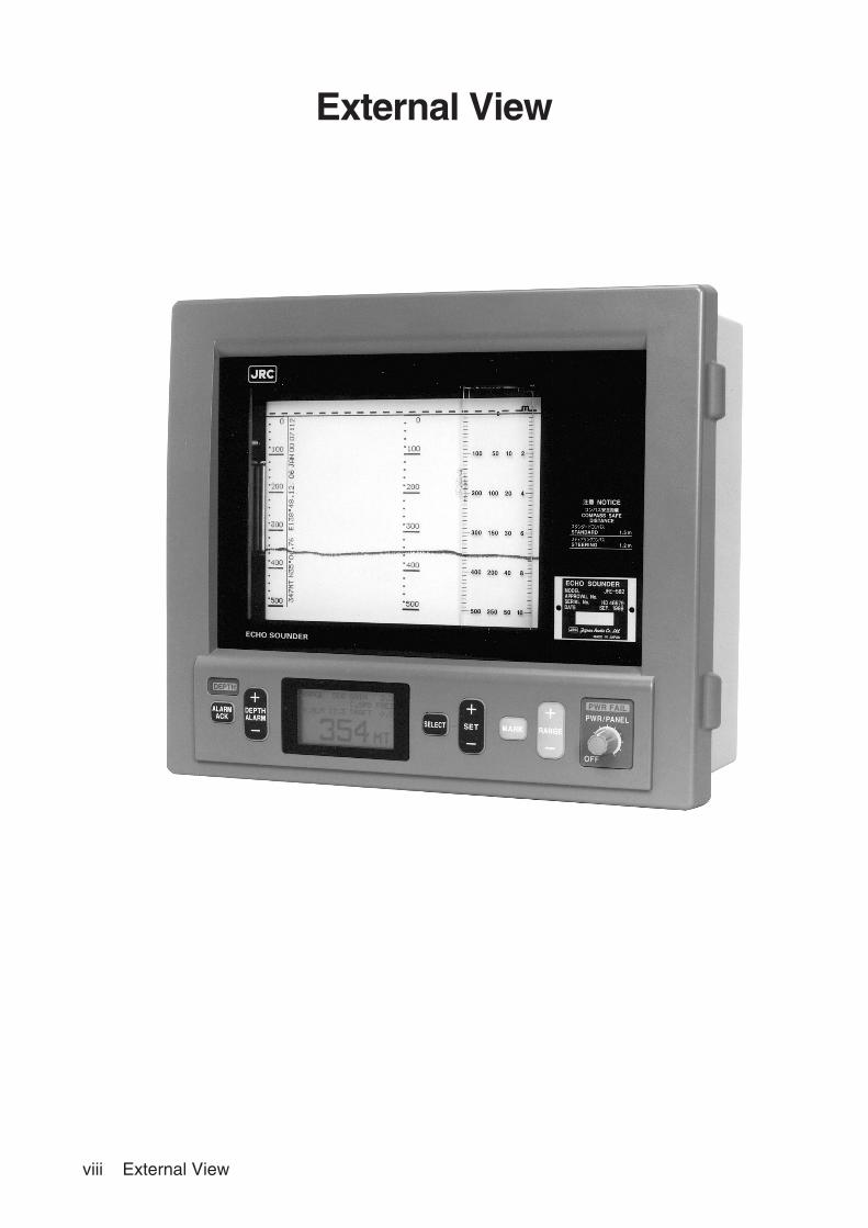
viii External View
External View
Contents ix
Contents
General Information ............................................................................................................ i
Before You Begin .............................................................................................................. iii
Usage Hints ....................................................................................................................... iv
External View ................................................................................................................... viii
Explanation of Terms ......................................................................................................... x
1. Introduction .................................................................................................................... 11.1 Function ................................................................................................................................. 1
1.2 Feature .................................................................................................................................. 1
1.3 Components .......................................................................................................................... 2
1.4 Construction .......................................................................................................................... 3
1.5 System Configuration ............................................................................................................ 5
2. Names and Functions of the Components .................................................................. 6
3. Installation ...................................................................................................................... 73.1 Installing the Recorder Unit ................................................................................................... 8
3.2 Installing the Transducer ..................................................................................................... 10
3.3 Connecting Components ..................................................................................................... 12
4. Operation ...................................................................................................................... 134.1 Basic Operations ................................................................................................................. 13
4.2 Setting Functions ................................................................................................................. 16
4.3 Device Settings .................................................................................................................... 19
4.4 Master Reset ...................................................................................................................... 23
5. Replacing Consumables ............................................................................................. 245.1 Replacing Recording Paper ................................................................................................. 24
5.2 Replacing Recording Pen .................................................................................................... 25
6. Maintenance and Inspection ....................................................................................... 266.1 Regular Maintenance .......................................................................................................... 26
6.2 Self-Diagnostic Function...................................................................................................... 27
6.3 Positional Adjustment for 0m Depth .................................................................................... 33
6.4 Adjusting Recording Belt Tension ........................................................................................ 33
6.5 Replacing the Recording Belt .............................................................................................. 34
6.6 Replacing the Fuses ............................................................................................................ 35
6.7 Replacing the Units ............................................................................................................. 36
7. Consider Installation.................................................................................................... 37
8. After-sales Service ....................................................................................................... 38
9. Disposal ........................................................................................................................ 399.1 Disposal of this equipment .................................................................................................. 39
10. Specifications ............................................................................................................. 40
Information ........................................Please refer to ‘Place of Contact’ on back cover.

x Explanation of Terms
NMEA0183 : NMEA stands for the National Marine Electronics Association. NMEA0183 is the format used
when sending or receiving depth, position, water temperature, ship speed and other
information between marine equipment.
Bubbling : The phenomenon where the image of the seabed is interrupted due to air bubbles caused by
the ship's hull or the propeller during a voyage.
Beam angle : The angle that sound waves spread out from the transducer. Sound waves spread out in a
conical manner taking the center of the bottom surface of the transducer at the apex of the
cone.
Transducer : Device that emits ultrasonic waves in water and receives the signals reflected off the seabed.
This is equivalent to an antenna on a radio.
IMO : stands for International Maritime Organization
MED : stands for Marine Equipment Directive. This is the directive for marine equipment in Europe.
This directive unifies format approval standards implemented separately by each European
country.
UTC : stands for Universal Time Coordinated.
Explanation of Terms
1. Introduction 1
1. Introduction
1.1 Function
The JFE-582 Echo-Sounder consists of a transducer mounted on the bottom of the ship's hull and a main unit
that displays information on the depth and formation of the sea bottom. This information is gained by using
ultrasonic waves sent from the transducer that are then reflected off the sea bottom and picked up again by
the transducer. The JFE-582 also has the following functions:
(1) depth alarm, (2) power fail alarm, (3) output of depth data, (4) output of depth and power fail alarms.
The recorder uses 150mm-wide paper to show the previous 10 minutes, 20 minutes, or 30 minutes of
historical data. Or the paper can be stopped. One roll of paper can record a maximum of approximately 37
hours continuously. Depth measuring ranges of 10m, 50m, 250m, or 500m can be selected.
1.2 Feature
The JFE-582 features the following:
Conforms to the IMO Standard
• When the depth becomes shallower than a previously set value, a depth alarm is issued by buzzer and
lamp.
• When power is cut to the main unit, a power fail alarm is issued by buzzer and lamp.
• Contact signals can be output for both depth and power fail alarms.
• Data on depths can be output.
Ease of Use
• Knobs are used for illumination controls, allowing them to be readily distinguished from other keys.
• Independent event mark, range, and depth alarm keys for instant operation.
• Remote cancellation of alarm buzzer.
Digital Depth Display
• No need for time-consuming reading of depths using a scale against the profile of the sea floor on the
paper! The current depth can be seen at a glance.
Self-Diagnostic Functions
• Self-diagnostic functions can be selected from a menu, improving ease of maintenance.
2 1. Introduction
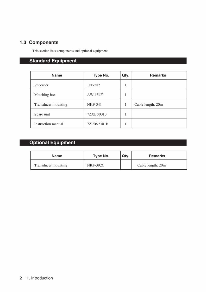
1.3 Components
This section lists components and optional equipment.
Standard Equipment
Name Type No. Qty. Remarks
Recorder JFE-582 1
Matching box AW-154F 1
Transducer mounting NKF-341 1 Cable length: 20m
Spare unit 7ZXBS0010 1
Instruction manual 7ZPBS2301B 1
Optional Equipment
Name Type No. Qty. Remarks
Transducer mounting NKF-392C Cable length: 20m
1. Introduction 3
334327
400
385
312.5
319.5
325.5
7376 19616
φ9 Mounting hole
Terminal board
Wire through metal
120°� 120°
�
φ186±1
70±426±2
64±4
20 c 20 b
(208
)
φ160±4
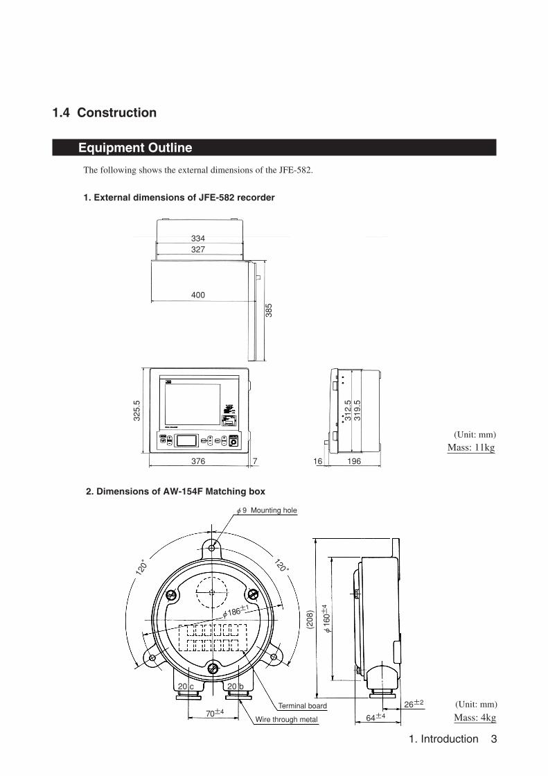
Mass: 11kg
2. Dimensions of AW-154F Matching box
1.4 Construction
Equipment Outline
The following shows the external dimensions of the JFE-582.
1. External dimensions of JFE-582 recorder
(Unit: mm)
(Unit: mm)
Mass: 4kg
4 1. Introduction
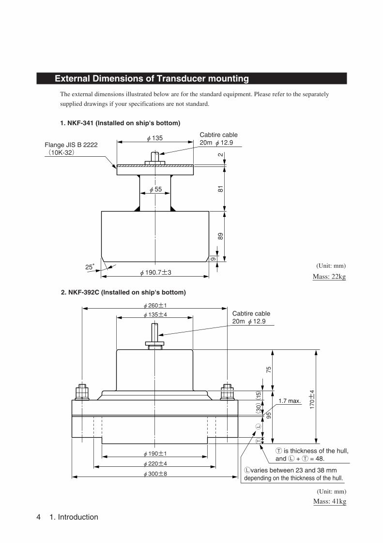
External Dimensions of Transducer mounting
The external dimensions illustrated below are for the standard equipment. Please refer to the separately
supplied drawings if your specifications are not standard.
1. NKF-341 (Installed on ship's bottom)
2. NKF-392C (Installed on ship's bottom)
(Unit: mm)
Mass: 22kg
(Unit: mm)
Mass: 41kg
φ135
φ55
φ190.7±325°�
8981
29
Cabtire cable�20m φ12.9Flange JIS B 2222�
(10K-32)�
Cabtire cable�20m φ12.9
Lvaries between 23 and 38 mm depending on the thickness of the hull.
φ260±1
φ300±8
φ135±4
φ190±1
φ220±4
75
170±4
95(30)�
LT
(15)�
1.7 max.
T is thickness of the hull,and L + T = 48.
1. Introduction 5
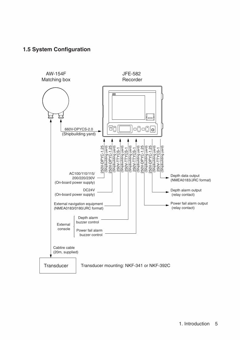
1.5 System Configuration
Cabtire cable (20m, supplied)
660V-DPYCS-2.0(Shipbuilding yard)
Depth data output(NMEA0183/JRC format)
Depth alarm output (relay contact)
Power fail alarm output (relay contact)
Transducer Transducer mounting: NKF-341 or NKF-392C
AW-154FMatching box
JFE-582 Recorder
250V
-DP
YC
-1.2
5 (
Shi
pbui
ldin
g ya
rd)
250V
-DP
YC
-1.2
5 (
Shi
pbui
ldin
g ya
rd)
250V
-TT
YC
S-1
(S
hipb
uild
ing
yard
)25
0V-T
TY
CS
-1 (
Shi
pbui
ldin
g ya
rd)
250V
-TT
YC
S-1
(S
hipb
uild
ing
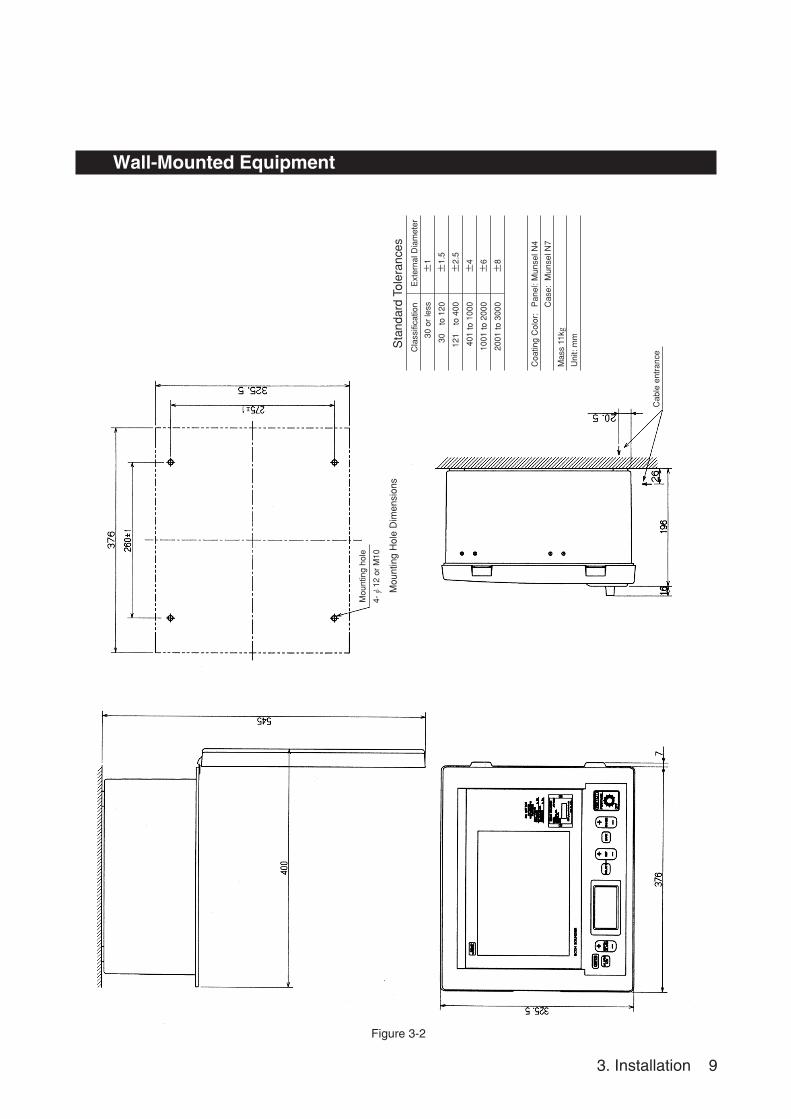
yard
)25
0V-D
PY
C-1
.25
(S
hipb
uild
ing
yard
)25
0V-D
PY
C-1
.25
(S
hipb
uild
ing
yard
)25
0V-T
TY
CS
-1 (
Shi
pbui
ldin
g ya
rd)
Power fail alarm buzzer control
AC100/110/115/ 200/220/230V
(On-board power supply)
DC24V(On-board power supply)
External navigation equipment(NMEA0183/0180/JRC format)
External console
Depth alarm buzzer control
6 2. Names and Functions of the Components
2. Names and Functions of the Components
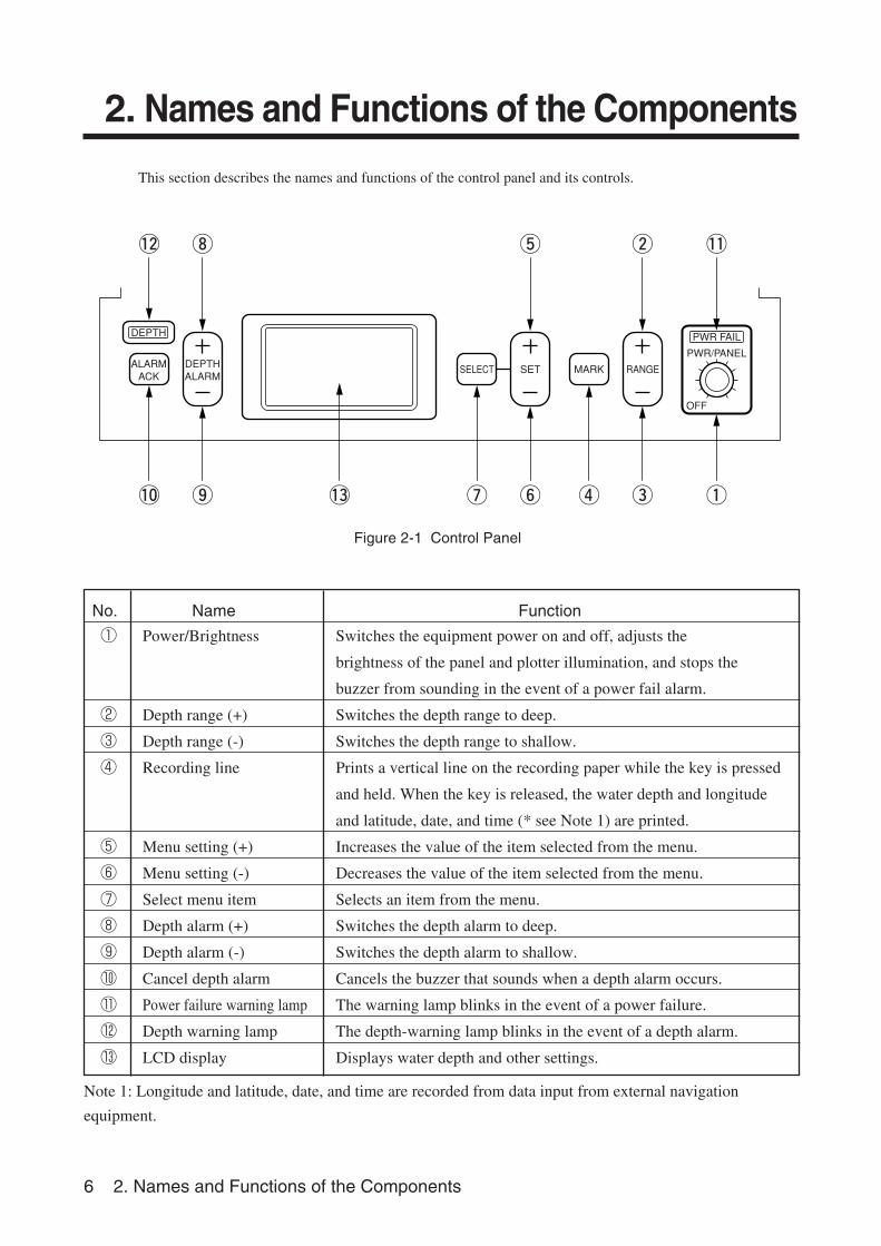
This section describes the names and functions of the control panel and its controls.
Figure 2-1 Control Panel
No. Name Function
① Power/Brightness Switches the equipment power on and off, adjusts the
brightness of the panel and plotter illumination, and stops the
buzzer from sounding in the event of a power fail alarm.
② Depth range (+) Switches the depth range to deep.
③ Depth range (-) Switches the depth range to shallow.
④ Recording line Prints a vertical line on the recording paper while the key is pressed
and held. When the key is released, the water depth and longitude
and latitude, date, and time (* see Note 1) are printed.
⑤ Menu setting (+) Increases the value of the item selected from the menu.
⑥ Menu setting (-) Decreases the value of the item selected from the menu.
⑦ Select menu item Selects an item from the menu.
⑧ Depth alarm (+) Switches the depth alarm to deep.
⑨ Depth alarm (-) Switches the depth alarm to shallow.
⑩ Cancel depth alarm Cancels the buzzer that sounds when a depth alarm occurs.
⑪ Power failure warning lamp The warning lamp blinks in the event of a power failure.
⑫ Depth warning lamp The depth-warning lamp blinks in the event of a depth alarm.
⑬ LCD display Displays water depth and other settings.
Note 1: Longitude and latitude, date, and time are recorded from data input from external navigation
equipment.
ALARMACK
DEPTH
DEPTHALARM
SET RANGEMARK
OFF
PWR FAIL
PWR/PANEL
SELECT
!2 i t w !1
!0 o !3 u y r e q
3. Installation 7
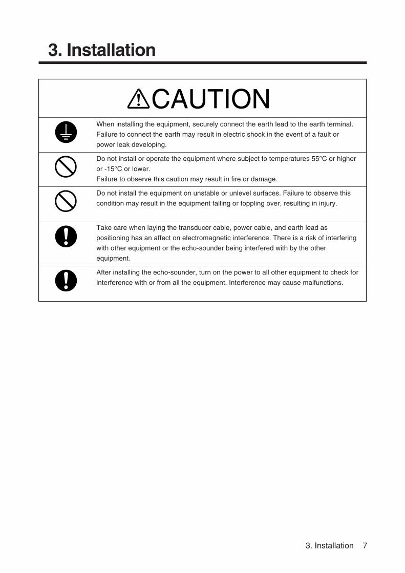
3. Installation
When installing the equipment, securely connect the earth lead to the earth terminal.
Failure to connect the earth may result in electric shock in the event of a fault or
power leak developing.
Do not install or operate the equipment where subject to temperatures 55°C or higher
or -15°C or lower.
Failure to observe this caution may result in fire or damage.
Do not install the equipment on unstable or unlevel surfaces. Failure to observe this
condition may result in the equipment falling or toppling over, resulting in injury.
Take care when laying the transducer cable, power cable, and earth lead as
positioning has an affect on electromagnetic interference. There is a risk of interfering
with other equipment or the echo-sounder being interfered with by the other
equipment.
After installing the echo-sounder, turn on the power to all other equipment to check for
interference with or from all the equipment. Interference may cause malfunctions.
CAUTION
8 3. Installation
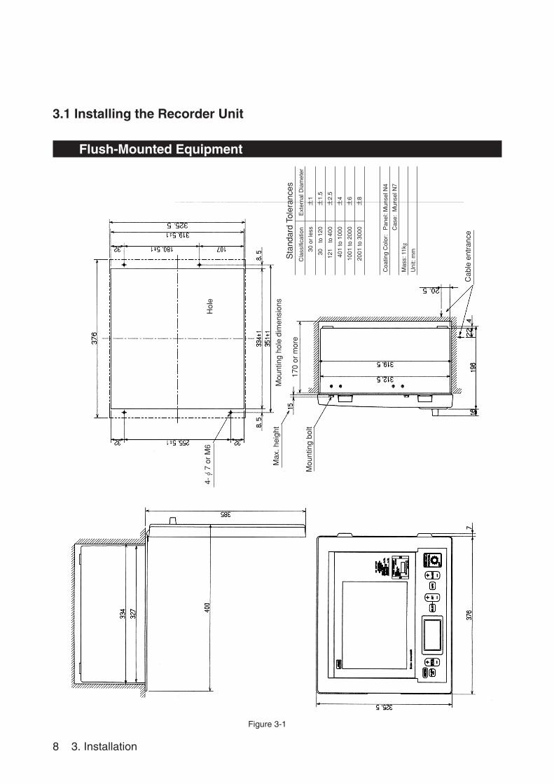
3.1 Installing the Recorder Unit
Flush-Mounted Equipment
4-φ
7 or
M6
Hol
e
Mou
ntin
g ho
le d
imen
sion
sM
ax. h
eigh
t
Mou
ntin
g bo
lt
170
or m
ore
Cab
le e
ntra
nce
Figure 3-1
Sta
ndar
d To
lera
nces
Cla
ssifi
catio
n
30 o
r le
ss
30
to 1
20
121
to 4
00
401
to 1
000
1001
to 2
000
2001
to 3
000
±1�
±1.5�
±2.5�
±4�
±6�
±8�
� �
Ext
erna
l Dia
met
er
Coa
ting
Col
or:
Pan
el: M
unse
l N4
Cas
e: M
unse
l N7
Mas
s: 1
1kg
Uni
t: m
m
3. Installation 9
Sta
ndar
d To
lera
nces
Cla
ssifi
catio
n
30 o
r le
ss
30
to 1
20
121
to 4
00
401
to 1
000
1001
to 2
000
2001
to 3
000
±1�
±1.5�
±2.5�
±4�
±6�
±8�
� �
Ext
erna
l Dia
met
er
Coa
ting
Col
or:
Pan
el: M
unse
l N4
Cas
e: M
unse
l N7
Mas
s 11
k g
Uni
t: m
m
Wall-Mounted Equipment
Mou
ntin
g ho
le
4-φ
12 o
r M
10
Mou
ntin
g H
ole
Dim
ensi
ons
Cab
le e
ntra
nce
Figure 3-2
10 3. Installation
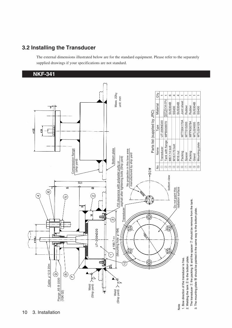
3.2 Installing the Transducer
The external dimensions illustrated below are for the standard equipment. Please refer to the separately
supplied drawings if your specifications are not standard.
NKF-341
Cab
le φ12.9 20m
Fla
nge
JIS
B 2
220
(10K
-32)
Wel
d(S
hip
yard
)
Wel
d(S
hip
yard
)(M
ount
ing
hole
φ194)
φ190.7±3
Fill
cle
aran
ce w
ith p
olye
ster
put
ty o
ras
phal
t afte
r tig
hten
ing
bolts
(S
hip
yard
)
Bottom plate
Tra
nsdu
cer
No
proj
ectio
n in
this
bow
are
am
anuf
actu
red
by s
hip
yard
Do
not p
aint
this
radi
atio
n su
rfac
e
botto
m v
iew
Com
pres
sion
flan
ge (
ship
yar
d)
Mas
s. 2
2kg
unit:
mm
Par
ts li
st (
supp
lied
by J
RC
) N
o N
ame
Typ
e Material
Q'ty
qT
rans
duce
r U
T-2
00N
D20
1w
Tan
k w
ith fl
ange
MP
BX
0997
01
eM
6×14
bol
t S
US
304B
6r
M16×
70 b
olt
SS
400
4t
M16
nut
SU
S30
4B4
yP
acki
ngM
TT
0041
70A
Join
t she
et1
uS
pace
rM
TT
0152
93R
ubbe
r1
iP
acki
ngM
PP
K00
784
Rub
ber
1o
Gla
ndM
TL0
2400
5S
US
304B
1!0
Mou
ntin
g pl
ate
MT
L024
129
SS
400
1
KSTP
T42
(KST
342)
(C=< 0
.23%
)
Not
e
1. B
ow d
irect
ion
of th
e tr
ansd
ucer
is fr
ee.
2. W
eldi
ng th
e ta
nk ②
to th
e bo
ttom
pla
te.
T
he tr
ansd
ucer
① th
e pa
ckin
g ⑧
and
the
spac
er ⑦
sho
uld
be r
emov
e fr
om th
e ta
nk.
3. T
he m
ount
ing
plat
e ⑩
sho
uld
be p
aint
ed in
the
sam
e w
ay to
the
botto
m p
late
.
3. Installation 11
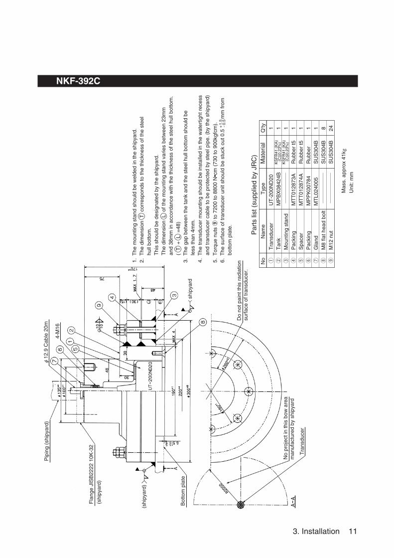
NKF-392C
φ12.9 C
able
20m
Mas
s. a
ppro
x 41
kg
Uni
t: m
m
4-M
16
Pip
ing
(shi
pyar
d)
Fla
nge
JIS
B22
22 1
0K-3
2
(shi
pyar
d)
(shi
pyar
d)
ship
yard
Bot
tom
pla
te
No
proj
ect i
n th
is b
ow a
rea
man
ufac
ture
d by
shi
pyar
d
Tra
nsdu
cer
Do
not p
aint
this
rad
iatio
nsu
rfac
e of
tran
sduc
er.
1. T
he m
ount
ing
stan
d sh
ould
be
wel
ded
in th
e sh
ipya
rd.
2. T
he d
imen
sion
T c
orre
spon
ds to
the
thic
knes
s of
the
stee
l
hul
l bot
tom
.
Thi
s sh
ould
be
desi
gnat
ed b
y th
e sh
ipya
rd.
T
he d
imen
sion
L o
f the
mou
ntin
g st
and
varie
s be
twee
n 23
mm
a
nd 3
8mm
in a
ccor
danc
e w
ith th
e th
ickn
ess
of th
e st
eel h
ull b
otto
m.
(
T +
L =
48)
3. T
he g
ap b
etw
een
the
tank
and
the
stee
l hul
l bot
tom
sho
uld
be
l
ess
than
4m
m.
4. T
he tr
ansd
ucer
mou
ntin
g sh
ould
be
inst
alle
d in
the
wat
ertig
ht r
eces
s
and
tran
sduc
er c
able
to b
e pr
otec
ted
by s
teel
pip
e. (
by th
e sh
ipya
rd)
5. T
orqu
e nu
ts ⑨
to 7
200
to 8
800
N•c
m (
730
to 9
00kg
fcm
).6.
The
sur
face
of t
rans
duce
r un
it sh
ould
be
stuc
k ou
t 0.5
mm
from
b
otto
m p
late
.
+ -1.5
0.5
Par
ts li
st (
supp
lied
by J
RC
) N
o N
ame
Typ
e Material
Q'ty
qT
rans
duce
r U
T-2
00N
D20
1w
Tan
kM
PB
X08
424B
1e
Mou
ntin
g st
and
1r
Pac
king
MT
T01
2873
AR
ubbe
r t5
1t
Spa
cer
MT
T01
2874
AR
ubbe
r t5
1y
Pac
king
MP
PK
0078
4R
ubbe
r1
uG
land
MT
L024
005
SU
S30
4B1
iM
8 fla
t hea
d bo
ltS
US
304B
8o
M12
nut
SU
S30
4B24
KS
FR
41 (
KA
)(C
=<0.
23%
)K
SF
R41
(K
A)
(C=<
0.23
%)
12 3. Installation
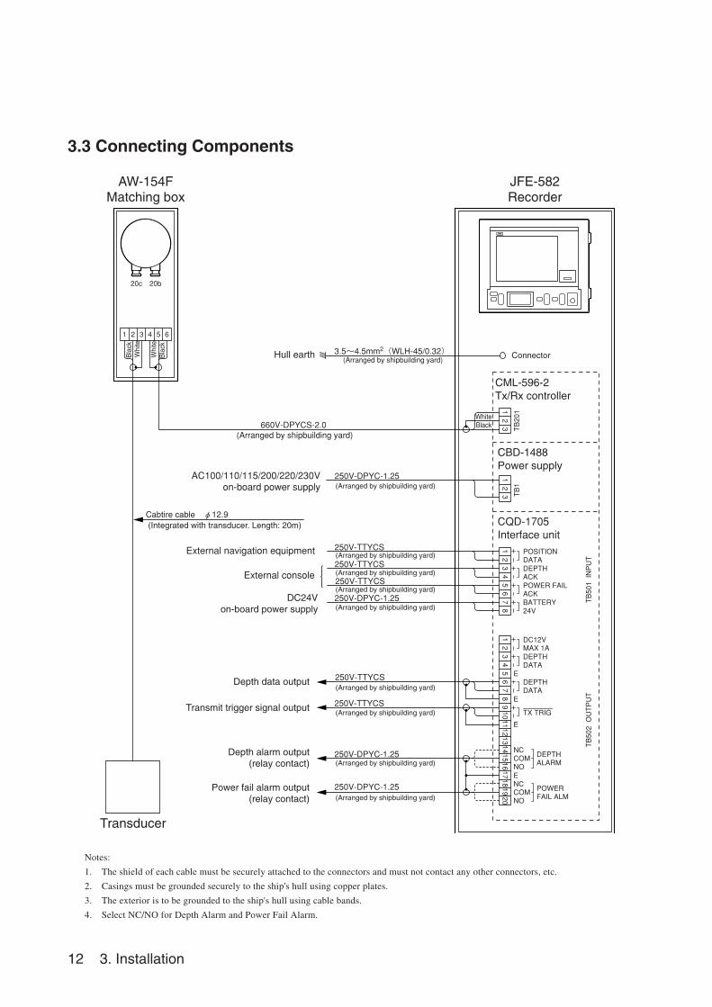
3.3 Connecting Components
Notes:
1. The shield of each cable must be securely attached to the connectors and must not contact any other connectors, etc.
2. Casings must be grounded securely to the ship's hull using copper plates.
3. The exterior is to be grounded to the ship's hull using cable bands.
4. Select NC/NO for Depth Alarm and Power Fail Alarm.
660V-DPYCS-2.0� (Arranged by shipbuilding yard)
3.5~4.5mm2(WLH-45/0.32)� (Arranged by shipbuilding yard)
20c 20b
1 2 3 4 5 6
1
TB501 INPUT
TB1
TB502 OUTPUT
2345678
123
TB2011
23
POSITION�DATADEPTH�ACKPOWER FAIL�ACKBATTERY�24V
1234567891011121314151617181920
DC12V�MAX 1ADEPTH�DATA
DEPTH�DATA
E
E
E
E
NC�COM�NO
TX TRIG
DEPTH�ALARM
NC�COM�NO
POWER�FAIL ALM
CML-596-2Tx/Rx controller
AW-154FMatching box
Bla
ck
Whi
te
Whi
teB
lack
Cabtire cable φ12.9 (Integrated with transducer. Length: 20m)
Hull earth
External navigation equipment
AC100/110/115/200/220/230V�on-board power supply
External console
DC24Von-board power supply
Depth alarm output (relay contact)
Power fail alarm output (relay contact)
250V-TTYCS
250V-TTYCS
250V-TTYCS
250V-DPYC-1.25
250V-TTYCS
250V-TTYCS
250V-DPYC-1.25
250V-DPYC-1.25
250V-DPYC-1.25 �
Depth data output
Transmit trigger signal output
Transducer
(Arranged by shipbuilding yard)
(Arranged by shipbuilding yard)
(Arranged by shipbuilding yard)
(Arranged by shipbuilding yard)
(Arranged by shipbuilding yard)
(Arranged by shipbuilding yard)
(Arranged by shipbuilding yard)
(Arranged by shipbuilding yard)
(Arranged by shipbuilding yard)
JFE-582Recorder
Connector
CBD-1488Power supply
CQD-1705�Interface unit
Black White
4. Operation 13
4. Operation
500
400
300
200
100
0
500
400
300
200
100
0
380M
T
N35
1
3.12
E13
9
25
.34
1
9 O
CT
99
10:1
0
Scale
OFF
PWR FAIL
PWR/PANEL
OFF
PWR FAIL
PWR/PANEL
OFF
PWR FAIL
PWR/PANEL
RANGE
4.1 Basic Operations
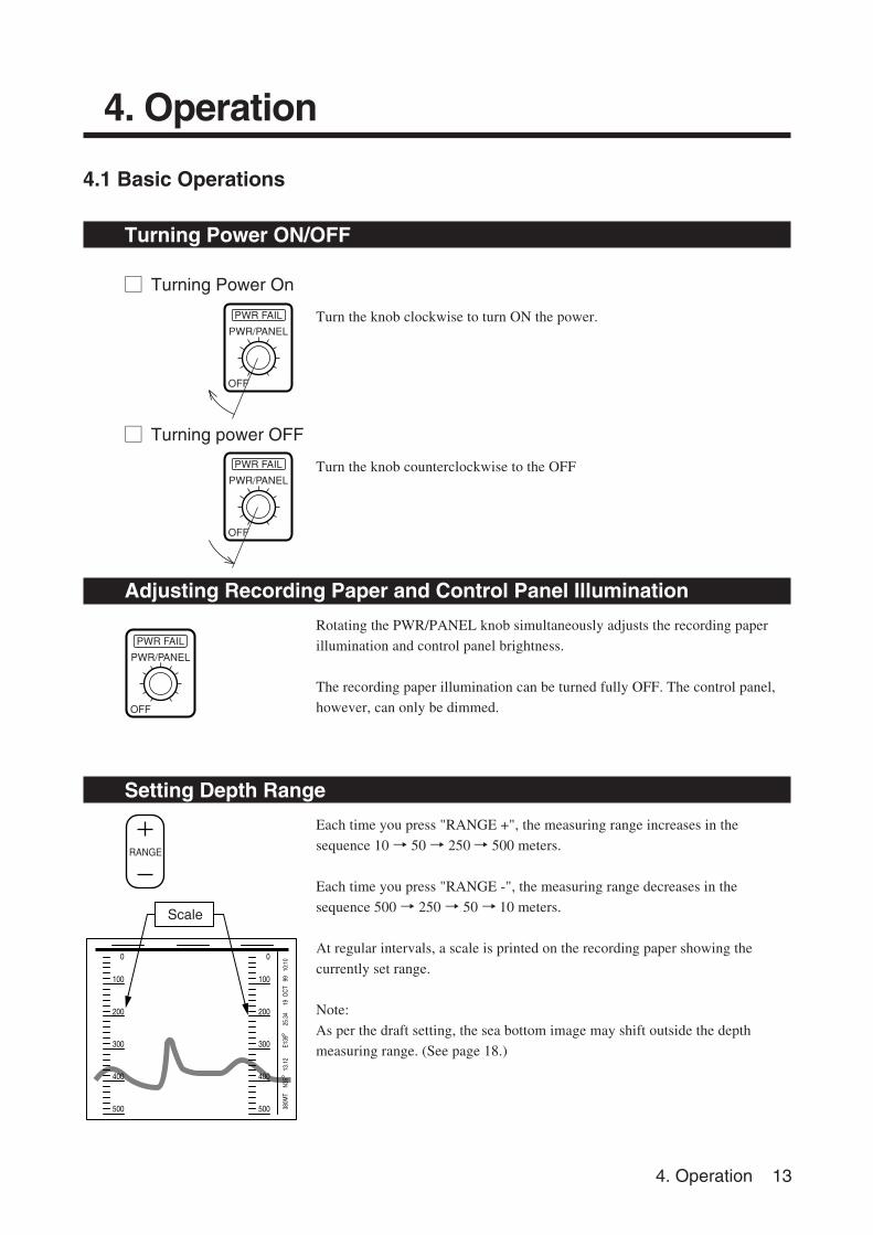
Turning Power ON/OFF
M Turning Power On
Turn the knob clockwise to turn ON the power.
M Turning power OFF
Turn the knob counterclockwise to the OFF
Adjusting Recording Paper and Control Panel Illumination
Rotating the PWR/PANEL knob simultaneously adjusts the recording paper
illumination and control panel brightness.
The recording paper illumination can be turned fully OFF. The control panel,
however, can only be dimmed.
Setting Depth Range
Each time you press "RANGE +", the measuring range increases in the
sequence 10 → 50 → 250→ 500 meters.
Each time you press "RANGE -", the measuring range decreases in the
sequence 500 → 250 → 50 → 10 meters.
At regular intervals, a scale is printed on the recording paper showing the
currently set range.
Note:
As per the draft setting, the sea bottom image may shift outside the depth
measuring range. (See page 18.)
14 4. Operation
RANGE 10
D.ALM OFF
TRANSDUCER
GAIN
C.SPD
MT
3
20
5 8 . 2
Set range
MARK
DEPTHALARM
Warning sounded
Depth alarm value.
Sea bottom
Buzzer sound
Depth alarm character
indication.
ALARMACK
DEPTH
DEPTHALARM
SET RANGEMARK
OFF
PWR FAIL
PWR/PANEL
SELECT
500
400
300
200
100
0
500
400
300
200
100
0
380M
T
N35
1
3.12
E13
9
25
.34
1
9 O
CT
99
10:1
0
Recording line (Mark)
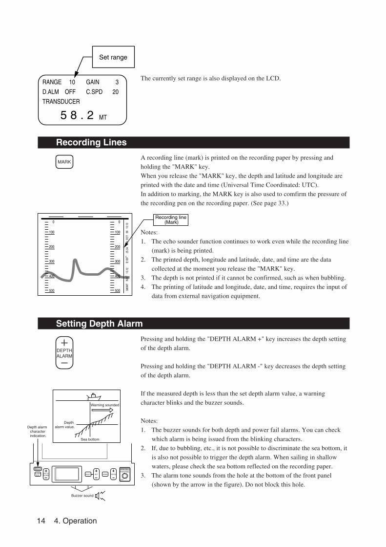
The currently set range is also displayed on the LCD.
Recording Lines
A recording line (mark) is printed on the recording paper by pressing and
holding the "MARK" key.
When you release the "MARK" key, the depth and latitude and longitude are
printed with the date and time (Universal Time Coordinated: UTC).
In addition to marking, the MARK key is also used to comfirm the pressure of
the recording pen on the recording paper. (See page 33.)
Notes:
1. The echo sounder function continues to work even while the recording line
(mark) is being printed.
2. The printed depth, longitude and latitude, date, and time are the data
collected at the moment you release the "MARK" key.
3. The depth is not printed if it cannot be confirmed, such as when bubbling.
4. The printing of latitude and longitude, date, and time, requires the input of
data from external navigation equipment.
Setting Depth Alarm
Pressing and holding the "DEPTH ALARM +" key increases the depth setting
of the depth alarm.
Pressing and holding the "DEPTH ALARM -" key decreases the depth setting
of the depth alarm.
If the measured depth is less than the set depth alarm value, a warning
character blinks and the buzzer sounds.
Notes:
1. The buzzer sounds for both depth and power fail alarms. You can check
which alarm is being issued from the blinking characters.
2. If, due to bubbling, etc., it is not possible to discriminate the sea bottom, it
is also not possible to trigger the depth alarm. When sailing in shallow
waters, please check the sea bottom reflected on the recording paper.
3. The alarm tone sounds from the hole at the bottom of the front panel
(shown by the arrow in the figure). Do not block this hole.
4. Operation 15
RANGE 10
D.ALM 50
TRANSDUCER
GAIN
C.SPD
MT
3
20
5 8 . 2
Depth alarm setting
ALARMACK
OFF
PWR FAIL
PWR/PANEL
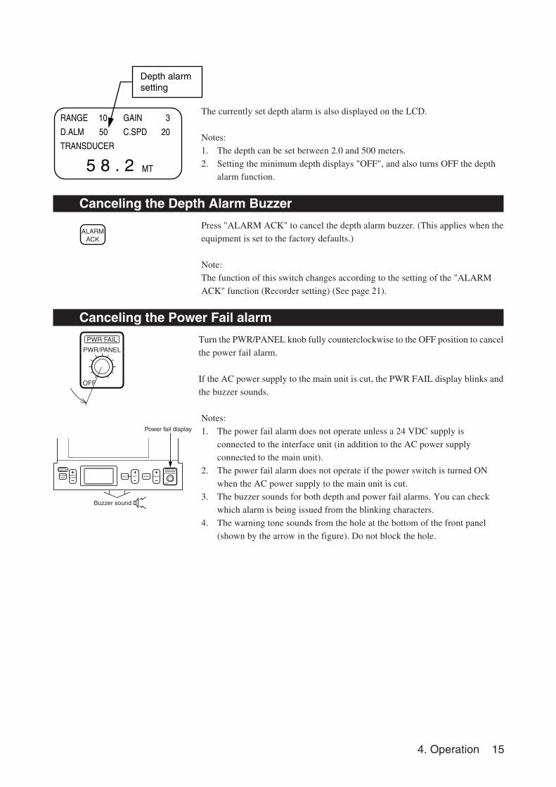
The currently set depth alarm is also displayed on the LCD.
Notes:
1. The depth can be set between 2.0 and 500 meters.
2. Setting the minimum depth displays "OFF", and also turns OFF the depth
alarm function.
Canceling the Depth Alarm Buzzer
Press "ALARM ACK" to cancel the depth alarm buzzer. (This applies when the
equipment is set to the factory defaults.)
Note:
The function of this switch changes according to the setting of the "ALARM
ACK" function (Recorder setting) (See page 21).
Canceling the Power Fail alarm
Turn the PWR/PANEL knob fully counterclockwise to the OFF position to cancel
the power fail alarm.
If the AC power supply to the main unit is cut, the PWR FAIL display blinks and
the buzzer sounds.
Notes:
1. The power fail alarm does not operate unless a 24 VDC supply is
connected to the interface unit (in addition to the AC power supply
connected to the main unit).
2. The power fail alarm does not operate if the power switch is turned ON
when the AC power supply to the main unit is cut.
3. The buzzer sounds for both depth and power fail alarms. You can check
which alarm is being issued from the blinking characters.
4. The warning tone sounds from the hole at the bottom of the front panel
(shown by the arrow in the figure). Do not block the hole.
Buzzer sound
Power fail display
ALARMACK
DEPTH
DEPTHALARM
SET RANGEMARK
OFF
PWR FAIL
PWR/PANEL
SELECT
16 4. Operation
DISP SURF
STC MID
LCD CONT 7
GAIN
C.SPD
DRAFT
MT
3
20
0.0
5 8 . 2
DISP SURF
STC MID
LCD CONT 7
GAIN
C.SPD
DRAFT
MT
3
20
0.0
5 8 . 2
DISP SURF
STC MID
LCD CONT 7
GAIN
C.SPD
DRAFT
MT
3
20
0.0
5 8 . 2
SELECT
SET
SET
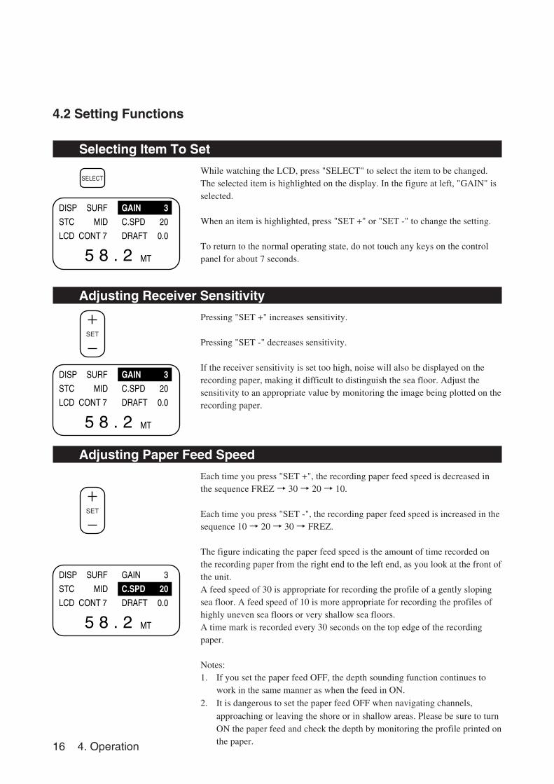
4.2 Setting Functions
Selecting Item To Set
While watching the LCD, press "SELECT" to select the item to be changed.The selected item is highlighted on the display. In the figure at left, "GAIN" isselected.
When an item is highlighted, press "SET +" or "SET -" to change the setting.
To return to the normal operating state, do not touch any keys on the controlpanel for about 7 seconds.
Adjusting Receiver Sensitivity
Pressing "SET +" increases sensitivity.
Pressing "SET -" decreases sensitivity.
If the receiver sensitivity is set too high, noise will also be displayed on therecording paper, making it difficult to distinguish the sea floor. Adjust thesensitivity to an appropriate value by monitoring the image being plotted on therecording paper.
Adjusting Paper Feed Speed
Each time you press "SET +", the recording paper feed speed is decreased inthe sequence FREZ → 30 → 20 → 10.
Each time you press "SET -", the recording paper feed speed is increased in thesequence 10 → 20 → 30 → FREZ.
The figure indicating the paper feed speed is the amount of time recorded onthe recording paper from the right end to the left end, as you look at the front ofthe unit.A feed speed of 30 is appropriate for recording the profile of a gently slopingsea floor. A feed speed of 10 is more appropriate for recording the profiles ofhighly uneven sea floors or very shallow sea floors.A time mark is recorded every 30 seconds on the top edge of the recordingpaper.
Notes:1. If you set the paper feed OFF, the depth sounding function continues to
work in the same manner as when the feed in ON.2. It is dangerous to set the paper feed OFF when navigating channels,
approaching or leaving the shore or in shallow areas. Please be sure to turnON the paper feed and check the depth by monitoring the profile printed onthe paper.
4. Operation 17
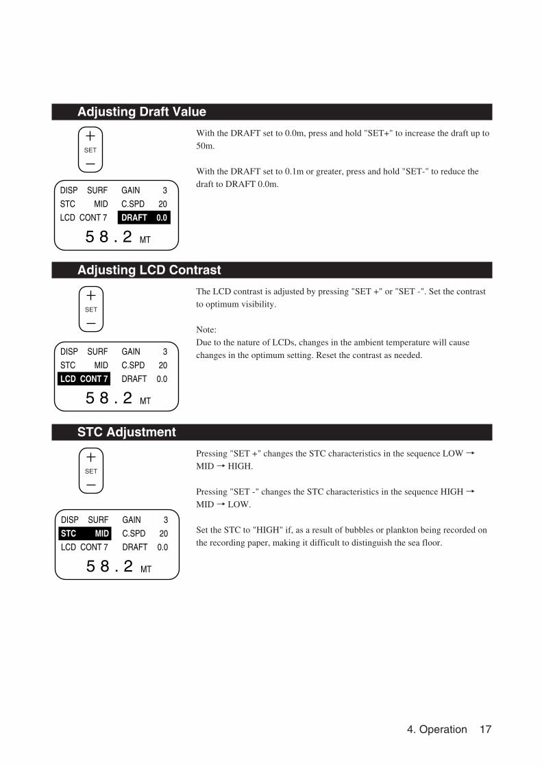
Adjusting Draft Value
With the DRAFT set to 0.0m, press and hold "SET+" to increase the draft up to
50m.
With the DRAFT set to 0.1m or greater, press and hold "SET-" to reduce the
draft to DRAFT 0.0m.
Adjusting LCD Contrast
The LCD contrast is adjusted by pressing "SET +" or "SET -". Set the contrast
to optimum visibility.
Note:
Due to the nature of LCDs, changes in the ambient temperature will cause
changes in the optimum setting. Reset the contrast as needed.
STC Adjustment
Pressing "SET +" changes the STC characteristics in the sequence LOW →MID → HIGH.
Pressing "SET -" changes the STC characteristics in the sequence HIGH →MID → LOW.
Set the STC to "HIGH" if, as a result of bubbles or plankton being recorded on
the recording paper, making it difficult to distinguish the sea floor.
DISP SURF
STC MID
LCD CONT 7
GAIN
C.SPD
DRAFT
MT
3
20
0.0
5 8 . 2
SET
DISP SURF
STC MID
LCD CONT 7
GAIN
C.SPD
DRAFT
MT
3
20
0.0
5 8 . 2
DISP SURF
STC MID
LCD CONT 7
GAIN
C.SPD
DRAFT
MT
3
20
0.0
5 8 . 2
SET
SET
18 4. Operation
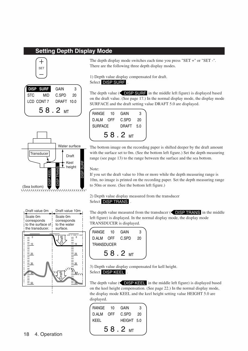
Setting Depth Display Mode
The depth display mode switches each time you press "SET +" or "SET -".There are the following three depth display modes.
1) Depth value display compensated for draft.Select DISP SURF .
The depth value ( DISP SURF in the middle left figure) is displayed basedon the draft value. (See page 17.) In the normal display mode, the display modeSURFACE and the draft setting value DRAFT 5.0 are displayed.
The bottom image on the recording paper is shifted deeper by the draft amountwith the surface set to 0m. (See the bottom left figure.) Set the depth measuringrange (see page 13) to the range between the surface and the sea bottom.
Note:If you set the draft value to 10m or more while the depth measuring range is10m, no image is printed on the recording paper. Set the depth measuring rangeto 50m or more. (See the bottom left figure.)
2) Depth value display measured from the transducerSelect DISP TRANS .
The depth value measured from the transducer ( DISP TRANS in the middleleft figure) is displayed. In the normal display mode, the display modeTRANSDUCER is displayed.
3) Depth value display compensated for kell height.Select DISP KEEL .
The depth value ( DISP KEEL in the middle left figure) is displayed basedon the keel height compensation. (See page 22.) In the normal display mode,the display mode KEEL and the keel height setting value HEIGHT 5.0 aredisplayed.
DISP SURF
STC MID
LCD CONT 7
GAIN
C.SPD
DRAFT
MT
3
20
10.0
5 8 . 2
SET
RANGE 10
D.ALM OFF
SURFACE
GAIN
C.SPD
DRAFT
MT
3
20
5.0
5 8 . 2
RANGE 10
D.ALM OFF
TRANSDUCER
GAIN
C.SPD
MT
3
20
5 8 . 2
RANGE 10
D.ALM OFF
KEEL
GAIN
C.SPD
HEIGHT
MT
3
20
5.0
5 8 . 2
TransducerDraft
Keel height
DIS
P S
UR
F
DIS
P T
RA
NS
DIS
P K
EE
L
(Sea bottom)
Water surface
50
40
30
20
10
0
50
40
30
20
10
0
Dra
ftD
raft
Draft value 0m
Scale 0m corresponds to the surface of the transducer.
Draft value 10m
Scale 0m corresponds to the water surface.
4. Operation 19
INPUT POSI DATA NMEA0183OUTPUT DEP DATA NMEA183V2.3OUTPUT DEP ALARM STATUS LEVELNEXT PAGE
INPUT POSI DATA NMEA0183OUTPUT DEP DATA NMEA183V2.3OUTPUT DEP ALARM STATUS LEVELNEXT PAGE
OFF
PWR FAIL
PWR/PANEL
OFF
PWR FAIL
PWR/PANEL
ALARMACK SET
ALARMACK
SELECT
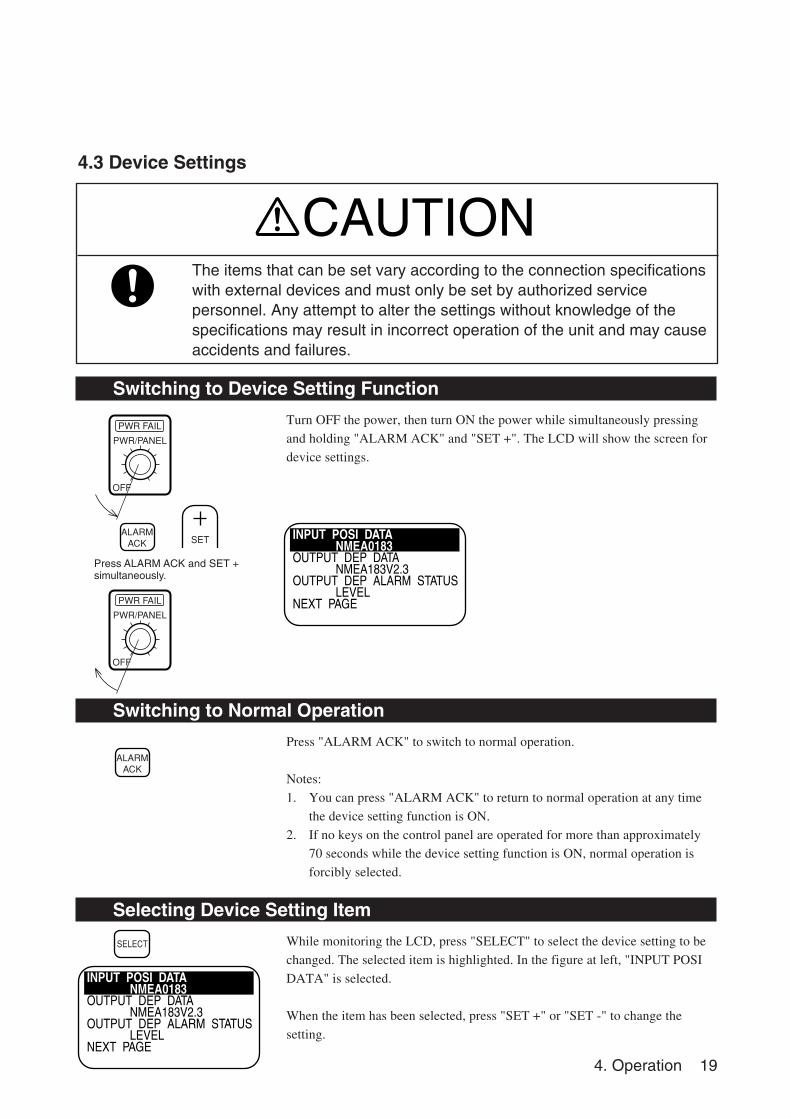
Switching to Device Setting Function
Turn OFF the power, then turn ON the power while simultaneously pressing
and holding "ALARM ACK" and "SET +". The LCD will show the screen for
device settings.
Switching to Normal Operation
Press "ALARM ACK" to switch to normal operation.
Notes:
1. You can press "ALARM ACK" to return to normal operation at any time
the device setting function is ON.
2. If no keys on the control panel are operated for more than approximately
70 seconds while the device setting function is ON, normal operation is
forcibly selected.
Selecting Device Setting Item
While monitoring the LCD, press "SELECT" to select the device setting to be
changed. The selected item is highlighted. In the figure at left, "INPUT POSI
DATA" is selected.
When the item has been selected, press "SET +" or "SET -" to change the
setting.
The items that can be set vary according to the connection specificationswith external devices and must only be set by authorized servicepersonnel. Any attempt to alter the settings without knowledge of thespecifications may result in incorrect operation of the unit and may causeaccidents and failures.
4.3 Device Settings
CAUTION
Press ALARM ACK and SET +simultaneously.
20 4. Operation
INPUT POSI DATA NMEA0183OUTPUT DEP DATA NMEA183V2.3OUTPUT DEP ALARM STATUS LEVELNEXT PAGE
INPUT POSI DATA NMEA0183OUTPUT DEP DATA NMEA183V2.3OUTPUT DEP ALARM STATUS LEVELNEXT PAGE
SET
SET
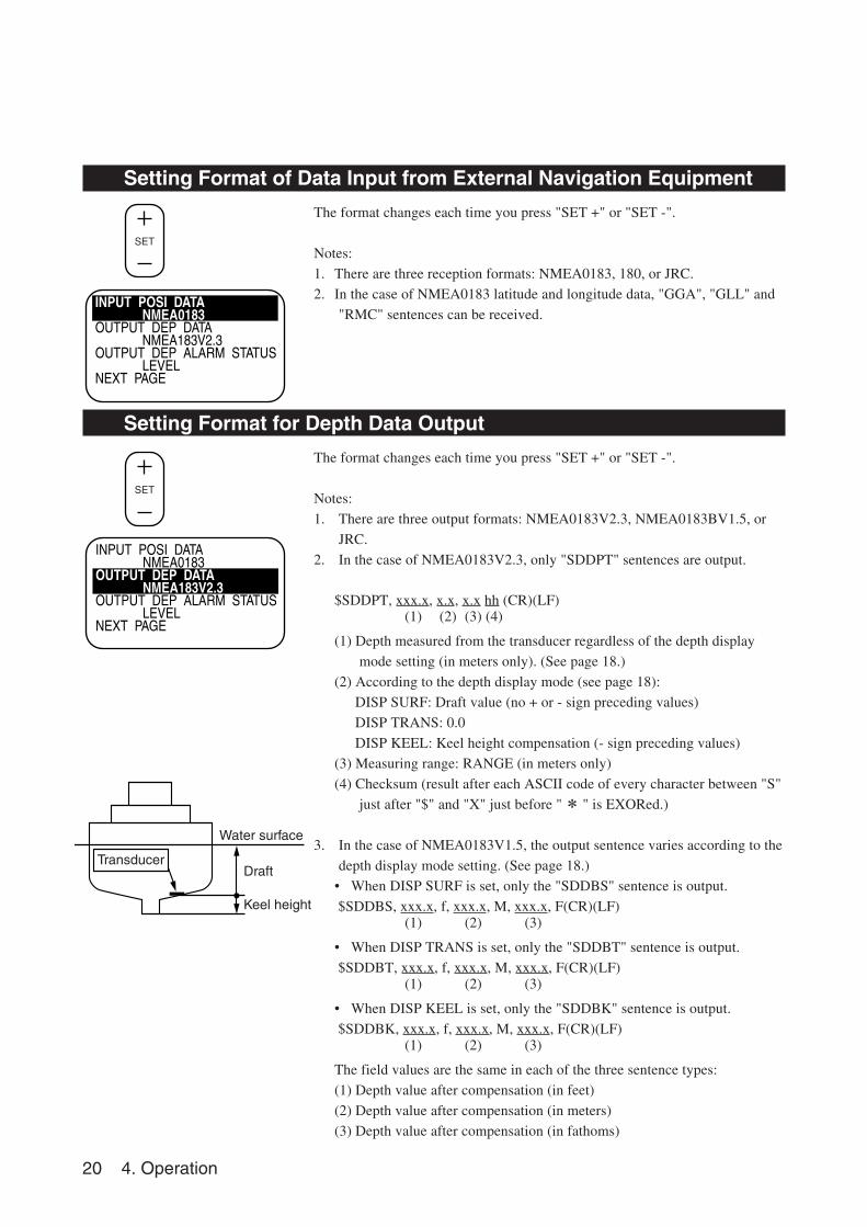
Setting Format of Data Input from External Navigation Equipment
The format changes each time you press "SET +" or "SET -".
Notes:
1. There are three reception formats: NMEA0183, 180, or JRC.
2. In the case of NMEA0183 latitude and longitude data, "GGA", "GLL" and
"RMC" sentences can be received.
Setting Format for Depth Data Output
The format changes each time you press "SET +" or "SET -".
Notes:
1. There are three output formats: NMEA0183V2.3, NMEA0183BV1.5, or
JRC.
2. In the case of NMEA0183V2.3, only "SDDPT" sentences are output.
$SDDPT, xxx.x, x.x, x.x hh (CR)(LF)(1) (2) (3) (4)
(1) Depth measured from the transducer regardless of the depth display
mode setting (in meters only). (See page 18.)
(2) According to the depth display mode (see page 18):
DISP SURF: Draft value (no + or - sign preceding values)
DISP TRANS: 0.0
DISP KEEL: Keel height compensation (- sign preceding values)
(3) Measuring range: RANGE (in meters only)
(4) Checksum (result after each ASCII code of every character between "S"
just after "$" and "X" just before "* " is EXORed.)
3. In the case of NMEA0183V1.5, the output sentence varies according to the
depth display mode setting. (See page 18.)
• When DISP SURF is set, only the "SDDBS" sentence is output.
$SDDBS, xxx.x, f, xxx.x, M, xxx.x, F(CR)(LF)(1) (2) (3)
• When DISP TRANS is set, only the "SDDBT" sentence is output.
$SDDBT, xxx.x, f, xxx.x, M, xxx.x, F(CR)(LF)(1) (2) (3)
• When DISP KEEL is set, only the "SDDBK" sentence is output.
$SDDBK, xxx.x, f, xxx.x, M, xxx.x, F(CR)(LF)(1) (2) (3)
The field values are the same in each of the three sentence types:
(1) Depth value after compensation (in feet)
(2) Depth value after compensation (in meters)
(3) Depth value after compensation (in fathoms)
Transducer
Water surface
Draft
Keel height
4. Operation 21
INPUT POSI DATA NMEA0183OUTPUT DEP DATA NMEA183V2.3OUTPUT DEP ALARM STATUS LEVELNEXT PAGE
PANEL ACK MODE OWN SELFOUT CONSOLE ACK MODE OUT ALM STATUSADC MODE 6NEXT PAGE
PANEL ACK MODE OWN SELFOUT CONSOLE ACK MODE OUT ALM STATUSADC MODE 6NEXT PAGE
PANEL ACK MODE OWN SELFOUT CONSOLE ACK MODE OUT ALM STATUSADC MODE 6NEXT PAGE
SET
SET
SET
SET
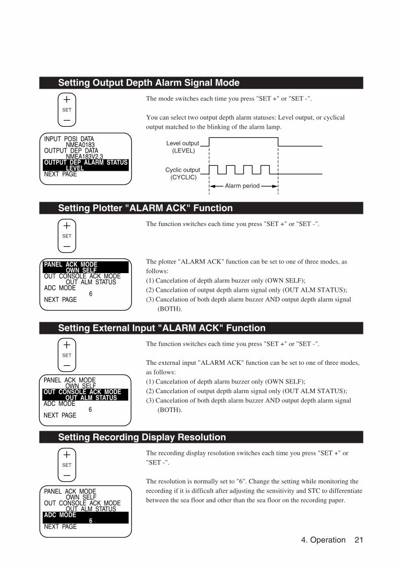
Setting Output Depth Alarm Signal Mode
The mode switches each time you press "SET +" or "SET -".
You can select two output depth alarm statuses: Level output, or cyclical
output matched to the blinking of the alarm lamp.
Setting Plotter "ALARM ACK" Function
The function switches each time you press "SET +" or "SET -".
The plotter "ALARM ACK" function can be set to one of three modes, as
follows:
(1) Cancelation of depth alarm buzzer only (OWN SELF);
(2) Cancelation of output depth alarm signal only (OUT ALM STATUS);
(3) Cancelation of both depth alarm buzzer AND output depth alarm signal
(BOTH).
Setting External Input "ALARM ACK" Function
The function switches each time you press "SET +" or "SET -".
The external input "ALARM ACK" function can be set to one of three modes,
as follows:
(1) Cancelation of depth alarm buzzer only (OWN SELF);
(2) Cancelation of output depth alarm signal only (OUT ALM STATUS);
(3) Cancelation of both depth alarm buzzer AND output depth alarm signal
(BOTH).
Setting Recording Display Resolution
The recording display resolution switches each time you press "SET +" or
"SET -".
The resolution is normally set to "6". Change the setting while monitoring the
recording if it is difficult after adjusting the sensitivity and STC to differentiate
between the sea floor and other than the sea floor on the recording paper.
Level output (LEVEL)
Alarm period
Cyclic output (CYCLIC)
22 4. Operation
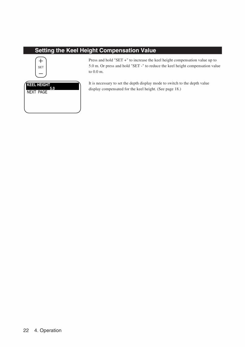
Setting the Keel Height Compensation Value
Press and hold "SET +" to increase the keel height compensation value up to
5.0 m. Or press and hold "SET -" to reduce the keel height compensation value
to 0.0 m.
It is necessary to set the depth display mode to switch to the depth value
display compensated for the keel height. (See page 18.)KEEL HEIGHT 5.0NEXT PAGE
SET
4. Operation 23
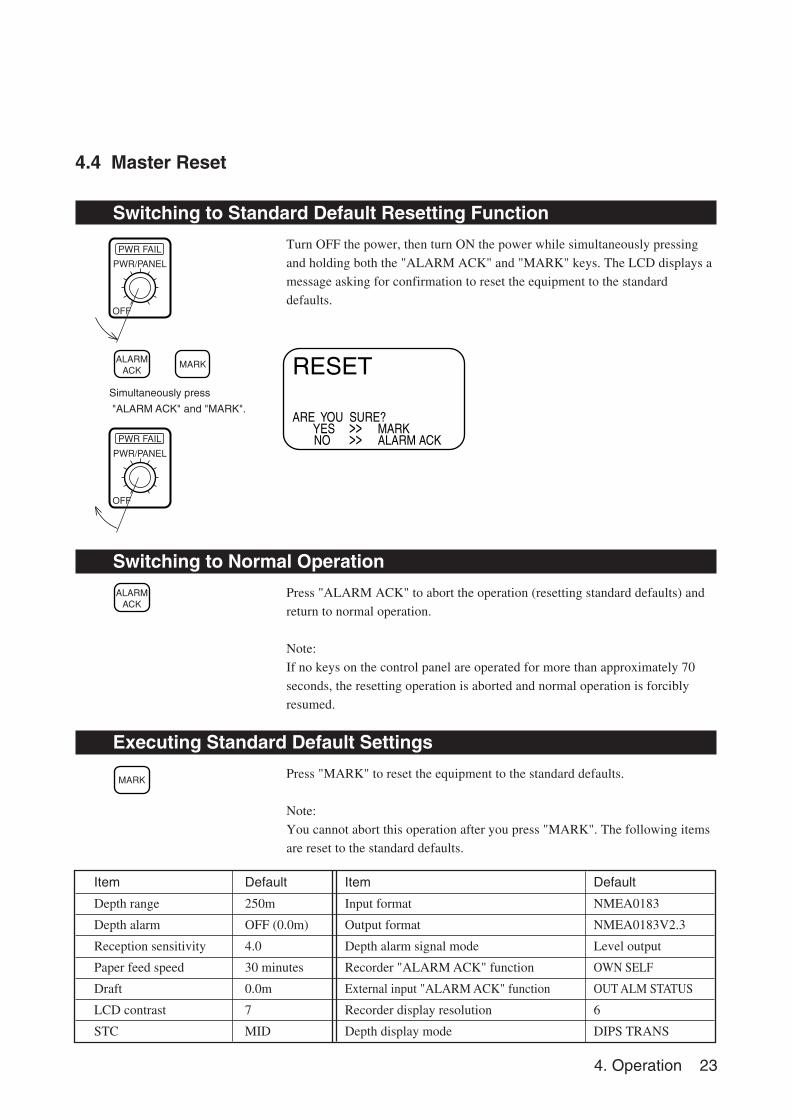
Item Default Item Default
Depth range 250m Input format NMEA0183
Depth alarm OFF (0.0m) Output format NMEA0183V2.3
Reception sensitivity 4.0 Depth alarm signal mode Level output
Paper feed speed 30 minutes Recorder "ALARM ACK" function OWN SELF
Draft 0.0m External input "ALARM ACK" function OUT ALM STATUS
LCD contrast 7 Recorder display resolution 6
STC MID Depth display mode DIPS TRANS
ARE YOU SURE? YES NO
>>>>
MARKALARM ACK
RESET
OFF
PWR FAIL
PWR/PANEL
OFF
PWR FAIL
PWR/PANEL
ALARMACK
MARK
ALARMACK
MARK
4.4 Master Reset
Switching to Standard Default Resetting Function
Turn OFF the power, then turn ON the power while simultaneously pressing
and holding both the "ALARM ACK" and "MARK" keys. The LCD displays a
message asking for confirmation to reset the equipment to the standard
defaults.
Switching to Normal Operation
Press "ALARM ACK" to abort the operation (resetting standard defaults) and
return to normal operation.
Note:
If no keys on the control panel are operated for more than approximately 70
seconds, the resetting operation is aborted and normal operation is forcibly
resumed.
Executing Standard Default Settings
Press "MARK" to reset the equipment to the standard defaults.
Note:
You cannot abort this operation after you press "MARK". The following items
are reset to the standard defaults.
Simultaneously press
"ALARM ACK" and "MARK".
24 5. Replacing Consumables
Platen locks
Lift flange
Align the cuts on the spool with the pins.
Back side of recording paper
The platen locks are released whenthe flat faces of the knobs are vertical. The platen can then be opened by hinging it forward.
Insert
recording
paper
Insert the end of the recording paperinto the slot in the takeup spool,then wind the paper round the spoolcounterclockwise.
Position of the recording pen during the replacement of recording paper
*
5. Replacing Consumables
OFF
PWR FAIL
PWR/PANEL
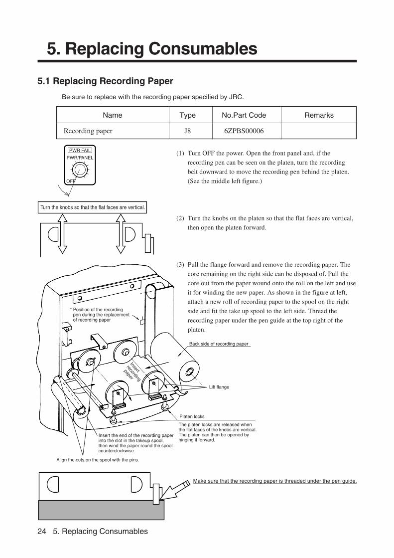
Name Type No.Part Code Remarks
Recording paper J8 6ZPBS00006
5.1 Replacing Recording Paper
Be sure to replace with the recording paper specified by JRC.
Make sure that the recording paper is threaded under the pen guide.
Turn the knobs so that the flat faces are vertical.
(1) Turn OFF the power. Open the front panel and, if the
recording pen can be seen on the platen, turn the recording
belt downward to move the recording pen behind the platen.
(See the middle left figure.)
(2) Turn the knobs on the platen so that the flat faces are vertical,
then open the platen forward.
(3) Pull the flange forward and remove the recording paper. The
core remaining on the right side can be disposed of. Pull the
core out from the paper wound onto the roll on the left and use
it for winding the new paper. As shown in the figure at left,
attach a new roll of recording paper to the spool on the right
side and fit the take up spool to the left side. Thread the
recording paper under the pen guide at the top right of the
platen.
5. Replacing Consumables 25
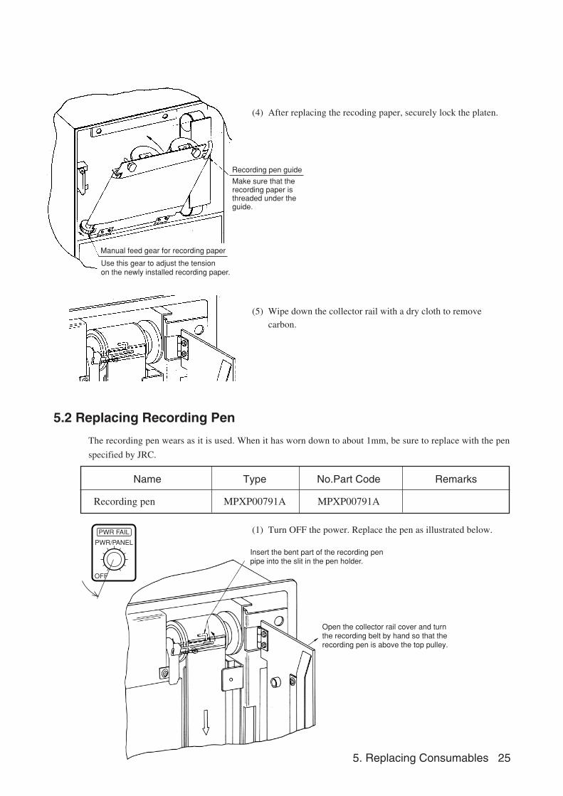
Insert the bent part of the recording penpipe into the slit in the pen holder.
Open the collector rail cover and turn the recording belt by hand so that the recording pen is above the top pulley.
OFF
PWR FAIL
PWR/PANEL
(4) After replacing the recoding paper, securely lock the platen.
(5) Wipe down the collector rail with a dry cloth to remove
carbon.
5.2 Replacing Recording Pen
The recording pen wears as it is used. When it has worn down to about 1mm, be sure to replace with the pen
specified by JRC.
(1) Turn OFF the power. Replace the pen as illustrated below.
Recording pen guide
Manual feed gear for recording paper
Use this gear to adjust the tension on the newly installed recording paper.
Make sure that the recording paper is threaded under the guide.
Name Type No.Part Code Remarks
Recording pen MPXP00791A MPXP00791A
26 6. Maintenance and Inspection
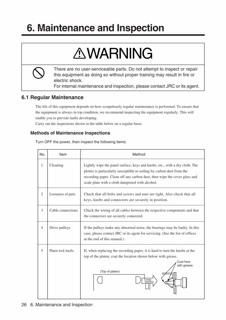
Cross-section
(Top of platen)
Coat here with grease.
6. Maintenance and Inspection
6.1 Regular Maintenance
The life of this equipment depends on how scrupulously regular maintenance is performed. To ensure that
the equipment is always in top condition, we recommend inspecting the equipment regularly. This will
enable you to prevent faults developing.
Carry out the inspections shown in the table below on a regular basis.
No. Item Method
1 Cleaning Lightly wipe the panel surface, keys and knobs, etc., with a dry cloth. The
plotter is particularly susceptible to soiling by carbon dust from the
recording paper. Clean off any carbon dust, then wipe the cover glass and
scale plate with a cloth dampened with alcohol.
2 Looseness of parts Check that all bolts and screws and nuts are tight. Also check that all
keys, knobs and connectors are securely in position.
3 Cable connections Check the wiring of all cables between the respective components and that
the connectors are securely connected.
4 Drive pulleys If the pulleys make any abnormal noise, the bearings may be faulty. In this
case, please contact JRC or its agent for servicing. (See the list of offices
at the end of this manual.)
5 Platen lock knobs If, when replacing the recording paper, it is hard to turn the knobs at the
top of the platen, coat the location shown below with grease.
Methods of Maintenance Inspections
Turn OFF the power, then inspect the following items.
WARNINGThere are no user-serviceable parts. Do not attempt to inspect or repairthis equipment as doing so without proper training may result in fire orelectric shock.For internal maintenance and inspection, please contact JRC or its agent.
6. Maintenance and Inspection 27
RANGE
6.2 Self-Diagnostic Function
ROM VER 1.01RAM TESTING 25%UART SHORT STAND BYPANEL CHECKXX XX XX X X X 1ARAM SKIP SELECT,ACKEXIT MODE MARK,ACK
>>>>
ROM VER 1.01RAM TESTING 25%UART SHORT STAND BYPANEL CHECKXX XX XX X X X 1ARAM SKIP SELECT,ACKEXIT MODE MARK,ACK
>>>>
OFF
PWR FAIL
PWR/PANEL
OFF
PWR FAIL
PWR/PANEL
ALARMACK
MARK
ALARMACK
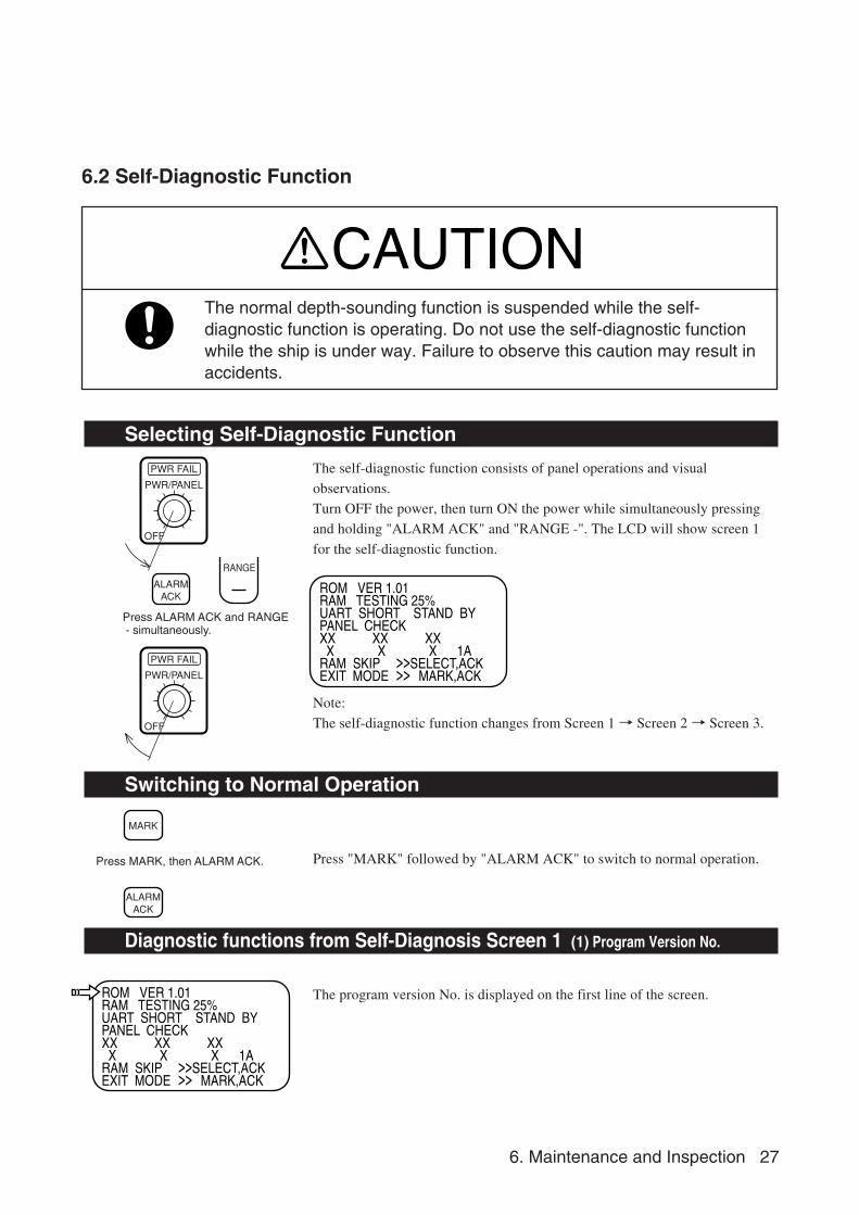
Selecting Self-Diagnostic Function
The self-diagnostic function consists of panel operations and visual
observations.
Turn OFF the power, then turn ON the power while simultaneously pressing
and holding "ALARM ACK" and "RANGE -". The LCD will show screen 1
for the self-diagnostic function.
Note:
The self-diagnostic function changes from Screen 1 → Screen 2 → Screen 3.
Switching to Normal Operation
Press "MARK" followed by "ALARM ACK" to switch to normal operation.
Diagnostic functions from Self-Diagnosis Screen 1 (1) Program Version No.
The program version No. is displayed on the first line of the screen.
CAUTIONThe normal depth-sounding function is suspended while the self-diagnostic function is operating. Do not use the self-diagnostic functionwhile the ship is under way. Failure to observe this caution may result inaccidents.
Press ALARM ACK and RANGE - simultaneously.
Press MARK, then ALARM ACK.
28 6. Maintenance and Inspection
ROM VER 1.01RAM TESTING 25%UART SHORT STAND BYPANEL CHECKXX XX XX X X X 1ARAM SKIP SELECT,ACKEXIT MODE MARK,ACK
>>>>
ROM VER 1.01RAM TESTING 25%UART SHORT STAND BYPANEL CHECKXX XX XX X X X 1ARAM SKIP SELECT,ACKEXIT MODE MARK,ACK
>>>>
ROM VER 1.01RAM TESTING 25%UART SHORT STAND BYPANEL CHECKXX XX XX X X X 1ARAM SKIP SELECT,ACKEXIT MODE MARK,ACK
>>>>
CQD-1705 Interface
POSITION
DATA IN
DEPTH
DATA OUT
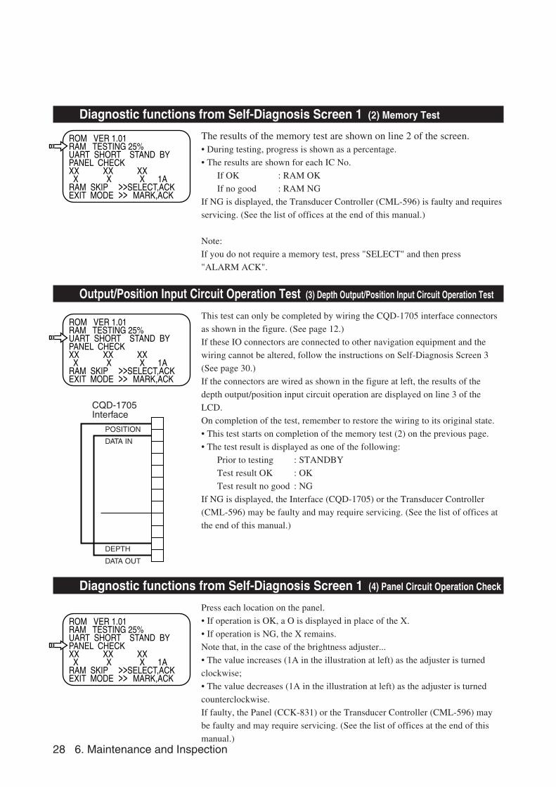
Diagnostic functions from Self-Diagnosis Screen 1 (2) Memory Test
The results of the memory test are shown on line 2 of the screen.• During testing, progress is shown as a percentage.
• The results are shown for each IC No.
If OK : RAM OK
If no good : RAM NG
If NG is displayed, the Transducer Controller (CML-596) is faulty and requires
servicing. (See the list of offices at the end of this manual.)
Note:
If you do not require a memory test, press "SELECT" and then press
"ALARM ACK".
Output/Position Input Circuit Operation Test (3) Depth Output/Position Input Circuit Operation Test
This test can only be completed by wiring the CQD-1705 interface connectors
as shown in the figure. (See page 12.)
If these IO connectors are connected to other navigation equipment and the
wiring cannot be altered, follow the instructions on Self-Diagnosis Screen 3
(See page 30.)
If the connectors are wired as shown in the figure at left, the results of the
depth output/position input circuit operation are displayed on line 3 of the
LCD.
On completion of the test, remember to restore the wiring to its original state.
• This test starts on completion of the memory test (2) on the previous page.
• The test result is displayed as one of the following:
Prior to testing : STANDBY
Test result OK : OK
Test result no good : NG
If NG is displayed, the Interface (CQD-1705) or the Transducer Controller
(CML-596) may be faulty and may require servicing. (See the list of offices at
the end of this manual.)
Diagnostic functions from Self-Diagnosis Screen 1 (4) Panel Circuit Operation Check
Press each location on the panel.
• If operation is OK, a O is displayed in place of the X.
• If operation is NG, the X remains.
Note that, in the case of the brightness adjuster...
• The value increases (1A in the illustration at left) as the adjuster is turned
clockwise;
• The value decreases (1A in the illustration at left) as the adjuster is turned
counterclockwise.
If faulty, the Panel (CCK-831) or the Transducer Controller (CML-596) may
be faulty and may require servicing. (See the list of offices at the end of this
manual.)
6. Maintenance and Inspection 29
12.3
MT
N
12 1
3.12
3
E12
3 2
5.34
525
D
EC
98
10:
10
12.3
MT
N
12 1
3.12
3
E12
3 2
5.34
525
D
EC
98
10:
10
50
40
30
20
10
0
10
8
6
4
2
0
ALARMACK
SELECT
Selecting Self-Diagnostics Screen 2
With Self-Diagnostics Screen 1 displayed, press "SELECT" and then press
"ALARM ACK" to switch to Self-Diagnostics Screen 2.
Diagnostic Functions in Self-Diagnostics Screen 2 (1) LCD Check
• This test fills the whole LCD screen from the left to the right. The screen is
repeatedly filled with black, followed by white. If there is any dropout, the
Panel (CCK-831) or Transducer Controller (CML-596) may be faulty. Please
contact JRC or its agent. (See the list of offices at the end of this manual.)
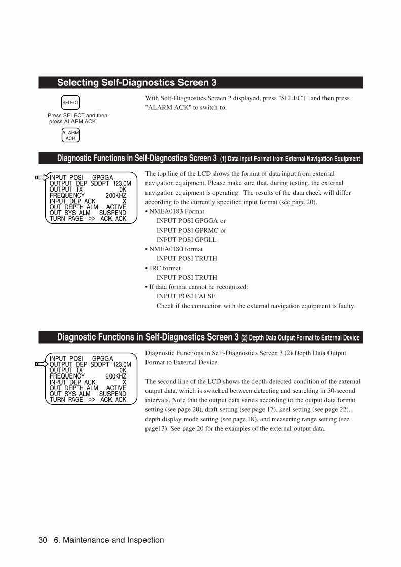
Diagnostic Functions in Self-Diagnostics Screen 2 (2) Recording Paper Surface Check
• This check prints a line at regular intervals on the recording paper. Except for
the top line, the density is reduced every four lines.
• A fixed line is printed at regular intervals and the paper feed speed and depth
scale alternated in the following order. Note that the equipment automatically
prints a fixed line and switches paper feed speed and depth scale. The water
depth, longitude and latitude, date, and time printed with the fixed line are as
follows: 12.3MT N12˚13. 123 E123˚25. 345 23 DEC 98 10:10.
• If the printing is blurred, the pen may be worn out (see page 25) or the pen
belt may be incorrectly tensioned (see page 33). See the respective pages for
details of adjustment.
Press SELECT and then press ALARM ACK.
30 6. Maintenance and Inspection
INPUT POSI GPGGAOUTPUT DEP SDDPT 123.0MOUTPUT TXFREQUENCYINPUT DEP ACKOUT DEPTH ALMOUT SYS ALMTURN PAGE
0K200KHZ
XACTIVE
SUSPENDACK, ACK>>
INPUT POSI GPGGAOUTPUT DEP SDDPT 123.0MOUTPUT TXFREQUENCYINPUT DEP ACKOUT DEPTH ALMOUT SYS ALMTURN PAGE
0K200KHZ
XACTIVE
SUSPENDACK, ACK>>
ALARMACK
SELECT
Selecting Self-Diagnostics Screen 3
With Self-Diagnostics Screen 2 displayed, press "SELECT" and then press
"ALARM ACK" to switch to.
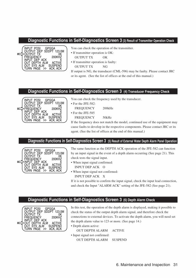
Diagnostic Functions in Self-Diagnostics Screen 3 (1) Data Input Format from External Navigation Equipment
The top line of the LCD shows the format of data input from external
navigation equipment. Please make sure that, during testing, the external
navigation equipment is operating. The results of the data check will differ
according to the currently specified input format (see page 20).
• NMEA0183 Format
INPUT POSI GPGGA or
INPUT POSI GPRMC or
INPUT POSI GPGLL
• NMEA0180 format
INPUT POSI TRUTH
• JRC format
INPUT POSI TRUTH
• If data format cannot be recognized:
INPUT POSI FALSE
Check if the connection with the external navigation equipment is faulty.
Diagnostic Functions in Self-Diagnostics Screen 3 (2) Depth Data Output Format to External Device
Diagnostic Functions in Self-Diagnostics Screen 3 (2) Depth Data Output
Format to External Device.
The second line of the LCD shows the depth-detected condition of the external
output data, which is switched between detecting and searching in 30-second
intervals. Note that the output data varies according to the output data format
setting (see page 20), draft setting (see page 17), keel setting (see page 22),
depth display mode setting (see page 18), and measuring range setting (see
page13). See page 20 for the examples of the external output data.
Press SELECT and then press ALARM ACK.
6. Maintenance and Inspection 31
INPUT POSI GPGGAOUTPUT DEP SDDPT 123.0MOUTPUT TXFREQUENCYINPUT DEP ACKOUT DEPTH ALMOUT SYS ALMTURN PAGE
0K200KHZ
XACTIVE
SUSPENDACK, ACK>>
INPUT POSI GPGGAOUTPUT DEP SDDPT 123.0MOUTPUT TXFREQUENCYINPUT DEP ACKOUT DEPTH ALMOUT SYS ALMTURN PAGE
0K200KHZ
XACTIVE
SUSPENDACK, ACK>>
INPUT POSI GPGGAOUTPUT DEP SDDPT 123.0MOUTPUT TXFREQUENCYINPUT DEP ACKOUT DEPTH ALMOUT SYS ALMTURN PAGE
0K200KHZ
XACTIVE
SUSPENDACK, ACK>>
INPUT POSI GPGGAOUTPUT DEP SDDPT 123.0MOUTPUT TXFREQUENCYINPUT DEP ACKOUT DEPTH ALMOUT SYS ALMTURN PAGE
0K200KHZ
XACTIVE
SUSPENDACK, ACK>>
Diagnostic Functions in Self-Diagnostics Screen 3 (3) Result of Transmitter Operation Check
You can check the operation of the transmitter.
• If transmitter operation is OK:
OUTPUT TX OK
• If transmitter operation is faulty:
OUTPUT TX NG
If output is NG, the transducer (CML-596) may be faulty. Please contact JRC
or its agent. (See the list of offices at the end of this manual.)
Diagnostic Functions in Self-Diagnostics Screen 3 (4) Transducer Frequency Check
You can check the frequency used by the transducer.
• For the JFE-582:
FREQUENCY 200kHz
• For the JFE-585
FREQUENCY 50kHz
If the frequency does not match the model, continued use of the equipment may
cause faults to develop in the respective components. Please contact JRC or its
agent. (See the list of offices at the end of this manual.)
Diagnostic Functions in Self-Diagnostics Screen 3 (5) Result of External Water Depth Alarm Panel Operation
The same function as the DEPTH ACK operation of the JFE-582 can function
by an input signal in the event of a depth alarm occurring (See page 21). This
check tests the signal input.
• When input signal confirmed:
INPUT DEP ACK O
• When input signal not confirmed:
INPUT DEP ACK X
If it is not possible to confirm the input signal, check the input lead connection,
and check the Input "ALARM ACK" setting of the JFE-582 (See page 21).
Diagnostic Functions in Self-Diagnostics Screen 3 (6) Depth Alarm Check
In this test, the operation of the depth alarm is displayed, making it possible to
check the status of the output depth alarm signal, and therefore check the
connections to external devices. To activate the depth alarm, you will need set
the depth alarm value to 123 or more. (See page 14.)
• Depth alarm active:
OUT DEPTH ALARM ACTIVE
• Input signal not confirmed:
OUT DEPTH ALARM SUSPEND
32 6. Maintenance and Inspection
INPUT POSI GPGGAOUTPUT DEP SDDPT 123.0MOUTPUT TXFREQUENCYINPUT DEP ACKOUT DEPTH ALMOUT SYS ALMTURN PAGE
0K200KHZ
XACTIVE
SUSPENDACK, ACK>>
INPUT POSI GPGGAOUTPUT DEP SDDPT 123.0MOUTPUT TXFREQUENCYINPUT DEP ACKOUT DEPTH ALMOUT SYS ALMTURN PAGE
0K200KHZ
XACTIVE
SUSPENDACK, ACK>>
RANGE 10D.ALM OFFTRANSDUCER
TURN PAGEEXIT MODE
>>>>
ACK, ACKMARK, ACK
GAINC.SPD
320
(Self-diagnostic screen 3)
(Function setting screen)
ALARMACK
ALARMACK
Press ALARM ACK twice toalternate between Self-Diag-nostic Screen 3 and FunctionSetting Screen.
MARK
ALARMACK
Diagnostic Functions in Self-Diagnostics Screen 3 (7) Sea bottom Detection Signal Check
This test forcibly outputs the CQD-1705 interface SYSTEM ALM output
signal as a sea bottom detection signal at 30-second cycles making it possible
to check the connection to the external device.
• When able to detect sea floor:
OUT SYS ALM SUSPEND
• When unable to detect sea floor:
OUT SYS ALM ACTIVE
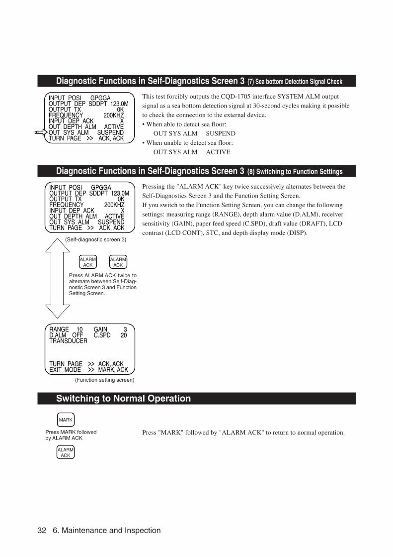
Diagnostic Functions in Self-Diagnostics Screen 3 (8) Switching to Function Settings
Pressing the "ALARM ACK" key twice successively alternates between the
Self-Diagnostics Screen 3 and the Function Setting Screen.
If you switch to the Function Setting Screen, you can change the following
settings: measuring range (RANGE), depth alarm value (D.ALM), receiver
sensitivity (GAIN), paper feed speed (C.SPD), draft value (DRAFT), LCD
contrast (LCD CONT), STC, and depth display mode (DISP).
Switching to Normal Operation
Press "MARK" followed by "ALARM ACK" to return to normal operation.Press MARK followedby ALARM ACK
6. Maintenance and Inspection 33
Loosen these two screws toadjust the 0m depth position.
Transmission trigger mount
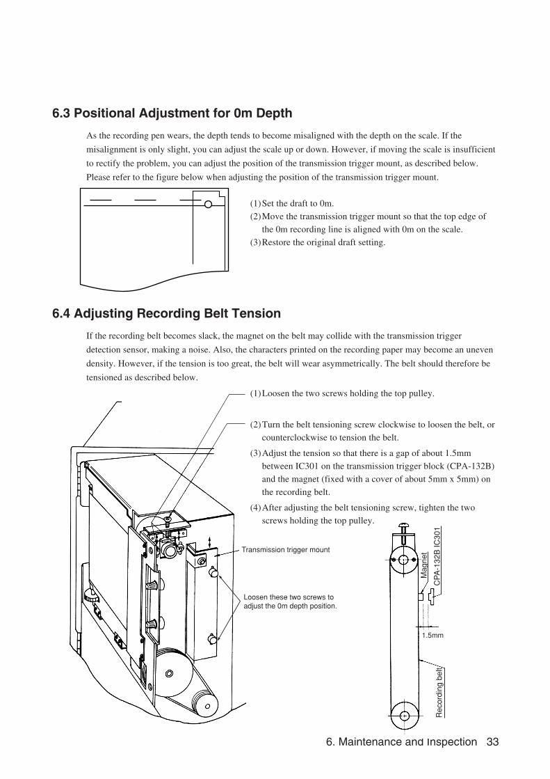
6.3 Positional Adjustment for 0m Depth
As the recording pen wears, the depth tends to become misaligned with the depth on the scale. If the
misalignment is only slight, you can adjust the scale up or down. However, if moving the scale is insufficient
to rectify the problem, you can adjust the position of the transmission trigger mount, as described below.
Please refer to the figure below when adjusting the position of the transmission trigger mount.
(1)Set the draft to 0m.
(2)Move the transmission trigger mount so that the top edge of
the 0m recording line is aligned with 0m on the scale.
(3)Restore the original draft setting.
Rec
ordi
ng b
elt
Mag
net
CP
A-1
32B
IC30
1
1.5mm
6.4 Adjusting Recording Belt Tension
If the recording belt becomes slack, the magnet on the belt may collide with the transmission trigger
detection sensor, making a noise. Also, the characters printed on the recording paper may become an uneven
density. However, if the tension is too great, the belt will wear asymmetrically. The belt should therefore be
tensioned as described below.
(1)Loosen the two screws holding the top pulley.
(2)Turn the belt tensioning screw clockwise to loosen the belt, or
counterclockwise to tension the belt.
(3)Adjust the tension so that there is a gap of about 1.5mm
between IC301 on the transmission trigger block (CPA-132B)
and the magnet (fixed with a cover of about 5mm x 5mm) on
the recording belt.
(4)After adjusting the belt tensioning screw, tighten the two
screws holding the top pulley.
34 6. Maintenance and Inspection
Name Type No.Part Code Remarks
Recording belt MPGK30636 MPGK30636 Standard Goods
Recording belt MPGK01821 MPGK01821 Substitute Goods
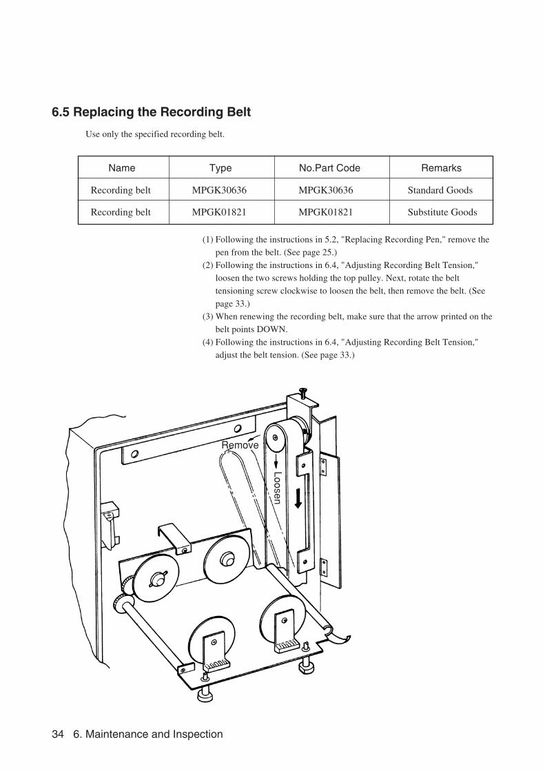
6.5 Replacing the Recording Belt
Use only the specified recording belt.
(1) Following the instructions in 5.2, "Replacing Recording Pen," remove the
pen from the belt. (See page 25.)
(2) Following the instructions in 6.4, "Adjusting Recording Belt Tension,"
loosen the two screws holding the top pulley. Next, rotate the belt
tensioning screw clockwise to loosen the belt, then remove the belt. (See
page 33.)
(3) When renewing the recording belt, make sure that the arrow printed on the
belt points DOWN.
(4) Following the instructions in 6.4, "Adjusting Recording Belt Tension,"
adjust the belt tension. (See page 33.)
Loosen
Remove
6. Maintenance and Inspection 35
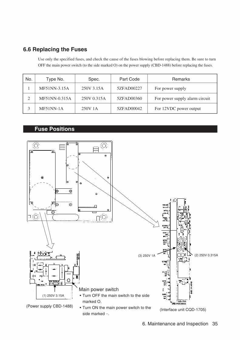
6.6 Replacing the Fuses
Use only the specified fuses, and check the cause of the fuses blowing before replacing them. Be sure to turn
OFF the main power switch (to the side marked O) on the power supply (CBD-1488) before replacing the fuses.
No. Type No. Spec. Part Code Remarks
1 MF51NN-3.15A 250V 3.15A 5ZFAD00227 For power supply
2 MF51NN-0.315A 250V 0.315A 5ZFAD00360 For power supply alarm circuit
3 MF51NN-1A 250V 1A 5ZFAD00042 For 12VDC power output
Fuse Positions
(1) 250V 3.15A
(2) 250V 0.315A(3) 250V 1A
Main power switch
(Power supply CBD-1488)(Interface unit CQD-1705)
• Turn OFF the main switch to the side
marked O.
• Turn ON the main power switch to the
side marked _.
36 6. Maintenance and Inspection
(1) Replacing Main Power Supply Fuse
One reason for this fuse blowing is a faulty cable attached to the power supply. Check the cables before
replacing the fuse, then turn the power on. If the fuse blows again, the Power Supply (CBD-1488) may be
faulty. Contact JRC or its agent.
(2) Replacing Power Fail Alarm Circuit Fuse
One reason for this fuse blowing is the input of an abnormal voltage. Check the input voltage at pins (7)
and (8) of the Interface Block (CQD-1705, TB501). Check that the voltage is as rated (24VDC) (operating
voltage: 21.5 to 31.5VDC) before replacing the fuse. If the fuse blows again, the Transducer Controller
(CML-596) may be faulty. (See the list of offices at the end of this manual.)
(3) Replacing 12VDC Output Power Supply Fuse
One reason for this fuse blowing is an overcurrent in an external device connected to pins (1) and (2) of the
interface block (CQD-1705, TB502). Temporarily remove the cable to the external device. If the fuse blows
again, either the Transducer Controller (CML-596) or Interface Block (CQD-1705) may be faulty. Contact
JRC or its agent. (See the list of offices at the end of this manual.)
6.7 Replacing the Units
Unit Type Code Remarks
Panel CCK-831 CCK-831
Interface CQD-1705 CQD-1705
Tx/Rx Control CML-596-2 CML-596-2
Power Supply CBD-1488 CBD-1488
Recording paper J8 6ZPBS00006
Recording pen MPXP00791A MPXP00791A
Recording belt MPGK30636 MPGK30636
Transducer UT-200ND20 UT-200ND20 Cable length: 20m
7. Consider Installation 37
7. Consider Installation
• Do not install the JFE-582 where subject to the following conditions as such conditions
may cause failures and reduce the life of the equipment.
1. Where liable to be splashed with water.
2. Where ventilation is poor.
• Do not coat the part of the transducer that outputs the ultrasonic waves (the rubber part of
the tank on the ship's bottom) with the hull coating as this will deteriorate performance.
38 8. After-sales Service
8. After-sales Service
8.1 When Requesting Servicing
If you suspect a fault, stop using the equipment and contact JRC or its agent.
Servicing Under Warranty
When the fault develops while the equipment is being used as indicated in the Instruction Manual, the
equipment will be repaired free of charge. However, if the fault occurs as the result of misuse, negligence,
natural disaster, fire, or other acts of God, a charge will be made for its repair.
Servicing Out of Warranty
If the fault can be rectified by servicing the equipment, the repair will be made at your expense.
Details to be Submitted
- Name, type No., month and year of manufacture, and serial number;
- Nature of fault (in as much detail as possible);
- Contact details (your name, address and phone number, etc.).
8.2 Recommendations for Inspection and Maintenance
Depending on the conditions of usage, the performance may deteriorate due to the aging of components. In
such conditions, please consult JRC or its agent for inspection and maintenance, as distinct from the daily
care you normally give your equipment.
Note that such inspection and maintenance is subject to charge.
Please consult JRC or its agent for further details of any part of the afterservice conditions.
Contact: See list at end of manual.
9. Disposal 39
9. Disposal
9.1 Disposal of this equipment
Please dispose of this equipment following the guidelines of the local body governing the
location at which the equipment is disposed of.
40 10. Specifications
10. Specifications
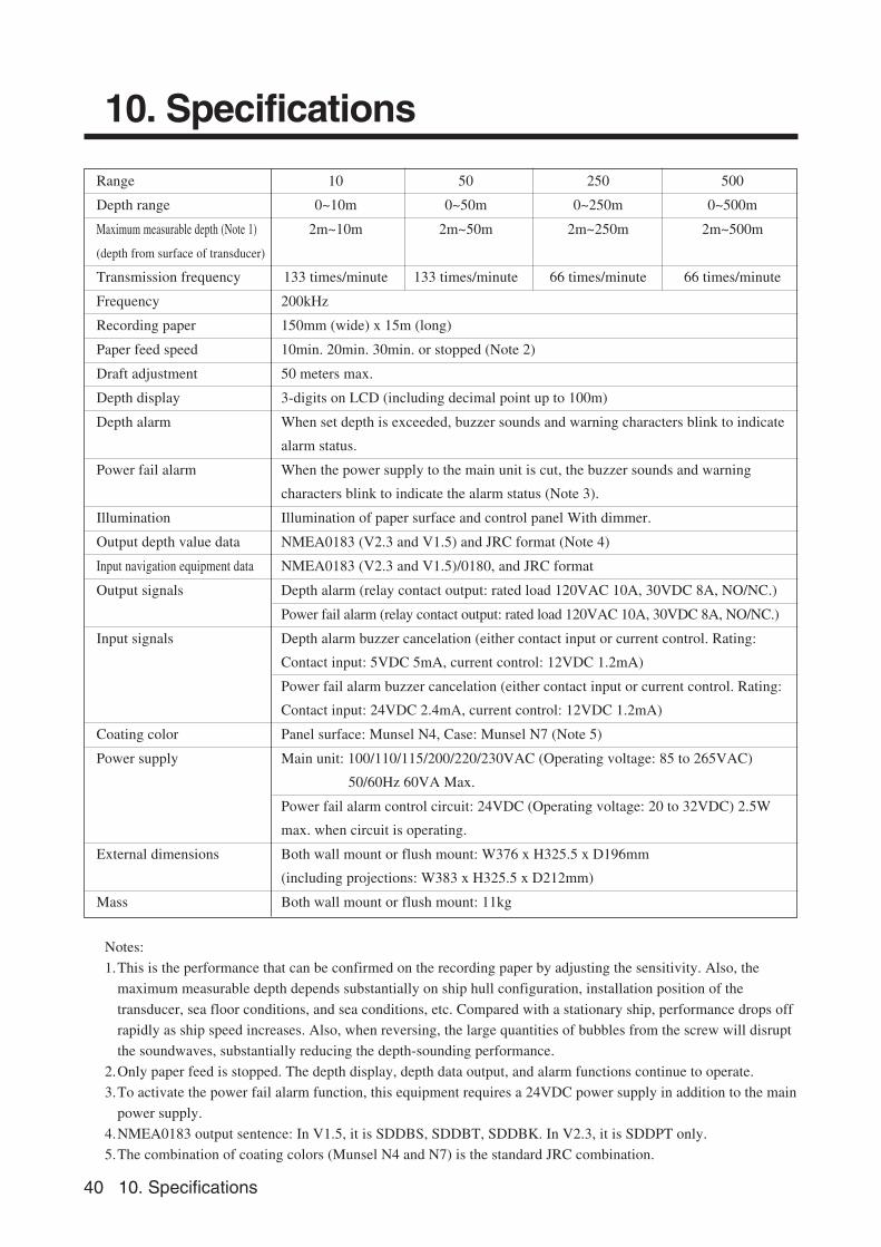
Range 10 50 250 500
Depth range 0~10m 0~50m 0~250m 0~500m
Maximum measurable depth (Note 1) 2m~10m 2m~50m 2m~250m 2m~500m
(depth from surface of transducer)
Transmission frequency 133 times/minute 133 times/minute 66 times/minute 66 times/minute
Frequency 200kHz
Recording paper 150mm (wide) x 15m (long)
Paper feed speed 10min. 20min. 30min. or stopped (Note 2)
Draft adjustment 50 meters max.
Depth display 3-digits on LCD (including decimal point up to 100m)
Depth alarm When set depth is exceeded, buzzer sounds and warning characters blink to indicate
alarm status.
Power fail alarm When the power supply to the main unit is cut, the buzzer sounds and warning
characters blink to indicate the alarm status (Note 3).
Illumination Illumination of paper surface and control panel With dimmer.
Output depth value data NMEA0183 (V2.3 and V1.5) and JRC format (Note 4)
Input navigation equipment data NMEA0183 (V2.3 and V1.5)/0180, and JRC format
Output signals Depth alarm (relay contact output: rated load 120VAC 10A, 30VDC 8A, NO/NC.)
Power fail alarm (relay contact output: rated load 120VAC 10A, 30VDC 8A, NO/NC.)
Input signals Depth alarm buzzer cancelation (either contact input or current control. Rating:
Contact input: 5VDC 5mA, current control: 12VDC 1.2mA)
Power fail alarm buzzer cancelation (either contact input or current control. Rating:
Contact input: 24VDC 2.4mA, current control: 12VDC 1.2mA)
Coating color Panel surface: Munsel N4, Case: Munsel N7 (Note 5)
Power supply Main unit: 100/110/115/200/220/230VAC (Operating voltage: 85 to 265VAC)
50/60Hz 60VA Max.
Power fail alarm control circuit: 24VDC (Operating voltage: 20 to 32VDC) 2.5W
max. when circuit is operating.
External dimensions Both wall mount or flush mount: W376 x H325.5 x D196mm
(including projections: W383 x H325.5 x D212mm)
Mass Both wall mount or flush mount: 11kg
Notes:
1.This is the performance that can be confirmed on the recording paper by adjusting the sensitivity. Also, the
maximum measurable depth depends substantially on ship hull configuration, installation position of the
transducer, sea floor conditions, and sea conditions, etc. Compared with a stationary ship, performance drops off
rapidly as ship speed increases. Also, when reversing, the large quantities of bubbles from the screw will disrupt
the soundwaves, substantially reducing the depth-sounding performance.
2.Only paper feed is stopped. The depth display, depth data output, and alarm functions continue to operate.
3.To activate the power fail alarm function, this equipment requires a 24VDC power supply in addition to the main
power supply.
4.NMEA0183 output sentence: In V1.5, it is SDDBS, SDDBT, SDDBK. In V2.3, it is SDDPT only.
5.The combination of coating colors (Munsel N4 and N7) is the standard JRC combination.
���������������� ����������������� ����������������� ����������������� �������������������������������������������� ���������������������������� ������������������������������� !��"�#�$��������%�& �'(������#���)*���!�!+� ���!!,�-.)*���!�!+� ���+�/����������&�0� �� �'(������#���)*���!�!+� ���!1,�-.)*���!�!+� �����2����������� �34��(�������������5'(������#���)*���!�!+� ��� +,�-.)*���!�!+� ����6
�����������#&����������#&����������#&����������#&�������%������7����+����������������������+���"�#�$#���)*��� ��� +�6���,�-.)*��� ��� +�6���
����������������������������������������������������������������������������"82��9:��;����<"82��9:��;����<"82��9:��;����<"82��9:��;����<�!1��� ��,&�����,���� �=�� ��+�>�1��0&������� �8��<�;��<���%3���3?��9@:@#���)* ������1������,�-.)* �������!��661
������������������������������������������������������������������������������������9@%@�9@%@�9@%@�9@%@�@@@@"�(���8�<���2�@�;�<@>%���&�0���������%A�:&�������A��0&<5@0��%�������%���&��A��6��! �9@�%@��@#���)*����1�1+ �+1 ,�-.)*����1�1+ ���!�
������������������������
������������������������������������������������������������������������������������
��9@%@�9@%@�9@%@�9@%@�@@@@"�(���8�<���2�@�;�<@$� �������< �0��&<��5��%����������+�2�����B����,����&�$@�"@����� ��9@�%@��@#���)*������� ������,�-.)*������� �����+
����////�<�� ���<�� ���<�� ���<�� ��"�(���8�<���2�@�;�<@C8�=��%98D��/$�38$9%�����,�@�� ������!��"�@�=@8@�8� ����%��<�:�B@�E��@"���������6+��� � /$'�$3%/�#���)*1�����+���!���,�-.)*1�����+���!��!
����#��&�((�� #��&�((�� #��&�((�� #��&�((�� "�(���8�<���2�@�;�<@�!���������B����&�������&��#=/;/##/$3%#���)*1!���+� ��+1+F+�+�!+�6,�-.)*1!���+���+� 6
��������&��<����&��<����&��<����&��<"�(���8�<���2�@�;�<@2��������5���(����0��&<��5 +��#����%������%���0��5�����������=�/;�$'#���>,�-)*11�������� ��
����/�<��/�<��/�<��/�<��"�(���8�<���2�@�;�<@0 ��A ����%�����=��&��0� �� �2���$��,���< �2�&�����$��'&�������1+��/$'/�#���)�*6�����16��6�6 F16��6�6�,�-.)�*6�����16��6!�+
����������������������������"�(���8�<���2�@�;�<@�,�$�@� 1�%��5�2����5�8��<���(����/A�$#���)*��1����+���!���,�-.)*��1����+����666
����%(���%(���%(���%(���"�(���8�<���2�@�;�<@2�&&�;�� �'�� ��%�&B���+����0�'�;� #�&�� �'�C����2�������%#�/$#���)*! �6����6���1,�-.)*! �6����6!�++
����%��5�(��%��5�(��%��5�(��%��5�(��"�(���8�<���2�@�;�<@>��2�'�8�#�3@�;�'@!�+��������8��<�G����1>�������0����;���0��&<��5�%��5�(����16�� �%/$C�#�83#���)*1+����6�6�,�-.)*1+����6!6�
����C�C�C�C�"�(���8�<���2�@�;�<@+�������������&��#���� �C83323#���)�*!���� �6�!!� F �6�!!�+,�-.)�*!���� �6�!!�1
��:���:���:���:���"�(���8�<���2�@�;�<@8���������A��<��5�0&<5@�� ����� �C�2���5��5�'��5��2���5�:���#� ����:�83�#���)�*���+�� ����!+,�-.)�*���+�� 1 ��16+..
��������������� ���������������� ���������������� ���������������� �����$���&��< $���&��< $���&��< $���&��< "�(���8�<���2�@�;�<@2 ��&���� �� �����6$;�%��(��&�8�7��=3�$3�=38;�$'%#���)*!�����1+����+�,�-.)*!�����1+����++
�����

Akasaka Twin Tower (Main)17-22, Akasaka 2-chome, Minato-ku, Tokyo.107-8432 JAPANPhone : +81-3-3584-8711Fax : +81-3-3584-8715Telex : 0242-5420 JRCTOK J
1-1, Shimorenjaku 5-chome, Mitaka-shi, Tokyo.181-8510 JAPANPhone : +81-422-45-9111Fax : +81-422-45-9110Telex : 02822-351 JRCMTK J
HEAD OFFICE & SALES DEPT.
MAIN PLANT
For further information contact:
Since 1915
CODE NO. :7ZPBS2301B