615 series ansi modbus communication protocol manual · 615 series ansi modbus communication...
TRANSCRIPT

Relion® Protection and Control
615 series ANSIModbus Communication Protocol Manual


Document ID: 1MAC052634-MBIssued: 01/20/2010
Revision: CProduct version: 2.0
© Copyright 2010 ABB. All rights reserved

CopyrightThis document and parts thereof must not be reproduced or copied without writtenpermission from ABB, and the contents thereof must not be imparted to a third party,nor used for any unauthorized purpose.
The software or hardware described in this document is furnished under a license andmay be used, copied, or disclosed only in accordance with the terms of such license.
TrademarksABB and Relion are registered trademarks of ABB Group. All other brand or productnames mentioned in this document may be trademarks or registered trademarks of theirrespective holders.
WarrantyPlease inquire about the terms of warranty from your nearest ABB representative.
ABB Inc.
Distribution Automation
4300 Coral Ridge Drive
Coral Springs, FL 33065, USA
Toll-free: 1 (800) 523-2620
Phone: +1 954-752-6700
Fax: +1 954 345-5329
http://www.abb.com/substationautomation

DisclaimerThe data, examples and diagrams in this manual are included solely for the concept orproduct description and are not to be deemed as a statement of guaranteed properties.All persons responsible for applying the equipment addressed in this manual mustsatisfy themselves that each intended application is suitable and acceptable, includingthat any applicable safety or other operational requirements are complied with. Inparticular, any risks in applications where a system failure and/or product failure wouldcreate a risk for harm to property or persons (including but not limited to personalinjuries or death) shall be the sole responsibility of the person or entity applying theequipment, and those so responsible are hereby requested to ensure that all measuresare taken to exclude or mitigate such risks.
This document has been carefully checked by ABB but deviations cannot becompletely ruled out. In case any errors are detected, the reader is kindly requested tonotify the manufacturer. Other than under explicit contractual commitments, in noevent shall ABB be responsible or liable for any loss or damage resulting from the useof this manual or the application of the equipment.

ConformityThis product complies with the directive of the Council of the European Communitieson the approximation of the laws of the Member States relating to electromagneticcompatibility (EMC Directive 2004/108/EC) and concerning electrical equipment foruse within specified voltage limits (Low-voltage directive 2006/95/EC). Thisconformity is the result of tests conducted by ABB in accordance with the productstandards EN 50263 and EN 60255-26 for the EMC directive, and with the productstandards EN 60255-6 and EN 60255-27 for the low voltage directive. The IED isdesigned in accordance with the international standards of the IEC 60255 series andANSI C37.90.

Table of contents
Section 1 Introduction............................................................................5This manual..............................................................................................5Intended audience....................................................................................5Product documentation.............................................................................6
Product documentation set..................................................................6Document revision history...................................................................7Related documentation........................................................................8
Symbols and conventions.........................................................................8Safety indication symbols....................................................................8Manual conventions.............................................................................8
Section 2 Modbus overview................................................................11Modbus standard....................................................................................11
Serial communication........................................................................11Ethernet communication....................................................................11Application data implementation .......................................................12
Terms and definitions.............................................................................12Documentation........................................................................................13
Section 3 Vendor-specific implementation..........................................15Modbus link alternatives.........................................................................15
Serial link...........................................................................................15Modbus serial link parameters......................................................15Modbus serial diagnostic counters...............................................17Character framing in different serial link modes...........................17
TCP/IP link.........................................................................................18TCP/IP interface configuration......................................................18Modbus TCP/IP diagnostic counters............................................20
Supported function codes.......................................................................21Application functions..........................................................................21Diagnostic functions..........................................................................21Exception codes................................................................................22
Application data......................................................................................23Modbus data objects.........................................................................23Modbus data implementation............................................................23Data mapping principles....................................................................24
Table of contents
615 series ANSI 1Communication Protocol Manual
Data in monitoring direction..........................................................24One bit data mapping...................................................................25Data in control direction................................................................25
Digital input data................................................................................25Multiple digital inputs mapping.....................................................26
Measurand registers..........................................................................27Primary and per-unit values..........................................................27Register sizes...............................................................................28Time of update..............................................................................28
Control operations.............................................................................29Control functions...........................................................................30Control operations through 4X register structures........................31Additional control operations........................................................33
System status registers ....................................................................33SSR1............................................................................................34SSR2 ...........................................................................................34SSR3 ...........................................................................................35SSR4 ...........................................................................................36SSR5 ...........................................................................................37SSR6 ...........................................................................................37
Event records ....................................................................................38Single event record structure........................................................39Single event record reading..........................................................39Other event record registers.........................................................41Multiple event records reading.....................................................44
Fault records .....................................................................................46Fault record structure...................................................................47Fault record reading.....................................................................47Other fault record registers...........................................................49
Parameter setting group selection.....................................................50Time synchronization ........................................................................51
Real-time clock structure..............................................................51Writing to real-time structures.......................................................51
Device information.............................................................................52ASCII character coding.................................................................53ASCII string syntax.......................................................................53
Reset time structure...........................................................................54
Section 4 Modbus parameters and diagnostics..................................57Parameter list..........................................................................................57
Table of contents
2 615 series ANSICommunication Protocol Manual

Monitored data........................................................................................58
Section 5 Glossary..............................................................................61
Table of contents
615 series ANSI 3Communication Protocol Manual

4
Section 1 Introduction
1.1 This manual
The communication protocol manual describes a communication protocol supported bythe IED. The manual concentrates on vendor-specific implementations.
1.2 Intended audience
This manual addresses the communication system engineer or system integratorresponsible for pre-engineering and engineering for communication setup in asubstation from an IED perspective.
The system engineer or system integrator must have a basic knowledge ofcommunication in protection and control systems and thorough knowledge of thespecific communication protocol.
1MAC052634-MB C Section 1Introduction
615 series ANSI 5Communication Protocol Manual
1.3 Product documentation
1.3.1 Product documentation set
Pla
nnin
g &
pur
chas
e
Eng
inee
ring
Inst
allin
g
Com
mis
sion
ing
Ope
ratio
n
Mai
nten
ance
Dec
omm
issi
onin
gde
inst
allin
g&
dis
posa
l
Application manual
Operation manual
Installation manual
Service manual
Engineering manual
Commissioning manual
Communication protocolmanual
Technical manual
Pla
nnin
g &
pur
chas
e
Eng
inee
ring
Inst
allin
g
Com
mis
sion
ing
Ope
ratio
n
Mai
nten
ance
Dec
omm
issi
onin
gde
inst
allin
g&
dis
posa
l
Pla
nnin
g &
pur
chas
e
Eng
inee
ring
Inst
allin
g
Com
mis
sion
ing
Ope
ratio
n
Mai
nten
ance
Dec
omm
issi
onin
gde
inst
allin
g&
dis
posa
l
Application manualApplication manual
Operation manualOperation manual
Installation manualInstallation manual
Service manualService manual
Engineering manualEngineering manual
Commissioning manualCommissioning manual
Communication protocolmanualCommunication protocolmanual
Technical manualTechnical manual
en07000220.vsd
IEC07000220 V1 EN
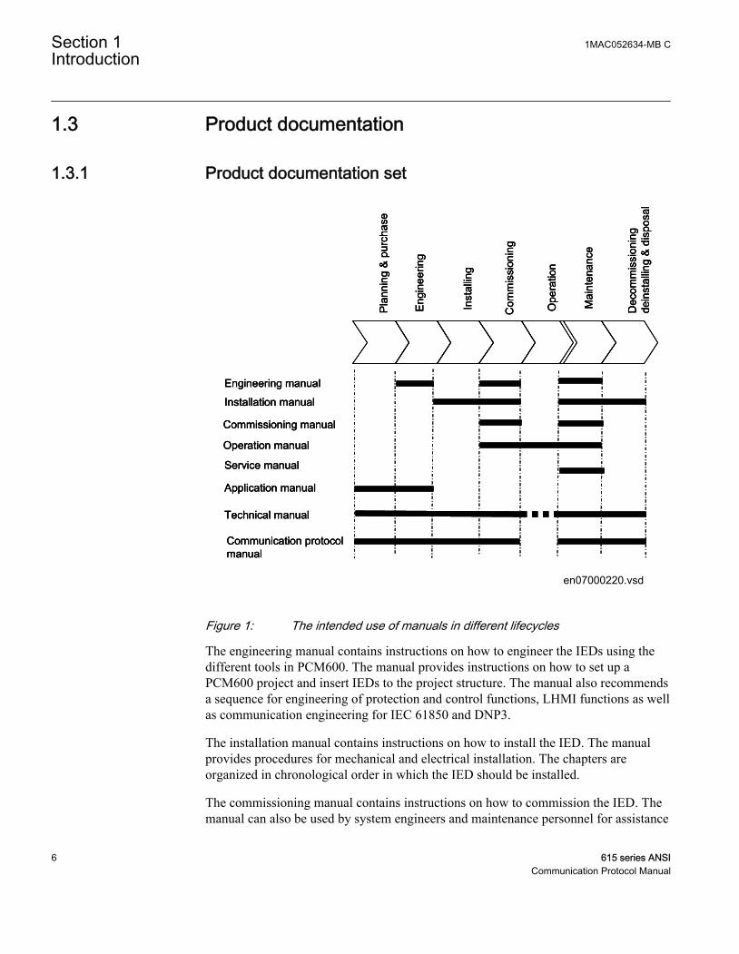
Figure 1: The intended use of manuals in different lifecycles
The engineering manual contains instructions on how to engineer the IEDs using thedifferent tools in PCM600. The manual provides instructions on how to set up aPCM600 project and insert IEDs to the project structure. The manual also recommendsa sequence for engineering of protection and control functions, LHMI functions as wellas communication engineering for IEC 61850 and DNP3.
The installation manual contains instructions on how to install the IED. The manualprovides procedures for mechanical and electrical installation. The chapters areorganized in chronological order in which the IED should be installed.
The commissioning manual contains instructions on how to commission the IED. Themanual can also be used by system engineers and maintenance personnel for assistance
Section 1 1MAC052634-MB CIntroduction
6 615 series ANSICommunication Protocol Manual
during the testing phase. The manual provides procedures for checking of externalcircuitry and energizing the IED, parameter setting and configuration as well asverifying settings by secondary injection. The manual describes the process of testingan IED in a substation which is not in service. The chapters are organized inchronological order in which the IED should be commissioned.
The operation manual contains instructions on how to operate the IED once it has beencommissioned. The manual provides instructions for monitoring, controlling andsetting the IED. The manual also describes how to identify disturbances and how toview calculated and measured power grid data to determine the cause of a fault.
The service manual contains instructions on how to service and maintain the IED. Themanual also provides procedures for de-energizing, de-commissioning and disposal ofthe IED.
The application manual contains application descriptions and setting guidelines sortedper function. The manual can be used to find out when and for what purpose a typicalprotection function can be used. The manual can also be used when calculating settings.
The technical manual contains application and functionality descriptions and listsfunction blocks, logic diagrams, input and output signals, setting parameters andtechnical data sorted per function. The manual can be used as a technical referenceduring the engineering phase, installation and commissioning phase, and during normalservice.
The communication protocol manual describes a communication protocol supported bythe IED. The manual concentrates on vendor-specific implementations.
The point list manual describes the outlook and properties of the data points specific tothe IED. The manual should be used in conjunction with the correspondingcommunication protocol manual.
Some of the manuals are not available yet.
1.3.2 Document revision historyDocument revision/date Product series version HistoryA/03/28/2008 1.0.1 First release
B/12/22/2008 1.1 Content updated to correspond to theproduct series version
C/01/20/2010 2.0 Content updated to correspond to theproduct series version
1MAC052634-MB C Section 1Introduction
615 series ANSI 7Communication Protocol Manual
Download the latest documents from the ABB web site http://www.abb.com/substationautomation.
1.3.3 Related documentationProduct-specific point list manuals and other product series- and product-specificmanuals can be downloaded from the ABB web site http://www.abb.com/substationautomation.
1.4 Symbols and conventions
1.4.1 Safety indication symbols
The caution icon indicates important information or warning related tothe concept discussed in the text. It might indicate the presence of ahazard which could result in corruption of software or damage toequipment or property.
The information icon alerts the reader to important facts and conditions.
The tip icon indicates advice on, for example, how to design yourproject or how to use a certain function.
Although warning hazards are related to personal injury, it should be understood thatoperation of damaged equipment could, under certain operational conditions, result indegraded process performance leading to personal injury or death. Therefore, complyfully with all warning and caution notices.
1.4.2 Manual conventionsConventions used in IED manuals. A particular convention may not be used in thismanual.
Section 1 1MAC052634-MB CIntroduction
8 615 series ANSICommunication Protocol Manual
• Abbreviations and acronyms in this manual are spelled out in the glossary. Theglossary also contains definitions of important terms.
• Push button navigation in the LHMI menu structure is presented by using the pushbutton icons, for example:To navigate between the options, use and .
• HMI menu paths are presented in bold, for example:Select Main menu/Settings.
• LHMI messages are shown in Courier font, for example:To save the changes in non-volatile memory, select Yes and press .
• Parameter names are shown in italics, for example:The function can be enabled and disabled with the Operation setting.
• Parameter values are indicated with quotation marks, for example:The corresponding parameter values are "Enabled" and "Disabled".
• IED input/output messages and monitored data names are shown in Courier font,for example:When the function picks up, the PICKUP output is set to TRUE.
• Dimensions are provided both in inches and mm. If it is not specifically mentionedthen the dimension is in mm.
1MAC052634-MB C Section 1Introduction
615 series ANSI 9Communication Protocol Manual

10
Section 2 Modbus overview
2.1 Modbus standard
Modbus is a communication protocol developed by the Modicon company in the1970’s. Originally it was used for communication in PLCs and RTU devices. Later onthe Modbus protocol has been used in a variety of different device applications. Todaythe Modbus protocol is mainly used over serial communication networks and Ethernet.
The Modbus serial communication and the Ethernet based Modbus TCP/IPcommunication in this IED follow the specifications maintained by ModbusOrganization.
Modbus communication reference guides are downloadable fromTechnical Resources at www.modbus.org.
2.1.1 Serial communicationModbus is a master-slave protocol when it is used over serial communicationnetworks. This IED implements the slave side of the protocol. Depending on thechosen physical serial interface it is possible to build multidrop networks or point-to-point communication connections.
There can only be one Modbus master unit on a Modbus serial network. The Modbusmaster unit communicates with one Modbus slave unit at a time. Usually the masterreads, or scans, data from the slaves cyclically. The master can also write data or givecommands to the slave units. Each slave unit has a unique unit address. Thus, themaster can identify the slave with which it communicates. The Modbus standard alsodefines the possibility for Master broadcast transmissions.
Modbus serial protocol uses two link modes: Modbus RTU and Modbus ASCII. Bothmodes are supported by this IED.
2.1.2 Ethernet communicationModbus communication over Ethernet TCP/IP is of client-server type. This IEDoperates as a Modbus server.
1MAC052634-MB C Section 2Modbus overview
615 series ANSI 11Communication Protocol Manual
Modbus TCP/IP connection is established when the Modbus client opens a TCP socketconnection to the Modbus server. The socket port 502 on the TCP/IP stack is reservedfor Modbus. If the connection request is accepted by the server, the client can startcommunicating with the server unit.
IEDs can usually accept several simultaneous Modbus TCP/IP client connections eventhough the number of connections is limited. It is possible to configure the IED to onlyaccept socket connection requests from known client IP addresses.
2.1.3 Application data implementationThis IED is designed to operate with a wide range of different Modbus masters andclients. The Modbus memory map offers the possibility to view IED's internal processdata in a simple I/O map style which is mainly aimed at PLC masters and other processautomation devices. Time-tagged, chronological event lists and fault records can beread over the Modbus interface. These data are more suitable for SCADA type ofModbus masters.
The Modbus standard defines four main memory areas for mapping IED's process data.Due to its open nature, the Modbus standard does not define exactly what type of datashould be mapped to each memory area. The Modbus mapping approach of the IEDensures that the same process data are readable from as many Modbus memory areas aspossible. The users may then choose the memory areas that are most suitable for theirModbus master systems.
All Modbus data in the IEDs can be accessed using command functions belonging toModbus conformance classes 0 and 1. This means that most master systems are able tocommunicate with the IED.
2.2 Terms and definitions
Modbus data appears in different memory areas in the Modbus device. The four mostcommon areas are coils, digital input, input register and holding register. These are alsoreferred to as 0X, 1X, 3X and 4X areas respectively.
Data within these four areas are addressed from 1 onwards. Modbus defines addressingin two ways: PLC addressing starts from address 1 and regular Modbus data addressingstarts from 0. For example, a holding register at PLC address 234 can be referred toeither as 4X register 234 or as 40234. The regular Modbus addressing, that is the PLCaddress decremented by one, is shown when analyzing the Modbus traffic on thephysical network.
Section 2 1MAC052634-MB CModbus overview
12 615 series ANSICommunication Protocol Manual

Listings and references to the Modbus data in this documentation follow the PLCaddressing scheme. Refer also to the Modbus protocol standard documentation that canbe found for free at www.modbus.org.
2.3 Documentation
The ANSI Modbus point list manuals cover all the 615 series variants.
A newer SW version of the same 615 series configuration may containadditional Modbus points.
1MAC052634-MB C Section 2Modbus overview
615 series ANSI 13Communication Protocol Manual

14
Section 3 Vendor-specific implementation
3.1 Modbus link alternatives
Modbus communication is possible over the serial communication interface, over theEthernet interface, or over both interfaces simultaneously.
3.1.1 Serial linkModbus serial communication requires that the IED variant is equipped with a serialinterface card at the slot X000. The serial interface card can contain one or two serialinterfaces.
The Modbus link mode can be either Modbus RTU or Modbus ASCII.
Modbus serial communication can run on two separate serial ports simultaneously. TheModbus serial link characteristics can be different on the two ports. This applies also tothe Modbus RTU and ASCII link modes and the unit address.
Documentation concerning the Modbus serial link messages and theModbus standard can be obtained from www.modbus.org.
3.1.1.1 Modbus serial link parameters
Serial link setting parameters can be accessed with PST or via the LHMI pathConfiguration/Communication/Modbus.
In the LHMI parameter names end either with number 1 or withnumber 2. The numbers refer to two separate serial ports, that is theinstances 1 and 2.
AddressEach serial link can be given a separate unit address.
1MAC052634-MB C Section 3Vendor-specific implementation
615 series ANSI 15Communication Protocol Manual
End delayThe end of message delay, or timeout, is used only in the Modbus RTU link mode.According to the Modbus standard, an idle period of 3.5 characters, that is the time ittakes to transmit 3.5 characters with the used baud rate, defines the end of a ModbusRTU frame in the RTU mode. This parameter can be given with the accuracy of onecharacter. The default setting is three characters but the user can increase or decreasethe value.
In a multidrop RS-485 Modbus network the unit may detect and receiveresponse messages from other slave units. Thus, consider the minimumsilent time between the response frame and the beginning of master’snext request frame when setting the end delay in Modbus RTU mode.
This parameter has no meaning in the Modbus ASCII link mode.
Start delayThe intraframe delay on serial Modbus RTU link is defined as a silent interval of 3.5characters. The delay is essential for Modbus devices to recognize the beginning andend of each RTU frame. If the end delay is decreased in this IED, the responsemessages may be transmitted too fast according to the link standard especially truewith slower baud rates. The start delay parameter adds idle characters before thetransmission, thus increasing the silent interval between the Modbus RTU link frames.The start delay default setting is four idle (silent) characters.
To set the timing properly, consider also how the other slave units in amultidrop RS-485 network detect the Modbus traffic between themaster and this IED.
Serial portIt is possible to define which serial port is used for separate Modbus serial instances:COM1 or COM2. The serial communication instance is not active if this parameter isset to “Not in use.”
If this protocol does not operate as expected, make sure that other serialprotocols are not using the COM port as well.
Section 3 1MAC052634-MB CVendor-specific implementation
16 615 series ANSICommunication Protocol Manual
Baud rate is defined on the serial driver side and are therefore locatedvia the LHMI paths Configuration/Communication/COM1 andConfiguration/Communication/COM2.
3.1.1.2 Modbus serial diagnostic counters
Modbus Serial diagnostic counters can be viewed via the LHMI path Monitoring/Communication/Modbus/Serial.
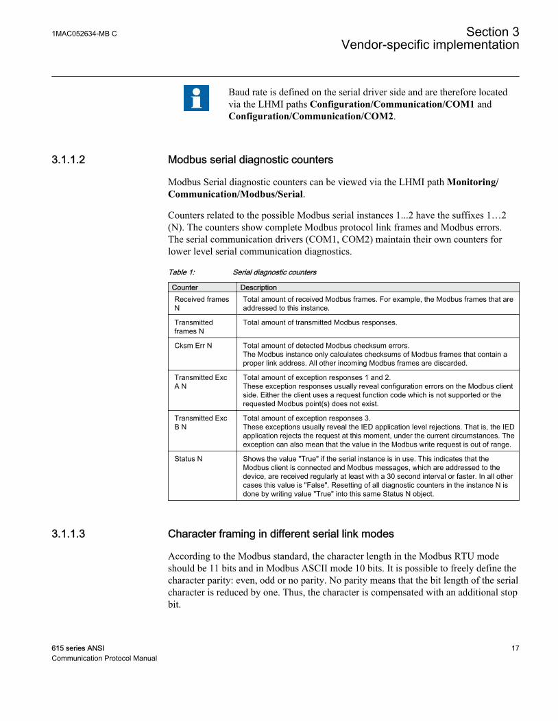
Counters related to the possible Modbus serial instances 1...2 have the suffixes 1…2(N). The counters show complete Modbus protocol link frames and Modbus errors.The serial communication drivers (COM1, COM2) maintain their own counters forlower level serial communication diagnostics.
Table 1: Serial diagnostic counters
Counter DescriptionReceived framesN
Total amount of received Modbus frames. For example, the Modbus frames that areaddressed to this instance.
Transmittedframes N
Total amount of transmitted Modbus responses.
Cksm Err N Total amount of detected Modbus checksum errors.The Modbus instance only calculates checksums of Modbus frames that contain aproper link address. All other incoming Modbus frames are discarded.
Transmitted ExcA N
Total amount of exception responses 1 and 2.These exception responses usually reveal configuration errors on the Modbus clientside. Either the client uses a request function code which is not supported or therequested Modbus point(s) does not exist.
Transmitted ExcB N
Total amount of exception responses 3.These exceptions usually reveal the IED application level rejections. That is, the IEDapplication rejects the request at this moment, under the current circumstances. Theexception can also mean that the value in the Modbus write request is out of range.
Status N Shows the value "True" if the serial instance is in use. This indicates that theModbus client is connected and Modbus messages, which are addressed to thedevice, are received regularly at least with a 30 second interval or faster. In all othercases this value is "False". Resetting of all diagnostic counters in the instance N isdone by writing value "True" into this same Status N object.
3.1.1.3 Character framing in different serial link modes
According to the Modbus standard, the character length in the Modbus RTU modeshould be 11 bits and in Modbus ASCII mode 10 bits. It is possible to freely define thecharacter parity: even, odd or no parity. No parity means that the bit length of the serialcharacter is reduced by one. Thus, the character is compensated with an additional stopbit.
1MAC052634-MB C Section 3Vendor-specific implementation
615 series ANSI 17Communication Protocol Manual
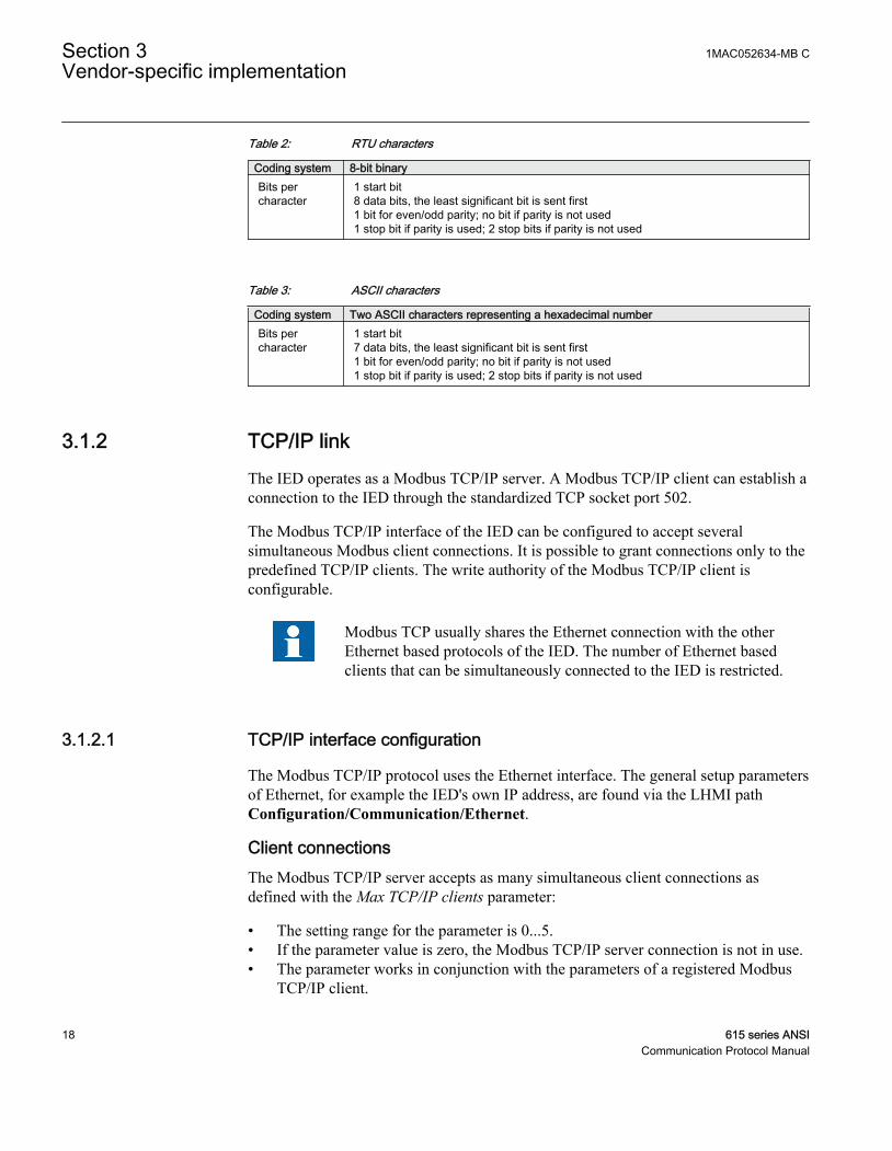
Table 2: RTU characters
Coding system 8-bit binaryBits percharacter
1 start bit8 data bits, the least significant bit is sent first1 bit for even/odd parity; no bit if parity is not used1 stop bit if parity is used; 2 stop bits if parity is not used
Table 3: ASCII characters
Coding system Two ASCII characters representing a hexadecimal numberBits percharacter
1 start bit7 data bits, the least significant bit is sent first1 bit for even/odd parity; no bit if parity is not used1 stop bit if parity is used; 2 stop bits if parity is not used
3.1.2 TCP/IP linkThe IED operates as a Modbus TCP/IP server. A Modbus TCP/IP client can establish aconnection to the IED through the standardized TCP socket port 502.
The Modbus TCP/IP interface of the IED can be configured to accept severalsimultaneous Modbus client connections. It is possible to grant connections only to thepredefined TCP/IP clients. The write authority of the Modbus TCP/IP client isconfigurable.
Modbus TCP usually shares the Ethernet connection with the otherEthernet based protocols of the IED. The number of Ethernet basedclients that can be simultaneously connected to the IED is restricted.
3.1.2.1 TCP/IP interface configuration
The Modbus TCP/IP protocol uses the Ethernet interface. The general setup parametersof Ethernet, for example the IED's own IP address, are found via the LHMI pathConfiguration/Communication/Ethernet.
Client connectionsThe Modbus TCP/IP server accepts as many simultaneous client connections asdefined with the Max TCP/IP clients parameter:
• The setting range for the parameter is 0...5.• If the parameter value is zero, the Modbus TCP/IP server connection is not in use.• The parameter works in conjunction with the parameters of a registered Modbus
TCP/IP client.
Section 3 1MAC052634-MB CVendor-specific implementation
18 615 series ANSICommunication Protocol Manual
When client X reconnects, the old connection of that client is disconnected and the newconnection is accepted to avoid zombie clients. When the maximum number of clientsare connected, a new connection request is handled as follows:
• If there are unregistered clients connected, the one with the longest silent period isdisconnected and a new connection is accepted.
• If there are only registered clients connected, the new connection request is rejected.
It is possible to predefine the client or clients which are always granted Modbus TCP/IP connections by registering the clients' IP addresses. For example, if four concurrentconnections are allowed and three of them are registered, they are seen as Clientconnection 1...Client connection 3. These three registered connections are thendedicated to certain clients only and the fourth connection is available to other clients.
Client IP addressesThere are five Modbus setting parameters for Modbus client IP addresses. Theparameter value "0.0.0.0" indicates that the client IP address is not defined.
If there are, for example, four available TCP/IP connections defined and one of theconnections is to be dedicated for a certain client X, enter the client X's IP address tothe Client IP1 parameter. The IP addresses of the Modbus clients 2..4 can be set to"0.0.0.0". The setting of the Modbus client5 IP address has no meaning in this exampleas the connection is not in use. In this example, the TCP/IP session 1 is dedicated to theclient X which means that this registered client X is always able to connect to the IED.Unregistered clients can connect to sessions 2...4. However, an unregistered clientconnection request can be rejected if sessions 2...4 are already occupied. The writeauthority can also be assigned differently for registered TCP/IP clients.
Client's write authorityThe registering of a Modbus client affects the client's write authority and the reading oflatched Modbus data.
The TCP write authority parameter can be set to three different states:
• 0 = No write authority for any Modbus TCP/IP client• 1 = Write authority only for registered Modbus TCP/IP clients• 2 = Write authority for all Modbus TCP/IP clients
The possible blocking of write operation does not include the selection write operationthat has to be done to read out Modbus event and fault record structures.
1MAC052634-MB C Section 3Vendor-specific implementation
615 series ANSI 19Communication Protocol Manual
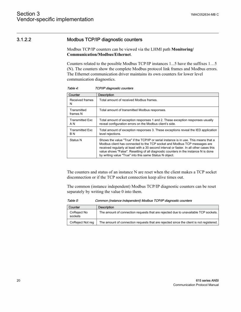
3.1.2.2 Modbus TCP/IP diagnostic counters
Modbus TCP/IP counters can be viewed via the LHMI path Monitoring/Communication/Modbus/Ethernet.
Counters related to the possible Modbus TCP/IP instances 1...5 have the suffixes 1…5(N). The counters show the complete Modbus protocol link frames and Modbus errors.The Ethernet communication driver maintains its own counters for lower levelcommunication diagnostics.
Table 4: TCP/IP diagnostic counters
Counter DescriptionReceived framesN
Total amount of received Modbus frames.
Transmittedframes N
Total amount of transmitted Modbus responses.
Transmitted ExcA N
Total amount of exception responses 1 and 2. These exception responses usuallyreveal configuration errors on the Modbus client’s side.
Transmitted ExcB N
Total amount of exception responses 3. These exceptions reveal the IED applicationlevel rejections.
Status N Shows the value "True" if the TCP/IP or serial instance is in use. This means that aModbus client has connected to the TCP socket and Modbus TCP messages arereceived regularly at least with a 30 second interval or faster. In all other cases thisvalue shows "False". Resetting of all diagnostic counters in the instance N is doneby writing value "True" into this same Status N object.
The counters and status of an instance N are reset when the client makes a TCP socketdisconnection or if the TCP socket connection keep alive times out.
The common (instance independent) Modbus TCP/IP diagnostic counters can be resetseparately by writing the value 0 into them.
Table 5: Common (instance independent) Modbus TCP/IP diagnostic counters
Counter DescriptionCnReject Nosockets
The amount of connection requests that are rejected due to unavailable TCP sockets.
CnReject Not reg The amount of connection requests that are rejected since the client is not registered.
Section 3 1MAC052634-MB CVendor-specific implementation
20 615 series ANSICommunication Protocol Manual

3.2 Supported function codes
3.2.1 Application functionsTable 6: Supported application functions
Functioncode
Name Description
01 Read coil status Reads the status of discrete outputs.
02 Read digital input status Reads the status of discrete inputs.
03 Read holding registers Reads the contents of output registers.
04 Read input registers Reads the contents of input registers.
05 Force single coil Sets the status of a discrete output.
06 Preset single register Sets the value of a holding register.
08 Diagnostics Checks the communication system betweenthe master and the slave.
15 Force multiple coils Sets the status of multiple discrete outputs.
16 Preset multiple registers Sets the value of multiple holding registers.
23 Read/write holding registers Exchanges holding registers in one query.
3.2.2 Diagnostic functionsThe diagnostic functions are only intended for serial communication. However, theserial diagnostic counters can be read, but not reset, via the Modbus TCP/IP interface.The serial line cannot be forced to the listen mode via the Modbus TCP/IP interface.
Table 7: Supported diagnostic subfunctions
Functioncode
Name Description
00 Return query data The data in the query data field is returned(looped back) in the response. The entireresponse is identical to the query.
01 Restart communication option The slaves peripheral port is initialized andrestarted and the communication eventcounters are cleared. Before this, a normalresponse will be sent provided that the portis not in the listen only mode. If the port is inthe listen only mode, no response will be sent.
04 Force listen only mode The slave is forced to enter the listen onlymode for Modbus communication.
10 Clear counters and diagnostic register All counters and the diagnostic register arecleared.
Table continues on next page
1MAC052634-MB C Section 3Vendor-specific implementation
615 series ANSI 21Communication Protocol Manual
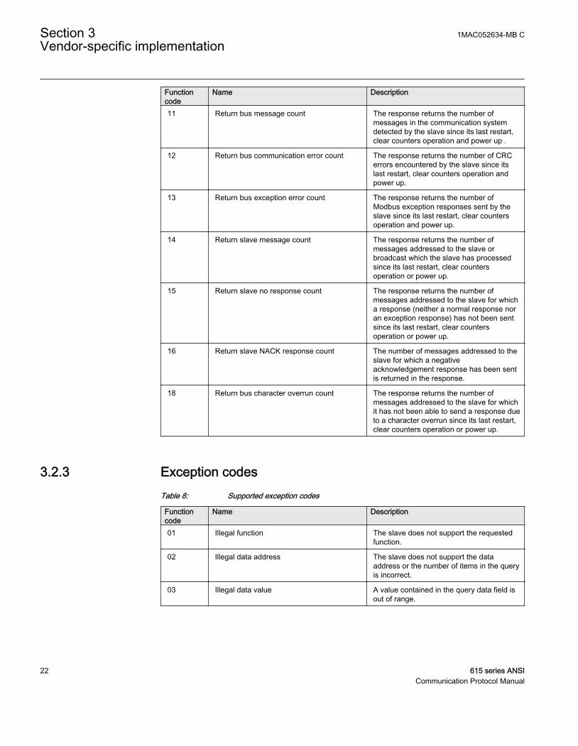
Functioncode
Name Description
11 Return bus message count The response returns the number ofmessages in the communication systemdetected by the slave since its last restart,clear counters operation and power up .
12 Return bus communication error count The response returns the number of CRCerrors encountered by the slave since itslast restart, clear counters operation andpower up.
13 Return bus exception error count The response returns the number ofModbus exception responses sent by theslave since its last restart, clear countersoperation and power up.
14 Return slave message count The response returns the number ofmessages addressed to the slave orbroadcast which the slave has processedsince its last restart, clear countersoperation or power up.
15 Return slave no response count The response returns the number ofmessages addressed to the slave for whicha response (neither a normal response noran exception response) has not been sentsince its last restart, clear countersoperation or power up.
16 Return slave NACK response count The number of messages addressed to theslave for which a negativeacknowledgement response has been sentis returned in the response.
18 Return bus character overrun count The response returns the number ofmessages addressed to the slave for whichit has not been able to send a response dueto a character overrun since its last restart,clear counters operation or power up.
3.2.3 Exception codesTable 8: Supported exception codes
Functioncode
Name Description
01 Illegal function The slave does not support the requestedfunction.
02 Illegal data address The slave does not support the dataaddress or the number of items in the queryis incorrect.
03 Illegal data value A value contained in the query data field isout of range.
Section 3 1MAC052634-MB CVendor-specific implementation
22 615 series ANSICommunication Protocol Manual
3.3 Application data
3.3.1 Modbus data objectsThe Modbus protocol in 615 series IEDs is built on top of the internal IEC 61850 datamodel. Thus, the Modbus application data objects, proprietary events and MCD bitsare derived from IEC 61850 data objects and data set reporting. The 615 series IEDshave a predefined IEC 61850 data set configuration. In other words, it is predefinedwhich internal data object changes the 615 series IEDs detect.
The available Modbus indications in the 615 series IEDs are generally selected fromthe IEC 61850 indications residing in data sets. Objects that do not reside in any dataset are updated to the Modbus database slower. This concerns, for example, somemeasurand register values. Fast changes in these object values may not be detected orpropagated to the Modbus database. However, the latest value of these objects isalways found in the Modbus database. The DS column in the Modbus point list manualshows if the object resides in some data set as a default.
For a list of the available data objects, see the point list manual.
3.3.2 Modbus data implementation
The numeric register locations used in this section are for examplepurposes only. The genuine Modbus register locations are located in theIED's memory map.
The IED is internally modelled according to the IEC 61850 standard. The Modbusprotocol is implemented on top of this model. However, all features of the IEC61850data model are not available through the Modbus interface.
The Modbus protocol standard defines one bit digital data and 16 bit register data asthe application data alternatives but it does not define exactly how the digital data andthe register data should be used by the application. Instead, the choice of the usage isleft to the IEDs implementation.
Change events and time synchronizationThe Modbus standard does not define event reporting or time synchronizationprocedures. Proprietary solutions have been introduced in this IED to support thesefunctionalities.
1MAC052634-MB C Section 3Vendor-specific implementation
615 series ANSI 23Communication Protocol Manual
Control operationsThe Modbus standard defines data types 0X for coils and 4X for holding registers to beused for control operations.
Depending on the controlled object, the control operations may be of direct-operate orselect-before-operate type. Control operations include automatic checking forauthorization, local and remote blockings and preventing simultaneous controlling bymultiple clients.
Application data compatibilityThis IED is designed to operate with a wide range of Modbus masters spanning fromindustrial PLCs to substation SCADA devices. The application solutions have beenchosen to achieve the highest possible level of compatibility with these systems:
• Application data are readable in many different Modbus memory areas. Digitaldata are readable as bits or packed bits in registers.
• Both 16 and 32 bit register sizes are used for measurands.• The proprietary Modbus event buffer can be read in many different ways. A
master can continuously read and log change events in real time or, for example,read out the n latest events on demand.
• Change detect data can be used as an alternative to the event record reading tocatch fast indication data transitions between the master scans.
• The Modbus fault record gives a summary of the captured analog quantities andprotection stages picking up and possibly tripping during a fault.
• The addressing of the application data in the documentation and tools follows theso-called Modbus-PLC addressing principle where the base address 1 is used. Theapplication data addressing in this IED spans only between the locations 1 and 9999.
• UDRs are not yet supported in ANSI IEDs.
3.3.3 Data mapping principlesModbus data is organized sequentially. This is the most efficient organization methodsince the master normally scans the Modbus data in blocks.
3.3.3.1 Data in monitoring direction
All data in the monitoring direction is available through the 4X memory area. Thisincludes the digital indication data which is also readable in the 1X and 0X areas.
All register structures are located in the 4X area.
The Modbus data may contain empty bits or registers within the sequential data areas.These bits and registers are intended for possible future expansion. Reading this data
Section 3 1MAC052634-MB CVendor-specific implementation
24 615 series ANSICommunication Protocol Manual
does not result in any Mobdus exception response. The value in these bits or registersis always zero.
3.3.3.2 One bit data mapping
All one bit data in the IED is readable either from the 0X or 1X memory area. TheModbus bit point addresses are similar regardless of the memory area.One bit data isalso available in 4X register memory area as bit packed 16 bit registers. The bitlocations follow a pattern similar to the 0X and 1X locations.
3.3.3.3 Data in control direction
IED controls, set points and acknowledgements are mapped to Modbus 0X data (coils).Coils can only be operated one by one.
Currently the ANSI implementation of controls via the Modbus protocol are restrictedto the 4X registers map.
Some control bits are packed bits in the 4X control register structures. The 4X controlstructure contains a password which has to be given before starting control operations.
3.3.4 Digital input dataIndication signals related to protection applications often change rapidly. Thus, theModbus master might not be able to detect all changes.
Momentary- and momentary change detect bitsIn this IED, indications are presented as two adjacent Modbus bits in the Modbusmemory map. The two bits represent the momentary position and the momentarychange detect state of the indication.
1MAC052634-MB C Section 3Vendor-specific implementation
615 series ANSI 25Communication Protocol Manual
MOM
MCD
A070894 V2 EN
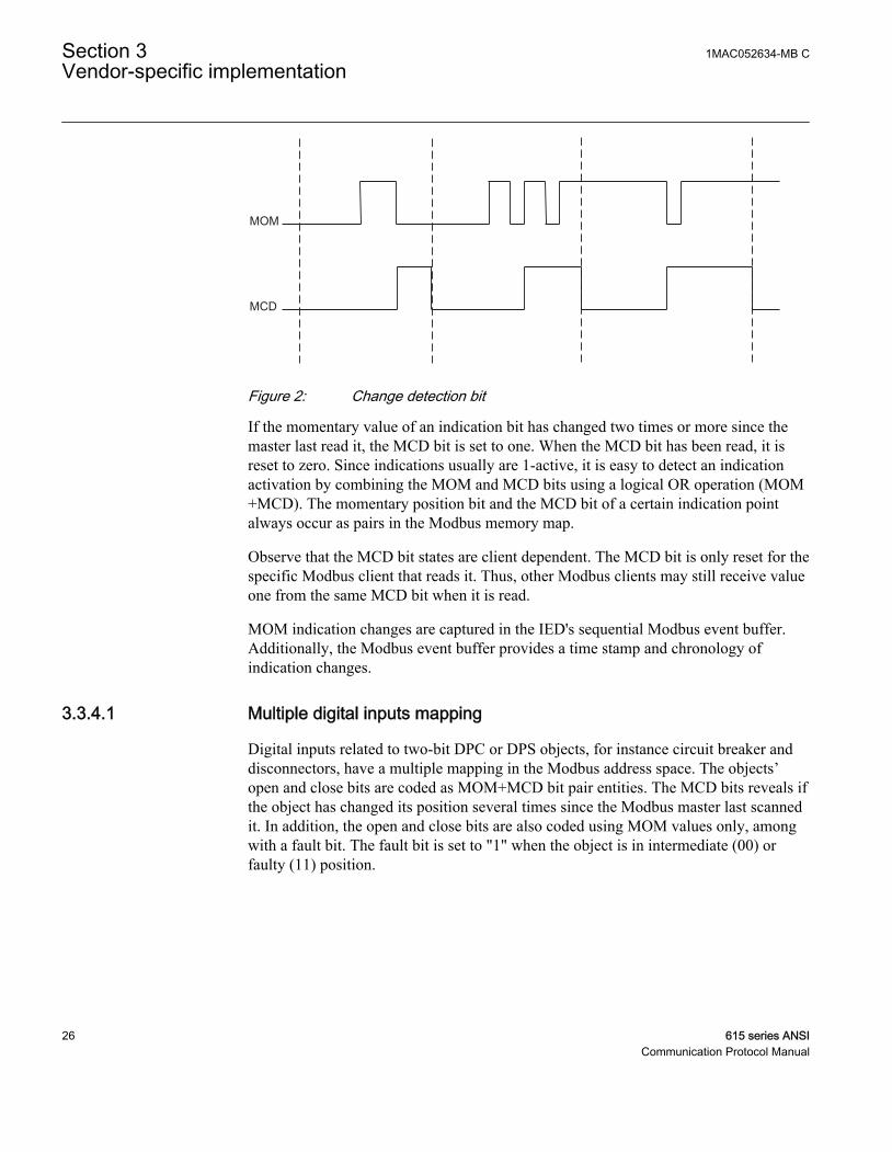
Figure 2: Change detection bit
If the momentary value of an indication bit has changed two times or more since themaster last read it, the MCD bit is set to one. When the MCD bit has been read, it isreset to zero. Since indications usually are 1-active, it is easy to detect an indicationactivation by combining the MOM and MCD bits using a logical OR operation (MOM+MCD). The momentary position bit and the MCD bit of a certain indication pointalways occur as pairs in the Modbus memory map.
Observe that the MCD bit states are client dependent. The MCD bit is only reset for thespecific Modbus client that reads it. Thus, other Modbus clients may still receive valueone from the same MCD bit when it is read.
MOM indication changes are captured in the IED's sequential Modbus event buffer.Additionally, the Modbus event buffer provides a time stamp and chronology ofindication changes.
3.3.4.1 Multiple digital inputs mapping
Digital inputs related to two-bit DPC or DPS objects, for instance circuit breaker anddisconnectors, have a multiple mapping in the Modbus address space. The objects’open and close bits are coded as MOM+MCD bit pair entities. The MCD bits reveals ifthe object has changed its position several times since the Modbus master last scannedit. In addition, the open and close bits are also coded using MOM values only, amongwith a fault bit. The fault bit is set to "1" when the object is in intermediate (00) orfaulty (11) position.
Section 3 1MAC052634-MB CVendor-specific implementation
26 615 series ANSICommunication Protocol Manual
Table 9: Bit treatment
Bits TreatmentClose MOM One 2 bit entity
Close MCD
Open MOM One 2 bit entity
Open MCD
:
Close MOM One 1 bit entity
Open MOM One 1 bit entity
Faulty position MOM One 1 bit entity
:
The MOM values are identical in each entity. The MCD bit is only reset if the MOMbit in the same entity is read.
3.3.5 Measurand registersThe Modbus measurands are located in the Modbus register area. The measurands arereadable from 4X areas.
The formula for calculating the Modbus register value is:
Modbus value IEC Value scaleFactor Offset = ×( ) +61850
A070857 V1 EN (Equation 1)
The range of the original IEC 61850 value can be seen in the Modbus memory mappoint list.
All frequently updated data are readable from a sequential data area. Additionally,there is a separate sequential data area for measurands and counters with a slow updaterate.
3.3.5.1 Primary and per-unit values
Measurands originating from CT measurements can be obtained from the IED in twoways. They can be viewed either as primary values or as per-unit values.
The primary values are represented internally as decimal numbers. The primary unitsare [A] for current. The internal representation of the per-unit values is always 1.0 atnominal current. A typical range for a per-unit value is 0.00...40.00, that is 0 to 40times nominal.
1MAC052634-MB C Section 3Vendor-specific implementation
615 series ANSI 27Communication Protocol Manual
If the primary value representation is selected but no CT ratioparameters are configured in the IED, the Modbus values remain as per-unit values.
3.3.5.2 Register sizes
In most cases the measurands or counters are located in single 16 bit registers. Themeasurands are either unsigned or signed two's complement values while the countersare always unsigned values.
In some rare cases the measurands or counter values can be located in two consecutiveregisters, thus forming a single 32 bit integer value. The 32 bit value is always codedso that the high word part, that means the higher 16 bits, is located first in the lowerregister address. The low word part, that means the lower 16 bits, is then always in thenext register address.
Register sizes and types are clearly stated in the Modbus memory map list.
3.3.5.3 Time of update
Some Modbus values may have a time structure attached to their values in the Modbusmemory map. This is often the case with demand measurement values. The timestructure shows the time when the value was last updated.
Table 10: Time structure data
Address Register Values CommentN TimeStamp
(Year,Month) High byte:year, low
byte:month
N+1 TimeStamp (Day,Hour) High byte:day, lowbyte:hour
N+2 TimeStamp (Min,Sec) High byte:min, lowbyte:seconds
N+3 TimeStamp(Milliseconds)
Word: milliseconds
N+4 Time quality See the table abouttime quality register
Section 3 1MAC052634-MB CVendor-specific implementation
28 615 series ANSICommunication Protocol Manual
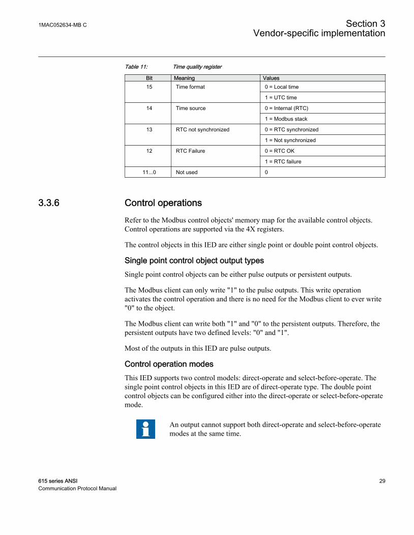
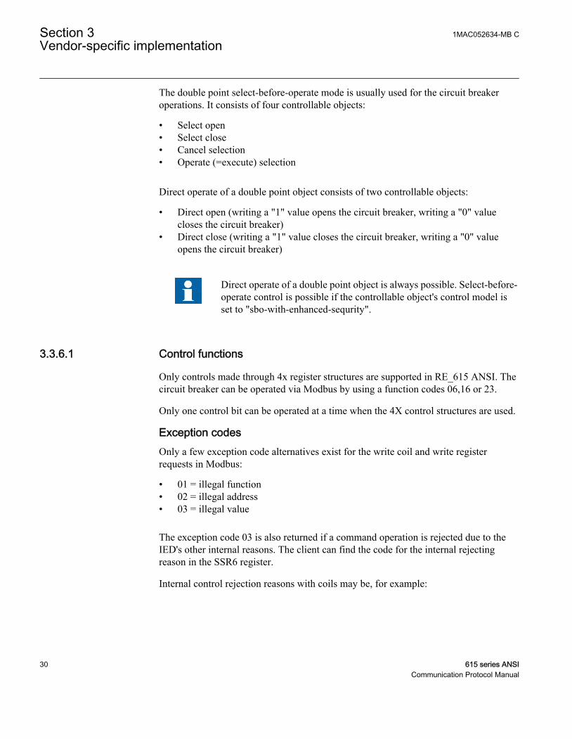
Table 11: Time quality register
Bit Meaning Values15 Time format 0 = Local time
1 = UTC time
14 Time source 0 = Internal (RTC)
1 = Modbus stack
13 RTC not synchronized 0 = RTC synchronized
1 = Not synchronized
12 RTC Failure 0 = RTC OK
1 = RTC failure
11...0 Not used 0
3.3.6 Control operationsRefer to the Modbus control objects' memory map for the available control objects.Control operations are supported via the 4X registers.
The control objects in this IED are either single point or double point control objects.
Single point control object output typesSingle point control objects can be either pulse outputs or persistent outputs.
The Modbus client can only write "1" to the pulse outputs. This write operationactivates the control operation and there is no need for the Modbus client to ever write"0" to the object.
The Modbus client can write both "1" and "0" to the persistent outputs. Therefore, thepersistent outputs have two defined levels: "0" and "1".
Most of the outputs in this IED are pulse outputs.
Control operation modesThis IED supports two control models: direct-operate and select-before-operate. Thesingle point control objects in this IED are of direct-operate type. The double pointcontrol objects can be configured either into the direct-operate or select-before-operatemode.
An output cannot support both direct-operate and select-before-operatemodes at the same time.
1MAC052634-MB C Section 3Vendor-specific implementation
615 series ANSI 29Communication Protocol Manual
The double point select-before-operate mode is usually used for the circuit breakeroperations. It consists of four controllable objects:
• Select open• Select close• Cancel selection• Operate (=execute) selection
Direct operate of a double point object consists of two controllable objects:
• Direct open (writing a "1" value opens the circuit breaker, writing a "0" valuecloses the circuit breaker)
• Direct close (writing a "1" value closes the circuit breaker, writing a "0" valueopens the circuit breaker)
Direct operate of a double point object is always possible. Select-before-operate control is possible if the controllable object's control model isset to "sbo-with-enhanced-sequrity".
3.3.6.1 Control functions
Only controls made through 4x register structures are supported in RE_615 ANSI. Thecircuit breaker can be operated via Modbus by using a function codes 06,16 or 23.
Only one control bit can be operated at a time when the 4X control structures are used.
Exception codesOnly a few exception code alternatives exist for the write coil and write registerrequests in Modbus:
• 01 = illegal function• 02 = illegal address• 03 = illegal value
The exception code 03 is also returned if a command operation is rejected due to theIED's other internal reasons. The client can find the code for the internal rejectingreason in the SSR6 register.
Internal control rejection reasons with coils may be, for example:
Section 3 1MAC052634-MB CVendor-specific implementation
30 615 series ANSICommunication Protocol Manual
• The client has no write authority.• The IED is in local state.• The control operation is already reserved by another client and thus blocked.
If a positive acknowledgement is returned, the control command has been initiated bythe IED.
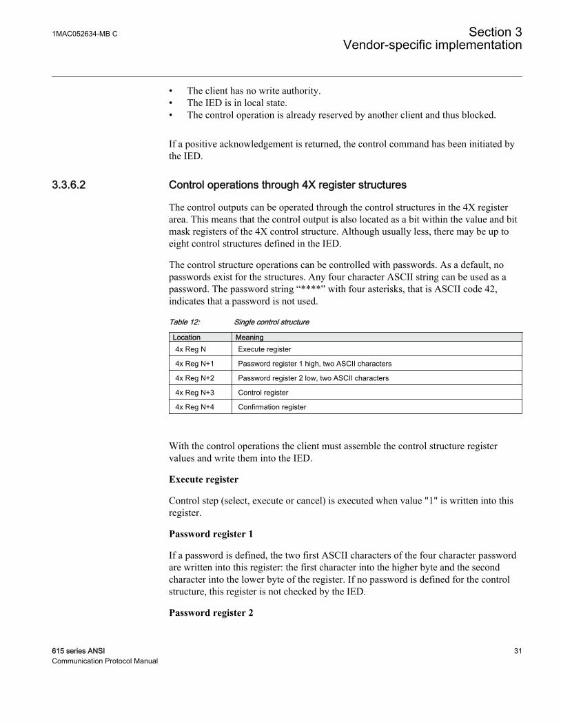
3.3.6.2 Control operations through 4X register structures
The control outputs can be operated through the control structures in the 4X registerarea. This means that the control output is also located as a bit within the value and bitmask registers of the 4X control structure. Although usually less, there may be up toeight control structures defined in the IED.
The control structure operations can be controlled with passwords. As a default, nopasswords exist for the structures. Any four character ASCII string can be used as apassword. The password string “****” with four asterisks, that is ASCII code 42,indicates that a password is not used.
Table 12: Single control structure
Location Meaning4x Reg N Execute register
4x Reg N+1 Password register 1 high, two ASCII characters
4x Reg N+2 Password register 2 low, two ASCII characters
4x Reg N+3 Control register
4x Reg N+4 Confirmation register
With the control operations the client must assemble the control structure registervalues and write them into the IED.
Execute register
Control step (select, execute or cancel) is executed when value "1" is written into thisregister.
Password register 1
If a password is defined, the two first ASCII characters of the four character passwordare written into this register: the first character into the higher byte and the secondcharacter into the lower byte of the register. If no password is defined for the controlstructure, this register is not checked by the IED.
Password register 2
1MAC052634-MB C Section 3Vendor-specific implementation
615 series ANSI 31Communication Protocol Manual
If a password is defined, the two last ASCII characters of the four character passwordare written into this register: the third character into the higher byte and the fourthcharacter into the lower byte of the register. If no password is defined for the controlstructure, this register is not checked by the IED.
Control register
Set the register bit corresponding to the output to the proper write value. For pulse typeoutputs the value is always "1".
Confirmation register
Set the register bit corresponding to the object to be operated to "1". All other bits mustbe set to zero.
Control structure register assembling orderThe Modbus client can assemble all the control structure registers and write them inone multiple registers write function 16 request.
The Modbus client can also write the registers in several separate transactions or evenone by one using registers write function 06. The execute register has to be written lastand no more than 15 seconds may occur between the separate register writes. Thecontrol structure operation will time out after 15 seconds after the last register write.The timeout between select and operate steps is fixed to 15 seconds regardless of thecontrollable object’s configured timeout value.
If several clients are allowed to perform control operationssimultaneously, this method should not be used by more than one of themultiple clients in question.
Exception codesOnly a few exception code alternatives exist for control structures:
• 01 = illegal function• 02 = illegal address• 03 = illegal value
The exception code 03 is also returned if a command operation is rejected due to theIED's other internal reasons. The client can find the code for the internal rejectingreason in the SSR6 register.
The primary internal rejection reasons for control structure write operations may be forexample:
Section 3 1MAC052634-MB CVendor-specific implementation
32 615 series ANSICommunication Protocol Manual
• The Modbus control structure write has timed out (15 sec).• The client has no write authority.• The IED is in the local state.• The control operation is blocked, that means already reserved, by another client.
If a positive acknowledgement is returned, the control command has been initiatedinside the IED.
3.3.6.3 Additional control operations
Secured and unsecured control operationsIf the control command initiates an object that is internally defined to perform asecured control operation, the SSR6 register CmdState bits will show "Command InProgress" during the actual control operation. Once the command sequence is over, theSSR6 command state bits change to "Response Ready”. The contents of the SSR6CmdResultCode can then be examined.
In unsecured operation mode, the positive confirmation response to a Modbuscommand request is based on the internal, IEC 61850 level, positive activationconfirmation and not on the command termination confirmation. In secured operationmode, the Modbus command response is always based on the termination confirmation.
The update of the SSR6 bits (sequence number + command state) is based on thetermination confirmation in both operation modes. If a new control operation is issuedby the client before the previous command has been concluded, that is before the SSR6has been updated, the operation is rejected because the command operation still inprogress.
Location of control structuresOne or several control structures may be defined in the IED. If there are several controlstructures, they are located one after another in the Modbus 4X memory map. Refer tothe IED's Modbus memory map for the actual locations of control structures.
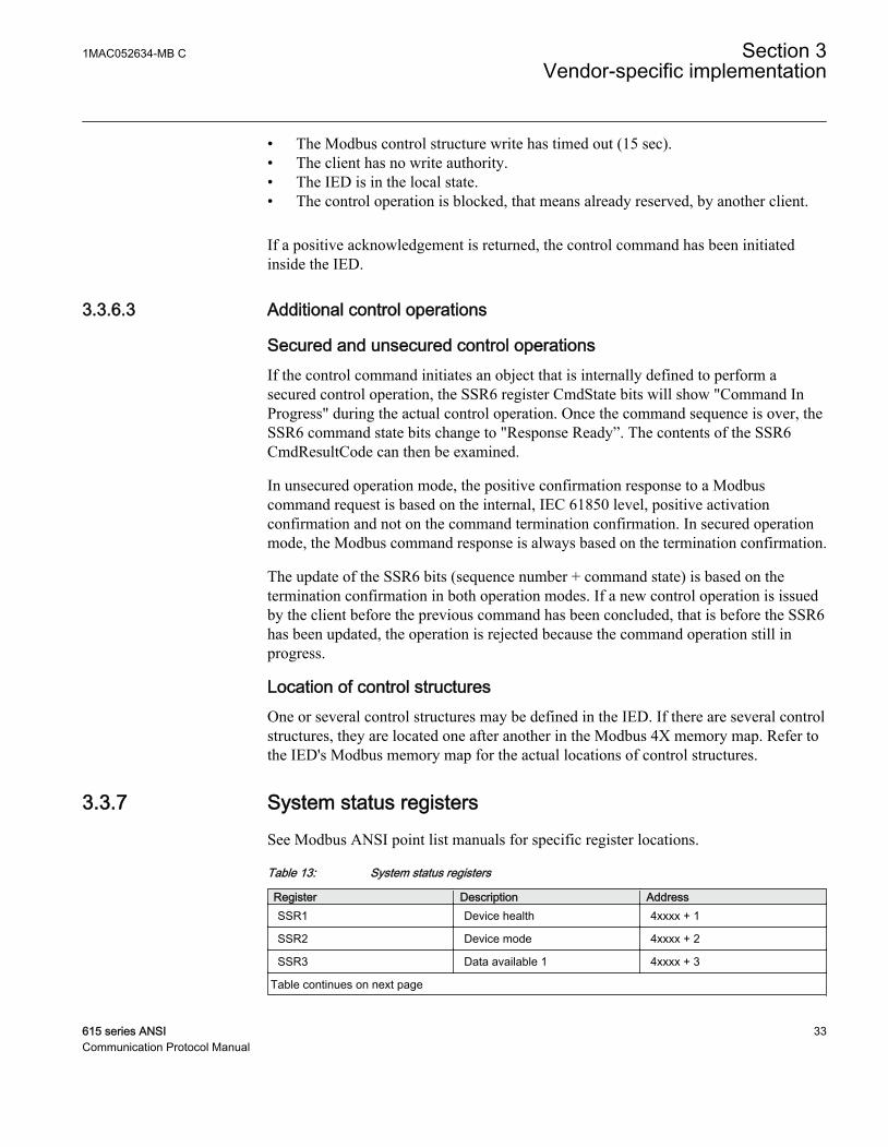
3.3.7 System status registersSee Modbus ANSI point list manuals for specific register locations.
Table 13: System status registers
Register Description AddressSSR1 Device health 4xxxx + 1
SSR2 Device mode 4xxxx + 2
SSR3 Data available 1 4xxxx + 3
Table continues on next page
1MAC052634-MB C Section 3Vendor-specific implementation
615 series ANSI 33Communication Protocol Manual

Register Description AddressSSR4 Data available 2 4xxxx + 4
SSR5 Device alive counter 4xxxx + 5
SSR6 Last command result 4xxxx + 6
3.3.7.1 SSR1
The bits in SSR1 are common for all Modbus clients. The bits in SSR1 give anoverview of the IEDs health. If a specific bit in this register is "1", it signifies awarning or an error in the hardware entity in question.
More specific warning and error codes can be read from elsewhere inthe Modbus memory. Refer to the Modbus memory map for theseregister locations.
Table 14: 16 bit SSR1 register
Bit Meaning0 Device global warning
1 Device global error
2 Slot 0 (X130) warning or error
3 Slot 1 (X120) warning or error
4 Slot 2 (X110) warning or error
5 Slot 3 (X100) warning or error
6 Slot 4 (X000) warning or error
7...15 0 = not used
3.3.7.2 SSR2
The bit values in SSR2 are common for all Modbus clients. The bits give an overviewof the IED's mode. For example, bit 6 is activated if the IED's configured timesynchronization source is lost.
Table 15: 16 bit SSR2 register
Bit Meaning0 Test mode (1= Device is set into test mode)
1 Local/Remote Off (0= On, 1= Off)
2 Local/Remote state (0= Remote, 1= Local, only relevant if Bit 1=0)
Table continues on next page
Section 3 1MAC052634-MB CVendor-specific implementation
34 615 series ANSICommunication Protocol Manual

Bit Meaning3...5 Active setting parameter setting group (bit 3 = LSB)
001 = Setting group 1010 = Setting group 2011 = Setting group 3100 = Setting group 4
6 IED time synchronization failure (1 = Failure)
7 0 = not used
8 Last reset cause (1= Power reset)
9 Last reset cause (1= Watchdog reset)
10 Last reset cause (1= Warm reset)
11...15 0 = not used
3.3.7.3 SSR3
The bit values in the SSR3 register are Modbus client dependent.
Bits 0 and 1 are set to "1" as long as the client in question has not read out the availableModbus event or fault records.
Bit 4 is set to "1" if any momentary bit has been updated in the Modbus memory map.The bit is reset when the client reads the register.
Bit 5 is set to "1" if any MCD bit has been set in the Modbus memory map. The bit isreset when the client reads the register.
Bit 6 is set to "1" to indicate the device restart. The bit is reset when the client readsthis register.
Bit 8 is set to "1" when an event record has been recorded. The bit is reset when theclient writes the reset code 4 to the event record selection register.
Bit 9 is set to "1" when a fault record has been recorded. The bit is reset when theclient writes the reset code 4 to the fault record selection register.
Table 16: 16 bit SSR3 register
Bit Meaning0 Unread event records available
1 Unread fault records available
2 0 = not used
3 0 = not used
4 Any MOM bit updated
5 Any indication MCD bit set
Table continues on next page
1MAC052634-MB C Section 3Vendor-specific implementation
615 series ANSI 35Communication Protocol Manual
Bit Meaning6 Device restart bit
7 0 = not used
8 Event record ready for reading
9 Fault record ready for reading
10...15 0 = not used
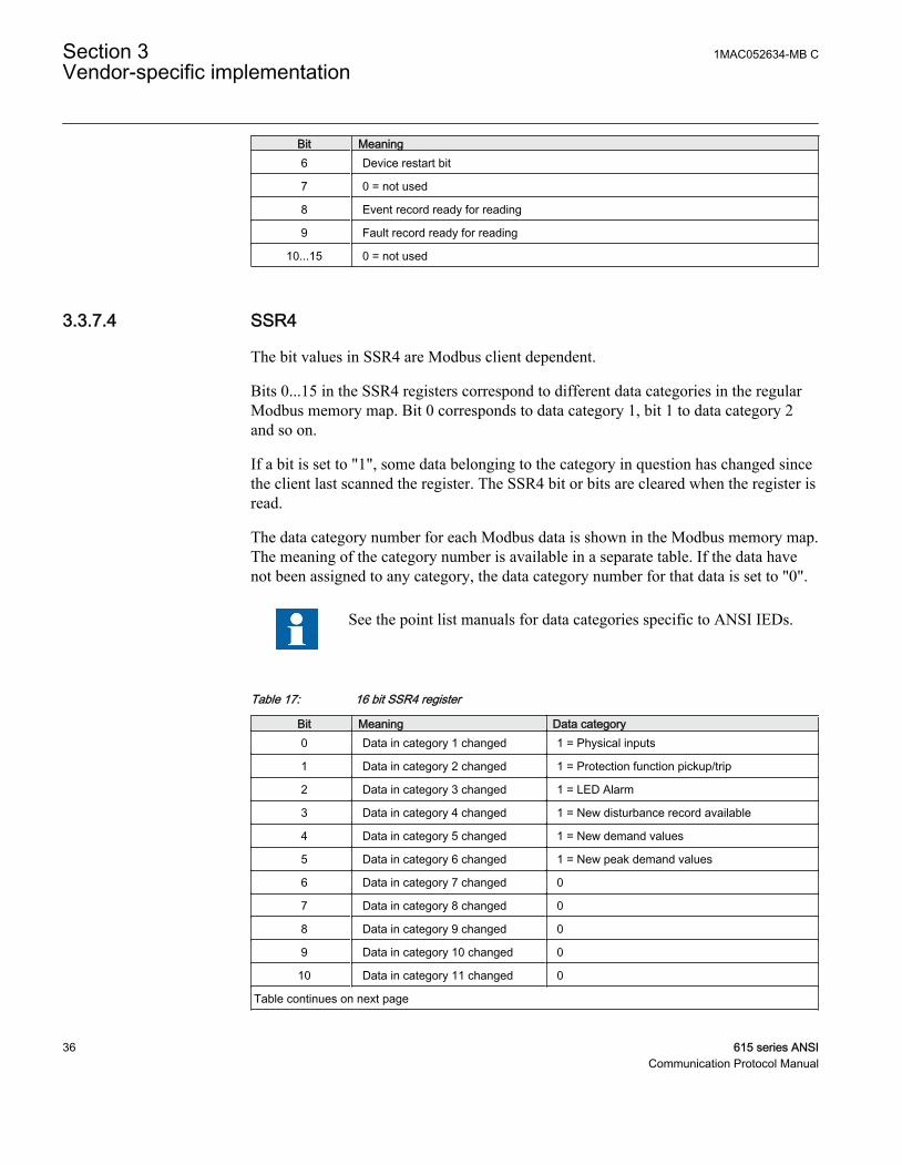
3.3.7.4 SSR4
The bit values in SSR4 are Modbus client dependent.
Bits 0...15 in the SSR4 registers correspond to different data categories in the regularModbus memory map. Bit 0 corresponds to data category 1, bit 1 to data category 2and so on.
If a bit is set to "1", some data belonging to the category in question has changed sincethe client last scanned the register. The SSR4 bit or bits are cleared when the register isread.
The data category number for each Modbus data is shown in the Modbus memory map.The meaning of the category number is available in a separate table. If the data havenot been assigned to any category, the data category number for that data is set to "0".
See the point list manuals for data categories specific to ANSI IEDs.
Table 17: 16 bit SSR4 register
Bit Meaning Data category0 Data in category 1 changed 1 = Physical inputs
1 Data in category 2 changed 1 = Protection function pickup/trip
2 Data in category 3 changed 1 = LED Alarm
3 Data in category 4 changed 1 = New disturbance record available
4 Data in category 5 changed 1 = New demand values
5 Data in category 6 changed 1 = New peak demand values
6 Data in category 7 changed 0
7 Data in category 8 changed 0
8 Data in category 9 changed 0
9 Data in category 10 changed 0
10 Data in category 11 changed 0
Table continues on next page
Section 3 1MAC052634-MB CVendor-specific implementation
36 615 series ANSICommunication Protocol Manual
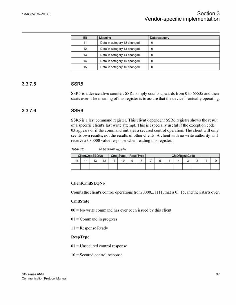
Bit Meaning Data category11 Data in category 12 changed 0
12 Data in category 13 changed 0
13 Data in category 14 changed 0
14 Data in category 15 changed 0
15 Data in category 16 changed 0
3.3.7.5 SSR5
SSR5 is a device alive counter. SSR5 simply counts upwards from 0 to 65535 and thenstarts over. The meaning of this register is to assure that the device is actually operating.
3.3.7.6 SSR6
SSR6 is a last command register. This client dependent SSR6 register shows the resultof a specific client's last write attempt. This is especially useful if the exception code03 appears or if the command initiates a secured control operation. The client will onlysee its own results, not the results of other clients. A client with no write authority willreceive a 0x0000 value response when reading this register.
Table 18: 16 bit SSR6 register
ClientCmdSEQNo Cmd State Resp Type CMDResultCode15 14 13 12 11 10 9 8 7 6 5 4 3 2 1 0
ClientCmdSEQNo
Counts the client's control operations from 0000...1111, that is 0...15, and then starts over.
CmdState
00 = No write command has ever been issued by this client
01 = Command in progress
11 = Response Ready
RespType
01 = Unsecured control response
10 = Secured control response
1MAC052634-MB C Section 3Vendor-specific implementation
615 series ANSI 37Communication Protocol Manual

11 = Modbus 03 exception response valid. CMDResultCode is in this case 0. Thereason for the 03 exception is an invalid written value.
Table 19: CMDResultCode
Code Meaning0 OK
201 Device in local mode
202 Control operation reserved by another client
203 Select-timeout or Execute/Cancel without select
204 Control operation internally blocked
205 Control operation timed out
250 Other reason
3.3.8 Event recordsThe IED creates a Modbus event record when a momentary digital input bit changes itsvalue. The IED then stores the changed Modbus bit location and value into the Modbusevent record buffer. The event time tag is also stored into the record. The time tagincludes a full time stamp from a year down to milliseconds.
The size of the IED's internal Modbus event record buffer is 500 events. The 500 latestevents are at any time readable from the IED. When the Modbus event record bufferbecomes full, the IED overwrites the oldest event records in the buffer.
Multiple clients supportSeveral Modbus clients can independently of one another read out Modbus eventrecords from the IED. The Modbus event buffer keeps track of where in the eventbuffer the different clients are reading at the moment. Clients are identified either bythe serial port from where the requests are issued or by the client's IP address in the TCP/IP network. Up to 25 different IP addresses are memorized by the IED.
Multiple events reading, backwards compatibilityThe original 615 series event reading concept only allowed reading out one eventstructure at a time. In later 615 series IED versions this was extended to include up to10 event structures at a time. Multiple event structures reading adds one Modbusregister, "Num of event records in multiple event reading", that normally shouldcontain the amount of event structures to be read. However, it is not necessary to writea "1" into this register if the client only wants to read one event at a time. This featureprovides backwards compatibility with the original event reading concept.
Section 3 1MAC052634-MB CVendor-specific implementation
38 615 series ANSICommunication Protocol Manual
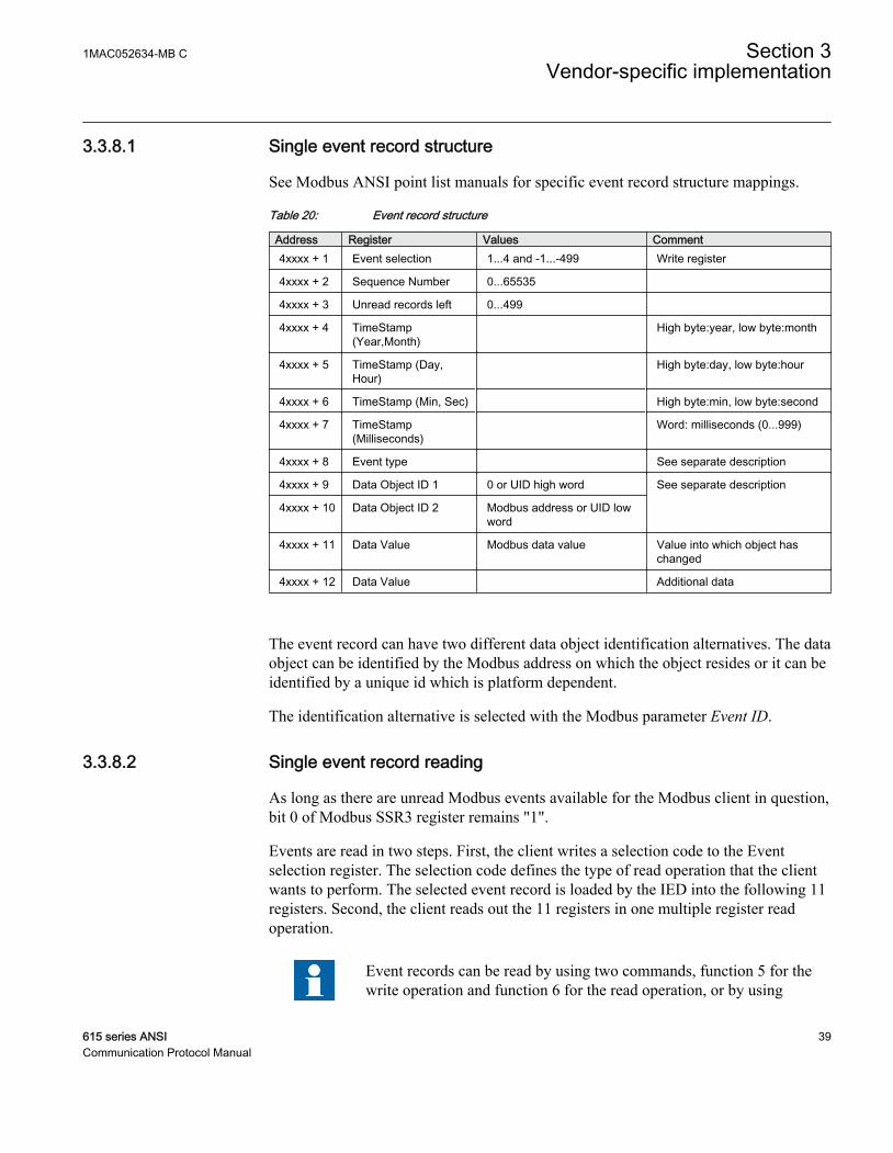
3.3.8.1 Single event record structure
See Modbus ANSI point list manuals for specific event record structure mappings.
Table 20: Event record structure
Address Register Values Comment4xxxx + 1 Event selection 1...4 and -1...-499 Write register
4xxxx + 2 Sequence Number 0...65535
4xxxx + 3 Unread records left 0...499
4xxxx + 4 TimeStamp(Year,Month)
High byte:year, low byte:month
4xxxx + 5 TimeStamp (Day,Hour)
High byte:day, low byte:hour
4xxxx + 6 TimeStamp (Min, Sec) High byte:min, low byte:second
4xxxx + 7 TimeStamp(Milliseconds)
Word: milliseconds (0...999)
4xxxx + 8 Event type See separate description
4xxxx + 9 Data Object ID 1 0 or UID high word See separate description
4xxxx + 10 Data Object ID 2 Modbus address or UID lowword
4xxxx + 11 Data Value Modbus data value Value into which object haschanged
4xxxx + 12 Data Value Additional data
The event record can have two different data object identification alternatives. The dataobject can be identified by the Modbus address on which the object resides or it can beidentified by a unique id which is platform dependent.
The identification alternative is selected with the Modbus parameter Event ID.
3.3.8.2 Single event record reading
As long as there are unread Modbus events available for the Modbus client in question,bit 0 of Modbus SSR3 register remains "1".
Events are read in two steps. First, the client writes a selection code to the Eventselection register. The selection code defines the type of read operation that the clientwants to perform. The selected event record is loaded by the IED into the following 11registers. Second, the client reads out the 11 registers in one multiple register readoperation.
Event records can be read by using two commands, function 5 for thewrite operation and function 6 for the read operation, or by using
1MAC052634-MB C Section 3Vendor-specific implementation
615 series ANSI 39Communication Protocol Manual

function 23 that includes write and read operations in the sametransaction.
If event records are read by using two commands, the positiveconfirmation to the write select operation tells the client that an eventrecord has been loaded for reading. Another way to detect the positiveconfirmation is by monitoring the state of SSR3 bit 8.
Selection code 1: Reading the oldest unread recordWhen writing the selection code 1, the IED first checks the client. If the client has readevents before, the IED knows which internal event has been sent to this specific clientduring the last reading. The IED then loads the next event, that is the oldest unread,into the next 11 registers. If this is the first time the client reads events from the IED,the oldest event of the Modbus event buffer is loaded into the 11 event record registers.
Selection code 2: Reading the oldest stored recordSelection code 2 always forces the event reading to go back to the oldest event in theModbus event buffer. The oldest event record is then loaded into the 11 event recordregisters. After the client has read out this record, the next record becomes the oldestunread. The client can continue with the selection code 1 by reading out the oldestunread event record again.
Selection code -1...-499A negative selection code, that is a 16 bit two's complement value, defines how manyrecords backwards from the newest event the event record reading is to be moved. Forexample, the ten latest events could be read out at any time by first selecting -10,reading out the event and then continuing with the selection code 1 to read out the nineadditional event records. There can be 500 event records altogether.
Selection code 3: Resetting the event read pointerThe write selection 3 is not followed by a read operation. The selection 3 means thatthere are no unread records in the Modbus event buffer left for the client in question,that is, the buffer is cleared. The next new event that is logged into the Modbus eventbuffer becomes the first unread record for this specific client.
Selection code 4: Resetting SSR3 bit 8The write selection 4 is not followed by a read operation. The selection code onlyresets the bit 8 in SSR3.
If event records are read by using two commands, the client can re-readthe 11 event record registers as many times as it wants. As long as no
Section 3 1MAC052634-MB CVendor-specific implementation
40 615 series ANSICommunication Protocol Manual

new selection write operation is performed, the contents of the 11 eventrecord registers are not changed.
3.3.8.3 Other event record registers
Sequence numberEvery Modbus event record is given a sequence number. The sequence number runsfrom 1 to 65535 and then rolls over to 1 again. The client can check that the sequencenumbers of the recorded data are sequential. During the event buffer overflow theclient can notice a jump in the sequence numbers when some event records are lost.The gap between the new and the previous sequence number reveals exactly how manyevent records have been lost.
Unread records leftThis register shows how many unread event records still remain unread for the client inquestion at a particular moment.
Time stamp registersTime stamp is either in local time or UTC time. The time stamp alternative is selectedwith a Modbus parameter.
Time stamp registers usually hold two data values in the high and low byte of theregisters. High byte value = RegisterValue DIV 256, Low byte value = RegisterValueMOD 256. The Milliseconds register is an exception as it contains the milliseconds0...999 coded as such.
Event typeThis register contains information to interpret the event data correctly.
Table 21: Information contained by the 16 bit register
Bit Meaning Values15 Event time
stamp format0 = Local time 1 = UTC time
14 Time stampsource
0 = Internal application 1 = Modbus stack
13 Clock notsynchronized
0 = Synchronized
1 = Time not synchronized
12 Clock failure 0 = Clock OK 1 = Clock failure
11 Reserved 0
10 Reserved 0
Table continues on next page
1MAC052634-MB C Section 3Vendor-specific implementation
615 series ANSI 41Communication Protocol Manual
Bit Meaning Values9 Reserved 0
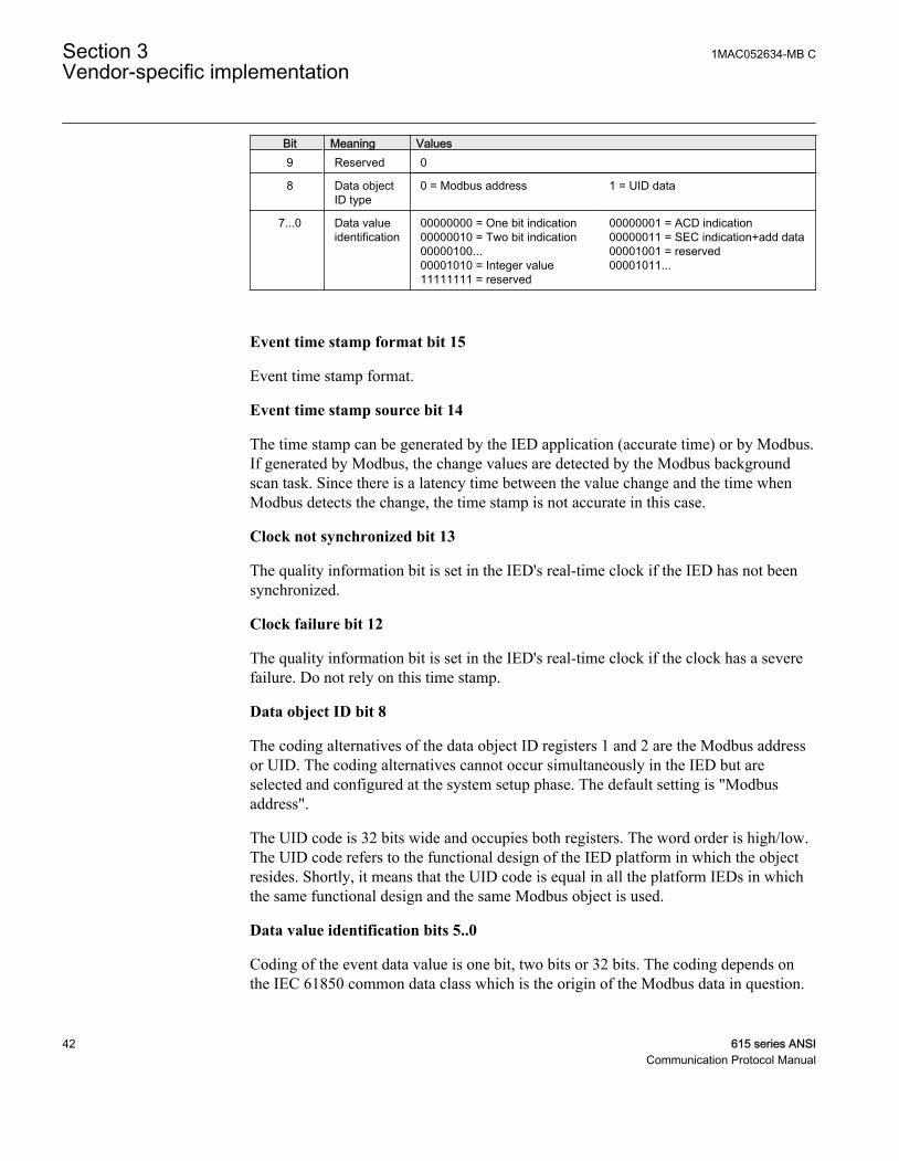
8 Data objectID type
0 = Modbus address 1 = UID data
7...0 Data valueidentification
00000000 = One bit indication00000010 = Two bit indication00000100...00001010 = Integer value11111111 = reserved
00000001 = ACD indication00000011 = SEC indication+add data00001001 = reserved00001011...
Event time stamp format bit 15
Event time stamp format.
Event time stamp source bit 14
The time stamp can be generated by the IED application (accurate time) or by Modbus.If generated by Modbus, the change values are detected by the Modbus backgroundscan task. Since there is a latency time between the value change and the time whenModbus detects the change, the time stamp is not accurate in this case.
Clock not synchronized bit 13
The quality information bit is set in the IED's real-time clock if the IED has not beensynchronized.
Clock failure bit 12
The quality information bit is set in the IED's real-time clock if the clock has a severefailure. Do not rely on this time stamp.
Data object ID bit 8
The coding alternatives of the data object ID registers 1 and 2 are the Modbus addressor UID. The coding alternatives cannot occur simultaneously in the IED but areselected and configured at the system setup phase. The default setting is "Modbusaddress".
The UID code is 32 bits wide and occupies both registers. The word order is high/low.The UID code refers to the functional design of the IED platform in which the objectresides. Shortly, it means that the UID code is equal in all the platform IEDs in whichthe same functional design and the same Modbus object is used.
Data value identification bits 5..0
Coding of the event data value is one bit, two bits or 32 bits. The coding depends onthe IEC 61850 common data class which is the origin of the Modbus data in question.
Section 3 1MAC052634-MB CVendor-specific implementation
42 615 series ANSICommunication Protocol Manual

Table 22: Modbus event value alternatives
Object derived fromIEC 61850 Class
Meaning One Bit DataValue
Two Bit DataValue
32 bit DataValue
SPS Single Point Status X
SPC Single Point Status of a controllableobject
X
DPS Dual Point Status X
DPC Dual Point Status of a controllableobject
X
ACT Trip status X
ACD Start/Pick-up status X
INS/INC Integer status X
Table 23: Interpretation of the one-bit data value
Register 4xxxx binary coded value Meaningxxxx.xxxx.xxxx.xxx0 Object in OFF position
xxxx.xxxx.xxxx.xxx1 Object in ON position
Table 24: Interpretation of the two-bit data value
Register 4xxxx binary coded value Meaningxxxx.xxxx.xxxx.xx00 Object in intermediate position (changing)
xxxx.xxxx.xxxx.xx01 Object in ON (close) position
xxxx.xxxx.xxxx.xx10 Object in OFF (open) position
xxxx.xxxx.xxxx.xx11 Object in faulty position
In case of a DPS/DPC two-bit event value (Data value identification =2), the data object ID registers always refer to the Modbus address orUID of the CLOSE momentary value bit.
Table 25: Interpretation of the integer status data value
Register address1) Meaning4xxxx Higher 16 bit part of the 32 bit integer value
4xxxx + 1 Lower 16 bit part of the 32 bit integer value
1) See Modbus ANSI point list manual for specific event record structure mappings.
1MAC052634-MB C Section 3Vendor-specific implementation
615 series ANSI 43Communication Protocol Manual
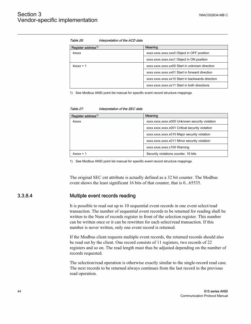
Table 26: Interpretation of the ACD data
Register address1) Meaning4xxxx xxxx.xxxx.xxxx.xxx0 Object in OFF position
xxxx.xxxx.xxxx.xxx1 Object in ON position
4xxxx + 1 xxxx.xxxx.xxxx.xx00 Start in unknown direction
xxxx.xxxx.xxxx.xx01 Start in forward direction
xxxx.xxxx.xxxx.xx10 Start in backwards direction
xxxx.xxxx.xxxx.xx11 Start in both directions
1) See Modbus ANSI point list manual for specific event record structure mappings.
Table 27: Interpretation of the SEC data
Register address1) Meaning4xxxx xxxx.xxxx.xxxx.x000 Unknown security violation
xxxx.xxxx.xxxx.x001 Critical security violation
xxxx.xxxx.xxxx.x010 Major security violation
xxxx.xxxx.xxxx.x011 Minor security violation
xxxx.xxxx.xxxx.x100 Warning
4xxxx + 1 Security violations counter, 16 bits
1) See Modbus ANSI point list manual for specific event record structure mappings.
The original SEC cnt attribute is actually defined as a 32 bit counter. The Modbusevent shows the least significant 16 bits of that counter, that is 0...65535.
3.3.8.4 Multiple event records reading
It is possible to read out up to 10 sequential event records in one event select/readtransaction. The number of sequential event records to be returned for reading shall bewritten to the Num of records register in front of the selection register. This numbercan be written once or it can be rewritten for each select/read transaction. If thisnumber is never written, only one event record is returned.
If the Modbus client requests multiple event records, the returned records should alsobe read out by the client. One record consists of 11 registers, two records of 22registers and so on. The read length must thus be adjusted depending on the number ofrecords requested.
The selection/read operation is otherwise exactly similar to the single-record read case.The next records to be returned always continues from the last record in the previousread operation.
Section 3 1MAC052634-MB CVendor-specific implementation
44 615 series ANSICommunication Protocol Manual
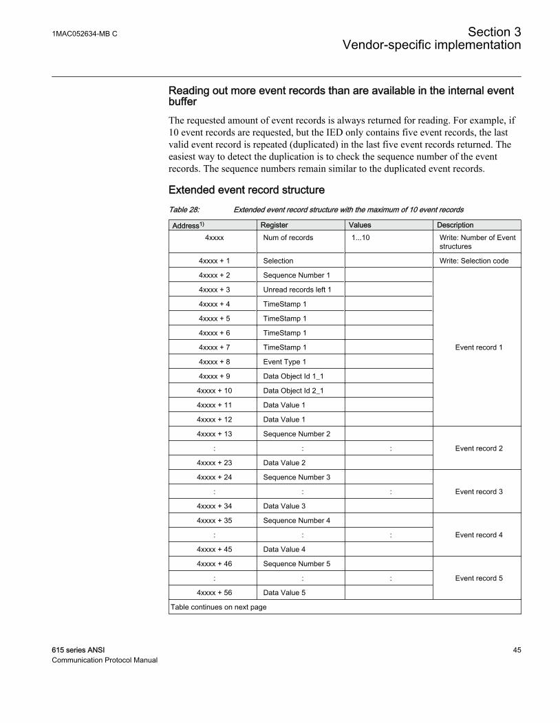
Reading out more event records than are available in the internal eventbufferThe requested amount of event records is always returned for reading. For example, if10 event records are requested, but the IED only contains five event records, the lastvalid event record is repeated (duplicated) in the last five event records returned. Theeasiest way to detect the duplication is to check the sequence number of the eventrecords. The sequence numbers remain similar to the duplicated event records.
Extended event record structureTable 28: Extended event record structure with the maximum of 10 event records
Address1) Register Values Description4xxxx Num of records 1...10 Write: Number of Event
structures
4xxxx + 1 Selection Write: Selection code
4xxxx + 2 Sequence Number 1
Event record 1
4xxxx + 3 Unread records left 1
4xxxx + 4 TimeStamp 1
4xxxx + 5 TimeStamp 1
4xxxx + 6 TimeStamp 1
4xxxx + 7 TimeStamp 1
4xxxx + 8 Event Type 1
4xxxx + 9 Data Object Id 1_1
4xxxx + 10 Data Object Id 2_1
4xxxx + 11 Data Value 1
4xxxx + 12 Data Value 1
4xxxx + 13 Sequence Number 2
Event record 2: : :
4xxxx + 23 Data Value 2
4xxxx + 24 Sequence Number 3
Event record 3: : :
4xxxx + 34 Data Value 3
4xxxx + 35 Sequence Number 4
Event record 4: : :
4xxxx + 45 Data Value 4
4xxxx + 46 Sequence Number 5
Event record 5: : :
4xxxx + 56 Data Value 5
Table continues on next page
1MAC052634-MB C Section 3Vendor-specific implementation
615 series ANSI 45Communication Protocol Manual
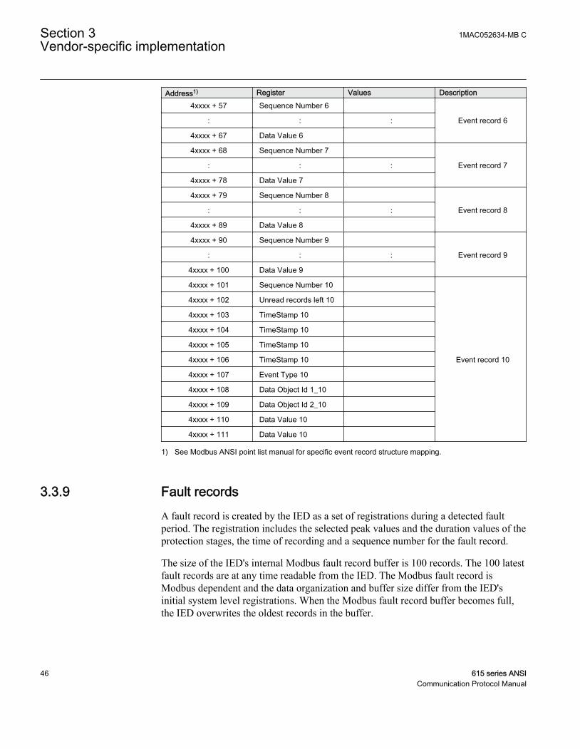
Address1) Register Values Description4xxxx + 57 Sequence Number 6
Event record 6: : :
4xxxx + 67 Data Value 6
4xxxx + 68 Sequence Number 7
Event record 7: : :
4xxxx + 78 Data Value 7
4xxxx + 79 Sequence Number 8
Event record 8: : :
4xxxx + 89 Data Value 8
4xxxx + 90 Sequence Number 9
Event record 9: : :
4xxxx + 100 Data Value 9
4xxxx + 101 Sequence Number 10
Event record 10
4xxxx + 102 Unread records left 10
4xxxx + 103 TimeStamp 10
4xxxx + 104 TimeStamp 10
4xxxx + 105 TimeStamp 10
4xxxx + 106 TimeStamp 10
4xxxx + 107 Event Type 10
4xxxx + 108 Data Object Id 1_10
4xxxx + 109 Data Object Id 2_10
4xxxx + 110 Data Value 10
4xxxx + 111 Data Value 10
1) See Modbus ANSI point list manual for specific event record structure mapping.
3.3.9 Fault recordsA fault record is created by the IED as a set of registrations during a detected faultperiod. The registration includes the selected peak values and the duration values of theprotection stages, the time of recording and a sequence number for the fault record.
The size of the IED's internal Modbus fault record buffer is 100 records. The 100 latestfault records are at any time readable from the IED. The Modbus fault record isModbus dependent and the data organization and buffer size differ from the IED'sinitial system level registrations. When the Modbus fault record buffer becomes full,the IED overwrites the oldest records in the buffer.
Section 3 1MAC052634-MB CVendor-specific implementation
46 615 series ANSICommunication Protocol Manual
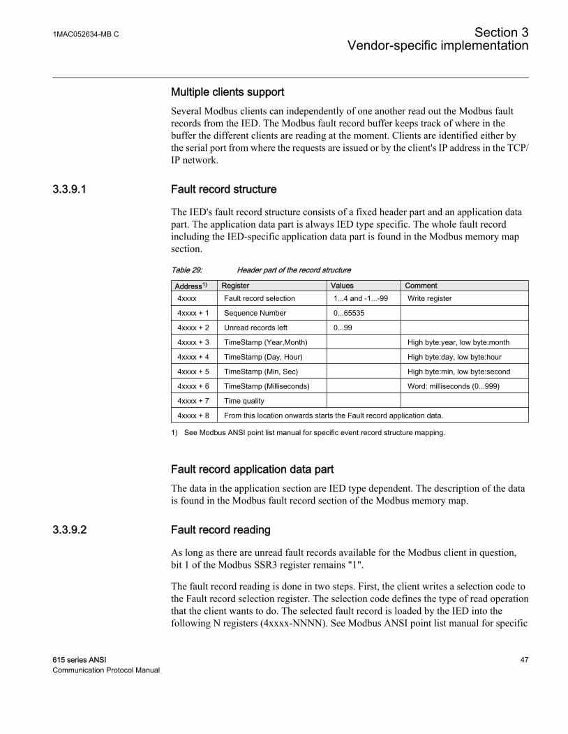
Multiple clients supportSeveral Modbus clients can independently of one another read out the Modbus faultrecords from the IED. The Modbus fault record buffer keeps track of where in thebuffer the different clients are reading at the moment. Clients are identified either bythe serial port from where the requests are issued or by the client's IP address in the TCP/IP network.
3.3.9.1 Fault record structure
The IED's fault record structure consists of a fixed header part and an application datapart. The application data part is always IED type specific. The whole fault recordincluding the IED-specific application data part is found in the Modbus memory mapsection.
Table 29: Header part of the record structure
Address1) Register Values Comment4xxxx Fault record selection 1...4 and -1...-99 Write register
4xxxx + 1 Sequence Number 0...65535
4xxxx + 2 Unread records left 0...99
4xxxx + 3 TimeStamp (Year,Month) High byte:year, low byte:month
4xxxx + 4 TimeStamp (Day, Hour) High byte:day, low byte:hour
4xxxx + 5 TimeStamp (Min, Sec) High byte:min, low byte:second
4xxxx + 6 TimeStamp (Milliseconds) Word: milliseconds (0...999)
4xxxx + 7 Time quality
4xxxx + 8 From this location onwards starts the Fault record application data.
1) See Modbus ANSI point list manual for specific event record structure mapping.
Fault record application data partThe data in the application section are IED type dependent. The description of the datais found in the Modbus fault record section of the Modbus memory map.
3.3.9.2 Fault record reading
As long as there are unread fault records available for the Modbus client in question,bit 1 of the Modbus SSR3 register remains "1".
The fault record reading is done in two steps. First, the client writes a selection code tothe Fault record selection register. The selection code defines the type of read operationthat the client wants to do. The selected fault record is loaded by the IED into thefollowing N registers (4xxxx-NNNN). See Modbus ANSI point list manual for specific
1MAC052634-MB C Section 3Vendor-specific implementation
615 series ANSI 47Communication Protocol Manual
fault record structure mapping. Second, the client reads out these registers in onemultiple register read operation.
The fault records can be read by using two commands, the function 5for the write operation and the function 6 for the read operation, or byusing the function 23 that includes write and read operations in thesame transaction.
If the fault records are read by using two commands, the positiveconfirmation to the write select operation tells the client that a faultrecord has been loaded for reading. Another way to detect the positiveconfirmation is by monitoring the state of SSR3 bit 9.
Fault record structure lengthSince the application data part is IED type dependent, the length of the fault recordstructures vary in different types of IEDs. A client can read out more Modbus registersthan are actually coded in one structure when reading out the data structures. Themaximum read amount is 80 Modbus registers. The additional trailing registers containthe value 0. The Modbus protocol will give an exception response if the client tries toread out too few registers from the fault record structure.
Selection code 1: Reading the oldest unread recordWhen writing the selection code 1, the IED first checks the client. If the client has beenreading fault records before, the IED knows which internal fault record has been sentto this specific client during the last reading. The IED then loads the next fault record,that is the oldest unread, into the registers following the selection register. If this is thefirst time the client reads fault records from the IED, the oldest fault record of theModbus fault record buffer is given to the client.
Selection code 2: Reading the oldest stored recordThe selection code 2 always forces the fault record reading to go back to the oldestfault record stored in the buffer. The oldest fault record is then loaded into the registersfollowing the selection register. After the client has read out this record, the next recordbecomes the oldest unread. The client can continue by reading out the oldest unreadfault records again with the selection code 1.
Selection code -1...-99A negative selection code, that is a 16 bit two's complement value, defines how manyrecords backwards from the newest fault record the reading is to be moved. Forexample, the ten latest fault records can be read out at any time by first selecting -10,
Section 3 1MAC052634-MB CVendor-specific implementation
48 615 series ANSICommunication Protocol Manual
reading out the record and then continuing with the selection code 1 to read out thenine additional records
Selection code 3: Resetting the fault record read pointerThe write selection code 3 is not followed by a read operation. The selection 3 meansthat there are no unread records in the Modbus fault record buffer left for the client inquestion, that is, the buffer is cleared.. The next new fault record that is logged into theModbus fault record buffer becomes the first unread record for this specific client.
Selection code 4: Resetting SSR3 bit 9The write selection 4 is not followed by any read operation. The selection code onlyresets bit 9 in SSR3.
If the fault records are read by using two commands, the client can re-read the given fault record registers as many times as it wants. As longas no new selection write operation is performed, the contents of thefault record registers are not changed.
3.3.9.3 Other fault record registers
Sequence numberEvery fault record is given a sequence number. The sequence number runs from 1 to65535 and then rolls over to one again. The client can check that the sequence numbersof the recorded data are sequential. During the fault record buffer overflow the clientcan notice a jump in the sequence numbers when some fault records are lost. The gapbetween the new and the previous sequence number reveals exactly how many recordshave been lost.
Unread records LeftThis register shows how many unread fault records still remain unread for the client inquestion at a particular moment.
Time stamp registersThe time stamp registers usually hold two data values in the high and low byte of theregisters. High byte value = RegisterValue DIV 256, Low byte value = RegisterValueMOD 256. An exception is the milliseconds register which contains the milliseconds0...999 coded as such. Time stamp also contains a time quality register.
1MAC052634-MB C Section 3Vendor-specific implementation
615 series ANSI 49Communication Protocol Manual
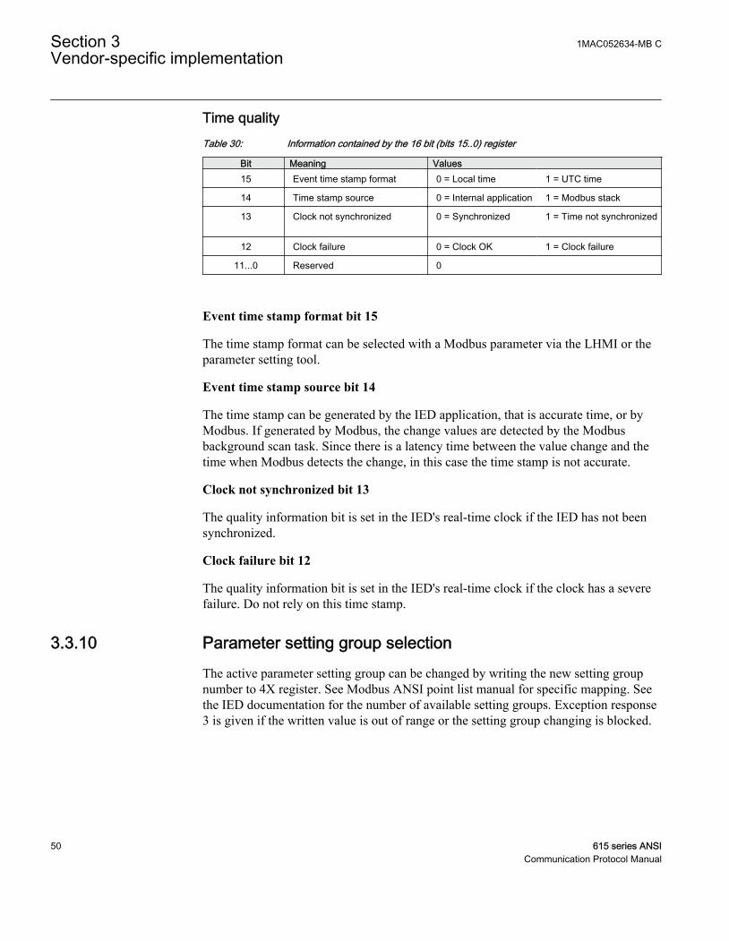
Time qualityTable 30: Information contained by the 16 bit (bits 15..0) register
Bit Meaning Values15 Event time stamp format 0 = Local time 1 = UTC time
14 Time stamp source 0 = Internal application 1 = Modbus stack
13 Clock not synchronized 0 = Synchronized
1 = Time not synchronized
12 Clock failure 0 = Clock OK 1 = Clock failure
11...0 Reserved 0
Event time stamp format bit 15
The time stamp format can be selected with a Modbus parameter via the LHMI or theparameter setting tool.
Event time stamp source bit 14
The time stamp can be generated by the IED application, that is accurate time, or byModbus. If generated by Modbus, the change values are detected by the Modbusbackground scan task. Since there is a latency time between the value change and thetime when Modbus detects the change, in this case the time stamp is not accurate.
Clock not synchronized bit 13
The quality information bit is set in the IED's real-time clock if the IED has not beensynchronized.
Clock failure bit 12
The quality information bit is set in the IED's real-time clock if the clock has a severefailure. Do not rely on this time stamp.
3.3.10 Parameter setting group selectionThe active parameter setting group can be changed by writing the new setting groupnumber to 4X register. See Modbus ANSI point list manual for specific mapping. Seethe IED documentation for the number of available setting groups. Exception response3 is given if the written value is out of range or the setting group changing is blocked.
Section 3 1MAC052634-MB CVendor-specific implementation
50 615 series ANSICommunication Protocol Manual

3.3.11 Time synchronizationThe real-time clock inside the IED runs in UTC time. However, the local time is alsoknown by the IED through the time parameter settings. With Modbus the IED time canbe viewed and set either in local time or UTC time.
Two identical time structures are available in the Modbus memory map: the IED's localtime and the internal UTC time.
Time synchronization can be given either to the local time structure or to the UTC timestructure.
The IED accepts Modbus time synchronization only if the Synch sourcesetting is set to "Modbus". The parameter can be set via the LHMI pathConfiguration/Time/Synchronization/Synch source.
3.3.11.1 Real-time clock structure
Table 31: Modbus real-time clock structure
Modbus address1) Register contents ValuesLocal Time UTC Time
4xxxx 4xxxx + 19 Control register 0...2
4xxxx + 1 4xxxx + 10 Year 2000...9999
4xxxx + 2 4xxxx + 11 Month 1...12
4xxxx + 3 4xxxx + 12 Day 1...31
4xxxx + 4 4xxxx + 13 Hour 0...23
4xxxx + 5 4xxxx + 14 Minutes 0...59
4xxxx + 6 4xxxx + 15 Seconds 0...59
4xxxx + 7 4xxxx + 16 Milliseconds 0...999
1) See Modbus ANSI point list manual for specific event record structure mapping.
3.3.11.2 Writing to real-time structures
The Modbus time synchronization can be done in several ways. Over the serialinterface, the host's synchronization write can be given with the Modbus broadcastaddress "0". Thus, all IEDs in the same serial network can be synchronized at the sametime.
1MAC052634-MB C Section 3Vendor-specific implementation
615 series ANSI 51Communication Protocol Manual
Method 1: Synchronization in one stepThe real-time clock structure registers should be written in one multiple registers presetrequest (function 16) by a Modbus TCP/IP client or by a serial interface master. TheIED's Modbus address or the Modbus broadcast address can be used with the serialinterface. If the clock is written in one step, the write value of the control register is notchecked by the IED.
Method 2: Synchronization in three steps1. The client reserves the time synchronization by writing value "1" to the control
register. If necessary, check that the reservation value is zero at the beginning. Ifthe time synchronization writing is already reserved by another client, the IEDreturns the exception response 03.
2. The client writes the time structure to the IED. This can be done in one transactionor alternatively each register can be written separately.
3. The client sets the clock by writing "2" into the control register. When the value"2" is written, the timesync registers are latched onto the IED's internal clock andthe reservation of the control register is released.
The Modbus broadcast address cannot be used with the synchronizationmethod 2.
There is an internal timeout for the clock setting. The time synchronization reservationis released if the clock is not set within two minutes. The client can abort the timesynchronization at any time by writing "0" into the control register. In that case the real-time clock is not set at all.
Other Modbus clients can read the currently running real-time clock even if the timewriting is reserved by another client.
3.3.12 Device informationThe IED's device information can be read from the Modbus registers.
If the information data are in practice shorter, the trailing registers inthe response are filled with the value "0".
The Modbus device information is based on the IED's internal IEC 61850 deviceinformation model. All internal descriptions are coded as ASCII strings. The Modbusdevice information ASCII string includes the information from the IED:
Section 3 1MAC052634-MB CVendor-specific implementation
52 615 series ANSICommunication Protocol Manual
• IED model (max. 12 characters)• IED type (max. 6 characters)• IED serial number (max. 12 characters)• IED location information (max. 34 characters)• CPU card SWand HW revision numbers• HMI card SW and HW revision numbers• Slot 0 (X130) card SW and HW revision numbers• Slot 1 (X120) card SW and HW revision numbers• Slot 2 (X110) card SW and HW revision numbers• Slot 3 (X100) card SW and HW revision numbers• Slot 4 (X000) card SW and HW revision numbers
The IED does not need to contain cards in all slots nor does a specificcard need to include a CPU. The SW revision information is simplyomitted from the information string.
3.3.12.1 ASCII character coding
Table 32: The 8 bit ASCII character coding in the Modbus registers
Modbus register ASCII characterRegister 1 High byte = ASCII character 1
Register 1 Low byte = ASCII character 2
Register 2 High byte = ASCII character 3
: :
3.3.12.2 ASCII string syntax
Syntax:C(model;type;serialNo;location;swRev;hwRev)H(swRev;hwRev)0(swRev;hwRev)1(swRev;hwRev)2(swRev;hwRev)3(swRev;hwRev)4(swRev;HwRev)• Parenthesis and semicolon ASCII characters are used as delimiters inside the string.• Section C(...) contains IED information and CPU version information.• Section H(...) contains version information of the local HMI card.• Sections 0(... ) to 4(...) contain version information of the additional HW
cards (slots 0...4).• If an additional card does not include any version information, it is signalled with
a ”-” (minus) character in the swRev field. If both swRev and hwRev aresignalled with ”-” signs, the card in question does not exist in the IED.
1MAC052634-MB C Section 3Vendor-specific implementation
615 series ANSI 53Communication Protocol Manual
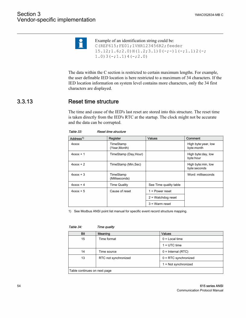
Example of an identification string could be:C(REF615;FE01;1VHR123456R2;feeder15.12;1.6;2.0)H(1.2;3.1)0(-;-)1(-;1.1)2(-;1.0)3(-;1.1)4(-;2.0)
The data within the C section is restricted to certain maximum lengths. For example,the user definable IED location is here restricted to a maximum of 34 characters. If theIED location information on system level contains more characters, only the 34 firstcharacters are displayed.
3.3.13 Reset time structureThe time and cause of the IED's last reset are stored into this structure. The reset timeis taken directly from the IED's RTC at the startup. The clock might not be accurateand the data can be corrupted.
Table 33: Reset time structure
Address1) Register Values Comment4xxxx TimeStamp
(Year,Month) High byte:year, low
byte:month
4xxxx + 1 TimeStamp (Day,Hour) High byte:day, lowbyte:hour
4xxxx + 2 TimeStamp (Min,Sec) High byte:min, lowbyte:seconds
4xxxx + 3 TimeStamp(Milliseconds)
Word: milliseconds
4xxxx + 4 Time Quality See Time quality table
4xxxx + 5 Cause of reset 1 = Power reset
2 = Watchdog reset
3 = Warm reset
1) See Modbus ANSI point list manual for specific event record structure mapping.
Table 34: Time quality
Bit Meaning Values15 Time format 0 = Local time
1 = UTC time
14 Time source 0 = Internal (RTC)
13 RTC not synchronized 0 = RTC synchronized
1 = Not synchronized
Table continues on next page
Section 3 1MAC052634-MB CVendor-specific implementation
54 615 series ANSICommunication Protocol Manual

Bit Meaning Values12 RTC Failure 0 = RTC OK
1 = RTC failure
11...0 Not used 0
1MAC052634-MB C Section 3Vendor-specific implementation
615 series ANSI 55Communication Protocol Manual

56

Section 4 Modbus parameters and diagnostics
4.1 Parameter list
The Modbus parameters can be accessed with PCM600 or via the LHMI pathConfiguration/Communication/Modbus.
Table 35: MODBUS settings
Parameter Values (Range) Unit Step Default DescriptionInOv 0=False
1=True 0=False Modbus Internal Overflow: TRUE-System
level overflow occured (indication only)
Serial port 1 0=Not in use1=COM 12=COM 2
0=Not in use COM port for Serial interface 1
Parity 1 0=none1=odd2=even
2=even Parity for Serial interface 1
Address 1 1...255 1 Modbus unit address on Serial interface 1
Link mode 1 1=RTU2=ASCII
1=RTU Modbus link mode on Serial interface 1
Start delay 1 0...20 char 4 Start frame delay in chars on Serial interface 1
End delay 1 0...20 char 3 End frame delay in chars on Serial interface 1
Serial port 2 0=Not in use1=COM 12=COM 2
0=Not in use COM port for Serial interface 2
Parity 2 0=none1=odd2=even
2=even Parity for Serial interface 2
Address 2 1...255 2 Modbus unit address on Serial interface 2
Link mode 2 1=RTU2=ASCII
1=RTU Modbus link mode on Serial interface 2
Start delay 2 0...20 4 Start frame delay in chars on Serial interface 2
End delay 2 0...20 3 End frame delay in chars on Serial interface 2
MaxTCPClients 0...5 5 Maximum number of Modbus TCP/IP clients
TCPWriteAuthority 0=No clients1=Reg. clients2=All clients
2=All clients Write authority setting for Modbus TCP/IPclients
EventID 0=Address1=UID
0=Address Event ID selection
Table continues on next page
1MAC052634-MB C Section 4Modbus parameters and diagnostics
615 series ANSI 57Communication Protocol Manual
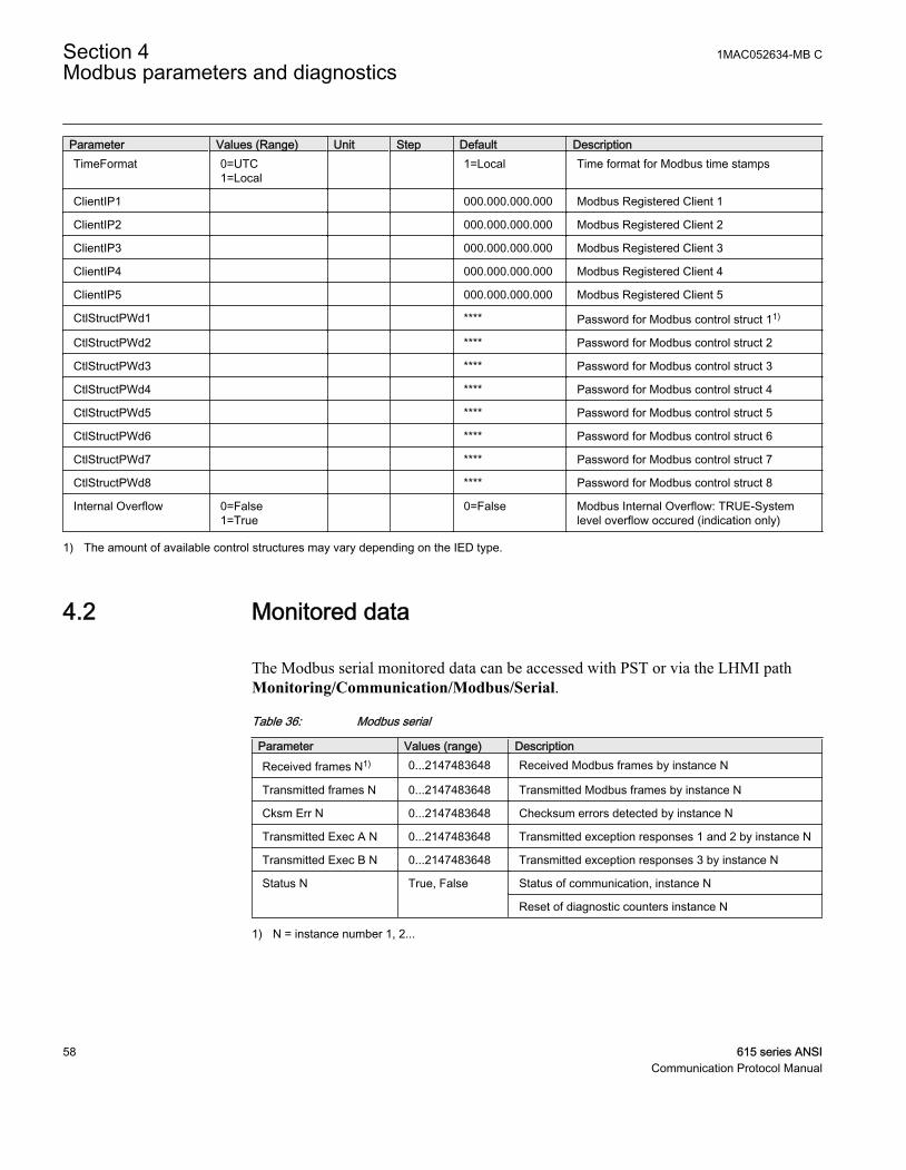
Parameter Values (Range) Unit Step Default DescriptionTimeFormat 0=UTC
1=Local 1=Local Time format for Modbus time stamps
ClientIP1 000.000.000.000 Modbus Registered Client 1
ClientIP2 000.000.000.000 Modbus Registered Client 2
ClientIP3 000.000.000.000 Modbus Registered Client 3
ClientIP4 000.000.000.000 Modbus Registered Client 4
ClientIP5 000.000.000.000 Modbus Registered Client 5
CtlStructPWd1 **** Password for Modbus control struct 11)
CtlStructPWd2 **** Password for Modbus control struct 2
CtlStructPWd3 **** Password for Modbus control struct 3
CtlStructPWd4 **** Password for Modbus control struct 4
CtlStructPWd5 **** Password for Modbus control struct 5
CtlStructPWd6 **** Password for Modbus control struct 6
CtlStructPWd7 **** Password for Modbus control struct 7
CtlStructPWd8 **** Password for Modbus control struct 8
Internal Overflow 0=False1=True
0=False Modbus Internal Overflow: TRUE-Systemlevel overflow occured (indication only)
1) The amount of available control structures may vary depending on the IED type.
4.2 Monitored data
The Modbus serial monitored data can be accessed with PST or via the LHMI pathMonitoring/Communication/Modbus/Serial.
Table 36: Modbus serial
Parameter Values (range) DescriptionReceived frames N1) 0...2147483648 Received Modbus frames by instance N
Transmitted frames N 0...2147483648 Transmitted Modbus frames by instance N
Cksm Err N 0...2147483648 Checksum errors detected by instance N
Transmitted Exec A N 0...2147483648 Transmitted exception responses 1 and 2 by instance N
Transmitted Exec B N 0...2147483648 Transmitted exception responses 3 by instance N
Status N True, False Status of communication, instance N
Reset of diagnostic counters instance N
1) N = instance number 1, 2...
Section 4 1MAC052634-MB CModbus parameters and diagnostics
58 615 series ANSICommunication Protocol Manual
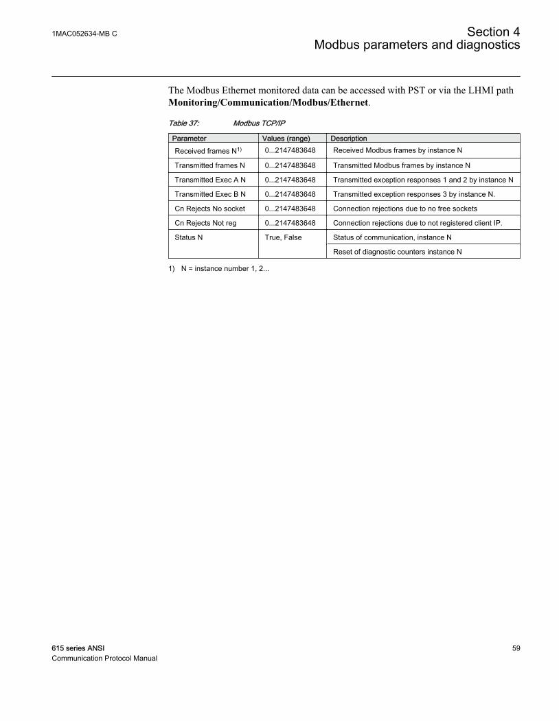
The Modbus Ethernet monitored data can be accessed with PST or via the LHMI pathMonitoring/Communication/Modbus/Ethernet.
Table 37: Modbus TCP/IP
Parameter Values (range) DescriptionReceived frames N1) 0...2147483648 Received Modbus frames by instance N
Transmitted frames N 0...2147483648 Transmitted Modbus frames by instance N
Transmitted Exec A N 0...2147483648 Transmitted exception responses 1 and 2 by instance N
Transmitted Exec B N 0...2147483648 Transmitted exception responses 3 by instance N.
Cn Rejects No socket 0...2147483648 Connection rejections due to no free sockets
Cn Rejects Not reg 0...2147483648 Connection rejections due to not registered client IP.
Status N True, False Status of communication, instance N
Reset of diagnostic counters instance N
1) N = instance number 1, 2...
1MAC052634-MB C Section 4Modbus parameters and diagnostics
615 series ANSI 59Communication Protocol Manual

60
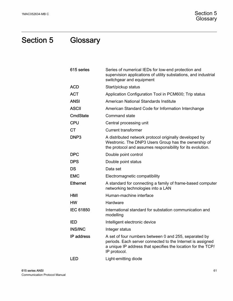
Section 5 Glossary
615 series Series of numerical IEDs for low-end protection andsupervision applications of utility substations, and industrialswitchgear and equipment
ACD Start/pickup statusACT Application Configuration Tool in PCM600; Trip statusANSI American National Standards InstituteASCII American Standard Code for Information InterchangeCmdState Command stateCPU Central processing unitCT Current transformerDNP3 A distributed network protocol originally developed by
Westronic. The DNP3 Users Group has the ownership ofthe protocol and assumes responsibility for its evolution.
DPC Double point controlDPS Double point statusDS Data setEMC Electromagnetic compatibilityEthernet A standard for connecting a family of frame-based computer
networking technologies into a LANHMI Human-machine interfaceHW HardwareIEC 61850 International standard for substation communication and
modellingIED Intelligent electronic deviceINS/INC Integer statusIP address A set of four numbers between 0 and 255, separated by
periods. Each server connected to the Internet is assigneda unique IP address that specifies the location for the TCP/IP protocol.
LED Light-emitting diode
1MAC052634-MB C Section 5Glossary
615 series ANSI 61Communication Protocol Manual
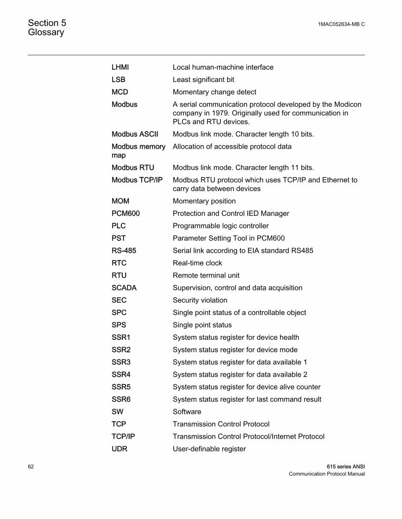
LHMI Local human-machine interfaceLSB Least significant bitMCD Momentary change detectModbus A serial communication protocol developed by the Modicon
company in 1979. Originally used for communication inPLCs and RTU devices.
Modbus ASCII Modbus link mode. Character length 10 bits.Modbus memorymap
Allocation of accessible protocol data
Modbus RTU Modbus link mode. Character length 11 bits.Modbus TCP/IP Modbus RTU protocol which uses TCP/IP and Ethernet to
carry data between devicesMOM Momentary positionPCM600 Protection and Control IED ManagerPLC Programmable logic controllerPST Parameter Setting Tool in PCM600RS-485 Serial link according to EIA standard RS485RTC Real-time clockRTU Remote terminal unitSCADA Supervision, control and data acquisitionSEC Security violationSPC Single point status of a controllable objectSPS Single point statusSSR1 System status register for device healthSSR2 System status register for device modeSSR3 System status register for data available 1SSR4 System status register for data available 2SSR5 System status register for device alive counterSSR6 System status register for last command resultSW SoftwareTCP Transmission Control ProtocolTCP/IP Transmission Control Protocol/Internet ProtocolUDR User-definable register
Section 5 1MAC052634-MB CGlossary
62 615 series ANSICommunication Protocol Manual

UID Unique IDUTC Coordinated universal time
1MAC052634-MB C Section 5Glossary
615 series ANSI 63Communication Protocol Manual

64

65

Contact us
ABB Inc.Distribution Automation4300 Coral Ridge DriveCoral Springs, FL 33065, USAPhone +1 (800) 523-2620Phone +1 954-752-6700Fax +1 954 345-5329
www.abb.com/substationautomation
1MA
C05
2634
-MB
C©
Cop
yrig
ht 2
010
AB
B. A
ll rig
hts
rese
rved
.