6. gprs protocol structure for data transfer and 7. gprs...
TRANSCRIPT
GPRS – Transmission Planes Page 63
Rohde & Schwarz Trainingscenter, V 2.0
6. GPRS Protocol Structure for Data Transfer and7. GPRS-Protocol Structure for Signalling
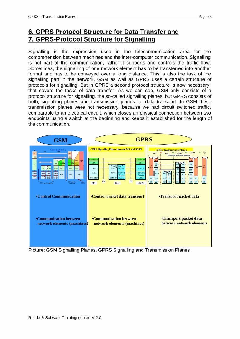
Signalling is the expression used in the telecommunication area for thecomprehension between machines and the inter-computer communication. Signallingis not part of the communication, rather it supports and controls the traffic flow.Sometimes, the signalling of one network element has to be transferred into anotherformat and has to be conveyed over a long distance. This is also the task of thesignalling part in the network. GSM as well as GPRS uses a certain structure ofprotocols for signalling. But in GPRS a second protocol structure is now necessary,that covers the tasks of data transfer. As we can see, GSM only consists of aprotocol structure for signalling, the so-called signalling planes, but GPRS consists ofboth, signalling planes and transmission planes for data transport. In GSM thesetransmission planes were not necessary, because we had circuit switched traffic,comparable to an electrical circuit, which closes an physical connection between twoendpoints using a switch at the beginning and keeps it established for the length ofthe communication.
Picture: GSM Signalling Planes, GPRS Signalling and Transmission Planes
•Control Communication •Control packet data transport •Transport packet data
GSM GPRS
GPRS Transmission Planes
MAC
GSMRF
RLC
LLC
SNDCP
IP/X.25
MAC
GSMR F
RLC
FR
L1bis
BSSG P
Relay
FR
L1bis
BSSGP
LLC
S N DCP
L1
L2 L2
IP IP
UDP /TCP
UDP /TCP
GTP GTPRelay
IP/X.25
MS BSS SGSN GGSNUm Gb Gn Gi
L1
L2‘
IP/ X.25
L1‘
Relay
L2 ‘
IP/ X.25
L1 ‘
L2‘
IP/ X.25
L1‘
Relay
Application/ Higher level protocols
Rou-ter
GSM-Signalling
LAPDm
TDMAFDMA
LAPDm
G.703G.705G.732
LAPD
G.703G.705G.732
LAPDMTP’
RR
M M
CM
BTSM SCCP
MTP’ MTP
SCCPSCCP
DTAP
MM
CM
TCAP
ISDNUP
TDMAFDMA
RR’
DTAPRRBSSMAP
BSSMAP
BTSM
MAP
Um Abis A
B,C,E,FGSM specific sigallingISDN specific
signalling
MSBTS BSC
MSC
BSSGP
GMM/SM
LLC
RLC
MAC
GSM RF
GMM/SM
LLC
BSSGP
L1bis
Um Gb MS BSS SGSN
Network Service
RLC
MAC
GSM RF L1bis
Network Service
Relay
GPRS Signalling Planes between MS and SGSN
•Communication between network elements (machines)
•Transport packet databetween network elements
•Communication between network elements (machines)

GPRS – Transmission Planes Page 64
Rohde & Schwarz Trainingscenter, V 2.0
6. GPRS-Transmission Planes
In contrast to the circuit switched GSM, GPRS deals with packet data. This requires acomplete new protocol structure that is able to convey packet data units. Some ofthese protocols are also used in existing packet data networks.GPRS carries out the connection between internet and mobile communication, itprovides a direct link between the mobile communication network and an externalpacket data network. Now there is the task to transfer the packet data networkprotocols and to adapt them to the transport over a radio communication network. Inpractice, this means, the mobile communication network has to learn the internetprotocol, IP.
The first picture clarifies this aspect further. The user of the GPRS network only seesthe interface or connection points between Mobile Station and the packet datanetwork. In the first step, we consider the complete transmission plane structure,without any details. The complete GPRS network is seen as a black box thatconnects the mobile station to the packet data network.
Picture: Connection of a Mobile Station to an external packet data network
Gi -Interface
Air-Interface
GPRS-Network
Mobile Station
Packet Data Network

GPRS – Transmission Planes Page 65
Rohde & Schwarz Trainingscenter, V 2.0
The next contemplation step illuminates the GPRS-network a little bit more in detail.Some protocols have to be defined for the communication between networkelements. GPRS distinguishes between the use of transmission protocols betweennetwork nodes and transmission protocols between network nodes over the airinterface. Also we can see a clear separation between lower layer protocols for theair interface and protocols between network elements, which are independent of thelower layers, e.g. the air interface protocols. The presented picture shows this effect,the higher layer protocols are not influenced by the lower layer Base StationSubsystem BSS.
Picture: Symbolic Protocol Structure in GPRS
Protocol Groups of the symbolic protocol structure:
1. Node to node protocols between 2 network nodes. Defined for the datatransport and signalling between 2 network nodes.
2. Network transmitting protocols form the interface below the application aswell as the interface between the external network and the MobileStation.
3. Application based protocols defining the interface between the applicationat the subscriber side and the external network. This could be forexample the Internet Protocol used between a network browser on amobile desktop and the database on an internet server. These protocolsare out of the scope of the GPRS Specifications.
4. Switching system protocols between the mobile station and the switchingnode control the data transfer between the network switching node andthe user terminal. This layer is the lowest switching layer in the switchingsubsystem.
5. Protocols for the air interface. These protocols ensure the data transportover the air interface and through this the mobility of the subscriber.
Application based protocol
Network transmitting protocol
Switching System protocols
Node to node protocols
GGSNSGSNBSSMS

GPRS – Transmission Planes Page 66
Rohde & Schwarz Trainingscenter, V 2.0
This symbolic protocol structure can be regained in the next picture, describing thewhole transmission planes used in GPRS:
Picture: GPRS Transmission Planes
GPRS Transmission Planes
MAC
GSMRF
RLC
LLC
SNDCP
IP/X.25
MAC
GSMRF
RLC
FR
L1bis
BSSGP
Relay
FR
L1bis
BSSGP
LLC
SNDCP
L1
L2 L2
IP IP
UDP /TCP
UDP /TCP
GTP GTPRelay
IP/ X.25
MS BSS SGSN GGSNUm Gb Gn Gi
L1
BSSGP: BSS GPRS Protocol LLC: Logical Link Control SNDCP : SubNetwork DependentFR: Frame Relayl MAC: Medium Access Control Convergence ProtocolGTP: GPRS Tunnelling Protocol RLC: Radio Link Control TCP: Transmission Control Protocol IP: Internet Protocol UDP: User Datagram Protocol
L2‘
IP/ X.25
L1‘
Relay
L2‘
IP/ X.25
L1‘
L2‘
IP/ X.25
L1‘
Relay
Application/ Higher level protocols
Rou-ter

GPRS – Transmission Planes Page 67
Rohde & Schwarz Trainingscenter, V 2.0
6.1. General Tasks of Protocols
Before the detailed contemplation of protocols, some general tasks shall bepresented.
Protocols are ensuring the interoperability between certain protocol layer in the OSI-Modell and between some switching nodes in the NSS. Below some of the generaltasks of protocols are described, though for the moment not concerning the concreterealisation:
• Ciphering is the establishment of a secure point-to-point connection that protectsagainst eavesdropping. One possibility to realise this feature is the ciphering orcombination of the raw data with a secret key, at the sending and receiving side.
• Segmentation refers to the segmentation of data in smaller units to be adapted tothe size of the transportation way.
• Concatenation is the opposite of segmentation at the receiver side. The data isconcatenated to the original size. Concatenation means reassemble in the rightorder.
• Error Correction: This feature protects data against possible errors on thetransmitting channel. The receiver detects errors and corrects them. Hereby wehave to distinguish between error detection and error correction.
• Flow Control establishes a communication between transmitting peer andreceiving peer. This enables the receiver to notify the sending side how manydata packets can be transmitted until the next message. Due to this feature thedata flow between receiver and transmitter can be controlled.
• Multiplexing means the distributing of the data on to different physical channels.
• Routing is the combination of the transmitting data with an address information ofthe destination.
• Encapsulation is the combination of the transported data with the information oflower layer protocols.
• Connection oriented is the referencing of the transmitted packets with asequence number. Thus they can be delivered in the right order.
GPRS – Transmission Planes Page 68
Rohde & Schwarz Trainingscenter, V 2.0
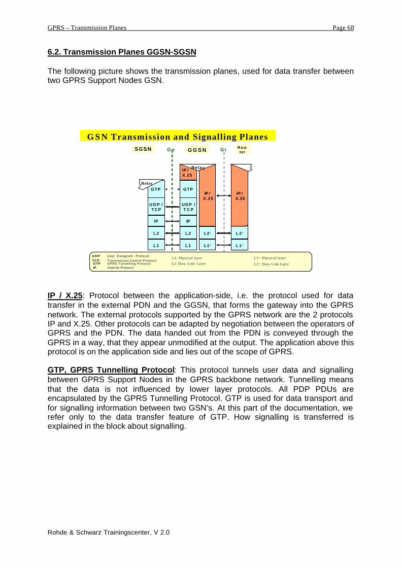
6.2. Transmission Planes GGSN-SGSN
The following picture shows the transmission planes, used for data transfer betweentwo GPRS Support Nodes GSN.
G S N Transmission and Signalling Planes
L 1
L 2 L 2
IP IP
U D P /TCP
U D P /T C P
GTP GTP
IP / X.25
SGSN G G S NG n G i
L 1
GTP: GPRS Tunnel l ing Protocol T C P : Transmission Control Protocol
IP : Internet Protocol
U D P: User Datagram Protocol
L2‘
IP / X .25
L1‘
Relay
L 2 ‘
IP / X.25
L 1 ‘
Rou-ter
Relay
L1: Physical layer
L2: Data Link Layer
L1‘ : Physical layer
L2‘ : Data Link Layer
IP / X.25: Protocol between the application-side, i.e. the protocol used for datatransfer in the external PDN and the GGSN, that forms the gateway into the GPRSnetwork. The external protocols supported by the GPRS network are the 2 protocolsIP and X.25. Other protocols can be adapted by negotiation between the operators ofGPRS and the PDN. The data handed out from the PDN is conveyed through theGPRS in a way, that they appear unmodified at the output. The application above thisprotocol is on the application side and lies out of the scope of GPRS.
GTP, GPRS Tunnelling Protocol: This protocol tunnels user data and signallingbetween GPRS Support Nodes in the GPRS backbone network. Tunnelling meansthat the data is not influenced by lower layer protocols. All PDP PDUs areencapsulated by the GPRS Tunnelling Protocol. GTP is used for data transport andfor signalling information between two GSN’s. At this part of the documentation, werefer only to the data transfer feature of GTP. How signalling is transferred isexplained in the block about signalling.

GPRS – Transmission Planes Page 69
Rohde & Schwarz Trainingscenter, V 2.0
In the case of data transport, GTP makes use of the tunnelling mechanism, whichtransports data between two endpoints. Which way the data packets are conveyed isdepending from the application. This determines for example reliable data transfer ornot.
Picture: Transmission Plane – Protocol structure
The GTP protocol is embedded between the protocol at the application side and thepath-protocol at the transport side. Incoming data units are encapsulated into the 20octets long protocol header as presented in the picture below. The different fieldshave different contents, depending if the tunnel, built with the GTP conveys data orsignalling information. The GTP header structure is the following:
Bits
Octets 8 7 6 5 4 3 2 1
1 Version PT Spare ‘ 1 1 1 ‘ SNN
2 Message Type
3-4 Length
5-6 Sequence Number
7-8 Flow Label
9 SNDCP N-PDULLC Number
10 Spare ‘ 1 1 1 1 1 1 1 1 ‘
11 Spare ‘ 1 1 1 1 1 1 1 1 ‘
12 Spare ‘ 1 1 1 1 1 1 1 1 ‘
13-20 TID
Picture: GTP-Header Structure
GSN Gn, Gp GSN
End user prot.
GTP
Path Protocol
End user prot.
GTP
Path Protocol

GPRS – Transmission Planes Page 70
Rohde & Schwarz Trainingscenter, V 2.0
Important for data transfer are the following fields in the protocol header:
Message Type: Indicates the type of the GTP message. In our case at the moment,we do not transmit signalling commands from one GSN to the other, we wantto convey user data. Message Type = 255 (decimal) indicates, that thecontent of the data unit is no command but user data.
Sequence number: The sequence number is a transaction identity to reference thetunnelled data unit. This is an increasing sequence number.
TID: Tunnel Identifier, points out the used tunnel for data transport. It is used todistinguish for example between MM messages and PDP context data. TheTID consists of the IMSI-number and the NSAPI, pointing out the accesspoint of the current application. Furthermore, it describes the two points ofthe communication: Subscriber and access point to the PDN.
Transmission Control Protocol, TCP and User Datagram Protocol, UDP:
The two protocols, Transmission Control Protocol and User Datagram Protocol areused to convey data between 2 network nodes. TCP guarantees a reliable link, UDPdoes not. Features of TCP are the in-order-delivery of the transmitted data and theprovision of a reliable link due to acknowledged data transfer. Errors during thetransmission are corrected.
Picture: Use of TCP or UDP
TCP TCP
UDP UDP
GSN
GSN GSN
GSN
Transmitting GSN Receiving GSN
Reliable Link•In-order delivery•Acknowledged transfer
Non-Reliable Link•No In-order delivery guaranteed•No Acknowledged transfer

GPRS – Transmission Planes Page 71
Rohde & Schwarz Trainingscenter, V 2.0
Transmission Control Protocol, TCP:The Transmission Control Protocol, TCP delivers the transmitted data packets in theright order to the receiver and guarantees a reliable link due to acknowledged datatransfer. Errors are corrected with retransmission.
Features of TCP:
• Layered hierarchy: TCP is defined for the use in a Layer-Model, it providesinterfaces to lower as well as higher protocol layers to communicate to them.
• Connection-oriented: TCP is connection-oriented. The incoming data units arecombined with a reference or sequence number before transmitting. In advance ofthe data transmission, a connection to the receiver side is established.
• Basic Data Transfer: TCP provides data transfer, is able to segment a continuousdata stream and to hand it out to lower layer protocols. These lower layerprotocols, e.g. the Internet Protocol, IP are ordered to transmit the received datato the IP-address peer of the receiver.
• Reliability: The TCP must recover data that is damaged, lost, duplicated ordelivered out of order by the internet communication system. This is achieved byassigning a sequence number to each octet transmitted, and requiring a positiveacknowledgement (ACK) from the receiving TCP. If the ACK is not receivedwithin a timeout interval, the data is retransmitted. At the receiver, the sequencenumbers are used to correctly order segments that may be received out of orderand to eliminate duplicates. Damage is handled by adding a checksum to eachsegment transmitted, checking it at the receiver, and discarding damagedsegments. This requires the buffering of the outgoing data until the receipt isconfirmed.
• Flow Control: TCP provides a means for the receiver to govern the amount ofdata sent by the sender. This is achieved by returning a "window" with every ACKindicating a range of acceptable sequence numbers beyond the last segmentsuccessfully received. The window indicates an allowed number of octets that thesender may transmit before receiving further permission.
• Multiplexing, To allow for many processes within a single Host to use TCPcommunication facilities simultaneously, the TCP provides a set of addresses orports within each host.
• Connections: The reliability and flow control mechanisms described above requirethat TCPs initialize and maintain certain status information for each data stream.The combination of this information, including sockets, sequence numbers, andwindow sizes, is called a connection. Each connection is uniquely specified by apair of sockets identifying its two sides.
• Precedence and Security: The users of TCP may indicate the security andprecedence of their communication.

GPRS – Transmission Planes Page 72
Rohde & Schwarz Trainingscenter, V 2.0
The basic model of operation:
Processes transmit data by calling on the TCP and passing buffers of data asarguments. The TCP packages the data from these buffers into segments and callson the internet module to transmit each segment to the destination TCP. Thereceiving TCP places the data from a segment into the receiving user's buffer andnotifies the receiving user. The TCPs include control information in the segmentsthat they use to ensure reliable ordered data transmission. The connection isterminated after command of the initiating side. The structure of such a TCP headeris the following:
Picture: TCP-Header Format
Description of the individual fields in the TCP-Header format:
Source Port (16 Bits): Identifies the source port number of the application
Destination Port (16 Bits): The destination port number of the receiving peer
Sequence Number (32 Bit): The sequence number of the first data octet in thissegment to ensure a in-order-delivery.
Acknowledgement number (32 Bit): If the ACK control bit is set this field contains thevalue of the next sequence number the sender of the segment is expecting toreceive. Once a connection is established this is always sent. If a datasegment has been received correctly, the receiver indicates with this numbera higher value to order the next segment. The transmitter side considers therequest of a higher sequence number as confirmation of the lower sequencenumbers.
Data Offset (4Bit): The number of 32 words in the TCP Header. This indicates wheredata begins. Please note that the option field can have a various length.
Reserved (6Bits): Reserved for future use. Must be zero.
Source Port Destination Port
Sequence Number
Acknowledgement Number
Checksum Urgent Pointer
Window SizeDataoffse
Reserved
Data
Options / PaddingU
RG
AC
KPSHR
STSY
N
FIN
GPRS – Transmission Planes Page 73
Rohde & Schwarz Trainingscenter, V 2.0
Control Bits:
URG: Urgent Pointer field significant
ACK: Acknowledgement Flag significant
PSH: Push-Function to obtain the immediate delivery of the received segment
to the higher layer, without buffering.
RST: Reset, to terminate the connection due to an error.
SYN: Synchronization. To synchronise sequence numbers. The initiating side
informs the receiving side about the establishment of a connection.
FIN: Final Flag, no more data. The receiver acknowledges also with the set
FIN-bit and terminates the connection.
Window Size (16Bit): The number of data octets beginning with the one indicated inthe acknowledgment field which the sender of this segment is willing to accept.Avoids an overflow of the incoming-buffer.
Checksum (16Bit): Value of the calculated checksum. Necessary for error detection.
Urgent Pointer (16 Bit): This field communicates the current value of the urgentpointer as a positive offset from the sequence number in this segment. The urgentpointer points to the sequence number of the octet following the urgent data. Thisfield is only interpreted in segments with the URG control bit set.
Options: Variable length to enable further options. Padding is the process of filling-upwith zero’s until the total length of 32 bits is reached.
User Datagram Protocol, UDP:
This protocol provides a procedure for application programs to send messages toother programs with a minimum of protocol mechanism. The protocol is transactionoriented, and delivery and duplicate protection are not guaranteed. Applicationsrequiring ordered reliable delivery of streams of data should use the TransmissionControl Protocol (TCP). Advantage is the higher speed in data transfer, becausethere will be no acknowledgement. At first glance it seems peculiar that the layer 4uses a connectionless, non-reliable protocol. The Internet Protocol at layer 3 hasexactly the same features. The reason can be found in the ability to hand out, ordeliver received data to various application layers. IP is not able to hand out receiveddata segments to such corresponding higher layers. This is the main task. Due tomultiplexing, various application layers can use the services of UDP and access thesame physical transmitting channel.
GPRS – Transmission Planes Page 74
Rohde & Schwarz Trainingscenter, V 2.0
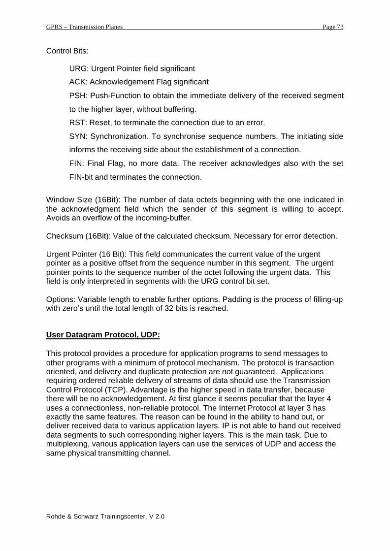
Picture: UDP-Datagramm Format
Source Port (16 Bit): Identifies the source port, or the initiating peer.
Destination Port (16 Bit): Identifies the receiver and has a meaning within the context
of a particular internet destination address.
Length (16Bit): Is the length in octets of this user datagram including this header and
the data
Checksum (16 Bit): Checksum of the data field and the protocol-header.
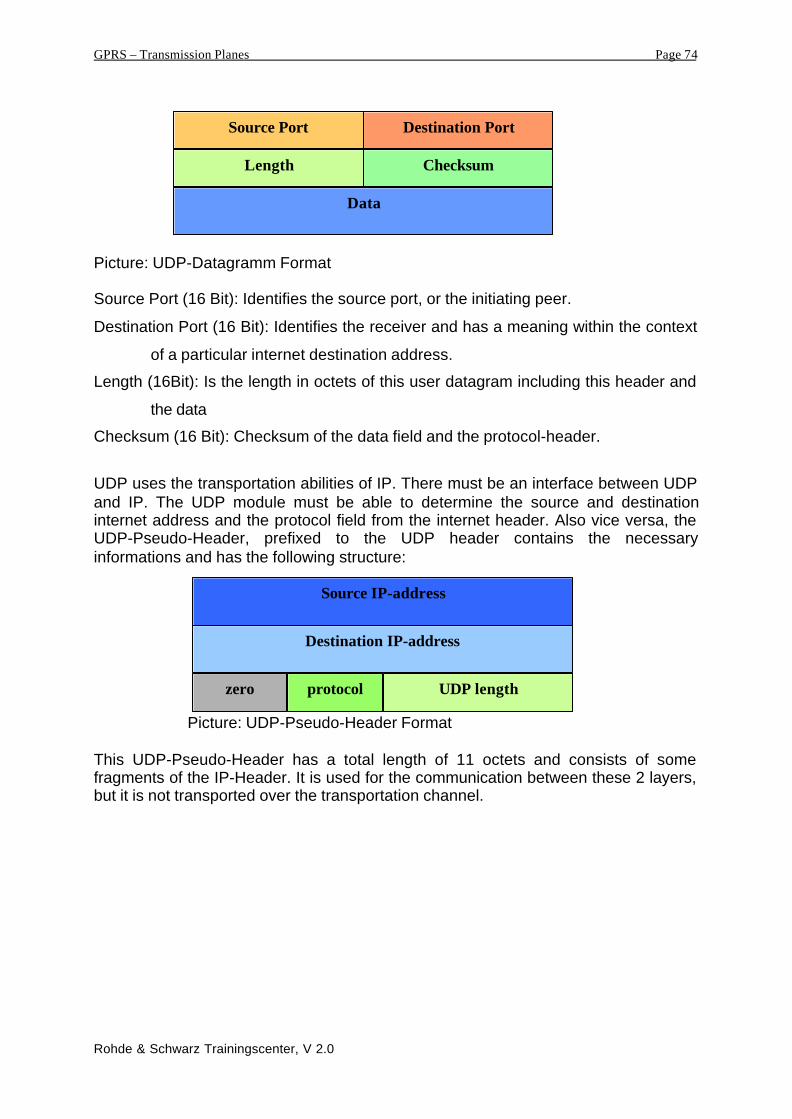
UDP uses the transportation abilities of IP. There must be an interface between UDPand IP. The UDP module must be able to determine the source and destinationinternet address and the protocol field from the internet header. Also vice versa, theUDP-Pseudo-Header, prefixed to the UDP header contains the necessaryinformations and has the following structure:
Picture: UDP-Pseudo-Header Format
This UDP-Pseudo-Header has a total length of 11 octets and consists of somefragments of the IP-Header. It is used for the communication between these 2 layers,but it is not transported over the transportation channel.
Source IP-address
Destination IP-address
UDP lengthzero protocol
Data
Length Checksum
Source Port Destination Port

GPRS – Transmission Planes Page 75
Rohde & Schwarz Trainingscenter, V 2.0
Internet Protocol, IP:
The Internet Protocol, IP is the GPRS-Backbone-Protocol used to convey bothsignalling information and user data. In general, IP fragments and addresses the dataand transports it from transmitter to receiver side, but does not provide a reliable link.In GPRS we find a transportation IP over IP, user data, identified with an IP addressis conveyed with the IP protocol to the correct GSN, identified by the lower layer IPaddress. Signalling between original-GSN and destination-GSN is also transportedwith the Internet Protocol.
Characteristics of the Internet Protocol:
• Addressing: We have to distinguish between name, address and route: „A nameindicates what we seek. An address indicates where it is. A route indicates how toget there“ [RFC791]. IP needs addresses, but the translation of names intoaddresses has to be performed by higher layer protocols. Each packet data unit iscombined with a header field that contains the destination address and is thebasis for routing. The routing table is a list of all network nodes that have to bepassed between transmitter and receiver. IPv4 has an address field length of 32bit, in a further step of realisation, GPRS will use the Internet Protocol IPv6, withan address field length of 128 bit. There is no restriction concerning the amount ofInterfaces to the IP layer and to the amount of several logical addresses.
• Fragmentation
Fragmentation of an internet datagram is necessary when it originates in a localnet that allows a large packet size and must traverse a local net that limitspackets to a smaller size to reach its destination. Fragmentation, transmissionand reassembly across a local network which is invisible to the internet protocolmodule is called intranet fragmentation and may be used. The following picturegives a short example of such a fragmentation procedure:
• Error protection: Internet Protocol only provides an check sum field that protectsthe header field. There is no acknowledgement or retransmission of data. Thishas to be guaranteed by higher protocol layers, e.g. TCP.
• Options-field: Due to the option field, some optional information, supporting thefunctions of routing, diagnosting and statistic counts can be exchanged.
•
I P -H e a d e r
I P -H e a d e r
I P -H e a d e r
D a t a
D a t a D a t a
L a r g e p a c k e t s i z e
S m a l l p a c k e t s i z e S m a l l p a c k e t s i z e
r e s t

GPRS – Transmission Planes Page 76
Rohde & Schwarz Trainingscenter, V 2.0
IP-Datagram
The data transportation unit in IP is the so-called Datagram. Its structure is normallydepicted in 32-bit-blocks, including a header field of 20 octets and an option-field, upto 40 octets. The data is added to the header field up to a total length of 64 Kbyte.The data field contains the protocol headers of the higher layer protocols that areencapsulated in the IP field.
Picture: IP-Header Structure: IPv4-Header
The meaning of the single fields is:
Version (4Bit): This is the actual version number of the Internet Protocol. Currently itis IPv4 but in the future this field will indicate IPv6.
IHL, Internet Header Lenght (4Bit): Indicates the total header length, including thevariable option field.
Type of Service (8Bit): Description of the service parameters of the requested qualityof service, e.g. priority level, throughput, reliability and delay.
Packet Lenght (16 Bit): Total length of the datagram, including header and data field.
Identification (16 Bit): This field is used for identification and numbering of fragmentedpacket data units. This is not the same meaning then the sequence numberin the TCP layer, but it is used if the IP-layer has to segment thetransportation data into smaller units on request from an intermediatenetwork. The receiver side can reassemble or concatenate the units in theright order.
version IHL Type of Service Packet Length
Identification Flags Fragment Offset
Time to Live Protocol Header Checksum
Source IP Address
Destination IP Address
Options / Padding
Data

GPRS – Transmission Planes Page 77
Rohde & Schwarz Trainingscenter, V 2.0
Flags (3Bit): Controlling of the fragmentation, e.g. if a packet data unit is not to besegmented.
Fragment Offset (13 Bit): Indicates the position of the datagram before thefragmentation. Is needed at the concatenation.
Time to Live (8Bit): To avoid data units that could not be delivered, running forever inthe network, each packet header has a countdown field, that is decrementedat each hop. If the countdown field is 0, the packet data unit is discarded.
Protocol (8 Bit): Identifies the higher layer protocol. In GPRS the identifier 17 for UDPor 6 for TCP are used.
Header Checksum: A checksum on the header only. Since some header fieldschange (e.g., time to live), this is recomputed and verified at each point that theinternet header is processed.
Source IP-Address (32Bit): The IP-Adress of the sending network element. In future,there will be the transition of IPv4 to IPv6 and many more networkcomponents can be identified.
Destination IP-Address (32Bit): IP-Adress of the receiver element, or the destination.
Options: This optional field allows the communication of additional controlinformation, for example security information or additional routing informaiton.
Padding: With the aid of this padding-field, consisting of only filling bits, the IP-headeris replenished up to a 32-Bit Block.
The IP Protocol Layer contains during the transportation some information about thenext hop or the next switching node, if the absolute destination is not achieved.

GPRS – Transmission Planes Page 78
Rohde & Schwarz Trainingscenter, V 2.0
Picture: Comparison between Pv6 Header (above) and IPv4 – Header (below)
GPRS uses in the first step the Internet Protocol IPv4 and will move in a furtherdevelopment step to the IPv6 or IPnG (IP next Generation). Advantage of the IPv6 isthe much longer address field and additional possibilities to transmit someinformation about quality of service profiles, due to the „traffic class“ field.
L2:Data Link Layer Protocols, e.g. Frame Relay or ATM.
L1:Physical Layer Protocols, e.g. PCM30 or STM 1-4 connections.
The two Layers, L2 and L1 are not specified in GPRS. It is the scope of the operator-realisation.
L2‘:Data Link Layer Protocol between 2 GPRS-PLMN‘s.
L1‘:Physical Layer Protocol between 2 GPRS-PLMN‘s.
Same as L1 and L2, the two layers L1‘ and L2‘ are not specified and aer underlyingthe discussion between two network operators.
GPRS – Transmission Planes Page 79
Rohde & Schwarz Trainingscenter, V 2.0
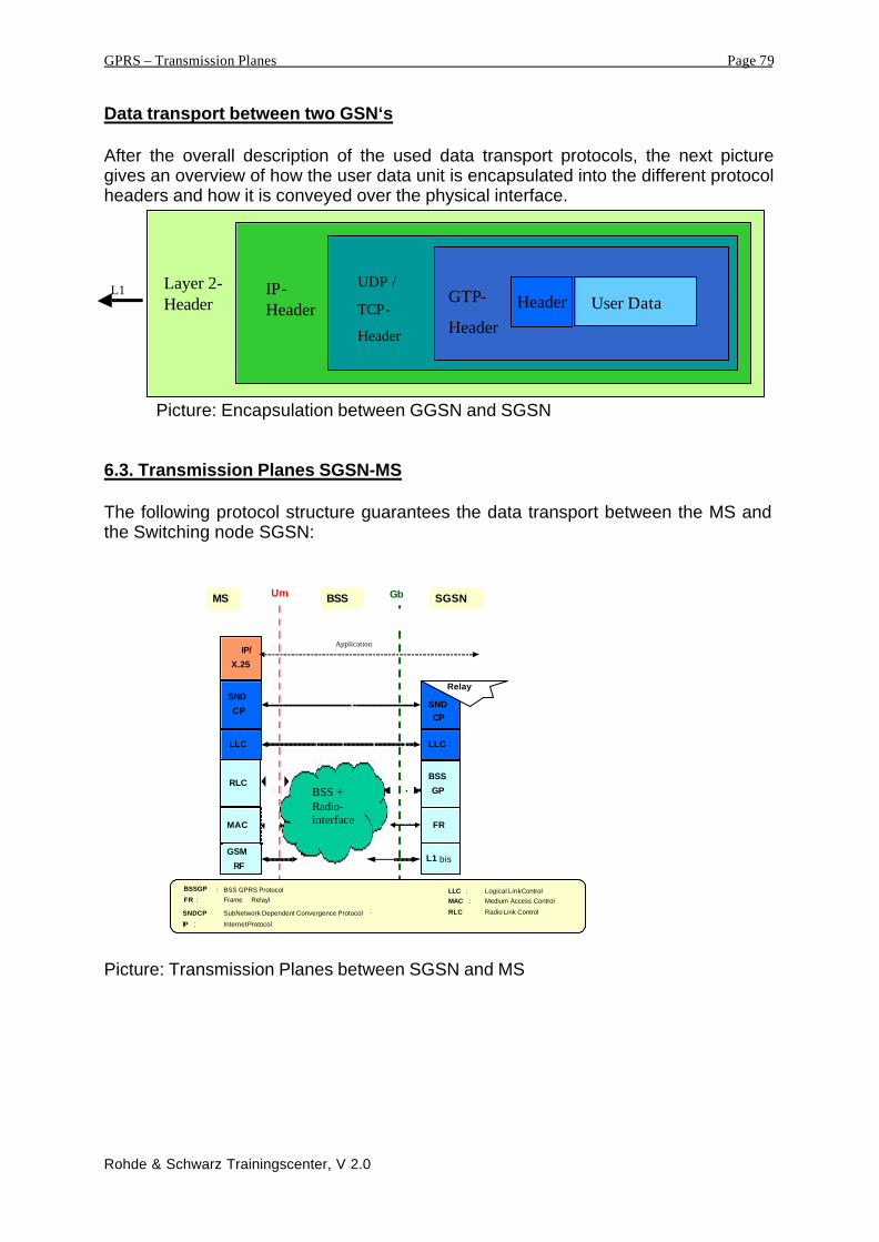
Data transport between two GSN‘s
After the overall description of the used data transport protocols, the next picturegives an overview of how the user data unit is encapsulated into the different protocolheaders and how it is conveyed over the physical interface.
Picture: Encapsulation between GGSN and SGSN
6.3. Transmission Planes SGSN-MS
The following protocol structure guarantees the data transport between the MS andthe Switching node SGSN:
MAC
GSM
RF
RLC
LLC
SND
CP
IP/
X.25
FR
L1 bis
BSS
GP
LLC
SNDCP
Relay
MS BSS SGSNUm Gb
BSSGP : BSS GPRS Protocol LLC : Logical Link Control
SNDCP
SubNetwork Dependent Convergence Protocol
FR : Frame Relayl MAC : Medium Access Control RLC: Radio Link Control
IP : Internet Protocol
BSS +Radio-interface
Application
Picture: Transmission Planes between SGSN and MS
Header User DataGTP-
Header
UDP /
TCP-
Header
L1 IP-Header
Layer 2-Header

GPRS – Transmission Planes Page 80
Rohde & Schwarz Trainingscenter, V 2.0
SNDCP, Subnetwork Dependent Convergence Protocol:
The SNDCP-Protocol maps the characteristics of the network onto the characteristicsof the underlying network layers. Its main task is the transparent data transport ofpacket data unit, independent from the radio subsystem, BSS. Application data (inthat case, the application is the switching network) has to be conveyed independentfrom the lower layer protocols, they have to be tunnelled through the network. Theconsequence will be an easy change in the protocol structure. The SNDCP forms theinterface between the backbone-network, the NSS and the Base Station Subsystem,BSS. The result will be a gateway between protocols of the BSS-side and the NSS-side.
RLC
MAC
Relay
NetworkService
GTP
Application
IP / X.25
SNDCP
LLC
RLC
MAC
GSM RF
SNDCP
LLC
BSSGP
L1bisGSM RF
BSSGP
L1bis
Relay
L2
L1
IP
Um GbMS BSS SGSN
NetworkService
UDP /TCP
Picture: GPRS-Protokollstructure, Position of the SNDCP
The SNDCP-Protocol has its position above the LLC-layer, the data transport layerand above the Session Management Layer, that is responsible for the distribution ofidentifiers and names, e.g. the allocation of the TLLI. Above the SNDCP-Layer wefind the Packet Data Protocol on the MS side and the relay function on the SGSNside, which converts the data into the GPRS Tunnelling Protocol, GTP. The followingpicture explains the service primitives used for communication between the SNDCPlayer and other layers. It illustrates the service access points through which theprimitives are carried out.

GPRS – Transmission Planes Page 81
Rohde & Schwarz Trainingscenter, V 2.0
SessionManagement entity
LL5 LL9LL3 LL11
5 6
PDPor
Relay
SNDCP entity
LLC layer
SNDCP users
SNDCPmanagement
entity
PDPor
Relay
15 NSAPI
SAPI
. . .
SNDCP layer
SNSM
ControlEntity
Picture: Service Access Points between SNDCP and surrounding protocol layers
Functions of the SNDCP-Protocol:
Compression: For reasons of increased efficiency of the transmitting of data overthe air interface, which forms the bottleneck in GPRS, the data is compressedbefore transmitting. Thereby an algorithm is used which compresses theredundant blocks of the data. This kind of compression is reversible. It can beundone at the receiver side. We have to distinguish between the compressionof protocol header information and compression of user data units. Themethod of compression depends on the used transmission and networkprotocols and does not depend on the PDP-context. Parameters of thecompression function are negotiated between the SGSN and the MS.

GPRS – Transmission Planes Page 82
Rohde & Schwarz Trainingscenter, V 2.0
LL 5 LL 9LL 3 LL 11
5 6
PDPor
Relay
LLC layer entity
PDPor
Relay
15NSAPI
SAPI
. . .
SNDCP layer
Protocolcompr.
7
PDPor
Relay
Datacompr.
Datacompr.
8
PDPor
Relay
Protocolcompr.
Datacompr.
Protocolcompr.
SNDCP users
Picture: An example for the usage of NSAPIs, SNDCP functions, and SAPIs
Segmentation and Concatenation: The SNDCP-Layer segments the data units insmaller units which size can be handled by the lower layer protocols. Thereceiver side concatenates or reassembles them in the right order to result inthe original unit.
Multiplexing: Multiplexing is the simultaneous use of one single transmitting channelby different N-PDU’s containing different PDP’s. Example: If a user hasactivated more PDP-contextes, i.e. more applications are active, e.g.transmitting electronic mail and downloading of a website. Each of theseapplications is combined with a PDP-context, an identifier of the certainapplication. But as transmission channel, we have only the transmissionplanes given by the protocol layer LLC. Now it is task of the SNDCP-layer tomultiplex the N-PDU’s of these different applications to only one transmittingchannel, the LLC-layer.

GPRS – Transmission Planes Page 83
Rohde & Schwarz Trainingscenter, V 2.0
SNDCP
Packet DataProtocol
LLC
NSAPI
N-PDU
SAPISN-PDU
Packet DataProtocol
Packet DataProtocol
. . .
Picture: Multiplexing by the SNDCP-Layer
SNDCP uses the transmitting services of the LLC-layer. The SNDCP-layer itselfsdoes not perform any error correction or error detection. There does not exist a fixedstructure of the primitives, exchanged between SNDCP and LLC. The formatdepends on the chosen frame format of the LLC-layer.
LLC: Logical Link Control:
The LLC-Layer provides a reliable link between two endpoints in ciphered mode. Thedata transfer is absolutely independent from the protocol layers below, in our casethere will be a data transport between the MS and the SGSN absolutely independetfrom the air interface. This enables in future the introduction of other transmittingsolutions on the air interface, for example the step from GSM/GPRS to UMTS.
Belonging to the OSI-Modell, the LLC forms a subblock of the layer 2, the data linklayer. LLC provides to transfer modes:
Unacknowledge peer-to-peer operation:Unacknowledged mode means, that the receiver side does not confirm the receiveddata units. There is no error correction due to retransmission. Erroneous data unitsare discarded. In addition, there is no guarantee of in-order-delivery of the data units.
Acknowledged peer-to-peer operation:In the case of acknowledged data transfer mode, receiver and transmitter side are inthe so-called „Asynchronous Balanced Mode“, ABM, that means that both sides,receiver and transmitter are responsible for data flow and error correction. Each sidecan send commands to the peer-side. Every transported data packet will beconfirmed by the receiver side. In that case, we can provide an in-order-delivery ofthe data units.

GPRS – Transmission Planes Page 84
Rohde & Schwarz Trainingscenter, V 2.0
Characteristics and requirements of the LLC-protocol:• LLC shall provide a highly reliable logical link between the MS and the SGSN.
• LLC shall be independent of the underlying radio interface protocols in order toallow introduction of alternative GPRS radio solutions with minimal change to theNSS.
• LLC shall support variable-length information frames.
• LLC shall support peer-to-peer data transfers.
• LLC shall support both acknowledged and unacknowledged data transfers.
• LLC shall permit information transfer between the SGSN and one or more MSsusing the same physical (e.g., radio) resources. Thus each LLC frame shalluniquely identify the MS sending (uplink) or receiving (downlink) the information.
• LLC shall allow information transfer with different service criteria, such that high-priority data transfers may take precedence over lower-priority transfers to thesame MS.
• LLC shall provide user data confidentiality by means of a ciphering function.
• LLC shall support user identity confidentiality.
Position of LLC in the protocol structure:
Um GbMS BSS SGSN
SNDC SMSGMM
LLC
RLC
MAC
GSM RF
Relay
RLC
MAC
GSM RF
BSSGP
NetworkService
L1
SNDC SMSGMM
LLC
BSSGP
NetworkService
L1
TOM TOM
Protocol structure in GPRS: Protocols above and below the LLC-layer
In the presented picture we can see the GPRS-protocol structure with a special focuson the position of the LLC-layer. The independance of the underlying protocolstructure can clearly be seen, the link between MS and SGSN is independent fromthe solution and methods of the air interface.

GPRS – Transmission Planes Page 85
Rohde & Schwarz Trainingscenter, V 2.0
The layers above the LLC-Layer are:
SNDC, SubNetwork Dependent Convergence that controls the transport of user databetween MS and SGSN.
GMM, GPRS Mobility Management that is responsible for the mobility management,i.e. the management of the subscriber’s location information.
SMS, Short Message Service
TOM, Tunnelling of Messages Protocol. This protocol stack is used to conveysignalling information between the MS and not-GSM-MSC’s, for example if GPRSnetwork elements are inserted in non-GSM-networks.
The interfaces between the LLC-Layer and the superior layers are identified bydifferent, so-called Service Access Points, SAP.The following picture gives a functional modell of the protocol stack. We can see thedifferent SAP’s between the LLC Layer and the Layers above and below.
LogicalLink
EntitySAPI=7
LogicalLink
EntitySAPI=8
SGSNMS
GPRS Mobility Management
LogicalLink
ManagementEntity
Multiplex Procedure
LL5 LL9LL3 LL11
SNDCP
LLGMM
SMS
LogicalLink
EntitySAPI=2
RLC/MAC
LogicalLink
EntitySAPI=11
LogicalLink
EntitySAPI=9
LogicalLinkEntity
SAPI=5
LogicalLink
EntitySAPI=3
LogicalLink
EntitySAPI=1
GRR
LLGMM
RLC/MAC layer
LLC layer
Layer 3
LLC layer
BSSGP
BSSGP
BSSGP layer
SignallingSignalling and data transfer
TOM
TOM8 LLSMSTOM2
Picture: Functional modell of the LLC-layer. Interfaces between protocol layers.

GPRS – Transmission Planes Page 86
Rohde & Schwarz Trainingscenter, V 2.0
Identification of a LLC-connection
A connection between two LLC-endpoints is identified with the so-called DLCI, theData Link Connection Identifier. The DLCI consist of the SAP and the TLLI. Thismeans the respective Service Access Point of the corresponding data unit and theTemporary Logical Link Identifier that identifies a MS are unambiguous.
LLC-Frame Format:
A LLC-frame has the following structure:
Picture: LLC-frame format
D L C I = S A P + T L L I
T e m p o r a r y L o g i c a l L i n k I d e n t i f i e r
I d e n t i f i e s L L Cp e e r - t o - p e e r -c o n n e c t i o n
S e r v i c e A c c e s s P o i n tD a t a L i n k C o n n e c t i o n I d e n t i f i e r
I d e n t i f i e s u p p e r o r l o w e r l a y e r , i . e . :G M M , S N D C P , T O M ,S M S , R L C / M A C , B S S G P
I n c l u d e d i n L L C - H e a d e r
I d e n t i f i e s a s p e c i f i c M S
I n c l u d e d i n t h e R L C / M A C -H e a d e r
8 7 6 5 4 3 2 1Bit
Address Field
Control Field
InformationField
Frame Check Sequence
1 octet
Max. 36 octets
Max N201octets
3 octets
Contains SAP
Identifies U, S, Iand UI-Frames
Contains data of upperlayer protocols
Used for Error detection

GPRS – Transmission Planes Page 87
Rohde & Schwarz Trainingscenter, V 2.0
The LLC-Frame consists of the following 4 fields:
Addressfield:The 1 octet (=8Bit) long addressfield contains the SAP, i.e. the ServiceAccess Point to identify the interface point by which the data unit has to behanded over to the superior protocol layer.
Control field :Similar to the layer 2 protocols LAPD and LAPDm in GSM, the LLC layer usesdifferent frame formats for various transportation opportunities and occasions.The length of the control field varies between 1 and 36 octets. The control fielddistinguishes between 4 different frame formats:
Information transfer format I: This frame format is used for the transportof Layer-3 data units.
Supervisory format S: The S format shall be used to perform logical linksupervisory control functions such as acknowledge I frames andrequest a temporary suspension of I-frame transmission.
Unconfirmed information format UI: Same task as the I-frame, though inNonacknowledged – Mode, i.e. unconfirmed data transfer.
Unumbered format, U: The U format shall be used to provide additionallogical link control functions.
Information Field:This field is optional. It contains data of higher layer protocols. It’s length isvarious, up to a maximum of N201 octets. This constant N201 has differentsignifications, depending on the corresponding frame format. The intervallranges from 400 octets up to 1520 octets.
Frame Check Sequence Field, FCS:This 3 octet long field is used to identify transportation errors.

GPRS – Transmission Planes Page 88
Rohde & Schwarz Trainingscenter, V 2.0
Details to different LLC-frame formats:
In the following pages will be given some additional detailed information about thedifferent frame structures of the LLC-layer. The frame just presented formats:address field and control field are contemplated concerning structure and content in afurther detailed way.
The address field and it‘s structure:
The structure of the address field is given by the 3 elements:
• Protocol Discriminator bit PD
• Command/Response bit C/R
• The SAPI.
Octet
1
8 7 6 5 4 3 2 1
SAPI
Bit
PD C/R X X
Picture: Addressfield- Format
Protocol Discriminator Bit, PD
The PD bit indicates whether a frame is an LLC frame or belongs to a differentprotocol. LLC frames shall have the PD bit set to 0. If a frame with the PD bitset to 1 is received, then it shall be treated as an invalid frame. This variant isreserved for future enhancements.
Command/Response Bit, C/R
The C/R bit identifies a frame as either a command or a response. The MSside shall send commands with the C/R bit set to 0, and responses with theC/R bit set to 1. The SGSN side shall do the opposite; i.e., commands are sentwith C/R set to 1, and responses are sent with C/R set to 0. The combinationsfor the SGSN side and MS side are shown in the table.
Type Direction C/R valueCommand SGSN side to MS side 1Command MS side to SGSN side 0Response SGSN side to MS side 0Response MS side to SGSN side 1
Table: Usage of the C/R Bits

GPRS – Transmission Planes Page 89
Rohde & Schwarz Trainingscenter, V 2.0
Service Access Point Identifier, SAPI:
SAPI identifies a point at which LLC services are provided by an LLE to alayer-3 entity. Consequently, SAPI identifies an LLE that should process anLLC frame and also a layer-3 entity that is to receive information carried by theLLC frame.SAPI allows 16 service access points to be specified. The SAPI values areallocated as shown in the following table. Please note that the related-servicename „user data“ refers to the superior protocol SNDCP.
SAPI Related Service SAP Name0000 Reserved -0001 GPRS Mobility Management LLGMM0010 Tunnelling of messages 2 TOM20011 User data 3 LL30100 Reserved -0101 User data 5 LL50110 Reserved -0111 SMS LLSMS1000 Tunnelling of messages 8 TOM81001 User data 9 LL91010 Reserved -1011 User data 11 LL111100 Reserved -1101 Reserved -1110 Reserved -1111 Reserved -
Table: Specified interfaces between LLC and layer 3 identified by the SAPI

GPRS – Transmission Planes Page 90
Rohde & Schwarz Trainingscenter, V 2.0
The control field and its structure:
The control field identifies the type of frame. Four types of control field formats arespecified: I, UI, S and U frame.
The I-Format, Information-Format:A possible frame format of the control field is the I-Format that transports data oflayer 3 protocol entities. This means, that the information field, following the controlfield contains layer 3 protocol information. The structure of the I-format consists of thefollowing bits:
Picture: Control-Field-Format in case of I-Format
I-format N(S) X
A
N(R) S1 S2
0 N(S)X
N(R)
1
2
3
Control Field Bits2 14 3568 7 Octet
1 A
N(R)
0
S2S1
X X N(R) 1
2S-format
Control Field Bits2 14 3568 7 Octet
1 0
N(U)
1
PME
X X N(U) 1
2UI-format
Control Field Bits2 14 3568 7 Octet
1 11 M1M2P/F M4 1U-format
Control Field Bits2 14 3568 7 Octet
M3
I-format N(S) X
A
N(R) S1 S2
0 N(S)X
N(R)
1
2
3
Control Field Bits
2 14 3568 7 Octet

GPRS – Transmission Planes Page 91
Rohde & Schwarz Trainingscenter, V 2.0
Thereby, the bits signify:
Acknowledge- request bit, A:The A bit set to 1 is used by an LLE to solicit an acknowledgement (i.e., an I+S orS frame) from the peer LLE. The A bit set to 0 is used by an LLE to indicate that thepeer LLE is not requested to send an acknowledgement.
Send sequence number N(S):In Asynchronous Balanced Mode, only I frames contain N(S), the send sequencenumber of transmitted I frames. This guarantees the in-order-delivery of data units.The value N(S) is derived from the Send-State-counter V(S).
Receive sequence number N(R):In Asynchronous Balanced Mode, all I frames and supervisory frames contain N(R),the expected send sequence number of the next in-sequence received I frame. At thetime that a frame of the above types is designated for transmission, the value of N(R)is set equal to the value of the receive state variable V(R). N(R) indicates that theLLE transmitting the N(R) has correctly received all I frames numbered up to andincluding N(R) - 1.
Supervisory function bit Sn:Due to the two function bits, S1 and S2 it is possible to transfer some commands. Indetail 4 possible combinations exist:
Format Commands Responses S1 S2RR RR 0 0
Information + ACK ACK 0 1Supervisory RNR RNR 1 0
SACK SACK 1 1
The corresponding significations of the commands are:
Receive Ready command / response, RR:The receive ready (RR) supervisory frame is used by an LLE to indicate that it isready to receive an I frame and acknowledge previously received I frames numberedup to and including N(R) - 1.In addition to indicate the status of an LLE, the RR frame with the A bit set to 1 maybe used by the LLE to request an acknowledgement from its peer LLE.The transmission of a RR frame shall also indicate the clearance of any busycondition within the sending LLE that was reported by the earlier transmission of anRNR frame by the same LLE.
Acknowledgement command / response, ACK:The ACK supervisory frame shall be used by an LLE to acknowledge a single ormultiple I frames. Frames up to and including N(R) - 1, and frame N(R) + 1, havebeen received correctly.
GPRS – Transmission Planes Page 92
Rohde & Schwarz Trainingscenter, V 2.0
Receive Not Ready command / response, RNR:The receive not ready (RNR) supervisory frame shall be used by an LLE to indicate abusy condition; that is, a temporary inability to accept additional incoming I frames.The value of N(R) in the RNR frame acknowledges I frames numbered up to andincluding N(R) - 1. Subsequent frames, if any, shall not be considered confirmed.
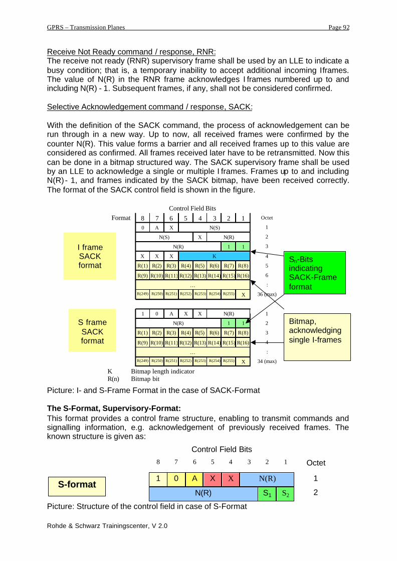
Selective Acknowledgement command / response, SACK:
With the definition of the SACK command, the process of acknowledgement can berun through in a new way. Up to now, all received frames were confirmed by thecounter N(R). This value forms a barrier and all received frames up to this value areconsidered as confirmed. All frames received later have to be retransmitted. Now thiscan be done in a bitmap structured way. The SACK supervisory frame shall be usedby an LLE to acknowledge a single or multiple I frames. Frames up to and includingN(R) - 1, and frames indicated by the SACK bitmap, have been received correctly.The format of the SACK control field is shown in the figure.
Picture: I- and S-Frame Format in the case of SACK-Format
The S-Format, Supervisory-Format:This format provides a control frame structure, enabling to transmit commands andsignalling information, e.g. acknowledgement of previously received frames. Theknown structure is given as:
Picture: Structure of the control field in case of S-Format
R(249) R(250) R(251) R(252) R(253) R(254) R(255) X
R(16)
…
R(8)
R(9) R(10) R(11) R(12) R(13) R(14) R(15)
R(1) R(2) R(3) R(4) R(5) R(6) R(7)
FormatControl Field Bits
S frameSACKformat
I frameSACKformat
1 X
2 10
4 3568 7N(S)A
N(R)
A
N(R)
0
11
11
X
X
X
X
R(249) R(250) R(251) R(252) R(253) R(254) R(255) X
R(16)
…
R(8)
R(9) R(10) R(11) R(12) R(13) R(14) R(15)
R(1) R(2) R(3) R(4) R(5) R(6) R(7)
N(S) N(R)
KXX
N(R)
Octet
1
2
:
34 (max)
:
3
4
36 (max)
5
6
1
2
3
4
K Bitmap length indicatorR(n) Bitmap bit
Sn-BitsindicatingSACK-Frameformat
Bitmap,acknowledgingsingle I-frames
1 A
N(R)
0
S2S1
X X N(R) 1
2S-format
Control Field Bits2 14 3568 7 Octet

GPRS – Transmission Planes Page 93
Rohde & Schwarz Trainingscenter, V 2.0
The signification of the different bit – fields is already described in the block,presenting the I-Format. It is referred to this passage.
The UI-Format, Unnumbered Information:In principle, the task of the UI-frame is the same as the already presented I-Frame. Itis indicating, that the LLC-frame contains a Information-field, transporting all thehigher layer data. The difference to the I-frame is that transmitted UI-frames do nothave to be acknowledged by the receiving peer. The structure of the UI-frame is asfollows:
Picture: Control-field-structure in the case of UI-Format
Thereby signifies:
Encryption mode bit, E-Bit:The E bit is used to indicate whether the information and FCS fields of the UI frameare encrypted (ciphered) to provide user data confidentiality. The E bit is set to 1 toindicate an encrypted frame. The E bit is set to 0 to indicate a frame sent withoutencryption. Please note that this case refers to the non-acknowledged data transfer.In case of acknowledged data transfer, ciphering is always activated.
Protected Mode bit, PM-Bit:The PM bit is used to indicate whether the FCS field shall be calculated using boththe frame header and information fields.The PM bit is set to 1 to indicate that the FCS covers the frame header andinformation fields.The PM bit is set to 0 to indicate that the FCS covers only the frame header field andthe first N202 octets of the information field. If the length of the information field isless than N202 octets then the FCS shall cover the complete information field. Thispermits UI frames to transport "unprotected" information, so that errors beyond thefirst N202 octets of the information field do not result in the frame being discarded.
PM E UI frame information field0 0 unprotected, non-ciphered information0 1 unprotected, ciphered information1 0 protected, non-ciphered information1 1 protected, ciphered information
Table: Usage of the PM- and E-Bits in the UI-frame
Unconfirmed sequence number, N(U):Only UI frames contain N(U), the unconfirmed sequence number of transmittedUI frames. At the time that a UI frame is designated for transmission, the value ofN(U) is set equal to the value of the unconfirmed send state variable V(U). This is acounter of all transmitted frames, not covering if it concerns a „new“ frame or aretransmitted frame. It does not form an acknowledgement-value like the counterN(R) in the case of being I-Format.
1 0
N(U)
1
PME
X X N(U) 1
2UI-format
Control Field Bits2 14 3568 7 Octet

GPRS – Transmission Planes Page 94
Rohde & Schwarz Trainingscenter, V 2.0
The U-Format, Unnumbered-Format:The control field U-format allows the transport of additional control- and signallingmessages. The structure is given by:
Picture: Structure of the control field in case of U-Format
Thereby signifies:
The Poll/Final-Bit, P/F-Bit:
All U frames contain the Poll/Final (P/F) bit. The P/F bit serves a function in bothcommand frames and response frames. In command frames the P/F bit is referred toas the P bit. In response frames it is referred to as the F bit.The P bit set to 1 is used by an LLE to solicit (poll) a response frame from the peerLLE. The F bit set to 1 is used by an LLE to indicate the response frame transmittedas a result of a soliciting (poll) command.
The Unnumbered Function Bits, Mn-Bits:Similar to the Supervisory and Information Frame the Unnumbered-Frame providesthe possibility to send additional command-messages. They are described with theaid of the 4 Bits Mn. Possible combinations are:
Format Commands Responses M4 M3 M2 M1- DM 0 0 0 1
DISC - 0 1 0 0Unnumbered - UA 0 1 1 0
SABM - 0 1 1 1- FRMR 1 0 0 0
XID XID 1 0 1 1Table: Commands in case of Unnumbered Format identified by Mn-Bits
Set Asynchronous Balanced Mode command, SABM:The SABM unnumbered command shall be used to place the addressed MS orSGSN side into ABM acknowledged operation.An LLE shall confirm acceptance of a SABM command by the transmission at thefirst opportunity of a UA response. Asynchronous Balanced Mode describes the casethat both communication peer-entities know of each other and have equal rights totransmit commands to the corresponding opposite peer.
Disconnect command, DISC:The DISC unnumbered command shall be transmitted in order to terminate the ABMoperation.No information field is permitted with the DISC command. Prior to executing thecommand, the LLE receiving the DISC command shall confirm the acceptance of a
1 11 M1M2P/F M4 1U-format
Control Field Bits2 14 3568 7 Octet
M3
GPRS – Transmission Planes Page 95
Rohde & Schwarz Trainingscenter, V 2.0
DISC command by the transmission of a UA response. The LLE sending the DISCcommand shall terminate the ABM operation when it receives the acknowledging UAor DM response. This is the regular process to terminate a communication.
Unnumbered Acknowledgement response, UA:The UA unnumbered response shall be used by an LLE to acknowledge the receiptand acceptance of the mode-setting commands (SABM or DISC). Received mode-setting commands are not initiated until the UA response is transmitted.An information field is only permitted when UA is the response to a SABM command.The UA response shall in this case contain signalling parameters of thecommunication establishment.
Disconnected Mode response, DM:The DM unnumbered response shall be used by an LLE to report to its peer that theLLE is in a state such that ABM operation cannot be performed. An LLE shalltransmit a DM response to any valid command received that it cannot action.No information field is permitted with the DM response.
Frame Reject response, FRMR:The FRMR unnumbered response may be received by an LLE as a report of a framerejection condition not recoverable by retransmission of the identical frame:
1) receipt of a command or response control field that is undefined or notimplemented
2) receipt of a supervisory or unnumbered frame with incorrect length; or3) receipt of an I frame with an information field that exceeds the maximum
established length.
An undefined control field is any of the control field encodings that are not identifiedin the figures describing the control field structure.An information field that immediately follows the control field and that consists of 10octets shall be returned with this response to provide the reason for the FRMRresponse. Only the first 6 octets of the control field of the rejected frame shall besent. If the control field of the rejected frame is fewer than 6 octets, then the unusedoctets shall be set to 0.
Exchange Identification command/response, XID:This frame shall be used to negotiate and re-negotiate LLC layer parameters andlayer-3 parameters. XID frames can be transmitted in ADM and ABM.The negotiation procedure is one-step, i.e., one side shall start the process bysending an XID command, offering a certain set of parameters from the applicableparameter repertoire the sending entity wants to negotiate, proposing values withinthe allowed range. There are only mentioned the parameters being matter ofnegotiation. In return, the other side shall send an XID response, either confirmingthese parameter values by returning the requested values, or offering higher or lowerones in their place. As an optimisation, parameters confirming the requested valuesmay be omitted from the XID response. There is a long list of possible layer 3parameters to be negotiated that can be found in the specifications. For furtherinformation it is referred to GSM Spec. 04.64.

GPRS – Transmission Planes Page 96
Rohde & Schwarz Trainingscenter, V 2.0
6.4. Transmission Planes SGSN - BSS
FR
L1 bis
BSS
GP
Relay
FR
L1 bis
BSS
GP
LLC
SND
CP
Relay
BSS SGSN
Gb
BSSGP : BSS GPRS Protocol LLC : Logical Link Control
SNDCP : SubNetwork DependentFR : Frame Relayl
Convergence Protocol
Data transfer between the SGSN and BSS runs via the Gb-Interface. In GSM wecould find at this position the A-Interface between MSC and BSC. Some fundamentaldifferences, respectively characteristics of the Gb-interface are:Different to the A-Interface where every subscriber has been assigned a dedicatedchannel ressource for the length of the communication, independent of the datatransfer being active or not, the Gb-Interface performs a packet data transport. Usingthis method, it allows the Multiplexing of several subscribers onto one commonphysical channel.Due to this, the data throughput for one subscriber can vary between Zero andmaximum throughput.

GPRS – Transmission Planes Page 97
Rohde & Schwarz Trainingscenter, V 2.0
BSSGP, Base Station System GPRS Protocol:
This protocol layer represents the transmission plane for the Gb-interface as ittransports the higher layer data from the SGSN to the BSS. LLC PDU’s areencapsulated and tunnelled through the Gb-interface. The main task of this protocollayer can be found considering the signalling side. The BSSGP is conveying routing-and QoS-relevant information between the BSS and the SGSN. BSSGP does notperform any error correction. It forms the relay function between the RLC/MAC-informationen and the switching system SGSN. The position of the BSSGP in thegeneral plane is below the LLC-Layers and above the Network-Service-Layers and itforms the relay interface to the RLC/MAC-Layer in the BSS.
GbBSS
LLC
BSSGP
L1
SGSN
NS
L1
MAC
BSSGPRLC
RELAY
NS
Picture: Postion of BSSGP in the GPRS-protocol structure
The BSSGP-Protocol provides a lot of surveying and control functions to managedifferent instances and services. It provides the presented interfaces:
Picture: BSSGP Service Modell: Interfaces to surrounding layers
Network Service
BSSGP
LLC
BSSGP
GMM
GMM
PFM
PFM
NM
NM
GSM 08.16
Service model in an SGSN
Network Service
BSSGP
GMM NMRELAY
GSM 03.64 GMM
PFM
PFM NM
GSM 08.16
Service model in an BSS
RL
RLC/MAC

GPRS – Transmission Planes Page 98
Rohde & Schwarz Trainingscenter, V 2.0
The BSGP-layer provides the following Service Access Points:
• BSSGP: For functions controlling the transfer of LLC frames passed between anSGSN and an MS across the Gb interface.
• RL, Radio Link Relay: For functions controlling the transfer of LLC framesbetween the RLC/MAC function and BSSGP.
• GMM, GPRS Mobility Management: For functions associated with mobilitymanagement between an SGSN and a BSS.
• NM, Network Management: For functions associated with Gb-interface andBSS—SGSN node management.
• PFM, Packet Flow Management: For functions associated with the managementof BSS Packet Flow Contexts (PFCs).
The BSSGP-layer communicates with its environment via defined messages, so-called primitives that are transported via the corresponding interface to thedetermined layer-entitiy. These primitives are provided as certain packets with acertain format to the corresponding layer. Data of the LLC-layer are packed into sucha primitive and are provided to the corresponding layer via the SAP. Before handingthem out, the data is combined with an Information Element Identifier. Due to theseprimitives, containing the Information Elements, signalling information can betransported via the Gb-interface.
Network Services, NS:
The lower layer network services, NS provides the means for data transport betweenBSS and SGSN. The used mechanisms are based on a Frame-Relay-network-concept.
Picture: Position of the Network Services
GbBSS
LLC
BSSGP
L1
SGSN
NS
L1
MAC
BSSGPRLC
RELAY
NS

GPRS – Transmission Planes Page 99
Rohde & Schwarz Trainingscenter, V 2.0
The NS-layer has the following tasks that are described in more detail in the passageabout the characteristics of the Frame Relay network:
• Transfer of BSSGP-Paket Data Units over the Gb-Interface
• Congestion Detection and indication on the Gb-Interface
• Status-Indic ation of the connection, e.g. information if any transfer
characteristics have been modified.
The Network Services work on the principle that this layer provides primitives tohigher layers used for data transport. The higher layers become external users of thenetwork services. The really transport of data units is established and maintainedwith the aid of so called Virtual Connections, VC. A Virtual Connection means, incontrary to a physical connection, that due to an address identification, a logical pathbetween two endpoints can be maintained. Each physical or logical channel of apeer-to-peer connection between two endpoints has to be identified. Addressing of allconnected endpoints occurs. This addressing can be reduced in the case of a Point-to-point, PtP-connection, i.e. one SGSN is connected to one BSS.
The Layer Network Services, NS is subdivided into 2 Sub-Layers:
Sub-Network Service /Sub-Network Service protocol
Network Service Control /Network Service Control protocol
Network Service
Picture: Internal architecture of the layer Network Service
The Network Service Control entity is responsible for the following functions:- NS SDU transmission: The Network Service SDUs shall be transmitted
on the Network Service-Virtual Connections. The NS SDUs areencapsulated into Network Service Control PDUs that in turn areencapsulated into Sub-Network Service PDUs.
- Load sharing: The load sharing function distributes the NS SDU trafficamongst the available (i.e. unblocked) NS-VCs of a group.
- NS-VC management: A blocking procedure is used by an NS entity toinform an NS peer entity when an NS-VC becomes unavailable for NSuser traffic. An unblocking procedure is used for the reverse operation.A reset procedure is used between peer NS entities in order to set anNS-VC to a determined state, after events resulting in possiblyinconsistent states of the NS-VC at both sides of the Gb interface. A

GPRS – Transmission Planes Page 100
Rohde & Schwarz Trainingscenter, V 2.0
test procedure is used to check that an NS-VC is operating properlybetween peer NS entities.
The Sub-Network Service is responsible for:
The Sub-Network Service entity provides a communication service to NetworkService Control peer entities. The Network Service Control peer entities usethe Sub-Network Service for communication with each other. The peer-to-peercommunication accross the Gb interface between remote Network ServiceControl entities is performed over Network Service Virtual Connections (NS-VCs). An NS-VC is a virtual communication path between Network ServiceControl peer entities.
The data transfer over the Gb-Interface is performed with the use of a Frame RelayNetwork.This Frame Relay Network can be realized as Point-to-point connection or can berealized as a Frame Relay Network, using an Intermediate Frame Relay Network.
Frame Relay:
Similar to X.25, Frame Relay is a packet switched data communication network, withthe advantage of being much faster. This is due to the renounciation of signalling andadministration data. All the signalling and administration has to be performed byhigher protocol layerers. Also, Frame Relay does not provide a reliable link and soerror correction and protection mechanisms have to be implemented in the higherlayers. This results in all the data overhead being greatly reduced and the speedbeing accelerated.
Data transfer:
The data units in a Frame Relay network are conveyed with the assistance of socalled Frames. A big advantage of this communication principle is the variable size ofthese frames and by this, the adaptive variation of the data throughput. The maintask of the network elements is to transport or to route to frame through the networkto the determined destination endpoint. The switching does not run through physicalchannels, furthermore it is conveyed due to logical connections. We remember theidentification of such a logical channel as virtual connection, VC. As long as data hasto be transferred, the physical resource on the transmitting channel is allocated in therequired bandwidth. Frame Relay, in duty in a GPRS-network uses permanentassigned virtual connections. Each of these connections is identified with a Data LinkConnection Identifier, DLCI. Such a DLCI identifies the node that represents thetransfer point to the user layer. In other words, the DLCI gives the address of thedestination endpoint to which the frames, containing the higher protocol data, have tobe routed.

GPRS – Transmission Planes Page 101
Rohde & Schwarz Trainingscenter, V 2.0
Picture: Structure of a Frame
Picture: Addressing of a virtual connection with different DLCIs

GPRS – Transmission Planes Page 102
Rohde & Schwarz Trainingscenter, V 2.0
Congestion Identification:
A Frame Relay Network provides different means and strategies to protect and avoidcongestion on the transmitting channel. If a network-switching node detects overload,it will send a notice or indication to all successing and predecessing nodes, so thatthey can reduce the amount of data. In case of congestion or transmitting errors, theframes will be deleted, according to order of their importance. There is a flag,indicating the importance or precedence of the data unit. The data units with thelowest precedence class will be deleted the first. Please notice, that all data units,SDU’s are protected by higher protocols against transmitting errors, such aserroneous data, discarded data or twice-delivered data units.
Picture: Congestion in a Frame Relay Network. Notification of neighborhood nodes.
Status of a PVC, Permanent Virtual Connection
With the assistance of a additional, optional signalling mechanism it can be defined inwhich way the two sides of the communication in a Frame Relay Network (e.g.network and router) communicate with each other concerning the state of theinterface or concerning the different PVCs, connected to the network. This means,that Frame Relay interfaces can be implemented and data units can be transferredwithout the introduction of such a signalling mechanism. But otherwise, it is quiteeasy to implement a signalling process for status information due to the definition ofadditional Management Frames. These management frames, with their own DLCI-addresses provide the transfer of the status information to be exchanged betweenthe network and the access-system.
GPRS – Transmission Planes Page 103
Rohde & Schwarz Trainingscenter, V 2.0
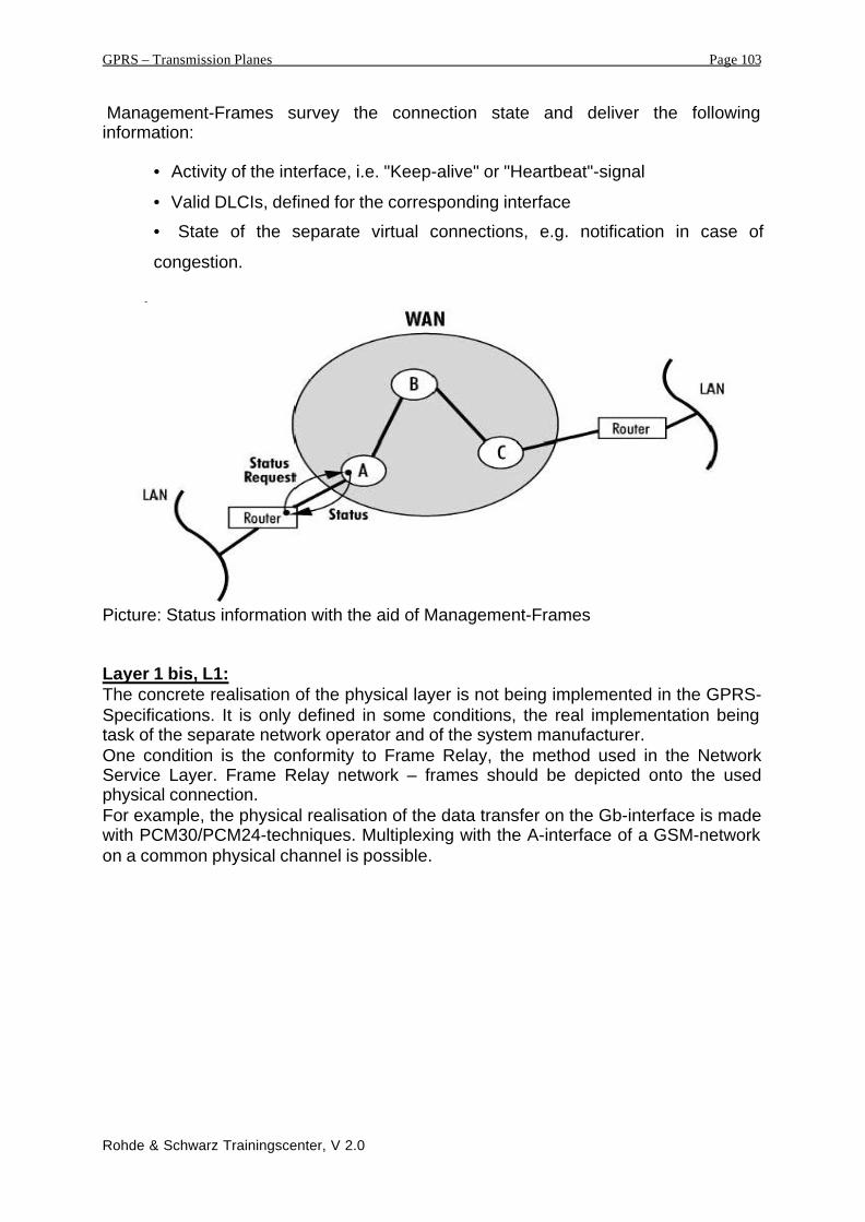
Management-Frames survey the connection state and deliver the followinginformation:
• Activity of the interface, i.e. "Keep-alive" or "Heartbeat"-signal
• Valid DLCIs, defined for the corresponding interface
• State of the separate virtual connections, e.g. notification in case of
congestion.
Picture: Status information with the aid of Management-Frames
Layer 1 bis, L1:The concrete realisation of the physical layer is not being implemented in the GPRS-Specifications. It is only defined in some conditions, the real implementation beingtask of the separate network operator and of the system manufacturer.One condition is the conformity to Frame Relay, the method used in the NetworkService Layer. Frame Relay network – frames should be depicted onto the usedphysical connection.For example, the physical realisation of the data transfer on the Gb-interface is madewith PCM30/PCM24-techniques. Multiplexing with the A-interface of a GSM-networkon a common physical channel is possible.

GPRS – Transmission Planes Page 104
Rohde & Schwarz Trainingscenter, V 2.0
6.5. Transmission Planes MS - BSS
GPRS Transmission Planes
MAC
GSMRF
RLC
LLC
SNDCP
IP/X.25
MAC
GSMRF
RLC
Relay
MS BSSUm
LLC : Logical Link Control MAC : Medium Access Control RLC : Radio Link Control
GSM RF: GSM Air interface
IncludingCCU and PCU
Radio Link Control / Medium Access Control, RLC / MAC:
This layer contains 2 functional units: The Radio Link Control represents a linkdepending on the used radio link-methods. The Medium Access Control layercontrols the access to the physical channel and distributes the LLC-data units on theair interface. It assigns the physical resources on the air interface. Both layers arecombined strongly, thus their functions and characteristics are explained in acombined way.The RLC/MAC-Protocol layer offers the two data transfer methods:Acknowledged Mode and Non-acknowledged Mode.
RLC-Functions:• The RLC-Layer offers Primitives that enable the handling of LLC-PDU’s
between MAC-Layer and LLC-Layer.• Segmentation and concatenation of LLC PDU’s.• Backward Error Correction, BEC as error correction, this means the request of
retransmission of erroneous data units. This can be performed with the aid ofa bitmap-structure, the erroneous data units are retransmitted.

GPRS – Transmission Planes Page 105
Rohde & Schwarz Trainingscenter, V 2.0
MAC-Functions:The MAC-layer controls the access to the resources of the air interface. It hasprocedures to coordinate and control the common access and the sharing ofmultiple mobile stations on one common physical channel. The sharing ofmultiple mobile phones can be done in parallel way. We have to coordinate amultiple access on the physical resource in Up- and Downlink.Tools, respective means of the Mre the identifier TBF, or TFI to identify aphysical ressource and the USF to indicate the correct physical channel areused.
Further details and description of the RLC/MAC-Layer are given in the chapter aboutthe air interface.
Physical Layer, GSM-RF:
This Layer contains the two sub-layer, Physical RF-Layer and Physical Link Layer.Their tasks are:
• Modulation and Demodulation, i.e. transfer of the digital information with the
aid of a high frequency radio wave signal.
• Generation of Bursts: Segmentation of the binary bitstream in blocks to be
placed into the single bursts and on the receiver side the concatenation and
reassembling of the bit-sequence.
• Channel coding, depending on the radio link quality, the mapping of data and
error correction, using the 4 different coding schemes, CS1 – 4.
• Error Protection mechanisms, for example: Interleaving and Convolutional
Coding.
This layer does not differ in a big way from the layer 1 we know from GSM, i.e. thereal data transfer is run through with the use of the GSM-principles, TDMA+FDMAaccess methods and the burst types we know in GSM. The only difference will be inthe content of the information part in the normal burst. What this looks like, isdescribed in the chapter on the air interface.