5g versus 4g waveforms benchmarking based on link-level ... · 3 • 4g/5g introduction •...
TRANSCRIPT
5G versus 4G waveforms benchmarking based on link-level modeling tools and SDR hardware
applied in education and research
Dr. Sławomir Pietrzyk
Łukasz Kwiatkowski
IEEE GLOBECOM 2016 Industry tutorial
1
2
• 4G/5G Introduction
• Experimentation platform
• Realization and demonstration of use case scenarios
• Conclusions for education and research
2
Tutorial outline
3
• 4G/5G Introduction
• Experimentation platform
• Realization and demonstration of use case scenarios
• Conclusions for education and research
3
Tutorial outline
4
• Fundamentals of 4G waveforms – OFDM, SC-FDMA
• Framing and basic PHY signaling in LTE – FDD frame structure
– Physical and transport channels
– Reference and Synchronization signals
• Fundamentals of 5G waveform candidates – UFMC, GFDM
4
4G/5G INTRODUCTION
5
5
Fundamentals of 4G waveforms
6
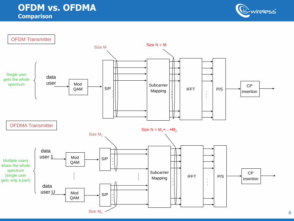
OFDM vs. OFDMA Comparison
S/P . . .
Subcarrier
Mapping . . .
IFFT . . .
P/S CP
insertion
Size M1 Size N = M1+…+MU
S/P . . .
Size MU
data
user 1 Mod
QAM
data
user U Mod
QAM
OFDM Transmitter
OFDMA Transmitter
Subcarrier
Mapping . . .
IFFT . . .
P/S CP
insertion
Size N = M
data
user Mod
QAM
Size M
S/P . . .
Single user
gets the whole
spectrum
Multiple users
share the whole
spectrum
(single user
gets only a part)
…..
…..
7
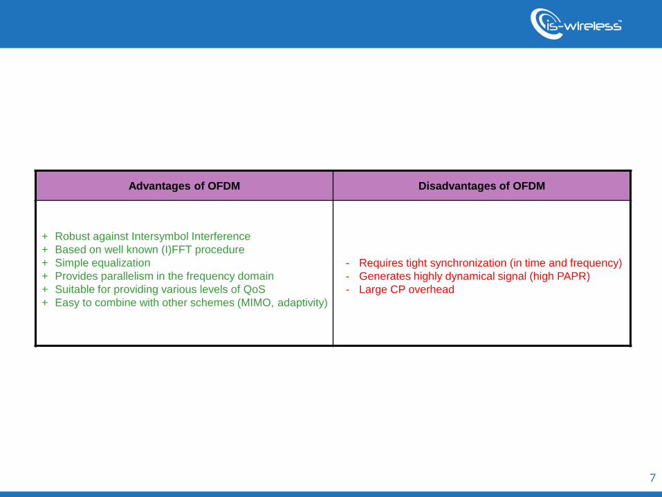
Advantages of OFDM Disadvantages of OFDM
+ Robust against Intersymbol Interference
+ Based on well known (I)FFT procedure
+ Simple equalization
+ Provides parallelism in the frequency domain
+ Suitable for providing various levels of QoS
+ Easy to combine with other schemes (MIMO, adaptivity)
- Requires tight synchronization (in time and frequency)
- Generates highly dynamical signal (high PAPR)
- Large CP overhead
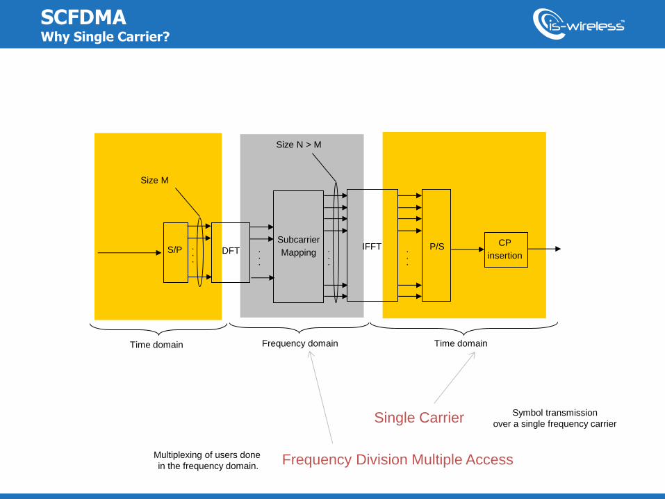
SCFDMA Why Single Carrier?
S/P DFT . . .
.
.
.
Subcarrier
Mapping . . .
IFFT . . .
P/S CP
insertion
Time domain Frequency domain Time domain
Size M
Size N > M
Symbol transmission
over a single frequency carrier Single Carrier
Frequency Division Multiple Access Multiplexing of users done
in the frequency domain.
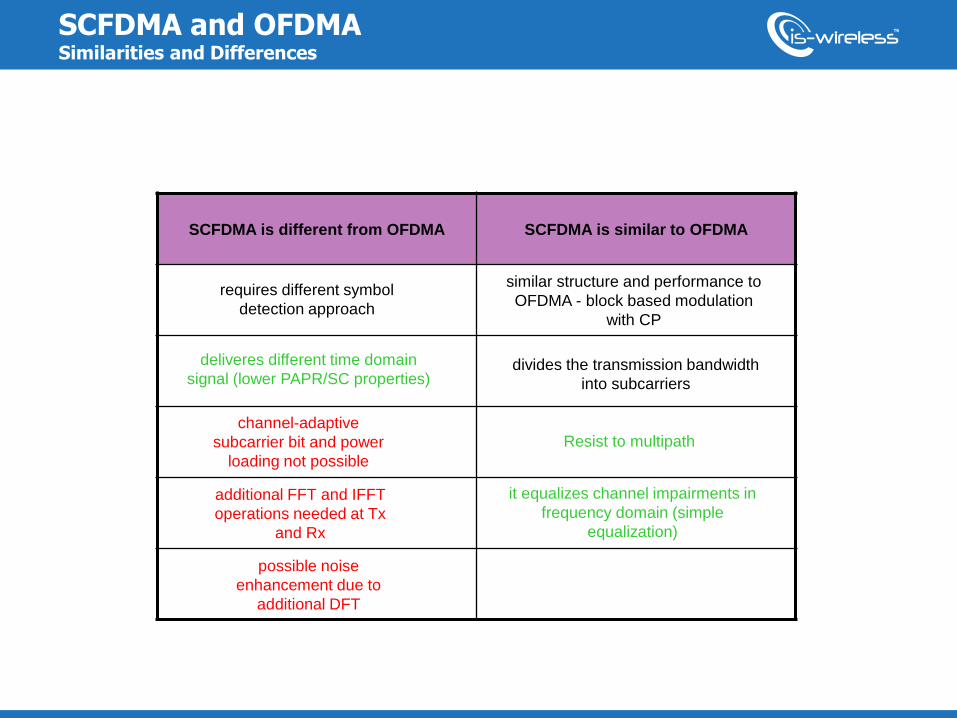
SCFDMA and OFDMA Similarities and Differences
SCFDMA is different from OFDMA SCFDMA is similar to OFDMA
similar structure and performance to
OFDMA - block based modulation
with CP
deliveres different time domain
signal (lower PAPR/SC properties)
requires different symbol
detection approach
channel-adaptive
subcarrier bit and power
loading not possible
additional FFT and IFFT
operations needed at Tx
and Rx
possible noise
enhancement due to
additional DFT
Resist to multipath
it equalizes channel impairments in
frequency domain (simple
equalization)
divides the transmission bandwidth
into subcarriers
10
10
Framing and basic PHY signaling in LTE
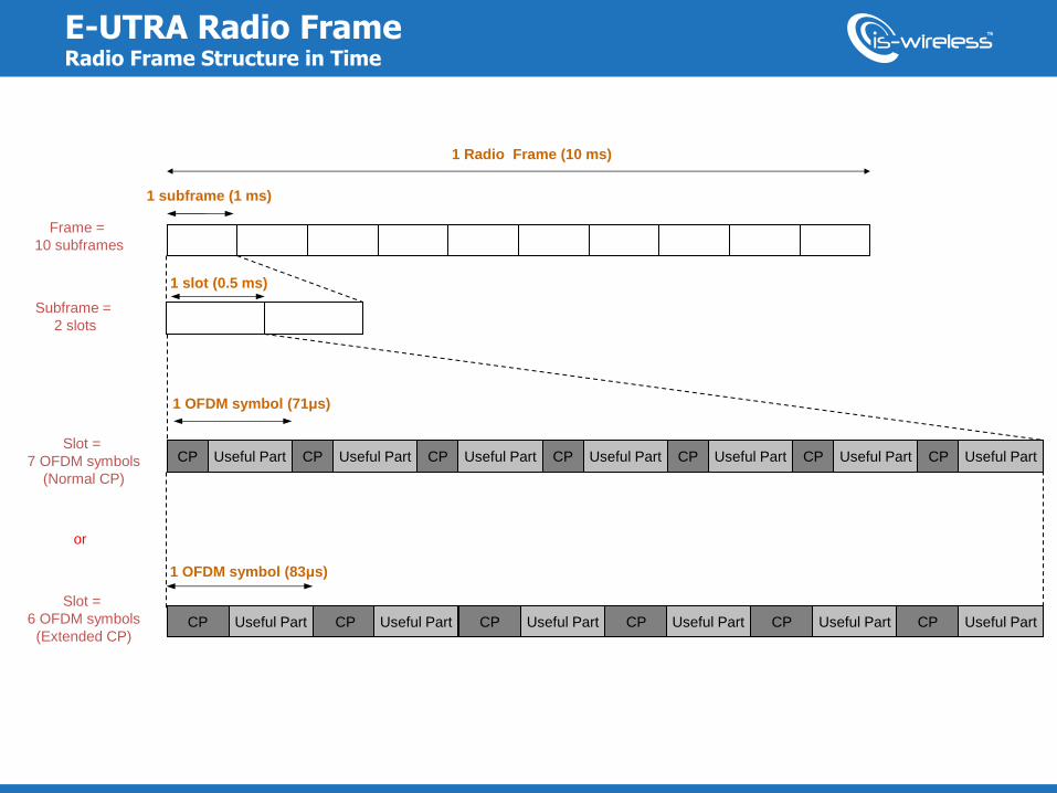
E-UTRA Radio Frame Radio Frame Structure in Time
1 Radio Frame (10 ms)
1 subframe (1 ms)
1 slot (0.5 ms)
Slot =
7 OFDM symbols
(Normal CP)
CP CP CP CP CP CP Useful Part
CP Useful Part CP Useful Part CP Useful Part CP Useful Part CP Useful Part CP Useful Part CP Useful Part
1 OFDM symbol (83μs)
1 OFDM symbol (71μs)
Frame =
10 subframes
Subframe =
2 slots
Slot =
6 OFDM symbols
(Extended CP)
or
Useful Part Useful Part Useful Part Useful Part Useful Part
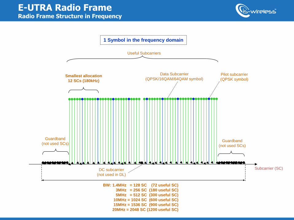
E-UTRA Radio Frame Radio Frame Structure in Frequency
1 Symbol in the frequency domain
Subcarrier (SC)
BW: 1.4MHz = 128 SC (72 useful SC)
3MHz = 256 SC (180 useful SC)
5MHz = 512 SC (300 useful SC)
10MHz = 1024 SC (600 useful SC)
15MHz = 1536 SC (900 useful SC)
20MHz = 2048 SC (1200 useful SC)
Smallest allocation
12 SCs (180kHz)
Guardband
(not used SCs) Guardband
(not used SCs)
DC subcarrier
(not used in DL)
Pilot subcarrier
(QPSK symbol)
Data Subcarrier
(QPSK/16QAM/64QAM symbol)
Useful Subcarriers
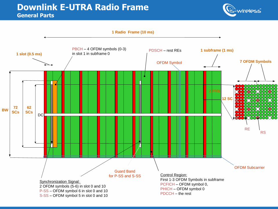
Downlink E-UTRA Radio Frame General Parts
1 slot (0.5 ms)
Control Region:
First 1-3 OFDM Symbols in subframe
PCFICH – OFDM symbol 0,
PHICH – OFDM symbol 0
PDCCH – the rest
PBCH – 4 OFDM symbols (0-3)
in slot 1 in subframe 0
Synchronization Signal:
2 OFDM symbols (5-6) in slot 0 and 10
P-SS – OFDM symbol 6 in slot 0 and 10
S-SS – OFDM symbol 5 in slot 0 and 10
BW
PDSCH – rest REs
DC
1 subframe (1 ms)
62
SCs
72
SCs
1 Radio Frame (10 ms)
12 SC
7 OFDM Symbols
RS RE
2 PRB
OFDM Subcarrier
OFDM Symbol
Guard Band
for P-SS and S-SS
1
1
Fundamentals of 5G waveforms candidates
2
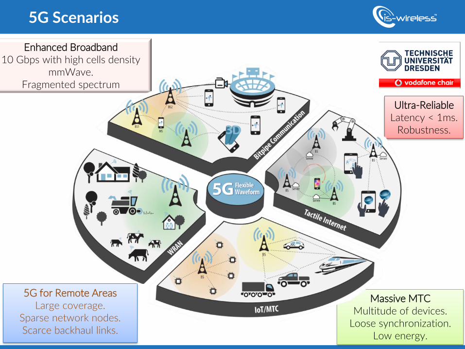
5G Scenarios
Enhanced Broadband 10 Gbps with high cells density
mmWave. Fragmented spectrum
Massive MTC Multitude of devices.
Loose synchronization. Low energy.
Ultra-Reliable Latency < 1ms.
Robustness.
5G for Remote Areas Large coverage.
Sparse network nodes. Scarce backhaul links.
ni.com
• Master text styles
• Second level
o Third level – Fourth level
ni.com | 3
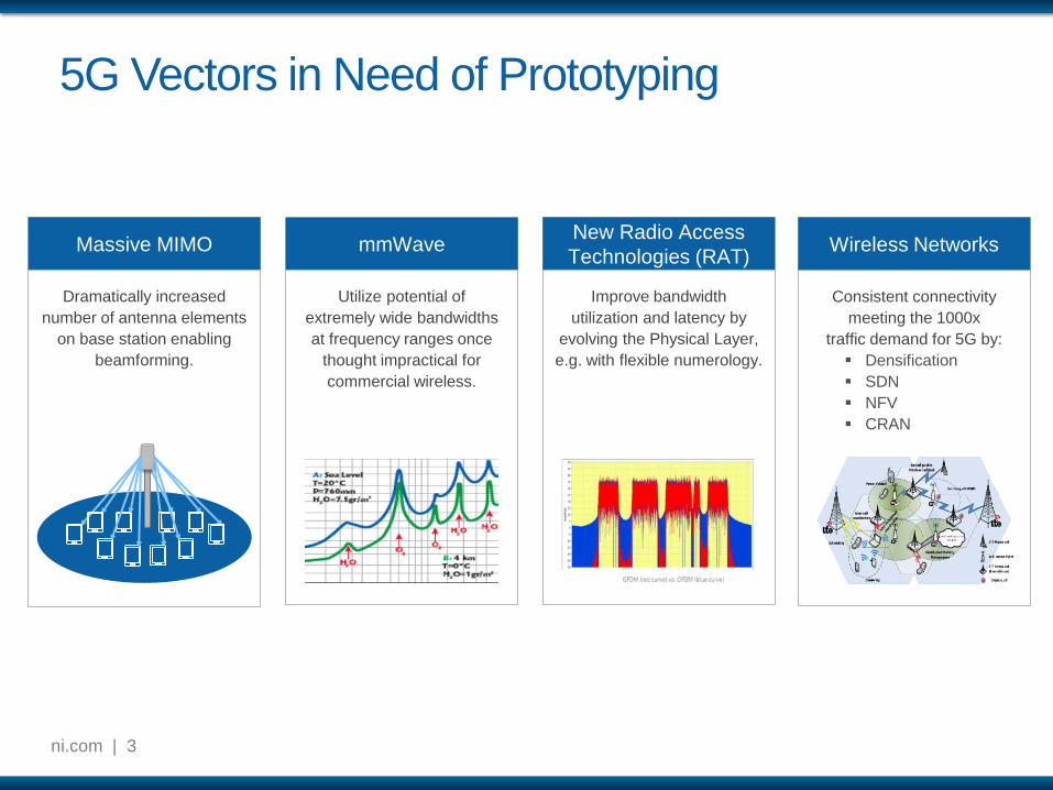
5G Vectors in Need of Prototyping
Improve bandwidth
utilization and latency by
evolving the Physical Layer,
e.g. with flexible numerology.
New Radio Access
Technologies (RAT)
Utilize potential of
extremely wide bandwidths
at frequency ranges once
thought impractical for
commercial wireless.
mmWave
Dramatically increased
number of antenna elements
on base station enabling
beamforming.
Massive MIMO
Consistent connectivity
meeting the 1000x
traffic demand for 5G by:
Densification
SDN
NFV
CRAN
Wireless Networks
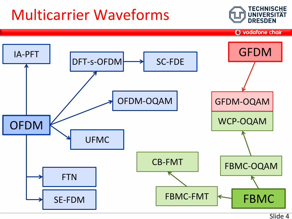
Multicarrier Waveforms
DFT-s-OFDM
OFDM
FBMC-OQAM
SC-FDE
FBMC-FMT
CB-FMT
GFDM
UFMC
FTN
SE-FDM FBMC
GFDM-OQAM
WCP-OQAM
OFDM-OQAM
IA-PFT
Slide 4
5
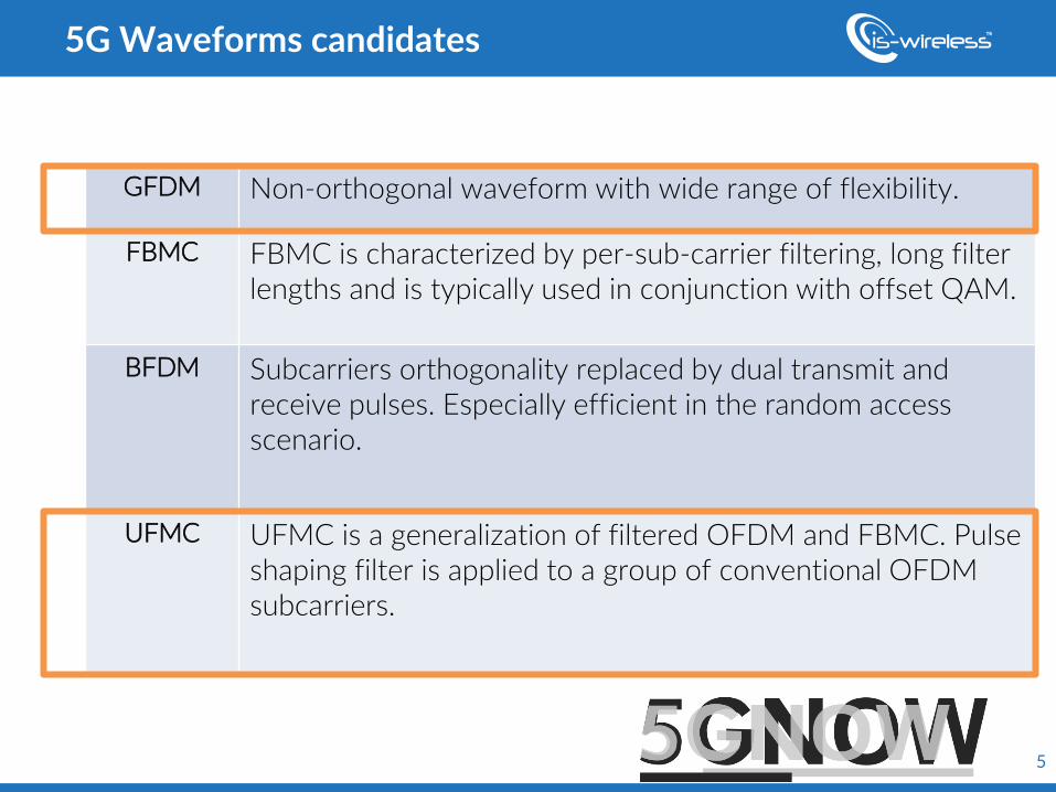
GFDM Non-orthogonal waveform with wide range of flexibility.
FBMC FBMC is characterized by per-sub-carrier filtering, long filter lengths and is typically used in conjunction with offset QAM.
BFDM Subcarriers orthogonality replaced by dual transmit and receive pulses. Especially efficient in the random access scenario.
UFMC UFMC is a generalization of filtered OFDM and FBMC. Pulse shaping filter is applied to a group of conventional OFDM subcarriers.
5G Waveforms candidates
6
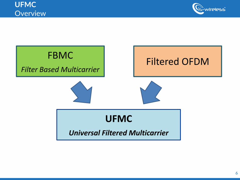
UFMC Overview
UFMC Universal Filtered Multicarrier
FBMC
Filter Based Multicarrier Filtered OFDM
7
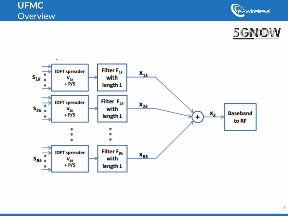
UFMC Overview
8
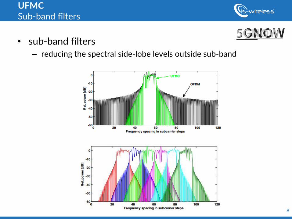
• sub-band filters – reducing the spectral side-lobe levels outside sub-band
UFMC Sub-band filters
9
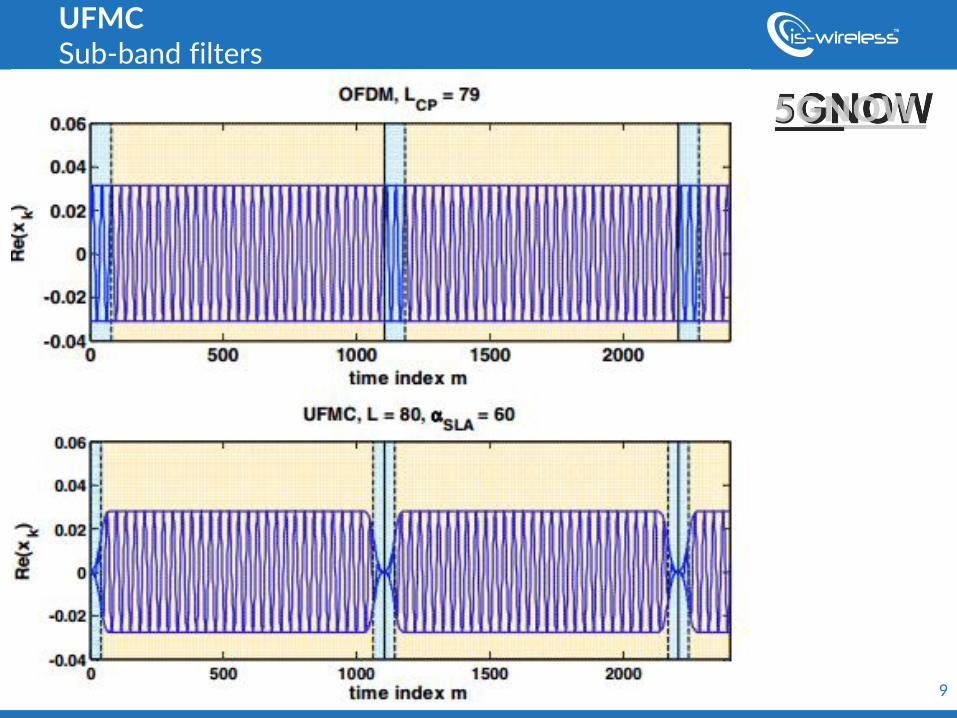
UFMC Sub-band filters
w w w. e w i n e - p r o j e c t . e u
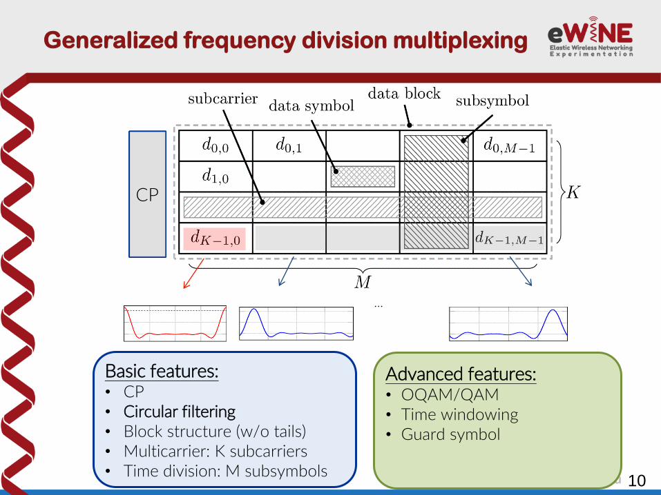
Generalized frequency division multiplexing
10
Basic features: • CP • Circular filtering • Block structure (w/o tails) • Multicarrier: K subcarriers • Time division: M subsymbols
Advanced features: • OQAM/QAM • Time windowing • Guard symbol
CP
…
w w w. e w i n e - p r o j e c t . e u
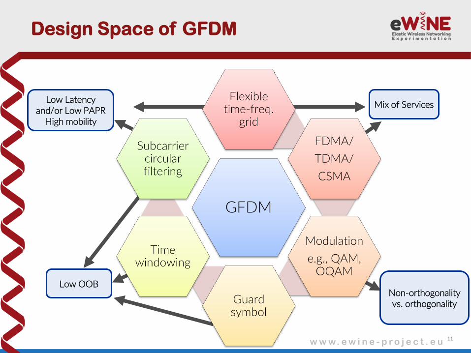
Design Space of GFDM
GFDM
Flexible time-freq.
grid
FDMA/
TDMA/
CSMA
Modulation
e.g., QAM, OQAM
Guard symbol
Time windowing
Subcarrier circular filtering
11
Low Latency and/or Low PAPR
High mobility
Low OOB
Mix of Services
Non-orthogonality vs. orthogonality
w w w. e w i n e - p r o j e c t . e u
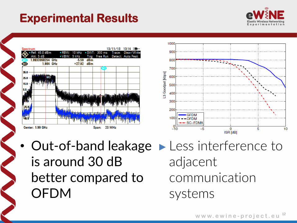
Experimental Results
12
• Out-of-band leakage is around 30 dB better compared to OFDM
►Less interference to adjacent communication systems
13
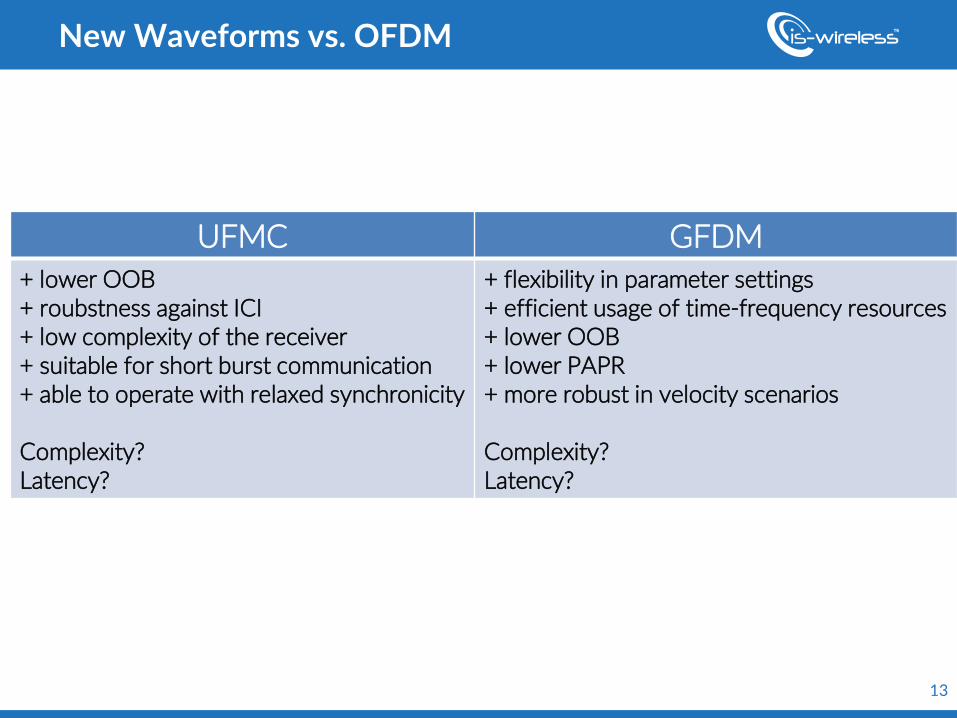
New Waveforms vs. OFDM
UFMC GFDM
+ lower OOB + roubstness against ICI + low complexity of the receiver + suitable for short burst communication + able to operate with relaxed synchronicity Complexity? Latency?
+ flexibility in parameter settings + efficient usage of time-frequency resources + lower OOB + lower PAPR + more robust in velocity scenarios Complexity? Latency?
1
• 4G/5G Introduction
• Experimentation platform
• Realization and demonstration of use case scenarios
• Conclusions for education and research
1
Tutorial outline
2
• eWINE project – Overview
– ISW activity
• Link-level modelling tool – LTE PHY Lab
• Overview
• Block model
2
Experimentation platform
3
3
eWINE project
w w w . e w i n e - p r o j e c t . e u
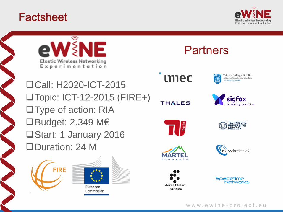
Factsheet
Call: H2020-ICT-2015
Topic: ICT-12-2015 (FIRE+)
Type of action: RIA
Budget: 2.349 M€
Start: 1 January 2016
Duration: 24 M
Partners
w w w . e w i n e - p r o j e c t . e u
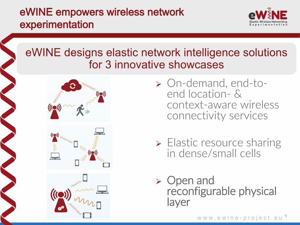
eWINE empowers wireless network
experimentation
5
On-demand, end-to-end location- & context-aware wireless connectivity services
Elastic resource sharing in dense/small cells
Open and reconfigurable physical layer
eWINE designs elastic network intelligence solutions for 3 innovative showcases
w w w . e w i n e - p r o j e c t . e u
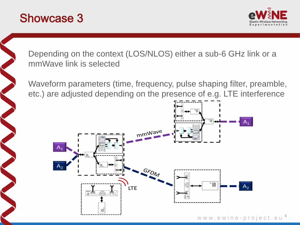
Showcase 3
6
Depending on the context (LOS/NLOS) either a sub-6 GHz link or a
mmWave link is selected
Waveform parameters (time, frequency, pulse shaping filter, preamble,
etc.) are adjusted depending on the presence of e.g. LTE interference
w w w . e w i n e - p r o j e c t . e u
Showcase 3
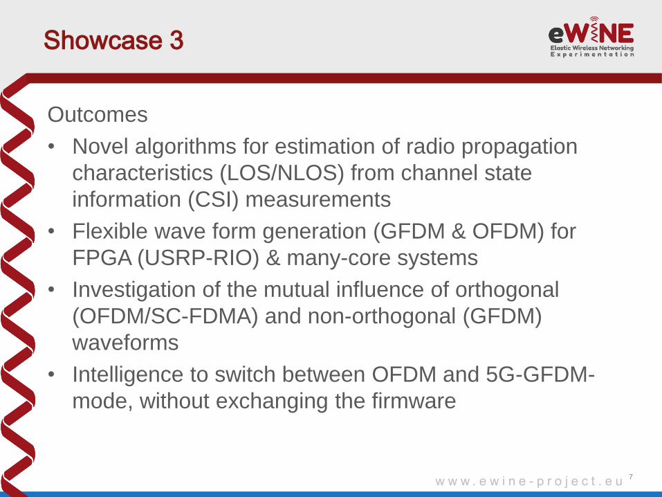
Outcomes
• Novel algorithms for estimation of radio propagation
characteristics (LOS/NLOS) from channel state
information (CSI) measurements
• Flexible wave form generation (GFDM & OFDM) for
FPGA (USRP-RIO) & many-core systems
• Investigation of the mutual influence of orthogonal
(OFDM/SC-FDMA) and non-orthogonal (GFDM)
waveforms
• Intelligence to switch between OFDM and 5G-GFDM-
mode, without exchanging the firmware
7
w w w . e w i n e - p r o j e c t . e u
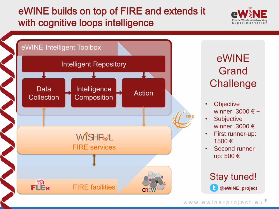
eWINE builds on top of FIRE and extends it
with cognitive loops intelligence
8
FIRE facilities
eWINE Intelligent Toolbox
eWINE
Grand
Challenge
• Objective
winner: 3000 € +
• Subjective
winner: 3000 €
• First runner-up:
1500 €
• Second runner-
up: 500 €
Stay tuned!
CREW
FIRE services
WiSHF L
Intelligent Repository
Action Intelligence
Composition
Data
Collection
@eWINE_project
9
9
Link-level modelling tool
10
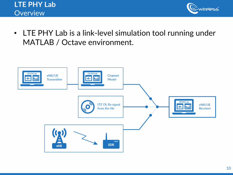
• LTE PHY Lab is a link-level simulation tool running under MATLAB / Octave environment.
LTE PHY Lab Overview
11
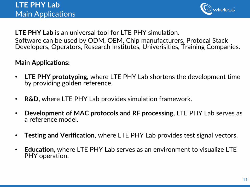
LTE PHY Lab Main Applications
LTE PHY Lab is an universal tool for LTE PHY simulation. Software can be used by ODM, OEM, Chip manufacturers, Protocal Stack Developers, Operators, Research Institutes, Univerisities, Training Companies. Main Applications: • LTE PHY prototyping, where LTE PHY Lab shortens the development time
by providing golden reference. • R&D, where LTE PHY Lab provides simulation framework.
• Development of MAC protocols and RF processing, LTE PHY Lab serves as
a reference model.
• Testing and Verification, where LTE PHY Lab provides test signal vectors.
• Education, where LTE PHY Lab serves as an environment to visualize LTE PHY operation.
12
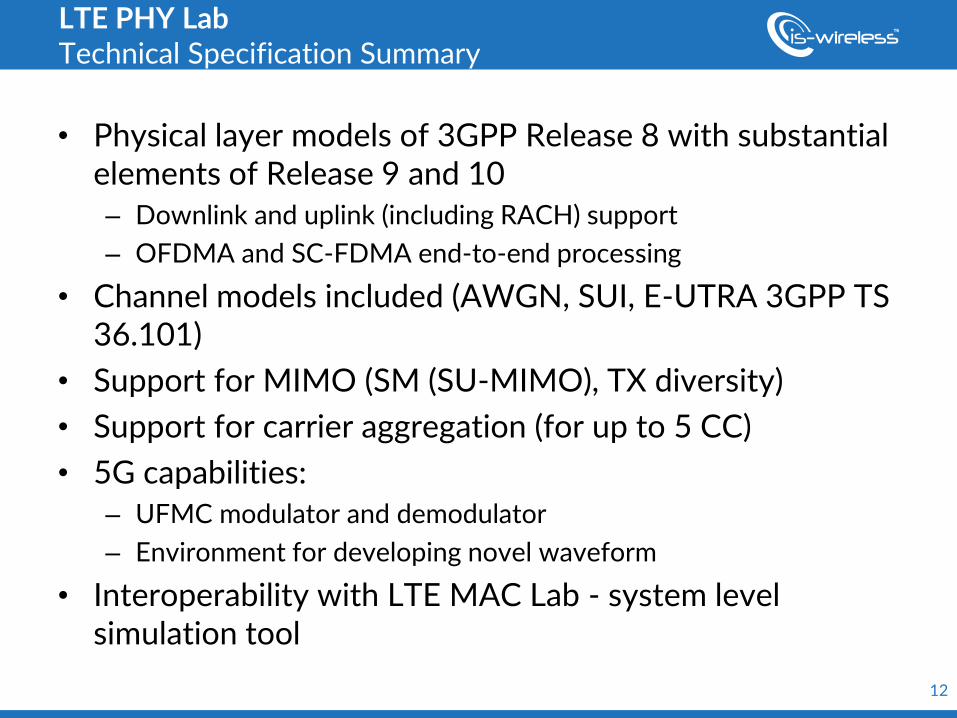
LTE PHY Lab Technical Specification Summary
• Physical layer models of 3GPP Release 8 with substantial elements of Release 9 and 10 – Downlink and uplink (including RACH) support
– OFDMA and SC-FDMA end-to-end processing
• Channel models included (AWGN, SUI, E-UTRA 3GPP TS 36.101)
• Support for MIMO (SM (SU-MIMO), TX diversity)
• Support for carrier aggregation (for up to 5 CC)
• 5G capabilities: – UFMC modulator and demodulator
– Environment for developing novel waveform
• Interoperability with LTE MAC Lab - system level simulation tool
13
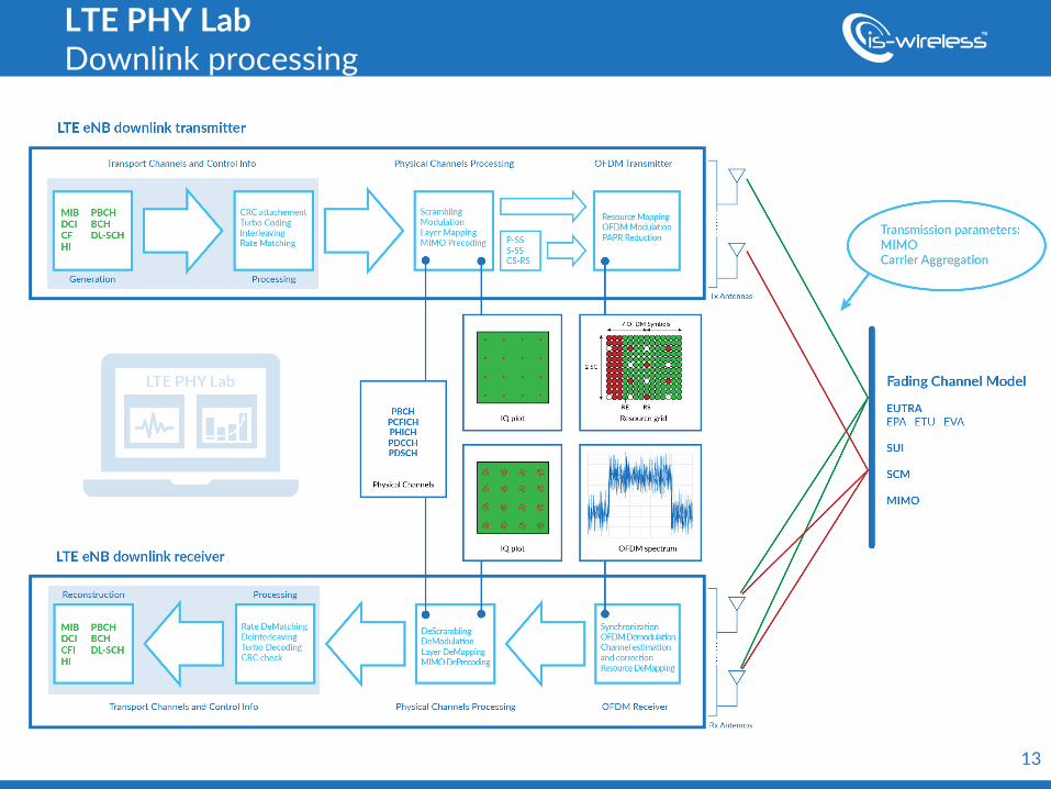
LTE PHY Lab Downlink processing
1
• 4G/5G Introduction
• Experimentation platform
• Realization and demonstration of use case scenarios
• Conclusions for education and research
1
Tutorial outline
2
• Setup overview
• Exemplary scearios and their educational aspects
• Waveform generation
• Comaprision of key measures and conclusions
2
Realization and demonstration of use case scenarios
3
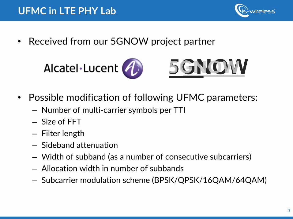
• Received from our 5GNOW project partner
• Possible modification of following UFMC parameters: – Number of multi-carrier symbols per TTI
– Size of FFT
– Filter length
– Sideband attenuation
– Width of subband (as a number of consecutive subcarriers)
– Allocation width in number of subbands
– Subcarrier modulation scheme (BPSK/QPSK/16QAM/64QAM)
UFMC in LTE PHY Lab

4
Parameter name Value
Number of multi-carrier symbols per TTI 14
Size of FFT 512
Filter length 37
Sideband attenuation [dB] 40
Width of subband [subcarriers] 32
Allocation width in number of subbands 16
Modulation scheme QPSK
UFMC in LTE PHY Lab
5
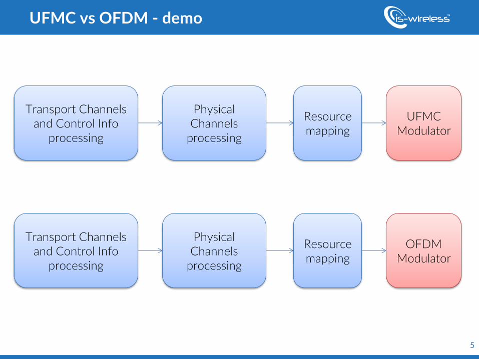
UFMC vs OFDM - demo
Transport Channels and Control Info
processing
Physical Channels
processing
Resource mapping
UFMC Modulator
Transport Channels and Control Info
processing
Physical Channels
processing
Resource mapping
OFDM Modulator
6
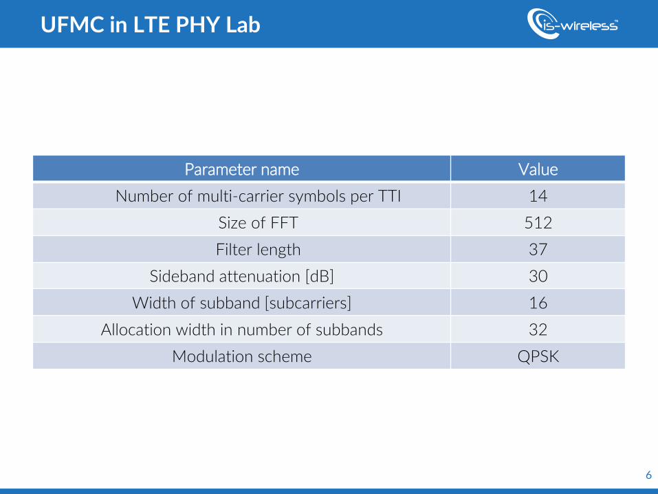
Parameter name Value
Number of multi-carrier symbols per TTI 14
Size of FFT 512
Filter length 37
Sideband attenuation [dB] 30
Width of subband [subcarriers] 16
Allocation width in number of subbands 32
Modulation scheme QPSK
UFMC in LTE PHY Lab
w w w . e w i n e - p r o j e c t . e u
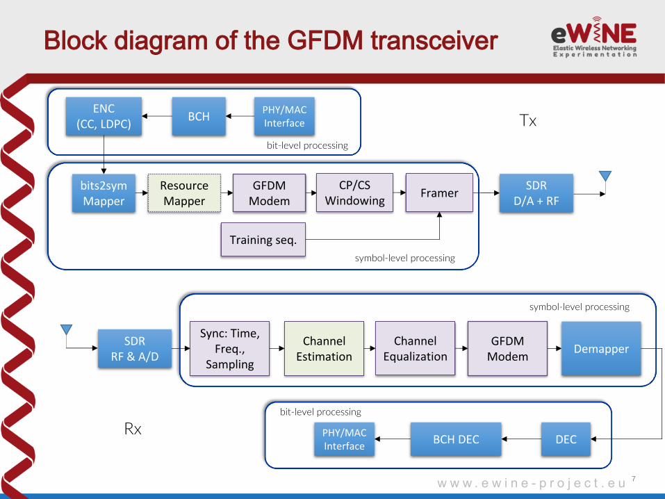
symbol-level processing
bit-level processing
Block diagram of the GFDM transceiver
7
BCH ENC
(CC, LDPC)
bits2symMapper
PHY/MAC Interface
Channel Estimation
Framer SDR
D/A + RF
Sync: Time, Freq.,
Sampling
DEC
GFDM Modem
Training seq.
SDR RF & A/D
Demapper
BCH DEC PHY/MAC Interface
bit-level processing
symbol-level processing
Tx
Rx
Resource Mapper
Channel Equalization
GFDM Modem
CP/CS Windowing
w w w . e w i n e - p r o j e c t . e u
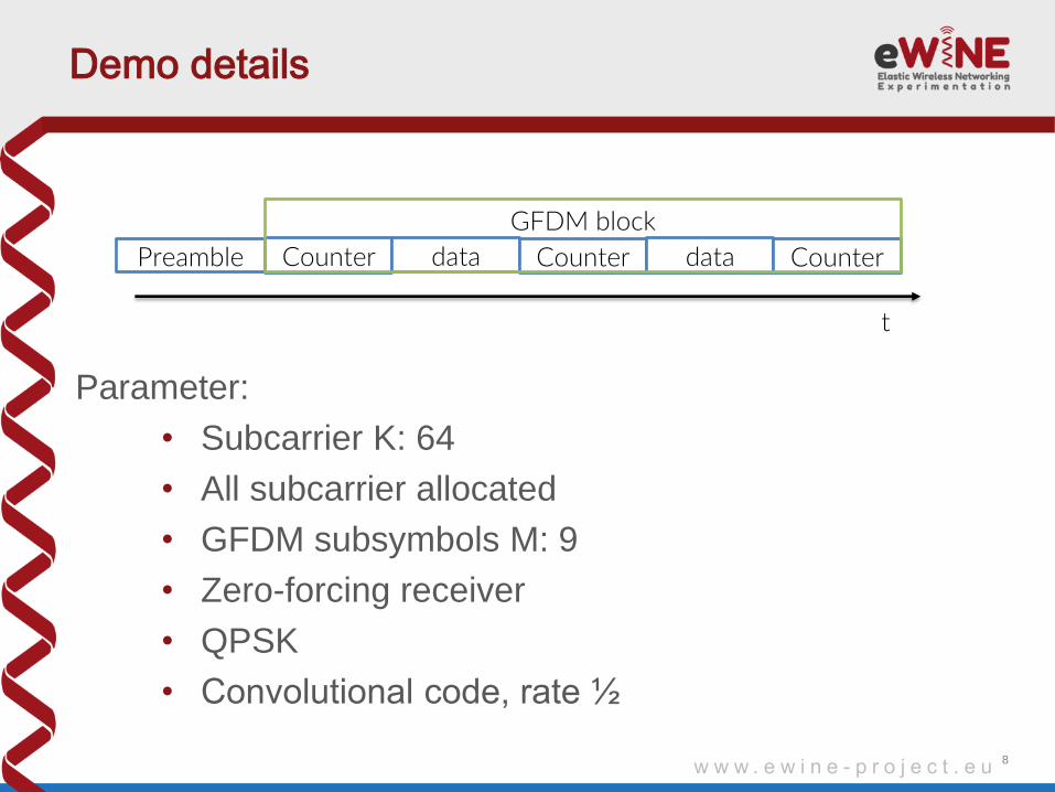
Demo details
Parameter:
• Subcarrier K: 64
• All subcarrier allocated
• GFDM subsymbols M: 9
• Zero-forcing receiver
• QPSK
• Convolutional code, rate ½
8
Preamble Counter data Counter data Counter
GFDM block
t
w w w . e w i n e - p r o j e c t . e u
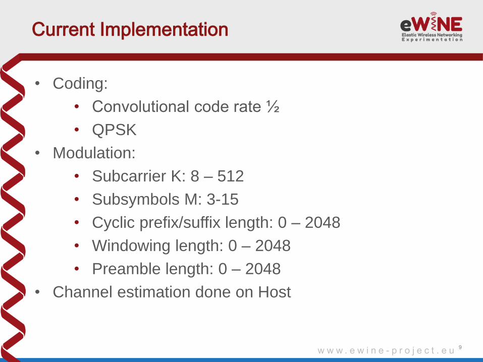
Current Implementation
• Coding:
• Convolutional code rate ½
• QPSK
• Modulation:
• Subcarrier K: 8 – 512
• Subsymbols M: 3-15
• Cyclic prefix/suffix length: 0 – 2048
• Windowing length: 0 – 2048
• Preamble length: 0 – 2048
• Channel estimation done on Host
9
w w w . e w i n e - p r o j e c t . e u
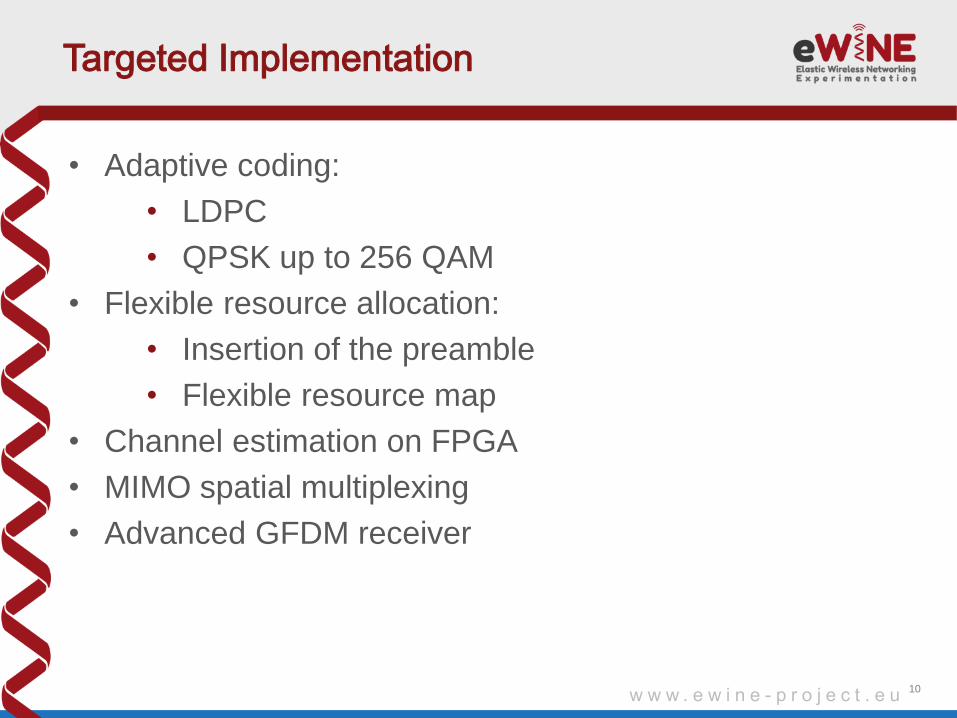
Targeted Implementation
• Adaptive coding:
• LDPC
• QPSK up to 256 QAM
• Flexible resource allocation:
• Insertion of the preamble
• Flexible resource map
• Channel estimation on FPGA
• MIMO spatial multiplexing
• Advanced GFDM receiver
10
w w w . e w i n e - p r o j e c t . e u
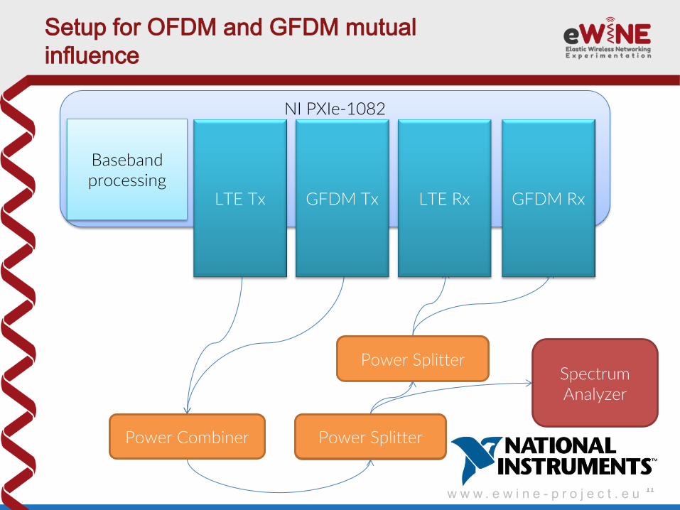
Setup for OFDM and GFDM mutual
influence
11
NI PXIe-1082
NI PXIe-8133
(Win7)
NI PXIe-7965R
NI PXIe-7965R
NI PXIe-7965R
NI 5791 NI 5791 NI 5791
Power Combiner ZN2PD-63-S+
Power Splitter ZN2PD-63-S+ Spectrum
Analyzer
NI PXIe-7965R
NI 5791
Power Splitter ZN2PD-63-S+
LTE Tx GFDM Tx LTE Rx GFDM Rx
Baseband processing
Power Splitter
Power Splitter Power Combiner
w w w . e w i n e - p r o j e c t . e u
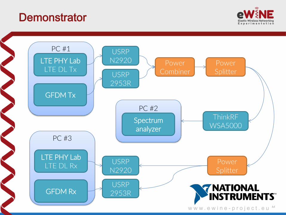
Demonstrator
12
PC #1
LTE PHY Lab LTE DL Tx
USRP N2920
USRP 2953R
GFDM Tx
Power Combiner
Power Splitter
PC #3
LTE PHY Lab LTE DL Rx
GFDM Rx
Power Splitter
ThinkRF WSA5000
PC #2
Spectrum analyzer
USRP N2920
USRP 2953R
13
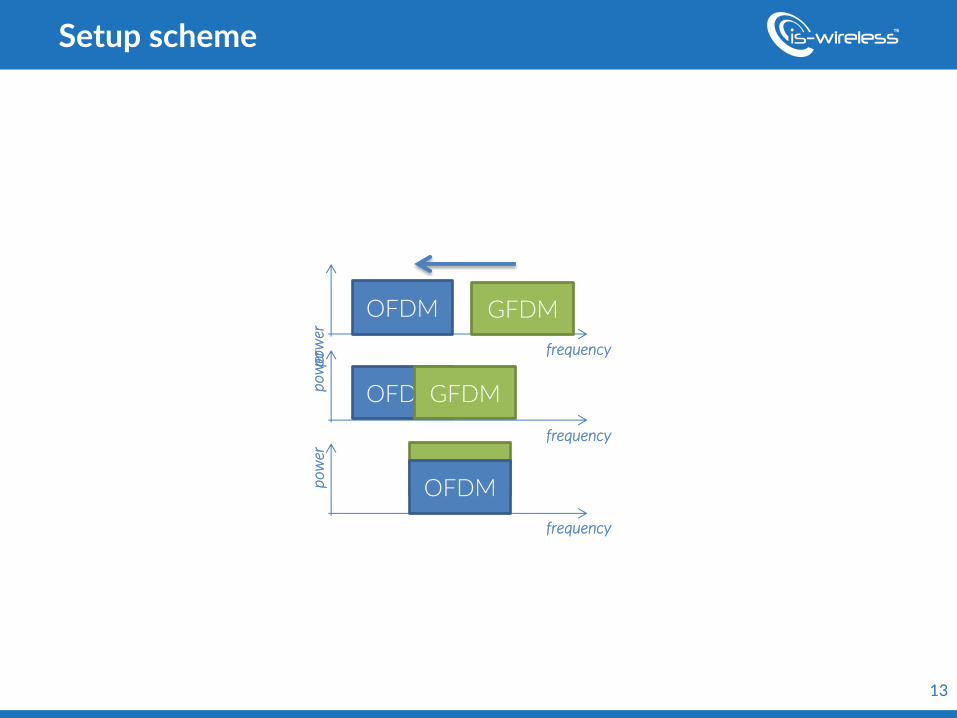
Setup scheme
GFDM
OFDM GFDM
OFDM GFDM
OFDM
frequency
frequency
frequency
po
wer
p
ow
er
po
wer
1
• 4G/5G Introduction
• Experimentation platform
• Realization and demonstration of use case scenarios
• Conclusions for education and research
1
Tutorial outline
2
• Summary
• Other solutions for education and research – aLTErnative
– University Suite
2
Conclusions for education and research
3
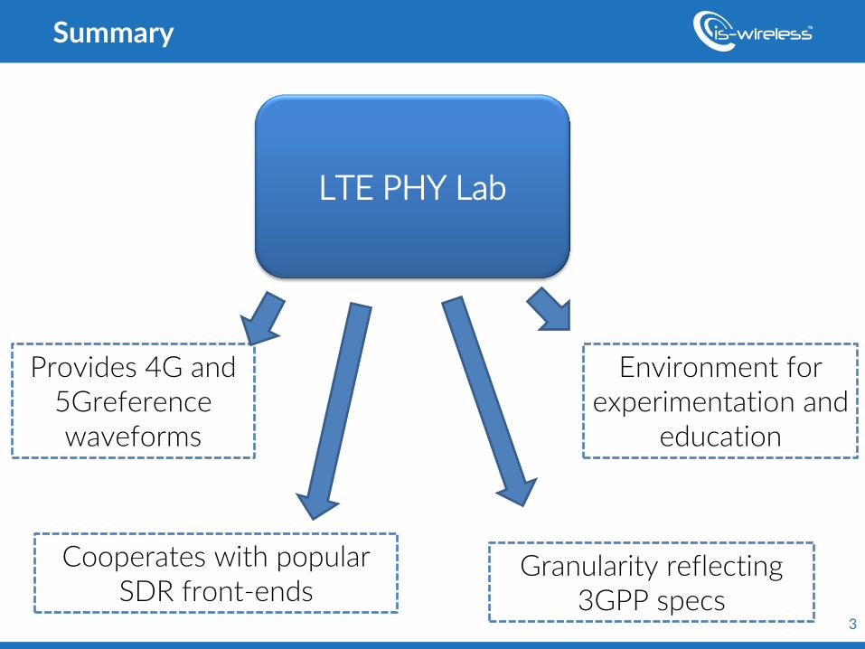
Summary
LTE PHY Lab
Provides 4G and 5Greference waveforms
Cooperates with popular SDR front-ends
Environment for experimentation and
education
Granularity reflecting 3GPP specs
4
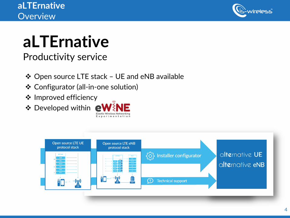
aLTErnative Overview
Open source LTE stack – UE and eNB available
Configurator (all-in-one solution)
Improved efficiency
Developed within
aLTErnative Productivity service
5
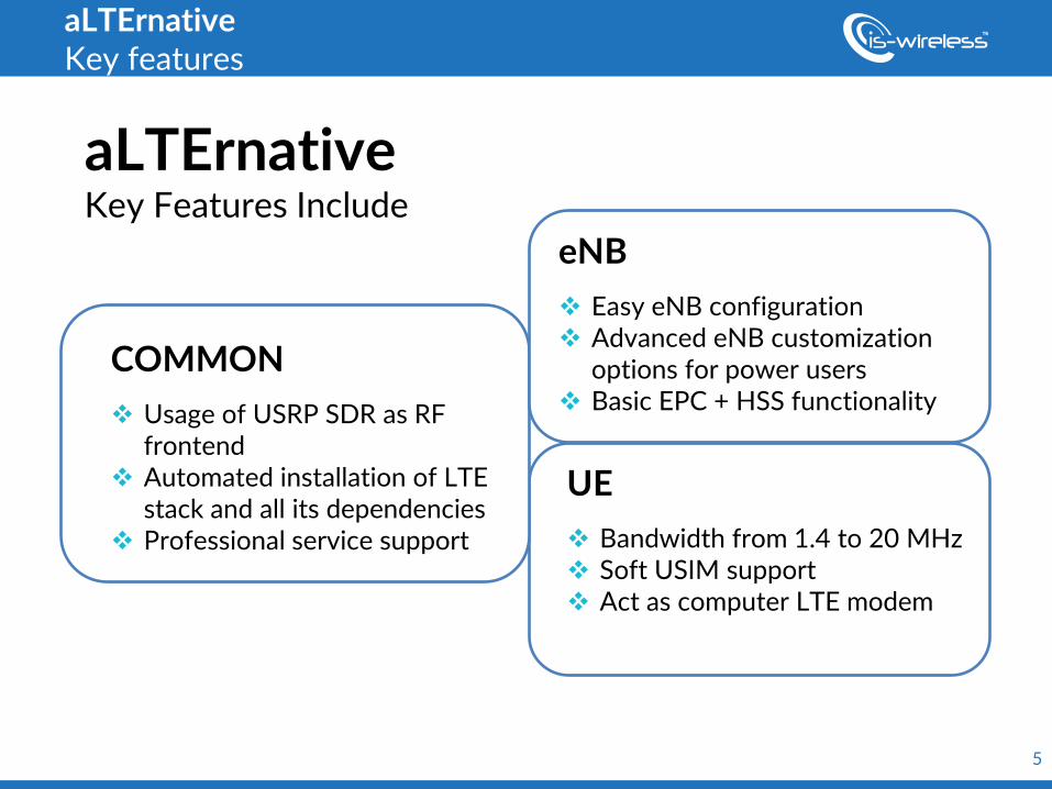
aLTErnative Key features
aLTErnative Key Features Include
COMMON
Usage of USRP SDR as RF frontend
Automated installation of LTE stack and all its dependencies
Professional service support
eNB
Easy eNB configuration Advanced eNB customization
options for power users Basic EPC + HSS functionality
UE
Bandwidth from 1.4 to 20 MHz Soft USIM support Act as computer LTE modem
6
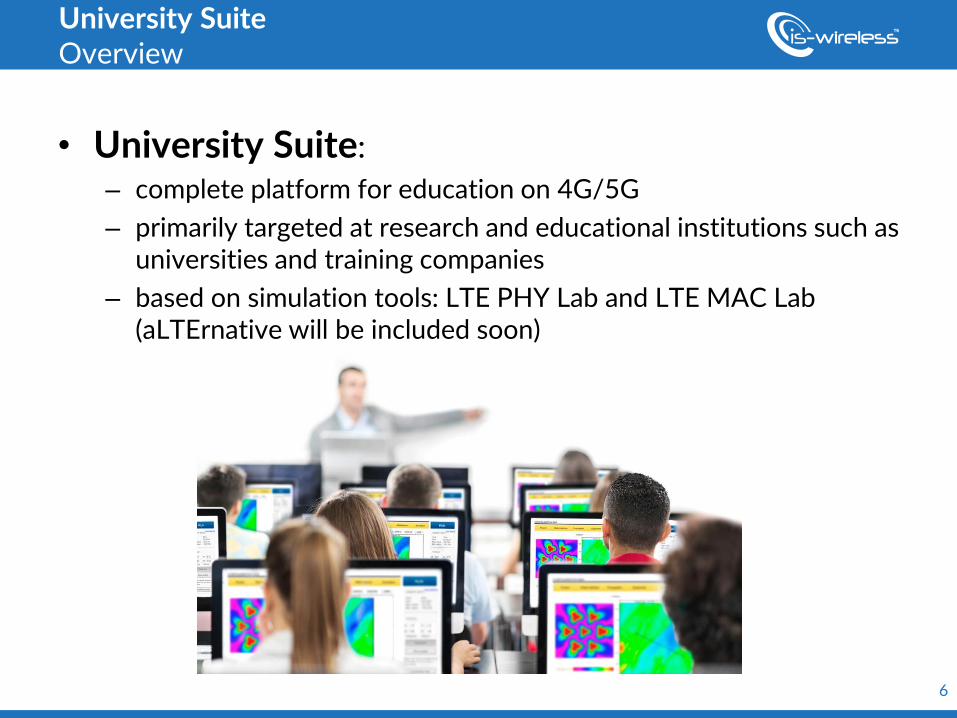
• University Suite:
– complete platform for education on 4G/5G
– primarily targeted at research and educational institutions such as universities and training companies
– based on simulation tools: LTE PHY Lab and LTE MAC Lab (aLTErnative will be included soon)
University Suite Overview
7
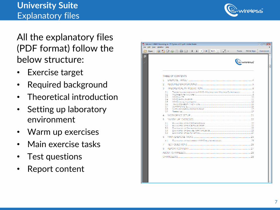
University Suite Explanatory files
All the explanatory files (PDF format) follow the below structure:
• Exercise target
• Required background
• Theoretical introduction
• Setting up laboratory environment
• Warm up exercises
• Main exercise tasks
• Test questions
• Report content
8
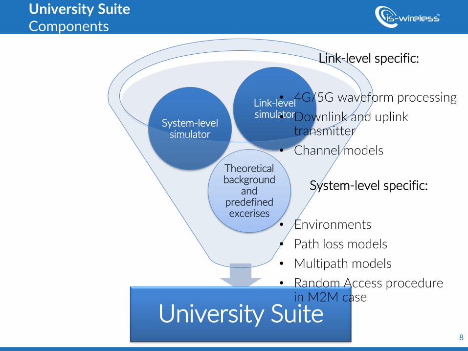
University Suite
Theoretical background
and predefined excerises
System-level simulator
Link-level simulator
University Suite Components
Link-level specific:
• 4G/5G waveform processing
• Downlink and uplink transmitter
• Channel models
System-level specific:
• Environments
• Path loss models
• Multipath models
• Random Access procedure in M2M case
9
IS-Wireless
ul. Puławska 45b,
05-500 Piaseczno / near Warsaw,
Poland, EU
9
phone fax
web e-mail
+48 22 213 8297 +48 22 213 8298 www.is-wireless.com [email protected]
CONTACT DETAILS