5.14. exception and interrupt referenceinterrupt and exception handling interrupt 1—debug...
TRANSCRIPT
5-22 Vol. 3
INTERRUPT AND EXCEPTION HANDLING
5.14. EXCEPTION AND INTERRUPT REFERENCEThe following sections describe conditions which generate exceptions and interrupts. They arearranged in the order of vector numbers. The information contained in these sections are asfollows:
Exception Class Indicates whether the exception class is a fault, trap, or abort type.Some exceptions can be either a fault or trap type, depending onwhen the error condition is detected. (This section is not applicableto interrupts.)
Description Gives a general description of the purpose of the exception or inter-rupt type. It also describes how the processor handles the exceptionor interrupt.
Exception Error Code Indicates whether an error code is saved for the exception. If one issaved, the contents of the error code are described. (This section isnot applicable to interrupts.)
Saved Instruction Pointer Describes which instruction the saved (or return) instruction pointerpoints to. It also indicates whether the pointer can be used to restarta faulting instruction.
Program State Change Describes the effects of the exception or interrupt on the state of thecurrently running program or task and the possibilities of restartingthe program or task without loss of continuity.

Vol. 3 5-23
INTERRUPT AND EXCEPTION HANDLING
Interrupt 0—Divide Error Exception (#DE)
Exception Class Fault.
Description
Indicates the divisor operand for a DIV or IDIV instruction is 0 or that the result cannot be repre-sented in the number of bits specified for the destination operand.
Exception Error Code
None.
Saved Instruction Pointer
Saved contents of CS and EIP registers point to the instruction that generated the exception.
Program State Change
A program-state change does not accompany the divide error, because the exception occursbefore the faulting instruction is executed.

5-24 Vol. 3
INTERRUPT AND EXCEPTION HANDLING
Interrupt 1—Debug Exception (#DB)
Exception Class Trap or Fault. The exception handler can distinguish between traps or faults by examining the contents of DR6 and the other debug registers.
Description
Indicates that one or more of several debug-exception conditions has been detected. Whether theexception is a fault or a trap depends on the condition (see Table 5-3). See Chapter 15, Debug-ging and Performance Monitoring, for detailed information about the debug exceptions.
Exception Error Code
None. An exception handler can examine the debug registers to determine which conditioncaused the exception.
Saved Instruction Pointer
Fault—Saved contents of CS and EIP registers point to the instruction that generated theexception.
Trap—Saved contents of CS and EIP registers point to the instruction following the instructionthat generated the exception.
Program State Change
Fault—A program-state change does not accompany the debug exception, because the excep-tion occurs before the faulting instruction is executed. The program can resume normal execu-tion upon returning from the debug exception handler.
Trap—A program-state change does accompany the debug exception, because the instruction ortask switch being executed is allowed to complete before the exception is generated. However,the new state of the program is not corrupted and execution of the program can continue reliably.
Table 5-3. Debug Exception Conditions and Corresponding Exception Classes
Exception Condition Exception Class
Instruction fetch breakpoint Fault
Data read or write breakpoint Trap
I/O read or write breakpoint Trap
General detect condition (in conjunction with in-circuit emulation) Fault
Single-step Trap
Task-switch Trap
Vol. 3 5-25
INTERRUPT AND EXCEPTION HANDLING
Interrupt 2—NMI Interrupt
Exception Class Not applicable.
Description
The nonmaskable interrupt (NMI) is generated externally by asserting the processor’s NMI pinor through an NMI request set by the I/O APIC to the local APIC. This interrupt causes the NMIinterrupt handler to be called.
Exception Error Code
Not applicable.
Saved Instruction Pointer
The processor always takes an NMI interrupt on an instruction boundary. The saved contents ofCS and EIP registers point to the next instruction to be executed at the point the interrupt istaken. See Section 5.5., “Exception Classifications”, for more information about when theprocessor takes NMI interrupts.
Program State Change
The instruction executing when an NMI interrupt is received is completed before the NMI isgenerated. A program or task can thus be restarted upon returning from an interrupt handlerwithout loss of continuity, provided the interrupt handler saves the state of the processor beforehandling the interrupt and restores the processor’s state prior to a return.

5-26 Vol. 3
INTERRUPT AND EXCEPTION HANDLING
Interrupt 3—Breakpoint Exception (#BP)
Exception Class Trap.
Description
Indicates that a breakpoint instruction (INT 3) was executed, causing a breakpoint trap to begenerated. Typically, a debugger sets a breakpoint by replacing the first opcode byte of aninstruction with the opcode for the INT 3 instruction. (The INT 3 instruction is one byte long,which makes it easy to replace an opcode in a code segment in RAM with the breakpointopcode.) The operating system or a debugging tool can use a data segment mapped to the samephysical address space as the code segment to place an INT 3 instruction in places where it isdesired to call the debugger.
With the P6 family, Pentium, Intel486, and Intel386 processors, it is more convenient to setbreakpoints with the debug registers. (See Section 15.3.2., “Breakpoint Exception(#BP)—Interrupt Vector 3”, for information about the breakpoint exception.) If more break-points are needed beyond what the debug registers allow, the INT 3 instruction can be used.
The breakpoint (#BP) exception can also be generated by executing the INT n instruction withan operand of 3. The action of this instruction (INT 3) is slightly different than that of the INT3 instruction (see “INTn/INTO/INT3—Call to Interrupt Procedure” in Chapter 3 of the IA-32Intel Architecture Software Developer’s Manual, Volume 2).
Exception Error Code
None.
Saved Instruction Pointer
Saved contents of CS and EIP registers point to the instruction following the INT 3 instruction.
Program State Change
Even though the EIP points to the instruction following the breakpoint instruction, the state ofthe program is essentially unchanged because the INT 3 instruction does not affect any registeror memory locations. The debugger can thus resume the suspended program by replacing theINT 3 instruction that caused the breakpoint with the original opcode and decrementing thesaved contents of the EIP register. Upon returning from the debugger, program executionresumes with the replaced instruction.

Vol. 3 5-27
INTERRUPT AND EXCEPTION HANDLING
Interrupt 4—Overflow Exception (#OF)
Exception Class Trap.
Description
Indicates that an overflow trap occurred when an INTO instruction was executed. The INTOinstruction checks the state of the OF flag in the EFLAGS register. If the OF flag is set, an over-flow trap is generated.
Some arithmetic instructions (such as the ADD and SUB) perform both signed and unsignedarithmetic. These instructions set the OF and CF flags in the EFLAGS register to indicate signedoverflow and unsigned overflow, respectively. When performing arithmetic on signed operands,the OF flag can be tested directly or the INTO instruction can be used. The benefit of using theINTO instruction is that if the overflow exception is detected, an exception handler can be calledautomatically to handle the overflow condition.
Exception Error Code
None.
Saved Instruction Pointer
The saved contents of CS and EIP registers point to the instruction following the INTOinstruction.
Program State Change
Even though the EIP points to the instruction following the INTO instruction, the state of theprogram is essentially unchanged because the INTO instruction does not affect any register ormemory locations. The program can thus resume normal execution upon returning from theoverflow exception handler.
5-28 Vol. 3
INTERRUPT AND EXCEPTION HANDLING
Interrupt 5—BOUND Range Exceeded Exception (#BR)
Exception Class Fault.
Description
Indicates that a BOUND-range-exceeded fault occurred when a BOUND instruction wasexecuted. The BOUND instruction checks that a signed array index is within the upper andlower bounds of an array located in memory. If the array index is not within the bounds of thearray, a BOUND-range-exceeded fault is generated.
Exception Error Code
None.
Saved Instruction Pointer
The saved contents of CS and EIP registers point to the BOUND instruction that generated theexception.
Program State Change
A program-state change does not accompany the bounds-check fault, because the operands forthe BOUND instruction are not modified. Returning from the BOUND-range-exceeded excep-tion handler causes the BOUND instruction to be restarted.

Vol. 3 5-29
INTERRUPT AND EXCEPTION HANDLING
Interrupt 6—Invalid Opcode Exception (#UD)
Exception Class Fault.
Description
Indicates that the processor did one of the following things:
• Attempted to execute an invalid or reserved opcode.
• Attempted to execute an instruction with an operand type that is invalid for its accompa-nying opcode; for example, the source operand for a LES instruction is not a memorylocation.
• Attempted to execute an MMX or SSE/SSE2/SSE3 instruction on an IA-32 processor thatdoes not support the MMX technology or SSE/SSE2/SSE3 extensions, respectively.CPUID feature flags MMX (bit 23), SSE (bit 25), SSE2 (bit 26), SSE3 (ECX, bit 0)indicate support for these extensions.
• Attempted to execute an MMX instruction or SSE/SSE2/SSE3 SIMD instruction (with theexception of the MOVNTI, PAUSE, PREFETCHh, SFENCE, LFENCE, MFENCE, andCLFLUSH instructions) when the EM flag in control register CR0 is set (1).
• Attempted to execute an SSE/SE2/SSE3 instruction when the OSFXSR bit in controlregister CR4 is clear (0). Note this does not include the following SSE/SSE2/SSE3 instruc-tions: MASKMOVQ, MOVNTQ, MOVNTI, PREFETCHh, SFENCE, LFENCE,MFENCE, and CLFLUSH; or the 64-bit versions of the PAVGB, PAVGW, PEXTRW,PINSRW, PMAXSW, PMAXUB, PMINSW, PMINUB, PMOVMSKB, PMULHUW,PSADBW, PSHUFW, PADDQ, and PSUBQ.
• Attempted to execute an SSE/SSE2/SSE3 instruction on an IA-32 processor that causes aSIMD floating-point exception when the OSXMMEXCPT bit in control register CR4 isclear (0).
• Executed a UD2 instruction. Note that even though it is the execution of the UD2instruction that causes the invalid opcode exception, the saved instruction pointer stillpoints at the UD2 instruction.
• Detected a LOCK prefix that precedes an instruction that may not be locked or one thatmay be locked but the destination operand is not a memory location.
• Attempted to execute an LLDT, SLDT, LTR, STR, LSL, LAR, VERR, VERW, or ARPLinstruction while in real-address or virtual-8086 mode.
• Attempted to execute the RSM instruction when not in SMM mode.
In the Pentium 4, Intel Xeon, and P6 family processors, this exception is not generated until anattempt is made to retire the result of executing an invalid instruction; that is, decoding and spec-ulatively attempting to execute an invalid opcode does not generate this exception. Likewise, inthe Pentium processor and earlier IA-32 processors, this exception is not generated as the resultof prefetching and preliminary decoding of an invalid instruction. (See Section 5.5., “ExceptionClassifications”, for general rules for taking of interrupts and exceptions.)

5-30 Vol. 3
INTERRUPT AND EXCEPTION HANDLING
The opcodes D6 and F1 are undefined opcodes that are reserved by the IA-32 architecture.These opcodes, even though undefined, do not generate an invalid opcode exception.
The UD2 instruction is guaranteed to generate an invalid opcode exception.
Exception Error Code
None.
Saved Instruction Pointer
The saved contents of CS and EIP registers point to the instruction that generated the exception.
Program State Change
A program-state change does not accompany an invalid-opcode fault, because the invalidinstruction is not executed.

Vol. 3 5-31
INTERRUPT AND EXCEPTION HANDLING
Interrupt 7—Device Not Available Exception (#NM)
Exception Class Fault.
Description
Indicates one of the following things:
The device-not-available exception is generated by either of three conditions:
• The processor executed an x87 FPU floating-point instruction while the EM flag in controlregister CR0 was set (1). See the paragraph below for the special case of the WAIT/FWAITinstruction.
• The processor executed a WAIT/FWAIT instruction while the MP and TS flags of registerCR0 were set, regardless of the setting of the EM flag.
• The processor executed an x87 FPU, MMX, or SSE/SSE2/SSE3 instruction (with theexception of MOVNTI, PAUSE, PREFETCHh, SFENCE, LFENCE, MFENCE, andCLFLUSH) while the TS flag in control register CR0 was set and the EM flag is clear.
The EM flag is set when the processor does not have an internal x87 FPU floating-point unit. Adevice-not-available exception is then generated each time an x87 FPU floating-point instruc-tion is encountered, allowing an exception handler to call floating-point instruction emulationroutines.
The TS flag indicates that a context switch (task switch) has occurred since the last time an x87floating-point, MMX, or SSE/SSE2/SSE3 instruction was executed; but that the context of thex87 FPU, XMM, and MXCSR registers were not saved. When the TS flag is set and the EM flagis clear, the processor generates a device-not-available exception each time an x87 floating-point, MMX, or SSE/SSE2/SSE3 instruction is encountered (with the exception of the instruc-tions listed above). The exception handler can then save the context of the x87 FPU, XMM, andMXCSR registers before it executes the instruction. See Section 2.5., “Control Registers”, formore information about the TS flag.
The MP flag in control register CR0 is used along with the TS flag to determine if WAIT orFWAIT instructions should generate a device-not-available exception. It extends the function ofthe TS flag to the WAIT and FWAIT instructions, giving the exception handler an opportunityto save the context of the x87 FPU before the WAIT or FWAIT instruction is executed. The MPflag is provided primarily for use with the Intel 286 and Intel386 DX processors. For programsrunning on the Pentium 4, Intel Xeon, P6 family, Pentium, or Intel486 DX processors, or theIntel 487 SX coprocessors, the MP flag should always be set; for programs running on theIntel486 SX processor, the MP flag should be clear.
Exception Error Code
None.

5-32 Vol. 3
INTERRUPT AND EXCEPTION HANDLING
Saved Instruction Pointer
The saved contents of CS and EIP registers point to the floating-point instruction or theWAIT/FWAIT instruction that generated the exception.
Program State Change
A program-state change does not accompany a device-not-available fault, because the instruc-tion that generated the exception is not executed.
If the EM flag is set, the exception handler can then read the floating-point instruction pointedto by the EIP and call the appropriate emulation routine.
If the MP and TS flags are set or the TS flag alone is set, the exception handler can save thecontext of the x87 FPU, clear the TS flag, and continue execution at the interrupted floating-point or WAIT/FWAIT instruction.

Vol. 3 5-33
INTERRUPT AND EXCEPTION HANDLING
Interrupt 8—Double Fault Exception (#DF)
Exception Class Abort.
Description
Indicates that the processor detected a second exception while calling an exception handler fora prior exception. Normally, when the processor detects another exception while trying to callan exception handler, the two exceptions can be handled serially. If, however, the processorcannot handle them serially, it signals the double-fault exception. To determine when two faultsneed to be signalled as a double fault, the processor divides the exceptions into three classes:benign exceptions, contributory exceptions, and page faults (see Table 5-4).
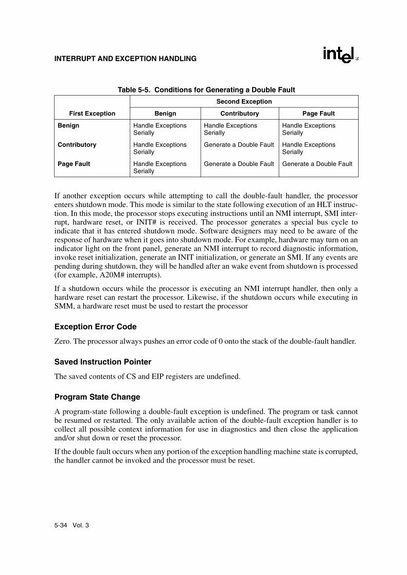
Table 5-5 shows the various combinations of exception classes that cause a double fault to begenerated. A double-fault exception falls in the abort class of exceptions. The program or taskcannot be restarted or resumed. The double-fault handler can be used to collect diagnostic infor-mation about the state of the machine and/or, when possible, to shut the application and/orsystem down gracefully or restart the system.
A segment or page fault may be encountered while prefetching instructions; however, thisbehavior is outside the domain of Table 5-5. Any further faults generated while the processor isattempting to transfer control to the appropriate fault handler could still lead to a double-faultsequence.
Table 5-4. Interrupt and Exception Classes
Class Vector Number Description
Benign Exceptions and Interrupts 1 2 3 4 5 6 7916171819AllAll
DebugNMI InterruptBreakpointOverflowBOUND Range ExceededInvalid OpcodeDevice Not AvailableCoprocessor Segment OverrunFloating-Point ErrorAlignment CheckMachine CheckSIMD floating-pointINT nINTR
Contributory Exceptions 010111213
Divide ErrorInvalid TSSSegment Not PresentStack FaultGeneral Protection
Page Faults 14 Page Fault
5-34 Vol. 3
INTERRUPT AND EXCEPTION HANDLING
If another exception occurs while attempting to call the double-fault handler, the processorenters shutdown mode. This mode is similar to the state following execution of an HLT instruc-tion. In this mode, the processor stops executing instructions until an NMI interrupt, SMI inter-rupt, hardware reset, or INIT# is received. The processor generates a special bus cycle toindicate that it has entered shutdown mode. Software designers may need to be aware of theresponse of hardware when it goes into shutdown mode. For example, hardware may turn on anindicator light on the front panel, generate an NMI interrupt to record diagnostic information,invoke reset initialization, generate an INIT initialization, or generate an SMI. If any events arepending during shutdown, they will be handled after an wake event from shutdown is processed(for example, A20M# interrupts).
If a shutdown occurs while the processor is executing an NMI interrupt handler, then only ahardware reset can restart the processor. Likewise, if the shutdown occurs while executing inSMM, a hardware reset must be used to restart the processor
Exception Error Code
Zero. The processor always pushes an error code of 0 onto the stack of the double-fault handler.
Saved Instruction Pointer
The saved contents of CS and EIP registers are undefined.
Program State Change
A program-state following a double-fault exception is undefined. The program or task cannotbe resumed or restarted. The only available action of the double-fault exception handler is tocollect all possible context information for use in diagnostics and then close the applicationand/or shut down or reset the processor.
If the double fault occurs when any portion of the exception handling machine state is corrupted,the handler cannot be invoked and the processor must be reset.
Table 5-5. Conditions for Generating a Double Fault
Second Exception
First Exception Benign Contributory Page Fault
Benign Handle Exceptions Serially
Handle Exceptions Serially
Handle Exceptions Serially
Contributory Handle Exceptions Serially
Generate a Double Fault Handle Exceptions Serially
Page Fault Handle Exceptions Serially
Generate a Double Fault Generate a Double Fault

Vol. 3 5-35
INTERRUPT AND EXCEPTION HANDLING
Interrupt 9—Coprocessor Segment Overrun
Exception Class Abort. (Intel reserved; do not use. Recent IA-32 processors do not generate this exception.)
Description
Indicates that an Intel386 CPU-based systems with an Intel 387 math coprocessor detected apage or segment violation while transferring the middle portion of an Intel 387 math copro-cessor operand. The P6 family, Pentium, and Intel486 processors do not generate this exception;instead, this condition is detected with a general protection exception (#GP), interrupt 13.
Exception Error Code
None.
Saved Instruction Pointer
The saved contents of CS and EIP registers point to the instruction that generated the exception.
Program State Change
A program-state following a coprocessor segment-overrun exception is undefined. The programor task cannot be resumed or restarted. The only available action of the exception handler is tosave the instruction pointer and reinitialize the x87 FPU using the FNINIT instruction.
5-36 Vol. 3
INTERRUPT AND EXCEPTION HANDLING
Interrupt 10—Invalid TSS Exception (#TS)
Exception Class Fault.
Description
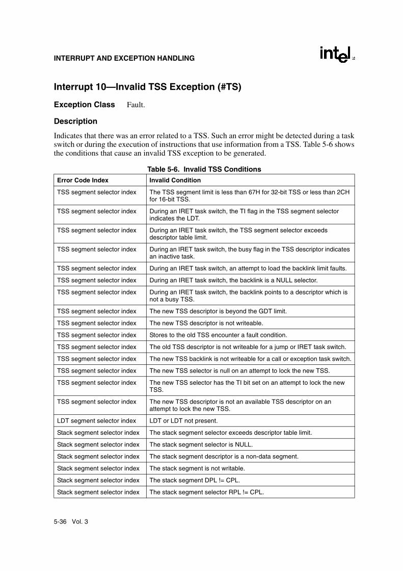
Indicates that there was an error related to a TSS. Such an error might be detected during a taskswitch or during the execution of instructions that use information from a TSS. Table 5-6 showsthe conditions that cause an invalid TSS exception to be generated.
Table 5-6. Invalid TSS Conditions Error Code Index Invalid Condition
TSS segment selector index The TSS segment limit is less than 67H for 32-bit TSS or less than 2CH for 16-bit TSS.
TSS segment selector index During an IRET task switch, the TI flag in the TSS segment selector indicates the LDT.
TSS segment selector index During an IRET task switch, the TSS segment selector exceeds descriptor table limit.
TSS segment selector index During an IRET task switch, the busy flag in the TSS descriptor indicates an inactive task.
TSS segment selector index During an IRET task switch, an attempt to load the backlink limit faults.
TSS segment selector index During an IRET task switch, the backlink is a NULL selector.
TSS segment selector index During an IRET task switch, the backlink points to a descriptor which is not a busy TSS.
TSS segment selector index The new TSS descriptor is beyond the GDT limit.
TSS segment selector index The new TSS descriptor is not writeable.
TSS segment selector index Stores to the old TSS encounter a fault condition.
TSS segment selector index The old TSS descriptor is not writeable for a jump or IRET task switch.
TSS segment selector index The new TSS backlink is not writeable for a call or exception task switch.
TSS segment selector index The new TSS selector is null on an attempt to lock the new TSS.
TSS segment selector index The new TSS selector has the TI bit set on an attempt to lock the new TSS.
TSS segment selector index The new TSS descriptor is not an available TSS descriptor on an attempt to lock the new TSS.
LDT segment selector index LDT or LDT not present.
Stack segment selector index The stack segment selector exceeds descriptor table limit.
Stack segment selector index The stack segment selector is NULL.
Stack segment selector index The stack segment descriptor is a non-data segment.
Stack segment selector index The stack segment is not writable.
Stack segment selector index The stack segment DPL != CPL.
Stack segment selector index The stack segment selector RPL != CPL.

Vol. 3 5-37
INTERRUPT AND EXCEPTION HANDLING
This exception can generated either in the context of the original task or in the context of thenew task (see Section 6.3., “Task Switching”). Until the processor has completely verified thepresence of the new TSS, the exception is generated in the context of the original task. Once theexistence of the new TSS is verified, the task switch is considered complete. Any invalid-TSSconditions detected after this point are handled in the context of the new task. (A task switch isconsidered complete when the task register is loaded with the segment selector for the new TSSand, if the switch is due to a procedure call or interrupt, the previous task link field of the newTSS references the old TSS.)
The invalid-TSS handler must be a task called using a task gate. Handling this exception insidethe faulting TSS context is not recommended because the processor state may not be consistent.
Exception Error Code
An error code containing the segment selector index for the segment descriptor that caused theviolation is pushed onto the stack of the exception handler. If the EXT flag is set, it indicates thatthe exception was caused by an event external to the currently running program (for example, ifan external interrupt handler using a task gate attempted a task switch to an invalid TSS).
Saved Instruction Pointer
If the exception condition was detected before the task switch was carried out, the savedcontents of CS and EIP registers point to the instruction that invoked the task switch. If the
Code segment selector index The code segment selector exceeds descriptor table limit.
Code segment selector index The code segment selector is NULL.
Code segment selector index The code segment descriptor is not a code segment type.
Code segment selector index The nonconforming code segment DPL != CPL.
Code segment selector index The conforming code segment DPL is greater than CPL.
Data segment selector index The data segment selector exceeds the descriptor table limit.
Data segment selector index The data segment descriptor is not a readable code or data type.
Data segment selector index The data segment descriptor is a nonconforming code type and RPL > DPL.
Data segment selector index The data segment descriptor is a nonconforming code type and CPL > DPL.
TSS segment selector index The TSS segment selector is NULL for LTR.
TSS segment selector index The TSS segment selector has the TI bit set for LTR.
TSS segment selector index The TSS segment descriptor/upper descriptor is beyond the GDT segment limit.
TSS segment selector index The TSS segment descriptor is not an available TSS type.
Table 5-6. Invalid TSS Conditions (Contd.)Error Code Index Invalid Condition

5-38 Vol. 3
INTERRUPT AND EXCEPTION HANDLING
exception condition was detected after the task switch was carried out, the saved contents of CSand EIP registers point to the first instruction of the new task.
Program State Change
The ability of the invalid-TSS handler to recover from the fault depends on the error conditionthan causes the fault. See Section 6.3., “Task Switching”, for more information on the taskswitch process and the possible recovery actions that can be taken.
If an invalid TSS exception occurs during a task switch, it can occur before or after the commit-to-new-task point. If it occurs before the commit point, no program state change occurs. If itoccurs after the commit point (when the segment descriptor information for the new segmentselectors have been loaded in the segment registers), the processor will load all the state infor-mation from the new TSS before it generates the exception. During a task switch, the processorfirst loads all the segment registers with segment selectors from the TSS, then checks theircontents for validity. If an invalid TSS exception is discovered, the remaining segment registersare loaded but not checked for validity and therefore may not be usable for referencing memory.The invalid TSS handler should not rely on being able to use the segment selectors found in theCS, SS, DS, ES, FS, and GS registers without causing another exception. The exception handlershould load all segment registers before trying to resume the new task; otherwise, general-protection exceptions (#GP) may result later under conditions that make diagnosis more diffi-cult. The Intel recommended way of dealing situation is to use a task for the invalid TSS excep-tion handler. The task switch back to the interrupted task from the invalid-TSS exception-handler task will then cause the processor to check the registers as it loads them from the TSS.

Vol. 3 5-39
INTERRUPT AND EXCEPTION HANDLING
Interrupt 11—Segment Not Present (#NP)
Exception Class Fault.
Description
Indicates that the present flag of a segment or gate descriptor is clear. The processor can generatethis exception during any of the following operations:
• While attempting to load CS, DS, ES, FS, or GS registers. [Detection of a not-presentsegment while loading the SS register causes a stack fault exception (#SS) to begenerated.] This situation can occur while performing a task switch.
• While attempting to load the LDTR using an LLDT instruction. Detection of a not-presentLDT while loading the LDTR during a task switch operation causes an invalid-TSSexception (#TS) to be generated.
• When executing the LTR instruction and the TSS is marked not present.
• While attempting to use a gate descriptor or TSS that is marked segment-not-present, but isotherwise valid.
An operating system typically uses the segment-not-present exception to implement virtualmemory at the segment level. If the exception handler loads the segment and returns, the inter-rupted program or task resumes execution.
A not-present indication in a gate descriptor, however, does not indicate that a segment is notpresent (because gates do not correspond to segments). The operating system may use thepresent flag for gate descriptors to trigger exceptions of special significance to the operatingsystem.
A contributory exception or page fault that subsequently referenced a not-present segmentwould cause a double fault (#DF) to be generated instead of #NP.
Exception Error Code
An error code containing the segment selector index for the segment descriptor that caused theviolation is pushed onto the stack of the exception handler. If the EXT flag is set, it indicates thatthe exception resulted from either:
• an external event (NMI or INTR) that caused an interrupt, which subsequently referenced anot-present segment
• a benign exception that subsequently referenced a not-present segment
The IDT flag is set if the error code refers to an IDT entry. This occurs when the IDT entry foran interrupt being serviced references a not-present gate. Such an event could be generated byan INT instruction or a hardware interrupt.

5-40 Vol. 3
INTERRUPT AND EXCEPTION HANDLING
Saved Instruction Pointer
The saved contents of CS and EIP registers normally point to the instruction that generated theexception. If the exception occurred while loading segment descriptors for the segment selectorsin a new TSS, the CS and EIP registers point to the first instruction in the new task. If the excep-tion occurred while accessing a gate descriptor, the CS and EIP registers point to the instructionthat invoked the access (for example a CALL instruction that references a call gate).
Program State Change
If the segment-not-present exception occurs as the result of loading a register (CS, DS, SS, ES,FS, GS, or LDTR), a program-state change does accompany the exception because the registeris not loaded. Recovery from this exception is possible by simply loading the missing segmentinto memory and setting the present flag in the segment descriptor.
If the segment-not-present exception occurs while accessing a gate descriptor, a program-statechange does not accompany the exception. Recovery from this exception is possible merely bysetting the present flag in the gate descriptor.
If a segment-not-present exception occurs during a task switch, it can occur before or after thecommit-to-new-task point (see Section 6.3., “Task Switching”). If it occurs before the commitpoint, no program state change occurs. If it occurs after the commit point, the processor will loadall the state information from the new TSS (without performing any additional limit, present, ortype checks) before it generates the exception. The segment-not-present exception handlershould not rely on being able to use the segment selectors found in the CS, SS, DS, ES, FS, andGS registers without causing another exception. (See the Program State Change description for“Interrupt 10—Invalid TSS Exception (#TS)” in this chapter for additional information on howto handle this situation.)

Vol. 3 5-41
INTERRUPT AND EXCEPTION HANDLING
Interrupt 12—Stack Fault Exception (#SS)
Exception Class Fault.
Description
Indicates that one of the following stack related conditions was detected:
• A limit violation is detected during an operation that refers to the SS register. Operationsthat can cause a limit violation include stack-oriented instructions such as POP, PUSH,CALL, RET, IRET, ENTER, and LEAVE, as well as other memory references whichimplicitly or explicitly use the SS register (for example, MOV AX, [BP+6] or MOV AX,SS:[EAX+6]). The ENTER instruction generates this exception when there is not enoughstack space for allocating local variables.
• A not-present stack segment is detected when attempting to load the SS register. Thisviolation can occur during the execution of a task switch, a CALL instruction to a differentprivilege level, a return to a different privilege level, an LSS instruction, or a MOV or POPinstruction to the SS register.
Recovery from this fault is possible by either extending the limit of the stack segment (in thecase of a limit violation) or loading the missing stack segment into memory (in the case of a not-present violation.
Exception Error Code
If the exception is caused by a not-present stack segment or by overflow of the new stack duringan inter-privilege-level call, the error code contains a segment selector for the segment thatcaused the exception. Here, the exception handler can test the present flag in the segmentdescriptor pointed to by the segment selector to determine the cause of the exception. For anormal limit violation (on a stack segment already in use) the error code is set to 0.
Saved Instruction Pointer
The saved contents of CS and EIP registers generally point to the instruction that generated theexception. However, when the exception results from attempting to load a not-present stacksegment during a task switch, the CS and EIP registers point to the first instruction of the newtask.
Program State Change
A program-state change does not generally accompany a stack-fault exception, because theinstruction that generated the fault is not executed. Here, the instruction can be restarted afterthe exception handler has corrected the stack fault condition.
If a stack fault occurs during a task switch, it occurs after the commit-to-new-task point (seeSection 6.3., “Task Switching”). Here, the processor loads all the state information from the newTSS (without performing any additional limit, present, or type checks) before it generates the
5-42 Vol. 3
INTERRUPT AND EXCEPTION HANDLING
exception. The stack fault handler should thus not rely on being able to use the segment selectorsfound in the CS, SS, DS, ES, FS, and GS registers without causing another exception. Theexception handler should check all segment registers before trying to resume the new task;otherwise, general protection faults may result later under conditions that are more difficult todiagnose. (See the Program State Change description for “Interrupt 10—Invalid TSS Exception(#TS)” in this chapter for additional information on how to handle this situation.)

Vol. 3 5-43
INTERRUPT AND EXCEPTION HANDLING
Interrupt 13—General Protection Exception (#GP)
Exception Class Fault.
Description
Indicates that the processor detected one of a class of protection violations called “general-protection violations.” The conditions that cause this exception to be generated comprise all theprotection violations that do not cause other exceptions to be generated (such as, invalid-TSS,segment-not-present, stack-fault, or page-fault exceptions). The following conditions causegeneral-protection exceptions to be generated:
• Exceeding the segment limit when accessing the CS, DS, ES, FS, or GS segments.
• Exceeding the segment limit when referencing a descriptor table (except during a taskswitch or a stack switch).
• Transferring execution to a segment that is not executable.
• Writing to a code segment or a read-only data segment.
• Reading from an execute-only code segment.
• Loading the SS register with a segment selector for a read-only segment (unless theselector comes from a TSS during a task switch, in which case an invalid-TSS exceptionoccurs).
• Loading the SS, DS, ES, FS, or GS register with a segment selector for a system segment.
• Loading the DS, ES, FS, or GS register with a segment selector for an execute-only codesegment.
• Loading the SS register with the segment selector of an executable segment or a nullsegment selector.
• Loading the CS register with a segment selector for a data segment or a null segmentselector.
• Accessing memory using the DS, ES, FS, or GS register when it contains a null segmentselector.
• Switching to a busy task during a call or jump to a TSS.
• Using a segment selector on a non-IRET task switch that points to a TSS descriptor in thecurrent LDT. TSS descriptors can only reside in the GDT. This condition causes a #TSexception during an IRET task switch.
• Violating any of the privilege rules described in Chapter 4, Protection.
• Exceeding the instruction length limit of 15 bytes (this only can occur when redundantprefixes are placed before an instruction).
• Loading the CR0 register with a set PG flag (paging enabled) and a clear PE flag(protection disabled).

5-44 Vol. 3
INTERRUPT AND EXCEPTION HANDLING
• Loading the CR0 register with a set NW flag and a clear CD flag.
• Referencing an entry in the IDT (following an interrupt or exception) that is not aninterrupt, trap, or task gate.
• Attempting to access an interrupt or exception handler through an interrupt or trap gatefrom virtual-8086 mode when the handler’s code segment DPL is greater than 0.
• Attempting to write a 1 into a reserved bit of CR4.
• Attempting to execute a privileged instruction when the CPL is not equal to 0 (see Section4.9., “Privileged Instructions”, for a list of privileged instructions).
• Writing to a reserved bit in an MSR.
• Accessing a gate that contains a null segment selector.
• Executing the INT n instruction when the CPL is greater than the DPL of the referencedinterrupt, trap, or task gate.
• The segment selector in a call, interrupt, or trap gate does not point to a code segment.
• The segment selector operand in the LLDT instruction is a local type (TI flag is set) ordoes not point to a segment descriptor of the LDT type.
• The segment selector operand in the LTR instruction is local or points to a TSS that is notavailable.
• The target code-segment selector for a call, jump, or return is null.
• If the PAE and/or PSE flag in control register CR4 is set and the processor detects anyreserved bits in a page-directory-pointer-table entry set to 1. These bits are checked duringa write to control registers CR0, CR3, or CR4 that causes a reloading of the page-directory-pointer-table entry.
• Attempting to write a non-zero value into the reserved bits of the MXCSR register.
• Executing an SSE/SSE2/SSE3 instruction that attempts to access a 128-bit memorylocation that is not aligned on a 16-byte boundary when the instruction requires 16-bytealignment. This condition also applies to the stack segment.
A program or task can be restarted following any general-protection exception. If the exceptionoccurs while attempting to call an interrupt handler, the interrupted program can be restartable,but the interrupt may be lost.
Exception Error Code
The processor pushes an error code onto the exception handler's stack. If the fault condition wasdetected while loading a segment descriptor, the error code contains a segment selector to or IDTvector number for the descriptor; otherwise, the error code is 0. The source of the selector in anerror code may be any of the following:
• An operand of the instruction.
• A selector from a gate which is the operand of the instruction.

Vol. 3 5-45
INTERRUPT AND EXCEPTION HANDLING
• A selector from a TSS involved in a task switch.
• IDT vector number.
Saved Instruction Pointer
The saved contents of CS and EIP registers point to the instruction that generated the exception.
Program State Change
In general, a program-state change does not accompany a general-protection exception, becausethe invalid instruction or operation is not executed. An exception handler can be designed tocorrect all of the conditions that cause general-protection exceptions and restart the program ortask without any loss of program continuity.
If a general-protection exception occurs during a task switch, it can occur before or after thecommit-to-new-task point (see Section 6.3., “Task Switching”). If it occurs before the commitpoint, no program state change occurs. If it occurs after the commit point, the processor will loadall the state information from the new TSS (without performing any additional limit, present, ortype checks) before it generates the exception. The general-protection exception handler shouldthus not rely on being able to use the segment selectors found in the CS, SS, DS, ES, FS, andGS registers without causing another exception. (See the Program State Change description for“Interrupt 10—Invalid TSS Exception (#TS)” in this chapter for additional information on howto handle this situation.)

5-46 Vol. 3
INTERRUPT AND EXCEPTION HANDLING
Interrupt 14—Page-Fault Exception (#PF)
Exception Class Fault.
Description
Indicates that, with paging enabled (the PG flag in the CR0 register is set), the processor detectedone of the following conditions while using the page-translation mechanism to translate a linearaddress to a physical address:
• The P (present) flag in a page-directory or page-table entry needed for the addresstranslation is clear, indicating that a page table or the page containing the operand is notpresent in physical memory.
• The procedure does not have sufficient privilege to access the indicated page (that is, aprocedure running in user mode attempts to access a supervisor-mode page).
• Code running in user mode attempts to write to a read-only page. In the Intel486 and laterprocessors, if the WP flag is set in CR0, the page fault will also be triggered by coderunning in supervisor mode that tries to write to a read-only user-mode page.
• One or more reserved bits in page directory entry are set to 1. See description below ofRSVD error code flag
The exception handler can recover from page-not-present conditions and restart the program ortask without any loss of program continuity. It can also restart the program or task after a privi-lege violation, but the problem that caused the privilege violation may be uncorrectable.
Exception Error Code
Yes (special format). The processor provides the page-fault handler with two items of informa-tion to aid in diagnosing the exception and recovering from it:
• An error code on the stack. The error code for a page fault has a format different from thatfor other exceptions (see Figure 5-7). The error code tells the exception handler fourthings:
— The P flag indicates whether the exception was due to a not-present page (0) or toeither an access rights violation or the use of a reserved bit (1).
— The W/R flag indicates whether the memory access that caused the exception was aread (0) or write (1).
— The U/S flag indicates whether the processor was executing at user mode (1) orsupervisor mode (0) at the time of the exception.
— The RSVD flag indicates that the processor detected 1s in reserved bits of the pagedirectory, when the PSE or PAE flags in control register CR4 are set to 1. (The PSEflag is only available in the Pentium 4, Intel Xeon, P6 family, and Pentium processors,and the PAE flag is only available on the Pentium 4, Intel Xeon, and P6 familyprocessors. In earlier IA-32 processor, the bit position of the RSVD flag is reserved.)

Vol. 3 5-47
INTERRUPT AND EXCEPTION HANDLING
• The contents of the CR2 register. The processor loads the CR2 register with the 32-bitlinear address that generated the exception. The page-fault handler can use this address tolocate the corresponding page directory and page-table entries. Another page fault canpotentially occur during execution of the page-fault handler; the handler should save thecontents of the CR2 register before a second page fault can occur.1 If a page fault is causedby a page-level protection violation, the access flag in the page-directory entry is set whenthe fault occurs. The behavior of IA-32 processors regarding the access flag in the corre-sponding page-table entry is model specific and not architecturally defined.
Saved Instruction Pointer
The saved contents of CS and EIP registers generally point to the instruction that generated theexception. If the page-fault exception occurred during a task switch, the CS and EIP registersmay point to the first instruction of the new task (as described in the following “Program StateChange” section).
Program State Change
A program-state change does not normally accompany a page-fault exception, because theinstruction that causes the exception to be generated is not executed. After the page-fault excep-tion handler has corrected the violation (for example, loaded the missing page into memory),execution of the program or task can be resumed.
Figure 5-7. Page-Fault Error Code
1. Processors update CR2 whenever a page fault is detected. If a second page fault occurs while an earlierpage fault is being delivered, the faulting linear address of the second fault will overwrite the contents ofCR2 (replacing the previous address). These updates to CR2 occur even if the page fault results in adouble fault or occurs during the delivery of a double fault.
The fault was caused by a non-present page.The fault was caused by a page-level protection violation.
The access causing the fault was a read.The access causing the fault was a write.
The access causing the fault originated when the processorwas executing in supervisor mode.The access causing the fault originated when the processorwas executing in user mode.
31 0
PReservedR/
W
U/S
1234RSVD
The fault was not caused by reserved bit violation.The fault was caused by reserved bits set to 1 in a page directory.
P 01
W/R 01
U/S 0
RSVD 01
1

5-48 Vol. 3
INTERRUPT AND EXCEPTION HANDLING
When a page-fault exception is generated during a task switch, the program-state may change,as follows. During a task switch, a page-fault exception can occur during any of following oper-ations:
• While writing the state of the original task into the TSS of that task.
• While reading the GDT to locate the TSS descriptor of the new task.
• While reading the TSS of the new task.
• While reading segment descriptors associated with segment selectors from the new task.
• While reading the LDT of the new task to verify the segment registers stored in the newTSS.
In the last two cases the exception occurs in the context of the new task. The instruction pointerrefers to the first instruction of the new task, not to the instruction which caused the task switch(or the last instruction to be executed, in the case of an interrupt). If the design of the operatingsystem permits page faults to occur during task-switches, the page-fault handler should be calledthrough a task gate.
If a page fault occurs during a task switch, the processor will load all the state information fromthe new TSS (without performing any additional limit, present, or type checks) before it gener-ates the exception. The page-fault handler should thus not rely on being able to use the segmentselectors found in the CS, SS, DS, ES, FS, and GS registers without causing another exception.(See the Program State Change description for “Interrupt 10—Invalid TSS Exception (#TS)” inthis chapter for additional information on how to handle this situation.)
Additional Exception-Handling Information
Special care should be taken to ensure that an exception that occurs during an explicit stackswitch does not cause the processor to use an invalid stack pointer (SS:ESP). Software writtenfor 16-bit IA-32 processors often use a pair of instructions to change to a new stack, for example:MOV SS, AXMOV SP, StackTop
When executing this code on one of the 32-bit IA-32 processors, it is possible to get a page fault,general-protection fault (#GP), or alignment check fault (#AC) after the segment selector hasbeen loaded into the SS register but before the ESP register has been loaded. At this point, thetwo parts of the stack pointer (SS and ESP) are inconsistent. The new stack segment is beingused with the old stack pointer.
The processor does not use the inconsistent stack pointer if the exception handler switches to awell defined stack (that is, the handler is a task or a more privileged procedure). However, if theexception handler is called at the same privilege level and from the same task, the processor willattempt to use the inconsistent stack pointer.

Vol. 3 5-49
INTERRUPT AND EXCEPTION HANDLING
In systems that handle page-fault, general-protection, or alignment check exceptions within thefaulting task (with trap or interrupt gates), software executing at the same privilege level as theexception handler should initialize a new stack by using the LSS instruction rather than a pairof MOV instructions, as described earlier in this note. When the exception handler is running atprivilege level 0 (the normal case), the problem is limited to procedures or tasks that run at priv-ilege level 0, typically the kernel of the operating system.
5-50 Vol. 3
INTERRUPT AND EXCEPTION HANDLING
Interrupt 16—x87 FPU Floating-Point Error (#MF)
Exception Class Fault.
Description
Indicates that the x87 FPU has detected a floating-point error. The NE flag in the register CR0must be set for an interrupt 16 (floating-point error exception) to be generated. (See Section 2.5.,“Control Registers”, for a detailed description of the NE flag.)
NOTE
SIMD floating-point exceptions (#XF) are signaled through interrupt 19.
While executing x87 FPU instructions, the x87 FPU detects and reports six types of floating-point error conditions:
• Invalid operation (#I)
— Stack overflow or underflow (#IS)
— Invalid arithmetic operation (#IA)
• Divide-by-zero (#Z)
• Denormalized operand (#D)
• Numeric overflow (#O)
• Numeric underflow (#U)
• Inexact result (precision) (#P)
Each of these error conditions represents an x87 FPU exception type, and for each of exceptiontype, the x87 FPU provides a flag in the x87 FPU status register and a mask bit in the x87 FPUcontrol register. If the x87 FPU detects a floating-point error and the mask bit for the exceptiontype is set, the x87 FPU handles the exception automatically by generating a predefined (default)response and continuing program execution. The default responses have been designed toprovide a reasonable result for most floating-point applications.
If the mask for the exception is clear and the NE flag in register CR0 is set, the x87 FPU doesthe following:
1. Sets the necessary flag in the FPU status register.
2. Waits until the next “waiting” x87 FPU instruction or WAIT/FWAIT instruction isencountered in the program’s instruction stream.
3. Generates an internal error signal that cause the processor to generate a floating-pointexception (#MF).
Prior to executing a waiting x87 FPU instruction or the WAIT/FWAIT instruction, the x87 FPUchecks for pending x87 FPU floating-point exceptions (as described in step 2 above). Pending

Vol. 3 5-51
INTERRUPT AND EXCEPTION HANDLING
x87 FPU floating-point exceptions are ignored for “non-waiting” x87 FPU instructions, whichinclude the FNINIT, FNCLEX, FNSTSW, FNSTSW AX, FNSTCW, FNSTENV, and FNSAVEinstructions. Pending x87 FPU exceptions are also ignored when executing the state manage-ment instructions FXSAVE and FXRSTOR.
All of the x87 FPU floating-point error conditions can be recovered from. The x87 FPU floating-point-error exception handler can determine the error condition that caused the exception fromthe settings of the flags in the x87 FPU status word. See “Software Exception Handling” inChapter 8 of the IA-32 Intel Architecture Software Developer’s Manual, Volume 1, for moreinformation on handling x87 FPU floating-point exceptions.
Exception Error Code
None. The x87 FPU provides its own error information.
Saved Instruction Pointer
The saved contents of CS and EIP registers point to the floating-point or WAIT/FWAIT instruc-tion that was about to be executed when the floating-point-error exception was generated. Thisis not the faulting instruction in which the error condition was detected. The address of thefaulting instruction is contained in the x87 FPU instruction pointer register. See “x87 FPUInstruction and Operand (Data) Pointers” in Chapter 8 of the IA-32 Intel Architecture SoftwareDeveloper’s Manual, Volume 1, for more information about information the FPU saves for usein handling floating-point-error exceptions.
Program State Change
A program-state change generally accompanies an x87 FPU floating-point exception becausethe handling of the exception is delayed until the next waiting x87 FPU floating-point orWAIT/FWAIT instruction following the faulting instruction. The x87 FPU, however, savessufficient information about the error condition to allow recovery from the error and re-execu-tion of the faulting instruction if needed.
In situations where non- x87 FPU floating-point instructions depend on the results of an x87FPU floating-point instruction, a WAIT or FWAIT instruction can be inserted in front of adependent instruction to force a pending x87 FPU floating-point exception to be handled beforethe dependent instruction is executed. See “x87 FPU Exception Synchronization” in Chapter 8of the IA-32 Intel Architecture Software Developer’s Manual, Volume 1, for more informationabout synchronization of x87 floating-point-error exceptions.

5-52 Vol. 3
INTERRUPT AND EXCEPTION HANDLING
Interrupt 17—Alignment Check Exception (#AC)
Exception Class Fault.
Description
Indicates that the processor detected an unaligned memory operand when alignment checkingwas enabled. Alignment checks are only carried out in data (or stack) segments (not in code orsystem segments). An example of an alignment-check violation is a word stored at an odd byteaddress, or a doubleword stored at an address that is not an integer multiple of 4. Table 5-7 liststhe alignment requirements various data types recognized by the processor.
Note that the alignment check exception (#AC) is generated only for data types that must bealigned on word, doubleword, and quadword boundaries. A general-protection exception (#GP)is generated 128-bit data types that are not aligned on a 16-byte boundary.
To enable alignment checking, the following conditions must be true:
• AM flag in CR0 register is set.
• AC flag in the EFLAGS register is set.
• The CPL is 3 (protected mode or virtual-8086 mode).
Table 5-7. Alignment Requirements by Data Type
Data Type Address Must Be Divisible By
Word 2
Doubleword 4
Single-precision floating-point (32-bits) 4
Double-precision floating-point (64-bits) 8
Double extended-precision floating-point (80-bits) 8
Quadword 8
Double quadword 16
Segment Selector 2
32-bit Far Pointer 2
48-bit Far Pointer 4
32-bit Pointer 4
GDTR, IDTR, LDTR, or Task Register Contents 4
FSTENV/FLDENV Save Area 4 or 2, depending on operand size
FSAVE/FRSTOR Save Area 4 or 2, depending on operand size
Bit String 2 or 4 depending on the operand-size attribute.

Vol. 3 5-53
INTERRUPT AND EXCEPTION HANDLING
Alignment-check exceptions (#AC) are generated only when operating at privilege level 3 (usermode). Memory references that default to privilege level 0, such as segment descriptor loads, donot generate alignment-check exceptions, even when caused by a memory reference made fromprivilege level 3.
Storing the contents of the GDTR, IDTR, LDTR, or task register in memory while at privilegelevel 3 can generate an alignment-check exception. Although application programs do notnormally store these registers, the fault can be avoided by aligning the information stored on aneven word-address.
The FXSAVE and FXRSTOR instructions save and restore a 512-byte data structure, the firstbyte of which must be aligned on a 16-byte boundary. If the alignment-check exception (#AC)is enabled when executing these instructions (and CPL is 3), a misaligned memory operand cancause either an alignment-check exception or a general-protection exception (#GP) dependingon the IA-32 processor implementation (see “FXSAVE-Save x87 FPU, MMX, SSE, and SSE2State” and “FXRSTOR-Restore x87 FPU, MMX, SSE, and SSE2 State” in Chapter 3 of the IA-32 Intel Architecture Software Developer’s Manual, Volume 2.
The MOVUPS and MOVUPD instructions, which perform a 128-bit unaligned load or store donot generate general-protection exceptions (#GP) when an operand is not aligned on a 16-byteboundary. However, if alignment checking is enabled (as described above), 2-, 4-, and 8-bytemisalignments will be detected and cause an alignment-check exception to be generated.
FSAVE and FRSTOR instructions generate unaligned references, which can cause alignment-check faults. These instructions are rarely needed by application programs.
Exception Error Code
Yes (always zero).
Saved Instruction Pointer
The saved contents of CS and EIP registers point to the instruction that generated the exception.
Program State Change
A program-state change does not accompany an alignment-check fault, because the instructionis not executed.

5-54 Vol. 3
INTERRUPT AND EXCEPTION HANDLING
Interrupt 18—Machine-Check Exception (#MC)
Exception Class Abort.
Description
Indicates that the processor detected an internal machine error or a bus error, or that an externalagent detected a bus error. The machine-check exception is model-specific, available only onthe Pentium 4, Intel Xeon, P6 family, and Pentium processors. The implementation of themachine-check exception is different between the Pentium 4, Intel Xeon, P6 family, andPentium processors, and these implementations may not be compatible with future IA-32processors. (Use the CPUID instruction to determine whether this feature is present.)
Bus errors detected by external agents are signaled to the processor on dedicated pins: theBINIT# and MCERR# pins on the Pentium 4, Intel Xeon, and P6 family processors and theBUSCHK# pin on the Pentium processor. When one of these pins is enabled, asserting the pincauses error information to be loaded into machine-check registers and a machine-check excep-tion is generated.
The machine-check exception and machine-check architecture are discussed in detail in Chapter14, Machine-Check Architecture. Also, see the data books for the individual processors forprocessor-specific hardware information.
Exception Error Code
None. Error information is provide by machine-check MSRs.
Saved Instruction Pointer
For the Pentium 4 and Intel Xeon processors, the saved contents of extended machine-checkstate registers are directly associated with the error that caused the machine-check exception tobe generated (see Section 14.3.1.3., “IA32_MCG_STATUS MSR” and Section 14.3.2.5.,“IA32_MCG Extended Machine Check State MSRs”).
For the P6 family processors, if the EIPV flag in the MCG_STATUS MSR is set, the savedcontents of CS and EIP registers are directly associated with the error that caused the machine-check exception to be generated; if the flag is clear, the saved instruction pointer may not beassociated with the error (see Section 14.3.1.3., “IA32_MCG_STATUS MSR”).
For the Pentium processor, contents of the CS and EIP registers may not be associated with theerror.
Program State Change
The machine-check mechanism is enabled by setting the MCE flag in control register CR4.
For the Pentium 4, Intel Xeon, P6 family, and Pentium processors, a program-state changealways accompanies a machine-check exception, and an abort class exception is generated. For

Vol. 3 5-55
INTERRUPT AND EXCEPTION HANDLING
abort exceptions, information about the exception can be collected from the machine-checkMSRs, but the program cannot generally be restarted.
If the machine-check mechanism is not enabled (the MCE flag in control register CR4 is clear),a machine-check exception causes the processor to enter the shutdown state.

5-56 Vol. 3
INTERRUPT AND EXCEPTION HANDLING
Interrupt 19—SIMD Floating-Point Exception (#XF)
Exception Class Fault.
Description
Indicates the processor has detected an SSE/SSE2/SSE3 SIMD floating-point exception. Theappropriate status flag in the MXCSR register must be set and the particular exceptionunmasked for this interrupt to be generated.
There are six classes of numeric exception conditions that can occur while executing an SSE/SSE2/SSE3 SIMD floating-point instruction:
• Invalid operation (#I)
• Divide-by-zero (#Z)
• Denormal operand (#D)
• Numeric overflow (#O)
• Numeric underflow (#U)
• Inexact result (Precision) (#P)
The invalid operation, divide-by-zero, and denormal-operand exceptions are pre-computationexceptions; that is, they are detected before any arithmetic operation occurs. The numeric under-flow, numeric overflow, and inexact result exceptions are post-computational exceptions.
See "SIMD Floating-Point Exceptions", in Chapter 11 of the IA-32 Intel Architecture SoftwareDeveloper’s Manual, Volume 1, for additional information about the SIMD floating-point excep-tion classes.
When a SIMD floating-point exception occurs, the processor does either of the following things:
• It handles the exception automatically by producing the most reasonable result andallowing program execution to continue undisturbed. This is the response to maskedexceptions.
• It generates a SIMD floating-point exception, which in turn invokes a software exceptionhandler. This is the response to unmasked exceptions.
Each of the six SIMD floating-point exception conditions has a corresponding flag bit and maskbit in the MXCSR register. If an exception is masked (the corresponding mask bit in the MXCSRregister is set), the processor takes an appropriate automatic default action and continues withthe computation. If the exception is unmasked (the corresponding mask bit is clear) and theoperating system supports SIMD floating-point exceptions (the OSXMMEXCPT flag in controlregister CR4 is set), a software exception handler is invoked through a SIMD floating-pointexception. If the exception is unmasked and the OSXMMEXCPT bit is clear (indicating that theoperating system does not support unmasked SIMD floating-point exceptions), an invalidopcode exception (#UD) is signaled instead of a SIMD floating-point exception.

Vol. 3 5-57
INTERRUPT AND EXCEPTION HANDLING
Note that because SIMD floating-point exceptions are precise and occur immediately, the situ-ation does not arise where an x87 FPU instruction, a WAIT/FWAIT instruction, or anotherSSE/SSE2/SSE3 instruction will catch a pending unmasked SIMD floating-point exception.
In situations where a SIMD floating-point exception occurred while the SIMD floating-pointexceptions were masked (causing the corresponding exception flag to be set) and the SIMDfloating-point exception was subsequently unmasked, then no exception is generated when theexception is unmasked.
When SSE/SSE2/SSE3 SIMD floating-point instructions operate on packed operands (made upof two or four sub-operands), multiple SIMD floating-point exception conditions may bedetected. If no more than one exception condition is detected for one or more sets of sub-oper-ands, the exception flags are set for each exception condition detected. For example, an invalidexception detected for one sub-operand will not prevent the reporting of a divide-by-zero excep-tion for another sub-operand. However, when two or more exceptions conditions are generatedfor one sub-operand, only one exception condition is reported, according to the precedencesshown in Table 5-8. This exception precedence sometimes results in the higher priority excep-tion condition being reported and the lower priority exception conditions being ignored.
Notes:1. Though a QNaN this is not an exception, the handling of a QNaN operand has precedence over lower pri-
ority exceptions. For example, a QNaN divided by zero results in a QNaN, not a divide-by-zero- excep-tion.
2. If masked, then instruction execution continues, and a lower priority exception can occur as well.
Exception Error Code
None.
Table 5-8. SIMD Floating-Point Exceptions Priority
Priority Description
1 (Highest) Invalid operation exception due to SNaN operand (or any NaN operand for maximum,minimum, or certain compare and convert operations).
2 QNaN operand1.
3 Any other invalid operation exception not mentioned above or a divide-by-zeroexception2.
4 Denormal operand exception2.
5 Numeric overflow and underflow exceptions possibly in conjunction with the inexactresult exception2.
6 (Lowest) Inexact result exception.

5-58 Vol. 3
INTERRUPT AND EXCEPTION HANDLING
Saved Instruction Pointer
The saved contents of CS and EIP registers point to the SSE/SSE2/SSE3 instruction that wasexecuted when the SIMD floating-point exception was generated. This is the faulting instructionin which the error condition was detected.
Program State Change
A program-state change does not accompany a SIMD floating-point exception because thehandling of the exception is immediate unless the particular exception is masked. The availablestate information is often sufficient to allow recovery from the error and re-execution of thefaulting instruction if needed.

Vol. 3 5-59
INTERRUPT AND EXCEPTION HANDLING
Interrupts 32 to 255—User Defined Interrupts
Exception Class Not applicable.
Description
Indicates that the processor did one of the following things:
• Executed an INT n instruction where the instruction operand is one of the vector numbersfrom 32 through 255.
• Responded to an interrupt request at the INTR pin or from the local APIC when theinterrupt vector number associated with the request is from 32 through 255.
Exception Error Code
Not applicable.
Saved Instruction Pointer
The saved contents of CS and EIP registers point to the instruction that follows the INT ninstruction or instruction following the instruction on which the INTR signal occurred.
Program State Change
A program-state change does not accompany interrupts generated by the INT n instruction orthe INTR signal. The INT n instruction generates the interrupt within the instruction stream.When the processor receives an INTR signal, it commits all state changes for all previousinstructions before it responds to the interrupt; so, program execution can resume upon returningfrom the interrupt handler.