5.1 technical requirements for roadside greenery provision 5.1.1
TRANSCRIPT

5.1 Technical Requirements for Roadside Greenery Provision
5.1.1 Planting verges (tree planting and service verges) are to be provided in accordance with LTA standard road codes.(When there is no requirement from the road authority to provide standard road reserve for the road, the width of roadside verge should then match with existing conditions.)
5.1.2 The length of a planting island should be at least 6.0m.
5.1.3 Roadside planting verges should generally be flat. The finished soil level of the verge is to be 25mm below the footpath.
5.1.4 Planting verges of less than 0.5m wide or less than 1m2 should be paved to match with the adjacent footpath.
5.1.5 No underground services are allowed to be laid within the 5.1.5 No underground services are allowed to be laid within the roadside tree planting verges. Services that are required to transverse through a planting verge into a building plot are to be laid at least 2.0m away from the centre of a tree/palm. Dependent on the root spread, especially for trees with girth of more than 2.0m, a wider clearance may be required as determined on a case-by-case basis.
Footpath cum Drain
Min. 2.0m
Tree
Planting Verge
Service Verge
Underground services traversing
through a planting verge into a building plot
12/07/2011

5.1.6 Fire engine hardstanding areas are not to encroach into the roadside verges.
5.1.7 Proposed roadside verges are to be excavated to 1m deep, backfilled with approved soil mixture (ASM) and closed turfedwith 50mm thick Axonopus compressus (cow grass). (Please see Specifications for Approved Soil Mixture (ASM) in Table 5.1.10)
5.1.8 Disturbed roadside verges are to be reinstated with 50mm thick Axonopus compressus (cow grass) in close turfing with provision of 100mm depth planting mixture. The planting mixture should be made up of ASM.
5.1.9 The component of ASM shall be in the ratio 3:2:1 of loamy soil, compost and washed sand, respectively. The proportions are by volume.
5.1.10 The specifications for ASM is as shown in Table 5.1.10.
Parameters Required Range/Value
pH 6.5 – 7.5
Electrical Conductivity Less than 2.0 dS/m
Organic Matter Minimum 10% by dry weight
Cation Exchange Capacity Greater than 10meq/100g soil by dry weight
Bulk Density Greater than 0.8Mg/cubic m
Soil Texture Composition Sand (0.05 – 2.00mm) Max 75% Min 20%
Silt (0.002 – 0.05mm) Max 60% Min 5%
Clay (less than 0.002mm) Max 30% Min 5%
Heavy Metal Concentration To comply with national standards under public health
and pollution control, whenever such standards are applicable
Organic Contaminants To comply with national standards under public health
and pollution control, whenever such standards are applicable
Pathogens To comply with national standards under public health
and pollution control, whenever such standards are applicable
Table 5.1.10Specifications for Approved Soil Mixture(ASM)
12/07/2011
5.1.11 Mulching
a) Initial mulching is to take place within 2 days of installation of planting.
b) All weeds at the plant bases are to be removed before spreading the mulch.
c) Mulch should be forked slightly into the soil and should not be heaped up into a high mound more than 100mm thick. Mulch materials should not come into contact with the root collar of the tree or palm.
d) Mulching should be of organic nature e.g. compost. Mulches shall be an approved friable and composted organic material such as wood chips, oil palm husks, oil palm kernels, organic compost or an approved mix. Coco-peat will not be allowed on its own unless mixed in a proportion of 50 - 50 with another its own unless mixed in a proportion of 50 - 50 with another mulching material free from soluble salts or toxic materials and resistant to rapid decay. Mulches shall have a pH of between 5.5-7.0.
5.2 Requirements for Roadside Trees/Palms/Shrubs
5.2.1 Species of proposed roadside trees/palms/shrubs will be specified/approved by NParks. (Tables 5.2.1a to 5.1.2d - Lists of Trees are for references.)
5.2.2 Vehicular impact guard-rails are to be camouflaged with shrubs.
5.2.3 Shrub planting beds should be provided beneath the staircases of the pedestrian overhead bridges.
12/07/2011

Table 5.2.1a
Large sized trees are generally recommended for planting along major roads and expressways with planting verge greater than 3.0m in width
SPECIES
APPROXIMATE HEIGHT WHEN MATURE (m)
RECOMMENDED SPACING (m)
ROADSIDE OPEN SPACE
1 Alstonia angustiloba (Pulai) 25 12 18
2 Azedirachta exceksa (Sentang) 20 12 18
3 Caesalpinia ferrea (Brazilian Ironwood) 20 12 18
4 Casuarina noblis (Sumatran Rhu) 20 8 12
5 Couroupita guianensis (Cannon Ball Tree) 20 8 12
6 Dalbergia latifolia 15 12 18
7 Dalbergia oliveri (Tamalan) 20 12 12
8 Dyera costulata (Jelutong) 30 12 18
9 Erythrina variegata (Variegated Coral Tree) 15 12 18
10 Erythrophloeum guineense (Ordeal Tree) 30 18 24
11 Eucalyptus camaldulensis 25 8 12
12 Eugenia grandis (Jambu Laut) 25 12 16
13 Fagraea crenulata 25 18 16
14 Fagraea fragrans (Tembusu) 30 18 20
15 Filicium decipiens (Fern Tree) 24 12 16
16 Hopea odorata 25 8 12
17 Khaya grandifoliola 30 12 16
18 Khaya senegalensis (Senegal Khaya) 30 18 18
19 Mesua ferrea (Ceylon Ironwood) 20 12 18
20 Michelia alba (White Chempaka) 22 12 18
21 Milletia atropurpurea (Purple Milletia) 30 18 24
22 Peltophorum pterocarpum (Yellow Flame) 20 12 18
23 Pterocarpus indicus (Angsana) 30 18 24
24 Samanea saman (Rain Tree) 25 18 24
25Swietenia macrophylla (Broad leaf Mahogony)
25 12 18
26 Tabebuia rosea (Pink Poui) 18 12 18
27 Tectona grandis (Teak) 20 12 18
28 Terminalia catappa (Ketapang) 30 12 18
12/07/2011
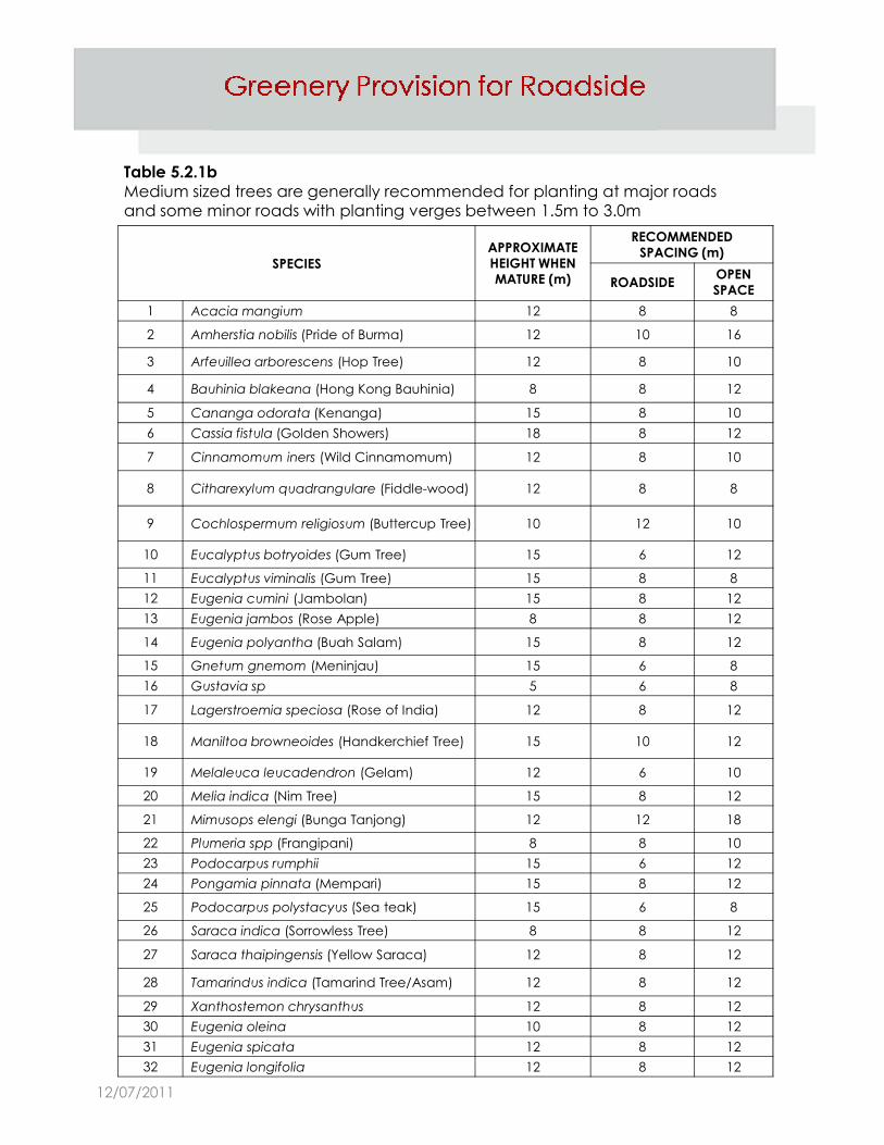
Table 5.2.1b
Medium sized trees are generally recommended for planting at major roads and some minor roads with planting verges between 1.5m to 3.0m
SPECIES
APPROXIMATE HEIGHT WHEN MATURE (m)
RECOMMENDED SPACING (m)
ROADSIDEOPEN SPACE
1 Acacia mangium 12 8 8
2 Amherstia nobilis (Pride of Burma) 12 10 16
3 Arfeuillea arborescens (Hop Tree) 12 8 10
4 Bauhinia blakeana (Hong Kong Bauhinia) 8 8 12
5 Cananga odorata (Kenanga) 15 8 10
6 Cassia fistula (Golden Showers) 18 8 12
7 Cinnamomum iners (Wild Cinnamomum) 12 8 10
8 Citharexylum quadrangulare (Fiddle-wood) 12 8 8
9 Cochlospermum religiosum (Buttercup Tree) 10 12 10
10 Eucalyptus botryoides (Gum Tree) 15 6 12
11 Eucalyptus viminalis (Gum Tree) 15 8 811 Eucalyptus viminalis (Gum Tree) 15 8 8
12 Eugenia cumini (Jambolan) 15 8 12
13 Eugenia jambos (Rose Apple) 8 8 12
14 Eugenia polyantha (Buah Salam) 15 8 12
15 Gnetum gnemom (Meninjau) 15 6 8
16 Gustavia sp 5 6 8
17 Lagerstroemia speciosa (Rose of India) 12 8 12
18 Maniltoa browneoides (Handkerchief Tree) 15 10 12
19 Melaleuca leucadendron (Gelam) 12 6 10
20 Melia indica (Nim Tree) 15 8 12
21 Mimusops elengi (Bunga Tanjong) 12 12 18
22 Plumeria spp (Frangipani) 8 8 10
23 Podocarpus rumphii 15 6 12
24 Pongamia pinnata (Mempari) 15 8 12
25 Podocarpus polystacyus (Sea teak) 15 6 8
26 Saraca indica (Sorrowless Tree) 8 8 12
27 Saraca thaipingensis (Yellow Saraca) 12 8 12
28 Tamarindus indica (Tamarind Tree/Asam) 12 8 12
29 Xanthostemon chrysanthus 12 8 12
30 Eugenia oleina 10 8 12
31 Eugenia spicata 12 8 12
32 Eugenia longifolia 12 8 12
12/07/2011
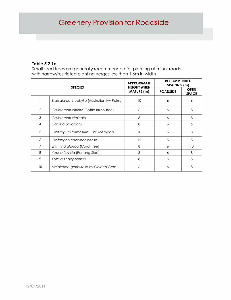
Table 5.2.1c
Small sized trees are generally recommended for planting at minor roads with narrow/restricted planting verges less than 1.6m in width
SPECIES
APPROXIMATE HEIGHT WHEN MATURE (m)
RECOMMENDED SPACING (m)
ROADSIDEOPEN SPACE
1 Brassaia actinophylla (Australian Ivy Palm) 10 6 6
2 Callistemon citrinus (Bottle Brush Tree) 6 6 8
3 Callistemon viminalis 8 6 8
4 Carallia brachiata 8 6 6
5 Cratoxylum formosum (Pink Mempat) 10 6 8
6 Crotoxylon cochinchinense 12 6 8
7 Erythrina glauca (Coral Tree) 8 6 10
8 Kopsia flavida (Penang Sloe) 8 6 8
9 Kopsia singaporensis 8 6 8
10 Melaleuca genistifolia cv Golden Gem 6 6 8
12/07/2011
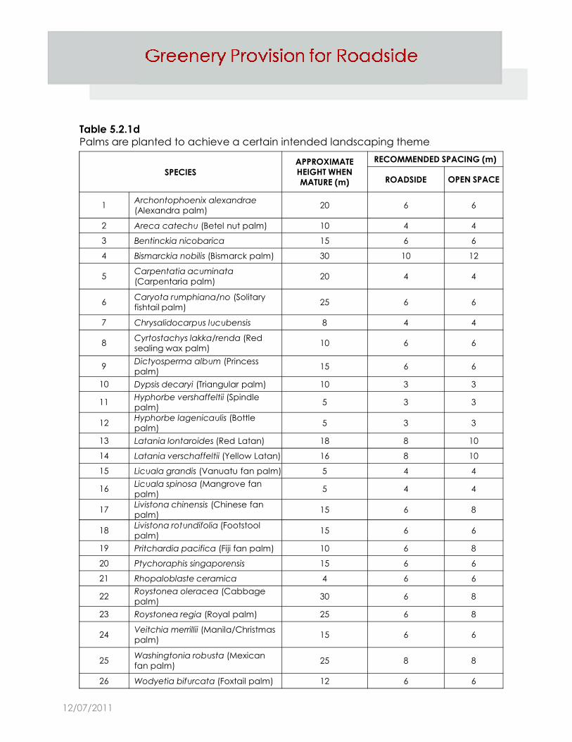
Table 5.2.1d
Palms are planted to achieve a certain intended landscaping theme.
SPECIES
APPROXIMATE HEIGHT WHEN MATURE (m)
RECOMMENDED SPACING (m)
ROADSIDE OPEN SPACE
1Archontophoenix alexandrae (Alexandra palm)
20 6 6
2 Areca catechu (Betel nut palm) 10 4 4
3 Bentinckia nicobarica 15 6 6
4 Bismarckia nobilis (Bismarck palm) 30 10 12
5Carpentatia acuminata (Carpentaria palm)
20 4 4
6Caryota rumphiana/no (Solitary fishtail palm)
25 6 6
7 Chrysalidocarpus lucubensis 8 4 4
8Cyrtostachys lakka/renda (Red sealing wax palm)
10 6 6
9Dictyosperma album (Princess palm)
15 6 69palm)
15 6 6
10 Dypsis decaryi (Triangular palm) 10 3 3
11Hyphorbe vershaffeltii (Spindle palm)
5 3 3
12Hyphorbe lagenicaulis (Bottle palm)
5 3 3
13 Latania lontaroides (Red Latan) 18 8 10
14 Latania verschaffeltii (Yellow Latan) 16 8 10
15 Licuala grandis (Vanuatu fan palm) 5 4 4
16Licuala spinosa (Mangrove fan palm)
5 4 4
17Livistona chinensis (Chinese fan palm)
15 6 8
18Livistona rotundifolia (Footstool palm)
15 6 6
19 Pritchardia pacifica (Fiji fan palm) 10 6 8
20 Ptychoraphis singaporensis 15 6 6
21 Rhopaloblaste ceramica 4 6 6
22Roystonea oleracea (Cabbage palm)
30 6 8
23 Roystonea regia (Royal palm) 25 6 8
24Veitchia merrillii (Manila/Christmas palm)
15 6 6
25Washingtonia robusta (Mexican fan palm)
25 8 8
26 Wodyetia bifurcata (Foxtail palm) 12 6 6
12/07/2011

5.2.4a For planting verges that are equal to or less than 1.2m wide, trees are to be planted at the midpoint of the verge as shown in Figure 5.2.4a.
Figure 5.2.4a Planting Verge ≤1.2m wide
Footpath cum drain
Tree
Width of roadside
planting verge ≤1.2m
Midpoint distance of roadside planting
verge as measured from the edge of the footpath cum drain
Figure 5.2.4b Planting Verge >1.2m wide
For planting verges that are more than 1.2m wide, proposed trees should be planted at the midpoint of the roadside tree planting verge as shown in the Figure 5.2.4b.
(Depending on the width of road reserve, the roadside tree planting verge may be 1.2m, 1.5m or 2.0m wide.)
5.2.4b
Footpath cum drain
Tree
Width of roadside tree
planting verge
Width of service verge
Midpoint distance of roadside
planting verge as measured from the edge of the footpath cum drain
Total width of
roadside planting verge >1.2m
12/07/2011

If there are existing trees planted on an existing footpath which is equal to or greater than 1.2m wide, proposed trees are to be planted to match the existing ones, with aeration provision.The aeration provision should comprise a minimum area of unpaved area, and loose paved PC slabs around the tree base that matches with the existing ones, or in accordance with the details as shown in Figure 5.2.5.
5.2.5
Drain
1.0m
Unsealed aeration area (1.0m × 1.0m) to be closed turfed with Axonopus
Compressus (Cow Grass)
Figure 5.2.5
FootpathFootpath
Loose paved PC slabExisting/proposed tree
1.0m 1.0m 1.0m
Carriageway
12/07/2011

Position of Roadside Element
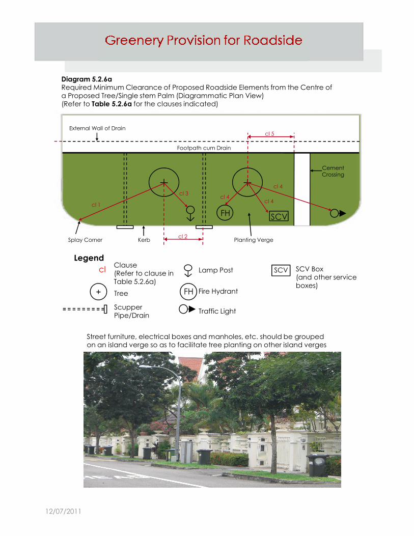
The clearance from a proposed road element to the centre of a proposed tree/single stem palm should be as stipulated in the Table 5.2.6a.(Refer to Diagram 5.2.6a for illustration of the clauses below)
5.2.6
Table 5.2.6aRequired Minimum Clearance of Proposed Roadside Elements from the Centre of a
Proposed Tree/Single Stem Palm(Refer to Diagram 5.2.6b for illustration of the clauses below)
Clause Proposed roadside elements
Required minimum clearance of proposed roadside elements from proposed:
Single stem palmSmall to medium
size treeLarge tree
1 Splay corner of:
1.0m 1.5m 2.5mEntrance culvert, bin centre access, substation access, MDF room access, 1.0m 1.5m 2.5msubstation access, MDF room access,
fire engine access
2 Scupper pipe/drain 1.0m 1.5m 2.5m
3 Lamp post 2.0m 3.0m 6.0m
4 OG box
2.0m 2.0m 2.5m
TAS manhole
Sewer line and manhole
Electrical post
Fire hydrant
SCV box
Lighting control box
Traffic control box
Traffic light
5 Cement crossing (e.g. pushcart ramp
for bin centre) 1.5m
12/07/2011
cl SCVLamp Post SCV Box
Legend
SCVFH
External Wall of Drain
Footpath cum Drain
CementCrossing
Splay Corner Kerb Planting Verge
cl 5
cl 1 cl 4
cl 4
cl 4cl 3
cl 2
Diagram 5.2.6aRequired Minimum Clearance of Proposed Roadside Elements from the Centre of
a Proposed Tree/Single stem Palm (Diagrammatic Plan View)(Refer to Table 5.2.6a for the clauses indicated)
Clausecl
FH
SCV
Tree
ScupperPipe/Drain
Lamp Post
Fire Hydrant
Traffic Light
SCV Box(and other service
boxes)
Clause(Refer to clause in
Table 5.2.6a)
Street furniture, electrical boxes and manholes, etc. should be grouped on an island verge so as to facilitate tree planting on other island verges
12/07/2011

Aeration Requirements For Planting On Plaza
If a tree is to be planted on a plaza, an unsealed soil area of at
least 2.0m × 2.0m, with a total surrounding aeration area of 16.0m², is to be provided around the tree.
Figure 5.3a illustrates various possible shapes of planting plaza and soil area for tree planting.
5.3
Figure 5.3aTree Planting on Plaza
2.0m
2.0m
Soil area (shape can be square,
circle or regular polygon with min. 4 sides)
Total surrounding
4.0m2 soil area
If a palm is to be planted on a plaza, an unsealed soil area of at
least 1.5m × 1.5m, with a total surrounding aeration area of 16.0m², is to be provided around the palm.
Figure 5.3b illustrates various possible shapes of planting plaza and soil area for palms planting.
Figure 5.3bPalm Planting on Plaza
Total surrounding aeration area of
16.0m2 (shape can be of any form)
1.5m
1.5m
Soil area (shape can be square,
circle or regular polygon with min. 4 sides)
Total surrounding aeration area of
16.0m2 (shape can be of any form)
2.25m2 soil area
12/07/2011

5.4 Planting Requirements for Pedestrian Overhead Bridge
5.4.1 Continuous planting troughs are to be provided along the span on both sides of the bridge.
5.4.2 The troughs should have internal minimum width of 650mm and depth of 750mm. They are to be backfilled with 1 part of expanded clay, 1 part of compost and 2 parts of approved loamy soil. (Reference: Specifications for Approved Soil Mixture (ASM) in Table 5.1.10).
5.4.3 The troughs must be waterproofed.
12/07/2011
5.4.4 The roof of the pedestrian overhead bridge should extend not more than 50% over the width of the planting surface of the trough laterally from the edge of the bridge deck. (Refer to Figure 5.4.4).
5.4.5 Shrubs are to be planted within the troughs and beneath the staircases of the pedestrian overhead bridges.
5.4.6 All footings of the columns are to be recessed at least 0.6m below the planting level.
5.4.7 The RC columns and staircase beams should have a rough and absorbent finish to facilitate the growth and anchorage of creepers onto the structure.
5.4.8 Creepers (Ficus pumila) are to be planted immediately around the columns at 150mm c/c.
12/07/2011

Figure 5.4.4Standard Design of Pedestrian Overhead Bridge with Roof Cover
The roof of the pedestrian overhead
3500mm
250mm
650mm
250mm1250mm 1250mm
760m
m
The roof of the pedestrian overhead
bridge should extend not more than 50% over the width of the planting
surface of the trough laterally from the edge of the bridge deck.
2300m
m
2200m
m
12/07/2011

5.5 Irrigation System for Pedestrian Overhead Bridge
5.5.1 For pedestrian overhead bridges less than 25.0m long, a 25mm stainless steel sprinkler pipe (with 5mm diameter holes are provided at 200mm c/c along the bottom of the pipe) should be fixed to the inner wall of the trough that abuts the platform and above the soil level.
5.5.2 For pedestrian overhead bridges between 25.0m and 50.0m long, a 25mm stainless steel sprinkler pipe (with 3mm diameter holes are provided at 400mm c/c along the bottom of the pipe) should be fixed to the inner wall of the trough that abuts the platform and above the soil level.
5.5.3 For pedestrian overhead bridges exceeding 50.0m long, a multiple pipe system with robust switch valve to channel water to different pipes is to be used. A 25mm stainless steel sprinkler pipe (with 3mm diameter holes are provided at 400mm c/c along pipe (with 3mm diameter holes are provided at 400mm c/c along the bottom of the pipe) should be fixed to the inner wall of the trough that abuts the platform and above the soil level.
5.5.4 The watering system pipes are to be terminated 1m above the ground level with 37.5mm diameter male adapter.
5.5.5 Unless there is a technical reason, e.g. long span of pedestrian overhead bridge, there should be only one coupling point provided. The coupling point should be easily and safely accessible by a water tanker.
5.5.6 A breeching inlet which is not mounted to the column of the bridge is to be housed in a pit, flush with ground level, with a hinged metal cover.
12/07/2011

Figure 5.5Typical Cross Sectional Drawing on Watering and Drainage Systems, and Planting Troughs
of a Pedestrian Overhead Bridge
25mm Ø S.S sprinkler pipe with 5mm Ø perforation at 200 C/C
with sealed end at mid span point
Railing design should allow accessibility to the trough for regular
maintenance such as forking, manuring or replacement of plants. The top of the trough is to be level with the overhead bridge platform
100mm Ø UPVC pipe with 5mm Ø
perforation at 100mm C/C in all directions
150mm thick porous
graded hardcore layer
Planting trough
100mm wide x 50mm deep
trench with UPVC strainer
1000m
m750m
m
650mm
Fall Fall Soil
100mm Ø PVC down water pipe to channel excess water to
the nearest roadside drain
Roadside drain
50mm Ø UPVC water down pipe
Water supply pipe
Vehicular impact guard-rail to
comply with LTA requirement
Footing of the column
Road level
600mm
1000m
m
12/07/2011

Water Tanker Lay-by
A lay-by of 23.0m long and 3.0m wide is to be provided for water tankers, unless there is a paved shoulder. (A letter from the Land Transport Authority indicating no objection for the use of paved area is attached)
The location of the water tanker lay-by has to be within a radius of 8m from the coupling point (at the column of the bridge or housed in a pit) to the mid- point of the lay-by.
5.6
10.0m
Figure 5.6Dimension of Water Tanker Lay-By
5.6.1
5.6.2
10.0m
5.0m
9.0m
10.0m
4.0m
3.0m
Traffic Direction
12/07/2011
5.7 Specification of Trees/Palms/Shrubs
5.7.1 A sapling tree should :i. have a total overall height of 2.5m with a clear trunk height of
1.5m (measured from ground level)ii. have girth of at least 0.1miii. be upright and in good formiv. have a terminal shoot
5.7.2 A single stem palm should :i. have a total overall height of 2.0m (measured from ground
level)ii. be upright and in good formiii. have a terminal shoot
5.7.3 A cluster palm should:i. have a total overall height of 2.0m (measured from ground
level)level)ii. be upright and in good formiii. have a minimum of 4 suckers
5.7.4 A planting hole for a sapling tree/single stem palm/cluster palm
should be 1.0m × 1.0m × 1.0m, and be backfilled with ASM (Reference: Specifications for Approved Soil Mixture (ASM) in Table 5.1.10).
5.7.5 Sapling trees/single stem palms are to be staked as and when required. The stake provided should be:i. galvanised steel pipe, or treated wood of 25mm diameterii. slightly lower than the sapling and 1/3 buried underground iii. positioned 200mm away from the collar of the treeiv. provided with PVC tubed nylon string placed round the trunk
and tied firmly to the stake
12/07/2011

Figure 5.7.5Staking for a sapling tree/single stem palm
12/07/2011

5.7.6
5.7.7
5.7.8
5.7.9
Tree collar protectors are to be provided for all proposed sapling trees/single stem palms. A protector is to be made of a PVC tube of length 200mm, diameter 75mm and thickness 2mm with a slit cut along the full length of the tube.
An instant tree should :i. have a girth of at least 0.3mii. have a clear trunk height of 2.0m (measured from the ground
level)iii. be upright and in good formiv. have a minimum of 3 primary branches of 500mm long
A planting hole for an instant tree should be 1.5m× 1.5m × 1.0m, and be backfilled with ASM.
Aeration Trough Proposed trees/palms or existing trees of girth < 0.5m will require aeration troughs to be provided if the planting verge is less than
5.7.10
5.7.11
aeration troughs to be provided if the planting verge is less than 3.0m wide. (Details of aeration trough to be in accordance with the specification shown on the drawing number : LTA/RD/SD99/PNR/2 & 3 in LTA’s Standard Details of Road Elements.)
Shrubs planting
i. For single shrub planting, each shrub should be at least 0.5m tall.
A shrub hole should be 0.6m × 0.6m × 0.6m, and be backfilled with ASM.
ii. For shrub bed planting, depending on the species, each shrub should have a height of 0.3 to 0.5m and planted at 0.3 to 0.5m centre to centre. A shrub bed should have a soil depth of 0.6m, and be backfilled with ASM.
The proposed plants should be maintained for a period of eight weeks or until they are well established to the satisfaction of NParks.
12/07/2011
5.8 Plan Submission Requirements
A registered architect/professional engineer is required to submit a completed NParks’ submission form, enclose the letter of authorisation from the developer, and sign all layers of drawing digitally.
5.8.1 The plans should comprise:a. Key and location plans of the development site (scale 1 :
10,000 or 1 : 5,000) showing access to the site from the street or road
b. Site plan (scale 1 : 500, 1 : 200 or 1 : 100)c. Cross section of road sidetables (scale at least 1 : 50)d. Lot and/or plot number of the lots on both sides of the
development sitee. Address of the development site (if applicable)
12/07/2011

5.8.2 General site information should be provided as shown in Table 5.8.2a.
Site PlanCross Sectional
Drawing
(a) Development boundary verged in red Indicate -
(b) Road reserve line/width of existing and proposed roads Indicate Indicate
(c)
Locations and dimensions of carriageway, roadside drain,
existing/proposed roadside planting verges (coloured green), service verges (coloured green) and footpath.
Existing carriageway, roadside drain, roadside planting verge, service verge and footpath to be demolished are to be indicated in yellow broken line.
Indicate Indicate
(d) Existing and proposed road sidetable levels. Indicate Indicate
Location of existing and proposed lamp posts, OG boxes,
Table 5.8.2aGeneral Site Information Required for Plan Submission
(e)
Location of existing and proposed lamp posts, OG boxes,
SCV boxes, TAS manholes, sewer lines and manholes, electrical posts, fire hydrants, traffic lights, authorised signs
and etc. (Please consult Power Grid on the provision of OG box. If no new OG box is required, to attach a confirmation letter from Power Grid)
Indicate -
(f)Fire engine access and hardstanding areas and other
proposed structures such as retaining walls and boundary walls.
Indicate Indicate
(g)Radius of splay corners of entrance culverts and
driveways. Indicate -
(h)
Existing roadside trees/palms/shrubs abutting the
development boundary and up to 10m on both sides of the boundary are to be indicated. (Please refer to 3.3.4 in
Conservation of Trees/Plants). Any changes on the status of the existing trees approved at DC/BP stage of Architect’s plan are to be reflected.
Indicate -
(i)
For existing trees/palms on footpath, the existing unpaved
areas and loose paved PC slabs around the trees/palms are to be shown.
Indicate -
(j)The clearance from a road element to the centre of a
tree/palm should be indicated on the site plan.Indicate -
12/07/2011

Additional information requirement for pedestrian overhead bridgesand/or covered linkways are shown in Table 5.8.2b.
Site PlanCross Sectional
Drawing
(a)
Alignment of proposed overhead bridge, the spans of
the proposed planting troughs and schematic engineering drawing with dimensions of the pedestrian
overhead bridge and foundation
Indicate Indicate
(b)
Alignment of proposed covered linkway and schematic
engineering drawing with dimensions of the covered linkway
Indicate Indicate
(c)Location and dimension of proposed water tanker lay-
byIndicate -
Table 5.8.2bAdditional Information Required for Plan Submission
(d)Planting beds beneath pedestrian overhead bridge
staircases. The beds are to be coloured on plan.Indicate -
(e)Details of footings and the clearance from existing trees
and roadside drain - Indicate
(f) Roof dimension and the clearance from existing trees Indicate Indicate
(g)Depth and types of existing/proposed underground
services Indicate Indicate
(h)Planting scheme within the planting beds (To be
provided at BP Stage) Indicate -
(i)Shrubs within the troughs for pedestrian overhead
bridges (To be provided at BP Stage) Indicate -
(j)Detailed drawings of irrigation/drainage systems (To be
provided at BP Stage)Indicate Indicate
12/07/2011

Planting Scheme
a) Location and species of proposed trees/palms are to be shown on the plan and uniquely numbered with prefix ‘P’.
b) Species and locations of proposed shrubs, if applicable, are to be shown on the plan.
c) Please use colours other than green, red and yellow for proposed trees/palms/shrubs.
d) A legend for proposed trees/palms/shrubs is to be provided.
e) Specifications for turfing, proposed trees/palms/shrubs and the planting holes/ planting beds are to be endorsed on the plan.
5.8.3
Aeration for Plaza Planting
Detailed drawings of aeration provision for proposed trees/palms are to be shown on site plan, cross-sections and detail plan.
5.8.4
12/07/2011