5 indoor lighting - california energy commission · 2008 nonresidential compliance manual august...
TRANSCRIPT
Indoor Lighting – Overview Page 5-1
2008 Nonresidential Compliance Manual August 2009
5 Indoor Lighting This chapter covers the requirements for indoor lighting design and installation, including controls. It is addressed primarily to lighting designers or electrical engineers and to enforcement agency personnel responsible for lighting and electrical plan checking and inspection. Chapter 6 addresses outdoor lighting applications.
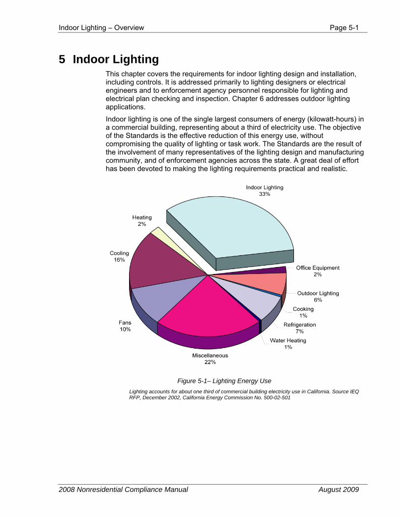
Indoor lighting is one of the single largest consumers of energy (kilowatt-hours) in a commercial building, representing about a third of electricity use. The objective of the Standards is the effective reduction of this energy use, without compromising the quality of lighting or task work. The Standards are the result of the involvement of many representatives of the lighting design and manufacturing community, and of enforcement agencies across the state. A great deal of effort has been devoted to making the lighting requirements practical and realistic.
Figure 5-1– Lighting Energy Use Lighting accounts for about one third of commercial building electricity use in California. Source IEQ RFP, December 2002, California Energy Commission No. 500-02-501
Page 5-2 Indoor Lighting – Overview
2008 Nonresidential Compliance Manual August 2009
5.1 Overview The primary mechanism for regulating indoor lighting energy under the Standards is to limit the allowed lighting power in watts installed in the building. Other mechanisms require basic equipment efficiency, and require that the lighting is controlled to permit efficient operation. §119, §130, §131
5.1.1 Mandatory measures
Mandatory measures apply to all lighting systems and related equipment. These requirements may include manual switching, daylit area controls, and automatic shut-off controls. New in the 2008 Standards are requirements for dimmers, track lighting integral current limiters, high efficacy LED light sources, ballast for residential recessed luminaires, and dimmable fluorescent ballasts when those ballasts are used to obtain a power adjustment factor. The mandatory requirements must be met under either the prescriptive or performance approach. §146(a)
5.1.2 Allowed lighting power
Allowed lighting power for a building is determined by one of the following four methods:
1. Prescriptive Approach – Complete building method: applicable when the entire building’s lighting system is designed and permitted at one time, and when at least 90 percent of the building is one primary type of use. In some cases, the complete building method may be used for an entire tenant space in a multi-tenant building. A single allowed lighting power value governs the entire building §146(b)1. See Section 5.3.1.
2. Prescriptive Approach – Area category method: applicable for any permit situation, including tenant improvements. Lighting power values are assigned to each of the major function areas of a building (offices, lobbies, corridors, etc.). See Section 5.3.2.
3. Prescriptive Approach – Tailored method: applicable when additional flexibility is needed to accommodate special task lighting needs in specific task areas. Lighting power allowances are determined room-by-room and task-by-task, with the area category method used for other areas in the building. See Section 5.3.3.
4. Performance approach: applicable when the designer uses an Energy Commission-certified compliance software program to demonstrate that the proposed building's energy consumption, including lighting power, meets the energy budget. The performance approach incorporates one of the three previous methods which set the appropriate Allowed Lighting Power Density used in calculating the building’s custom energy budget. The performance approach may only be used to model the
Indoor Lighting – Overview Page 5-3
2008 Nonresidential Compliance Manual August 2009
performance of lighting systems that are covered under the building permit application. See Section 5.4 and Chapter 9 of this document.
5.1.3 Actual lighting power (adjusted)
Actual lighting power is based on total design wattage of lighting, less adjustments for any qualifying automatic lighting controls, such as occupant-sensing devices or automatic daylighting controls.
The actual lighting power (adjusted) must not exceed the allowed lighting power for the lighting system to comply.
5.1.4 Lighting Trade-offs
The Standards restrict the overall installed lighting power in the building, regardless of the compliance approach. However, there is no general restriction regarding where or how general lighting power is used. This means that installed lighting may be greater in some areas of the building and lower in others, as long as the total does not exceed the allowed lighting power. See Section 5.2.2.2 for additional information about lighting trade-off restrictions.
There is another type of lighting trade-off available under the Standards. This is the ability to make trade-offs under the performance approach between the lighting system and the envelope or mechanical systems. Trade-offs can only be made when permit applications are sought for those systems involved. For example, under the performance approach, a building with an envelope or mechanical system that is more efficient than the prescriptive efficiency requirements may be able to meet the standard design energy budget with a bit more lighting power than allowed under the prescriptive approach. When a lighting power allowance is calculated using the performance approach, the allowance is treated exactly the same as an allowance determined using one of the other compliance methods. No trade-offs are allowed between indoor lighting and outdoor lighting or with lighting that is in unconditioned spaces.
Example 5-1
Question Under the area category method, a mixed-use building is determined to have an allowed lighting power of 23,500 W. As part of this determination, private office areas less than 250 ft² within the building are found to have an allowance of 1.1 W/ft². One of the private offices within this area is designed with an actual lighting power density of 2.0 W/ft². Is this permitted?
Answer Yes. Provided the actual lighting power of the entire building does not exceed the 23,500 W , there is no limit on the individual office.
This is true for general lighting, no matter what method is used to determine the allowed lighting power.
Page 5-4 Indoor Lighting – Overview
2008 Nonresidential Compliance Manual August 2009
Note that it is not necessary to specify precisely where the watts come from when a trade-off occurs. These details are not needed for compliance; any individual trade-offs are included in the totals. It is only necessary to demonstrate that the actual total watt for the building does not exceed the total allowable. Trade-offs are not allowed with so-called “use-it-or-lose-it” categories of lighting. These are specific task or display lighting applications, such as chandeliers under the area category method or display lighting under the tailored method, where the allowable lighting power for the application is determined from:
1. Wattage allowance specified by the Standards.
2. Actual wattage of the fixture(s) assigned to the application.
For use-it-or-lose it applications, the allowable lighting power is the lesser of these two wattages. This means that the allowance cannot exceed the actual lighting wattage. If the actual lighting watts are lower than the allowance, the remaining watts in the allowance are not available for trade-off to other areas of the building.
Example 5-2
Question A display lighting application (one of the use-it-or-lose-it applications) is determined to have a lighting power allowance of 350 W. The actual luminaires specified for the display total 300 W. How does this affect the allowed watts and the actual watts (adjusted if applicable) for the building?
Answer The lower value, 300 W, is shown as total allowed watts for the building. The actual lighting power is also 300 W. There are no watts available for use through trade-offs elsewhere in the building.
Example 5-3
Question A display lighting application is determined to have a lighting power allowance of 500 W. The actual luminaires specified for the display total 600 W. How does this affect the allowed watts and the actual watts (adjusted if applicable) for the building?
Answer As before, the lower value, 500 W in this case, is shown as the total allowed watts for the display. The proposed lighting power will include the full 600 W. For the building lighting to comply, the extra 100 W used by the display fixtures must be traded-off against eligible lighting systems such as general lighting from elsewhere in the building.
Lighting control credits reduce the actual installed watts, making it easier to meet the allowed watts. The specific calculations involved in the trade-offs discussed in this section are carried out on the compliance forms.
Indoor Lighting – Overview Page 5-5
2008 Nonresidential Compliance Manual August 2009
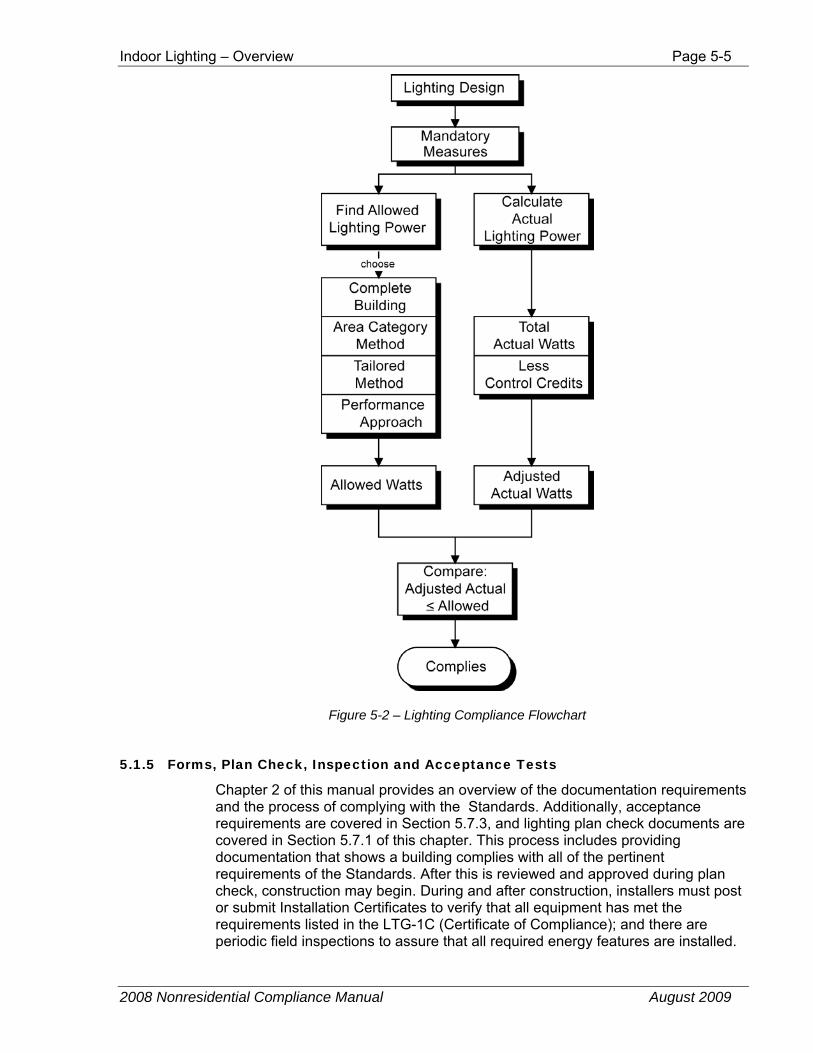
Figure 5-2 – Lighting Compliance Flowchart
5.1.5 Forms, Plan Check, Inspection and Acceptance Tests
Chapter 2 of this manual provides an overview of the documentation requirements and the process of complying with the Standards. Additionally, acceptance requirements are covered in Section 5.7.3, and lighting plan check documents are covered in Section 5.7.1 of this chapter. This process includes providing documentation that shows a building complies with all of the pertinent requirements of the Standards. After this is reviewed and approved during plan check, construction may begin. During and after construction, installers must post or submit Installation Certificates to verify that all equipment has met the requirements listed in the LTG-1C (Certificate of Compliance); and there are periodic field inspections to assure that all required energy features are installed.
Page 5-6 Indoor Lighting – Lighting Design Procedures
2008 Nonresidential Compliance Manual August 2009
At the end of construction, acceptance tests are performed on HVAC and lighting controls to assure they are installed and work correctly.
If inspections or acceptance testing uncover systems that are not installed as shown in the plans and documentation, or are found not to be operating correctly through acceptance testing, these defects have to be fixed before the building is approved. Once approved by the code official as complying with all the building code requirements including the energy code, the building receives a Certificate of Occupancy.
5.2 Lighting Design Procedures This section discusses how the requirements of the Standards affect lighting system design. For procedures on documenting the lighting design, including compliance forms see Section 5.7. For information on lighting equipment certification, see Section 5.2.1.
5.2.1 Mandatory Measures
Applicable mandatory features and devices for any specific project must be included in the building design and properly installed, regardless of how compliance is demonstrated using either the prescriptive or performance approach. These features have been proven cost-effective over a wide range of building occupancy types.
There are four main types of mandatory measures:
1. Lighting equipment complies with the Title 20 Appliance Efficiency Regulations
2. Lighting controls are certified to comply with the requirements of §119 and are listed in the Directory of Automatic Lighting Control Devices
3. High efficacy lighting and lighting control requirements in dwelling units
4. Mandatory control requirements for certain applications
Many of the mandatory features and devices are requirements for manufacturers of building products, who must certify the performance of their products to the Energy Commission. It is the responsibility of the designer to specify products that meet these requirements. It is the responsibility of the installer to comply with all of the mandatory requirements, even if the plans mistakenly do not. Code enforcement officials, in turn, must check that the mandatory features and specified devices are installed.
5.2.1.1 California Appliance Efficiency Regulations (Title 20) §111
Lighting products regulated by the California Appliance Efficiency Regulations (Title 20) must be certified to the Energy Commission by the manufacturer before they can be sold in California stores or specified on California building projects subject to the Standards. The California Appliance Efficiency Regulations include
Indoor Lighting – Lighting Design Procedures Page 5-7
2008 Nonresidential Compliance Manual August 2009
requirements for both federally-regulated appliances and non-federally-regulated appliances. The Title 20 regulations apply to appliances that are sold or offered for sale in California, except those sold wholesale in California for final retail sale outside the state and those designed and sold exclusively for use in recreational vehicles or other mobile equipment.
At the time the 2008 Standards were adopted, key lighting equipment that have separate California Appliance Efficiency Regulations include:
1. Metal halide luminaires (≤ 500W must be pulse start, electronic ballasts of ballast efficiency ≥ 88 percent)
2. Exit signs (Appliance Regulations requires less than 5 W per face)
3. Torchieres (requirement of no more than 190 W).
4. Lighting of cabinets and wine chillers (lighting efficacy comparable to T-8 fluorescent lamps with electronic ballasts)
5. Lighting of beverage vending machines (automatic controls for placing cooling and lighting in low power mode)
For a complete and up-to-date list of Appliance Efficiency Regulations, the Regulations can be downloaded from: http://www.energy.ca.gov/appliances/
5.2.1.2 Lighting Equipment Certification §119
The mandatory requirements for lighting control devices specify minimum features for automatic time switch controls, occupant-sensing devices, automatic daylighting controls, indoor photosensors, dimmers, track lighting integral current limiters, high efficacy and LED light sources. There are also mandatory requirements for dimmable fluorescent ballasts when used to obtain a power adjustment factor.
The Standards clarify that lighting control devices may be individual devices or systems consisting of two or more components. For control systems consisting of two or more components, such as an Energy Management Control System (EMCS), the manufacturer of the control system shall certify each of the components required for the system to comply with §119.
This section addresses all of the lighting equipment regulated in §119. Most of this lighting equipment is used in nonresidential indoor applications. However, some of the lighting equipment requirements in this section are used in outdoor or residential applications only.
Many of these requirements are part of standard practice in California and should be well understood by those responsible for designing or installing lighting systems. The lighting control acceptance tests verify that equipment is capable of meeting the requirements in §119. If the equipment installed equipment cannot meet these requirements, it must be replaced, and thus it is very important that electrical designers are aware of the requirements of this section.
All lighting control devices, ballasts, and luminaires that are subject to the requirements of §119 and installed to comply with mandatory requirements or to obtain control credits must be certified by the manufacturer before they can be installed in a building. The manufacturer must certify the devices to the Energy Commission.
Page 5-8 Indoor Lighting – Lighting Design Procedures
2008 Nonresidential Compliance Manual August 2009
Once a device is certified, it will be listed in the Directory of Automatic Lighting Control Devices, which is available from the link below:
http://www.energy.ca.gov/appliances/database/
Call the Energy Hotline at 1-800-772-3300 to obtain more information.
Note: If the lighting control you would like to specify is not in the Directory of Automatic Lighting Control Devices, call the manufacturer and ask them to apply to the California Energy Commission for certification of their product. The requirements of §119 are listed here so the designer can make verify the product is certified for the intended application.
A. Installation and Calibration §119(a)
All devices must have instructions for installation and start-up calibration and must be installed in accordance with such directions §130(a)
B. Indicator Lights §119(b)
Indicator lighting that is integral to lighting control devices shall consume no more than 1 watt of power per indicator light.
C. Automatic Time Switch Control Devices §119(c)
Automatic time switch control devices, typically a time clock or Energy Management Control System (EMCS), are programmable switches that are used to automatically shut-off the lights, according to pre-established schedules depending on the hours of operation of the building. The device must have the capability to store two separate daily programs (for weekdays and weekends). The automatic time switch control device must have program backup capabilities that prevent the loss of the device’s schedules for at least 7 days, and the device’s time and date setting for at least 72 hours if power is interrupted. Most building automation systems can meet these requirements, provided they are certified to the Energy Commission.
D. Occupant Sensors, Motion Sensors, and Vacancy Sensors §119(d)
The Standards typically refer to occupant sensors for indoor nonresidential lighting applications, motion sensors for outdoor lighting applications, and vacancy sensors for residential manual-on/automatic-off applications.
Occupant, motion, and vacancy-sensing devices shall be capable of automatically turning off all of the lights in an area no more than 30 minutes after the area has been vacated, and shall have a visible status signal that indicates that the device is operating properly or that it has failed or malfunctioned. The visible status signal may have an override switch that turns the signal off.
Indoor Lighting – Lighting Design Procedures Page 5-9
2008 Nonresidential Compliance Manual August 2009
Additionally, the following sensors must meet special requirements:
1. The ultrasonic type must meet certain minimum health requirements in accordance with §119(d)1, and have the built-in ability for sensitivity calibration (to reduce false signals for both on and off).
2. The microwave devices must have emission controls, permanently affixed installation requirements, and built-in sensitivity adjustment in accordance with §119(d)2. Microwave devices are rarely used in occupant sensors.
E. Multi-level Occupancy Sensors §119(e)
Multi-level occupancy sensors provide more energy savings than simple on/off occupancy sensors because they give the occupant the choice to turn only a fraction of the lights each time the room is entered. Like all other occupancy sensors, these sensors turn off all of the lights when the space is vacated.
Multi-level occupancy sensors provide either automatic on or manual on control of 30 to 70 percent of lighting when a space is entered. A separate switch must turn on the rest of the lights. Since the multi-level occupancy controls must turn on only a fraction of the lights when the room is entered, this control cannot be provided with a standard occupancy sensor and two standard switches.
This type of control can be accomplished with a special multi-level occupancy sensor or by installing switches with latching relays (sentry switches) in combination with a standard occupancy sensor.
F. Automatic Daylighting Control Devices §119(f)
Daylighting controls consist of photosensors that compare actual illumination levels with a reference illumination level and reduce the electric lighting until the reference level has been reached. These controls may be used to apply for power adjustment factor (PAF) lighting credits in the daylit areas near windows or under skylights as defined in Table 5-9 (Table 146-C in the Standards). If one wishes to use automatic daylighting controls to satisfy the mandatory requirements for controls under skylights or in the primary sidelit daylit area and associated power adjustment factor (PAF) credits, additional multi-level requirements must be met see §131(c), §119(i).
When automatic daylighting control devices and systems are used, they must be certified to the Energy Commission that they meet all of the following requirements:
1. The device shall have the ability to automatically reduce the general lighting power of the controlled area by at least two-thirds of rated power consumption in response to available daylight. It should be noted that some dimming technologies (such as metal halide) are unable to reduce power consumption by two-thirds. In this case, the control has to be able to turn off some of the lamps or be applied to a different light source.
Page 5-10 Indoor Lighting – Lighting Design Procedures
2008 Nonresidential Compliance Manual August 2009
2. If the device is a dimmer controlling incandescent or fluorescent lamps, the device shall provide electrical outputs to the lamps for reduced flicker operation throughout the dimming range, so that the light output has an amplitude modulation of less than 30 percent for frequencies less than 200 Hz, and without causing premature lamp failure.
If the control causes the lamps to visibly flicker it is likely the control will be disabled. Visible flicker can be a function of the extent of dimming, the ballast itself, the lead length between the ballast and lamps and whether the leads are in metallic conduit.
3. If the device reduces lighting in control steps, the device shall incorporate time-delay circuits to prevent cycling of the light level changes of less than three minutes. The device shall have a manual or automatic means of adjusting the deadband to provide separation of ON and OFF points for each control step.
Note that this is two separate requirements: a minimum time delay of 3 minutes before turning lights off and an adjustable deadband between ON and OFF of a control step. The time delay prevents lights turning ON and OFF when daylight levels are fluctuating. The adjustable deadband between ON and OFF prevents cycling of lights on and off due to the controlled electric lighting being sensed by the photocontrol light sensor.
4. If the device is placed in calibration mode, the devices shall automatically restore its time delay settings to normal operation programmed time delays after no more than 60 minutes.
5. The device shall have a setpoint control that easily distinguishes settings to within 10 percent of full-scale adjustment.
This requirement is for the setpoint adjustment on switching controls. A numerical indication (not just a dial with high and low) is required for the method of setting the setpoint for a switching controller. To minimally comply, one would need at least five regularly spaced marks on an adjustment dial. In many cases this requirement will be met with a digital display. This allows the installer to adjust the setpoint of a switching control under daylight conditions that do not match the desired amount of interior illuminance.
As an example the installer could calibrate the control under daylight conditions that provide only 80 percent of design illuminance, the installer can then set the control to turn off the lights at a daylight illuminance setpoint that is 25 percent higher than the current conditions.
Continuously dimming controls do not have a single fixed setpoint that must be calculated and thus do not fall under this requirement.
6. The device shall have a light sensor that has a linear response with 5 percent accuracy over the range of illuminance measured by the light sensor.
This requirement assures that the control will be able to accurately respond to daylight levels over a wide range of iluminances.
7. The device shall have a light sensor that is physically separated from where calibration adjustments are made, or it shall be capable of being calibrated in a manner that the person initiating calibration is remote from the sensor during calibration to avoid influencing calibration accuracy.
Indoor Lighting – Lighting Design Procedures Page 5-11
2008 Nonresidential Compliance Manual August 2009
This requirement simplifies photocontrol calibration. In the past, the installer would be shielding the sensor with their body while making calibration adjustments. Also this type of control is easier to re-calibrate when the sensor is located in a very high or inaccessible location.
Compliance with this requirement can be met in a number of ways: the calibration controls can be remote from the sensor (either wired or wireless controls) or the control can be self-calibrating and thus the control technician does not have to be close to the sensor during control adjustment.
G. Interior Photosensors §119(g)
Daylighting control systems incorporate a photosensor that measures the amount of light at a reference location. The photosensor provides light level information to the controller so it can decide when to increase or decrease the electric light level.
Photosensor devices must be certified to the Energy Commission as not having mechanical slide covers or other means that allow easy unauthorized adjusting or disabling of the photosensor. In addition, they shall not be combined in a wall mounted occupant-sensing device. (This means that wall-mounted occupant-sensing devices with photosensor controls can be certified as occupant-sensing devices but not interior photosensor devices.)
H. Multi-level Astronomical Time Switch Controls §119(h)
An astronomical time switch control is a time switch designed to control lighting based on sunrise and sunset hours. It automatically adjusts the turning on and off of lights every day of the year, typically using an internal program based on longitude and latitude of installation.
Multi-level astronomical time-switch controls shall meet the following requirements:
1. Contain at least 2 separately programmable steps per zone that reduces illuminance in a relatively uniform manner as specified in §131(b).
2. Have a separate offset control for each step of 1 to 240 minutes.
3. Have sunrise and sunset prediction accuracy within +/- 15 minutes and timekeeping accuracy within 5 minutes per year.
4. Store astronomical time parameters (used to develop longitude, latitude, time zone) for at least 7 days if power is interrupted.
5. Display date/time, sunrise and sunset, and switching times for each step.
6. Have an automatic daylight savings time adjustment.
7. Have automatic time switch capabilities specified in §119(c).
8. A multi-level astronomical time switch control is required for Exception 3 to §131(c)B, and for §146(a)3G. Exception 3 to §131(c)B allows one
Page 5-12 Indoor Lighting – Lighting Design Procedures
2008 Nonresidential Compliance Manual August 2009
to use a multi-level astronomical time switch instead of a photocontrol when the skylight effective aperture is greater than 4 percent. This amount of skylight glazing rarely occurs except in atria. Similarly, §146(a)3G applies to exempt lighting power that is “for plant growth or maintenance,” in general this will be in locations that have large amounts of glazing where the lights can be off for most of the daytime hours.
I. Outdoor Astronomical Time Switch Controls §119(i)
An outdoor astronomical time switch control is used for compliance with the Outdoor Lighting Standards. §119 also address devices used in nonresidential indoor lighting and residential lighting. Even though this chapter deals with nonresidential indoor lighting, information on outdoor astronomical time switch controls has been included in this section so as to not omit any subsections of §119 from this discussion.
See Chapter 6 for more information about the Outdoor Lighting Standards.
The requirements for the outdoor astronomical time switch controls are very similar to the requirements for the indoor multi-level astronomical controls (§119(h)), except this control has a less stringent requirement for the offset from sunrise or sunset. This control is required to have the capability of independently offsetting on or off settings up to 120 minutes from sunrise or sunset.
§132(c)2 requires automated multi-level switching of some outdoor lighting areas. This creates the opportunity to have all, half or none of the lights on for different times of day, for different days of the week, while making sure that the lights are off during the day.
J. Manual-On Occupant Sensor (Vacancy Sensor) §119(j)
A manual-on/automatic-off occupant sensor can be used in some limited applications for compliance with the Residential Lighting Standards §150(k). Because dwelling units of high-rise residential and hotel/motels must comply with the Residential Lighting Standards, a manual-on occupant sensor may be used in these applications in accordance with the applicable requirements in §150(k).
This type of occupancy sensor is called a vacancy sensor by some manufacturers to clarify that the sensor is used to turn off the lights after a room has been vacated, and does not automatically turn them back on when the room is occupied. Thus, it responds to vacancy by turning the lights off when a room is vacant, but does not respond to occupancy after the lights have been automatically turned off.
A similar device, described as a multi-level manual-on/automatic-off sensor can be used to each a power adjustment factor (PAF) in accordance with §146(a)2D. However, for compliance with §146(a)2D, the device must able to operate the lighting power on at least two separate levels See §119(e).
Indoor Lighting – Lighting Design Procedures Page 5-13
2008 Nonresidential Compliance Manual August 2009
A residential vacancy sensor used to comply with §150(k) shall be a device, or system (such as an energy management control system), which meets all of the following requirements:
1. Turns off the lighting automatically within 30 minutes or less after the room has been vacated in response to the absence of occupants in the room
2. Has a visible status signal in accordance with §119(d)
3. Shall not turn of the lighting automatically, except the sensor shall have a grace period of 15 to 30 seconds to turn on the lighting automatically after the sensor has timed out
4. Shall not have an override switch that disables the occupant sensor
5. Shall not have an override switch that converts the sensor from a manual-on to an automatic-on system.
K. Dimmers §119(k)
A dimmer can be used in some limited applications for compliance with the Residential Lighting Standards §150(k). Dimming controls used in conjunction with dimmable lighting systems can also be used for compliance with the Nonresidential Lighting Standards, including multi-level lighting control requirements in §131(b), daylight control requirements in §131(c), and for some Power Adjustment Factor’s in Table 5-9 (Table 146-C in the Standards).
Dimmers used to control lighting shall meet the following requirements:
1. Be capable of reducing power consumption by a minimum of 65 percent when the dimmer is at its lowest light level
2. If the device is a dimmer controlling incandescent or fluorescent lamps, the device shall provide electrical outputs to lamps for reduced flicker operation through the dimming range. This means that the light output has an amplitude modulation of less than 30 percent for frequencies less than 200 Hz, and without causing premature lamp failure
3. Be listed by a rating lab recognized by the International Code Council (ICC) as being in compliance with Underwriters Laboratories Standards
4. If the device is a wall box dimmer designed to be used in a three or more-way circuit with non-dimmable switches, the level set by the dimmer shall not be overridden by any of the switches in the circuit. The dimmer and all of the switches in the circuit shall have the capability of turning lighting OFF if it is ON, and turning lighting ON to the level set by the dimmer if the lighting is OFF. Any wall box dimmer that is connected to a system with and emergency override function shall be controlled by the emergency override
5. If the device is a stepped dimmer, shall include an OFF position to turn lights completely off.
Page 5-14 Indoor Lighting – Lighting Design Procedures
2008 Nonresidential Compliance Manual August 2009
L. Track Lighting Integral Current Limiter §119(l)
The use of a track lighting integral current limiter is one of the options provided in §130(d)3 for calculating the installed lighting power of a line-voltage track lighting system. A track lighting integral current limiter that has not been certified to the Energy Commission, and also listed on the Directory of Automatic Lighting Control Devices, cannot be installed. The Directory is available from the link below:
http://www.energy.ca.gov/appliances/database/
Another option for calculating the installed lighting power of a line-voltage track lighting system is the use of a supplementary overcurrent protection panel meeting all of the requirements in §130(d)3Aiv. However, a supplementary overcurrent protection panel does not qualify as an integral current limiter.
Additionally, a field assembly of components does not qualify as an integral current limiter. The integral current limiter must be integrated into the track lighting “fixture” at the factory, and must comply with all of the following requirements:
1. Be designed so that the integral current limiter housing is permanently attached to the track so that the track will be irreparably damaged if the integral current limiter housing were to be removed after installation into the track. Note that it is the current limiter housing that must be permanently attached to the track, and not the current limiter itself, because the current limiter must be replaceable in the event that it fails.
2. Have the volt-ampere (VA) rating of the current limiter clearly marked on the circuit breaker visible for the building officials’ field inspection without opening coverplates, fixtures, or panels, and also on a permanent factory-installed label inside the wiring compartment. Note that this requires two labels, one that can be viewed from the outside of the assembled unit, and one that is permanently attached to the housing base for a permanent reference when the coverplate has been removed for maintenance.
3. Employ tamper resistant fasteners for the cover to the wiring compartment.
4. Have a conspicuous permanent factory-installed label affixed to the inside of the wiring compartment warning against removing, tampering with, rewiring, or bypassing the device. Electricians are required to replace the current limiter with one that has the same or lower rating.
M. High Efficacy LED Light Sources §119(m)
The Residential Lighting Standards require the classification of high efficacy and low efficacy luminaires. Some areas of high-rise residential and hotel/motel buildings are required to comply with the Residential Lighting Standards.
Indoor Lighting – Lighting Design Procedures Page 5-15
2008 Nonresidential Compliance Manual August 2009
The Nonresidential Lighting Standards do not require light sources to be classified as high efficacy. Rather, the Nonresidential Lighting Standards require the input wattage to be determined according to §130(d).
See Section 5.2.1.4 for more information about the application of high efficacy luminaires.
There are requirements in §150(k)1 and 2 for luminaires to qualify as high efficacy luminaires. Most high efficacy luminaires are not required to be certified to the Energy Commission to be classified as high efficacy. Only LED luminaires, or LED light engines are required to be certified to the Energy Commission to be classified as high efficacy.
To qualify as high efficacy for compliance with §150(k), a high efficacy LED luminaire, or LED light engine with integral heat sink, shall meet the minimum efficacy requirements in Table 150-C of the Standards, and luminaire power shall be determined as specified by §130(d)5. LED lighting that has not been certified to the Energy Commission as high efficacy in accordance with §119(m) shall be classified as low efficacy for compliance with the Standards. See Section 6.2.9 of the Residential Compliance Manual for additional information about certifying LED lighting systems as high efficacy.
N. Ballast for Residential Recessed Luminaires §119(n)
To qualify as high efficacy, a ballast for residential recessed luminaires must be certified to the Energy Commission as complying §119(n). Some areas of high-rise residential and hotel/motel buildings are required to comply with the Residential Lighting Standards. See Section 5.2.1.4 for more information about the application of high efficacy luminaires.
To qualify as high efficacy for compliance with §150(k), any ballast in a residential recessed luminaire shall meet all of the following conditions:
Be rated by the ballast manufacturer to have a minimum rated life of 30,000 hours when operated at or below a specified maximum case temperature. This maximum ballast case temperature specified by the ballast manufacturer shall not be exceeded when tested in accordance to UL 1598 Section 19:15.
Have a ballast factor of not less than 0.90 for non-dimming ballast, and a ballast factor of not less than 0.85 for dimming ballasts.
O. Dimmable Florescent Ballasts for Power Adjustment Factor §119(o)
To qualify for the Power Adjustment Factor (PAF) in §146(a)2 and Table 5-9 (Table 146-C of the Standards), and when dimming ballasts are required to qualify for the PAF in accordance with Table 5-9, ballasts for T5 and T8 linear fluorescent lamps shall be electronic, dimmable, and shall meet the minimum Relative System Efficiency (RSE) in Table 5-10 (Table 146-D of the Standards). There are also opportunities to qualify for a PAF using multi-level switching of non-dimmable ballasts.
Ballasts that are not certified to the Energy Commission and not listed on the Directory of Automatic Lighting Control Devices cannot be used to qualify for the
Page 5-16 Indoor Lighting – Lighting Design Procedures
2008 Nonresidential Compliance Manual August 2009
PAF whenever a dimmable ballast is required to qualify for the PAF in accordance with Table 5-9 (Table 146-C of the Standards). The Directory is available from the link below:
http://www.energy.ca.gov/appliances/database/
5.2.1.3 Mandatory Lighting Controls §131
The simplest way to improve lighting efficiency is to turn off the lights when they are not in use. All lighting systems must have switching or control capabilities to allow lights to be turned off when they are not needed. In addition, it is desirable to reduce light output and power consumption when full light output is not needed. These mandatory requirements apply to all nonresidential, high-rise residential and hotel/motel buildings for both conditioned and unconditioned interior spaces. The mandatory lighting control requirements in §131 can be summarized as follows:
1. Light switches (or other control) in each room §131(a).
2. Multi-level control for lighting systems > 0.8 W/ft² §131(b).
3. Daylighting controls §131(c).
a. Separate switches when skylit or primary sidelit zone > 250 ft².
b. Automatic multi-level daylighting controls when skylit or primary sidelit zone > 2,500 ft².
c. Controls calibrated so that space always meets or exceeds design footcandles and electric lighting is fully dimmed when daylight is 150 percent of design illuminance.
4. Automatic shut-off controls – a time sweep with an override switch or occupancy sensor to assure lights are off after business hours. §131(d).
5. Display lighting is separately switched. §131(e)
6. When the tailored lighting method is used to show compliance, general lighting must be on a separate shut-off control from display lighting §131(f).
7. Stores larger than 50,000 ft² must have 15 percent of the lighting load connected to a demand responsive lighting control system.
Detailed descriptions of each of these mandatory control requirements follow. Since there is a substantial discussion of daylighting, Section 5.2.1.5 is dedicated to the daylighting requirements contained in §131(c).
A. Area Controls for Each Room §131(a)1
Independent lighting controls are required for each area enclosed by ceiling height partitions. In the simplest case, this means that each room must have its
Indoor Lighting – Lighting Design Procedures Page 5-17
2008 Nonresidential Compliance Manual August 2009
own switches; gang switching of several rooms is not allowed. This allows the lighting in each room to be controlled separately by the room’s occupants.
1. Accessibility §131(a)1A, B, & C
The lighting switch required in §131(a)1 may be manually operated or automatically controlled by an occupant-sensing device that meets the applicable requirements of §119. However, automatic controls must still allow an occupant to manually turn off all of the lights in a room. All manually operated switching devices must be located so that personnel can see the controlled area when operating the switch(es). When not located within view of the lights or areas, the switch shall be annunciated to indicate the status of the lights (on or off). Annunciated is defined in §101 as indicating the on, off, or other status of a load through the use of a visual signaling device.
2. Security or Emergency §131(a) Exception No. 1
Lighting in areas within a building that must be continuously illuminated for reasons of building security or emergency egress are exempt from the switching requirements for a maximum of 0.3 W/ft² along the path of egress. These lights must be installed in areas designated as security or emergency egress areas on the plans, and must be controlled by switches accessible only to authorized personnel. The remaining lighting in the area, however, is still subject to the area switching requirements.
3. Public Areas §131(a) Exception No. 2
In public areas, such as building lobbies, concourses, etc., the switches may be located in areas accessible only to authorized personnel.
4. Other Devices §131(a)2
If the room switching operates in conjunction with any other kind of lighting control device, there are two other requirements: 1) the other control device must allow the room switching to manually turn the lights off in each area enclosed by ceiling-height partitions; and 2) if the other control device is automatic, it must automatically reset to its normal operation mode without any further action.
For example, if there is an automatic control system that sweeps all the lights off in a group of offices at a certain hour to comply with the automatic shut-off requirements in §131(d), the room switch in any individual office must be able to override the sweep and turn the office’s lights back on according to §131(a)2. The sweep must be set up to occur every 2 hours, as the override is not allowed to last more than 2 hours. The next time the automatic control sweeps the lights off: however, the override for that individual office must not remain in effect but must return to automatic mode and shut the lights off. This same type of manual switch is also required when using a manually operated override switch in conjunction with an automatic time switch control device when used to comply with §131(d).
Note that an occupancy control or daylighting control (photocontrol) could be wired in series with a standard light switch and be in compliance with this
Page 5-18 Indoor Lighting – Lighting Design Procedures
2008 Nonresidential Compliance Manual August 2009
requirement. The switch does not affect the operational mode of the automatic system.
Example 5-4
Question A 5,000 ft² building will be equipped with an automatic control device to shut off the lights, and in compliance with §131(b) it has multi-level controls. How are the local switches supposed to respond when an occupant wishes to turn on lights after the lights are shut off?
Answer The local switch as specified in §131(a) must allow the occupant to override the shut-off and turn on the lights in their area §131(a)2A. Following the override, the automatic function of the shut-off must resume, so that when the automatic control sweeps the lights off, these lights will be shut off unless the local switch again overrides the shut-off §131(a)2B.
Example 5-5
Question The card access system of a proposed building will automatically turn on the lobby and corridor lights when activated by someone entering the building after hours. In addition, the lobby and corridor lights are on an automatic time switch control. Are manual switches required for the lobby and corridor?
Answer Yes. The manual switch is still required under the area control mandatory measure requirement. Furthermore, the manual switch must be able to turn off the lights when either the automatic time switch control or card access system has turned them on. The automatic devices must be automatically reset.
B. Multi-Level Switching §131(b)
Most areas in buildings must be controlled so that the connected general lighting load may be reduced while maintaining reasonably uniform illumination. The intent of this requirement is to achieve the lighting power reduction without losing use of any part of the space. Typically, the multi-level switching will give the occupants the option of selecting all, approximately one-third to one-half, or none of the connected lighting load any time they occupy the area. However, there may be occasions when lighting power has already been automatically reduced through the use of automatic daylighting controls, an energy management controls system, or demand responsive lighting controls. Even when such controls have already automatically reduced the lighting power, the occupant should still have the opportunity to turn the lights completely off while occupying the room.
A multi-level lighting control is a lighting control that reduces lighting power by either continuous dimming, stepped dimming, or stepped switching while maintaining a reasonably uniform level of illuminance throughout the area controlled. Multilevel controls shall have at least one control step that is between 30 percent and 70 percent of design lighting power.
Indoor Lighting – Lighting Design Procedures Page 5-19
2008 Nonresidential Compliance Manual August 2009
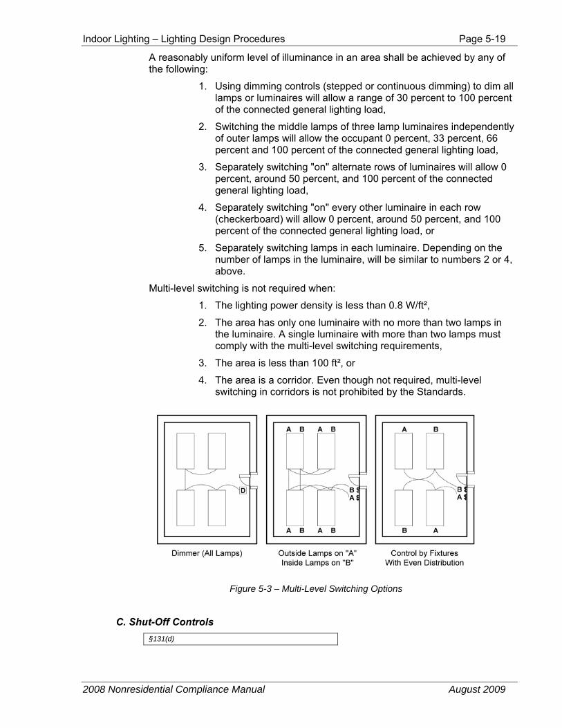
A reasonably uniform level of illuminance in an area shall be achieved by any of the following:
1. Using dimming controls (stepped or continuous dimming) to dim all lamps or luminaires will allow a range of 30 percent to 100 percent of the connected general lighting load,
2. Switching the middle lamps of three lamp luminaires independently of outer lamps will allow the occupant 0 percent, 33 percent, 66 percent and 100 percent of the connected general lighting load,
3. Separately switching "on" alternate rows of luminaires will allow 0 percent, around 50 percent, and 100 percent of the connected general lighting load,
4. Separately switching "on" every other luminaire in each row (checkerboard) will allow 0 percent, around 50 percent, and 100 percent of the connected general lighting load, or
5. Separately switching lamps in each luminaire. Depending on the number of lamps in the luminaire, will be similar to numbers 2 or 4, above.
Multi-level switching is not required when:
1. The lighting power density is less than 0.8 W/ft²,
2. The area has only one luminaire with no more than two lamps in the luminaire. A single luminaire with more than two lamps must comply with the multi-level switching requirements,
3. The area is less than 100 ft², or
4. The area is a corridor. Even though not required, multi-level switching in corridors is not prohibited by the Standards.
Figure 5-3 – Multi-Level Switching Options
C. Shut-Off Controls §131(d)
Page 5-20 Indoor Lighting – Lighting Design Procedures
2008 Nonresidential Compliance Manual August 2009
In addition to the manual controls installed to comply with §131(a & b). The Standards require that lights on each floor of a building be controlled by a separate automatic control device (or control point with multiple point control systems).
The areas exempted from the automatic shut-off requirements of §131(d) are:
1. Areas that must be continuously lit 24-hour, 365 day per year (≥ 8760 hours per year) such as hotel lobbies where lights are never turned off.
2. Lighting in corridors; lighting in guestrooms and dwelling units of high-rise residential buildings and hotel/motels; and lighting in parking garages.
3. Up to 0.3 W/ft² of lighting in any area within a building that must be continuously illuminated for reasons of building security or emergency egress provided that the area is designated a security or emergency egress area on the plans and specifications submitted to the enforcement agency under §10-103(a)2 . Note that the path of egress must be shown on the building plans to take this exception.
The shut-off control need not be a single control, but may include automatic time switches, occupancy sensors, or other automatic controls that are capable of automatically shutting off the lighting according to a schedule or based on sensing occupancy. (See Section 5.2.1.2 for information about certification requirements for these automatic controls).
When an occupant-sensing device is used to meet the automatic shut-off requirement, it must be installed in accordance with manufacturer's instructions with regard to placement of the sensors §130(a).
Automatic time switches with programmable solid-state perpetual calendar control devices can also be used to meet the shut-off requirement provided they are certified to the Energy Commission according to the applicable provision of §119. These devices are typically available with multiple channels of control, and may also be used to meet the mechanical system automatic time switch control requirements.
Indoor Lighting – Lighting Design Procedures Page 5-21
2008 Nonresidential Compliance Manual August 2009
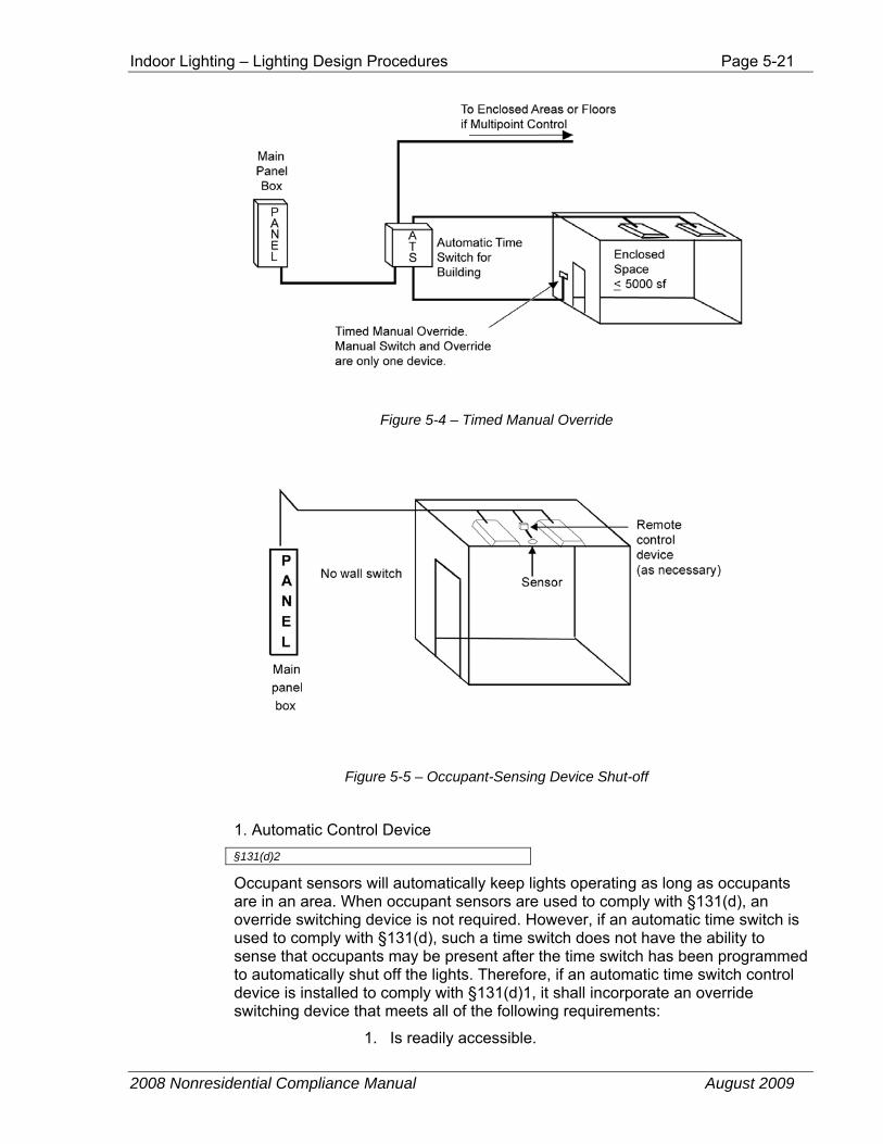
Figure 5-4 – Timed Manual Override
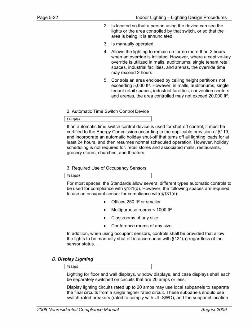
Figure 5-5 – Occupant-Sensing Device Shut-off
1. Automatic Control Device §131(d)2
Occupant sensors will automatically keep lights operating as long as occupants are in an area. When occupant sensors are used to comply with §131(d), an override switching device is not required. However, if an automatic time switch is used to comply with §131(d), such a time switch does not have the ability to sense that occupants may be present after the time switch has been programmed to automatically shut off the lights. Therefore, if an automatic time switch control device is installed to comply with §131(d)1, it shall incorporate an override switching device that meets all of the following requirements:
1. Is readily accessible.
Page 5-22 Indoor Lighting – Lighting Design Procedures
2008 Nonresidential Compliance Manual August 2009
2. Is located so that a person using the device can see the lights or the area controlled by that switch, or so that the area is being lit is annunciated.
3. Is manually operated.
4. Allows the lighting to remain on for no more than 2 hours when an override is initiated. However, where a captive-key override is utilized in malls, auditoriums, single tenant retail spaces, industrial facilities, and arenas, the override time may exceed 2 hours.
5. Controls an area enclosed by ceiling height partitions not exceeding 5,000 ft². However, in malls, auditoriums, single tenant retail spaces, industrial facilities, convention centers and arenas, the area controlled may not exceed 20,000 ft².
2. Automatic Time Switch Control Device §131(d)3
If an automatic time switch control device is used for shut-off control, it must be certified to the Energy Commission according to the applicable provision of §119, and incorporate an automatic holiday shut-off that turns off all lighting loads for at least 24 hours, and then resumes normal scheduled operation. However, holiday scheduling is not required for: retail stores and associated malls, restaurants, grocery stores, churches, and theaters.
3. Required Use of Occupancy Sensors §131(d)4
For most spaces, the Standards allow several different types automatic controls to be used for compliance with §131(d). However, the following spaces are required to use an occupant sensor for compliance with §131(d):
• Offices 250 ft² or smaller
• Multipurpose rooms < 1000 ft²
• Classrooms of any size
• Conference rooms of any size
In addition, when using occupant sensors, controls shall be provided that allow the lights to be manually shut off in accordance with §131(a) regardless of the sensor status.
D. Display Lighting §131(e)
Lighting for floor and wall displays, window displays, and case displays shall each be separately switched on circuits that are 20 amps or less.
Display lighting circuits rated up to 20 amps may use local subpanels to separate the final circuits from a single higher rated circuit. These subpanels should use switch-rated breakers (rated to comply with UL-SWD), and the subpanel location
Indoor Lighting – Lighting Design Procedures Page 5-23
2008 Nonresidential Compliance Manual August 2009
must be so that the controlled lighting is visible from the switch. These switches must be located where a user would reasonably expect to find a lighting control for the display lighting, and must be readily accessible (they can not be locked).
For example, a benefit of general lighting being on a separate switch is that it can be operated without having to turn on the display lighting (as, for example, when the cleaning crew is working at night and there is no need for the displays to be lit). Additionally, some retailers prefer to leave window displays on part of the night. The retailer must not be required to keep all of the other display lighting on when only one type of display lighting is required.
E. Automatic Controls Required for Tailored Method §131(f)
In addition to general lighting and display lighting, the Standards have provisions for allowing ornamental and special effects lighting, ornamental chandeliers and sconces, and specialized task lighting. When the Tailored Method in §146 is used for calculation allowed indoor lighting power density, the general lighting shall be controlled separately from the display, ornamental, and display case lighting.
F. Demand Responsive Lighting Controls §131(g)
In retail buildings with sales floor areas > 50,000 ft², demand responsive automatic lighting controls that uniformly reduce lighting power consumption by a 15 percent or more shall be installed. The lighting is not required to be uniformly reduced throughout the entire sales floor area, but must be reduced in a manner that does not cause any sales floor area to be non-functional. Buildings where more than 50 percent of the lighting power is controlled by daylighting controls are not required to have demand responsive automatic lighting controls.
Demand responsive controls must have the capability to be connected to the local utility’s demand response system, and be ready to respond to a utility demand responsive signal. However, if the local utility does not have a demand response system in place at this time, the lighting may be connected to the customer’s own demand limiting, energy management control system, or other similar type of control input. One type of utility system sends a signal that indicates the cost of power or a request to shed lighting according to utility developed protocols. The building operator programs the lighting controls to automatically reduce lighting power consumption in response to these signals. It is the responsibility of the designer to specify controls that are compatible with the local utility’s demand response protocol. These controls can save significant amounts of money for the stores who are using the capability of these controls.
Page 5-24 Indoor Lighting – Lighting Design Procedures
2008 Nonresidential Compliance Manual August 2009
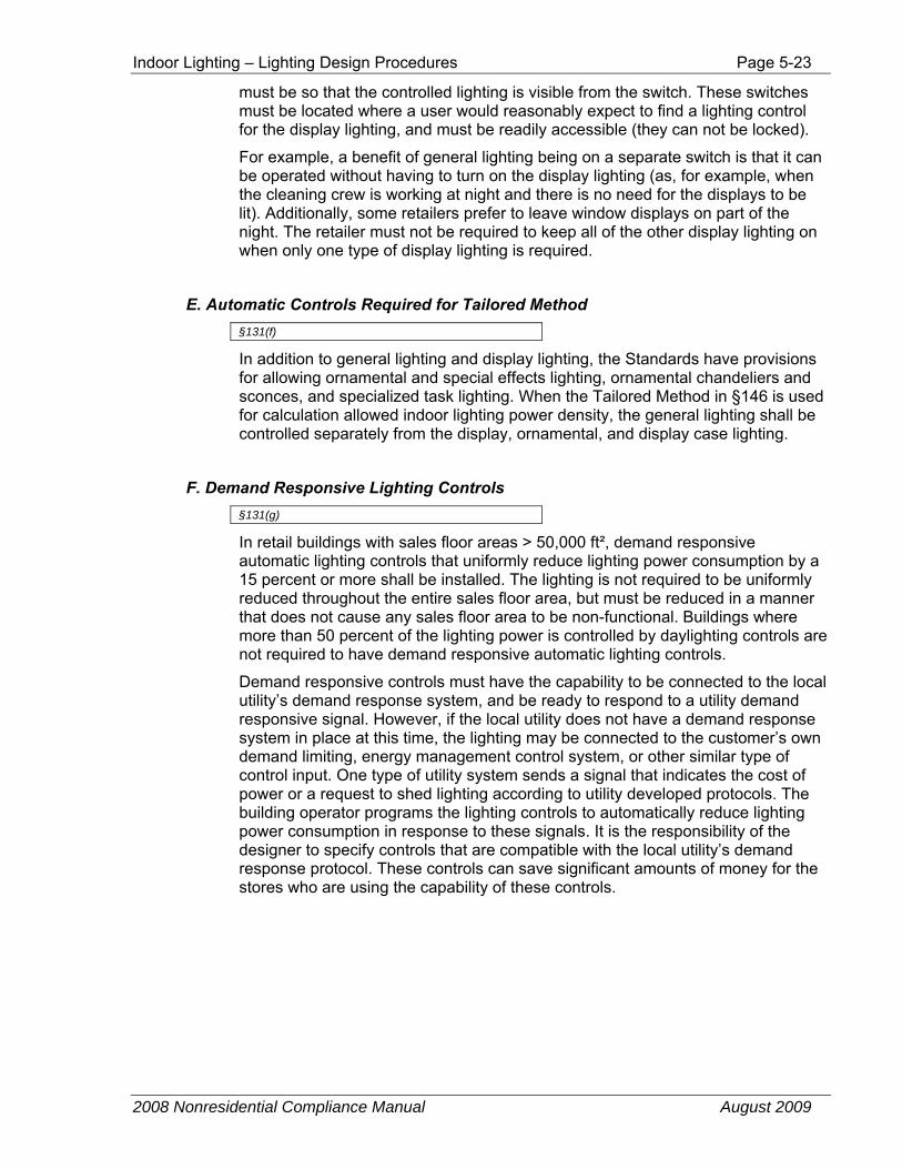
Figure 5-6 – Sample retail DR (demand response) control strategy
Figure 5-6 illustrates a sample demand response design that maintains uniformity and with a 25 percent power reduction exceeds the 15 percent minimum power reduction requirement. The triangles in this plan are halogen display lighting – the triangles with colored centers are turned off during the DR period. The striped squares are fluorescent troffers and the stripped lines are fluorescent wall washers. These fluorescent fixtures are wired for bi-level control so that half of the lamps are turned off during the DR period.
5.2.1.4 Dwelling Unit Mandatory Requirements Lighting in dwelling units of high-rise residential or hotel/motel occupancies must comply with the mandatory requirement in §150. The main requirements can be summarized as a requirement for high efficacy luminaires and for manual controls.
High Efficacy Lighting & Controls §150(k)
The classification of luminaires as high efficacy or low efficacy is required for compliance with the Residential Lighting Standards. However, for compliance with the Nonresidential Lighting Standards, the distinction between high efficacy and low efficacy luminaires is not considered.
However, for some mixed-use buildings, such as high-rise residential, hotels, and motels, the common areas must comply with the Nonresidential Lighting Standards, while dwelling units must comply with the Residential Lighting Standards. Therefore, in these dwelling units, the classification of luminaires as high or low efficacy is required for compliance with the Standards. See Section
Indoor Lighting – Lighting Design Procedures Page 5-25
2008 Nonresidential Compliance Manual August 2009
5.2.3.1 for more information about high-rise residential dwelling units and hotel/motel guest rooms.
In most cases, low efficacy lighting installed inside the dwelling units, when combined with either a dimmer or an occupancy sensor, can be substituted for high efficacy lighting.
Additionally, lighting that is permanently attached to the outside of high rise residential buildings, hotels, and motels, building, and is separately switched from the inside of a dwelling unit or guest room must also comply with the Residential Lighting Standards. These requirements include that such luminaires be either high efficacy or if low efficacy, they must be controlled by a combination of two lighting controls as follows:
1. A motions sensor, in addition to
2. A photo control, astronomical time clock, or an Energy Management Control System (EMCS).
Therefore, in these dwelling units, the classification of outdoor luminaires as high or low efficacy is required for compliance with the Standards. See §150(k)13.
High efficacy luminaires are defined by §150(k). See Section 6.2.1 of the Residential Compliance Manual for additional information about high efficacy luminaires.
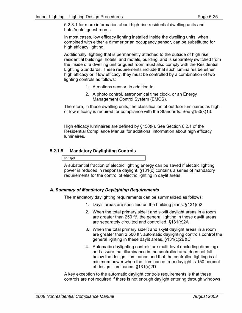
5.2.1.5 Mandatory Daylighting Controls §131(c)
A substantial fraction of electric lighting energy can be saved if electric lighting power is reduced in response daylight. §131(c) contains a series of mandatory requirements for the control of electric lighting in daylit areas.
A. Summary of Mandatory Daylighting Requirements The mandatory daylighting requirements can be summarized as follows:
1. Daylit areas are specified on the building plans. §131(c)2
2. When the total primary sidelit and skylit daylight areas in a room are greater than 250 ft², the general lighting in these daylit areas are separately circuited and controlled. §131(c)2A
3. When the total primary sidelit and skylit daylight areas in a room are greater than 2,500 ft², automatic daylighting controls control the general lighting in these daylit areas. §131(c)2B&C
4. Automatic daylighting controls are multi-level (including dimming) and assure that illuminance in the controlled area does not fall below the design illuminance and that the controlled lighting is at minimum power when the illuminance from daylight is 150 percent of design illuminance. §131(c)2D
A key exception to the automatic daylight controls requirements is that these controls are not required if there is not enough daylight entering through windows
Page 5-26 Indoor Lighting – Lighting Design Procedures
2008 Nonresidential Compliance Manual August 2009
or skylights. Either they are too small or not transmitting enough (low effective aperture) or that sunlight is significantly blocked by nearby buildings.
B. Description of Terms There are a number of terms that will be described briefly here in this overview.
1. General lighting §101(b).
The requirements above require general lighting to be controlled in daylit areas. General lighting is lighting that is meant to provide ambient and circulation lighting. It is not task lighting, or display lighting. Typical general lighting fixture types include but are not limited to: essentially all fluorescent fixtures outside of cove lighting, recessed cans, high bay and low bay fixtures and just about any fixture that cannot be aimed.
2. Automatic daylighting controls.
Automatic daylighting controls, sense daylight and reduce electric lighting so that the general lighting illumination served by the controlled lighting is never less than the design illumination. The design illumination is the light level in the space from the general lighting at full output but with no daylight. The daylighting controls are multi-level so there is at least one switching control step or one point along the continuous dimming curve where the controlled lighting system is consuming between 50 and 70 percent of rated power. These controls are adjusted so that the power draw of the controlled lighting system is reduced to 35 percent or less or rated power when the daylight contribution to the space is greater than 150 percent of the design illuminance. See Section 5.2.1.2 for a description of the required manufacturer’s certification of automatic daylighting controls §119(e).
3. Daylight areas.
Automatic daylighting control systems save more energy per fixture and are less likely to be disabled if the controlled fixtures are close to the source of daylight. If an automatic daylighting control controls lights that are too far away from the daylight source, if the control is configured correctly, it will rarely turn off the electric lights and not yield the benefit of frequently turning off the lights near windows and skylights.
Daylight areas are not to be double counted thus overlapping areas are not double counted. The primary sidelit daylight area is counted first, then the skylit daylight area is counted and finally the secondary sidelit area is counted last.
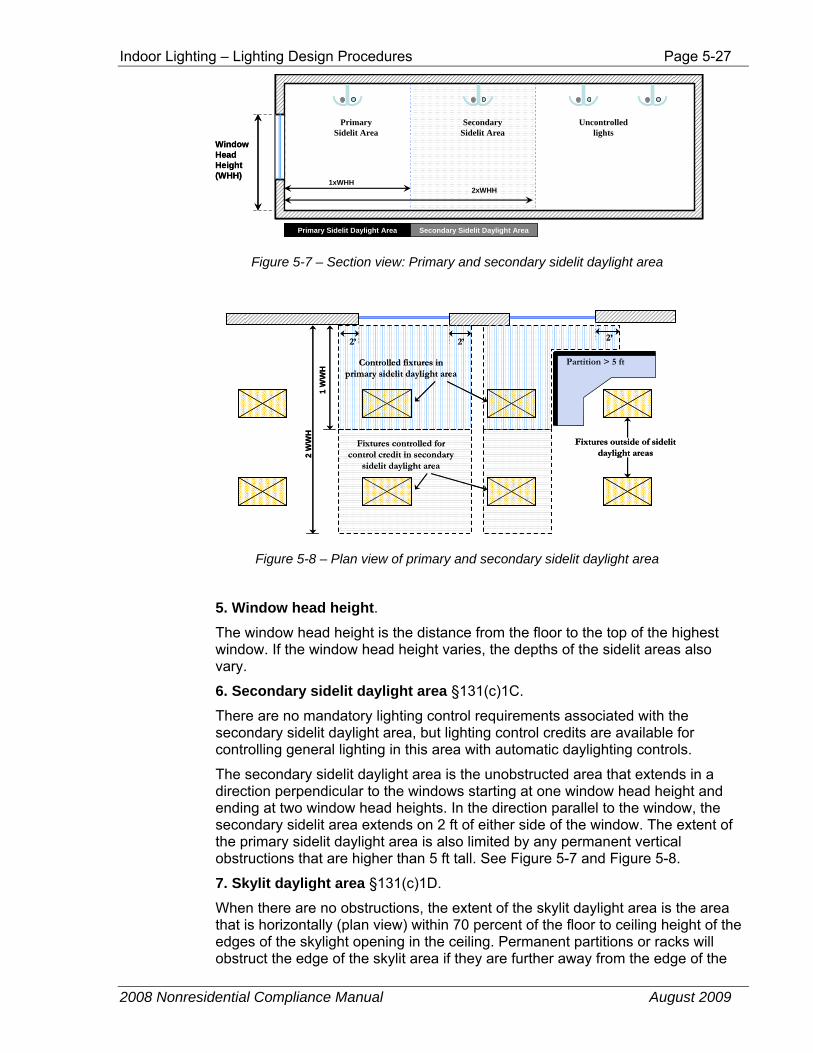
4. Primary sidelit daylight area §131(c)1B.
The primary sidelit daylight area is the unobstructed area next to perimeter windows that extends on two feet on either side of the window in a direction parallel to the window and one window head height perpendicular to the window. The extent of the primary sidelit daylight area is also limited by any permanent vertical obstructions that are higher than 5 ft tall. Typical office “cubicle” walls are not permanent vertical obstructions. The best way to understand these extents of the daylight area is to look at Figure 5-7 and Figure 5-8.
Indoor Lighting – Lighting Design Procedures Page 5-27
2008 Nonresidential Compliance Manual August 2009
WindowHead Height(WHH)
Primary Sidelit Area
Uncontrolledlights
Secondary Sidelit Area
1xWHH2xWHH
Primary Sidelit Daylight Area Secondary Sidelit Daylight Area
WindowHead Height(WHH)
Primary Sidelit Area
Uncontrolledlights
Secondary Sidelit Area
1xWHH2xWHH
Primary Sidelit Daylight Area Secondary Sidelit Daylight Area
Figure 5-7 – Section view: Primary and secondary sidelit daylight area
Fixtures outside of sidelit daylight areas
Fixtures controlled for control credit in secondary
sidelit daylight area
Controlled fixtures in primary sidelit daylight area
2’
Partition > 5 ft
1 W
WH
2 W
WH
2’ 2’
Fixtures outside of sidelit daylight areas
Fixtures controlled for control credit in secondary
sidelit daylight area
Controlled fixtures in primary sidelit daylight area
2’
Partition > 5 ft
1 W
WH
2 W
WH
2’ 2’
Figure 5-8 – Plan view of primary and secondary sidelit daylight area
5. Window head height. The window head height is the distance from the floor to the top of the highest window. If the window head height varies, the depths of the sidelit areas also vary.
6. Secondary sidelit daylight area §131(c)1C.
There are no mandatory lighting control requirements associated with the secondary sidelit daylight area, but lighting control credits are available for controlling general lighting in this area with automatic daylighting controls.
The secondary sidelit daylight area is the unobstructed area that extends in a direction perpendicular to the windows starting at one window head height and ending at two window head heights. In the direction parallel to the window, the secondary sidelit area extends on 2 ft of either side of the window. The extent of the primary sidelit daylight area is also limited by any permanent vertical obstructions that are higher than 5 ft tall. See Figure 5-7 and Figure 5-8.
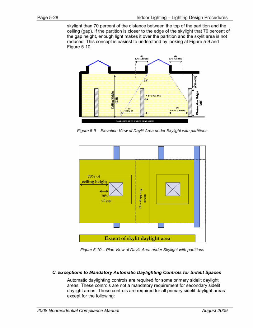
7. Skylit daylight area §131(c)1D.
When there are no obstructions, the extent of the skylit daylight area is the area that is horizontally (plan view) within 70 percent of the floor to ceiling height of the edges of the skylight opening in the ceiling. Permanent partitions or racks will obstruct the edge of the skylit area if they are further away from the edge of the
Page 5-28 Indoor Lighting – Lighting Design Procedures
2008 Nonresidential Compliance Manual August 2009
skylight than 70 percent of the distance between the top of the partition and the ceiling (gap). If the partition is closer to the edge of the skylight that 70 percent of the gap height, enough light makes it over the partition and the skylit area is not reduced. This concept is easiest to understand by looking at Figure 5-9 and Figure 5-10.
Obs
truc
tion
Hei
ght
(OH
)
(CH
–O
H)
(iii)> 0.7 x (CH-OH)
DAYLIGHT AREA UNDER SKYLIGHTS
Cei
ling
Hei
ght
(CH
)
(i)CH x 0.7
(ii)0.7 x (CH-OH)
(ii)0.7 x (CH-OH)
< 0.7 x (CH-OH)
35º
Obs
truc
tion
Hei
ght
(OH
)
(CH
–O
H)
(iii)> 0.7 x (CH-OH)
DAYLIGHT AREA UNDER SKYLIGHTS
Cei
ling
Hei
ght
(CH
)
(i)CH x 0.7
(ii)0.7 x (CH-OH)
(ii)0.7 x (CH-OH)
< 0.7 x (CH-OH)
35º
Figure 5-9 – Elevation View of Daylit Area under Skylight with partitions
70% of gap
70% of ceiling height
Extent of skylit daylight area
Ove
rlap
pin
g
area
s70% of gap
70% of ceiling height
Extent of skylit daylight area
Ove
rlap
pin
g
area
s
Figure 5-10 – Plan View of Daylit Area under Skylight with partitions
C. Exceptions to Mandatory Automatic Daylighting Controls for Sidelit Spaces Automatic daylighting controls are required for some primary sidelit daylight areas. These controls are not a mandatory requirement for secondary sidelit daylight areas. These controls are required for all primary sidelit daylight areas except for the following:
Indoor Lighting – Lighting Design Procedures Page 5-29
2008 Nonresidential Compliance Manual August 2009
1. Small primary sidelit daylight areas.
Automatic daylighting controls are required only if the total area of primary sidelit areas in room exceed 2,500 ft². Exception 1 to §131(c)2C. This is the primary exception as most spaces will have smaller primary sidelit daylight areas.
Rooms with smaller primary sidelit areas are not required to install automatic daylighting controls. However, one can obtain lighting control credits for daylighting controls in primary sidelit daylight areas less than 2,500 ft². §146(a)2E. These lighting control credits can be exchanged for more installed lighting power. See Section 5.5.4 for more details about lighting control credits.
2. Primary Sidelit Effective Aperture Less than 10 percent. Automatic daylighting controls are not required if the windows do not transmit enough light into the primary sidelit area. Exception 2 to §131(c)2C. The primary sidelit effective aperture describes how transmitting the wall is near the primary sidelit area. It defined by Equation 5-1 (Equation 146–A in the Standards) and is defined in more detail later in this Chapter. §146(a)2Ei. In most cases this exception will not apply unless the glass is not very transmitting or for small windows located high up on a wall.
3. Existing structures obstruct daylight. Automatic daylighting controls are not required in primary sidelit areas where existing surrounding structures are tall enough to obstruct significant daylight from reaching the windows. Exception 3 to §131(c)2C The exception is applicable for those windows, where the height of buildings facing the windows will be substantially shaded during daytime hours. This occurs when the height of buildings facing the windows is at least twice as high above the floor level of the windows as the adjacent buildings’ horizontal distance away from the window(s). This will rarely apply to the windows facing the street but may apply to windows near an adjacent building.
4. Parking Garages.
Parking garages are not required to install the automatic daylighting control devices. Exception 4 to §131(c)2C
D. Exceptions to Mandatory Automatic Daylighting Controls for Skylit Spaces The general lighting in the daylit area must be on a automatic daylighting control device that meets the applicable requirements of §119 and be installed in accordance with §131(c)2D. However, when the daylit area under the skylights in any enclosed space (room) is ≤ 2,500 ft², the daylight area for the skylights is not required to be automatically controlled. Barring exceptions written into the Standards, the automatic daylighting control device needs to be a photocontrol device capable of doing multi-level lighting control (dimming controls are considered to meet the multi-level requirement).
There are four exceptions that allow the designer to NOT specify such an automatic daylighting control device:
1. Where total skylit daylit area in an enclosed space is less than or equal to 2,500 ft².
2. Where the designer can prove to the satisfaction of the building compliance official that existing adjacent structures would obstruct
Page 5-30 Indoor Lighting – Lighting Design Procedures
2008 Nonresidential Compliance Manual August 2009
direct beam sunlight for at least 6 hours per day during the equinox as calculated using computer or graphical methods.
3. For spaces where the skylight effective aperture is greater than 4.0% and all general lighting in the skylit area is controlled by a multi-level astronomical time switch. Such a time switch needs to meet the requirements of §119(h) and needs to have an override switch that meets the requirements of §131(d)2.
4. Where skylight effective aperture is less than 0.006. The effective aperture for skylit daylit area is specified in §146(a)2E and explained later in this section.
E. Lighting Controls Required §131(c)2
§131(c) requires specific lighting controls to be installed in spaces. Fixtures in the daylit area(s) are required to be circuited such as that they can be controlled separately and effectively, in order to maximize energy savings from daylighting present in the daylit area(s).
F. Separate Switching near Windows and under Skylights §131(c)2A
The control of electric lighting in the area where daylighting enters a building through windows or skylights is addressed in the Standards. It falls under the mandatory requirement for separate switching in daylit areas, and may receive credit under the optional automatic controls credits. Under the mandatory measures, the electric lighting within the daylit area must be switched so that the lights can be controlled separately from the non-daylit areas. However, the separate daylit area control is not required where an enclosed space has a combined daylit area (skylights and windows) of ≤ 250 ft². Separate switching of the secondary sidelit area is not required, but a higher power adjustment factor (PAF) is available for separate automatic daylighting control of the secondary sidelit area. It is acceptable to achieve control in the daylit area by being able to shut off at least 50 percent of the lamps within the daylit area. This must be done by a control dedicated to serving only luminaires in the daylit area. If there are separate daylit areas for windows and skylights, they must be controlled separately.
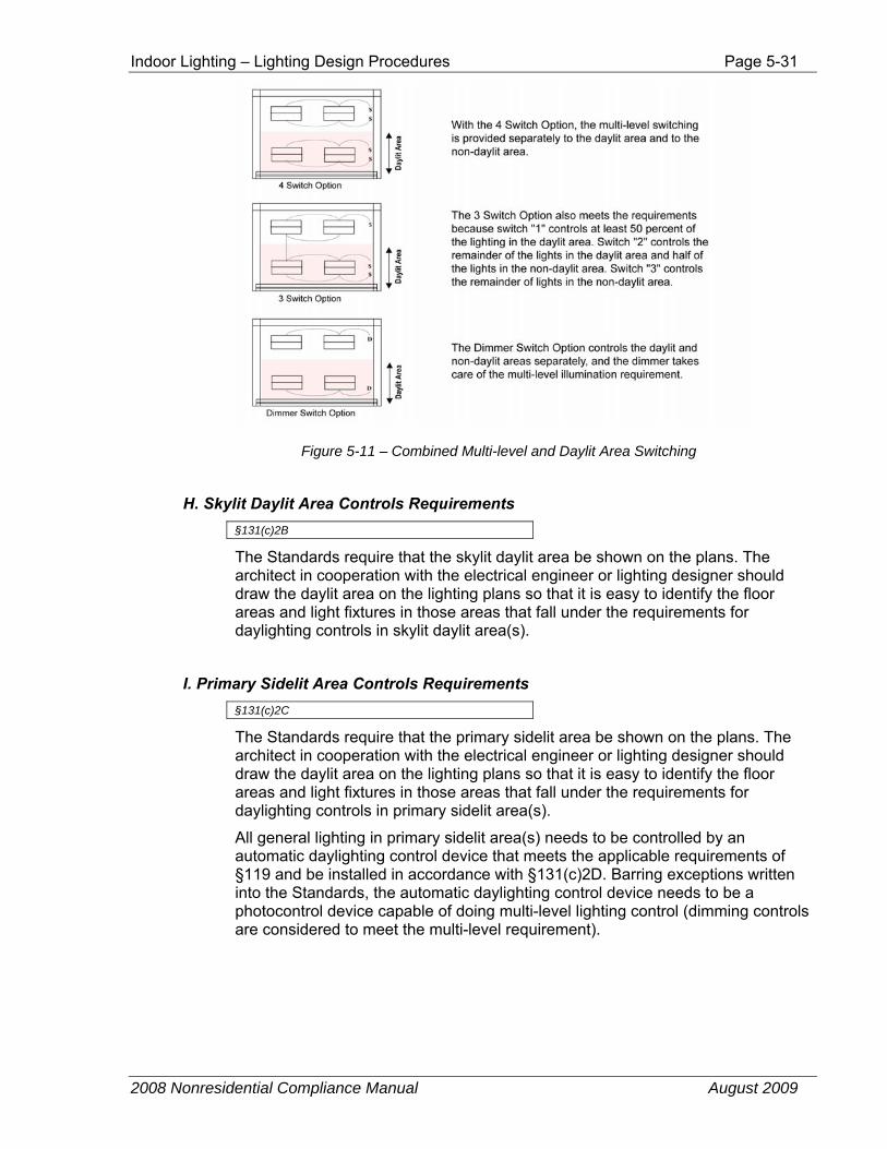
G. Daylighting Controls and Multi-Level Switching §131(c)2A
The daylit area switching requirements are in addition to the multi-level switching requirements. Taken together, there are at least three ways to comply. See Figure 5-11. Daylight switching must be applied to a fixture if any portion of that fixture is within the daylit area.
Indoor Lighting – Lighting Design Procedures Page 5-31
2008 Nonresidential Compliance Manual August 2009
Figure 5-11 – Combined Multi-level and Daylit Area Switching
H. Skylit Daylit Area Controls Requirements §131(c)2B
The Standards require that the skylit daylit area be shown on the plans. The architect in cooperation with the electrical engineer or lighting designer should draw the daylit area on the lighting plans so that it is easy to identify the floor areas and light fixtures in those areas that fall under the requirements for daylighting controls in skylit daylit area(s).
I. Primary Sidelit Area Controls Requirements §131(c)2C
The Standards require that the primary sidelit area be shown on the plans. The architect in cooperation with the electrical engineer or lighting designer should draw the daylit area on the lighting plans so that it is easy to identify the floor areas and light fixtures in those areas that fall under the requirements for daylighting controls in primary sidelit area(s).
All general lighting in primary sidelit area(s) needs to be controlled by an automatic daylighting control device that meets the applicable requirements of §119 and be installed in accordance with §131(c)2D. Barring exceptions written into the Standards, the automatic daylighting control device needs to be a photocontrol device capable of doing multi-level lighting control (dimming controls are considered to meet the multi-level requirement).
Page 5-32 Indoor Lighting – Lighting Design Procedures
2008 Nonresidential Compliance Manual August 2009
J. Automatic Daylighting Control Device Installation and Operation §131(c)2D
When automatic daylighting control devices are required by the Standards, they are required to be installed and configured to operate according to all of the following requirements:
1. Photosensors that are installed as part of the automatic daylighting control system need to be placed away from locations where they can be easily accessed and tampered with. However, it is also important to place them in locations where they provide adequate control of the fixtures in the daylit area. Ceiling mounted photosensors would meet this requirement as long as the ceiling is not within easy reach of a standing person. Wall-mounted photosensors within reach of the standing person (commonly called wall-box sensors) do not meet this requirement of the Standards.
2. The location where the calibration adjustments are made to the automatic daylighting control system needs to be easily accessible to authorized personnel (but not to all occupants of the space). If the calibration adjustments are made in a ceiling mounted device, such a device must be placed in a ceiling that is no higher than 11 ft from the floor, and within 2 ft of a ceiling access panel.
3. The automatic daylighting control system needs to provide multi-level lighting controls; this can include continuous dimming. The automatic switching control must have at least one step that is between 50 and 70 percent of rated power and a minimum step that is less than 35 percent of rated power.
The following situations are not required to have the multi-level lighting control:
a. Areas having a lighting power density < 0.3 W/ft²
b. When skylights are replaced or added to an existing building with and existing general lighting system.
Complying controls include but are not limited to a 2/3’s controlled on/off or 1/2 + off controls as shown in Figure 5-13.
Indoor Lighting – Lighting Design Procedures Page 5-33
2008 Nonresidential Compliance Manual August 2009
C B B C A AE
C B B C A AD
C B B C A AD
C B B C A AE
D D D D E E E
14 ft
14 ft
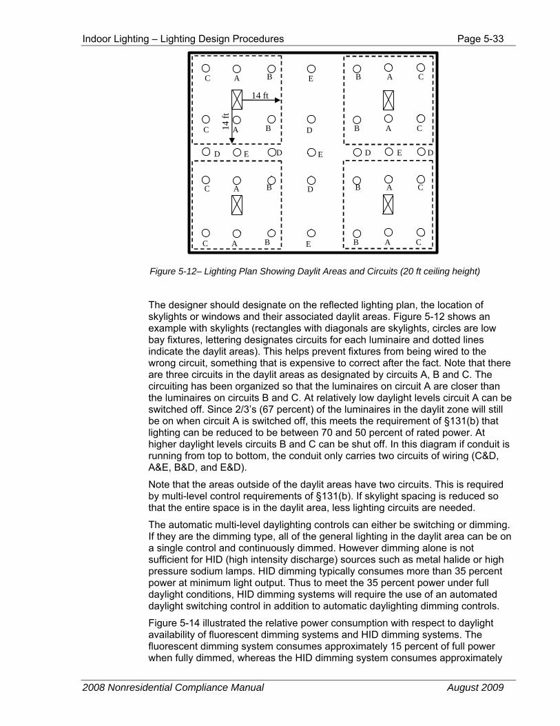
Figure 5-12– Lighting Plan Showing Daylit Areas and Circuits (20 ft ceiling height)
The designer should designate on the reflected lighting plan, the location of skylights or windows and their associated daylit areas. Figure 5-12 shows an example with skylights (rectangles with diagonals are skylights, circles are low bay fixtures, lettering designates circuits for each luminaire and dotted lines indicate the daylit areas). This helps prevent fixtures from being wired to the wrong circuit, something that is expensive to correct after the fact. Note that there are three circuits in the daylit areas as designated by circuits A, B and C. The circuiting has been organized so that the luminaires on circuit A are closer than the luminaires on circuits B and C. At relatively low daylight levels circuit A can be switched off. Since 2/3’s (67 percent) of the luminaires in the daylit zone will still be on when circuit A is switched off, this meets the requirement of §131(b) that lighting can be reduced to be between 70 and 50 percent of rated power. At higher daylight levels circuits B and C can be shut off. In this diagram if conduit is running from top to bottom, the conduit only carries two circuits of wiring (C&D, A&E, B&D, and E&D).
Note that the areas outside of the daylit areas have two circuits. This is required by multi-level control requirements of §131(b). If skylight spacing is reduced so that the entire space is in the daylit area, less lighting circuits are needed.
The automatic multi-level daylighting controls can either be switching or dimming. If they are the dimming type, all of the general lighting in the daylit area can be on a single control and continuously dimmed. However dimming alone is not sufficient for HID (high intensity discharge) sources such as metal halide or high pressure sodium lamps. HID dimming typically consumes more than 35 percent power at minimum light output. Thus to meet the 35 percent power under full daylight conditions, HID dimming systems will require the use of an automated daylight switching control in addition to automatic daylighting dimming controls.
Figure 5-14 illustrated the relative power consumption with respect to daylight availability of fluorescent dimming systems and HID dimming systems. The fluorescent dimming system consumes approximately 15 percent of full power when fully dimmed, whereas the HID dimming system consumes approximately
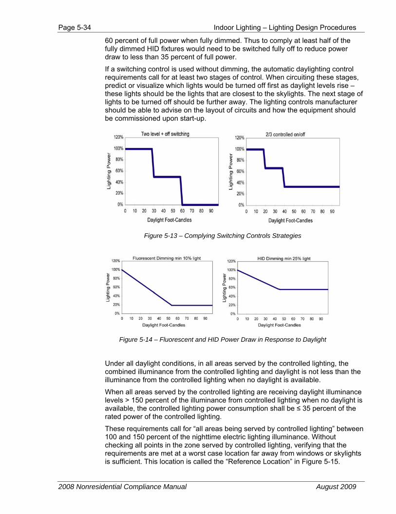
Page 5-34 Indoor Lighting – Lighting Design Procedures
2008 Nonresidential Compliance Manual August 2009
60 percent of full power when fully dimmed. Thus to comply at least half of the fully dimmed HID fixtures would need to be switched fully off to reduce power draw to less than 35 percent of full power.
If a switching control is used without dimming, the automatic daylighting control requirements call for at least two stages of control. When circuiting these stages, predict or visualize which lights would be turned off first as daylight levels rise – these lights should be the lights that are closest to the skylights. The next stage of lights to be turned off should be further away. The lighting controls manufacturer should be able to advise on the layout of circuits and how the equipment should be commissioned upon start-up.
Figure 5-13 – Complying Switching Controls Strategies
Figure 5-14 – Fluorescent and HID Power Draw in Response to Daylight
Under all daylight conditions, in all areas served by the controlled lighting, the combined illuminance from the controlled lighting and daylight is not less than the illuminance from the controlled lighting when no daylight is available.
When all areas served by the controlled lighting are receiving daylight illuminance levels > 150 percent of the illuminance from controlled lighting when no daylight is available, the controlled lighting power consumption shall be ≤ 35 percent of the rated power of the controlled lighting.
These requirements call for “all areas being served by controlled lighting” between 100 and 150 percent of the nighttime electric lighting illuminance. Without checking all points in the zone served by controlled lighting, verifying that the requirements are met at a worst case location far away from windows or skylights is sufficient. This location is called the “Reference Location” in Figure 5-15.

Indoor Lighting – Lighting Design Procedures Page 5-35
2008 Nonresidential Compliance Manual August 2009
Zone Illuminated by Controlled Luminaires
Zone Illuminated by Controlled Luminaires
Primary Sidelit AreaPrimary Sidelit Area
a) Sidelit Area Larger than Zone Illuminated by Controlled Lighting
b) Zone Illuminated by Controlled Lighting Larger than Sidelit Area
Reference Location
Halfway between
luminaires
Halfway between luminaires
Zone Illuminated by Controlled Luminaires
Zone Illuminated by Controlled Luminaires
Primary Sidelit AreaPrimary Sidelit Area
a) Sidelit Area Larger than Zone Illuminated by Controlled Lighting
b) Zone Illuminated by Controlled Lighting Larger than Sidelit Area
Reference Location
Halfway between
luminaires
Halfway between luminaires
Figure 5-15 – Zone Illuminated by Controlled Luminaires and Reference Location for Measuring Reference Illuminance
Figure 5-16 and Figure 5-17 plot the performance of switching and dimming automatic daylighting controls (photocontrols). The performance is indicated in terms of lighting at the darkest point of the zone served by the controlled lighting (indicated as the Reference Location in Figure 5-15). The total lighting as plotted on the y-axis made up of both daylit and electric lighting contribution to total foot-candles at this darkest location in the area served by the controlled lighting. Daylight plotted on the x-axis is just the daylight available at this darkest location.
Stepped Switching3 level + off control
50%
100%
150%
200%
0% 35% 70% 105% 140% 175%
Daylight % Reference fc
Tota
l Lig
ht %
Ref
fc
Maximum savingsMinimum savings
Range of AllowableIlluminances when Stage
Turns Off
Figure 5-16 – Performance of compliant switching controls - total light (daylight + electric light) versus daylight
In Figure 5-16, the light levels are given as a fraction of the reference or design foot-candles (fc). The bottom points of both controls indicate the total illuminance just after a stage of lighting has switched off. Both controls are compliant because the total illuminance at the darkest location in the area served by controlled lighting just after switching off a stage of lighting is between 100 and 150 percent of the reference illuminance. The reference illuminance is the illuminance at this same location when there is no daylight (night time).
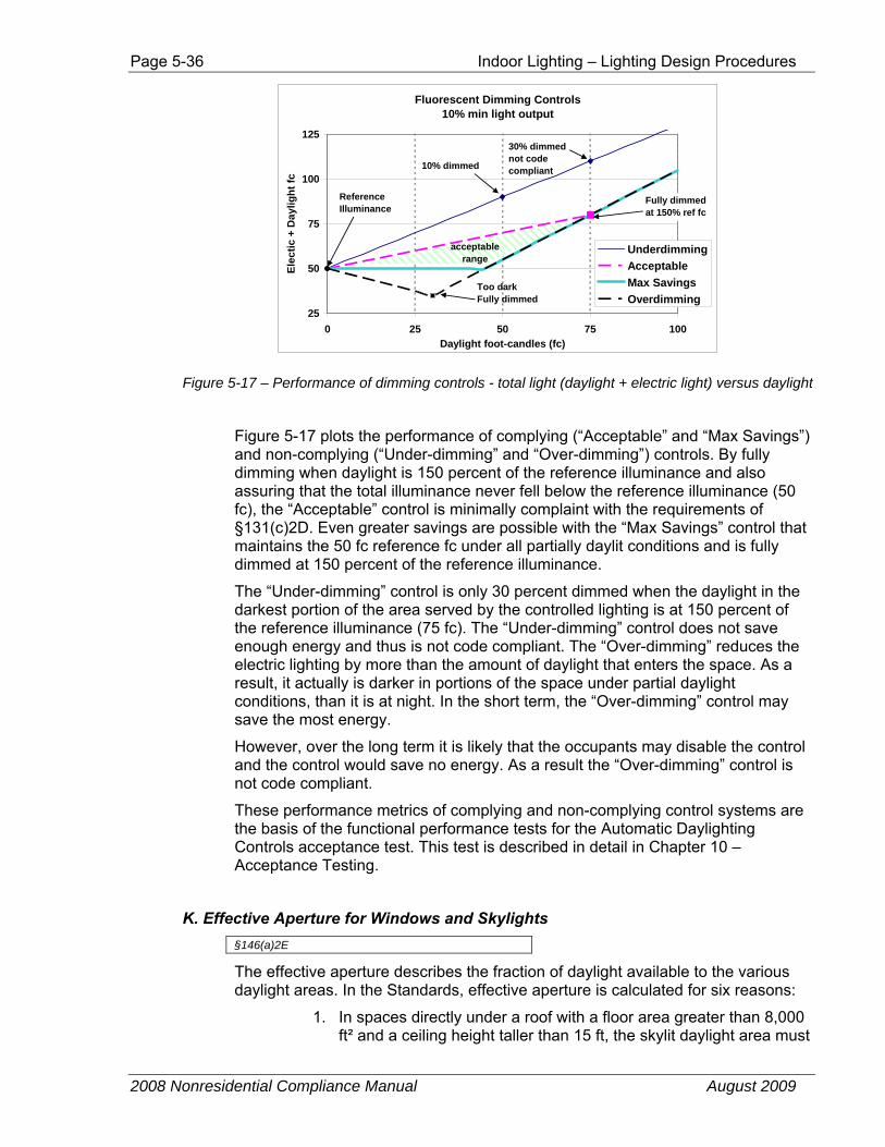
Page 5-36 Indoor Lighting – Lighting Design Procedures
2008 Nonresidential Compliance Manual August 2009
Fluorescent Dimming Controls10% min light output
25
50
75
100
125
0 25 50 75 100Daylight foot-candles (fc)
Elec
tic +
Day
light
fc
UnderdimmingAcceptableMax SavingsOverdimming
ReferenceIlluminance
10% dimmed
Too darkFully dimmed
Fully dimmedat 150% ref fc
30% dimmednot codecompliant
acceptablerange
Figure 5-17 – Performance of dimming controls - total light (daylight + electric light) versus daylight
Figure 5-17 plots the performance of complying (“Acceptable” and “Max Savings”) and non-complying (“Under-dimming” and “Over-dimming”) controls. By fully dimming when daylight is 150 percent of the reference illuminance and also assuring that the total illuminance never fell below the reference illuminance (50 fc), the “Acceptable” control is minimally complaint with the requirements of §131(c)2D. Even greater savings are possible with the “Max Savings” control that maintains the 50 fc reference fc under all partially daylit conditions and is fully dimmed at 150 percent of the reference illuminance.
The “Under-dimming” control is only 30 percent dimmed when the daylight in the darkest portion of the area served by the controlled lighting is at 150 percent of the reference illuminance (75 fc). The “Under-dimming” control does not save enough energy and thus is not code compliant. The “Over-dimming” reduces the electric lighting by more than the amount of daylight that enters the space. As a result, it actually is darker in portions of the space under partial daylight conditions, than it is at night. In the short term, the “Over-dimming” control may save the most energy.
However, over the long term it is likely that the occupants may disable the control and the control would save no energy. As a result the “Over-dimming” control is not code compliant.
These performance metrics of complying and non-complying control systems are the basis of the functional performance tests for the Automatic Daylighting Controls acceptance test. This test is described in detail in Chapter 10 – Acceptance Testing.
K. Effective Aperture for Windows and Skylights §146(a)2E
The effective aperture describes the fraction of daylight available to the various daylight areas. In the Standards, effective aperture is calculated for six reasons:
1. In spaces directly under a roof with a floor area greater than 8,000 ft² and a ceiling height taller than 15 ft, the skylit daylight area must
Indoor Lighting – Lighting Design Procedures Page 5-37
2008 Nonresidential Compliance Manual August 2009
be 50 percent of the floor area. In these spaces the minimum skylight area is either 3 percent of the daylit area or a skylight effective aperture of 1.1 percent §143(c). This more complex method is used only if one wants to use less skylight area and the skylight has a high visible light transmittance.
2. An alternative to installing skylights when they are required for daylighting is to install windows so that the sum of the skylit daylit area and the primary sidelit daylit area is greater than 50 percent of the room area. The installed windows must be large and transmitting enough so that the primary sidelit effective aperture is greater than 10 percent. §143(c). This might occur of one has a long building and plans on having windows anyway.
3. In daylit areas where automatic daylighting controls are not required (skylit and primary sidelit areas < 2.500 ft², secondary sidelit areas), one can obtain a lighting control credit or power adjustment factor (PAF) by installing automatic daylighting controls. The control credit is function of the lighting power density of the controlled lighting and the effective aperture of daylit area. §146(a)2E & Table 146-C of the Standards. The lighting control credits can be used when the designer would like to use more lighting or to have a beyond code electric lighting design.
4. Primary sidelit areas are exempt from the automatic daylighting control requirements when the primary sidelit effective aperture is less than 10 percent. §131(c)2B Exception 2 This exception would be relatively rare except in the cases of small windows placed high on the wall or windows with low visible light transmittance.
5. Skylit areas are exempt from the automatic daylighting control requirements when the skylit effective aperture is less than 0.6 percent. §131(c)2B Exception 4. This would apply when a few small skylights widely spaced are in a high ceiling.
6. Skylit areas can use multi-level astronomical time switches instead of photocontrols when the effective aperture is greater than 4 percent. §131(c)2B Exception 3. This would apply in large atria or other situations with a significant amount of skylight area. The skylight to floor ratios for such a design is around 10 percent+.
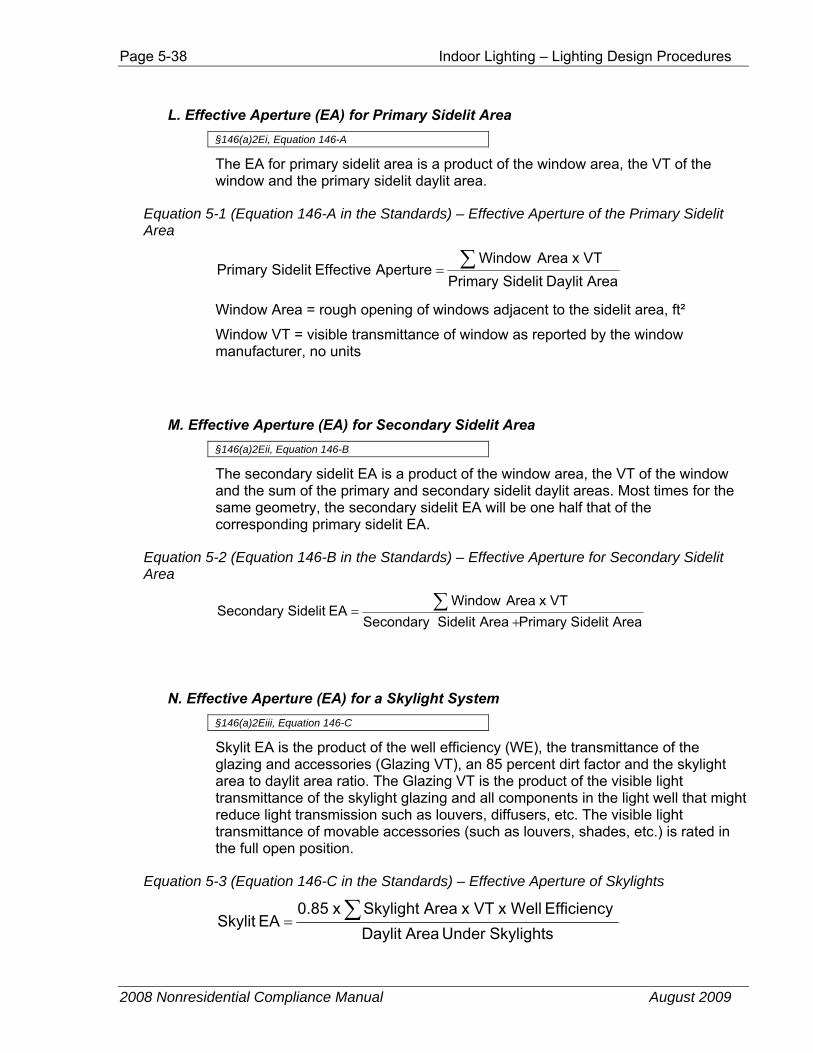
Page 5-38 Indoor Lighting – Lighting Design Procedures
2008 Nonresidential Compliance Manual August 2009
L. Effective Aperture (EA) for Primary Sidelit Area §146(a)2Ei, Equation 146-A
The EA for primary sidelit area is a product of the window area, the VT of the window and the primary sidelit daylit area.
Equation 5-1 (Equation 146-A in the Standards) – Effective Aperture of the Primary Sidelit Area
AreaDaylit SidelitPrimary x VTAreaWindow
ApertureEffective SidelitPrimary ∑=
Window Area = rough opening of windows adjacent to the sidelit area, ft²
Window VT = visible transmittance of window as reported by the window manufacturer, no units
M. Effective Aperture (EA) for Secondary Sidelit Area §146(a)2Eii, Equation 146-B
The secondary sidelit EA is a product of the window area, the VT of the window and the sum of the primary and secondary sidelit daylit areas. Most times for the same geometry, the secondary sidelit EA will be one half that of the corresponding primary sidelit EA.
Equation 5-2 (Equation 146-B in the Standards) – Effective Aperture for Secondary Sidelit Area
AreaSidelitPrimary AreaSidelit Secondary x VTAreaWindow
EA SidelitSecondary +
= ∑
N. Effective Aperture (EA) for a Skylight System §146(a)2Eiii, Equation 146-C
Skylit EA is the product of the well efficiency (WE), the transmittance of the glazing and accessories (Glazing VT), an 85 percent dirt factor and the skylight area to daylit area ratio. The Glazing VT is the product of the visible light transmittance of the skylight glazing and all components in the light well that might reduce light transmission such as louvers, diffusers, etc. The visible light transmittance of movable accessories (such as louvers, shades, etc.) is rated in the full open position.
Equation 5-3 (Equation 146-C in the Standards) – Effective Aperture of Skylights
Skylights Under AreaDaylit Efficiency x Well x VT AreaSkylight x 0.85
EA Skylit ∑=
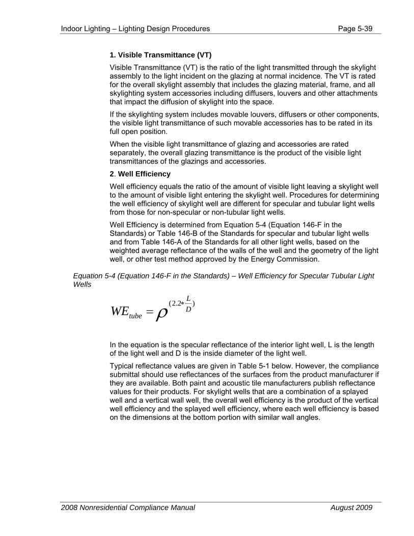
Indoor Lighting – Lighting Design Procedures Page 5-39
2008 Nonresidential Compliance Manual August 2009
1. Visible Transmittance (VT) Visible Transmittance (VT) is the ratio of the light transmitted through the skylight assembly to the light incident on the glazing at normal incidence. The VT is rated for the overall skylight assembly that includes the glazing material, frame, and all skylighting system accessories including diffusers, louvers and other attachments that impact the diffusion of skylight into the space.
If the skylighting system includes movable louvers, diffusers or other components, the visible light transmittance of such movable accessories has to be rated in its full open position.
When the visible light transmittance of glazing and accessories are rated separately, the overall glazing transmittance is the product of the visible light transmittances of the glazings and accessories.
2. Well Efficiency
Well efficiency equals the ratio of the amount of visible light leaving a skylight well to the amount of visible light entering the skylight well. Procedures for determining the well efficiency of skylight well are different for specular and tubular light wells from those for non-specular or non-tubular light wells.
Well Efficiency is determined from Equation 5-4 (Equation 146-F in the Standards) or Table 146-B of the Standards for specular and tubular light wells and from Table 146-A of the Standards for all other light wells, based on the weighted average reflectance of the walls of the well and the geometry of the light well, or other test method approved by the Energy Commission.
Equation 5-4 (Equation 146-F in the Standards) – Well Efficiency for Specular Tubular Light Wells
ρ )2.2(DL
tubeWE∗
=
In the equation is the specular reflectance of the interior light well, L is the length of the light well and D is the inside diameter of the light well.
Typical reflectance values are given in Table 5-1 below. However, the compliance submittal should use reflectances of the surfaces from the product manufacturer if they are available. Both paint and acoustic tile manufacturers publish reflectance values for their products. For skylight wells that are a combination of a splayed well and a vertical wall well, the overall well efficiency is the product of the vertical well efficiency and the splayed well efficiency, where each well efficiency is based on the dimensions at the bottom portion with similar wall angles.
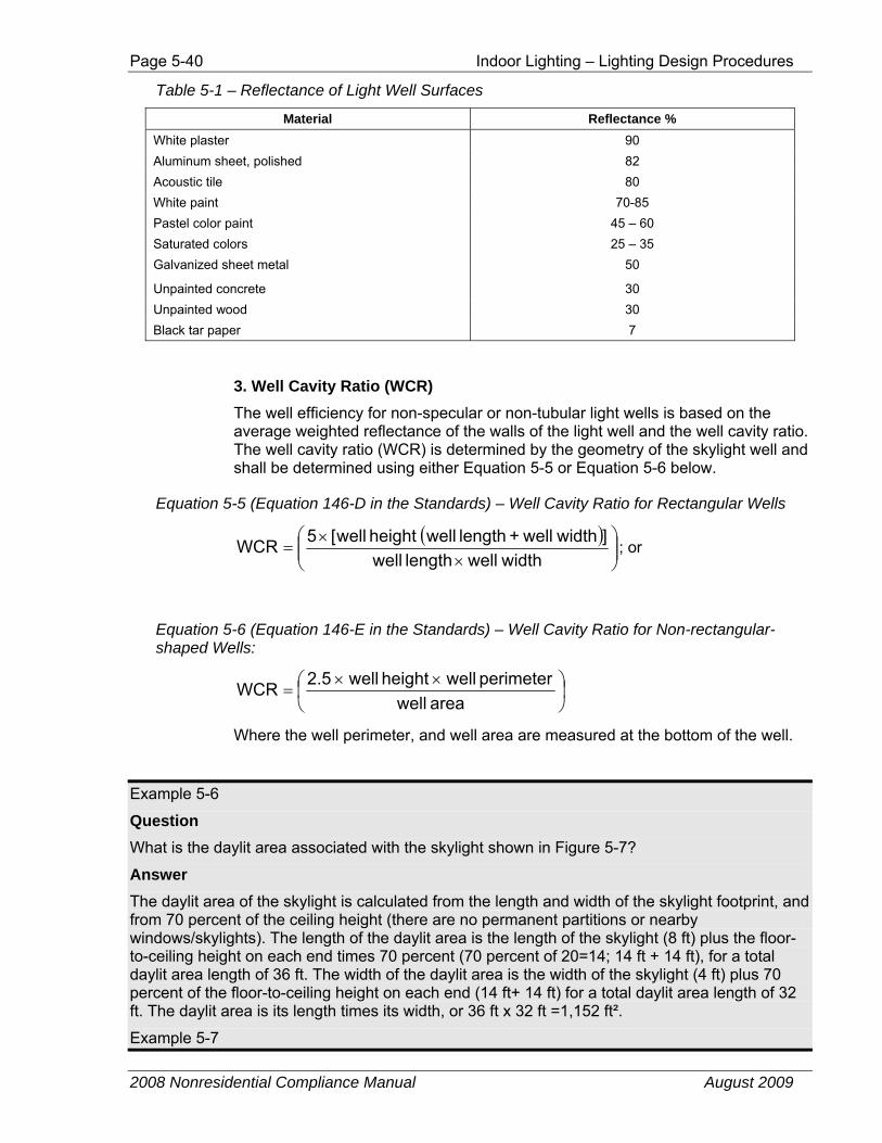
Page 5-40 Indoor Lighting – Lighting Design Procedures
2008 Nonresidential Compliance Manual August 2009
Table 5-1 – Reflectance of Light Well Surfaces
Material Reflectance % White plaster 90 Aluminum sheet, polished 82 Acoustic tile 80 White paint 70-85 Pastel color paint 45 – 60 Saturated colors 25 – 35 Galvanized sheet metal 50
Unpainted concrete 30 Unpainted wood 30 Black tar paper 7
3. Well Cavity Ratio (WCR) The well efficiency for non-specular or non-tubular light wells is based on the average weighted reflectance of the walls of the light well and the well cavity ratio. The well cavity ratio (WCR) is determined by the geometry of the skylight well and shall be determined using either Equation 5-5 or Equation 5-6 below.
Equation 5-5 (Equation 146-D in the Standards) – Well Cavity Ratio for Rectangular Wells
( )⎟⎟⎠
⎞⎜⎜⎝
⎛×
×=
widthwelllength well] widthwell+length well height well[5WCR ; or
Equation 5-6 (Equation 146-E in the Standards) – Well Cavity Ratio for Non-rectangular-shaped Wells:
⎟⎠⎞
⎜⎝⎛ ××
=area well
perimeter well height well2.5WCR
Where the well perimeter, and well area are measured at the bottom of the well.
Example 5-6
Question What is the daylit area associated with the skylight shown in Figure 5-7?
Answer The daylit area of the skylight is calculated from the length and width of the skylight footprint, and from 70 percent of the ceiling height (there are no permanent partitions or nearby windows/skylights). The length of the daylit area is the length of the skylight (8 ft) plus the floor-to-ceiling height on each end times 70 percent (70 percent of 20=14; 14 ft + 14 ft), for a total daylit area length of 36 ft. The width of the daylit area is the width of the skylight (4 ft) plus 70 percent of the floor-to-ceiling height on each end (14 ft+ 14 ft) for a total daylit area length of 32 ft. The daylit area is its length times its width, or 36 ft x 32 ft =1,152 ft².
Example 5-7
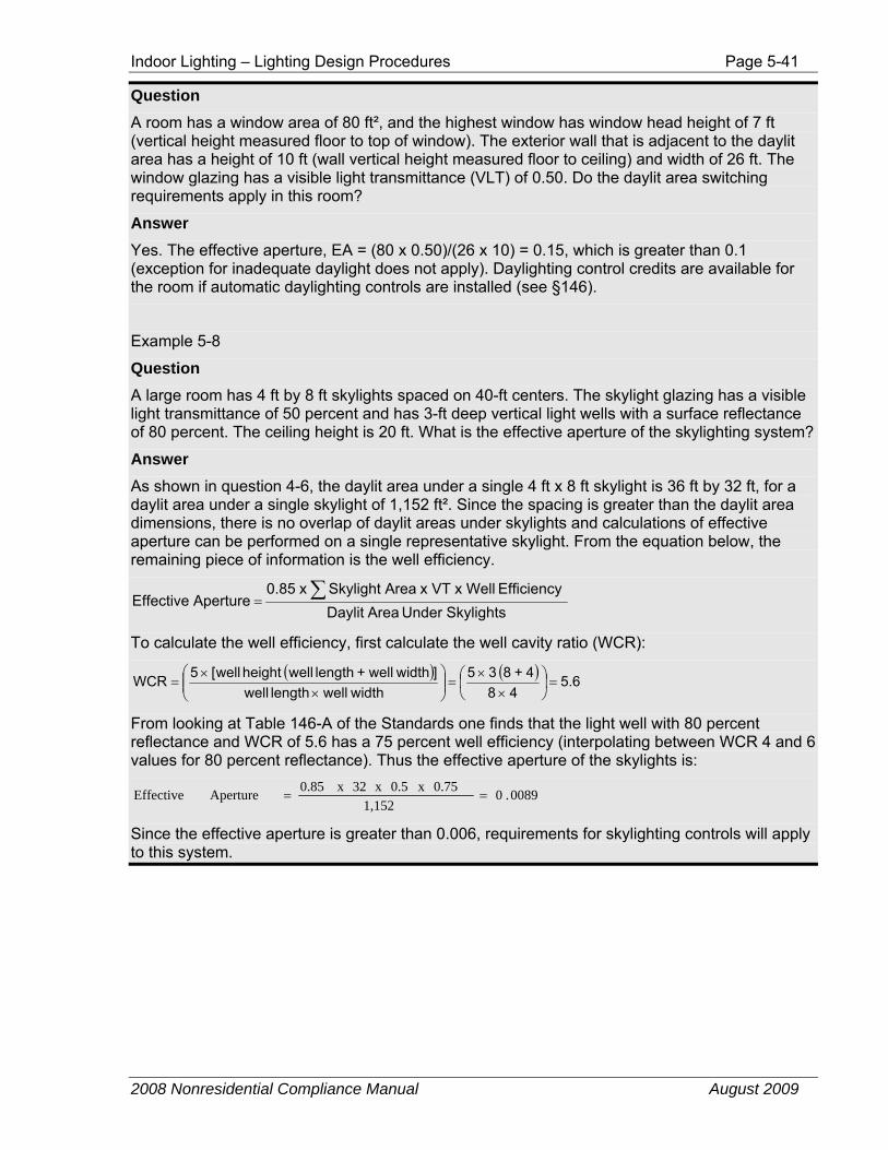
Indoor Lighting – Lighting Design Procedures Page 5-41
2008 Nonresidential Compliance Manual August 2009
Question A room has a window area of 80 ft², and the highest window has window head height of 7 ft (vertical height measured floor to top of window). The exterior wall that is adjacent to the daylit area has a height of 10 ft (wall vertical height measured floor to ceiling) and width of 26 ft. The window glazing has a visible light transmittance (VLT) of 0.50. Do the daylit area switching requirements apply in this room?
Answer Yes. The effective aperture, EA = (80 x 0.50)/(26 x 10) = 0.15, which is greater than 0.1 (exception for inadequate daylight does not apply). Daylighting control credits are available for the room if automatic daylighting controls are installed (see §146).
Example 5-8
Question A large room has 4 ft by 8 ft skylights spaced on 40-ft centers. The skylight glazing has a visible light transmittance of 50 percent and has 3-ft deep vertical light wells with a surface reflectance of 80 percent. The ceiling height is 20 ft. What is the effective aperture of the skylighting system?
Answer As shown in question 4-6, the daylit area under a single 4 ft x 8 ft skylight is 36 ft by 32 ft, for a daylit area under a single skylight of 1,152 ft². Since the spacing is greater than the daylit area dimensions, there is no overlap of daylit areas under skylights and calculations of effective aperture can be performed on a single representative skylight. From the equation below, the remaining piece of information is the well efficiency.
Skylights Under AreaDaylit Efficiency x Well x VT AreaSkylight x 0.85
ApertureEffective ∑=
To calculate the well efficiency, first calculate the well cavity ratio (WCR):
( ) ( ) 6.548
4+8 35 widthwelllength well
] widthwell+length well height well[5WCR =⎟⎠⎞
⎜⎝⎛
××
=⎟⎟⎠
⎞⎜⎜⎝
⎛×
×=
From looking at Table 146-A of the Standards one finds that the light well with 80 percent reflectance and WCR of 5.6 has a 75 percent well efficiency (interpolating between WCR 4 and 6 values for 80 percent reflectance). Thus the effective aperture of the skylights is:
0089.01,152
0.75 x 0.5 x 32 x 0.85 Aperture Effective ==
Since the effective aperture is greater than 0.006, requirements for skylighting controls will apply to this system.
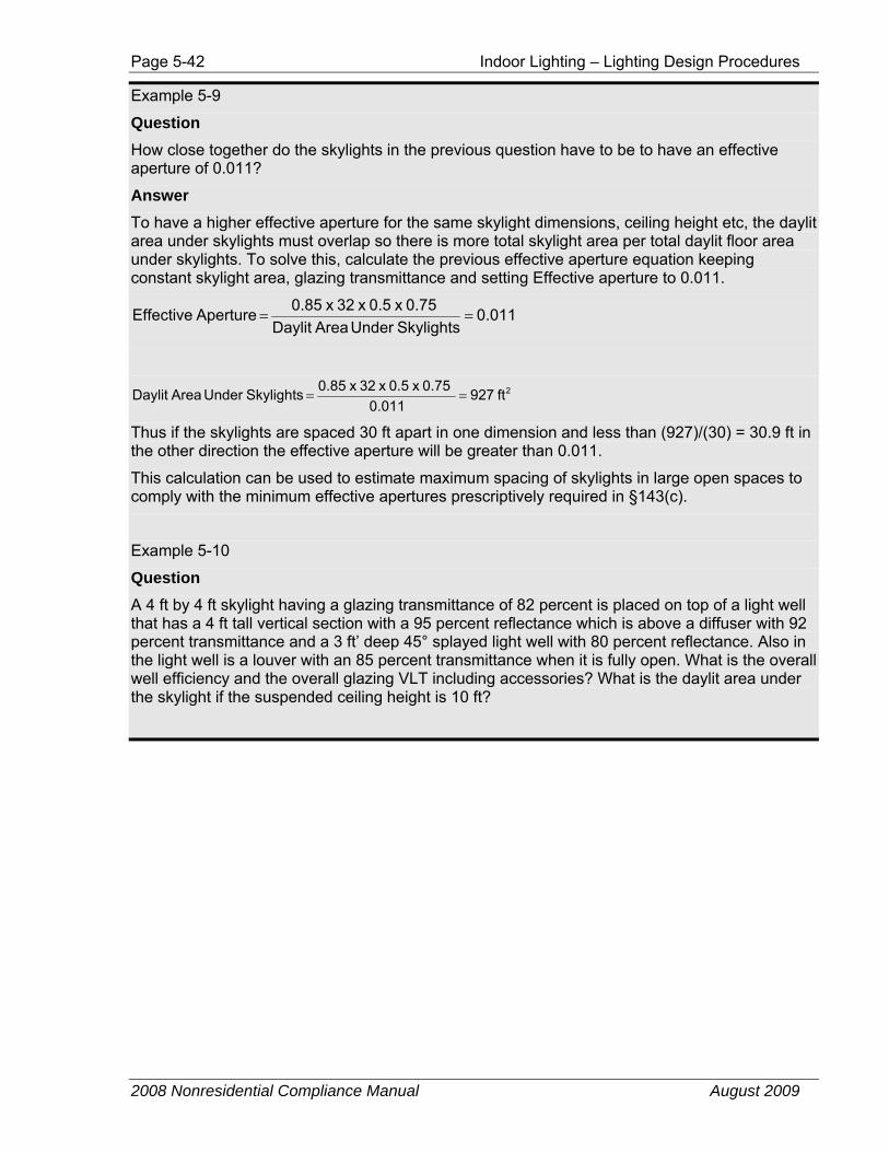
Page 5-42 Indoor Lighting – Lighting Design Procedures
2008 Nonresidential Compliance Manual August 2009
Example 5-9
Question How close together do the skylights in the previous question have to be to have an effective aperture of 0.011?
Answer To have a higher effective aperture for the same skylight dimensions, ceiling height etc, the daylit area under skylights must overlap so there is more total skylight area per total daylit floor area under skylights. To solve this, calculate the previous effective aperture equation keeping constant skylight area, glazing transmittance and setting Effective aperture to 0.011.
011.0Skylights Under AreaDaylit
0.75 x 0.5 x 32 x 0.85 ApertureEffective ==
2ft 9270.011
0.75 x 0.5 x 32 x 0.85 Skylights Under AreaDaylit ==
Thus if the skylights are spaced 30 ft apart in one dimension and less than (927)/(30) = 30.9 ft in the other direction the effective aperture will be greater than 0.011.
This calculation can be used to estimate maximum spacing of skylights in large open spaces to comply with the minimum effective apertures prescriptively required in §143(c).
Example 5-10
Question A 4 ft by 4 ft skylight having a glazing transmittance of 82 percent is placed on top of a light well that has a 4 ft tall vertical section with a 95 percent reflectance which is above a diffuser with 92 percent transmittance and a 3 ft’ deep 45° splayed light well with 80 percent reflectance. Also in the light well is a louver with an 85 percent transmittance when it is fully open. What is the overall well efficiency and the overall glazing VLT including accessories? What is the daylit area under the skylight if the suspended ceiling height is 10 ft?
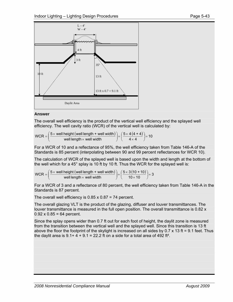
Indoor Lighting – Lighting Design Procedures Page 5-43
2008 Nonresidential Compliance Manual August 2009
4 ft
3 ft
10 ft 13 ft
35°
13 ft x 0.7 = 9.1 ft
L – 4’ W – 4’
Daylit Area
Answer The overall well efficiency is the product of the vertical well efficiency and the splayed well efficiency. The well cavity ratio (WCR) of the vertical well is calculated by:
( ) ( ) 1044
4+4 45 widthwelllength well
widthwell+length well height well5WCR =⎟⎠⎞
⎜⎝⎛
××
=⎟⎟⎠
⎞⎜⎜⎝
⎛×
×=
For a WCR of 10 and a reflectance of 95%, the well efficiency taken from Table 146-A of the Standards is 85 percent (interpolating between 90 and 99 percent reflectances for WCR 10).
The calculation of WCR of the splayed well is based upon the width and length at the bottom of the well which for a 45° splay is 10 ft by 10 ft. Thus the WCR for the splayed well is:
( ) ( ) 30101
10+10 35 widthwelllength well
widthwell+length well height well5WCR =⎟⎠⎞
⎜⎝⎛
××
=⎟⎟⎠
⎞⎜⎜⎝
⎛×
×=
For a WCR of 3 and a reflectance of 80 percent, the well efficiency taken from Table 146-A in the Standards is 87 percent.
The overall well efficiency is 0.85 x 0.87 = 74 percent.
The overall glazing VLT is the product of the glazing, diffuser and louver transmittances. The louver transmittance is measured in the full open position. The overall transmittance is 0.82 x 0.92 x 0.85 = 64 percent.
Since the splay opens wider than 0.7 ft out for each foot of height, the daylit zone is measured from the transition between the vertical well and the splayed well. Since this transition is 13 ft above the floor the footprint of the skylight is increased on all sides by 0.7 x 13 ft = 9.1 feet. Thus the daylit area is 9.1+ 4 + 9.1 = 22.2 ft on a side for a total area of 492 ft².

Page 5-44 Indoor Lighting – Lighting Design Procedures
2008 Nonresidential Compliance Manual August 2009
Example 5-11
Question Each of the two rooftop monitors as shown in the below figure, has 4-14 ft long by 4 ft tall windows placed end-to-end with a visible transmittance of 60 percent. Each monitor sits on top of a light well 60 ft long, 5.5 ft wide and 3.75 ft tall with surface reflectance of 80 percent. The two light wells are 8 ft apart and the ceiling height is 10 ft. The lighting power density of general lighting is 1.5 W/ft². What is the daylit area, effective aperture and the power adjustment factor (PAF) associated with the rooftop monitors?
10'
14'
Daylight Area under Rooftop Monitors
4'
13'6"
Answer Standards currently define skylights as glazing having a slope less than 60 degrees from the horizontal with conditioned or unconditioned space below. Since rooftop monitors have a slope greater than 60 degrees, they are therefore considered to be windows.
Daylit Area Since the rooftop monitor is considered to be the same as a window, the daylit area can be calculated the same way one calculates the primary sidelit daylit area from windows. In this case, the daylit zone starts from the vertical plane of the monitor, since there is no “wall”.
Thus, the primary sidelit daylit area depth in this case will be 14 ft (vertical height from the floor to the top of the monitor). As noted in the diagram above, the two rooftop monitors are positioned 13 ft6 inches apart. Thus there is an overlap of 6 inches in the daylit area depth from the two monitors. Standards disallows double-counting this overlap, thus, the overall daylit zone depth from both monitors will be = 14 ft + 14 ft – 6 inches = 27 ft6 inches.
As for the width of the primary sidelit daylit area that is equal to the clerestory width plus 2 ft on either side of each monitor (as long as the 2 ft areas do not overlap). In our example, since the monitors are placed end to end, we will count the 2 ft only at the two ends.
Thus, daylit area width =
Indoor Lighting – Lighting Design Procedures Page 5-45
2008 Nonresidential Compliance Manual August 2009
(4 monitors in each bay x 14 ft length of each monitor) + 2 ft + 2 ft = 60 ft.
Thus the total primary sidelit daylit area under rooftop monitors =
Primary sidelit daylit area depth x primary sidelit daylit area width = 27 ft 6 inches x 60 ft = 1656 ft².
Effective Aperture The effective aperture is the fraction of light entering the space as compared to the amount of sunlight on the rooftop monitor above the daylit area.
Again we will use the effective aperture formula used for primary sidelit daylit area.
AreaDaylit SidelitPrimary x VTAreaWindow
ApertureEffective SidelitPrimary ∑=
Thus EA = (2 bays x 4 window per bay x 14 ft width x 4 ft height) x 60 percent / 1656 ft²
= 448 x 0.60/1656 = 0.1623
Power Adjustment Factor (PAF) Since the daylit area due to the rooftop monitors is less than 2,500 ft², daylighting controls are not required by Standards, and the space is eligible for a PAF. Based on Table 146-C of the Standards, for an effective aperture of 16.23 percent, the PAF equals 0.12.
The controlled lighting consists of 27 fixtures with a rated input power of 90 W each. Therefore, the total wattage of the controlled lighting is 2,430 W. The lighting control credit is the product of the power adjustment factor and the wattage of he controlled lighting. Thus the lighting control credit is:
Lighting control credit = 0.12 x 2,430 = 292 W
Example 5-12
Question An office space with a 10-ft ceiling height is daylit with tubular skylights, also known as tubular daylighting devices or TDD’s. These TDD’s have a an acrylic dome with 90 percent visible transmittance and a 6 ft deep light shaft, The light shaft is 22 inches in diameter, has a 95 percent reflectance and terminates into a 2 ft by 2 ft square adapter with a 92 percent transmissive lens. This lens has a haze rating greater than 90 percent (i.e. it is sufficiently diffusing). The eight skylights are placed in two rows with 10 ft by 20 ft on center spacing. This office space has a general lighting power density of 1.1 W/ft² and the lights that are in the daylit area under skylights are on multi-level daylighting controls. What PAF should be applied?
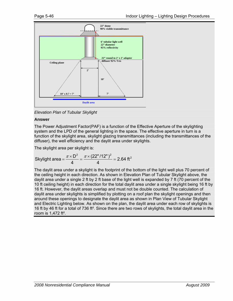
Page 5-46 Indoor Lighting – Lighting Design Procedures
2008 Nonresidential Compliance Manual August 2009
6’ tubular light well 22” diameter 95% reflectivity
7’ 10’ x 0.7 = 7’
2’
22” dome 90% visible transmittance
22” round to 2’ x 2’ adapter diffuser 92% Tvis
Ceiling plane
10’
Daylit area
Elevation Plan of Tubular Skylight
Answer The Power Adjustment Factor(PAF) is a function of the Effective Aperture of the skylighting system and the LPD of the general lighting in the space. The effective aperture in turn is a function of the skylight area, skylight glazing transmittances (including the transmittances of the diffuser), the well efficiency and the daylit area under skylights.
The skylight area per skylight is:
222
ft 2.644
)/12"(22"4D area Skylight =
×=
×=
ππ
The daylit area under a skylight is the footprint of the bottom of the light well plus 70 percent of the ceiling height in each direction. As shown in Elevation Plan of Tubular Skylight above, the daylit area under a single 2 ft by 2 ft base of the light well is expanded by 7 ft (70 percent of the 10 ft ceiling height) in each direction for the total daylit area under a single skylight being 16 ft by 16 ft. However, the daylit areas overlap and must not be double counted. The calculation of daylit area under skylights is simplified by plotting on a roof plan the skylight openings and then around these openings to designate the daylit area as shown in Plan View of Tubular Skylight and Electric Lighting below. As shown on the plan, the daylit area under each row of skylights is 16 ft by 46 ft for a total of 736 ft². Since there are two rows of skylights, the total daylit area in the room is 1,472 ft².
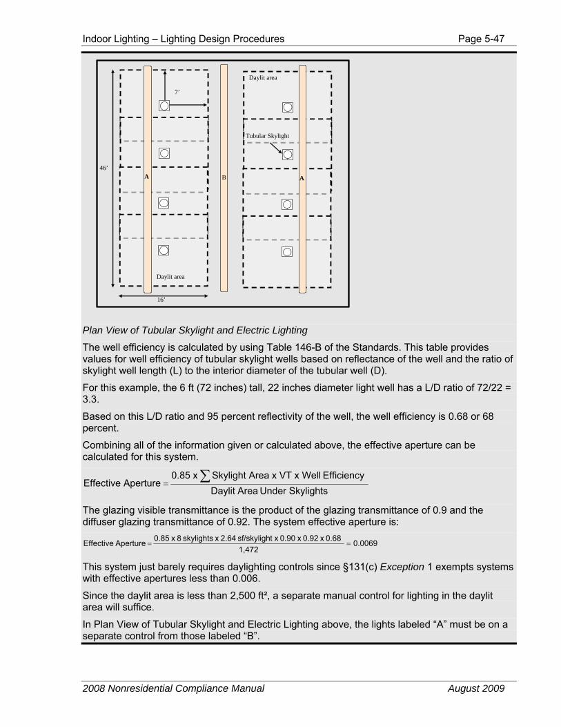
Indoor Lighting – Lighting Design Procedures Page 5-47
2008 Nonresidential Compliance Manual August 2009
A B
7’
46’ A
16’
Daylit area
Daylit area
Tubular Skylight
Plan View of Tubular Skylight and Electric Lighting
The well efficiency is calculated by using Table 146-B of the Standards. This table provides values for well efficiency of tubular skylight wells based on reflectance of the well and the ratio of skylight well length (L) to the interior diameter of the tubular well (D).
For this example, the 6 ft (72 inches) tall, 22 inches diameter light well has a L/D ratio of 72/22 = 3.3.
Based on this L/D ratio and 95 percent reflectivity of the well, the well efficiency is 0.68 or 68 percent.
Combining all of the information given or calculated above, the effective aperture can be calculated for this system.
Skylights Under AreaDaylit Efficiency x Well x VT AreaSkylight x 0.85
ApertureEffective ∑=
The glazing visible transmittance is the product of the glazing transmittance of 0.9 and the diffuser glazing transmittance of 0.92. The system effective aperture is:
0.00691,472
0.68 x 0.92 x 0.90 x tsf/skyligh 2.64 x skylights 8 x 0.85 ApertureEffective ==
This system just barely requires daylighting controls since §131(c) Exception 1 exempts systems with effective apertures less than 0.006.
Since the daylit area is less than 2,500 ft², a separate manual control for lighting in the daylit area will suffice.
In Plan View of Tubular Skylight and Electric Lighting above, the lights labeled “A” must be on a separate control from those labeled “B”.
Page 5-48 Indoor Lighting – Lighting Design Procedures
2008 Nonresidential Compliance Manual August 2009
The Power Adjustment Factor (PAF) for electric lighting in daylit areas under skylights and controlled by a multi-level daylighting control meeting the requirements of §119(i) is calculated per Table 146-C of the Standards. Given that the general lighting power density is 1.1 W/ft² and the effective aperture is 0.0068, the PAF is 0.12.
Alternatively, if the light wells of the tubular skylights have a 99 percent reflectance, the well efficiency would be 87 percent and the resulting effective aperture would be increased to 0.0088. Such a system would have a power adjustment factor of 0.178. One can also increase the effective aperture and thus the PAF by spacing the skylights closer together.
5.2.2 Lighting Power Allowances
5.2.2.1 Allowed Lighting Power The prescriptive approach for lighting involves a comparison of the building’s allowed lighting power with its actual lighting power (as adjusted for controls). The actual power shall be less than the allowed power.
There are three methods to determine the allowed lighting power using the prescriptive approach: the complete building, the area category, and the tailored method. The lighting allotment must be based on area intended only for occupancy, or complete lighting plans must be submitted.
5.2.2.2 Indoor Lighting Power Trade-offs Indoor lighting power trade-offs shall be determined as follows:
A. Complete Building Method Allowed lighting power determined according to the Complete Building Method may be traded only within a single building. Allowed lighting power shall not be traded between two or more buildings using the Complete Building Method.
Conditioned and unconditioned spaces shall be separate allotments, which shall be met separately without trade-offs between the separate allotments.
B. Area Category Method Allowed lighting power determined according to the Area Category Method may be traded between the primary function areas using the Area Category Method.
Conditioned and unconditioned spaces shall be separate allotments, which shall be met separately without trade-offs between the separate allotments.
Exception to §146(b)2: Additional lighting power that is allowed according to the footnotes in Table 5-3 (Table 146-F in the Standards) shall not be traded. For example, in footnote 1, the allowance for ornamental chandeliers and sconces, when available, is the smaller of 1.0 W/ft² or the actual design wattage. If 0.5 W/ft² is used, then the allowance is only 0.5 W/ft². There is no left over wattage to be traded.
C. Tailored Method 1. Allowed lighting power for wall display, floor display and
ornamental/special effects lighting determined according to the
Indoor Lighting – Lighting Design Procedures Page 5-49
2008 Nonresidential Compliance Manual August 2009
Tailored Method shall be separate allotments without trade-offs between the separate allotments.
2. Allowed lighting power for general illumination determined according to the Tailored Method may be traded only within the primary function areas using the Tailored Method.
D. Between Complete Building, Area Category, and Tailored Methods 1. Allowed lighting power shall not be traded between the Complete
Building Method, Area Category Method, or Tailored Method.
2. Exception to §146(b)4: Allowed lighting power may be traded from primary function areas using the Area Category Method to primary function areas using the Tailored Method.
E. No Trade-offs Between Indoor and Outdoor Areas 1. Trading off lighting power allowances between indoor and outdoor
areas shall not be permitted.
F. No Trade-offs Between Conditioned and Unconditioned Indoor Spaces 1. Conditioned and unconditioned spaces shall be separate
allotments, which shall be met separately without trade-offs between the separate allotments.
5.2.2.3 Nonresidential Type of Use and Function Area Definitions There have been a number of definition edits and additions that support and clarify the Types of Use found in Table 5-2 (Table 146-E in the Standards), and the Primary Function areas found in Table 5-3 (Table 146-F in the Standards) and Table 5-5 (Table 146-G in the Standards). Refer to these definitions in §101 to determine how to classify a building type of use, or area primary function.
5.2.3 Miscellaneous Applications
5.2.3.1 High-Rise Residential Dwelling Units and Hotel/Motel Guest Rooms - General §130(b), §150(k)
Chapter 6, Residential Compliance Manual
The Standards require that lighting in high-rise residential dwelling units and in hotel/motel guest rooms comply with all applicable lighting requirements of the Residential Lighting Standards.
High efficacy luminaires are required for almost all rooms in the dwelling unit or hotel guest room. Exceptions are made in some rooms if the fixtures are on a separate circuit or are controlled by occupancy switches or dimmers, depending on the type of room. The specific language for these requirements can be found in §150(k).
The dwelling unit requirements apply only to permanently installed luminaires; i.e., luminaires that are part of the building, as opposed to portable luminaires such as torchieres or table lamps that are provided by the occupant. Permanently installed
Page 5-50 Indoor Lighting – Lighting Design Procedures
2008 Nonresidential Compliance Manual August 2009
luminaires include ceiling fixtures, chandeliers, vanity lamps, wall sconces and any other type of luminaire that is a permanent part of the house.
Refer to Chapter 5 of the Residential Compliance Manual for additional information about the residential lighting requirements.
5.2.3.2 Theme Parks Specialty lighting within theme parks are exempt from the lighting power density calculations in §146(c). However, all other lighting must comply with the Standards. The Standards must be enforced for primary function areas that are included in Standards Tables 146-E, F or G. The primary function areas in theme parks must be quantified in the Standards lighting documentation, and are not exempt from the lighting power density requirements. These include, retail, restrooms, restaurants, lobbies, ballrooms, theaters and other primary function areas in theme parks. The treatment of these primary function areas is no different for theme parks than for other building projects. However, the lighting that is used strictly for entertainment in theme parks, such as the entertainment production lighting related only to presenting the theme of the theme park, may be exempted from the Standards lighting power density compliance. An example of a theme park may be a large amusement park, which includes carnival rides, shows, and exhibits.
5.2.3.3 Exit Way and Egress Lighting Lighting that is required for exit signs subject to the California Building Code and has an input power rating of 5 W per illuminated face or less, and exit way or egress illumination that is normally off and that is subject to the California Building Code, is exempt from lighting power calculations in §146(c). Exit signs must meet the requirements of the Appliance Efficiency Regulations (Title 20).
A. Exit way and egress lighting systems are regulated by Article 700 of the California Electricity Code (Title 24, Part 3), which specifies that:
B. Emergency systems are those systems legally required and classed as emergency by municipal, state, federal, other codes, or by any governmental agency having jurisdiction.
C. These systems are intended to automatically provide illumination to designated areas in the event of failure of normal power supply.
D. These systems must be separately switched from the general lighting systems.
E. These systems shall be so arranged that only authorized persons have control of the emergency lighting.
F. These systems have an emergency power supply independent of the general lighting power supply, or are equipped with two or more separate and complete systems with independent power supply, each system providing sufficient current for emergency lighting purposes.
Note that §131(a) , the area controls of the mandatory measures, specifies that lighting in areas within a building that must be continuously illuminated for reasons of building security or emergency egress are exempt from the switching
Indoor Lighting – Prescriptive Approach Page 5-51
2008 Nonresidential Compliance Manual August 2009
requirements of the area controls of the mandatory measures for a maximum of 0.3 w/ft². These lights must be installed in areas designated as security or emergency egress areas on the plans and specifications submitted to the enforcement agency in accordance with §10-103(a)2, and must be controlled by switches accessible only to authorized personnel. The remaining lighting in the area, however, is still subject to the area switching requirements.
When applying lighting power adjustment factors in accordance with §146(a)2 to luminaires in a space, exit way, emergency, and egress lighting systems that have not been included in the lighting power calculations in §146(c), or are on a separate circuit and are not controlled by a qualifying control device, are not eligible for these credits.
5.2.3.4 Historic Buildings Exception 1 to §100(a) states that qualified historic buildings, as regulated by the California Historical Building Code (Title 24, Part 8 or California Building Code, Title 24, Part 2, Volume I, Chapter 34, Division II) are not covered by the Standards. However, non-historical components of the buildings, such as new or replacement mechanical, plumbing, and electrical (including lighting) equipment, additions and alterations to historic buildings, and new appliances in historic buildings may need to comply with the Standards and Appliance Efficiency Regulations, as well as other codes. For more information about energy compliance requirements for Historic Buildings, see Section 1.7.1, Building Types Covered, in Chapter 1 of this manual.
5.3 Prescriptive Approach This section contains information on the three prescriptive approaches for complying with the Lighting Standards: Complete Building Method, Area Category Method, and Tailored Method. Following in Section 5.4 is information about using the Tailored Method for complying with the lighting Standards.
5.3.1 Complete Building Method
§146(c)1
Standards Table 146-E
The Complete Building Method can only be applied when all areas in the entire building are complete (i.e., lighting will be installed throughout the entire building under the permit for which the Standards compliance is prepared). The building must consist of one type of use for a minimum of 90 percent of the floor area of the entire building (in determining the area of the primary type of use, include the following areas if they serve as support for the primary type of use: lobbies, corridors, restrooms and storage closets).
Complete Building Method Not Permitted Retail and wholesale stores, hotels and motels, and high-rise residential buildings shall not use the Complete Building Method. These types of applications may use
Page 5-52 Indoor Lighting – Prescriptive Approach
2008 Nonresidential Compliance Manual August 2009
the Area Category Method or the Tailored Method for complying with the prescriptive Lighting Standards. These areas may also use the Performance method for complying with the Lighting Standards. See Section 5.4 for more information about the Performance method.
Multi-Use Buildings Exception to §146(c)1: When using the Complete Building Method, if a Parking Garage and other Type of Use are part of a single building, the Parking Garage portion of the building and the remaining portion of the building shall each separately use the Complete Building Method Type of Use categories from Table 5-2 (Table 146-E in the Standards). For example, if the bottom two stories of a five story office building is a parking garage, the top three stories can comply using the Office Building Type of Use, and the bottom two stories can comply using the Parking Garage Type of Use.
To determine the allowed lighting power, multiply the complete building floor area times the lighting power density for the specific building type, as found in Table 5-3 (Table 146-F in the Standards).
Definition Clarifications Note the distinction between the definitions of a Classroom Building and a School in §101:
Classroom Building is a building or group of buildings that is predominately classrooms used by an organization that provides instruction to students, which may include corridors and stairways, restrooms and small storage closets, faculty offices, and workshops and labs. A classroom building does not include buildings that are not predominantly classroom, including auditorium, gymnasium, kitchen, library, multi-purpose, dining and cafeteria, student union, maintenance staff workroom, or storage buildings.
School is a building or group of buildings that is used by an organization that provides instruction to students, which is predominately classroom buildings but may also include auditorium, gymnasium, kitchen, library, multi-purpose rooms, dining and cafeteria, student union, maintenance staff workroom, and small storage spaces.
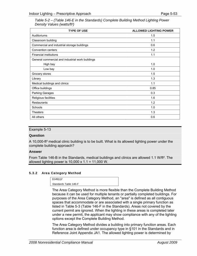
Indoor Lighting – Prescriptive Approach Page 5-53
2008 Nonresidential Compliance Manual August 2009
Table 5-2 – (Table 146-E in the Standards) Complete Building Method Lighting Power Density Values (watts/ft²)
TYPE OF USE ALLOWED LIGHTING POWER Auditoriums 1.5 Classroom building 1.1 Commercial and industrial storage buildings 0.6 Convention centers 1.2 Financial institutions 1.1 General commercial and industrial work buildings High bay 1.0 Low bay 1.0 Grocery stores 1.5 Library 1.3 Medical buildings and clinics 1.1 Office buildings 0.85 Parking Garages 0.3 Religious facilities 1.6 Restaurants 1.2 Schools 1.0 Theaters 1.3 All others 0.6
Example 5-13
Question A 10,000-ft² medical clinic building is to be built. What is its allowed lighting power under the complete building approach?
Answer From Table 146-B in the Standards, medical buildings and clinics are allowed 1.1 W/ft². The allowed lighting power is 10,000 x 1.1 = 11,000 W.
5.3.2 Area Category Method
§146(c)2
Standards Table 146-F
The Area Category Method is more flexible than the Complete Building Method because it can be used for multiple tenants or partially completed buildings. For purposes of the Area Category Method, an "area" is defined as all contiguous spaces that accommodate or are associated with a single primary function as listed in Table 5-3 (Table 146-F in the Standards). Areas not covered by the current permit are ignored. When the lighting in these areas is completed later under a new permit, the applicant may show compliance with any of the lighting options except the Complete Building Method.
The Area Category Method divides a building into primary function areas. Each function area is defined under occupancy type in §101 in the Standards and in Reference Joint Appendix JA1. The allowed lighting power is determined by
Page 5-54 Indoor Lighting – Prescriptive Approach
2008 Nonresidential Compliance Manual August 2009
multiplying the area of each function times the lighting power density for that function. Where areas are bounded or separated by interior partitions, the floor space occupied by those interior partitions shall be included in any area. The total allowed watts is the summation of the allowed lighting power for each area covered by the permit application.
When using this method, each function area in the building must be included as a separate area. Boundaries between primary function areas may or may not consist of walls or partitions. For example, kitchen and dining areas within a fast food restaurant may or may not be separated by walls. Also, it is not necessary to separate aisles or entries within primary function areas. However, when the Area Category Method is used to calculate the allowed total lighting power for an entire building, the main entry lobbies, corridors, restrooms, and support functions shall be treated as separate areas.
When using this method, the public and common areas of Multifamily, Dormitory, and Senior Housing refers to exercise rooms, lobbies, hallways, corridors, and stairwells. Square footage of the dwelling units shall not be used to determine the square footage of the common areas. The dwelling units of Multifamily, Dormitory, and Senior Housing shall comply with the applicable lighting requirements in §150(k).
The Transportation Function refers to the ticketing area, waiting area, baggage handling areas, concourse, or other areas not covered by primary functions in Standards Table 146-C in an airport terminal, bus or rail terminal or station, subway or transit station, or a marine terminal.
If at the time of permitting a tenant is not identified for a multi-tenant space, the tenant leased space allowance from Table 5-3 (Table 146-F in the Standards) must be used. For example, in a strip mall or other malls, if at the time of permitting a tenant is not identified for a space, the tenant lease space allowance and not the retail merchandise sales must be used. To qualify for a power allowance other than Tenant Lease Space, documentation must be provided to indicate the actual tenant and their type of business at the time of permitting.
Transferring lighting power from one area to another is acceptable only for areas for which lighting plans are being submitted and lighting is being installed as part of the same approved permit. Areas not proposed for lighting improvements are left out both on the allowance side and the installed power side. Allowed and proposed lighting calculations for unconditioned and conditioned spaces must be kept separate, with no trade-offs between the two.
For example, from Table 5-3 (Table 146-F in the Standards), the lighting power allowance for an unconditioned parking garage is 0.2 w/ft², and no trade-offs with the conditioned areas or outdoor lighting are available to increase the lighting power allowance above 0.2 w/ft².
Calculating Areas for Area Category Method Figure 5-18 shows a function area that has interior, non-bounding partitions (dotted) and bounding partitions (solid). The area is calculated by multiplying the width times the depth, as measured from the center of the interior bounding partitions. If the function area is bounded by exterior walls on one or more sides, the area is calculated by multiplying the width times the depth, as measured from the inside surface of the exterior walls to the center of the interior bounding
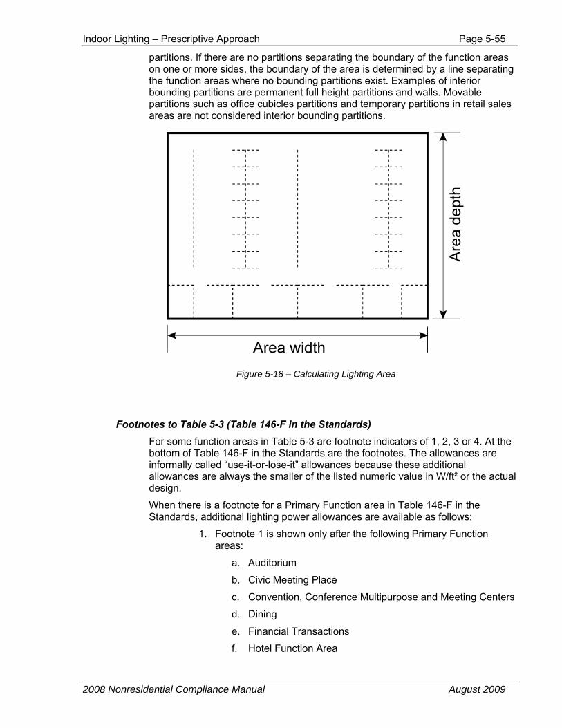
Indoor Lighting – Prescriptive Approach Page 5-55
2008 Nonresidential Compliance Manual August 2009
partitions. If there are no partitions separating the boundary of the function areas on one or more sides, the boundary of the area is determined by a line separating the function areas where no bounding partitions exist. Examples of interior bounding partitions are permanent full height partitions and walls. Movable partitions such as office cubicles partitions and temporary partitions in retail sales areas are not considered interior bounding partitions.
Figure 5-18 – Calculating Lighting Area
Footnotes to Table 5-3 (Table 146-F in the Standards) For some function areas in Table 5-3 are footnote indicators of 1, 2, 3 or 4. At the bottom of Table 146-F in the Standards are the footnotes. The allowances are informally called “use-it-or-lose-it” allowances because these additional allowances are always the smaller of the listed numeric value in W/ft² or the actual design.
When there is a footnote for a Primary Function area in Table 146-F in the Standards, additional lighting power allowances are available as follows:
1. Footnote 1 is shown only after the following Primary Function areas:
a. Auditorium
b. Civic Meeting Place
c. Convention, Conference Multipurpose and Meeting Centers
d. Dining
e. Financial Transactions
f. Hotel Function Area
Page 5-56 Indoor Lighting – Prescriptive Approach
2008 Nonresidential Compliance Manual August 2009
g. Hotel Lobby
h. Main Entry Lobby
i. Malls and Atria
j. Religious Worship
k. Theater – Motion Picture
l. Theater – Performance
m. Waiting Area
For all of the Primary Function areas in Table 5-3 (Table 146-F in the Standards) with Footnote 1, the smallest of the following values may be added to the allowed lighting power for ornamental chandeliers and sconces that are in addition to and switched or dimmed on circuits different from the circuits for general lighting:
i. W/ft² times the area of the task space that the chandelier or sconce is in; or
ii. The actual design wattage of the chandelier or sconce.
2. Footnote 2 is shown only after the following Primary Function areas:
a. Auto Repair
b. Electrical, Mechanical, Telephone Rooms
c. Low Bay and High Bay General Commercial and Industrial Work
For all of the Primary Function areas in Table 5-3 (Table 146-F in the Standards) with Footnote 2, the smallest of the following values may be added to the allowed lighting power for specialized task work:
i. 0.5 W/ft² times the area of the task space required for an art, craft assembly or manufacturing operation; or
ii. The actual design wattage of the luminaire(s) providing illuminance to the specialized task area.
For spaces employing this allowance, the plans shall clearly identify all task spaces using these tasks and the lighting equipment designed to illuminate these tasks. Tasks that are performed less than 2 hours per day or poor quality tasks that can be improved are not eligible for this specialized task work allowance.
3. Footnote 3 is shown only after Precision General Commercial and Industrial Work
The smallest of the following values may be added to the allowed power for precision commercial and industrial work:
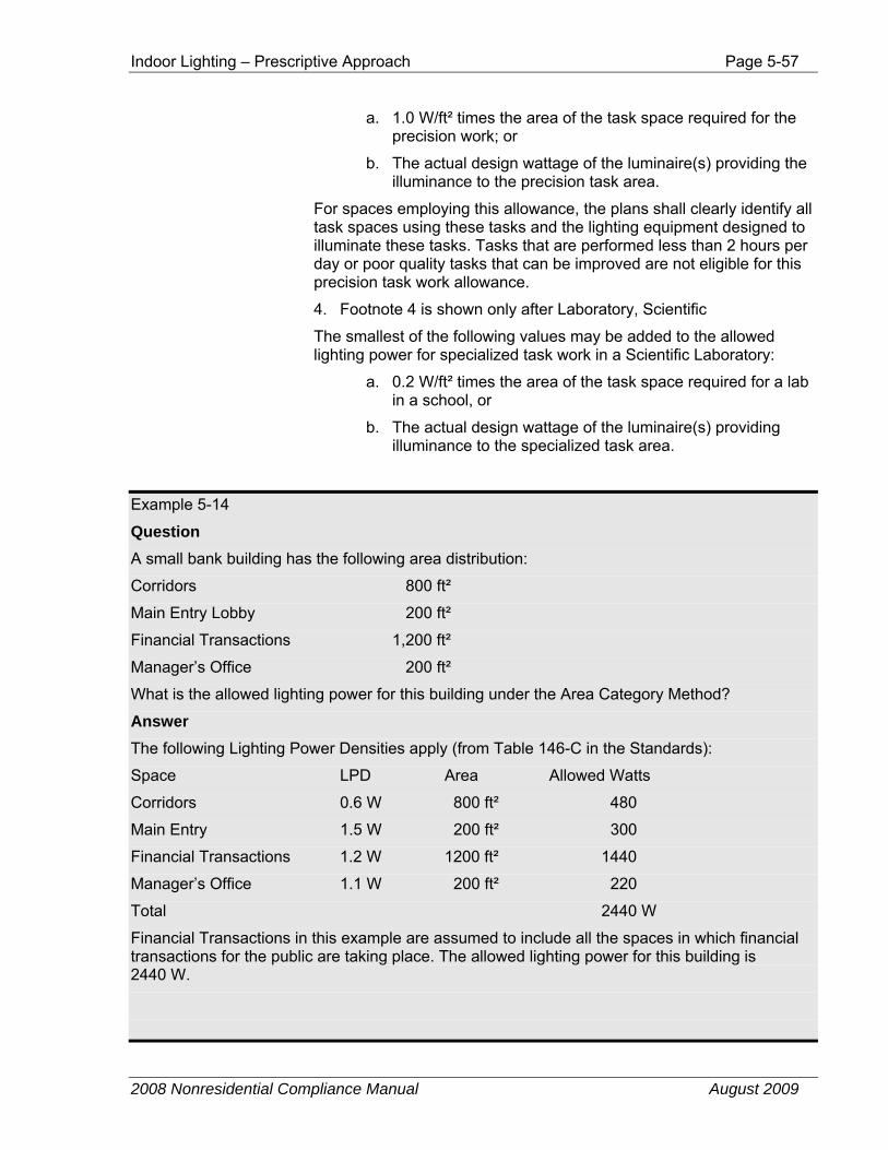
Indoor Lighting – Prescriptive Approach Page 5-57
2008 Nonresidential Compliance Manual August 2009
a. 1.0 W/ft² times the area of the task space required for the precision work; or
b. The actual design wattage of the luminaire(s) providing the illuminance to the precision task area.
For spaces employing this allowance, the plans shall clearly identify all task spaces using these tasks and the lighting equipment designed to illuminate these tasks. Tasks that are performed less than 2 hours per day or poor quality tasks that can be improved are not eligible for this precision task work allowance.
4. Footnote 4 is shown only after Laboratory, Scientific
The smallest of the following values may be added to the allowed lighting power for specialized task work in a Scientific Laboratory:
a. 0.2 W/ft² times the area of the task space required for a lab in a school, or
b. The actual design wattage of the luminaire(s) providing illuminance to the specialized task area.
Example 5-14
Question A small bank building has the following area distribution:
Corridors 800 ft²
Main Entry Lobby 200 ft²
Financial Transactions 1,200 ft²
Manager’s Office 200 ft²
What is the allowed lighting power for this building under the Area Category Method?
Answer The following Lighting Power Densities apply (from Table 146-C in the Standards):
Space LPD Area Allowed Watts
Corridors 0.6 W 800 ft² 480
Main Entry 1.5 W 200 ft² 300
Financial Transactions 1.2 W 1200 ft² 1440
Manager’s Office 1.1 W 200 ft² 220
Total 2440 W
Financial Transactions in this example are assumed to include all the spaces in which financial transactions for the public are taking place. The allowed lighting power for this building is 2440 W.
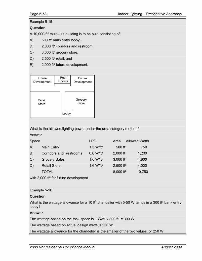
Page 5-58 Indoor Lighting – Prescriptive Approach
2008 Nonresidential Compliance Manual August 2009
Example 5-15
Question A 10,000-ft² multi-use building is to be built consisting of:
A) 500 ft² main entry lobby,
B) 2,000 ft² corridors and restroom,
C) 3,000 ft² grocery store,
D) 2,500 ft² retail, and
E) 2,000 ft² future development.
FutureDevelopment
RestRooms
FutureDevelopment
GroceryStore
RetailStore
Lobby
What is the allowed lighting power under the area category method?
Answer
Space LPD Area Allowed Watts
A) Main Entry 1.5 W/ft² 500 ft² 750
B) Corridors and Restrooms 0.6 W/ft² 2,000 ft² 1,200
C) Grocery Sales 1.6 W/ft² 3,000 ft² 4,800
D) Retail Store 1.6 W/ft² 2,500 ft² 4,000
TOTAL 8,000 ft² 10,750
with 2,000 ft² for future development.
Example 5-16
Question What is the wattage allowance for a 10 ft3 chandelier with 5-50 W lamps in a 300 ft² bank entry lobby?
Answer The wattage based on the task space is 1 W/ft² x 300 ft² = 300 W
The wattage based on actual design watts is 250 W.
The wattage allowance for the chandelier is the smaller of the two values, or 250 W.
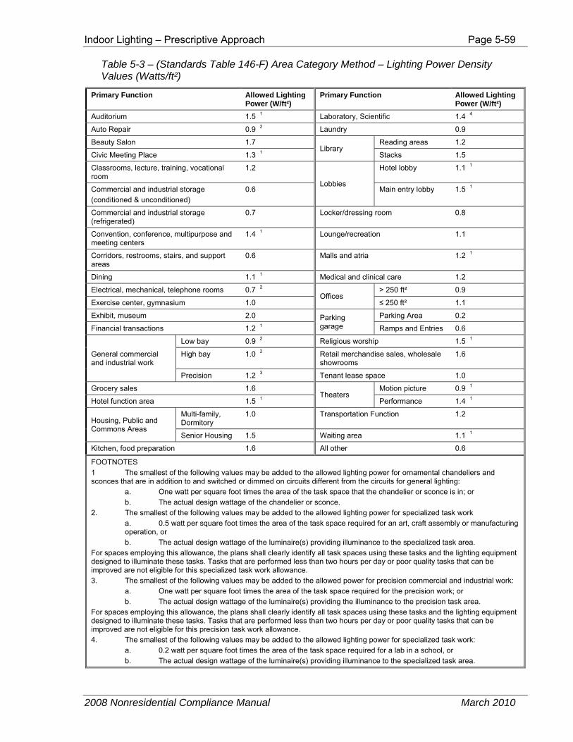
Indoor Lighting – Prescriptive Approach Page 5-59
2008 Nonresidential Compliance Manual March 2010
Table 5-3 – (Standards Table 146-F) Area Category Method – Lighting Power Density Values (Watts/ft²)
Primary Function Allowed Lighting Power (W/ft²)
Primary Function Allowed Lighting Power (W/ft²)
Auditorium 1.5 1 Laboratory, Scientific 1.4 4
Auto Repair 0.9 2 Laundry 0.9
Beauty Salon 1.7 Library
Reading areas 1.2
Civic Meeting Place 1.3 1 Stacks 1.5
Classrooms, lecture, training, vocational room
1.2
Lobbies
Hotel lobby 1.1 1
Commercial and industrial storage (conditioned & unconditioned)
0.6 Main entry lobby 1.5 1
Commercial and industrial storage (refrigerated)
0.7 Locker/dressing room 0.8
Convention, conference, multipurpose and meeting centers
1.4 1 Lounge/recreation 1.1
Corridors, restrooms, stairs, and support areas
0.6 Malls and atria 1.2 1
Dining 1.1 1 Medical and clinical care 1.2
Electrical, mechanical, telephone rooms 0.7 2 Offices
> 250 ft² 0.9
Exercise center, gymnasium 1.0 ≤ 250 ft² 1.1
Exhibit, museum 2.0 Parking garage
Parking Area 0.2
Financial transactions 1.2 1 Ramps and Entries 0.6
General commercial and industrial work
Low bay 0.9 2 Religious worship 1.5 1
High bay 1.0 2 Retail merchandise sales, wholesale showrooms
1.6
Precision 1.2 3 Tenant lease space 1.0
Grocery sales 1.6 Theaters
Motion picture 0.9 1
Hotel function area 1.5 1 Performance 1.4 1
Housing, Public and Commons Areas
Multi-family, Dormitory
1.0 Transportation Function 1.2
Senior Housing 1.5 Waiting area 1.1 1
Kitchen, food preparation 1.6 All other 0.6
FOOTNOTES 1 The smallest of the following values may be added to the allowed lighting power for ornamental chandeliers and sconces that are in addition to and switched or dimmed on circuits different from the circuits for general lighting: a. One watt per square foot times the area of the task space that the chandelier or sconce is in; or b. The actual design wattage of the chandelier or sconce. 2. The smallest of the following values may be added to the allowed lighting power for specialized task work a. 0.5 watt per square foot times the area of the task space required for an art, craft assembly or manufacturing operation, or b. The actual design wattage of the luminaire(s) providing illuminance to the specialized task area. For spaces employing this allowance, the plans shall clearly identify all task spaces using these tasks and the lighting equipment designed to illuminate these tasks. Tasks that are performed less than two hours per day or poor quality tasks that can be improved are not eligible for this specialized task work allowance. 3. The smallest of the following values may be added to the allowed power for precision commercial and industrial work: a. One watt per square foot times the area of the task space required for the precision work; or b. The actual design wattage of the luminaire(s) providing the illuminance to the precision task area. For spaces employing this allowance, the plans shall clearly identify all task spaces using these tasks and the lighting equipment designed to illuminate these tasks. Tasks that are performed less than two hours per day or poor quality tasks that can be improved are not eligible for this precision task work allowance. 4. The smallest of the following values may be added to the allowed lighting power for specialized task work: a. 0.2 watt per square foot times the area of the task space required for a lab in a school, or b. The actual design wattage of the luminaire(s) providing illuminance to the specialized task area.
Page 5-60 Indoor Lighting – Prescriptive Approach
2008 Nonresidential Compliance Manual March 2010
5.3.3 Tailored Method
§146(c)3
Standards Table 146-G
The Tailored Method is a compliance approach, which establishes allowed lighting power on a room-by-room basis. The Standards allow the Tailored Method for most buildings and spaces. Use of Tailored Method is acceptable when the building or space has function types, which are allowable display and/or ornamental lighting. It may also be helpful when a building and/or areas have spaces with higher room cavity ratios (RCR’s) such as those with an RCR of 3.5 or higher. Tailored Method has several components (wall display, floor display, ornamental and very valuable display lighting) that are “use it or lose it” allowances. As a result, if a lighting design does not include these components, the allowed wattage under the Tailored Method may be less than if the Area Category Method or Whole Building Method of compliance is used.
Allowed lighting power may be traded from Primary Function areas using the Area Category Method to Primary Function areas using the Tailored Method. However, trade-offs may not be traded from the Tailored Method to the Area Category Method.
Some of the Primary Function areas in Table 5-5 (Table 146-G in the Standards) have been renamed, and some of the Primary Function area definitions have been edited and clarified. Refer to the definitions in §101 to appropriately classify a primary function area according to the current definitions.
Note: As a reminder, in many buildings the Tailored Method may actually result in less allowed lighting power than other methods. Larger allowances generally result from special lighting needs in a substantial portion of the building or from control credits.
Room Cavity Ratio (RCR) The room cavity ratio must be determined for a space using the Tailored Lighting Method.
The lighting level in a room is affected by the amount of light its fixtures provide and by the configuration of the room, expressed as the room cavity ratio (RCR). Small cramped rooms are more difficult to light and have a high RCR. Large open rooms are easier to light and have a low RCR. Since lighting fixtures are not as effective in a room with a high RCR, the Standards allow a greater LPD to compensate for this effect.
The RCR is based on the entire space bounded by floor-to-ceiling partitions. If a task area within a larger space is not bounded by floor to ceiling partitions, the RCR of the entire space must be used for the task area. The exception to this rule allows for imaginary or virtual walls when the boundaries are established by “high stack” elements (library stacks and storage shelves) or high partial walls defined as “perimeter full height partitions” described in §146(c)3Bi wall display.
Note: For use in calculating the RCR of the space, the walls are not required to be display walls as is required under §146(c)3Bi.
Indoor Lighting – Prescriptive Approach Page 5-61
2008 Nonresidential Compliance Manual August 2009
The RCR is calculated from one of the following formulas:
Equation 5-7 (Equation 146-G in the Standards) Rectangular Shaped Rooms
( )A
WLH5RCR +××=
Where:
RCR = The room cavity ratio
H = The room cavity height, vertical distance measured from the work plane to the center line of the lighting fixture
L = The room length using interior dimensions
W = The room width using interior dimensions
A = The room area
Equation 5-8 (Equation 146-H in the Standards) Non-Rectangular Shaped Rooms
[ ]A
PH5.2RCR ××=
Where:
RCR = The room cavity ratio
H = The room cavity height (see equation above)
A = The room area
P = The room perimeter
These two methods yield the same result and the second more general form of calculating RCR may be used in all instances, if desirable.
It is not necessary to document RCR values for rooms with an RCR less than 3.5. Rooms with a RCR higher than 3.5 are allowed higher LPDs under the Tailored Method. Table 5-4 gives typical RCR values calculated for rooms with the task surface at desk height (2.5 ft above the floor). This table is useful in assessing whether or not a room is likely to have an RCR greater than 3.5.
A special situation occurs when illuminating stacks of shelves in libraries, warehouses, and similar spaces. In this situation, the lighting requirements are to illuminate the vertical stack rather than the horizontal floor area (see example below). In stack areas the RCR is assumed to be greater than seven. The non-stack areas are treated normally.
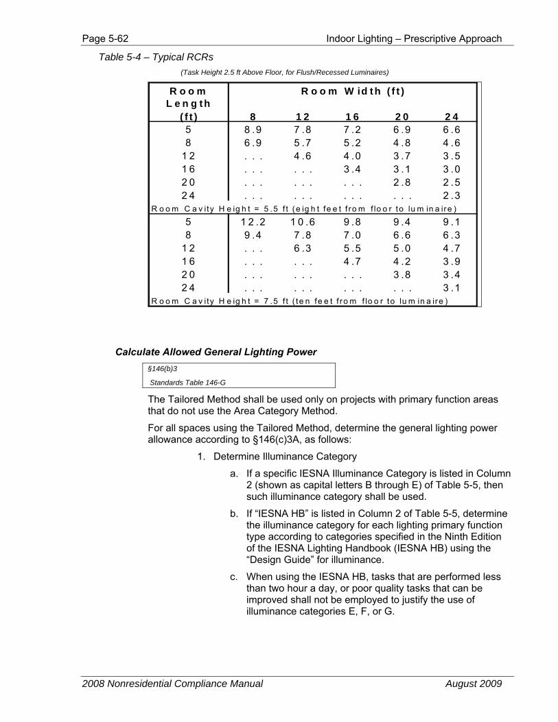
Page 5-62 Indoor Lighting – Prescriptive Approach
2008 Nonresidential Compliance Manual August 2009
Table 5-4 – Typical RCRs (Task Height 2.5 ft Above Floor, for Flush/Recessed Luminaires)
R o o m R o o m W id th ( f t )L e n g th
( f t ) 8 1 2 1 6 2 0 2 45 8 .9 7 .8 7 .2 6 .9 6 .68 6 .9 5 .7 5 .2 4 .8 4 .6
1 2 . . . 4 .6 4 .0 3 .7 3 .51 6 . . . . . . 3 .4 3 .1 3 .02 0 . . . . . . . . . 2 .8 2 .52 4 . . . . . . . . . . . . 2 .3
R o o m C a v ity H e ig h t = 5 .5 f t (e ig h t fe e t f ro m f lo o r to lu m in a ire )
5 1 2 .2 1 0 .6 9 .8 9 .4 9 .18 9 .4 7 .8 7 .0 6 .6 6 .3
1 2 . . . 6 .3 5 .5 5 .0 4 .71 6 . . . . . . 4 .7 4 .2 3 .92 0 . . . . . . . . . 3 .8 3 .42 4 . . . . . . . . . . . . 3 .1
R o o m C a v ity H e ig h t = 7 .5 f t ( te n fe e t f ro m f lo o r to lu m in a ire )
Calculate Allowed General Lighting Power §146(b)3
Standards Table 146-G
The Tailored Method shall be used only on projects with primary function areas that do not use the Area Category Method.
For all spaces using the Tailored Method, determine the general lighting power allowance according to §146(c)3A, as follows:
1. Determine Illuminance Category
a. If a specific IESNA Illuminance Category is listed in Column 2 (shown as capital letters B through E) of Table 5-5, then such illuminance category shall be used.
b. If “IESNA HB” is listed in Column 2 of Table 5-5, determine the illuminance category for each lighting primary function type according to categories specified in the Ninth Edition of the IESNA Lighting Handbook (IESNA HB) using the “Design Guide” for illuminance.
c. When using the IESNA HB, tasks that are performed less than two hour a day, or poor quality tasks that can be improved shall not be employed to justify the use of illuminance categories E, F, or G.
Indoor Lighting – Prescriptive Approach Page 5-63
2008 Nonresidential Compliance Manual August 2009
2. Determine Area.
a. Determine the area of each primary function using the Tailored Method.
b. Areas that use the Area Category Method shall not be used to determine Tailored Method areas.
3. Determine RCR (discussed in previous section)
a. Determine the room cavity ration (RCR) for each primary function area.
b. The RCR shall be calculated using either Equation 5-7 (Equation 146-G in the Standards) or Equation 5-8 (Equation 146-H in the Standards).
4. Calculate Allowed General Lighting Power
a. Multiply the area of each primary function by the allowed lighting power density for the illuminance category and RCR for each primary function area according to Table 5-7 (Table 146-I in the Standards).
b. The product is the Allowed General Lighting Power for the space. However, according to §146(b)3, the allowed lighting power for general illumination determined according to the Tailored Method may be traded only within the primary function areas using the Tailored Method.
5. Determine Additional Allowed Power
Determine Additional Allowed Power §146(b)3
Standards Table 146-G
Determine additional allowed power for display and decorative lighting according to §146(c)3B. Displays that are installed against a wall shall not qualify for the floor display lighting power allowances. Floor displays shall not qualify for the wall display allowances.
Additional allowed power for display and decorative lighting is determined as follows:
1. Determine the additional wall display lighting power if allowed by column 3 of Table 5-5 (Table 146-G in the Standards). If there is no power allowance listed in column 3 for a Primary Function, then no additional wall display lighting power is allowed for that Primary Function. If allowed, the additional wall display lighting power is the smaller of:
a. Multiply the length of the display wall lengths times the allowed power density watts per linear foot (W/ft) in column
Page 5-64 Indoor Lighting – Prescriptive Approach
2008 Nonresidential Compliance Manual August 2009
3 of Table 5-5 (Table 146-G in the Standards), if applicable, or
b. The actual power of wall lighting systems.
How to Determine Wall Length
The length of display walls shall include the length of the perimeter walls, including closable openings and permanent full height interior partitions.
Definition of Permanent Partitions
Permanent full height partitions are those that extend from the floor to within 2 ft of the ceiling or are taller than 10 ft, and are permanently anchored to the floor.
Commercial and industrial storage stacks are not permanent full height partitions.
Include Height Multiplier if Appropriate
For display lighting with a mounting height of 11 ft 6 inches above the finished floor or higher, this amount may be increased by multiplying the product by the appropriate factor from Table 5-6 (Table 146-H in the Standards).
Qualifying Wall Lighting System
Qualifying wall lighting systems shall be mounted within ten feet of the wall and shall be of a lighting system type appropriate for wall lighting including a lighting track, wallwasher, valance, cove, or accent light including adjustable or fixed luminaires with PAR, R, MR, AR, or other projector lamp types.
2. Determine the additional floor display lighting power if allowed by column 4 of Table 5-5. If there is no power allowance listed in column 4 for a Primary Function, then no additional floor display lighting power is allowed for that Primary Function. If allowed, the additional floor display lighting power is the smaller of
a. Multiply the area of the primary function using the Tailored Method times the allowed floor display lighting power density listed in column 4 of Table 5-5, if applicable, or
b. The actual power of floor display lighting systems.
Include Height Multiplier if Appropriate
For display lighting with a mounting height of 11 ft 6 inches above finished floor or higher, this amount may be increased by multiplying the product by the appropriate factor from Table 5-6 (Table 146-H in the Standards).
Qualifying Floor Lighting System
Qualifying floor display lighting systems shall be mounted no closer than 2 feet to a wall and shall be a lighting system type such as track lighting, adjustable or fixed luminaires with PAR, R, MR, AR, or other projector lamp types or employing optics providing directional display light from non-directional lamps.
Indoor Lighting – Prescriptive Approach Page 5-65
2008 Nonresidential Compliance Manual August 2009
Except for lighting that is external to display cases as defined below, lighting mounted inside of display cases shall also be considered floor display lighting.
3. Determine the additional ornamental and special effects lighting power if allowed by column 5 of Table 5-5. If there is no power allowance listed in column 5 for a Primary Function, then no additional ornamental or special effects lighting power is allowed for that Primary Function. If allowed, the additional ornamental and special effects lighting power is the smaller of:
a. Multiply the area of the primary function using the Tailored Method times the allowed ornamental/special effects lighting power density specified in column 5 of Table 5-5, if applicable, or
b. The actual power of allowed ornamental/special effects lighting luminaires.
Qualifying Ornamental/ Special Effects Lighting
Qualifying ornamental luminaires include chandeliers, sconces, lanterns, neon and cold cathode, light emitting diodes, theatrical projectors, moving lights, and light color panels when used in a decorative manner that does not serve as display lighting.
Must Not Be Only Light Source
Ornamental/special effects lighting shall not be the only light source in the space.
4. Determine additional lighting power for display cases presenting very valuable merchandise or other very valuable display items only for retail merchandise sales, museum, and religious worship.
If applicable, additional lighting power for display cases presenting very valuable merchandise or other very valuable display items is the smallest of the following three options:
a. Multiply the area of the primary function using the Tailored Method times 1.0 W/ft²; or
b. Multiply the area of the display case and 16 W/ft², or
c. The actual power of lighting for very valuable displays
Qualifying Very Valuable Display Lighting
Qualifying lighting includes internal display case lighting or external lighting employing highly directional luminaires specifically designed to illuminate the case or inspection area without spill light.
To qualify for this allowance, cases shall contain jewelry, coins, fine china or crystal, precious stones, silver, small art objects and artifacts, and/or valuable collections the display of which involves customer inspection of very fine detail from outside of a locked case.
Page 5-66 Indoor Lighting – Prescriptive Approach
2008 Nonresidential Compliance Manual August 2009
5. Only the allowed general lighting power determined in accordance with §146(c)3A above shall be used for trade-offs among the various occupancy or task types of the permitted space.
Use-It-Or-Lose-It
The additional allowed wall display lighting power, the additional allowed floor display lighting power, the additional allowed ornamental/special effect lighting power, and the additional allowed lighting power for very valuable displays are “use it or lose it” power allowances that shall not be traded off. That is, if the installed watts are less than the allowed watts, the difference in watts is not available for trade-offs elsewhere in the building.
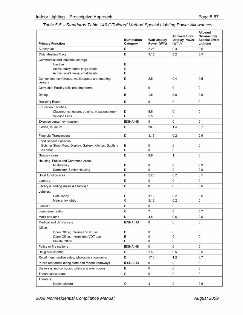
Indoor Lighting – Prescriptive Approach Page 5-67
2008 Nonresidential Compliance Manual August 2009
Table 5-5 – Standards Table 146-GTailored Method Special Lighting Power Allowances
Primary Function Illumination Category
Wall Display Power (W/ft)
Allowed Floor Display Power (W/ft²)
Allowed Ornamental/ Special Effect Lighting
Auditorium D 2.25 0.3 0.5
Civic Meeting Place D 3.15 0.2 0.5
Commercial and industrial storage Inactive Active: bulky items; large labels Active: small items; small labels
B C D
Convention, conference, multipurpose and meeting centers
D 2.5 0.4 0.5
Correction Facility cells and day rooms D 0 0 0
Dining B 1.5 0.6 0.6
Dressing Room D 0 0 0
Education Facilities Classrooms, lecture, training, vocational room Science Labs
D E
5.5 5.5
0 0
0 0
Exercise center, gymnasium IESNA HB 0 0 0
Exhibit, museum C 20.0 1.4 0.7
Financial Transactions D 3.15 0.2 0.6
Food Service Facilities Butcher Shop, Food Display, Gallery, Kitchen, Scullery All other
E C
0 0
0 0
0 0
Grocery store D 9.9 1.1 0
Housing, Public and Commons Areas Multi-family Dormitory, Senior Housing
D D
0 0
0 0
0.9 0.9
Hotel function area D 2.25 0.2 0.5
Laundry D 0 0 0
Library (Reading Areas & Stacks) 1 D 0 0 0.6
Lobbies: Hotel lobby Main entry lobby
C C
3.15 3.15
0.2 0.2
0.6 0
Locker 1 C 0 0 0
Lounge/recreation C 7 0 0.7
Malls and atria D 3.5 0.5 0.6
Medical and clinical care IESNA HB 0 0 0
Office Open Office; Intensive VDT use Open Office; Intermittent VDT use Private Office
D E E
0 0 0
0 0 0
0 0 0
Police or fire stations IESNA HB 0 0 0
Religious worship D 1.5 0.5 0.5
Retail merchandise sales, wholesale showrooms D 17.0 1.2 0.7
Public rest areas along state and federal roadways IESNA HB 0 0 0
Stairways and corridors; toilets and washrooms B 0 0 0
Tenant lease space C 0 0 0
Theaters: Motion picture
C
3
0
0.6
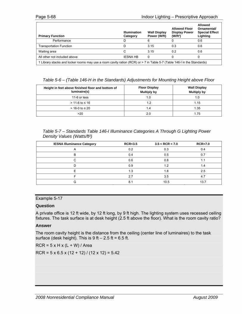
Page 5-68 Indoor Lighting – Prescriptive Approach
2008 Nonresidential Compliance Manual August 2009
Primary Function Illumination Category
Wall Display Power (W/ft)
Allowed Floor Display Power (W/ft²)
Allowed Ornamental/ Special Effect Lighting
Performance D 6 0 0.6
Transportation Function D 3.15 0.3 0.6
Waiting area C 3.15 0.2 0.6
All other not included above IESNA HB 0 0 0
1 Library stacks and locker rooms may use a room cavity ration (RCR) or > 7 in Table 5-7 (Table 146-I in the Standards)
Table 5-6 – (Table 146-H in the Standards) Adjustments for Mounting Height above Floor
Height in feet above finished floor and bottom of luminaire(s)
Floor Display Multiply by
Wall Display Multiply by
11-6 or less 1.0 1.0
> 11-6 to ≤ 16 1.2 1.15
> 16-0 to ≤ 20 1.4 1.35
>20 2.0 1.75
Table 5-7 – Standards Table 146-I Illuminance Categories A Through G Lighting Power Density Values (Watts/ft²)
IESNA Illuminance Category RCR<3.5 3.5 < RCR < 7.0 RCR>7.0 A 0.2 0.3 0.4
B 0.4 0.5 0.7
C 0.6 0.8 1.1
D 0.9 1.2 1.4
E 1.3 1.8 2.5
F 2.7 3.5 4.7
G 8.1 10.5 13.7
Example 5-17
Question A private office is 12 ft wide, by 12 ft long, by 9 ft high. The lighting system uses recessed ceiling fixtures. The task surface is at desk height (2.5 ft above the floor). What is the room cavity ratio?
Answer The room cavity height is the distance from the ceiling (center line of luminaires) to the task surface (desk height). This is 9 ft – 2.5 ft = 6.5 ft.
RCR = 5 x H x (L + W) / Area
RCR = 5 x 6.5 x (12 + 12) / (12 x 12) = 5.42
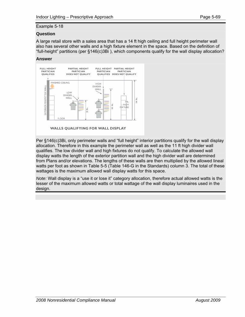
Indoor Lighting – Prescriptive Approach Page 5-69
2008 Nonresidential Compliance Manual August 2009
Example 5-18
Question A large retail store with a sales area that has a 14 ft high ceiling and full height perimeter wall also has several other walls and a high fixture element in the space. Based on the definition of “full-height” partitions (per §146(c)3Bi ), which components qualify for the wall display allocation?
Answer
Per §146(c)3Bi, only perimeter walls and “full height” interior partitions qualify for the wall display allocation. Therefore in this example the perimeter wall as well as the 11 ft high divider wall qualifies. The low divider wall and high fixtures do not qualify. To calculate the allowed wall display watts the length of the exterior partition wall and the high divider wall are determined from Plans and/or elevations. The lengths of these walls are then multiplied by the allowed lineal watts per foot as shown in Table 5-5 (Table 146-G in the Standards) column 3. The total of these wattages is the maximum allowed wall display watts for this space.
Note: Wall display is a “use it or lose it” category allocation, therefore actual allowed watts is the lesser of the maximum allowed watts or total wattage of the wall display luminaires used in the design.
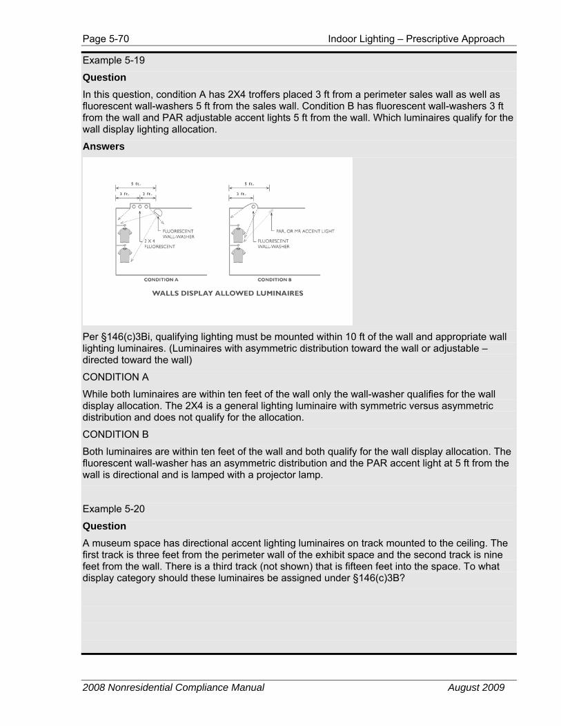
Page 5-70 Indoor Lighting – Prescriptive Approach
2008 Nonresidential Compliance Manual August 2009
Example 5-19
Question In this question, condition A has 2X4 troffers placed 3 ft from a perimeter sales wall as well as fluorescent wall-washers 5 ft from the sales wall. Condition B has fluorescent wall-washers 3 ft from the wall and PAR adjustable accent lights 5 ft from the wall. Which luminaires qualify for the wall display lighting allocation.
Answers
Per §146(c)3Bi, qualifying lighting must be mounted within 10 ft of the wall and appropriate wall lighting luminaires. (Luminaires with asymmetric distribution toward the wall or adjustable –directed toward the wall)
CONDITION A
While both luminaires are within ten feet of the wall only the wall-washer qualifies for the wall display allocation. The 2X4 is a general lighting luminaire with symmetric versus asymmetric distribution and does not qualify for the allocation.
CONDITION B
Both luminaires are within ten feet of the wall and both qualify for the wall display allocation. The fluorescent wall-washer has an asymmetric distribution and the PAR accent light at 5 ft from the wall is directional and is lamped with a projector lamp.
Example 5-20
Question A museum space has directional accent lighting luminaires on track mounted to the ceiling. The first track is three feet from the perimeter wall of the exhibit space and the second track is nine feet from the wall. There is a third track (not shown) that is fifteen feet into the space. To what display category should these luminaires be assigned under §146(c)3B?
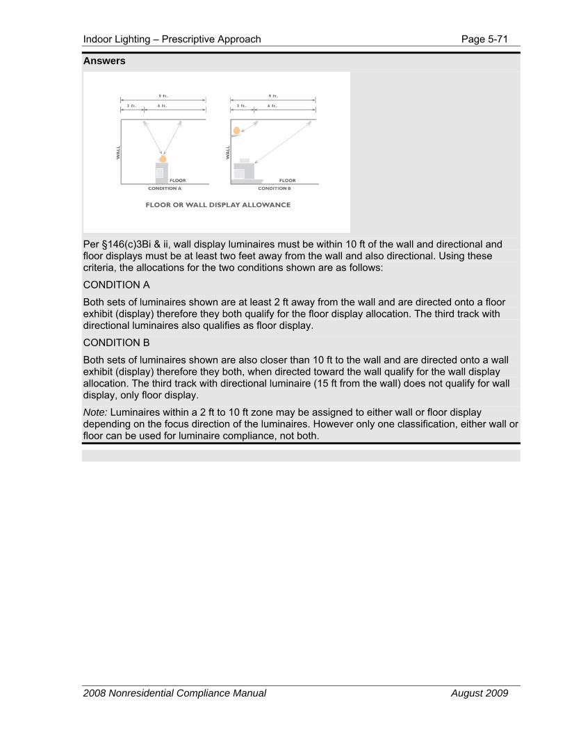
Indoor Lighting – Prescriptive Approach Page 5-71
2008 Nonresidential Compliance Manual August 2009
Answers
Per §146(c)3Bi & ii, wall display luminaires must be within 10 ft of the wall and directional and floor displays must be at least two feet away from the wall and also directional. Using these criteria, the allocations for the two conditions shown are as follows:
CONDITION A
Both sets of luminaires shown are at least 2 ft away from the wall and are directed onto a floor exhibit (display) therefore they both qualify for the floor display allocation. The third track with directional luminaires also qualifies as floor display.
CONDITION B
Both sets of luminaires shown are also closer than 10 ft to the wall and are directed onto a wall exhibit (display) therefore they both, when directed toward the wall qualify for the wall display allocation. The third track with directional luminaire (15 ft from the wall) does not qualify for wall display, only floor display.
Note: Luminaires within a 2 ft to 10 ft zone may be assigned to either wall or floor display depending on the focus direction of the luminaires. However only one classification, either wall or floor can be used for luminaire compliance, not both.
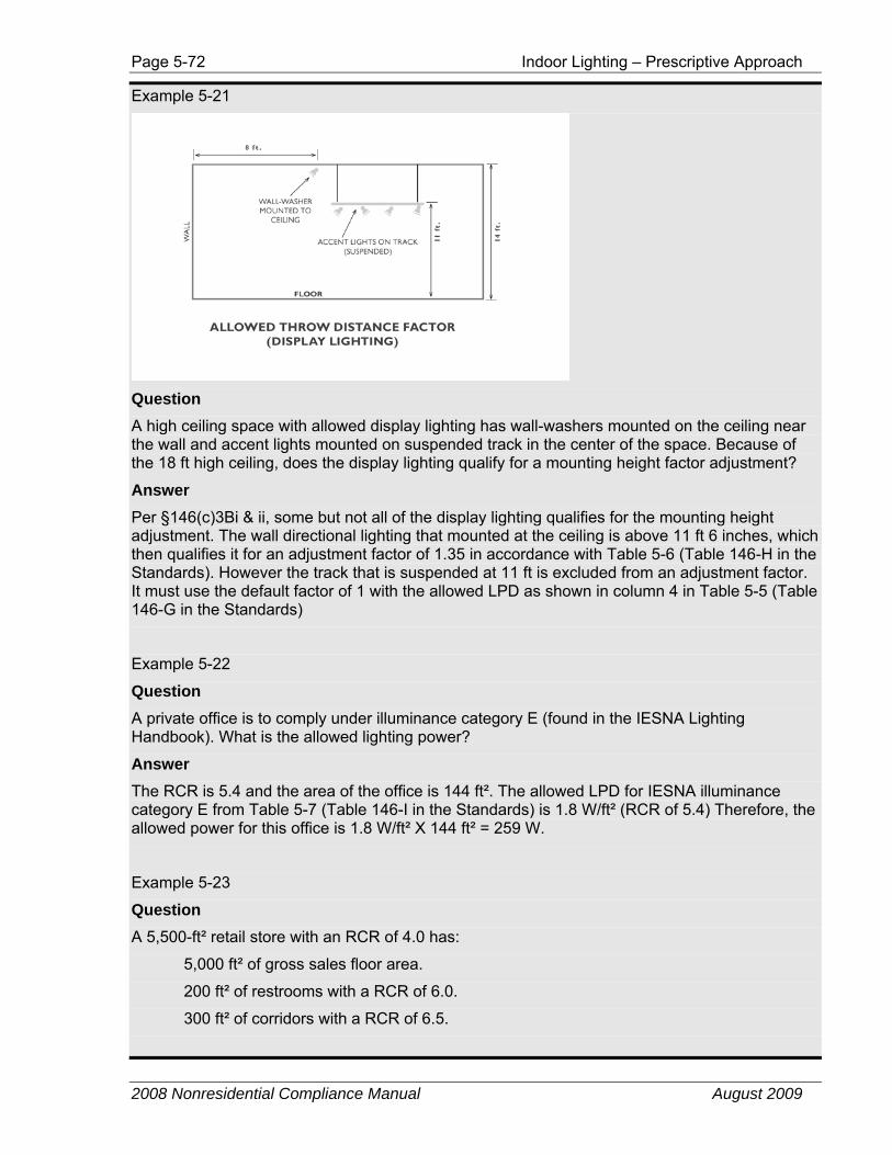
Page 5-72 Indoor Lighting – Prescriptive Approach
2008 Nonresidential Compliance Manual August 2009
Example 5-21
Question A high ceiling space with allowed display lighting has wall-washers mounted on the ceiling near the wall and accent lights mounted on suspended track in the center of the space. Because of the 18 ft high ceiling, does the display lighting qualify for a mounting height factor adjustment?
Answer Per §146(c)3Bi & ii, some but not all of the display lighting qualifies for the mounting height adjustment. The wall directional lighting that mounted at the ceiling is above 11 ft 6 inches, which then qualifies it for an adjustment factor of 1.35 in accordance with Table 5-6 (Table 146-H in the Standards). However the track that is suspended at 11 ft is excluded from an adjustment factor. It must use the default factor of 1 with the allowed LPD as shown in column 4 in Table 5-5 (Table 146-G in the Standards)
Example 5-22
Question A private office is to comply under illuminance category E (found in the IESNA Lighting Handbook). What is the allowed lighting power?
Answer The RCR is 5.4 and the area of the office is 144 ft². The allowed LPD for IESNA illuminance category E from Table 5-7 (Table 146-I in the Standards) is 1.8 W/ft² (RCR of 5.4) Therefore, the allowed power for this office is 1.8 W/ft² X 144 ft² = 259 W.
Example 5-23
Question A 5,500-ft² retail store with an RCR of 4.0 has:
5,000 ft² of gross sales floor area.
200 ft² of restrooms with a RCR of 6.0.
300 ft² of corridors with a RCR of 6.5.
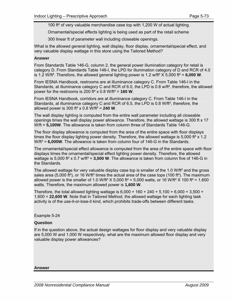
Indoor Lighting – Prescriptive Approach Page 5-73
2008 Nonresidential Compliance Manual August 2009
100 ft² of very valuable merchandise case top with 1,200 W of actual lighting.
Ornamental/special effects lighting is being used as part of the retail scheme
300 linear ft of parameter wall including closeable openings.
What is the allowed general lighting, wall display, floor display, ornamental/special effect, and very valuable display wattage in this store using the Tailored Method?
Answer From Standards Table 146-G, column 2, the general power illumination category for retail is category D. From Standards Table 146-I, the LPD for illumination category of D and RCR of 4.0 is 1.2 W/ft². Therefore, the allowed general lighting power is 1.2 w/ft² X 5,000 ft² = 6,000 W.
From IESNA Handbook, restrooms are at illuminance category C. From Table 146-I in the Standards, at illuminance category C and RCR of 6.0, the LPD is 0.8 w/ft², therefore, the allowed power for the restrooms is 200 ft² x 0.8 W/ft² = 160 W.
From IESNA Handbook, corridors are at illuminance category C. From Table 146-I in the Standards, at illuminance category C and RCR of 6.5, the LPD is 0.8 W/ft², therefore, the allowed power is 300 ft² x 0.8 W/ft² = 240 W.
The wall display lighting is computed from the entire wall parameter including all closeable openings times the wall display power allowance. Therefore, the allowed wattage is 300 ft x 17 W/ft = 5,100W. The allowance is taken from column three of Standards Table 146-G.
The floor display allowance is computed from the area of the entire space with floor displays times the floor display lighting power density. Therefore, the allowed wattage is 5,000 ft² x 1.2 W/ft² = 6,000W. The allowance is taken from column four of 146-G in the Standards.
The ornamental/special effect allowance is computed from the area of the entire space with floor displays times the ornamental/special effect lighting power density. Therefore, the allowed wattage is 5,000 ft² x 0.7 w/ft² = 3,500 W. The allowance is taken from column five of 146-G in the Standards.
The allowed wattage for very valuable display case top is smaller of the 1.0 W/ft² and the gross sales area (5,000 ft²), or 16 W/ft² times the actual area of the case tops (100 ft²). The maximum allowed power is the smaller of 1.0 W/ft² X 5,000 ft² = 5,000 watts, or 16 W/ft² X 100 ft² = 1,600 watts. Therefore, the maximum allowed power is 1,600 W.
Therefore, the total allowed lighting wattage is 6,000 + 160 + 240 + 5,100 + 6,000 + 3,500 + 1,600 = 22,600 W. Note that in Tailored Method, the allowed wattage for each lighting task activity is of the use-it-or-lose-it kind, which prohibits trade-offs between different tasks.
Example 5-24
Question If in the question above, the actual design wattages for floor display and very valuable display are 5,000 W and 1,000 W respectively, what are the maximum allowed floor display and very valuable display power allowances?
Answer
Page 5-74 Indoor Lighting – Performance Approach
2008 Nonresidential Compliance Manual August 2009
Since the floor display and very valuable display allowances are use-it-or-lose-it allowances, the maximum power allowed is the smaller of allowed watts for floor display (6,000 W) and very valuable display (1,600 W) or the actual design watts for floor display (5,000 W) and very valuable display (1,000 W). Therefore, the maximum allowed watts for floor display and very valuable display are the 5,000 W and 1,000 W actual design watts, not 6,000 W and 1,600 W maximum allowed watts.
Example 5-25
Question How is the RCR determined for the library reading room/stack area shown in below?
Answer A RCR value of 7 may be assumed for the stack area. The reading area RCR is calculated based on the reading area room dimensions (20 ft x 40 ft) and on the room cavity height.
5.4 Performance Approach The performance approach provides an alternative method to the prescriptive approach for establishing the allowed lighting power for the building.
Under the performance approach, the energy use of the building is modeled using a compliance software program approved by the Energy Commission. In this energy analysis, the standard lighting power density for the building is determined by the compliance software program based on occupancy type, in accordance with either the complete building, area category, or tailored rules described above. This standard lighting power density is used to determine the energy budget for the building.
When a lighting permit is sought under the performance approach, the applicant uses a proposed lighting power density to determine whether or not the building meets the energy budget. If it does, this proposed lighting power density is automatically translated into the allowed lighting power for the building (by multiplying by the area of the building).
Indoor Lighting – Calculating the Lighting Power Page 5-75
2008 Nonresidential Compliance Manual August 2009
If the building envelope or mechanical systems are included in the performance analysis (because they are part of the current permit application), then the performance approach allows energy trade-offs between systems that can let the allowed lighting power go higher than any other method. Alternatively, it allows lighting power to be traded away to other systems, which would result in a lower allowed lighting power. This flexibility in establishing allowed lighting power is one of the more attractive benefits of the performance approach.
When tailored lighting is used to justify increases in the lighting load, a lower lighting load cannot be modeled for credit. The standard design building uses the lesser of allowed W/ft², or actual lighting power, to be installed in the building. The proposed design building uses the actual lighting power to be installed as detailed on the lighting plans. This value must be equal to, or greater than the allowed W/ft².
5.5 Calculating the Lighting Power Once the allowed lighting power is determined by one of the prescriptive methods or the performance approach, it is compared to the actual lighting power (adjusted for controls). The designed or actual lighting power is simply the sum of the wattages of all planned permanent and portable lighting fixtures in the building, based on the same floor area as was used to calculate the allowed lighting power. The actual lighting power may be adjusted through lighting control credits, called Power Adjustment Factors Table 5-9 (Table 146-C in the Standards), if optional automatic lighting controls are installed.
The actual lighting power does not necessarily include every light in the building. There are a number of lighting applications that are exempted from the Standards limits on lighting power.
5.5.1 Exempt Lighting
§146(a)3
The following lighting applications are exempt from the actual lighting power used to compare with the allowed lighting power for compliance with §146(c). However, some of the applications listed below are regulated by other sections of the Standards. For example, lighting in hotel/motel guest rooms is exempt from §146(c), but it is regulated in §150(k) in accordance with §130(b).
A. In theme parks: lighting for themes and special effects. Regular spaces such as administrative offices and retail areas are not exempt.
B. Studio lighting for film or photography provided that these lighting systems are separately switched from a general lighting system.
C. Lighting for dance floors, lighting for theatrical and other live performances, and theatrical lighting used for religious worship, provided that these lighting systems are additions to a general lighting system and are controlled by a multiscene or theatrical cross-fade control station accessible only to authorized operators.
D. In civic facilities, transportation facilities, convention centers, and hotel function areas: lighting for temporary exhibits if the lighting is an addition
Page 5-76 Indoor Lighting – Calculating the Lighting Power
2008 Nonresidential Compliance Manual August 2009
to a general lighting system and is separately controlled from a panel accessible only to authorized operators.
E. Lighting installed by the manufacturer in refrigerated cases, walk-in freezers, vending machines, food preparation equipment, and scientific and industrial equipment.
F. In medical and clinical buildings: examination and surgical lights, low-level night lights, and lighting integral to medical equipment, provided that these lighting systems are additions to and separately switched from a general lighting system.
G. Lighting for plant growth or maintenance, if it is controlled by a multi-level astronomical time-switch control that complies with §119(h).
H. Lighting equipment that is for sale.
I. Lighting demonstration equipment in lighting education facilities.
J. Lighting that is required for exit signs subject to the California Building Code. Exit signs shall meet the requirements of the Appliance Efficiency Regulations.
K. Exitway or egress illumination that is normally off and that is subject to the California Building Code.
L. Lighting in guestrooms in hotel/motel buildings: lighting in hotel/motel guestrooms shall comply with the applicable provisions in §150(k) in accordance with §130(b).
M. In high-rise residential buildings dwelling units: lighting in high-rise residential dwelling units shall comply with the applicable provisions in §150(k) in accordance with §130(b) (see Chapter 6 of the Residential Compliance Manual).
N. Temporary lighting systems, as defined in §101.
O. Lighting in occupancy group U buildings less than 1,000 ft².
P. Lighting in unconditioned agricultural buildings less than 2,500 ft².
Q. Lighting systems in qualified historic buildings, as defined in the State Historic Building Code (Title 24, Part 8), are exempt from the lighting power allowances if they consist solely of historic lighting components or replicas of historic lighting components. All other lighting systems in qualified historic buildings, or non-historic parts of those lighting systems, shall comply with the lighting power allowances.
R. Lighting in parking garages for seven or less vehicles. Lighting in parking garages for seven or less vehicles shall comply with the applicable provisions of §150(k).
S. Lighting for signs. Signs shall comply with §148.
T. Lighting in a videoconferencing studio: Up to 2.5 W/ft² of lighting in a videoconferencing studio provided the videoconferencing lighting is in addition to and separately switched from a general lighting system; all of the lighting is controlled by a multiscene programmable control system; and the video conferencing studio has permanently installed videoconferencing cameras, audio equipment, and playback equipment.
Indoor Lighting – Calculating the Lighting Power Page 5-77
2008 Nonresidential Compliance Manual August 2009
U. Lighting for automatic teller machines that are located inside parking garages.
5.5.2 Actual Lighting Power Calculation
§146(a)
For calculating the actual lighting power, wattages of all planned permanent, and portable (including planned portable), including hard wired and plug-in lighting systems shown on the plans at the time of permitting, must be considered (except those exempt under §146(a)3). This includes track lighting systems, chandeliers, portable free standing lights, lights attached to workstation panels, movable displays and cabinets, and internally illuminated case work for task or display purposes. The individual signing the lighting plans must clearly indicate on the plans the actual power for the portable lighting systems in the area (§146(a)2).
The calculation of actual lighting power is accomplished with the following steps:
1. Determine the watts for each type of fixture. This includes both the lamp and the ballast wattage. These are interdependent, so the wattage of a particular lamp/ballast combination is best determined from reputable manufacturer’s test data. Default values from Reference Nonresidential Appendix NA8 may be used for standard lamp and ballast combinations.
2. Determine the number of each fixture type in the design.
3. Multiply the fixture wattages by the numbers of fixtures and sum to obtain the building total actual lighting power in watts (this includes wattages of portable lighting systems).
4. Adjust for Power Adjustment Factors (PAF), if applicable.
Portable Lighting Systems §146(a)
For all spaces, the actual wattage of all planned permanent and portable lighting must be included in determining the actual lighting power density. The individual signing the lighting plans must clearly indicate the actual power for the planned permanent and portable lighting systems in the area.
However, for offices of any size, the first 0.2 W/ ft² of portable lighting is not used for determining the actual installed lighting power density. For example, if 0.3 W/ ft² of portable lighting is planned in an office, then only 0.1 W/ ft² (0.3 minus 0.2 = 0.1) will be added to the actual installed lighting power density.
Multiple Interlocked Lighting Systems Serving a Space §146(a)1
When multiple interlocked lighting systems serve an auditorium, convention center, conference room, multipurpose room, or theater, the watts of all systems except the system with the highest wattage may be excluded if the lighting systems are interlocked with a non-programmable double throw switch to prevent simultaneous operation.
Page 5-78 Indoor Lighting – Calculating the Lighting Power
2008 Nonresidential Compliance Manual August 2009
Example 5-26
Question A retail building has two enclosed office spaces (120 ft² each) with floor-to-ceiling permanent partitions, for store managers. Should calculations for installed lighting power account for portable lighting for these spaces?
Answer Yes. All office spaces are required to account for portable lighting, regardless of the size of the office.
Example 5-27
Question An 8,000-ft² office building is to be built. At the time of permit application, the actual wattage of planned portable lighting for the office area is not known and no portable lighting is shown on the plans. Further, the percentage of office areas versus support areas is not known at the time of permitting. Using the complete building method, how does this affect the installed lighting power calculation for the building?
Answer The Standards require that portable lighting power in excess of 0.2 W/ft² be included in the calculation of installed lighting power for office buildings. If it can be assumed that no more than 0.2 W/ft² of portable lighting will be installed in the office spaces, the portable lighting is not required to be included in determining the actual lighting power density. However, if more than 0.2 W/ft² of portable lighting will be installed in the office spaces, then portable lighting in excess of 0.2 W/ft² is required to be included in determining the actual lighting power density. The building inspector may require compliance documentation be resubmitted after the portable lighting has been installed.
Example 5-28
Question An 8,000-ft² office building is to be built. The building contains 2,000 ft² of corridors, restrooms, and storage rooms. The actual wattage of planned portable lighting for the office area is 0.3 w/ft² . Using the complete building method, how does this affect the installed lighting power calculation for the building?
Answer The Standards require that portable lighting power in excess of 0.2 W/ft² be included in the calculation of installed lighting power for office buildings. Therefore, 0.1 W/ft² must be added to the installed lighting power of the permanent fixtures installed in the 6,000 ft² of office space.
Indoor Lighting – Calculating the Lighting Power Page 5-79
2008 Nonresidential Compliance Manual August 2009
Example 5-29
Question A general commercial area will have portable lighting. Because this area is not an office, is the portable lighting excluded in determining the actual lighting power density?
Answer No, portable lighting is not excluded in determining the actual lighting power density in general commercial areas or any other function areas. The Standards require that all planned portable and permanent lighting be included in determining the actual lighting power density, regardless of the building type of use or function of the area.
Example 5-30
Question An auditorium will have two lighting systems. Only one lighting system will ever be needed at a time. When added together, these two lighting systems exceed the power allowances. However, individually they comply with the Standards. Can a preset dimming system that prevents simultaneous operation of more than one lighting system be used so that one of the lighting systems may be excluded from the actual lighting power density?
Answer No, a preset dimming system does not qualify for the multiple interlocked lighting system provision. The only approved type of control that will allow the smaller wattage of the two lighting systems to be excluded from the actual lighting power density is a non-programmable double throw switch.
Example 5-31
Question A restaurant will have two lighting systems. Only one lighting system will ever be used at a time. When added together, these two lighting systems exceed the power allowances. However, individually they comply with the Standards. Can a non-programmable double throw switch be used so that one of the lighting systems may be excluded from the actual lighting power density?
Answer No, a restaurant does not qualify for the multiple interlocked lighting system provision. The only function areas that qualify are an auditorium, convention center, conference room, multipurpose room, or theater.
5.5.3 Determining Luminaire Wattage
§130(d)
Reference Nonresidential Appendix NA-8 2008
The Standards determine the luminaire wattage to be counted towards calculating installed indoor lighting power based on lamps, ballasts, and luminaire type. Depending on the lighting technology used in the luminaire, there are various methods for determining luminaire wattage in §130(d). The various methods are described below.
Page 5-80 Indoor Lighting – Calculating the Lighting Power
2008 Nonresidential Compliance Manual August 2009
Actual wattage installed may require obtaining information from manufacturer cut sheets, catalog data, or from the permanent, pre-printed factory-installed labels, depending on the type of luminaire. Reference Nonresidential Appendix NA8 may be used as a default to determine luminaire wattage for some fluorescent, high intensity discharge, and 12-volt tungsten halogen lighting systems. However, luminaire wattage for lighting systems which are not specifically listed in Reference Nonresidential Appendix NA8 cannot be determined using default wattages listed in NA8.
A. Line-Voltage Sockets §130(d)1
A medium screw-base socket, which is one type of line-voltage socket, can accommodate a variety of different lamp technologies, including general service incandescent, halogen, reflector, and compact fluorescent lamps, ranging in wattages from 2-1/2 to 250 W per socket. Line-voltage sockets include a variety of screw, pin, and bayonet types of bases, for which there is no transformer, ballast, or power supply between the mains power and the lamp.
The wattage of a luminaire with line-voltage sockets is determined by the rating of the luminaire, as described below, and not by the wattage of the initial lamp installed in the luminaire.
There are different requirements for determining the wattage of recessed luminaires than there are for determining the wattage of luminaires which are not recessed, as follows:
1. Line-Voltage Luminaires Which Are Not Recessed – shall be the maximum relamping rated wattage of the luminaire, as listed on a permanent, pre-printed, factory-installed label, as specified by UL 1598. Permanently-installed luminaries which are not recessed include the following types:
a. Surface mounted, to a ceiling, wall, or under-cabinet
b. Pendant mounted, typically from a ceiling
c. Mounted on a pole, a method most often used for outdoor lighting
d. Under-cabinet mounted
The pre-printed, factory-installed wattage label shall not consist of peel-off or peel-down layers or other methods which allow the rated wattage to be changed after the luminaire has been shipped from the manufacturer.
1. Line-Voltage Luminaires Which Are Recessed – shall be the larger of ‘a.’ or ‘b.’ below:
a. The maximum relamping rated wattage of the recessed luminaire, as listed on a permanent, pre-printed, factory-installed label, as specified by UL 1598, or the following, or
b. If the relamping rated wattage on the label is smaller than the wattages listed below, then the wattages listed below must be used. The wattages listed below are determined by
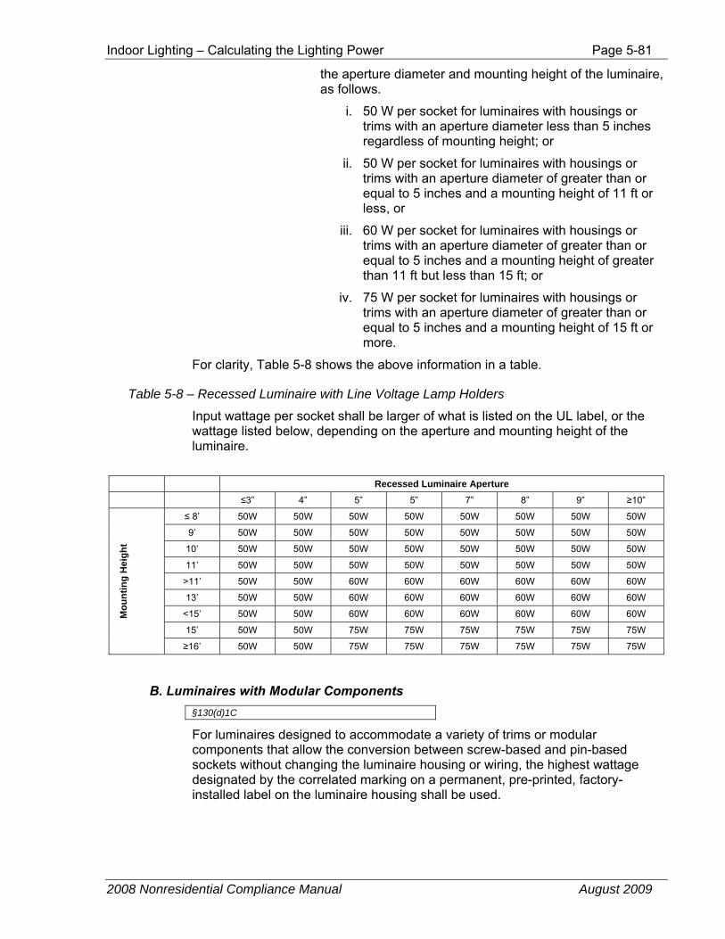
Indoor Lighting – Calculating the Lighting Power Page 5-81
2008 Nonresidential Compliance Manual August 2009
the aperture diameter and mounting height of the luminaire, as follows.
i. 50 W per socket for luminaires with housings or trims with an aperture diameter less than 5 inches regardless of mounting height; or
ii. 50 W per socket for luminaires with housings or trims with an aperture diameter of greater than or equal to 5 inches and a mounting height of 11 ft or less, or
iii. 60 W per socket for luminaires with housings or trims with an aperture diameter of greater than or equal to 5 inches and a mounting height of greater than 11 ft but less than 15 ft; or
iv. 75 W per socket for luminaires with housings or trims with an aperture diameter of greater than or equal to 5 inches and a mounting height of 15 ft or more.
For clarity, Table 5-8 shows the above information in a table.
Table 5-8 – Recessed Luminaire with Line Voltage Lamp Holders
Input wattage per socket shall be larger of what is listed on the UL label, or the wattage listed below, depending on the aperture and mounting height of the luminaire.
Recessed Luminaire Aperture ≤3” 4” 5” 5” 7” 8” 9” ≥10”
Mou
ntin
g H
eigh
t
≤ 8’ 50W 50W 50W 50W 50W 50W 50W 50W
9’ 50W 50W 50W 50W 50W 50W 50W 50W
10’ 50W 50W 50W 50W 50W 50W 50W 50W
11’ 50W 50W 50W 50W 50W 50W 50W 50W
>11’ 50W 50W 60W 60W 60W 60W 60W 60W
13’ 50W 50W 60W 60W 60W 60W 60W 60W
<15’ 50W 50W 60W 60W 60W 60W 60W 60W
15’ 50W 50W 75W 75W 75W 75W 75W 75W
≥16’ 50W 50W 75W 75W 75W 75W 75W 75W
B. Luminaires with Modular Components §130(d)1C
For luminaires designed to accommodate a variety of trims or modular components that allow the conversion between screw-based and pin-based sockets without changing the luminaire housing or wiring, the highest wattage designated by the correlated marking on a permanent, pre-printed, factory-installed label on the luminaire housing shall be used.
Page 5-82 Indoor Lighting – Calculating the Lighting Power
2008 Nonresidential Compliance Manual August 2009
C. Luminaires with Permanently or Remotely Installed Ballasts §130(d)2
The wattage of luminaires with permanently-installed or remotely-installed ballasts shall be the operating input wattage of the rated lamp/ballast combination based on values published in manufacturer’s catalogs based on values from independent testing lab reports as specified by UL 1598.
The wattage of a compact fluorescent or high intensity discharge luminaire that can accommodate a range of wattages without changing the luminaire housing, ballast, or wiring shall be the larger of:
a. The installed wattage, or
b. The average wattage of the lamp/ballast combinations for which the luminaire is rated.
An example of a compact fluorescent luminaire which is rated for use with 26, 32, or 42 W compact fluorescent lamps without changing the luminaire housing, ballast or wiring is shown below:
Initial Lamp Wattage Installed Installed Wattage
26 W 33.33 W
32 W 33.33 W
42 W 42 W
D. Line Voltage Track and Busway Lighting §130(d)3
There are two types voltages used with track and busway lighting systems: line-voltage tracks and busway, and low-voltage tracks and busway. Line-voltage includes tracks and busway that operate on 90 through 480 volts. Low-voltage includes tracks and busway that operate on less than 90 volts.
The wattage for low-voltage track lighting is determined according to §130(d)4, and is described later in this chapter. The wattage for line-voltage track and busway is determined as follows:
1. Track and Busway Rated More Than 20 Amperes. The wattage of line voltage busway and track rated for more than 20 amperes shall be the total volt-ampere rating of the branch circuit feeding the busway or track.
2. Track and Busway Rated 20 Amperes or Less. For convenience and versatility, there are four different options for determining the wattage of line voltage busway and track rated for 20 amperes or less, as follows:
a. Use the VA rating of the branch circuit feeding the track or busway
b. Use the higher of ‘i’ or ‘ii’ below:

Indoor Lighting – Calculating the Lighting Power Page 5-83
2008 Nonresidential Compliance Manual August 2009
i. The higher of the rated wattage of all of the luminaires included in the system, where wattage is determined according to §130(d)1, 2, 4, 5, or 6 as applicable, or
ii. 45 W/lf of track or busway, or
c. When using a track lighting integral current limiter which has been certified to the Energy Commission according to §119(l), use the higher of ‘i’ or ‘ii’ below:
i. The VA rating of the integral current limiter controlling the track or busway, or
ii. 12.5 W/lf of track or busway
Note: There are changes to the requirements for track lighting integral current limiters. Track lighting integral current limiters that were certified only under the provisions of the 2005 Standards must be re-certified under the requirements of the 2008 Standards. Track lighting integral current limiters which have not been certified to the Energy Commission under the requirements in the Standards shall not be installed.
d. When using a dedicated track lighting supplementary overcurrent protection panel, use the sum of the ampere (A) rating of all of the overcurrent protection devices times the branch circuit voltages.
The supplementary overcurrent protection panel shall meet all of the following requirements:
i. Be listed as defined in §101, and
ii. Be used only with line voltage track lighting; and
iii. Be permanently installed in an electrical equipment room, or permanently installed adjacent to the lighting panel board providing supplementary overcurrent protection for the track lighting circuits served by the supplementary over current protection panel; and
iv. Be prominently labeled
NOTICE: This Panel for Track Lighting Energy Code Compliance Only. The overcurrent protection devices in this panel shall only be replaced with the same or lower amperage. No other overcurrent protective device shall be added to this panel. Adding to, or replacement of existing overcurrent protective device(s) with higher continuous ampere rating, will void the panel listing and require re-submittal and re-certification of California Title 24, Part 6 compliance documentation.
Page 5-84 Indoor Lighting – Calculating the Lighting Power
2008 Nonresidential Compliance Manual August 2009
E. Low-Voltage Lighting §130(d)4
This method applies to any low-voltage lighting system having a transformer, including low-voltage track lighting, or individual low-voltage luminaires.
The wattage of luminaires or lighting systems with permanently installed or remotely installed transformers shall be determined as follows:
1. The rated wattage of the lamp/transformer combination, listed on a permanent, pre-printed, factory-installed label, as specified by UL, and
2. For luminaires with transformers rated greater than 50 W, the factory-installed wattage label shall not consist of peel-off or peel-down layers or other methods which allow the rated wattage to be changed after the luminaire or lighting system has been shipped from the manufacturer.
F. LED Lighting Source Systems §130(d5)
LED lighting source systems shall be the maximum rated input wattage of the system as defined in §101. LED lighting system wattage shall be tested in accordance with Reference Joint Appendix JA8 or IES LM-79-08.
The Standards require that the maximum rated input wattage shall be listed on a permanent, pre-printed, factory-installed label as specified by Underwriters Laboratories (UL). However, there have been new LED lighting systems recently introduced, where a centrally located driver is being used to operate more than one luminaire. Therefore, when multiple luminaires are connected to a single power supply/driver, the label used to determine the maximum wattage of the LED system shall be located on the LED power supply/driver, and the wattage of the system shall be based on the connected load of that LED power supply/driver as determined by the luminaire manufacturer or the rating of that LED power supply/driver as determined by the manufacturer of the power supply/driver.
G. Miscellaneous Lighting Systems §130(d)6
This method applies only to lighting systems which have not already been addressed by another subsection of §130(d), and is primarily intended to address new technologies. This method shall not be applied to incandescent, fluorescent, HID, or LED luminaires because these lighting technologies are already addressed in different subsections of §130(d).
The wattage of all other miscellaneous lighting equipment shall be the maximum rated wattage of the lighting equipment, or operating input wattage of the system, listed on a permanent, pre-printed, factory-installed label, or published in manufacturer’s catalogs, based on independent testing lab reports as specified by UL 1574 or UL 1598.
Indoor Lighting – Calculating the Lighting Power Page 5-85
2008 Nonresidential Compliance Manual August 2009
H. GU-24 Lamps, Luminaires, and Adaptors §130(e)
GU-24 Lamps, Luminaires, and Adaptors installed in California shall meet the following requirements:
1. Lamps with GU-24 bases shall have a minimum efficacy no lower than specified in Table 150-C of the Standards.
2. The wattage of luminaires with GU-24 sockets shall be the operating input wattage as listed on a permanent, pre-printed, factory-installed label on the luminaire housing, as specified by UL. Luminaires with GU-24 sockets shall not be rated for any lighting system that has an efficacy lower than specified in Table 150-C of the Standards.
3. Luminaires with GU-24 sockets shall not have modular components allowing conversion to any lighting system that has an efficacy lower than specified in Table 150-C of the Standards.
4. There shall be no adaptors that convert a GU-24 socket to any other type of lighting system that has an efficacy lower than specified in Table 150-C of the Standards.
Example 5-32
Question What is the wattage of a 6 ft length of track lighting that has three 150 W listed fixtures with 60 W, medium base lamps proposed, assuming this track is not equipped with a current limiter?
Answer Based on medium base socket fixtures the total wattage is 450 W (three fixtures at 150 W listed each).
Based on the length of track the wattage is 270 W (6 ft x 45 w/ft).
Therefore, the actual lighting power of the track is the larger of the two, or 450 W.
Example 5-33
Question What is the wattage of a 20 ft track system that is equipped with an integral current limiter rated at 400 W?
Answer If the integral current limited has been certified to the Energy Commission, the wattage of the track is the higher of:
12.5 w/lf X 20 ft of track = 250 W, or the wattage rating of the current limiter which is 400 W.
Therefore, the wattage of this track is the greater of the two, or 400 W
If the integral current limiter has not been certified to the Energy Commission, this method for determining wattage shall not be used.
Page 5-86 Indoor Lighting – Calculating the Lighting Power
2008 Nonresidential Compliance Manual August 2009
Example 5-34
Question If, in the example above, the track is not equipped with a current limiter and is equipped with 350 W of track heads, what would be the wattage of the track?
Answer In the absence of a current limiter, the wattage of the track is the higher of:
1. the maximum relamping rated wattage of all of the luminaires included in the system (350 W), or
2. 45 w/lf of the track which is 45 w/lf X 25 ft = 1,125 W.
Therefore, the wattage of the track is 1,125 W.
Example 5-35
Question A 20-amp branch circuit is supplying two line-voltage tacks. Only one of the tracks is equipped with an integral current limiter. How are the wattages of the tracks on this branch circuit is determined?
Answer The wattage of the track may be calculated using one of the following options:
Option 1. The wattage of the current limiter (or 12.5 W /ft if greater), plus 45 W/ft of the second track, or
Option 2. The VA of the branch circuit that supplies both tracks.
5.5.4 Reduction of Wattage Through Controls
§146(a)2
The controlled watts of connected lighting within the building may be adjusted to take credit for the benefits of certain types of automatic lighting controls. A list of the controls that qualify for these credits is shown in Table 146-C in the Standards.
The lighting control credits set out “Power Adjustment Factors” (PAF). These are multipliers that allow the actual lighting power to be reduced, giving a lower adjusted lighting power. This makes it easier to meet the allowed lighting power requirement. A credit is only permitted when the control types indicated in Standards Table 146-C are used.
In order to qualify for the power savings adjustment, the control system or device must be certified to the Energy Commission (see Section 5.2.1.2, Lighting Equipment Certification), and must control all of the fixtures for which credit is claimed; only controlled luminaires are eligible for lighting control credit. Exit way, emergency, egress and other lighting systems that are on a separate circuit and are not controlled by a qualifying control device, are not eligible for these credits.

Indoor Lighting – Calculating the Lighting Power Page 5-87
2008 Nonresidential Compliance Manual August 2009
PAFs shall not be available for lighting controls that are required by the Standards.
At least 50 percent of the light output of the controlled luminaire must fall within the applicable type of space listed in Table 5-9 (Table 146-C in the Standards). Additionally, credits may not be combined, with the exception of those listed as combined controls in Table 5-9.
A. Multi-Level Occupant Sensors/Switching A multi-level occupant sensor combined with multi-level circuitry and switching in accordance with §146(a)2D, used in any space ≤ to 250 ft² enclosed by floor to ceiling partitions, any size classrooms, corridors, conference rooms, or waiting rooms qualifies for a power adjustment factor. The multi-level occupant sensor must be certified to the Energy Commission according to the applicable requirements in §119, and shall meet the multi-level lighting control requirements of §131(b), including the following:
1. The sensor shall have an automatic OFF function that turns off all the lights within 30 minutes after the area has been vacated. For example, the sensor may turn off the lights in 5 minutes after the area has been vacated because 5 minutes is within 30 minutes.
2. The sensor shall have either an automatically or manually controlled ON function.
3. The sensor shall have wiring capabilities so that each switch function activates a portion of the lights.
4. One control step must be able to activate between 30-70 percent of the design lighting power in a room either through an automatic or manual action, and may be a switching or dimming system.
5. The lighting shall achieve a reasonably uniform level of illuminance.
In addition, the occupant sensor must meet the “multi-level circuitry” requirements described in the following section.
Occupant Sensors with Multi-level Circuitry An occupant sensor used in a room less than or equal to 250 ft²) shall have the following features §146(a)2D:
1. Upon entering the room, a first stage of control activates between 30-70 percent of the lights in the space automatically or by manually turning on a switch.
2. After that action occurs, the following actions must be able to occur based upon manual control by the occupant:
a. Activating the alternate set of lights.
b. Activating 100 percent of the lights.
c. Deactivating all lights.
3. When the room is unoccupied, all of the lights must automatically turn off.
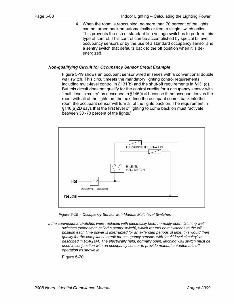
Page 5-88 Indoor Lighting – Calculating the Lighting Power
2008 Nonresidential Compliance Manual August 2009
4. When the room is reoccupied, no more than 70 percent of the lights can be turned back on automatically or from a single switch action. This prevents the use of standard line voltage switches to perform this type of control. This control can be accomplished by special bi-level occupancy sensors or by the use of a standard occupancy sensor and a sentry switch that defaults back to the off position when it is de-energized.
Non-qualifying Circuit for Occupancy Sensor Credit Example Figure 5-19 shows an occupant sensor wired in series with a conventional double wall switch. This circuit meets the mandatory lighting control requirements including multi-level control in §131(b) and the shut-off requirements in §131(d). But this circuit does not qualify for the control credits for a occupancy sensor with “multi-level circuitry” as described in §146(a)4 because if the occupant leaves the room with all of the lights on, the next time the occupant comes back into the room the occupant sensor will turn all of the lights back on. The requirement in §146(a)2D says that the first level of lighting to come back on must “activate between 30 -70 percent of the lights.”
Figure 5-19 – Occupancy Sensor with Manual Multi-level Switches
If the conventional switches were replaced with electrically held, normally open, latching wall switches (sometimes called a sentry switch), which returns both switches to the off position each time power is interrupted for an extended periods of time, this would then quality for the compliance credit for occupancy sensors with “multi-level circuitry” as described in §146(a)4. The electrically held, normally open, latching wall switch must be used in conjunction with an occupancy sensor to provide manual on/automatic off operation as shown in
Figure 5-20.
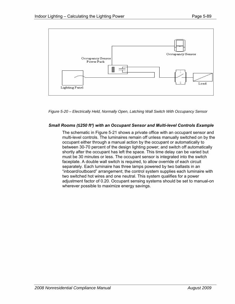
Indoor Lighting – Calculating the Lighting Power Page 5-89
2008 Nonresidential Compliance Manual August 2009
Figure 5-20 – Electrically Held, Normally Open, Latching Wall Switch With Occupancy Sensor
Small Rooms (≤250 ft²) with an Occupant Sensor and Multi-level Controls Example The schematic in Figure 5-21 shows a private office with an occupant sensor and multi-level controls. The luminaires remain off unless manually switched on by the occupant either through a manual action by the occupant or automatically to between 30-70 percent of the design lighting power; and switch off automatically shortly after the occupant has left the space. This time delay can be varied but must be 30 minutes or less. The occupant sensor is integrated into the switch faceplate. A double wall switch is required, to allow override of each circuit separately. Each luminaire has three lamps powered by two ballasts in an “inboard/outboard” arrangement; the control system supplies each luminaire with two switched hot wires and one neutral. This system qualifies for a power adjustment factor of 0.20. Occupant sensing systems should be set to manual-on wherever possible to maximize energy savings.
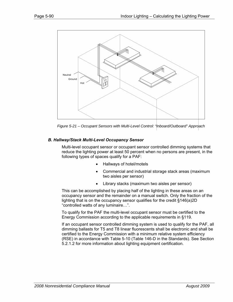
Page 5-90 Indoor Lighting – Calculating the Lighting Power
2008 Nonresidential Compliance Manual August 2009
HotGround
Neutral
Figure 5-21 – Occupant Sensors with Multi-Level Control: “Inboard/Outboard” Approach
B. Hallway/Stack Multi-Level Occupancy Sensor Multi-level occupant sensor or occupant sensor controlled dimming systems that reduce the lighting power at least 50 percent when no persons are present, in the following types of spaces qualify for a PAF:
• Hallways of hotel/motels
• Commercial and industrial storage stack areas (maximum two aisles per sensor)
• Library stacks (maximum two aisles per sensor)
This can be accomplished by placing half of the lighting in these areas on an occupancy sensor and the remainder on a manual switch. Only the fraction of the lighting that is on the occupancy sensor qualifies for the credit §146(a)2D “controlled watts of any luminaire…”.
To qualify for the PAF the multi-level occupant sensor must be certified to the Energy Commission according to the applicable requirements in §119.
If an occupant sensor controlled dimming system is used to qualify for the PAF, all dimming ballasts for T5 and T8 linear fluorescents shall be electronic and shall be certified to the Energy Commission with a minimum relative system efficiency (RSE) in accordance with Table 5-10 (Table 146-D in the Standards). See Section 5.2.1.2 for more information about lighting equipment certification.
Indoor Lighting – Calculating the Lighting Power Page 5-91
2008 Nonresidential Compliance Manual August 2009
C. Dimming systems including manual and multi-scene programmable systems in
hotels/motels, restaurants, auditoriums, and theaters qualify for a PAF. To qualify for this PAF all dimming ballasts for T5 and T8 linear fluorescents shall be electronic and shall be certified to the Energy Commission with a minimum relative system efficiency (RSE) in accordance with Table 5-10 (Table 146-D in the Standards).
D. Manual Dimming of Dimmable Electronic Ballasts for All Buildings+ Manual dimming of dimmable electronic ballasts in all building types qualifies for a PAF. To qualify for this PAF, all dimming ballasts for T5 and T8 linear fluorescents shall be electronic and shall be certified to the Energy Commission with a minimum relative system efficiency (RSE) in accordance with Table 5-10 (Table 146-D in the Standards.
E. Demand Responsive Lighting Control for All Buildings A demand responsive lighting control allows load shedding (dimming or switching off of lights) initiated by the utilities or other grid system operators in the event of an electricity shortage. To qualify for this PAF the lighting must be controlled by a control system that is ready to respond to a load curtailment or real time pricing signal. Such a system is enabled to dim or switch off the lights receiving the control credit below a fixed setting or to a fraction of their setting at the time the signal is received.
There are two types of demand response lighting control systems that qualify for a PAF in all buildings. Only those lamps that are controlled through the demand responsive lighting control qualify for this PAF. The two types of control systems are as follows:
1. A demand responsive lighting control that reduces lighting power consumption in response to a demand responsive signal through the use of multi-level switching. The multi-level switching shall meet the uniformity requirements of §131(b). Only those lamps that are switch off when receiving the demand responsive signal qualify for this PAF.
This PAF shall not be available for lighting controls required by the Standards.
2. A demand responsive lighting control that reduces lighting power consumption in response to a demand responsive signal when used in combination with manual dimming of dimmable electronic ballasts.
To qualify for this PAF, all dimming ballasts for T5 and T8 linear fluorescents shall be electronic and shall be certified to the Energy Commission with a minimum relative system efficiency (RSE) in accordance with Table 5-10 (Table 146-D in the Standards).
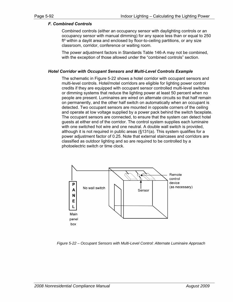
Page 5-92 Indoor Lighting – Calculating the Lighting Power
2008 Nonresidential Compliance Manual August 2009
F. Combined Controls Combined controls (either an occupancy sensor with daylighting controls or an occupancy sensor with manual dimming) for any space less than or equal to 250 ft² within a daylit area and enclosed by floor-to-ceiling partitions, or any size classroom, corridor, conference or waiting room.
The power adjustment factors in Standards Table 146-A may not be combined, with the exception of those allowed under the “combined controls” section.
Hotel Corridor with Occupant Sensors and Multi-Level Controls Example The schematic in Figure 5-22 shows a hotel corridor with occupant sensors and multi-level controls. Hotel/motel corridors are eligible for lighting power control credits if they are equipped with occupant sensor controlled multi-level switches or dimming systems that reduce the lighting power at least 50 percent when no people are present. Luminaires are wired on alternate circuits so that half remain on permanently, and the other half switch on automatically when an occupant is detected. Two occupant sensors are mounted in opposite corners of the ceiling and operate at low voltage supplied by a power pack behind the switch faceplate. The occupant sensors are connected, to ensure that the system can detect hotel guests at either end of the corridor. The control system supplies each luminaire with one switched hot wire and one neutral. A double wall switch is provided, although it is not required in public areas (§131(a). This system qualifies for a power adjustment factor of 0.25. Note that external staircases and corridors are classified as outdoor lighting and so are required to be controlled by a photoelectric switch or time clock.
Figure 5-22 – Occupant Sensors with Multi-Level Control: Alternate Luminaire Approach
Indoor Lighting – Calculating the Lighting Power Page 5-93
2008 Nonresidential Compliance Manual August 2009
G. Daylighting Control Credits §146(a)4 E
Control credits as defined by §146(a)2E permit a reduction in the computed lighting power in a building based on special allowances for installing controls that save more energy than the basic mandatory controls required by §131. These credits are based upon power adjustment factors (PAFs) which when multiplied by the wattage of the controlled lighting, is subtracted from the installed lighting power to yield the calculated lighting power. A lighting system prescriptively complies when the calculated lighting power is less than or equal to the allowed indoor lighting power.
Under the performance compliance approach, automatic daylighting control credits for side-lighting and skylights, listed in Standards Table 146-C, are NOT available when automatic daylighting controls are required under the mandatory or prescriptive standards. These credits are only available in spaces where daylighting and controls are not already required by mandatory requirements or prescriptive or performance approach requirements. For example, if performance approach is used to install skylights in addition to what is prescriptively required and the daylit area is greater than 2500 ft², control credits are not available for the automatic daylighting controls associated with additional skylights since there are mandatory requirements for these controls.
Automatic daylight control devices include stepped dimming, continuous dimming, and stepped switching devices. For definitions of these terms see §101 or the definitions in the Reference Joint Appendix JA1.
Installing controls that have power adjustment factors increases the efficiency of the lighting system and this efficiency is captured in both the prescriptive and performance documentation of lighting system wattage. The control credits can be used when more installed lighting capacity is required, or for exceeding the requirements of the energy code to gain credit for building rating systems such as LEED1 or CHPS2.
For controlled lighting to receive a reduction in its calculated wattage from a daylighting control power adjustment factor, it must be in the daylit area and comply with the restrictions associated with the specific power adjustment factor.
For automatic daylighting controls with windows, the power adjustment factor (PAF) is a function of dimming versus switching controls, the glazing visible transmittance (VT) of the fenestration units (Section 3.2.8) and the window to wall ratio (WWR) using the interior wall-to-wall and floor-to-ceiling dimensions (Section 5.2.1.4)
For automatic multi-level daylighting controls with skylights, the power adjustment factors are only applied to control general lighting in the daylit area under skylights. To qualify for the power adjustment credits, the control must conform to the requirements of §119(i) automatic multi-level daylighting controls, and the skylight glazing or diffuser must have a haze rating greater than 90 percent. The
1 LEED stands for Leadership in Energy and Environmental Design and is a rating program of the U.
S. Green Building Council.
2 CHPS is the Collaborative for High Performance Schools, which has a rating program for K-12 schools, based in part on exceeding the Title 24 standards.
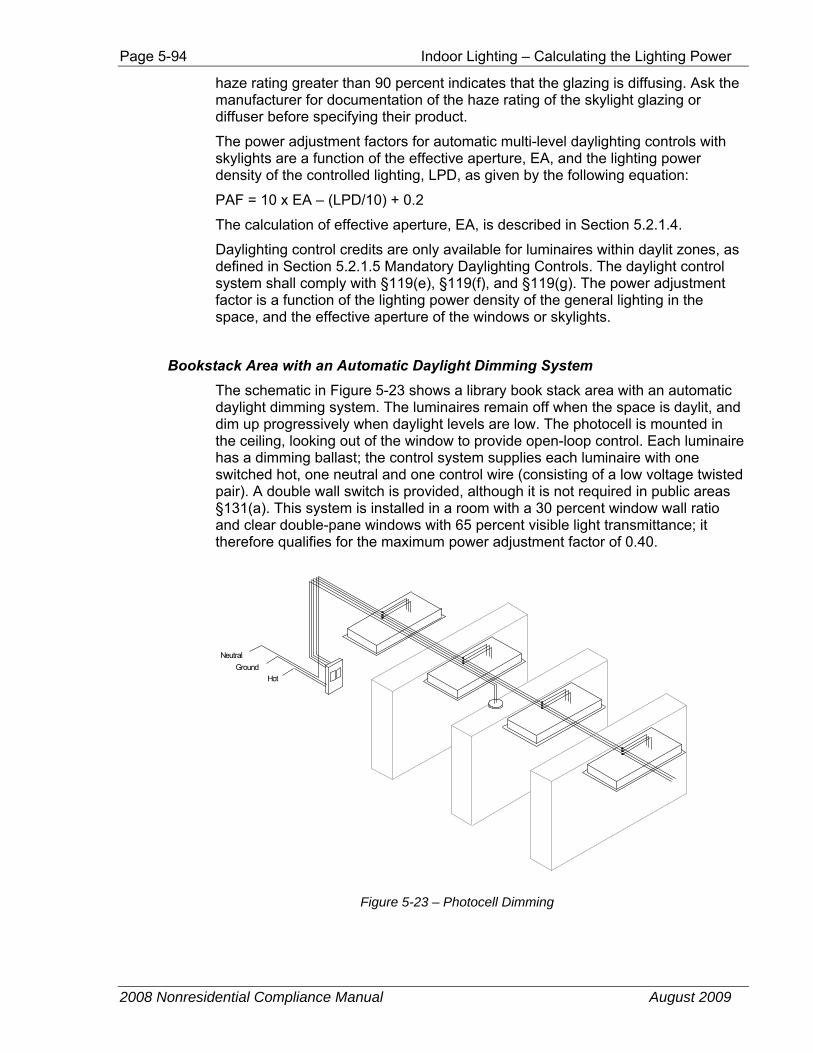
Page 5-94 Indoor Lighting – Calculating the Lighting Power
2008 Nonresidential Compliance Manual August 2009
haze rating greater than 90 percent indicates that the glazing is diffusing. Ask the manufacturer for documentation of the haze rating of the skylight glazing or diffuser before specifying their product.
The power adjustment factors for automatic multi-level daylighting controls with skylights are a function of the effective aperture, EA, and the lighting power density of the controlled lighting, LPD, as given by the following equation:
PAF = 10 x EA – (LPD/10) + 0.2
The calculation of effective aperture, EA, is described in Section 5.2.1.4.
Daylighting control credits are only available for luminaires within daylit zones, as defined in Section 5.2.1.5 Mandatory Daylighting Controls. The daylight control system shall comply with §119(e), §119(f), and §119(g). The power adjustment factor is a function of the lighting power density of the general lighting in the space, and the effective aperture of the windows or skylights.
Bookstack Area with an Automatic Daylight Dimming System The schematic in Figure 5-23 shows a library book stack area with an automatic daylight dimming system. The luminaires remain off when the space is daylit, and dim up progressively when daylight levels are low. The photocell is mounted in the ceiling, looking out of the window to provide open-loop control. Each luminaire has a dimming ballast; the control system supplies each luminaire with one switched hot, one neutral and one control wire (consisting of a low voltage twisted pair). A double wall switch is provided, although it is not required in public areas §131(a). This system is installed in a room with a 30 percent window wall ratio and clear double-pane windows with 65 percent visible light transmittance; it therefore qualifies for the maximum power adjustment factor of 0.40.
Hot Ground
Neutral
Figure 5-23 – Photocell Dimming
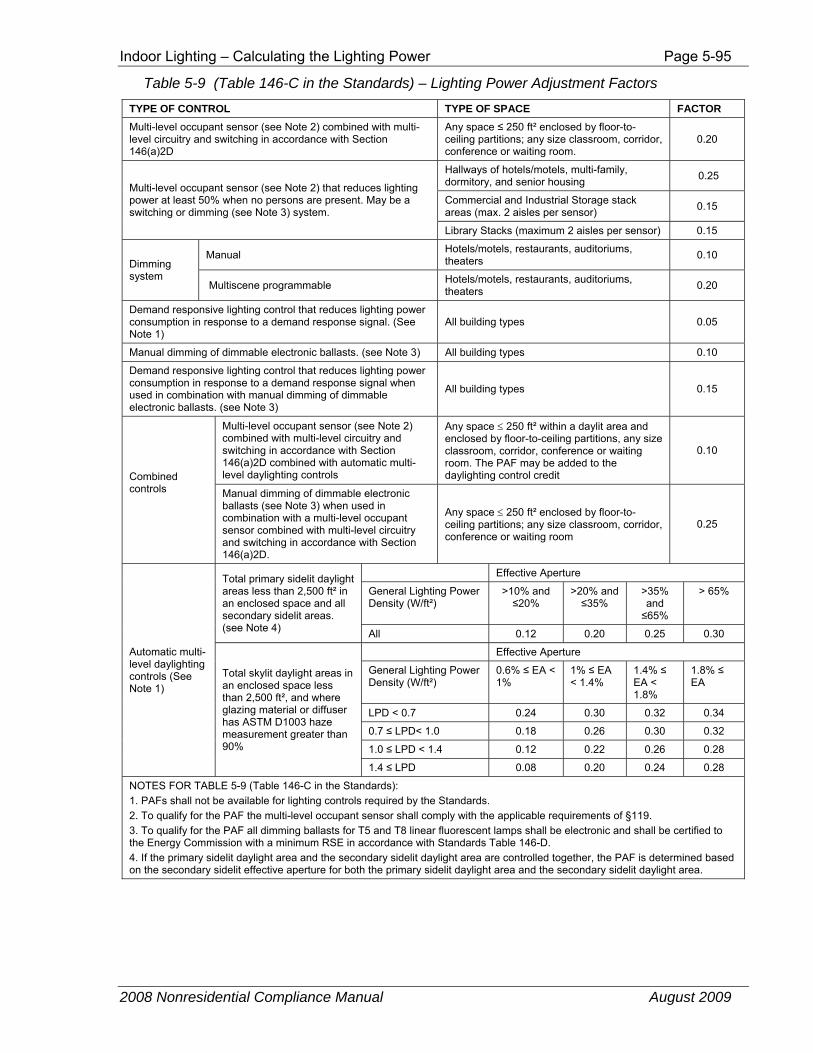
Indoor Lighting – Calculating the Lighting Power Page 5-95
2008 Nonresidential Compliance Manual August 2009
Table 5-9 (Table 146-C in the Standards) – Lighting Power Adjustment Factors
TYPE OF CONTROL TYPE OF SPACE FACTOR Multi-level occupant sensor (see Note 2) combined with multi-level circuitry and switching in accordance with Section 146(a)2D
Any space ≤ 250 ft² enclosed by floor-to-ceiling partitions; any size classroom, corridor, conference or waiting room.
0.20
Multi-level occupant sensor (see Note 2) that reduces lighting power at least 50% when no persons are present. May be a switching or dimming (see Note 3) system.
Hallways of hotels/motels, multi-family, dormitory, and senior housing 0.25
Commercial and Industrial Storage stack areas (max. 2 aisles per sensor) 0.15
Library Stacks (maximum 2 aisles per sensor) 0.15
Dimming system
Manual Hotels/motels, restaurants, auditoriums, theaters 0.10
Multiscene programmable Hotels/motels, restaurants, auditoriums, theaters 0.20
Demand responsive lighting control that reduces lighting power consumption in response to a demand response signal. (See Note 1)
All building types 0.05
Manual dimming of dimmable electronic ballasts. (see Note 3) All building types 0.10
Demand responsive lighting control that reduces lighting power consumption in response to a demand response signal when used in combination with manual dimming of dimmable electronic ballasts. (see Note 3)
All building types 0.15
Combined controls
Multi-level occupant sensor (see Note 2) combined with multi-level circuitry and switching in accordance with Section 146(a)2D combined with automatic multi-level daylighting controls
Any space ≤ 250 ft² within a daylit area and enclosed by floor-to-ceiling partitions, any size classroom, corridor, conference or waiting room. The PAF may be added to the daylighting control credit
0.10
Manual dimming of dimmable electronic ballasts (see Note 3) when used in combination with a multi-level occupant sensor combined with multi-level circuitry and switching in accordance with Section 146(a)2D.
Any space ≤ 250 ft² enclosed by floor-to-ceiling partitions; any size classroom, corridor, conference or waiting room
0.25
Automatic multi-level daylighting controls (See Note 1)
Total primary sidelit daylight areas less than 2,500 ft² in an enclosed space and all secondary sidelit areas. (see Note 4)
Effective Aperture
General Lighting Power Density (W/ft²)
>10% and ≤20%
>20% and ≤35%
>35% and ≤65%
> 65%
All 0.12 0.20 0.25 0.30
Total skylit daylight areas in an enclosed space less than 2,500 ft², and where glazing material or diffuser has ASTM D1003 haze measurement greater than 90%
Effective Aperture
General Lighting Power Density (W/ft²)
0.6% ≤ EA < 1%
1% ≤ EA < 1.4%
1.4% ≤ EA < 1.8%
1.8% ≤ EA
LPD < 0.7 0.24 0.30 0.32 0.34
0.7 ≤ LPD< 1.0 0.18 0.26 0.30 0.32
1.0 ≤ LPD < 1.4 0.12 0.22 0.26 0.28
1.4 ≤ LPD 0.08 0.20 0.24 0.28
NOTES FOR TABLE 5-9 (Table 146-C in the Standards): 1. PAFs shall not be available for lighting controls required by the Standards. 2. To qualify for the PAF the multi-level occupant sensor shall comply with the applicable requirements of §119. 3. To qualify for the PAF all dimming ballasts for T5 and T8 linear fluorescent lamps shall be electronic and shall be certified to the Energy Commission with a minimum RSE in accordance with Standards Table 146-D. 4. If the primary sidelit daylight area and the secondary sidelit daylight area are controlled together, the PAF is determined based on the secondary sidelit effective aperture for both the primary sidelit daylight area and the secondary sidelit daylight area.
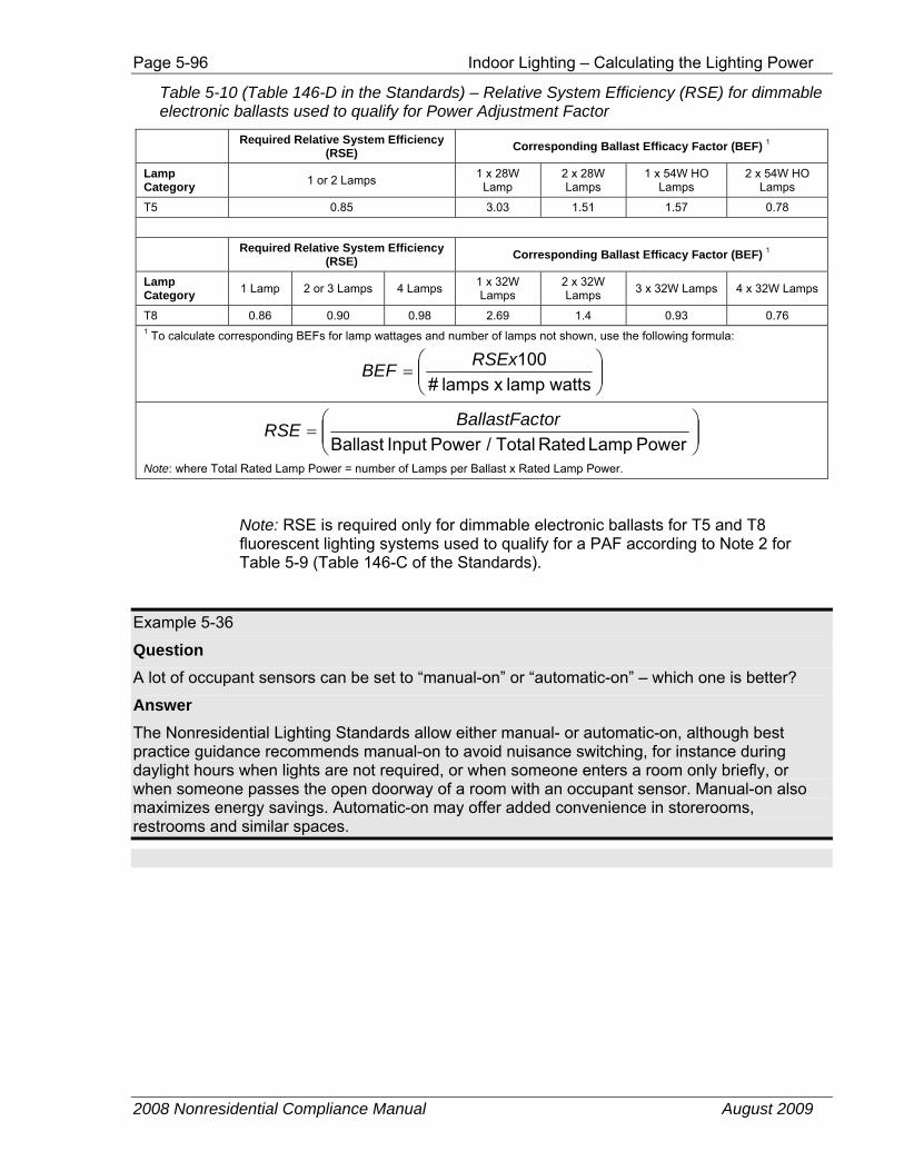
Page 5-96 Indoor Lighting – Calculating the Lighting Power
2008 Nonresidential Compliance Manual August 2009
Table 5-10 (Table 146-D in the Standards) – Relative System Efficiency (RSE) for dimmable electronic ballasts used to qualify for Power Adjustment Factor
Required Relative System Efficiency (RSE) Corresponding Ballast Efficacy Factor (BEF) 1
Lamp Category 1 or 2 Lamps 1 x 28W
Lamp 2 x 28W Lamps
1 x 54W HO Lamps
2 x 54W HO Lamps
T5 0.85 3.03 1.51 1.57 0.78
Required Relative System Efficiency (RSE) Corresponding Ballast Efficacy Factor (BEF) 1
Lamp Category 1 Lamp 2 or 3 Lamps 4 Lamps 1 x 32W
Lamps 2 x 32W Lamps 3 x 32W Lamps 4 x 32W Lamps
T8 0.86 0.90 0.98 2.69 1.4 0.93 0.76 1 To calculate corresponding BEFs for lamp wattages and number of lamps not shown, use the following formula:
⎟⎟⎠
⎞⎜⎜⎝
⎛=
wattslamp x lamps #100RSExBEF
⎟⎟⎠
⎞⎜⎜⎝
⎛=
Power Lamp Rated Total / Power Input BallasttorBallastFacRSE
Note: where Total Rated Lamp Power = number of Lamps per Ballast x Rated Lamp Power.
Note: RSE is required only for dimmable electronic ballasts for T5 and T8 fluorescent lighting systems used to qualify for a PAF according to Note 2 for Table 5-9 (Table 146-C of the Standards).
Example 5-36
Question A lot of occupant sensors can be set to “manual-on” or “automatic-on” – which one is better?
Answer The Nonresidential Lighting Standards allow either manual- or automatic-on, although best practice guidance recommends manual-on to avoid nuisance switching, for instance during daylight hours when lights are not required, or when someone enters a room only briefly, or when someone passes the open doorway of a room with an occupant sensor. Manual-on also maximizes energy savings. Automatic-on may offer added convenience in storerooms, restrooms and similar spaces.
Indoor Lighting – Calculating the Lighting Power Page 5-97
2008 Nonresidential Compliance Manual August 2009
Example 5-37
Question A multi-scene programmable controller is used to control display lighting in a store. Can a power adjustment factor be applied?
Answer No. The 0.2 power adjustment factor for multiscene programmable controllers is only available for the general lighting of hotels/motels, restaurants, auditoriums and theaters. However, special lighting power allowances are available for retail display lighting under the tailored compliance method.
Example 5-38
Question Can I provide multi-level control with occupant sensors just by wiring an occupant sensor in series with a wall switch? Will such a combination qualify for a power adjustment factor?
Answer This arrangement will meet the mandatory requirements for multi-level control in §131(b) and automatic shut-off control in §131(d). But this configuration does not qualify for a power adjustment factor credit because if one leaves the room with all of the lights on, the next time the lights are turned on, all the lights will be on. Special circuitry is required. Many control system manufacturers offer products specifically for bi-level occupant sensing systems, many of which use a double wall switch with an occupant sensor integrated into the switch faceplate, or an integrated power pack that supplies an occupant sensor in the ceiling. See Section 5.5.4 Non-qualifying Circuit for Occupancy Sensor Credit Example.
Example 5-39
Question Where can I find guidance on how to commission lighting controls? I need information on where to position sensors, how to set time delays and how to get the best performance from my system.
Answer Many manufacturers provide comprehensive guidance on the design and commissioning of systems; this guidance is often tailored to the characteristics of their own products and is therefore the best advice available. More general information can be obtained from best practices guidance such as The Advanced Lighting Guidelines which can be downloaded free of charge at http://www.newbuildings.org, or from the Lighting Controls Association website http://www.aboutlightingcontrols.org.
Page 5-98 Indoor Lighting – Additions and Alterations
2008 Nonresidential Compliance Manual August 2009
5.6 Additions and Alterations §149
New additions must meet the all mandatory measures for both the prescriptive and performance method of compliance. Prescriptive requirements, including the lighting power densities must be met if prescriptive method of compliance is used. If performance approach is used, the lighting power densities may be traded-off against other prescriptive building features.
Altered lighting components must also meet applicable mandatory measures described below. Prescriptive requirements apply if in a permitted space (The Basis for the Alteration Area is discussed in Section 5.6.3, Prescriptive Measure – Alterations below) where a total of more than 50 percent of the fixtures are replaced or removed and re-installed, or if the connected lighting load is increased. These requirements are discussed in detail in the following sections.
Lighting alterations generally refers to replacing the entire luminaire, which includes the housing, lamps, ballasts, and louvers or lenses. Lighting alterations also refers to removing and re-installing luminaires. Simply replacing the lamps and ballasts in an existing fixture while the fixture remains in place is not considered a lighting alteration. Replacing or installing new wiring that connects the luminaires to switches, relays, branch circuits, and other control devices represents a lighting alteration and therefore must meet the applicable mandatory requirements as described below.
5.6.1 Mandatory Measures – Additions and Alterations
New additions and lighting systems that are installed for the first time in an existing space must comply with mandatory requirements of §119, §130, §131, and §134.
All “altered” lighting components in alterations must comply with applicable mandatory requirements of §119, §130, §131, and §134. Although these mandatory requirements may apply only to alter lighting components, it is recommended that mandatory measures be considered for the entire space to achieve maximum energy savings. Additionally, having the same controls on the entire lighting system will be less confusing to the building occupants and operators.
Compliance requirements vary with the details and extent of the alterations. The mandatory requirements include certification of any new lamps and ballasts that are installed if they are the type regulated by the Appliance Efficiency Regulations. Any new lighting controls must meet minimum performance requirements. In addition, control and circuiting requirements apply to the altered lighting components as follows:
1. Spaces with lighting systems installed for the first time shall meet the applicable requirements of §119, §130, §131, and §134.
2. When the requirements of §131(c)2B are triggered by the addition of skylights to an existing building and the lighting
Indoor Lighting – Additions and Alterations Page 5-99
2008 Nonresidential Compliance Manual August 2009
system is not re-circuited, the daylighting control need not meet the multi-level requirements in §131(c)2Diii.
The following wiring alterations shall meet the applicable requirements of §119, §130, §131, and §134:
1. Where new or moved wiring is being installed to serve added or moved luminaires.
2. Where conductor wiring from the panel or from a light switch to the luminaires is being replaced.
3. Where a lighting panel is installed or moved to a new location.
4. Where an existing enclosed space is subdivided into two or more spaces, the new enclosed spaces shall meet the applicable requirements of §119, §130, §131, and §134.
5. Alterations to an existing space, where the existing lighting system is less than 0.5 W/ft², and the lighting is increased to more than 0.5 W/ft² shall meet the applicable requirements of §119, §130, §131, and §134.
For more information on mandatory requirements, see Sections 5.1 Overview, 5.2 Lighting Design Procedure, Section 5.2.1.2 Lighting Equipment Certification, and Section 5.2.1.5 Daylighting Control.
5.6.2 Prescriptive Measures – Additions
All additions must comply with the prescriptive requirements of:
1. §143(c) – Minimum Skylight Area for Large Enclosed Spaces in Low-rise Buildings, and
2. §146 – Prescriptive Requirements for Indoor Lighting
Additions must also meet the mandatory requirements discussed in Section 5.6.1 above. For more information on these requirements, refer to Section 5.3 Prescriptive Approach.
5.6.3 Prescriptive Measures – Alterations
Alterations to existing indoor lighting systems shall meet the following requirements:
1. Spaces with lighting systems installed for the first time shall meet the applicable requirements of §149(b)1, §143(c), and §146.
2. Alterations that increase the connected lighting load, replace, or remove and re-install a total of 50 percent or more of the luminaires in an enclosed space, shall meet the requirements of §149(b)1 and §146.
3. Alterations to an existing space, where the existing lighting system is less than 0.5 W/ft², and the lighting is increased to more than 0.5 W/ft² shall meet the applicable requirements of §149(b)1, §143(c), and §146.
Page 5-100 Indoor Lighting – Additions and Alterations
2008 Nonresidential Compliance Manual August 2009
The Basis for the Alteration Area Areas of the building enclosed by floor-to-ceiling partitions in which no lighting is being altered, or in which no wiring is being altered, do not need to meet lighting requirements of the Standards. The basis for determining if more than 50 percent of fixtures are being replaced, or removed and re-installed, is the permitted space (not the building space), excluding any enclosed areas that are not receiving new or re-installed light fixtures. Enclosed areas are areas that are surrounded by permanent floor-to-ceiling partitions. For alterations, the permitted space is usually not an entire building, and may not be an entire tenant space. Enforcement agencies will often define "permitted space" to include only those areas where alterations are proposed.
Lighting Systems Installed for the First Time Spaces with lighting systems that are installed for the first time must comply with the applicable prescriptive requirements of §143(c) and §146. “Installed for the first time” refers to when the first lighting permit has been issued for a lighting system in a given space. This means skylights will be required in all large open spaces (greater than 8,000 ft²) with ceiling heights greater than 15 ft, where a lighting system is being installed for the first time even if the building shell was constructed without any skylights, or with minimal lights. For example: If the building shell is built with a minimal lighting system such as exit, egress, and emergency and later a general lighting system is installed in the building, the general lighting system is considered a lighting system installed for the first time for the purposes of the §143(c)..
If it is likely that the building will ultimately be finished as a big box retail space, warehouse, exhibition hall, etc. where a room can be larger than 8,000 ft² and with ceiling heights greater than 15 ft, it is recommended to consider skylights and skylight controls as an integral part of the design and construction phase of the building shell, early in the design process. If skylights are impractical, the performance approach may be used to show overall compliance for the entire building by installing other energy savings features that save as much energy as skylights with multi-level astronomical time switch control of lighting.
Note that alterations must also meet the mandatory requirements discussed in Section 5.6.1 above.
Example 5-40
Question There are 30 lighting fixtures in an existing office space. We are replacing five fixtures without increasing the connected lighting load or rewiring any of fixtures. Which Standards requirements must we comply with?
Answer All altered lighting components must meet the mandatory measures of §119, §130 and §131. However, since the luminaires are not being rewired, only independent room switching controls, daylit area under skylight controls (if applicable), and the automatic shut-off control requirements apply, if the luminaires are not already controlled by these devices.
Indoor Lighting – Additions and Alterations Page 5-101
2008 Nonresidential Compliance Manual August 2009
No prescriptive requirements apply to this space since less than 50 percent of the luminaires are being replaced without increasing the connected lighting load.
Example 5-41
Question If in the example above, the five replaced luminaries are also being rewired, which Standards requirement must be complied with?
Answer In addition to the mandatory measures that are discussed in the example above, the luminaires must also meet the requirements for multi-level controls, daylit area controls (if applicable), and display lighting controls, if the luminaires are not already controlled by these devices. As in the example above, there are no prescriptive requirements that apply to this space.
Example 5-42
Question If in the example above, 20 fixtures were being replaced, then which Standards requirements must be complied with?
Answer Since more than 50 percent of the fixtures are being replaced, in addition to all the mandatory requirements discussed above, all prescriptive requirements of §146 must also be complied with.
Example 5-43
Question If in the example above, 20 fixtures were being removed and re-installed, then which Standards requirements must be complied with?
Answer Since more than 50 percent of the fixtures are being removed and re-installed, in addition to all the mandatory requirements discussed above, all prescriptive requirements of §146 must also be complied with.
Example 5-44
Question If in the example above, 10 fixtures were being removed and re-installed, and 10 fixtures are being replaced, then which Standards requirements must be complied with?
Answer Since a total of more than 50 percent of the fixtures are being installed, removed and re-installed, in addition to all the mandatory requirements discussed above, all prescriptive requirements of §146 must also be complied with.
Page 5-102 Indoor Lighting – Additions and Alterations
2008 Nonresidential Compliance Manual August 2009
Example 5-45
Question There are 10 luminaires on the same circuit controlled by a single switch. Two of these luminaires are being replaced without rewiring. How would the automatic shut-off control requirement apply to these luminaires?
Answer All altered (or replaced)) luminaires must comply with the automatic shut-off control requirements regardless of rewiring. Since the two altered luminaires are on the same circuit as the remaining eight unaltered luminaires, the simplest and most energy efficient option is to apply the automatic shut-off control device to all 10 luminaires that are on the same circuit. An automatic shut-off control may be a programmable time clock, a light swiping device, an occupant sensor, or any other device capable of turning off the light automatically. A second choice may be to isolate and apply to control device only to the two altered luminaires.
Example 5-46
Question All light fixtures are being replaced in one enclosed room of a commercial tenant space. The entire tenant space currently has a total of 25 light fixtures. The altered room will receive a total of eight new light fixtures. How much lighting power is allowed for the new lighting?
Answer Since all lighting fixtures within the enclosed area (room) are being replaced, then more than 50 percent of the lighting in the applicable space (the enclosed room) is new. Therefore, the lighting power in this space must meet the requirements for new construction.
Example 5-47
Question All light fixtures in one enclosed room of a commercial tenant space are being replaced. The permitted space however, covers the entire tenant space due to a proposed replacement HVAC system. How much lighting power is allowed for the new lighting?
Answer Though the entire tenant space is the permitted space, only the room where new lighting is proposed is evaluated for determining whether more than 50 percent of the light fixtures are new. In this case, 100 percent of the lighting in this room is being altered, so the lighting power in this room must meet the requirements for new construction.

Indoor Lighting – Additions and Alterations Page 5-103
2008 Nonresidential Compliance Manual August 2009
Example 5-48
Question All light fixtures in a men's clothing department are being replaced. The men’s clothing department covers one-third of main open sales floor of the department store. The permit space covers only the men’s clothing department floor area. How much lighting power is allowed for the new lighting?
Answer Although the men’s clothing department covers only one-third of the entire enclosed floor area, it still constitutes 100 percent of the permitted space. Only this area should be considered for the basis of determining if more than 50 percent of fixtures are being replaced. In this case, 100 percent of the lighting in area is being altered, so the lighting power in this area must meet the requirements for new construction.
Example 5-49
Question In a 30,000 ft² unconditioned warehouse, a 7,000 ft² portion is supposed to be converted into an office space, with 1 W/ ft² for lighting with 16 ft ceilings. Do skylights have to be installed in the office portion of the building?
Answer No. The portion of the buildings with lighting power density of 1 W/ ft² is less than 8,000 ft², so there will be no requirements for skylights.
Example 5-50
Question In the example above, 26,000 ft² of the area is converted into 26 office areas of 1,000 ft² each. Do skylights have to be installed in the office portion of the building?
Answer No. §143(c) require skylights in “enclosed spaces that are greater than 8,000 ft²…”. In this example since each enclosed area is only 1,000 ft², there will be no skylight requirements.
Example 5-51
Question A 30,000 ft² building has a 16,000 ft² area with an 18 ft high ceiling and another 14,000 ft² area with 13 ft high ceiling. The lighting power density in this building is 1 W/ ft². Do skylights have to be installed in the portion of the building with 18 ft ceiling?
Answer Yes. §143(c) require skylights in “enclosed spaces that are greater than 8,000 ft² directly under a roof with ceiling height greater than 15 ft…”. In this example the area with ceiling of greater than 15 ft is 16,000 ft², therefore there are mandatory skylight requirements.
Page 5-104 Indoor Lighting – Additions and Alterations
2008 Nonresidential Compliance Manual August 2009
Example 5-52
Question If in the example above the area under the 18ft ceiling is 26,000 ft² and the area under the 13 ft ceiling is 4,000 ft², must skylights be installed in the 26,000 ft² portion of the building.
Answer Yes. The 26,000 ft² portion of the building meets all three criteria for skylights specified in §143 (c): 1) the enclosed area is greater than 8,000 ft²; 2) the ceiling height for the whole area is greater than 15 ft; and 3) the lighting power density exceeds 0.5 W/ ft².
Example 5-53
Question A 30,000 ft² speculative building shell with a 30 ft ceiling height is built.
A minimal lighting system is installed for exit lighting resulting in a lighting power density of 0.1 W/ ft². No general lighting has been installed. Are skylights required?
Answer No. Since the LPD is less that 0.5 W/ ft², skylights are not required even though the other criteria of §143(c) are met (an open space greater than 8,000 ft² and ceiling heights greater than 15 ft).
Example 5-54
Question In the example above, the space is sold to a big box retailer who is going to add a 1.5 W/ ft² general lighting system but no suspended ceiling so that the building will retain 30 ft ceiling heights. Will skylights be required for the tenant finish?
Answer Yes, skylights are prescriptively required. §149(b)1F says that when lighting systems are installed for the first time, the lighting system must comply with the requirements of new lighting systems and the building must meet the skylighting requirements of §143(c). Thus speculative buildings designed for the warehouse or big box retail market will be more salable with skylights pre-installed.
Example 5-55
Question A pre-existing air-conditioned 30,000 ft² warehouse with 30 ft ceiling and no skylights will have its general lighting system replaced as part of a conversion to a big box retail store. Are skylights prescriptively required?
Answer No. The general lighting system is being replaced and is not “installed for the first time.” Thus §149(b)1F does not apply and therefore does not trigger the requirements in §143(c) for skylighting.
Indoor Lighting – Compliance and Enforcement Page 5-105
2008 Nonresidential Compliance Manual August 2009
Example 5-56
Question A pre-existing unconditioned 30,000 ft² warehouse with 30 ft ceiling and no skylights has a 1.5 W/ ft² lighting power density and will have air conditioning added as part of a conversion to a big box retail store. Are skylights prescriptively required?
Answer Yes. Since the space is defined as “newly conditioned,” all of the requirements of §149(a) apply to the space. This includes the prescriptive skylighting requirements in §143(c) when there is an enclosed space larger than 8,000 ft², with a ceiling height greater than 15 ft and a lighting power density greater than 0.5 W/ ft².
5.7 Compliance and Enforcement
5.7.1 Indoor Lighting Compliance Documents
At the time a building permit application is submitted to the enforcement agency, the applicant also submits plans and energy compliance documentation. This section describes the recommended forms and procedures for documenting compliance with the lighting requirements of the Standards. It does not describe the details of the requirements. The following discussion is addressed to the designer preparing construction and compliance documents, and to the enforcement agency plan checkers who are examining those documents for compliance with the Standards.
The use of each form is briefly described below, and complete instructions for each form are presented in the following subsections. These forms may be included in the lighting equipment schedules on the plans, provided the information is in a similar format as the suggested form.
• LTG-1C: Certificate of Compliance:
This form is required for every job, and all four pages are required to appear on the plans.
• LTG-2C: Lighting Controls Credit Worksheet:
This form is only required when calculating control credit watts. See Standards Table 146-C for lighting control credits.
• LTG-3C: Interior Lighting Power Allowance Worksheet:
This form is required when calculating the Lighting Power Allowance using the Complete Building, Area Category, or Tailored Method for compliance. For conditioned and unconditioned spaces the allowed watts need to be separately indicated in the appropriate sections on the form.
• LTG-4C: Tailored Method Worksheet:
This form should only be required when calculating the Lighting Power Allowance using the Tailored Method.
Page 5-106 Indoor Lighting – Compliance and Enforcement
2008 Nonresidential Compliance Manual August 2009
• LTG-5C: Line Voltage Track Lighting Worksheet:
This form is only used when line voltage track lighting is used.
5.7.1.1 LTG-1C: Certificate of Compliance The LTG-1C Certificate of Compliance form has four pages. Each page must appear on the plans (usually near the front of the electrical drawings). A copy of these forms should also be submitted to the enforcement agency along with the rest of the compliance submittal at the time of building permit application. With enforcement agency approval, the applicant may use alternative formats of these forms (rather than the official Energy Commission forms), provided the information is the same and in a similar format.
LTG-1C Page 1 of 4 Certificate of Compliance
Project Description
• PROJECT NAME is the title of the project, as shown on the plans and known to the enforcement agency.
• DATE is the date of preparation of the compliance submittal package. It should be on or after the date of the plans, and on or before the date of the building permit application.
• PROJECT ADDRESS is the address of the project as shown on the plans and as known to the enforcement agency.
• CLIMATE ZONE is the California climate zone in which the project is located. See Joint Appendix JA2 for a listing of climate zones.
• BUILDING CFA is the total conditioned floor area of the building as defined in §101(b). For additions, the total conditioned floor area is the total area of the addition alone. For alterations, the total conditioned floor area refers to only to the altered floor area.
• UNCONDITIONED FLOOR AREA is the total floor area of unconditioned space, as defined in §101(b). For additions, the total unconditioned floor area refers to the addition alone. For alterations, the total unconditioned floor area refers to the altered floor area.
General Information BUILDING TYPE is specified because there are special requirements for high-rise residential and hotel/motel guest room occupancies. All other occupancies that fall under the Nonresidential Standards are designated “Nonresidential” including schools. It is possible for a building to include more than one building type. See §101(b) for the formal definitions of these occupancies. All appropriate boxes shall be checked as appropriate:
• NONRESIDENTIAL if the project includes nonresidential indoor lighting.

Indoor Lighting – Compliance and Enforcement Page 5-107
2008 Nonresidential Compliance Manual August 2009
• HIGH-RISE RESIDENTIAL if the project includes common areas of a high-rise residential building. Common areas are any interior areas which are not dwelling units. If this project also includes dwelling units, the residential lighting CF6R-LTG must also be completed and submitted.
• HOTEL/MOTEL if the project includes common areas in a hotel or motel Common areas of a hotel/motel include any interior areas which are not dwelling units. If the project also includes dwelling units, the residential lighting CF6R-LTG must also be completed and submitted.
• SCHOOLS and RELOCATABLE PUBLIC SCHOOLS
• CONDITIONED SPACES is defined in §101(b) as an enclosed space that is provided with wood or mechanical heating exceeding 10 (BTU/hr ft²) or provided with mechanical cooling exceeding 5 (BTU/hr ft²).
• UNCONDITIONED SPACE is defined in §101(b) as an enclosed space within a building that is not directly or indirectly conditioned.
PHASE OF CONSTRUCTION indicates the status of the building project described in the compliance documents. Refer to Section 1.6 for detailed discussion of the various choices.
• NEW CONSTRUCTION should be checked for all new buildings, newly conditioned space or for new construction in existing buildings (tenant improvements, see Section 1.7.10).
• ADDITION should be checked for an addition that is not treated as a stand-alone building, but which uses option 2 described in Section 1.7.12. Tenant improvements that increase conditioned floor area and volume are additions.
• ALTERATION should be checked for alterations to an existing building lighting system (see Section 1.7.12). Tenant improvements are usually alterations.
METHOD OF COMPLIANCE indicates the method of compliance used for the project.
• COMPLETE BUILDING METHOD can be used only on projects involving entire buildings or tenant space with one type of use occupancy or mixed occupancy buildings where one type makes up 90 percent of the entire building or tenant space.
• AREA CATEGORY METHOD, this method may be used when different primary function areas of a building are included in the permit application.
• TAILORED METHOD can be used only on projects with primary function areas that do not use the Area Category Method.
Page 5-108 Indoor Lighting – Compliance and Enforcement
2008 Nonresidential Compliance Manual August 2009
Declaration Statement of Documentation Author DOCUMENTATION AUTHOR is the person who prepared the energy compliance documentation and who signs the Declaration Statement. The person’s telephone number is given to facilitate response to any questions that arise. A Documentation Author may have additional certifications such as an Energy Analyst or a Certified Energy Plans Examiner certification number. Enter number in the EA# or CEPE# box if applicable.
Declaration Statement of Principle Lighting Designer The Declaration Statement is signed by the person responsible for preparation of the plans for the building and the documentation author. This principal designer is also responsible for the energy compliance documentation, even if the actual work is delegated to someone else (the Documentation Author as described above). It is necessary that the compliance documentation be consistent with the plans. The Business and Professions Code governs who is qualified to prepare plans and therefore to sign this statement. See Section 2.2.2 Permit Application for applicable text from the Business and Professions Code.
The person’s telephone number is given to facilitate response to any questions that arise.
Lighting Mandatory Measures The mandatory measures should be incorporated into the construction documents. The designer may use whatever format is most appropriate for specifying the mandatory measures in the plan set. In general, this will take the form of a note block near the front of the set, possibly with cross-references to other locations in the plans where measures are specified. This is offered as a starting point for designers; it should be incorporated into the organization of the plan set and modified to be specific to the building design. When complying with the mandatory measures, the following must be considered if they apply.
Mandatory Measures Note Block The person with overall responsibility must ensure that the Mandatory Measures that apply to the project are listed on the plans. The format of the list is left to the discretion of the Principal Designer.
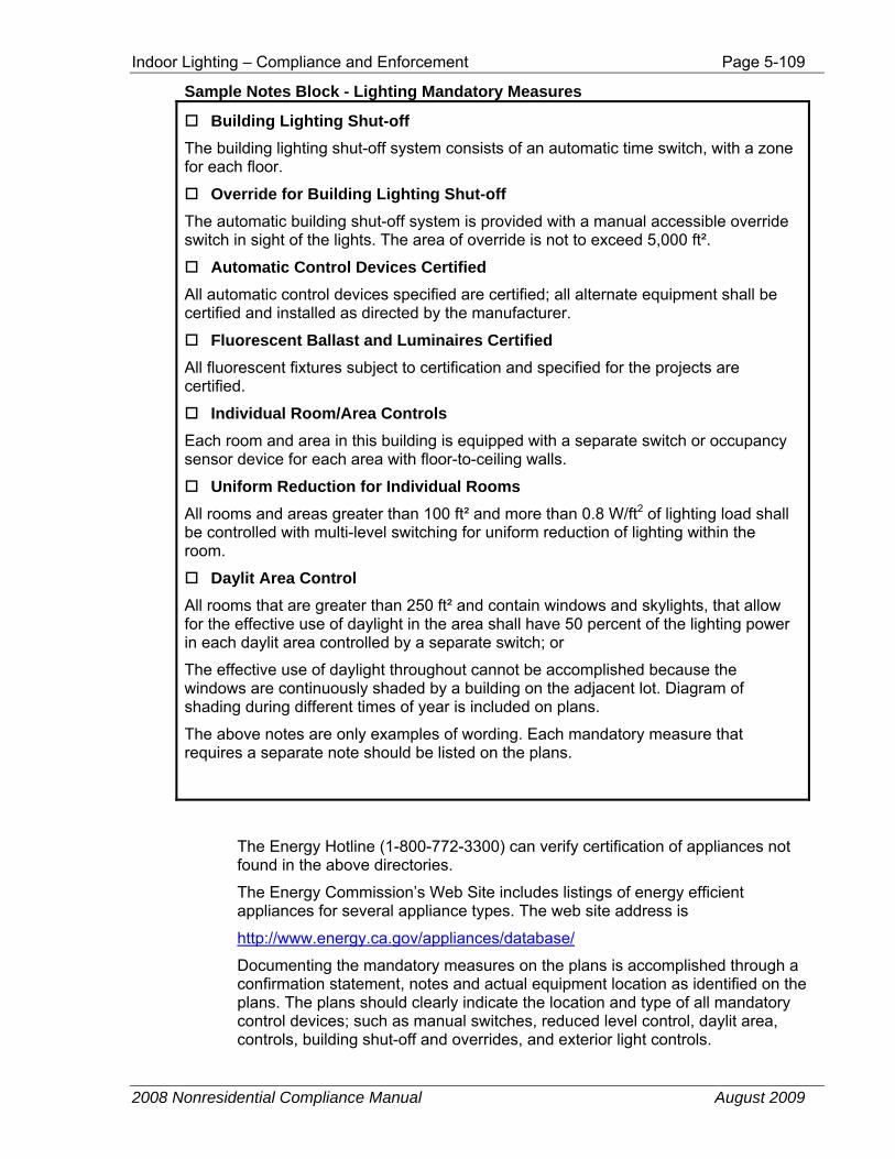
Indoor Lighting – Compliance and Enforcement Page 5-109
2008 Nonresidential Compliance Manual August 2009
Sample Notes Block - Lighting Mandatory Measures
Building Lighting Shut-off The building lighting shut-off system consists of an automatic time switch, with a zone for each floor.
Override for Building Lighting Shut-off The automatic building shut-off system is provided with a manual accessible override switch in sight of the lights. The area of override is not to exceed 5,000 ft².
Automatic Control Devices Certified All automatic control devices specified are certified; all alternate equipment shall be certified and installed as directed by the manufacturer.
Fluorescent Ballast and Luminaires Certified All fluorescent fixtures subject to certification and specified for the projects are certified.
Individual Room/Area Controls Each room and area in this building is equipped with a separate switch or occupancy sensor device for each area with floor-to-ceiling walls.
Uniform Reduction for Individual Rooms All rooms and areas greater than 100 ft² and more than 0.8 W/ft2 of lighting load shall be controlled with multi-level switching for uniform reduction of lighting within the room.
Daylit Area Control All rooms that are greater than 250 ft² and contain windows and skylights, that allow for the effective use of daylight in the area shall have 50 percent of the lighting power in each daylit area controlled by a separate switch; or
The effective use of daylight throughout cannot be accomplished because the windows are continuously shaded by a building on the adjacent lot. Diagram of shading during different times of year is included on plans.
The above notes are only examples of wording. Each mandatory measure that requires a separate note should be listed on the plans.
The Energy Hotline (1-800-772-3300) can verify certification of appliances not found in the above directories.
The Energy Commission’s Web Site includes listings of energy efficient appliances for several appliance types. The web site address is
http://www.energy.ca.gov/appliances/database/
Documenting the mandatory measures on the plans is accomplished through a confirmation statement, notes and actual equipment location as identified on the plans. The plans should clearly indicate the location and type of all mandatory control devices; such as manual switches, reduced level control, daylit area, controls, building shut-off and overrides, and exterior light controls.
Page 5-110 Indoor Lighting – Compliance and Enforcement
2008 Nonresidential Compliance Manual August 2009
Lighting Worksheet Check the appropriate boxes to indicate which worksheet(s) are being included with the certificate of compliance.
LTG-1C Page 2 of 4 Indoor Lighting Schedule and Field Inspection Energy Checklist
Page 2 of 4 serves two separate functions:
1. To describe and document the lighting fixtures designed to be installed in the building. The Installed Lighting Power for conditioned and unconditioned spaces is calculated by completing this form.
2. As a Field Inspection Energy Checklist to be utilized by the enforcement agency. The Field Inspector verifies at the end of installation that the LTG-1-INST and the appropriate Certificates of Acceptance have been completed. The Field Inspector also verifies that lighting schedule describes what was installed and checks the appropriate box in column H.
Indoor lighting for conditioned and unconditioned spaces shall be listed on separate pages. Check only one box as appropriate for Conditioned Space, or for Unconditioned Space for each page used.
A: NAME OR ITEM TAG is the name or symbol used on the plans to identify the luminaire.
B: LUMINAIRE DESCRIPTION is a complete narrative description of the luminaire, including the type of luminaire, number and type of lamps in the luminaire, and number and type of ballast(s) in the luminaire. For example:
LUMINAIRE TYPE is the type of luminaire, such as surface mount, recessed troffer, pendant, linear slot, etc.
LAMP TYPE is the type of lamps such as T-8, T-5, high output (HO), etc.
BALLAST TYPE is the type of ballast, such as electronic, dimmable, etc.
C: SPECIAL FEATURES refers to the type of lighting features used to show compliance, such as:
The tailored method, or unconditioned space that must meet prescriptive lighting levels, refer to the Nonresidential ACM Manual Section 2.4.2 for more information.
D: WATTS PER LUMINAIRE is the total input wattage of the complete lighting unit. This is rated wattage of the luminaire, not the nominal wattage of the lamp (blub) used in the luminaire.
E: HOW WAS WATTAGE DETERMINED? If CEC DEFAULT is checked, this indicates the wattage is a standard value taken from the data in Reference Nonresidential Appendix NA8. If this column is not checked, this indicates the nonstandard values must be substantiated with manufacturer’s data sheets and determined according to §130(d or e).
Indoor Lighting – Compliance and Enforcement Page 5-111
2008 Nonresidential Compliance Manual August 2009
F: NUMBER OF LUMINAIRES is the number of identical luminaires in the space.
G: INSTALLED WATTS is total installed watts for identical luminaire installed in the space, which is the product of WATTS PER LUMINAIRE and NUMBER OF LUMINAIRES (Columns C X F).
After the page has been completed, all of the installed watts in Column G shall be added up and shown in the Page Total cell.
H: FIELD ISNPSECTOR is to verify if the items listed in the lighting schedule are equal to what was installed.
BUILDING TOTAL NUMBER OF PAGES indicates when multiple lighting schedules are present.
BUILDING TOTAL is the sum of all page totals. The sum is also to be entered into Part 4 of the LTG-1C.
If more than one page of LTG-1C (Page 2 of 4) is needed, list the Building total number of pages that were used in the appropriate cell at the bottom of the page. Add up all of the Column G page totals, and list as the Building Total (Sum of all pages).
LTG-1C Page 3 of 4 – Mandatory Lighting Controls Schedule and Field Inspection Energy Checklist
LTG-1C, Part 3 of 4 is required to show compliance with the mandatory lighting control requirements, and serves two separate functions:
1. To describe and document the mandatory lighting controls.
2. As a Field Inspection Energy Checklist to be utilized by the enforcement agency. The Field Inspector verifies at the end of installation that the LTG-1-INST and the appropriate Certificates of Acceptance have been completed. The Field Inspector also verifies that lighting control schedule describes what was installed and checks the appropriate box
• CONTROL TYPE/DESCRIPTION lists the type of certified control device used to meet the control requirement. Such controls include occupant, daylight, dimming sensors etc. The type should use the same name as shown on the plans.
• NUMBER OF UNITS is the number of controls of the same type.
• LOCATION IN BUILDING indicates the room or space the control is to be used and should be named the same as shown on the plans.
The Field Inspector also verifies that lighting schedule describes what was installed and checks the appropriate box in the column.
The space entitled SPECIAL FEATURES INSPECTION CHECKLIST is provided for listing specific features of the design that required special written justification, documentation and verification.
Page 5-112 Indoor Lighting – Compliance and Enforcement
2008 Nonresidential Compliance Manual July 2010
LTG-1C Page 4 of 4 – Indoor Lighting Power for Conditioned and Unconditioned Spaces
The indoor lighting power calculations are to be separate between conditioned and unconditioned spaces. Trade-offs between the two spaces is not allowed.
• INSTALLED LIGHTING is total amount of watts calculated on Page 2 of the LTG-1C for either conditioned or unconditioned space as checked on Page 2 of LTG-1C
• LIGHTING CONTROL CREDIT is the amount watts calculated on the LTG-2C for either conditioned or unconditioned space as checked on LTG-2C
• ADJUSTED INSTALLED LIGHTING POWER is the difference between the INSTALLED LIGHTING and the LIGHTING CONTROL CREDIT. The result is the amount of lighting power compared to the ALLOWED LIGHTING POWER for compliance.
• ALLOWED LIGHTING POWER is calculated on the LTG-3C using the Complete Building, Area Category or Tailed Methods of compliance, for either conditioned or unconditioned space.
The designer must indicate in the space entitled REQUIRED ACCEPTANCE TEST, LTG-2A, and LTG-3A as to which of the installed equipment requires testing. A short description should be given of the equipment type, number of controls and the location of the building in which the system is installed.
5.7.1.1 LTG-2C: Lighting Controls Credit Worksheet LTG-2C is used to report the lighting control credits for conditioned and unconditioned spaces. This worksheet is required whenever lighting control credits are claimed on LTG-1C (Page 4 of 4).
When certain types of automatic lighting controls are listed in Table 146-C (Power Adjustment Factors) in the Standards, a credit is permitted. This table also lists some restrictions that must be met in order to take credit for the controls. A separate worksheet must be completed for conditioned and unconditioned spaces. Check only one box as appropriate per page, for Conditioned Space, or for Unconditioned Space.
At least 50 percent of the light output of the luminaire must be within the applicable space for which the lighting control credit is claimed.
LTG-2C Page 1 of 2 – Lighting Control Credits for Non-Daylight Controls LTG-2C (Page 1 of 2) is used to report control credits allowed in Table 146-C which are not daylighting control credits. (Daylighting control credits are separately reported on page 2 of 2). The bottom of (Page 1 of 2) is also used to add together the non-daylight control credits plus the daylight control credits to determine the total lighting control credit available.
A: ROOM # – List the room where the control device is controlling luminaires.
B: LIGHTING CONTROL DESCRIPTION – List a description of the device that is consistent with the controls listed in Table 146-C.
Indoor Lighting – Compliance and Enforcement Page 5-113
2008 Nonresidential Compliance Manual August 2009
C: PLAN REFERENCE – Indicate where on the plan set the controls are shown.
D: ROOM AREA – Indicate the area of the room in which the controls are located.
E: WATTS OF CONTROL LIGHTING – The watts of only the lighting in each room controlled by that specific control device shall be listed here. Do not include watts in a room that are not controlled by the specific control for which the adjustment factor is claimed.
F: POWER ADJUSTMENT FACTOR – Indicate the power adjustment factor for that specific control device from Table 146-C in the Standards.
G: CONTROL CREDIT WATTS – The product of COLUMN E (Watts of Control Lighting) and COLUMN F (Power Adjustment Factor).
If there are Lighting Control Credit Worksheets for both conditioned and unconditioned spaces, the total lighting control credits shall be separately determined for conditioned and unconditioned spaces
The Page Total for column G is entered near the bottom of the Page 1 of 2. If more than on page of LTG-2C (Page 1 of 2) is needed, list the total number of pages used in the appropriate cell near the bottom of the page.
If more than one page of LTG-2C (Page 1 of 2) is used for conditioned spaces, add all of the Page Totals together and enter in the appropriate cell on the bottom of the page for which Conditioned is checked. Likewise, if more than one page of LTG-2C (Page 1 of 2) is used for unconditioned spaces, add all of the Page Totals together and enter in the appropriate cell on the bottom of the page for which Unconditioned is checked.
If there are Power Adjustment Factors for daylight controls determined on Page 2, enter the total of all daylight controls credits from Page 2 into the appropriate cell on the bottom of Page 1.
The total control credit watts (entered on LTG-1C, Part 4 of 4) are the sum of the control credit watts taken from the bottom cell in COLUMN G. This credit is subtracted from the total installed watts to determine the actual lighting power (adjusted).
LTG-2C Page 2 of 2 – Lighting Control Credits for Daylight Controls LTG-2C (Page 2 of 2) is used to report daylight control credits allowed in Table 146-C in the Standards. At least 50 percent of the light output of the luminaire must be within the applicable daylight area listed in Table 146-C.
A: ROOM # – List the room where the control device is controlling luminaires.
B: TYPE DAYLIGHT CONTROLLED – Check one of the three boxes to indicate the daylighting area controlled as follows:
• Check Skylit only if the qualifying control device is used to control only lighting in the Skylit area.
• Check Primary Sidelit if the qualifying control device is used to control only lighting in the Primary Sidelit area
• Check Secondary Sidelit if the qualifying control device is used to control only lighting in the Secondary Sidelit area, or is used to control the lighting in both the Primary and Secondary Sidelit areas together.
Page 5-114 Indoor Lighting – Compliance and Enforcement
2008 Nonresidential Compliance Manual August 2009
C: PLAN REFERENCE – Indicate where on the plan set the controls are shown.
D: DAYLIGHT AREA – Indicate square feet of daylight area for the type of daylight controlled that was checked in Column B, Do not double count overlapping daylight areas. Indicate the daylight area as follows:
• Primary Sidelit Area according to Section 131(c)1B
• Secondary Sidelit Area according to Section 131(c)1C
• Skylight Area according to Section 131(c)1D
E: VT (Visible Light Transmittance) – Enter VT of windows or skylights determined in accordance with Section 146(a)2E.
F: FOR SKYLIGHTS – When Skylit is checked in Column B, indicate Well Efficiency, Well Cavity Ratio, and Skylit Area, determined in accordance with Section 146(a)2E(iii). These are the assumptions that were used when determining the effective aperture for Column G.
G: EFFECT APERTURE – Indicate Primary Sidelit, Secondary Sidelit, or Skylit Effective Aperture according to which box has been checked in Column B, and determined according to Section 146(a)2E.
H: GENERAL LIGHTING POWER DENSITY (W/ft2) – Indicate only the W/ft2 used for general lighting in the room or area where the PAF for daylight controls is claimed. The W/ft2 is required as one of the factors in Table 146-C for determining the PAF allowed.
I: WATTS OF CONTROL LIGHTING – The watts of only the lighting in each room controlled by that specific daylight control device shall be listed here. Do not include watts in a room that are not controlled by the specific control for which the adjustment factor is claimed.
J: POWER ADJUSTMENT FACTOR – Indicate the power adjustment factor for that specific daylight control device from Table 146-C in the Standards.
K: CONTROL CREDIT WATTS – The product of COLUMN I (Watts of Control Lighting) and COLUMN J (Power Adjustment Factor).
If there are daylighting Control Credit Worksheets for both conditioned and unconditioned spaces, the total daylighting control credits shall be separately determined for conditioned and unconditioned spaces
The Page Total for column K is entered near the bottom of the Page 2 of 2. If more than on page of LTG-2C (Page 2 of 2) is needed, list the total number of pages used in the appropriate cell near the bottom of the page.
If more than one page of LTG-2C (Page 2 of 2) is used for conditioned spaces, add all of the Page Totals together and enter in the appropriate cell on the bottom of the page for which Conditioned is checked. Likewise, if more than one page of LTG-2C (Page 2 of 2) is used for unconditioned spaces, add all of the Page Totals together and enter in the appropriate cell on the bottom of the page for which Unconditioned is checked.
Enter the total of all daylight controls credits from Page 2 into the appropriate cell on the bottom of Page 1.
Indoor Lighting – Compliance and Enforcement Page 5-115
2008 Nonresidential Compliance Manual March 2010
5.7.1.2 LTG-3C: Indoor Lighting Power Allowance
Allowed Lighting Power The lighting power allowance is determined by calculating the maximum total watts of lighting that may be installed. There are three different prescriptive methods, plus the performance method, that may be used. These methods may not be mixed in the same building permit application, except as specifically allowed according to Section 146(b).
There are separate sections in LTG-3C for each of the different prescriptive compliance methods.
Indoor Lighting Power Allowance for conditioned and unconditioned spaces shall be listed on separate pages. Check only one box as appropriate for Conditioned Space, or for Unconditioned Space for each page used.
Complete Building Method This method may only be used when plans and specifications for the entire building or tenant space are included in the permit application. Also, the building or tenant space must involve only one type of use occupancy or mixed occupancy where one type of occupancy makes up 90 percent of the space. Lighting power determined according to the Complete Building Method may be traded only within a single building.
A: BUILDING CATEGORY is the occupancy type description listed in §146, Table 146-E.
B: WATTS PER SF is the listed alongside the occupancy description in Standards Table 146-E.
C: COMPLETE BUILDING AREA is the area or the entire building or tenant space.
D: ALLOWED WATTS is the product of the COMPLETE BUILDING AREA and WATTS PER SF.
The sum of the lighting power allowance is the lighting power allowance for the building.
Area Category Method – Part A This method may be used when different primary function areas of a building are included in the permit application. The total Area Category Method allowed watts includes wattage determined in Part A plus Part B of this form, if applicable.
A: AREA CATEGORY is taken from Table 146-F in the Standards for the primary function of the area. If the building has a mixture of areas, each function area must be listed separately.
B: WATTS PER SF for that building type is taken from Standards Table 146-F and entered here.
C: AREA (SF) is the floor area of the primary function area, which is calculated by multiplying the width times the depth, as measured from the center of the interior
Page 5-116 Indoor Lighting – Compliance and Enforcement
2008 Nonresidential Compliance Manual July 2010
bounding partitions. If the function area is bounded by exterior walls on one or more sides, the area is calculated by multiplying the width times the depth, as measured from the inside surface of the exterior walls to the center of the interior bounding partitions. If there are no partitions separating the boundary of the function areas on one or more sides, the boundary of the area is determined by a line separating the function areas where no bounding partitions exist.
D: ALLOWED WATTS is the product of the WATTS PER SF times the AREA (SF) separately determined for each row listed in Part A. This becomes the lighting power allowance for each Primary Function Area listed in Part A.
The sum of Additional Allowed Watts is taken from Area Category Method – Part B of this form, and entered into the bottom row of Part A.
The sum of the lighting power allowance for each primary function area, plus the total additional wattage allowances taken Part B of this form, is the Area Category Method lighting power allowance for the building.
Area Category Method – Part B These are additional wattage allowances for ornamental chandeliers and sconces; specialized task work for an art, craft assemble or manufacturing operation; precision commercial and industrial work; and specialized task work for school labs, according to the footnotes at the bottom of Table 146-F. Only those primary function areas which have a corresponding footnote to the right of the allowed lighting power in Table 146-F may use these additional Area Category Method wattage allowances. Because these allowances are “use it or lose it,” only the smaller of what is allowed, or what is actually used, may be included in the total Area Category Method wattage allowance
A: PRIMARY FUNCTION is taken from Table 146-F in the Standards for the primary function for which the additional wattage is allowed according to the footnote for that Primary Function area.
B: SQUARE FEET (SF) it the square feet of the primary function area for which the additional wattage is allowed in Standards Table 146-F.
C: ADDITIONAL WATTS PER SQUARE FEET ALLOWED is the additional watts per square foot allowed according to the footnotes at the bottom of Table 146-F.
D: WATTAGE ALLOWANCE is the product of the SF in column B times the Additional. Watts per Square Feet Allowed listed in column C.
E: QUANTIY AND DESCRIPTION OF SPECIAL LUMINAIRE TYPES IN EACH PRIMARY FUCNTION AREA is the total number, description, and wattage of each of the following: Ornamental chandeliers, sconces; Specialized task light for an art, craft assemble or manufacturing operation; Precision commercial and industrial light; or, Specialized task work for school labs, for the Primary Function shown in column A.
F: TOTAL DESIGN WATTS is the total wattage of all of the special luminaires installed in the primary function area, determined in accordance with §130(d and e) of the Standards, for the Primary Function shown in column A.
G: ALLOWED WATTS is the smaller of the Wattage Allowance in column D, or the Total Design Watts in column F, calculated separately for each row in Part B of this form.
Indoor Lighting – Compliance and Enforcement Page 5-117
2008 Nonresidential Compliance Manual March 2010
The sum of the Additional Wattage Allowance is the sum of all of the row in column G. This total shall be entered into the bottom row of Area Category Method – Part A of this form
Tailored Method This method may be used .only on projects with primary function areas that do not use the Area Category Method, and cannot be used on buildings using the Complete Building Method. A separate set of LTG-4C forms shall be filled out for Conditioned and Unconditioned Spaces.
When the Tailored Method is used, the LTG-4C form, or a similar form, must be included in the compliance submittal. Enter into the Tailored Method section at the bottom of LTG-3C the number determined in Row 3 (Page 1 of 4) of LTG-4C.
5.7.1.3 LTG-4C: Tailored Method Worksheets The Tailored Method is the most detailed method of calculation for the Lighting Power Allowance. The Lighting Power Allowance is determined based on the individual needs of each task. This method is appropriate for buildings that have unusual lighting needs and in some cases, may increase the lighting power allowance to meet those needs. For a complete description of this method, refer to Section 5.2.2.
If there are both conditioned and unconditioned spaces in a building and the Tailored Method is used to determine the allowed lighting power for both types of spaces, separate tailored method worksheets (LTG-4C) must be filled out, one for conditioned spaces and one for unconditioned spaces. Each form must clearly indicate if it is used for conditioned or unconditioned spaces. Note that unconditioned spaces are all those areas that are not directly or indirectly conditioned. The conditioned and unconditioned allowances must be kept separated because when the performance method is used to show compliance for the entire building, the tailored LPD lighting for only the conditioned space must be entered for both the standards and proposed buildings. Inclusion of the unconditioned LPD would result in erroneous HVAC load calculations.
LTG-4C: Page 1 of 4 This form shall be submitted with all tailored method applications. It summarizes the results of the different parts of LTG-4C, and includes the lighting power allowance calculations for illuminance categories A through G (Standards Table 146-I).
Tailored Method Summary 1. LINE 1 is the BUILDING TOTAL ALLOWED WATTS for general lighting
power for illuminance categories A through G. This value is the summation of all the individual allowed watts calculation in column G.
2. LINE 2 is the BUILDING TOTAL ALLOWED WATTS for display, floor, very valuable merchandise and ornamental/special effects lighting. This value is obtained from the total watts entries on LTG-4C, Page 2, and
Page 5-118 Indoor Lighting – Compliance and Enforcement
2008 Nonresidential Compliance Manual July 2010
Page 3. Each allotment is separately calculated and entered into the appropriate box on this form.
3. LINE 3 is the sum of lines 1, and 2. The TOTAL ALLOWED WATTS is the lighting power allowance using the Tailored Method. This number shall be inserted into the appropriate conditioned or unconditioned section at the top of LTG-1C (Page 4 of 4).
Tailored LPD – Illuminance To complete the Tailored Allowed General Lighting Power in the lower portion of Page 1 of this form, complete the following steps.
A: ROOM NUMBER is the space designation and should correspond with the plans.
B: PRIMARY FUNCTION TYPE is one of the Primary Functions identified in Column 1 of Table 146-G of the Standards.
C. ILLUMINANCE CATEGORY is the illuminance category for the room or space. This is determined according to the letter identified in Column 2 of Table 146-G, or if IESNA HB is listed in Column 2, using the IES Handbook, Ninth Edition, 2000.
C: ROOM CAVITY RATIO is the room cavity ratio (RCR) of each room or space. A RCR of less than 3.5 may be assumed for any room and the “’N’ box shall be checked. The LTG-4C, Page 4 of 4, shall be used to calculate an RCR greater than or equal to 3.5 and the ‘Y’ box shall be checked.
D: FLOOR AREA is the actual floor area of the room or space from the plans. If the floor area extends all the way to a permanent full-height partition, the area is determined by measuring from the inside of the partitions that bound the task area.
E: ALLOWED LPD Is the Light Power Density from Table 146-F in the Standards using the illuminance category (COLUMN B) and room cavity ratio (COLUMN C) for each room.
F: ALLOWED WATTS is the product of the Floor Area (Column D) times Light Power Density (Column E). The sum of all rows in Column G shall be entered as the Page Total at the bottom of the page. If more than one page of LTG-4C is needed, add all of the page totals together to determine Building Total. The Building total for all rooms or spaces shall be entered in line 1 at the top of LTG-4C, Page 1 of 4.
LTG-4C: Page 2 of 4
Display Lighting: Walls On the top half of LTG-4C (Page 2 of 4) is a table with calculations used to determine how many watts are allowed for wall display lighting. The total allowed watts is the smaller of the allotted watts or the design watts.
Wall display lighting must be mounted within 10 feet of the wall it is illuminating. Note: Display lighting is provided to create contrast to the general lighting system. Ceiling mounted fluorescent fixtures do not qualify as wall display lighting.
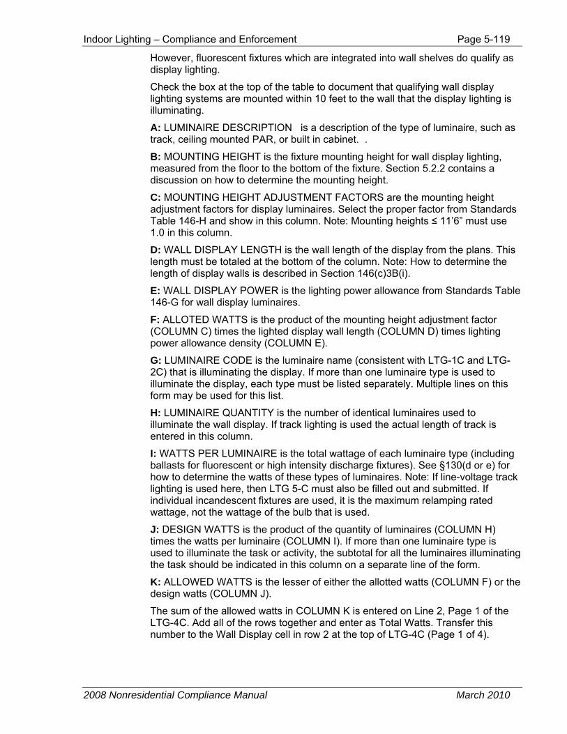
Indoor Lighting – Compliance and Enforcement Page 5-119
2008 Nonresidential Compliance Manual March 2010
However, fluorescent fixtures which are integrated into wall shelves do qualify as display lighting.
Check the box at the top of the table to document that qualifying wall display lighting systems are mounted within 10 feet to the wall that the display lighting is illuminating.
A: LUMINAIRE DESCRIPTION is a description of the type of luminaire, such as track, ceiling mounted PAR, or built in cabinet. .
B: MOUNTING HEIGHT is the fixture mounting height for wall display lighting, measured from the floor to the bottom of the fixture. Section 5.2.2 contains a discussion on how to determine the mounting height.
C: MOUNTING HEIGHT ADJUSTMENT FACTORS are the mounting height adjustment factors for display luminaires. Select the proper factor from Standards Table 146-H and show in this column. Note: Mounting heights ≤ 11’6” must use 1.0 in this column.
D: WALL DISPLAY LENGTH is the wall length of the display from the plans. This length must be totaled at the bottom of the column. Note: How to determine the length of display walls is described in Section 146(c)3B(i).
E: WALL DISPLAY POWER is the lighting power allowance from Standards Table 146-G for wall display luminaires.
F: ALLOTED WATTS is the product of the mounting height adjustment factor (COLUMN C) times the lighted display wall length (COLUMN D) times lighting power allowance density (COLUMN E).
G: LUMINAIRE CODE is the luminaire name (consistent with LTG-1C and LTG-2C) that is illuminating the display. If more than one luminaire type is used to illuminate the display, each type must be listed separately. Multiple lines on this form may be used for this list.
H: LUMINAIRE QUANTITY is the number of identical luminaires used to illuminate the wall display. If track lighting is used the actual length of track is entered in this column.
I: WATTS PER LUMINAIRE is the total wattage of each luminaire type (including ballasts for fluorescent or high intensity discharge fixtures). See §130(d or e) for how to determine the watts of these types of luminaires. Note: If line-voltage track lighting is used here, then LTG 5-C must also be filled out and submitted. If individual incandescent fixtures are used, it is the maximum relamping rated wattage, not the wattage of the bulb that is used.
J: DESIGN WATTS is the product of the quantity of luminaires (COLUMN H) times the watts per luminaire (COLUMN I). If more than one luminaire type is used to illuminate the task or activity, the subtotal for all the luminaires illuminating the task should be indicated in this column on a separate line of the form.
K: ALLOWED WATTS is the lesser of either the allotted watts (COLUMN F) or the design watts (COLUMN J).
The sum of the allowed watts in COLUMN K is entered on Line 2, Page 1 of the LTG-4C. Add all of the rows together and enter as Total Watts. Transfer this number to the Wall Display cell in row 2 at the top of LTG-4C (Page 1 of 4).
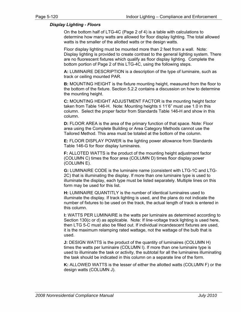
Page 5-120 Indoor Lighting – Compliance and Enforcement
2008 Nonresidential Compliance Manual July 2010
Display Lighting - Floors On the bottom half of LTG-4C (Page 2 of 4) is a table with calculations to determine how many watts are allowed for floor display lighting. The total allowed watts is the smaller of the allotted watts or the design watts.
Floor display lighting must be mounted more than 2 feet from a wall. Note: Display lighting is provided to create contrast to the general lighting system. There are no fluorescent fixtures which qualify as floor display lighting. Complete the bottom portion of Page 2 of this LTG-4C, using the following steps.
A: LUMINAIRE DESCRIPTION is a description of the type of luminaire, such as track or ceiling mounted PAR.
B: MOUNTING HEIGHT is the fixture mounting height, measured from the floor to the bottom of the fixture. Section 5.2.2 contains a discussion on how to determine the mounting height.
C: MOUNTING HEIGHT ADJUSTMENT FACTOR is the mounting height factor taken from Table 146-H. Note: Mounting heights ≤ 11’6” must use 1.0 in this column. Select the proper factor from Standards Table 146-H and show in this column.
D: FLOOR AREA is the area of the primary function of that space. Note: Floor area using the Complete Building or Area Category Methods cannot use the Tailored Method. This area must be totaled at the bottom of the column.
E: FLOOR DISPLAY POWER is the lighting power allowance from Standards Table 146-G for floor display luminaires.
F: ALLOTED WATTS is the product of the mounting height adjustment factor (COLUMN C) times the floor area (COLUMN D) times floor display power (COLUMN E).
G: LUMINAIRE CODE is the luminaire name (consistent with LTG-1C and LTG-2C) that is illuminating the display. If more than one luminaire type is used to illuminate the display, each type must be listed separately. Multiple lines on this form may be used for this list.
H: LUMINAIRE QUANTITLY is the number of identical luminaires used to illuminate the display. If track lighting is used, and the plans do not indicate the number of fixtures to be used on the track, the actual length of track is entered in this column.
I: WATTS PER LUMINAIRE is the watts per luminaire as determined according to Section 130(c or d) as applicable. Note: If line-voltage track lighting is used here, then LTG 5-C must also be filled out. If individual incandescent fixtures are used, it is the maximum relamping rated wattage, not the wattage of the bulb that is used.
J: DESIGN WATTS is the product of the quantity of luminaires (COLUMN H) times the watts per luminaire (COLUMN I). If more than one luminaire type is used to illuminate the task or activity, the subtotal for all the luminaires illuminating the task should be indicated in this column on a separate line of the form.
K: ALLOWED WATTS is the lesser of either the allotted watts (COLUMN F) or the design watts (COLUMN J).
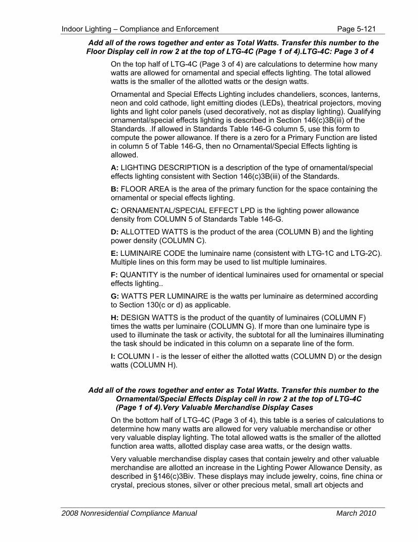
Indoor Lighting – Compliance and Enforcement Page 5-121
2008 Nonresidential Compliance Manual March 2010
Add all of the rows together and enter as Total Watts. Transfer this number to the Floor Display cell in row 2 at the top of LTG-4C (Page 1 of 4).LTG-4C: Page 3 of 4
On the top half of LTG-4C (Page 3 of 4) are calculations to determine how many watts are allowed for ornamental and special effects lighting. The total allowed watts is the smaller of the allotted watts or the design watts.
Ornamental and Special Effects Lighting includes chandeliers, sconces, lanterns, neon and cold cathode, light emitting diodes (LEDs), theatrical projectors, moving lights and light color panels (used decoratively, not as display lighting). Qualifying ornamental/special effects lighting is described in Section 146(c)3B(iii) of the Standards. .If allowed in Standards Table 146-G column 5, use this form to compute the power allowance. If there is a zero for a Primary Function are listed in column 5 of Table 146-G, then no Ornamental/Special Effects lighting is allowed.
A: LIGHTING DESCRIPTION is a description of the type of ornamental/special effects lighting consistent with Section 146(c)3B(iii) of the Standards.
B: FLOOR AREA is the area of the primary function for the space containing the ornamental or special effects lighting.
C: ORNAMENTAL/SPECIAL EFFECT LPD is the lighting power allowance density from COLUMN 5 of Standards Table 146-G.
D: ALLOTTED WATTS is the product of the area (COLUMN B) and the lighting power density (COLUMN C).
E: LUMINAIRE CODE the luminaire name (consistent with LTG-1C and LTG-2C). Multiple lines on this form may be used to list multiple luminaires.
F: QUANTITY is the number of identical luminaires used for ornamental or special effects lighting..
G: WATTS PER LUMINAIRE is the watts per luminaire as determined according to Section 130(c or d) as applicable.
H: DESIGN WATTS is the product of the quantity of luminaires (COLUMN F) times the watts per luminaire (COLUMN G). If more than one luminaire type is used to illuminate the task or activity, the subtotal for all the luminaires illuminating the task should be indicated in this column on a separate line of the form.
I: COLUMN I - is the lesser of either the allotted watts (COLUMN D) or the design watts (COLUMN H).
Add all of the rows together and enter as Total Watts. Transfer this number to the Ornamental/Special Effects Display cell in row 2 at the top of LTG-4C (Page 1 of 4).Very Valuable Merchandise Display Cases
On the bottom half of LTG-4C (Page 3 of 4), this table is a series of calculations to determine how many watts are allowed for very valuable merchandise or other very valuable display lighting. The total allowed watts is the smaller of the allotted function area watts, allotted display case area watts, or the design watts.
Very valuable merchandise display cases that contain jewelry and other valuable merchandise are allotted an increase in the Lighting Power Allowance Density, as described in §146(c)3Biv. These displays may include jewelry, coins, fine china or crystal, precious stones, silver or other precious metal, small art objects and
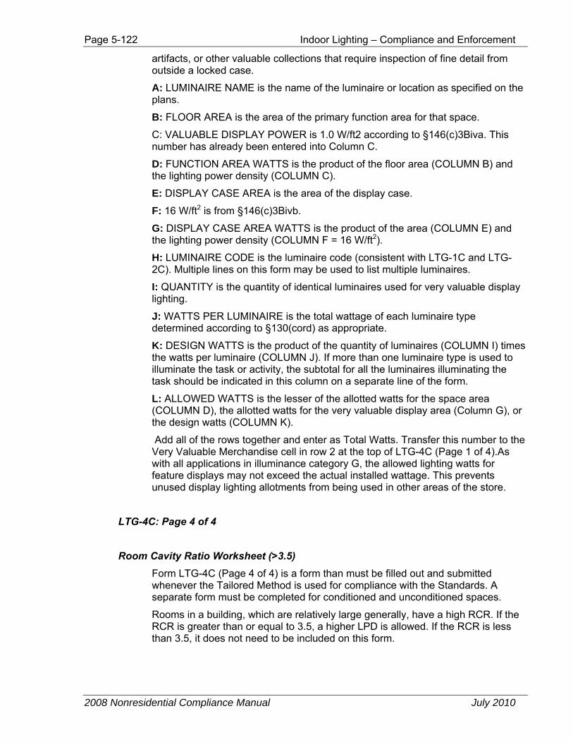
Page 5-122 Indoor Lighting – Compliance and Enforcement
2008 Nonresidential Compliance Manual July 2010
artifacts, or other valuable collections that require inspection of fine detail from outside a locked case.
A: LUMINAIRE NAME is the name of the luminaire or location as specified on the plans.
B: FLOOR AREA is the area of the primary function area for that space.
C: VALUABLE DISPLAY POWER is 1.0 W/ft2 according to §146(c)3Biva. This number has already been entered into Column C.
D: FUNCTION AREA WATTS is the product of the floor area (COLUMN B) and the lighting power density (COLUMN C).
E: DISPLAY CASE AREA is the area of the display case.
F: 16 W/ft2 is from §146(c)3Bivb.
G: DISPLAY CASE AREA WATTS is the product of the area (COLUMN E) and the lighting power density (COLUMN F = 16 W/ft2).
H: LUMINAIRE CODE is the luminaire code (consistent with LTG-1C and LTG-2C). Multiple lines on this form may be used to list multiple luminaires.
I: QUANTITY is the quantity of identical luminaires used for very valuable display lighting.
J: WATTS PER LUMINAIRE is the total wattage of each luminaire type determined according to §130(cord) as appropriate.
K: DESIGN WATTS is the product of the quantity of luminaires (COLUMN I) times the watts per luminaire (COLUMN J). If more than one luminaire type is used to illuminate the task or activity, the subtotal for all the luminaires illuminating the task should be indicated in this column on a separate line of the form.
L: ALLOWED WATTS is the lesser of the allotted watts for the space area (COLUMN D), the allotted watts for the very valuable display area (Column G), or the design watts (COLUMN K).
Add all of the rows together and enter as Total Watts. Transfer this number to the Very Valuable Merchandise cell in row 2 at the top of LTG-4C (Page 1 of 4).As with all applications in illuminance category G, the allowed lighting watts for feature displays may not exceed the actual installed wattage. This prevents unused display lighting allotments from being used in other areas of the store.
LTG-4C: Page 4 of 4
Room Cavity Ratio Worksheet (>3.5) Form LTG-4C (Page 4 of 4) is a form than must be filled out and submitted whenever the Tailored Method is used for compliance with the Standards. A separate form must be completed for conditioned and unconditioned spaces.
Rooms in a building, which are relatively large generally, have a high RCR. If the RCR is greater than or equal to 3.5, a higher LPD is allowed. If the RCR is less than 3.5, it does not need to be included on this form.
Indoor Lighting – Compliance and Enforcement Page 5-123
2008 Nonresidential Compliance Manual March 2010
The form has two sections: Rectangular Spaces is for rooms with four 90° walls, and Non-rectangular Spaces is for all other room types (including oblique four walled and circular rooms).
Rectangular Spaces A: ROOM NUMBER, this column should list each room’s number, and should correspond with the plans.
B: TASK/ACTIVITY DESCRIPTION for the room should be listed in this column. If the room has multiple tasks or activities, use the dominant activity for the room in this column.
C: ROOM LENGTH is the length (L) of the room, measured in linear feet, from the interior surfaces of opposing walls. The length is typically the longest distance between two parallel walls in the room.
D: ROOM WIDTH is the width (W) of the room, measured in linear feet, from the interior surfaces of opposing walls. The width is typically the smallest distance between two parallel walls in the room.
E: ROOM CAVITY HEIGHT is the vertical distance, measured in linear feet, from the work plane to the center line of the lighting fixture. This measurement is called the room cavity height (H).
F: ROOM CAVITY RATIO (RCR) is 5 multiplied by the product of the room cavity height H (from COLUMN E) and the sum of the room length and width (L from COLUMN C plus W from COLUMN D), all divided by the room area L (from COLUMN C) times room width (W from COLUMN D). This quantity is the RCR and shall be entered in COLUMN D of Page 1 of LTG-4C.
Non-rectangular Spaces A: ROOM NUMBER, this column should list each room’s number, and should correspond with the plans.
B: TASK/ACTIVITY DESCRIPTION for the room should be listed in this column. If the room has multiple tasks or activities, use the dominant activity for the room in this column.
C: ROOM AREA is the interior area (A) of the room in square feet. This should be determined by whatever means appropriate for the shape of the room.
D: ROOM PERIMETER is the room perimeter (P) measured in feet along the interior surfaces of the walls that define the boundaries of the room. For rooms with angled walls, this is the sum of the interior lengths of each wall in the room. For circular rooms, this is the interior radius of the room multiplied by 2 and pi (3.413).
E: ROOM CAVITY HEIGHT is the vertical distance, measured in linear feet, from the work plane to the center line of the lighting fixture. This measurement is called the room cavity height (H).
F: ROOM CAVITY RATIO (RCR) is 2.5 multiplied by the product of the room cavity height H (from COLUMN E) and room perimeter P (from COLUMN D), all divided by the room area A (from COLUMN C). This quantity is the RCR and shall be entered in COLUMN D of Page 1 of LTG-4C.
Page 5-124 Indoor Lighting – Compliance and Enforcement
2008 Nonresidential Compliance Manual July 2010
5.7.1.4 LTG-5C: Line Voltage Track Lighting Worksheet LTG-5C shall be used to calculate and document all line voltage track and busway lighting. (Line voltage track typically operates around 120 volts or greater). Completing this form and entering the results on page 2 of LTG-1C will calculate the installed lighting power for line voltage track lighting.
To determine luminaire wattage incorporated into the installed lighting power for line voltage track lighting, use one of the two Methods described in 5.4.3 of the Nonresidential Manual.
There are four different methods available for determining track and busway lighting input wattage as follows:
Method 1 – Volt-Ampere (VA) Rating of the Branch Circuit(s) Feeding the Tracks or Busway, or the Wattage of Integral Current Limiters
Note: The Standards do not allow the VA rating to be devalued by 20%, even though the California Electric Code does require circuits to be loaded to no more than 80% of their capacity. The energy Standards are not the same as the Electric Code
If using this method to determine track or busway lighting power, check the box to the left of “Method 1.” Also check one of the two following boxes to indicate if the method is being used to determine wattage for track or busway rated for more than 20 amperes, or for 20 amperes or less. A: BRANCH CIRCUIT NAME OR ID is the name or number that identifies the branch circuit feeding the track. This column must be filled for all branch circuits feeding track lighting systems.
B: VOLT-AMPERE RATING list the volt-ampere rating of the branch circuit identified in column A. Fill out this column only when you are using the VA of the branch circuit to determine the wattage of the track(s). If integral current limiters are used to determine the wattage of the tracks, do not use this method. The total of column B shall be entered in the appropriate space provided on Page 2 of the LTG-5C.
Method 2 – Use the Higher of: 45 watts per linear foot of track or the maximum relamping rated wattage of all luminaires.
If using this method to determine track or busway lighting power, check the box to the left of “Method 2.” A: TRACK NUMBER OF NAME is the name or number that identifies the track lighting and should correspond to the plans.
B: LINEAR FEET OF TRACK is the length of track measured in linear feet.
C: WATTS PER LINEAR FEET is 45 W/lf. This number is required for using Method 2.
D: WATTS CALCULATED by multiplying the linear feet (column B) by the assumed watts per linear feet (column C).
E: TOTAL RATED WATTAGE is the rated wattage of each luminaire (track head) that will be installed on the line voltage track identified in column A according to §130(c or d) . Luminaire wattage for incandescent track heads is based upon the
Indoor Lighting – Compliance and Enforcement Page 5-125
2008 Nonresidential Compliance Manual March 2010
rating of the track head, not the wattage of the bulb that is screwed into the track head. The Wattage of incandescent track heads shall be the maximum relamping rated wattage as listed on a permanent pre-printed factory-installed label according to §130(c)1. Luminaire wattage for fluorescent and high intensity discharge (HID) track heads shall be the operating input wattage of the rated lamp/ballast combination according to §130(c)2. Luminaire wattage for low-voltage track heads (when mounted on line-voltage track) shall be the maximum rated wattage of the transformer on each track head according to §130(c)5. Add up the wattage for every luminaire that will be installed on the identified track and enter the total amount as the rated wattage.
F: WATTS INSTALLED is the larger of column D or column E. This is the installed lighting power for the track listed in column A. Add up all of the numbers in column F and list the total at the bottom. Enter this number in the space provided in Page 2 of the LTG-5C.
Method 3 – Use the Higher of: 12.5 watts per linear foot of track or the VA rating of the integral current limiter.
If using this method to determine track or busway lighting power, check the box to the left of “Method 3.” Also, check the box to indicate that the integral current limiter has been certified to the Energy Commission. This method may be used only for Track Lighting Integral Current Limiters which have been certified to the Energy Commission, and listed on the Energy Commission database of certified devices. Devices which have not been certified to the Energy Commission and other assembly of controls shall not qualify as Track Lighting Integral Current Limiters. A: TRACK NUMBER OF NAME is the name or number that identifies the track lighting and should correspond to the plans.
B: LINEAR FEET OF TRACK is the length of track measured in linear feet.
C: WATTS PER LINEAR FEET is 12.5 W/lf. This number is required for using Method 3.
D: WATTS CALCULATED by multiplying the linear feet (column B) by the assumed watts per linear feet (column C).
E: VA RATING is the volt-ampere rating of the integral current limiter controlling the track or busway as specified in §130(d)3Biii
F: WATTS INSTALLED is the larger of column D or column E. This is the installed lighting power for the track listed in column A. Add up all of the numbers in column F and list the total at the bottom. Enter this number in the space provided at the bottom of the page.
Method 4 – Dedicated Track Lighting Over Current Protection Panel. If using this method to determine track or busway lighting power, check the box to the left of “Method 3.” Also, all five of the following boxes shall be checked to document that the supplemental overcurrent protection panel complies with all of the required provisions in the Standards.
A: NAME OR ID is the description of the track lighting that corresponds to the plans.
Page 5-126 Indoor Lighting – Compliance and Enforcement
2008 Nonresidential Compliance Manual July 2010
B: VOLTAGE OF THE BRANCH is the total voltage of the branch described in column A.
C: LIST OF AMPERAGE RATING is the complete list of each device installed the panel for the branch described in column A.
D: SUM OF THE AMPERE RATING is the sum of the listed values from column C.
E: WATTS INSTALLED is the product of the voltage of the branch (column B) and the sum of the ampere ratings (column D). The total from column E should be entered on the appropriate space at the bottom of the form.
At the bottom of Page 2 of the LTG-5C, the total track/busway wattage is totalized for each of the compliance methods utilized, and this number shall be entered on the LTG-2C.
5.7.2 Installation Certificate
A new two-page form, LTG-INST, the Installation Certificate has been included in the Nonresidential Compliance Manual. This form includes general information about the project, a declaration statement, the responsible person’s name and signature, and a table to identify all applicable construction documents for the scope of responsibility for the Installation Certificate.
§10-103(a)3 requires, for all buildings, the person with overall responsibility for construction or the person(s) responsible for the installation of features, materials, components or manufactured devices regulated by the Standards or the Appliance Efficiency Regulations shall submit Installation Certificate(s).
For all buildings, a copy of the Installation Certificate(s) shall be posted, or made available with the building permit(s) issued for the building, and shall be made available to the enforcement agency for all applicable inspections.
5.7.3 Certificate of Acceptance
Acceptance tests, LTG-2A, and LTG-3A, are used to verify that lighting controls were installed and calibrated correctly. These tests require that a responsible party certify that controls are installed and calibrated properly. This responsible party is typically the contractor who installed the lighting controls. To verify that they are calibrated properly, the responsible party must conduct a test and make modifications to the control until it passes the test. The test results must be recorded on acceptance test forms and are part of the building documentation. These forms must be filled out before the enforcement agency grants a certificate of occupancy.
The Standards have acceptance test requirements for:
• Manual daylighting controls
• Automatic daylighting controls.
• Occupancy sensors.
• Automatic time-switch controls.
A detailed description of each acceptance test can be found in Chapter 10 of this manual, Acceptance Requirements and in the Reference Nonresidential Joint Appendix NA7.6.