4l60e update handbook
TRANSCRIPT
INDEX
Copyright © ATSG 1999
THM 4L60-E/4L65-E"UPDATE HANDBOOK"
2
AUTOMATIC TRANSMISSION SERVICE GROUP9200 S. DADELAND BLVD. SUITE 720
MIAMI, FLORIDA 33156(305) 670-4161
PUMP CHANGE FOR ADDED "PWM" TCC SOLENOID ............................................................................... 3PUMP CHANGE FOR BOLT ON BELL HOUSINGS ........................................................................................ 10PUMP CHANGE FOR 13 VANE ROTOR AND SLIDE ....................................................................................... 21PUMP INTERCHANGE CHART ........................................................................................................................... 253-2 DOWNSHIFT SOLENOID CHANGE .............................................................................................................. 33SPACER PLATE IDENTIFICATION BY MODEL CODE, 1997-2003 ............................................................... 39NEW DESIGN SOLENOIDS .................................................................................................................................... 48INTERNAL HARNESS IDENTIFICATION .......................................................................................................... 52PREMATURE LOW/REVERSE CLUTCH FAILURE ......................................................................................... 57NEW VALVE BODY AND MANUAL VALVE FOR 1996 ..................................................................................... 59SOFT 1-2 UPSHIFT, NEW ACCUMULATOR VALVE SPRING ......................................................................... 62ACCUMULATOR PISTON WEAR ......................................................................................................................... 63NEW DESIGN 1-2 ACCU,ULATOR PISTON ........................................................................................................ 65TRANSMISSION AND/OR ENGINE OVERHEAT .............................................................................................. 67PUSH-IN COOLER LINE FITTINGS ..................................................................................................................... 74INTERMITTENT PRESSURE RISE, 1996 MODELS ONLY .............................................................................. 75PREMATURE 3-4 CLUTCH FAILURE, THICKER STEELS ............................................................................ 77HIGHER GEAR START OR LACK OF PRESSURE RISE ................................................................................. 80NEW DESIGN OUTPUT SPEED SENSORS .......................................................................................................... 81STAMPED STEEL, MOLDED RUBBER CLUTCH PISTONS ........................................................................... 82NEW "DEEP" BOTTOM PAN AND FILTERS ..................................................................................................... 84NEW DIPSTICK STOP ............................................................................................................................................. 88BIND IN M1, 2ND GEAR START, BIND ON 2-3 SHIFT ...................................................................................... 91P/N SWITCH CONNECTOR CANNOT BE REMOVED ..................................................................................... 93FORWARD SPRAG, "SKF" VERSUS BORG-WARNER ................................................................................... 97SEVEN CLUTCH 3-4 CLUTCH PACK FOR 2001 ............................................................................................... 104FIVE PINION CARRIERS, BOTH FRONT AND REAR .................................................................................... 110NEW DESIGN VALVE BODY CASTING FOR 2001 ........................................................................................... 112TROUBLE CODE P1870 AND HOW TO FIX ...................................................................................................... 116
INTRODUCTIONTHM 4L60-E/4L65-E
AUTOMATIC TRANSMISSION SERVICE GROUP9200 S. DADELAND BLVD. SUITE 720
MIAMI, FLORIDA 33156(305) 670-4161
DALE ENGLANDFIELD SERVICE CONSULTANT
ED KRUSETECHNICAL CONSULTANT
WAYNE COLONNATECHNICAL SUPERVISOR
PETER LUBANTECHNICAL CONSULTANT
JIM DIALTECHNICAL CONSULTANT
GREGORY LIPNICKTECHNICAL CONSULTANT
JERRY GOTTTECHNICAL CONSULTANT
JON GLATSTEINTECHNICAL CONSULTANT
DAVID CHALKERTECHNICAL CONSULTANT
STANTON ANDERSONTECHNICAL CONSULTANT
ROLAND ALVAREZTECHNICAL CONSULTANT
GERALD CAMPBELLTECHNICAL CONSULTANT
1
No part of any ATSG publication may be reproduced, stored in any retrieval system or transmitted in any form or by any means, including but not limited to electronic, mechanical, photocopying, recording or otherwise, without written permission of Automatic Transmission Service Group. This includes all text illustrations, tables and charts.
"Portions of materials contained herein have been reprinted underlicense from General Motors Corp, Service & Parts Operations."
The information and part numbers contained in this booklet havebeen carefully compiled from industry sources known for their
reliability, but ATSG does not guarantee its accuracy.
Copyright © ATSG 1993
UpdatedJanuary, 2003
Since the introduction of the THM 4L60-E transmission in model year 1993, there have been many major engineering design changes to improve durability and reliability. These changes have affected nearly every part used in the THM 4L60-E. This "Update Handbook" will explain each change, the parts affected by the change, and any parts interchangeability concerns created by the change. Beginning at the start of production for model year 2001, General Motors introduced a new transmission designated THM 4L65-E with many engineering changes. Currently this unit is found in all 2001 Cadillac Escalade and any vehicle with 6.0L engine or larger, that was previously equipped with the THM 4L60-E transmision. We will also cover the changes in the THM 4L65-E transmission in this booklet.
THM 4L60-ETCC "PWM" SOLENOID ADDED IN1995
AND NEW OIL PUMP ASSEMBLY FOR 1995
CHANGE:
REASON:
PARTS AFFECTED:
INTERCHANGEABILITY:
SERVICE INFORMATION:
Beginning at the start of production for 1995 models, all THM 4L60-E transmissions were built with an added "PWM" solenoid on the valve body to control TCC apply feel. The new TCC PWM Solenoid ramps the torque converter clutch on and off, as in most other GM units.
Improved pleaseability of torque converter clutch apply and release.
(1)
(2)
(3)
(4)
(5)
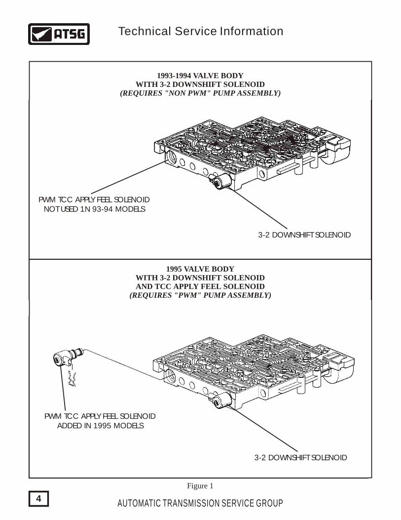
VALVE BODY CASTING - 1995 models are now machined to accept the added TCC PWM Solenoid, as shown in Figure 1. The added TCC PWM Solenoid is exactly the same and will interchange with the 3-2 downshift solenoid (See Figure 1).
VALVE BODY SPACER PLATE - There were two holes added in the spacer plate to accommodate the added TCC PWM Solenoid as shown in Figure 2. The 1995 spacer plate can be identified with the first letter of the two digit code being either an "M" or "N", as shown in Figure 2. The first letter of the two digit code on the 1994 spacer plate will be "K" or "L". The 1993 spacer plate first letter will be "J". Refer to Figure 2 for location of the I.D. code stamped into the spacer plate
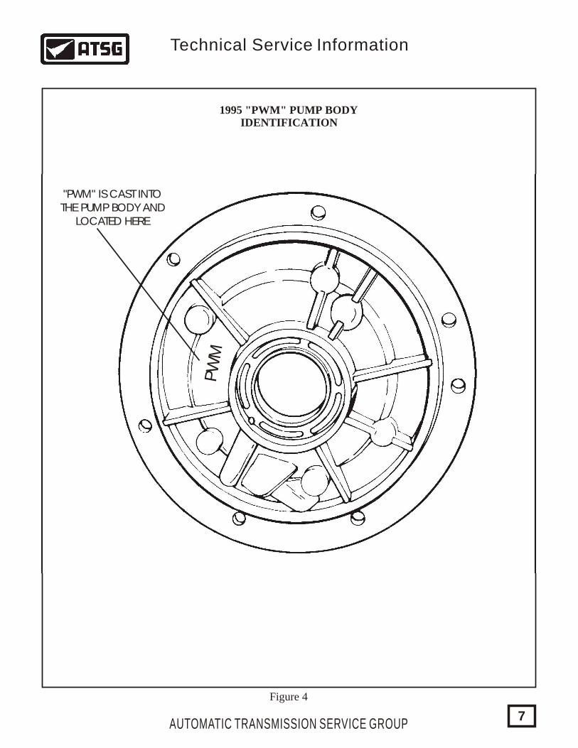
OIL PUMP BODY - There were changes in the worm track configuration on the new design pump body to accommodate the added TCC PWM solenoid. The pump body can be easily identified with "PWM" cast into the pump body, in the location shown in Figure 4. Refer to Figure 3 for the differences in the worm track area, which we have shaded for easy reference.
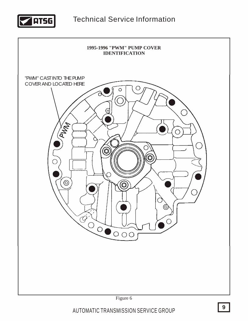
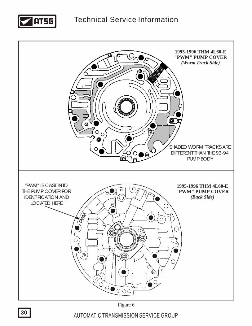
OIL PUMP COVER (STATOR) - There were changes in the worm track configuration on the new design pump cover to accommodate the added TCC PWM solenoid. The pump cover can be easily identified with "PWM" cast into the pump cover, in the location shown in Figure 6. Refer to Figure 5 for the differences in the worm track area, which we have shaded for easy reference.
TURBINE SHAFT BALL CAPSULE - Change in orifice sizes to accommodate the added TCC PWM solenoid, and calibrate converter release oil to the new TCC PWM solenoid.
None of the parts listed above will interchange with one another, nor will any of these parts back service any 1993-1994 model transmissions.
TCC PWM Solenoid (95-96 Models) ............................................................................ 8683187Turbine Shaft Ball Capsule (Bronze - 298mm Converter) .......................................... 24201472Turbine Shaft Ball Capsule (Silver - 245mm Converter) .............................................. 8654326
AUTOMATIC TRANSMISSION SERVICE GROUP
Technical Service Information
3
1995 VALVE BODYWITH 3-2 DOWNSHIFT SOLENOIDAND TCC APPLY FEEL SOLENOID
(REQUIRES "PWM" PUMP ASSEMBLY)
3-2 DOWNSHIFT SOLENOID
3-2 DOWNSHIFT SOLENOID
PWM TCC APPLY FEEL SOLENOIDADDED IN 1995 MODELS
PWM TCC APPLY FEEL SOLENOIDNOT USED 1N 93-94 MODELS
1993-1994 VALVE BODYWITH 3-2 DOWNSHIFT SOLENOID
(REQUIRES "NON PWM" PUMP ASSEMBLY)
Figure 1
AUTOMATIC TRANSMISSION SERVICE GROUP
Technical Service Information
4
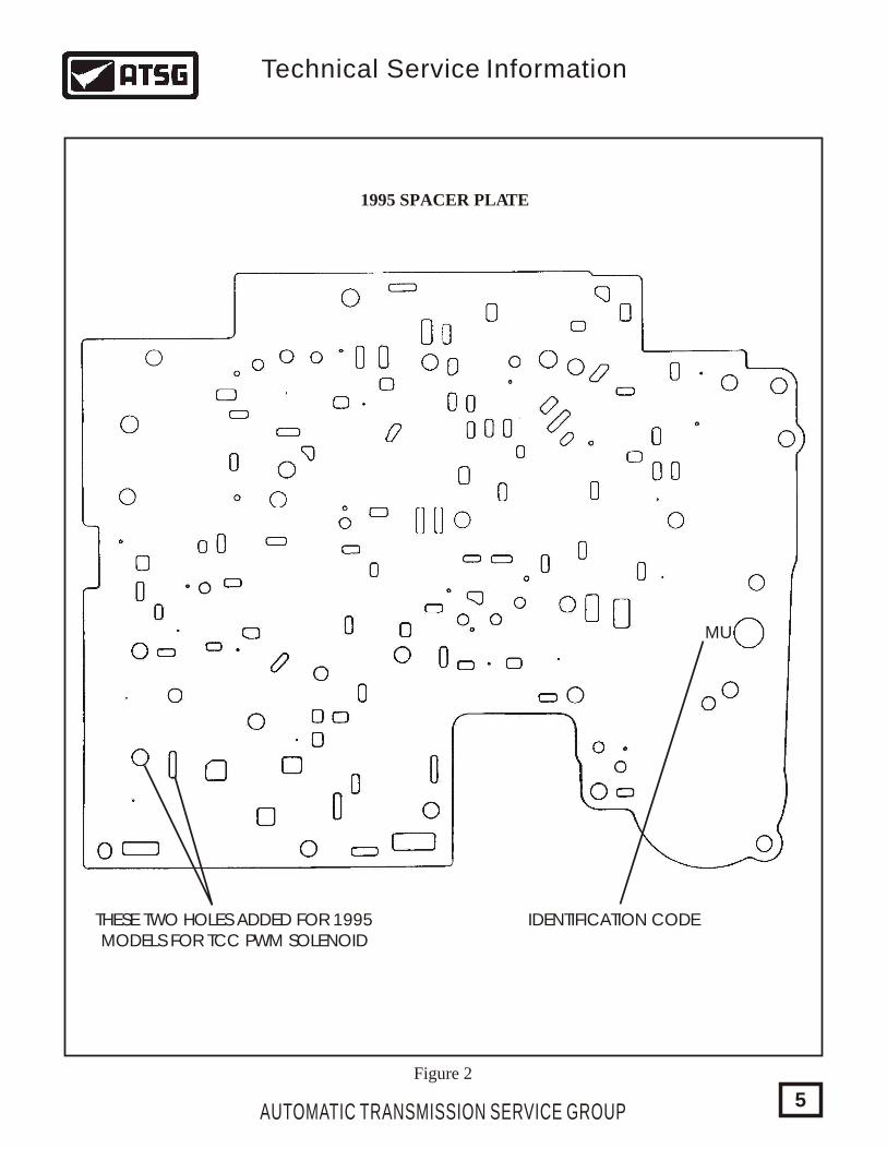
MU
IDENTIFICATION CODETHESE TWO HOLES ADDED FOR 1995MODELS FOR TCC PWM SOLENOID
Figure 2
1995 SPACER PLATE
AUTOMATIC TRANSMISSION SERVICE GROUP
Technical Service Information
5
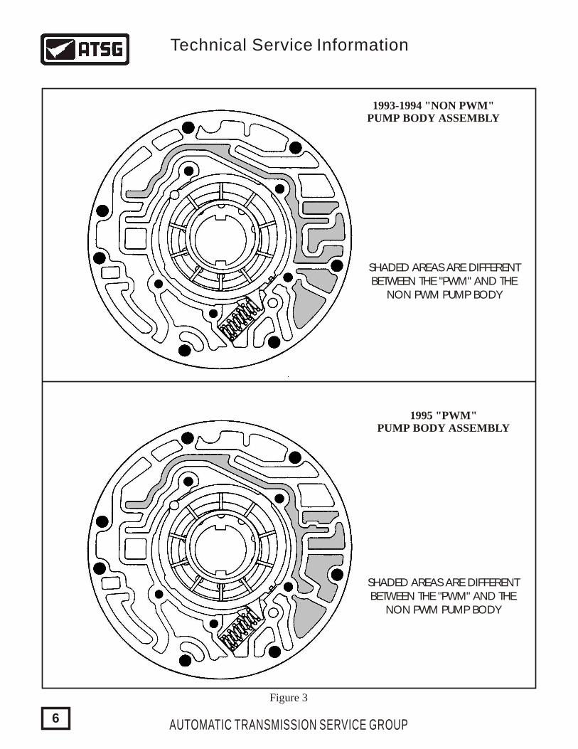
1993-1994 "NON PWM"PUMP BODY ASSEMBLY
1995 "PWM"PUMP BODY ASSEMBLY
SHADED AREAS ARE DIFFERENTBETWEEN THE "PWM" AND THE
NON PWM PUMP BODY
SHADED AREAS ARE DIFFERENTBETWEEN THE "PWM" AND THE
NON PWM PUMP BODY
Figure 3
AUTOMATIC TRANSMISSION SERVICE GROUP
Technical Service Information
6
PW
M
1995 "PWM" PUMP BODYIDENTIFICATION
"PWM" IS CAST INTOTHE PUMP BODY AND
LOCATED HERE
Figure 4
AUTOMATIC TRANSMISSION SERVICE GROUP
Technical Service Information
7
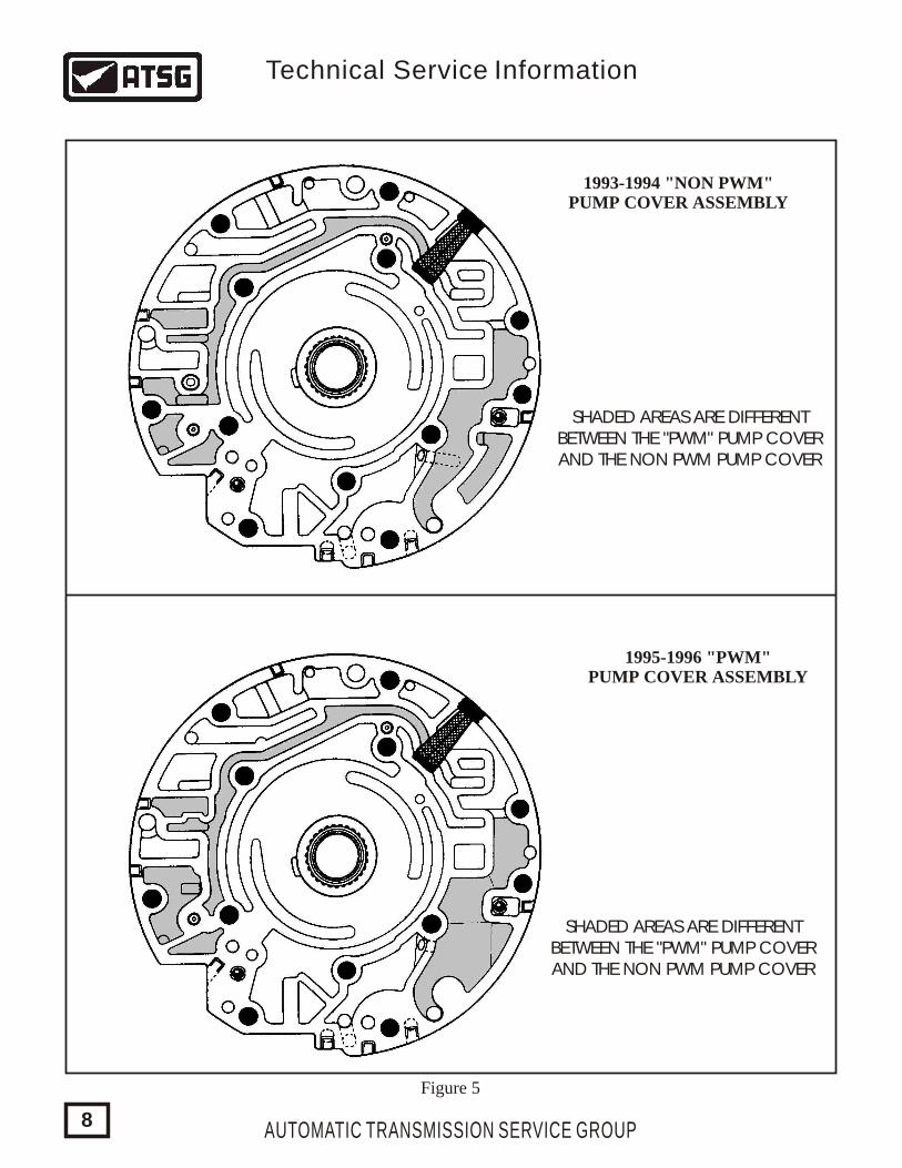
1993-1994 "NON PWM"PUMP COVER ASSEMBLY
SHADED AREAS ARE DIFFERENTBETWEEN THE "PWM" PUMP COVERAND THE NON PWM PUMP COVER
SHADED AREAS ARE DIFFERENTBETWEEN THE "PWM" PUMP COVERAND THE NON PWM PUMP COVER
1995-1996 "PWM"PUMP COVER ASSEMBLY
Figure 5
AUTOMATIC TRANSMISSION SERVICE GROUP
Technical Service Information
8
PWM
1995-1996 "PWM" PUMP COVERIDENTIFICATION
"PWM" CAST INTO THE PUMPCOVER AND LOCATED HERE
Figure 6
AUTOMATIC TRANSMISSION SERVICE GROUP
Technical Service Information
9
THM 4L60-EBOLT-ON BELLHOUSING
CHANGE:
REASON:
PARTS AFFECTED:
INTERCHANGEABILITY:
Beginning at the start of production for 1996 models, some THM 4L60-E transmissions were built with a bolt-on bellhousing. The 4.3L V6 engine is the only one to recieve the bolt-on bellhousing for 1996 models, and will be expanded to most other engine sizes for 1997. Refer to Figure 1 for illustrations.
Makes the THM 4L60-E transmission much more versatile, for a wide variety of engine sizes and a wide variety of vehicles.
BELLHOUSING - Now bolted to the main case with eight bolts that require what appears to be a normal 50 Torx-bit to remove. These bolts require a "TORX PLUS 50-IP" bit to remove. The normal 50 Torx-bit will strip the head on most bellhousing bolts, if used for removal. Refer to Figure 1 for the profile of both bits.
(1)
(2)
(3)
(4)
MAIN CASE - Totally different casting to accommodate the bolt-on bellhousing, as shown in Figure 1. There were no changes in worm track configuration, or bolt hole locations for the bottom pan and valve body area.
EXTENSION HOUSING - Totally different casting to accommodate the changes in the case design, and notice the new design has six retaining bolts instead of the previous four, as shown in Figure 1.
OIL PUMP BODY - A machined ring has been added to the front of the pump body to accommodate and center the bolt-on bellhousing, as shown in Figure 2.
All of the parts listed above are unique to the 1996 model 2-piece case. However, the pump body with the added machined ring, will be found in some 1995 models, and will back service to 1995 models only. It cannot be used in 93-94 models because of worm track cavity differences that occured in 1995.
AUTOMATIC TRANSMISSION SERVICE GROUP
Technical Service Information
10
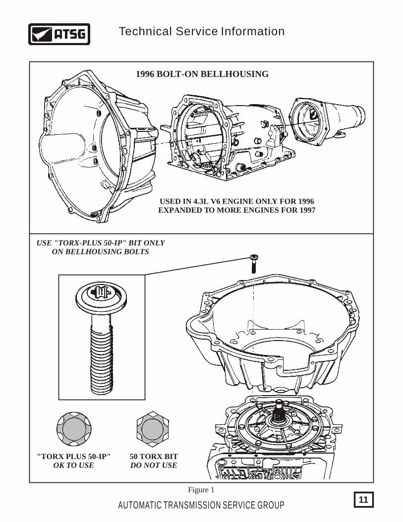
1996 BOLT-ON BELLHOUSING
USED IN 4.3L V6 ENGINE ONLY FOR 1996EXPANDED TO MORE ENGINES FOR 1997
USE "TORX-PLUS 50-IP" BIT ONLYON BELLHOUSING BOLTS
"TORX PLUS 50-IP"OK TO USE
50 TORX BITDO NOT USE
Figure 1
AUTOMATIC TRANSMISSION SERVICE GROUP
Technical Service Information
11
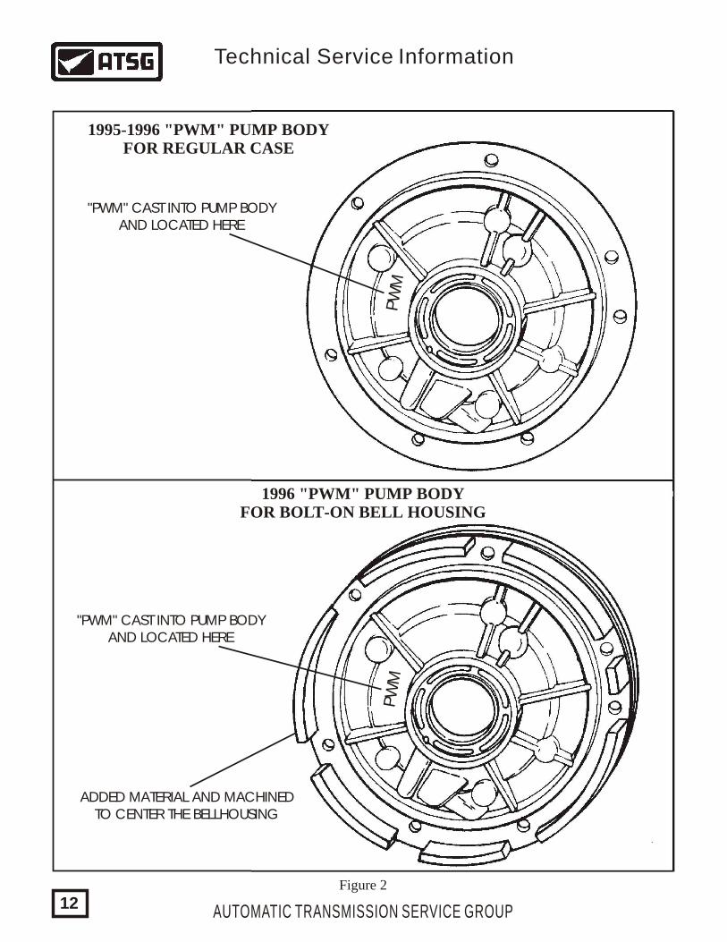
1995-1996 "PWM" PUMP BODYFOR REGULAR CASE
"PWM" CAST INTO PUMP BODYAND LOCATED HERE
"PWM" CAST INTO PUMP BODYAND LOCATED HERE
ADDED MATERIAL AND MACHINEDTO CENTER THE BELLHOUSING
1996 "PWM" PUMP BODYFOR BOLT-ON BELL HOUSING
PW
MPW
M
Figure 2
AUTOMATIC TRANSMISSION SERVICE GROUP
Technical Service Information
12
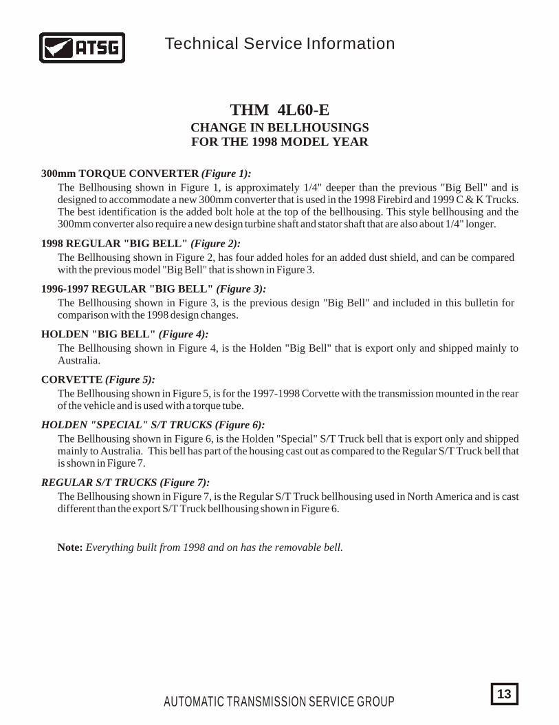
THM 4L60-ECHANGE IN BELLHOUSINGSFOR THE 1998 MODEL YEAR
300mm TORQUE CONVERTER (Figure 1):
1998 REGULAR "BIG BELL" (Figure 2):
1996-1997 REGULAR "BIG BELL" (Figure 3):
HOLDEN "BIG BELL" (Figure 4):
CORVETTE (Figure 5):
HOLDEN "SPECIAL" S/T TRUCKS (Figure 6):
REGULAR S/T TRUCKS (Figure 7):
The Bellhousing shown in Figure 1, is approximately 1/4" deeper than the previous "Big Bell" and is designed to accommodate a new 300mm converter that is used in the 1998 Firebird and 1999 C & K Trucks. The best identification is the added bolt hole at the top of the bellhousing. This style bellhousing and the 300mm converter also require a new design turbine shaft and stator shaft that are also about 1/4" longer.
The Bellhousing shown in Figure 2, has four added holes for an added dust shield, and can be compared with the previous model "Big Bell" that is shown in Figure 3.
The Bellhousing shown in Figure 3, is the previous design "Big Bell" and included in this bulletin for comparison with the 1998 design changes.
The Bellhousing shown in Figure 4, is the Holden "Big Bell" that is export only and shipped mainly to Australia.
The Bellhousing shown in Figure 5, is for the 1997-1998 Corvette with the transmission mounted in the rear of the vehicle and is used with a torque tube.
The Bellhousing shown in Figure 6, is the Holden "Special" S/T Truck bell that is export only and shipped mainly to Australia. This bell has part of the housing cast out as compared to the Regular S/T Truck bell that is shown in Figure 7.
The Bellhousing shown in Figure 7, is the Regular S/T Truck bellhousing used in North America and is cast different than the export S/T Truck bellhousing shown in Figure 6.
AUTOMATIC TRANSMISSION SERVICE GROUP
Technical Service Information
13
Note: Everything built from 1998 and on has the removable bell.
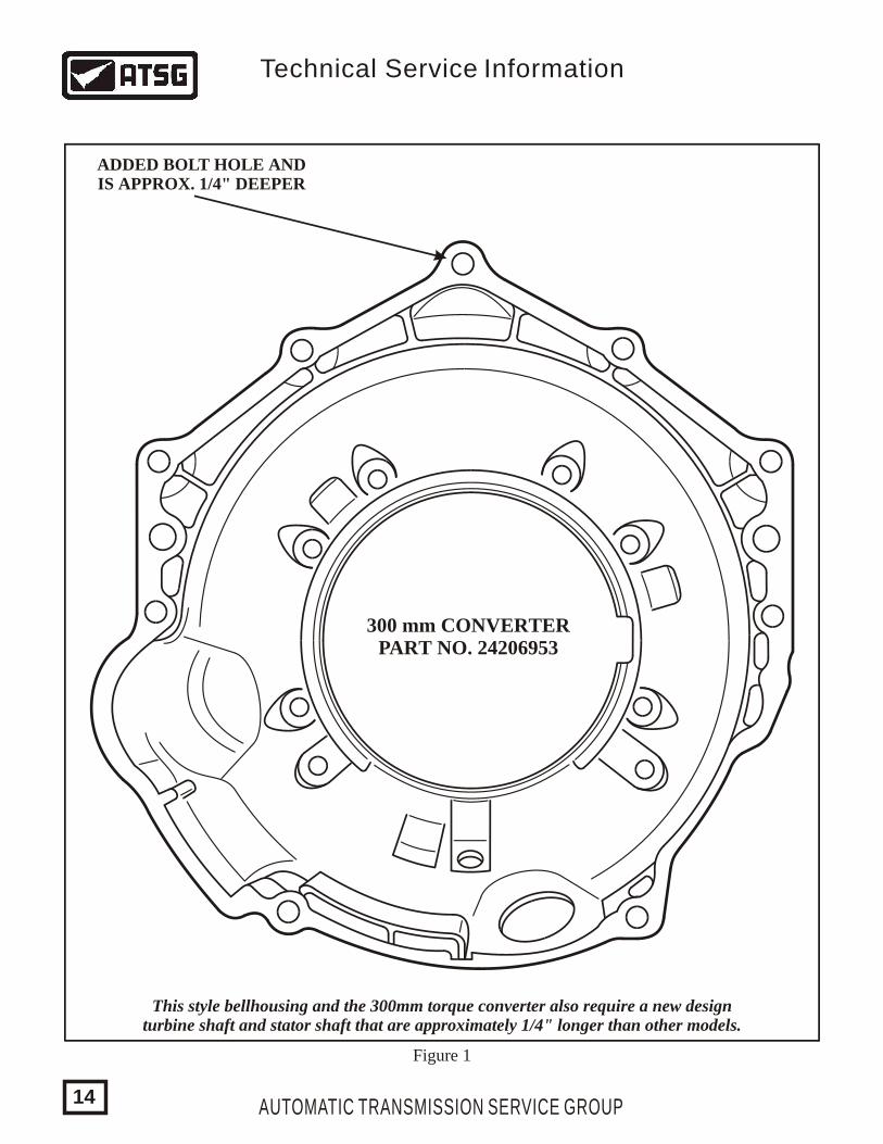
300 mm CONVERTERPART NO. 24206953
ADDED BOLT HOLE ANDIS APPROX. 1/4" DEEPER
Figure 1
This style bellhousing and the 300mm torque converter also require a new designturbine shaft and stator shaft that are approximately 1/4" longer than other models.
AUTOMATIC TRANSMISSION SERVICE GROUP
Technical Service Information
14
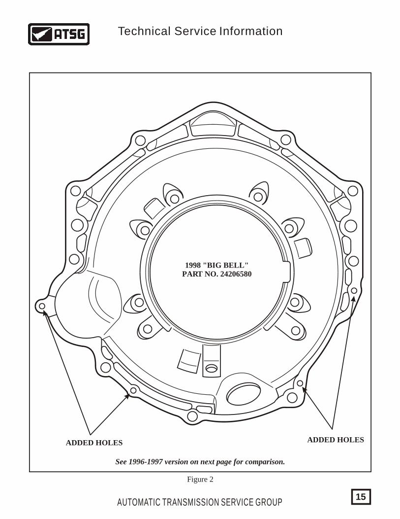
1998 "BIG BELL"PART NO. 24206580
ADDED HOLES ADDED HOLES
See 1996-1997 version on next page for comparison.
Figure 2
AUTOMATIC TRANSMISSION SERVICE GROUP
Technical Service Information
15
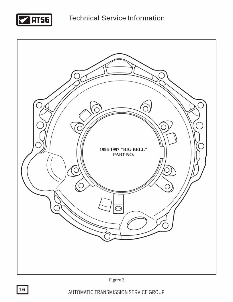
1996-1997 "BIG BELL"PART NO.
Figure 3
AUTOMATIC TRANSMISSION SERVICE GROUP
Technical Service Information
16
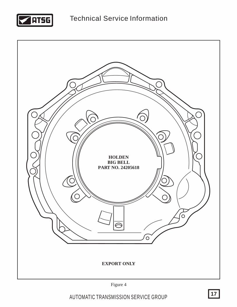
HOLDENBIG BELL
PART NO. 24205618
EXPORT ONLY
Figure 4
AUTOMATIC TRANSMISSION SERVICE GROUP
Technical Service Information
17
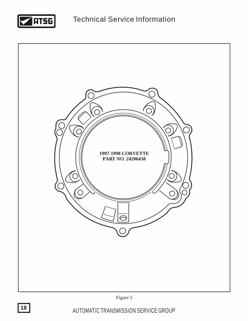
1997-1998 CORVETTEPART NO. 24206438
Figure 5
AUTOMATIC TRANSMISSION SERVICE GROUP
Technical Service Information
18
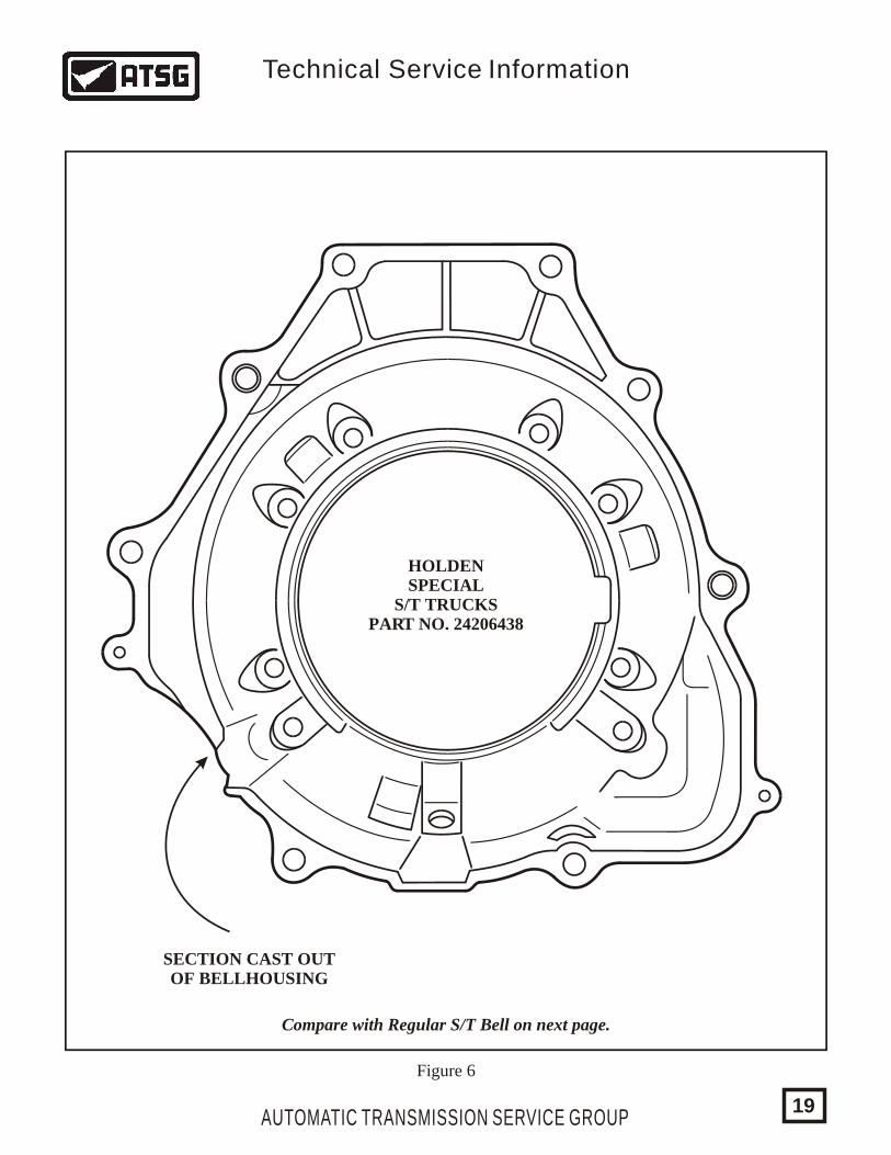
HOLDENSPECIAL
S/T TRUCKSPART NO. 24206438
SECTION CAST OUTOF BELLHOUSING
Compare with Regular S/T Bell on next page.
Figure 6
AUTOMATIC TRANSMISSION SERVICE GROUP
Technical Service Information
19
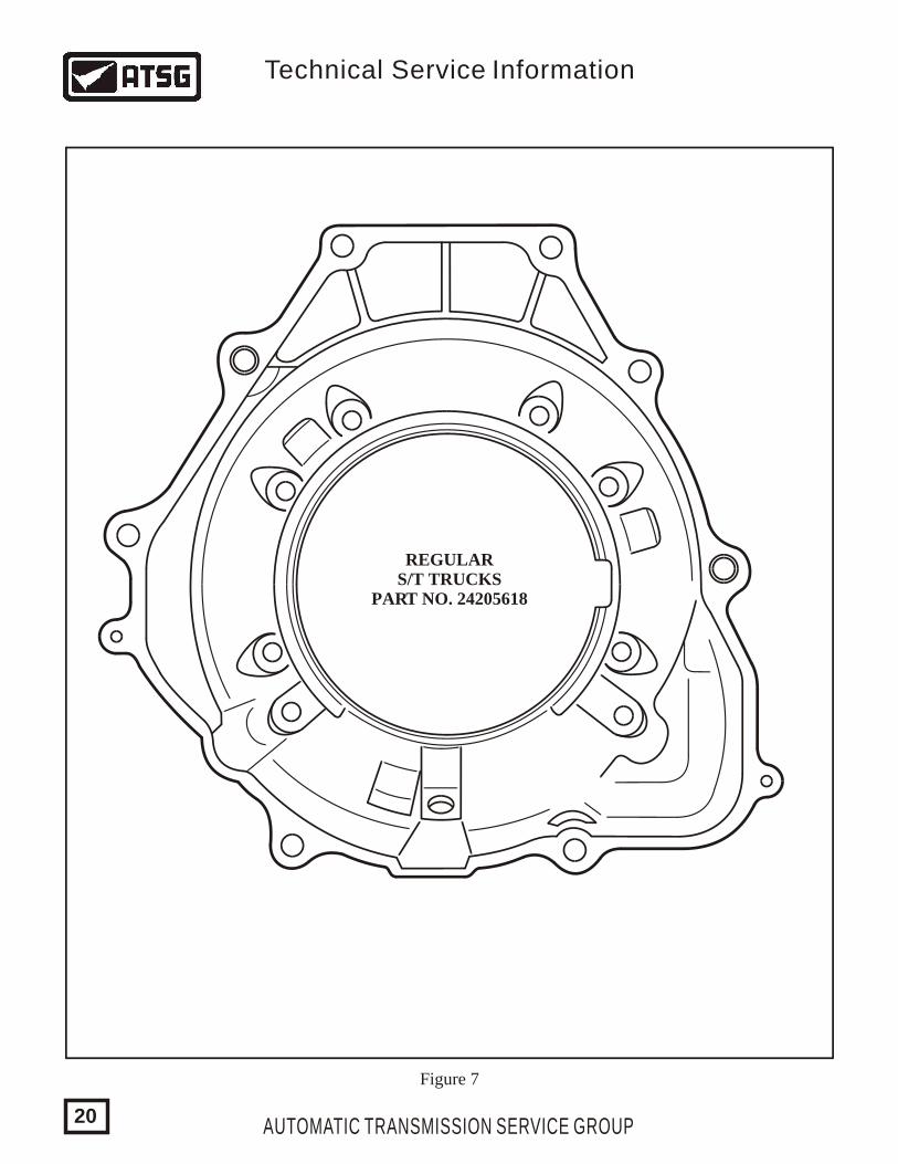
REGULARS/T TRUCKS
PART NO. 24205618
Figure 7
AUTOMATIC TRANSMISSION SERVICE GROUP
Technical Service Information
20
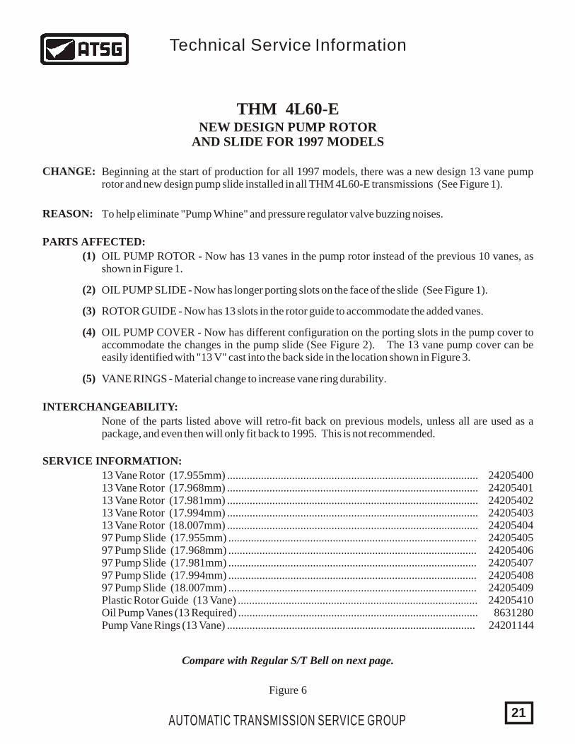
THM 4L60-ENEW DESIGN PUMP ROTOR
AND SLIDE FOR 1997 MODELS
CHANGE:
REASON:
PARTS AFFECTED:
INTERCHANGEABILITY:
SERVICE INFORMATION:
Beginning at the start of production for all 1997 models, there was a new design 13 vane pump rotor and new design pump slide installed in all THM 4L60-E transmissions (See Figure 1).
To help eliminate "Pump Whine" and pressure regulator valve buzzing noises.
(1)
(2)
(3)
(4)
(5)
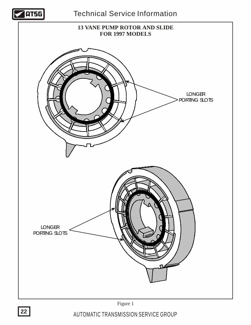
OIL PUMP ROTOR - Now has 13 vanes in the pump rotor instead of the previous 10 vanes, as shown in Figure 1.
OIL PUMP SLIDE - Now has longer porting slots on the face of the slide (See Figure 1).
ROTOR GUIDE - Now has 13 slots in the rotor guide to accommodate the added vanes.
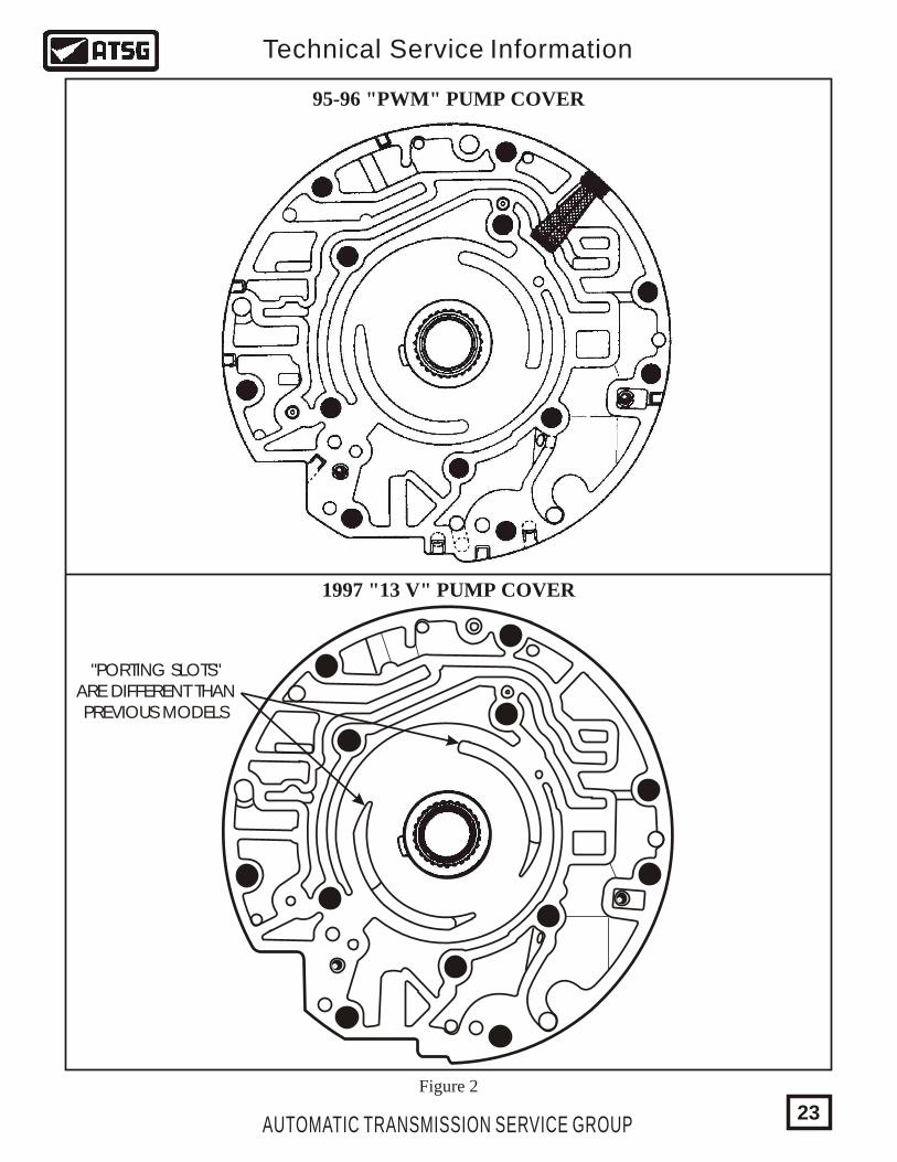
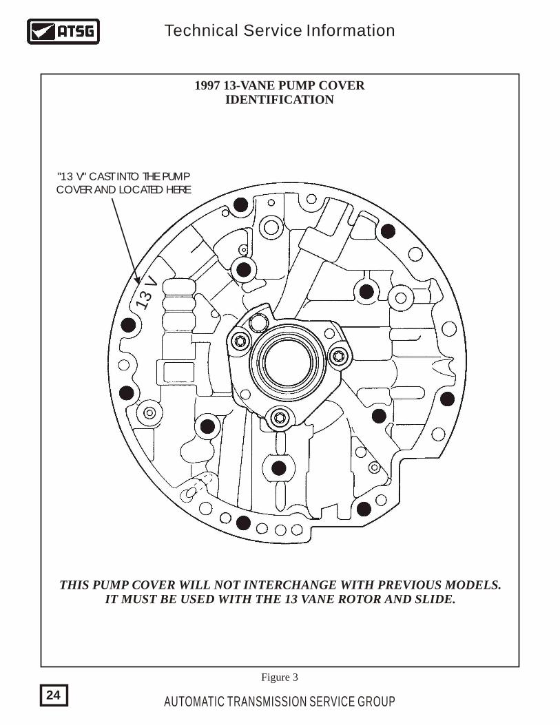
OIL PUMP COVER - Now has different configuration on the porting slots in the pump cover to accommodate the changes in the pump slide (See Figure 2). The 13 vane pump cover can be easily identified with "13 V" cast into the back side in the location shown in Figure 3.
13 Vane Rotor (17.955mm) .........................................................................................13 Vane Rotor (17.968mm) .........................................................................................13 Vane Rotor (17.981mm) .........................................................................................13 Vane Rotor (17.994mm) .........................................................................................13 Vane Rotor (18.007mm) .........................................................................................97 Pump Slide (17.955mm) ........................................................................................97 Pump Slide (17.968mm) ........................................................................................97 Pump Slide (17.981mm) ........................................................................................97 Pump Slide (17.994mm) ........................................................................................97 Pump Slide (18.007mm) ........................................................................................Plastic Rotor Guide (13 Vane) .....................................................................................Oil Pump Vanes (13 Required) .....................................................................................Pump Vane Rings (13 Vane) ........................................................................................
2420540024205401242054022420540324205404242054052420540624205407242054082420540924205410
863128024201144
VANE RINGS - Material change to increase vane ring durability.
None of the parts listed above will retro-fit back on previous models, unless all are used as a package, and even then will only fit back to 1995. This is not recommended.
Technical Service Information
Compare with Regular S/T Bell on next page.
Figure 6
AUTOMATIC TRANSMISSION SERVICE GROUP21
AUTOMATIC TRANSMISSION SERVICE GROUP
Technical Service Information
13 VANE PUMP ROTOR AND SLIDEFOR 1997 MODELS
LONGERPORTING SLOTS
LONGERPORTING SLOTS
LONGERPORTING SLOTS
LONGERPORTING SLOTS
Figure 1
22
AUTOMATIC TRANSMISSION SERVICE GROUP
Technical Service Information
Figure 2
95-96 "PWM" PUMP COVER
1997 "13 V" PUMP COVER
"PORTING SLOTS"ARE DIFFERENT THANPREVIOUS MODELS
23
13 V
1997 13-VANE PUMP COVERIDENTIFICATION
"13 V" CAST INTO THE PUMPCOVER AND LOCATED HERE
Figure 3
AUTOMATIC TRANSMISSION SERVICE GROUP
Technical Service Information
THIS PUMP COVER WILL NOT INTERCHANGE WITH PREVIOUS MODELS.IT MUST BE USED WITH THE 13 VANE ROTOR AND SLIDE.
24
THM 4L60-EPUMP INTERCHANGE
1993 -1994 MODELS:
1995 -1996 MODELS:
1997 MODELS:
INTERCHANGEABILITY:
Pump Body - All models use the 10 Vane rotor and slide assembly, and this Pump Body has the same casting and worm track configuration as the 1985-1993 models of the 700-R4 transmission. Refer to Figure 3.
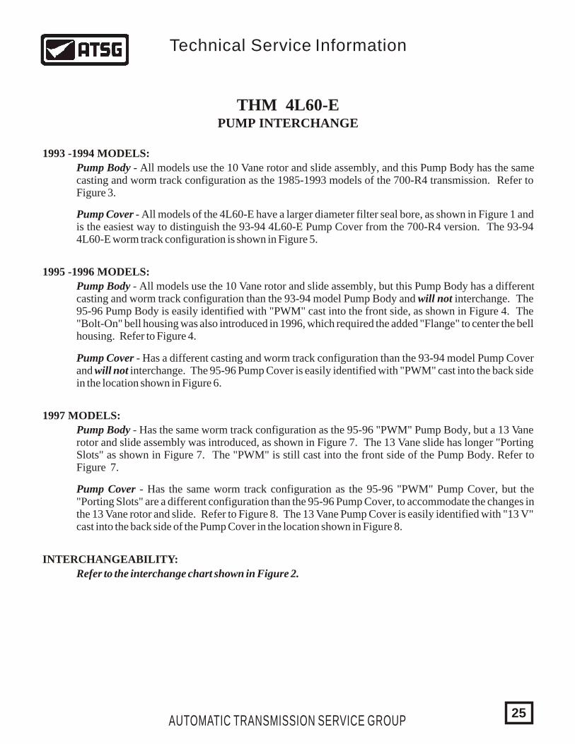
Pump Cover - All models of the 4L60-E have a larger diameter filter seal bore, as shown in Figure 1 and is the easiest way to distinguish the 93-94 4L60-E Pump Cover from the 700-R4 version. The 93-94 4L60-E worm track configuration is shown in Figure 5.
Pump Body - All models use the 10 Vane rotor and slide assembly, but this Pump Body has a different casting and worm track configuration than the 93-94 model Pump Body and will not interchange. The 95-96 Pump Body is easily identified with "PWM" cast into the front side, as shown in Figure 4. The "Bolt-On" bell housing was also introduced in 1996, which required the added "Flange" to center the bell housing. Refer to Figure 4.
Pump Cover - Has a different casting and worm track configuration than the 93-94 model Pump Cover and will not interchange. The 95-96 Pump Cover is easily identified with "PWM" cast into the back side in the location shown in Figure 6.
Pump Body - Has the same worm track configuration as the 95-96 "PWM" Pump Body, but a 13 Vane rotor and slide assembly was introduced, as shown in Figure 7. The 13 Vane slide has longer "Porting Slots" as shown in Figure 7. The "PWM" is still cast into the front side of the Pump Body. Refer to Figure 7.
Pump Cover - Has the same worm track configuration as the 95-96 "PWM" Pump Cover, but the "Porting Slots" are a different configuration than the 95-96 Pump Cover, to accommodate the changes in the 13 Vane rotor and slide. Refer to Figure 8. The 13 Vane Pump Cover is easily identified with "13 V" cast into the back side of the Pump Cover in the location shown in Figure 8.
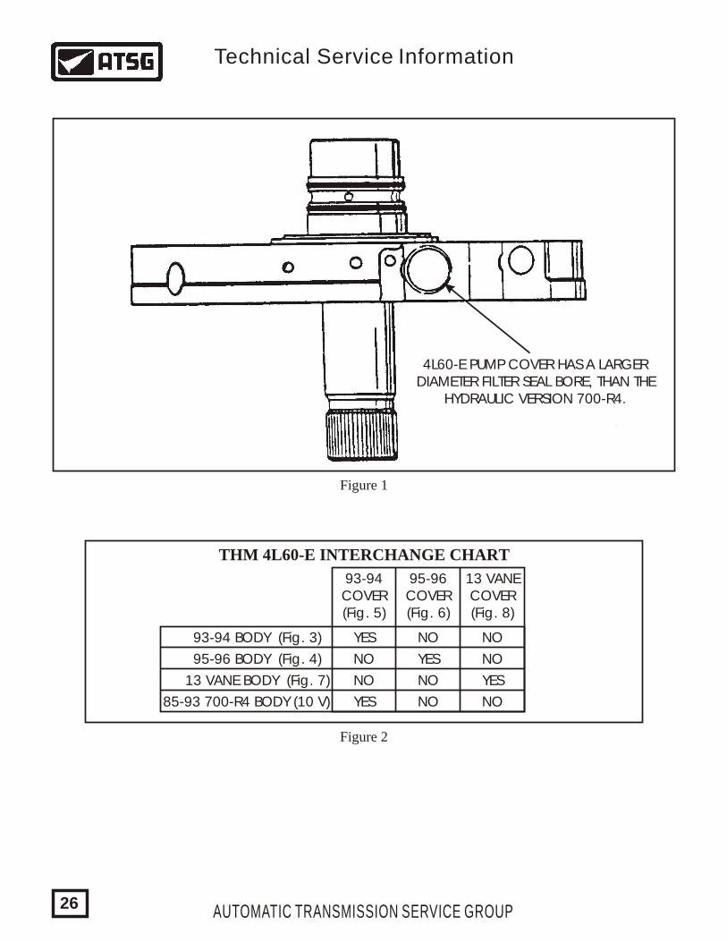
Refer to the interchange chart shown in Figure 2.
AUTOMATIC TRANSMISSION SERVICE GROUP
Technical Service Information
25
93-94COVER(Fig. 5)
93-94 BODY (Fig. 3)
YES
YES
YES
YES
NO
NO NO
NO
NO
NO
NO
NO
95-96 BODY (Fig. 4)
13 VANE BODY (Fig. 7)
85-93 700-R4 BODY (10 V)
95-96COVER(Fig. 6)
13 VANECOVER(Fig. 8)
4L60-E PUMP COVER HAS A LARGERDIAMETER FILTER SEAL BORE, THAN THE
HYDRAULIC VERSION 700-R4.
THM 4L60-E INTERCHANGE CHART
Figure 1
Figure 2
AUTOMATIC TRANSMISSION SERVICE GROUP
Technical Service Information
26
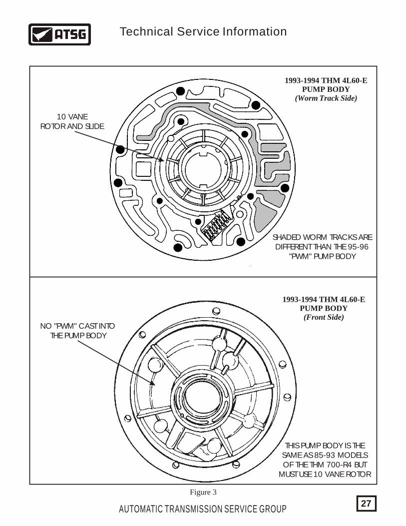
1993-1994 THM 4L60-EPUMP BODY
(Worm Track Side)
1993-1994 THM 4L60-EPUMP BODY(Front Side)
SHADED WORM TRACKS AREDIFFERENT THAN THE 95-96
"PWM" PUMP BODY
NO "PWM" CAST INTOTHE PUMP BODY
THIS PUMP BODY IS THESAME AS 85-93 MODELSOF THE THM 700-R4 BUT
MUST USE 10 VANE ROTOR
Figure 3
10 VANEROTOR AND SLIDE
AUTOMATIC TRANSMISSION SERVICE GROUP
Technical Service Information
27
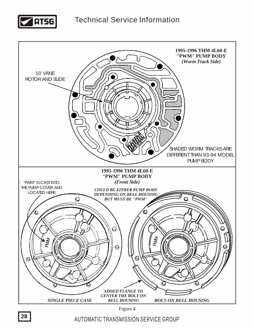
1995-1996 THM 4L60-E"PWM" PUMP BODY
(Worm Track Side)
SHADED WORM TRACKS AREDIFFERENT THAN 93-94 MODEL
PUMP BODY
1995-1996 THM 4L60-E"PWM" PUMP BODY
(Front Side)
Figure 4
PW
MPW
M
PW
MPW
M
COULD BE EITHER PUMP BODYDEPENDING ON BELL HOUSING
BUT MUST BE "PWM"
ADDED FLANGE TOCENTER THE BOLT-ON
BELL HOUSINGSINGLE PIECE CASE BOLT-ON BELL HOUSING
10 VANEROTOR AND SLIDE
"PWM" IS CAST INTOTHE PUMP COVER AND
LOCATED HERE
AUTOMATIC TRANSMISSION SERVICE GROUP
Technical Service Information
28
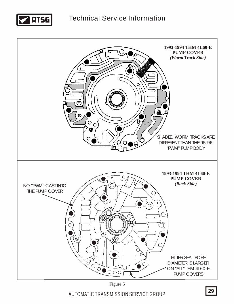
1993-1994 THM 4L60-EPUMP COVER
(Worm Track Side)
1993-1994 THM 4L60-EPUMP COVER
(Back Side)
SHADED WORM TRACKS AREDIFFERENT THAN THE 95-96
"PWM" PUMP BODY
NO "PWM" CAST INTOTHE PUMP COVER
FILTER SEAL BOREDIAMETER IS LARGERON "ALL" THM 4L60-E
PUMP COVERS
Figure 5
AUTOMATIC TRANSMISSION SERVICE GROUP
Technical Service Information
29
PWM
PWM
1995-1996 THM 4L60-E"PWM" PUMP COVER
(Worm Track Side)
1995-1996 THM 4L60-E"PWM" PUMP COVER
(Back Side)
SHADED WORM TRACKS AREDIFFERENT THAN THE 93-94
PUMP BODY
"PWM" IS CAST INTOTHE PUMP COVER FORIDENTIFICATION AND
LOCATED HERE
Figure 6
AUTOMATIC TRANSMISSION SERVICE GROUP
Technical Service Information
30
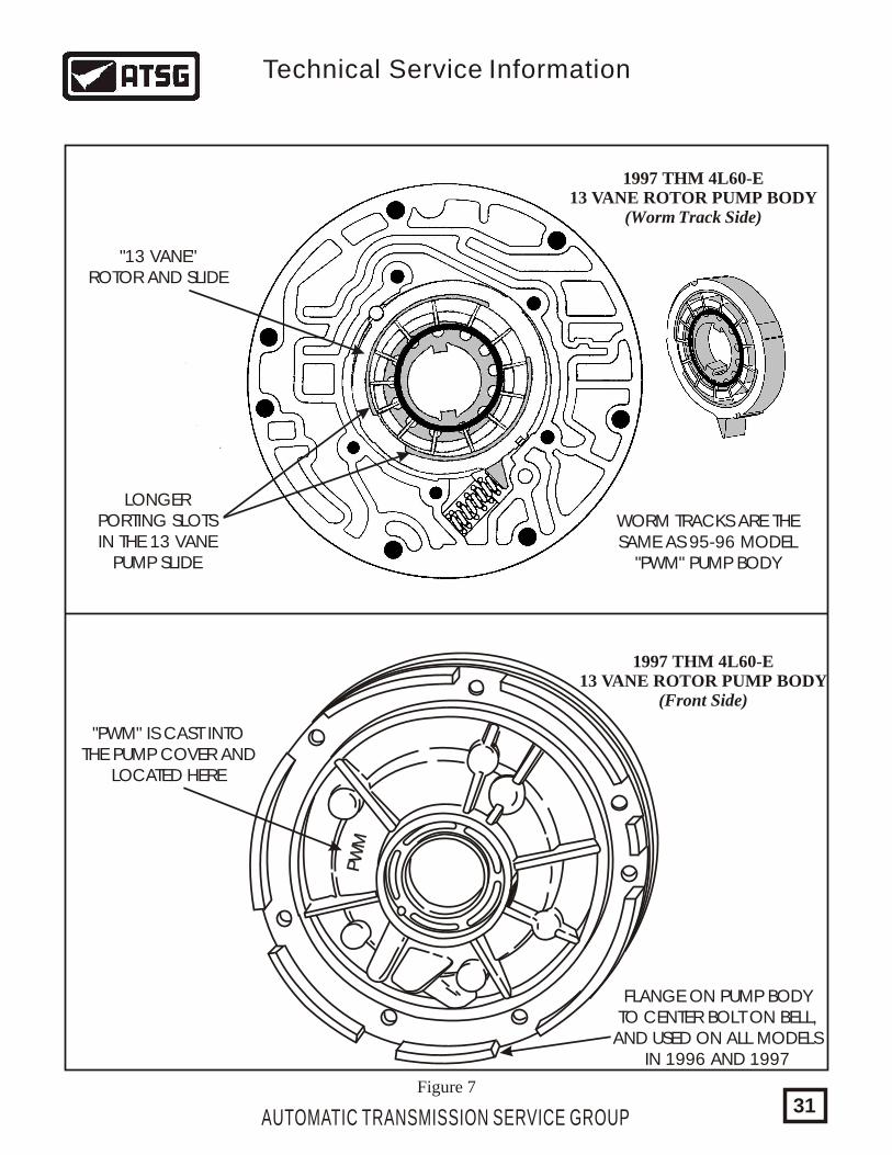
1997 THM 4L60-E13 VANE ROTOR PUMP BODY
(Worm Track Side)
1997 THM 4L60-E13 VANE ROTOR PUMP BODY
(Front Side)
WORM TRACKS ARE THESAME AS 95-96 MODEL
"PWM" PUMP BODY
LONGERPORTING SLOTSIN THE 13 VANE
PUMP SLIDE
Figure 7
FLANGE ON PUMP BODYTO CENTER BOLT ON BELL,
AND USED ON ALL MODELSIN 1996 AND 1997
"PWM" IS CAST INTOTHE PUMP COVER AND
LOCATED HERE
PW
MPW
M
"13 VANE"ROTOR AND SLIDE
AUTOMATIC TRANSMISSION SERVICE GROUP
Technical Service Information
31
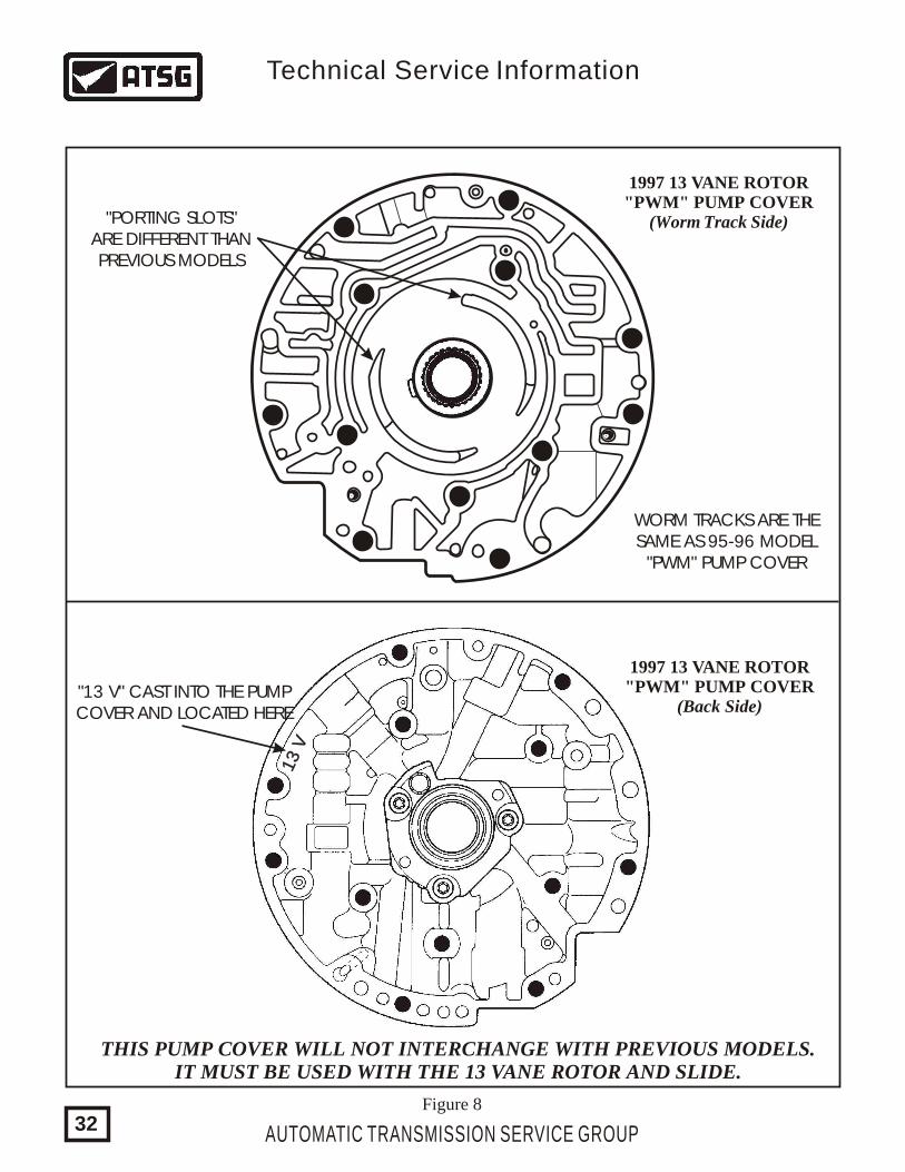
1997 13 VANE ROTOR"PWM" PUMP COVER
(Back Side)
1997 13 VANE ROTOR"PWM" PUMP COVER
(Worm Track Side)
"13 V" CAST INTO THE PUMPCOVER AND LOCATED HERE
Figure 8
13 V
13 V
"PORTING SLOTS"ARE DIFFERENT THANPREVIOUS MODELS
WORM TRACKS ARE THESAME AS 95-96 MODEL
"PWM" PUMP COVER
THIS PUMP COVER WILL NOT INTERCHANGE WITH PREVIOUS MODELS.IT MUST BE USED WITH THE 13 VANE ROTOR AND SLIDE.
AUTOMATIC TRANSMISSION SERVICE GROUP
Technical Service Information
32
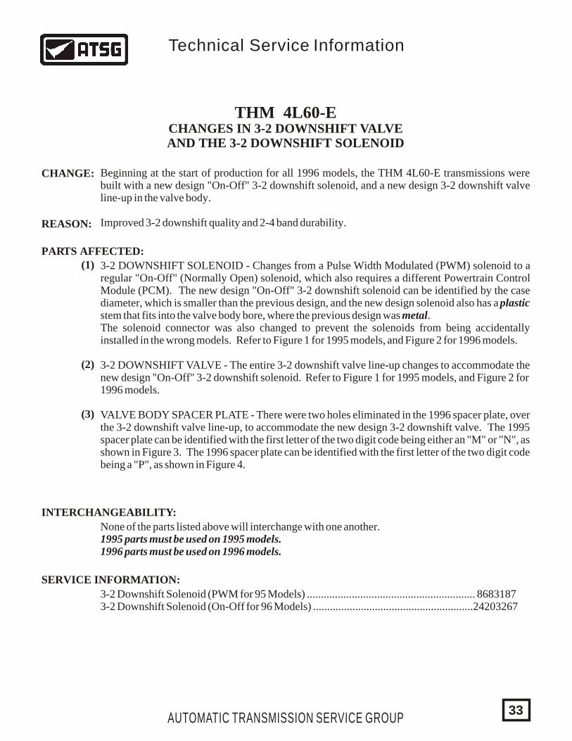
THM 4L60-ECHANGES IN 3-2 DOWNSHIFT VALVEAND THE 3-2 DOWNSHIFT SOLENOID
CHANGE:
REASON:
PARTS AFFECTED:
INTERCHANGEABILITY:
SERVICE INFORMATION:
Beginning at the start of production for all 1996 models, the THM 4L60-E transmissions were built with a new design "On-Off" 3-2 downshift solenoid, and a new design 3-2 downshift valve line-up in the valve body.
Improved 3-2 downshift quality and 2-4 band durability.
(1)
(2)
(3)
3-2 DOWNSHIFT SOLENOID - Changes from a Pulse Width Modulated (PWM) solenoid to a regular "On-Off" (Normally Open) solenoid, which also requires a different Powertrain Control Module (PCM). The new design "On-Off" 3-2 downshift solenoid can be identified by the case diameter, which is smaller than the previous design, and the new design solenoid also has a plastic stem that fits into the valve body bore, where the previous design was metal.The solenoid connector was also changed to prevent the solenoids from being accidentally installed in the wrong models. Refer to Figure 1 for 1995 models, and Figure 2 for 1996 models.
3-2 DOWNSHIFT VALVE - The entire 3-2 downshift valve line-up changes to accommodate the new design "On-Off" 3-2 downshift solenoid. Refer to Figure 1 for 1995 models, and Figure 2 for 1996 models.
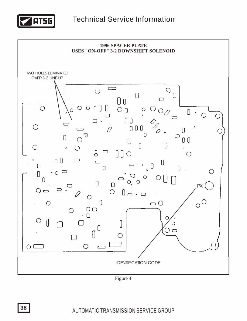
VALVE BODY SPACER PLATE - There were two holes eliminated in the 1996 spacer plate, over the 3-2 downshift valve line-up, to accommodate the new design 3-2 downshift valve. The 1995 spacer plate can be identified with the first letter of the two digit code being either an "M" or "N", as shown in Figure 3. The 1996 spacer plate can be identified with the first letter of the two digit code being a "P", as shown in Figure 4.
None of the parts listed above will interchange with one another.1995 parts must be used on 1995 models.1996 parts must be used on 1996 models.
3-2 Downshift Solenoid (PWM for 95 Models) ............................................................ 86831873-2 Downshift Solenoid (On-Off for 96 Models) .........................................................24203267
AUTOMATIC TRANSMISSION SERVICE GROUP
Technical Service Information
33

AUTOMATIC TRANSMISSION SERVICE GROUP34
ORDER TODAY ONLINEhttp://www.atsgmiami.comOR CALL (800) 245-7722
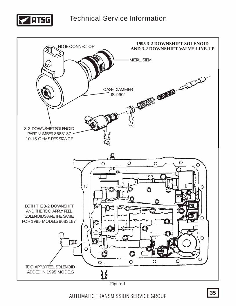
1995 3-2 DOWNSHIFT SOLENOIDAND 3-2 DOWNSHIFT VALVE LINE-UP
METAL STEM
NOTE CONNECTOR
CASE DIAMETERIS .990"
TCC APPLY FEEL SOLENOIDADDED IN 1995 MODELS
BOTH THE 3-2 DOWNSHIFTAND THE TCC APPLY FEEL
SOLENOIDS ARE THE SAMEFOR 1995 MODELS 8683187
Figure 1
3-2 DOWNSHIFT SOLENOIDPART NUMBER 8683187
10-15 OHMS RESISTANCE
AUTOMATIC TRANSMISSION SERVICE GROUP
Technical Service Information
35
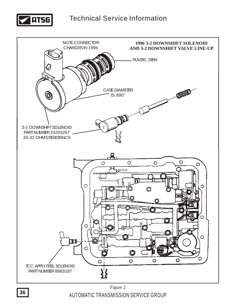
1996 3-2 DOWNSHIFT SOLENOIDAND 3-2 DOWNSHIFT VALVE LINE-UP
PLASTIC STEM
NOTE CONNECTORCHANGES IN 1996
3-2 DOWNSHIFT SOLENOIDPART NUMBER 2420326720-31 OHMS RESISTANCE
CASE DIAMETERIS .890"
TCC APPLY FEEL SOLENOIDPART NUMBER 8683187
Figure 2
AUTOMATIC TRANSMISSION SERVICE GROUP
Technical Service Information
36
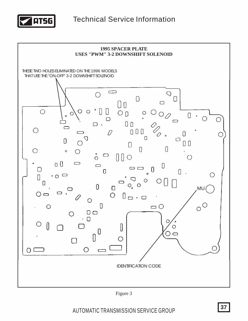
MU
1995 SPACER PLATEUSES "PWM" 3-2 DOWNSHIFT SOLENOID
THESE TWO HOLES ELIMINATED ON THE 1996 MODELS THAT USE THE "ON-OFF" 3-2 DOWNSHIFT SOLENOID
Figure 3
IDENTIFICATION CODE
AUTOMATIC TRANSMISSION SERVICE GROUP
Technical Service Information
37
AUTOMATIC TRANSMISSION SERVICE GROUP
Technical Service Information
PX
1996 SPACER PLATEUSES "ON-OFF" 3-2 DOWNSHIFT SOLENOID
TWO HOLES ELIMINATEDOVER 3-2 LINE-UP
Figure 4
IDENTIFICATION CODE
38
AUTOMATIC TRANSMISSION SERVICE GROUP
Technical Service Information
39
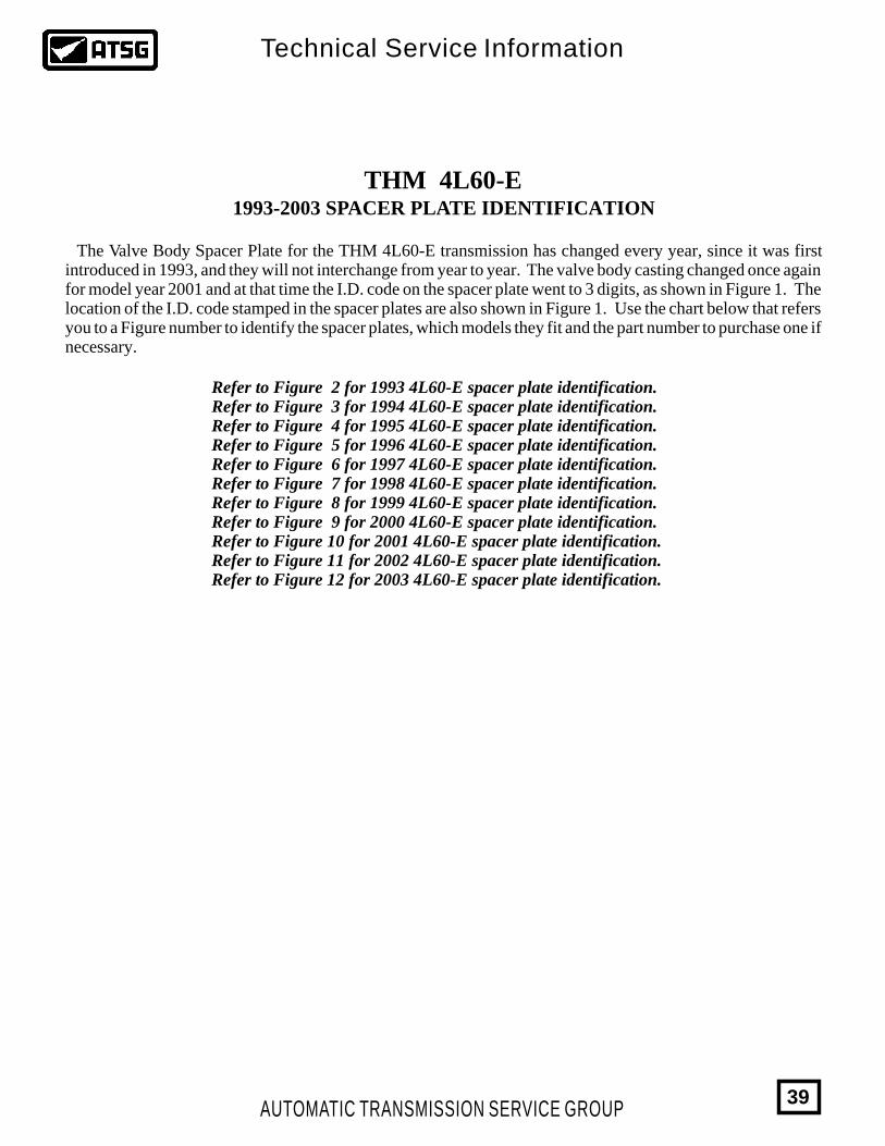
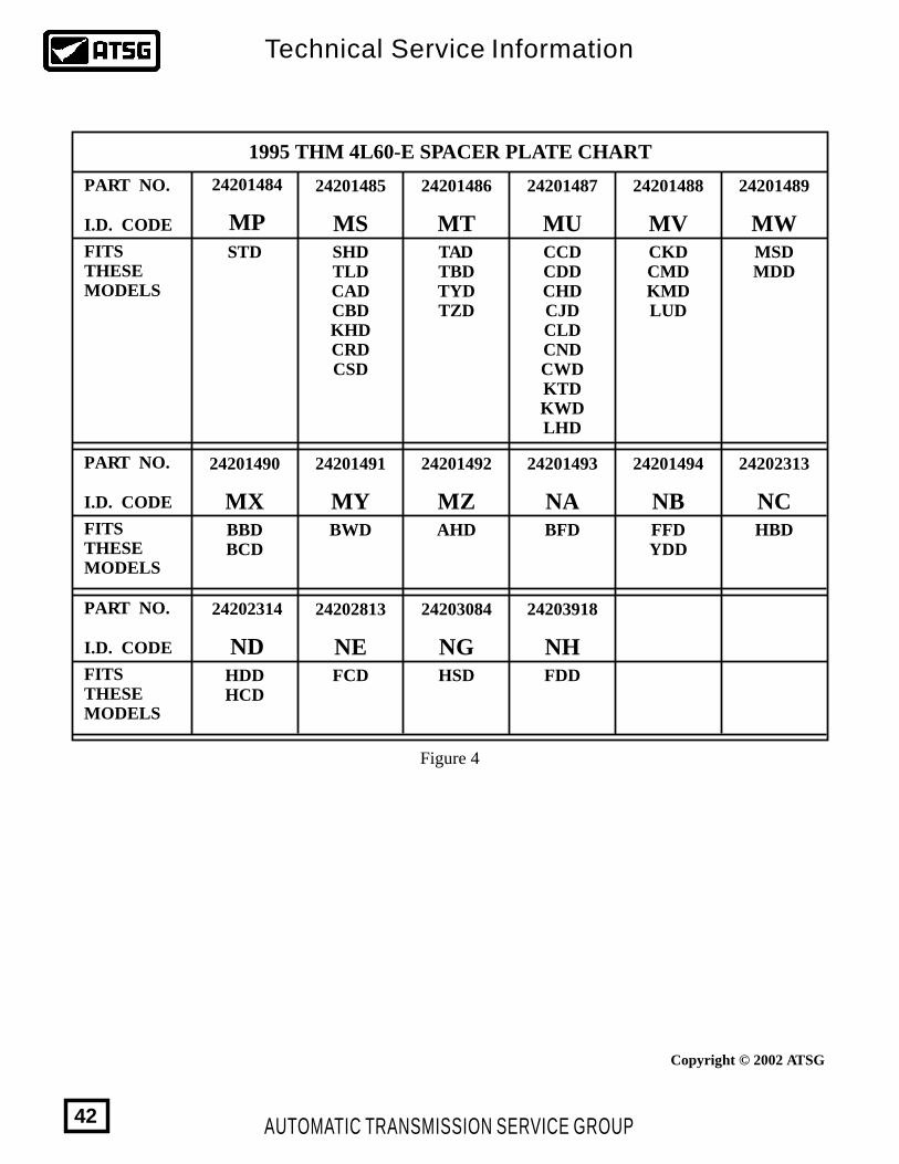
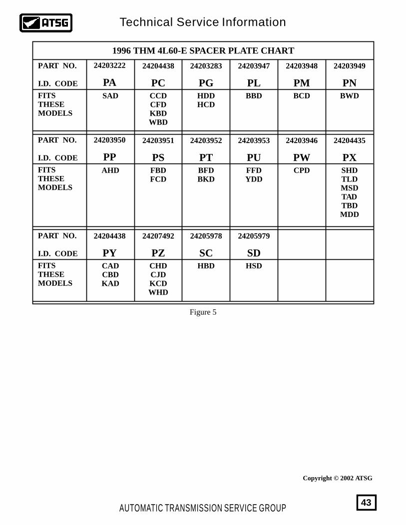
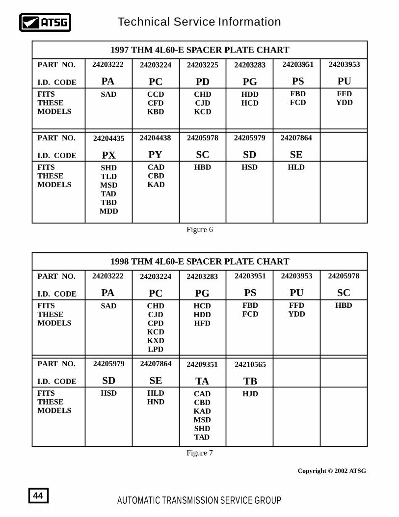
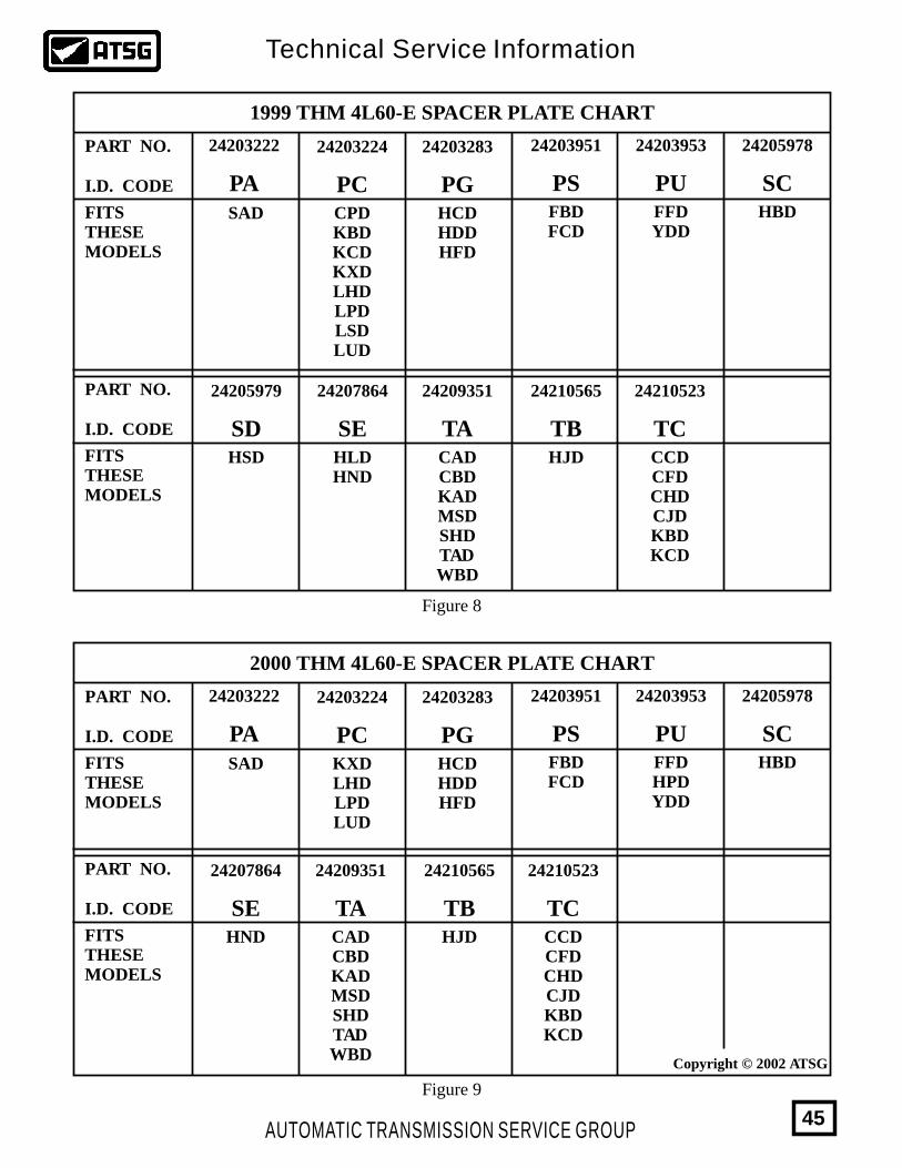
THM 4L60-E1993-2003 SPACER PLATE IDENTIFICATION
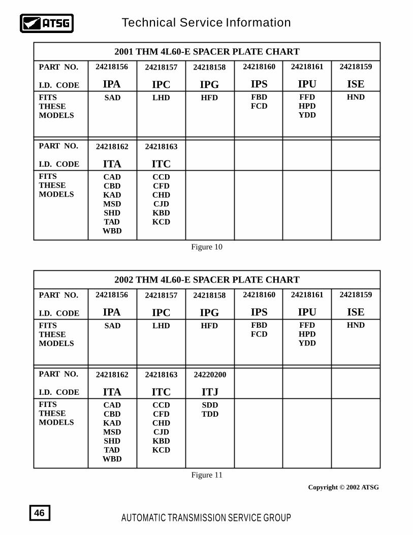
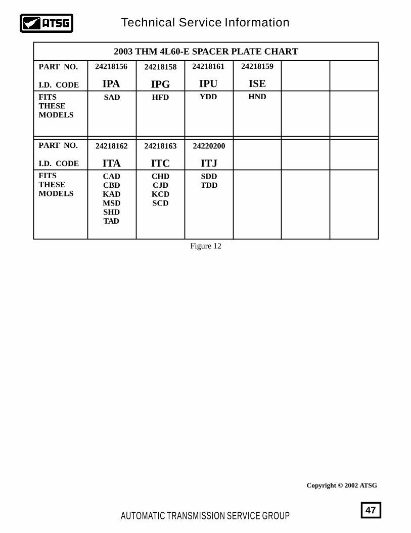
Refer to Figure 2 for 1993 4L60-E spacer plate identification.Refer to Figure 3 for 1994 4L60-E spacer plate identification.Refer to Figure 4 for 1995 4L60-E spacer plate identification.Refer to Figure 5 for 1996 4L60-E spacer plate identification.Refer to Figure 6 for 1997 4L60-E spacer plate identification.Refer to Figure 7 for 1998 4L60-E spacer plate identification.Refer to Figure 8 for 1999 4L60-E spacer plate identification.Refer to Figure 9 for 2000 4L60-E spacer plate identification.Refer to Figure 10 for 2001 4L60-E spacer plate identification.Refer to Figure 11 for 2002 4L60-E spacer plate identification.Refer to Figure 12 for 2003 4L60-E spacer plate identification.
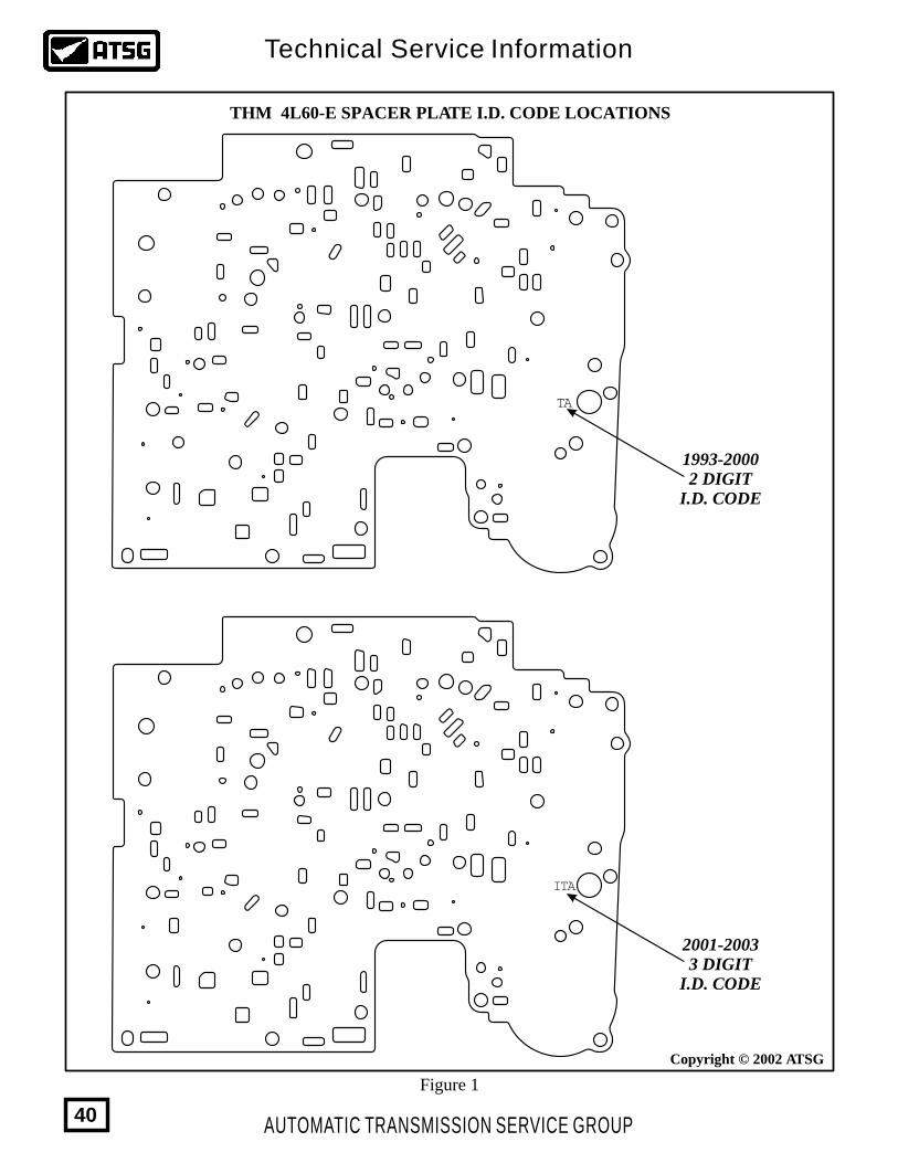
The Valve Body Spacer Plate for the THM 4L60-E transmission has changed every year, since it was first introduced in 1993, and they will not interchange from year to year. The valve body casting changed once again for model year 2001 and at that time the I.D. code on the spacer plate went to 3 digits, as shown in Figure 1. The location of the I.D. code stamped in the spacer plates are also shown in Figure 1. Use the chart below that refers you to a Figure number to identify the spacer plates, which models they fit and the part number to purchase one if necessary.
AUTOMATIC TRANSMISSION SERVICE GROUP
Technical Service Information
40
ITA
TA
1993-20002 DIGIT
I.D. CODE
2001-20033 DIGIT
I.D. CODE
THM 4L60-E SPACER PLATE I.D. CODE LOCATIONS
Figure 1
Copyright © 2002 ATSG
AUTOMATIC TRANSMISSION SERVICE GROUP
Technical Service Information
41
PART NO.
PART NO.
PART NO.
I.D. CODE
I.D. CODE
I.D. CODE
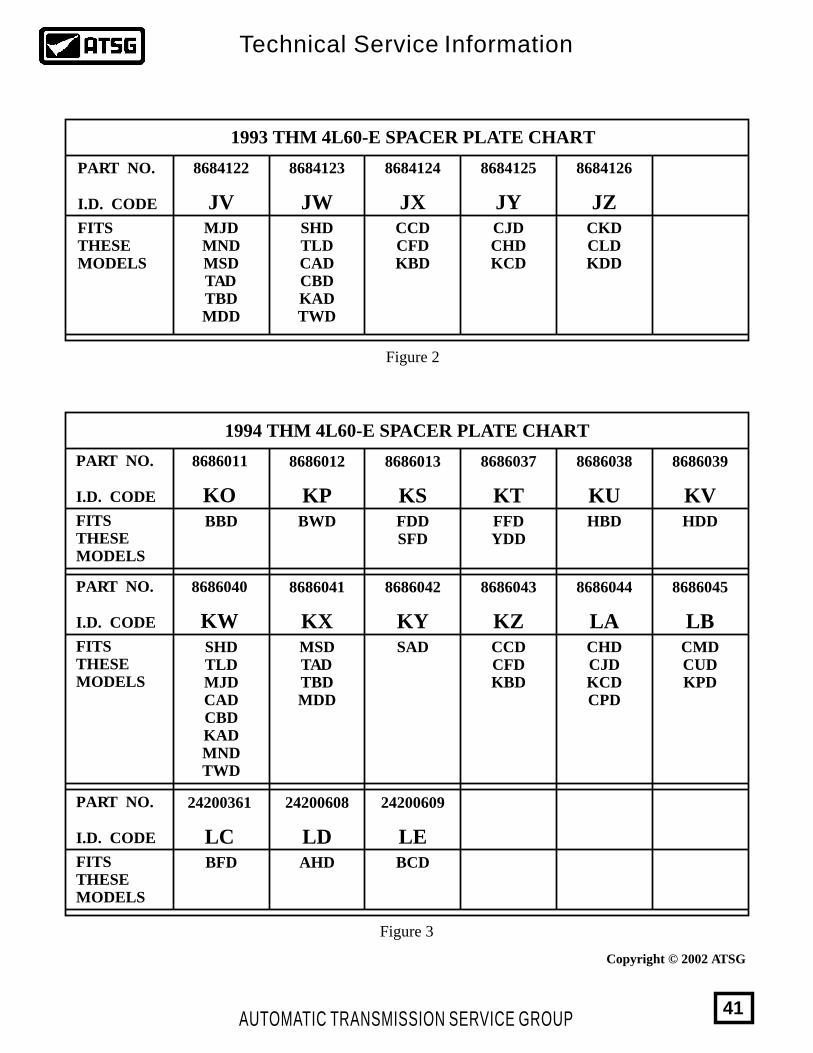
8686011 8686012 8686013 8686037 8686038 8686039
8686040 8686041 8686042 8686043 8686044 8686045
24200361 24200608 24200609
KO KP KS KT KU KV
KW KX KY KZ LA LB
LC LD LE
FITSTHESEMODELS
FITSTHESEMODELS
FITSTHESEMODELS
1994 THM 4L60-E SPACER PLATE CHART
BBD BWD FDDSFD
FFDYDD
HBD HDD
SHDTLDMJDCADCBDKADMNDTWD
MSDTADTBDMDD
SAD CCDCFDKBD
CHDCJDKCDCPD
CMDCUDKPD
BFD AHD BCD
Figure 3
1993 THM 4L60-E SPACER PLATE CHART
PART NO.
I.D. CODE
8684122 8684123 8684124 8684125 8684126
JV JW JX JY JZFITSTHESEMODELS
MJDMNDMSDTADTBDMDD
SHDTLDCADCBDKADTWD
CCDCFDKBD
CJDCHDKCD
CKDCLDKDD
Figure 2
Copyright © 2002 ATSG
AUTOMATIC TRANSMISSION SERVICE GROUP
Technical Service Information
42
PART NO.
PART NO.
PART NO.
I.D. CODE
I.D. CODE
I.D. CODE
24201484 24201485 24201486 24201487 24201488 24201489
24201490 24201491 24201492 24201493 24201494 24202313
24202314 24202813 24203084 24203918
MP MS MT MU MV MW
MX MY MZ NA NB NC
ND NE NG NH
FITSTHESEMODELS
FITSTHESEMODELS
FITSTHESEMODELS
1995 THM 4L60-E SPACER PLATE CHART
STD SHDTLDCADCBDKHDCRDCSD
TADTBDTYDTZD
CCDCDDCHDCJDCLDCNDCWDKTDKWDLHD
CKDCMDKMDLUD
MSDMDD
BBDBCD
BWD AHD BFD FFDYDD
HBD
HDDHCD
FCD HSD FDD
Figure 4
Copyright © 2002 ATSG
43
PART NO.
PART NO.
PART NO.
I.D. CODE
I.D. CODE
I.D. CODE
24204438 24207492 24205978 24205979
24203950 24203951 24203952 24203953 24203946 24204435
24203222 24204438 24203283 24203947 24203948 24203949
PY PZ SC SD
PP PS PT PU PW PX
PA PC PG PL PM PNFITSTHESEMODELS
FITSTHESEMODELS
FITSTHESEMODELS
1996 THM 4L60-E SPACER PLATE CHART
SAD CCDCFDKBDWBD
HDDHCD
BBD BCD BWD
AHD FBDFCD
BFDBKD
FFDYDD
CPD SHDTLDMSDTADTBDMDD
CADCBDKAD
CHDCJDKCDWHD
HBD HSD
Figure 5
AUTOMATIC TRANSMISSION SERVICE GROUP
Technical Service Information
Copyright © 2002 ATSG
PART NO.
PART NO.
PART NO.
PART NO.
I.D. CODE
I.D. CODE
I.D. CODE
I.D. CODE
24204438 24205978
24205978
24205979
24205979
24207864
24207864
24203951
24203951
24210565
24203953
24203953
24204435
24203222
24203222
24203224
24203224
24203225 24203283
24203283
24209351
PY SC
SC
SD
SD
SE
SE
PS
PS
TB
PU
PU
PX
PA
PA
PC
PC
PD PG
PG
TA
FITSTHESEMODELS
FITSTHESEMODELS
FITSTHESEMODELS
FITSTHESEMODELS
1997 THM 4L60-E SPACER PLATE CHART
1998 THM 4L60-E SPACER PLATE CHART
SAD
SAD
CCDCFDKBD
CHDCJDCPDKCDKXDLPD
CHDCJDKCD
HDDHCD
HCDHDDHFD
CADCBDKADMSDSHDTAD
FBDFCD
FBDFCD
HJD
FFDYDD
FFDYDD
SHDTLDMSDTADTBDMDD
CADCBDKAD
HBD
HBD
HSD
HSD
HLD
HLDHND
Figure 6
Figure 7
Copyright © 2002 ATSG
AUTOMATIC TRANSMISSION SERVICE GROUP
Technical Service Information
44
PART NO.
PART NO.
PART NO.
PART NO.
I.D. CODE
I.D. CODE
I.D. CODE
I.D. CODE
24205978
24205978
24205979 24207864
24207864
24203951
24203951
24210565
24210565
24210523
24210523
24203953
24203953
24203222
24203222
24203224
24203224
24203283
24203283
24209351
24209351
SC
SC
SD SE
SE
PS
PS
TB
TB
TC
TC
PU
PU
PA
PA
PC
PC
PG
PG
TA
TA
FITSTHESEMODELS
FITSTHESEMODELS
FITSTHESEMODELS
FITSTHESEMODELS
1999 THM 4L60-E SPACER PLATE CHART
2000 THM 4L60-E SPACER PLATE CHART
SAD
SAD
CPDKBDKCDKXDLHDLPDLSDLUD
KXDLHDLPDLUD
HCDHDDHFD
HCDHDDHFD
CADCBDKADMSDSHDTADWBD
CADCBDKADMSDSHDTADWBD
FBDFCD
FBDFCD
HJD
HJD
CCDCFDCHDCJDKBDKCD
CCDCFDCHDCJDKBDKCD
FFDYDD
FFDHPDYDD
HBD
HBD
HSD HLDHND
HND
Figure 8
Figure 9
Copyright © 2002 ATSG
45AUTOMATIC TRANSMISSION SERVICE GROUP
Technical Service Information
PART NO.
PART NO.
PART NO.
PART NO.
I.D. CODE
I.D. CODE
I.D. CODE
I.D. CODE
24218159
24218159
24218160
24218160
24218163
24218163 24220200
24218161
24218161
24218156
24218156
24218157
24218157
24218158
24218158
24218162
24218162
ISE
ISE
IPS
IPS
ITC
ITC ITJ
IPU
IPU
IPA
IPA
IPC
IPC
IPG
IPG
ITA
ITA
FITSTHESEMODELS
FITSTHESEMODELS
FITSTHESEMODELS
FITSTHESEMODELS
2001 THM 4L60-E SPACER PLATE CHART
2002 THM 4L60-E SPACER PLATE CHART
SAD
SAD
LHD
LHD
HFD
HFD
CADCBDKADMSDSHDTADWBD
CADCBDKADMSDSHDTADWBD
FBDFCD
FBDFCD
CCDCFDCHDCJDKBDKCD
CCDCFDCHDCJDKBDKCD
SDDTDD
FFDHPDYDD
FFDHPDYDD
HND
HND
Figure 10
Figure 11
Copyright © 2002 ATSG
AUTOMATIC TRANSMISSION SERVICE GROUP
Technical Service Information
46
PART NO.
PART NO.
I.D. CODE
I.D. CODE
24218159
24218163 24220200
2421816124218156 24218158
24218162
ISE
ITC ITJ
IPUIPA IPG
ITA
FITSTHESEMODELS
FITSTHESEMODELS
2003 THM 4L60-E SPACER PLATE CHART
SAD HFD
CADCBDKADMSDSHDTAD
CHDCJDKCDSCD
SDDTDD
YDD HND
Figure 12
Copyright © 2002 ATSG
47AUTOMATIC TRANSMISSION SERVICE GROUP
Technical Service Information

THM 4L60-ENEW DESIGN SHIFT SOLENOIDS,
EPC SOLENOID AND TCC/PWM SOLENOID
CHANGE:
REASON:
PARTS AFFECTED:
INTERCHANGEABILITY:
SERVICE INFORMATION:
Beginning at the start of production for all 1998 models, the THM 4L60-E transmissions were built with a new design for both Shift Solenoids, a new design EPC Solenoid, and a new design TCC/PWM Solenoid.
Improved shift quality and durability., and eliminates some mis-assembly concerns.
(1)
(2)
(3)
(1)
(2)
(3)
TCC/PWM SOLENOID - Changes from a metal stem to a "Gray Plastic" stem as shown in Figure 1, and the solenoid connector is also Gray in color to help distinguish it from the 3-2 Downshift (ON-OFF) Solenoid. These two solenoids are now manufactured identical, with the exact same dimensions, except for the difference in color of the solenoid stem and solenoid connector. The wide groove to accept the internal harness connector is also on opposite sides of the solenoid connector to prevent the solenoids from being accidentally installed in the wrong models, as shown in Figure 1.
3-2 Downshift Solenoid (PWM for 95 Models) ............................................................ 86831873-2 Downshift Solenoid (On-Off for 96-97 Models).................................................... 24209121TCC/PWM Solenoid (For 95-97 Models) .................................................................. 24207054Shift Solenoids "A" and "B" (All Models) .................................................................. 10478131
SHIFT SOLENOIDS "A" AND "B" - One groove has been removed from the stem of the Shift Solenoids to prevent mis-assembly concerns, as the retaining clip can be installed in the previous design solenoids, which means the solenoid is not all the way into it's bore. Refer to Figure 2.
PRESSURE CONTROL SOLENOID - New design has larger micron screens in the solenoid to greatly improve cold weather operation. This will allow the colder oil through the screens easier. Refer to Figure 3.
SHIFT SOLENOIDS "A" AND "B" - New design will retro-fit back to all previous models.
TCC/PWM SOLENOID - New design will retro-fit back to 1995 models.
PRESSURE CONTROL SOLENOID - New design will retro-fit back to all previous models.
AUTOMATIC TRANSMISSION SERVICE GROUP
Technical Service Information
48
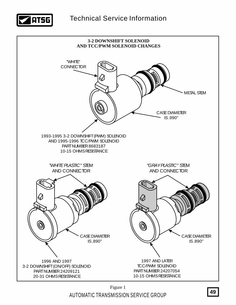
3-2 DOWNSHIFT SOLENOIDAND TCC/PWM SOLENOID CHANGES
1996 AND 19973-2 DOWNSHIFT (ON/OFF) SOLENOID
PART NUMBER 2420912120-31 OHMS RESISTANCE
1997 AND LATERTCC/PWM SOLENOID
PART NUMBER 2420705410-15 OHMS RESISTANCE
CASE DIAMETERIS .890"
CASE DIAMETERIS .890"
Figure 1
METAL STEM
"WHITE"CONNECTOR
CASE DIAMETERIS .990"
1993-1995 3-2 DOWNSHIFT (PWM) SOLENOIDAND 1995-1996 TCC/PWM SOLENOID
PART NUMBER 868318710-15 OHMS RESISTANCE
"GRAY PLASTIC" STEMAND CONNECTOR
"WHITE PLASTIC" STEMAND CONNECTOR
AUTOMATIC TRANSMISSION SERVICE GROUP
Technical Service Information
49
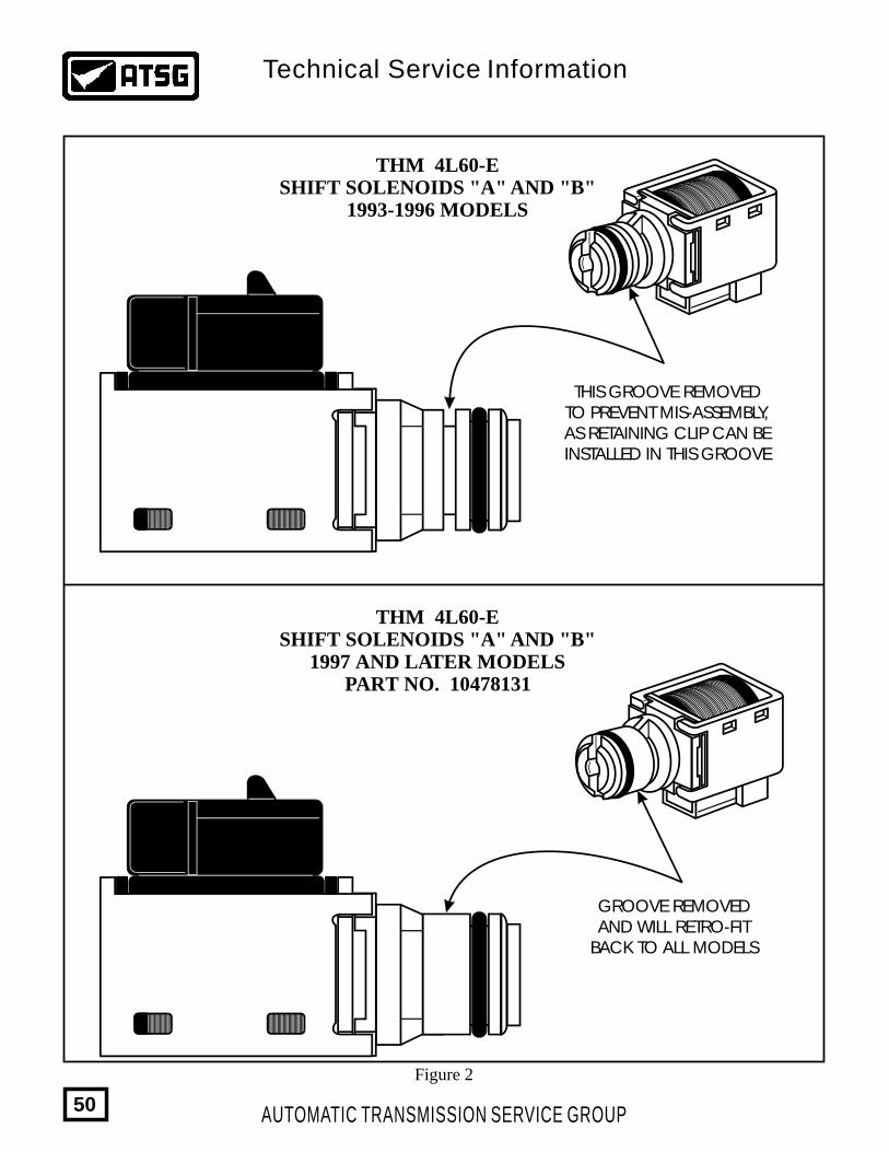
Figure 2
THM 4L60-ESHIFT SOLENOIDS "A" AND "B"
1993-1996 MODELS
THM 4L60-ESHIFT SOLENOIDS "A" AND "B"
1997 AND LATER MODELSPART NO. 10478131
GROOVE REMOVEDAND WILL RETRO-FIT
BACK TO ALL MODELS
THIS GROOVE REMOVEDTO PREVENT MIS-ASSEMBLY,AS RETAINING CLIP CAN BEINSTALLED IN THIS GROOVE
AUTOMATIC TRANSMISSION SERVICE GROUP
Technical Service Information
50
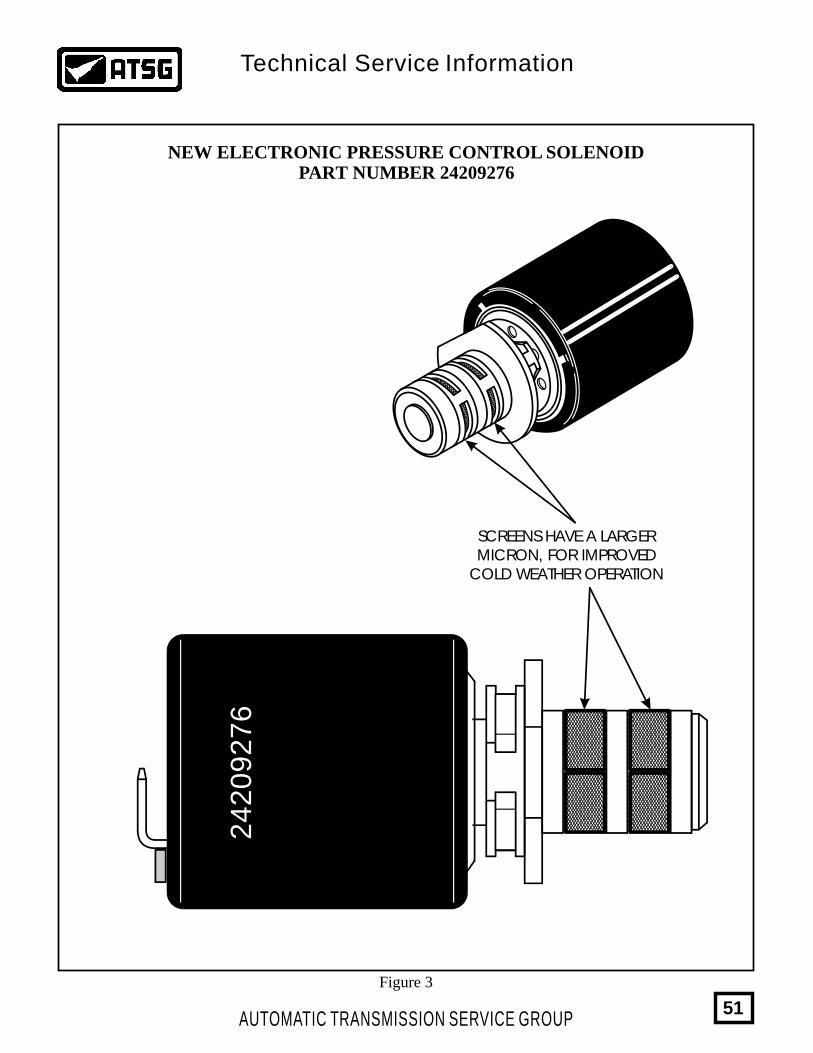
Figure 3
24209276
SCREENS HAVE A LARGERMICRON, FOR IMPROVED
COLD WEATHER OPERATION
NEW ELECTRONIC PRESSURE CONTROL SOLENOIDPART NUMBER 24209276
AUTOMATIC TRANSMISSION SERVICE GROUP
Technical Service Information
51
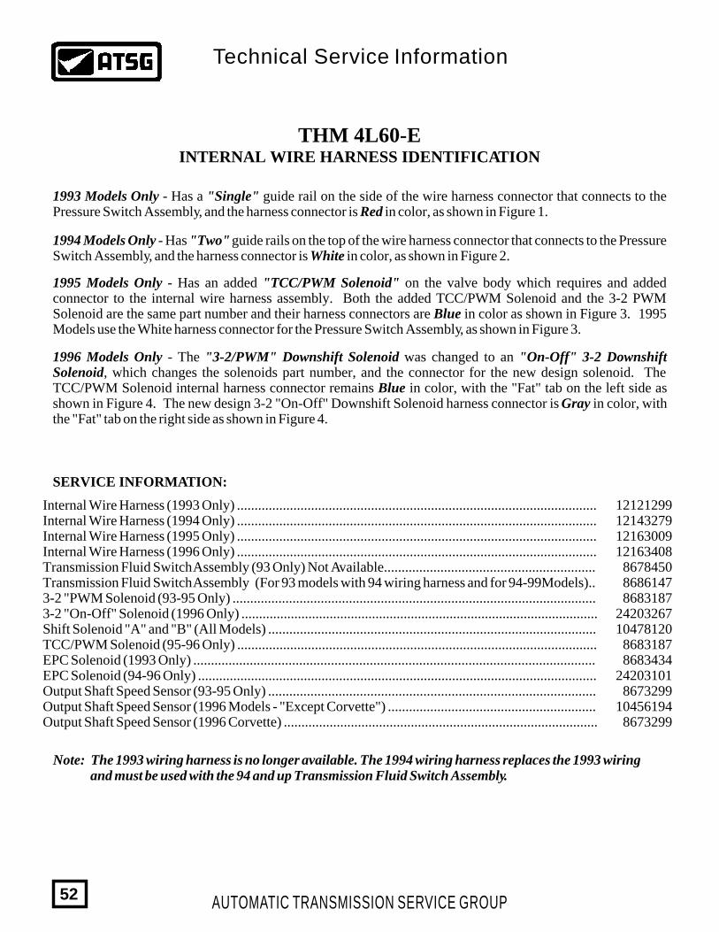
THM 4L60-EINTERNAL WIRE HARNESS IDENTIFICATION
1993 Models Only - Has a "Single" guide rail on the side of the wire harness connector that connects to the Pressure Switch Assembly, and the harness connector is Red in color, as shown in Figure 1.
1994 Models Only - Has "Two" guide rails on the top of the wire harness connector that connects to the Pressure Switch Assembly, and the harness connector is White in color, as shown in Figure 2.
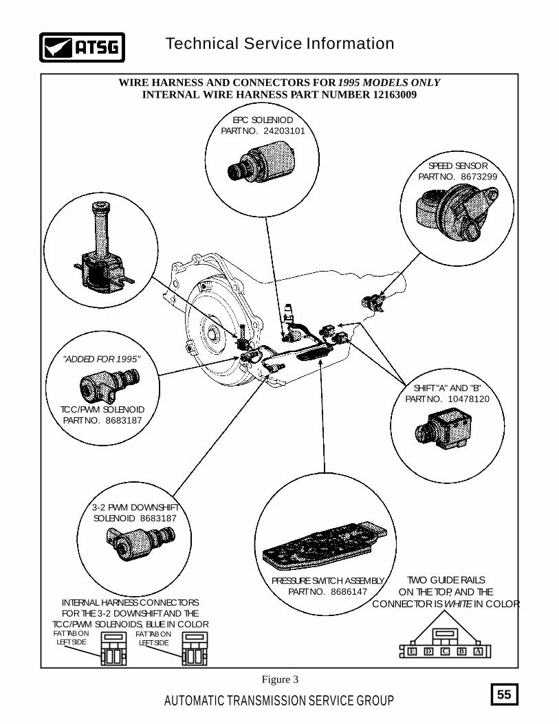
1995 Models Only - Has an added "TCC/PWM Solenoid" on the valve body which requires and added connector to the internal wire harness assembly. Both the added TCC/PWM Solenoid and the 3-2 PWM Solenoid are the same part number and their harness connectors are Blue in color as shown in Figure 3. 1995 Models use the White harness connector for the Pressure Switch Assembly, as shown in Figure 3.
1996 Models Only - The "3-2/PWM" Downshift Solenoid was changed to an "On-Off" 3-2 Downshift Solenoid, which changes the solenoids part number, and the connector for the new design solenoid. The TCC/PWM Solenoid internal harness connector remains Blue in color, with the "Fat" tab on the left side as shown in Figure 4. The new design 3-2 "On-Off" Downshift Solenoid harness connector is Gray in color, with the "Fat" tab on the right side as shown in Figure 4.
SERVICE INFORMATION:
12121299121432791216300912163408
867845086861478683187
2420326710478120
86831878683434
242031018673299
104561948673299
Internal Wire Harness (1993 Only) ......................................................................................................Internal Wire Harness (1994 Only) ......................................................................................................Internal Wire Harness (1995 Only) ......................................................................................................Internal Wire Harness (1996 Only) ......................................................................................................Transmission Fluid Switch Assembly (93 Only) Not Available............................................................Transmission Fluid Switch Assembly (For 93 models with 94 wiring harness and for 94-99Models)..3-2 "PWM Solenoid (93-95 Only) .......................................................................................................3-2 "On-Off" Solenoid (1996 Only) .....................................................................................................Shift Solenoid "A" and "B" (All Models) .............................................................................................TCC/PWM Solenoid (95-96 Only) ......................................................................................................EPC Solenoid (1993 Only) ..................................................................................................................EPC Solenoid (94-96 Only) .................................................................................................................Output Shaft Speed Sensor (93-95 Only) .............................................................................................Output Shaft Speed Sensor (1996 Models - "Except Corvette") ...........................................................Output Shaft Speed Sensor (1996 Corvette) .........................................................................................
AUTOMATIC TRANSMISSION SERVICE GROUP
Technical Service Information
52
Note: The 1993 wiring harness is no longer available. The 1994 wiring harness replaces the 1993 wiring and must be used with the 94 and up Transmission Fluid Switch Assembly.
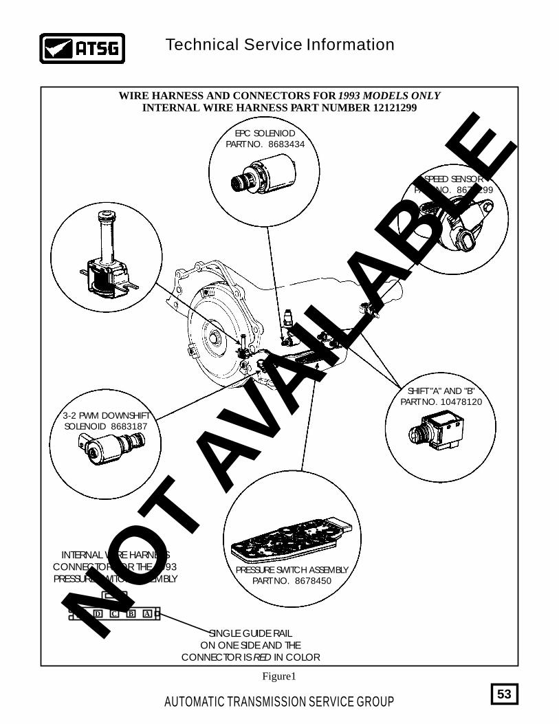
Figure1
WIRE HARNESS AND CONNECTORS FOR 1993 MODELS ONLYINTERNAL WIRE HARNESS PART NUMBER 12121299
ABCDE
INTERNAL WIRE HARNESSCONNECTOR FOR THE 1993PRESSURE SWITCH ASSEMBLY
SINGLE GUIDE RAILON ONE SIDE AND THE
CONNECTOR IS RED IN COLOR
PRESSURE SWITCH ASSEMBLYPART NO. 8678450
3-2 PWM DOWNSHIFTSOLENOID 8683187
SHIFT "A" AND "B"PART NO. 10478120
EPC SOLENIODPART NO. 8683434
SPEED SENSORPART NO. 8673299
AUTOMATIC TRANSMISSION SERVICE GROUP
Technical Service Information
53
NO
T AV
AIL
ABLE
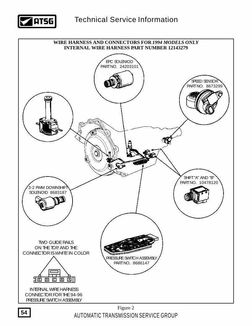
Figure 2
WIRE HARNESS AND CONNECTORS FOR 1994 MODELS ONLYINTERNAL WIRE HARNESS PART NUMBER 12143279
INTERNAL WIRE HARNESSCONNECTOR FOR THE 94-96PRESSURE SWITCH ASSEMBLY
TWO GUIDE RAILSON THE TOP, AND THE
CONNECTOR IS WHITE IN COLOR
ABCDE
PRESSURE SWITCH ASSEMBLYPART NO. 8686147
3-2 PWM DOWNSHIFTSOLENOID 8683187
SHIFT "A" AND "B"PART NO. 10478120
EPC SOLENIODPART NO. 24203101
SPEED SENSORPART NO. 8673299
AUTOMATIC TRANSMISSION SERVICE GROUP
Technical Service Information
54
TWO GUIDE RAILSON THE TOP, AND THE
CONNECTOR IS WHITE IN COLOR
ABCDE
WIRE HARNESS AND CONNECTORS FOR 1995 MODELS ONLYINTERNAL WIRE HARNESS PART NUMBER 12163009
EPC SOLENIODPART NO. 24203101
SPEED SENSORPART NO. 8673299
3-2 PWM DOWNSHIFTSOLENOID 8683187
SHIFT "A" AND "B"PART NO. 10478120
INTERNAL HARNESS CONNECTORSFOR THE 3-2 DOWNSHIFT AND THE
TCC/PWM SOLENOIDS, BLUE IN COLOR
TCC/PWM SOLENOIDPART NO. 8683187
"ADDED FOR 1995"
PRESSURE SWITCH ASSEMBLYPART NO. 8686147
FAT TAB ONLEFT SIDE
FAT TAB ONLEFT SIDE
Figure 3
AUTOMATIC TRANSMISSION SERVICE GROUP
Technical Service Information
55
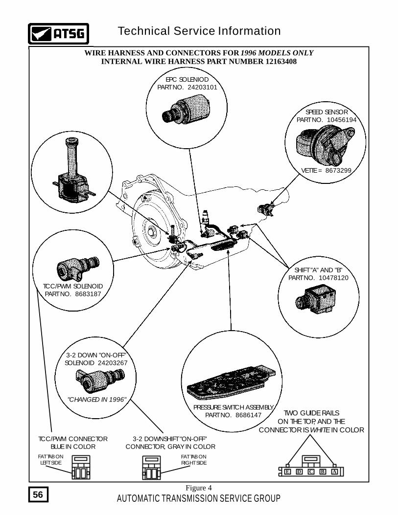
TWO GUIDE RAILSON THE TOP, AND THE
CONNECTOR IS WHITE IN COLOR
ABCDE
WIRE HARNESS AND CONNECTORS FOR 1996 MODELS ONLYINTERNAL WIRE HARNESS PART NUMBER 12163408
EPC SOLENIODPART NO. 24203101
SPEED SENSORPART NO. 10456194
VETTE = 8673299
3-2 DOWN "ON-OFF"SOLENOID 24203267
3-2 DOWNSHIFT "ON-OFF"CONNECTOR, GRAY IN COLOR
TCC/PWM CONNECTORBLUE IN COLOR
TCC/PWM SOLENOIDPART NO. 8683187
SHIFT "A" AND "B"PART NO. 10478120
"CHANGED IN 1996"PRESSURE SWITCH ASSEMBLY
PART NO. 8686147
FAT TAB ONLEFT SIDE
FAT TAB ONRIGHT SIDE
Figure 4
AUTOMATIC TRANSMISSION SERVICE GROUP
Technical Service Information
56
THM 4L60-EPREMATURE LOW/REVERSE CLUTCH FAILURE
(1993-1995 MODELS ONLY)
COMPLAINT:
CAUSE:
CORRECTION:
Figure 1
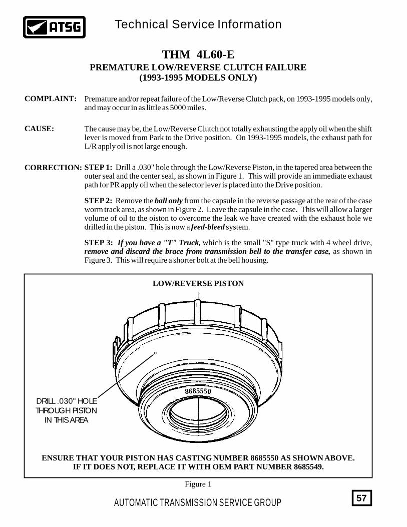
Premature and/or repeat failure of the Low/Reverse Clutch pack, on 1993-1995 models only, and may occur in as little as 5000 miles.
The cause may be, the Low/Reverse Clutch not totally exhausting the apply oil when the shift lever is moved from Park to the Drive position. On 1993-1995 models, the exhaust path for L/R apply oil is not large enough.
STEP 1: Drill a .030" hole through the Low/Reverse Piston, in the tapered area between the outer seal and the center seal, as shown in Figure 1. This will provide an immediate exhaust path for PR apply oil when the selector lever is placed into the Drive position.
STEP 2: Remove the ball only from the capsule in the reverse passage at the rear of the case worm track area, as shown in Figure 2. Leave the capsule in the case. This will allow a larger volume of oil to the oiston to overcome the leak we have created with the exhaust hole we drilled in the piston. This is now a feed-bleed system.
STEP 3: If you have a "T" Truck, which is the small "S" type truck with 4 wheel drive, remove and discard the brace from transmission bell to the transfer case, as shown in Figure 3. This will require a shorter bolt at the bell housing.
LOW/REVERSE PISTON
DRILL .030" HOLETHROUGH PISTON
IN THIS AREA
ENSURE THAT YOUR PISTON HAS CASTING NUMBER 8685550 AS SHOWN ABOVE.IF IT DOES NOT, REPLACE IT WITH OEM PART NUMBER 8685549.
85556 08
o
AUTOMATIC TRANSMISSION SERVICE GROUP
Technical Service Information
57
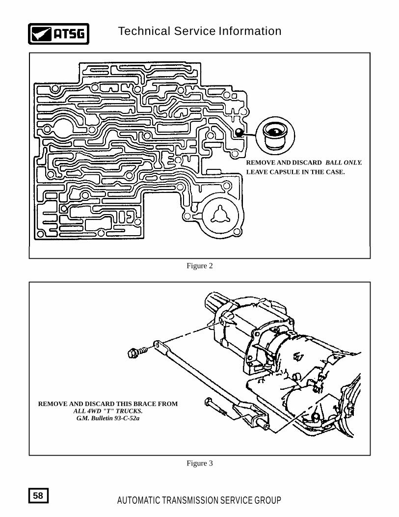
Figure 2
Figure 3
REMOVE AND DISCARD BALL ONLY.
LEAVE CAPSULE IN THE CASE.
REMOVE AND DISCARD THIS BRACE FROMALL 4WD "T" TRUCKS.G.M. Bulletin 93-C-52a
AUTOMATIC TRANSMISSION SERVICE GROUP
Technical Service Information
58
THM 4L60-ENEW MANUAL VALVE AND
VALVE BODY CASTING FOR 1996
CHANGE:
REASON:
PARTS AFFECTED:
INTERCHANGEABILITY:
Beginning at the start of production for all 1996 models, the THM 4L60-E transmissions were built with a new design Manual Valve, and a new design Valve Body Casting. Refer to Figures 1 and 2.
Improved exhaust path for Lo/Reverse clutch oil, when the selector lever is in the Drive position, which greatly improves Lo/Reverse clutch durability.
(1)
(2)
VALVE BODY CASTING - Added exhaust hole through the valve body casting in the manual valve bore, to exhaust Lo/Reverse clutch oil at a faster rate when the manual valve is in the Drive position. Refer to Figure 1 for 1995 models, and to Figure 2 for 1996 models.
MANUAL VALVE - Totally different design to accommodate the added exhaust hole in the valve body casting. Refer to Figure 1 for 1995 models, and to Figure 2 for 1996 models.
None of the parts listed above are interchangeable with one another. The 1996 valve body and manual valve cannot be used on 1995 models because of other changes that occured in the 3-2 downshift valve line up, and the 3-2 downshift solenoid.1995 parts must be used on 1995 models.1996 parts must be used on 1996 models.
AUTOMATIC TRANSMISSION SERVICE GROUP
Technical Service Information
59
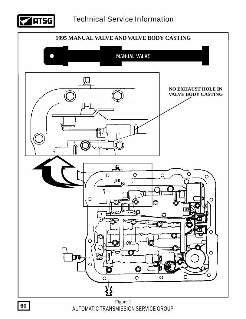
1995 MANUAL VALVE AND VALVE BODY CASTING
NO EXHAUST HOLE INVALVE BODY CASTING
Figure 1
AUTOMATIC TRANSMISSION SERVICE GROUP
Technical Service Information
60
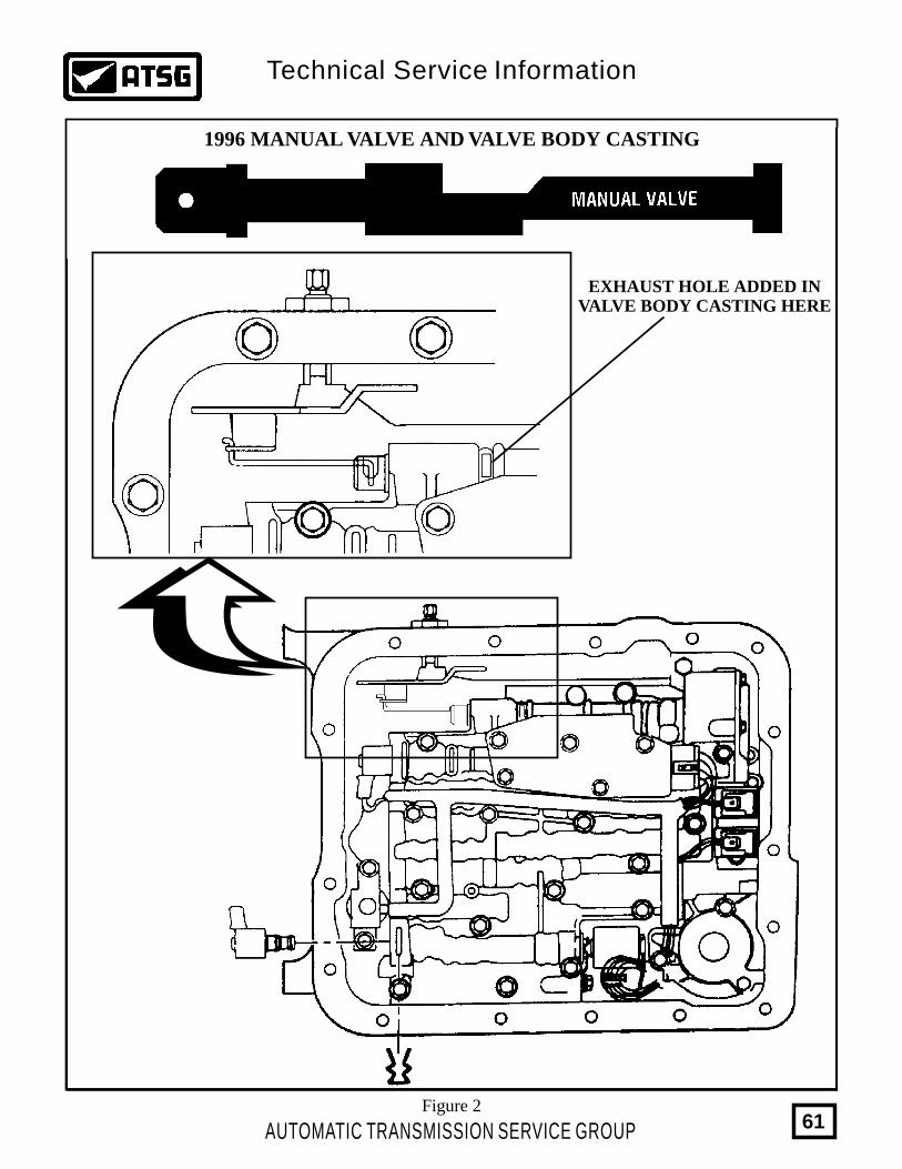
1996 MANUAL VALVE AND VALVE BODY CASTING
EXHAUST HOLE ADDED INVALVE BODY CASTING HERE
Figure 2
AUTOMATIC TRANSMISSION SERVICE GROUP
Technical Service Information
61
THM 4L60-ESOFT 1-2 UPSHIFT
COMPLAINT:
CAUSE:
CORRECTION:
SERVICE INFORMATION:
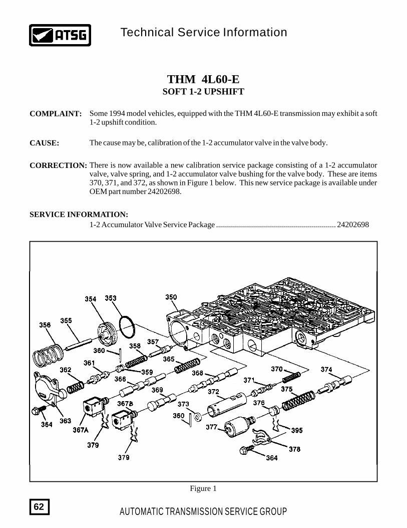
Some 1994 model vehicles, equipped with the THM 4L60-E transmission may exhibit a soft 1-2 upshift condition.
The cause may be, calibration of the 1-2 accumulator valve in the valve body.
There is now available a new calibration service package consisting of a 1-2 accumulator valve, valve spring, and 1-2 accumulator valve bushing for the valve body. These are items 370, 371, and 372, as shown in Figure 1 below. This new service package is available under OEM part number 24202698.
1-2 Accumulator Valve Service Package ............................................................ 24202698
Figure 1
AUTOMATIC TRANSMISSION SERVICE GROUP
Technical Service Information
62
THM 4L60-EACCUMULATOR PISTON WEAR
COMPLAINT:
CAUSE:
CORRECTION:
SERVICE INFORMATION:
When the accumulator piston wears with an "Egg-Shaped" hole where the accumulator piston strokes, it can create a delayed engagement to drive, slipping condition in forward gears, slipping 1-2 shift, slipping 3-4 shift, depending on which accumulator piston is worn, and how bad it is worn.
The cause may be, a worn accumulator piston pin bore (See Figure 1).
Replace the accumulator piston with the proper part number from "Service Information" as shown below.
1-2 Accumulator Piston (Package of 2) ...............................................................3-4 Accumulator Piston (Package of 2) ...............................................................Forward Clutch Accumulator Piston ...................................................................
868442986820968679738
Service Note:The THM 4L60-E, 3-4 accumulator piston is same as 700-R4.The THM 4L60-E, 1-2 accumulator piston has a smaller pin diameter.The THM 4L60-E, forward accumulator piston is a smaller outside diameter.
AUTOMATIC TRANSMISSION SERVICE GROUP
Technical Service Information
63
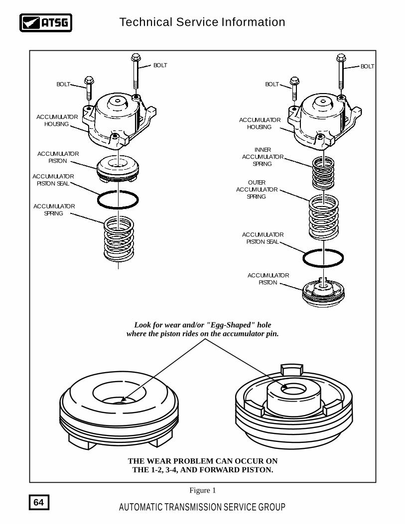
Figure 1
ACCUMULATORSPRING
ACCUMULATORPISTON SEAL
ACCUMULATORPISTON SEAL
OUTERACCUMULATOR
SPRING
INNERACCUMULATOR
SPRING
ACCUMULATORHOUSING
ACCUMULATORHOUSING
ACCUMULATORPISTON
ACCUMULATORPISTON
BOLT
BOLT
BOLT
BOLT
Look for wear and/or "Egg-Shaped" holewhere the piston rides on the accumulator pin.
THE WEAR PROBLEM CAN OCCUR ONTHE 1-2, 3-4, AND FORWARD PISTON.
AUTOMATIC TRANSMISSION SERVICE GROUP
Technical Service Information
64
THM 4L60-ENEW DESIGN 1-2 ACCUMULATOR PISTON
CHANGE:
REASON:
PARTS AFFECTED:
INTERCHANGEABILITY:
SERVICE INFORMATION:
Beginning on May 11, 1998 (Julian Date 131) all THM 4L60-E transmissions were built with a new design plastic 1-2 Accumulator Piston, and an ovate (oval) wire outer accumulator spring, to replace the previous design aluminum piston and round wire outer accumulator spring, as shown in Figure 1.
More cost effective than the aluminum piston.
(1)
(2)
1-2 ACCUMULATOR PISTON - Now manufactured out of plastic instead of the previous aluminum, which necessitated a dimensional change, as the plastic piston is thicker as shown in Figure 1.
1-2 ACCUMULATOR OUTER SPRING - Now manufactured out of an ovate (oval) wire instead of the previous design round wire, to eliminate coil bind as shown in Figure 1.
The different 1-2 Accumulator Pistons and Outer Springs are not interchangeable. When replacing these parts you must remove the 1-2 Accumulator Assembly and inspect for the presence of either the aluminum or plastic 1-2 accumulator piston.The plastic piston must use the ovate wire outer spring, and the aluminum piston must use the round wire outer spring to ensure against coil bind and spring breakage.Refer to "Service Information" below for the proper service package part numbers if replacement is necessary.
1-2 Accum. Piston Service Package, 4L60, (1982-1993 Aluminum) .......................... 242044951-2 Accum. Piston Service Package, 4L60-E, (1994-1997 Aluminum)....................... 242044961-2 Accum. Piston Service Package, 4L60-E, (1998-1999 Plastic) ............................. 24214343
Note: All service packages include the proper outer spring.
AUTOMATIC TRANSMISSION SERVICE GROUP
Technical Service Information
65
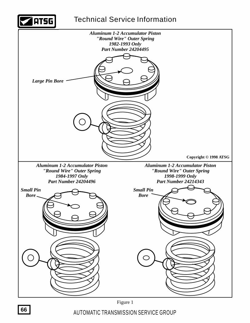
Aluminum 1-2 Accumulator Piston"Round Wire" Outer Spring
1982-1993 OnlyPart Number 24204495
Aluminum 1-2 Accumulator Piston"Round Wire" Outer Spring
1998-1999 OnlyPart Number 24214343
Aluminum 1-2 Accumulator Piston"Round Wire" Outer Spring
1984-1997 OnlyPart Number 24204496
Large Pin Bore
Small PinBore
Small PinBore
Copyright © 1998 ATSG
Figure 1
AUTOMATIC TRANSMISSION SERVICE GROUP
Technical Service Information
66
THM 4L60-ETRANSMISSION AND ENGINE OVERHEATS
1994-1996 CHEVROLET CAPRICE
COMPLAINT:
CAUSE:
CORRECTION:
Some models of 1994-1996 Chevrolet Caprice may exhibit a engine and/or transmission overheating condition, and usually occurs in heavy duty operation, such as Police and Taxi use.
The Primary Cooling Fan Relay may overheat and fail, rendering the cooling fan inoperative and resulting in the overheat condition. The Secondary fan may operate, but will not provide enough cooling air to prevent the overheat condition.
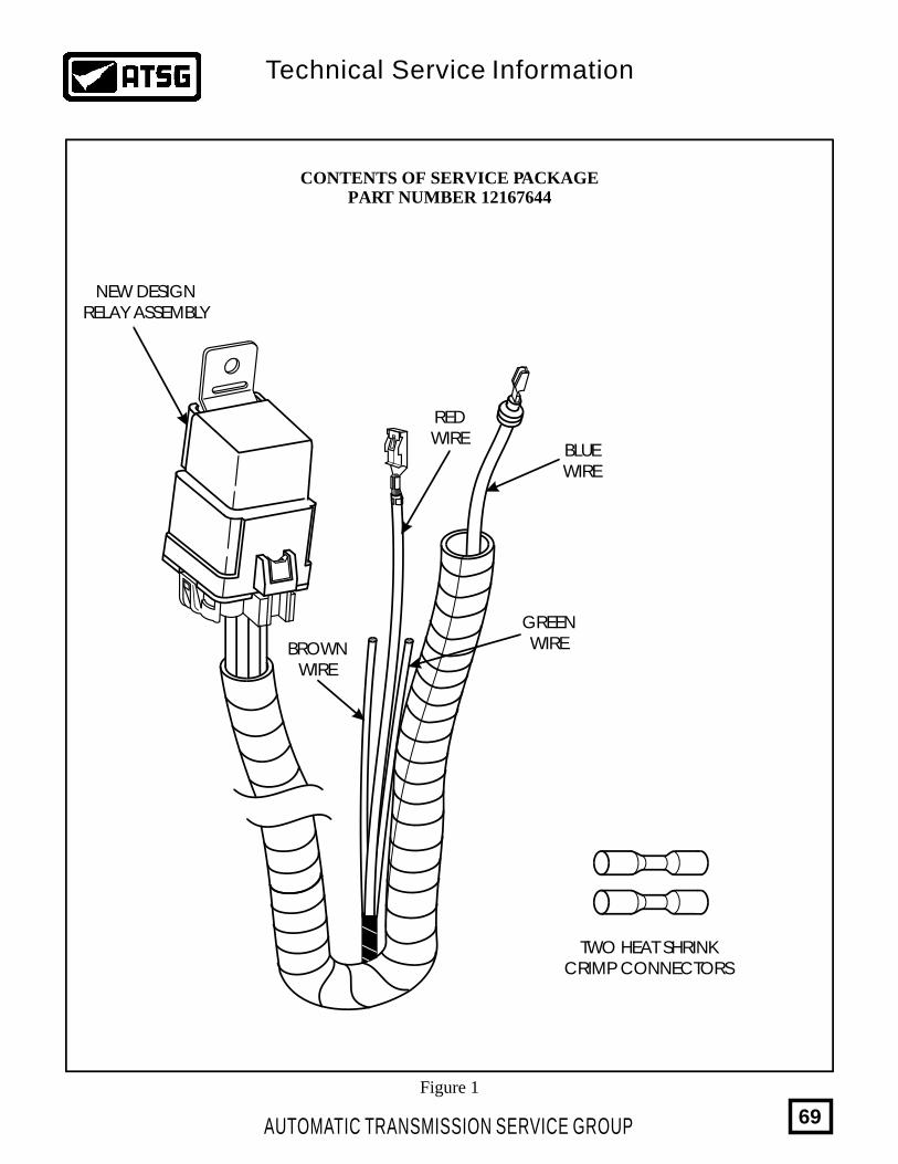
A new service package is available under OEM part number 12167644, that moves the Primary Cooling Fan Relay to a new location and upgrades the terminal ends. No instructions are provided in the service package, so you will need this bulletin for installation instructions. Contents of the service package are shown in Figure 1.
(1)
(2)
(3)
(4)
(5)
(6)
Disconnect the Negative battery cable.
Locate the underhood Electrical Center, located at the top rear of the right front wheel housing, and remove the cover.
Remove the Electrical Center from the casing, by releasing the tabs using a small screwdriver, as shown in Figure 2.
Remove the current Primary Cooling Fan Relay and the 40 Amp, number 12 Maxi-fuse, as shown in Figure 2.
From the back of the Electrical Center, as shown in Figure 3: (A) Remove the 10 gauge "Red" jumper wire and terminals from cavities "K2" and "C4", and discard this jumper wire. (B) Remove the 10 gauge "Blue" wire and terminal from cavity "B6". Cut off the terminal end and discard, and tape the wire end. (C) Remove the 22 gauge "Brown" wire and terminal from cavity "B4", and the 22 gauge "Green" wire and terminal from cavity "C6". These wires will be reused in step seven.
Locate connector number "C103", located just in front of the Electrical Center, as shown in Figure 4. Unplug the connector and remove the "Blue" 10 gauge wire and terminal from cavity "A". Cut off the terminal end and discard, and tape the bare end of the wire.
Continued on Next Page.
AUTOMATIC TRANSMISSION SERVICE GROUP
Technical Service Information
67
Installation procedure continued.
(7)
(8)
(9)
(10)
(11)
Locate the new cooling fan relay and harness assembly from the service package, and insert the "Red" wire and terminal int cavity "K2" of the Electrical Center, as shown in Figure 5. Cut the old terminal ends from the "Brown" and "Green" wires that were previously removed from the Electrical Center in Step 5, and discard. Using the crimp connectors from the service package, connect the "Brown" wire from the new harness assembly to the "Brown" wire removed from terminal "B4", as shown in Figure 5. Using the remaining crimp connector from the service package, connect the "Green" wire from the new harness assembly to the "Green" wire removed from terminal "C6", as shown in Figure 5. Heat shrink the connections to insure a water tight seal, and reinstall the Electrical Center into the case.
Reinstall the 40 Amp, number 12 Maxi-fuse.
At connector number "C103", install the "Blue" wire and terminal from the new harness assembly into cavity "A", as shown in Figure 6, and plug the connector back together.
Remove the hex nut that secures the hood ground strap to the cowl, as shown in Figure 7. Install the new cooling fan relay bracket on top of the ground strap, leaving the ground strap in place, and reinstall the hex nut. Refer to Figure 7.
Secure the new harness into position, making sure there are no rub or pinch points, reconnect the Negative battery cable, and verify the operation of the cooling fan.
ADDITIONAL "IMPORTANT" INFORMATION
It has come to our attention that some models have the external transmission cooler mounted directly behid the front bumper, and greatly restricted from the air flow. Make sure you check the mounting in the vehicle that you are working on, and if in this location, it would be advisable to "remount" the external transmission cooler so that it is higher, and in the direct air flow from the front of vehicle.
AUTOMATIC TRANSMISSION SERVICE GROUP
Technical Service Information
68
........... ...........
.. .........
CONTENTS OF SERVICE PACKAGEPART NUMBER 12167644
NEW DESIGNRELAY ASSEMBLY
REDWIRE
BLUEWIRE
BROWNWIRE
TWO HEAT SHRINKCRIMP CONNECTORS
GREENWIRE
Figure 1
AUTOMATIC TRANSMISSION SERVICE GROUP
Technical Service Information
69
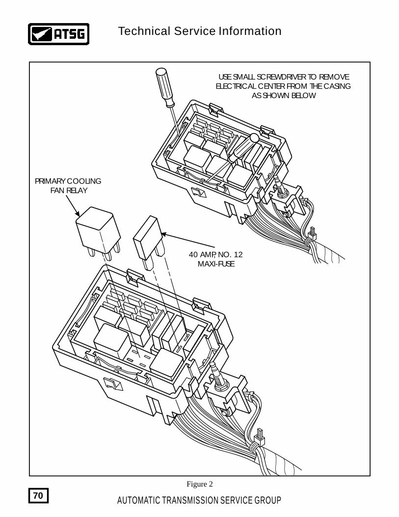
PRIMARY COOLINGFAN RELAY
USE SMALL SCREWDRIVER TO REMOVEELECTRICAL CENTER FROM THE CASING
AS SHOWN BELOW
40 AMP, NO. 12MAXI-FUSE
Figure 2
AUTOMATIC TRANSMISSION SERVICE GROUP
Technical Service Information
70
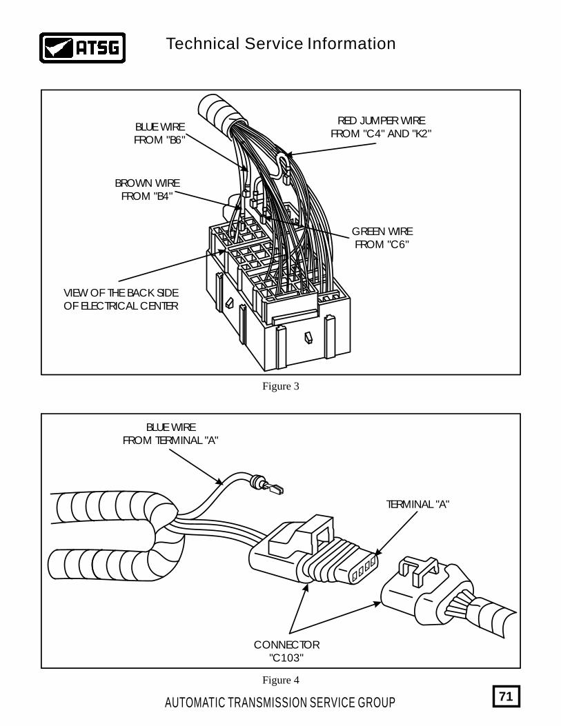
Figure 3
Figure 4
BLUE WIREFROM "B6"
BROWN WIREFROM "B4"
GREEN WIREFROM "C6"
VIEW OF THE BACK SIDEOF ELECTRICAL CENTER
RED JUMPER WIREFROM "C4" AND "K2"
CONNECTOR"C103"
BLUE WIREFROM TERMINAL "A"
TERMINAL "A"
AUTOMATIC TRANSMISSION SERVICE GROUP
Technical Service Information
71
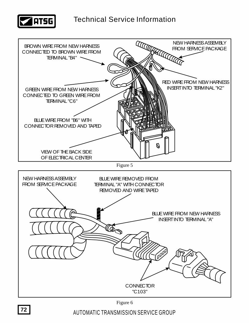
Figure 5
Figure 6
VIEW OF THE BACK SIDEOF ELECTRICAL CENTER
RED WIRE FROM NEW HARNESSINSERT INTO TERMINAL "K2"
BLUE WIRE FROM NEW HARNESSINSERT INTO TERMINAL "A"
NEW HARNESS ASSEMBLYFROM SERVICE PACKAGE
CONNECTOR"C103"
NEW HARNESS ASSEMBLYFROM SERVICE PACKAGE
BROWN WIRE FROM NEW HARNESSCONNECTED TO BROWN WIRE FROM
TERMINAL "B4"
GREEN WIRE FROM NEW HARNESSCONNECTED TO GREEN WIRE FROM
TERMINAL "C6"
BLUE WIRE FROM "B6" WITHCONNECTOR REMOVED AND TAPED
BLUE WIRE REMOVED FROMTERMINAL "A" WITH CONNECTOR
REMOVED AND WIRE TAPED
AUTOMATIC TRANSMISSION SERVICE GROUP
Technical Service Information
72
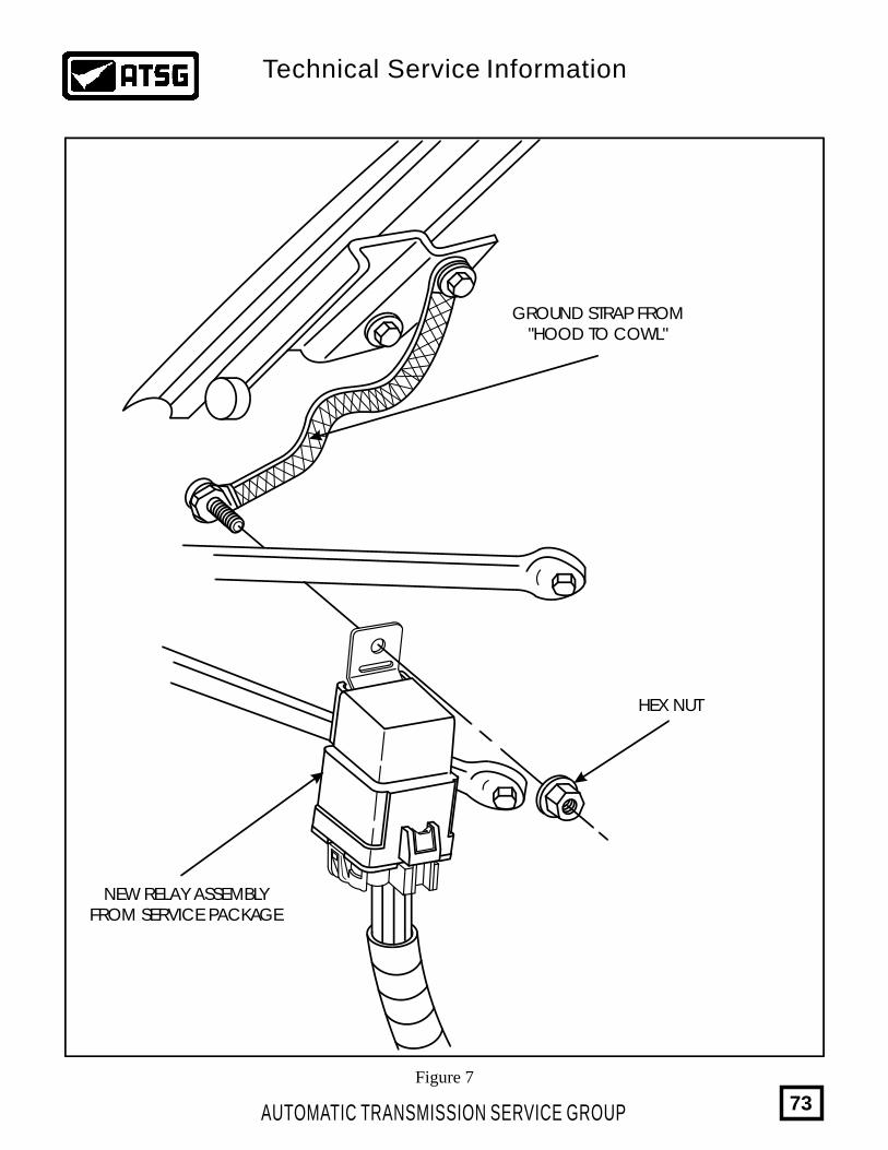
Figure 7
GROUND STRAP FROM"HOOD TO COWL"
NEW RELAY ASSEMBLYFROM SERVICE PACKAGE
HEX NUT
AUTOMATIC TRANSMISSION SERVICE GROUP
Technical Service Information
73
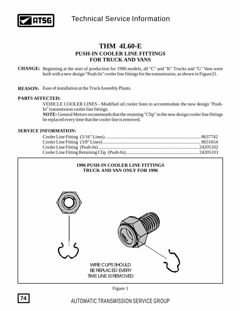
1996 PUSH-IN COOLER LINE FITTINGSTRUCK AND VAN ONLY FOR 1996
Figure 1
THM 4L60-EPUSH-IN COOLER LINE FITTINGS
FOR TRUCK AND VANS
CHANGE:
REASON:
PARTS AFFECTED:
SERVICE INFORMATION:
Beginning at the start of production for 1996 models, all "C" and "K" Trucks and "G" Vans were built with a new design "Push-In" cooler line fittings for the transmission, as shown in Figure21.
Ease of installation at the Truck Assenbly Plants.
VEHICLE COOLER LINES - Modified oil cooler lines to accommodate the new design "Push-In" transmission cooler line fittings.NOTE: General Motors recommends that the retaining "Clip" in the new design cooler line fittings be replaced every time that the cooler line is removed.
Cooler Line Fitting (5/16" Lines) ................................................................................. 8637742Cooler Line Fitting (3/8" Lines) ................................................................................... 8651654Cooler Line Fitting (Push-In) ..................................................................................... 24205102Cooler Line Fitting Retaining Clip (Push-In).............................................................. 24205103
WIRE CLIPS SHOULDBE REPLACED EVERY
TIME LINE IS REMOVED
AUTOMATIC TRANSMISSION SERVICE GROUP
Technical Service Information
74
THM 4L60-EINTERMITTENT PRESSURE RISE
ON 1996 MODELS ONLY
COMPLAINT:
CAUSE:
CORRECTION:
SERVICE INFORMATION:
Beginning at the start of production for all 1996 model vehicles equipped with the THM 4L60-E transmission, there was a VCM (Vehicle Control Module) installed on the vehicles with an internal ground wire that connects the two printed circuit boards together. Some vehicles with the VCM will display very erratic and unstable line pressure rise in the transmission, and in some instances, premature failure of the transmission.
Bad ground connection from one printed circuit board to the other.
There is now available from OEM parts sources, a new service repair kit with an instruction sheet, to repair 1996 vehicles with this condition, and is available under OEM part number 12167310.
Step Number One:
Step Number Two:
Step Number Three:
Remove the wire and terminal from location 18 in the "Clear" connector, and install one end of the jumper wire that is included in the service kit into location 18 in the "Clear" connector, and reinstall the clear connector, as shown in Figure 1.
Install the wire and terminal that was removed from cavity location 18 in the clear connector, into empty cavity location 23 of the "Blue" connector, as shown in Figure 1.
Install the other end of the included jumper wire that was previously installed in cavity 18 of the clear connector, into empty cavity location 26 of the "Red" connector, as shown in Figure 1.
12167310Service Repair Kit ..............................................................................................
AUTOMATIC TRANSMISSION SERVICE GROUP
Technical Service Information
75
AUTOMATIC TRANSMISSION SERVICE GROUP
Technical Service Information
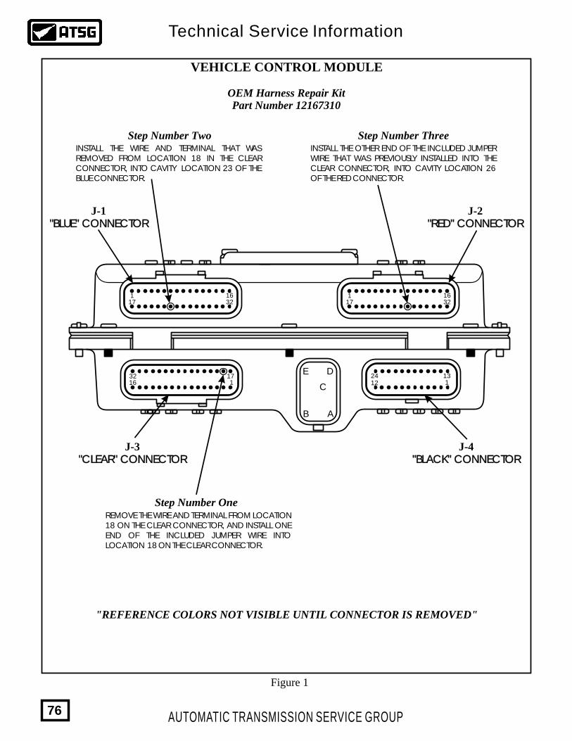
VEHICLE CONTROL MODULE
OEM Harness Repair KitPart Number 12167310
J-1 J-2
J-4J-3
"BLUE" CONNECTOR"BLUE" CONNECTOR "RED" CONNECTOR"RED" CONNECTOR
"BLACK" CONNECTOR"BLACK" CONNECTOR"CLEAR" CONNECTOR"CLEAR" CONNECTOR
163217
1 163217
1
1632 17
1 11324
12
AB
C
DE
REMOVE THE WIRE AND TERMINAL FROM LOCATION 18 ON THE CLEAR CONNECTOR, AND INSTALL ONE END OF THE INCLUDED JUMPER WIRE INTO LOCATION 18 ON THE CLEAR CONNECTOR.
INSTALL THE WIRE AND TERMINAL THAT WAS REMOVED FROM LOCATION 18 IN THE CLEAR CONNECTOR, INTO CAVITY LOCATION 23 OF THE BLUE CONNECTOR.
INSTALL THE OTHER END OF THE INCLUDED JUMPER WIRE THAT WAS PREVIOUSLY INSTALLED INTO THE CLEAR CONNECTOR, INTO CAVITY LOCATION 26 OF THE RED CONNECTOR.
Step Number One
Step Number Two Step Number Three
"REFERENCE COLORS NOT VISIBLE UNTIL CONNECTOR IS REMOVED"
Figure 1
76
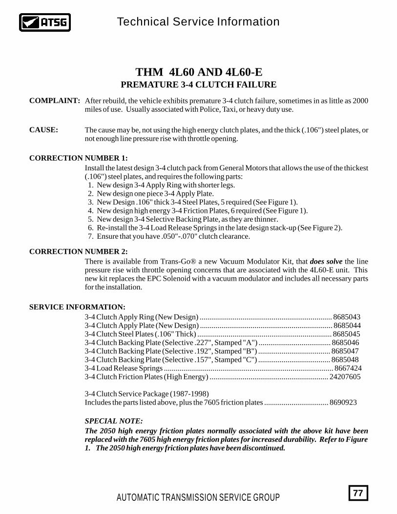
THM 4L60 AND 4L60-EPREMATURE 3-4 CLUTCH FAILURE
COMPLAINT:
CAUSE:
CORRECTION NUMBER 1:
CORRECTION NUMBER 2:
SERVICE INFORMATION:
SPECIAL NOTE:
After rebuild, the vehicle exhibits premature 3-4 clutch failure, sometimes in as little as 2000 miles of use. Usually associated with Police, Taxi, or heavy duty use.
The cause may be, not using the high energy clutch plates, and the thick (.106") steel plates, or not enough line pressure rise with throttle opening.
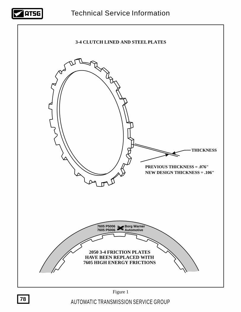
Install the latest design 3-4 clutch pack from General Motors that allows the use of the thickest (.106") steel plates, and requires the following parts: 1. New design 3-4 Apply Ring with shorter legs. 2. New design one piece 3-4 Apply Plate. 3. New Design .106" thick 3-4 Steel Plates, 5 required (See Figure 1). 4. New design high energy 3-4 Friction Plates, 6 required (See Figure 1). 5. New design 3-4 Selective Backing Plate, as they are thinner. 6. Re-install the 3-4 Load Release Springs in the late design stack-up (See Figure 2). 7. Ensure that you have .050"-.070" clutch clearance.
There is available from Trans-Go® a new Vacuum Modulator Kit, that does solve the line pressure rise with throttle opening concerns that are associated with the 4L60-E unit. This new kit replaces the EPC Solenoid with a vacuum modulator and includes all necessary parts for the installation.
3-4 Clutch Apply Ring (New Design) .................................................................... 86850433-4 Clutch Apply Plate (New Design) .................................................................... 86850443-4 Clutch Steel Plates (.106" Thick) ..................................................................... 86850453-4 Clutch Backing Plate (Selective .227", Stamped "A") ..................................... 86850463-4 Clutch Backing Plate (Selective .192", Stamped "B") ..................................... 86850473-4 Clutch Backing Plate (Selective .157", Stamped "C") ..................................... 86850483-4 Load Release Springs ....................................................................................... 86674243-4 Clutch Friction Plates (High Energy) ............................................................. 24207605
3-4 Clutch Service Package (1987-1998)Includes the parts listed above, plus the 7605 friction plates ................................. 8690923
The 2050 high energy friction plates normally associated with the above kit have been replaced with the 7605 high energy friction plates for increased durability. Refer to Figure 1. The 2050 high energy friction plates have been discontinued.
AUTOMATIC TRANSMISSION SERVICE GROUP
Technical Service Information
77
Borg WarnerAutomotive
7605 P50067605 P5006
2050 3-4 FRICTION PLATESHAVE BEEN REPLACED WITH
7605 HIGH ENERGY FRICTIONS
NEW DESIGN THICKNESS = .106"
PREVIOUS THICKNESS = .076"
THICKNESS
3-4 CLUTCH LINED AND STEEL PLATES
Figure 1
AUTOMATIC TRANSMISSION SERVICE GROUP
Technical Service Information
78
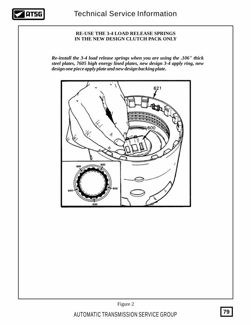
RE-USE THE 3-4 LOAD RELEASE SPRINGSIN THE NEW DESIGN CLUTCH PACK ONLY
Re-install the 3-4 load release springs when you are using the .106" thick steel plates, 7605 high energy lined plates, new design 3-4 apply ring, new design one piece apply plate and new design backing plate.
Figure 2
AUTOMATIC TRANSMISSION SERVICE GROUP
Technical Service Information
79
THM 4L60-E2ND GEAR START, 2-3 SHIFT ONLYOR LACK OF LINE PRESSURE RISE
COMPLAINT:
CAUSE:
CORRECTION:
SERVICE INFORMATION:
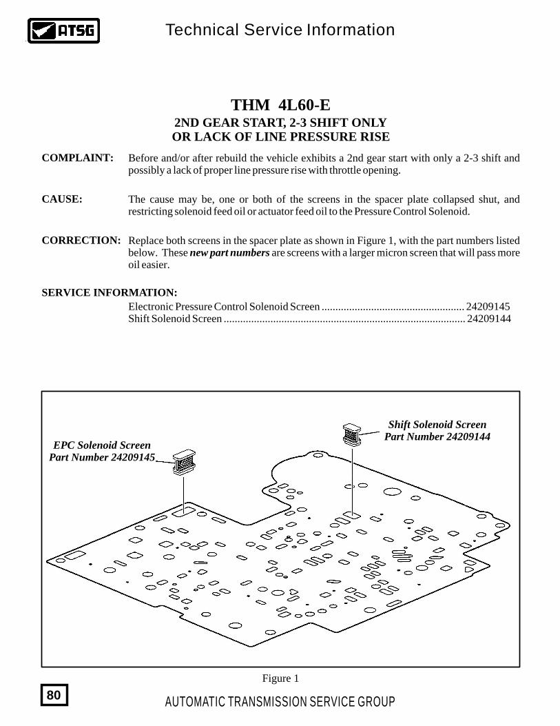
Before and/or after rebuild the vehicle exhibits a 2nd gear start with only a 2-3 shift and possibly a lack of proper line pressure rise with throttle opening.
The cause may be, one or both of the screens in the spacer plate collapsed shut, and restricting solenoid feed oil or actuator feed oil to the Pressure Control Solenoid.
Replace both screens in the spacer plate as shown in Figure 1, with the part numbers listed below. These new part numbers are screens with a larger micron screen that will pass more oil easier.
Electronic Pressure Control Solenoid Screen .................................................... 24209145Shift Solenoid Screen ........................................................................................ 24209144
EPC Solenoid ScreenPart Number 24209145
Shift Solenoid ScreenPart Number 24209144
Figure 1
AUTOMATIC TRANSMISSION SERVICE GROUP
Technical Service Information
80
THM 4L60-ENEW DESIGN OUTPUT SHAFT
SPEED SENSOR
CHANGE:
REASON:
PARTS AFFECTED:
SERVICE INFORMATION:
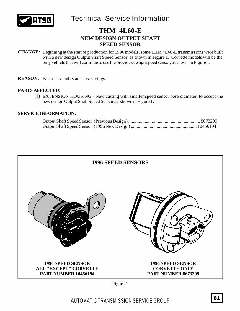
Beginning at the start of production for 1996 models, some THM 4L60-E transmissions were built with a new design Output Shaft Speed Sensor, as shown in Figure 1. Corvette models will be the only vehicle that will continue to use the previous design speed sensor, as shown in Figure 1.
Ease of assembly and cost savings.
(1) EXTENSION HOUSING - New casting with smaller speed sensor bore diameter, to accept the new design Output Shaft Speed Sensor, as shown in Figure 1.
Output Shaft Speed Sensor (Previous Design) ............................................................. 8673299Output Shaft Speed Sensor (1996 New Design) ........................................................ 10456194
AUTOMATIC TRANSMISSION SERVICE GROUP
Technical Service Information
81
1996 SPEED SENSORS
1996 SPEED SENSORCORVETTE ONLY
PART NUMBER 8673299
1996 SPEED SENSORALL "EXCEPT" CORVETTE
PART NUMBER 10456194
Figure 1
AUTOMATIC TRANSMISSION SERVICE GROUP
Technical Service Information
82
THM 4L60-ESTAMPED STEEL, MOULDED RUBBER,
FORWARD AND OVERRUN PISTONS ADDED FOR 1997
CHANGE:
REASON:
PARTS AFFECTED:
INTERCHANGEABILITY:
SERVICE INFORMATION:
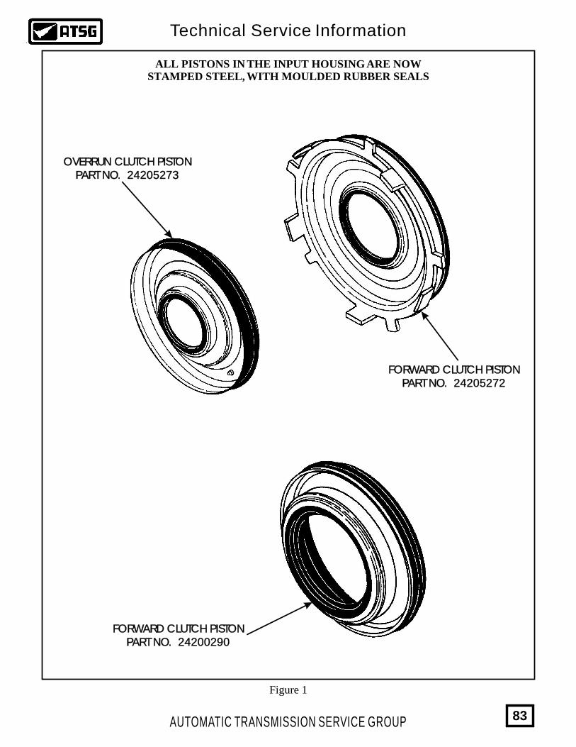
Beginning at the start of production for 1997 models, all THM 4L60-E transmissions will be built with stamped steel, moulded rubber seals for both forward and overrun clutch pistons, as shown in Figure 1. The 3-4 clutch stamped steel piston was introduced in 1993.
Cost savings and increased durability.
(1)
(2)
FORWARD CLUTCH PISTON - Now manufactured of stamped steel with moulded rubber inner and outer seals, for increased durability against cracking (See Figure 1).
OVERRUN CLUTCH PISTON - Now manufactured of stamped steel with moulded rubber inner and outer seals, for increased durability and cost savings (See Figure 1).
All of the pistons listed above, the Forward Clutch Piston, the Overrun Clutch Piston, and the 3-4 Clutch Piston will retro-fit back on all previous models, including the THM 700-R4 transmission.
(3) 3-4 CLUTCH PISTON - Now manufactured of stamped steel with moulded rubber inner and outer seals, for increased durability and cost savings (See Figure 1).
Forward Clutch Piston (Stamped Steel, Moulded Rubber) .......................................... 24205272Overrun Clutch Piston (Stamped Steel, Moulded Rubber) .......................................... 242052733-4 Clutch Piston (Stamped Steel, Moulded Rubber) .................................................. 24200290
AUTOMATIC TRANSMISSION SERVICE GROUP
Technical Service Information
83
ALL PISTONS IN THE INPUT HOUSING ARE NOWSTAMPED STEEL, WITH MOULDED RUBBER SEALS
OVERRUN CLUTCH PISTONPART NO. 24205273
OVERRUN CLUTCH PISTONPART NO. 24205273
FORWARD CLUTCH PISTONPART NO. 24205272
FORWARD CLUTCH PISTONPART NO. 24205272
FORWARD CLUTCH PISTONPART NO. 24200290
FORWARD CLUTCH PISTONPART NO. 24200290
Figure 1
THM 4L60-ENEW "DEEP" BOTTOM PAN
AND FILTER FOR 1998
CHANGE:
REASON:
PARTS AFFECTED:
INTERCHANGEABILITY:
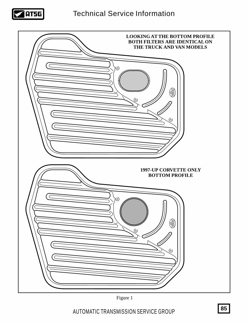
Beginning at the start of production for 1998 model vehicles, there was a new design bottom pan introduced on all "C" Trucks, "K" Trucks and "G" Vans. All other models use the regular pan, except the Corvette. The Corvette has its own pan since 1997. The new design bottom pan is approximately 17mm deeper and requires a new design filter.
Improved fluid temperature control.
(1)
(2)
BOTTOM PAN - New design is approximately 17mm deeper than the regular pan, and all three bottom pans used in 1998 models are illustrated in Figure 3 for identification purposes.
BOTTOM PAN FILTER - There are now three different filters for the 1998 model year. The bottom profile of the filters are all the same as shown in Figure 1. The side profiles however are different as the "Deep" pan requires the filter with the longer neck, the "Regular" pan requires the filter with the shorter neck, and the 97-up Corvette requires the filter with the added extension on the bottom. Refer to Figure 2.
Bottom pan filters must be used with the correct design level bottom pans and must be used on the models that they were intended for, as shown in Figures 1, 2, and 3.
AUTOMATIC TRANSMISSION SERVICE GROUP
Technical Service Information
84
FILTR
AN
SP
xx
LOOKING AT THE BOTTOM PROFILEBOTH FILTERS ARE IDENTICAL ON
THE TRUCK AND VAN MODELS
FILTR
AN
SP
xx
1997-UP CORVETTE ONLYBOTTOM PROFILE
Figure 1
AUTOMATIC TRANSMISSION SERVICE GROUP
Technical Service Information
85
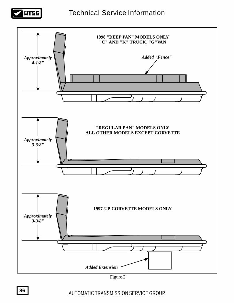
1998 "DEEP PAN" MODELS ONLY"C" AND "K" TRUCK, "G"VAN
"REGULAR PAN" MODELS ONLYALL OTHER MODELS EXCEPT CORVETTE
1997-UP CORVETTE MODELS ONLY
Added "Fence"
Added Extension
Approximately4-1/8"
Approximately3-3/8"
Approximately3-3/8"
Figure 2
AUTOMATIC TRANSMISSION SERVICE GROUP
Technical Service Information
86
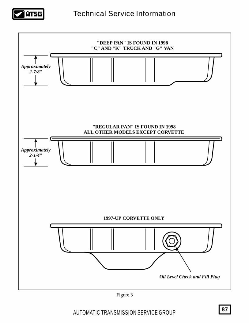
Approximately2-7/8"
Approximately2-1/4"
"DEEP PAN" IS FOUND IN 1998"C" AND "K" TRUCK AND "G" VAN
"REGULAR PAN" IS FOUND IN 1998ALL OTHER MODELS EXCEPT CORVETTE
1997-UP CORVETTE ONLY
Oil Level Check and Fill Plug
Figure 3
AUTOMATIC TRANSMISSION SERVICE GROUP
Technical Service Information
87

NEW "DIPSTICK STOP BRACKET”
CHANGE:
REASON:
PARTS AFFECTED:
INTERCHANGEABILITY:
(1)
(2)
THM 4L60-E
Beginning at the start of production for 1998 model vehicles, new design Dipstick Stop Brakets have been introduced bringing the total number of available brackets up to 3.
There was a new design bottom pan introduced on all "C" Trucks, "K" Trucks and "G" Vans. All other models use the regular pan, except the Corvette. The Corvette has its own pan since 1997. The new design bottom pan is approximately 17mm deeper and requires a new design filter and dipstick stop bracket (See Figure 1 for dipstick bracket location).
BOTTOM PAN - The 1998 new design pan is 17mm deeper than the regular pan.
VALVE BODY - The 1998 Valve body now has an added chamfer made to the casting making room for the design change to the dipstick stop bracket (See Figure 2).
Dipstick stop bracket # 1 is to be used only with regular pans on valve bodies without the additional chamfer (See Figure 2 and 3).
Dipstick stop bracket # 2 is to be used only with regular pans on valve bodies with the additional chamfer (See Figure 2 and 3).
Dipstick stop bracket # 3 is to be used only with deep pans on valve bodies with the additional chamfer (See Figure 2 and 3).
(3) DIPSTICK STOP BRACKET - There is a new dipstick stop bracket for regular pans with chamfered valve bodies and one specifically designed for deep pans with chamfered valve bodies (See Figure 3).
AUTOMATIC TRANSMISSION SERVICE GROUP
Technical Service Information
88
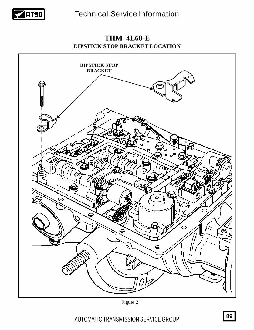
THM 4L60-EDIPSTICK STOP BRACKET LOCATION
DIPSTICK STOPBRACKET
Figure 2
AUTOMATIC TRANSMISSION SERVICE GROUP
Technical Service Information
89
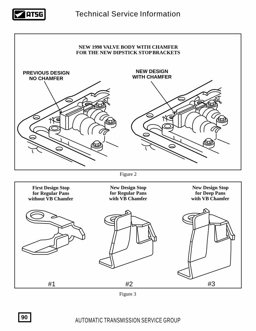
PREVIOUS DESIGNNO CHAMFER
NEW DESIGNWITH CHAMFER
NEW 1998 VALVE BODY WITH CHAMFER FOR THE NEW DIPSTICK STOP BRACKETS
#1 #2 #3
First Design Stopfor Regular Pans
without VB Chamfer
New Design Stopfor Regular Panswith VB Chamfer
New Design Stopfor Deep Pans
with VB Chamfer
Figure 2
Figure 3
AUTOMATIC TRANSMISSION SERVICE GROUP
Technical Service Information
90
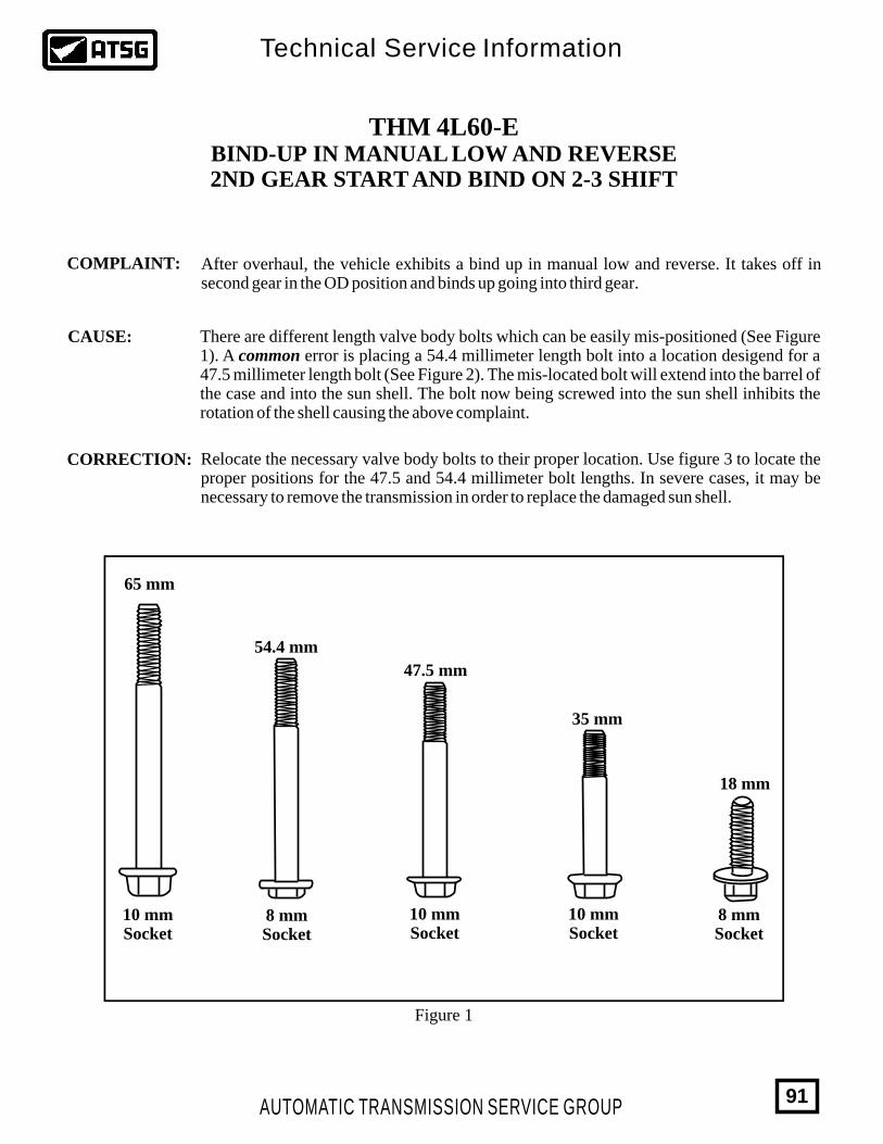
THM 4L60-EBIND-UP IN MANUAL LOW AND REVERSE2ND GEAR START AND BIND ON 2-3 SHIFT
COMPLAINT:
CORRECTION:
There are different length valve body bolts which can be easily mis-positioned (See Figure 1). A common error is placing a 54.4 millimeter length bolt into a location desigend for a 47.5 millimeter length bolt (See Figure 2). The mis-located bolt will extend into the barrel of the case and into the sun shell. The bolt now being screwed into the sun shell inhibits the rotation of the shell causing the above complaint.
After overhaul, the vehicle exhibits a bind up in manual low and reverse. It takes off in second gear in the OD position and binds up going into third gear.
Relocate the necessary valve body bolts to their proper location. Use figure 3 to locate the proper positions for the 47.5 and 54.4 millimeter bolt lengths. In severe cases, it may be necessary to remove the transmission in order to replace the damaged sun shell.
Figure 1
65 mm
54.4 mm
47.5 mm
35 mm
18 mm
10 mmSocket
CAUSE:
8 mmSocket
10 mmSocket
10 mmSocket
8 mmSocket
AUTOMATIC TRANSMISSION SERVICE GROUP
Technical Service Information
91
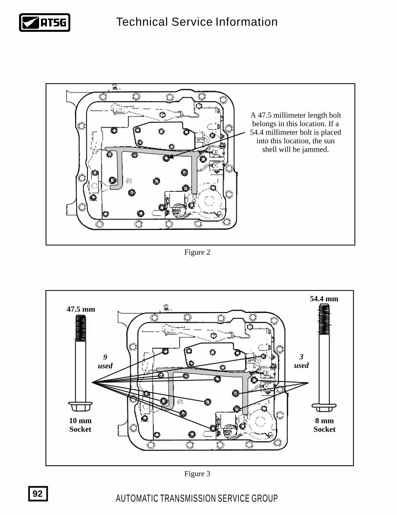
A 47.5 millimeter length boltbelongs in this location. If a
54.4 millimeter bolt is placedinto this location, the sun
shell will be jammed.
Figure 2
54.4 mm
47.5 mm
9 used
3used
Figure 3
10 mmSocket
8 mmSocket
AUTOMATIC TRANSMISSION SERVICE GROUP
Technical Service Information
92
THM 4L60-E
PARK/NEUTRAL POSITION SWITCHCONNECTOR CANNOT BE REMOVED
COMPLAINT:
CAUSE:
CORRECTION:
Technicians may experience difficulty in removing the connectord from the Park/Neutral Position Switch, on some 1995-1998 model trucks and vans, usually when trying to remove the switch during transmission service. In rare cases the customer may report switch related electrical problems, such as improper or no shift indication on the dash indicator, or no back-up light operation.
The cause may be high ambient heat causing the sealing compound in the switch to melt and flow into the connectors, sealing the connectors to the switch. This normally causes no customer concerns, but may cause an open electrical circuit in rare cases.
If the switch is being removed as part of transmission service, and there are no switch related concerns, the switch can be removed without removing the connectors, and left hanging until time to be re-installed. However, some models have a mounting bolt directly behind the switch connectors, which requires removing the connectors, and the switch will be damaged in the process (See Figure 3).There is now available from OEM sources, service repair connectors for both the 7-way and the 4-way connectors under part numbers 15305887 and 15305925 (See Figure 3).Note: The service connector pigtails use wires that are all the same color. Use the old connector as a pattern to ensure that the new wires are connected to the vehicle harness correctly. This switch is in a wet area, and it is imperative that the wires be soldered and heat-shrink tubing be used to insure water-tight connections. Refer to Figure 1 for the location of the Park/Neutral Position Switch. Refer to Figure 2 for a full wiring schematic of the Park/Neutral Position Switch circuit for diagnostic purposes.
SERVICE INFORMATION:
124500161530588715305925
Park/Neutral Position Switch (All Models) .........................................................7-Way Repair Connector Assembly (Includes Heat-Shrink Connectors) ............4-Way Repair Connector Assembly (Includes Heat-Shrink Connectors) ............
AUTOMATIC TRANSMISSION SERVICE GROUP
Technical Service Information
93
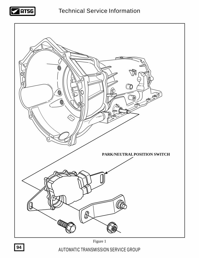
Figure 1
PARK/NEUTRAL POSITION SWITCH
AUTOMATIC TRANSMISSION SERVICE GROUP
Technical Service Information
94
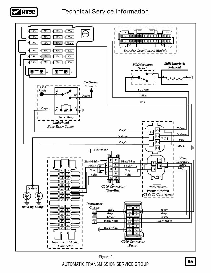
10A6 25A12
25A7
25A11
10A10
10A8
20A9 20A15
20A16
20A13
10A14
10A17
10A18 25A24
25A23
10A21
10A20
10A19
Blank22
10A5
10A4
20A3
20A2
20A1
A B
Flasher
12
10
11
9
Instrument ClusterConnector
32
31
30
23
29
22
28
21
27
20
26
19
25
18
24
17
16
15
14
7
13
6
12
5
11
4
10
3
9
2
8
1
Transfer Case Control Module
C16
D16
C1
D1
16 15 14 13 12 11 10 9 8 7 6 5 4 3 2 1
16 15 14 13 12 11 10 9 8 7 6 5 4 3 2 1
To StarterSolenoid
Purple
12 VoltSupply
Purple
Purple
Lt. GreenLt. Green
Pink
Pink
Lt. Green
Black
Yellow
Yellow
Lt. Green
Purple
Black/White
Black/White
Black/White Black/White
Black/WhiteBlack/White
Black/White
White
White
WhiteWhite
InstrumentCluster
White
Yellow Yellow
YellowYellow
Yellow
GrayGray
GrayGray
Gray
Back-up Lamps
TCC/StoplampSwitch
Shift InterlockSolenoid
Starter Relay
UnderhoodFuse-Relay Center
A9
A7
B7
B9
A
B
C
DE
F
G
C
DB
A
Park/NeutralPosition Switch
C1 & C2 Connectors
C200 Connector(Diesel)
A
D
S
N
B
E
G
R
M
K
C
F
H
P
L
J
C200 Connector(Gasoline)
CH
A
B
D
E
K
J
G
F
Figure 2
"C2"
"C1"
AUTOMATIC TRANSMISSION SERVICE GROUP
Technical Service Information
95
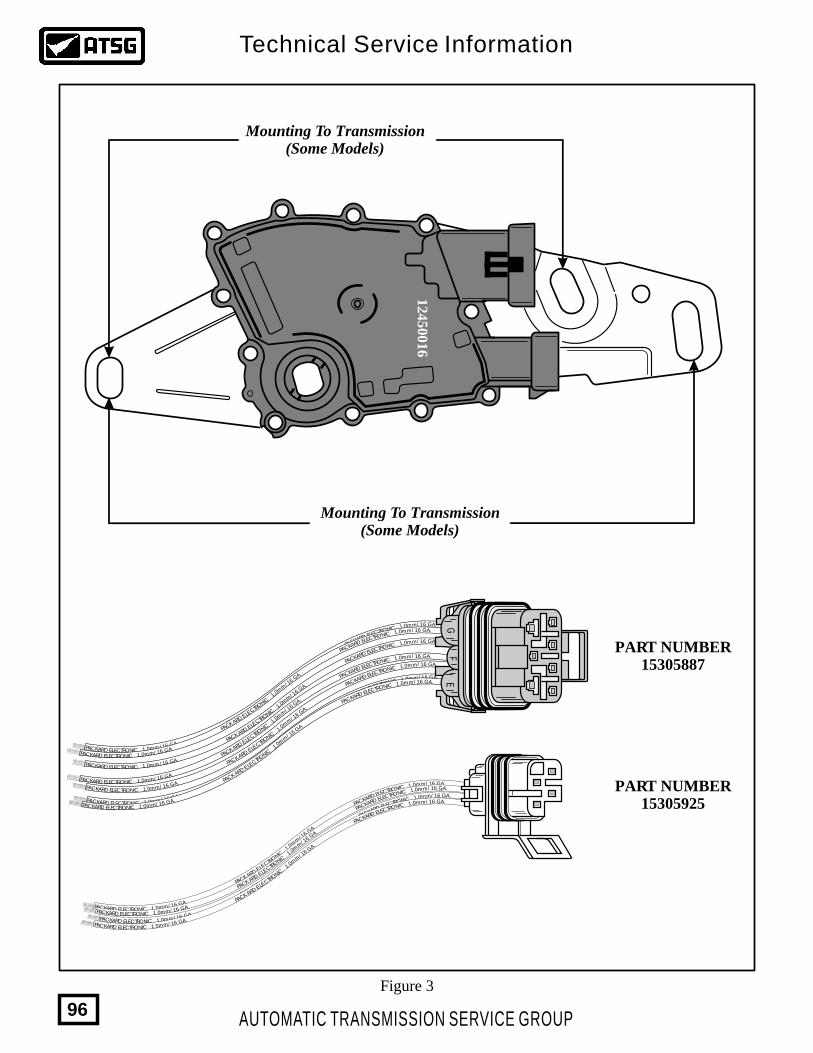
12
45001
6
Mounting To Transmission(Some Models)
Mounting To Transmission(Some Models)
Figure 3
/ 16 GA.mm.01 ICNORTCELE DRAKCAP .AG 61 /m
m0.1 CINORTCELE DRAKCAP .A G6 1PA /C mmKA .0RD 1 ELE NIC CTRO
/ 16 GA.mm.01 ICNORTCELE DRAKCAP .AG 61 /m
m0.1 CINORTCELE DRAKCAP .A G6 1PA /C mmKA .0RD 1 ELE NIC CTRO
/ 16 GA.mm.01 ICNORTCELE DRAKCAP .AG 61 /m
m0.1 CINORTCELE DRAKCAP .A G6 1PA /C mmKA .0RD 1 ELE NIC CTRO
/ 16 GA.mm.01 ICNORTCELE DRAKCAP .AG 61 /m
m0.1 CINORTCELE DRAKCAP .A G6 1PA /C mmKA .0RD 1 ELE NIC CTRO
/ 16 GA.mm.01 ICNORTCELE DRAKCAP .AG 61 /m
m0.1 CINORTCELE DRAKCAP .A G6 1PA /C mmKA .0RD 1 ELE NIC CTRO
/ 16 GA.mm.01 ICNORTCELE DRAKCAP .AG 61 /m
m0.1 CINORTCELE DRAKCAP .A G6 1PA /C mmKA .0RD 1 ELE NIC CTRO
/ 16 GA.mm.01 ICNORTCELE DRAKCAP .AG 61 /m
m0.1 CINORTCELE DRAKCAP .A G6 1PA /C mmKA .0RD 1 ELE NIC CTRO
GF
E
/ 16 GA.mm.01 ICNORTCELE DRAKCAP .AG 61 /m
m0.1 CINORTCELE DRAKCAP .A G6 1PA /C mmKA .0RD 1 ELE NIC CTRO
/ 16 GA.mm.01 ICNORTCELE DRAKCAP .AG 61 /m
m0.1 CINORTCELE DRAKCAP .A G6 1PA /C mmKA .0RD 1 ELE NIC CTRO
/ 16 GA.mm.01 ICNORTCELE DRAKCAP .AG 61 /m
m0.1 CINORTCELE DRAKCAP .A G6 1PA /C mmKA .0RD 1 ELE NIC CTRO
/ 16 GA.mm.01 ICNORTCELE DRAKCAP .AG 61 /m
m0.1 CINORTCELE DRAKCAP .A G6 1PA /C mmKA .0RD 1 ELE NIC CTRO
PART NUMBER15305925
PART NUMBER15305887
AUTOMATIC TRANSMISSION SERVICE GROUP
Technical Service Information
96
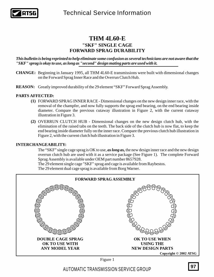
THM 4L60-E
CHANGE:
REASON:
PARTS AFFECTED:
INTERCHANGEABILITY:
Beginning in January 1995, all THM 4L60-E transmissions were built with dimensional changes on the Forward Sprag Inner Race and the Overrun Clutch Hub.
Greatly improved durability of the 29 element “SKF” Forward Sprag Assembly.
"SKF" SINGLE CAGEFORWARD SPRAG DURABILITY
FORWARD SPRAG INNER RACE - Dimensional changes on the new design inner race, with the removal of the champfer, and now fully supports the sprag end bearing, on the end bearing inside diameter. Compare the previous cutaway illustration in Figure 2, with the current cutaway illustration in Figure 3.
(1)
(2) OVERRUN CLUTCH HUB - Dimensional changes on the new design clutch hub, with the elimination of the raised tabs on the teeth. The back side of the clutch hub is now flat, to keep the end bearing inside diameter fully on the inner race. Compare the previous clutch hub illustration in Figure 2, with the current clutch hub illustration in Figure 3.
The “SKF” single cage sprag is OK to use, as long as, the new design inner race and the new design overrun clutch hub are used with it as a service package (See Figure 1). The complete Forward Sprag Assembly is available under OEM part number 8657928.The 29 element single cage "SKF" sprag and cage is available from Raybestos.The 29 element dual cage sprag is available from Borg Warner.
This bulletin is being reprinted to help eliminate some confusion as several technicians are not aware that the "SKF" sprag is okay to use, as long as "second" design mating parts are used with it.
Figure 1
Copyright © 2002 ATSG
OK TO USE WHENUSING THE
NEW DESIGN PARTS
DOUBLE CAGE SPRAGOK TO USE WITH
ANY MODEL YEAR
FORWARD SPRAG ASSEMBLY
AUTOMATIC TRANSMISSION SERVICE GROUP
Technical Service Information
97
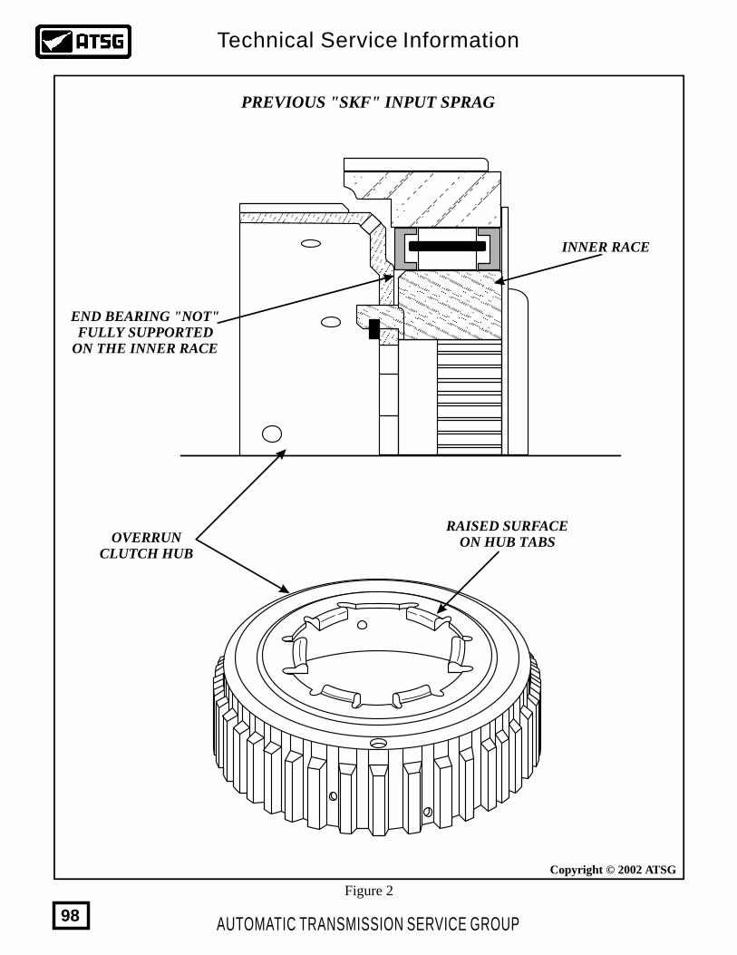
OVERRUNCLUTCH HUB
RAISED SURFACEON HUB TABS
END BEARING "NOT"FULLY SUPPORTED
ON THE INNER RACE
INNER RACE
PREVIOUS "SKF" INPUT SPRAG
Figure 2
Copyright © 2002 ATSG
AUTOMATIC TRANSMISSION SERVICE GROUP
Technical Service Information
98
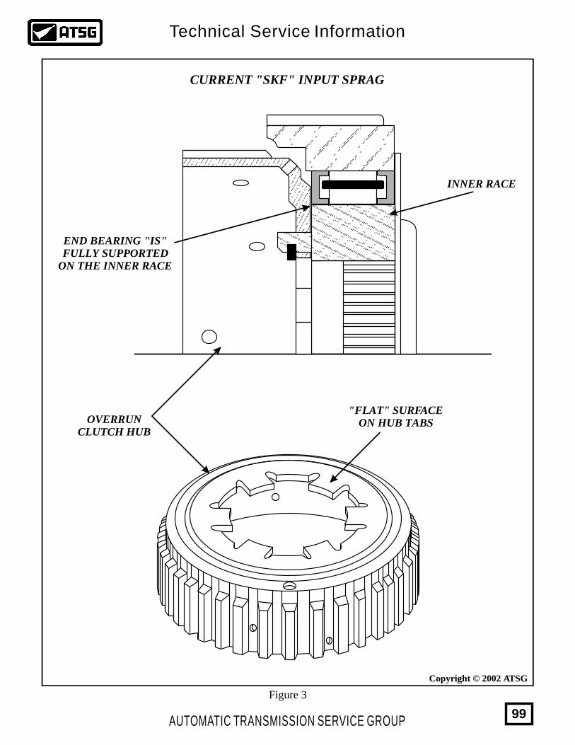
OVERRUNCLUTCH HUB
"FLAT" SURFACEON HUB TABS
END BEARING "IS"FULLY SUPPORTED
ON THE INNER RACE
INNER RACE
CURRENT "SKF" INPUT SPRAG
Figure 3
Copyright © 2002 ATSG
AUTOMATIC TRANSMISSION SERVICE GROUP
Technical Service Information
99
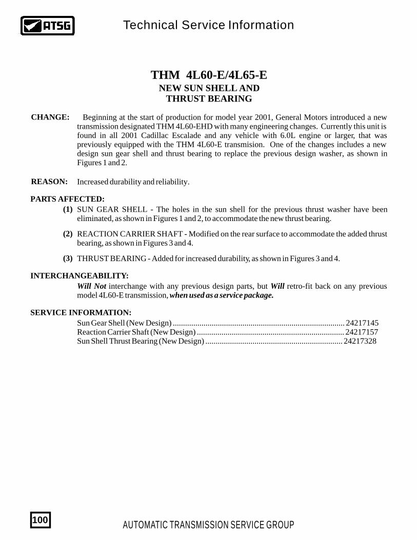
THM 4L60-E/4L65-ENEW SUN SHELL AND
THRUST BEARING
CHANGE:
REASON:
PARTS AFFECTED:
INTERCHANGEABILITY:
SERVICE INFORMATION:
Beginning at the start of production for model year 2001, General Motors introduced a new transmission designated THM 4L60-EHD with many engineering changes. Currently this unit is found in all 2001 Cadillac Escalade and any vehicle with 6.0L engine or larger, that was previously equipped with the THM 4L60-E transmision. One of the changes includes a new design sun gear shell and thrust bearing to replace the previous design washer, as shown in Figures 1 and 2.
Increased durability and reliability.
(1)
(2)
(3)
SUN GEAR SHELL - The holes in the sun shell for the previous thrust washer have been eliminated, as shown in Figures 1 and 2, to accommodate the new thrust bearing.
REACTION CARRIER SHAFT - Modified on the rear surface to accommodate the added thrust bearing, as shown in Figures 3 and 4.
THRUST BEARING - Added for increased durability, as shown in Figures 3 and 4.
Will Not interchange with any previous design parts, but Will retro-fit back on any previous model 4L60-E transmission, when used as a service package.
Sun Gear Shell (New Design) .................................................................................... 24217145Reaction Carrier Shaft (New Design) ........................................................................ 24217157Sun Shell Thrust Bearing (New Design) ................................................................... 24217328
AUTOMATIC TRANSMISSION SERVICE GROUP
Technical Service Information
100
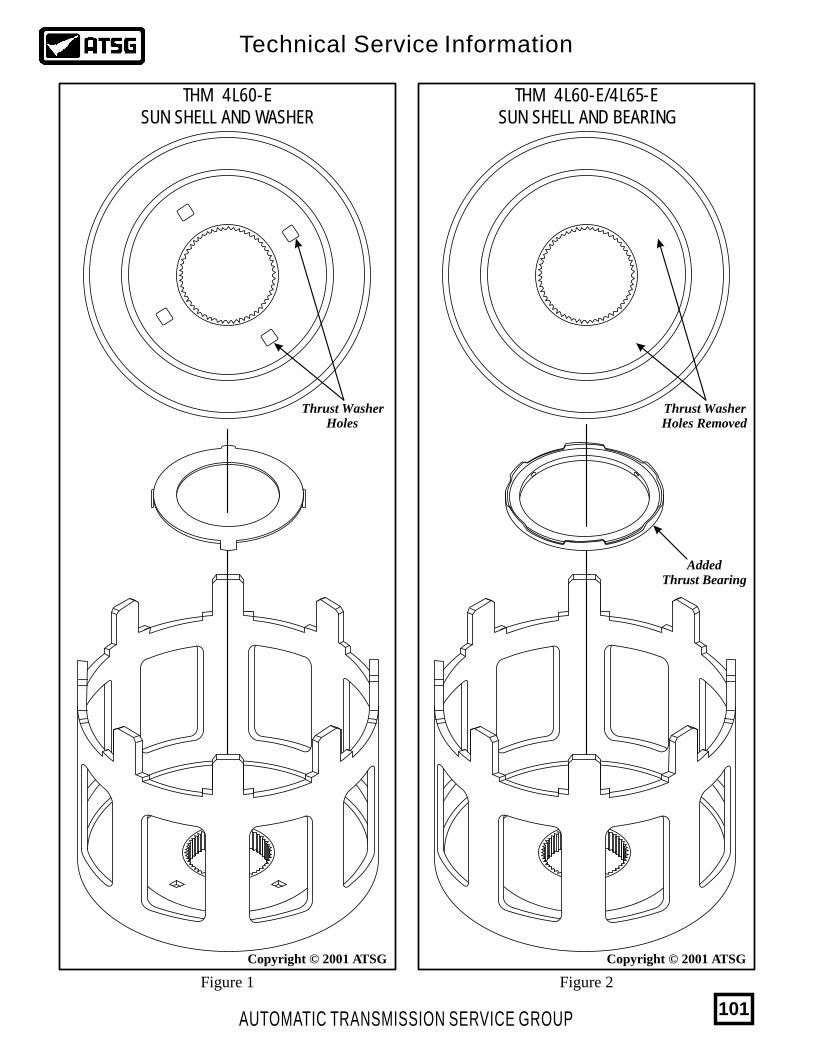
Copyright © 2001 ATSGCopyright © 2001 ATSG
THM 4L60-ESUN SHELL AND WASHER
THM 4L60-E/4L65-ESUN SHELL AND BEARING
Thrust WasherHoles
Thrust WasherHoles Removed
AddedThrust Bearing
Figure 1 Figure 2
AUTOMATIC TRANSMISSION SERVICE GROUP
Technical Service Information
101
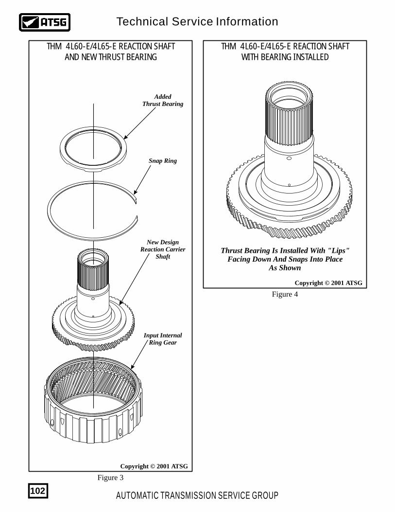
Copyright © 2001 ATSG
Copyright © 2001 ATSG
THM 4L60-E/4L65-E REACTION SHAFTWITH BEARING INSTALLED
THM 4L60-E/4L65-E REACTION SHAFTAND NEW THRUST BEARING
AddedThrust Bearing
Snap Ring
New DesignReaction Carrier
Shaft
Input InternalRing Gear
Figure 3
Figure 4
Thrust Bearing Is Installed With "Lips"Facing Down And Snaps Into Place
As Shown
AUTOMATIC TRANSMISSION SERVICE GROUP
Technical Service Information
102
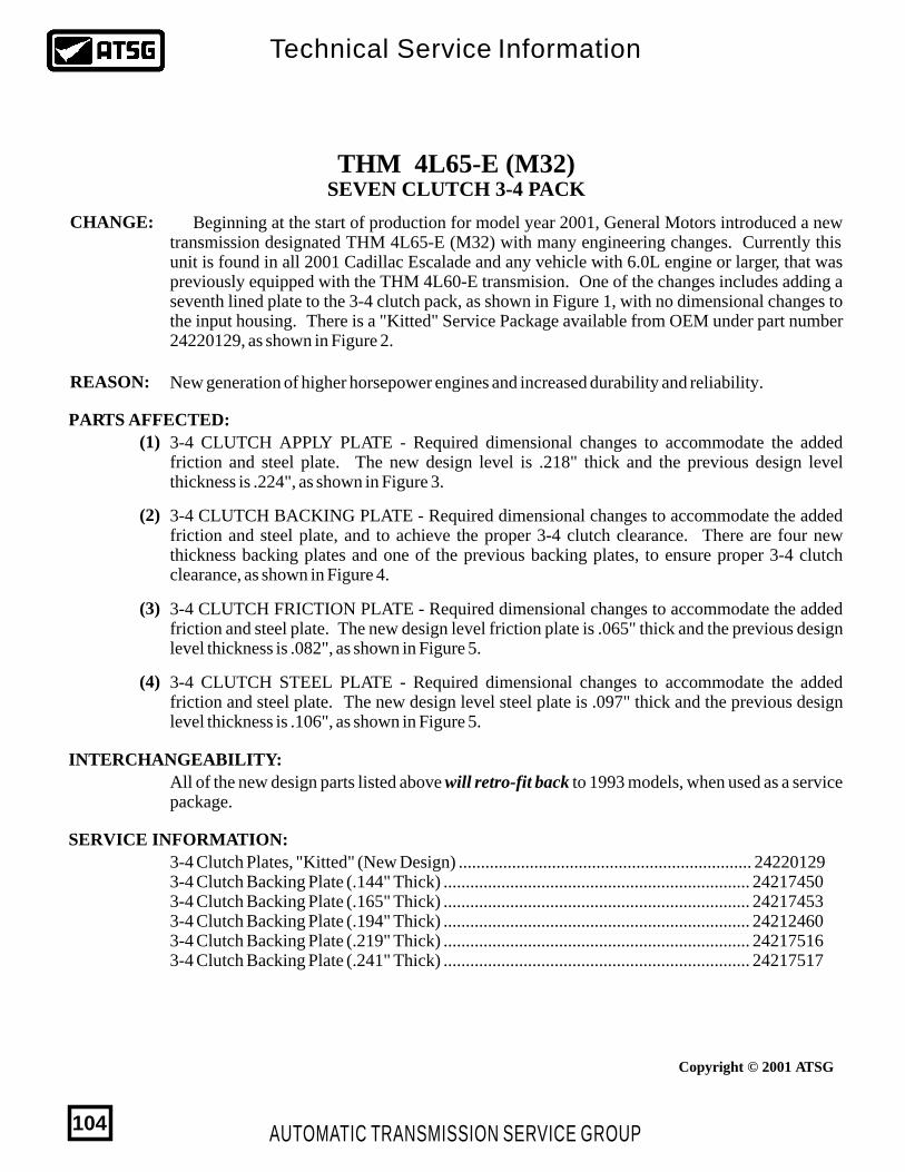
Copyright © 2001 ATSG
THM 4L65-E (M32)SEVEN CLUTCH 3-4 PACK
CHANGE:
PARTS AFFECTED:
INTERCHANGEABILITY:
SERVICE INFORMATION:
Beginning at the start of production for model year 2001, General Motors introduced a new transmission designated THM 4L65-E (M32) with many engineering changes. Currently this unit is found in all 2001 Cadillac Escalade and any vehicle with 6.0L engine or larger, that was previously equipped with the THM 4L60-E transmision. One of the changes includes adding a seventh lined plate to the 3-4 clutch pack, as shown in Figure 1, with no dimensional changes to the input housing. There is a "Kitted" Service Package available from OEM under part number 24220129, as shown in Figure 2.
REASON: New generation of higher horsepower engines and increased durability and reliability.
(1)
(2)
(3)
(4)
3-4 CLUTCH APPLY PLATE - Required dimensional changes to accommodate the added friction and steel plate. The new design level is .218" thick and the previous design level thickness is .224", as shown in Figure 3.
3-4 CLUTCH FRICTION PLATE - Required dimensional changes to accommodate the added friction and steel plate. The new design level friction plate is .065" thick and the previous design level thickness is .082", as shown in Figure 5.
3-4 CLUTCH STEEL PLATE - Required dimensional changes to accommodate the added friction and steel plate. The new design level steel plate is .097" thick and the previous design level thickness is .106", as shown in Figure 5.
3-4 CLUTCH BACKING PLATE - Required dimensional changes to accommodate the added friction and steel plate, and to achieve the proper 3-4 clutch clearance. There are four new thickness backing plates and one of the previous backing plates, to ensure proper 3-4 clutch clearance, as shown in Figure 4.
All of the new design parts listed above will retro-fit back to 1993 models, when used as a service package.
3-4 Clutch Plates, "Kitted" (New Design) .................................................................. 242201293-4 Clutch Backing Plate (.144" Thick) ..................................................................... 242174503-4 Clutch Backing Plate (.165" Thick) ..................................................................... 242174533-4 Clutch Backing Plate (.194" Thick) ..................................................................... 242124603-4 Clutch Backing Plate (.219" Thick) ..................................................................... 242175163-4 Clutch Backing Plate (.241" Thick) ..................................................................... 24217517
AUTOMATIC TRANSMISSION SERVICE GROUP
Technical Service Information
104
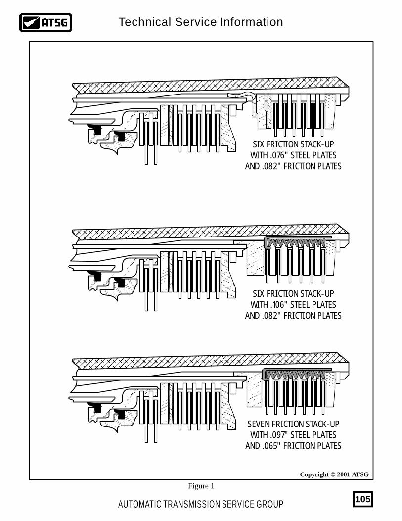
Copyright © 2001 ATSG
SEVEN FRICTION STACK-UPWITH .097" STEEL PLATES
AND .065" FRICTION PLATES
SIX FRICTION STACK-UPWITH .076" STEEL PLATES
AND .082" FRICTION PLATES
SIX FRICTION STACK-UPWITH .106" STEEL PLATES
AND .082" FRICTION PLATES
Figure 1
AUTOMATIC TRANSMISSION SERVICE GROUP
Technical Service Information
105
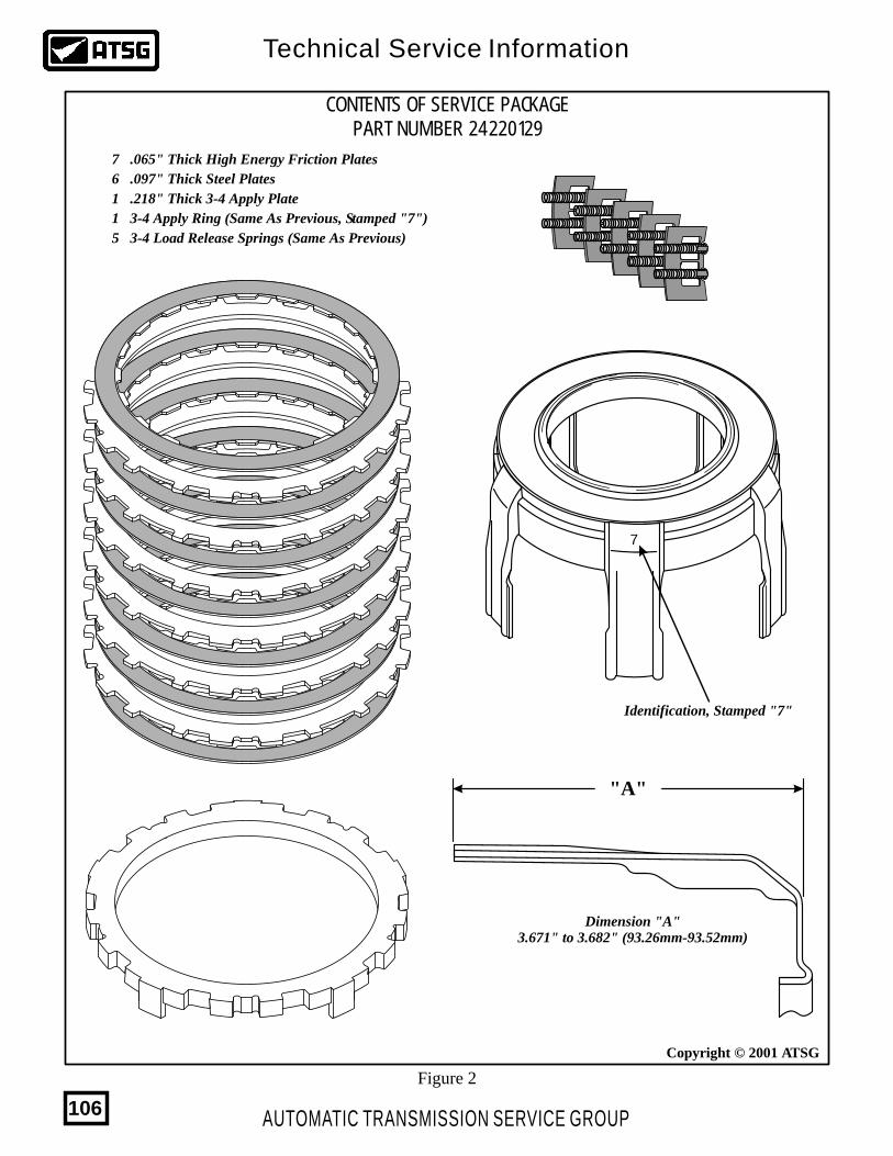
Copyright © 2001 ATSG
CONTENTS OF SERVICE PACKAGEPART NUMBER 24220129
Figure 2
7 .065" Thick High Energy Friction Plates
6 .097" Thick Steel Plates
1 .218" Thick 3-4 Apply Plate
1 3-4 Apply Ring (Same As Previous, Stamped "7")
5 3-4 Load Release Springs (Same As Previous)
Dimension "A"3.671" to 3.682" (93.26mm-93.52mm)
Identification, Stamped "7"
7
"A"
AUTOMATIC TRANSMISSION SERVICE GROUP
Technical Service Information
106
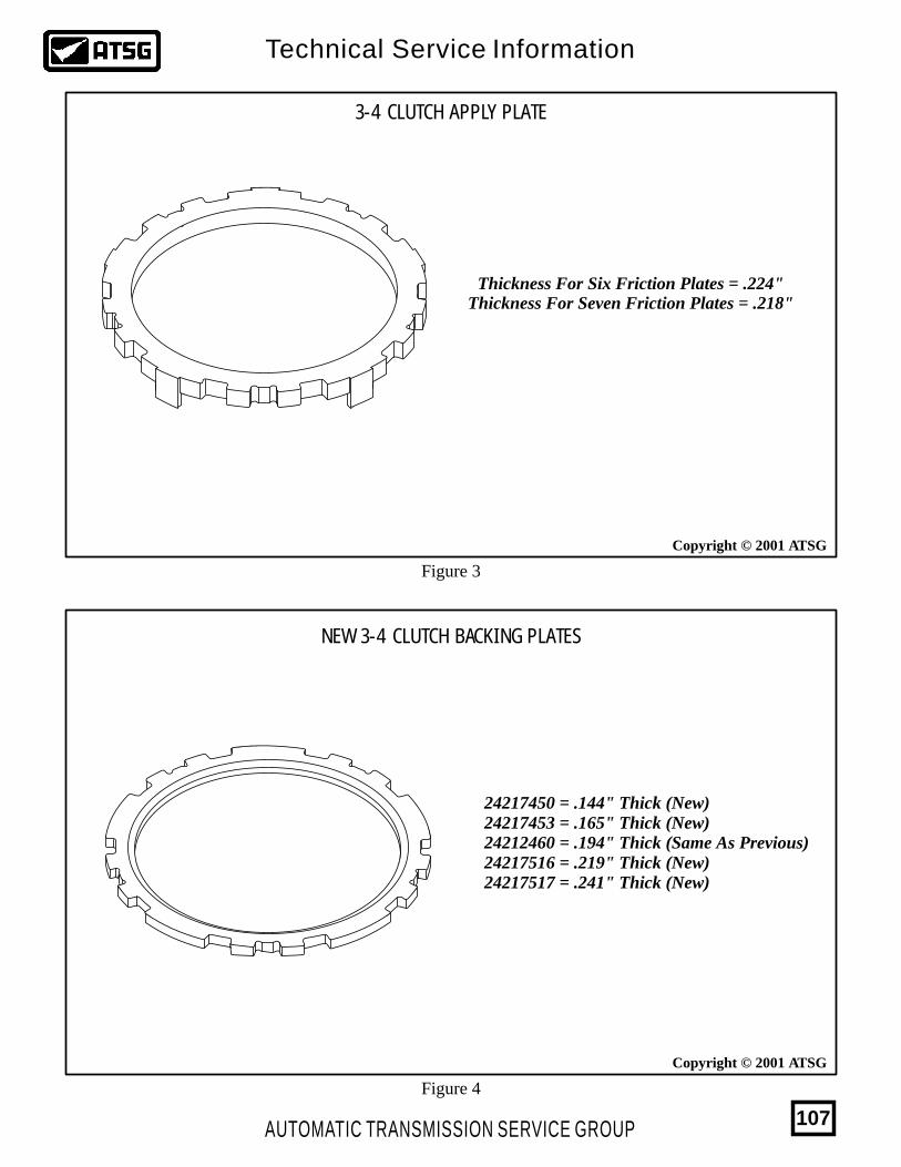
Copyright © 2001 ATSG
Copyright © 2001 ATSG
3-4 CLUTCH APPLY PLATE
NEW 3-4 CLUTCH BACKING PLATES
Figure 4
Figure 3
Thickness For Six Friction Plates = .224"Thickness For Seven Friction Plates = .218"
24217450 = .144" Thick (New)24217453 = .165" Thick (New)24212460 = .194" Thick (Same As Previous)24217516 = .219" Thick (New)24217517 = .241" Thick (New)
AUTOMATIC TRANSMISSION SERVICE GROUP
Technical Service Information
107
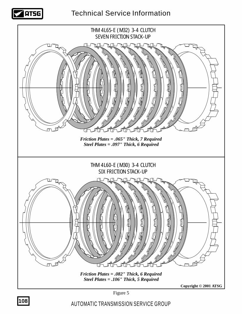
Copyright © 2001 ATSG
THM 4L65-E (M32) 3-4 CLUTCHSEVEN FRICTION STACK-UP
THM 4L60-E (M30) 3-4 CLUTCHSIX FRICTION STACK-UP
Friction Plates = .065" Thick, 7 Required
Friction Plates = .082" Thick, 6 Required
Steel Plates = .097" Thick, 6 Required
Steel Plates = .106" Thick, 5 Required
Figure 5
AUTOMATIC TRANSMISSION SERVICE GROUP
Technical Service Information
108

http://www.atsgmiami.com
YOU CAN STILL SHOP AT HOME OR WORK FOR YOUR FAVORITE ATSGPRODUCTS. VISIT OUR NEW WEB SITES FOR MANUALS, SOFTWARE,
ATSG IS NOW ONLINE WITH BULLETIN SERVICEWITH A VALID ATSG SUBSCRIBER NUMBER
http://www.atsg.bizhttp://www.transonline.com
http://www.atsgmiami.com
Online
AUTOMATIC TRANSMISSION SERVICE GROUP
Technical Service Information
109
THM 4L65-E5 PINION FRONT AND REAR
PLANETARY CARRIERS
CHANGE:
REASON:
PARTS AFFECTED:
INTERCHANGEABILITY:
SERVICE INFORMATION:
Special Note:
Beginning at the start of production for model year 2001, General Motors introduced a new transmission designated THM 4L65-E with many engineering changes. Currently this unit is found in all 2001 Cadillac Escalade and any vehicle with 6.0L engine or larger, that was previously equipped with the THM 4L60-E transmision. One of the changes includes adding a 5 pinion reaction(rear) planetary carrier and a 5 pinion input (front) planetary carrier, as shown in Figures 1 and 2, with no dimensional changes to the related parts.
Increased durability and reliability.
(1)
(2)
REACTION (Rear) PLANETARY CARRIER - Now equipped with 5 planetary pinion gears, as shown in Figure 1.
INPUT (Front) PLANETARY CARRIER - Now equipped with 5 planetary pinion gears, as shown in Figure 2.
Both Input and Reaction 5 pinion planetary carriers can be used in any previous model 4L60-E transmission for increased durability.
Input Planetary Carrier Assembly, 5 Pinion ............................................................... 24218063Reaction Planetary Carrier Assembly, 5 Pinion ......................................................... 24218069
ATSG has recieved several calls on these units with the reaction (rear) ring gear broken. Since the part number changed but the dimensions did not, it would be logical to assume that the manufacturing process changed in some manner. Our recommended procedure, at this time, is to replace it with a reaction ring gear from a THM 4L60-E transmission and available under OEM part number 8667055.
AUTOMATIC TRANSMISSION SERVICE GROUP
Technical Service Information
110
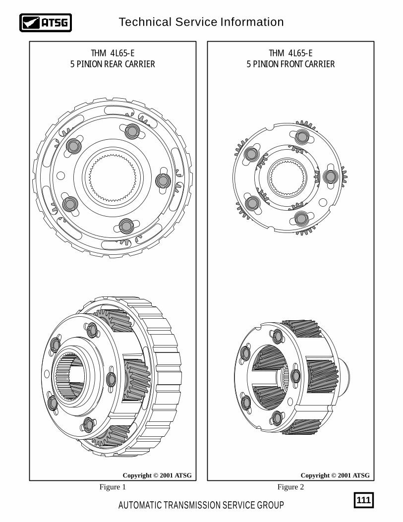
Copyright © 2001 ATSGCopyright © 2001 ATSG
THM 4L65-E5 PINION REAR CARRIER
THM 4L65-E5 PINION FRONT CARRIER
Figure 1 Figure 2
AUTOMATIC TRANSMISSION SERVICE GROUP
Technical Service Information
111
Copyright © 2002 ATSG
THM 4L60-ENEW DESIGN VALVE BODY AND
SPACER PLATE FOR 2001
CHANGE:
REASON:
PARTS AFFECTED:
INTERCHANGEABILITY:
Beginning at the start of production for 2001, all 4L60-E transmissions were produced with a new design converter clutch regulator valve line-up located in the valve body, in the location shown in Figure 1.
Reduced bore wear and improved performance for apply and release of the converter clutch.
(1)
(2)
(3)
TCC REGULATOR AND ISOLATOR VALVES - This line-up now has re-designed aluminum TCC Regulator Valve and Isolator Valves, instead of the previous steel, as shown in Figure 1.
VALVE BODY CASTING - Has changed in the worm track areas that are identified inside the circles, as shown in Figure 2, to accommodate the new design converter clutch regulator and isolator valves.
SPACER PLATE - There are two holes in the spacer plate that have been revised, as shown in Figure 3, to accommodate the new design converter clutch regulator and isolator valves.
None of the parts listed above will interchange with the previous design level parts. However, when new design valve body and spacer plate are used as a service package, they will back service to 1998 models.
AUTOMATIC TRANSMISSION SERVICE GROUP
Technical Service Information
112
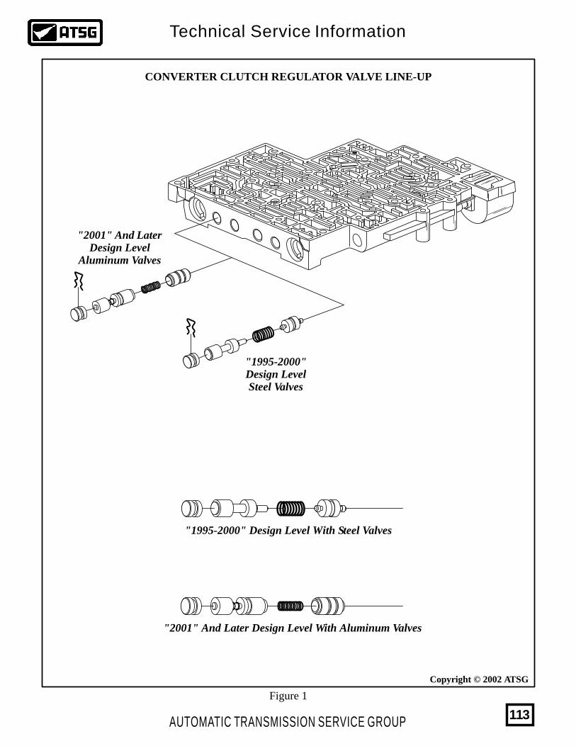
Copyright © 2002 ATSG
"2001" And LaterDesign Level
Aluminum Valves
"2001" And Later Design Level With Aluminum Valves
"1995-2000"Design LevelSteel Valves
"1995-2000" Design Level With Steel Valves
CONVERTER CLUTCH REGULATOR VALVE LINE-UP
Figure 1
AUTOMATIC TRANSMISSION SERVICE GROUP
Technical Service Information
113
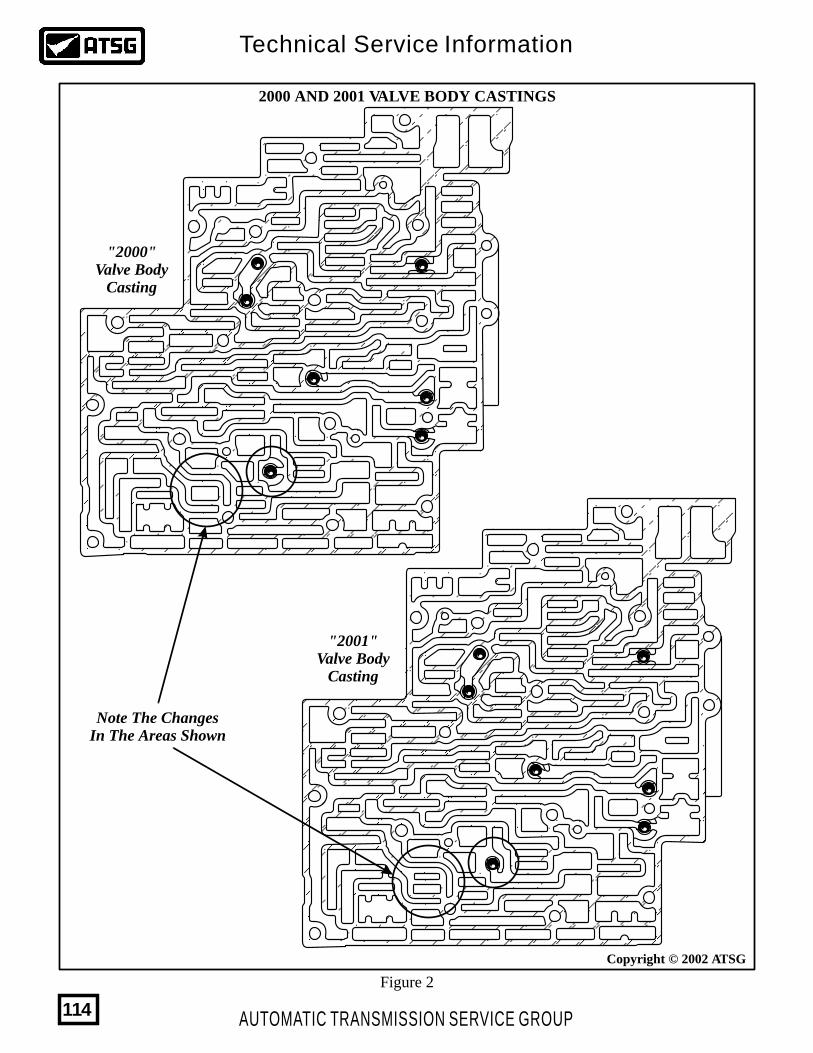
Note The ChangesIn The Areas Shown
"2000"Valve Body
Casting
"2001"Valve Body
Casting
2000 AND 2001 VALVE BODY CASTINGS
Copyright © 2002 ATSG
Figure 2
AUTOMATIC TRANSMISSION SERVICE GROUP
Technical Service Information
114
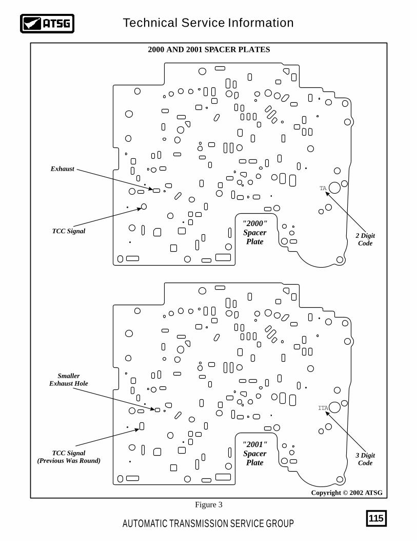
ITA
SmallerExhaust Hole
TCC Signal(Previous Was Round)
TA
TCC Signal2 DigitCode
3 DigitCode
Exhaust
"2001"SpacerPlate
"2000"SpacerPlate
Copyright © 2002 ATSG
2000 AND 2001 SPACER PLATES
Figure 3
AUTOMATIC TRANSMISSION SERVICE GROUP
Technical Service Information
115
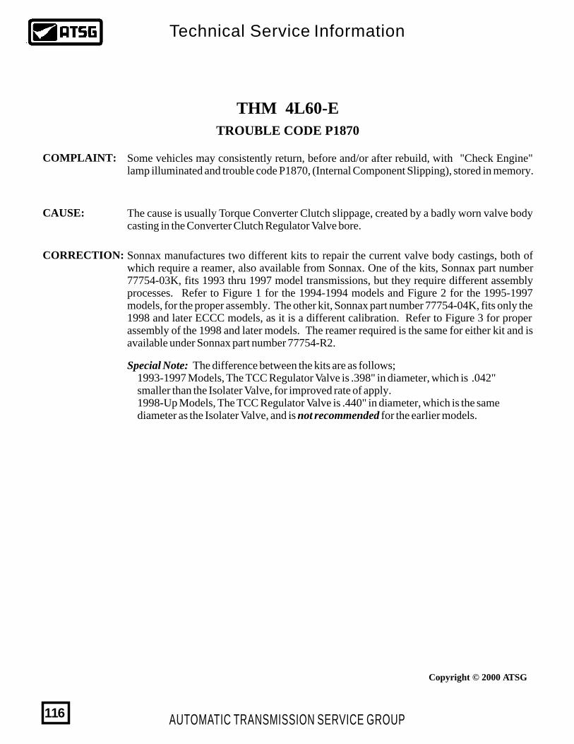
Copyright © 2000 ATSG
THM 4L60-ETROUBLE CODE P1870
COMPLAINT:
CAUSE:
CORRECTION:
Some vehicles may consistently return, before and/or after rebuild, with "Check Engine" lamp illuminated and trouble code P1870, (Internal Component Slipping), stored in memory.
The cause is usually Torque Converter Clutch slippage, created by a badly worn valve body casting in the Converter Clutch Regulator Valve bore.
Sonnax manufactures two different kits to repair the current valve body castings, both of which require a reamer, also available from Sonnax. One of the kits, Sonnax part number 77754-03K, fits 1993 thru 1997 model transmissions, but they require different assembly processes. Refer to Figure 1 for the 1994-1994 models and Figure 2 for the 1995-1997 models, for the proper assembly. The other kit, Sonnax part number 77754-04K, fits only the 1998 and later ECCC models, as it is a different calibration. Refer to Figure 3 for proper assembly of the 1998 and later models. The reamer required is the same for either kit and is available under Sonnax part number 77754-R2.
Special Note: The difference between the kits are as follows; 1993-1997 Models, The TCC Regulator Valve is .398" in diameter, which is .042" smaller than the Isolater Valve, for improved rate of apply. 1998-Up Models, The TCC Regulator Valve is .440" in diameter, which is the same diameter as the Isolater Valve, and is not recommended for the earlier models.
AUTOMATIC TRANSMISSION SERVICE GROUP
Technical Service Information
116
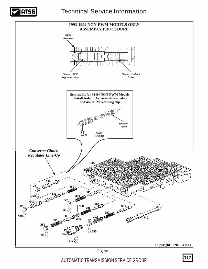
Copyright © 2000 ATSG
1993-1994 NON-PWM MODELS ONLYASSEMBLY PROCEDURE
Sonnax kit for 93-94 NON-PWM Models:Install Isolator Valve as shown below
and use OEM retaining clip.
IsolatorValve
Sonnax IsolatorValve
Sonnax TCCRegulator Valve
OEMRetainer
OEMRetainer
Converter ClutchRegulator Line-Up
Figure 1
AUTOMATIC TRANSMISSION SERVICE GROUP
Technical Service Information
117
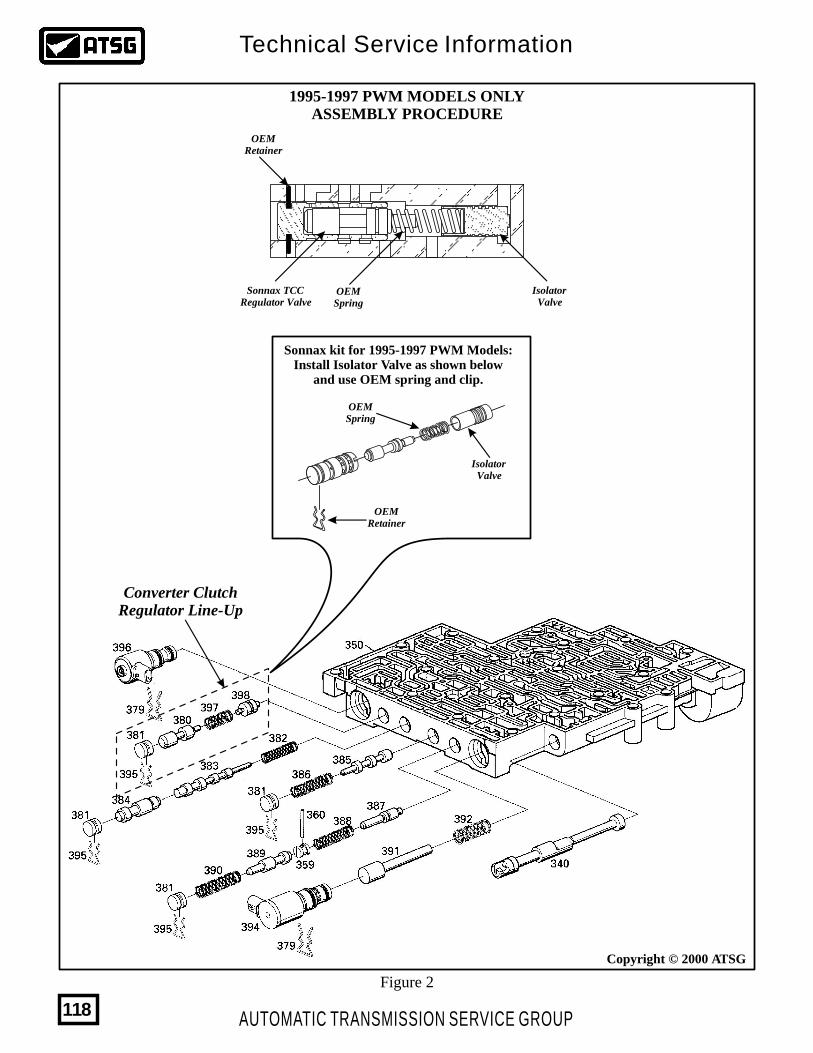
Copyright © 2000 ATSG
1995-1997 PWM MODELS ONLYASSEMBLY PROCEDURE
Sonnax kit for 1995-1997 PWM Models:Install Isolator Valve as shown below
and use OEM spring and clip.
IsolatorValve
OEMSpring
OEMRetainer
Converter ClutchRegulator Line-Up
IsolatorValve
OEMRetainer
OEMSpring
Figure 2
Sonnax TCCRegulator Valve
AUTOMATIC TRANSMISSION SERVICE GROUP
Technical Service Information
118
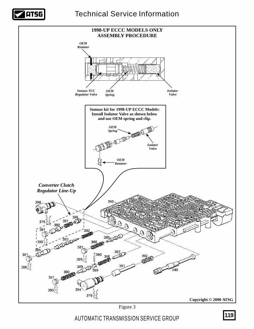
Copyright © 2000 ATSG
1998-UP ECCC MODELS ONLYASSEMBLY PROCEDURE
Sonnax kit for 1998-UP ECCC Models:Install Isolator Valve as shown below
and use OEM spring and clip.
IsolatorValve
OEMSpring
OEMRetainer
Converter ClutchRegulator Line-Up
IsolatorValve
OEMRetainer
OEMSpring
Figure 3
Sonnax TCCRegulator Valve
AUTOMATIC TRANSMISSION SERVICE GROUP
Technical Service Information
119

AUTOMATIC TRANSMISSION SERVICE GROUP
Technical Service Information
120
THE MOST COMPLETE LINE OF DOMESTIC AND IMPORT MANUALS
IS NOW AVAILABLE FORALL WINDOWS AND MAC OPERATING
FOR MORE INFORMATION CALL(800) 245-7722
OR VISIT US ON THE WEB
Adobe
FordFord
F7TP
-7F2
93-A
A
F7TP
-7F2
93-A
A
NEUTRAL
NEUTRAL LL CC
Ford Ford
5050F8T1-DBF8T1-DB
PRA-YCPRA-YC
BD-4J03BD-4J03
4 X 44 X 4
65206520
0000144700001447
0000144700001447
AUTOMATIC TRANSMISSIONSERVICE GROUP