4l60e overhaul manual
DESCRIPTION
Manual to rebuild General Motors/Chevrolet 4L60e transmission.TRANSCRIPT
M. Miller AUTO 211 4L60-E
4L60-E Overhaul Procedures
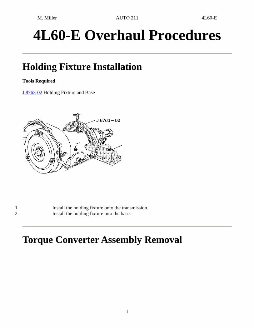
Holding Fixture Installation Tools Required
J 8763-02 Holding Fixture and Base
1. Install the holding fixture onto the transmission. 2. Install the holding fixture into the base.
Torque Converter Assembly Removal
1
M. Miller AUTO 211 4L60-E
2
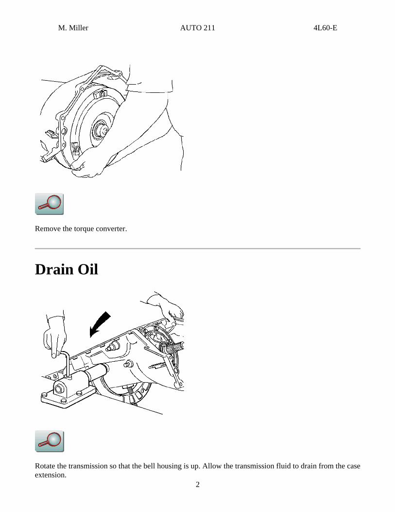
Remove the torque converter.
Drain Oil
Rotate the transmission so that the bell housing is up. Allow the transmission fluid to drain from the case extension.
M. Miller AUTO 211 4L60-E
3
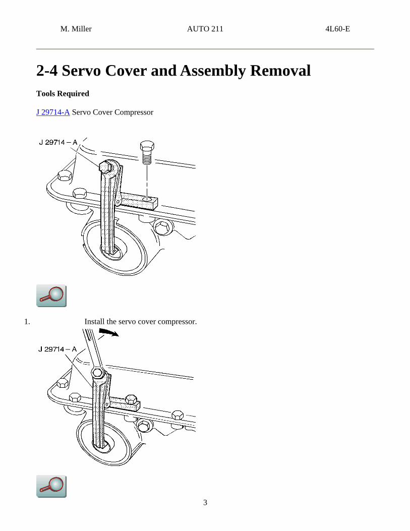
2-4 Servo Cover and Assembly Removal Tools Required
J 29714-A Servo Cover Compressor
1. Install the servo cover compressor.
M. Miller AUTO 211 4L60-E
2. Tighten the bolt to compress the servo cover.
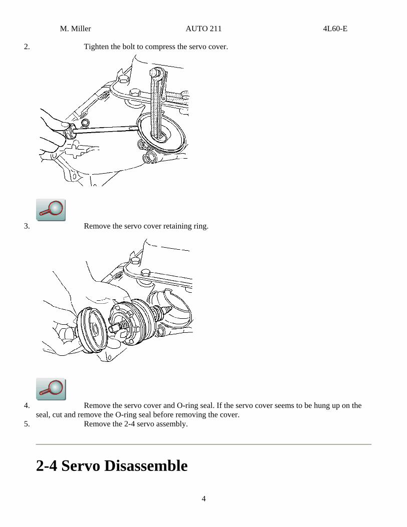
3. Remove the servo cover retaining ring.
4. Remove the servo cover and O-ring seal. If the servo cover seems to be hung up on the
seal, cut and remove the O-ring seal before removing the cover. 5. Remove the 2-4 servo assembly.
2-4 Servo Disassemble
4
M. Miller AUTO 211 4L60-E
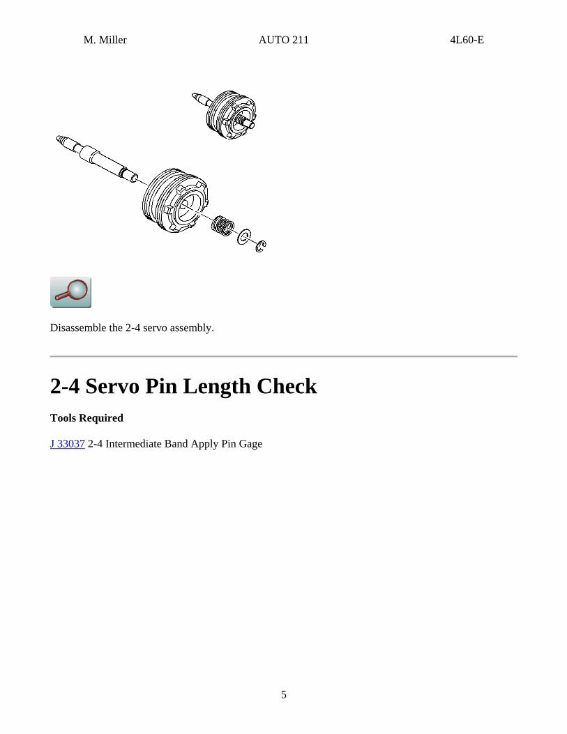
Disassemble the 2-4 servo assembly.
2-4 Servo Pin Length Check Tools Required
J 33037 2-4 Intermediate Band Apply Pin Gage
5

M. Miller AUTO 211 4L60-E
1. Disassemble the 2-4 servo assembly.
2. Install the band apply pin and the J 33037 .
6
M. Miller AUTO 211 4L60-E
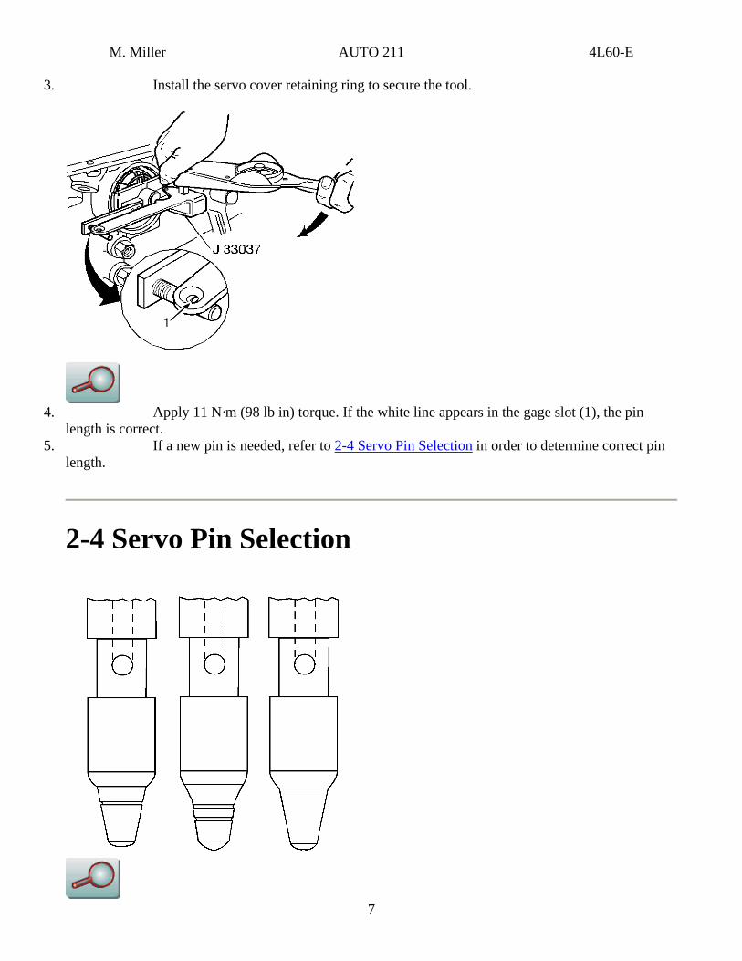
3. Install the servo cover retaining ring to secure the tool.
4. Apply 11 N·m (98 lb in) torque. If the white line appears in the gage slot (1), the pin
length is correct.
7
5. If a new pin is needed, refer to 2-4 Servo Pin Selection in order to determine correct pin length.
2-4 Servo Pin Selection
M. Miller AUTO 211 4L60-E
rvo Pin Selection
Pin Length mm inch
Pin Identification
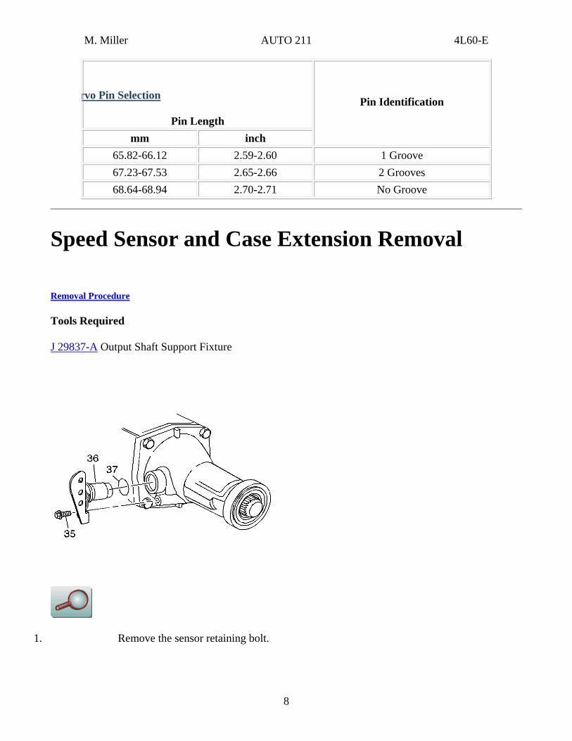
65.82-66.12 2.59-2.60 1 Groove 67.23-67.53 2.65-2.66 2 Grooves 68.64-68.94 2.70-2.71 No Groove
Speed Sensor and Case Extension Removal
Removal Procedure
Tools Required
J 29837-A Output Shaft Support Fixture
1. Remove the sensor retaining bolt.
8
M. Miller AUTO 211 4L60-E
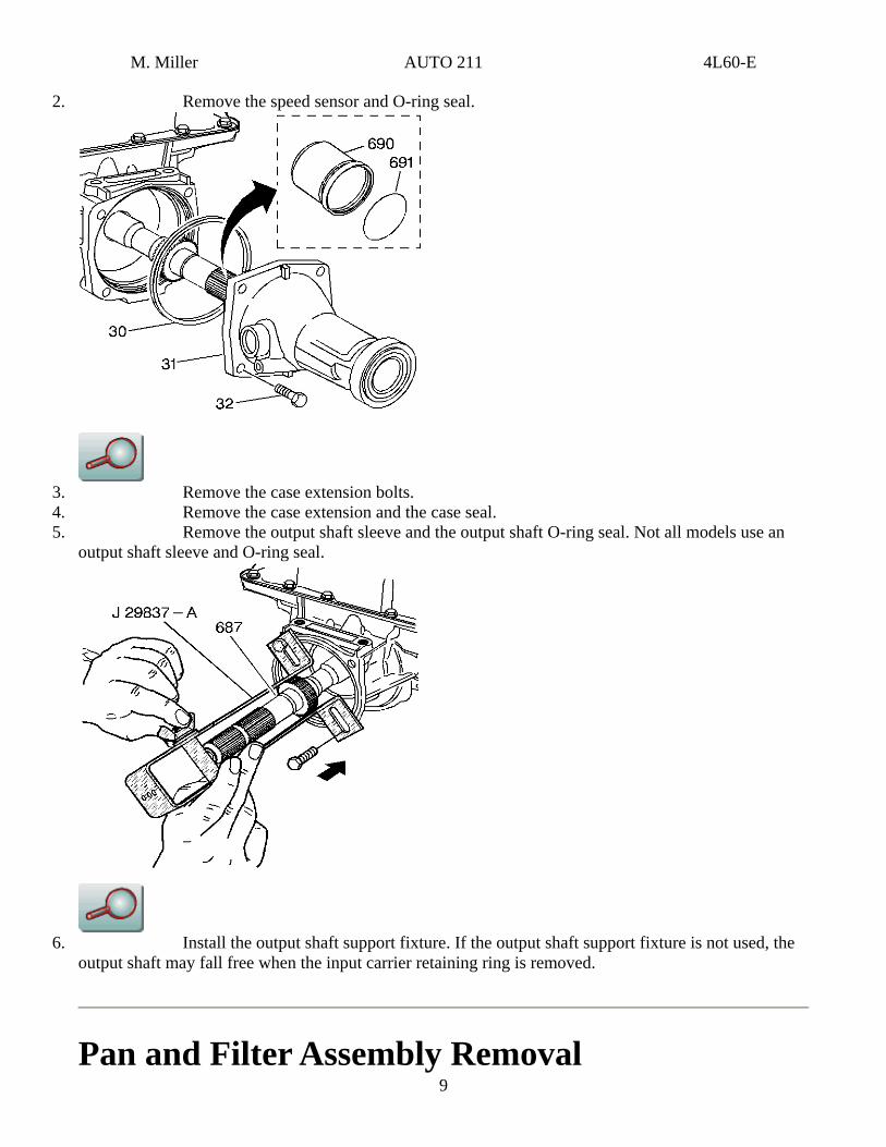
2. Remove the speed sensor and O-ring seal.
3. Remove the case extension bolts. 4. Remove the case extension and the case seal. 5. Remove the output shaft sleeve and the output shaft O-ring seal. Not all models use an
output shaft sleeve and O-ring seal.
9
6. Install the output shaft support fixture. If the output shaft support fixture is not used, the output shaft may fall free when the input carrier retaining ring is removed.
Pan and Filter Assembly Removal
M. Miller AUTO 211 4L60-E
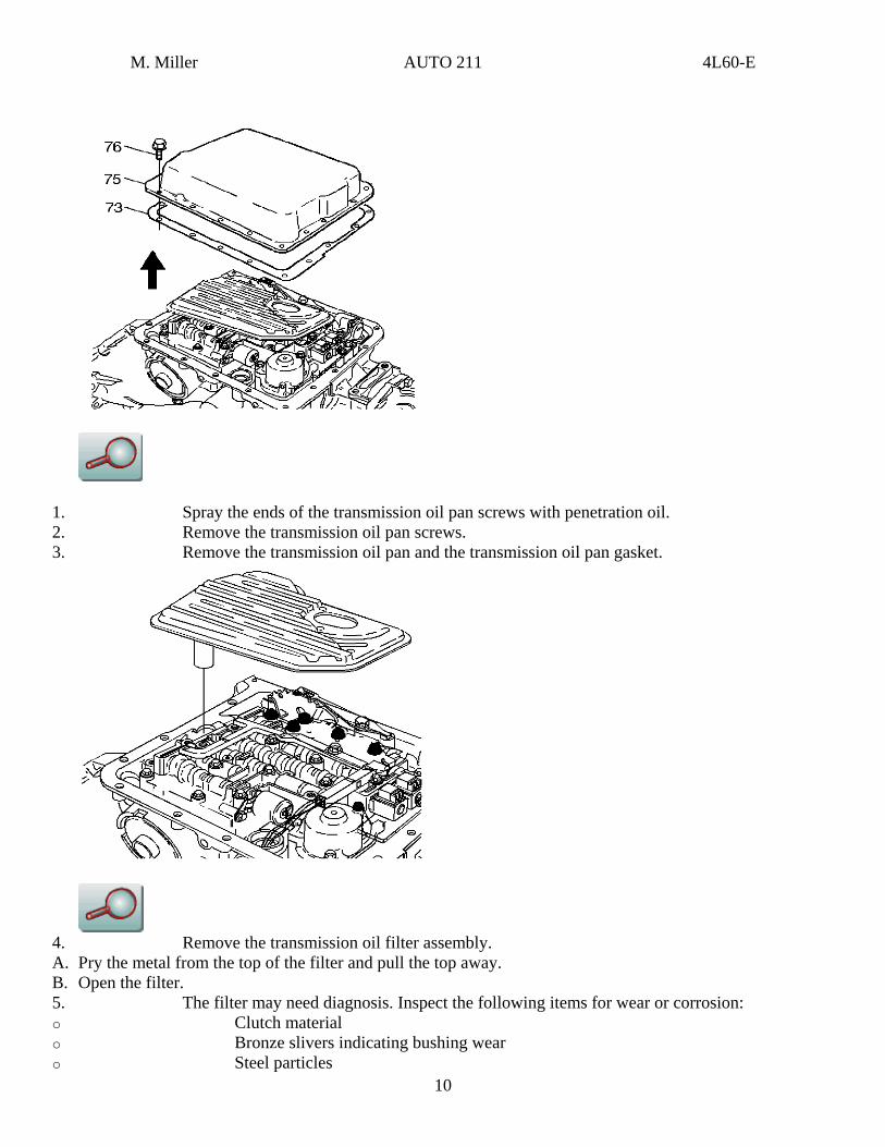
1. Spray the ends of the transmission oil pan screws with penetration oil. 2. Remove the transmission oil pan screws. 3. Remove the transmission oil pan and the transmission oil pan gasket.
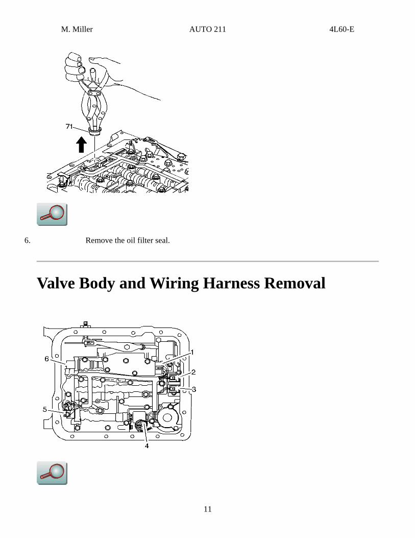
4. Remove the transmission oil filter assembly. A. Pry the metal from the top of the filter and pull the top away. B. Open the filter. 5. The filter may need diagnosis. Inspect the following items for wear or corrosion: o Clutch material o Bronze slivers indicating bushing wear o Steel particles
10
M. Miller AUTO 211 4L60-E
6. Remove the oil filter seal.
Valve Body and Wiring Harness Removal
11
M. Miller AUTO 211 4L60-E
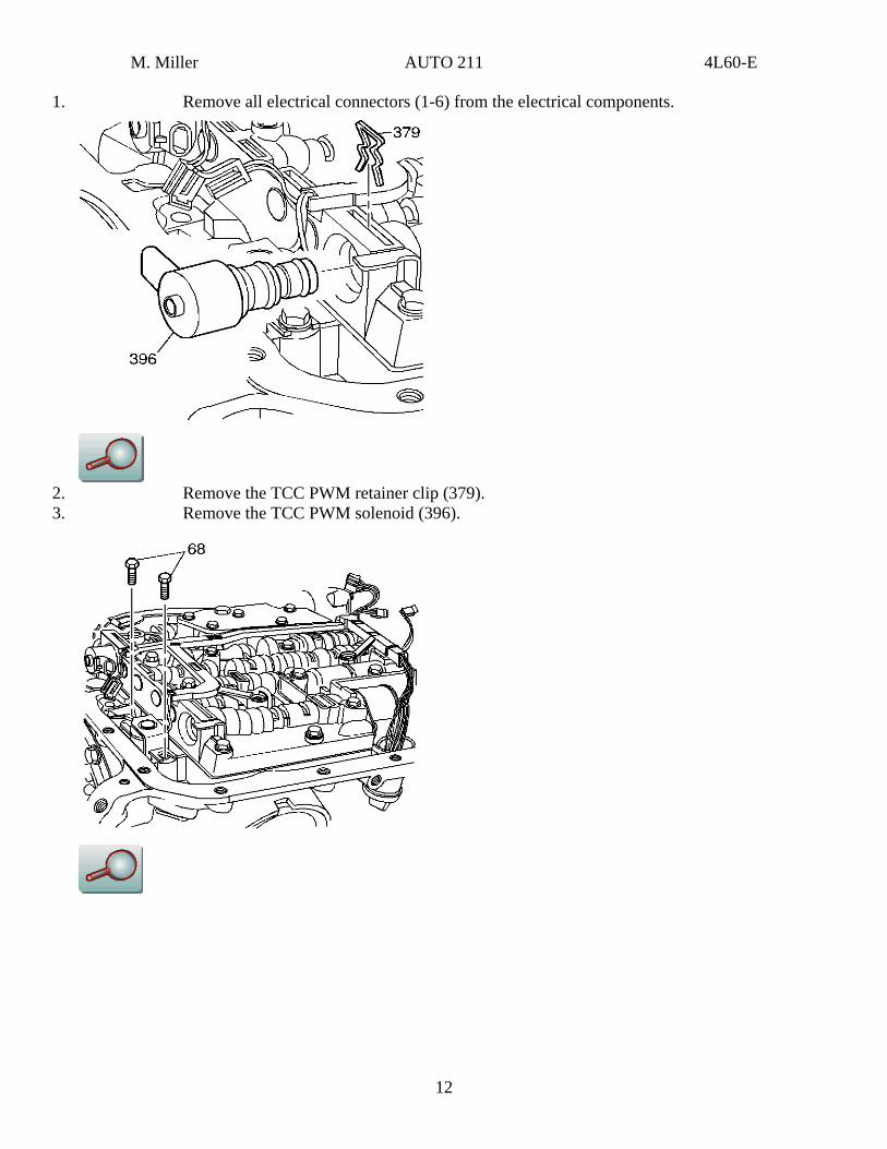
1. Remove all electrical connectors (1-6) from the electrical components.
2. Remove the TCC PWM retainer clip (379). 3. Remove the TCC PWM solenoid (396).
12
M. Miller AUTO 211 4L60-E
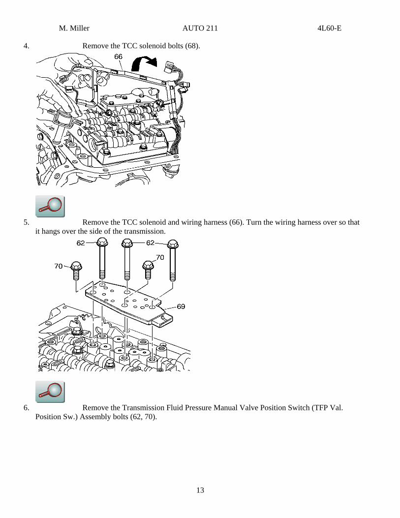
4. Remove the TCC solenoid bolts (68).
5. Remove the TCC solenoid and wiring harness (66). Turn the wiring harness over so that
it hangs over the side of the transmission.
6. Remove the Transmission Fluid Pressure Manual Valve Position Switch (TFP Val.
Position Sw.) Assembly bolts (62, 70).
13
M. Miller AUTO 211 4L60-E
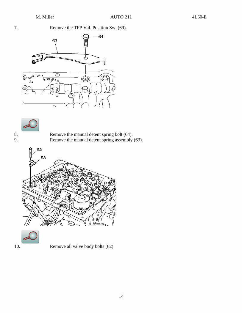
7. Remove the TFP Val. Position Sw. (69).
8. Remove the manual detent spring bolt (64). 9. Remove the manual detent spring assembly (63).
10. Remove all valve body bolts (62).
14
M. Miller AUTO 211 4L60-E
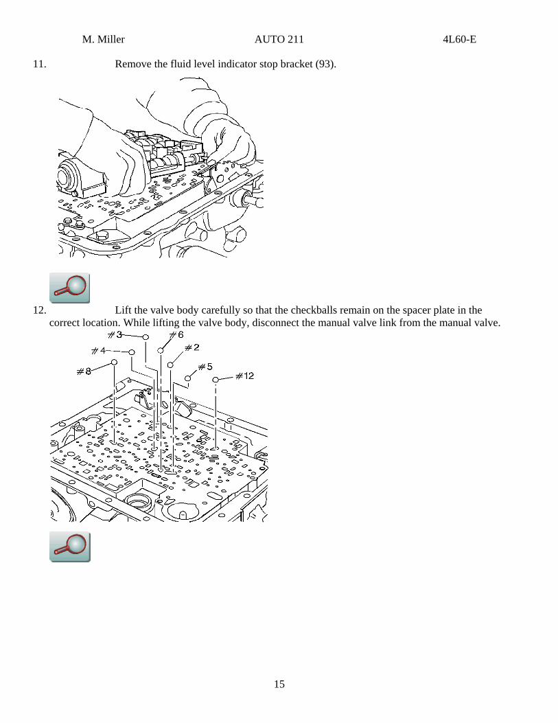
11. Remove the fluid level indicator stop bracket (93).
12. Lift the valve body carefully so that the checkballs remain on the spacer plate in the
correct location. While lifting the valve body, disconnect the manual valve link from the manual valve.
15
M. Miller AUTO 211 4L60-E
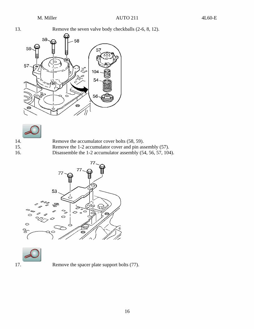
13. Remove the seven valve body checkballs (2-6, 8, 12).
14. Remove the accumulator cover bolts (58, 59). 15. Remove the 1-2 accumulator cover and pin assembly (57). 16. Disassemble the 1-2 accumulator assembly (54, 56, 57, 104).
17. Remove the spacer plate support bolts (77).
16
M. Miller AUTO 211 4L60-E
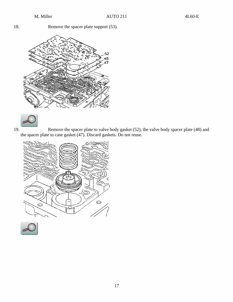
18. Remove the spacer plate support (53).
19. Remove the spacer plate to valve body gasket (52), the valve body spacer plate (48) and
the spacer plate to case gasket (47). Discard gaskets. Do not reuse.
17
M. Miller AUTO 211 4L60-E
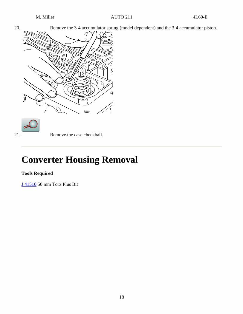
20. Remove the 3-4 accumulator spring (model dependent) and the 3-4 accumulator piston.
21. Remove the case checkball.
Converter Housing Removal Tools Required
J 41510 50 mm Torx Plus Bit
18
M. Miller AUTO 211 4L60-E
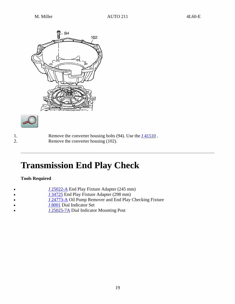
1. Remove the converter housing bolts (94). Use the J 41510 . 2. Remove the converter housing (102).
Transmission End Play Check Tools Required
• J 25022-A End Play Fixture Adapter (245 mm) • J 34725 End Play Fixture Adapter (298 mm) • J 24773-A Oil Pump Remover and End Play Checking Fixture • J 8001 Dial Indicator Set • J 25025-7A Dial Indicator Mounting Post
19
M. Miller AUTO 211 4L60-E
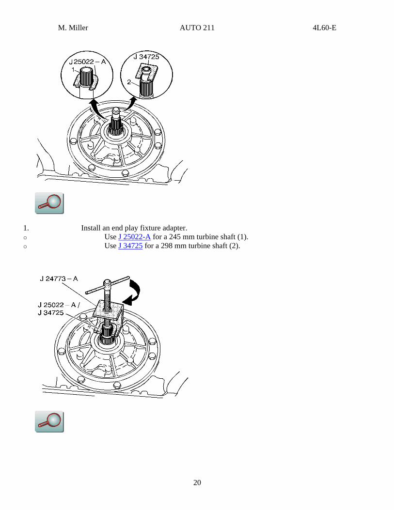
1. Install an end play fixture adapter. o Use J 25022-A for a 245 mm turbine shaft (1). o Use J 34725 for a 298 mm turbine shaft (2).
20
M. Miller AUTO 211 4L60-E
2. Install the J 24773-A .
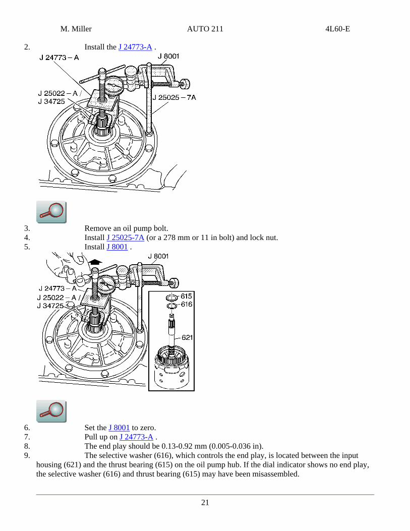
3. Remove an oil pump bolt. 4. Install J 25025-7A (or a 278 mm or 11 in bolt) and lock nut. 5. Install J 8001 .
6. Set the J 8001 to zero. 7. Pull up on J 24773-A . 8. The end play should be 0.13-0.92 mm (0.005-0.036 in).
21
9. The selective washer (616), which controls the end play, is located between the input housing (621) and the thrust bearing (615) on the oil pump hub. If the dial indicator shows no end play, the selective washer (616) and thrust bearing (615) may have been misassembled.
M. Miller AUTO 211 4L60-E
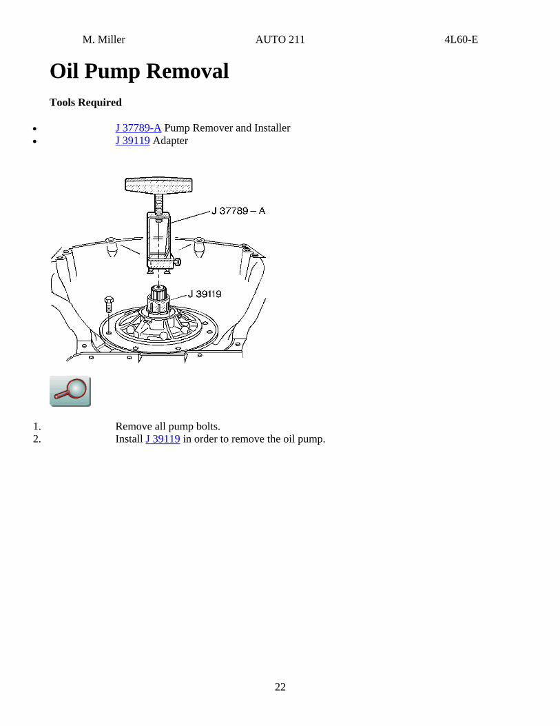
Oil Pump Removal Tools Required
• J 37789-A Pump Remover and Installer • J 39119 Adapter
1. Remove all pump bolts. 2. Install J 39119 in order to remove the oil pump.
22
M. Miller AUTO 211 4L60-E
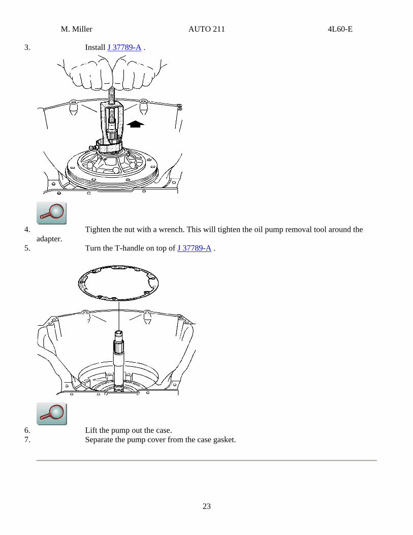
3. Install J 37789-A .
4. Tighten the nut with a wrench. This will tighten the oil pump removal tool around the
adapter. 5. Turn the T-handle on top of J 37789-A .
6. Lift the pump out the case. 7. Separate the pump cover from the case gasket.
23
M. Miller AUTO 211 4L60-E
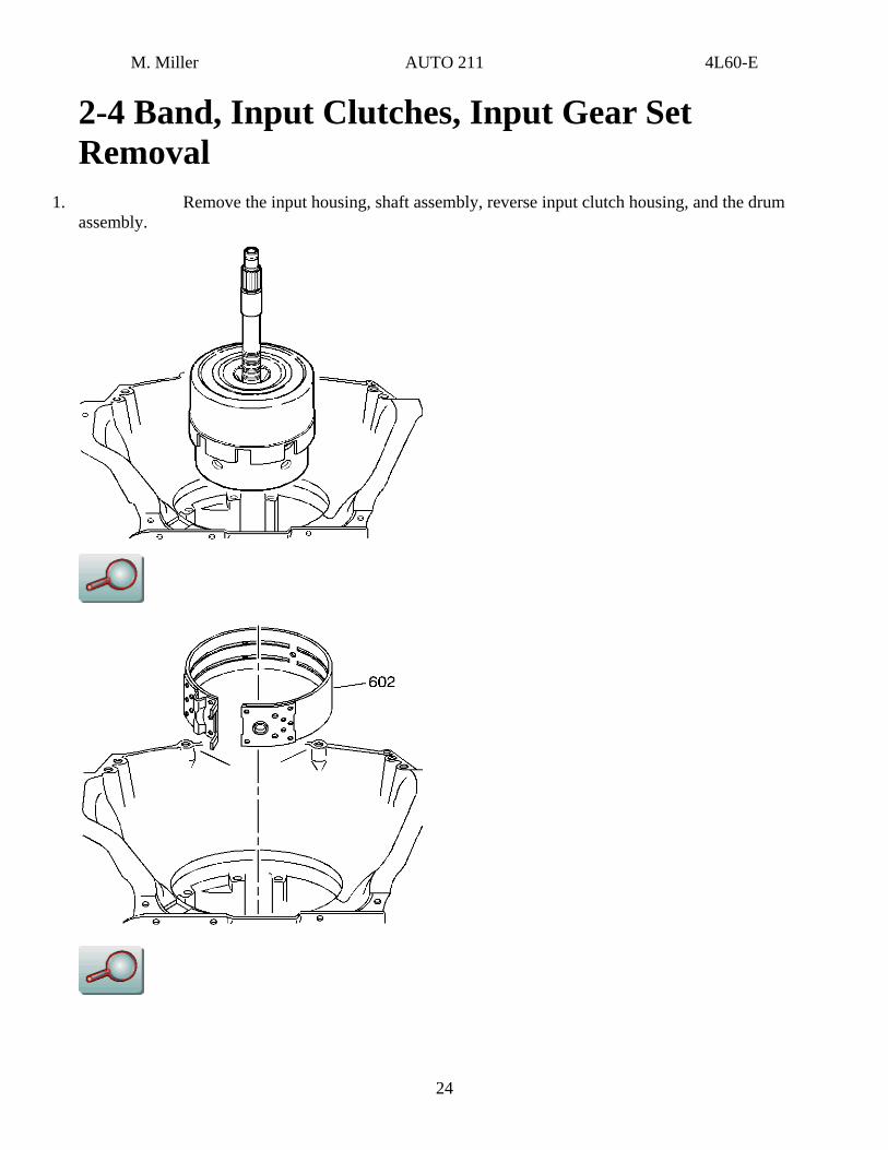
2-4 Band, Input Clutches, Input Gear Set Removal
1. Remove the input housing, shaft assembly, reverse input clutch housing, and the drum assembly.
24
M. Miller AUTO 211 4L60-E
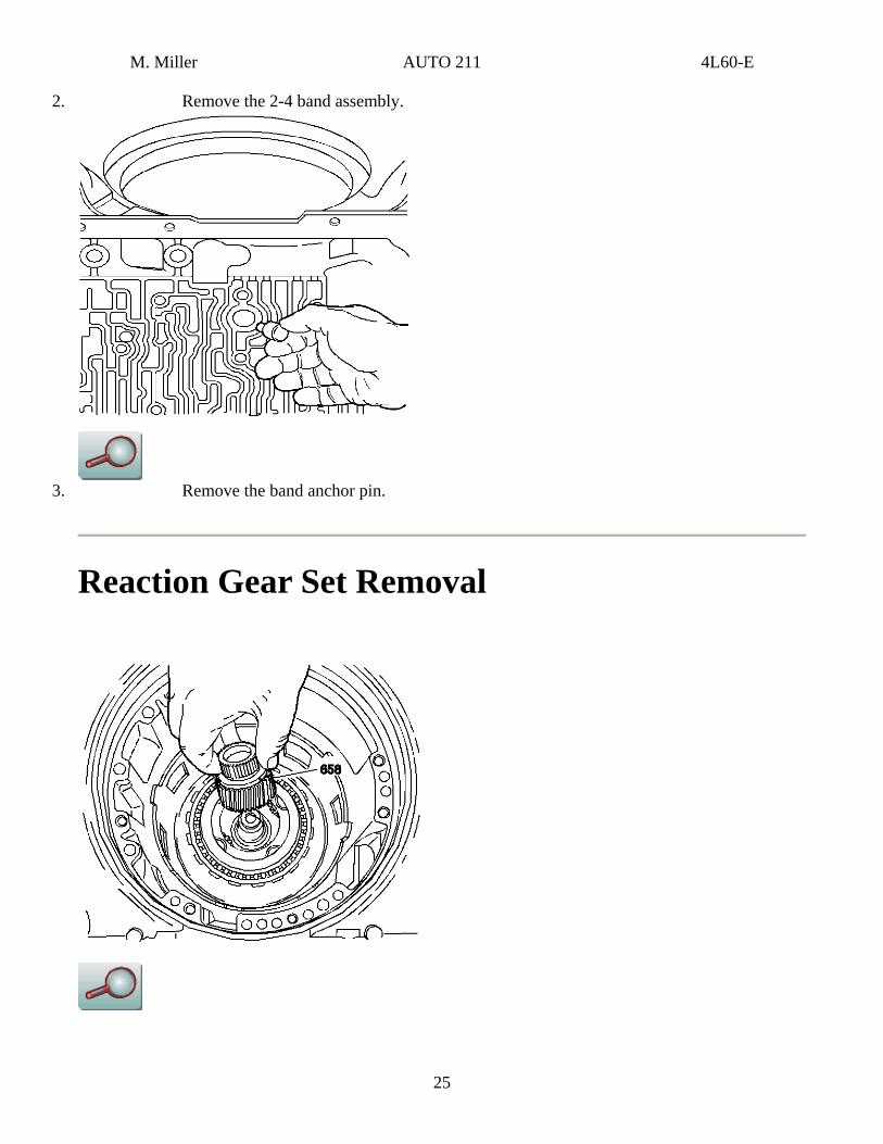
2. Remove the 2-4 band assembly.
3. Remove the band anchor pin.
Reaction Gear Set Removal
25
M. Miller AUTO 211 4L60-E
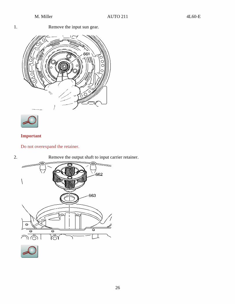
1. Remove the input sun gear.
Important
Do not overexpand the retainer.
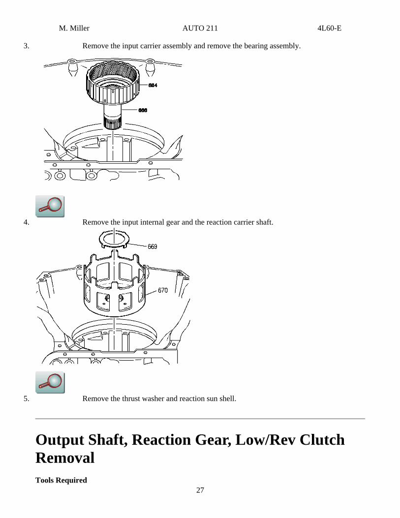
2. Remove the output shaft to input carrier retainer.
26
M. Miller AUTO 211 4L60-E
3. Remove the input carrier assembly and remove the bearing assembly.
4. Remove the input internal gear and the reaction carrier shaft.
27
5. Remove the thrust washer and reaction sun shell.
Output Shaft, Reaction Gear, Low/Rev Clutch Removal Tools Required
M. Miller AUTO 211 4L60-E
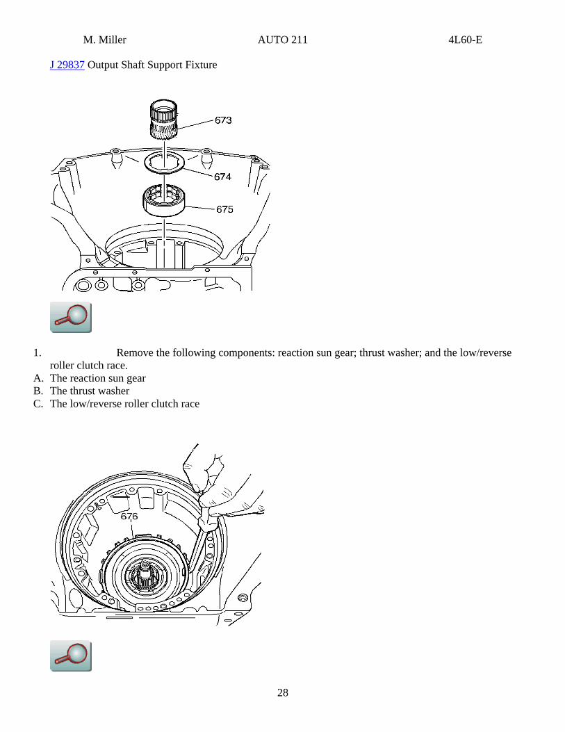
J 29837 Output Shaft Support Fixture
1. Remove the following components: reaction sun gear; thrust washer; and the low/reverse roller clutch race.
A. The reaction sun gear B. The thrust washer C. The low/reverse roller clutch race
28
M. Miller AUTO 211 4L60-E
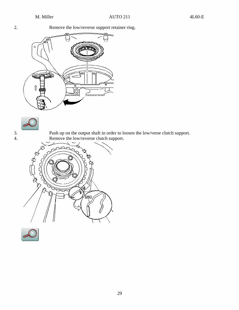
2. Remove the low/reverse support retainer ring.
3. Push up on the output shaft in order to loosen the low/verse clutch support. 4. Remove the low/reverse clutch support.
29
M. Miller AUTO 211 4L60-E
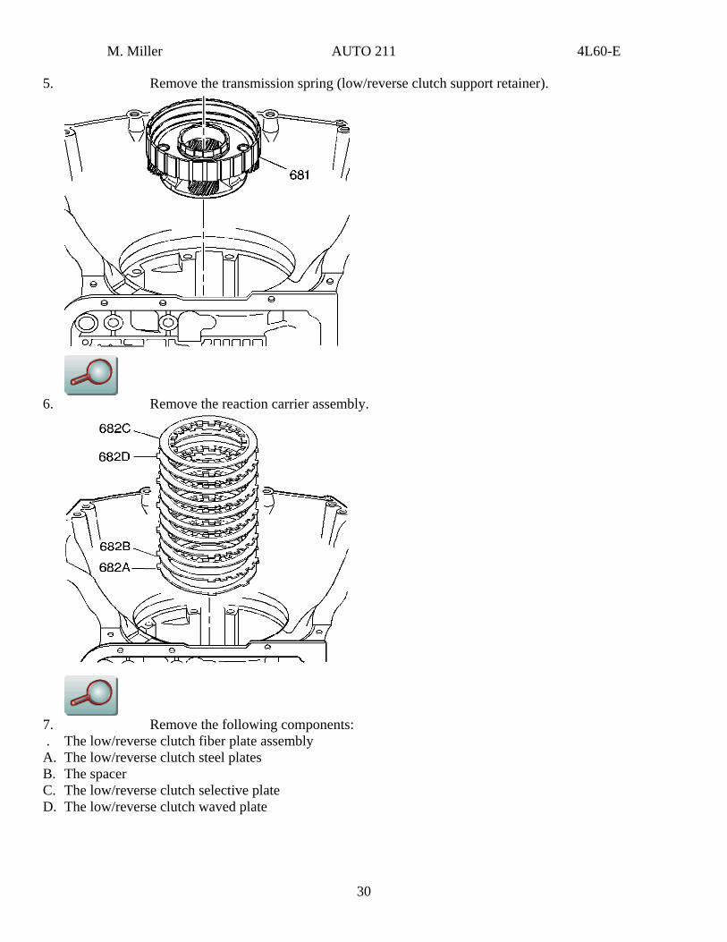
5. Remove the transmission spring (low/reverse clutch support retainer).
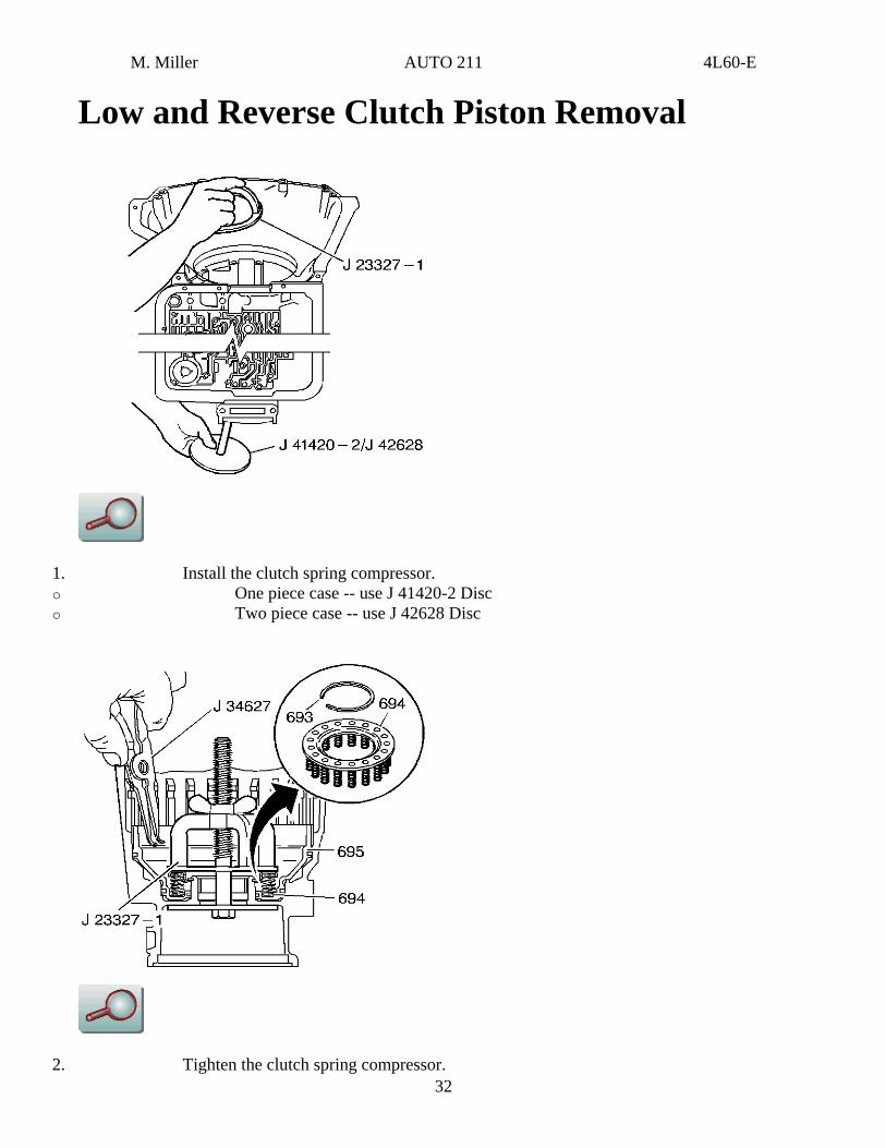
6. Remove the reaction carrier assembly.
7. Remove the following components: . The low/reverse clutch fiber plate assembly A. The low/reverse clutch steel plates B. The spacer C. The low/reverse clutch selective plate D. The low/reverse clutch waved plate
30

M. Miller AUTO 211 4L60-E
8. Remove the following components: . The thrust bearing assembly (reaction carrier support) A. The internal reaction gear B. The internal reaction gear support C. The reaction gear support bearing 9. Remove the output shaft support fixture.
10. Remove the output shaft.
31
M. Miller AUTO 211 4L60-E
Low and Reverse Clutch Piston Removal
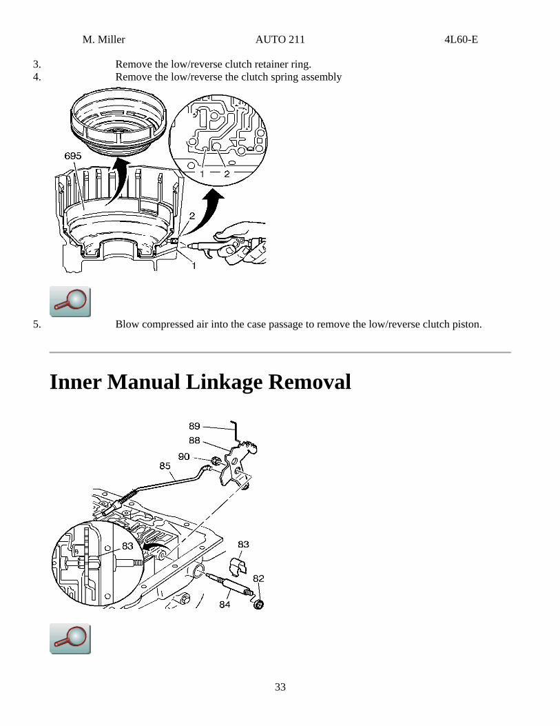
1. Install the clutch spring compressor. o One piece case -- use J 41420-2 Disc o Two piece case -- use J 42628 Disc
32 2. Tighten the clutch spring compressor.
M. Miller AUTO 211 4L60-E
3. Remove the low/reverse clutch retainer ring. 4. Remove the low/reverse the clutch spring assembly
5. Blow compressed air into the case passage to remove the low/reverse clutch piston.
Inner Manual Linkage Removal
33
M. Miller AUTO 211 4L60-E
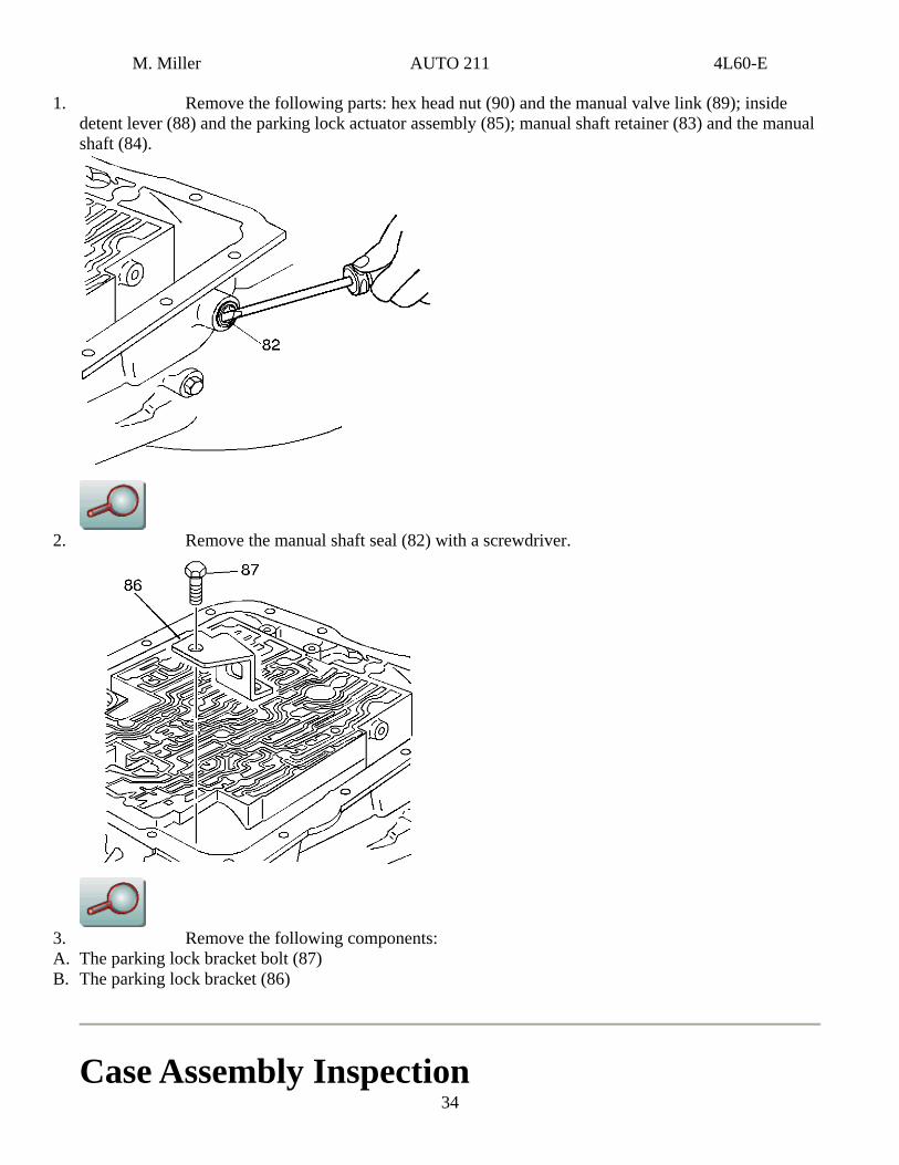
1. Remove the following parts: hex head nut (90) and the manual valve link (89); inside detent lever (88) and the parking lock actuator assembly (85); manual shaft retainer (83) and the manual shaft (84).
2. Remove the manual shaft seal (82) with a screwdriver.
3. Remove the following components: A. The parking lock bracket bolt (87)
34
B. The parking lock bracket (86)
Case Assembly Inspection
M. Miller AUTO 211 4L60-E
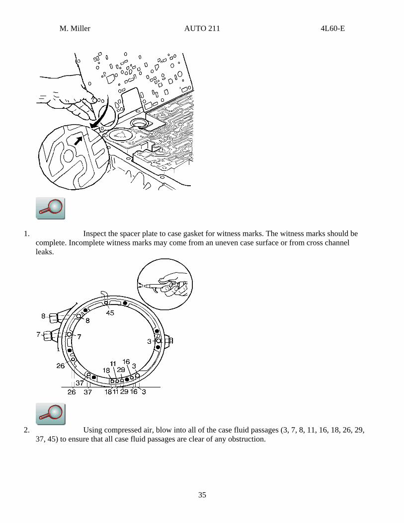
1. Inspect the spacer plate to case gasket for witness marks. The witness marks should be complete. Incomplete witness marks may come from an uneven case surface or from cross channel leaks.
2. Using compressed air, blow into all of the case fluid passages (3, 7, 8, 11, 16, 18, 26, 29,
37, 45) to ensure that all case fluid passages are clear of any obstruction.
35
M. Miller AUTO 211 4L60-E
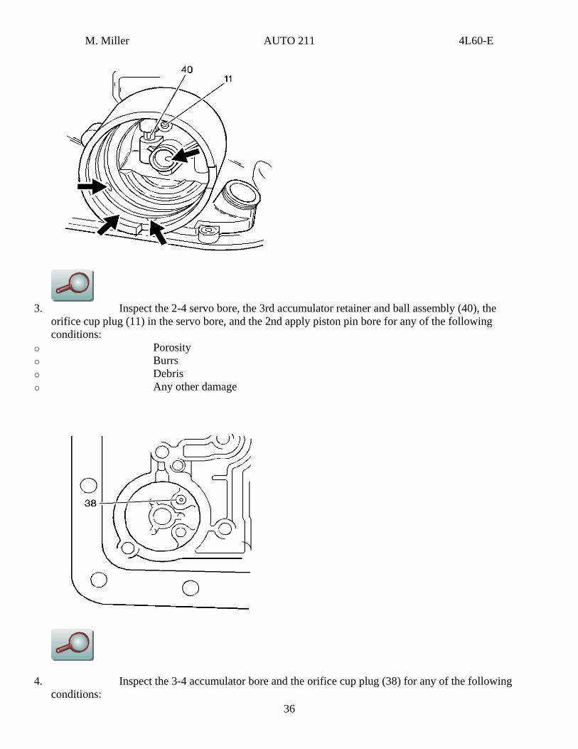
3. Inspect the 2-4 servo bore, the 3rd accumulator retainer and ball assembly (40), the
orifice cup plug (11) in the servo bore, and the 2nd apply piston pin bore for any of the following conditions:
o Porosity o Burrs o Debris o Any other damage
36
4. Inspect the 3-4 accumulator bore and the orifice cup plug (38) for any of the following conditions:
M. Miller AUTO 211 4L60-E
o Porosity o Burrs o Blockage o Any other damage 5. Inspect all bolt holes for thread damage. Use heli-coil to repair damaged threads. 6. Inspect the cooler connectors for damage and proper torque. Specification
Cooler connector torque should be 38 N·m (28 lb ft)
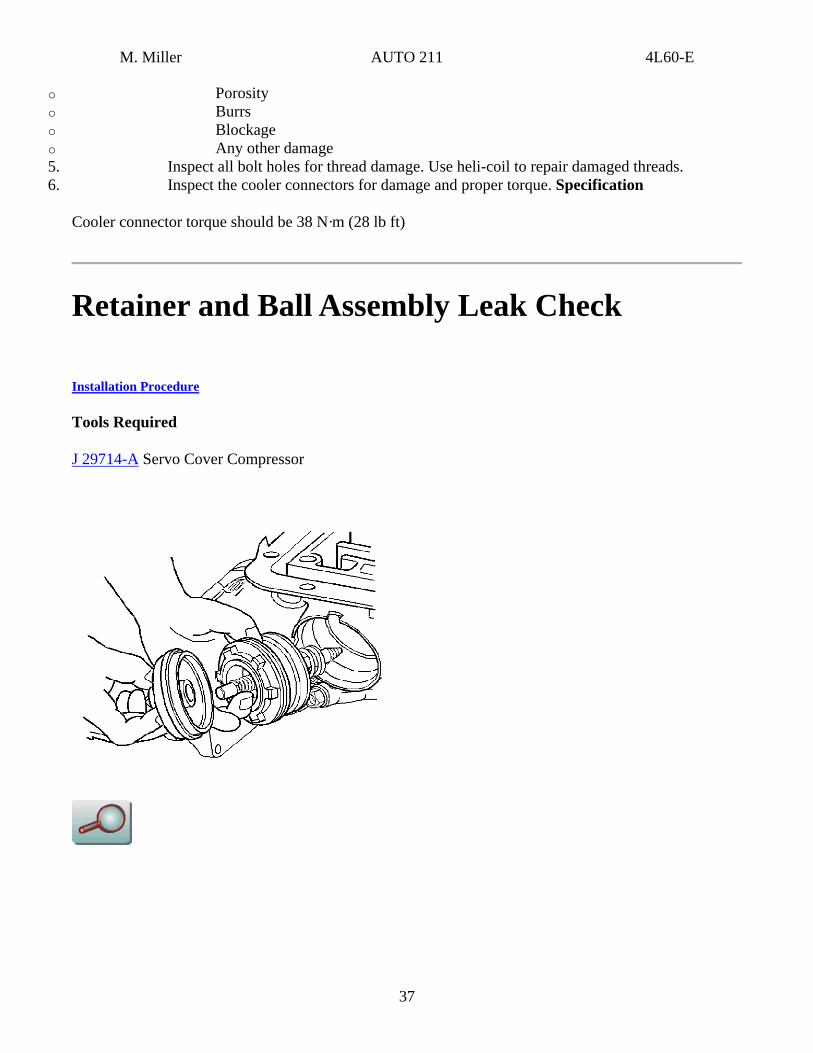
Retainer and Ball Assembly Leak Check
Installation Procedure
Tools Required
J 29714-A Servo Cover Compressor
37
M. Miller AUTO 211 4L60-E
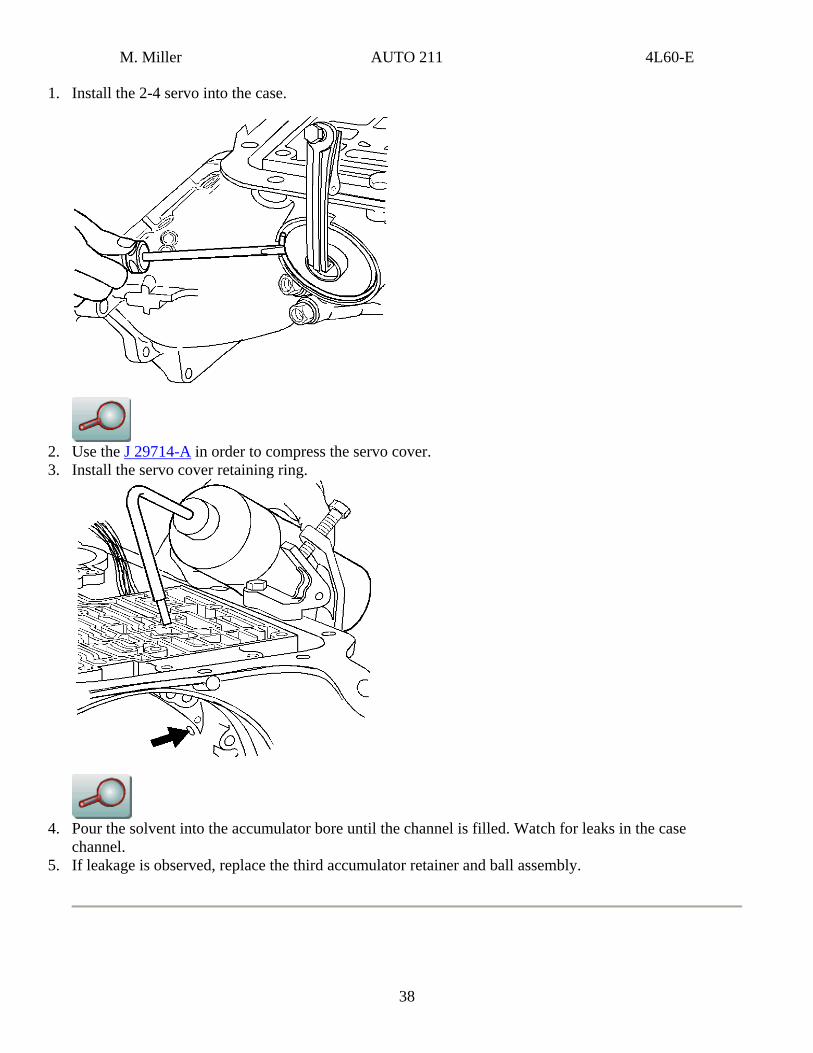
1. Install the 2-4 servo into the case.
2. Use the J 29714-A in order to compress the servo cover. 3. Install the servo cover retaining ring.
4. Pour the solvent into the accumulator bore until the channel is filled. Watch for leaks in the case
channel. 5. If leakage is observed, replace the third accumulator retainer and ball assembly.
38
M. Miller AUTO 211 4L60-E
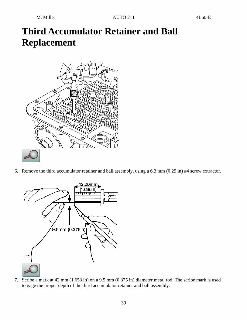
Third Accumulator Retainer and Ball Replacement
6. Remove the third accumulator retainer and ball assembly, using a 6.3 mm (0.25 in) #4 screw extractor.
7. Scribe a mark at 42 mm (1.653 in) on a 9.5 mm (0.375 in) diameter metal rod. The scribe mark is used
to gage the proper depth of the third accumulator retainer and ball assembly.
39
M. Miller AUTO 211 4L60-E
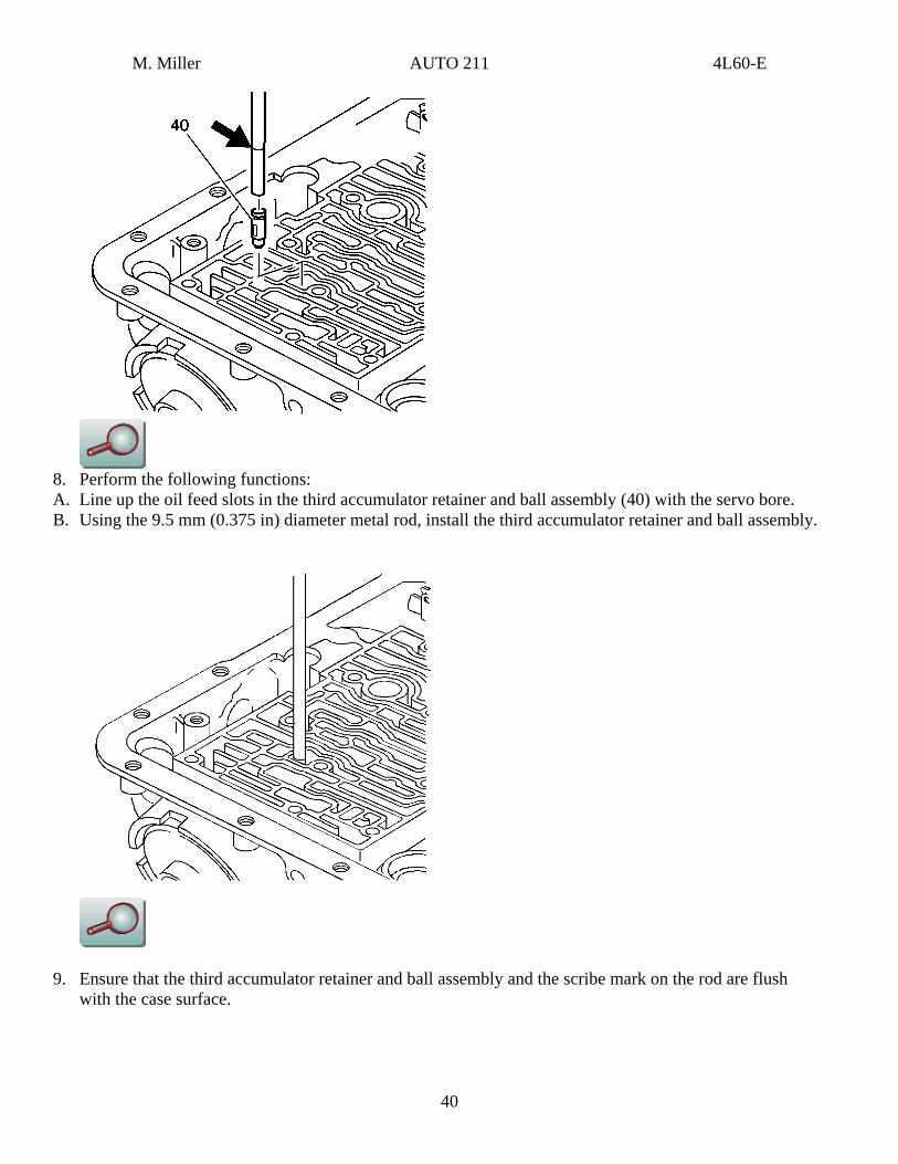
8. Perform the following functions: A. Line up the oil feed slots in the third accumulator retainer and ball assembly (40) with the servo bore. B. Using the 9.5 mm (0.375 in) diameter metal rod, install the third accumulator retainer and ball assembly.
9. Ensure that the third accumulator retainer and ball assembly and the scribe mark on the rod are flush with the case surface.
40
M. Miller AUTO 211 4L60-E
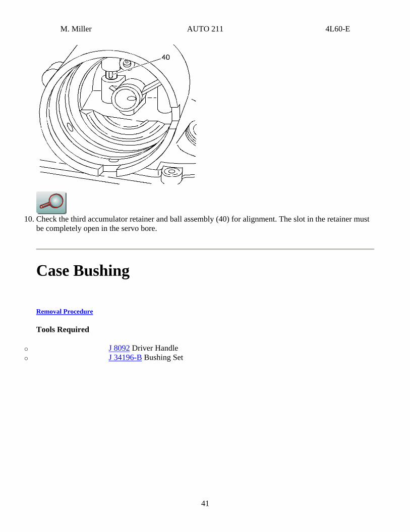
10. Check the third accumulator retainer and ball assembly (40) for alignment. The slot in the retainer must
be completely open in the servo bore.
Case Bushing
Removal Procedure
Tools Required
o J 8092 Driver Handle o J 34196-B Bushing Set
41
M. Miller AUTO 211 4L60-E
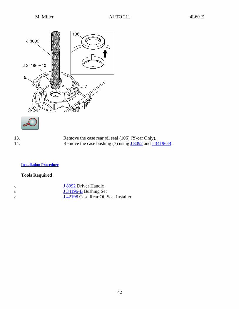
13. Remove the case rear oil seal (106) (Y-car Only). 14. Remove the case bushing (7) using J 8092 and J 34196-B .
Installation Procedure
Tools Required
o J 8092 Driver Handle o J 34196-B Bushing Set o J 42198 Case Rear Oil Seal Installer
42
M. Miller AUTO 211 4L60-E
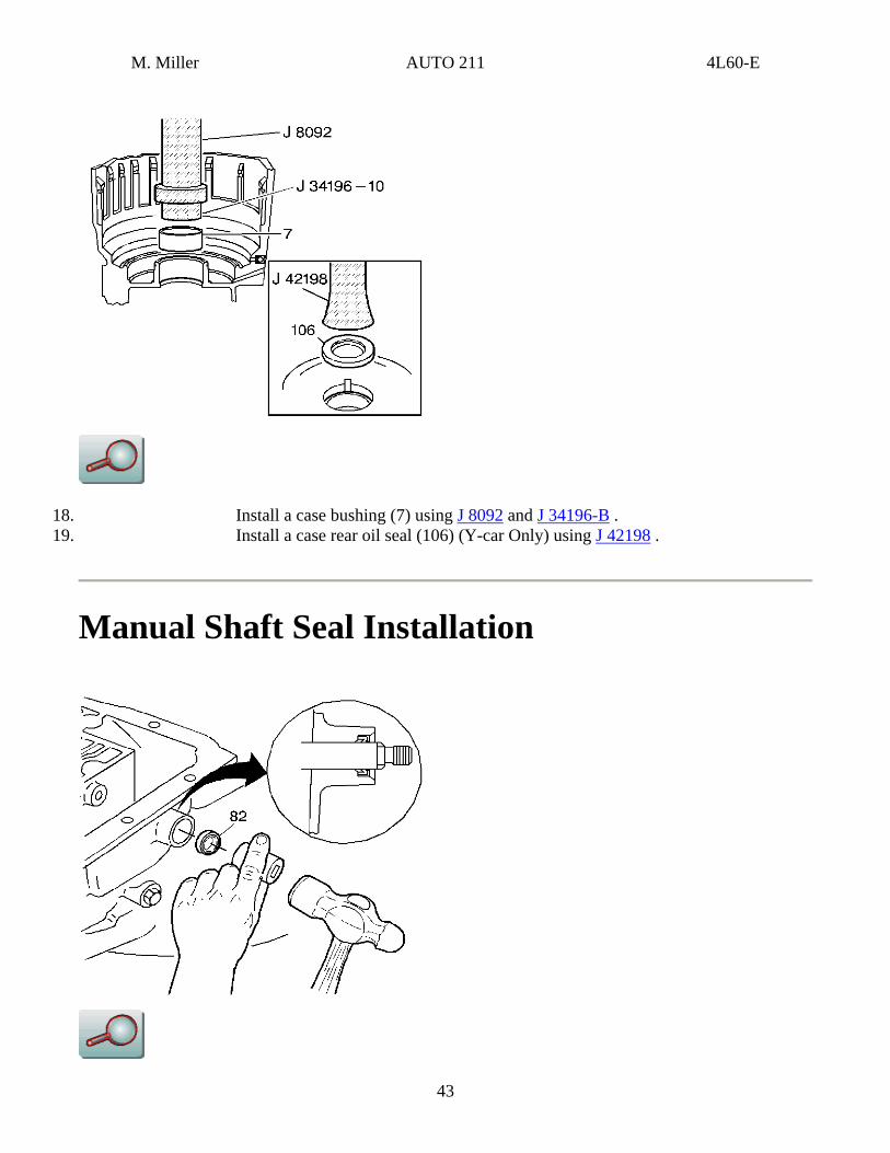
18. Install a case bushing (7) using J 8092 and J 34196-B . 19. Install a case rear oil seal (106) (Y-car Only) using J 42198 .
Manual Shaft Seal Installation
43
M. Miller AUTO 211 4L60-E
Install a new manual shaft seal (82).
Inner Manual Linkage Installation
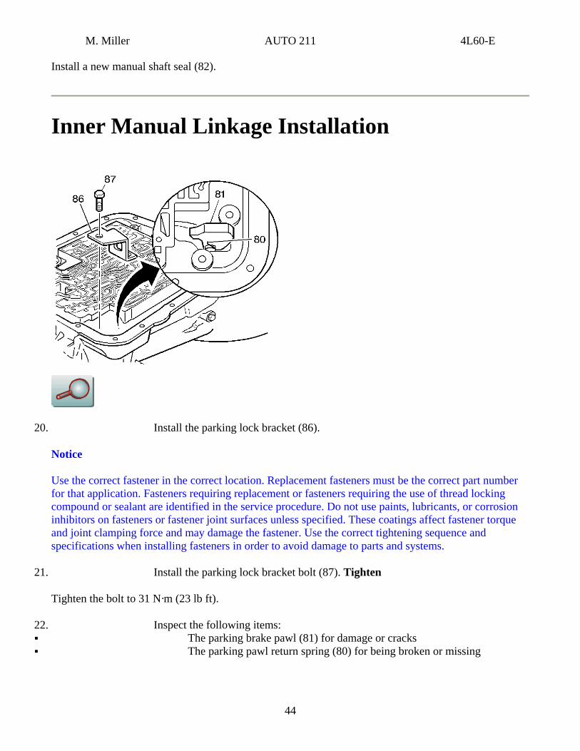
20. Install the parking lock bracket (86).
Notice
Use the correct fastener in the correct location. Replacement fasteners must be the correct part number for that application. Fasteners requiring replacement or fasteners requiring the use of thread locking compound or sealant are identified in the service procedure. Do not use paints, lubricants, or corrosion inhibitors on fasteners or fastener joint surfaces unless specified. These coatings affect fastener torque and joint clamping force and may damage the fastener. Use the correct tightening sequence and specifications when installing fasteners in order to avoid damage to parts and systems.
21. Install the parking lock bracket bolt (87). Tighten
Tighten the bolt to 31 N·m (23 lb ft).
22. Inspect the following items: The parking brake pawl (81) for damage or cracks The parking pawl return spring (80) for being broken or missing
44
M. Miller AUTO 211 4L60-E
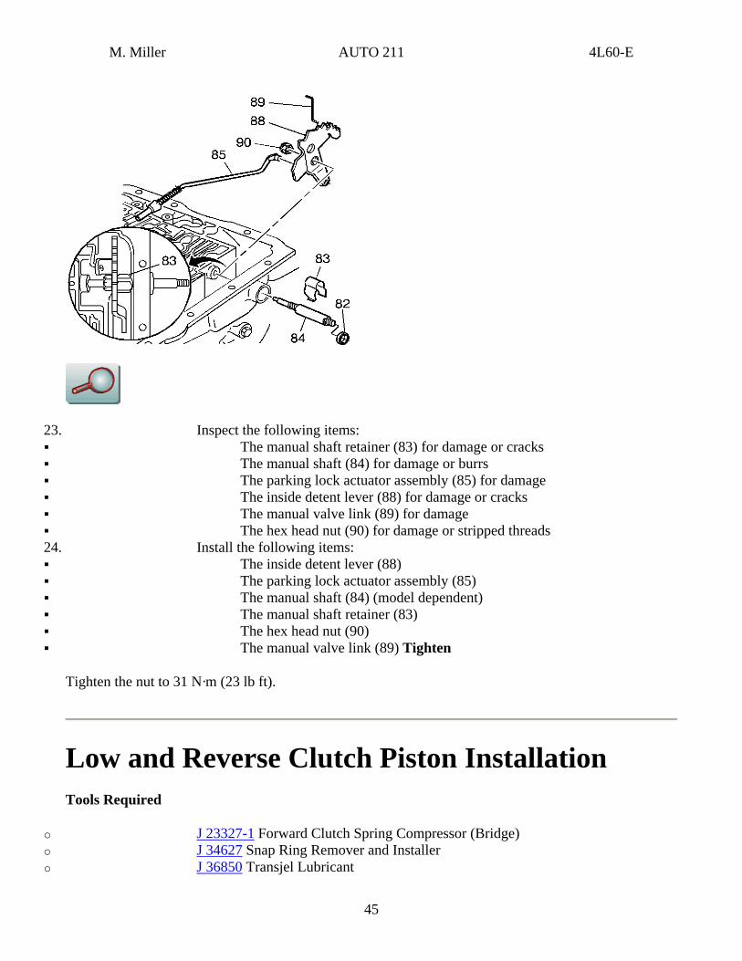
23. Inspect the following items: The manual shaft retainer (83) for damage or cracks The manual shaft (84) for damage or burrs The parking lock actuator assembly (85) for damage The inside detent lever (88) for damage or cracks The manual valve link (89) for damage The hex head nut (90) for damage or stripped threads
24. Install the following items: The inside detent lever (88) The parking lock actuator assembly (85) The manual shaft (84) (model dependent) The manual shaft retainer (83) The hex head nut (90) The manual valve link (89) Tighten
Tighten the nut to 31 N·m (23 lb ft).
Low and Reverse Clutch Piston Installation Tools Required
o J 23327-1 Forward Clutch Spring Compressor (Bridge) o J 34627 Snap Ring Remover and Installer o J 36850 Transjel Lubricant
45
M. Miller AUTO 211 4L60-E
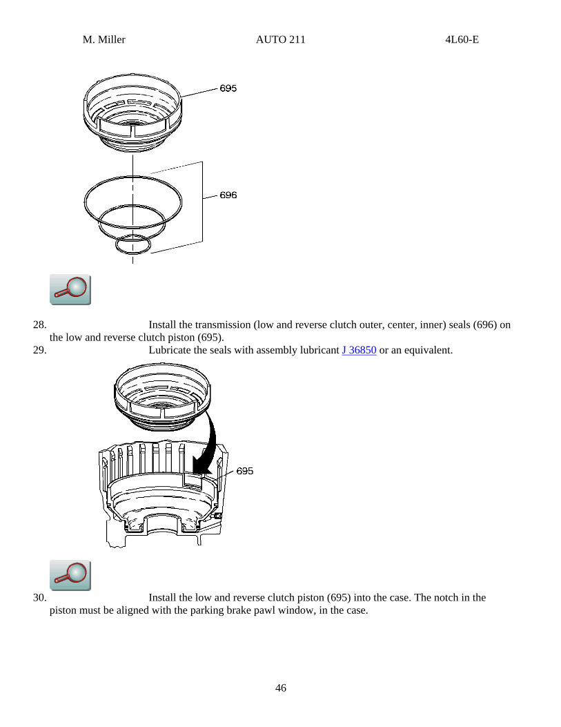
28. Install the transmission (low and reverse clutch outer, center, inner) seals (696) on the low and reverse clutch piston (695).
29. Lubricate the seals with assembly lubricant J 36850 or an equivalent.
30. Install the low and reverse clutch piston (695) into the case. The notch in the
piston must be aligned with the parking brake pawl window, in the case.
46
M. Miller AUTO 211 4L60-E
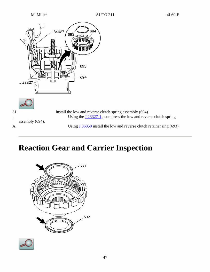
31. Install the low and reverse clutch spring assembly (694). . Using the J 23327-1 , compress the low and reverse clutch spring
assembly (694). A. Using J 36850 install the low and reverse clutch retainer ring (693).
Reaction Gear and Carrier Inspection
47
M. Miller AUTO 211 4L60-E
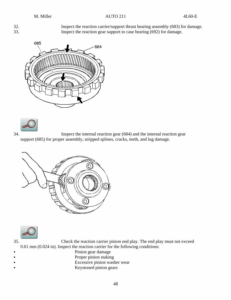
32. Inspect the reaction carrier/support thrust bearing assembly (683) for damage. 33. Inspect the reaction gear support to case bearing (692) for damage.
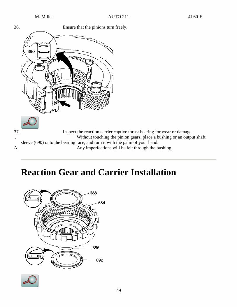
34. Inspect the internal reaction gear (684) and the internal reaction gear
support (685) for proper assembly, stripped splines, cracks, teeth, and lug damage.
35. Check the reaction carrier pinion end play. The end play must not exceed
0.61 mm (0.024 in). Inspect the reaction carrier for the following conditions: Pinion gear damage Proper pinion staking Excessive pinion washer wear Keystoned pinion gears
48
M. Miller AUTO 211 4L60-E
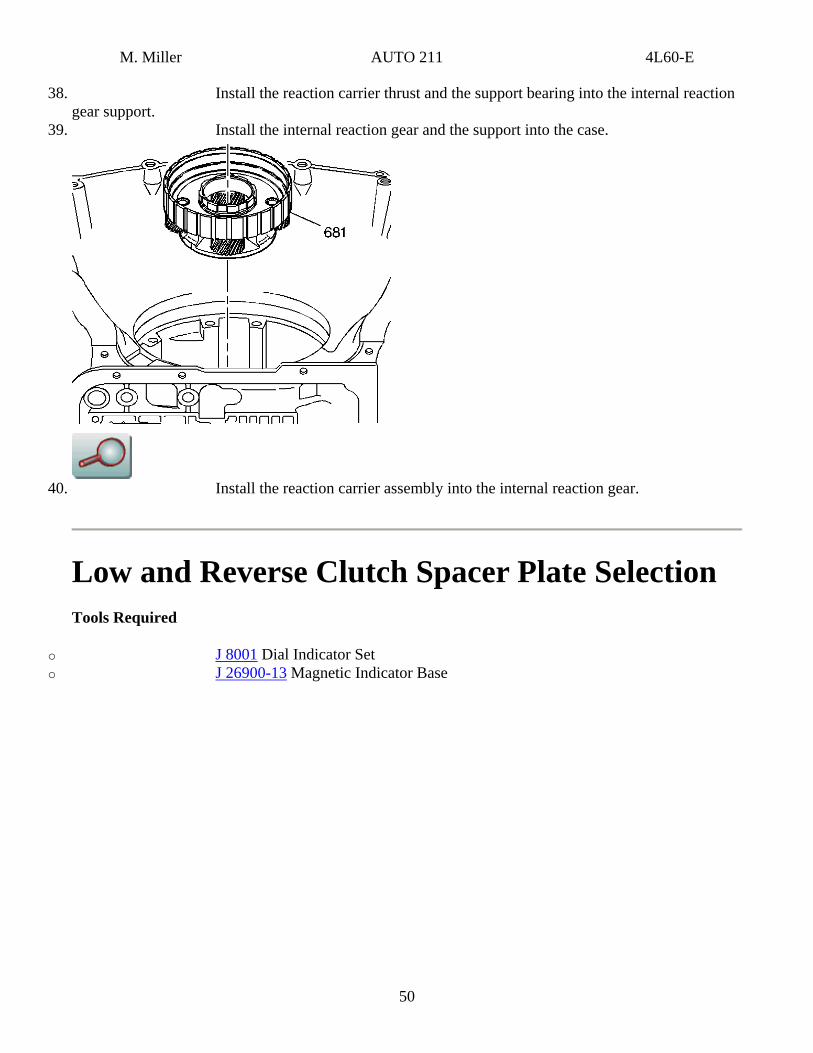
36. Ensure that the pinions turn freely.
37. Inspect the reaction carrier captive thrust bearing for wear or damage. . Without touching the pinion gears, place a bushing or an output shaft
sleeve (690) onto the bearing race, and turn it with the palm of your hand.
49
A. Any imperfections will be felt through the bushing.
Reaction Gear and Carrier Installation
M. Miller AUTO 211 4L60-E
38. Install the reaction carrier thrust and the support bearing into the internal reaction gear support.
39. Install the internal reaction gear and the support into the case.
40. Install the reaction carrier assembly into the internal reaction gear.
Low and Reverse Clutch Spacer Plate Selection Tools Required
o J 8001 Dial Indicator Set o J 26900-13 Magnetic Indicator Base
50
M. Miller AUTO 211 4L60-E
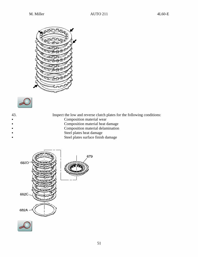
43. Inspect the low and reverse clutch plates for the following conditions: Composition material wear Composition material heat damage Composition material delamination Steel plates heat damage Steel plates surface finish damage
51
M. Miller AUTO 211 4L60-E
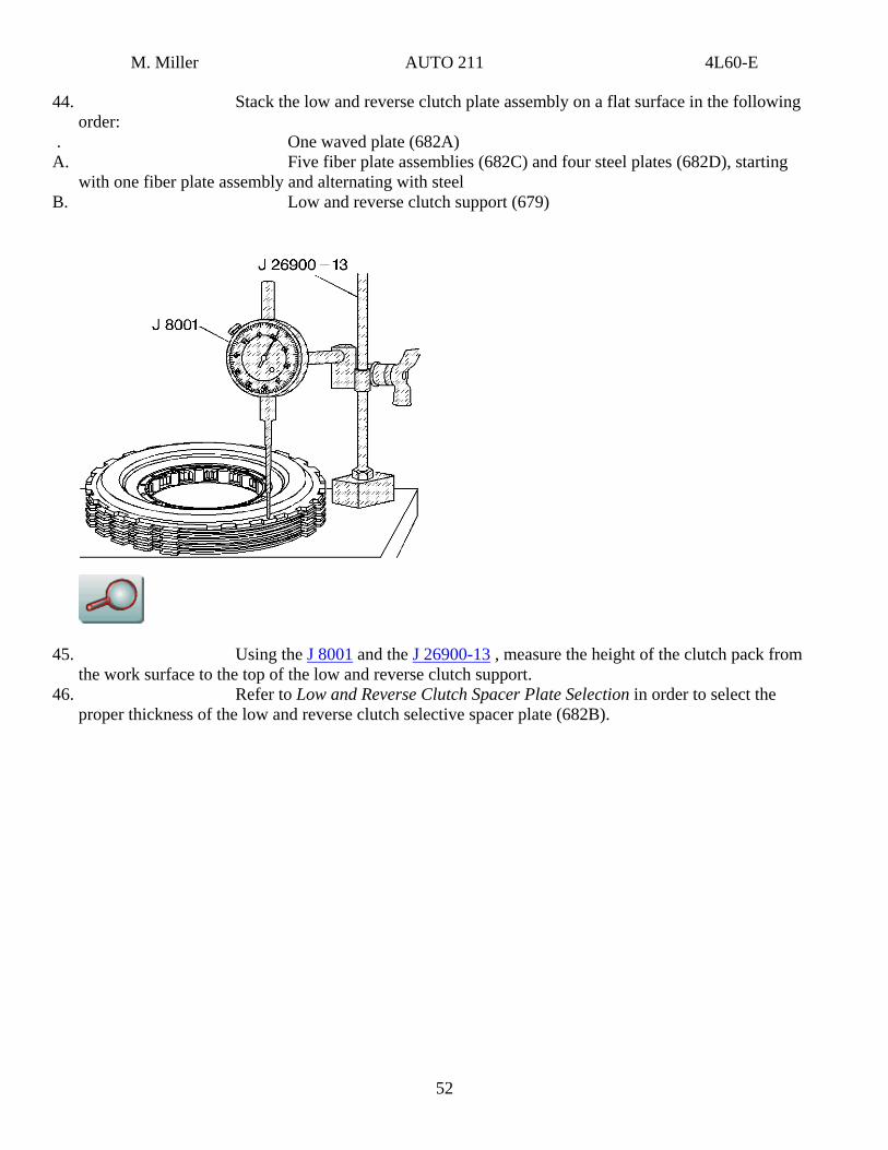
44. Stack the low and reverse clutch plate assembly on a flat surface in the following order:
. One waved plate (682A) A. Five fiber plate assemblies (682C) and four steel plates (682D), starting
with one fiber plate assembly and alternating with steel B. Low and reverse clutch support (679)
45. Using the J 8001 and the J 26900-13 , measure the height of the clutch pack from the work surface to the top of the low and reverse clutch support.
46. Refer to Low and Reverse Clutch Spacer Plate Selection in order to select the proper thickness of the low and reverse clutch selective spacer plate (682B).
52
M. Miller AUTO 211 4L60-E
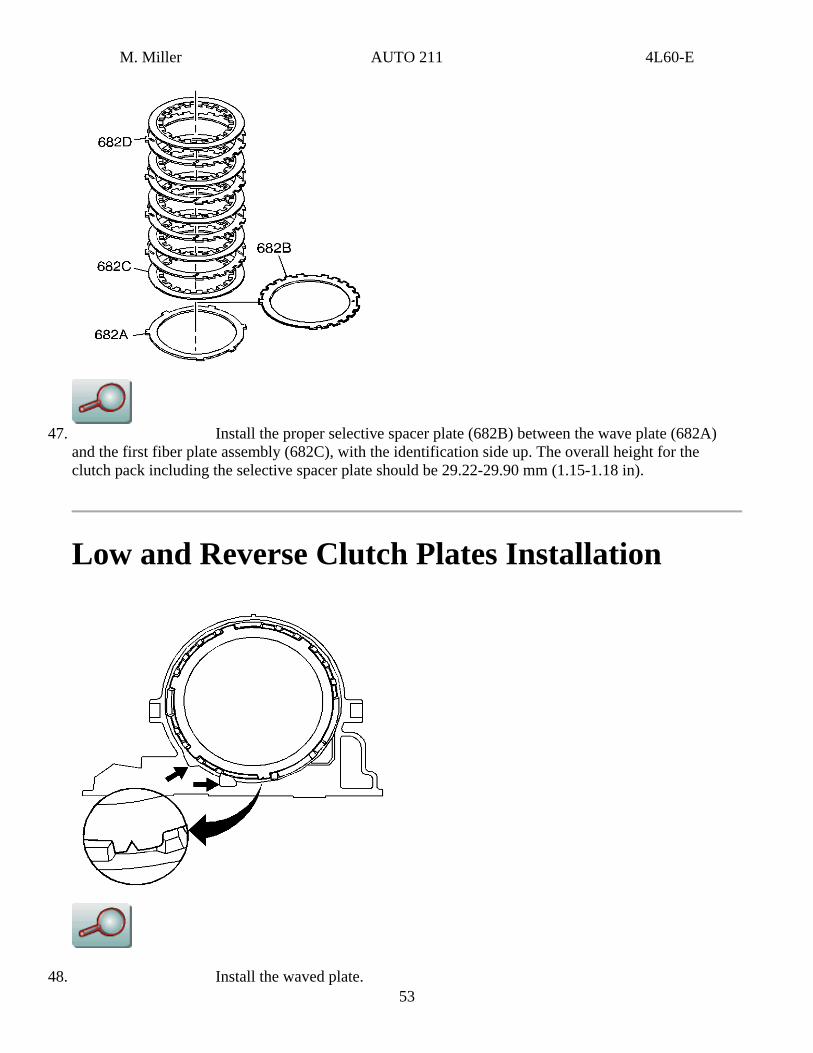
47. Install the proper selective spacer plate (682B) between the wave plate (682A)
and the first fiber plate assembly (682C), with the identification side up. The overall height for the clutch pack including the selective spacer plate should be 29.22-29.90 mm (1.15-1.18 in).
Low and Reverse Clutch Plates Installation
48. Install the waved plate. 53
M. Miller AUTO 211 4L60-E
49. Install the correct selective spacer plate (from the selection procedure). 50. Install the five fiber plate assemblies and four steel plates, starting with one fiber
plate assembly and alternating with steel. 51. Index the steel plate splines in the case as shown.
Low and Reverse Clutch Support Disassemble
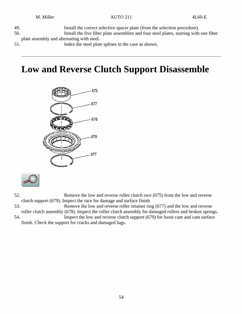
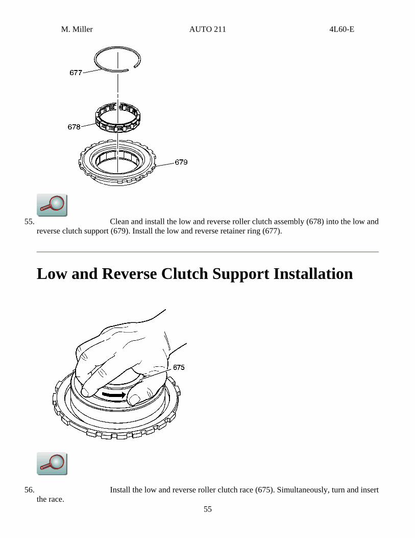
52. Remove the low and reverse roller clutch race (675) from the low and reverse clutch support (679). Inspect the race for damage and surface finish.
53. Remove the low and reverse roller retainer ring (677) and the low and reverse roller clutch assembly (678). Inspect the roller clutch assembly for damaged rollers and broken springs.
54. Inspect the low and reverse clutch support (679) for loose cam and cam surface finish. Check the support for cracks and damaged lugs.
54
M. Miller AUTO 211 4L60-E
55. Clean and install the low and reverse roller clutch assembly (678) into the low and
reverse clutch support (679). Install the low and reverse retainer ring (677).
Low and Reverse Clutch Support Installation
55
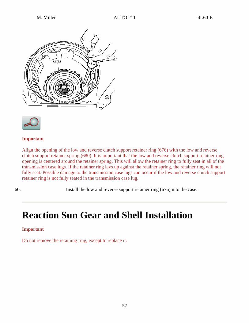
56. Install the low and reverse roller clutch race (675). Simultaneously, turn and insert the race.

M. Miller AUTO 211 4L60-E
57. Rotate the race in order to verify proper operation. The race should only rotate in one direction.
58. Install the low and reverse clutch support retainer spring (680) into the case.
Important
Align the wide low and reverse clutch support notch with the wide case lug.
59. Install the low and reverse clutch support (679), roller clutch and roller clutch race (675) assembly into the case. Position the hub side down during the installation.
56
M. Miller AUTO 211 4L60-E
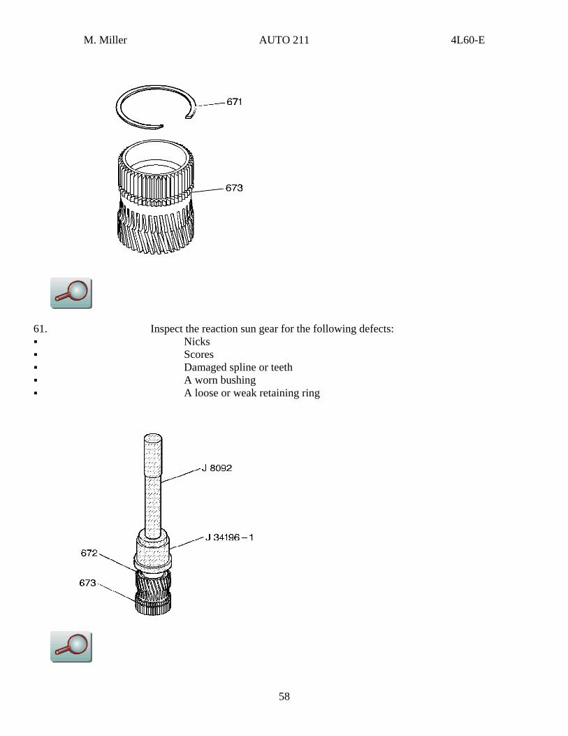
Important
Align the opening of the low and reverse clutch support retainer ring (676) with the low and reverse clutch support retainer spring (680). It is important that the low and reverse clutch support retainer ring opening is centered around the retainer spring. This will allow the retainer ring to fully seat in all of the transmission case lugs. If the retainer ring lays up against the retainer spring, the retainer ring will not fully seat. Possible damage to the transmission case lugs can occur if the low and reverse clutch support retainer ring is not fully seated in the transmission case lug.
60. Install the low and reverse support retainer ring (676) into the case.
Reaction Sun Gear and Shell Installation Important
Do not remove the retaining ring, except to replace it.
57
M. Miller AUTO 211 4L60-E
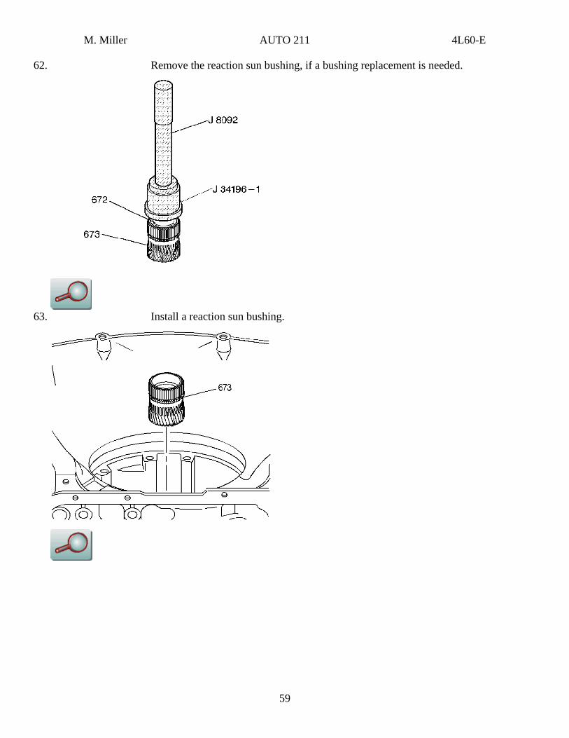
61. Inspect the reaction sun gear for the following defects: Nicks Scores Damaged spline or teeth A worn bushing A loose or weak retaining ring
58
M. Miller AUTO 211 4L60-E
62. Remove the reaction sun bushing, if a bushing replacement is needed.
63. Install a reaction sun bushing.
59
M. Miller AUTO 211 4L60-E
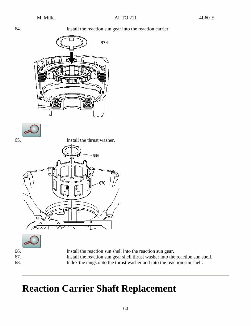
64. Install the reaction sun gear into the reaction carrier.
65. Install the thrust washer.
66. Install the reaction sun shell into the reaction sun gear. 67. Install the reaction sun gear shell thrust washer into the reaction sun shell.
60
68. Index the tangs onto the thrust washer and into the reaction sun shell.
Reaction Carrier Shaft Replacement
M. Miller AUTO 211 4L60-E
Removal Procedure
Tools Required
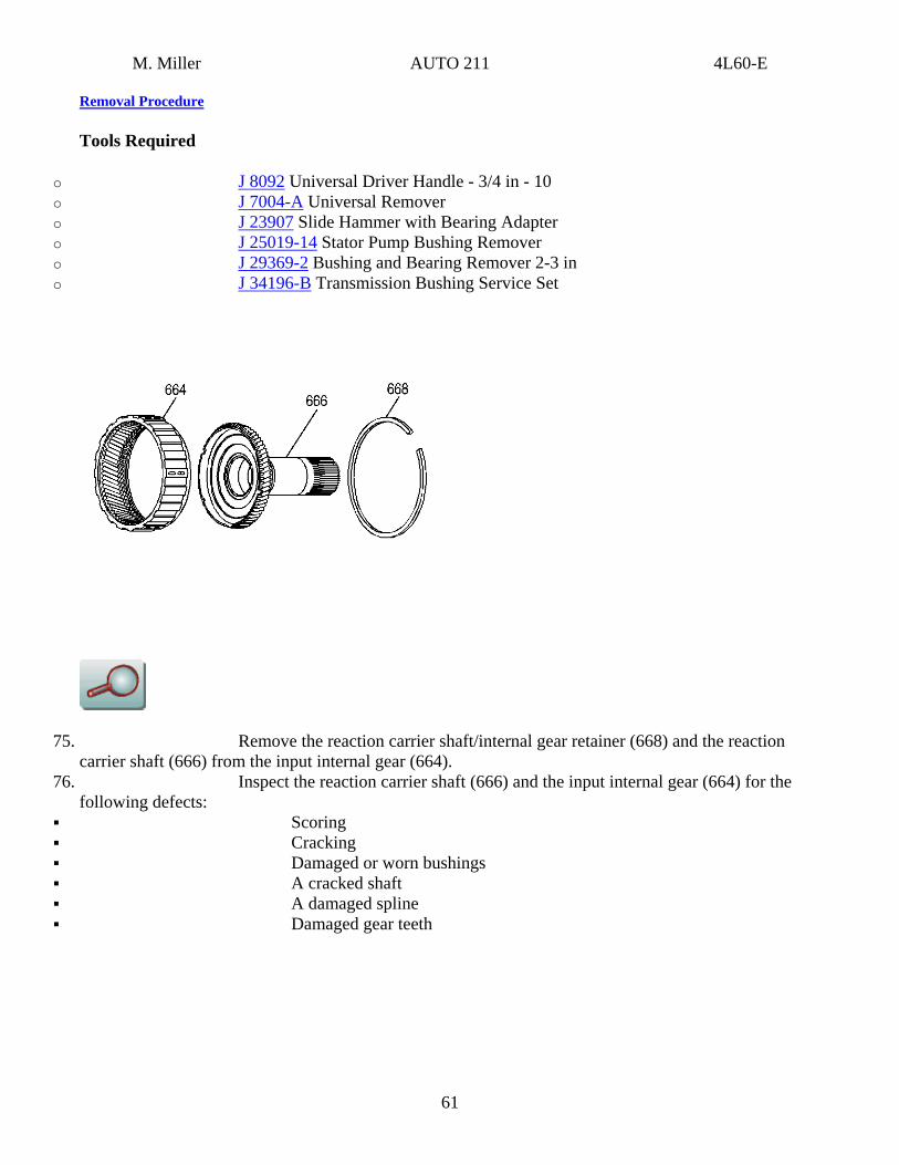
o J 8092 Universal Driver Handle - 3/4 in - 10 o J 7004-A Universal Remover o J 23907 Slide Hammer with Bearing Adapter o J 25019-14 Stator Pump Bushing Remover o J 29369-2 Bushing and Bearing Remover 2-3 in o J 34196-B Transmission Bushing Service Set
75. Remove the reaction carrier shaft/internal gear retainer (668) and the reaction carrier shaft (666) from the input internal gear (664).
76. Inspect the reaction carrier shaft (666) and the input internal gear (664) for the following defects:
Scoring Cracking Damaged or worn bushings A cracked shaft A damaged spline Damaged gear teeth
61
M. Miller AUTO 211 4L60-E
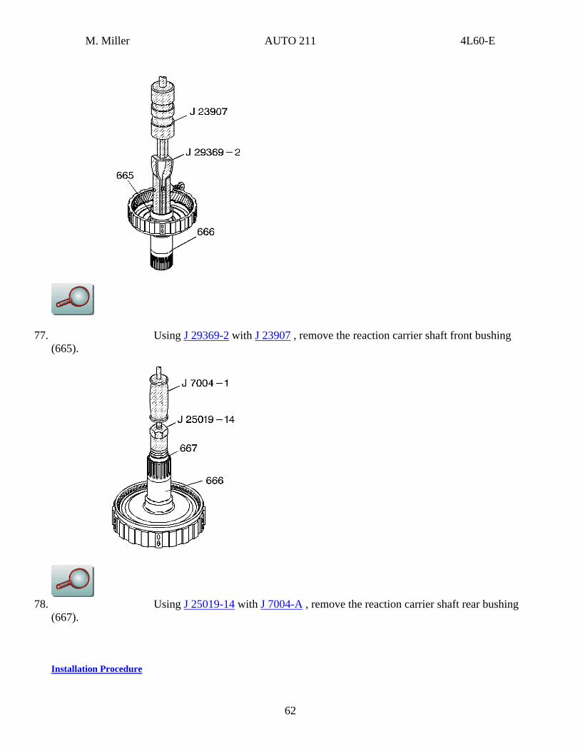
77. Using J 29369-2 with J 23907 , remove the reaction carrier shaft front bushing (665).
78. Using J 25019-14 with J 7004-A , remove the reaction carrier shaft rear bushing
(667).
Installation Procedure
62
M. Miller AUTO 211 4L60-E
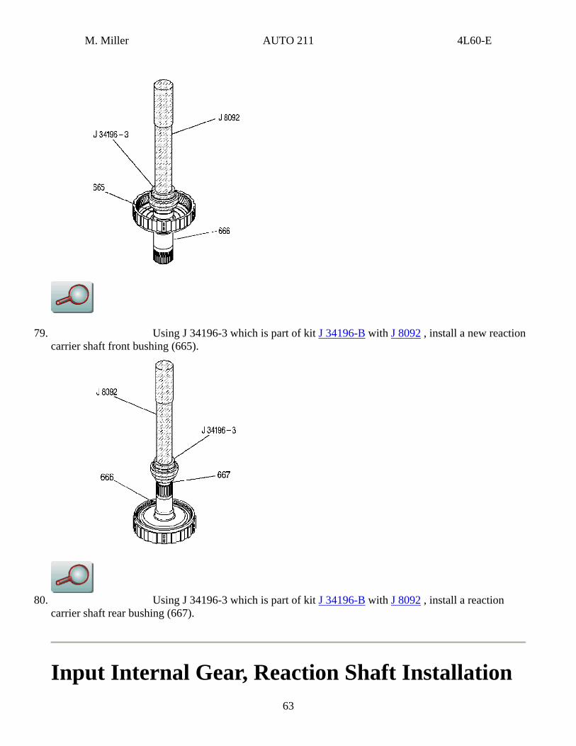
79. Using J 34196-3 which is part of kit J 34196-B with J 8092 , install a new reaction carrier shaft front bushing (665).
80. Using J 34196-3 which is part of kit J 34196-B with J 8092 , install a reaction
carrier shaft rear bushing (667).
Input Internal Gear, Reaction Shaft Installation 63
M. Miller AUTO 211 4L60-E
Installation Procedure
Tools Required
o J 34196-B Bushing Set o J 8092 Driver Handle
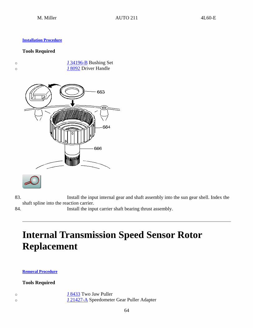
83. Install the input internal gear and shaft assembly into the sun gear shell. Index the shaft spline into the reaction carrier.
84. Install the input carrier shaft bearing thrust assembly.
Internal Transmission Speed Sensor Rotor Replacement
Removal Procedure
Tools Required
o J 8433 Two Jaw Puller o J 21427-A Speedometer Gear Puller Adapter
64
M. Miller AUTO 211 4L60-E
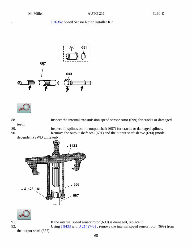
o J 36352 Speed Sensor Rotor Installer Kit
88. Inspect the internal transmission speed sensor rotor (699) for cracks or damaged teeth.
89. Inspect all splines on the output shaft (687) for cracks or damaged splines. 90. Remove the output shaft seal (691) and the output shaft sleeve (690) (model
dependent) 2WD units only.
91. If the internal speed sensor rotor (699) is damaged, replace it.
65
92. Using J 8433 with J 21427-01 , remove the internal speed sensor rotor (699) from the output shaft (687).
M. Miller AUTO 211 4L60-E
Installation Procedure
Important
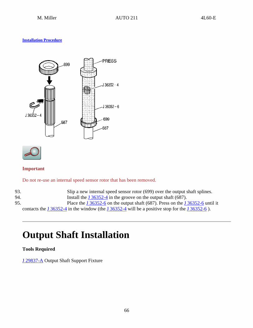
Do not re-use an internal speed sensor rotor that has been removed.
93. Slip a new internal speed sensor rotor (699) over the output shaft splines. 94. Install the J 36352-4 in the groove on the output shaft (687). 95. Place the J 36352-6 on the output shaft (687). Press on the J 36352-6 until it
contacts the J 36352-4 in the window (the J 36352-4 will be a positive stop for the J 36352-6 ).
Output Shaft Installation Tools Required
J 29837-A Output Shaft Support Fixture
66
M. Miller AUTO 211 4L60-E
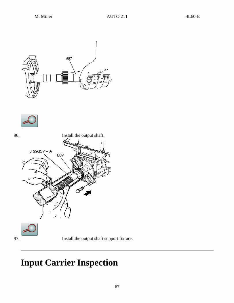
96. Install the output shaft.
97. Install the output shaft support fixture.
Input Carrier Inspection
67
M. Miller AUTO 211 4L60-E
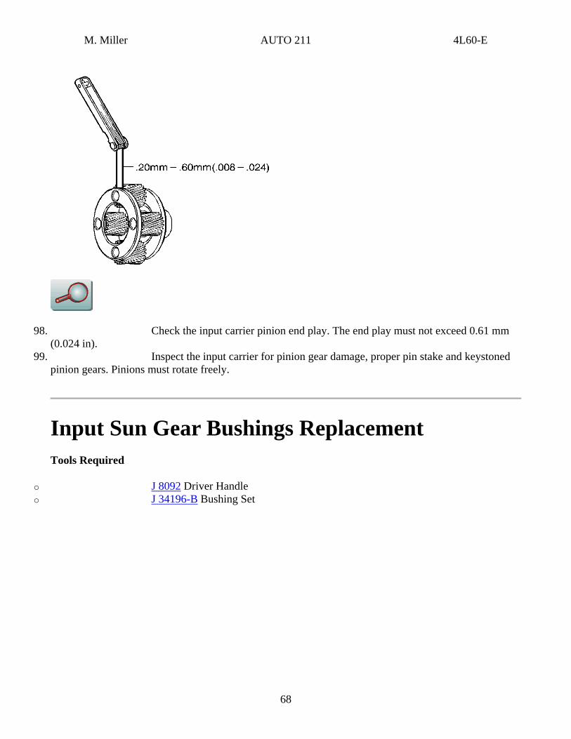
98. Check the input carrier pinion end play. The end play must not exceed 0.61 mm (0.024 in).
99. Inspect the input carrier for pinion gear damage, proper pin stake and keystoned pinion gears. Pinions must rotate freely.
Input Sun Gear Bushings Replacement Tools Required
o J 8092 Driver Handle o J 34196-B Bushing Set
68

M. Miller AUTO 211 4L60-E
102. Remove the input sun gear front and rear bushings.
103. Install the input sun gear front and rear bushings.
Input Carrier Inspection and Installation
69
M. Miller AUTO 211 4L60-E
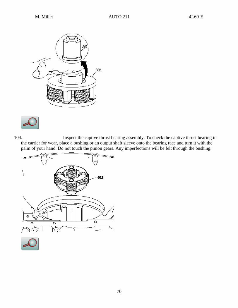
104. Inspect the captive thrust bearing assembly. To check the captive thrust bearing in the carrier for wear, place a bushing or an output shaft sleeve onto the bearing race and turn it with the palm of your hand. Do not touch the pinion gears. Any imperfections will be felt through the bushing.
70
M. Miller AUTO 211 4L60-E
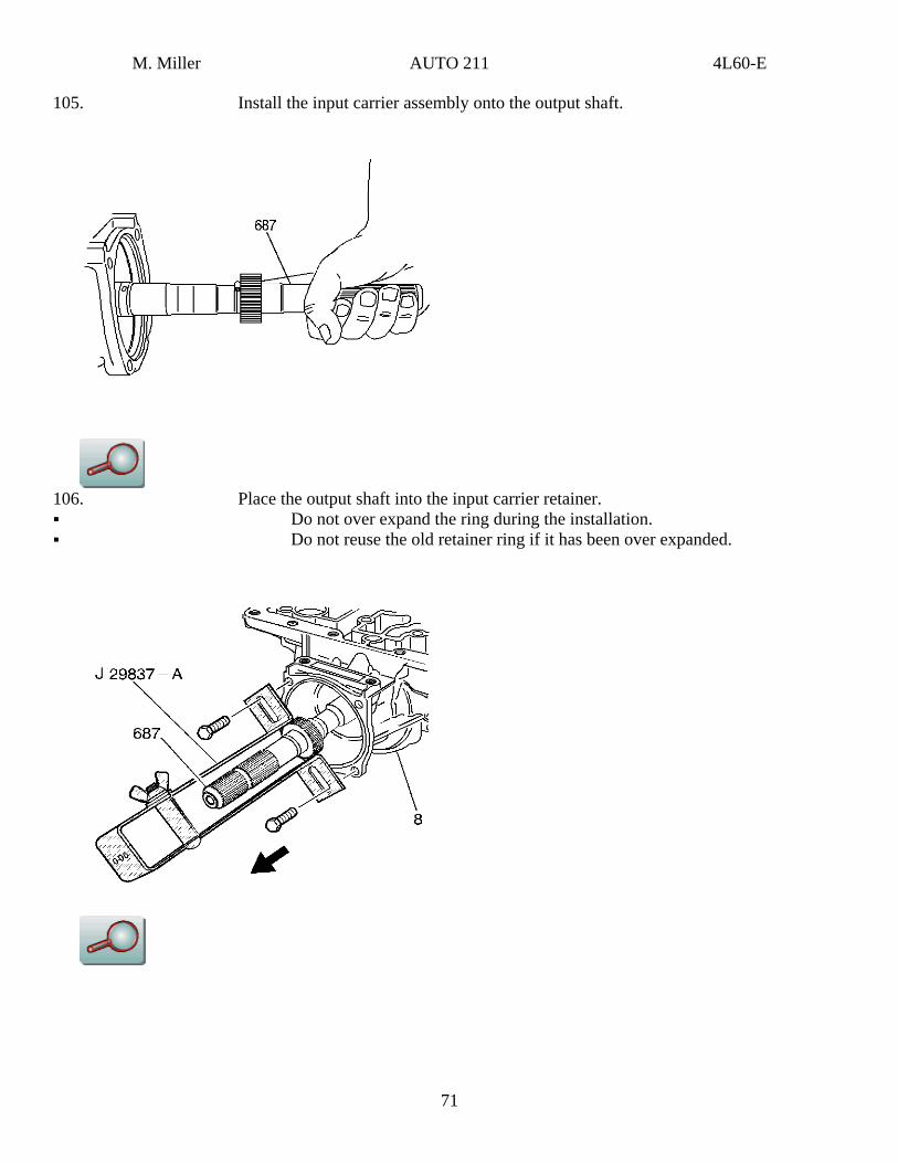
105. Install the input carrier assembly onto the output shaft.
106. Place the output shaft into the input carrier retainer. Do not over expand the ring during the installation. Do not reuse the old retainer ring if it has been over expanded.
71
M. Miller AUTO 211 4L60-E
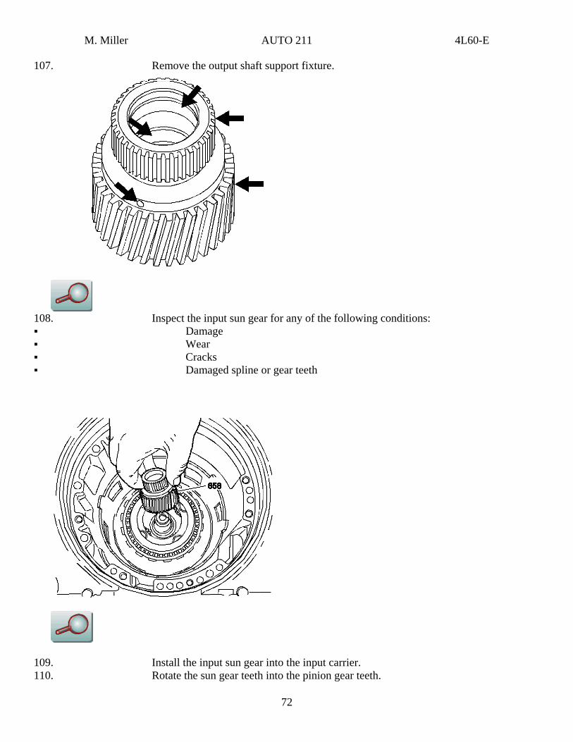
107. Remove the output shaft support fixture.
108. Inspect the input sun gear for any of the following conditions: Damage Wear Cracks Damaged spline or gear teeth
109. Install the input sun gear into the input carrier. 110. Rotate the sun gear teeth into the pinion gear teeth.
72

M. Miller AUTO 211 4L60-E
73
Input Clutch Assembly Disassemble
Removal Procedure
Tools Required
o J 23327-1 Clutch Spring Compressor o J 23456 Clutch Spring Compressor Press o J 25018-A Clutch Spring Compressor Adaptor
114. Remove the reverse input clutch housing; and the drum assembly from the input clutch assembly.
115. Remove the stator shaft/selective washer bearing assembly.
M. Miller AUTO 211 4L60-E
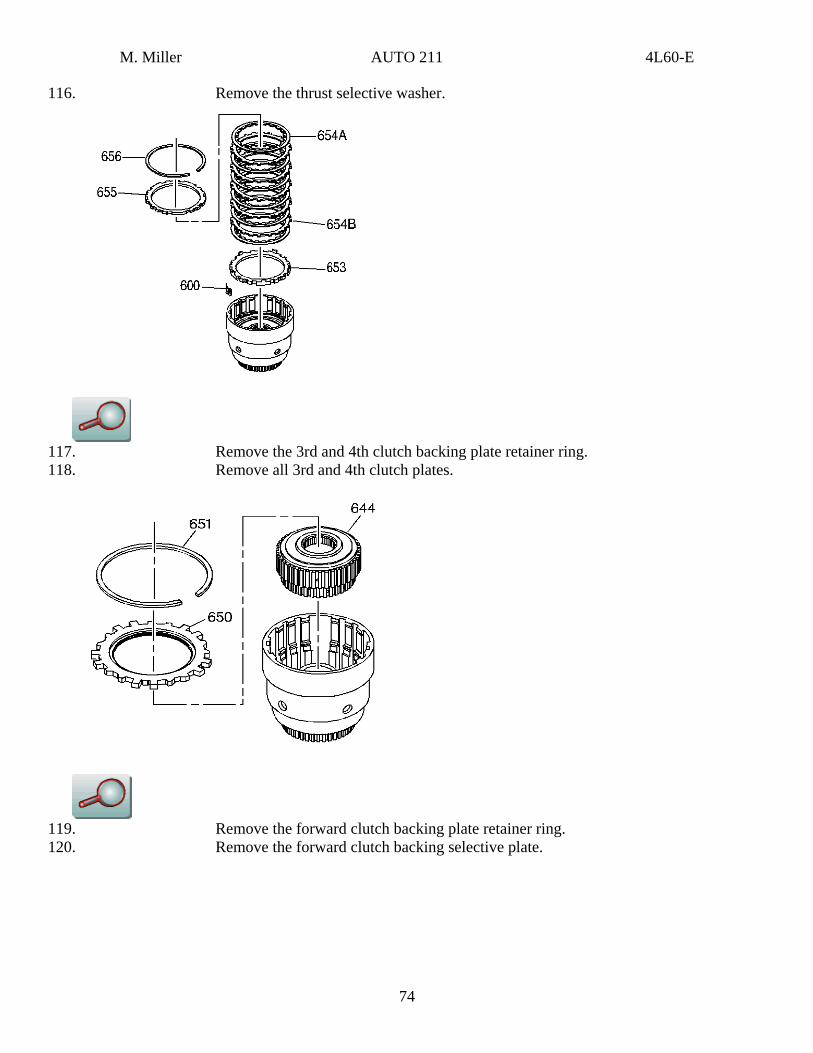
116. Remove the thrust selective washer.
117. Remove the 3rd and 4th clutch backing plate retainer ring. 118. Remove all 3rd and 4th clutch plates.
119. Remove the forward clutch backing plate retainer ring. 120. Remove the forward clutch backing selective plate.
74
M. Miller AUTO 211 4L60-E
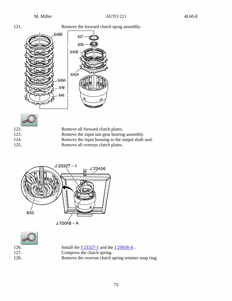
121. Remove the forward clutch sprag assembly.
122. Remove all forward clutch plates. 123. Remove the input sun gear bearing assembly. 124. Remove the input housing to the output shaft seal. 125. Remove all overrun clutch plates.
126. Install the J 23327-1 and the J 25018-A . 127. Compress the clutch spring. 128. Remove the overrun clutch spring retainer snap ring.
75
M. Miller AUTO 211 4L60-E
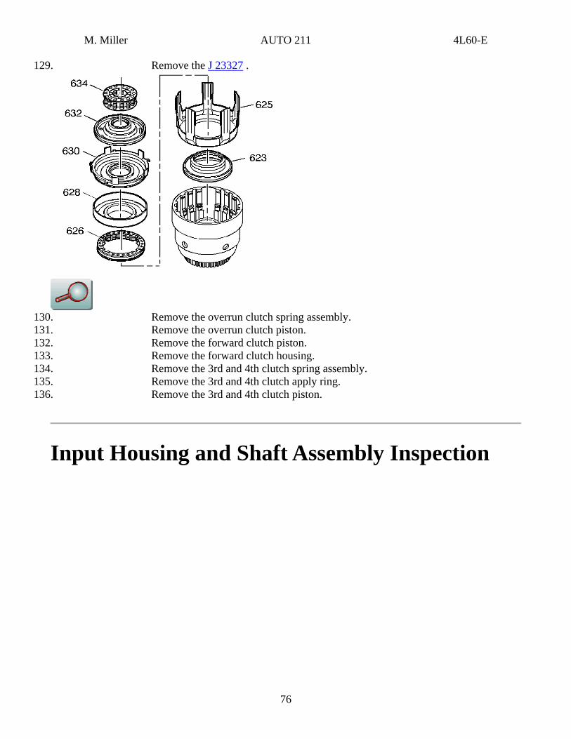
129. Remove the J 23327 .
130. Remove the overrun clutch spring assembly. 131. Remove the overrun clutch piston. 132. Remove the forward clutch piston. 133. Remove the forward clutch housing. 134. Remove the 3rd and 4th clutch spring assembly. 135. Remove the 3rd and 4th clutch apply ring. 136. Remove the 3rd and 4th clutch piston.
Input Housing and Shaft Assembly Inspection
76
M. Miller AUTO 211 4L60-E
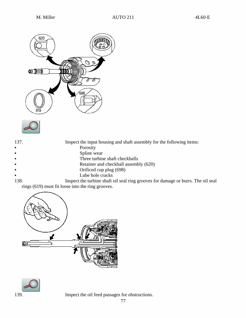
137. Inspect the input housing and shaft assembly for the following items: Porosity Spline wear Three turbine shaft checkballs Retainer and checkball assembly (620) Orificed cup plug (698) Lube hole cracks
138. Inspect the turbine shaft oil seal ring grooves for damage or burrs. The oil seal rings (619) must fit loose into the ring grooves.
77 139. Inspect the oil feed passages for obstructions.
M. Miller AUTO 211 4L60-E
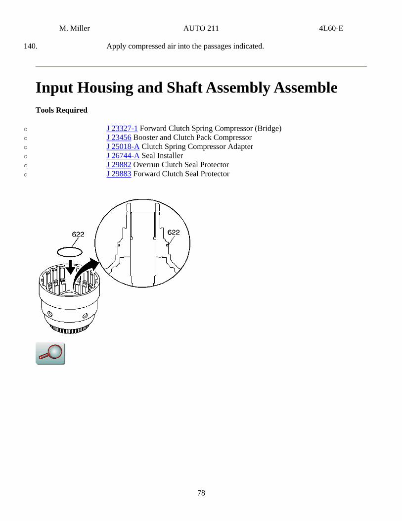
140. Apply compressed air into the passages indicated.
Input Housing and Shaft Assembly Assemble Tools Required
o J 23327-1 Forward Clutch Spring Compressor (Bridge) o J 23456 Booster and Clutch Pack Compressor o J 25018-A Clutch Spring Compressor Adapter o J 26744-A Seal Installer o J 29882 Overrun Clutch Seal Protector o J 29883 Forward Clutch Seal Protector
78

M. Miller AUTO 211 4L60-E
147. Install a new input to forward clutch housing O-ring seal (622).
148. Inspect the 3rd and 4th clutch piston (623) for the following conditions: Porosity or damage Seal damage
149. Install the 3rd and 4th clutch piston (623) into the input housing.
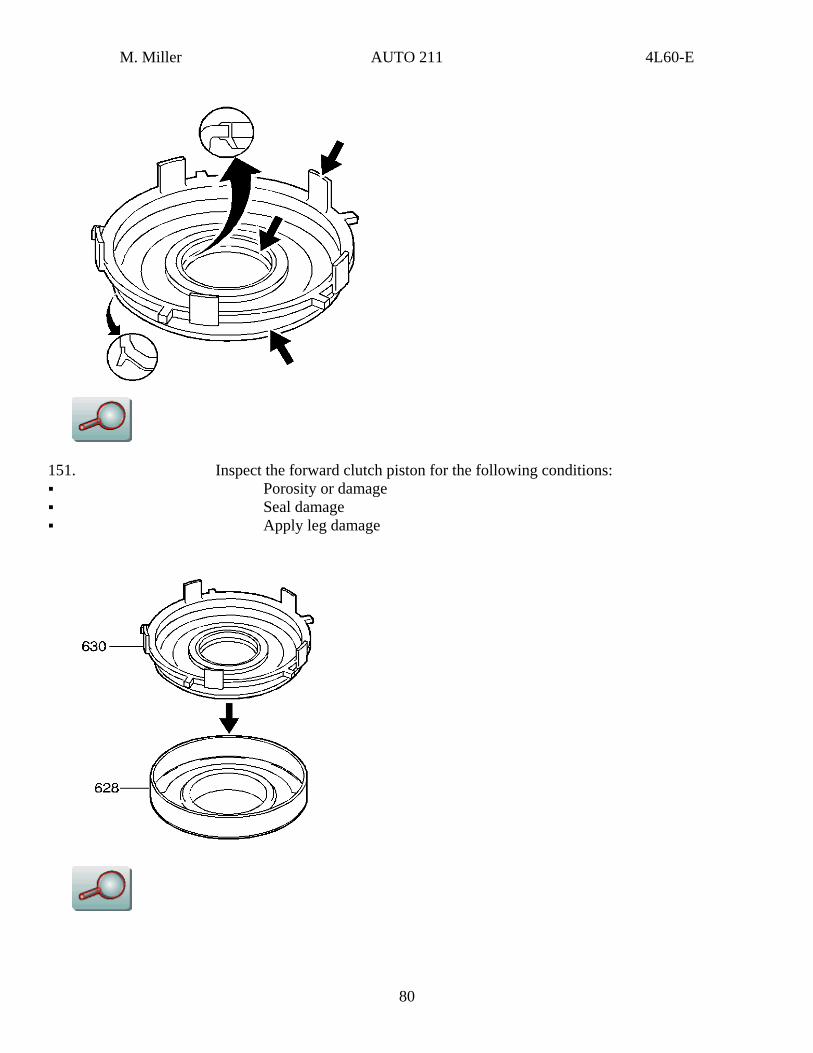
150. Inspect the forward clutch housing (628) for the following conditions: Proper check ball operation Damage or distortion Burrs in the seal areas Cracks
79
M. Miller AUTO 211 4L60-E
151. Inspect the forward clutch piston for the following conditions: Porosity or damage Seal damage Apply leg damage
80
M. Miller AUTO 211 4L60-E
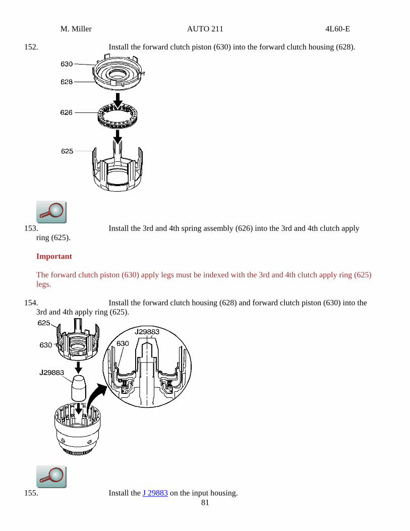
152. Install the forward clutch piston (630) into the forward clutch housing (628).
153. Install the 3rd and 4th spring assembly (626) into the 3rd and 4th clutch apply
ring (625).
Important
The forward clutch piston (630) apply legs must be indexed with the 3rd and 4th clutch apply ring (625) legs.
154. Install the forward clutch housing (628) and forward clutch piston (630) into the 3rd and 4th apply ring (625).
81 155. Install the J 29883 on the input housing.
M. Miller AUTO 211 4L60-E
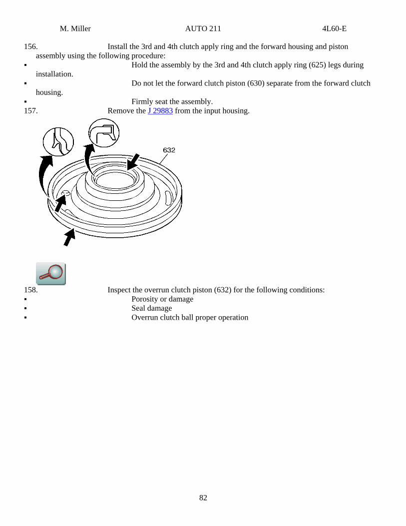
156. Install the 3rd and 4th clutch apply ring and the forward housing and piston assembly using the following procedure:
Hold the assembly by the 3rd and 4th clutch apply ring (625) legs during installation.
Do not let the forward clutch piston (630) separate from the forward clutch housing.
Firmly seat the assembly. 157. Remove the J 29883 from the input housing.
158. Inspect the overrun clutch piston (632) for the following conditions: Porosity or damage Seal damage Overrun clutch ball proper operation
82
M. Miller AUTO 211 4L60-E
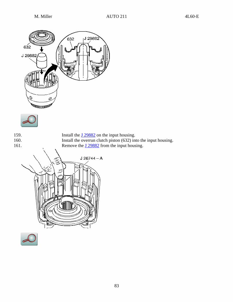
159. Install the J 29882 on the input housing. 160. Install the overrun clutch piston (632) into the input housing. 161. Remove the J 29882 from the input housing.
83
M. Miller AUTO 211 4L60-E
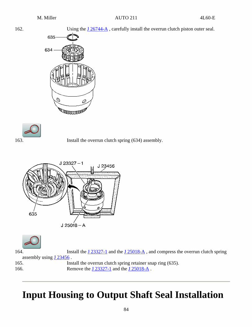
162. Using the J 26744-A , carefully install the overrun clutch piston outer seal.
163. Install the overrun clutch spring (634) assembly.
164. Install the J 23327-1 and the J 25018-A , and compress the overrun clutch spring
assembly using J 23456 . 165. Install the overrun clutch spring retainer snap ring (635). 166. Remove the J 23327-1 and the J 25018-A .
Input Housing to Output Shaft Seal Installation 84
M. Miller AUTO 211 4L60-E
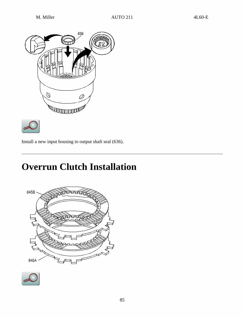
Install a new input housing to output shaft seal (636).
Overrun Clutch Installation
85
M. Miller AUTO 211 4L60-E
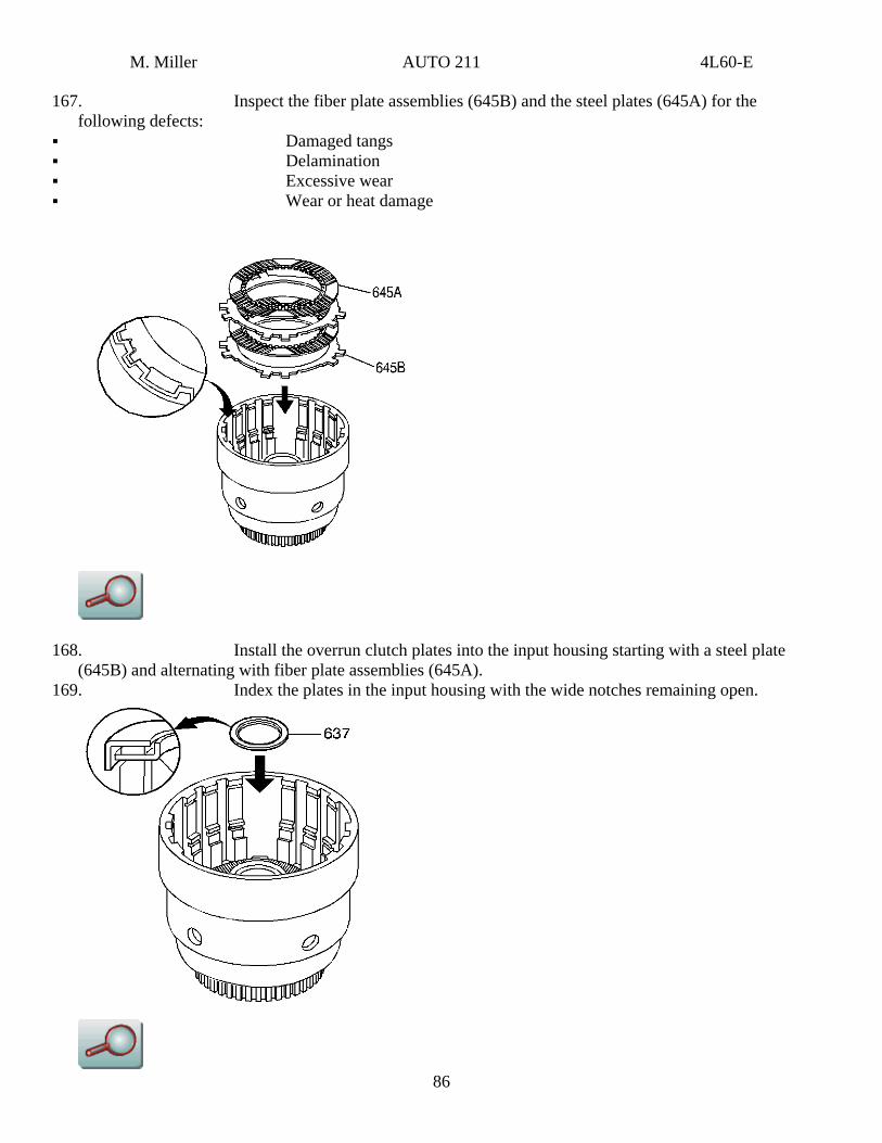
167. Inspect the fiber plate assemblies (645B) and the steel plates (645A) for the following defects:
Damaged tangs Delamination Excessive wear Wear or heat damage
168. Install the overrun clutch plates into the input housing starting with a steel plate (645B) and alternating with fiber plate assemblies (645A).
86
169. Index the plates in the input housing with the wide notches remaining open.
M. Miller AUTO 211 4L60-E
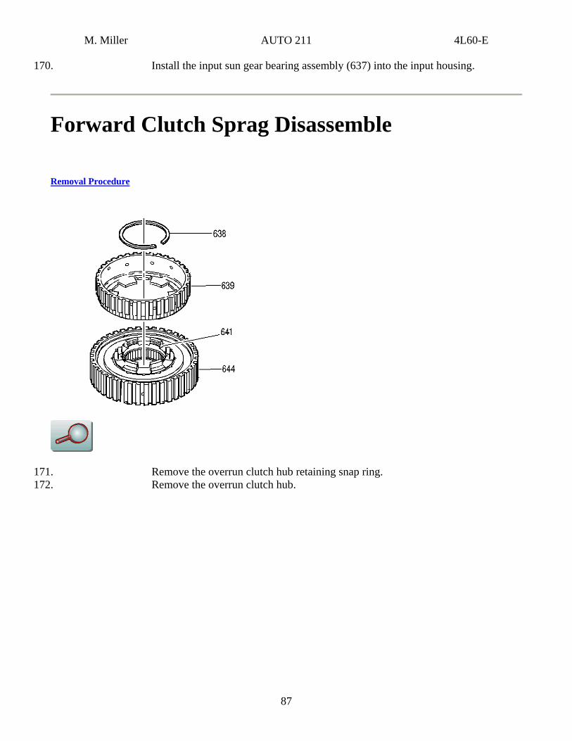
170. Install the input sun gear bearing assembly (637) into the input housing.
Forward Clutch Sprag Disassemble
Removal Procedure
171. Remove the overrun clutch hub retaining snap ring. 172. Remove the overrun clutch hub.
87
M. Miller AUTO 211 4L60-E
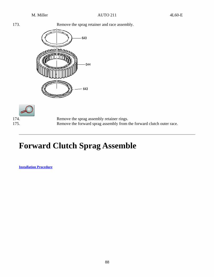
173. Remove the sprag retainer and race assembly.
174. Remove the sprag assembly retainer rings. 175. Remove the forward sprag assembly from the forward clutch outer race.
Forward Clutch Sprag Assemble
Installation Procedure
88
M. Miller AUTO 211 4L60-E
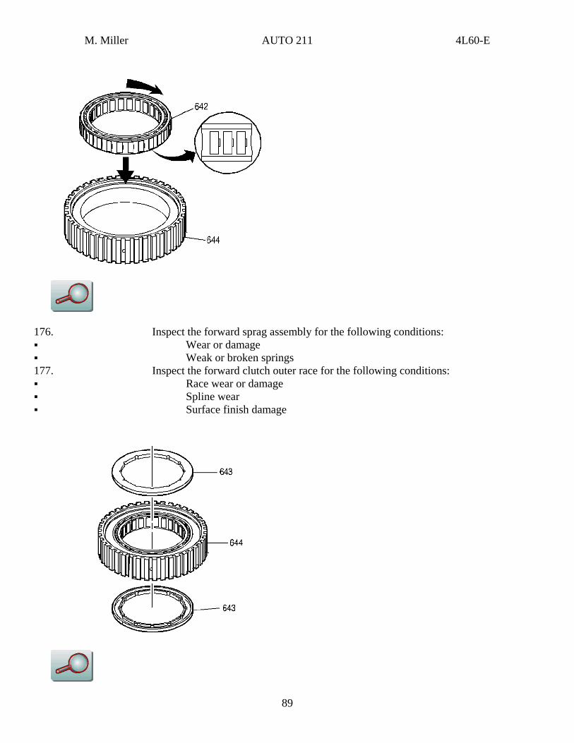
176. Inspect the forward sprag assembly for the following conditions: Wear or damage Weak or broken springs
177. Inspect the forward clutch outer race for the following conditions: Race wear or damage Spline wear Surface finish damage
89
M. Miller AUTO 211 4L60-E
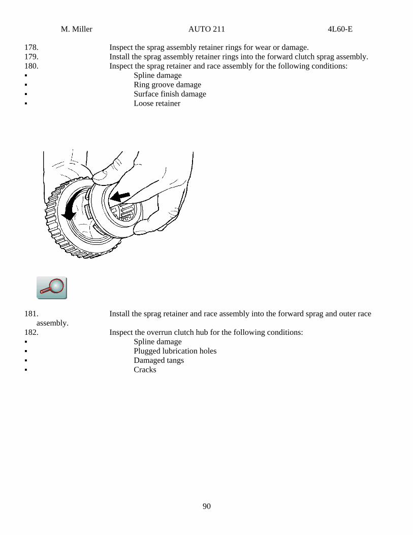
178. Inspect the sprag assembly retainer rings for wear or damage. 179. Install the sprag assembly retainer rings into the forward clutch sprag assembly. 180. Inspect the sprag retainer and race assembly for the following conditions: Spline damage Ring groove damage Surface finish damage Loose retainer
181. Install the sprag retainer and race assembly into the forward sprag and outer race assembly.
182. Inspect the overrun clutch hub for the following conditions: Spline damage Plugged lubrication holes Damaged tangs Cracks
90
M. Miller AUTO 211 4L60-E
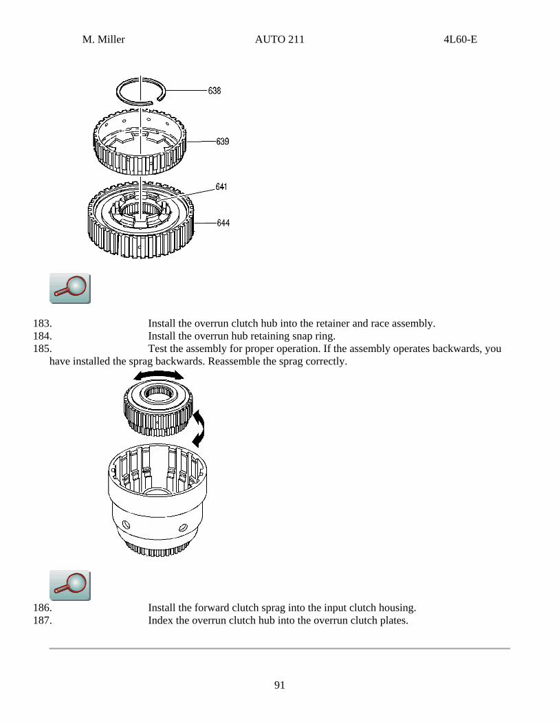
183. Install the overrun clutch hub into the retainer and race assembly. 184. Install the overrun hub retaining snap ring. 185. Test the assembly for proper operation. If the assembly operates backwards, you
have installed the sprag backwards. Reassemble the sprag correctly.
186. Install the forward clutch sprag into the input clutch housing. 187. Index the overrun clutch hub into the overrun clutch plates.
91
M. Miller AUTO 211 4L60-E
Forward Clutch Assembly Assemble
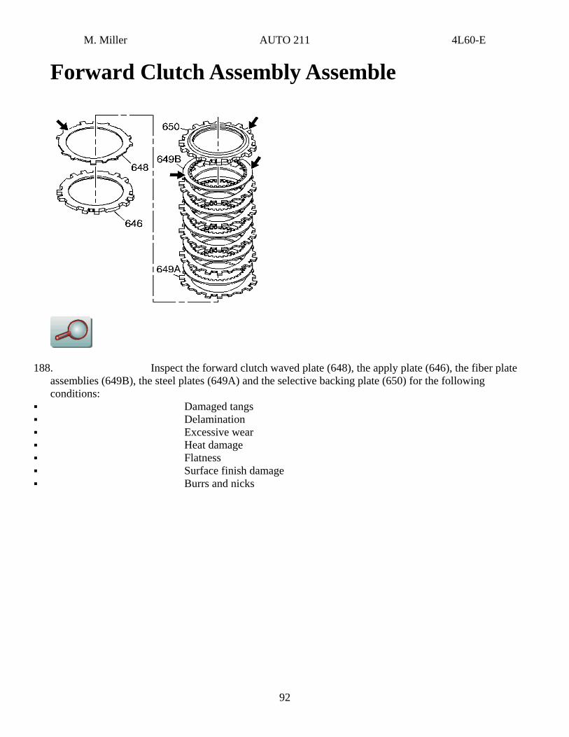
188. Inspect the forward clutch waved plate (648), the apply plate (646), the fiber plate assemblies (649B), the steel plates (649A) and the selective backing plate (650) for the following conditions:
Damaged tangs Delamination Excessive wear Heat damage Flatness Surface finish damage Burrs and nicks
92
M. Miller AUTO 211 4L60-E
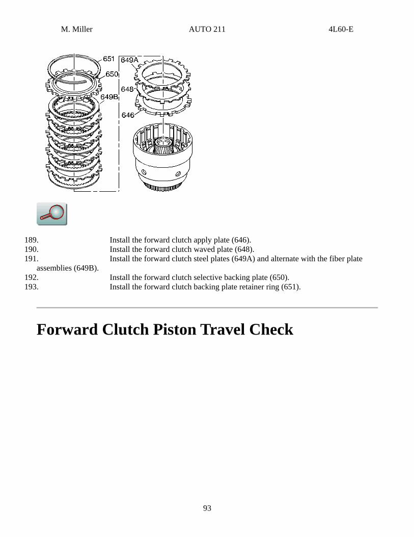
189. Install the forward clutch apply plate (646). 190. Install the forward clutch waved plate (648). 191. Install the forward clutch steel plates (649A) and alternate with the fiber plate
assemblies (649B). 192. Install the forward clutch selective backing plate (650). 193. Install the forward clutch backing plate retainer ring (651).
Forward Clutch Piston Travel Check
93
M. Miller AUTO 211 4L60-E
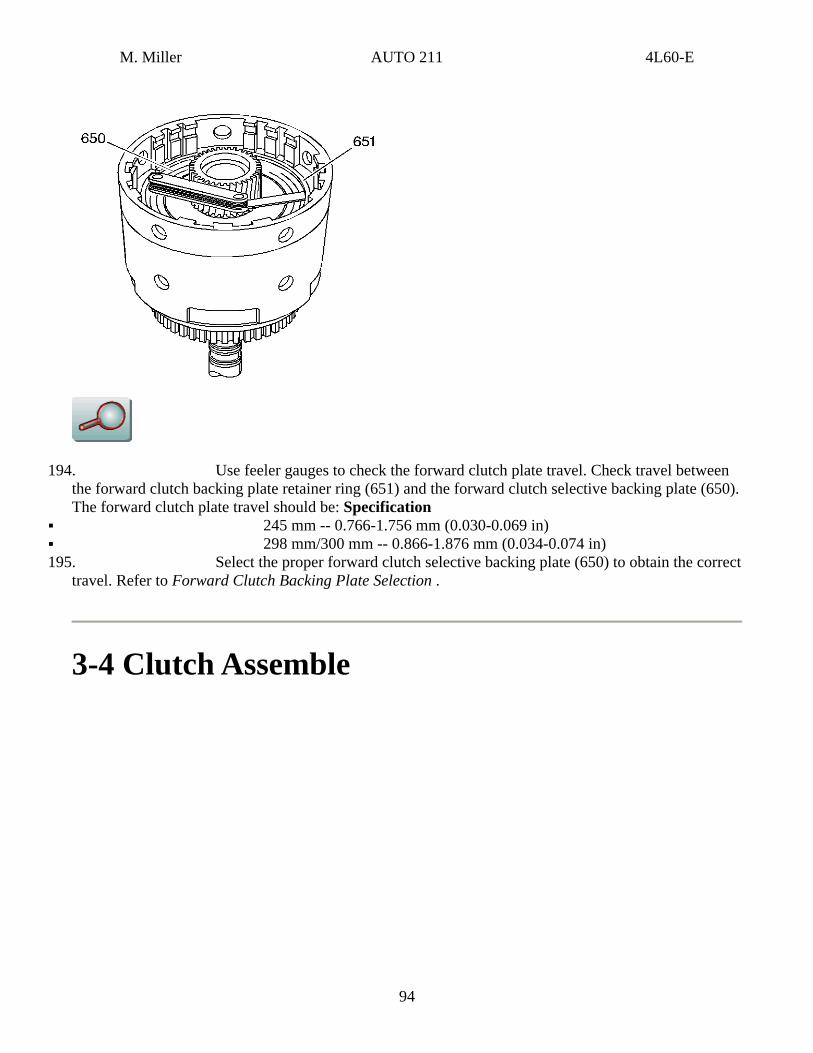
194. Use feeler gauges to check the forward clutch plate travel. Check travel between the forward clutch backing plate retainer ring (651) and the forward clutch selective backing plate (650). The forward clutch plate travel should be: Specification
245 mm -- 0.766-1.756 mm (0.030-0.069 in) 298 mm/300 mm -- 0.866-1.876 mm (0.034-0.074 in)
195. Select the proper forward clutch selective backing plate (650) to obtain the correct travel. Refer to Forward Clutch Backing Plate Selection .
3-4 Clutch Assemble
94
M. Miller AUTO 211 4L60-E
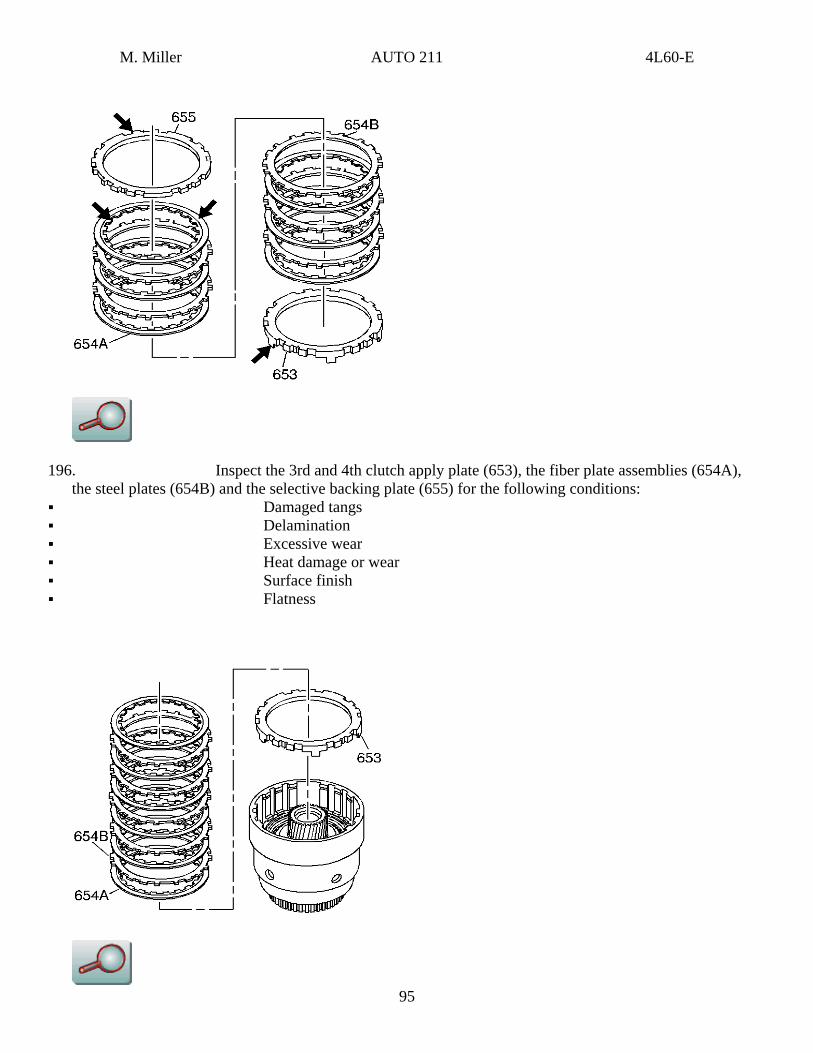
196. Inspect the 3rd and 4th clutch apply plate (653), the fiber plate assemblies (654A), the steel plates (654B) and the selective backing plate (655) for the following conditions:
Damaged tangs Delamination Excessive wear Heat damage or wear Surface finish Flatness
95
M. Miller AUTO 211 4L60-E
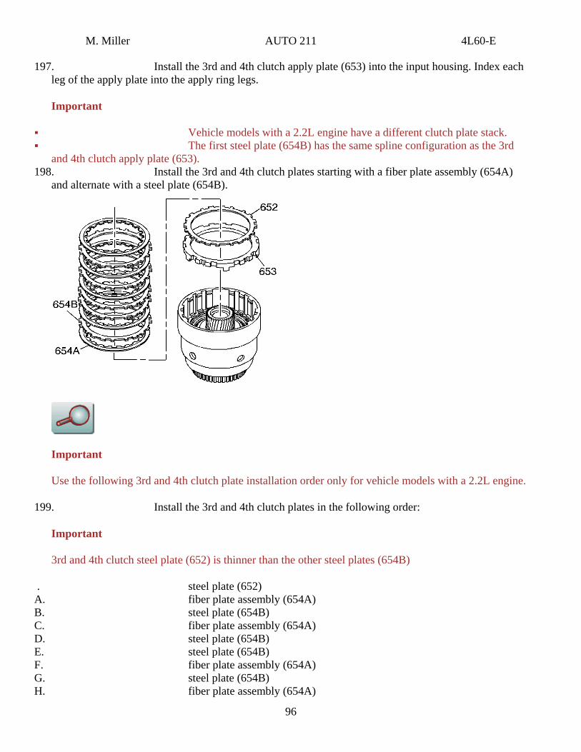
197. Install the 3rd and 4th clutch apply plate (653) into the input housing. Index each leg of the apply plate into the apply ring legs.
Important
Vehicle models with a 2.2L engine have a different clutch plate stack. The first steel plate (654B) has the same spline configuration as the 3rd
and 4th clutch apply plate (653). 198. Install the 3rd and 4th clutch plates starting with a fiber plate assembly (654A)
and alternate with a steel plate (654B).
Important
Use the following 3rd and 4th clutch plate installation order only for vehicle models with a 2.2L engine.
199. Install the 3rd and 4th clutch plates in the following order:
Important
3rd and 4th clutch steel plate (652) is thinner than the other steel plates (654B)
. steel plate (652) A. fiber plate assembly (654A) B. steel plate (654B) C. fiber plate assembly (654A) D. steel plate (654B) E. steel plate (654B) F. fiber plate assembly (654A) G. steel plate (654B) H. fiber plate assembly (654A)
96
M. Miller AUTO 211 4L60-E
I. steel plate (654B) J. fiber plate assembly (654A)
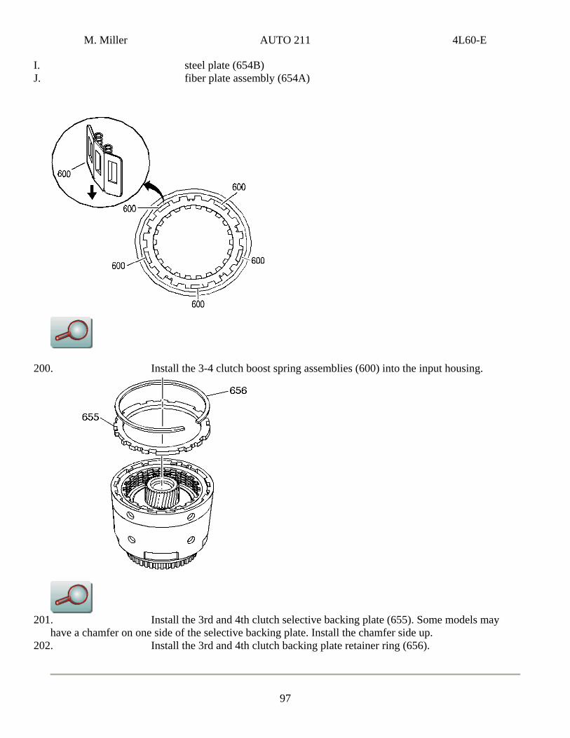
200. Install the 3-4 clutch boost spring assemblies (600) into the input housing.
201. Install the 3rd and 4th clutch selective backing plate (655). Some models may
have a chamfer on one side of the selective backing plate. Install the chamfer side up. 202. Install the 3rd and 4th clutch backing plate retainer ring (656).
97
M. Miller AUTO 211 4L60-E
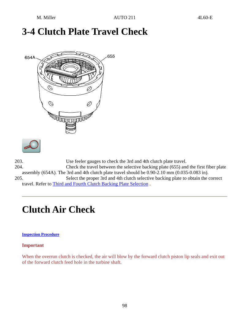
3-4 Clutch Plate Travel Check
203. Use feeler gauges to check the 3rd and 4th clutch plate travel. 204. Check the travel between the selective backing plate (655) and the first fiber plate
assembly (654A). The 3rd and 4th clutch plate travel should be 0.90-2.10 mm (0.035-0.083 in). 205. Select the proper 3rd and 4th clutch selective backing plate to obtain the correct
travel. Refer to Third and Fourth Clutch Backing Plate Selection .
Clutch Air Check
Inspection Procedure
Important
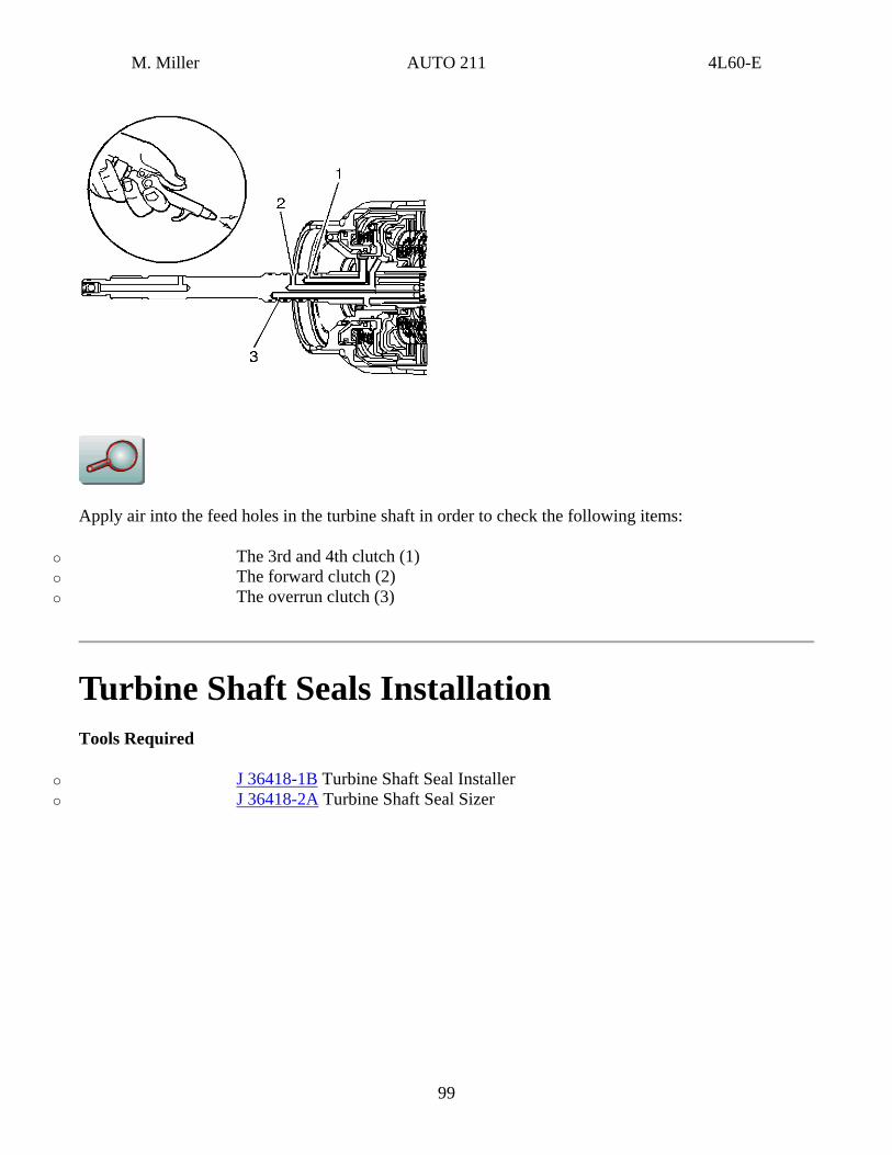
When the overrun clutch is checked, the air will blow by the forward clutch piston lip seals and exit out of the forward clutch feed hole in the turbine shaft.
98
M. Miller AUTO 211 4L60-E
Apply air into the feed holes in the turbine shaft in order to check the following items:
o The 3rd and 4th clutch (1) o The forward clutch (2) o The overrun clutch (3)
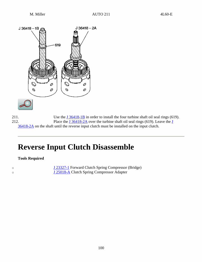
Turbine Shaft Seals Installation Tools Required
o J 36418-1B Turbine Shaft Seal Installer o J 36418-2A Turbine Shaft Seal Sizer
99
M. Miller AUTO 211 4L60-E
211. Use the J 36418-1B in order to install the four turbine shaft oil seal rings (619). 212. Place the J 36418-2A over the turbine shaft oil seal rings (619). Leave the J
36418-2A on the shaft until the reverse input clutch must be installed on the input clutch.
Reverse Input Clutch Disassemble Tools Required
o J 23327-1 Forward Clutch Spring Compressor (Bridge) o J 25018-A Clutch Spring Compressor Adapter
100
M. Miller AUTO 211 4L60-E
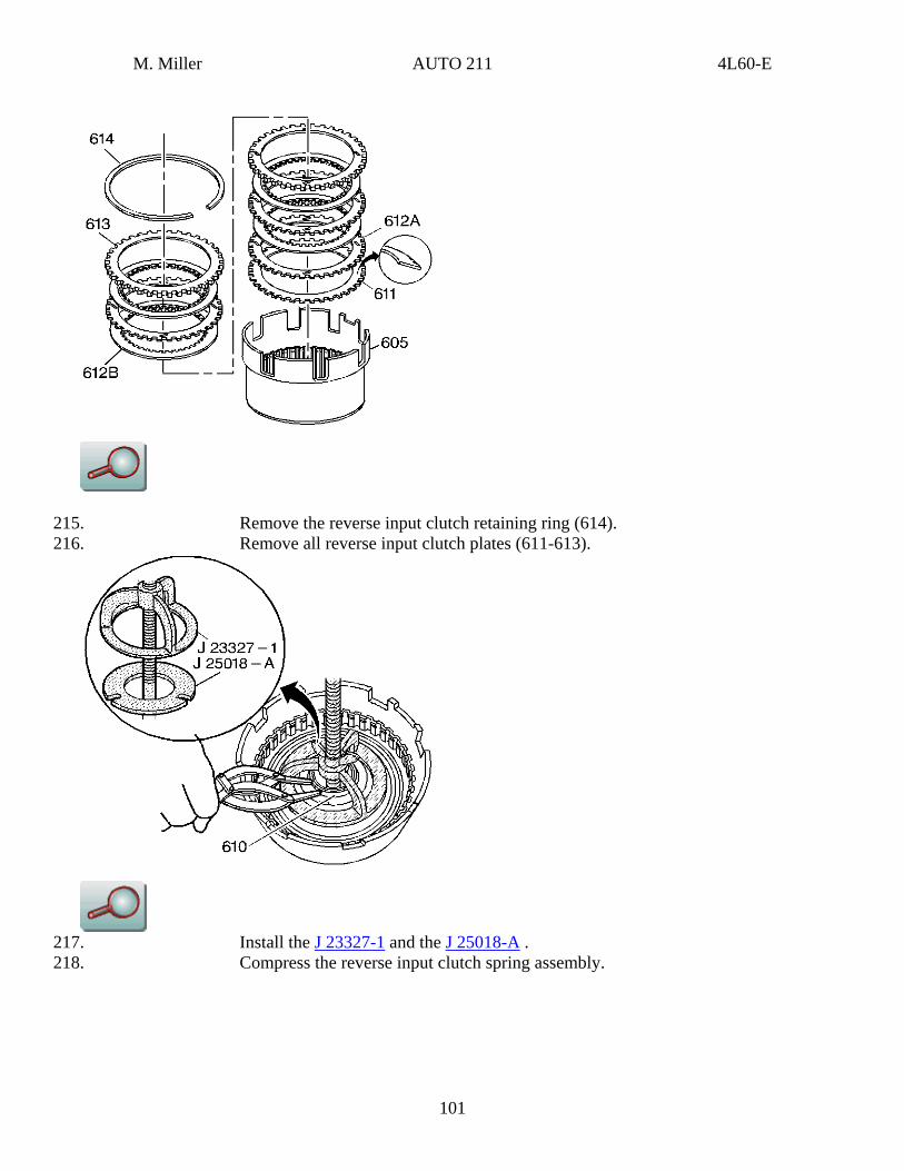
215. Remove the reverse input clutch retaining ring (614). 216. Remove all reverse input clutch plates (611-613).
217. Install the J 23327-1 and the J 25018-A . 218. Compress the reverse input clutch spring assembly.
101
M. Miller AUTO 211 4L60-E
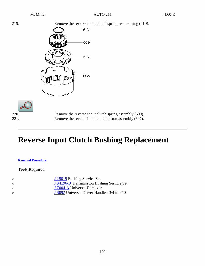
219. Remove the reverse input clutch spring retainer ring (610).
220. Remove the reverse input clutch spring assembly (609). 221. Remove the reverse input clutch piston assembly (607).
Reverse Input Clutch Bushing Replacement
Removal Procedure
Tools Required
o J 25019 Bushing Service Set o J 34196-B Transmission Bushing Service Set o J 7004-A Universal Remover o J 8092 Universal Driver Handle - 3/4 in - 10
102
M. Miller AUTO 211 4L60-E
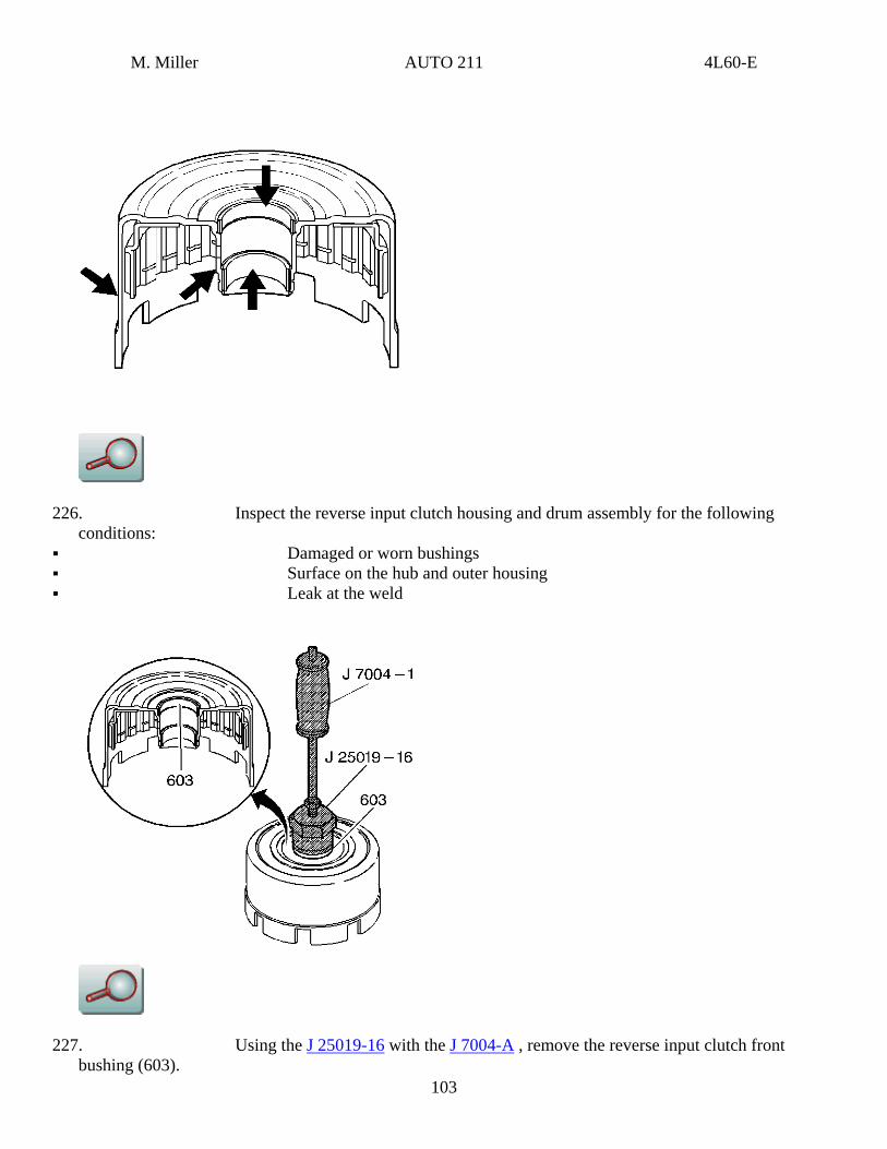
226. Inspect the reverse input clutch housing and drum assembly for the following conditions:
Damaged or worn bushings Surface on the hub and outer housing Leak at the weld
103
227. Using the J 25019-16 with the J 7004-A , remove the reverse input clutch front bushing (603).
M. Miller AUTO 211 4L60-E
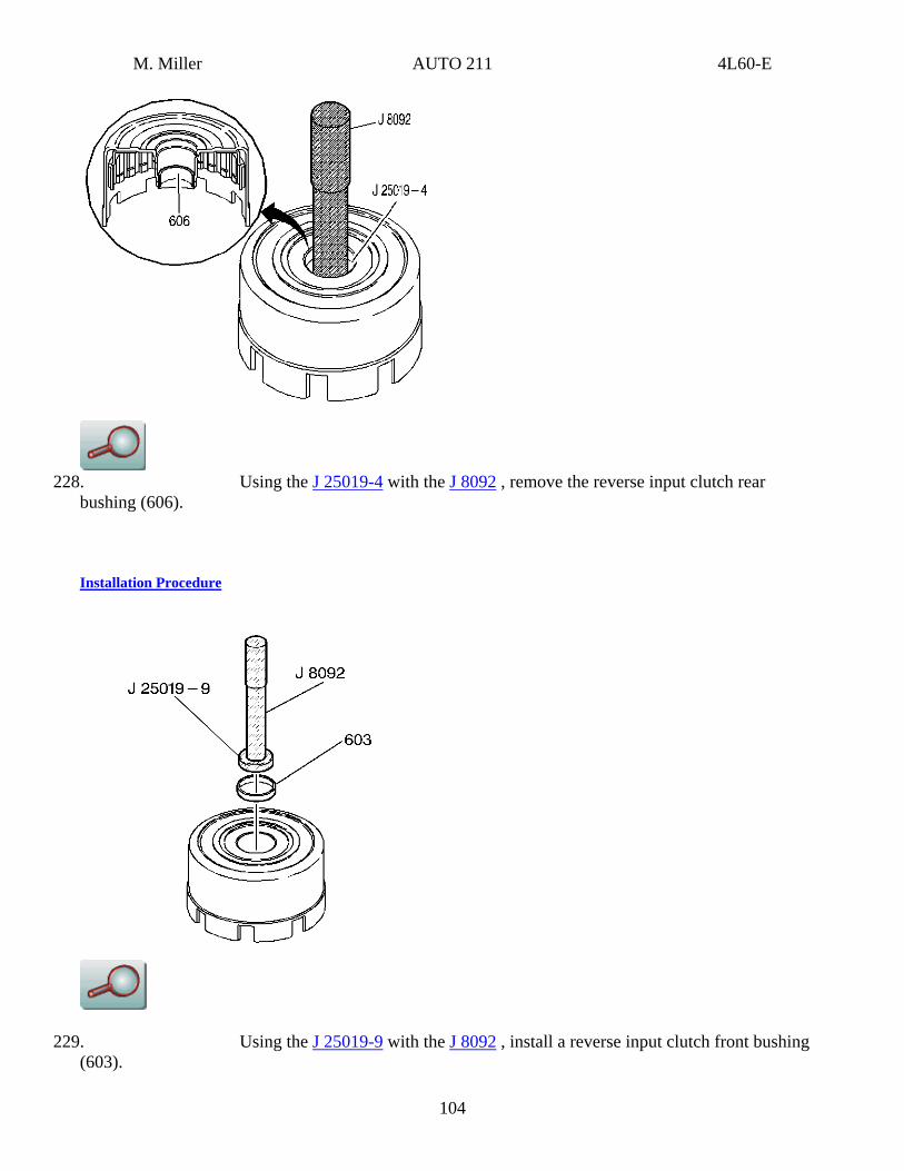
228. Using the J 25019-4 with the J 8092 , remove the reverse input clutch rear
bushing (606).
Installation Procedure
229. Using the J 25019-9 with the J 8092 , install a reverse input clutch front bushing (603).
104
M. Miller AUTO 211 4L60-E
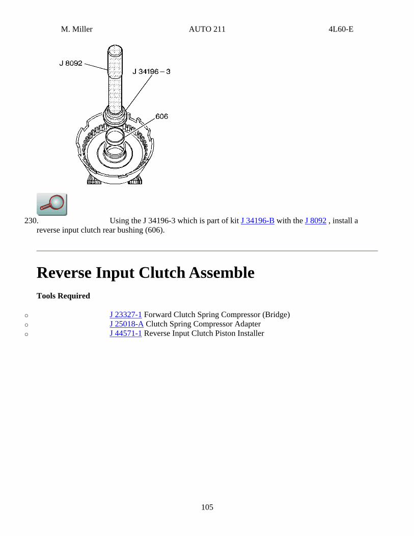
230. Using the J 34196-3 which is part of kit J 34196-B with the J 8092 , install a
reverse input clutch rear bushing (606).
Reverse Input Clutch Assemble Tools Required
o J 23327-1 Forward Clutch Spring Compressor (Bridge) o J 25018-A Clutch Spring Compressor Adapter o J 44571-1 Reverse Input Clutch Piston Installer
105
M. Miller AUTO 211 4L60-E
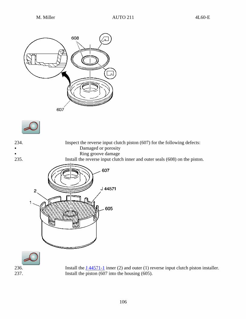
234. Inspect the reverse input clutch piston (607) for the following defects: Damaged or porosity Ring groove damage
235. Install the reverse input clutch inner and outer seals (608) on the piston.
236. Install the J 44571-1 inner (2) and outer (1) reverse input clutch piston installer. 237. Install the piston (607 into the housing (605).
106
M. Miller AUTO 211 4L60-E
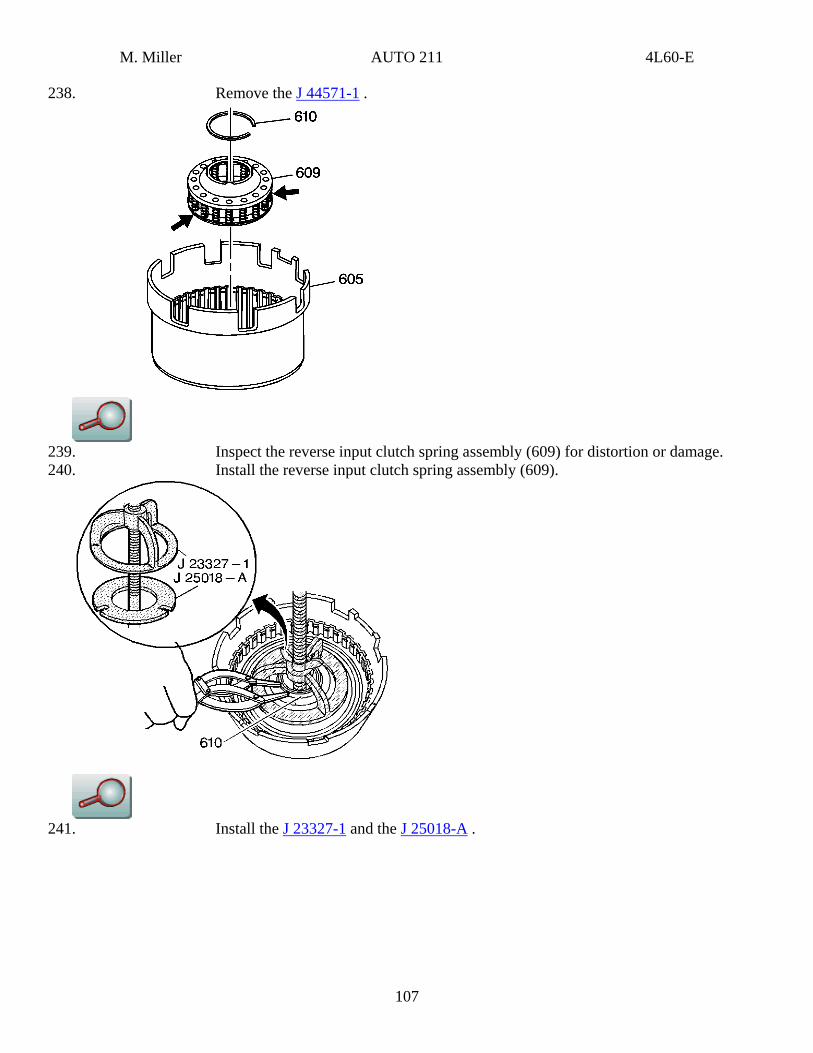
238. Remove the J 44571-1 .
239. Inspect the reverse input clutch spring assembly (609) for distortion or damage. 240. Install the reverse input clutch spring assembly (609).
241. Install the J 23327-1 and the J 25018-A .
107
M. Miller AUTO 211 4L60-E
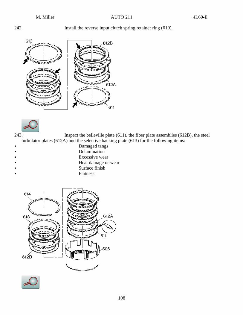
242. Install the reverse input clutch spring retainer ring (610).
243. Inspect the belleville plate (611), the fiber plate assemblies (612B), the steel
turbulator plates (612A) and the selective backing plate (613) for the following items: Damaged tangs Delamination Excessive wear Heat damage or wear Surface finish Flatness
108
M. Miller AUTO 211 4L60-E
244. Install the reverse input clutch belleville plate (611), with the inner diameter up, into the reverse input clutch housing and drum assembly (605).
245. Install the reverse input clutch plates starting with a steel turbulator plate (612A) and alternate with a fiber plate assembly (612B).
246. Install the reverse input clutch selective backing plate (613). 247. Install the reverse input clutch retaining ring (614).
Reverse Input Clutch Plate Travel Check
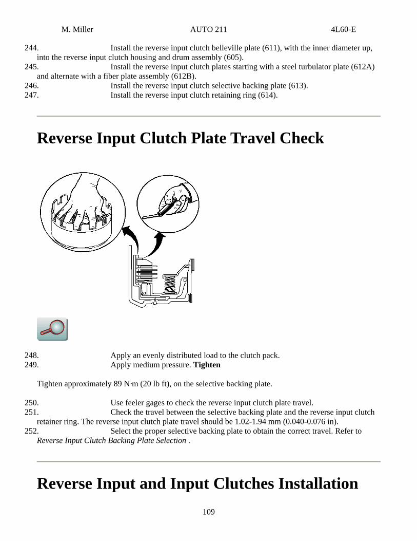
248. Apply an evenly distributed load to the clutch pack. 249. Apply medium pressure. Tighten
Tighten approximately 89 N·m (20 lb ft), on the selective backing plate.
250. Use feeler gages to check the reverse input clutch plate travel. 251. Check the travel between the selective backing plate and the reverse input clutch
retainer ring. The reverse input clutch plate travel should be 1.02-1.94 mm (0.040-0.076 in). 252. Select the proper selective backing plate to obtain the correct travel. Refer to
Reverse Input Clutch Backing Plate Selection .
Reverse Input and Input Clutches Installation 109
M. Miller AUTO 211 4L60-E
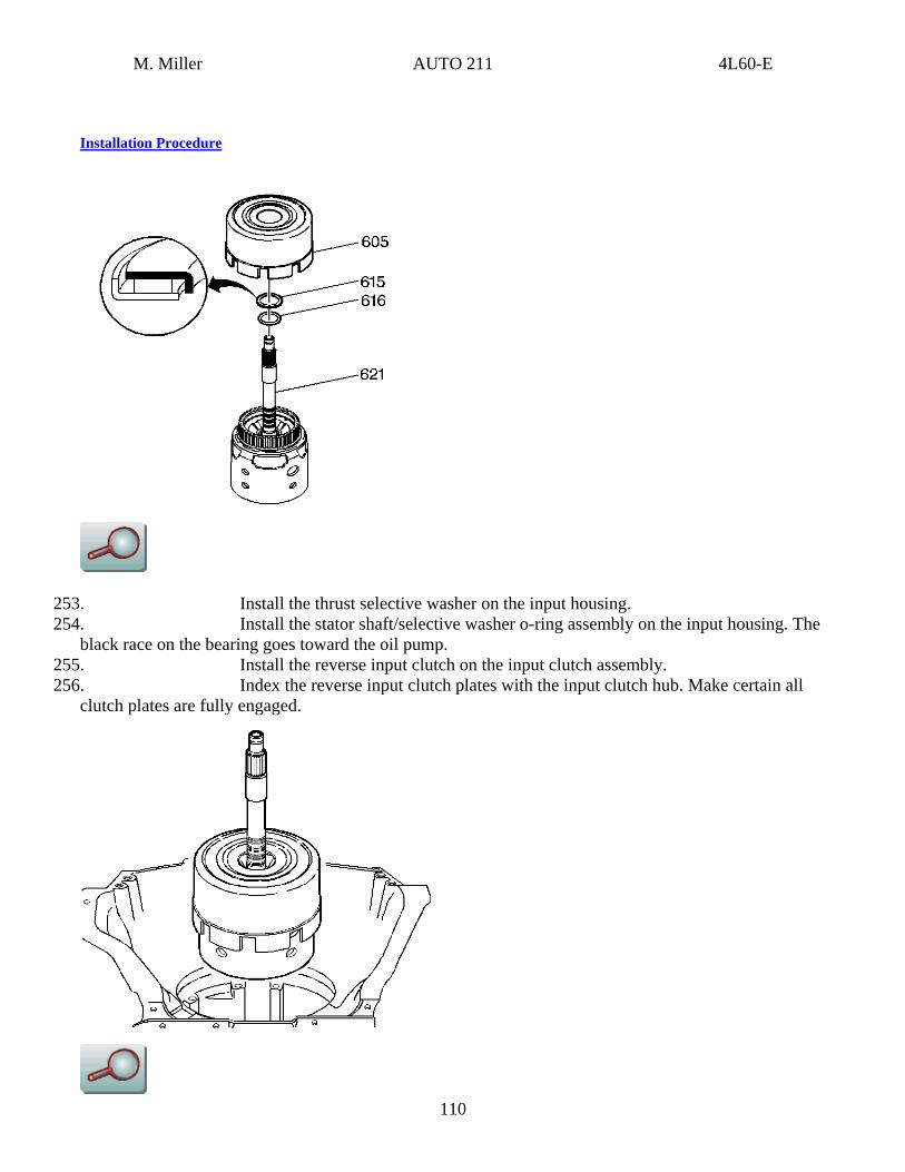
Installation Procedure
253. Install the thrust selective washer on the input housing. 254. Install the stator shaft/selective washer o-ring assembly on the input housing. The
black race on the bearing goes toward the oil pump. 255. Install the reverse input clutch on the input clutch assembly.
110
256. Index the reverse input clutch plates with the input clutch hub. Make certain all clutch plates are fully engaged.
M. Miller AUTO 211 4L60-E
257. Install the reverse input and the input clutch assembly into the transmission case. 258. Index the 3rd and 4th clutch plates with the input internal gear. Ensure that all clutch plates are fully engaged. When properly assembled, the reverse input clutch housing will be located
just below the case oil pump face.
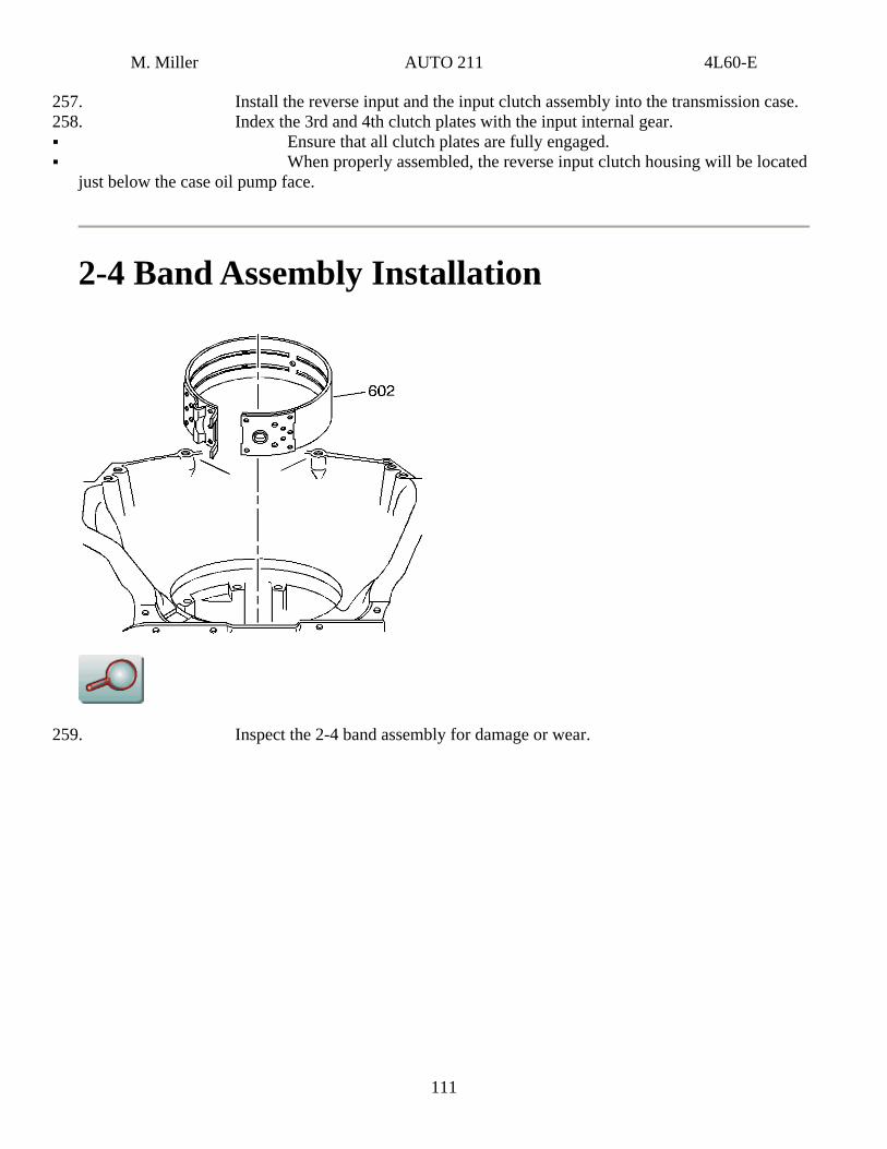
2-4 Band Assembly Installation
259. Inspect the 2-4 band assembly for damage or wear.
111
M. Miller AUTO 211 4L60-E
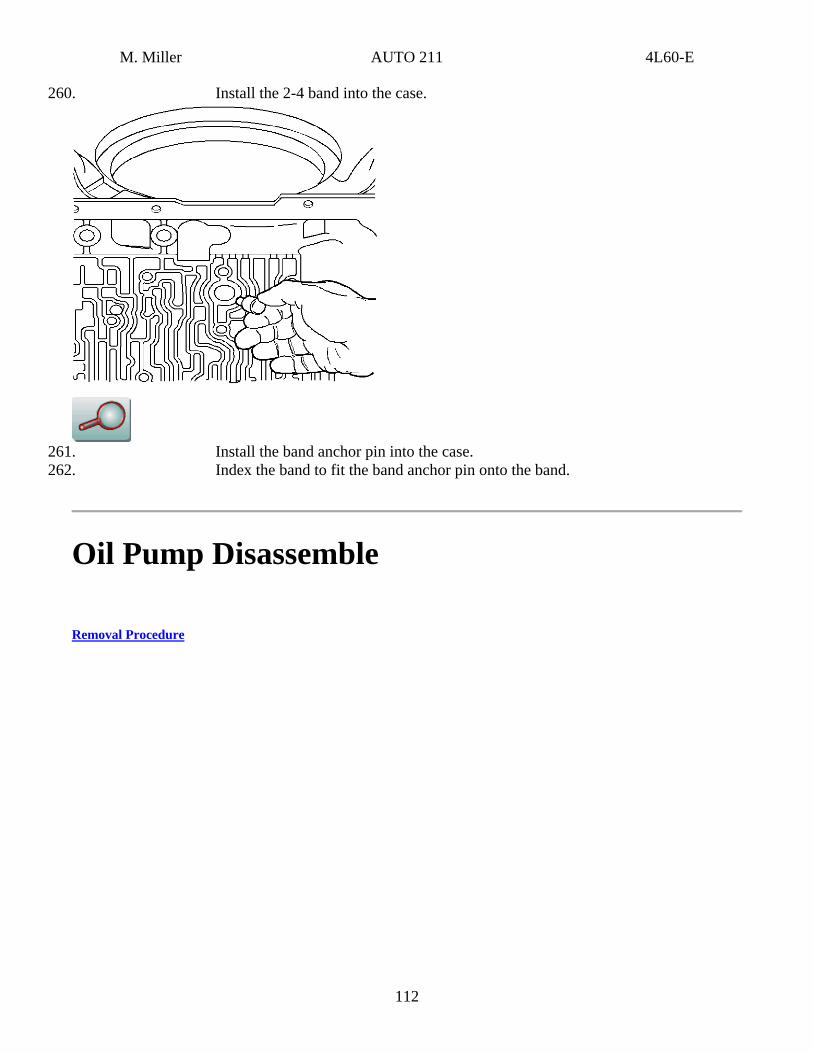
260. Install the 2-4 band into the case.
261. Install the band anchor pin into the case. 262. Index the band to fit the band anchor pin onto the band.
Oil Pump Disassemble
Removal Procedure
112
M. Miller AUTO 211 4L60-E
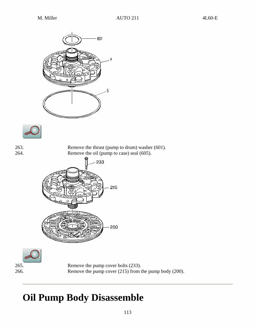
263. Remove the thrust (pump to drum) washer (601). 264. Remove the oil (pump to case) seal (605).
265. Remove the pump cover bolts (233). 266. Remove the pump cover (215) from the pump body (200).
Oil Pump Body Disassemble 113
M. Miller AUTO 211 4L60-E
Removal Procedure
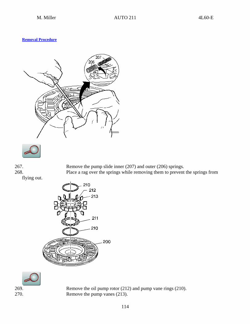
267. Remove the pump slide inner (207) and outer (206) springs. 268. Place a rag over the springs while removing them to prevent the springs from
flying out.
269. Remove the oil pump rotor (212) and pump vane rings (210). 270. Remove the pump vanes (213).
114
M. Miller AUTO 211 4L60-E
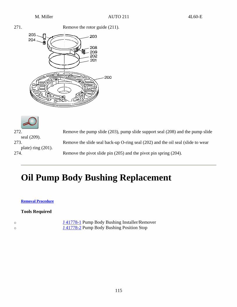
271. Remove the rotor guide (211).
272. Remove the pump slide (203), pump slide support seal (208) and the pump slide
seal (209). 273. Remove the slide seal back-up O-ring seal (202) and the oil seal (slide to wear
plate) ring (201). 274. Remove the pivot slide pin (205) and the pivot pin spring (204).
Oil Pump Body Bushing Replacement
Removal Procedure
Tools Required
o J 41778-1 Pump Body Bushing Installer/Remover o J 41778-2 Pump Body Bushing Position Stop
115
M. Miller AUTO 211 4L60-E
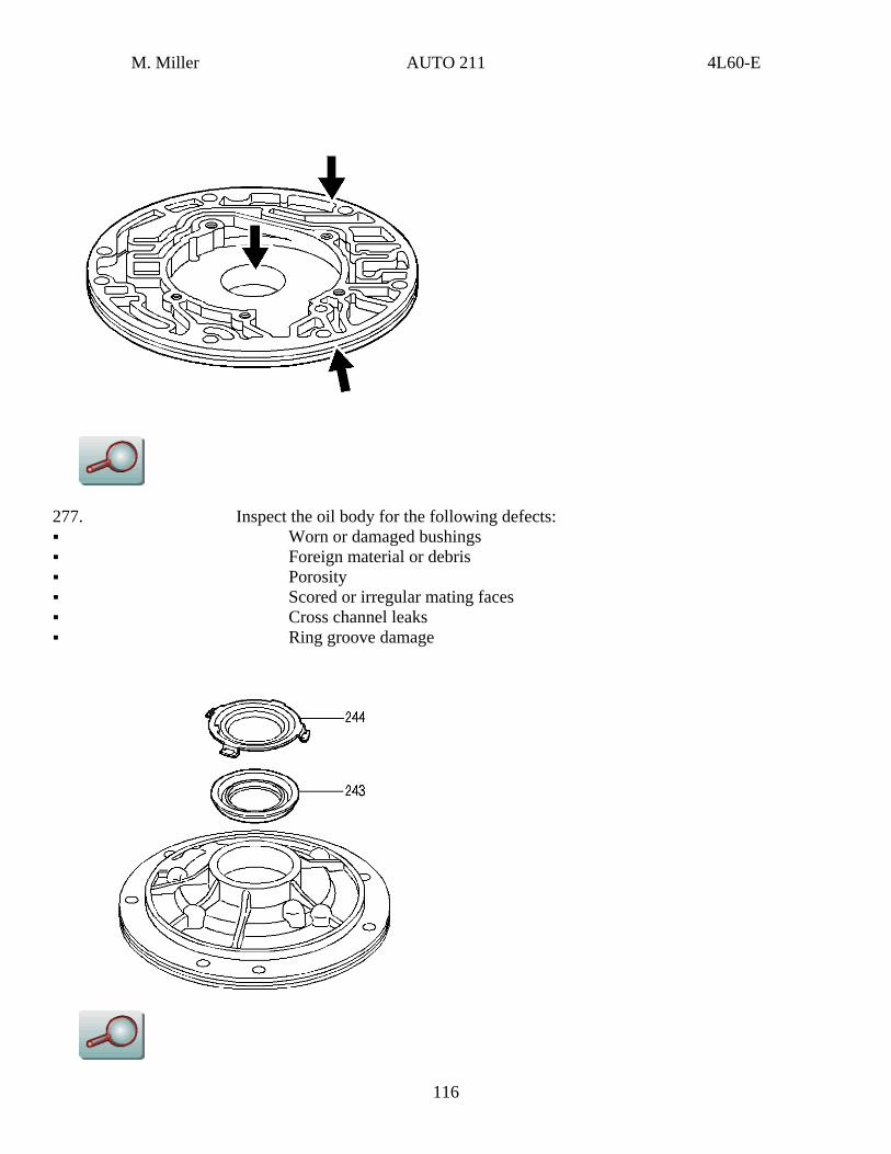
277. Inspect the oil body for the following defects: Worn or damaged bushings Foreign material or debris Porosity Scored or irregular mating faces Cross channel leaks Ring groove damage
116
M. Miller AUTO 211 4L60-E
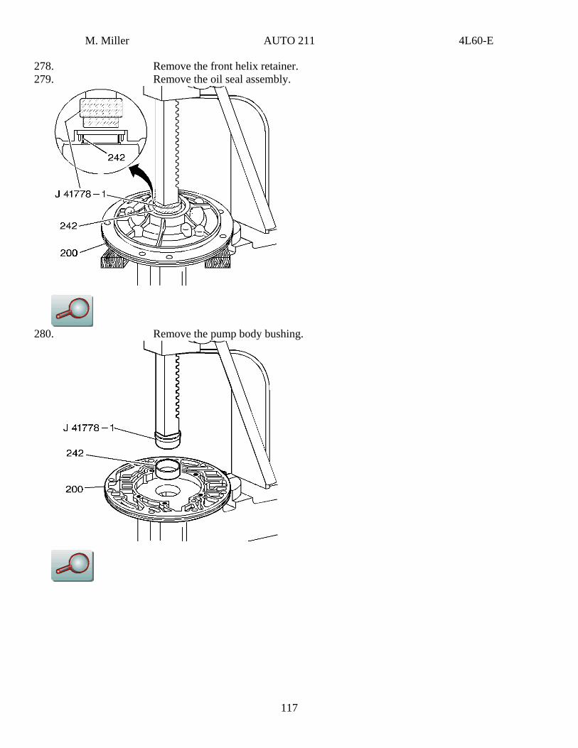
278. Remove the front helix retainer. 279. Remove the oil seal assembly.
280. Remove the pump body bushing.
117
M. Miller AUTO 211 4L60-E
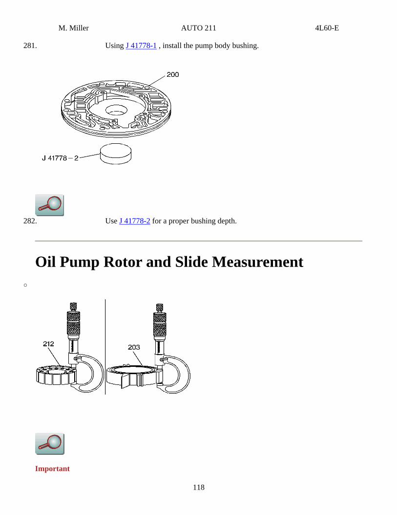
281. Using J 41778-1 , install the pump body bushing.
282. Use J 41778-2 for a proper bushing depth.
Oil Pump Rotor and Slide Measurement o
Important
118
M. Miller AUTO 211 4L60-E
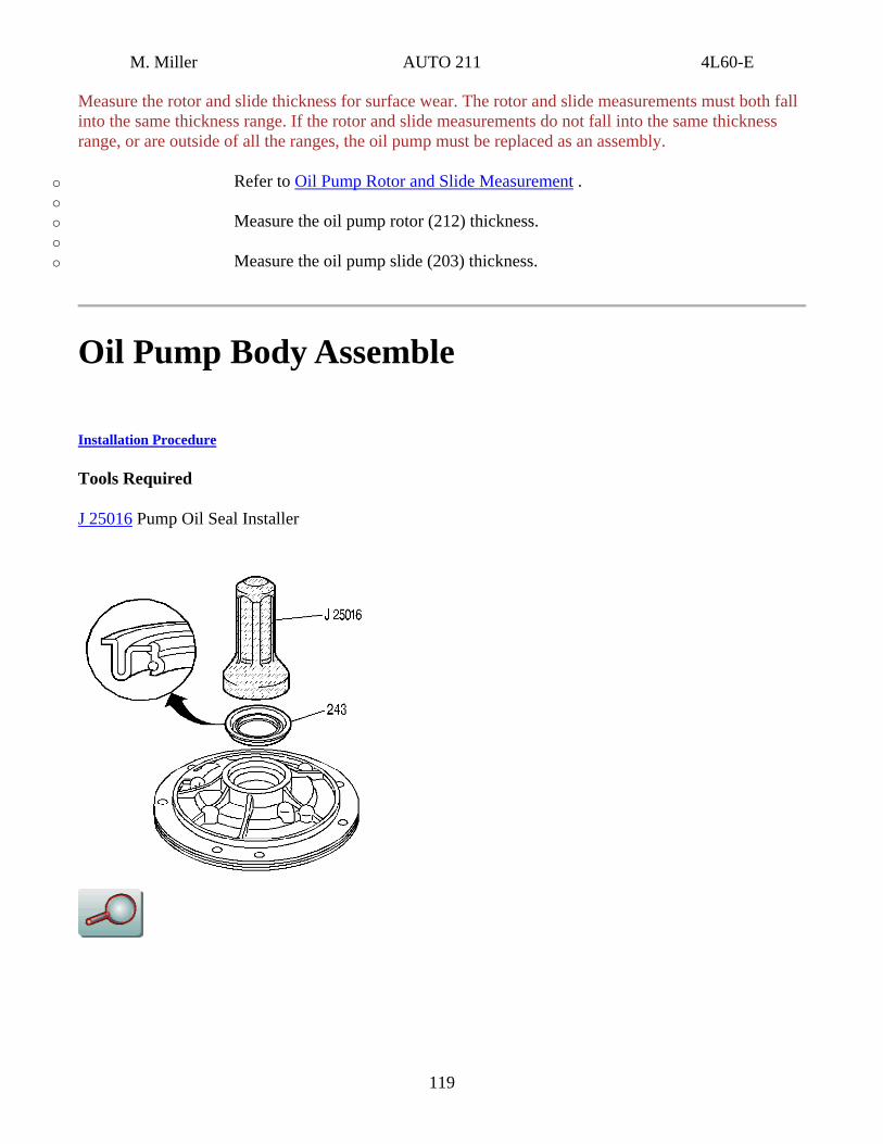
Measure the rotor and slide thickness for surface wear. The rotor and slide measurements must both fall into the same thickness range. If the rotor and slide measurements do not fall into the same thickness range, or are outside of all the ranges, the oil pump must be replaced as an assembly.
o Refer to Oil Pump Rotor and Slide Measurement . o o Measure the oil pump rotor (212) thickness. o o Measure the oil pump slide (203) thickness.
Oil Pump Body Assemble
Installation Procedure
Tools Required
J 25016 Pump Oil Seal Installer
119
M. Miller AUTO 211 4L60-E
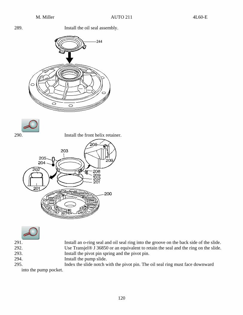
289. Install the oil seal assembly.
290. Install the front helix retainer.
291. Install an o-ring seal and oil seal ring into the groove on the back side of the slide. 292. Use Transjel® J 36850 or an equivalent to retain the seal and the ring on the slide. 293. Install the pivot pin spring and the pivot pin. 294. Install the pump slide. 295. Index the slide notch with the pivot pin. The oil seal ring must face downward
into the pump pocket.
120
M. Miller AUTO 211 4L60-E
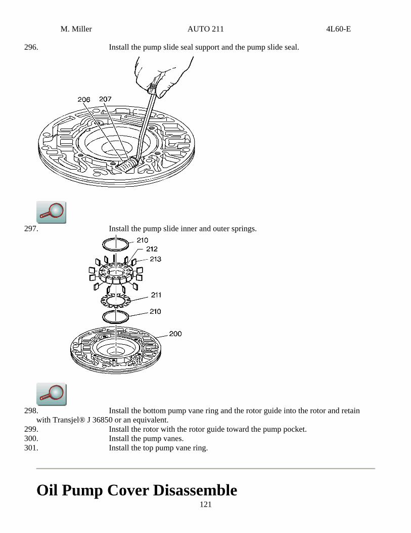
296. Install the pump slide seal support and the pump slide seal.
297. Install the pump slide inner and outer springs.
298. Install the bottom pump vane ring and the rotor guide into the rotor and retain
with Transjel® J 36850 or an equivalent. 299. Install the rotor with the rotor guide toward the pump pocket. 300. Install the pump vanes.
121
301. Install the top pump vane ring.
Oil Pump Cover Disassemble
M. Miller AUTO 211 4L60-E
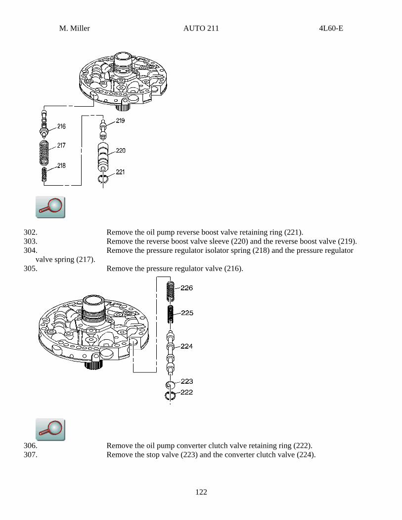
302. Remove the oil pump reverse boost valve retaining ring (221). 303. Remove the reverse boost valve sleeve (220) and the reverse boost valve (219). 304. Remove the pressure regulator isolator spring (218) and the pressure regulator
valve spring (217). 305. Remove the pressure regulator valve (216).
306. Remove the oil pump converter clutch valve retaining ring (222). 307. Remove the stop valve (223) and the converter clutch valve (224).
122
M. Miller AUTO 211 4L60-E
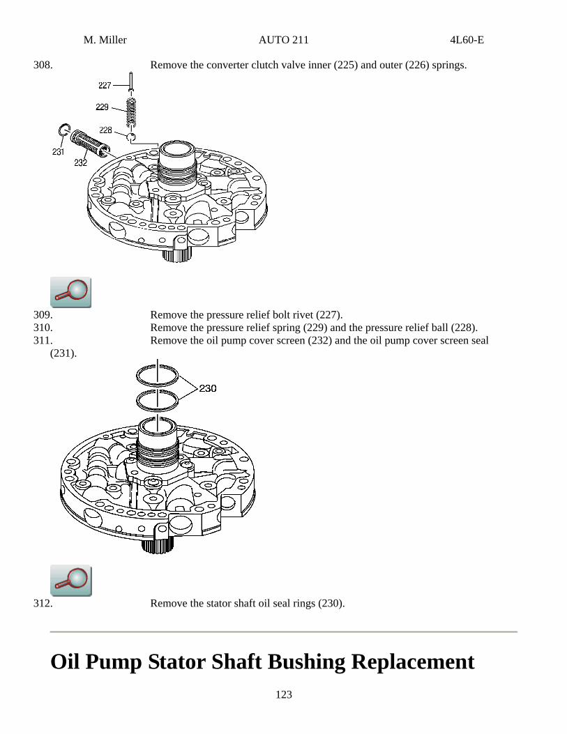
308. Remove the converter clutch valve inner (225) and outer (226) springs.
309. Remove the pressure relief bolt rivet (227). 310. Remove the pressure relief spring (229) and the pressure relief ball (228). 311. Remove the oil pump cover screen (232) and the oil pump cover screen seal
(231).
312. Remove the stator shaft oil seal rings (230).
Oil Pump Stator Shaft Bushing Replacement 123
M. Miller AUTO 211 4L60-E
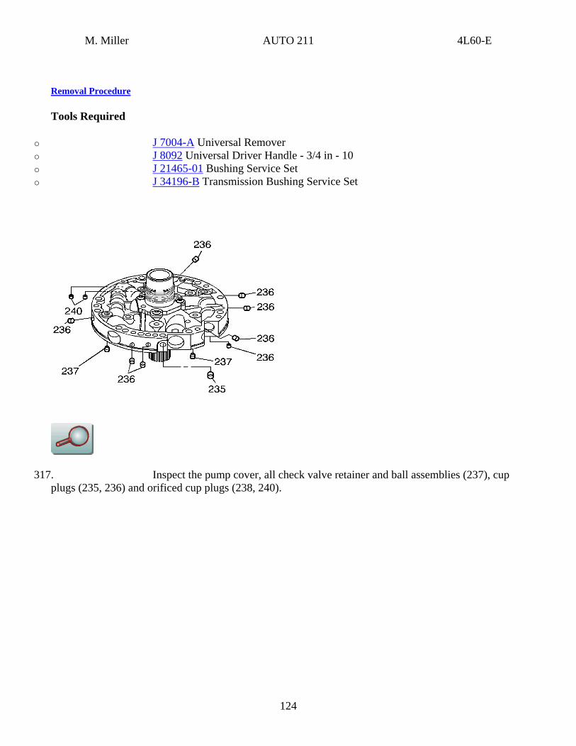
Removal Procedure
Tools Required
o J 7004-A Universal Remover o J 8092 Universal Driver Handle - 3/4 in - 10 o J 21465-01 Bushing Service Set o J 34196-B Transmission Bushing Service Set
317. Inspect the pump cover, all check valve retainer and ball assemblies (237), cup plugs (235, 236) and orificed cup plugs (238, 240).
124
M. Miller AUTO 211 4L60-E
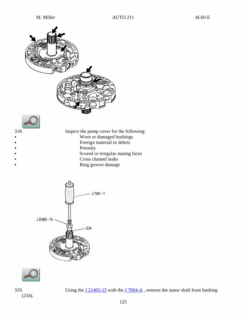
318. Inspect the pump cover for the following: Worn or damaged bushings Foreign material or debris Porosity Scored or irregular mating faces Cross channel leaks Ring groove damage
125
319. Using the J 21465-15 with the J 7004-A , remove the stator shaft front bushing (234).
M. Miller AUTO 211 4L60-E
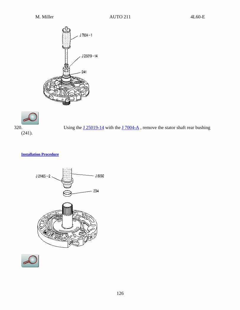
320. Using the J 25019-14 with the J 7004-A , remove the stator shaft rear bushing
(241).
Installation Procedure
126
M. Miller AUTO 211 4L60-E
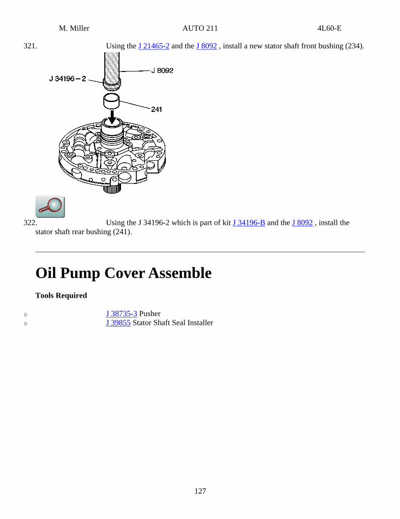
321. Using the J 21465-2 and the J 8092 , install a new stator shaft front bushing (234).
322. Using the J 34196-2 which is part of kit J 34196-B and the J 8092 , install the
stator shaft rear bushing (241).
Oil Pump Cover Assemble Tools Required
o J 38735-3 Pusher o J 39855 Stator Shaft Seal Installer
127
M. Miller AUTO 211 4L60-E
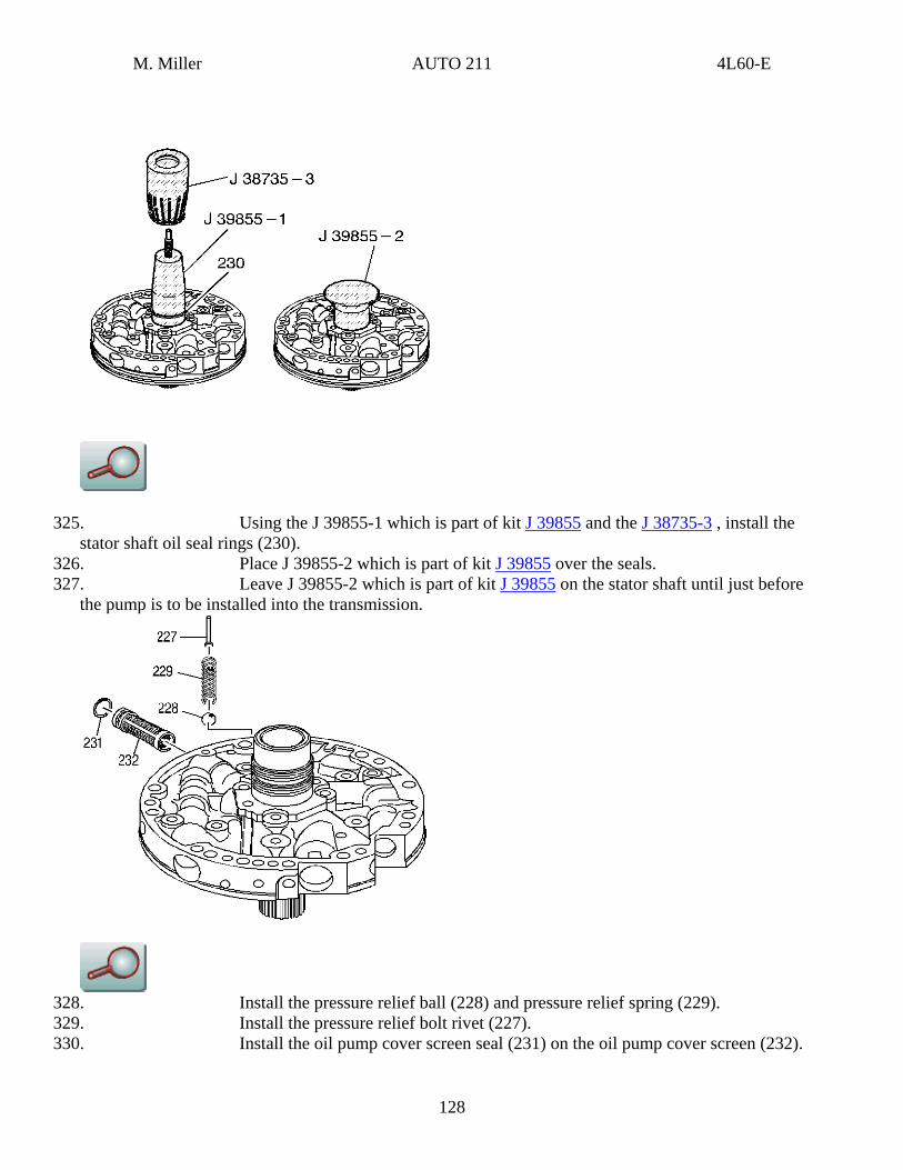
325. Using the J 39855-1 which is part of kit J 39855 and the J 38735-3 , install the stator shaft oil seal rings (230).
326. Place J 39855-2 which is part of kit J 39855 over the seals. 327. Leave J 39855-2 which is part of kit J 39855 on the stator shaft until just before
the pump is to be installed into the transmission.
328. Install the pressure relief ball (228) and pressure relief spring (229). 329. Install the pressure relief bolt rivet (227). 330. Install the oil pump cover screen seal (231) on the oil pump cover screen (232).
128
M. Miller AUTO 211 4L60-E
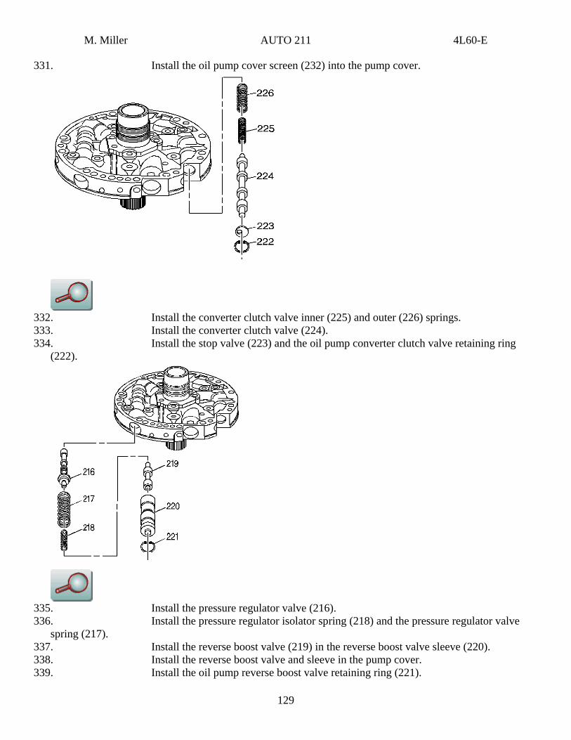
331. Install the oil pump cover screen (232) into the pump cover.
332. Install the converter clutch valve inner (225) and outer (226) springs. 333. Install the converter clutch valve (224). 334. Install the stop valve (223) and the oil pump converter clutch valve retaining ring
(222).
335. Install the pressure regulator valve (216). 336. Install the pressure regulator isolator spring (218) and the pressure regulator valve
spring (217). 337. Install the reverse boost valve (219) in the reverse boost valve sleeve (220). 338. Install the reverse boost valve and sleeve in the pump cover. 339. Install the oil pump reverse boost valve retaining ring (221).
129

M. Miller AUTO 211 4L60-E
130
Oil Pump Cover and Body Assemble Tools Required
J 21368 Pump Body and Cover Alignment Band
340. Place the oil pump cover onto the oil pump body and put stator shaft through a hole in the bench.
341. Install the pump cover bolts (223) finger tight only. 342. Install the J 21368 .
Notice
Use the correct fastener in the correct location. Replacement fasteners must be the correct part number for that application. Fasteners requiring replacement or fasteners requiring the use of thread locking compound or sealant are identified in the service procedure. Do not use paints, lubricants, or corrosion inhibitors on fasteners or fastener joint surfaces unless specified. These coatings affect fastener torque and joint clamping force and may damage the fastener. Use the correct tightening sequence and specifications when installing fasteners in order to avoid damage to parts and systems.
343. Tighten the pump cover bolts (223). Tighten
Tighten the bolts to 24 N·m (18 lb ft).
344. Remove the J 21368 .
M. Miller AUTO 211 4L60-E
131
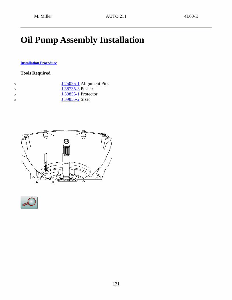
Oil Pump Assembly Installation
Installation Procedure
Tools Required
o J 25025-1 Alignment Pins o J 38735-3 Pusher o J 39855-1 Protector o J 39855-2 Sizer
M. Miller AUTO 211 4L60-E
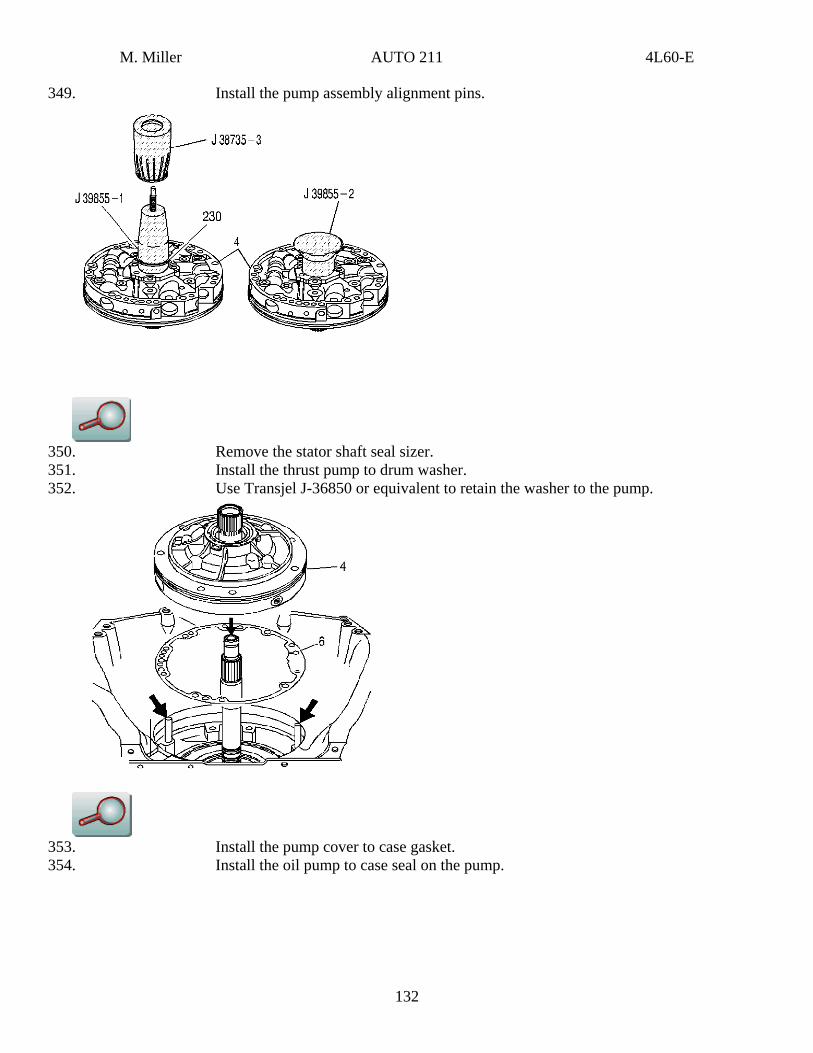
349. Install the pump assembly alignment pins.
350. Remove the stator shaft seal sizer. 351. Install the thrust pump to drum washer. 352. Use Transjel J-36850 or equivalent to retain the washer to the pump.
353. Install the pump cover to case gasket. 354. Install the oil pump to case seal on the pump.
132
M. Miller AUTO 211 4L60-E
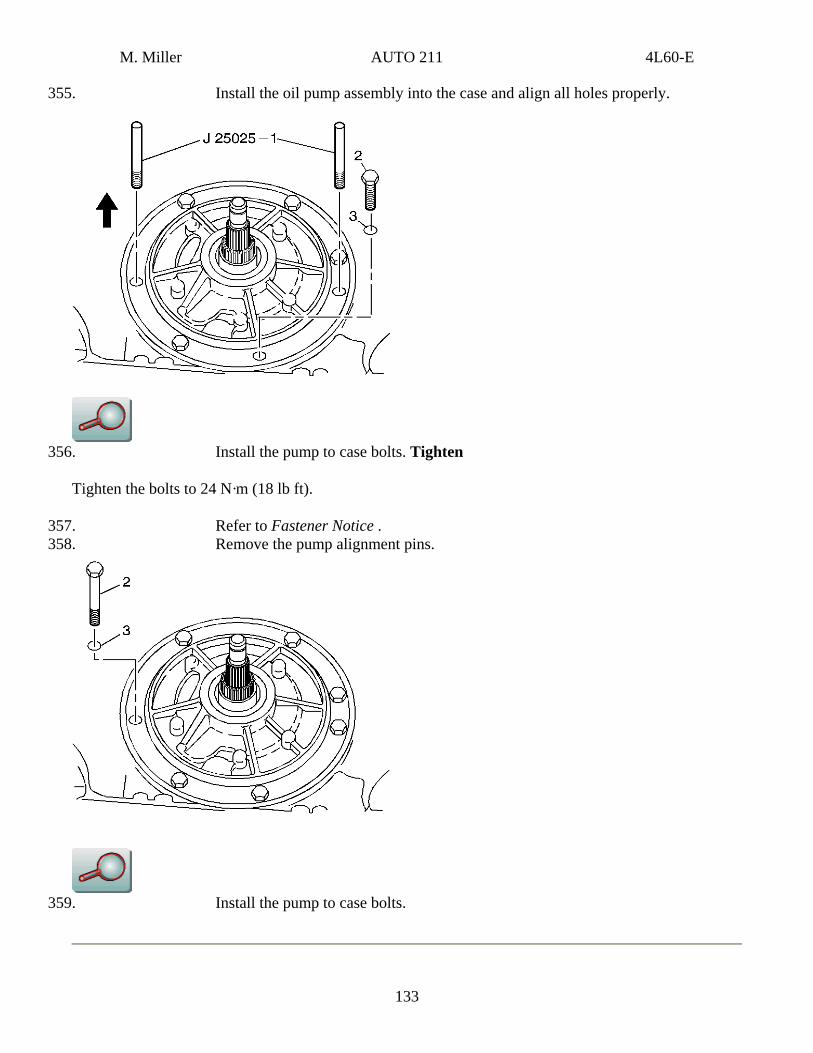
355. Install the oil pump assembly into the case and align all holes properly.
356. Install the pump to case bolts. Tighten
Tighten the bolts to 24 N·m (18 lb ft).
357. Refer to Fastener Notice . 358. Remove the pump alignment pins.
359. Install the pump to case bolts.
133
M. Miller AUTO 211 4L60-E
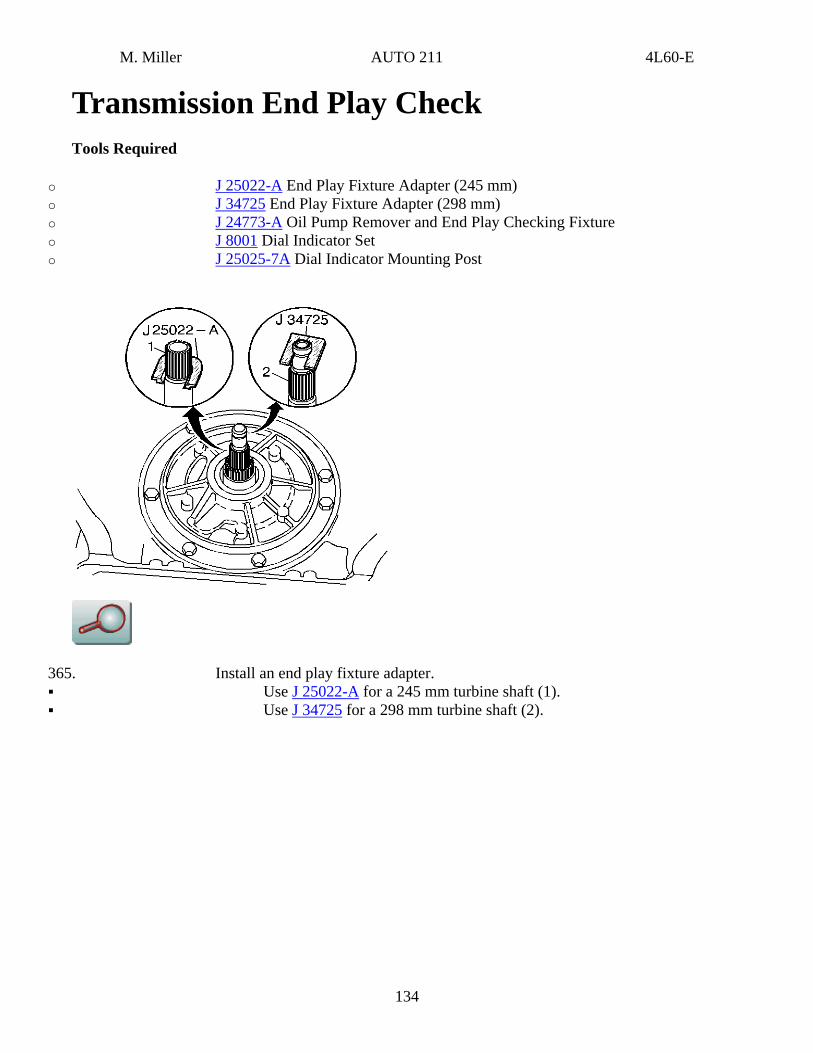
Transmission End Play Check Tools Required
o J 25022-A End Play Fixture Adapter (245 mm) o J 34725 End Play Fixture Adapter (298 mm) o J 24773-A Oil Pump Remover and End Play Checking Fixture o J 8001 Dial Indicator Set o J 25025-7A Dial Indicator Mounting Post
365. Install an end play fixture adapter. Use J 25022-A for a 245 mm turbine shaft (1). Use J 34725 for a 298 mm turbine shaft (2).
134
M. Miller AUTO 211 4L60-E
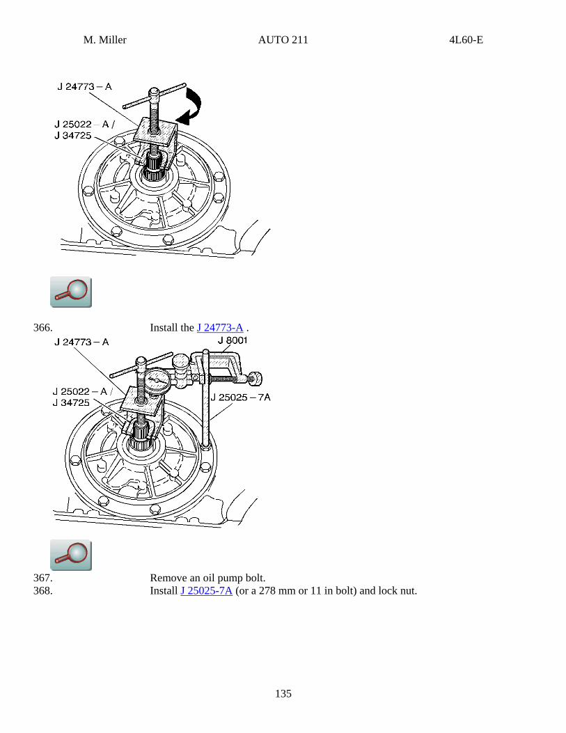
366. Install the J 24773-A .
367. Remove an oil pump bolt. 368. Install J 25025-7A (or a 278 mm or 11 in bolt) and lock nut.
135
M. Miller AUTO 211 4L60-E
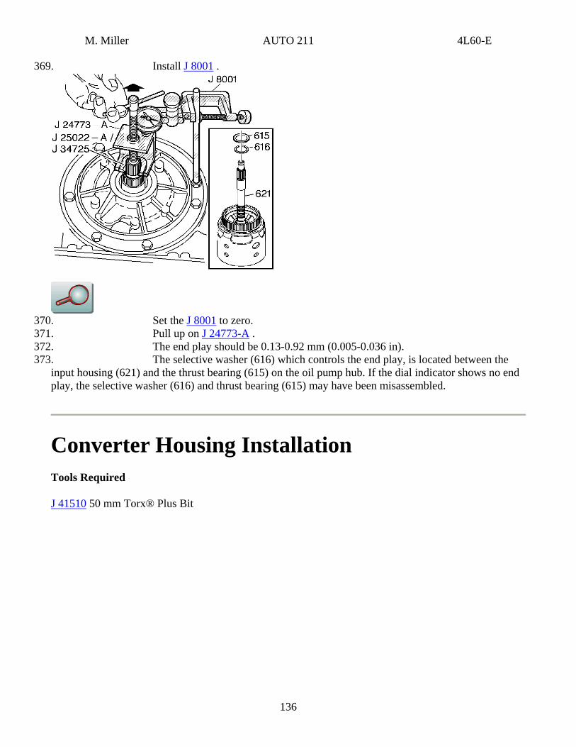
369. Install J 8001 .
370. Set the J 8001 to zero. 371. Pull up on J 24773-A . 372. The end play should be 0.13-0.92 mm (0.005-0.036 in). 373. The selective washer (616) which controls the end play, is located between the
input housing (621) and the thrust bearing (615) on the oil pump hub. If the dial indicator shows no end play, the selective washer (616) and thrust bearing (615) may have been misassembled.
Converter Housing Installation Tools Required
J 41510 50 mm Torx® Plus Bit
136
M. Miller AUTO 211 4L60-E
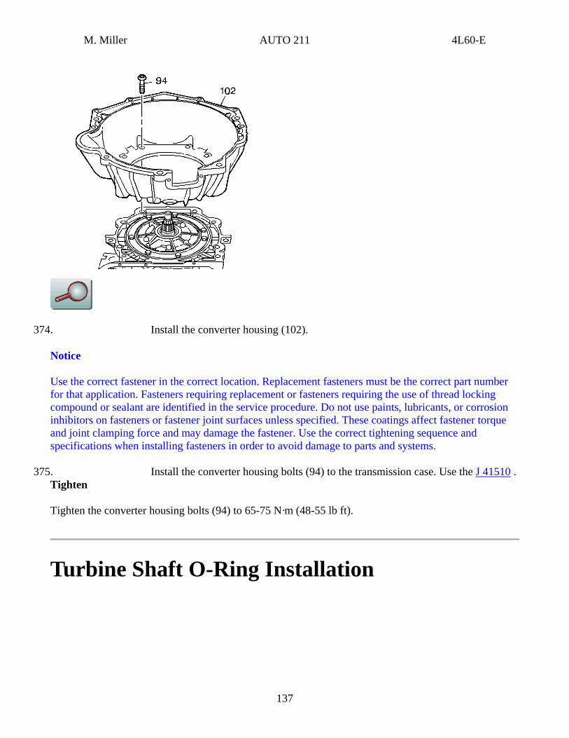
374. Install the converter housing (102).
Notice
Use the correct fastener in the correct location. Replacement fasteners must be the correct part number for that application. Fasteners requiring replacement or fasteners requiring the use of thread locking compound or sealant are identified in the service procedure. Do not use paints, lubricants, or corrosion inhibitors on fasteners or fastener joint surfaces unless specified. These coatings affect fastener torque and joint clamping force and may damage the fastener. Use the correct tightening sequence and specifications when installing fasteners in order to avoid damage to parts and systems.
375. Install the converter housing bolts (94) to the transmission case. Use the J 41510 . Tighten
Tighten the converter housing bolts (94) to 65-75 N·m (48-55 lb ft).
Turbine Shaft O-Ring Installation
137
M. Miller AUTO 211 4L60-E
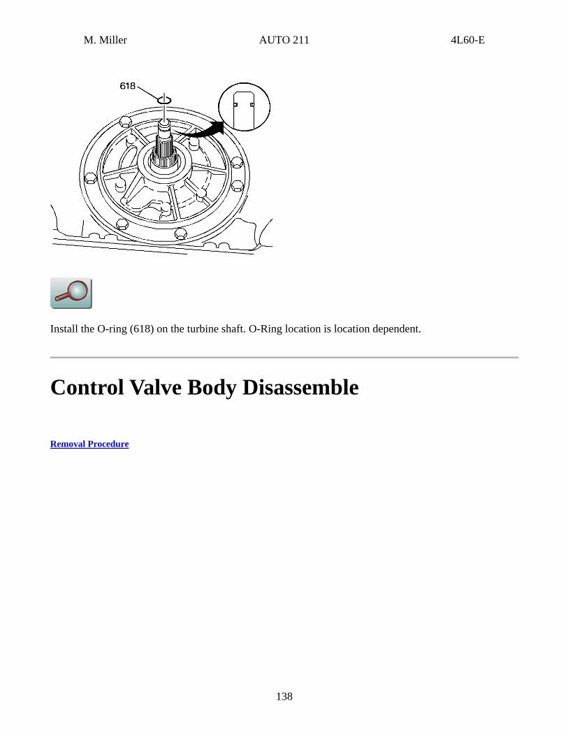
Install the O-ring (618) on the turbine shaft. O-Ring location is location dependent.
Control Valve Body Disassemble
Removal Procedure
138
M. Miller AUTO 211 4L60-E
Caution
Valve springs can be tightly compressed. Use care when removing retainers and plugs. Personal injury could result.
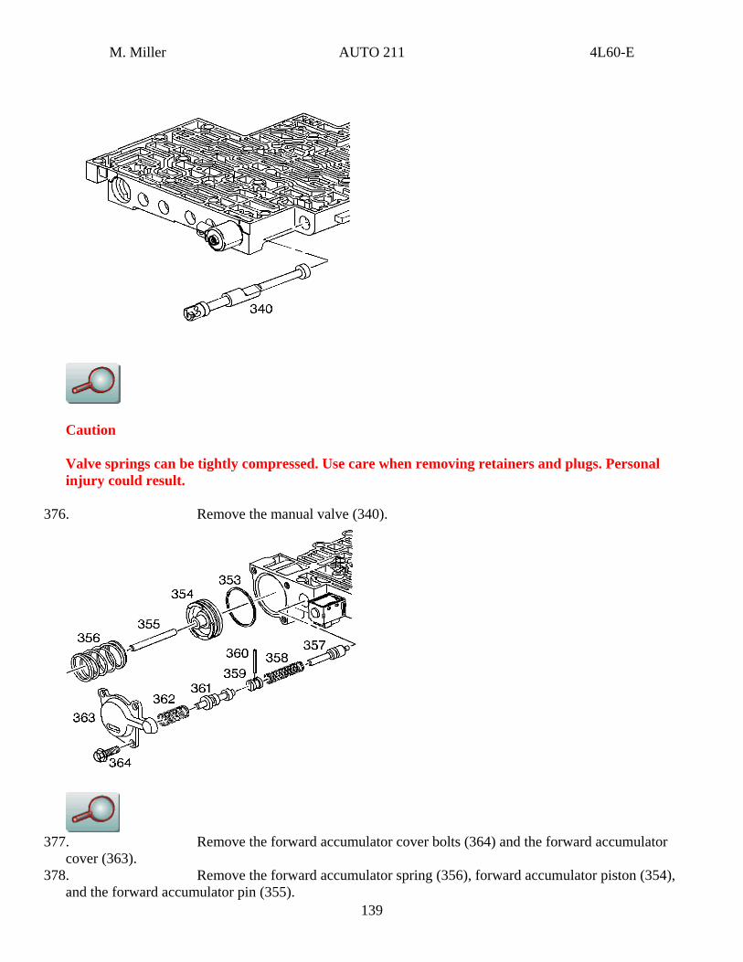
376. Remove the manual valve (340).
377. Remove the forward accumulator cover bolts (364) and the forward accumulator
cover (363).
139
378. Remove the forward accumulator spring (356), forward accumulator piston (354), and the forward accumulator pin (355).
M. Miller AUTO 211 4L60-E
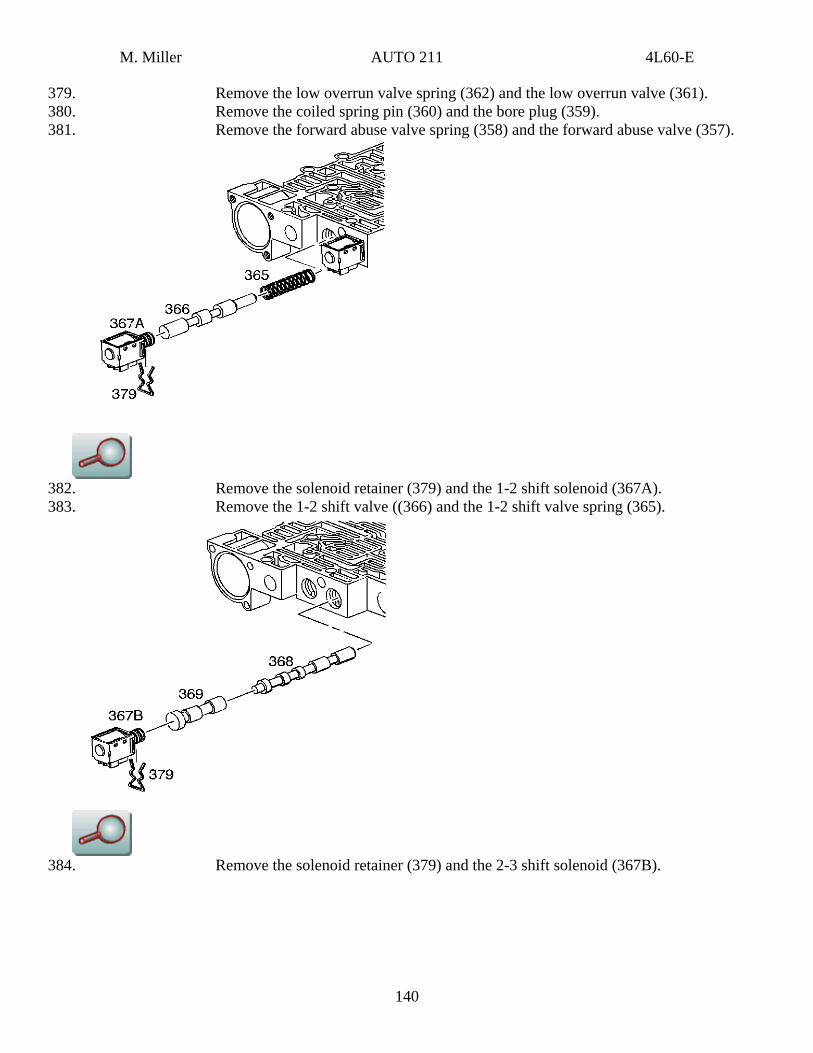
379. Remove the low overrun valve spring (362) and the low overrun valve (361). 380. Remove the coiled spring pin (360) and the bore plug (359). 381. Remove the forward abuse valve spring (358) and the forward abuse valve (357).
382. Remove the solenoid retainer (379) and the 1-2 shift solenoid (367A). 383. Remove the 1-2 shift valve ((366) and the 1-2 shift valve spring (365).
384. Remove the solenoid retainer (379) and the 2-3 shift solenoid (367B).
140
M. Miller AUTO 211 4L60-E
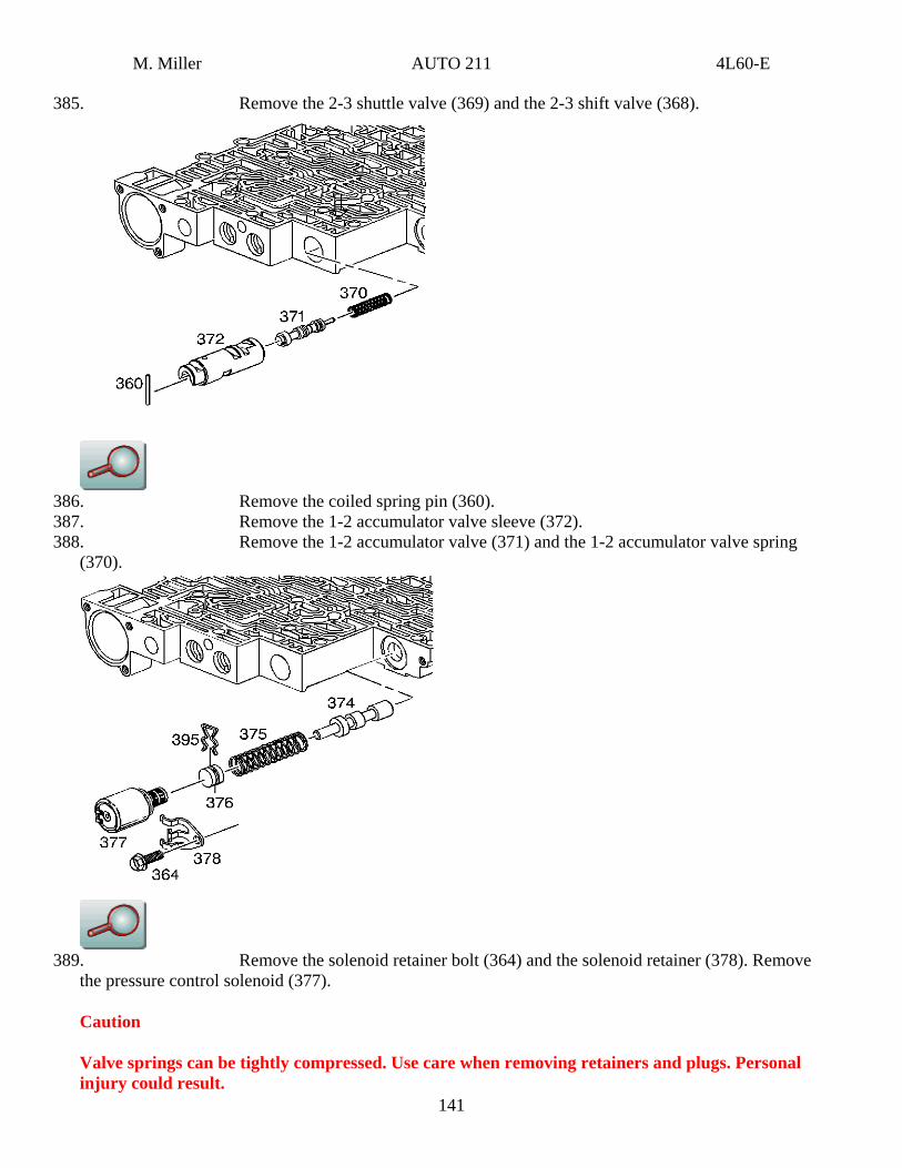
385. Remove the 2-3 shuttle valve (369) and the 2-3 shift valve (368).
386. Remove the coiled spring pin (360). 387. Remove the 1-2 accumulator valve sleeve (372). 388. Remove the 1-2 accumulator valve (371) and the 1-2 accumulator valve spring
(370).
141
389. Remove the solenoid retainer bolt (364) and the solenoid retainer (378). Remove the pressure control solenoid (377).
Caution
Valve springs can be tightly compressed. Use care when removing retainers and plugs. Personal injury could result.
M. Miller AUTO 211 4L60-E
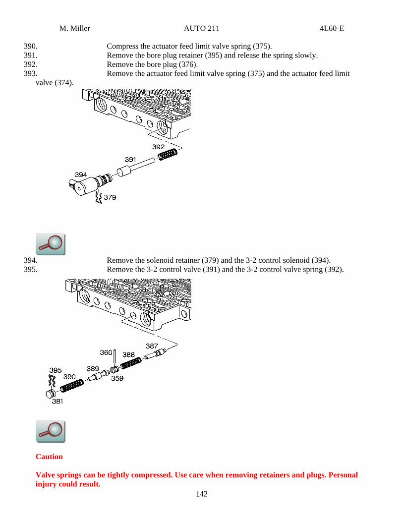
390. Compress the actuator feed limit valve spring (375). 391. Remove the bore plug retainer (395) and release the spring slowly. 392. Remove the bore plug (376). 393. Remove the actuator feed limit valve spring (375) and the actuator feed limit
valve (374).
394. Remove the solenoid retainer (379) and the 3-2 control solenoid (394).
142
395. Remove the 3-2 control valve (391) and the 3-2 control valve spring (392).
Caution
Valve springs can be tightly compressed. Use care when removing retainers and plugs. Personal injury could result.
M. Miller AUTO 211 4L60-E
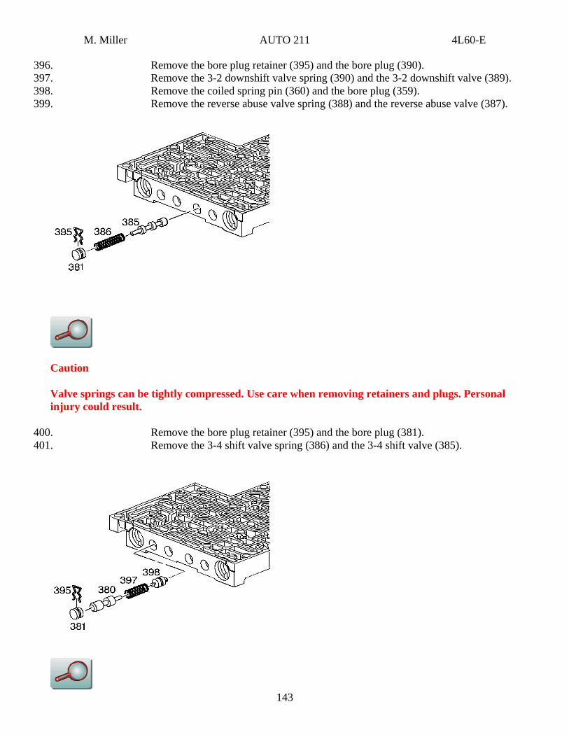
396. Remove the bore plug retainer (395) and the bore plug (390). 397. Remove the 3-2 downshift valve spring (390) and the 3-2 downshift valve (389). 398. Remove the coiled spring pin (360) and the bore plug (359). 399. Remove the reverse abuse valve spring (388) and the reverse abuse valve (387).
Caution
Valve springs can be tightly compressed. Use care when removing retainers and plugs. Personal injury could result.
400. Remove the bore plug retainer (395) and the bore plug (381).
143
401. Remove the 3-4 shift valve spring (386) and the 3-4 shift valve (385).
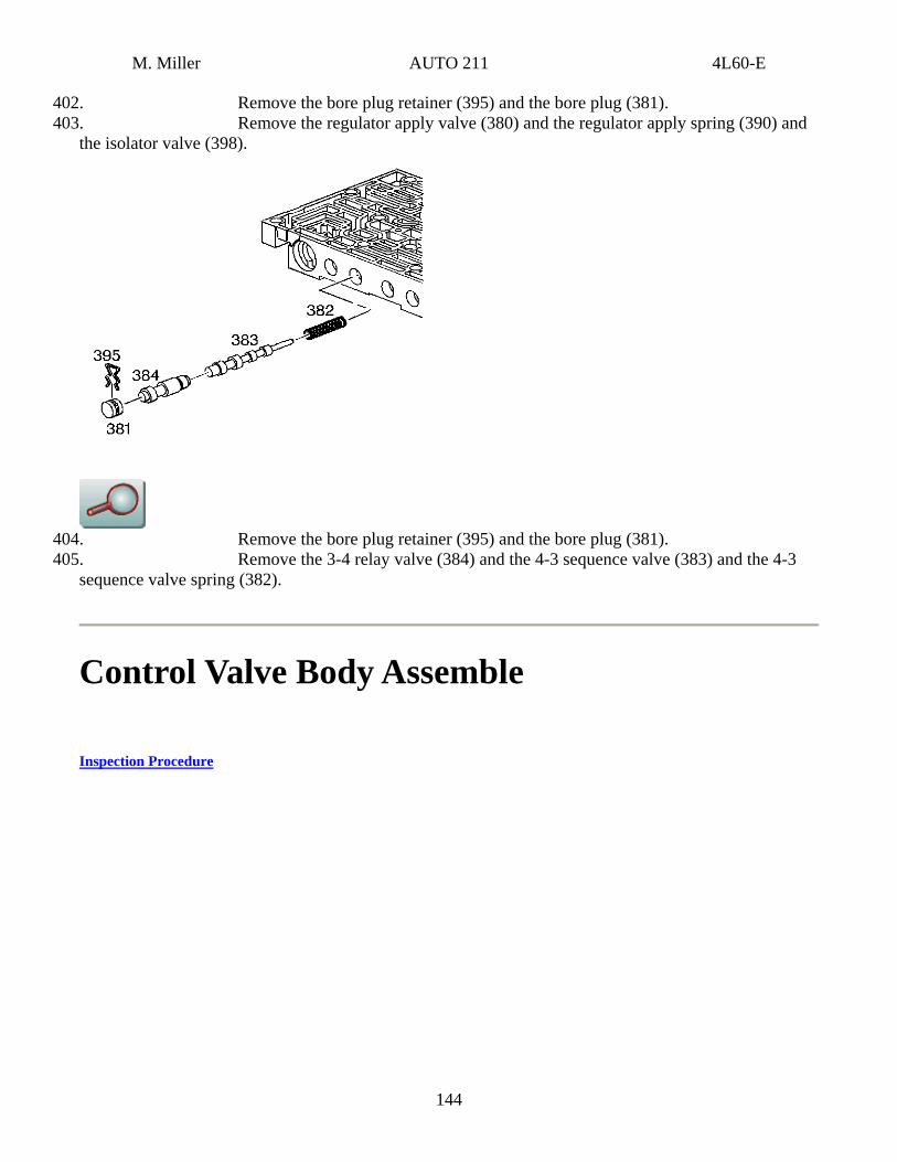
M. Miller AUTO 211 4L60-E
402. Remove the bore plug retainer (395) and the bore plug (381). 403. Remove the regulator apply valve (380) and the regulator apply spring (390) and
the isolator valve (398).
404. Remove the bore plug retainer (395) and the bore plug (381). 405. Remove the 3-4 relay valve (384) and the 4-3 sequence valve (383) and the 4-3
sequence valve spring (382).
Control Valve Body Assemble
Inspection Procedure
144
M. Miller AUTO 211 4L60-E
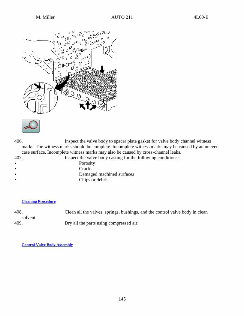
406. Inspect the valve body to spacer plate gasket for valve body channel witness marks. The witness marks should be complete. Incomplete witness marks may be caused by an uneven case surface. Incomplete witness marks may also be caused by cross-channel leaks.
407. Inspect the valve body casting for the following conditions: Porosity Cracks Damaged machined surfaces Chips or debris
Cleaning Procedure
408. Clean all the valves, springs, bushings, and the control valve body in clean solvent.
409. Dry all the parts using compressed air.
Control Valve Body Assembly
145

M. Miller AUTO 211 4L60-E
Caution
Valve springs can be tightly compressed. Use care when removing retainers and plugs. Personal injury could result.
Important
Lubricate all parts with Dexron®-lll automatic transmission fluid before installation.
410. Install the following items: . The isolator valve (398) A. The regulator apply spring (397) B. The regulator apply valve (380) C. The bore plug (381) D. The bore plug retainer (395)
146
M. Miller AUTO 211 4L60-E
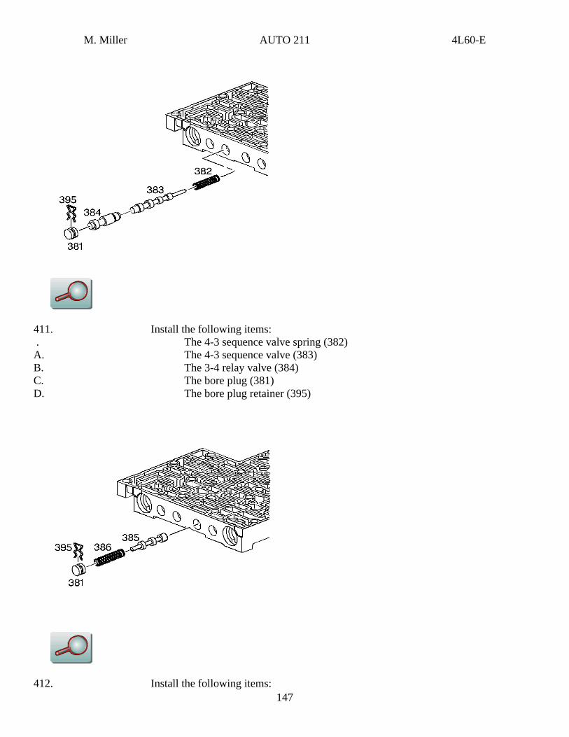
411. Install the following items: . The 4-3 sequence valve spring (382) A. The 4-3 sequence valve (383) B. The 3-4 relay valve (384) C. The bore plug (381) D. The bore plug retainer (395)
147 412. Install the following items:
M. Miller AUTO 211 4L60-E
. The 3-4 shift valve (385) A. The 3-4 shift valve spring (386) B. The bore plug (381) C. The bore plug retainer (395)
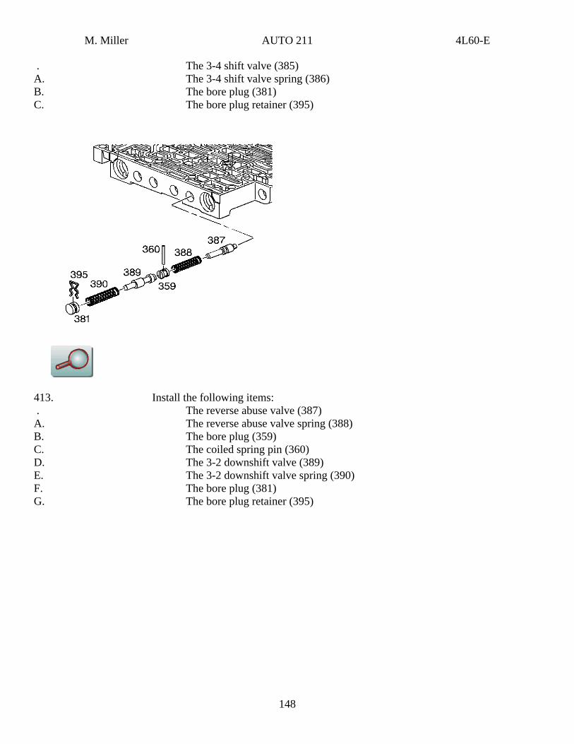
413. Install the following items: . The reverse abuse valve (387) A. The reverse abuse valve spring (388) B. The bore plug (359) C. The coiled spring pin (360) D. The 3-2 downshift valve (389) E. The 3-2 downshift valve spring (390) F. The bore plug (381) G. The bore plug retainer (395)
148
M. Miller AUTO 211 4L60-E
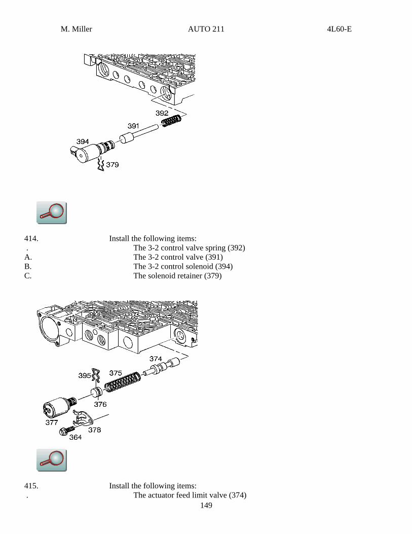
414. Install the following items: . The 3-2 control valve spring (392) A. The 3-2 control valve (391) B. The 3-2 control solenoid (394) C. The solenoid retainer (379)
415. Install the following items:
149 . The actuator feed limit valve (374)
M. Miller AUTO 211 4L60-E
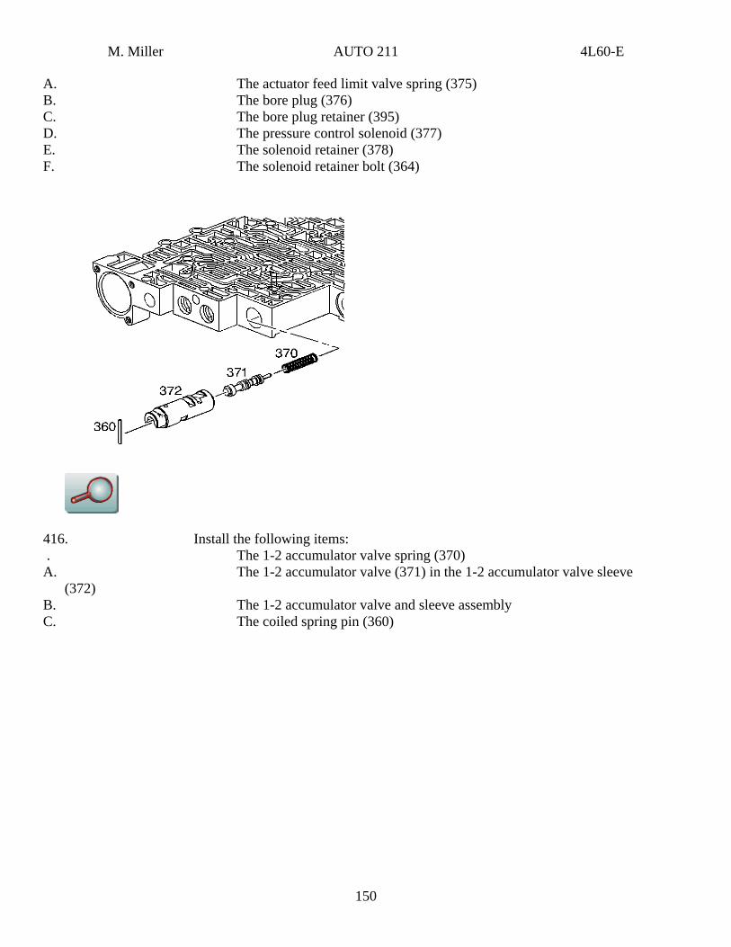
A. The actuator feed limit valve spring (375) B. The bore plug (376) C. The bore plug retainer (395) D. The pressure control solenoid (377) E. The solenoid retainer (378) F. The solenoid retainer bolt (364)
416. Install the following items: . The 1-2 accumulator valve spring (370) A. The 1-2 accumulator valve (371) in the 1-2 accumulator valve sleeve
(372) B. The 1-2 accumulator valve and sleeve assembly C. The coiled spring pin (360)
150

M. Miller AUTO 211 4L60-E
417. Install the following items: . The 2-3 shift valve (368) A. The 2-3 shuttle valve (369) B. The 2-3 shift solenoid valve (367B) C. The solenoid retainer (379)
418. Install the following items:
151 . Install the 1-2 shift valve spring (365)
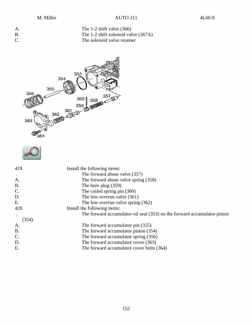
M. Miller AUTO 211 4L60-E
A. The 1-2 shift valve (366) B. The 1-2 shift solenoid valve (367A) C. The solenoid valve retainer
419. Install the following items: . The forward abuse valve (357) A. The forward abuse valve spring (358) B. The bore plug (359) C. The coiled spring pin (360) D. The low overrun valve (361) E. The low overrun valve spring (362) 420. Install the following items: . The forward accumulator oil seal (353) on the forward accumulator piston
(354) A. The forward accumulator pin (355) B. The forward accumulator piston (354) C. The forward accumulator spring (356) D. The forward accumulator cover (363) E. The forward accumulator cover bolts (364)
152

M. Miller AUTO 211 4L60-E
421. Install the manual valve (340).
3-4 Accumulator Installation
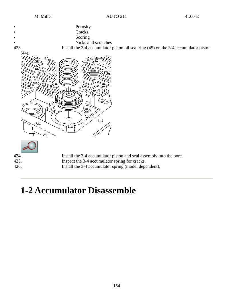
153 422. Inspect the 3-4 accumulator piston (44) for the following conditions:
M. Miller AUTO 211 4L60-E
Porosity Cracks Scoring Nicks and scratches
423. Install the 3-4 accumulator piston oil seal ring (45) on the 3-4 accumulator piston (44).
424. Install the 3-4 accumulator piston and seal assembly into the bore. 425. Inspect the 3-4 accumulator spring for cracks. 426. Install the 3-4 accumulator spring (model dependent).
1-2 Accumulator Disassemble
154
M. Miller AUTO 211 4L60-E
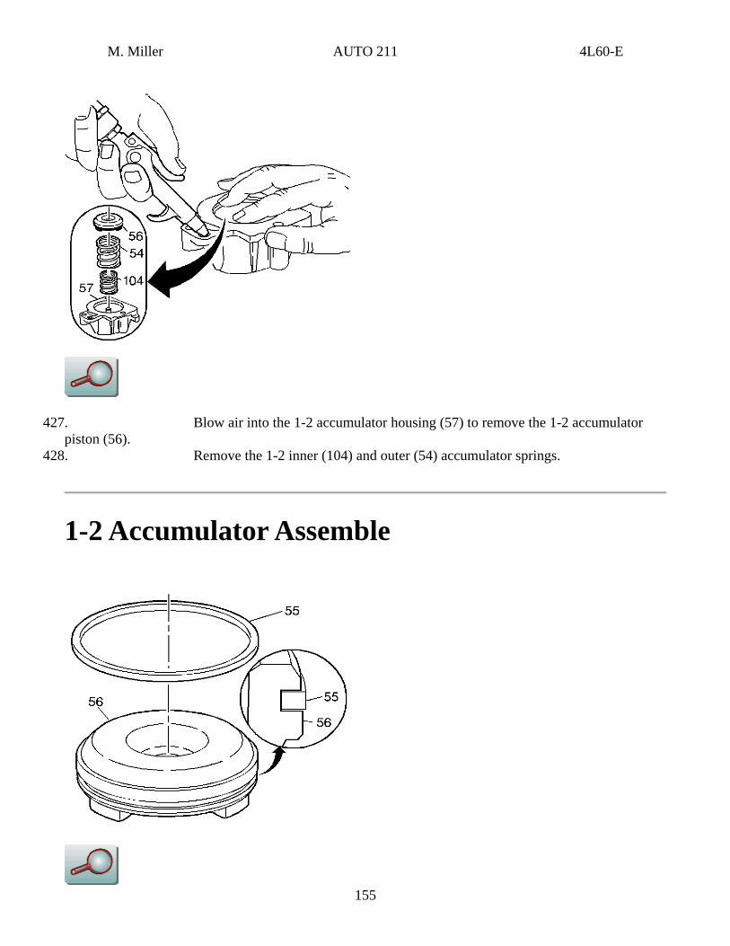
427. Blow air into the 1-2 accumulator housing (57) to remove the 1-2 accumulator piston (56).
155
428. Remove the 1-2 inner (104) and outer (54) accumulator springs.
1-2 Accumulator Assemble
M. Miller AUTO 211 4L60-E
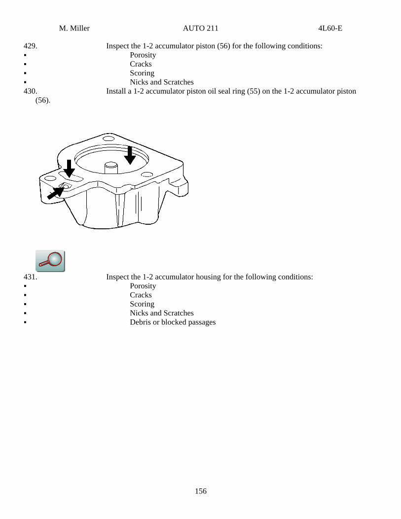
429. Inspect the 1-2 accumulator piston (56) for the following conditions: Porosity Cracks Scoring Nicks and Scratches
430. Install a 1-2 accumulator piston oil seal ring (55) on the 1-2 accumulator piston (56).
431. Inspect the 1-2 accumulator housing for the following conditions: Porosity Cracks Scoring Nicks and Scratches Debris or blocked passages
156
M. Miller AUTO 211 4L60-E
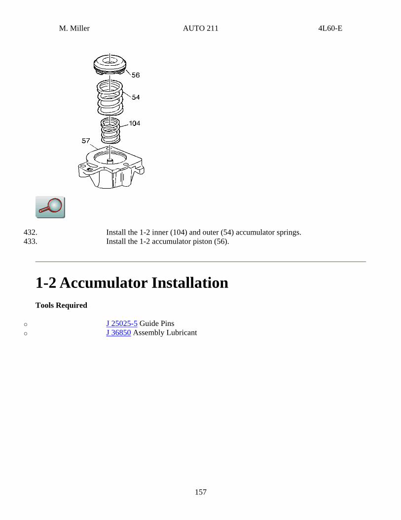
432. Install the 1-2 inner (104) and outer (54) accumulator springs. 433. Install the 1-2 accumulator piston (56).
1-2 Accumulator Installation Tools Required
o J 25025-5 Guide Pins o J 36850 Assembly Lubricant
157
M. Miller AUTO 211 4L60-E
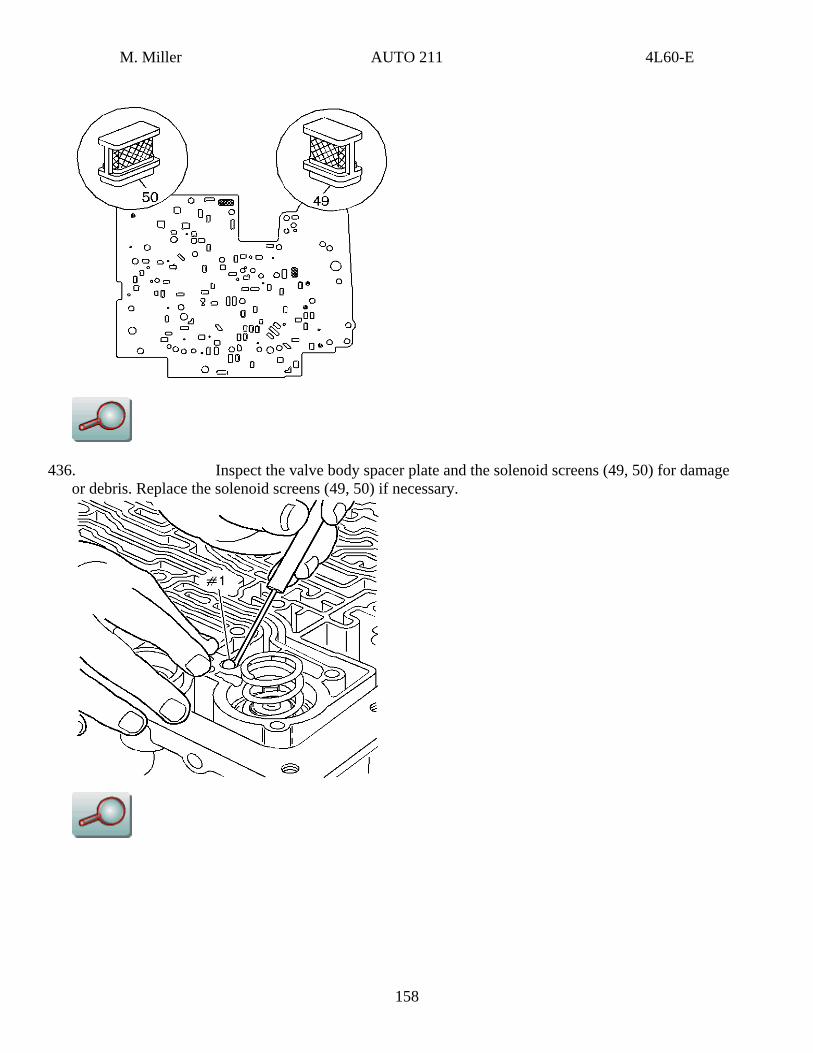
436. Inspect the valve body spacer plate and the solenoid screens (49, 50) for damage or debris. Replace the solenoid screens (49, 50) if necessary.
158
M. Miller AUTO 211 4L60-E
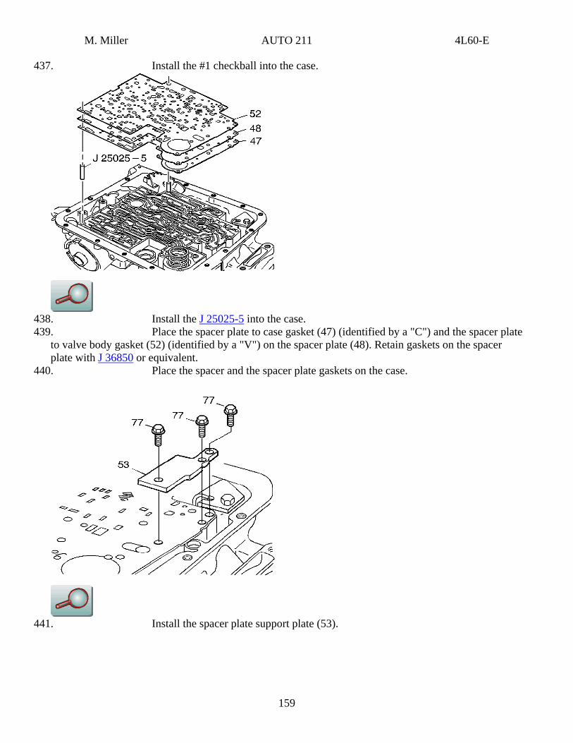
437. Install the #1 checkball into the case.
438. Install the J 25025-5 into the case. 439. Place the spacer plate to case gasket (47) (identified by a "C") and the spacer plate
to valve body gasket (52) (identified by a "V") on the spacer plate (48). Retain gaskets on the spacer plate with J 36850 or equivalent.
440. Place the spacer and the spacer plate gaskets on the case.
441. Install the spacer plate support plate (53).
159
M. Miller AUTO 211 4L60-E
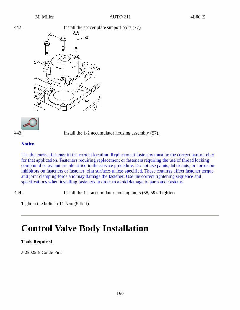
442. Install the spacer plate support bolts (77).
443. Install the 1-2 accumulator housing assembly (57).
Notice
Use the correct fastener in the correct location. Replacement fasteners must be the correct part number for that application. Fasteners requiring replacement or fasteners requiring the use of thread locking compound or sealant are identified in the service procedure. Do not use paints, lubricants, or corrosion inhibitors on fasteners or fastener joint surfaces unless specified. These coatings affect fastener torque and joint clamping force and may damage the fastener. Use the correct tightening sequence and specifications when installing fasteners in order to avoid damage to parts and systems.
444. Install the 1-2 accumulator housing bolts (58, 59). Tighten
Tighten the bolts to 11 N·m (8 lb ft).
Control Valve Body Installation Tools Required
J-25025-5 Guide Pins
160
M. Miller AUTO 211 4L60-E
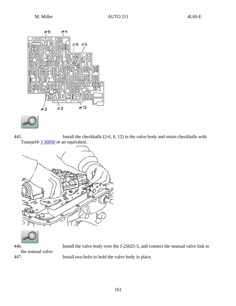
445. Install the checkballs (2-6, 8, 12) in the valve body and retain checkballs with Transjel® J 36850 or an equivalent.
446. Install the valve body over the J-25025-5, and connect the manual valve link to
the manual valve. 447. Install two bolts to hold the valve body in place.
161
M. Miller AUTO 211 4L60-E
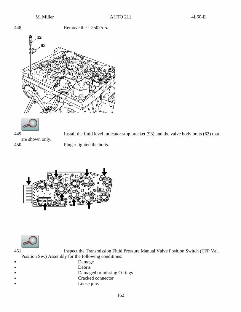
448. Remove the J-25025-5.
449. Install the fluid level indicator stop bracket (93) and the valve body bolts (62) that
are shown only. 450. Finger tighten the bolts.
451. Inspect the Transmission Fluid Pressure Manual Valve Position Switch (TFP Val.
Position Sw.) Assembly for the following conditions: Damage Debris Damaged or missing O-rings Cracked connector Loose pins
162
M. Miller AUTO 211 4L60-E
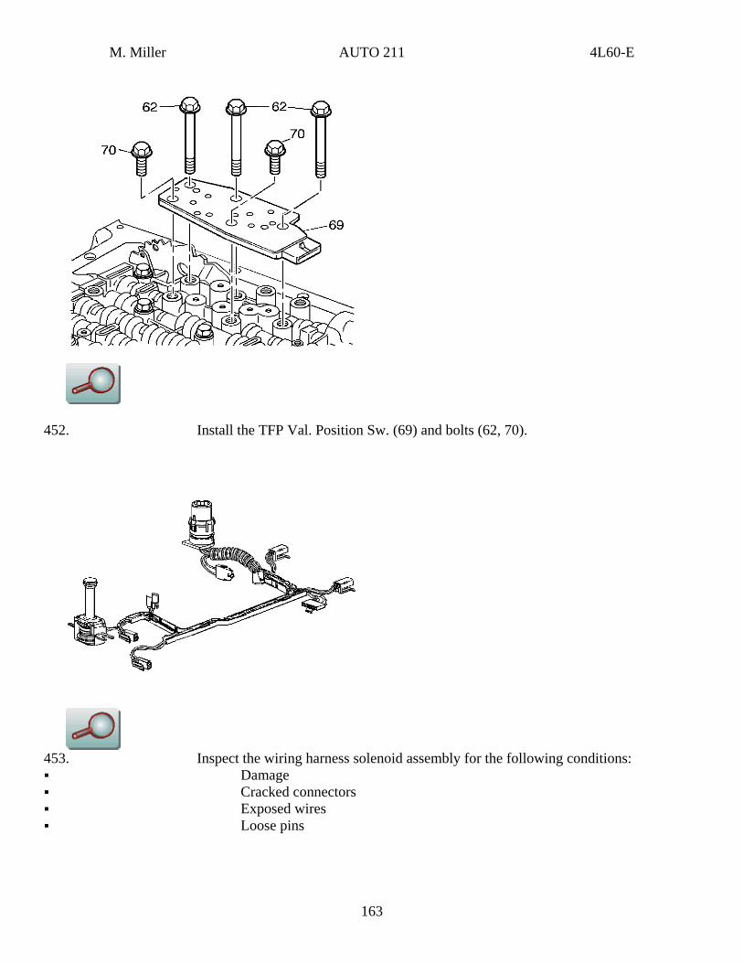
452. Install the TFP Val. Position Sw. (69) and bolts (62, 70).
453. Inspect the wiring harness solenoid assembly for the following conditions: Damage Cracked connectors Exposed wires Loose pins
163
M. Miller AUTO 211 4L60-E
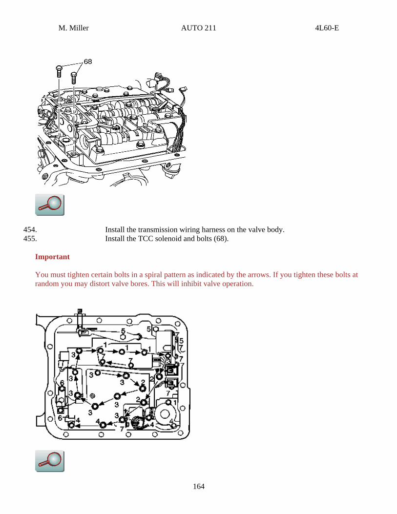
454. Install the transmission wiring harness on the valve body. 455. Install the TCC solenoid and bolts (68).
Important
You must tighten certain bolts in a spiral pattern as indicated by the arrows. If you tighten these bolts at random you may distort valve bores. This will inhibit valve operation.
164
M. Miller AUTO 211 4L60-E
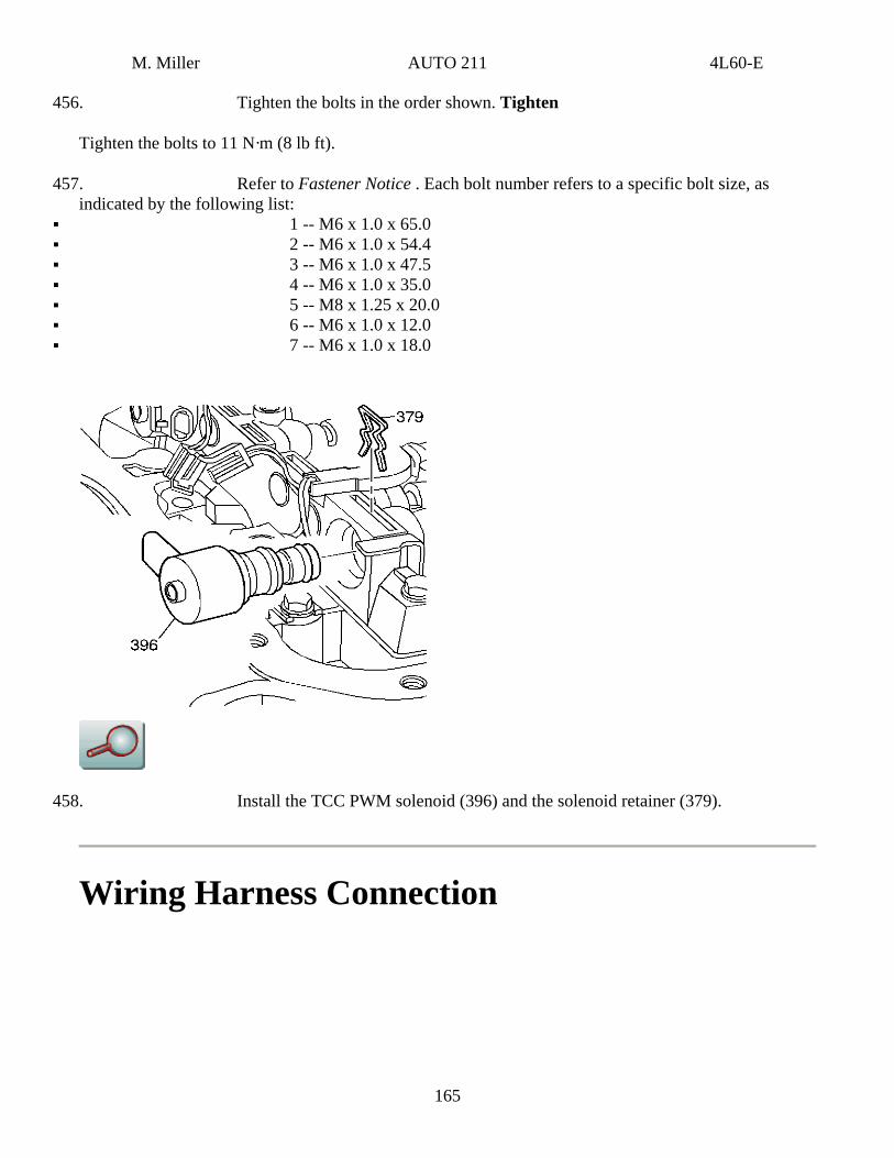
456. Tighten the bolts in the order shown. Tighten
Tighten the bolts to 11 N·m (8 lb ft).
457. Refer to Fastener Notice . Each bolt number refers to a specific bolt size, as indicated by the following list:
1 -- M6 x 1.0 x 65.0 2 -- M6 x 1.0 x 54.4 3 -- M6 x 1.0 x 47.5 4 -- M6 x 1.0 x 35.0 5 -- M8 x 1.25 x 20.0 6 -- M6 x 1.0 x 12.0 7 -- M6 x 1.0 x 18.0
458. Install the TCC PWM solenoid (396) and the solenoid retainer (379).
Wiring Harness Connection
165
M. Miller AUTO 211 4L60-E
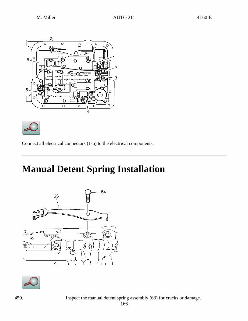
Connect all electrical connectors (1-6) to the electrical components.
Manual Detent Spring Installation
166 459. Inspect the manual detent spring assembly (63) for cracks or damage.
M. Miller AUTO 211 4L60-E
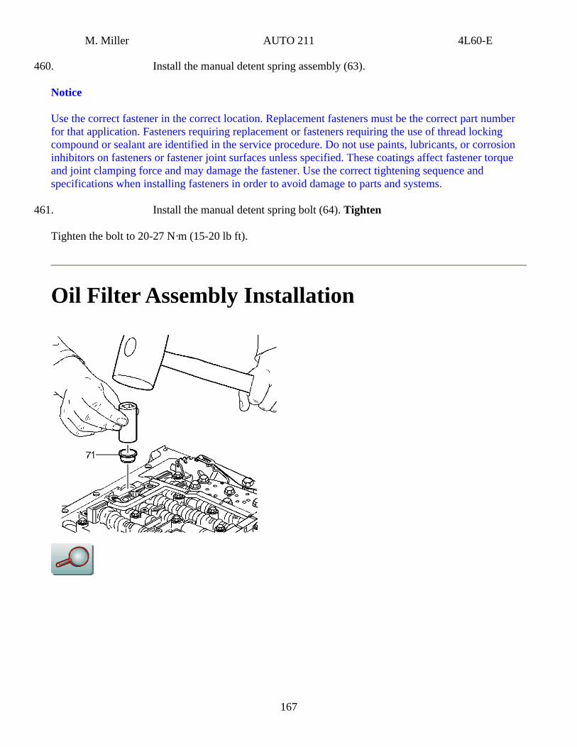
460. Install the manual detent spring assembly (63).
Notice
Use the correct fastener in the correct location. Replacement fasteners must be the correct part number for that application. Fasteners requiring replacement or fasteners requiring the use of thread locking compound or sealant are identified in the service procedure. Do not use paints, lubricants, or corrosion inhibitors on fasteners or fastener joint surfaces unless specified. These coatings affect fastener torque and joint clamping force and may damage the fastener. Use the correct tightening sequence and specifications when installing fasteners in order to avoid damage to parts and systems.
461. Install the manual detent spring bolt (64). Tighten
Tighten the bolt to 20-27 N·m (15-20 lb ft).
Oil Filter Assembly Installation
167
M. Miller AUTO 211 4L60-E
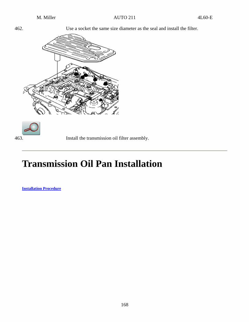
462. Use a socket the same size diameter as the seal and install the filter.
463. Install the transmission oil filter assembly.
Transmission Oil Pan Installation
Installation Procedure
168
M. Miller AUTO 211 4L60-E
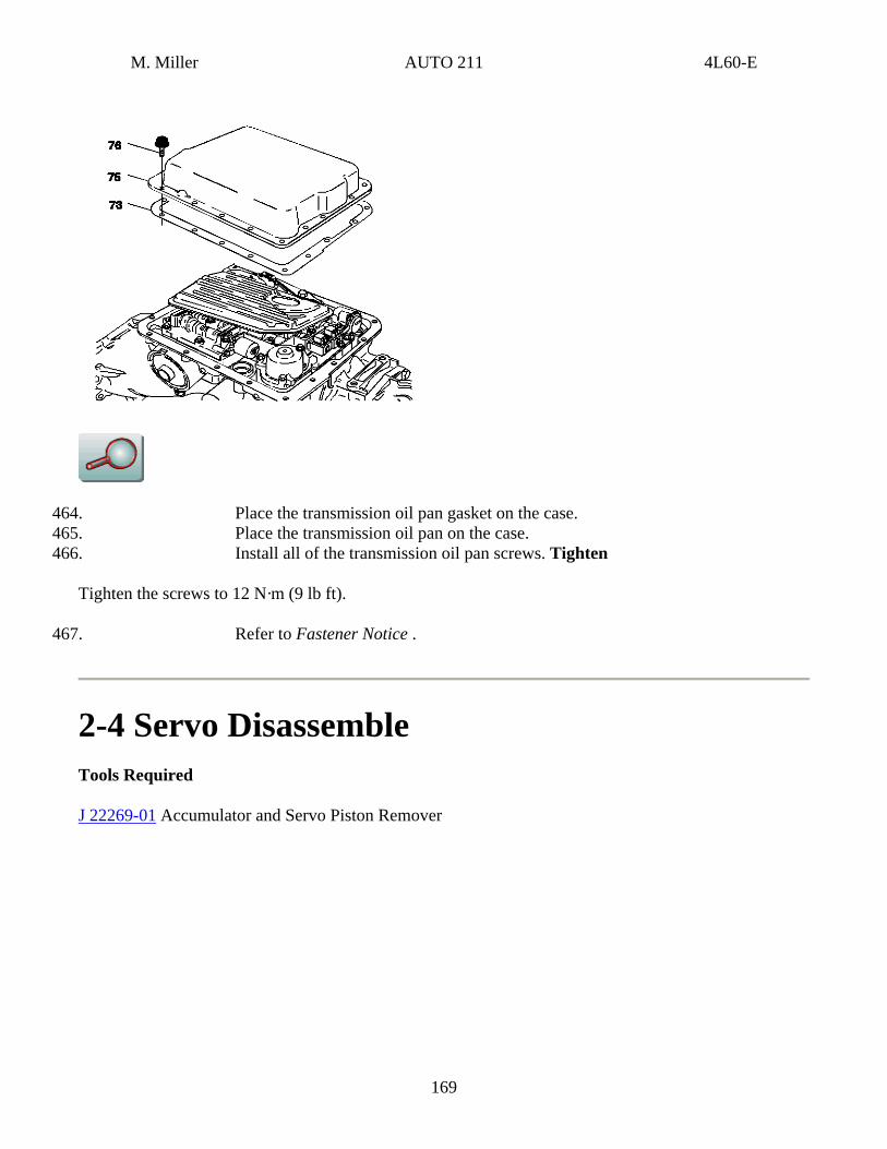
464. Place the transmission oil pan gasket on the case. 465. Place the transmission oil pan on the case. 466. Install all of the transmission oil pan screws. Tighten
Tighten the screws to 12 N·m (9 lb ft).
467. Refer to Fastener Notice .
2-4 Servo Disassemble Tools Required
J 22269-01 Accumulator and Servo Piston Remover
169
M. Miller AUTO 211 4L60-E
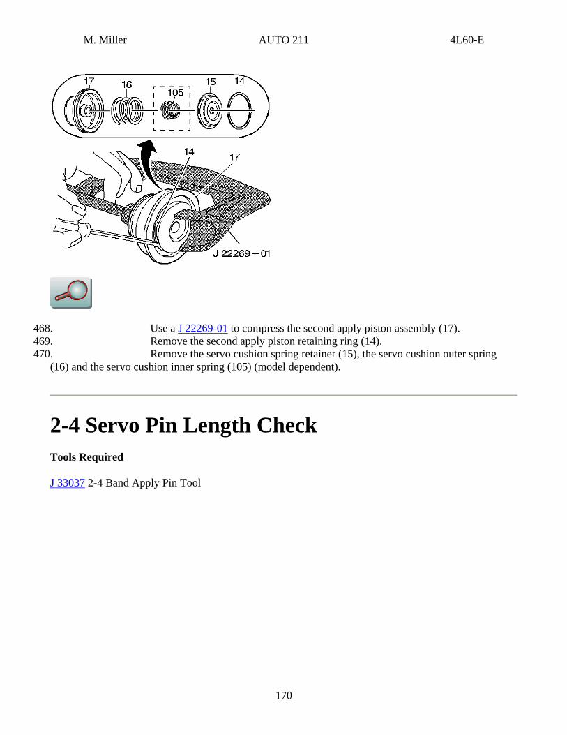
468. Use a J 22269-01 to compress the second apply piston assembly (17). 469. Remove the second apply piston retaining ring (14). 470. Remove the servo cushion spring retainer (15), the servo cushion outer spring
(16) and the servo cushion inner spring (105) (model dependent).
2-4 Servo Pin Length Check Tools Required
J 33037 2-4 Band Apply Pin Tool
170
M. Miller AUTO 211 4L60-E
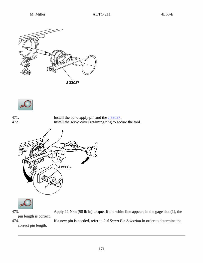
471. Install the band apply pin and the J 33037 . 472. Install the servo cover retaining ring to secure the tool.
473. Apply 11 N·m (98 lb in) torque. If the white line appears in the gage slot (1), the
pin length is correct. 474. If a new pin is needed, refer to 2-4 Servo Pin Selection in order to determine the
correct pin length.
171
M. Miller AUTO 211 4L60-E
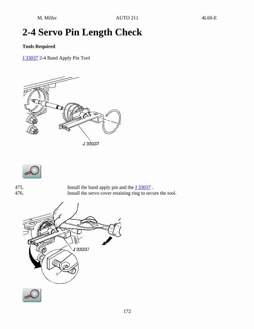
2-4 Servo Pin Length Check Tools Required
J 33037 2-4 Band Apply Pin Tool
475. Install the band apply pin and the J 33037 . 476. Install the servo cover retaining ring to secure the tool.
172

M. Miller AUTO 211 4L60-E
477. Apply 11 N·m (98 lb in) torque. If the white line appears in the gage slot (1), the pin length is correct.
478. If a new pin is needed, refer to 2-4 Servo Pin Selection in order to determine the correct pin length.
2-4 Servo Pin Selection
rvo Pin Selection
Pin Length mm inch
Pin Identification
65.82-66.12 2.59-2.60 1 Groove 67.23-67.53 2.65-2.66 2 Grooves 68.64-68.94 2.70-2.71 No Groove
2-4 Servo Assembly Installation 173
M. Miller AUTO 211 4L60-E
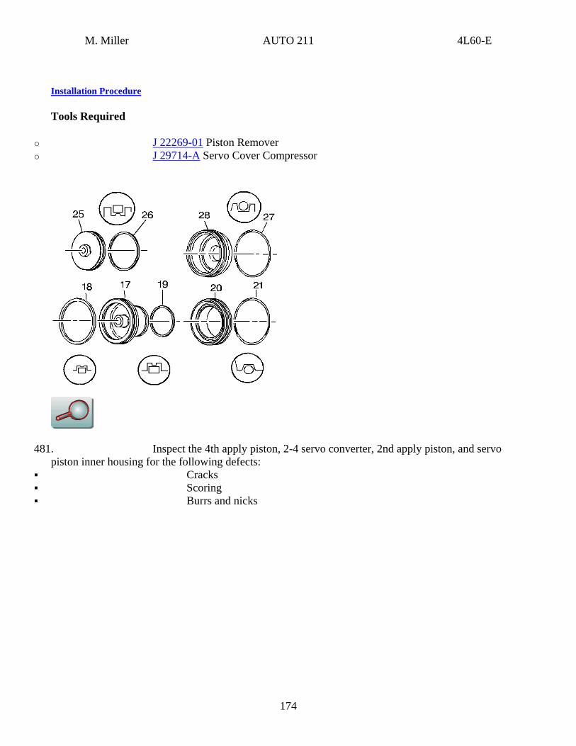
Installation Procedure
Tools Required
o J 22269-01 Piston Remover o J 29714-A Servo Cover Compressor
481. Inspect the 4th apply piston, 2-4 servo converter, 2nd apply piston, and servo piston inner housing for the following defects:
Cracks Scoring Burrs and nicks
174
M. Miller AUTO 211 4L60-E
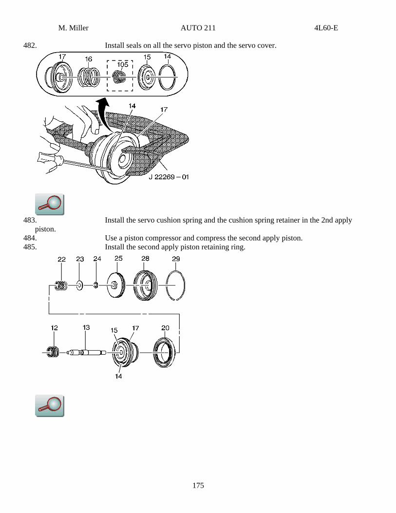
482. Install seals on all the servo piston and the servo cover.
483. Install the servo cushion spring and the cushion spring retainer in the 2nd apply
piston. 484. Use a piston compressor and compress the second apply piston. 485. Install the second apply piston retaining ring.
175
M. Miller AUTO 211 4L60-E
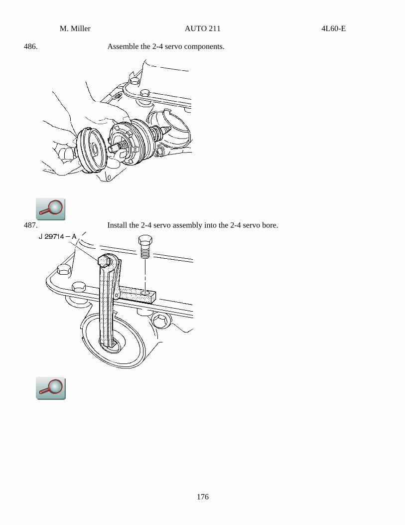
486. Assemble the 2-4 servo components.
487. Install the 2-4 servo assembly into the 2-4 servo bore.
176
M. Miller AUTO 211 4L60-E
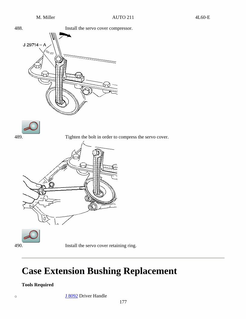
488. Install the servo cover compressor.
489. Tighten the bolt in order to compress the servo cover.
490. Install the servo cover retaining ring.
Case Extension Bushing Replacement Tools Required
o J 8092 Driver Handle 177

M. Miller AUTO 211 4L60-E
o J 23062-14 Bushing Remover o J 34196-B Bushing Set
494. Inspect the case extension for the following defects: Nicks Burrs Worn bushings
178
M. Miller AUTO 211 4L60-E
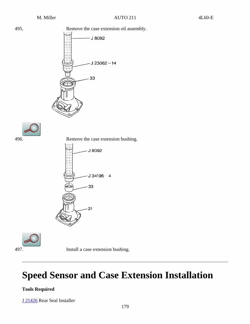
495. Remove the case extension oil assembly.
496. Remove the case extension bushing.
179
497. Install a case extension bushing.
Speed Sensor and Case Extension Installation Tools Required
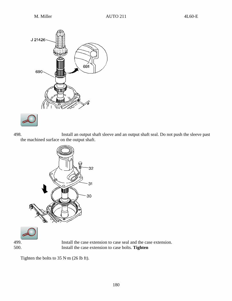
J 21426 Rear Seal Installer
M. Miller AUTO 211 4L60-E
498. Install an output shaft sleeve and an output shaft seal. Do not push the sleeve past the machined surface on the output shaft.
499. Install the case extension to case seal and the case extension. 500. Install the case extension to case bolts. Tighten
Tighten the bolts to 35 N·m (26 lb ft).
180
M. Miller AUTO 211 4L60-E
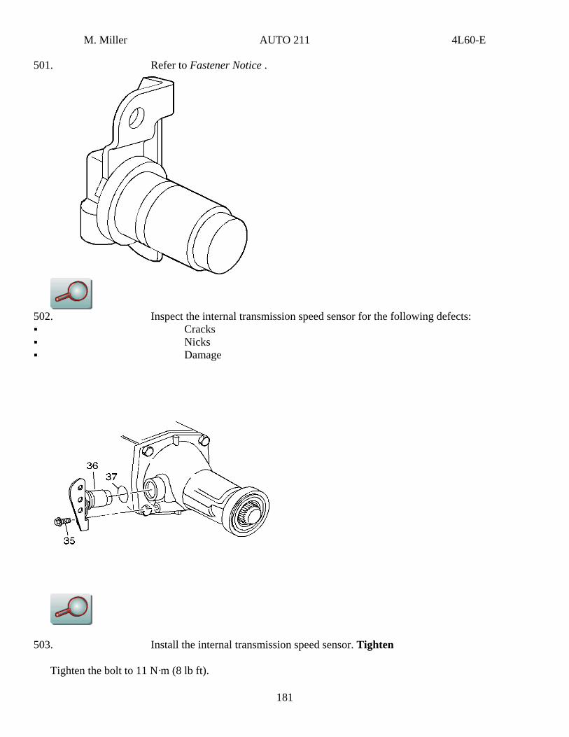
501. Refer to Fastener Notice .
502. Inspect the internal transmission speed sensor for the following defects: Cracks Nicks Damage
503. Install the internal transmission speed sensor. Tighten
Tighten the bolt to 11 N·m (8 lb ft).
181
M. Miller AUTO 211 4L60-E
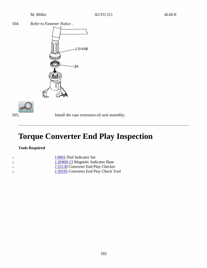
504. Refer to Fastener Notice .
505. Install the case extension oil seal assembly.
Torque Converter End Play Inspection Tools Required
o J 8001 Dial Indicator Set o J 26900-13 Magnetic Indicator Base o J 35138 Converter End Play Checker o J 39195 Converter End Play Check Tool
182
M. Miller AUTO 211 4L60-E
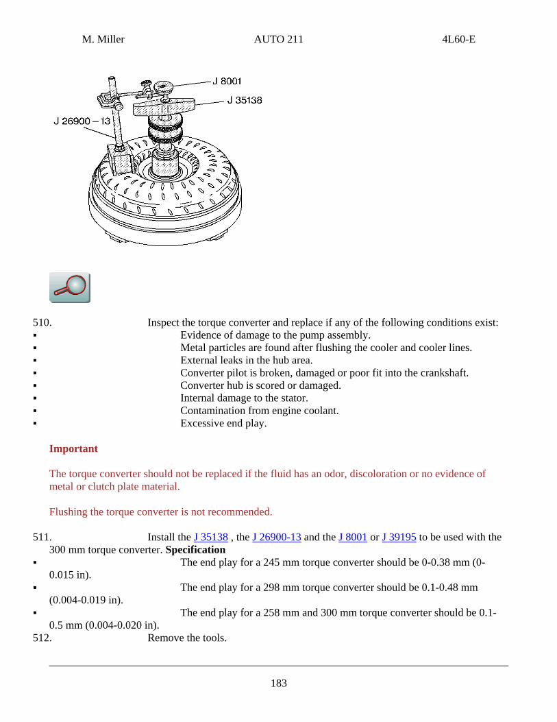
510. Inspect the torque converter and replace if any of the following conditions exist: Evidence of damage to the pump assembly. Metal particles are found after flushing the cooler and cooler lines. External leaks in the hub area. Converter pilot is broken, damaged or poor fit into the crankshaft. Converter hub is scored or damaged. Internal damage to the stator. Contamination from engine coolant. Excessive end play.
Important
The torque converter should not be replaced if the fluid has an odor, discoloration or no evidence of metal or clutch plate material.
Flushing the torque converter is not recommended.
511. Install the J 35138 , the J 26900-13 and the J 8001 or J 39195 to be used with the 300 mm torque converter. Specification
The end play for a 245 mm torque converter should be 0-0.38 mm (0-0.015 in).
The end play for a 298 mm torque converter should be 0.1-0.48 mm (0.004-0.019 in).
The end play for a 258 mm and 300 mm torque converter should be 0.1-0.5 mm (0.004-0.020 in).
512. Remove the tools.
183
M. Miller AUTO 211 4L60-E
Torque Converter Installation
Installation Procedure
Tools Required
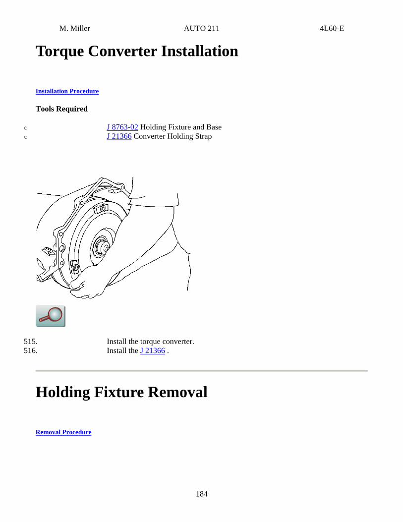
o J 8763-02 Holding Fixture and Base o J 21366 Converter Holding Strap
515. Install the torque converter. 516. Install the J 21366 .
Holding Fixture Removal
Removal Procedure
184
M. Miller AUTO 211 4L60-E
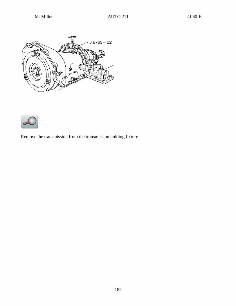
Remove the transmission from the transmission holding fixture.
185