497 airfield lighting
TRANSCRIPT
8/2/2019 497 Airfield Lighting
http://slidepdf.com/reader/full/497-airfield-lighting 1/4
copper seven wires stranded circular conductor
has an extruded tracking resistant XLPE (cross-
linked polyethylene) insulation. Optionally, a
separator or conductor shield may be applied
between both.
2. Non-shielded jacketed type: a bare copper
seven wires stranded circular conductor has
an extruded XLPE (cross-linked polyethylene)insulation. Optionally, a separator or conductor
shield may be applied between both.
A PVC or PE outer jacket is applied overall on
an optional separating tape;
3. Shielded jacketed type: a bare copper seven
wires stranded circular conductor has an
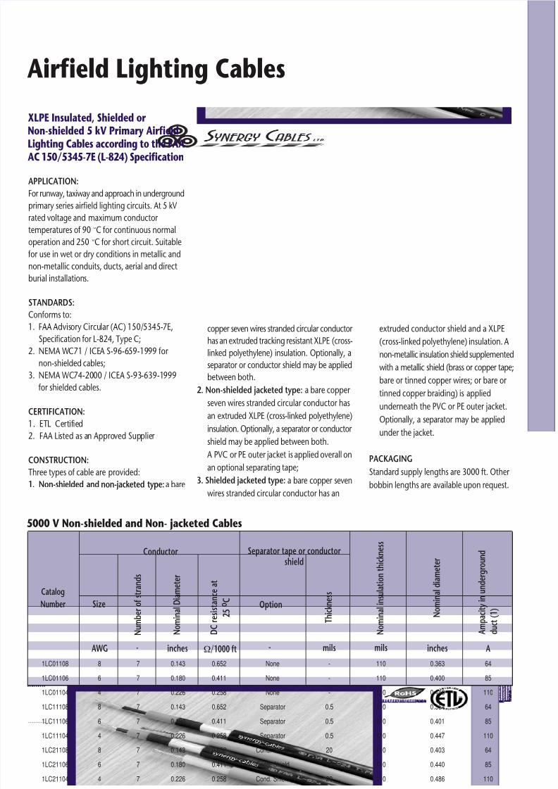
APPLICATION:
For runway, taxiway and approach in underground
primary series airfield lighting circuits. At 5 kV
rated voltage and maximum conductor
temperatures of 90 °C for continuous normal
operation and 250 °C for short circuit. Suitable
for use in wet or dry conditions in metallic and
non-metallic conduits, ducts, aerial and direct
burial installations.
STANDARDS:
Conforms to:
1. FAA Advisory Circular (AC) 150/5345-7E,
Specification for L-824, Type C;
2. NEMA WC71 / ICEA S-96-659-1999 for
non-shielded cables;
3. NEMA WC74-2000 / ICEA S-93-639-1999
for shielded cables.
CERTIFICATION:1. ETL Certified
2. FAA Listed as an Approved Supplier
CONSTRUCTION:
Three types of cable are provided:
1. Non-shielded and non-jacketed type: a bare
extruded conductor shield and a XLPE
(cross-linked polyethylene) insulation. A
non-metallic insulation shield supplemented
with a metallic shield (brass or copper tape;
bare or tinned copper wires; or bare or
tinned copper braiding) is applied
underneath the PVC or PE outer jacket.
Optionally, a separator may be applied
under the jacket.
PACKAGING
Standard supply lengths are 3000 ft. Other
bobbin lengths are available upon request.
Airfield Lighting Cables
XLPE Insulated, Shielded or Non-shielded 5 kV Primary AirfieldLighting Cables according to the FAAAC 150/5345-7E (L-824) Specification
Catalog
Number
A
1LC01108
1LC01106
1LC01104
1LC11108
1LC11106
1LC11104
1LC21108
1LC21106
1LC21104
0.652
0.411
0.258
0.652
0.411
0.258
0.652
0.411
0.258
8
6
4
8
6
4
8
6
4
-
-
-
0.5
0.5
0.5
20
20
20
None
None
None
Separator
Separator
Separator
Cond. Shield
Cond. Shield
Cond. Shield
0.143
0.180
0.226
0.143
0.180
0.226
0.143
0.180
0.226
110
110
110
110
110
110
110
110
110
0.363
0.400
0.446
0.364
0.401
0.447
0.403
0.440
0.486
64
85
110
64
85
110
64
85
110
7
7
7
7
7
7
7
7
7
Conductor Separator tape or conductorshield
N o m i n a l i n s u l a t i o n t h i c k n e s s
N o m i n a l d i a m e t e r
A m p a c i t y i n u n d e r g r o u n d
d u c t ( 1 )
Size
N u m b e r o f s t r a n d s
D C r e s i s t a n c e a t
2 5
o C
N o m i n a l D i a m e t e r
Option
T h i c k n e s s
AWG - Ω/1000 ft - mils mils inchesinches
5000 V Non-shielded and Non- jacketed Cables
8/2/2019 497 Airfield Lighting
http://slidepdf.com/reader/full/497-airfield-lighting 2/4
Airfield Lighting Cables
CatalogNumber
0.652
0.652
0.411
0.411
0.258
0.258
0.652
0.652
0.4110.411
0.258
0.258
0.652
0.652
0.411
0.411
0.258
0.258
8
8
6
6
4
4
8
8
66
4
4
8
8
6
6
4
4
-
-
-
-
-
-
0.5
0.5
0.50.5
0.5
0.5
20
20
20
20
20
20
None
None
None
None
None
None
Separator
Separator
SeparatorSeparator
Separator
Separator
Cond. Shield
Cond. Shield
Cond. Shield
Cond. Shield
Cond. Shield
Cond. Shield
0.143
0.143
0.180
0.180
0.226
0.226
0.143
0.143
0.1800.180
0.226
0.226
0.143
0.143
0.180
0.180
0.226
0.226
30
30
30
30
45
45
30
30
3030
45
45
30
30
30
30
45
45
0.395
0.395
0.432
0.432
0.508
0.508
0.396
0.396
0.4330.433
0.509
0.509
0.435
0.435
0.472
0.472
0.548
0.548
7
7
7
7
7
7
7
7
77
7
7
7
7
7
7
7
7
ConductorSeparator tape orconductor shield
N o m i n a l d i a m e t e r
Size
N u m b e r o f
s t r a n d s
D C r e s i s t a n c e
a t 2 5 o C
N o m i n a l
D i a m e t e r
Option T h i c k n e
s s
AWG - - mils mils inchesinches
90
90
90
90
90
90
90
90
9090
90
90
90
90
90
90
90
90
N o m i n a l i n
s u l a t i o n
t h i c k n e s s
mils A
64
64
85
85
110
110
64
64
8585
110
110
64
64
85
85
110
110
A m p a c i t y i n
u n d e r g r o u n d
d u c t ( 1 )
6
6
6
6
6
6
6
6
66
6
6
6
6
6
6
6
6
S e p a r a t o r t a p e
t h i c k n e s s
mils
T h i c k n e s s
M a t e r i a l t y
p e
Jacket
PVC
PE
PVC
PE
PVC
PE
PVC
PE
PVCPE
PVC
PE
PVC
PE
PVC
PE
PVC
PE
1LC09081
1LC09082
1LC09061
1LC09062
1LC09041
1LC09042
1LC19081
1LC19082
1LC190611LC19062
1LC19041
1LC19042
1LC29081
1LC29082
1LC29061
1LC29062
1LC29041
1LC29042
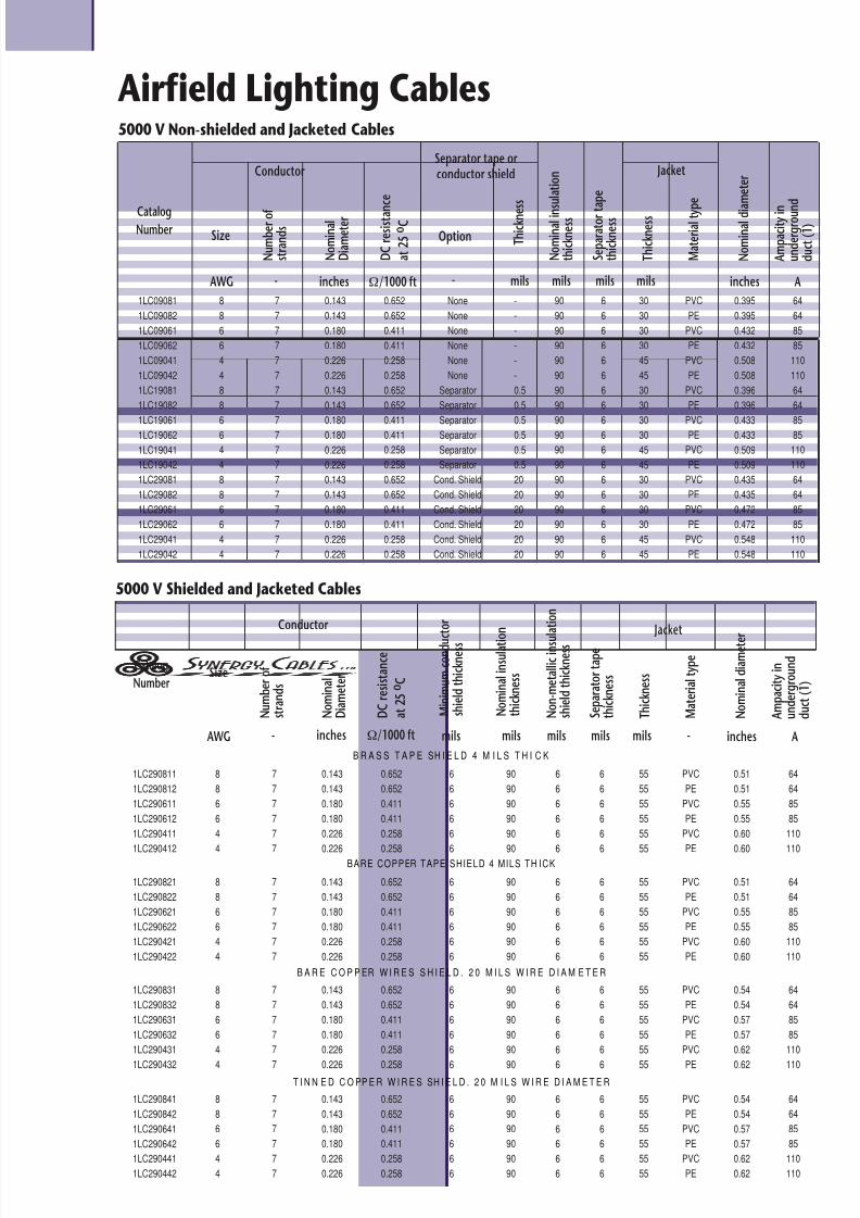
5000 V Non-shielded and Jacketed Cables
Catalog
Number
0.652
0.652
0.411
0.411
0.258
0.258
8
8
6
6
4
4
90
90
90
90
90
90
6
6
6
6
6
6
0.143
0.143
0.180
0.180
0.226
0.226
55
55
55
55
55
55
0.51
0.51
0.55
0.55
0.60
0.60
7
7
7
7
7
7
Conductor
N o m i n a l d i a m e t e r
Size
N u m b e r o f
s t r a n d s
D C r e s i s t a n c e
a t 2 5 o C
N o m i n a l
D i a m e t e r
AWG - mils mils inchesinches
6
6
6
6
6
6
N o n - m e t a l l i c i n s u
l a t i o n
s h i e l d t h i c k n e s s
mils A
64
64
85
85
110
110
A m p a c i t y i n
u n d e r g r o u n d
d u c t ( 1 )
6
6
6
6
6
6
S e p a r a t o r t a p e
t h i c k n e s s
mils
T h i c k n e s s
M a t e r i a l t y p e
Jacket
PVC
PE
PVC
PE
PVC
PE
1LC290811
1LC290812
1LC290611
1LC290612
1LC290411
1LC290412
5000 V Shielded and Jacketed Cables
mils -
M i n i m u m
c o n d u c
t o r
s h i e l d t h i c k n e s s
N o m i n a l i n s u l a t i o
n
t h i c k n e s s
64
64
85
85
110
110
64
64
85
85
110
110
64
64
85
85
110
110
8
8
6
6
4
4
90
90
90
90
90
90
6
6
6
6
6
6
55
55
55
55
55
55
7
7
7
7
7
7
6
6
6
6
6
6
6
6
6
6
6
6
PVC
PE
PVC
PE
PVC
PE
8
8
6
6
4
4
90
90
90
90
90
90
6
6
6
6
6
6
55
55
55
55
55
55
7
7
7
7
7
7
6
6
6
6
6
6
6
6
6
6
6
6
PVC
PE
PVC
PE
PVC
PE
8
8
6
6
4
4
90
90
90
90
90
90
6
6
6
6
6
6
55
55
55
55
55
55
7
7
7
7
7
7
6
6
6
6
6
6
6
6
6
6
6
6
PVC
PE
PVC
PE
PVC
PE
1LC290821
1LC290822
1LC290621
1LC290622
1LC290421
1LC290422
0.652
0.652
0.411
0.411
0.258
0.258
0.143
0.143
0.180
0.180
0.226
0.226
0.51
0.51
0.55
0.55
0.60
0.60
0.652
0.652
0.411
0.411
0.258
0.258
0.143
0.143
0.180
0.180
0.226
0.226
0.54
0.54
0.57
0.57
0.62
0.62
0.652
0.652
0.411
0.411
0.258
0.258
0.143
0.143
0.180
0.180
0.226
0.226
0.54
0.54
0.57
0.57
0.62
0.62
1LC290831
1LC290832
1LC290631
1LC290632
1LC290431
1LC290432
1LC290841
1LC290842
1LC290641
1LC290642
1LC290441
1LC290442
Ω/1000 ft
B R A S S T A P E SH I E L D 4 M I L S T H I C K
B A R E C O P P ER W I R E S S H I E L D . 2 0 M I L S W I R E D I A M E T E R
BARE COPPER TAPE SHIELD 4 MILS TH ICK
T I N N E D C O PP E R W I R E S SH I E L D . 2 0 M I L S W I R E D I A M E T E R
Ω/1000 ft
8/2/2019 497 Airfield Lighting
http://slidepdf.com/reader/full/497-airfield-lighting 3/4
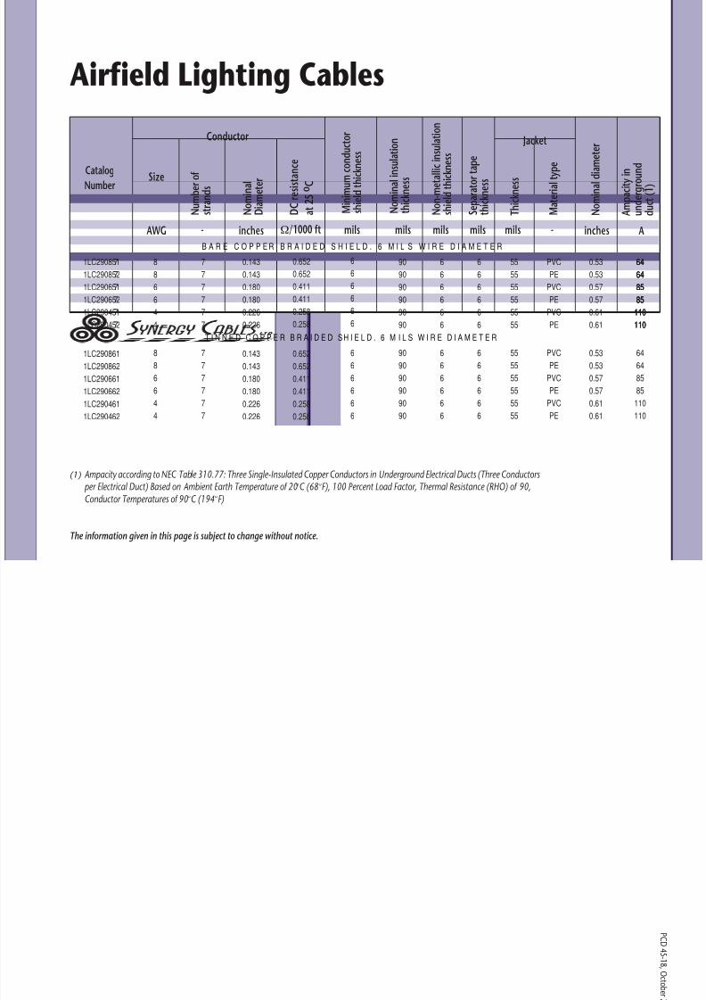
(1) Ampacity according to NEC Table 310.77: Three Single-Insulated Copper Conductors in Underground Electrical Ducts (Three Conductors per Electrical Duct) Based on Ambient Earth Temperature of 20°C (68°F), 100 Percent Load Factor, Thermal Resistance (RHO) of 90,Conductor Temperatures of 90°C (194°F)
The information given in this page is subject to change without notice.
P C D 4 5 -1 8 , O c t o b e
Airfield Lighting Cables
CatalogNumber
8
8
6
6
4
4
90
90
90
90
90
90
55
55
55
55
55
55
7
7
7
7
7
7
Conductor
N o m i n a l d i a m e t e r
Size
N u m b e r o f
s t r a n d s
D C r e s i s t a n c e
a t 2 5 o C
N o m i n a l
D i a m e t e r
AWG - mils mils inchesinches
6
6
6
6
6
6
N o n - m e t a l l i c i n s u l a t i o n
s h i e l d t h i c k
n e s s
mils A
64
64
85
85
110
110
A m p a c i t y i n
u n d e r g r o u n d
d u c t ( 1 )
6
6
6
6
6
6
S e p a r a t o r t a p e
t h i c k n e s s
mils
T h i c k n e s s
M a t e r i a l t y
p e
Jacket
PVC
PE
PVC
PE
PVC
PE
mils -
M i n i m u m c o n d u c t o r
s h i e l d t h i c k n e s s
N o m i n a l i n
s u l a t i o n
t h i c k n e s s
B A R E C O P P E R B R A I D E D S H I E L D . 6 M I L S W I R E D I A M E T E R
64
64
85
85
110
110
T I N N E D C O P P E R B R A I D E D S H I E L D . 6 M I L S W I R E D I A M E T E R
8
8
6
6
4
4
90
90
90
90
90
90
6
6
6
6
6
6
55
55
55
55
55
55
7
7
7
7
7
7
6
6
6
6
6
6
6
6
6
6
6
6
PVC
PE
PVC
PE
PVC
PE
1LC290851
1LC290852
1LC290651
1LC290652
1LC290451
1LC290452
7
7
7
7
7
7
0.143
0.143
0.180
0.180
0.226
0.226
64
64
85
85
110
110
64
64
85
85
110
110
1LC290861
1LC290862
1LC290661
1LC290662
1LC290461
1LC290462
0.143
0.143
0.180
0.180
0.226
0.226
0.652
0.652
0.411
0.411
0.258
0.258
0.53
0.53
0.57
0.57
0.61
0.61
0.53
0.53
0.57
0.57
0.61
0.61
Ω/1000 ft
0.652
0.652
0.411
0.411
0.258
0.258
6
6
6
6
6
6
8/2/2019 497 Airfield Lighting
http://slidepdf.com/reader/full/497-airfield-lighting 4/4
P C D
4 5 -1 8 , O c t o b e r 2 0 0 7
Tel: (972) 4-8466222Fax: (972) 4-8466286
e-mail: [email protected]://www.synergy-cables.com
SCOPE
This specification describes XLPE insulated
shielded or non-shielded single core 5 kV cables
for runway, taxiway and approach in
Wunderground primary series airfield lighting
circuits. For a maximum conductor
temperatures of 90 °C for continuous normal
operation and 250 °C for short circuit, in wet
or dry conditions. Suitable for use in metallic
and non-metallic conduits, ducts, aerial anddirect burial installations.
STANDARDS
The following standards shall form a part of
this specification to the extent specified herein:
- Conforms to FAA Advisory Circular (AC)
150/5345-7E, Specification for L-824,
Type C, Underground Electrical Cable for
Airfield Lighting Circuits
- NEMA WC71 / ICEA S-96-659-1999:
“Standard for Non-shielded Power Cables
Rated 2,001 – 5,000 Volts for the
Distribution of Electrical Energy” asreferenced by FAA AC 150/5345-7E.
- NEMA WC74-2000 / ICEA S-93-639-1999:
“Standard for Shielded Power Cables Rated
5,000 – 46,000 Volts for the Transmission
& Distribution of Electrical Energy” as
referenced by FAA AC 150/5345-7E.
CONDUCTORS
Bare soft annealed, high conductivity copper
per ASTM B-3, concentric stranded, class B
(seven strands) per ASTM B 8. Class C (19
strands) is available upon request.
SEPARATOR (for non-shielded cables)
An optional separator is applied to facilitate
the insulation stripping.
CONDUCTOR SHIELD
Optional for non-shielded cables, it is
mandatory for shielded cables. Accordingly,
the conductors are covered with a layer of
extruded conducting cross-linked polyolefin
compound, firmly bonded to the insulation
and which shall meet the requirements of
NEMA WC74-2000 / ICEA S-93-639-1999
Standard, Section 3.
INSULATION
Directly over the conductor, separator or screen
(as applicable) shall be applied a homogeneous
wall of XLPE insulation. For non-shielded cables
it shall meet the requirements of NEMA WC71
/ ICEA S-96-659-1999, Table 4-2. For shielded
cables it shall meet the requirements of NEMA
WC74-2000 / ICEA S-93-639-1999 Standard,
Section 4.
INSULATION SHIELD (for shielded cables)
- The insulation shield shall consist of a
graphite coating in combination with semi-conducting tape and a metallic layer applied
directly over the insulation.
- The metallic layer shall consist of one of
the following:
- an overlapping copper tape
- an overlapping brass tape
- helically applied bare copper wires
- helically applied tinned copper wires
- bare copper wires braid
- tinned copper wires braid
- Other tape thickness or wire diameter than
the ones indicated in the tables can be
supplied upon request.- An optional separator tape may be applied
over all.
S p e c i f i c a t i o n
OVERALL JACKET
- Where applicable, an extruded PVC or black
PE jacket shall be applied on the assembly.
- Properties of the jacket shall be in
accordance with NEMA WC71 /
ICEA S-96-659-1999 Standard, Table 5-1
or NEMA WC74-2000 / ICEA S-93-639-
1999 Standard, Table 7-1 depending upon
the cable type.
TESTS
The cable shall be tested in accordance with
NEMA WC71 / ICEA S-96-659-1999 Standard,
Table 5-1 or NEMA WC74-2000 /
ICEA S-93-639-1999 Standard, Table 7-1
depending upon the cable type.
Airfield Lighting Cables
XLPE Insulated, Shielded or Non-shielded 5 kV Primary AirfieldLighting Cables according to the FAAAC 150/5345-7E (L-824) Specification