463 131 463 131 01 463 131 02 463 131 03 463 134 463 … 463-131 user manual.pdf · en 954-1 /...
TRANSCRIPT

ELB_0008XF.book Seite 1 Freitag, 21. April 2006 8:37 08
Betriebsanleitung Auswerteeinheit
Operating instructions Control unit
Notice d’utilisation Unité de contrôle
Istruzioni d’impiego Unità di controllo
Manual de usario Unidad de control
D
GB
F
I
E
463 131463 131 01463 131 02463 131 03463 134463 134 01463 134 02463 134 11463 134 12
21.04.2006
ELB_0008XF.book Seite 2 Freitag, 21. April 2006 8:37 08
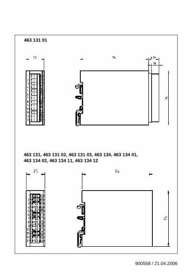
463 131 01
463 131, 463 131 02, 463 131 03, 463 134, 463 134 01, 463 134 02, 463 134 11, 463 134 12
900558 / 21.04.2006
2 900558 / 21.04.2006
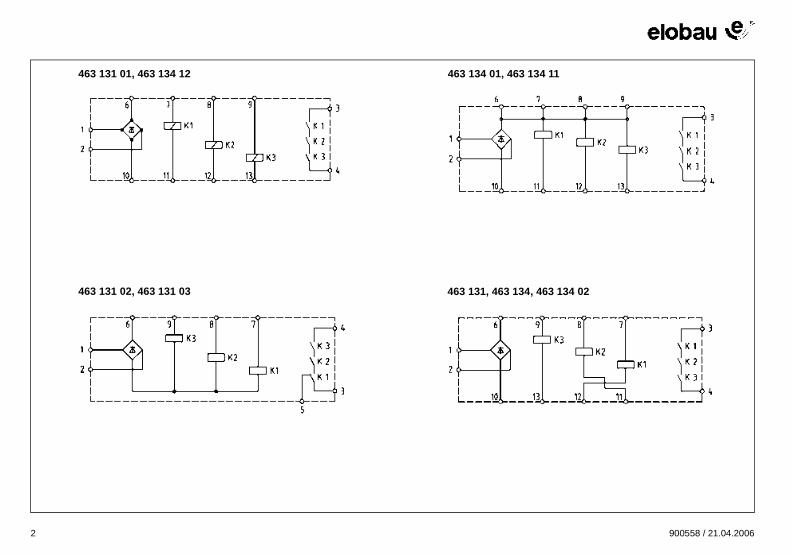
463 131 01, 463 134 12
463 131 02, 463 131 03
463 134 01, 463 134 11
463 131, 463 134, 463 134 02
ELB_0008XF.book Seite 2 Freitag, 21. April 2006 8:37 08
GB
ELB_0008XF.book Seite 11 Freitag, 21. April 2006 8:37 08
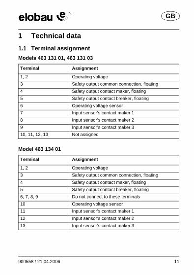
1 Technical data
1.1 Terminal assignment
Models 463 131 01, 463 131 03
Model 463 134 01
Terminal Assignment
1, 2 Operating voltage
3 Safety output common connection, floating
4 Safety output contact maker, floating
5 Safety output contact breaker, floating
6 Operating voltage sensor
7 Input sensor’s contact maker 1
8 Input sensor’s contact maker 2
9 Input sensor’s contact maker 3
10, 11, 12, 13 Not assigned
Terminal Assignment
1, 2 Operating voltage
3 Safety output common connection, floating
4 Safety output contact maker, floating
5 Safety output contact breaker, floating
6, 7, 8, 9 Do not connect to these terminals
10 Operating voltage sensor
11 Input sensor’s contact maker 1
12 Input sensor’s contact maker 2
13 Input sensor’s contact maker 3
900558 / 21.04.2006 11
GB
ELB_0008XF.book Seite 12 Freitag, 21. April 2006 8:37 08
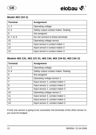
Model 463 134 11
Models 463 131, 463 131 01, 463 134, 463 134 02, 463 134 12
If only one sensor is going to be connected, the terminals of the other sensor in-put must be bridged.
Terminal Assignment
1, 2 Operating voltage
3, 4 Safety output contact maker, floating
5 Not assigned
6, 7, 8, 9 Do not connect to these terminals
10 Operating voltage sensor
11 Input sensor’s contact maker 1
12 Input sensor’s contact maker 2
13 Input sensor’s contact maker 3
Terminal Assignment
1, 2 Operating voltage
3, 4 Safety output contact maker, floating
5 Not assigned
6 Operating voltage sensor 1
7 Input sensor 1, contact maker 1
8 Input sensor 1, contact maker 2
9 Input sensor 1, contact maker 3
10 Operating voltage sensor 2
11 Input sensor 2, contact maker 1
12 Input sensor 2, contact maker 2
13 Input sensor 2, contact maker 3
12 900558 / 21.04.2006
GB
ELB_0008XF.book Seite 13 Freitag, 21. April 2006 8:37 08
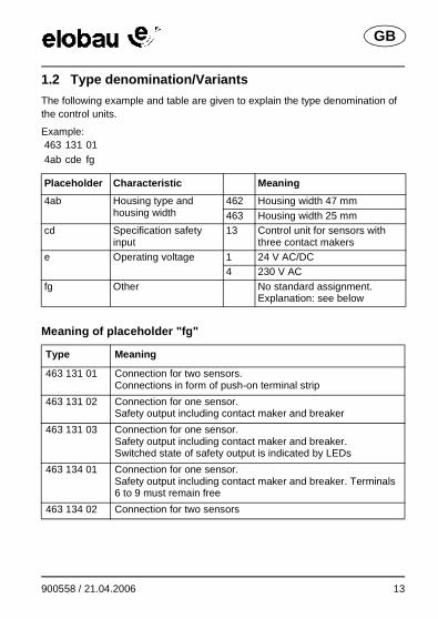
1.2 Type denomination/Variants
The following example and table are given to explain the type denomination of the control units.
Example:
Meaning of placeholder "fg"
463 131 014ab cde fg
Placeholder Characteristic Meaning
4ab Housing type and housing width
462 Housing width 47 mm
463 Housing width 25 mmcd Specification safety
input13 Control unit for sensors with
three contact makerse Operating voltage 1 24 V AC/DC
4 230 V AC
fg Other No standard assignment.Explanation: see below
Type Meaning
463 131 01 Connection for two sensors. Connections in form of push-on terminal strip
463 131 02 Connection for one sensor.Safety output including contact maker and breaker
463 131 03 Connection for one sensor.Safety output including contact maker and breaker.Switched state of safety output is indicated by LEDs
463 134 01 Connection for one sensor.Safety output including contact maker and breaker. Terminals 6 to 9 must remain free
463 134 02 Connection for two sensors
900558 / 21.04.2006 13
GB
ELB_0008XF.book Seite 14 Freitag, 21. April 2006 8:37 08
1.3 Electrical and mechanical data
The control unit in a deenergized state is depicted on the circuit diagram of the fold-out page.
General
Models
Operating voltage
Type Meaning
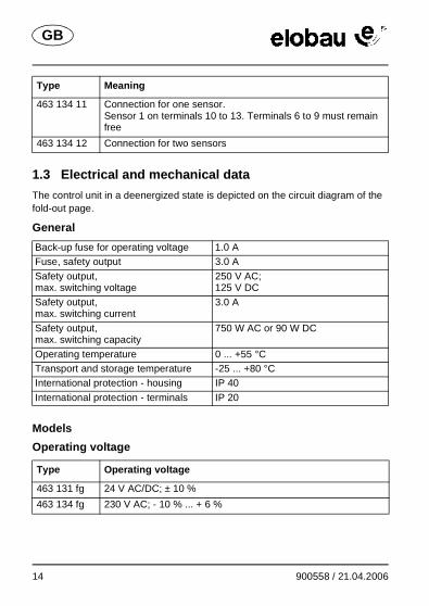
463 134 11 Connection for one sensor.Sensor 1 on terminals 10 to 13. Terminals 6 to 9 must remain free
463 134 12 Connection for two sensors
Back-up fuse for operating voltage 1.0 AFuse, safety output 3.0 A
Safety output,max. switching voltage
250 V AC;125 V DC
Safety output,max. switching current
3.0 A
Safety output,max. switching capacity
750 W AC or 90 W DC
Operating temperature 0 ... +55 °CTransport and storage temperature -25 ... +80 °CInternational protection - housing IP 40
International protection - terminals IP 20
Type Operating voltage
463 131 fg 24 V AC/DC; ± 10 %
463 134 fg 230 V AC; - 10 % ... + 6 %
14 900558 / 21.04.2006
GB
ELB_0008XF.book Seite 15 Freitag, 21. April 2006 8:37 08
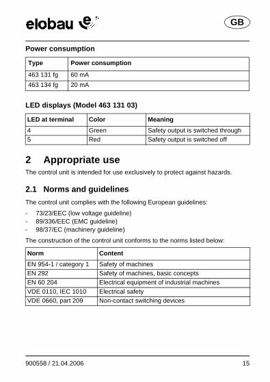
Power consumption
LED displays (Model 463 131 03)
2 Appropriate useThe control unit is intended for use exclusively to protect against hazards.
2.1 Norms and guidelines
The control unit complies with the following European guidelines:
- 73/23/EEC (low voltage guideline)- 89/336/EEC (EMC guideline)- 98/37/EC (machinery guideline)
The construction of the control unit conforms to the norms listed below:
Type Power consumption
463 131 fg 60 mA
463 134 fg 20 mA
LED at terminal Color Meaning
4 Green Safety output is switched through5 Red Safety output is switched off
Norm Content
EN 954-1 / category 1 Safety of machinesEN 292 Safety of machines, basic conceptsEN 60 204 Electrical equipment of industrial machines
VDE 0110, IEC 1010 Electrical safetyVDE 0660, part 209 Non-contact switching devices
900558 / 21.04.2006 15
GB
ELB_0008XF.book Seite 16 Freitag, 21. April 2006 8:37 08
2.2 Safety/Dangers
General
- Ensure that the control unit is only installed and put into operation by specially-trained authorised personnel.
- Ensure that the appropriate corresponding fuses (see Technical data) are used. Never bridge or repair fuses.
- Only operate the control unit when it’s in an undamaged condition.- Ensure that the control unit is only used for protection against dangers.- Ensure that all safety requirements applying for the machine in question are
observed.- Ensure that all European guidelines and national laws/guidelines applying
are observed.
Models 463 134 01, 463 134 11
- Ensure that terminals 6 to 9 of the control unit remain free.
3 FunctionThe control unit monitors connected sensors which are equipped with three con-tact makers. The control unit safety output will be open or closed according to the position of the connected sensors.
The control unit switches off the safety output in the following situations:
- One or more contact makers of a connected sensor are opened.- A fault has been detected (control unit or connected sensor is defective).
16 900558 / 21.04.2006
GB
ELB_0008XF.book Seite 17 Freitag, 21. April 2006 8:37 08
4 InstallationModels 463 134 01, 463 134 11
- Snap the control unit onto a mounting rail (DIN 50 022) in the switch cabinet.The control unit is attached.
- Connect control unit, see Technical data.- Ensure that the prescribed fuses are used, see Technical data.
Models 463 131, 463 131 01, 463 131 02, 463 131 03, 463 134, 463 134 02, 463 134 12
- Snap the control unit onto a mounting rail (DIN 50 022) in the switch cabinet.The control unit is attached.
- Connect control unit, see Technical data.- Ensure that the prescribed fuses are used, see Technical data.
Danger
� Danger of electrocution!Ensure that the control unit is only installed and put into opera-tion by specially-trained authorised personnel.
Caution
� Possibility of damage to the control unit because of incor-rect connectionsEnsure that terminals 6 to 9 of the control unit remain free.
Danger
� Danger of electrocution!Ensure that the control unit is only installed and put into opera-tion by specially-trained authorised personnel.
900558 / 21.04.2006 17
GB
ELB_0008XF.book Seite 18 Freitag, 21. April 2006 8:37 08
5 Putting into operation
- Apply operating voltage.- Close the contacts at the sensor’s contact maker inputs.
The control unit switches through the safety output.The control unit is ready for operation.
6 Troubleshooting
6.1 Restoring device to a state of readiness for operation
One or more contact makers of the connected sensor were opened.
- Close the contacts at the sensor’s contact maker inputs.
The control unit switches through the safety output.The control unit is ready for operation.
7 MaintenanceThe control unit is maintenance-free.
Danger
� Danger of electrocution!Ensure that the control unit is only installed and put into opera-tion by specially-trained authorised personnel.
18 900558 / 21.04.2006
elobauElektrobauelemente GmbH & Co. KGPostfach 126588306 Isny/AllgäuGermany
Werk:Zeppelinstr. 4488299 LeutkirchGermanyTel.: +49 7561 970-0Fax: +49 7561 970-100E-Mail:[email protected]: www.elobau.de
Artikelnummer / Article Number / Référence / Codice articolo / N° de artículo: 900558Version / Version / Version / Versione / Versión: 1.0Datum / Date / Date / Data / Fecha: 21.04.2006Seiten / Pages / Pages / Pagine / Páginas: 44
ELB_0008XF.book Seite 44 Freitag, 21. April 2006 8:37 08