43 pow diste
TRANSCRIPT

Power DistributionAC & DC Power
Distribution and BatteryDisconnects
Steven Engineering-230 Ryan Way-South San Francisco, CA 94080-6370-Main Office:(650)588-9200-Outside Local Area:(800)258-9200-www.stevenengineering.com

www.carlingtech.com
Carling Technologies™
Introduction to Power Distribution
With over 80 years of experience in the development of power switching and protection components, Carling Technologies offersstandard and custom designed AC and DC power distribution centers that provide the utmost in safety, reliability and performance.
Power Distribution Center, or PDC, is Carling's term for a standard or custom power distribution panel or unit that's factory wired andcontains overcurrent and short circuit protection devices. It may also contain auxiliary devices such as surge suppressors, groundfault circuit interrupters, power receptacles, etc. A PDC is usually supplied by the main feeder and then divides the power into small-er branch circuits. A PDC provides the required circuit control and overcurrent protection needed to all the circuits and the loads con-nected to it. Power Distribution Unit, or PDU, is an industry term for horizontally mounted panels used in 19” or 23” racks.
Carling Technologies’ expertise in custom design solutions, tooling, manufacturing, and our broad customer base has allowed us todevelop a high quality standard product line of power distribution centers. Our standard PDU and PDC products have been designedto meet today's demanding global industry standards, taking into account the growing need to reduce the amount of real estate thatpanels require, without sacrificing power.
In addition, our dedicated engineering team designs and develops custom Power Distribution Centers or Battery Disconnect Panelsthat will meet your special requirements. Utilizing a comprehensive range of quality circuit protection and control products, you canspecify the physical size of the enclosure and add your component requirements including temperature stable Carling Technologies'hydraulic-magnetic circuit breakers, ground fault circuit protectors, transient voltage surge suppressors, meters, power receptacles,relays, bus bars, hole plugs and LED's.
For the Telecommunication, Server, Marine, Generator, Alternative Power, and Medical industries, Carling Technologies' expertise inpower distribution and electrical design can help you meet your power needs. Contact us with your requirements today.
CHARGER/RECTIFIER
AC DISTRIBUTION
LAC1-Series
CHARGER/RECTIFIER
BATTERY DISCONNECT
LBD-Series
DC DISTRIBUTION
LDC1, LDC2 & LDM1-Series
ALARM/MONITOR
L0039
DCLOAD
BATTERYBANK A
DCLOAD
DCLOAD
DCLOAD
BATTERY DISCONNECT
LBD-Series
BATTERYBANK B
DC DISTRIBUTION
LDC1, LDC2 & LDM1-Series
˜
UTILITY POWER
˜
GENERATOR(BACK-UP)
Block Diagram illustrating a typical telecommunications power distribution circuit featuring Carling Technologies PDU and PDCproducts. The Power Distribution circuit can be fed by utility power on a back-up generator. In addition, battery power can besupplied and controlled with Carling Technologies Battery Disconnect PDU’s. The DC Power Distribution can be monitored byCarling Technologies Alarm/Monitor PDU.
Steven Engineering-230 Ryan Way-South San Francisco, CA 94080-6370-Main Office:(650)588-9200-Outside Local Area:(800)258-9200-www.stevenengineering.com
Carling Technologies™
1
Contents
www.carlingtech.com
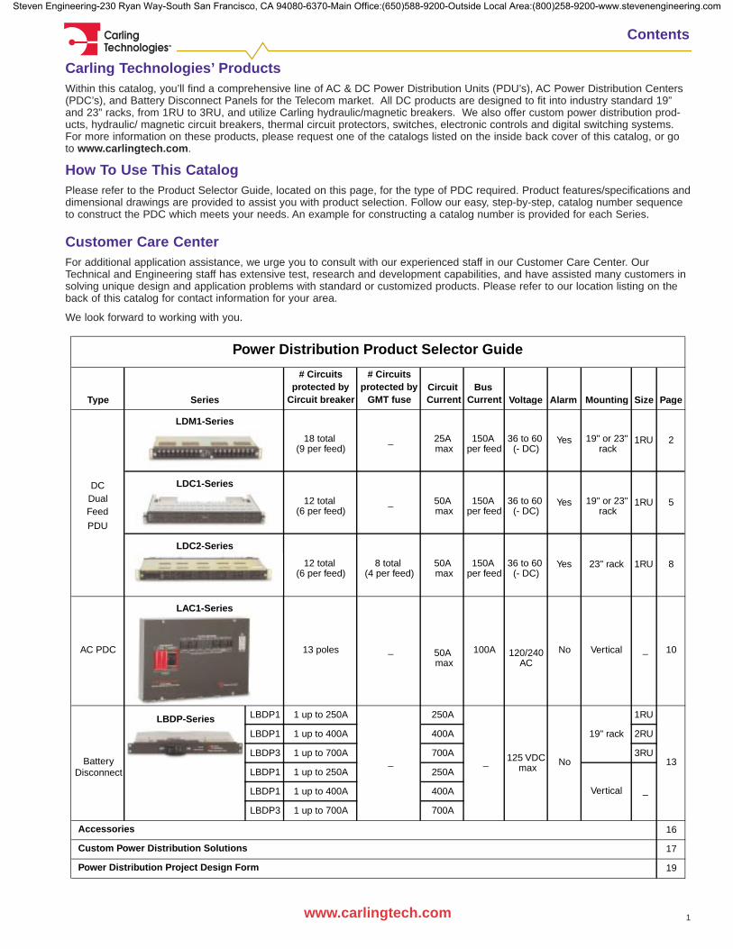
Carling Technologies’ ProductsWithin this catalog, you’ll find a comprehensive line of AC & DC Power Distribution Units (PDU’s), AC Power Distribution Centers(PDC’s), and Battery Disconnect Panels for the Telecom market. All DC products are designed to fit into industry standard 19”and 23” racks, from 1RU to 3RU, and utilize Carling hydraulic/magnetic breakers. We also offer custom power distribution prod-ucts, hydraulic/ magnetic circuit breakers, thermal circuit protectors, switches, electronic controls and digital switching systems.For more information on these products, please request one of the catalogs listed on the inside back cover of this catalog, or goto www.carlingtech.com.
How To Use This CatalogPlease refer to the Product Selector Guide, located on this page, for the type of PDC required. Product features/specifications anddimensional drawings are provided to assist you with product selection. Follow our easy, step-by-step, catalog number sequenceto construct the PDC which meets your needs. An example for constructing a catalog number is provided for each Series.
Customer Care CenterFor additional application assistance, we urge you to consult with our experienced staff in our Customer Care Center. OurTechnical and Engineering staff has extensive test, research and development capabilities, and have assisted many customers insolving unique design and application problems with standard or customized products. Please refer to our location listing on theback of this catalog for contact information for your area.
We look forward to working with you.
# Circuits # Circuitsprotected by protected by
Circuit breaker GMT fuse Current Current
(9 per feed) max per feed (- DC) rack
(6 per feed) max per feed (- DC) rack
(6 per feed) (4 per feed) max per feed (- DC)
max AC
LBDP-Series LBDP1 1 up to 250A 250A 1RU
LBDP1 1 up to 400A 400A 2RU
LBDP3 1 up to 700A 700A 3RU
LBDP1 1 up to 250A 250A max
LBDP1 1 up to 400A 400A
LBDP3 1 up to 700A 700A
16
17
19
Power Distribution Product Selector Guide
Power Distribution Project Design Form
Custom Power Distribution Solutions
Accessories
150A 25A _
DC
Circuit Bus
12 total
SeriesType
LDM1-Series
LDC1-Series
LDC2-Series
Dual _
_
1RU
1RU
36 to 60 Yes150A
Disconnect
No120/240AC PDC 13 poles
125 VDCBattery
LAC1-Series
100A
_ _ 13
No
19" rack
Vertical _
18 total
12 total
Vertical 10 _ 50A
8 total 50A 23" rack
50A 150A 19" or 23"36 to 60 Yes
Yes36 to 60
Alarm MountingVoltage
19" or 23"
Size Page
8
5
21RU
Feed
PDU
Steven Engineering-230 Ryan Way-South San Francisco, CA 94080-6370-Main Office:(650)588-9200-Outside Local Area:(800)258-9200-www.stevenengineering.com

2 www.carlingtech.com
Carling Technologies™
LDM1-Series DC Secondary Power Distribution
General Specifications
To help conserve valuable cabinet space, Carling Technologiesintroduces a new, advanced 1RU DC Power Distribution Unit(PDU) for the telecom industry. This new PDU is designed tofit industry standard 19” rack systems. This 1RU is listed toUL/CUL 1801 and designed to EN60950.
The Carling circuit breakers installed in the 1RU are the minia-ture M-Series hydraulic-magnetic breakers — the smallestbreaker on the market that is UL489A listed up to 80 VDC. Inaddition, these breakers are plug in style to allow for hot“swappable” and front access, and are rated to 25 amps perpole.
Even as a “condensed” panel, this new 1RU exceeds thetough demands of today's applications while still offering safe-ty, reliability and performance.
LDM1-Series:
19” or 23” One Rack Unit
The LDM1-Series One Rack Unit (1RU) saves valuable
real estate on a rack, while offering ease
of installation and service.
Features & Benefits
Standards: UL 1801, CUL ApprovedDimensions: Rack mounts to EIA standard
EIA-310-D 19" rack for a 1RU panel, 1.75"H.
Enclosure: 16 gauge yellow zinc chromate cold rolled steel.
Feeds: Dual, rated up to 150 amps per feed.Max. circuit breakers per feed: 9Max. breaker rating: 25 amps.Connections: two hole compression lugs for 1/4 - 20 stud terminals x 5/8 centers.
Load Connections: Requires 10 awg wire/ring or fork terminal for 25 A/75 C Rating, Top or bottom wire entry.
Operating Voltage: -36V to –60V DC (-48VDC nominal)
Alarm Feature: Power alarm: If either A or BFEED or both fail.Breaker alarm: If any populated breaker is OFF or "tripped."Alarm is not affected by unused breaker positions. LED indicatorson the front panel. Breaker slots can be set or deactivated on the removable Alarm Card.
LED indicators: Green lamps on A and B feeds.Red lamp for tripped breakeralarm indication.
Chassis Ground: Via studs on the back panel. Use two hole X 5/8" center lugs. Grounding is also achieved through the rack mounting brackets to the yellow zinc chromate steel panel enclosure.
• Panel incorporates Carling M-Series style hydraulic/magnetic breakers: The smallest UL489Alisted hydraulic-magnetic circuit breaker on the market today!
• Keyed terminal to prevent breaker from being mounted incorrectly.
• Hot “swappable” circuit breakers that can be installed, changed, or replaced in the field or factory.
• Circuit breakers are front panel accessible. • Maximum of 9 circuit breakers per feed; 18 per panel.• One Rack Unit (1RU) size.• Panel plugs provided for non populated circuit breaker
slots.• Rockerguard circuit breakers to prevent accidental
operation.• Panel is easily configurable and upgradeable in the
field. Provides flexibility when designing added features or options.
• Conserves valuable cabinet space to meet the tough demands of today’s applications.
• Front accessible removable alarm card.• Optional Rack Extenders to expand the panel
mounting from a 19" rack to a 23" rack. Part Numbers: 8L1-A-DC1A (offset mounting)
8L1-A-DC1B (center mounting)
Steven Engineering-230 Ryan Way-South San Francisco, CA 94080-6370-Main Office:(650)588-9200-Outside Local Area:(800)258-9200-www.stevenengineering.com

Carling Technologies™
3www.carlingtech.com
LDM1-Series DC Secondary Power Distribution
A
A
8.56[217.4]
17.74[450.6]
19.000 {482.6}23.000 {584.2} with Optional Rack Extenders
1.750 {44.45}
LDM1-Series Dimensional Specifications
4 through 12 BREAKER RATING00 No breaker01 1 amp03 3 amps05 5 ampsH7 7.5 amps
10 10 amps12 12 amps15 15 amps20 20 amps25 25 amps
3 DELAYN No breaker M Medium Delay, Curve 14
2 ROCKER STYLEN No breakerB Black with white legend
W White Visi-Rockerindicate OFF
1 SERIESLDM1
1Series
M13Approvals
2RockerStyle
3Delay
BLDM1 A4Breaker inPosition 1
05
13 APPROVALSA No approvals G UL/CUL J UL/CUL, CE, TUV
NOTES:Redundant feed. Breaker layout will be duplicated on the second feed.Feeds A and B are rated for 150 amps. Total combined breaker ratings can not exceed 150 amps per feed.A panel plug will be supplied in the breaker positions that do not have a circuit breaker selected.
- -5Breaker inPosition 2
206Breaker inPosition 3
107Breaker inPosition 4
01 -8Breaker inPosition 5
039Breaker inPosition 6
2510Breaker inPosition 7
1511Breaker inPosition 8
H712Breaker inPosition 9
20
LDM1-Series Ordering Scheme
Steven Engineering-230 Ryan Way-South San Francisco, CA 94080-6370-Main Office:(650)588-9200-Outside Local Area:(800)258-9200-www.stevenengineering.com
Carling Technologies™
4 www.carlingtech.com
LDM1-Series DC Secondary Power Distribution
Circuit Breakers
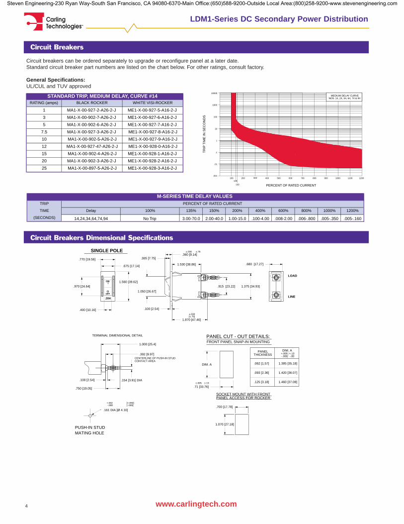
Circuit breakers can be ordered separately to upgrade or reconfigure panel at a later date. Standard circuit breaker part numbers are listed on the chart below. For other ratings, consult factory.
General Specifications:UL/CUL and TUV approved
RATING (amps) BLACK ROCKER WHITE VISI-ROCKER
1 MA1-X-00-927-2-A26-2-J ME1-X-00-927-5-A16-2-J
3 MA1-X-00-902-7-A26-2-J ME1-X-00-927-6-A16-2-J
5 MA1-X-00-902-6-A26-2-J ME1-X-00-927-7-A16-2-J
7.5 MA1-X-00-927-3-A26-2-J ME1-X-00-927-8-A16-2-J
10 MA1-X-00-902-5-A26-2-J ME1-X-00-927-9-A16-2-J
12 MA1-X-00-927-47-A26-2-J ME1-X-00-928-0-A16-2-J
15 MA1-X-00-902-4-A26-2-J ME1-X-00-928-1-A16-2-J
20 MA1-X-00-902-3-A26-2-J ME1-X-00-928-2-A16-2-J
25 MA1-X-00-897-5-A26-2-J ME1-X-00-928-3-A16-2-J
STANDARD TRIP, MEDIUM DELAY, CURVE #14
TRIP
TIME Delay 100% 135% 150% 200% 400% 600% 800% 1000% 1200%
(SECONDS) 14,24,34,64,74,94 No Trip 3.00-70.0 2.00-40.0 1.00-15.0 .100-4.00 .008-2.00 .006-.800 .005-.350 .005-.160
M-SERIES TIME DELAY VALUESPERCENT OF RATED CURRENT
.680 [17.27]
.360 [9.14]
1.530 [38.86]
±.030 ±.76
1.870 [47.46]
±.030 [±.76]
.770 [19.56]
.675 [17.14]
ON
SINGLE POLE
.400 [10.16]
20A
OFF
.915 [23.22] 1.375 [34.93]
.305 [7.75]
1.050 [26.67]
.100 [2.54]
LOAD
LINE
.970 [24.64]1.560 [39.62]
.71 [33.76]
DIM. A
±.005 ±.13
DIM. A+.005 +.13-.000 -.00
1.420 [36.07]
1.460 [37.08]
1.385 [35.18]
FRONT PANEL SNAP-IN MOUNTING
PANELTHICKNESS
SOCKET MOUNT WITH FRONT PANEL ACCESS FOR ROCKER
.062 [1.57]
.125 [3.18]
.093 [2.36]
PANEL CUT - OUT DETAILS:
1.070 [27.18]
.700 [17.78]+.002 [+.050] -.000 [-.000]
.161 DIA [Ø 4.10]
PUSH-IN STUD MATING HOLE
.100 [2.54]
CENTERLINE OF PUSH-IN STUD CONTACT AREA
TERMINAL DIMENSIONAL DETAIL
1.000 [25.4]
.392 [9.97]
.750 [19.05]
.154 [3.91] DIA
700 800 900 1000 1100 1200
10000
1000
100
10
1
.1
.01
.001
MEDIUM DELAY CURVE NOS. 14, 24, 34, 64, 74 & 94
PERCENT OF RATED CURRENT
TR
IP T
IME
IN S
EC
ON
DS
135
150
100 200 300 400 500 600
Circuit Breakers Dimensional Specifications
Steven Engineering-230 Ryan Way-South San Francisco, CA 94080-6370-Main Office:(650)588-9200-Outside Local Area:(800)258-9200-www.stevenengineering.com
Carling Technologies™
5www.carlingtech.com
LDC1-Series DC Secondary Power Distribution
General Specifications
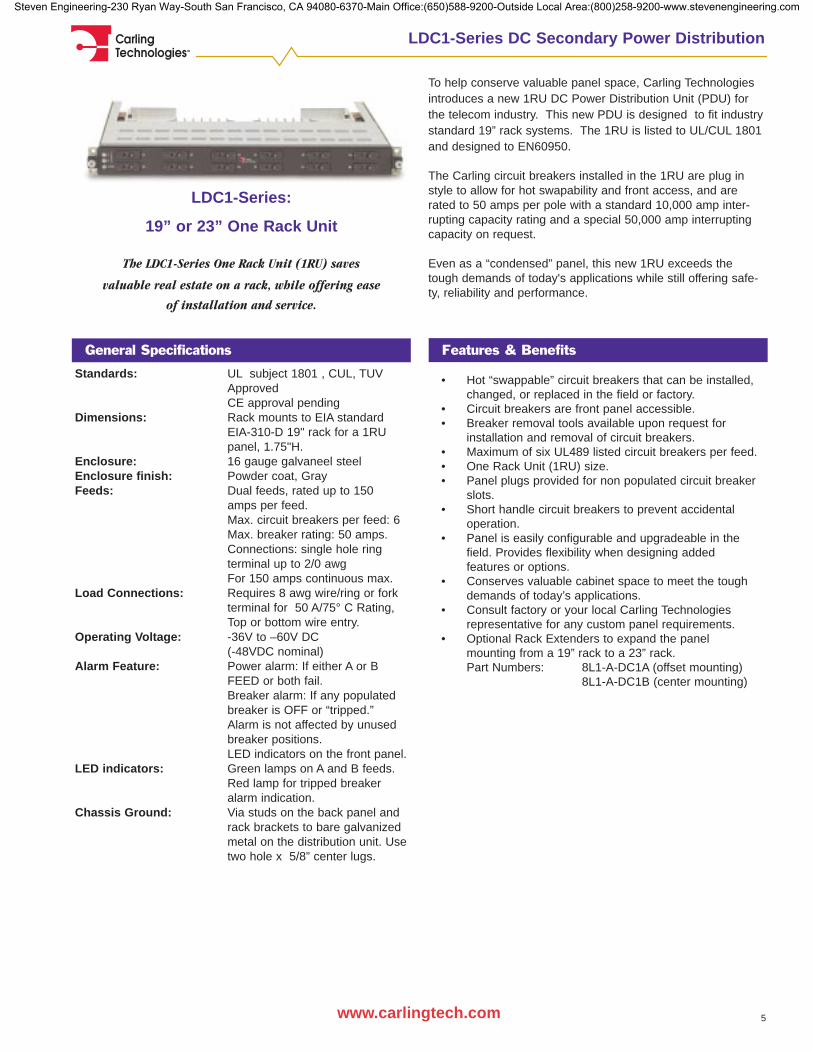
To help conserve valuable panel space, Carling Technologiesintroduces a new 1RU DC Power Distribution Unit (PDU) forthe telecom industry. This new PDU is designed to fit industrystandard 19” rack systems. The 1RU is listed to UL/CUL 1801and designed to EN60950.
The Carling circuit breakers installed in the 1RU are plug instyle to allow for hot swapability and front access, and arerated to 50 amps per pole with a standard 10,000 amp inter-rupting capacity rating and a special 50,000 amp interruptingcapacity on request.
Even as a “condensed” panel, this new 1RU exceeds thetough demands of today's applications while still offering safe-ty, reliability and performance.
LDC1-Series:
19” or 23” One Rack Unit
The LDC1-Series One Rack Unit (1RU) saves
valuable real estate on a rack, while offering ease
of installation and service.
Features & Benefits
Standards: UL subject 1801 , CUL, TUV ApprovedCE approval pending
Dimensions: Rack mounts to EIA standard EIA-310-D 19" rack for a 1RU panel, 1.75"H.
Enclosure: 16 gauge galvaneel steelEnclosure finish: Powder coat, GrayFeeds: Dual feeds, rated up to 150
amps per feed.Max. circuit breakers per feed: 6Max. breaker rating: 50 amps.Connections: single hole ring terminal up to 2/0 awgFor 150 amps continuous max.
Load Connections: Requires 8 awg wire/ring or fork terminal for 50 A/75° C Rating, Top or bottom wire entry.
Operating Voltage: -36V to –60V DC (-48VDC nominal)
Alarm Feature: Power alarm: If either A or BFEED or both fail.Breaker alarm: If any populated breaker is OFF or “tripped.”Alarm is not affected by unused breaker positions. LED indicators on the front panel.
LED indicators: Green lamps on A and B feeds.Red lamp for tripped breaker alarm indication.
Chassis Ground: Via studs on the back panel and rack brackets to bare galvanized metal on the distribution unit. Usetwo hole x 5/8” center lugs.
• Hot “swappable” circuit breakers that can be installed, changed, or replaced in the field or factory.
• Circuit breakers are front panel accessible. • Breaker removal tools available upon request for
installation and removal of circuit breakers.• Maximum of six UL489 listed circuit breakers per feed.• One Rack Unit (1RU) size.• Panel plugs provided for non populated circuit breaker
slots.• Short handle circuit breakers to prevent accidental
operation.• Panel is easily configurable and upgradeable in the
field. Provides flexibility when designing added features or options.
• Conserves valuable cabinet space to meet the tough demands of today’s applications.
• Consult factory or your local Carling Technologies representative for any custom panel requirements.
• Optional Rack Extenders to expand the panel mounting from a 19” rack to a 23” rack. Part Numbers: 8L1-A-DC1A (offset mounting)
8L1-A-DC1B (center mounting)
Steven Engineering-230 Ryan Way-South San Francisco, CA 94080-6370-Main Office:(650)588-9200-Outside Local Area:(800)258-9200-www.stevenengineering.com

Carling Technologies™
6 www.carlingtech.com
LDC1-Series DC Secondary Power Distribution
ON 5/8" (.625") CENTERS. BARE GALVANIZED METAL UNDER,CHASSIS GROUND LOCATION: 2X 1/4-20 STUDS
TO ACCEPT TWO-HOLE WIRE LUG.
GREEN LED INDICTIONS FOR "POWER" ON A & B FEEDSRED LED ALARM INDICATION FOR EITHER "TRIPPED" OR "OFF"CONDITION ON ANY BREAKER; BREAKER POSITIONSNOT POPULATED DO NOT CAUSE ALARM CONDITION
1.750 {44.45}
19.000 {482.6}
PANEL SUPPLIED CONFIGURED POPULATED WITH SPECIFIC BREAKER RATINGS / POSITIONS. UNPOPULATED POSITIONS SUPPLIED WITH PANEL PLUGS. BREAKER RATINGS IDENTICAL FOR A / B SIDES.
.251[6.38]
1.248 [31.7]
FOR LOADSRETURNS ACCEPT SINGLE HOLE TERMINAL LUGS,
UP TO 2/0 AWG CABLE. BUS RATED 150 AMP CONTINUOUS, MIN.MAINS FEED BUS ACCEPTS SINGLE HOLE RING TERMINAL
UP TO 2/0 AWG FOR MAIN, UP TO 6 AWG
17.71[449.8}
12.00 [304.8}
LDC1-Series Dimensional Specifications
4 through 9 BREAKER RATING00 No breaker01 1 amp03 3 amps05 5 amps10 10 amps15 15 amps
20 20 amps25 25 amps30 30 amps35 35 amps40 40 amps45 45 amps50 50 amps
3 DELAYN No breakerM Medium Delay, Curve 14
L Medium Delay, Curve 16
2 BREAKER FUNCTIONN No breakerA Standard Trip
S Mid-Trip
1 SERIESLDC1
1Series
L10Approvals
2BreakerFunction
3Delay
ALDC1 A4Breaker inPosition 1
05
10 APPROVALSA No approvals G UL/CUL J UL/CUL, CE, TUV
NOTES:Redundant feed. Breaker layout will be duplicated on the second feed.Feeds A and B are rated for 150 amps. Total combined breaker ratings can not exceed 150 amps per feed.
- -5Breaker inPosition 2
206Breaker inPosition 3
407Breaker inPosition 4
01 -8Breaker inPosition 5
039Breaker inPosition 6
20
LDC1-Series Ordering Scheme
-----
Steven Engineering-230 Ryan Way-South San Francisco, CA 94080-6370-Main Office:(650)588-9200-Outside Local Area:(800)258-9200-www.stevenengineering.com
Carling Technologies™
7www.carlingtech.com
LDC2-Series DC Secondary Power Distribution
General Specifications
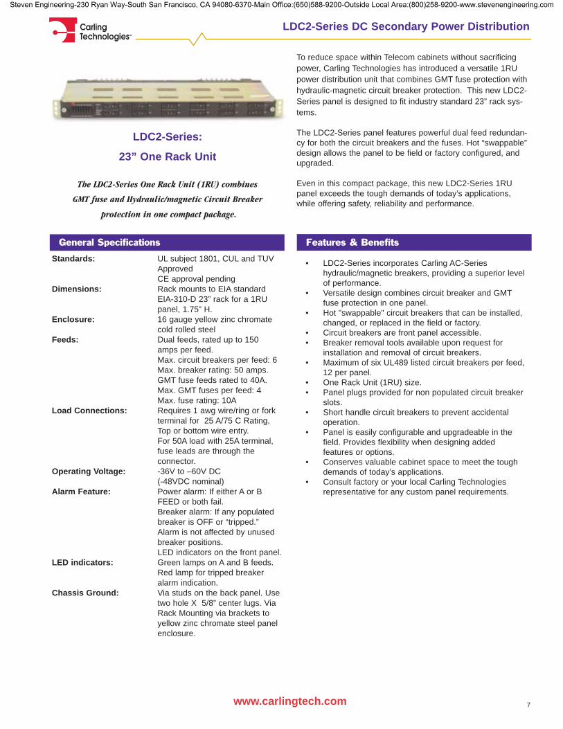
To reduce space within Telecom cabinets without sacrificingpower, Carling Technologies has introduced a versatile 1RUpower distribution unit that combines GMT fuse protection withhydraulic-magnetic circuit breaker protection. This new LDC2-Series panel is designed to fit industry standard 23” rack sys-tems.
The LDC2-Series panel features powerful dual feed redundan-cy for both the circuit breakers and the fuses. Hot “swappable”design allows the panel to be field or factory configured, andupgraded.
Even in this compact package, this new LDC2-Series 1RUpanel exceeds the tough demands of today’s applications,while offering safety, reliability and performance.
LDC2-Series:
23” One Rack Unit
The LDC2-Series One Rack Unit (1RU) combines
GMT fuse and Hydraulic/magnetic Circuit Breaker
protection in one compact package.
Features & Benefits
Standards: UL subject 1801, CUL and TUV ApprovedCE approval pending
Dimensions: Rack mounts to EIA standard EIA-310-D 23” rack for a 1RU panel, 1.75” H.
Enclosure: 16 gauge yellow zinc chromate cold rolled steel
Feeds: Dual feeds, rated up to 150 amps per feed.Max. circuit breakers per feed: 6Max. breaker rating: 50 amps.GMT fuse feeds rated to 40A. Max. GMT fuses per feed: 4Max. fuse rating: 10A
Load Connections: Requires 1 awg wire/ring or fork terminal for 25 A/75 C Rating, Top or bottom wire entry. For 50A load with 25A terminal, fuse leads are through the connector.
Operating Voltage: -36V to –60V DC (-48VDC nominal)
Alarm Feature: Power alarm: If either A or BFEED or both fail.Breaker alarm: If any populated breaker is OFF or “tripped.”Alarm is not affected by unused breaker positions. LED indicators on the front panel.
LED indicators: Green lamps on A and B feeds.Red lamp for tripped breaker alarm indication.
Chassis Ground: Via studs on the back panel. Use two hole X 5/8” center lugs. Via Rack Mounting via brackets to yellow zinc chromate steel panel enclosure.
• LDC2-Series incorporates Carling AC-Series hydraulic/magnetic breakers, providing a superior level of performance.
• Versatile design combines circuit breaker and GMTfuse protection in one panel.
• Hot "swappable" circuit breakers that can be installed, changed, or replaced in the field or factory.
• Circuit breakers are front panel accessible. • Breaker removal tools available upon request for
installation and removal of circuit breakers.• Maximum of six UL489 listed circuit breakers per feed,
12 per panel.• One Rack Unit (1RU) size.• Panel plugs provided for non populated circuit breaker
slots.• Short handle circuit breakers to prevent accidental
operation.• Panel is easily configurable and upgradeable in the
field. Provides flexibility when designing added features or options.
• Conserves valuable cabinet space to meet the tough demands of today’s applications.
• Consult factory or your local Carling Technologies representative for any custom panel requirements.
Steven Engineering-230 Ryan Way-South San Francisco, CA 94080-6370-Main Office:(650)588-9200-Outside Local Area:(800)258-9200-www.stevenengineering.com
Carling Technologies™
8
LDC2-Series DC Secondary Power Distribution
www.carlingtech.com
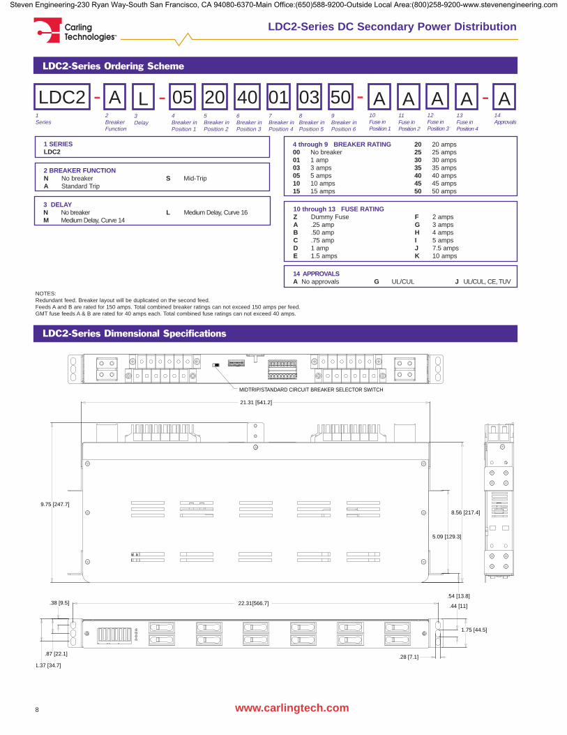
.38 [9.5]
1.37 [34.7]
.87 [22.1]
.44 [11]
.28 [7.1]
1.75 [44.5]
5.09 [129.3]
8.56 [217.4]
9.75 [247.7]
MIDTRIP/STANDARD CIRCUIT BREAKER SELECTOR SWITCH
21.31 [541.2]
22.31[566.7].54 [13.8]
LDC2-Series Dimensional Specifications
4 through 9 BREAKER RATING00 No breaker01 1 amp03 3 amps05 5 amps10 10 amps15 15 amps
20 20 amps25 25 amps30 30 amps35 35 amps40 40 amps45 45 amps50 50 amps
3 DELAYN No breakerM Medium Delay, Curve 14
L Medium Delay, Curve 16
2 BREAKER FUNCTIONN No breakerA Standard Trip
S Mid-Trip
1 SERIESLDC2
1Series
L10Fuse inPosition 1
2BreakerFunction
3Delay
ALDC2 A4Breaker inPosition 1
05
14 APPROVALSA No approvals G UL/CUL J UL/CUL, CE, TUV
NOTES:Redundant feed. Breaker layout will be duplicated on the second feed.Feeds A and B are rated for 150 amps. Total combined breaker ratings can not exceed 150 amps per feed.GMT fuse feeds A & B are rated for 40 amps each. Total combined fuse ratings can not exceed 40 amps.
- -5Breaker inPosition 2
206Breaker inPosition 3
407Breaker inPosition 4
01 -8Breaker inPosition 5
039Breaker inPosition 6
50
LDC2-Series Ordering Scheme
-11Fuse inPosition 2
A12Fuse inPosition 3
A13Fuse inPosition 4
A14Approvals
A
10 through 13 FUSE RATINGZ Dummy FuseA .25 ampB .50 ampC .75 ampD 1 ampE 1.5 amps
F 2 ampsG 3 ampsH 4 ampsI 5 ampsJ 7.5 ampsK 10 amps
Steven Engineering-230 Ryan Way-South San Francisco, CA 94080-6370-Main Office:(650)588-9200-Outside Local Area:(800)258-9200-www.stevenengineering.com

Carling Technologies™
9www.carlingtech.com
LDC1 & LDC2-Series Power Distribution Breakers
Circuit Breakers
Circuit breakers can be ordered separately to upgrade or reconfigure panel at a later date. Standard circuit breaker part numbers are listed on the chart below. For other ratings, consult factory.
General Specifications:UL489, CSA and VDE approved10,000 amp interrupting capacity
TRIP Delay 100% 125% 150% 200% 400% 600% 800% 1000% 1200%
TIME 14 No trip 2.00-60.0 1.20-40.0 .600-20.0 .150-3.00 .030-1.30 .004-.600 .004-.100 .004-.100
(SECONDS) 16 No Trip 45.0-345 20.0-150 9.00-60.0 1.40-11.4 .150-5.80 .009-3.70 .005-1.70 .005-.500
C-SERIES TIME DELAY VALUESPERCENT OF RATED CURRENT
RATING (amps) STANDARD TRIP MID-TRIP with LDC1-Series MID-TRIP with LDC2-Series
1 CA1-X0-08-561-AX1-MF CS1-X0-09-033-AX1-MF CT1-X0-09-033-AX1-MF
3 CA1-X0-07-803-AX1-MF CS1-X0-09-003-AX1-MF CT1-X0-09-003-AX1-MF
5 CA1-X0-07-804-AX1-MF CS1-X0-09-004-AX1-MF CT1-X0-09-004-AX1-MF
10 CA1-X0-07-805-AX1-MF CS1-X0-09-005-AX1-MF CT1-X0-09-005-AX1-MF
15 CA1-X0-07-806-AX1-MF CS1-X0-09-006-AX1-MF CT1-X0-09-006-AX1-MF
20 CA1-X0-07-807-AX1-MF CS1-X0-09-007-AX1-MF CT1-X0-09-007-AX1-MF
25 CA1-X0-07-645-AX1-MF CS1-X0-09-008-AX1-MF CT1-X0-09-008-AX1-MF
30 CA1-X0-07-646-AX1-MF CS1-X0-09-009-AX1-MF CT1-X0-09-009-AX1-MF
35 CA1-X0-07-808-AX1-MF CS1-X0-09-010-AX1-MF CT1-X0-09-010-AX1-MF
40 CA1-X0-07-809-AX1-MF CS1-X0-09-011-AX1-MF CT1-X0-09-011-AX1-MF
45 CA1-X0-07-810-AX1-MF CS1-X0-09-012-AX1-MF CT1-X0-09-012-AX1-MF
50 CA1-X0-07-811-AX1-MF CS1-X0-09-013-AX1-MF CT1-X0-09-013-AX1-MF
LONG DELAY, CURVE #16
RATING (amps) STANDARD TRIP MID-TRIP with LDC1-Series MID-TRIP with LDC2-Series
1 CA1-X0-09-031-AX1-MF CS1-X0-09-032-AX1-MF CT1-X0-09-032-AX1-MF
3 CA1-X0-08-981-AX1-MF CS1-X0-08-992-AX1-MF CT1-X0-08-992-AX1-MF
5 CA1-X0-08-982-AX1-MF CS1-X0-08-993-AX1-MF CT1-X0-08-993-AX1-MF
10 CA1-X0-08-983-AX1-MF CS1-X0-08-994-AX1-MF CT1-X0-08-994-AX1-MF
15 CA1-X0-08-984-AX1-MF CS1-X0-08-995-AX1-MF CT1-X0-08-995-AX1-MF
20 CA1-X0-08-985-AX1-MF CS1-X0-08-996-AX1-MF CT1-X0-08-996-AX1-MF
25 CA1-X0-08-986-AX1-MF CS1-X0-08-997-AX1-MF CT1-X0-08-997-AX1-MF
30 CA1-X0-08-987-AX1-MF CS1-X0-08-998-AX1-MF CT1-X0-08-998-AX1-MF
35 CA1-X0-08-988-AX1-MF CS1-X0-08-999-AX1-MF CT1-X0-08-999-AX1-MF
40 CA1-X0-08-989-AX1-MF CS1-X0-08-000-AX1-MF CT1-X0-08-000-AX1-MF
45 CA1-X0-08-990-AX1-MF CS1-X0-08-001-AX1-MF CT1-X0-08-001-AX1-MF
50 CA1-X0-08-991-AX1-MF CS1-X0-08-002-AX1-MF CT1-X0-08-002-AX1-MF
MEDIUM DELAY, CURVE #14
Circuit Breakers Dimensional Specifications
TYP-OPTIONAL"ON-0FF", I-OLEGEND
CENTERLINE OFPUSH-IN STUDCONTACT AREA
±.020 ±.51 PUSH-IN STUD DETAIL
OFFO
±.060 ±1.52
ONI
LOADTYP.
±.020 ±.51
#6-32 [M3] THREAD X .195 [4.95] DEEP (2 PLCS) / POLE
C
NO
NC
.135 [3.42]
LINE
.500 [12.67]
OFFO
.960[24.38]
.406 [10.31]
.558[14.17]
2.810 [71.38] TYP
1.850 [47.00] TYP
.273 [7.14] TYP
1.438 [36.53]
.755 [19.18] MAX.
60°2.500 [63.50] TYP
.150 [3.81]
30°1.940 [49.28] TYP
2.250 [57.15] TYP
.930 [23.62].640 [16.26]
1.220 [30.98]
SHORT HANDLE CIRCUIT BREAKER REQUIRES NO HANDLE GUARD,HAS MINIMAL HANDLE PROTRUSION IN "ON" AND "OFF" POSITION
600 700 800 900 1000 1100 1200
10000
1000
100
10
1
.1
.01
.001100 200 300 400 500
125
150
TR
IP T
IME
IN S
EC
ON
DS
PERCENT OF RATED CURRENT
D.C. MEDIUM DELAYCURVE NO. 14
900 1000 1100 1200100 200 300
10000
1000
100
10
1
.1
.01
.001
150
125400 500 600 700 800
D.C. LONG DELAYCURVE NO. 16
TR
IP T
IME
IN S
EC
ON
DS
PERCENT OF RATED CURRENT
Steven Engineering-230 Ryan Way-South San Francisco, CA 94080-6370-Main Office:(650)588-9200-Outside Local Area:(800)258-9200-www.stevenengineering.com
Carling Technologies™
10 www.carlingtech.com
LAC1-Series Telecom AC Power Distribution Panel
General Specifications
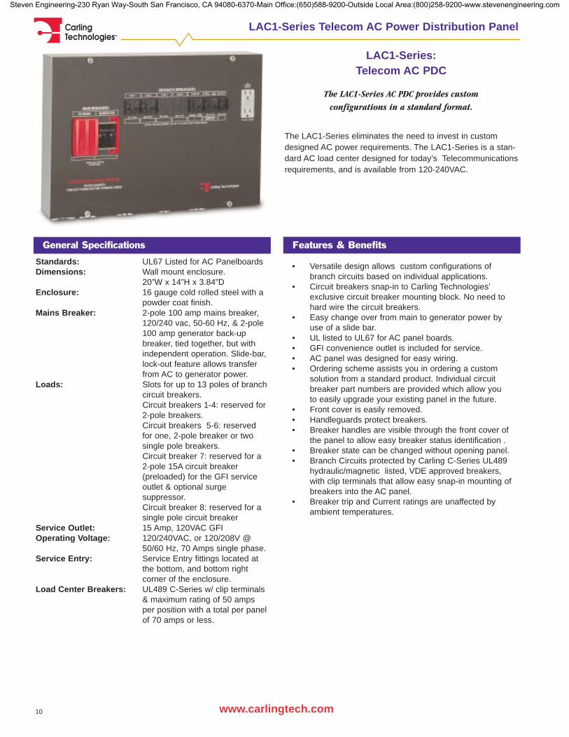
The LAC1-Series eliminates the need to invest in customdesigned AC power requirements. The LAC1-Series is a stan-dard AC load center designed for today’s Telecommunicationsrequirements, and is available from 120-240VAC.
LAC1-Series: Telecom AC PDC
The LAC1-Series AC PDC provides custom configurations in a standard format.
Features & Benefits
Standards: UL67 Listed for AC PanelboardsDimensions: Wall mount enclosure.
20”W x 14”H x 3.84”DEnclosure: 16 gauge cold rolled steel with a
powder coat finish.Mains Breaker: 2-pole 100 amp mains breaker,
120/240 vac, 50-60 Hz, & 2-pole 100 amp generator back-up breaker, tied together, but with independent operation. Slide-bar, lock-out feature allows transfer from AC to generator power.
Loads: Slots for up to 13 poles of branch circuit breakers.Circuit breakers 1-4: reserved for 2-pole breakers.Circuit breakers 5-6: reserved for one, 2-pole breaker or two single pole breakers.Circuit breaker 7: reserved for a 2-pole 15A circuit breaker(preloaded) for the GFI service outlet & optional surge suppressor.Circuit breaker 8: reserved for a single pole circuit breaker
Service Outlet: 15 Amp, 120VAC GFIOperating Voltage: 120/240VAC, or 120/208V @
50/60 Hz, 70 Amps single phase.Service Entry: Service Entry fittings located at
the bottom, and bottom right corner of the enclosure.
Load Center Breakers: UL489 C-Series w/ clip terminals & maximum rating of 50 amps per position with a total per panel of 70 amps or less.
• Versatile design allows custom configurations of branch circuits based on individual applications.
• Circuit breakers snap-in to Carling Technologies’exclusive circuit breaker mounting block. No need to hard wire the circuit breakers.
• Easy change over from main to generator power by use of a slide bar.
• UL listed to UL67 for AC panel boards.• GFI convenience outlet is included for service.• AC panel was designed for easy wiring. • Ordering scheme assists you in ordering a custom
solution from a standard product. Individual circuit breaker part numbers are provided which allow you to easily upgrade your existing panel in the future.
• Front cover is easily removed.• Handleguards protect breakers.• Breaker handles are visible through the front cover of
the panel to allow easy breaker status identification . • Breaker state can be changed without opening panel.• Branch Circuits protected by Carling C-Series UL489
hydraulic/magnetic listed, VDE approved breakers, with clip terminals that allow easy snap-in mounting of breakers into the AC panel.
• Breaker trip and Current ratings are unaffected by ambient temperatures.
Steven Engineering-230 Ryan Way-South San Francisco, CA 94080-6370-Main Office:(650)588-9200-Outside Local Area:(800)258-9200-www.stevenengineering.com
Carling Technologies™
11www.carlingtech.com
LAC1-Series AC Power Distribution
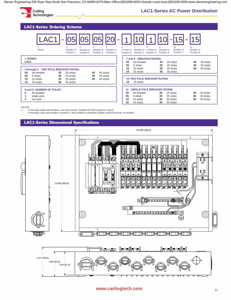
LAC1-Series Dimensional Specifications
7 and 9 BREAKER RATING
6 and 8 NUMBER OF POLES1
0 No breaker1 single pole2 two pole
1 SERIESLAC1
1Series
10Breaker inPosition 7
2Breaker inPosition 1
3Breaker inPosition 2
LAC1 14Breaker inPosition 3
05
NOTES:1 If choosing single pole breakers, you must choose breakers for both positions 5 and 6.
If choosing a two pole breaker in position 5, then position 6 (selected in fields 8 and 9) must be “no breaker”.
- -5Breaker inPosition 4
056# Poles inPosition 5
057Breaker inPosition 5
20 -8# Poles inPosition 6
109Breaker inPosition 6
10
LAC1-Series Ordering Scheme
11Breaker inPosition 8
1
10 TWO POLE BREAKER RATING15 15 amps
15-15
2 through 5 TWO POLE BREAKER RATING00 No breaker05 5 amps10 10 amps15 15 amps
20 20 amps25 25 amps30 30 amps35 35 amps
40 40 amps45 45 amps50 50 amps
00 No breaker05 5 amps10 10 amps15 15 amps
20 20 amps25 25 amps30 30 amps35 35 amps
40 40 amps45 45 amps50 50 amps
11 SINGLE POLE BREAKER RATING00 No breaker05 5 amps10 10 amps15 15 amps
20 20 amps25 25 amps30 30 amps35 35 amps
40 40 amps45 45 amps50 50 amps
Steven Engineering-230 Ryan Way-South San Francisco, CA 94080-6370-Main Office:(650)588-9200-Outside Local Area:(800)258-9200-www.stevenengineering.com
Carling Technologies™
12 www.carlingtech.com
LAC1-Series AC Power Distribution
Circuit Breakers
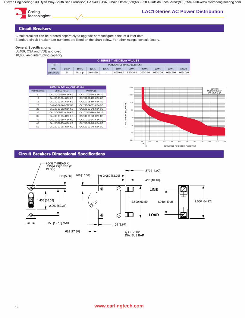
Circuit breakers can be ordered separately to upgrade or reconfigure panel at a later date. Standard circuit breaker part numbers are listed on the chart below. For other ratings, consult factory.
General Specifications:UL489, CSA and VDE approved10,000 amp interrupting capacity
TRIP
TIME Delay 100% 125% 135% 150% 200% 400% 600% 800% 1200%
(SECONDS) 24 No trip 10.0-160 - .600-60.0 2.20-20.0 .300-3.00 .050-1.30 .007-.500 .005-.040
C-SERIES TIME DELAY VALUESPERCENT OF RATED CURRENT
RATING (amps) SINGLE POLE TWO POLE
5 CA1-X0-09-250-C2X-KG CA2-X0-09-244-C2X-CG
10 CA1-X0-06-604-C2X-KG CA2-X0-07-169-C2X-CG
15 CA1-X0-09-251-C2X-KG CA2-X0-08-169-C2X-CG
20 CA1-X0-06-606-C2X-DJ CA2-X0-04-891-C2X-CG
25 CA1-X0-09-252-C2X-KG CA2-X0-09-245-C2X-CG
30 CA1-X0-09-253-C2X-KG CA2-X0-06-299-C2X-CG
35 CA1-X0-09-254-C2X-KG CA2-X0-09-246-C2X-CG
40 CA1-X0-09-255-C2X-KG CA2-X0-09-247-C2X-CG
45 CA1-X0-09-256-C2X-KG CA2-X0-09-248-C2X-CG
50 CA1-X0-09-261-C2X-KG CA2-X0-09-249-C2X-CG
MEDIUM DELAY, CURVE #24
Circuit Breakers Dimensional Specifications
700 800 900 1000 1100 1200
10000
1000
100
10
1
.1
.01
.001
50/60 HzMEDIUM DELAYCURVE NO. 24
150
125
100 200 300 400 500 600
PERCENT OF RATED CURRENT
TR
IP T
IME
IN S
EC
ON
DS
Steven Engineering-230 Ryan Way-South San Francisco, CA 94080-6370-Main Office:(650)588-9200-Outside Local Area:(800)258-9200-www.stevenengineering.com
Carling Technologies™
13www.carlingtech.com
LBD-Series Battery Disconnect Panel
General Specifications
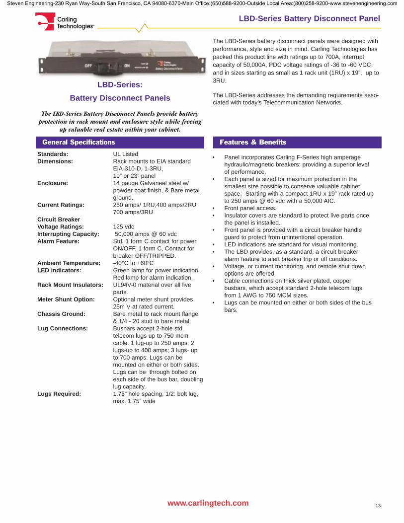
The LBD-Series battery disconnect panels were designed withperformance, style and size in mind. Carling Technologies haspacked this product line with ratings up to 700A, interruptcapacity of 50,000A, PDC voltage ratings of -36 to -60 VDCand in sizes starting as small as 1 rack unit (1RU) x 19”, up to3RU.
The LBD-Series addresses the demanding requirements asso-ciated with today’s Telecommunication Networks.
LBD-Series:
Battery Disconnect Panels
The LBD-Series Battery Disconnect Panels provide batteryprotection in rack mount and enclosure style while freeing
up valuable real estate within your cabinet.
Features & Benefits
Standards: UL Listed Dimensions: Rack mounts to EIA standard
EIA-310-D, 1-3RU, 19” or 23” panel
Enclosure: 14 gauge Galvaneel steel w/powder coat finish, & Bare metal ground.
Current Ratings: 250 amps/ 1RU;400 amps/2RU700 amps/3RU
Circuit BreakerVoltage Ratings: 125 vdcInterrupting Capacity: 50,000 amps @ 60 vdcAlarm Feature: Std. 1 form C contact for power
ON/OFF, 1 form C, Contact for breaker OFF/TRIPPED.
Ambient Temperature: -40°C to +60°CLED indicators: Green lamp for power indication.
Red lamp for alarm indication.Rack Mount Insulators: UL94V-0 material over all live
parts.Meter Shunt Option: Optional meter shunt provides
25m V at rated current.Chassis Ground: Bare metal to rack mount flange
& 1/4 - 20 stud to bare metal.Lug Connections: Busbars accept 2-hole std.
telecom lugs up to 750 mcm cable. 1 lug-up to 250 amps; 2 lugs-up to 400 amps; 3 lugs- up to 700 amps. Lugs can be mounted on either or both sides. Lugs can be through bolted on each side of the bus bar, doublinglug capacity.
Lugs Required: 1.75” hole spacing, 1/2: bolt lug, max. 1.75” wide
• Panel incorporates Carling F-Series high amperage hydraulic/magnetic breakers: providing a superior level of performance.
• Each panel is sized for maximum protection in the smallest size possible to conserve valuable cabinet space. Starting with a compact 1RU x 19” rack rated up to 250 amps @ 60 vdc with a 50,000 AIC.
• Front panel access.• Insulator covers are standard to protect live parts once
the panel is installed.• Front panel is provided with a circuit breaker handle
guard to protect from unintentional operation.• LED indications are standard for visual monitoring.• The LBD provides, as a standard, a circuit breaker
alarm feature to alert breaker trip or off conditions.• Voltage, or current monitoring, and remote shut down
options are offered.• Cable connections on thick silver plated, copper
busbars, which accept standard 2-hole telecom lugs from 1 AWG to 750 MCM sizes.
• Lugs can be mounted on either or both sides of the busbars.
Steven Engineering-230 Ryan Way-South San Francisco, CA 94080-6370-Main Office:(650)588-9200-Outside Local Area:(800)258-9200-www.stevenengineering.com

Carling Technologies™
14 www.carlingtech.com
LBD-Series Battery Disconnect Panels
LBD-Series Rack Mount Dimensional Specifications
LBD-Series Ordering Scheme
NOTES:Circuit breakers are provided with a DC medium delay curve.1 Current & voltage monitoring are available as special options. Select X in position 9, and advise factory.
4 FUNCTION0 Switch Only1 Series Trip
2 Series Trip with Aux. Switch3 Mid-trip with Alarm Switch
3 RACK SIZE1 19” rack 2 23” rack E Enclosure
2 STYLEP Rack Mount E Enclosure/Wall Mount
1 SERIESLBD
1Series
12Style
3Rack Size
PLBD A4Function
7 METERING SHUNT0 No shunt A Metering shunt
--5Current Rating
6Bus BarType
7MeteringShunt
-8RemoteDisconnectVoltage
9SpecialOptions
-A 0 010Approvals
A
5 CURRENT RATING810 100 amp (1RU)820 200 amp (1RU)
825 250 amp (1RU)840 400 amp (1RU)
860 600 amp (1RU)870 700 amp (1RU)
1 810 - - -
6 BUS BAR TYPEA figure 1 B figure 1 w/ PEM studs
8 REMOTE DISCONNECT VOLTAGE0 No remote optionA 24 vdc
B 48 vdcC 120 vdcD 240 vdc
9 SPECIAL OPTIONS0 None X Consult factory
10 APPROVALSA No approvals B UL Listed
Steven Engineering-230 Ryan Way-South San Francisco, CA 94080-6370-Main Office:(650)588-9200-Outside Local Area:(800)258-9200-www.stevenengineering.com
Carling Technologies™
15www.carlingtech.com
LBD-Series Battery Disconnect Panels
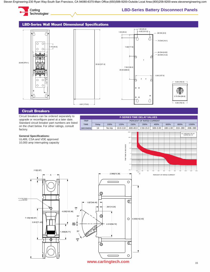
LBD-Series Wall Mount Dimensional Specifications
Circuit BreakersCircuit breakers can be ordered separately toupgrade or reconfigure panel at a later date. Standard circuit breaker part numbers are listedon the chart below. For other ratings, consultfactory.
General Specifications:UL489, CSA and VDE approved10,000 amp interrupting capacity
TRIP
TIME Delay 100% 125% 150% 200% 400% 600% 800% 1200%
(SECONDS) 14 No trip 10.0-110 .600-40.0 2.50-15.0 .500-3.00 .180-1.00 .010-.280 .008-.080
F-SERIES TIME DELAY VALUESPERCENT OF RATED CURRENT
.001
.01
.1
1
10
100
1000
10000
PERCENT OF RATED CURRENT
120011001000900800700600500400300200100
150
125
TR
IP T
IME
IN S
EC
ON
DS
D.C. MEDIUM DELAYCURVE NO. 14
Steven Engineering-230 Ryan Way-South San Francisco, CA 94080-6370-Main Office:(650)588-9200-Outside Local Area:(800)258-9200-www.stevenengineering.com

Carling Technologies™
16 www.carlingtech.com
Power Distribution Accessories
Circuit BreakerRemoval Tool
Panel Hole Plug
C-Series with Push-In Stud Terminals Mounting Kit & Removal Tool
1 Part Number
8C1-X0-08-639
1 PART NUMBER8C1-X0-08-639 Removal Tool for 6-32 inserts8C1-X0-09-593 Removal Tool for M3 inserts8C1-X0-07-628 Mounting kit for one circuit breaker position (includes mounting block, bullet sockets, aux. switch,
PC board connectors, aux. switch connector housing and two screws. Bus bar and PCB are not included in the mounting kit.)
C-Series Circuit Breaker AC Plug-In Bracket
1 Part Number
809-70194-001
1 PART NUMBER809-70194-001 LAC1 Snap-In Panel Plugs809-70194-002 LDC1 & LDC2 Snap-In Panel Plugs
1 Part Number
PR8080-6671 PART NUMBERPR8080-667 C-Series Circuit Breaker AC Plug-In Bracket
C-Series Circuit Breaker Module for DC Power Distribution
1 Part Number
L00531 PART NUMBERL0053 Circuit Breaker Module
• Six position circuit breaker module, individual circuit breaker slot rated to 100amps• Hot swappable plug-in circuit breakers• UL489 listed hydraulic/magnetic circuit breakers available for the module• Breaker alarm circuit• 300 amp line bus• Custom mounting block allows for Load bus to easily change• Building block design allows for easy changes
8C1-X0-08-573 Circuit Breaker Module Kit for individual loads (includes mounting block, auxiliary switch housing,rivet, two screws, two push-in terminal receptacles and three .110QC terminal receptacles.)
Steven Engineering-230 Ryan Way-South San Francisco, CA 94080-6370-Main Office:(650)588-9200-Outside Local Area:(800)258-9200-www.stevenengineering.com

Carling Technologies™
17www.carlingtech.com
Custom Power Distribution Solutions
Carling Technologies offers expertise in electrical and mechan-ical design, tooling, prototyping, testing, and manufacturing. AtCarling we do much more than manufacture standard prod-ucts. Our dedicated PDC team provides innovative design andskillfully engineered power distribution solutions to meettoday's demanding custom requirements. We work closely withyour engineering team to meet your application requirementsand exceed your expectations.
Let the Carling PDC team design and develop a customPower Distribution Center or Battery Disconnect Panel that willmeet your special requirements. Please take a moment tobrowse through our PDC photo galleries and view someexamples of our custom design & solution capabilities. Thencontact us today and let us assist you with your customdesigns.
Custom Power Distribution Solutions
Custom AC Gallery
L0005 • 100 amp rating• 208-420VAC• UL489 listed hydraulic magnetic
circuit breakers• Optional surge suppressor
4-115V convenience outlets, GFI & non-GFI protected 4-250V twist lock
• Designed for UL50
L0066 • 23" rack mount design• 100 amp 3 pole UL489 listed Mains circuit
breaker• 16 slots for plug-in circuit breakers• Rocker style branch circuit breaker
with rocker guard and visual trip indication• Hydraulic magnetic circuit breakers• Power strip top for a variety of outlets
L0069 Remote Power Management• Independent circuit breakers
controlled remotely via your phone
• RPMS calls an assigned phone number when a breaker has tripped, & allows you to service or reset the breaker over
the phone• Dial up feature allows you to
change breaker states asneeded
L0081• UL67 listed for AC panelboards• Wall mount enclosure• 70A 2 pole Mains breaker,
with 2 pole 70A generator back-up breaker tied together but operating independently
• Slide bar lock out allows transfer slots for up to 13 poles of branch circuit breakers
• UL489 listed hydraulic/magnetic breakers with handle guards• 15 amp GFI service outlet• Circuit breakers visible through front cover
L0118• Compact wall mount design• 2 pole circuit breaker for rectifiers• 1 pole circuit breaker for battery heater• 1 pole circuit breaker for GFI outlet• GFI service outlet• Battery heater outlet• UL489 listed hydraulic/magnetic breakers with
handle guards• Designed for UL67
L0125• Compact wall design• 30A 3 pole Mains breaker with 3 pole generator
back-up breaker tied together but operatingindependently - slide bar lock out allows transfer
• Slots for up to 10 poles of branch circuit breakers• UL489 listed hydraulic magnetic circuit breakers
L0054• Battery disconnect for single battery
string• Mounts directly to a battery
housing• Connections made by Anderson
Connectors• UL489 Listed hydraulic/magnetic circuit breaker• Circuit breaker rating 100A @ 80VDC with a 50,000 AIC
L0059• Battery Disconnect for multiple
battery strings• Two UL489 Listed hydraulic/
magnetic circuit breakers, one to disconnect an individual battery string, one to disconnect theentire battery system
• Breakers are rated for 100 amps @ 80VDC with 50,000 AIC• Panel attaches directly to a battery compartment• Connections made with Anderson Connectors
Custom Battery Disconnect Gallery
Steven Engineering-230 Ryan Way-South San Francisco, CA 94080-6370-Main Office:(650)588-9200-Outside Local Area:(800)258-9200-www.stevenengineering.com
Carling Technologies™
18 www.carlingtech.com
Custom Power Distribution Solutions
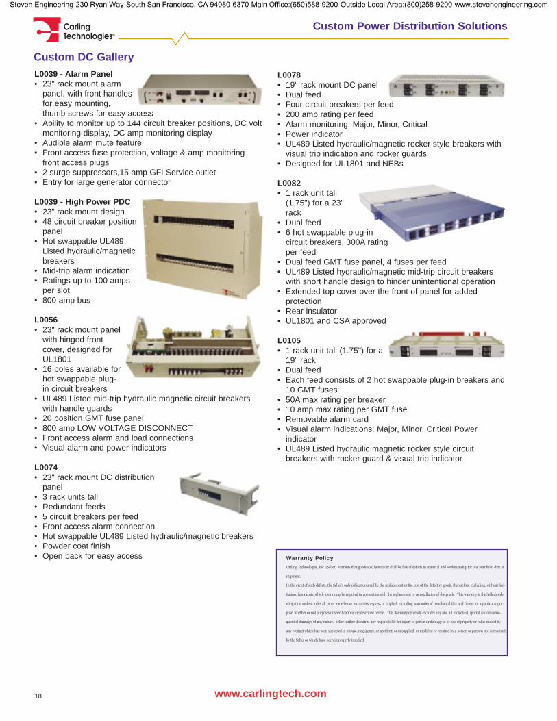
Custom DC GalleryL0039 - Alarm Panel• 23" rack mount alarm
panel, with front handlesfor easy mounting, thumb screws for easy access
• Ability to monitor up to 144 circuit breaker positions, DC voltmonitoring display, DC amp monitoring display
• Audible alarm mute feature• Front access fuse protection, voltage & amp monitoring
front access plugs• 2 surge suppressors,15 amp GFI Service outlet• Entry for large generator connector
L0039 - High Power PDC• 23" rack mount design• 48 circuit breaker position
panel• Hot swappable UL489
Listed hydraulic/magnetic breakers
• Mid-trip alarm indication• Ratings up to 100 amps
per slot• 800 amp bus
L0056 • 23" rack mount panel
with hinged front cover, designed for UL1801
• 16 poles available forhot swappable plug-in circuit breakers
• UL489 Listed mid-trip hydraulic magnetic circuit breakers with handle guards
• 20 position GMT fuse panel • 800 amp LOW VOLTAGE DISCONNECT• Front access alarm and load connections• Visual alarm and power indicators
L0074 • 23" rack mount DC distribution
panel• 3 rack units tall• Redundant feeds• 5 circuit breakers per feed• Front access alarm connection• Hot swappable UL489 Listed hydraulic/magnetic breakers• Powder coat finish• Open back for easy access
L0078• 19" rack mount DC panel• Dual feed• Four circuit breakers per feed• 200 amp rating per feed• Alarm monitoring: Major, Minor, Critical• Power indicator• UL489 Listed hydraulic/magnetic rocker style breakers with
visual trip indication and rocker guards• Designed for UL1801 and NEBs
L0082• 1 rack unit tall
(1.75") for a 23" rack
• Dual feed• 6 hot swappable plug-in
circuit breakers, 300A rating per feed
• Dual feed GMT fuse panel, 4 fuses per feed• UL489 Listed hydraulic/magnetic mid-trip circuit breakers
with short handle design to hinder unintentional operation• Extended top cover over the front of panel for added
protection• Rear insulator• UL1801 and CSA approved
L0105• 1 rack unit tall (1.75") for a
19" rack• Dual feed• Each feed consists of 2 hot swappable plug-in breakers and
10 GMT fuses• 50A max rating per breaker• 10 amp max rating per GMT fuse• Removable alarm card• Visual alarm indications: Major, Minor, Critical Power
indicator• UL489 Listed hydraulic magnetic rocker style circuit
breakers with rocker guard & visual trip indicator
Warranty Policy
Carling Technologies, Inc. (Seller) warrants that goods sold hereunder shall be free of defects in material and workmanship for one year from date of
shipment.
In the event of such defects, the Seller’s only obligation shall be the replacement or the cost of the defective goods, themselves, excluding, without lim-
itation, labor costs, which are or may be required in connection with the replacement or reinstallation of the goods. This warranty is the Seller’s sole
obligation and excludes all other remedies or warranties, express or implied, including warranties of merchantability and fitness for a particular pur-
pose, whether or not purposes or specifications are described herein. This Warranty expressly excludes any and all incidental, special and/or conse-
quential damages of any nature. Seller further disclaims any responsibility for injury to person or damage to or loss of property or value caused by
any product which has been subjected to misuse, negligence, or accident; or misapplied, or modified or repaired by a person or persons not authorized
by the Seller or which have been improperly installed.
Steven Engineering-230 Ryan Way-South San Francisco, CA 94080-6370-Main Office:(650)588-9200-Outside Local Area:(800)258-9200-www.stevenengineering.com

Carling Technologies™
19
Power Distribution Project Design Form
www.carlingtech.com
IGS DXF DWG PDF STEP other:
EAU Year 1: EAU Year 2: EAU Year 3: # of prototypes:
19": 23":
UL UL STD CUL TUV CE Other:
Target Price:
Target Price:
Type of Trip Indication Alarming Required:
New Product Details: Development Budget Limitations:
Specifications Available?: Existing Sample Available?:
Schematic Available?:
Operating Voltage Tolerance:
AC/DC Voltage:
Product Life: Project Value:
Redesign Details:
Rep. Company: Region Manager:
Address: City, State, ZIP:
*** Please fax completed forms to 860-793-9231 or email to: [email protected] ***
CUSTOMER INFORMATION:
PROJECT INFORMATION:
Engineering Contact: Title:
Company Name:
NOTES AND ACTION ITEMS:
Power DistributionProject Design Form
Application:
Date of Non-Disclosure:
APPLICATION INFORMATION:
Acceptable electronic files:
Index Number: Submittal Date:
Sales Representative: Phone/email:
Phone: Fax:
email:
Purchasing Contact: Title:
Phone: Fax:
email:
SPECIFICATIONS:
Pilot Production Schedule:
Competitors Part Number: Current Price:
For DC, Rack Type:
Mains Feed Amps:
Open/Closed Frame:
Enclosure Dimensions:
Number of Breakers: If necessary, add additional information to notes section below, or attach second sheet.
COMPETITIVE INFORMATION:
Competition:
AGENCY APPROVALS:
Carling Technologies™
Innovative Designs. Powerful Solutions.
Steven Engineering-230 Ryan Way-South San Francisco, CA 94080-6370-Main Office:(650)588-9200-Outside Local Area:(800)258-9200-www.stevenengineering.com

Carling Technologies™
20
Notes
www.carlingtech.com
Steven Engineering-230 Ryan Way-South San Francisco, CA 94080-6370-Main Office:(650)588-9200-Outside Local Area:(800)258-9200-www.stevenengineering.com
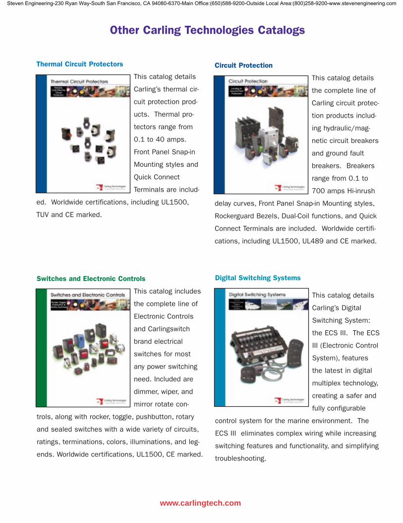
Thermal Circuit Protectors
This catalog details
Carling’s thermal cir-
cuit protection prod-
ucts. Thermal pro-
tectors range from
0.1 to 40 amps.
Front Panel Snap-in
Mounting styles and
Quick Connect
Terminals are includ-
ed. Worldwide certifications, including UL1500,
TUV and CE marked.
www.carlingtech.com
Other Carling Technologies Catalogs
Switches and Electronic Controls
This catalog includes
the complete line of
Electronic Controls
and Carlingswitch
brand electrical
switches for most
any power switching
need. Included are
dimmer, wiper, and
mirror rotate con-
trols, along with rocker, toggle, pushbutton, rotary
and sealed switches with a wide variety of circuits,
ratings, terminations, colors, illuminations, and leg-
ends. Worldwide certifications, UL1500, CE marked.
Digital Switching Systems
This catalog details
Carling’s Digital
Switching System:
the ECS III. The ECS
III (Electronic Control
System), features
the latest in digital
multiplex technology,
creating a safer and
fully configurable
control system for the marine environment. The
ECS III eliminates complex wiring while increasing
switching features and functionality, and simplifying
troubleshooting.
Circuit Protection
This catalog details
the complete line of
Carling circuit protec-
tion products includ-
ing hydraulic/mag-
netic circuit breakers
and ground fault
breakers. Breakers
range from 0.1 to
700 amps Hi-inrush
delay curves, Front Panel Snap-in Mounting styles,
Rockerguard Bezels, Dual-Coil functions, and Quick
Connect Terminals are included. Worldwide certifi-
cations, including UL1500, UL489 and CE marked.
Steven Engineering-230 Ryan Way-South San Francisco, CA 94080-6370-Main Office:(650)588-9200-Outside Local Area:(800)258-9200-www.stevenengineering.com
Worldwide HeadquartersCarling Technologies, Inc., Connecticut, USA(860) 793-9281, fax: (860) 793-9231e-mail: [email protected]
Eastern U.S. and Eastern Canada:(860) 586-8413, fax: (860) 586-8513e-mail: [email protected]
Midwestern U.S.:(815) 653-9333, fax: (815) 653-2206e-mail: [email protected]
Western U.S., Western Canada, Mexico and South America:(972) 509-0807, fax: (972) 509-0368e-mail: [email protected]
Europe/Middle East/Africa HeadquartersCarling Technologies Ltd., Devon, EnglandInt + 44 1392-364422, fax: Int + 44 1392-364477e-mail: [email protected]
Central Europe:Carling Technologies GmbHInt + 49 6104-959157, fax: Int + 49 6104-959158e-mail: [email protected]
Southern Europe:Carling Technologies SARLInt + 33 3 84 43 0706, fax: Int + 33 3 84 43 14 44e-mail: [email protected]
Asia-Pacific HeadquartersCarling Technologies, Asia-Pacific Ltd.,Kowloon, Hong KongInt + 852-2737-2277, fax: Int + 852-2736-9332e-mail: [email protected]
ChinaInt + 86-21-6390-6916, fax: Int + 86-21-6390-6918e-mail: [email protected]
JapanInt + 813-5789-2925, fax: Int + 813-5789-2927e-mail: [email protected]
PD_7_03
Steven Engineering-230 Ryan Way-South San Francisco, CA 94080-6370-Main Office:(650)588-9200-Outside Local Area:(800)258-9200-www.stevenengineering.com