4-h-451 vs pcea vs sgl ngb-10_страница 4
TRANSCRIPT

SWELLING OF NUCLEAR GRAPHITE AND HIGH QUALITY CARBON FIBER COMPOSITE UNDER VERY HIGH IRRADIATION TEMPERATURE—L. L. Snead, T. D. Burchell, and Y Katoh (Oak Ridge National Laboratory) OBJECTIVE The objective of this work is to define the thermophysical property changes of high quality graphite materials under high temperature neutron irradiation. SUMMARY The purpose of this experiment was to evaluate the dimensional change of newly proposed nuclear graphite material following high-temperature irradiation, and to compare the measured swelling with the historic nuclear graphite H-451. Over the irradiation temperature range studied (~850-1475°C) and neutron dose range (~1.78, ~5.25 and 8.73 x 1025 n/m2 (E>0.1 MeV)) the UCAR PCEA and SGL NBG-10 candidate nuclear graphite had similar densification to that of Great Lakes Carbon nuclear graphite H-451. In this temperature and dose range all materials remained in the densification stage. Additionally, the effect of high-temperature irradiation on the dimensional stability of high-quality carbon fiber composites was investigated. A high thermal conductivity three dimensional carbon fiber composite, FMI-222, and a very high thermal conductivity one dimensional carbon fiber composite MKC-1PH, were studied. Results indicate that a greater than anticipated dimensional change occurs for these composites. Moreover, the dimensional stability of the 3-D composite appears to be a strong function of the sample size chosen, raising the question of the appropriate size sample to use to determine irradiation-induced dimensional change for these materials. PROGRESS AND STATUS Introduction Fusion reactors have and continue to use nuclear graphite and carbon fiber composite at higher temperatures than typically considered for previous generations of nuclear reactors. This article reports on data generated in the METS (Mapping Elevated Temperature Swelling) capsule irradiated in the High Flux Isotope Reactor (HFIR) at the Oak Ridge National Laboratory. This set of capsules is unique in that it was designed to achieve, extremely high irradiation temperatures (800-1500°C.) This temperature range includes and well exceeds the design temperature for both core graphite and control rod materials for the NGNP. The primary purpose of the experiment was to determine the irradiation-induced dimensional change of two graphite materials recently produced to mimic the historic nuclear graphite H-451. A secondary purpose was the evaluation of very high performance (i.e., high thermal conductivity) carbon fiber composites for which there are only limited performance data. Experimental The METS capsules were irradiated in the flux trap region of HFIR to doses of ~1.78,~5.25 and 8.73 x 1025 n/m2 (E>0.1 MeV, ~ 2.4, 7, and 11.6 dpa respectively.) A depiction of a METS capsule taken prior to assembly is shown in Fig. 1. Each capsule contained ten sub-capsules, individually containing many specimens. The specimens were nominally 5.8 mm in diameter with varied thicknesses. The samples were loaded in contact with a high-purity POCO AXF-5Q graphite holder, and the capsule environment was high purity argon. For the three highest temperature sub-capsules a molybdenum sleeve was used external to the graphite holder to increase the gamma heating. On both ends of the sub-capsule cylinders were threaded graphite caps that included eight wells each containing a melt-block. An end of view of the melt block holder is shown in Fig. 2. The melt blocks were pure materials or binary alloys specifically blended to achieve a select melting temperature. For a given sub-capsule the design temperature was achieved by varying the gas gap between the outside of the sample holder and
51

the inner diameter of the capsule containment. The maximum sub-capsule irradiation temperature was then determined by viewing the melt-wires following irradiation. The melt-blocks were arrayed to compensate for either an overestimation or underestimation of the true temperature of the sub-capsules. Typical intervals between melt-blocks were ~20-40°C. A temporal variation in temperature within a sub-capsule is expected due to the radiation-induced dimensional change of the POCO AXF-5Q holder, thus changing the gap between the sample holder and capsule containment. No change in temperature due to variation in reactor power was expected due to the exceptionally steady power history of the HFIR reactor during the irradiations.
Fig. 1. Photograph of METS capsule components.
Fig. 2. End on view of melt block holder. Materials for this study (see Table 1) included three nuclear graphite materials and two high-quality carbon fiber composites. All materials were machined in cylinders of 5.8 mm diameter of varied lengths (approximately 3 mm). The nuclear graphite H-451, a near-isotropic, medium size grain graphite previously manufactured by Sigri Great Lakes Carbon, was included as a standard for comparison. The two other graphite materials are NBG-10 manufactured by SGL and PCEA manufactured by UCAR. All graphite materials were machined with the cylindrical axis parallel to the extrusion direction. The carbon fiber composites were manufactured by Fiber Materials
52

Incorporated (FMI-222) and Mitsubishi Kasei (MKC-1PH). The FMI-222 material is a three dimensional, balanced weave, composite utilizing P-55 pitch based fibers and a mesophase pitch matrix. The thermal properties of this composite are near isotropic. The MKC-1PH is also based on a pitch fiber (K-139) and a mesophase pitch matrix, though has a 1-dimensional architecture
53

Table 1. Properties of material studied Designation Manufacturer Architecture Constituents Grain or
cell size Density (g/cc)
SGL NBG-10 Sigri Carbon graphite Pitch Coke Extruded Graphite Near Isotropic
1.6 mm (Max)
1.8
PCEA Graftech graphite Petroleum Coke Extruded Graphite Near Isotropic
0.8 (Max.) 1.79
H-451 Great Lakes Carbon
graphite Coal tar pitch binder. Petroleum pitch impregnation. Petroleum Coke.
0.5 (Mean) 1.76
FMI-222 Fiber Materials Incorporated
3-D Balanced Weave Composite
Amoco P-series Pitch Fiber. Pitch Derived Matrix.
0.7 mm 1.96
MKC-1PH Mitsubishi Kasei
1-D Composite
K-139 Pitch Based Fiber, Pitch Derived Matrix.
n/a 1.93
yielding highly anisotropic thermal properties. The cylindrical axis of the MKC-1PH was parallel to the fiber axis. Dimensional and mass measurements were taken on each sample before and after irradiation. A calibration-certified micrometer was used to measure the thickness and diameter. Three measurements of thickness and four of diameter were taken and averaged. Accuracy of determining the change in thickness and diameter was limited by the smallness of the sample and the statistical variation in repeated measurements. Results The effects of irradiation on the sample thickness and diameter for the UCAR, Sigri, and H-451 nuclear graphites are given in Figs. 3 and 4, respectively. Error bars shown (Figs. 3 and 4) for irradiation temperature, determined by evaluation of the melt-blocks and the calculated change due to the sleeve dimensional change, are included in the figures. It is noted that the scatter in the dimensional change data is approximately 0.5 %. This is in part due to the error associated with the measurement itself, and in part due to the limited size of the sample. The sample thickness and diameter were typically 3.0 and 5.8 mm, respectively. These dimensions are small when considering the grain size of the nuclear graphite and the unit cell size of the FMI-222 composite. Specifically, the maximum grain size for the NBG-10 materials is approximately 1.6 mm. [1] The unit cell size for the FMI-222 composite is approximately 0.7 mm. Given the intrinsic anisotropic swelling behavior of graphite combined with the small ratio of sample size-to-grain size statistical scatter would be expected for dimensional change. Such a scatter in as-irradiated dimensional change for nuclear graphite is common in the literature. It is noted that the thickness measurements were quite accurate (<0.1% error) and repeatable. However, the diameter measurements were less repeatable. This was especially true for the FMI-222 composites, which became distinctly out-of-round due to irradiation.
54

-4
-3
-2
-1
0
1
800 900 1000 1100 1200 1300 1400 1500
H451
UCAR
SGL
Dim
ensi
onal
Cha
nge
(%)
Irradiation Temperature (°C)
2 dpa
6 dpa
10 dpadpa
10 6 2
Fig. 3. Effect of irradiation on thickness of graphite materials.
-2
-1.5
-1
-0.5
0
0.5
1
800 900 1000 1100 1200 1300 1400 1500
H451 10 dpaH451 2 dpaH451 6 dpaUCAR 10 dpaUCAR 2 dpaUCAR 6 dpaSGL 10 dpaSGL 2 dpaSGL 6 dpa
Dia
met
ral C
hang
e (%
)
Irradiation Temperature (°C)
Fig. 4. Effect of irradiation on sample diameter of graphite materials. The irradiation-induced dimensional change for the FMI-222 and MKC-1PH composite are shown in Figs. 5 and 6, respectively. The data plotted in Figs. 5 and 6 are limited to the 2.4 dpa irradiation. As seen from the figures the amount of swelling for the composite materials at the 2.4 dpa level was substantial. For all irradiation conditions the gross dimensional change caused the FMI-222 material to become friable. This was especially the case for the higher dose irradiations. Given the condition of the samples, and the gross dimensional change occurring, the dimensional changes for doses higher than 2.4 dpa were not considered meaningful.
55

-5
0
5
10
15
900 1000 1100 1200 1300 1400 1500
Dim
ensi
onal
Cha
nge
(%)
Irradiation Temperature (°C)
Length Change(Parallel to Axis)
Diameter Change(Perp. Axis)
FMI-2222.4 dpa
Fig. 5. Effect of irradiation on dimensional change of FMI-222 composite.
56

-4
-2
0
2
4
6
800 900 1000 1100 1200 1300 1400 1500
Dim
ensi
onal
Cha
nge
(%)
Irradiation Temperature (°C)
MKC 1-PH2.4 dpa
Length Change(Parallel to Axis)
Diameter Change(Perp. Axis)
Fig. 6. Effect of irradiation on dimensional change of MKC-1PH composite.
57
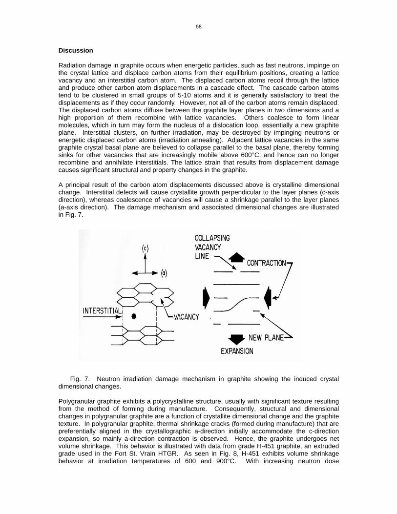
Discussion Radiation damage in graphite occurs when energetic particles, such as fast neutrons, impinge on the crystal lattice and displace carbon atoms from their equilibrium positions, creating a lattice vacancy and an interstitial carbon atom. The displaced carbon atoms recoil through the lattice and produce other carbon atom displacements in a cascade effect. The cascade carbon atoms tend to be clustered in small groups of 5-10 atoms and it is generally satisfactory to treat the displacements as if they occur randomly. However, not all of the carbon atoms remain displaced. The displaced carbon atoms diffuse between the graphite layer planes in two dimensions and a high proportion of them recombine with lattice vacancies. Others coalesce to form linear molecules, which in turn may form the nucleus of a dislocation loop, essentially a new graphite plane. Interstitial clusters, on further irradiation, may be destroyed by impinging neutrons or energetic displaced carbon atoms (irradiation annealing). Adjacent lattice vacancies in the same graphite crystal basal plane are believed to collapse parallel to the basal plane, thereby forming sinks for other vacancies that are increasingly mobile above 600°C, and hence can no longer recombine and annihilate interstitials. The lattice strain that results from displacement damage causes significant structural and property changes in the graphite. A principal result of the carbon atom displacements discussed above is crystalline dimensional change. Interstitial defects will cause crystallite growth perpendicular to the layer planes (c-axis direction), whereas coalescence of vacancies will cause a shrinkage parallel to the layer planes (a-axis direction). The damage mechanism and associated dimensional changes are illustrated in Fig. 7.
Fig. 7. Neutron irradiation damage mechanism in graphite showing the induced crystal dimensional changes. Polygranular graphite exhibits a polycrystalline structure, usually with significant texture resulting from the method of forming during manufacture. Consequently, structural and dimensional changes in polygranular graphite are a function of crystallite dimensional change and the graphite texture. In polygranular graphite, thermal shrinkage cracks (formed during manufacture) that are preferentially aligned in the crystallographic a-direction initially accommodate the c-direction expansion, so mainly a-direction contraction is observed. Hence, the graphite undergoes net volume shrinkage. This behavior is illustrated with data from grade H-451 graphite, an extruded grade used in the Fort St. Vrain HTGR. As seen in Fig. 8, H-451 exhibits volume shrinkage behavior at irradiation temperatures of 600 and 900°C. With increasing neutron dose
58
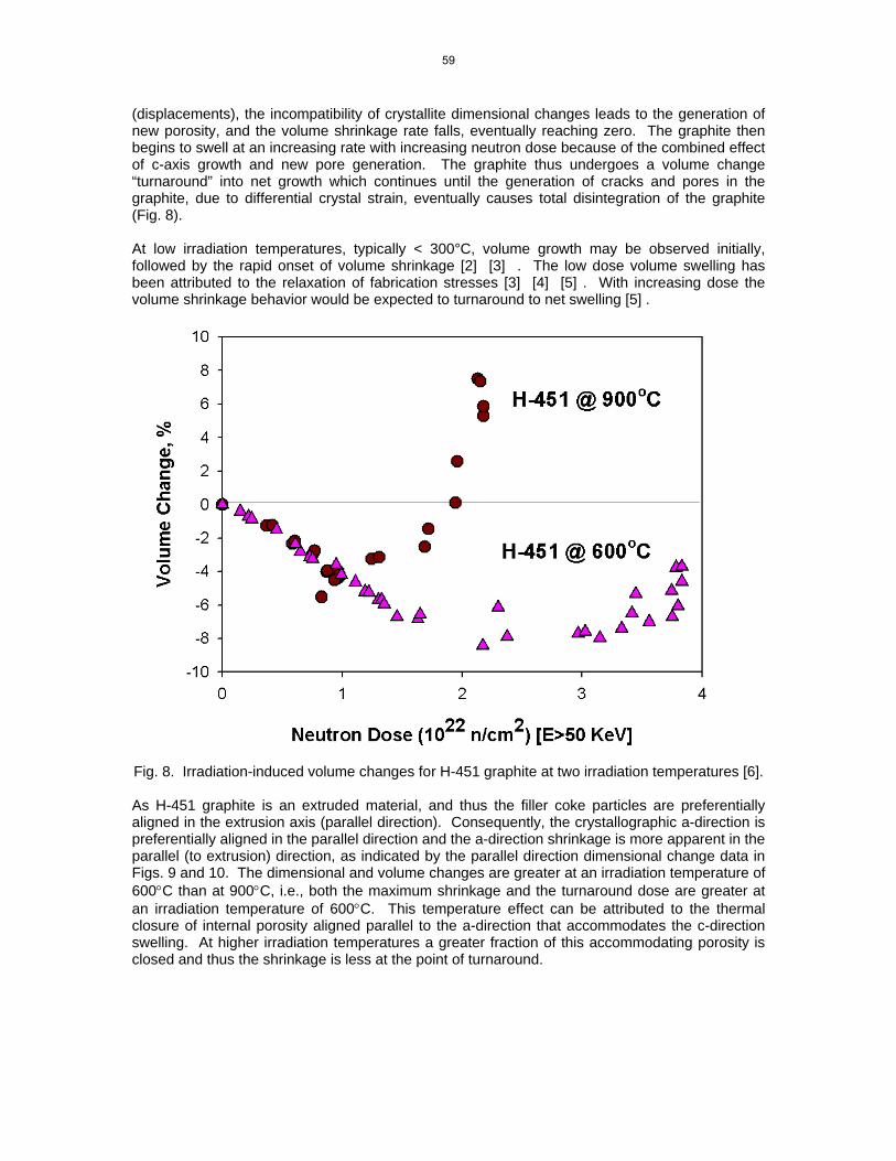
(displacements), the incompatibility of crystallite dimensional changes leads to the generation of new porosity, and the volume shrinkage rate falls, eventually reaching zero. The graphite then begins to swell at an increasing rate with increasing neutron dose because of the combined effect of c-axis growth and new pore generation. The graphite thus undergoes a volume change “turnaround” into net growth which continues until the generation of cracks and pores in the graphite, due to differential crystal strain, eventually causes total disintegration of the graphite (Fig. 8).
At low irradiation temperatures, typically < 300°C, volume growth may be observed initially, followed by the rapid onset of volume shrinkage [2] [3] . The low dose volume swelling has been attributed to the relaxation of fabrication stresses [3] [4] [5] . With increasing dose the volume shrinkage behavior would be expected to turnaround to net swelling [5] .
Fig. 8. Irradiation-induced volume changes for H-451 graphite at two irradiation temperatures [6]. As H-451 graphite is an extruded material, and thus the filler coke particles are preferentially aligned in the extrusion axis (parallel direction). Consequently, the crystallographic a-direction is preferentially aligned in the parallel direction and the a-direction shrinkage is more apparent in the parallel (to extrusion) direction, as indicated by the parallel direction dimensional change data in Figs. 9 and 10. The dimensional and volume changes are greater at an irradiation temperature of 600°C than at 900°C, i.e., both the maximum shrinkage and the turnaround dose are greater at an irradiation temperature of 600°C. This temperature effect can be attributed to the thermal closure of internal porosity aligned parallel to the a-direction that accommodates the c-direction swelling. At higher irradiation temperatures a greater fraction of this accommodating porosity is closed and thus the shrinkage is less at the point of turnaround.
59

Fig. 9. Dimensional change behavior of H-451 graphite at an irradiation temperature of 600°C [6].
Fig. 10. Dimensional change behavior of H-451 graphite at an irradiation temperature of
900°C [6].
60

Limited work has been carried out on the dimensional stability of H-451 graphite at the very high temperatures of the current work. The work of Engle[7] provides data over the temperature range of 550-1350°C for both H-451 and H429 materials in a dose range relevant for discussion. Figure 11 gives a set of dimensional change curves for H-451 measured both perpendicular and parallel to the extrusion direction. This data was taken from the trend curves of Engle’s data for a dose of to 2 x 1025 n/m2 (E>0.1 MeV). From this figure a clear trend towards greater densification of higher irradiation temperatures is observed, along with a difference in swelling behavior for directions perpendicular and parallel to the extrusion direction. The data for dimensional change in the direction parallel to extrusion of Fig. 11 is compared to the 2.4 dpa data of Fig. 3, and are seen to be in general agreement. To summarize the behavior of the nuclear graphite studied here, within experimental error, the dimensional change for the UCAR PCEA and SLG NBG-10 are similar to the standard nuclear graphite H-451, whose swelling is consistent with previous data at similar irradiation temperatures. This is true for the ~ 2.4 dpa dose level. Limited, higher dose data (~ 6dpa) on H-451 is available from the Engle[7] report, which is also consistent with the present work.
-0.7
-0.6
-0.5
-0.4
-0.3
-0.2
-0.1
0
600 700 800 900 1000 1100 1200 1300 1400
Dim
ensi
onal
Cha
nge
(%)
Irradiation Temperature (°C)
Parallelto Extrusion
Perpendicularto Extrusion
Engle 742 x 10 25 n/m 2 (E>0.1 MeV)
Fig. 11. Dimensional change for H-451 irradiated to 2.4 x 1025 n/m2(E>0.1 MeV) as a function of temperature [7]. The physical processes leading to the irradiation-induced anisotropic dimensional changes for graphite crystals and non-isotropic graphite (discussed previously) also explain the dimensional change in composite materials. In Fig. 7, the anisotropic dimensional change is explained by irradiation-created interstitials forming new planes between the existing basal planes leading to swelling perpendicular, and shrinkage parallel to these planes. The same process applies to graphitic carbon fiber, though the microstructure of the fibers differ from pyrolytic or nuclear
61

graphites in that the basal planes tend to form circumferentially around the fiber axis. By applying the graphite crystal swelling mechanism to the core-sheath microstructure typical of a graphite fiber (see Fig. 12) the as-irradiation dimensional change for graphite fibers would be for diameteral swelling and axial shrinkage. The matrix of the carbon fiber composite will behave in a fashion similar to graphite.
Fig. 12. Schematic representation of graphite fiber. Figure 13 shows the dimensional change behavior of 1, 2 and 3 directional composites replotted from the literature. [8] In this example, solid cylinders were irradiated at 600°C to doses ranging from 0-5 dpa and the resulting diameter and length measured. The behavior of each material can be explained by the accepted theory for dimensional change in graphite after taking into account the individual fiber architectures, and by observing that a graphite fiber, PAN based in this example, is basically a filament of circumferential or radial basal planes running parallel to the fiber axis. The irradiation induced dimensional change of such a fiber is therefore to shrink in length and grow in diameter, as observed for the unidirectional composite of Fig. 5. At doses less than 1 dpa the dimensional change is relatively minor for the unidirectional composite of Fig. 13. As the dose is increased, the direction perpendicular to the fiber axis is more or less unchanged while a significant shrinkage along the direction parallel to the fiber axis occurs. At about 2 to 3 dpa swelling in the composite occurs in the perpendicular direction. The random fiber composite of Fig. 13 has a random orientation of chopped PAN fibers in the plane perpendicular to the cylindrical axis. The specimen diameter shows practically no change perpendicular to the fiber axis to about 4.5 dpa, though exhibits ~ 2% shrinkage parallel to the fiber axis. The 3-D balanced PAN weave fiber has essentially isotropic shrinkage to a dose of ~ 2 dpa, at which point the diameter of the fibers and hence the sample begin to swell. Also given in the 3-D composite plot in Fig. 14 is the radiation induced dimensional change behavior parallel to the fiber axis of an Amoco P55 pitch fiber composite (the FMI-222 material of the present study.) This material was processed in an identical manner to the PAN fiber composite. From the plot it appears that the pitch fibers, and thus the composite, undergoes slightly less shrinkage, possibly due to the higher fiber crystallinity. This hypothesis is also supported by the observation that fibers with higher final heat treatment temperatures tend to exhibit less dimension change and is also consistent with the observation that elevating the heat treatment temperature of graphite reduces the irradiation induced shrinkage.
62

-4
-3.5
-3
-2.5
-2
-1.5
-1
-0.5
0
0 1 2 3 4 5
Composite Diameter-PAN composite|| Fiber Axis - PAN composite|| Fiber Axis - Pitch composite
DIM
EN
SIO
NA
L C
HA
NG
E (%
)
Neutron Dose (dpa)
THREE DIMESIONAL BALANCE WEAVE
axis parallel toa set of fiber axes
-2.5
-2
-1.5
-1
-0.5
0
0.5
⊥ ||
0 1 2 3 4 5
Fiber Axis
Fiber Axis
RANDOM FIBER (RFC) COMPOSITE
axis perpendicular to fibers axes
UNIDIRECTIONAL FIBER COMPOSITE (UFC)
-4
-3
-2
-1
0
1
⊥
||
0 1 2 3 4 5
Fiber AxisFiber Axis
axis parallel to fiber axes
Fig. 13. As-irradiated dimensional changes for carbon fiber composites of varied architectures. Irradiation temperature of 600°C [8].
63
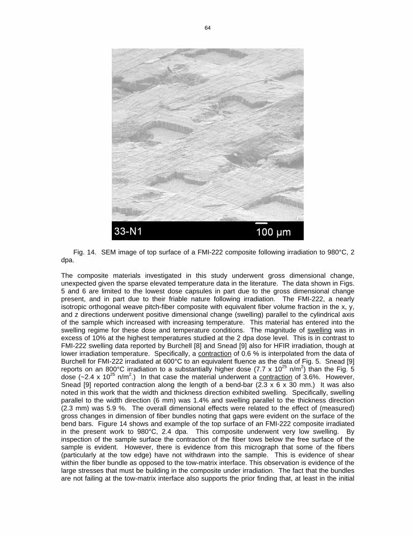
Fig. 14. SEM image of top surface of a FMI-222 composite following irradiation to 980°C, 2 dpa.
The composite materials investigated in this study underwent gross dimensional change, unexpected given the sparse elevated temperature data in the literature. The data shown in Figs. 5 and 6 are limited to the lowest dose capsules in part due to the gross dimensional change present, and in part due to their friable nature following irradiation. The FMI-222, a nearly isotropic orthogonal weave pitch-fiber composite with equivalent fiber volume fraction in the x, y, and z directions underwent positive dimensional change (swelling) parallel to the cylindrical axis of the sample which increased with increasing temperature. This material has entered into the swelling regime for these dose and temperature conditions. The magnitude of swelling was in excess of 10% at the highest temperatures studied at the 2 dpa dose level. This is in contrast to FMI-222 swelling data reported by Burchell [8] and Snead [9] also for HFIR irradiation, though at lower irradiation temperature. Specifically, a contraction of 0.6 % is interpolated from the data of Burchell for FMI-222 irradiated at 600°C to an equivalent fluence as the data of Fig. 5. Snead [9] reports on an 800°C irradiation to a substantially higher dose (7.7 x 1025 n/m2) than the Fig. 5 dose (~2.4 x 1025 n/m2.) In that case the material underwent a contraction of 3.6%. However, Snead [9] reported contraction along the length of a bend-bar (2.3 x 6 x 30 mm.) It was also noted in this work that the width and thickness direction exhibited swelling. Specifically, swelling parallel to the width direction (6 mm) was 1.4% and swelling parallel to the thickness direction (2.3 mm) was 5.9 %. The overall dimensional effects were related to the effect of (measured) gross changes in dimension of fiber bundles noting that gaps were evident on the surface of the bend bars. Figure 14 shows and example of the top surface of an FMI-222 composite irradiated in the present work to 980°C, 2.4 dpa. This composite underwent very low swelling. By inspection of the sample surface the contraction of the fiber tows below the free surface of the sample is evident. However, there is evidence from this micrograph that some of the fibers (particularly at the tow edge) have not withdrawn into the sample. This is evidence of shear within the fiber bundle as opposed to the tow-matrix interface. This observation is evidence of the large stresses that must be building in the composite under irradiation. The fact that the bundles are not failing at the tow-matrix interface also supports the prior finding that, at least in the initial
64

period of gross dimensional change, the load carrying capacity of the composite has not been degraded. In fact, previous measurement of FMI-222 irradiated to a dose of ~ 7.7x1025 n/m2 (E>0.1 MeV) at 800°C, described a 54% increase in strength. [9] Figure 15 compares the surface morphology of FMI-222 irradiated in previous work with that of the present. Figure 15(c) and 15(d) show side views of two samples from the present study. Specifically, Fig. 15(c) shows a sample which exhibited very small (~0.5%) swelling with a sample exhibiting > 10% swelling parallel to the cylindrical axis. By inspection of Figs. 15(b) and 15(d), it is apparent that gross changes in the fiber bundle length (and diameter) have occurred, leading to gaps at the free surfaces. Given these gross changes it is speculated that, for this nearly isotropic composite, the difference between the observed contraction parallel to the bend bar axis, and swelling in the smaller thickness and width directions, is attributed solely sample size effects. For the samples of this study, for which there are approximately 4 unit cells to the thickness, the constraint is limited leading to exaggerated apparent swelling.
QuickTime™ and aPhoto - JPEG decompressor
are needed to see this picture.
samplesurface
bundleshrinkage
bundle swelling
gap500°C, 7 dpa 800°C, 8.73 dpa
500 microns 500 microns
A B
C D
890°C, 2.4 dpa 1088°C, 7 dpa
Fig. 15. SEM image of side surface of FMI-222: (A) 500°C, 6 dpa 800°C dpa [9], 500°C, 7.7
dpa 800°C dpa [9], (C) 890°C, 2 dpa (this study), and (D) 1088°C, 6 dpa (this study).
65

The behavior of the FMI-222 balanced weave composite is in contrast to the unidirectional MKC-1PH of Fig. 6. The unidirectional composite behavior is as explained by the upper plot of Fig. 13, swelling perpendicular to the unidirectional fibers’ axis, and shrinking parallel to the fiber axis. This data compares favorably with the data of Eto [10] for the irradiation of MKC-1PH at 1000°C to a dose equivalent to the dose of Fig. 6 (~2.2 x 1025 n/m2 , E>0.1 MeV). In this case, the MKC composite underwent a 0.97-2.11% contraction parallel to the fiber axis. This is in good agreement with the data presented in Fig. 6. Conclusions Over the irradiation temperature range studied (~850-1475°C) and neutron dose range (2-10 x 1025 n/m2 (E>0.1 MeV)) the UCAR PCEA and SGL NBG-10 candidate nuclear graphites had similar densification to that of Great Lakes Carbon Nuclear Graphite H-451. In this temperature and dose range all materials remained in the densification stage exhibiting higher densification with increased irradiation temperature and dose. Swelling for high-quality unidirectional and three-dimensional composites at the same irradiation temperature and dose range have been found to be several percent, and in the case of the 1-1-1 balanced weave material the swelling for the small samples studied was found to be quite large (>10%) even for the lowest dose studied. It is speculated that the large dimensional change observed for the three-dimensional composite is in part attributed to the geometry of the sample raising the question as to the appropriate sample size required to obtain relevant design data. Acknowledgements This work is sponsored by the U.S. Department of Energy, Office of Nuclear Energy Science and Technology and Office of Science Fusion Energy Sciences under contract DE-AC05-00OR22725 with Oak Ridge National Laboratory, managed by UT-Battelle, LLC. The authors would like to thank Katey Lenox, Joel McDuffee, Bob Sitterson, and Dennis Heatherly who were involved in design and construction of the irradiation capsules and Marie Williams who carried out the SEM imaging. References [1] B. Tahon and F. Gerstgrasser, “Nuclear Graphite Grades,” presented at the Generation IV Reactors International Forum, Knutsford, Cheshire, United Kingdom, September 7, 2004. [2] J. W. H. Simmons, Radiation Damage in Graphite, Pergamon Press, Vol. 102, First Ed., 1965. [3] R. E. Nightingale, Nuclear Graphite, Academic Press, 1962. [4] C. R. Kennedy, “TSX Graphite for Extended use in the N-Reactor,” 1985. [5] T. D. Burchell and A. J. Wickham, “The Dimensional Change in Pile Grade A Graphite Irradiated in CEGB Magnox Power Reactors,” Proceedings of the CARBON ’87, 18th Biennial Conference on Carbon, 1987. [6] T. D. Burchell, Proceedings of Carbon '02, Beijing China, 2002. [7] G. B. Engle et al., “Development status of near-isotropic graphites for large HTGRs,” General Atomics (1974) 73. [8] T. D. Burchell, Materials Properties Data for Fusion Reactor Plasma Facing Carbon-Carbon Composites, in Physical Processes of the Interaction of Fusion Plasmas with Solids, Plasma-Materials Interactions, W. O. Hofer and J. Roth (eds.), Academic Press (1996) 341. [9] L. L. Snead, T. D. Burchell, and A. L. Qualls, J. Nucl. Mater. 321 (2003) 165. [10] M. Eto et al., J. Nucl. Mater. 212–215 (1994) 1223.
66

67