4 driveline driveline |actuators - siko-global.com · encoders, geared potentiometers linearline...
TRANSCRIPT
DriveLine | Actuators
05 | 2017
44
Driv
eLin
e

SIKO | Precision in Motion2
4 product index www.siko-global.com
OverviewTable of contents 3
4 product index | 4.0 Overview www.siko-global.com
4.04.0 | Overview
Measurement technology since 1963 4
Press review | User reports 6
4.1 | Actuators 9
4.2 | Accessories 55
4.3 | Appendix 81
4.4 | Product index, contact information 85
4.1
4.2
4.3
4.4
OverviewMeasurement technology since 19634
4 product index | 4.0 Overview www.siko-global.com
4.0
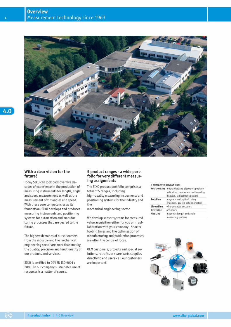
With a clear vision for the future!Today SIKO can look back over fi ve de-cades of experience in the production of measuring instruments for length, angle and speed measurement as well as the measurement of tilt angles and speed. With these core competencies as its foundation, SIKO develops and produces measuring instruments and positioning systems for automation and manufac-turing processes that are geared to the future.
The highest demands of our customers from the industry and the mechanical engineering sector are more than met by the quality, precision and functionality of our products and services.
SIKO is certifi ed to DIN EN ISO 9001 : 2008. In our company sustainable use of resources is a matter of course.
5 product ranges - a wide port-folio for very di� erent measur-ing assignmentsThe SIKO product portfolio comprises a total of 5 ranges, including high-quality measuring instruments and positioning systems for the industry and themechanical engineering sector.
We develop sensor systems for measured value acquisition either for you or in col-laboration with your company. Shorter tooling times and the optimization of manufacturing and production processes are often the centre of focus.
OEM customers, projects and special so-lutions, retrofi ts or spare parts supplies directly to end users - all our customers are important!
5 distinctive product linesPositionLine mechanical and electronic position
indicators, handwheels with analog displays, adjustment buttons
RotoLine magnetic and optical rotaryencoders, geared potentiometers
LinearLine wire-actuated encodersDriveLine actuatorsMagLine magnetic length and angle
measuring systems
5
4 product index | 4.0 Overview www.siko-global.com
4.0
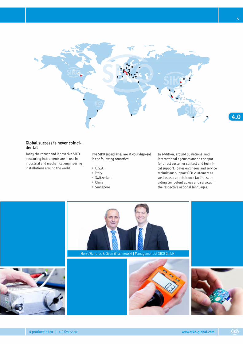
Global success is never coinci-dentalToday the robust and innovative SIKO measuring instruments are in use in industrial and mechanical engineering installations around the world.
Five SIKO subsidiaries are at your disposal in the following countries:
■ U.S.A. ■ Italy ■ Switzerland ■ China ■ Singapore
In addition, around 60 national and international agencies are on the spot for direct customer contact and techni-cal support. Sales engineers and service technicians support OEM customers as well as users at their own facilities, pro-viding competent advice and services in the respective national languages.
Horst Wandres & Sven Wischnewski | Management of SIKO GmbH
OverviewPress review | User reports6
4 product index | 4.0 Overview www.siko-global.com
4.0
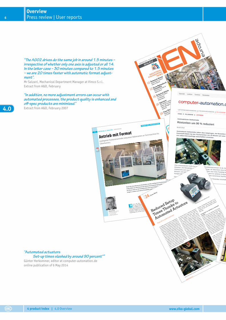
“The AG02 drives do the same job in around 1.5 minutes – irrespective of whether only one axis is adjusted or all 14. In the la� er case – 30 minutes compared to 1.5 minutes – we are 20 times faster with automatic format adjust-ment”.Mr Salzani, Mechanical Department Manager at Vimco S.r.l.Extract from A&D, February
“In addition, no more adjustment errors can occur with automated processes, the product quality is enhanced and o� -spec products are minimized.”Extract from A&D, February 2007
“Automated actuators Set-up times slashed by around 90 percent““Günter Herkommer, editor at computer-automation.deonline publication of 6 May 2014
JUNE/JULY 2014 - Vol 40 - N
o 6/7
IEN.EU
INDUSTRIAL
ENGINEERING
NEWS
ISSN
: 20
31-9
193
10
12
16
26
28
Technical Article
Sealed Micro Switch
Likes It Humid
Focus Hydraulics &
Pneumatics
Technical Articles &
Applications
Technical Article
The Role of Valves
in Industrial
Automation
Interview
IEN talked to Andy
Baker, UK & Ireland
Sales Manager at FLIR
Systems
Case Study
Frequency Inverters in
Ice Cream Production
CASE STUDY
Reduced Setup Times Thanks
to Automated Actuators
page 24
21NORD - IP
69K Drives The intelligent
drives have been developed for strict
hygiene requirements and feature
IP66/IP69K ingress protection.
LET’S TWEET!
Follow us!@ieneurope
A&D Februar 2007 | www.AuD24.net
A N T R I E B E & Z U B E H Ö R A N W E N D U N G
38
Durch die Umstellung von Handrädern auf die intelligenten Positionieran-
triebe AG02 von Siko konnte der italienische Verpackungstechnik-Spezia-
list Vimco nicht nur die Produktivität seiner Kartonformmaschine FAC820
steigern, sondern auch deren Flexibilität und Zuverlässigkeit.
■ Michael Schwab
asser, Saft, Bier, Wein, Champag-
ner oder Hochprozentiges – Genau-
so vielfältig wie das Angebot an Ge-
tränken fallen auch Form und Größe der dazu
passenden Trinkgefäße aus. Daraus wird sofort
ersichtlich, worauf es bei der Produktion von
Verpackungen für all diese Gläser besonders
38
Antrieb mit Format
ankommt: Die Verpackungsmaschinen müs-
sen sich so schnell wie möglich auf die unter-
schiedlichen Formate anpassen lassen, um eine
hohe Produktivität bei maximaler Flexibilität si-
cherzustellen. Im italienischen Fino Mornasco,
außerhalb Como gelegen, hat sich die Firma
Vimco S. r. l. seit 1980 auf die Konstruktion und
Intelligente Positionierantriebe reduzieren Nebenzeiten an Formmaschine für
Gläserkartons
Michael Schwab
ist Produktmanager DriveLine
bei Siko in Buchenbach
T +49/7661/394-405
W
Die Kartonformma-
schine FAC820 nutzt
14 AG02-Antriebe für
die Achsverstellung
Beitrag als PDF auf
www.AuD24.net
ZIELMARKT-FOKUS: VERPACKUNGSTECHNIK
Automatisierte Stellantriebe: Rüstzeiten um 90 % reduziert – computer-automation.de
http://www.computer-automation.de/feldebene/antriebe/artikel/108237/[12.05.2014 08:11:58]
Specials Lexikon Termine Newsletter
Media Kontakt Heftarchiv Shop
UNTERNEHMENSEBENE STEUERUNGSEBENE FELDEBENE TECHNOLOGIE KARRIERE BILDER VIDEO ANBIETERKOMPASS
AKTUELLES WHITEPAPER
AKTUELLES HEFT
HOME FELDEBENE ANTRIEBE
Anzeige
Implementierung von Foundation Fieldbus H1-Feldgeräten
Mai 2014: Das Ende der TotzeitGerade bei der Herstellungkomplexer Teile – etwa bei derSpritzgießtechnik oder beim
Automatisierte StellantriebeRüstzeiten um 90 % reduziert
Automatische Stellantriebe haben dazu beigetragen, die Rüstzeiten in der Verpackungslinie vonKunststoff-Dübeln bei den Fischerwerken von 45 Minuten auf unter 5 Minuten senken. Damit sindnun selbst Kleinstaufträge wirtschaftlich umsetzbar.
Eine entscheidende Größe bei industriellen Produktionsprozessen ist die Stückzahl der gefertigtenEinheiten. Die Rentabilität steigt rapide an, je länger die Maschinen ohne Eingriffe laufen können.Andererseits wird von den Herstellern jedoch vielfach eine hohe Flexibilität hinsichtlich der Abarbeitungkleinerer und mittelgroßer Stückzahlen gefordert – denn für wirkliche Großserienfertigung ist bei derheutigen Marktdichte nur noch in bestimmten Bereichen hinreichend Nachfrage vorhanden.Voraussetzung für diese Flexibilität ist die Reduktion der Rüstzeiten innerhalb der Fertigungslinien. Ein
Günter Herkommer
06.05.2014
© Siko
Suchen
24 Cover Story
Reduced Setup
Times Thanks to
Automated Actuators
From 45 to under 5 minutes
N° 6/7 - JUNE/JULY 2014
The AG05 actuator from Siko is
making posi-
tive headlines. The actuators c
an be automat-
ed and lead to a dramatic reduction in set-up
times in
the areas of mechanical and plant en-
gineering. Fischerwerke has already sw
itched
parts of it
s packaging production over to
the
actuators. By usin
g approximately 50 actua-
tors of th
e AG05 series, f
ischer was a
ble to
reduce the set-up times of se
veral production
lines from 45 minutes to
under five minutes.
In addition to
the low weight a
nd small i
n-
stallation siz
e, the custo
mer was p
articularly
impressed by the connectivity and long-term
reliability of th
e solution and th
e flexib
ility
gained in th
e production process. Incoming
orders can be dealt w
ith quickly without hav-
ing to stock the full ra
nge of items.
The decisive fa
ctor in in
dustrial p
roduction
processes is
the number o
f units
manufac-
tured. Profitability
increases rapidly, the
longer machines can run without opera-
tor intervention. H
owever, with th
e current
market density
, suffic
ient demand fo
r mass
production only exists in certain areas. In
many market segments,
flexibility
in produc-
ing small a
nd medium lot sizes h
as become
a deciding competitive factor. If
you can of-
fer attractive prices despite the increased
demands, you will u
sually be rewarded with
well-fille
d order books. The key requirement
for this f
lexibility
is the re
duction of set-u
p
times in
the production line. A sig
nificant in
-
crease in efficiency can be realized by auto-
mating the set-u
p processes w
ith networked
actuators. Fischerwerke, best
known for it
s
“fischer anchors”,
already operates several
production lines with automated actuators
from Siko.
Prerequisites f
or switching to
automated
actuators
A quick look at th
e website of th
e fischer
Group is enough to get an idea of th
e manu-
facturer’s diversif
ied product range. There
is a particularly wide variety of packaging
options that can be directly integrated into
the production processes. T
he ready-for-sale
pallet can often be found at the end of th
e
production line. In
order to m
eet the chal-
lenges of this wide product range, fischer
develops specific production equipment in
its in-house Specialized Machinery divisio
n.
The machinery re
quired is desig
ned, devel-
oped and manufactured in
close collabora-
tion with the production divisions.
In 2007, fischer esta
blished a project te
am
with the aim of achieving maximum fle
xibil-
ity in the area of packaging by automating
the set-up processe
s. The ambitio
us goal
was to make even the smallest
of orders
economically viable and to further st
rength-
en the market position with the help of th
is
newly created customer b
ase. The existing
production lines were completely over-
hauled by the project team. Overall, t
he de-
gree of automation in
creased signific
antly.
In the area of packaging, se
t-up tim
es were
greatly reduced by using AG05 actuators
from Siko. During the changeover, the AG05
was teste
d against comparable drives fr
om
other reputable manufacturers and came
out on top.
View of the machine: Th
e AG05 from Siko in operation at th
e fischer Group.
The automated actuator AG05 from Siko
7
4 product index | 4.0 Overview www.siko-global.com
4.0
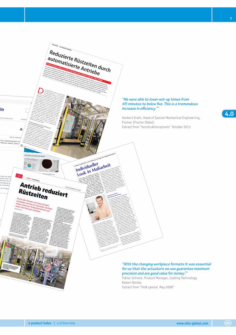
“With the changing workpiece formats it was essential for us that the actuators we use guarantee maximum precision and are good value for money.”“Tobias Schreck, Product Manager, Coating Technology Robert BürkleExtract from “HoB special May 2008”
“We were able to lower set-up times from 45 minutes to below � ve. This is a tremendous increase in e� ciency.““
Herbert Erath, Head of Special Mechanical Engineering,Fischer (Fischer Dübel)Extract from “konstruktionspraxis” October 2013
JUNE/JULY 2014 - Vol 40 - N
o 6/7
IEN.EU
INDUSTRIAL
ENGINEERING
NEWS
ISSN
: 20
31-9
193
10
12
16
26
28
Technical Article
Sealed Micro Switch
Likes It Humid
Focus Hydraulics &
Pneumatics
Technical Articles &
Applications
Technical Article
The Role of Valves
in Industrial
Automation
Interview
IEN talked to Andy
Baker, UK & Ireland
Sales Manager at FLIR
Systems
Case Study
Frequency Inverters in
Ice Cream Production
CASE STUDY
Reduced Setup Times Thanks
to Automated Actuators
page 24
21NORD - IP
69K Drives The intelligent
drives have been developed for strict
hygiene requirements and feature
IP66/IP69K ingress protection.
LET’S TWEET!
Follow us!@ieneurope
Automatisierte Stellantriebe: Rüstzeiten um 90 % reduziert – computer-automation.de
http://www.computer-automation.de/feldebene/antriebe/artikel/108237/[12.05.2014 08:11:58]
Specials Lexikon Termine Newsletter
Media Kontakt Heftarchiv Shop
UNTERNEHMENSEBENE STEUERUNGSEBENE FELDEBENE TECHNOLOGIE KARRIERE BILDER VIDEO ANBIETERKOMPASS
AKTUELLES WHITEPAPER
AKTUELLES HEFT
HOME FELDEBENE ANTRIEBE
Anzeige
Implementierung von Foundation Fieldbus H1-Feldgeräten
Mai 2014: Das Ende der TotzeitGerade bei der Herstellungkomplexer Teile – etwa bei derSpritzgießtechnik oder beim
Automatisierte StellantriebeRüstzeiten um 90 % reduziert
Automatische Stellantriebe haben dazu beigetragen, die Rüstzeiten in der Verpackungslinie vonKunststoff-Dübeln bei den Fischerwerken von 45 Minuten auf unter 5 Minuten senken. Damit sindnun selbst Kleinstaufträge wirtschaftlich umsetzbar.
Eine entscheidende Größe bei industriellen Produktionsprozessen ist die Stückzahl der gefertigtenEinheiten. Die Rentabilität steigt rapide an, je länger die Maschinen ohne Eingriffe laufen können.Andererseits wird von den Herstellern jedoch vielfach eine hohe Flexibilität hinsichtlich der Abarbeitungkleinerer und mittelgroßer Stückzahlen gefordert – denn für wirkliche Großserienfertigung ist bei derheutigen Marktdichte nur noch in bestimmten Bereichen hinreichend Nachfrage vorhanden.Voraussetzung für diese Flexibilität ist die Reduktion der Rüstzeiten innerhalb der Fertigungslinien. Ein
Günter Herkommer
06.05.2014
© Siko
Suchen
24 Cover Story
Reduced Setup
Times Thanks to
Automated Actuators
From 45 to under 5 minutes
N° 6/7 - JUNE/JULY 2014
The AG05 actuator from Siko is
making posi-
tive headlines. The actuators c
an be automat-
ed and lead to a dramatic reduction in set-up
times in
the areas of mechanical and plant en-
gineering. Fischerwerke has already sw
itched
parts of it
s packaging production over to
the
actuators. By usin
g approximately 50 actua-
tors of th
e AG05 series, f
ischer was a
ble to
reduce the set-up times of se
veral production
lines from 45 minutes to
under five minutes.
In addition to
the low weight a
nd small i
n-
stallation siz
e, the custo
mer was p
articularly
impressed by the connectivity and long-term
reliability of th
e solution and th
e flexib
ility
gained in th
e production process. Incoming
orders can be dealt w
ith quickly without hav-
ing to stock the full ra
nge of items.
The decisive fa
ctor in in
dustrial p
roduction
processes is
the number o
f units
manufac-
tured. Profitability
increases rapidly, the
longer machines can run without opera-
tor intervention. H
owever, with th
e current
market density
, suffic
ient demand fo
r mass
production only exists in certain areas. In
many market segments,
flexibility
in produc-
ing small a
nd medium lot sizes h
as become
a deciding competitive factor. If
you can of-
fer attractive prices despite the increased
demands, you will u
sually be rewarded with
well-fille
d order books. The key requirement
for this f
lexibility
is the re
duction of set-u
p
times in
the production line. A sig
nificant in
-
crease in efficiency can be realized by auto-
mating the set-u
p processes w
ith networked
actuators. Fischerwerke, best
known for it
s
“fischer anchors”,
already operates several
production lines with automated actuators
from Siko.
Prerequisites f
or switching to
automated
actuators
A quick look at th
e website of th
e fischer
Group is enough to get an idea of th
e manu-
facturer’s diversif
ied product range. There
is a particularly wide variety of packaging
options that can be directly integrated into
the production processes. T
he ready-for-sale
pallet can often be found at the end of th
e
production line. In
order to m
eet the chal-
lenges of this wide product range, fischer
develops specific production equipment in
its in-house Specialized Machinery divisio
n.
The machinery re
quired is desig
ned, devel-
oped and manufactured in
close collabora-
tion with the production divisions.
In 2007, fischer esta
blished a project te
am
with the aim of achieving maximum fle
xibil-
ity in the area of packaging by automating
the set-up processe
s. The ambitio
us goal
was to make even the smallest
of orders
economically viable and to further st
rength-
en the market position with the help of th
is
newly created customer b
ase. The existing
production lines were completely over-
hauled by the project team. Overall, t
he de-
gree of automation in
creased signific
antly.
In the area of packaging, se
t-up tim
es were
greatly reduced by using AG05 actuators
from Siko. During the changeover, the AG05
was teste
d against comparable drives fr
om
other reputable manufacturers and came
out on top.
View of the machine: Th
e AG05 from Siko in operation at th
e fischer Group.
The automated actuator AG05 from Siko
TECHNIK • AUTOMATISIEREN
04/2014 neue verpackung
54
Reduzierte Rüstzeiten durch
automatisierte Antriebe
Fischerwerke setzen auf den automatischen Stellantrieb der Siko GmbH
Die automatisierbaren Stellantriebe des Buchenbacher Traditionsunternehmens Siko führen zu einer Reduktion der
Rüstzeiten in den Bereichen Maschinen- und Anlagenbau. Die Fischerwerke haben bereits Teile der Verpackungsferti-
gung auf die Stellantriebe umgestellt. Durch den Einsatz von etwa 50 Stellantrieben der Baureihe AG05 konnte Fischer
die Rüstzeiten mehrerer Produktionslinien von etwa einer Dreiviertelstunde auf unter fünf Minuten senken. Neben
geringem Gewicht und kleiner Baugröße überzeugten den Kunden die gewonnene Flexibilität in der Fertigung: Ohne
sämtliche Positionen auf Lager halten zu müssen, kann kurzfristig auf eingehende Aufträge reagiert werden. D ie entscheidende Größe bei industriellen
Produktionsprozessen ist die Stückzahl
der gefertigten Einheiten. Die Rentabili-
tät steigt rapide an, je länger die Maschi-
nen ohne Eingri�e laufen können. Bei der heutigen
Marktdichte ist für wirkliche Großserienfertigung je-
doch nur in bestimmten Bereichen hinreichend Nach-
frage vorhanden. So wird in vielen Marktsegmenten
die Flexibilität bei der Abarbeitung kleinerer und mit-
telgroßer Stückzahlen zum entscheidenden Wettbe-
werbskriterium. Wer hier trotz der erhöhten Anforde-
rungen mit attraktiven Preisen punkten kann, wird in
aller Regel mit gut gefüllten Au�ragsbüchern belohnt.
Die entscheidende Voraussetzung für diese Flexibilität
ist die Reduktion der Rüstzeiten innerhalb der Ferti-
gungslinien. Ein deutlicher E�zienzschub lässt sich
durch die Automation der Rüstprozesse durch ver-
netzte Stellantriebe erzielen. Die Fischerwerke, be-
kannt durch ihre „Fischer-Dübel“, betreiben bereits
mehrere Produktionslinien mit den automatischen
Stellantrieben der Firma Siko. Voraussetzungen für die Umstellung auf
automatisierte Stellantriebe
Bereits ein kurzer Blick auf die Webseite der Unterneh-
mensgruppe Fischer reicht aus, um eine Vorstellung von
der diversi�zierten Produktpalette des Herstellers zu er-
halten. Besonders groß ist die Vielfalt im Bereich der
Verpackungen, deren Herstellung unmittelbar in die
Produktionsprozesse integriert ist. Am Ende der Pro-
duktionslinie steht häu�g die verkaufsfertige Palette.
Um diesem breiten Warenspektrum gewachsen zu sein,
erstellt Fischer spezi�sche Fertigungsanlagen im hausei-
genen Sondermaschinenbau. Der erforderliche Maschi-
nenpark wird in enger Zusammenarbeit mit den Pro-
duktionsabteilungen geplant, konstruiert und gefertigt.
1
Jeder kennt es zur Genüge von den Dru-
ckern im Büro oder Home Office: Wird das
Papier nicht ordnungsgemäß zugeführt,
streikt der Drucker oder lie
fert mangel-
hafte Ergebnisse. Der gleiche Zusammen-
hang gilt auch für das Bedrucken von
MDF-, HDF- und Spanplatten. In der Zu-
führeinrichtung ihrer Single-Pass-Digital-
druckanlage vertrauen die Konstrukteure
des Spezialisten für Oberflächentechnik,
Robert Bürkle in Freudenstadt, deshalb
auf die Präzision und Zuverlässigkeit der
Stellantriebe ‚AG02 PB’ von Siko. – Von
Michael Schwab, und Stefan J. Richter a
die Daten in digitaler Form direkt vom PC an
das Drucksystem gesandt, ohne dass bei je-
dem Motivwechsel eine eigene Druckform
hergestellt werden muss. 2007 präsentieren
die beiden Entwicklungspartner Bürkle und
Durst auf der ‚Ligna+’ in Hannover erstma-
lig eine Single-Pass-Digitaldruckanlage zum
Beschichten und Bedrucken von Holzwerk-
stoff-Platten. Seit Neuestem mit dabei in
der Zuführeinrichtung der Anlage sind jetzt
insgesamt zwölf Stellantriebe ‚AG02 PB’ von
Siko, ein führender Entwickler und Herstel-
ler von intelligenten Weg- und Winkelmess-
Systemen und Sersoren mit Sitz in Buchen-
bach im Schwarzwald.
Kundenorientierte
Oberflächengestaltung
Die innovative Anlage vereint Walzmaschi-
nen, Düsen-Trockenkanäle, UV-Anlagen
und Handlingsysteme von Bürkle mit einer
Durst-Digitaldruckmaschine ‚Rho SP 60’. „Di-
ese Kombination eröffnet bisher unbekann-
te Möglichkeiten einer kundenorientierten
und individualisierten Oberflächengestal-
tung und -veredelung“, versichert Sascha
Lämmle, Abteilung TBO bei Bürkle. Die An-
lage arbeitet mit dem Single-Pass-Verfah-
ren, das zu bedruckende Werkstück wird al-
so kontinuierlich durch die Maschine trans-
portiert, während die nebeneinander ange-
ordneten Druckköpfe starr fixiert sind. Bei
Multi-Pass-Digitaldruckern dagegen – unse-
re Tintenstrahl-Drucker im Büro zählen dazu
– bewegt sich der Druckkopf über das ste-
hende Werkstück. Nachdem eine Zeile be-
druckt ist, taktet der Drucker das Werkstück
weiter. „Der kontinuierliche Werkstücktrans-
port beim Single-Pass-Verfahren mit Vor-
schubgeschwindigkeiten bis zu 50 m/min.
gewährleistet eine rationelle Serienferti-
gung“, erläutert Tobias Schreck, Produktma-
nager Lackiertechnologie bei Bürkle.
Übrigens trägt auch die in der Anlage ein-
gesetzte Drucktechnik dazu bei, die Arbeits-
geschwindigkeit zu steigern: Die Farbe wird
mittels Piezotechnologie rechnergesteu-
ert durch feinste Düsen gespritzt. Der Pi-
ezokristall verformt sich beim Anlegen ei-
a Michael Schwab ist Produktmanager ‚DriveLine’ bei Siko
und Stefan J. Richter ist als Freier Journalist tä
tig
Individueller
Look in MaßarbeitProfibus-Stellantriebe in der Zuführung von Single-Pass-Digitaldruckanlagen
1 Michael Schwab, Produktmanager ‚DriveLine’
Wenn Sie das nächste Mal in einem Ge-
schäft oder Hotel die Wandvertäfelung aus
Marmor bestaunen, schauen Sie doch ein-
mal genauer hin. Oftmals handelt es sich
nämlich gar nicht um Marmor, sondern
um hochwertig bedruckte und beschichte-
te Holzpaneele. Verfahren wie der indirekte
Tiefdruck und der Digitaldruck erlauben es,
Boden- oder Wandpaneele kundenspezifisch
zu gestalten und damit Räumen eine indi-
viduelle Note zu verleihen. Der digitale De-
kordruck bietet dabei gegenüber analogen
Druckverfahren die Möglichkeit, individuelle
Oberflächen schnell und mit hoher Qualität
zu produzieren – und das bei vergleichswei-
se angemessenen Preisen. Hierbei werden
44.111
ActuatorsTable of contents 9
4 product index | 4.1 Actuators www.siko-global.com
4.1
4.1 | Actuators
General information and areas of application 10
Technical details 12
Function and benefit 14
Product matrix 15
Products AG26 Fieldbus/IE 16AG25 Fieldbus/IE 19AG06 Fieldbus 22AG05 Fieldbus 25AG04B Fieldbus 28AG03/1 Fieldbus 32AG02 Fieldbus 36AG02 Analog 39AG02 Incremental 42AG01 Analog 46AG01 Incremental 50
4.2 | Accessories 55
4.3 | Appendix 81
4.4 | Product index, contact information 85
4.0 | Overview 3
4.0
4.2
4.3
4.4
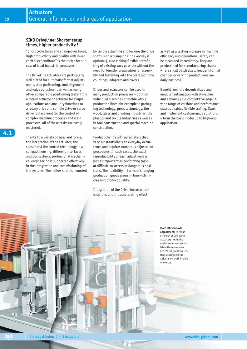
SIKO DriveLine: Shorter setup times, higher productivity !“Short cycle times and changeover times, high productivity and quality with lower capital expenditure” is the recipe for suc-cess of ideal industrial processes.
The DriveLine actuators are particularly well suited for automatic format adjust-ment, stop positioning, tool alignment and valve adjustment as well as many other comparable positioning tasks: from a rotary actuator or actuator for simple applications and ancillary functions to a rotary drive and spindle drive or servo drive replacement for the control of complex machine processes and main processes, all of these tasks are easily mastered.
Thanks to a variety of sizes and forms, the integration of the actuator, the sensor and the control technology in a compact housing, di� erent interfaces and bus systems, professional mechani-cal engineering is supported e� ectively in the integration and commissioning of the systems. The hollow shaft is mounted
by simply attaching and locking the drive shaft using a clamping ring (keyway is optional), also making fl exible retrofi t-ting of existing axes possible without the need for lengthy preparation for assem-bly and fastening with the corresponding couplings, adapters and covers.
Drives and actuators can be used in many production processes – both on individual machines or within whole production lines, for example in packag-ing technology, press technology, the wood, glass and printing industries, the plastics and textile industries as well as in tool construction and special machine construction.
Product change with parameters that vary substantially is an everyday occur-rence and requires numerous adjustment procedures. In such cases, the exact reproducibility of each adjustment is just as important as performing tasks at di� cult-to-access or dangerous posi-tions. The fl exibility in terms of changing production goods grows in line with in-creasing product quality.
Integration of the DriveLine actuators is simple, and the accelerating e� ect
as well as a lasting increase in machine e� ciency and operational safety can be measured immediately. They are predestined for manufacturing chains where small batch sizes, frequent format changes or varying product sizes are daily business.
Benefi t from the decentralized and modular automation with DriveLine and enhance your competitive edge: A wide range of versions and performance classes enables fl exible scaling. Start and implement custom-made solutions – from the basic model up to high-end application.
More e� cient axle adjustment: The true strength of DriveLine actuators lies in the useful series connection. When these modules are centrally controlled, they accomplish the adjustment work in only one cycle.
ActuatorsGeneral information and areas of application10
4 product index | 4.1 Actuators www.siko-global.com
4.1
11
4 product index | 4.1 Actuators www.siko-global.com
4.1
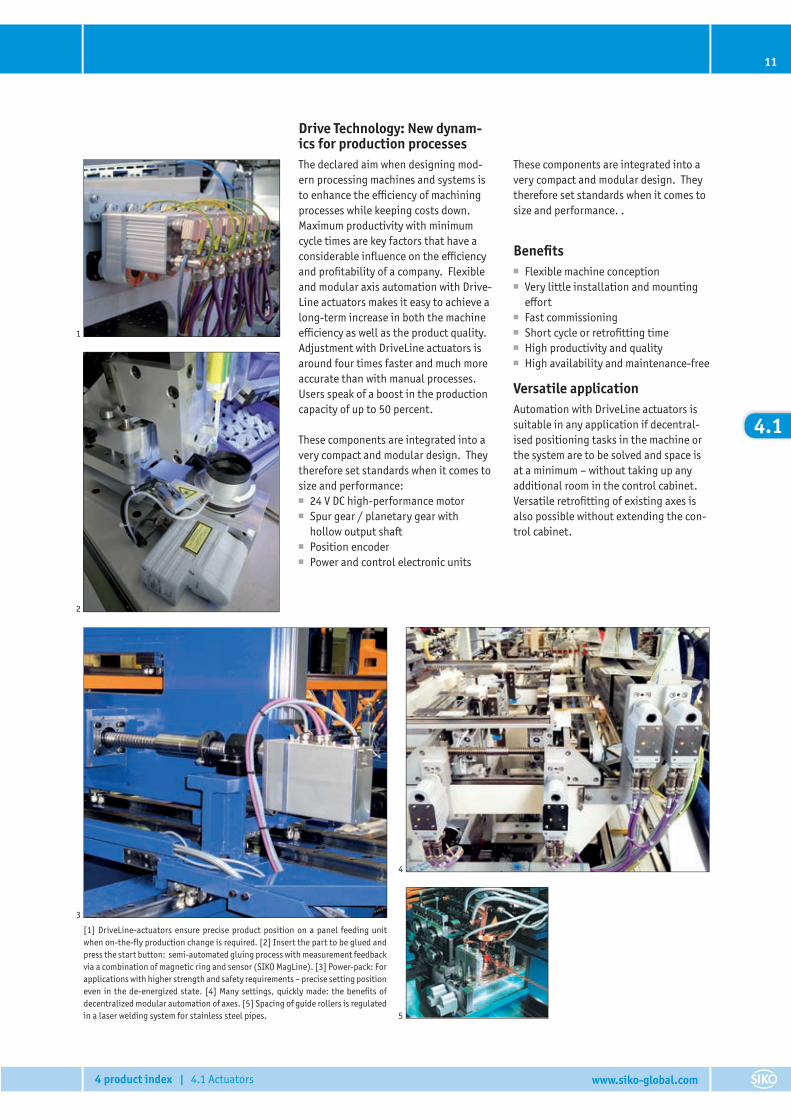
[1] DriveLine-actuators ensure precise product position on a panel feeding unit when on-the-fl y production change is required. [2] Insert the part to be glued and press the start button: semi-automated gluing process with measurement feedback via a combination of magnetic ring and sensor (SIKO MagLine). [3] Power-pack: For applications with higher strength and safety requirements – precise setting position even in the de-energized state. [4] Many settings, quickly made: the benefi ts of decentralized modular automation of axes. [5] Spacing of guide rollers is regulated in a laser welding system for stainless steel pipes.
Drive Technology: New dynam-ics for production processesThe declared aim when designing mod-ern processing machines and systems is to enhance the e� ciency of machining processes while keeping costs down. Maximum productivity with minimum cycle times are key factors that have a considerable infl uence on the e� ciency and profi tability of a company. Flexible and modular axis automation with Drive-Line actuators makes it easy to achieve a long-term increase in both the machine e� ciency as well as the product quality. Adjustment with DriveLine actuators is around four times faster and much more accurate than with manual processes. Users speak of a boost in the production capacity of up to 50 percent.
These components are integrated into a very compact and modular design. They therefore set standards when it comes to size and performance:
■ 24 V DC high-performance motor ■ Spur gear / planetary gear with
hollow output shaft ■ Position encoder ■ Power and control electronic units
These components are integrated into a very compact and modular design. They therefore set standards when it comes to size and performance. .
Benefi ts ■ Flexible machine conception ■ Very little installation and mounting
e� ort ■ Fast commissioning ■ Short cycle or retrofi tting time ■ High productivity and quality ■ High availability and maintenance-free
Versatile applicationAutomation with DriveLine actuators is suitable in any application if decentral-ised positioning tasks in the machine or the system are to be solved and space is at a minimum – without taking up any additional room in the control cabinet. Versatile retrofi tting of existing axes is also possible without extending the con-trol cabinet.
1
2
3
5
4
ActuatorsTechnical details12
4 product index | 4.1 Actuators www.siko-global.com
4.1
80
70
30
20
10
0
60
50
40
0 5 10 15
AG05/AG06/AG25/AG26
AG06/AG26, i368
AG06/AG26, i188
AG05/AG25, i98
AG05/AG25, i66
Torque [Nm]
Spee
d [r
pm]
150
100
50
00 1 2 3 5 74 6 8 9
AG02
AG02, 70 W, i135.8*
AG02, 70 W, i62.2*
AG02, 70 W, i55.3*AG02, 70 W, i55.3*
AG02, 150 W, i62.2
AG02, 150 W, i55.3
Torque [Nm]
Spee
d [r
pm] *
Bus
cont
rolle
d
500
400
300
200
100
00 1 2 3 4
AG01, AG03/1
AG03/1, i48
AG01, i48AG03/1, i24
AG01, i24
AG01, i12.4AG01, i12.4
Torque [Nm]
Spee
d [r
pm]
200
150
100
50
00 5 10 15
AG04B
AG04B, i70.8
AG04B, i50
AG04B, i30.6
Torque [Nm]
Spee
d [r
pm]
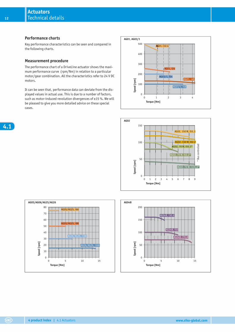
Performance chartsKey performance characteristics can be seen and compared in the following charts.
Measurement procedureThe performance chart of a DriveLine actuator shows the maxi-mum performance curve (rpm/Nm) in relation to a particular motor/gear combination. All the characteristics refer to 24 V DC motors.
It can be seen that, performance data can deviate from the dis-played values in actual use. This is due to a number of factors, such as motor-induced revolution divergences of ±15 %. We will be pleased to give you more detailed advice on these special cases.
13
4 product index | 4.1 Actuators www.siko-global.com
4.1
[1]
[3]
37
37
37
37
37
35ϒ
37
37
37
37
37
35ϒ
AG01, AG02
180°±30°
90°
±30°
A
/A
B
/B
0
I
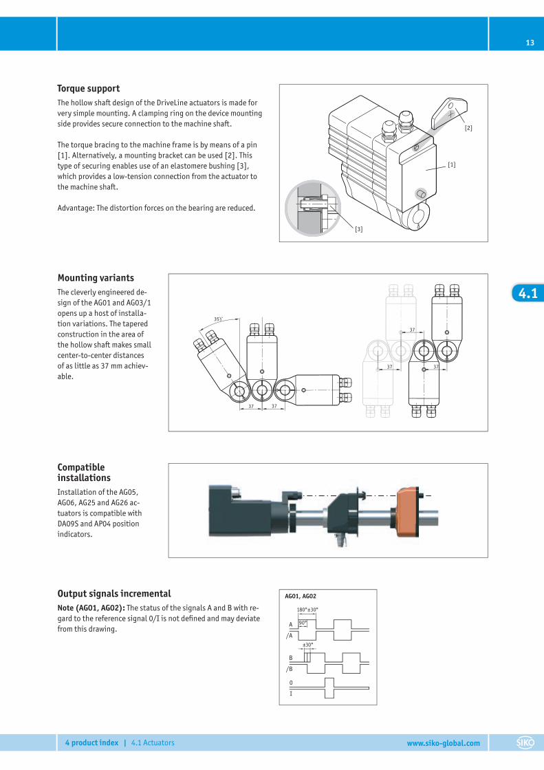
Torque supportThe hollow shaft design of the DriveLine actuators is made for very simple mounting. A clamping ring on the device mounting side provides secure connection to the machine shaft.
The torque bracing to the machine frame is by means of a pin [1]. Alternatively, a mounting bracket can be used [2]. This type of securing enables use of an elastomere bushing [3], which provides a low-tension connection from the actuator to the machine shaft.
Advantage: The distortion forces on the bearing are reduced.
[2]
Output signals incrementalNote (AG01, AG02): The status of the signals A and B with re-gard to the reference signal 0/I is not defi ned and may deviate from this drawing.
Compatible installationsInstallation of the AG05, AG06, AG25 and AG26 ac-tuators is compatible with DA09S and AP04 position indicators.
Mounting variantsThe cleverly engineered de-sign of the AG01 and AG03/1 opens up a host of installa-tion variations. The tapered construction in the area of the hollow shaft makes small center-to-center distances of as little as 37 mm achiev-able.
ActuatorsFunction and benefit14
4 product index | 4.1 Actuators www.siko-global.com
4.1
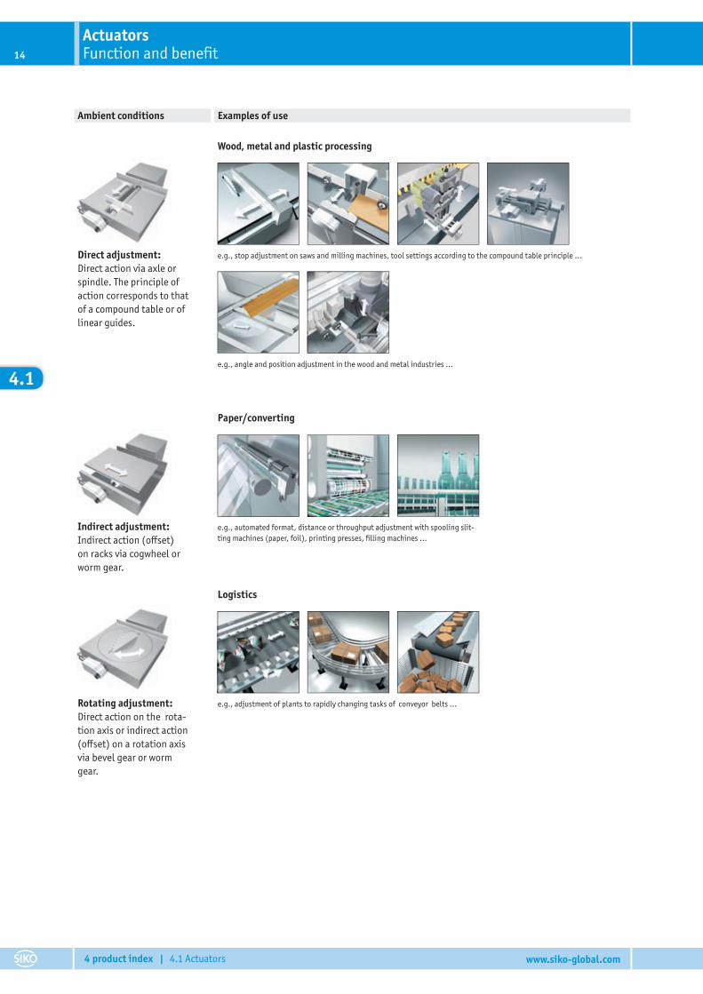
Direct adjustment: Direct action via axle or spindle. The principle of action corresponds to that of a compound table or of linear guides.
Indirect adjustment:Indirect action (o� set) on racks via cogwheel or worm gear.
Rotating adjustment:Direct action on the rota-tion axis or indirect action (o� set) on a rotation axis via bevel gear or worm gear.
Wood, metal and plastic processing
Paper/converting
Logistics
Ambient conditions Examples of use
e.g., stop adjustment on saws and milling machines, tool settings according to the compound table principle …
e.g., angle and position adjustment in the wood and metal industries …
e.g., automated format, distance or throughput adjustment with spooling slit-ting machines (paper, foil), printing presses, fi lling machines …
e.g., adjustment of plants to rapidly changing tasks of conveyor belts …
ActuatorsProduct matrix 15
4 product index | 4.1 Actuators www.siko-global.com
4.1
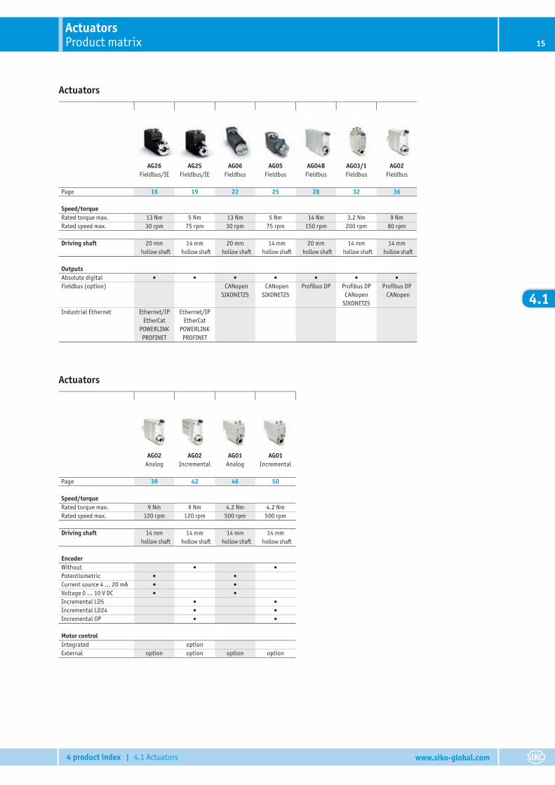
Actuators
Actuators
AG02Analog
AG02Incremental
AG01Analog
AG01Incremental
Page 39 42 46 50
Speed/torqueRated torque max. 9 Nm 9 Nm 4.2 Nm 4.2 NmRated speed max. 120 rpm 120 rpm 500 rpm 500 rpm
Driving shaft 14 mmhollow shaft
14 mmhollow shaft
14 mmhollow shaft
14 mmhollow shaft
EncoderWithout • •Potentiometric • •Current source 4 … 20 mA • •Voltage 0 … 10 V DC • •Incremental LD5 • •Incremental LD24 • •Incremental OP • •
Motor controlIntegrated optionExternal option option option option
AG26Fieldbus/IE
AG25Fieldbus/IE
AG06Fieldbus
AG05Fieldbus
AG04BFieldbus
AG03/1Fieldbus
AG02Fieldbus
Page 16 19 22 25 28 32 36
Speed/torqueRated torque max. 13 Nm 5 Nm 13 Nm 5 Nm 14 Nm 3.2 Nm 9 NmRated speed max. 30 rpm 75 rpm 30 rpm 75 rpm 150 rpm 200 rpm 80 rpm
Driving shaft 20 mmhollow shaft
14 mmhollow shaft
20 mmhollow shaft
14 mmhollow shaft
20 mmhollow shaft
14 mmhollow shaft
14 mmhollow shaft
OutputsAbsolute digital • • • • • • •Fieldbus (option) CANopen
SIKONETZ5CANopen
SIKONETZ5Profi bus DP Profi bus DP
CANopenSIKONETZ5
Profi bus DPCANopen
Industrial Ethernet Ethernet/IPEtherCat
POWERLINKPROFINET
Ethernet/IPEtherCat
POWERLINKPROFINET
Actuator AG26 Fieldbus/IEIndustrial Ethernet16
4 product index | 4.1 Actuators www.siko-global.com
4.1
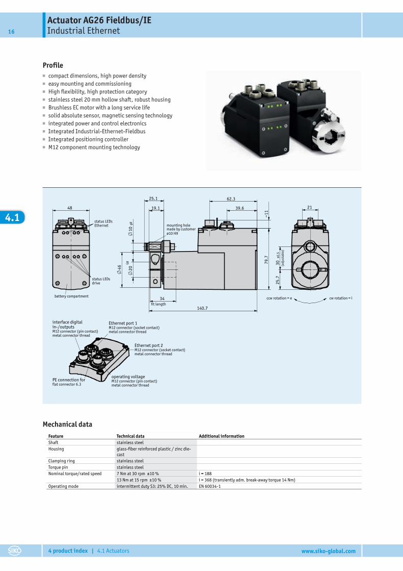
Profile■ compact dimensions, high power density■ easy mounting and commissioning■ High flexibility, high protection category■ stainless steel 20 mm hollow shaft, robust housing■ Brushless EC motor with a long service life■ solid absolute sensor, magnetic sensing technology■ integrated power and control electronics■ Integrated Industrial-Ethernet-Fieldbus■ Integrated positioning controller■ M12 component mounting technology
334/14
AG2626.08.2014 Kreutzmann
207971
Katalogzeichnung
39.6
62.3
79.
7
~11
46
10 g
8
19.1
25.1
140.7
20G8
fit length
mounting hole made by customerø10 H9
48
status LEDsEthernet
battery compartment
status LEDsdrive
21
30
±0.5
25.
7
(adj
usta
ble)
ccw rotation = e cw rotation = i
interface digitalin-/outputsM12 connector (pin contact)metal connector thread
Ethernet port 1M12 connector (socket contact)metal connector thread
operating voltageM12 connector (pin contact)metal connector thread
PE connection forflat connector 6.3
Ethernet port 2M12 connector (socket contact)metal connector thread
34
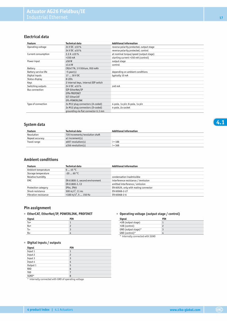
Mechanical dataFeature Technical data Additional informationShaft stainless steelHousing glass-fiber reinforced plastic / zinc die-
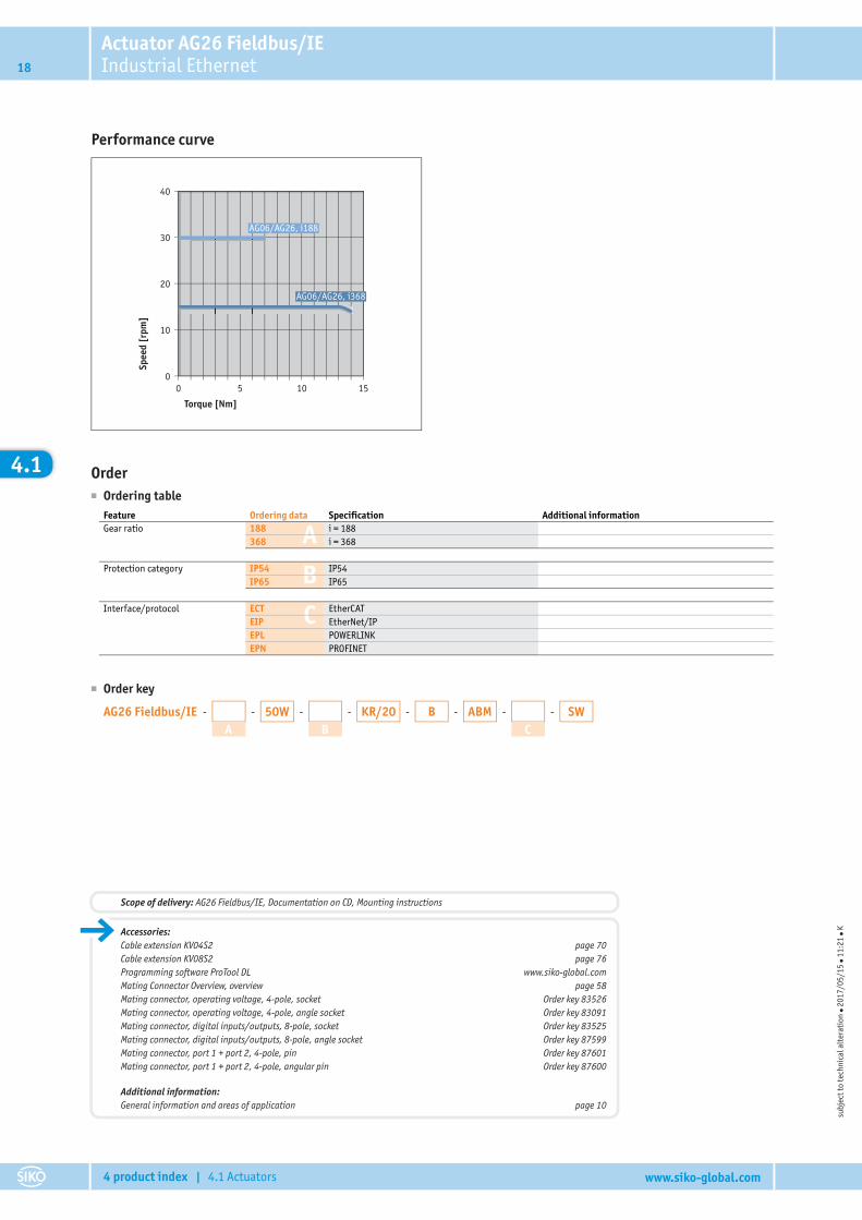
castClamping ring stainless steelTorque pin stainless steelNominal torque/rated speed 7 Nm at 30 rpm ±10 % i = 188
13 Nm at 15 rpm ±10 % i = 368 (transiently adm. break-away torque 14 Nm)Operating mode intermittent duty S3: 25% DC, 10 min. EN 60034-1
Actuator AG26 Fieldbus/IEIndustrial Ethernet 17
4 product index | 4.1 Actuators www.siko-global.com
4.1
Electrical dataFeature Technical data Additional informationOperating voltage 24 V DC ±10 % reverse polarity protected, output stage
24 V DC ±10 % reverse polarity protected, controlCurrent consumption 2.2 A ±10 % at nominal torque/speed (output stage)
<150 mA starting current >150 mA (control)Power input ≤58 W output stage
≤3.6 W controlBattery CR2477N, 3 V lithium, 950 mAhBattery service life ~5 year(s) depending on ambient conditionsDigital inputs 17 … 30 V DC typically 10 mAStatus display 8 LEDsKeys 2 internal keys, internal DIP switchSwitching outputs 24 V DC ±10 % ≤40 mABus connection EIP-EtherNet/IP
EPN-PROFINETECT-EtherCATEPL-POWERLINK
Type of connection 2x M12 plug connectors (A-coded) 4-pole, 1x pin; 8-pole, 1x pin2x M12 plug connectors (D-coded) 4-pole, 2x socketgrounding via flat connector 6.3 mm
System dataFeature Technical data Additional informationResolution 720 increments/revolution shaftRepeat accuracy ±1 increment(s)Travel range ±697 revolution(s) i = 188
±356 revolution(s) i = 368
Ambient conditionsFeature Technical data Additional informationAmbient temperature 0 … 45 °CStorage temperature -20 … 60 °CRelative humidity condensation inadmissibleEMC EN 61800-3, second environment interference resistance / immission
EN 61800-3, C2 emitted interference / emissionProtection category IP54, IP65 EN 60529, only with mating connectorShock resistance 500 m/s2, 11 ms EN 60068-2-27Vibration resistance <100 m/s2, 5 … 150 Hz EN 60068-2-6
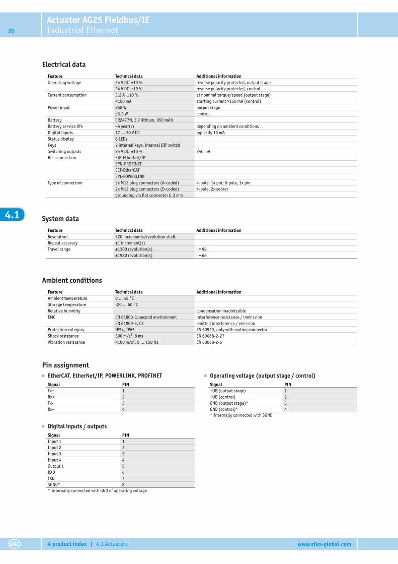
Pin assignment■ EtherCAT, EtherNet/IP, POWERLINK, PROFINET
Signal PINTx+ 1Rx+ 2Tx- 3Rx- 4
■ Operating voltage (output stage / control)Signal PIN+UB (output stage) 1+UB (control) 2GND (output stage)* 3GND (control)* 4* internally connected with SGND
■ Digital inputs / outputsSignal PINInput 1 1Input 2 2Input 3 3Input 4 4Output 1 5RXD 6TXD 7SGND* 8* internally connected with GND of operating voltage
Actuator AG26 Fieldbus/IEIndustrial Ethernet18
4 product index | 4.1 Actuators www.siko-global.com
4.1
Performance curve
40
30
20
10
00 5 10 15
AG06/AG26, i368
AG06/AG26, i188
Torque [Nm]
Spee
d [r
pm]
Order� Ordering table
A
B
C
Feature Ordering data Specification Additional informationGear ratio 188 i = 188
368 i = 368
Protection category IP54 IP54IP65 IP65
Interface/protocol ECT EtherCATEIP EtherNet/IPEPL POWERLINKEPN PROFINET
� Order key
AG26 Fieldbus/IE - -
A-50W -
B-KR/20 -B -ABM -
CSW
subj
ect t
o te
chni
cal a
lter
atio
n � 2
017/
05/1
5 � 1
1:21
� KAccessories:
Cable extension KV04S2 page 70Cable extension KV08S2 page 76Programming software ProTool DL www.siko-global.comMating Connector Overview, overview page 58Mating connector, operating voltage, 4-pole, socket Order key 83526Mating connector, operating voltage, 4-pole, angle socket Order key 83091Mating connector, digital inputs/outputs, 8-pole, socket Order key 83525Mating connector, digital inputs/outputs, 8-pole, angle socket Order key 87599Mating connector, port 1 + port 2, 4-pole, pin Order key 87601Mating connector, port 1 + port 2, 4-pole, angular pin Order key 87600
Additional information:General information and areas of application page 10
Scope of delivery: AG26 Fieldbus/IE, Documentation on CD, Mounting instructions
Actuator AG25 Fieldbus/IEIndustrial Ethernet 19
4 product index | 4.1 Actuators www.siko-global.com
4.1
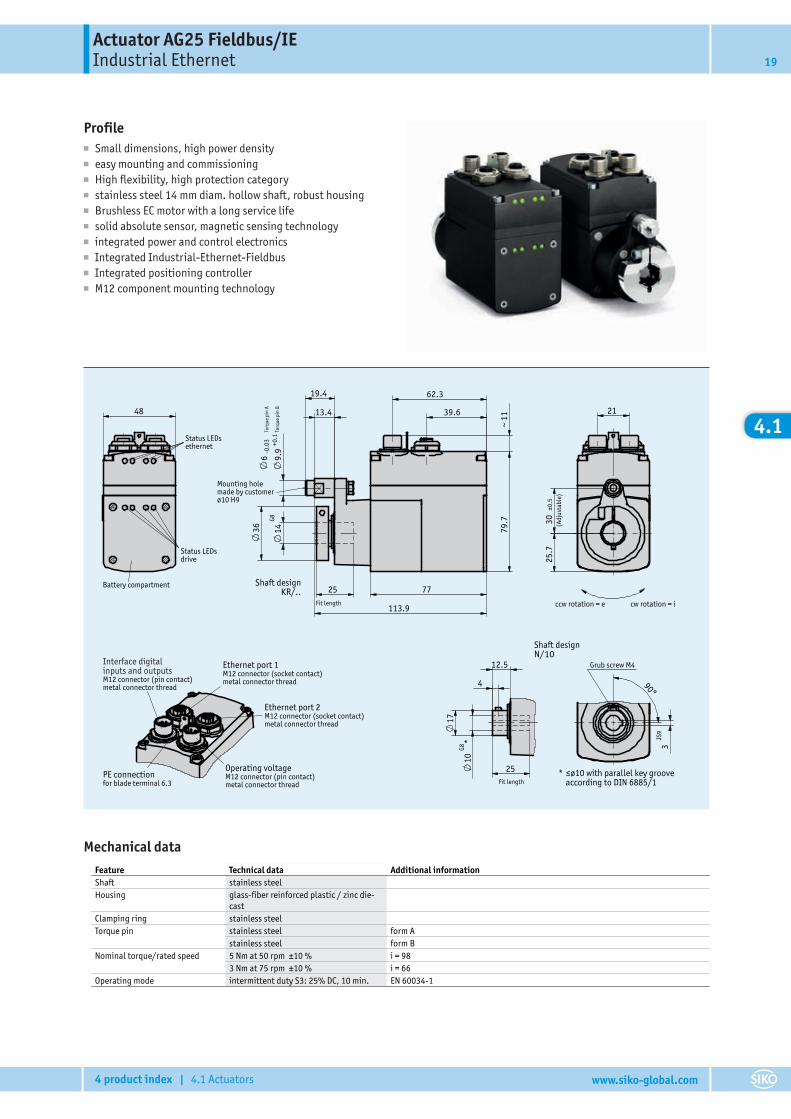
Profile■ Small dimensions, high power density■ easy mounting and commissioning■ High flexibility, high protection category■ stainless steel 14 mm diam. hollow shaft, robust housing■ Brushless EC motor with a long service life■ solid absolute sensor, magnetic sensing technology■ integrated power and control electronics■ Integrated Industrial-Ethernet-Fieldbus■ Integrated positioning controller■ M12 component mounting technology
Katalogzeichnung
207967
Weißer22.07.2014
AG25277/14
Shaft designN/10
Grub screw M4
*
90°
JS9
3
Fit length
25
*
G810
12.5
4
17
M12 connector (socket contact)metal connector thread
Ethernet port 2
for blade terminal 6.3PE connection M12 connector (pin contact)
metal connector thread
Operating voltage
M12 connector (socket contact)metal connector thread
Ethernet port 1
M12 connector (pin contact)metal connector thread
Interface digital inputs and outputs
cw rotation = iccw rotation = e
(Adj
usta
ble)
25.
7
±0.5
30
21
Status LEDsdrive
Battery compartment
Status LEDsethernet
48
Shaft designKR/..
Torq
ue p
in B
Torq
ue p
in A
-0.0
3
Mounting hole made by customerø10 H9
Fit length
25
G814
79.
7
77
~ 1
1
62.3
39.6
19.4
13.4
+0.1
9.9
636
113.9
≤ø10 with parallel key groove according to DIN 6885/1
Mechanical dataFeature Technical data Additional informationShaft stainless steelHousing glass-fiber reinforced plastic / zinc die-
castClamping ring stainless steelTorque pin stainless steel form A
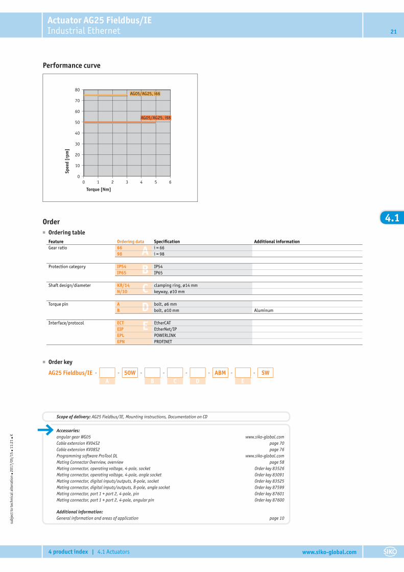
stainless steel form BNominal torque/rated speed 5 Nm at 50 rpm ±10 % i = 98
3 Nm at 75 rpm ±10 % i = 66Operating mode intermittent duty S3: 25% DC, 10 min. EN 60034-1
Actuator AG25 Fieldbus/IEIndustrial Ethernet20
4 product index | 4.1 Actuators www.siko-global.com
4.1
Electrical dataFeature Technical data Additional informationOperating voltage 24 V DC ±10 % reverse polarity protected, output stage
24 V DC ±10 % reverse polarity protected, controlCurrent consumption 2.2 A ±10 % at nominal torque/speed (output stage)
<150 mA starting current >150 mA (control)Power input ≤58 W output stage
≤3.6 W controlBattery CR2477N, 3 V lithium, 950 mAhBattery service life ~5 year(s) depending on ambient conditionsDigital inputs 17 … 30 V DC typically 10 mAStatus display 8 LEDsKeys 2 internal keys, internal DIP switchSwitching outputs 24 V DC ±10 % ≤40 mABus connection EIP-EtherNet/IP
EPN-PROFINETECT-EtherCATEPL-POWERLINK
Type of connection 2x M12 plug connectors (A-coded) 4-pole, 1x pin; 8-pole, 1x pin2x M12 plug connectors (D-coded) 4-pole, 2x socketgrounding via flat connector 6.3 mm
System dataFeature Technical data Additional informationResolution 720 increments/revolution shaftRepeat accuracy ±1 increment(s)Travel range ±1300 revolution(s) i = 98
±1980 revolution(s) i = 66
Ambient conditionsFeature Technical data Additional informationAmbient temperature 0 … 45 °CStorage temperature -20 … 60 °CRelative humidity condensation inadmissibleEMC EN 61800-3, second environment interference resistance / immission
EN 61800-3, C2 emitted interference / emissionProtection category IP54, IP65 EN 60529, only with mating connectorShock resistance 500 m/s2, 8 ms EN 60068-2-27Vibration resistance <100 m/s2, 5 … 150 Hz EN 60068-2-6
Pin assignment■ EtherCAT, EtherNet/IP, POWERLINK, PROFINET
Signal PINTx+ 1Rx+ 2Tx- 3Rx- 4
■ Operating voltage (output stage / control)Signal PIN+UB (output stage) 1+UB (control) 2GND (output stage)* 3GND (control)* 4* internally connected with SGND
■ Digital inputs / outputsSignal PINInput 1 1Input 2 2Input 3 3Input 4 4Output 1 5RXD 6TXD 7SGND* 8* internally connected with GND of operating voltage
Actuator AG25 Fieldbus/IEIndustrial Ethernet 21
4 product index | 4.1 Actuators www.siko-global.com
4.1
Performance curve
80
70
30
20
10
0
60
50
40
0 54321 6
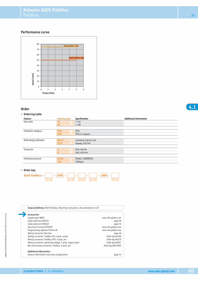
AG05/AG25, i98
AG05/AG25, i66
Torque [Nm]
Spee
d [r
pm]
Order� Ordering table
A
B
C
D
E
Feature Ordering data Specification Additional informationGear ratio 66 i = 66
98 i = 98
Protection category IP54 IP54IP65 IP65
Shaft design/diameter KR/14 clamping ring, ø14 mmN/10 keyway, ø10 mm
Torque pin A bolt, ø6 mmB bolt, ø10 mm Aluminum
Interface/protocol ECT EtherCATEIP EtherNet/IPEPL POWERLINKEPN PROFINET
� Order key
AG25 Fieldbus/IE - -
A-50W -
B-
C-
D-ABM -
ESW
subj
ect t
o te
chni
cal a
lter
atio
n � 2
017/
05/1
5 � 1
1:21
� K
Accessories:angular gear WG05 www.siko-global.comCable extension KV04S2 page 70Cable extension KV08S2 page 76Programming software ProTool DL www.siko-global.comMating Connector Overview, overview page 58Mating connector, operating voltage, 4-pole, socket Order key 83526Mating connector, operating voltage, 4-pole, angle socket Order key 83091Mating connector, digital inputs/outputs, 8-pole, socket Order key 83525Mating connector, digital inputs/outputs, 8-pole, angle socket Order key 87599Mating connector, port 1 + port 2, 4-pole, pin Order key 87601Mating connector, port 1 + port 2, 4-pole, angular pin Order key 87600
Additional information:General information and areas of application page 10
Scope of delivery: AG25 Fieldbus/IE, Mounting instructions, Documentation on CD
Actuator AG06 FieldbusFieldbus22
4 product index | 4.1 Actuators www.siko-global.com
4.1
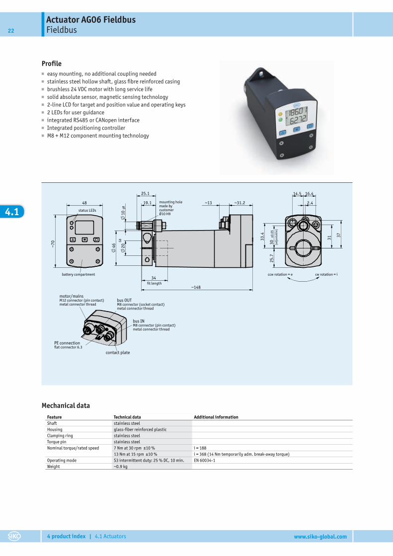
Profile■ easy mounting, no additional coupling needed■ stainless steel hollow shaft, glass fibre reinforced casing■ brushless 24 VDC motor with long service life■ solid absolute sensor, magnetic sensing technology■ 2-line LCD for target and position value and operating keys■ 2 LEDs for user guidance■ integrated RS485 or CANopen interface■ Integrated positioning controller■ M8 + M12 component mounting technology
001/15
AG0629.01.2015 Weißer
207474
Katalogzeichnung
10 g
8
status LEDs
battery compartment
mounting hole made by customerØ10 H9
motor/mainsM12 connector (pin contact)metal connector thread
bus OUT M8 connector (socket contact)metal connector thread
bus INM8 connector (pin contact)metal connector thread
contact plate
PE connectionflat connector 6.3
ccw rotation = e cw rotation = i
fit length
(adj
usta
ble)
~148
34
~31.2 ~13
46
19.1
25.1
20 G8
48
~70
2.4
14.5 16.4
31
37
30
±0.0
5
33.
4
25.
7
Mechanical dataFeature Technical data Additional informationShaft stainless steelHousing glass-fiber reinforced plasticClamping ring stainless steelTorque pin stainless steelNominal torque/rated speed 7 Nm at 30 rpm ±10 % i = 188
13 Nm at 15 rpm ±10 % i = 368 (14 Nm temporarily adm. break-away torque)Operating mode S3 intermittent duty: 25 % DC, 10 min. EN 60034-1Weight ~0.9 kg
Actuator AG06 FieldbusFieldbus 23
4 product index | 4.1 Actuators www.siko-global.com
4.1
Electrical dataFeature Technical data Additional informationOperating voltage 24 V DC ±10 % reverse polarity protected, output stage
24 V DC ±10 % reverse polarity protected, controlCurrent consumption 2.42 A max. adm. at set point 100% (output stage)Power input ~48 W output stageBattery CR2477N, 3 V lithium, 950 mAhBattery service life ~5 year(s) depending on environmental conditionsRated current 2.2 A ±10 % at max. adm. torque (output stage)
<60 mA at 24 V DC (control)Display/display range 5-digit LCD 7-segment, ~7 mm height decimal points, 2 rows, special charactersSpecial character battery, direction arrowsStatus display two LEDsKeys parameterizing, resetting, inching,
setpoint definitionBus connection RS485; CANopen no galvanic isolationType of connection 1x M12-plug connector (A-coded) 4-pole, 1x pin
2x M8 plug connectors 4-pole, 1x socket, 1x pingrounding via flat connector 6.3 mm
System dataFeature Technical data Additional informationResolution 720 increments/revolution shaftRepeat accuracy ±1 increment(s)Travel range ±697 revolution(s) i = 188
±356 revolution(s) i = 368
Ambient conditionsFeature Technical data Additional informationAmbient temperature 0 … 45 °CStorage temperature -20 … 60 °CRelative humidity condensation inadmissibleEMC EN 61800-3, second environment interference resistance / immission
EN 61800-3, C3 emitted interference / emissionProtection category IP54, IP65 EN 60529, mating connectors mountedShock resistance 500 m/s2, 11 ms EN 60068-2-27Vibration resistance <100 m/s2, 5 … 150 Hz EN 60068-2-6
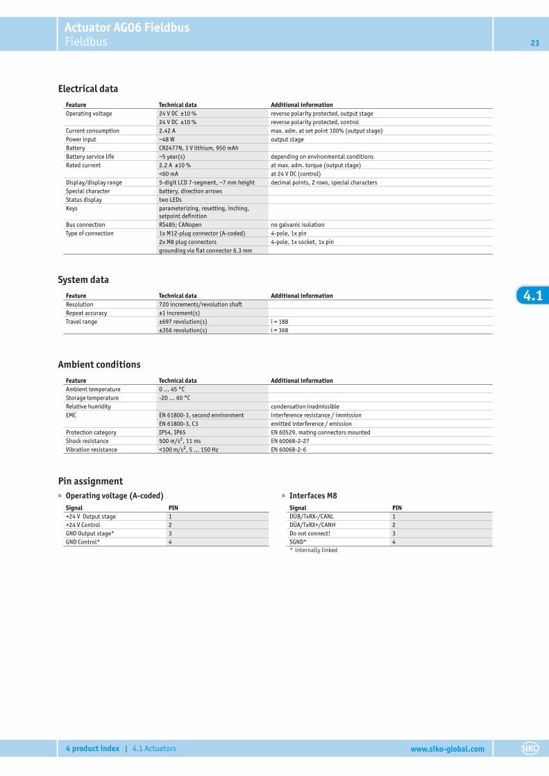
Pin assignment■ Operating voltage (A-coded)
Signal PIN+24 V Output stage 1+24 V Control 2GND Output stage* 3GND Control* 4
■ Interfaces M8Signal PINDÜB/TxRX-/CANL 1DÜA/TxRX+/CANH 2Do not connect! 3SGND* 4* internally linked

Actuator AG06 FieldbusFieldbus24
4 product index | 4.1 Actuators www.siko-global.com
4.1
Performance curve
40
30
20
10
00 5 10 15
AG06/AG26, i368
AG06/AG26, i188
Torque [Nm]
Spee
d [r
pm]
Order� Ordering table
A
B
C
D
Feature Ordering data Specification Additional informationGear ratio 188 i = 188
368 i = 368
Protection category IP54 IP54IP65 IP65
Shaft design/diameter KR/20 clamping ring, ø20 mmothers on request
Interface/protocol S3/09 RS485/SIKONETZ5CAN CANopen
� Order key
AG06 Fieldbus - -
A-50W -
B-
C-B -ABM -
DSW
subj
ect t
o te
chni
cal a
lter
atio
n � 2
017/
05/1
5 � 1
1:21
� K
Accessories:Cable extension KV04S1 page 68Cable extension KV04S2 page 70Easy Touch Control ETC5000 www.siko-global.comProgramming software ProTool DL www.siko-global.comMating Connector Overview page 58Mating connector, Fieldbus IN, 4-pole, socket Order key 84209Mating connector, Fieldbus OUT, 4-pole, pin Order key 84210Mating connector, voltage supply, 4-pole, angle socket Order key 83091Bus terminating connector, Fieldbus, 4-pole, pin Order key BAS-0005
Additional information:General information and areas of application page 10
Scope of delivery: AG06 Fieldbus, Mounting instructions, Documentation on CD
Actuator AG05 FieldbusFieldbus 25
4 product index | 4.1 Actuators www.siko-global.com
4.1
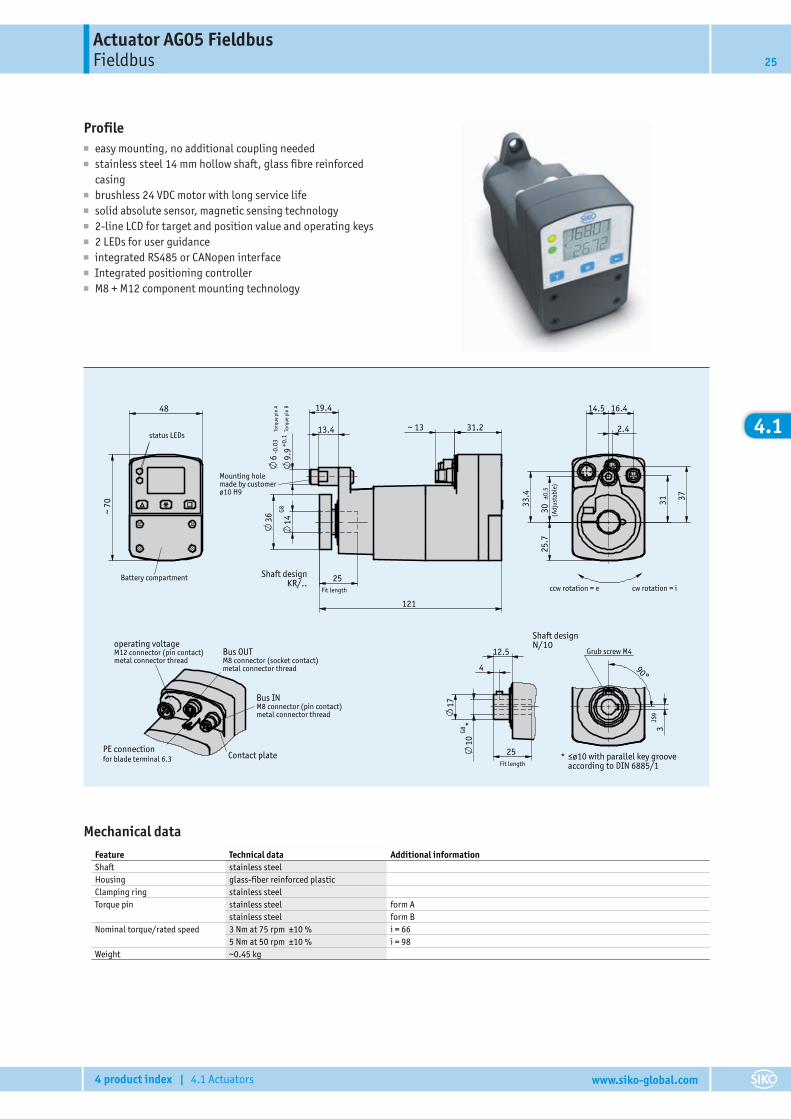
Profile■ easy mounting, no additional coupling needed■ stainless steel 14 mm hollow shaft, glass fibre reinforced
casing■ brushless 24 VDC motor with long service life■ solid absolute sensor, magnetic sensing technology■ 2-line LCD for target and position value and operating keys■ 2 LEDs for user guidance■ integrated RS485 or CANopen interface■ Integrated positioning controller■ M8 + M12 component mounting technology
Katalogzeichnung16.07.2014 Weißer
205531
5 Weißer18.04.2017
AG051x111/17
Grub screw M4
*
90°
JS9
3
Fit length
25
*
G810
12.5
4
17
Contact platePE connectionfor blade terminal 6.3
M12 connector (pin contact)metal connector thread
operating voltage
M8 connector (socket contact)metal connector thread
Bus OUT
M8 connector (pin contact)metal connector thread
Bus IN
ccw rotation = e cw rotation = i
(Adj
usta
ble)
16.4 14.5
2.4
37
31
33.
4
±0.5
30
25.
7
status LEDs
Battery compartment
~ 7
0
48
Mounting hole made by customerø10 H9
Torq
ue p
in B
Torq
ue p
in A
-0.0
3
Shaft designKR/..
Fit length
25
G814
+0
.19.
9
6
19.4
13.4 ~ 13 31.2
121
36
≤ø10 with parallel key groove according to DIN 6885/1
Shaft designN/10
Mechanical dataFeature Technical data Additional informationShaft stainless steelHousing glass-fiber reinforced plasticClamping ring stainless steelTorque pin stainless steel form A
stainless steel form BNominal torque/rated speed 3 Nm at 75 rpm ±10 % i = 66
5 Nm at 50 rpm ±10 % i = 98Weight ~0.45 kg
Actuator AG05 FieldbusFieldbus26
4 product index | 4.1 Actuators www.siko-global.com
4.1
Electrical dataFeature Technical data Additional informationOperating voltage 24 V DC ±10 % reverse polarity protected, output stage
24 V DC ±10 % reverse polarity protected, controlPower input ~58 W output stageBattery CR2477N, 3 V lithium, 950 mAhBattery service life ~5 year(s) depending on ambient conditionsRated current 2.2 A ±10 % at max. admissible torque (output stage)
<60 mA ±10 % at 24 V DC (control)Display/display range 5-digit LCD 7-segment, ~7 mm height decimal points, 2 rows, special charactersSpecial character battery, direction arrowsStatus display two LEDsKeys parameterizing, resetting, inching,
setpoint definitionBus connection RS485, CANopen no galvanic isolationType of connection 1x M12 plug connector (A-coded) 4-pole, 1x pin
2x M8 plug connectors 4-pole, 1x socket, 1x pingrounding via flat connector 6.3 mm
System dataFeature Technical data Additional informationResolution 720 increments/revolution shaftRepeat accuracy ±1 increment(s)Travel range ±1980 revolution(s) i = 66
±1300 revolution(s) i = 98
Ambient conditionsFeature Technical data Additional informationAmbient temperature 0 … 45 °CStorage temperature -20 … 60 °CRelative humidity condensation inadmissibleEMC EN 61800-3, second environment interference resistance / immission
EN 61800-3, C3 emitted interference / emissionProtection category IP54, IP65 EN 60529, only with mating connectorShock resistance 500 m/s2, 8 ms EN 60068-2-27Vibration resistance <100 m/s2, 5 … 150 Hz EN 60068-2-6
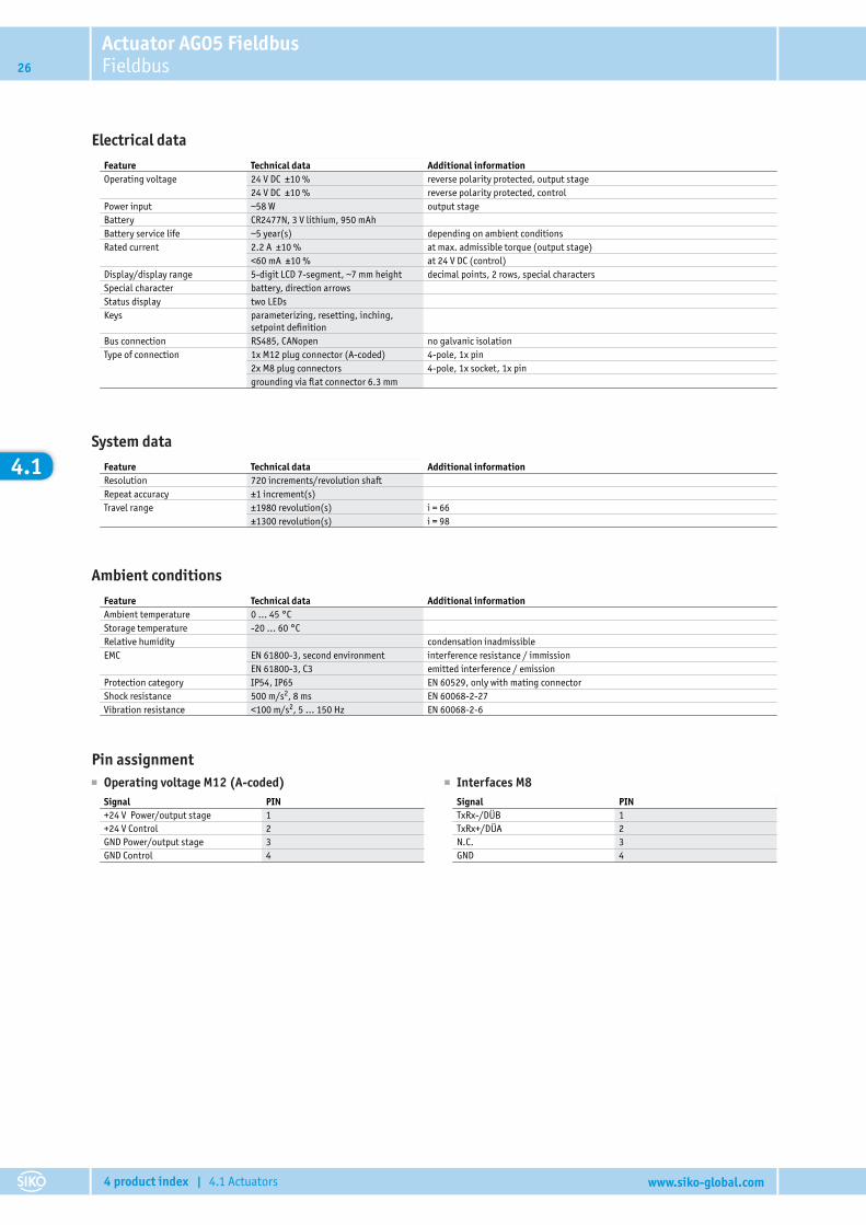
Pin assignment■ Operating voltage M12 (A-coded)
Signal PIN+24 V Power/output stage 1+24 V Control 2GND Power/output stage 3GND Control 4
■ Interfaces M8Signal PINTxRx-/DÜB 1TxRx+/DÜA 2N.C. 3GND 4
Actuator AG05 FieldbusFieldbus 27
4 product index | 4.1 Actuators www.siko-global.com
4.1
Performance curve
80
70
30
20
10
0
60
50
40
0 54321 6
AG05/AG25, i98
AG05/AG25, i66
Torque [Nm]
Spee
d [r
pm]
Order� Ordering table
A
B
C
D
E
Feature Ordering data Specification Additional informationGear ratio 66 i = 66
98 i = 98
Protection category IP54 IP54IP65 IP65 on request
Shaft design/diameter KR/14 clamping ring ø14 mmN/10 keyway, ø10 mm
Torque pin A bolt, ø6 mmB bolt, ø10 mm
Interface/protocol S3/09 RS485 / SIKONETZ5CAN CANopen
� Order key
AG05 Fieldbus - -
A-50W -
B-
C-
D-ABM
E
subj
ect t
o te
chni
cal a
lter
atio
n � 2
017/
05/1
5 � 1
1:21
� K Accessories:
angular gear WG05 www.siko-global.comCable extension KV04S1 page 68Cable extension KV04S2 page 70Easy Touch Control ETC5000 www.siko-global.comProgramming software ProTool DL www.siko-global.comMating Connector Overview page 58Mating connector, Fieldbus IN, 4-pole, socket Order key 84209Mating connector, Fieldbus OUT, 4-pole, pin Order key 84210Mating connector, operating voltage, 4-pole, angle socket Order key 83091Bus terminating connector, Fieldbus, 4-pole, pin Order key BAS-0005
Additional information:General information and areas of application page 10
Scope of delivery: AG05 Fieldbus, Mounting instructions, Documentation on CD
Actuator AG04B FieldbusFieldbus28
4 product index | 4.1 Actuators www.siko-global.com
4.1
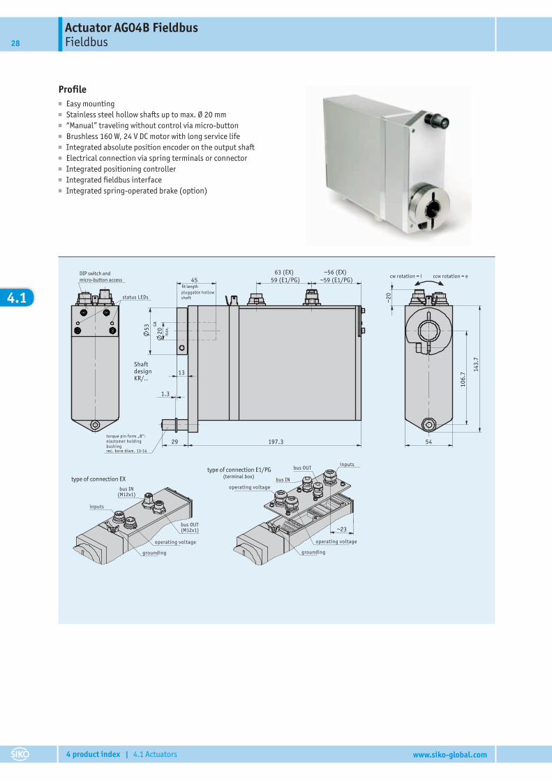
Profile■ Easy mounting■ Stainless steel hollow shafts up to max. Ø 20 mm■ “Manual” traveling without control via micro-button■ Brushless 160 W, 24 V DC motor with long service life■ Integrated absolute position encoder on the output shaft■ Electrical connection via spring terminals or connector■ Integrated positioning controller■ Integrated fieldbus interface■ Integrated spring-operated brake (option)
Katalogzeichnung23.07.2008 Weißer
203846
5 Weißer18.04.2017
AG04B111/17
54
DIP switch and micro-button access
status LEDs
fit lengthpluggable hollowshaft
max
.
cw rotation = i ccw rotation = e
inputs
(terminal box)
grounding
bus OUT
operating voltage
grounding
type of connection EX
bus IN
torque pin form „B“:elastomer holding bushing
rec. bore diam. 13-14
inputs
Shaft designKR/..
type of connection E1/PG
bus INoperating voltage
operating voltage
bus OUT
G820
45
106.
7 143.
7
~20
(M12x1)
(M12x1)
~23
29
~59 (E1/PG)59 (E1/PG)
53
63 (EX)
13
~56 (EX)
1.3
197.3
Actuator AG04B FieldbusFieldbus 29
4 product index | 4.1 Actuators www.siko-global.com
4.1
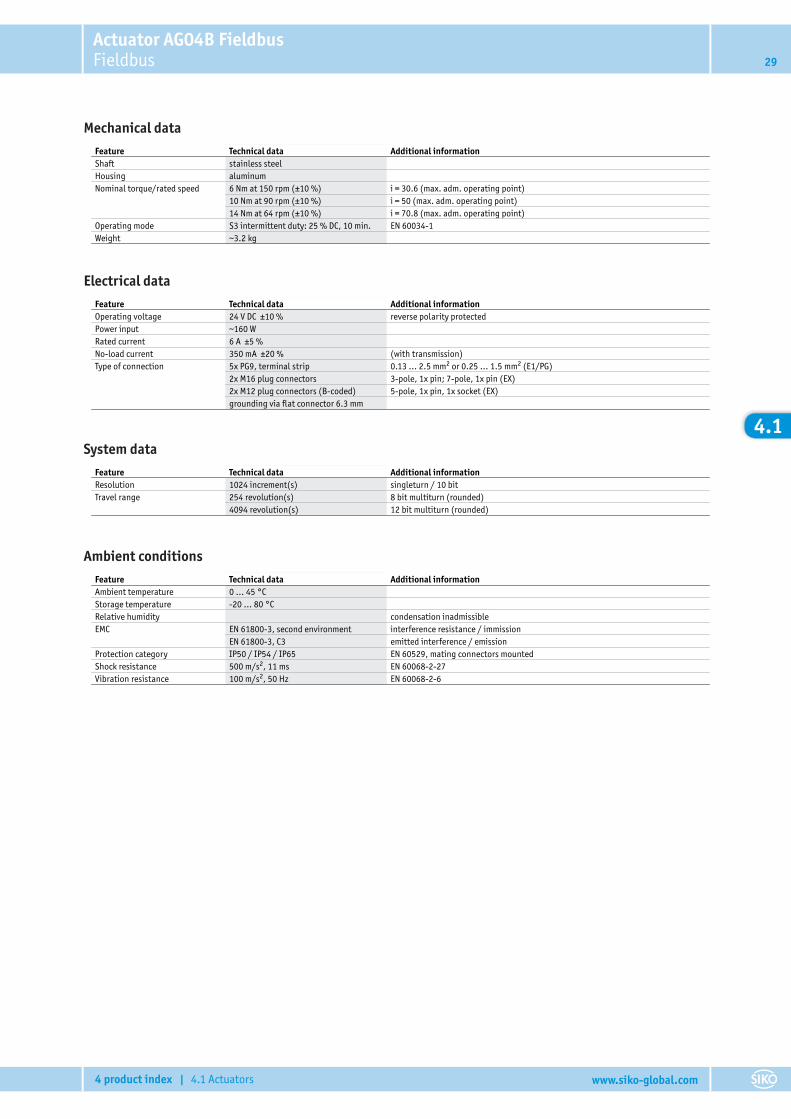
Mechanical dataFeature Technical data Additional informationShaft stainless steelHousing aluminumNominal torque/rated speed 6 Nm at 150 rpm (±10 %) i = 30.6 (max. adm. operating point)
10 Nm at 90 rpm (±10 %) i = 50 (max. adm. operating point)14 Nm at 64 rpm (±10 %) i = 70.8 (max. adm. operating point)
Operating mode S3 intermittent duty: 25 % DC, 10 min. EN 60034-1Weight ~3.2 kg
Electrical dataFeature Technical data Additional informationOperating voltage 24 V DC ±10 % reverse polarity protectedPower input ~160 WRated current 6 A ±5 %No-load current 350 mA ±20 % (with transmission)Type of connection 5x PG9, terminal strip 0.13 … 2.5 mm2 or 0.25 … 1.5 mm2 (E1/PG)
2x M16 plug connectors 3-pole, 1x pin; 7-pole, 1x pin (EX)2x M12 plug connectors (B-coded) 5-pole, 1x pin, 1x socket (EX)grounding via flat connector 6.3 mm
System dataFeature Technical data Additional informationResolution 1024 increment(s) singleturn / 10 bitTravel range 254 revolution(s) 8 bit multiturn (rounded)
4094 revolution(s) 12 bit multiturn (rounded)
Ambient conditionsFeature Technical data Additional informationAmbient temperature 0 … 45 °CStorage temperature -20 … 80 °CRelative humidity condensation inadmissibleEMC EN 61800-3, second environment interference resistance / immission
EN 61800-3, C3 emitted interference / emissionProtection category IP50 / IP54 / IP65 EN 60529, mating connectors mountedShock resistance 500 m/s2, 11 ms EN 60068-2-27Vibration resistance 100 m/s2, 50 Hz EN 60068-2-6
Actuator AG04B FieldbusFieldbus30
4 product index | 4.1 Actuators www.siko-global.com
4.1
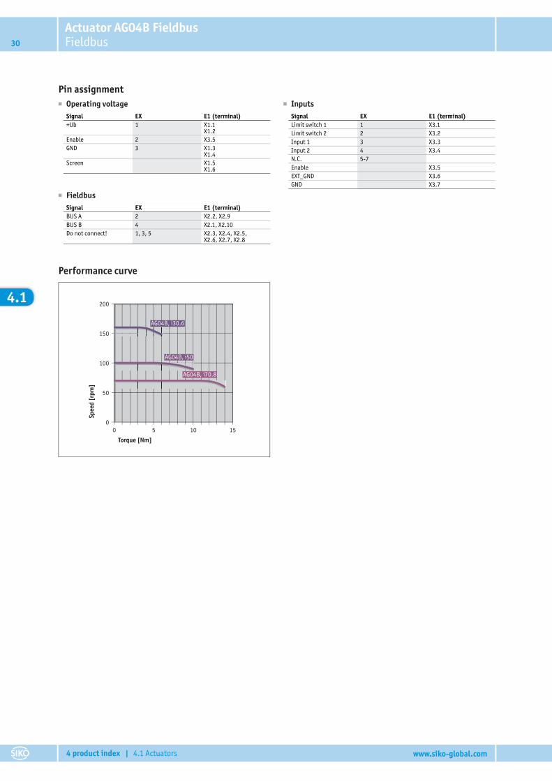
Pin assignment� Operating voltage
Signal EX E1 (terminal)+Ub 1 X1.1
X1.2Enable 2 X3.5GND 3 X1.3
X1.4Screen X1.5
X1.6
� InputsSignal EX E1 (terminal)Limit switch 1 1 X3.1Limit switch 2 2 X3.2Input 1 3 X3.3Input 2 4 X3.4N.C. 5-7Enable X3.5EXT_GND X3.6GND X3.7
� FieldbusSignal EX E1 (terminal)BUS A 2 X2.2, X2.9BUS B 4 X2.1, X2.10Do not connect! 1, 3, 5 X2.3, X2.4, X2.5,
X2.6, X2.7, X2.8
Performance curve
200
150
100
50
00 5 10 15
AG04B, i70.8
AG04B, i50
AG04B, i30.6
Torque [Nm]
Spee
d [r
pm]
Actuator AG04B FieldbusFieldbus 31
4 product index | 4.1 Actuators www.siko-global.com
4.1
Order■ Ordering table
A
B
C
D
E
F
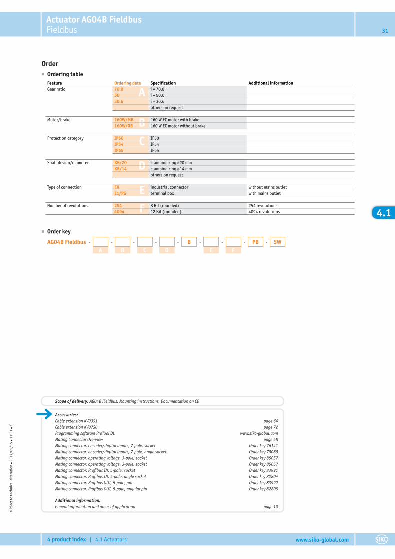
Feature Ordering data Specification Additional informationGear ratio 70.8 i = 70.8
50 i = 50.030.6 i = 30.6
others on request
Motor/brake 160W/MB 160 W EC motor with brake160W/OB 160 W EC motor without brake
Protection category IP50 IP50IP54 IP54IP65 IP65
Shaft design/diameter KR/20 clamping ring ø20 mmKR/14 clamping ring ø14 mm
others on request
Type of connection EX industrial connector without mains outletE1/PG terminal box with mains outlet
Number of revolutions 254 8 Bit (rounded) 254 revolutions4094 12 Bit (rounded) 4094 revolutions
■ Order key
AG04B Fieldbus - -
A-
B-
C-
D-B -
E-
F-PB SW
subj
ect t
o te
chni
cal a
lter
atio
n ● 2
017/
05/1
5 ● 1
1:21
● K
Accessories:Cable extension KV03S1 page 64Cable extension KV07S0 page 72Programming software ProTool DL www.siko-global.comMating Connector Overview page 58Mating connector, encoder/digital inputs, 7-pole, socket Order key 76141Mating connector, encoder/digital inputs, 7-pole, angle socket Order key 78088Mating connector, operating voltage, 3-pole, socket Order key 85057Mating connector, operating voltage, 3-pole, socket Order key 85057Mating connector, Profibus IN, 5-pole, socket Order key 83991Mating connector, Profibus IN, 5-pole, angle socket Order key 82804Mating connector, Profibus OUT, 5-pole, pin Order key 83992Mating connector, Profibus OUT, 5-pole, angular pin Order key 82805
Additional information:General information and areas of application page 10
Scope of delivery: AG04B Fieldbus, Mounting instructions, Documentation on CD
Actuator AG03/1 FieldbusFieldbus32
4 product index | 4.1 Actuators www.siko-global.com
4.1
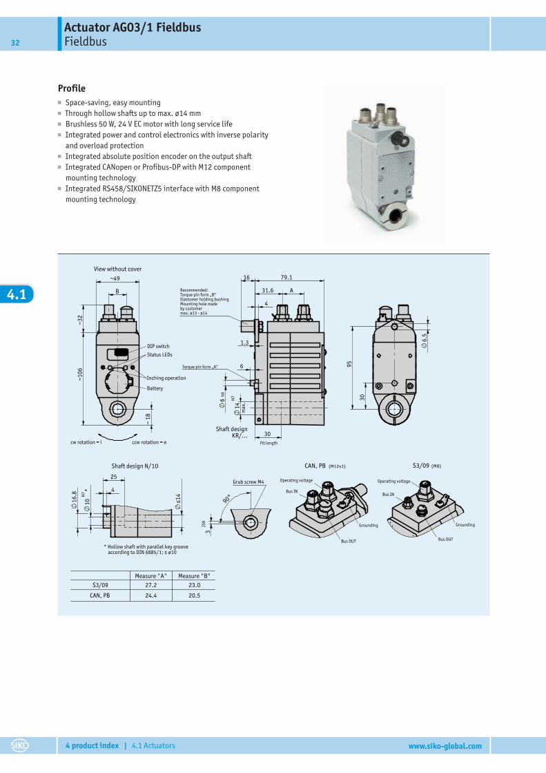
Profile■ Space-saving, easy mounting■ Through hollow shafts up to max. ø14 mm■ Brushless 50 W, 24 V EC motor with long service life■ Integrated power and control electronics with inverse polarity
and overload protection■ Integrated absolute position encoder on the output shaft■ Integrated CANopen or Profibus-DP with M12 component
mounting technology■ Integrated RS458/SIKONETZ5 interface with M8 component
mounting technology
111/17
AG03/118.04.2017 Weißer2
207930
Kreutzmann08.10.2013 Katalogzeichnung
20.524.4CAN, PB
23.027.2S3/09Measure "B"Measure "A"
Grub screw M4
90°
JS9
3
* Hollow shaft with parallel key groove according to DIN 6885/1; ≤ ø10
Shaft design N/10
≤14
*
H7
10
4
25
16.8
Grounding
Bus IN
Bus OUT
Operating voltage
(M8)S3/09
Grounding
Bus IN
Bus OUT
Operating voltage
(M12x1)CAN, PB
6.5
95
30
Torque pin form „A“
Shaft designKR/...
Fit length
Recommended: Torque pin form „B“Elastomer holding bushing Mounting hole made by customer max. ø13 - ø14
max
.
30
79.1 16
6
h96
4
1.3
A 31.6
cw rotation = i ccw rotation = e
Status LEDs
~ 1
8
~49
~32
~
106
B
H7
14
View without cover
DIP switch
Inching operation
Battery
Actuator AG03/1 FieldbusFieldbus 33
4 product index | 4.1 Actuators www.siko-global.com
4.1
Mechanical dataFeature Technical data Additional informationShaft black-finished steelHousing aluminum/zinc die cast anodized / powder-coatedNominal torque/rated speed 3.2 Nm at 100 rpm i = 48
1.6 Nm at 200 rpm i = 24Operating mode S3 intermittent operation: 25 % DC, 10
min.EN 60034-1
Electrical dataFeature Technical data Additional informationOperating voltage 24 V DC ±10 % reverse polarity protected, output stage
24 V DC ±10 % reverse polarity protected, control (only CAN, PB, S3/09)Power input 58 W output stageBattery CR2477N, 3 V lithium, 950 mAhBattery service life ~5 year(s) depending on ambient conditionsRated current 2.4 A ±10 % at max. adm. torque (output stage)
<100 mA at 24 V DC (control), only CAN, PB, S3/09Status display two LEDsKeys touch keys for setting-up modeBus connection CANopen, Profibus-DP, SIKONETZ5 galvanic isolation
Profibus-DP galvanic isolationSIKONETZ5 galvanic isolation
Type of connection 2x M12-plug connectors (A-coded) 5-pole, 1x socket, 1x pin (CAN)2x M12 plug connectors (B-coded) 5-pole, 1x socket, 1x pin (PB)2x M8-plug connectors 4-pole, 1 x socket, 1 x pin (S3/09)1x M12-plug connector (A-coded) 4-pole, 1x pin (CAN + PB + S3/09)grounding via flat connector 6.3 mm
System dataFeature Technical data Additional informationResolution 1600 increments/revolutionSystem accuracy ±0.8° unidirectionalRepeat accuracy ±1 increment(s) unidirectional / bidirectionalTravel range ±8192 revolution(s)
Ambient conditionsFeature Technical data Additional informationAmbient temperature 0 … 45 °CStorage temperature -20 … 60 °CRelative humidity condensation inadmissibleEMC EN 61800-3, second environment interference resistance / immission
EN 61800-3, C3 emitted interference / emissionProtection category IP50 / IP54 / IP65 EN 60529, mating connectors mountedShock resistance 500 m/s2, 8 ms EN 60068-2-27Vibration resistance ≤100 m/s2, 5 … 150 Hz EN 60068-2-6
Actuator AG03/1 FieldbusFieldbus34
4 product index | 4.1 Actuators www.siko-global.com
4.1
Pin assignment� Operating voltage
CAN, PB, S3/09 PIN+UB (output stage) 1+UB (control) 2GND (output stage + control) 3N.C. 4
� Fieldbus PB, CANPB CAN PINN.C. N.C. 1BUS A N.C. 2N.C. CAN_GND 3BUS B CAN_H 4N.C. CAN_L 5
� Fieldbus S3/09Signal PINDÜB/TxRx- 1DÜA/TxRx+ 2N.C. 3SGND 4
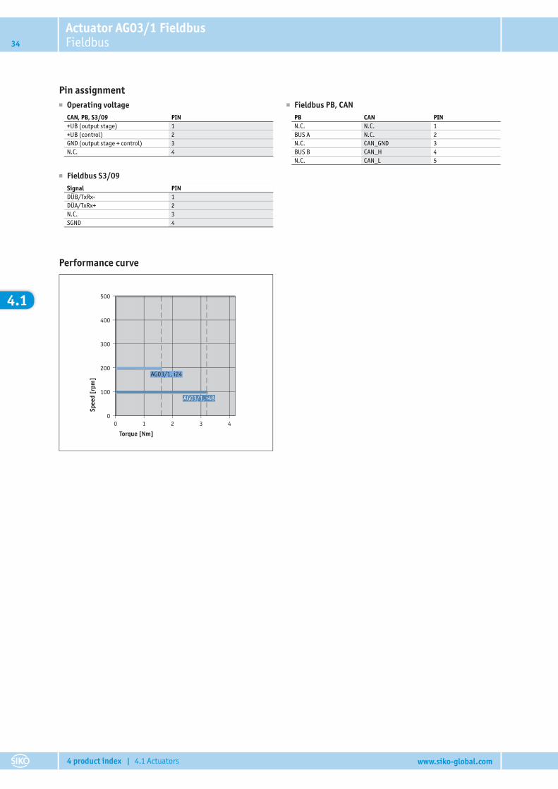
Performance curve
500
400
300
200
100
00 1 2 3 4
AG03/1, i48
AG03/1, i24
Torque [Nm]
Spee
d [r
pm]
Actuator AG03/1 FieldbusFieldbus 35
4 product index | 4.1 Actuators www.siko-global.com
4.1
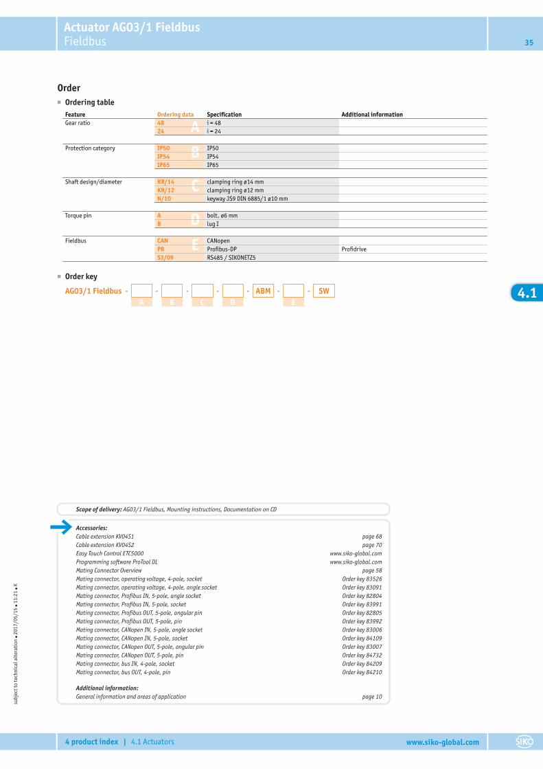
Order■ Ordering table
A
B
C
D
E
Feature Ordering data Specification Additional informationGear ratio 48 i = 48
24 i = 24
Protection category IP50 IP50IP54 IP54IP65 IP65
Shaft design/diameter KR/14 clamping ring ø14 mmKR/12 clamping ring ø12 mmN/10 keyway JS9 DIN 6885/1 ø10 mm
Torque pin A bolt, ø6 mmB lug I
Fieldbus CAN CANopenPB Profibus-DP ProfidriveS3/09 RS485 / SIKONETZ5
■ Order key
AG03/1 Fieldbus - -
A-
B-
C-
D-ABM -
ESW
subj
ect t
o te
chni
cal a
lter
atio
n ● 2
017/
05/1
5 ● 1
1:21
● K
Accessories:Cable extension KV04S1 page 68Cable extension KV04S2 page 70Easy Touch Control ETC5000 www.siko-global.comProgramming software ProTool DL www.siko-global.comMating Connector Overview page 58Mating connector, operating voltage, 4-pole, socket Order key 83526Mating connector, operating voltage, 4-pole, angle socket Order key 83091Mating connector, Profibus IN, 5-pole, angle socket Order key 82804Mating connector, Profibus IN, 5-pole, socket Order key 83991Mating connector, Profibus OUT, 5-pole, angular pin Order key 82805Mating connector, Profibus OUT, 5-pole, pin Order key 83992Mating connector, CANopen IN, 5-pole, angle socket Order key 83006Mating connector, CANopen IN, 5-pole, socket Order key 84109Mating connector, CANopen OUT, 5-pole, angular pin Order key 83007Mating connector, CANopen OUT, 5-pole, pin Order key 84732Mating connector, bus IN, 4-pole, socket Order key 84209Mating connector, bus OUT, 4-pole, pin Order key 84210
Additional information:General information and areas of application page 10
Scope of delivery: AG03/1 Fieldbus, Mounting instructions, Documentation on CD
Actuator AG02 FieldbusFieldbus36
4 product index | 4.1 Actuators www.siko-global.com
4.1
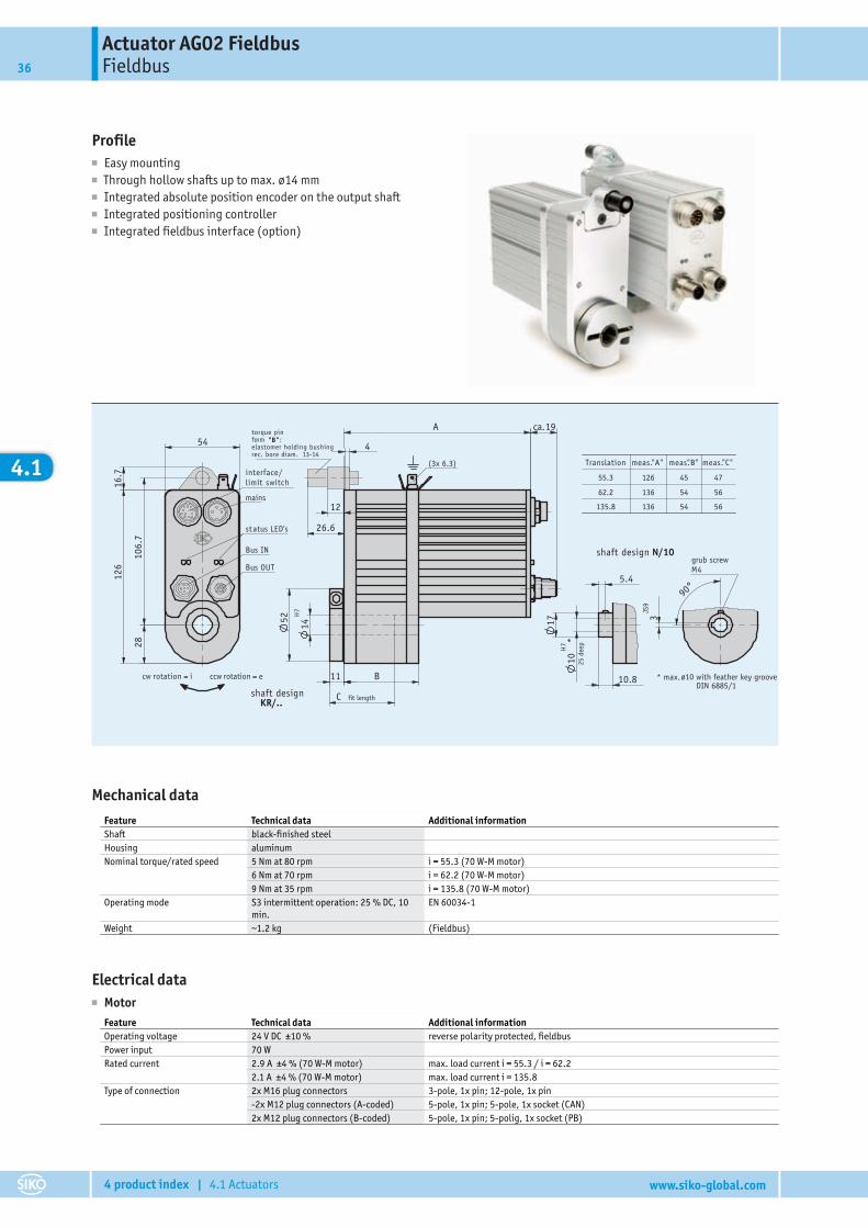
Profile■ Easy mounting■ Through hollow shafts up to max. ø14 mm■ Integrated absolute position encoder on the output shaft■ Integrated positioning controller■ Integrated fieldbus interface (option)
14H
7
C
10H
7 *
29.07.2008276/08
203357bAr tikel-Nr .
3JS
9
90°
KR/..
(3x 6.3)
19
12
26.6
11
52
ca.
4
A
B
16.7
54
2810
6.7
126
5.4
17
10.8
55.3 126 45 47
62.2 136 54 56
135.8 136 54 56
"A" "B" "C"Translation meas. meas. meas.
M4
N/10shaft designgrub screw
* max. ø10 with feather key grooveDIN 6885/1
fit lengthshaft design
cw rotation = i ccw rotation = e
mains
interface/limit switch
Bus IN
Bus OUT
status LED's
torque pinform "B":elastomer holding bushingrec. bore diam. 13-14
25 d
eep
Mechanical dataFeature Technical data Additional informationShaft black-finished steelHousing aluminumNominal torque/rated speed 5 Nm at 80 rpm i = 55.3 (70 W-M motor)
6 Nm at 70 rpm i = 62.2 (70 W-M motor)9 Nm at 35 rpm i = 135.8 (70 W-M motor)
Operating mode S3 intermittent operation: 25 % DC, 10min.
EN 60034-1
Weight ~1.2 kg (Fieldbus)
Electrical data■ Motor
Feature Technical data Additional informationOperating voltage 24 V DC ±10 % reverse polarity protected, fieldbusPower input 70 WRated current 2.9 A ±4 % (70 W-M motor) max. load current i = 55.3 / i = 62.2
2.1 A ±4 % (70 W-M motor) max. load current i = 135.8Type of connection 2x M16 plug connectors 3-pole, 1x pin; 12-pole, 1x pin
-2x M12 plug connectors (A-coded) 5-pole, 1x pin; 5-pole, 1x socket (CAN)2x M12 plug connectors (B-coded) 5-pole, 1x pin; 5-polig, 1x socket (PB)
Actuator AG02 FieldbusFieldbus 37
4 product index | 4.1 Actuators www.siko-global.com
4.1
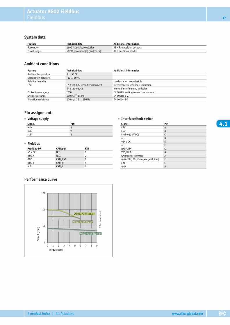
System dataFeature Technical data Additional informationResolution 1600 intervals/revolution ABM P10 position encoderTravel range ±6250 revolution(s) (multiturn) ABM position encoder
Ambient conditionsFeature Technical data Additional informationAmbient temperature 0 … 50 °CStorage temperature -20 … 60 °CRelative humidity condensation inadmissibleEMC EN 61800-3, second environment interference resistance / immission
EN 61800-3, C3 emitted interference / emissionProtection category IP50 EN 60529, mating connectors mountedShock resistance 500 m/s2, 11 ms EN 60068-2-27Vibration resistance 100 m/s2, 5 … 150 Hz EN 60068-2-6
Pin assignment� Voltage supply
Signal PIN+Ub 1N.C. 2-Ub 3
� Interface/limit switchSignal PINES1 AES2 BEnable (24 V DC) Cnc D+24 V DC Enc FRXD/DÜA GTXD/DÜB HGND/serial interface JGND (ES1, ES2,Emergency-off, CAL) KCAL LGND M
� FieldbusProfibus-DP CANopen PIN+5 V DC N.C. 1BUS A N.C. 2GND CAN_GND 3BUS B CAN_H 4N.C. CAN_L 5
Performance curve
150
100
50
00 1 2 3 5 74 6 8 9
AG02, 70 W, i135.8*
AG02, 70 W, i62.2*
AG02, 70 W, i55.3*AG02, 70 W, i55.3*
Torque [Nm]
Spee
d [r
pm] *
Bus
cont
rolle
d
Actuator AG02 FieldbusFieldbus38
4 product index | 4.1 Actuators www.siko-global.com
4.1
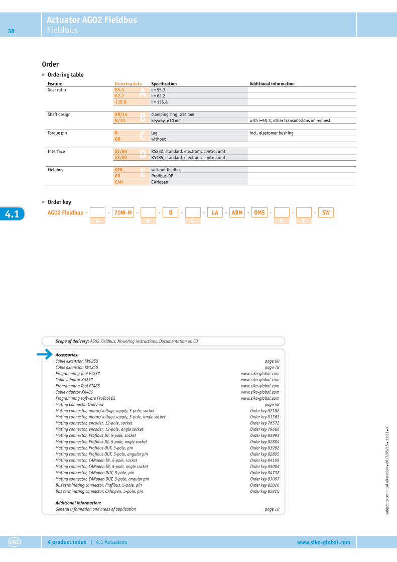
Order■ Ordering table
A
B
C
D
E
Feature Ordering data Specification Additional informationGear ratio 55.3 i = 55.3
62.2 i = 62.2135.8 i = 135.8
Shaft design KR/14 clamping ring, ø14 mmN/10 keyway, ø10 mm with i=55.3, other transmissions on request
Torque pin B lug incl. elastomer bushingOD without
Interface S1/00 RS232, standard, electronic control unitS3/00 RS485, standard, electronic control unit
Fieldbus OFB without fieldbusPB Profibus-DPCAN CANopen
■ Order key
AG02 Fieldbus - -
A-70W-M -
B-D -
C-LA -ABM -OMS -
D-
ESW
subj
ect t
o te
chni
cal a
lter
atio
n ● 2
017/
05/1
5 ● 1
1:21
● K
Accessories:Cable extension KV02S0 page 60Cable extension KV12S0 page 78Programming Tool PT232 www.siko-global.comCable adaptor KA232 www.siko-global.comProgramming Tool PT485 www.siko-global.comCable adaptor KA485 www.siko-global.comProgramming software ProTool DL www.siko-global.comMating Connector Overview page 58Mating connector, motor/voltage supply, 3-pole, socket Order key 82182Mating connector, motor/voltage supply, 3-pole, angle socket Order key 81363Mating connector, encoder, 12-pole, socket Order key 76572Mating connector, encoder, 12-pole, angle socket Order key 79666Mating connector, Profibus IN, 5-pole, socket Order key 83991Mating connector, Profibus IN, 5-pole, angle socket Order key 82804Mating connector, Profibus OUT, 5-pole, pin Order key 83992Mating connector, Profibus OUT, 5-pole, angular pin Order key 82805Mating connector, CANopen IN, 5-pole, socket Order key 84109Mating connector, CANopen IN, 5-pole, angle socket Order key 83006Mating connector, CANopen OUT, 5-pole, pin Order key 84732Mating connector, CANopen OUT, 5-pole, angular pin Order key 83007Bus terminating connector, Profibus, 5-pole, pin Order key 82816Bus terminating connector, CANopen, 5-pole, pin Order key 82815
Additional information:General information and areas of application page 10
Scope of delivery: AG02 Fieldbus, Mounting instructions, Documentation on CD
Actuator AG02 AnalogAnalog 39
4 product index | 4.1 Actuators www.siko-global.com
4.1
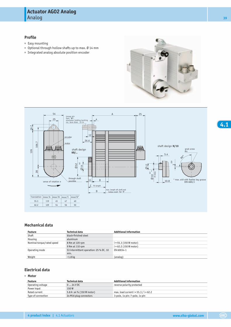
Profile■ Easy mounting■ Optional through hollow shafts up to max. Ø 14 mm■ Integrated analog absolute position encoder
C
14H
7
D
10H
7 *
29.07.2008276/08
203357a
Ar tikel-Nr .
126
25
54
2810
6.7
16.7
KR/..
A
B
12
26.6
11
52
4
25
N/10
5.4
17
10.8
55.3 119 45 47 40
62.2 129 54 56 50
M4
3JS
9
90°
e
motor
through shaft possible
max. length oft shaft endhollow shaft Typ "S"
* max. ø10
torque pinform "B":elastomer holding bushingrec. bore diam. 13-14
encoder
shaft design
sense of rotation
fit length
shaft designgrub screw
with feather key grooveDIN 6885/1
meas. meas. meas. meas."A "B "C "D"Translation
25 d
eep
Mechanical dataFeature Technical data Additional informationShaft black-finished steelHousing aluminumNominal torque/rated speed 8 Nm at 120 rpm i = 55.3 (150 W motor)
9 Nm at 110 rpm i = 62.2 (150 W motor)Operating mode S3 intermittent operation: 25 % DC, 10
min.EN 60034-1
Weight ~1.8 kg (analog)
Electrical data■ Motor
Feature Technical data Additional informationOperating voltage 0 … 24 V DC reverse polarity protectedPower input 150 WRated current 5.8 A ±4 % (150 W motor) max. load current i = 55.3 / i = 62.2Type of connection 2x M16 plug connectors 3-pole, 1x pin; 7-pole, 1x pin
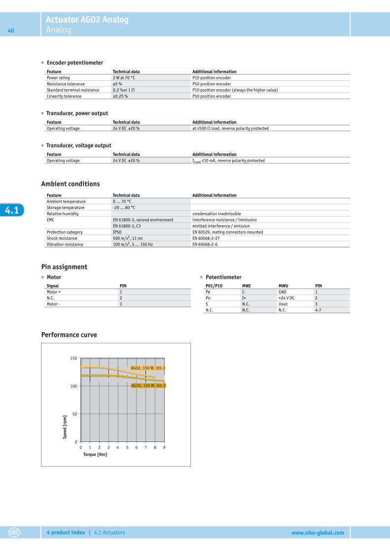
Actuator AG02 AnalogAnalog40
4 product index | 4.1 Actuators www.siko-global.com
4.1
� Encoder potentiometerFeature Technical data Additional informationPower rating 2 W at 70 °C P10 position encoderResistance tolerance ±5 % P10 position encoderStandard terminal resistance 0.2 %or 1 Ω P10 position encoder (always the higher value)Linearity tolerance ±0.25 % P10 position encoder
� Transducer, power outputFeature Technical data Additional informationOperating voltage 24 V DC ±20 % at ≤500 Ω load, reverse polarity protected
� Transducer, voltage outputFeature Technical data Additional informationOperating voltage 24 V DC ±20 % ILoad ≤10 mA, reverse polarity protected
Ambient conditionsFeature Technical data Additional informationAmbient temperature 0 … 70 °CStorage temperature -20 … 80 °CRelative humidity condensation inadmissibleEMC EN 61800-3, second environment interference resistance / immission
EN 61800-3, C3 emitted interference / emissionProtection category IP50 EN 60529, mating connectors mountedShock resistance 500 m/s2, 11 ms EN 60068-2-27Vibration resistance 100 m/s2, 5 … 150 Hz EN 60068-2-6
Pin assignment� Motor
Signal PINMotor + 1N.C. 2Motor - 3
� PotentiometerP01/P10 MWI MWU PINPe I- GND 1Po I+ +24 V DC 2S N.C. Uout 3N.C. N.C. N.C. 4-7
Performance curve
150
100
50
00 1 2 3 5 74 6 8 9
AG02, 150 W, i62.2
AG02, 150 W, i55.3
Torque [Nm]
Spee
d [r
pm]
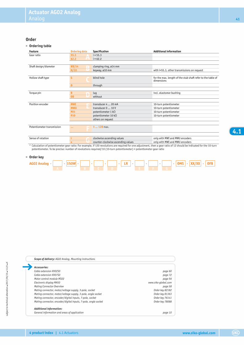
Actuator AG02 AnalogAnalog 41
4 product index | 4.1 Actuators www.siko-global.com
4.1
Order■ Ordering table
A
B
C
D
E
F
G
Feature Ordering data Specification Additional informationGear ratio 55.3 i = 55.3
62.2 i = 62.2
Shaft design/diameter KR/14 clamping ring, ø14 mmN/10 keyway, ø10 mm with i=55.3, other transmissions on request
Hollow shaft type S blind hole for the max. length of the stub shaft refer to the table ofdimensions
D through
Torque pin B lug incl. elastomer bushingOD without
Position encoder MWI transducer 4 … 20 mA 10-turn potentiometerMWU transducer 0 … 10 V 10-turn potentiometerP01 potentiometer 1 kΩ 10-turn potentiometerP10 potentiometer 10 kΩ 10-turn potentiometer
others on request
Potentiometer transmission ... 1 ... 128 max.
Sense of rotation i clockwise ascending values only with MWI and MWU encoderse counter-clockwise ascending values only with MWI and MWU encoders
* Calculation of potentiometer gear ratio: For example, if 120 revolutions are required for one adjustment, then a gear ratio of 12 should be indicated for the 10-turnpotentiometer. To be precise: number of revolutions required/10 (10-turn potentiometer) = potentiometer gear ratio
■ Order key
AG02 Analog - -
A-150W -
B-
C-
D-LR -
E-
F-
G-OMS -XX/XX OFB
subj
ect t
o te
chni
cal a
lter
atio
n ● 2
017/
05/1
5 ● 1
1:21
● K
Accessories:Cable extension KV02S0 page 60Cable extension KV07S0 page 72Motor control module MS02 page 56Electronic display MA50 www.siko-global.comMating Connector Overview page 58Mating connector, motor/voltage supply, 3-pole, socket Order key 82182Mating connector, motor/voltage supply, 3-pole, angle socket Order key 81363Mating connector, encoder/digital inputs, 7-pole, socket Order key 76141Mating connector, encoder/digital inputs, 7-pole, angle socket Order key 78088
Additional information:General information and areas of application page 10
Scope of delivery: AG02 Analog, Mounting instructions
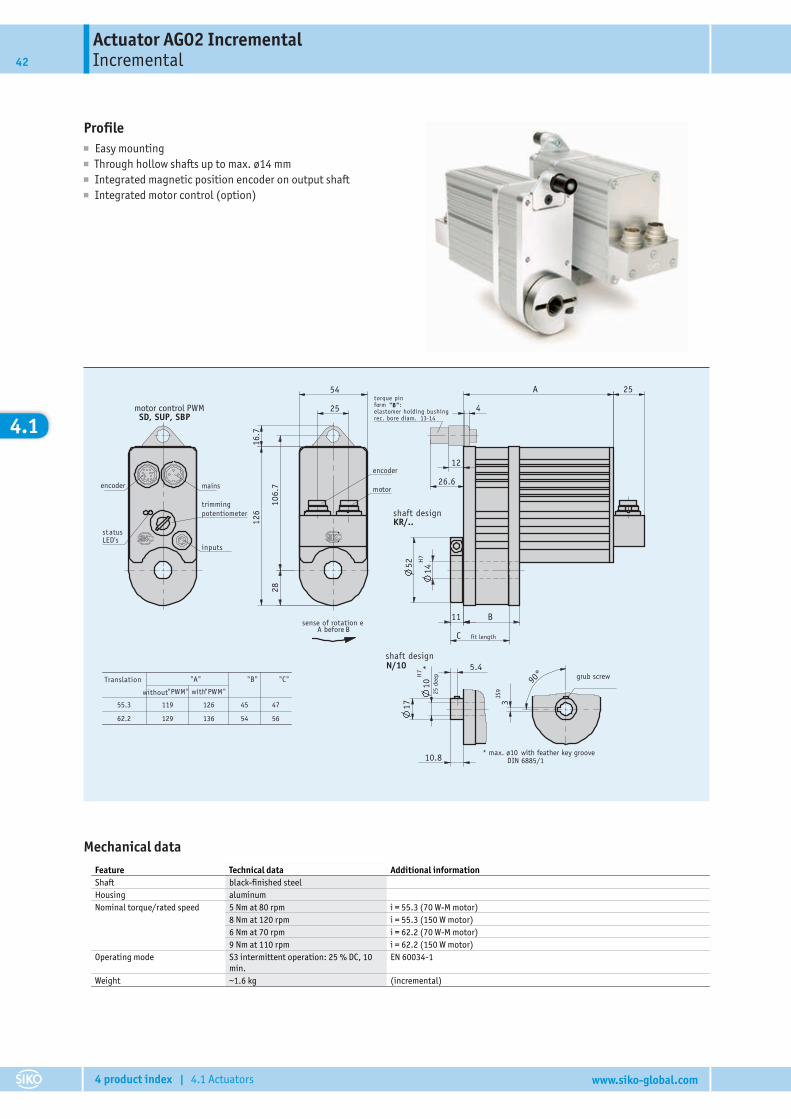
Actuator AG02 IncrementalIncremental42
4 product index | 4.1 Actuators www.siko-global.com
4.1
Profile■ Easy mounting■ Through hollow shafts up to max. ø14 mm■ Integrated magnetic position encoder on output shaft■ Integrated motor control (option)
10H
7 *14
H7
C
126
25
54
2810
6.7
16.7
5.4
17
10.8
55.3 119 126 45 47
62.2 129 136 54 56
KR/..
52
11 B
A
26.6
12
25
4
29.07.2008276/08
203357
Ar tikel-Nr .
SD, SUP, SBP
3JS
9
90°
N/10
A before
sense of rotation e B
r
25 d
eep
* max. ø10 with feather key grooveDIN 6885/1
shaft design
shaft design
torque pinform "B":elastomer holding bushingrec. bore diam. 13-14
fit length
motor control PWM
mains
inputs
statusLED's
trimmingpotentiometer
grub screw
moto
encoder
encoder
Translation "A" "B" "C"
" "PWM" with"PWMwithout
Mechanical dataFeature Technical data Additional informationShaft black-finished steelHousing aluminumNominal torque/rated speed 5 Nm at 80 rpm i = 55.3 (70 W-M motor)
8 Nm at 120 rpm i = 55.3 (150 W motor)6 Nm at 70 rpm i = 62.2 (70 W-M motor)9 Nm at 110 rpm i = 62.2 (150 W motor)
Operating mode S3 intermittent operation: 25 % DC, 10min.
EN 60034-1
Weight ~1.6 kg (incremental)
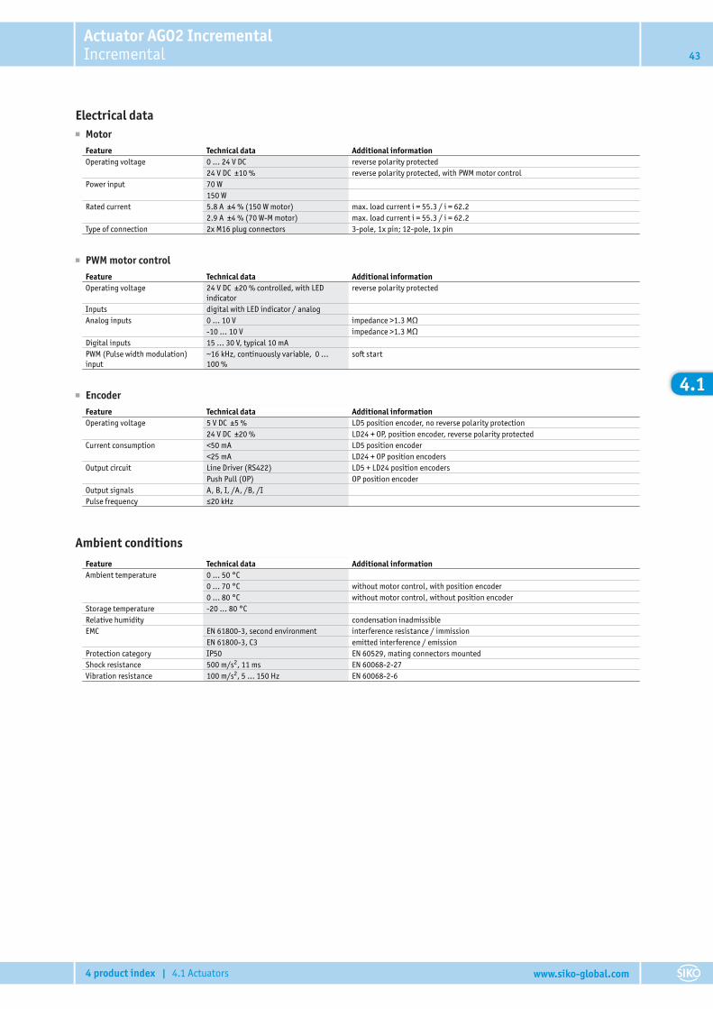
Actuator AG02 IncrementalIncremental 43
4 product index | 4.1 Actuators www.siko-global.com
4.1
Electrical data■ Motor
Feature Technical data Additional informationOperating voltage 0 … 24 V DC reverse polarity protected
24 V DC ±10 % reverse polarity protected, with PWM motor controlPower input 70 W
150 WRated current 5.8 A ±4 % (150 W motor) max. load current i = 55.3 / i = 62.2
2.9 A ±4 % (70 W-M motor) max. load current i = 55.3 / i = 62.2Type of connection 2x M16 plug connectors 3-pole, 1x pin; 12-pole, 1x pin
■ PWM motor controlFeature Technical data Additional informationOperating voltage 24 V DC ±20 % controlled, with LED
indicatorreverse polarity protected
Inputs digital with LED indicator / analogAnalog inputs 0 … 10 V impedance >1.3 MΩ
-10 … 10 V impedance >1.3 MΩDigital inputs 15 … 30 V, typical 10 mAPWM (Pulse width modulation)input
~16 kHz, continuously variable, 0 …100 %
soft start
■ EncoderFeature Technical data Additional informationOperating voltage 5 V DC ±5 % LD5 position encoder, no reverse polarity protection
24 V DC ±20 % LD24 + OP, position encoder, reverse polarity protectedCurrent consumption <50 mA LD5 position encoder
<25 mA LD24 + OP position encodersOutput circuit Line Driver (RS422) LD5 + LD24 position encoders
Push Pull (OP) OP position encoderOutput signals A, B, I, /A, /B, /IPulse frequency ≤20 kHz
Ambient conditionsFeature Technical data Additional informationAmbient temperature 0 … 50 °C
0 … 70 °C without motor control, with position encoder0 … 80 °C without motor control, without position encoder
Storage temperature -20 … 80 °CRelative humidity condensation inadmissibleEMC EN 61800-3, second environment interference resistance / immission
EN 61800-3, C3 emitted interference / emissionProtection category IP50 EN 60529, mating connectors mountedShock resistance 500 m/s2, 11 ms EN 60068-2-27Vibration resistance 100 m/s2, 5 … 150 Hz EN 60068-2-6
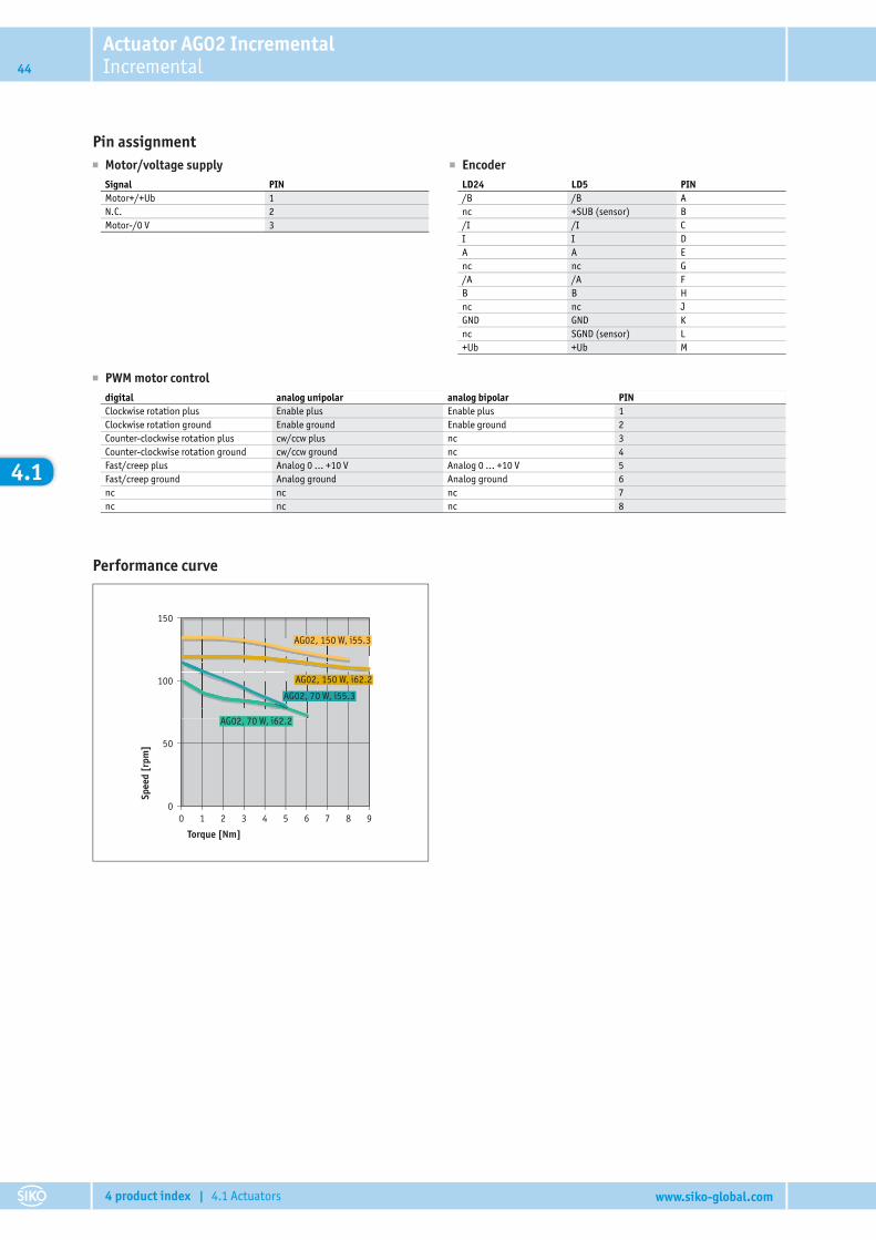
Actuator AG02 IncrementalIncremental44
4 product index | 4.1 Actuators www.siko-global.com
4.1
Pin assignment� Motor/voltage supply
Signal PINMotor+/+Ub 1N.C. 2Motor-/0 V 3
� EncoderLD24 LD5 PIN/B /B Anc +SUB (sensor) B/I /I CI I DA A Enc nc G/A /A FB B Hnc nc JGND GND Knc SGND (sensor) L+Ub +Ub M
� PWM motor controldigital analog unipolar analog bipolar PINClockwise rotation plus Enable plus Enable plus 1Clockwise rotation ground Enable ground Enable ground 2Counter-clockwise rotation plus cw/ccw plus nc 3Counter-clockwise rotation ground cw/ccw ground nc 4Fast/creep plus Analog 0 … +10 V Analog 0 … +10 V 5Fast/creep ground Analog ground Analog ground 6nc nc nc 7nc nc nc 8
Performance curve
150
100
50
00 1 2 3 5 74 6 8 9
AG02, 70 W, i62.2
AG02, 70 W, i55.3
AG02, 150 W, i62.2
AG02, 150 W, i55.3
Torque [Nm]
Spee
d [r
pm]
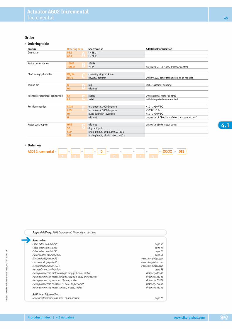
Actuator AG02 IncrementalIncremental 45
4 product index | 4.1 Actuators www.siko-global.com
4.1
Order■ Ordering table
A
B
C
D
E
F
G
Feature Ordering data Specification Additional informationGear ratio 55.3 i = 55.3
62.2 i = 62.2
Motor performance 150W 150 W70W-M 70 W only with SD, SUP or SBP motor control
Shaft design/diameter KR/14 clamping ring, ø14 mmN/10 keyway, ø10 mm with i=55.3, other transmissions on request
Torque pin B lug incl. elastomer bushingOD without
Position of electrical connection LR radial with external motor controlLA axial with integrated motor control
Position encoder LD24 incremental 1000 Impulse +10 … +30 V DCLD5 incremental 1000 Impulse +5 V DC ±5 %OP push-pull with inverting +10 … +30 V DCO without only with LR "Position of electrical connection"
Motor control pwm OMS without only with 150 W motor powerSD digital inputSUP analog input, unipolar 0 … +10 VSBP analog input, bipolar -10 … +10 V
■ Order key
AG02 Incremental - -
A-
B-
C-D -
D-
E-
F-
G-XX/XX OFB
subj
ect t
o te
chni
cal a
lter
atio
n ● 2
017/
05/1
5 ● 1
1:21
● K
Accessories:Cable extension KV02S0 page 60Cable extension KV08S0 page 74Cable extension KV12S0 page 78Motor control module MS02 page 56Electronic display MA55 www.siko-global.comElectronic display MA48 www.siko-global.comElectronic display MA10/4 www.siko-global.comMating Connector Overview page 58Mating connector, motor/voltage supply, 3-pole, socket Order key 82182Mating connector, motor/voltage supply, 3-pole, angle socket Order key 81363Mating connector, encoder, 12-pole, socket Order key 76572Mating connector, encoder, 12-pole, angle socket Order key 79666Mating connector, motor control, 8-pole, socket Order key 81351
Additional information:General information and areas of application page 10
Scope of delivery: AG02 Incremental, Mounting instructions
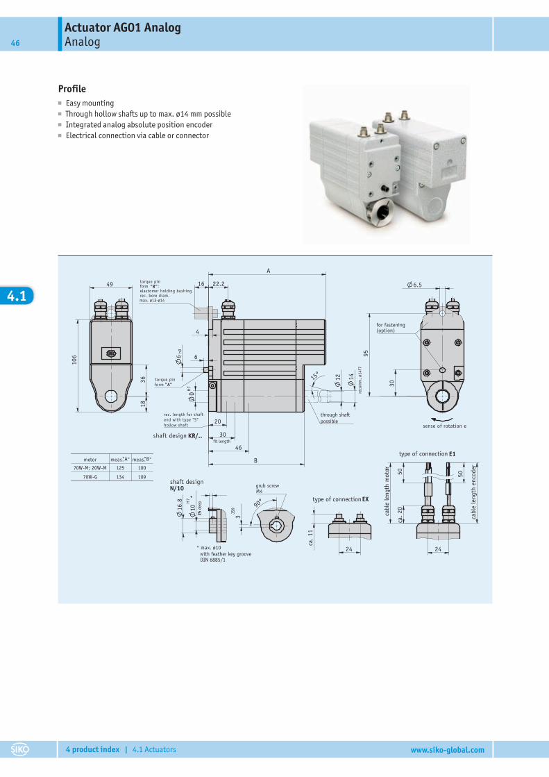
Actuator AG01 AnalogAnalog46
4 product index | 4.1 Actuators www.siko-global.com
4.1
Profile■ Easy mounting■ Through hollow shafts up to max. ø14 mm possible■ Integrated analog absolute position encoder■ Electrical connection via cable or connector
10H
7 *
12
30
46
20
D
15° 14
18
70W-M; 20W-M 125 100
70W-G 134 109
29.07.2008276/08
203801 aAr tikel-Nr .
25
16.8
30
95
6.5
24
ca.
11
H7
A
B
6
22.2
6h9
4
16
36
49
106
90°
3JS
9
50
24
20
r
ca.
50type of connection
for fastening(option)
sense of rotation e
E1
fit length
through shaft possible
max. ø13-ø14
form "A"
rec. length for shaftend with type "S"hollow shaft
KR/..shaft design
torque pinform "B":elastomer holding bushingrec. bore diam.
torque pin
M4
type of connection EX
cabl
e le
ngth
enc
oder
cabl
e le
ngth
mot
or
N/10
* max. ø10
shaft designgrub screw
with feather key grooveDIN 6885/1
25 d
eep
" "B"
reco
mm
.. ø1
4f7
meas.motor "Ameas.
Actuator AG01 AnalogAnalog 47
4 product index | 4.1 Actuators www.siko-global.com
4.1
Mechanical dataFeature Technical data Additional informationShaft black-finished steelHousing aluminum, powder coated zinc die castNominal torque/rated speed 1.1 Nm, 430 rpm i = 12.4 (70 W motors)
2.1 Nm, 225 rpm i = 24 (70 W motors)4.2 Nm, 110 rpm i = 48 (70 W motors)
Operating mode S3 intermittent operation: 25 % DC, 10min.
EN 60034-1
Weight ~1.5 kg
Electrical data■ Motor
Feature Technical data Additional informationOperating voltage 0 … 24 V DC 70 W motorsPower input 70 WRated current 2.9 A ±10 % (70W-M) 3.2 A max. load current
4.1 A ±10 % (70W-G) 4.5 A max. load currentType of connection 2x M9 plug connectors 4-pole, 1x pin; 3-pole, 1x pin
■ Encoder potentiometerFeature Technical data Additional informationPower rating 2 W at 70 °C P10 position encoderResistance tolerance ±5 % P10 position encoderStandard terminal resistance 0.2 %or 1 Ω P10 position encoder (always the higher value)Linearity tolerance ±0.25 % P10 position encoder
■ Transducer, power outputFeature Technical data Additional informationOperating voltage 24 V DC ±20 % at ≤500 Ω load
■ Transducer, voltage outputFeature Technical data Additional informationOperating voltage 24 V DC ±20 % ILoad ≤10 mA
Ambient conditionsFeature Technical data Additional informationAmbient temperature 0 … 70 °CStorage temperature -20 … 80 °CRelative humidity condensation inadmissibleEMC EN 61800-3, second environment interference resistance / immission
EN 61800-3, C3 emitted interference / emissionProtection category IP63 EN 60529, with mating connectors mountedShock resistance 500 m/s2, 11 ms EN 60068-2-27Vibration resistance 100 m/s2, 50 Hz EN 60068-2-6
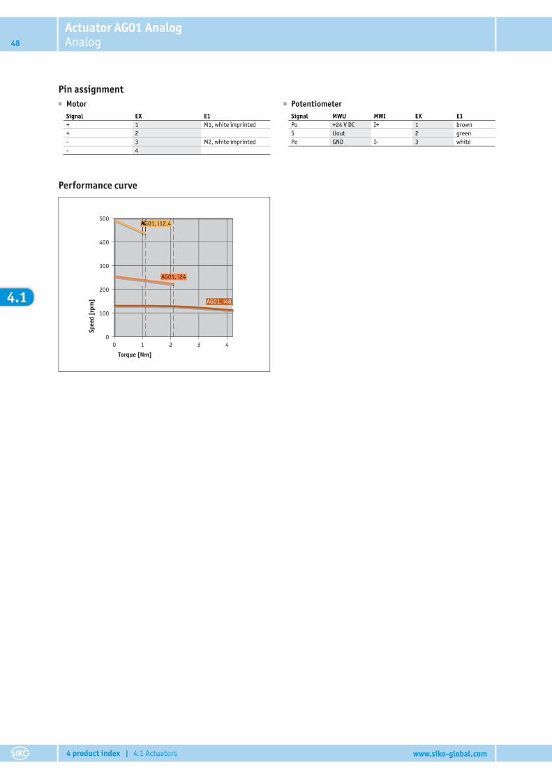
Actuator AG01 AnalogAnalog48
4 product index | 4.1 Actuators www.siko-global.com
4.1
Pin assignment� Motor
Signal EX E1+ 1 M1, white imprinted+ 2- 3 M2, white imprinted- 4
� PotentiometerSignal MWU MWI EX E1Po +24 V DC I+ 1 brownS Uout 2 greenPe GND I- 3 white
Performance curve
500
400
300
200
100
00 1 2 3 4
AG01, i48
AG01, i24
AG01, i12.4AG01, i12.4
Torque [Nm]
Spee
d [r
pm]
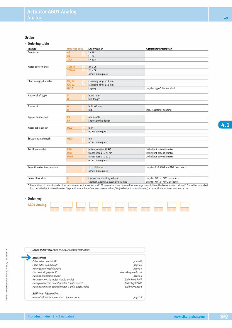
Actuator AG01 AnalogAnalog 49
4 product index | 4.1 Actuators www.siko-global.com
4.1
Order■ Ordering table
A
B
C
D
E
F
G
H
I
J
K
Feature Ordering data Specification Additional informationGear ratio 48 i = 48
24 i = 2412.4 i = 12.4
Motor performance 70W-M 24 V DC70W-G 24 V DC
others on request
Shaft design/diameter KR/14 clamping ring, ø14 mmKR/12 clamping ring, ø12 mmN/10 keyway only for type S hollow shaft
Hollow shaft type S blind holeD full-length
Torque pin A bolt, ø6 mmB lug I incl. elastomer bushing
Type of connection E1 open cableEX socket on the device
Motor cable length 02.0 in mothers on request
Encoder cable length 02.0 in mothers on request
Position encoder P10 potentiometer 10 kΩ 10 helipot potentiometerMWI transducer 4 … 20 mA 10 helipot potentiometerMWU transducer 0 … 10 V 10 helipot potentiometer
others on request
Potentiometer transmission ... 1 ... 128 max. only for P10, MWI and MWU encodersothers on request
Sense of rotation i clockwise ascending values only for MWI or MWU encoderse counter-clockwise ascending values only for MWI or MWU encoders
* Calculation of potentiometer transmission ratio: for instance, if 120 revolutions are required for one adjustment, then the transmission ratio of 12 must be indicatedfor the 10 helipot potentiometer. In practice: number of necessary revolutions/10 (10 helipot potentiometer) = potentiometer transmission ratrio
■ Order key
AG01 Analog - -
A-
B-
C-
D-
E-
F-
G-
H-
I-
J K
subj
ect t
o te
chni
cal a
lter
atio
n ● 2
017/
05/1
5 ● 1
1:21
● K
Accessories:Cable extension KV03S0 page 62Cable extension KV04S0 page 66Motor control module MS02 page 56Electronic display MA50 www.siko-global.comMating Connector Overview page 58Mating connector, motor, 4-pole, socket Order key 83447Mating connector, potentiometer, 3-pole, socket Order key 81487Mating connector, potentiometer, 3-pole, angle socket Order key 82366
Additional information:General information and areas of application page 10
Scope of delivery: AG01 Analog, Mounting instructions
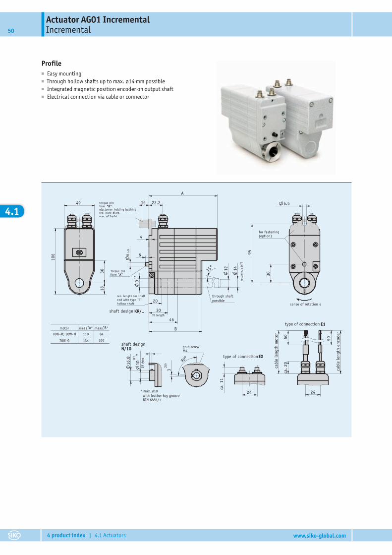
Actuator AG01 IncrementalIncremental50
4 product index | 4.1 Actuators www.siko-global.com
4.1
Profile■ Easy mounting■ Through hollow shafts up to max. ø14 mm possible■ Integrated magnetic position encoder on output shaft■ Electrical connection via cable or connector
10H
7 *
18
12
30
46
20
D
15° 14
90°
3JS
9
24
ca.
11
30
95
6.5
50
24
20ca
.
50
16.8
36
49
106
70W-M; 20W-M 110 84
70W-G 134 109
29.07.2008276/08
203801
Ar tikel-Nr .
H7
A
B
22.2
66h9
4
16
type of connection
for fastening(option)
sense of rotation e
E1
fit length
through shaft possible
max. ø13-ø14
form "A"
rec. length for shaftend with type "S"hollow shaft
KR/..shaft design
torque pinform "B":elastomer holding bushingrec. bore diam.
torque pin
M4
type of connection EX
cabl
e le
ngth
enc
oder
cabl
e le
ngth
mot
or
N/10
* max. ø10
shaft designgrub screw
with feather key grooveDIN 6885/1
25 d
eep
" "B"
reco
mm
.. ø1
4f7
meas.motor "Ameas.

Actuator AG01 IncrementalIncremental 51
4 product index | 4.1 Actuators www.siko-global.com
4.1
Mechanical dataFeature Technical data Additional informationShaft black-finished steelHousing aluminum, powder coated zinc die castNominal torque/rated speed 1.1 Nm, 430 rpm i = 12.4 (70 W motors)
2.1 Nm, 225 rpm i = 24 (70 W motors)4.2 Nm, 110 rpm i = 48 (70 W motors)
Operating mode S3 intermittent operation: 25 % DC, 10min.
EN 60034-1
Weight ~1.5 kg
Electrical data■ Motor
Feature Technical data Additional informationOperating voltage 0 … 24 V DC 70 W motorsPower input 70 WRated current 2.9 A ±10 % (70W-M) 3.2 A max. load current
4.1 A ±10 % (70W-G) 4.5 A max. load currentType of connection 2x M9 plug connectors 4-pole, 1x pin; 8-pole, 1x pin
■ EncoderFeature Technical data Additional informationOperating voltage 5 V DC ±5 % LD5 position encoder
24 V DC ±20 % LD24 + OP position encoderCurrent consumption ≤35 mAOutput circuit Line Driver (RS422) LD5 + LD24 position encoders
Push Pull (OP) OP position encoderOutput signals A, B, 0, /A, /B, IPulse frequency ≤20 kHz
Ambient conditionsFeature Technical data Additional informationAmbient temperature 0 … 70 °C
0 … 80 °C without position encoderStorage temperature -20 … 80 °CRelative humidity condensation inadmissibleEMC EN 61800-3, second environment interference resistance / immission
EN 61800-3, C3 emitted interference / emissionProtection category IP63 EN 60529, with mating connectors mountedShock resistance 500 m/s2, 11 ms EN 60068-2-27Vibration resistance 100 m/s2, 50 Hz EN 60068-2-6
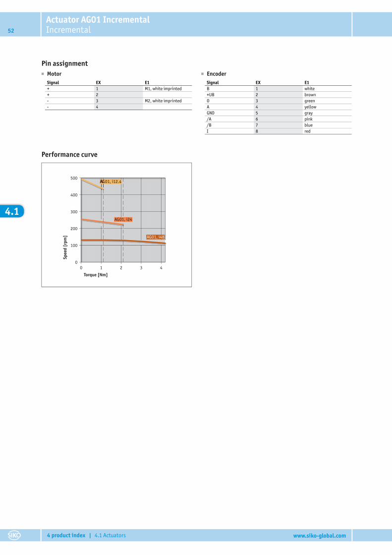
Actuator AG01 IncrementalIncremental52
4 product index | 4.1 Actuators www.siko-global.com
4.1
Pin assignment� Motor
Signal EX E1+ 1 M1, white imprinted+ 2- 3 M2, white imprinted- 4
� EncoderSignal EX E1B 1 white+UB 2 brownO 3 greenA 4 yellowGND 5 gray/A 6 pink/B 7 blueI 8 red
Performance curve
500
400
300
200
100
00 1 2 3 4
AG01, i48
AG01, i24
AG01, i12.4AG01, i12.4
Torque [Nm]
Spee
d [r
pm]
Actuator AG01 IncrementalIncremental 53
4 product index | 4.1 Actuators www.siko-global.com
4.1
Order■ Ordering table
A
B
C
D
E
F
G
H
I
Feature Ordering data Specification Additional informationGear ratio 48 i = 48
24 i = 2412.4 i = 12.4
Motor performance 70W-M 24 V DC70W-G 24 V DC
others on request
Shaft design/diameter KR/14 clamping ring, ø14 mmKR/12 clamping ring, ø12 mmN/10 keyway only for type S hollow shaft
Hollow shaft type S blind holeD full-length
Torque pin A bolt, ø6 mmB lug I incl. elastomer bushing
Type of connection E1 open cableEX socket on the device
Motor cable length 02.0 in mothers on request
Encoder cable length 02.0 in mothers on request
Position encoder LD24 incremental encoder 1024 pulsesLD5 incremental encoder 1024 pulsesOP Push-pull with invertingO without
■ Order key
AG01 Incremental - -
A-
B-
C-
D-
E-
F-
G-
H I
subj
ect t
o te
chni
cal a
lter
atio
n ● 2
017/
05/1
5 ● 1
1:21
● K
Accessories:Cable extension KV04S0 page 66Cable extension KV08S0 page 74Motor control module MS02 page 56Electronic display MA55 www.siko-global.comElectronic display MA48 www.siko-global.comElectronic display MA10/4 www.siko-global.comMating Connector Overview page 58Mating connector, motor, 4-pole, socket Order key 83447Mating connector, encoder, 8-pole, socket Order key 81351
Additional information:General information and areas of application page 10
Scope of delivery: AG01 Incremental, Mounting instructions
4.2
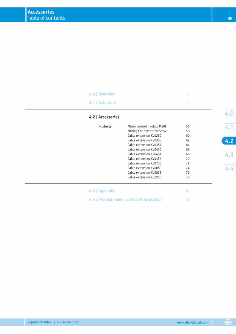
AccessoriesTable of contents 55
4 product index | 4.2 Accessories www.siko-global.com
4.2
4.2 | Accessories
Products Motor control module MS02 56Mating Connector Overview 58Cable extension KV02S0 60Cable extension KV03S0 62Cable extension KV03S1 64Cable extension KV04S0 66Cable extension KV04S1 68Cable extension KV04S2 70Cable extension KV07S0 72Cable extension KV08S0 74Cable extension KV08S2 76Cable extension KV12S0 78
4.3 | Appendix 81
4.4 | Product index, contact information 85
4.0 | Overview 3
4.1 | Actuators 9
4.0
4.1
4.3
4.4
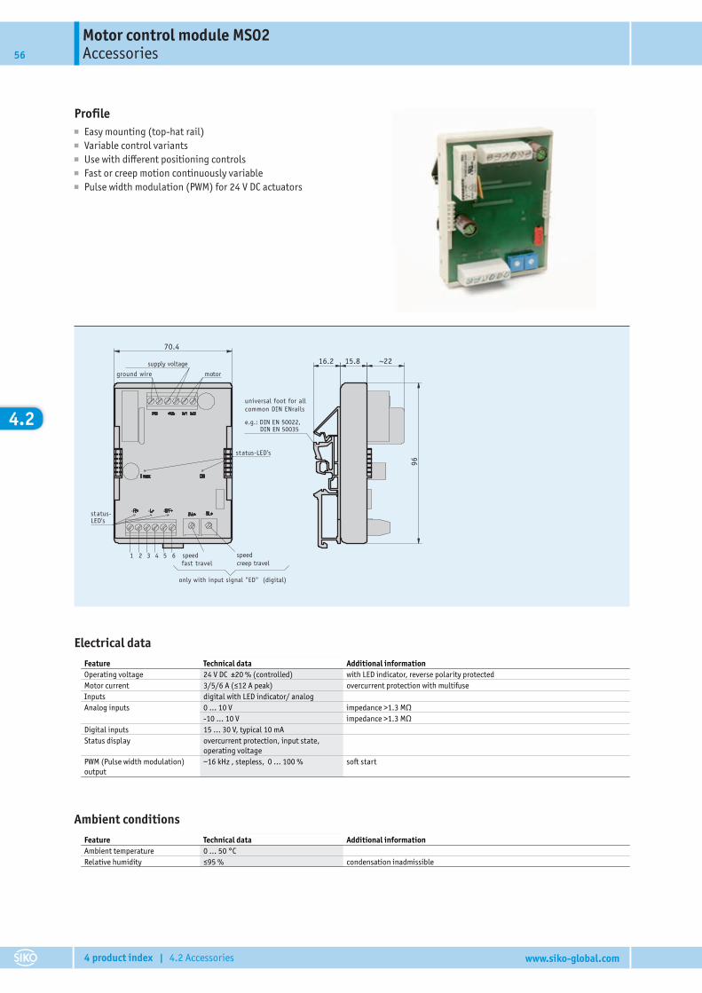
Motor control module MS02Accessories56
4 product index | 4.2 Accessories www.siko-global.com
4.2
Profile■ Easy mounting (top-hat rail)■ Variable control variants■ Use with different positioning controls■ Fast or creep motion continuously variable■ Pulse width modulation (PWM) for 24 V DC actuators
29.07.2008276/08
203845
Ar tikel-Nr.
~2216.2 15.8
96
1 2 3 4 5 6
70.4
universal foot for allcommon DIN ENrails
e.g.: DIN EN 50022, DIN EN 50035
ground wire
supply voltage
motor
status-LED's
status-LED's
fast travelspeedcreep travel
speed
only with input signal "ED" (digital)
Pin digital analog unipolar analog bipolar
1 enable ground
fast/creep ground ground ground
groundenable
2
cw rotation ground
cw rotation plus enable plus enable plus
3 right/left ground N.C.
4 right/left plus N.C.
5 analog analog
6 analog 0 ... +10V analog -10 ... +10V
ccw rotation ground
plusccw rotation
fast/creep plus
Electrical dataFeature Technical data Additional informationOperating voltage 24 V DC ±20 % (controlled) with LED indicator, reverse polarity protectedMotor current 3/5/6 A (≤12 A peak) overcurrent protection with multifuseInputs digital with LED indicator/ analogAnalog inputs 0 … 10 V impedance >1.3 MΩ
-10 … 10 V impedance >1.3 MΩDigital inputs 15 … 30 V, typical 10 mAStatus display overcurrent protection, input state,
operating voltagePWM (Pulse width modulation)output
~16 kHz , stepless, 0 … 100 % soft start
Ambient conditionsFeature Technical data Additional informationAmbient temperature 0 … 50 °CRelative humidity ≤95 % condensation inadmissible
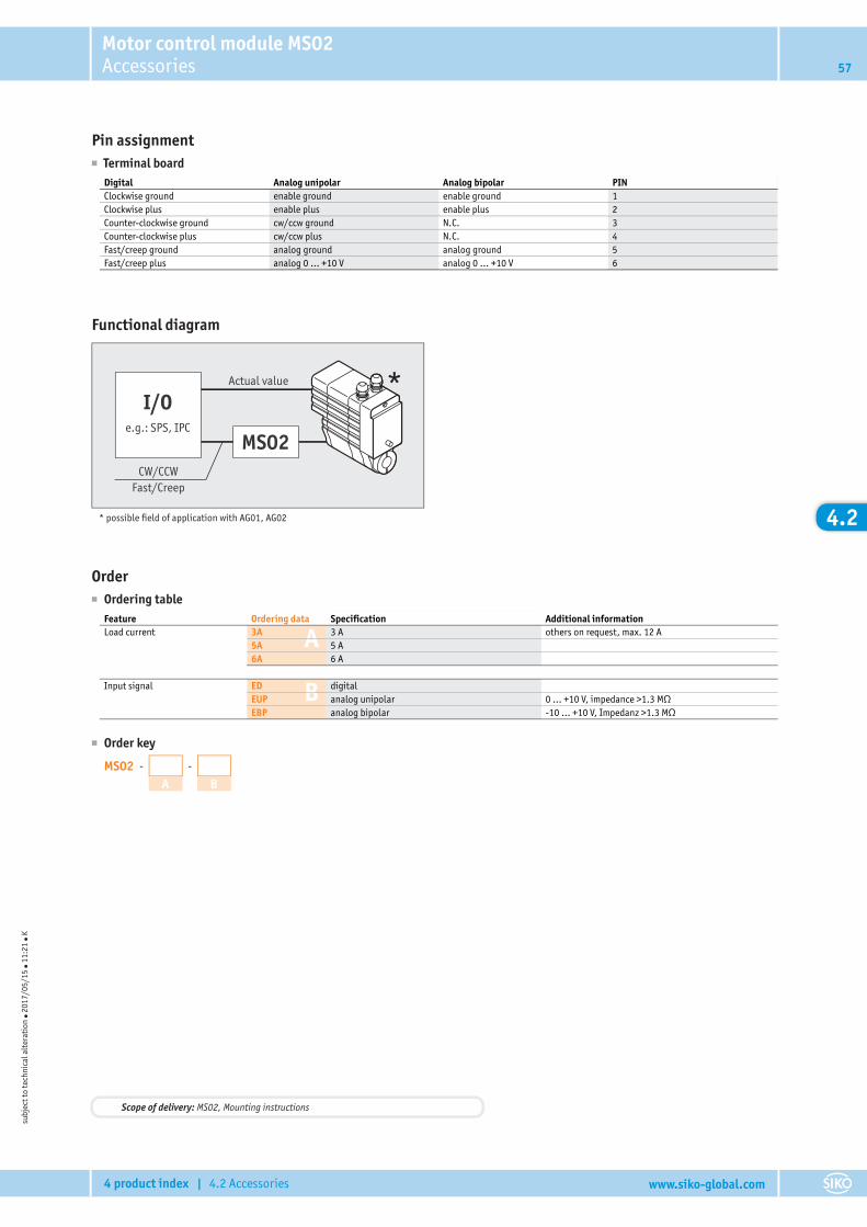
Motor control module MS02Accessories 57
4 product index | 4.2 Accessories www.siko-global.com
4.2
Pin assignment� Terminal board
Digital Analog unipolar Analog bipolar PINClockwise ground enable ground enable ground 1Clockwise plus enable plus enable plus 2Counter-clockwise ground cw/ccw ground N.C. 3Counter-clockwise plus cw/ccw plus N.C. 4Fast/creep ground analog ground analog ground 5Fast/creep plus analog 0 ... +10 V analog 0 ... +10 V 6
Functional diagram
*I/O
MS02e.g.: SPS, IPC
CW/CCWFast/Creep
Actual value
* possible field of application with AG01, AG02
Order� Ordering table
A
B
Feature Ordering data Specification Additional informationLoad current 3A 3 A others on request, max. 12 A
5A 5 A6A 6 A
Input signal ED digitalEUP analog unipolar 0 … +10 V, impedance >1.3 MΩEBP analog bipolar -10 … +10 V, Impedanz >1.3 MΩ
� Order key
MS02 - -
A B
subj
ect t
o te
chni
cal a
lter
atio
n � 2
017/
05/1
5 � 1
1:21
� K
Scope of delivery: MS02, Mounting instructions
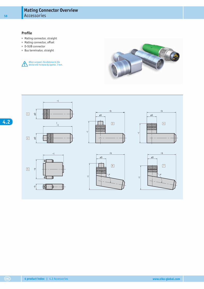
Mating Connector OverviewAccessories58
4 product index | 4.2 Accessories www.siko-global.com
4.2
Profile■ Mating connector, straight■ Mating connector, offset■ D-SUB connector■ Bus terminator, straight
When screwed, the distance to thedevice will increase by approx. 3 mm.
200534203510
Gegenstecker symbolischerstellt von VW
~l
øD
~l
øD
~b
~l
øD
~b
~l
øD
~b
~l
øD
~b
~l
øD
~l
~b~h
1
2
3 4
56 7
aa
l
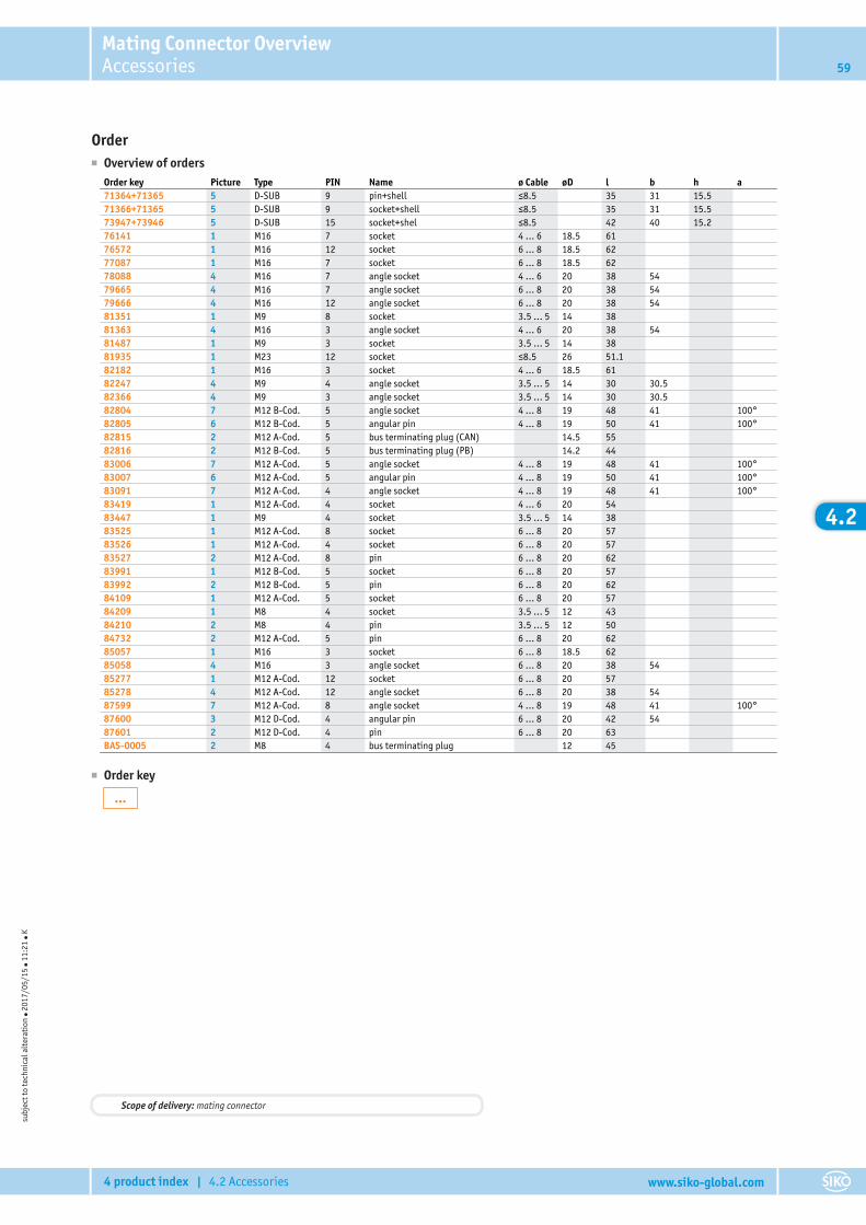
Mating Connector OverviewAccessories 59
4 product index | 4.2 Accessories www.siko-global.com
4.2
Order■ Overview of orders
Order key Picture Type PIN Name ø Cable øD l b h a71364+71365 5 D-SUB 9 pin+shell ≤8.5 35 31 15.571366+71365 5 D-SUB 9 socket+shell ≤8.5 35 31 15.573947+73946 5 D-SUB 15 socket+shel ≤8.5 42 40 15.276141 1 M16 7 socket 4 … 6 18.5 6176572 1 M16 12 socket 6 … 8 18.5 6277087 1 M16 7 socket 6 … 8 18.5 6278088 4 M16 7 angle socket 4 … 6 20 38 5479665 4 M16 7 angle socket 6 … 8 20 38 5479666 4 M16 12 angle socket 6 … 8 20 38 5481351 1 M9 8 socket 3.5 … 5 14 3881363 4 M16 3 angle socket 4 … 6 20 38 5481487 1 M9 3 socket 3.5 … 5 14 3881935 1 M23 12 socket ≤8.5 26 51.182182 1 M16 3 socket 4 … 6 18.5 6182247 4 M9 4 angle socket 3.5 … 5 14 30 30.582366 4 M9 3 angle socket 3.5 … 5 14 30 30.582804 7 M12 B-Cod. 5 angle socket 4 … 8 19 48 41 100°82805 6 M12 B-Cod. 5 angular pin 4 … 8 19 50 41 100°82815 2 M12 A-Cod. 5 bus terminating plug (CAN) 14.5 5582816 2 M12 B-Cod. 5 bus terminating plug (PB) 14.2 4483006 7 M12 A-Cod. 5 angle socket 4 … 8 19 48 41 100°83007 6 M12 A-Cod. 5 angular pin 4 … 8 19 50 41 100°83091 7 M12 A-Cod. 4 angle socket 4 … 8 19 48 41 100°83419 1 M12 A-Cod. 4 socket 4 … 6 20 5483447 1 M9 4 socket 3.5 … 5 14 3883525 1 M12 A-Cod. 8 socket 6 … 8 20 5783526 1 M12 A-Cod. 4 socket 6 … 8 20 5783527 2 M12 A-Cod. 8 pin 6 … 8 20 6283991 1 M12 B-Cod. 5 socket 6 … 8 20 5783992 2 M12 B-Cod. 5 pin 6 … 8 20 6284109 1 M12 A-Cod. 5 socket 6 … 8 20 5784209 1 M8 4 socket 3.5 … 5 12 4384210 2 M8 4 pin 3.5 … 5 12 5084732 2 M12 A-Cod. 5 pin 6 … 8 20 6285057 1 M16 3 socket 6 … 8 18.5 6285058 4 M16 3 angle socket 6 … 8 20 38 5485277 1 M12 A-Cod. 12 socket 6 … 8 20 5785278 4 M12 A-Cod. 12 angle socket 6 … 8 20 38 5487599 7 M12 A-Cod. 8 angle socket 4 … 8 19 48 41 100°87600 3 M12 D-Cod. 4 angular pin 6 … 8 20 42 5487601 2 M12 D-Cod. 4 pin 6 … 8 20 63BAS-0005 2 M8 4 bus terminating plug 12 45
■ Order key
…
subj
ect t
o te
chni
cal a
lter
atio
n ● 2
017/
05/1
5 ● 1
1:21
● K
Scope of delivery: mating connector
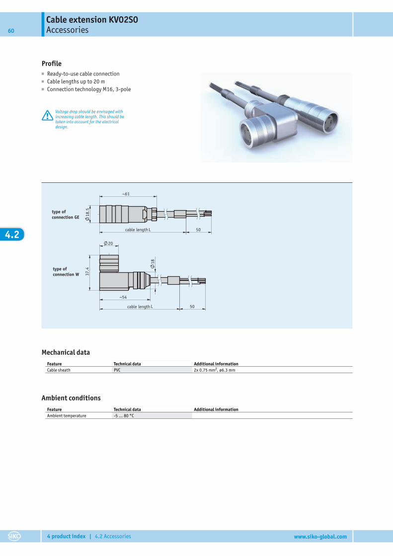
Cable extension KV02S0Accessories60
4 product index | 4.2 Accessories www.siko-global.com
4.2
Profile■ Ready-to-use cable connection■ Cable lengths up to 20 m■ Connection technology M16, 3-pole
Voltage drop should be envisaged withincreasing cable length. This should betaken into account for the electricaldesign.
18.5
61~
50
29.07.2008276/08
203844
Ar tikel-Nr .
50
37.4
54~
18
20
type of connection GE
type of connection W
L
L
cable length
cable length
Mechanical dataFeature Technical data Additional informationCable sheath PVC 2x 0.75 mm2, ø6.3 mm
Ambient conditionsFeature Technical data Additional informationAmbient temperature -5 … 80 °C

Cable extension KV02S0Accessories 61
4 product index | 4.2 Accessories www.siko-global.com
4.2
Pin assignment■ KV02S0
Cable number PIN1 (black) 1
22 (black) 3
Order■ Ordering table
A
B
Feature Ordering data Specification Additional informationType of connection GE straight connector
W right angle plug
Cable length ... 01.0 ... 20.0 m, in steps of 1 m
■ Order key
KV02S0 - -
A B
subj
ect t
o te
chni
cal a
lter
atio
n ● 2
017/
05/1
5 ● 1
1:21
● K
Scope of delivery: KV02S0
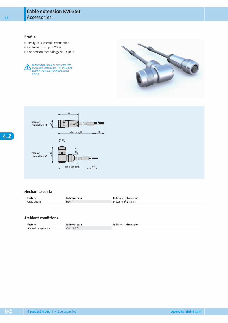
Cable extension KV03S0Accessories62
4 product index | 4.2 Accessories www.siko-global.com
4.2
Profile■ Ready-to-use cable connection■ Cable lengths up to 20 m■ Connection technology M9, 3-pole
Voltage drop should be envisaged withincreasing cable length. This should betaken into account for the electricaldesign.
14
50
~30
13
14
38~
50
29.07.2008276/08
203849
Ar tikel-Nr .
L
L
type of connection W
type of connection GE
cable length
cable length
Mechanical dataFeature Technical data Additional informationCable sheath PUR 3x 0.15 mm2, ø3.5 mm
Ambient conditionsFeature Technical data Additional informationAmbient temperature -30 … 85 °C
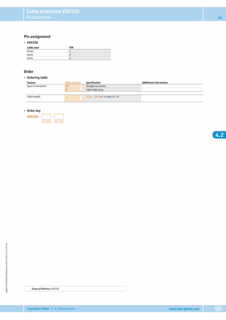
Cable extension KV03S0Accessories 63
4 product index | 4.2 Accessories www.siko-global.com
4.2
Pin assignment■ KV03S0
Cable color PINbrown 1green 2white 3
Order■ Ordering table
A
B
Feature Ordering data Specification Additional informationType of connection GE straight connector
W right angle plug
Cable length ... 01.0 ... 20.0 m, in steps of 1 m
■ Order key
KV03S0 - -
A B
subj
ect t
o te
chni
cal a
lter
atio
n ● 2
017/
05/1
5 ● 1
1:21
● K
Scope of delivery: KV03S0
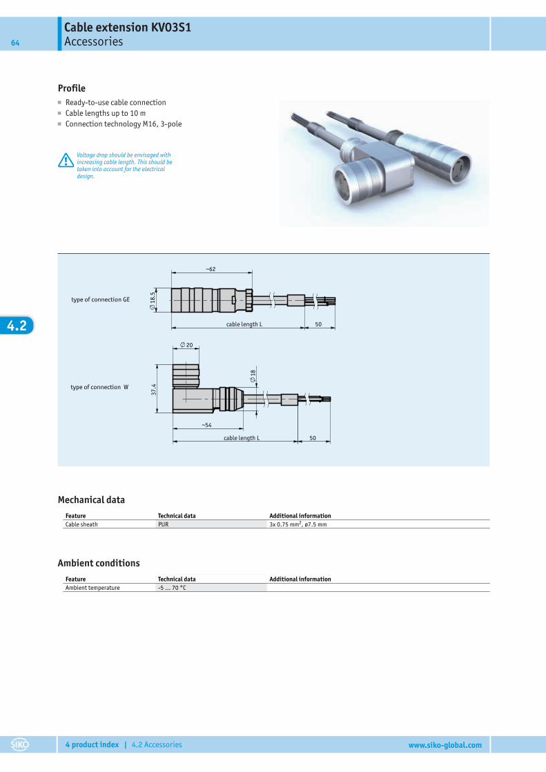
Cable extension KV03S1Accessories64
4 product index | 4.2 Accessories www.siko-global.com
4.2
Profile■ Ready-to-use cable connection■ Cable lengths up to 10 m■ Connection technology M16, 3-pole
Voltage drop should be envisaged withincreasing cable length. This should betaken into account for the electricaldesign.
Katalogzeichnung
208608
Weißer01.08.2014
KV03S1Kabelverlängerung
298/14
type of connection W
18
50 cable length L
~54
37.
4
20
type of connection GE
50 cable length L
18.5
~62
Mechanical dataFeature Technical data Additional informationCable sheath PUR 3x 0.75 mm2, ø7.5 mm
Ambient conditionsFeature Technical data Additional informationAmbient temperature -5 … 70 °C
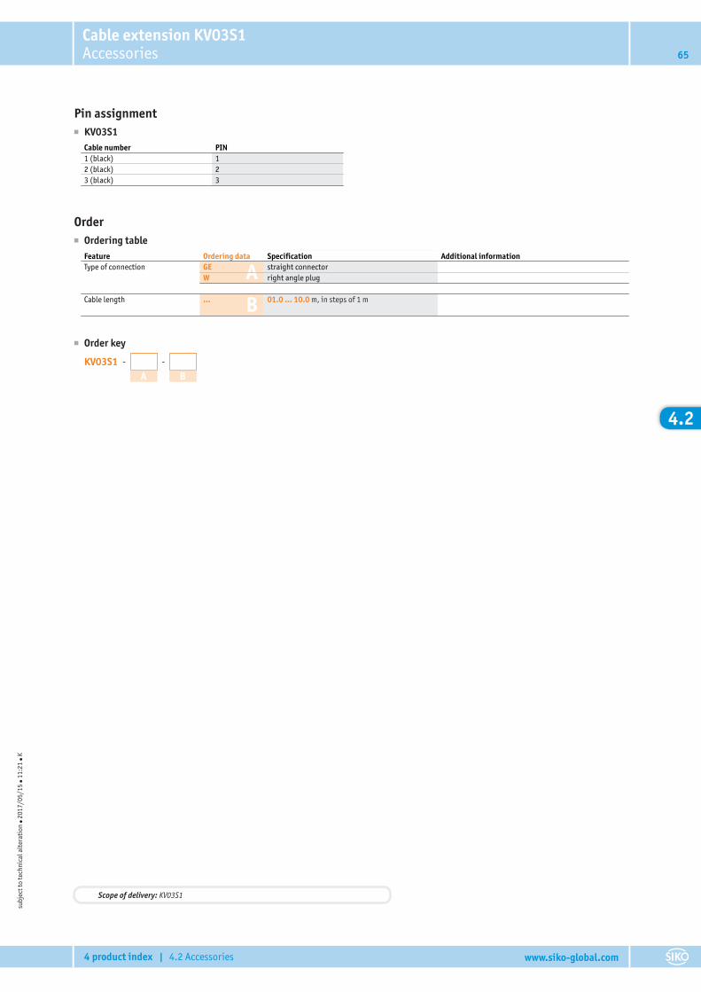
Cable extension KV03S1Accessories 65
4 product index | 4.2 Accessories www.siko-global.com
4.2
Pin assignment■ KV03S1
Cable number PIN1 (black) 12 (black) 23 (black) 3
Order■ Ordering table
A
B
Feature Ordering data Specification Additional informationType of connection GE straight connector
W right angle plug
Cable length ... 01.0 ... 10.0 m, in steps of 1 m
■ Order key
KV03S1 - -
A B
subj
ect t
o te
chni
cal a
lter
atio
n ● 2
017/
05/1
5 ● 1
1:21
● K
Scope of delivery: KV03S1

Cable extension KV04S0Accessories66
4 product index | 4.2 Accessories www.siko-global.com
4.2
Profile■ Ready-to-use cable connection■ Cable lengths up to 20 m■ Connection technology M9, 4-pole
Voltage drop should be envisaged withincreasing cable length. This should betaken into account for the electricaldesign.
50
14
13
~30
14
38~
50
29.07.2008276/08
203850Ar tikel-Nr .
L
L
type of connection GE
type of connection W
cable length
cable length
Mechanical dataFeature Technical data Additional informationCable sheath PVC 4x 0.15 mm2, ø4.8 mm
Ambient conditionsFeature Technical data Additional informationAmbient temperature -5 … 70 °C

Cable extension KV04S0Accessories 67
4 product index | 4.2 Accessories www.siko-global.com
4.2
Pin assignment■ KV04S0
Cable color PINwhite 1brown 2green 3yellow 4
Order■ Ordering table
A
B
Feature Ordering data Specification Additional informationType of connection GE straight connector
W right angle plug
Cable length ... 01.0 ... 20.0 m, in steps of 1 m
■ Order key
KV04S0 - -
A B
subj
ect t
o te
chni
cal a
lter
atio
n ● 2
017/
05/1
5 ● 1
1:21
● K
Scope of delivery: KV04S0
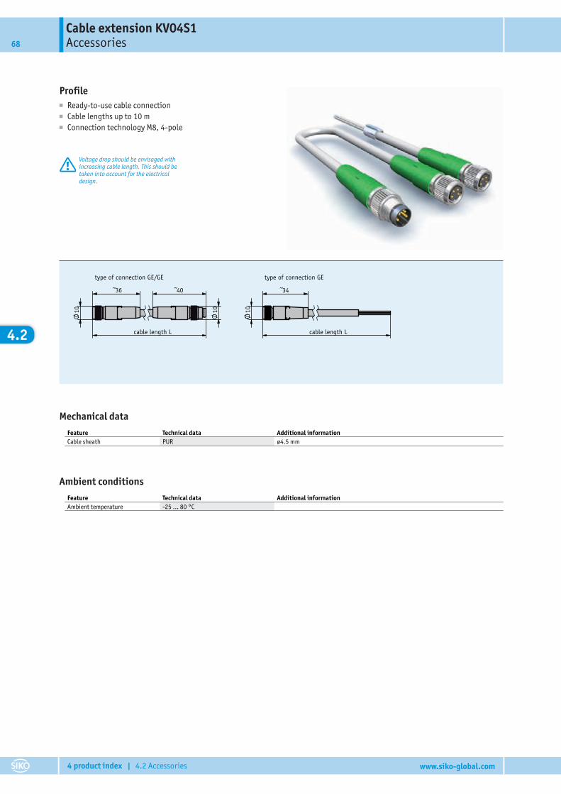
Cable extension KV04S1Accessories68
4 product index | 4.2 Accessories www.siko-global.com
4.2
Profile■ Ready-to-use cable connection■ Cable lengths up to 10 m■ Connection technology M8, 4-pole
Voltage drop should be envisaged withincreasing cable length. This should betaken into account for the electricaldesign.
~36 ~40
1010
~34
10
441/10
KV04S108.12.2010 Kreutzmann
201262
cable length L
type of connection GE/GE
cable length L
type of connection GE
Mechanical dataFeature Technical data Additional informationCable sheath PUR ø4.5 mm
Ambient conditionsFeature Technical data Additional informationAmbient temperature -25 … 80 °C
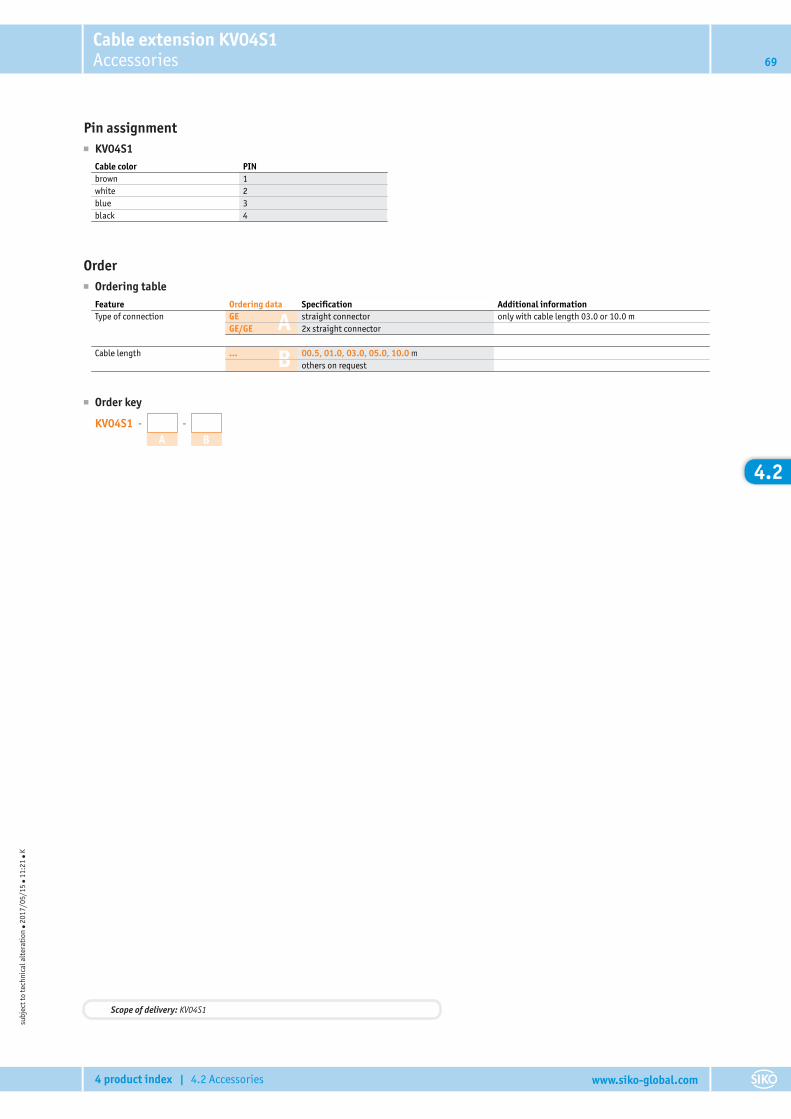
Cable extension KV04S1Accessories 69
4 product index | 4.2 Accessories www.siko-global.com
4.2
Pin assignment■ KV04S1
Cable color PINbrown 1white 2blue 3black 4
Order■ Ordering table
A
B
Feature Ordering data Specification Additional informationType of connection GE straight connector only with cable length 03.0 or 10.0 m
GE/GE 2x straight connector
Cable length ... 00.5, 01.0, 03.0, 05.0, 10.0 mothers on request
■ Order key
KV04S1 - -
A B
subj
ect t
o te
chni
cal a
lter
atio
n ● 2
017/
05/1
5 ● 1
1:21
● K
Scope of delivery: KV04S1
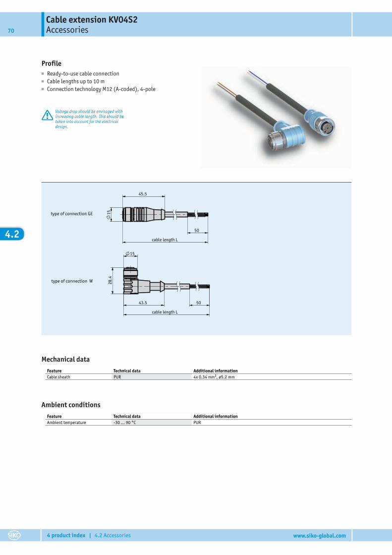
Cable extension KV04S2Accessories70
4 product index | 4.2 Accessories www.siko-global.com
4.2
Profile■ Ready-to-use cable connection■ Cable lengths up to 10 m■ Connection technology M12 (A-coded), 4-pole
Voltage drop should be envisaged withincreasing cable length. This should betaken into account for the electricaldesign.
Katalogzeichnung
208609
Weißer01.08.2014
KV04S2
298/14
type of connection W
cable length L
50 43.5
28.
4
15
type of connection GE
cable length L
50
45.5
15
Mechanical dataFeature Technical data Additional informationCable sheath PUR 4x 0.34 mm2, ø5.2 mm
Ambient conditionsFeature Technical data Additional informationAmbient temperature -30 … 90 °C PUR
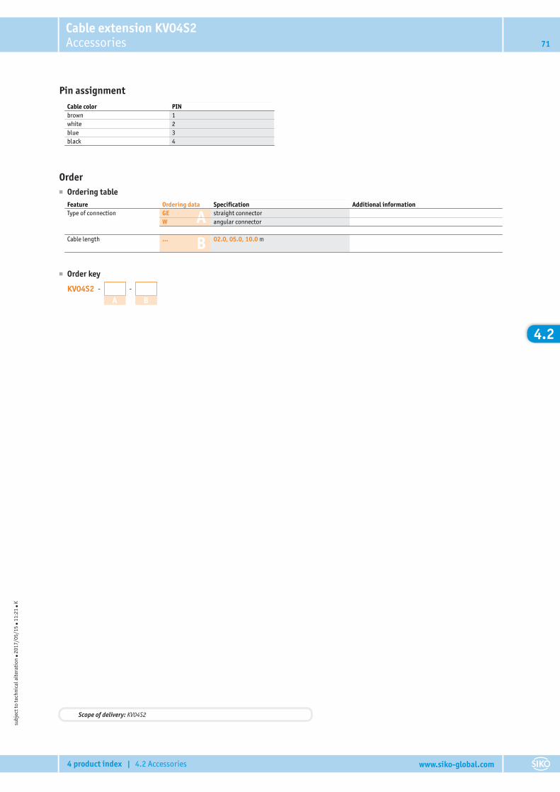
Cable extension KV04S2Accessories 71
4 product index | 4.2 Accessories www.siko-global.com
4.2
Pin assignmentCable color PINbrown 1white 2blue 3black 4
Order■ Ordering table
A
B
Feature Ordering data Specification Additional informationType of connection GE straight connector
W angular connector
Cable length ... 02.0, 05.0, 10.0 m
■ Order key
KV04S2 - -
A B
subj
ect t
o te
chni
cal a
lter
atio
n ● 2
017/
05/1
5 ● 1
1:21
● K
Scope of delivery: KV04S2

Cable extension KV07S0Accessories72
4 product index | 4.2 Accessories www.siko-global.com
4.2
Profile■ Ready-to-use cable connection■ Cable lengths up to 20 m■ Connection technology M16, 7-pole
Voltage drop should be envisaged withincreasing cable length. This should betaken into account for the electricaldesign.
17.03.2008109/08
203396
Artikel-Nr.
~
50
2037
.4
54
18
~61
18.5
50cable length L
cable length L
type of connection GE type of connection W
Mechanical dataFeature Technical data Additional informationCable sheath PUR 7x 0.14 mm2, ø5.1 mm
Ambient conditionsFeature Technical data Additional informationAmbient temperature -5 … 50 °C
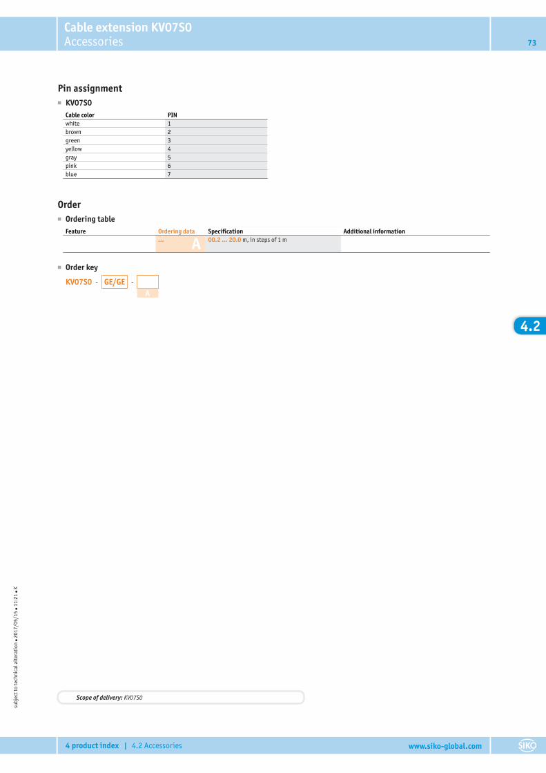
Cable extension KV07S0Accessories 73
4 product index | 4.2 Accessories www.siko-global.com
4.2
Pin assignment■ KV07S0
Cable color PINwhite 1brown 2green 3yellow 4gray 5pink 6blue 7
Order■ Ordering table
AFeature Ordering data Specification Additional information
... 00.2 ... 20.0 m, in steps of 1 m
■ Order key
KV07S0 - -GE/GEA
subj
ect t
o te
chni
cal a
lter
atio
n ● 2
017/
05/1
5 ● 1
1:21
● K
Scope of delivery: KV07S0
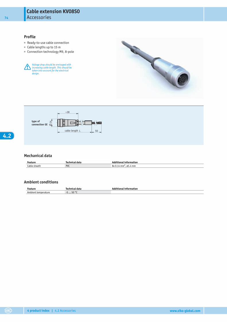
Cable extension KV08S0Accessories74
4 product index | 4.2 Accessories www.siko-global.com
4.2
Profile■ Ready-to-use cable connection■ Cable lengths up to 15 m■ Connection technology M9, 8-pole
Voltage drop should be envisaged withincreasing cable length. This should betaken into account for the electricaldesign.
29.07.2008276/08
203855
Ar tikel-Nr .
14
38~
50L
type of connection GE
cable length
Mechanical dataFeature Technical data Additional informationCable sheath PVC 8x 0.14 mm2, ø5.4 mm
Ambient conditionsFeature Technical data Additional informationAmbient temperature -5 … 50 °C
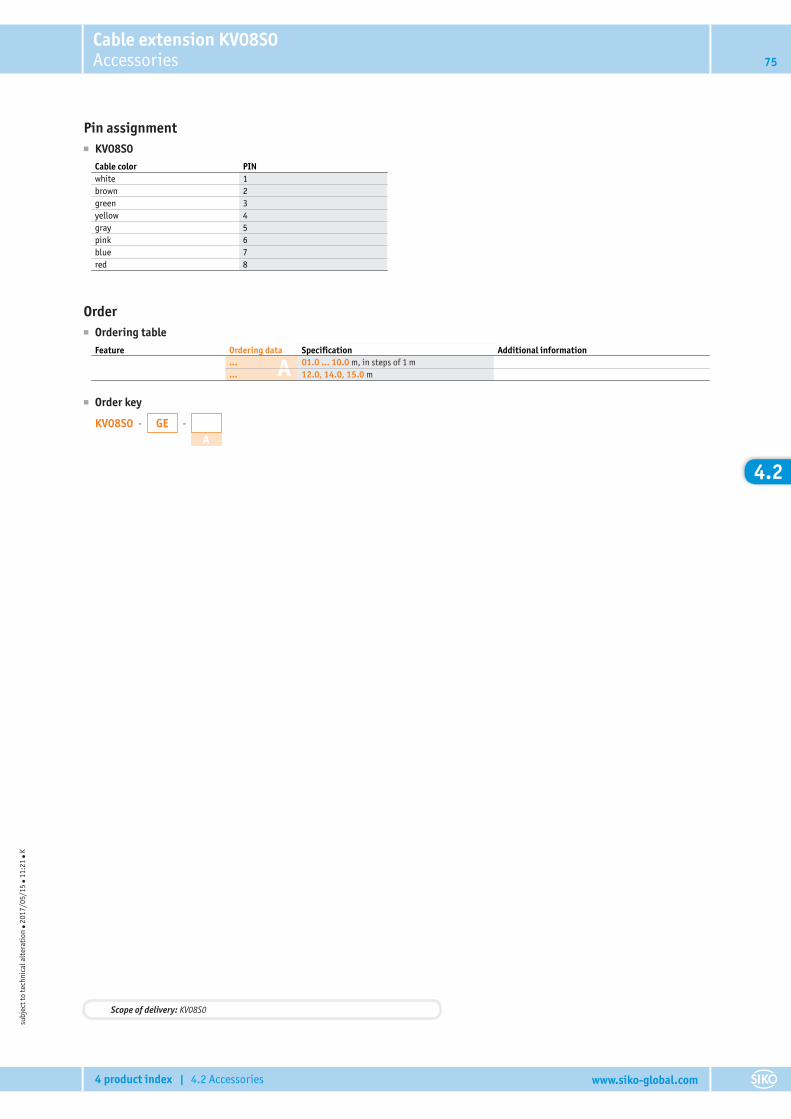
Cable extension KV08S0Accessories 75
4 product index | 4.2 Accessories www.siko-global.com
4.2
Pin assignment■ KV08S0
Cable color PINwhite 1brown 2green 3yellow 4gray 5pink 6blue 7red 8
Order■ Ordering table
AFeature Ordering data Specification Additional information
... 01.0 ... 10.0 m, in steps of 1 m
... 12.0, 14.0, 15.0 m
■ Order key
KV08S0 - -GEA
subj
ect t
o te
chni
cal a
lter
atio
n ● 2
017/
05/1
5 ● 1
1:21
● K
Scope of delivery: KV08S0
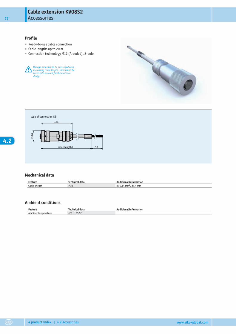
Cable extension KV08S2Accessories76
4 product index | 4.2 Accessories www.siko-global.com
4.2
Profile■ Ready-to-use cable connection■ Cable lengths up to 20 m■ Connection technology M12 (A-coded), 8-pole
Voltage drop should be envisaged withincreasing cable length. This should betaken into account for the electricaldesign.
Katalogzeichnung
203440
047/14 Weißer27.02.2014
KV08S2
type of connection GE
20
~56
50 cable length L
Mechanical dataFeature Technical data Additional informationCable sheath PUR 8x 0.14 mm2, ø5.4 mm
Ambient conditionsFeature Technical data Additional informationAmbient temperature -25 … 85 °C
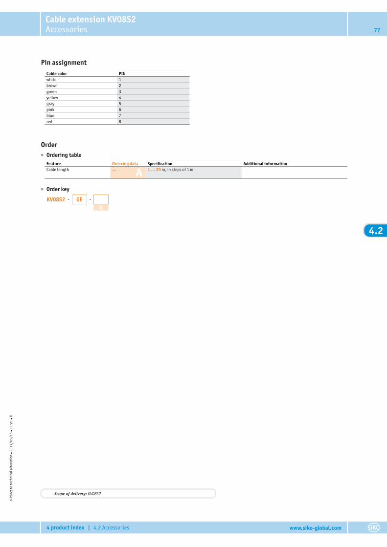
Cable extension KV08S2Accessories 77
4 product index | 4.2 Accessories www.siko-global.com
4.2
Pin assignmentCable color PINwhite 1brown 2green 3yellow 4gray 5pink 6blue 7red 8
Order■ Ordering table
AFeature Ordering data Specification Additional informationCable length ... 1 ... 20 m, in steps of 1 m
■ Order key
KV08S2 - -GEA
subj
ect t
o te
chni
cal a
lter
atio
n ● 2
017/
05/1
5 ● 1
1:21
● K
Scope of delivery: KV08S2
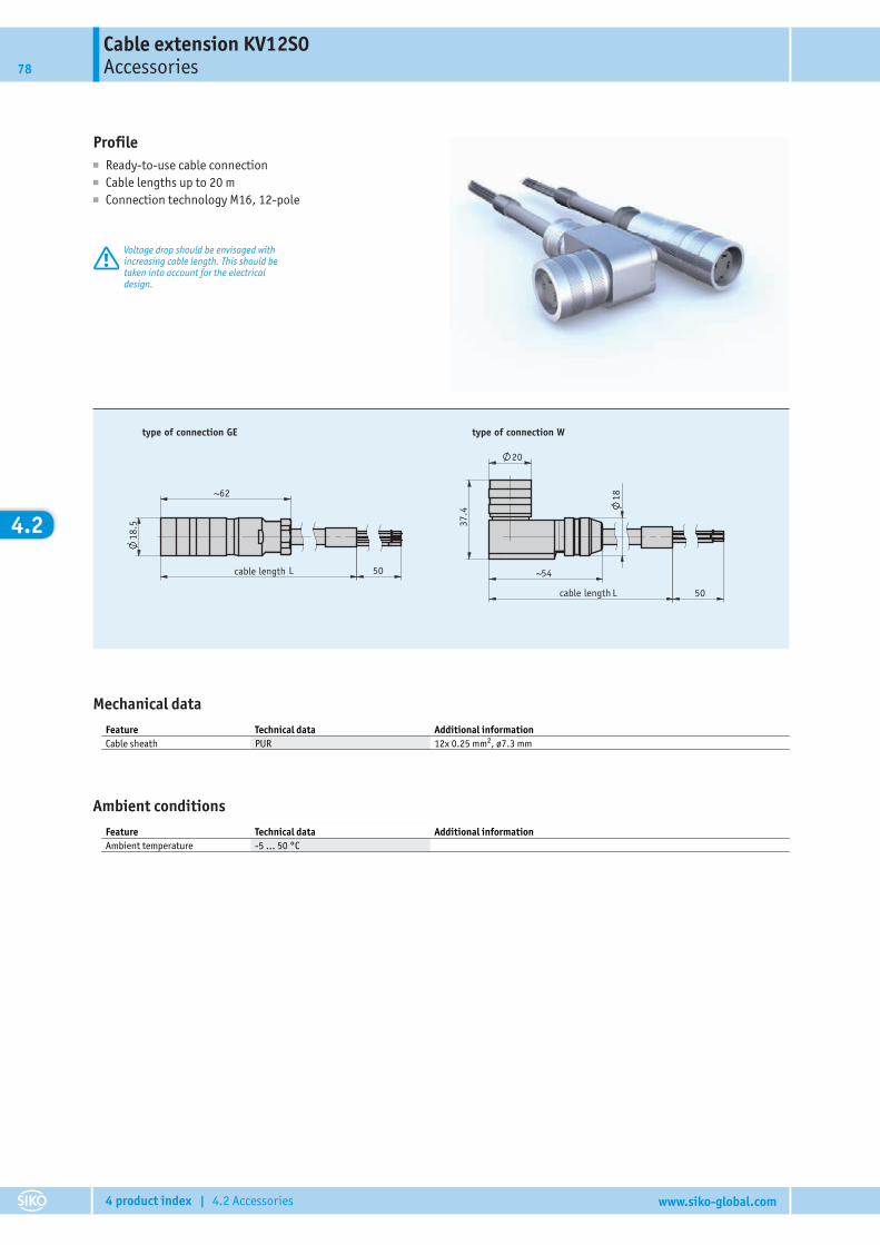
Cable extension KV12S0Accessories78
4 product index | 4.2 Accessories www.siko-global.com
4.2
Profile■ Ready-to-use cable connection■ Cable lengths up to 20 m■ Connection technology M16, 12-pole
Voltage drop should be envisaged withincreasing cable length. This should betaken into account for the electricaldesign.
~
50
2037
.4
54
18~62
18.5
50
17.03.2008109/08
203583
Ar tikel-Nr .
L
L
type of connection GE type of connection W
cable length
cable length
Mechanical dataFeature Technical data Additional informationCable sheath PUR 12x 0.25 mm2, ø7.3 mm
Ambient conditionsFeature Technical data Additional informationAmbient temperature -5 … 50 °C
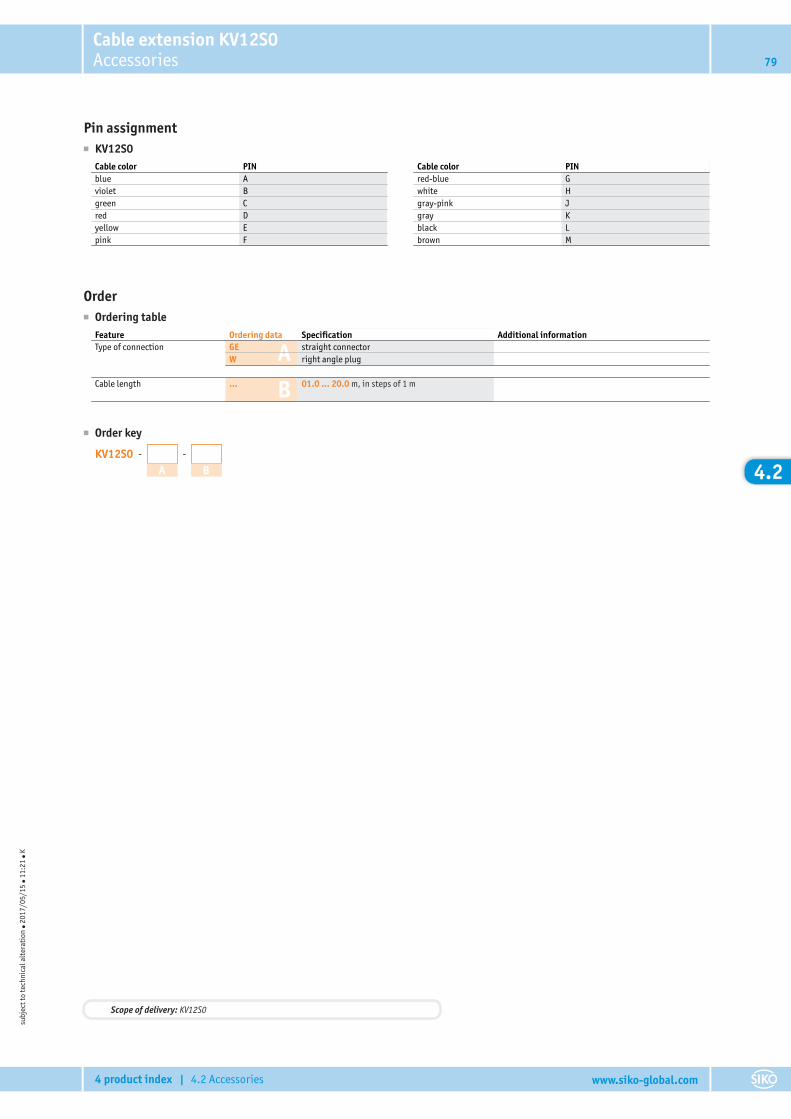
Cable extension KV12S0Accessories 79
4 product index | 4.2 Accessories www.siko-global.com
4.2
Pin assignment■ KV12S0
Cable color PINblue Aviolet Bgreen Cred Dyellow Epink F
Cable color PINred-blue Gwhite Hgray-pink Jgray Kblack Lbrown M
Order■ Ordering table
A
B
Feature Ordering data Specification Additional informationType of connection GE straight connector
W right angle plug
Cable length ... 01.0 ... 20.0 m, in steps of 1 m
■ Order key
KV12S0 - -
A B
subj
ect t
o te
chni
cal a
lter
atio
n ● 2
017/
05/1
5 ● 1
1:21
● K
Scope of delivery: KV12S0
44444..333333
AppendixTable of contents 81
4 product index | 4.3 Appendix www.siko-global.com
4.3
4.3 | Appendix
Overview of IP protection classes 82
4.4 | Product index, contact information 85
4.0 | Overview 3
4.1 | Actuators 9
4.2 | Accessories 55
4.0
4.1
4.2
4.4

AppendixOverview of IP protection classes82
4 product index | 4.3 Appendix www.siko-global.com
4.3
Protection classes according to DIN EN 60529
IP . .
Touch and foreign bodies protection
!!! 0 No protection.
1Protected against access with the back of the hand.Protection against solid foreign bodies with Ø > 50 mm.
2Protected against contact with a fi nger.Protected against solid foreign bodies with diameters > 12.5 mm.
3Protected against access with a tool.Protected against solid foreign bodies with diameters > 2.5 mm.
4Protected against access with a wire.Protected against solid foreign bodies with diameters > 1.0 mm.
5Full protection against contact.Protection against harmful quantities of dust.
6 Full protection against contact.Dust-proof.
Water protection
!!! 0 No protection.
1 Protection against vertical water drips.
15°+
2 Protection against vertical water dripsif the housing is tilted up to ±15°.
60°+
3 Protection against spray up to ±60° towards verticality.
360°
4 Protection against splash wa-ter coming from any angle.
360°
5 Protection against hose water (nozzle) coming from any angle.
360°
6 Protection against strong hose wa-ter coming from any angle .
7 Protection against temporary immersion.
. . .bar
8 Protection against continuous immersion.
360°
9k* Protection against ingress of water dur-ing high pressure or steam-jet clean-ing, specifi c for road vehicles.
* IPx9k is not part of DIN EN 60 529, rather it is contained in DIN 40 050
The two numbers are not indicative of the protection against ingress of oils or similar liquids. The second fi gure
indicates the protection class exclusively for water.
The standards deal with the protection of electric equipment by means of housings, covers and so forth. For purely mechanical de-
vices, the information is used fi guratively.

83
4 product index | 4.3 Appendix www.siko-global.com
4.3

4.4
Product index, contact informationTable of contents 85
4 product index | 4.4 Product index, contact information www.siko-global.com
4.4
4.4 | Product index, contact information
Product index 86
contact information 87
4.0 | Overview 3
4.1 | Actuators 9
4.2 | Accessories 55
4.3 | Appendix 81
4.0
4.1
4.2
4.3
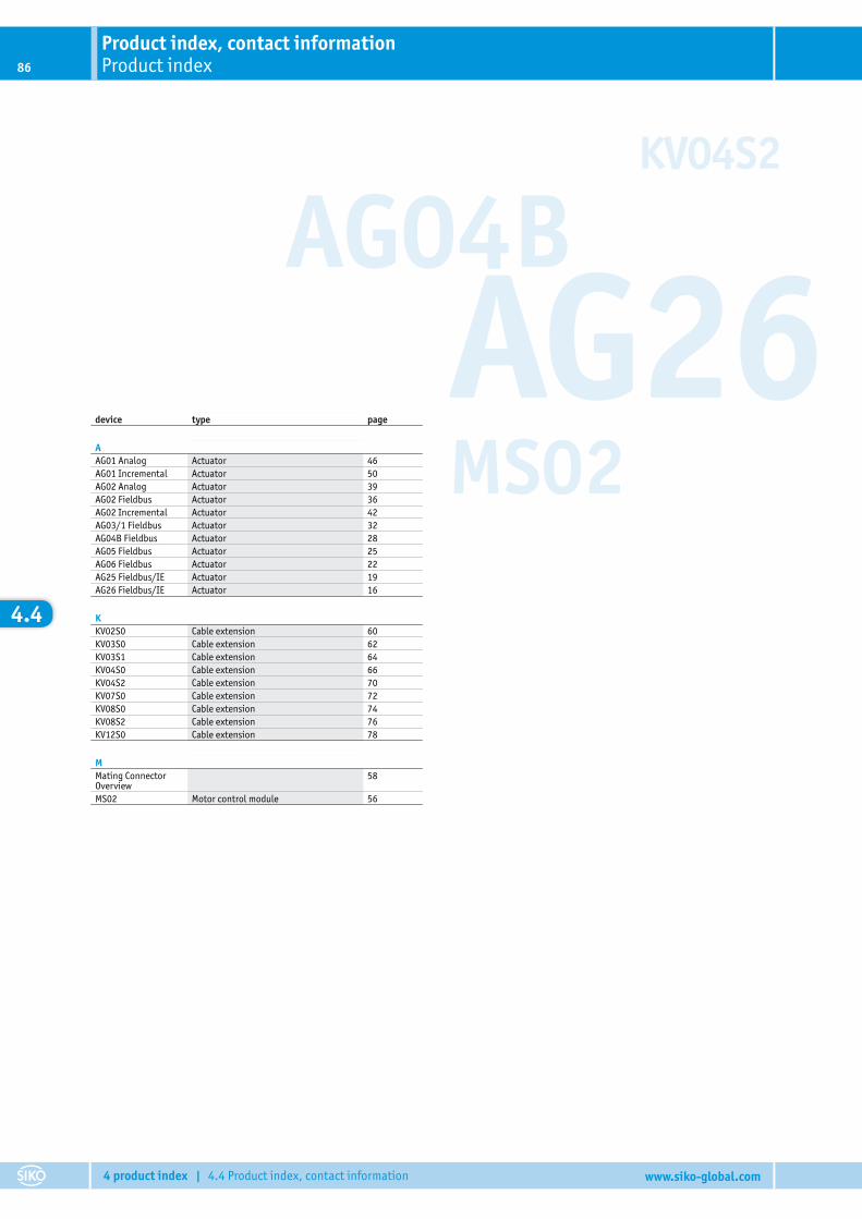
AG04BAG26MS02
KV04S2
Product index, contact informationProduct index86
4 product index | 4.4 Product index, contact information www.siko-global.com
4.4
device type page
AAG01 Analog Actuator 46AG01 Incremental Actuator 50AG02 Analog Actuator 39AG02 Fieldbus Actuator 36AG02 Incremental Actuator 42AG03/1 Fieldbus Actuator 32AG04B Fieldbus Actuator 28AG05 Fieldbus Actuator 25AG06 Fieldbus Actuator 22AG25 Fieldbus/IE Actuator 19AG26 Fieldbus/IE Actuator 16
KKV02S0 Cable extension 60KV03S0 Cable extension 62KV03S1 Cable extension 64KV04S0 Cable extension 66KV04S2 Cable extension 70KV07S0 Cable extension 72KV08S0 Cable extension 74KV08S2 Cable extension 76KV12S0 Cable extension 78
MMating ConnectorOverview
58
MS02 Motor control module 56
Product index, contact informationcontact information 87
4 product index | 4.4 Product index, contact information www.siko-global.com
Do you want to contact an agency near you?Visit or website www.siko-global.com, and go to the „Contact“ menu item to access all the latest contact data of our agencies.
AfricaEgyptSouth Africa
AsiaCanadaChinaIndiaIndonesiaIraqIranIsraelJapanMalaysiaSingapurSouth KoreaTaiwanThailandUnited Arab EmiratesVietnam
Australia AustraliaNew Zealand
EuropeAustriaBelarusBelgiumBulgariaCroatiaCyprusCzech RepublicDenmarkEstoniaFinlandFranceGermanyGreat BritainGreeceHungaryItalyLatviaLiechtensteinLithuaniaLuxembourgMontenegroNetherlandsNorwayPolandPortugalRomaniaRussiaSerbiaSlovakiaSloveniaSpainSwedenSwitzerlandTurkeyUkraine
AmericaArgentinaBrazilCanadaEcuadorMexicoUSA

Subj
ect t
o te
chni
cal a
lter
atio
ns 0
5/20
17 –
Nr.
8481
3
www.siko-global.com
Headquarters:SIKO GmbHWeihermattenweg 2D-79256 Buchenbach
Phon+49 7661 394-0Fax +49 7661 [email protected]
Subsidiaries:SIKO Products Inc
SIKO Italia S.r.l.
SIKO Magline AG
SIKO International Trading (Shanghai) CO., Ltd.
SIKO Products Asia Pte. Ltd.
4Dr
iveL
ine