3gpp ts 25.214 version
TRANSCRIPT

ETSI TS 125 214 V3.9.0 (2001-12)
Technical Specification
Universal Mobile Telecommunications System (UMTS);Physical layer procedures (FDD)
(3GPP TS 25.214 version 3.9.0 Release 1999)
ETSI
ETSI TS 125 214 V3.9.0 (2001-12)13GPP TS 25.214 version 3.9.0 Release 1999
Reference RTS/TSGR-0125214UR8
Keywords UMTS
ETSI
650 Route des Lucioles F-06921 Sophia Antipolis Cedex - FRANCE
Tel.: +33 4 92 94 42 00 Fax: +33 4 93 65 47 16
Siret N° 348 623 562 00017 - NAF 742 C
Association à but non lucratif enregistrée à la Sous-Préfecture de Grasse (06) N° 7803/88
Important notice
Individual copies of the present document can be downloaded from: http://www.etsi.org
The present document may be made available in more than one electronic version or in print. In any case of existing or perceived difference in contents between such versions, the reference version is the Portable Document Format (PDF).
In case of dispute, the reference shall be the printing on ETSI printers of the PDF version kept on a specific network drive within ETSI Secretariat.
Users of the present document should be aware that the document may be subject to revision or change of status. Information on the current status of this and other ETSI documents is available at
http://portal.etsi.org/tb/status/status.asp
If you find errors in the present document, send your comment to: [email protected]
Copyright Notification
No part may be reproduced except as authorized by written permission. The copyright and the foregoing restriction extend to reproduction in all media.
© European Telecommunications Standards Institute 2001.
All rights reserved.

ETSI
ETSI TS 125 214 V3.9.0 (2001-12)23GPP TS 25.214 version 3.9.0 Release 1999
Intellectual Property Rights IPRs essential or potentially essential to the present document may have been declared to ETSI. The information pertaining to these essential IPRs, if any, is publicly available for ETSI members and non-members, and can be found in ETSI SR 000 314: "Intellectual Property Rights (IPRs); Essential, or potentially Essential, IPRs notified to ETSI in respect of ETSI standards", which is available from the ETSI Secretariat. Latest updates are available on the ETSI Web server (http://webapp.etsi.org/IPR/home.asp).
Pursuant to the ETSI IPR Policy, no investigation, including IPR searches, has been carried out by ETSI. No guarantee can be given as to the existence of other IPRs not referenced in ETSI SR 000 314 (or the updates on the ETSI Web server) which are, or may be, or may become, essential to the present document.
Foreword This Technical Specification (TS) has been produced by ETSI 3rd Generation Partnership Project (3GPP).
The present document may refer to technical specifications or reports using their 3GPP identities, UMTS identities or GSM identities. These should be interpreted as being references to the corresponding ETSI deliverables.
The cross reference between GSM, UMTS, 3GPP and ETSI identities can be found under www.etsi.org/key .

ETSI
ETSI TS 125 214 V3.9.0 (2001-12)33GPP TS 25.214 version 3.9.0 Release 1999
Contents
Intellectual Property Rights ................................................................................................................................2 Foreword.............................................................................................................................................................2 Foreword.............................................................................................................................................................5 1 Scope ........................................................................................................................................................6 2 References ................................................................................................................................................6 3 Abbreviations ...........................................................................................................................................6 4 Synchronisation procedures .....................................................................................................................7 4.1 Cell search ..........................................................................................................................................................7 4.2 Common physical channel synchronisation .......................................................................................................7 4.3 DPCCH/DPDCH synchronisation......................................................................................................................7 4.3.1 Synchronisation primitives ...........................................................................................................................7 4.3.1.1 General ....................................................................................................................................................7 4.3.1.2 Downlink synchronisation primitives .....................................................................................................7 4.3.1.3 Uplink synchronisation primitives ..........................................................................................................8 4.3.2 Radio link establishment and physical layer reconfiguration for dedicated channels...................................8 4.3.2.1 General ....................................................................................................................................................8 4.3.2.2 Node B radio link set state machine........................................................................................................9 4.3.2.3 Synchronisation procedure A..................................................................................................................9 4.3.2.4 Synchronisation procedure B ................................................................................................................10 4.3.3 Radio link monitoring.................................................................................................................................10 4.3.3.1 Downlink radio link failure ...................................................................................................................10 4.3.3.2 Uplink radio link failure/restore............................................................................................................10 4.3.4 Transmission timing adjustments ...............................................................................................................11 5 Power control .........................................................................................................................................11 5.1 Uplink power control........................................................................................................................................11 5.1.1 PRACH.......................................................................................................................................................11 5.1.1.1 General ..................................................................................................................................................11 5.1.1.2 Setting of PRACH control and data part power difference ...................................................................11 5.1.2 DPCCH/DPDCH ........................................................................................................................................12 5.1.2.1 General ..................................................................................................................................................12 5.1.2.2 Ordinary transmit power control ...........................................................................................................12 5.1.2.2.1 General ............................................................................................................................................12 5.1.2.2.2 Algorithm 1 for processing TPC commands ...................................................................................13 5.1.2.2.3 Algorithm 2 for processing TPC commands ...................................................................................14 5.1.2.3 Transmit power control in compressed mode .......................................................................................15 5.1.2.4 Transmit power control in the uplink DPCCH power control preamble...............................................17 5.1.2.5 Setting of the uplink DPCCH/DPDCH power difference .....................................................................18 5.1.2.5.1 General ............................................................................................................................................18 5.1.2.5.2 Signalled gain factors ......................................................................................................................18 5.1.2.5.3 Computed gain factors.....................................................................................................................18 5.1.2.5.4 Setting of the uplink DPCCH/DPDCH power difference in compressed mode ..............................19 5.1.2.6 Maximum and minimum power limits ..................................................................................................19 5.1.3 PCPCH........................................................................................................................................................20 5.1.3.1 General ..................................................................................................................................................20 5.1.3.2 Power control in the message part.........................................................................................................20 5.1.3.3 Power control in the power control preamble .......................................................................................21 5.2 Downlink power control...................................................................................................................................21 5.2.1 DPCCH/DPDCH ........................................................................................................................................21 5.2.1.1 General ..................................................................................................................................................21 5.2.1.2 Ordinary transmit power control ...........................................................................................................21 5.2.1.2.1 UE behaviour...................................................................................................................................21 5.2.1.2.2 UTRAN behaviour ..........................................................................................................................22 5.2.1.3 Power control in compressed mode ......................................................................................................23 5.2.1.4 Site selection diversity transmit power control .....................................................................................24
ETSI
ETSI TS 125 214 V3.9.0 (2001-12)43GPP TS 25.214 version 3.9.0 Release 1999
5.2.1.4.1 General ............................................................................................................................................24 5.2.1.4.2 TPC procedure in UE ......................................................................................................................25 5.2.1.4.3 Selection of primary cell..................................................................................................................25 5.2.1.4.4 Delivery of primary cell ID .............................................................................................................25 5.2.1.4.5 TPC procedure in the network.........................................................................................................26 5.2.2 PDSCH .......................................................................................................................................................26 5.2.3 DL-DPCCH for CPCH ...............................................................................................................................27 5.2.3.1 UE behaviour ........................................................................................................................................27 5.2.3.2 UTRAN behaviour ................................................................................................................................27 5.2.4 AICH ..........................................................................................................................................................27 5.2.5 PICH ...........................................................................................................................................................27 5.2.6 S-CCPCH....................................................................................................................................................27 5.2.7 CSICH ........................................................................................................................................................27 5.2.8 AP-AICH ....................................................................................................................................................27 5.2.9 CA/CD-ICH................................................................................................................................................27 6 Random access procedure ......................................................................................................................28 6.1 Physical random access procedure ...................................................................................................................28 6.1.1 RACH sub-channels ...................................................................................................................................29 6.1.2 RACH access slot sets ................................................................................................................................29 6.2 CPCH Access Procedures ................................................................................................................................30 7 Closed loop mode transmit diversity......................................................................................................33 7.1 Determination of feedback information ...........................................................................................................34 7.2 Closed loop mode 1..........................................................................................................................................35 7.2.1 Mode 1 end of frame adjustment ................................................................................................................36 7.2.2 Mode 1 normal initialisation.......................................................................................................................36 7.2.3 Mode 1 operation during compressed mode ...............................................................................................37 7.2.3.1 Downlink in compressed mode and uplink in normal mode .................................................................37 7.2.3.2 Both downlink and uplink in compressed mode ...................................................................................37 7.2.3.3 Uplink in compressed mode and downlink in normal mode .................................................................38 7.2.4 Mode 1 initialisation during compressed mode ..........................................................................................38 7.2.4.1 Downlink in compressed mode .............................................................................................................38 7.2.4.2 Uplink in compressed mode..................................................................................................................38 7.3 Closed loop mode 2..........................................................................................................................................38 7.3.1 Mode 2 end of frame adjustment ................................................................................................................40 7.3.2 Mode 2 normal initialisation.......................................................................................................................40 7.3.3 Mode 2 operation during compressed mode ...............................................................................................41 7.3.3.1 Downlink in compressed mode and uplink in normal mode .................................................................41 7.3.3.2 Both downlink and uplink in compressed mode ...................................................................................42 7.3.3.3 Uplink in compressed mode and downlink in normal mode .................................................................42 7.3.4 Mode 2 initialisation during compressed mode ..........................................................................................42 7.3.4.1 Downlink in compressed mode .............................................................................................................42 7.3.4.2 Uplink in compressed mode..................................................................................................................42 8 Idle periods for IPDL location method...................................................................................................42 8.1 General .............................................................................................................................................................42 8.2 Parameters of IPDL..........................................................................................................................................43 8.3 Calculation of idle period position ...................................................................................................................43
Annex A (informative): .........................................................................................................................45 A.1 Antenna verification...............................................................................................................................45 A.2 Computation of feedback information for closed loop transmit diversity..............................................46
Annex B (informative): Downlink power control................................................................................47 B.1 Power control timing..............................................................................................................................47 B.2 Example of implementation in the UE ...................................................................................................48
Annex C (informative): Cell search procedure....................................................................................49
Annex D (informative): Change history ...............................................................................................50 History ..............................................................................................................................................................53

ETSI
ETSI TS 125 214 V3.9.0 (2001-12)53GPP TS 25.214 version 3.9.0 Release 1999
Foreword This Technical Specification (TS) has been produced by the 3rd Generation Partnership Project (3GPP).
The contents of the present document are subject to continuing work within the TSG and may change following formal TSG approval. Should the TSG modify the contents of this present document, it will be re-released by the TSG with an identifying change of release date and an increase in version number as follows:
Version x.y.z
where:
x the first digit:
1 presented to TSG for information;
2 presented to TSG for approval;
3 or greater indicates TSG approved document under change control.
y the second digit is incremented for all changes of substance, i.e. technical enhancements, corrections, updates, etc.
z the third digit is incremented when editorial only changes have been incorporated in the document.
ETSI
ETSI TS 125 214 V3.9.0 (2001-12)63GPP TS 25.214 version 3.9.0 Release 1999
1 Scope The present document specifies and establishes the characteristics of the physicals layer procedures in the FDD mode of UTRA.
2 References The following documents contain provisions which, through reference in this text, constitute provisions of the present document.
• References are either specific (identified by date of publication, edition number, version number, etc.) or non-specific.
• For a specific reference, subsequent revisions do not apply.
• For a non-specific reference, the latest version applies.
[1] 3GPP TS 25.211: "Physical channels and mapping of transport channels onto physical channels (FDD)".
[2] 3GPP TS 25.212: "Multiplexing and channel coding (FDD)".
[3] 3GPP TS 25.213: "Spreading and modulation (FDD)".
[4] 3GPP TS 25.215: "Physical layer – Measurements (FDD)".
[5] 3GPP TS 25.331: "RRC Protocol Specification".
[6] 3GPP TS 25.433: "UTRAN Iub Interface NBAP Signalling".
[7] 3GPP TS 25.101: "UE Radio transmission and Reception (FDD)".
[8] 3GPP TS 25.133: "Requirements for Support of Radio Resource Management (FDD)".
[9] 3GPP TS 25.321: " MAC protocol specification".
3 Abbreviations For the purposes of the present document, the following abbreviations apply:
AICH Acquisition Indicator Channel ASC Access Service Class AP Access Preamble BCH Broadcast Channel CA Channel Assignment CCC CPCH Control Command CCPCH Common Control Physical Channel CCTrCH Coded Composite Transport Channel CD Collision Detection CPCH Common Packet Channel CPICH Common Pilot Channel CRC Cyclic Redundancy Check CSICH CPCH Status Indicator Channel DCH Dedicated Channel DL Downlink DPCCH Dedicated Physical Control Channel DPCH Dedicated Physical Channel DPDCH Dedicated Physical Data Channel DTX Discontinuous Transmission
ETSI
ETSI TS 125 214 V3.9.0 (2001-12)73GPP TS 25.214 version 3.9.0 Release 1999
P-CCPCH Primary Common Control Physical Channel PCA Power Control Algorithm PCPCH Physical Common Packet Channel PDSCH Physical Downlink Shared Channel PICH Paging Indicator Channel PRACH Physical Random Access Channel RACH Random Access Channel RL Radio Link RPL Recovery Period Length RSCP Received Signal Code Power S-CCPCH Secondary Common Control Physical Channel SCH Synchronisation Channel SFN System Frame Number SIR Signal-to-Interference Ratio SNIR Signal to Noise Interference Ratio SSDT Site Selection Diversity TPC TFC Transport Format Combination TPC Transmit Power Control TrCH Transport Channel TTI Transmission Time Interval UE User Equipment UL Uplink UTRAN UMTS Terrestrial Radio Access Network
4 Synchronisation procedures
4.1 Cell search During the cell search, the UE searches for a cell and determines the downlink scrambling code and common channel frame synchronisation of that cell. How cell search is typically done is described in Annex C.
4.2 Common physical channel synchronisation The radio frame timing of all common physical channels can be determined after cell search. The P-CCPCH radio frame timing is found during cell search and the radio frame timing of all common physical channel are related to that timing as described in [1].
4.3 DPCCH/DPDCH synchronisation
4.3.1 Synchronisation primitives
4.3.1.1 General
For the dedicated channels, synchronisation primitives are used to indicate the synchronisation status of radio links, both in uplink and downlink. The definition of the primitives is given in the following subclauses.
4.3.1.2 Downlink synchronisation primitives
Layer 1 in the UE shall every radio frame check synchronisation status of the downlink dedicated channels. Synchronisation status is indicated to higher layers using the CPHY-Sync-IND and CPHY-Out-of-Sync-IND primitives.
The criteria for reporting synchronisation status are defined in two different phases.
The first phase starts when higher layers initiate physical dedicated channel establishment (as described in [5]) and lasts until 160 ms after the downlink dedicated channel is considered established by higher layers (physical channel
ETSI
ETSI TS 125 214 V3.9.0 (2001-12)83GPP TS 25.214 version 3.9.0 Release 1999
establishment is defined in [5]). During this time out-of-sync shall not be reported and in-sync shall be reported using the CPHY-Sync-IND primitive if the following criterion is fulfilled:
- The UE estimates the DPCCH quality over the previous 40 ms period to be better than a threshold Qin. This criterion shall be assumed not to be fulfilled before 40 ms of DPCCH quality measurements have been collected. Qin is defined implicitly by the relevant tests in [7].
The second phase starts 160 ms after the downlink dedicated channel is considered established by higher layers. During this phase both out-of-sync and in-sync are reported as follows.
Out-of-sync shall be reported using the CPHY-Out-of-Sync-IND primitive if any of the following criteria is fulfilled:
- The UE estimates the DPCCH quality over the previous 160 ms period to be worse than a threshold Qout. Qout is defined implicitly by the relevant tests in [7].
- The 20 most recently received transport blocks with a non-zero length CRC attached, as observed on all TrCHs using non-zero length CRC, have been received with incorrect CRC. In addition, over the previous 160 ms, all transport blocks with a non-zero length CRC attached have been received with incorrect CRC. In case no TFCI is used this criterion shall not be considered for the TrCH(s) not using guided detection if they do not use a non-zero length CRC in all transport formats. If no transport blocks with a non-zero length CRC attached are received over the previous 160 ms this criterion shall not be assumed to be fulfilled.
In-sync shall be reported using the CPHY-Sync-IND primitive if both of the following criteria are fulfilled:
- The UE estimates the DPCCH quality over the previous 160 ms period to be better than a threshold Qin. Qin is defined implicitly by the relevant tests in [7].
- At least one transport block with a non-zero length CRC attached, as observed on all TrCHs using non-zero length CRC, is received in a TTI ending in the current frame with correct CRC. If no transport blocks are received, or no transport block has a non-zero length CRC attached in a TTI ending in the current frame and in addition over the previous 160 ms at least one transport block with a non-zero length CRC attached has been received with a correct CRC this criterion shall be assumed to be fulfilled. If no transport blocks with a non-zero length CRC attached are received over the previous 160 ms this criterion shall also be assumed to be fulfilled. In case no TFCI is used this criterion shall not be considered for the TrCH(s) not using guided detection if they do not use a non-zero length CRC in all transport formats.
How the primitives are used by higher layers is described in [5]. The above definitions may lead to radio frames where neither the in-sync nor the out-of-sync primitives are reported.
4.3.1.3 Uplink synchronisation primitives
Layer 1 in the Node B shall every radio frame check synchronisation status of all radio link sets. Synchronisation status is indicated to the RL Failure/Restored triggering function using either the CPHY-Sync-IND or CPHY-Out-of-Sync-IND primitive. Hence, only one synchronisation status indication shall be given per radio link set.
The exact criteria for indicating in-sync/out-of-sync is not subject to specification, but could e.g. be based on received DPCCH quality or CRC checks. One example would be to have the same criteria as for the downlink synchronisation status primitives.
4.3.2 Radio link establishment and physical layer reconfiguration for dedicated channels
4.3.2.1 General
Two synchronisation procedures are defined in order to obtain physical layer synchronisation of dedicated channels between UE and UTRAN:
- Synchronisation procedure A : This procedure shall be used when at least one downlink dedicated physical channel and one uplink dedicated physical channel are to be set up on a frequency and none of the radio links after the establishment/reconfiguration existed prior to the establishment/reconfiguration which also includes the following cases :
- the UE was previously on another RAT i.e. inter-RAT handover

ETSI
ETSI TS 125 214 V3.9.0 (2001-12)93GPP TS 25.214 version 3.9.0 Release 1999
- the UE was previously on another frequency i.e. inter-frequency hard handover
- the UE has all its previous radio links removed and replaced by other radio links i.e. intra-frequency hard-handover
- Synchronisation procedure B : This procedure shall be used when one or several radio links are added to the active set and at least one of the radio links prior to the establishment/reconfiguration still exists after the establishment/reconfiguration.
For existing radio links, the reconfiguration of downlink phase reference from P-CPICH or S-CPICH to dedicated pilots is not supported. For all other physical layer reconfigurations not listed above, the UE and UTRAN shall not perform any of the synchronisation procedures listed above.
The two synchronisation procedures are described in subclauses 4.3.2.3 and 4.3.2.4 respectively.
4.3.2.2 Node B radio link set state machine
In Node B, each radio link set can be in three different states: initial state, out-of-sync state and in-sync state. Transitions between the different states is shown in figure 1 below. The state of the Node B at the start of radio link establishment is described in the following subclauses. Transitions between initial state and in-sync state are described in subclauses 4.3.2.3 and 4.3.2.4 and transitions between the in-sync and out-of-sync states are described in subclause 4.3.3.2.
Out-of-syncstate
In-syncstate
Initialstate
RL Restore
RL Restore
RL Failure
Figure 1: Node B radio link set states and transitions
4.3.2.3 Synchronisation procedure A
The synchronisation establishment procedure, which begins at the time indicated by higher layers (either immediately at receipt of upper layer signalling, or at an indicated activation time), is as follows:
a) Each Node B involved in the procedure sets all the radio link sets which are to be set-up for this UE in the initial state.
b) UTRAN shall start the transmission of the downlink DPCCH and may start the transmission of DPDCH if any data is to be transmitted. The initial downlink DPCCH transmit power is set by higher layers [6]. Downlink TPC commands are generated as described in 5.1.2.2.1.2.
c) The UE establishes downlink chip and frame synchronisation of DPCCH, using the P-CCPCH timing and timing offset information notified from UTRAN. Frame synchronisation can be confirmed using the frame synchronisation word. Downlink synchronisation status is reported to higher layers every radio frame according to subclause 4.3.1.2.
d) The UE shall not transmit on uplink until higher layers consider the downlink physical channel established. If no activation time for uplink DPCCH has been signalled to the UE, uplink DPCCH transmission shall start when higher layers consider the downlink physical channel established. If an activation time has been given, uplink DPCCH transmission shall not start before the downlink physical channel has been established and the activation time has been reached. Physical channel establishment and activation time are defined in [5]. The initial uplink DPCCH transmit power is set by higher layers [5]. In case of physical layer reconfiguration the uplink DPCCH power is kept unchanged between before and after the reconfiguration except for inner loop power control adjustments. A power control preamble shall be applied as indicated by higher layers. The transmission of the

ETSI
ETSI TS 125 214 V3.9.0 (2001-12)103GPP TS 25.214 version 3.9.0 Release 1999
uplink DPCCH power control preamble shall start Npcp radio frames prior to the start of uplink DPDCH transmission, where Npcp is a higher layer parameter set by UTRAN [5]. Note that the transmission start delay between DPCCH and DPDCH may be cancelled using a power control preamble of 0 length. The starting time for transmission of DPDCHs shall also satisfy the constraints on adding transport channels to a CCTrCH, as defined in [2] sub-clause 4.2.14, independently of whether there are any bits mapped to the DPDCHs. During the uplink DPCCH power control preamble, independently of the selected TFC, no transmission is done on the DPDCH.
e) UTRAN establishes uplink chip and frame synchronisation. Frame synchronisation can be confirmed using the frame synchronisation word. Radio link sets remain in the initial state until N_INSYNC_IND successive in-sync indications are received from layer 1, when Node B shall trigger the RL Restore procedure indicating which radio link set has obtained synchronisation. When RL Restore has been triggered the radio link set shall be considered to be in the in-sync state. The parameter value of N_INSYNC_IND is configurable, see [6]. The RL Restore procedure may be triggered several times, indicating when synchronisation is obtained for different radio link sets.
Note: The total signalling response delay for the establishment of a new DPCH shall not exceed the requirements given in [5] sub-clause 13.5.
4.3.2.4 Synchronisation procedure B
The synchronisation procedure B, which begins at the time indicated by higher layers (either immediately at receipt of upper layer signalling, or at an indicated activation time) is as follows:
a) The following applies to each Node B involved in the procedure:
- New radio link sets are set up to be in initial state.
- If one or several radio links are added to an existing radio link set, this radio link set shall be considered to be in the state the radio link set was prior to the addition of the radio link, i.e. if the radio link set was in the in-sync state before the addition of the radio link it shall remain in that state.
b) UTRAN starts the transmission of the downlink DPCCH/DPDCH for each new radio link at a frame timing such that the frame timing received at the UE will be within T0 ± 148 chips prior to the frame timing of the uplink DPCCH/DPDCH at the UE. Simultaneously, UTRAN establishes uplink chip and frame synchronisation of each new radio link. Frame synchronisation can be confirmed using the frame synchronization word. Radio link sets considered to be in the initial state shall remain in the initial state until N_INSYNC_IND successive in-sync indications are received from layer 1, when Node B shall trigger the RL Restore procedure indicating which radio link set has obtained synchronisation. When RL Restore is triggered the radio link set shall be considered to be in the in-sync state. The parameter value of N_INSYNC_IND is configurable, see [6]. The RL Restore procedure may be triggered several times, indicating when synchronisation is obtained for different radio link sets.
c) The UE establishes chip and frame synchronisation of each new radio link. Layer 1 in the UE keeps reporting downlink synchronisation status to higher layers every radio frame according to the second phase of sub-clause 4.3.1.2. Frame synchronisation can be confirmed using the frame synchronization word.
4.3.3 Radio link monitoring
4.3.3.1 Downlink radio link failure
The downlink radio links shall be monitored by the UE, to trigger radio link failure procedures. The downlink radio link failure criteria is specified in [5], and is based on the synchronisation status primitives CPHY-Sync-IND and CPHY-Out-of-Sync-IND, indicating in-sync and out-of-sync respectively.
4.3.3.2 Uplink radio link failure/restore
The uplink radio link sets are monitored by the Node B, to trigger radio link failure/restore procedures. Once the radio link sets have been established, they will be in the in-sync or out-of-sync states as shown in figure 1 in subclause 4.3.2.1. Transitions between those two states are described below.
ETSI
ETSI TS 125 214 V3.9.0 (2001-12)113GPP TS 25.214 version 3.9.0 Release 1999
The uplink radio link failure/restore criteria is based on the synchronisation status primitives CPHY-Sync-IND and CPHY-Out-of-Sync-IND, indicating in-sync and out-of-sync respectively. Note that only one synchronisation status indication shall be given per radio link set.
When the radio link set is in the in-sync state, Node B shall start timer T_RLFAILURE after receiving N_OUTSYNC_IND consecutive out-of-sync indications. Node B shall stop and reset timer T_RLFAILURE upon receiving successive N_INSYNC_IND in-sync indications. If T_RLFAILURE expires, Node B shall trigger the RL Failure procedure and indicate which radio link set is out-of-sync. When the RL Failure procedure is triggered, the state of the radio link set change to the out-of-sync state.
When the radio link set is in the out-of-sync state, after receiving N_INSYNC_IND successive in-sync indications Node B shall trigger the RL Restore procedure and indicate which radio link set has re-established synchronisation. When the RL Restore procedure is triggered, the state of the radio link set change to the in-sync state.
The specific parameter settings (values of T_RLFAILURE, N_OUTSYNC_IND, and N_INSYNC_IND) are configurable, see [6].
4.3.4 Transmission timing adjustments
During a connection the UE may adjust its DPDCH/DPCCH transmission time instant.
If the receive timing for any downlink DPCCH/DPDCH in the current active set has drifted, so the time between reception of the downlink DPCCH/DPDCH in question and transmission of uplink DPCCH/DPDCH lies outside the valid range, L1 shall inform higher layers of this, so that the network can be informed of this and downlink timing can be adjusted by the network.
NOTE: The maximum rate of uplink TX time adjustment, and the valid range for the time between downlink DPCCH/DPDCH reception and uplink DPCCH/DPDCH transmission in the UE is to be specified by RAN WG4.
5 Power control
5.1 Uplink power control
5.1.1 PRACH
5.1.1.1 General
The power control during the physical random access procedure is described in clause 6. The setting of power of the message control and data parts is described in the next subclause.
5.1.1.2 Setting of PRACH control and data part power difference
The message part of the uplink PRACH channel shall employ gain factors to control the control/data part relative power similar to the uplink dedicated physical channels. Hence, subclause 5.1.2.5 applies also for the RACH message part, with the differences that:
- βc is the gain factor for the control part (similar to DPCCH);
- βd is the gain factor for the data part (similar to DPDCH);
- no inner loop power control is performed.
ETSI
ETSI TS 125 214 V3.9.0 (2001-12)123GPP TS 25.214 version 3.9.0 Release 1999
5.1.2 DPCCH/DPDCH
5.1.2.1 General
The initial uplink DPCCH transmit power is set by higher layers. Subsequently the uplink transmit power control procedure simultaneously controls the power of a DPCCH and its corresponding DPDCHs (if present). The relative transmit power offset between DPCCH and DPDCHs is determined by the network and is computed according to subclause 5.1.2.5 using the gain factors signalled to the UE using higher layer signalling.
The operation of the inner power control loop, described in sub clause 5.1.2.2, adjusts the power of the DPCCH and DPDCHs by the same amount, provided there are no changes in gain factors. Additional adjustments to the power of the DPCCH associated with the use of compressed mode are described in sub clause 5.1.2.3.
Any change in the uplink DPCCH transmit power shall take place immediately before the start of the pilot field on the DPCCH. The change in DPCCH power with respect to its previous value is derived by the UE and is denoted by ∆DPCCH
(in dB). The previous value of DPCCH power shall be that used in the previous slot, except in the event of an interruption in transmission due to the use of compressed mode, when the previous value shall be that used in the last slot before the transmission gap.
During the operation of the uplink power control procedure the UE transmit power shall not exceed a maximum allowed value which is the lower out of the maximum output power of the terminal power class and a value which may be set by higher layer signalling.
Uplink power control shall be performed while the UE transmit power is below the maximum allowed output power.
The provisions for power control at the maximum allowed value and below the required minimum output power (as defined in [7]) are described in sub-clause 5.1.2.6.
5.1.2.2 Ordinary transmit power control
5.1.2.2.1 General
The uplink inner-loop power control adjusts the UE transmit power in order to keep the received uplink signal-to-interference ratio (SIR) at a given SIR target, SIRtarget.
The serving cells (cells in the active set) should estimate signal-to-interference ratio SIRest of the received uplink DPCH. The serving cells should then generate TPC commands and transmit the commands once per slot according to the following rule: if SIRest > SIRtarget then the TPC command to transmit is "0", while if SIRest < SIRtarget then the TPC command to transmit is "1".
Upon reception of one or more TPC commands in a slot, the UE shall derive a single TPC command, TPC_cmd, for each slot, combining multiple TPC commands if more than one is received in a slot. This is also valid when SSDT transmission is used in the downlink. Two algorithms shall be supported by the UE for deriving a TPC_cmd. Which of these two algorithms is used is determined by a UE-specific higher-layer parameter, "PowerControlAlgorithm", and is under the control of the UTRAN. If "PowerControlAlgorithm" indicates "algorithm1", then the layer 1 parameter PCA shall take the value 1 and if "PowerControlAlgorithm" indicates "algorithm2" then PCA shall take the value 2.
If PCA has the value 1, Algorithm 1, described in subclause 5.1.2.2.2, shall be used for processing TPC commands.
If PCA has the value 2, Algorithm 2, described in subclause 5.1.2.2.3, shall be used for processing TPC commands.
The step size ∆TPC is a layer 1 parameter which is derived from the UE-specific higher-layer parameter "TPC-StepSize" which is under the control of the UTRAN. If "TPC-StepSize" has the value "dB1", then the layer 1 parameter ∆TPC shall take the value 1 dB and if "TPC-StepSize" has the value "dB2", then ∆TPC shall take the value 2 dB. The parameter "TPC-StepSize" only applies to Algorithm 1 as stated in [5]. For Algorithm 2 ∆TPC shall always take the value 1 dB.
After deriving of the combined TPC command TPC_cmd using one of the two supported algorithms, the UE shall adjust the transmit power of the uplink DPCCH with a step of ∆DPCCH (in dB) which is given by:
∆DPCCH = ∆TPC × TPC_cmd.
ETSI
ETSI TS 125 214 V3.9.0 (2001-12)133GPP TS 25.214 version 3.9.0 Release 1999
5.1.2.2.1.1 Out of synchronisation handling
After 160 ms after physical channel establishment (defined in [5]), the UE shall control its transmitter according to a downlink DPCCH quality criterion as follows:
- The UE shall shut its transmitter off when the UE estimates the DPCCH quality over the last 160 ms period to be worse than a threshold Qout. Qout is defined implicitly by the relevant tests in [7].
- The UE can turn its transmitter on again when the UE estimates the DPCCH quality over the last 160 ms period to be better than a threshold Qin. Qin is defined implicitly by the relevant tests in [7]. When transmission is resumed, the power of the DPCCH shall be the same as when the UE transmitter was shut off.
5.1.2.2.1.2 TPC command generation on downlink during RL initialisation
When commanded by higher layers the TPC commands sent on a downlink radio link from Node Bs that have not yet achieved uplink synchronisation shall follow a pattern as follows:
If higher layers indicate by "First RLS indicator" that the radio link is part of the first radio link set sent to the UE and the value 'n' obtained from the parameter "DL TPC pattern 01 count" passed by higher layers is different from 0 then :
- the TPC pattern shall consist of n instances of the pair of TPC commands ("0" ,"1"), followed by one instance of TPC command "1", where ("0","1") indicates the TPC commands to be transmitted in 2 consecutive slots,
- the TPC pattern continuously repeat but shall be forcibly re-started at the beginning of each frame where CFN mod 4 = 0.
else
- The TPC pattern shall consist only of TPC commands "1".
The TPC pattern shall terminate once uplink synchronisation is achieved.
5.1.2.2.2 Algorithm 1 for processing TPC commands
5.1.2.2.2.1 Derivation of TPC_cmd when only one TPC command is received in each slot
When a UE is not in soft handover, only one TPC command will be received in each slot. In this case, the value of TPC_cmd shall be derived as follows:
- If the received TPC command is equal to 0 then TPC_cmd for that slot is –1.
- If the received TPC command is equal to 1, then TPC_cmd for that slot is 1.
5.1.2.2.2.2 Combining of TPC commands from radio links of the same radio link set
When a UE is in soft handover, multiple TPC commands may be received in each slot from different cells in the active set. In some cases, the UE has the knowledge that some of the transmitted TPC commands in a slot are the same. This is the case when the radio links are in the same radio link set. For these cases, the TPC commands from the same radio link set shall be combined into one TPC command, to be further combined with other TPC commands as described in subclause 5.1.2.2.2.3.
5.1.2.2.2.3 Combining of TPC commands from radio links of different radio link sets
This subclause describes the general scheme for combination of the TPC commands from radio links of different radio link sets.
First, the UE shall conduct a soft symbol decision Wi on each of the power control commands TPCi, where i = 1, 2, …, N, where N is greater than 1 and is the number of TPC commands from radio links of different radio link sets, that may be the result of a first phase of combination according to subclause 5.1.2.2.2.2.
Finally, the UE derives a combined TPC command, TPC_cmd, as a function γ of all the N soft symbol decisions Wi:
- TPC_cmd = γ (W1, W2, … WN), where TPC_cmd can take the values 1 or -1.
ETSI
ETSI TS 125 214 V3.9.0 (2001-12)143GPP TS 25.214 version 3.9.0 Release 1999
The function γ shall fulfil the following criteria:
If the N TPCi commands are random and uncorrelated, with equal probability of being transmitted as "0" or "1", the
probability that the output of γ is equal to 1 shall be greater than or equal to 1/(2N), and the probability that the output of
γ is equal to -1 shall be greater than or equal to 0.5. Further, the output of γ shall equal 1 if the TPC commands from all
the radio link sets are reliably “1”, and the output of γ shall equal –1 if a TPC command from any of the radio link sets is reliably “0”.
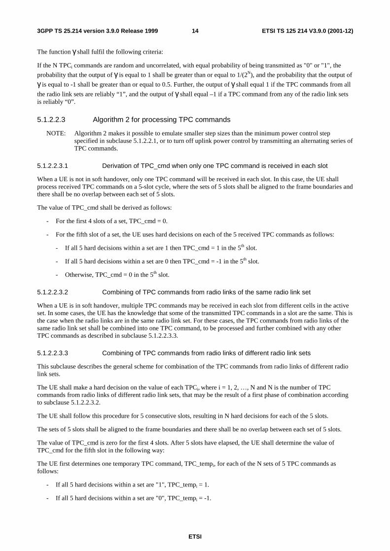
5.1.2.2.3 Algorithm 2 for processing TPC commands
NOTE: Algorithm 2 makes it possible to emulate smaller step sizes than the minimum power control step specified in subclause 5.1.2.2.1, or to turn off uplink power control by transmitting an alternating series of TPC commands.
5.1.2.2.3.1 Derivation of TPC_cmd when only one TPC command is received in each slot
When a UE is not in soft handover, only one TPC command will be received in each slot. In this case, the UE shall process received TPC commands on a 5-slot cycle, where the sets of 5 slots shall be aligned to the frame boundaries and there shall be no overlap between each set of 5 slots.
The value of TPC_cmd shall be derived as follows:
- For the first 4 slots of a set, TPC_cmd = 0.
- For the fifth slot of a set, the UE uses hard decisions on each of the 5 received TPC commands as follows:
- If all 5 hard decisions within a set are 1 then TPC_cmd = 1 in the 5th slot.
- If all 5 hard decisions within a set are 0 then TPC_cmd = -1 in the 5th slot.
- Otherwise, TPC_cmd = 0 in the 5th slot.
5.1.2.2.3.2 Combining of TPC commands from radio links of the same radio link set
When a UE is in soft handover, multiple TPC commands may be received in each slot from different cells in the active set. In some cases, the UE has the knowledge that some of the transmitted TPC commands in a slot are the same. This is the case when the radio links are in the same radio link set. For these cases, the TPC commands from radio links of the same radio link set shall be combined into one TPC command, to be processed and further combined with any other TPC commands as described in subclause 5.1.2.2.3.3.
5.1.2.2.3.3 Combining of TPC commands from radio links of different radio link sets
This subclause describes the general scheme for combination of the TPC commands from radio links of different radio link sets.
The UE shall make a hard decision on the value of each TPCi, where i = 1, 2, …, N and N is the number of TPC commands from radio links of different radio link sets, that may be the result of a first phase of combination according to subclause 5.1.2.2.3.2.
The UE shall follow this procedure for 5 consecutive slots, resulting in N hard decisions for each of the 5 slots.
The sets of 5 slots shall be aligned to the frame boundaries and there shall be no overlap between each set of 5 slots.
The value of TPC_cmd is zero for the first 4 slots. After 5 slots have elapsed, the UE shall determine the value of TPC_cmd for the fifth slot in the following way:
The UE first determines one temporary TPC command, TPC_tempi, for each of the N sets of 5 TPC commands as follows:
- If all 5 hard decisions within a set are "1", TPC_tempi = 1.
- If all 5 hard decisions within a set are "0", TPC_tempi = -1.
ETSI
ETSI TS 125 214 V3.9.0 (2001-12)153GPP TS 25.214 version 3.9.0 Release 1999
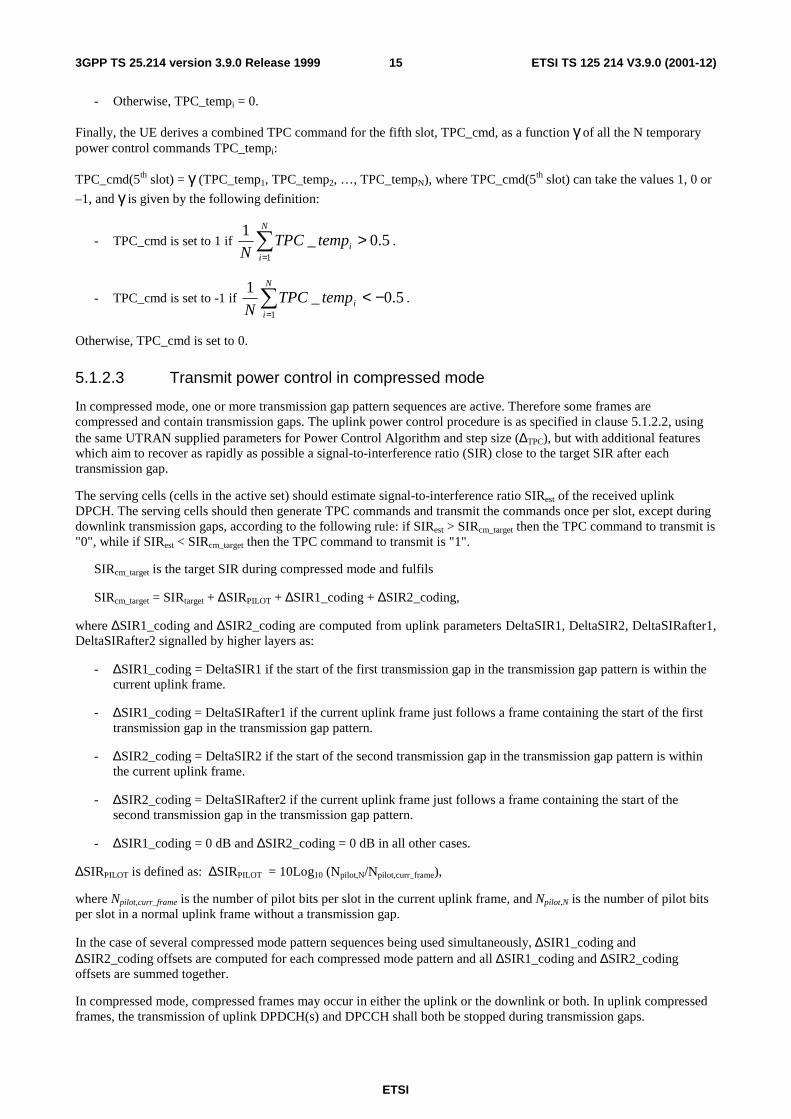
- Otherwise, TPC_tempi = 0.
Finally, the UE derives a combined TPC command for the fifth slot, TPC_cmd, as a function γ of all the N temporary power control commands TPC_tempi:
TPC_cmd(5th slot) = γ (TPC_temp1, TPC_temp2, …, TPC_tempN), where TPC_cmd(5th slot) can take the values 1, 0 or
–1, and γ is given by the following definition:
- TPC_cmd is set to 1 if 5.0_1
1
>∑=
N
iitempTPC
N.
- TPC_cmd is set to -1 if 5.0_1
1
−<∑=
N
iitempTPC
N.
Otherwise, TPC_cmd is set to 0.
5.1.2.3 Transmit power control in compressed mode
In compressed mode, one or more transmission gap pattern sequences are active. Therefore some frames are compressed and contain transmission gaps. The uplink power control procedure is as specified in clause 5.1.2.2, using the same UTRAN supplied parameters for Power Control Algorithm and step size (∆TPC), but with additional features which aim to recover as rapidly as possible a signal-to-interference ratio (SIR) close to the target SIR after each transmission gap.
The serving cells (cells in the active set) should estimate signal-to-interference ratio SIRest of the received uplink DPCH. The serving cells should then generate TPC commands and transmit the commands once per slot, except during downlink transmission gaps, according to the following rule: if SIRest > SIRcm_target then the TPC command to transmit is "0", while if SIRest < SIRcm_target then the TPC command to transmit is "1".
SIRcm_target is the target SIR during compressed mode and fulfils
SIRcm_target = SIRtarget + ∆SIRPILOT + ∆SIR1_coding + ∆SIR2_coding,
where ∆SIR1_coding and ∆SIR2_coding are computed from uplink parameters DeltaSIR1, DeltaSIR2, DeltaSIRafter1, DeltaSIRafter2 signalled by higher layers as:
- ∆SIR1_coding = DeltaSIR1 if the start of the first transmission gap in the transmission gap pattern is within the current uplink frame.
- ∆SIR1_coding = DeltaSIRafter1 if the current uplink frame just follows a frame containing the start of the first transmission gap in the transmission gap pattern.
- ∆SIR2_coding = DeltaSIR2 if the start of the second transmission gap in the transmission gap pattern is within the current uplink frame.
- ∆SIR2_coding = DeltaSIRafter2 if the current uplink frame just follows a frame containing the start of the second transmission gap in the transmission gap pattern.
- ∆SIR1_coding = 0 dB and ∆SIR2_coding = 0 dB in all other cases.
∆SIRPILOT is defined as: ∆SIRPILOT = 10Log10 (Npilot,N/Npilot,curr_frame),
where Npilot,curr_frame is the number of pilot bits per slot in the current uplink frame, and Npilot,N is the number of pilot bits per slot in a normal uplink frame without a transmission gap.
In the case of several compressed mode pattern sequences being used simultaneously, ∆SIR1_coding and ∆SIR2_coding offsets are computed for each compressed mode pattern and all ∆SIR1_coding and ∆SIR2_coding offsets are summed together.
In compressed mode, compressed frames may occur in either the uplink or the downlink or both. In uplink compressed frames, the transmission of uplink DPDCH(s) and DPCCH shall both be stopped during transmission gaps.
ETSI
ETSI TS 125 214 V3.9.0 (2001-12)163GPP TS 25.214 version 3.9.0 Release 1999
Due to the transmission gaps in compressed frames, there may be missing TPC commands in the downlink. If no downlink TPC command is transmitted, the corresponding TPC_cmd derived by the UE shall be set to zero.
Compressed and non-compressed frames in the uplink DPCCH may have a different number of pilot bits per slot. A change in the transmit power of the uplink DPCCH would be needed in order to compensate for the change in the total pilot energy. Therefore at the start of each slot the UE shall derive the value of a power offset ∆ PILOT. If the number of pilot bits per slot in the uplink DPCCH is different from its value in the most recently transmitted slot, ∆ PILOT (in dB) shall be given by:
∆ PILOT = 10Log10 (Npilot,prev/Npilot,curr);
where Npilot,prev is the number of pilot bits in the most recently transmitted slot , and Npilot,curr is the number of pilot bits in the current slot. Otherwise, including during transmission gaps in the downlink, ∆ PILOT shall be zero.
Unless otherwise specified, in every slot during compressed mode the UE shall adjust the transmit power of the uplink DPCCH with a step of ∆DPCCH (in dB) which is given by:
∆DPCCH = ∆TPC × TPC_cmd + ∆ PILOT.
At the start of the first slot after an uplink or downlink transmission gap the UE shall apply a change in the transmit power of the uplink DPCCH by an amount ∆DPCCH (in dB), with respect to the uplink DPCCH power in the most recently transmitted uplink slot, where:
∆DPCCH = ∆ RESUME + ∆ PILOT.
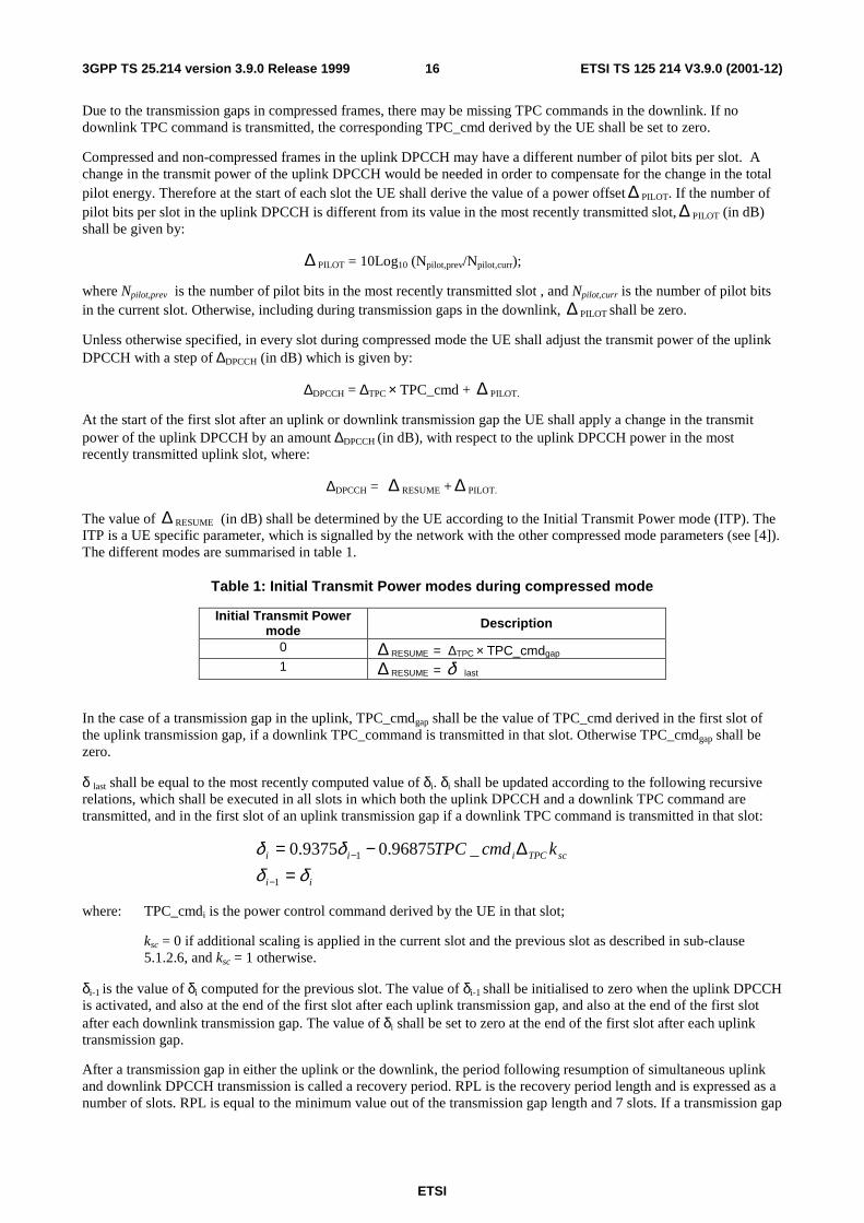
The value of ∆ RESUME (in dB) shall be determined by the UE according to the Initial Transmit Power mode (ITP). The ITP is a UE specific parameter, which is signalled by the network with the other compressed mode parameters (see [4]). The different modes are summarised in table 1.
Table 1: Initial Transmit Power modes during compressed mode
Initial Transmit Power mode Description
0 ∆ RESUME = ∆TPC × TPC_cmdgap 1 ∆ RESUME = δ last
In the case of a transmission gap in the uplink, TPC_cmdgap shall be the value of TPC_cmd derived in the first slot of the uplink transmission gap, if a downlink TPC_command is transmitted in that slot. Otherwise TPC_cmdgap shall be zero.
δ last shall be equal to the most recently computed value of δi. δi shall be updated according to the following recursive relations, which shall be executed in all slots in which both the uplink DPCCH and a downlink TPC command are transmitted, and in the first slot of an uplink transmission gap if a downlink TPC command is transmitted in that slot:
ii
scTPCiii kcmdTPC
δδδδ
=∆−=
−
−
1
1 _96875.09375.0
where: TPC_cmdi is the power control command derived by the UE in that slot;
ksc = 0 if additional scaling is applied in the current slot and the previous slot as described in sub-clause 5.1.2.6, and ksc = 1 otherwise.
δi-1 is the value of δi computed for the previous slot. The value of δi-1 shall be initialised to zero when the uplink DPCCH is activated, and also at the end of the first slot after each uplink transmission gap, and also at the end of the first slot after each downlink transmission gap. The value of δi shall be set to zero at the end of the first slot after each uplink transmission gap.
After a transmission gap in either the uplink or the downlink, the period following resumption of simultaneous uplink and downlink DPCCH transmission is called a recovery period. RPL is the recovery period length and is expressed as a number of slots. RPL is equal to the minimum value out of the transmission gap length and 7 slots. If a transmission gap

ETSI
ETSI TS 125 214 V3.9.0 (2001-12)173GPP TS 25.214 version 3.9.0 Release 1999
is scheduled to start before RPL slots have elapsed, then the recovery period shall end at the start of the gap, and the value of RPL shall be reduced accordingly.
During the recovery period, 2 modes are possible for the power control algorithm. The Recovery Period Power control mode (RPP) is signalled with the other compressed mode parameters (see [4]). The different modes are summarised in the table 2:
Table 2: Recovery Period Power control modes during compressed mode
Recovery Period power control mode Description
0 Transmit power control is applied using the algorithm determined by the value of PCA, as in subclause 5.1.2.2 with step size ∆TPC.
1 Transmit power control is applied using algorithm 1 (see subclause 5.1.2.2.2) with step size ∆RP-TPC during RPL slots after each transmission gap.
For RPP mode 0, the step size is not changed during the recovery period and ordinary transmit power control is applied (see subclause 5.1.2.2), using the algorithm for processing TPC commands determined by the value of PCA (see sub clauses 5.1.2.2.2 and 5.1.2.2.3).
For RPP mode 1, during RPL slots after each transmission gap, power control algorithm 1 is applied with a step size ∆RP-TPC instead of ∆TPC, regardless of the value of PCA. Therefore, the change in uplink DPCCH transmit power at the start of each of the RPL+1 slots immediately following the transmission gap (except for the first slot after the transmission gap) is given by:
∆DPCCH = ∆RP-TPC × TPC_cmd + ∆ PILOT
∆RP-TPC is called the recovery power control step size and is expressed in dB. If PCA has the value 1, ∆RP-TPC is equal to the minimum value of 3 dB and 2∆TPC. If PCA has the value 2 , ∆RP-TPC is equal to 1 dB.
After the recovery period, ordinary transmit power control resumes using the algorithm specified by the value of PCA and with step size ∆TPC.
If PCA has the value 2 , the sets of slots over which the TPC commands are processed shall remain aligned to the frame boundaries in the compressed frame. For both RPP mode 0 and RPP mode 1, if the transmission gap or the recovery period results in any incomplete sets of TPC commands, TPC_cmd shall be zero for those sets of slots which are incomplete.
5.1.2.4 Transmit power control in the uplink DPCCH power control preamble
An uplink DPCCH power control preamble is a period of uplink DPCCH transmission prior to the start of the uplink DPDCH transmission. The downlink DPCCH shall also be transmitted during an uplink DPCCH power control preamble.
The length of the uplink DPCCH power control preamble is a higher layer parameter signalled by the network as defined in [5]. The uplink DPDCH transmission shall commence after the end of the uplink DPCCH power control preamble.
During the uplink DPCCH power control preamble the change in uplink DPCCH transmit power shall be given by:
∆DPCCH = ∆TPC × TPC_cmd.
During the uplink DPCCH power control preamble TPC_cmd is derived according to algorithm 1 as described in sub clause 5.1.2.2.1, regardless of the value of PCA.
Ordinary power control (see subclause 5.1.2.2), with the power control algorithm determined by the value of PCA and step size ∆TPC, shall be used after the end of the uplink DPCCH power control preamble.

ETSI
ETSI TS 125 214 V3.9.0 (2001-12)183GPP TS 25.214 version 3.9.0 Release 1999
5.1.2.5 Setting of the uplink DPCCH/DPDCH power difference
5.1.2.5.1 General
The uplink DPCCH and DPDCH(s) are transmitted on different codes as defined in subclause 4.2.1 of [3]. The gain factors βc and βd may vary for each TFC. There are two ways of controlling the gain factors of the DPCCH code and the DPDCH codes for different TFCs in normal (non-compressed) frames:
− βc and βd are signalled for the TFC, or
− βc and βd is computed for the TFC, based on the signalled settings for a reference TFC.
Combinations of the two above methods may be used to associate βc and βd values to all TFCs in the TFCS. The two methods are described in subclauses 5.1.2.5.2 and 5.1.2.5.3 respectively. Several reference TFCs may be signalled from higher layers.
The gain factors may vary on radio frame basis depending on the current TFC used. Further, the setting of gain factors is independent of the inner loop power control.
After applying the gain factors, the UE shall scale the total transmit power of the DPCCH and DPDCH(s), such that the DPCCH output power follows the changes required by the power control procedure with power adjustments of ∆DPCCH dB, subject to the provisions of sub-clause 5.1.2.6.
The gain factors during compressed frames are based on the nominal power relation defined in normal frames, as specified in subclause 5.1.2.5.4.
5.1.2.5.2 Signalled gain factors
When the gain factors βc and βd are signalled by higher layers for a certain TFC, the signalled values are used directly for weighting of DPCCH and DPDCH(s). The variable Aj, called the nominal power relation is then computed as:
c
djA
ββ= .
5.1.2.5.3 Computed gain factors
The gain factors βc and βd may also be computed for certain TFCs, based on the signalled settings for a reference TFC.
Let βc,ref and βd,ref denote the signalled gain factors for the reference TFC. Further, let βc,j and βd,j denote the gain factors used for the j:th TFC. Also let Lref denote the number of DPDCHs used for the reference TFC and L,j denote the number of DPDCHs used for the j:th TFC.
Define the variable
∑ ⋅=i
iiref NRMK ;
where RMi is the semi-static rate matching attribute for transport channel i (defined in [2] subclause 4.2.7), Ni is the number of bits output from the radio frame segmentation block for transport channel i (defined in [2] subclause 4.2.6.1), and the sum is taken over all the transport channels i in the reference TFC.
Similarly, define the variable
∑ ⋅=i
iij NRMK ;
where the sum is taken over all the transport channels i in the j:th TFC.
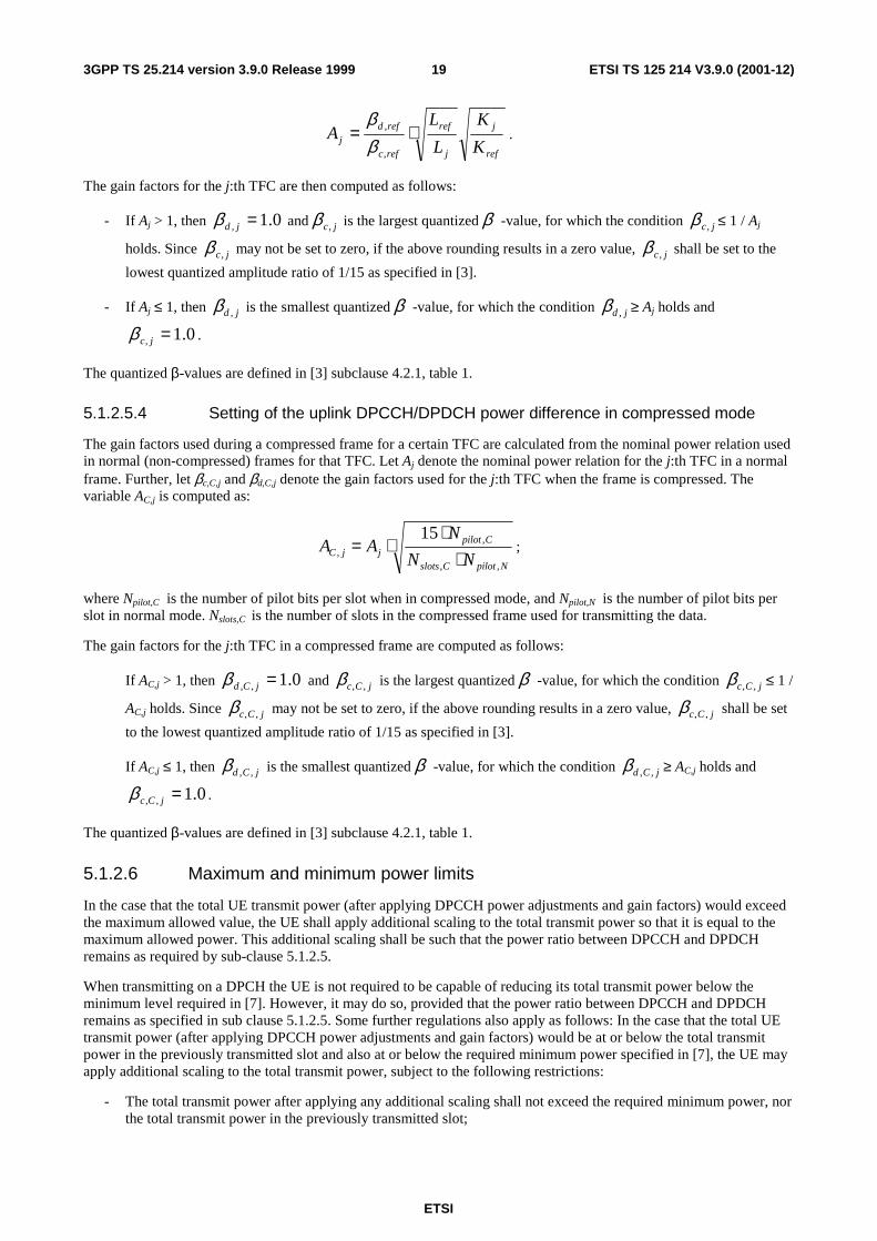
The variable Aj, called the nominal power relation is then computed as:
ETSI
ETSI TS 125 214 V3.9.0 (2001-12)193GPP TS 25.214 version 3.9.0 Release 1999
ref
j
j
ref
refc
refdj K
K
L
LA ⋅=
,
,
ββ
.
The gain factors for the j:th TFC are then computed as follows:
- If Aj > 1, then 0.1, =jdβ and jc,β is the largest quantized β -value, for which the condition jc,β ≤ 1 / Aj
holds. Since jc,β may not be set to zero, if the above rounding results in a zero value, jc,β shall be set to the
lowest quantized amplitude ratio of 1/15 as specified in [3].
- If Aj ≤ 1, then jd ,β is the smallest quantized β -value, for which the condition jd ,β ≥ Aj holds and
0.1, =jcβ .
The quantized β-values are defined in [3] subclause 4.2.1, table 1.
5.1.2.5.4 Setting of the uplink DPCCH/DPDCH power difference in compressed mode
The gain factors used during a compressed frame for a certain TFC are calculated from the nominal power relation used in normal (non-compressed) frames for that TFC. Let Aj denote the nominal power relation for the j:th TFC in a normal frame. Further, let βc,C,j and βd,C,j denote the gain factors used for the j:th TFC when the frame is compressed. The variable AC,j is computed as:
NpilotCslots
CpilotjjC NN
NAA
,,
,,
15
⋅⋅
⋅= ;
where Npilot,C is the number of pilot bits per slot when in compressed mode, and Npilot,N is the number of pilot bits per slot in normal mode. Nslots,C is the number of slots in the compressed frame used for transmitting the data.
The gain factors for the j:th TFC in a compressed frame are computed as follows:
If AC,j > 1, then 0.1,, =jCdβ and jCc ,,β is the largest quantized β -value, for which the condition jCc ,,β ≤ 1 /
AC,j holds. Since jCc ,,β may not be set to zero, if the above rounding results in a zero value, jCc ,,β shall be set
to the lowest quantized amplitude ratio of 1/15 as specified in [3].
If AC,j ≤ 1, then jCd ,,β is the smallest quantized β -value, for which the condition jCd ,,β ≥ AC,j holds and
0.1,, =jCcβ .
The quantized β-values are defined in [3] subclause 4.2.1, table 1.
5.1.2.6 Maximum and minimum power limits
In the case that the total UE transmit power (after applying DPCCH power adjustments and gain factors) would exceed the maximum allowed value, the UE shall apply additional scaling to the total transmit power so that it is equal to the maximum allowed power. This additional scaling shall be such that the power ratio between DPCCH and DPDCH remains as required by sub-clause 5.1.2.5.
When transmitting on a DPCH the UE is not required to be capable of reducing its total transmit power below the minimum level required in [7]. However, it may do so, provided that the power ratio between DPCCH and DPDCH remains as specified in sub clause 5.1.2.5. Some further regulations also apply as follows: In the case that the total UE transmit power (after applying DPCCH power adjustments and gain factors) would be at or below the total transmit power in the previously transmitted slot and also at or below the required minimum power specified in [7], the UE may apply additional scaling to the total transmit power, subject to the following restrictions:
- The total transmit power after applying any additional scaling shall not exceed the required minimum power, nor the total transmit power in the previously transmitted slot;
ETSI
ETSI TS 125 214 V3.9.0 (2001-12)203GPP TS 25.214 version 3.9.0 Release 1999
- The magnitude of any reduction in total transmit power between slots after applying any additional scaling shall not exceed the magnitude of the calculated power reduction before the additional scaling.
In the case that the total UE transmit power in the previously transmitted slot is at or below the required minimum power specfied in [7] and the DPCCH power adjustment and gain factors for the current slot would result in an increase in total power, then no additional scaling shall be used (i.e. power control shall operate as normal).
If the UE applies any additional scaling to the total transmit power as described above, this scaling shall be included in the computation of any DPCCH power adjustments to be applied in the next transmitted slot.
5.1.3 PCPCH
5.1.3.1 General
The power control during the CPCH access procedure is described in clause 6.2. The inner loop power control for the PCPCH is described in the following sub-clauses.
5.1.3.2 Power control in the message part
The uplink transmit power control procedure simultaneously controls the power of a PCPCH control part and its corresponding PCPCH data part. The relative transmit power offset between the PCPCH control part and the PCPCH data part is determined by the network and is computed according to sub-clause 5.1.2.5 using the gain factors signalled to the UE using higher-layer signalling, with the difference that:
- βc is the gain factor for the PCPCH control part (similar to DPCCH);
- βd is the gain factor for the PCPCH data part (similar to DPDCH).
The gain factors are applied as shown in sub clause 4.2.3.2 of [3].
The operation of the inner power control loop adjusts the power of the PCPCH control part and PCPCH data part by the same amount, provided there are no changes in gain factors.
Any change in the uplink PCPCH control part transmit power shall take place immediately before the start of the pilot field on the control part of the message part. The change in PCPCH control part power with respect to its value in the previous slot is derived by the UE and is denoted by ∆PCPCH-CP (in dB).
During the operation of the uplink power control procedure the UE transmit power shall not exceed a maximum allowed value which is the lower out of the maximum output power of the terminal power class and a value which may be set by higher layer signalling.
Uplink power control shall be performed while the UE transmit power is below the maximum allowed output power.
The provisions for power control at the maximum allowed value and below the required minimum output power (as defined in [7]) are described in sub-clause 5.1.2.6.
The uplink inner-loop power control adjusts the UE transmit power in order to keep the received uplink signal-to-interference ratio (SIR) at a given SIR target, SIRtarget, which is set by the higher layer outer loop.
The network should estimate the signal-to-interference ratio SIRest of the received PCPCH . The network should then generate TPC commands and transmit the commands once per slot according to the following rule: if SIRest > SIRtarget then the TPC command to transmit is "0", while if SIRest < SIRtarget then the TPC command to transmit is "1".
The UE derives a TPC command, TPC_cmd, for each slot. Two algorithms shall be supported by the UE for deriving a TPC_cmd. Which of these two algorithms is used is determined by a higher-layer parameter, "PowerControlAlgorithm", and is under the control of the UTRAN. If "PowerControlAlgorithm" indicates "algorithm1", then the layer 1 parameter PCA shall take the value 1 and if "PowerControlAlgorithm" indicates "algorithm2" then PCA shall take the value 2.
If PCA has the value 1, Algorithm 1, described in subclause 5.1.2.2.2, shall be used for processing TPC commands.
If PCA has the value 2, Algorithm 2, described in subclause 5.1.2.2.3, shall be used for processing TPC commands.

ETSI
ETSI TS 125 214 V3.9.0 (2001-12)213GPP TS 25.214 version 3.9.0 Release 1999
The step size ∆TPC is a layer 1 parameter which is derived from the higher-layer parameter "TPC-StepSize" which is under the control of the UTRAN. If "TPC-StepSize" has the value "dB1", then the layer 1 parameter ∆TPC shall take the value 1 dB and if "TPC-StepSize" has the value "dB2", then ∆TPC shall take the value 2 dB.
After deriving the TPC command TPC_cmd using one of the two supported algorithms, the UE shall adjust the transmit power of the uplink PCPCH control part with a step of ∆PCPCH-CP (in dB) which is given by:
∆PCPCH-CP = ∆TPC × TPC_cmd
5.1.3.3 Power control in the power control preamble
A PCPCH power control preamble is a period when both the UL PCPCH control part and the associated DL DPCCH are transmitted prior to the start of the uplink PCPCH data part.
The length of the power control preamble is a higher layer parameter, Lpc-preamble (see section 6.2), and can take the value 0 slots or 8 slots. The uplink PCPCH data part shall not commence before the end of the power control preamble.
If Lpc-preamble > 0, the details of power control used during the power control preamble differ from the ordinary power control which is used afterwards. After the first slot of the power control preamble the change in uplink PCPCH control part transmit power shall initially be given by:
∆PCPCH-CP = ∆TPC-init × TPC_cmd
If the value of PCA is 1 then ∆TPC-init is equal to the minimum value out of 3 dB and 2∆TPC.
If the value of PCA is 2 then ∆TPC-init is equal to 2dB.
TPC_cmd is derived according to algorithm 1 as described in sub clause 5.1.2.2.2, regardless of the value of PCA.
Power control as defined for the message part (see sub-clause 5.1.3.2), with the power control algorithm determined by the value of PCA and step size ∆TPC, shall be used as soon as the sign of TPC_cmd reverses for the first time, or at the end of the power control preamble if the power control preamble ends first.
5.2 Downlink power control The transmit power of the downlink channels is determined by the network. In general the ratio of the transmit power between different downlink channels is not specified and may change with time. However, regulations exist as described in the following subclauses.
Higher layer power settings shall be interpreted as setting of the total power, i.e. the sum of the power from the two antennas in case of transmit diversity.
5.2.1 DPCCH/DPDCH
5.2.1.1 General
The downlink transmit power control procedure controls simultaneously the power of a DPCCH and its corresponding DPDCHs. The power control loop adjusts the power of the DPCCH and DPDCHs with the same amount, i.e. the relative power difference between the DPCCH and DPDCHs is not changed.
The relative transmit power offset between DPCCH fields and DPDCHs is determined by the network The TFCI, TPC and pilot fields of the DPCCH are offset relative to the DPDCHs power by PO1, PO2 and PO3 dB respectively. The power offsets may vary in time. The method for controlling the power offsets within UTRAN is specified in [6]
5.2.1.2 Ordinary transmit power control
5.2.1.2.1 UE behaviour
The UE shall generate TPC commands to control the network transmit power and send them in the TPC field of the uplink DPCCH. An example on how to derive the TPC commands in given in Annex B.2.

ETSI
ETSI TS 125 214 V3.9.0 (2001-12)223GPP TS 25.214 version 3.9.0 Release 1999
The UE shall check the downlink power control mode (DPC_MODE) before generating the TPC command:
- if DPC_MODE = 0 : the UE sends a unique TPC command in each slot and the TPC command generated is transmitted in the first available TPC field in the uplink DPCCH;
- if DPC_MODE = 1 : the UE repeats the same TPC command over 3 slots and the new TPC command is transmitted such that there is a new command at the beginning of the frame.
The DPC_MODE parameter is a UE specific parameter controlled by the UTRAN.
The UE shall not make any assumptions on how the downlink power is set by UTRAN, in order to not prohibit usage of other UTRAN power control algorithms than what is defined in subclause 5.2.1.2.2.
5.2.1.2.2 UTRAN behaviour
Upon receiving the TPC commands UTRAN shall adjust its downlink DPCCH/DPDCH power accordingly. For DPC_MODE = 0, UTRAN shall estimate the transmitted TPC command TPCest to be 0 or 1, and shall update the power every slot. If DPC_MODE = 1, UTRAN shall estimate the transmitted TPC command TPCest over three slots to be 0 or 1, and shall update the power every three slots.
After estimating the k:th TPC command, UTRAN shall adjust the current downlink power P(k-1) [dB] to a new power P(k) [dB] according to the following formula:
P(k) = P(k - 1) + PTPC(k) + Pbal(k),
where PTPC(k) is the k:th power adjustment due to the inner loop power control, and Pbal(k) [dB] is a correction according to the downlink power control procedure for balancing radio link powers towards a common reference power. The power balancing procedure and control of the procedure is described in [6].
PTPC(k) is calculated according to the following.
If the value of Limited Power Increase Used parameter is 'Not used', then
=−=+
=0)(TPCif∆
1)(TPCif∆)(P
estTPC
estTPCTPC k
kk , [dB]. (1)
If the value of Limited Power Increase Used parameter is 'Used', then the k:th inner loop power adjustment shall be calculated as:
=≥∆+∆=<∆+∆=
∆−
∆+=
0)(TPC if
e_LimitPower_Rais)( and 1)(TPC if
e_LimitPower_Rais)( and 1)(TPC if
0)(
est
est
est
k
kk
kk
kP TPCsum
TPCsum
TPC
TPC
TPC , [dB] (2)
where
∑−
−==∆
1
indow_Sizeveraging_WDL_Power_A
)()(k
kiTPCsum iPk
is the temporary sum of the last DL_Power_Averaging_Window_Size inner loop power adjustments (in dB).
For the first (DL_Power_Averaging_Window_Size – 1) adjustments after the activation of the limited power increase method, formula (1) shall be used instead of formula (2). Power_Raise_Limit and DL_Power_Averaging_Window_Size are parameters configured in the UTRAN.
The power control step size ∆TPC can take four values: 0.5, 1, 1.5 or 2 dB. It is mandatory for UTRAN to support ∆TPC of 1 dB, while support of other step sizes is optional.
In addition to the above described formulas on how the downlink power is updated, the restrictions below apply.
In case of congestion (commanded power not available), UTRAN may disregard the TPC commands from the UE.

ETSI
ETSI TS 125 214 V3.9.0 (2001-12)233GPP TS 25.214 version 3.9.0 Release 1999
The average power of transmitted DPDCH symbols over one timeslot shall not exceed Maximum_DL_Power (dB), nor shall it be below Minimum_DL_Power (dB). Transmitted DPDCH symbol means here a complex QPSK symbol before spreading which does not contain DTX. Maximum_DL_Power (dB) and Minimum_DL_Power (dB) are power limits for one channelisation code, relative to the primary CPICH power [6].
5.2.1.3 Power control in compressed mode
The aim of downlink power control in uplink or/and downlink compressed mode is to recover as fast as possible a signal-to-interference ratio (SIR) close to the target SIR after each transmission gap.
The UE behaviour is the same in compressed mode as in normal mode, described in subclause 5.2.1.2, except that the target SIR is offset by higher layer signalling. However due to transmission gaps in uplink compressed frames there may be incomplete sets of TPC commands when DPC_MODE=1.
UTRAN behaviour is as stated in section 5.2.1.2.2 except for DPC_MODE = 1 where missing TPC commands in the UL may lead the UTRAN to changing its power more frequently than every 3 slots.
In compressed mode, compressed frames may occur in either the uplink or the downlink or both. In compressed frames, the transmission of downlink DPDCH(s) and DPCCH shall be stopped during transmission gaps.
The power of the DPCCH and DPDCH in the first slot after the transmission gap should be set to the same value as in the slot just before the transmission gap.
During compressed mode except during downlink transmission gaps, UTRAN shall estimate the k:th TPC command and adjust the current downlink power P(k-1) [dB] to a new power P(k) [dB] according to the following formula:
P(k) = P(k - 1) + PTPC(k) + PSIR(k) + Pbal(k),
where PTPC(k) is the k:th power adjustment due to the inner loop power control, PSIR(k) is the k-th power adjustment due to the downlink target SIR variation, and Pbal(k) [dB] is a correction according to the downlink power control procedure for balancing radio link powers towards a common reference power. The power balancing procedure and control of the procedure is described in [6].
Due to transmission gaps in uplink compressed frames, there may be missing TPC commands in the uplink.
For DPC_MODE = 0 if no uplink TPC command is received, PTPC(k) derived by the Node B shall be set to zero. Otherwise, PTPC(k) is calculated the same way as in normal mode (see sub-clause 5.2.1.2.2) but with a step size ∆STEP instead of ∆TPC.
For DPC_MODE = 1, the sets of slots over which the TPC commands are processed shall remain aligned to the frame boundaries in the compressed frame. If this results in an incomplete set of TPC commands, the UE shall transmit the same TPC commands in all slots of the incomplete set.
The power control step size ∆STEP = ∆RP-TPC during RPL slots after each transmission gap and ∆STEP = ∆TPC otherwise, where:
- RPL is the recovery period length and is expressed as a number of slots. RPL is equal to the minimum value out of the transmission gap length and 7 slots. If a transmission gap is scheduled to start before RPL slots have elapsed, then the recovery period shall end at the start of the gap, and the value of RPL shall be reduced accordingly.
− ∆RP-TPC is called the recovery power control step size and is expressed in dB. ∆RP-TPC is equal to the minimum value of 3 dB and 2∆TPC.
The power offset PSIR(k) = δPcurr - δPprev, where δPcurr and δPprev are respectively the value of δP in the current slot and the most recently transmitted slot and δP is computed as follows:
δP = max (∆P1_compression, …, ∆Pn_compression) + ∆P1_coding + ∆P2_coding
where n is the number of different TTI lengths amongst TTIs of all TrChs of the CCTrCh, where ∆P1_coding and ∆P2_coding are computed from uplink parameters DeltaSIR1, DeltaSIR2, DeltaSIRafter1, DeltaSIRafter2 signaled by higher layers as:
ETSI
ETSI TS 125 214 V3.9.0 (2001-12)243GPP TS 25.214 version 3.9.0 Release 1999
- ∆P1_coding = DeltaSIR1 if the start of the first transmission gap in the transmission gap pattern is within the current frame.
- ∆P1coding = DeltaSIRafter1 if the current frame just follows a frame containing the start of the first transmission gap in the transmission gap pattern.
- ∆P2_coding = DeltaSIR2 if the start of the second transmission gap in the transmission gap pattern is within the current frame.
- ∆P2_coding = DeltaSIRafter2 if the current frame just follows a frame containing the start of the second transmission gap in the transmission gap pattern.
- ∆P1_coding = 0 dB and ∆P2_coding = 0 dB in all other cases.
and ∆Pi_compression is defined by :
- ∆Pi_compression = 3 dB for downlink frames compressed by reducing the spreading factor by 2.
- ∆Pi_compression = 10 log (15*Fi / (15*Fi - TGLi)) if there is a transmission gap created by puncturing method within the current TTI of length Fi frames, where TGLi is the gap length in number of slots (either from one gap or a sum of gaps) in the current TTI of length Fi frames.
- ∆Pi_compression = 0 dB in all other cases.
In case several compressed mode patterns are used simultaneously, a δP offset is computed for each compressed mode pattern and the sum of all δP offsets is applied to the frame.
For all time slots except those in transmissions gaps, the average power of transmitted DPDCH symbols over one timeslot shall not exceed Maximum_DL_Power (dB) by more than PSIR, nor shall it be below Minimum_DL_Power (dB). Transmitted DPDCH symbol means here a complex QPSK symbol before spreading which does not contain DTX. Maximum_DL_Power (dB) and Minimum_DL_Power (dB) are power limits for one channelisation code, relative to the primary CPICH power [6].
5.2.1.4 Site selection diversity transmit power control
5.2.1.4.1 General
Site selection diversity transmit power control (SSDT) is another macro diversity method in soft handover mode. This method is optional in UTRAN.
Operation is summarised as follows. The UE selects one of the cells from its active set to be ‘primary’, all other cells are classed as ‘non primary’. The main objective is to transmit on the downlink from the primary cell, thus reducing the interference caused by multiple transmissions in a soft handover mode. A second objective is to achieve fast site selection without network intervention, thus maintaining the advantage of the soft handover. In order to select a primary cell, each cell is assigned a temporary identification (ID) and UE periodically informs a primary cell ID to the connecting cells. The non-primary cells selected by UE switch off the transmission power. The primary cell ID is delivered by UE to the active cells via uplink FBI field. SSDT activation, SSDT termination and ID assignment are all carried out by higher layer signalling.
SSDT is only supported when the P-CPICH is used as the downlink phase reference and closed loop mode transmit diversity is not used simultaneously.
5.2.1.4.1.1 Definition of temporary cell identification
Each cell is given a temporary ID during SSDT and the ID is utilised as site selection signal. The ID is given a binary bit sequence. There are three different lengths of coded ID available denoted as "long", "medium" and "short". The network decides which length of coded ID is used. Settings of ID codes for 1-bit and 2-bit FBI are exhibited in table 3 and table 4, respectively.
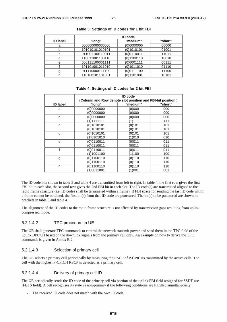
ETSI
ETSI TS 125 214 V3.9.0 (2001-12)253GPP TS 25.214 version 3.9.0 Release 1999
Table 3: Settings of ID codes for 1 bit FBI
ID code ID label "long" "medium" "short"
a 000000000000000 (0)0000000 00000 b 101010101010101 (0)1010101 01001 c 011001100110011 (0)0110011 11011 d 110011001100110 (0)1100110 10010 e 000111100001111 (0)0001111 00111 f 101101001011010 (0)1011010 01110 g 011110000111100 (0)0111100 11100 h 110100101101001 (0)1101001 10101
Table 4: Settings of ID codes for 2 bit FBI
ID code (Column and Row denote slot position and FBI-bit position.)
ID label "long" "medium" "short" a (0)0000000
(0)0000000 (0)000 (0)000
000 000
b (0)0000000 (1)1111111
(0)000 (1)111
000 111
c (0)1010101 (0)1010101
(0)101 (0)101
101 101
d (0)1010101 (1)0101010
(0)101 (1)010
101 010
e (0)0110011 (0)0110011
(0)011 (0)011
011 011
f (0)0110011 (1)1001100
(0)011 (1)100
011 100
g (0)1100110 (0)1100110
(0)110 (0)110
110 110
h (0)1100110 (1)0011001
(0)110 (1)001
110 001
The ID code bits shown in table 3 and table 4 are transmitted from left to right. In table 4, the first row gives the first FBI bit in each slot, the second row gives the 2nd FBI bit in each slot. The ID code(s) are transmitted aligned to the radio frame structure (i.e. ID codes shall be terminated within a frame). If FBI space for sending the last ID code within a frame cannot be obtained, the first bit(s) from that ID code are punctured. The bit(s) to be punctured are shown in brackets in table 3 and table 4.
The alignment of the ID codes to the radio frame structure is not affected by transmission gaps resulting from uplink compressed mode.
5.2.1.4.2 TPC procedure in UE
The UE shall generate TPC commands to control the network transmit power and send them in the TPC field of the uplink DPCCH based on the downlink signals from the primary cell only. An example on how to derive the TPC commands is given in Annex B.2.
5.2.1.4.3 Selection of primary cell
The UE selects a primary cell periodically by measuring the RSCP of P-CPICHs transmitted by the active cells. The cell with the highest P-CPICH RSCP is detected as a primary cell.
5.2.1.4.4 Delivery of primary cell ID
The UE periodically sends the ID code of the primary cell via portion of the uplink FBI field assigned for SSDT use (FBI S field). A cell recognises its state as non-primary if the following conditions are fulfilled simultaneously:
- The received ID code does not match with the own ID code.
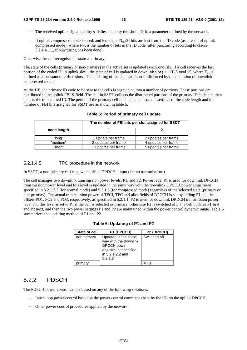
ETSI
ETSI TS 125 214 V3.9.0 (2001-12)263GPP TS 25.214 version 3.9.0 Release 1999
- The received uplink signal quality satisfies a quality threshold, Qth, a parameter defined by the network.
- If uplink compressed mode is used, and less than NID/3 bits are lost from the ID code (as a result of uplink compressed mode), where NID is the number of bits in the ID code (after puncturing according to clause 5.2.1.4.1.1, if puncturing has been done).
Otherwise the cell recognises its state as primary.
The state of the cells (primary or non-primary) in the active set is updated synchronously. If a cell receives the last portion of the coded ID in uplink slot j, the state of cell is updated in downlink slot (j+1+Tos) mod 15, where Tos is defined as a constant of 2 time slots. The updating of the cell state is not influenced by the operation of downlink compressed mode.
At the UE, the primary ID code to be sent to the cells is segmented into a number of portions. These portions are distributed in the uplink FBI S-field. The cell in SSDT collects the distributed portions of the primary ID code and then detects the transmitted ID. The period of the primary cell update depends on the settings of the code length and the number of FBI bits assigned for SSDT use as shown in table 5.
Table 5: Period of primary cell update
The number of FBI bits per slot assigned for SSDT
code length 1 2
"long" 1 update per frame 2 updates per frame "medium" 2 updates per frame 4 updates per frame
"short" 3 updates per frame 5 updates per frame
5.2.1.4.5 TPC procedure in the network
In SSDT, a non-primary cell can switch off its DPDCH output (i.e. no transmissions).
The cell manages two downlink transmission power levels, P1, and P2. Power level P1 is used for downlink DPCCH transmission power level and this level is updated in the same way with the downlink DPCCH power adjustment specified in 5.2.1.2.2 (for normal mode) and 5.2.1.3 (for compressed mode) regardless of the selected state (primary or non-primary). The actual transmission power of TFCI, TPC and pilot fields of DPCCH is set by adding P1 and the offsets PO1, PO2 and PO3, respectively, as specified in 5.2.1.1. P2 is used for downlink DPDCH transmission power level and this level is set to P1 if the cell is selected as primary, otherwise P2 is switched off. The cell updates P1 first and P2 next, and then the two power settings P1 and P2 are maintained within the power control dynamic range. Table 6 summarizes the updating method of P1 and P2.
Table 6: Updating of P1 and P2
State of cell P1 (DPCCH) P2 (DPDCH) non primary Updated in the same
way with the downlink DPCCH power adjustment specified in 5.2.1.2.2 and 5.2.1.3
Switched off
primary = P1
5.2.2 PDSCH
The PDSCH power control can be based on any of the following solutions:
- Inner-loop power control based on the power control commands sent by the UE on the uplink DPCCH.
- Other power control procedures applied by the network.
ETSI
ETSI TS 125 214 V3.9.0 (2001-12)273GPP TS 25.214 version 3.9.0 Release 1999
5.2.3 DL-DPCCH for CPCH
5.2.3.1 UE behaviour
The UE shall generate TPC commands to control the network transmit power and send them in the TPC field of the uplink DPCCH. The UE shall send a unique TPC command in each slot as in the DPCCH/DPDCH case for DPC_MODE=0.
The TPC commands setting may be based on the example provided in Annex B.2 for the DPCCH/DPDCH. However in the DL-DPCCH for CPCH case, the setting of the SIR_target by the outer loop power control is based on a DL-DPCCH for CPCH BER target provided by the UTRAN rather than a TrCH BLER. Also there is no soft handover, neither SSDT, used in combination with the CPCH.
The UE shall not make any assumptions on how the downlink power is set by UTRAN, in order to not prohibit usage of other UTRAN power control algorithms than what is defined in sub-clause 5.2.1.2.2.
5.2.3.2 UTRAN behaviour
The relative transmit power offsets between the different DPCCH fields (TPC and pilot) and CCC field is determined by the network. The power of CCC field in DL DPCCH for CPCH is the same as the power of the pilot field.
The TPC field of the DPCCH is offset relative to the pilot by PO2dB. This power offsets may vary in time. The method for controlling the power offset within UTRAN is specified in [6]
The UTRAN behaviour for the power control is left open to the implementation. As an example it may be based on the UTRAN behaviour for the DPCCH/DPDCH as specified in sub-clause 5.2.1.2.2, with the following exceptions : DPC_MODE should be set to 0 as there is no DPC_MODE parameter for CPCH and there is no support of Site selection diversity power control for the DL-DPCCH for CPCH as Soft handover is not applicable to the CPCH.
5.2.4 AICH
The UE is informed about the relative transmit power of the AICH (measured as the power per transmitted acquisition indicator) compared to the primary CPICH transmit power by the higher layers.
5.2.5 PICH
The UE is informed about the relative transmit power of the PICH (measured as the power over the paging indicators) compared to the primary CPICH transmit power by the higher layers.
5.2.6 S-CCPCH
The TFCI and pilot fields may be offset relative to the power of the data field. The power offsets may vary in time.
5.2.7 CSICH
The UE is informed about the relative transmit power of the CSICH (measured as the power per transmitted status indicator) compared to the primary CPICH transmit power by the higher layers.
5.2.8 AP-AICH
The UE is informed about the relative transmit power of the AP-AICH (measured as the power per transmitted acquisition indicator) compared to the primary CPICH transmit power by the higher layers.
5.2.9 CA/CD-ICH
The UE is informed about the relative transmit power of the CA/CD-ICH (measured as the power per transmitted acquisition indicator) compared to the primary CPICH transmit power by the higher layers.
ETSI
ETSI TS 125 214 V3.9.0 (2001-12)283GPP TS 25.214 version 3.9.0 Release 1999
6 Random access procedure
6.1 Physical random access procedure The physical random access procedure described in this subclause is initiated upon request from the MAC sublayer (cf. [9]).
Before the physical random-access procedure can be initiated, Layer 1 shall receive the following information from the higher layers (RRC):
- The preamble scrambling code.
- The message length in time, either 10 or 20 ms.
- The AICH_Transmission_Timing parameter [0 or 1].
- The set of available signatures and the set of available RACH sub-channels for each Access Service Class (ASC). Sub-channels are defined in subclause 6.1.1.
- The power-ramping factor Power Ramp Step [integer > 0].
- The parameter Preamble Retrans Max [integer > 0].
- The initial preamble power Preamble_Initial_Power.
- The Power offset P p-m = Pmessage-control – Ppreamble, measured in dB, between the power of the last transmitted preamble and the control part of the random-access message.
- The set of Transport Format parameters. This includes the power offset between the data part and the control part of the random-access message for each Transport Format.
Note that the above parameters may be updated from higher layers before each physical random access procedure is initiated.
At each initiation of the physical random access procedure, Layer 1 shall receive the following information from the higher layers (MAC):
- The Transport Format to be used for the PRACH message part.
- The ASC of the PRACH transmission.
- The data to be transmitted (Transport Block Set).
The physical random-access procedure shall be performed as follows:
1 Derive the available uplink access slots, in the next full access slot set, for the set of available RACH sub-channels within the given ASC with the help of subclauses 6.1.1. and 6.1.2. Randomly select one access slot among the ones previously determined. If there is no access slot available in the selected set, randomly select one uplink access slot corresponding to the set of available RACH sub-channels within the given ASC from the next access slot set. The random function shall be such that each of the allowed selections is chosen with equal probability.
2 Randomly select a signature from the set of available signatures within the given ASC. The random function shall be such that each of the allowed selections is chosen with equal probability.
3 Set the Preamble Retransmission Counter to Preamble Retrans Max.
4 Set the parameter Commanded Preamble Power to Preamble_Initial_Power.
5 In the case that the Commanded Preamble Power exceeds the maximum allowed value, set the preamble transmission power to the maximum allowed power. In the case that the Commanded Preamble Power is below the minimum level required in [7], set the preamble transmission power to a value, which shall be at or above the Commanded Preamble Power and at or below the required minimum power specified in [7]. Otherwise set the

ETSI
ETSI TS 125 214 V3.9.0 (2001-12)293GPP TS 25.214 version 3.9.0 Release 1999
preamble transmission power to the Commanded Preamble Power. Transmit a preamble using the selected uplink access slot, signature, and preamble transmission power.
6 If no positive or negative acquisition indicator (AI ≠ +1 nor –1) corresponding to the selected signature is detected in the downlink access slot corresponding to the selected uplink access slot:
6.1 Select the next available access slot in the set of available RACH sub-channels within the given ASC.
6.2 Randomly select a new signature from the set of available signatures within the given ASC. The random function shall be such that each of the allowed selections is chosen with equal probability.
6.3 Increase the Commanded Preamble Power by ∆P0 = Power Ramp Step [dB]. If the Commanded Preamble Power exceeds the maximum allowed power by 6dB, the UE may pass L1 status ("No ack on AICH") to the higher layers (MAC) and exit the physical random access procedure.
6.4 Decrease the Preamble Retransmission Counter by one.
6.5 If the Preamble Retransmission Counter > 0 then repeat from step 5. Otherwise pass L1 status ("No ack on AICH") to the higher layers (MAC) and exit the physical random access procedure.
7 If a negative acquisition indicator corresponding to the selected signature is detected in the downlink access slot corresponding to the selected uplink access slot, pass L1 status ("Nack on AICH received") to the higher layers (MAC) and exit the physical random access procedure.
8 Transmit the random access message three or four uplink access slots after the uplink access slot of the last transmitted preamble depending on the AICH transmission timing parameter. Transmission power of the control part of the random access message should be P p-m [dB] higher than the power of the last transmitted preamble. Transmission power of the data part of the random access message is set according to subclause 5.1.1.2.
9 Pass L1 status "RACH message transmitted" to the higher layers and exit the physical random access procedure.
6.1.1 RACH sub-channels
A RACH sub-channel defines a sub-set of the total set of uplink access slots. There are a total of 12 RACH sub-channels. RACH sub-channel #i (i = 0, …, 11) consists of the following uplink access slots:
- Uplink access slot #i leading by τp-a chips the downlink access slot #i contained within the 10 ms interval that is time aligned with P-CCPCH frames for which SFN mod 8 = 0 or SFN mod 8 = 1.
- Every 12th access slot relative to this access slot.
The access slots of different RACH sub-channels are also illustrated in Table 7.
Table 7: The available uplink access slots for different RACH sub-channels
Sub-channel number SFN modulo 8 of corresponding P-CCPCH frame
0 1 2 3 4 5 6 7 8 9 10 11
0 0 1 2 3 4 5 6 7 1 12 13 14 8 9 10 11 2 0 1 2 3 4 5 6 7 3 9 10 11 12 13 14 8 4 6 7 0 1 2 3 4 5 5 8 9 10 11 12 13 14 6 3 4 5 6 7 0 1 2 7 8 9 10 11 12 13 14
6.1.2 RACH access slot sets
The PRACH contains two sets of access slots as shown in Figure 2. Access slot set 1 contains PRACH slots 0 – 7 and starts τp-a chips before the downlink P-CCPCH frame for which SFN mod 2 = 0. Access slot set 2 contains PRACH slots 8 - 14 and starts (τp-a –2560) chips before the downlink P-CCPCH frame for which SFN mod 2 = 1.

ETSI
ETSI TS 125 214 V3.9.0 (2001-12)303GPP TS 25.214 version 3.9.0 Release 1999
AICH accessslots
10 ms
#0 #1 #2 #3 #14#13#12#11#10#9#8#7#6#5#4τp-a
#0 #1 #2 #3 #14#13#12#11#10#9#8#7#6#5#4
PRACHaccess slots
SFN mod 2 = 0 SFN mod 2 = 1
10 ms
Access slot set 1 Access slot set 2
Figure 2: PRACH access slot and downlink AICH relation (ττττp-a = 7680 chips)
6.2 CPCH Access Procedures For each CPCH physical channel in a CPCH set allocated to a cell the following physical layer parameters are included in the System Information message: L1 shall receive the following information from the higher layers (RRC).
- UL Access Preamble (AP) scrambling code.
- UL Access Preamble signature set.
- The Access preamble slot sub-channels group.
- AP- AICH preamble channelization code.
- UL Collision Detection(CD) preamble scrambling code.
- CD Preamble signature set.
- CD preamble slot sub-channels group.
- CD-AICH preamble channelization code.
- CPCH UL scrambling code.
- DPCCH DL channelization code.([512] chip).
NOTE: There may be some overlap between the AP signature set and CD signature set if they correspond to the same scrambling code.
The following physical layer parameters are received from the RRC layer:
1) N_AP_retrans_max = Maximum Number of allowed consecutive access attempts (retransmitted preambles) if there is no AICH response. This is a CPCH parameter and is equivalent to Preamble Retrans Max in RACH.
2) P RACH = P CPCH = Initial open loop power level for the first CPCH access preamble sent by the UE.
- [RACH/CPCH parameter].
3) ∆P0 = Power step size for each successive CPCH access preamble.
- [RACH/CPCH parameter].
4) ∆Pp-m = Pmessage-control – Pcd, measured in dB. This is the power offset between the transmit power of the CD preamble and the initial transmit power of the CPCH power control preamble (or the control part of the CPCH message part if the power control preamble length is 0 slots).
[CPCH parameter]
ETSI
ETSI TS 125 214 V3.9.0 (2001-12)313GPP TS 25.214 version 3.9.0 Release 1999
5) Tcpch = CPCH transmission timing parameter: This parameter is identical to PRACH/AICH transmission timing parameter.
- [RACH/CPCH parameter].
6) Lpc-preamble = Length of power control preamble (0 or 8 slots).
- [CPCH parameter].
7) NStart_Message = Number of frames for the transmission of Start of Message Indicator in DL-DPCCH for CPCH.
8) The set of Transport Format parameters. This includes a Transport Format to PCPCH mapping table.
L1 shall receive the following information from MAC prior to packet transmission:
1) Transport Format of the message part.
2) The data to be transmitted is delivered to L1 once every TTI until the data buffer is empty.
The overall CPCH -access procedure consists of two parts:
1) Upon receipt of a Status-REQ message from the MAC layer, the UE shall start monitoring the CSICH to determine the availability of the transport formats in the transport format subset included in the Status-REQ message. UTRAN transmits availability of each PCPCH or maximum available data rate with availability of each PCPCH over the CSICH in case CA is active. Upper layers will supply the UE with information to map the transport formats to the PCPCHs. The UE shall send a Status-CNF message to the MAC layer containing the transport format subset listing the transport formats of the requested subset which are currently indicated as "available".
The actual access procedure is then:
2) Upon receipt of the Access-REQ message from the MAC layer, which contains an identified transport format from the available ones ,the following sequence of events occur. The use of step 2a or 2b depends on whether availability of each PCPCH or the Maximum available data rate along with the availability of each PCPCH is transmitted over CSICH. Note that in the first case, each access resource combination (AP signatures and access subchannel group) maps to each PCPCH resource and in the second case each access resource combination maps to each data rate.
2a) (In case CA is not Active) The UE shall test the value(s) of the most recent transmission of the CSICH Status Indicator(s) corresponding to the PCPCH channel(s) for the identified transport format included in the Access-REQ message. If this indicates that no channel is ‘available’ the UE shall abort the access attempt and send a failure message to the MAC layer. The UE shall also retain the availability status of the each PCPCH for further verification in a later phase.
2b) (In case CA is active) The CSICH Status Indicators indicate the maximum available data rate along with individual PCPCH availability. The UE shall test the value of the most recent transmission of the Status Indicator(s). If this indicates that the maximum available data rate is less than the requested data rate, the UE shall abort the access attempt and send a failure message to the MAC layer. The PHY provides the availability information to the MAC. The UE shall also retain the availability status of the each PCPCH for further channel assignment message verification in a later phase in case of success.
3) The UE sets the preamble transmit power to the value PCPCH_ which is supplied by the MAC layer for initial power level for this CPCH access attempt.
4) The UE sets the AP Retransmission Counter to N_AP_Retrans_Max.
5a) In the case CA is not active, the uplink access slot and signature to be used for the CPCH-AP transmission are selected in the following steps:
a) The UE selects randomly one PCPCH from the set of available PCPCH channel(s) as indicated on the CSICH and supporting the identified transport format included in the Access-REQ message. The random function shall be such that each of the allowed selections is chosen with equal probability.
b) The UE randomly selects a CPCH-AP signature from the set of available signatures in the access resource combination corresponding to the selected PCPCH in step a). The random function shall be such that each of the allowed selections is chosen with equal probability.
ETSI
ETSI TS 125 214 V3.9.0 (2001-12)323GPP TS 25.214 version 3.9.0 Release 1999
c) Using the AP access slot sub-channel group of the access resource combination corresponding to selected PCPCH in step a), the UE derives the available CPCH-AP access slots with the help of subclauses 6.1.1. and 6.1.2. The UE randomly selects one uplink access slot from the derived available CPCH-AP access slots. If there is no access slot available in the selected set, the UE randomly selects one uplink access slot corresponding to the selected CPCH sub-channel group from the next access slot set. The random function shall be such that each of the allowed selections is chosen with equal probability.
5b) In the case CA is active, the uplink access slot and signature to be used for the CPCH-AP transmission are selected in the following steps:
a) The UE randomly selects a CPCH-AP signature from the set of available signatures in the access resource combination corresponding to the transport format identified in the Access-REQ message. The random function shall be such that each of the allowed selections is chosen with equal probability.
b) Using the AP access slot sub-channel group of the access resource combination corresponding to the transport format identified in the Access-REQ message, the UE derives the available CPCH-AP access slots with the help of subclauses 6.1.1 and 6.1.2. The UE randomly selects one uplink access slot from the derived available CPCH-AP access slots. If there is no access slot available in the selected set, the UE randomly selects one uplink access slot corresponding to the selected CPCH sub-channel group from the next access slot set. The random function shall be such that each of the allowed selections is chosen with equal probability.
6) The UE transmits the AP using the selected uplink access slot and signature, and MAC supplied initial preamble transmission power. The following sequence of events occur based on whether availability of each PCPCH or the Maximum available data rate along with the availability of each PCPCH is transmitted over CSICH.
6a) (In case CA is not Active) The UE shall test the value of the most recent transmission of the Status Indicator corresponding to the identified CPCH transport channel immediately before AP transmission. If this indicates that the channel is ‘not available’ the UE shall abort the access attempt and send a failure message to the MAC layer. Otherwise the UE transmits the AP using the UE selected uplink signature and access slot, and the initial preamble transmission power from step 3, above.
6b) (In case CA is active) The Status Indicator indicates the maximum available data rate as well as the availability of each PCPCH. The UE shall test the value of the Status Indicator. If this indicates that the maximum available data rate is less than the requested data rate, the UE shall abort the access attempt and send a failure message to the MAC layer. Otherwise the UE shall transmit the AP using the UE selected uplink access slot, the MAC supplied signature and initial preamble transmission power from step 3, above.
7) If the UE does not detect the positive or negative acquisition indicator corresponding to the selected signature in the downlink access slot corresponding to the selected uplink access slot, the UE shall test the value of the most recent transmission of the Status Indicator corresponding to the selected PCPCH immediately before AP transmission. If this indicates that the PCPCH is ‘not available’ the UE shall abort the access attempt and send a failure message to the MAC layer. Otherwise the following steps shall be executed:
a) Select the next available access slot in the sub-channel group used. There must be a minimum distance of three or four (per Tcpch parameter) access slots from the uplink access slot in which the last preamble was transmitted depending on the CPCH/AICH transmission timing parameter.
b) Increases the preamble transmission power with the specified offset ∆P. Power offset ∆P0 s is used.
c) Decrease the AP Retransmission Counter by one.
d) If the AP Retransmission Counter < 0, the UE aborts the access attempt and sends a failure message to the MAC layer.
8) If the UE detects the AP-AICH_nak (negative acquisition indicator) corresponding to the selected signature in the downlink access slot corresponding to the selected uplink access slot, the UE aborts the access attempt and sends a failure message to the MAC layer.
9) Upon reception of AP-AICH_ack with matching signature, the access segment ends and the contention resolution segment begins. In this segment, the UE randomly selects a CD signature from the CD signature set and also selects one CD access slot sub-channel from the CD sub-channel group supported in the cell and transmits a CD Preamble at the same power as the last AP, then waits for a CD/CA-ICH and the channel assignment (CA) (in case CA is active) message from the Node B. The slot selection procedure is as follows:
ETSI
ETSI TS 125 214 V3.9.0 (2001-12)333GPP TS 25.214 version 3.9.0 Release 1999
a) The next available slot when the PRACH and PCPCH scrambling code are not shared. Furthermore, the PCPCH AP preamble scrambling code and CD Preamble scrambling codes are different.
b) When the PRACH and PCPCH AP preamble scrambling code and CD preamble scrambling code are shared, the UE randomly selects one of the available access slots in the next 12 access slots. Number of CD sub-channels will be greater than 2.
10) If the UE does not receive a CD/CA-ICH in the designated slot, the UE aborts the access attempt and sends a failure message to the MAC layer.
11) If the UE receives a CD/CA-ICH in the designated slot with a signature that does not match the signature used in the CD Preamble, the UE aborts the access attempt and sends a failure message to the MAC layer.
12a) (In case CA is not Active) If the UE receives a CDI from the CD/CA-ICH with a matching signature, the UE transmits the power control preamble τ cd-p-pc-p ms later as measured from initiation of the CD Preamble. The initial transmission power of the power control preamble shall be ∆Pp-m [dB] higher than the power of the CD preamble. The inner loop power control in the power control preamble is described in sub clause 5.1.3.3. The transmission of the message portion of the burst starts immediately after the power control preamble. Power control in the message part is described in sub clause 5.1.3.2.
12b) (In case CA is active) If the UE receives a CDI from the CD/CA-ICH with a matching signature and CA message that points out to one of the PCPCH’s (mapping rule is in [5]) that were indicated to be free by the last received CSICH broadcast, the UE transmits the power control preamble τ cd-p-pc-p ms later as measured from initiation of the CD Preamble. The initial transmission power of the power control preamble shall be ∆Pp-m [dB] higher than the power of the CD preamble. The inner loop power control in the power control preamble is described in sub clause 5.1.3.3. The transmission of the message portion of the burst starts immediately after the power control preamble. Power control in the message part is described in sub clause 5.1.3.2. If the CA message received points out the channel that was indicated to be busy on the last status information transmission received on the CSICH, the UE shall abort the access attempt and send a failure message to the MAC layer.
NOTE: If the Lpc-preamble parameter indicates a zero length preamble, then there is no power control preamble and the message portion of the burst starts τ cd-p-pc-p ms after the initiation of the CD Preamble. In this case the initial transmission power of the control part of the message part shall be ∆Pp-m [dB] higher than the power of the CD preamble. Power control in the message part is described in sub clause 5.1.3.2
13) The UE shall test the value of Start of Message Indicator received from DL-DPCCH for CPCH during the first NStart_Message frames after Power Control preamble. Start of Message Indicator is a known sequence repeated on a frame by frame basis. The value of NStart_Message shall be provided by the higher layers.
14) If the UE does not detect Start of Message Indicator in the first NStart_Message frames of DL-DPCCH for CPCH after Power Control preamble, the UE aborts the access attempt and sends a failure message to the MAC layer. Otherwise, UE continuously transmits the packet data.
15) During CPCH Packet Data transmission, the UE and UTRAN perform inner-loop power control on both the CPCH UL and the DPCCH DL, as described in sub clause 5.1.3.
16) After the first NStart_Message frames after Power Control preamble, upon the detection of an Emergency Stop command sent by UTRAN, the UE halts CPCH UL transmission, aborts the access attempt and sends a failure message to the MAC layer.
17) If the UE detects loss of DPCCH DL during transmission of the power control preamble or the packet data, the UE halts CPCH UL transmission, aborts the access attempt and sends a failure message to the MAC layer.
18)The UE may send empty frames after the end of the packet to indicate the end of transmission. The number of the empty frames is set by higher layers.
7 Closed loop mode transmit diversity The general transmitter structure to support closed loop mode transmit diversity for DPCH transmission is shown in figure 3. Channel coding, interleaving and spreading are done as in non-diversity mode. The spread complex valued signal is fed to both TX antenna branches, and weighted with antenna specific weight factors w1 and w2. The weight factors are complex valued signals (i.e., wi = ai + jbi ), in general.
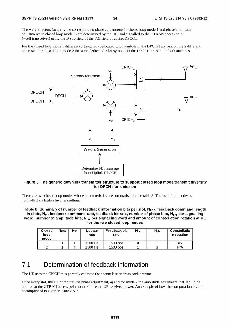
ETSI
ETSI TS 125 214 V3.9.0 (2001-12)343GPP TS 25.214 version 3.9.0 Release 1999
The weight factors (actually the corresponding phase adjustments in closed loop mode 1 and phase/amplitude adjustments in closed loop mode 2) are determined by the UE, and signalled to the UTRAN access point (=cell transceiver) using the D sub-field of the FBI field of uplink DPCCH.
For the closed loop mode 1 different (orthogonal) dedicated pilot symbols in the DPCCH are sent on the 2 different antennas. For closed loop mode 2 the same dedicated pilot symbols in the DPCCH are sent on both antennas.
Spread/scramblew1
w2
DPCHDPCCH
DPDCH
∑
CPICH1
∑
CPICH2
Ant1
Ant2
Weight Generation
w1 w2
Determine FBI messagefrom Uplink DPCCH
Figure 3: The generic downlink transmitter structure to support closed loop mode transmit diversity for DPCH transmission
There are two closed loop modes whose characteristics are summarised in the table 8. The use of the modes is controlled via higher layer signalling.
Table 8: Summary of number of feedback information bits per slot, NFBD, feedback command length in slots, NW, feedback command rate, feedback bit rate, number of phase bits, Nph, per signalling
word, number of amplitude bits, Npo, per signalling word and amount of constellation rotation at UE for the two closed loop modes
Closed loop
mode
NFBD NW Update rate
Feedback bit rate
Npo Nph Constellation rotation
1 1 1 1500 Hz 1500 bps 0 1 π/2 2 1 4 1500 Hz 1500 bps 1 3 N/A
7.1 Determination of feedback information The UE uses the CPICH to separately estimate the channels seen from each antenna.
Once every slot, the UE computes the phase adjustment, φ, and for mode 2 the amplitude adjustment that should be applied at the UTRAN access point to maximise the UE received power. An example of how the computations can be accomplished is given in Annex A.2.

ETSI
ETSI TS 125 214 V3.9.0 (2001-12)353GPP TS 25.214 version 3.9.0 Release 1999
The UE feeds back to the UTRAN access point the information on which phase/power settings to use. Feedback Signalling Message (FSM) bits are transmitted in the portion of FBI field of uplink DPCCH slot(s) assigned to closed loop mode transmit diversity, the FBI D field (see [1]). Each message is of length NW = Npo+Nph bits and its format is shown in the figure 4. The transmission order of bits is from MSB to LSB, i.e. MSB is transmitted first. FSMpo and FSMph subfields are used to transmit the power and phase settings, respectively.
FSMph
MSB LSB
FSMpo
Nph Npo
Figure 4: Format of feedback signalling message. FSMpo transmits the power setting and FSMph the phase setting
The adjustments are made by the UTRAN Access Point at the beginning of the downlink DPCCH pilot field. The downlink slot in which the adjustment is done is signalled to L1 of UE by higher layers. Two possibilities exist:
1) When feedback command is transmitted in uplink slot i, which is transmitted approximately 1024 chips in offset from the received downlink slot j, the adjustment is done at the beginning of the pilot field of the downlink slot (j+1) mod 15.
2) When feedback command is transmitted in uplink slot i, which is transmitted approximately 1024 chips in offset from the received downlink slot j, the adjustment is done at the beginning of the pilot field of the downlink slot (j+2) mod 15.
Thus, adjustment timing at UTRAN Access Point is either according to 1) or 2) as controlled by the higher layers.
In case a PDSCH is associated with a DPCH for which closed-loop transmit diversity is applied, the antenna weights applied to the PDSCH are the same as the antenna weights applied to the associated DPCH. The timing of the weight adjustment of the PDSCH is such that the PDSCH weight adjustment is done at the PDSCH slot border, N chips after the adjustment of the associated DPCH, where 0 ≤ N < 2560.
7.2 Closed loop mode 1 The UE uses the CPICH transmitted both from antenna 1 and antenna 2 to calculate the phase adjustment to be applied at UTRAN access point to maximise the UE received power. In each slot, UE calculates the optimum phase adjustment,
φ, for antenna 2, which is then quantized into Qφ having two possible values as follows:
≤−<
=otherwise,0
2/3)(2/ if, πφφππφ
irQ (1)
where:
==
=13,11,9,7,5,3,1,2/
14,12,10,8,6,4,2,0,0)(
i
iir π
φ (2)
If Qφ = 0, a command '0' is send to UTRAN using the FSMph field. Correspondingly, if Qφ = π, command '1' is send to
UTRAN using the FSMph field.
Due to rotation of the constellation at UE the UTRAN interprets the received commands according to table 9 which
shows the mapping between phase adjustment, iφ , and received feedback command for each uplink slot.
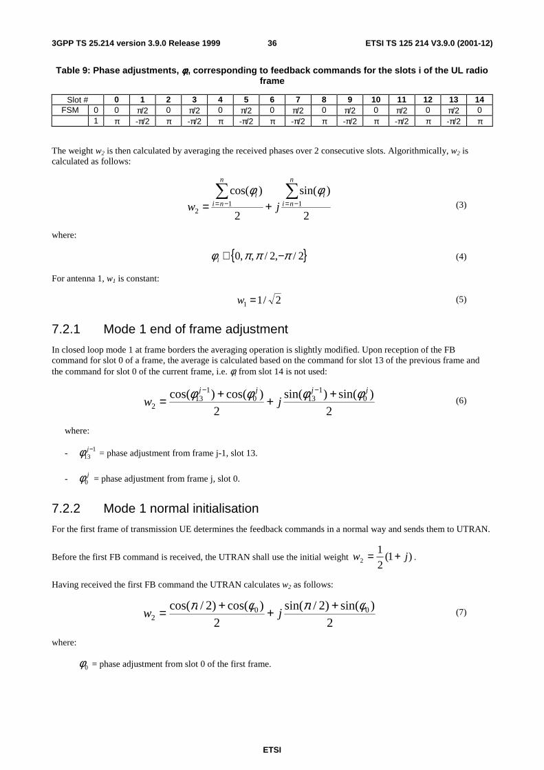
ETSI
ETSI TS 125 214 V3.9.0 (2001-12)363GPP TS 25.214 version 3.9.0 Release 1999
Table 9: Phase adjustments, φφφφi, corresponding to feedback commands for the slots i of the UL radio frame
Slot # 0 1 2 3 4 5 6 7 8 9 10 11 12 13 14 FSM 0 0 π/2 0 π/2 0 π/2 0 π/2 0 π/2 0 π/2 0 π/2 0
1 π -π/2 π -π/2 π -π/2 π -π/2 π -π/2 π -π/2 π -π/2 π
The weight w2 is then calculated by averaging the received phases over 2 consecutive slots. Algorithmically, w2 is calculated as follows:
2
)sin(
2
)cos(11
2
∑∑−=−= +=
n
nii
n
nii
jw
φφ (3)
where:
{ }2/,2/,,0 πππφ −∈i (4)
For antenna 1, w1 is constant:
2/11 =w (5)
7.2.1 Mode 1 end of frame adjustment
In closed loop mode 1 at frame borders the averaging operation is slightly modified. Upon reception of the FB command for slot 0 of a frame, the average is calculated based on the command for slot 13 of the previous frame and the command for slot 0 of the current frame, i.e. φi from slot 14 is not used:
2
)sin()sin(
2
)cos()cos( 01
1301
132
jjjj
jwφφφφ +++=
−− (6)
where:
- 113
−jφ = phase adjustment from frame j-1, slot 13.
- j0φ = phase adjustment from frame j, slot 0.
7.2.2 Mode 1 normal initialisation
For the first frame of transmission UE determines the feedback commands in a normal way and sends them to UTRAN.
Before the first FB command is received, the UTRAN shall use the initial weight )1(2
12 jw += .
Having received the first FB command the UTRAN calculates w2 as follows:
2
)sin()2/sin(
2
)cos()2/cos( 002
φπφπ +++= jw (7)
where:
0φ = phase adjustment from slot 0 of the first frame.
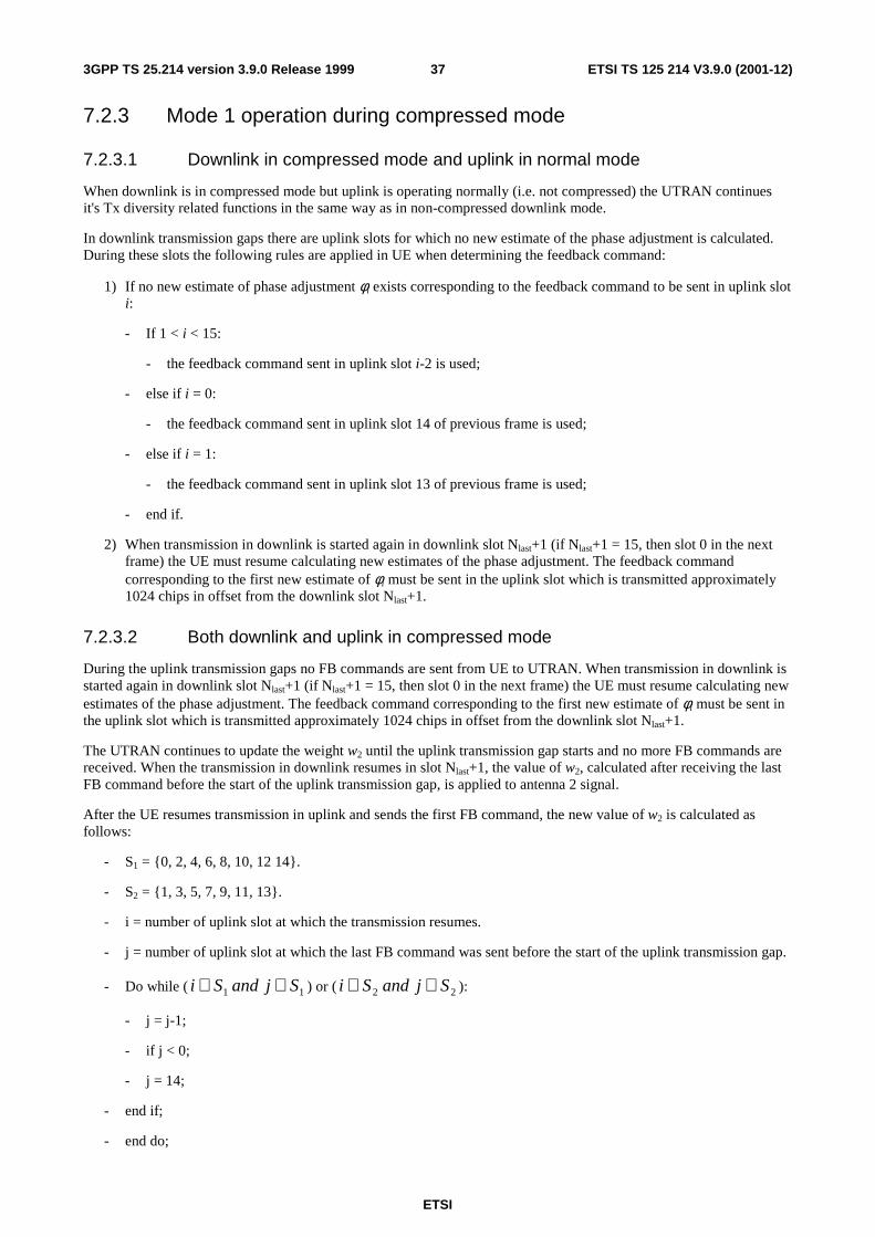
ETSI
ETSI TS 125 214 V3.9.0 (2001-12)373GPP TS 25.214 version 3.9.0 Release 1999
7.2.3 Mode 1 operation during compressed mode
7.2.3.1 Downlink in compressed mode and uplink in normal mode
When downlink is in compressed mode but uplink is operating normally (i.e. not compressed) the UTRAN continues it's Tx diversity related functions in the same way as in non-compressed downlink mode.
In downlink transmission gaps there are uplink slots for which no new estimate of the phase adjustment is calculated. During these slots the following rules are applied in UE when determining the feedback command:
1) If no new estimate of phase adjustment φi exists corresponding to the feedback command to be sent in uplink slot i:
- If 1 < i < 15:
- the feedback command sent in uplink slot i-2 is used;
- else if i = 0:
- the feedback command sent in uplink slot 14 of previous frame is used;
- else if i = 1:
- the feedback command sent in uplink slot 13 of previous frame is used;
- end if.
2) When transmission in downlink is started again in downlink slot Nlast+1 (if Nlast+1 = 15, then slot 0 in the next frame) the UE must resume calculating new estimates of the phase adjustment. The feedback command corresponding to the first new estimate of φi must be sent in the uplink slot which is transmitted approximately 1024 chips in offset from the downlink slot Nlast+1.
7.2.3.2 Both downlink and uplink in compressed mode
During the uplink transmission gaps no FB commands are sent from UE to UTRAN. When transmission in downlink is started again in downlink slot Nlast+1 (if Nlast+1 = 15, then slot 0 in the next frame) the UE must resume calculating new estimates of the phase adjustment. The feedback command corresponding to the first new estimate of φi must be sent in the uplink slot which is transmitted approximately 1024 chips in offset from the downlink slot Nlast+1.
The UTRAN continues to update the weight w2 until the uplink transmission gap starts and no more FB commands are received. When the transmission in downlink resumes in slot Nlast+1, the value of w2, calculated after receiving the last FB command before the start of the uplink transmission gap, is applied to antenna 2 signal.
After the UE resumes transmission in uplink and sends the first FB command, the new value of w2 is calculated as follows:
- S1 = {0, 2, 4, 6, 8, 10, 12 14}.
- S2 = {1, 3, 5, 7, 9, 11, 13}.
- i = number of uplink slot at which the transmission resumes.
- j = number of uplink slot at which the last FB command was sent before the start of the uplink transmission gap.
- Do while ( 11 SjandSi ∈∈ ) or ( 22 SjandSi ∈∈ ):
- j = j-1;
- if j < 0;
- j = 14;
- end if;
- end do;
ETSI
ETSI TS 125 214 V3.9.0 (2001-12)383GPP TS 25.214 version 3.9.0 Release 1999
- calculate w2 based on FB commands received in uplink slots i and j.
Note that for Nlast = 13 the end of frame adjustment procedure shall be based on the FB commands for the last odd slot prior to the uplink transmission gap and slot 0.
7.2.3.3 Uplink in compressed mode and downlink in normal mode
The UTRAN continues to update the value of w2 until the uplink transmission gap starts and no more FB commands are received. Then, the value of w2 calculated after receiving the last FB command before the uplink transmission gap is applied to the antenna 2 signal. When the UE resumes transmission in uplink, it shall send FB commands according to section 7.2 equations 2 and 3 (normal operation) and the UTRAN Access Point shall interpret the FB commands according to Table 9.
The calculation of w2 by the UTRAN following the uplink transmission gap, and before the first two FB commands following the gap are received is not specified.
7.2.4 Mode 1 initialisation during compressed mode
7.2.4.1 Downlink in compressed mode
When closed loop mode 1 is initialised during the downlink transmission gap of compressed mode there are slots for which no estimate of the phase adjustment is calculated and no previous feedback command is available.
In this case, if the UE is required to send feedback in the uplink, the FB command to the UTRAN shall be '0'.
When transmission in downlink is started again in slot Nlast+1 (if Nlast+1 = 15, then slot 0 in the next frame), the
UTRAN shall use the initial weight )1(2
12 jw += . The UE must start calculating estimates of the phase adjustment.
The feedback command corresponding to the first estimate of φi must be sent in the uplink slot which is transmitted approximately 1024 chips in offset from the downlink slot Nlast+1. Having received this feedback command the UTRAN calculates w2 as follows:
2
)sin()sin(
2
)cos()cos(2
jiji jwφφφφ +
++
= (8)
where:
iφ = phase adjustment in uplink slot i , which is transmitted approximately 1024 chips in offset from the downlink
slot Nlast+1.
2
πφ =j , if slot i is even ( }14,12,10,8,6,4,2,0{∈i ) and
0=jφ , if slot i is odd ( }13,11,9,7,5,3,1{∈i )
7.2.4.2 Uplink in compressed mode
Initialisation of closed loop mode 1 operation during uplink compressed mode only is not specified.
7.3 Closed loop mode 2 In closed loop mode 2 there are 16 possible combinations of phase and power adjustment from which the UE selects and transmits the FSM according to table 10 and table 11. As opposed to closed loop Mode 1, no constellation rotation is done at UE and no filtering of the received weights is performed at the UTRAN.

ETSI
ETSI TS 125 214 V3.9.0 (2001-12)393GPP TS 25.214 version 3.9.0 Release 1999
Table 10: FSMpo subfield of closed loop mode 2 signalling message
FSMpo Power_ant1 Power_ant2
0 0.2 0.8
1 0.8 0.2
Table 11: FSMph subfield of closed loop mode 2 signalling message
FSMph Phase difference between antennas (radians) 000 π 001 -3π/4 011 -π/2 010 -π/4 110 0 111 π/4 101 π/2 100 3π/4
To obtain the best performance, progressive updating is performed at both the UE and the UTRAN Access point. The UE procedure shown below is an example of how to determine FSM at UE. Different implementation is allowed. Every slot time, the UE may refine its choice of FSM, from the set of weights allowed given the previously transmitted bits of the FSM. This is shown in figure 5, where, in this figure bi (0 ≤ i ≤ 3) are the bits of the FSM (from table 10 and table 11) from the MSB to the LSB and m=0, 1, 2, 3 (the end of frame adjustment given in subclause 7.3.1 is not shown here).
At the beginning of a FSM to be transmitted, the UE chooses the best FSM out of the 16 possibilities. Then the UE starts sending the FSM bits from the MSB to the LSB in the portion of FBI field of the uplink DPCCH during 4 (FSM message length) slots. Within the transmission of the FSM the UE refines its choice of FSM. This is defined in the following:
- define the 4 bits of FSM, which are transmitted from slot number k to k+3, as {b3(k) b2(k+1) b1(k+2) b0(k+3)}, where k=0, 4, 8, 12. Define also the estimated received power criteria defined in Equation 1 for a given FSM as P ({x3, x2 x1 x0}), where { x3 x2 x1 x0 } is one of the 16 possible FSMs which defines an applied phase and power offset according to table 10 and table 11. The bi() and xi are 0 or 1.
The bits transmitted during the m’th FSM of the frame, where m=0,1,2,3, are then given by:
b3(4m)=X3 from the {X3 X2 X1 X0} which maximises P ({x3 x2 x1 x0}) over all x3,x2,x1,x0 (16 possible combinations);
b2(4m+1)=X2 from the {b3(4m) X2 X1 X0} which maximises P ({b3(4m) x2 x1 x0}) over all x2,x1,x0 (8 possible combinations);
b1(4m+2)=X1 from the {b3(4m) b2(4m+1) X1 X0} which maximises P ({b3(4m) b2(4m+1) x1 x0}) over all x1,x0 (4 possible combinations);
b0(4m+3)=X0 from the {b3(4m) b2(4m+1) b1(4m+2) X0} which maximises P ({b3(4m) b2(4m+1) b1(4m+2) x0}) over x0 (2 possible combinations).
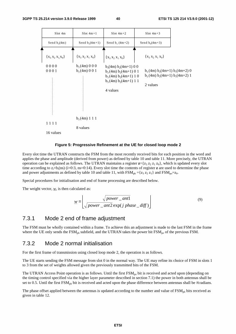
ETSI
ETSI TS 125 214 V3.9.0 (2001-12)403GPP TS 25.214 version 3.9.0 Release 1999
{x3 x2 x1 x0}
b3 (4m) 0 0 0b3 (4m) 0 0 1
b3 (4m) 1 1 1
8 values
{x3 x2 x1 x0}
b3(4m) b2(4m+1) 0 0b3 (4m) b2(4m+1) 0 1b3 (4m) b2(4m+1) 1 0b3 (4m) b2(4m+1) 1 1
4 values
{x3 x2 x1,x0}
0 0 0 00 0 0 1
1 1 1 1
16 values
Send b3(4m) Send b2(4m+1) Send b1 (4m+2) Send b0(4m+3)
Slot 4m Slot 4m+1 Slot 4m+2 Slot 4m+3
{x3 x2 x1 x0}
b3 (4m) b2(4m+1) b1(4m+2) 0b3 (4m) b2(4m+1) b1(4m+2) 1
2 values
Figure 5: Progressive Refinement at the UE for closed loop mode 2
Every slot time the UTRAN constructs the FSM from the most recently received bits for each position in the word and applies the phase and amplitude (derived from power) as defined by table 10 and table 11. More precisely, the UTRAN operation can be explained as follows. The UTRAN maintains a register z={z3 z2 z1 z0}, which is updated every slot time according to zi=bi(ns) (i=0:3, ns=0:14). Every slot time the contents of register z are used to determine the phase and power adjustments as defined by table 10 and table 11, with FSMph ={z3 z2 z1} and FSMpo=z0.
Special procedures for initialisation and end of frame processing are described below.
The weight vector, w, is then calculated as:
=
)_exp(2_
1_
diffphasejantpower
antpowerw (9)
7.3.1 Mode 2 end of frame adjustment
The FSM must be wholly contained within a frame. To achieve this an adjustment is made to the last FSM in the frame where the UE only sends the FSMph subfield, and the UTRAN takes the power bit FSMpo of the previous FSM.
7.3.2 Mode 2 normal initialisation
For the first frame of transmission using closed loop mode 2, the operation is as follows.
The UE starts sending the FSM message from slot 0 in the normal way. The UE may refine its choice of FSM in slots 1 to 3 from the set of weights allowed given the previously transmitted bits of the FSM.
The UTRAN Access Point operation is as follows. Until the first FSMpo bit is received and acted upon (depending on the timing control specified via the higher layer parameter described in section 7.1) the power in both antennas shall be set to 0.5. Until the first FSMph bit is received and acted upon the phase difference between antennas shall be π radians.
The phase offset applied between the antennas is updated according to the number and value of FSMph bits received as given in table 12.

ETSI
ETSI TS 125 214 V3.9.0 (2001-12)413GPP TS 25.214 version 3.9.0 Release 1999
Table 12: FSMph normal initialisation for closed loop mode 2
FSMph Phase difference between antennas (radians) - - - π (normal initialisation)
or held from previous setting (compressed mode recovery) 0 - - π 1 - - 0 0 0 - π 0 1 - -π/2 1 1 - 0 1 0 - π/2 0 0 0 π 0 0 1 -3π/4 0 1 1 -π/2 0 1 0 -π/4 1 1 0 0 1 1 1 π/4 1 0 1 π/2 1 0 0 3π/4
This operation applies in both the soft handover and non soft handover cases.
7.3.3 Mode 2 operation during compressed mode
7.3.3.1 Downlink in compressed mode and uplink in normal mode
When the downlink is in compressed mode and the uplink is in normal mode, the closed loop mode 2 functions are described below.
When the UE is not listening to the CPICH from antennas 1 and 2 during the downlink transmission gap, the UE sends the last FSM bits calculated before the start of the downlink transmission gap.
Recovery from compressed mode is described in the following. Downlink transmissions commence at the pilot field of slot Nlast as described in [2].
After a transmission gap, UTRAN Access Point sets the power in both antennas to 0.5 until a FSMpo bit is received and acted upon. Until the first FSMph bit is received and acted upon, UTRAN uses the phase offset, which was applied before the transmission interruption (table 12).
If the uplink slot Nlast+1 (modulo 15) occurs at the beginning of a FSM period (that is at slot 0,4,8,or 12), the UE sends the FSM message in the normal way, with 3 FSMph bits and with the FSMpo bit on slot 3, 7 or 11, and the UTRAN Access Point acts on the FSMph bits according to table 12.
If the uplink slot Nlast+1 (modulo 15) does not occur at the beginning of a FSM period, the following operation is performed. In each of the remaining slots of the partial FSM period, that is from slot Nlast+1 (modulo 15) until the final slot (slot 3, 7, 11or 14), and for the first slot of the next full FSM period, the UE sends the first (i.e. MSB) bit of the FSMph message, and at the UTRAN access point the phase offset applied between the antennas is updated according to the number and value of FSMph bits received as given in table 13. During the following full FSM period, which starts on slot 0, 4, 8, or 12, the UE sends the FSM message in the normal way, with 3 FSMph bits and with the FSMpo bit on slot 3, 7 or 11, and the UTRAN Access Point acts on the FSMph bits according to table 12.
Table 13: FSMph subfield of closed loop mode 2 in compressed mode recovery period
FSMph Phase difference between antennas (radians) - held from previous setting 0 π 1 0

ETSI
ETSI TS 125 214 V3.9.0 (2001-12)423GPP TS 25.214 version 3.9.0 Release 1999
7.3.3.2 Both downlink and uplink in compressed mode
During both downlink and uplink compressed mode, the UTRAN and the UE performs the functions of recovery after transmission gaps as described in the previous subclause 7.3.3.1.
7.3.3.3 Uplink in compressed mode and downlink in normal mode
The UTRAN continues to update the weight vector w until the uplink transmission gap starts and no more FSM bits are received. Then, UTRAN Access Point continues to apply the weight vector w, which was used before the transmission gap. When the UE resumes transmission in uplink, it chooses FSM according to normal operation as described in section 7.3 and 7.3.1. If the uplink signalling does not resume at the beginning of a FSM period, the UE shall calculate the remaining FSM bits according to section 7.3, using the last FSM(s) sent before the uplink gap as the "previously transmitted bits of the FSM".
The calculation of the phase adjustment by UTRAN remains unspecified until all 3 FSMph bits have been received following the uplink transmission gap. The calculation of the power adjustment by UTRAN remains unspecified until an FSMpo bit has been received following the uplink transmission gap.
7.3.4 Mode 2 initialisation during compressed mode
7.3.4.1 Downlink in compressed mode
When closed loop mode 2 is initialised during the downlink transmission gap of compressed mode there are slots for which no FSM bit is calculated and no previous sent FSM bit is available.
In this case, if the UE is required to send feedback in the uplink, the FB command to the UTRAN shall be '0'.
The UTRAN and the UE perform the functions of recovery after the downlink transmission gap as described in the previous subclause 7.3.3.1. If no previous phase setting is available, UTRAN shall use the phase offset π, until the first FSMph bit is received and acted upon.
7.3.4.2 Uplink in compressed mode
Initialisation of closed loop mode 2 operation during uplink compressed mode only is not specified.
8 Idle periods for IPDL location method
8.1 General To support time difference measurements for location services, idle periods can be created in the downlink (hence the name IPDL) during which time transmission of all channels from a Node B is temporarily seized. During these idle periods the visibility of neighbour cells from the UE is improved.
The idle periods are arranged in a predetermined pseudo random fashion according to higher layer parameters. Idle periods differ from compressed mode in that they are shorter in duration, all channels are silent simultaneously, and no attempt is made to prevent data loss.
In general there are two modes for these idle periods:
- Continuous mode, and
- Burst mode.
In continuous mode the idle periods are active all the time. In burst mode the idle periods are arranged in bursts where each burst contains enough idle periods to allow a UE to make sufficient measurements for its location to be calculated. The bursts are separated by a period where no idle periods occur.
ETSI
ETSI TS 125 214 V3.9.0 (2001-12)433GPP TS 25.214 version 3.9.0 Release 1999
8.2 Parameters of IPDL The following parameters are signalled to the UE via higher layers:
IP_Status: This is a logic value that indicates if the idle periods are arranged in continuous or burst mode.
IP_Spacing: The number of 10 ms radio frames between the start of a radio frame that contains an idle period and the next radio frame that contains an idle period. Note that there is at most one idle period in a radio frame.
IP_Length: The length of the idle periods, expressed in symbols of the CPICH.
IP_Offset: A cell specific offset that can be used to synchronise idle periods from different sectors within a Node B.
Seed: Seed for the pseudo random number generator.
Additionally in the case of burst mode operation the following parameters are also communicated to the UE.
Burst_Start: Specifies the start of the first burst of idle periods. 256×Burst_Start is the SFN where the first burst of idle periods starts.
Burst_Length: The number of idle periods in a burst of idle periods.
Burst_Freq: Specifies the time between the start of a burst and the start of the next burst. 256×Burst_Freq is the number of radio frames of the primary CPICH between the start of a burst and the start of the next burst.
8.3 Calculation of idle period position In burst mode, burst #0 starts in the radio frame with SFN = 256×Burst_Start. Burst #k starts in the radio frame with SFN = 256×Burst_Start + k×256×Burst_Freq( k = 0,1,2 …). The sequence of bursts according to this formula continues up to and including the radio frame with SFN = 4095. At the start of the radio frame with SFN = 0, the burst sequence is terminated (no idle periods are generated) and at SFN = 256×Burst_Start the burst sequence is restarted with burst #0 followed by burst #1 etc., as described above.
Continuous mode is equivalent to burst mode, with only one burst spanning the whole SFN cycle of 4096 radio frames, this burst starting in the radio frame with SFN = 0.
Assume that IP_Position(x) is the position of idle period number x within a burst, where x = 1, 2, …, and IP_Position(x) is measured in number of CPICH symbols from the start of the first radio frame of the burst.
The positions of the idle periods within each burst are then given by the following equation:
IP_Position(x) = (x × IP_Spacing × 150) + (rand(x modulo 64) modulo (150 – IP_Length)) + IP_Offset;
where rand(m) is a pseudo random generator defined as follows:
rand(0) = Seed;
rand(m) = (106×rand(m – 1) + 1283) modulo 6075, m = 1, 2, 3, ….
Note that x is reset to x = 1 for the first idle period in every burst.
Figure 6 below illustrates the idle periods for the burst mode case.
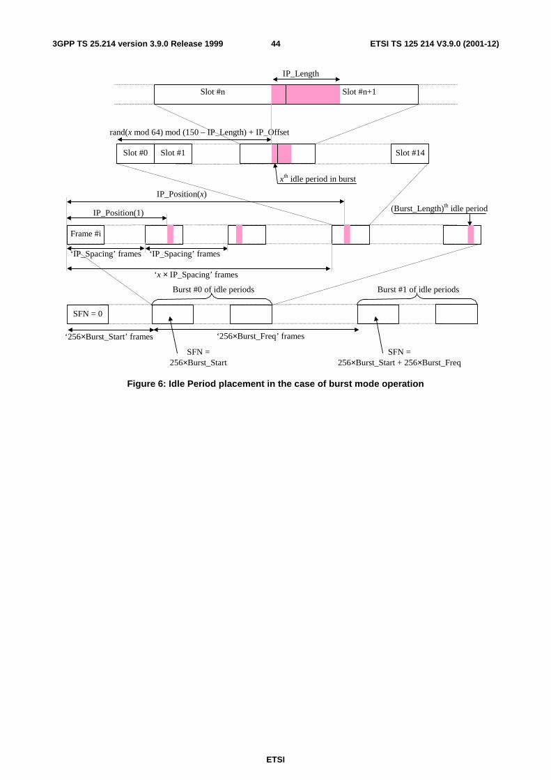
ETSI
ETSI TS 125 214 V3.9.0 (2001-12)443GPP TS 25.214 version 3.9.0 Release 1999
Slot #n+1 Slot #n
(Burst_Length)th idle period
IP_Length
‘x × IP_Spacing’ frames
IP_Position(x)
IP_Position(1)
xth idle period in burst
rand(x mod 64) mod (150 – IP_Length) + IP_Offset
‘256×Burst_Freq’ frames
Burst #0 of idle periods
Frame #i
SFN = 0
‘IP_Spacing’ frames
‘256×Burst_Start’ frames
Burst #1 of idle periods
‘IP_Spacing’ frames
Slot #0 Slot #1 Slot #14
SFN = 256×Burst_Start
SFN = 256×Burst_Start + 256×Burst_Freq
Figure 6: Idle Period placement in the case of burst mode operation
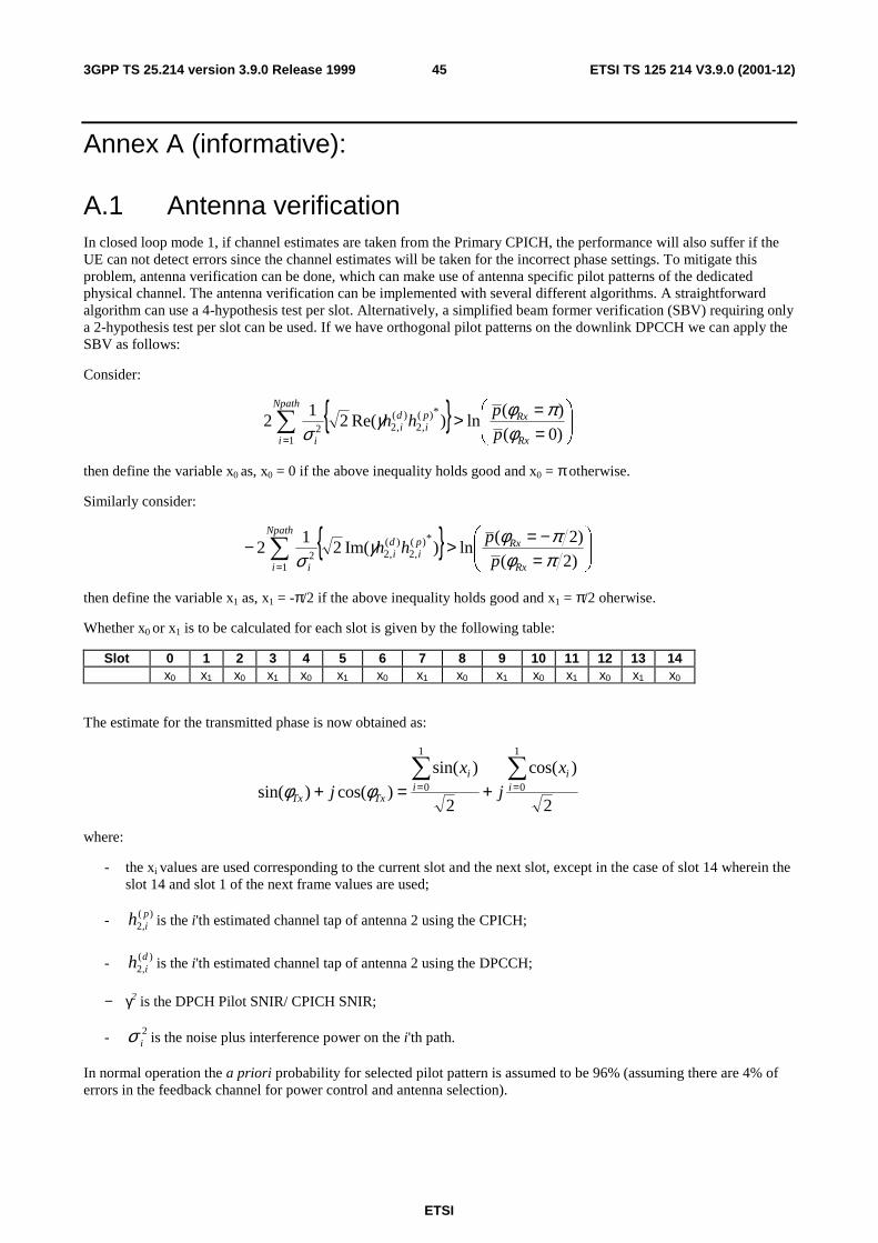
ETSI
ETSI TS 125 214 V3.9.0 (2001-12)453GPP TS 25.214 version 3.9.0 Release 1999
Annex A (informative):
A.1 Antenna verification
In closed loop mode 1, if channel estimates are taken from the Primary CPICH, the performance will also suffer if the UE can not detect errors since the channel estimates will be taken for the incorrect phase settings. To mitigate this problem, antenna verification can be done, which can make use of antenna specific pilot patterns of the dedicated physical channel. The antenna verification can be implemented with several different algorithms. A straightforward algorithm can use a 4-hypothesis test per slot. Alternatively, a simplified beam former verification (SBV) requiring only a 2-hypothesis test per slot can be used. If we have orthogonal pilot patterns on the downlink DPCCH we can apply the SBV as follows:
Consider:
{ }
==>∑
= )0(
)(ln)Re(2
12
*)(,2
)(,2
12
Rx
Rxpi
di
Npath
i i p
phh
φπφγ
σ
then define the variable x0 as, x0 = 0 if the above inequality holds good and x0 = π otherwise.
Similarly consider:
{ }
=−=>− ∑
= )2(
)2(ln)Im(2
12
*)(,2
)(,2
12 πφ
πφγσ Rx
Rxpi
di
Npath
i i p
phh
then define the variable x1 as, x1 = -π/2 if the above inequality holds good and x1 = π/2 oherwise.
Whether x0 or x1 is to be calculated for each slot is given by the following table:
Slot 0 1 2 3 4 5 6 7 8 9 10 11 12 13 14 x0 x1 x0 x1 x0 x1 x0 x1 x0 x1 x0 x1 x0 x1 x0
The estimate for the transmitted phase is now obtained as:
2
)cos(
2
)sin(
)cos()sin(
1
0
1
0∑∑== +=+ i
ii
i
TxTx
x
j
x
j φφ
where:
- the xi values are used corresponding to the current slot and the next slot, except in the case of slot 14 wherein the slot 14 and slot 1 of the next frame values are used;
- )(,2pih is the i'th estimated channel tap of antenna 2 using the CPICH;
- )(,2dih is the i'th estimated channel tap of antenna 2 using the DPCCH;
− γ2 is the DPCH Pilot SNIR/ CPICH SNIR;
- 2iσ is the noise plus interference power on the i'th path.
In normal operation the a priori probability for selected pilot pattern is assumed to be 96% (assuming there are 4% of errors in the feedback channel for power control and antenna selection).
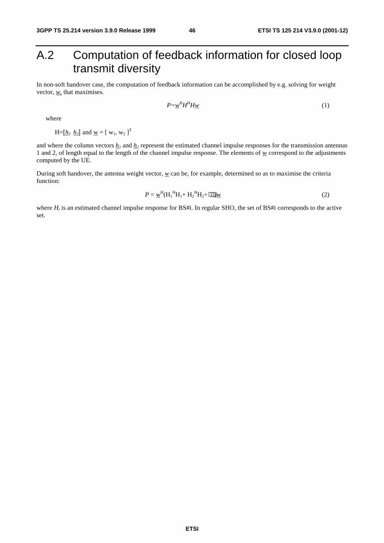
ETSI
ETSI TS 125 214 V3.9.0 (2001-12)463GPP TS 25.214 version 3.9.0 Release 1999
A.2 Computation of feedback information for closed loop transmit diversity
In non-soft handover case, the computation of feedback information can be accomplished by e.g. solving for weight vector, w, that maximises.
P=wHHHHw (1)
where
H=[h1 h2] and w = [ w1, w2 ]T
and where the column vectors h1 and h2 represent the estimated channel impulse responses for the transmission antennas 1 and 2, of length equal to the length of the channel impulse response. The elements of w correspond to the adjustments computed by the UE.
During soft handover, the antenna weight vector, w can be, for example, determined so as to maximise the criteria function:
P = wH(H1HH1+ H2
HH2+⋅⋅⋅⋅)w (2)
where Hi is an estimated channel impulse response for BS#i. In regular SHO, the set of BS#i corresponds to the active set.

ETSI
ETSI TS 125 214 V3.9.0 (2001-12)473GPP TS 25.214 version 3.9.0 Release 1999
Annex B (informative): Downlink power control
B.1 Power control timing The power control timing described in this annex should be seen as an example on how the control bits have to be placed in order to permit a short TPC delay.
In order to maximise the cell radius distance within which one-slot control delay is achieved, the frame timing of an uplink DPCH is delayed by 1024 chips from that of the corresponding downlink DPCH measured at the UE antenna.
Responding to a downlink TPC command, the UE shall change its uplink DPCH output power at the beginning of the first uplink pilot field after the TPC command reception. Responding to an uplink TPC command, the UTRAN access point shall change its DPCH output power at the beginning of the next downlink pilot field after the reception of the whole TPC command. Note that in soft handover, the TPC command is sent over one slot when DPC_MODE is 0 and over three slots when DPC_MODE is 1. Note also that the delay from the uplink TPC command reception to the power change timing is not specified for UTRAN. The UE shall decide and send TPC commands on the uplink based on the downlink SIR measurement. The TPC command field on the uplink starts, when measured at the UE antenna, 512 chips after the end of the downlink pilot field. The UTRAN access point shall decide and send TPC commands based on the uplink SIR measurement. However, the SIR measurement periods are not specified either for UE nor UTRAN.
Figure B.1 illustrates an example of transmitter power control timings.
Data2Data1
1,2 The SIR measurement periods illustrated here are examples. Other ways of measurement are allowed to achieve accurate SIR estimation.3 If there is not enough time for UTRAN to respond to the TPC, the action can be delayed until the next slot.
Data1TPC
Data1TPC
PILOTPILOT
PILOT
ResponseTo TPC (*3)
TPC
DL SIRmeasurement (*1)
PILOT TFCI TPC
DL-UL timing offset (1024 chips)
Slot (2560 chips)
PILOTPILOT Data2Data1TPC
PILOTPILOT TFCI TPC
Slot (2560 chips)
Propagation delay
UL SIRmeasurement (*2)
Responseto TPC
DL DPCCHat UTRAN
Propagation delay
DL DPCCHat UE
UL DPCCHat UTRAN
UL DPCCHat UE
512 chips
TFCI
TFCI
Figure B.1: Transmitter power control timing

ETSI
ETSI TS 125 214 V3.9.0 (2001-12)483GPP TS 25.214 version 3.9.0 Release 1999
B.2 Example of implementation in the UE The downlink inner-loop power control adjusts the network transmit power in order to keep the received downlink SIR at a given SIR target, SIRtarget. A higher layer outer loop adjusts SIRtarget independently for each connection.
The UE should estimate the received downlink DPCCH/DPDCH power of the connection to be power controlled. Simultaneously, the UE should estimate the received interference and calculate the signal-to-interference ratio, SIRest. SIRest can be calculated as RSCP/ISCP, where RSCP refers to the received signal code power on one code and ISCP refers to the non-orthogonal interference signal code power of the received signal on one code. Note that due to the specific SIR target offsets described in [5] that can be applied during compressed frames, the spreading factor shall not be considered in the calculation of SIRest.
The obtained SIR estimate SIRest is then used by the UE to generate TPC commands according to the following rule: if SIRest > SIRtarget then the TPC command to transmit is "0", requesting a transmit power decrease, while if SIRest < SIRtarget then the TPC command to transmit is "1", requesting a transmit power increase.
When the UE is in soft handover and SSDT is not activated, the UE should estimate SIRest from the downlink signals of all cells in the active set.
When SSDT is activated, the UE should estimate SIRest from the downlink signals of the primary cell. If the state of the cells (primary or non-primary) in the active set is changed and the UE sends the last portion of the coded ID in uplink slot j, the UE should change the basis for the estimation of SIRest at the beginning of downlink slot (j+1+Tos) mod 15, where Tos is defined as a constant of 2 time slots.

ETSI
ETSI TS 125 214 V3.9.0 (2001-12)493GPP TS 25.214 version 3.9.0 Release 1999
Annex C (informative): Cell search procedure During the cell search, the UE searches for a cell and determines the downlink scrambling code and frame synchronisation of that cell. The cell search is typically carried out in three steps:
Step 1: Slot synchronisation
During the first step of the cell search procedure the UE uses the SCH’s primary synchronisation code to acquire slot synchronisation to a cell. This is typically done with a single matched filter (or any similar device) matched to the primary synchronisation code which is common to all cells. The slot timing of the cell can be obtained by detecting peaks in the matched filter output.
Step 2: Frame synchronisation and code-group identification
During the second step of the cell search procedure, the UE uses the SCH’s secondary synchronisation code to find frame synchronisation and identify the code group of the cell found in the first step. This is done by correlating the received signal with all possible secondary synchronisation code sequences, and identifying the maximum correlation value. Since the cyclic shifts of the sequences are unique the code group as well as the frame synchronisation is determined.
Step 3: Scrambling-code identification
During the third and last step of the cell search procedure, the UE determines the exact primary scrambling code used by the found cell. The primary scrambling code is typically identified through symbol-by-symbol correlation over the CPICH with all codes within the code group identified in the second step. After the primary scrambling code has been identified, the Primary CCPCH can be detected.And the system- and cell specific BCH information can be read.
If the UE has received information about which scrambling codes to search for, steps 2 and 3 above can be simplified.
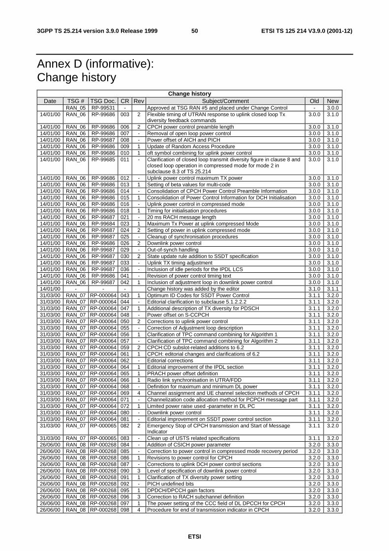
ETSI
ETSI TS 125 214 V3.9.0 (2001-12)503GPP TS 25.214 version 3.9.0 Release 1999
Annex D (informative): Change history
Change history Date TSG # TSG Doc. CR Rev Subject/Comment Old New
RAN_05 RP-99531 - Approved at TSG RAN #5 and placed under Change Control - 3.0.0 14/01/00 RAN_06 RP-99686 003 2 Flexible timing of UTRAN response to uplink closed loop Tx
diversity feedback commands 3.0.0 3.1.0
14/01/00 RAN_06 RP-99686 006 2 CPCH power control preamble length 3.0.0 3.1.0 14/01/00 RAN_06 RP-99686 007 - Removal of open loop power control 3.0.0 3.1.0 14/01/00 RAN_06 RP-99687 008 - Power offset of AICH and PICH 3.0.0 3.1.0 14/01/00 RAN_06 RP-99686 009 1 Update of Random Access Procedure 3.0.0 3.1.0 14/01/00 RAN_06 RP-99686 010 1 oft symbol combining for uplink power control 3.0.0 3.1.0 14/01/00 RAN_06 RP-99685 011 - Clarification of closed loop transmit diversity figure in clause 8 and
closed loop operation in compressed mode for mode 2 in subclause 8.3 of TS 25.214
3.0.0 3.1.0
14/01/00 RAN_06 RP-99686 012 - Uplink power control maximum TX power 3.0.0 3.1.0 14/01/00 RAN_06 RP-99686 013 1 Setting of beta values for multi-code 3.0.0 3.1.0 14/01/00 RAN_06 RP-99686 014 - Consolidation of CPCH Power Control Preamble Information 3.0.0 3.1.0 14/01/00 RAN_06 RP-99686 015 1 Consolidation of Power Control Information for DCH Initialisation 3.0.0 3.1.0 14/01/00 RAN_06 RP-99686 016 - Uplink power control in compressed mode 3.0.0 3.1.0 14/01/00 RAN_06 RP-99686 018 1 Timing for initialisation procedures 3.0.0 3.1.0 14/01/00 RAN_06 RP-99687 021 - 20 ms RACH message length 3.0.0 3.1.0 14/01/00 RAN_06 RP-99684 023 1 Maximum Tx Power at uplink compressed Mode 3.0.0 3.1.0 14/01/00 RAN_06 RP-99687 024 2 Setting of power in uplink compressed mode 3.0.0 3.1.0 14/01/00 RAN_06 RP-99687 025 - Cleanup of synchronisation procedures 3.0.0 3.1.0 14/01/00 RAN_06 RP-99686 026 2 Downlink power control 3.0.0 3.1.0 14/01/00 RAN_06 RP-99687 029 - Out-of-synch handling 3.0.0 3.1.0 14/01/00 RAN_06 RP-99687 030 2 State update rule addition to SSDT specification 3.0.0 3.1.0 14/01/00 RAN_06 RP-99687 033 - Uplink TX timing adjustment 3.0.0 3.1.0 14/01/00 RAN_06 RP-99687 036 - Inclusion of idle periods for the IPDL LCS 3.0.0 3.1.0 14/01/00 RAN_06 RP-99686 041 - Revision of power control timing text 3.0.0 3.1.0 14/01/00 RAN_06 RP-99687 042 1 Inclusion of adjustment loop in downlink power control 3.0.0 3.1.0 14/01/00 - - - Change history was added by the editor 3.1.0 3.1.1 31/03/00 RAN_07 RP-000064 043 1 Optimum ID Codes for SSDT Power Control 3.1.1 3.2.0 31/03/00 RAN_07 RP-000064 044 - Editorial clarification to subclause 5.1.2.2.2 3.1.1 3.2.0 31/03/00 RAN_07 RP-000064 047 1 Additional description of TX diversity for PDSCH 3.1.1 3.2.0 31/03/00 RAN_07 RP-000064 048 - Power offset on S-CCPCH 3.1.1 3.2.0 31/03/00 RAN_07 RP-000064 050 2 Corrections to uplink power control 3.1.1 3.2.0 31/03/00 RAN_07 RP-000064 055 - Correction of Adjustment loop description 3.1.1 3.2.0 31/03/00 RAN_07 RP-000064 056 1 Clarification of TPC command combining for Algorithm 1 3.1.1 3.2.0 31/03/00 RAN_07 RP-000064 057 - Clarification of TPC command combining for Algorithm 2 3.1.1 3.2.0 31/03/00 RAN_07 RP-000064 059 2 CPCH:CD subslot-related additions to 6.2 3.1.1 3.2.0 31/03/00 RAN_07 RP-000064 061 1 CPCH: editorial changes and clarifications of 6.2 3.1.1 3.2.0 31/03/00 RAN_07 RP-000064 062 - Editorial corrections 3.1.1 3.2.0 31/03/00 RAN_07 RP-000064 064 1 Editorial improvement of the IPDL section 3.1.1 3.2.0 31/03/00 RAN_07 RP-000064 065 1 PRACH power offset definition 3.1.1 3.2.0 31/03/00 RAN_07 RP-000064 066 1 Radio link synchronisation in UTRA/FDD 3.1.1 3.2.0 31/03/00 RAN_07 RP-000064 068 - Definition for maximum and minimum DL power 3.1.1 3.2.0 31/03/00 RAN_07 RP-000064 069 4 Channel assignment and UE channel selection methods of CPCH 3.1.1 3.2.0 31/03/00 RAN_07 RP-000064 071 - Channelization code allocation method for PCPCH message part 3.1.1 3.2.0 31/03/00 RAN_07 RP-000064 072 1 Limited power raise used -parameter in DL PC 3.1.1 3.2.0 31/03/00 RAN_07 RP-000064 080 - Downlink power control 3.1.1 3.2.0 31/03/00 RAN_07 RP-000064 081 - Editorial improvement on SSDT power control section 3.1.1 3.2.0 31/03/00 RAN_07 RP-000065 082 2 Emergency Stop of CPCH transmission and Start of Message
Indicator 3.1.1 3.2.0
31/03/00 RAN_07 RP-000065 083 - Clean up of USTS related specifications 3.1.1 3.2.0 26/06/00 RAN_08 RP-000268 084 - Addition of CSICH power parameter 3.2.0 3.3.0 26/06/00 RAN_08 RP-000268 085 - Correction to power control in compressed mode recovery period 3.2.0 3.3.0 26/06/00 RAN_08 RP-000268 086 1 Revisions to power control for CPCH 3.2.0 3.3.0 26/06/00 RAN_08 RP-000268 087 - Corrections to uplink DCH power control sections 3.2.0 3.3.0 26/06/00 RAN_08 RP-000268 090 3 Level of specification of downlink power control 3.2.0 3.3.0 26/06/00 RAN_08 RP-000268 091 1 Clarification of TX diversity power setting 3.2.0 3.3.0 26/06/00 RAN_08 RP-000268 092 - PICH undefined bits 3.2.0 3.3.0 26/06/00 RAN_08 RP-000268 095 1 DPDCH/DPCCH gain factors 3.2.0 3.3.0 26/06/00 RAN_08 RP-000268 096 3 Correction to RACH subchannel definition 3.2.0 3.3.0 26/06/00 RAN_08 RP-000268 097 1 The power setting of the CCC field of DL DPCCH for CPCH 3.2.0 3.3.0 26/06/00 RAN_08 RP-000268 098 4 Procedure for end of transmission indicator in CPCH 3.2.0 3.3.0

ETSI
ETSI TS 125 214 V3.9.0 (2001-12)513GPP TS 25.214 version 3.9.0 Release 1999
Change history Date TSG # TSG Doc. CR Rev Subject/Comment Old New
26/06/00 RAN_08 RP-000268 099 - Downlink inner-loop power control in compressed mode 3.2.0 3.3.0 26/06/00 RAN_08 RP-000268 100 - Definition of vector transmission weight entity 3.2.0 3.3.0 26/06/00 RAN_08 RP-000268 101 1 Number of slots for DPCCH power control preamble 3.2.0 3.3.0 26/06/00 RAN_08 RP-000268 102 - Clarification of UTRAN Tx diversity reponse timing description in
25.214 3.2.0 3.3.0
26/06/00 RAN_08 RP-000268 103 2 Corrections to transmit diversity section 3.2.0 3.3.0 26/06/00 RAN_08 RP-000268 104 1 Corrections to uplink power control in compressed mode 3.2.0 3.3.0 26/06/00 RAN_08 RP-000268 105 - Clarification of downlink power control mode 3.2.0 3.3.0 26/06/00 RAN_08 RP-000268 106 - Clarification of radio link set 3.2.0 3.3.0 26/06/00 RAN_08 RP-000268 107 1 Clarification of radio link synchronisation procedure 3.2.0 3.3.0 26/06/00 RAN_08 RP-000269 108 - Correctly quantized gainfactors for uplink compressed mode 3.2.0 3.3.0 23/09/00 RAN_09 RP-000342 110 4 Downlink inner-loop power control in compressed mode 3.3.0 3.4.0 23/09/00 RAN_09 RP-000342 112 - Adding reference for power offset variation text in TS 25.214 3.3.0 3.4.0 23/09/00 RAN_09 RP-000342 113 - Combining TPC commands in soft handover 3.3.0 3.4.0 23/09/00 RAN_09 RP-000342 115 1 Corrections to power control 3.3.0 3.4.0 23/09/00 RAN_09 RP-000342 116 - Corrections to 25.214 3.3.0 3.4.0 23/09/00 RAN_09 RP-000342 117 - Clarification to downlink power control 3.3.0 3.4.0 23/09/00 RAN_09 RP-000342 118 3 Clarification of power control at maximum and minimum power 3.3.0 3.4.0 23/09/00 RAN_09 RP-000342 119 - Clarification of SSDT text 3.3.0 3.4.0 23/09/00 RAN_09 RP-000342 120 - Corrections to CL transmit diversity mode 1 3.3.0 3.4.0 23/09/00 RAN_09 RP-000342 121 1 Clarification of SSDT ID code bit transmission order 3.3.0 3.4.0 23/09/00 RAN_09 RP-000342 122 1 Clarification on RACH and CPCH subchannel definition 3.3.0 3.4.0 23/09/00 RAN_09 RP-000342 123 1 DPCH initialisation procedure 3.3.0 3.4.0 23/09/00 RAN_09 RP-000342 124 - Clarification of closed loop mode TX diversity initialisation 3.3.0 3.4.0 23/09/00 RAN_09 RP-000342 127 2 Uplink power control in compressed mode 3.3.0 3.4.0 15/12/00 RAN_10 RP-000540 128 1 Clarification of downlink quality measurement in SSDT 3.4.0 3.5.0 15/12/00 RAN_10 RP-000540 129 - Formula typography and reference corrections 3.4.0 3.5.0 15/12/00 RAN_10 RP-000540 130 1 Radio link establishment and sync status reporting 3.4.0 3.5.0 15/12/00 RAN_10 RP-000540 133 - Correction of RACH/CPCH physical random access procedure 3.4.0 3.5.0 15/12/00 RAN_10 RP-000540 134 - Correction of uplink power control algorithm 2 3.4.0 3.5.0 15/12/00 RAN_10 RP-000540 135 1 TPC command generation on downlink during RLS initialisation 3.4.0 3.5.0 15/12/00 RAN_10 RP-000540 136 1 Clarification of RACH behaviour at maximum and minimum power 3.4.0 3.5.0 15/12/00 RAN_10 RP-000540 137 - Clarifications on the description of the radio link establishment
procedure (when no radio link exists) 3.4.0 3.5.0
15/12/00 RAN_10 RP-000540 138 1 Corrections on power control preambles 3.4.0 3.5.0 15/12/00 RAN_10 RP-000540 139 1 Clarification of RACH procedure 3.4.0 3.5.0 15/12/00 RAN_10 RP-000540 140 - Uplink power control in compressed mode 3.4.0 3.5.0 15/12/00 RAN_10 RP-000540 141 1 Revision of the abbreviation list 3.4.0 3.5.0 16/03/01 RAN_11 RP-010060 142 1 Uplink power control in compressed mode 3.5.0 3.6.0 16/03/01 RAN_11 RP-010060 144 - Removal of the power balancing algorithm from TS 25.214 3.5.0 3.6.0 16/03/01 RAN_11 RP-010254 145 2 Clarification of Nid parameter – when SSDT and uplink
compressed mode are in operation 3.5.0 3.6.0
16/03/01 RAN_11 RP-010060 146 - Clarification of closed loop transmit diversity mode 1 and mode 2 operation during compressed mode
3.5.0 3.6.0
16/03/01 RAN_11 RP-010060 148 1 Clarification of UE SIR estimation 3.5.0 3.6.0 16/03/01 RAN_11 RP-010060 150 1 Clarification of the order of SSDT signalling in 2 bit FBI 3.5.0 3.6.0 16/03/01 RAN_11 RP-010244 154 2 Uplink power control preamble 3.5.0 3.6.0 16/03/01 RAN_11 RP-010060 155 - Correction of limited power raise 3.5.0 3.6.0 16/03/01 RAN_11 RP-010060 156 - Clarification of initialisation procedure 3.5.0 3.6.0 16/03/01 RAN_11 RP-010060 158 - Definition of power control step size for algorithm 2 3.5.0 3.6.0 16/03/01 RAN_11 RP-010060 161 1 Correction of the UE behaviour in SSDT mode 3.5.0 3.6.0 16/03/01 RAN_11 RP-010060 163 - Correction on downlink synchronisation primitives 3.5.0 3.6.0 15/06/01 RAN_12 RP-010334 165 1 Limited power raise: aligning of terminology with TS25.433 3.6.0 3.7.0 15/06/01 RAN_12 RP-010334 168 1 Correction of synchronisation primitives 3.6.0 3.7.0 15/06/01 RAN_12 RP-010334 176 1 Clarification on TPC command generation on downlink during RL
initialisation 3.6.0 3.7.0
15/06/01 RAN_12 RP-010482 180 4 Clarification of synchronisation procedures 3.6.0 3.7.0 15/06/01 RAN_12 RP-010334 182 - Clarification of initialisation of closed loop mode 1 and 2 during
compressed mode 3.6.0 3.7.0
15/06/01 RAN_12 RP-010334 184 1 Correction of IPDL burst parameters 3.6.0 3.7.0 15/06/01 RAN_12 RP-010334 185 - DL maximum power level in compressed mode 3.6.0 3.7.0 21/09/01 RAN_13 RP-010520 191 Corrections and Clarifications for calculation of idle period position
in subclause 8.3 in 25.214 3.7.0 3.8.0
21/09/01 RAN_13 RP-010520 193 1 Minor modifications to the CPCH access procedure 3.7.0 3.8.0 21/09/01 RAN_13 RP-010520 196 - Downlink power control in compressed mode 3.7.0 3.8.0 21/09/01 RAN_13 RP-010520 198 1 Improvements of closed loop TX diversity description 3.7.0 3.8.0 21/09/01 RAN_13 RP-010520 200 1 Correction to Random access procedure (Primitive from MAC) 3.7.0 3.8.0 21/09/01 RAN_13 RP-010677 204 1 Proposed CR to TS25.214: Clarification of the SSDT behaviour
with beam forming 3.7.0 3.8.0
14/12/01 RAN_14 RP-010739 206 1 Power control in compressed mode when DPC_MODE=1 3.8.0 3.9.0

ETSI
ETSI TS 125 214 V3.9.0 (2001-12)523GPP TS 25.214 version 3.9.0 Release 1999
Change history Date TSG # TSG Doc. CR Rev Subject/Comment Old New
14/12/01 RAN_14 RP-010739 208 - Clarification of closed loop mode 1 and 2 Tx diversity operation during compressed mode
3.8.0 3.9.0
14/12/01 RAN_14 RP-010739 210 - Downlink phase reference reconfiguration 3.8.0 3.9.0 14/12/01 RAN_14 RP-010739 218 1 Downlink power control for channels supporting CPCH 3.8.0 3.9.0 14/12/01 RAN_14 RP-010739 222 - Removal of slow power control from TS 25.214 3.8.0 3.9.0 14/12/01 RAN_14 RP-010775 215 1 Uplink TPC command processing in SHO with SSDT 3.8.0 3.9.0 14/12/01 RAN_14 RP-010933 228 - Restriction to SSDT and closed loop mode transmit diversity
combination 3.8.0 3.9.0
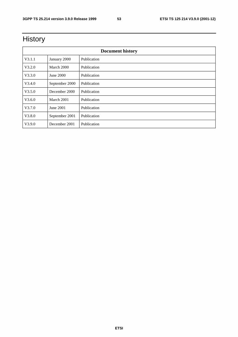
ETSI
ETSI TS 125 214 V3.9.0 (2001-12)533GPP TS 25.214 version 3.9.0 Release 1999
History
Document history
V3.1.1 January 2000 Publication
V3.2.0 March 2000 Publication
V3.3.0 June 2000 Publication
V3.4.0 September 2000 Publication
V3.5.0 December 2000 Publication
V3.6.0 March 2001 Publication
V3.7.0 June 2001 Publication
V3.8.0 September 2001 Publication
V3.9.0 December 2001 Publication