3d scanning with multiple depth sensors · 3d scanning with multiple depth sensors ... 2.4....
TRANSCRIPT
3D Scanning with Multiple Depth Sensors J. KILNER, A. NEOPHYTOU*, A. HILTON
CVSSP, University of Surrey, Guildford, UK
Abstract Recent developments in consumer depth cameras have prompted much interest in the use of commodity depth sensors for various computer vision tasks. This paper presents an open-source software framework for the simultaneous capture and control of multiple Prime Sense based depth cameras. The system, based on the OpenNI libraries, is designed primarily for use in scanning static human subjects. A description of the system including both intrinsic and extrinsic calibration parameters is presented. An analysis of the calibration is presented along with an estimate of potential errors. Keywords: 3d body scanning, multiple depth sensors
1. Introduction The release of the Microsoft Kinect® and other Prime Sense® based depth cameras such as the Asus Xtion® has generated a great deal of interest in depth-camera based computer vision research. Work has demonstrated the usefulness of these devices in applications such as pose and gesture recognition [1], robotics, 3D scene mapping [2] and the scanning of human subjects [3]. This paper describes a multi-sensor device for producing full 3D scans of human subjects.
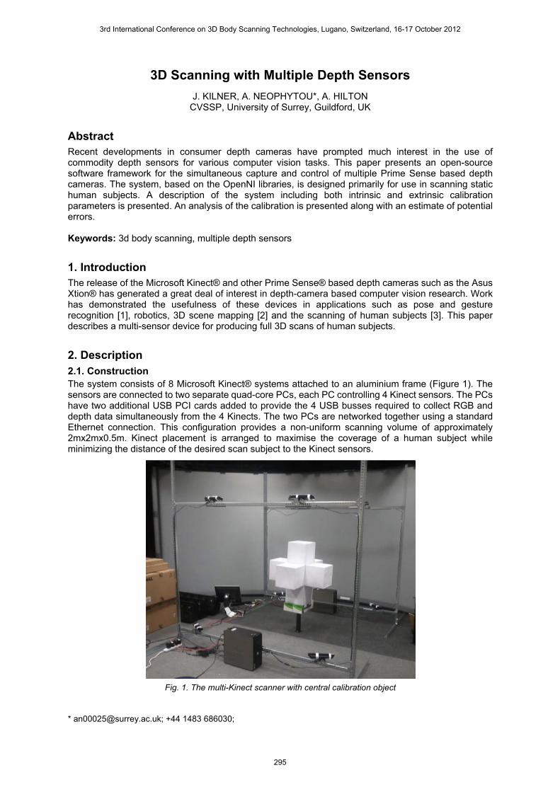
2. Description 2.1. Construction The system consists of 8 Microsoft Kinect® systems attached to an aluminium frame (Figure 1). The sensors are connected to two separate quad-core PCs, each PC controlling 4 Kinect sensors. The PCs have two additional USB PCI cards added to provide the 4 USB busses required to collect RGB and depth data simultaneously from the 4 Kinects. The two PCs are networked together using a standard Ethernet connection. This configuration provides a non-uniform scanning volume of approximately 2mx2mx0.5m. Kinect placement is arranged to maximise the coverage of a human subject while minimizing the distance of the desired scan subject to the Kinect sensors.
Fig. 1. The multi-Kinect scanner with central calibration object
* [email protected]; +44 1483 686030;
3rd International Conference on 3D Body Scanning Technologies, Lugano, Switzerland, 16-17 October 2012
295
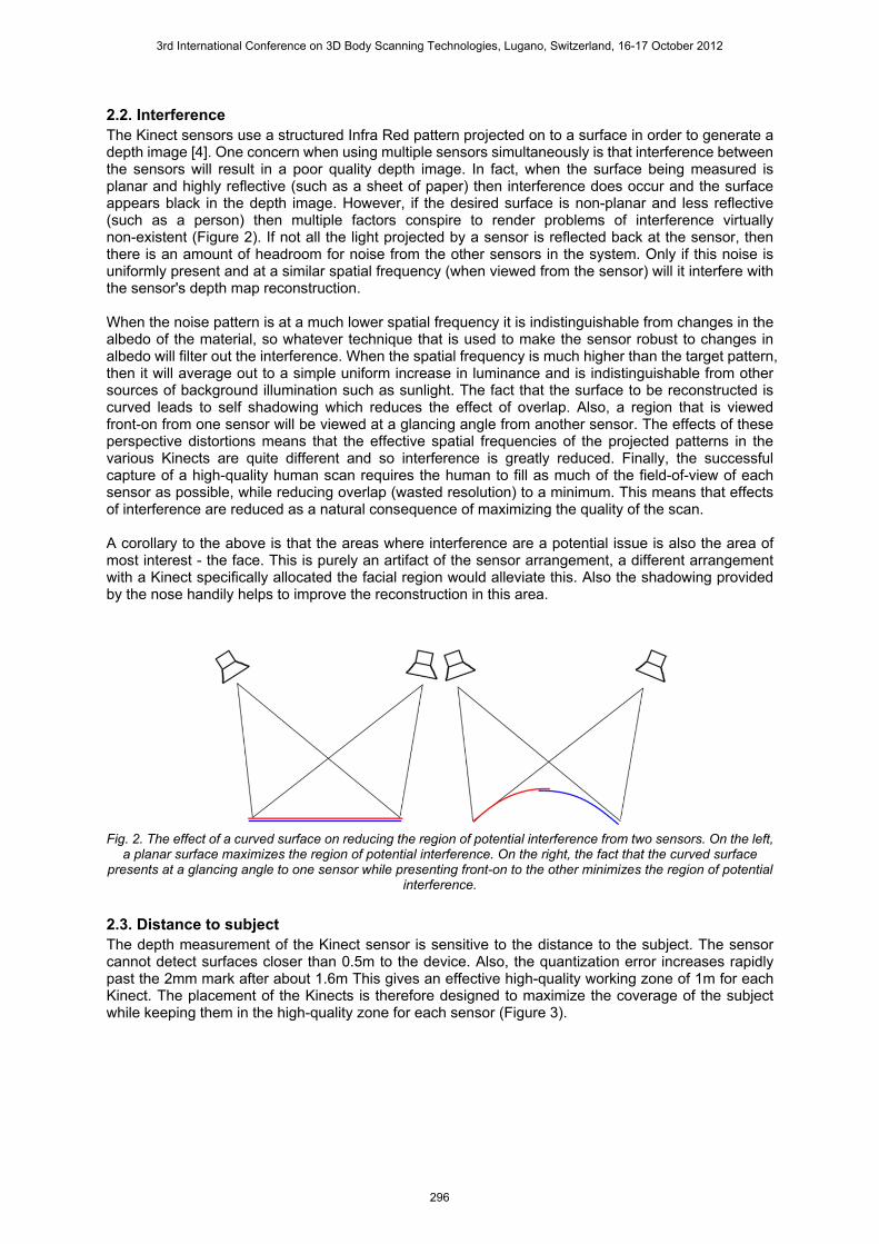
2.2. Interference The Kinect sensors use a structured Infra Red pattern projected on to a surface in order to generate a depth image [4]. One concern when using multiple sensors simultaneously is that interference between the sensors will result in a poor quality depth image. In fact, when the surface being measured is planar and highly reflective (such as a sheet of paper) then interference does occur and the surface appears black in the depth image. However, if the desired surface is non-planar and less reflective (such as a person) then multiple factors conspire to render problems of interference virtually non-existent (Figure 2). If not all the light projected by a sensor is reflected back at the sensor, then there is an amount of headroom for noise from the other sensors in the system. Only if this noise is uniformly present and at a similar spatial frequency (when viewed from the sensor) will it interfere with the sensor's depth map reconstruction. When the noise pattern is at a much lower spatial frequency it is indistinguishable from changes in the albedo of the material, so whatever technique that is used to make the sensor robust to changes in albedo will filter out the interference. When the spatial frequency is much higher than the target pattern, then it will average out to a simple uniform increase in luminance and is indistinguishable from other sources of background illumination such as sunlight. The fact that the surface to be reconstructed is curved leads to self shadowing which reduces the effect of overlap. Also, a region that is viewed front-on from one sensor will be viewed at a glancing angle from another sensor. The effects of these perspective distortions means that the effective spatial frequencies of the projected patterns in the various Kinects are quite different and so interference is greatly reduced. Finally, the successful capture of a high-quality human scan requires the human to fill as much of the field-of-view of each sensor as possible, while reducing overlap (wasted resolution) to a minimum. This means that effects of interference are reduced as a natural consequence of maximizing the quality of the scan. A corollary to the above is that the areas where interference are a potential issue is also the area of most interest - the face. This is purely an artifact of the sensor arrangement, a different arrangement with a Kinect specifically allocated the facial region would alleviate this. Also the shadowing provided by the nose handily helps to improve the reconstruction in this area.
Fig. 2. The effect of a curved surface on reducing the region of potential interference from two sensors. On the left,
a planar surface maximizes the region of potential interference. On the right, the fact that the curved surface presents at a glancing angle to one sensor while presenting front-on to the other minimizes the region of potential
interference.
2.3. Distance to subject The depth measurement of the Kinect sensor is sensitive to the distance to the subject. The sensor cannot detect surfaces closer than 0.5m to the device. Also, the quantization error increases rapidly past the 2mm mark after about 1.6m This gives an effective high-quality working zone of 1m for each Kinect. The placement of the Kinects is therefore designed to maximize the coverage of the subject while keeping them in the high-quality zone for each sensor (Figure 3).
3rd International Conference on 3D Body Scanning Technologies, Lugano, Switzerland, 16-17 October 2012
296
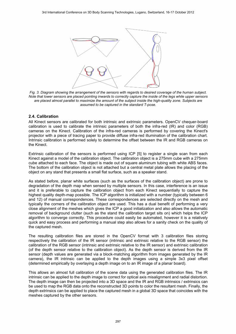
Fig. 3. Diagram showing the arrangement of the sensors with regards to desired coverage of the human subject.
Note that lower sensors are placed pointing inwards to correctly capture the inside of the legs while upper sensors are placed almost parallel to maximize the amount of the subject inside the high-quality zone. Subjects are
assumed to be captured in the standard T-pose.
2.4. Calibration All Kinect sensors are calibrated for both intrinsic and extrinsic parameters. OpenCV chequer-board calibration is used to calibrate the intrinsic parameters of both the infra-red (IR) and color (RGB) cameras on the Kinect. Calibration of the infra-red cameras is performed by covering the Kinect's projector with a piece of tracing paper to provide diffuse infra-red illumination of the calibration chart. Intrinsic calibration is performed solely to determine the offset between the IR and RGB cameras on the Kinect. Extrinsic calibration of the sensors is performed using ICP [5] to register a single scan from each Kinect against a model of the calibration object. The calibration object is a 275mm cube with a 275mm cube attached to each face. The object is made out of square aluminum tubing with white ABS faces. The bottom of the calibration object is not attached but a central metal plate allows the placing of the object on any stand that presents a small flat surface, such as a speaker stand. As stated before, planar white surfaces (such as the surfaces of the calibration object) are prone to degradation of the depth map when sensed by multiple sensors. In this case, interference is an issue and it is preferable to capture the calibration object from each Kinect sequentially to capture the highest quality depth-map possible. The ICP algorithm is initialized with a number (typically between 6 and 12) of manual correspondences. These correspondences are selected directly on the mesh and typically the corners of the calibration object are used. This has a dual benefit of performing a very close alignment of the meshes which gives the ICP a good initialization and also allows the automatic removal of background clutter (such as the stand the calibration target sits on) which helps the ICP algorithm to converge correctly. This procedure could easily be automated, however it is a relatively quick and easy process and performing a manual step also allows for a sanity check on the quality of the captured mesh. The resulting calibration files are stored in the OpenCV format with 3 calibration files storing respectively the calibration of the IR sensor (intrinsic and extrinsic relative to the RGB sensor) the calibration of the RGB sensor (intrinsic and extrinsic relative to the IR sensor) and extrinsic calibration (of the depth sensor relative to the calibration object). As the depth sensor is derived from the IR sensor (depth values are generated via a block-matching algorithm from images generated by the IR camera), the IR intrinsic can be applied to the depth images using a simple 3x3 pixel offset (determined empirically by overlaying a depth image on to an IR image of a planar board). This allows an almost full calibration of the scene data using the generated calibration files. The IR intrinsic can be applied to the depth image to correct for optical axis misalignment and radial distortion. The depth image can then be projected into a 3D space and the IR and RGB intrinsics / extrinsics can be used to map the RGB data onto the reconstructed 3D points to color the resultant mesh. Finally, the depth extrinsics can be applied to place the captured mesh in a global 3D space that coincides with the meshes captured by the other sensors.
3rd International Conference on 3D Body Scanning Technologies, Lugano, Switzerland, 16-17 October 2012
297
The problem with this calibration is that no correction to the depth map itself is applied. Thus, any errors in the measured distance will not be corrected. In practice this seems to have virtually no effect. We suspect that this is because the initial calibration of the sensor is performed in absolute terms, thus depth distortion is compensated for in the sensor itself.
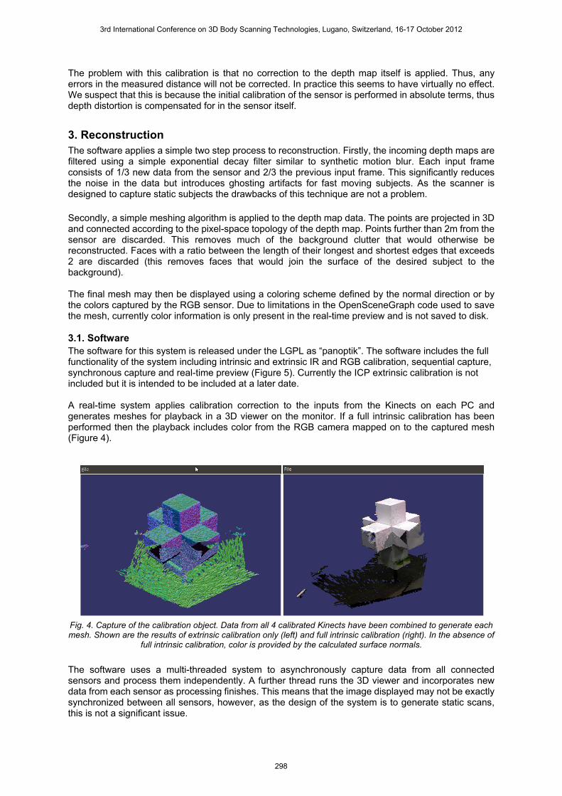
3. Reconstruction The software applies a simple two step process to reconstruction. Firstly, the incoming depth maps are filtered using a simple exponential decay filter similar to synthetic motion blur. Each input frame consists of 1/3 new data from the sensor and 2/3 the previous input frame. This significantly reduces the noise in the data but introduces ghosting artifacts for fast moving subjects. As the scanner is designed to capture static subjects the drawbacks of this technique are not a problem. Secondly, a simple meshing algorithm is applied to the depth map data. The points are projected in 3D and connected according to the pixel-space topology of the depth map. Points further than 2m from the sensor are discarded. This removes much of the background clutter that would otherwise be reconstructed. Faces with a ratio between the length of their longest and shortest edges that exceeds 2 are discarded (this removes faces that would join the surface of the desired subject to the background). The final mesh may then be displayed using a coloring scheme defined by the normal direction or by the colors captured by the RGB sensor. Due to limitations in the OpenSceneGraph code used to save the mesh, currently color information is only present in the real-time preview and is not saved to disk. 3.1. Software The software for this system is released under the LGPL as “panoptik”. The software includes the full functionality of the system including intrinsic and extrinsic IR and RGB calibration, sequential capture, synchronous capture and real-time preview (Figure 5). Currently the ICP extrinsic calibration is not included but it is intended to be included at a later date. A real-time system applies calibration correction to the inputs from the Kinects on each PC and generates meshes for playback in a 3D viewer on the monitor. If a full intrinsic calibration has been performed then the playback includes color from the RGB camera mapped on to the captured mesh (Figure 4).
Fig. 4. Capture of the calibration object. Data from all 4 calibrated Kinects have been combined to generate each mesh. Shown are the results of extrinsic calibration only (left) and full intrinsic calibration (right). In the absence of
full intrinsic calibration, color is provided by the calculated surface normals.
The software uses a multi-threaded system to asynchronously capture data from all connected sensors and process them independently. A further thread runs the 3D viewer and incorporates new data from each sensor as processing finishes. This means that the image displayed may not be exactly synchronized between all sensors, however, as the design of the system is to generate static scans, this is not a significant issue.
3rd International Conference on 3D Body Scanning Technologies, Lugano, Switzerland, 16-17 October 2012
298
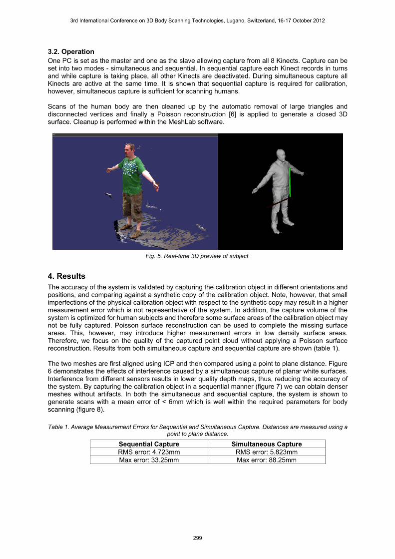
3.2. Operation One PC is set as the master and one as the slave allowing capture from all 8 Kinects. Capture can be set into two modes - simultaneous and sequential. In sequential capture each Kinect records in turns and while capture is taking place, all other Kinects are deactivated. During simultaneous capture all Kinects are active at the same time. It is shown that sequential capture is required for calibration, however, simultaneous capture is sufficient for scanning humans. Scans of the human body are then cleaned up by the automatic removal of large triangles and disconnected vertices and finally a Poisson reconstruction [6] is applied to generate a closed 3D surface. Cleanup is performed within the MeshLab software.
Fig. 5. Real-time 3D preview of subject.
4. Results The accuracy of the system is validated by capturing the calibration object in different orientations and positions, and comparing against a synthetic copy of the calibration object. Note, however, that small imperfections of the physical calibration object with respect to the synthetic copy may result in a higher measurement error which is not representative of the system. In addition, the capture volume of the system is optimized for human subjects and therefore some surface areas of the calibration object may not be fully captured. Poisson surface reconstruction can be used to complete the missing surface areas. This, however, may introduce higher measurement errors in low density surface areas. Therefore, we focus on the quality of the captured point cloud without applying a Poisson surface reconstruction. Results from both simultaneous capture and sequential capture are shown (table 1). The two meshes are first aligned using ICP and then compared using a point to plane distance. Figure 6 demonstrates the effects of interference caused by a simultaneous capture of planar white surfaces. Interference from different sensors results in lower quality depth maps, thus, reducing the accuracy of the system. By capturing the calibration object in a sequential manner (figure 7) we can obtain denser meshes without artifacts. In both the simultaneous and sequential capture, the system is shown to generate scans with a mean error of < 6mm which is well within the required parameters for body scanning (figure 8).
Table 1. Average Measurement Errors for Sequential and Simultaneous Capture. Distances are measured using a point to plane distance.
Sequential Capture Simultaneous Capture RMS error: 4.723mm RMS error: 5.823mm Max error: 33.25mm Max error: 88.25mm
3rd International Conference on 3D Body Scanning Technologies, Lugano, Switzerland, 16-17 October 2012
299
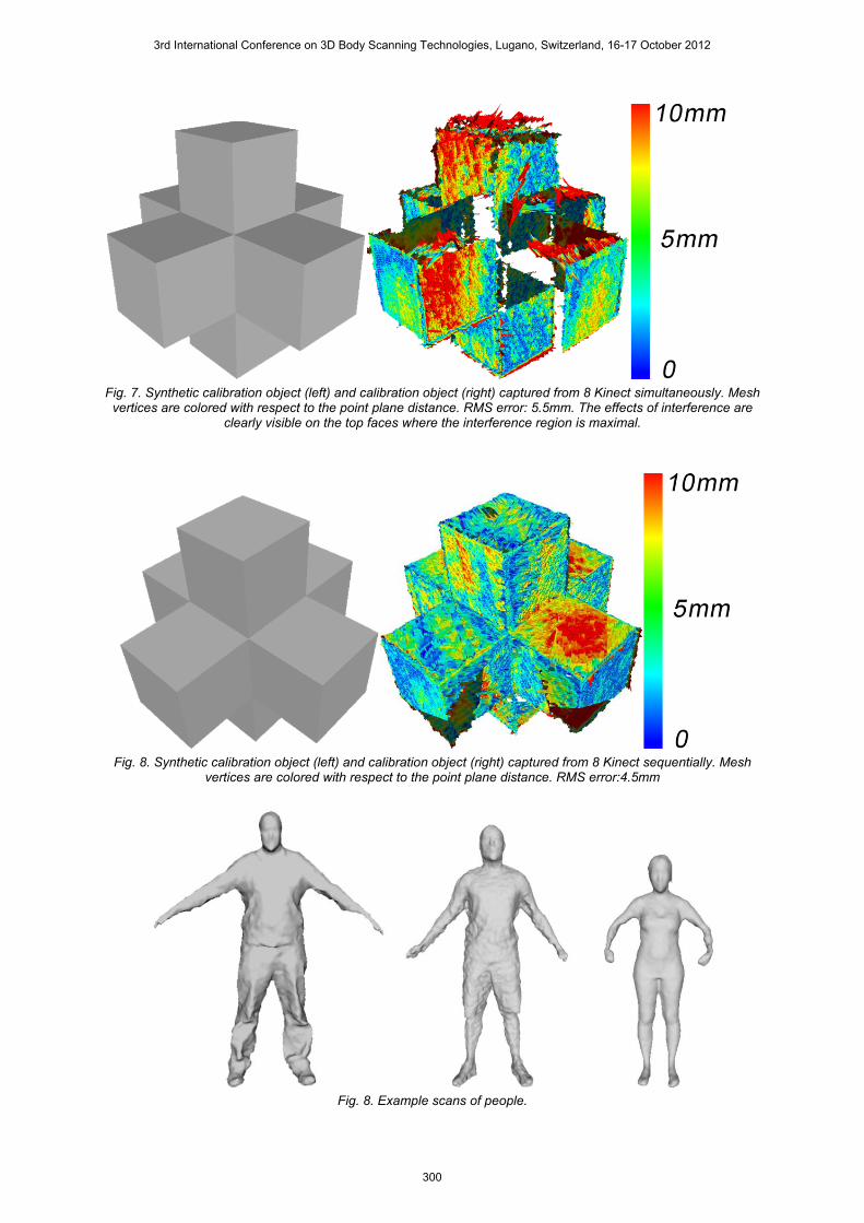
Fig. 7. Synthetic calibration object (left) and calibration object (right) captured from 8 Kinect simultaneously. Mesh
vertices are colored with respect to the point plane distance. RMS error: 5.5mm. The effects of interference are clearly visible on the top faces where the interference region is maximal.
Fig. 8. Synthetic calibration object (left) and calibration object (right) captured from 8 Kinect sequentially. Mesh
vertices are colored with respect to the point plane distance. RMS error:4.5mm
Fig. 8. Example scans of people.
3rd International Conference on 3D Body Scanning Technologies, Lugano, Switzerland, 16-17 October 2012
300
5. Conclusion The scanner described in this paper generates low cost high accuracy scans of human subjects using commodity hardware. A calibration technique using an object of known shape is described. The scanner software, available as an OpenSource project, allows simultaneous capture from 8 Kinects to generate a full 3D scan of the subject. It is shown that full intrinsic calibration of the scanner does not greatly improve the accuracy of the device as the effective optical distortion of the IR camera is low, and it is likely that some depth un-distortion is built into the device's depth calculation. Several shortcomings of the sensor with regards to moving subjects have been mentioned. Most of these problems are simply design choices that were made with respect to the initial application of the scanner and could be addressed simply. This is an area for further work. Also the re-meshing should be moved into a geometry/vertex shader to speed up the real-time preview to genuine real-time frame-rates.
References 1. Shotton, J. et al., (2011): "Real-Time Human Pose Recognition in Parts from Single Depth
Images", Computer Vision and Pattern Recognition (CVPR), 2011 IEEE Conference. 2. Shahram,I. et al., (2011): "KinectFusion: real-time 3D reconstruction and interaction using a
moving depth camera", in Proceedings of the 24th annual ACM symposium on User interface software and technology - UIST '11.
3. Weiss, A. et al., (2011): "Home 3D body scans from noisy image and range data", in ICCV. 4. Freedman, B. et al., (2008): Depth mapping using projected patterns. Patent Application, WO
/120217 A2. 5. Rusinkiewicz, S. and Levoy, M., (2001): Efficient variants of the ICP algorithm. 3D Digital Imaging
and Modeling, Int. Conf. on, 0:145. 6. Kazhdan, M. et al., (2006): Poisson surface reconstruction. In Proc. of the Eurographics
Symposium on Geometry Processing.
3rd International Conference on 3D Body Scanning Technologies, Lugano, Switzerland, 16-17 October 2012
301