3d engine design for virtual globes · 3d engine design for virtual globes patrick cozzi and kevin...
TRANSCRIPT
3D Engine Design
for Virtual Globes
Patrick Cozzi and Kevin Ring

Editorial, Sales, and Customer Service Office
A K Peters, Ltd.5 Commonwealth Road, Suite 2CNatick, MA 01760www.akpeters.com
Copyright 2011 by A K Peters, Ltd.
All rights reserved. No part of the material protected by this copyrightnotice may be reproduced or utilized in any form, electronic or mechani-cal, including photocopying, recording, or by any information storage andretrieval system, without written permission from the copyright owner.
Library of Congress Cataloging-in-Publication Data
To be determined
Printed in the United States of America
15 14 13 12 11 10 9 8 7 6 5 4 3 2 1

12Massive-Terrain
Rendering
Virtual globes visualize massive quantities of terrain and imagery. Imaginea single rectangular image that covers the entire world with a sufficientresolution such that each square meter is represented by a pixel. Thecircumference of Earth at the equator and around the poles is roughly40 million meters, so such an image would contain almost a quadrillion(1 × 10¹⁵) pixels. If each pixel is a 24-bit color, it would require over2 million gigabytes of storage—approximately 2 petabytes! Lossy com-pression reduces this substantially, but nowhere near enough to fit intolocal storage, never mind on main or GPU memory, on today’s or tomor-row’s computers. Consider that popular virtual globe applications offerimagery at resolution higher than one meter per pixel in some areas ofthe globe, and it quickly becomes obvious that such a naıve approach isunworkable.
Terrain and imagery datasets of this size must be managed with spe-cialized techniques, which are an active area of research. The basic idea, ofcourse, is to use a limited storage and processing budget where it providesthe most benefit. As a simple example, many applications do not needdetailed imagery for the approximately 70% of Earth covered by oceans;it makes little sense to provide one-meter resolution imagery there. Soour terrain- and imagery-rendering technique must be able to cope withdata with varying levels of detail in different areas. In addition, whenhigh-resolution data are available for a wide area, more triangles should beused to render nearby features and sharp peaks, and more texels shouldbe used where they map to more pixels on the screen. This basic goal hasbeen pursued from a number of angles over the years. With the explosivegrowth in GPU performance in recent years, the emphasis has shifted from
365

366 12. Massive-Terrain Rendering
minimizing the number of triangles drawn, usually by doing substantialcomputations on the CPU, to maximizing the GPU’s triangle throughout.
We consider the problem of rendering planet-sized terrains with thefollowing characteristics:
• They consist of far too many triangles to render with just the brute-force approaches introduced in Chapter 11.
• They are much larger than available system memory.
The first characteristic motivates the use of terrain LOD. We are mostconcerned with using LOD techniques to reduce the complexity of the ge-ometry being rendered; other LOD techniques include reducing shadingcosts. In addition, we use culling techniques to eliminate triangles in partsof the terrain that are not visible.
The second characteristic motivates the use of out-of-core renderingalgorithms. In out-of-core rendering, only a small subset of a dataset iskept in system memory. The rest resides in secondary storage, such as alocal hard disk or on a network server. Based on view parameters, newportions of the dataset are brought into system memory, and old portionsare removed, ideally without stuttering rendering.
Beautifully rendering immense terrain and imagery datasets using provenalgorithms is pretty easy if you’re a natural at spatial reasoning, have nevermade an off-by-one coding error, and scoff at those who consider themselves“big picture” people because you yourself live for the details. For the restof us, terrain and imagery rendering takes some patience and attentionto detail. It is immensely rewarding, though, combining diverse areas ofcomputer science and computer graphics to bring a world to life on yourcomputer screen.
Presenting all of the current research in terrain rendering could fill sev-eral books. Instead, this chapter presents a high-level overview of the mostimportant concepts, techniques, and strategies for rendering massive ter-rains, with an emphasis on pointing you toward useful resources from whichyou can learn more about any given area.
In Chapters 13 and 14, we dive into two specific terrain algorithms:geometry clipmapping and chunked LOD. These two algorithms, which takequite different approaches to rendering massive terrains, serve to illustratemany of the concepts in this chapter.
We hope that you will come away from these chapters with lots ofideas for how massive-terrain rendering can be implemented in your specificapplication. We also hope that you will acquire a solid foundation forunderstanding and evaluating the latest terrain-rendering research in theyears to come.

12.1. Level of Detail 367
12.1 Level of Detail
Terrain LOD is typically managed using algorithms that are tuned to theunique characteristics of terrain. This is especially true when the terrain isrepresented as a height map; the regular structure allows techniques thatare not applicable to arbitrary models. Even so, it is helpful to considerterrain LOD among the larger discipline of LOD algorithms.
LOD algorithms reduce an object’s complexity when it contributes lessto the scene. For example, an object in the distance may be rendered withless geometry and lower resolution textures than the same object if it wereclose to the viewer. Figure 12.1 shows the same view of Yosemite Valley,El Capitan, and Half Dome at different geometric levels of detail.
LOD algorithms consist of three major parts [3]:
• Generation creates different versions of a model. A simpler modelusually uses fewer triangles to approximate the shape of the origi-nal model. Simpler models can also be rendered with less-complexshaders, smaller textures, fewer passes, etc.
• Selection chooses the version of the model to render based on somecriteria, such as distance to the object, its bounding volume’s esti-mated pixel size, or estimated number of nonoccluded pixels.
• Switching changes from one version of a model to another. A primarygoal is to avoid popping : a noticeable, abrupt switch from one LODto another.
(a) (b)
Figure 12.1. The same view of Yosemite Valley, El Capitan, and Half Dome at(a) low detail and (b) high detail. The differences are most noticeable in theshapes of the peaks in the distance. Image USDA Farm Service Agency, Image(C) 2010 DigitalGlobe. (Figures taken using Google Earth.)

368 12. Massive-Terrain Rendering
Furthermore, we can group LOD algorithms into three broad categories:discrete, continuous, and hierarchical.
12.1.1 Discrete Level of Detail
Discrete LOD is perhaps the simplest LOD approach. Several independentversions of a model with different levels of detail are created. The modelsmay be created manually by an artist or automatically by a polygonalsimplification algorithm such as vertex clustering [146].
Applied to terrain, discrete LOD would imply that the entire terraindataset has several discrete levels of detail and that one of them is selectedfor rendering at each frame. This is unsuitable for rendering terrain invirtual globes because terrain is usually both “near” and “far” at the sametime.
The portion of terrain that is right in front of the viewer is nearby andrequires a high level of detail for accurate rendering. If this high level ofdetail is used for the entire terrain, the hills in the distance will be renderedwith far too many triangles. On the other hand, if we select the LOD basedon the distant hills, the nearby terrain will have insufficient detail.
12.1.2 Continuous Level of Detail
In continuous LOD (CLOD), a model is represented in such a way that thedetail used to display it can be precisely selected. Typically, the model isrepresented as a base mesh plus a sequence of transformations that makethe mesh more or less detailed as each is applied. Thus, each successiveversion of the mesh differs from the previous one by only a few triangles.
At runtime, a precise level of detail for the model is created by selectingand applying the desired mesh transformations. For example, the meshmight be encoded as a series of edge collapses, each of which simplifies themesh by removing two triangles. The opposite operation, called a vertex
split , adds detail by creating two triangles. The two operations are shownin Figure 12.2.
CLOD is appealing because it allows a mesh to be selected that has aminimal number of triangles for a required visual fidelity given the view-point or other simplification criteria. In days gone by, CLOD was thebest way to interactively render terrain. Many historically popular terrain-rendering algorithms use a CLOD approach, including Lindstrom et al.’sCLOD for height fields [102], Duchaineau et al.’s real-time optimally adapt-ing mesh (ROAM) [41], and Hoppe’s view-dependent progressive meshes[74]. Luebke et al. have excellent coverage of these techniques [107].
Today, however, these have largely fallen out of favor for use as runtimerendering techniques. CLOD generally requires traversing a CLOD data

12.1. Level of Detail 369
����������
�� ��������
Figure 12.2. For an edge interior to a mesh, edge collapse removes two trianglesand vertex split creates two triangles.
structure on the CPU and touching each vertex or edge in the current LOD.On older generations of hardware, this trade-off made a lot of sense; trianglethroughput was quite low, so it was important to make every triangle count.In addition, it was worthwhile to spend extra time refining a mesh on theCPU in order to have the GPU process fewer triangles.
Today’s GPUs have truly impressive triangle throughput and are, infact, significantly faster than CPUs for many tasks. It is no longer a worth-while trade-off to spend, for example, 50% more time on the CPU in orderto reduce the triangle count by 50%. For that reason, CLOD-based terrain-rendering algorithms are inappropriate for use on today’s hardware.
Today, these CLOD techniques, if they’re used at all, are instead usedto preprocess terrain into view-independent blocks for use with hierarchicalLOD algorithms such as chunked LOD. These blocks are static; the CPUdoes not modify them at runtime, so CPU time is minimized. The GPUcan easily handle the additional triangles that it is required to render as aresult.
A special form of CLOD is known as infinite level of detail. In an infiniteLOD scheme, we start with a surface that is defined by a mathematicalfunction (e.g., an implicit surface). Thus, there is no limit to the numberof triangles we can use to tessellate the surface. We saw an example of thisin Section 4.3, where the implicit surface of an ellipsoid was used to rendera pixel-perfect representation of a globe without tessellation.
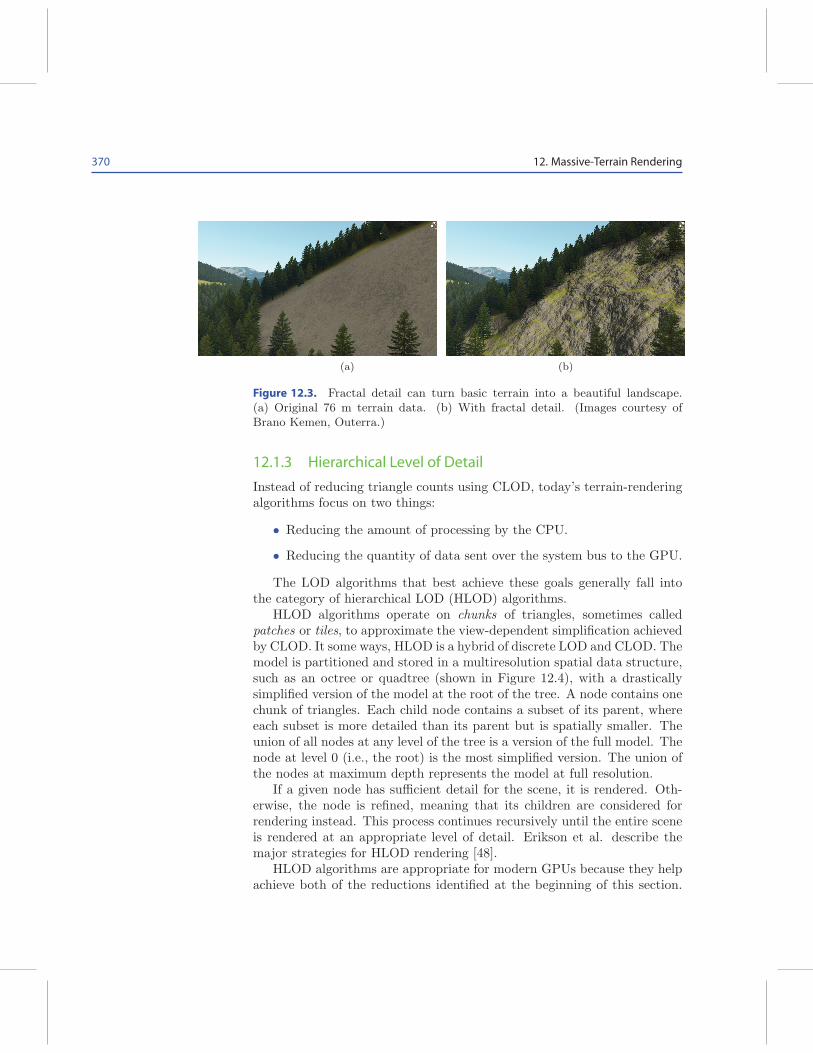
Some terrain engines, such as the one in Outerra,1 use fractal algorithmsto procedurally generate fine terrain details (see Figure 12.3). This is a formof infinite LOD. Representing an entire real-world terrain as an implicitsurface, however, is not feasible now or in the foreseeable future. For thatreason, infinite LOD has only limited applications to terrain rendering invirtual globes.
1http://www.outerra.com
370 12. Massive-Terrain Rendering
(a) (b)
Figure 12.3. Fractal detail can turn basic terrain into a beautiful landscape.(a) Original 76 m terrain data. (b) With fractal detail. (Images courtesy ofBrano Kemen, Outerra.)
12.1.3 Hierarchical Level of Detail
Instead of reducing triangle counts using CLOD, today’s terrain-renderingalgorithms focus on two things:
• Reducing the amount of processing by the CPU.
• Reducing the quantity of data sent over the system bus to the GPU.
The LOD algorithms that best achieve these goals generally fall intothe category of hierarchical LOD (HLOD) algorithms.
HLOD algorithms operate on chunks of triangles, sometimes calledpatches or tiles, to approximate the view-dependent simplification achievedby CLOD. It some ways, HLOD is a hybrid of discrete LOD and CLOD. Themodel is partitioned and stored in a multiresolution spatial data structure,such as an octree or quadtree (shown in Figure 12.4), with a drasticallysimplified version of the model at the root of the tree. A node contains onechunk of triangles. Each child node contains a subset of its parent, whereeach subset is more detailed than its parent but is spatially smaller. Theunion of all nodes at any level of the tree is a version of the full model. Thenode at level 0 (i.e., the root) is the most simplified version. The union ofthe nodes at maximum depth represents the model at full resolution.
If a given node has sufficient detail for the scene, it is rendered. Oth-erwise, the node is refined, meaning that its children are considered forrendering instead. This process continues recursively until the entire sceneis rendered at an appropriate level of detail. Erikson et al. describe themajor strategies for HLOD rendering [48].
HLOD algorithms are appropriate for modern GPUs because they helpachieve both of the reductions identified at the beginning of this section.

12.1. Level of Detail 371
�
�
�
�
(a)
����
��
�� ��
��
���� ����
���� ��
� ���
����
��
���� ����
�� ����
��
����
��
��
(b)
Figure 12.4. In HLOD algorithms, a model is partitioned and stored in a tree.The root contains a drastically simplified version of the model. Each child nodecontains a more detailed version of a subset of its parent.
In HLOD algorithms, the CPU only needs to consider each chunk ratherthan considering individual triangles, as is required in CLOD algorithms.In this way, the amount of processing that needs to be done by the CPUis greatly reduced.
HLOD algorithms can also reduce the quantity of data sent to the GPUover the system bus. At first glance, this is somewhat counterintuitive.After all, rendering with HLOD rather than CLOD generally means moretriangles in the scene for the same visual fidelity, and triangles are, ofcourse, data that need to be sent over the system bus.
HLOD, however, unlike CLOD, does not require that new data be sentto the GPU every time the viewer position changes. Instead, chunks arecached on the GPU using static vertex buffers that are applicable to a rangeof views. HLOD sends a smaller number of larger updates to the GPU,while CLOD sends a larger number of smaller updates.
Another strength of HLOD is that it integrates naturally with out-of-core rendering (see Section 12.3). The nodes in the spatial data structureare a convenient unit for loading data into memory, and the spatial orderingis useful for load ordering, replacement, and prefetching. In addition, thehierarchical organization offers an easy way to optimize culling, includinghardware occlusion queries (see Section 12.4.4).
12.1.4 Screen-Space Error
No matter the LOD algorithm we use, we must choose which of severalpossible LODs to use for a given object in a given scene. Typically, the

372 12. Massive-Terrain Rendering
������
�
�
�
�
�
����
�� �
����������
�����
�
Figure 12.5. The screen-space error, ρ, of an object is estimated from the distancebetween the object and the viewer, the parameters of the view, and the geometricerror, ǫ, of the object.
goal is to render with the simplest LOD possible while still rendering ascene that looks good. But how do we determine whether an LOD willprovide a scene that looks good?
A useful objective measure of quality is the number of pixels of differ-ence, or screen-space error, that would result by rendering a lower-detailversion of an object rather than a higher-detail version. Computing thisprecisely is usually challenging, but it can be estimated effectively. By es-timating it conservatively, we can arrive at a guaranteed error bound; thatis, we can be sure that the screen-space error introduced by using a lower-detail version of a model is less than or equal to a computed value [107].
In Figure 12.5, we are considering the LOD to use for an object adistance d from the viewer in the view direction, where the view frustumhas a width of w. In addition, the display has a resolution of x pixels anda field of view angle θ. A simplified version of the object has a geometricerror ǫ; that is, each vertex in the full-detail object diverges from the closestcorresponding point on the reduced-detail model by no more than ǫ units.What is the screen-space error, ρ, that would result if we were to renderthis simplified version of the object?
From the figure, we can see that ρ and ǫ are proportional and can solvefor ρ:
ǫ
w=
ρ
x,
ρ =ǫx
w.

12.1. Level of Detail 373
The view-frustum width, w, at distance d is easily determined andsubstituted into our equation for ρ:
w = 2d tanθ
2,
ρ =ǫx
2d tan θ
2
. (12.1)
'
&
$
%
Technically, this equation is only accurate for objects in the center ofthe viewport. For an object at the sides, it slightly underestimates thetrue screen-space error. This is generally considered acceptable, however,because other quantities are chosen conservatively. For example, thedistance from the viewer to the object is actually larger than d when theobject is not in the center of the viewport. In addition, the equationassumes that the greatest geometric error occurs at the point on theobject that is closest to the viewer.
Kevin Says
For a bounding sphere centered at c and with radius r, the distance d
to the closest point of the sphere in the direction of the view, v, is given by
d = (c− viewer) · v − r.
By comparing the computed screen-space error for an LOD againstthe desired maximum screen-space error, we can determine if the LOD isaccurate enough for our needs. If not, we refine.
12.1.5 Artifacts
While the LOD techniques used to render terrain are quite varied, there’sa surprising amount of commonality in the artifacts that show up in theprocess.
Cracking. Cracking is an artifact that occurs where two different levels ofdetail meet. As shown in Figure 12.6, cracking occurs because a vertex in ahigher-detail region does not lie on the corresponding edge of a lower-detailregion. The resulting mesh is not watertight.
The most straightforward solution to cracking is to drop vertical skirtsfrom the outside edges of each LOD. The major problem with skirts is thatthey introduce short vertical cliffs in the terrain surface that lead to texturestretching. In addition, care must be taken in computing the normals ofthe skirt vertices so that they aren’t visible as mysterious dark or light

374 12. Massive-Terrain Rendering
Figure 12.6. Cracking occurs when an edge shared by two adjacent LODs isdivided by an additional vertex in one LOD but not the other.
lines around an LOD region. Chunked LOD uses skirts to avoid cracking,as will be discussed in Section 14.3.
Another possibility is to introduce extra vertices around the perimeterof the lower LOD region to match the adjacent higher LODs. This iseffective when only a small number of different LODs are available or whenthere are reasonable bounds on the different LODs that are allowed tobe adjacent to each other. In the worst case, the coarsest LOD wouldrequire an incredible number of vertices at its perimeter to account for thepossibility that it is surrounded by regions of the finest LOD. Even in thebest cases, however, this approach requires extra vertices in coarse LODs.
A similar approach is to force the heights of the vertices in the finer LODto lie on the edges of the coarser LOD. The geometry-clipmapping terrainLOD algorithm (see Chapter 13) uses this technique effectively. A danger,however, is that this technique leads to a new problem: T-junctions.
T-junctions. T-junctions are similar to cracking, but more insidious. Where-as cracking occurs when a vertex in a higher-detail region does not lie onthe corresponding edge of a lower-detail region, T-junctions occur becausethe high-detail vertex does lie on the low-detail edge, forming a T shape.Small differences in floating-point rounding during rasterization of the ad-jacent triangles lead to very tiny pinholes in the terrain surface. Thesepinholes are distracting because the background is visible through them.
Ideally, these T-junctions are eliminated by subdividing the trianglein the coarser mesh so that it, too, has a vertex at the same location asthe vertex in the finer mesh. If the T-junctions were introduced in thefirst place in an attempt to eliminate cracking, however, this is a less thansatisfactory solution.

12.1. Level of Detail 375
���������
����
Figure 12.7. A side view of an exaggerated T-junction between two adjacentLODs. Skirts can hide T-junctions if they are angled slightly outward.
Another possibility is to fill the T-junctions with degenerate triangles.Even though these degenerate triangles mathematically have no area andthus should produce no fragments, the same rounding errors that cause thetiny T-junction holes to appear in the first place also cause a few fragmentsto be produced from the degenerate triangles, and those fragments fill theholes.
A final possibility, which is effective when cracks are filled with skirts,is to make the skirts of adjacent LODs overlap slightly, as shown in Fig-ure 12.7.
Popping. As the viewer moves, the level of detail of various objects in thescene is adjusted. When the LOD of a given object is abruptly changedfrom a coarser one to a finer one, or vice versa, the user may notice a “pop”as vertices and edges change position.
This may be acceptable. To a large extent, virtual globe users tend tobe more accepting of popping artifacts than, say, people playing a game.A virtual globe is like a web browser. Users instinctively understand thata web browser combines a whole lot of content loaded from remote servers.No one complains when a web browser shows the text of a page first andthen “pops” in the images once they have been downloaded from the webserver. This is much better than the alternative: showing nothing until allof the content is available.
Similarly, virtual globe users are not surprised that data are oftenstreamed incrementally from a remote server and, therefore, are also notsurprised when it suddenly pops into existence. As virtual globe devel-opers, we can take advantage of this user expectation even in situationswhere it is not strictly necessary, such as in the transition between twoLODs, both cached on the GPU.
In many cases, however, popping can be prevented.One way to prevent popping is to follow what Bloom refers to as the
“mantra of LOD”: a level of detail should only switch when that switch

376 12. Massive-Terrain Rendering
will be imperceptible to the user [18]. Depending on the specific LODalgorithm in use and the capabilities of the hardware, this may or may notbe a reasonable goal.
Another possibility is to blend between different levels of detail insteadof switching them abruptly. The specifics of how this blending is doneare tied closely to the terrain-rendering algorithm, so we cover two specificexamples in Sections 13.4 and 14.3.
12.2 Preprocessing
Rendering a planet-sized terrain dataset at interactive frame rates requiresthat the terrain dataset be preprocessed. As much as we wish it were not,this is an inescapable fact. Whatever format is used to store the terraindata in secondary storage, such as a disk or network server, must allowlower-detail versions of the terrain dataset to be obtained efficiently.
As described in Chapter 11, terrain data in virtual globes are mostcommonly represented as a height map. Consider a height map with 1trillion posts covering the entire Earth. This would give us approximately40 m between posts at the equator, which is relatively modest by virtualglobe standards. If this height map is stored as a giant image, it will have1 million texels on each side.
Now consider a view of Earth from orbit such that the entire Earth isvisible. How can we render such a scene? It’s unnecessary, even if it werepossible, to render all of the half a trillion visible posts. After all, half atrillion posts is orders of magnitude more posts than there are pixels oneven a high-resolution display.
Terrain-rendering algorithms strive to be output sensitive. That is, theruntime should be dependent on the number of pixels shaded, not on thesize or complexity of the dataset.
Perhaps we’d like to just fill a 1,024 × 1,024 texture with the mostrelevant posts and render it using the vertex-shader displacement-mappingtechnique described in Section 11.2.2. How do we obtain such a texturefrom our giant height map? Figure 12.8 illustrates what is required.
First we would read one post. Then we would seek past about 1,000posts before reading another post. This process would repeat until wehad scanned through nearly the entire file. Seeking through a file of thissize and reading just a couple of bytes at a time would take a substantialamount of time, even from local storage.
Worse, reading just one post out of every thousand posts would resultin aliasing artifacts. A much better approach would be to find the averageor maximum of the 1,000 × 1,000 “skipped” post heights to produce one