3d autocad 2009 - ningapi.ning.com/files/...yy7sji7vmgnjfaarsaa__/3d_auto_cad_2009.pdf · autocad...
TRANSCRIPT
AutoCAD 3D Tutorial
- 1 -
Written by Kristen Kurland
Copyright © 2008
3D Tutorials AutoCAD 2009
AutoCAD 3D Tutorial
- 2 -
AutoCAD 3D – Chapter 1 3D Interface
AutoCAD 3D Tutorial
- 3 -
1.1 Launching AutoCAD 3D 1. Choose Start from the Windows program manager.
2. Choose Programs, Autodesk ,AutoCAD 2009.
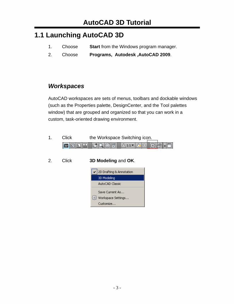
Workspaces
AutoCAD workspaces are sets of menus, toolbars and dockable windows (such as the Properties palette, DesignCenter, and the Tool palettes window) that are grouped and organized so that you can work in a custom, task-oriented drawing environment.
1. Click the Workspace Switching icon.
2. Click 3D Modeling and OK.
AutoCAD 3D Tutorial
- 4 -
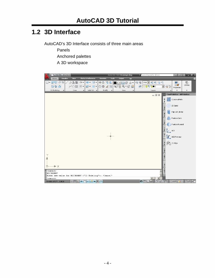
1.2 3D Interface
AutoCAD’s 3D Interface consists of three main areas Panels Anchored palettes A 3D workspace
AutoCAD 3D Tutorial
- 5 -
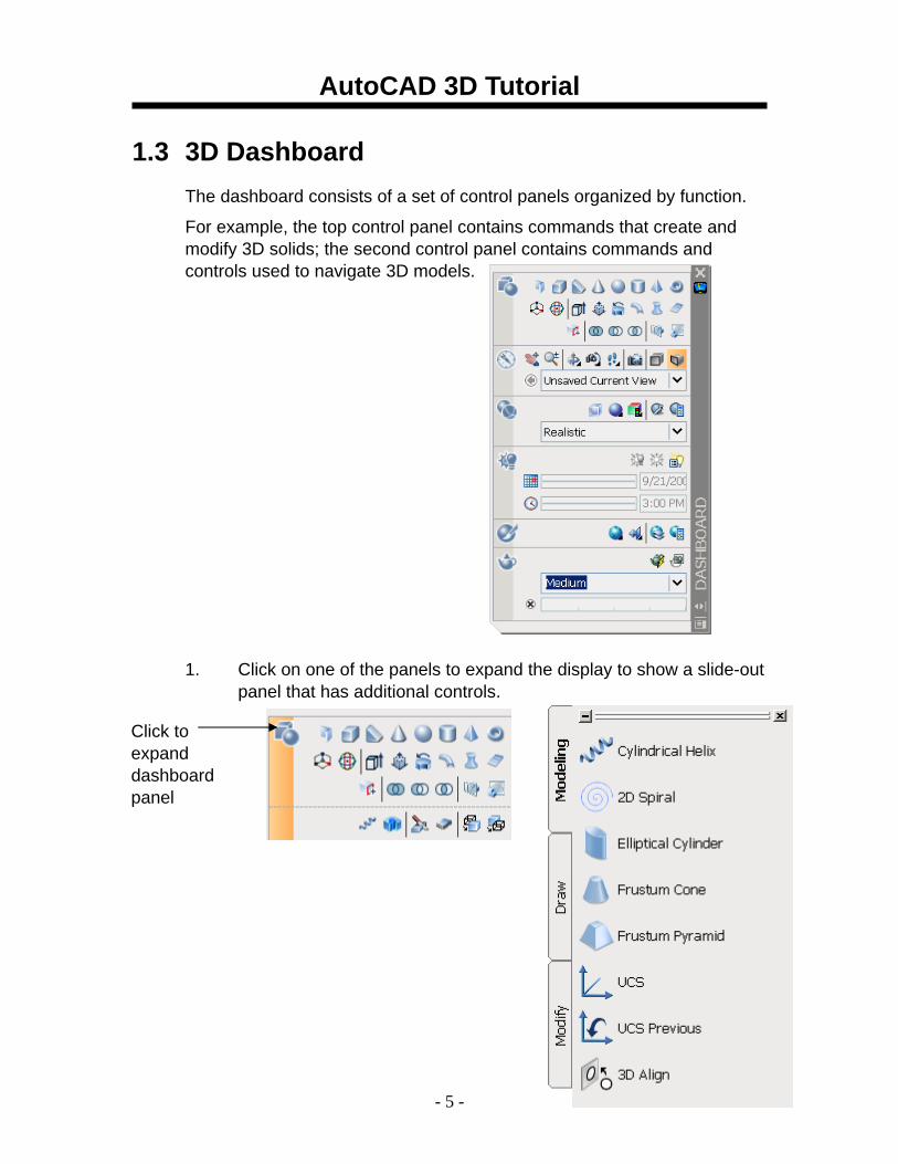
1.3 3D Dashboard The dashboard consists of a set of control panels organized by function.
For example, the top control panel contains commands that create and modify 3D solids; the second control panel contains commands and controls used to navigate 3D models.
1. Click on one of the panels to expand the display to show a slide-out panel that has additional controls.
Click to expand dashboard panel
AutoCAD 3D Tutorial
- 6 -
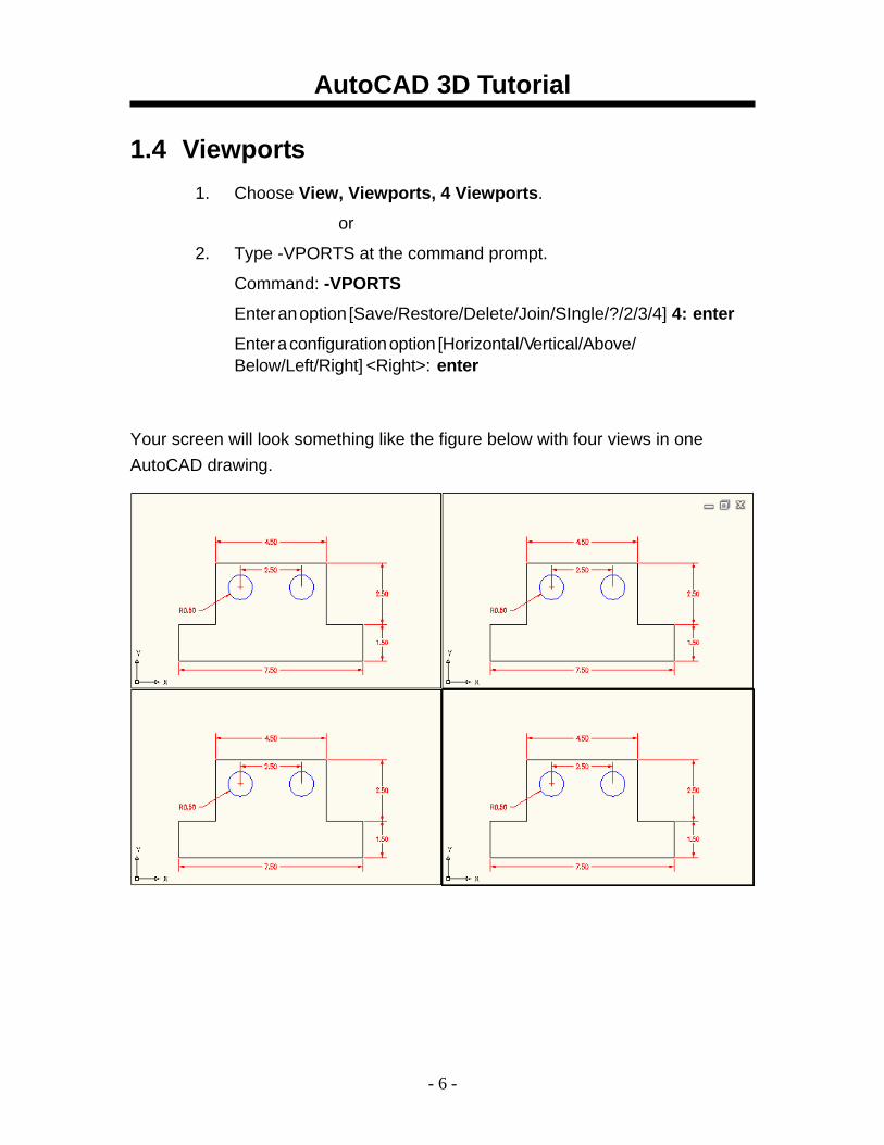
1.4 Viewports 1. Choose View, Viewports, 4 Viewports.
or
2. Type -VPORTS at the command prompt.
Command: -VPORTS
Enter an option [Save/Restore/Delete/Join/SIngle/?/2/3/4] 4: enter
Enter a configuration option [Horizontal/Vertical/Above/ Below/Left/Right] <Right>: enter
Your screen will look something like the figure below with four views in one AutoCAD drawing.
AutoCAD 3D Tutorial
- 7 -
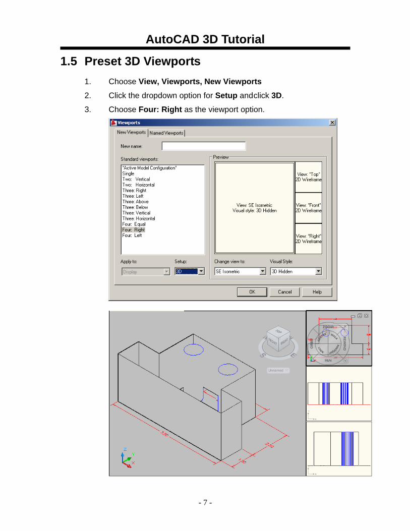
1.5 Preset 3D Viewports 1. Choose View, Viewports, New Viewports
2. Click the dropdown option for Setup and click 3D.
3. Choose Four: Right as the viewport option.
AutoCAD 3D Tutorial
- 8 -
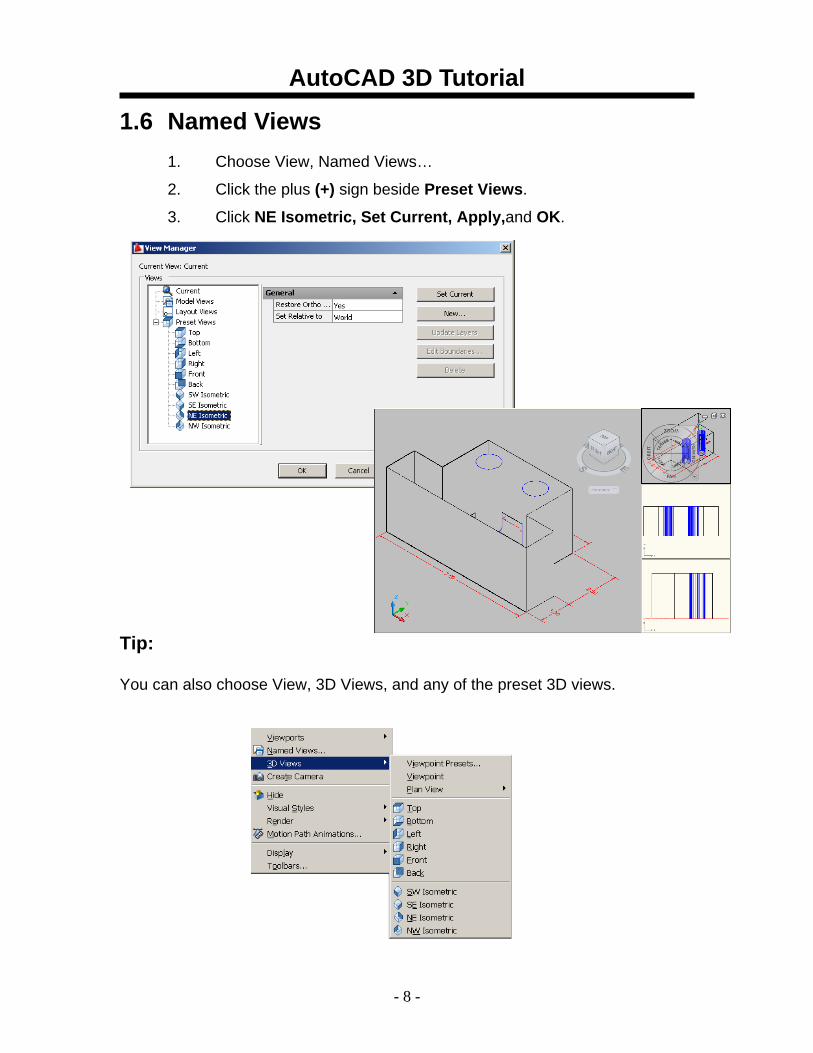
1.6 Named Views 1. Choose View, Named Views…
2. Click the plus (+) sign beside Preset Views.
3. Click NE Isometric, Set Current, Apply,and OK.
Tip:
You can also choose View, 3D Views, and any of the preset 3D views.
AutoCAD 3D Tutorial
- 9 -
1.7 Steering Wheel SteeringWheels are menus that track the cursor over the drawing window, and provide access to 2D and 3D navigation tools from a single interface. SteeringWheels, or “wheels,” are divided into wedges; each wedge contains a single navigation tool. You can start a navigation tool by clicking a wedge or by clicking and dragging the cursor over a wedge..
2D Navigation Wheel (Zoom & Pan)
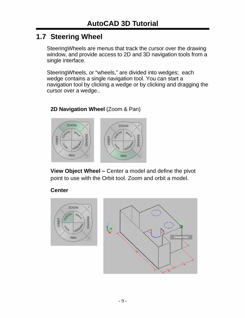
View Object Wheel – Center a model and define the pivot point to use with the Orbit tool. Zoom and orbit a model.
Center
AutoCAD 3D Tutorial
- 10 -
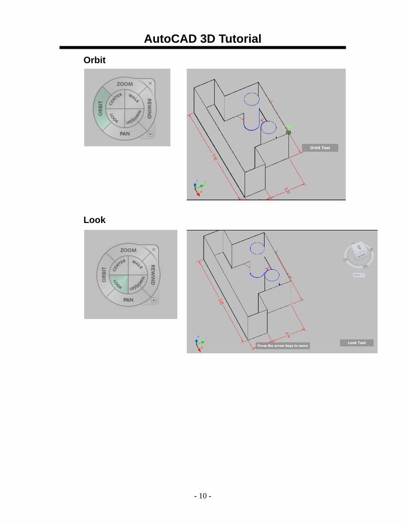
Orbit
Look
AutoCAD 3D Tutorial
- 11 -
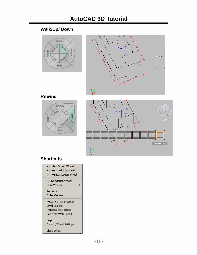
Walk/Up/ Down
Rewind
Shortcuts
AutoCAD 3D Tutorial
- 12 -
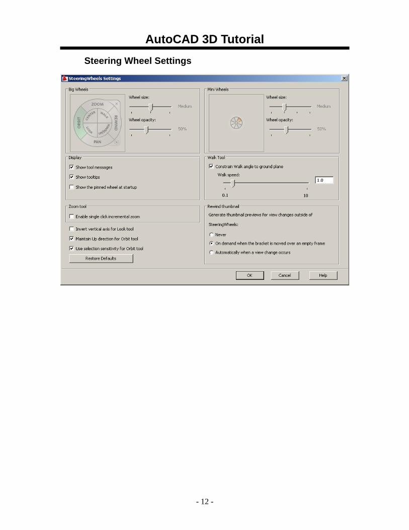
Steering Wheel Settings
AutoCAD 3D Tutorial
- 13 -
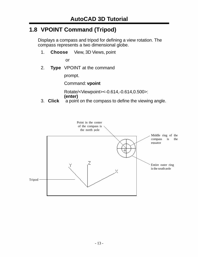
1.8 VPOINT Command (Tripod) Displays a compass and tripod for defining a view rotation. The compass represents a two dimensional globe.
1. Choose View, 3D Views, point
or
2. Type VPOINT at the command
prompt.
Command: vpoint
Rotate/<Viewpoint><-0.614,-0.614,0.500>: (enter)
3. Click a point on the compass to define the viewing angle.
Point in the center of the compass is
the north pole
Middle ring of thecompass is theequator
Entire outer ring is the south pole
Tripod
AutoCAD 3D Tutorial
- 14 -
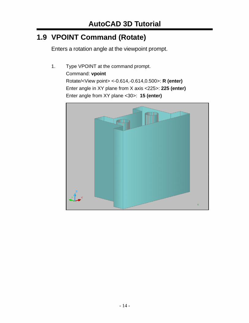
1.9 VPOINT Command (Rotate) Enters a rotation angle at the viewpoint prompt. 1. Type VPOINT at the command prompt.
Command: vpoint Rotate/<View point> <-0.614,-0.614,0.500>: R (enter) Enter angle in XY plane from X axis <225>: 225 (enter) Enter angle from XY plane <30>: 15 (enter)
AutoCAD 3D Tutorial
- 15 -
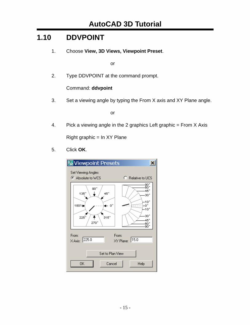
1.10 DDVPOINT
1. Choose View, 3D Views, Viewpoint Preset.
or
2. Type DDVPOINT at the command prompt.
Command: ddvpoint
3. Set a viewing angle by typing the From X axis and XY Plane angle.
or
4. Pick a viewing angle in the 2 graphics Left graphic = From X Axis
Right graphic = In XY Plane
5. Click OK.
AutoCAD 3D Tutorial
- 16 -
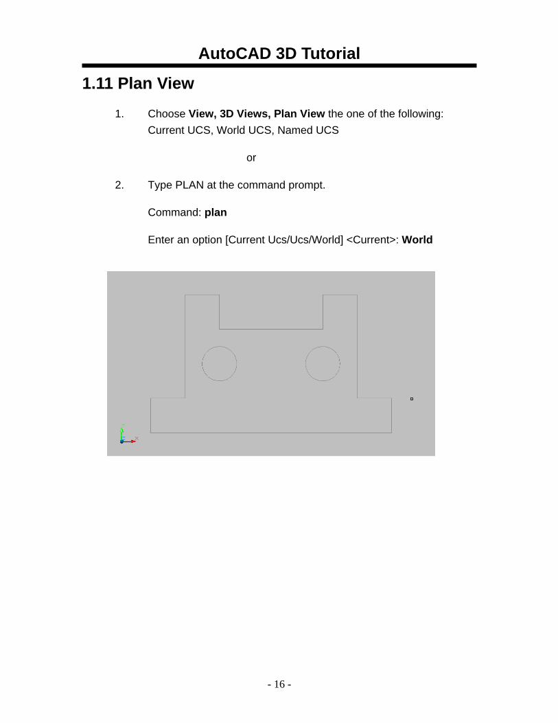
1.11 Plan View
1. Choose View, 3D Views, Plan View the one of the following: Current UCS, World UCS, Named UCS
or
2. Type PLAN at the command prompt.
Command: plan
Enter an option [Current Ucs/Ucs/World] <Current>: World
AutoCAD 3D Tutorial
- 17 -
AutoCAD 3D – Chapter 2 Thickness and Elevation
AutoCAD 3D Tutorial
- 18 -
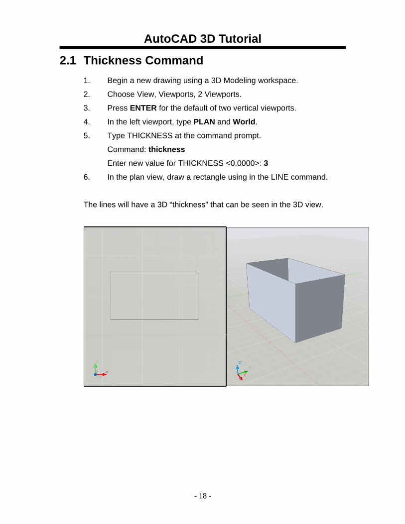
2.1 Thickness Command 1. Begin a new drawing using a 3D Modeling workspace.
2. Choose View, Viewports, 2 Viewports.
3. Press ENTER for the default of two vertical viewports.
4. In the left viewport, type PLAN and World.
5. Type THICKNESS at the command prompt.
Command: thickness
Enter new value for THICKNESS <0.0000>: 3
6. In the plan view, draw a rectangle using in the LINE command.
The lines will have a 3D “thickness” that can be seen in the 3D view.
AutoCAD 3D Tutorial
- 19 -
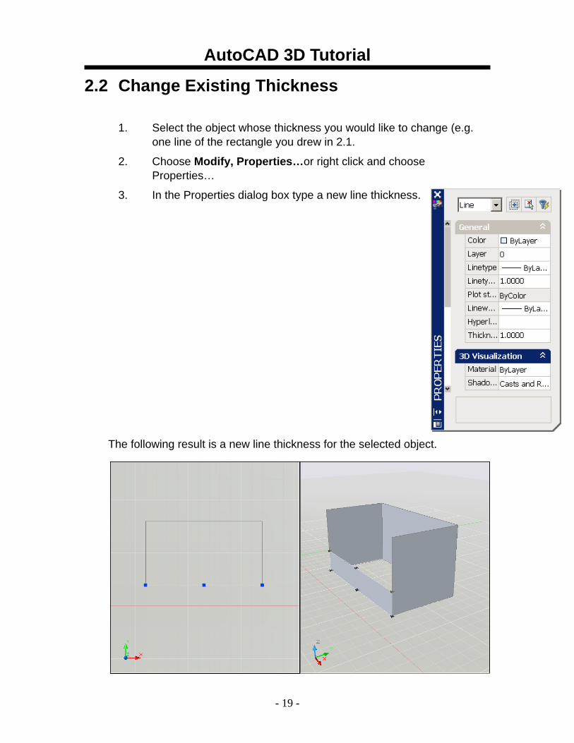
2.2 Change Existing Thickness
1. Select the object whose thickness you would like to change (e.g. one line of the rectangle you drew in 2.1.
2. Choose Modify, Properties…or right click and choose Properties…
3. In the Properties dialog box type a new line thickness.
The following result is a new line thickness for the selected object.
AutoCAD 3D Tutorial
- 20 -
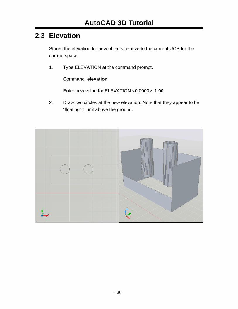
2.3 Elevation
Stores the elevation for new objects relative to the current UCS for the current space.
1. Type ELEVATION at the command prompt.
Command: elevation
Enter new value for ELEVATION <0.0000>: 1.00
2. Draw two circles at the new elevation. Note that they appear to be “floating” 1 unit above the ground.
AutoCAD 3D Tutorial
- 21 -
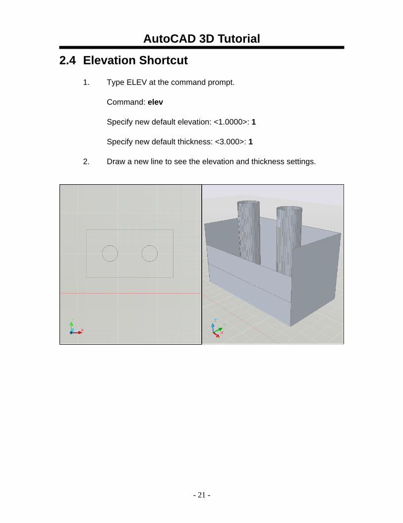
2.4 Elevation Shortcut
1. Type ELEV at the command prompt.
Command: elev
Specify new default elevation: <1.0000>: 1
Specify new default thickness: <3.000>: 1
2. Draw a new line to see the elevation and thickness settings.
AutoCAD 3D Tutorial
- 22 -
AutoCAD 3D – Chapter 3 Visualizing Your Model
AutoCAD 3D Tutorial
- 23 -
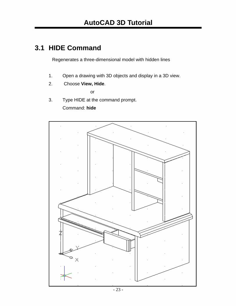
3.1 HIDE Command Regenerates a three-dimensional model with hidden lines
1. Open a drawing with 3D objects and display in a 3D view.
2. Choose View, Hide.
or
3. Type HIDE at the command prompt.
Command: hide
AutoCAD 3D Tutorial
- 24 -
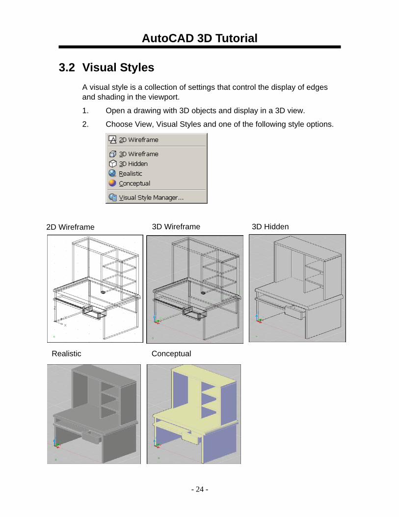
3.2 Visual Styles A visual style is a collection of settings that control the display of edges and shading in the viewport.
1. Open a drawing with 3D objects and display in a 3D view.
2. Choose View, Visual Styles and one of the following style options.
2D Wireframe 3D Wireframe 3D Hidden
Realistic Conceptual
AutoCAD 3D Tutorial
- 25 -
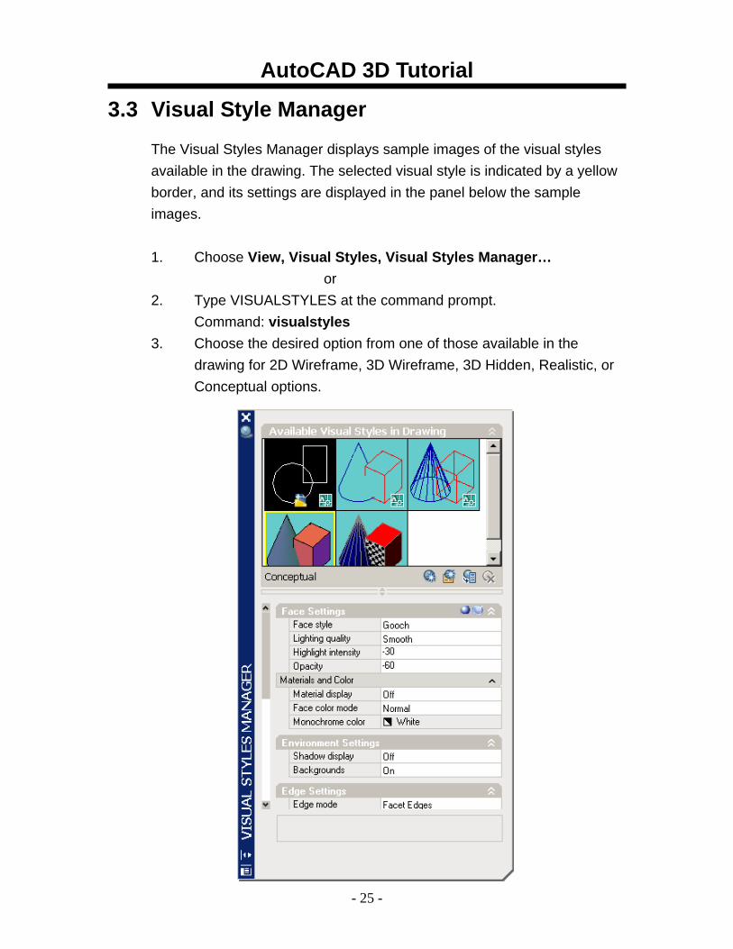
3.3 Visual Style Manager
The Visual Styles Manager displays sample images of the visual styles available in the drawing. The selected visual style is indicated by a yellow border, and its settings are displayed in the panel below the sample images.
1. Choose View, Visual Styles, Visual Styles Manager…
or 2. Type VISUALSTYLES at the command prompt.
Command: visualstyles 3. Choose the desired option from one of those available in the
drawing for 2D Wireframe, 3D Wireframe, 3D Hidden, Realistic, or Conceptual options.
AutoCAD 3D Tutorial
- 26 -
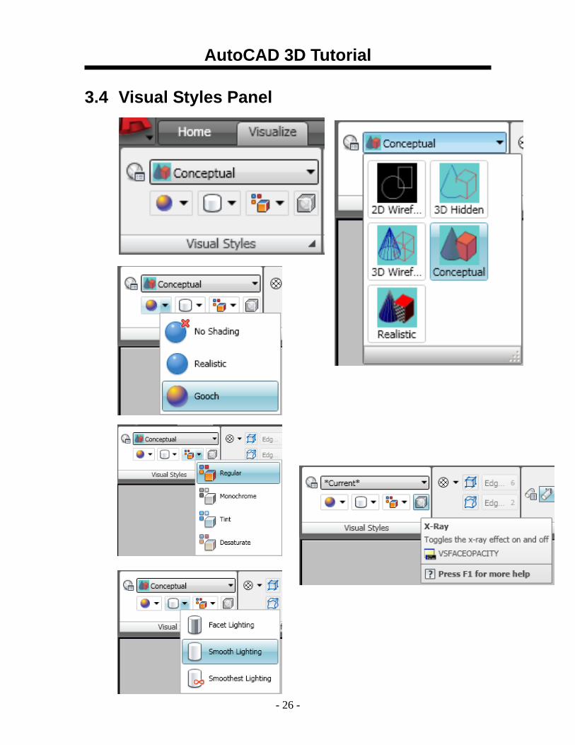
3.4 Visual Styles Panel
AutoCAD 3D Tutorial
- 27 -
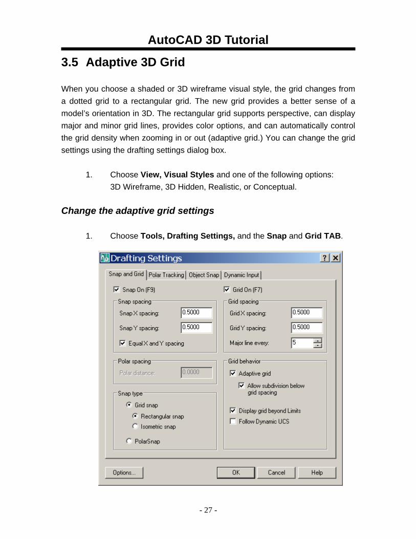
3.5 Adaptive 3D Grid When you choose a shaded or 3D wireframe visual style, the grid changes from a dotted grid to a rectangular grid. The new grid provides a better sense of a model’s orientation in 3D. The rectangular grid supports perspective, can display major and minor grid lines, provides color options, and can automatically control the grid density when zooming in or out (adaptive grid.) You can change the grid settings using the drafting settings dialog box.
1. Choose View, Visual Styles and one of the following options: 3D Wireframe, 3D Hidden, Realistic, or Conceptual.
Change the adaptive grid settings 1. Choose Tools, Drafting Settings, and the Snap and Grid TAB.
AutoCAD 3D Tutorial
- 28 -
AutoCAD 3D – Chapter 4 Z Coordinates
AutoCAD 3D Tutorial
- 29 -
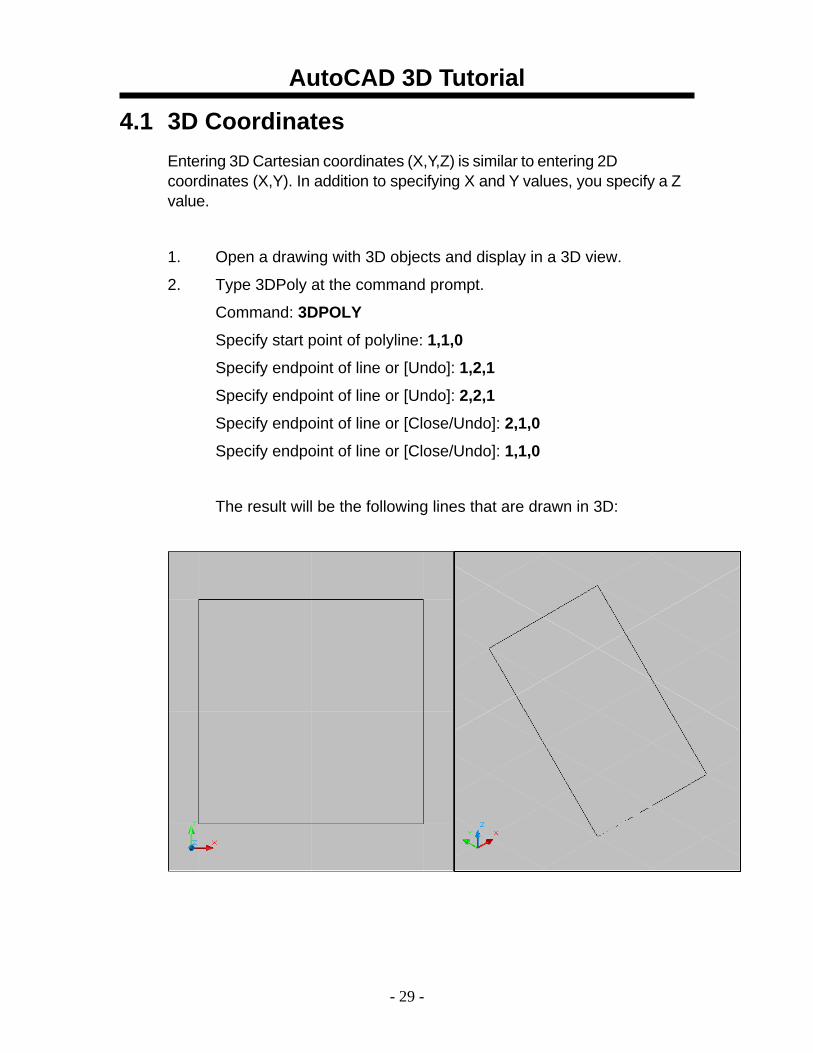
4.1 3D Coordinates Entering 3D Cartesian coordinates (X,Y,Z) is similar to entering 2D coordinates (X,Y). In addition to specifying X and Y values, you specify a Z value.
1. Open a drawing with 3D objects and display in a 3D view.
2. Type 3DPoly at the command prompt.
Command: 3DPOLY
Specify start point of polyline: 1,1,0
Specify endpoint of line or [Undo]: 1,2,1
Specify endpoint of line or [Undo]: 2,2,1
Specify endpoint of line or [Close/Undo]: 2,1,0
Specify endpoint of line or [Close/Undo]: 1,1,0
The result will be the following lines that are drawn in 3D:
AutoCAD 3D Tutorial
- 30 -
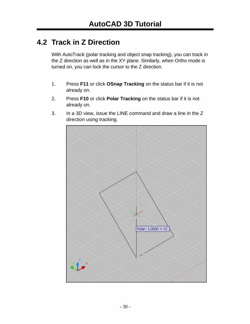
4.2 Track in Z Direction With AutoTrack (polar tracking and object snap tracking), you can track in the Z direction as well as in the XY plane. Similarly, when Ortho mode is turned on, you can lock the cursor to the Z direction.
1. Press F11 or click OSnap Tracking on the status bar if it is not already on.
2. Press F10 or click Polar Tracking on the status bar if it is not already on.
3. In a 3D view, issue the LINE command and draw a line in the Z direction using tracking.

AutoCAD 3D Tutorial
- 31 -
4.3 Move in Z Direction 1. Open a drawing with 3D objects in it.
2. Type MOVE at the command prompt.
Command: move
Select objects: pick object in 3D view
Select objects: press enter
Specify base point or displacement:
Specify second point of displacement or
<use first point as displacement>: 0,0,1 or use polar tracking to move the object.
before move after move
AutoCAD 3D Tutorial
- 32 -
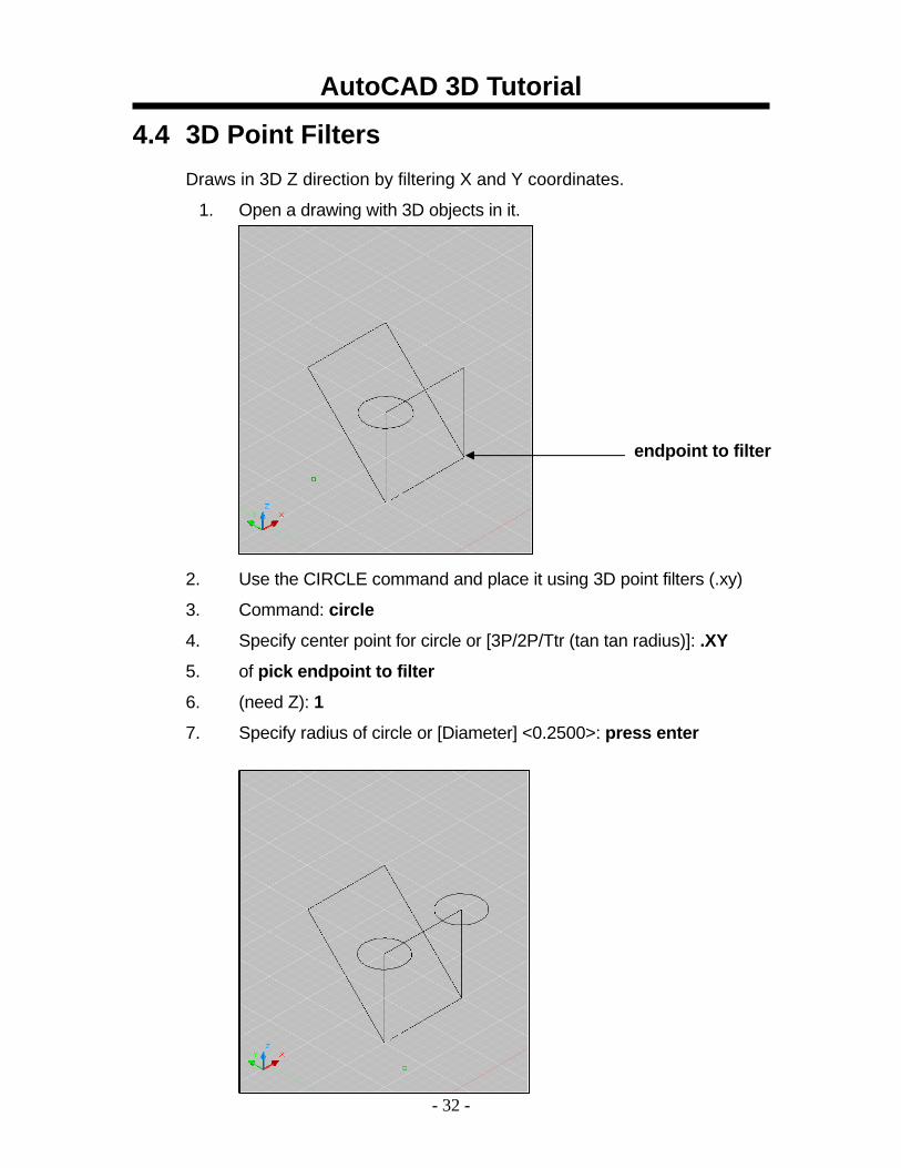
4.4 3D Point Filters Draws in 3D Z direction by filtering X and Y coordinates.
1. Open a drawing with 3D objects in it.
2. Use the CIRCLE command and place it using 3D point filters (.xy)
3. Command: circle
4. Specify center point for circle or [3P/2P/Ttr (tan tan radius)]: .XY
5. of pick endpoint to filter
6. (need Z): 1
7. Specify radius of circle or [Diameter] <0.2500>: press enter
endpoint to filter
AutoCAD 3D Tutorial
- 33 -
AutoCAD 3D – Chapter 5 User Coordinate System
AutoCAD 3D Tutorial
- 34 -
5.1 UCS Icon
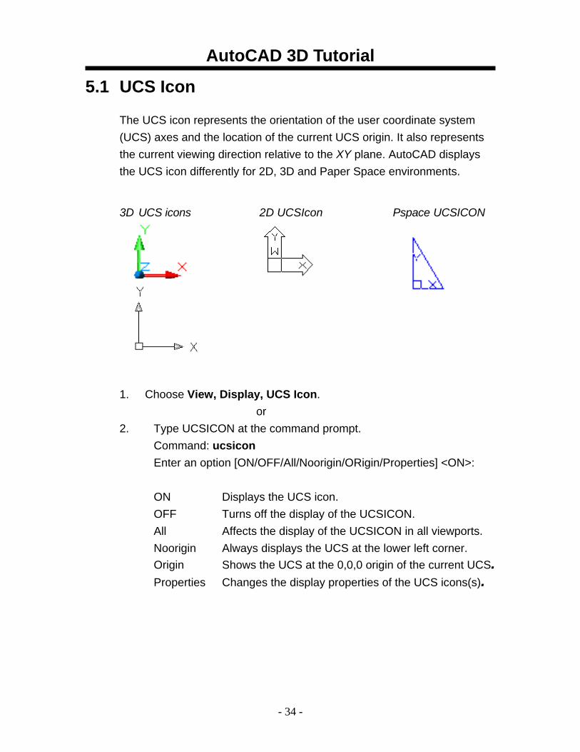
The UCS icon represents the orientation of the user coordinate system (UCS) axes and the location of the current UCS origin. It also represents the current viewing direction relative to the XY plane. AutoCAD displays the UCS icon differently for 2D, 3D and Paper Space environments.
1. Choose View, Display, UCS Icon.
or 2. Type UCSICON at the command prompt.
Command: ucsicon Enter an option [ON/OFF/All/Noorigin/ORigin/Properties] <ON>:
ON Displays the UCS icon. OFF Turns off the display of the UCSICON. All Affects the display of the UCSICON in all viewports. Noorigin Always displays the UCS at the lower left corner. Origin Shows the UCS at the 0,0,0 origin of the current UCS. Properties Changes the display properties of the UCS icons(s).
3D UCS icons 2D UCSIcon Pspace UCSICON
AutoCAD 3D Tutorial
- 35 -
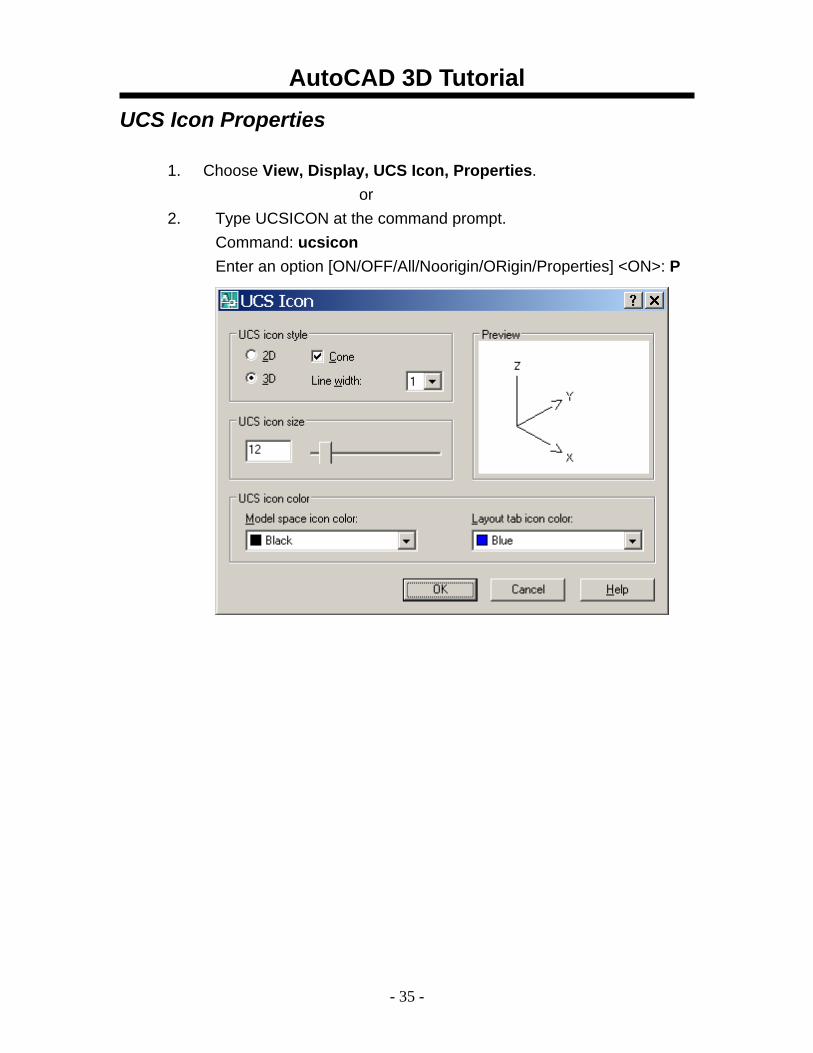
UCS Icon Properties 1. Choose View, Display, UCS Icon, Properties.
or 2. Type UCSICON at the command prompt.
Command: ucsicon Enter an option [ON/OFF/All/Noorigin/ORigin/Properties] <ON>: P
AutoCAD 3D Tutorial
- 36 -
5.2 UCS Overview The user coordinate system provides an alternate movable coordinate system for coordinate entry, planes of operation, and viewing. Most AutoCAD geometric editing commands are dependent on the location and orientation of the UCS. There are a variety of ways to set the User Coordinate System using the UCS command.
1. Type UCS at the command prompt. Command: ucs Enter an option [New/Move/orthoGraphic/Prev/Restore/ Save/Del/Apply/?/World] <World>:
New Defines a new coordinate system by one of six
methods: Origin, Z Axis, 3 Point, Object, Face, View X, Y, Z
Origin Defines a new UCS by shifting the origin of the current UCS, leaving the direction of the X,Y, and Z axes unchanged.
ZAxis Allows you to define a new origin. 3 Point Specifies a UCS by its origin and a point on the
positive X and Y axes. Object Lets you define a new UCS by pointing at an object. Face Aligns the UCS to the selected face of a solid object. View Establishes a new UCS whose XY plane is
perpendicular to your viewing direction (e.g. parallel to your screen).
X/Y/Z Rotates the ucs around a specified axis
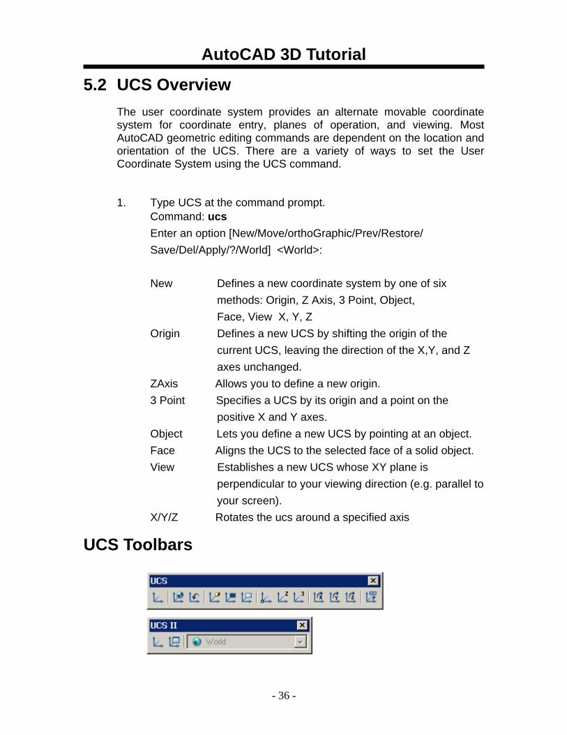
UCS Toolbars
AutoCAD 3D Tutorial
- 37 -
5.3 3 Point UCS
The 3 Point option is one of the easiest ways to define a new UCS on a given 3D object.
1. Open a drawing with a simple 3D object (e.g. 3D box)
2. Type UCS at the command prompt.
Command: ucs
Enter an option [New/Move/orthoGraphic/Prev/Restore/ Save/Del/Apply/?/World] <World>: N
Specify origin of new UCS or [ZAxis/3point/OBject/ Face/View/X/Y/Z] <0,0,0>: 3
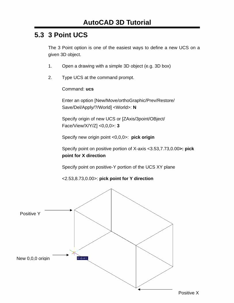
Specify new origin point <0,0,0>: pick origin
Specify point on positive portion of X-axis <3.53,7.73,0.00>: pick point for X direction
Specify point on positive-Y portion of the UCS XY plane
<2.53,8.73,0.00>: pick point for Y direction
Positive Y
New 0,0,0 origin
Positive X
AutoCAD 3D Tutorial
- 38 -
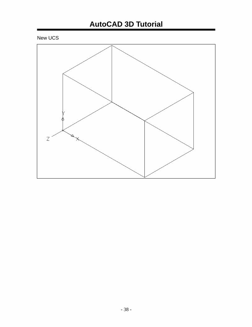
New UCS
AutoCAD 3D Tutorial
- 39 -
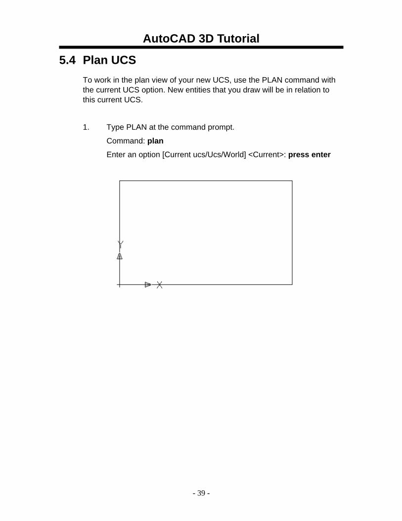
5.4 Plan UCS To work in the plan view of your new UCS, use the PLAN command with the current UCS option. New entities that you draw will be in relation to this current UCS.
1. Type PLAN at the command prompt.
Command: plan
Enter an option [Current ucs/Ucs/World] <Current>: press enter
AutoCAD 3D Tutorial
- 40 -
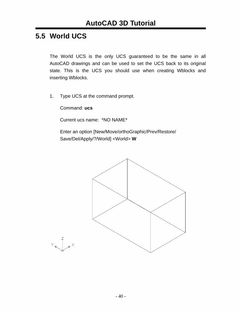
5.5 World UCS
The World UCS is the only UCS guaranteed to be the same in all AutoCAD drawings and can be used to set the UCS back to its original state. This is the UCS you should use when creating Wblocks and inserting Wblocks.
1. Type UCS at the command prompt.
Command: ucs
Current ucs name: *NO NAME*
Enter an option [New/Move/orthoGraphic/Prev/Restore/ Save/Del/Apply/?/World] <World> W
AutoCAD 3D Tutorial
- 41 -
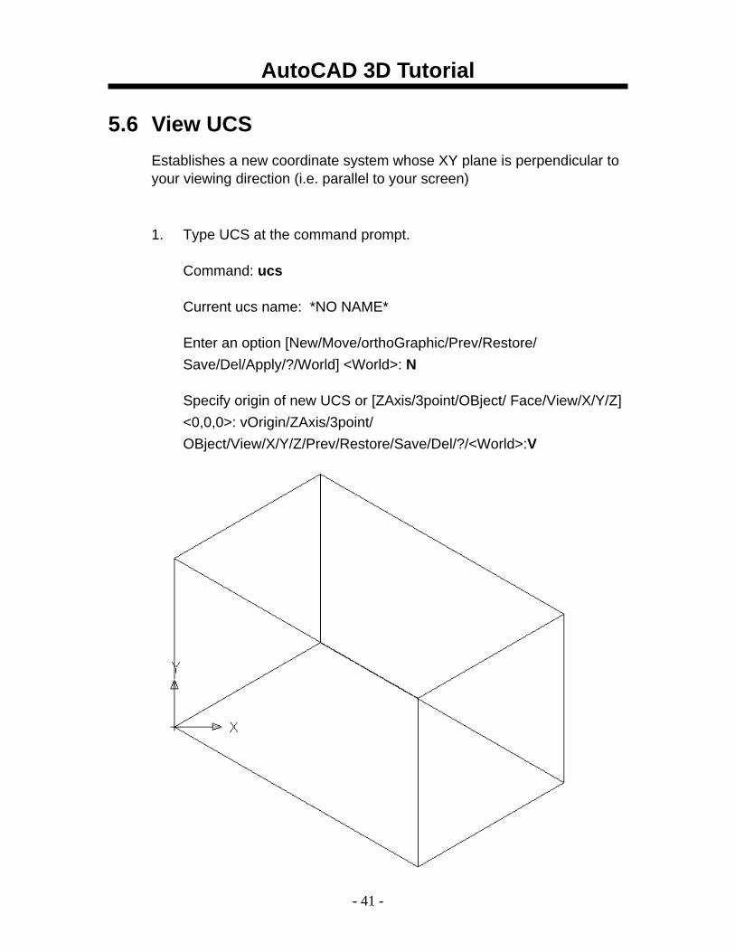
5.6 View UCS Establishes a new coordinate system whose XY plane is perpendicular to your viewing direction (i.e. parallel to your screen)
1. Type UCS at the command prompt.
Command: ucs
Current ucs name: *NO NAME*
Enter an option [New/Move/orthoGraphic/Prev/Restore/ Save/Del/Apply/?/World] <World>: N
Specify origin of new UCS or [ZAxis/3point/OBject/ Face/View/X/Y/Z] <0,0,0>: vOrigin/ZAxis/3point/ OBject/View/X/Y/Z/Prev/Restore/Save/Del/?/<World>:V
X.X XXXXXXXXXXXXXXX Regenerates a three-dimensional model with hidden lines
1. Open a drawing with 3D objects and display in a 3D view.
or
2. Choose View, Hide.
3. Type HIDE at the command prompt.
Command: hide
AutoCAD 3D Tutorial
- 42 -
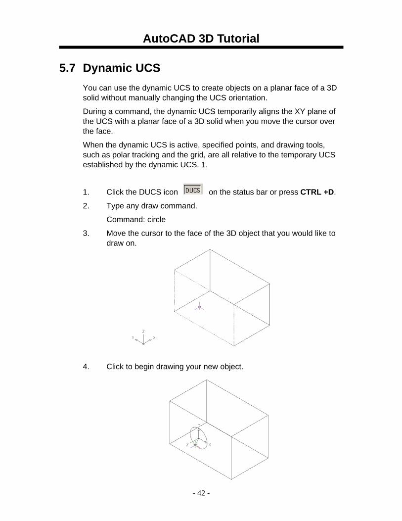
5.7 Dynamic UCS You can use the dynamic UCS to create objects on a planar face of a 3D solid without manually changing the UCS orientation.
During a command, the dynamic UCS temporarily aligns the XY plane of the UCS with a planar face of a 3D solid when you move the cursor over the face.
When the dynamic UCS is active, specified points, and drawing tools, such as polar tracking and the grid, are all relative to the temporary UCS established by the dynamic UCS. 1.
1. Click the DUCS icon on the status bar or press CTRL +D.
2. Type any draw command.
Command: circle
3. Move the cursor to the face of the 3D object that you would like to draw on.
4. Click to begin drawing your new object.
AutoCAD 3D Tutorial
- 43 -
5.8 Naming and Saving a UCS User coordinate systems can sometimes be complicated and it is often useful to name and save them so you can quickly recall them.
1. Type UCS at the command prompt.
Command: UCS
Specify origin of UCS or [Face/NAmed/OBject/Previous/View/World/X/Y/Z/ZAxis]
<World>: NA
Enter an option [Restore/Save/Delete/?]: S
Enter name to save current UCS or [?]: LeftSide
AutoCAD 3D Tutorial
- 44 -
5.9 Restoring a UCS A named and saved UCS can be restored at any time.
1. Type UCS at the command prompt.
Command: UCS
Specify origin of UCS or [Face/NAmed/OBject/Previous/View/World/X/Y/Z/ZAxis]
<World>: NA
Enter an option [Restore/Save/Delete/?]: R
Enter name to save current UCS or [?]: LeftSide
AutoCAD 3D Tutorial
- 45 -
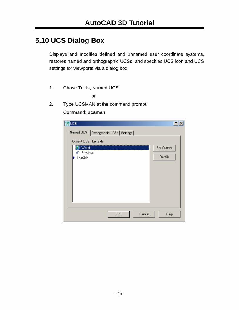
5.10 UCS Dialog Box
Displays and modifies defined and unnamed user coordinate systems, restores named and orthographic UCSs, and specifies UCS icon and UCS settings for viewports via a dialog box.
1. Chose Tools, Named UCS.
or
2. Type UCSMAN at the command prompt.
Command: ucsman
AutoCAD 3D Tutorial
- 46 -
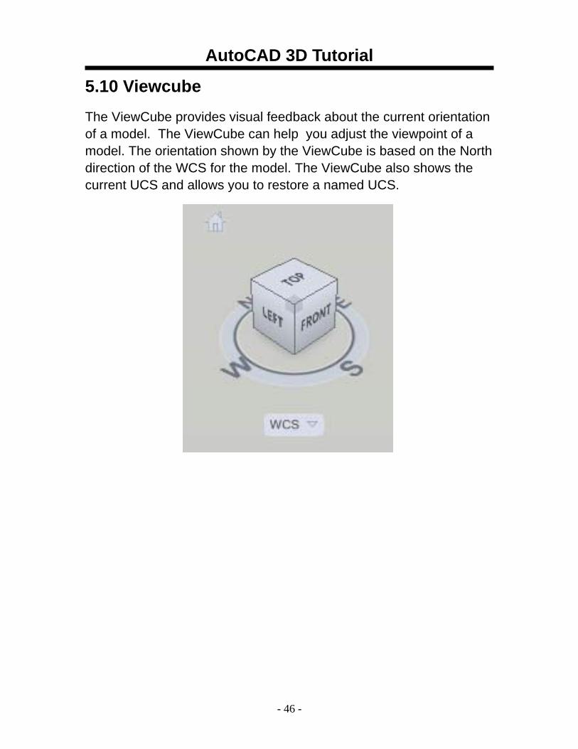
5.10 Viewcube The ViewCube provides visual feedback about the current orientation of a model. The ViewCube can help you adjust the viewpoint of a model. The orientation shown by the ViewCube is based on the North direction of the WCS for the model. The ViewCube also shows the current UCS and allows you to restore a named UCS.
AutoCAD 3D Tutorial
- 47 -
AutoCAD 3D – Chapter 6 3D Orbit
AutoCAD 3D Tutorial
- 48 -
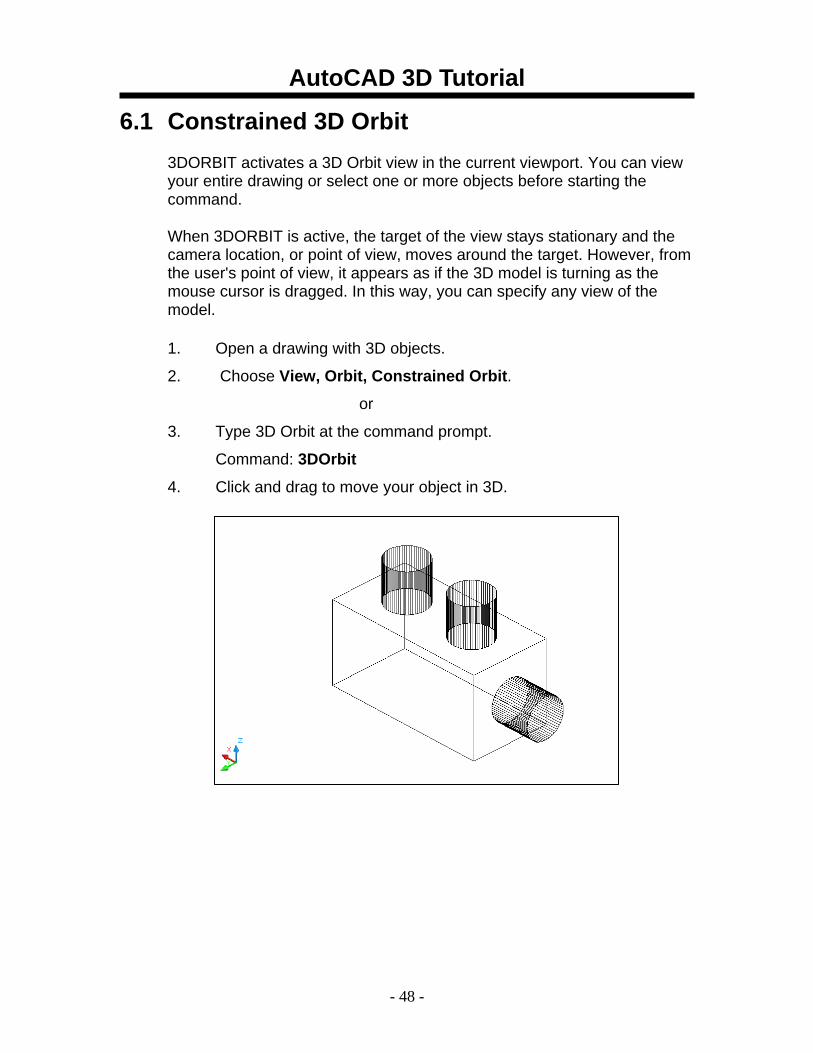
6.1 Constrained 3D Orbit 3DORBIT activates a 3D Orbit view in the current viewport. You can view your entire drawing or select one or more objects before starting the command.
When 3DORBIT is active, the target of the view stays stationary and the camera location, or point of view, moves around the target. However, from the user's point of view, it appears as if the 3D model is turning as the mouse cursor is dragged. In this way, you can specify any view of the model.
1. Open a drawing with 3D objects.
2. Choose View, Orbit, Constrained Orbit.
or
3. Type 3D Orbit at the command prompt.
Command: 3DOrbit
4. Click and drag to move your object in 3D.
AutoCAD 3D Tutorial
- 49 -
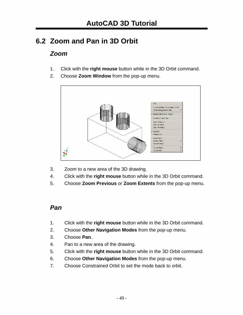
6.2 Zoom and Pan in 3D Orbit Zoom 1. Click with the right mouse button while in the 3D Orbit command. 2. Choose Zoom Window from the pop-up menu. 3. Zoom to a new area of the 3D drawing. 4. Click with the right mouse button while in the 3D Orbit command. 5. Choose Zoom Previous or Zoom Extents from the pop-up menu.
Pan 1. Click with the right mouse button while in the 3D Orbit command. 2. Choose Other Navigation Modes from the pop-up menu. 3. Choose Pan. 4. Pan to a new area of the drawing. 5. Click with the right mouse button while in the 3D Orbit command. 6. Choose Other Navigation Modes from the pop-up menu. 7. Choose Constrained Orbit to set the mode back to orbit.
AutoCAD 3D Tutorial
- 50 -
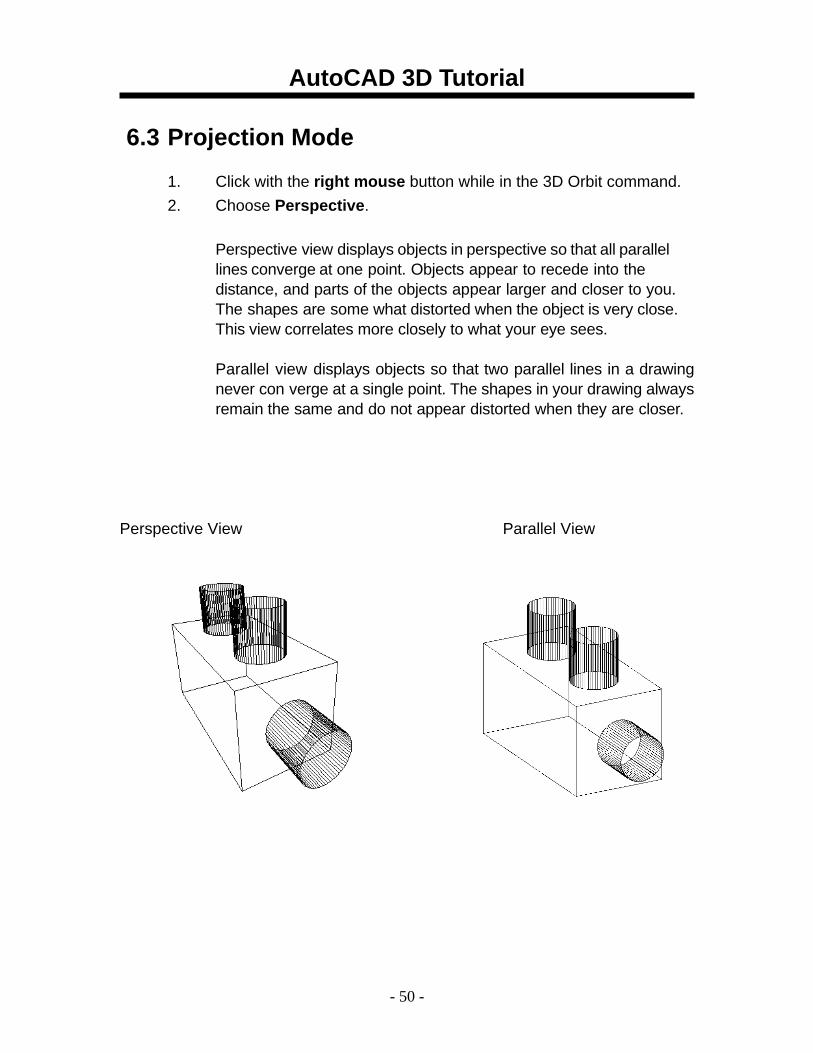
6.3 Projection Mode
1. Click with the right mouse button while in the 3D Orbit command. 2. Choose Perspective.
Perspective view displays objects in perspective so that all parallel lines converge at one point. Objects appear to recede into the distance, and parts of the objects appear larger and closer to you. The shapes are some what distorted when the object is very close. This view correlates more closely to what your eye sees. Parallel view displays objects so that two parallel lines in a drawing never con verge at a single point. The shapes in your drawing always remain the same and do not appear distorted when they are closer.
Perspective View Parallel View
AutoCAD 3D Tutorial
- 51 -
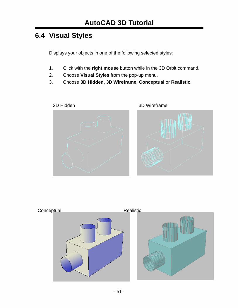
6.4 Visual Styles
Displays your objects in one of the following selected styles:
1. Click with the right mouse button while in the 3D Orbit command. 2. Choose Visual Styles from the pop-up menu. 3. Choose 3D Hidden, 3D Wireframe, Conceptual or Realistic.
3D Hidden 3D Wireframe
Conceptual Realistic
AutoCAD 3D Tutorial
- 52 -
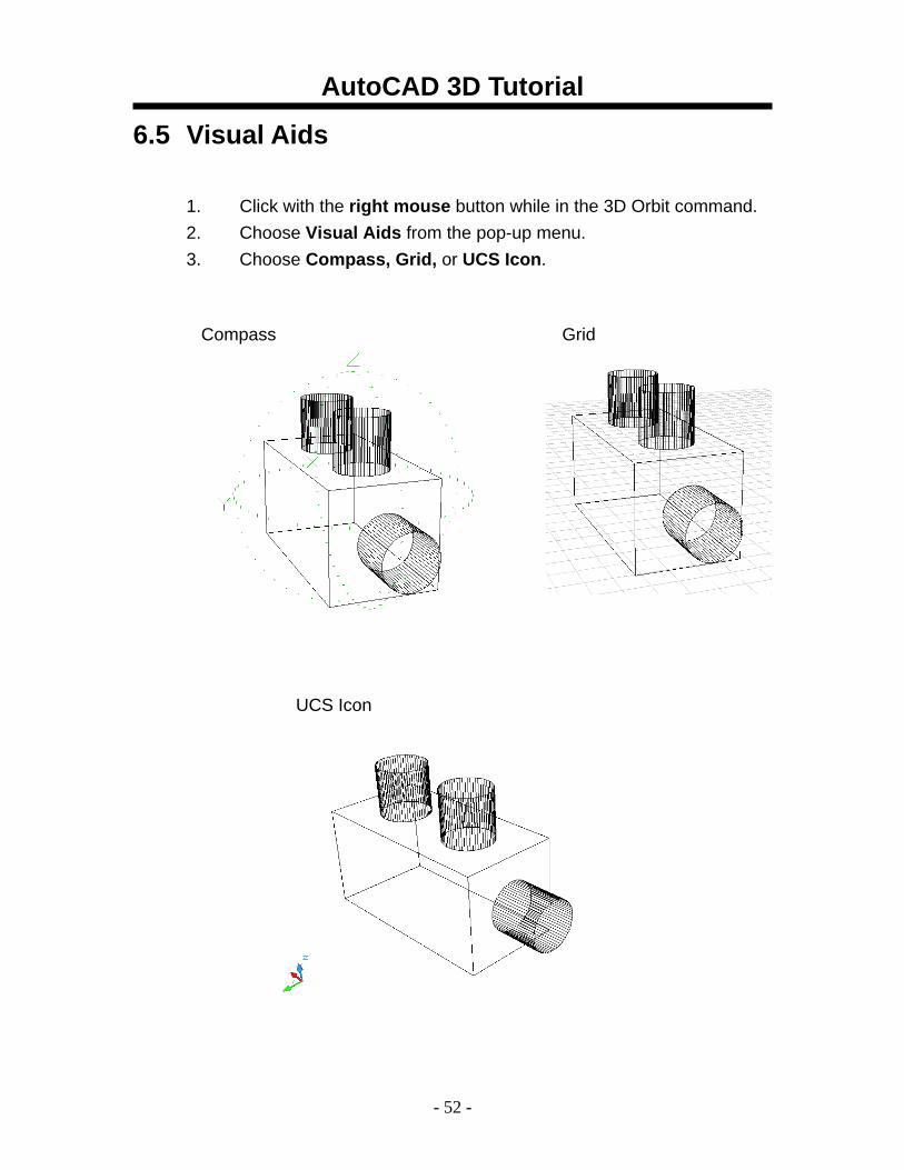
6.5 Visual Aids 1. Click with the right mouse button while in the 3D Orbit command. 2. Choose Visual Aids from the pop-up menu. 3. Choose Compass, Grid, or UCS Icon.
Compass Grid
UCS Icon
AutoCAD 3D Tutorial
- 53 -
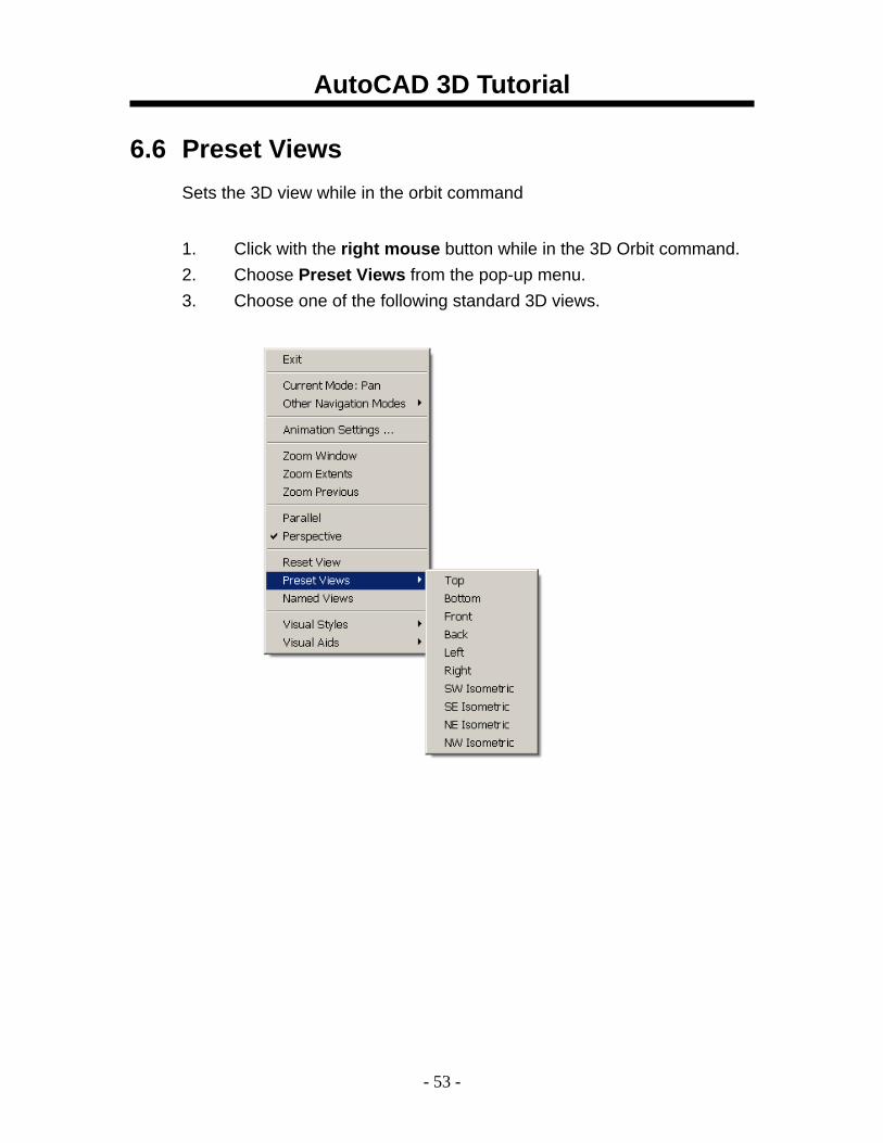
6.6 Preset Views Sets the 3D view while in the orbit command
1. Click with the right mouse button while in the 3D Orbit command. 2. Choose Preset Views from the pop-up menu. 3. Choose one of the following standard 3D views.
AutoCAD 3D Tutorial
- 54 -
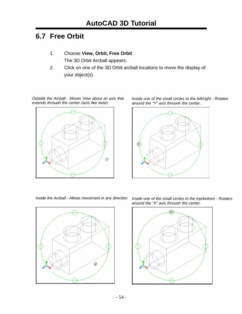
6.7 Free Orbit
1. Choose View, Orbit, Free Orbit. The 3D Orbit Arcball appears.
2. Click on one of the 3D Orbit arcball locations to move the display of your object(s).
Inside the Arcball - Allows movement in any direction
Outside the Arcball - Moves View about an axis thatextends through the center (acts like twist)
Inside one of the small circles to the left/right - Rotatesaround the “Y” axis through the center.
Inside one of the small circles to the top/bottom - Rotates around the “X” axis through the center.
AutoCAD 3D Tutorial
- 55 -
6.8 Continuous Orbit
1. Choose View, Orbit, Continuous Orbit. 2. Click and drag to define the direction and speed of a continuous
orbit for your object(s). 3. Press ESC on the keyboard to stop the orbit.
AutoCAD 3D Tutorial
- 56 -
6.9 Other Navigational Modes
1. Click with the right mouse button while in the 3D Orbit command. 2. Choose Other Navigational Modes from the pop-up menu. 3. Choose one of the following modes. Adjust Distance (4) Simulates moving the camera closer to the
object or farther away. Swivel (5) Changes the cursor to an arched arrow and
simulates the effect of swiveling the camera. See 3DSWIVEL.
Walk (6) Changes the cursor to a plus sign and enables
you to "walk through" a model at a fixed height above the XY plane, by dynamically controlling the location and target of the camera. See 3DWALK.
Fly (7) Changes the cursor to a plus sign and enables
you to "fly through" a model without being restricted to a fixed height above the XY plane. See 3DFLY.
Zoom (8) Changes the cursor to a magnifying glass with
plus (+) and minus (-) sign and simulates moving the camera closer to an object or farther away. Works like the Adjust Distance option. See 3DZOOM.
AutoCAD 3D Tutorial
- 57 -
AutoCAD 3D – Chapter 7 3D Navigation
AutoCAD 3D Tutorial
- 58 -
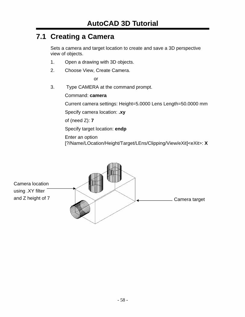
7.1 Creating a Camera Sets a camera and target location to create and save a 3D perspective view of objects.
1. Open a drawing with 3D objects.
2. Choose View, Create Camera.
or
3. Type CAMERA at the command prompt.
Command: camera
Current camera settings: Height=5.0000 Lens Length=50.0000 mm
Specify camera location: .xy
of (need Z): 7
Specify target location: endp
Enter an option [?/Name/LOcation/Height/Target/LEns/Clipping/View/eXit]<eXit>: X
Camera location using .XY filter and Z height of 7 Camera target
AutoCAD 3D Tutorial
- 59 -
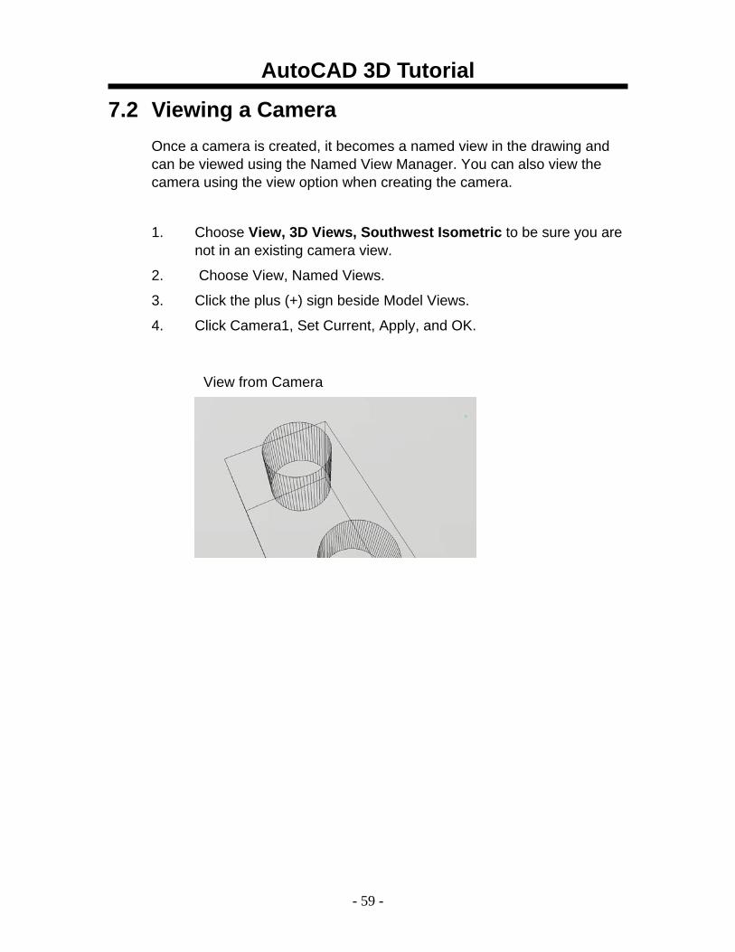
7.2 Viewing a Camera Once a camera is created, it becomes a named view in the drawing and can be viewed using the Named View Manager. You can also view the camera using the view option when creating the camera.
1. Choose View, 3D Views, Southwest Isometric to be sure you are not in an existing camera view.
2. Choose View, Named Views.
3. Click the plus (+) sign beside Model Views.
4. Click Camera1, Set Current, Apply, and OK.
View from Camera
AutoCAD 3D Tutorial
- 60 -
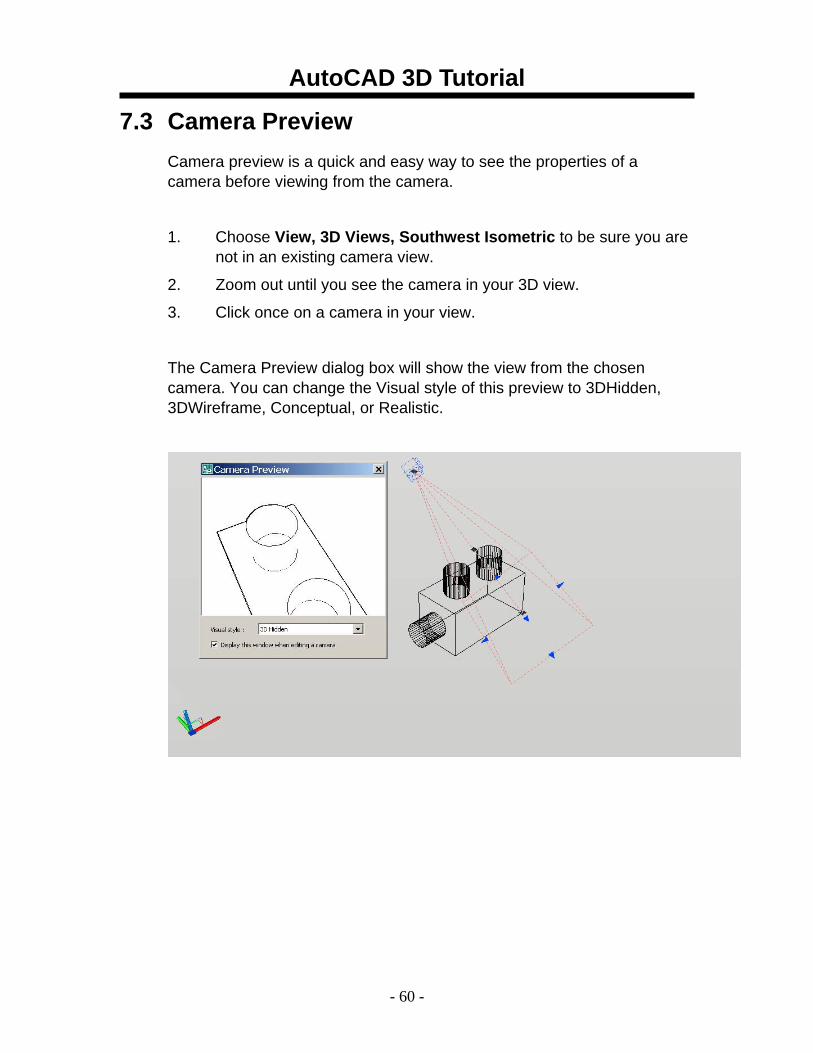
7.3 Camera Preview Camera preview is a quick and easy way to see the properties of a camera before viewing from the camera.
1. Choose View, 3D Views, Southwest Isometric to be sure you are not in an existing camera view.
2. Zoom out until you see the camera in your 3D view.
3. Click once on a camera in your view.
The Camera Preview dialog box will show the view from the chosen camera. You can change the Visual style of this preview to 3DHidden, 3DWireframe, Conceptual, or Realistic.

AutoCAD 3D Tutorial
- 61 -
7.4 Camera Properties 1. In a 3D isometric view, double click a camera.
AutoCAD 3D Tutorial
- 62 -
7.5 Displaying and Plotting a Camera
Displaying a Camera 1. Choose View, Display, Cameras.
Plotting a Camera
1. If cameras are not already displayed in the drawing, click View,
Display, Cameras. 2. Double-click a camera. 3. In the Properties palette, Camera section, Plot option, click Yes or
No.
AutoCAD 3D Tutorial
- 63 -
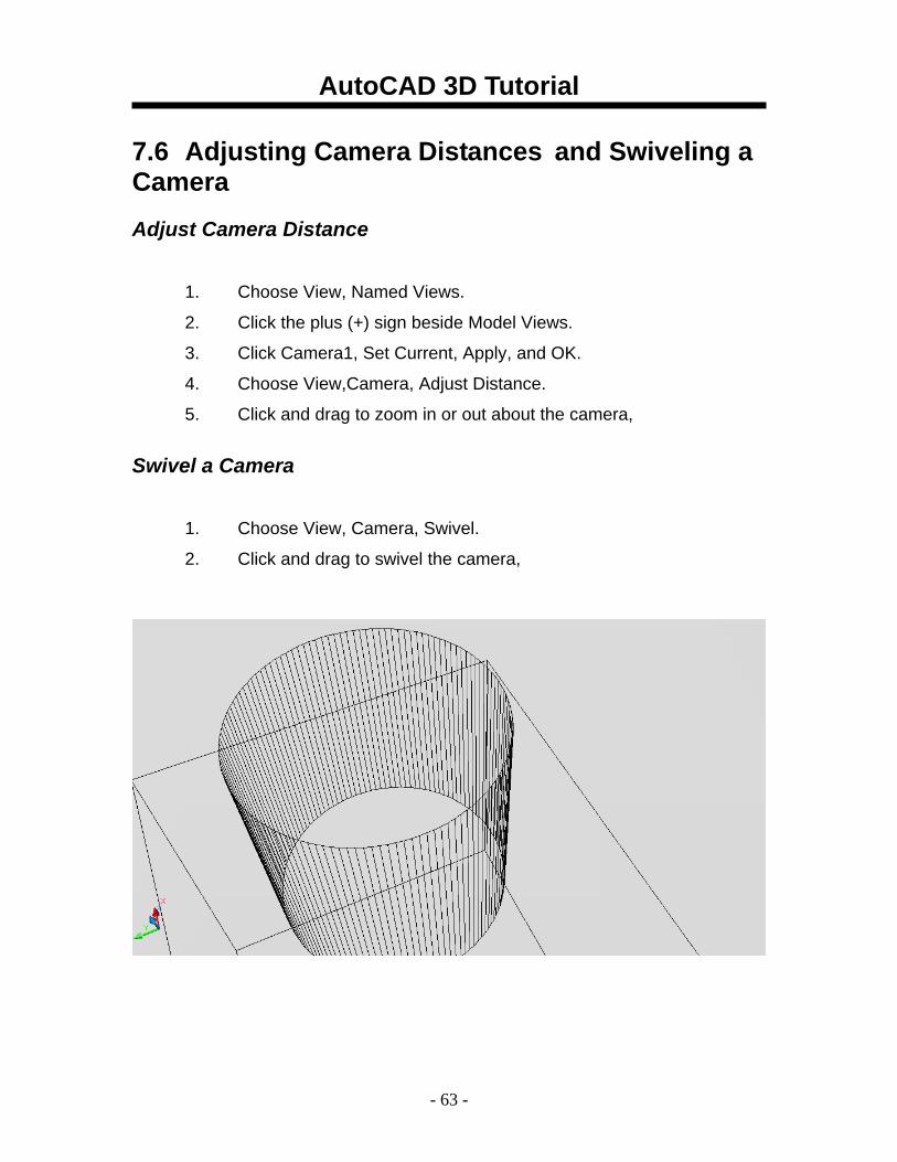
7.6 Adjusting Camera Distances and Swiveling a Camera Adjust Camera Distance
1. Choose View, Named Views.
2. Click the plus (+) sign beside Model Views.
3. Click Camera1, Set Current, Apply, and OK.
4. Choose View,Camera, Adjust Distance.
5. Click and drag to zoom in or out about the camera, Swivel a Camera
1. Choose View, Camera, Swivel.
2. Click and drag to swivel the camera,
AutoCAD 3D Tutorial
- 64 -
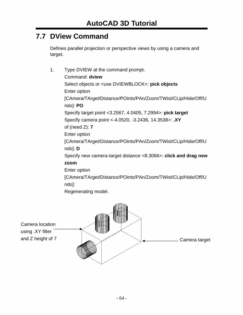
7.7 DView Command Defines parallel projection or perspective views by using a camera and target.
1. Type DVIEW at the command prompt.
Command: dview Select objects or <use DVIEWBLOCK>: pick objects Enter option [CAmera/TArget/Distance/POints/PAn/Zoom/TWist/CLip/Hide/Off/Undo]: PO Specify target point <3.2567, 4.0405, 7.2994>: pick target Specify camera point <-4.0520, -3.2436, 14.3538>: .XY of (need Z): 7 Enter option [CAmera/TArget/Distance/POints/PAn/Zoom/TWist/CLip/Hide/Off/Undo]: D Specify new camera-target distance <8.3066>: click and drag new zoom Enter option [CAmera/TArget/Distance/POints/PAn/Zoom/TWist/CLip/Hide/Off/Undo]: Regenerating model.
Camera location using .XY filter and Z height of 7 Camera target
AutoCAD 3D Tutorial
- 65 -
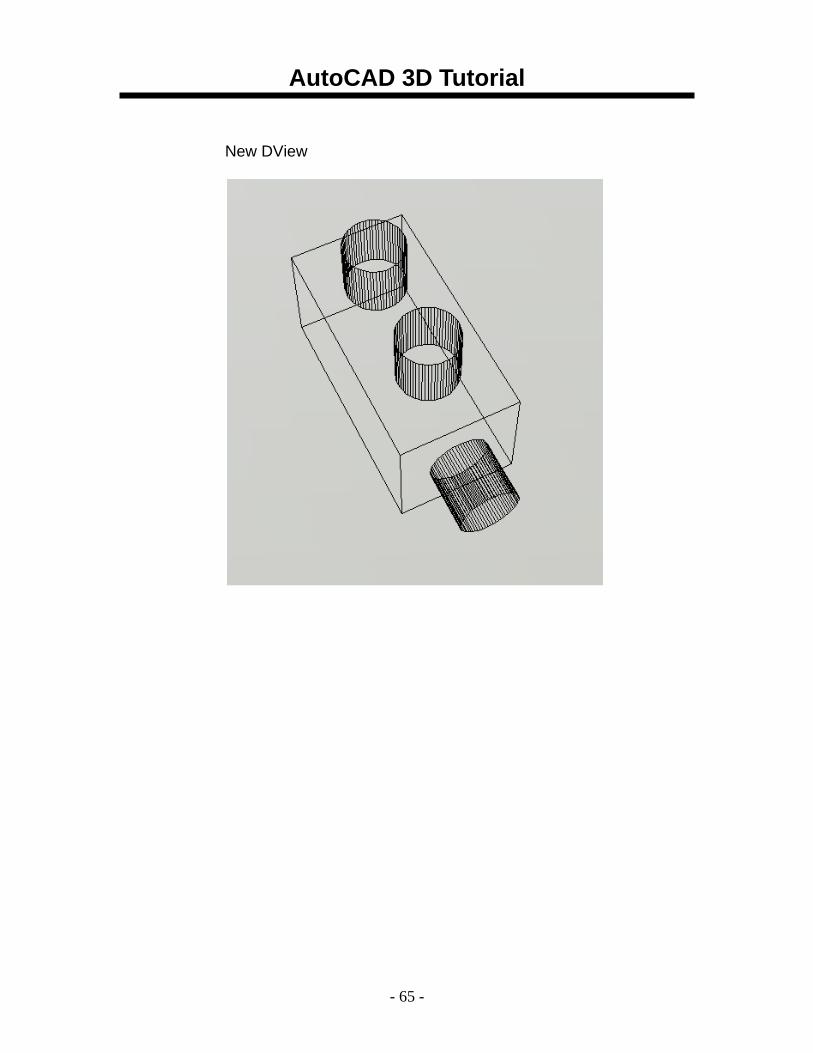
New DView
AutoCAD 3D Tutorial
- 66 -
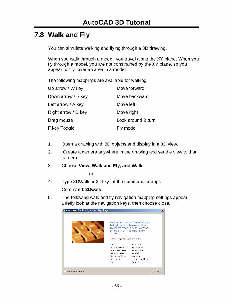
7.8 Walk and Fly
You can simulate walking and flying through a 3D drawing.
When you walk through a model, you travel along the XY plane. When you fly through a model, you are not constrained by the XY plane, so you appear to “fly” over an area in a model.
The following mappings are available for walking:
Up arrow / W key Move forward
Down arrow / S key Move backward
Left arrow / A key Move left
Right arrow / D key Move right
Drag mouse Look around & turn
F key Toggle Fly mode
1. Open a drawing with 3D objects and display in a 3D view.
2. Create a camera anywhere in the drawing and set the view to that camera.
3. Choose View, Walk and Fly, and Walk.
or
4. Type 3DWalk or 3DFky at the command prompt.
Command: 3Dwalk
5. The following walk and fly navigation mapping settings appear. Briefly look at the navigation keys, then choose close.
AutoCAD 3D Tutorial
- 67 -
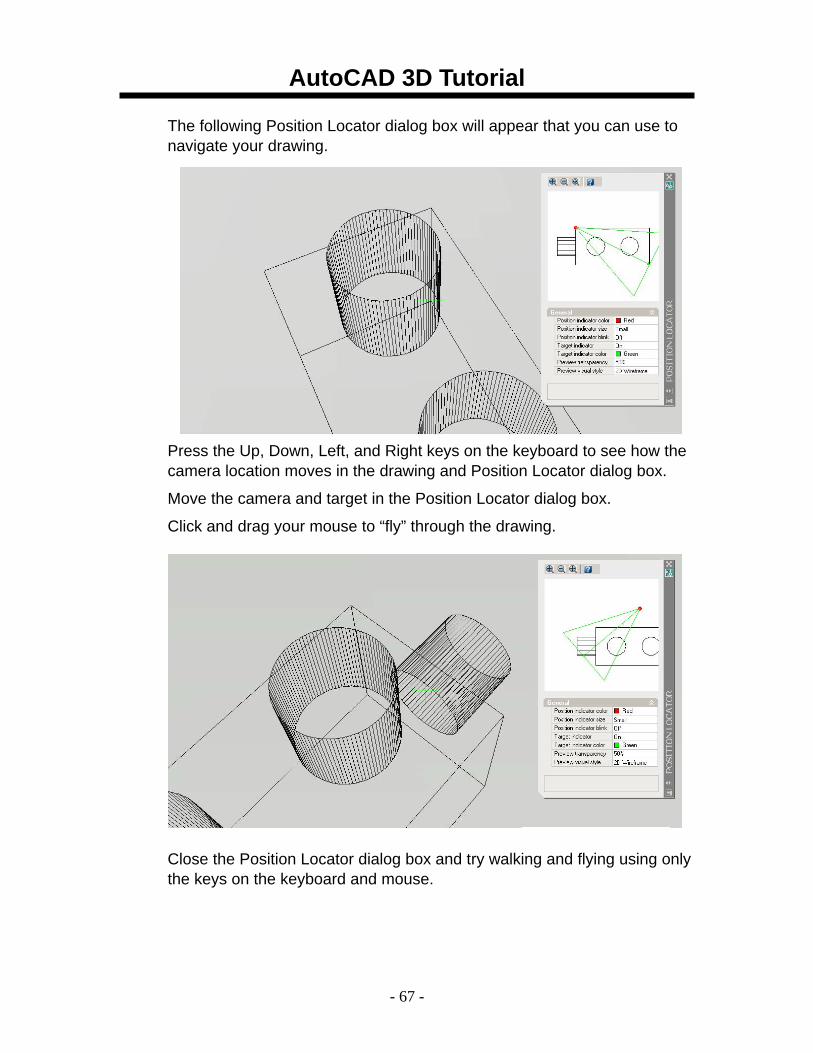
The following Position Locator dialog box will appear that you can use to navigate your drawing.
Press the Up, Down, Left, and Right keys on the keyboard to see how the camera location moves in the drawing and Position Locator dialog box.
Move the camera and target in the Position Locator dialog box.
Click and drag your mouse to “fly” through the drawing.
Close the Position Locator dialog box and try walking and flying using only the keys on the keyboard and mouse.
AutoCAD 3D Tutorial
- 68 -
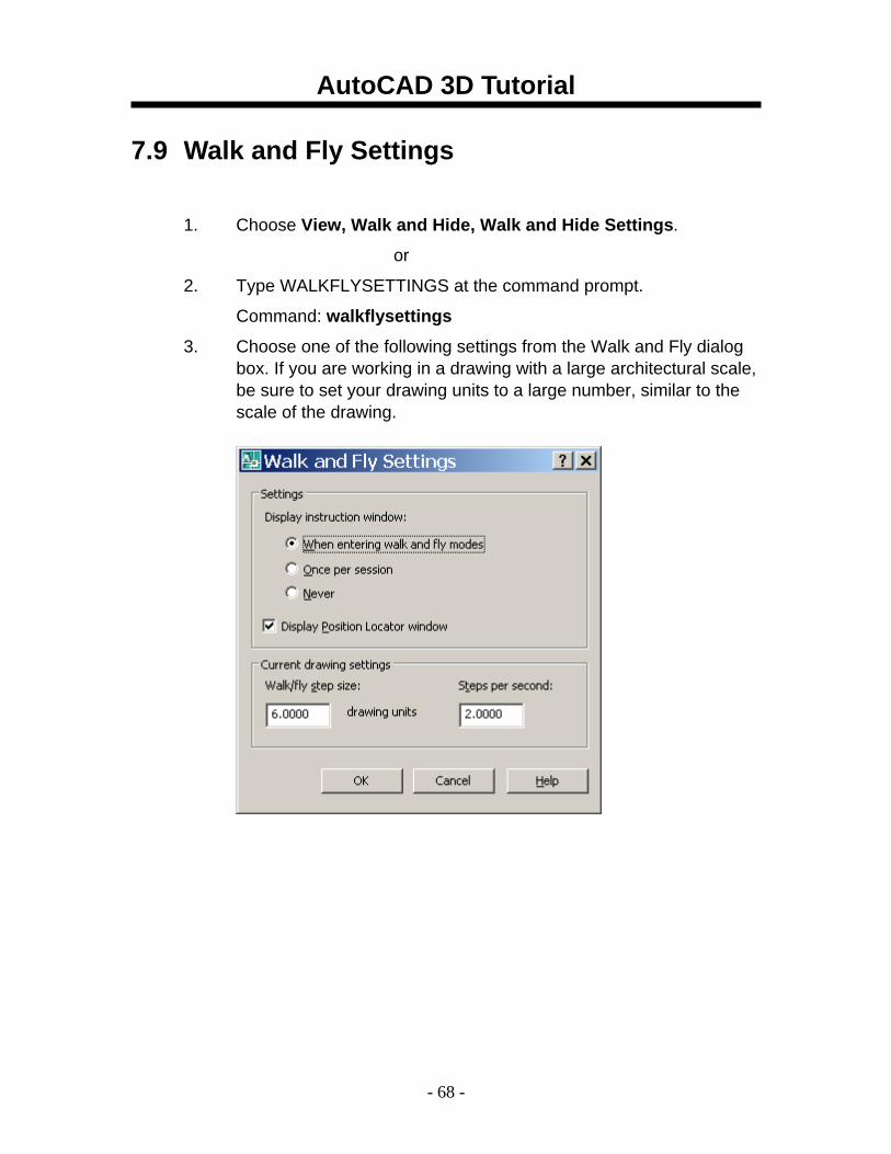
7.9 Walk and Fly Settings
1. Choose View, Walk and Hide, Walk and Hide Settings.
or
2. Type WALKFLYSETTINGS at the command prompt.
Command: walkflysettings
3. Choose one of the following settings from the Walk and Fly dialog box. If you are working in a drawing with a large architectural scale, be sure to set your drawing units to a large number, similar to the scale of the drawing.
AutoCAD 3D Tutorial
- 69 -
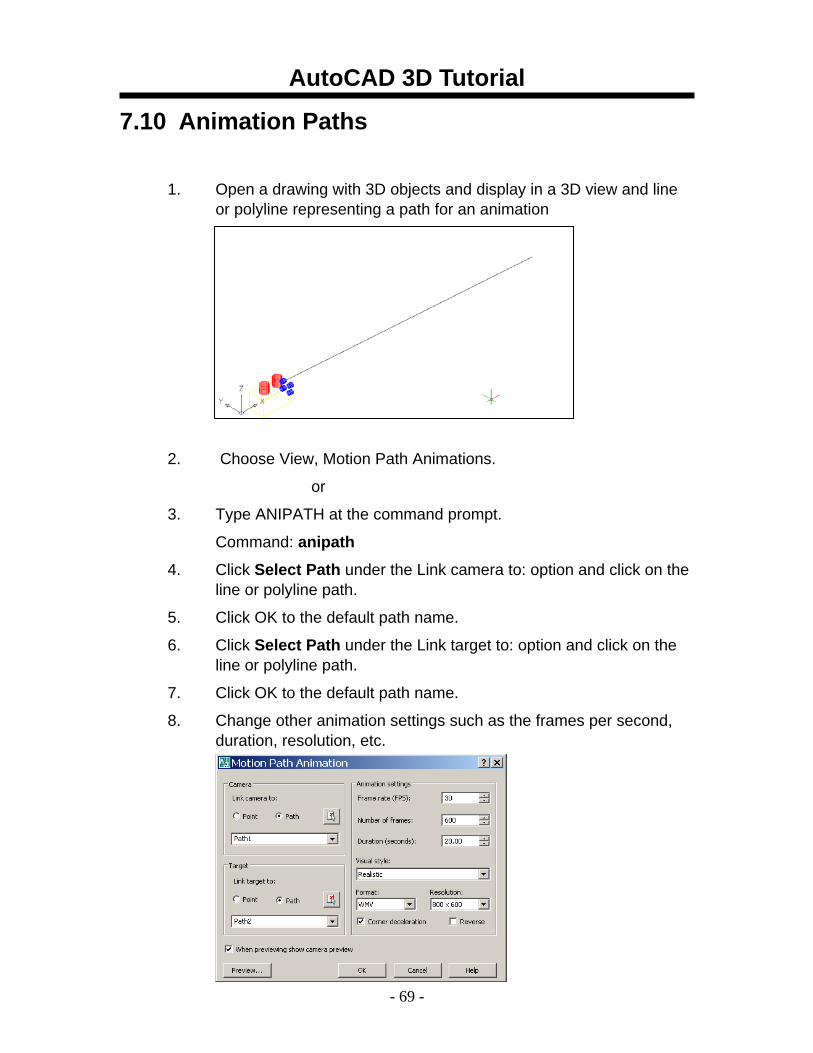
7.10 Animation Paths
1. Open a drawing with 3D objects and display in a 3D view and line or polyline representing a path for an animation
2. Choose View, Motion Path Animations.
or
3. Type ANIPATH at the command prompt.
Command: anipath
4. Click Select Path under the Link camera to: option and click on the line or polyline path.
5. Click OK to the default path name.
6. Click Select Path under the Link target to: option and click on the line or polyline path.
7. Click OK to the default path name.
8. Change other animation settings such as the frames per second, duration, resolution, etc.
AutoCAD 3D Tutorial
- 70 -
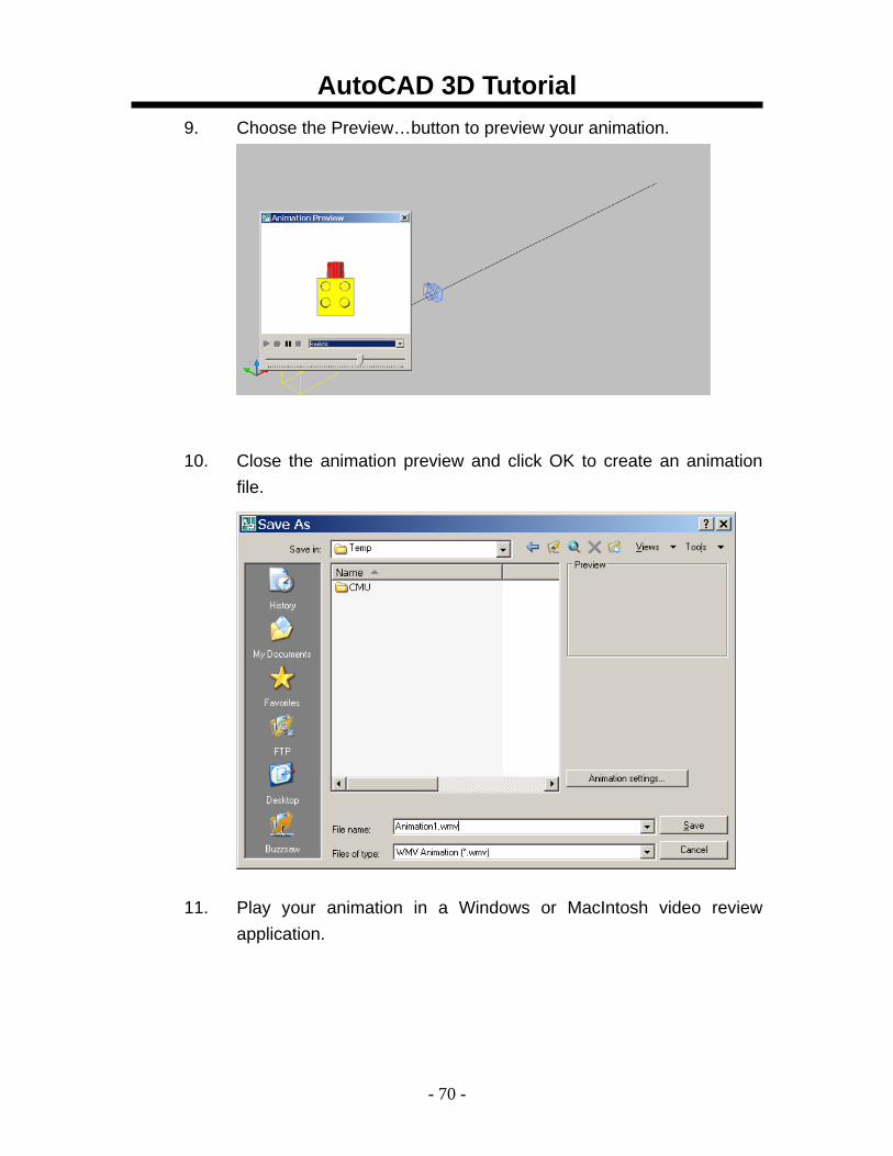
9. Choose the Preview…button to preview your animation.
10. Close the animation preview and click OK to create an animation file.
11. Play your animation in a Windows or MacIntosh video review application.
AutoCAD 3D Tutorial
- 71 -
7.11 3D Navigation Using the Dashboard Regenerates a three-dimensional model with hidden lines
1. Choose Tools, Palettes, Dashboard.
or
2. Type DASHBOARD at the command prompt.
Command: dashboard
AutoCAD 3D Tutorial
- 72 -
AutoCAD 3D – Chapter 8 3D Model Objects
AutoCAD 3D Tutorial
- 73 -
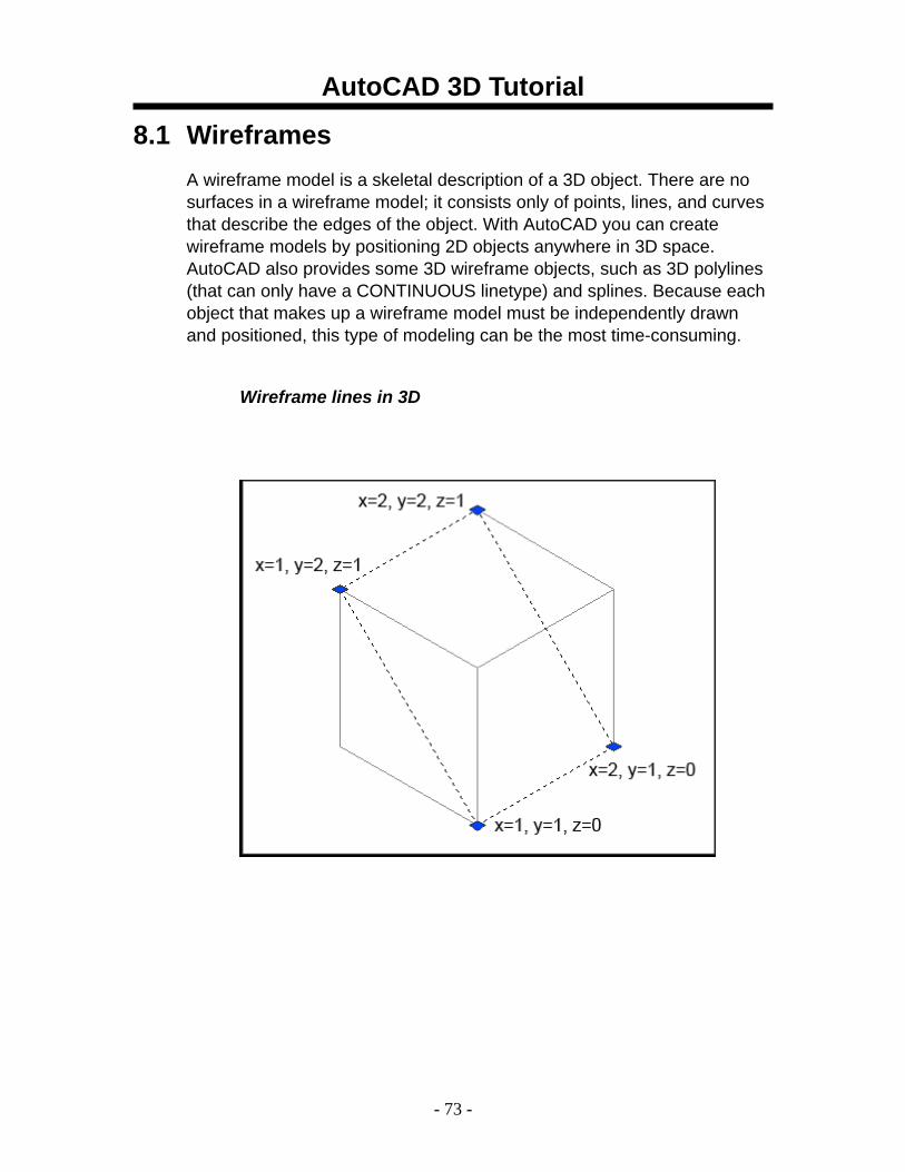
8.1 Wireframes A wireframe model is a skeletal description of a 3D object. There are no surfaces in a wireframe model; it consists only of points, lines, and curves that describe the edges of the object. With AutoCAD you can create wireframe models by positioning 2D objects anywhere in 3D space. AutoCAD also provides some 3D wireframe objects, such as 3D polylines (that can only have a CONTINUOUS linetype) and splines. Because each object that makes up a wireframe model must be independently drawn and positioned, this type of modeling can be the most time-consuming.
Wireframe lines in 3D
AutoCAD 3D Tutorial
- 74 -
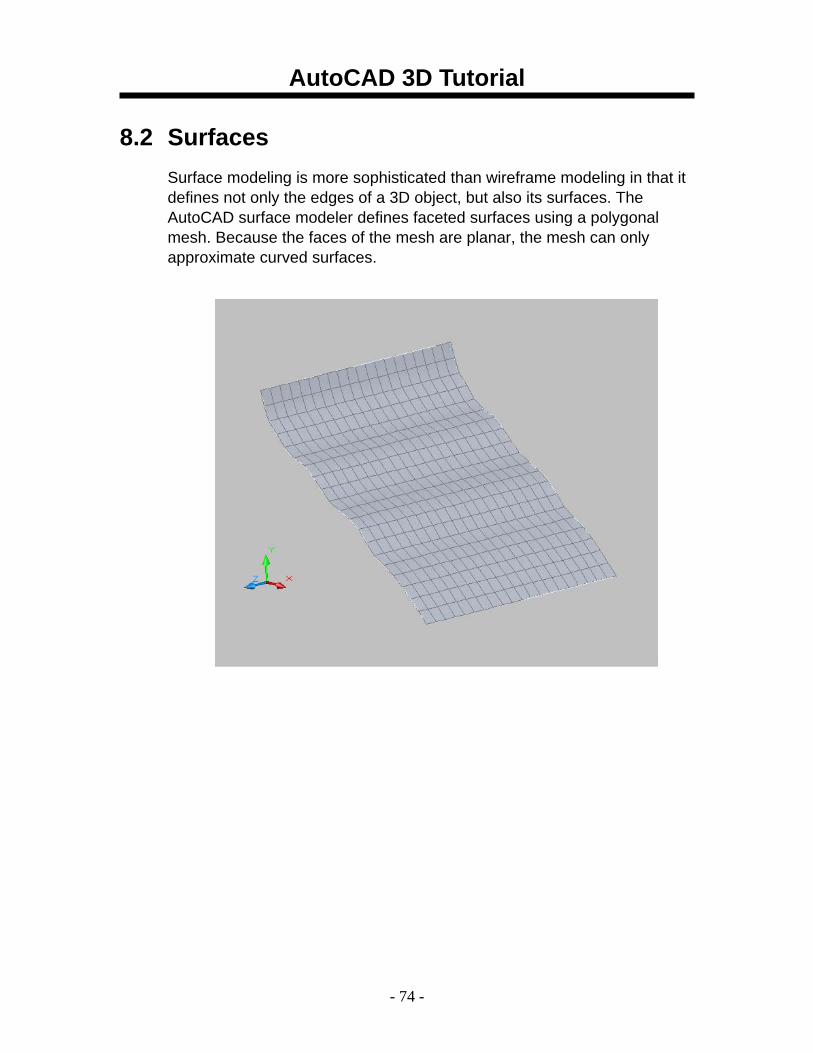
8.2 Surfaces Surface modeling is more sophisticated than wireframe modeling in that it defines not only the edges of a 3D object, but also its surfaces. The AutoCAD surface modeler defines faceted surfaces using a polygonal mesh. Because the faces of the mesh are planar, the mesh can only approximate curved surfaces.
AutoCAD 3D Tutorial
- 75 -
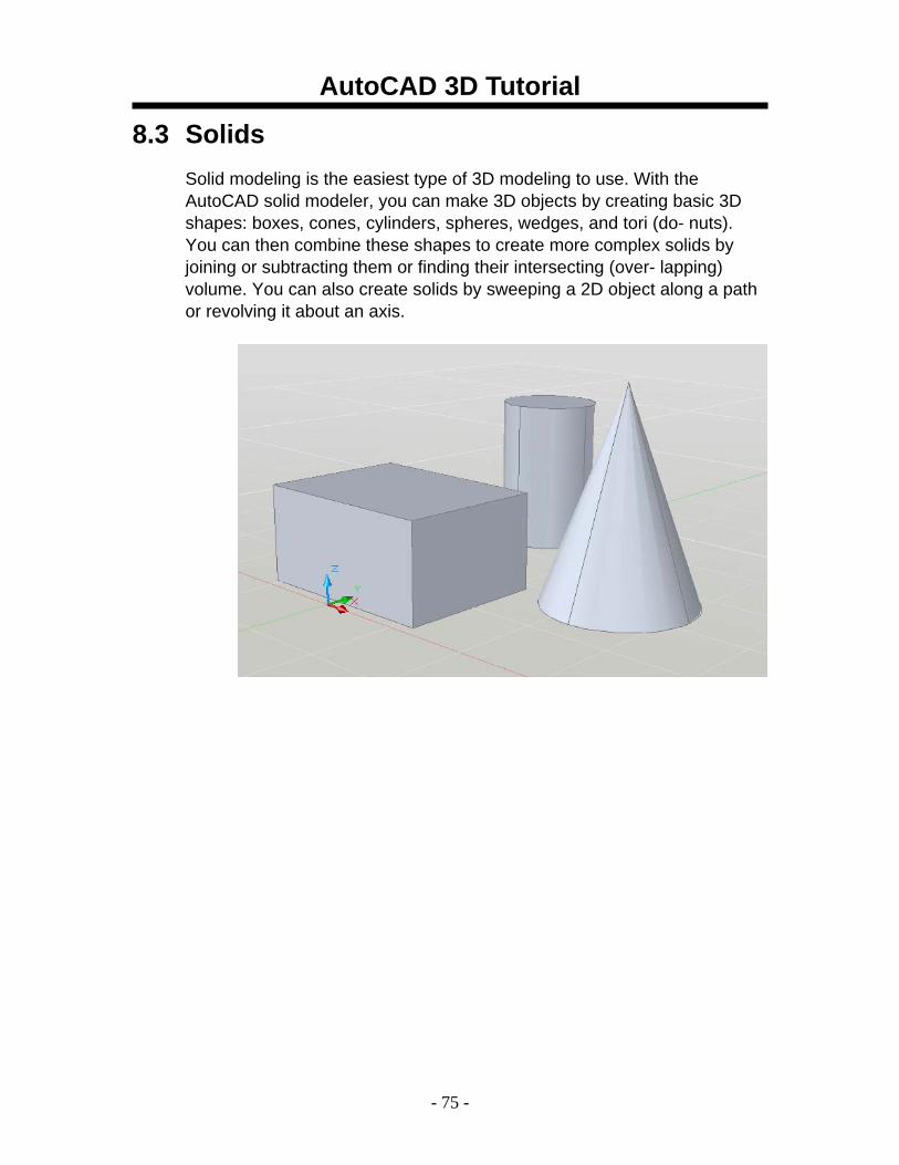
8.3 Solids Solid modeling is the easiest type of 3D modeling to use. With the AutoCAD solid modeler, you can make 3D objects by creating basic 3D shapes: boxes, cones, cylinders, spheres, wedges, and tori (do- nuts). You can then combine these shapes to create more complex solids by joining or subtracting them or finding their intersecting (over- lapping) volume. You can also create solids by sweeping a 2D object along a path or revolving it about an axis.
AutoCAD 3D Tutorial
- 76 -
AutoCAD 3D – Chapter 9 2D Solids and 3D Faces
AutoCAD 3D Tutorial
- 77 -
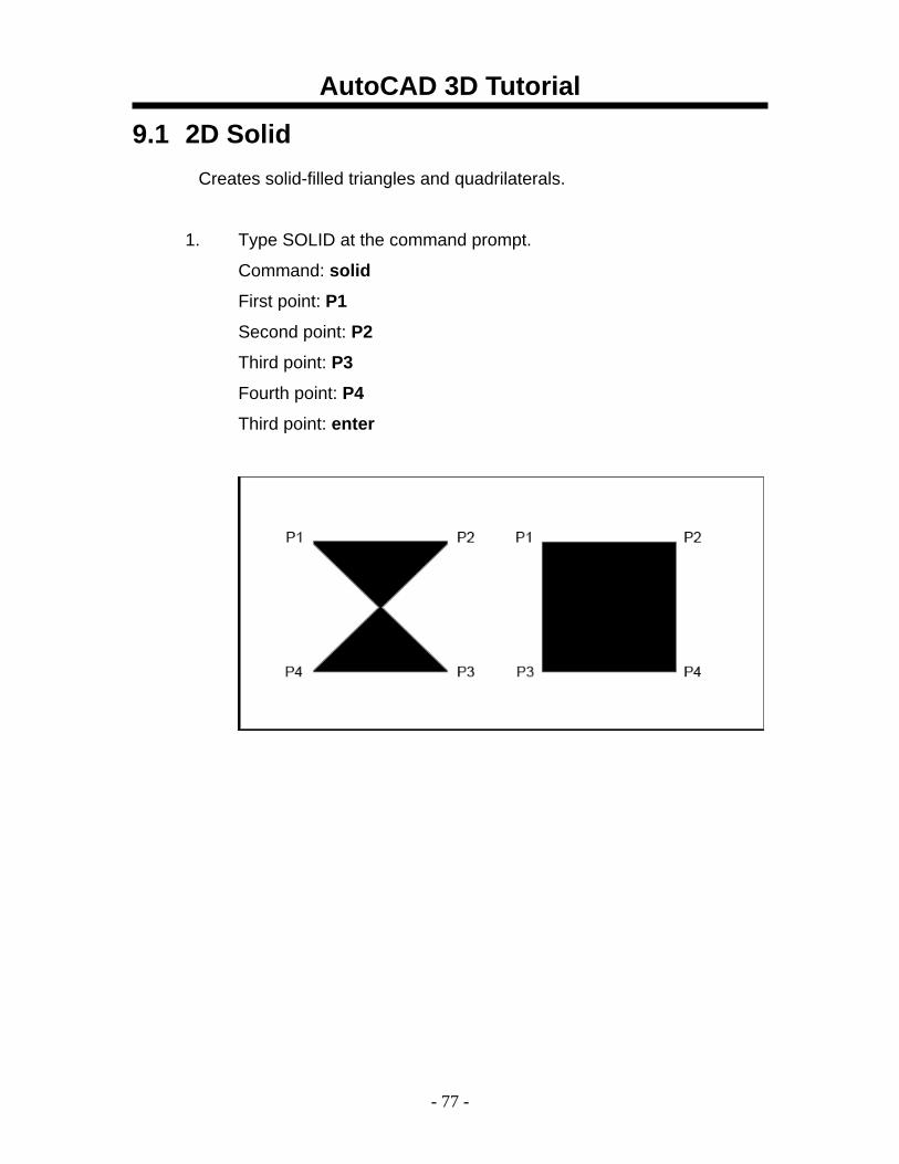
9.1 2D Solid Creates solid-filled triangles and quadrilaterals.
1. Type SOLID at the command prompt.
Command: solid
First point: P1
Second point: P2
Third point: P3
Fourth point: P4
Third point: enter
AutoCAD 3D Tutorial
- 78 -
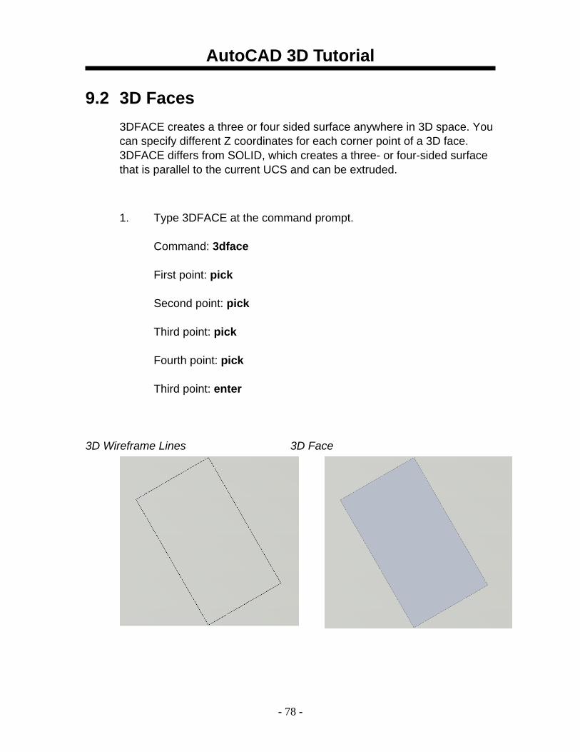
9.2 3D Faces 3DFACE creates a three or four sided surface anywhere in 3D space. You can specify different Z coordinates for each corner point of a 3D face. 3DFACE differs from SOLID, which creates a three- or four-sided surface that is parallel to the current UCS and can be extruded.
1. Type 3DFACE at the command prompt.
Command: 3dface
First point: pick
Second point: pick
Third point: pick
Fourth point: pick
Third point: enter
3D Wireframe Lines 3D Face
AutoCAD 3D Tutorial
- 79 -
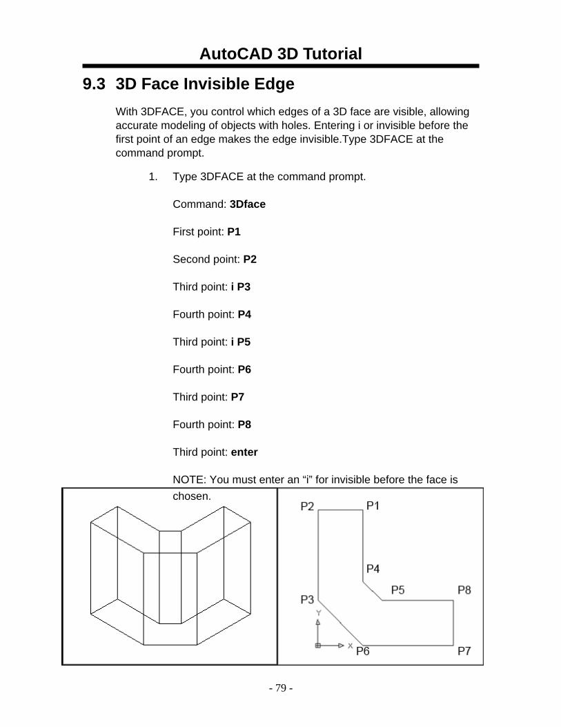
9.3 3D Face Invisible Edge With 3DFACE, you control which edges of a 3D face are visible, allowing accurate modeling of objects with holes. Entering i or invisible before the first point of an edge makes the edge invisible.Type 3DFACE at the command prompt.
1. Type 3DFACE at the command prompt.
Command: 3Dface
First point: P1
Second point: P2
Third point: i P3
Fourth point: P4
Third point: i P5
Fourth point: P6
Third point: P7
Fourth point: P8
Third point: enter
NOTE: You must enter an “i” for invisible before the face is chosen.
AutoCAD 3D Tutorial
- 80 -
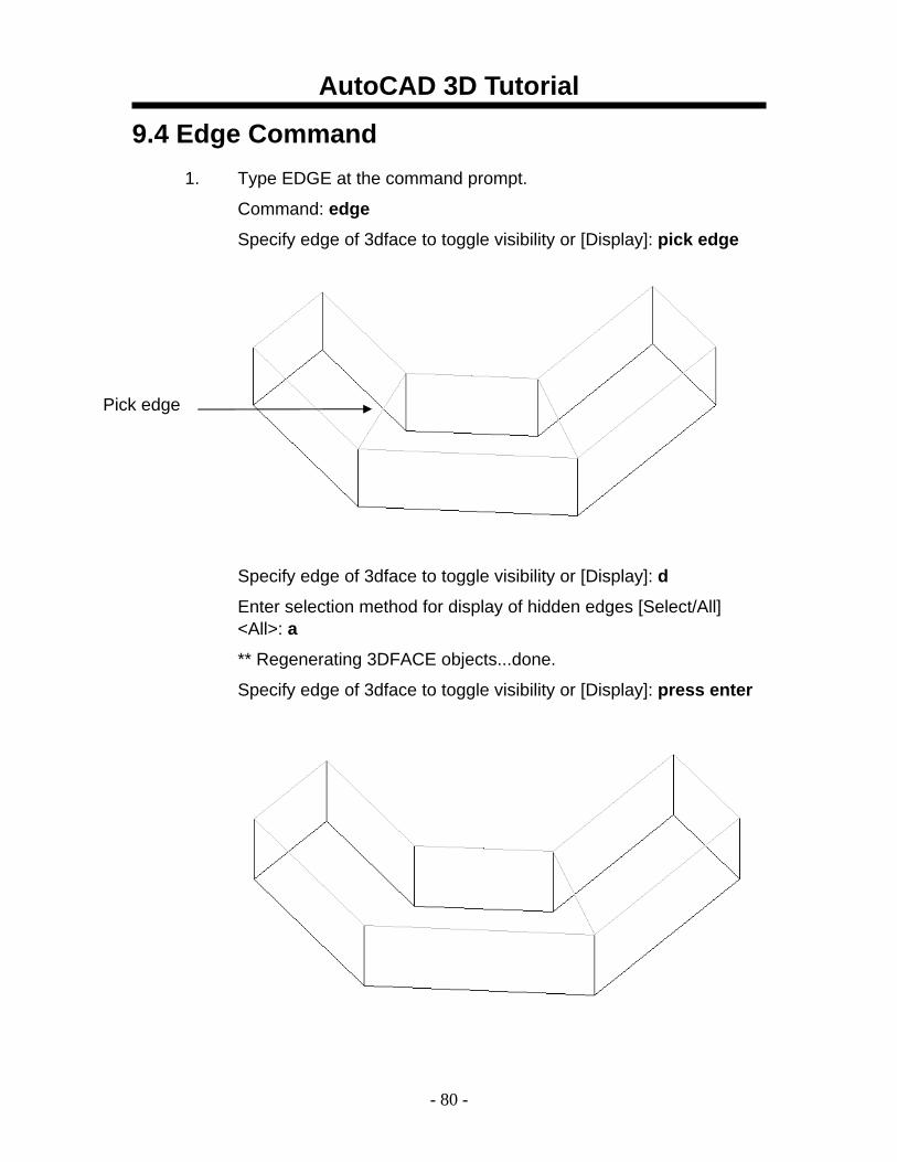
9.4 Edge Command 1. Type EDGE at the command prompt.
Command: edge
Specify edge of 3dface to toggle visibility or [Display]: pick edge
Specify edge of 3dface to toggle visibility or [Display]: d
Enter selection method for display of hidden edges [Select/All] <All>: a
** Regenerating 3DFACE objects...done.
Specify edge of 3dface to toggle visibility or [Display]: press enter
Pick edge
AutoCAD 3D Tutorial
- 81 -
9.5 PFace Creates a three-dimensional polyface mesh vertex by vertex
1. Type PFACE at the command prompt.
Command: pface
Specify location for vertex 1: pick point 1
Specify location for vertex 2 or <define faces>: pick point 2
Specify location for vertex 3 or <define faces>: pick point 3
Specify location for vertex 4 or <define faces>: pick point 4
Specify location for vertex 5 or <define faces>: pick point 5
Specify location for vertex 6 or <define faces>: pick point 6
Specify location for vertex 7 or <define faces>: pick point 7
Specify location for vertex 8 or <define faces>: enter
Face 1, vertex 1:
Enter a vertex number or [Color/Layer]: type 1
Face 1, vertex 2:
Enter a vertex number or [Color/Layer] <next face>: type 2
Face 1, vertex 3:
Enter a vertex number or [Color/Layer] <next face>: type 6
Face 1, vertex 4:
Enter a vertex number or [Color/Layer] <next face>: type 7
Face 1, vertex 5: enter
Enter a vertex number or [Color/Layer] <next face>:
Face 2, vertex 1:
Enter a vertex number or [Color/Layer]: type 2
Face 2, vertex 2:
Enter a vertex number or [Color/Layer] <next face>: type 3
Face 2, vertex 3:
Enter a vertex number or [Color/Layer] <next face>: type 4
Face 2, vertex 4:
AutoCAD 3D Tutorial
- 82 -
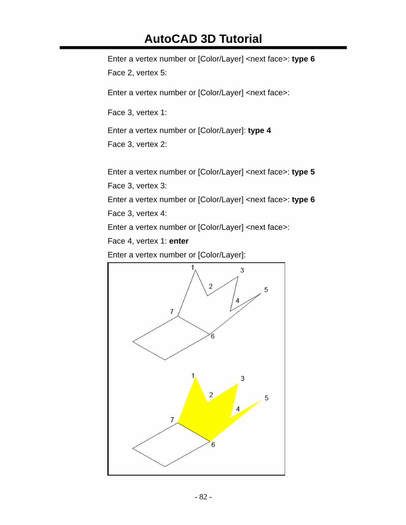
Enter a vertex number or [Color/Layer] <next face>: type 6
Face 2, vertex 5:
Enter a vertex number or [Color/Layer] <next face>:
Face 3, vertex 1:
Enter a vertex number or [Color/Layer]: type 4
Face 3, vertex 2:
Enter a vertex number or [Color/Layer] <next face>: type 5
Face 3, vertex 3:
Enter a vertex number or [Color/Layer] <next face>: type 6
Face 3, vertex 4:
Enter a vertex number or [Color/Layer] <next face>:
Face 4, vertex 1: enter
Enter a vertex number or [Color/Layer]:
AutoCAD 3D Tutorial
- 83 -
AutoCAD 3D – Chapter 10 Basic 3D Surfaces
AutoCAD 3D Tutorial
- 84 -
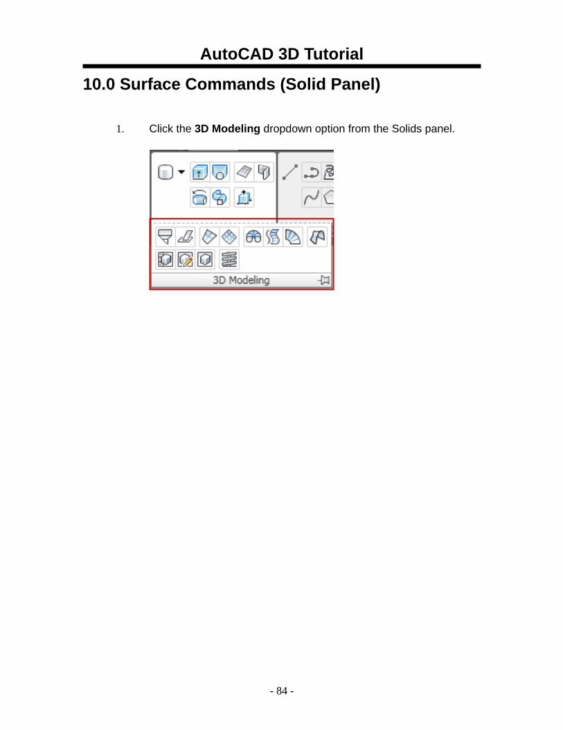
10.0 Surface Commands (Solid Panel) 1. Click the 3D Modeling dropdown option from the Solids panel.
AutoCAD 3D Tutorial
- 85 -
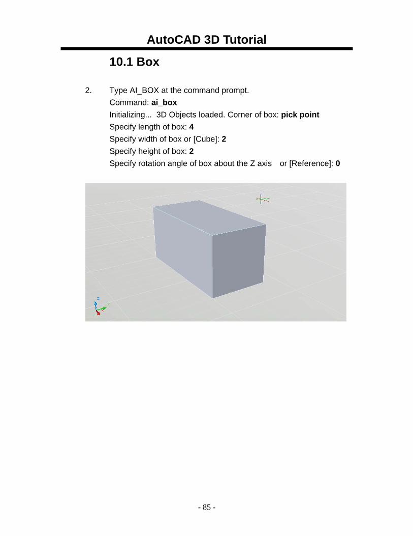
10.1 Box 2. Type AI_BOX at the command prompt.
Command: ai_box Initializing... 3D Objects loaded. Corner of box: pick point Specify length of box: 4 Specify width of box or [Cube]: 2 Specify height of box: 2 Specify rotation angle of box about the Z axis or [Reference]: 0
AutoCAD 3D Tutorial
- 86 -
10.2 Pyramid
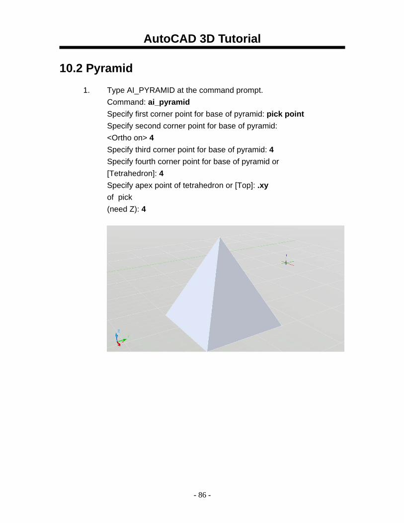
1. Type AI_PYRAMID at the command prompt. Command: ai_pyramid Specify first corner point for base of pyramid: pick point Specify second corner point for base of pyramid: <Ortho on> 4 Specify third corner point for base of pyramid: 4 Specify fourth corner point for base of pyramid or [Tetrahedron]: 4 Specify apex point of tetrahedron or [Top]: .xy of pick (need Z): 4
AutoCAD 3D Tutorial
- 87 -
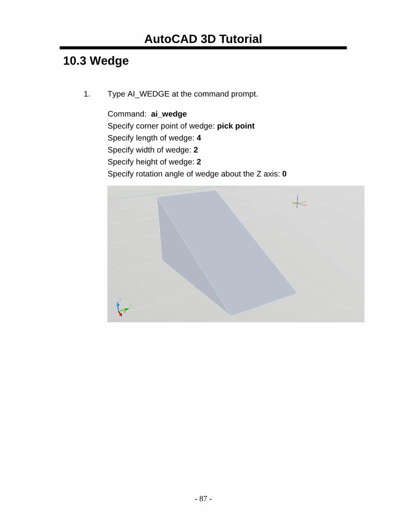
10.3 Wedge
1. Type AI_WEDGE at the command prompt.
Command: ai_wedge Specify corner point of wedge: pick point Specify length of wedge: 4 Specify width of wedge: 2 Specify height of wedge: 2 Specify rotation angle of wedge about the Z axis: 0
AutoCAD 3D Tutorial
- 88 -
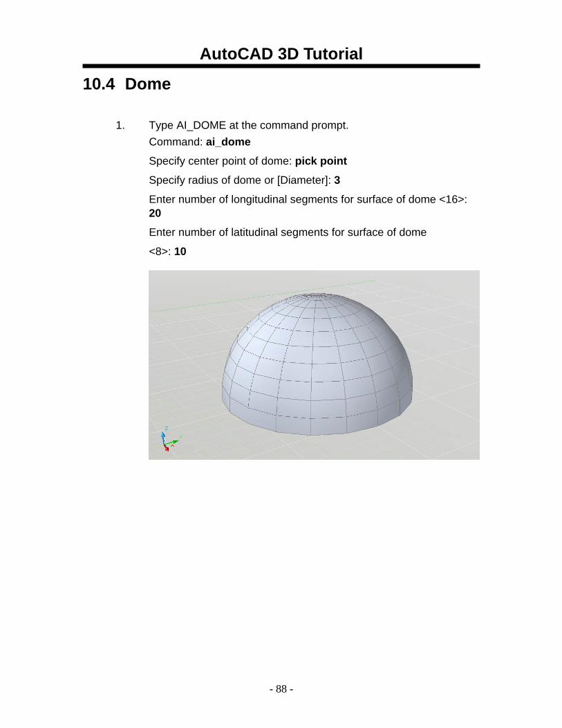
10.4 Dome
1. Type AI_DOME at the command prompt. Command: ai_dome
Specify center point of dome: pick point
Specify radius of dome or [Diameter]: 3
Enter number of longitudinal segments for surface of dome <16>: 20
Enter number of latitudinal segments for surface of dome
<8>: 10
AutoCAD 3D Tutorial
- 89 -
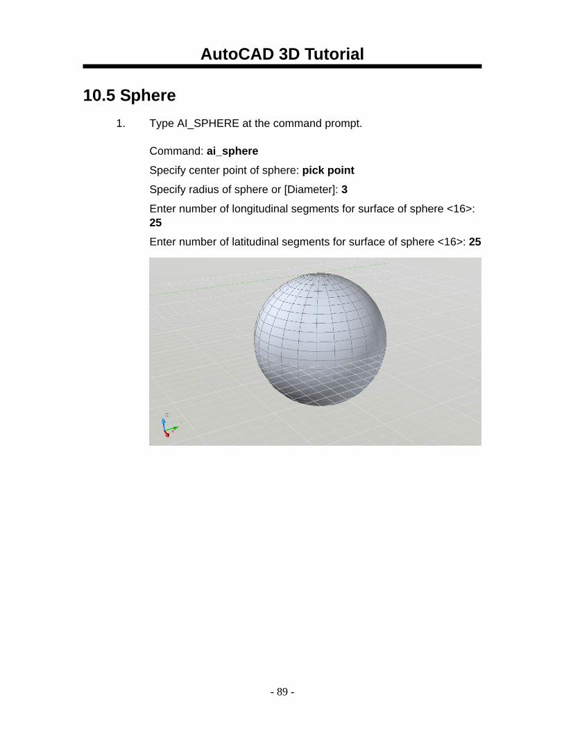
10.5 Sphere 1. Type AI_SPHERE at the command prompt.
Command: ai_sphere
Specify center point of sphere: pick point
Specify radius of sphere or [Diameter]: 3
Enter number of longitudinal segments for surface of sphere <16>: 25
Enter number of latitudinal segments for surface of sphere <16>: 25
AutoCAD 3D Tutorial
- 90 -
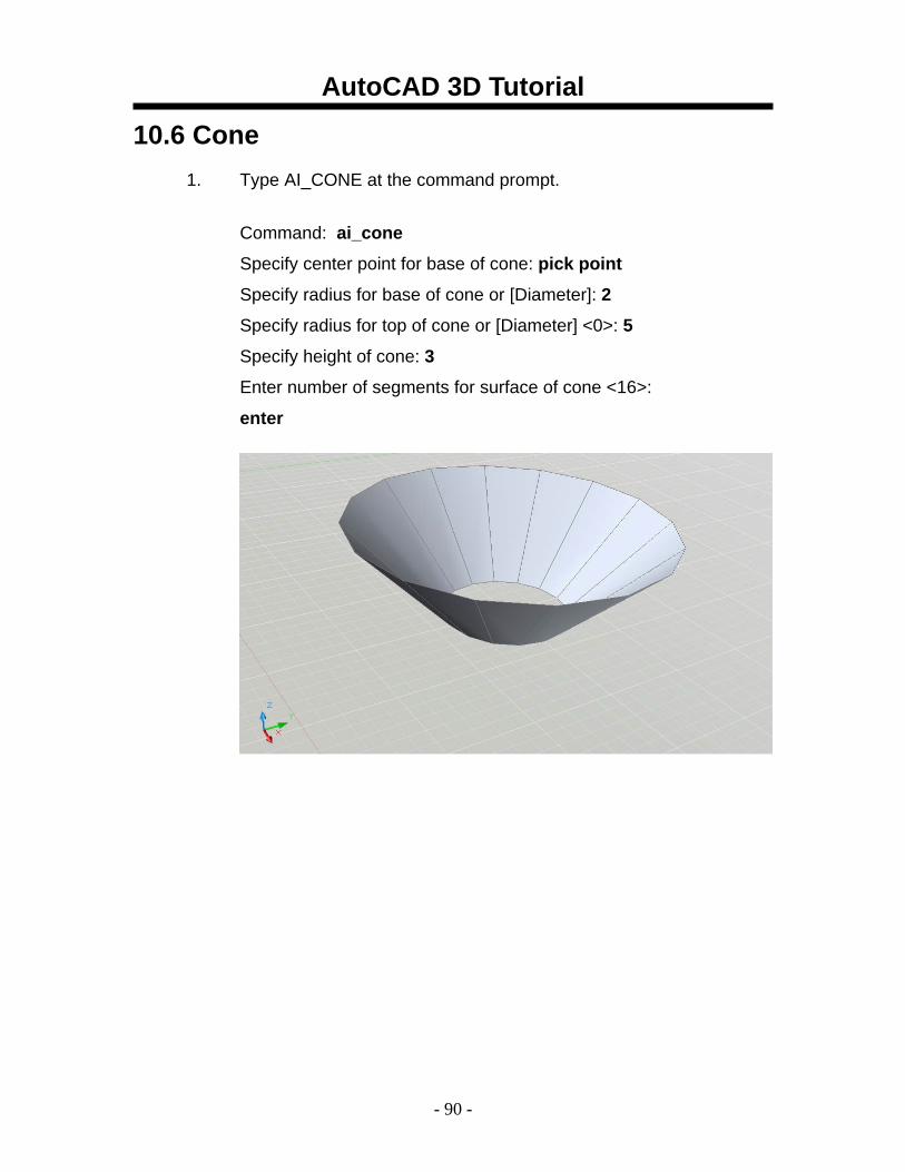
10.6 Cone 1. Type AI_CONE at the command prompt.
Command: ai_cone
Specify center point for base of cone: pick point
Specify radius for base of cone or [Diameter]: 2
Specify radius for top of cone or [Diameter] <0>: 5
Specify height of cone: 3
Enter number of segments for surface of cone <16>:
enter
AutoCAD 3D Tutorial
- 91 -
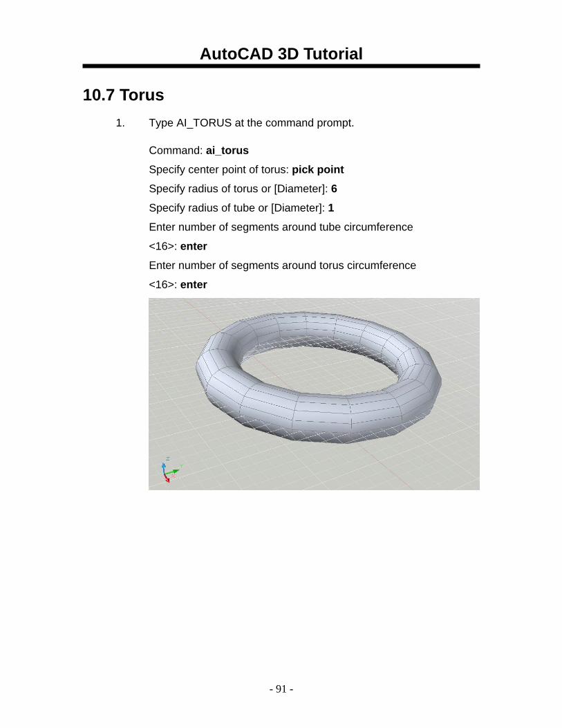
10.7 Torus 1. Type AI_TORUS at the command prompt.
Command: ai_torus
Specify center point of torus: pick point
Specify radius of torus or [Diameter]: 6
Specify radius of tube or [Diameter]: 1
Enter number of segments around tube circumference
<16>: enter
Enter number of segments around torus circumference
<16>: enter
AutoCAD 3D Tutorial
- 92 -
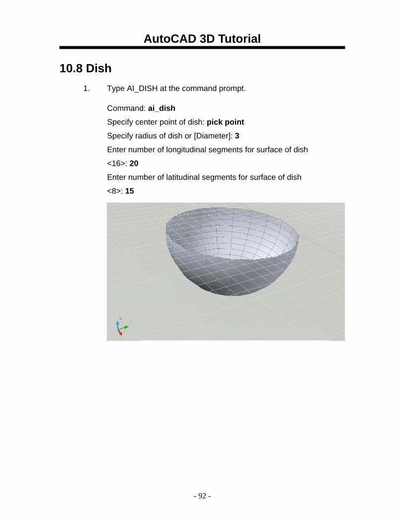
10.8 Dish 1. Type AI_DISH at the command prompt.
Command: ai_dish
Specify center point of dish: pick point
Specify radius of dish or [Diameter]: 3
Enter number of longitudinal segments for surface of dish
<16>: 20
Enter number of latitudinal segments for surface of dish
<8>: 15
AutoCAD 3D Tutorial
- 93 -
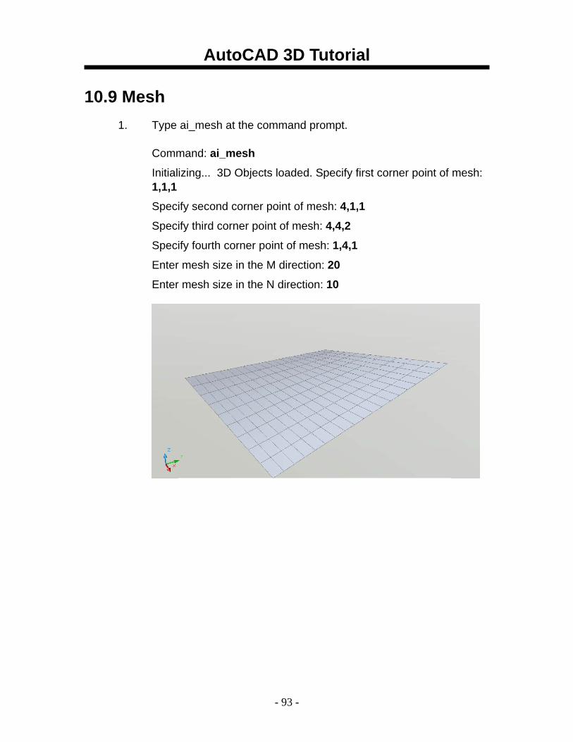
10.9 Mesh 1. Type ai_mesh at the command prompt.
Command: ai_mesh
Initializing... 3D Objects loaded. Specify first corner point of mesh: 1,1,1
Specify second corner point of mesh: 4,1,1
Specify third corner point of mesh: 4,4,2
Specify fourth corner point of mesh: 1,4,1
Enter mesh size in the M direction: 20
Enter mesh size in the N direction: 10
AutoCAD 3D Tutorial
- 94 -
AutoCAD 3D – Chapter 11 Complex Surfaces
AutoCAD 3D Tutorial
- 95 -
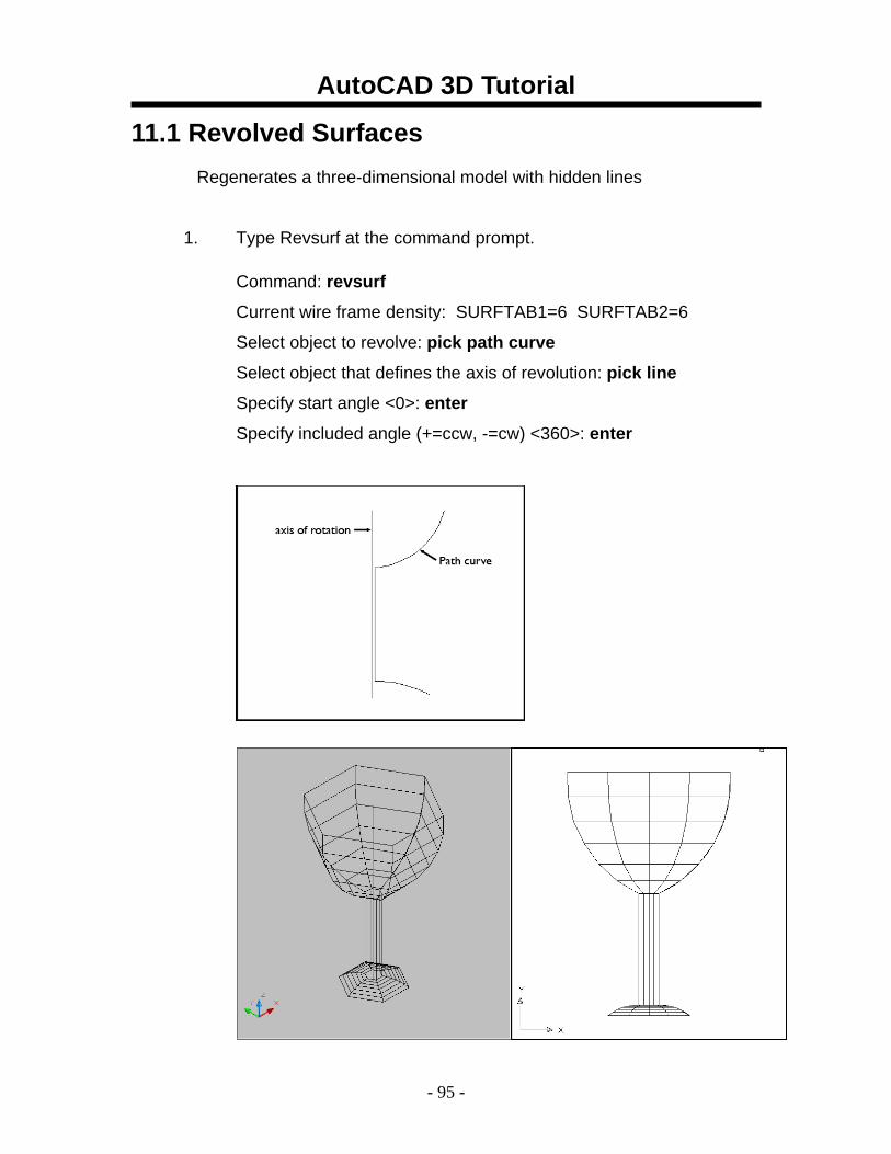
11.1 Revolved Surfaces Regenerates a three-dimensional model with hidden lines
1. Type Revsurf at the command prompt. Command: revsurf
Current wire frame density: SURFTAB1=6 SURFTAB2=6
Select object to revolve: pick path curve
Select object that defines the axis of revolution: pick line
Specify start angle <0>: enter
Specify included angle (+=ccw, -=cw) <360>: enter
AutoCAD 3D Tutorial
- 96 -
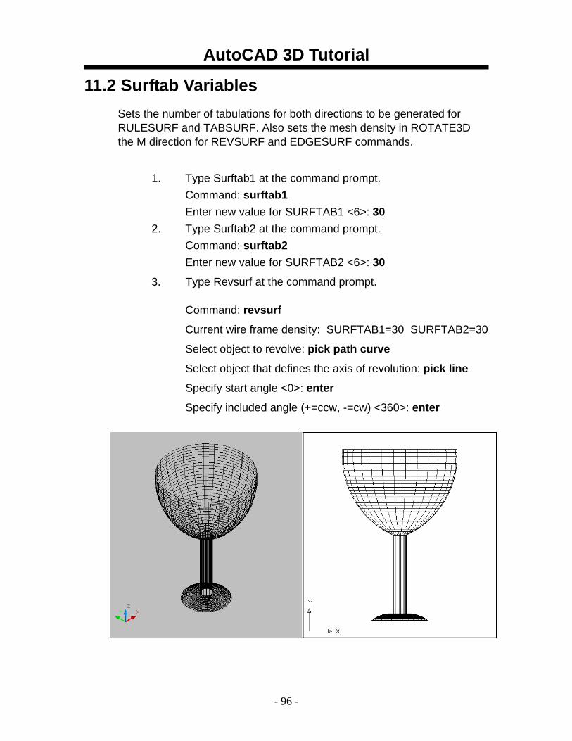
11.2 Surftab Variables Sets the number of tabulations for both directions to be generated for RULESURF and TABSURF. Also sets the mesh density in ROTATE3D the M direction for REVSURF and EDGESURF commands.
1. Type Surftab1 at the command prompt.
Command: surftab1 Enter new value for SURFTAB1 <6>: 30
2. Type Surftab2 at the command prompt. Command: surftab2 Enter new value for SURFTAB2 <6>: 30
3. Type Revsurf at the command prompt. Command: revsurf
Current wire frame density: SURFTAB1=30 SURFTAB2=30
Select object to revolve: pick path curve
Select object that defines the axis of revolution: pick line
Specify start angle <0>: enter
Specify included angle (+=ccw, -=cw) <360>: enter
AutoCAD 3D Tutorial
- 97 -
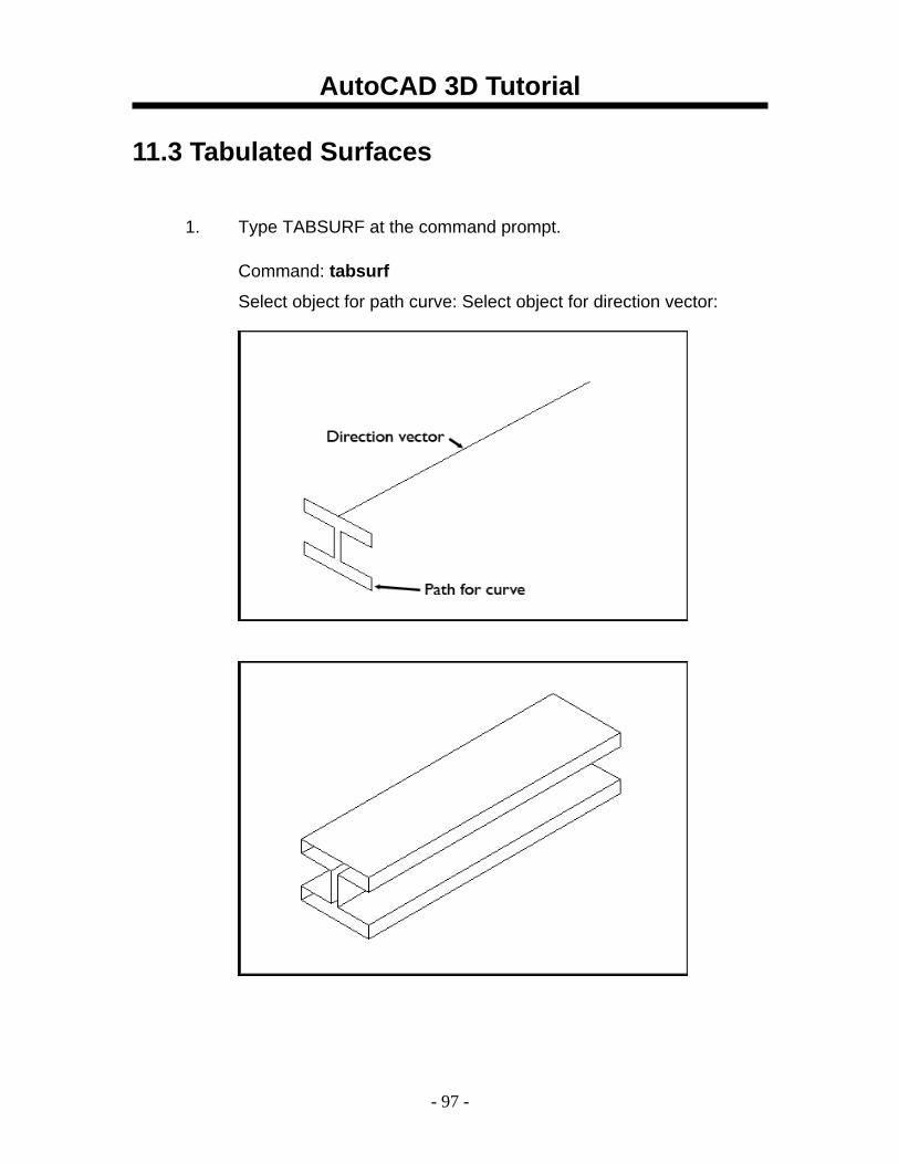
11.3 Tabulated Surfaces
1. Type TABSURF at the command prompt. Command: tabsurf
Select object for path curve: Select object for direction vector:
AutoCAD 3D Tutorial
- 98 -
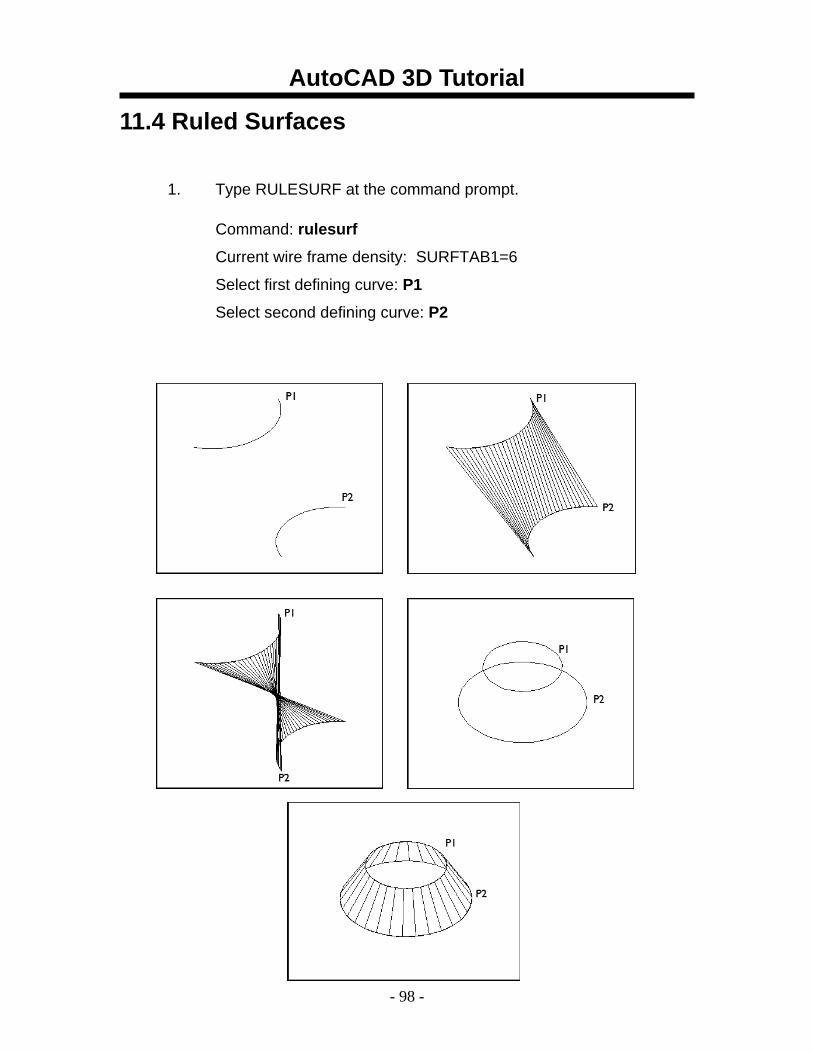
11.4 Ruled Surfaces
1. Type RULESURF at the command prompt. Command: rulesurf
Current wire frame density: SURFTAB1=6
Select first defining curve: P1
Select second defining curve: P2
AutoCAD 3D Tutorial
- 99 -
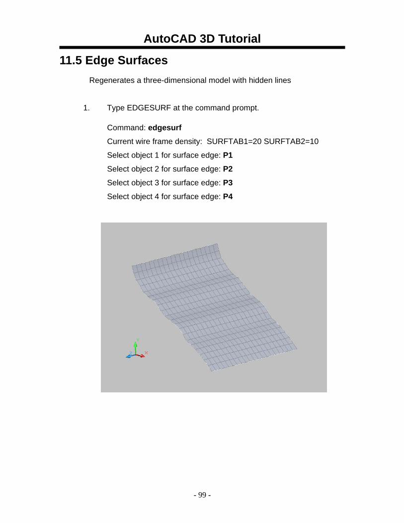
11.5 Edge Surfaces Regenerates a three-dimensional model with hidden lines
1. Type EDGESURF at the command prompt. Command: edgesurf
Current wire frame density: SURFTAB1=20 SURFTAB2=10
Select object 1 for surface edge: P1
Select object 2 for surface edge: P2
Select object 3 for surface edge: P3
Select object 4 for surface edge: P4
AutoCAD 3D Tutorial
- 100 -
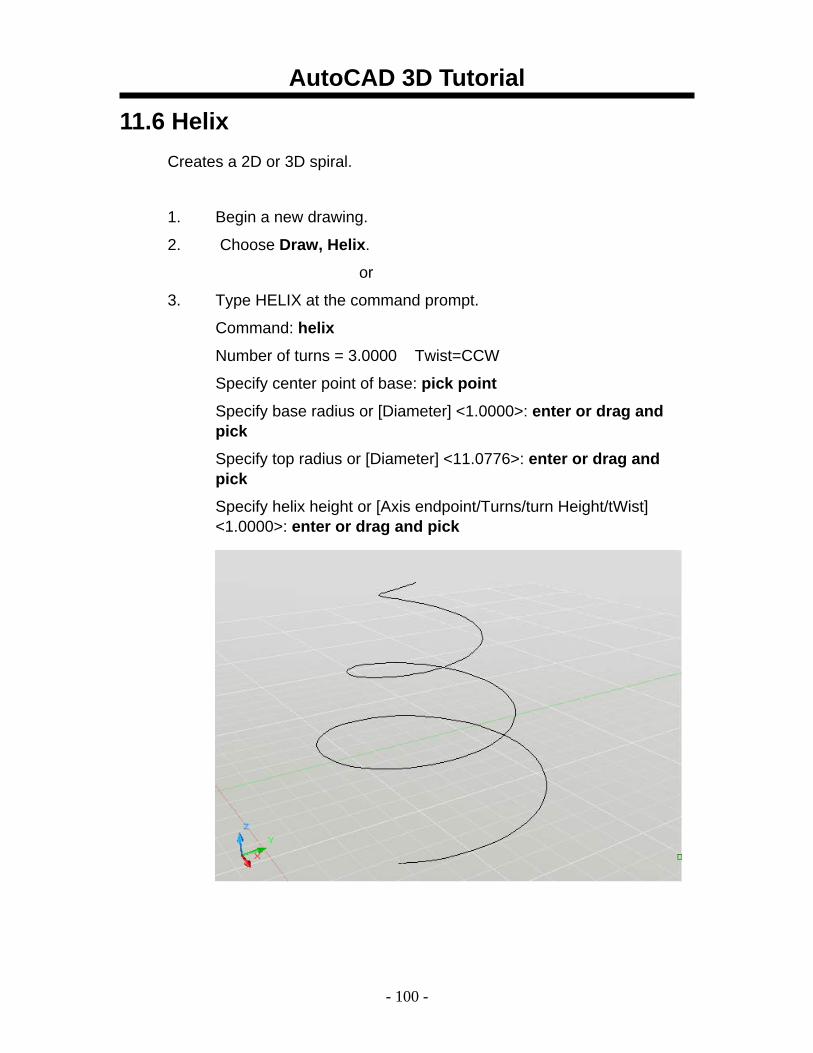
11.6 Helix Creates a 2D or 3D spiral.
1. Begin a new drawing.
2. Choose Draw, Helix.
or
3. Type HELIX at the command prompt.
Command: helix
Number of turns = 3.0000 Twist=CCW
Specify center point of base: pick point
Specify base radius or [Diameter] <1.0000>: enter or drag and pick
Specify top radius or [Diameter] <11.0776>: enter or drag and pick
Specify helix height or [Axis endpoint/Turns/turn Height/tWist] <1.0000>: enter or drag and pick
AutoCAD 3D Tutorial
- 101 -
AutoCAD 3D – Chapter 12 Creating Solids
AutoCAD 3D Tutorial
- 102 -
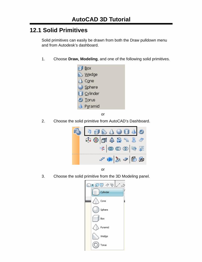
12.1 Solid Primitives Solid primitives can easily be drawn from both the Draw pulldown menu and from Autodesk’s dashboard.
1. Choose Draw, Modeling, and one of the following solid primitives.
or
2. Choose the solid primitive from AutoCAD’s Dashboard.
or
3. Choose the solid primitive from the 3D Modeling panel.
AutoCAD 3D Tutorial
- 103 -
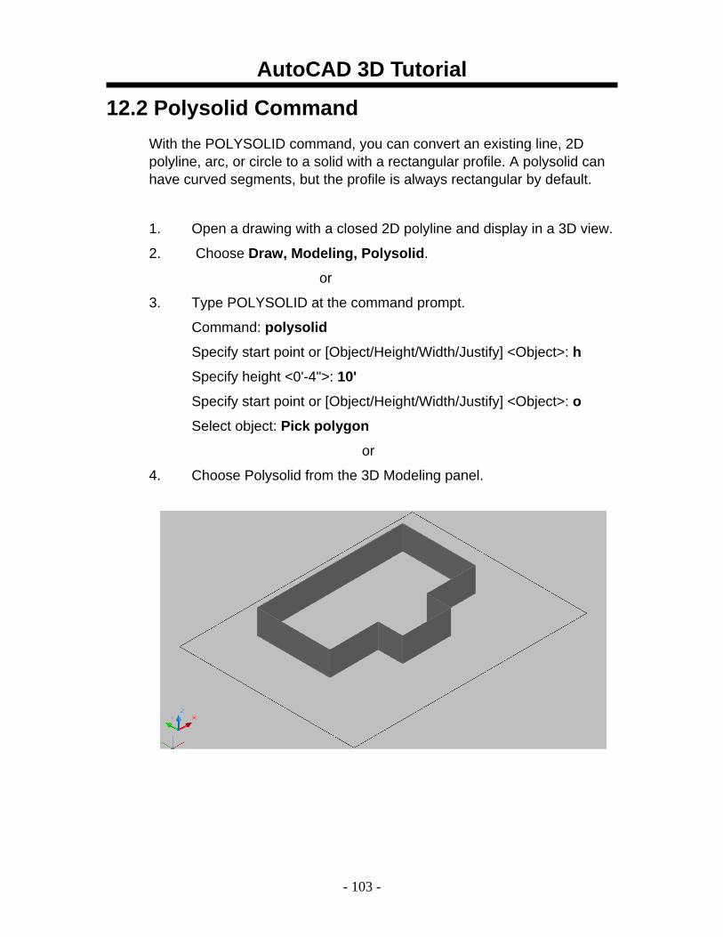
12.2 Polysolid Command With the POLYSOLID command, you can convert an existing line, 2D polyline, arc, or circle to a solid with a rectangular profile. A polysolid can have curved segments, but the profile is always rectangular by default.
1. Open a drawing with a closed 2D polyline and display in a 3D view.
2. Choose Draw, Modeling, Polysolid.
or
3. Type POLYSOLID at the command prompt.
Command: polysolid
Specify start point or [Object/Height/Width/Justify] <Object>: h
Specify height <0'-4">: 10'
Specify start point or [Object/Height/Width/Justify] <Object>: o
Select object: Pick polygon
or
4. Choose Polysolid from the 3D Modeling panel.
AutoCAD 3D Tutorial
- 104 -
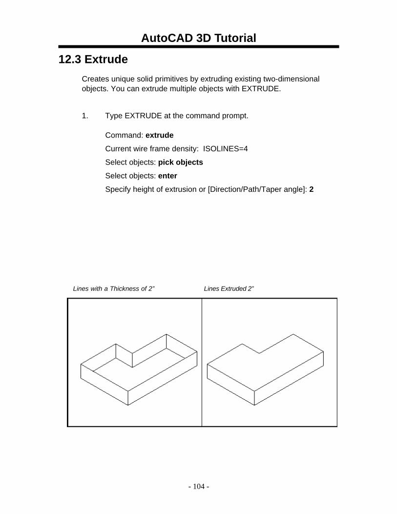
12.3 Extrude Creates unique solid primitives by extruding existing two-dimensional objects. You can extrude multiple objects with EXTRUDE.
1. Type EXTRUDE at the command prompt. Command: extrude
Current wire frame density: ISOLINES=4
Select objects: pick objects
Select objects: enter
Specify height of extrusion or [Direction/Path/Taper angle]: 2
Lines with a Thickness of 2” Lines Extruded 2”
AutoCAD 3D Tutorial
- 105 -
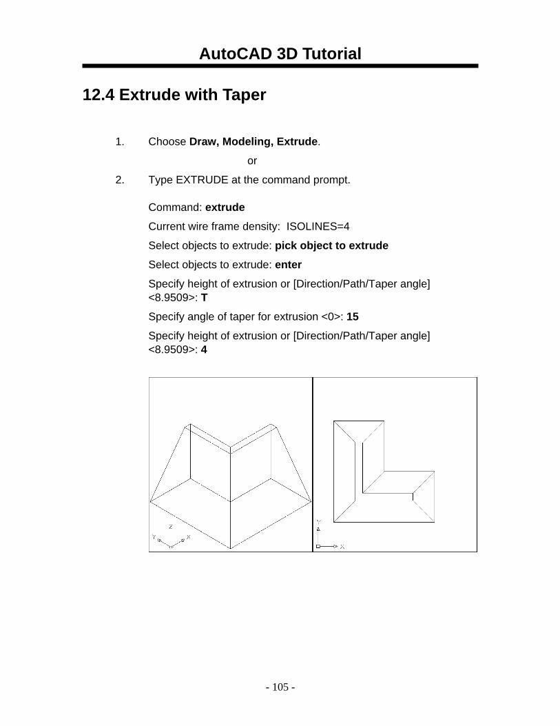
12.4 Extrude with Taper
1. Choose Draw, Modeling, Extrude.
or
2. Type EXTRUDE at the command prompt. Command: extrude
Current wire frame density: ISOLINES=4
Select objects to extrude: pick object to extrude
Select objects to extrude: enter
Specify height of extrusion or [Direction/Path/Taper angle] <8.9509>: T
Specify angle of taper for extrusion <0>: 15
Specify height of extrusion or [Direction/Path/Taper angle] <8.9509>: 4
AutoCAD 3D Tutorial
- 106 -
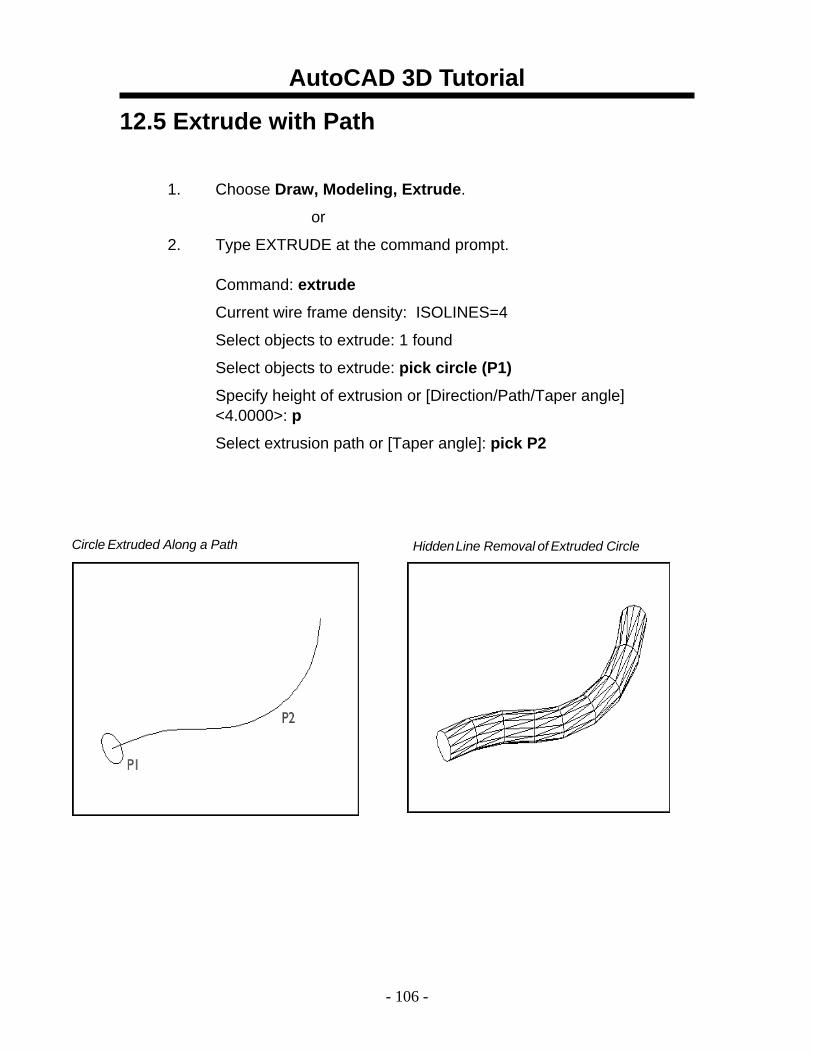
12.5 Extrude with Path
1. Choose Draw, Modeling, Extrude.
or
2. Type EXTRUDE at the command prompt. Command: extrude
Current wire frame density: ISOLINES=4
Select objects to extrude: 1 found
Select objects to extrude: pick circle (P1)
Specify height of extrusion or [Direction/Path/Taper angle] <4.0000>: p
Select extrusion path or [Taper angle]: pick P2
Circle Extruded Along a Path Hidden Line Removal of Extruded Circle
AutoCAD 3D Tutorial
- 107 -
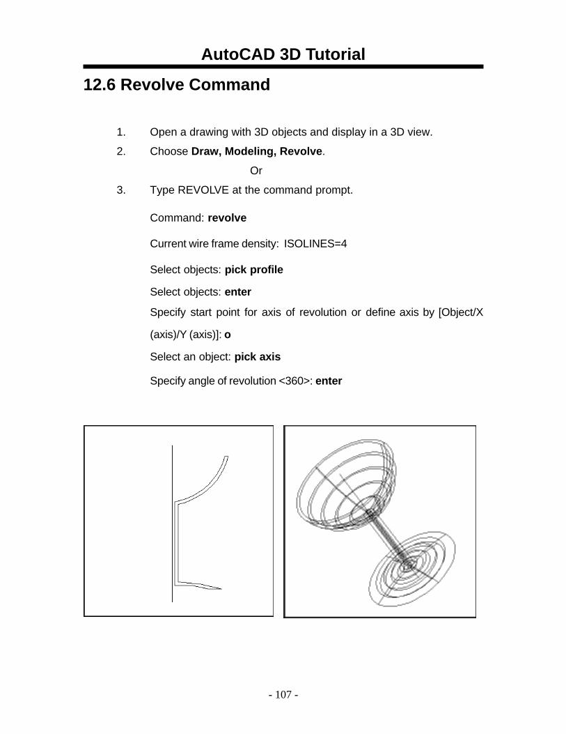
12.6 Revolve Command
1. Open a drawing with 3D objects and display in a 3D view.
2. Choose Draw, Modeling, Revolve.
Or
3. Type REVOLVE at the command prompt. Command: revolve
Current wire frame density: ISOLINES=4 Select objects: pick profile
Select objects: enter
Specify start point for axis of revolution or define axis by [Object/X
(axis)/Y (axis)]: o
Select an object: pick axis
Specify angle of revolution <360>: enter
AutoCAD 3D Tutorial
- 108 -
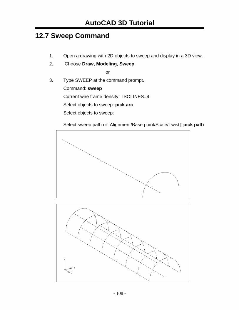
12.7 Sweep Command
1. Open a drawing with 2D objects to sweep and display in a 3D view.
2. Choose Draw, Modeling, Sweep.
or
3. Type SWEEP at the command prompt.
Command: sweep
Current wire frame density: ISOLINES=4
Select objects to sweep: pick arc
Select objects to sweep:
Select sweep path or [Alignment/Base point/Scale/Twist]: pick path
AutoCAD 3D Tutorial
- 109 -
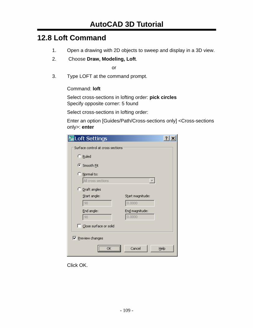
12.8 Loft Command 1. Open a drawing with 2D objects to sweep and display in a 3D view.
2. Choose Draw, Modeling, Loft.
or
3. Type LOFT at the command prompt. Command: loft
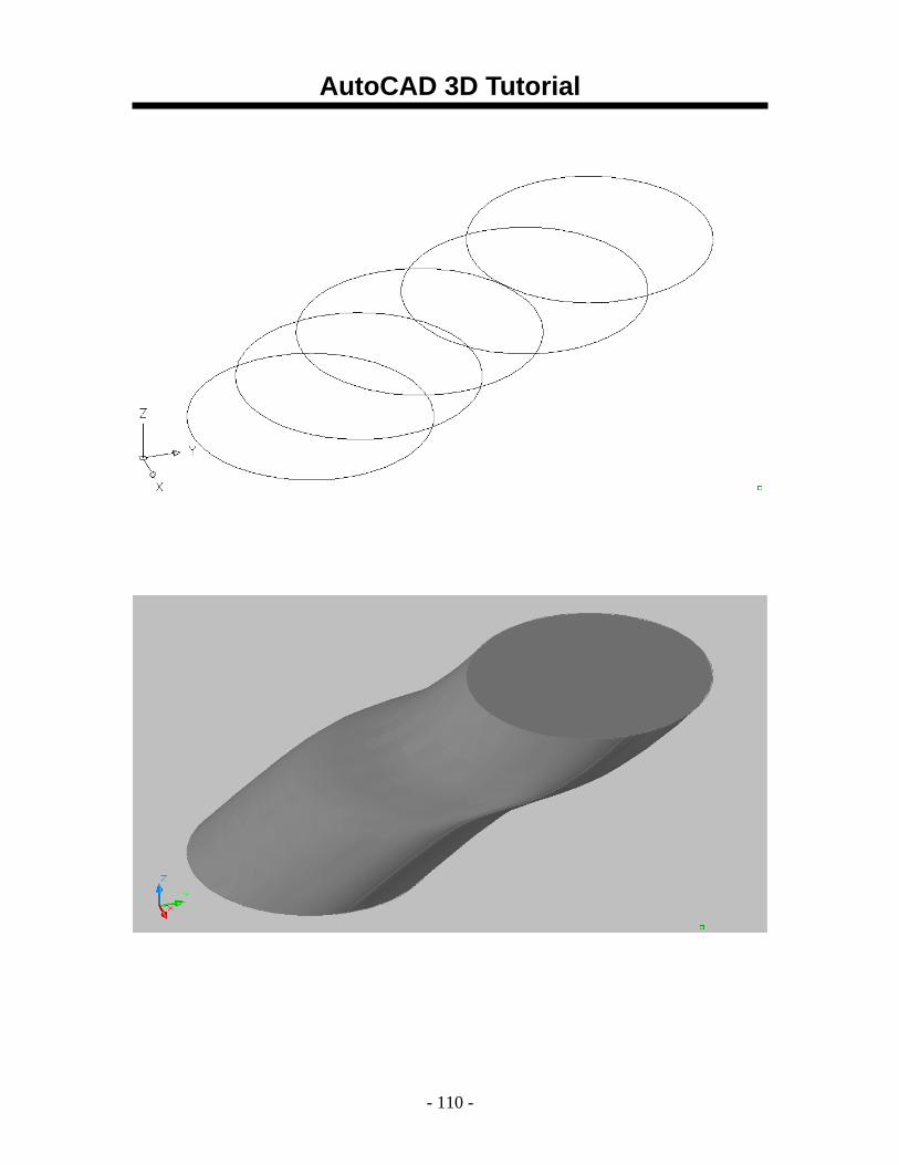
Select cross-sections in lofting order: pick circles Specify opposite corner: 5 found
Select cross-sections in lofting order:
Enter an option [Guides/Path/Cross-sections only] <Cross-sections only>: enter
Click OK.
AutoCAD 3D Tutorial
- 110 -
AutoCAD 3D Tutorial
- 111 -
AutoCAD 3D – Chapter 13 3D Edits
AutoCAD 3D Tutorial
- 112 -
13.1 Convert to Solid
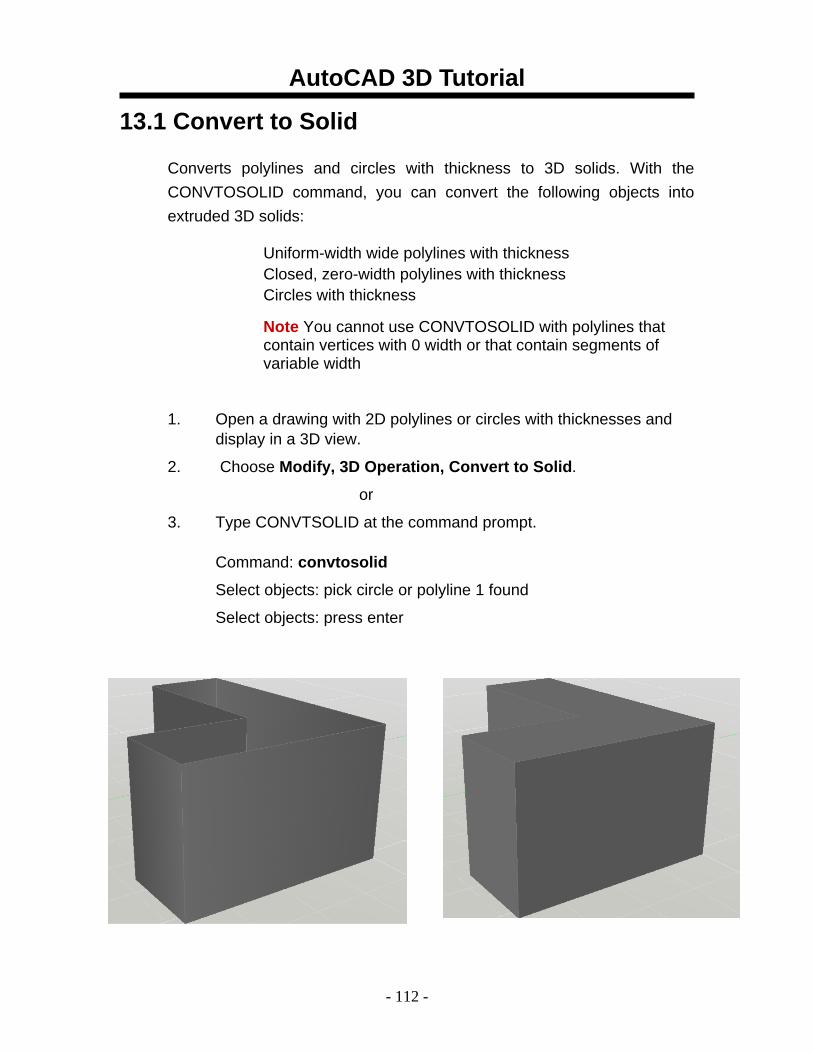
Converts polylines and circles with thickness to 3D solids. With the CONVTOSOLID command, you can convert the following objects into extruded 3D solids:
Uniform-width wide polylines with thickness Closed, zero-width polylines with thickness Circles with thickness
Note You cannot use CONVTOSOLID with polylines that contain vertices with 0 width or that contain segments of variable width
1. Open a drawing with 2D polylines or circles with thicknesses and display in a 3D view.
2. Choose Modify, 3D Operation, Convert to Solid.
or
3. Type CONVTSOLID at the command prompt. Command: convtosolid
Select objects: pick circle or polyline 1 found
Select objects: press enter
AutoCAD 3D Tutorial
- 113 -
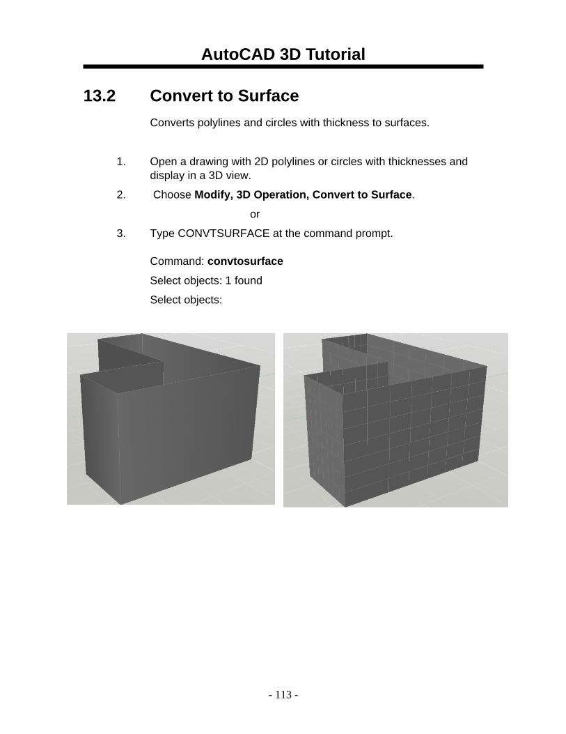
13.2 Convert to Surface Converts polylines and circles with thickness to surfaces.
1. Open a drawing with 2D polylines or circles with thicknesses and display in a 3D view.
2. Choose Modify, 3D Operation, Convert to Surface.
or
3. Type CONVTSURFACE at the command prompt. Command: convtosurface
Select objects: 1 found
Select objects:
AutoCAD 3D Tutorial
- 114 -
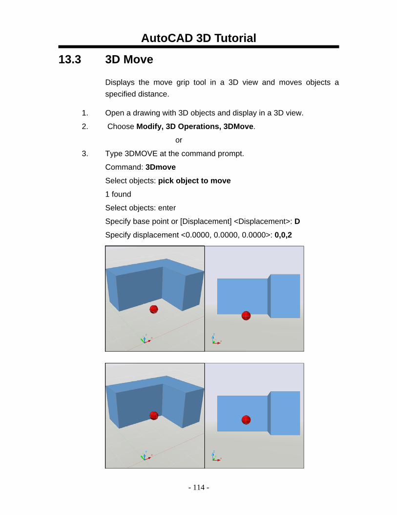
13.3 3D Move
Displays the move grip tool in a 3D view and moves objects a specified distance.
1. Open a drawing with 3D objects and display in a 3D view.
2. Choose Modify, 3D Operations, 3DMove.
or
3. Type 3DMOVE at the command prompt.
Command: 3Dmove
Select objects: pick object to move
1 found
Select objects: enter
Specify base point or [Displacement] <Displacement>: D
Specify displacement <0.0000, 0.0000, 0.0000>: 0,0,2
AutoCAD 3D Tutorial
- 115 -
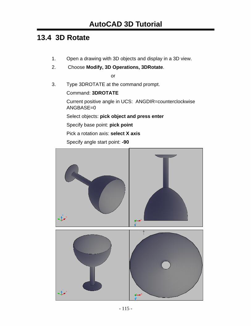
13.4 3D Rotate
1. Open a drawing with 3D objects and display in a 3D view.
2. Choose Modify, 3D Operations, 3DRotate.
or
3. Type 3DROTATE at the command prompt.
Command: 3DROTATE
Current positive angle in UCS: ANGDIR=counterclockwise ANGBASE=0
Select objects: pick object and press enter
Specify base point: pick point
Pick a rotation axis: select X axis
Specify angle start point: -90
AutoCAD 3D Tutorial
- 116 -
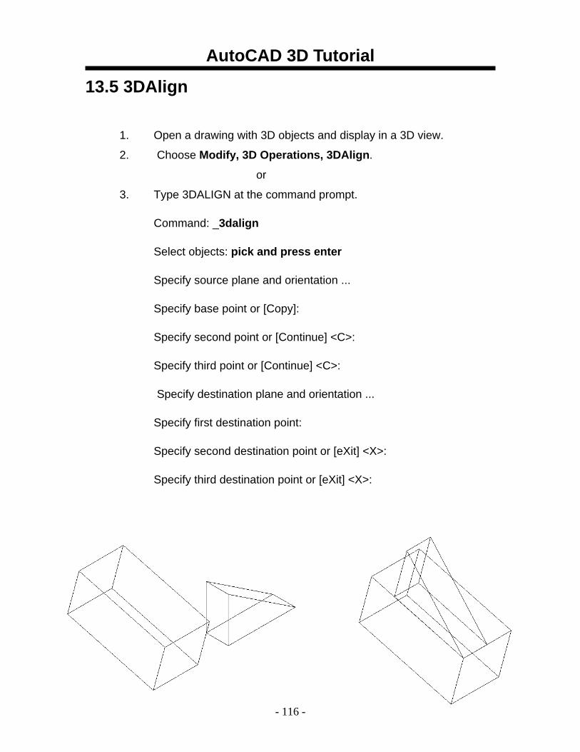
13.5 3DAlign
1. Open a drawing with 3D objects and display in a 3D view.
2. Choose Modify, 3D Operations, 3DAlign.
or
3. Type 3DALIGN at the command prompt.
Command: _3dalign
Select objects: pick and press enter
Specify source plane and orientation ...
Specify base point or [Copy]:
Specify second point or [Continue] <C>:
Specify third point or [Continue] <C>:
Specify destination plane and orientation ...
Specify first destination point:
Specify second destination point or [eXit] <X>:
Specify third destination point or [eXit] <X>:
AutoCAD 3D Tutorial
- 117 -
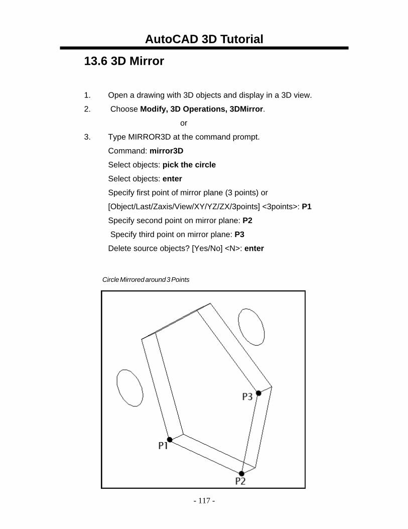
13.6 3D Mirror
1. Open a drawing with 3D objects and display in a 3D view.
2. Choose Modify, 3D Operations, 3DMirror.
or
3. Type MIRROR3D at the command prompt.
Command: mirror3D
Select objects: pick the circle
Select objects: enter
Specify first point of mirror plane (3 points) or
[Object/Last/Zaxis/View/XY/YZ/ZX/3points] <3points>: P1
Specify second point on mirror plane: P2
Specify third point on mirror plane: P3
Delete source objects? [Yes/No] <N>: enter
Circle Mirrored around3Points
AutoCAD 3D Tutorial
- 118 -
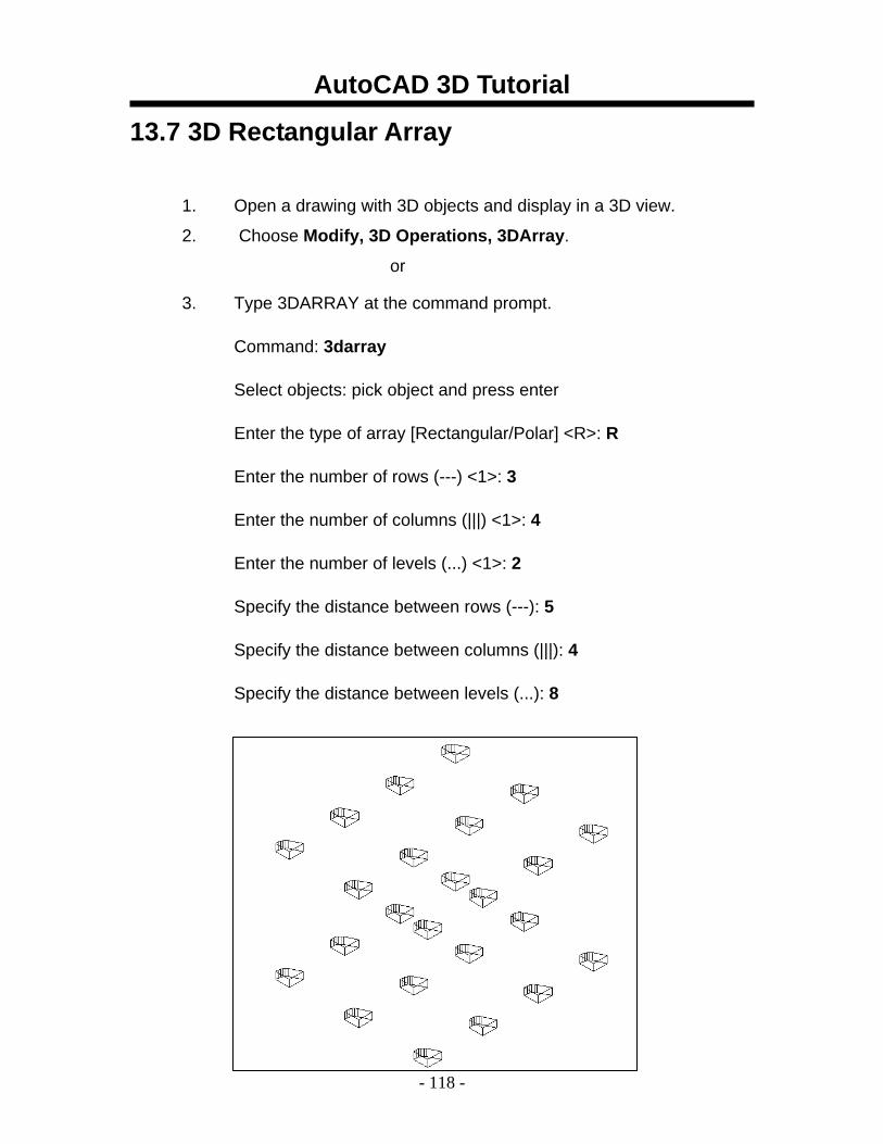
13.7 3D Rectangular Array
1. Open a drawing with 3D objects and display in a 3D view.
2. Choose Modify, 3D Operations, 3DArray.
or
3. Type 3DARRAY at the command prompt.
Command: 3darray
Select objects: pick object and press enter
Enter the type of array [Rectangular/Polar] <R>: R
Enter the number of rows (---) <1>: 3
Enter the number of columns (|||) <1>: 4
Enter the number of levels (...) <1>: 2
Specify the distance between rows (---): 5
Specify the distance between columns (|||): 4
Specify the distance between levels (...): 8

AutoCAD 3D Tutorial
- 119 -
13.8 3D Polar Array
1. Open a drawing with 3D objects and display in a 3D view.
2. Choose Modify, 3D Operations, 3DArray.
or
3. Type 3DARRAY at the command prompt.
Command: 3darray
Select objects: pick cube
Select objects: enter
Enter the type of array [Rectangular/Polar] <R>: P
Enter the number of items in the array: 5
Specify the angle to fill (+=ccw, -=cw) <360>: enter
Rotate arrayed objects? [Yes/No] <Y>: enter
Specify center point of array: mid of axis line
Specify second point on axis of rotation: pick
Arrayed Objects Around a Line Arrayed Objects in Plan View
AutoCAD 3D Tutorial
- 120 -
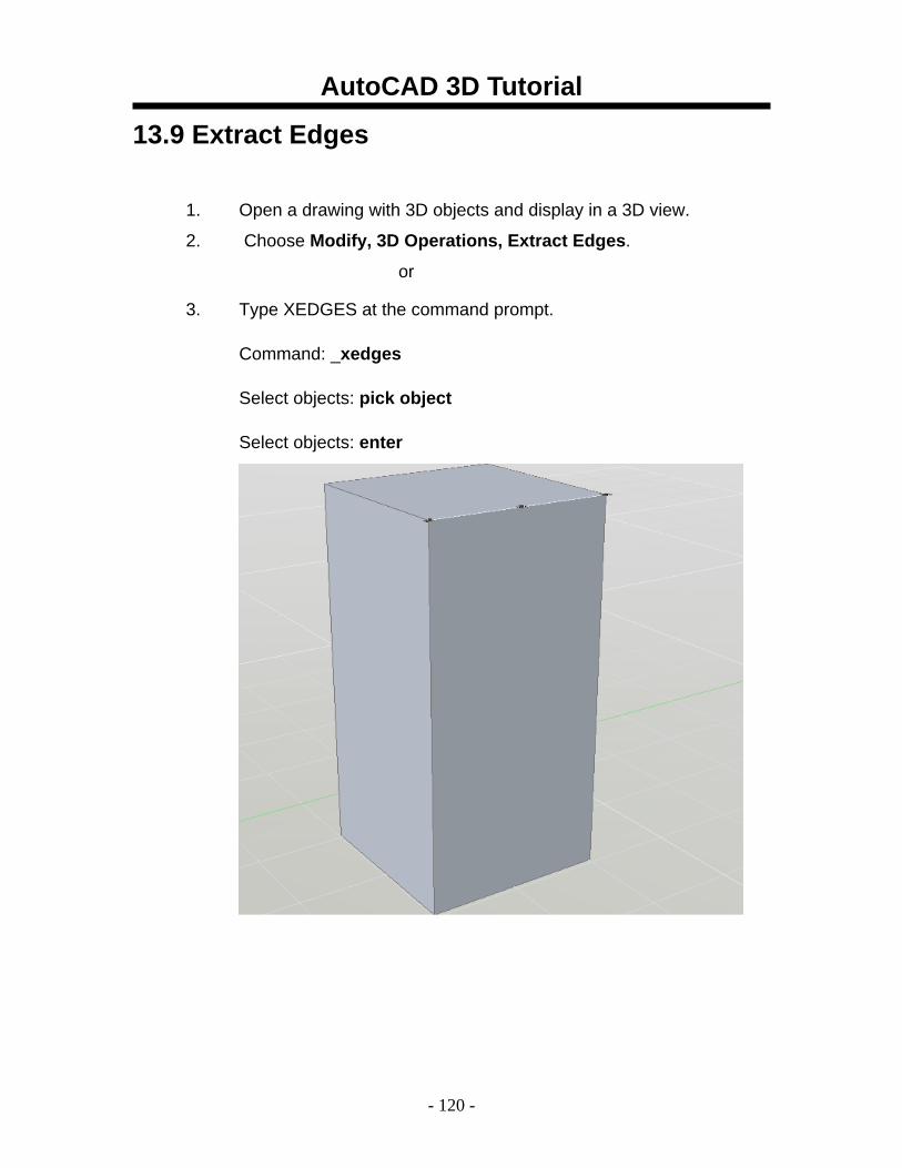
13.9 Extract Edges
1. Open a drawing with 3D objects and display in a 3D view.
2. Choose Modify, 3D Operations, Extract Edges.
or
3. Type XEDGES at the command prompt.
Command: _xedges
Select objects: pick object
Select objects: enter
AutoCAD 3D Tutorial
- 121 -
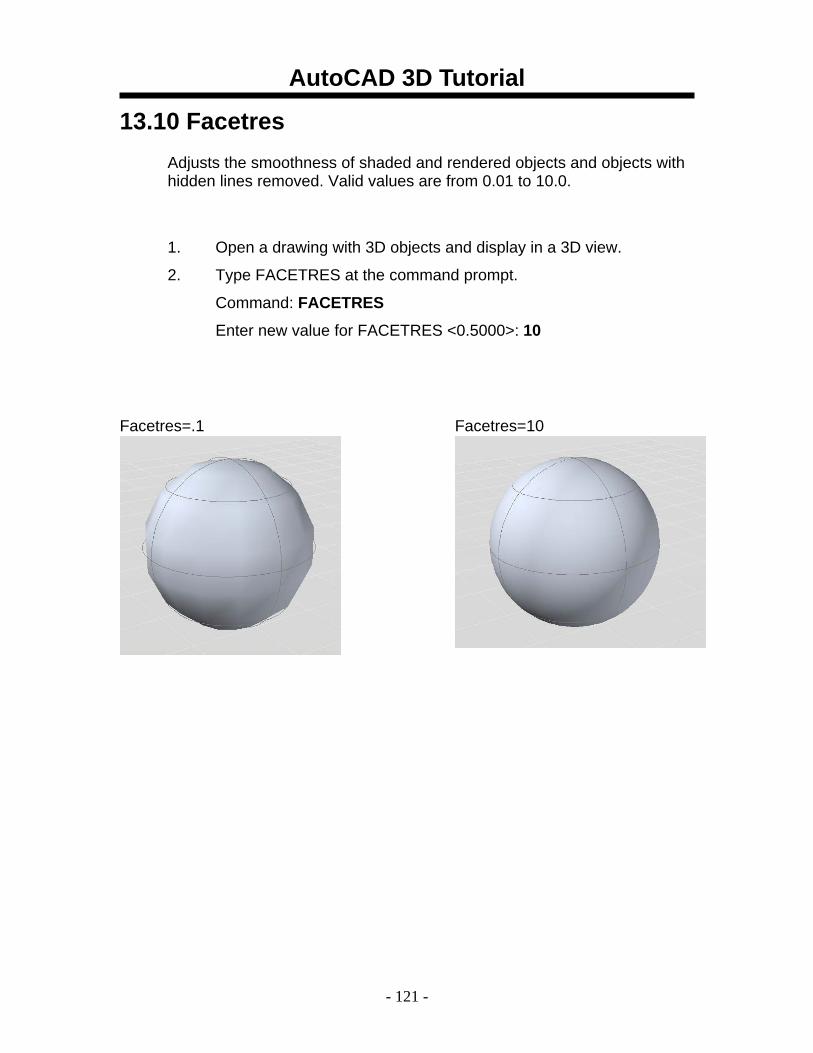
13.10 Facetres Adjusts the smoothness of shaded and rendered objects and objects with hidden lines removed. Valid values are from 0.01 to 10.0.
1. Open a drawing with 3D objects and display in a 3D view.
2. Type FACETRES at the command prompt.
Command: FACETRES
Enter new value for FACETRES <0.5000>: 10
Facetres=.1 Facetres=10
AutoCAD 3D Tutorial
- 122 -
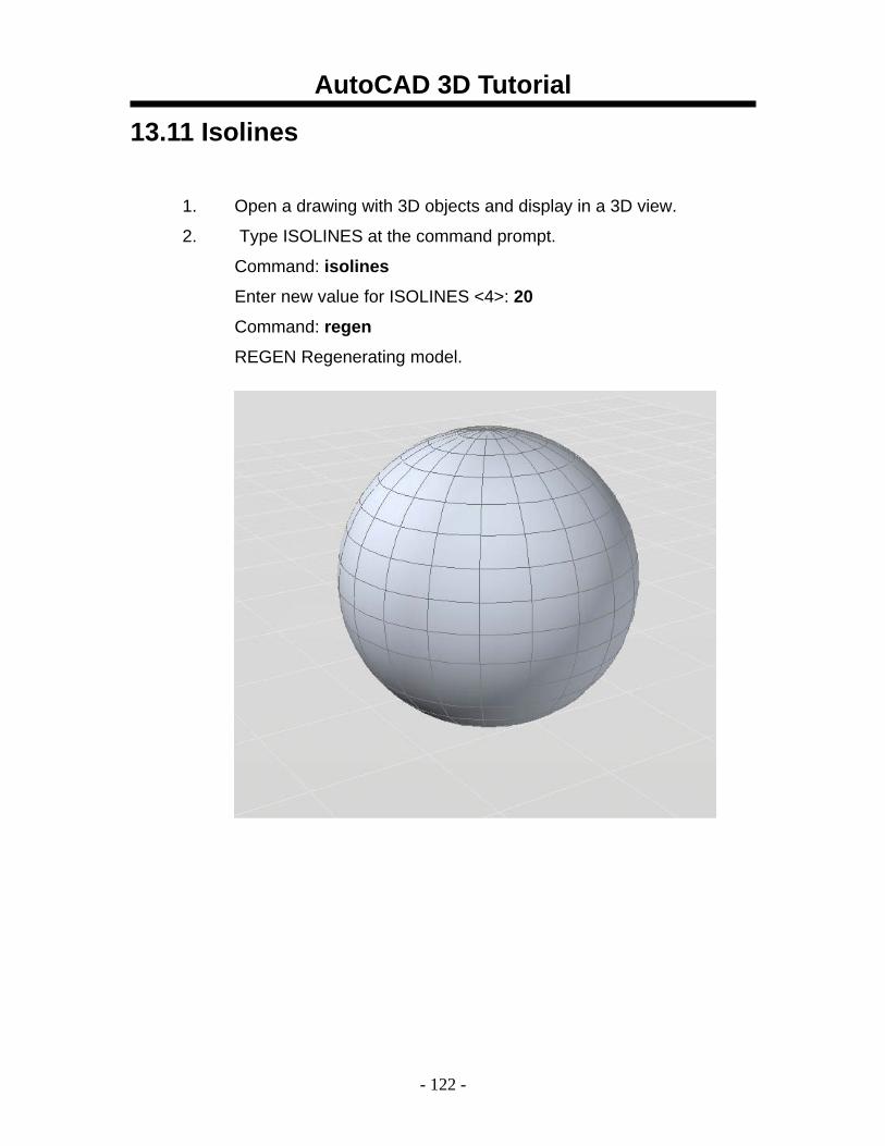
13.11 Isolines
1. Open a drawing with 3D objects and display in a 3D view.
2. Type ISOLINES at the command prompt.
Command: isolines
Enter new value for ISOLINES <4>: 20
Command: regen
REGEN Regenerating model.
AutoCAD 3D Tutorial
- 123 -
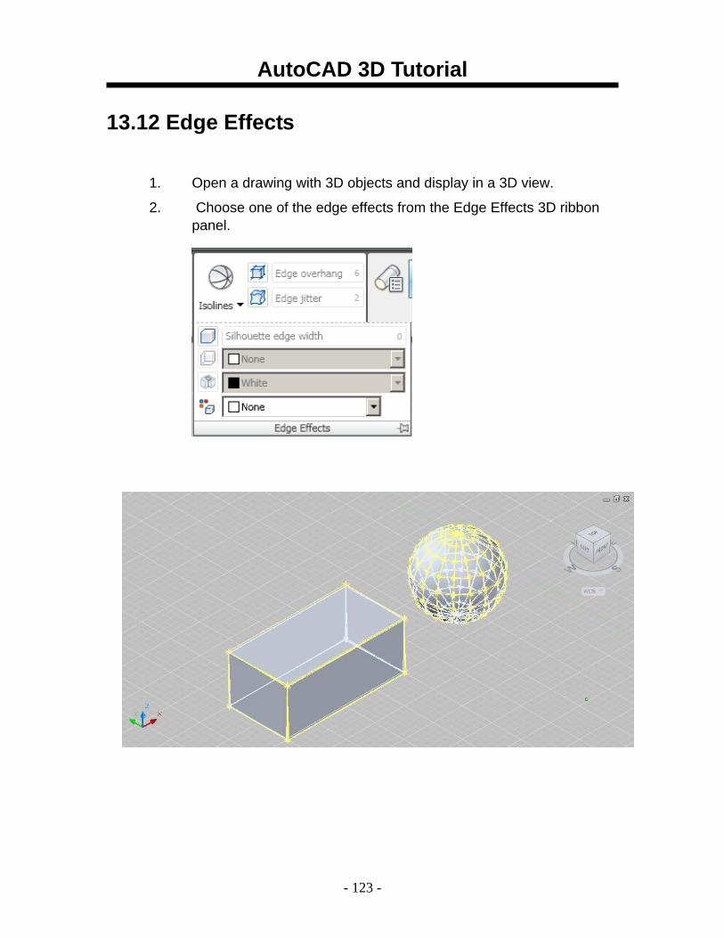
13.12 Edge Effects
1. Open a drawing with 3D objects and display in a 3D view.
2. Choose one of the edge effects from the Edge Effects 3D ribbon panel.
AutoCAD 3D Tutorial
- 124 -
AutoCAD 3D – Chapter 14 Solid Composites
AutoCAD 3D Tutorial
- 125 -
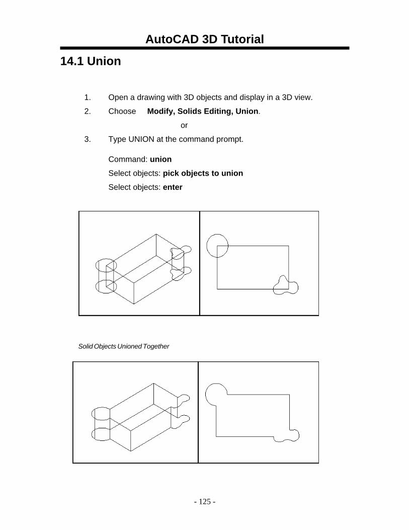
14.1 Union
1. Open a drawing with 3D objects and display in a 3D view.
2. Choose Modify, Solids Editing, Union.
or
3. Type UNION at the command prompt. Command: union
Select objects: pick objects to union
Select objects: enter
Solid Objects Unioned Together
AutoCAD 3D Tutorial
- 126 -
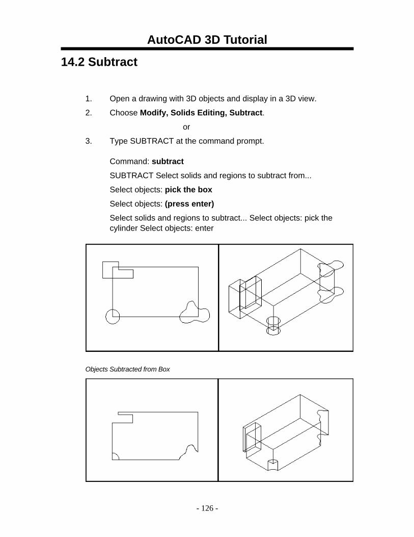
14.2 Subtract
1. Open a drawing with 3D objects and display in a 3D view.
2. Choose Modify, Solids Editing, Subtract.
or
3. Type SUBTRACT at the command prompt. Command: subtract
SUBTRACT Select solids and regions to subtract from...
Select objects: pick the box
Select objects: (press enter)
Select solids and regions to subtract... Select objects: pick the cylinder Select objects: enter
Objects Subtracted from Box
AutoCAD 3D Tutorial
- 127 -
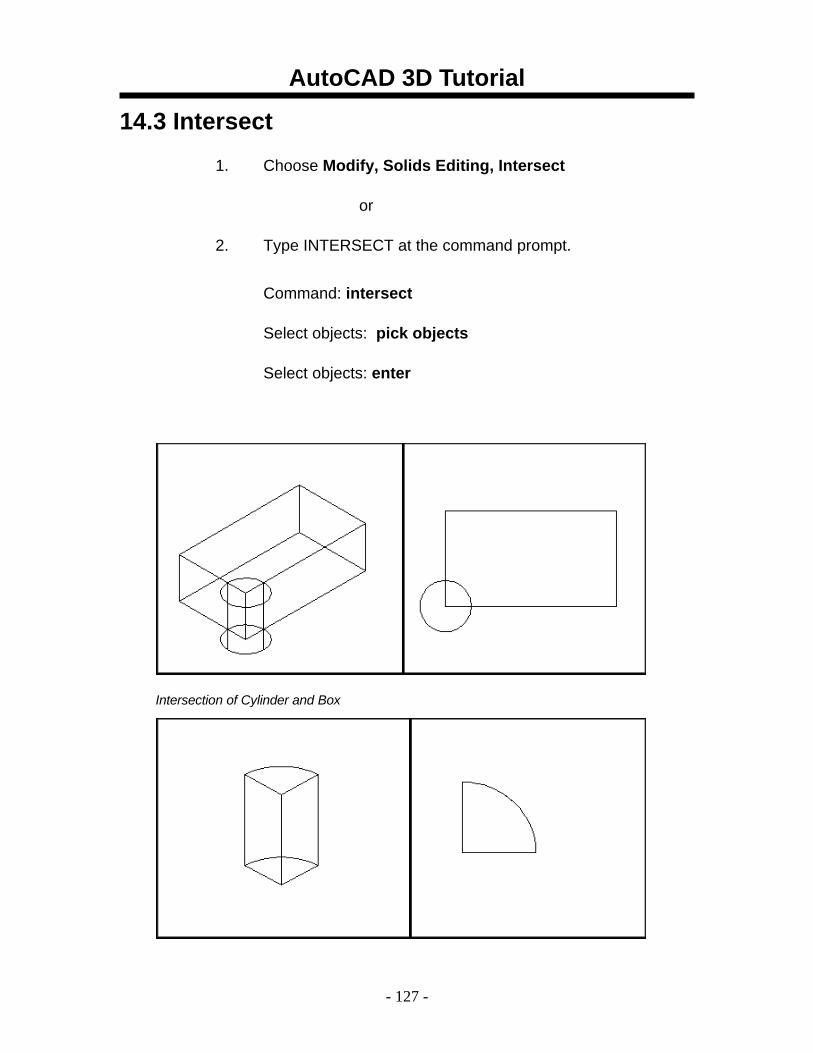
14.3 Intersect
1. Choose Modify, Solids Editing, Intersect
or
2. Type INTERSECT at the command prompt. Command: intersect
Select objects: pick objects
Select objects: enter
Intersection of Cylinder and Box
AutoCAD 3D Tutorial
- 128 -
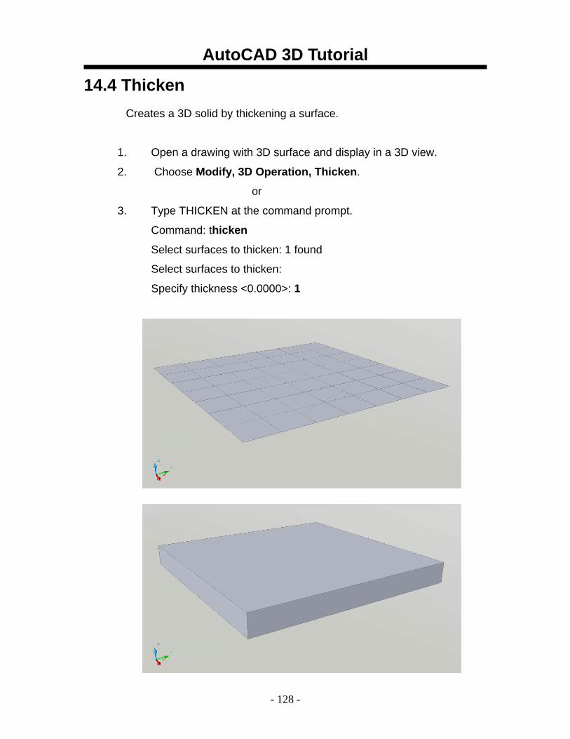
14.4 Thicken Creates a 3D solid by thickening a surface.
1. Open a drawing with 3D surface and display in a 3D view.
2. Choose Modify, 3D Operation, Thicken.
or
3. Type THICKEN at the command prompt.
Command: thicken
Select surfaces to thicken: 1 found
Select surfaces to thicken:
Specify thickness <0.0000>: 1
AutoCAD 3D Tutorial
- 129 -
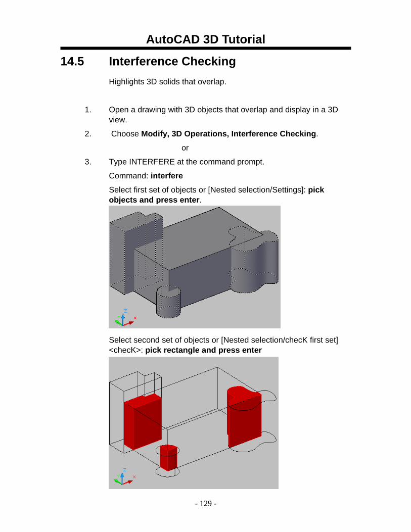
14.5 Interference Checking Highlights 3D solids that overlap.
1. Open a drawing with 3D objects that overlap and display in a 3D view.
2. Choose Modify, 3D Operations, Interference Checking.
or
3. Type INTERFERE at the command prompt.
Command: interfere
Select first set of objects or [Nested selection/Settings]: pick objects and press enter.
Select second set of objects or [Nested selection/checK first set] <checK>: pick rectangle and press enter
Solids that interfere will highlight in red.
AutoCAD 3D Tutorial
- 130 -
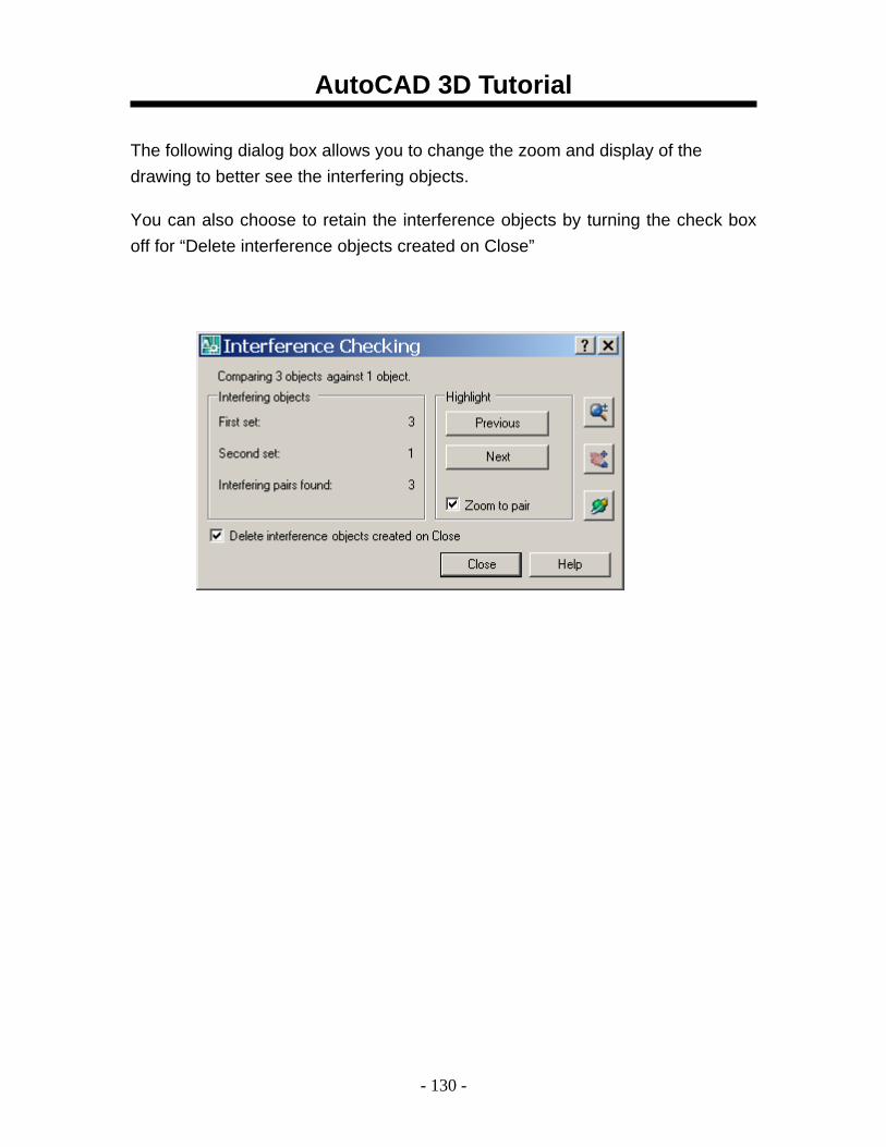
The following dialog box allows you to change the zoom and display of the drawing to better see the interfering objects.
You can also choose to retain the interference objects by turning the check box off for “Delete interference objects created on Close”
AutoCAD 3D Tutorial
- 131 -
AutoCAD 3D – Chapter 15 Modifying Solid Faces
AutoCAD 3D Tutorial
- 132 -
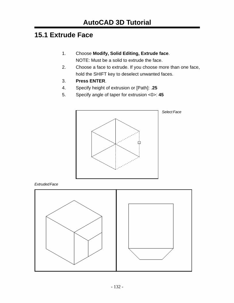
15.1 Extrude Face
1. Choose Modify, Solid Editing, Extrude face. NOTE: Must be a solid to extrude the face.
2. Choose a face to extrude. If you choose more than one face, hold the SHIFT key to deselect unwanted faces.
3. Press ENTER. 4. Specify height of extrusion or [Path]: .25 5. Specify angle of taper for extrusion <0>: 45
Select Face
Extruded Face
AutoCAD 3D Tutorial
- 133 -
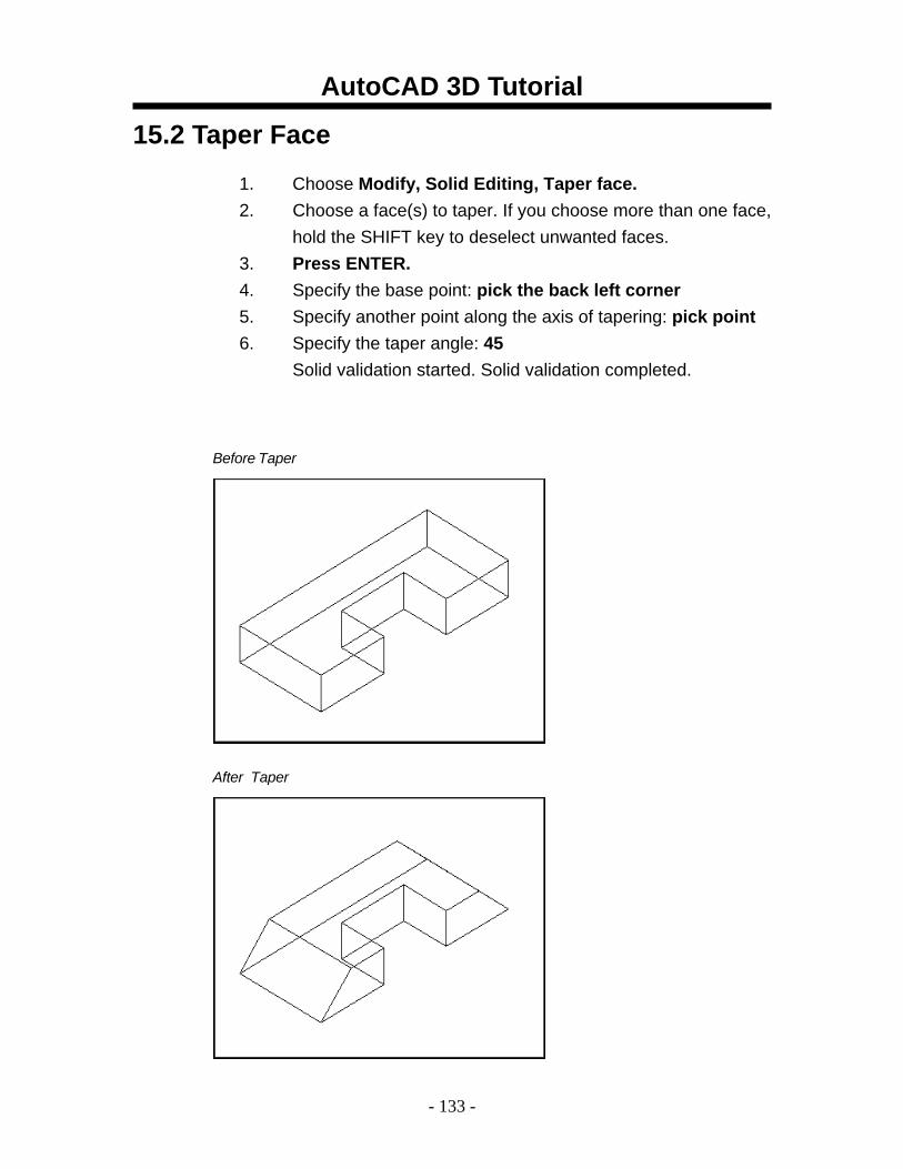
15.2 Taper Face
1. Choose Modify, Solid Editing, Taper face. 2. Choose a face(s) to taper. If you choose more than one face,
hold the SHIFT key to deselect unwanted faces. 3. Press ENTER. 4. Specify the base point: pick the back left corner 5. Specify another point along the axis of tapering: pick point 6. Specify the taper angle: 45
Solid validation started. Solid validation completed.
Before Taper
After Taper
AutoCAD 3D Tutorial
- 134 -
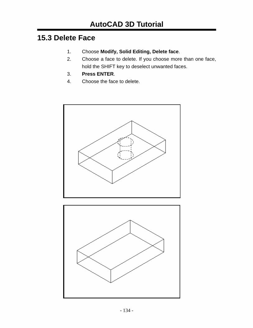
15.3 Delete Face
1. Choose Modify, Solid Editing, Delete face. 2. Choose a face to delete. If you choose more than one face,
hold the SHIFT key to deselect unwanted faces. 3. Press ENTER. 4. Choose the face to delete.
AutoCAD 3D Tutorial
- 135 -
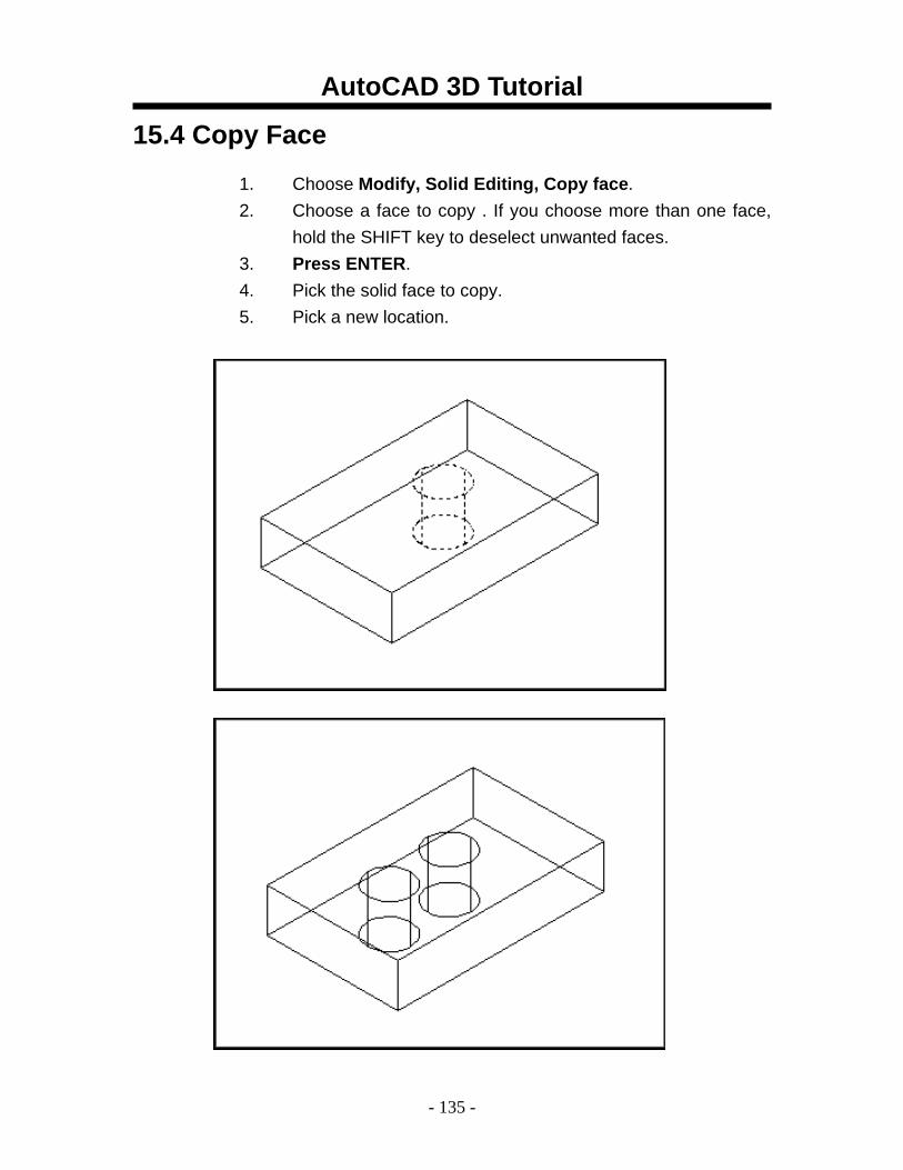
15.4 Copy Face
1. Choose Modify, Solid Editing, Copy face. 2. Choose a face to copy . If you choose more than one face,
hold the SHIFT key to deselect unwanted faces. 3. Press ENTER. 4. Pick the solid face to copy. 5. Pick a new location.
AutoCAD 3D Tutorial
- 136 -
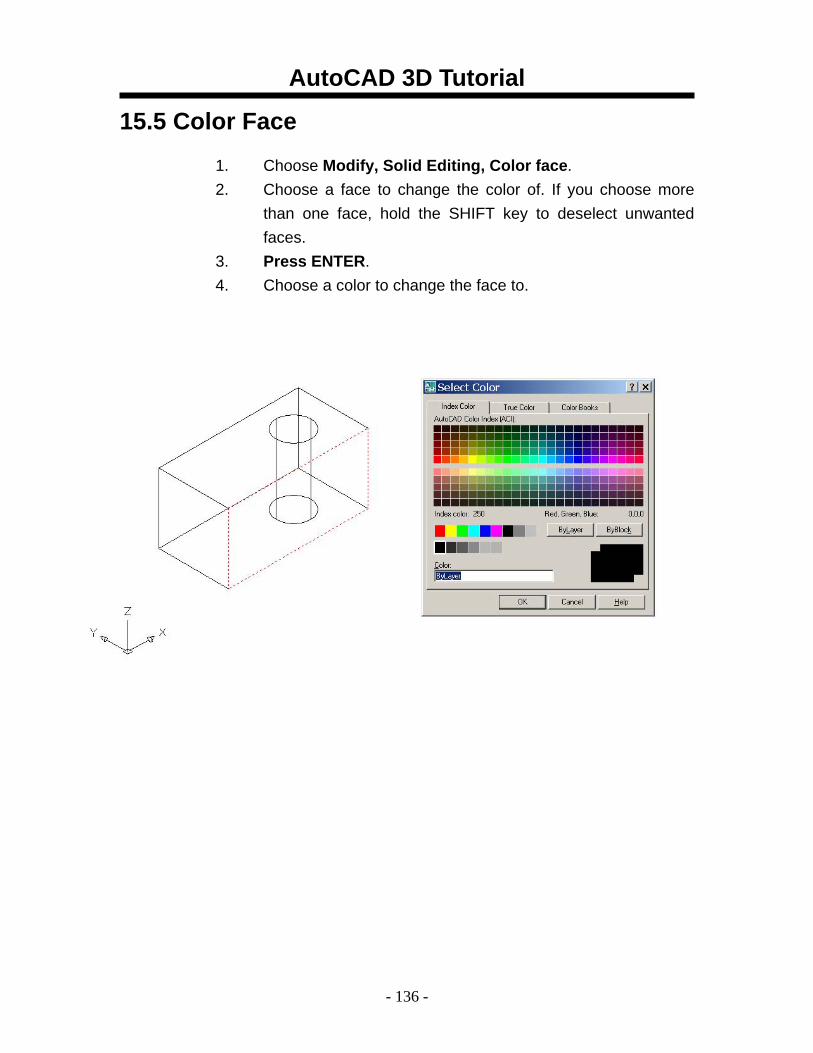
15.5 Color Face
1. Choose Modify, Solid Editing, Color face. 2. Choose a face to change the color of. If you choose more
than one face, hold the SHIFT key to deselect unwanted faces.
3. Press ENTER. 4. Choose a color to change the face to.
AutoCAD 3D Tutorial
- 137 -
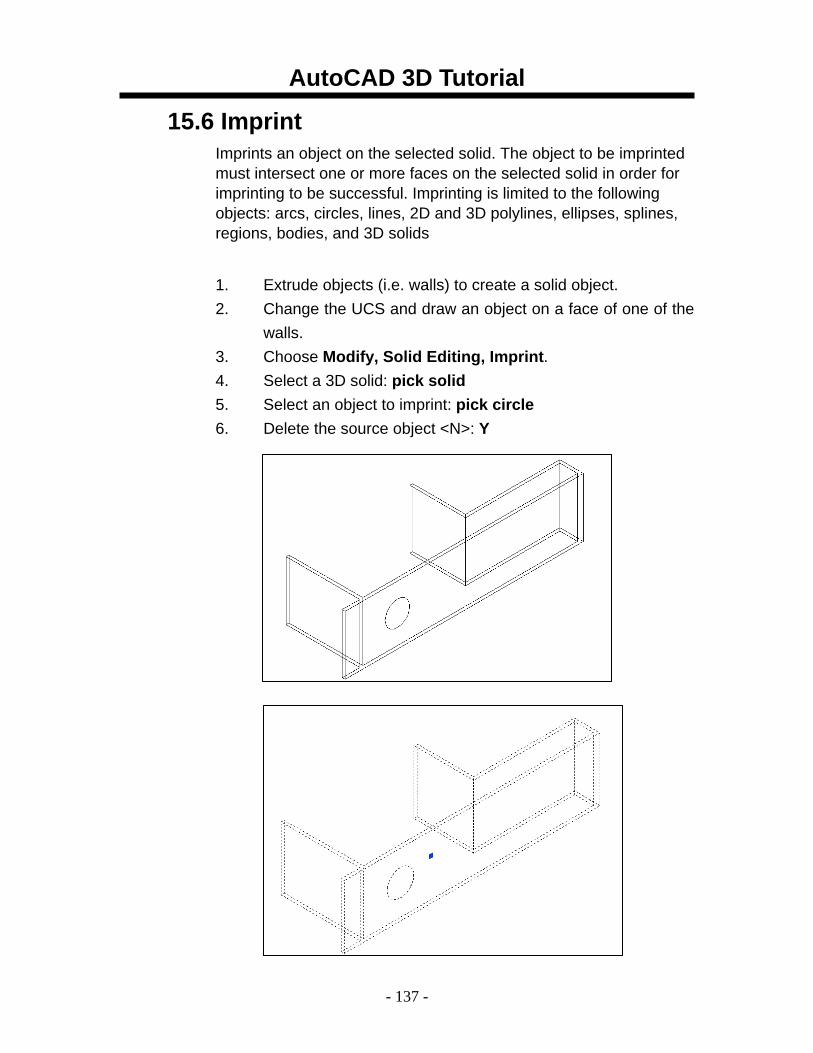
15.6 Imprint Imprints an object on the selected solid. The object to be imprinted must intersect one or more faces on the selected solid in order for imprinting to be successful. Imprinting is limited to the following objects: arcs, circles, lines, 2D and 3D polylines, ellipses, splines, regions, bodies, and 3D solids
1. Extrude objects (i.e. walls) to create a solid object.
2. Change the UCS and draw an object on a face of one of the walls.
3. Choose Modify, Solid Editing, Imprint. 4. Select a 3D solid: pick solid 5. Select an object to imprint: pick circle 6. Delete the source object <N>: Y
AutoCAD 3D Tutorial
- 138 -
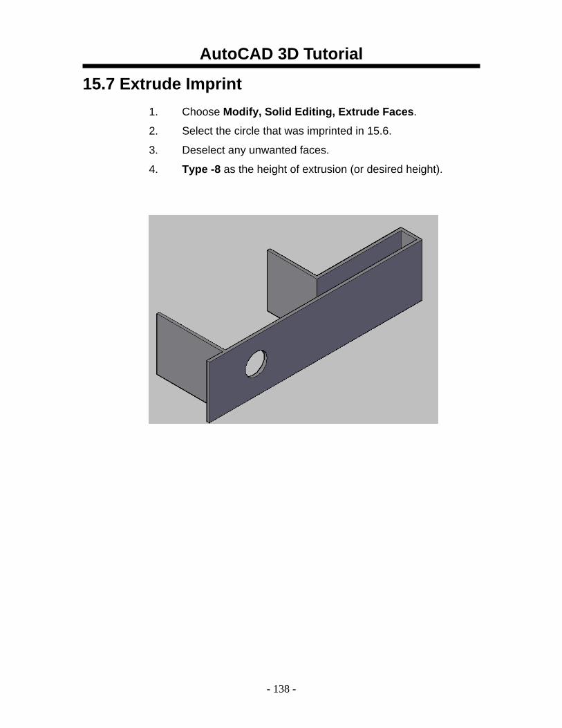
15.7 Extrude Imprint 1. Choose Modify, Solid Editing, Extrude Faces.
2. Select the circle that was imprinted in 15.6.
3. Deselect any unwanted faces.
4. Type -8 as the height of extrusion (or desired height).
AutoCAD 3D Tutorial
- 139 -
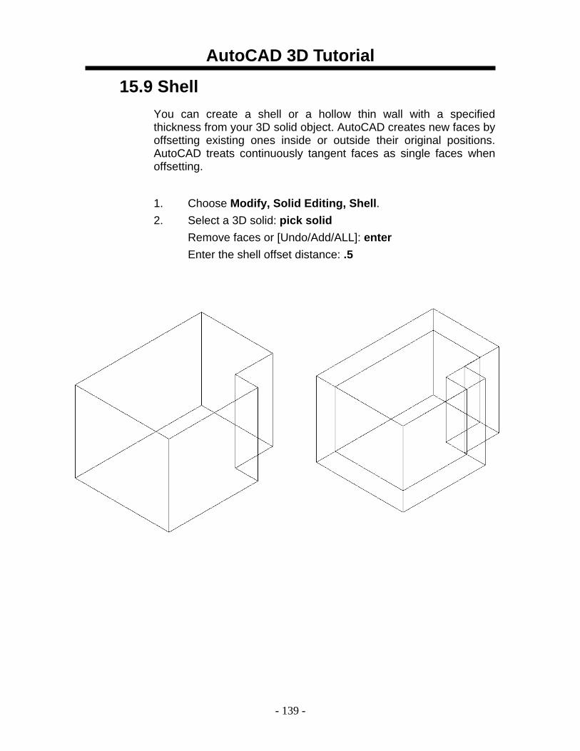
15.9 Shell You can create a shell or a hollow thin wall with a specified thickness from your 3D solid object. AutoCAD creates new faces by offsetting existing ones inside or outside their original positions. AutoCAD treats continuously tangent faces as single faces when offsetting.
1. Choose Modify, Solid Editing, Shell. 2. Select a 3D solid: pick solid
Remove faces or [Undo/Add/ALL]: enter Enter the shell offset distance: .5
AutoCAD 3D Tutorial
- 140 -
AutoCAD 3D – Chapter 16 Editing Solids
AutoCAD 3D Tutorial
- 141 -
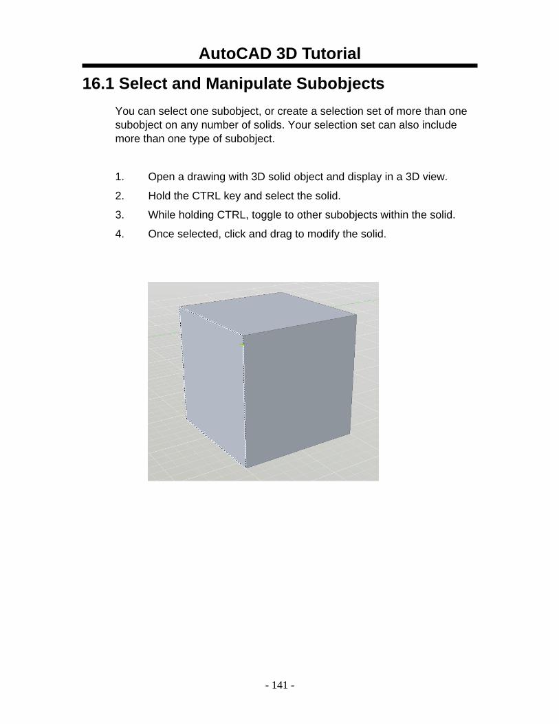
16.1 Select and Manipulate Subobjects You can select one subobject, or create a selection set of more than one subobject on any number of solids. Your selection set can also include more than one type of subobject.
1. Open a drawing with 3D solid object and display in a 3D view.
2. Hold the CTRL key and select the solid.
3. While holding CTRL, toggle to other subobjects within the solid.
4. Once selected, click and drag to modify the solid.
AutoCAD 3D Tutorial
- 142 -
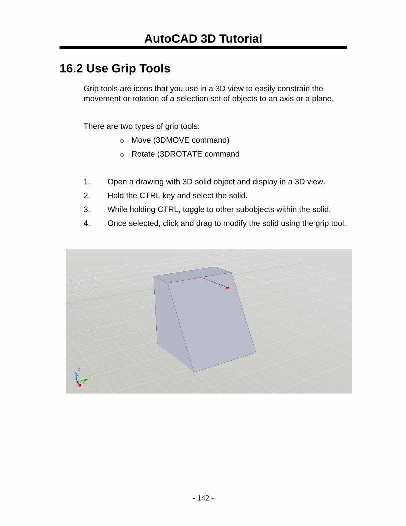
16.2 Use Grip Tools Grip tools are icons that you use in a 3D view to easily constrain the movement or rotation of a selection set of objects to an axis or a plane.
There are two types of grip tools:
o Move (3DMOVE command)
o Rotate (3DROTATE command
1. Open a drawing with 3D solid object and display in a 3D view.
2. Hold the CTRL key and select the solid.
3. While holding CTRL, toggle to other subobjects within the solid.
4. Once selected, click and drag to modify the solid using the grip tool.
AutoCAD 3D Tutorial
- 143 -
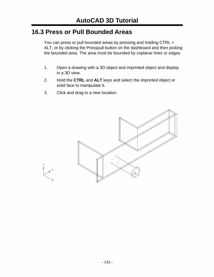
16.3 Press or Pull Bounded Areas You can press or pull bounded areas by pressing and holding CTRL + ALT, or by clicking the Presspull button on the dashboard and then picking the bounded area. The area must be bounded by coplanar lines or edges.
1. Open a drawing with a 3D object and imprinted object and display in a 3D view.
2. Hold the CTRL and ALT keys and select the imprinted object or solid face to manipulate it.
3. Click and drag to a new location.
AutoCAD 3D Tutorial
- 144 -
AutoCAD 3D – Chapter 17 Sections and Flat Objects
from 3D Models
AutoCAD 3D Tutorial
- 145 -
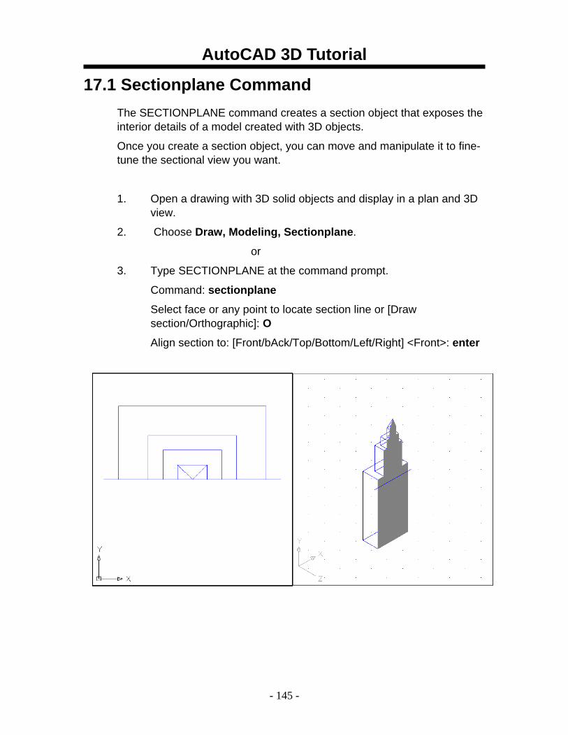
17.1 Sectionplane Command The SECTIONPLANE command creates a section object that exposes the interior details of a model created with 3D objects.
Once you create a section object, you can move and manipulate it to fine-tune the sectional view you want.
1. Open a drawing with 3D solid objects and display in a plan and 3D view.
2. Choose Draw, Modeling, Sectionplane.
or
3. Type SECTIONPLANE at the command prompt.
Command: sectionplane
Select face or any point to locate section line or [Draw section/Orthographic]: O
Align section to: [Front/bAck/Top/Bottom/Left/Right] <Front>: enter

AutoCAD 3D Tutorial
- 146 -
17.2 Manipulate Section Using Grips
1. Click on a section line created using the SECTIONPLANE command.
2. Click on one of the grips to manipulate the section.
Base grip - moves the entire section object
Directional arrow grip – changes the cutting plane direction
Segment end grip - rotates the section object around the base grip
Menu grip - moves between the three states
section line
segment end grip
directional arrow grip
menu grip
base grip
AutoCAD 3D Tutorial
- 147 -
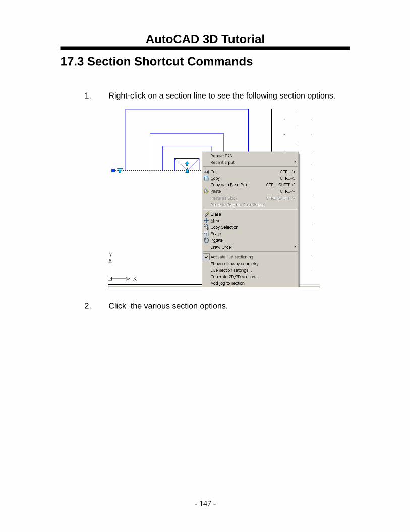
17.3 Section Shortcut Commands
1. Right-click on a section line to see the following section options.
2. Click the various section options.
AutoCAD 3D Tutorial
- 148 -
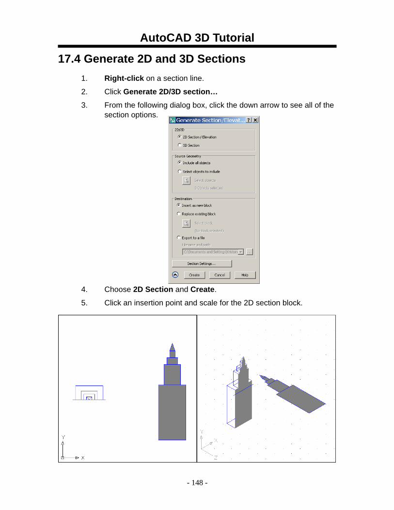
17.4 Generate 2D and 3D Sections 1. Right-click on a section line.
2. Click Generate 2D/3D section…
3. From the following dialog box, click the down arrow to see all of the section options.
4. Choose 2D Section and Create.
5. Click an insertion point and scale for the 2D section block.
AutoCAD 3D Tutorial
- 149 -
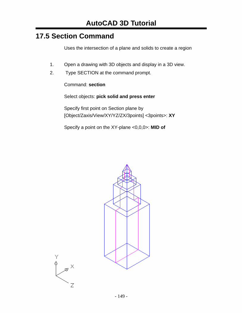
17.5 Section Command Uses the intersection of a plane and solids to create a region
1. Open a drawing with 3D objects and display in a 3D view.
2. Type SECTION at the command prompt.
Command: section
Select objects: pick solid and press enter
Specify first point on Section plane by [Object/Zaxis/View/XY/YZ/ZX/3points] <3points>: XY
Specify a point on the XY-plane <0,0,0>: MID of
AutoCAD 3D Tutorial
- 150 -
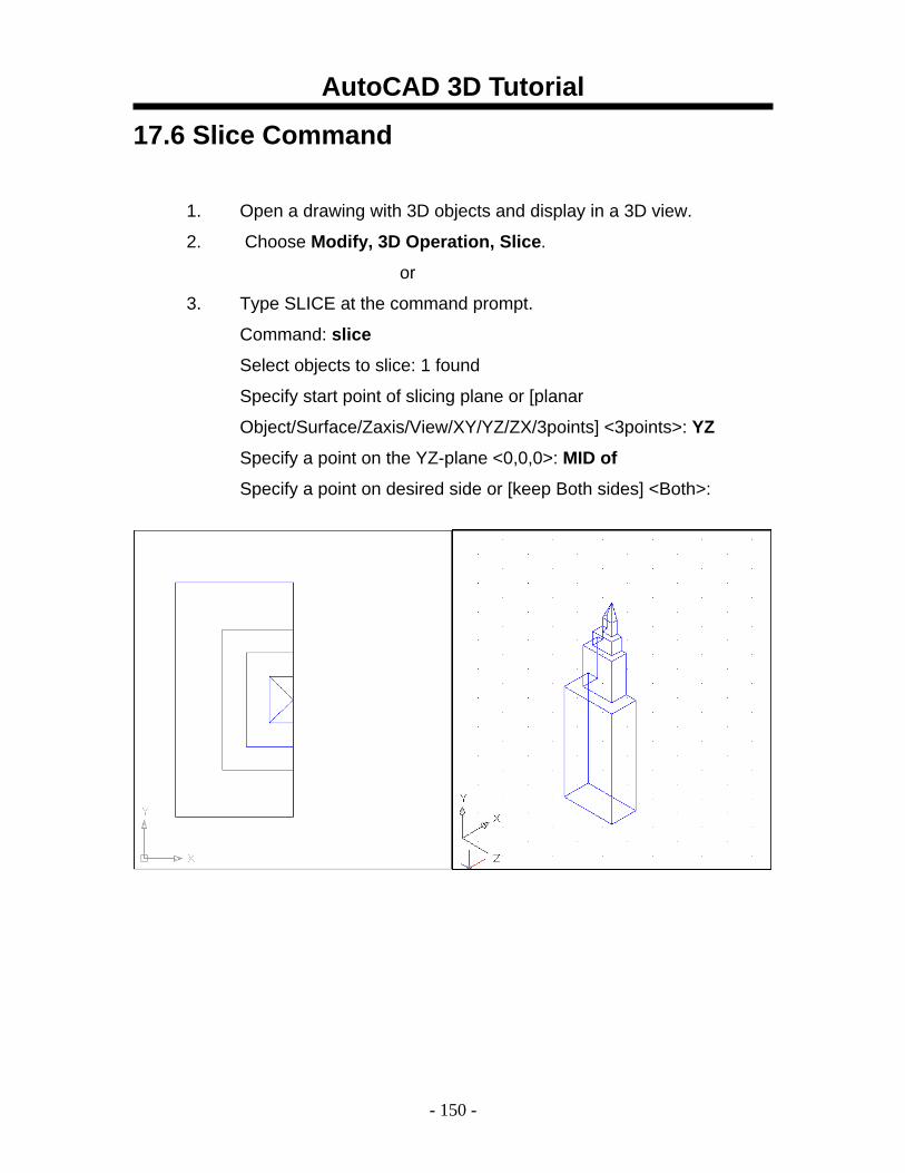
17.6 Slice Command
1. Open a drawing with 3D objects and display in a 3D view.
2. Choose Modify, 3D Operation, Slice.
or
3. Type SLICE at the command prompt.
Command: slice
Select objects to slice: 1 found
Specify start point of slicing plane or [planar
Object/Surface/Zaxis/View/XY/YZ/ZX/3points] <3points>: YZ
Specify a point on the YZ-plane <0,0,0>: MID of
Specify a point on desired side or [keep Both sides] <Both>:
AutoCAD 3D Tutorial
- 151 -
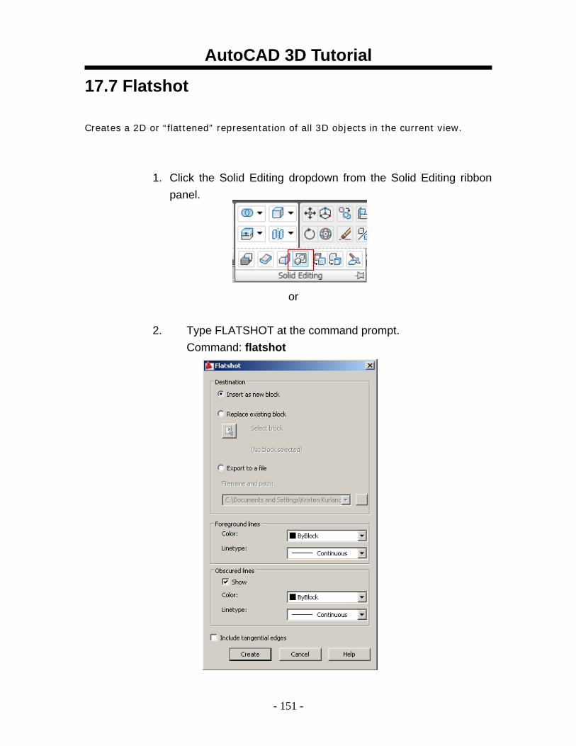
17.7 Flatshot
Creates a 2D or “flattened” representation of all 3D objects in the current view.
1. Click the Solid Editing dropdown from the Solid Editing ribbon panel.
or
2. Type FLATSHOT at the command prompt. Command: flatshot
AutoCAD 3D Tutorial
- 152 -
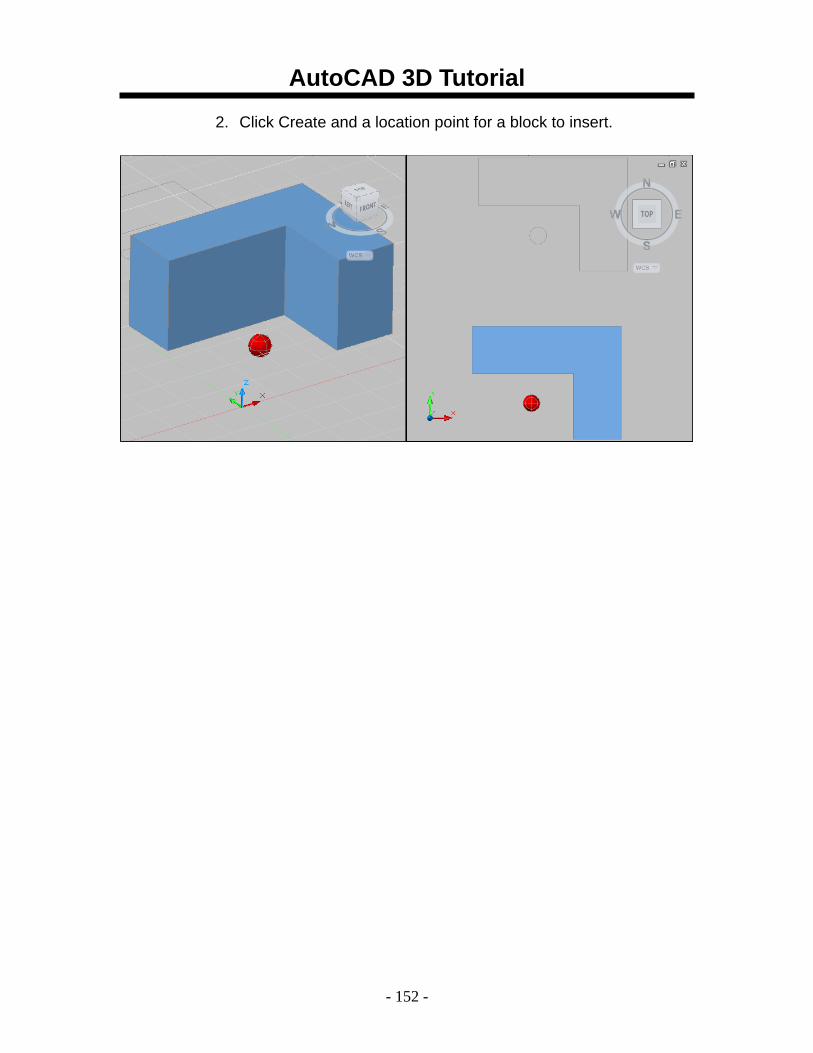
2. Click Create and a location point for a block to insert.
AutoCAD 3D Tutorial
- 153 -
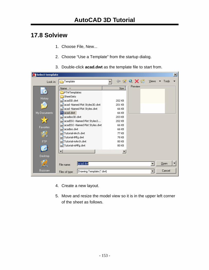
17.8 Solview
1. Choose File, New...
2. Choose “Use a Template” from the startup dialog.
3. Double-click acad.dwt as the template file to start from.
4. Create a new layout.
5. Move and resize the model view so it is in the upper left corner of the sheet as follows.
AutoCAD 3D Tutorial
- 154 -
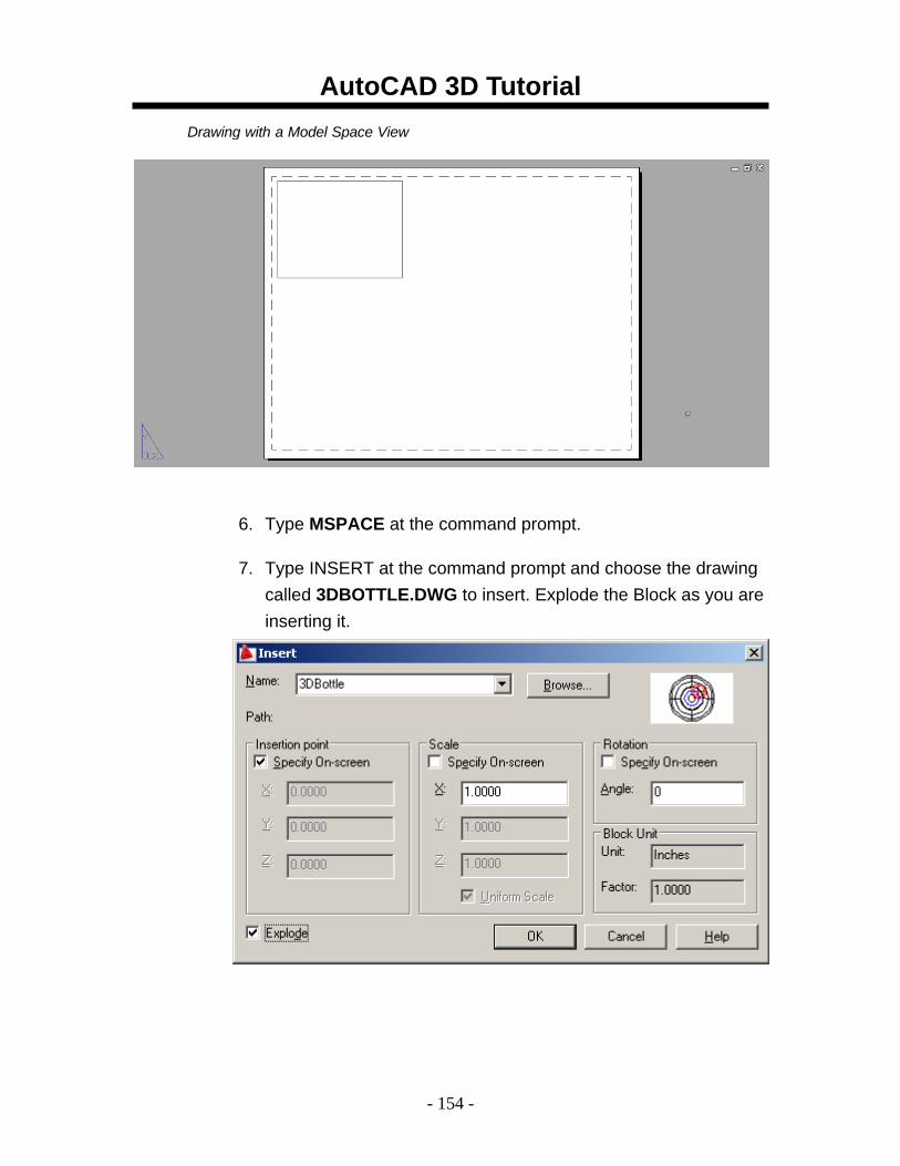
6. Type MSPACE at the command prompt.
7. Type INSERT at the command prompt and choose the drawing called 3DBOTTLE.DWG to insert. Explode the Block as you are inserting it.
Drawing with a Model Space View
AutoCAD 3D Tutorial
- 155 -
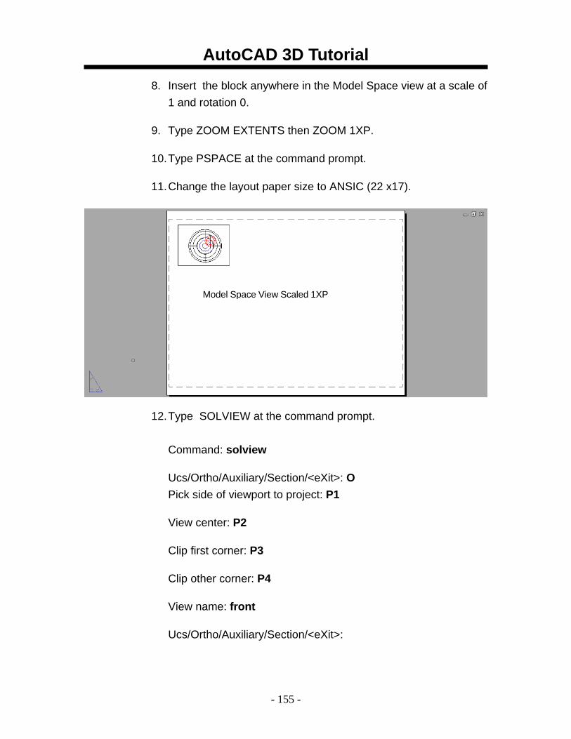
8. Insert the block anywhere in the Model Space view at a scale of 1 and rotation 0.
9. Type ZOOM EXTENTS then ZOOM 1XP.
10. Type PSPACE at the command prompt.
11. Change the layout paper size to ANSIC (22 x17).
12. Type SOLVIEW at the command prompt. Command: solview
Ucs/Ortho/Auxiliary/Section/<eXit>: O Pick side of viewport to project: P1
View center: P2
Clip first corner: P3
Clip other corner: P4
View name: front
Ucs/Ortho/Auxiliary/Section/<eXit>:
Model Space View Scaled 1XP
AutoCAD 3D Tutorial
- 156 -
AutoCAD 3D Tutorial
- 157 -
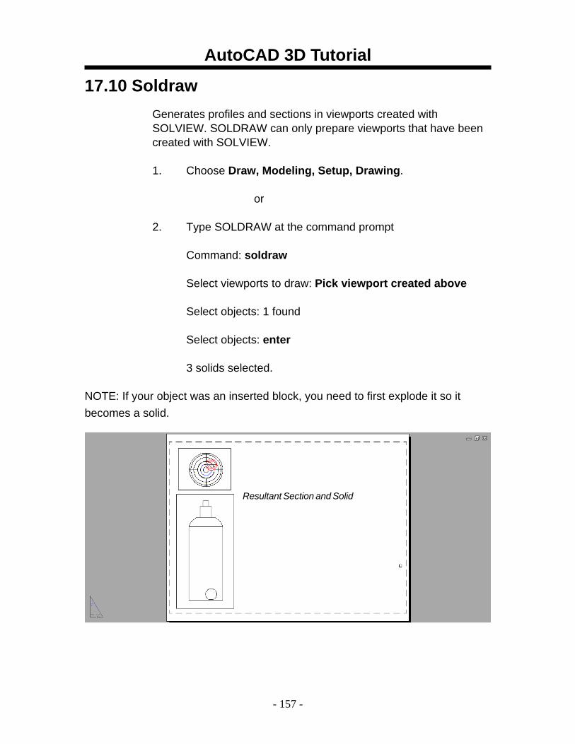
17.10 Soldraw Generates profiles and sections in viewports created with SOLVIEW. SOLDRAW can only prepare viewports that have been created with SOLVIEW.
1. Choose Draw, Modeling, Setup, Drawing.
or
2. Type SOLDRAW at the command prompt
Command: soldraw
Select viewports to draw: Pick viewport created above
Select objects: 1 found
Select objects: enter
3 solids selected.
NOTE: If your object was an inserted block, you need to first explode it so it becomes a solid.
Resultant Section and Solid
AutoCAD 3D Tutorial
- 158 -
17.11 Create 3D View Using UCS
1. Type MSPACE and the plan view of the 3D Bottle.
2. Choose View, 3D Viewport, SW Isometric...
3. Type UCS at the command prompt.
Command: ucs
Origin/ZAxis/3point/OBject/View/X/Y/Z/ Prev/Restore/Save/Del/?/<World>: view
This sets the current UCS parallel to the screen. We now need to save this ucs.
4. Type UCS at the command prompt. Command: ucscs Origin/ZAxis/3point/OBject/View/X/Y/Z/ Prev/Restore/Save/Del/?/<World>: save
?/Desired UCS name: 3dview
5. Click PSPACE at the command prompt.
6. Type SOLVIEW at the commandprompt.
Command: solview Ucs/Ortho/Auxiliary/Section/<eXit>: UNamed/World/?/<Current>: N
Name of UCS to restore: 3dview Enter view scale<1.0000>: enter View center: pick
View center: pick
Enter view name: 3DVIEW
AutoCAD 3D Tutorial
- 159 -
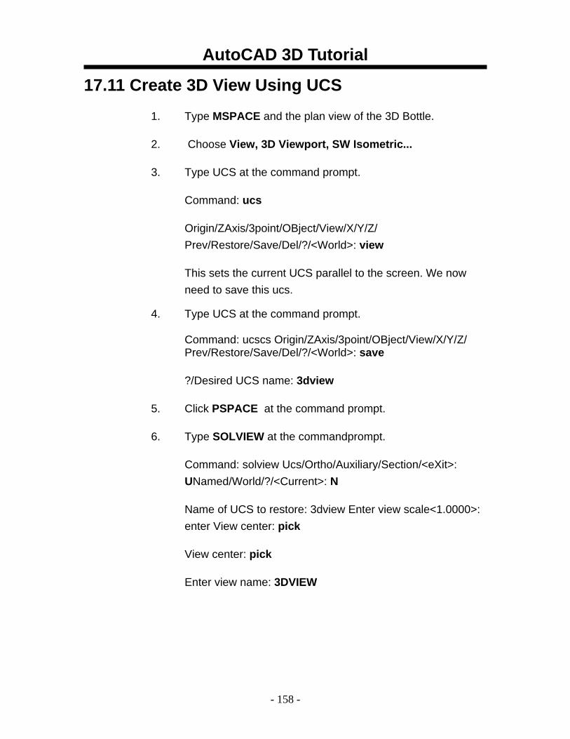
3D Model View
AutoCAD 3D Tutorial
- 160 -
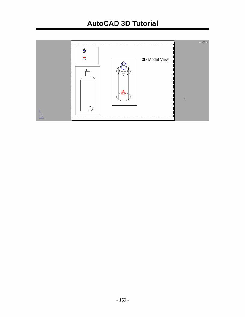
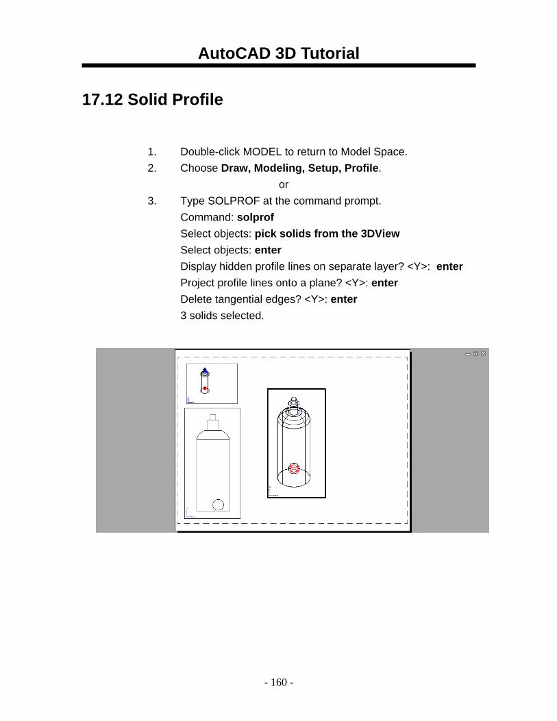
17.12 Solid Profile
1. Double-click MODEL to return to Model Space. 2. Choose Draw, Modeling, Setup, Profile.
or 3. Type SOLPROF at the command prompt.
Command: solprof Select objects: pick solids from the 3DView Select objects: enter Display hidden profile lines on separate layer? <Y>: enter Project profile lines onto a plane? <Y>: enter Delete tangential edges? <Y>: enter 3 solids selected.
AutoCAD 3D Tutorial
- 161 -
AutoCAD 3D – Chapter 18 Introduction to Rendering
AutoCAD 3D Tutorial
- 162 -
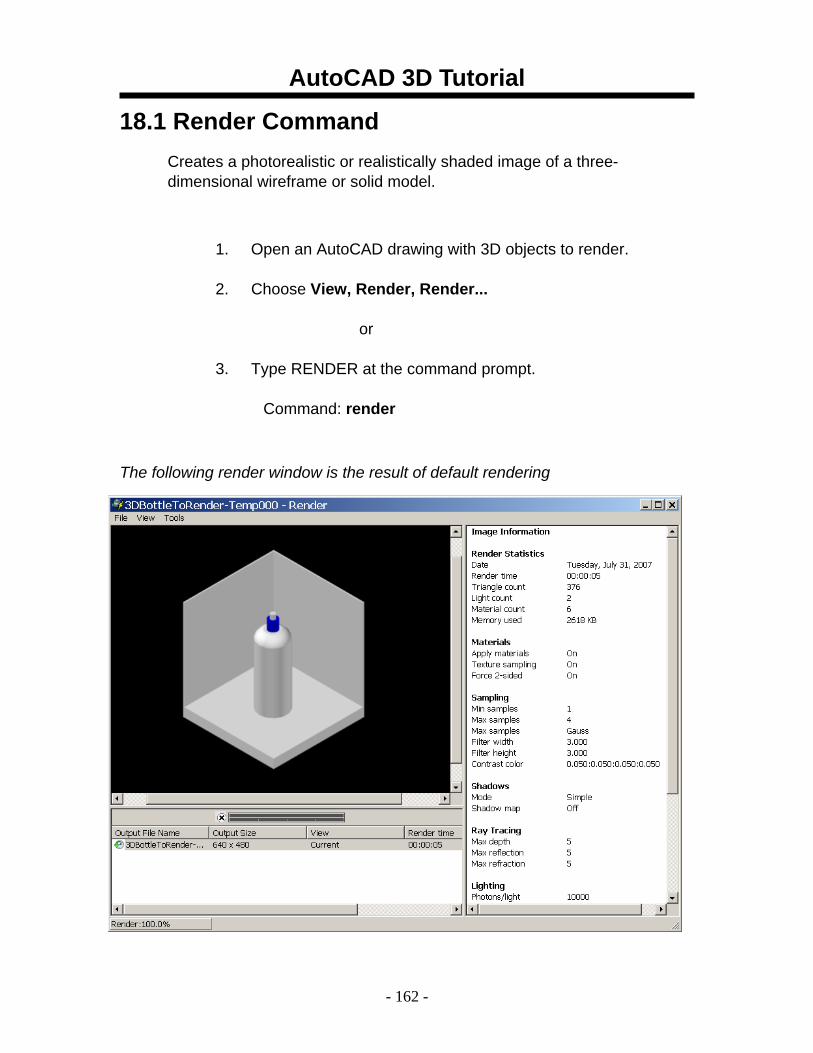
18.1 Render Command Creates a photorealistic or realistically shaded image of a three- dimensional wireframe or solid model.
1. Open an AutoCAD drawing with 3D objects to render.
2. Choose View, Render, Render...
or
3. Type RENDER at the command prompt.
Command: render
The following render window is the result of default rendering
AutoCAD 3D Tutorial
- 163 -
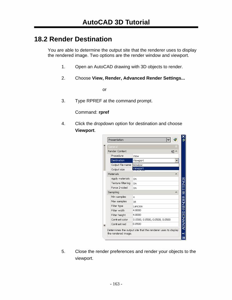
18.2 Render Destination You are able to determine the output site that the renderer uses to display the rendered image. Two options are the render window and viewport.
1. Open an AutoCAD drawing with 3D objects to render.
2. Choose View, Render, Advanced Render Settings...
or
3. Type RPREF at the command prompt.
Command: rpref
4. Click the dropdown option for destination and choose Viewport.
5. Close the render preferences and render your objects to the viewport.
AutoCAD 3D Tutorial
- 164 -
18.3 Render Quality
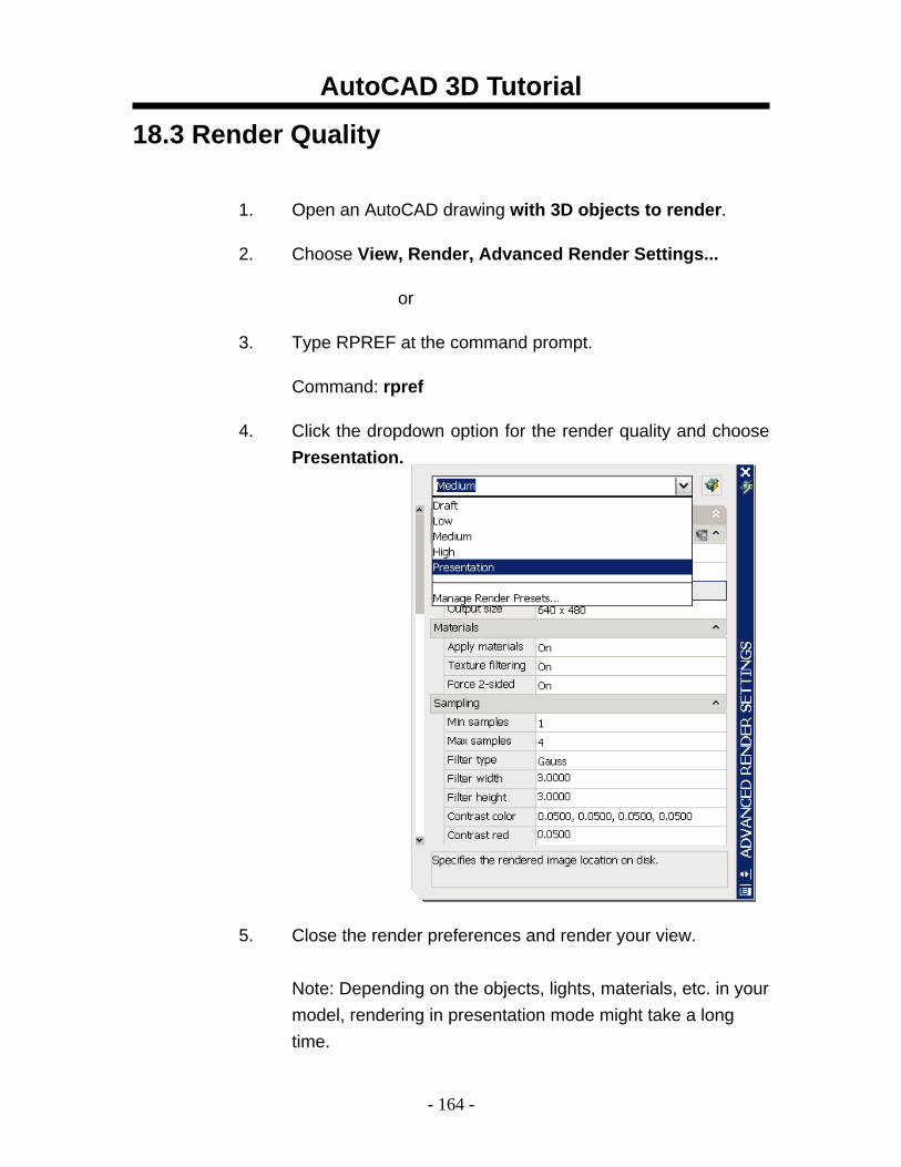
1. Open an AutoCAD drawing with 3D objects to render.
2. Choose View, Render, Advanced Render Settings...
or
3. Type RPREF at the command prompt.
Command: rpref
4. Click the dropdown option for the render quality and choose Presentation.
5. Close the render preferences and render your view. Note: Depending on the objects, lights, materials, etc. in your model, rendering in presentation mode might take a long time.
AutoCAD 3D Tutorial
- 165 -
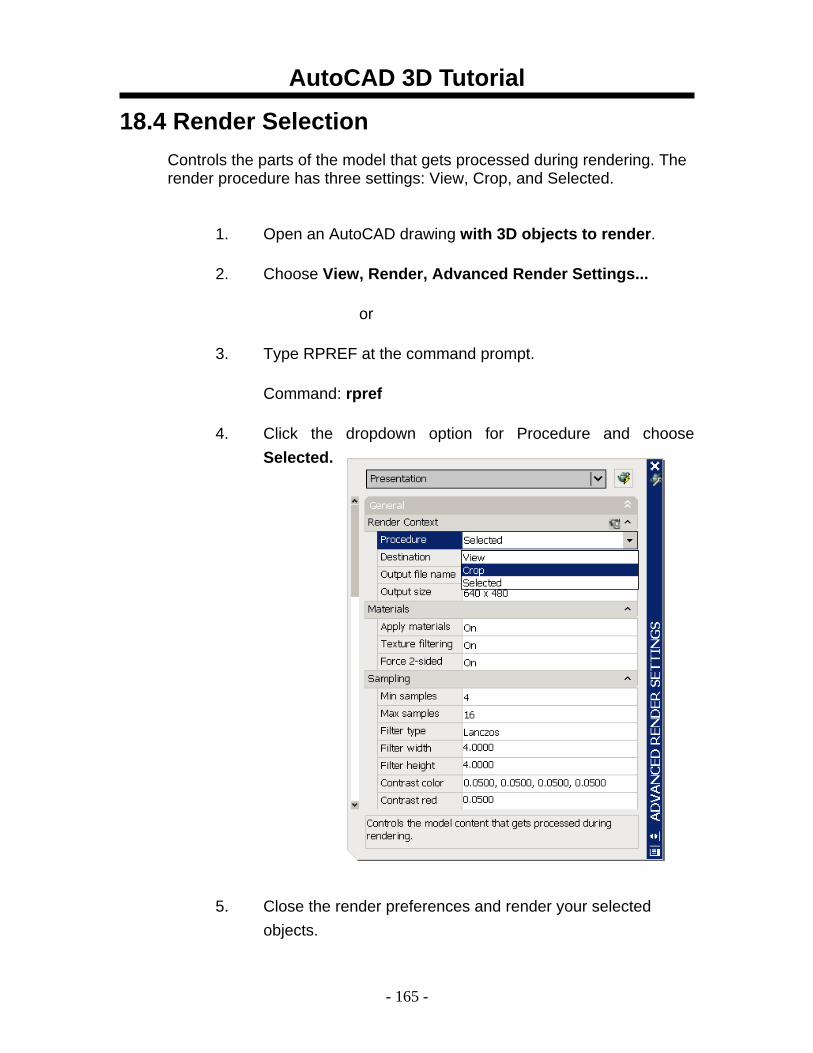
18.4 Render Selection Controls the parts of the model that gets processed during rendering. The render procedure has three settings: View, Crop, and Selected.
1. Open an AutoCAD drawing with 3D objects to render.
2. Choose View, Render, Advanced Render Settings...
or
3. Type RPREF at the command prompt.
Command: rpref
4. Click the dropdown option for Procedure and choose Selected.
5. Close the render preferences and render your selected objects.
AutoCAD 3D Tutorial
- 166 -
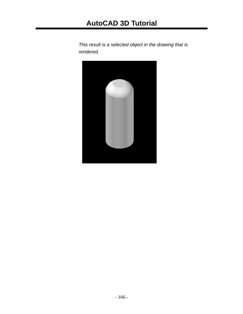
This result is a selected object in the drawing that is rendered.
AutoCAD 3D Tutorial
- 167 -
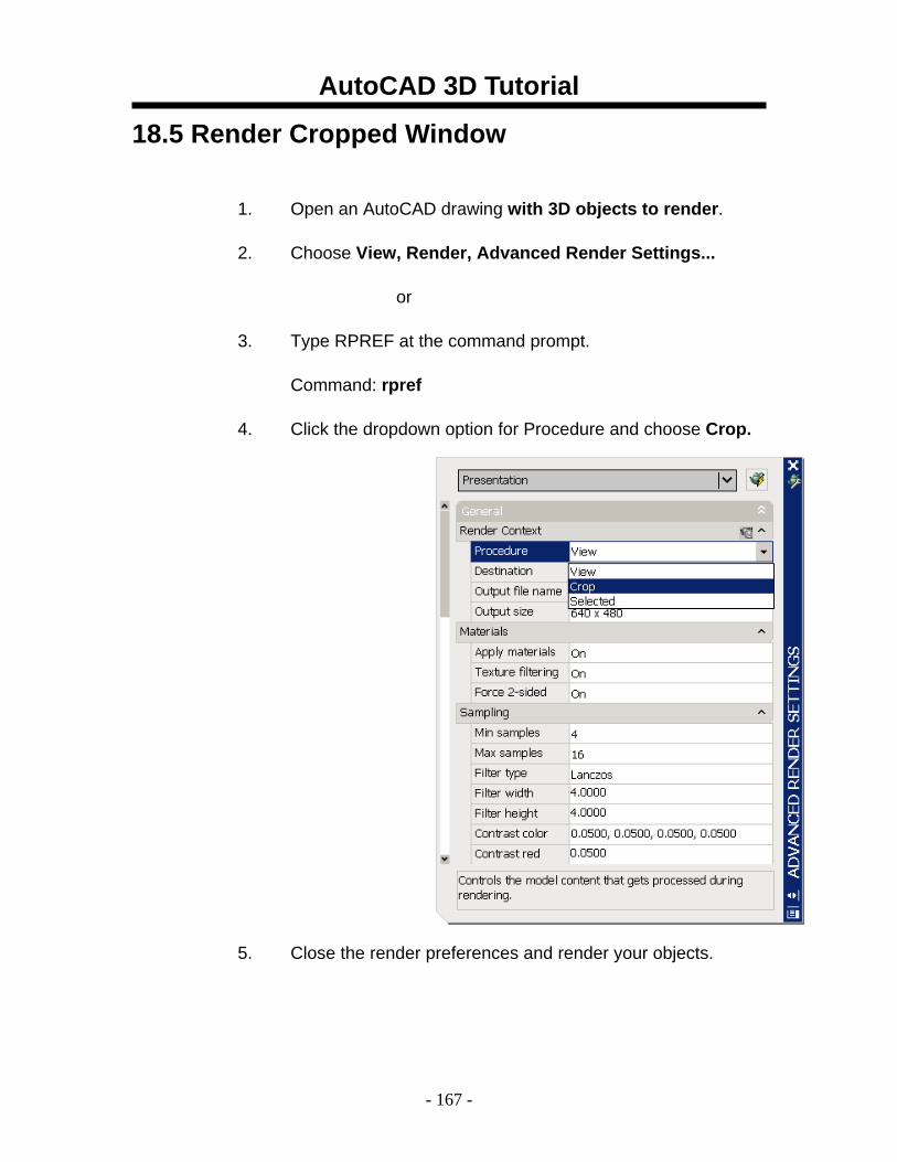
18.5 Render Cropped Window
1. Open an AutoCAD drawing with 3D objects to render.
2. Choose View, Render, Advanced Render Settings...
or
3. Type RPREF at the command prompt.
Command: rpref
4. Click the dropdown option for Procedure and choose Crop.
5. Close the render preferences and render your objects.
AutoCAD 3D Tutorial
- 168 -
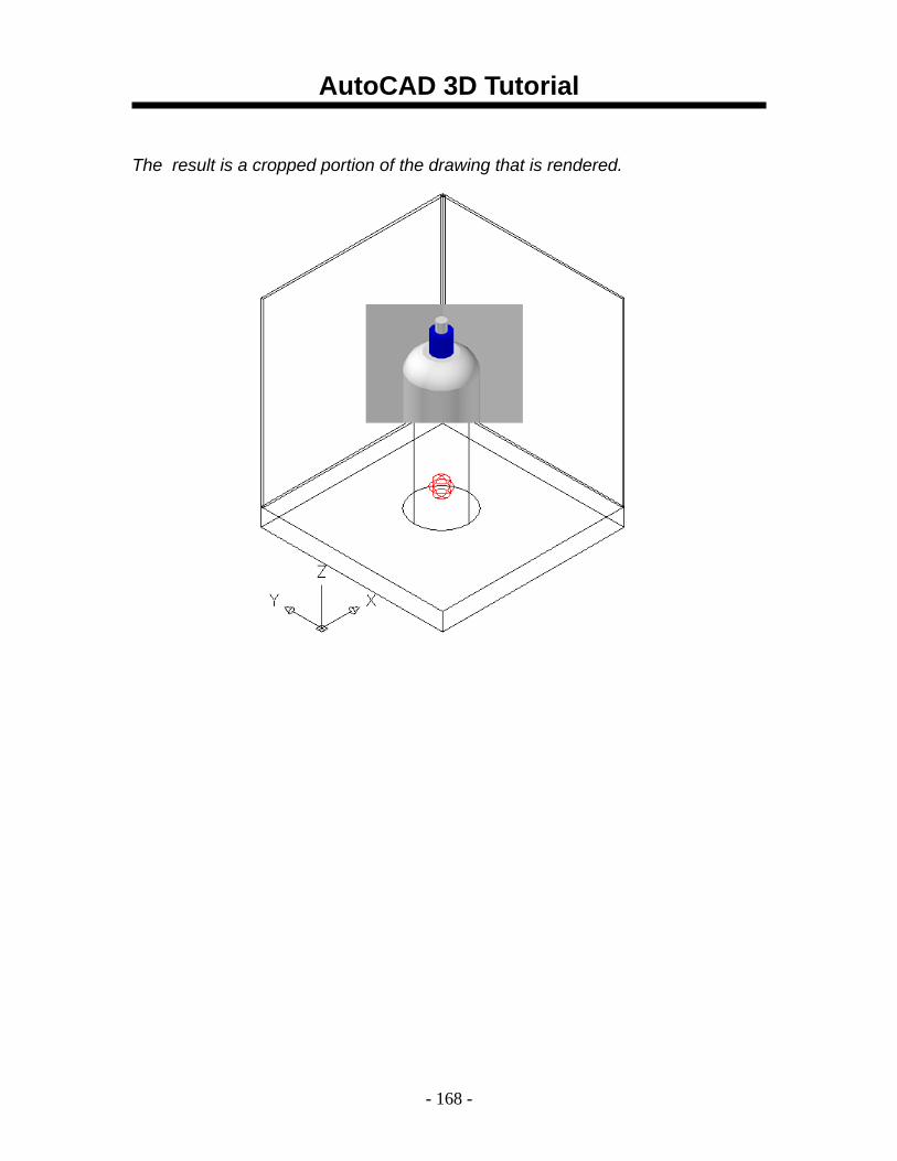
The result is a cropped portion of the drawing that is rendered.
AutoCAD 3D Tutorial
- 169 -
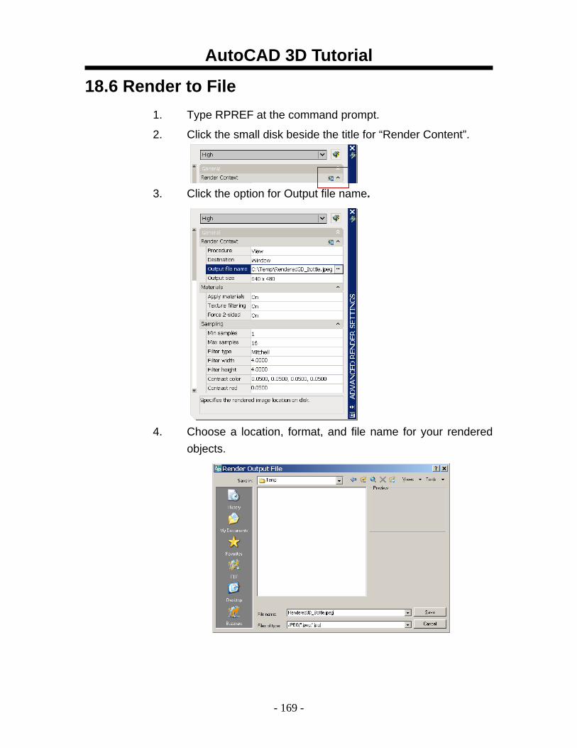
18.6 Render to File 1. Type RPREF at the command prompt.
2. Click the small disk beside the title for “Render Content”.
3. Click the option for Output file name.
4. Choose a location, format, and file name for your rendered objects.
AutoCAD 3D Tutorial
- 170 -
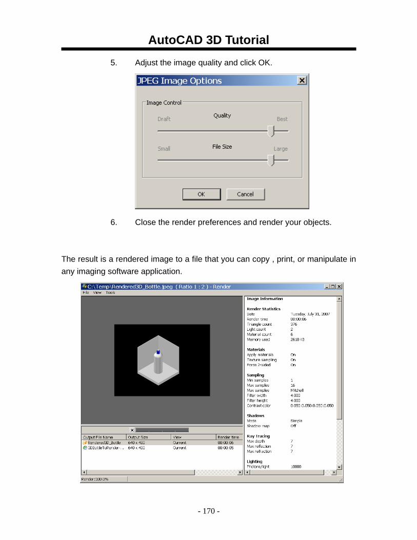
5. Adjust the image quality and click OK.
6. Close the render preferences and render your objects.
The result is a rendered image to a file that you can copy , print, or manipulate in any imaging software application.
AutoCAD 3D Tutorial
- 171 -
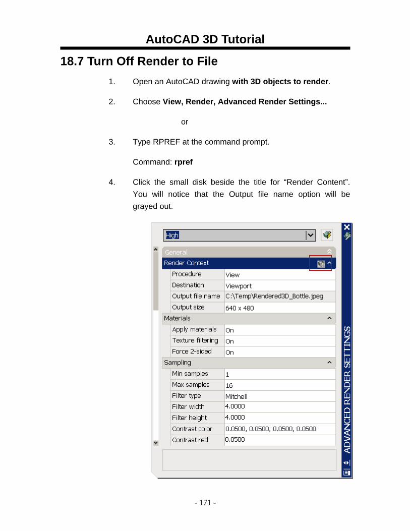
18.7 Turn Off Render to File 1. Open an AutoCAD drawing with 3D objects to render.
2. Choose View, Render, Advanced Render Settings...
or
3. Type RPREF at the command prompt.
Command: rpref
4. Click the small disk beside the title for “Render Content”. You will notice that the Output file name option will be grayed out.
AutoCAD 3D Tutorial
- 172 -
AutoCAD 3D – Chapter 19 Materials
AutoCAD 3D Tutorial
- 173 -
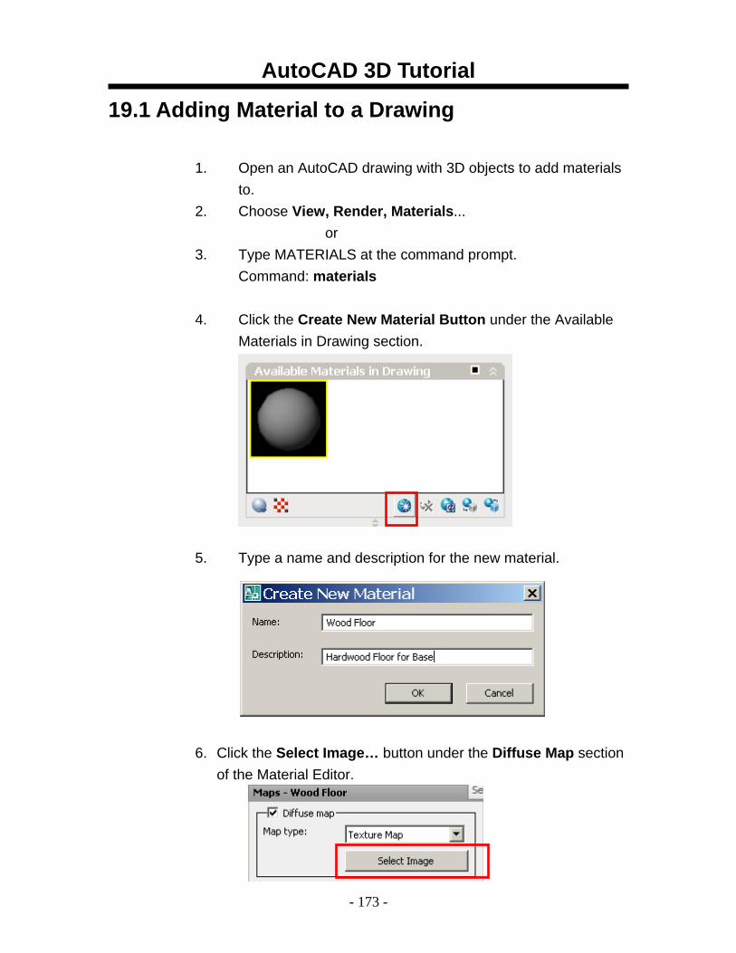
19.1 Adding Material to a Drawing
1. Open an AutoCAD drawing with 3D objects to add materials to.
2. Choose View, Render, Materials... or
3. Type MATERIALS at the command prompt. Command: materials
4. Click the Create New Material Button under the Available
Materials in Drawing section. 5. Type a name and description for the new material.
6. Click the Select Image… button under the Diffuse Map section of the Material Editor.
AutoCAD 3D Tutorial
- 174 -
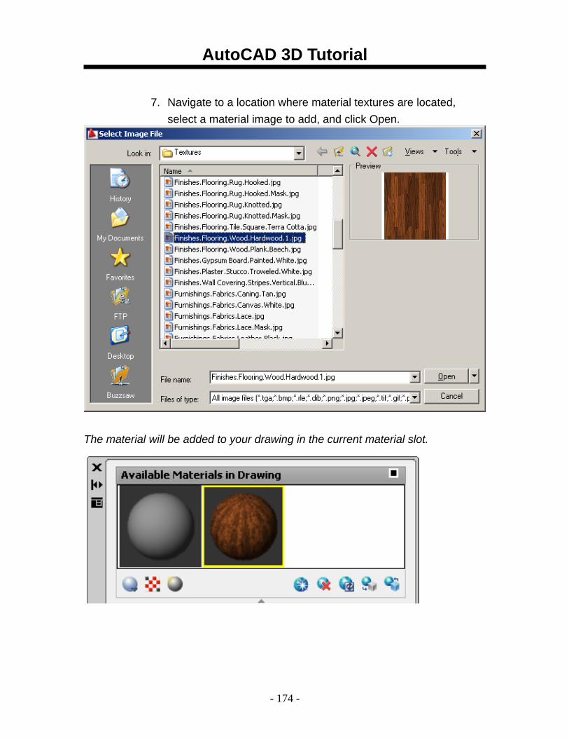
7. Navigate to a location where material textures are located,
select a material image to add, and click Open.
The material will be added to your drawing in the current material slot.
AutoCAD 3D Tutorial
- 175 -
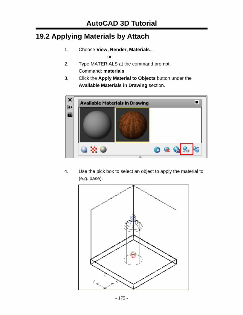
19.2 Applying Materials by Attach
1. Choose View, Render, Materials... or
2. Type MATERIALS at the command prompt. Command: materials
3. Click the Apply Material to Objects button under the Available Materials in Drawing section.
4. Use the pick box to select an object to apply the material to
(e.g. base).
AutoCAD 3D Tutorial
- 176 -
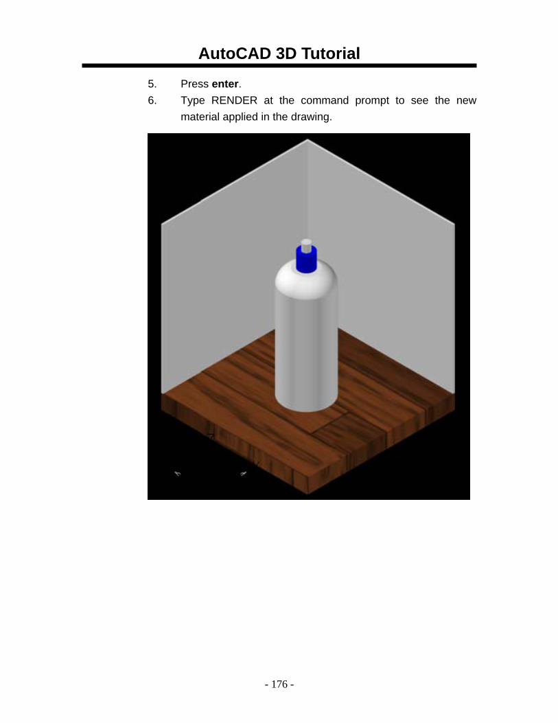
5. Press enter. 6. Type RENDER at the command prompt to see the new
material applied in the drawing.
AutoCAD 3D Tutorial
- 177 -
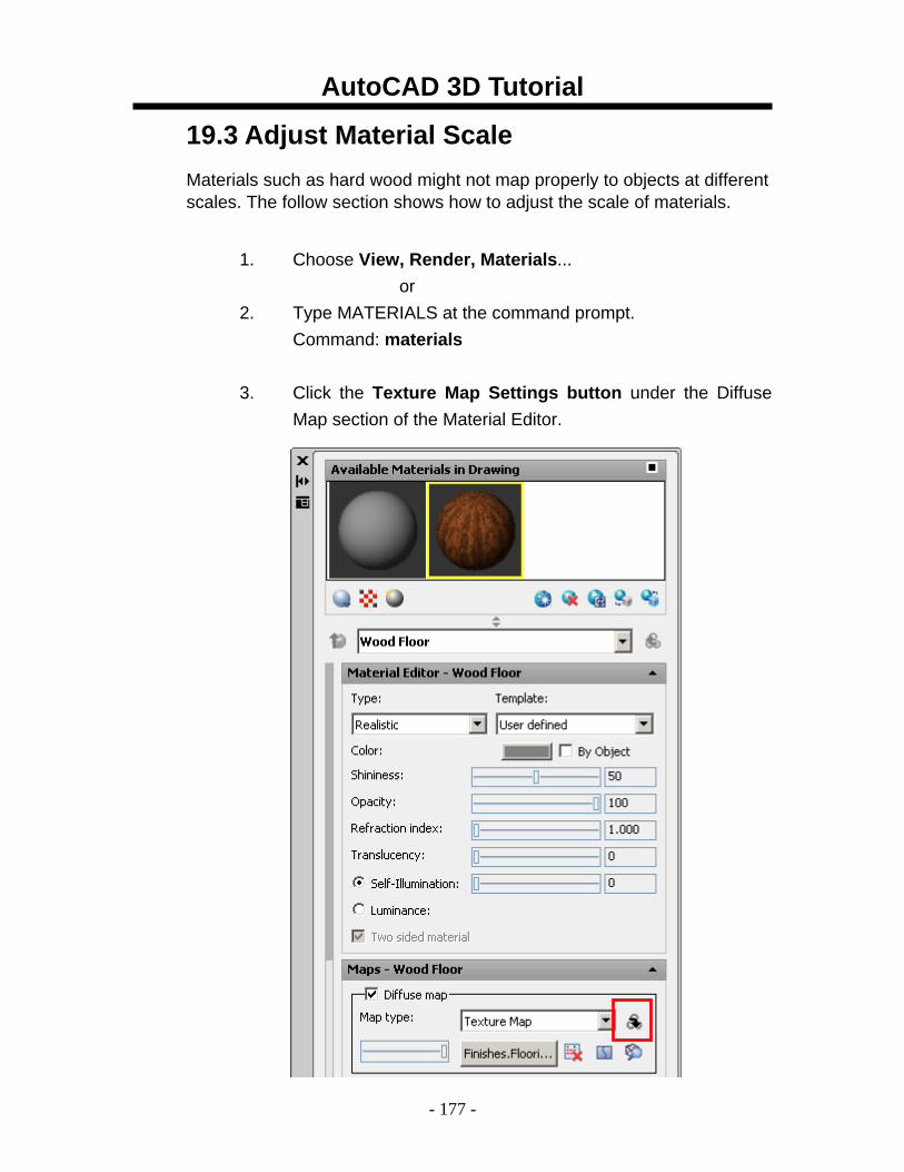
19.3 Adjust Material Scale Materials such as hard wood might not map properly to objects at different scales. The follow section shows how to adjust the scale of materials.
1. Choose View, Render, Materials...
or 2. Type MATERIALS at the command prompt.
Command: materials
3. Click the Texture Map Settings button under the Diffuse Map section of the Material Editor.

AutoCAD 3D Tutorial
- 178 -
4. Double-click Scaling & Tiling. 5. Click the lock icon to scale the materials evenly in both
directions. 6. Change the U and V tile settings to make the material
smaller or larger.
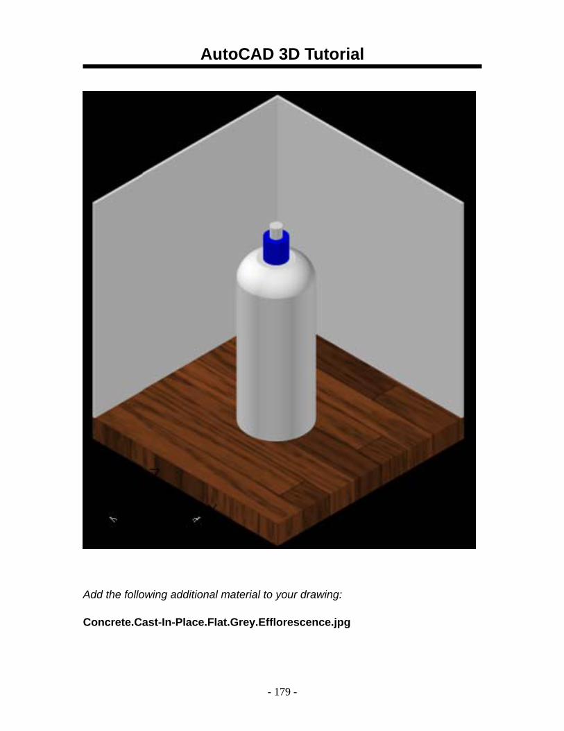
7. Render the drawing to see the newly mapped material.
AutoCAD 3D Tutorial
- 179 -
Add the following additional material to your drawing: Concrete.Cast-In-Place.Flat.Grey.Efflorescence.jpg
AutoCAD 3D Tutorial
- 180 -
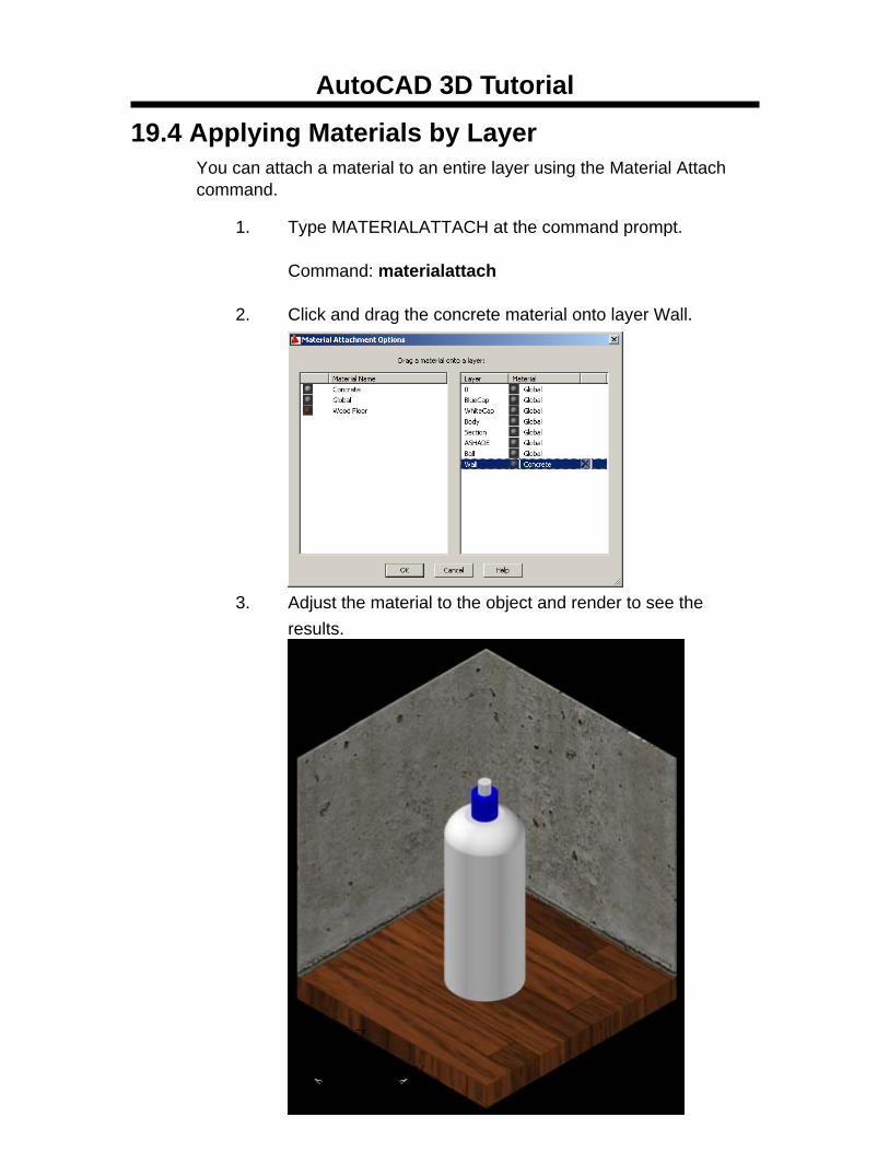
19.4 Applying Materials by Layer You can attach a material to an entire layer using the Material Attach command.
1. Type MATERIALATTACH at the command prompt.
Command: materialattach
2. Click and drag the concrete material onto layer Wall. 3. Adjust the material to the object and render to see the
results.
AutoCAD 3D Tutorial
- 181 -
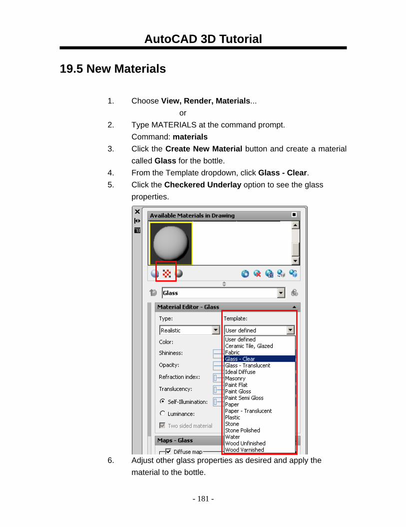
19.5 New Materials
1. Choose View, Render, Materials... or
2. Type MATERIALS at the command prompt. Command: materials
3. Click the Create New Material button and create a material called Glass for the bottle.
4. From the Template dropdown, click Glass - Clear. 5. Click the Checkered Underlay option to see the glass
properties. 6. Adjust other glass properties as desired and apply the
material to the bottle.
AutoCAD 3D Tutorial
- 182 -
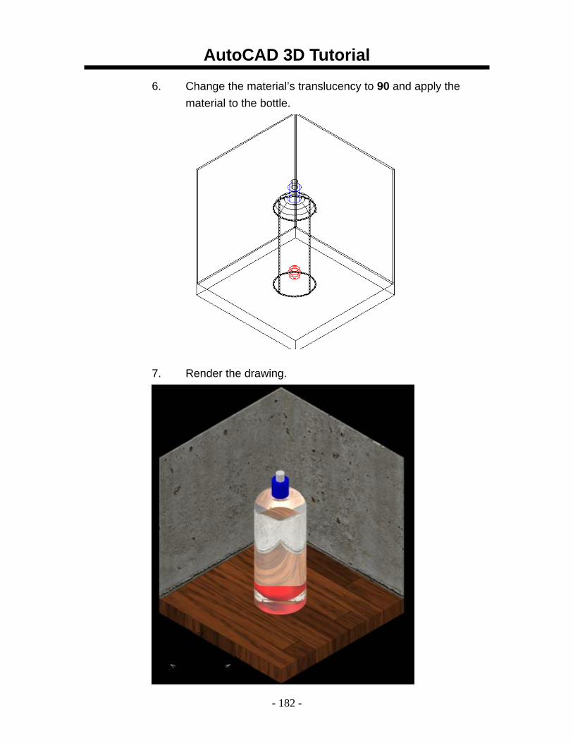
6. Change the material’s translucency to 90 and apply the material to the bottle.
7. Render the drawing.
AutoCAD 3D Tutorial
- 183 -
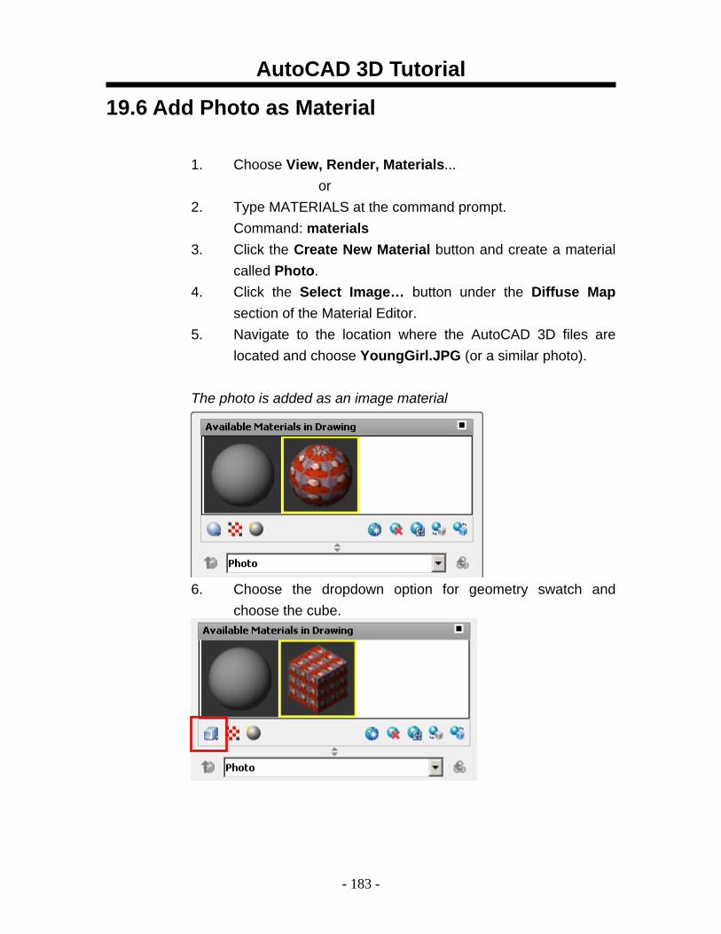
19.6 Add Photo as Material
1. Choose View, Render, Materials... or
2. Type MATERIALS at the command prompt. Command: materials
3. Click the Create New Material button and create a material called Photo.
4. Click the Select Image… button under the Diffuse Map section of the Material Editor.
5. Navigate to the location where the AutoCAD 3D files are located and choose YoungGirl.JPG (or a similar photo).
The photo is added as an image material 6. Choose the dropdown option for geometry swatch and
choose the cube.
AutoCAD 3D Tutorial
- 184 -
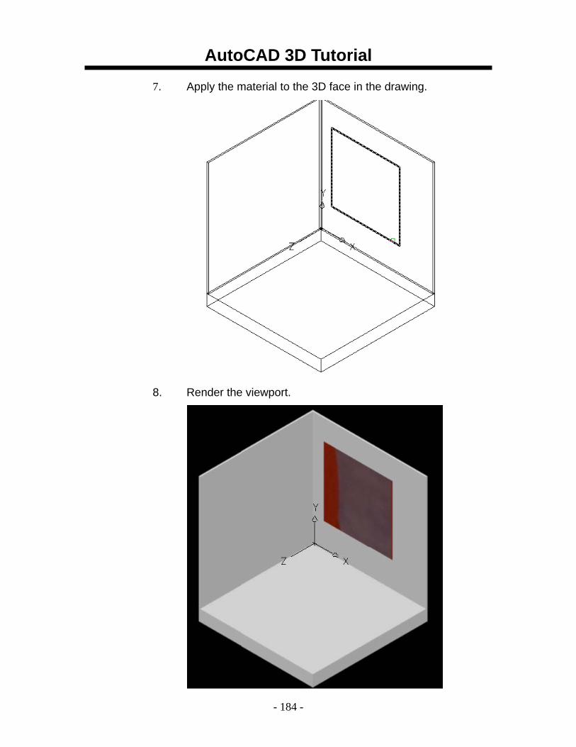
7. Apply the material to the 3D face in the drawing. 8. Render the viewport.
AutoCAD 3D Tutorial
- 185 -
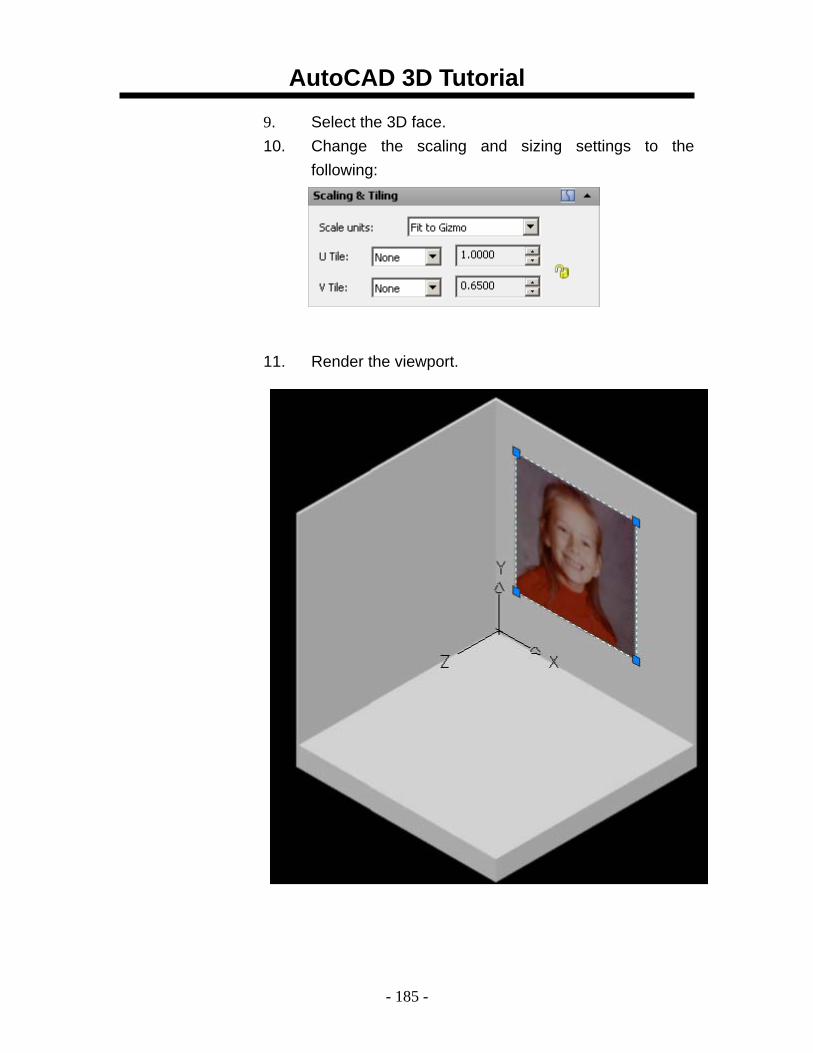
9. Select the 3D face. 10. Change the scaling and sizing settings to the
following: 11. Render the viewport.
AutoCAD 3D Tutorial
- 186 -
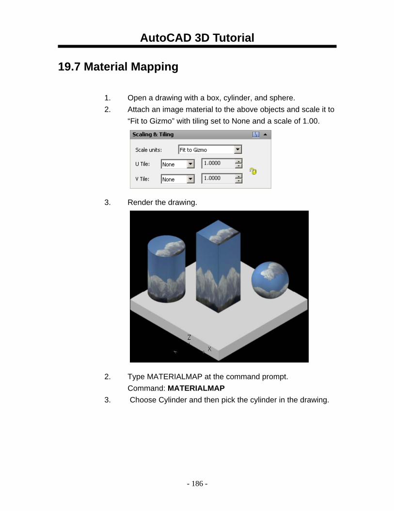
19.7 Material Mapping
1. Open a drawing with a box, cylinder, and sphere. 2. Attach an image material to the above objects and scale it to
“Fit to Gizmo” with tiling set to None and a scale of 1.00. 3. Render the drawing. 2. Type MATERIALMAP at the command prompt.
Command: MATERIALMAP 3. Choose Cylinder and then pick the cylinder in the drawing.
AutoCAD 3D Tutorial
- 187 -
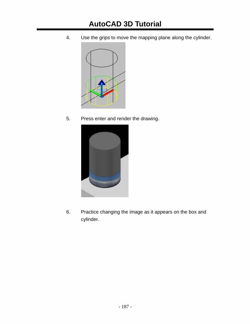
4. Use the grips to move the mapping plane along the cylinder.
5. Press enter and render the drawing.
6. Practice changing the image as it appears on the box and cylinder.
AutoCAD 3D Tutorial
- 188 -
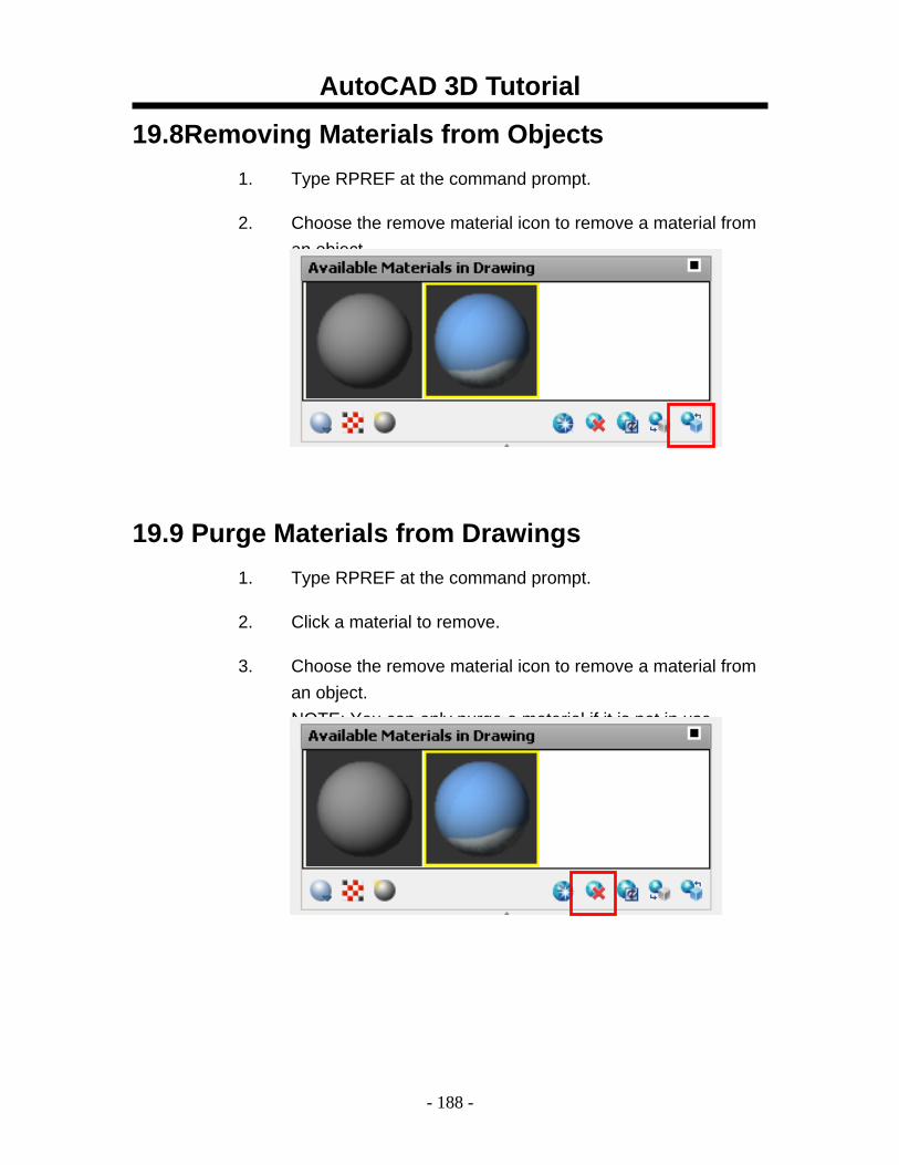
19.8Removing Materials from Objects 1. Type RPREF at the command prompt.
2. Choose the remove material icon to remove a material from an object.
19.9 Purge Materials from Drawings 1. Type RPREF at the command prompt.
2. Click a material to remove.
3. Choose the remove material icon to remove a material from an object. NOTE: You can only purge a material if it is not in use.
AutoCAD 3D Tutorial
- 189 -
19.10 Opacity Materials
1. Choose View, Render, Materials... or
2. Type MATERIALS at the command prompt. Command: materials
3. Click the Create New Material button and create a material called Opacity Material.
4. Click Select Image under the Opacity map option and choose the opacity material.
5. Click Select Image under the Diffuse map option and choose the texture (image).
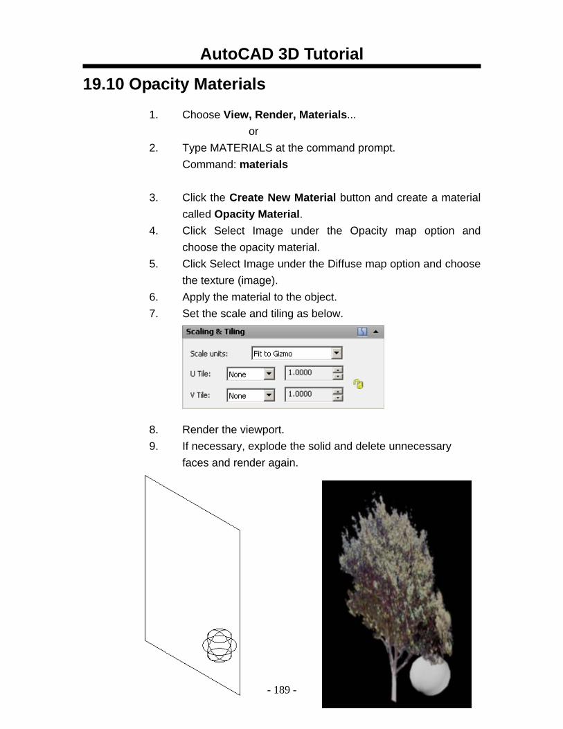
6. Apply the material to the object. 7. Set the scale and tiling as below. 8. Render the viewport. 9. If necessary, explode the solid and delete unnecessary
faces and render again.
AutoCAD 3D Tutorial
- 190 -
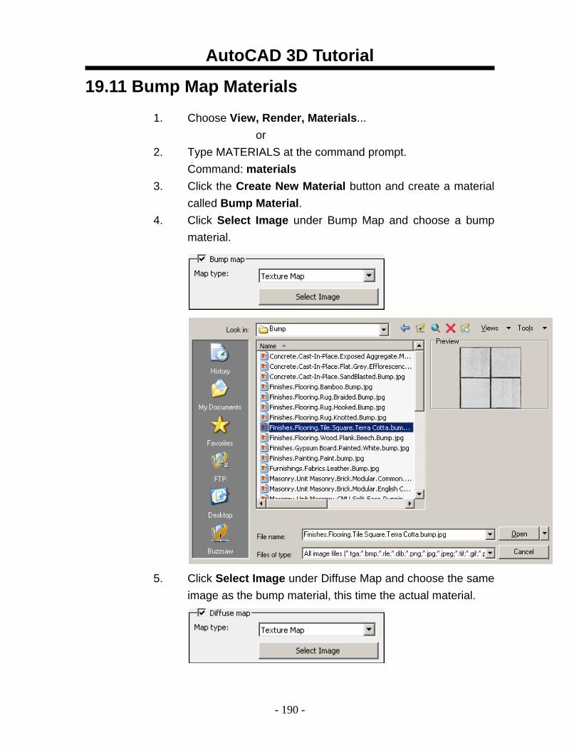
19.11 Bump Map Materials
1. Choose View, Render, Materials... or
2. Type MATERIALS at the command prompt. Command: materials
3. Click the Create New Material button and create a material called Bump Material.
4. Click Select Image under Bump Map and choose a bump material.
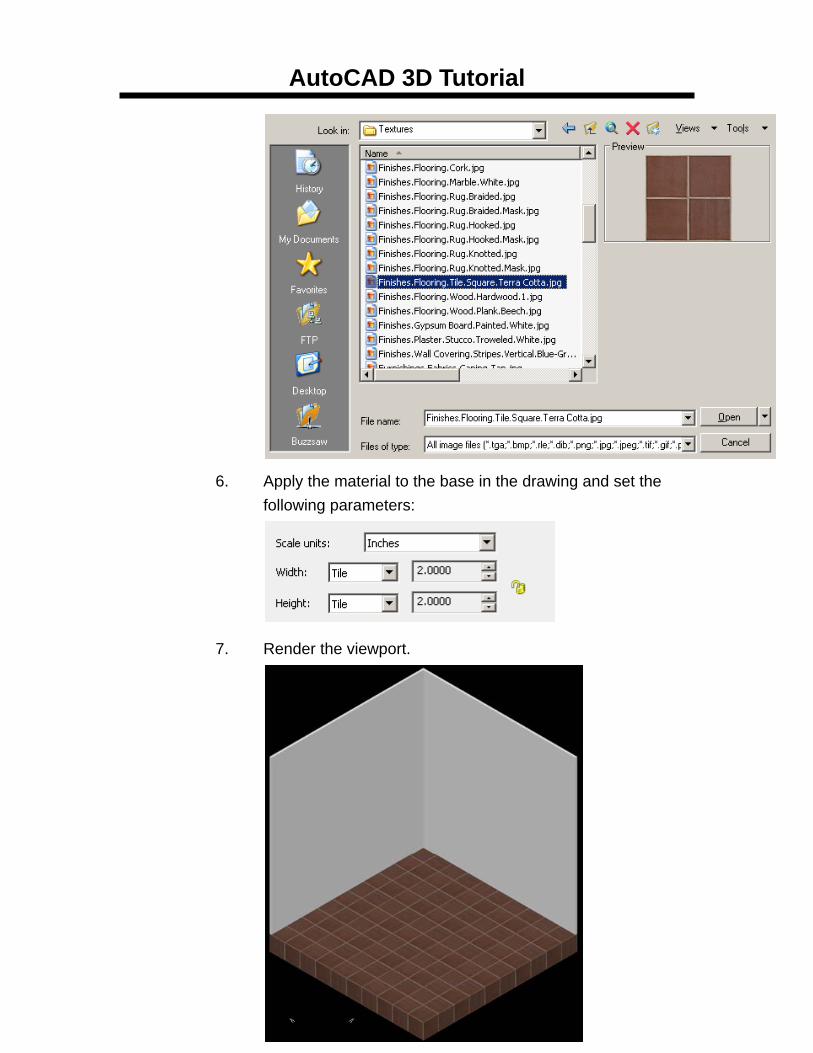
5. Click Select Image under Diffuse Map and choose the same
image as the bump material, this time the actual material.
AutoCAD 3D Tutorial
- 191 -
6. Apply the material to the base in the drawing and set the following parameters:
7. Render the viewport.
AutoCAD 3D Tutorial
- 192 -
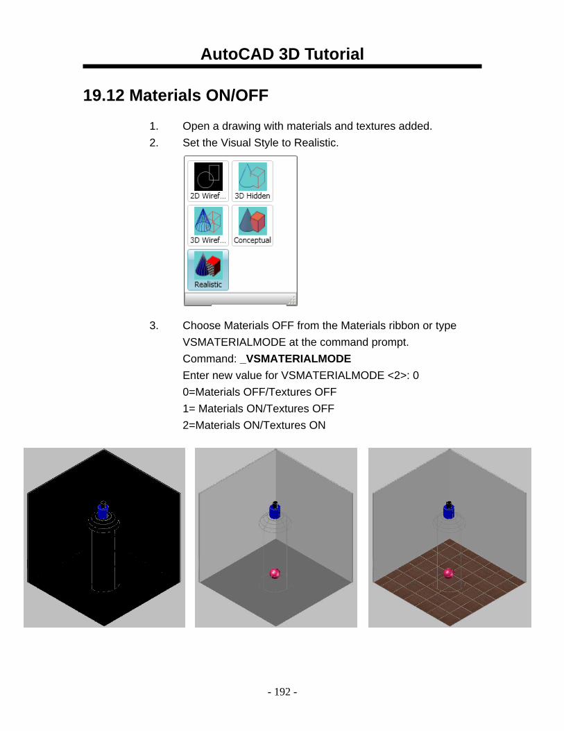
19.12 Materials ON/OFF
1. Open a drawing with materials and textures added. 2. Set the Visual Style to Realistic. 3. Choose Materials OFF from the Materials ribbon or type
VSMATERIALMODE at the command prompt. Command: _VSMATERIALMODE
Enter new value for VSMATERIALMODE <2>: 0 0=Materials OFF/Textures OFF 1= Materials ON/Textures OFF 2=Materials ON/Textures ON
AutoCAD 3D Tutorial
- 193 -
AutoCAD 3D – Chapter 20 Lights
AutoCAD 3D Tutorial
- 194 -
20.1 Default Lighting When there are no lights in a scene, the scene is shaded with default lighting. Default lighting is derived from two distant sources that follow the viewpoint as you move around the model. All faces in the model are illuminated so that they are visually discernible. You can control brightness and contrast, but you do not need to create or place lights yourself.
When you insert custom lights or add sunlight, you can disable the default lighting. You can apply default lighting to the viewport only; at the same time, you can apply custom lights to the rendering.
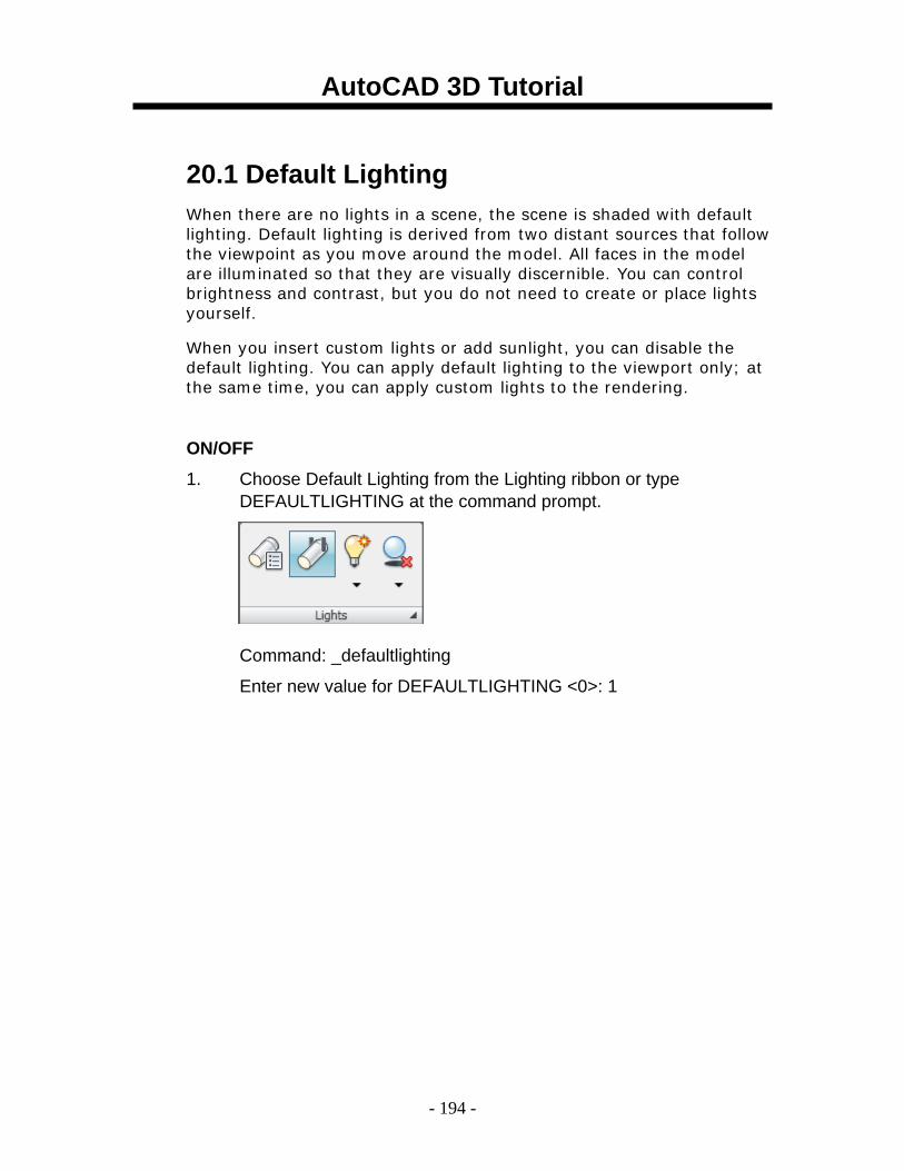
ON/OFF 1. Choose Default Lighting from the Lighting ribbon or type
DEFAULTLIGHTING at the command prompt.
Command: _defaultlighting
Enter new value for DEFAULTLIGHTING <0>: 1
AutoCAD 3D Tutorial
- 195 -
20.2 Point Lights A point light radiates light in all directions from its location.
1. Open a drawing with 3D objects and display in a 3D view.
2. Choose View, Render, Light, New Point Light.
or
3. Type POINTLIGHT at the command prompt.
Command: pointlight
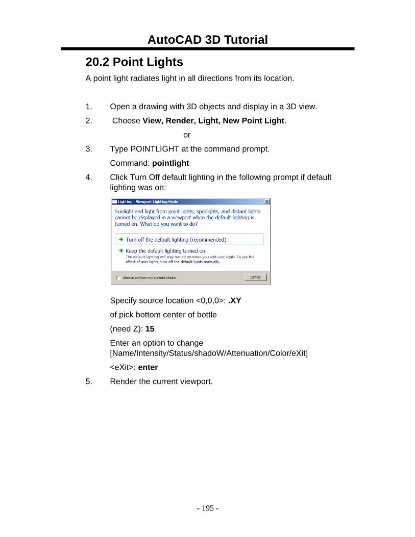
4. Click Turn Off default lighting in the following prompt if default lighting was on:
Specify source location <0,0,0>: .XY
of pick bottom center of bottle
(need Z): 15
Enter an option to change [Name/Intensity/Status/shadoW/Attenuation/Color/eXit]
<eXit>: enter
5. Render the current viewport.
AutoCAD 3D Tutorial
- 196 -
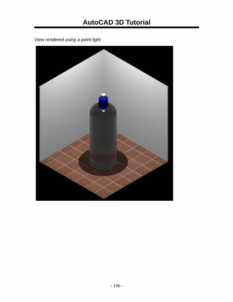
View rendered using a point light
AutoCAD 3D Tutorial
- 197 -
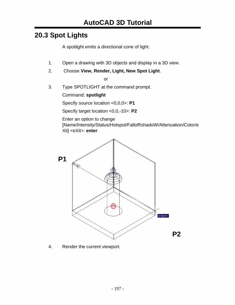
20.3 Spot Lights A spotlight emits a directional cone of light.
1. Open a drawing with 3D objects and display in a 3D view.
2. Choose View, Render, Light, New Spot Light.
or
3. Type SPOTLIGHT at the command prompt.
Command: spotlight
Specify source location <0,0,0>: P1
Specify target location <0,0,-10>: P2
Enter an option to change [Name/Intensity/Status/Hotspot/Falloff/shadoW/Attenuation/Color/eXit] <eXit>: enter
4. Render the current viewport.
P1
P2
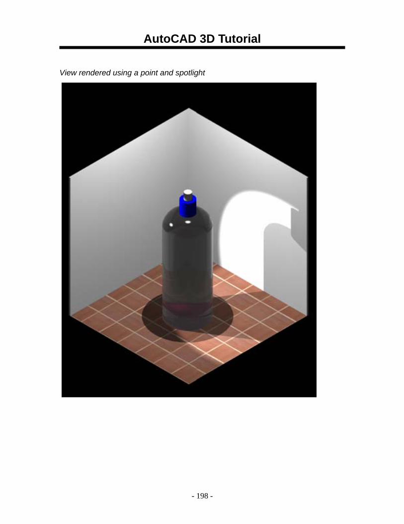
AutoCAD 3D Tutorial
- 198 -
View rendered using a point and spotlight
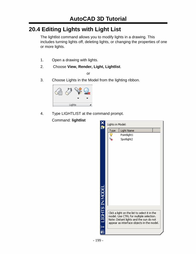
AutoCAD 3D Tutorial
- 199 -
20.4 Editing Lights with Light List The lightlist command allows you to modify lights in a drawing. This includes turning lights off, deleting lights, or changing the properties of one or more lights.
1. Open a drawing with lights.
2. Choose View, Render, Light, Lightlist.
or
3. Choose Lights in the Model from the lighting ribbon.
4. Type LIGHTLIST at the command prompt.
Command: lightlist
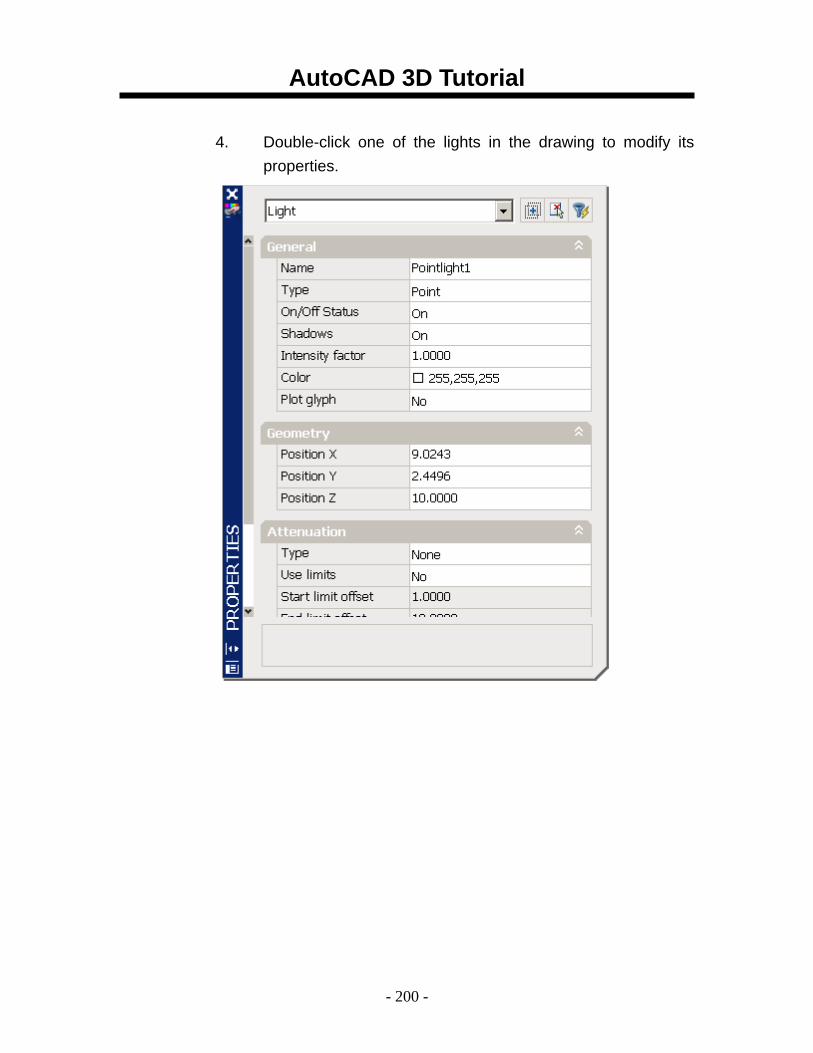
AutoCAD 3D Tutorial
- 200 -
4. Double-click one of the lights in the drawing to modify its
properties.
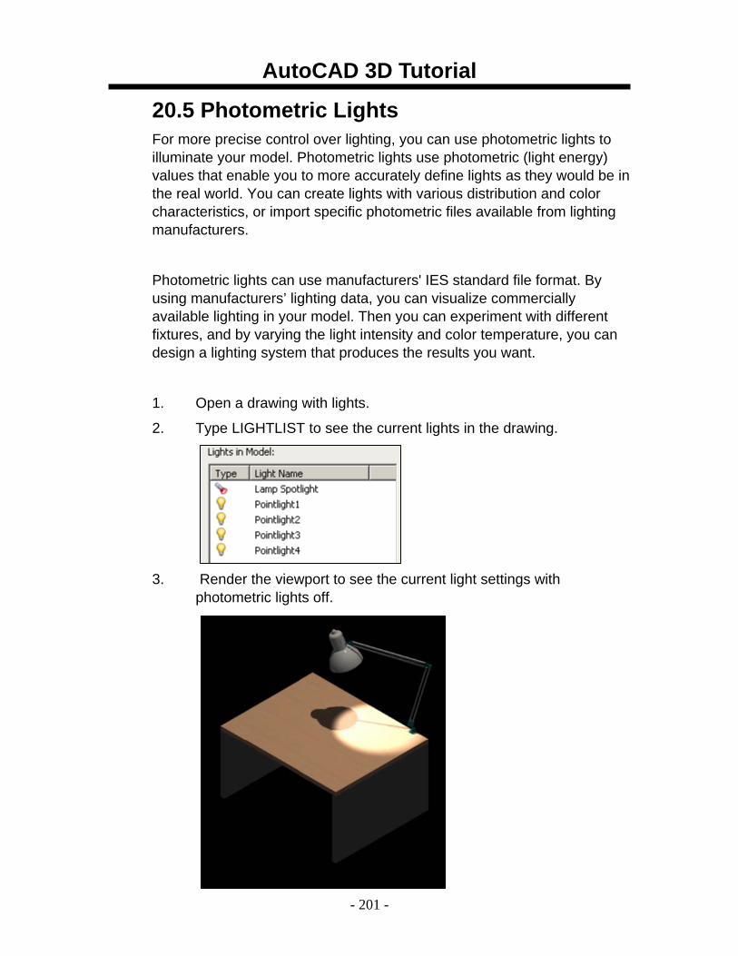
AutoCAD 3D Tutorial
- 201 -
20.5 Photometric Lights For more precise control over lighting, you can use photometric lights to illuminate your model. Photometric lights use photometric (light energy) values that enable you to more accurately define lights as they would be in the real world. You can create lights with various distribution and color characteristics, or import specific photometric files available from lighting manufacturers.
Photometric lights can use manufacturers' IES standard file format. By using manufacturers’ lighting data, you can visualize commercially available lighting in your model. Then you can experiment with different fixtures, and by varying the light intensity and color temperature, you can design a lighting system that produces the results you want.
1. Open a drawing with lights.
2. Type LIGHTLIST to see the current lights in the drawing.
3. Render the viewport to see the current light settings with photometric lights off.
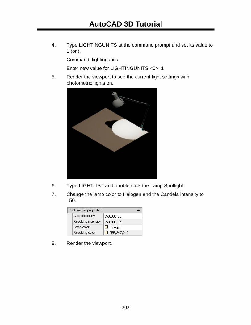
AutoCAD 3D Tutorial
- 202 -
4. Type LIGHTINGUNITS at the command prompt and set its value to 1 (on).
Command: lightingunits
Enter new value for LIGHTINGUNITS <0>: 1
5. Render the viewport to see the current light settings with photometric lights on.
6. Type LIGHTLIST and double-click the Lamp Spotlight.
7. Change the lamp color to Halogen and the Candela intensity to 150.
8. Render the viewport.
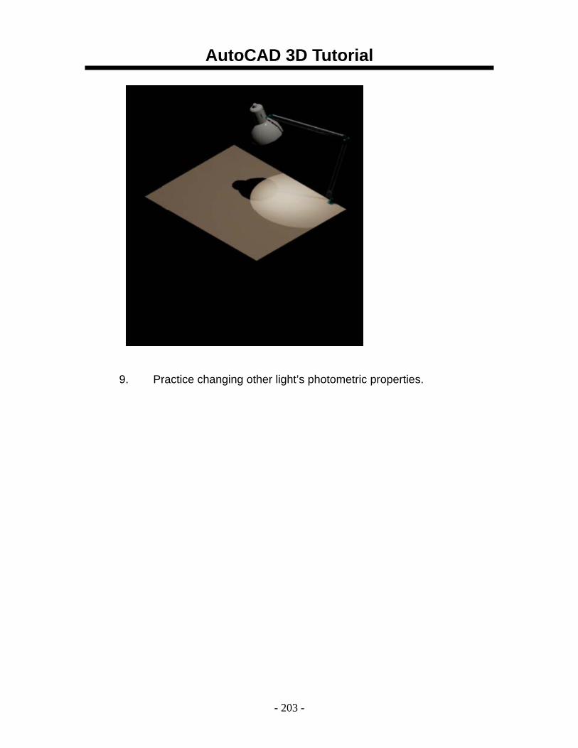
AutoCAD 3D Tutorial
- 203 -
9. Practice changing other light’s photometric properties.
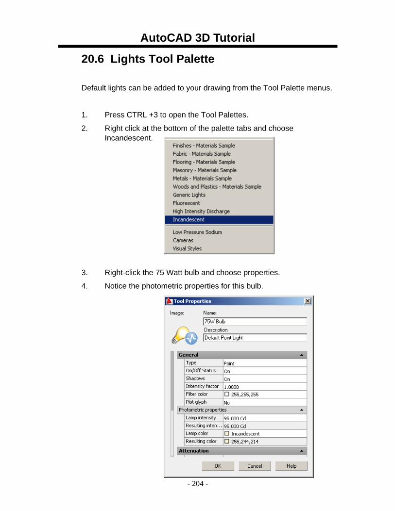
AutoCAD 3D Tutorial
- 204 -
20.6 Lights Tool Palette
Default lights can be added to your drawing from the Tool Palette menus.
1. Press CTRL +3 to open the Tool Palettes.
2. Right click at the bottom of the palette tabs and choose Incandescent.
3. Right-click the 75 Watt bulb and choose properties.
4. Notice the photometric properties for this bulb.
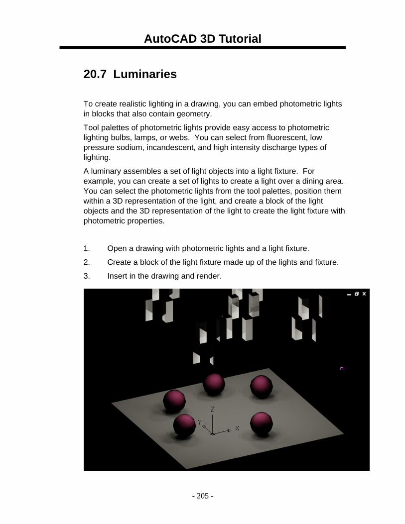
AutoCAD 3D Tutorial
- 205 -
20.7 Luminaries
To create realistic lighting in a drawing, you can embed photometric lights in blocks that also contain geometry.
Tool palettes of photometric lights provide easy access to photometric lighting bulbs, lamps, or webs. You can select from fluorescent, low pressure sodium, incandescent, and high intensity discharge types of lighting.
A luminary assembles a set of light objects into a light fixture. For example, you can create a set of lights to create a light over a dining area. You can select the photometric lights from the tool palettes, position them within a 3D representation of the light, and create a block of the light objects and the 3D representation of the light to create the light fixture with photometric properties.
1. Open a drawing with photometric lights and a light fixture.
2. Create a block of the light fixture made up of the lights and fixture.
3. Insert in the drawing and render.
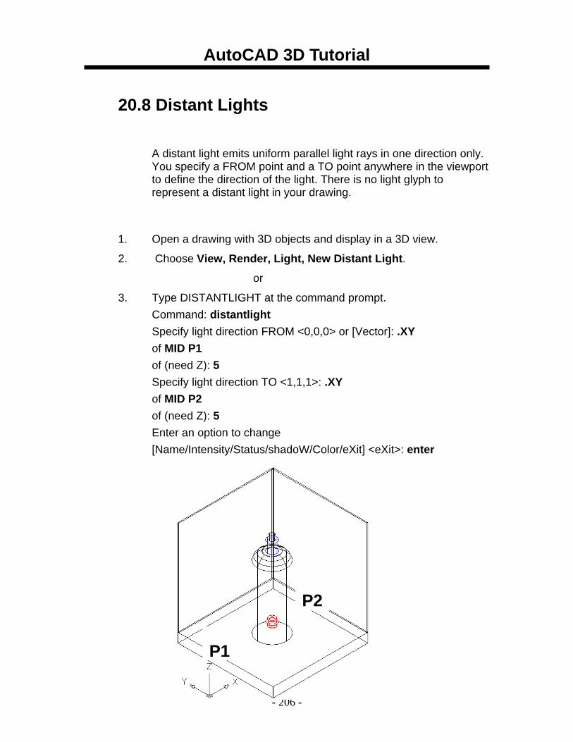
AutoCAD 3D Tutorial
- 206 -
20.8 Distant Lights
A distant light emits uniform parallel light rays in one direction only. You specify a FROM point and a TO point anywhere in the viewport to define the direction of the light. There is no light glyph to represent a distant light in your drawing.
1. Open a drawing with 3D objects and display in a 3D view.
2. Choose View, Render, Light, New Distant Light.
or
3. Type DISTANTLIGHT at the command prompt. Command: distantlight
Specify light direction FROM <0,0,0> or [Vector]: .XY of MID P1 of (need Z): 5 Specify light direction TO <1,1,1>: .XY of MID P2 of (need Z): 5 Enter an option to change [Name/Intensity/Status/shadoW/Color/eXit] <eXit>: enter
P1
P2
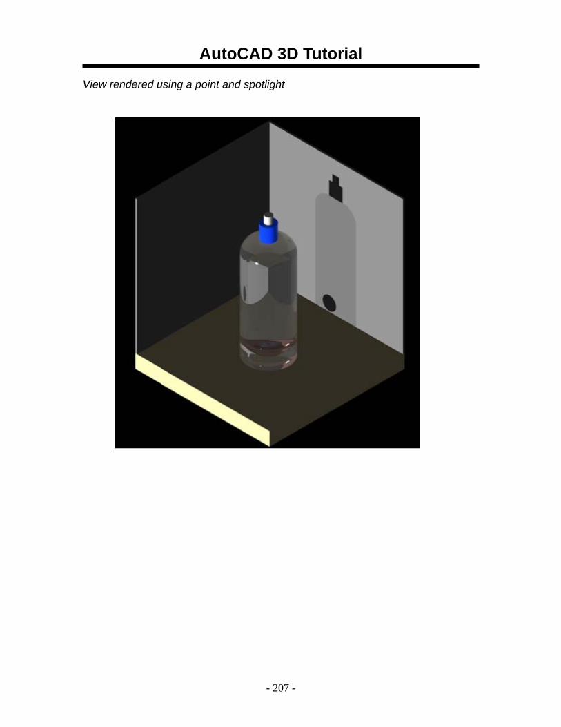
AutoCAD 3D Tutorial
- 207 -
View rendered using a point and spotlight
AutoCAD 3D Tutorial
- 208 -
20.9 Other Lights
Weblights
Photometric weblights provide real-world light distribution.
A photometric weblight (web) is a 3D representation of the light intensity distribution of a light source. Photometric weblights can be used to represent anisotropic (non-uniform) light distributions derived from data provided by manufacturers of real-world lights. This gives a far more precise representation of the rendered light than either spot or point lights are capable of.
This directional light distribution information is stored in a photometric data file in the IES format using the IES LM-63-1991 standard file format for photometric data. You can load photometric data files provided by various manufacturers under the Photometric Web panel in the Properties palette for the light. The light icon represents the photometric web you select.
Light that uses a photometric web can be added to a drawing by entering the commands WEBLIGHT and FREEWEB at the command prompt. A weblight targets an object whereas a freeweb light does not.
Target Point Lights You create a target point light with the TARGETPOINT command. The difference between the target point light and a point light is the additional target properties that are available. A target light can be pointed to an object. A target point light can also be created from a point light by changing the target property of the point light from No to Yes.
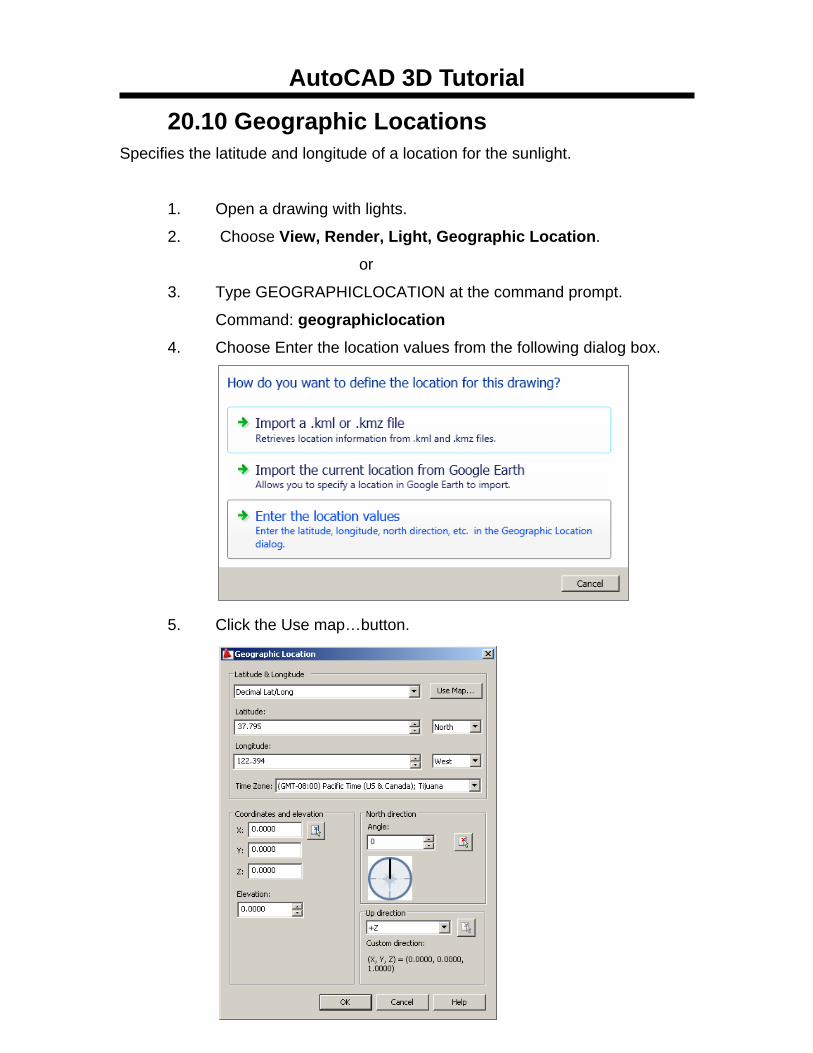
AutoCAD 3D Tutorial
- 209 -
20.10 Geographic Locations Specifies the latitude and longitude of a location for the sunlight.
1. Open a drawing with lights.
2. Choose View, Render, Light, Geographic Location.
or
3. Type GEOGRAPHICLOCATION at the command prompt.
Command: geographiclocation
4. Choose Enter the location values from the following dialog box.
5. Click the Use map…button.
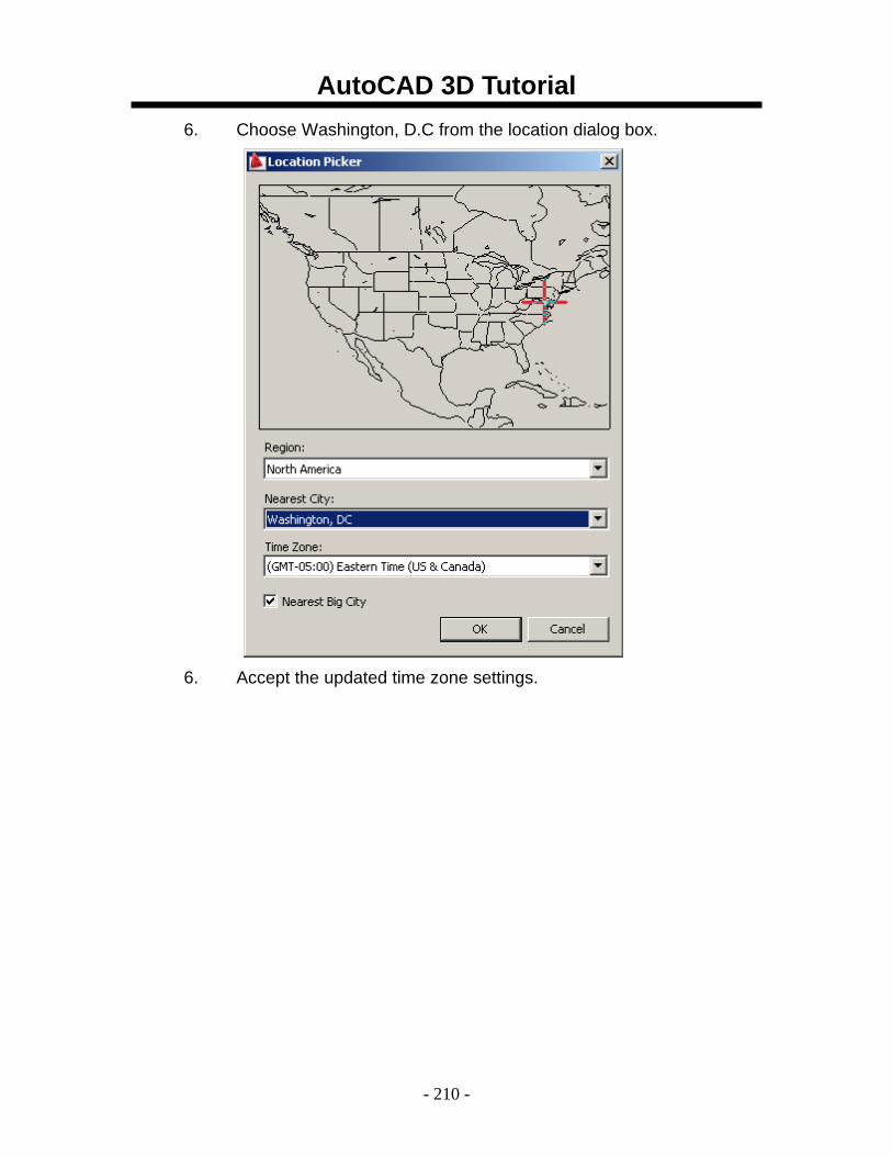
AutoCAD 3D Tutorial
- 210 -
6. Choose Washington, D.C from the location dialog box.
6. Accept the updated time zone settings.
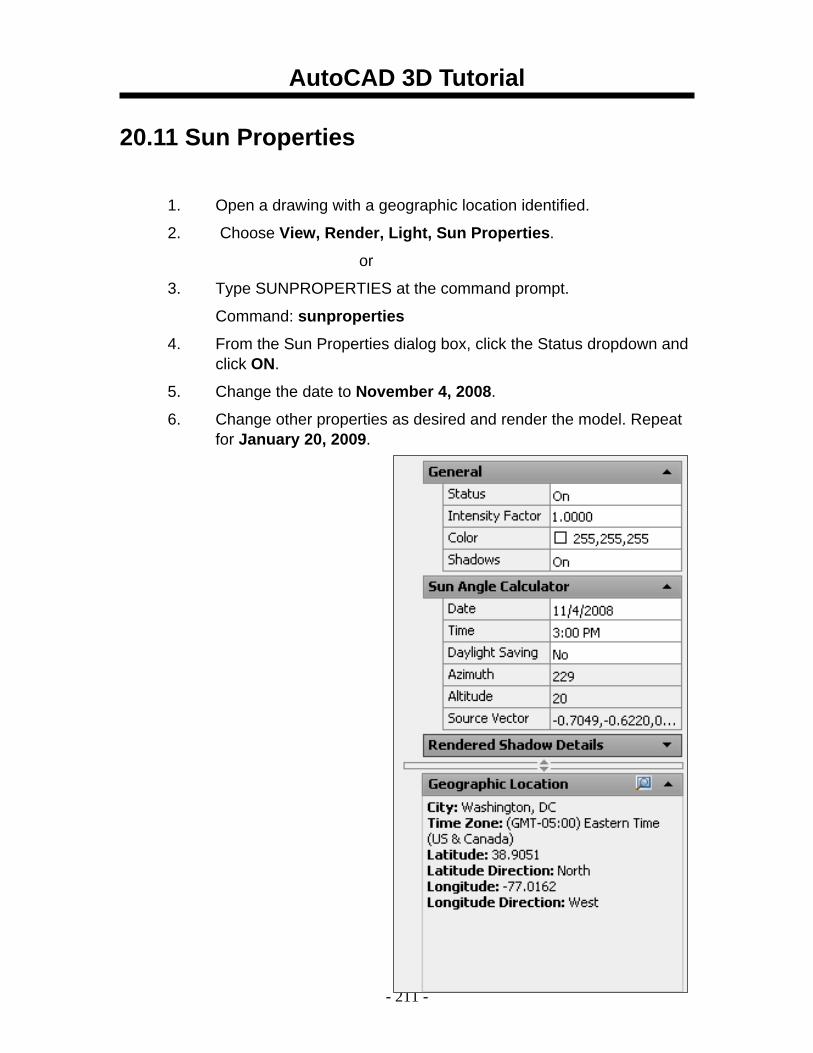
AutoCAD 3D Tutorial
- 211 -
20.11 Sun Properties
1. Open a drawing with a geographic location identified.
2. Choose View, Render, Light, Sun Properties.
or
3. Type SUNPROPERTIES at the command prompt.
Command: sunproperties
4. From the Sun Properties dialog box, click the Status dropdown and click ON.
5. Change the date to November 4, 2008.
6. Change other properties as desired and render the model. Repeat for January 20, 2009.
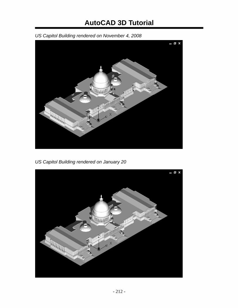
AutoCAD 3D Tutorial
- 212 -
US Capitol Building rendered on November 4, 2008
US Capitol Building rendered on January 20
AutoCAD 3D Tutorial
- 213 -
AutoCAD 3D – Chapter 21 Render Environments and
Background
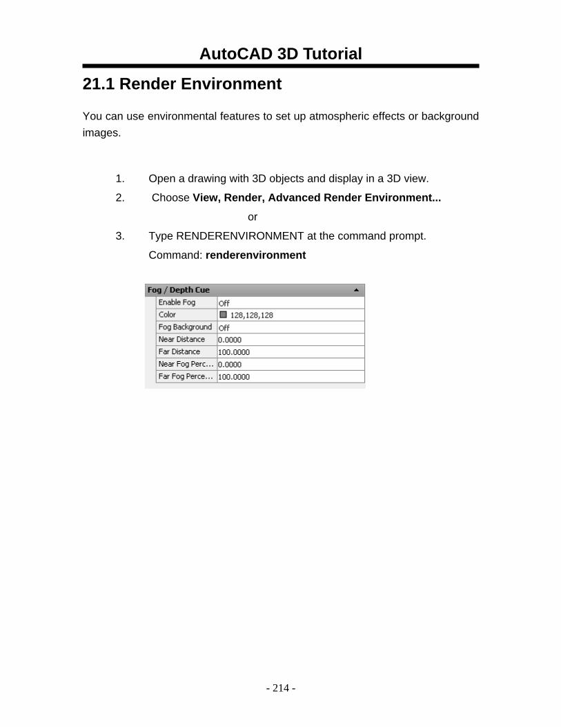
AutoCAD 3D Tutorial
- 214 -
21.1 Render Environment
You can use environmental features to set up atmospheric effects or background images.
1. Open a drawing with 3D objects and display in a 3D view.
2. Choose View, Render, Advanced Render Environment...
or
3. Type RENDERENVIRONMENT at the command prompt.
Command: renderenvironment

AutoCAD 3D Tutorial
- 215 -
21.2 Solid Background A background is a backdrop that displays behind your model. Backgrounds can be a single color, a multi-color gradient, or a bitmap image.
1. Open a drawing with 3D objects and display in a 3D view.
2. Choose View, Named Views.
or
3. Type VIEW at the command prompt.
Command: view
4. Choose New…
5. Type a name for your new view.
6. Click the drop down box under background and choose Solid.
7. Choose a color for your solid background.
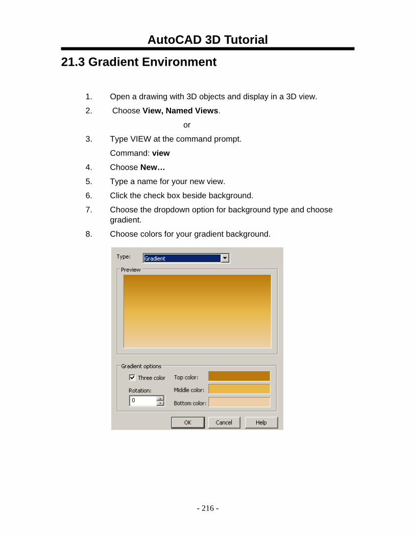
AutoCAD 3D Tutorial
- 216 -
21.3 Gradient Environment
1. Open a drawing with 3D objects and display in a 3D view.
2. Choose View, Named Views.
or
3. Type VIEW at the command prompt.
Command: view
4. Choose New…
5. Type a name for your new view.
6. Click the check box beside background.
7. Choose the dropdown option for background type and choose gradient.
8. Choose colors for your gradient background.
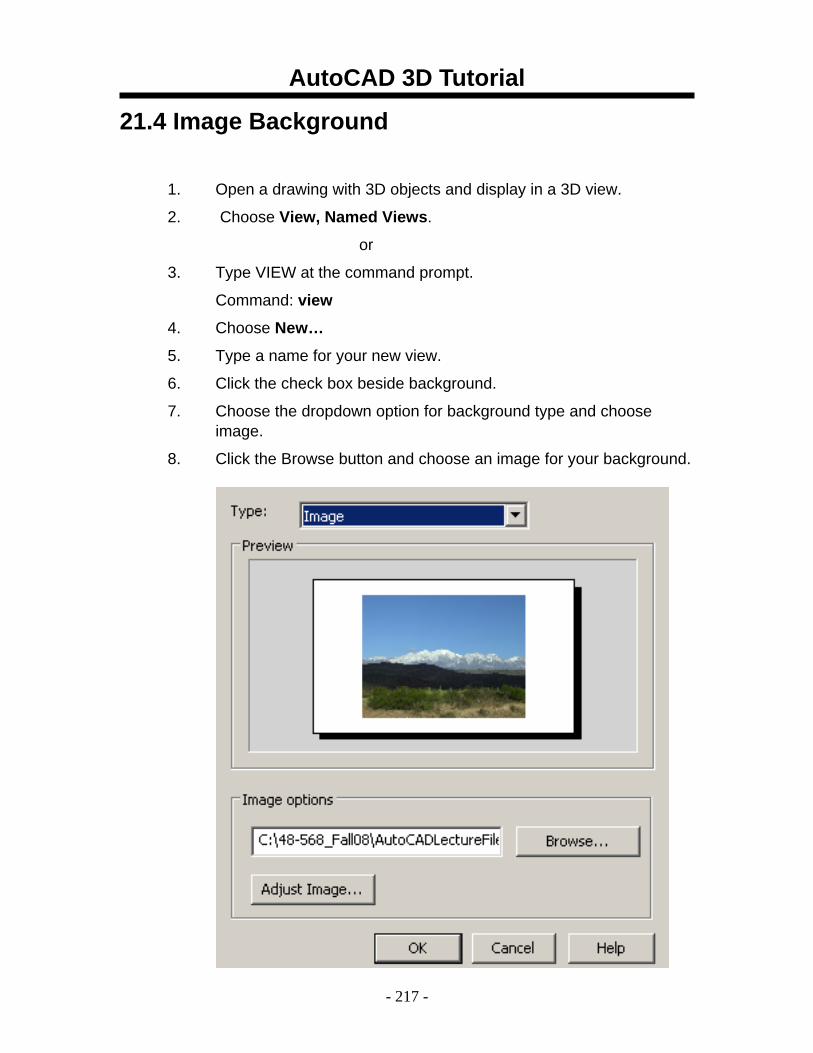
AutoCAD 3D Tutorial
- 217 -
21.4 Image Background
1. Open a drawing with 3D objects and display in a 3D view.
2. Choose View, Named Views.
or
3. Type VIEW at the command prompt.
Command: view
4. Choose New…
5. Type a name for your new view.
6. Click the check box beside background.
7. Choose the dropdown option for background type and choose image.
8. Click the Browse button and choose an image for your background.
AutoCAD 3D Tutorial
- 218 -
AutoCAD 3D – Chapter 22 Advanced Render
Commands
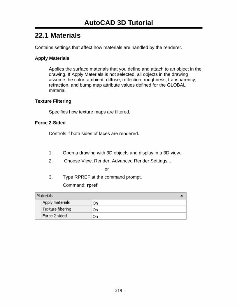
AutoCAD 3D Tutorial
- 219 -
22.1 Materials Contains settings that affect how materials are handled by the renderer.
Apply Materials
Applies the surface materials that you define and attach to an object in the drawing. If Apply Materials is not selected, all objects in the drawing assume the color, ambient, diffuse, reflection, roughness, transparency, refraction, and bump map attribute values defined for the GLOBAL material.
Texture Filtering
Specifies how texture maps are filtered.
Force 2-Sided
Controls if both sides of faces are rendered.
1. Open a drawing with 3D objects and display in a 3D view.
2. Choose View, Render, Advanced Render Settings...
or
3. Type RPREF at the command prompt.
Command: rpref
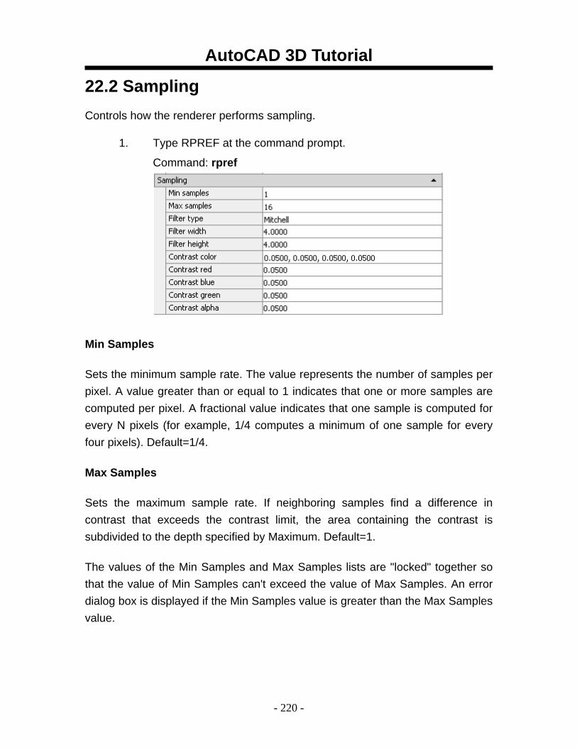
AutoCAD 3D Tutorial
- 220 -
22.2 Sampling Controls how the renderer performs sampling.
1. Type RPREF at the command prompt.
Command: rpref
Min Samples
Sets the minimum sample rate. The value represents the number of samples per pixel. A value greater than or equal to 1 indicates that one or more samples are computed per pixel. A fractional value indicates that one sample is computed for every N pixels (for example, 1/4 computes a minimum of one sample for every four pixels). Default=1/4.
Max Samples
Sets the maximum sample rate. If neighboring samples find a difference in contrast that exceeds the contrast limit, the area containing the contrast is subdivided to the depth specified by Maximum. Default=1.
The values of the Min Samples and Max Samples lists are "locked" together so that the value of Min Samples can't exceed the value of Max Samples. An error dialog box is displayed if the Min Samples value is greater than the Max Samples value.
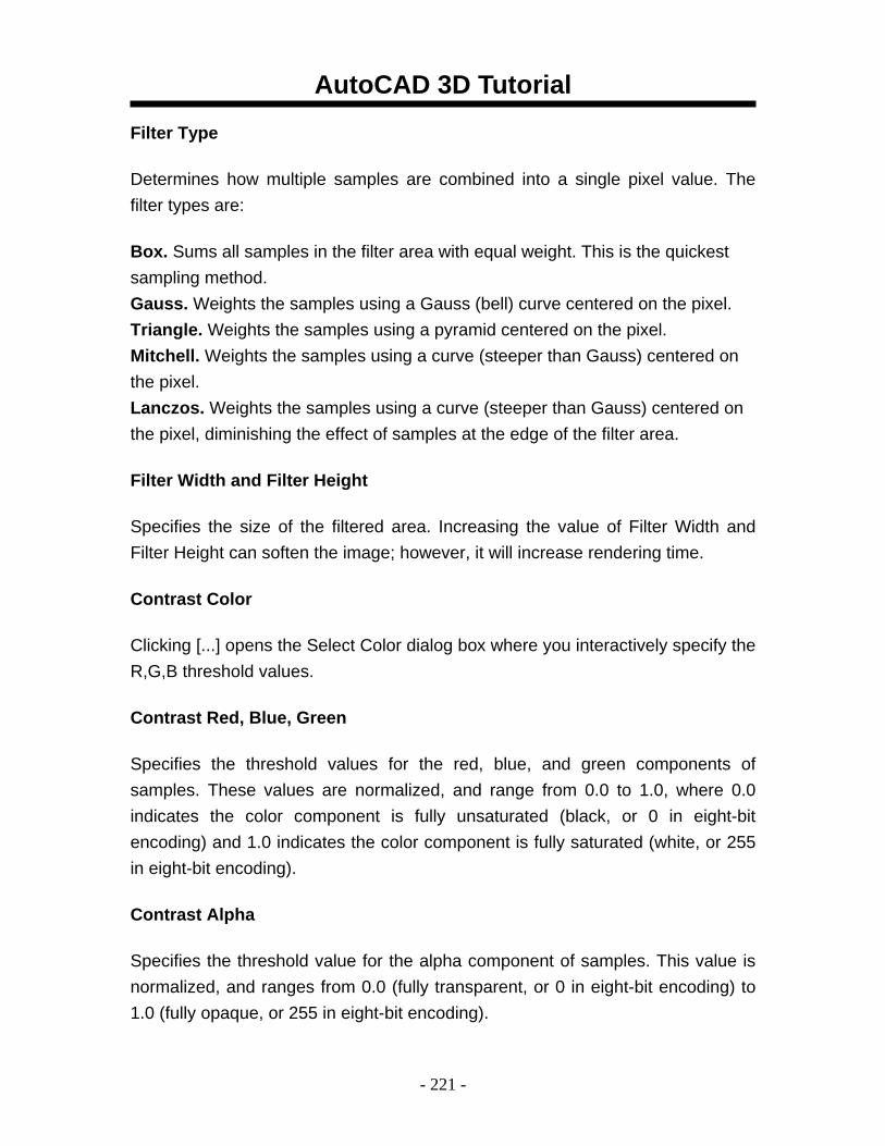
AutoCAD 3D Tutorial
- 221 -
Filter Type
Determines how multiple samples are combined into a single pixel value. The filter types are:
Box. Sums all samples in the filter area with equal weight. This is the quickest sampling method. Gauss. Weights the samples using a Gauss (bell) curve centered on the pixel. Triangle. Weights the samples using a pyramid centered on the pixel. Mitchell. Weights the samples using a curve (steeper than Gauss) centered on the pixel. Lanczos. Weights the samples using a curve (steeper than Gauss) centered on the pixel, diminishing the effect of samples at the edge of the filter area.
Filter Width and Filter Height
Specifies the size of the filtered area. Increasing the value of Filter Width and Filter Height can soften the image; however, it will increase rendering time.
Contrast Color
Clicking [...] opens the Select Color dialog box where you interactively specify the R,G,B threshold values.
Contrast Red, Blue, Green
Specifies the threshold values for the red, blue, and green components of samples. These values are normalized, and range from 0.0 to 1.0, where 0.0 indicates the color component is fully unsaturated (black, or 0 in eight-bit encoding) and 1.0 indicates the color component is fully saturated (white, or 255 in eight-bit encoding).
Contrast Alpha
Specifies the threshold value for the alpha component of samples. This value is normalized, and ranges from 0.0 (fully transparent, or 0 in eight-bit encoding) to 1.0 (fully opaque, or 255 in eight-bit encoding).
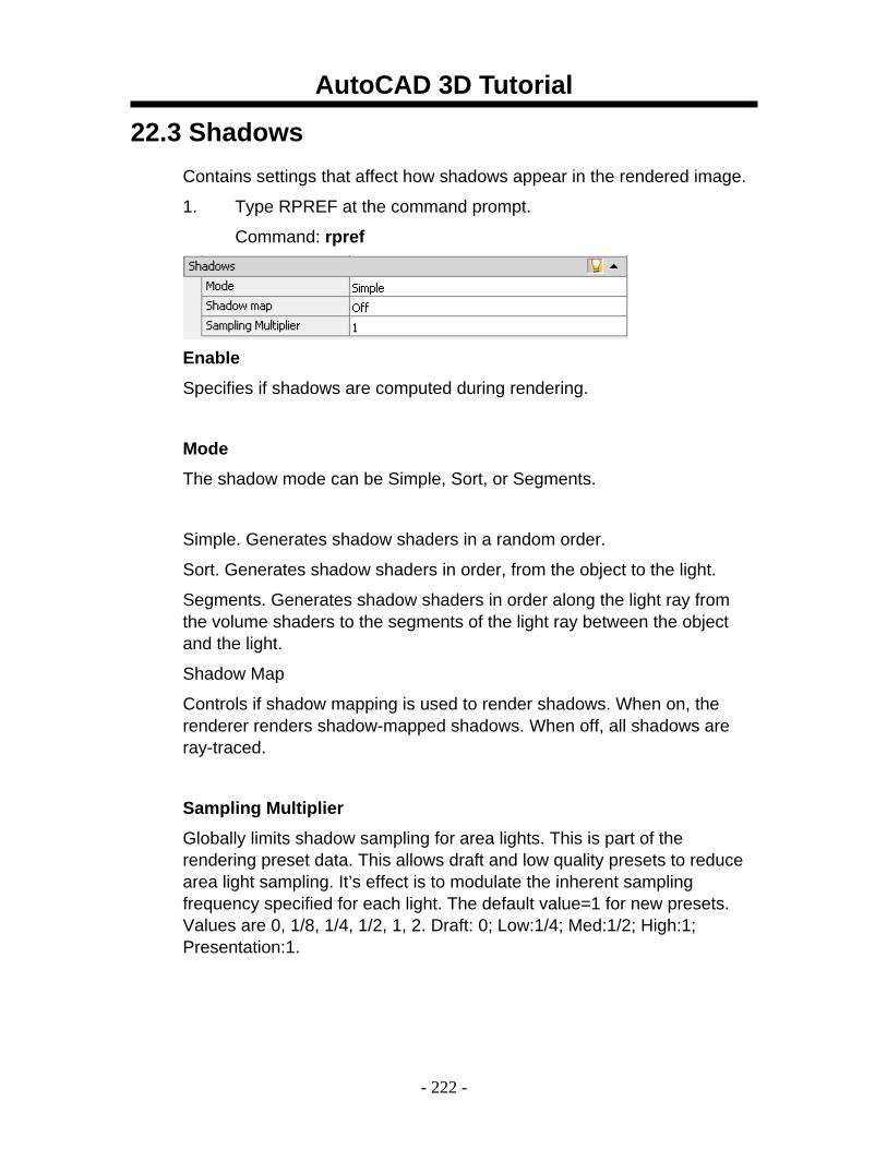
AutoCAD 3D Tutorial
- 222 -
22.3 Shadows Contains settings that affect how shadows appear in the rendered image.
1. Type RPREF at the command prompt.
Command: rpref
Enable
Specifies if shadows are computed during rendering.
Mode The shadow mode can be Simple, Sort, or Segments.
Simple. Generates shadow shaders in a random order.
Sort. Generates shadow shaders in order, from the object to the light.
Segments. Generates shadow shaders in order along the light ray from the volume shaders to the segments of the light ray between the object and the light.
Shadow Map
Controls if shadow mapping is used to render shadows. When on, the renderer renders shadow-mapped shadows. When off, all shadows are ray-traced.
Sampling Multiplier
Globally limits shadow sampling for area lights. This is part of the rendering preset data. This allows draft and low quality presets to reduce area light sampling. It’s effect is to modulate the inherent sampling frequency specified for each light. The default value=1 for new presets. Values are 0, 1/8, 1/4, 1/2, 1, 2. Draft: 0; Low:1/4; Med:1/2; High:1; Presentation:1.
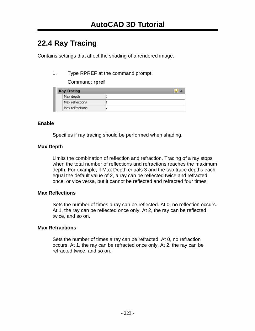
AutoCAD 3D Tutorial
- 223 -
22.4 Ray Tracing Contains settings that affect the shading of a rendered image.
1. Type RPREF at the command prompt.
Command: rpref
Enable
Specifies if ray tracing should be performed when shading.
Max Depth
Limits the combination of reflection and refraction. Tracing of a ray stops when the total number of reflections and refractions reaches the maximum depth. For example, if Max Depth equals 3 and the two trace depths each equal the default value of 2, a ray can be reflected twice and refracted once, or vice versa, but it cannot be reflected and refracted four times.
Max Reflections
Sets the number of times a ray can be reflected. At 0, no reflection occurs. At 1, the ray can be reflected once only. At 2, the ray can be reflected twice, and so on.
Max Refractions
Sets the number of times a ray can be refracted. At 0, no refraction occurs. At 1, the ray can be refracted once only. At 2, the ray can be refracted twice, and so on.
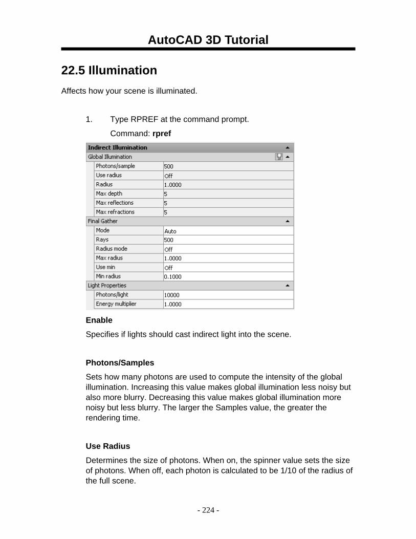
AutoCAD 3D Tutorial
- 224 -
22.5 Illumination Affects how your scene is illuminated.
1. Type RPREF at the command prompt.
Command: rpref
Enable
Specifies if lights should cast indirect light into the scene.
Photons/Samples Sets how many photons are used to compute the intensity of the global illumination. Increasing this value makes global illumination less noisy but also more blurry. Decreasing this value makes global illumination more noisy but less blurry. The larger the Samples value, the greater the rendering time.
Use Radius
Determines the size of photons. When on, the spinner value sets the size of photons. When off, each photon is calculated to be 1/10 of the radius of the full scene.
AutoCAD 3D Tutorial
- 225 -
Radius Specifies the area within which photons will be used when illuminance is computed.
Max Depth
Limits the combination of reflection and refraction. Reflection and refraction of a photon stop when the total number of both equals the Max Depth setting. For example, if Max Depth equals 3 and the trace depths each equal 2, a photon can be reflected twice and refracted once, or vice versa, but it can’t be reflected and refracted four times.
Max Reflections Sets the number of times a photon can be reflected. At 0, no reflection occurs. At 1, the photon can be reflected once only. At 2, the photon can be reflected twice, and so on.
Max Refractions
Sets the number of times a photon can be refracted. At 0, no refraction occurs. At 1, the photon can be refracted once only. At 2, the photon can be refracted twice, and so on.
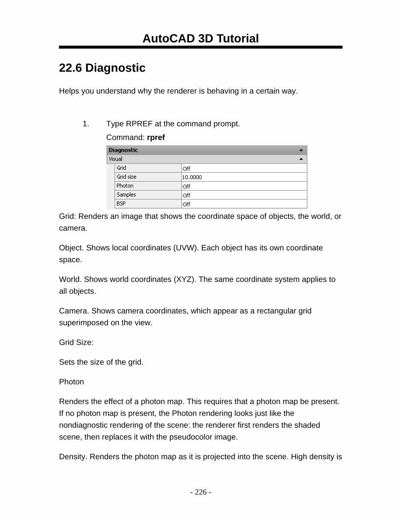
AutoCAD 3D Tutorial
- 226 -
22.6 Diagnostic
Helps you understand why the renderer is behaving in a certain way.
1. Type RPREF at the command prompt.
Command: rpref
Grid: Renders an image that shows the coordinate space of objects, the world, or camera.
Object. Shows local coordinates (UVW). Each object has its own coordinate space.
World. Shows world coordinates (XYZ). The same coordinate system applies to all objects.
Camera. Shows camera coordinates, which appear as a rectangular grid superimposed on the view.
Grid Size:
Sets the size of the grid.
Photon
Renders the effect of a photon map. This requires that a photon map be present. If no photon map is present, the Photon rendering looks just like the nondiagnostic rendering of the scene: the renderer first renders the shaded scene, then replaces it with the pseudocolor image.
Density. Renders the photon map as it is projected into the scene. High density is
AutoCAD 3D Tutorial
- 227 -
displayed in red, and lower values render in increasingly cooler colors.
Irradiance. Similar to the Density rendering, but shades the photons based on their irradiance. The maximum irradiance is rendered in red, and lower values render in increasingly cooler colors.
BSP
Renders a visualization of the parameters used by the tree in the BSP ray-trace acceleration method. If a message from the renderer reports excessively large depth or size values, or if rendering seems unusually slow, this can help you locate the problem. Depth. Shows the depth of the tree, with top faces in bright red, and increasingly deep faces in increasingly cool colors.
Size. Shows the size of leaves in the tree, with differently sized leaves indicated by different colors.
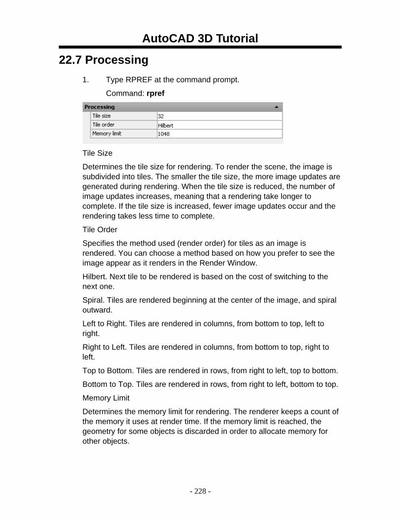
AutoCAD 3D Tutorial
- 228 -
22.7 Processing 1. Type RPREF at the command prompt.
Command: rpref
Tile Size
Determines the tile size for rendering. To render the scene, the image is subdivided into tiles. The smaller the tile size, the more image updates are generated during rendering. When the tile size is reduced, the number of image updates increases, meaning that a rendering take longer to complete. If the tile size is increased, fewer image updates occur and the rendering takes less time to complete.
Tile Order
Specifies the method used (render order) for tiles as an image is rendered. You can choose a method based on how you prefer to see the image appear as it renders in the Render Window.
Hilbert. Next tile to be rendered is based on the cost of switching to the next one.
Spiral. Tiles are rendered beginning at the center of the image, and spiral outward.
Left to Right. Tiles are rendered in columns, from bottom to top, left to right.
Right to Left. Tiles are rendered in columns, from bottom to top, right to left.
Top to Bottom. Tiles are rendered in rows, from right to left, top to bottom.
Bottom to Top. Tiles are rendered in rows, from right to left, bottom to top.
Memory Limit
Determines the memory limit for rendering. The renderer keeps a count of the memory it uses at render time. If the memory limit is reached, the geometry for some objects is discarded in order to allocate memory for other objects.