3900 series base station product description v1.4 series base... · 3900 series base station...
TRANSCRIPT

3900 Series Base Station Product
Description
Issue V1.4
Date 2011-09-09
HUAWEI TECHNOLOGIES CO., LTD.
Issue V1.4 (2011-09-09) Huawei Proprietary and Confidential
Copyright © Huawei Technologies Co., Ltd.
i
Copyright © Huawei Technologies Co., Ltd. 2011. All rights reserved.
No part of this document may be reproduced or transmitted in any form or by any means without prior written
consent of Huawei Technologies Co., Ltd.
Trademarks and Permissions
and other Huawei trademarks are trademarks of Huawei Technologies Co., Ltd.
All other trademarks and trade names mentioned in this document are the property of their respective holders.
Notice
The purchased products, services and features are stipulated by the contract made between Huawei and the customer.
All or part of the products, services and features described in this document may not be within the purchase scope or
the usage scope. Unless otherwise specified in the contract, all statements, information, and recommendations in this
document are provided "AS IS" without warranties, guarantees or representations of any kind, either express or
implied.
The information in this document is subject to change without notice. Every effort has been made in the preparation
of this document to ensure accuracy of the contents, but all statements, information, and recommendations in this
document do not constitute a warranty of any kind, express or implied.
Huawei Technologies Co., Ltd.
Address: Huawei Industrial Base
Bantian, Longgang
Shenzhen 518129
People's Republic of China
Website: http://www.huawei.com
Email: [email protected]

3900 Series Base Station Product Description Contents
Issue V1.4 (2011-09-09) Huawei Proprietary and Confidential
Copyright © Huawei Technologies Co., Ltd.
ii
Contents
1 Introduction ..................................................................................................................................... 1
2 Architecture ..................................................................................................................................... 5
2.2.1 BBU3900 ................................................................................................................................................ 6
2.2.2 RFU ......................................................................................................................................................... 6
2.2.3 RRU ........................................................................................................................................................ 7
2.7.1 APM30H/APM30H (Ver.C) Power Cabinet .......................................................................................... 22
2.7.2 TP48600A Power Cabinet ..................................................................................................................... 23
2.7.3 TMC11H/TMC11H (Ver.C) Transmission Cabinet ............................................................................... 23
2.7.4 IBBS200T/IBBS200T (Ver.C)/IBBS200D/IBBS200D (Ver.C) Battery Cabinet .................................. 25
2.7.5 IBBS700D/IBBS700T Battery Cabinet ................................................................................................ 27
3 Operation and Maintenance ........................................................................................................ 31
4 Technical Specifications ................................................................................................................ 34
5 Acronyms and Abbreviations ....................................................................................................... 39

3900 Series Base Station Product Description 1 Introduction
Issue V1.4 (2011-09-09) Huawei Proprietary and Confidential
Copyright © Huawei Technologies Co., Ltd.
1
1 Introduction
1.1 Overview
To keep abreast of rapidly advancing mobile communications technologies, mobile operators
are continually seeking partners who provide cutting-edge technologies to set up high-quality,
multi-mode-enabled, and future-oriented mobile networks efficiently and cost-effectively.
With this aim in mind, Huawei developed 3900 series base stations, which are designed based
on a high-performance platform and use an optimized hardware and software architecture.
These base stations can work in multi-mode due to their cutting-edge modular design. They
also have broad bandwidth and are eco-friendly and easily upgradeable.
Specifically, 3900 series base stations use the newly developed power amplifiers (PAs),
provide the temperature control function, and employ the innovated power saving technique.
In addition, by adopting the cutting-edge modular design, 3900 series base stations use
multi-mode modules with different appearances to meet requirements in various conditions.
Thanks to all these merits of 3900 series base stations, mobile operators can set up
high-quality, multi-mode-enabled, and future-oriented mobile networks and capital
expenditure (CAPEX) on site acquisition, capacity expansion, and environment protection
can be greatly reduced.
Different types of 3900 series base stations can be delivered on request because the newly
designed modules and auxiliary devices can be flexibly combined and configured.
Figure 1-1 shows the different types of 3900 series base stations.

3900 Series Base Station Product Description 1 Introduction
Issue V1.4 (2011-09-09) Huawei Proprietary and Confidential
Copyright © Huawei Technologies Co., Ltd.
2
Figure 1-1 3900 series base station types
This document focuses on the BTS3900, BTS3900A, BTS3900L, BTS3900AL, and DBS3900 only. For
a description of the other types of 3900 series base stations, see the product description for the base
station in question.
1.2 Benefits
Smooth Evolution
Upgrading from Global System for Mobile Communications (GSM) to Universal Mobile
Telecommunications System (UMTS) and then to Long Term Evolution (LTE) is easy thanks
to the following factors:
� A BBU3900 is equipped with different boards, among which some work in one mode
and the others work in another mode. The BBU3900 can process services for both of
these modes. With two BBUs, the triple-mode application can be achieved.
3900 Series Base Station Product Description 1 Introduction
Issue V1.4 (2011-09-09) Huawei Proprietary and Confidential
Copyright © Huawei Technologies Co., Ltd.
3
� Developed with the Software-defined radio (SDR) technique, RF modules can work in
GU or GL dual-mode. SDR RF modules and single-mode RF modules can be installed in
the same cabinet to achieve multi-mode and multi-band applications.
Energy-Efficient and Eco-Friendly
Thanks to their small size and modular design, PAs do not take up much space in the
equipment room and power resources are saved with the new power-saving technique.
The following measures also help save energy:
� RF channels are blocked and PA voltage is adjusted if the downlink load reaches a preset
threshold.
� The power supply unit (PSU) shuts down if the base station is provided with sufficient
power.
� The temperature control function controls board temperature, outdoor cabinets use a
direct ventilation system, and RRUs adopt the natural heat dissipation mechanism.
Low CAPEX
In terms of the CAPEX for devices,
• 3900 series base stations use one set of multi-mode devices to support multi-mode
applications.
• An external reference clock and transmission resources are shared across modes on a
3900 series base station, reducing the CAPEX for transmission resources and external
clock sources.
• Various types of radio frequency (RF) modules are introduced, for example,
software-defined radio (SDR) RF modules supporting antenna-sharing, dual-transmitter
RF modules supporting the multiple-input multiple-output (MIMO) technology, and
single-transmitter RF modules with high power and large capacity.
• The GU or GL refarming feature is introduced to facilitate the evolution from GSM to
UMTS, and LTE and eventually to save the CAPEX for evolution.
In terms of operation and maintenance (O&M), different modes on a single 3900 series base
station share the same auxiliary devices and are managed by the same network management
system, which greatly reduces O&M costs. The O&M manpower required is also reduced,
because 3900 series base stations are easy to install and maintain and it is easy to expand their
capacities.
High Transmission Reliability and High Board Performance
The following features are introduced to ensure high transmission reliability and high board
performance:
� Support for the Huawei SingleBTS platform
� Support for Co-Radio Resource Management (Co-RRM), Co-Transmission Resource
Management (Co-TRM), Co-Operation and Management (Co-OAM), and Co-Radio
Network Plan&Radio Network Optimization (Co-RNP&RNO)
� Support for route backup. Transmission paths can be switched over to protect
high-priority service data.

3900 Series Base Station Product Description 1 Introduction
Issue V1.4 (2011-09-09) Huawei Proprietary and Confidential
Copyright © Huawei Technologies Co., Ltd.
4
� Support for priority-based GSM/UMTS/LTE-combined intelligent power-off. For
example, if power is insufficient, some RF modules are powered off and therefore stop
serving the related modes, which helps prolong the operating time for the base station.
� Support for the backup of important boards and power modules

3900 Series Base Station Product Description 2 Architecture
Issue V1.4 (2011-09-09) Huawei Proprietary and Confidential
Copyright © Huawei Technologies Co., Ltd.
5
2 Architecture
2.1 Overview
3900 series base stations are classified into macro base stations, distributed base stations,
micro base stations, and Pico base stations. Each type of base station is applicable to a
specific scenario, which enables operators to efficiently set up a network with low CAPEX.
� Macro base stations
− Indoor
BTS3900s using BTS3900 or BTS3900 (Ver.C) cabinets
BTS3900Ls using BTS3900L or BTS3900L (Ver.C) cabinets
− Outdoor
BTS3900A using BTS3900A or BTS3900A (Ver.C) cabinets
BTS3900ALs
− Outdoor compact BTS
BTS3900Cs
� Distributed base stations
− DBS3900s
� Micro base stations
− BTS3900Es
− BTS3902Es
� Pico base stations
− BTS3900Bs
This document focuses on the BTS3900, BTS3900A, BTS3900L, BTS3900AL, and DBS3900 only. For
details about the other base stations, see the product description of the base station in question.
2.2 Basic Modules
The basic modules of a 3900 series base station are the baseband unit (BBU), radio frequency
units (RFUs), and remote radio units (RRUs). The BBU uses common public radio interfaces
(CPRIs) and electrical or optical cables to communicate with the RFUs or RRUs.

3900 Series Base Station Product Description 2 Architecture
Issue V1.4 (2011-09-09) Huawei Proprietary and Confidential
Copyright © Huawei Technologies Co., Ltd.
6
2.2.1 BBU3900
As a baseband control unit, a BBU3900 provides the following functions:
� Centrally manages the entire base station, including operation and maintenance,
signaling processing, and the system clock.
� Processes uplink and downlink baseband signals.
� Provides physical ports, which are used to connect the base station to the transport
network for information exchange; a maintenance channel, which is used to connect the
BBU3900 to the operation and maintenance center (OMC); CPRI ports for
communication with RF modules; and ports for communication with environment
monitoring devices.
Figure 2-1 shows the slot layout of a BBU3900.
Figure 2-1 Slot layout of a BBU3900
For more details about the BBU3900, see the BBU3900 Description.
2.2.2 RFU
RFUs can be used in a BTS3900, BTS3900L, BTS3900A, or BTS3900AL. The RFU
modulates and demodulates baseband and RF signals, processes data, amplifies power, and
conducts VSWR detection.
RFUs fall into the following three types:
� Multi-mode modules: MRFUs, MRFUds, MRFUes
� GSM modules: GRFUs, DRFUs
� UMTS modules: WRFU, WRFUds
Figure 2-2 shows the appearance of an RFU.

3900 Series Base Station Product Description 2 Architecture
Issue V1.4 (2011-09-09) Huawei Proprietary and Confidential
Copyright © Huawei Technologies Co., Ltd.
7
Figure 2-2 Appearance of an RFU
The MRFUd and MRFUe can only be used in a BTS3900 (Ver.C), BTS3900L (Ver.C),
BTS3900A (Ver.C), or BTS3900AL cabinet. Meanwhile, the WRFUd is recommended for use
in BTS3900 (Ver.C), BTS3900L (Ver.C), BTS3900A (Ver.C), or BTS3900AL cabinets. When
the WRFUd is used in a BTS3900, BTS3900L, or BTS3900A cabinet, some auxiliary devices
must be reconstructed in the cabinet. The other types of RFU modules can be used in any
cabinet type.
� For the specifications and parameters of each type of RFU, see the description of the RFU in
question.
� GRFU, MRFU, MRFUd, MRFUe, WRFU, and WRFUd modules have the same appearance but can
be identified by different silkscreens.
2.2.3 RRU
As an RF component on a distributed base station, the RRU modulates and demodulates
baseband and RF signals, combines and divides baseband and RF signals, and processes data.
RRUs are installed near antennas.
RRUs fall into the following three types:
� Multi-mode modules: RRU3908s, RRU3928s, RRU3929s, RRU3942s
� GSM modules: RRU3004s, RRU3008s
� UMTS modules: RRU3804s, RRU3806s, RRU3801Es, RRU3808s, RRU3829s,
RRU3828s
Figure 2-3 shows the appearance of a direct current (DC) RRU.
3900 Series Base Station Product Description 2 Architecture
Issue V1.4 (2011-09-09) Huawei Proprietary and Confidential
Copyright © Huawei Technologies Co., Ltd.
8
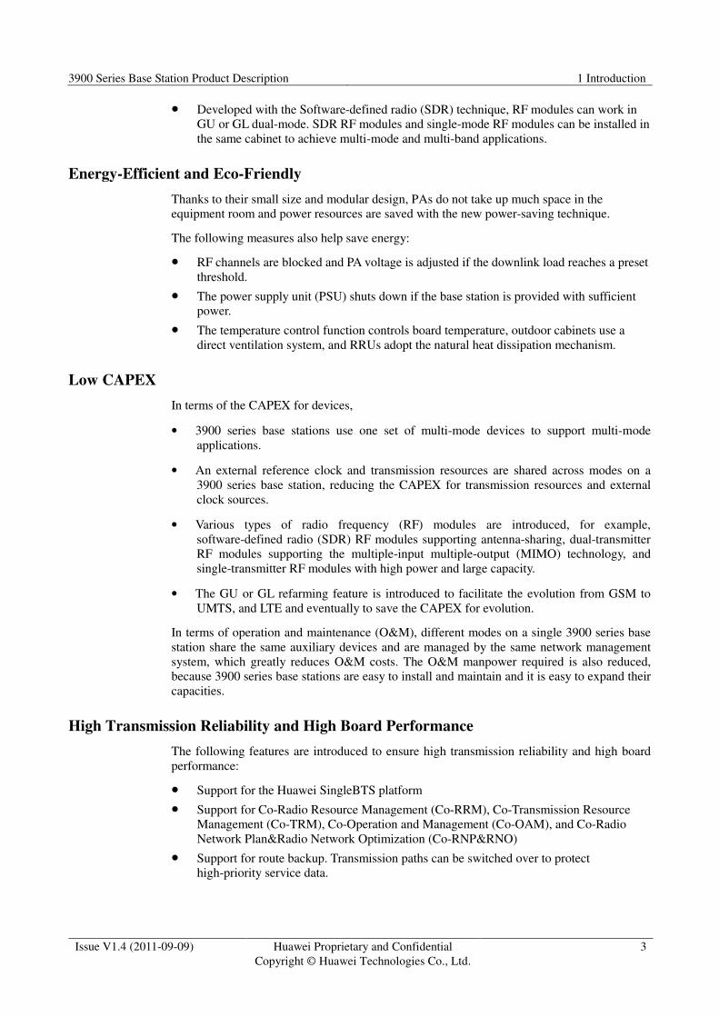
Figure 2-3 Appearance of a DC RRU
RRU3829s and RRU3929s are recommended for use in APM30H (Ver.C) or TMC11H (Ver.C)
cabinets. When RRU3929s or RRU3829s are used in an APM30H or TMC11H cabinet, some
auxiliary devices must be reconstructed. Other types of RRUs can be used in any cabinet type.
For the specifications and parameters of each type of RRU, see the description of the RRU in question.
2.3 BTS3900/BTS3900 (Ver.C) Cabinet
BTS3900 or BTS3900 (Ver.C) cabinets house indoor macro base stations because these
cabinets have a large capacity and a small size, support multi-mode applications, and are easy
to expand the capacities of.
BTS3900 cabinets support -48 V DC, +24 V DC, and AC power input while BTS3900 (Ver.C)
cabinets support -48 V DC and AC power input.
Figure 2-4 shows the internal structure of a BTS3900 cabinet supporting -48 V DC power
input, and Figure 2-5 shows the internal structure of a BTS3900 (Ver.C) cabinet supporting
-48 V DC power input.
A cabinet supporting +24 V DC or AC power input has the same internal structure as a cabinet
supporting -48 V DC power input. However, the former uses different power modules.
3900 Series Base Station Product Description 2 Architecture
Issue V1.4 (2011-09-09) Huawei Proprietary and Confidential
Copyright © Huawei Technologies Co., Ltd.
9
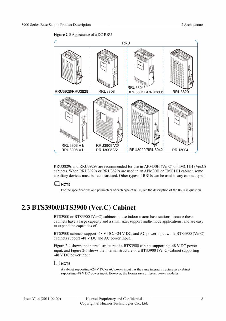
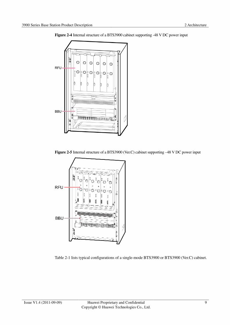
Figure 2-4 Internal structure of a BTS3900 cabinet supporting -48 V DC power input
Figure 2-5 Internal structure of a BTS3900 (Ver.C) cabinet supporting –48 V DC power input
Table 2-1 lists typical configurations of a single-mode BTS3900 or BTS3900 (Ver.C) cabinet.

3900 Series Base Station Product Description 2 Architecture
Issue V1.4 (2011-09-09) Huawei Proprietary and Confidential
Copyright © Huawei Technologies Co., Ltd.
10
Table 2-1 Typical configurations of a single-mode BTS3900 or BTS3900 (Ver.C) cabinet
Mode Typical Configurations Number of RF
Modules
Output Power of Each
Carrier
GSM S4/4/4 6 DRFU 20 W (900 MHz)/18 W (1800
MHz)
S12/12/12 6 GRFU 12 W
S12/12/12 6 MRFU 12 W
S12/12/12 6 MRFUe 20 W
S8/8/8 + S8/8/8 3 MRFUd + 3 MRFUd 20 W (900 MHz) + 20 W
(1800 MHz)
UMTS S4/4/4 3 WRFU 20 W
S4/4/4 (MIMO) 3 WRFUd 30 W (1 x 15 W)
S4/4/4 3 MRFU 20 W
S4/4/4 (MIMO) 3 MRFUd 40 W (2 x 20 W)
LTE S1/1/1 (20 MHz MIMO) 6 MRFU/3 MRFUd 80 W (2 x 40 W)/120W (2 x
60 W)
The preceding configurations assume that each cell uses one dual-polarized antenna.
Table 2-2 lists typical configurations of a dual-mode BTS3900 or BTS3900 (Ver.C) cabinet.
Table 2-2 Typical configurations of a dual-mode BTS3900 or BTS3900 (Ver.C) cabinet
Mode Typical Configurations Number of RF
Modules
Output Power of
Each Carrier
GU
GSM S4/4/4 + UMTS
S2/2/2
3 MRFUd 20 W + 40 W
GL GSM S8/8/8 + LTE
S1/1/1 (20 MHz MIMO)
3 MRFUd (GO) + 3
MRFUd (LO)
20 W + 80 W (2 x 40
W)
UL UMTS S2/2/2 (MIMO) +
LTE S1/1/1 (20 MHz
MIMO)
3 MRFUd (UO) + 3
MRFUd (LO)
80 W (2 x 40 W) +
120 W (2 x 60 W)

3900 Series Base Station Product Description 2 Architecture
Issue V1.4 (2011-09-09) Huawei Proprietary and Confidential
Copyright © Huawei Technologies Co., Ltd.
11
� The preceding configurations assume that each cell uses one dual-polarized antenna.
� In Table 2-2, GU indicates that GSM and UMTS share one BBU, GL indicates that GSM and LTE
share one BBU, and UL indicates that UMTS and LTE share one BBU.
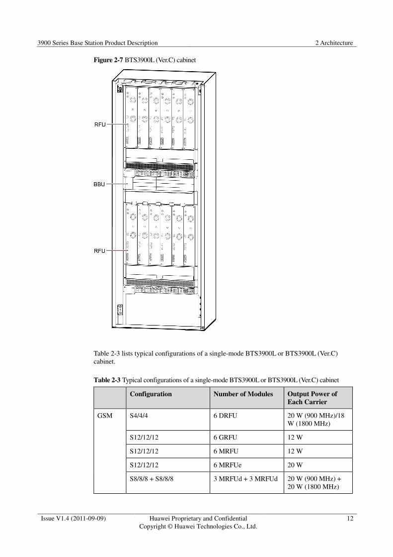
2.4 BTS3900L/BTS3900L (Ver.C) Cabinet
BTS3900L/BTS3900L (Ver.C) cabinets house BBU3900s and RFUs and provide the power
distribution and surge protection functions. A single BTS3900L/BTS3900L (Ver.C) cabinet
can house a maximum of 12 RFUs and 2 BBU3900s. This saves installation space and
facilitates smooth evolution.
Figure 2-6 shows the internal structure of a BTS3900L cabinet.
Figure 2-6 Internal structure of a BTS3900L cabinet
Figure 2-7 shows the internal structure of a BTS3900L (Ver.C) cabinet.
3900 Series Base Station Product Description 2 Architecture
Issue V1.4 (2011-09-09) Huawei Proprietary and Confidential
Copyright © Huawei Technologies Co., Ltd.
12
Figure 2-7 BTS3900L (Ver.C) cabinet
Table 2-3 lists typical configurations of a single-mode BTS3900L or BTS3900L (Ver.C)
cabinet.
Table 2-3 Typical configurations of a single-mode BTS3900L or BTS3900L (Ver.C) cabinet
Configuration Number of Modules Output Power of
Each Carrier
GSM S4/4/4 6 DRFU 20 W (900 MHz)/18
W (1800 MHz)
S12/12/12 6 GRFU 12 W
S12/12/12 6 MRFU 12 W
S12/12/12 6 MRFUe 20 W
S8/8/8 + S8/8/8 3 MRFUd + 3 MRFUd 20 W (900 MHz) +
20 W (1800 MHz)
3900 Series Base Station Product Description 2 Architecture
Issue V1.4 (2011-09-09) Huawei Proprietary and Confidential
Copyright © Huawei Technologies Co., Ltd.
13
Configuration Number of Modules Output Power of
Each Carrier
UMTS S4/4/4 3 WRFU 20 W
S4/4/4 (MIMO) 3 WRFUd 30 W (2 x 15 W)
S4/4/4 3 MRFU 20 W
S4/4/4 (MIMO) 3 MRFUd 40 W (2 x 20 W)
LTE S1/1/1 (20 MHz MIMO) 6 MRFU/3 MRFUd 80 W (2 x 40 W)/120
W (2 x 60 W)
The preceding configurations assume that each cell uses one dual-polarized antenna.
BTS3900L or BTS3900L (Ver.C) cabinets are mainly used in scenarios where multiple
frequency bands are applied and multiple modes co-exist. Table 2-4 lists typical
configurations of a multi-mode BTS3900L or BTS3900L (Ver.C) cabinet.
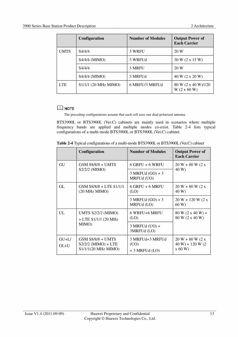
Table 2-4 Typical configurations of a multi-mode BTS3900L or BTS3900L (Ver.C) cabinet
Configuration Number of Modules Output Power of
Each Carrier
GU GSM S8/8/8 + UMTS
S2/2/2 (MIMO)
6 GRFU + 6 WRFU 20 W + 80 W (2 x
40 W) 3 MRFUd (GO) + 3
MRFUd (UO)
GL GSM S8/8/8 + LTE S1/1/1
(20 MHz MIMO)
6 GRFU + 6 MRFU
(LO)
20 W + 80 W (2 x
40 W)
3 MRFUd (GO) + 3
MRFUd (LO)
20 W + 120 W (2 x
60 W)
UL UMTS S2/2/2 (MIMO)
+ LTE S1/1/1 (20 MHz
MIMO)
6 WRFU+6 MRFU
(LO)
80 W (2 x 40 W) +
80 W (2 x 40 W)
3 MRFUd (UO) +
3MRFUd (LO)
GU+L/
GL+U
GSM S8/8/8 + UMTS
S2/2/2 (MIMO) + LTE
S1/1/1(20 MHz MIMO)
3 MRFUd+3 MRFUd
(UO)
+ 3 MRFUd (LO)
20 W + 80 W (2 x
40 W) + 120 W (2
x 60 W)
3900 Series Base Station Product Description 2 Architecture
Issue V1.4 (2011-09-09) Huawei Proprietary and Confidential
Copyright © Huawei Technologies Co., Ltd.
14
� The preceding configurations assume that each cell uses one dual-polarized antenna.
� In Table 2-4, GU indicates that GSM and UMTS share one BBU, GL indicates that GSM and LTE
share one BBU, UL indicates that UMTS and LTE share one BBU, GU+L indicates that GSM and
UMTS share one BBU and LTE uses the other BBU, and GL+U indicates that GSM and LTE share
one BBU and UMTS uses the other BBU.
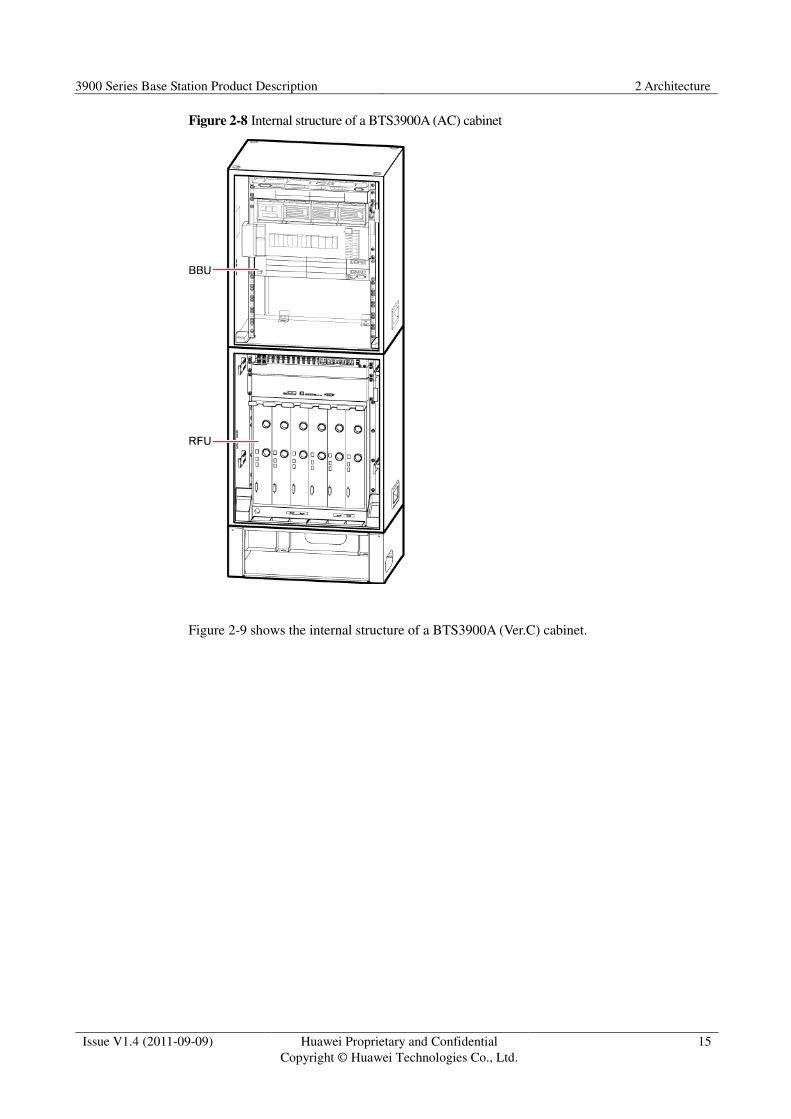
2.5 BTS3900A/BTS3900A (Ver.C) Cabinet
A BTS3900A or BTS3900A (Ver.C) cabinet consists of an RF cabinet and a power cabinet, or
of an RF cabinet and a transmission cabinet.
The RF cabinet is installed outdoors and uses a direct ventilation system. The power cabinet
or transmission cabinet can be stacked on top of the RF cabinet. Together with the RF cabinet,
the power cabinet or transmission cabinet provides the power distribution and surge
protection functions for the BBU3900 and RFUs. An RF cabinet can house a maximum of six
RFUs.
If a 110 V AC or 220 V AC power supply is applied, an APM30H or APM30H (Ver.C) power
cabinet is used and the BBU3900 can be installed inside the power cabinet.
If a -48 V DC power supply is applied, a TMC11H or TMC11H (Ver.C) transmission cabinet
is used and the BBU3900 can be installed inside the transmission cabinet.
Figure 2-8 shows the internal structure of a BTS3900A (AC) cabinet.
3900 Series Base Station Product Description 2 Architecture
Issue V1.4 (2011-09-09) Huawei Proprietary and Confidential
Copyright © Huawei Technologies Co., Ltd.
15
Figure 2-8 Internal structure of a BTS3900A (AC) cabinet
Figure 2-9 shows the internal structure of a BTS3900A (Ver.C) cabinet.

3900 Series Base Station Product Description 2 Architecture
Issue V1.4 (2011-09-09) Huawei Proprietary and Confidential
Copyright © Huawei Technologies Co., Ltd.
16
Figure 2-9 Internal structure of a BTS3900A (Ver.C) cabinet
Table 2-5 lists typical configurations of a single-mode BTS3900A or BTS3900A (Ver.C)
cabinet.
Table 2-5 Typical configurations of a single-mode BTS3900A or BTS3900A (Ver.C) cabinet
Mode Typical Configurations Number of RF
Modules
Output Power of
Each Carrier
GSM S4/4/4 6 DRFU 20 W (900 MHz)/18
W (1800 MHz)
S12/12/12 6 GRFU 12 W
S12/12/12 6 MRFU 12 W
S12/12/12 6 MRFUe 20 W
S8/8/8 + S8/8/8 3 MRFUd + 3 MRFUd 20 W (900 MHz) +
20 W (1800 MHz)
UMTS S4/4/4 3 WRFU 20 W
S4/4/4 (MIMO) 3 WRFUd 30 W (2 x 15 W)

3900 Series Base Station Product Description 2 Architecture
Issue V1.4 (2011-09-09) Huawei Proprietary and Confidential
Copyright © Huawei Technologies Co., Ltd.
17
Mode Typical Configurations Number of RF
Modules
Output Power of
Each Carrier
S4/4/4 3 MRFU 20 W
S4/4/4 (MIMO) 3 MRFUd 40 W (2 x 20 W)
LTE S1/1/1 (20 MHz MIMO) 6 MRFU/3 MRFUd 80 W (2 x 40 W)/120
W (2 x 60 W)
The preceding configurations assume that each cell uses one dual-polarized antenna.
Table 2-6 lists typical configurations of a dual-mode BTS3900A or BTS3900A (Ver.C)
cabinet.
Table 2-6 Typical configurations of a dual-mode BTS3900A or BTS3900A (Ver.C) cabinet
Mode Typical
Configurations
Number of RF Modules Output Power
of Each Carrier
GU GSM S4/4/4 + UMTS
S2/2/2
3 MRFUd 20 W + 40 W
GL GSM S8/8/8 + LTE
S1/1/1 (20 MHz
MIMO)
3 MRFUd (GO) + 3 MRFUd
(LO)
20 W + 80 W (2
x 40 W)
UL UMTS S2/2/2 (MIMO)
+ LTE S1/1/1 (20 MHz
MIMO)
3 MRFUd (UO) + 3 MRFUd
(LO)
80 W (2 x 40 W)
+ 120 W (2 x 60
W)
� The preceding configurations assume that each cell uses one dual-polarized antenna.
� In Table 2-6, GU indicates that GSM and UMTS share one BBU, GL indicates that GSM and LTE
share one BBU, and UL indicates that UMTS and LTE share one BBU.
2.6 BTS3900AL Cabinet
A BTS3900AL cabinet performs power distribution and surge protection. It consists of
BBU3900s and RFUs. As a high-integration outdoor site solution, the BTS3900AL cabinet
houses a maximum of two BBU3900s and nine RFUs to save installation space and ensure
smooth evolution.
Figure 2-10 shows the internal structure of a BTS3900AL cabinet.
3900 Series Base Station Product Description 2 Architecture
Issue V1.4 (2011-09-09) Huawei Proprietary and Confidential
Copyright © Huawei Technologies Co., Ltd.
18
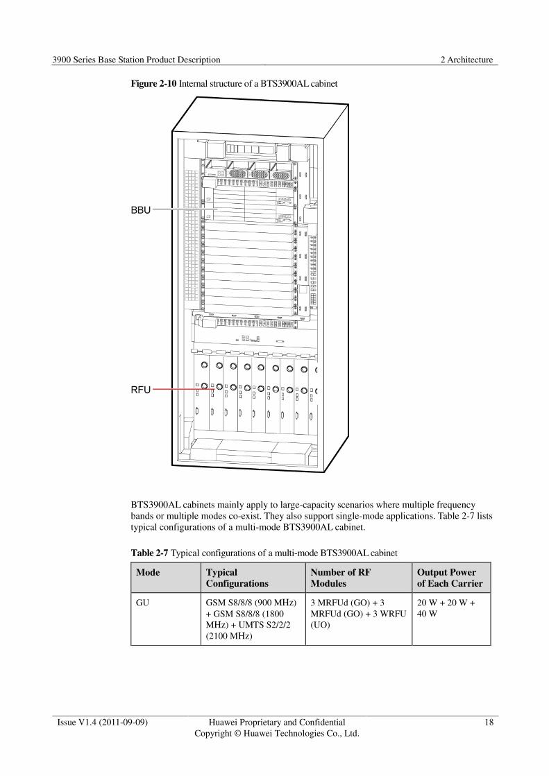
Figure 2-10 Internal structure of a BTS3900AL cabinet
BTS3900AL cabinets mainly apply to large-capacity scenarios where multiple frequency
bands or multiple modes co-exist. They also support single-mode applications. Table 2-7 lists
typical configurations of a multi-mode BTS3900AL cabinet.
Table 2-7 Typical configurations of a multi-mode BTS3900AL cabinet
Mode Typical
Configurations
Number of RF
Modules
Output Power
of Each Carrier
GU GSM S8/8/8 (900 MHz)
+ GSM S8/8/8 (1800
MHz) + UMTS S2/2/2
(2100 MHz)
3 MRFUd (GO) + 3
MRFUd (GO) + 3 WRFU
(UO)
20 W + 20 W +
40 W

3900 Series Base Station Product Description 2 Architecture
Issue V1.4 (2011-09-09) Huawei Proprietary and Confidential
Copyright © Huawei Technologies Co., Ltd.
19
GSM S6/6/6 (900 MHz)
+ UMTS S1/1/1(900
MHz) + GSM S8/8/8
(1800 MHz) + UMTS
S2/2/2 (2100 MHz)
3 MRFUd (GU) + 3
MRFUd (GO) + 3
WRFUd (UO)
20 W + 40 W +
20 W + 80 W (2 x
40 W)
GL GSM S4/4/4 (900 MHz)
+ GSM S4/4/4 (1800
MHz) + LTE S1/1/1 (20
MHz MIMO)
3 GRFU (GO) + 3 GRFU
(GO) + 3 LRFU (LO)
20 W + 80 W (2 x
40 W)
GSM S6/6/6 + LTE
S1/1/1 (10 MHz 2T2R)+
LTE S1/1/1 (20 MHz
MIMO)
6 MRFU (GL) + 3 LRFU
(LO)
20 W + 2 x 20 W
+ 80 W (2 x 40
W)
GSM S8/8/8 (900 MHz)
+ LTE S1/1/1 (800 MHz,
20 MHz MIMO)
3 MRFUd (GO) + 3
LRFU (LO)
20 W + 120 W (2
x 60 W)
UL UMTS S2/2/2 + LTE
S1/1/1 (20 MHz 2T2R)
3 WRFU + 3 MRFU
(LO)
40 W + 80 W (2 x
40 W)
3 MRFU (UO) + 3
MRFU (LO)
UMTS S2/2/2 (MIMO) +
LTE S1/1/1 (20 MHz
4T4R)
3 WRFUd + 6 LRFU 80 W (2 x 40 W)
+ 80 W (2 x 40
W) 3 MRFUd (UO) + 6
MRFUd (LO)
GU+L/GL+U
(independent
BBUs)
GSM S8/8/8 + UMTS
S2/2/2 (MIMO) + LTE
S1/1/1 (20 MHz MIMO)
3 MRFUd (UO) + 3
WRFUd + 3 MRFUd
(LO)
20 W + 80 W (2 x
40 W) + 120 W (2
x 60 W)
GU+L/GL+U
(interconnected
BBUs)
GSM S6/6/6 + UMTS
S1/1/1 (MIMO) +GSM
S6/6/6 + LTE S1/1/1 (10
MHz MIMO) + UMTS
S2/2/2 (MIMO)
3 MRFUd (GU) + 3
MRFUd (GL) + 3 WRFU
20 W + 40 W (2 x
20 W) + 20 W +
40 W (2 x 20 W)
+ 80 W (2 x 40
W)
� The preceding configurations assume that each cell uses one dual-polarized antenna.
� In Table 2-7, GU indicates that GSM and UMTS share one BBU, GL indicates that GSM and LTE
share one BBU, and UL indicates that UMTS and LTE share one BBU; GU+L indicates that GSM
and UMTS share one BBU and LTE uses another BBU, and GL+U indicates that GSM and LTE
share one BBU and UMTS uses another BBU.
2.7 DBS3900
The DBS3900 facilitates site acquisition as well as network planning and optimization, and
reduces network deployment time. It enables operators to efficiently deploy a
high-performance GSM/UMTS/LTE network with a low total cost of ownership (TCO) by
minimizing investment in electricity, space, and manpower.

3900 Series Base Station Product Description 2 Architecture
Issue V1.4 (2011-09-09) Huawei Proprietary and Confidential
Copyright © Huawei Technologies Co., Ltd.
20
The DBS3900 consists of BBU3900s and RRUs. In scenarios requiring distributed
installation, RRUs can be installed near the antenna to reduce feeder loss.
� DBS3900 outdoor site: if 220 V AC, 110 V AC, or +24 V DC power supply is provided,
an APM30H/APM30H (Ver.C) is used; if –48 V DC power supply is provided, a
TMC11H/TMC11H (Ver.C) is used. See scenario 1 in Figure 2-11.
� When RRUs must be installed in centralized mode at a DBS3900 indoor site, the
L-shaped stand can be used. See scenario 2 in Figure 2-11.
� When –48 V DC input power is available at a DBS3900 indoor site, the BBU + RRU
configuration can be used, with the BBU mounted on a wall. See scenario 3 in Figure
2-11.
Figure 2-11 shows typical installation scenarios for the DBS3900.
Figure 2-11 Typical installation scenarios for the DBS3900
3900 Series Base Station Product Description 2 Architecture
Issue V1.4 (2011-09-09) Huawei Proprietary and Confidential
Copyright © Huawei Technologies Co., Ltd.
21
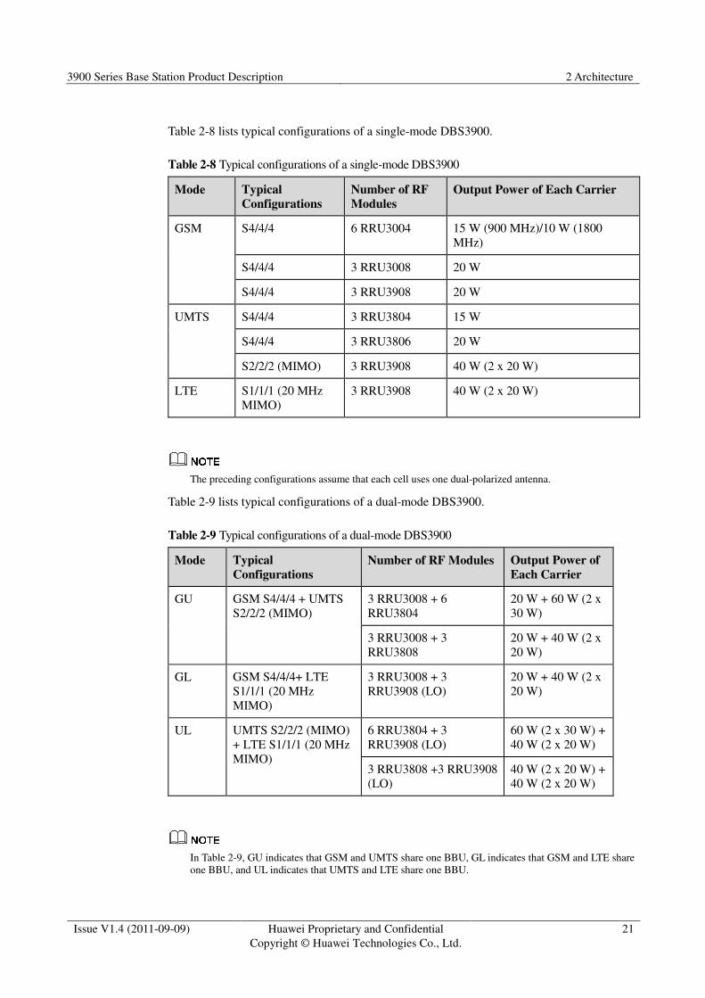
Table 2-8 lists typical configurations of a single-mode DBS3900.
Table 2-8 Typical configurations of a single-mode DBS3900
Mode Typical
Configurations
Number of RF
Modules
Output Power of Each Carrier
GSM S4/4/4 6 RRU3004 15 W (900 MHz)/10 W (1800
MHz)
S4/4/4 3 RRU3008 20 W
S4/4/4 3 RRU3908 20 W
UMTS S4/4/4 3 RRU3804 15 W
S4/4/4 3 RRU3806 20 W
S2/2/2 (MIMO) 3 RRU3908 40 W (2 x 20 W)
LTE S1/1/1 (20 MHz
MIMO)
3 RRU3908 40 W (2 x 20 W)
The preceding configurations assume that each cell uses one dual-polarized antenna.
Table 2-9 lists typical configurations of a dual-mode DBS3900.
Table 2-9 Typical configurations of a dual-mode DBS3900
Mode Typical
Configurations
Number of RF Modules Output Power of
Each Carrier
GU GSM S4/4/4 + UMTS
S2/2/2 (MIMO)
3 RRU3008 + 6
RRU3804
20 W + 60 W (2 x
30 W)
3 RRU3008 + 3
RRU3808
20 W + 40 W (2 x
20 W)
GL GSM S4/4/4+ LTE
S1/1/1 (20 MHz
MIMO)
3 RRU3008 + 3
RRU3908 (LO)
20 W + 40 W (2 x
20 W)
UL UMTS S2/2/2 (MIMO)
+ LTE S1/1/1 (20 MHz
MIMO)
6 RRU3804 + 3
RRU3908 (LO)
60 W (2 x 30 W) +
40 W (2 x 20 W)
3 RRU3808 +3 RRU3908
(LO)
40 W (2 x 20 W) +
40 W (2 x 20 W)
In Table 2-9, GU indicates that GSM and UMTS share one BBU, GL indicates that GSM and LTE share
one BBU, and UL indicates that UMTS and LTE share one BBU.

3900 Series Base Station Product Description 2 Architecture
Issue V1.4 (2011-09-09) Huawei Proprietary and Confidential
Copyright © Huawei Technologies Co., Ltd.
22
2.7.1 APM30H/APM30H (Ver.C) Power Cabinet
The APM30H/APM30H (Ver.C) power cabinet converts AC input power into DC power and
provides DC power to the DBS3900. It also provides space for installing the BBU3900 and
other equipment. The light and small APM30H/APM30H (Ver.C) dissipates heat using a heat
exchanger and internal and external circulation fans.
Figure 2-12 shows the internal structure of the APM30H.
Figure 2-12 Internal structure of the APM30H
(1) Fan box (2) SLPU (3) PSU (AC/DC)
(4) EPS subrack (5) BBU3900 (6) EMUA
(7) PMU (8) HAU (9) SOU
Figure 2-13 shows the internal structure of the APM30H (Ver.C).
Figure 2-13 Internal structure of the APM30H (Ver.C)

3900 Series Base Station Product Description 2 Architecture
Issue V1.4 (2011-09-09) Huawei Proprietary and Confidential
Copyright © Huawei Technologies Co., Ltd.
23
(1) Fan box (2) SLPU (3) PSU
(4) EPU subrack (5) BBU3900 (6) EMUA
(7) Filler module (8) AC HAU (9) SOU
(10) PMU - -
2.7.2 TP48600A Power Cabinet
The TP48600A provides power to the DBS3900. It also provides space for installing the
BBU3900 and other equipment. Figure 2-14 shows the internal structure of the TP48600A.
Figure 2-14 Internal structure of the TP48600A
2.7.3 TMC11H/TMC11H (Ver.C) Transmission Cabinet
The TMC11H/TMC11H (Ver.C) transmission cabinet is used outdoors. It is small and easy to
transport. The TMC11H/TMC11H (Ver.C) dissipates heat using a heat exchanger. If –48 V
DC input power is available or more space is required for transmission equipment, the
TMC11H/TMC11H (Ver.C) can be configured to accommodate either situation.
Figure 2-15 shows the internal structure of the TMC11H.

3900 Series Base Station Product Description 2 Architecture
Issue V1.4 (2011-09-09) Huawei Proprietary and Confidential
Copyright © Huawei Technologies Co., Ltd.
24
� If the TMC11H is only used to provide space for transmission equipment, the internal
structure is as shown in part A of Figure 2-15.
� If the TMC11H is configured with the BBU3900 in a –48 V DC power supply scenario,
the internal structure is as shown in part B of Figure 2-15.
Figure 2-15 Internal structure of the TMC11H
(1) Fan box (2) SLPU (3) DCDU-03
(4) BBU3900 (5) HAU
Figure 2-16 shows the internal structure of the TMC11H (Ver.C).
� If the TMC11H (Ver.C) is only used to provide space for transmission equipment, the
internal structure is as shown in part A of Figure 2-16.
� If the TMC11H (Ver.C) is configured with the BBU3900 in a –48 V DC power supply
scenario, the internal structure is as shown in part B of Figure 2-16.
Figure 2-16 Internal structure of the TMC11H (Ver.C)
3900 Series Base Station Product Description 2 Architecture
Issue V1.4 (2011-09-09) Huawei Proprietary and Confidential
Copyright © Huawei Technologies Co., Ltd.
25
(1) Fan box (2) SLPU (3) DCDU-11C
(4) BBU3900 (5) Filler module (6) AC HAU
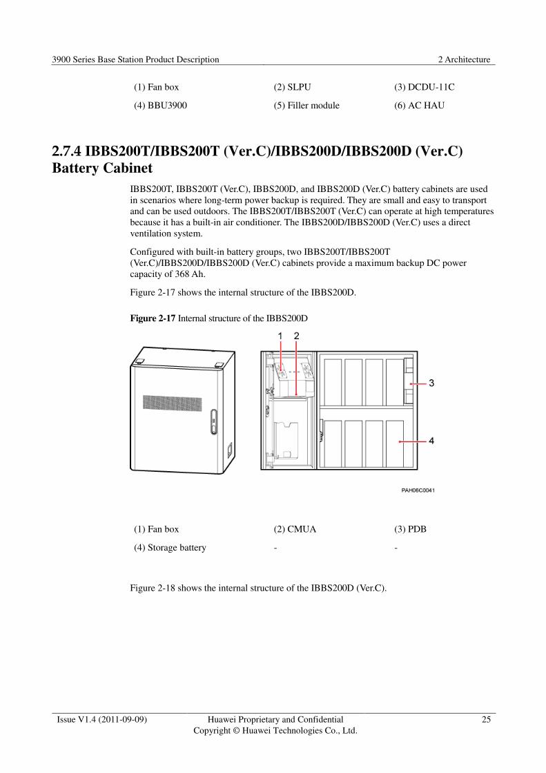
2.7.4 IBBS200T/IBBS200T (Ver.C)/IBBS200D/IBBS200D (Ver.C)
Battery Cabinet
IBBS200T, IBBS200T (Ver.C), IBBS200D, and IBBS200D (Ver.C) battery cabinets are used
in scenarios where long-term power backup is required. They are small and easy to transport
and can be used outdoors. The IBBS200T/IBBS200T (Ver.C) can operate at high temperatures
because it has a built-in air conditioner. The IBBS200D/IBBS200D (Ver.C) uses a direct
ventilation system.
Configured with built-in battery groups, two IBBS200T/IBBS200T
(Ver.C)/IBBS200D/IBBS200D (Ver.C) cabinets provide a maximum backup DC power
capacity of 368 Ah.
Figure 2-17 shows the internal structure of the IBBS200D.
Figure 2-17 Internal structure of the IBBS200D
(1) Fan box (2) CMUA (3) PDB
(4) Storage battery - -
Figure 2-18 shows the internal structure of the IBBS200D (Ver.C).

3900 Series Base Station Product Description 2 Architecture
Issue V1.4 (2011-09-09) Huawei Proprietary and Confidential
Copyright © Huawei Technologies Co., Ltd.
26
Figure 2-18 Internal structure of the IBBS200D (Ver.C)
(1) Fan box (2) CMUE (3) PDB
(4) Storage battery - -
Figure 2-19 shows the internal structure of the IBBS200T.
Figure 2-19 Internal structure of the IBBS200T
(1) TEC (2) CMUA (3) PDB
(4) Storage battery - -
Figure 2-20 shows the internal structure of the IBBS200T (Ver.C).
3900 Series Base Station Product Description 2 Architecture
Issue V1.4 (2011-09-09) Huawei Proprietary and Confidential
Copyright © Huawei Technologies Co., Ltd.
27
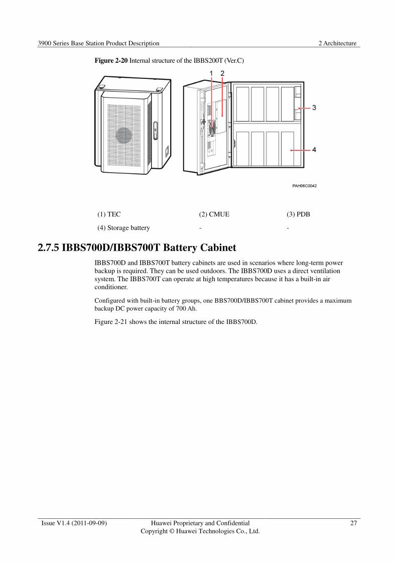
Figure 2-20 Internal structure of the IBBS200T (Ver.C)
(1) TEC (2) CMUE (3) PDB
(4) Storage battery - -
2.7.5 IBBS700D/IBBS700T Battery Cabinet
IBBS700D and IBBS700T battery cabinets are used in scenarios where long-term power
backup is required. They can be used outdoors. The IBBS700D uses a direct ventilation
system. The IBBS700T can operate at high temperatures because it has a built-in air
conditioner.
Configured with built-in battery groups, one BBS700D/IBBS700T cabinet provides a maximum
backup DC power capacity of 700 Ah.
Figure 2-21 shows the internal structure of the IBBS700D.

3900 Series Base Station Product Description 2 Architecture
Issue V1.4 (2011-09-09) Huawei Proprietary and Confidential
Copyright © Huawei Technologies Co., Ltd.
28
Figure 2-21 Internal structure of the IBBS700D
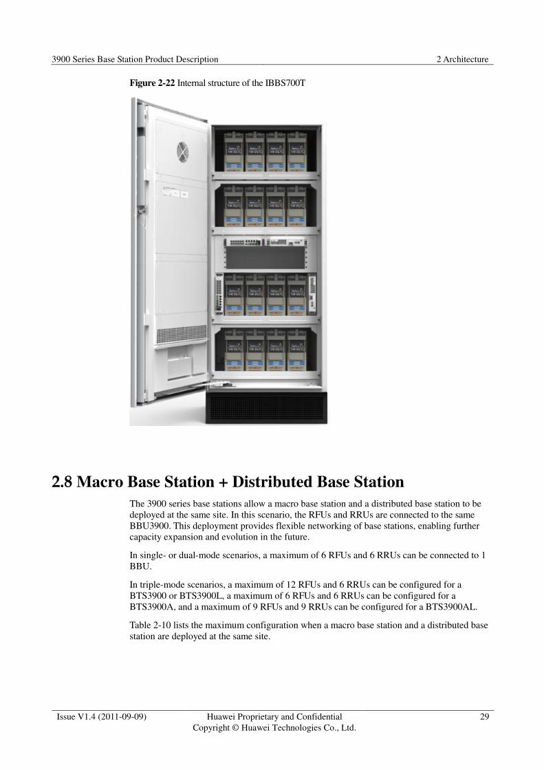
Figure 2-22 shows the internal structure of the IBBS700T.
3900 Series Base Station Product Description 2 Architecture
Issue V1.4 (2011-09-09) Huawei Proprietary and Confidential
Copyright © Huawei Technologies Co., Ltd.
29
Figure 2-22 Internal structure of the IBBS700T
2.8 Macro Base Station + Distributed Base Station
The 3900 series base stations allow a macro base station and a distributed base station to be
deployed at the same site. In this scenario, the RFUs and RRUs are connected to the same
BBU3900. This deployment provides flexible networking of base stations, enabling further
capacity expansion and evolution in the future.
In single- or dual-mode scenarios, a maximum of 6 RFUs and 6 RRUs can be connected to 1
BBU.
In triple-mode scenarios, a maximum of 12 RFUs and 6 RRUs can be configured for a
BTS3900 or BTS3900L, a maximum of 6 RFUs and 6 RRUs can be configured for a
BTS3900A, and a maximum of 9 RFUs and 9 RRUs can be configured for a BTS3900AL.
Table 2-10 lists the maximum configuration when a macro base station and a distributed base
station are deployed at the same site.

3900 Series Base Station Product Description 2 Architecture
Issue V1.4 (2011-09-09) Huawei Proprietary and Confidential
Copyright © Huawei Technologies Co., Ltd.
30
Table 2-10 Maximum configuration when a macro base station and a distributed base station are
deployed at the same site
Base Station Mode Number
of BBUs
Number of
Cabinets
Number
of RFUs
Number
of RRUs
BTS3900 Single-mode/
dual-mode
1 1 6 6
Triple-mode 2 2 12 6
BTS3900L Single-mode/
dual-mode
1 1 6 6
Triple-mode 2 1 12 6
BTS3900A Single-mode/
dual-mode
1 APM30H/APM30H
(Ver.C): 2
TMC11H/ TMC11H
(Ver.C): 1
6 6
Triple-mode 2 APM30H/APM30H
(Ver.C): 2
TMC11H/ TMC11H
(Ver.C): 1
6 6
BTS3900AL Triple-mode 2 1 9 9

3900 Series Base Station Product Description 3 Operation and Maintenance
Issue V1.4 (2011-09-09) Huawei Proprietary and Confidential
Copyright © Huawei Technologies Co., Ltd.
31
3 Operation and Maintenance
3.1 Overview
3900 series base stations are managed by an O&M system using either MML commands or a
graphical user interface (GUI). This system is hardware-independent and provides
comprehensive functions to meet users' various O&M requirements.
3.2 O&M System Structure
Figure 3-1 shows the O&M system structure.

3900 Series Base Station Product Description 3 Operation and Maintenance
Issue V1.4 (2011-09-09) Huawei Proprietary and Confidential
Copyright © Huawei Technologies Co., Ltd.
32
Figure 3-1 O&M system structure
The O&M system consists of the following items:
� GBTS SMT: locally manages one GBTS. O&M personnel use network cables to connect
the PC running the GBTS SMT to the O&M port of the GBTS that the GBTS SMT will
manage.
� BSC LMT: remotely manages multiple GBTSs. O&M personnel use the BSC LMT to
remotely manage multiple GBTSs in a centralized manner.
� NodeB LMT: manages one NodeB. O&M personnel can use network cables to connect
the PC running the NodeB LMT to the O&M port of the NodeB that the NodeB LMT
will manage. Alternatively, O&M personnel can remotely manage a NodeB through
O&M channels by connecting the PC running the NodeB LMT to the NodeB.
� eNodeB LMT: manages one eNodeB. O&M personnel can use network cables to
connect the PC running the eNodeB LMT to the O&M port of the eNodeB that the
eNodeB LMT will manage. Alternatively, O&M personnel can remotely manage an
eNodeB through O&M channels by connecting the PC running the eNodeB LMT to the
eNodeB.
� M2000: Huawei central O&M system. It centrally manages multiple base stations,
provides a data configuration device called Configuration Management Express (CME),

3900 Series Base Station Product Description 3 Operation and Maintenance
Issue V1.4 (2011-09-09) Huawei Proprietary and Confidential
Copyright © Huawei Technologies Co., Ltd.
33
and incorporates the alarm monitoring, performance monitoring, software update, and
inventory device management functions.
3900 Series Base Station Product Description 4 Technical Specifications
Issue V1.4 (2011-09-09) Huawei Proprietary and Confidential
Copyright © Huawei Technologies Co., Ltd.
34
4 Technical Specifications
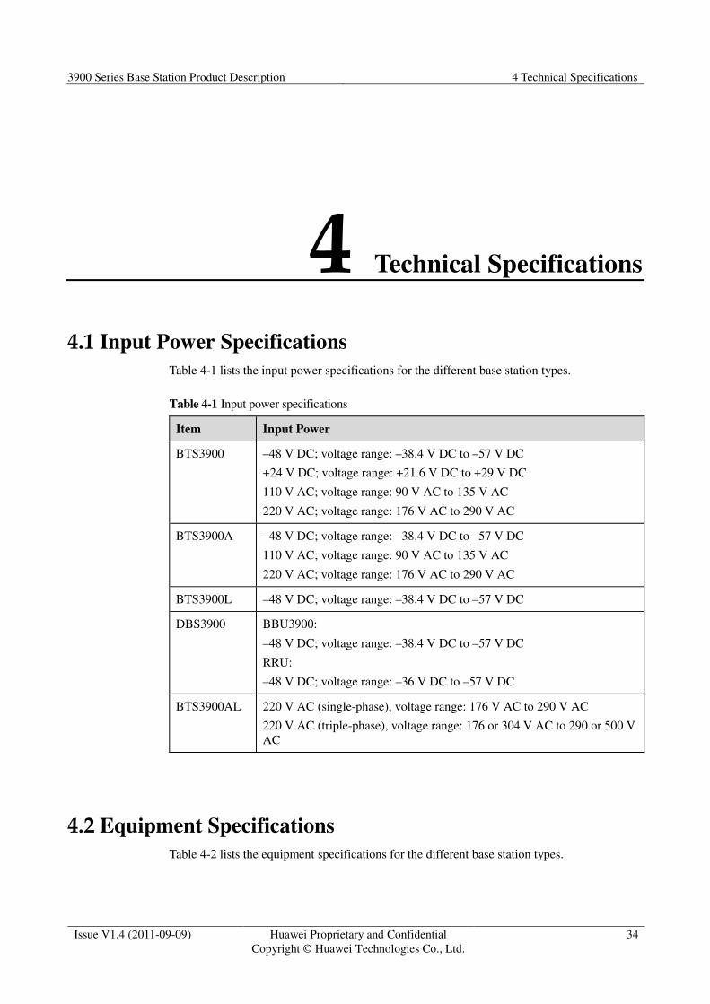
4.1 Input Power Specifications
Table 4-1 lists the input power specifications for the different base station types.
Table 4-1 Input power specifications
Item Input Power
BTS3900 –48 V DC; voltage range: –38.4 V DC to –57 V DC
+24 V DC; voltage range: +21.6 V DC to +29 V DC
110 V AC; voltage range: 90 V AC to 135 V AC
220 V AC; voltage range: 176 V AC to 290 V AC
BTS3900A –48 V DC; voltage range: –38.4 V DC to –57 V DC
110 V AC; voltage range: 90 V AC to 135 V AC
220 V AC; voltage range: 176 V AC to 290 V AC
BTS3900L –48 V DC; voltage range: –38.4 V DC to –57 V DC
DBS3900 BBU3900:
–48 V DC; voltage range: –38.4 V DC to –57 V DC
RRU:
–48 V DC; voltage range: –36 V DC to –57 V DC
BTS3900AL 220 V AC (single-phase), voltage range: 176 V AC to 290 V AC
220 V AC (triple-phase), voltage range: 176 or 304 V AC to 290 or 500 V
AC
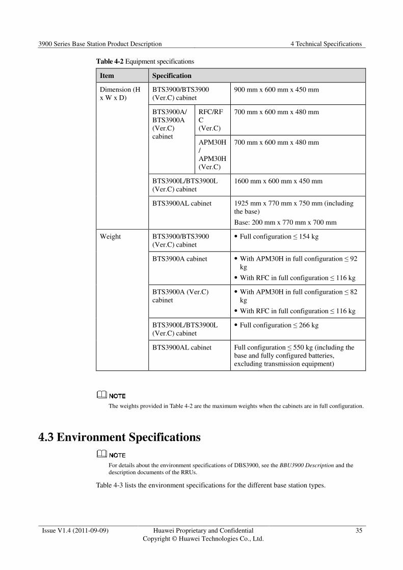
4.2 Equipment Specifications
Table 4-2 lists the equipment specifications for the different base station types.
3900 Series Base Station Product Description 4 Technical Specifications
Issue V1.4 (2011-09-09) Huawei Proprietary and Confidential
Copyright © Huawei Technologies Co., Ltd.
35
Table 4-2 Equipment specifications
Item Specification
Dimension (H
x W x D)
BTS3900/BTS3900
(Ver.C) cabinet
900 mm x 600 mm x 450 mm
BTS3900A/
BTS3900A
(Ver.C)
cabinet
RFC/RF
C
(Ver.C)
700 mm x 600 mm x 480 mm
APM30H
/
APM30H
(Ver.C)
700 mm x 600 mm x 480 mm
BTS3900L/BTS3900L
(Ver.C) cabinet
1600 mm x 600 mm x 450 mm
BTS3900AL cabinet 1925 mm x 770 mm x 750 mm (including
the base)
Base: 200 mm x 770 mm x 700 mm
Weight BTS3900/BTS3900
(Ver.C) cabinet
� Full configuration ≤ 154 kg
BTS3900A cabinet � With APM30H in full configuration ≤ 92
kg
� With RFC in full configuration ≤ 116 kg
BTS3900A (Ver.C)
cabinet
� With APM30H in full configuration ≤ 82
kg
� With RFC in full configuration ≤ 116 kg
BTS3900L/BTS3900L
(Ver.C) cabinet
� Full configuration ≤ 266 kg
BTS3900AL cabinet Full configuration ≤ 550 kg (including the
base and fully configured batteries,
excluding transmission equipment)
The weights provided in Table 4-2 are the maximum weights when the cabinets are in full configuration.
4.3 Environment Specifications
For details about the environment specifications of DBS3900, see the BBU3900 Description and the
description documents of the RRUs.
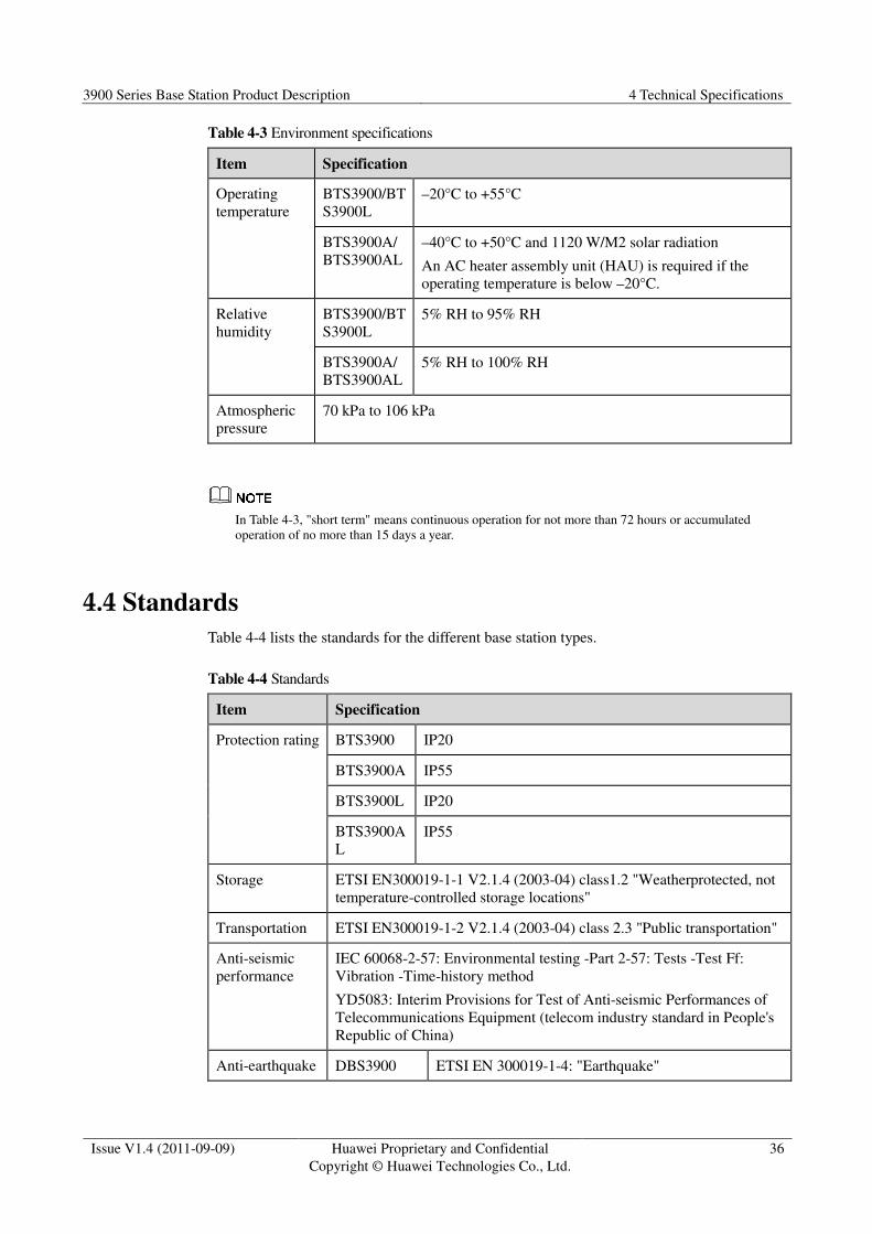
Table 4-3 lists the environment specifications for the different base station types.
3900 Series Base Station Product Description 4 Technical Specifications
Issue V1.4 (2011-09-09) Huawei Proprietary and Confidential
Copyright © Huawei Technologies Co., Ltd.
36
Table 4-3 Environment specifications
Item Specification
Operating
temperature
BTS3900/BT
S3900L
–20°C to +55°C
BTS3900A/
BTS3900AL
–40°C to +50°C and 1120 W/M2 solar radiation
An AC heater assembly unit (HAU) is required if the
operating temperature is below –20°C.
Relative
humidity
BTS3900/BT
S3900L
5% RH to 95% RH
BTS3900A/
BTS3900AL
5% RH to 100% RH
Atmospheric
pressure
70 kPa to 106 kPa
In Table 4-3, "short term" means continuous operation for not more than 72 hours or accumulated
operation of no more than 15 days a year.
4.4 Standards
Table 4-4 lists the standards for the different base station types.
Table 4-4 Standards
Item Specification
Protection rating BTS3900 IP20
BTS3900A IP55
BTS3900L IP20
BTS3900A
L
IP55
Storage ETSI EN300019-1-1 V2.1.4 (2003-04) class1.2 "Weatherprotected, not
temperature-controlled storage locations"
Transportation ETSI EN300019-1-2 V2.1.4 (2003-04) class 2.3 "Public transportation"
Anti-seismic
performance
IEC 60068-2-57: Environmental testing -Part 2-57: Tests -Test Ff:
Vibration -Time-history method
YD5083: Interim Provisions for Test of Anti-seismic Performances of
Telecommunications Equipment (telecom industry standard in People's
Republic of China)
Anti-earthquake DBS3900 ETSI EN 300019-1-4: "Earthquake"

3900 Series Base Station Product Description 4 Technical Specifications
Issue V1.4 (2011-09-09) Huawei Proprietary and Confidential
Copyright © Huawei Technologies Co., Ltd.
37
Item Specification
performance BTS3900 ETSI EN 300019-1-3: "Earthquake"
BTS3900A ETSI EN 300019-1-4: "Earthquake"
BTS3900L ETSI EN 300019-1-3: "Earthquake"
BTS3900AL ETSI EN 300019-1-4: "Earthquake"
EMC The MBTS meets the Electromagnetic Compatibility (EMC)
requirements and complies with the following standards:
� R&TTE Directive 1999/5/EC
� R&TTE Directive 89/336/EEC
� ETSI EN 301489-1/8/23
� 3GPP TS 25.113
� ETSI EN 301908-1
� ITU-T SM 329-10
� FCC PART15
The GBTS meets the EMC requirements and complies with the
following standards:
� R&TTE Directive 1999/5/EC
� R&TTE Directive 89/336/EEC
� ETSI EN 301489-1/8
� ETSI EN 301908-1
� ITU-T SM 329-10
� FCC PART15
The NodeB meets the EMC requirements and complies with the
following standards:
� CISPR 22 (1997)
� EN 55022 (1998)
� EN 301 489-23 V1.2.1 (2002-11)
� CISPR 24 (1998)
� IEC 61000-4-2
� IEC 61000-4-3
� IEC 61000-4-4
� IEC 61000-4-5
� IEC 61000-4-6
� IEC 61000-4-29
� GB 9254-1998
� ETSI 301 489-1 V1.3.1 (2001-09)
� FCC Part 15
The NodeB has been certified by European standards.

3900 Series Base Station Product Description 4 Technical Specifications
Issue V1.4 (2011-09-09) Huawei Proprietary and Confidential
Copyright © Huawei Technologies Co., Ltd.
38
Item Specification
The eNodeB meets the EMC requirements and complies with the
following standards:
� R&TTE Directive 1999/5/EC
� R&TTE Directive 89/336/EEC
� 3GPP TS 36.113
� ETSI EN 301489-1/23
� ETSI EN 301908-1 V2.2.1 (2003-10)
� ITU-R SM.329-10
The eNodeB has been certified by European standards.

3900 Series Base Station Product Description 5 Acronyms and Abbreviations
Issue V1.4 (2011-09-09) Huawei Proprietary and Confidential
Copyright © Huawei Technologies Co., Ltd.
39
5 Acronyms and Abbreviations
3GPP 3rd Generation Partnership Project
AC Alternating current
APM Advanced power module
BBU Baseband unit
CAPEX Capital expenditure
CME Configuration Management Express
CMUA Central monitoring unit type A
CMUE Central monitoring unit type E
Co-OAM Co-Operation and Maintenance
Co-RNP&RNO Co-Radio Network Planning & Radio Network Optimization
Co-RRM Co-Radio Resource Management
Co-TRM Co-Transmission Management
CPRI Common public radio interface
DC Direct current
DCDU Direct current distribution unit
EMC Electromagnetic compatibility
EMUA Environment monitoring unit type A
EPS Embedded power system
EPU Enhanced Packet forward Unit
ETSI European Telecommunications Standards Institute
GSM Global System for Mobile Communications
GUI Graphical user interface
HAU Heater assembly unit

3900 Series Base Station Product Description 5 Acronyms and Abbreviations
Issue V1.4 (2011-09-09) Huawei Proprietary and Confidential
Copyright © Huawei Technologies Co., Ltd.
40
HPMI Hert Power Monitoring Interface unit
IBBS Integrated Backup Battery System
LMT Local maintenance terminal
LTE Long Term Evolution
MIMO Multiple-input multiple-output
O&M Operation and maintenance
OMC Operation and maintenance center
PA Power amplifier
PMU Power monitoring unit
PSU Power supply unit
RF Radio frequency
RFC Radio frequency cabinet
RFU Radio frequency unit
RRU Remote radio unit
SDR Software-defined radio
SLPU Signal Lightning Protection Unit
TCO Total cost of ownership
TEC Thermoelectric cooling unit
TMC Transport Management Cabinet
UMTS Universal Mobile Telecommunications System