$35(6 · 2. runtime patching we consider programs that describe non-functional as-pects of...
TRANSCRIPT
APRES'08Adaptive and Reconfigurable
Embedded Systems
First International Workshop on Adaptive
and Reconfigurable Embedded Systems
St. Louis, MO, USA
April 21st, 2008
Editors:
Luís Almeida
Sebastian Fischmeister
Insup Lee
Julián Proenza
Sponsored by:

First International Workshop on Adaptiveand Reconfigurable Embedded Systems
(APRES’08)
St. Louis, MO, USA, April 21st, 2008


Organizers:
Luís Almeida, Univ. of Aveiro, Portugal
Sebastian Fischmeister, Univ. of Waterloo, Canada
Insup Lee, Univ. of Pennsylvania, USA
Julián Proenza, Univ. of the Balearic Islands, Spain
Program Committee:
Anton Cervin, Lund University, Sweden
Antonio Casimiro, University of Lisbon, Portugal
Arnaldo Oliveira, University of Aveiro, Portugal
Carlos Eduardo Pereira, UFRG, Brazil
Chang-Gun Lee, Seoul National University, Korea
Christoph Kirsch, University of Salzburg, Austria
Eric Rutten, INRIA Grenoble, France
Guillem Bernat, Rapita Systems, UK
Jane Liu, Academia Sinica, Taiwan
Jean-Dominique Decotignie, CSEM, Switzerland
Jörg Kaiser, University of Magdeburg, Germany
Joseph Sifakis, VERIMAG, Grenoble, France
Lucia Lo Bello, University of Catania, Italy
Marco Caccamo, University of Illinois UC, USA
Marga Marcos, University of the Basque Country, Spain
Marisol García-Valls, Univ. Carlos III in Madrid, Spain
MoonZoo Kim, KAIST, Korea
Neil Audsley, University of York, UK
Pau Martí, Technical University of Catalonia, Spain
Paulo Pedreiras, University of Aveiro, Portugal
Raj Rajkumar, Carnegie Mellon University, USA
Robert Trausmuth, Univ. of Applied Sciences WN, Austria
Roman Obermaisser, Technical University Vienna, Austria
Stefan Petters, NICTA, Australia
Thomas Nolte, Malardalen University, Sweden
Xue Liu, McGill University, Canada
Additional Reviewers:
Eduardo R. B. Marques
Elisabet Estévez
Emanuele Toscano
Federico Pérez
Insik Shin
Qixin Wang
Rainer Trummer
Reiner Perozzo
Robert Staudinger
Sina Meraji
Stanley Bak
Yunho Kim
Sponsors:
IST-004527 ARTIST2 Network of Excellence on Embedded Systems Design


Preface
Adaptive systems can respond to environmental changes including hardware/software defects,
resource changes, and non-continual feature usage. As such, adaptive systems can extend the
area of operations and improve efficiency in the use of system resources. However, adaptability
also incurs overhead in terms of system complexity and resource requirements. For example, an
adaptive system requires some means for reconfiguration. These means and their mechanisms
introduce additional complexity to the design and the architecture, and they also require
additional resources such as computation, power, and communication bandwidth. Consequently,
adaptive systems must be diligently planned, designed, analyzed, and built to find the right
tradeoffs between too much and too little flexibility.
The issue is how to provide the adaptability to the application, because it affects all aspects of
the development process (e.g., capturing, methodologies, modeling, analysis, testing, and
implementation), the chosen system technologies (e.g., computation and communication
models, interfaces, component-based design, programming languages, dependability, and design
patterns) and the system itself (e.g., operating system, middleware, network protocols, and
application frameworks).
In many systems, flexibility and the resulting tradeoffs is usually ignored until a very late stage.
Many try to retrofit existing prototypes, middleware, operating systems, and protocols with
concepts and means for flexibility such as run-time system reconfiguration or reflexive
diagnostics and steering methods. Such retrofitting typically leads to disproportionate overhead,
unusual tradeoffs, and in general it leads to less satisfactory results.
The purpose of the workshop is to discuss new and on-going research that is centered on the
idea of adaptability as first class citizen and consider the involved tradeoffs.
Among the 26 initial submissions, 16 papers have been selected and organized in 4 sessions,
covering a wide spectrum of the subject of Adaptive and Reconfigurable Embedded Systems. It
is our wish that the workshop provides an appropriate and relaxed environment to discuss these
new ideas and approaches. In order to facilitate it each speaker will have 15 minutes for the
presentation and each session will finish with a 30-minute panel discussion with the 4 speakers
of that session. Moreover, we will have Prof. Karl-Erik Arzen from Lund University in Sweden
as invited speaker. The title of his speech will be: Adaptivity in Embedded Systems, Why, What
and How.
We would like to thank all the people that have made possible this event. First of all, thanks to
the organizers of the Cyber Physical Systems Week for accepting our proposal of celebrating
this workshop; second, to the authors that submitted their articles; third, to the members of the
Program Committee and other reviewers for their fundamental contribution to the quality of the
final program; and last but not least, to the ARTIST2 Network of Excellence on Embedded
Systems Design for their financial support.
Luís Almeida, Univ. of Aveiro, Portugal
Sebastian Fischmeister, Univ. of Waterloo, Canada
Insup Lee, Univ. of Pennsylvania, USA
Julián Proenza, Univ. of the Balearic Islands, Spain

List of Papers
1 Systems 11.1 Semantics-Preserving and Incremental Runtime Patching of Real-Time Programs.
Christoph M Kirsch, Luıs Lopes and Eduardo R B Marques. . . . . . . . . . . . . . . . . . . . . 31.2 Limitations of Adaptable System Architectures for WCET Reduction.
Jack Whitham and Neil Audsley. . . . . . . . . . . . . . . . . . . . . . . . . . . . . . . . . . . . 81.3 Adaptive Framework for Efficient Resource Management in RTOS.
Ameet Patil and Neil Audsley. . . . . . . . . . . . . . . . . . . . . . . . . . . . . . . . . . . . . 121.4 Enhancing the Adaptivity for Multi-Core Embedded Systems with Dynamic Performance Scaling
in FPGA.Yan Zhang and Gang Quan. . . . . . . . . . . . . . . . . . . . . . . . . . . . . . . . . . . . . . 16
2 Distributed Systems 212.1 Building Adaptive Embedded Systems by Monitoring and Dynamic Loading of Application Mod-
ules.Florian Kluge, Jorg Mische, Sascha Uhrig and Theo Ungerer. . . . . . . . . . . . . . . . . . . . 23
2.2 A Programmable Arbitration Layer for Adaptive Real-Time Systems.Sebastian Fischmeister and Robert Trausmuth. . . . . . . . . . . . . . . . . . . . . . . . . . . . 27
2.3 ViRe: Virtual Reconfiguration Framework for Embedded Processing in Distributed Image Sensors.Rahul Balani, Akhilesh Singhania, Chih-Chieh Han and Mani Srivastava. . . . . . . . . . . . . 32
2.4 Trade-off Analysis of Communications Protocols for Wireless Sensor Networks.Jerome Rousselot, Amre El-Hoiydi and Jean-Dominique Decotignie. . . . . . . . . . . . . . . . 36
3 Scheduling 413.1 A GA-Based Approach to Dynamic Reconfiguration of Real-Time Systems.
Marco A. C. Simoes, George M. Lima and Eduardo Camponogara. . . . . . . . . . . . . . . . . 433.2 CPU Utilization Control Based on Adaptive Critic Design .
Jianguo Yao and Xue Liu. . . . . . . . . . . . . . . . . . . . . . . . . . . . . . . . . . . . . . . 473.3 A hierarchical approach for reconfigurable and adaptive embedded systems.
Moris Behnam, Thomas Nolte and Insik Shin. . . . . . . . . . . . . . . . . . . . . . . . . . . . 513.4 Suitability of Dynamic Load Balancing in Resource-Constrained Embedded Systems: An Overview
of Challenges and Limitations.Magnus Persson, Tahir Naseer Qureshi and Martin Torngren . . . . . . . . . . . . . . . . . . . . 55
4 Design and Modeling 594.1 Flexible User-Centric Automation and Assistive devices.
J. W. S. Liu, C. S. Shih, T. W. Kuo, S. Y. Chang, Y. F. Lu and M. K. Ouyang. . . . . . . . . . . . . 614.2 Towards an Integrated Planning and Adaptive Resource Management Architecture for Distributed
Real-time Embedded Systems.Nishanth Shankaran, John Kinnebrew, Xenofon Koutsoukos, Chenyang Lu, Douglas Schmidt andGautam Biswas. . . . . . . . . . . . . . . . . . . . . . . . . . . . . . . . . . . . . . . . . . . .65
4.3 Designing Reconfigurable Component Systems with a Model Approach.Brahim Hamid, Agnes Lanusse, Ansgar Radermacher and Sebastien Gerard . . . . . . . . . . . . 69
4.4 Enabling Extensibility of Sensing Systems through Automatic Composition over Physical Loca-tion.Maurice Chu and Juan Liu. . . . . . . . . . . . . . . . . . . . . . . . . . . . . . . . . . . . . . 74
v


1. Systems

Semantics-Preserving and IncrementalRuntime Patching of Real-Time Programs†
Christoph M. KirschUniversity of [email protected]
Luıs LopesCRACS/University of Porto
Eduardo R. B. MarquesUniversity of [email protected]
Abstract
We propose semantics-preserving and incremental run-time patching of real-time programs as a robust means forreconfiguring hard real-time systems at runtime. We con-sider programs that describe non-functional aspects of pro-cesses such as their timing properties and communicationbehavior, and give examples written in the HierarchicalTiming Language (HTL). Runtime patching is the processof replacing portions of such programs at runtime by newcode. It is semantics-preserving if the switch to the result-ing code and the code itself could have been compiled be-forehand, had the patch been known. It is incremental ifanalyzing and generating the code only involves an effortproportional to the size of the patch, not the patched pro-gram. This can even be done with system-wide propertiessuch as schedulability by exploiting HTL-specific features.
1. IntroductionSoftware has the great advantage of being flexible. In
fact, for now, it probably remains the single most flexibleconcept for engineering even the most complex systems.The majority of IT industries exploit that flexibility andsometimes even use it as foundation for their business mod-els. There are important exceptions though. Large portionsof the real-time systems industry, in particular, the onesworking on mission- and safety-critical applications essen-tially ignore software-related flexibility. There are goodrea-sons after all. Getting large software systems and, in partic-ular, real-time systems right is still extremely difficult.Howcan we then even think about modifying such systems whilethey are running? Clearly, adaptivity is not just a nice-to-have feature, especially in real-time systems where it may
†C. M. Kirsch is supported by a 2007 IBM Faculty Award, the EUArtistDesign Network of Excellence on Embedded Systems Design, andthe Austrian Science Fund No. P18913-N15. L. Lopes is partially sup-ported by project CALLAS from Fundacao para a Ciencia e Tecnologia(contract PTDC/EIA/71462/2006). E. R. B. Marques is supported by theSFRH/BD/29461/2006 grant from Fundacao para a Ciencia eTecnologia.
We would like to thank Joao Sousa and Raja Sengupta for inspirationin this work and Sebastian Fischmeister for some relevant suggestions andcomments.
give rise to unforeseen application scenarios and softwaredevelopment methodologies. What is even more excitingthough is that the essential, enabling technologies may cur-rently be shaping up to make adaptivity of even hard real-time systems a reality.
We believe there are two key ingredients. Adaptivityneeds a strong semantical foundation and non-trivial scal-ability. We need to know what reconfiguration means andhow to do it fast, even on large systems. There is a growingresearch trend towards so-called semantics-preserving exe-cution environments for real-time systems such as the real-time language Giotto [9] and its successors but also otherwork on synchronous reactive languages [2], which providenotions of composability that go beyond the typical schedu-lability guarantees of more traditional real-time languagesand operating systems. For example, Giotto programs canbe modified without changing the relevant properties of theunmodified portions as long as there are sufficient computa-tional resources. Relevant properties are not just schedula-bility but also task functionality, intertask communication,and I/O times. Nevertheless, checking schedulability andother system-wide properties remains necessary but is of-ten difficult and may limit scalability of reconfiguration at-tempts. Recent work, however, on incremental schedulabil-ity analysis of traditional task models [5] but also language-based models [7], in combination with stronger, semanti-cal notions of composability, may lead to fast, scalable, andsemantics-preserving reconfiguration of real-time systems.
In this paper, we propose semantics-preserving and in-crementalruntime patchingof real-time programs as a ro-bust means for reconfiguring even large systems at runtime,and give examples written in HTL [7], a Giotto succes-sor. So far, we have only studied the idea conceptually andworked with examples. Our plan is to design and imple-ment runtime patching support in our existing HTL infras-tructure [1] and perform experiments with unmanned vehi-cles in Salzburg [4] and Porto [12]. In Section 2, we give anintuitive overview of our approach. In Section 3, key con-cepts of HTL are provided, followed by a presentation of anHTL-based runtime patching model in Section 4.
1. Systems 3
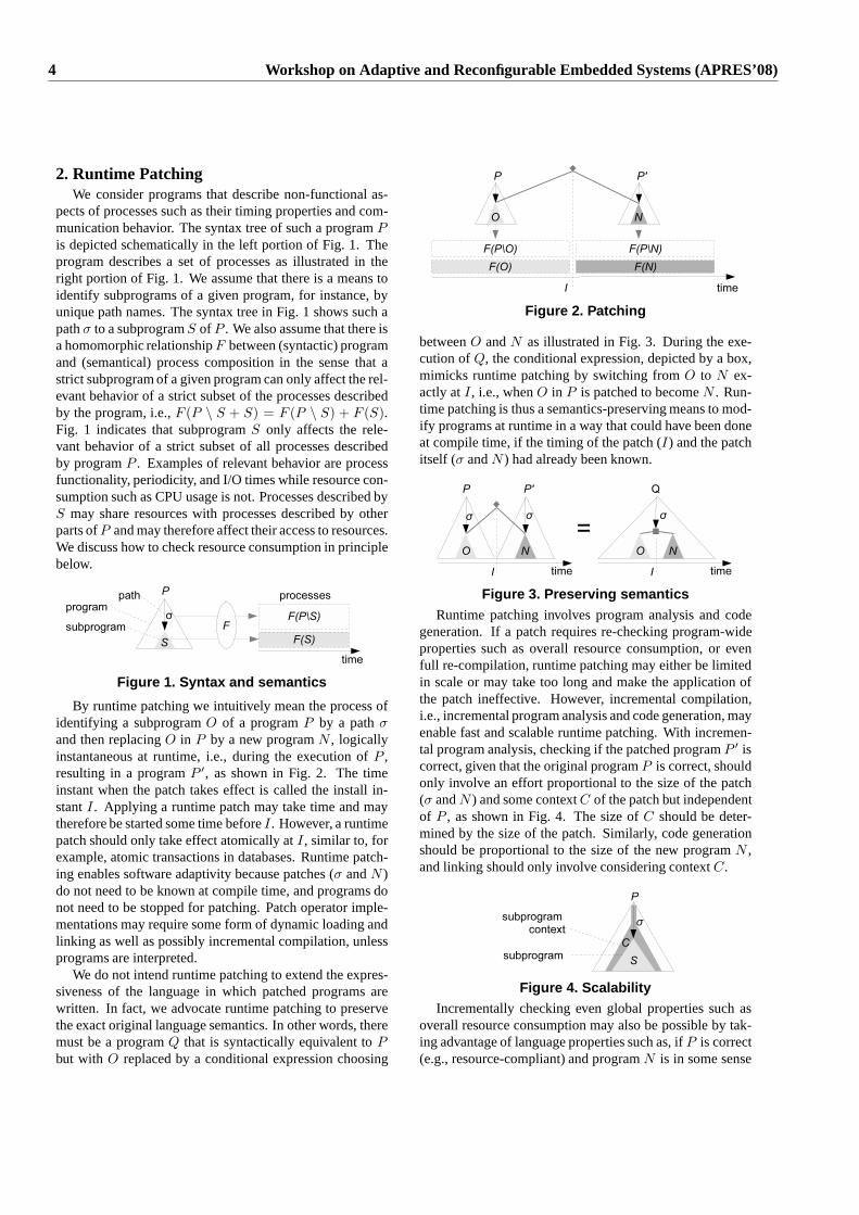
2. Runtime PatchingWe consider programs that describe non-functional as-
pects of processes such as their timing properties and com-munication behavior. The syntax tree of such a programP
is depicted schematically in the left portion of Fig. 1. Theprogram describes a set of processes as illustrated in theright portion of Fig. 1. We assume that there is a means toidentify subprograms of a given program, for instance, byunique path names. The syntax tree in Fig. 1 shows such apathσ to a subprogramS of P . We also assume that there isa homomorphic relationshipF between (syntactic) programand (semantical) process composition in the sense that astrict subprogram of a given program can only affect the rel-evant behavior of a strict subset of the processes describedby the program, i.e.,F (P \ S + S) = F (P \ S) + F (S).Fig. 1 indicates that subprogramS only affects the rele-vant behavior of a strict subset of all processes describedby programP . Examples of relevant behavior are processfunctionality, periodicity, and I/O times while resource con-sumption such as CPU usage is not. Processes described byS may share resources with processes described by otherparts ofP and may therefore affect their access to resources.We discuss how to check resource consumption in principlebelow.
Figure 1. Syntax and semantics
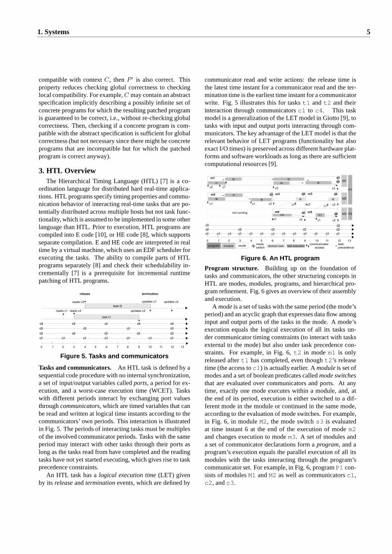
By runtime patching we intuitively mean the process ofidentifying a subprogramO of a programP by a pathσ
and then replacingO in P by a new programN , logicallyinstantaneous at runtime, i.e., during the execution ofP ,resulting in a programP ′, as shown in Fig. 2. The timeinstant when the patch takes effect is called the install in-stantI. Applying a runtime patch may take time and maytherefore be started some time beforeI. However, a runtimepatch should only take effect atomically atI, similar to, forexample, atomic transactions in databases. Runtime patch-ing enables software adaptivity because patches (σ andN )do not need to be known at compile time, and programs donot need to be stopped for patching. Patch operator imple-mentations may require some form of dynamic loading andlinking as well as possibly incremental compilation, unlessprograms are interpreted.
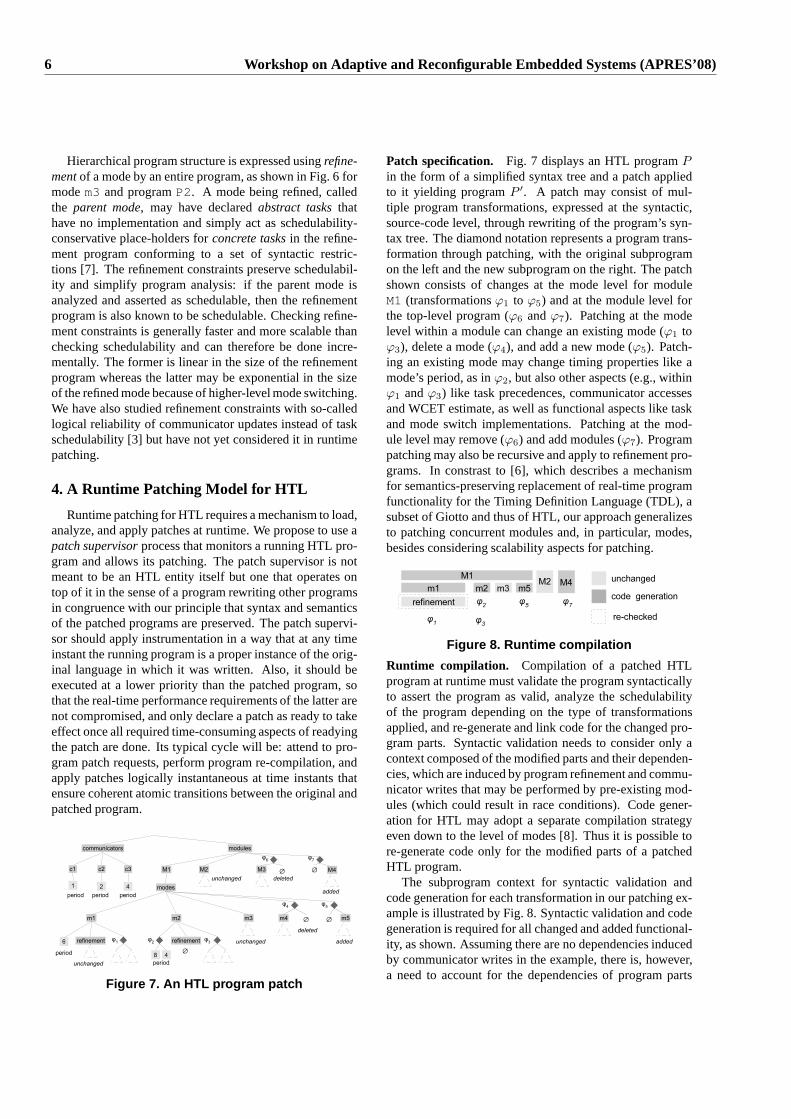
We do not intend runtime patching to extend the expres-siveness of the language in which patched programs arewritten. In fact, we advocate runtime patching to preservethe exact original language semantics. In other words, theremust be a programQ that is syntactically equivalent toPbut with O replaced by a conditional expression choosing
Figure 2. Patching
betweenO andN as illustrated in Fig. 3. During the exe-cution ofQ, the conditional expression, depicted by a box,mimicks runtime patching by switching fromO to N ex-actly atI, i.e., whenO in P is patched to becomeN . Run-time patching is thus a semantics-preserving means to mod-ify programs at runtime in a way that could have been doneat compile time, if the timing of the patch (I) and the patchitself (σ andN ) had already been known.
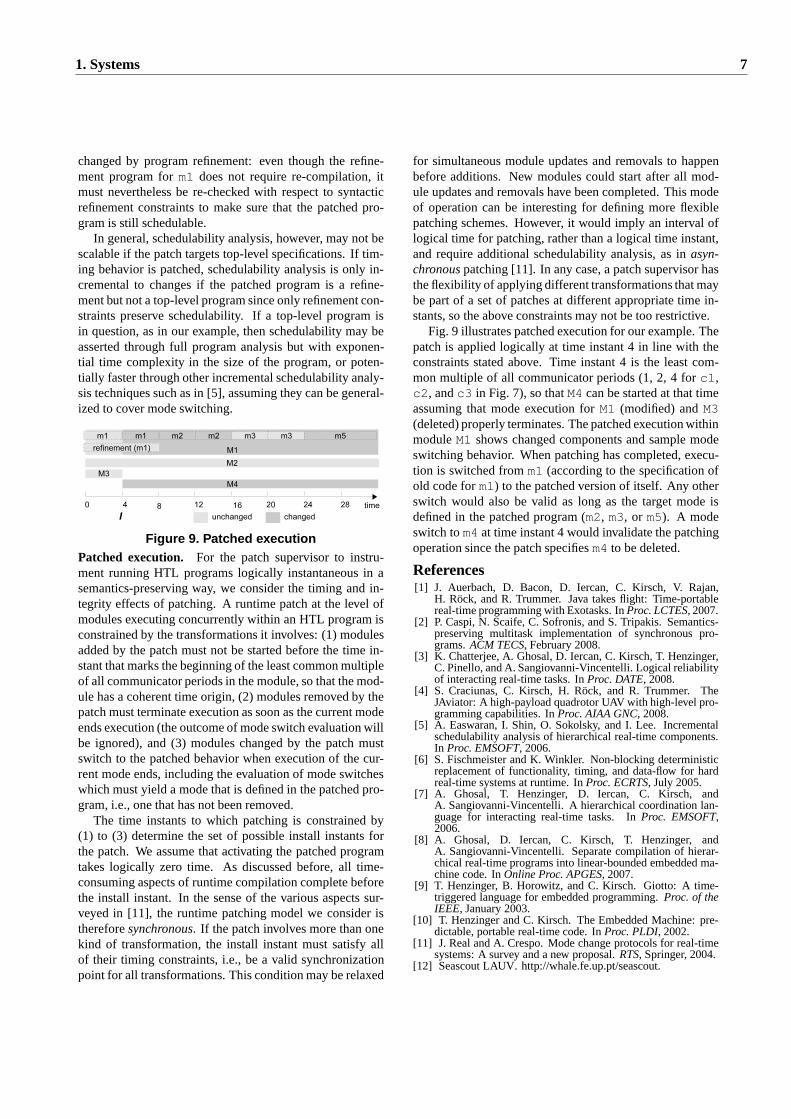
Figure 3. Preserving semanticsRuntime patching involves program analysis and code
generation. If a patch requires re-checking program-wideproperties such as overall resource consumption, or evenfull re-compilation, runtime patching may either be limitedin scale or may take too long and make the application ofthe patch ineffective. However, incremental compilation,i.e., incremental program analysis and code generation, mayenable fast and scalable runtime patching. With incremen-tal program analysis, checking if the patched programP ′ iscorrect, given that the original programP is correct, shouldonly involve an effort proportional to the size of the patch(σ andN ) and some contextC of the patch but independentof P , as shown in Fig. 4. The size ofC should be deter-mined by the size of the patch. Similarly, code generationshould be proportional to the size of the new programN ,and linking should only involve considering contextC.
Figure 4. ScalabilityIncrementally checking even global properties such as
overall resource consumption may also be possible by tak-ing advantage of language properties such as, ifP is correct(e.g., resource-compliant) and programN is in some sense
4 Workshop on Adaptive and Reconfigurable Embedded Systems (APRES’08)
compatible with contextC, thenP ′ is also correct. Thisproperty reduces checking global correctness to checkinglocal compatibility. For example,C may contain an abstractspecification implicitly describing a possibly infinite setofconcrete programs for which the resulting patched programis guaranteed to be correct, i.e., without re-checking globalcorrectness. Then, checking if a concrete program is com-patible with the abstract specification is sufficient for globalcorrectness (but not necessary since there might be concreteprograms that are incompatible but for which the patchedprogram is correct anyway).
3. HTL OverviewThe Hierarchical Timing Language (HTL) [7] is a co-
ordination language for distributed hard real-time applica-tions. HTL programs specify timing properties and commu-nication behavior of interacting real-time tasks that are po-tentially distributed across multiple hosts but not task func-tionality, which is assumed to be implemented in some otherlanguage than HTL. Prior to execution, HTL programs arecompiled into E code [10], or HE code [8], which supportsseparate compilation. E and HE code are interpreted in realtime by a virtual machine, which uses an EDF scheduler forexecuting the tasks. The ability to compile parts of HTLprograms separately [8] and check their schedulability in-crementally [7] is a prerequisite for incremental runtimepatching of HTL programs.
Figure 5. Tasks and communicators
Tasks and communicators. An HTL task is defined by asequential code procedure with no internal synchronization,a set of input/output variables calledports, a period for ex-ecution, and a worst-case execution time (WCET). Taskswith different periods interact by exchanging port valuesthroughcommunicators, which are timed variables that canbe read and written at logical time instants according to thecommunicators’ own periods. This interaction is illustratedin Fig. 5. The periods of interacting tasks must be multiplesof the involved communicator periods. Tasks with the sameperiod may interact with other tasks through their ports aslong as the tasks read from have completed and the readingtasks have not yet started executing, which gives rise to taskprecedence constraints.
An HTL task has alogical execution time(LET) givenby its releaseandterminationevents, which are defined by
communicator read and write actions: the release time isthe latest time instant for a communicator read and the ter-mination time is the earliest time instant for a communicatorwrite. Fig. 5 illustrates this for taskst1 andt2 and theirinteraction through communicatorsc1 to c4. This taskmodel is a generalization of the LET model in Giotto [9], totasks with input and output ports interacting through com-municators. The key advantage of the LET model is that therelevant behavior of LET programs (functionality but alsoexact I/O times) is preserved across different hardware plat-forms and software workloads as long as there are sufficientcomputational resources [9].
Figure 6. An HTL program
Program structure. Building up on the foundation oftasks and communicators, the other structuring concepts inHTL are modes, modules, programs, and hierarchical pro-gram refinement. Fig. 6 gives an overview of their assemblyand execution.
A modeis a set of tasks with the same period (the mode’speriod) and an acyclic graph that expresses data flow amonginput and output ports of the tasks in the mode. A mode’sexecution equals the logical execution of all its tasks un-der communicator timing constraints (to interact with tasksexternal to the mode) but also under task precedence con-straints. For example, in Fig. 6,t2 in modem1 is onlyreleased aftert1 has completed, even thought2’s releasetime (the access toc1) is actually earlier. Amoduleis set ofmodes and a set of boolean predicates calledmode switchesthat are evaluated over communicators and ports. At anytime, exactly one mode executes within a module, and, atthe end of its period, execution is either switched to a dif-ferent mode in the module or continued in the same mode,according to the evaluation of mode switches. For example,in Fig. 6, in moduleM2, the mode switchs3 is evaluatedat time instant 6 at the end of the execution of modem2and changes execution to modem3. A set of modules anda set of communicator declarations form aprogram, and aprogram’s execution equals the parallel execution of all itsmodules with the tasks interacting through the program’scommunicator set. For example, in Fig. 6, programP1 con-sists of modulesM1 andM2 as well as communicatorsc1,c2, andc3.
1. Systems 5
Hierarchical program structure is expressed usingrefine-mentof a mode by an entire program, as shown in Fig. 6 formodem3 and programP2. A mode being refined, calledthe parent mode, may have declaredabstract tasksthathave no implementation and simply act as schedulability-conservative place-holders forconcrete tasksin the refine-ment program conforming to a set of syntactic restric-tions [7]. The refinement constraints preserve schedulabil-ity and simplify program analysis: if the parent mode isanalyzed and asserted as schedulable, then the refinementprogram is also known to be schedulable. Checking refine-ment constraints is generally faster and more scalable thanchecking schedulability and can therefore be done incre-mentally. The former is linear in the size of the refinementprogram whereas the latter may be exponential in the sizeof the refined mode because of higher-level mode switching.We have also studied refinement constraints with so-calledlogical reliability of communicator updates instead of taskschedulability [3] but have not yet considered it in runtimepatching.
4. A Runtime Patching Model for HTL
Runtime patching for HTL requires a mechanism to load,analyze, and apply patches at runtime. We propose to use apatch supervisorprocess that monitors a running HTL pro-gram and allows its patching. The patch supervisor is notmeant to be an HTL entity itself but one that operates ontop of it in the sense of a program rewriting other programsin congruence with our principle that syntax and semanticsof the patched programs are preserved. The patch supervi-sor should apply instrumentation in a way that at any timeinstant the running program is a proper instance of the orig-inal language in which it was written. Also, it should beexecuted at a lower priority than the patched program, sothat the real-time performance requirements of the latter arenot compromised, and only declare a patch as ready to takeeffect once all required time-consuming aspects of readyingthe patch are done. Its typical cycle will be: attend to pro-gram patch requests, perform program re-compilation, andapply patches logically instantaneous at time instants thatensure coherent atomic transitions between the original andpatched program.
Figure 7. An HTL program patch
Patch specification. Fig. 7 displays an HTL programPin the form of a simplified syntax tree and a patch appliedto it yielding programP ′. A patch may consist of mul-tiple program transformations, expressed at the syntactic,source-code level, through rewriting of the program’s syn-tax tree. The diamond notation represents a program trans-formation through patching, with the original subprogramon the left and the new subprogram on the right. The patchshown consists of changes at the mode level for moduleM1 (transformationsϕ1 to ϕ5) and at the module level forthe top-level program (ϕ6 andϕ7). Patching at the modelevel within a module can change an existing mode (ϕ1 toϕ3), delete a mode (ϕ4), and add a new mode (ϕ5). Patch-ing an existing mode may change timing properties like amode’s period, as inϕ2, but also other aspects (e.g., withinϕ1 andϕ3) like task precedences, communicator accessesand WCET estimate, as well as functional aspects like taskand mode switch implementations. Patching at the mod-ule level may remove (ϕ6) and add modules (ϕ7). Programpatching may also be recursive and apply to refinement pro-grams. In constrast to [6], which describes a mechanismfor semantics-preserving replacement of real-time programfunctionality for the Timing Definition Language (TDL), asubset of Giotto and thus of HTL, our approach generalizesto patching concurrent modules and, in particular, modes,besides considering scalability aspects for patching.
Figure 8. Runtime compilation
Runtime compilation. Compilation of a patched HTLprogram at runtime must validate the program syntacticallyto assert the program as valid, analyze the schedulabilityof the program depending on the type of transformationsapplied, and re-generate and link code for the changed pro-gram parts. Syntactic validation needs to consider only acontext composed of the modified parts and their dependen-cies, which are induced by program refinement and commu-nicator writes that may be performed by pre-existing mod-ules (which could result in race conditions). Code gener-ation for HTL may adopt a separate compilation strategyeven down to the level of modes [8]. Thus it is possible tore-generate code only for the modified parts of a patchedHTL program.
The subprogram context for syntactic validation andcode generation for each transformation in our patching ex-ample is illustrated by Fig. 8. Syntactic validation and codegeneration is required for all changed and added functional-ity, as shown. Assuming there are no dependencies inducedby communicator writes in the example, there is, however,a need to account for the dependencies of program parts
6 Workshop on Adaptive and Reconfigurable Embedded Systems (APRES’08)
changed by program refinement: even though the refine-ment program form1 does not require re-compilation, itmust nevertheless be re-checked with respect to syntacticrefinement constraints to make sure that the patched pro-gram is still schedulable.
In general, schedulability analysis, however, may not bescalable if the patch targets top-level specifications. If tim-ing behavior is patched, schedulability analysis is only in-cremental to changes if the patched program is a refine-ment but not a top-level program since only refinement con-straints preserve schedulability. If a top-level program isin question, as in our example, then schedulability may beasserted through full program analysis but with exponen-tial time complexity in the size of the program, or poten-tially faster through other incremental schedulability analy-sis techniques such as in [5], assuming they can be general-ized to cover mode switching.
Figure 9. Patched executionPatched execution. For the patch supervisor to instru-ment running HTL programs logically instantaneous in asemantics-preserving way, we consider the timing and in-tegrity effects of patching. A runtime patch at the level ofmodules executing concurrently within an HTL program isconstrained by the transformations it involves: (1) modulesadded by the patch must not be started before the time in-stant that marks the beginning of the least common multipleof all communicator periods in the module, so that the mod-ule has a coherent time origin, (2) modules removed by thepatch must terminate execution as soon as the current modeends execution (the outcome of mode switch evaluation willbe ignored), and (3) modules changed by the patch mustswitch to the patched behavior when execution of the cur-rent mode ends, including the evaluation of mode switcheswhich must yield a mode that is defined in the patched pro-gram, i.e., one that has not been removed.
The time instants to which patching is constrained by(1) to (3) determine the set of possible install instants forthe patch. We assume that activating the patched programtakes logically zero time. As discussed before, all time-consuming aspects of runtime compilation complete beforethe install instant. In the sense of the various aspects sur-veyed in [11], the runtime patching model we consider isthereforesynchronous. If the patch involves more than onekind of transformation, the install instant must satisfy allof their timing constraints, i.e., be a valid synchronizationpoint for all transformations. This condition may be relaxed
for simultaneous module updates and removals to happenbefore additions. New modules could start after all mod-ule updates and removals have been completed. This modeof operation can be interesting for defining more flexiblepatching schemes. However, it would imply an interval oflogical time for patching, rather than a logical time instant,and require additional schedulability analysis, as inasyn-chronouspatching [11]. In any case, a patch supervisor hasthe flexibility of applying different transformations thatmaybe part of a set of patches at different appropriate time in-stants, so the above constraints may not be too restrictive.
Fig. 9 illustrates patched execution for our example. Thepatch is applied logically at time instant 4 in line with theconstraints stated above. Time instant 4 is the least com-mon multiple of all communicator periods (1, 2, 4 forc1,c2, andc3 in Fig. 7), so thatM4 can be started at that timeassuming that mode execution forM1 (modified) andM3(deleted) properly terminates. The patched execution withinmoduleM1 shows changed components and sample modeswitching behavior. When patching has completed, execu-tion is switched fromm1 (according to the specification ofold code form1) to the patched version of itself. Any otherswitch would also be valid as long as the target mode isdefined in the patched program (m2, m3, or m5). A modeswitch tom4 at time instant 4 would invalidate the patchingoperation since the patch specifiesm4 to be deleted.
References[1] J. Auerbach, D. Bacon, D. Iercan, C. Kirsch, V. Rajan,
H. Rock, and R. Trummer. Java takes flight: Time-portablereal-time programming with Exotasks. InProc. LCTES, 2007.
[2] P. Caspi, N. Scaife, C. Sofronis, and S. Tripakis. Semantics-preserving multitask implementation of synchronous pro-grams.ACM TECS, February 2008.
[3] K. Chatterjee, A. Ghosal, D. Iercan, C. Kirsch, T. Henzinger,C. Pinello, and A. Sangiovanni-Vincentelli. Logical reliabilityof interacting real-time tasks. InProc. DATE, 2008.
[4] S. Craciunas, C. Kirsch, H. Rock, and R. Trummer. TheJAviator: A high-payload quadrotor UAV with high-level pro-gramming capabilities. InProc. AIAA GNC, 2008.
[5] A. Easwaran, I. Shin, O. Sokolsky, and I. Lee. Incrementalschedulability analysis of hierarchical real-time components.In Proc. EMSOFT, 2006.
[6] S. Fischmeister and K. Winkler. Non-blocking deterministicreplacement of functionality, timing, and data-flow for hardreal-time systems at runtime. InProc. ECRTS, July 2005.
[7] A. Ghosal, T. Henzinger, D. Iercan, C. Kirsch, andA. Sangiovanni-Vincentelli. A hierarchical coordinationlan-guage for interacting real-time tasks. InProc. EMSOFT,2006.
[8] A. Ghosal, D. Iercan, C. Kirsch, T. Henzinger, andA. Sangiovanni-Vincentelli. Separate compilation of hierar-chical real-time programs into linear-bounded embedded ma-chine code. InOnline Proc. APGES, 2007.
[9] T. Henzinger, B. Horowitz, and C. Kirsch. Giotto: A time-triggered language for embedded programming.Proc. of theIEEE, January 2003.
[10] T. Henzinger and C. Kirsch. The Embedded Machine: pre-dictable, portable real-time code. InProc. PLDI, 2002.
[11] J. Real and A. Crespo. Mode change protocols for real-timesystems: A survey and a new proposal.RTS, Springer, 2004.
[12] Seascout LAUV. http://whale.fe.up.pt/seascout.
1. Systems 7
Limitations of Adaptable System Architectures for WCET Reduction
Jack Whitham and Neil AudsleyReal-Time Systems Group
Department of Computer ScienceUniversity of York, York, YO10 5DD, UK
AbstractThis paper identifies three major issues facing worst-
case execution time (WCET) reduction algorithms onadaptable architectures based on research carried out forthe MCGREP-2 CPU project. The issues are exposingmore instruction level parallelism (ILP) in code, reduc-ing loading costs for the memory and processing elementsused to reduce WCET, and making use of application-specific hardware. Potential difficulties in each of theseareas are identified and possible solutions are proposed.
1 IntroductionEmbedded systems often include some real-time func-
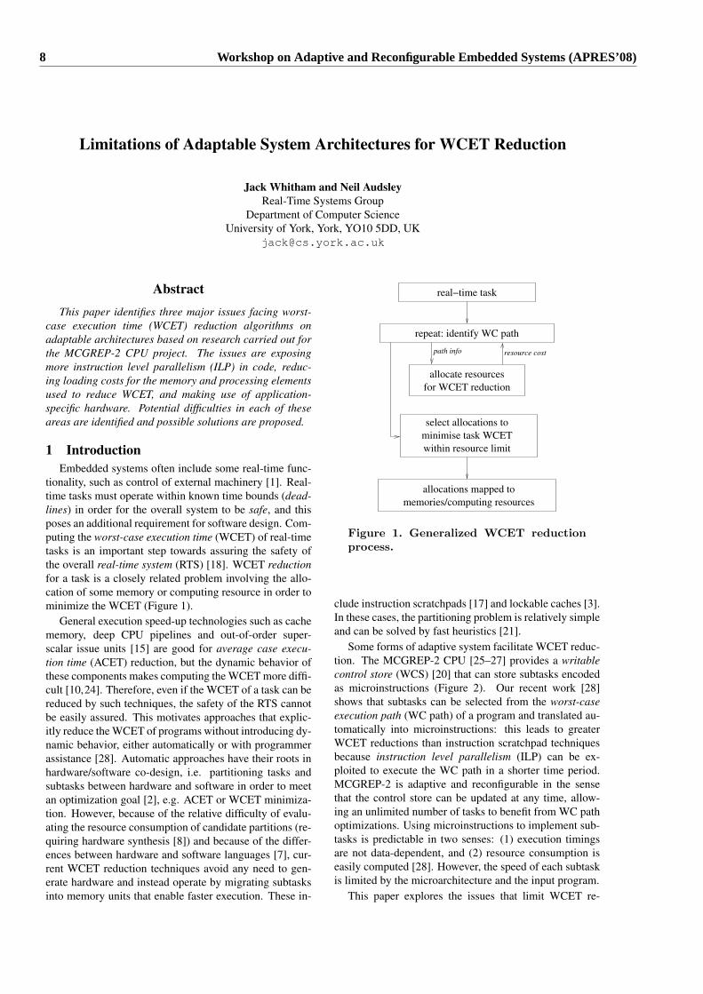
tionality, such as control of external machinery [1]. Real-time tasks must operate within known time bounds (dead-lines) in order for the overall system to be safe, and thisposes an additional requirement for software design. Com-puting the worst-case execution time (WCET) of real-timetasks is an important step towards assuring the safety ofthe overall real-time system (RTS) [18]. WCET reductionfor a task is a closely related problem involving the allo-cation of some memory or computing resource in order tominimize the WCET (Figure 1).
General execution speed-up technologies such as cachememory, deep CPU pipelines and out-of-order super-scalar issue units [15] are good for average case execu-tion time (ACET) reduction, but the dynamic behavior ofthese components makes computing the WCET more diffi-cult [10,24]. Therefore, even if the WCET of a task can bereduced by such techniques, the safety of the RTS cannotbe easily assured. This motivates approaches that explic-itly reduce the WCET of programs without introducing dy-namic behavior, either automatically or with programmerassistance [28]. Automatic approaches have their roots inhardware/software co-design, i.e. partitioning tasks andsubtasks between hardware and software in order to meetan optimization goal [2], e.g. ACET or WCET minimiza-tion. However, because of the relative difficulty of evalu-ating the resource consumption of candidate partitions (re-quiring hardware synthesis [8]) and because of the differ-ences between hardware and software languages [7], cur-rent WCET reduction techniques avoid any need to gen-erate hardware and instead operate by migrating subtasksinto memory units that enable faster execution. These in-
repeat: identify WC path
allocate resources
path info resource cost
select allocations to
minimise task WCET
for WCET reduction
within resource limit
real−time task
allocations mapped to
memories/computing resources
Figure 1. Generalized WCET reductionprocess.
clude instruction scratchpads [17] and lockable caches [3].In these cases, the partitioning problem is relatively simpleand can be solved by fast heuristics [21].
Some forms of adaptive system facilitate WCET reduc-tion. The MCGREP-2 CPU [25–27] provides a writablecontrol store (WCS) [20] that can store subtasks encodedas microinstructions (Figure 2). Our recent work [28]shows that subtasks can be selected from the worst-caseexecution path (WC path) of a program and translated au-tomatically into microinstructions: this leads to greaterWCET reductions than instruction scratchpad techniquesbecause instruction level parallelism (ILP) can be ex-ploited to execute the WC path in a shorter time period.MCGREP-2 is adaptive and reconfigurable in the sensethat the control store can be updated at any time, allow-ing an unlimited number of tasks to benefit from WC pathoptimizations. Using microinstructions to implement sub-tasks is predictable in two senses: (1) execution timingsare not data-dependent, and (2) resource consumption iseasily computed [28]. However, the speed of each subtaskis limited by the microarchitecture and the input program.
This paper explores the issues that limit WCET re-
8 Workshop on Adaptive and Reconfigurable Embedded Systems (APRES’08)
bs
bubble
cnt
com
pre
ss
crc
div
duff
edn
expin
t
fdct
fibca
ll
fir
inse
rtso
rt
janne_c
om
ple
x
jfdct
int
matm
ult
ndes
ns
0
20
40
60
80
100
120
140
160
Tota
l G
ain
Vers
us
Inst
. Sp., p
erc
ent
8192 bits, 2 units16384 bits, 2 units24576 bits, 3 units32768 bits, 3 units65536 bits, 3 units
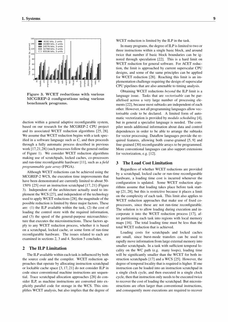
Figure 3. WCET reductions with variousMCGREP-2 configurations using variousbenchmark programs.
duction within a general adaptive reconfigurable system,based on our research for the MCGREP-2 CPU projectand its associated WCET reduction algorithms [25, 28].We assume that WCET reduction begins with a task spec-ified in a software language such as C, and then proceedsthrough a fully automatic process described in previouswork [17,21,28] (such processes follow the general outlineof Figure 1). We consider WCET reduction algorithmsmaking use of scratchpads, locked caches, co-processorsand run-time reconfigurable hardware [11], such as a fieldprogrammable gate array (FPGA).
Although WCET reductions can be achieved using theMCGREP-2 WCS, the execution time improvements thathave been demonstrated are currently limited to about 50-150% [25] over an instruction scratchpad [17, 21] (Figure3). Independent of the architecture actually used to im-plement the WCS [27], and independent of the technologyused to apply WCET reductions [28], the magnitude of thepossible reduction is limited by three major factors. Theseare: (1) the ILP available within the task, (2) the cost ofloading the control store with the required information,and (3) the speed of the general-purpose microarchitec-ture that executes the microinstructions. These factors ap-ply to any WCET reduction process, whether it is basedon a scratchpad, locked cache, or some form of run-timereconfigurable hardware. The issues related to each areexamined in sections 2, 3 and 4. Section 5 concludes.
2 The ILP LimitationThe ILP available within each task is influenced by both
the source code and the compiler. WCET reduction ap-proaches that operate by allocating instruction scratchpador lockable cache space [3, 17, 21] do not consider ILP incode since conventional machine instructions are sequen-tial. Trace scratchpad allocation approaches [28] do con-sider ILP, as machine instructions are converted into ex-plicitly parallel code for storage in the WCS. This sim-plifies WCET analysis, but also implies that the degree of
WCET reduction is limited by the ILP in the task.In many programs, the degree of ILP is limited to two or
three instructions within a single basic block, and aroundtwice that number if basic block boundaries can be ig-nored through speculation [22]. This is a hard limit onWCET reduction for general software. For ACET reduc-tion, the limit is approached by current superscalar CPUdesigns, and some of the same principles can be appliedfor WCET reduction [28]. Reaching this limit is an im-plementation challenge requiring the design of superscalarCPU pipelines that are also amenable to timing analysis.
Obtaining WCET reductions beyond the ILP limit is alanguage issue. Tasks that are vectorisable can be par-allelised across a very large number of processing ele-ments [22], because most subtasks are independent of eachother. However, not all programming languages allow vec-torisable code to be declared. A limited form of auto-matic vectorization is provided by modulo scheduling [4],but in general a specialist language is needed. The com-piler needs additional information about data and controldependences in order to be able to arrange the subtasksfor vector processing. Dataflow languages provide the re-quired features, allowing both coarse-grained [5, 9] andfine-grained [30] reconfigurable arrays to be programmed.More conventional languages can also support extensionsfor vectorization, e.g. [12].
3 The Load Cost LimitationRegardless of whether WCET reductions are provided
by a scratchpad, locked cache or run-time reconfigurablehardware, a loading time cost is incurred whenever theconfiguration is updated. Some WCET reduction algo-rithms assume that loading takes place before task start-up [21, 28], but this is restrictive because it places a limiton the complexity of each task. This limit also applies toWCET reduction approaches that make use of fixed co-processors, since these are not run-time reconfigurable.The solution is to allow loading during execution and in-corporate it into the WCET reduction process [17], af-ter partitioning each task into regions with local memorymaps [16]. The total loading time must be less than thetotal WCET reduction that is achieved.
Loading costs for scratchpads and locked cachesare small, since burst-mode transfers can be used torapidly move information from large external memory intosmaller scratchpads. In a task with sufficient temporal lo-cality on the WC path (e.g. many loops), loading timewill be significantly smaller than the WCET for both in-struction scratchpads [17] and a WCS [25]. However, thedegree of temporal locality that is required is higher. If oneinstruction can be loaded into an instruction scratchpad ina single clock cycle, and then executed in a single clockcycle, then that instruction only needs to be executed twiceto recover the cost of loading the scratchpad. But microin-structions are often larger than conventional instructions,and consequently more executions are required to recover
1. Systems 9
������������������������������������������������������������������������������������������������������������������������������������������������������������������������������������������������������������������������������������������������������������������������������������������������������������������������������������������������������������������������������������������������������������������������������������������������������������������������������������������������������������������������������������������������������������������������������������������������������������������������������������������������������������������������������������������������������������������������������������������������������������������������������������������������������������������������������������������������������������������������������������������������������������������������������������������������������������������������������������������������������������������������������������������������������������������������������������������������������������������������������������������������������������������������������������������������������������������������������������������������������������������������
������������������������������������������������������������������������������������������������������������������������������������������������������������������������������������������������������������������������������������������������������������������������������������������������������������������������������������������������������������������������������������������������������������������������������������������������������������������������������������������������������������������������������������������������������������������������������������������������������������������������������������������������������������������������������������������������������������������������������������������������������������������������������������������������������������������������������������������������������������������������������������������������������������������������������������������������������������������������������������������������������������������������������������������������������������������������������������������������������������������������������������������������������������������������������������������������������������������������������������������������������������������������
����������������������������������������������������������������������������������������������������������������������������������������������������������������������������������������������������������������������������������������������������������������������������������������������������������������������������������������������������������������������������������������������������������������������������������������������������������������������������������������������������������������������������������������������������������������������������������������������������������������������������������������������������������������������������������������������������������������������������������������������������������������������������������������������������������������������������������������������������������������������������������������������������������������������������������������������������������������������������������������������������������������������������������������������������������������������������������������������������������������������������������������������������������������������������������������������������������������
����������������������������������������������������������������������������������������������������������������������������������������������������������������������������������������������������������������������������������������������������������������������������������������������������������������������������������������������������������������������������������������������������������������������������������������������������������������������������������������������������������������������������������������������������������������������������������������������������������������������������������������������������������������������������������������������������������������������������������������������������������������������������������������������������������������������������������������������������������������������������������������������������������������������������������������������������������������������������������������������������������������������������������������������������������������������������������������������������������������������������������������������������������������������������������������������������������������
������������������������������������������������������������������������������������������������������������������������������������������������������������������������������������������������������������������������������������������������������������������������������������������������������������������������������������������������������������������������������������������������������������������������������������������������������������������������������������������������������������������������������������������������������������������������������������������������������������������������������������������������������������������������������������������������������������������������������������������������������������������������������������������������������������������������������������������������������������������������������������������������������������������������������������������������������������������������������������������������������������������������������������������������������������������������������������������������������������������������������������������������������������������������������������������������������������������������������������������������������������������������
������������������������������������������������������������������������������������������������������������������������������������������������������������������������������������������������������������������������������������������������������������������������������������������������������������������������������������������������������������������������������������������������������������������������������������������������������������������������������������������������������������������������������������������������������������������������������������������������������������������������������������������������������������������������������������������������������������������������������������������������������������������������������������������������������������������������������������������������������������������������������������������������������������������������������������������������������������������������������������������������������������������������������������������������������������������������������������������������������������������������������������������������������������������������������������������������������������������������������������������������������������������������
������������������������������������������������������������������������������������������������������������������������������������������������������������������������������������������������������������������������������������������������������������������������������������������������������������������������������������������������������������������������������������������������������������������������������������������������������������������������������������
������������������������������������������������������������������������������������������������������������������������������������������������������������������������������������������������������������������������������������������������������������������������������������������������������������������������������������������������������������������������������������������������������������������������������������������������������������������������������������
�������������������������������������������������������������������������������������������������������������������������������������������������������������������������������������������������������������������������������������������������������������������������������������������������������������������������������������������������������������������������������������������������������������������������������������������������������������������������������������������������
�������������������������������������������������������������������������������������������������������������������������������������������������������������������������������������������������������������������������������������������������������������������������������������������������������������������������������������������������������������������������������������������������������������������������������������������������������������������������������������������������
������������������������������������������������������������������������������������������������������������������������������������������������������������������������������������������������������������������������������������������������������������������������������������������������������������������������������������������������������������������������������������������������������������������������������������������������������������������������������������������������������������������������������������������������������������������������������������������������������������������������������������������������������������������������������������������������������������������������������������������������������������������������������������������������������������������������������������������������������������������������������������������������������������������������������������������������������������������������
������������������������������������������������������������������������������������������������������������������������������������������������������������������������������������������������������������������������������������������������������������������������������������������������������������������������������������������������������������������������������������������������������������������������������������������������������������������������������������������������������������������������������������������������������������������������������������������������������������������������������������������������������������������������������������������������������������������������������������������������������������������������������������������������������������������������������������������������������������������������������������������������������������������������������������������������������������������������
����������������������������������������������������������������������������������������������������������������������������������������������������������������������������������������������������������������������������������������������������������������������������������������������������������������������������������������������������������������������������������������������������������������������������������������������������������������������������������������������������������������������������������������������������������������������������������������������������������������������������������������������������������������������������������������������������������������������������������������������������������������������������������������������������������������������������������������������������������������
����������������������������������������������������������������������������������������������������������������������������������������������������������������������������������������������������������������������������������������������������������������������������������������������������������������������������������������������������������������������������������������������������������������������������������������������������������������������������������������������������������������������������������������������������������������������������������������������������������������������������������������������������������������������������������������������������������������������������������������������������������������������������������������������������������������������������������������������������������������
������������������������������������������������������������������������������������������������������������������������������������������������������������������������������������������������������������������������������������������������������������������������������������������������������������������������������������������������������������������������������������������������������������������������������������������������������������������������������������������������������������������������������������������������������������������������������������������������������������������������������������������������������������������������������������������������������������������������������������������������������������������������������������������������������������������������������������������������������������������������������������������������������������������������������������������������������������������������������������������������������������������������������������������������������������������������������������������������������������������������������������������������������������������������������������������������������������������������������������������������������������������������
������������������������������������������������������������������������������������������������������������������������������������������������������������������������������������������������������������������������������������������������������������������������������������������������������������������������������������������������������������������������������������������������������������������������������������������������������������������������������������������������������������������������������������������������������������������������������������������������������������������������������������������������������������������������������������������������������������������������������������������������������������������������������������������������������������������������������������������������������������������������������������������������������������������������������������������������������������������������������������������������������������������������������������������������������������������������������������������������������������������������������������������������������������������������������������������������������������������������������������������������������������������������
Dispatch
unit
Deb
ug
un
it
Deb
ug
po
rts
IR 0
IR −1
LSU
MCGREP−2 Units
Dat
a th
at h
as b
een
lo
aded
Microprogram data
Instructions
uco
de
add
ress
Dat
a to
be
sto
red
reg
iste
r ad
dre
ss
interface
MemoryExternal
Scratchpad
RAM and/or
INTERCONNECT 1 INTERCONNECT 0
D in B
D in A D out A
D out B
Adr A
Adr B
Address Mux
ALU
INT
ER
CO
NN
EC
T 1
Reg File
Reg File
D in D
D in C D out C
D out D
Adr C
Adr D
in 0
in 1
Sig
n E
x
To shared components
Control logic
Writable
control store
uPC
INT
ER
CO
NN
EC
T 0
to other units
to other unitsto other units
to other units
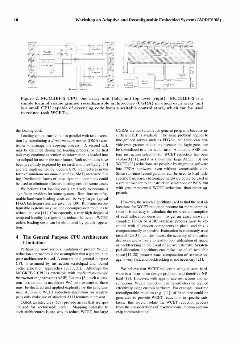
Figure 2. MCGREP-2 CPU: one array unit (left) and top level (right). MCGREP-2 is asimple form of coarse grained reconfigurable architecture (CGRA) in which each array unitis a small CPU capable of executing code from a writable control store, which can be usedto reduce task WCETs.
the loading cost.Loading can be carried out in parallel with task execu-
tion by introducing a direct memory access (DMA) con-troller to manage the copying process. A second taskmay be executed during the loading process, or the firsttask may continue execution as information is loaded intoscratchpad for use in the near future. Both techniques havebeen previously explored by research into overlaying [14]and are implemented by modern CPU architectures in theform of simultaneous multithreading (SMT) and cache fill-ing. Predictable forms of these dynamic operations couldbe used to eliminate effective loading costs in some cases.
We believe that loading costs are likely to become asignificant problem for some systems. Run-time reconfig-urable hardware loading costs can be very large: typicalFPGA bitstream sizes are given by [30]. Run-time recon-figurable systems may include decompression modules toreduce the cost [11]. Consequently, a very high degree oftemporal locality is required to reduce the overall WCETunless loading costs can be eliminated by parallel opera-tion.
4 The General Purpose CPU ArchitectureLimitation
Perhaps the most serious limitation of present WCETreduction approaches is the assumption that a general pur-pose architecture is used. A conventional general-purposeCPU is assumed by instruction scratchpad and lockedcache allocation approaches [3, 17, 21]. Although theMCGREP-2 CPU is extensible with application-specificinstruction set processor (ASIP) features [6], such as cus-tom instructions to accelerate WC path execution, thesemust be declared and applied explicitly by the program-mer. Automatic WCET reduction algorithms for scratch-pads only make use of standard ALU features at present.
CGRA architectures [5, 9] provide arrays that are spe-cialized for vectorisable code. Mapping subtasks tosuch architectures is one way to reduce WCET, but large
CGRAs are not suitable for general programs because in-sufficient ILP is available. The same problem applies tofine-grained arrays such as FPGAs, but these can pro-vide even greater reductions because the logic gates canbe specialized to a particular task. Automatic ASIP cus-tom instruction selection for WCET reduction has beenexplored [31], and it is known that large ACET [13] andWCET [23] reductions are possible by migrating softwareinto FPGA hardware, even without vectorisable code.Since run-time reconfiguration can be used to load task-specific hardware, customized hardware could be used ina similar manner to an instruction scratchpad or WCS, butwith greater potential WCET reductions than either ap-proach.
However, the search algorithms used to find the best al-locations for WCET reduction become far more complex,since it is not easy to calculate the resource consumptionof each allocation decision. To get an exact answer, acomplete FPGA or ASIC synthesis process must be ex-ecuted with all chosen components in place, and this iscomputationally expensive. Estimation is commonly usedinstead [29, 31], but this lowers the accuracy of allocationdecisions and is likely to lead to poor utilization of space,or backtracking in the event of an overestimate. Scratch-pad allocation algorithms can make use of all availablespace [17, 28] because exact computation of resource us-age is very fast, and backtracking is not necessary [21].
We believe that WCET reduction using custom hard-ware is a form of co-design problem, and therefore NP-hard [19]. However, with appropriate restrictions and as-sumptions, WCET reduction can nevertheless be appliedeffectively using custom hardware. For example, run-timereconfigurable modules (e.g. [11]) of fixed size could begenerated to provide WCET reductions to specific sub-tasks: this would isolate the WCET reduction processfrom the considerations of resource consumption and on-chip communication.
10 Workshop on Adaptive and Reconfigurable Embedded Systems (APRES’08)
5 ConclusionThis paper has explored three issues that affect the de-
gree of WCET reduction available for tasks in an adaptablearchitecture. Major challenges exist: specifying vectoriza-tion in order to exploit greater ILP is important [22], as isminimizing loading time costs [17]. Finding a way to ap-ply WCET reduction algorithms to custom hardware maybe the most rewarding challenge, as large execution timereductions are possible [13,23] if the technical issues of ef-ficiently searching for the best resource allocation can besolved. These problems have been given only partial con-sideration by existing work. Solutions would allow em-bedded real-time systems to carry out more operations pertime unit by explicitly reducing the WCET of each task.
References[1] A. Burns and A. J. Wellings. Real-Time Systems and Pro-
gramming Languages. Addison Wesley, 2001.[2] R. Ernst, J. Henkel, and T. Benner. Hardware-software
cosynthesis for microcontrollers. IEEE Des. Test, 10(4):64–75, 1993.
[3] H. Falk, S. Plazar, and H. Theiling. Compile-time decidedinstruction cache locking using worst-case execution paths.In Proc. CODES+ISSS, pages 143–148, New York, NY,USA, 2007. ACM Press.
[4] J. Fisher, P. Faraboschi, and C. Young. Embedded Com-puting: A VLIW Approach to Architecture, Compilers andTools. Morgan Kaufmann, 2004.
[5] S. C. Goldstein, H. Schmit, M. Budiu, S. Cadambi, M. Moe,and R. R. Taylor. PipeRench: A reconfigurable architectureand compiler. Computer, 33(4):70–77, 2000.
[6] R. E. Gonzalez. Xtensa — A configurable and extensibleprocessor. IEEE Micro, 20(2):60–70, 2000.
[7] B. Grattan, G. Stitt, and F. Vahid. Codesign-extended appli-cations. In Proc. 10th Int. Symp. Hardware/Software Code-sign, pages 1–6, 2002.
[8] R. K. Gupta and G. D. Micheli. Hardware-software cosyn-thesis for digital systems. IEEE Des. Test, 10(3):29–41,1993.
[9] R. Hartenstein, M. Herz, T. Hoffmann, and U. Nageldinger.KressArray Xplorer: a new CAD environment to optimizereconfigurable datapath array. In Proc. ASP-DAC, pages163–168, New York, NY, USA, 2000. ACM Press.
[10] R. Heckmann, M. Langenbach, S. Thesing, and R. Wil-helm. The influence of processor architecture on the designand the results of WCET tools. Proc. IEEE, 91(7):1038–1054, 2003.
[11] M. Hubner and J. Becker. Exploiting dynamic and partialreconfiguration for FPGAs: toolflow, architecture and sys-tem integration. In Proc. SBCCI, pages 1–4, New York, NY,USA, 2006. ACM Press.
[12] Intel. Optimizing Applications with the Intel C++and Fortran Compilers (accessed 26 April 07).ftp://download.intel.com/software/products/compilers/techtopics/Compiler_Optimization_7_02.pdf, 2004.
[13] R. Lysecky, G. Stitt, and F. Vahid. Warp processors. ACMTODAES, 11(3):659–681, 2006.
[14] R. J. Pankhurst. Operating systems: Program overlay tech-niques. Commun. ACM, 11(2):119–125, 1968.
[15] D. A. Patterson and J. L. Hennessy. Computer organiza-tion & design: the hardware/software interface. MorganKaufmann Publishers Inc., San Francisco, CA, USA, 1993.
[16] I. Puaut and D. Hardy. Predictable paging in real-time sys-tems: A compiler approach. In Proc. ECRTS, pages 169–178, Washington, DC, USA, 2007. IEEE Computer Society.
[17] I. Puaut and C. Pais. Scratchpad memories vs locked cachesin hard real-time systems: a quantitative comparison. InProc. DATE, pages 1484–1489, San Jose, CA, USA, 2007.EDA Consortium.
[18] P. Puschner and A. Burns. Guest editorial: A review ofworst-case execution-time analysis. Real-Time Syst., 18(2-3):115–128, 2000.
[19] R. Niemann and P. Marwedel. Hardware/software par-titioning using integer programming. In Proceedings ofthe European Design and Test Conference (ED & TC),pages 473–480, Paris, France, 1996. IEEE Computer So-ciety Press (Los Alamitos, California).
[20] R. F. Rosin, G. Frieder, and J. Richard H. Eckhouse. Anenvironment for research in microprogramming and emula-tion. Commun. ACM, 15(8):748–760, 1972.
[21] V. Suhendra, T. Mitra, A. Roychoudhury, and T. Chen.WCET Centric Data Allocation to Scratchpad Memory. InProc. RTSS, pages 223–232, Washington, DC, USA, 2005.IEEE Computer Society.
[22] D. W. Wall. Limits of Instruction-Level Parallelism. Tech-nical Report WRL-93-6, DEC Western Research Labora-tory, 1995.
[23] M. Ward and N. Audsley. Hardware compilation of se-quential Ada. In Proc. CASES, pages 99–107, New York,NY, USA, 2001. ACM Press.
[24] I. Wenzel, R. Kirner, P. Puschner, and B. Rieder. Principlesof timing anomalies in superscalar processors. In Proc. Int.Conf. Quality Software, Sep. 2005.
[25] J. Whitham. Real-time Processor Architectures for WorstCase Execution Time Reduction. PhD thesis, 2008.
[26] J. Whitham and N. Audsley. MCGREP - A PredictableArchitecture for Embedded Real-time Systems. In Proc.RTSS, pages 13–24, 2006.
[27] J. Whitham and N. Audsley. A self-optimising simula-tor for a coarse-grained reconfigurable array. In Proc. UKEmbedded Forum, pages 99–109. University of Newcastle,April 2007.
[28] J. Whitham and N. Audsley. Using trace scratchpads to re-duce execution times in predictable real-time architectures.In Proc. RTAS (to appear), 2008.
[29] Y. Xie and W. Wolf. Co-synthesis with custom asics. InProc. ASP-DAC, pages 129–134, 2000.
[30] Xilinx. Virtex-4 Family Overview. Datasheet DS112, Xil-inx Corporation, 2007.
[31] P. Yu and T. Mitra. Satisfying real-time constraints withcustom instructions. In Proc. CODES+ISSS, pages 166–171, 2005.
1. Systems 11
Adaptive Framework for Efficient ResourceManagement in RTOS
Ameet Patil Neil AudsleyReal-Time Systems Group,
Department of Computer Science, University of York, York YO10 5DD, UKEmail:{appatil,neil}@cs.york.ac.uk
I. INTRODUCTION
Embedded systems, applications and the environment thatthey are deployed in have all become increasingly complexin recent years. Application demands for more resources anddynamic changes in the environment make resource man-agement in Real-Time Operating Systems (RTOS) extremelychallenging. Key approaches include specialisation or adap-tation of the RTOSs resource management policies accordingto the dynamic requirements of the applications. This paperdescribes a reflection-based adaptive RTOS framework that al-lows dynamic application driven adaptation of RTOS resourcemanagement policies.
The context assumed by the paper is that of low-cost,limited-resource embedded systems with modern hardwareie. complex CPUs with support for virtual memory. Also,when developing a general purpose RTOS, there is limitedknowledge of the potential applications that will use theRTOS. Thus, the RTOS is built for the general-case ratherthan according to application-specific requirements. Such anRTOS implements generic resource management policies. Thispaper discusses the issues related to providing application-specific resource management in a general purpose RTOS. Anexisting approach of defining an adaptive framework in theRTOS using reflection is described along with some results ofits implementation in Linux (2.6.16 kernel). The paper alsodiscusses the possible future directions to the approach.
The paper is organised as follows. The next section providesbackground and motivation for the approach adopted withinthe paper. Section III describes the reflection-based RTOSframework for adapting the resource management policies.Section IV presents some experimental results of the imple-mentation of CASP [4] - an application-specific paging mech-anism using the reflective framework. Section V discusses thefuture work to be taken up to provide better support and furtherimprove the existing reflective approach. Finally, conclusionsare presented in section VI.
II. BACKGROUND
Specialising or customising the hardware and the RTOSresource management policies for every change in the ap-plication requirements is an expensive and time consumingprocess. Existing approaches use standard hardware along witha general purpose RTOS that implements generic resource
management policies that can provide good average-case per-formance. As a result, the performance of applications withdynamic resource requirements is affected by the limited sup-port provided by such generic policies. The RTOS is built forthe generic-case rather than application-specific requirements.
Several different approaches have been proposed in the pastto address this issue. Many approaches provide solution toonly a part of the problem. For example: Rivas et. al. [16]proposed an ada-based API for application-defined schedulingin the RTOS, but no API for changing any other module likememory management; more recently Ruocco [17] proposeda user-level reflection-based approach for adaptive schedulingalone. The exokernel [10] approach also addresses the prob-lem by allowing applications to use application-specific OSlibraries. Due to the redundant OS library code attached todifferent applications, this approach is not suitable for realtimeembedded systems with limited-resources.
Summarising, current approaches do not consider applica-tion based resource management across multiple resources.There is a need for a general approach encompassing all thesystem resources. Such an approach should be able to changeor adapt the resource management policies to meet the dy-namic application-specific requirements. The next subsectionintroduces reflection and related approaches.
A. Reflection
Reflection is a mechanism by which a program code orapplication becomes self-aware, checks its progress and canchange itself or its behaviour dynamically at runtime orstatically at compile time [6]. This change can occur bychanging data structures, the program code itself, or sometimeseven the semantics of the language its written in. To facilitatethis, the application or program code has to have knowledgeabout the data structures, language semantics, etc. The processby which this information is provided to it is called Reification.
The Reflection model consists of a base-level and one ormore meta-level forming a structure called Reflective tower.The code in the meta-level is responsible to analyse thereified information, intercept the necessary calls from or to thebaselevel and affect any change if required. A protocol definedso as to establish a mechanism by which the meta-level entitiesintrospect (analyse), intercede (Eg. by intercepting calls to orfrom base-level) and affect change to the base-level is calledthe Meta-Object Protocol (MOP) [15]. In reflection the meta-
12 Workshop on Adaptive and Reconfigurable Embedded Systems (APRES’08)
level code can form a causal link (two objects are said to becausally linked to each other when a change initiated by oneaffects the other [6]) with the data structures in the base-levelto affect a change directly.
The mechanism of Reflection has been widely used inobject-oriented programming, object-oriented databases, mid-dlewares, artificial intelligence, virtual machines and OSs [11],[13]. Reflective OSs such as ApertOS [18], Chameleon [7] and2K [14] focus on the aspects of composition and configura-bility of the system as a whole and not application-specificresource management. With the use of three different customdesigned languages: Spring-C [8], SDL [9] and FERT [1],the Spring OS [12] makes use of reflective information inthe system to bring about certain changes in the system.More subtle fine-grained changes to the resource managementpolicies in an RTOS can be brought about by exchangingresource related information between the applications and theRTOS. The framework described in the next section lays thefoundation to such information exchange and adaptation of theRTOS resource management policies.
III. REFLECTION-BASED RTOS FRAMEWORK
In the context of an RTOS, the process of reificationand introspection help applications and resource managementmodules exchange valuable information amongst each other.This allows interception to be used to bring about fine-grainedchanges in the resource management modules. Within this pa-per, the framework consists of a base kernel core implementingsupport for reflection, in the form of an interface to systemmodules and applications to reify information, introspect andintercept the base-level [2], [3].
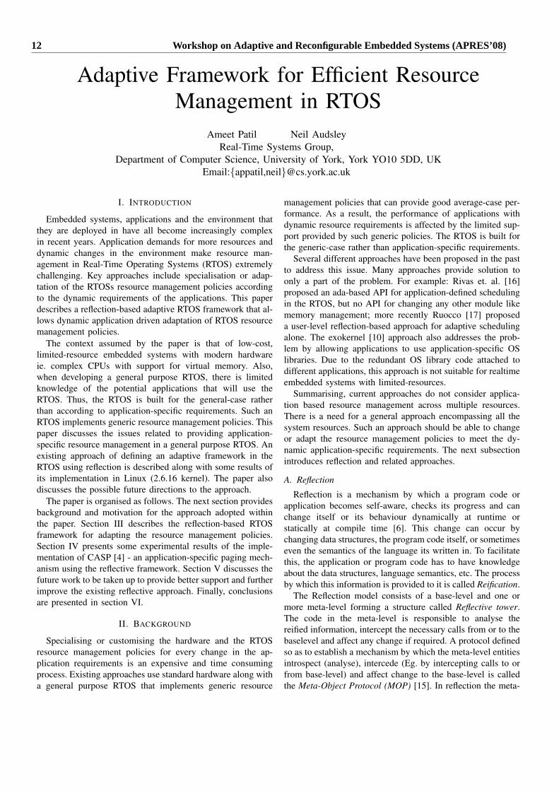
Unlike existing reflective approaches, the RTOS frameworkuses a non-traditional method of reification such that thecontrol over reified information lies solely with the kernel.This allows the kernel to maintain a priority based list ofvaluable information and discard any unwanted (eg. old)information. Fig. 1 shows the movement of information withinthe framework.
Normally, in the traditional approach, the meta-level compo-nent receives all the information reified by its base-level. Thismeans that whether or not the reified information is useful,the meta-level will receive it potentially adding unnecessarycommunication overhead.
In the framework, all the information that is reified, ispassed to and stored in the kernel. Each reified information isassigned a relative importance-level depending on the source,destination and the time the information was reified. It is storedin the kernel until a meta-level component explicitly requeststhe information or until it gets too old to be useful anymore.The kernel moderates the flow of information between thevarious reflective entities in the system.
System modules and applications can choose not to bereflective. Furthermore, the framework allows reification ofinformation not only by the base-level components but by anyentity in the system. Also, the information reified by an entitycan have multiple destinations. i.e. a meta-level component is
Fig. 1. Generic Reflective OS framework
able to obtain information pertaining to its resource not onlyfrom its base-level but from any entity in the system providinggreater freedom and flexibility in the system.
Base Kernel Core
CodeBase−level
CodeMeta−level
link
readreified
data
causal
Install codeorInterceptionrequest for
transferintercepted
call
reify data
Reflective System module
installcode
reifieddata
Application
Fig. 2. Reflective System module
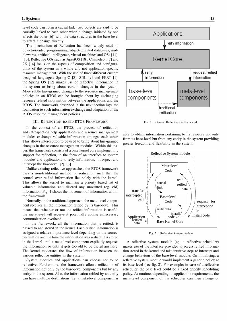
A reflective system module (eg. a reflective scheduler)makes use of the interface provided to access reified informa-tion stored in the kernel and take intuitive steps to intercept andchange behaviour of the base-level module. On initialising, areflective system module would implement a generic policy atits base-level (see fig. 2). For example: in case of a reflectivescheduler, the base level could be a fixed priority schedulingpolicy. At runtime, depending on application requirements, themeta-level component of the scheduler can then change or
1. Systems 13
0
0.2
0.4
0.6
0.8
1
1.2
1.4
O L M AMATVEC
O L M ASCAN
O L M AFFT-I
O L M AFFT
O L M AMAD
Nor
mal
ised
Pag
e-fa
ults
Minor faultsMajor faults
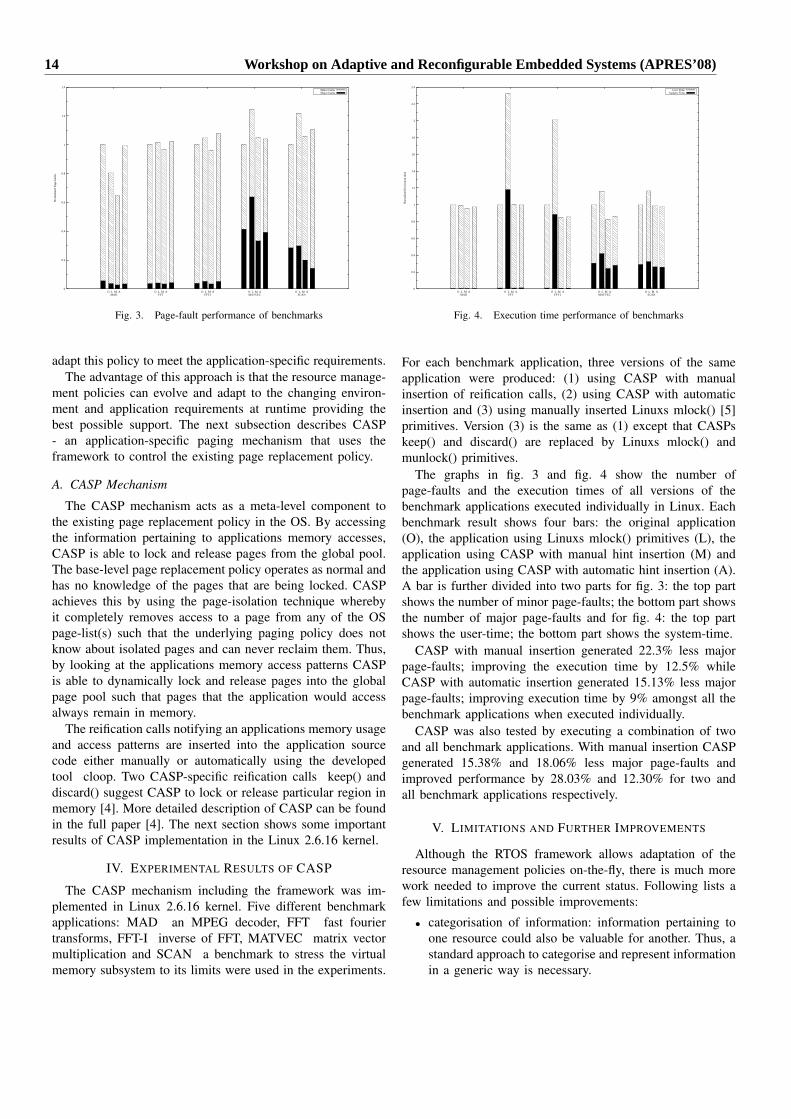
Fig. 3. Page-fault performance of benchmarks
adapt this policy to meet the application-specific requirements.The advantage of this approach is that the resource manage-
ment policies can evolve and adapt to the changing environ-ment and application requirements at runtime providing thebest possible support. The next subsection describes CASP- an application-specific paging mechanism that uses theframework to control the existing page replacement policy.
A. CASP Mechanism
The CASP mechanism acts as a meta-level component tothe existing page replacement policy in the OS. By accessingthe information pertaining to applications memory accesses,CASP is able to lock and release pages from the global pool.The base-level page replacement policy operates as normal andhas no knowledge of the pages that are being locked. CASPachieves this by using the page-isolation technique wherebyit completely removes access to a page from any of the OSpage-list(s) such that the underlying paging policy does notknow about isolated pages and can never reclaim them. Thus,by looking at the applications memory access patterns CASPis able to dynamically lock and release pages into the globalpage pool such that pages that the application would accessalways remain in memory.
The reification calls notifying an applications memory usageand access patterns are inserted into the application sourcecode either manually or automatically using the developedtool cloop. Two CASP-specific reification calls keep() anddiscard() suggest CASP to lock or release particular region inmemory [4]. More detailed description of CASP can be foundin the full paper [4]. The next section shows some importantresults of CASP implementation in the Linux 2.6.16 kernel.
IV. EXPERIMENTAL RESULTS OF CASP
The CASP mechanism including the framework was im-plemented in Linux 2.6.16 kernel. Five different benchmarkapplications: MAD an MPEG decoder, FFT fast fouriertransforms, FFT-I inverse of FFT, MATVEC matrix vectormultiplication and SCAN a benchmark to stress the virtualmemory subsystem to its limits were used in the experiments.
0
0.2
0.4
0.6
0.8
1
1.2
1.4
1.6
1.8
2
2.2
2.4
O L M AMATVEC
O L M ASCAN
O L M AFFT-I
O L M AFFT
O L M AMAD
Nor
mal
ised
Exe
cutio
n tim
e
User TimeSystem Time
Fig. 4. Execution time performance of benchmarks
For each benchmark application, three versions of the sameapplication were produced: (1) using CASP with manualinsertion of reification calls, (2) using CASP with automaticinsertion and (3) using manually inserted Linuxs mlock() [5]primitives. Version (3) is the same as (1) except that CASPskeep() and discard() are replaced by Linuxs mlock() andmunlock() primitives.
The graphs in fig. 3 and fig. 4 show the number ofpage-faults and the execution times of all versions of thebenchmark applications executed individually in Linux. Eachbenchmark result shows four bars: the original application(O), the application using Linuxs mlock() primitives (L), theapplication using CASP with manual hint insertion (M) andthe application using CASP with automatic hint insertion (A).A bar is further divided into two parts for fig. 3: the top partshows the number of minor page-faults; the bottom part showsthe number of major page-faults and for fig. 4: the top partshows the user-time; the bottom part shows the system-time.
CASP with manual insertion generated 22.3% less majorpage-faults; improving the execution time by 12.5% whileCASP with automatic insertion generated 15.13% less majorpage-faults; improving execution time by 9% amongst all thebenchmark applications when executed individually.
CASP was also tested by executing a combination of twoand all benchmark applications. With manual insertion CASPgenerated 15.38% and 18.06% less major page-faults andimproved performance by 28.03% and 12.30% for two andall benchmark applications respectively.
V. LIMITATIONS AND FURTHER IMPROVEMENTS
Although the RTOS framework allows adaptation of theresource management policies on-the-fly, there is much morework needed to improve the current status. Following lists afew limitations and possible improvements:
• categorisation of information: information pertaining toone resource could also be valuable for another. Thus, astandard approach to categorise and represent informationin a generic way is necessary.
14 Workshop on Adaptive and Reconfigurable Embedded Systems (APRES’08)
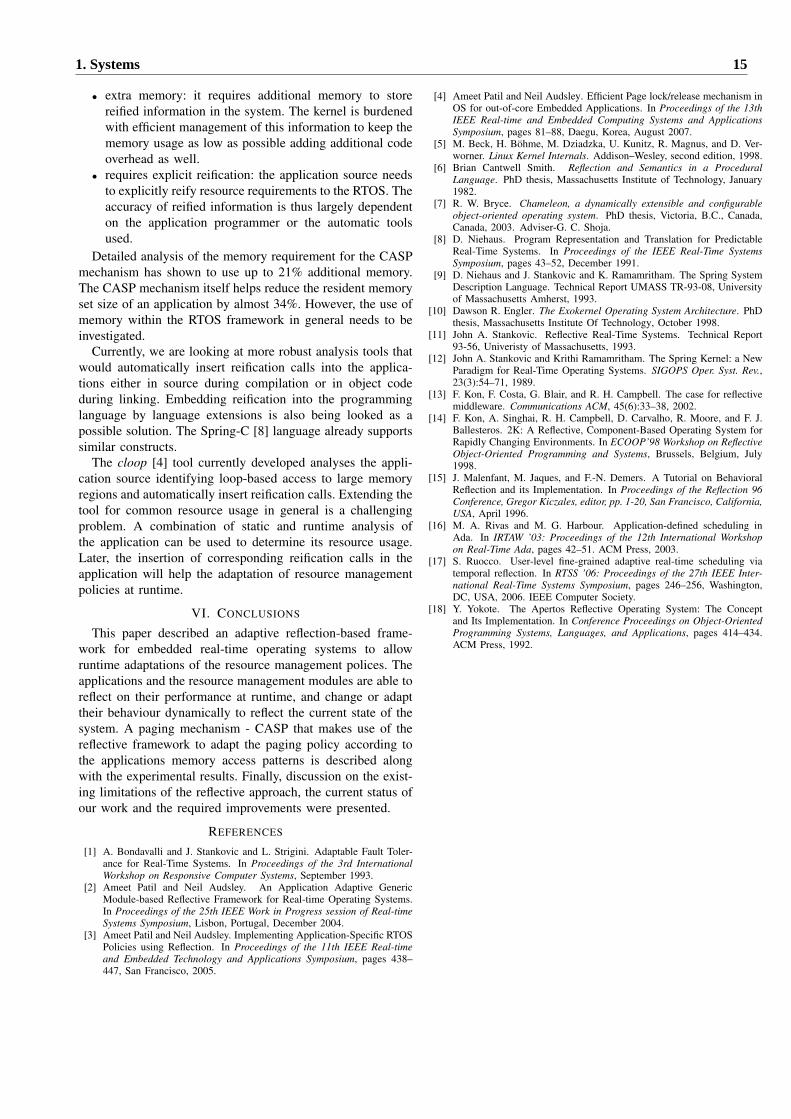
• extra memory: it requires additional memory to storereified information in the system. The kernel is burdenedwith efficient management of this information to keep thememory usage as low as possible adding additional codeoverhead as well.
• requires explicit reification: the application source needsto explicitly reify resource requirements to the RTOS. Theaccuracy of reified information is thus largely dependenton the application programmer or the automatic toolsused.
Detailed analysis of the memory requirement for the CASPmechanism has shown to use up to 21% additional memory.The CASP mechanism itself helps reduce the resident memoryset size of an application by almost 34%. However, the use ofmemory within the RTOS framework in general needs to beinvestigated.
Currently, we are looking at more robust analysis tools thatwould automatically insert reification calls into the applica-tions either in source during compilation or in object codeduring linking. Embedding reification into the programminglanguage by language extensions is also being looked as apossible solution. The Spring-C [8] language already supportssimilar constructs.
The cloop [4] tool currently developed analyses the appli-cation source identifying loop-based access to large memoryregions and automatically insert reification calls. Extending thetool for common resource usage in general is a challengingproblem. A combination of static and runtime analysis ofthe application can be used to determine its resource usage.Later, the insertion of corresponding reification calls in theapplication will help the adaptation of resource managementpolicies at runtime.
VI. CONCLUSIONS
This paper described an adaptive reflection-based frame-work for embedded real-time operating systems to allowruntime adaptations of the resource management polices. Theapplications and the resource management modules are able toreflect on their performance at runtime, and change or adapttheir behaviour dynamically to reflect the current state of thesystem. A paging mechanism - CASP that makes use of thereflective framework to adapt the paging policy according tothe applications memory access patterns is described alongwith the experimental results. Finally, discussion on the exist-ing limitations of the reflective approach, the current status ofour work and the required improvements were presented.
REFERENCES
[1] A. Bondavalli and J. Stankovic and L. Strigini. Adaptable Fault Toler-ance for Real-Time Systems. In Proceedings of the 3rd InternationalWorkshop on Responsive Computer Systems, September 1993.
[2] Ameet Patil and Neil Audsley. An Application Adaptive GenericModule-based Reflective Framework for Real-time Operating Systems.In Proceedings of the 25th IEEE Work in Progress session of Real-timeSystems Symposium, Lisbon, Portugal, December 2004.
[3] Ameet Patil and Neil Audsley. Implementing Application-Specific RTOSPolicies using Reflection. In Proceedings of the 11th IEEE Real-timeand Embedded Technology and Applications Symposium, pages 438–447, San Francisco, 2005.
[4] Ameet Patil and Neil Audsley. Efficient Page lock/release mechanism inOS for out-of-core Embedded Applications. In Proceedings of the 13thIEEE Real-time and Embedded Computing Systems and ApplicationsSymposium, pages 81–88, Daegu, Korea, August 2007.
[5] M. Beck, H. Bohme, M. Dziadzka, U. Kunitz, R. Magnus, and D. Ver-worner. Linux Kernel Internals. Addison–Wesley, second edition, 1998.
[6] Brian Cantwell Smith. Reflection and Semantics in a ProceduralLanguage. PhD thesis, Massachusetts Institute of Technology, January1982.
[7] R. W. Bryce. Chameleon, a dynamically extensible and configurableobject-oriented operating system. PhD thesis, Victoria, B.C., Canada,Canada, 2003. Adviser-G. C. Shoja.
[8] D. Niehaus. Program Representation and Translation for PredictableReal-Time Systems. In Proceedings of the IEEE Real-Time SystemsSymposium, pages 43–52, December 1991.
[9] D. Niehaus and J. Stankovic and K. Ramamritham. The Spring SystemDescription Language. Technical Report UMASS TR-93-08, Universityof Massachusetts Amherst, 1993.
[10] Dawson R. Engler. The Exokernel Operating System Architecture. PhDthesis, Massachusetts Institute Of Technology, October 1998.
[11] John A. Stankovic. Reflective Real-Time Systems. Technical Report93-56, Univeristy of Massachusetts, 1993.
[12] John A. Stankovic and Krithi Ramamritham. The Spring Kernel: a NewParadigm for Real-Time Operating Systems. SIGOPS Oper. Syst. Rev.,23(3):54–71, 1989.
[13] F. Kon, F. Costa, G. Blair, and R. H. Campbell. The case for reflectivemiddleware. Communications ACM, 45(6):33–38, 2002.
[14] F. Kon, A. Singhai, R. H. Campbell, D. Carvalho, R. Moore, and F. J.Ballesteros. 2K: A Reflective, Component-Based Operating System forRapidly Changing Environments. In ECOOP’98 Workshop on ReflectiveObject-Oriented Programming and Systems, Brussels, Belgium, July1998.
[15] J. Malenfant, M. Jaques, and F.-N. Demers. A Tutorial on BehavioralReflection and its Implementation. In Proceedings of the Reflection 96Conference, Gregor Kiczales, editor, pp. 1-20, San Francisco, California,USA, April 1996.
[16] M. A. Rivas and M. G. Harbour. Application-defined scheduling inAda. In IRTAW ’03: Proceedings of the 12th International Workshopon Real-Time Ada, pages 42–51. ACM Press, 2003.
[17] S. Ruocco. User-level fine-grained adaptive real-time scheduling viatemporal reflection. In RTSS ’06: Proceedings of the 27th IEEE Inter-national Real-Time Systems Symposium, pages 246–256, Washington,DC, USA, 2006. IEEE Computer Society.
[18] Y. Yokote. The Apertos Reflective Operating System: The Conceptand Its Implementation. In Conference Proceedings on Object-OrientedProgramming Systems, Languages, and Applications, pages 414–434.ACM Press, 1992.
1. Systems 15
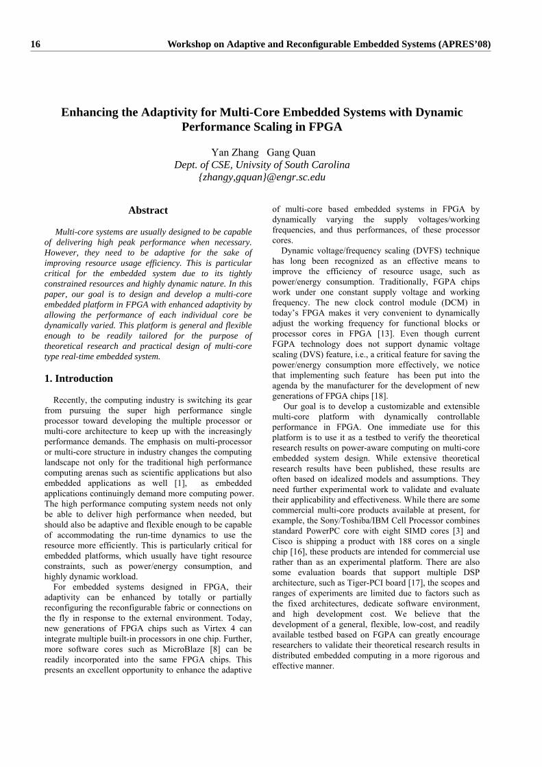
Enhancing the Adaptivity for Multi-Core Embedded Systems with Dynamic Performance Scaling in FPGA
Yan Zhang Gang Quan
Dept. of CSE, Univsity of South Carolina {zhangy,gquan}@engr.sc.edu
Abstract
Multi-core systems are usually designed to be capable of delivering high peak performance when necessary. However, they need to be adaptive for the sake of improving resource usage efficiency. This is particular critical for the embedded system due to its tightly constrained resources and highly dynamic nature. In this paper, our goal is to design and develop a multi-core embedded platform in FPGA with enhanced adaptivity by allowing the performance of each individual core be dynamically varied. This platform is general and flexible enough to be readily tailored for the purpose of theoretical research and practical design of multi-core type real-time embedded system. 1. Introduction
Recently, the computing industry is switching its gear from pursuing the super high performance single processor toward developing the multiple processor or multi-core architecture to keep up with the increasingly performance demands. The emphasis on multi-processor or multi-core structure in industry changes the computing landscape not only for the traditional high performance computing arenas such as scientific applications but also embedded applications as well [1], as embedded applications continuingly demand more computing power. The high performance computing system needs not only be able to deliver high performance when needed, but should also be adaptive and flexible enough to be capable of accommodating the run-time dynamics to use the resource more efficiently. This is particularly critical for embedded platforms, which usually have tight resource constraints, such as power/energy consumption, and highly dynamic workload.
For embedded systems designed in FPGA, their adaptivity can be enhanced by totally or partially reconfiguring the reconfigurable fabric or connections on the fly in response to the external environment. Today, new generations of FPGA chips such as Virtex 4 can integrate multiple built-in processors in one chip. Further, more software cores such as MicroBlaze [8] can be readily incorporated into the same FPGA chips. This presents an excellent opportunity to enhance the adaptive
of multi-core based embedded systems in FPGA by dynamically varying the supply voltages/working frequencies, and thus performances, of these processor cores.
Dynamic voltage/frequency scaling (DVFS) technique has long been recognized as an effective means to improve the efficiency of resource usage, such as power/energy consumption. Traditionally, FGPA chips work under one constant supply voltage and working frequency. The new clock control module (DCM) in today’s FPGA makes it very convenient to dynamically adjust the working frequency for functional blocks or processor cores in FPGA [13]. Even though current FGPA technology does not support dynamic voltage scaling (DVS) feature, i.e., a critical feature for saving the power/energy consumption more effectively, we notice that implementing such feature has been put into the agenda by the manufacturer for the development of new generations of FPGA chips [18].
Our goal is to develop a customizable and extensible multi-core platform with dynamically controllable performance in FPGA. One immediate use for this platform is to use it as a testbed to verify the theoretical research results on power-aware computing on multi-core embedded system design. While extensive theoretical research results have been published, these results are often based on idealized models and assumptions. They need further experimental work to validate and evaluate their applicability and effectiveness. While there are some commercial multi-core products available at present, for example, the Sony/Toshiba/IBM Cell Processor combines standard PowerPC core with eight SIMD cores [3] and Cisco is shipping a product with 188 cores on a single chip [16], these products are intended for commercial use rather than as an experimental platform. There are also some evaluation boards that support multiple DSP architecture, such as Tiger-PCI board [17], the scopes and ranges of experiments are limited due to factors such as the fixed architectures, dedicate software environment, and high development cost. We believe that the development of a general, flexible, low-cost, and readily available testbed based on FGPA can greatly encourage researchers to validate their theoretical research results in distributed embedded computing in a more rigorous and effective manner.
16 Workshop on Adaptive and Reconfigurable Embedded Systems (APRES’08)
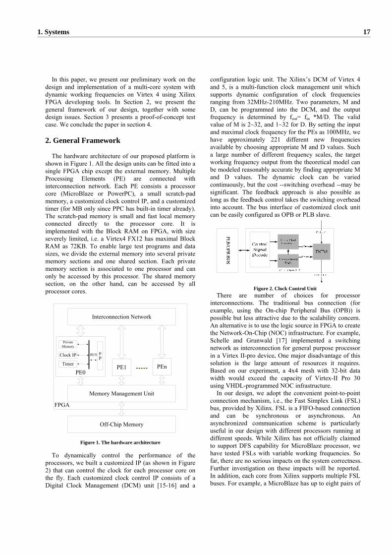
In this paper, we present our preliminary work on the design and implementation of a multi-core system with dynamic working frequencies on Virtex 4 using Xilinx FPGA developing tools. In Section 2, we present the general framework of our design, together with some design issues. Section 3 presents a proof-of-concept test case. We conclude the paper in section 4.
2. General Framework
The hardware architecture of our proposed platform is shown in Figure 1. All the design units can be fitted into a single FPGA chip except the external memory. Multiple Processing Elements (PE) are connected with interconnection network. Each PE consists a processor core (MicroBlaze or PowerPC), a small scratch-pad memory, a customized clock control IP, and a customized timer (for MB only since PPC has built-in timer already). The scratch-pad memory is small and fast local memory connected directly to the processor core. It is implemented with the Block RAM on FPGA, with size severely limited, i.e. a Virtex4 FX12 has maximal Block RAM as 72KB. To enable large test programs and data sizes, we divide the external memory into several private memory sections and one shared section. Each private memory section is associated to one processor and can only be accessed by this processor. The shared memory section, on the other hand, can be accessed by all processor cores.
PE0PE1
Private Memory
Clock IP
Timer
μP
BUS
PEn
Off-Chip Memory
Memory Management Unit
Interconnection Network
FPGA
Figure 1. The hardware architecture
To dynamically control the performance of the processors, we built a customized IP (as shown in Figure 2) that can control the clock for each processor core on the fly. Each customized clock control IP consists of a Digital Clock Management (DCM) unit [15-16] and a
configuration logic unit. The Xilinx’s DCM of Virtex 4 and 5, is a multi-function clock management unit which supports dynamic configuration of clock frequencies ranging from 32MHz-210MHz. Two parameters, M and D, can be programmed into the DCM, and the output frequency is determined by fout= fin *M/D. The valid value of M is 2~32, and 1~32 for D. By setting the input and maximal clock frequency for the PEs as 100MHz, we have approximately 221 different new frequencies available by choosing appropriate M and D values. Such a large number of different frequency scales, the target working frequency output from the theoretical model can be modeled reasonably accurate by finding appropriate M and D values. The dynamic clock can be varied continuously, but the cost --switching overhead --may be significant. The feedback approach is also possible as long as the feedback control takes the switching overhead into account. The bus interface of customized clock unit can be easily configured as OPB or PLB slave.
Figure 2. Clock Control Unit
There are number of choices for processor interconnections. The traditional bus connection (for example, using the On-chip Peripheral Bus (OPB)) is possible but less attractive due to the scalability concern. An alternative is to use the logic source in FPGA to create the Network-On-Chip (NOC) infrastructure. For example, Schelle and Grunwald [17] implemented a switching network as interconnection for general purpose processor in a Virtex II-pro device. One major disadvantage of this solution is the large amount of resources it requires. Based on our experiment, a 4x4 mesh with 32-bit data width would exceed the capacity of Virtex-II Pro 30 using VHDL-programmed NOC infrastructure.
In our design, we adopt the convenient point-to-point connection mechanism, i.e., the Fast Simplex Link (FSL) bus, provided by Xilinx. FSL is a FIFO-based connection and can be synchronous or asynchronous. An asynchronized communication scheme is particularly useful in our design with different processors running at different speeds. While Xilinx has not officially claimed to support DFS capability for MicroBlaze processor, we have tested FSLs with variable working frequencies. So far, there are no serious impacts on the system correctness. Further investigation on these impacts will be reported. In addition, each core from Xilinx supports multiple FSL buses. For example, a MicroBlaze has up to eight pairs of
1. Systems 17
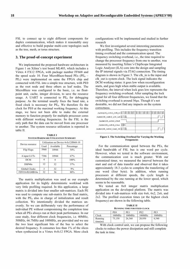
FSL to connect up to eight different components for duplex communication, which makes it reasonably easy and effective to build popular multi-core topologies such as the tree, mesh, or torus structure.
3. The proof-of-concept experiment
We implemented the proposed hardware architecture in Figure 1 on Xilinx’s test board ML403, which includes a Virtex 4 FX12 FPGA, with package number FF668 and the speed scale 10. Four MicroBlaze-based PEs (PE0 – PE3) were implemented on same the FPGA chip and connected with FSL into a simple tree structure, with PE0 as the root node and three others as leaf nodes. The MicroBlaze was configured to the basic, i.e. no float-point unit, cache, integer division, to save the resource usage. A UART is connected to PE0 for debugging purpose. As the terminal usually fixes the baud rate, a fixed clock is necessary for PE0. We therefore fix the clock for PE0 at the maximal working frequency. At this stage, we have not been able to make the external memory to function properly for multiple processor cores with different working frequencies. So the FSL is the only path that the data can be moved from one processor to another. The system resource utilization is reported in table II.
TABLE I SYSTEM HARDWARE UTILIZATION SUMMARY
Utilization on Device 4vfx12ff668-10 Device resource
Used Available Percentage Flip Flops 5968 10944 54%
4 input LUTs 7386 10944 67% DCM 4 4 100%
DSP48s 12 32 37%
Global Clocks 3 32 9% FIFO16/RAMB16s 32 36 88%
The matrix multiplication was used as our example
application for its highly deterministic workload with very little profiling required. In this application, a large matrix is divided into four smaller sub-matrices. Each PE was used to compute one sub-matrix for the final matrix, with the PE0 also in charge of initialization and result collection. We intentionally divided the matrices un-evenly. So we can deliberately vary the performance of individual PE without compromising the completion time when all PEs always run at their peak performance. In our case study, four different clock frequencies, i.e. 40MHz, 50MHz, 66.7MHz and 100MHz, are provided and we use the two least significant bits of the bus to select the desired frequency. It consumes less than 1% of the slices when synthesized in a Virtex 4vfx12 FPGA. More clock
configurations will be implemented and studied in further research
We first investigated several interesting parameters with profiling. This includes the frequency transition timing overhead and the communication speed. The frequency switching overhead, i.e., the time required to change the processor frequency from one to another, was measured by inserting Xilinx’s ChipScope Integrated Logic Analyzer (ILA) core into the design and sampling the IP internal signals via JTAG connection. The timing diagram is shown in Figure 3. The clk_in is the input and clk_out is system clock. The lock signal indicates the DCM working status: it goes low when reconfiguration starts, and goes high when stable output is available. Therefore, the interval when lock goes low represents the frequency switching overhead. After sampling the lock signal for all four different frequencies, we found that the switching overhead is around 56μs. Though it’s not desirable, we did not find any impacts on the system correctness.
Figure 3. The Switching Overhead for Varying the Working Frequencies
For the communication speed between the PEs, the
ideal bandwidth of FSL bus is one word per cycle. However, when we tested in the software environment, the communication cost is much greater. With our customized timer, we measured the interval between the start and end of data transfer and observed that it takes approximately 18.3 cycles to complete the transferring of one word (four byte). In addition, when running processors at different speeds, the cycle length is determined by the one running at the lower speed, which seems to be reasonable.
We tested an 8x8 integer matrix multiplication application on the developed platform. The matrix was divided into 4 sub-matrices with size 6x6, 6x2, 2x6, and 2x2. The profiled execution times (at the highest clock frequency) are shown in the following table.
TABLE II RUNNING TIME FOR FIXED CLOCK
PE0 PE1 PE2 PE3 Clock 100MHz 100MHz 100MHz 100MHz Running time(ns)
75,150 26,360 20,950 8,540
With clock control unit, we can propose the following clocks to reduce the power dissipation and still complete the task in time.
18 Workshop on Adaptive and Reconfigurable Embedded Systems (APRES’08)
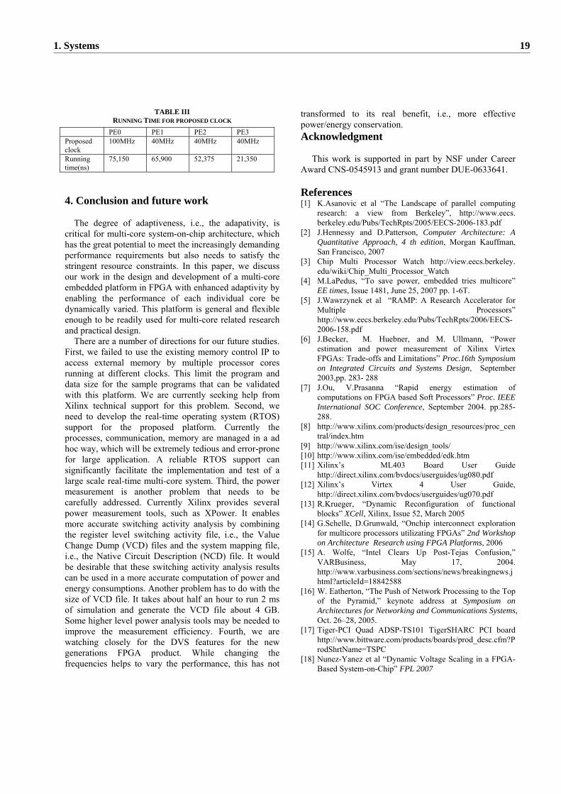
TABLE III RUNNING TIME FOR PROPOSED CLOCK
PE0 PE1 PE2 PE3 Proposed clock
100MHz 40MHz 40MHz 40MHz
Running time(ns)
75,150 65,900 52,375 21,350
4. Conclusion and future work
The degree of adaptiveness, i.e., the adapativity, is critical for multi-core system-on-chip architecture, which has the great potential to meet the increasingly demanding performance requirements but also needs to satisfy the stringent resource constraints. In this paper, we discuss our work in the design and development of a multi-core embedded platform in FPGA with enhanced adaptivity by enabling the performance of each individual core be dynamically varied. This platform is general and flexible enough to be readily used for multi-core related research and practical design.
There are a number of directions for our future studies. First, we failed to use the existing memory control IP to access external memory by multiple processor cores running at different clocks. This limit the program and data size for the sample programs that can be validated with this platform. We are currently seeking help from Xilinx technical support for this problem. Second, we need to develop the real-time operating system (RTOS) support for the proposed platform. Currently the processes, communication, memory are managed in a ad hoc way, which will be extremely tedious and error-prone for large application. A reliable RTOS support can significantly facilitate the implementation and test of a large scale real-time multi-core system. Third, the power measurement is another problem that needs to be carefully addressed. Currently Xilinx provides several power measurement tools, such as XPower. It enables more accurate switching activity analysis by combining the register level switching activity file, i.e., the Value Change Dump (VCD) files and the system mapping file, i.e., the Native Circuit Description (NCD) file. It would be desirable that these switching activity analysis results can be used in a more accurate computation of power and energy consumptions. Another problem has to do with the size of VCD file. It takes about half an hour to run 2 ms of simulation and generate the VCD file about 4 GB. Some higher level power analysis tools may be needed to improve the measurement efficiency. Fourth, we are watching closely for the DVS features for the new generations FPGA product. While changing the frequencies helps to vary the performance, this has not
transformed to its real benefit, i.e., more effective power/energy conservation. Acknowledgment
This work is supported in part by NSF under Career Award CNS-0545913 and grant number DUE-0633641.
References [1] K.Asanovic et al “The Landscape of parallel computing
research: a view from Berkeley”, http://www.eecs. berkeley.edu/Pubs/TechRpts/2005/EECS-2006-183.pdf
[2] J.Hennessy and D.Patterson, Computer Architecture: A Quantitative Approach, 4 th edition, Morgan Kauffman, San Francisco, 2007
[3] Chip Multi Processor Watch http://view.eecs.berkeley. edu/wiki/Chip_Multi_Processor_Watch
[4] M.LaPedus, “To save power, embedded tries multicore” EE times, Issue 1481, June 25, 2007 pp. 1-6T.
[5] J.Wawrzynek et al “RAMP: A Research Accelerator for Multiple Processors” http://www.eecs.berkeley.edu/Pubs/TechRpts/2006/EECS-2006-158.pdf
[6] J.Becker, M. Huebner, and M. Ullmann, “Power estimation and power measurement of Xilinx Virtex FPGAs: Trade-offs and Limitations” Proc.16th Symposium on Integrated Circuits and Systems Design, September 2003,pp. 283- 288
[7] J.Ou, V.Prasanna “Rapid energy estimation of computations on FPGA based Soft Processors” Proc. IEEE International SOC Conference, September 2004. pp.285- 288.
[8] http://www.xilinx.com/products/design_resources/proc_central/index.htm
[9] http://www.xilinx.com/ise/design_tools/ [10] http://www.xilinx.com/ise/embedded/edk.htm [11] Xilinx’s ML403 Board User Guide
http://direct.xilinx.com/bvdocs/userguides/ug080.pdf [12] Xilinx’s Virtex 4 User Guide,
http://direct.xilinx.com/bvdocs/userguides/ug070.pdf [13] R.Krueger, “Dynamic Reconfiguration of functional
blocks” XCell, Xilinx, Issue 52, March 2005 [14] G.Schelle, D.Grunwald, “Onchip interconnect exploration
for multicore processors utilizating FPGAs” 2nd Workshop on Architecture Research using FPGA Platforms, 2006
[15] A. Wolfe, “Intel Clears Up Post-Tejas Confusion,” VARBusiness, May 17, 2004. http://www.varbusiness.com/sections/news/breakingnews.jhtml?articleId=18842588
[16] W. Eatherton, “The Push of Network Processing to the Top of the Pyramid,” keynote address at Symposium on Architectures for Networking and Communications Systems, Oct. 26–28, 2005.
[17] Tiger-PCI Quad ADSP-TS101 TigerSHARC PCI board http://www.bittware.com/products/boards/prod_desc.cfm?ProdShrtName=TSPC
[18] Nunez-Yanez et al “Dynamic Voltage Scaling in a FPGA-Based System-on-Chip” FPL 2007
1. Systems 19

2. Distributed Systems

Building Adaptive Embedded Systems byMonitoring and Dynamic Loading of Application
ModulesFlorian Kluge, Jorg Mische, Sascha Uhrig, Theo Ungerer
Department of Computer Science - University of Augsburg86159 Augsburg, Germany
{kluge, mische, uhrig, ungerer}@informatik.uni-augsburg.de
Abstract— Networks of embedded systems usually lack flexi-bility due to the static configuration of their nodes. In this paper,we present a concept to adapt distributed embedded real-timeenvironments at runtime using code relocation techniques. Themain objectives of this work are to improve the availability ofservices within such environments and to increase the flexibility ofthe whole distributed system. The decision about reconfigurationis based on an extensive monitoring of the hardware and softwaresystem.
I. INTRODUCTION
Today, the number of embedded systems is constantlygrowing and establishing distributed systems of EmbeddedControl Units (ECUs). For example, a car can contain over70 ECUs fulfilling most different duties. Usually these ECUsare statically configured for specific tasks. This leads to thedeployment of many different but highly specialised ECUswithin such a system. Thus, the complete system has a highsusceptibility for failures. Simultaneously, its adaptability isrestricted to the abilities of the single ECUs.
With an intelligent management that supports the relocationof applications between processing nodes, it would be possibleto decrease the number of ECUs in such a system, whilethe dependability of the whole system would be increased.Also, adaptability techniques were no longer restricted tothe capabilities of single nodes, but could exploit the wholedistributed system. Through the dynamic adaptability it wouldbe possible to switch off single nodes to save energy. In carsthis would directly decrease the CO2 emissions.
Such a management uses the runtime information of thesingle nodes to adapt the whole system to the actual require-ments. Applications that will probably fail operation in thenear future due to resource constraints (e.g. low battery, lowmemory, high CPU load) should be moved to other nodes forproper operation. If hardware devices attached to a processingnode fail operation, it might be possible to substitute theirfunctionality by other devices. Two precondition exist for thisapproach:
1) an extensive monitoring of hard- and software parame-ters and
2) a mechanism to relocate applications between nodes.
In this paper we describe how we employ the system moni-toring facilities of CAROS (Connective Autonomic Real-timeOperating System)[1] to detect or predict future bottlenecks ofresources and possibilities for system optimization. With thehelp of a runtime linker the system is adapted to these newconditions and still able to keep maximum performance.
CAROS is part of the CAR-SoC (Connective AutonomicReal-time System-on-Chip) project [2]. The base of thisproject is the CarCore processor, which is binary compatibleto the Infineon TriCore architecture, a well-known automotiveprocessor. However, it is extended by the capability of simul-taneous multithreading and implements a real-time capablescheduling technique [1] based on the Guaranteed Percentagescheduling [3]. Thereby, a thread gets a specific share ofthe processing time which can be guaranteed for real-timethreads over a recurring period of time. The CarCore processoris currently available as a SystemC simulation model. Thereal-time operating system CAROS provides a comfortableinterface for application development.
We draw special benefit from the scheduling technique ofthe CarCore processor which allows us to run so-called helperthreads in parallel to real-time applications without disturbingtheir timing behaviour. “Helper thread” thereby is a term usedfor threads running in parallel to the actual application andsupporting its operation, but they are not required for properoperation.
This paper is organized as follows. Section II presentsrelated work. In section III we describe how applications andhardware core components are monitored and which adapta-tions are possible for specific system states. Our frameworkfor the migration of applications is presented in section IV. Insection V we present some performance measurements of ourimplementation. Section VI concludes this paper and gives ashort overview of future prospects.
II. RELATED WORK
The concept of code migration is well-known from the areaof mobile agents. The MESSENGER project [4] provided avirtual machine for agents written in a special language. It wasported to the Java virtual machine as JMessengers [5], [6], nowusing common Java code for the framework and as well for
2. Distributed Systems 23
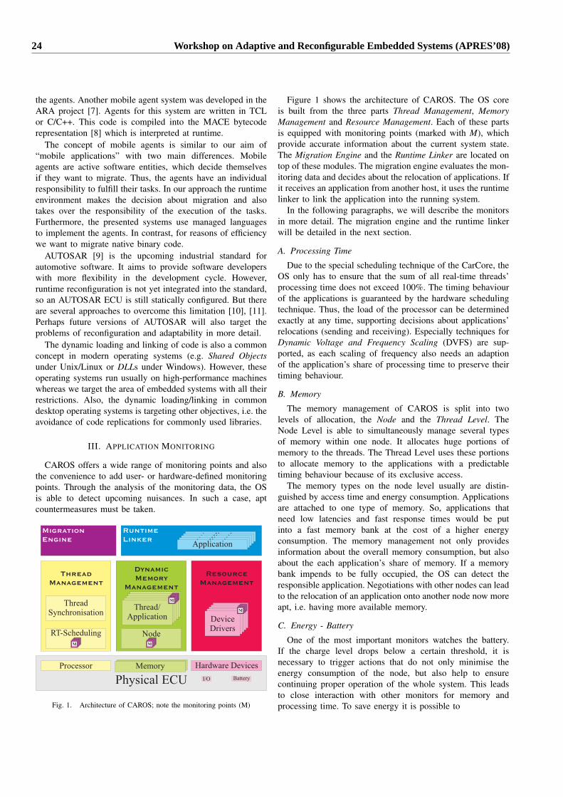
the agents. Another mobile agent system was developed in theARA project [7]. Agents for this system are written in TCLor C/C++. This code is compiled into the MACE bytecoderepresentation [8] which is interpreted at runtime.
The concept of mobile agents is similar to our aim of“mobile applications” with two main differences. Mobileagents are active software entities, which decide themselvesif they want to migrate. Thus, the agents have an individualresponsibility to fulfill their tasks. In our approach the runtimeenvironment makes the decision about migration and alsotakes over the responsibility of the execution of the tasks.Furthermore, the presented systems use managed languagesto implement the agents. In contrast, for reasons of efficiencywe want to migrate native binary code.
AUTOSAR [9] is the upcoming industrial standard forautomotive software. It aims to provide software developerswith more flexibility in the development cycle. However,runtime reconfiguration is not yet integrated into the standard,so an AUTOSAR ECU is still statically configured. But thereare several approaches to overcome this limitation [10], [11].Perhaps future versions of AUTOSAR will also target theproblems of reconfiguration and adaptability in more detail.
The dynamic loading and linking of code is also a commonconcept in modern operating systems (e.g. Shared Objectsunder Unix/Linux or DLLs under Windows). However, theseoperating systems run usually on high-performance machineswhereas we target the area of embedded systems with all theirrestrictions. Also, the dynamic loading/linking in commondesktop operating systems is targeting other objectives, i.e. theavoidance of code replications for commonly used libraries.
III. APPLICATION MONITORING
CAROS offers a wide range of monitoring points and alsothe convenience to add user- or hardware-defined monitoringpoints. Through the analysis of the monitoring data, the OSis able to detect upcoming nuisances. In such a case, aptcountermeasures must be taken.
Dynamic
Memory
Management
Node
Thread/Application
Thread/Application
Thread/Application
Thread/Application
Thread/Application
Resource
Management
DeviceDriversDeviceDriversDeviceDriversDeviceDriversDeviceDrivers
Thread
Management
RT-Scheduling
ThreadSynchronisation
Physical ECU
MemoryMemoryMemory Hardware DevicesProcessor
BatteryI/O
MMMMM
MMMM
MMMMMMMM
Runtime
LinkerApplicationApplicationApplicationApplicationApplication
Migration
Engine
Fig. 1. Architecture of CAROS; note the monitoring points (M)
Figure 1 shows the architecture of CAROS. The OS coreis built from the three parts Thread Management, MemoryManagement and Resource Management. Each of these partsis equipped with monitoring points (marked with M), whichprovide accurate information about the current system state.The Migration Engine and the Runtime Linker are located ontop of these modules. The migration engine evaluates the mon-itoring data and decides about the relocation of applications. Ifit receives an application from another host, it uses the runtimelinker to link the application into the running system.
In the following paragraphs, we will describe the monitorsin more detail. The migration engine and the runtime linkerwill be detailed in the next section.
A. Processing Time
Due to the special scheduling technique of the CarCore, theOS only has to ensure that the sum of all real-time threads’processing time does not exceed 100%. The timing behaviourof the applications is guaranteed by the hardware schedulingtechnique. Thus, the load of the processor can be determinedexactly at any time, supporting decisions about applications’relocations (sending and receiving). Especially techniques forDynamic Voltage and Frequency Scaling (DVFS) are sup-ported, as each scaling of frequency also needs an adaptionof the application’s share of processing time to preserve theirtiming behaviour.
B. Memory
The memory management of CAROS is split into twolevels of allocation, the Node and the Thread Level. TheNode Level is able to simultaneously manage several typesof memory within one node. It allocates huge portions ofmemory to the threads. The Thread Level uses these portionsto allocate memory to the applications with a predictabletiming behaviour because of its exclusive access.
The memory types on the node level usually are distin-guished by access time and energy consumption. Applicationsare attached to one type of memory. So, applications thatneed low latencies and fast response times would be putinto a fast memory bank at the cost of a higher energyconsumption. The memory management not only providesinformation about the overall memory consumption, but alsoabout the each application’s share of memory. If a memorybank impends to be fully occupied, the OS can detect theresponsible application. Negotiations with other nodes can leadto the relocation of an application onto another node now moreapt, i.e. having more available memory.
C. Energy - Battery
One of the most important monitors watches the battery.If the charge level drops below a certain threshold, it isnecessary to trigger actions that do not only minimise theenergy consumption of the node, but also help to ensurecontinuing proper operation of the whole system. This leadsto close interaction with other monitors for memory andprocessing time. To save energy it is possible to
24 Workshop on Adaptive and Reconfigurable Embedded Systems (APRES’08)

• switch off memory banks with high power consumption,• decrease the processor’s frequency and voltage,• combine both of the above, or• switch off the complete node, in the worst case.
On the other hand, a node is able to realize if its powersupply will suffice for a long time. In such a case it can offerto take over the applications of failing nodes.
D. Other Hardware Resources
Most hardware resources are accessed through the resourcemanagement and device drivers. CAROS urges these driversto provide at least minimum information about availabilityand state of the devices. The drivers may also provide moredetailed information that can be used for relocation decisions.In fact, the energy monitoring for batteries is just anotherdevice driver that merely consists of the monitoring functions.
If a specific hardware device fails operation, a servicedepending on it may possibly be restarted on another nodethat can substitute the hardware functionality.
IV. THE MIGRATION FRAMEWORK
In this section, we present the OS components that arerelated to the relocation of applications.
A. Application Development
We use the object-files (.o) generated by the Hightectricore-gcc [12] as application images. Hence, we havedeveloped a framework that ensures that these files havea certain layout. Additionally to the application itself, thedeveloper has to provide the following:
• functions for un-/packing of the application’s data: wegive the application developer full control over the mi-gration of the application data. The developer knowsbest, what data is necessary for a successful relocationand so also only the most necessary data is transmitted.Thus, the usually rather restricted communication net-work bandwidth is saved. The functions for un-/packingthe application data are integrated into the object file,because they depend only on the application code.
• memory and processing time constraints of the applica-tion: these will be determined through a separate WCETanalysis of the application. They are necessary for therelocation decision and to keep the timing behaviour ofthe application. Such information is kept separate fromthe object file, because it may vary for different systemconfigurations and/or QoS levels.
Thus, a relocatable application consists of the “raw image”produced by the compiler and of the additional timing andmemory information. The raw image cannot be executeddirectly, instead it must be linked into the running system bythe Runtime Linker, which we describe next.
B. The Migration Engine and the Runtime Linker
In addition to the Raw Image and the Application Con-straints, a relocatable applications also comprises the Migra-tion Data. Here the application’s runtime data is stored formigration.
Based on the monitoring data (section III), the migrationengine decides about the acceptance respectively relocationof applications. The decision itself is made by a middlewarewhich is not part of this work.
If a node accepts an application from another node, theMigration Engine receives a data packet from the application’ssource node. It disassembles the received data packet intothe raw image, the application data, and the applicationconstraints. The raw image is passed to the Runtime Linker,which creates the Process Image. If necessary, the memoryconstraints defined for the application are taken into account.Dependencies to symbols (variables and functions, e.g. callsto OS services, but also function calls within the applicationmodule) are resolved at this point (“code relocations”). Also,the application’s data memory is prepared. After the linkingprocess, the application data received along with the applica-tion image is passed to the application’s unpack function.The scheduling parameters for the thread slot containing theapplication are set according to the given timing constraints.Now the application is ready to run. The raw image of theapplication is kept in the migration engine for later relocationsto other nodes.
If a relocation is decided, the migration engine stops theapplication, its data is packed using the application’s packfunction and then it is bundled together with the raw imageand the constraint data and sent to the target node. After it hasbeen linked successfully, the local process image is destroyedand the corresponding thread slot is released.
C. Real-Time Considerations
The timing behaviour of the whole relocation process issubject to several constraints. The decision process and thetransmission of the application to another node may be real-time capable, if the decision algorithm and the communicationnetwork are real-time capable. The timing behaviour of theun-/packing of the application’s data is completely at theresponsibility of the developer.
The timing of the linking process itself is a bit moredifficult. Timing problems may arise from the necessary coderelocation. In particular, we must distinguish the followingcode relocation types:
• Internal: The time to resolve symbols within an applica-tion module only depends on the application’s code itself.It is constant over all nodes and is known in advance.
• Kernel: OS services usually are accessed throughsystem calls, i.e. trap routines. These trap calls areresolved by the processor, so no code relocation is neces-sary. If OS services are accessed through normal functioncalls instead, code relocations are necessary. However, aseach node runs the same OS, the access tables for the OSservices are everywhere the same, and thus the time for
2. Distributed Systems 25
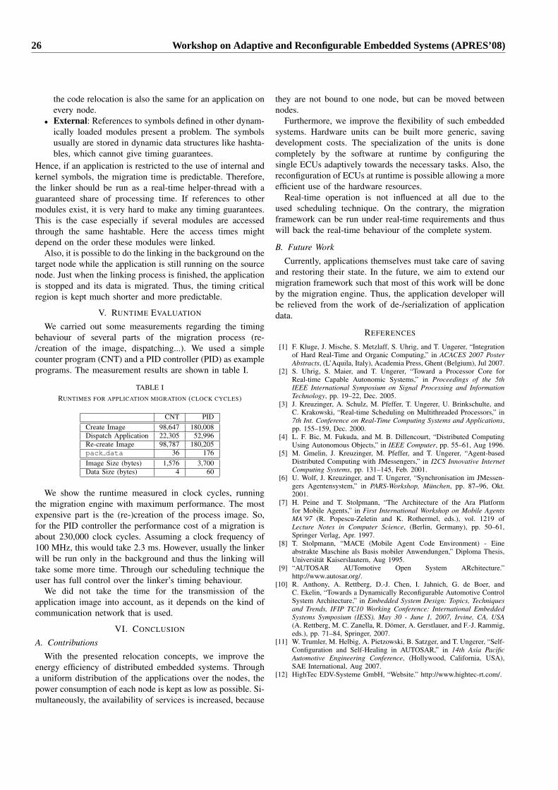
the code relocation is also the same for an application onevery node.
• External: References to symbols defined in other dynam-ically loaded modules present a problem. The symbolsusually are stored in dynamic data structures like hashta-bles, which cannot give timing guarantees.
Hence, if an application is restricted to the use of internal andkernel symbols, the migration time is predictable. Therefore,the linker should be run as a real-time helper-thread with aguaranteed share of processing time. If references to othermodules exist, it is very hard to make any timing guarantees.This is the case especially if several modules are accessedthrough the same hashtable. Here the access times mightdepend on the order these modules were linked.
Also, it is possible to do the linking in the background on thetarget node while the application is still running on the sourcenode. Just when the linking process is finished, the applicationis stopped and its data is migrated. Thus, the timing criticalregion is kept much shorter and more predictable.
V. RUNTIME EVALUATION
We carried out some measurements regarding the timingbehaviour of several parts of the migration process (re-/creation of the image, dispatching...). We used a simplecounter program (CNT) and a PID controller (PID) as exampleprograms. The measurement results are shown in table I.
TABLE IRUNTIMES FOR APPLICATION MIGRATION (CLOCK CYCLES)
CNT PIDCreate Image 98,647 180,008Dispatch Application 22,305 52,996Re-create Image 98,787 180,205pack data 36 176Image Size (bytes) 1,576 3,700Data Size (bytes) 4 60
We show the runtime measured in clock cycles, runningthe migration engine with maximum performance. The mostexpensive part is the (re-)creation of the process image. So,for the PID controller the performance cost of a migration isabout 230,000 clock cycles. Assuming a clock frequency of100 MHz, this would take 2.3 ms. However, usually the linkerwill be run only in the background and thus the linking willtake some more time. Through our scheduling technique theuser has full control over the linker’s timing behaviour.
We did not take the time for the transmission of theapplication image into account, as it depends on the kind ofcommunication network that is used.
VI. CONCLUSION
A. Contributions
With the presented relocation concepts, we improve theenergy efficiency of distributed embedded systems. Througha uniform distribution of the applications over the nodes, thepower consumption of each node is kept as low as possible. Si-multaneously, the availability of services is increased, because
they are not bound to one node, but can be moved betweennodes.
Furthermore, we improve the flexibility of such embeddedsystems. Hardware units can be built more generic, savingdevelopment costs. The specialization of the units is donecompletely by the software at runtime by configuring thesingle ECUs adaptively towards the necessary tasks. Also, thereconfiguration of ECUs at runtime is possible allowing a moreefficient use of the hardware resources.
Real-time operation is not influenced at all due to theused scheduling technique. On the contrary, the migrationframework can be run under real-time requirements and thuswill back the real-time behaviour of the complete system.
B. Future Work
Currently, applications themselves must take care of savingand restoring their state. In the future, we aim to extend ourmigration framework such that most of this work will be doneby the migration engine. Thus, the application developer willbe relieved from the work of de-/serialization of applicationdata.
REFERENCES
[1] F. Kluge, J. Mische, S. Metzlaff, S. Uhrig, and T. Ungerer, “Integrationof Hard Real-Time and Organic Computing,” in ACACES 2007 PosterAbstracts, (L’Aquila, Italy), Academia Press, Ghent (Belgium), Jul 2007.
[2] S. Uhrig, S. Maier, and T. Ungerer, “Toward a Processor Core forReal-time Capable Autonomic Systems,” in Proceedings of the 5thIEEE International Symposium on Signal Processing and InformationTechnology, pp. 19–22, Dec. 2005.
[3] J. Kreuzinger, A. Schulz, M. Pfeffer, T. Ungerer, U. Brinkschulte, andC. Krakowski, “Real-time Scheduling on Multithreaded Processors,” in7th Int. Conference on Real-Time Computing Systems and Applications,pp. 155–159, Dec. 2000.
[4] L. F. Bic, M. Fukuda, and M. B. Dillencourt, “Distributed ComputingUsing Autonomous Objects,” in IEEE Computer, pp. 55–61, Aug 1996.
[5] M. Gmelin, J. Kreuzinger, M. Pfeffer, and T. Ungerer, “Agent-basedDistributed Computing with JMessengers,” in I2CS Innovative InternetComputing Systems, pp. 131–145, Feb. 2001.
[6] U. Wolf, J. Kreuzinger, and T. Ungerer, “Synchronisation im JMessen-gers Agentensystem,” in PARS-Workshop, Munchen, pp. 87–96, Okt.2001.
[7] H. Peine and T. Stolpmann, “The Architecture of the Ara Platformfor Mobile Agents,” in First International Workshop on Mobile AgentsMA’97 (R. Popescu-Zeletin and K. Rothermel, eds.), vol. 1219 ofLecture Notes in Computer Science, (Berlin, Germany), pp. 50–61,Springer Verlag, Apr. 1997.
[8] T. Stolpmann, “MACE (Mobile Agent Code Environment) - Eineabstrakte Maschine als Basis mobiler Anwendungen,” Diploma Thesis,Universitat Kaiserslautern, Aug 1995.
[9] “AUTOSAR AUTomotive Open System ARchitecture.”http://www.autosar.org/.
[10] R. Anthony, A. Rettberg, D.-J. Chen, I. Jahnich, G. de Boer, andC. Ekelin, “Towards a Dynamically Reconfigurable Automotive ControlSystem Architecture,” in Embedded System Design: Topics, Techniquesand Trends, IFIP TC10 Working Conference: International EmbeddedSystems Symposium (IESS), May 30 - June 1, 2007, Irvine, CA, USA(A. Rettberg, M. C. Zanella, R. Domer, A. Gerstlauer, and F.-J. Rammig,eds.), pp. 71–84, Springer, 2007.
[11] W. Trumler, M. Helbig, A. Pietzowski, B. Satzger, and T. Ungerer, “Self-Configuration and Self-Healing in AUTOSAR,” in 14th Asia PacificAutomotive Engineering Conference, (Hollywood, California, USA),SAE International, Aug 2007.
[12] HighTec EDV-Systeme GmbH, “Website.” http://www.hightec-rt.com/.
26 Workshop on Adaptive and Reconfigurable Embedded Systems (APRES’08)
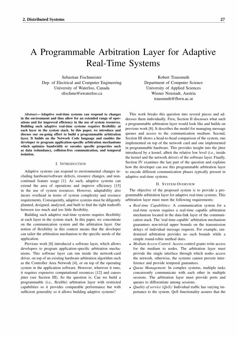
A Programmable Arbitration Layer for AdaptiveReal-Time Systems
Sebastian FischmeisterDep. of Electrical and Computer Engineering
University of Waterloo, [email protected]
Robert TrausmuthDepartment of Computer ScienceUniversity of Applied Sciences
Wiener Neustadt, [email protected]
Abstract— Adaptive real-time systems can respond to changesin the environment and thus allow for an extended range of oper-ations and for improved efficiency in the use of system resources.Building such adaptive real-time systems requires flexibility ateach layer in the system stack. In this paper, we introduce anddiscuss our on-going effort to build a programmable arbitrationlayer. It builds on the Network Code language and enables thedeveloper to program application-specific arbitration mechanismswhich optimize bandwidth or encodes specific properties suchas data redundancy, collision-free communication, and temporalisolation.
I. INTRODUCTION
Adaptive systems can respond to environmental changes in-cluding hardware/software defects, resource changes, and non-continual feature usage [1]. As such, adaptive systems canextend the area of operations and improve efficiency [15]in the use of system resources. However, adaptability alsoincurs overhead in terms of system complexity and resourcerequirements. Consequently, adaptive systems must be diligentlyplanned, designed, analyzed, and built to find the right tradeoffsbetween too much and too little flexibility.
Building such adaptive real-time systems requires flexibilityat each layer in the system stack. In this paper, we concentrateon the communication system and the arbitration layer. Ournotion of flexibility in this context means that the developercan tailor the arbitration mechanism to the specific needs of theapplication.
Previous work [8] introduced a software layer, which allowsdevelopers to program application-specific arbitration mecha-nisms. This software layer can run inside the network-carddriver, on top of an existing hardware arbitration algorithm suchas the Controller Area Network [4], or on top of the operatingsystem in the application software. However, wherever it runs,it requires expensive computational resources [12] and causesjitter (see Section III). So the question is: Can we build aprogrammable (i.e., flexible) arbitration layer with restrictedcapabilities so it provides comparable performance but withsufficient generality so it allows building adaptive systems?
This work breaks this question into several pieces and ad-dresses them individually. First, Section II discusses what sucha programmable arbitration layer would look like and builds onprevious work [8]. It describes the model for managing messagequeues and access to the communication medium. Second,Section III shows a head-to-head comparison of the system, oneimplemented on top of the network card and one implementedin programmable hardware. This provides insight into the jitterintroduced by a kernel, albeit the relative low level (i.e., insidethe kernel and the network driver) of the software layer. Finally,Section IV examines the last part of the question and explainshow the developer can use this programmable arbitration layerto encode different communication phases typically present inadaptive real-time systems.
II. SYSTEM OVERVIEW
The objective of the proposed system is to provide a pro-grammable arbitration layer for adaptive real-time systems. Thisarbitration layer must meet the following requirements:
• Real-time Capabilities: A communication system for areal-time system requires a real-time capable arbitrationmechanism located in the data-link layer of the communi-cation stack. The ’real-time capable’ arbitration mechanismguarantees non-trivial upper bounds on the transmissiondelays of individual message requests. For example, ran-domized arbitration provides no such bounds while asimple round-robin method does.
• Medium Access Control: Access control grants write accessfor the medium to nodes. The arbitration layer mustprovide the single interface through which nodes accessthe network, otherwise, the systems cannot prevent inter-ference and provide temporal guarantees.
• Queue Management: In complex systems, multiple tasksconcurrently communicate with each other in multiplesessions. The arbitration layer must provide ports andqueues to differentiate among sessions.
• Quality of service (QoS): Individual traffic has varying im-portance to the system. QoS functionality assures that the
2. Distributed Systems 27
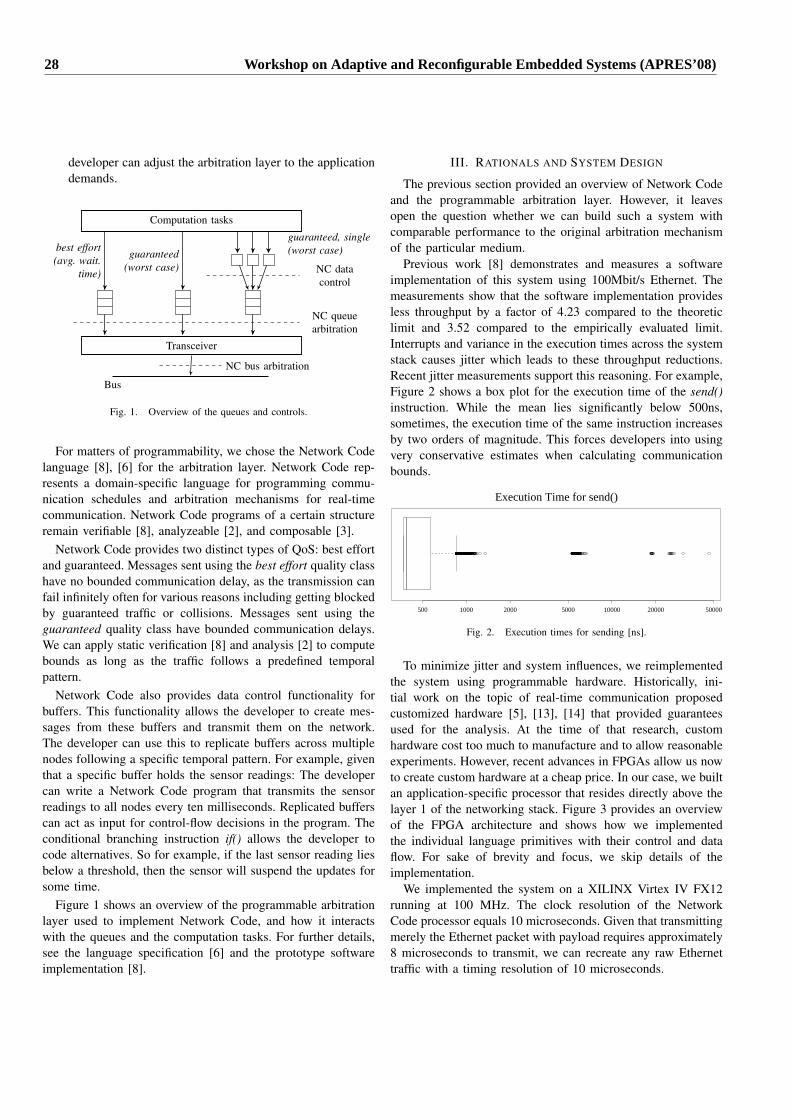
developer can adjust the arbitration layer to the applicationdemands.
Computation tasks
Transceiver
Bus
best effort(avg. wait.
time)
guaranteed(worst case)
guaranteed, single(worst case)
NC queuearbitration
NC datacontrol
NC bus arbitration
Fig. 1. Overview of the queues and controls.
For matters of programmability, we chose the Network Codelanguage [8], [6] for the arbitration layer. Network Code rep-resents a domain-specific language for programming commu-nication schedules and arbitration mechanisms for real-timecommunication. Network Code programs of a certain structureremain verifiable [8], analyzeable [2], and composable [3].
Network Code provides two distinct types of QoS: best effortand guaranteed. Messages sent using the best effort quality classhave no bounded communication delay, as the transmission canfail infinitely often for various reasons including getting blockedby guaranteed traffic or collisions. Messages sent using theguaranteed quality class have bounded communication delays.We can apply static verification [8] and analysis [2] to computebounds as long as the traffic follows a predefined temporalpattern.
Network Code also provides data control functionality forbuffers. This functionality allows the developer to create mes-sages from these buffers and transmit them on the network.The developer can use this to replicate buffers across multiplenodes following a specific temporal pattern. For example, giventhat a specific buffer holds the sensor readings: The developercan write a Network Code program that transmits the sensorreadings to all nodes every ten milliseconds. Replicated bufferscan act as input for control-flow decisions in the program. Theconditional branching instruction if() allows the developer tocode alternatives. So for example, if the last sensor reading liesbelow a threshold, then the sensor will suspend the updates forsome time.
Figure 1 shows an overview of the programmable arbitrationlayer used to implement Network Code, and how it interactswith the queues and the computation tasks. For further details,see the language specification [6] and the prototype softwareimplementation [8].
III. RATIONALS AND SYSTEM DESIGN
The previous section provided an overview of Network Codeand the programmable arbitration layer. However, it leavesopen the question whether we can build such a system withcomparable performance to the original arbitration mechanismof the particular medium.
Previous work [8] demonstrates and measures a softwareimplementation of this system using 100Mbit/s Ethernet. Themeasurements show that the software implementation providesless throughput by a factor of 4.23 compared to the theoreticlimit and 3.52 compared to the empirically evaluated limit.Interrupts and variance in the execution times across the systemstack causes jitter which leads to these throughput reductions.Recent jitter measurements support this reasoning. For example,Figure 2 shows a box plot for the execution time of the send()instruction. While the mean lies significantly below 500ns,sometimes, the execution time of the same instruction increasesby two orders of magnitude. This forces developers into usingvery conservative estimates when calculating communicationbounds.
Execution Time for send()
500 1000 2000 5000 10000 20000 50000
Fig. 2. Execution times for sending [ns].
To minimize jitter and system influences, we reimplementedthe system using programmable hardware. Historically, ini-tial work on the topic of real-time communication proposedcustomized hardware [5], [13], [14] that provided guaranteesused for the analysis. At the time of that research, customhardware cost too much to manufacture and to allow reasonableexperiments. However, recent advances in FPGAs allow us nowto create custom hardware at a cheap price. In our case, we builtan application-specific processor that resides directly above thelayer 1 of the networking stack. Figure 3 provides an overviewof the FPGA architecture and shows how we implementedthe individual language primitives with their control and dataflow. For sake of brevity and focus, we skip details of theimplementation.
We implemented the system on a XILINX Virtex IV FX12running at 100 MHz. The clock resolution of the NetworkCode processor equals 10 microseconds. Given that transmittingmerely the Ethernet packet with payload requires approximately8 microseconds to transmit, we can recreate any raw Ethernettraffic with a timing resolution of 10 microseconds.
28 Workshop on Adaptive and Reconfigurable Embedded Systems (APRES’08)
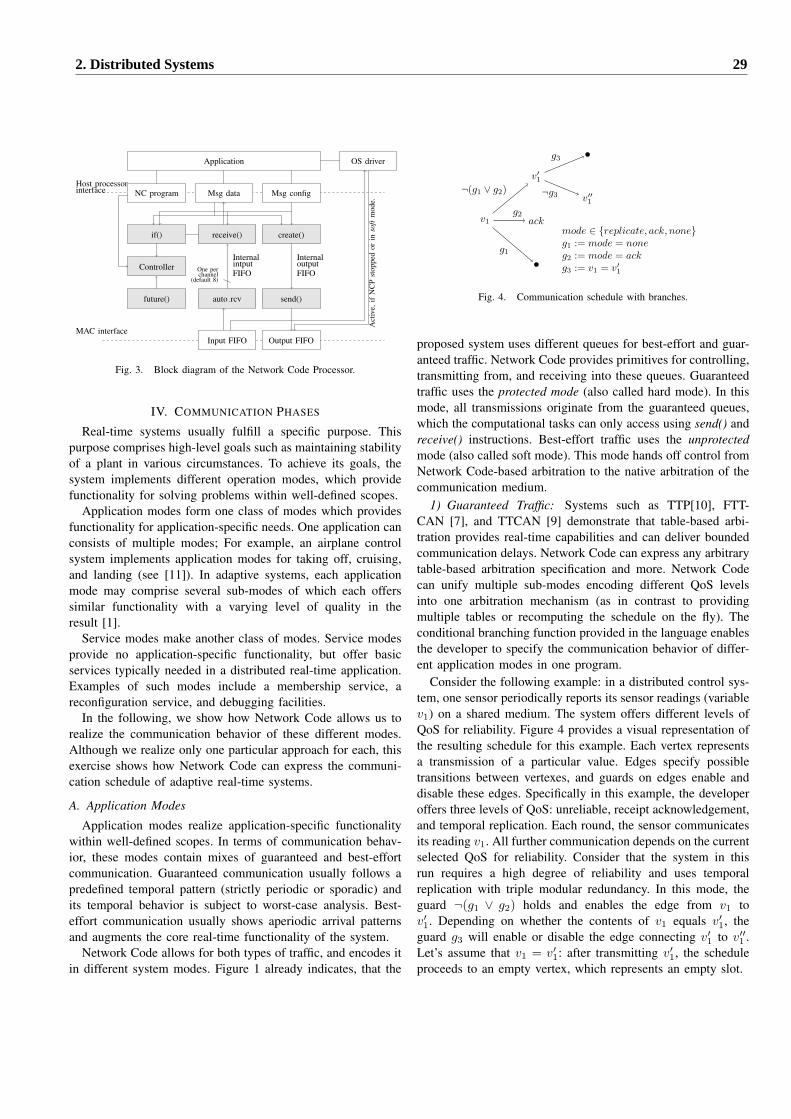
OS driver
Msg data Msg configHost processorinterface
if() receive() create()
send()future()
NC program
Controller
auto rcv
channelOne per
(default 8)
Application
Act
ive,
ifN
CP
stop
ped
orin
soft
mod
e.
InternalintputFIFO
outputInternal
FIFO
Output FIFOInput FIFOMAC interface
Fig. 3. Block diagram of the Network Code Processor.
IV. COMMUNICATION PHASES
Real-time systems usually fulfill a specific purpose. Thispurpose comprises high-level goals such as maintaining stabilityof a plant in various circumstances. To achieve its goals, thesystem implements different operation modes, which providefunctionality for solving problems within well-defined scopes.
Application modes form one class of modes which providesfunctionality for application-specific needs. One application canconsists of multiple modes; For example, an airplane controlsystem implements application modes for taking off, cruising,and landing (see [11]). In adaptive systems, each applicationmode may comprise several sub-modes of which each offerssimilar functionality with a varying level of quality in theresult [1].
Service modes make another class of modes. Service modesprovide no application-specific functionality, but offer basicservices typically needed in a distributed real-time application.Examples of such modes include a membership service, areconfiguration service, and debugging facilities.
In the following, we show how Network Code allows us torealize the communication behavior of these different modes.Although we realize only one particular approach for each, thisexercise shows how Network Code can express the communi-cation schedule of adaptive real-time systems.
A. Application Modes
Application modes realize application-specific functionalitywithin well-defined scopes. In terms of communication behav-ior, these modes contain mixes of guaranteed and best-effortcommunication. Guaranteed communication usually follows apredefined temporal pattern (strictly periodic or sporadic) andits temporal behavior is subject to worst-case analysis. Best-effort communication usually shows aperiodic arrival patternsand augments the core real-time functionality of the system.
Network Code allows for both types of traffic, and encodes itin different system modes. Figure 1 already indicates, that the
v1
g1
ackg2
v′1
v′′1
¬g3
g3
¬(g1 ∨ g2)
mode ∈ {replicate, ack, none}g1 := mode = noneg2 := mode = ackg3 := v1 = v′
1
Fig. 4. Communication schedule with branches.
proposed system uses different queues for best-effort and guar-anteed traffic. Network Code provides primitives for controlling,transmitting from, and receiving into these queues. Guaranteedtraffic uses the protected mode (also called hard mode). In thismode, all transmissions originate from the guaranteed queues,which the computational tasks can only access using send() andreceive() instructions. Best-effort traffic uses the unprotectedmode (also called soft mode). This mode hands off control fromNetwork Code-based arbitration to the native arbitration of thecommunication medium.
1) Guaranteed Traffic: Systems such as TTP[10], FTT-CAN [7], and TTCAN [9] demonstrate that table-based arbi-tration provides real-time capabilities and can deliver boundedcommunication delays. Network Code can express any arbitrarytable-based arbitration specification and more. Network Codecan unify multiple sub-modes encoding different QoS levelsinto one arbitration mechanism (as in contrast to providingmultiple tables or recomputing the schedule on the fly). Theconditional branching function provided in the language enablesthe developer to specify the communication behavior of differ-ent application modes in one program.
Consider the following example: in a distributed control sys-tem, one sensor periodically reports its sensor readings (variablev1) on a shared medium. The system offers different levels ofQoS for reliability. Figure 4 provides a visual representation ofthe resulting schedule for this example. Each vertex representsa transmission of a particular value. Edges specify possibletransitions between vertexes, and guards on edges enable anddisable these edges. Specifically in this example, the developeroffers three levels of QoS: unreliable, receipt acknowledgement,and temporal replication. Each round, the sensor communicatesits reading v1. All further communication depends on the currentselected QoS for reliability. Consider that the system in thisrun requires a high degree of reliability and uses temporalreplication with triple modular redundancy. In this mode, theguard ¬(g1 ∨ g2) holds and enables the edge from v1 tov′1. Depending on whether the contents of v1 equals v′
1, theguard g3 will enable or disable the edge connecting v′
1 to v′′1 .
Let’s assume that v1 = v′1: after transmitting v′
1, the scheduleproceeds to an empty vertex, which represents an empty slot.
2. Distributed Systems 29
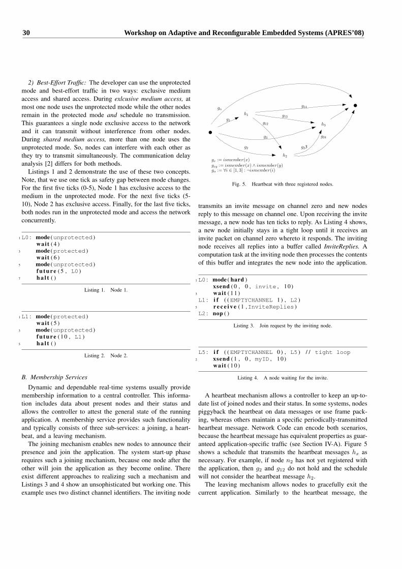
2) Best-Effort Traffic: The developer can use the unprotectedmode and best-effort traffic in two ways: exclusive mediumaccess and shared access. During exlcusive medium access, atmost one node uses the unprotected mode while the other nodesremain in the protected mode and schedule no transmission.This guarantees a single node exclusive access to the networkand it can transmit without interference from other nodes.During shared medium access, more than one node uses theunprotected mode. So, nodes can interfere with each other asthey try to transmit simultaneously. The communication delayanalysis [2] differs for both methods.
Listings 1 and 2 demonstrate the use of these two concepts.Note, that we use one tick as safety gap between mode changes.For the first five ticks (0-5), Node 1 has exclusive access to themedium in the unprotected mode. For the next five ticks (5-10), Node 2 has exclusive access. Finally, for the last five ticks,both nodes run in the unprotected mode and access the networkconcurrently.
1 L0 : mode (unprotected )wait ( 4 )
3 mode (protected )wait ( 6 )
5 mode (unprotected )f u t u r e ( 5 , L0 )
7 h a l t ( )
Listing 1. Node 1.
1 L1 : mode (protected )wait ( 5 )
3 mode (unprotected )f u t u r e ( 1 0 , L1 )
5 h a l t ( )
Listing 2. Node 2.
B. Membership Services
Dynamic and dependable real-time systems usually providemembership information to a central controller. This informa-tion includes data about present nodes and their status andallows the controller to attest the general state of the runningapplication. A membership service provides such functionalityand typically consists of three sub-services: a joining, a heart-beat, and a leaving mechanism.
The joining mechanism enables new nodes to announce theirpresence and join the application. The system start-up phaserequires such a joining mechanism, because one node after theother will join the application as they become online. Thereexist different approaches to realizing such a mechanism andListings 3 and 4 show an unsophisticated but working one. Thisexample uses two distinct channel identifiers. The inviting node
h1g1
h2
g2
h3
g3
gα
g12
g13
g14
g23
g24
gx := ismember(x)gxy := ismember(x) ∧ ismember(y)gα := ∀i ∈ [1, 3] : ¬ismember(i)
Fig. 5. Heartbeat with three registered nodes.
transmits an invite message on channel zero and new nodesreply to this message on channel one. Upon receiving the invitemessage, a new node has ten ticks to reply. As Listing 4 shows,a new node initially stays in a tight loop until it receives aninvite packet on channel zero whereto it responds. The invitingnode receives all replies into a buffer called InviteReplies. Acomputation task at the inviting node then processes the contentsof this buffer and integrates the new node into the application.
1 L0 : mode ( hard )xsend ( 0 , 0 , invite , 10 )
3 wait ( 1 1 )L1 : i f ( (EMPTYCHANNEL 1 ) , L2 )
5 r e c e i v e ( 1 ,InviteReplies )L2 : nop ( )
Listing 3. Join request by the inviting node.
L5 : i f ( (EMPTYCHANNEL 0 ) , L5 ) / / tight loop2 xsend ( 1 , 0 , myID , 10 )
wait ( 1 0 )
Listing 4. A node waiting for the invite.
A heartbeat mechanism allows a controller to keep an up-to-date list of joined nodes and their status. In some systems, nodespiggyback the heartbeat on data messages or use frame pack-ing, whereas others maintain a specific periodically-transmittedheartbeat message. Network Code can encode both scenarios,because the heartbeat message has equivalent properties as guar-anteed application-specific traffic (see Section IV-A). Figure 5shows a schedule that transmits the heartbeat messages hx asnecessary. For example, if node n2 has not yet registered withthe application, then g2 and g12 do not hold and the schedulewill not consider the heartbeat message h2.
The leaving mechanism allows nodes to gracefully exit thecurrent application. Similarly to the heartbeat message, the
30 Workshop on Adaptive and Reconfigurable Embedded Systems (APRES’08)
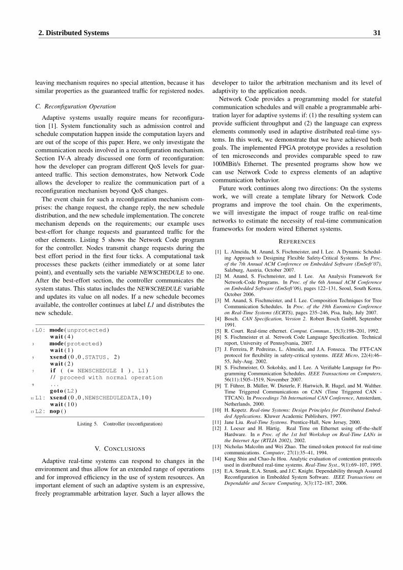
leaving mechanism requires no special attention, because it hassimilar properties as the guaranteed traffic for registered nodes.
C. Reconfiguration Operation
Adaptive systems usually require means for reconfigura-tion [1]. System functionality such as admission control andschedule computation happen inside the computation layers andare out of the scope of this paper. Here, we only investigate thecommunication needs involved in a reconfiguration mechanism.Section IV-A already discussed one form of reconfiguration:how the developer can program different QoS levels for guar-anteed traffic. This section demonstrates, how Network Codeallows the developer to realize the communication part of areconfiguration mechanism beyond QoS changes.
The event chain for such a reconfiguration mechanism com-prises: the change request, the change reply, the new scheduledistribution, and the new schedule implementation. The concretemechanism depends on the requirements; our example usesbest-effort for change requests and guaranteed traffic for theother elements. Listing 5 shows the Network Code programfor the controller. Nodes transmit change requests during thebest effort period in the first four ticks. A computational taskprocesses these packets (either immediately or at some laterpoint), and eventually sets the variable NEWSCHEDULE to one.After the best-effort section, the controller communicates thesystem status. This status includes the NEWSCHEDULE variableand updates its value on all nodes. If a new schedule becomesavailable, the controller continues at label L1 and distributes thenew schedule.
1 L0 : mode (unprotected )wait ( 4 )
3 mode (protected )wait ( 1 )
5 xsend ( 0 , 0 ,STATUS , 2 )wait ( 2 )
7 i f ( (= NEWSCHEDULE 1 ) , L1 )/ / proceed with normal operation
9 . . .goto (L2 )
11 L1 : xsend ( 0 , 0 ,NEWSCHEDULEDATA , 1 0 )wait ( 1 0 )
13 L2 : nop ( )
Listing 5. Controller (reconfiguration)
V. CONCLUSIONS
Adaptive real-time systems can respond to changes in theenvironment and thus allow for an extended range of operationsand for improved efficiency in the use of system resources. Animportant element of such an adaptive system is an expressive,freely programmable arbitration layer. Such a layer allows the
developer to tailor the arbitration mechanism and its level ofadaptivity to the application needs.
Network Code provides a programming model for statefulcommunication schedules and will enable a programmable arbi-tration layer for adaptive systems if: (1) the resulting system canprovide sufficient throughput and (2) the language can expresselements commonly used in adaptive distributed real-time sys-tems. In this work, we demonstrate that we have achieved bothgoals. The implemented FPGA prototype provides a resolutionof ten microseconds and provides comparable speed to raw100MBit/s Ethernet. The presented programs show how wecan use Network Code to express elements of an adaptivecommunication behavior.
Future work continues along two directions: On the systemswork, we will create a template library for Network Codeprograms and improve the tool chain. On the experiments,we will investigate the impact of rouge traffic on real-timenetworks to estimate the necessity of real-time communicationframeworks for modern wired Ethernet systems.
REFERENCES
[1] L. Almeida, M. Anand, S. Fischmeister, and I. Lee. A Dynamic Schedul-ing Approach to Designing Flexible Safety-Critical Systems. In Proc.of the 7th Annual ACM Conference on Embedded Software (EmSoft’07),Salzburg, Austria, October 2007.
[2] M. Anand, S. Fischmeister, and I. Lee. An Analysis Framework forNetwork-Code Programs. In Proc. of the 6th Annual ACM Conferenceon Embedded Software (EmSoft’06), pages 122–131, Seoul, South Korea,October 2006.
[3] M. Anand, S. Fischmeister, and I. Lee. Composition Techniques for TreeCommunication Schedules. In Proc. of the 19th Euromicro Conferenceon Real-Time Systems (ECRTS), pages 235–246, Pisa, Italy, July 2007.
[4] Bosch. CAN Specification, Version 2. Robert Bosch GmbH, September1991.
[5] R. Court. Real-time ethernet. Comput. Commun., 15(3):198–201, 1992.[6] S. Fischmeister et al. Network Code Language Specification. Technical
report, University of Pennsylvania, 2007.[7] J. Ferreira, P. Pedreiras, L. Almeida, and J.A. Fonseca. The FTT-CAN
protocol for flexibility in safety-critical systems. IEEE Micro, 22(4):46–55, July-Aug. 2002.
[8] S. Fischmeister, O. Sokolsky, and I. Lee. A Verifiable Language for Pro-gramming Communication Schedules. IEEE Transactions on Computers,56(11):1505–1519, November 2007.
[9] T. Fuhrer, B. Muller, W. Dieterle, F. Hartwich, R. Hugel, and M. Walther.Time Triggered Communications on CAN (Time Triggered CAN -TTCAN). In Proceedings 7th International CAN Conference, Amsterdam,Netherlands, 2000.
[10] H. Kopetz. Real-time Systems: Design Principles for Distributed Embed-ded Applications. Kluwer Academic Publishers, 1997.
[11] Jane Liu. Real-Time Systems. Prentice-Hall, New Jersey, 2000.[12] J. Loeser and H. Hartig. Real Time on Ethernet using off-the-shelf
Hardware. In n Proc. of the 1st Intl Workshop on Real-Time LANs inthe Internet Age (RTLIA 2002), 2002.
[13] Nicholas Malcolm and Wei Zhao. The timed-token protocol for real-timecommunications. Computer, 27(1):35–41, 1994.
[14] Kang Shin and Chao-Ju Hou. Analytic evaluation of contention protocolsused in distributed real-time systems. Real-Time Syst., 9(1):69–107, 1995.
[15] E.A. Strunk, E.A. Strunk, and J.C. Knight. Dependability through AssuredReconfiguration in Embedded System Software. IEEE Transactions onDependable and Secure Computing, 3(3):172–187, 2006.
2. Distributed Systems 31
ViRe: Virtual Reconfiguration Framework forEmbedded Processing in Distributed Image Sensors
Rahul Balani, Akhilesh Singhania, Chih-Chieh Han and Mani SrivastavaUniversity of California at Los Angeles
Los Angeles, CA 90095, USA
Abstract—Image processing applications introduce new chal-lenges to the design of sensor network systems via non-trivialin-network computation. As embedded processing becomes morecomplex, in-situ reconfiguration is seen as the key enablingtechnology to maintain and manage such systems. In dynamicevent-driven heterogeneous sensor networks, reconfiguration alsoencompasses autonomous re-partitioning of applications acrossmultiple tiers to provide a low-power responsive system byefficiently coping with variations in run-time resource usageand availability. Hence, we aim to provide an efficient low-power macro-programming environment that supports multi-dimensional software reconfiguration of heterogeneous imagingnetworks.
Working towards this initiative, we present the ViRe frame-work for mote-class devices based on data-centric applicationcomposition and execution. Applications, modeled as dataflowgraphs, are composed from a library of pre-defined and reusableimage processing elements. Concise scripts capture the wiringinformation and are used to install applications in the network,while execution on the nodes is performed via processor nativecode to minimize overhead. A lean run-time engine tightlymonitors application execution to provide an efficient, robust andscalable support for complex reconfigurable embedded imageprocessing. Thus, the system is able to lower application re-partitioning overhead and minimize loss of work during softwarereconfiguration.
Index Terms — Sensor Networks, Differential partitioning,Reconfiguration, Dataflow
I. MOTIVATION
Image sensors demonstrate vital importance in understand-ing and characterization of diverse environments. Applicationsinvolving these sensors pose new challenges to the design ofsensor network systems, particularly in the context of recentlydeveloped low-power, but resource-constrained, image sensingplatforms such as Cyclops [1] and AER Imager [2]. In-networksensor information processing takes on a particularly importantrole with image sensors, because to save communicationbandwidth and energy, image sensor nodes must process theimages in-network to extract relevant events or features beforetransmission. Prior work, comprising of mere filter chains,linear dataflow graphs or SQL aggregate functions, is notenough to affect adequate data reduction. Rather, significantlyricher and complex recursive algorithms are needed to com-press image frames, or to detect features or events of interest.Another reason for the recursive nature of the computation isthat the high cost of image acquisition itself usually motivatesapplication structures where a feedback control loop controlswhen to acquire the next image frame based on history. Thus,
typical image processing algorithms require system softwaresupport for efficient and reliable functioning when embeddedin resource-constrained sensor nodes.
Clearly, the ability to reconfigure application-specific em-bedded sensor processing on the nodes at run-time, for pur-poses of re-tasking and environment-specific tuning, withoutsacrificing the efficiency of processing, is important for effec-tive operation and maintenance of complex sensor networks.This recognition has led to emergence of systems such as Con-tiki [3], SOS [4], TENET [5], VanGo [6], and Mate [7] whererun-time retasking and reconfiguration of application-specificprocessing at the node are directly supported. However, theseprior systems are either too low-level (e.g. Contiki and SOS)and thus do not provide support for higher level programmingabstractions common to image sensing, or significantly restrictthe complexity or efficiency of application-specific processingand flexibility of reconfiguration (e.g. TENET, VanGo, andMate) and thus unable to support the requirements of recon-figurable embedded image processing.
However, in a dynamic event-driven multi-tier heteroge-neous sensor network, software reconfiguration is not re-stricted to simple parameter and logic updates, but involvesdynamic re-partitioning of the data processing pipeline acrossdifferent tiers. It is required in dense high data-rate networksthat exhibit a clear trade-off between local computation andtransmission of data in terms of both latency and energy.For instance, processing data locally at a certain sensor nodemay reduce energy consumption by reducing data transmissionacross the network, but may increase overall time (latency)required to obtain the result at the base station due to lengthycomputation. This trade-off is unique to each node as thenetwork latency experienced at that node is not only affectedby its proximity to the intermediate or final data sink, but alsoby status of its local transmission queue and network trafficat higher tiers. Thus, to support often conflicting goals of lowlatency and low power, it is necessary to monitor the abovefactors at run-time and migrate computation appropriately,resulting in different configurations of the same end-to-endpipeline at different nodes. Henceforth, this dynamic migrationof components of a data processing pipeline, to supportapplication re-partitioning, is referred to as task migration inthis text.
Prior work [8][5] has essentially focused on providing anefficient, robust and scalable macro-programming environmentfor heterogeneous sensor networks, but consistently ignored
32 Workshop on Adaptive and Reconfigurable Embedded Systems (APRES’08)
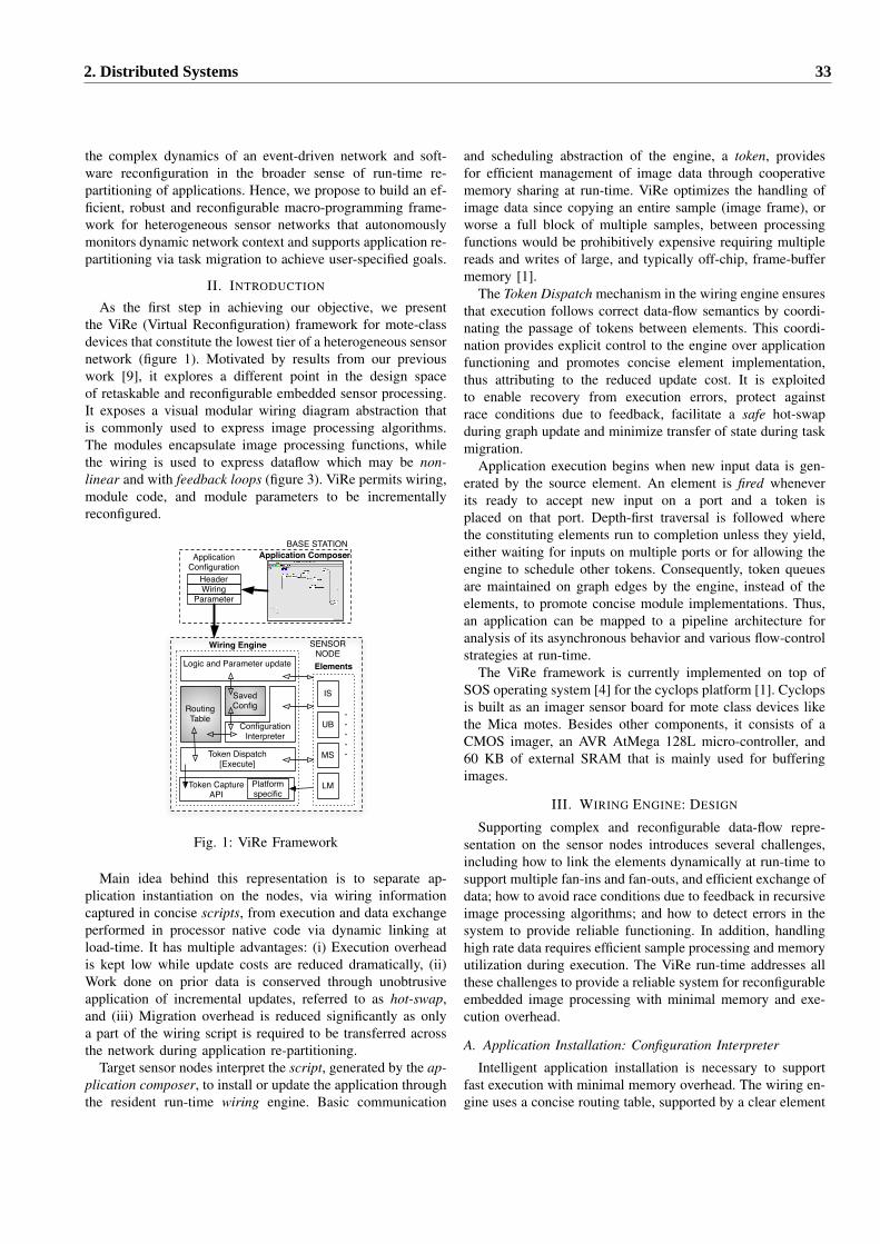
the complex dynamics of an event-driven network and soft-ware reconfiguration in the broader sense of run-time re-partitioning of applications. Hence, we propose to build an ef-ficient, robust and reconfigurable macro-programming frame-work for heterogeneous sensor networks that autonomouslymonitors dynamic network context and supports application re-partitioning via task migration to achieve user-specified goals.
II. INTRODUCTION
As the first step in achieving our objective, we presentthe ViRe (Virtual Reconfiguration) framework for mote-classdevices that constitute the lowest tier of a heterogeneous sensornetwork (figure 1). Motivated by results from our previouswork [9], it explores a different point in the design spaceof retaskable and reconfigurable embedded sensor processing.It exposes a visual modular wiring diagram abstraction thatis commonly used to express image processing algorithms.The modules encapsulate image processing functions, whilethe wiring is used to express dataflow which may be non-linear and with feedback loops (figure 3). ViRe permits wiring,module code, and module parameters to be incrementallyreconfigured.
ApplicationConfiguration
BASE STATION
RoutingTable
SavedConfig
ParameterWiringHeader
Token Dispatch[Execute]
Logic and Parameter update
ConfigurationInterpreter
IS
UB
MS
LM
.
.
.
.
.
Elements
Wiring Engine SENSORNODE
Application Composer
Platformspecific
Token CaptureAPI
Fig. 1: ViRe Framework
Main idea behind this representation is to separate ap-plication instantiation on the nodes, via wiring informationcaptured in concise scripts, from execution and data exchangeperformed in processor native code via dynamic linking atload-time. It has multiple advantages: (i) Execution overheadis kept low while update costs are reduced dramatically, (ii)Work done on prior data is conserved through unobtrusiveapplication of incremental updates, referred to as hot-swap,and (iii) Migration overhead is reduced significantly as onlya part of the wiring script is required to be transferred acrossthe network during application re-partitioning.
Target sensor nodes interpret the script, generated by the ap-plication composer, to install or update the application throughthe resident run-time wiring engine. Basic communication
and scheduling abstraction of the engine, a token, providesfor efficient management of image data through cooperativememory sharing at run-time. ViRe optimizes the handling ofimage data since copying an entire sample (image frame), orworse a full block of multiple samples, between processingfunctions would be prohibitively expensive requiring multiplereads and writes of large, and typically off-chip, frame-buffermemory [1].
The Token Dispatch mechanism in the wiring engine ensuresthat execution follows correct data-flow semantics by coordi-nating the passage of tokens between elements. This coordi-nation provides explicit control to the engine over applicationfunctioning and promotes concise element implementation,thus attributing to the reduced update cost. It is exploitedto enable recovery from execution errors, protect againstrace conditions due to feedback, facilitate a safe hot-swapduring graph update and minimize transfer of state during taskmigration.
Application execution begins when new input data is gen-erated by the source element. An element is fired wheneverits ready to accept new input on a port and a token isplaced on that port. Depth-first traversal is followed wherethe constituting elements run to completion unless they yield,either waiting for inputs on multiple ports or for allowing theengine to schedule other tokens. Consequently, token queuesare maintained on graph edges by the engine, instead of theelements, to promote concise module implementations. Thus,an application can be mapped to a pipeline architecture foranalysis of its asynchronous behavior and various flow-controlstrategies at run-time.
The ViRe framework is currently implemented on top ofSOS operating system [4] for the cyclops platform [1]. Cyclopsis built as an imager sensor board for mote class devices likethe Mica motes. Besides other components, it consists of aCMOS imager, an AVR AtMega 128L micro-controller, and60 KB of external SRAM that is mainly used for bufferingimages.
III. WIRING ENGINE: DESIGN
Supporting complex and reconfigurable data-flow repre-sentation on the sensor nodes introduces several challenges,including how to link the elements dynamically at run-time tosupport multiple fan-ins and fan-outs, and efficient exchange ofdata; how to avoid race conditions due to feedback in recursiveimage processing algorithms; and how to detect errors in thesystem to provide reliable functioning. In addition, handlinghigh rate data requires efficient sample processing and memoryutilization during execution. The ViRe run-time addresses allthese challenges to provide a reliable system for reconfigurableembedded image processing with minimal memory and exe-cution overhead.
A. Application Installation: Configuration Interpreter
Intelligent application installation is necessary to supportfast execution with minimal memory overhead. The wiring en-gine uses a concise routing table, supported by a clear element
2. Distributed Systems 33
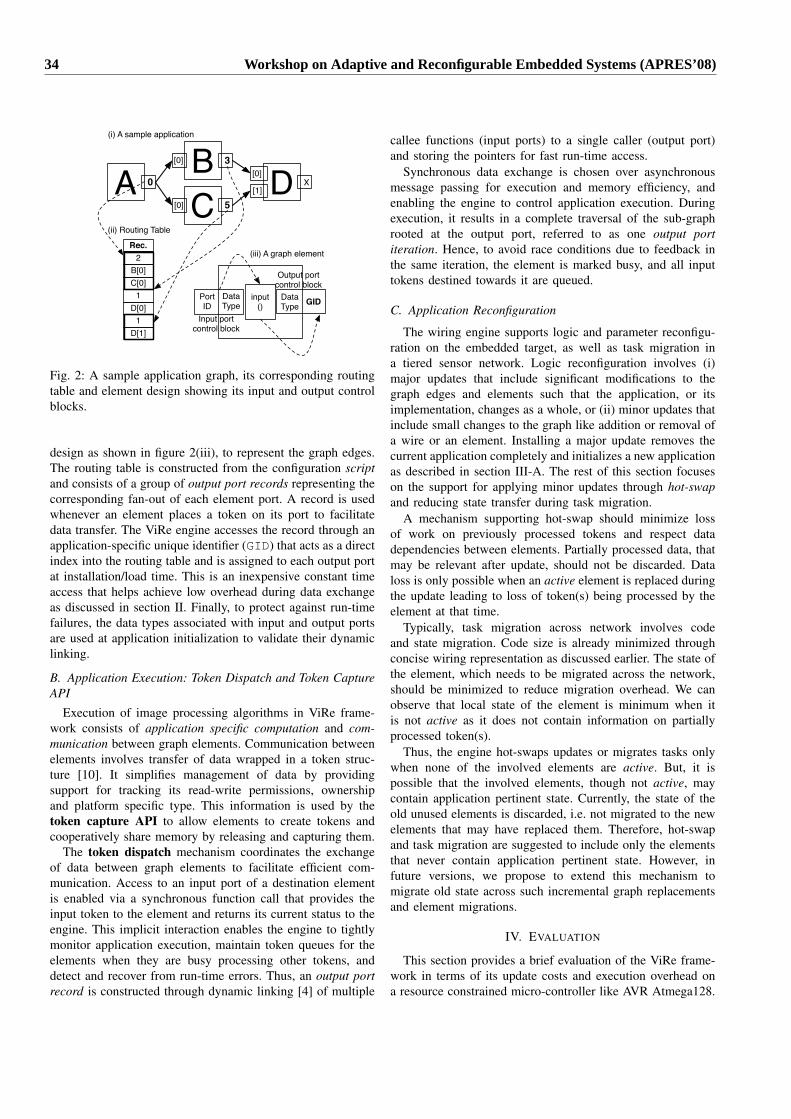
BA 0
C 5
3
D X
[0]
[0]
[0]
[1]
2
D[1]
D[0]
Rec.
C[0]
1
B[0]
1
(ii) Routing Table
DataType
Port ID GIDData
Typeinput
()Input port
control block
Output portcontrol block
(iii) A graph element
(i) A sample application
Fig. 2: A sample application graph, its corresponding routingtable and element design showing its input and output controlblocks.
design as shown in figure 2(iii), to represent the graph edges.The routing table is constructed from the configuration scriptand consists of a group of output port records representing thecorresponding fan-out of each element port. A record is usedwhenever an element places a token on its port to facilitatedata transfer. The ViRe engine accesses the record through anapplication-specific unique identifier (GID) that acts as a directindex into the routing table and is assigned to each output portat installation/load time. This is an inexpensive constant timeaccess that helps achieve low overhead during data exchangeas discussed in section II. Finally, to protect against run-timefailures, the data types associated with input and output portsare used at application initialization to validate their dynamiclinking.
B. Application Execution: Token Dispatch and Token CaptureAPI
Execution of image processing algorithms in ViRe frame-work consists of application specific computation and com-munication between graph elements. Communication betweenelements involves transfer of data wrapped in a token struc-ture [10]. It simplifies management of data by providingsupport for tracking its read-write permissions, ownershipand platform specific type. This information is used by thetoken capture API to allow elements to create tokens andcooperatively share memory by releasing and capturing them.
The token dispatch mechanism coordinates the exchangeof data between graph elements to facilitate efficient com-munication. Access to an input port of a destination elementis enabled via a synchronous function call that provides theinput token to the element and returns its current status to theengine. This implicit interaction enables the engine to tightlymonitor application execution, maintain token queues for theelements when they are busy processing other tokens, anddetect and recover from run-time errors. Thus, an output portrecord is constructed through dynamic linking [4] of multiple
callee functions (input ports) to a single caller (output port)and storing the pointers for fast run-time access.
Synchronous data exchange is chosen over asynchronousmessage passing for execution and memory efficiency, andenabling the engine to control application execution. Duringexecution, it results in a complete traversal of the sub-graphrooted at the output port, referred to as one output portiteration. Hence, to avoid race conditions due to feedback inthe same iteration, the element is marked busy, and all inputtokens destined towards it are queued.
C. Application Reconfiguration
The wiring engine supports logic and parameter reconfigu-ration on the embedded target, as well as task migration ina tiered sensor network. Logic reconfiguration involves (i)major updates that include significant modifications to thegraph edges and elements such that the application, or itsimplementation, changes as a whole, or (ii) minor updates thatinclude small changes to the graph like addition or removal ofa wire or an element. Installing a major update removes thecurrent application completely and initializes a new applicationas described in section III-A. The rest of this section focuseson the support for applying minor updates through hot-swapand reducing state transfer during task migration.
A mechanism supporting hot-swap should minimize lossof work on previously processed tokens and respect datadependencies between elements. Partially processed data, thatmay be relevant after update, should not be discarded. Dataloss is only possible when an active element is replaced duringthe update leading to loss of token(s) being processed by theelement at that time.
Typically, task migration across network involves codeand state migration. Code size is already minimized throughconcise wiring representation as discussed earlier. The state ofthe element, which needs to be migrated across the network,should be minimized to reduce migration overhead. We canobserve that local state of the element is minimum when itis not active as it does not contain information on partiallyprocessed token(s).
Thus, the engine hot-swaps updates or migrates tasks onlywhen none of the involved elements are active. But, it ispossible that the involved elements, though not active, maycontain application pertinent state. Currently, the state of theold unused elements is discarded, i.e. not migrated to the newelements that may have replaced them. Therefore, hot-swapand task migration are suggested to include only the elementsthat never contain application pertinent state. However, infuture versions, we propose to extend this mechanism tomigrate old state across such incremental graph replacementsand element migrations.
IV. EVALUATION
This section provides a brief evaluation of the ViRe frame-work in terms of its update costs and execution overhead ona resource constrained micro-controller like AVR Atmega128.
34 Workshop on Adaptive and Reconfigurable Embedded Systems (APRES’08)
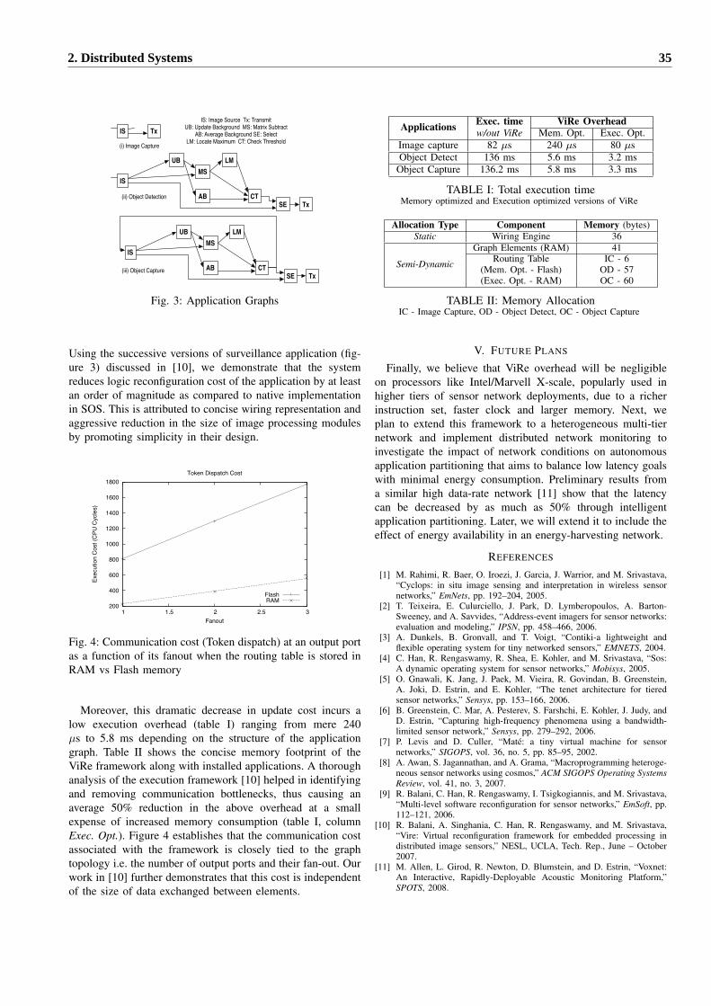
IS TxIS: Image Source Tx: Transmit
UB: Update Background MS: Matrix SubtractAB: Average Background SE: Select
LM: Locate Maximum CT: Check Threshold
IS
UBMS
AB
LM
CTSE
IS
UBMS
AB
LM
CTSE
(i) Image Capture
(ii) Object Detection
(iii) Object Capture
Tx
Tx
Fig. 3: Application Graphs
Using the successive versions of surveillance application (fig-ure 3) discussed in [10], we demonstrate that the systemreduces logic reconfiguration cost of the application by at leastan order of magnitude as compared to native implementationin SOS. This is attributed to concise wiring representation andaggressive reduction in the size of image processing modulesby promoting simplicity in their design.
200
400
600
800
1000
1200
1400
1600
1800
1 1.5 2 2.5 3
Exec
utio
n Co
st (C
PU C
ycle
s)
Fanout
Token Dispatch Cost
FlashRAM
Fig. 4: Communication cost (Token dispatch) at an output portas a function of its fanout when the routing table is stored inRAM vs Flash memory
Moreover, this dramatic decrease in update cost incurs alow execution overhead (table I) ranging from mere 240µs to 5.8 ms depending on the structure of the applicationgraph. Table II shows the concise memory footprint of theViRe framework along with installed applications. A thoroughanalysis of the execution framework [10] helped in identifyingand removing communication bottlenecks, thus causing anaverage 50% reduction in the above overhead at a smallexpense of increased memory consumption (table I, columnExec. Opt.). Figure 4 establishes that the communication costassociated with the framework is closely tied to the graphtopology i.e. the number of output ports and their fan-out. Ourwork in [10] further demonstrates that this cost is independentof the size of data exchanged between elements.
Applications Exec. time ViRe Overheadw/out ViRe Mem. Opt. Exec. Opt.
Image capture 82 µs 240 µs 80 µsObject Detect 136 ms 5.6 ms 3.2 ms
Object Capture 136.2 ms 5.8 ms 3.3 ms
TABLE I: Total execution timeMemory optimized and Execution optimized versions of ViRe
Allocation Type Component Memory (bytes)Static Wiring Engine 36
Semi-Dynamic
Graph Elements (RAM) 41Routing Table IC - 6
(Mem. Opt. - Flash) OD - 57(Exec. Opt. - RAM) OC - 60
TABLE II: Memory AllocationIC - Image Capture, OD - Object Detect, OC - Object Capture
V. FUTURE PLANS
Finally, we believe that ViRe overhead will be negligibleon processors like Intel/Marvell X-scale, popularly used inhigher tiers of sensor network deployments, due to a richerinstruction set, faster clock and larger memory. Next, weplan to extend this framework to a heterogeneous multi-tiernetwork and implement distributed network monitoring toinvestigate the impact of network conditions on autonomousapplication partitioning that aims to balance low latency goalswith minimal energy consumption. Preliminary results froma similar high data-rate network [11] show that the latencycan be decreased by as much as 50% through intelligentapplication partitioning. Later, we will extend it to include theeffect of energy availability in an energy-harvesting network.
REFERENCES
[1] M. Rahimi, R. Baer, O. Iroezi, J. Garcia, J. Warrior, and M. Srivastava,“Cyclops: in situ image sensing and interpretation in wireless sensornetworks,” EmNets, pp. 192–204, 2005.
[2] T. Teixeira, E. Culurciello, J. Park, D. Lymberopoulos, A. Barton-Sweeney, and A. Savvides, “Address-event imagers for sensor networks:evaluation and modeling,” IPSN, pp. 458–466, 2006.
[3] A. Dunkels, B. Gronvall, and T. Voigt, “Contiki-a lightweight andflexible operating system for tiny networked sensors,” EMNETS, 2004.
[4] C. Han, R. Rengaswamy, R. Shea, E. Kohler, and M. Srivastava, “Sos:A dynamic operating system for sensor networks,” Mobisys, 2005.
[5] O. Gnawali, K. Jang, J. Paek, M. Vieira, R. Govindan, B. Greenstein,A. Joki, D. Estrin, and E. Kohler, “The tenet architecture for tieredsensor networks,” Sensys, pp. 153–166, 2006.
[6] B. Greenstein, C. Mar, A. Pesterev, S. Farshchi, E. Kohler, J. Judy, andD. Estrin, “Capturing high-frequency phenomena using a bandwidth-limited sensor network,” Sensys, pp. 279–292, 2006.
[7] P. Levis and D. Culler, “Mate: a tiny virtual machine for sensornetworks,” SIGOPS, vol. 36, no. 5, pp. 85–95, 2002.
[8] A. Awan, S. Jagannathan, and A. Grama, “Macroprogramming heteroge-neous sensor networks using cosmos,” ACM SIGOPS Operating SystemsReview, vol. 41, no. 3, 2007.
[9] R. Balani, C. Han, R. Rengaswamy, I. Tsigkogiannis, and M. Srivastava,“Multi-level software reconfiguration for sensor networks,” EmSoft, pp.112–121, 2006.
[10] R. Balani, A. Singhania, C. Han, R. Rengaswamy, and M. Srivastava,“Vire: Virtual reconfiguration framework for embedded processing indistributed image sensors,” NESL, UCLA, Tech. Rep., June – October2007.
[11] M. Allen, L. Girod, R. Newton, D. Blumstein, and D. Estrin, “Voxnet:An Interactive, Rapidly-Deployable Acoustic Monitoring Platform,”SPOTS, 2008.
2. Distributed Systems 35

Trade-off Analysis of Communication Protocols forWireless Sensor Networks
Jérôme Rousselot, Amre El-Hoiydi, Jean-Dominique DecotignieCentre Suisse d’Electronique et Microtechnique SA
Jaquet-Droz 12002 Neuchâtel
Switzerland
Abstract—Embedded systems must react and adapt to changes intheir environment. Wireless sensor networks, which must guar-antee network connectivity and offer low latency services whilekeeping energy consumption at a minimum in an unpredictableenvironment, are a typical example.
Each layer of their communications stack offers some tunableparameters. Most sensor networks deployments define theseparameters at design time, thereby forcing the network to remainalways at the same operating point.
Instead, this work aims to identify a set of operating pointsbetween which the application could switch depending on itscurrent state. Two protocol stacks are being implemented in anetwork simulator. The first uses existing state of the art ultra lowpower protocols and the second one approximates optimal latencyand power consumption. Simulation runs allow the evaluation oftwo criteria: energy consumption and end-to-end latency.
Preliminary results are given for the optimal stack. It is shownthat the transmit power of a popular ZigBee transceiver doesnot allow trading energy consumption against end-to-end latencyin the considered configurations, albeit it might be possiblewith other transceivers. These results validate the methodologyadopted in this work and allow to expect more practical resultsfrom the trade-off analysis of the ultra low power stack once itsimplementation is finished.
I. INTRODUCTION
Wireless sensor networks must often operate several yearson battery. Their power consumption, generally dominated bythe use of a radio transceiver, is a critical factor for correctoperation. In the last few years, several low-power mediumaccess control (MAC) protocols have been proposed. Energy-aware routing has also been studied extensively, and sometransport protocols have been specifically developed for sensornetworks.
These advances have made energy consumption less ofan issue, and it is now realistic to envision wireless sensornetworks reaching the end of their deployment with significantremaining energy. It is thus tempting to allow temporary moreaggressive energy usage when the application requires it, e.g.when a fire detection network identifies an emergency situa-tion. Many properties could benefit from an increase in powerconsumption. End-to-end latency, network connectivity and
The work presented in this paper was supported (in part) by the NationalCompetence Center in Research on Mobile Information and CommunicationSystems NCCR-MICS, a center supported by the Swiss National ScienceFoundation under grant number 5005-67322.
link quality are only a few examples. This work in progressaims to identify the potential trade-offs of a communicationsstack for wireless sensor networks.
A stack approximating optimal performance at low datarates has been defined and fully implemented in a networksimulator. It uses a detailed model of an IEEE 802.15.4 radiotransceiver, a carrier sense multiple access (CSMA) MACprotocol compatible with the non-beacon enabled mode ofIEEE 802.15.4, and routes pre-computed offline with Dijk-stra’s algorithm for the all-shortest-paths-to-source problem.Another, more realistic stack, is composed of the same modelof radio transceiver, of the ultra low-power WiseMac protocoland of the distributed routing protocol NSafeLinks. This paperpresents intermediate results on the trade-off potential of theoptimal stack.
This paper is organized as follows: section II gives anoverview of communication protocols for wireless sensornetworks. Section III presents the methodology adopted to findthese trade-offs and explains the architecture of the two stacks.Section IV analyzes the results obtained thus far and sectionV concludes the paper.
II. RELATED WORK
This section briefly describes the requirements of sensornetworks deployments for the lowest layers of the commu-nication protocols stack (Physical, Data Link and Network)and identifies for each of these layers the most commonparameters.
A. Physical Layer
At the lowest layer, wireless communications pose thechallenges of an unreliable communication channel and ofvariable connectivity. Low-power narrow band radios arewidely available on the market, and many share a common setof characteristics as defined in the IEEE 802.15.4 [1] standardand are certified interoperable by the ZigBee Alliance [2].They can often be configured to change the bit rate or thetransmit power, influencing bit error rate, power consumptionand network connectivity.
Other physical layers such as Ultra Wideband ImpulseRadio [3] are in development and promise lower powerconsumption, robustness to multipath propagation and to multiuser interference, and accurate ranging. Transmit power andbit rate can, here also, be configured.
36 Workshop on Adaptive and Reconfigurable Embedded Systems (APRES’08)

B. Link Layer
Several medium access control protocols for sensor net-works have been proposed during the last years. Their mainobjective is to reduce the power consumption caused bythe radio transceiver. They are divided in two categories:scheduled access protocols and contention based protocols.
The first category regroups protocols which establish a TimeDivision Multiple Access schedule. This can be done using acentral coordinator as in the IEEE 802.15.4 beacon-enabledmode or in a distributed fashion as in L-Mac [4], Flama [5]and Trama [6]. They usually define a superframe structureand communications slots whose durations are key parametersfor transmission delay and reactivity to changes in networkconnectivity.
The second category allows nodes to access the mediumusing probabilistic mechanisms. Some such as S-Mac [7],T-Mac [8] and SCP-Mac [9] are based on a synchronoussleep mechanism. Others such as B-Mac [10], CSMA-PS [11],WiseMac [12], CSMA-MPS [13], X-Mac [14] and SyncWUF[15] are based on asynchronous sleep mechanism and wake-uppreambles.
The performance of all contention based protocols, eithersynchronous or asynchronous, is heavily influenced by theirwake-up interval. This parameter is the maximal time duringwhich a node is inaccessible, and the choice of its valueinfluences both latency and power consumption.
C. Network Layer
Wireless sensor networks pose significant challenges forrouting [16]:• the possibly large number of nodes makes the addressing
scheme itself an issue ;• specific traffic patterns such as convergecast must be con-
sidered while still allowing peer-to-peer communications;
• fault tolerance must be built in the protocol because of theunreliability of the physical layer and because the largenumber of nodes and long deployment times increase theprobability of a node failure ;
• load balancing between nodes to prevent early nodefailure due to an empty battery ;
• timeliness requirements may vary greatly from one ap-plication to the other.
Routing protocols for sensor networks can be regrouped inthree categories : flat, hierarchical and location-based routing.In flat networks, all nodes are considered equal and areassigned the same functions (SPIN [17], Directed Diffusion[18], Energy Aware Routing [19], NSafeLinks [20]). Hierar-chical networks select some of the nodes to act as gatewaysor cluster heads, rotating this function among several nodesto balance the power consumption (LEACH [21], PEGASIS[22]). Location based routing rely on positioning informationto decide which route to use (GEAR [23]).
This work focuses on data collection applications. In thiscase, all traffic converges to a sink node (convergecast). Eachprotocol has often a long list of parameters. Size of neighbourstable, timers, and metrics all influence performance.
III. METHODOLOGY
This work aims to evaluate the potential for trade-off inwireless sensor networks data collection applications by usingthe network simulator Omnet++ [24]. This section describesthe simulation models used and explains the current state ofthe work.
Regarding the application, network nodes regularly generatedata packets. The time intervals between the generation of twopackets from the same node follows an exponential distributionof parameter λ: P [ti < x] = 1 − e−λx, where ti is the timebetween packets i and i + 1, and the mean is equal to 1
λ .An ultra low power stack can be defined from the building
blocks described in section II. At the physical layer, a ZigBeecompatible chip like the Texas Instruments CC 2420 radiotransceiver [25] is a popular choice. WiseMac is a highperformance low power MAC protocol which has been testedin many deployments. NSafeLinks is a distributed routingprotocol providing N redundant routes from each node tothe sink, thereby offering load balancing and robustness tofailures.
For benchmarking purposes, it is interesting to define asecond stack to approximate optimal performance both interms of latency and of power consumption. This can be doneby using the same radio model to take into account hardware-induced delays, a CSMA/CA MAC protocol (compatible withthe IEEE 802.15.4 non-beacon enabled mode) which allowsalmost immediate transmissions in low data rate conditions,and the use of routes pre-computed offline so that theyminimize retransmissions, packet losses and the number ofhops to the sink.
Routes are computed offline using a Matlab script. Theproblem is formulated as an all-shortest-paths-to-sink problemwhich can be solved using Dijkstra’s algorithm. The weightsof the paths between two nodes are computed as follows.Since the latency and energy cost of a link are related to theaverage number of retransmissions of a packet until successfulreception and acknowledgement, the link cost is defined as
CDA =1
PSDPSA
where PSD and PSA are the probabilities of successful dataand acknowledgement transmissions.
The probability of a successful transmission of a packet ofn bits is PS = (1 − Pb)n where Pb is the bit error rate. Thebit error rate as a function of SNIR is given in [1]:
Pb =815
116
16∑
k=2
(−1)k16∑
k
e20SNIR 1k 1
And the SNIR is obtained as follows:
SNIR =PT
LP
N0WF
where PT is the transmitted power, LP the pathloss, W thesignal bandwidth, F the noise figure and N0 = 1.38∗10−23 ∗290 the noise density. For a TI CC 2420 transceiver, W and Ftake respectively the values 2 ∗ 106 and 15.3 dB.
The end-to-end delay for each packet and the total numberof packets sent by each node are recorded for each simulation
2. Distributed Systems 37
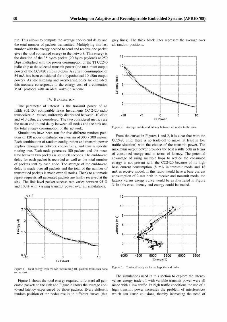
run. This allows to compute the average end-to-end delay andthe total number of packets transmitted. Multiplying this lastnumber with the energy needed to send and receive one packetgives the total consumed energy in the network. This energy isthe duration of the 35 bytes packet (20 bytes payload) at 250kbps multiplied with the power consumption of the TI CC240radio chip at the selected transmit power (the maximum outputpower of the CC2420 chip is 0 dBm. A current consumption of34 mA has been considered for a hypothetical 10 dBm outputpower). As idle listening and overhearing costs are excluded,this measure corresponds to the energy cost of a contentionMAC protocol with an ideal wake-up scheme.
IV. EVALUATION
The parameter of interest is the transmit power of anIEEE 802.15.4 compatible Texas Instruments CC 2420 radiotransceiver. 21 values, uniformly distributed between -10 dBmand +10 dBm, are considered. The two considered metrics arethe mean end-to-end delay between all nodes and the sink andthe total energy consumption of the network.
Simulations have been run for five different random posi-tions of 120 nodes distributed on a terrain of 300 x 300 meters.Each combination of random configuration and transmit powerimplies changes in network connectivity, and thus a specificrouting tree. Each node generates 100 packets and the meantime between two packets is set to 60 seconds. The end-to-enddelay for each packet is recorded as well as the total numberof packets sent by each node. The average of the end-to-enddelay is made over all packets and the total of the number oftransmitted packets is made over all nodes. Thank to automaticrepeat requests, all generated packets are finally received at thesink. The link level packet success rate varies between 95 %and 100% with varying transmit power over all simulations.
Figure 1. Total energy required for transmitting 100 packets from each nodeto the sink.
Figure 1 shows the total energy required to forward all gen-erated packets to the sink and Figure 2 shows the average end-to-end latency experienced by those packets. Every differentrandom position of the nodes results in different curves (thin
grey lines). The thick black lines represent the average overall random positions.
Figure 2. Average end-to-end latency between all nodes to the sink.
From the curves in Figures 1 and 2, it is clear that with theCC2420 chip, there is no trade-off to make (at least in lowtraffic situation) with the choice of the transmit power. Themaximum output power provides the best results both in termsof consumed energy and in terms of latency. The potentialadvantage of using multiple hops to reduce the consumedenergy is not present with the CC2420 because of its highbase current consumption (8 mA in transmit mode and 18mA in receive mode). If this radio would have a base currentconsumption of 2 mA both in receive and transmit mode, thelatency versus energy curve would be as illustrated in Figure3. In this case, latency and energy could be traded.
Figure 3. Trade-off analysis for an hypothetical radio.
The simulations used in this section to explore the latencyversus energy trade-off with variable transmit power were allmade with a low traffic. In high traffic conditions the use of ahigh transmit power increases the problem of interferenceswhich can cause collisions, thereby increasing the need of
38 Workshop on Adaptive and Reconfigurable Embedded Systems (APRES’08)

retransmissions and ultimately the power consumption. Evenwith the CC2420 radio chip, it can be of interest to choosea transmission power below the maximum permitted by thechip to limit interferences.
V. CONCLUSION
This work in progress studies the impact of a change intransmit power of a popular TI CC 2420 radio transceiver,using ideal low power MAC and routing protocols, on com-munications latency and network power consumption.
It is shown that there is no such trade-off in this particularcase, and that by considering an hypothetical transceiver withslightly different characteristics, an interesting trade-off couldbe exploited. This result validates the methodology adoptedby this work in progress.
The next step will be the study of a realistic ultra lowpower stack consisting of a TI CC 2420 radio transceiver,WiseMac and NSafeLinks. In addition to transmit power,the impact of the periodic wake-up interval of WiseMac, ofthe number of redundant routes of NSafeLinks, and of themaximum number of retransmissions will be evaluated. Otherdeployments scenarios will also be considered, in particularhigh density networks.
In addition to latency and power consumption, the percent-age of traffic correctly reaching its destination (goodput) willalso be considered.
Extending the scope of this work to more scenarios, moreparameters and additional metrics can only increase the like-lihood of identifying valuable trade-offs.
REFERENCES
[1] IEEE Std 802.15.4-2006, IEEE Standard for Information technology-Telecommunications and information exchange between systems-Localand metropolitan area networks-Specific requirements- Part 15.4: Wire-less Medium Access Control (MAC) and Physical Layer (PHY) Specifi-cations for Low-Rate Wireless Personal Area Networks (LR-WPANs).
[2] ZigBee Alliance, http://www.zigbee.org.[3] M. Z. Win and R. A. Scholtz, “Impulse radio: How it works,” IEEE
Communications Letters, vol. 2, no. 2, pp. 36–37, February 1998.[4] L. van Hoesel and P. Havinga, “A lightweight medium access protocol
(lmac) for wireless sensor networks,” in Proceedings of the 1st Interna-tional Workshop on Networked Sensing Systems (INSS 2004), 2003.
[5] V. Rajendran, J. J. Garcia-Luna-Aceves, and K. Obraczka, “Energy-efficient, application-aware medium access for sensor networks,” inProceedings of the 2nd IEEE International Conference on Mobile AdhocAnd Sensor Systems (MASS 2005), 2005.
[6] V. Rajendran, K. Obraczka, and J. J. Garcia-Luna-Aceves, “Energy-efficient, collision-free medium access control for wireless sensor net-works,” Wireless Networks, vol. 12, no. 1, pp. 63–78, 2006.
[7] W. Ye, J. Heidemann, and D. Estrin, “An energy-efficient mac protocolfor wireless sensor networks,” in Proceedings of the Twenty-First AnnualJoint Conference of the IEEE Computer and Communications Societies(INFOCOM), vol. 3, 2002, pp. 1567–1576.
[8] T. van Dam and K. Langendoen, “An adaptive energy-efficient macprotocol for wireless sensor networks,” in Proceedings of the 1stinternational conference on Embedded networked sensor systems, 2003,pp. 171–180.
[9] W. Ye, F. Silva, and J. Heidemann, “Ultra-low duty cycle mac withscheduled channel polling,” in Proceedings of the 4th internationalconference on Embedded networked sensor systems, 2006, pp. 321–334.
[10] J. Polastre, J. Hill, and D. Culler, “Versatile low power media accessfor wireless sensor networks,” in Proceedings of the 2nd internationalconference on Embedded networked sensor systems, 2004, pp. 95–107.
[11] A. El-Hoiydi, “Spatial tdma and csma with preamble sampling for lowpower ad hoc wireless sensor networks,” in Proceedings of the SeventhIEEE International Symposium on Computers and Communications(ISCC 2002), 2002, pp. 685– 692.
[12] A. El-Hoiydi and J.-D. Decotignie, “Wisemac: An ultra low power macprotocol for multi-hop wireless sensor networks,” in Proceedings of the1st International Workshop on Algorithmic Aspects of Wireless SensorNetworks, 2004.
[13] S. Mahlknecht and M. Böck, “Csma-mps: a minimum preamble sam-pling mac protocol for low power wireless sensor networks,” in Pro-ceedings of the 2004 IEEE International Workshop on Factory Commu-nication Systems, 2004, pp. 73–80.
[14] M. Buettner, G. Yee, E. Anderson, and R. Han, “X-mac: a short preamblemac protocol for duty-cycled wireless sensor networks,” in Proceedingsof the 4th international conference on Embedded networked sensorsystems, 2006, pp. 307–320.
[15] X. Shi and G. Stromberg, “Syncwuf: An ultra low-power mac protocolfor wireless sensor networks,” IEEE Transactions on Mobile Computing,vol. 6, no. 1, pp. 115–125, 2007.
[16] J. N. Al-Karaki and A. E. Kamal, “Routing techniques in wireless sensornetworks: a survey,” IEEE Wireless Communications, vol. 11, no. 6, p. 6,2004.
[17] J. Kulik and W. R. Heinzelman, “Negotiation-based protocols for dis-seminating information in wireless sensor networks,” Wireless Networks,vol. 8, pp. 169–185, 2002.
[18] C. Intanagonwiwat, R. Govindan, and D. Estrin, “Directed diffusion:A scalable and robust communication paradigm for sensor networks,”2000.
[19] R. C. Shah and J. Rabaey, “Energy aware routing for low energy ad hocsensor networks,” in IEEE WCNC, 2002.
[20] T. Ikikardes, M. Hofbauer, A. Kaelin, and M. May, “A robust, responsive,distributed tree-based routing algorithm guaranteeing n valid links pernode in wireless ad-hoc networks,” in Proceedings of the IEEE Inter-national Symposium on Computers and Communications (ISCC 2007),2007.
[21] . B. H. Heinzelman W., Kulk J., “Energy-efficient communicationprotocols for wireless microsensor networks,” January 2000, lEACH.
[22] S. Lindsey and C. S. Raghavendra, “Pegasis: Power-efficient gatheringin sensor information systems,” in Proceedings of the IEEE AerospaceConference, vol. 3, no. 9-16, 2002, pp. 1125–30.
[23] Y. Yu, R. Govindan, and D. Estrin, “Geographical and energy awarerouting: A recursive data dissemination protocol for wireless sensornetworks,” Tech. Rep., 2001.
[24] A. Varga, Omnet++ Discrete Event Simulation System,http://www.omnetpp.org.
[25] Texas Instruments 2.4 GHz IEEE 802.15.4 / ZigBee-ready RFTransceiver, 2007, http://www.ti.com.
2. Distributed Systems 39


3. Scheduling

A GA-Based Approach to Dynamic Reconfiguration of Real-TimeSystems∗
Marco A. C. SimõesBahia State UniversityACSO/UNEB, [email protected]
George LimaFederal University of
Bahia - LaSiD/UFBA, [email protected]
Eduardo CamponogaraFederal University of
Santa Catarina (DAS/UFSC), [email protected]
Abstract
Modern real-time systems have become increasinglycomplex since they have been required to operate in modernarchitectures and environments with high level of temporaluncertainty, where the actual execution demand is deter-mined only during execution and is valid only for a givenperiod of time. Thus such systems require both temporalisolation and dynamic reconfiguration. In this paper wedeal with both these requirements. By assuming that thesystem is structured such that there are several modes ofoperation to be chosen at runtime, we formulate a reconfig-uration problem. Temporal isolation is ensured by CBS. Asolution to the reconfiguration problem is based on GeneticAlgorithms, which provide the graceful adaption of the sys-tem so that it copes with new demands of the environment.The proposed solution is evaluated by simulation and theresults found show the suitability of the approach.
1 Introduction
The design of real-time systems has become increas-ingly complex. Modern hardware and software architec-tures and/or the support to open environments, for exam-ple, make it difficult or even impossible to estimate taskworst-case execution times accurately [13]. A usual wayof dealing with this problem is by providingtemporal iso-lation in the system. Indeed, if a certain task runs more thanwhat was expected, the effect of this timing fault should notpropagate to other application tasks. There are several ap-proaches to temporal isolation and for EDF-scheduled sys-tems the Constant Bandwidth Server (CBS) has receivedspecial attention recently [1, 9, 5, 4].
Although temporal isolation is an important aspect, forcertain kinds of modern applications, the system should alsoprovide support fordynamic reconfiguration. Indeed, mod-ern systems may be structured so that their tasks have one or
∗This work is funded by CNPq (grant number: 475851/2006-4) andCAPES/PROCAD (AST project)
more modes of operation. For example, a control task canexecute one among several control functions and/or withone among several sampling periods previously set. In otherwords, a task that has more than one operation mode mayhave alternative pieces of code to execute or alternative re-lease periods. Assuming that each operation mode gives adifferent benefit for the system, the problem is then to se-lect, at runtime, the set of task modes that maximizes thesystem benefit subject to the system schedulability.
Applications such as autonomous mobile robots, whichembed several complex functions into off-the-shelf com-plex hardware components, are among those that requiresupport to both temporal isolation and dynamic reconfigu-ration. For example, the robot computer vision subsystemmay experiment different operational modes due to environ-ment changes. Light conditions, obstacles, vision angle andother unpredictable environmental characteristics may gen-erate strong variation on execution times of vision subsys-tem tasks. Also, modifications in the robot goals during itslifetime may well require dynamic reconfiguration. Furthertiming faults in one of the system components, even dur-ing reconfiguration, should not jeopardize the system per-formance as a whole.
Some approaches to dynamic reconfiguration have beenproposed. For example, Feedback Scheduling (FS) [11],based on control theory, treats the system scheduling as acontrol plant and uses a controller to adjust the schedulingparameters at runtime. This approach offers no temporalisolation. FS-CBS [14] uses FS. It is assumed that the sys-tem is composed of Model Predictive Control (MPC) tasksserved by CBS. Although this approach provides temporalisolation, its applicability is restricted to MPC tasks. Fur-ther, FS-CBS does not deal with reconfiguration of serverperiods. Other approaches aim at providing server capacitysharing mechanisms [4, 5, 9]. However, they do not providedynamic reconfiguration. If a system has no idle time, forexample, there is no slack time to be shared.
In this paper we deal with dynamic reconfiguration in anew and challenging scenario, as will be seen in Section 2.Temporal isolation is ensured by the use of CBS. Differ-
3. Scheduling 43
ent server modes are previously defined, each one giving abenefit for the system. Dynamically reconfiguring the sys-tem is then seen as choosing the operation modes of eachserver so that the system benefit is maximized. Clearly, thisis a reasonably complex optimization problem, which mayrequire too much computational resources to be solved on-line. However, as will be explained in Section 3, instead ofsearching for the optimal solution, the approach providedhere is capable of progressively reconfiguring the systemtoward the optimal solution. To do that, we use Genetic Al-gorithms (GA). The results of experiments, given in Section4, highlight the suitability of the described approach for thekind of system we are considering. Final comments on thiswork and on the challenges it brings about are given in Sec-tion 5.
2 System Model and Problem Definition
We are considering a system with one processor sup-porting n Constant Bandwidth Servers (CBS) [1]S ={S1, S2, ..., Sn} that are scheduled by the Earliest DeadlineFirst algorithm (EDF) [10]. Each serverSi ∈ S hasκ(i) ≥1 operation modes and we denoteKi = {1, 2, . . . , κ(i)}.The k-th operation mode ofSi is denoted by the tuple(Qik, Tik), whereQik represents the server mode capac-ity andTik is its period. Thus, each serverSi operating inmodek has a maximum processor utilizationUik = Qik
Tik. In
other words, the system allocates, to each task served bySi,a constant bandwidth defined byUik so that temporal iso-lation is ensured [1]. As the system is scheduled by EDF,it is possible to use 100% of processor resources. Clearly,by the CBS schedulability properties [1], if the parametersQik andTik are appropriately set for each server, tasks meettheir deadlines or have an acceptable lateness (in case of softtasks) provided that there are no timing faults.
We assume that the system may require that prede-fined values ofQik and Tik are assigned to each serverSi at runtime so that the system can adapt or switch it-self to attend to new demands by means of dynamic re-configuration. This is performed by a system call, sayreconfig(U1k1
, v1, U2k2, v2, . . . , Unkn
, vn), whereUikiis
the new desired processor utilization for serverSi andvi isthe associated benefit to this new configuration. Thus, if thesystem can allocate at leastUiki
for serverSi, there will bea benefitvi for the system. Without loss of generality, weassume that the benefit function associated toSi running inmodek is defined by
Aik(Uiki, ui, vi) =
min(ui, Uiki)
Uiki
vi , (1)
whereui represents the processor utilization effectively al-located toSi. Other benefit functions are possible and we
do not impose any restriction on them. Interesting discus-sion on benefit functions can be found elsewhere [3] and isbeyond the scope of this paper. The benefitsvi are definedby the application when it uses thereconfig system call.
The execution ofreconfig solves the optimizationproblemR defined as follows:
R : f = Maximize∑
Si∈S
∑
k∈Ki
Aikxik (2a)
∑
Si∈S
∑
k∈Ki
Uikxik ≤ 1 (2b)
Uik =Qik
Tik
(2c)∑
k∈Ki
xik = 1, Si ∈ S (2d)
xik ∈ {0, 1}, Si ∈ S, k ∈ Ki (2e)
Equation (2a) defines the objective function, which isbased on equation (1). Variablexik, defined by equation(2e), represents the choice of one of theκ(i) server opera-tion modes ofSi. Only one configuration must be selectedbyreconfig, which is ensured by equation (2d). Restric-tion (2b) guarantees the schedulability ofS according to theEDF policy.
It is not difficult to see that the classical knapsack prob-lem can be reduced toR and so it is aNP−Hard problem.One can solveR by using some standard optimization tech-niques. In particular, we have used dynamic programmingto get optimal results, which will be used to assess our GA-based reconfiguration approach, as will be seen in Section4. There is a recursive formulation forR which leads toa solution via dynamic programming, which is not shownhere for the sake of space.
3 GA-Based Dynamic Reconfiguration
In this section we explain how the reconfiguration pro-cedure was set up. The parameters of the procedure wereempirically adjusted using an example of 10 servers with15 operation modes each. The fitness function is given byequation (2a). The individuals (represented by their chro-mosomes) that have the highest value returned by the fitnessfunction represent an optimal solution for the problem. Inthe context of problemR, a solution can be defined by a list(k1, k2, . . . , kn), whereki ∈ Ki. Let κ∗ = maxn
i=1κ(i).
Thus, a binary encoding [12] can be used so thatdn log2κ∗e
bits are needed to represent a possible solution (an individ-ual). For example, a system with 10 servers each of whichwith 15 operation modes would require a 40-bit chromo-some.
At the start of thereconfig procedure, we set theinitial population by randomly generating5n individuals.
44 Workshop on Adaptive and Reconfigurable Embedded Systems (APRES’08)
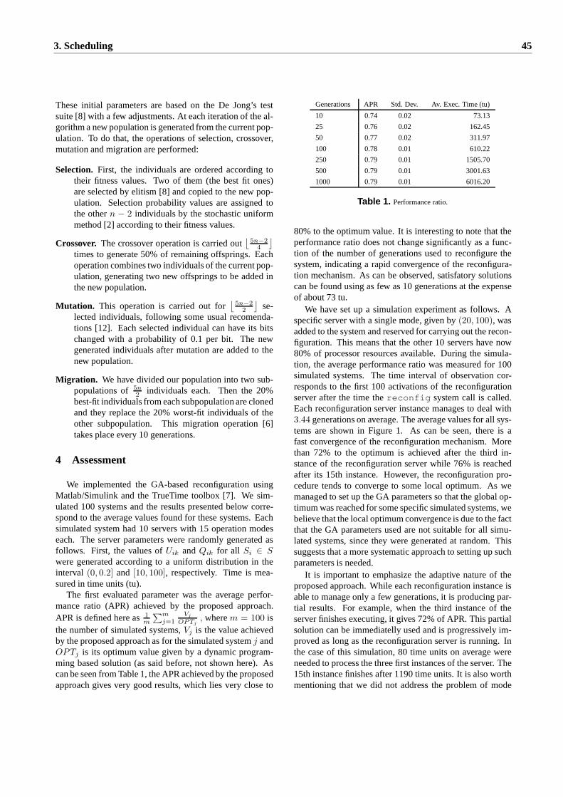
These initial parameters are based on the De Jong’s testsuite [8] with a few adjustments. At each iteration of the al-gorithm a new population is generated from the current pop-ulation. To do that, the operations of selection, crossover,mutation and migration are performed:
Selection. First, the individuals are ordered according totheir fitness values. Two of them (the best fit ones)are selected by elitism [8] and copied to the new pop-ulation. Selection probability values are assigned tothe othern − 2 individuals by the stochastic uniformmethod [2] according to their fitness values.
Crossover. The crossover operation is carried out⌊
5n−2
4
⌋
times to generate 50% of remaining offsprings. Eachoperation combines two individuals of the current pop-ulation, generating two new offsprings to be added inthe new population.
Mutation. This operation is carried out for⌊
5n−2
2
⌋
se-lected individuals, following some usual recomenda-tions [12]. Each selected individual can have its bitschanged with a probability of 0.1 per bit. The newgenerated individuals after mutation are added to thenew population.
Migration. We have divided our population into two sub-populations of5n
2individuals each. Then the 20%
best-fit individuals from each subpopulation are clonedand they replace the 20% worst-fit individuals of theother subpopulation. This migration operation [6]takes place every 10 generations.
4 Assessment
We implemented the GA-based reconfiguration usingMatlab/Simulink and the TrueTime toolbox [7]. We sim-ulated 100 systems and the results presented below corre-spond to the average values found for these systems. Eachsimulated system had 10 servers with 15 operation modeseach. The server parameters were randomly generated asfollows. First, the values ofUik andQik for all Si ∈ S
were generated according to a uniform distribution in theinterval (0, 0.2] and [10, 100], respectively. Time is mea-sured in time units (tu).
The first evaluated parameter was the average perfor-mance ratio (APR) achieved by the proposed approach.APR is defined here as1
m
∑m
j=1
Vj
OPTj, wherem = 100 is
the number of simulated systems,Vj is the value achievedby the proposed approach as for the simulated systemj andOPTj is its optimum value given by a dynamic program-ming based solution (as said before, not shown here). Ascan be seen from Table 1, the APR achieved by the proposedapproach gives very good results, which lies very close to
Generations APR Std. Dev. Av. Exec. Time (tu)
10 0.74 0.02 73.13
25 0.76 0.02 162.45
50 0.77 0.02 311.97
100 0.78 0.01 610.22
250 0.79 0.01 1505.70
500 0.79 0.01 3001.63
1000 0.79 0.01 6016.20
Table 1. Performance ratio.
80% to the optimum value. It is interesting to note that theperformance ratio does not change significantly as a func-tion of the number of generations used to reconfigure thesystem, indicating a rapid convergence of the reconfigura-tion mechanism. As can be observed, satisfatory solutionscan be found using as few as 10 generations at the expenseof about 73 tu.
We have set up a simulation experiment as follows. Aspecific server with a single mode, given by(20, 100), wasadded to the system and reserved for carrying out the recon-figuration. This means that the other 10 servers have now80% of processor resources available. During the simula-tion, the average performance ratio was measured for 100simulated systems. The time interval of observation cor-responds to the first 100 activations of the reconfigurationserver after the time thereconfig system call is called.Each reconfiguration server instance manages to deal with3.44 generations on average. The average values for all sys-tems are shown in Figure 1. As can be seen, there is afast convergence of the reconfiguration mechanism. Morethan 72% to the optimum is achieved after the third in-stance of the reconfiguration server while 76% is reachedafter its 15th instance. However, the reconfiguration pro-cedure tends to converge to some local optimum. As wemanaged to set up the GA parameters so that the global op-timum was reached for some specific simulated systems, webelieve that the local optimum convergence is due to the factthat the GA parameters used are not suitable for all simu-lated systems, since they were generated at random. Thissuggests that a more systematic approach to setting up suchparameters is needed.
It is important to emphasize the adaptive nature of theproposed approach. While each reconfiguration instance isable to manage only a few generations, it is producing par-tial results. For example, when the third instance of theserver finishes executing, it gives 72% of APR. This partialsolution can be immediatelly used and is progressively im-proved as long as the reconfiguration server is running. Inthe case of this simulation, 80 time units on average wereneeded to process the three first instances of the server. The15th instance finishes after 1190 time units. It is also worthmentioning that we did not address the problem of mode
3. Scheduling 45
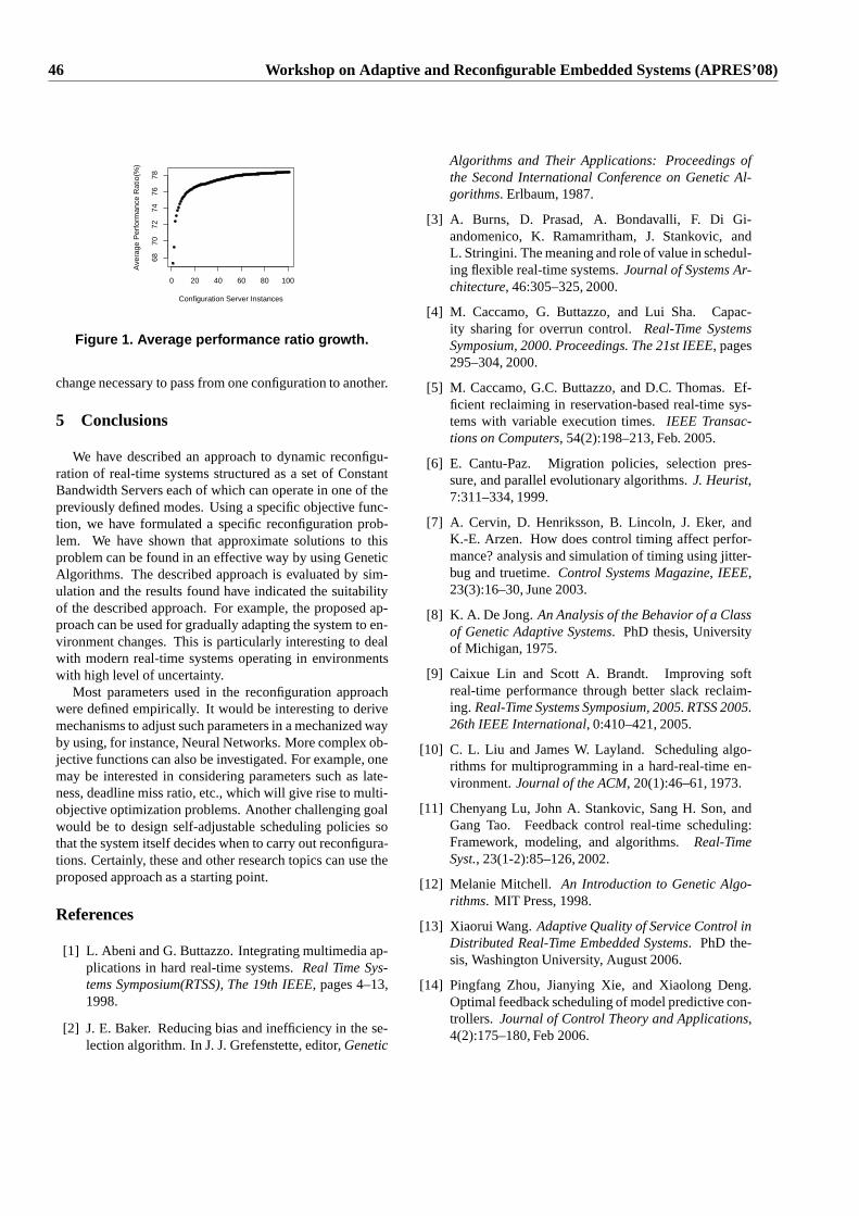
0 20 40 60 80 100
6870
7274
7678
Configuration Server Instances
Ave
rage
Per
form
ance
Rat
io(%
)
Figure 1. Average performance ratio growth.
change necessary to pass from one configuration to another.
5 Conclusions
We have described an approach to dynamic reconfigu-ration of real-time systems structured as a set of ConstantBandwidth Servers each of which can operate in one of thepreviously defined modes. Using a specific objective func-tion, we have formulated a specific reconfiguration prob-lem. We have shown that approximate solutions to thisproblem can be found in an effective way by using GeneticAlgorithms. The described approach is evaluated by sim-ulation and the results found have indicated the suitabilityof the described approach. For example, the proposed ap-proach can be used for gradually adapting the system to en-vironment changes. This is particularly interesting to dealwith modern real-time systems operating in environmentswith high level of uncertainty.
Most parameters used in the reconfiguration approachwere defined empirically. It would be interesting to derivemechanisms to adjust such parameters in a mechanized wayby using, for instance, Neural Networks. More complex ob-jective functions can also be investigated. For example, onemay be interested in considering parameters such as late-ness, deadline miss ratio, etc., which will give rise to multi-objective optimization problems. Another challenging goalwould be to design self-adjustable scheduling policies sothat the system itself decides when to carry out reconfigura-tions. Certainly, these and other research topics can use theproposed approach as a starting point.
References
[1] L. Abeni and G. Buttazzo. Integrating multimedia ap-plications in hard real-time systems.Real Time Sys-tems Symposium(RTSS), The 19th IEEE, pages 4–13,1998.
[2] J. E. Baker. Reducing bias and inefficiency in the se-lection algorithm. In J. J. Grefenstette, editor,Genetic
Algorithms and Their Applications: Proceedings ofthe Second International Conference on Genetic Al-gorithms. Erlbaum, 1987.
[3] A. Burns, D. Prasad, A. Bondavalli, F. Di Gi-andomenico, K. Ramamritham, J. Stankovic, andL. Stringini. The meaning and role of value in schedul-ing flexible real-time systems.Journal of Systems Ar-chitecture, 46:305–325, 2000.
[4] M. Caccamo, G. Buttazzo, and Lui Sha. Capac-ity sharing for overrun control.Real-Time SystemsSymposium, 2000. Proceedings. The 21st IEEE, pages295–304, 2000.
[5] M. Caccamo, G.C. Buttazzo, and D.C. Thomas. Ef-ficient reclaiming in reservation-based real-time sys-tems with variable execution times.IEEE Transac-tions on Computers, 54(2):198–213, Feb. 2005.
[6] E. Cantu-Paz. Migration policies, selection pres-sure, and parallel evolutionary algorithms.J. Heurist,7:311–334, 1999.
[7] A. Cervin, D. Henriksson, B. Lincoln, J. Eker, andK.-E. Arzen. How does control timing affect perfor-mance? analysis and simulation of timing using jitter-bug and truetime.Control Systems Magazine, IEEE,23(3):16–30, June 2003.
[8] K. A. De Jong.An Analysis of the Behavior of a Classof Genetic Adaptive Systems. PhD thesis, Universityof Michigan, 1975.
[9] Caixue Lin and Scott A. Brandt. Improving softreal-time performance through better slack reclaim-ing. Real-Time Systems Symposium, 2005. RTSS 2005.26th IEEE International, 0:410–421, 2005.
[10] C. L. Liu and James W. Layland. Scheduling algo-rithms for multiprogramming in a hard-real-time en-vironment.Journal of the ACM, 20(1):46–61, 1973.
[11] Chenyang Lu, John A. Stankovic, Sang H. Son, andGang Tao. Feedback control real-time scheduling:Framework, modeling, and algorithms.Real-TimeSyst., 23(1-2):85–126, 2002.
[12] Melanie Mitchell. An Introduction to Genetic Algo-rithms. MIT Press, 1998.
[13] Xiaorui Wang.Adaptive Quality of Service Control inDistributed Real-Time Embedded Systems. PhD the-sis, Washington University, August 2006.
[14] Pingfang Zhou, Jianying Xie, and Xiaolong Deng.Optimal feedback scheduling of model predictive con-trollers. Journal of Control Theory and Applications,4(2):175–180, Feb 2006.
46 Workshop on Adaptive and Reconfigurable Embedded Systems (APRES’08)
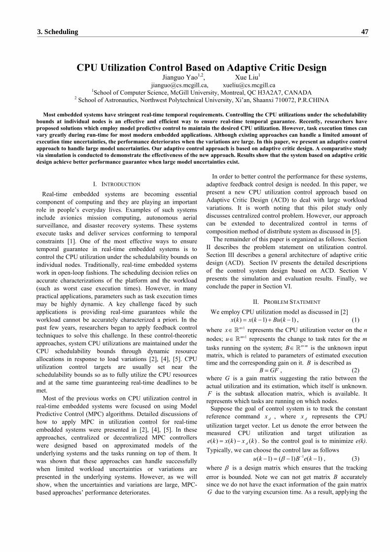
CPU Utilization Control Based on Adaptive Critic Design Jianguo Yao1,2, Xue Liu1
[email protected], [email protected] 1School of Computer Science, McGill University, Montreal, QC H3A2A7, CANADA
2 School of Astronautics, Northwest Polytechnical University, Xi’an, Shaanxi 710072, P.R.CHINA
Most embedded systems have stringent real-time temporal requirements. Controlling the CPU utilizations under the schedulability bounds at individual nodes is an effective and efficient way to ensure real-time temporal guarantee. Recently, researchers have proposed solutions which employ model predictive control to maintain the desired CPU utilization. However, task execution times can vary greatly during run-time for most modern embedded applications. Although existing approaches can handle a limited amount of execution time uncertainties, the performance deteriorates when the variations are large. In this paper, we present an adaptive control approach to handle large model uncertainties. Our adaptive control approach is based on adaptive critic design. A comparative study via simulation is conducted to demonstrate the effectiveness of the new approach. Results show that the system based on adaptive critic design achieve better performance guarantee when large model uncertainties exist.
I. INTRODUCTION Real-time embedded systems are becoming essential
component of computing and they are playing an important role in people’s everyday lives. Examples of such systems include avionics mission computing, autonomous aerial surveillance, and disaster recovery systems. These systems execute tasks and deliver services conforming to temporal constraints [1]. One of the most effective ways to ensure temporal guarantee in real-time embedded systems is to control the CPU utilization under the schedulability bounds on individual nodes. Traditionally, real-time embedded systems work in open-loop fashions. The scheduling decision relies on accurate characterizations of the platform and the workload (such as worst case execution times). However, in many practical applications, parameters such as task execution times may be highly dynamic. A key challenge faced by such applications is providing real-time guarantees while the workload cannot be accurately characterized a priori. In the past few years, researchers began to apply feedback control techniques to solve this challenge. In these control-theoretic approaches, system CPU utilizations are maintained under the CPU schedulability bounds through dynamic resource allocations in response to load variations [2], [4], [5]. CPU utilization control targets are usually set near the schedulability bounds so as to fully utilize the CPU resources and at the same time guaranteeing real-time deadlines to be met.
Most of the previous works on CPU utilization control in real-time embedded systems were focused on using Model Predictive Control (MPC) algorithms. Detailed discussions of how to apply MPC in utilization control for real-time embedded systems were presented in [2], [4], [5]. In these approaches, centralized or decentralized MPC controllers were designed based on approximated models of the underlying systems and the tasks running on top of them. It was shown that these approaches can handle successfully when limited workload uncertainties or variations are presented in the underlying systems. However, as we will show, when the uncertainties and variations are large, MPC-based approaches’ performance deteriorates.
In order to better control the performance for these systems, adaptive feedback control design is needed. In this paper, we present a new CPU utilization control approach based on Adaptive Critic Design (ACD) to deal with large workload variations. It is worth noting that this pilot study only discusses centralized control problem. However, our approach can be extended to decentralized control in terms of composition method of distribute system as discussed in [5].
The remainder of this paper is organized as follows. Section II describes the problem statement on utilization control. Section III describes a general architecture of adaptive critic design (ACD). Section IV presents the detailed descriptions of the control system design based on ACD. Section V presents the simulation and evaluation results. Finally, we conclude the paper in Section VI.
II. PROBLEM STATEMENT We employ CPU utilization model as discussed in [2]
( ) ( 1) ( 1)x k x k Bu k= − + − , (1) where 1nx ×∈ represents the CPU utilization vector on the n nodes; 1mu ×∈ represents the change to task rates for the m tasks running on the system; n mB ×∈ is the unknown input matrix, which is related to parameters of estimated execution time and the corresponding gain on it. B is described as
B GF= , (2) where G is a gain matrix suggesting the ratio between the actual utilization and its estimation, which itself is unknown. F is the subtask allocation matrix, which is available. It represents which tasks are running on which nodes.
Suppose the goal of control system is to track the constant reference command dx , where dx represents the CPU utilization target vector. Let us denote the error between the measured CPU utilization and target utilization as
( ) ( ) ( )de k x k x k= − . So the control goal is to minimize e(k). Typically, we can choose the control law as follows
1( 1) ( 1) ( 1)u k B e kβ −− = − − , (3) where β is a design matrix which ensures that the tracking error is bounded. Note we can not get matrix B accurately since we do not have the exact information of the gain matrix G due to the varying excursion time. As a result, applying the
3. Scheduling 47
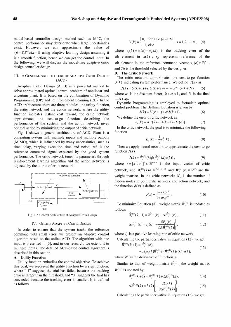
model-based controller design method such as MPC, the control performance may deteriorate when large uncertainties exist. However, we can approximate the value of
1( 1) ( 1)B e kβ −− − using adaptive learning design assuming it is a smooth function, hence we can get the control input. In the following, we will discuss the model-free adaptive critic design controller design.
III. A GENERAL ARCHITECTURE OF ADAPTIVE CRITIC DESIGN (ACD)
Adaptive Critic Design (ACD) is a powerful method to solve approximated optimal control problem of nonlinear and uncertain plant. It is based on the combination of Dynamic Programming (DP) and Reinforcement Learning (RL). In the ACD architecture, there are three modules: the utility function, the critic network and the action network, where the utility function indicates instant cost reward, the critic network approximates the cost-to-go function describing the performance of the system, and the action network gives optimal action by minimizing the output of critic network.
Fig. 1 shows a general architecture of ACD. Plant is a computing system with multiple inputs and multiple outputs (MIMO), which is influenced by many uncertainties, such as time delay, varying execution time and noise; ref is the reference command signal expected by the good system performance. The critic network tunes its parameters through reinforcement learning algorithm and the action network is adjusted by the output of critic network.
Action Network
ComputingSystem
Critic Network
ref
x(t)
u(t)
Plant
ACD-based controller
UtilityFunction
Fig. 1. A General Architecture of Adaptive Critic Design
IV. ONLINE ADAPTIVE CRITIC DESIGN In order to ensure that the system tracks the reference
command with small error, we present an adaptive control algorithm based on the online ACD. The algorithm with one input is presented in [3], and in our research, we extend it to multiple inputs. The detailed ACD-based control algorithm is described in this section. A. Utility Function
Utility function embodies the control objective. To achieve this goal, we represent the utility function by a step function, where “-1” suggests the trial has failed because the tracking error is larger than the threshold, and “0” suggests the trial has succeeded because the tracking error is smaller. It is defined as follows
0, for all ( )( ) , 1,2, ,
1, elseie k Th
U k i n<⎧
= =⎨−⎩, (4)
where ( ) ( ) ( )i i die k x k x k= − is the tracking error of the thi element in ( )x k , dix represents reference of the
thi element in the reference command vector ( ) ndx k ∈ ,
and Th is the threshold selected by the designer. B. The Critic Network
The critic network approximates the cost-to-go function ( )J k indicating system performance. We define ( )J k as
1( ) ( 1) ( 2) ( )NJ k U k U k U k Nα α −= + + + + + + , (5) where α is the discount factor, 0 1α< < , and N is the final time step.
Dynamic Programming is employed to formulate optimal control problem. The Bellman Equation is given by
( ) ( 1) ( 1)J k U k J kα= + + + . (6) We define the error of critic network as
( ) ( ) [ ( 1) ( )]ce k J k J k U kα= − − − . (7) In the critic network, the goal is to minimize the following
function 21( ) ( )
2c cE k e k= . (8)
Then we apply neural network to approximate the cost-to-go function ( )J k
(2) (1)ˆ ˆ( ) ( ) ( ( ) ( ))c cJ k W k W k s kφ= , (9) where [ , ]T T T m ns x u += ∈ is the input vector of critic
network, and ( )(1)ˆ ( ) hN m ncW k × +∈ and (2)ˆ ( ) hN
cW k ∈ are the weight matrices in the critic network; hN is the number of hidden nodes in both critic network and action network; and the function ( )xφ is defined as
1 exp( )1 exp
x
xxφ−
−
−=
+. (10)
To minimize Equation (8), weight matrix (1)ˆcW is updated as
follows (1) (1) (1)ˆ ˆ ˆ( 1) ( ) ( )c c cW k W k W k+ = + ∆ , (11)
(1)(1)
( )ˆ ( ) ( ) ˆ ( )c
c cc
E kW k l k
W k
⎡ ⎤∂∆ = −⎢ ⎥
∂∆⎢ ⎥⎣ ⎦, (12)
where cl is a positive learning rate of critic network. Calculating the partial derivative in Equation (12), we get,
(1) (1)
(2) (1)
ˆ ˆ( 1) ( )ˆ ˆ( ) ( ( ) ( )) ( ),
c c
c c c c
W k W k
l e k W W k s k s kα φ
+ =
′− (13)
where φ′ is the derivative of function φ .
Similar to that of weight matrix (1)ˆcW , the weight matrix
(2)ˆcW is updated by
(2) (2) (2)ˆ ˆ ˆ( 1) ( ) ( )c c cW k W k W k+ = + ∆ , (14)
(2)(2)
( )ˆ ( ) ( ) ˆ ( )c
c cc
E kW k l k
W k
⎡ ⎤∂∆ = −⎢ ⎥
∂∆⎢ ⎥⎣ ⎦. (15)
Calculating the partial derivative in Equation (15), we get,
48 Workshop on Adaptive and Reconfigurable Embedded Systems (APRES’08)
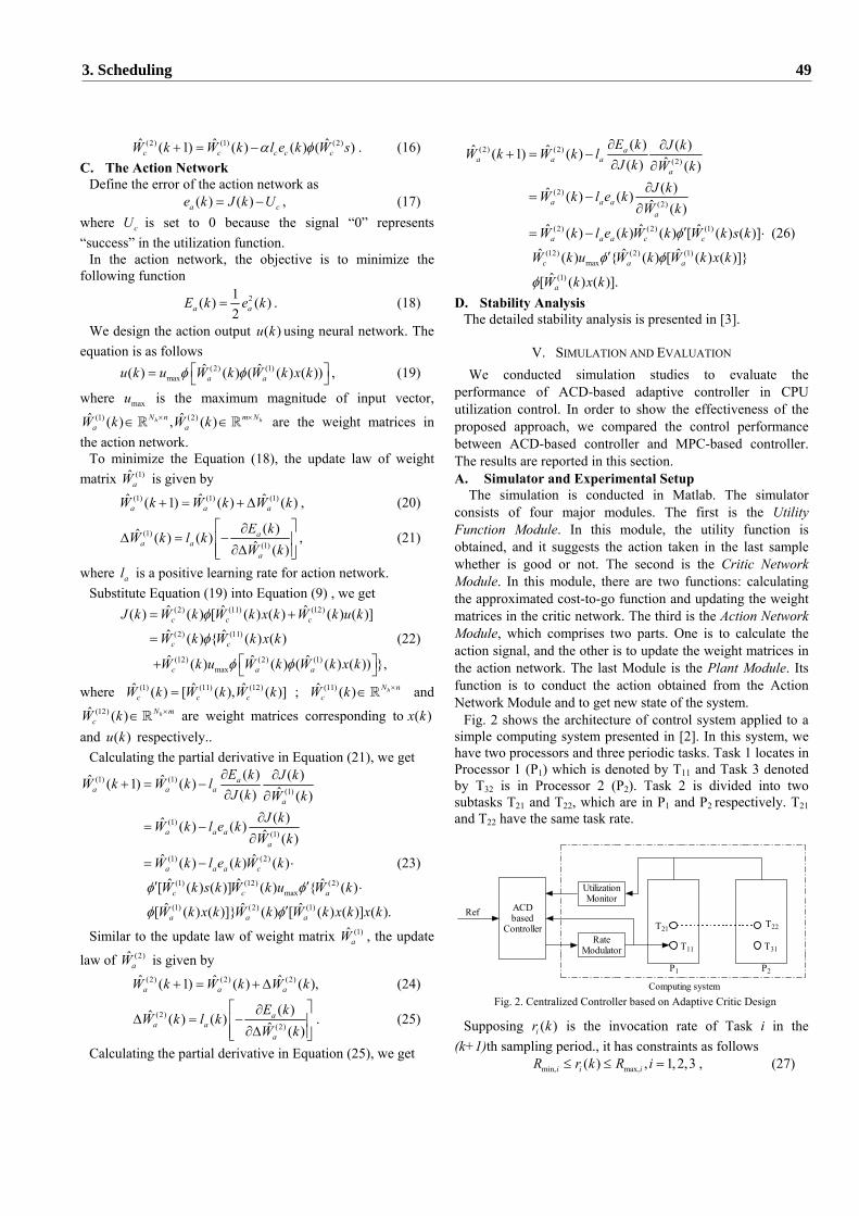
(2) (1) (2)ˆ ˆ ˆ( 1) ( ) ( ) ( )c c c c cW k W k l e k W sα φ+ = − . (16) C. The Action Network
Define the error of the action network as ( ) ( )a ce k J k U= − , (17)
where cU is set to 0 because the signal “0” represents “success” in the utilization function.
In the action network, the objective is to minimize the following function
21( ) ( )2a aE k e k= . (18)
We design the action output ( )u k using neural network. The equation is as follows
(2) (1)max
ˆ ˆ( ) ( ) ( ( ) ( ))a au k u W k W k x kφ φ⎡ ⎤= ⎣ ⎦ , (19)
where maxu is the maximum magnitude of input vector, (1) (2)ˆ ˆ( ) , ( )h hN n m N
a aW k W k× ×∈ ∈ are the weight matrices in the action network.
To minimize the Equation (18), the update law of weight matrix (1)ˆ
aW is given by (1) (1) (1)ˆ ˆ ˆ( 1) ( ) ( )a a aW k W k W k+ = + ∆ , (20)
(1)(1)
( )ˆ ( ) ( ) ˆ ( )a
a aa
E kW k l k
W k
⎡ ⎤∂∆ = −⎢ ⎥
∂∆⎢ ⎥⎣ ⎦, (21)
where al is a positive learning rate for action network. Substitute Equation (19) into Equation (9) , we get
(2) (11) (12)
(2) (11)
(12) (2) (1)max
ˆ ˆ ˆ( ) ( ) [ ( ) ( ) ( ) ( )]ˆ ˆ( ) { ( ) ( )ˆ ˆ ˆ( ) ( ) ( ( ) ( )) },
c c c
c c
c a a
J k W k W k x k W k u k
W k W k x k
W k u W k W k x k
φ
φ
φ φ
= +
=
⎡ ⎤+ ⎣ ⎦
(22)
where (1) (11) (12)ˆ ˆ ˆ( ) [ ( ), ( )]c c cW k W k W k= ; (11)ˆ ( ) hN ncW k ×∈ and
(12)ˆ ( ) hN mcW k ×∈ are weight matrices corresponding to ( )x k
and ( )u k respectively.. Calculating the partial derivative in Equation (21), we get
(1) (1)(1)
(1)(1)
(1) (2)
(1) (12) (2)max
(1) (2) (1)
( ) ( )ˆ ˆ( 1) ( ) ˆ( ) ( )( )ˆ ( ) ( ) ˆ ( )
ˆ ˆ( ) ( ) ( )ˆ ˆ ˆ[ ( ) ( )] ( ) { ( )ˆ ˆ ˆ[ ( ) ( )]} ( ) [ ( ) ( )] (
aa a a
a
a a aa
a a a c
c c a
a a a
E k J kW k W k lJ k W k
J kW k l e kW k
W k l e k W k
W k s k W k u W k
W k x k W k W k x k x
φ φ
φ φ
∂ ∂+ = −
∂ ∂∂
= −∂
= − ⋅
′ ′ ⋅
′ ).k
(23)
Similar to the update law of weight matrix (1)ˆaW , the update
law of (2)ˆaW is given by
(2) (2) (2)ˆ ˆ ˆ( 1) ( ) ( ),a a aW k W k W k+ = + ∆ (24)
(2)(2)
( )ˆ ( ) ( ) ˆ ( )a
a aa
E kW k l k
W k
⎡ ⎤∂∆ = −⎢ ⎥
∂∆⎢ ⎥⎣ ⎦. (25)
Calculating the partial derivative in Equation (25), we get
(2) (2)(2)
(2)(2)
(2) (2) (1)
(12) (2) (1)max
(1)
( ) ( )ˆ ˆ( 1) ( ) ˆ( ) ( )( )ˆ ( ) ( ) ˆ ( )
ˆ ˆ ˆ( ) ( ) ( ) [ ( ) ( )]ˆ ˆ ˆ( ) { ( ) [ ( ) ( )]}
ˆ[ ( ) ( )].
aa a a
a
a a aa
a a a c c
c a a
a
E k J kW k W k lJ k W k
J kW k l e kW k
W k l e k W k W k s k
W k u W k W k x k
W k x k
φ
φ φ
φ
∂ ∂+ = −
∂ ∂∂
= −∂
′= − ⋅
′
(26)
D. Stability Analysis The detailed stability analysis is presented in [3].
V. SIMULATION AND EVALUATION We conducted simulation studies to evaluate the
performance of ACD-based adaptive controller in CPU utilization control. In order to show the effectiveness of the proposed approach, we compared the control performance between ACD-based controller and MPC-based controller. The results are reported in this section. A. Simulator and Experimental Setup
The simulation is conducted in Matlab. The simulator consists of four major modules. The first is the Utility Function Module. In this module, the utility function is obtained, and it suggests the action taken in the last sample whether is good or not. The second is the Critic Network Module. In this module, there are two functions: calculating the approximated cost-to-go function and updating the weight matrices in the critic network. The third is the Action Network Module, which comprises two parts. One is to calculate the action signal, and the other is to update the weight matrices in the action network. The last Module is the Plant Module. Its function is to conduct the action obtained from the Action Network Module and to get new state of the system.
Fig. 2 shows the architecture of control system applied to a simple computing system presented in [2]. In this system, we have two processors and three periodic tasks. Task 1 locates in Processor 1 (P1) which is denoted by T11 and Task 3 denoted by T32 is in Processor 2 (P2). Task 2 is divided into two subtasks T21 and T22, which are in P1 and P2 respectively. T21 and T22 have the same task rate.
T11
T21 T22
T31
UtilizationMonitor
RateModulator
ACDbased
Controller
P1 P2
Ref
Computing system Fig. 2. Centralized Controller based on Adaptive Critic Design
Supposing ( )ir k is the invocation rate of Task i in the (k+1)th sampling period., it has constraints as follows
min, max,( ) , 1,2,3i i iR r k R i≤ ≤ = , (27)
3. Scheduling 49
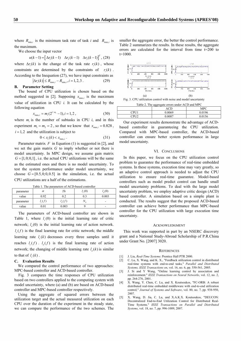
where min,iR is the minimum task rate of task i and max,iR is the maximum.
We choose the input vector
[ ]1 2 3( 1) ( 1) ( 1) ( 1) Tu k r k r k r k− = ∆ − ∆ − ∆ − , (28) where ( )ir k∆ is the change of the task rate ( )ir k , whose constraints are determined by the constraints of ( )ir k . According to the Inequation (27), we have input constraints as
max, min,( ) , 1, 2,3i i ir k R R i∆ ≤ − = . (29) B. Parameter Setting
The bound of CPU utilization is chosen based on the method suggested in [2]. Supposing max,ix is the maximum value of utilization in CPU i. It can be calculated by the following equation
1/max, (2 1), 1, 2im
i ix m i= − = , (30) where im is the number of subtasks in CPU i, and in this experiment 1 2 2m m= = , so that we know that max, 0.828ix = ,
1, 2i = and the utilization is subject to
max,0 ( )i ix k x< < . (31) Parameter matrix F in Equation (1) is suggested in [2], and
we set the gain matrix G to imply whether or not there is model uncertainty. In MPC design, we assume gain matrix
[1,0;0,1]G = , i.e. the actual CPU utilizations will be the same as the estimated ones and there is no model uncertainty. To test the system performance under model uncertainty, we choose [0.5,0;0,0.5]G = in the simulation, i.e. the actual CPU utilizations are a half of the estimations.
Table 1. The parameters of ACD-based controller parameter α Th (0)cl (0)al
value 0.92 0.2 0.3 0.003 parameter ( )cl f ( )al f hN -
value 0.01 0.003 9 -
The parameters of ACD-based controller are shown in Table 1, where (0)cl is the initial learning rate of critic network; (0)al is the initial learning rate of action network.
( )cl f is the final learning rate for critic network; the middle learning rate ( )cl k decreases every three samples until it reaches ( )cl f . ( )al f is the final learning rate of action network; the changing of middle learning rate ( )al k is similar to that of ( )cl k . C. Evaluation Results
We compared the control performance of two approaches: MPC-based controller and ACD-based controller.
Fig. 3 compares the time responses of CPU utilization based on two controllers applied to the computing system with model uncertainty, where (a) and (b) are based on ACD-based controller and MPC-based controller respectively.
Using the aggregate of squared errors between the utilization target and the actual measured utilization on each CPU over the duration of the experiment in the steady state, we can compare the performance of the two schemes. The
smaller the aggregate error, the better the control performance. Table 2 summarizes the results. In these results, the aggregate errors are calculated for the interval from time t=200 to t=1000.
(a) (b)
Fig. 3. CPU utilization control with noise and model uncertainty Table 2. The aggregate errors under ACD and MPC
ACD MPC CPU1 0.0069 0.0196 CPU2 0.0087 0.0156
Our experiment results demonstrate the advantage of ACD-based controller in guaranteeing the CPU utilization. Compared with MPC-based controller, the ACD-based controller can ensure better system performance in large model uncertainty.
VI. CONCLUSIONS In this paper, we focus on the CPU utilization control
problem to guarantee the performance of real-time embedded systems. In these systems, execution time may vary greatly, so an adaptive control approach is needed to adjust the CPU utilization to ensure real-time guarantee. Model-based controllers such as model predict control can handle small model uncertainty problems. To deal with the large model uncertainty problem, we employ adaptive critic design (ACD) based controller. A simulation based on a simple plant is conducted. The results suggest that the proposed ACD-based controller can achieve better performance than MPC-based controller for the CPU utilization with large execution time uncertainty.
ACKNOWLEDGMENT This work was supported in part by an NSERC discovery
grant and a National Study-Abroad Scholarship of P.R.China under Grant No. [2007] 3020.
REFERENCES [1] J. Liu, Real-Time Systems: Prentice Hall PTR 2000. [2] C. Lu, X. Wang, and K. X., "Feedback utilization control in distributed
real-time systems with end-to-end tasks," Parallel and Distributed Systems, IEEE Transactions on, vol. 16, no. 6, pp. 550-561, 2005.
[3] J. Si and Y Wang, "Online learning control by association and reinforcement," IEEE Transactions on Neural Networks, vol. 12, no. 2, pp. 264-276, 2001.
[4] X. Wang, Y. Chen, C. Lu, and X. Koutsoukos, "FC-ORB: A robust distributed real-time embedded middleware with end-to-end utilization control," Journal of Systems and Software, vol. 80, no. 7, pp. 938-950, 2007.
[5] X. Wang, D. Jia, C. Lu, and X.A.K.X. Koutsoukos, "DEUCON: Decentralized End-to-End Utilization Control for Distributed Real-Time Systems," IEEE Transactions on Parallel and Distributed Systems, vol. 18, no. 7, pp. 996-1009, 2007.
50 Workshop on Adaptive and Reconfigurable Embedded Systems (APRES’08)
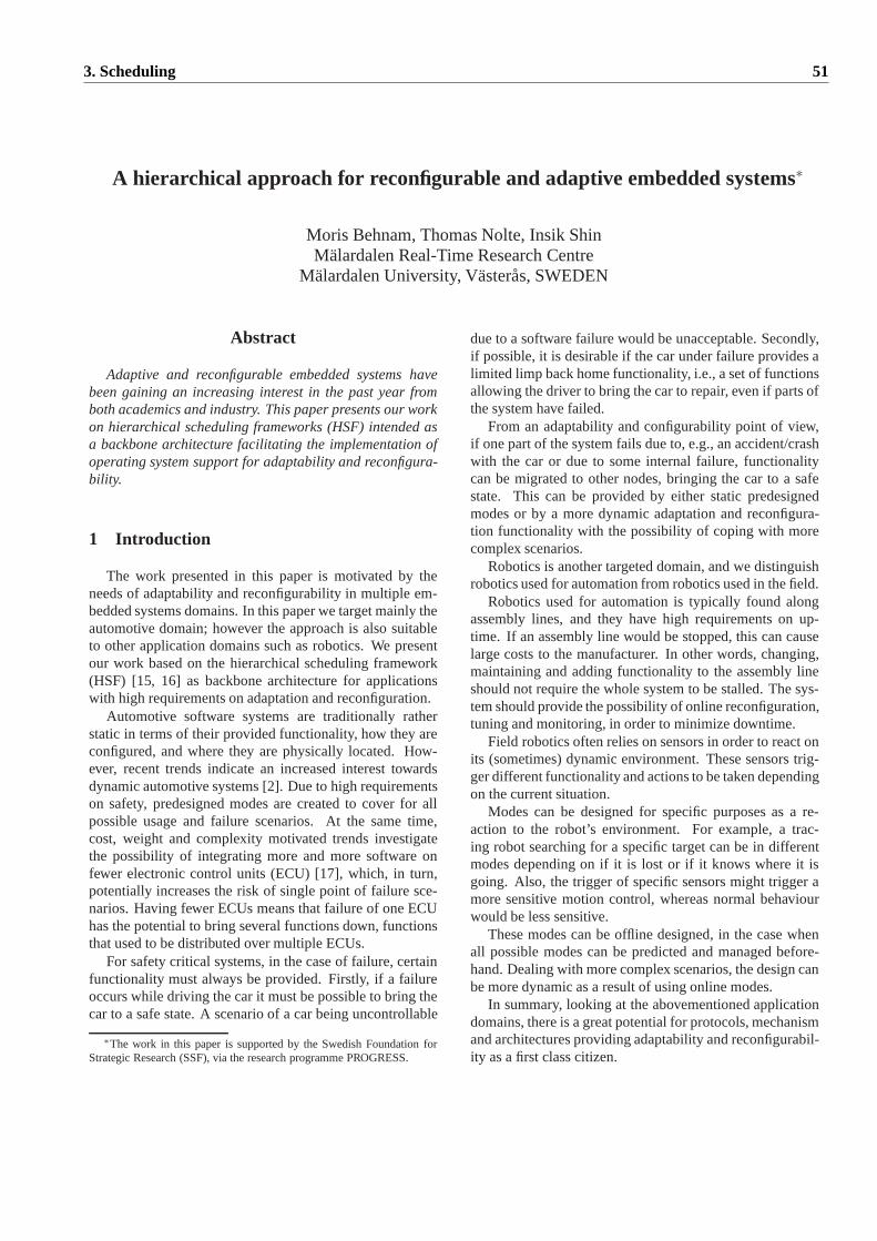
A hierarchical approach for reconfigurable and adaptive embedded systems∗
Moris Behnam, Thomas Nolte, Insik ShinMalardalen Real-Time Research Centre
Malardalen University, Vasteras, SWEDEN
Abstract
Adaptive and reconfigurable embedded systems havebeen gaining an increasing interest in the past year fromboth academics and industry. This paper presents our workon hierarchical scheduling frameworks (HSF) intended asa backbone architecture facilitating the implementation ofoperating system support for adaptability and reconfigura-bility.
1 Introduction
The work presented in this paper is motivated by theneeds of adaptability and reconfigurability in multiple em-bedded systems domains. In this paper we target mainly theautomotive domain; however the approach is also suitableto other application domains such as robotics. We presentour work based on the hierarchical scheduling framework(HSF) [15, 16] as backbone architecture for applicationswith high requirements on adaptation and reconfiguration.
Automotive software systems are traditionally ratherstatic in terms of their provided functionality, how they areconfigured, and where they are physically located. How-ever, recent trends indicate an increased interest towardsdynamic automotive systems [2]. Due to high requirementson safety, predesigned modes are created to cover for allpossible usage and failure scenarios. At the same time,cost, weight and complexity motivated trends investigatethe possibility of integrating more and more software onfewer electronic control units (ECU) [17], which, in turn,potentially increases the risk of single point of failure sce-narios. Having fewer ECUs means that failure of one ECUhas the potential to bring several functions down, functionsthat used to be distributed over multiple ECUs.
For safety critical systems, in the case of failure, certainfunctionality must always be provided. Firstly, if a failureoccurs while driving the car it must be possible to bring thecar to a safe state. A scenario of a car being uncontrollable
∗The work in this paper is supported by the Swedish FoundationforStrategic Research (SSF), via the research programme PROGRESS.
due to a software failure would be unacceptable. Secondly,if possible, it is desirable if the car under failure provides alimited limp back home functionality, i.e., a set of functionsallowing the driver to bring the car to repair, even if parts ofthe system have failed.
From an adaptability and configurability point of view,if one part of the system fails due to, e.g., an accident/crashwith the car or due to some internal failure, functionalitycan be migrated to other nodes, bringing the car to a safestate. This can be provided by either static predesignedmodes or by a more dynamic adaptation and reconfigura-tion functionality with the possibility of coping with morecomplex scenarios.
Robotics is another targeted domain, and we distinguishrobotics used for automation from robotics used in the field.
Robotics used for automation is typically found alongassembly lines, and they have high requirements on up-time. If an assembly line would be stopped, this can causelarge costs to the manufacturer. In other words, changing,maintaining and adding functionality to the assembly lineshould not require the whole system to be stalled. The sys-tem should provide the possibility of online reconfiguration,tuning and monitoring, in order to minimize downtime.
Field robotics often relies on sensors in order to react onits (sometimes) dynamic environment. These sensors trig-ger different functionality and actions to be taken dependingon the current situation.
Modes can be designed for specific purposes as a re-action to the robot’s environment. For example, a trac-ing robot searching for a specific target can be in differentmodes depending on if it is lost or if it knows where it isgoing. Also, the trigger of specific sensors might trigger amore sensitive motion control, whereas normal behaviourwould be less sensitive.
These modes can be offline designed, in the case whenall possible modes can be predicted and managed before-hand. Dealing with more complex scenarios, the design canbe more dynamic as a result of using online modes.
In summary, looking at the abovementioned applicationdomains, there is a great potential for protocols, mechanismand architectures providing adaptability and reconfigurabil-ity as a first class citizen.
3. Scheduling 51
In the following sections, the HSF is presented and howit provides operating system support for adaptability includ-ing policies and algorithms for resource reconfiguration. Fi-nally, our ongoing work on admission control functions ispresented, and the paper is concluded.
2 The hierarchical scheduling framework
2.1 What is HSF?
The hierarchical scheduling framework (HSF) has beenintroduced to support hierarchical resource sharing amongapplications under different scheduling services. The hier-archical scheduling framework can be generally representedas a tree of nodes, where each node represents an applica-tion with its own scheduler for scheduling internal work-loads (e.g., threads), and resources are allocated from a par-ent node to its children nodes.
From a general point of view, it is desirable that a hi-erarchical scheduling framework can support the followingproperties; (1)independency: i.e., that the fulfilment of tem-poral requirements (schedulability) of a subsystem can beanalyzed independently of other subsystems as there willbe no unpredictable interference among subsystems. (2)abstraction: i.e., that a subsystem imposes minimal tempo-ral requirements on its environments in order to guaranteefunctional and extra-functional correctness. (3)universal-ity: i.e., that any scheduler can be used within a subsystem,allowing for the most appropriate scheduler to be used for aspecific function. (4)flexibility: i.e., it should enable adap-tation and reconfiguration of its subsystems, implementingoperating system support for adaptability including policiesand algorithms for resource reconfiguration.
2.2 What are the benefits?
The HSF has been constructed withmodularityas a maincriterion. Component based design has been widely ac-cepted as a methodology for designing and developing com-plex systems through systematic abstraction and composi-tion. The HSF provides means for decomposing a complexsystem into well-defined parts, calledsubsystems, and forinterfacesspecifying the relevant properties of these sub-systems precisely, such that subsystems can be indepen-dently developed and assembled in different environments.The HSF provides a means for composing subsystems intoa subsystem assembly, orcomposite, according to the prop-erties specified by their interfaces, facilitating the reuse ofsubsystems. A challenging problem in composing subsys-tems is to support the principle ofcomposabilitysuch thatproperties established at the subsystem level also hold atthe composite level. The HSF can be effectively useful insupporting composability on timing properties in the de-sign and analysis of real-time systems, since it allows the
system-level timing property to be established by combin-ing the subsystem-level timing properties (specified by in-dividual subsystem interfaces).
The HSF can be used to support multiple applicationswhile guaranteeing independent execution of those applica-tions. This can be correctly achieved when the system pro-videspartitioning, where the applications may be separatedfunctionally for fault containment and for compositionalverification, validation and certification. The HSF pro-vides such a partitioning, preventing one partitioned func-tion from causing a failure of another partitioned functionin the time domain.
The HSF is particularly useful in the domain of open en-vironments, where applications may be developed and vali-dated independently in different environments. For exam-ple, the HSF allows an application to be developed withits own scheduling algorithm internal to the application andthen later included in a system that has a different meta-level scheduler for scheduling applications.
2.3 Enabling adaptability and reconfigurability
The HSF is very useful when it comes to the implemen-tation of operating system support for adaptability and re-configurability needed in dynamic open systems, where ap-plications (one or more subsystems) may be allowed to joinand/or leave the system during runtime. In allowing suchfunctionality, a properadmission control(AC) must be pro-vided. Also, the HSF allows for a convenient implementa-tion of quality of service management policies, allowing fora dynamic allocation of resources to subsystems.
2.4 Related work on HSFs
Over the years, there has been a growing attention toHSFs for real-time systems. Since Deng and Liu [6] pro-posed a two-level HSF for open systems, several stud-ies have followed proposing its schedulability analysis [8,9]. Various processor reource models, such as bounded-delay [12] and periodic [10, 15], have been proposed formulti-level HSFs, and schedulability analysis techniqueshave been developed for the proposed processor mod-els [1, 5, 7, 10, 14]. The work in this paper extends [15, 16].
3 Admission control
The admission control (AC) applies one or more algo-rithms to determine if a new application (consisting of oneor multiple subsystems) can be allowed to join the systemand start execution (admission) without violating the re-quirements of the already existing applications (or the re-quirements of the whole system). The decision of the ACdepends on the state of the system resources and the re-sources required by the new application asking for admis-sion. If there are enough resources available in the system,
52 Workshop on Adaptive and Reconfigurable Embedded Systems (APRES’08)
the application will be admitted; otherwise the applicationwill be rejected.
In general, since the AC uses online algorithms thecomplexity and overhead of implementing these algorithmsshould be very low for several reasons, such as maintainingscalability of the AC and minimizing its interference on thesystem. Hence, one objective in designing the AC concernskeeping the input to these algorithms as simple as possi-ble, e.g., the resource requirement for each individual taskcould be abstracted to the subsystem level. Another objec-tive concerns minimizing interference between the AC andthe system online, making it desirable to perform as muchwork as possible offline.
3.1 Resources
The resourcesconsidered by the AC may include, butare not limited to,CPU resources,memoryresources,net-work resource andenergyresources. Initially, we have beenfocusing on CPU and network resources, and are now alsolooking at memory resources.
CPU resources When using the HSF, traditional schedu-lability algorithms can be used in order to check the CPUresources, e.g., by using the global schedulability test inthe HSF [15, 16]. This algorithm depends on the type ofsystem level scheduler used, e.g., EDF, FPS, etc. The ACchecks the schedulability condition of the system includingthe new subsystem. If the system is still schedulable, thenew subsystem will pass this test; otherwise the new appli-cation will be rejected. In using this test, it is guaranteedthat all hard real time requirements will be met. The inputto the algorithm is the subsystem interface (subsystem bud-get and period) of each running subsystem together with theinterface of the new subsystem. Note that these parametersare evaluated and determined during the development of thesubsystem (offline).
Memory resources When allowing for a new applicationto enter the system, the AC should guarantee that there issufficient memory space to be used by all subsystems. Oth-erwise, unexpected problems may happen during run time.In a similar way as for CPU resources, the maximum mem-ory space required by each subsystem is evaluated duringits development. In the AC test, a simple algorithm can beused to check if there is enough memory space availablein the system, by checking if the summation of the maxi-mum memory space for all subsystems is less than or equalto the memory space provided by the platform. Such analgorithm is very simple; however, the accuracy of the re-sult is not high as all applications will not likely need theirspecified maximum memory space at the same time. Higherefficiency can be achieved by the usage of algorithms suchas the approximated algorithm presented in [4].
Energy resources Most of the modern processors sup-port changing the frequency and voltage of the CPU dur-
ing runtime, in controlling the CPU’s power consumption.The HSF can use this feature to select the lowest fre-quency/voltage that guarantees the hard real time require-ments of the system. Decreasing the frequency of a pro-cessor will increase the worst-case execution time (WCET)of its tasks. In doing this, more CPU resources should beallocated to subsystems in order to ensure that all hard realtime tasks will meet their deadlines. Looking at the HSF,if predefined levels of frequencies are used, we can find asubsystem interface for each frequency level for all subsys-tems. Then, during runtime, the AC will make sure thatthe processor is working with the lowest frequency keepingthe schedulability of the current set of subsystems. Whenit is required to add a new subsystem, the AC will checkthe schedulability condition with the current processor fre-quency; if the system is deemed not schedulable, then theAC will try with higher frequencies. When a subsystem isremoved from the system, the AC will try to reduce the fre-quency of the CPU in order to reduce its power consump-tion.
Network resources This type of resource is important indistributed systems where there typically exist communica-tions between nodes in the network. The network resourceis different from the other resources previously describedinthe sense that the network resource is shared by all nodes,while the other resources are local to each node. When theAC is faced with a request for adding a subsystem, it shouldcheck if the communications requirements will be met, i.e.,check if all important messages will be delivered in propertime [13]. Selecting an algorithm that checks this resourceis more complex as there are many different requirements,communication protocols, network types, etc. Covering allthese aspects might not be necessary but as an illustrationconsider a simple algorithm which relies on the commu-nication bandwidth. During the development of each sub-system, their maximum communication bandwidth require-ments should be evaluated such that the AC can use it inorder to check if the summation of required bandwidth forall subsystems is less than 100%.
3.2 Admission control in distributed systems
Implementing the AC in distributed systems is morecomplex than doing so for a single CPU. The main reasonfor this is that the information needed by the AC algorithmsmust be consistent. For example, when using the networkresources, awareness of all network users must be main-tained by the AC, and these users are typically located onmany nodes throughout the distributed system. Commonly,information on the current state is kept at one place, manag-ing the information needed by the AC. Also, when an appli-cation consists of more than one subsystem, and these sub-systems are located at different nodes, all these subsystemsshould pass the AC tests before admitting the application.
3. Scheduling 53

In designing the AC we have identified 3 different ap-proaches based on where the AC test will be implemented.
• A specialMaster Node (MA) will implement the ACtests of all resources in the system. Only the MAwill have information about resources in the system.Hence, consistency is not a problem, it is easy to de-termine the order between AC requests, and the ACdoes not have to contact multiple nodes in getting thecurrent system state as only a single AC request to theMA is needed. On the downside the MA is a singlesystem level point of failure.
• All Nodes (AN) will implement the AC tests of all re-sources in the system. Each node should have the con-sistent information of all resources that are used by thesystem. Hence, in this fully distributed approach theAC test can be performed without having to commu-nicate with other nodes. Also, the approach is toler-ant to failures. On the downside, consistency must bemaintained between all nodes, and ordering is morecomplex compared with MA. Also, more memory isneeded in maintaining all resource state replicas.
• There will beOne Node (ON)implementing the ACtest of each resource in the system. Each node willmaintain information about the resources that is re-sponsible for. Hence, there will be no issues withrespect to data consistencies between replicas of thesame information, but a single AC request might haveto communicate with a number of nodes in order toget a valid system state. Also, ordering among AC re-quests must be solved, and each resource owner willbe a single resource level point of failure.
As a first step, we consider the MA approach that webelieve possess strong properties in terms of flexibility, pro-moting the evaluation of multiple algorithms. Also, this ap-proach fits very well with the HSF.
4 Summary
To summarise we are currently active in 3 areas related tothe motivation of this paper. Firstly, we have done work inthe area of synchronization algorithms for HSFs [3]. Whenmultiple subsystems are sharing the same CPU it is likelythat they also share logical resources that must be protectedby the usage of a proper synchronization protocol. Sec-ondly, we are implementing the HSF on a commercial op-erating system on an application given by one of our indus-trial partners. This implementation will have an importantrole in evaluating the efficiency of the HSF itself, as wellas the AC approaches presented in this paper. Thirdly, weare designing the admission control and quality of servicemanager. These will also be implemented in the HSF im-plementation. In summary we believe that the result of these
three areas will provide important knowledge towards adap-tive and reconfigurable systems; results that have both highindustrial relevance as well as academic relevance.
Acknowledgements
The authors wish to express their gratitude to the anony-mous reviewers for their helpful comments.
References
[1] L. Almeida and P. Pedreiras. Scheduling within temporalpartitions: response-time analysis and server design. InEM-SOFT ’04, 2004.
[2] R. Anthony, A. Leonhardi, C. Ekelin, D. Chen, M. Torngren,G. de Boer, I. Jahnich, S. Burton, O. Redell, A. Weber, andV. Vollmer. A future dynamically reconfigurable automotivesoftware system. InElektronik im Kraftfahrzeug, June 2007.
[3] M. Behnam, I. Shin, T. Nolte, and M. Nolin. Sirap: Asynchronization protocol for hierarchical resource sharing inreal-time open systems. InEMSOFT’07, 2007.
[4] M. Bohlin, K. Hanninen, J. Maki-Turja, J. Carlson, andM. Nolin. Safe shared stack bounds in systems with offsetsand precedences. Technical Report, Malardalen University,January 2008.
[5] R. I. Davis and A. Burns. Hierarchical fixed priority pre-emptive scheduling. InRTSS, 2005.
[6] Z. Deng and J. W.-S. Liu. Scheduling real-time applicationsin an open environment. InRTSS ’97, 1997.
[7] X. A. Feng and A. K. Mok. A model of hierarchical real-time virtual resources. InRTSS, 2002.
[8] T.-W. Kuo and C.-H. Li. A fixed-priority-driven open envi-ronment for real-time applications. InRTSS, 1999.
[9] G. Lipari and S. Baruah. Efficient scheduling of real-timemulti-task applications in dynamic systems. InRTAS ’00,2000.
[10] G. Lipari and E. Bini. Resource partitioning among real-time applications. InECRTS, 2003.
[11] G. Lipari, J. Carpenter, and S. Baruah. A framework forachieving inter-application isolation in multiprogrammedhard-real-time environments. InRTSS ’00, 2000.
[12] A. Mok, X. Feng, and D. Chen. Resource partition for real-time systems. InRTAS ’01, 2001.
[13] T. Nolte. Share-Driven Scheduling of Embedded Networks.PhD thesis, Department of Computer and Science and Elec-tronics, Malardalen University, Sweden, May 2006.
[14] S. Saewong, R. R. Rajkumar, J. P. Lehoczky, and M. H.Klein. Analysis of hierar hical fixed-priority scheduling.InECRTS ’02, 2002.
[15] I. Shin and I. Lee. Periodic resource model for composi-tional real-time guarantees. InRTSS ’03, 2003.
[16] I. Shin and I. Lee. Compositional real-time schedulingframework. InRTSS ’04, 2004.
[17] G. Spiegelberg. The impact of new gateways and busses -are these the answers for furhter innovations?, Podiums Dis-cussion at the Embedded Systems Week, Salzburg, Austria,October 2007.
54 Workshop on Adaptive and Reconfigurable Embedded Systems (APRES’08)
Suitability of Dynamic Load Balancing in Resource-Constrained Embedded Systems: An Overview of Challenges and Limitations
Magnus Persson [email protected]
Tahir Naseer Qureshi [email protected]
Martin Törngren [email protected]
Department of Machine Design, KTH (The Royal Institute of Technology), Stockholm, Sweden. Abstract In this paper, we discuss the challenges and limitations of applying load balancing to networked and resource constrained embedded systems. The paper proposes a problem formulation and a checklist for guiding design and implementation of load balancing in such systems.
Keywords Load balancing, distributed systems, networked embedded systems
1 INTRODUCTION With the advancement of technology, networked embedded systems are becoming increasingly common, more computationally and communication intensive and complex. Current design techniques are dominated by static and worst-case designs. This leads to underutilization of resources which causes an increase in product costs but also difficulties in exploiting software and computer systems flexibility. As a consequence, reconfiguration at runtime, i.e. dynamic reconfiguration, implying techniques to change the structural (e.g. allocation) and/or behavioral configuration (e.g. priorities), is increasingly considered in networked real-time embedded systems [1]. This trend is exemplified by the DySCAS1 project [2], which develops an automotive middleware. In [3], the DySCAS consortium describes the project use cases, including load balancing, and in [4], the need for further investigation of the problem was identified. Typically, many of the simpler ECUs (electronic control unit) in a car are only 8-bit, have kilobytes of memory, and communicate over a CAN bus which has a maximum bandwidth of 1 Mbit/s. In addition they run very simple real time operating systems (RTOS) or even more simplistic run time environments. During the work of exploring approaches to dynamic reconfiguration for these systems, a number of questions regarding dynamic load balancing in resource-constrained embedded systems have been raised, such as the limitations of its use; implementation challenges; and which approaches are most suitable for embedded systems. In this paper, we explore some of these issues. A more extensive survey is given in [6].
1 The abbreviation stands for “Dynamically Self-Configuring
Automotive Systems”.
2 INTRODUCING LOAD BALANCING Task allocation is the assignment of a set of tasks to a set of nodes in a networked system. Load distribution is a specialization of task allocation, where resource usage (loads) at the different nodes is taken into consideration. Load balancing is a further specialization, where the allocation is fully or partially optimized based on one or several resource usage metrics. These metrics convey some type of evenness or fairness of resource usage at different nodes. Even though this paper focuses on load balancing, its results are also relevant to load distribution in general. There is a major difference between static and dynamic load balancing. Static load balancing is done at system design time (or possibly configuration time) and allocations are then kept fixed through-out the life time of the system. Dynamic load balancing is done during system startup or runtime, possibly taking different aspects of application behavior into consideration. When the task set or available resources in the network changes, dynamic load balancing is re-executed, potentially changing the task assignment during runtime. Load balancing can be applied to several different types of resources. Without doubt, the most common one is CPU usage, but some systems also at least partly take other scarce resources into account; e.g. memory or network bandwidth. The purposes of implementing load balancing in different systems are diverse. Generally, the main reason is often performance (average throughput) maximization. Parallel execution of a work task on several nodes, a common approach for performance improvement, by itself implies some scheme of load distribution. Runtime load distribution is sometimes also implemented in systems with the main goal to provide e.g. flexibility, robustness or reliability. Common to these is that task assignment before deployment is problematic to implement. The main optimization goal in these systems is to provide certain level of service and maintain performance guarantees. One final example objective for implementing load balancing is energy efficiency – by distributing processor loads equally, clock frequencies (and thus energy consumption) of processors can be minimized, or the number of nodes could even be reduced. Load balancing is related to techniques for quality of service (QoS) where QoS usually refers to reservation and control mechanisms for different resources such as network traffic to provide a guaranteed level of data flow in a network. However, QoS and load balancing are rarely studied together [6]. We
3. Scheduling 55
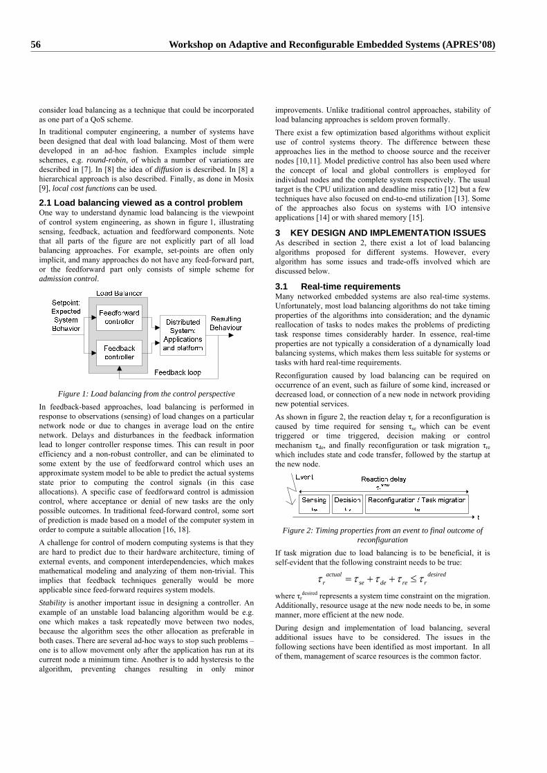
consider load balancing as a technique that could be incorporated as one part of a QoS scheme. In traditional computer engineering, a number of systems have been designed that deal with load balancing. Most of them were developed in an ad-hoc fashion. Examples include simple schemes, e.g. round-robin, of which a number of variations are described in [7]. In [8] the idea of diffusion is described. In [8] a hierarchical approach is also described. Finally, as done in Mosix [9], local cost functions can be used.
2.1 Load balancing viewed as a control problem One way to understand dynamic load balancing is the viewpoint of control system engineering, as shown in figure 1, illustrating sensing, feedback, actuation and feedforward components. Note that all parts of the figure are not explicitly part of all load balancing approaches. For example, set-points are often only implicit, and many approaches do not have any feed-forward part, or the feedforward part only consists of simple scheme for admission control.
Figure 1: Load balancing from the control perspective
In feedback-based approaches, load balancing is performed in response to observations (sensing) of load changes on a particular network node or due to changes in average load on the entire network. Delays and disturbances in the feedback information lead to longer controller response times. This can result in poor efficiency and a non-robust controller, and can be eliminated to some extent by the use of feedforward control which uses an approximate system model to be able to predict the actual systems state prior to computing the control signals (in this case allocations). A specific case of feedforward control is admission control, where acceptance or denial of new tasks are the only possible outcomes. In traditional feed-forward control, some sort of prediction is made based on a model of the computer system in order to compute a suitable allocation [16, 18]. A challenge for control of modern computing systems is that they are hard to predict due to their hardware architecture, timing of external events, and component interdependencies, which makes mathematical modeling and analyzing of them non-trivial. This implies that feedback techniques generally would be more applicable since feed-forward requires system models. Stability is another important issue in designing a controller. An example of an unstable load balancing algorithm would be e.g. one which makes a task repeatedly move between two nodes, because the algorithm sees the other allocation as preferable in both cases. There are several ad-hoc ways to stop such problems – one is to allow movement only after the application has run at its current node a minimum time. Another is to add hysteresis to the algorithm, preventing changes resulting in only minor
improvements. Unlike traditional control approaches, stability of load balancing approaches is seldom proven formally. There exist a few optimization based algorithms without explicit use of control systems theory. The difference between these approaches lies in the method to choose source and the receiver nodes [10,11]. Model predictive control has also been used where the concept of local and global controllers is employed for individual nodes and the complete system respectively. The usual target is the CPU utilization and deadline miss ratio [12] but a few techniques have also focused on end-to-end utilization [13]. Some of the approaches also focus on systems with I/O intensive applications [14] or with shared memory [15].
3 KEY DESIGN AND IMPLEMENTATION ISSUES As described in section 2, there exist a lot of load balancing algorithms proposed for different systems. However, every algorithm has some issues and trade-offs involved which are discussed below.
3.1 Real-time requirements Many networked embedded systems are also real-time systems. Unfortunately, most load balancing algorithms do not take timing properties of the algorithms into consideration; and the dynamic reallocation of tasks to nodes makes the problems of predicting task response times considerably harder. In essence, real-time properties are not typically a consideration of a dynamically load balancing systems, which makes them less suitable for systems or tasks with hard real-time requirements. Reconfiguration caused by load balancing can be required on occurrence of an event, such as failure of some kind, increased or decreased load, or connection of a new node in network providing new potential services. As shown in figure 2, the reaction delay τr for a reconfiguration is caused by time required for sensing τse which can be event triggered or time triggered, decision making or control mechanism τde, and finally reconfiguration or task migration τre which includes state and code transfer, followed by the startup at the new node.
Figure 2: Timing properties from an event to final outcome of
reconfiguration If task migration due to load balancing is to be beneficial, it is self-evident that the following constraint needs to be true:
desiredrredese
actualr τττττ ≤++=
where τrdesired represents a system time constraint on the migration.
Additionally, resource usage at the new node needs to be, in some manner, more efficient at the new node. During design and implementation of load balancing, several additional issues have to be considered. The issues in the following sections have been identified as most important. In all of them, management of scarce resources is the common factor.
56 Workshop on Adaptive and Reconfigurable Embedded Systems (APRES’08)
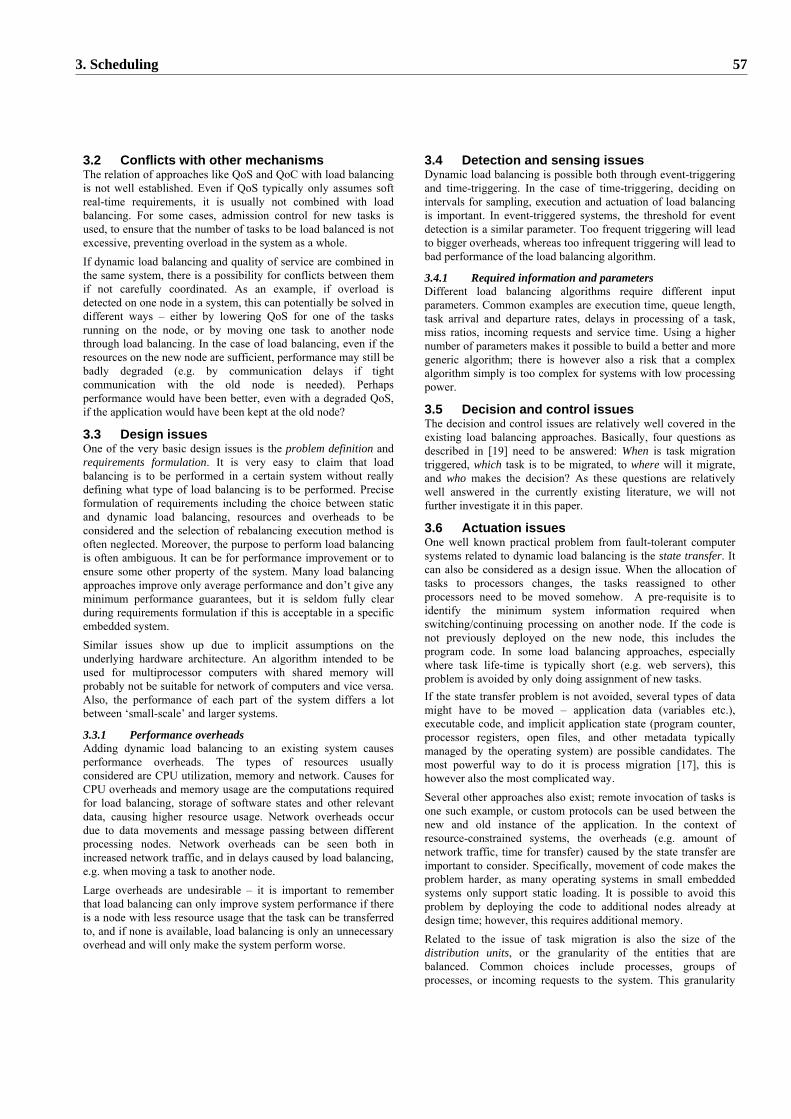
3.2 Conflicts with other mechanisms The relation of approaches like QoS and QoC with load balancing is not well established. Even if QoS typically only assumes soft real-time requirements, it is usually not combined with load balancing. For some cases, admission control for new tasks is used, to ensure that the number of tasks to be load balanced is not excessive, preventing overload in the system as a whole. If dynamic load balancing and quality of service are combined in the same system, there is a possibility for conflicts between them if not carefully coordinated. As an example, if overload is detected on one node in a system, this can potentially be solved in different ways – either by lowering QoS for one of the tasks running on the node, or by moving one task to another node through load balancing. In the case of load balancing, even if the resources on the new node are sufficient, performance may still be badly degraded (e.g. by communication delays if tight communication with the old node is needed). Perhaps performance would have been better, even with a degraded QoS, if the application would have been kept at the old node?
3.3 Design issues One of the very basic design issues is the problem definition and requirements formulation. It is very easy to claim that load balancing is to be performed in a certain system without really defining what type of load balancing is to be performed. Precise formulation of requirements including the choice between static and dynamic load balancing, resources and overheads to be considered and the selection of rebalancing execution method is often neglected. Moreover, the purpose to perform load balancing is often ambiguous. It can be for performance improvement or to ensure some other property of the system. Many load balancing approaches improve only average performance and don’t give any minimum performance guarantees, but it is seldom fully clear during requirements formulation if this is acceptable in a specific embedded system. Similar issues show up due to implicit assumptions on the underlying hardware architecture. An algorithm intended to be used for multiprocessor computers with shared memory will probably not be suitable for network of computers and vice versa. Also, the performance of each part of the system differs a lot between ‘small-scale’ and larger systems.
3.3.1 Performance overheads Adding dynamic load balancing to an existing system causes performance overheads. The types of resources usually considered are CPU utilization, memory and network. Causes for CPU overheads and memory usage are the computations required for load balancing, storage of software states and other relevant data, causing higher resource usage. Network overheads occur due to data movements and message passing between different processing nodes. Network overheads can be seen both in increased network traffic, and in delays caused by load balancing, e.g. when moving a task to another node. Large overheads are undesirable – it is important to remember that load balancing can only improve system performance if there is a node with less resource usage that the task can be transferred to, and if none is available, load balancing is only an unnecessary overhead and will only make the system perform worse.
3.4 Detection and sensing issues Dynamic load balancing is possible both through event-triggering and time-triggering. In the case of time-triggering, deciding on intervals for sampling, execution and actuation of load balancing is important. In event-triggered systems, the threshold for event detection is a similar parameter. Too frequent triggering will lead to bigger overheads, whereas too infrequent triggering will lead to bad performance of the load balancing algorithm.
3.4.1 Required information and parameters Different load balancing algorithms require different input parameters. Common examples are execution time, queue length, task arrival and departure rates, delays in processing of a task, miss ratios, incoming requests and service time. Using a higher number of parameters makes it possible to build a better and more generic algorithm; there is however also a risk that a complex algorithm simply is too complex for systems with low processing power.
3.5 Decision and control issues The decision and control issues are relatively well covered in the existing load balancing approaches. Basically, four questions as described in [19] need to be answered: When is task migration triggered, which task is to be migrated, to where will it migrate, and who makes the decision? As these questions are relatively well answered in the currently existing literature, we will not further investigate it in this paper.
3.6 Actuation issues One well known practical problem from fault-tolerant computer systems related to dynamic load balancing is the state transfer. It can also be considered as a design issue. When the allocation of tasks to processors changes, the tasks reassigned to other processors need to be moved somehow. A pre-requisite is to identify the minimum system information required when switching/continuing processing on another node. If the code is not previously deployed on the new node, this includes the program code. In some load balancing approaches, especially where task life-time is typically short (e.g. web servers), this problem is avoided by only doing assignment of new tasks. If the state transfer problem is not avoided, several types of data might have to be moved – application data (variables etc.), executable code, and implicit application state (program counter, processor registers, open files, and other metadata typically managed by the operating system) are possible candidates. The most powerful way to do it is process migration [17], this is however also the most complicated way. Several other approaches also exist; remote invocation of tasks is one such example, or custom protocols can be used between the new and old instance of the application. In the context of resource-constrained systems, the overheads (e.g. amount of network traffic, time for transfer) caused by the state transfer are important to consider. Specifically, movement of code makes the problem harder, as many operating systems in small embedded systems only support static loading. It is possible to avoid this problem by deploying the code to additional nodes already at design time; however, this requires additional memory. Related to the issue of task migration is also the size of the distribution units, or the granularity of the entities that are balanced. Common choices include processes, groups of processes, or incoming requests to the system. This granularity
3. Scheduling 57
will impact the result of the load balancing. However, choosing too small distribution units might impact system scalability.
4 CONCLUSIONS For future implementations of load balancing in resource-constrained embedded systems, we propose the following checklist to be gone through at system design time to check if the suggested variant of load balancing is suitable:
• The design problem should be clearly defined., including: o The main purpose of using of load balancing. o The type of resources to be balanced. o Decision to allow runtime movement of tasks and the
method to be used. o Size of distribution units.
• When choosing a specific load balancing algorithm, its performance overhead should be thoroughly evaluated.
• Real-time requirements on the system and real-time performance of the load balancing algorithm should be examined and compared in detail.
Due to real-time and dependability requirements, most of the current approaches to load balancing are not suitable in hard real-time systems. To deploy load balancing in such systems further research is needed. One approach is to develop load balancing algorithms that explicitly take hard real-time requirements into consideration e.g. through QoS or QoC mechanisms, or to build systems where hard real-time is ensured in the traditional way, and load balancing is only applied to other tasks. The conflict and tradeoff between QoS and load balancing, as described in section 5.4, is not yet a well understood problem and needs further investigation, e.g. through simulation followed by analytical work. Integrating QoS and load balancing techniques requires a well defined architecture and design/analysis of the interactions. DySCAS [2] is studying this integration for automotive systems. A further challenge in applying dynamic load balancing to embedded systems is that of performance. Some of the algorithms are so simple that they clearly will perform well even in embedded systems, but that is not all to it. In addition, a very simplistic algorithm may not be efficient enough to fulfill the performance requirements for the load balancing algorithm. The actuation of the rebalancing should also be efficiently performed. Clearly, some approaches to actuation, such as process migration, are only relevant to more powerful systems.
5 ACKNOWLEDGEMENT This work was funded within the DYSCAS project part of the 6th framework program “Information Society Technologies” of the European Commission. Project number: FP6-IST-2006-034904.
6 REFERENCES [1] K-E. Årzén, A. Cervin, T. Abdelzahler, H. Hjalmarsson, A. Robertsson, Roadmap on Control of RealTime Computing System, EU/IST FP6 ARTIST NoE, Control for Embedded Systems Cluster [2] DySCAS project webpage, http://www.dyscas.org [3] DySCAS Consortium, deliverable D1.2 Scenario and System Requirements, 2007
[4] I. Jahnich, A. Rettberg, Towards Dynamic Load Balancing for Distributed Embedded Automotive Systems, at International Embedded Systems Symposium, Irvine, CA, USA, May 29 – June 1 2007 [5] G. Buttazzo, M. Velasco, P. Marti, Quality-of-Control Management in Overloaded Real-Time Systems, IEEE Trans. on Computers, Vol. 56, Issue 2, pp, 253-266, Feb. 2007 [6] M. Persson, T. Naseer Qureshi: Survey on Dynamic Load Balancing in Distributed Computer Systems, Internal Technical Report, KTH, 2008 [7] V. Kumar and A. Grama: Scalable Load Balancing Techniques for Parallel Computers, in Journals of Parallel and distributed computers, vol. 22, p. 60, 1994 [8] M. Willebeek-LeMair and A. Reeves, Strategies for Dynamic Load Balancing on Highly Parallel Computers. IEEE Trans. on Parallel and Distributed Systems, vol 4, pp 979-993, 2004 [9] Mosix project webpage, http://www.mosix.org [10] N. Widell, Migration Algorithms for Automated Load Balancing, Proceedings, Parallel and Distributed Computing and Systems, Boston, 2004 [11] T. Schenekenburger and G. Rackl. Implementing dynamic load distribution strategies with Orbix, Proceedings, IEEE Information Survivability Conference, SC, 2000 [12] S. Lin and G. Manimaran, Douple-loop feedback-based scheduling approach for distributed real-time systems, in Proc. Conference on High Performance Computing (HiPC), pp. 268-278, Hyderabad, India, Dec. 2003 [13] C. Lu, X. Wang, and X. Koutsoukos, End-to-End Utilization Control in Distributed Real-Time Systems, the 24th IEEE International Conference on Distributed Computing Systems (ICDCS 2004), Tokyo, Japan, March 2004. [14] X. Qin, H. Jiang, Y. Zhu, and D. Swanson, A Dynamic Load Balancing Scheme for I/O-Intensive Applications in Distributed Systems, Proceedings of the 32nd International Conference on Parallel Processing Workshops (ICPP Workshop 2003), Oct. 6-9, 2003 [15] Y-T. Liu, T-Y. Liang, C-T. Huang, C-K. Shieh, Memory Resource Considerations in the Load Balancing of Software DSM Systems, Proc. of the 2003 ICPP Workshops on CRTPC, p. 71-78. [16] K–M. Yu, S. J.-W. Wu, T-P. Hong, A load balancing algorithm using prediction, Proceedings of the 2nd AIZU International Symposium on Parallel Algorithms / Architecture Synthesis, p.159, March 17-21, 1997 [17] D. Milojicic, F. Douglis, Y. Paindaveine, R. Wheeler, S. Zhou, Process Migration. In: ACM computing surveys, vol. 32, pp. 241-299, 2000. [18] W-O. Yoon, Jin-Ha, S-B. Choi, Dynamic Load Balancing Algorithm using Execution Time Prediction on Cluster Systems, Proc. 2002 Int. Technical Conference on Circuits/Systems, Computers and Communications, vol. 1, pp. 176-179, July 2002. [19] F. Douglis and J. Ousterhout, Transparent Process Migration: Design Alternatives and the Sprite Implementation, Software – Practice and Experience, vol. 21, pp. 757-785, 1991
58 Workshop on Adaptive and Reconfigurable Embedded Systems (APRES’08)

4. Design and Modeling

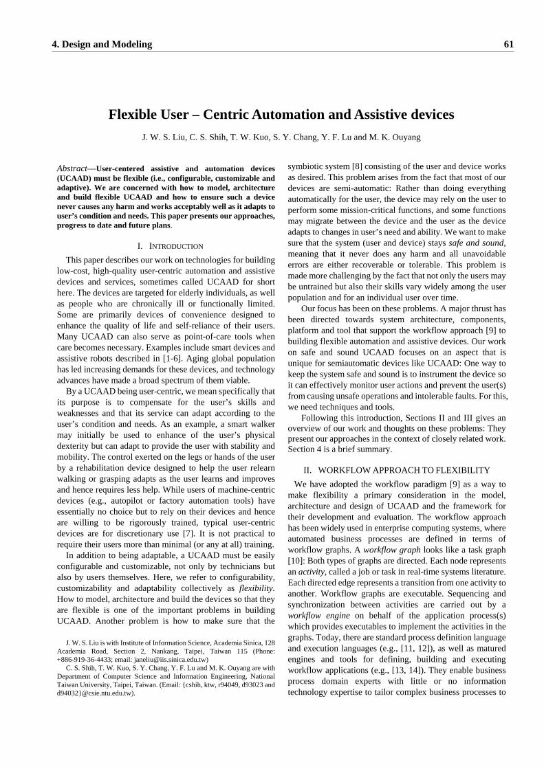
Abstract—User-centered assistive and automation devices (UCAAD) must be flexible (i.e., configurable, customizable and adaptive). We are concerned with how to model, architecture and build flexible UCAAD and how to ensure such a device never causes any harm and works acceptably well as it adapts to user’s condition and needs. This paper presents our approaches, progress to date and future plans.
I. INTRODUCTION This paper describes our work on technologies for building
low-cost, high-quality user-centric automation and assistive devices and services, sometimes called UCAAD for short here. The devices are targeted for elderly individuals, as well as people who are chronically ill or functionally limited. Some are primarily devices of convenience designed to enhance the quality of life and self-reliance of their users. Many UCAAD can also serve as point-of-care tools when care becomes necessary. Examples include smart devices and assistive robots described in [1-6]. Aging global population has led increasing demands for these devices, and technology advances have made a broad spectrum of them viable.
By a UCAAD being user-centric, we mean specifically that its purpose is to compensate for the user’s skills and weaknesses and that its service can adapt according to the user’s condition and needs. As an example, a smart walker may initially be used to enhance of the user’s physical dexterity but can adapt to provide the user with stability and mobility. The control exerted on the legs or hands of the user by a rehabilitation device designed to help the user relearn walking or grasping adapts as the user learns and improves and hence requires less help. While users of machine-centric devices (e.g., autopilot or factory automation tools) have essentially no choice but to rely on their devices and hence are willing to be rigorously trained, typical user-centric devices are for discretionary use [7]. It is not practical to require their users more than minimal (or any at all) training.
In addition to being adaptable, a UCAAD must be easily configurable and customizable, not only by technicians but also by users themselves. Here, we refer to configurability, customizability and adaptability collectively as flexibility. How to model, architecture and build the devices so that they are flexible is one of the important problems in building UCAAD. Another problem is how to make sure that the
J. W. S. Liu is with Institute of Information Science, Academia Sinica, 128 Academia Road, Section 2, Nankang, Taipei, Taiwan 115 (Phone: +886-919-36-4433; email: [email protected])
C. S. Shih, T. W. Kuo, S. Y. Chang, Y. F. Lu and M. K. Ouyang are with Department of Computer Science and Information Engineering, National Taiwan University, Taipei, Taiwan. (Email: {cshih, ktw, r94049, d93023 and d94032}@csie.ntu.edu.tw).
symbiotic system [8] consisting of the user and device works as desired. This problem arises from the fact that most of our devices are semi-automatic: Rather than doing everything automatically for the user, the device may rely on the user to perform some mission-critical functions, and some functions may migrate between the device and the user as the device adapts to changes in user’s need and ability. We want to make sure that the system (user and device) stays safe and sound, meaning that it never does any harm and all unavoidable errors are either recoverable or tolerable. This problem is made more challenging by the fact that not only the users may be untrained but also their skills vary widely among the user population and for an individual user over time.
Our focus has been on these problems. A major thrust has been directed towards system architecture, components, platform and tool that support the workflow approach [9] to building flexible automation and assistive devices. Our work on safe and sound UCAAD focuses on an aspect that is unique for semiautomatic devices like UCAAD: One way to keep the system safe and sound is to instrument the device so it can effectively monitor user actions and prevent the user(s) from causing unsafe operations and intolerable faults. For this, we need techniques and tools.
Following this introduction, Sections II and III gives an overview of our work and thoughts on these problems: They present our approaches in the context of closely related work. Section 4 is a brief summary.
II. WORKFLOW APPROACH TO FLEXIBILITY We have adopted the workflow paradigm [9] as a way to
make flexibility a primary consideration in the model, architecture and design of UCAAD and the framework for their development and evaluation. The workflow approach has been widely used in enterprise computing systems, where automated business processes are defined in terms of workflow graphs. A workflow graph looks like a task graph [10]: Both types of graphs are directed. Each node represents an activity, called a job or task in real-time systems literature. Each directed edge represents a transition from one activity to another. Workflow graphs are executable. Sequencing and synchronization between activities are carried out by a workflow engine on behalf of the application process(s) which provides executables to implement the activities in the graphs. Today, there are standard process definition language and execution languages (e.g., [11, 12]), as well as matured engines and tools for defining, building and executing workflow applications (e.g., [13, 14]). They enable business process domain experts with little or no information technology expertise to tailor complex business processes to
Flexible User – Centric Automation and Assistive devices J. W. S. Liu, C. S. Shih, T. W. Kuo, S. Y. Chang, Y. F. Lu and M. K. Ouyang
4. Design and Modeling 61
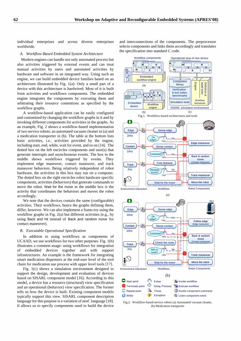
individual enterprises and across diverse enterprises worldwide.
A. Workflow-Based Embedded System Architecture Modern engines can handle not only automated process but
also activities triggered by external events and can treat manual activities by users and automated activities by hardware and software in an integrated way. Using such an engine, we can build embedded device families based on an architecture illustrated by Fig. 1(a): Only a small part of a device with this architecture is hardwired. Most of it is built from activities and workflows components. The embedded engine integrates the components by executing them and arbitrating their resource contentions as specified by the workflow graphs.
A workflow-based application can be easily configured and customized by changing the workflow graphs in it and by invoking different components for activities in the graphs. As an example, Fig. 2 shows a workflow-based implementation of two service robots: an automated vacuum cleaner in (a) and a medication transporter in (b). The table at the bottom lists basic activities, i.e., activities provided by the engine, including start, end, while, wait for event, and so on [14]. The dotted box on the left encircles components and user(s) that generate interrupts and asynchronous events. The box in the middle shows workflows triggered by events. They implement edge maneuver, contact maneuver, and track maneuver behaviors. Being relatively independent of robot hardware, the activities in this box may run on a computer. The dotted box on the right encircles robot hardware specific components, activities (behaviors) that generate commands to move the robot. Wait for the move in the middle box is the activity that coordinates the behaviors and moves the robot accordingly.
We note that the devices contain the same (configurable) activities. Their workflows, hence the graphs defining them, differ, however. We can also implement a Sumo toy using the workflow graphs in Fig. 2(a) but different activities (e.g., by using Back and hit instead of Back and random move for contact maneuver).
B. Executable Operational Specification In addition to using workflows as components of
UCAAD, we use workflows for two other purposes. Fig. 1(b) illustrates a common usage: using workflows for integration of embedded devices together and with support infrastructures. An example is the framework for integrating smart medication dispensers at the end-user level of the tool chain for medication use process with upper level tools [17].
Fig. 1(c) shows a simulation environment designed to support the design, development and evaluation of devices based on SISARL component model [16]. According to this model, a device has a resource (structural) view specification and an operational (behavior) view specification. The former tells us how the device is built. Existing component models typically support this view. SISARL component description language for this purpose is a variation of nesC language [18]. It allows us to specify components used to build the device
and interconnections of the components. The preprocessor selects components and links them accordingly and translates the specification into standard C code.
SISARL simulation environment
Simulation tools
Verification & test suites,benchmarks
Componentlibrary
Workflow framework
Engine
Definition &
build tools
(c)
Operational view of new device
(a)
Embeddedworkflow engine
Embedded device
(b)
Workflowengine
Workflow components
Fig.1. Workflow-based architectures and tools
Environment Interaction Workflows Robot Components
Edge maneuverEdge maneuverEdge maneuver
Sense edgeSense edgeEdgeEdge
20Hz
ContactContactContact
10Hz
TrackTrackTrack
2Hz
Sense contactSense contact
Find obstacleFind obstacle
Track maneuverTrack maneuverTrack maneuver
Move the robotMove the robotMove the robotWait for the moveWait for the move
On edge? No
Yes
Contacted? NoYes
Obstacle found?
Yes
No
Back & random move
(Contact maneuver)
Back & random Back & random movemove
(Contact maneuver)(Contact maneuver)
(a)
Environment Interaction Workflows Robot Components
Sense edgeSense edgeEdgeEdge
20Hz
ContactContactContact
10Hz
TrackTrackTrack
2Hz
Sense contactSense contact
Check the routeCheck the route
Track maneuverTrack maneuverTrack maneuver
Move the robotMove the robotMove the robotWait for the moveWait for the move
On edge? No
Yes
Contacted? NoYes
Still on route?
Yes
No
Back & random move
(Contact maneuver)
Back & random Back & random movemove
(Contact maneuver)(Contact maneuver)
Follow edge(Edge maneuver)Follow edgeFollow edge
(Edge maneuver)(Edge maneuver)
(b) Start point
Terminate point
Repeat point
While
If else
Delay /Timeout
ThrowException
Invoke workflow
Execute workflow
Invoke component command
Listen component event Fig.2. Workflow-based service robots (a) Automated vacuum cleaner,
(b) Medication transporter
62 Workshop on Adaptive and Reconfigurable Embedded Systems (APRES’08)
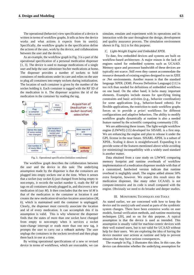
The operational (behavior) view specification of a device is written in terms of workflow graphs. It tells us how the device works and what actions it expects from its user(s). Specifically, the workflow graphs in the specification define the actions of the user, work by the device, and collaborations between the user and the device.
As an example, the workflow graph in Fig. 3 is a part of the operational specification of a personal medication dispenser [1, 3]. The device is used to manage medications of a single user and help the user administer his/her medications at home. The dispenser provides a number of sockets to hold containers of medications under its care and relies on the user to plug all containers into empty sockets during initialization. The location of each container is given by the number of the socket holding it. Each container is tagged with the RF ID of the medication in it. The dispenser acquires the id of the medication in the container by reading the tag.
Sense the stateof some socket
has changed
Pluga container into a socket
rollbackactivityyes
Get location kof newly filled
socket andread RFID tags
N > 1?No of new ids > 1?
Store new id Mand
(M, k) - mapping
yes
Acquisition of (medication – id, socket-location)
association
More container to plug?
yes
Get number Nof newly filled
sockets
Fig. 3. Operational specification (initialize containers)
The workflow graph describes the collaboration between the user and the device in this task: The underlying assumption made by the dispenser is that the containers are plugged into empty sockets one at the time. When it senses that a socket (say socket k) just changed from being empty to non-empty, it records the socket number k, reads the RF id tags on all containers already plugged in, and discovers a new medication id (say M). It then concludes that the new id M is that of the medication in the container at location k and creates the new medication-id-socket-location association (M, k), which is maintained until the container is unplugged. Clearly, the dispenser must correctly associate the location and id of every medication. It can accomplish this if its assumption is valid. This is why whenever the dispenser finds that the states of more than one socket have changed from empty to non-empty when it services a socket state-change interrupt or reads more than one new tag, it prompts the user to carry out a rollback activity: The user unplugs the containers in the sockets involved and then plugs them back in one at a time.
By writing operational specifications of a new or revised device in terms of workflows, which are executable, we can
simulate, emulate and experiment with its operations and its interaction with the user throughout the design, development and quality assurance process. The simulation environment shown in Fig. 1(c) is for this purpose.
C. Light-Weight Engine and Embedded XPDL To date, few embedded devices and systems are built on
workflow-based architecture. A major reason is the lack of engines suited for embedded systems such as UCAAD. Memory space and processor bandwidth of these devices are typically not scarce. Still even they cannot accommodate the resource demands of existing engines designed to run in J2EE or .Net environments. Another reason is that the standard language XPDL (XML Process Definition Language) [11] is too rich than needed for definitions of embedded workflows on one hand. On the other hand, it lacks many important elements. Examples include means for specifying timing constraints and basic activities (e.g., behavior coordination) for some applications (e.g., behavior-based robots). For flexible applications, the restriction to static workflow graphs forces us to provide a priori workflows for different configurations and adaptive behaviors. The ability to modify workflow graphs dynamically at runtime is also a needed feature named by the scientific computing community [19].
We are addressing these issues. The light-weight workflow engine (LIWWE) [15] developed for SISARL is a first step. We are enhancing the engine and plan to release it under the GPL license in the near future. SISARL-XPDL is a subset of XPDL. Scaling it down is straightforward. Expanding it to provide some of the features mentioned above while avoiding (or minimizing) incompatibility with a widely used standard is another matter.
Data obtained from a case study on LIWWE comparing memory footprint and runtime overheads of workflow implementation of a medication dispenser module with that of a customized, hardwired version indicate that runtime overhead is negligibly small. The engine added almost 50% extra footprint, however. We expect this result since the medication dispenser, like many other UCAAD, is not compute-intensive and its code is small compared with the engine. Obviously we need to do broader and deeper studies.
III. MONITORING TECHNIQUES AND TOOLS As stated earlier, we are concerned with how to keep the device and its user(s) safe and sound as parts of the symbiotic system changes. There have been extensive works on user models, formal verification methods, and runtime monitoring techniques [20], and so on for this purpose. A typical assumption is that the device is used as intended. This assumption is usually valid for machine-centric devices with their well trained users, but is not valid for UCAAD without help for their users. We are exploring the idea of having the device monitor user actions at runtime and help to prevent misuses that may have serious consequences. The example in Fig. 3 illustrates this idea. In this case, the device can determine whether the underlying assumption for
4. Design and Modeling 63
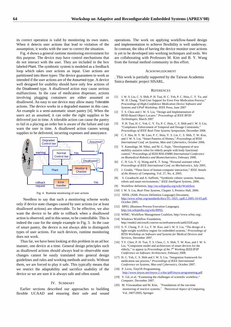
its correct operation is valid by monitoring its own states. When it detects user actions that lead to violation of the assumption, it works with the user to correct the situation. Fig. 4 shows a general runtime monitoring environment for this purpose. The device may have control mechanisms that do not interact with the user. They are included in the box labeled Plant. The symbiotic system is modeled as a feedback loop which takes user actions as input. User actions are partitioned into three types: The device guarantees to work as intended if the user actions are of the Assumed type. A device well designed for usability should have only few actions of the Disallowed type. A disallowed action may cause serious malfunctions. In the case of medication dispenser, actions involving plugging containers are either assumed or disallowed. An easy to use device may allow many Tolerable actions. The device works in a degraded manner in this case. An example is a semi-automatic smart pantry [4]. When the users act as assumed, it can order the right supplies to be delivered just in time. A tolerable action can cause the pantry to fail in a placing an order but is aware of the failure and can warn the user in time. A disallowed action causes wrong supplies to be delivered, incurring expenses and annoyance.
Disallowed?
YesError Handler
Assumed?
Plant Monitor &Checker
Yes
rollback request
NormalControl law
warning
Degraded Control law
Fig. 4. Runtime monitoring of user actions
Needless to say that such a monitoring scheme works only if device state changes caused by user actions (or at least disallowed actions) are observable. To be effective, we also want the device to be able to rollback when a disallowed action is observed, and in this sense, to be controllable. This is indeed the case for the simple example in Fig. 3. In the case of smart pantry, the device is not always able to distinguish types of user actions. For such devices, runtime monitoring does not work.
Thus far, we have been looking at this problem in an ad hoc manner, one device at a time. General design principles such as disallowed actions should always lead to observable state changes cannot be easily translated into general design guidelines and rules and working methods and tools. Without them, we are forced to play it safe. This typically means that we restrict the adaptability and sacrifice usability of the device so we are sure it is always safe and often sound.
IV. SUMMARY Earlier sections described our approaches to building
flexible UCAAD and ensuring their safe and sound
operations. The work on applying workflow-based design and implementation to achieve flexibility is well underway. In contrast, the idea of having the device monitor user actions is yet to be developed into working techniques and tools. We are collaborating with Professors M. Kim and B. Y. Wang from the formal method community in this effort.
ACKNOWLEDGMENT . This work is partially supported by the Taiwan Academia Sinica thematic project SISARL.
REFERENCES [1] J. W. S. Liu, C. S. Shih, P. H. Tsai, H. C. Yeh, P. C. Hsiu, C. Y. Yu, and
W. H. Chang, “End-User Support for Error Free Medication Process,” Proceedings of High-Confidence Medication Device Software and Systems and UPnP Workshop, IEEE Press, June 2007
[2] T. S. Chou and J. W. S. Liu, “Design and Implementation of RFID-Based Object Locator,” Proceedings of IEEE RFID Technologies, March 2007
[3] P. H. Tsai, H. C. Yeh, C. Y. Yu, P. C. Hsiu, C. S. Shih and J. W. S. Liu, “Compliance Enforcement of Temporal and Dosage Constraints,” Proceedings of IEEE Real-Time Systems Symposium, December 2006.
[4] C. F. Hsu, H. Y. M. Liao, P. C. Hsiu, Y. S. Lin, C. S. Shih, T. W. Kuo, and J. W. S. Liu, “Smart Pantries of Homes,” Proceedings of IEEE International Conf. on Systems, Man and Cybernetics, October 2006.
[5] Y. Kaneshige, M. Nihei, and M. G. Fujie, “Development of new mobility assistive robot for elderly people with body functional control,” Proceedings of IEEE/RAS-EMBS International Conference on Biomedical Robotics and Biomechatronics, February 2006.
[6] C. H. Lin, Y. Q. Wang and K. T. Song, “Personal assistant robot,” Proceedings of IEEE International Conf. on Mechatronics, July 2005.
[7] J. Grudin, “Three faces of human-computer interaction,” IEEE Annals of the History of Computing, Vol. 27, No. 4, 2005.
[8] S. Coradeschi and A. Saffiotti, “Symbiotic robotic systems: humans, robots and smart environments,” IEEE Intelligent Systems, 2006.
[9] Workflow definition, http://en.wikipedia.org/wiki/Workflow [10] J. W. S. Liu, Real-Time Systems, Chapter 3, Prentice Hall, 2000. [11] XPDL (XML Process Definition Language) Document,
http://www.wfmc.org/standards/docs/TC-1025_xpdl.2.2005-10-03.pdf, October 2005.
[12] BPEL (Business Process Execution Language), http://en.wikipedia.org/wiki/BPEL
[13] WfMC: Workflow Management Coalition, http://www.wfmc.org/, [14] Windows Workflow Foundation,
http://msdn2.microsoft.com/en-us/netframework/aa663328.aspx [15] S.-Y. Chang, Y.-F. Lu, T. W. Kuo, and J. W. S. Liu, “The design of a
light-weight workflow engine for embedded systems," Proceedings of RTSS Workshop on Software and Systems for Medical Devices and Services, December 2007.
[16] T.Y. Chen, P. H. Tsai, T. S. Chou, C. S. Shih, T. W. Kuo, and J. W. S. Liu, “Component model and architecture of smart devices for the elderly,” to appear in Proceedings of the 7th Working IEEE/IFIP Conference on Software Architecture, February 2008.
[17] H. C. Yeh, C. S. Shih and J. W. S. Liu, “Integration framework for medication use process,” Proceedings of IEEE International Conference on Systems, Man and Cybernetics, October 2007.
[18] P. Levis, TinyOS Programming, http://www.tinyos.net/tinyos-2.x/doc/pdf/tinyos-programming.pdf
[19] Y. Gil, et al, “Examining the challenges of scientific workflow,” Computer, December 2007.
[20] M. Viswanathan and M. Kim, “Foundations of the run-time monitoring of reactive systems," Theoretical Aspect of Computing, Vol. 3407/2005, Springer
64 Workshop on Adaptive and Reconfigurable Embedded Systems (APRES’08)
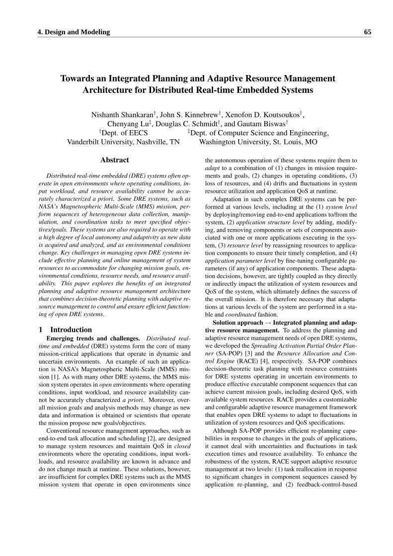
Towards an Integrated Planning and Adaptive Resource ManagementArchitecture for Distributed Real-time Embedded Systems
Nishanth Shankaran†, John S. Kinnebrew†, Xenofon D. Koutsoukos†,Chenyang Lu‡, Douglas C. Schmidt†, and Gautam Biswas†
†Dept. of EECS ‡Dept. of Computer Science and Engineering,Vanderbilt University, Nashville, TN Washington University, St. Louis, MO
Abstract
Distributed real-time embedded (DRE) systems often op-erate in open environments where operating conditions, in-put workload, and resource availability cannot be accu-rately characterized a priori. Some DRE systems, such asNASA’s Magnetospheric Multi-Scale (MMS) mission, per-form sequences of heterogeneous data collection, manip-ulation, and coordination tasks to meet specified objec-tives/goals. These systems are also required to operate witha high degree of local autonomy and adaptivity as new datais acquired and analyzed, and as environmental conditionschange. Key challenges in managing open DRE systems in-clude effective planning and online management of systemresources to accommodate for changing mission goals, en-vironmental conditions, resource needs, and resource avail-ability. This paper explores the benefits of an integratedplanning and adaptive resource management architecturethat combines decision-theoretic planning with adaptive re-source management to control and ensure efficient function-ing of open DRE systems.
1 IntroductionEmerging trends and challenges. Distributed real-
time and embedded (DRE) systems form the core of manymission-critical applications that operate in dynamic anduncertain environments. An example of such an applica-tion is NASA’s Magnetospheric Multi-Scale (MMS) mis-sion [1]. As with many other DRE systems, the MMS mis-sion system operates in open environments where operatingconditions, input workload, and resource availability can-not be accurately characterized a priori. Moreover, over-all mission goals and analysis methods may change as newdata and information is obtained or scientists that operatethe mission propose new goals/objectives.
Conventional resource management approaches, such asend-to-end task allocation and scheduling [2], are designedto manage system resources and maintain QoS in closedenvironments where the operating conditions, input work-loads, and resource availability are known in advance anddo not change much at runtime. These solutions, however,are insufficient for complex DRE systems such as the MMSmission system that operate in open environments since
the autonomous operation of these systems require them toadapt to a combination of (1) changes in mission require-ments and goals, (2) changes in operating conditions, (3)loss of resources, and (4) drifts and fluctuations in systemresource utilization and application QoS at runtime.
Adaptation in such complex DRE systems can be per-formed at various levels, including at the (1) system levelby deploying/removing end-to-end applications to/from thesystem, (2) application structure level by adding, modify-ing, and removing components or sets of components asso-ciated with one or more applications executing in the sys-tem, (3) resource level by reassigning resources to applica-tion components to ensure their timely completion, and (4)application parameter level by fine-tuning configurable pa-rameters (if any) of application components. These adapta-tion decisions, however, are tightly coupled as they directlyor indirectly impact the utilization of system resources andQoS of the system, which ultimately defines the success ofthe overall mission. It is therefore necessary that adapta-tions at various levels of the system are performed in a sta-ble and coordinated fashion.
Solution approach→ Integrated planning and adap-tive resource management. To address the planning andadaptive resource management needs of open DRE systems,we developed the Spreading Activation Partial Order Plan-ner (SA-POP) [3] and the Resource Allocation and Con-trol Engine (RACE) [4], respectively. SA-POP combinesdecision-theoretic task planning with resource constraintsfor DRE systems operating in uncertain environments toproduce effective executable component sequences that canachieve current mission goals, including desired QoS, withavailable system resources. RACE provides a customizableand configurable adaptive resource management frameworkthat enables open DRE systems to adapt to fluctuations inutilization of system resources and QoS specifications.
Although SA-POP provides efficient re-planning capa-bilities in response to changes in the goals of applications,it cannot deal with uncertainties and fluctuations in taskexecution times and resource availability. To enhance therobustness of the system, RACE support adaptive resourcemanagement at two levels: (1) task reallocation in responseto significant changes in component sequences caused byapplication re-planning, and (2) feedback-control-based
4. Design and Modeling 65
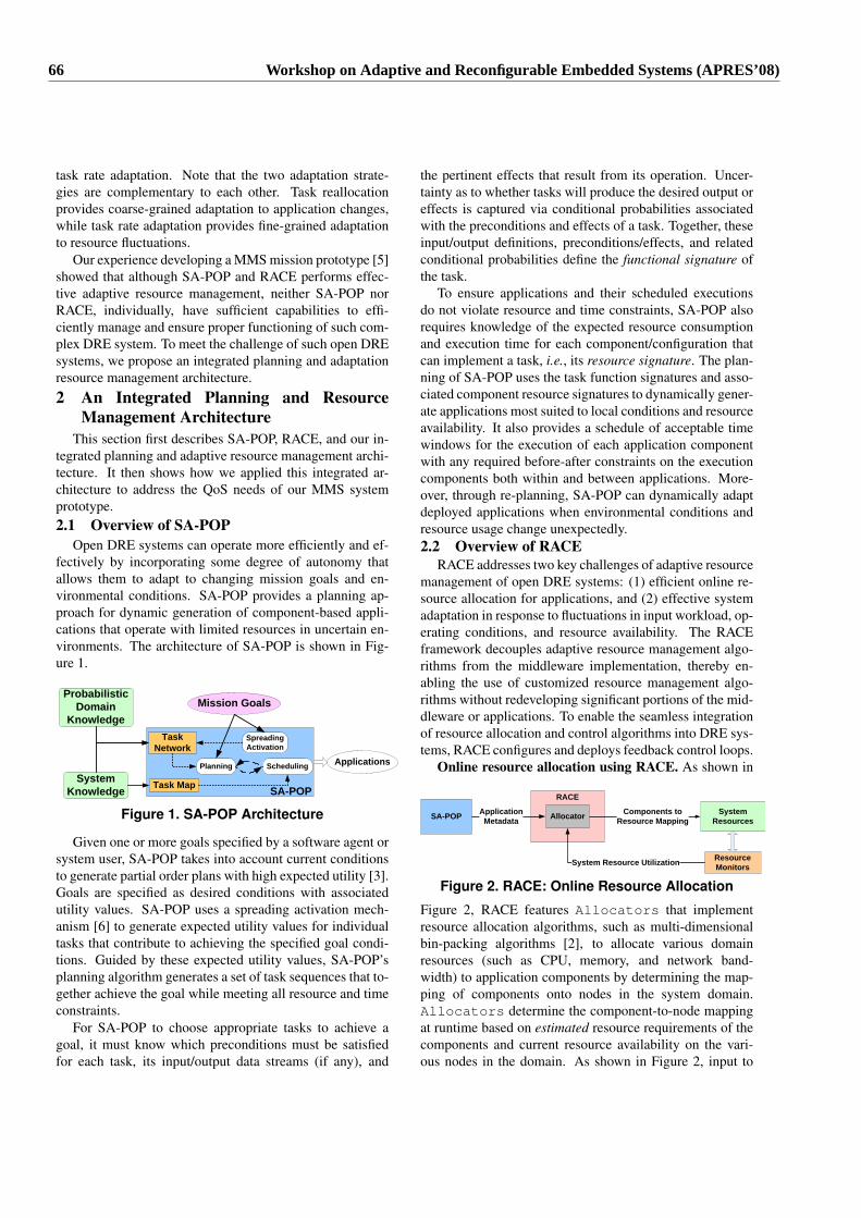
task rate adaptation. Note that the two adaptation strate-gies are complementary to each other. Task reallocationprovides coarse-grained adaptation to application changes,while task rate adaptation provides fine-grained adaptationto resource fluctuations.
Our experience developing a MMS mission prototype [5]showed that although SA-POP and RACE performs effec-tive adaptive resource management, neither SA-POP norRACE, individually, have sufficient capabilities to effi-ciently manage and ensure proper functioning of such com-plex DRE system. To meet the challenge of such open DREsystems, we propose an integrated planning and adaptationresource management architecture.2 An Integrated Planning and Resource
Management ArchitectureThis section first describes SA-POP, RACE, and our in-
tegrated planning and adaptive resource management archi-tecture. It then shows how we applied this integrated ar-chitecture to address the QoS needs of our MMS systemprototype.2.1 Overview of SA-POP
Open DRE systems can operate more efficiently and ef-fectively by incorporating some degree of autonomy thatallows them to adapt to changing mission goals and en-vironmental conditions. SA-POP provides a planning ap-proach for dynamic generation of component-based appli-cations that operate with limited resources in uncertain en-vironments. The architecture of SA-POP is shown in Fig-ure 1.
ProbabilisticDomain
Knowledge
System Knowledge
TaskNetwork
Task Map
SpreadingActivation
Planning Scheduling
Mission Goals
SA-POP
Applications
Figure 1. SA-POP Architecture
Given one or more goals specified by a software agent orsystem user, SA-POP takes into account current conditionsto generate partial order plans with high expected utility [3].Goals are specified as desired conditions with associatedutility values. SA-POP uses a spreading activation mech-anism [6] to generate expected utility values for individualtasks that contribute to achieving the specified goal condi-tions. Guided by these expected utility values, SA-POP’splanning algorithm generates a set of task sequences that to-gether achieve the goal while meeting all resource and timeconstraints.
For SA-POP to choose appropriate tasks to achieve agoal, it must know which preconditions must be satisfiedfor each task, its input/output data streams (if any), and
the pertinent effects that result from its operation. Uncer-tainty as to whether tasks will produce the desired output oreffects is captured via conditional probabilities associatedwith the preconditions and effects of a task. Together, theseinput/output definitions, preconditions/effects, and relatedconditional probabilities define the functional signature ofthe task.
To ensure applications and their scheduled executionsdo not violate resource and time constraints, SA-POP alsorequires knowledge of the expected resource consumptionand execution time for each component/configuration thatcan implement a task, i.e., its resource signature. The plan-ning of SA-POP uses the task function signatures and asso-ciated component resource signatures to dynamically gener-ate applications most suited to local conditions and resourceavailability. It also provides a schedule of acceptable timewindows for the execution of each application componentwith any required before-after constraints on the executioncomponents both within and between applications. More-over, through re-planning, SA-POP can dynamically adaptdeployed applications when environmental conditions andresource usage change unexpectedly.2.2 Overview of RACE
RACE addresses two key challenges of adaptive resourcemanagement of open DRE systems: (1) efficient online re-source allocation for applications, and (2) effective systemadaptation in response to fluctuations in input workload, op-erating conditions, and resource availability. The RACEframework decouples adaptive resource management algo-rithms from the middleware implementation, thereby en-abling the use of customized resource management algo-rithms without redeveloping significant portions of the mid-dleware or applications. To enable the seamless integrationof resource allocation and control algorithms into DRE sys-tems, RACE configures and deploys feedback control loops.
Online resource allocation using RACE. As shown in
RACE
SA-POP Components to Resource Mapping
Resource MonitorsSystem Resource Utilization
ApplicationMetadata Allocator System
Resources
Figure 2. RACE: Online Resource Allocation
Figure 2, RACE features Allocators that implementresource allocation algorithms, such as multi-dimensionalbin-packing algorithms [2], to allocate various domainresources (such as CPU, memory, and network band-width) to application components by determining the map-ping of components onto nodes in the system domain.Allocators determine the component-to-node mappingat runtime based on estimated resource requirements of thecomponents and current resource availability on the vari-ous nodes in the domain. As shown in Figure 2, input to
66 Workshop on Adaptive and Reconfigurable Embedded Systems (APRES’08)
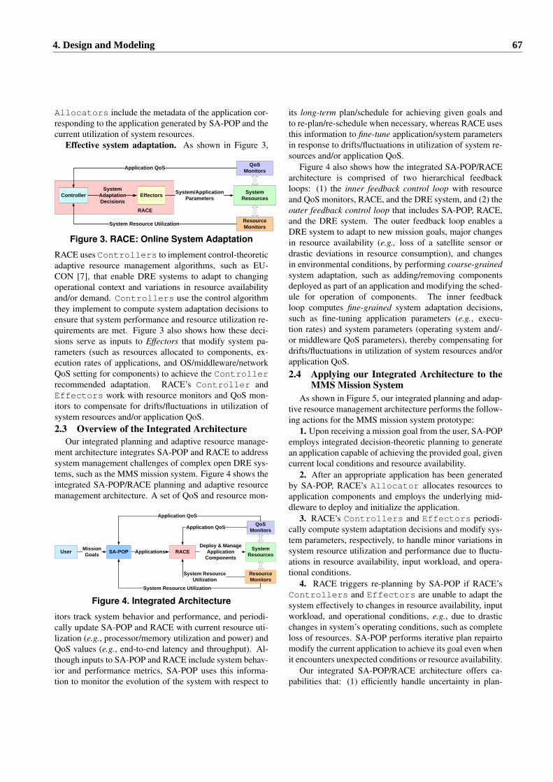
Allocators include the metadata of the application cor-responding to the application generated by SA-POP and thecurrent utilization of system resources.
Effective system adaptation. As shown in Figure 3,
Resource Monitors
QoS Monitors
ControllerSystem
Adaptation Decisions
Effectors System/Application Parameters
Application QoS
System Resource Utilization
RACE
System Resources
Figure 3. RACE: Online System Adaptation
RACE uses Controllers to implement control-theoreticadaptive resource management algorithms, such as EU-CON [7], that enable DRE systems to adapt to changingoperational context and variations in resource availabilityand/or demand. Controllers use the control algorithmthey implement to compute system adaptation decisions toensure that system performance and resource utilization re-quirements are met. Figure 3 also shows how these deci-sions serve as inputs to Effectors that modify system pa-rameters (such as resources allocated to components, ex-ecution rates of applications, and OS/middleware/networkQoS setting for components) to achieve the Controllerrecommended adaptation. RACE’s Controller andEffectors work with resource monitors and QoS mon-itors to compensate for drifts/fluctuations in utilization ofsystem resources and/or application QoS.2.3 Overview of the Integrated Architecture
Our integrated planning and adaptive resource manage-ment architecture integrates SA-POP and RACE to addresssystem management challenges of complex open DRE sys-tems, such as the MMS mission system. Figure 4 shows theintegrated SA-POP/RACE planning and adaptive resourcemanagement architecture. A set of QoS and resource mon-
ApplicationsUser SA-POP RACEMission Goals
Deploy & Manage Application
Components
Resource Monitors
QoS MonitorsApplication QoS
System Resource Utilization
System Resource Utilization
Application QoS
System Resources
Figure 4. Integrated Architecture
itors track system behavior and performance, and periodi-cally update SA-POP and RACE with current resource uti-lization (e.g., processor/memory utilization and power) andQoS values (e.g., end-to-end latency and throughput). Al-though inputs to SA-POP and RACE include system behav-ior and performance metrics, SA-POP uses this informa-tion to monitor the evolution of the system with respect to
its long-term plan/schedule for achieving given goals andto re-plan/re-schedule when necessary, whereas RACE usesthis information to fine-tune application/system parametersin response to drifts/fluctuations in utilization of system re-sources and/or application QoS.
Figure 4 also shows how the integrated SA-POP/RACEarchitecture is comprised of two hierarchical feedbackloops: (1) the inner feedback control loop with resourceand QoS monitors, RACE, and the DRE system, and (2) theouter feedback control loop that includes SA-POP, RACE,and the DRE system. The outer feedback loop enables aDRE system to adapt to new mission goals, major changesin resource availability (e.g., loss of a satellite sensor ordrastic deviations in resource consumption), and changesin environmental conditions, by performing coarse-grainedsystem adaptation, such as adding/removing componentsdeployed as part of an application and modifying the sched-ule for operation of components. The inner feedbackloop computes fine-grained system adaptation decisions,such as fine-tuning application parameters (e.g., execu-tion rates) and system parameters (operating system and/-or middleware QoS parameters), thereby compensating fordrifts/fluctuations in utilization of system resources and/orapplication QoS.2.4 Applying our Integrated Architecture to the
MMS Mission SystemAs shown in Figure 5, our integrated planning and adap-
tive resource management architecture performs the follow-ing actions for the MMS mission system prototype:
1. Upon receiving a mission goal from the user, SA-POPemploys integrated decision-theoretic planning to generatean application capable of achieving the provided goal, givencurrent local conditions and resource availability.
2. After an appropriate application has been generatedby SA-POP, RACE’s Allocator allocates resources toapplication components and employs the underlying mid-dleware to deploy and initialize the application.
3. RACE’s Controllers and Effectors periodi-cally compute system adaptation decisions and modify sys-tem parameters, respectively, to handle minor variations insystem resource utilization and performance due to fluctu-ations in resource availability, input workload, and opera-tional conditions.
4. RACE triggers re-planning by SA-POP if RACE’sControllers and Effectors are unable to adapt thesystem effectively to changes in resource availability, inputworkload, and operational conditions, e.g., due to drasticchanges in system’s operating conditions, such as completeloss of resources. SA-POP performs iterative plan repairtomodify the current application to achieve its goal even whenit encounters unexpected conditions or resource availability.
Our integrated SA-POP/RACE architecture offers ca-pabilities that: (1) efficiently handle uncertainty in plan-
4. Design and Modeling 67
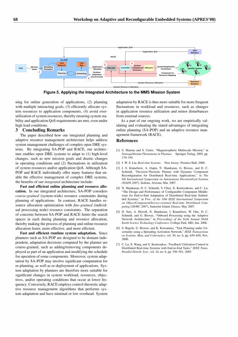
Satellite System
Resource Monitors
QoS Monitors
ControllerSystem
Adaptation Decisions
Effectors System/Application Parameters
Application QoS
System Resource Utilization
Allocator
RACE
User
SA-POP
SpreadingActivation
Planning Scheduling
TaskNetwork
TaskMap
Mission Goals
ApplicationMetadata
Component to Resource Mapping
System Resource Utilization
Application QoS
1
2 3
4
Runtime Adaptation
Unsuccessful
Figure 5. Applying the Integrated Architecture to the MMS Mission System
ning for online generation of applications, (2) planningwith multiple interacting goals, (3) efficiently allocate sys-tem resources to application components, (4) avoid over-utilization of system resources, thereby ensuring system sta-bility and application QoS requirements are met, even underhigh load conditions.3 Concluding Remarks
The paper described how our integrated planning andadaptive resource management architecture helps addresssystem management challenges of complex open DRE sys-tems. By integrating SA-POP and RACE, our architec-ture enables open DRE systems to adapt to (1) high-levelchanges, such as new mission goals and drastic changesin operating conditions and (2) fluctuations in utilizationof system resources and/or application QoS. Although SA-POP and RACE individually offer many features that en-able the effective management of complex DRE systems,the benefits of our integrated architecture include:
Fast and efficient online planning and resource allo-cation. In our integrated architecture, SA-POP considerscoarse-grained (system-wide) resource constraints duringplanning of applications. In contrast, RACE handles re-source allocation optimization with fine-grained (individ-ual processing node) resource constraints. The separationof concerns between SA-POP and RACE limits the searchspaces in each during planning and resource allocation,thereby making the process of planning and online resourceallocation faster, more effective, and more efficient.
Fast and efficient runtime system adaptation. Sinceplanners such as SA-POP are designed to be domain inde-pendent, adaptation decisions computed by the planner arecoarse-grained, such as adding/removing components de-ployed as part of an application and modifying the schedulefor operation of some components. Moreover, system adap-tation by SA-POP may involve significant computation forre-planning, as well as re-deployment of applications. Sys-tem adaptation by planners are therefore more suitable forsignificant changes in system workload, resources, objec-tives, and/or operating conditions that occur at lower fre-quency. Conversely, RACE employs control-theoretic adap-tive resource management algorithms that performs sys-tem adaptation and have minimal or low overhead. System
adaptation by RACE is thus more suitable for more frequentfluctuations in workload and resources, such as changesin application resource utilization and minor disturbancesfrom external sources.
As a part of our ongoing work, we are empirically val-idating and evaluating the stated advantages of integratingonline planning (SA-POP) and an adaptive resource man-agement framework (RACE).
References
[1] S. Sharma and S. Curtis, “Magnetospheric Multiscale Mission,” inNonequilibrium Phenomena in Plasmas. Springer Verlag, 2005, pp.179–195.
[2] J. W. S. Liu, Real-time Systems. New Jersey: Prentice Hall, 2000.
[3] J. S. Kinnebrew, A. Gupta, N. Shankaran, G. Biswas, and D. C.Schmidt, “Decision-Theoretic Planner with Dynamic ComponentReconfiguration for Distributed Real-time Applications,” in The8th International Symposium on Autonomous Decentralized Systems(ISADS 2007), Sedona, Arizona, Mar. 2007.
[4] N. Shankaran, D. C. Schmidt, Y. Chen, X. Koutsoukous, and C. Lu,“The Design and Performance of Configurable Component Middle-ware for End-to-End Adaptation of Distributed Real-time Embed-ded Systems,” in Proc. of the 10th IEEE International Symposiumon Object/Component/Service-oriented Real-time Distributed Com-puting (ISORC 2007), Santorini Island, Greece, May 2007.
[5] D. Suri, A. Howell, N. Shankaran, J. Kinnebrew, W. Otte, D. C.Schmidt, and G. Biswas, “Onboard Processing using the AdaptiveNetwork Architecture,” in Proceedings of the Sixth Annual NASAEarth Science Technology Conference, College Park, MD, Jun. 2006.
[6] S. Bagchi, G. Biswas, and K. Kawamura, “Task Planning under Un-certainty using a Spreading Activation Network,” IEEE Transactionson Systems, Man, and Cybernetics, vol. 30, no. 6, pp. 639–650, Nov.2000.
[7] C. Lu, X. Wang, and X. Koutsoukos, “Feedback Utilization Control inDistributed Real-time Systems with End-to-End Tasks,” IEEE Trans.Parallel Distrib. Syst., vol. 16, no. 6, pp. 550–561, 2005.
68 Workshop on Adaptive and Reconfigurable Embedded Systems (APRES’08)
Designing Reconfigurable Component Systems with a Model Based Approach
Brahim HamidCEA LIST
email:[email protected]
Agnes LanusseCEA LIST
email:[email protected]
Ansgar RadermacherCEA LIST
email:[email protected]
Sebastien GerardCEA LIST
email:[email protected]
Abstract
Dynamic reconfigurability of systems is of particularimportance when considering dependability issues. In thispaper we consider the utilization of such techniques inthe context of fault-tolerance. Indeed, one way to achievefault management is to use reconfiguration mechanisms.In this paper we propose a model driven approach tohelp specify and configure reconfigurability issues.Withinthis development process, component application andreconfiguration properties are declaratively specifiedat model level and are transparent for the componentimplementation. An application is described using UMLand specialized extensions: QoS &FT, D&C profiles fromthe OMG. From this model, we generate descriptor files fora framework based on the CORBA component model andconfigure specific infrastructure components devoted toreconfiguration management. The approach is illustratedon a simple example.
Key words: Distributed applications, CORBA Compo-nent Model, Connector, Fault tolerance, Profile, Reconfigu-ration, UML.
1 Introduction
The “Inflexion” project 1 aims at providing a flexibleinfrastructure framework in the domain of real-time em-bedded applications. The framework promotes an infras-tructure based on the CORBA Component model (CCM)[5] and its Component/Container paradigm. It extends thismodel with the concept of Connector that provides an ab-straction for connections. The project provides also toolsto
1This work has been performed in the context of the Usine Logi-cielle (software-factory) project of the System@tic ParisRegion Cluster(http://www.usine-logicielle.org).
configure and generate efficient containers – from a descrip-tion of deployment specification at a model level. This workhas already been successful in previous projects, namely theIST project Compare (http://www.ist-compare.org).
We present an ongoing work which extends this frame-work with support for the management of fault-tolerant ar-chitectures. It is based on the definition of a run-time frame-work and on code generation tools and an accompanyingmodeling process. The former offers transparent manage-ment of fault-tolerance (mainly fault-detection and redun-dancy mechanisms), the latter supports the application de-signer in the development process. In the scope of this pa-per, we focus on reconfiguration support at model level.
In the context of fault-tolerance, the failure of a node hasto be properly dealt with. Whereas critical components areactively replicated and have to continue without interrup-tion, other parts of an application may bere-configuredinorder to adapt to the node-failure. We study reconfigura-tion at multiple layers within a model driven engineeringapproach, including the model level and required runtimesupport from the execution platform.
A major reason for using CCM is its separation of busi-ness code from non-functional or service code within a con-tainer. Non-functional services support the reconfigurationprocess by blocking for instance the access to ports duringreconfiguration in order to maintain a consistent state (avoidmessages loss).
The paper is organized as follows: In the next sectionwe present some background related to component model,the connector extension and the modeling support for adap-tive quality of service design. In section 3, we present ourapproach to deal with reconfiguration at a model level. Sec-tion 4 describes briefly the proposed framework to imple-ment reconfiguration in the context of fault-tolerance. In thefollowing section, we propose our process to design recon-figurable applications. We review in Section 6 some relatedworks. Finally, Section 7 concludes the paper with short
4. Design and Modeling 69
discussion about future works.
2 Background
In this section, we outline two different aspects: the com-ponent platform, namely the CORBA Component modeland an extension of it and the modeling support for adap-tive quality of service design.
2.1 CCM Connectors – non-standard in-teraction mechanisms
In the context of fault tolerance, a connection with areplicated component should perform the group communi-cation. Whereas this could be done with standard CCM anda specific CORBA implementation supporting group com-munication, it would be impossible to configure and controlit (in case for instance of node failures) from standard CCM.
This motivates the introduction of what we callcon-nectorsthat offer the possibility to use a specific interac-tion semantic and multiple implementations of this seman-tic within CCM [10]. The basic idea of this extension isthat the semantics of an interaction is defined by a certainport type and that one or more connectors can support thisport type. The port types are already fixed at component de-sign time, whereas the choice of a connector (and a specificimplementation) is not fixed until application deployment.
A connector has certain similarities with a component.A main difference is that it is a fragmented entity: since theconnection between a (part of a) component and its connec-tor is always local, the connector needs to be split into anumber offragmentswhich represent the connector in theaddress space of its users.
Since a connector fragment is responsible for incomingand outgoing messages, it is an ideal place for the inte-gration of code that transparently interacts with a group ofreplicas. In addition, the connector caninterceptmessagesand block these until a reconfiguration is done - thus avoid-ing message loss.
2.2 Modeling Support for Adaptive Qual-ity of Service Design
Model Driven Engineering is becoming more and moresuccessful in software engineering. Though, primarily usedin information systems, it is particularly well suited to thedomain of real-time embedded applications since it puts inaction the separation of concerns promoted by the OMGstandard Model-Driven ArchitectureTM (MDA). But untilnow, there was a lack of tools to support such methodolo-gies and approaches in this domain.
In this context the “Inflexion” sub-project takes advan-tage of “Usine logicielle” environment and on recent ad-vances in modeling non-functional issues offered mainly
by QoS & FT [7] and more recently by MARTE(Modelingand Analysis of Real-Time Embedded systems) [8] OMGstandards to support dependability modeling issues in thedevelopment of Component Based systems. Advances inAADL (Architecture Analysis and Design Language) andits recent extensions (behavior and error annex) devoted todependability oriented modeling [3] have also been takeninto account.
Adaptive systems implement generally decision strate-gies for dynamic reconfiguration depending on criteria de-fined during design. These can be expressed by means ofconstraints (defining contracts) on services offered or re-quired by components, these constraints can be related todifferent quality levels and/or to different phases duringtheapplication life. Promoting a unified framework to specifydeclaratively such quality related concepts is thus a majorissue. Several proposals have been issued until now :
• One of the most achieved work in this direction wasthe QoS&FT profile. In this profile, many aspects ofQuality of Service have been investigated and mod-eling features have been proposed that are directly inrelation with the modeling of adaptive systems. Theprofile helps modelingQoSLevels. These levels re-fer to states where a certain degree of quality can beachieved. A component remains in aQoSLevelas longas the constraints attached to this level are verified.When this is no longer the case, aQoSTransitionisfired. This QoSTransitioncontains a set ofadapta-tionActionsthat determine the reconfiguration processthat must be achieved. This meta-model of adaptabil-ity is pretty much general and must be detailed in or-der to support adaptive systems development method-ology. However, the framework fits well to most exist-ing adaptive systems.
However, the concept ofQosLevelis not suitable formodeling operationalmodesof an application. An op-erational mode is a global application mode, in caseof an aerospace application it may for instance corre-spond to a start and in-flight phase of a launch vehiclewhich have quite different demands. Modes and tran-sitions between these are usually specified by means ofsome kind of automaton.
• MARTE profile provides a more general frameworkto specify non-functional properties (generalization ofQoSChracteristics), libraries of predefined types de-voted to RTE domain and specific sub-profiles havebeen defined to support Schedulability and Perfor-mance Analysis. These concepts can be used (butare not explicitly devoted) to expressQoSConstraints.In MARTE profile, the notion of operational modes (close to AADL concept) has been introduced and is at-tached toRT-Unitsin a subprofile named RTEMoCC
70 Workshop on Adaptive and Reconfigurable Embedded Systems (APRES’08)
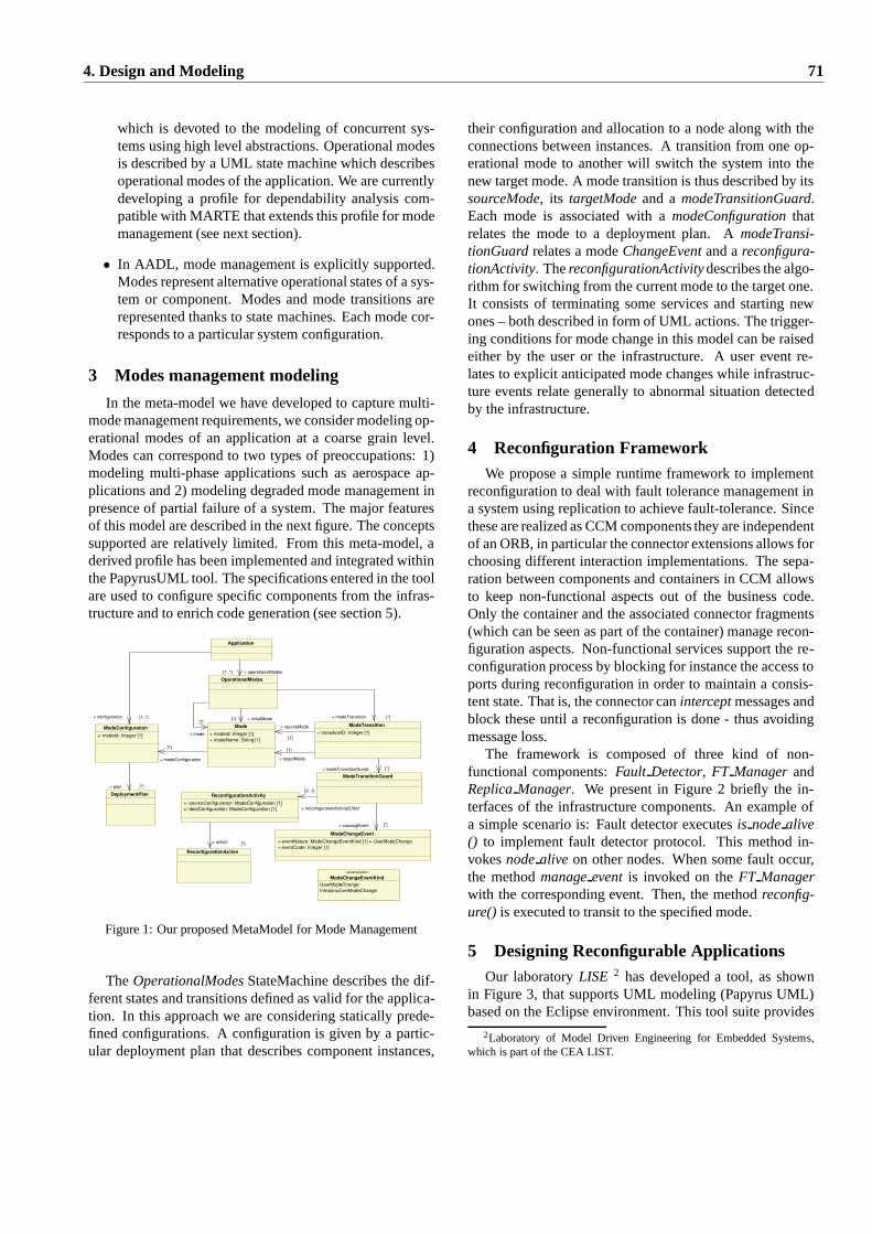
which is devoted to the modeling of concurrent sys-tems using high level abstractions. Operational modesis described by a UML state machine which describesoperational modes of the application. We are currentlydeveloping a profile for dependability analysis com-patible with MARTE that extends this profile for modemanagement (see next section).
• In AADL, mode management is explicitly supported.Modes represent alternative operational states of a sys-tem or component. Modes and mode transitions arerepresented thanks to state machines. Each mode cor-responds to a particular system configuration.
3 Modes management modeling
In the meta-model we have developed to capture multi-mode management requirements, we consider modeling op-erational modes of an application at a coarse grain level.Modes can correspond to two types of preoccupations: 1)modeling multi-phase applications such as aerospace ap-plications and 2) modeling degraded mode management inpresence of partial failure of a system. The major featuresof this model are described in the next figure. The conceptssupported are relatively limited. From this meta-model, aderived profile has been implemented and integrated withinthe PapyrusUML tool. The specifications entered in the toolare used to configure specific components from the infras-tructure and to enrich code generation (see section 5).
Application
OperationalModes
Mode
+ modeId: Integer [1]
+ modeName: String [1]
ModeTransition
+ transitionID: Integer [1]
ModeTransitionGuard
ModeChangeEvent
+ eventNature: ModeChangeEventKind [1] = UserModeChange
+ eventCode: Integer [1]
«enumeration»
ModeChangeEventKind
UserModeChange
InfrastructureModeChange
ModeConfiguration
+/ modeId: Integer [1]
DeploymentPlan
ReconfigurationAction
ReconfigurationActivity
+/ sourceConfiguration: ModeConfiguration [1]
+/ destConfiguration: ModeConfiguration [1]
+ operationalModes [1..*]
+ configuration [1..*] + initialMode [1] + modeTransition [*]
+ mode
[*]
+ modeConfiguration
[1]
+ sourceMode
[1]
+ targetMode
[1]
+ modeTransitionGuard [*]
+ causingEvent [*]
+ reconfigurationActivityEffect
[0..1] + plan [*]
+ action [*]
Figure 1: Our proposed MetaModel for Mode Management
TheOperationalModesStateMachine describes the dif-ferent states and transitions defined as valid for the applica-tion. In this approach we are considering statically prede-fined configurations. A configuration is given by a partic-ular deployment plan that describes component instances,
their configuration and allocation to a node along with theconnections between instances. A transition from one op-erational mode to another will switch the system into thenew target mode. A mode transition is thus described by itssourceMode, its targetModeand amodeTransitionGuard.Each mode is associated with amodeConfigurationthatrelates the mode to a deployment plan. AmodeTransi-tionGuardrelates a modeChangeEventand areconfigura-tionActivity. ThereconfigurationActivitydescribes the algo-rithm for switching from the current mode to the target one.It consists of terminating some services and starting newones – both described in form of UML actions. The trigger-ing conditions for mode change in this model can be raisedeither by the user or the infrastructure. A user event re-lates to explicit anticipated mode changes while infrastruc-ture events relate generally to abnormal situation detectedby the infrastructure.
4 Reconfiguration FrameworkWe propose a simple runtime framework to implement
reconfiguration to deal with fault tolerance management ina system using replication to achieve fault-tolerance. Sincethese are realized as CCM components they are independentof an ORB, in particular the connector extensions allows forchoosing different interaction implementations. The sepa-ration between components and containers in CCM allowsto keep non-functional aspects out of the business code.Only the container and the associated connector fragments(which can be seen as part of the container) manage recon-figuration aspects. Non-functional services support the re-configuration process by blocking for instance the access toports during reconfiguration in order to maintain a consis-tent state. That is, the connector caninterceptmessages andblock these until a reconfiguration is done - thus avoidingmessage loss.
The framework is composed of three kind of non-functional components:Fault Detector, FT ManagerandReplicaManager. We present in Figure 2 briefly the in-terfaces of the infrastructure components. An example ofa simple scenario is: Fault detector executesis nodealive() to implement fault detector protocol. This method in-vokesnodealive on other nodes. When some fault occur,the methodmanageeventis invoked on theFT Managerwith the corresponding event. Then, the methodreconfig-ure() is executed to transit to the specified mode.
5 Designing Reconfigurable ApplicationsOur laboratoryLISE 2 has developed a tool, as shown
in Figure 3, that supports UML modeling (Papyrus UML)based on the Eclipse environment. This tool suite provides
2Laboratory of Model Driven Engineering for Embedded Systems,which is part of the CEA LIST.
4. Design and Modeling 71
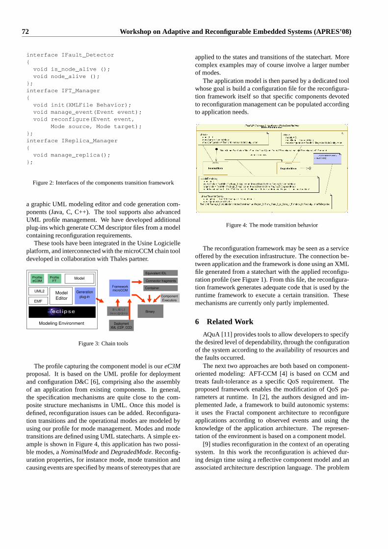
interface IFault_Detector{void is_node_alive ();void node_alive ();
};interface IFT_Manager{void init(XMLFile Behavior);void manage_event(Event event);void reconfigure(Event event,
Mode source, Mode target);};interface IReplica_Manager{void manage_replica();
};
Figure 2: Interfaces of the components transition framework
a graphic UML modeling editor and code generation com-ponents (Java, C, C++). The tool supports also advancedUML profile management. We have developed additionalplug-ins which generate CCM descriptor files from a modelcontaining reconfiguration requirements.
These tools have been integrated in the Usine Logicielleplatform, and interconnected with the microCCM chain tooldeveloped in collaboration with Thales partner.
Binary
ModelProfileeC3M
ProfileFT
IDL/IDL3
descriptions
DeploymentXML (CDP, CCD)
FrameworkmicroCCM
Model
Editor
UML2
EMF
Generation
plug−in
Modeling
Modeling Environment
Component
Executors
Equivalent IDL
Connector fragments
Container
Figure 3: Chain tools
The profile capturing the component model is oureC3Mproposal. It is based on the UML profile for deploymentand configuration D&C [6], comprising also the assemblyof an application from existing components. In general,the specification mechanisms are quite close to the com-posite structure mechanisms in UML. Once this model isdefined, reconfiguration issues can be added. Reconfigura-tion transitions and the operational modes are modeled byusing our profile for mode management. Modes and modetransitions are defined using UML statecharts. A simple ex-ample is shown in Figure 4, this application has two possi-ble modes, aNominalModeandDegradedMode. Reconfig-uration properties, for instance mode, mode transition andcausing events are specified by means of stereotypes that are
applied to the states and transitions of the statechart. Morecomplex examples may of course involve a larger numberof modes.
The application model is then parsed by a dedicated toolwhose goal is build a configuration file for the reconfigura-tion framework itself so that specific components devotedto reconfiguration management can be populated accordingto application needs.
Figure 4: The mode transition behavior
The reconfiguration framework may be seen as a serviceoffered by the execution infrastructure. The connection be-tween application and the framework is done using an XMLfile generated from a statechart with the applied reconfigu-ration profile (see Figure 1). From this file, the reconfigura-tion framework generates adequate code that is used by theruntime framework to execute a certain transition. Thesemechanisms are currently only partly implemented.
6 Related Work
AQuA [11] provides tools to allow developers to specifythe desired level of dependability, through the configurationof the system according to the availability of resources andthe faults occurred.
The next two approaches are both based on component-oriented modeling: AFT-CCM [4] is based on CCM andtreats fault-tolerance as a specific QoS requirement. Theproposed framework enables the modification of QoS pa-rameters at runtime. In [2], the authors designed and im-plemented Jade, a framework to build autonomic systems:it uses the Fractal component architecture to reconfigureapplications according to observed events and using theknowledge of the application architecture. The represen-tation of the environment is based on a component model.
[9] studies reconfiguration in the context of an operatingsystem. In this work the reconfiguration is achieved dur-ing design time using a reflective component model and anassociated architecture description language. The problem
72 Workshop on Adaptive and Reconfigurable Embedded Systems (APRES’08)
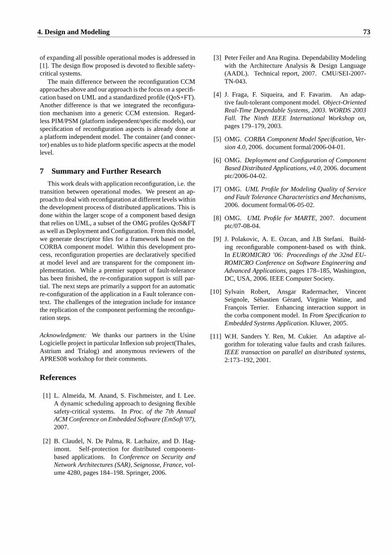
of expanding all possible operational modes is addressed in[1]. The design flow proposed is devoted to flexible safety-critical systems.
The main difference between the reconfiguration CCMapproaches above and our approach is the focus on a specifi-cation based on UML and a standardized profile (QoS+FT).Another difference is that we integrated the reconfigura-tion mechanism into a generic CCM extension. Regard-less PIM/PSM (platform independent/specific models), ourspecification of reconfiguration aspects is already done ata platform independent model. The container (and connec-tor) enables us to hide platform specific aspects at the modellevel.
7 Summary and Further Research
This work deals with application reconfiguration, i.e. thetransition between operational modes. We present an ap-proach to deal with reconfiguration at different levels withinthe development process of distributed applications. Thisisdone within the larger scope of a component based designthat relies on UML, a subset of the OMG profiles QoS&FTas well as Deployment and Configuration. From this model,we generate descriptor files for a framework based on theCORBA component model. Within this development pro-cess, reconfiguration properties are declaratively specifiedat model level and are transparent for the component im-plementation. While a premier support of fault-tolerancehas been finished, the re-configuration support is still par-tial. The next steps are primarily a support for an automaticre-configuration of the application in a Fault tolerance con-text. The challenges of the integration include for instancethe replication of the component performing the reconfigu-ration steps.
Acknowledgment:We thanks our partners in the UsineLogicielle project in particular Inflexion sub project(Thales,Astrium and Trialog) and anonymous reviewers of theAPRES08 workshop for their comments.
References
[1] L. Almeida, M. Anand, S. Fischmeister, and I. Lee.A dynamic scheduling approach to designing flexiblesafety-critical systems. InProc. of the 7th AnnualACM Conference on Embedded Software (EmSoft’07),2007.
[2] B. Claudel, N. De Palma, R. Lachaize, and D. Hag-imont. Self-protection for distributed component-based applications. InConference on Security andNetwork Architectures (SAR), Seignosse, France, vol-ume 4280, pages 184–198. Springer, 2006.
[3] Peter Feiler and Ana Rugina. Dependability Modelingwith the Architecture Analysis & Design Language(AADL). Technical report, 2007. CMU/SEI-2007-TN-043.
[4] J. Fraga, F. Siqueira, and F. Favarim. An adap-tive fault-tolerant component model.Object-OrientedReal-Time Dependable Systems, 2003. WORDS 2003Fall. The Ninth IEEE International Workshop on,pages 179–179, 2003.
[5] OMG. CORBA Component Model Specification, Ver-sion 4.0, 2006. document formal/2006-04-01.
[6] OMG. Deployment and Configuration of ComponentBased Distributed Applications, v4.0, 2006. documentptc/2006-04-02.
[7] OMG. UML Profile for Modeling Quality of Serviceand Fault Tolerance Characteristics and Mechanisms,2006. document formal/06-05-02.
[8] OMG. UML Profile for MARTE, 2007. documentptc/07-08-04.
[9] J. Polakovic, A. E. Ozcan, and J.B Stefani. Build-ing reconfigurable component-based os with think.In EUROMICRO ’06: Proceedings of the 32nd EU-ROMICRO Conference on Software Engineering andAdvanced Applications, pages 178–185, Washington,DC, USA, 2006. IEEE Computer Society.
[10] Sylvain Robert, Ansgar Radermacher, VincentSeignole, Sebastien Gerard, Virginie Watine, andFrancois Terrier. Enhancing interaction support inthe corba component model. InFrom Specification toEmbedded Systems Application. Kluwer, 2005.
[11] W.H. Sanders Y. Ren, M. Cukier. An adaptive al-gorithm for tolerating value faults and crash failures.IEEE transaction on parallel an distributed systems,2:173–192, 2001.
4. Design and Modeling 73
Enabling Extensibility of Sensing Systems through Automatic Composition over Physical Location
Maurice Chu and Juan Liu Palo Alto Research Center [mchu, jjliu] @parc.com
Abstract
Networked sensing systems are increasingly adopted in many applications, but today’s systems are generally single purpose and hard to extend. This paper addresses the problem of enabling developers to develop extensible networked sensing systems. We propose a design methodology, which centers on a novel automatic composition service where the sensor processing software modules are parameterized by a physical location region. The automatic composer automatically configures the processing and communication occurring in a networked sensing system based on up-to-date sensing needs and sensor device availability. Our approach also enables adaptability and robustness against sensor failures. 1 Introduction
Adding functionality into existing sensing systems that were never designed to be extended can be such a complicated and costly task that deploying a separate system with its own set of sensors is often the simpler, more reliable, and economical choice. This short-sighted “reinvent versus reuse” design methodology results in multiple, isolated sensing systems that cannot be adapted or extended in a robust and reliable way.
For a concrete example, let us consider two video surveillance applications in high demand in retail stores today: security and marketing research. Commercial products for security include surveillance systems from ObjectVideo [1] and Vidient, and products for market research include those from Brickstream. Today, to get security and market research capabilities, separate systems must be purchased. Extending a security surveillance system to do market research (or vice versa) is difficult, which requires a thorough understanding of the processing flow and function call hierarchies. However, these two systems are similar in hardware usage and share a lot of functionality. A potentially more cost effective alternative is to design the systems to be extensible.
Compared to multiple isolated sensing systems, an integrated, extensible system has several advantages. Redundant deployment of sensors can be avoided, so
that the upfront cost of deployment is amortized over multiple applications over the system lifetime. The availability of more sensors can improve performance through increased sensor or spatial diversity.
We are interested in a practical methodology that will encourage developers to design for extensibility. This methodology should be simple and impose minimal overhead cost for the benefit of extensibility. In this paper, we propose a design methodology that leverages the key role of physical location in sensing and an automatic composition service. The automatic composer monitors dynamically changing sensor availability and evolving sensing needs, and automatically instantiates, integrates, and reconfigures software components on devices as the system evolves.
The focus of this paper is on extensibility of sensors and sensing, not the entirety of application logic. Although handling heterogeneity in data types, protocols, interfaces, networks, and devices are important for a total solution, our focus will be on designing a methodology that minimizes developer effort to design extensible sensing systems.
Several existing middleware systems also perform automatic composition. For example, [2] composes an appropriate set of sensors and algorithms based on pre-defined roles and connections, but since it is designed for “ tiny” nodes, it composes only at compile-time. GRATIS [3], on the other hand, performs dynamic reconfiguration but chooses among developer-specified alternatives of operations to meet quality-of-service goals. Neither of these focus on physical location as we do.
2 Practical Extensibility Requirements
Let us revisit the video surveillance applications: security and market research. Figure 1 shows a possible reuse scenario. In this example, the retail store is first deployed with a security surveillance system that captures video from cameras, detects people, and tracks them (CameraImager, PeopleDetector, and Tracker). With the initial deployment in place, store managers may wish to leverage this system to extract customer count information throughout a store to help them dispatch sales people accordingly, which can be
74 Workshop on Adaptive and Reconfigurable Embedded Systems (APRES’08)
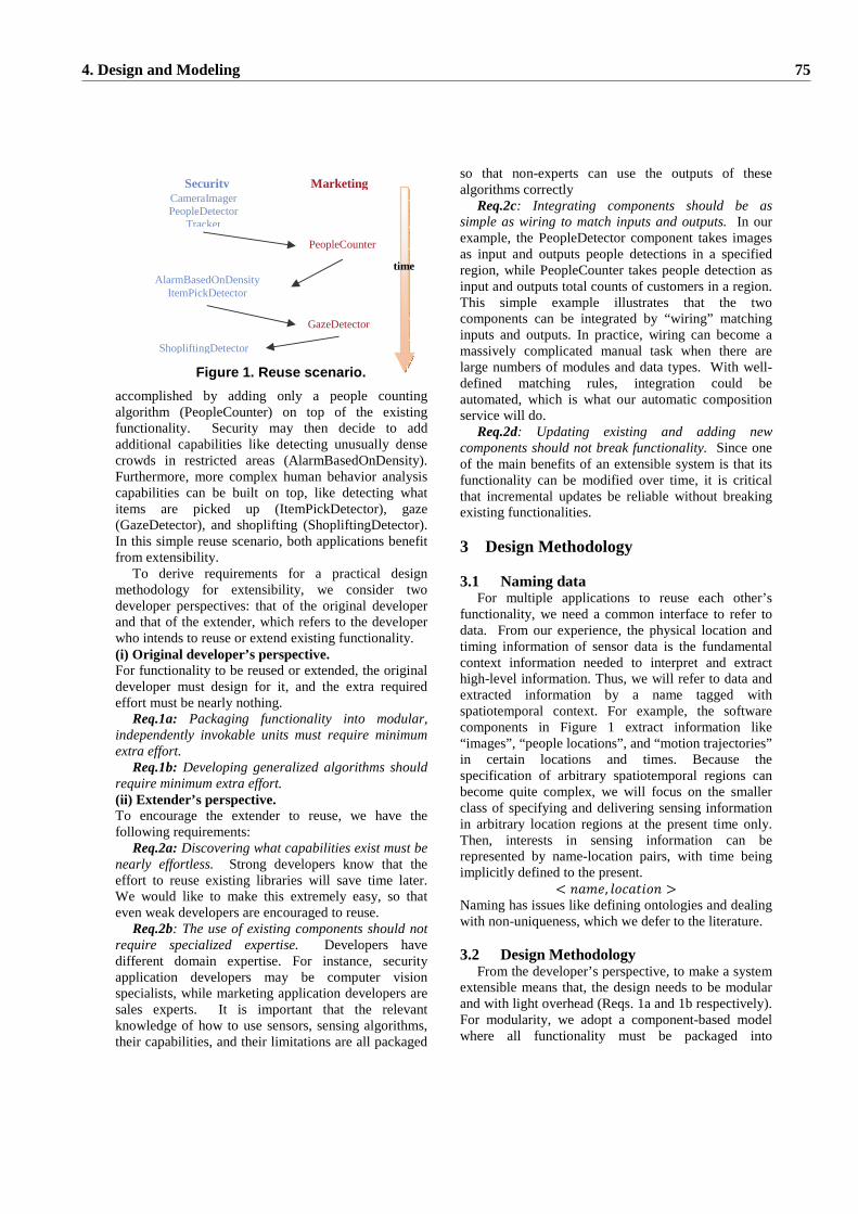
accomplished by adding only a people counting algorithm (PeopleCounter) on top of the existing functionality. Security may then decide to add additional capabilities like detecting unusually dense crowds in restricted areas (AlarmBasedOnDensity). Furthermore, more complex human behavior analysis capabilities can be built on top, like detecting what items are picked up (ItemPickDetector), gaze (GazeDetector), and shoplifting (ShopliftingDetector). In this simple reuse scenario, both applications benefit from extensibility.
To derive requirements for a practical design methodology for extensibility, we consider two developer perspectives: that of the original developer and that of the extender, which refers to the developer who intends to reuse or extend existing functionality. (i) Or iginal developer ’s perspective. For functionality to be reused or extended, the original developer must design for it, and the extra required effort must be nearly nothing.
Req.1a: Packaging functionality into modular, independently invokable units must require minimum extra effort.
Req.1b: Developing generalized algorithms should require minimum extra effort. (ii) Extender ’ s perspective. To encourage the extender to reuse, we have the following requirements:
Req.2a: Discovering what capabilities exist must be nearly effortless. Strong developers know that the effort to reuse existing libraries will save time later. We would like to make this extremely easy, so that even weak developers are encouraged to reuse.
Req.2b: The use of existing components should not require specialized expertise. Developers have different domain expertise. For instance, security application developers may be computer vision specialists, while marketing application developers are sales experts. It is important that the relevant knowledge of how to use sensors, sensing algorithms, their capabilities, and their limitations are all packaged
so that non-experts can use the outputs of these algorithms correctly
Req.2c: Integrating components should be as simple as wiring to match inputs and outputs. In our example, the PeopleDetector component takes images as input and outputs people detections in a specified region, while PeopleCounter takes people detection as input and outputs total counts of customers in a region. This simple example illustrates that the two components can be integrated by “wiring” matching inputs and outputs. In practice, wiring can become a massively complicated manual task when there are large numbers of modules and data types. With well-defined matching rules, integration could be automated, which is what our automatic composition service will do.
Req.2d: Updating existing and adding new components should not break functionality. Since one of the main benefits of an extensible system is that its functionality can be modified over time, it is critical that incremental updates be reliable without breaking existing functionalities.
3 Design Methodology 3.1 Naming data
For multiple applications to reuse each other’s functionality, we need a common interface to refer to data. From our experience, the physical location and timing information of sensor data is the fundamental context information needed to interpret and extract high-level information. Thus, we will refer to data and extracted information by a name tagged with spatiotemporal context. For example, the software components in Figure 1 extract information like “ images” , “people locations” , and “motion trajectories” in certain locations and times. Because the specification of arbitrary spatiotemporal regions can become quite complex, we will focus on the smaller class of specifying and delivering sensing information in arbitrary location regions at the present time only. Then, interests in sensing information can be represented by name-location pairs, with time being implicitly defined to the present.
Naming has issues like defining ontologies and dealing with non-uniqueness, which we defer to the literature. 3.2 Design Methodology
From the developer’s perspective, to make a system extensible means that, the design needs to be modular and with light overhead (Reqs. 1a and 1b respectively). For modularity, we adopt a component-based model where all functionality must be packaged into
Secur ity Marketing CameraImager PeopleDetector
Tracker
AlarmBasedOnDensity ItemPickDetector
ShopliftingDetector
PeopleCounter
GazeDetector
time
Figure 1. Reuse scenario.
4. Design and Modeling 75
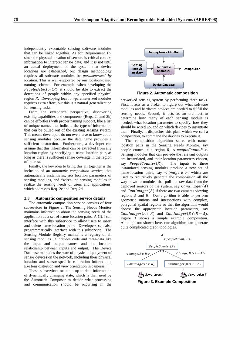
independently executable sensing software modules that can be linked together. As for Requirement 1b, since the physical location of sensors is critical context information to interpret sensor data, and it is not until an actual deployment of the system that device locations are established, our design methodology requires all software modules be parameterized by location. This is well-supported by our location-based naming scheme. For example, when developing the
, it should be able to extract the detections of people within any specified physical region . Developing location-parameterized modules requires extra effort, but this is a natural generalization for sensing tasks.
From the extender’s perspective, discovering existing capabilities and components (Reqs. 2a and 2b) can be effortless with proper naming support, like a list of unique names that indicate the type of information that can be pulled out of the existing sensing system. This means developers do not even have to know about sensing modules because the data name provides a sufficient abstraction. Furthermore, a developer can assume that this information can be extracted from any location region by specifying a name-location pair, as long as there is sufficient sensor coverage in the region of interest.
Finally, the key idea to bring this all together is the inclusion of an automatic composition service, that automatically instantiates, sets location parameters of sensing modules, and “wires-up” sensing modules to realize the sensing needs of users and applications, which addresses Req. 2c and Req. 2d.
3.3 Automatic composition service details
The automatic composition service consists of four subservices in Figure 2. The Sensing Needs Monitor maintains information about the sensing needs of the application as a set of name-location pairs. A GUI can interface with this subservice to allow users to insert and delete name-location pairs. Developers can also programmatically interface with this subservice. The Sensing Module Registry maintains a registry of all sensing modules. It includes code and meta-data like the input and output names and the location relationship between inputs and output. The Device Database maintains the state of physical deployment of sensor devices on the network, including their physical location and sensor-specific calibration information, like lens distortion and view orientation in cameras.
These subservices maintain up-to-date information of dynamically changing state, which is then used by the Automatic Composer to decide what processing and communication should be occurring in the
networked sensing system by performing three tasks. First, it acts as a broker to figure out what software modules and hardware devices are needed to fulfill the sensing needs. Second, it acts as an architect to determine how many of each sensing module is needed, what location parameter to specify, how they should be wired up, and on which devices to instantiate them. Finally, it dispatches this plan, which we call a composition, to command the devices to execute it.
The composition algorithm starts with name-location pairs in the Sensing Needs Monitor, say people counts in a region , . Sensing modules that can provide the relevant outputs are instantiated, and their location parameters chosen, say . The inputs to these instantiated sensing modules produce a new set of name-location pairs, say , which are used to recursively generate the composition all the way down to modules that pull out raw data from the deployed sensors of the system, say and if there are two cameras viewing regions and . Our algorithm is able to perform geometric unions and intersections with complex, polygonal spatial regions so that the algorithm would choose the appropriate location parameters, say
and . Figure 3 shows a simple example composition. Although not shown here, our algorithm can generate quite complicated graph topologies.
��������� ��� ������������ � ��
� ����� ��� ��� � ���� ���
��������� ������� �� ���� ��� �!
" �� ��# � � � �$��#&%��'��� (�)�*,+�)�-'. / . )�0
Figure 2. Automatic composition
1 . 2�34-�5 2�6�. )�0 1 . 2�34-�5 2�6�. )�0
Figure 3. Example Composition
76 Workshop on Adaptive and Reconfigurable Embedded Systems (APRES’08)
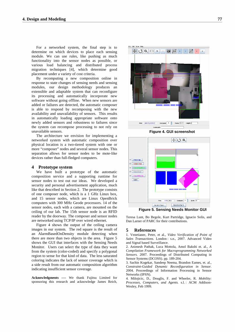
For a networked system, the final step is to determine on which devices to place each sensing module. We can use rules, like pushing as much functionality into the sensor nodes as possible, or various load balancing and distributed process migration techniques [4], which determine good placement under a variety of cost criteria.
By recomputing a new composition online in response to state changes of sensing needs and sensing modules, our design methodology produces an extensible and adaptable system that can reconfigure its processing and automatically incorporate new software without going offline. When new sensors are added or failures are detected, the automatic composer is able to respond by recomposing with the new availability and unavailability of sensors. This results in automatically loading appropriate software onto newly added sensors and robustness to failures since the system can recompose processing to not rely on unavailable sensors.
The architecture we envision for implementing a networked system with automatic composition over physical location is a two-tiered system with one or more “composer” nodes and several sensor nodes. This separation allows for sensor nodes to be mote-like devices rather than full-fledged computers. 4 Prototype system
We have built a prototype of the automatic composition service and a supporting runtime for sensor nodes to test out our ideas. We developed a security and personal advertisement application, much like that described in Section 2. The prototype consists of one composer node, which is a 1 GHz Linux box, and 15 sensor nodes, which are Linux OpenBrick computers with 300 MHz Geode processors. 14 of the sensor nodes, each with a camera, are mounted on the ceiling of our lab. The 15th sensor node is an RFID reader by the doorway. The composer and sensor nodes are networked using TCP/IP over wired ethernet.
Figure 4 shows the output of the ceiling camera images in our system. The red square is the result of an AlarmBasedOnDensity module detecting when there are more than two objects in the area. Figure 5 shows the GUI that interfaces with the Sensing Needs Monitor. Users can select the type of data they want from the system (color-coded) and specify a polygonal region to sense for that kind of data. The less saturated coloring indicates the lack of sensor coverage which is a side result from our automatic composition algorithm indicating insufficient sensor coverage.
Acknowledgments ---- We thank Fujitsu Limited for sponsoring this research and acknowledge James Reich,
Teresa Lunt, Bo Begole, Kurt Partridge, Ignacio Solis, and Dan Larner of PARC for their contributions.
5 References 1. Venetianer, Peter, et al., Video Verification of Point of Sales Transactions. London : s.n., 2007. Advanced Video and Signal based Surveillance. 2. Animesh Pathak, Luca Mottola, Amol Bakshi et. al., A Compilation Framework for Macroprogramming Networked Sensors. 2007. Proceedings of Distributed Computing in Sensor Systems (DCOSS). pp. 189-204. 3. Sachin Kogekar, Sandeep Neema, Brandon Eames, et. al., Constraint-Guided Dynamic Reconfiguration in Sensor. 2004. Proceedings of Information Processing in Sensor Networks (IPSN). 4. Milojicic, D., Douglis, F. and Wheeler, R. Mobility: Processes, Computers, and Agents. s.l. : ACM Addison-Wesley, Feb 1999.
Figure 5. Sensing Needs Monitor GUI
Figure 4. GUI screenshot
4. Design and Modeling 77
