34 rst, 34 rst ecoflex - southeastern equipment · iv - form no. 56043115 - 34 rst table of...
TRANSCRIPT
4/08 revised 12/13 FORM NO. 56043115
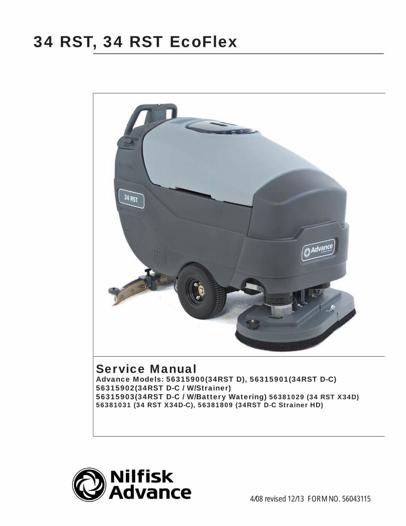
34 RST, 34 RST EcoFlex
Service ManualAdvance Models: 56315900(34RST D), 56315901(34RST D-C)56315902(34RST D-C / W/Strainer) 56315903(34RST D-C / W/Battery Watering) 56381029 (34 RST X34D) 56381031 (34 RST X34D-C), 56381809 (34RST D-C Strainer HD)
ii - FORM NO. 56043115 - 34 RST
Table of Contents
Table of Contents
Introduction . . . . . . . . . . . . . . . . . . . . . . . . . . . . . . . . . . . . . . . . . . . . . . . . . . .5Parts and Service 5Nameplate 5Other Manuals Available For Your Machine 5Conventions 6Transporting the Machine 6Cautions and Warnings 6
Symbols 6General Safety Instructions 7
Technical Specifications 8Maintenance Schedule 10
Batteries and Chargers 10Lubricating the Machine 10
PM Checklist 11Know Your Machine 12
Control Panel . . . . . . . . . . . . . . . . . . . . . . . . . . . . . . . . . . . . . . . . . . . . . . . . . 15Standard Models 15EcoFlex Models 16Functional Description 17Description of Indicators 18
Scrub Mode Indicators 19Battery Indicator 20
Main Controller 21Main Control Board Programming 21
Displaying the Control Board Revision Level 22Recall of Stored Error Codes 22Turning Fault Detection On or Off: 23Low-voltage Cutout Threshold 23Selecting Machine Type (EcoFlex version only) 24Chemical Option (EcoFlex Models) 24Scrub Deck Down Time Period Adjustment 25Scrub Deck Pressure, Solution Flow Rate, and Chemical Flow Rate Adjustments 26
Restoring the Scrub Pressures to Factory Default Settings 26Regular Scrub Setting Adjustment 27Heavy Scrub Setting Adjustment: 28Extreme Scrub Setting Adjustment 29
Troubleshooting Guide 30Main Controller Error Codes 30Main Controller I/O Table 32Service Test Mode 33Test Mode Input Indicators 33
Battery Voltage 33Speed Controller Status 33Forward/Reverse Status 33Reverse Status 33
Test Mode Output Controls 34Description of Output Controls 34
iii - FORM NO. 56043115 - 34 RST
Table of Contents
Solution System . . . . . . . . . . . . . . . . . . . . . . . . . . . . . . . . . . . . . . . . . . . . . . . . 37Functional Overview 37Circuit Overview 38
Electrical Diagram 38Maintenance 39Troubleshooting Guide 39Electrical Troubleshooting 39Removal and Installation 40
Solenoid Valve Removal 40Solenoid Valve Disassembly and Cleaning 40Solution Filter and Ball Valve Removal 41
Scrub System . . . . . . . . . . . . . . . . . . . . . . . . . . . . . . . . . . . . . . . . . . . . . . . . . 42Functional Overview 42
M2/M3 - Scrub Brush Motor Run Function 42M5 - Scrub Brush Actuator Lift Motor Function 42Scrub System Low-voltage Cut-out Function 42Electrical Diagram 43
Removal and Installation 44Motor Gimbal . . . . . . . . . . . . . . . . . . . . . . . . . . . . . . . . . . . . . . . . . . . . . . . . . . . . . . . . . 44Scrub Brush Deck 45Scrub Brush lift Actuator 46Scrub Brush Motor/Gearbox 47
Recovery System . . . . . . . . . . . . . . . . . . . . . . . . . . . . . . . . . . . . . . . . . . . . . . . 48Functional Overview . . . . . . . . . . . . . . . . . . . . . . . . . . . . . . . . . . . . . . . . . . . . . . . . . . . . . . 48
Vacuum Motor Control Circuit Overview (Auto Mode) 49Maintenance 50
Service Maintenance Checklist 50Troubleshooting Guide 50Maintenance of the Recovery Tank Float Switch 51Maintenance of Vacuum Motor Inlet Screen 52
Removal and Installation 53Vacuum Motor Removal 53Recovery Tank Removal 54
Squeegee System . . . . . . . . . . . . . . . . . . . . . . . . . . . . . . . . . . . . . . . . . . . . . . . 55Maintenance 55
Squeegee Lift Linkage Adjustment 55Servicing the Squeegee 56Adjusting the Squeegee . . . . . . . . . . . . . . . . . . . . . . . . . . . . . . . . . . . . . . . . . . . . . . . . . . . 56
Removal and Installation 57Squeegee Mount Assembly Removal 57Caster Wheel Removal 58
Wheel Drive System . . . . . . . . . . . . . . . . . . . . . . . . . . . . . . . . . . . . . . . . . . . . . 59Functional Overview 59
Drive Motor System Function 59Electrical Diagram 60A2 Speed Controller Pin Key Detail 61
Wheel Drive Troubleshooting guide 62Removal and Installation 63
Drive Motor Transaxle Removal 63Drive Motor Transaxle Removal (continued) 64Drive Wheel Removal 65Testing the Palm Drive Buttons 66
iv - FORM NO. 56043115 - 34 RST
Table of Contents
Palm Drive Button Replacement 67Testing the Reverse Button 68Reverse Button Replacement 69Testing the Speed Limit Control Potentiometer 70Speed Limit Control Potentiometer Replacement 70
Electrical System . . . . . . . . . . . . . . . . . . . . . . . . . . . . . . . . . . . . . . . . . . . . . . . 72Schematic 72Batteries 73
Description of the Low Voltage Cut-Out Feature 73Description Of The Battery Condition Indicators 73Specific Wet Cell Battery Information 73
Battery Maintenance 74Charging Batteries 74Extending Battery Life 74Removal and Installation 75Battery Testing 75
Maintenance and Adjustment 76Lift Actuator Limit Adjustment 76
Curtis Controller Diagnostics 78Function of the Speed Controller Status Light and Display 78Diagnostics Using the Curtis Handheld Programmer 78Fault History 78Drive Status LED Fault Codes 79
Speed Control Programming Options 80Installation Checkout for the Curtis Speed Controller 80Programming Vehicle Speed Changes 80Maintenance 80
5 - FORM NO. 56043115 - 34 RST
Introduction
IntroductionThis manual will help you get the most from your Advance 34 RST D and 34 RST D-C models, 34 RST D-C models with Strainer, and 34 RST D-C models with a Battery Watering Kit. Read it thoroughly before servicing the machine.
Note: Bold numbers and letters in parentheses indicate illustrated items.
Note: All references to right, left, front, or rear in this manual are as seen from the operator’s standpoint.
Parts and Service
Repairs should be performed by your Authorized Nilfisk-Advance Service Center, who employs factory trained service personnel, and maintains an inventory of Nilfisk-Advance original replacement parts and accessories.
Call the NILFISK-ADVANCE DEALER named below for repair parts or service. Please specify the Model and Serial Number when discussing your machine.
(Dealer, affix service sticker here.)
Nameplate
The Model Number and Serial Number of your machine are shown on the Nameplate on the machine. This information is needed when ordering repair parts for the machine. Use the space below to note the Model Number and Serial Number of your machine for future reference.
MODEL NUMBER ________________________________________
SERIAL NUMBER ________________________________________
Other Manuals Available For Your Machine
The manuals listed below can be found via Nilfisk-Advance’s two electronic supported databases. They are:• Nilfisk-Advance Dealer Customer Zone• EzParts service / parts CD-Rom• Instructions for Use (English/Español) – Form Number 56041706• Parts List – Form Number 56042485• Curtis Programmer Manual – Form Number 56043101
6 - FORM NO. 56043115 - 34 RST
Introduction
ConventionsForward, backward, front, rear, left or right are intended with reference to the operator’s position, that is to say in operating position with the hands on the handlebar.
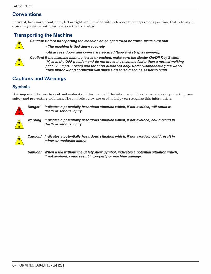
Transporting the MachineCaution! Before transporting the machine on an open truck or trailer, make sure that
• The machine is tied down securely.
• All access doors and covers are secured (tape and strap as needed).Caution! If the machine must be towed or pushed, make sure the Master On/Off Key Switch
(A) is in the OFF position and do not move the machine faster than a normal walking pace (2-3 mph, 3-5kph) and for short distances only. Note: Disconnecting the wheel drive motor wiring connector will make a disabled machine easier to push.
Cautions and Warnings
Symbols
It is important for you to read and understand this manual. The information it contains relates to protecting your safety and preventing problems. The symbols below are used to help you recognize this information.
Danger! Indicates a potentially hazardous situation which, if not avoided, will result in death or serious injury.
Warning! Indicates a potentially hazardous situation which, if not avoided, could result in death or serious injury.
Caution! Indicates a potentially hazardous situation which, if not avoided, could result in minor or moderate injury.
Caution! When used without the Safety Alert Symbol, indicates a potential situation which, if not avoided, could result in property or machine damage.
7 - FORM NO. 56043115 - 34 RST
Introduction
General Safety Instructions
Warning!
This machine should be used only by properly trained and authorized persons. Never work under a machine without safety blocks or stands to support the machine. Keep sparks, flame and smoking materials away from batteries. Explosive gases are vented
during normal operation. Charging the batteries produces highly explosive hydrogen gas. Charge batteries only in well-
ventilated areas away from open flame. Do not smoke while charging the batteries. Remove all jewelry when working near electrical components. Do not dispense flammable cleaning agents, operate the machine on or near these agents, or
operate in areas where flammable liquids exist.Caution!:
When operating this machine, ensure that third parties, particularly children, are not endangered.
Turn the key switch off (O) and disconnect the batteries before servicing electrical components. Turn the key switch off (O) and remove the key, before changing the brushes, and before
opening any access panels. This machine is not suitable for picking up hazardous dust. Do not use on surfaces having a gradient exceeding that marked on the machine. While on ramps or inclines, avoid sudden stops when loaded. Avoid abrupt sharp turns. Use low
speed down hills. Clean only while ascending (driving up) the ramp. Before performing any service function, carefully read all instructions pertaining to that
function. Do not leave the machine unattended without first turning the key switch off (O), removing the
key and securing the machine. Take precautions to prevent hair, jewelry, or loose clothing from becoming caught in moving
parts. Only use the brushes provided with the appliance or those specified in the instruction manual.
The use of other brushes may impair safety. Refer to the battery charger OEM product manual for additional specific battery charger
warnings.Caution!:
This machine is not approved for use on public paths or roads. Use care when using abrasive brushes, scarifier discs, or grinding stones. Advance will not be
held responsible for any damage to floor surfaces. Turn the key switch off (O) and remove the key, before changing the brushes, and before
opening any access panels. Use caution when moving this machine in below freezing temperature conditions. Any water
in the solution, recovery or detergent tanks or in the hose lines could freeze, causing damage to valves and fittings. Flush with windshield washer fluid.
The batteries must be removed from the machine before the machine is scrapped. The disposal of the batteries should be safely done in accordance with your local environmental regulations.
Do not clean this machine with a pressure washer. All doors and covers are to be positioned as indicated in the instruction manual before using the
machine.
8 - FORM NO. 56043115 - 34 RST
Introduction
Technical Specifications
Voltage 36-Volt
Power Source (6) 6-volt Batteries (wet acid and gel cell available)
Battery Capacity 305 amp-hrs.
Protection Grade IPX3
Onboard Battery Charger 36-volt, 25-amp Wet/Gel Compatible
Solution Control Pulse-control gravity feed
Solution Tank 30 gal. (114 L)
Recovery Tank 30 gal. (114 L)
Scrub Motors (2) 0.75 HP (560-watt)
Vacuum Motor 0.75 HP (560-watt) three-stage
Sound Pressure Level (IEC 60704-1) 74.5 dB(A)/20µPaDrive System 0.5 HP (375-watt) variable forward and reverse; max. speed = 3 mph (4.83 km/hr)
Drive Wheels (2) 13-inch (33 cm) diameter; foam-filled; black non-marking
Scrub Head Type Disc
Scrub Path 34 inches (86 cm)
GradeabilityTransport 2% (1.15º)
Cleaning 2% (1.15º)
Max. Productivity @ 3.0 mph 44,880 ft2/hr (4,169 m2/hr)
Max. Productivity @ 1.5 mph 22,440 ft2/hr (2,085 m2/hr)
Scrub Head Size and Type (2) 17 in,(43 cm) Brushes or Pad Holders
Scrub Pressure
(1) Regular Scrub Max. 90 lbs (40.8 kg)
(2) Heavy Scrub Max. 175 lbs (79.4 kg)
(3) Extreme Scrub Max. 250 lbs (113.4 kg)
Scrub Head Speed 220 RPM
Solution Flow Rate
(1) Regular Scrub 0.30 gal/min (1.1 L/min) or 100 minutes per solution tank
(2) Heavy Scrub 0.60 gal/min (2.3 L/min) or 50 minutes per solution tank
(3) Extreme Scrub 0.90 gal/min (3.4 L/min) or 33 minutes per solution tank
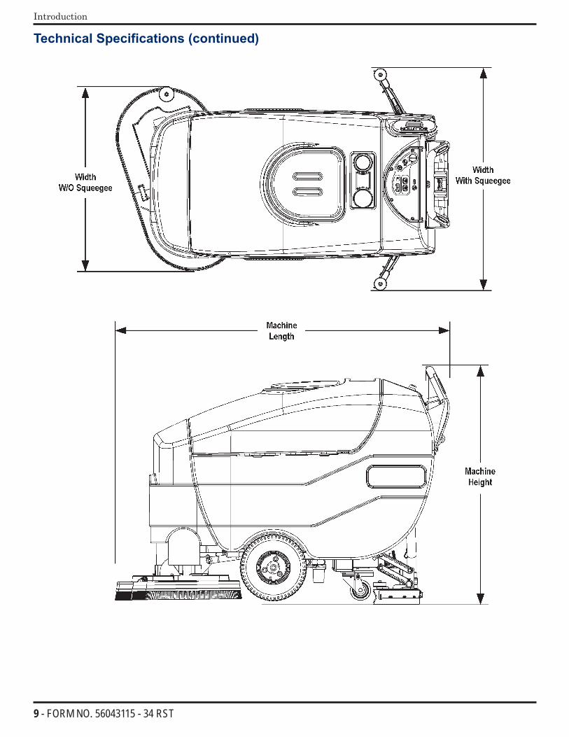
Squeegee Width 41.9 in (106 cm)
Dimensions (w/o Squeegee) W = 35.5 in (90 cm); L = 62.5 in (159 cm); H = 45 in (114 cm)
Gross Weight w/Standard Batteries 1,245 lbs (565 kg)
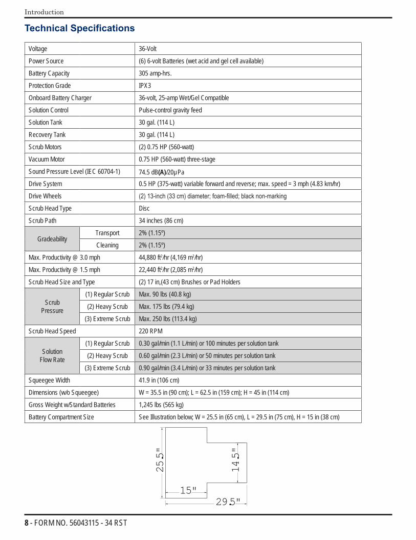
Battery Compartment Size See Illustration below; W = 25.5 in (65 cm), L = 29.5 in (75 cm), H = 15 in (38 cm)
14.5
"
15"
25.5
"
29.5"
9 - FORM NO. 56043115 - 34 RST
Introduction
Technical Specifications (continued)
10 - FORM NO. 56043115 - 34 RST
Introduction
Maintenance Schedule
Maintenance intervals given are for average operating conditions. Machines used in severe operational environments may require service more often.
MAINTENANCE ITEM Daily Weekly Monthly Yearly Charge the Batteries X Check/Clean Tanks and Hoses (clean recovery tank switch and vacuum inlet screen) X Check/Clean/Rotate the Brushes/Pads X Check/Clean the Squeegee X Check the Water Level in each Battery Cell (does not apply to gel cell batteries) X Inspect the Brush Housings X Inspect and Clean the Solution Filter X Lubricate the Machine X * Check the Carbon Brushes X
Note: See the individual machine system sections in this manual for maintenance information.
Warning! Turn the key switch off and disconnect the batteries before servicing the machine.
* Carbon brush inspection intervals and replacement recommendations:• Check the vacuum motor carbon brushes (two per motor) once a year or after 300 operating hours.• Check the carbon brushes on the brush and wheel drive motors (four per motor) once a year or after 500 operating
hours.• The original (new) length of each carbon brush is 1” (25.4mm) on all 36-volt machine models brush and wheel
drive motors.• All motors: Replace carbon brushes when shorter than 3/8” (9.5mm) to obtain the same motor efficiency as new
brushes.
Important! Motor damage resulting from failure to service the carbon brushes is not covered under warranty. See the Limited Warranty Statement.
Batteries and Chargers
Attention: See the Electrical System/Batteries section in this manual for battery installation, battery maintenance and charger system requirements.
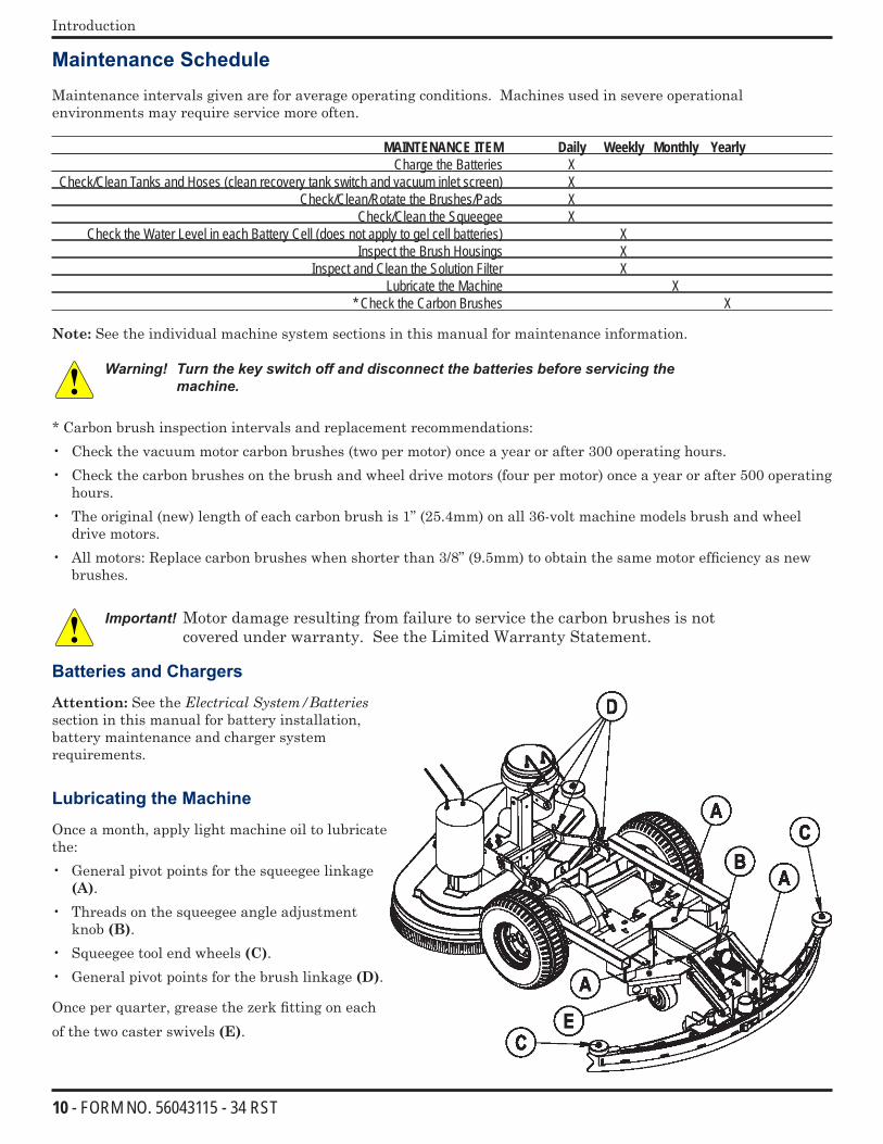
Lubricating the Machine
Once a month, apply light machine oil to lubricate the:• General pivot points for the squeegee linkage
(A).• Threads on the squeegee angle adjustment
knob (B).• Squeegee tool end wheels (C).• General pivot points for the brush linkage (D).
Once per quarter, grease the zerk fitting on each of the two caster swivels (E).
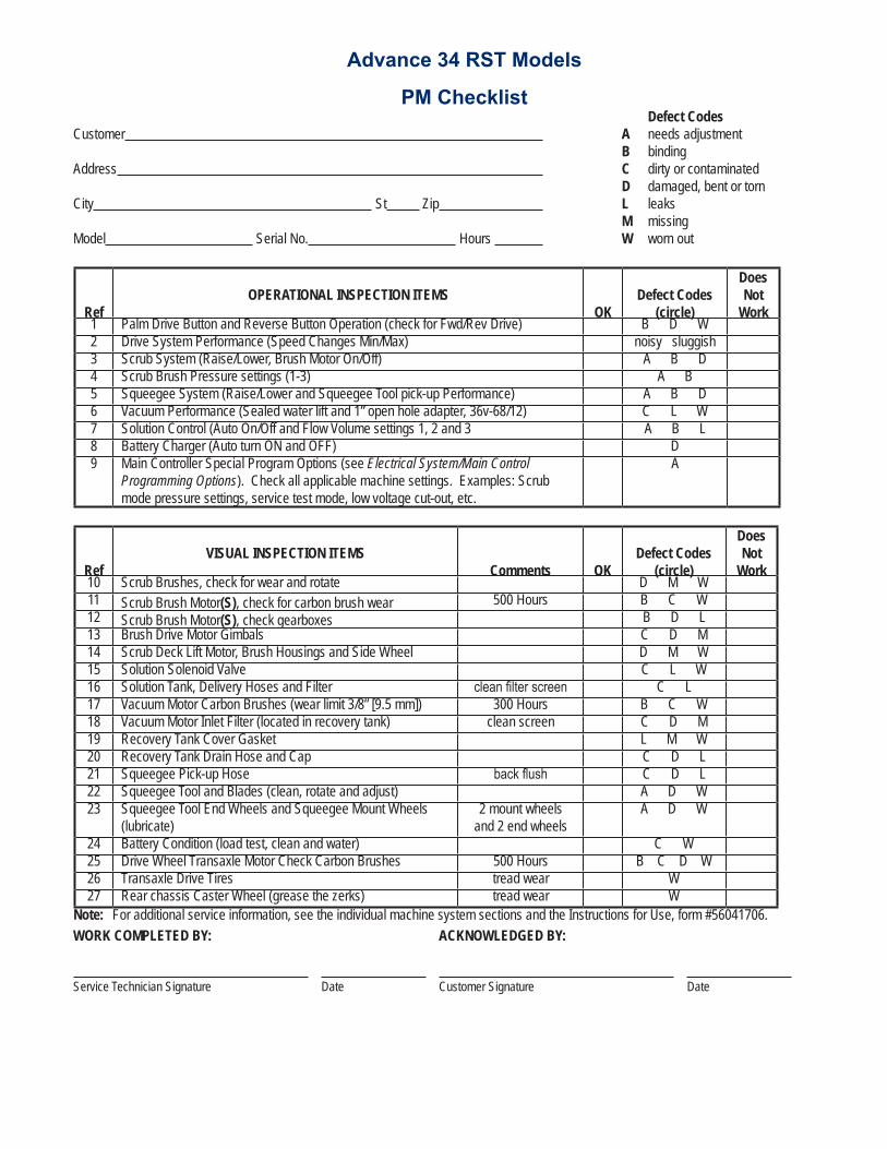
Advance 34 RST Models
PM Checklist Defect CodesCustomer A needs adjustment B bindingAddress C dirty or contaminated D damaged, bent or tornCity St Zip L leaks M missingModel Serial No. Hours W worn out
RefOPERATIONAL INSPECTION ITEMS
OKDefect Codes
(circle)
Does Not
Work1 Palm Drive Button and Reverse Button Operation (check for Fwd/Rev Drive) B D W2 Drive System Performance (Speed Changes Min/Max) noisy sluggish3 Scrub System (Raise/Lower, Brush Motor On/Off) A B D4 Scrub Brush Pressure settings (1-3) A B5 Squeegee System (Raise/Lower and Squeegee Tool pick-up Performance) A B D6 Vacuum Performance (Sealed water lift and 1” open hole adapter, 36v-68/12) C L W7 Solution Control (Auto On/Off and Flow Volume settings 1, 2 and 3 A B L8 Battery Charger (Auto turn ON and OFF) D9 Main Controller Special Program Options (see Electrical System/Main Control
Programming Options). Check all applicable machine settings. Examples: Scrub mode pressure settings, service test mode, low voltage cut-out, etc.
A
RefVISUAL INSPECTION ITEMS
Comments OKDefect Codes
(circle)
Does Not
Work10 Scrub Brushes, check for wear and rotate D M W11 Scrub Brush Motor(S), check for carbon brush wear 500 Hours B C W12 Scrub Brush Motor(S), check gearboxes B D L13 Brush Drive Motor Gimbals C D M14 Scrub Deck Lift Motor, Brush Housings and Side Wheel D M W15 Solution Solenoid Valve C L W16 Solution Tank, Delivery Hoses and Filter clean filter screen C L17 Vacuum Motor Carbon Brushes (wear limit 3/8” [9.5 mm]) 300 Hours B C W18 Vacuum Motor Inlet Filter (located in recovery tank) clean screen C D M19 Recovery Tank Cover Gasket L M W20 Recovery Tank Drain Hose and Cap C D L21 Squeegee Pick-up Hose back flush C D L22 Squeegee Tool and Blades (clean, rotate and adjust) A D W23 Squeegee Tool End Wheels and Squeegee Mount Wheels
(lubricate)2 mount wheels
and 2 end wheelsA D W
24 Battery Condition (load test, clean and water) C W25 Drive Wheel Transaxle Motor Check Carbon Brushes 500 Hours B C D W26 Transaxle Drive Tires tread wear W27 Rear chassis Caster Wheel (grease the zerks) tread wear W
Note: For additional service information, see the individual machine system sections and the Instructions for Use, form #56041706.WORK COMPLETED BY: ACKNOWLEDGED BY:
Service Technician Signature Date Customer Signature Date
12 - FORM NO. 56043115 - 34 RST
Introduction
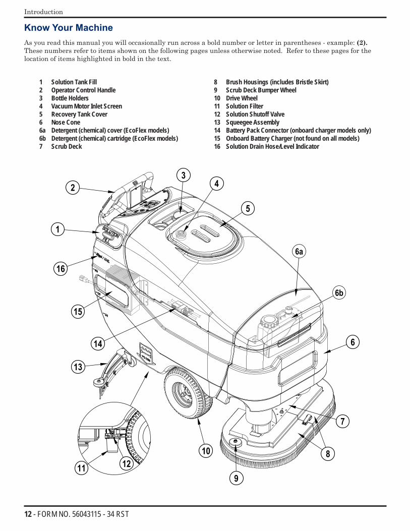
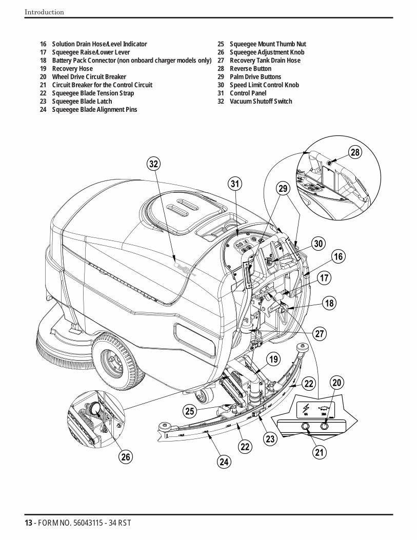
Know Your MachineAs you read this manual you will occasionally run across a bold number or letter in parentheses - example: (2). These numbers refer to items shown on the following pages unless otherwise noted. Refer to these pages for the location of items highlighted in bold in the text.
1 Solution Tank Fill2 Operator Control Handle3 Bottle Holders4 Vacuum Motor Inlet Screen5 Recovery Tank Cover6 Nose Cone6a Detergent (chemical) cover (EcoFlex models)6b Detergent (chemical) cartridge (EcoFlex models)7 Scrub Deck
8 Brush Housings (includes Bristle Skirt) 9 Scrub Deck Bumper Wheel10 Drive Wheel11 Solution Filter12 Solution Shutoff Valve13 Squeegee Assembly14 Battery Pack Connector (onboard charger models only)15 Onboard Battery Charger (not found on all models)16 Solution Drain Hose/Level Indicator
13 - FORM NO. 56043115 - 34 RST
Introduction
16 Solution Drain Hose/Level Indicator17 Squeegee Raise/Lower Lever18 Battery Pack Connector (non onboard charger models only)19 Recovery Hose20 Wheel Drive Circuit Breaker21 Circuit Breaker for the Control Circuit22 Squeegee Blade Tension Strap23 Squeegee Blade Latch24 Squeegee Blade Alignment Pins
25 Squeegee Mount Thumb Nut26 Squeegee Adjustment Knob27 Recovery Tank Drain Hose28 Reverse Button29 Palm Drive Buttons30 Speed Limit Control Knob31 Control Panel32 Vacuum Shutoff Switch
14 - FORM NO. 56043115 - 34 RST
Introduction
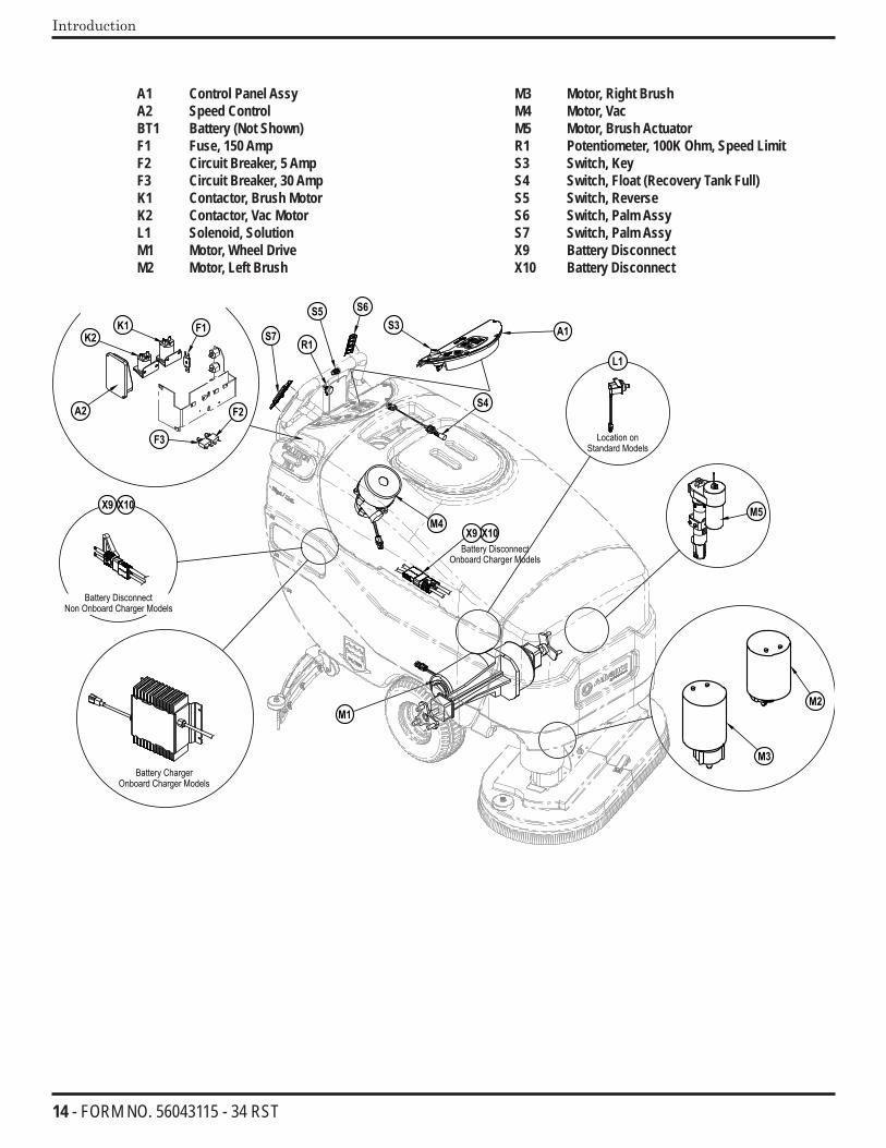
A1 Control Panel Assy A2 Speed Control BT1 Battery (Not Shown) F1 Fuse, 150 Amp F2 Circuit Breaker, 5 Amp F3 Circuit Breaker, 30 Amp K1 Contactor, Brush Motor K2 Contactor, Vac Motor L1 Solenoid, Solution M1 Motor, Wheel Drive M2 Motor, Left Brush
M3 Motor, Right Brush M4 Motor, Vac M5 Motor, Brush Actuator R1 Potentiometer, 100K Ohm, Speed Limit S3 Switch, Key S4 Switch, Float (Recovery Tank Full) S5 Switch, Reverse S6 Switch, Palm Assy S7 Switch, Palm Assy X9 Battery Disconnect X10 Battery Disconnect
15 - FORM NO. 56043115 - 34 RST
Control Panel
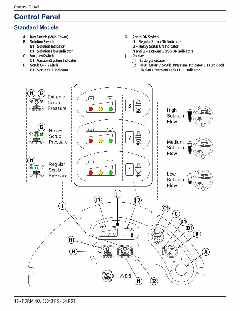
Control PanelStandard Models
A Key Switch (Main Power)B Solution Switch
B1 Solution IndicatorD1 Solution Flow Indicator
C Vacuum SwitchC1 Vacuum System Indicator
H Scrub OFF SwitchH1 Scrub OFF Indicator
I- Scrub ON SwitchI1 – Regular Scrub ON IndicatorI2 – Heavy Scrub ON IndicatorI1 and I2 – Extreme Scrub ON Indicators
J DisplayJ1 Battery IndicatorJ2 Hour Meter / Scrub Pressure Indicator / Fault Code
Display / Recovery Tank FULL Indicator
A
B
C
H
I
JJ1 J2
1
2
3
D1
H1
I1 I2
I1
I2
I2I1
C1
B1
Extreme ScrubPressure
Heavy ScrubPressure
Regular ScrubPressure
High Solution Flow
Low Solution Flow
Medium Solution Flow
16 - FORM NO. 56043115 - 34 RST
Control Panel
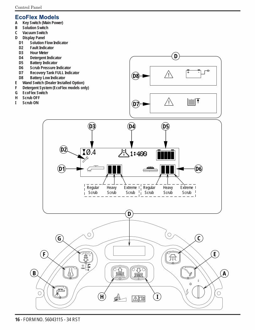
EcoFlex ModelsA Key Switch (Main Power)B Solution SwitchC Vacuum SwitchD Display Panel
D1 Solution Flow IndicatorD2 Fault IndicatorD3 Hour MeterD4 Detergent IndicatorD5 Battery IndicatorD6 Scrub Pressure IndicatorD7 Recovery Tank FULL IndicatorD8 Battery Low Indicator
E Wand Switch (Dealer Installed Option)F Detergent System (EcoFlex models only)G EcoFlex SwitchH Scrub OFFI Scrub ON
Ø.4
!
!
A
E
CG
F
B
H I
D
D1
D2
D3 D4 D5
D6
D7
D8
D
Regular Heavy Extreme Regular Heavy Extreme Scrub Scrub Scrub Scrub Scrub Scrub
17 - FORM NO. 56043115 - 34 RST
Control Panel
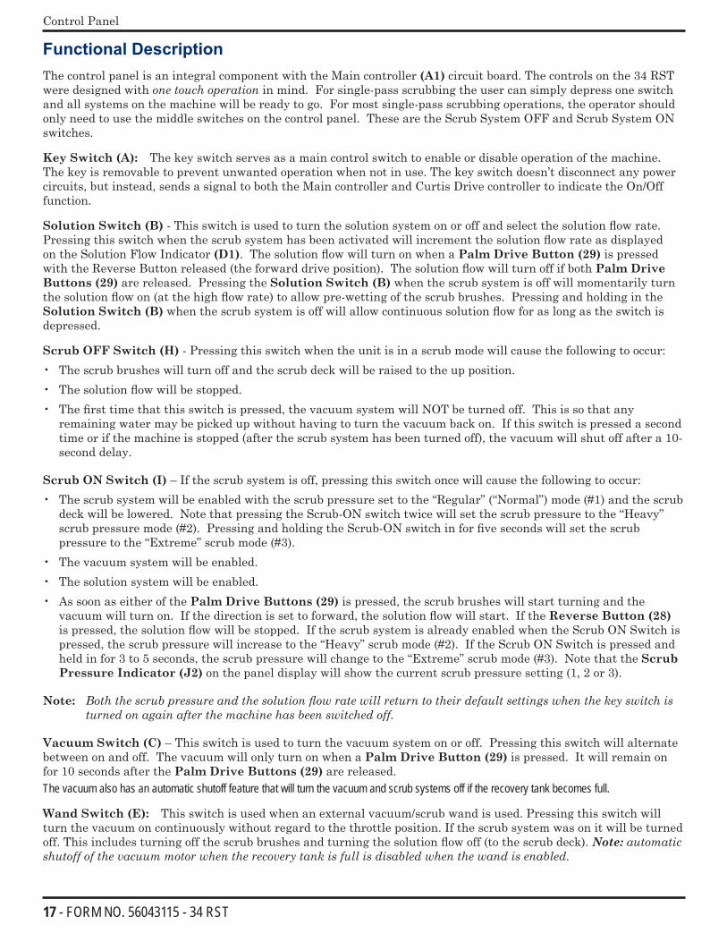
Functional DescriptionThe control panel is an integral component with the Main controller (A1) circuit board. The controls on the 34 RST were designed with one touch operation in mind. For single-pass scrubbing the user can simply depress one switch and all systems on the machine will be ready to go. For most single-pass scrubbing operations, the operator should only need to use the middle switches on the control panel. These are the Scrub System OFF and Scrub System ON switches.
Key Switch (A): The key switch serves as a main control switch to enable or disable operation of the machine. The key is removable to prevent unwanted operation when not in use. The key switch doesn’t disconnect any power circuits, but instead, sends a signal to both the Main controller and Curtis Drive controller to indicate the On/Off function.
Solution Switch (B) - This switch is used to turn the solution system on or off and select the solution flow rate. Pressing this switch when the scrub system has been activated will increment the solution flow rate as displayed on the Solution Flow Indicator (D1). The solution flow will turn on when a Palm Drive Button (29) is pressed with the Reverse Button released (the forward drive position). The solution flow will turn off if both Palm Drive Buttons (29) are released. Pressing the Solution Switch (B) when the scrub system is off will momentarily turn the solution flow on (at the high flow rate) to allow pre-wetting of the scrub brushes. Pressing and holding in the Solution Switch (B) when the scrub system is off will allow continuous solution flow for as long as the switch is depressed.
Scrub OFF Switch (H) - Pressing this switch when the unit is in a scrub mode will cause the following to occur:• The scrub brushes will turn off and the scrub deck will be raised to the up position.• The solution flow will be stopped.• The first time that this switch is pressed, the vacuum system will NOT be turned off. This is so that any
remaining water may be picked up without having to turn the vacuum back on. If this switch is pressed a second time or if the machine is stopped (after the scrub system has been turned off), the vacuum will shut off after a 10-second delay.
Scrub ON Switch (I) – If the scrub system is off, pressing this switch once will cause the following to occur:• The scrub system will be enabled with the scrub pressure set to the “Regular” (“Normal”) mode (#1) and the scrub
deck will be lowered. Note that pressing the Scrub-ON switch twice will set the scrub pressure to the “Heavy” scrub pressure mode (#2). Pressing and holding the Scrub-ON switch in for five seconds will set the scrub pressure to the “Extreme” scrub mode (#3).
• The vacuum system will be enabled.• The solution system will be enabled.• As soon as either of the Palm Drive Buttons (29) is pressed, the scrub brushes will start turning and the
vacuum will turn on. If the direction is set to forward, the solution flow will start. If the Reverse Button (28) is pressed, the solution flow will be stopped. If the scrub system is already enabled when the Scrub ON Switch is pressed, the scrub pressure will increase to the “Heavy” scrub mode (#2). If the Scrub ON Switch is pressed and held in for 3 to 5 seconds, the scrub pressure will change to the “Extreme” scrub mode (#3). Note that the Scrub Pressure Indicator (J2) on the panel display will show the current scrub pressure setting (1, 2 or 3).
Note: Boththescrubpressureandthesolutionflowratewillreturntotheirdefaultsettingswhenthekeyswitchisturnedonagainafterthemachinehasbeenswitchedoff.
Vacuum Switch (C) – This switch is used to turn the vacuum system on or off. Pressing this switch will alternate between on and off. The vacuum will only turn on when a Palm Drive Button (29) is pressed. It will remain on for 10 seconds after the Palm Drive Buttons (29) are released.The vacuum also has an automatic shutoff feature that will turn the vacuum and scrub systems off if the recovery tank becomes full.
Wand Switch (E): This switch is used when an external vacuum/scrub wand is used. Pressing this switch will turn the vacuum on continuously without regard to the throttle position. If the scrub system was on it will be turned off. This includes turning off the scrub brushes and turning the solution flow off (to the scrub deck). Note: automatic shutoffofthevacuummotorwhentherecoverytankisfullisdisabledwhenthewandisenabled.
18 - FORM NO. 56043115 - 34 RST
Control Panel
Chemical Switch (F): The chemical (detergent mixing) option is available on EcoFlex models. Pressing this switch will turn on or off the chemical option. When active, a small pump will inject chemical (detergent) into the solution line upstream from the scrub deck. The chemical pump is disabled any time the solution system is inactive. See the main programming options in this manual to select (activate) the onboard chemical distribution system.
EcoFlex Switch (G): This option is available only on EcoFlex models. By default, the EcoFlex cleaning mode is active during normal operation to conserve solution and detergent. Press this switch for 2 seconds to override the EcoFlex cleaning mode and temporarily increase scrub pressure, solution flow, and the detergent ratio. See the main programming options in this manual to select (activate) the EcoFlex option.
Description of Indicators
Each of the switches on the control panel have an indicator LED adjacent to the switch. Most LEDs are dual channel and provide two colors within the same LED. In general, the following guidelines apply to the control panel indicators, and various exceptions to this rule are listed separately: • A steady green indicator means that the particular system or function is on. • A flashing green indicator means that the particular system is in a delayed-off condition. An example of this is
when a scrub mode is selected and the throttle goes from forward or reverse to neutral. When this happens the vacuum indicator will flash green indicating that the vacuum is still on but that it will be turning off after the delay period.
• A steady yellow indicator means that the particular function has been enabled and in a ready state, but is not currently on. For example, if a scrub mode is selected and the throttle is in neutral, the scrub system, vacuum, and solution indicators will all be yellow indicating that the systems are enabled and ready to turn on when the throttle is moved to forward and/or reverse.
• A flashing yellow indicator means that a fault has occurred in the particular system. An example of this would be an over-current fault on one of the motors.
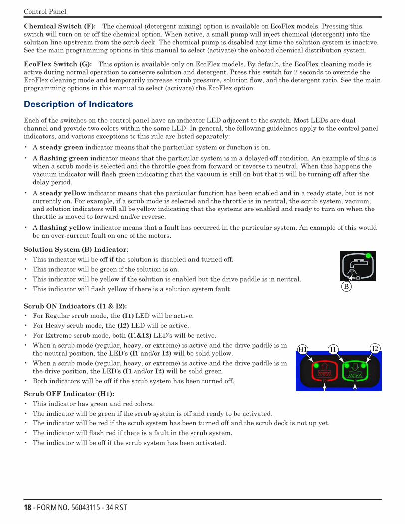
Solution System (B) Indicator:• This indicator will be off if the solution is disabled and turned off. • This indicator will be green if the solution is on. • This indicator will be yellow if the solution is enabled but the drive paddle is in neutral. • This indicator will flash yellow if there is a solution system fault.
Scrub ON Indicators (I1 & I2):• For Regular scrub mode, the (I1) LED will be active.• For Heavy scrub mode, the (I2) LED will be active.• For Extreme scrub mode, both (I1&I2) LED’s will be active.• When a scrub mode (regular, heavy, or extreme) is active and the drive paddle is in
the neutral position, the LED’s (I1 and/or I2) will be solid yellow.• When a scrub mode (regular, heavy, or extreme) is active and the drive paddle is in
the drive position, the LED’s (I1 and/or I2) will be solid green.• Both indicators will be off if the scrub system has been turned off.
Scrub OFF Indicator (H1): • This indicator has green and red colors. • The indicator will be green if the scrub system is off and ready to be activated. • The indicator will be red if the scrub system has been turned off and the scrub deck is not up yet. • The indicator will flash red if there is a fault in the scrub system. • The indicator will be off if the scrub system has been activated.
B
I1 I2H1
H I
19 - FORM NO. 56043115 - 34 RST
Control Panel
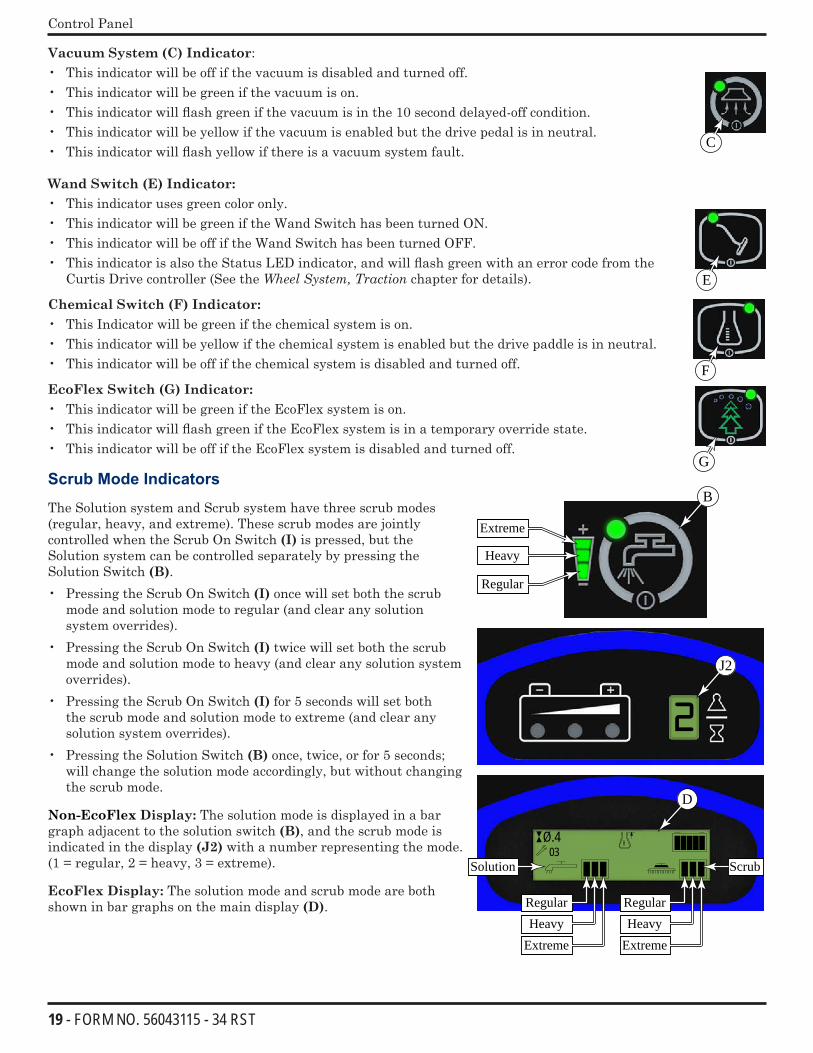
Vacuum System (C) Indicator:• This indicator will be off if the vacuum is disabled and turned off. • This indicator will be green if the vacuum is on. • This indicator will flash green if the vacuum is in the 10 second delayed-off condition. • This indicator will be yellow if the vacuum is enabled but the drive pedal is in neutral. • This indicator will flash yellow if there is a vacuum system fault.
Wand Switch (E) Indicator: • This indicator uses green color only.• This indicator will be green if the Wand Switch has been turned ON. • This indicator will be off if the Wand Switch has been turned OFF. • This indicator is also the Status LED indicator, and will flash green with an error code from the
Curtis Drive controller (See the Wheel System, Traction chapter for details).
Chemical Switch (F) Indicator: • This Indicator will be green if the chemical system is on. • This indicator will be yellow if the chemical system is enabled but the drive paddle is in neutral. • This indicator will be off if the chemical system is disabled and turned off.
EcoFlex Switch (G) Indicator: • This indicator will be green if the EcoFlex system is on. • This indicator will flash green if the EcoFlex system is in a temporary override state.• This indicator will be off if the EcoFlex system is disabled and turned off.
Scrub Mode Indicators
The Solution system and Scrub system have three scrub modes (regular, heavy, and extreme). These scrub modes are jointly controlled when the Scrub On Switch (I) is pressed, but the Solution system can be controlled separately by pressing the Solution Switch (B). • Pressing the Scrub On Switch (I) once will set both the scrub
mode and solution mode to regular (and clear any solution system overrides).
• Pressing the Scrub On Switch (I) twice will set both the scrub mode and solution mode to heavy (and clear any solution system overrides).
• Pressing the Scrub On Switch (I) for 5 seconds will set both the scrub mode and solution mode to extreme (and clear any solution system overrides).
• Pressing the Solution Switch (B) once, twice, or for 5 seconds; will change the solution mode accordingly, but without changing the scrub mode.
Non-EcoFlex Display: The solution mode is displayed in a bar graph adjacent to the solution switch (B), and the scrub mode is indicated in the display (J2) with a number representing the mode. (1 = regular, 2 = heavy, 3 = extreme).
EcoFlex Display: The solution mode and scrub mode are both shown in bar graphs on the main display (D).
C
E
F
G
2
Ø.403
B
J2
D
Regular
Heavy
Extreme
RegularHeavy
Extreme
RegularHeavy
Extreme
Solution Scrub
20 - FORM NO. 56043115 - 34 RST
Control Panel
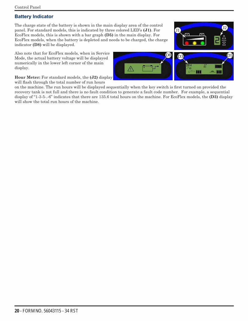
Battery Indicator The charge state of the battery is shown in the main display area of the control panel. For standard models, this is indicated by three colored LED’s (J1). For EcoFlex models, this is shown with a bar graph (D5) in the main display. For EcoFlex models, when the battery is depleted and needs to be charged, the charge indicator (D8) will be displayed.
Also note that for EcoFlex models, when in Service Mode, the actual battery voltage will be displayed numerically in the lower left corner of the main display.
Hour Meter: For standard models, the (J2) display will flash through the total number of run hours on the machine. The run hours will be displayed sequentially when the key switch is first turned on provided the recovery tank is not full and there is no fault condition to generate a fault code number. For example, a sequential display of “1-3-5-.-6” indicates that there are 135.6 total hours on the machine. For EcoFlex models, the (D3) display will show the total run hours of the machine.
2
Ø.403
D5
J1 J2
D3
!
D8
21 - FORM NO. 56043115 - 34 RST
Control Panel
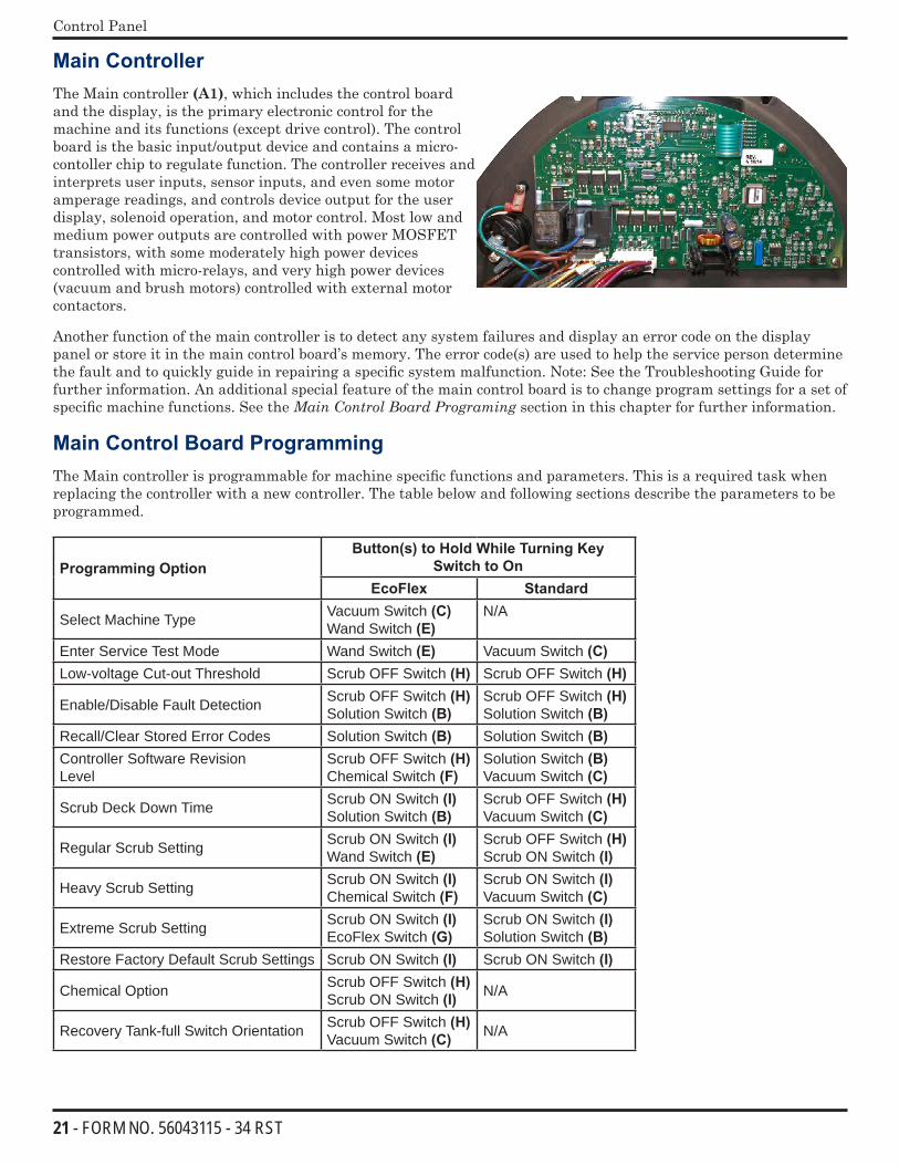
Main ControllerThe Main controller (A1), which includes the control board and the display, is the primary electronic control for the machine and its functions (except drive control). The control board is the basic input/output device and contains a micro-contoller chip to regulate function. The controller receives and interprets user inputs, sensor inputs, and even some motor amperage readings, and controls device output for the user display, solenoid operation, and motor control. Most low and medium power outputs are controlled with power MOSFET transistors, with some moderately high power devices controlled with micro-relays, and very high power devices (vacuum and brush motors) controlled with external motor contactors.
Another function of the main controller is to detect any system failures and display an error code on the display panel or store it in the main control board’s memory. The error code(s) are used to help the service person determine the fault and to quickly guide in repairing a specific system malfunction. Note: See the Troubleshooting Guide for further information. An additional special feature of the main control board is to change program settings for a set of specific machine functions. See the MainControlBoardPrograming section in this chapter for further information.
Main Control Board Programming The Main controller is programmable for machine specific functions and parameters. This is a required task when replacing the controller with a new controller. The table below and following sections describe the parameters to be programmed.
Programming OptionButton(s) to Hold While Turning Key
Switch to OnEcoFlex Standard
Select Machine Type Vacuum Switch (C)Wand Switch (E)
N/A
Enter Service Test Mode Wand Switch (E) Vacuum Switch (C)Low-voltage Cut-out Threshold Scrub OFF Switch (H) Scrub OFF Switch (H)
Enable/Disable Fault Detection Scrub OFF Switch (H)Solution Switch (B)
Scrub OFF Switch (H)Solution Switch (B)
Recall/Clear Stored Error Codes Solution Switch (B) Solution Switch (B)Controller Software RevisionLevel
Scrub OFF Switch (H)Chemical Switch (F)
Solution Switch (B) Vacuum Switch (C)
Scrub Deck Down Time Scrub ON Switch (I)Solution Switch (B)
Scrub OFF Switch (H)Vacuum Switch (C)
Regular Scrub Setting Scrub ON Switch (I)Wand Switch (E)
Scrub OFF Switch (H)Scrub ON Switch (I)
Heavy Scrub Setting Scrub ON Switch (I)Chemical Switch (F)
Scrub ON Switch (I)Vacuum Switch (C)
Extreme Scrub Setting Scrub ON Switch (I)EcoFlex Switch (G)
Scrub ON Switch (I)Solution Switch (B)
Restore Factory Default Scrub Settings Scrub ON Switch (I) Scrub ON Switch (I)
Chemical Option Scrub OFF Switch (H)Scrub ON Switch (I) N/A
Recovery Tank-full Switch Orientation Scrub OFF Switch (H)Vacuum Switch (C) N/A
22 - FORM NO. 56043115 - 34 RST
Control Panel
Displaying the Control Board Revision Level
During machine service, it may be helpful to know the control board revision level to determine machine configuration. To view the control board revision level:
EcoFlex Models:
1. Turn the key switch to the off position.
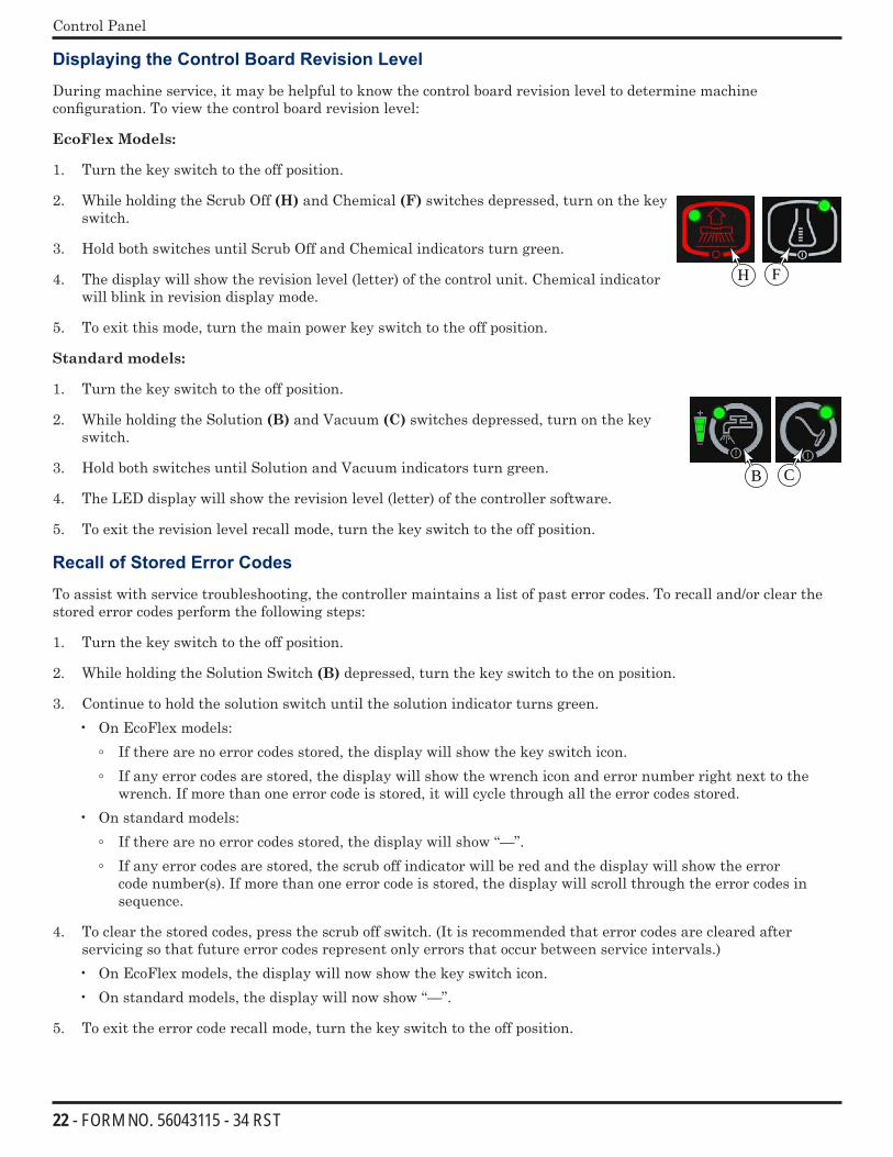
2. While holding the Scrub Off (H) and Chemical (F) switches depressed, turn on the key switch.
3. Hold both switches until Scrub Off and Chemical indicators turn green.
4. The display will show the revision level (letter) of the control unit. Chemical indicator will blink in revision display mode.
5. To exit this mode, turn the main power key switch to the off position.
Standard models:
1. Turn the key switch to the off position.
2. While holding the Solution (B) and Vacuum (C) switches depressed, turn on the key switch.
3. Hold both switches until Solution and Vacuum indicators turn green.
4. The LED display will show the revision level (letter) of the controller software.
5. To exit the revision level recall mode, turn the key switch to the off position.
Recall of Stored Error Codes
To assist with service troubleshooting, the controller maintains a list of past error codes. To recall and/or clear the stored error codes perform the following steps:
1. Turn the key switch to the off position.
2. While holding the Solution Switch (B) depressed, turn the key switch to the on position.
3. Continue to hold the solution switch until the solution indicator turns green. • On EcoFlex models:
If there are no error codes stored, the display will show the key switch icon. If any error codes are stored, the display will show the wrench icon and error number right next to the
wrench. If more than one error code is stored, it will cycle through all the error codes stored. • On standard models:
If there are no error codes stored, the display will show “—”. If any error codes are stored, the scrub off indicator will be red and the display will show the error
code number(s). If more than one error code is stored, the display will scroll through the error codes in sequence.
4. To clear the stored codes, press the scrub off switch. (It is recommended that error codes are cleared after servicing so that future error codes represent only errors that occur between service intervals.)• On EcoFlex models, the display will now show the key switch icon. • On standard models, the display will now show “—”.
5. To exit the error code recall mode, turn the key switch to the off position.
FH
CB
23 - FORM NO. 56043115 - 34 RST
Control Panel
Turning Fault Detection On or Off:
If a fault occurs in a particular system, that system (and possibly others) will be shut down. This can make troubleshooting the system difficult. This option will allow service personnel to disable some of the fault detection checks to facilitate troubleshooting. This will not disable the over-current protection on any of the systems. Important: Make sure to turn Fault Detection back on before returning the machine to normal operation. To turn the fault checking on or off:
1. Turn the key switch to the off position.
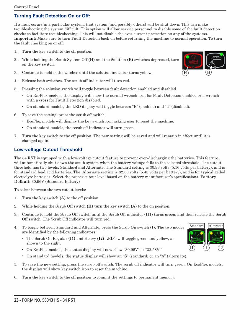
2. While holding the Scrub System Off (H) and the Solution (B) switches depressed, turn on the key switch.
3. Continue to hold both switches until the solution indicator turns yellow.
4. Release both switches. The scrub off indicator will turn red.
5. Pressing the solution switch will toggle between fault detection enabled and disabled. • On EcoFlex models, the display will show the normal wrench icon for Fault Detection enabled or a wrench
with a cross for Fault Detection disabled. • On standard models, the LED display will toggle between “E” (enabled) and “d” (disabled).
6. To save the setting, press the scrub off switch. • EcoFlex models will display the key switch icon asking user to reset the machine. • On standard models, the scrub off indicator will turn green.
7. Turn the key switch to the off position. The new setting will be saved and will remain in effect until it is changed again.
Low-voltage Cutout Threshold
The 34 RST is equipped with a low-voltage cutout feature to prevent over-discharging the batteries. This feature will automatically shut down the scrub system when the battery voltage falls to the selected threshold. The cutout threshold has two levels: Standard and Alternate. The Standard setting is 30.96 volts (5.16 volts per battery), and is for standard lead acid batteries. The Alternate setting is 32.58 volts (5.43 volts per battery), and is for typical gelled electrolyte batteries. Select the proper cutout level based on the battery manufacturer’s specifications. Factory Default: 30.96V (Standard Battery)
To select between the two cutout levels:
1. Turn the key switch (A) to the off position.
2. While holding the Scrub Off switch (H) turn the key switch (A) to the on position.
3. Continue to hold the Scrub Off switch until the Scrub Off indicator (H1) turns green, and then release the Scrub Off switch. The Scrub Off indicator will turn red.
4. To toggle between Standard and Alternate, press the Scrub On switch (I). The two modes are identified by the following indicators:• The Scrub On Regular (I1) and Heavy (I2) LED’s will toggle green and yellow, as
shown to the right.• On EcoFlex models, the status display will now show “30.96V” or “32.58V.”• On standard models, the status display will show an “S” (standard) or an “A” (alternate).
5. To save the new setting, press the scrub off switch. The scrub off indicator will turn green. On EcoFlex models, the display will show key switch icon to reset the machine.
6. Turn the key switch to the off position to commit the settings to permanent memory.
H B
AlternateStandard
I2II1
24 - FORM NO. 56043115 - 34 RST
Control Panel
Selecting Machine Type (EcoFlex version only)
Selecting the machine type must be done before selecting the scrub deck type in order for the correct scrub deck values to be available. This menu is only available on EcoFlex version machines and not the AXP or ST versions.
1. Turn the key switch to the off position.
2. While holding the Vacuum Switch (C) and the Wand Switch (F) depressed, turn on the key switch.
3. Hold both switches until the scrub on (M) and scrub off (N )indicators both turn green.
4. Release both switches.• The display will show either “Warrior” or “34-RST”
5. Press the Scrub On (D) switch to toggle between the values.• Select “34-RST”
6. Once the proper machine type has been selected, press the Scrub Off switch (E) to save this setting.• The display will show the key switch icon.
7. Turn the key switch to the off position to commit the setting.
Chemical Option (EcoFlex Models)
EcoFlex models are equipped with the chemical (detergent) system. To enable or disable this option, do the following:
1. Turn the key switch to the off position.
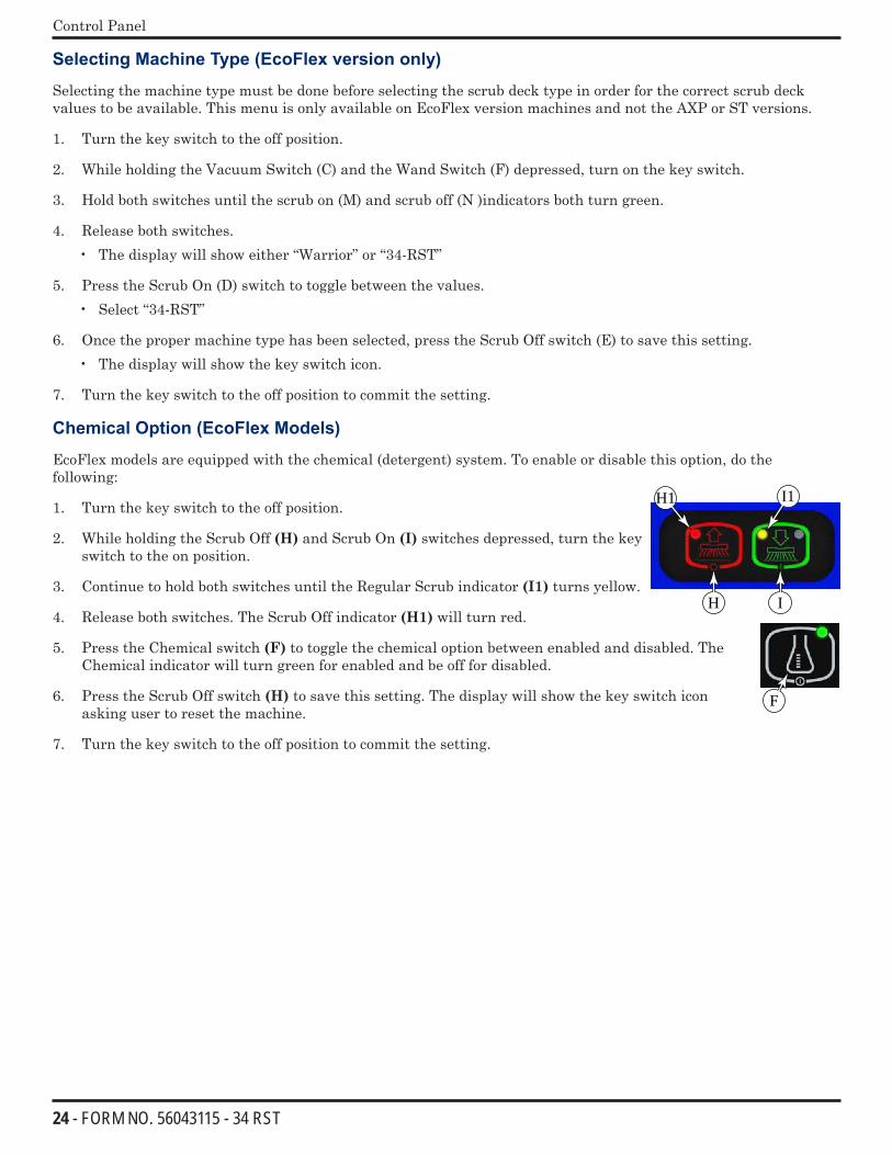
2. While holding the Scrub Off (H) and Scrub On (I) switches depressed, turn the key switch to the on position.
3. Continue to hold both switches until the Regular Scrub indicator (I1) turns yellow.
4. Release both switches. The Scrub Off indicator (H1) will turn red.
5. Press the Chemical switch (F) to toggle the chemical option between enabled and disabled. The Chemical indicator will turn green for enabled and be off for disabled.
6. Press the Scrub Off switch (H) to save this setting. The display will show the key switch icon asking user to reset the machine.
7. Turn the key switch to the off position to commit the setting.
I1H1
H I
F
25 - FORM NO. 56043115 - 34 RST
Control Panel
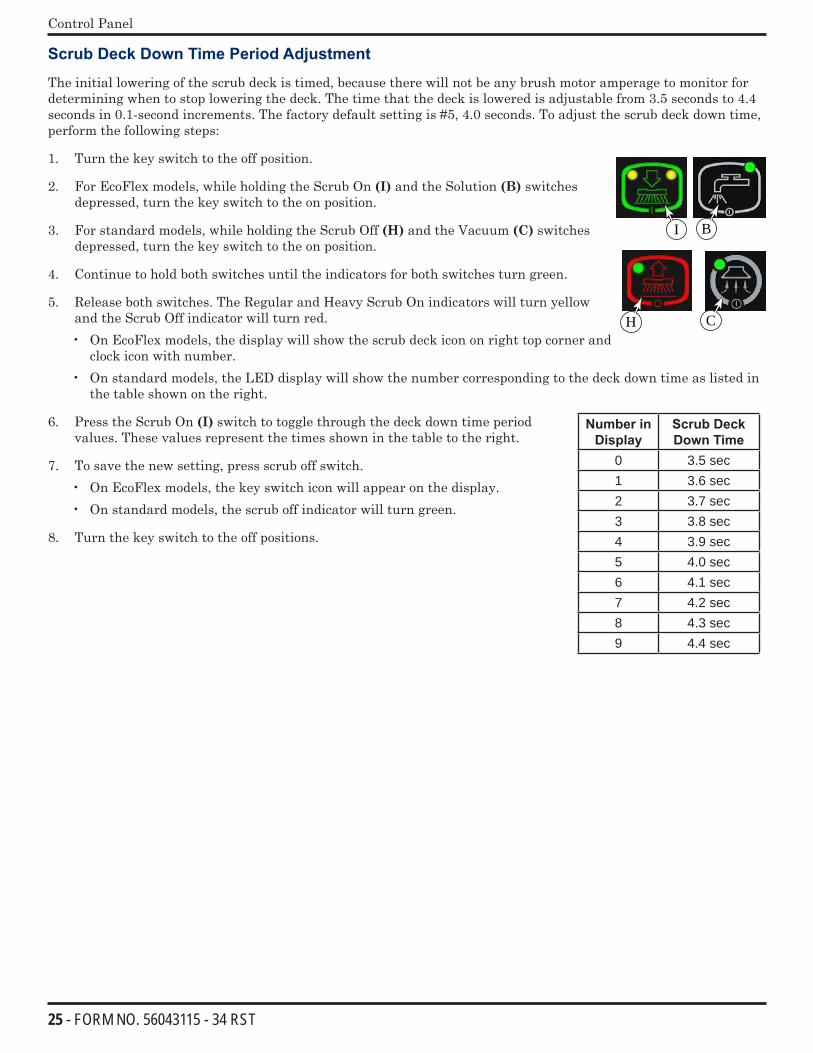
Scrub Deck Down Time Period Adjustment
The initial lowering of the scrub deck is timed, because there will not be any brush motor amperage to monitor for determining when to stop lowering the deck. The time that the deck is lowered is adjustable from 3.5 seconds to 4.4 seconds in 0.1-second increments. The factory default setting is #5, 4.0 seconds. To adjust the scrub deck down time, perform the following steps:
1. Turn the key switch to the off position.
2. For EcoFlex models, while holding the Scrub On (I) and the Solution (B) switches depressed, turn the key switch to the on position.
3. For standard models, while holding the Scrub Off (H) and the Vacuum (C) switches depressed, turn the key switch to the on position.
4. Continue to hold both switches until the indicators for both switches turn green.
5. Release both switches. The Regular and Heavy Scrub On indicators will turn yellow and the Scrub Off indicator will turn red. • On EcoFlex models, the display will show the scrub deck icon on right top corner and
clock icon with number. • On standard models, the LED display will show the number corresponding to the deck down time as listed in
the table shown on the right.
6. Press the Scrub On (I) switch to toggle through the deck down time period values. These values represent the times shown in the table to the right.
7. To save the new setting, press scrub off switch. • On EcoFlex models, the key switch icon will appear on the display.• On standard models, the scrub off indicator will turn green.
8. Turn the key switch to the off positions.
BI
H C
Number in Display
Scrub Deck Down Time
0 3.5 sec1 3.6 sec2 3.7 sec3 3.8 sec4 3.9 sec5 4.0 sec6 4.1 sec7 4.2 sec8 4.3 sec9 4.4 sec
26 - FORM NO. 56043115 - 34 RST
Control Panel
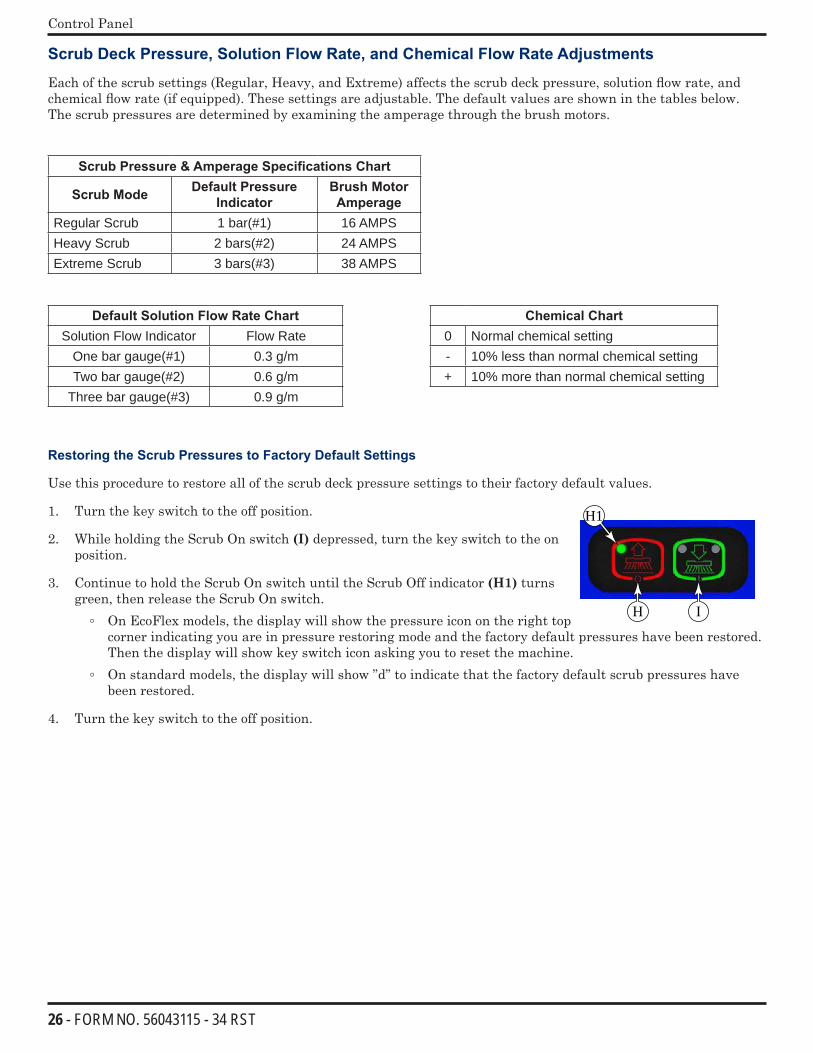
Scrub Deck Pressure, Solution Flow Rate, and Chemical Flow Rate Adjustments
Each of the scrub settings (Regular, Heavy, and Extreme) affects the scrub deck pressure, solution flow rate, and chemical flow rate (if equipped). These settings are adjustable. The default values are shown in the tables below. The scrub pressures are determined by examining the amperage through the brush motors.
Scrub Pressure & Amperage Specifications Chart
Scrub Mode Default Pressure Indicator
Brush Motor Amperage
Regular Scrub 1 bar(#1) 16 AMPSHeavy Scrub 2 bars(#2) 24 AMPSExtreme Scrub 3 bars(#3) 38 AMPS
Default Solution Flow Rate Chart Chemical ChartSolution Flow Indicator Flow Rate 0 Normal chemical setting
One bar gauge(#1) 0.3 g/m - 10% less than normal chemical settingTwo bar gauge(#2) 0.6 g/m + 10% more than normal chemical setting
Three bar gauge(#3) 0.9 g/m
Restoring the Scrub Pressures to Factory Default Settings
Use this procedure to restore all of the scrub deck pressure settings to their factory default values.
1. Turn the key switch to the off position.
2. While holding the Scrub On switch (I) depressed, turn the key switch to the on position.
3. Continue to hold the Scrub On switch until the Scrub Off indicator (H1) turns green, then release the Scrub On switch.
On EcoFlex models, the display will show the pressure icon on the right top corner indicating you are in pressure restoring mode and the factory default pressures have been restored. Then the display will show key switch icon asking you to reset the machine.
On standard models, the display will show ”d” to indicate that the factory default scrub pressures have been restored.
4. Turn the key switch to the off position.
H1
H I
27 - FORM NO. 56043115 - 34 RST
Control Panel
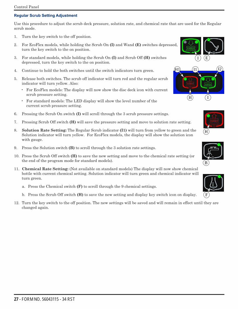
Regular Scrub Setting Adjustment
Use this procedure to adjust the scrub deck pressure, solution rate, and chemical rate that are used for the Regular scrub mode.
1. Turn the key switch to the off position.
2. For EcoFlex models, while holding the Scrub On (I) and Wand (E) switches depressed, turn the key switch to the on position.
3. For standard models, while holding the Scrub On (I) and Scrub Off (H) switches depressed, turn the key switch to the on position.
4. Continue to hold the both switches until the switch indicators turn green.
5. Release both switches. The scrub off indicator will turn red and the regular scrub indicator will turn yellow. Also:• For EcoFlex models: The display will now show the disc deck icon with current
scrub pressure setting.• For standard models: The LED display will show the level number of the
current scrub pressure setting.
6. Pressing the Scrub On switch (I) will scroll through the 3 scrub pressure settings.
7. Pressing Scrub Off switch (H) will save the pressure setting and move to solution rate setting.
8. Solution Rate Setting: The Regular Scrub indicator (I1) will turn from yellow to green and the Solution indicator will turn yellow. For EcoFlex models, the display will show the solution icon with gauge.
9. Press the Solution switch (B) to scroll through the 3 solution rate settings.
10. Press the Scrub Off switch (H) to save the new setting and move to the chemical rate setting (or the end of the program mode for standard models).
11. Chemical Rate Setting: (Not available on standard models) The display will now show chemical bottle with current chemical setting. Solution indicator will turn green and chemical indicator will turn green.
a. Press the Chemical switch (F) to scroll through the 9 chemical settings.
b. Press the Scrub Off switch (H) to save the new setting and display key switch icon on display.
12. Turn the key switch to the off position. The new settings will be saved and will remain in effect until they are changed again.
EI
I1 I2H1
H I
H
B
F
28 - FORM NO. 56043115 - 34 RST
Control Panel
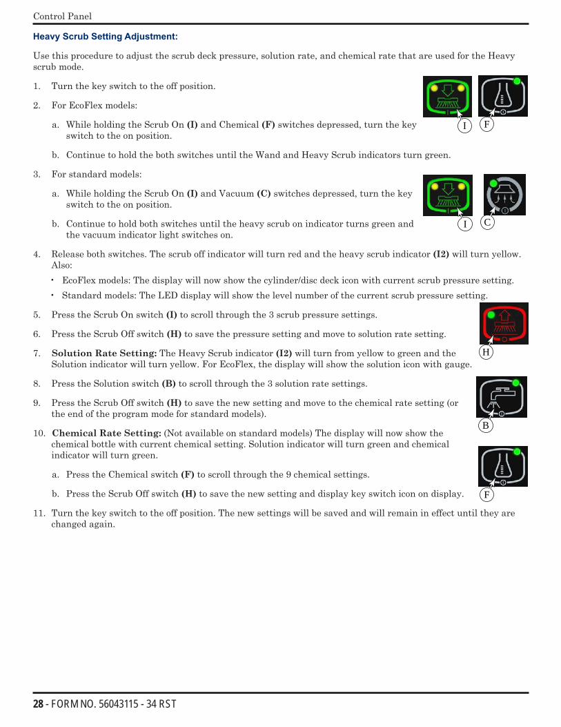
Heavy Scrub Setting Adjustment:
Use this procedure to adjust the scrub deck pressure, solution rate, and chemical rate that are used for the Heavy scrub mode.
1. Turn the key switch to the off position.
2. For EcoFlex models:
a. While holding the Scrub On (I) and Chemical (F) switches depressed, turn the key switch to the on position.
b. Continue to hold the both switches until the Wand and Heavy Scrub indicators turn green.
3. For standard models:
a. While holding the Scrub On (I) and Vacuum (C) switches depressed, turn the key switch to the on position.
b. Continue to hold both switches until the heavy scrub on indicator turns green and the vacuum indicator light switches on.
4. Release both switches. The scrub off indicator will turn red and the heavy scrub indicator (I2) will turn yellow. Also:• EcoFlex models: The display will now show the cylinder/disc deck icon with current scrub pressure setting.• Standard models: The LED display will show the level number of the current scrub pressure setting.
5. Press the Scrub On switch (I) to scroll through the 3 scrub pressure settings.
6. Press the Scrub Off switch (H) to save the pressure setting and move to solution rate setting.
7. Solution Rate Setting: The Heavy Scrub indicator (I2) will turn from yellow to green and the Solution indicator will turn yellow. For EcoFlex, the display will show the solution icon with gauge.
8. Press the Solution switch (B) to scroll through the 3 solution rate settings.
9. Press the Scrub Off switch (H) to save the new setting and move to the chemical rate setting (or the end of the program mode for standard models).
10. Chemical Rate Setting: (Not available on standard models) The display will now show the chemical bottle with current chemical setting. Solution indicator will turn green and chemical indicator will turn green.
a. Press the Chemical switch (F) to scroll through the 9 chemical settings.
b. Press the Scrub Off switch (H) to save the new setting and display key switch icon on display.
11. Turn the key switch to the off position. The new settings will be saved and will remain in effect until they are changed again.
I F
I C
H
B
F
29 - FORM NO. 56043115 - 34 RST
Control Panel
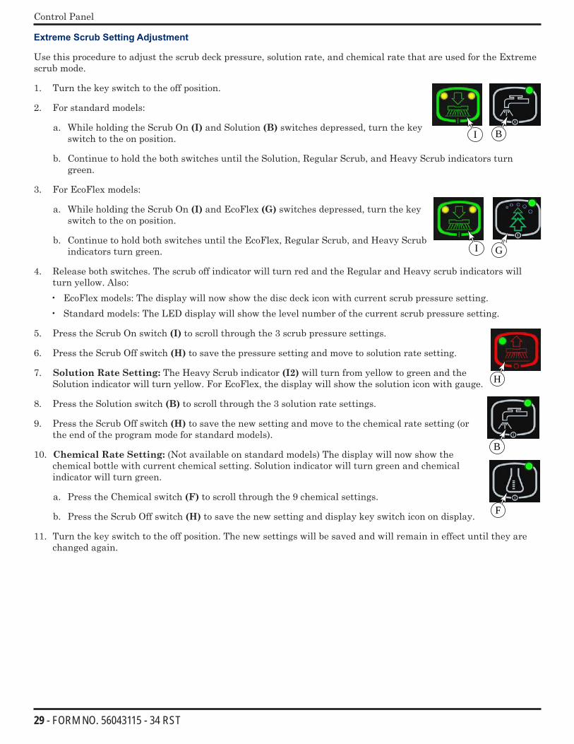
Extreme Scrub Setting Adjustment
Use this procedure to adjust the scrub deck pressure, solution rate, and chemical rate that are used for the Extreme scrub mode.
1. Turn the key switch to the off position.
2. For standard models:
a. While holding the Scrub On (I) and Solution (B) switches depressed, turn the key switch to the on position.
b. Continue to hold the both switches until the Solution, Regular Scrub, and Heavy Scrub indicators turn green.
3. For EcoFlex models:
a. While holding the Scrub On (I) and EcoFlex (G) switches depressed, turn the key switch to the on position.
b. Continue to hold both switches until the EcoFlex, Regular Scrub, and Heavy Scrub indicators turn green.
4. Release both switches. The scrub off indicator will turn red and the Regular and Heavy scrub indicators will turn yellow. Also:• EcoFlex models: The display will now show the disc deck icon with current scrub pressure setting.• Standard models: The LED display will show the level number of the current scrub pressure setting.
5. Press the Scrub On switch (I) to scroll through the 3 scrub pressure settings.
6. Press the Scrub Off switch (H) to save the pressure setting and move to solution rate setting.
7. Solution Rate Setting: The Heavy Scrub indicator (I2) will turn from yellow to green and the Solution indicator will turn yellow. For EcoFlex, the display will show the solution icon with gauge.
8. Press the Solution switch (B) to scroll through the 3 solution rate settings.
9. Press the Scrub Off switch (H) to save the new setting and move to the chemical rate setting (or the end of the program mode for standard models).
10. Chemical Rate Setting: (Not available on standard models) The display will now show the chemical bottle with current chemical setting. Solution indicator will turn green and chemical indicator will turn green.
a. Press the Chemical switch (F) to scroll through the 9 chemical settings.
b. Press the Scrub Off switch (H) to save the new setting and display key switch icon on display.
11. Turn the key switch to the off position. The new settings will be saved and will remain in effect until they are changed again.
I B
I G
H
B
F
30 - FORM NO. 56043115 - 34 RST
Control Panel
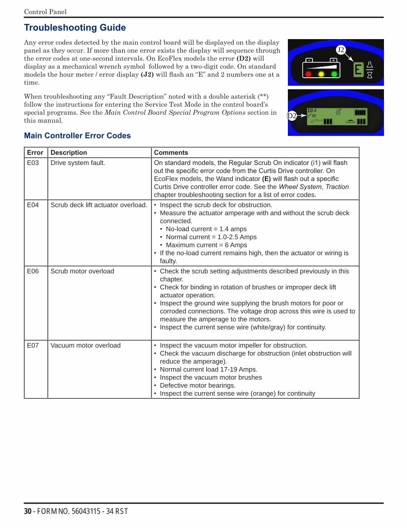
Troubleshooting Guide Any error codes detected by the main control board will be displayed on the display panel as they occur. If more than one error exists the display will sequence through the error codes at one-second intervals. On EcoFlex models the error (D2) will display as a mechanical wrench symbol followed by a two-digit code. On standard models the hour meter / error display (J2) will flash an “E” and 2 numbers one at a time.
When troubleshooting any “Fault Description” noted with a double asterisk (**) follow the instructions for entering the Service Test Mode in the control board’s special programs. See the MainControlBoardSpecialProgramOptions section in this manual.
Main Controller Error Codes
Error Description CommentsE03 Drive system fault. On standard models, the Regular Scrub On indicator (i1) will flash
out the specific error code from the Curtis Drive controller. On EcoFlex models, the Wand indicator (E) will flash out a specific Curtis Drive controller error code. See the Wheel System, Traction chapter troubleshooting section for a list of error codes.
E04 Scrub deck lift actuator overload. • Inspect the scrub deck for obstruction.• Measure the actuator amperage with and without the scrub deck
connected.• No-load current = 1.4 amps• Normal current = 1.0-2.5 Amps• Maximum current = 6 Amps
• If the no-load current remains high, then the actuator or wiring is faulty.
E06 Scrub motor overload • Check the scrub setting adjustments described previously in this chapter.
• Check for binding in rotation of brushes or improper deck lift actuator operation.
• Inspect the ground wire supplying the brush motors for poor or corroded connections. The voltage drop across this wire is used to measure the amperage to the motors.
• Inspect the current sense wire (white/gray) for continuity.
E07 Vacuum motor overload • Inspect the vacuum motor impeller for obstruction. • Check the vacuum discharge for obstruction (inlet obstruction will
reduce the amperage).• Normal current load 17-19 Amps. • Inspect the vacuum motor brushes • Defective motor bearings. • Inspect the current sense wire (orange) for continuity
E
Ø.403D2
J2

31 - FORM NO. 56043115 - 34 RST
Control Panel
Error Description CommentsE08 Solenoid Bank Coil Circuit
Overload• Brush Motor Contactor (K1)• Vacuum Motor contactor (K2)• Solution Solenoid (L1)
The sum of the currents through these coils is too high• Inspect the “B-3” ground bus (J2-9 wire) at the controller
for negative battery voltage. This error will occur if B-3 is disconnected.
• If this error occurs when no coils are active (and J2-9 wire is good), the control board is defective
• Operate various combinations of coils to identify which coil is causing the problem.
• Check for wiring problems on the coil circuit(s) and repair wiring.• Check resistance on all contactor/solenoid coils. If the value is less
than 20% of the values below, replace the contactor/solenoid• Brush motor contactor coil (K1): 98 to 120 Ω• Vacuum motor contactor coil (K2): 102 to 120 Ω• Solution solenoid coil (L1): ST 76 Ω
E017 Scrub deck lift actuator circuit open (**)
The controller’s internal circuitry is not seeing any voltage change.• Inspect the B+2 bus (J2-7) and fuse (F2) for positive battery
voltage.• Check for disconnected actuator wiring or defective actuator
motor.• Check controller’s actuator output voltage. This is a switched
ground PWM, so one terminal will be 36 volts (B+2 bus) to Battery-Negative and the other should be non-zero (PWM of B-2)to Battery-Negative. If both remain near 36 volts, it indicates a controller failure.
E018 Scrub deck lift actuator short The controller’s internal circuitry is seeing maximum voltage in the current sensing circuit.• Inspect the B-2 bus (J1-9) for connection to ground• Inspect the actuator wiring for short circuit(s)• Inspect the scrub deck for obstructions to movement• Check the lift actuator limit adjustment
E021 Brush motor circuit open (**) The controller’s internal circuitry is not seeing any voltage change.• Inspect the current sense wire (white/gray) for continuity. • Inspect the brush motor contactor for proper operation.• Inspect the motor power circuit and cable connectors for open
circuitsE022) Scrub motor short The controller’s internal circuitry is seeing maximum voltage in the
current sensing circuit.• Same troubleshooting as E06
E023) Vacuum motor circuit open (**) The controller’s internal circuitry is not seeing any voltage change.• Inspect the current sense wire (orange) for continuity. • Check the vacuum motor contactor for proper operation• Inspect the motor’s power wiring for open circuit
E024) Vacuum motor short The controller’s internal circuitry is seeing maximum voltage in the current sensing circuit.• Same troubleshooting as E07
32 - FORM NO. 56043115 - 34 RST
Control Panel
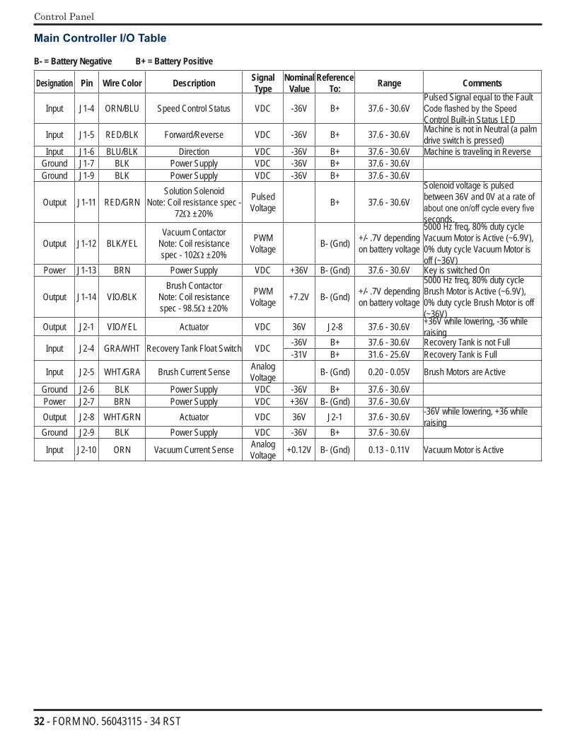
Main Controller I/O Table
B- = Battery Negative B+ = Battery Positive
Designation Pin Wire Color Description Signal Type
Nominal Value
Reference To: Range Comments
Input J1-4 ORN/BLU Speed Control Status VDC -36V B+ 37.6 - 30.6VPulsed Signal equal to the Fault Code flashed by the Speed Control Built-in Status LED
Input J1-5 RED/BLK Forward/Reverse VDC -36V B+ 37.6 - 30.6V Machine is not in Neutral (a palm drive switch is pressed)
Input J1-6 BLU/BLK Direction VDC -36V B+ 37.6 - 30.6V Machine is traveling in ReverseGround J1-7 BLK Power Supply VDC -36V B+ 37.6 - 30.6V Ground J1-9 BLK Power Supply VDC -36V B+ 37.6 - 30.6V
Output J1-11 RED/GRNSolution Solenoid
Note: Coil resistance spec - 72Ω ±20%
Pulsed Voltage B+ 37.6 - 30.6V
Solenoid voltage is pulsed between 36V and 0V at a rate of about one on/off cycle every five seconds.
Output J1-12 BLK/YELVacuum Contactor
Note: Coil resistance spec - 102Ω ±20%
PWM Voltage B- (Gnd) +/- .7V depending
on battery voltage
5000 Hz freq, 80% duty cycle Vacuum Motor is Active (~6.9V), 0% duty cycle Vacuum Motor is off (~36V)
Power J1-13 BRN Power Supply VDC +36V B- (Gnd) 37.6 - 30.6V Key is switched On
Output J1-14 VIO/BLKBrush Contactor
Note: Coil resistance spec - 98.5Ω ±20%
PWM Voltage +7.2V B- (Gnd) +/- .7V depending
on battery voltage
5000 Hz freq, 80% duty cycle Brush Motor is Active (~6.9V), 0% duty cycle Brush Motor is off (~36V)
Output J2-1 VIO/YEL Actuator VDC 36V J2-8 37.6 - 30.6V +36V while lowering, -36 while raising
Input J2-4 GRA/WHT Recovery Tank Float Switch VDC -36V B+ 37.6 - 30.6V Recovery Tank is not Full-31V B+ 31.6 - 25.6V Recovery Tank is Full
Input J2-5 WHT/GRA Brush Current Sense Analog Voltage B- (Gnd) 0.20 - 0.05V Brush Motors are Active
Ground J2-6 BLK Power Supply VDC -36V B+ 37.6 - 30.6V Power J2-7 BRN Power Supply VDC +36V B- (Gnd) 37.6 - 30.6V Output J2-8 WHT/GRN Actuator VDC 36V J2-1 37.6 - 30.6V -36V while lowering, +36 while
raisingGround J2-9 BLK Power Supply VDC -36V B+ 37.6 - 30.6V
Input J2-10 ORN Vacuum Current Sense Analog Voltage +0.12V B- (Gnd) 0.13 - 0.11V Vacuum Motor is Active
33 - FORM NO. 56043115 - 34 RST
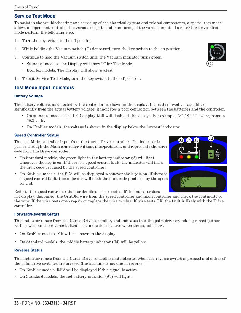
Control Panel
Service Test ModeTo assist in the troubleshooting and servicing of the electrical system and related components, a special test mode allows independent control of the various outputs and monitoring of the various inputs. To enter the service test mode perform the following step:
1. Turn the key switch to the off position.
2. While holding the Vacuum switch (C) depressed, turn the key switch to the on position.
3. Continue to hold the Vacuum switch until the Vacuum indicator turns green. • Standard models: The Display will show “t” for Test Mode.• EcoFlex models: The Display will show “svctest”
4. To exit Service Test Mode, turn the key switch to the off position.
Test Mode Input Indicators
Battery Voltage
The battery voltage, as detected by the controller, is shown in the display. If this displayed voltage differs significantly from the actual battery voltage, it indicates a poor connection between the batteries and the controller.
• On standard models, the LED display (J2) will flash out the voltage. For example, “3”, “8”, “-”, “2” represents 38.2 volts.
• On EcoFlex models, the voltage is shown in the display below the “svctest” indicator.
Speed Controller Status
This is a Main controller input from the Curtis Drive controller. The indicator is passed through the Main controller without interpretation, and represents the error code from the Drive controller. • On Standard models, the green light in the battery indicator (j5) will light
whenever the key is on. If there is a speed control fault, the indicator will flash the fault code produced by the speed controller.
• On EcoFlex models, the SCS will be displayed whenever the key is on. If there is a speed control fault, this indicator will flash the fault code produced by the speed control.
Refer to the speed control section for details on these codes. If the indicator does not display, disconnect the Orn/Blu wire from the speed controller and main controller and check the continuity of the wire. If the wire tests open repair or replace the wire or plug. If wire tests OK, the fault is likely with the Drive controller.
Forward/Reverse Status
This indicator comes from the Curtis Drive controller, and indicates that the palm drive switch is pressed (either with or without the reverse button). The indicator is active when the signal is low.
• On EcoFlex models, F/R will be shown in the display.
• On Standard models, the middle battery indicator (J4) will be yellow.
Reverse Status
This indicator comes from the Curtis Drive controller and indicates when the reverse switch is pressed and either of the palm drive switches are pressed (the machine is moving in reverse). • On EcoFlex models, REV will be displayed if this signal is active. • On Standard models, the red battery indicator (J3) will light.
C
t
SVCTEST36.5VF/RREV SCS
J2J3 J4 J5
34 - FORM NO. 56043115 - 34 RST
Control Panel
Test Mode Output Controls
The control panel switches are used to control various output functions of the Main controller while in Test Mode. Below is a list of each switch and the function it controls. Following the list is a detailed description of each function.
Scrub off Switch (H): Controls the brush motors. Scrub on Switch (I): Controls the scrub deck lift actuator. Vacuum Switch (C): Controls the vacuum motor. Wand Switch (E): Jogs the scrub deck lift actuator. Solution Switch (B): Turns on the solution solenoid valve. Detergent System Switch (F): Turns on the chemical pump (If available).
Description of Output Controls
Scrub System Off Switch (H):
This switch is used to toggle the state of the brush motor contactor. Pressing and releasing this switch will alternately turn the brush motor contactor on and off. The indicator provides the following status information:
Off – Brush motor output is off and there is no brush motor current sensed.
Steady Green – Brush motor output is on and there is normal brush motor current sensed.
Brief On Green Flash – Brush motor output is off and brush motor current is being sensed (abnormal condition). • Check for voltage at the Wht wire on K1 contactor to battery ground. • If any voltage is present, replace K1 contactor. • NO voltage, replace the Main control board.
Brief Off Green Flash – Brush motor output is on and brush motor current is not being sensed (abnormal condition). • Check brush motor wiring plugs. • Check one of the Blk wires of the main harness connector at the brush motor to battery Positive. If no voltage
repair or replace wire. • Check one of the Wht wires of the main harness connector at the brush motor to battery Neg. If no voltage repair
or replace wire. • Check for voltage at the Red wire on K1 contactor to battery ground. If no voltage is present repair the Red wire. • Check for voltage at the Wht wire on K1 contactor to battery ground. If no voltage is present replace the K1
contactor.
Flashing Red – Brush motor overload has occurred. • Check to see that the proper brush programming type is selected (disc or cyl). • Check for binding in rotation of brushes or improper scrub brush type installed. (Amp. Test) See Pressure Chart
in this Manual. • Check the negative supply cable at the brush motor for a wiring problem or improper modifications. • Check for open in the small WHT/GRA current sense wire. • Check for short circuit* in brush motor or wiring. • Inspect gearbox for failure (disc). Repair or replace. • Inspect scrub brush drive bearings for excessive wear (cyl.).

35 - FORM NO. 56043115 - 34 RST
Control Panel
Scrub On Switch (I)
This switch is used to control the output to the scrub deck lift actuator. Pressing and releasing this switch will cycle the actuator output through 4 states. These are:
1 – Output off, direction = up
2 – Output on, direction = down • EcoFlex models - display will show down arrow. • Standard models – the normal scrub on indicator will be green.
3 – Output off, direction = down
4 – Output on, direction = up • EcoFlex models - display will show up arrow. • Standard models – the normal scrub on indicator will be yellow.
When the output is in state 1, the actuator output is turned off. The scrub pressure decrease indicator should be off. If the indicator is flashing green, this indicates that the control is sensing current flow through the actuator (shorted output driver, control error). If the scrub pressure decrease switch was the last switch pressed, it is possible to momentarily activate the actuator output using the wand switch. This can be used to jog the actuator to allow precise positioning of the actuator. Note: the actuator can only move in this situation if it is not at its up limit.
When the output is in state 2, the actuator output is turned on. The scrub pressure decrease indicator should be green or flashing green. The indicator will be a steady green if the control senses current flow through the actuator. It will flash green if no actuator current flow is sensed (actuator at limit, open circuit, open output driver). The wand switch has no effect in this state.
When the output is in state 3, the actuator output is turned off. The scrub pressure decrease indicator should be off. If the indicator is flashing green, this indicates that the control is sensing current flow through the actuator (shorted output driver, control error). If the scrub pressure decrease switch was the last switch pressed, it is possible to momentarily activate the actuator output using the wand switch. This can be used to jog the actuator to allow precise positioning of the actuator. Note: the actuator can only move in this situation if it is not at its down limit.
When the output is in state 4, the actuator output is turned on. The scrub pressure decrease indicator should be green or flashing green. The indicator will be a steady green if the control senses current flow through the actuator. It will flash green if no actuator current flow is sensed (actuator at limit, open circuit, open output driver). The wand switch has no effect in this state.
Vacuum Switch (C)
This switch is used to toggle the state of the vacuum motor. Pressing and releasing this switch will alternately turn the vacuum motor on and off. The indicator provides the following status information:
Off - Vacuum motor output is off and there is no vacuum motor current sensed.
On Steady Green - Vacuum motor output is on and there is normal vacuum motor current sensed.
Brief On Green Flash – Vacuum motor output is off and vacuum motor current is being sensed (abnormal condition). • Check for voltage at the Blu wire on K2 contactor to battery ground. • If any voltage is present, replace K2 contactor.• NO voltage, replace the Main control board.
Brief Off Green Flash – Vacuum motor output is on and vacuum motor current is not being sensed (abnormal condition). • Check Vacuum Motor wiring plug, disconnection. • Check for voltage at the Red wire on K2 contactor to battery ground. If no voltage is present repair the Red wire. • Check for voltage at the Blu wire on K2 contactor to battery ground. If no voltage is present replace the K2
contactor.
36 - FORM NO. 56043115 - 34 RST
Control Panel
• Check the Blu wire of the main harness connector at the vacuum motor to battery Negative. If no voltage repair or replace wire.
• Check the Blk wire of the main harness connector at the vacuum motor to battery Positive. If no voltage repair or replace wire.
Flashing Yellow – Vacuum motor overload has occurred. • Check for an open in the small ORG current sense wire. • To confirm an overload, disconnect the motor plug from the main harness, run a 30 amp fused test leads from the
batteries to the motor and perform an Amp draw test. Normal current load 36V 16-19 Amps. • Check for debris in the vacuum motor. • Worn carbon brushes. • Defective motor bearings. • Check for short circuit* in vacuum motor or wiring. Repair or replace.
Solution Switch (B)
This switch is used to toggle the state of the solution solenoid. Pressing and releasing this switch will alternately turn the solution solenoid (L1) on and off. The indicator provides the following status information:
Off - Solution output is off.
Steady Green - Solution output is on.
Flashing Yellow – Solution solenoid overload has occurred.
Detergent Switch (F)
This switch is used to toggle the state of the chemical pump (if the machine is so equipped). Pressing and releasing this switch will alternately turn the chemical pump on and off. The indicator provides the following status information:
Off – Chemical pump and valve off.
Steady Green – Chemical output is on.
37 - FORM NO. 56043115 - 34 RST
Solution System
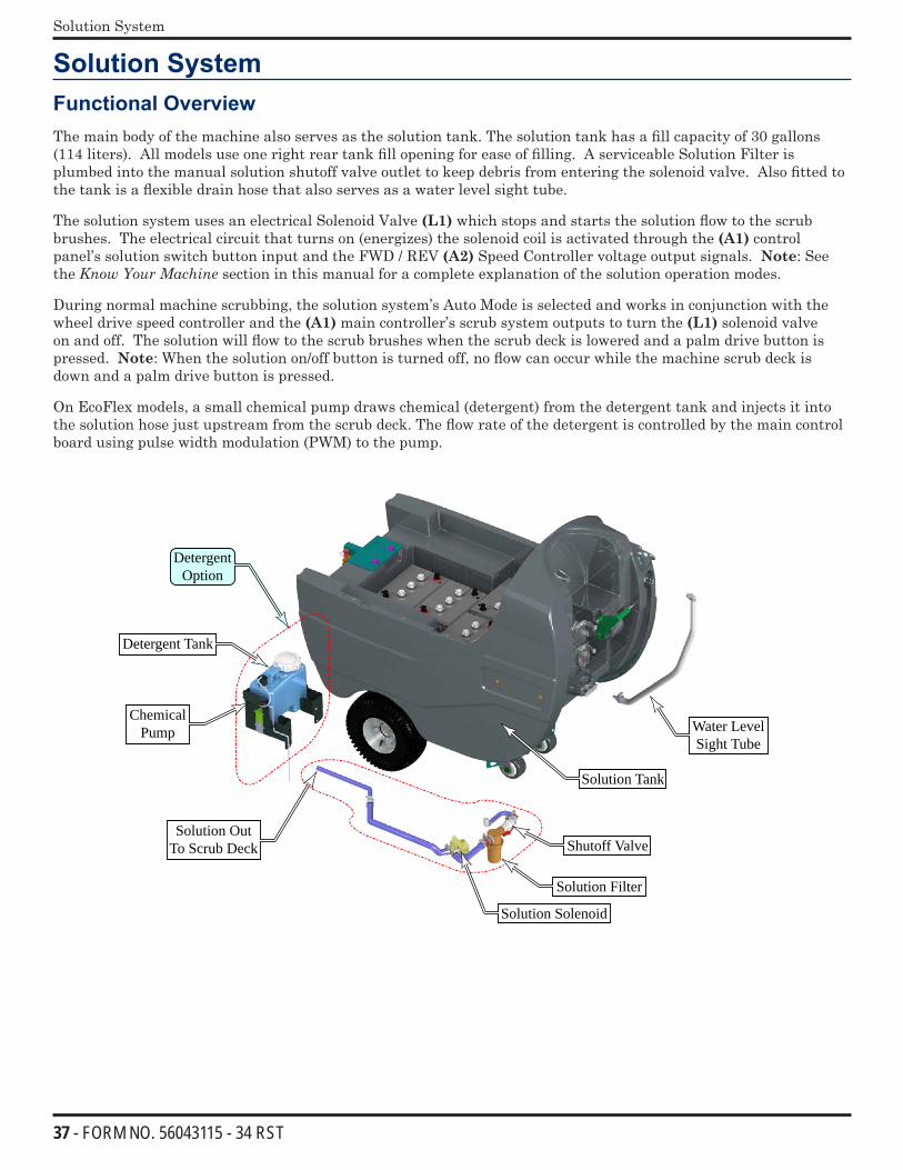
Solution SystemFunctional Overview The main body of the machine also serves as the solution tank. The solution tank has a fill capacity of 30 gallons (114 liters). All models use one right rear tank fill opening for ease of filling. A serviceable Solution Filter is plumbed into the manual solution shutoff valve outlet to keep debris from entering the solenoid valve. Also fitted to the tank is a flexible drain hose that also serves as a water level sight tube.
The solution system uses an electrical Solenoid Valve (L1) which stops and starts the solution flow to the scrub brushes. The electrical circuit that turns on (energizes) the solenoid coil is activated through the (A1) control panel’s solution switch button input and the FWD / REV (A2) Speed Controller voltage output signals. Note: See the KnowYourMachine section in this manual for a complete explanation of the solution operation modes.
During normal machine scrubbing, the solution system’s Auto Mode is selected and works in conjunction with the wheel drive speed controller and the (A1) main controller’s scrub system outputs to turn the (L1) solenoid valve on and off. The solution will flow to the scrub brushes when the scrub deck is lowered and a palm drive button is pressed. Note: When the solution on/off button is turned off, no flow can occur while the machine scrub deck is down and a palm drive button is pressed.
On EcoFlex models, a small chemical pump draws chemical (detergent) from the detergent tank and injects it into the solution hose just upstream from the scrub deck. The flow rate of the detergent is controlled by the main control board using pulse width modulation (PWM) to the pump.
Water LevelSight Tube
Shutoff Valve
Solution Filter
Solution Solenoid
Detergent Option
Detergent Tank
Solution Out To Scrub Deck
Chemical Pump
Solution Tank
38 - FORM NO. 56043115 - 34 RST
Solution System
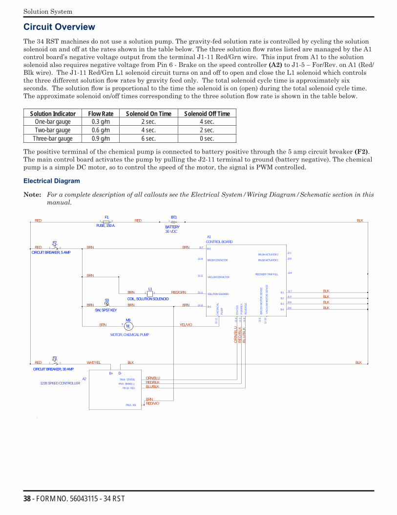
Circuit OverviewThe 34 RST machines do not use a solution pump. The gravity-fed solution rate is controlled by cycling the solution solenoid on and off at the rates shown in the table below. The three solution flow rates listed are managed by the A1 control board’s negative voltage output from the terminal J1-11 Red/Grn wire. This input from A1 to the solution solenoid also requires negative voltage from Pin 6 - Brake on the speed controller (A2) to J1-5 – For/Rev. on A1 (Red/Blk wire). The J1-11 Red/Grn L1 solenoid circuit turns on and off to open and close the L1 solenoid which controls the three different solution flow rates by gravity feed only. The total solenoid cycle time is approximately six seconds. The solution flow is proportional to the time the solenoid is on (open) during the total solenoid cycle time. The approximate solenoid on/off times corresponding to the three solution flow rate is shown in the table below.
Solution Indicator Flow Rate Solenoid On Time Solenoid Off TimeOne-bar gauge 0.3 g/m 2 sec. 4 sec.Two-bar gauge 0.6 g/m 4 sec. 2 sec.
Three-bar gauge 0.9 g/m 6 sec. 0 sec.
The positive terminal of the chemical pump is connected to battery positive through the 5 amp circuit breaker (F2). The main control board activates the pump by pulling the J2-11 terminal to ground (battery negative). The chemical pump is a simple DC motor, so to control the speed of the motor, the signal is PWM controlled.
Electrical Diagram
Note: ForacompletedescriptionofallcalloutsseetheElectricalSystem/WiringDiagram/Schematicsectioninthismanual.
36VDC
B+2
B+1
BRUSHCONTACTOR
VACUUMCONTACTOR
SOLUTIONSOLENOID
FOR
/REV
.
BRU
SHM
OTO
RSE
NSE
VAC
UU
MM
OTO
RSE
NSE
J2-7
J1-13
J1-14
J1-12
J1-11
REV
ERSE
B-1
BRUSHACTUATOR1
BRUSHACTUATOR2
B-3
B-4
B-2
A1CONTROLBOARD
J1-5
J2-5
J2-1
0
J1-6
J2-4
J1-7
J2-8
J2-1
J2-6
J1-9
J2-9
RECOVERYTANKFULL
A2B+ B-
1228SPEEDCONTROLLER
PIN5- KSI
PIN16- REVPIN6- BRAKE(-)
STAT
US
PIN9 - STATUS
J1-4
CH
EMIC
ALPU
MP
J2-1
1
+
BT1
BATTERY
BT1
BATTERY+ -
L1
COIL, SOLUTIONSOLENOID
L1
COIL, SOLUTIONSOLENOID
1 2
F1
FUSE, 150A.
F1
FUSE, 150A.1 2
S3
SW, SPSTKEY
S3
SW, SPSTKEY
F3
CIRCUITBREAKER, 30AMP
F3
CIRCUITBREAKER, 30AMP
1 2
MM6MM6
MOTOR, CHEMICALPUMP
F2
CIRCUITBREAKER, 5AMP
F2
CIRCUITBREAKER, 5AMP1 2
BLK
RED
/BLK
BLK
OR
N/B
LU
BLU
/BLK
BLKBLKBLK
RED/GRN
BRN
BRN
BRN
RED
BRN
BRN YEL/VIO
BRN
BRNRED
BRN
RED
RED WHT/YEL
RED/VIO
BLK
ORN/BLURED/BLKBLU/BLK
BRN
BLK
39 - FORM NO. 56043115 - 34 RST
Solution System
Maintenance• Solution Tank: Empty the solution tank weekly; remove the solution Drain Hose from its storage area (located
on the right rear control handle compartment). Direct the hose to a designated “Disposal Site” and flush the tank with clean water.
• Solution Filter: Remove and clean the inline Solution Filter. To access the filter housing for removal, work underneath the middle right rear side of the machine’s chassis. No tools are needed to remove the filter (hand tighten only). Service Tip: The solution manual shutoff valve must be placed in the OFF (Closed) position. This prevents loss of solution when servicing the filter strainer with a partial or full tank.
Troubleshooting GuideProblem Possible CauseInadequate or no solution flow No solution in the tank
Solution tank filter ball valve in the off positionClogged solution filter, solenoid valve or hoses
Electrical TroubleshootingPossible Symptom - No solution flow while in the scrub auto solution mode.Note: Activate the Service Test Mode Program. See the Electrical System/Service Test Mode section in this manual for instructions.All testing will be performed in the Service Test Mode Program.
Symptom
No solution flow when scrubbing in the auto solution mode.
Note: Activate the Service Test Mode Program. See optional program section for instructions.
While in the Service Test Mode activate the solution button. Does the L1 solenoid click turn on & off, pulse as designed ?
Inspect the solution system components listed below to help locate the cause for the solution not feeding through an electrically (good) functional L1 valve.
•No solution in tank.
•Solution tank shut-off valve closed.
•Clogged solution filter, fittings & or hoses.
•Clogged L1 solenoid valve. Disassemble clean, repair or replace.
Separate the wiring harness connector that feeds the L1 solenoid ( 2 wires Brn & Red/Grn). Activate the solution button & test for 36V.
Test the L1 coil resistance (spec. 75 ohms).
Replace the L1 solenoid valve.
Test the continuity of the wiring to coil L1 (Brn & Red/Grn wires). Repair or replace damaged wires. Is there voltage @ the L1 coil?
Replace the A1 control board
YesYes
No
NoNo
No
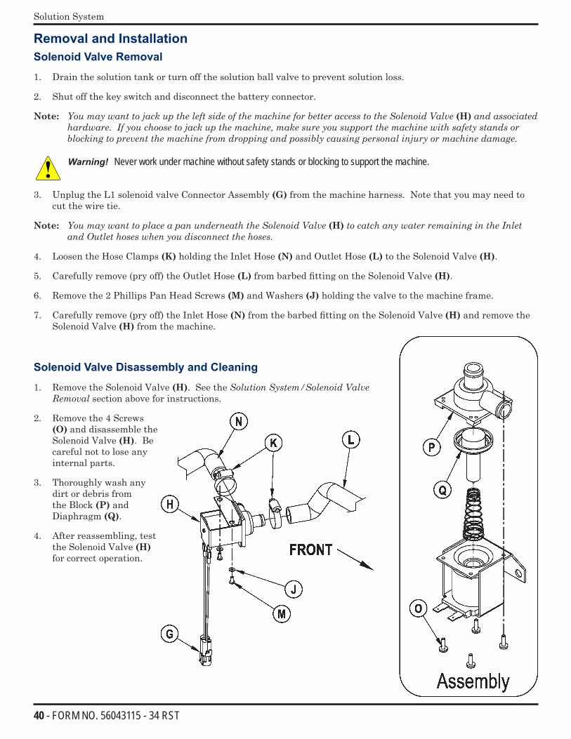
40 - FORM NO. 56043115 - 34 RST
Solution System
Removal and InstallationSolenoid Valve Removal
1. Drain the solution tank or turn off the solution ball valve to prevent solution loss.
2. Shut off the key switch and disconnect the battery connector.
Note: YoumaywanttojackuptheleftsideofthemachineforbetteraccesstotheSolenoidValve(H) and associated hardware.Ifyouchoosetojackupthemachine,makesureyousupportthemachinewithsafetystandsorblockingtopreventthemachinefromdroppingandpossiblycausingpersonalinjuryormachinedamage.
Warning! Never work under machine without safety stands or blocking to support the machine.
3. Unplug the L1 solenoid valve Connector Assembly (G) from the machine harness. Note that you may need to cut the wire tie.
Note: YoumaywanttoplaceapanunderneaththeSolenoidValve(H)tocatchanywaterremainingintheInletandOutlethoseswhenyoudisconnectthehoses.
4. Loosen the Hose Clamps (K) holding the Inlet Hose (N) and Outlet Hose (L) to the Solenoid Valve (H).
5. Carefully remove (pry off) the Outlet Hose (L) from barbed fitting on the Solenoid Valve (H).
6. Remove the 2 Phillips Pan Head Screws (M) and Washers (J) holding the valve to the machine frame.
7. Carefully remove (pry off) the Inlet Hose (N) from the barbed fitting on the Solenoid Valve (H) and remove the Solenoid Valve (H) from the machine.
Solenoid Valve Disassembly and Cleaning
1. Remove the Solenoid Valve (H). See the SolutionSystem/SolenoidValveRemovalsection above for instructions.
2. Remove the 4 Screws (O) and disassemble the Solenoid Valve (H). Be careful not to lose any internal parts.
3. Thoroughly wash any dirt or debris from the Block (P) and Diaphragm (Q).
4. After reassembling, test the Solenoid Valve (H) for correct operation.
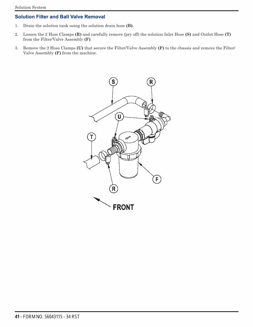
41 - FORM NO. 56043115 - 34 RST
Solution System
Solution Filter and Ball Valve Removal
1. Drain the solution tank using the solution drain hose (B).
2. Loosen the 2 Hose Clamps (R) and carefully remove (pry off) the solution Inlet Hose (S) and Outlet Hose (T) from the Filter/Valve Assembly (F).
3. Remove the 2 Hose Clamps (U) that secure the Filter/Valve Assembly (F) to the chassis and remove the Filter/Valve Assembly (F) from the machine.
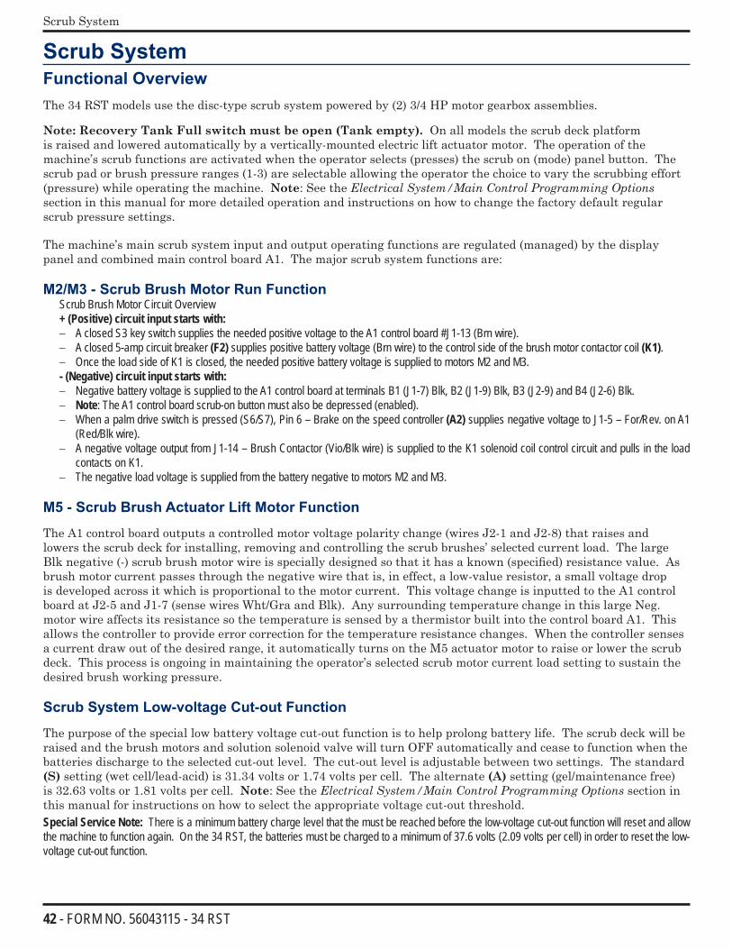
42 - FORM NO. 56043115 - 34 RST
Scrub System
Scrub SystemFunctional OverviewThe 34 RST models use the disc-type scrub system powered by (2) 3/4 HP motor gearbox assemblies.
Note: Recovery Tank Full switch must be open (Tank empty). On all models the scrub deck platform is raised and lowered automatically by a vertically-mounted electric lift actuator motor. The operation of the machine’s scrub functions are activated when the operator selects (presses) the scrub on (mode) panel button. The scrub pad or brush pressure ranges (1-3) are selectable allowing the operator the choice to vary the scrubbing effort (pressure) while operating the machine. Note: See the ElectricalSystem/MainControlProgrammingOptions section in this manual for more detailed operation and instructions on how to change the factory default regular scrub pressure settings.
The machine’s main scrub system input and output operating functions are regulated (managed) by the display panel and combined main control board A1. The major scrub system functions are:
M2/M3 - Scrub Brush Motor Run FunctionScrub Brush Motor Circuit Overview + (Positive) circuit input starts with:− A closed S3 key switch supplies the needed positive voltage to the A1 control board #J1-13 (Brn wire).− A closed 5-amp circuit breaker (F2) supplies positive battery voltage (Brn wire) to the control side of the brush motor contactor coil (K1).− Once the load side of K1 is closed, the needed positive battery voltage is supplied to motors M2 and M3.- (Negative) circuit input starts with:− Negative battery voltage is supplied to the A1 control board at terminals B1 (J1-7) Blk, B2 (J1-9) Blk, B3 (J2-9) and B4 (J2-6) Blk.− Note: The A1 control board scrub-on button must also be depressed (enabled). − When a palm drive switch is pressed (S6/S7), Pin 6 – Brake on the speed controller (A2) supplies negative voltage to J1-5 – For/Rev. on A1
(Red/Blk wire).− A negative voltage output from J1-14 – Brush Contactor (Vio/Blk wire) is supplied to the K1 solenoid coil control circuit and pulls in the load
contacts on K1.− The negative load voltage is supplied from the battery negative to motors M2 and M3.
M5 - Scrub Brush Actuator Lift Motor Function
The A1 control board outputs a controlled motor voltage polarity change (wires J2-1 and J2-8) that raises and lowers the scrub deck for installing, removing and controlling the scrub brushes’ selected current load. The large Blk negative (-) scrub brush motor wire is specially designed so that it has a known (specified) resistance value. As brush motor current passes through the negative wire that is, in effect, a low-value resistor, a small voltage drop is developed across it which is proportional to the motor current. This voltage change is inputted to the A1 control board at J2-5 and J1-7 (sense wires Wht/Gra and Blk). Any surrounding temperature change in this large Neg. motor wire affects its resistance so the temperature is sensed by a thermistor built into the control board A1. This allows the controller to provide error correction for the temperature resistance changes. When the controller senses a current draw out of the desired range, it automatically turns on the M5 actuator motor to raise or lower the scrub deck. This process is ongoing in maintaining the operator’s selected scrub motor current load setting to sustain the desired brush working pressure.
Scrub System Low-voltage Cut-out Function
The purpose of the special low battery voltage cut-out function is to help prolong battery life. The scrub deck will be raised and the brush motors and solution solenoid valve will turn OFF automatically and cease to function when the batteries discharge to the selected cut-out level. The cut-out level is adjustable between two settings. The standard (S) setting (wet cell/lead-acid) is 31.34 volts or 1.74 volts per cell. The alternate (A) setting (gel/maintenance free) is 32.63 volts or 1.81 volts per cell. Note: See the ElectricalSystem/MainControlProgrammingOptions section in this manual for instructions on how to select the appropriate voltage cut-out threshold.Special Service Note: There is a minimum battery charge level that the must be reached before the low-voltage cut-out function will reset and allow the machine to function again. On the 34 RST, the batteries must be charged to a minimum of 37.6 volts (2.09 volts per cell) in order to reset the low-voltage cut-out function.
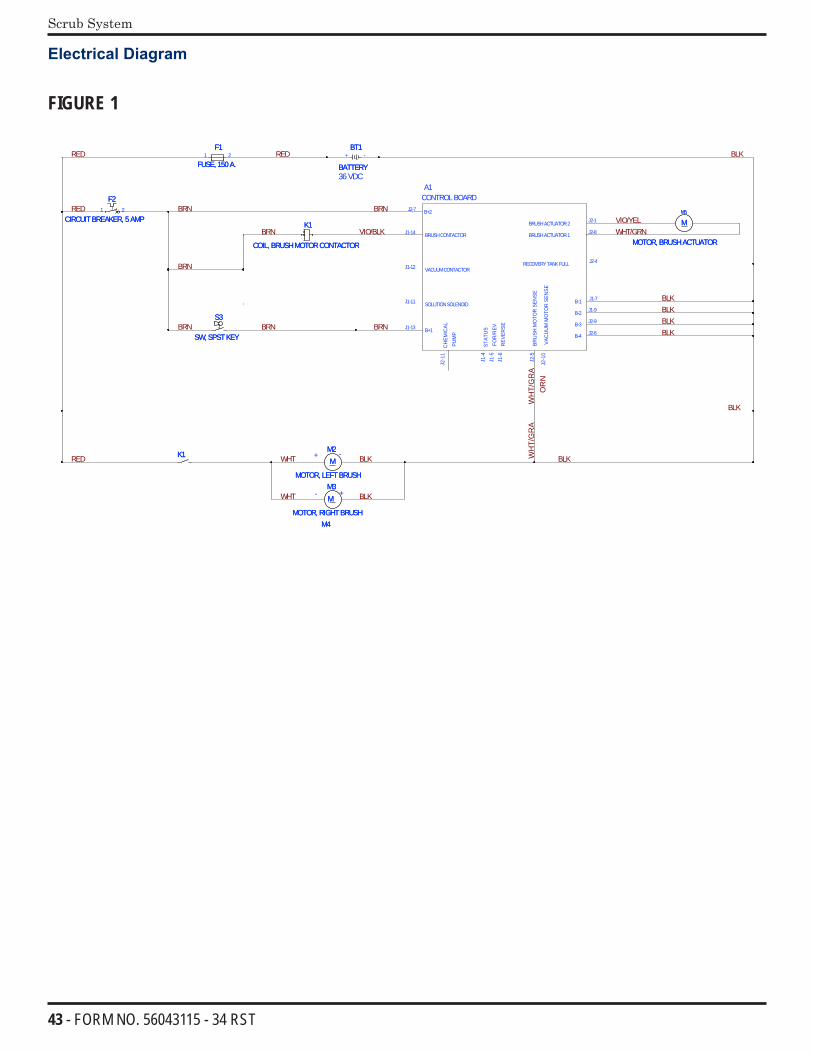
43 - FORM NO. 56043115 - 34 RST
Scrub System
Electrical Diagram
FIGURE 1
BLK
BLK
OR
N
BLKBLKBLK
VIO/YELWHT/GRN
WH
T/G
RA
BLK
BRN
BRNBRN
VIO/BLKBRN
BRN
BRN
RED
BRN
RED
RED
RED WHT
WHT BLK
BLK BLKWH
T/G
RA
-
- +
+
36VDC
B+2
B+1
BRUSHCONTACTOR
VACUUMCONTACTOR
SOLUTIONSOLENOID
FOR
/REV
.
BRU
SHM
OTO
RSE
NSE
VAC
UU
MM
OTO
RSE
NSE
J2-7
J1-13
J1-14
J1-12
J1-11
REV
ERSE
B-1
BRUSHACTUATOR1
BRUSHACTUATOR2
B-3
B-4
B-2
A1CONTROLBOARD
J1-5
J2-5
J2-1
0
J1-6
J2-4
J1-7
J2-8
J2-1
J2-6
J1-9
J2-9
RECOVERYTANKFULL
STAT
US
J1-4
CH
EMIC
ALPU
MP
J2-1
1
M4M4
MM5
MOTOR, BRUSHACTUATOR
MM5
MOTOR, BRUSHACTUATOR
K1
COIL, BRUSHMOTORCONTACTOR
K1
COIL, BRUSHMOTORCONTACTOR
BT1
BATTERY
BT1
BATTERY+ -
F1
FUSE, 150A.
F1
FUSE, 150A.1 2
MM2
MOTOR, LEFTBRUSH
MM2
MOTOR, LEFTBRUSH
S3
SW, SPSTKEY
S3
SW, SPSTKEY
MM3
MOTOR, RIGHTBRUSH
MM3
MOTOR, RIGHTBRUSH
1K1K
F2
CIRCUITBREAKER, 5AMP
F2
CIRCUITBREAKER, 5AMP1 2
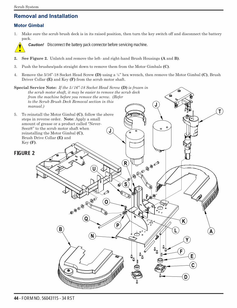
44 - FORM NO. 56043115 - 34 RST
Scrub System
Removal and Installation
Motor Gimbal
1. Make sure the scrub brush deck is in its raised position, then turn the key switch off and disconnect the battery pack.
Caution! Disconnect the battery pack connector before servicing machine.
2. See Figure 2. Unlatch and remove the left- and right-hand Brush Housings (A and B).
3. Push the brushes/pads straight down to remove them from the Motor Gimbals (C).
4. Remove the 5/16”-18 Socket Head Screw (D) using a ¼” hex wrench, then remove the Motor Gimbal (C), Brush Driver Collar (E) and Key (F) from the scrub motor shaft.
Special Service Note:Ifthe5/16”-18SocketHeadScrew(D)isfrozeninthescrubmotorshaft,itmaybeeasiertoremovethescrubdeckfromthemachinebeforeyouremovethescrew.(RefertotheScrubBrushDeckRemovalsectioninthismanual.)
5. To reinstall the Motor Gimbal (C), follow the above steps in reverse order. Note: Apply a small amount of grease or a product called “Never-Seez®” to the scrub motor shaft when reinstalling the Motor Gimbal (C), Brush Drive Collar (E) and Key (F).
FIGURE 2
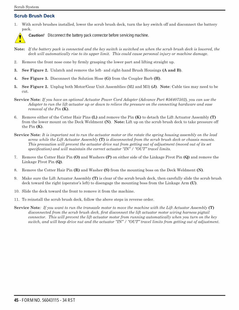
45 - FORM NO. 56043115 - 34 RST
Scrub System
Scrub Brush Deck
1. With scrub brushes installed, lower the scrub brush deck, turn the key switch off and disconnect the battery pack.
Caution! Disconnect the battery pack connector before servicing machine.
Note: Ifthebatterypackisconnectedandthekeyswitchisswitchedonwhenthescrubbrushdeckislowered,thedeckwillautomaticallyrisetoitsupperlimit.Thiscouldcausepersonalinjuryormachinedamage.
2. Remove the front nose cone by firmly grasping the lower part and lifting straight up.
3. See Figure 2. Unlatch and remove the left- and right-hand Brush Housings (A and B).
4. See Figure 3. Disconnect the Solution Hose (G) from the Coupler Barb (H).
5. See Figure 2. Unplug both Motor/Gear Unit Assemblies (M2 and M3) (J). Note: Cable ties may need to be cut.
Service Note:IfyouhaveanoptionalActuatorPowerCordAdapter(AdvancePart#56407502),youcanusetheAdaptertoruntheliftactuatorupordowntorelievethepressureontheconnectinghardwareandeaseremovalofthePin(K).
6. Remove either of the Cotter Hair Pins (L) and remove the Pin (K) to detach the Lift Actuator Assembly (T) from the lower mount on the Deck Weldment (N). Note: Lift up on the scrub brush deck to take pressure off the Pin (K).
Service Note:ItisimportantnottoruntheactuatormotorortherotatethespringhousingassemblyontheleadscrewwhiletheLiftActuatorAssembly(T)isdisconnectedfromthescrubbrushdeckorchassismounts.Thisprecautionwillpreventtheactuatordrivenutfromgettingoutofadjustment(movedoutofitssetspecification)andwillmaintainthecorrectactuator“IN”/“OUT”travellimits.
7. Remove the Cotter Hair Pin (O) and Washers (P) on either side of the Linkage Pivot Pin (Q) and remove the Linkage Pivot Pin (Q).
8. Remove the Cotter Hair Pin (R) and Washer (S) from the mounting boss on the Deck Weldment (N).
9. Make sure the Lift Actuator Assembly (T) is clear of the scrub brush deck, then carefully slide the scrub brush deck toward the right (operator’s left) to disengage the mounting boss from the Linkage Arm (U).
10. Slide the deck toward the front to remove it from the machine.
11. To reinstall the scrub brush deck, follow the above steps in reverse order.
Service Note:IfyouwanttorunthetransaxlemotortomovethemachinewiththeLiftActuatorAssembly(T) disconnectedfromthescrubbrushdeck,firstdisconnecttheliftactuatormotorwiringharnesspigtailconnector.Thiswillpreventtheliftactuatormotorfromrunningautomaticallywhenyouturnonthekeyswitch,andwillkeepdrivenutandtheactuator“IN”/“OUT”travellimitsfromgettingoutofadjustment.
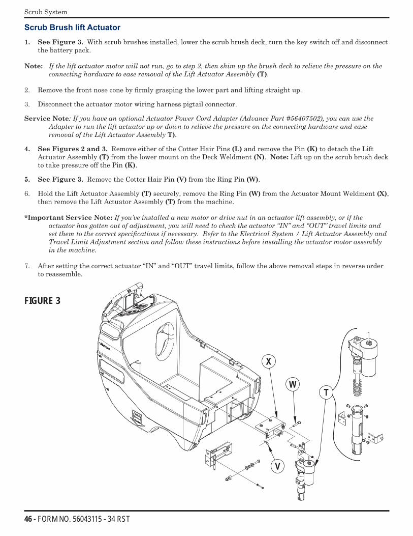
46 - FORM NO. 56043115 - 34 RST
Scrub System
Scrub Brush lift Actuator
1. See Figure 3. With scrub brushes installed, lower the scrub brush deck, turn the key switch off and disconnect the battery pack.
Note: Iftheliftactuatormotorwillnotrun,gotostep2,thenshimupthebrushdecktorelievethepressureontheconnectinghardwaretoeaseremovaloftheLiftActuatorAssembly(T).
2. Remove the front nose cone by firmly grasping the lower part and lifting straight up.
3. Disconnect the actuator motor wiring harness pigtail connector.
Service Note:IfyouhaveanoptionalActuatorPowerCordAdapter(AdvancePart#56407502),youcanusetheAdaptertoruntheliftactuatorupordowntorelievethepressureontheconnectinghardwareandeaseremovaloftheLiftActuatorAssemblyT).
4. See Figures 2 and 3. Remove either of the Cotter Hair Pins (L) and remove the Pin (K) to detach the Lift Actuator Assembly (T) from the lower mount on the Deck Weldment (N). Note: Lift up on the scrub brush deck to take pressure off the Pin (K).
5. See Figure 3. Remove the Cotter Hair Pin (V) from the Ring Pin (W).
6. Hold the Lift Actuator Assembly (T) securely, remove the Ring Pin (W) from the Actuator Mount Weldment (X), then remove the Lift Actuator Assembly (T) from the machine.
*Important Service Note: Ifyou’veinstalledanewmotorordrivenutinanactuatorliftassembly,oriftheactuatorhasgottenoutofadjustment,youwillneedtochecktheactuator“IN”and“OUT”travellimitsandsetthemtothecorrectspecificationsifnecessary.RefertotheElectricalSystem/LiftActuatorAssemblyandTravelLimitAdjustmentsectionandfollowtheseinstructionsbeforeinstallingtheactuatormotorassemblyinthemachine.
7. After setting the correct actuator “IN” and “OUT” travel limits, follow the above removal steps in reverse order to reassemble.
FIGURE 3
47 - FORM NO. 56043115 - 34 RST
Scrub System
Scrub Brush Motor/Gearbox
1. Remove the scrub deck from the machine following the steps in the ScrubBrushDeckRemoval section.
2. Turn the brush deck on its back.
3. See Figure 2. Remove the brushes/pads from the Motor Gimbals (C). If removing both Motor / Gear Unit Assemblies (J), mark the location of the Assemblies on the Deck Weldment (N) for correct reassembly.
4. Remove the 5/16”-18 Socket Head Screw (D) holding the Motor Gimbal (C) to the motor output shaft, then remove the Motor Gimbal (C), Brush Driver Collar (E) and Key (F). Make sure to save the Key (F).
5. Remove the (4) 3/8”-16 Hex Head Locking Screws (Y) holding the Motor / Gear Unit Assembly (J) to the Deck Weldment (N) and remove the Motor / Gear Unit Assembly (J).
6. Reinstall the Motor / Gear Unit Assembly (J) by following the above steps in reverse order, then test for correct operation. Note: Apply a small amount of grease or a product called “Never-Seez®” to the output shaft on the Motor / Gear Unit Assembly (J) when reinstalling the Motor Gimbals (C), Brush Drive Collars (E) and Keys (F).
7. Reinstall the scrub deck by following the steps in the ScrubBrushDeckRemoval section.
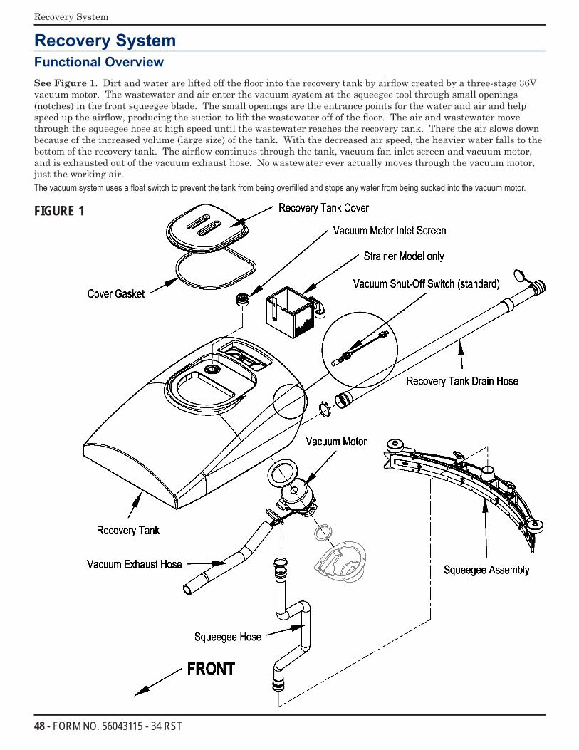
48 - FORM NO. 56043115 - 34 RST
Recovery System
Recovery SystemFunctional Overview
See Figure 1. Dirt and water are lifted off the floor into the recovery tank by airflow created by a three-stage 36V vacuum motor. The wastewater and air enter the vacuum system at the squeegee tool through small openings (notches) in the front squeegee blade. The small openings are the entrance points for the water and air and help speed up the airflow, producing the suction to lift the wastewater off of the floor. The air and wastewater move through the squeegee hose at high speed until the wastewater reaches the recovery tank. There the air slows down because of the increased volume (large size) of the tank. With the decreased air speed, the heavier water falls to the bottom of the recovery tank. The airflow continues through the tank, vacuum fan inlet screen and vacuum motor, and is exhausted out of the vacuum exhaust hose. No wastewater ever actually moves through the vacuum motor, just the working air.The vacuum system uses a float switch to prevent the tank from being overfilled and stops any water from being sucked into the vacuum motor.
FIGURE 1
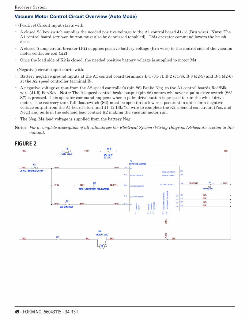
49 - FORM NO. 56043115 - 34 RST
Recovery System
Vacuum Motor Control Circuit Overview (Auto Mode)
+ (Positive) Circuit input starts with:• A closed S3 key switch supplies the needed positive voltage to the A1 control board J1-13 (Brn wire). Note: The
A1 control board scrub-on button must also be depressed (enabled). This operator command lowers the brush deck.
• A closed 5-amp circuit breaker (F2) supplies positive battery voltage (Brn wire) to the control side of the vacuum motor contactor coil (K2).
• Once the load side of K2 is closed, the needed positive battery voltage is supplied to motor M4.
- (Negative) circuit input starts with:• Battery negative ground inputs at the A1 control board terminals B-1 (J1-7), B-2 (J1-9), B-3 (J2-9) and B-4 (J2-6)
at the A2 speed controller terminal B-.• A negative voltage output from the A2 speed controller’s (pin #6) Brake Neg. to the A1 control boards Red/Blk
wire (J1-5) For/Rev. Note: The A2 speed control brake output (pin #6) occurs whenever a palm drive switch (S6/S7) is pressed. This operator command happens when a palm drive button is pressed to run the wheel drive motor. The recovery tank full float switch (S4) must be open (in its lowered position) in order for a negative voltage output from the A1 board’s terminal J1-12 Blk/Yel wire to complete the K2 solenoid coil circuit (Pos. and Neg.) and pulls in the solenoid load contact K2 making the vacuum motor run.
• The Neg. M4 load voltage is supplied from the battery Neg.
Note: ForacompletedescriptionofallcalloutsseetheElectricalSystem/WiringDiagram/Schematicsectioninthismanual.
FIGURE 2 BLK
BLK
BLK
OR
N
BLKBLKBLK
GRA/WHT
BRN
BRNBRN
BLK/YELBRNBRN
BRN
RED
BRN
RED
RED
RED BLU BLK BLKOR
N
36VDC
B+2
B+1
BRUSHCONTACTOR
VACUUMCONTACTOR
SOLUTIONSOLENOID
FOR
/REV
.
BRU
SHM
OTO
RSE
NSE
VAC
UU
MM
OTO
RSE
NSE
J2-7
J1-13
J1-14
J1-12
J1-11
REV
ERSE
B-1
BRUSHACTUATOR1
BRUSHACTUATOR2
B-3
B-4
B-2
A1CONTROLBOARD
J1-5
J2-5
J2-1
0
J1-6
J2-4
J1-7
J2-8
J2-1
J2-6
J1-9
J2-9
RECOVERYTANKFULL
STAT
US
J1-4
CH
EMIC
ALPU
MP
J2-1
1
M
M4MOTOR, VAC
M
M4MOTOR, VAC
1 2
BT1
BATTERY
BT1
BATTERY+ -
F1
FUSE, 150A.
F1
FUSE, 150A.1 2
2K2K
S4
SWITCH, FLOAT
S4
SWITCH, FLOAT
1 2
S3
SW, SPSTKEY
S3
SW, SPSTKEY
K2
COIL, VACMOTORCONTACTOR
K2
COIL, VACMOTORCONTACTOR
F2
CIRCUITBREAKER, 5AMP
F2
CIRCUITBREAKER, 5AMP1 2
50 - FORM NO. 56043115 - 34 RST
Recovery System
Maintenance
Service Maintenance Checklist
Whenever there is a vacuum problem, it’s best to check over the entire system. Use the checklist below as a guide to thoroughly check the vacuum system.
Inspect and clean the vacuum motor float switch. (If the switch is closed [tipped up] the vacuum motor will not operate)
Clean built-up dirt from the inside of the squeegee tool.
Replace the squeegee blades if they are nicked or torn.
Inspect the hose between the squeegee tool and the recovery tank and rinse any built-up dirt from the hose. Replace the hose if it is kinked or damaged.
Inspect and make sure the gasket on the recovery tank cover is sealing and not damaged.
Make sure that the recovery tank drain hose cap seals airtight.
Inspect and clean the vacuum motor inlet filter screen.
Troubleshooting Guide
If water flows around the ends of the squeegee tool instead of being pulled into the tool, the vacuum system is not working correctly. When a vacuum system performs poorly it is usually because of one of the following problems:
Vacuum Leaks – Air flowing into the vacuum system past a bad gasket or leaky hose, damaged tank or a leaky drain valve. A vacuum leak below the water line will create turbulence in the recovery tank, causing water to enter the vacuum motor.
Restrictions – Anything that blocks the flow of air through the system. Restrictions may also be caused by built-up debris in the squeegee tool, vacuum hoses or vacuum motor inlet screen, or wherever the airflow is forced to make a sharp turn.
Both leaks and restrictions decrease the quantity of air flowing through the squeegee tool. The air that does go through the squeegee tool moves slower, so it has less suction (water lift performance).
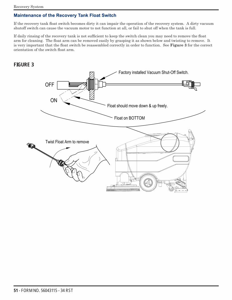
51 - FORM NO. 56043115 - 34 RST
Recovery System
Maintenance of the Recovery Tank Float Switch
If the recovery tank float switch becomes dirty it can impair the operation of the recovery system. A dirty vacuum shutoff switch can cause the vacuum motor to not function at all, or fail to shut off when the tank is full.
If daily rinsing of the recovery tank is not sufficient to keep the switch clean you may need to remove the float arm for cleaning. The float arm can be removed easily by grasping it as shown below and twisting to remove. It is very important that the float switch be reassembled correctly in order to function. See Figure 3 for the correct orientation of the switch float arm.
FIGURE 3
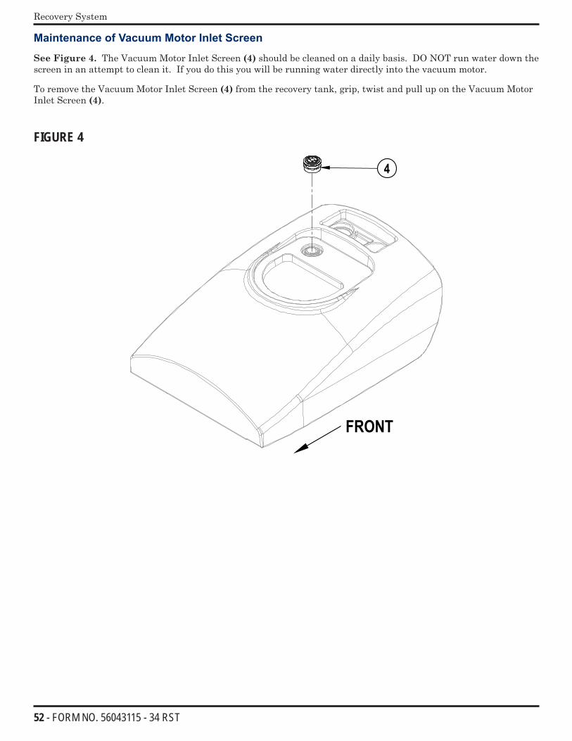
52 - FORM NO. 56043115 - 34 RST
Recovery System
Maintenance of Vacuum Motor Inlet Screen
See Figure 4. The Vacuum Motor Inlet Screen (4) should be cleaned on a daily basis. DO NOT run water down the screen in an attempt to clean it. If you do this you will be running water directly into the vacuum motor.
To remove the Vacuum Motor Inlet Screen (4) from the recovery tank, grip, twist and pull up on the Vacuum Motor Inlet Screen (4).
FIGURE 4
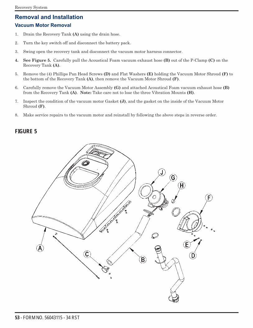
53 - FORM NO. 56043115 - 34 RST
Recovery System
Removal and InstallationVacuum Motor Removal
1. Drain the Recovery Tank (A) using the drain hose.
2. Turn the key switch off and disconnect the battery pack.
3. Swing open the recovery tank and disconnect the vacuum motor harness connector.
4. See Figure 5. Carefully pull the Acoustical Foam vacuum exhaust hose (B) out of the P-Clamp (C) on the Recovery Tank (A).
5. Remove the (4) Phillips Pan Head Screws (D) and Flat Washers (E) holding the Vacuum Motor Shroud (F) to the bottom of the Recovery Tank (A), then remove the Vacuum Motor Shroud (F).
6. Carefully remove the Vacuum Motor Assembly (G) and attached Acoustical Foam vacuum exhaust hose (B) from the Recovery Tank (A). Note: Take care not to lose the three Vibration Mounts (H).
7. Inspect the condition of the vacuum motor Gasket (J), and the gasket on the inside of the Vacuum Motor Shroud (F).
8. Make service repairs to the vacuum motor and reinstall by following the above steps in reverse order.
FIGURE 5
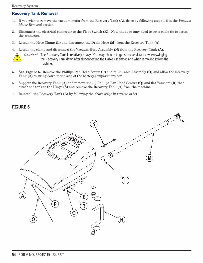
54 - FORM NO. 56043115 - 34 RST
Recovery System
Recovery Tank Removal
1. If you wish to remove the vacuum motor from the Recovery Tank (A), do so by following steps 1-6 in the VacuumMotorRemoval section.
2. Disconnect the electrical connector to the Float Switch (K). Note that you may need to cut a cable tie to access the connector.
3. Loosen the Hose Clamp (L) and disconnect the Drain Hose (M) from the Recovery Tank (A).
4. Loosen the clamp and disconnect the Vacuum Hose Assembly (N) from the Recovery Tank (A).Caution! The Recovery Tank is relatively heavy. You may choose to get some assistance when swinging
the Recovery Tank down after disconnecting the Cable Assembly, and when removing it from the machine.
5. See Figure 6. Remove the Phillips Pan Head Screw (P) and tank Cable Assembly (O) and allow the Recovery Tank (A) to swing down to the side of the battery compartment box.
6. Support the Recovery Tank (A) and remove the (3) Phillips Pan Head Screws (Q) and flat Washers (R) that attach the tank to the Hinge (S) and remove the Recovery Tank (A) from the machine.
7. Reinstall the Recovery Tank (A) by following the above steps in reverse order.
FIGURE 6
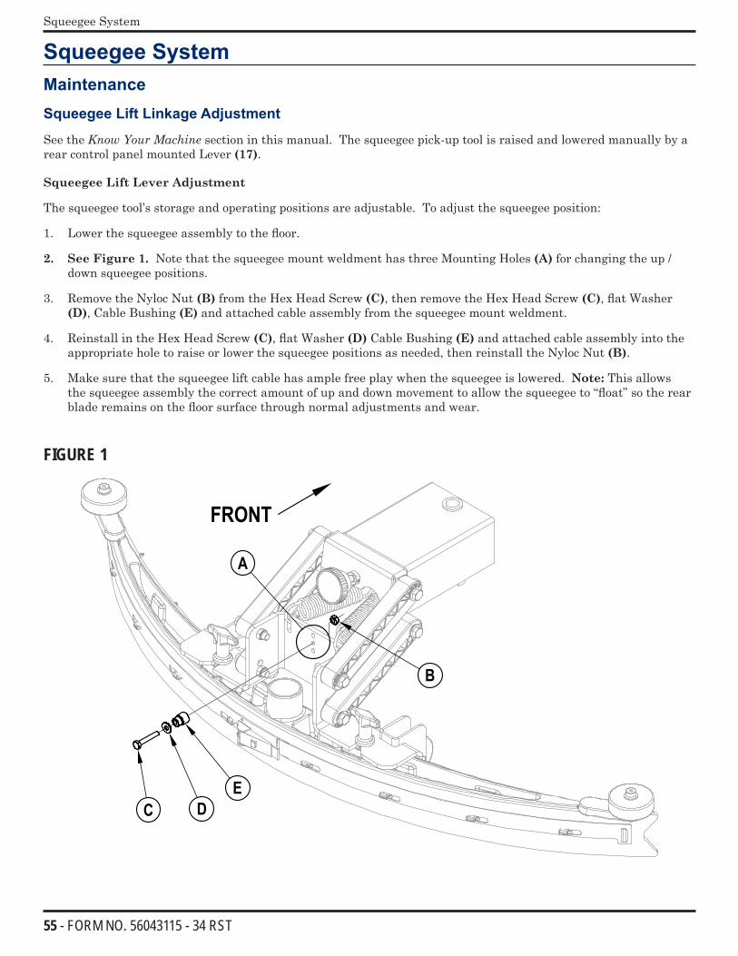
55 - FORM NO. 56043115 - 34 RST
Squeegee System
Squeegee SystemMaintenance
Squeegee Lift Linkage Adjustment
See the KnowYourMachine section in this manual. The squeegee pick-up tool is raised and lowered manually by a rear control panel mounted Lever (17).
Squeegee Lift Lever Adjustment
The squeegee tool’s storage and operating positions are adjustable. To adjust the squeegee position:
1. Lower the squeegee assembly to the floor.
2. See Figure 1. Note that the squeegee mount weldment has three Mounting Holes (A) for changing the up / down squeegee positions.
3. Remove the Nyloc Nut (B) from the Hex Head Screw (C), then remove the Hex Head Screw (C), flat Washer (D), Cable Bushing (E) and attached cable assembly from the squeegee mount weldment.
4. Reinstall in the Hex Head Screw (C), flat Washer (D) Cable Bushing (E) and attached cable assembly into the appropriate hole to raise or lower the squeegee positions as needed, then reinstall the Nyloc Nut (B).
5. Make sure that the squeegee lift cable has ample free play when the squeegee is lowered. Note: This allows the squeegee assembly the correct amount of up and down movement to allow the squeegee to “float” so the rear blade remains on the floor surface through normal adjustments and wear.
FIGURE 1
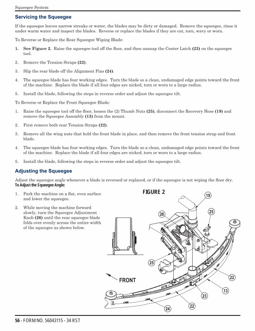
56 - FORM NO. 56043115 - 34 RST
Squeegee System
Servicing the Squeegee
If the squeegee leaves narrow streaks or water, the blades may be dirty or damaged. Remove the squeegee, rinse it under warm water and inspect the blades. Reverse or replace the blades if they are cut, torn, wavy or worn.
To Reverse or Replace the Rear Squeegee Wiping Blade:
1. See Figure 2. Raise the squeegee tool off the floor, and then unsnap the Center Latch (23) on the squeegee tool.
2. Remove the Tension Straps (22).
3. Slip the rear blade off the Alignment Pins (24).
4. The squeegee blade has four working edges. Turn the blade so a clean, undamaged edge points toward the front of the machine. Replace the blade if all four edges are nicked, torn or worn to a large radius.
5. Install the blade, following the steps in reverse order and adjust the squeegee tilt.
To Reverse or Replace the Front Squeegee Blade:
1. Raise the squeegee tool off the floor, loosen the (2) Thumb Nuts (25), disconnect the Recovery Hose (19) and remove the Squeegee Assembly (13) from the mount.
2. First remove both rear Tension Straps (22).
3. Remove all the wing nuts that hold the front blade in place, and then remove the front tension strap and front blade.
4. The squeegee blade has four working edges. Turn the blade so a clean, undamaged edge points toward the front of the machine. Replace the blade if all four edges are nicked, torn or worn to a large radius.
5. Install the blade, following the steps in reverse order and adjust the squeegee tilt.
Adjusting the Squeegee
Adjust the squeegee angle whenever a blade is reversed or replaced, or if the squeegee is not wiping the floor dry. To Adjust the Squeegee Angle:
1. Park the machine on a flat, even surface and lower the squeegee.
2. While moving the machine forward slowly, turn the Squeegee Adjustment Knob (26) until the rear squeegee blade folds over evenly across the entire width of the squeegee as shown below.
FIGURE 2
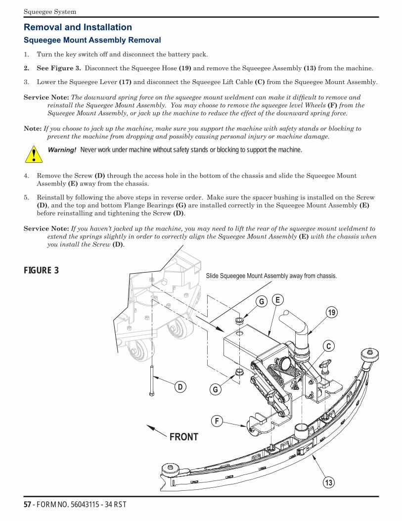
57 - FORM NO. 56043115 - 34 RST
Squeegee System
Removal and InstallationSqueegee Mount Assembly Removal
1. Turn the key switch off and disconnect the battery pack.
2. See Figure 3. Disconnect the Squeegee Hose (19) and remove the Squeegee Assembly (13) from the machine.
3. Lower the Squeegee Lever (17) and disconnect the Squeegee Lift Cable (C) from the Squeegee Mount Assembly.
Service Note:ThedownwardspringforceonthesqueegeemountweldmentcanmakeitdifficulttoremoveandreinstalltheSqueegeeMountAssembly.YoumaychoosetoremovethesqueegeelevelWheels(F)fromtheSqueegeeMountAssembly,orjackupthemachinetoreducetheeffectofthedownwardspringforce.
Note:Ifyouchoosetojackupthemachine,makesureyousupportthemachinewithsafetystandsorblockingtopreventthemachinefromdroppingandpossiblycausingpersonalinjuryormachinedamage.
Warning! Never work under machine without safety stands or blocking to support the machine.
4. Remove the Screw (D) through the access hole in the bottom of the chassis and slide the Squeegee Mount Assembly (E) away from the chassis.
5. Reinstall by following the above steps in reverse order. Make sure the spacer bushing is installed on the Screw (D), and the top and bottom Flange Bearings (G) are installed correctly in the Squeegee Mount Assembly (E) before reinstalling and tightening the Screw (D).
Service Note:Ifyouhaven’tjackedupthemachine,youmayneedtolifttherearofthesqueegeemountweldmenttoextendthespringsslightlyinordertocorrectlyaligntheSqueegeeMountAssembly(E)withthechassiswhenyouinstalltheScrew(D).
FIGURE 3
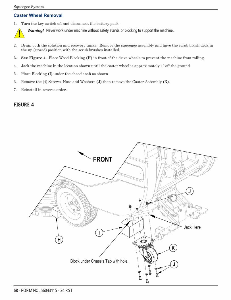
58 - FORM NO. 56043115 - 34 RST
Squeegee System
Caster Wheel Removal
1. Turn the key switch off and disconnect the battery pack.
Warning! Never work under machine without safety stands or blocking to support the machine.
2. Drain both the solution and recovery tanks. Remove the squeegee assembly and have the scrub brush deck in the up (stored) position with the scrub brushes installed.
3. See Figure 4. Place Wood Blocking (H) in front of the drive wheels to prevent the machine from rolling.
4. Jack the machine in the location shown until the caster wheel is approximately 1” off the ground.
5. Place Blocking (I) under the chassis tab as shown.
6. Remove the (4) Screws, Nuts and Washers (J) then remove the Caster Assembly (K).
7. Reinstall in reverse order.
FIGURE 4
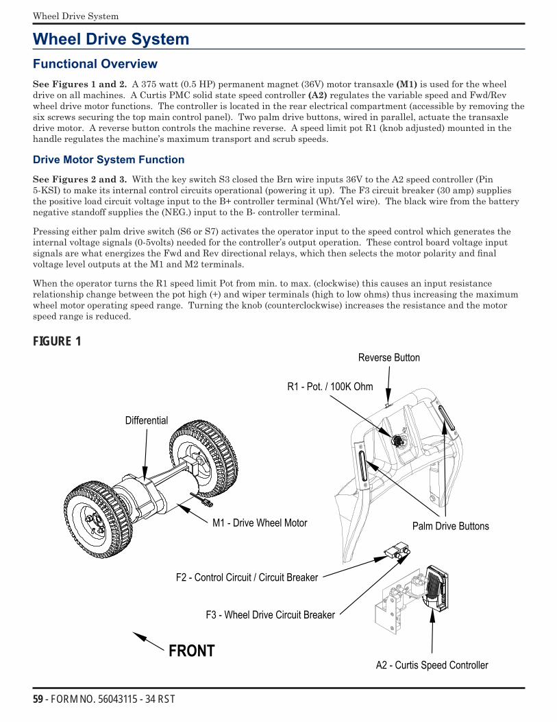
59 - FORM NO. 56043115 - 34 RST
Wheel Drive System
Wheel Drive SystemFunctional OverviewSee Figures 1 and 2. A 375 watt (0.5 HP) permanent magnet (36V) motor transaxle (M1) is used for the wheel drive on all machines. A Curtis PMC solid state speed controller (A2) regulates the variable speed and Fwd/Rev wheel drive motor functions. The controller is located in the rear electrical compartment (accessible by removing the six screws securing the top main control panel). Two palm drive buttons, wired in parallel, actuate the transaxle drive motor. A reverse button controls the machine reverse. A speed limit pot R1 (knob adjusted) mounted in the handle regulates the machine’s maximum transport and scrub speeds.
Drive Motor System Function
See Figures 2 and 3. With the key switch S3 closed the Brn wire inputs 36V to the A2 speed controller (Pin 5-KSI) to make its internal control circuits operational (powering it up). The F3 circuit breaker (30 amp) supplies the positive load circuit voltage input to the B+ controller terminal (Wht/Yel wire). The black wire from the battery negative standoff supplies the (NEG.) input to the B- controller terminal.
Pressing either palm drive switch (S6 or S7) activates the operator input to the speed control which generates the internal voltage signals (0-5volts) needed for the controller’s output operation. These control board voltage input signals are what energizes the Fwd and Rev directional relays, which then selects the motor polarity and final voltage level outputs at the M1 and M2 terminals.
When the operator turns the R1 speed limit Pot from min. to max. (clockwise) this causes an input resistance relationship change between the pot high (+) and wiper terminals (high to low ohms) thus increasing the maximum wheel motor operating speed range. Turning the knob (counterclockwise) increases the resistance and the motor speed range is reduced.
FIGURE 1
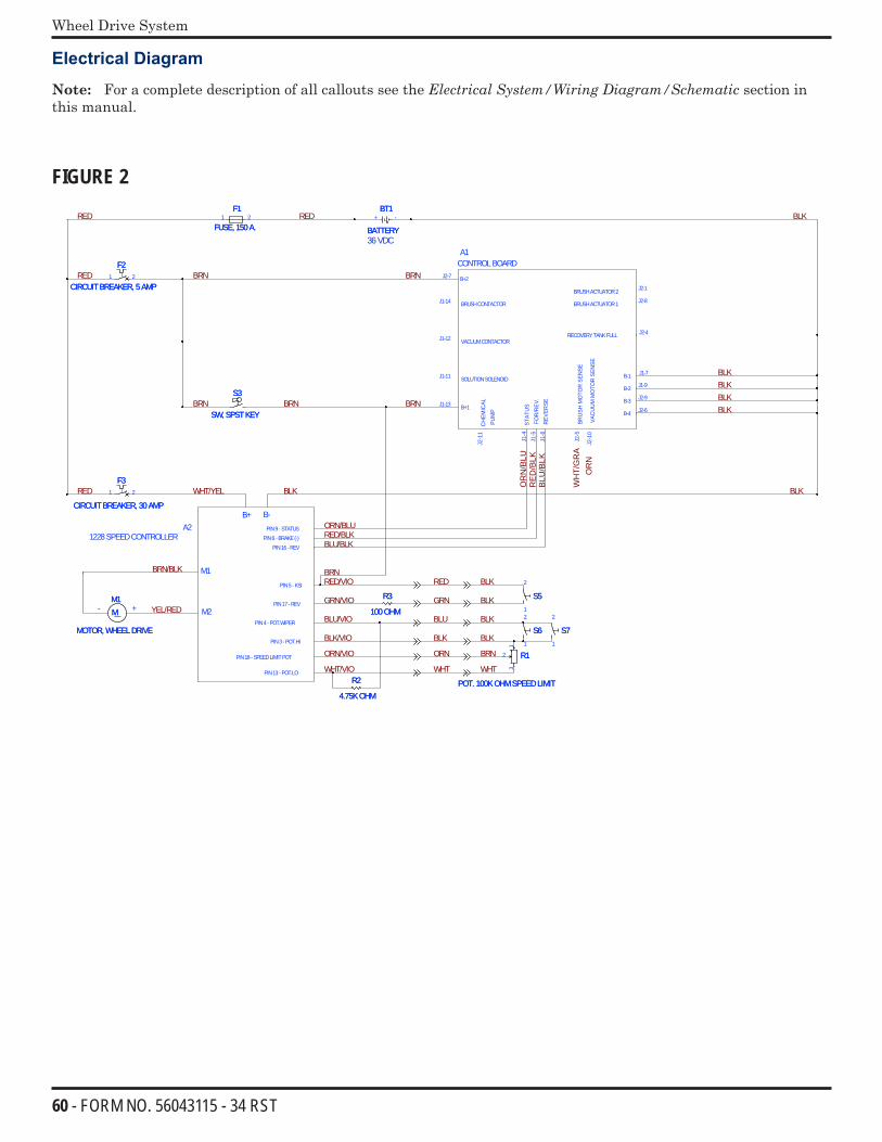
60 - FORM NO. 56043115 - 34 RST
Wheel Drive System
Electrical Diagram
Note: For a complete description of all callouts see the ElectricalSystem/WiringDiagram/Schematic section in this manual.
FIGURE 2
BLK
RED
/BLK
BLK
OR
N/B
LU
BLU
/BLK
OR
N
BLKBLKBLK
WH
T/G
RA
BLK
BRN
BRNBRN
BRN
RED
BRN
RED
RED
BRN/BLK
YEL/RED
RED WHT/YEL
RED/VIO
BLK
ORN/BLURED/BLKBLU/BLK
BRN
GRN/VIO
BLU/VIO
BLK/VIO
ORN/VIO
WHT/VIO
BLK
BLKRED
GRN
BLKBLU
BLK
BRNORN
BLK
WHT WHT
+
36VDC
-
B+2
B+1
BRUSHCONTACTOR
VACUUMCONTACTOR
SOLUTIONSOLENOID
FOR
/REV
.
BRU
SHM
OTO
RSE
NSE
VAC
UU
MM
OTO
RSE
NSE
J2-7
J1-13
J1-14
J1-12
J1-11
REV
ERSE
B-1
BRUSHACTUATOR1
BRUSHACTUATOR2
B-3
B-4
B-2
A1CONTROLBOARD
J1-5
J2-5
J2-1
0
J1-6
J2-4
J1-7
J2-8
J2-1
J2-6
J1-9
J2-9
RECOVERYTANKFULL
A2B+ B-
1228SPEEDCONTROLLER
M1
M2
PIN3- POT.HI
PIN4- POT.WIPER
PIN13- POT.LO
PIN5- KSI
PIN16- REVPIN6- BRAKE(-)
STAT
US
PIN9 - STATUS
PIN18- SPEEDLIMITPOT
J1-4
PIN17 - REV
CH
EMIC
ALPU
MP
J2-1
1
MM1
MOTOR, WHEELDRIVE
MM1
MOTOR, WHEELDRIVE
R3
100OHM
R3
100OHM
BT1
BATTERY
BT1
BATTERY+ -
F1
FUSE, 150A.
F1
FUSE, 150A.1 2
S3
SW, SPSTKEY
S3
SW, SPSTKEY
5S5S1
2
R2
4.75KOHM
R2
4.75KOHM
6S6S1
2
F3
CIRCUITBREAKER, 30AMP
F3
CIRCUITBREAKER, 30AMP
1 2
R1
POT. 100KOHMSPEEDLIMIT
R1
POT. 100KOHMSPEEDLIMIT
1
2
3
F2
CIRCUITBREAKER, 5AMP
F2
CIRCUITBREAKER, 5AMP1 2
7S7S1
2
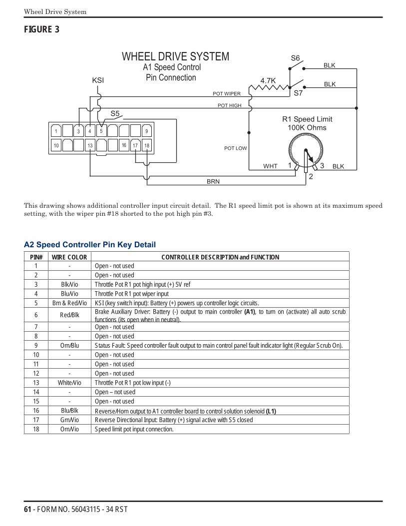
61 - FORM NO. 56043115 - 34 RST
Wheel Drive System
FIGURE 3
WHEEL DRIVE SYSTEMA1 Speed ControlPin Connection
3 5
13 18
9
16
4
POT HIGH
S6
S7
100K OhmsR1 Speed Limit
BRN
BLKWHT
BLK
12
3
4.7K
1710
1
POT LOW
POT WIPER
S5
KSI
BLK
This drawing shows additional controller input circuit detail. The R1 speed limit pot is shown at its maximum speed setting, with the wiper pin #18 shorted to the pot high pin #3.
A2 Speed Controller Pin Key DetailPIN# WIRE COLOR CONTROLLER DESCRIPTION and FUNCTION
1 - Open - not used2 - Open - not used3 Blk/Vio Throttle Pot R1 pot high input (+) 5V ref4 Blu/Vio Throttle Pot R1 pot wiper input5 Brn & Red/Vio KSI (key switch input): Battery (+) powers up controller logic circuits.
6 Red/Blk Brake Auxiliary Driver: Battery (-) output to main controller (A1), to turn on (activate) all auto scrub functions (its open when in neutral).
7 - Open - not used8 - Open - not used9 Orn/Blu Status Fault: Speed controller fault output to main control panel fault indicator light (Regular Scrub On).10 - Open - not used11 - Open - not used12 - Open - not used13 White/Vio Throttle Pot R1 pot low input (-)14 - Open – not used15 - Open - not used16 Blu/Blk Reverse/Horn output to A1 controller board to control solution solenoid (L1)17 Grn/Vio Reverse Directional Input: Battery (+) signal active with S5 closed18 Orn/Vio Speed limit pot input connection.
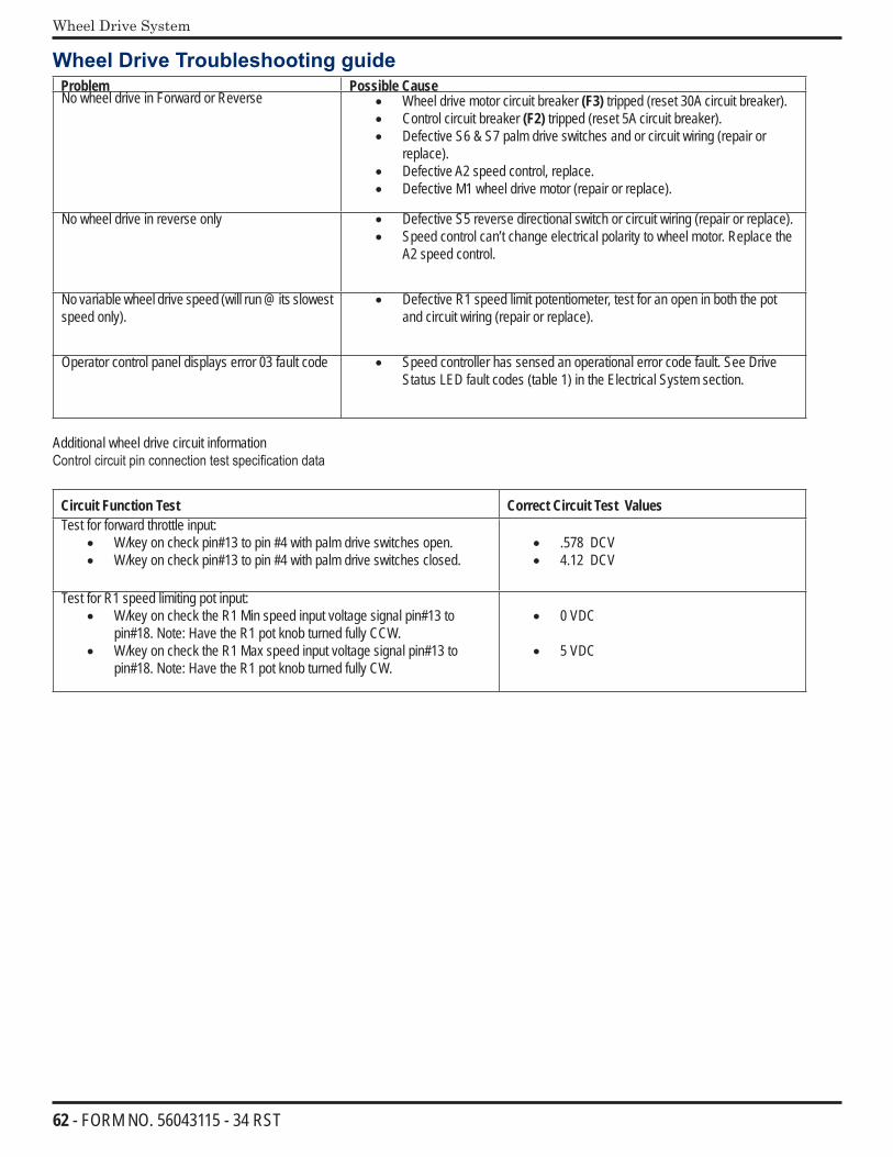
62 - FORM NO. 56043115 - 34 RST
Wheel Drive System
Wheel Drive Troubleshooting guideProblem Possible CauseNo wheel drive in Forward or Reverse • Wheel drive motor circuit breaker (F3) tripped (reset 30A circuit breaker).
• Control circuit breaker (F2) tripped (reset 5A circuit breaker).• Defective S6 & S7 palm drive switches and or circuit wiring (repair or
replace).• Defective A2 speed control, replace. • Defective M1 wheel drive motor (repair or replace).
No wheel drive in reverse only • Defective S5 reverse directional switch or circuit wiring (repair or replace).• Speed control can’t change electrical polarity to wheel motor. Replace the
A2 speed control.
No variable wheel drive speed (will run @ its slowest speed only).
• Defective R1 speed limit potentiometer, test for an open in both the pot and circuit wiring (repair or replace).
Operator control panel displays error 03 fault code • Speed controller has sensed an operational error code fault. See Drive Status LED fault codes (table 1) in the Electrical System section.
Additional wheel drive circuit informationControl circuit pin connection test specification data
Circuit Function Test Correct Circuit Test ValuesTest for forward throttle input:
• W/key on check pin#13 to pin #4 with palm drive switches open.• W/key on check pin#13 to pin #4 with palm drive switches closed.
• .578 DCV• 4.12 DCV
Test for R1 speed limiting pot input:• W/key on check the R1 Min speed input voltage signal pin#13 to
pin#18. Note: Have the R1 pot knob turned fully CCW.• W/key on check the R1 Max speed input voltage signal pin#13 to
pin#18. Note: Have the R1 pot knob turned fully CW.
• 0 VDC
• 5 VDC
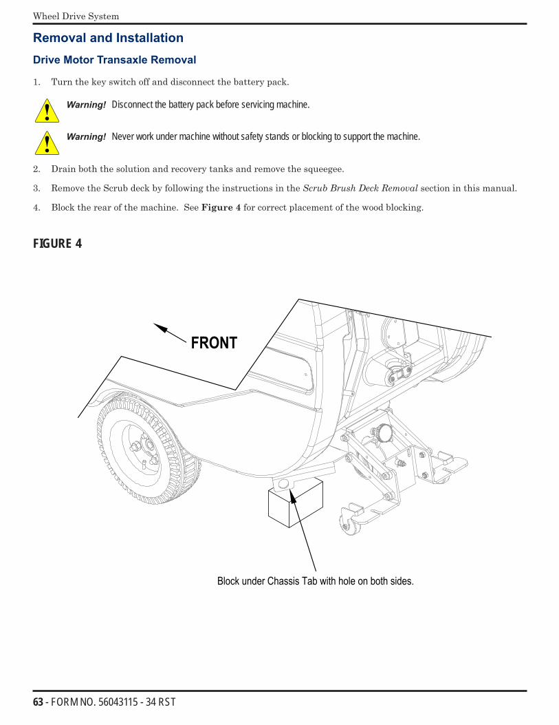
63 - FORM NO. 56043115 - 34 RST
Wheel Drive System
Removal and Installation
Drive Motor Transaxle Removal
1. Turn the key switch off and disconnect the battery pack.
Warning! Disconnect the battery pack before servicing machine.
Warning! Never work under machine without safety stands or blocking to support the machine.
2. Drain both the solution and recovery tanks and remove the squeegee.
3. Remove the Scrub deck by following the instructions in the ScrubBrushDeckRemoval section in this manual.
4. Block the rear of the machine. See Figure 4 for correct placement of the wood blocking.
FIGURE 4
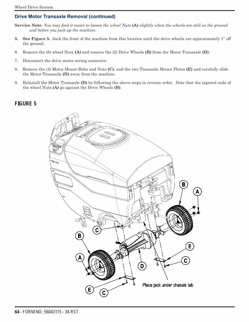
64 - FORM NO. 56043115 - 34 RST
Wheel Drive System
Drive Motor Transaxle Removal (continued)
Service Note:YoumayfinditeasiertoloosenthewheelNuts(A)slightlywhenthewheelsarestillonthegroundandbeforeyoujackupthemachine.
5. See Figure 5. Jack the front of the machine from this location until the drive wheels are approximately 1” off the ground.
6. Remove the (6) wheel Nuts (A) and remove the (2) Drive Wheels (B) from the Motor Transaxle (D).
7. Disconnect the drive motor wiring connector.
8. Remove the (4) Motor Mount Bolts and Nuts (C), and the two Transaxle Mount Plates (E) and carefully slide the Motor Transaxle (D) away from the machine.
9. Reinstall the Motor Transaxle (D) by following the above steps in reverse order. Note that the tapered ends of the wheel Nuts (A) go against the Drive Wheels (B).
FIGURE 5
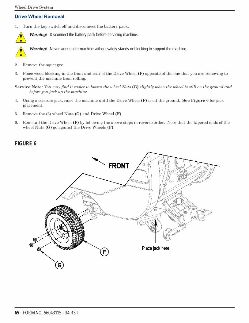
65 - FORM NO. 56043115 - 34 RST
Wheel Drive System
Drive Wheel Removal
1. Turn the key switch off and disconnect the battery pack.
Warning! Disconnect the battery pack before servicing machine.
Warning! Never work under machine without safety stands or blocking to support the machine.
2. Remove the squeegee.
3. Place wood blocking in the front and rear of the Drive Wheel (F) opposite of the one that you are removing to prevent the machine from rolling.
Service Note:YoumayfinditeasiertoloosenthewheelNuts(G)slightlywhenthewheelisstillonthegroundandbeforeyoujackupthemachine.
4. Using a scissors jack, raise the machine until the Drive Wheel (F) is off the ground. See Figure 6 for jack placement.
5. Remove the (3) wheel Nuts (G) and Drive Wheel (F).
6. Reinstall the Drive Wheel (F) by following the above steps in reverse order. Note that the tapered ends of the wheel Nuts (G) go against the Drive Wheels (F).
FIGURE 6
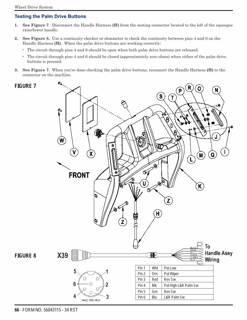
66 - FORM NO. 56043115 - 34 RST
Wheel Drive System
Testing the Palm Drive Buttons
1. See Figure 7. Disconnect the Handle Harness (H) from the mating connector located to the left of the squeegee raise/lower handle.
2. See Figure 8. Use a continuity checker or ohmmeter to check the continuity between pins 4 and 6 on the Handle Harness (H). When the palm drive buttons are working correctly:• The circuit through pins 4 and 6 should be open when both palm drive buttons are released.• The circuit through pins 4 and 6 should be closed (approximately zero ohms) when either of the palm drive
buttons is pressed.
3. See Figure 7. When you’re done checking the palm drive buttons, reconnect the Handle Harness (H) to the connector on the machine.
FIGURE 7
FIGURE 8
Pin 1 Wht Pot LowPin 2 Orn Pot WiperPin 3 Red Rev SwPin 4 Blk Pot High L&R Palm SwPin 5 Grn Rev SwPin 6 Blu L&R Palm Sw
67 - FORM NO. 56043115 - 34 RST
Wheel Drive System
Palm Drive Button Replacement
Note: It’srecommendedthatyouemptytheRecoveryTankbeforereplacingaPalmDriveButton.
1. See Figure 7. Remove the (2) Phillips Flat Head Screws (I) and remove the Palm Switch Assembly (J) from the Handle (K).
2. See the detail in Figure 7. Remove the (2) Phillips Pan Head Screws (L) and Flat Washers (M) and remove the Palm Button Switch (N) and (2) Switch Springs (O) from the Palm Switch Housing (P). Be careful not to lose the Switch Springs (O).
3. Remove the Retaining Nut (Q) and Star Washer (R) from the SPST Momentary Switch (S), then remove the SPST Momentary Switch (S) and the other (2) Star Washers (T) from the Palm Switch Housing (P).
4. Pull the Drain Hose out of the brackets to access the 5/16”-18 Hex Head Screws (U & Z).
5. Disconnect the Handle Harness (H) from the mating connector located to the left of the squeegee raise/lower handle. (This will prevent excessive pulling or stress on the Handle Harness (H) and connector when the Handle (K) is swung down to remove the Access Plate (V).)
6. Loosen the bottom left- and right-hand 5/16”-18 Hex Head Screws (Z) holding the Handle (K) to the machine.
7. Remove the top left- and right-hand 5/16”-18 Hex Head Screws (U) holding the Handle (K) to the machine, then swing the Handle (K) down to allow access to the bottom Phillips Pan Head Screw (W) holding the Access Plate (V).
8. Remove the (2) Phillips Pan Head Screws (W) and remove the Access Plate (V) and attached Access Panel Gasket (X) from the Handle (K).
9. Note the wire colors and connector locations, then disconnect the SPST Momentary Switch leads from the connectors in the access area and remove the old SPST Momentary Switch (S). Note that you may need to cut a cable tie to access the wires and connectors.
10. Thread the leads from the replacement SPST Momentary Switch (S) into the side of the Handle (K) and to the access area, then plug them into the corresponding connectors. Replace the cable tie if necessary.
11. Reinstall the Access Plate (V) and attached Access Panel Gasket (X) onto the Handle (K), then reinstall and tighten the (2) Phillips Pan Head Screws (W).
12. Swing the Handle (K) back up into position, reinstall the top left- and right-hand 5/16”-18 Hex Head Screws (U), then tighten the bottom left- and right-hand 5/16”-18 Hex Head Screws (Z).
13. Install the (2) Star Washers (T) onto the SPST Momentary Switch (S), then fasten the SPST Momentary Switch (S) to the Palm Switch Housing (P) with the remaining Star Washer (R) and Retaining Nut (Q).
14. Reassemble the Palm Button Switch (N) and (2) Switch Springs (O) to the Palm Switch Housing (P), then reinstall the (2) Phillips Pan Head Screws (L) and Flat Washers (M). Check the function of the Palm Button Switch (N) to make sure the Switch Springs (O) are assembled correctly.
15. Reassemble the Palm Switch Assembly (J) to the Handle (K), then reinstall and tighten the (2) Phillips Flat Head Screws (I).
16. Reconnect the Handle Harness (H) to the connector on the machine.
17. Snap the Drain Hose back into the brackets.
18. Check the machine drive functions (forward, reverse, speed control) to make sure the controls are working correctly.
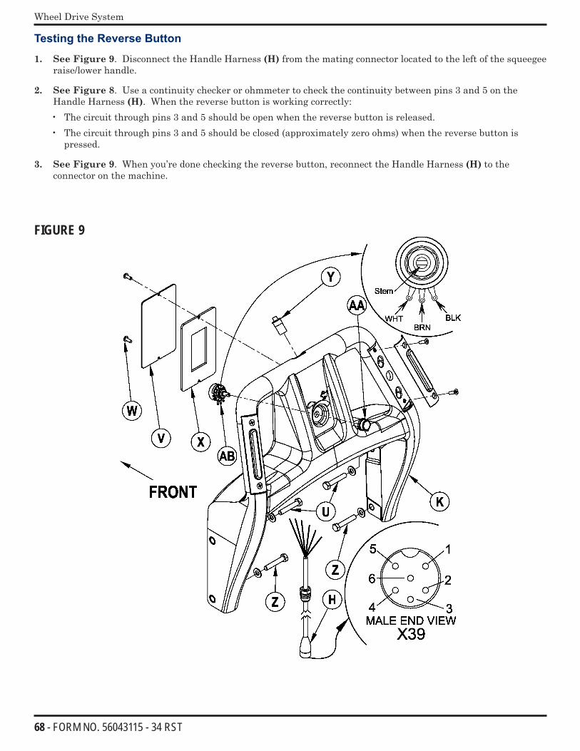
68 - FORM NO. 56043115 - 34 RST
Wheel Drive System
Testing the Reverse Button
1. See Figure 9. Disconnect the Handle Harness (H) from the mating connector located to the left of the squeegee raise/lower handle.
2. See Figure 8. Use a continuity checker or ohmmeter to check the continuity between pins 3 and 5 on the Handle Harness (H). When the reverse button is working correctly:• The circuit through pins 3 and 5 should be open when the reverse button is released.• The circuit through pins 3 and 5 should be closed (approximately zero ohms) when the reverse button is
pressed.
3. See Figure 9. When you’re done checking the reverse button, reconnect the Handle Harness (H) to the connector on the machine.
FIGURE 9
69 - FORM NO. 56043115 - 34 RST
Wheel Drive System
Reverse Button Replacement
1. Turn the key switch off and disconnect the battery pack.Note: It’s recommended that you empty the Recovery Tank before replacing the Reverse Button.
2. Pull the Drain Hose out of the brackets to access the 5/16”-18 Hex Head Screws (U & Z).
3. Disconnect the Handle Harness (H) from the mating connector located to the left of the squeegee raise/lower handle. (This will prevent excessive pulling or stress on the Handle Harness (H) and connector when the Handle (K) is swung down to remove the Access Plate (V).)
4. Loosen the bottom left- and right-hand 5/16”-18 Hex Head Screws (Z) holding the Handle (K) to the machine.
5. Remove the top left- and right-hand 5/16”-18 Hex Head Screws (U) holding the Handle (K) to the machine, then swing the Handle (K) down to allow access to the bottom Phillips Pan Head Screw (W) holding the Access Plate (V).
6. Remove the (2) Phillips Pan Head Screws (W) and remove the Access Plate (V) and attached Access Panel Gasket (X) from the Handle (K).
7. Note the wire colors and connector locations, then disconnect the leads on the reverse button SPST Momentary Switch (Y) from the connectors in the access area. Note that you may need to cut a cable tie to access the wires and connectors.
8. Remove the old reverse button through the top of the Handle (K).
9. Insert the leads from the replacement reverse button SPST Momentary Switch (Y) through the hole in the top of the Handle (K) and to the access area, then carefully press the new reverse button into the Handle (K).
10. Plug the leads from the reverse button SPST Momentary Switch (Y) into the corresponding connectors. Replace the cable tie if necessary.
11. Reinstall the Access Plate (V) and attached Access Panel Gasket (X) onto the Handle (K), then reinstall and tighten the (2) Phillips Pan Head Screws (W).
12. Swing the Handle (K) back up into position, reinstall the top left- and right-hand 5/16”-18 Hex Head Screws (U), then tighten the bottom left- and right-hand 5/16”-18 Hex Head Screws (Z).
13. Reconnect the Handle Harness (H) to the connector on the machine.
14. Snap the Drain Hose back into the brackets.
15. Check the machine drive functions (forward, reverse, speed control) to make sure the controls are working correctly.
70 - FORM NO. 56043115 - 34 RST
Wheel Drive System
Testing the Speed Limit Control Potentiometer
1. See Figure 9. Disconnect the Handle Harness (H) from the mating connector located to the left of the squeegee raise/lower handle.
2. See Figure 8. Use an ohmmeter on pins 1 and 4 to check the total resistance of the potentiometer. If the potentiometer is working correctly, the resistance across pins 1 and 4 should measure approximately 100K ohms.
3. Use an ohmmeter to measure the resistance across pins 2 and 4. If the potentiometer is working correctly:• The resistance across pins 2 and 4 should measure 100K ohms with the Speed Limit Control Knob rotated all
the way counterclockwise (slow speed).• The resistance across pins 2 and 4 should measure close to zero ohms with the Speed Limit Control Knob
rotated all the way clockwise (fast speed).• The resistance values across pins 2 and 4 should change proportionately between 100K ohms to zero ohms as
the Speed Limit Control Knob is rotated between slow and fast speed. Note that any “dead spots” or spikes in the resistance values could indicate a problem with the potentiometer.
4. See Figure 9. When you’re done checking the speed limit control potentiometer, reconnect the Handle Harness (H) to the connector on the machine.
Speed Limit Control Potentiometer Replacement
1. Turn the key switch off and disconnect the battery pack.
2. See Figure 9. Loosen the setscrew in the Knob (AA), then remove the Knob (AA) from the Potentiometer (AB) shaft.
3. Pull the Drain Hose out of the brackets to access the 5/16”-18 Hex Head Screws (U & Z).
4. Disconnect the Handle Harness (H) from the mating connector located to the left of the squeegee raise/lower handle. (This will prevent excessive pulling or stress on the Handle Harness (H) and connector when the Handle (K) is swung down to remove the Access Plate (V).)
5. Loosen the bottom left- and right-hand 5/16”-18 Hex Head Screws (Z) holding the Handle (K) to the machine.
6. Remove the top left- and right-hand 5/16”-18 Hex Head Screws (U) holding the Handle (K) to the machine, then swing the Handle (K) down to allow access to the bottom Phillips Pan Head Screw (W) holding the Access Plate (V).
7. Remove the (2) Phillips Pan Head Screws (W) and remove the Access Plate (V) and attached Access Panel Gasket (X) from the Handle (K).
8. Note the wire colors and connector locations, then disconnect the three Potentiometer leads from the connectors in the access area. Note that you may need to cut a cable tie to access the wires and connectors.
9. Note the position of the Potentiometer (AB) in the Handle (K), then remove the retaining nut and star washer and remove the old Potentiometer (AB) from the Handle (K).
10. Insert the leads from the replacement Potentiometer (AB) through the hole in the front of the Handle (K) and to the access area, then plug them into the corresponding connectors. Replace the cable tie if necessary.
11. Install the new Potentiometer (AB) into the Handle (K), then reinstall the star washer and retaining nut.
12. Reinstall the Access Plate (V) and attached Access Panel Gasket (X) onto the Handle (K), then reinstall and tighten the (2) Phillips Pan Head Screws (W).
13. Swing the Handle (K) back up into position, reinstall the top left- and right-hand 5/16”-18 Hex Head Screws (U), then tighten the bottom left- and right-hand 5/16”-18 Hex Head Screws (Z).
14. Reinstall the Knob (AA) onto the Potentiometer (AB) shaft, then tighten the setscrew.

71 - FORM NO. 56043115 - 34 RST
Wheel Drive System
15. Check the position of the gray indicator on the Knob (AA) with the Potentiometer (AB) set to both the full clockwise (fast) and full counterclockwise (slow) positions. Readjust the rotational position of the Knob (AA) on the Potentiometer (AB) shaft as necessary to center the indicator to the Handle (K).
16. Reconnect the Handle Harness (H) to the connector on the machine.
17. Snap the Drain Hose back into the brackets.
18. Check the machine drive functions (forward, reverse, speed control) to make sure the controls are working correctly.
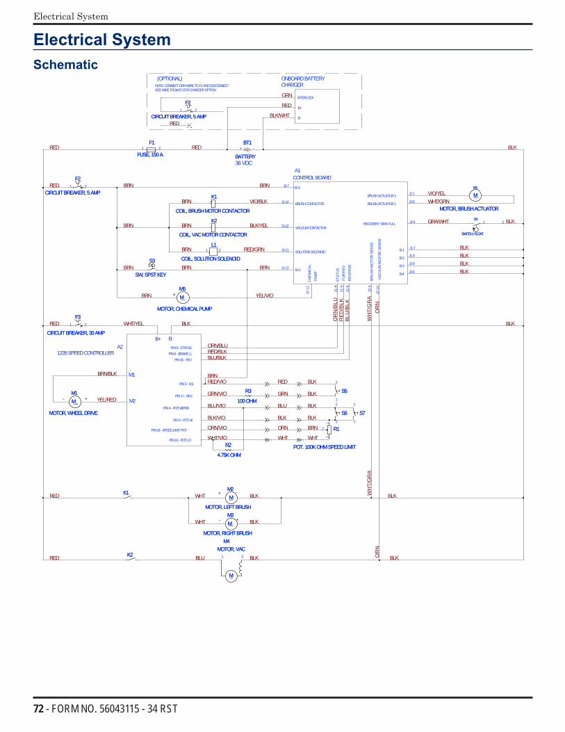
72 - FORM NO. 56043115 - 34 RST
Electrical System
Electrical SystemSchematic
BLK
RED
/BLK
BLK
OR
N/B
LU
BLU
/BLK
BLK
OR
N
BLKBLKBLK
VIO/YELWHT/GRN
GRA/WHT
WH
T/G
RA
BLK
BRN
RED/GRN
BRNBRN
VIO/BLK
BLK/YEL
BRN
BRN
BRN
BRN
BRN
RED
BRN
BRN YEL/VIO
GRN
RED
REDBLK/WHT
RED
RED
BRN/BLK
YEL/RED
RED WHT/YEL
RED/VIO
BLK
ORN/BLURED/BLKBLU/BLK
BRN
GRN/VIO
BLU/VIO
BLK/VIO
ORN/VIO
WHT/VIO
BLK
BLKRED
GRN
BLKBLU
BLK
BRNORN
BLK
WHT WHT
RED
RED WHT
WHT
BLU
BLK
BLK
BLK
BLK
BLKOR
NW
HT/
GR
A
+
-
- +
+
36VDC
-
B+2
B+1
BRUSHCONTACTOR
VACUUMCONTACTOR
SOLUTIONSOLENOID
FOR
/REV
.
BRU
SHM
OTO
RSE
NSE
VAC
UU
MM
OTO
RSE
NSE
J2-7
J1-13
J1-14
J1-12
J1-11
REV
ERSE
B-1
BRUSHACTUATOR1
BRUSHACTUATOR2
B-3
B-4
B-2
A1CONTROLBOARD
J1-5
J2-5
J2-1
0
J1-6
J2-4
J1-7
J2-8
J2-1
J2-6
J1-9
J2-9
RECOVERYTANKFULL
A2B+ B-
1228SPEEDCONTROLLER
M1
M2
PIN3- POT.HI
PIN4- POT.WIPER
PIN13- POT.LO
PIN5- KSI
PIN16- REVPIN6- BRAKE(-)
STAT
US
PIN9 - STATUS
PIN18- SPEEDLIMITPOT
ONBOARDBATTERYCHARGER
(OPTIONAL)
B+
B-
INTERLOCK
NOTE: CONNECTGRNWIRETOF2ANDDISCONNECTREDWIREFROMF2FORCHARGEROPTION
J1-4
PIN17 - REV
CH
EMIC
ALPU
MP
J2-1
1
+
M
M4MOTOR, VAC
M
M4MOTOR, VAC
1 2
F2
CIRCUITBREAKER, 5AMP
F2
CIRCUITBREAKER, 5AMP1 2
MM1
MOTOR, WHEELDRIVE
MM1
MOTOR, WHEELDRIVE
R3
100OHM
R3
100OHM
MM5
MOTOR, BRUSHACTUATOR
MM5
MOTOR, BRUSHACTUATOR
K1
COIL, BRUSHMOTORCONTACTOR
K1
COIL, BRUSHMOTORCONTACTOR
BT1
BATTERY
BT1
BATTERY+ -
L1
COIL, SOLUTIONSOLENOID
L1
COIL, SOLUTIONSOLENOID
1 2
F1
FUSE, 150A.
F1
FUSE, 150A.1 2
2K2K
MM2
MOTOR, LEFTBRUSH
MM2
MOTOR, LEFTBRUSH
S4
SWITCH, FLOAT
S4
SWITCH, FLOAT
1 2
S3
SW, SPSTKEY
S3
SW, SPSTKEY
5S5S1
2
MM3
MOTOR, RIGHTBRUSH
MM3
MOTOR, RIGHTBRUSH
1K1K
R2
4.75KOHM
R2
4.75KOHM
K2
COIL, VACMOTORCONTACTOR
K2
COIL, VACMOTORCONTACTOR
6S6S1
2
F3
CIRCUITBREAKER, 30AMP
F3
CIRCUITBREAKER, 30AMP
1 2
R1
POT. 100KOHMSPEEDLIMIT
R1
POT. 100KOHMSPEEDLIMIT
1
2
3
MM6
MOTOR, CHEMICALPUMP
MM6
MOTOR, CHEMICALPUMP
F2
CIRCUITBREAKER, 5AMP
F2
CIRCUITBREAKER, 5AMP1 2
7S7S1
2

73 - FORM NO. 56043115 - 34 RST
Electrical System
Batteries
Description of the Low Voltage Cut-Out FeatureAll models discussed in this manual are equipped with a low voltage cut-out feature to prevent over-discharging of the batteries. When a machine’s battery pack voltage falls below specifically defined thresholds (voltage settings), the scrub system is automatically shut down. The cut-out level is adjustable. The standard lead-acid battery (wet cell) setting is 31.34 volts or 1.74 volts per cell. The alternate maintenance free battery (gel cell) setting is 32.63 volts or 1.81 volts per cell. The standard setting is factory-selected and should be used unless the battery manufacturer specifies the higher cut-out voltage.Special Service Note: There is a minimum battery charge level that the must be reached before the low-voltage cut-out function will reset and allow the machine to function again. On the 34 RST, the batteries must be charged to a minimum of 37.6 volts (2.09 volts per cell) in order to reset the low-voltage cut-out function.
Description Of The Battery Condition Indicators
The Battery Condition Indicator will give an indication of the state of charge of the batteries based on the voltage of the batteries. The standard model display has three colored LED’s (J1) showing 5-levels of voltage. The EcoFlex display has 5 vertical bars (D5) showing 6-levels of voltage. When the low-voltage cutout is active, the charge symbol (D8) will be shown, or the red LED will flash. These levels are summarized in the tables below.
EcoFlex Display Standard DisplayDisplay Standard Alternate Display Standard Alternate5 bars 36.1+ 36.1+ Grn 34.0+ 34.5+4 bars 35.5-36.1 35.5-36.1 Grn & Yel 33.0-34.0 34.0-34.53 bars 34.4-35.5 34.4-35.5 Yel 32.0-33.0 33.5-34.02 bars 33.9-34.4 33.9-34.4 Yel & Red 31.5-32.0 33.0-33.51 bars 32.2-33.9 33.3-33.9 Red 31.0-31.5 32.5-33.00 bars 30.9-32.2 32.8-33.3 Flash Red <31.0 <32.5Cutout <30.9 <32.8
Specific Wet Cell Battery Information
Wet Cell Battery Specifications• Use a combination of multiple two-volt cell units to construct a 36-volt DC battery pack system.• Nilfisk-Advance recommended battery pack capacity is a 305 AH @ 20 Hour Rate deep cycle battery system.
Note: The battery pack must fit the battery compartment size listed in Specifications.
Wet Cell Battery Charger Specifications• Use a 36-volt DC output charger matching the DC battery pack voltage and the input AC line voltage supply
being used.• When selecting a battery charger always follow the recommendation of the battery supplier to match the correct
charger DC output amperage to the amp/hour rating of the batteries being installed. This will prevent the battery pack from being overcharged or undercharged.
• The recommended 305 AH battery should be matched to a 36-volt, 20-25 amp output charger on machines using (six) 6V batteries.
!
Ø.403
D8
D5
J1
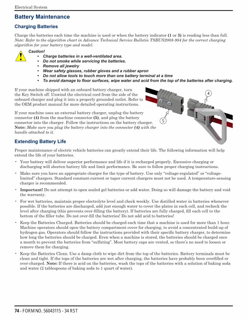
74 - FORM NO. 56043115 - 34 RST
Electrical System
Battery Maintenance
Charging Batteries
Charge the batteries each time the machine is used or when the battery indicator (1 or 3) is reading less than full. Note:RefertothealgorithmchartinAdvanceTechnicalServiceBulletinTSBUS2008-984forthecorrectchargingalgorithmforyourbatterytypeandmodel.
Caution! • Charge batteries in a well-ventilated area. • Do not smoke while servicing the batteries.• Remove all jewelry• Wear safety glasses, rubber gloves and a rubber apron • Do not allow tools to touch more than one battery terminal at a time• To avoid damage to floor surfaces, wipe water and acid from the top of the batteries after charging.
If your machine shipped with an onboard battery charger, turn the Key Switch off. Unwind the electrical cord from the side of the onboard charger and plug it into a properly grounded outlet. Refer to the OEM product manual for more detailed operating instructions.
If your machine uses an external battery charger, unplug the battery connector (4) from the machine connector (5), and plug the battery connector into the charger. Follow the instructions on the battery charger. Note: Makesureyouplugthebatterychargerintotheconnector(4)withthehandleattachedtoit.
Extending Battery Life
Proper maintenance of electric vehicle batteries can greatly extend their life. The following information will help extend the life of your batteries.• Your battery will deliver superior performance and life if it is recharged properly. Excessive charging or
discharging will shorten battery life and limit performance. Be sure to follow proper charging instructions. • Make sure you have an appropriate charger for the type of battery. Use only “voltage-regulated” or “voltage-
limited” chargers. Standard constant-current or taper current chargers must not be used. A temperature-sensing charger is recommended.
• Important! Do not attempt to open sealed gel batteries or add water. Doing so will damage the battery and void the warranty.
• For wet batteries, maintain proper electrolyte level and check weekly. Use distilled water in batteries whenever possible. If the batteries are discharged, add just enough water to cover the plates in each cell, and recheck the level after charging (this prevents over-filling the battery). If batteries are fully charged, fill each cell to the bottom of the filler tube. Do not over-fill the batteries! Do not add acid to batteries!
• Keep the Batteries Charged. Batteries should be charged each time that a machine is used for more than 1 hour. Machine operators should open the battery compartment cover for charging, to avoid a concentrated build-up of hydrogen gas. Operators should follow the instructions provided with their specific battery charger, to determine how long the batteries should be charged. Even when a machine is stored, the batteries should be charged once a month to prevent the batteries from “sulfating”. Most battery caps are vented, so there’s no need to loosen or remove them for charging.
• Keep the Batteries Clean. Use a damp cloth to wipe dirt from the top of the batteries. Battery terminals must be clean and tight. If the tops of the batteries are wet after charging, the batteries have probably been overfilled or over-charged. Note: If there is acid on the batteries, wash the tops of the batteries with a solution of baking soda and water (2 tablespoons of baking soda to 1 quart of water).
5
4
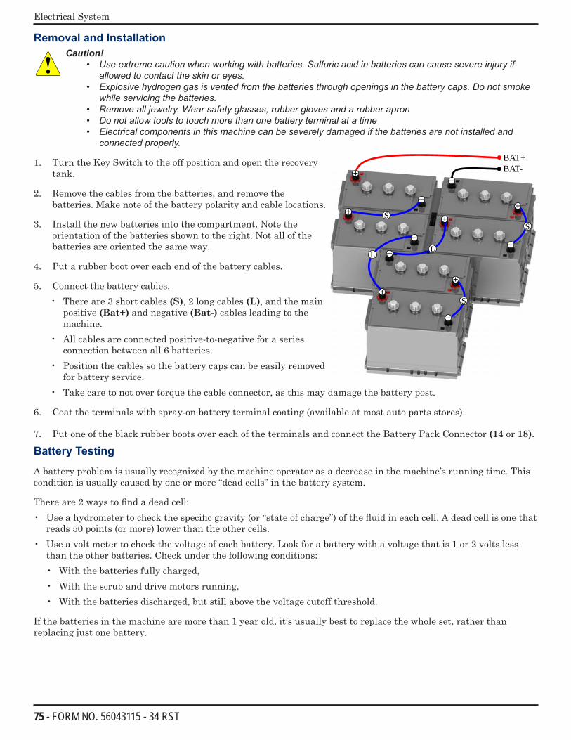
75 - FORM NO. 56043115 - 34 RST
Electrical System
Removal and InstallationCaution!
• Use extreme caution when working with batteries. Sulfuric acid in batteries can cause severe injury if allowed to contact the skin or eyes.
• Explosive hydrogen gas is vented from the batteries through openings in the battery caps. Do not smoke while servicing the batteries.
• Remove all jewelry. Wear safety glasses, rubber gloves and a rubber apron • Do not allow tools to touch more than one battery terminal at a time• Electrical components in this machine can be severely damaged if the batteries are not installed and
connected properly.
1. Turn the Key Switch to the off position and open the recovery tank.
2. Remove the cables from the batteries, and remove the batteries. Make note of the battery polarity and cable locations.
3. Install the new batteries into the compartment. Note the orientation of the batteries shown to the right. Not all of the batteries are oriented the same way.
4. Put a rubber boot over each end of the battery cables.
5. Connect the battery cables.• There are 3 short cables (S), 2 long cables (L), and the main
positive (Bat+) and negative (Bat-) cables leading to the machine.
• All cables are connected positive-to-negative for a series connection between all 6 batteries.
• Position the cables so the battery caps can be easily removed for battery service.
• Take care to not over torque the cable connector, as this may damage the battery post.
6. Coat the terminals with spray-on battery terminal coating (available at most auto parts stores).
7. Put one of the black rubber boots over each of the terminals and connect the Battery Pack Connector (14 or 18).
Battery Testing
A battery problem is usually recognized by the machine operator as a decrease in the machine’s running time. This condition is usually caused by one or more “dead cells” in the battery system.
There are 2 ways to find a dead cell:• Use a hydrometer to check the specific gravity (or “state of charge”) of the fluid in each cell. A dead cell is one that
reads 50 points (or more) lower than the other cells.• Use a volt meter to check the voltage of each battery. Look for a battery with a voltage that is 1 or 2 volts less
than the other batteries. Check under the following conditions:• With the batteries fully charged,• With the scrub and drive motors running,• With the batteries discharged, but still above the voltage cutoff threshold.
If the batteries in the machine are more than 1 year old, it’s usually best to replace the whole set, rather than replacing just one battery.
BAT+BAT-
+
−
+
−
+
−
+
−
+
−
+
−
L
S
S
S
L
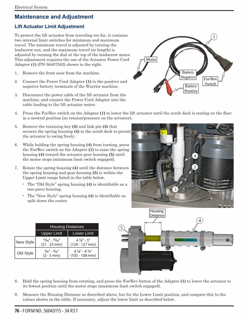
76 - FORM NO. 56043115 - 34 RST
Electrical System
Maintenance and Adjustment
Lift Actuator Limit Adjustment
To protect the lift actuator from traveling too far, it contains two internal limit switches for minimum and maximum travel. The minimum travel is adjusted by turning the leadscrew nut, and the maximum travel (or length) is adjusted by turning the dial at the top of the leadscrew motor. This adjustment requires the use of the Actuator Power Cord Adapter (1) (PN 56407502) shown to the right.
1. Remove the front nose from the machine.
2. Connect the Power Cord Adapter (1) to the positive and negative battery terminals of the Warrior machine.
3. Disconnect the power cable of the lift actuator from the machine, and connect the Power Cord Adapter into the cable leading to the lift actuator motor.
4. Press the For/Rev switch on the Adapter (1) to lower the lift actuator until the scrub deck is resting on the floor in a neutral position (no tension/pressure on the actuator).
5. Remove the retaining key (2) and link pin (3) that secures the spring housing (4) to the scrub deck to permit the actuator to swing freely.
6. While holding the spring housing (4) from turning, press the For/Rev switch on the Adapter (1) to raise the spring housing (4) toward the actuator gear housing (5) until the motor stops (minimum limit switch engaged).
7. Rotate the spring housing (4) until the distance between the spring housing and gear housing (5) is within the Upper Limit range listed in the table below.• The “Old Style” spring housing (4) is identifiable as a
one-piece housing.• The “New Style” spring housing (4) is identifiable as
split down the center.
Housing DistancesUpper Limit Lower Limit
New Style 13/16" - 15/16"(21 - 23 mm)
4 7/8" - 5"(124 - 127 mm)
Old Style 1/16" - 3/16"(2 - 5 mm)
4 1/8" - 4 1/4"(105 - 108 mm)
Housing Distance
5
4
8. Hold the spring housing from rotating, and press the For/Rev button of the Adapter (1) to lower the actuator to its lowest position until the motor stops (maximum limit switch engaged).
9. Measure the Housing Distance as described above, but for the Lower Limit position, and compare this to the values shown in the table. If necessary, adjust the lower limit as described below.
1
Battery Positive
Motor
Battery Negative For/Rev
Switch
2
3
4
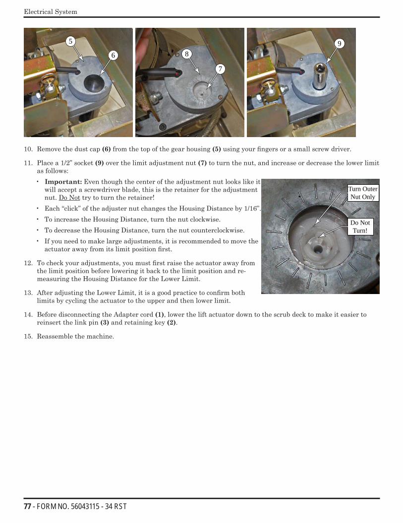
77 - FORM NO. 56043115 - 34 RST
Electrical System
6
7
95
8
10. Remove the dust cap (6) from the top of the gear housing (5) using your fingers or a small screw driver.
11. Place a 1/2” socket (9) over the limit adjustment nut (7) to turn the nut, and increase or decrease the lower limit as follows:• Important: Even though the center of the adjustment nut looks like it
will accept a screwdriver blade, this is the retainer for the adjustment nut. Do Not try to turn the retainer!
• Each “click” of the adjuster nut changes the Housing Distance by 1/16”.• To increase the Housing Distance, turn the nut clockwise.• To decrease the Housing Distance, turn the nut counterclockwise.• If you need to make large adjustments, it is recommended to move the
actuator away from its limit position first.
12. To check your adjustments, you must first raise the actuator away from the limit position before lowering it back to the limit position and re-measuring the Housing Distance for the Lower Limit.
13. After adjusting the Lower Limit, it is a good practice to confirm both limits by cycling the actuator to the upper and then lower limit.
14. Before disconnecting the Adapter cord (1), lower the lift actuator down to the scrub deck to make it easier to reinsert the link pin (3) and retaining key (2).
15. Reassemble the machine.
Do Not Turn!
Turn Outer Nut Only
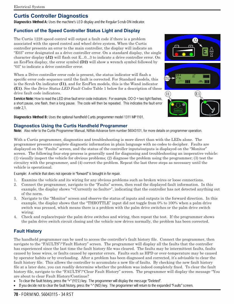
78 - FORM NO. 56043115 - 34 RST
Electrical System
Curtis Controller DiagnosticsDiagnostics Method A: Uses the machine’s LED display and the Regular Scrub ON indicator.
Function of the Speed Controller Status Light and Display
The Curtis 1228 speed control will output a fault code if there is a problem associated with the speed control and wheel drive system. When the Curtis controller presents an error to the main controller, the display will indicate an “E03” error designated as a drive controller error. On a standard display, the single character display (J2) will flash out E...0...3 to indicate a drive controller error. On an EcoFlex display, the error symbol (D2) will show a wrench symbol followed by “03” to indicate a drive controller error.
When a Drive controller error code is present, the status indicator will flash a specific error code sequence until the fault is corrected. For Standard models, this is the Scrub On indicator (I1), and for EcoFlex models, this is the Wand indicator (E1). See the DriveStatusLEDFaultCodes Table 1 below for a description of these drive fault code indicators. Service Note: How to read the LED drive fault error code indicators: For example, OO O = two light flashes, a short pause, one flash, then a long pause. The code will then be repeated. This indicates the fault error code 2,1.
Diagnostics Method B: Uses the optional handheld Curtis programmer model 1311 MP1101.
Diagnostics Using the Curtis Handheld ProgrammerNote: Also refer to the Curtis Programmer Manual, Nilfisk-Advance form number 56043101, for more details on programmer operation.
With a Curtis programmer, diagnostics and troubleshooting is more direct than with the LEDs alone. The programmer presents complete diagnostic information in plain language with no codes to decipher. Faults are displayed on the “Faults” screen, and the status of the controller inputs/outputs is displayed on the “Monitor” screen. The following four-step process is generally used for diagnosing and troubleshooting an inoperative vehicle: (1) visually inspect the vehicle for obvious problems; (2) diagnose the problem using the programmer; (3) test the circuitry with the programmer, and (4) correct the problem. Repeat the last three steps as necessary until the vehicle is operational. Example: A vehicle that does not operate in “forward” is brought in for repair.1. Examine the vehicle and its wiring for any obvious problems such as broken wires or loose connections.2. Connect the programmer, navigate to the “Faults” screen, then read the displayed fault information. In this
example, the display shows “<Currently no faults>”, indicating that the controller has not detected anything out of the norm.
3. Navigate to the “Monitor” screen and observe the status of inputs and outputs in the forward direction. In this example, the display shows that the “THROTTLE” input did not toggle from 0% to 100% when a palm drive switch was pressed, which means there is a problem with the palm drive switches or the palm drive switch wiring.
4. Check and replace/repair the palm drive switches and wiring, then repeat the test. If the programmer shows the palm drive switch circuit closing and the vehicle now drives normally, the problem has been corrected.
Fault History
The handheld programmer can be used to access the controller’s fault history file. Connect the programmer, then navigate to the “FAULTS”/“Fault History” screen. The programmer will display all the faults that the controller has experienced since the last time the fault history file was cleared. The faults may be intermittent faults, faults caused by loose wires, or faults caused by operator errors. Faults such as HPD or over-temperature may be caused by operator habits or by overloading. After a problem has been diagnosed and corrected, it’s advisable to clear the fault history file. This allows the controller to accumulate a new file of faults. By checking the new fault history file at a later date, you can readily determine whether the problem was indeed completely fixed. To clear the fault history file, navigate to the “FAULTS”/“Clear Fault History” screen. The programmer will display the message “You are about to clear Fault History/Continue?• To clear the fault history, press the “+” (YES) key. The programmer will display the message “Deleted”.• If you decide not to clear the fault history, press the “-“ (NO) key. The programmer will return to the expanded “Faults” screen.
E
Ø.403D2
J2
E1I1
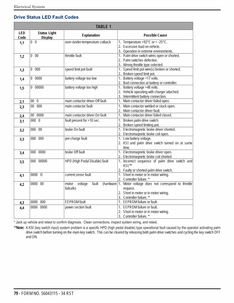
79 - FORM NO. 56043115 - 34 RST
Electrical System
Drive Status LED Fault Codes
TABLE 1LED Code
Status LightDisplay Explanation Possible Cause
1,1 0 0 over-/under-temperature cutback 1. Temperature >92°C or < -25°C. 2. Excessive load on vehicle.3. Operation in extreme environments.
1,2 0 00 throttle fault 1. Palm drive switch wires open or shorted.2. Palm switches defective.3. Wrong throttle type selected.
1,3 0 000 speed limit pot fault 1. Speed limit pot wire(s) broken or shorted.2. Broken speed limit pot.
1,4 0 0000 battery voltage too low 1. Battery voltage <17 volts. 2. Bad connection at battery or controller.
1,5 0 00000 battery voltage too high 1. Battery voltage >48 volts. 2. Vehicle operating with charger attached.3. Intermittent battery connection.
2,1 00 0 main contactor driver Off fault 1. Main contactor driver failed open.2,3 00 000 main contactor fault 1. Main contactor welded or stuck open.
2. Main contactor driver fault.2,4 00 0000 main contactor driver On fault 1. Main contactor driver failed closed.3,1 000 0 fault present for >10 sec. 1. Broken palm drive switch.
2. Broken speed limiting pot.3,2 000 00 brake On fault 1. Electromagnetic brake driver shorted.
2. Electromagnetic brake coil open.3,3 000 000 pre-charge fault 1. Low battery voltage.
2. KSI and palm drive switch turned on at same time.
3,4 000 0000 brake Off fault 1. Electromagnetic brake driver open.2. Electromagnetic brake coil shorted
3,5 000 00000 HPD (High Pedal Disable) fault 1. Incorrect sequence of palm drive switch and KSI.**
2. Faulty or shorted palm drive switch.4,1 0000 O current sense fault 1. Short in motor or in motor wiring.
2. Controller failure. *4,2 0000 00 motor voltage fault (hardware
failsafe)1. Motor voltage does not correspond to throttle
request.2. Short in motor or in motor wiring.3. Controller failure. *
4,3 0000 000 EEPROM fault 1. EEPROM failure or fault.4,4 0000 0000 power section fault 1. EEPROM failure or fault.
2. Short in motor or in motor wiring.3. Controller failure. *
* Jack up vehicle and retest to confirm diagnosis. Clean connections, inspect system wiring, and retest.**Note: A KSI (key switch input) system problem is a specific HPD (high pedal disable) type operational fault caused by the operator activating palm
drive switch before turning on the main key switch. This can be cleared by releasing both palm drive switches and cycling the key switch OFF and ON.
80 - FORM NO. 56043115 - 34 RST
Electrical System
Speed Control Programming OptionsFollowing are the two speed control parameters that can be adjusted using a Curtis handheld programmer:M1 MAX SPD – Forward Transport/Scrub maximum speed limit (% of full throttle)M1 REV MAX SPD – Reverse Transport/Scrub maximum speed limit (% of full throttle)
Installation Checkout for the Curtis Speed Controller
After installing a controller and before operating the vehicle, carefully complete the following checkout procedure. If you find a problem during the checkout, refer to theCurtisControllerDiagnostics section for further information. You can perform the installation checkout with or without the handheld programmer. The checkout procedure is easier with a programmer. Otherwise, observe the yellow Regular Scrub ON or Wand indicator LED for codes. The Curtis handheld programmer part number is 56409441.
The 1228 controller is inherently a high-power device. You must take the necessary safety precautions when working around any battery-powered vehicle. These include, but are not limited to: proper training, wearing eye protection, avoiding loose clothing and jewelry, and using insulated wrenches.• Put the vehicle up on blocks to get the drive wheels off the ground before beginning these tests.• Turn the key switch off and make sure that both palm drive switches are released.• Do not stand, or allow anyone else to stand, directly in front of or behind the vehicle during the tests.
1. If a programmer is available, connect it to the programmer plug-in port.2. Turn the key switch on. The programmer should “power up” and display “Loading…”. If neither happens, check
for continuity in the key switch circuit and controller ground.3. If you are using a programmer, navigate to the “Faults”/”System Faults” screen. The display should read
“<Currently no faults>”. • If there is a problem, the LED will flash a diagnostic code and the programmer will display a diagnostic
message. If you are conducting the checkout without a programmer, look up the LED fault code in Table 1 in the Electrical System section.
• When the problem has been corrected, it may be necessary to cycle the key switch to clear the fault code.4. Press one of the palm drive switches. The motor should begin to turn in the selected direction. If it does not,
verify the wiring to the controller and to the motor. The motor speed should correspond to the speed limit pot setting. If not, refer to Table 1 in the Electrical System section.
5. If you are using a programmer, navigate to the “Monitor” screen. Scroll down to the “THROTTLE” and “REVERSE INPUT” screens to observe the status of the palm switches and the reverse button. Cycle each switch in turn, observing the programmer. Each input should show the correct state on the programmer.
6. Take the vehicle off the blocks and drive it in an open area. It should have smooth acceleration and good top speed.
Programming Vehicle Speed Changes
You can change the maximum M1 forward and reverse speeds electronically using the handheld programmer. To change a speed parameter using the programmer, select the “Program” screen.• To change the maximum forward speed, navigate to the “Program”/ “M1 MAX SPD screen. Press the “+” or (-)
keys to increase or decrease the forward speed. Note that the speeds range from 0-100% and the factory setting is 100%.
• To change the maximum reverse speed, navigate to the “Program”/ “M1 REV MAX SPD screen. Press the “+” or (-) keys to increase or decrease the reverse speed. Note that the speeds range from 15-100% and the factory setting is 55%.
Maintenance
There are no user-serviceable parts inside the Curtis PMC 1228 controller. No attempt should be made to open the controller. Opening the controller may damage it and will void the warranty. It is recommended however that the controller exterior be cleaned periodically. Note that if the handheld programmer is available, this periodic cleaning provides a good opportunity to check the controller’s fault history file.