33107240 1915 homemade toys for girls and boys
TRANSCRIPT
I;
Y PUBLIC LIBRARY THE BRANCH LIBRARIES
3 333302373 6214
7 n -? \ <2 v r
'THE CENTRAL CHILDREN'S ROOM
DOTOTLL I.ir?;-?,Y CENTER
? 53 STREET
I.YORK, H-*. i 019

HOME-MADE TOYSFOR
GIRLS AND BOYS
BOOKS BY A. NEELY HALL
Svo. Cloth. Illustrated with hundreds of full-page
and ivorking drawings by the author
and Norman /'. Hall
THE BOY CRAFTSMAN ..
( Postpaid 1.82
HANDICRAFT FOR HANDY BOYS \Pnce net * 2 '
( Postpaid 2.25
< Price */# 1 .60THE HANDY BOY( Postpaid 1.82
LOTHROP, LEE & SHEPARD CO., BOSTON
CON TCtNTS
CHAPTER I
PAGE
HOME-MADE WINDMILLS . . 1
The Paper Pinwheel- - The Pinion-wheel Windmill- - To mount the
Pinion-wheel- -The Four-blade Windmill- -To mount the Windmill -
The Eight-blade Windmill The Hub The Eight Blades --TheShaft - -The Tail To pivot the Windmill --To operate a Toy Jump-
ing-Jack.
CHAPTER II
HOME-MADE KITES .... . 9
How to make a Malay- -The Sticks-- Framing the Sticks Cover-
ing the Framework-- Attaching the Bridle -- Flying-line-- The Box-
kite -- The Kite Sticks --The Side Frames Covering for the End
Cells Assembling the Kite Attaching the Bridle A Good Hand
Kite-reel A Body Kite-reel.
CHAPTER III
A HOME-MADE MODEL AEROPLANE ... 21
Accuracy in Model Construction- - The Most Successful Type of
Model The Fuselage The Thrust Bearings- - The Bow Hooks -
The Main Plane --The Elevator- -The Fin --The Propellers Howto prepare the Propellers The Propeller Blank --The Propeller-
shafts - The Motors -- The Home-made Motor-winder- - How the
Egg-beater winds the Motors Care in winding the Motors Position
to take for launching a Model.
CHAPTER IV
A HOME-MADE TOY MOTOR-BOAT .33
How operated The Hull Bottom --The Sides --The Deck --The
Propeller --The Propeller-shaft-- The Bearing Plate -- The Thrust
Bearing The Rubber-band Motor- -To wind the Motor-- How to
elaborate upon the Design and Construction.
vii
viii CONTENTS
CHAPTER VPAGE
HOME-MADE TOY WATER-MOTORS 38
A Varnish-can Water-motor -The Case The Water-motor Wheel
-The Eight Paddles The Wheel Shaft An Outlet A Pulley-
belt Pulley-wheels Connecting up the Water-motor Another
Water-motor The Water-motor Wheel The Wheel Supports Tomount the Wheel The Pulley Wheel The Water-motor Case.
\
CHAPTER VI
A HOME-MADE TOY RAILWAY 47
The Trolley-line Supports for Trolley-line Power for Operating
-Railway Tracks The Cars A Gondola Car A Street Car
Other Cars Operation of the Railway A Station.
CHAPTER VII
HOME-MADE TOY ELEVATORS 59
A Toy Elevator that appears Magical in its Operation AdaptingElevator to Toy Office Building-- Floors Partitions- -The Elevator
Car --The Elevator Guides The Cables --The Counter-balance -
The Smoke-stack- -The Overhead Pulleys --How the Car operates
Ballast To make the Car Rise A Simple Control Two Levers
An Outdoor Elevator The Guide Supports The Car --TheGuides The Counter-balance --The Lifting Cable The LoweringCable.
CHAPTER VIII
HOME-MADE MECHANICAL TOYS .71The Simple Construction of Small Mechanical Toys A Buzz-saw
Whirligig-- Operating the Whirligig -- The Clog-dancer A Toy
Jumping-Jack A Cricket-rattle -- The Turtle Toy - - To make the
Turtle Crawl.
CHAPTER IX
HOME-MADE TOPS 79
Top Spinning on the South Sea Islands Clock Wheel Tops A
Rug-tack Top A Spool Top A Spinning Top Race-track A
Shoe-polish Can Top A Spiral Top -A Merry-go-round TopHow the Top Spins Horses and Riders A Flag.
CONTENTS ix
CHAPTER XPAGE
HOME-MADE CLOCKWORK TOYS 88
The Necessary Materials - - How to prepare the Clockwork The
Merry-go-round The Standard The Tent The Tent-poles TheHorses The Sleighs The Shafts The Girl Riders The BoyRiders The Platform How to operate the Merry-go-round Other
Animals A Miniature Ferris Wheel The Standard 'The Clock-
work Motor The Station Platform The Wheel Rims Hubs
Spokes Assembling the Wheel The Cars Axles How to mountthe Wheel The Platform Steps The "Flying Airships
" TheStandard The Mast The Cars Increasing the Speed of the
Clockwork An Electric Motor An Automobile The Frame
The Belt Testing the Machine -- The Cardboard Sides TheWheels The Mud-guards The Lamps - - The Steering-wheel -
The Horn The Brake -- The Chauffeur Painting the Machine
An Automobile Delivery Wagon The Cardboard Sides -The Wheels
Other Portions Painting the Wagon A Clockwork Railway.
CHAPTER XI
HOME-MADE ELECTRICAL TOYS 117
An Electro-magnet Derrick --The Electro-magnet A Home-madeSwitch The Derrick --The Windlass 'The Hoisting Cables Howthe Derrick Works A Toy Shocking Machine --The Induction-coil
The Primary-coil The Secondary-coil The Handles An Inter-
rupter How the Interrupter Works A Toy Electric Motor Truck -
The Wheels The Upper Shaft The Belts The Battery The
Bi-chromate Battery Fluid Amalgamating a Zinc Pencil The Seat
and Canopy-top The Seat-arms The Steering-wheel The Levers.
CHAPTER XII
A HOME-MADE TOY SHOOTING GALLERY 140
The Framework The Circular Target --The Animal Targets-
The Card-shooting Pistol How to number the Targets 'How to
shoot at the Targets.
CHAPTER XIII
A HOME-MADE DOLL-HOUSE . 145
The Building Material The Floor Plans The Partitions The
Elevator-shaft The Side Walls The Rear Wall The Front Wall
The Windows The Roof The Chimney --An Elevator--The
Car The Guide-wires The Pulleys The Chain Cable The
x CONTENTS/
PAGECounter-balance --The Gable-ends Spring-catches --The Stairway
Stringers-- Treads and Risers Newel-posts Hand-rails Bal-
usters --The Front Steps --The Window Openings The WindowGlass The Front and Rear Doors --The Outside Trimmings TheInterior Woodwork Setting the Nail-heads Painting.
CHAPTER XIV
FURNISHING THE HOME-MADE DOLL-HOUSE '
156
The Walls and Ceiling-- Hardwood Floors 'Carpets Rugs -
Window-shades - - Lace Curtains - - Portieres Pictures A Cosey-corner Buying Furnishings Making Furniture.
CHAPTER XVA HOME-MADE TOY STABLE . . . . . . . . . 160
Dimensions of Stable --The First Story --The Roof --The Gable-
end --The Stall Partitions -- The Feed-troughs Windows Ladder
to Hay- loft --Feed-hoist --The Drop-front A Stable Door-- Paint-
ing If you prefer a Garage.
CHAPTER XVI
A HOME-MADE DOLL APARTMENT BUILDING . . . . . . 165
A New Idea in Doll-houses How the Three Units are arranged to
form a Three-story Building or Six-room Apartment Building Mate-
rial -- The Room Dimensions --The First Story Unit --The Second
Story Unit --The Third Story Unit --The Door and Window Open-
ings --The Bay Windows --The Joints between the Units --The Roof
Construction --The Chimney --The Windows --The Front Door-The Inside Doorways -- The Interior Trim A Fireplace LightingFixtures Decorating Painting the Outside Walls.
CHAPTER XVII
HOME-MADE DOLL FURNITURE 174
Metal Furniture Miniature Mission Furniture Material Draw-
ing the Patterns and Enlarging by Squares-- The Chairs The Settee
-Tables A Dining-room Table A Sideboard-- A Mirror TheGrandfather's Clock Kitchen Furniture- -The Beds The Dresser- A Wash-stand Finishing.
OTHER CIGAR-BOX FURNITURE . .... 187
A Folding-bed A Dresser Wardrobe.
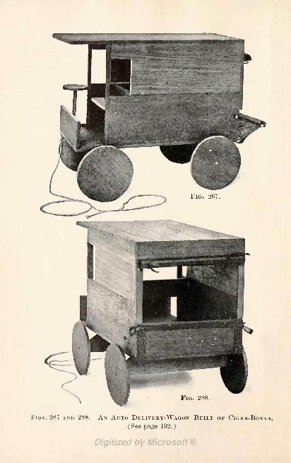
FIGS. 287 AND 288. AN AUTO DELIVERY-WAGON BUILT OF CIGAR-BOXES.
(See page 192.)
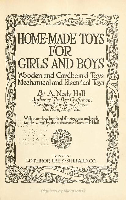
HOME-MADE TOYSFOR
GIRLS AND BOYSCardboard Toys,
Mechanicaland Eleetrical Toys
ANeely HallAuthorof"TheJ3ov Craftsman,"HandicraftforHandy Boys'.
"The nanJyBoy "Etc.
With over threehundred illustrations anawork-
ingMw <ne auinor anaNormanPHal]
-I ' 3 1 '
> . ,
> ) '1
I J
-*t
^ '~>.
ni
9 -J >9,
' I' . ,*153
BOSTONLOTHROP, LEE fr SHEPARD CO.
COPYRIGHT, 1915, BY
LOTHROP, LEE & SHEPARD COMPANY
PUBLISHED, AUGUST, 1915
All rights reserved
HOME-MADE TOYS FOR GIRLS AND BOYS
PU, LIBK
A8TOR, LENOX ANDTILDEN FOUNDATIONSo
NortoooB
J. S. Cashing Co. Berwick & Smith Co.
Norwood, Mass., U.S.A.
H
Constructive ideas expel destructive ideas from the juvenile mind.
INTRODUCTORY NOTES
THROUGH the author's handicraft volumes, and magazine and
newspaper articles, thousands of boys and girls who never real-
ized they could make their own toys, have succeeded in con-
structing models which would do credit to Santa Claus' master
toy-makers.The success of this new home industry has suggested the
need of a volume devoted entirely to toy-making, and in HOME-
MADE TOYS FOR GIRLS AND BOYS the author has brought
together a large number of the toy ideas from his former
handicraft volumes, and from his articles published in the
Ladies' Home Journal, Woman's Home Companion, Good House-
keeping, the Boys' Magazine, and other publications, and he be-
lieves that as collected and arranged the material will be found
a veritable gold-mine of toy-making information.
Go to any toy store and price the toys similar to those de-
scribed within these covers, then estimate if you can how much
the other toys you do not find would cost if manufactured, and
you: will, discover, that one hundred dollars would not cover
their -value, On <jp.kifcc.id thing about these home-made toys
is that the greater .part of them require little more than the
pick-up 'mare'rUl' fo.urjd at home. Few boys and girls are given
a one Jiuridfed: dollar -assortment of toys at a time, yet any one
can own a collection of this value who is willing to spend the
time necessary to follow the instructions given in this book.
Probably, though, some of the toys will be wanted now, and
the others one, two or three seasons hence, because, you see,
the book is an all-the-year-round handy book with suggestions
for every season. Some of the toys will be of especial interest
to boys, yet girls who like what boys like will enjoy makingthem also.
vi INTRODUCTORY NOTES
Home-made toys are generally longer lived than store toys
because the boy or girl who expends a certain amount of effort
producing gives them better care. Home-made toys have a
greater value than boughten ones because there is as muchfun making them as playing with them. Doing something
interesting, getting satisfying results out of the work, puttingan idea into tangible form, and having a toy to show of which
it can be said,"
I made this all myself," these are the factors
in toy-making so fascinating to boys and girls.
It is no less a child's nature to want to do that which is
most pleasing to him, than an adult's, so why not encouragethis wholesome activity of toy-making to which the child takes
as readily as a duck takes to water ? It trains the mind to
think clearly, the hands to work cleverly, replaces destructive
thoughts with constructive ideas, and, in making the boy or
girl dependent upon himself or herself for toys, is invaluable
in developing resourcefulness.
Recognizing how easily the child's interest is attracted and
held by anything of a building nature, toy manufacturers have
placed scores of so-called"construction sets
"upon the market,
but, though excellent as these outfits are, the toys they form
are merely assembled, not really mads 'by 'the/ boy or'
'girl tand
much of the value of making is lost; r Exactly as good" models
as those assembled with "construction se'cs^' car;- be made ofr
! ,
pick-up materials, as chapters in this bopk'show.' Tri fact, some
of the models in the manufacturers' ifcstriictioi'i j-Lt^prilets-
f " ' c f f -.
merry-go-rounds, Ferris wheels and swings are almost iden-
tical with home-made models devised long ago by the author
for his readers. Furthermore, there are many, very many toysin HOME-MADE TOYS FOR GIRLS AND BOYS which are beyondthe limited possibilities of "construction sets."
A. N. H.OAK PARK, ILLINOIS,
May 31, 1915.
CONTENTS xi
CHAPTER XVIIIPAGE
HOME-MADE CIGAR-BOX TOYS . . . 191
Material Cutting An Express-wagon A Cart An Auto De-
livery-wagon A Jack-in-the-box A Round-seated Chair A RoundCenter-table-- A Dining-table -- A Square-seated Chair A Doll's
Cradle Finishing the Cigar-box Wood.
CHAPTER XIX
HOME-MADE SPOOL AND CARDBOARD TOYS . 196
Material A Baby Carriage A Two-wheel Cart A Toy Merry-
go-round A Teeter-board A Doll Swing A Sofa A Chair
A Square Center-table A Round Center-table.
CHAPTER XX
A HOME-MADE TOY MAIL-BOX . ... 205
Playing Postman Material for Mail-box- - The Sides, Ends, and
Bottom of Box --The Top --The Letter-drop --The Collection-drop
-Reinforcing the Corners Covering the Box A Collection Sched-
ule Card --How to hang up the Mail-box-- A Mail-bag --The Way to
play Post-office.
CHAPTER XXI
A HOME-MADE REFLECTOSCOPE ... 210
The Working Principle of the Reflectoscope Material for makingOne - - The Lens Opening Ventilator Holes - The Interior Arrange-ment A Hood for the Ventilators-- If Oil Lamps are Used --If
Electric Light is Used --How to mount the Lens Puttying Cracks
Painting the Inside of the Box --The Back Boards --The Picture
Holder How the Lens reverses Pictures Adjustments.
INDEX 215
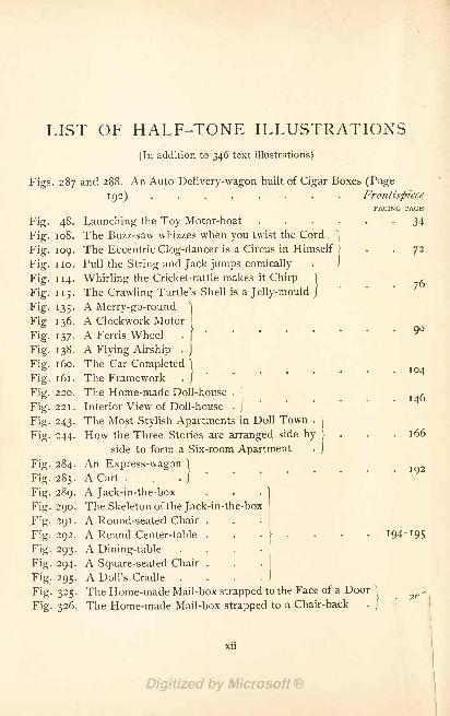
LIST OF HALF-TONE ILLUSTRATIONS
(In addition to 346 text illustrations)
Figs. 287 and 288. An Auto Delivery-wagon built of Cigar Boxes (Page
192) . . . . . . . FrontispieceFACING PAGE
Fig. 48. Launching the Toy Motor-boat . . . . . . 34
Fig. 1 08. The Buzz-saw whizzes when you twist the Cord]
Fig. 109. The Eccentric Clog-dancer is a Circus in Himself } . . 72
Fig. 1 10. Pull the String and Jack jumps comically
Fig. 114. Whirling the Cricket-rattle makes it Chirp } ,
Fig. 115. The Crawling Turtle's Shell is a Jelly-mould J
135- A Merry-go-round 1
Fig 136. A Clockwork Motor I
Fig. 137. A Ferris Wheel .
[
Fig. 138. A Flying Airship .
]
Fig. 1 60. The Car Completed \
Fig. 161. The Framework . }
Fig. 220. The Home-made Doll-house .
|,
Fig. 221. Interior View of Doll-house . j
Fig. 243. The Most Stylish Apartments in Doll Town .
]
Fig. 244. How the Three Stories are arranged side by J
.166side to form a Six-room Apartment .
j
Fig. 284. An Express-wagon \
Fig. 285. A Cart . . . /
Fig. 289. A Jack-in-the-box . .
}
Fig. 290. The Skeleton of the Jack-in-the-box
Fig. 291. A Round-seated Chair .
Fig. 292. A Round Center-table . .1 94-195
Fig. 293. A Dining-table
Fig. 294. A Square-seated Chair .
Fig. 295. A Doll's Cradle
Fig. 325. The Home-made Mail-box strapped to the Face of a Door\
Fig. 326. The Home-made Mail-box strapped to a Chair-back . /
xu
HOME-MADE TOYSFOR
GIRLS AND BOYS
HOME-MADE TOYS
FOR GIRLS AND BOYS
CHAPTER
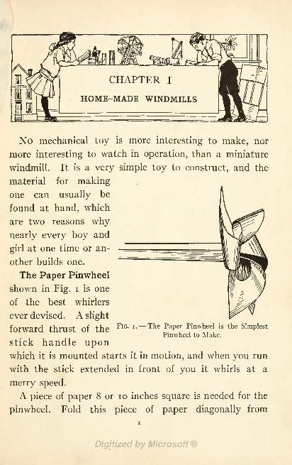
HOME-MADE WINDMILLS
No mechanical toy is more interesting to make, nor
more interesting to watch in operation, than a miniature
windmill. It is a very simple toy to construct, and the
material for makingone can usually be
found at hand, which
are two reasons why
nearly every boy and
girl at one time or an-
other builds one.
The Paper Pinwheel
shown in Fig. i is one
of the best whirlers
ever devised. A slight
forward thrust of the FlG> '--T^ PaPer Pinwheel is the Simplest
Pinwheel to Make.stick handle uponwhich it is mounted starts it in motion, and when you run
with the stick extended in front of you it whirls at a
merry speed.
A piece of paper 8 or 10 inches square is needed for the
pinwheel. Fold this piece of paper diagonally from
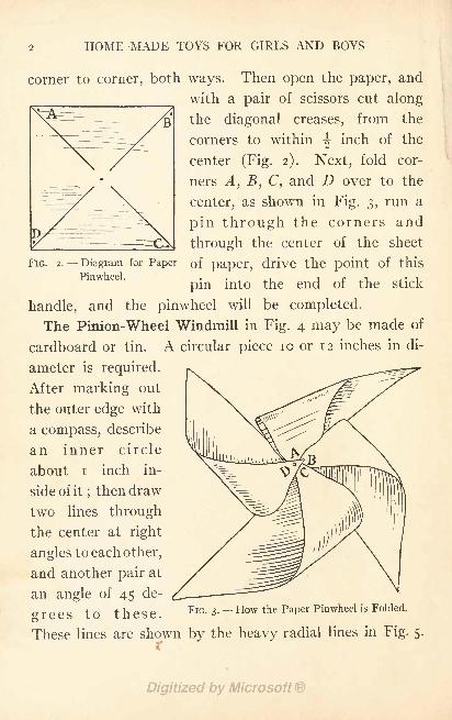
HOME-MADE TOYS FOR GIRLS AND BOYS
corner to corner, both ways. Then open the paper, and
with a pair of scissors cut along
the diagonal creases, from the
corners to within ^ inch of the
center (Fig. 2). Next, fold cor-
ners A, B, C, and D over to the
center, as shown in Fig. 3, run a
pin through the corners and
through the center of the sheet
FIG. 2. - - Diagram for Paper of paper, drive the point of thisPinwheel. . ,. -,
pm into the end of the stick
handle, and the pinwheel will be completed.
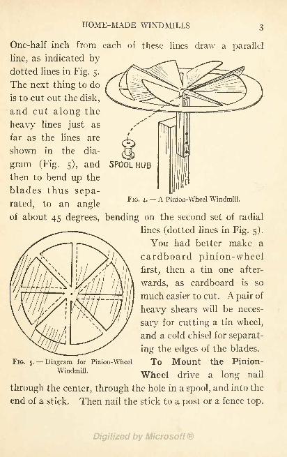
The Pinion-Wheel Windmill in Fig. 4 may be made of
cardboard or tin. A circular piece 10 or 12 inches in di-
ameter is required.
After marking out
the outer edge with
a compass, describe
an inner circle
about i inch in-
side of it; then draw
two lines through
the center at right
angles to each other,
and another pair at
an angle of 45 de-
grees to these.
These lines are shown by the heavy radial lines in Fig. 5.
r
FIG. 3. How the Paper Pinwheel is Folded.
HOME-MADE WINDMILLS
One-half inch from each of these lines draw a parallel
line, as indicated bydotted lines in Fig. 5.
The next thing to do
is to cut out the disk,
and cut along the
heavy lines just as
FIG. 4. A Pinion-Wheel Windmill.
far as the lines are
shown in the dia-
gram (Fig. 5), and SPOOL HUB
then to bend up the
blades thus sepa-
rated, to an angle
of about 45 degrees, bending on the second set of radial
lines (dotted lines in Fig. 5).
You had better make a
cardboard pinion-wheel
first, then a tin one after-
wards, as cardboard is so
much easier to cut. A pair of
heavy shears will be neces-
sary for cutting a tin wheel,
and a cold chisel for separat-
ing the edges of the blades.
To Mount the Pinion-
Wheel drive a long nail
through the center, through the hole in a spool, and into the
end of a stick. Then nail the stick to a post or a fence top.
FIG. 5. Diagram for Pinion-Wheel
Windmill.
HOME-MADE TOYS FOR GIRLS AND BOYS
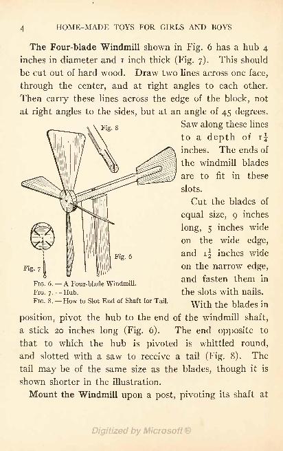
The Four-blade Windmill shown in Fig. 6 has a hub 4
inches in diameter and i inch thick (Fig. 7). This should
be cut out of hard wood. Draw two lines across one face,
through the center, and at right angles to each other.
Then carry these lines across the edge of the block, not
at right angles to the sides, but at an angle of 45 degrees,
Fi 8Saw along these lines
to a depth of i|
inches. The ends of
the windmill blades
are to fit in these
slots.
Cut the blades of
equal size, 9 inches
long, 5 inches wide
on the wide edge,
and i| inches wide
on the narrow edge,
and fasten them in
the slots with nails.
With the blades in
position, pivot the hub to the end of the windmill shaft,
a stick 20 inches long (Fig. 6). The end opposite to
that to which the hub is pivoted is whittled round,
and slotted with a saw to receive a tail (Fig. 8). The
tail may be of the same size as the blades, though it is
shown shorter in the illustration.
Mount the Windmill upon a post, pivoting its shaft at
Fig
FIG. 6. A Four-blade Windmill.
FIG. 7. Hub.
FIG. 8. How to Slot End of Shaft for Tail.
HOME-MADE WINDMILLS 5
the balancing center with a nail or screw. Bore a
hole large enough so the shaft will turn freely uponthe pivot, and the windmill will thus keep headed into
the wind.
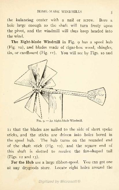
The Eight-blade Windmill in Fig. 9 has a spool hub
(Fig. 10), and blades made of cigar-box wood, shingles,
tin, or cardboard (Fig. n). You will see by Figs. 10 and
FIG. 9. An Eight-blade Windmill.
ii that the blades are nailed to the side of short spoke
sticks, and the sticks are driven into holes bored in
the spool hub. The hub turns on the rounded end
of the shaft stick (Fig. 12), and the square end of
this shaft is slotted to receive the fan-shaped tail
(Figs. 12 and 13).
For the Hub use a large ribbon-spool. You can get one
at any drygoods store. Locate eight holes around the
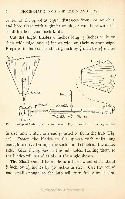
HOME-MADE TOYS FOR GIRLS AND BOYS
center of the spool at equal distances from one another,
and bore these with a gimlet or bit, or cut them with the
small blade of your jack-knife.
Cut the Eight Blades 6 inches long, 5 inches wide on
their wide edge, and ij inches wide on their narrow edge.
Prepare the hub sticks about f inch by f inch by 4^ inches
Fig. ii
NAIL
WASHER-^
Fig. 10
WASHER ^ Fig. 12
FIG. 10. Spool Hub. FIG. ii. Blades. FIG. 12. Shaft. FIG. 13. Tail.
in size, and whittle one end pointed to fit in the hub (Fig.
n). Fasten the blades to the spokes with nails long
enough to drive through the spokes and clinch on the under
side. Glue the spokes in the hub holes, turning them so
the blades will stand at about the angle shown.
The Shaft should be made of a hard wood stick about
J inch by ij inches by 30 inches in size. Cut the round
end small enough so the hub will turn freely on it, and
HOME-MADE WINDMILLS
punch a small hole through it so a brad may be driven
through to hold the hub in place. Cut the slot in the
square end with a saw.
Cut the Tail of the shape shown in Fig. 13.
Pivot the Windmill upon the top of a post support, in
the same manner as directed for
the other windmills.
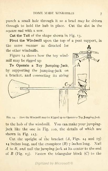
Figure 14 shows how the toy wind-
mill may be rigged upTo Operate a Toy Jumping-Jack,
by supporting the jumping-jack on
a bracket, and connecting its string
FIG. 14. How the Windmill may be Rigged up to Operate a Toy Jumping-Jack.
to the hub of the windmill. You can make your jumping-
jack like the one in Fig. no, the details of which are
shown in Fig. 113.
Cut the upright of the bracket (A, Figs. 14 and 15)
14 inches long, and the crosspiece (B) 7 inches long. Nail
A to B, and nail the jumping-jack at its center to the end
of B (Fig. 15). Fasten the triangular block (C) to the
8 HOME-MADE TOYS FOR GIRLS AND BOYS
Fig. 1 6
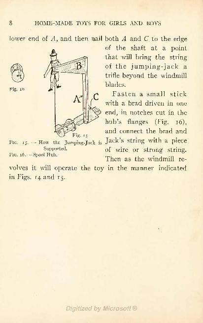
lower end of A}and then nail both A and C to the edge
of the shaft at a point
that will bring the string
of the jumping-jack a
trifle beyond the windmill
blades.
Fasten a small stick
with a brad driven in one
end, in notches cut in the
hub's flanges (Fig. 16),
and connect the brad andFig. 15
FIG. 15.- How the Jumping-jack is Jack
'
S string with a Piece
Supported. of wjre or strong string.FIG. 1 6. Spool Hub.
Then as the windmill re-
volves it will operate the toy in the manner indicated
in Figs. 14 and 15.
CHAPTER II
HOME-MADE KITES
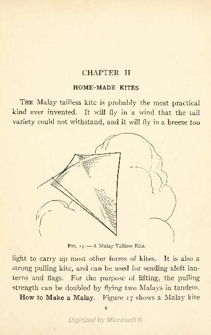
THE Malay tailless kite is probably the most practical
kind ever invented. It will fly in a wind that the tail
variety could not withstand, and it will fly in a breeze too
FIG. 17. A Malay Tailless Kite.
light to carry up most other forms of kites. It is also a
strong pulling kite, and can be used for sending aloft lan-
terns and flags. For the purpose of lifting, the pulling
strength can be doubled by flying two Malays in tandem.
How to Make a Malay. Figure 17 shows a Malay kite
9

TO HOME-MADE TOYS FOR GIRLS AND BOYS
in flight, Fig. 18 a detail of the completed kite, Fig. 19
the completed framework, and Figs. 20, 21, and 22 the
details for preparing the frame sticks.
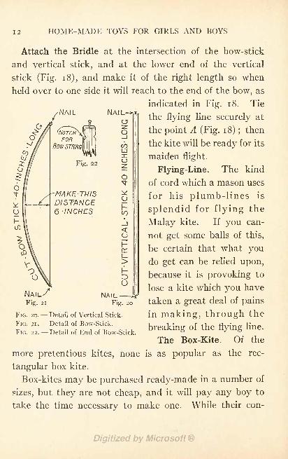
The Sticks. This kite has a vertical stick and a bow-
stick, each of which should be 40 inches long, about f
inch wide, and f inch thick, for a kite of medium size
In the cutting of the sticks lies half the secret of making a
kite that will fly suc-
cessfully.
Drive a small nail or
large tack into each end
of the two sticks, to
fasten the framing-
string to (Figs. 20 and
21), and notch the side
edges of the bow-stick
near each end for the
attachment of the bow-
FIG. 18. Completed Malay Kite with Belly- string (FigS. 21 and 22).Band Attached. rrn \ jThe amount to bend
the bow-stick is important. For a kite with a bow 40
inches long the distance between the string and stick
should be 6 inches (Fig. 21). Use a strong twine for
the bow-string, and tie it securely to the notched ends.
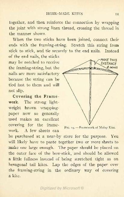
Framing the Sticks. Fasten the bow-stick at its exact
center to the vertical stick, placing it 4 inches down from
the top of the vertical stick, as indicated in Fig. 19. Drive
a couple of brads through the two sticks to hold them
HOME-MADE KITES II
MAKE THISDISTANCE
4 INCHES
together, and then reinforce the connection by wrappingthe joint with strong linen thread, crossing the thread in
the manner shown.
When the two sticks have been joined, connect their
ends with the framing-string. Stretch this string from
stick to stick, and tie securely to the end nails. Instead
of the end nails, the sticks
may be notched to receive
the framing-string, but the
nails are more satisfactory
because the string can be
tied fast to them and will
not slip.
Covering the Frame-work. The strong light-
weight brown wrapping-
paper now so generally
used makes an excellent
covering for the frame-
work. A few sheets can
be purchased at a near-by store for the purpose. You
will likely have to paste together two or more sheets to
make one large enough. The paper should be placed on
the outer face of the bow-stick, and should be allowed
a little fullness instead of being stretched tight as on
hexagonal tail kites. Lap the edges of the paper over
the framing-string in the ordinary way of covering
a kite.
FIG. 19. Framework of Malay Kite.
12 HOME-MADE TOYS FOR GIRLS AND BOYS
<J)
NAIL
(NOTCHFOR
BOW-STRING
Fig. 22
-MAKE -THIS
DISTANCE6 -INCHES
NAIL-o
fCO
HrCJ
Attach the Bridle at the intersection of the bow-stick
and vertical stick, and at the lower end of the vertical
stick (Fig. 1 8), and make it of the right length so when
held over to one side it will reach to the end of the bow, as
indicated in Fig. 18. Tie
the flying line securely at
the point A (Fig. 18) ;then
the kite will be ready for its
maiden flight.
Flying-Line. The kind
of cord which a mason uses
for his plumb-lines is
splendid for flying the
Malay kite. If you can-
not get some balls of this,
be certain that what you
do get can be relied upon,
because it is provoking to
lose a kite which you have
taken a great deal of pains
in making, through the
breaking of the flying line.
The Box-Kite. Of the
more pretentious kites, none is as popular as the rec-
tangular box-kite.
Box-kites may be purchased ready-made in a number of
sizes, but they are not cheap, and it will pay any boy to
take the time necessary to make one. While their con-
CO
O
LU
*
\-
uNAfL
Fig. 20
FIG. 20. Detail of Vertical Stick.
FIG. 2i. Detail of Bow-Stick.
FIG. 22. Detail of End of Bow-Stick.
HOME-MADE KITES
struction requires considerable more work than the single-
plane type of kite, it is not difficult.
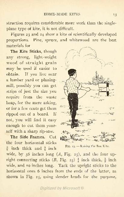
Figures 23 and 24 show a kite of scientifically developed
proportions. Pine, spruce, and whitewood are the best
materials for
The Kite Sticks, though
any strong, light-weight
wood of straight grain
may be used if easier to
obtain. If you live near
a lumber yard or planing-
mill, possibly you can get
strips of just the size you
require from the waste
heap, for the mere asking,
or for a few cents get them
ripped out of a board. If
not, you will find it easy
enough to cut them your-
self with a sharp rip-saw.
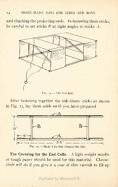
The Side Frames. Cut
the four horizontal sticks
f inch thick and f inch
wide, by 36 inches long (A, Fig. 25), and the four up-
right connecting sticks (B, Fig. 25) | inch thick, ^ inch
wide, and 10 inches long. Tack the upright sticks to the
horizontal ones 6 inches from the ends of the latter, as
shown in Fig. 25, using slender brads for the purpose,
FIG. 23. Raising the Box-Kite.
14 HOME-MADE TOYS FOR GIRLS AND BOYS
and clinching the projecting ends. In fastening these sticks,
be careful to set sticks B at right angles to sticks A.
FIG. 24.- - The Box-Kite.
After fastening together the side-frame sticks as shown
in Fig. 25, lay them aside until you have prepared
FIG. 25. Make Two Side Frames like this.
The Covering for the End Cells. A light-weight muslin
or tough paper should be used for this material. Cheese-
cloth will do if you give it a coat of thin varnish to fill up
HOME-MADE KITES 15
the pores and make it air-tight, after it has been put on.
The light-weight brown wrapping-paper now so commonlyused is good covering material.
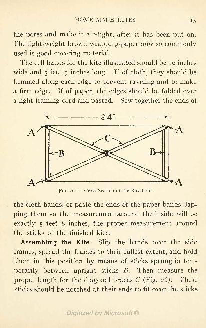
The cell bands for the kite illustrated should be 10 inches
wide and 5 feet 9 inches long. If of cloth, they should be
hemmed along each edge to prevent raveling and to make
a firm edge. If of paper, the edges should be folded over
a light framing-cord and pasted. Sew together the ends of
FIG. 26. - - Cross-Section of the Box-Kite.
the cloth bands, or paste the ends of the paper bands, lap-
ping them so the measurement around the inside will be
exactly 5 feet 8 inches, the proper measurement around
the sticks of the finished kite.
Assembling the Kite. Slip the bands over the side
frames, spread the frames to their fullest extent, and hold
them in this position by means of sticks sprung in tem-
porarily between upright sticks B. Then measure the
proper length for the diagonal braces C (Fig. 26). These
sticks should be notched at their ends to fit over the sticks
i6 HOME-MADE TOYS FOR GIRLS AND BOYS
B
Ayas shown in Fig. 27, and they should be a trifle long so
they will be slightly bow-shaped when put in place. In
this way the frames will keep the cloth or paper bands
stretched tight.
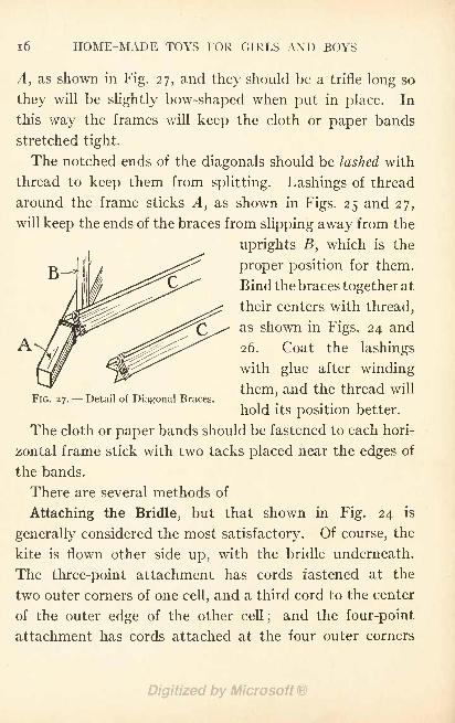
The notched ends of the diagonals should be lashed with
thread to keep them from splitting. Lashings of thread
around the frame sticks A, as shown in Figs. 25 and 27,
will keep the ends of the braces from slipping away from the
uprights B, which is the
proper position for them.
Bind the braces together at
their centers with thread,
as shown in Figs. 24 and
26. Coat the lashings
with glue after winding
them, and the thread will
hold its position better.
The cloth or paper bands should be fastened to each hori-
zontal frame stick with two tacks placed near the edges of
the bands.
There are several methods of
Attaching the Bridle, but that shown in Fig. 24 is
generally considered the most satisfactory. Of course, the
kite is flown other side up, with the bridle underneath.
The three-point attachment has cords fastened at the
two outer corners of one cell, and a third cord to the center
of the outer edge of the other cell;and the four-point
attachment has cords attached at the four outer corners
FIG. 27. Detail of Diagonal Braces.
HOME-MADE KITES 17
of the kite. The ends of the bridle should be brought
together and tied at a distance of about 3 feet from the
kite. It is a good plan to connect the ends to a fancy-
work ring.
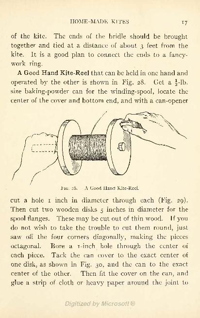
A Good Hand Kite-Reel that can be held in one hand and
operated by the other is shown in Fig. 28. Get a ^-lb.
size baking-powder can for the winding-spool, locate the
center of the cover and bottom end, and with a can-opener
FIG. 28. A Good Hand Kite-Reel.
cut a hole i inch in diameter through each (Fig. 29).
Then cut two wooden disks 5 inches in diameter for the
spool flanges. These may be cut out of thin wood. If youdo not wish to take the trouble to cut them round, just
saw off the four corners diagonally, making the pieces
octagonal. Bore a i-inch hole through the center of
each piece. Tack the can cover to the exact center of
one disk, as shown in Fig. 30, and the can to the exact
center of the other. Then fit the cover on the can, and
glue a strip of cloth or heavy paper around the joint to
i8 HOME-MADE TOYS FOR GIRLS AND BOYS
keep the cover from working off, and the spool will be
completed.
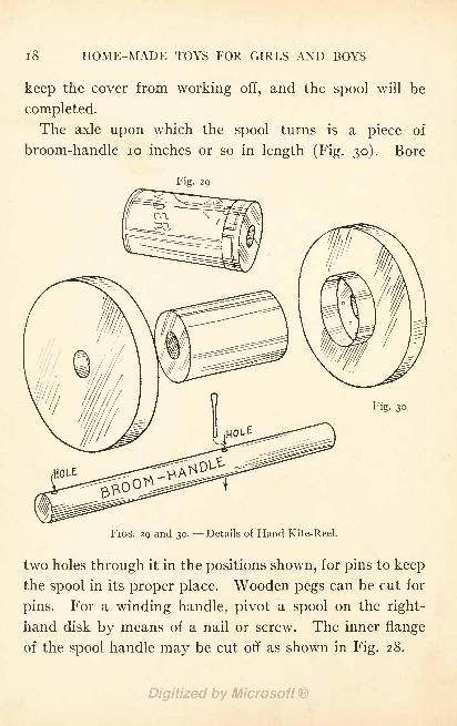
The axle upon which the spool turns is a piece of
broom-handle 10 inches or so in length (Fig. 30). Bore
Fig. 29
Fig. 30
FIGS. 29 and 30. Details of Hand Kite-Reel.
two holes through it in the positions shown, for pins to keep
the spool in its proper place. Wooden pegs can be cut for
pins. For a winding handle, pivot a spool on the right-
hand disk by means of a nail or screw. The inner flange
of the spool handle may be cut off as shown in Fig. 28.
HOME-MADE KITES
Both hands are frequently needed to haul in string
quickly enough to bring a kite around into the wind, or to
handle it when it pulls very strong, and then there is nothing
to do but drop the hand reel upon the ground, unless youhave an assistant to give it to. This is where the advan-
tage of
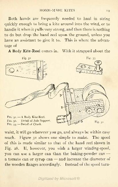
A Body Kite-Reel comes in. With it strapped about the
Fig- 33
FIG. 31. A Body Kite-Reel.
FIG. 32. Detail of Axle Support.
FIG. 33. Detail of Crank.Fig. 31
waist, it will go wherever you go, and always be within easy
reach. Figure 31 shows one simple to make. The spool
of this is made similar to that of the hand reel shown in
Fig. 28. If, however, you wish a larger winding-spool,
you can use a larger can than the baking-powder can -
a tomato can or syrup can - - and increase the diameter of
the wooden flanges accordingly. Instead of the spool turn-
20 HOME-MADE TOYS FOR GIRLS AND BOYS
ing upon the broom-handle axle, the axle turns with the
spool, so the spool must be fastened to the axle.
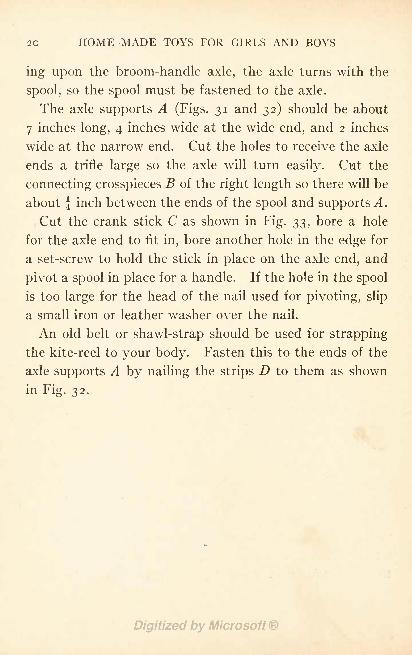
The axle supports A (Figs. 31 and 32) should be about
7 inches long, 4 inches wide at the wide end, and 2 inches
wide at the narrow end. Cut the holes to receive the axle
ends a trifle large so the axle will turn easily. Cut the
connecting crosspieces B of the right length so there will be
about | inch between the ends of the spool and supports^.
Cut the crank stick C as shown in Fig. 33, bore a hole
for the axle end to fit in, bore another hole in the edge for
a set-screw to hold the stick in place on the axle end, and
pivot a spool in place for a handle. If the hole in the spool
is too large for the head of the nail used for pivoting, slip
a small iron or leather washer over the nail.
An old belt or shawl-strap should be used for strapping
the kite-reel to your body. Fasten this to the ends of the
axle supports A by nailing the strips D to them as shown
in Fig. 32.
CHAPTER III
A HOME-MADE MODEL AEROPLANE
MODEL aeronautics has become nearly as popular as kite
flying, and girls as well as boys have taken to building
these unique air toys.
The model aeroplane requires more work than ordinary
kite construction. It also requires more patience and
greater accuracy, because each part of the little aircraft
must be made just so, assembled just so, and "tuned-up
'
just so, to produce a model which will give a good account
of itself. Of course your first model will probably not be
perfect. But if you do your work correctly and carefully
it will fly, and the experience you have acquired will make
it possible to turn out a more nearly perfect second model.
Many types of model aeroplanes have been devised,
but those of the simplest form of construction have made
the best showing. The majority of record-breaking models
have been of one type- - a triangular framework, equipped
with two planes, and a pair of propellers operated by a
pair of rubber-strand motors. A most successful model of
this type is shown in Fig. 34, and described and illustrated
on the following pages. This model has a distance record
of 1620 feet made at the Aero Club of Illinois' aviation
21
22 HOME-MADE TOYS FOR GIRLS AND BOYS
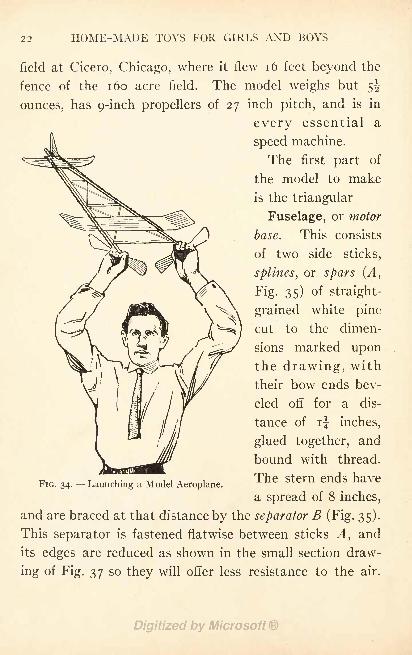
field at Cicero, Chicago, where it flew 16 feet beyond the
fence of the 160 acre field. The model weighs but 5^
ounces, has g-inch propellers of 27 inch pitch, and is in
every essential a
speed machine.
The first part of
the model to make
is the triangular
Fuselage, or motor
base. This consists
of two side sticks,
splines, or spars (A,
Fig. 35) of straight-
v X \ grained white pine
/^^) cut to the dimen-
sions marked upon
the drawing, with
their bow ends bev-
eled off for a dis-
tance of ij inches,
glued together, and
bound with thread.
The stern ends have
a spread of 8 inches,
and are braced at that distance by the separator B (Fig. 35).
This separator is fastened flatwise between sticks A, and
its edges are reduced as shown in the small section draw-
ing of Fig. 37 so they will offer less resistance to the air.
FIG. 34. Launching a Model Aeroplane.
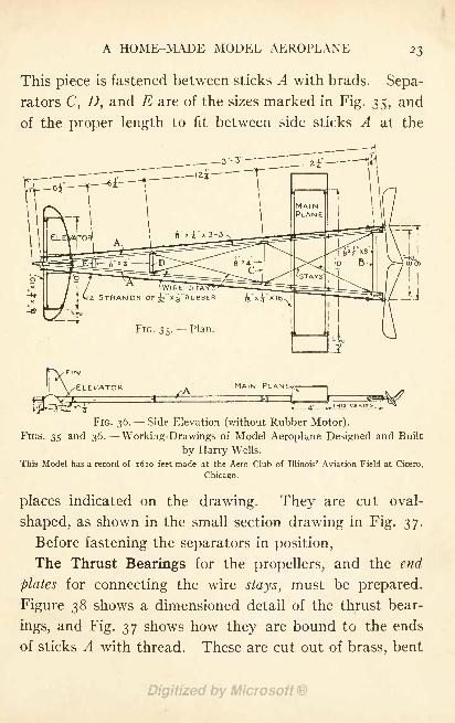
A HOME-MADE MODEL AEROPLANE
This piece is fastened between sticks A with brads. Sepa-
rators C, D, and E are of the sizes marked in Fig. 35, and
of the proper length to fit between side sticks A at the
MAIN PLANE.
FIG. 36. Side Elevation (without Rubber Motor).FIGS. 35 and 36. Working-Drawings of Model Aeroplane Designed and Built
by Harry Wells.
This Model has a record of 1620 feet made at the Aero Club of Illinois' Aviation Field at Cicero,
Chicago.
places indicated on the drawing. They are cut oval-
shaped, as shown in the small section drawing in Fig. 37.
Before fastening the separators in position,
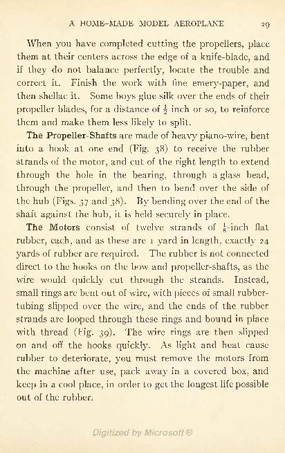
The Thrust Bearings for the propellers, and the end
plates for connecting the wire stays, must be prepared.
Figure 38 shows a dimensioned detail of the thrust bear-
ings, and Fig. 37 shows how they are bound to the ends
of sticks A with thread. These are cut out of brass, bent
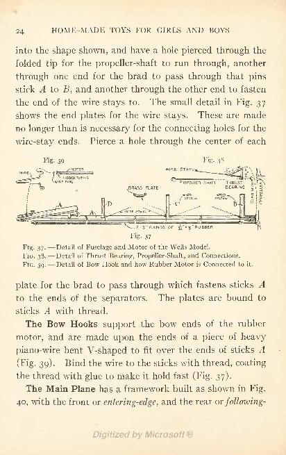
HOME-MADE TOYS FOR GIRLS AND BOYS
into the shape shown, and have a hole pierced through the
folded tip for the propeller-shaft to run through, another
through one end for the brad to pass through that pins
stick A to B, and another through the other end to fasten
the end of the wire stays to. The small detail in Fig. 37
shows the end plates for the wire stays. These are made
no longer than is necessary for the connecting holes for the
wire-stay ends. Pierce a hole through the center of each
Fig. 39 Fig- 38
PROPELLER SHAFT THRUSTBEARING
Fig.
FIG.
FIG.
37-
38.
39-
Fig. 37
Detail of Fuselage and Motor of the Wells Model.
Detail of Thrust Bearing, Propeller-Shaft, and Connections.
Detail of Bow Hook and how Rubber Motor is Connected to it.
plate for the brad to pass through which fastens sticks Ato the ends of the separators. The plates are bound to
sticks A with thread.
The Bow Hooks support the bow ends of the rubber
motor, and are made upon the ends of a piece of heavy
piano-wire bent V-shaped to fit over the ends of sticks A
(Fig. 39). Bind the wire to the sticks with thread, coating
the thread with glue to make it hold fast (Fig. 37).
The Main Plane has a framework built as shown in Fig.
40, with the front or entering-edge, and the rear or following-
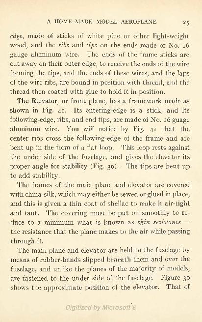
A HOME-MADE MODEL AEROPLANE 25
edge, made of sticks of white pine or other light-weight
wood, and the ribs and tips on the ends made of No. 16
gauge aluminum wire. The ends of the frame sticks are
cut away on their outer edge, to receive the ends of the wire
forming the tips, and the ends of these wires, and the laps
of the wire ribs, are bound in position with thread, and the
thread then coated with glue to hold it in position.
The Elevator, or front plane, has a framework made as
shown in Fig. 41. Its entering-edge is a stick, and its
following-edge, ribs, and end tips, are made of No. 16 guage
aluminum wire. You will notice by Fig. 41 that the
center ribs cross the following-edge of the frame and are
bent up in the form of a flat loop. This loop rests against
the under side of the fuselage, and gives the elevator its
proper angle for stability (Fig. 36). The tips are bent upto add stability.
The frames of the main plane and elevator are covered
with china-silk, which may either be sewed or glued in place,
and this is given a thin coat of shellac to make it air-tight
and taut. The covering must be put on smoothly to re-
duce to a minimum what is known as skin resistance -
the resistance that the plane makes to the air while passing
through it.
The main plane and elevator are held to the fuselage by
means of rubber-bands slipped beneath them and over the
fuselage, and unlike the planes of the majority of models,
are fastened to the under side of the fuselage. Figure 36
shows the approximate position of the elevator. That of
26 HOME-MADE TOYS FOR GIRLS AND BOYS
the main plane will vary under different air conditions,
sometimes being placed over the separator C, and at other
times closer to separator B than is shown in Fig. 35.
Therefore, you must adjust your plane and elevator -
this operation is known as tuning- to suit the condition
of the atmosphere, until you find the positions where they
will give the machine the greatest stability. A great factor
Fig. 41 Fig. 42PLAN
4" xj"x 10" WOOD
NO 16 GAUGE 1
ALUMINUM WIRE L
FIG. 40.
FIG. 41.
FIG. 42.
16'WOOD
Fig. 40
Detail of the Main Plane Framework of the Wells Model.
Detail of the Elevator Framework.
Detail of Fin.
in the successful flight of a model aeroplane lies in properly
tuning the planes, both laterally and longitudinally, and of
course the planes must balance at their centers, in order
to make the machine balance properly.
The Fin directly over the center of the elevator (Figs. 34
and 36) is provided for stability, and may be used as a
rudder by turning it slightly to one side or the other. It
is made of No. 34 gauge sheet aluminum, cut to the form
A HOME-MADE MODEL AEROPLANE 27
GLASS BEAD
WIRE SHAFT
shown in Fig. 42. Its vertical edge is bent around a piece
of heavy wire, as shown in the plan detail of Fig. 42, and
the lower end of the wire is fastened upright between the
bow ends of sticks A.
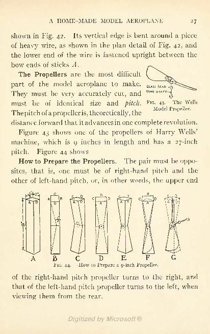
The Propellers are the most difficult
part of the model aeroplane to make.
They must be very accurately cut, and
must be of identical size and pitch.FlG - 43- --The Wells
.... Model Propeller.The pitch of a propeller is, theoretically, the
distance forward that it advances in one complete revolution.
Figure 43 shows one of the propellers of Harry Wells'
machine, which is 9 inches in length and has a 27-inch
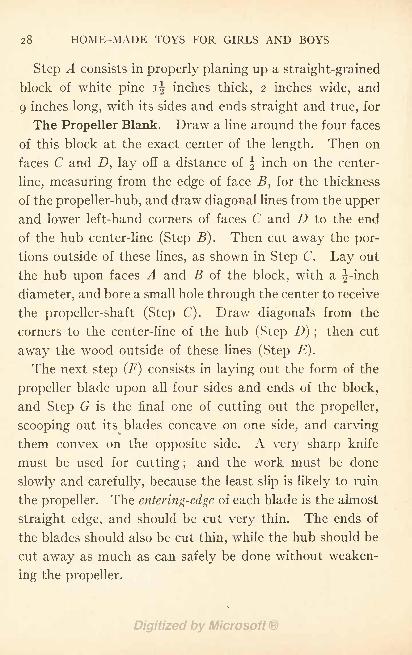
pitch. Figure 44 shows
How to Prepare the Propellers. The pair must be oppo-
sites, that is, one must be of right-hand pitch and the
other of left-hand pitch, or, in other words, the upper end
C
28 HOME-MADE TOYS FOR GIRLS AND BOYS
Step A consists in properly planing up a straight-grained
block of white pine i^ inches thick, 2 inches wide, and
9 inches long, with its sides and ends straight and true, for
The Propeller Blank. Draw a line around the four faces
of this block at the exact center of the length. Then on
faces C and D, lay off a distance of J inch on the center-
line, measuring from the edge of face B, for the thickness
of the propeller-hub, and draw diagonal lines from the upper
and lower left-hand corners of faces C and D to the end
of the hub center-line (Step B). Then cut away the por-
tions outside of these lines, as shown in Step C. Lay out
the hub upon faces A and B of the block, with a J-inch
diameter, and bore a small hole through the center to receive
the propeller-shaft (Step C). Draw diagonals from the
corners to the center-line of the hub (Step D) ;then cut
away the wood outside of these lines (Step E).
The next step (F) consists in laying out the form of the
propeller blade upon all four sides and ends of the block,
and Step G is the final one of cutting out the propeller,
scooping out its blades concave on one side, and carving
them convex on the opposite side. A very sharp knife
must be used for cutting ;and the work must be done
slowly and carefully, because the least slip is likely to ruin
the propeller. The entering-edge of each blade is the almost
straight edge, and should be cut very thin. The ends of
the blades should also be cut thin, while the hub should be
cut away as much as can safely be done without weaken-
ing the propeller.
A HOME-MADE MODEL AEROPLANE 29
When you have completed cutting the propellers, place
them at their centers across the edge of a knife-blade, and
if they do not balance perfectly, locate the trouble and
correct it. Finish the work with fine emery-paper, and
then shellac it. Some boys glue silk over the ends of their
propeller blades, for a distance of | inch or so, to reinforce
them and make them less likely to split.
The Propeller-Shafts are made of heavy piano-wire, bent
into a hook at one end (Fig. 38) to receive the rubber
strands of the motor, and cut of the right length to extend
through the hole in the bearing, through a glass bead,
through the propeller, and then to bend over the side of
the hub (Figs. 37 and 38). By bending over the end of the
shaft against the hub, it is held securely in place.
The Motors consist of twelve strands of J-inch flat
rubber, each, and as these are i yard in length, exactly 24
yards of rubber are required. The rubber is not connected
direct to the hooks on the bow and propeller-shafts, as the
wire would quickly cut through the strands. Instead,
small rings are bent out of wire, with pieces of small rubber-
tubing slipped over the wire, and the ends of the rubber
strands are looped through these rings and bound in place
with thread (Fig. 39). The wire rings are then slipped
on and off the hooks quickly. As light and heat cause
rubber to deteriorate, you must remove the motors from
the machine after use, pack away in a covered box, and
keep in a cool place, in order to get the longest life possible
out of the rubber.
HOME-MADE TOYS FOR GIRLS AND BOYS
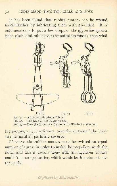
It has been found that rubber motors can be wound
much farther by lubricating them with glycerine. It is
only necessary to put a few drops of the glycerine upon a
clean cloth, and rub it over the outside strands;then wind
Fig. 47 Fig. 45 Fig. 46
FIG. 45. A Home-made Motor Winder.
FIG. 46.- -The Kind of Fgg-Beater to Use.
FIG. 47. How the Motors are Connected to Winder for Winding.
the motors, and it will work over the surface of the inner
strands until all parts are covered.
Of course the rubber motors must be twisted an equal
number of turns, in order to make the propellers work the
same, and this is usually done with an ingenious winder
made from an egg-beater, which winds both motors simul-
taneously.
A HOME-MADE MODEL AEROPLANE 31
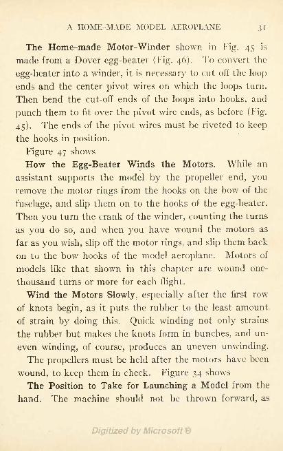
The Home-made Motor-Winder shown in Fig. 45 is
made from a Dover egg-beater (Fig. 46). To convert the
egg-beater into a winder, it is necessary to cut off the loop
ends and the center pivot wires on which the loops turn.
Then bend the cut-off ends of the loops into hooks, and
punch them to fit over the pivot wire ends, as before (Fig.
45). The ends of the pivot wires must be riveted to keep
the hooks in position.
Figure 47 shows
How the Egg-Beater Winds the Motors. While an
assistant supports the model by the propeller end, you
remove the motor rings from the hooks on the bow of the
fuselage, and slip them on to the hooks of the egg-beater.
Then you turn the crank of the winder, counting the turns
as you do so, and when you have wound the motors as
far as you wish, slip off the motor rings, and slip them back
on to the bow hooks of the model aeroplane. Motors of
models like that shown in this chapter are wound one-
thousand turns or more for each flight.
Wind the Motors Slowly, especially after the first row
of knots begin, as it puts the rubber to the least amount
of strain by doing this. Quick winding not only strains
the rubber but makes the knots form in bunches, and un-
even winding, of course, produces an uneven unwinding.
The propellers must be held after the motors have been
wound, to keep them in check. Figure 34 shows
The Position to Take for Launching a Model from the
hand. The machine should not be thrown forward, as
32 HOME-MADE TOYS FOR GIRLS AND BOYS
the movement would cause too great a disturbance of the
air, resulting in the machine losing its stability, and prob-
ably upsetting. The best method is to give the model a
slight push that will start it off at a speed a trifle under
that produced by its propellers.
CHAPTER IV
A HOME MADE TOY MOTOR-BOAT
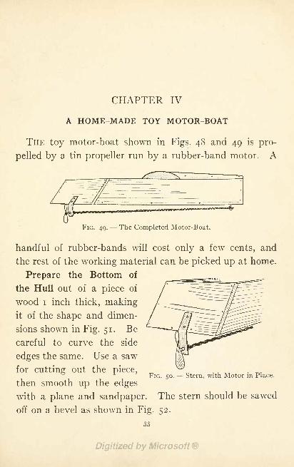
THE toy motor-boat shown in Figs. 48 and 49 is pro-
pelled by a tin propeller run by a rubber-band motor. A
FIG. 49.- -The Completed Motor-Boat.
handful of rubber-bands will cost only a few cents, and
the rest of the working material can be picked up at home.
Prepare the Bottom of
the Hull out of a piece of
wood i inch thick, makingit of the shape and dimen-
sions shown in Fig. 51. Be
careful to curve the side
FIG. 50. Stern, with Motor in Place.
edges the same. Use a saw
for cutting out the piece,
then smooth up the edges
with a plane and sandpaper. The stern should be sawed
off on a bevel as shown in Fig. 52.
33
34 HOME-MADE TOYS FOR GIRLS AND BOYS
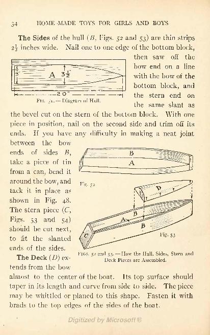
The Sides of the hull (5, Figs. 52 and 53) are thin strips
\ inches wide. Nail one to one edge of the bottom block,
then saw off the
bow end on a line
with the bow of the
bottom block, and
the stern end on
the same slant as
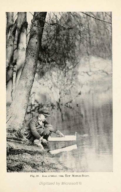
Fig. 48. LAUNCHING THE TOY MOTOR-BOAT.
A HOME-MADE TOY MOTOR-BOAT 35
To Complete the Boat, go over the work carefully, trim
off all projecting edges, drive nail heads beneath the sur-
faces, putty nail holes and cracks, and give the wood two
coats of paint of whatever color you want to have the
motor-boat.
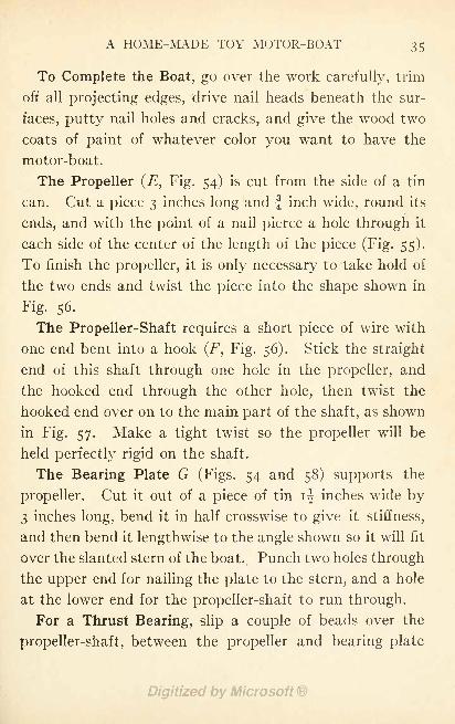
The Propeller (, Fig. 54) is cut from the side of a tin
can. Cut a piece 3 inches long and f inch wide, round its
ends, and with the point of a nail pierce a hole through it
each side of the center of the length of the piece (Fig. 55).
To finish the propeller, it is only necessary to take hold of
the two ends and twist the piece into the shape shown in
Fig. 56-
The Propeller-Shaft requires a short piece of wire with
one end bent into a hook (F, Fig. 56). Stick the straight
end of this shaft through one hole in the propeller, and
the hooked end through the other hole, then twist the
hooked end over on to the main part of the shaft, as shown
in Fig. 57. Make a tight twist so the propeller will be
held perfectly rigid on the shaft.
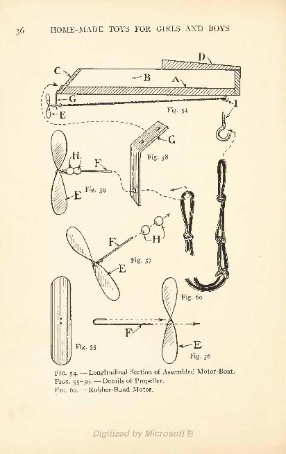
The Bearing Plate G (Figs. 54 and 58) supports the
propeller. Cut it out of a piece of tin i| inches wide by
3 inches long, bend it in half crosswise to give it stiffness,
and then bend it lengthwise to the angle shown so it will fit
over the slanted stern of the boat. Punch two holes through
the upper end for nailing the plate to the stern, and a hole
at the lower end for the propeller-shaft to run through.
For a Thrust Bearing, slip a couple of beads over the
propeller-shaft, between the propeller and bearing plate
HOME-MADE TOYS FOR GIRLS AND BOYS
FIG. 54. Longitudinal Section of Assembled Motor-Boat.
FIGS. 55-59- Details of Propeller.
FIG. 60. Rubber-Band Motor.
A HOME-MADE TOY MOTOR-BOAT 37
G. Probably you can find glass beads in your mother's
button bag.
After slipping the beads on to the shaft, and sticking
the shaft through the hole in bearing plate G, bend the
end of the shaft into a hook;
then screw a small screw-
hook into the bottom of the hull, at the bow end (/, Fig.
54), and you will be ready for
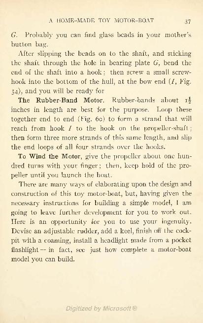
The Rubber-Band Motor. Rubber-bands about ij
inches in length are best for the purpose. Loop these
together end to end (Fig. 60) to form a strand that will
reach from hook I to the hook on the propeller-shaft ;
then form three more strands of this same length, and slip
the end loops of all four strands over the hooks.
To Wind the Motor, give the propeller about one hun-
dred turns with your finger ; then, keep hold of the pro-
peller until you launch the boat.
There are many ways of elaborating upon the design and
construction of this toy motor-boat, but, having given the
necessary instructions for building a simple model, I am
going to leave further development for you to work out.
Here is an opportunity for you to use your ingenuity.
Devise an adjustable rudder, add a keel, finish off the cock-
pit with a coaming, install a headlight made from a pocket
flashlight- -in fact, see just how complete a motor-boat
model you can build.
CHAPTER V
HOME-MADE TOY WATER-MOTORS
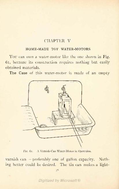
You can own a water-motor like the one shown in Fig.
61, because its construction requires nothing but easily
obtained materials.
The Case of this water-motor is made of an empty
FIG. 61. A Varnish-Can Water-Motor in Operation.
varnish can - -
preferably one of gallon capacity. Noth-
ing better could be desired. The tin can makes a light-
38
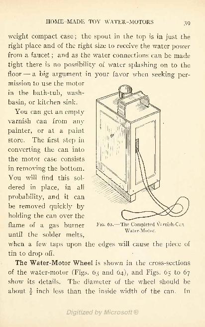
HOME-MADE TOY WATER-MOTORS 39
weight compact case;
the spout in the top is in just the
right place and of the right size to receive the water powerfrom a faucet
;and as the water connections can be made
tight there is no possibility of water splashing on to the
floor a big argument in your favor when seeking per-
mission to use the motor
in the bath-tub, wash-
basin, or kitchen sink.
You can get an emptyvarnish can from any
painter, or at a paint
store. The first step in
converting the can into
the motor case consists
in removing the bottom.
You will find this sol-
dered in place, in all
probability, and it can
be removed quickly by
holding the can over the
flame of a gas burner
until the solder melts,
when a few taps upon the edges will cause the piece of
tin to drop off.
The Water-Motor Wheel is shown in the cross-sections
of the water-motor (Figs. 63 and 64), and Figs. 65 to 67
show its details. The diameter of the wheel should be
about inch less than the inside width of the can. In
FIG. 62. --The Completed Varnish-Can
Water-Motor.
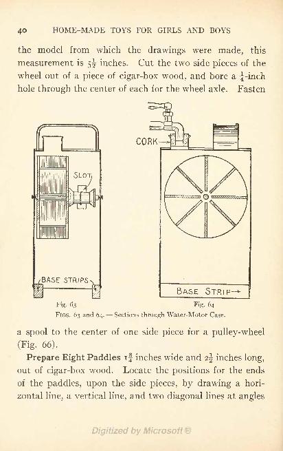
HOME-MADE TOYS FOR GIRLS AND BOYS
the model from which the drawings were made, this
measurement is 5^ inches. Cut the two side pieces of the
wheel out of a piece of cigar-box wood, and bore a f-inch
hole through the center of each for the wheel axle. Fasten
CORK
BASE STRIP
Fig. 63
FIGS. 63 and 64.
Fig. 64
Sections through Water-Motor Case.
a spool to the center of one side piece for a pulley-wheel
(Fig. 66).
Prepare Eight Paddles if inches wide and i\ inches long,
out of cigar-box wood. Locate the positions for the ends
of the paddles, upon the side pieces, by drawing a hori-
zontal line, a vertical line, and two diagonal lines at angles
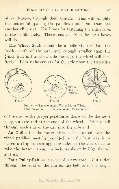
HOME-MADE TOY 'WATER-MOTORS
of 45 degrees, through their centers. This will simplify
the matter of spacing the paddles equidistant from one
another (Fig. 67). Use brads for fastening the side pieces
to the paddle ends. Those removed from the cigar boxes
will do.
The Wheel Shaft should be a trifle shorter than the
inside width of the can, and enough smaller than the
j-inch hole in the wheel side pieces so the wheel will turn
freely. Locate the centers for the axle upon the two sides
SPOOLPULLEY-WHEEL
Fig. 65 Fig. 66
FIG. 65.- -The Completed Water-Motor Wheel.
FIGS. 66 and 67. Details of Water-Motor Wheel.
Fig. 67
of the can, in the proper position so there will be the same
margin above and at the ends of the wheel. Drive a nail
through each side of the can into the axle end.
An Outlet for the water after it has passed over the
wheel paddles must be provided, and the best way is to
fasten a strip to two opposite sides of the can so as to
raise the bottom about an inch, as shown in Figs. 62, 63,
and 64.
For a Pulley-Belt use a piece of heavy cord. Cut a slot
through the front of the can for the belt to run through,
HOME-MADE TOYS FOR GIRLS AXD BOYS
and make this slot large enough so the cord will not rub
against the sides (Fig. 63).
Pulley-Wheels for attaining different speeds can be made
of spools of various sizes. A bicycle wheel with the tire
removed, mounted in a frame, is excellent for a large wheel.
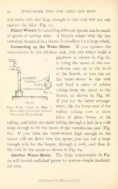
Connecting up the Water-Motor. If you operate the
water-motor in the kitchen sink, you can either build a
platform as shown in Fig. 61,
to bring the spout of the var-
nish-can case up to the level
of the faucet, or you can set
the water-motor in the sink
and lead a piece of rubber
tubing from the spout to the
faucet, as shown in Fig. 68.
If you use the latter arrange-
ment, slip the lower end of the
RUBBERTUBING
CORKTUBING
r
Fig. 69
I
Fig. 68
FIGS. 68-69. How to Make a
Fater-tight Connection between rubber tubing over a shortFaucet and Water-Motor. .
piece of glass, brass, or tin
tubing, and stick the short tubing through a hole in a cork
large enough to fit the spout of the varnish-can case (Fig.
69). If you raise the water-motor high enough so the
faucet will set down into the spout, you can cut a large
enough hole for the faucet, through a cork, and then fit
the cork in the spout as shown in Fig. 64.
Another Water-Motor. The little water-motor in Fig.
70 will furnish sufficient power to operate simple mechani-
cal toys.
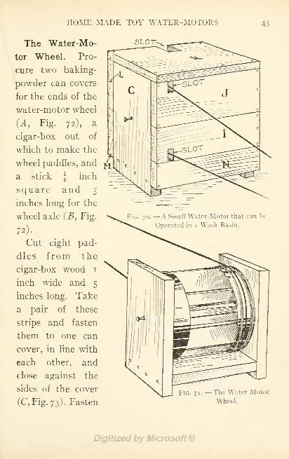
HOME-MADE TOY WATER-MOTORS 43
The Water-Mo-
tor Wheel. Pro-
cure two baking-
powder can covers
for the ends of the
water-motor wheel
(.4, Fig. 72), a
cigar-box out of
which to make the
wheel paddles, and
a stick \ inch
square and 5
inches long for the
wheel axle (B, Fig.
72).
Cut eight pad-
dles from the
cigar-box wood i
inch wide and 5
inches long. Take
a pair of these
strips and fasten
them to one can
cover, in line with
each other, and
close against the
sides of the cover
(C, Fig. 73). Fasten
SLOT-
FIG. 70. A Small Water-Motor that can be
Operated in a Wash-Basin.
FlG. 71. The Water-Motor
Wheel
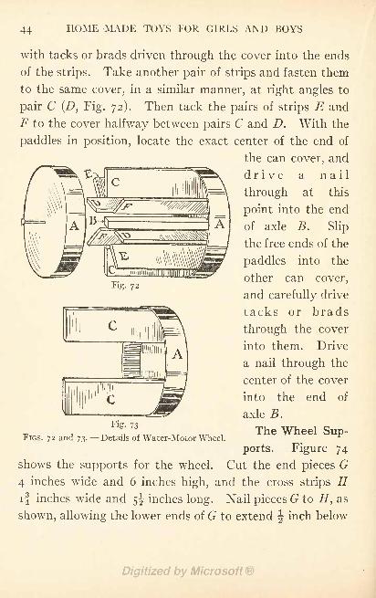
44 HOME-MADE TOYS FOR GIRLS AND BOYS
with tacks or brads driven through the cover into the ends
of the strips. Take another pair of strips and fasten them
to the same cover, in a similar manner, at right angles to
pair C (D, Fig. 72). Then tack the pairs of strips E and
F to the cover halfway between pairs C and D. With the
paddles in position, locate the exact center of the end of
the can cover, and
drive a nail
through at this
point into the end
of axle B. Slip
the free ends of the
paddles into the
other can cover,
and carefully drive
tacks or brads
through the cover
into them. Drive
a nail through the
center of the cover
into the end of
axle B.
The Wheel Sup-
ports. Figure 74
shows the supports for the wheel. Cut the end pieces G
4 inches wide and 6 inches high, and the cross strips Hif inches wide and 5^ inches long. Nail pieces G to H, as
shown, allowing the lower ends of G to extend \ inch below
Fig. 72
Fig. 73
FIGS. 72 and 73. Details of Water-Motor Wheel.
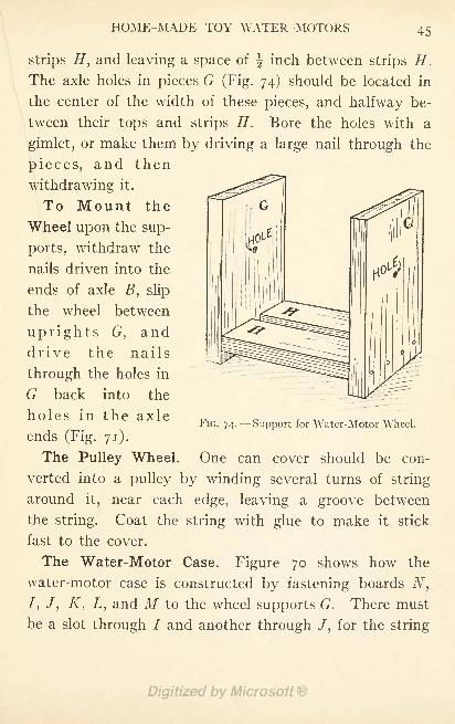
HOME-MADE TOY WATER-MOTORS 45
strips H, and leaving a space of f inch between strips H,
The axle holes in pieces G (Fig. 74) should be located in
the center of the width of these pieces, and halfway be-
tween their tops and strips H. Bore the holes with a
gimlet, or make them by driving a large nail through the
pieces, and then
withdrawing it.
To Mount the
Wheel upon the sup-
ports, withdraw the
nails driven into the
ends of axle B, slip
the wheel between
uprights G, anddrive the nails
through the holes in
G back into the
holes in the axle
ends (Fig. 71).
FIG. 74. Support for Water-Motor Wheel.
The Pulley Wheel. One can cover should be con-
verted into a pulley by winding several turns of string
around it, near each edge, leaving a groove between
the string. Coat the string with glue to make it stick
fast to the cover.
The Water-Motor Case. Figure 70 shows how the
water-motor case is constructed by fastening boards N,
/, /, K, L, and M to the wheel supports G. There must
be a slot through / and another through /, for the string
46 HOME-MADE TOYS FOR GIRLS AND BOYS
belt to pass through, and a hole through K for the intake
of water from a faucet. These can be cut out of the
edges of the boards, as shown, before they are nailed in
place. Leave an opening between boards N and M, and
the bottom of ends G, for an outlet for waste water.
CHAPTER VI
A HOME-MADE TOY RAILWAY
IT is often thought that a toy railway is beyond a boy's
ingenuity to construct, whereas, in reality, it is one of
the simplest toys he can make. This applies to the
tracks, stations, and cars of every description, all of which
can be made with a few strips of wood, some spools, nails,
cardboard, and a bottle of glue, for materials. If youhave passed the age of caring for such toys as this, you
will, no doubt, enjoy the making of one
for your younger brother, or for one of
your boy relatives.
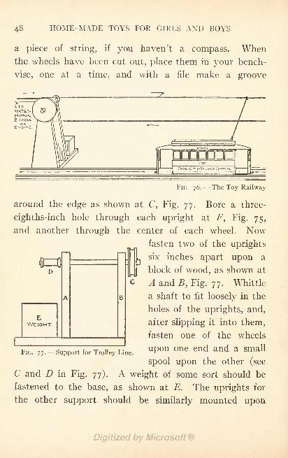
Figure 76 shows a railway set up and
in running order. As shown in the illus-
tration,
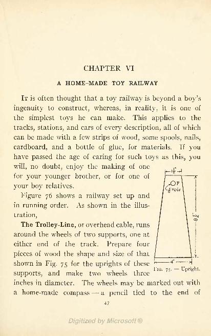
The Trolley-Line, or overhead cable, runs
around the wheels of two supports, one at
either end of the track. Prepare four
pieces of wood the shape and size of that
shown in Fig. 75 for the uprights of these*
FIG. 75.- -
Upright.supports, and make two wheels three
inches in diameter. The wheels may be marked out with
a home-made compass- - a pencil tied to the end of
47
48 HOME-MADE TOYS FOR GIRLS AND BOYS
a piece of string, if you haven't a compass. Whenthe wheels have been cut out, place them in your bench-
vise, one at a time, and with a file make a groove
WATER-( 5*
MOTOR,BICVCLE
ORENGINE.
EWEIGHT
B
FIG. 76.- - The Toy Railway
around the edge as shown at C, Fig. 77. Bore a three-
eighths-inch hole through each upright at F, Fig. 75,
and another through the center of each wheel. Nowfasten two of the uprights
r six inches apart upon a
block of wood, as shown at
A and B, Fig. 77. Whittle
a shaft to fit loosely in the
holes of the uprights, and,
after slipping it into them,
fasten one of the wheels
FIG. 77- -Support for Trolley-Line.UP n n6 Cnd and a Sma11
spool upon the other (see
C and D in Fig. 77). A weight of some sort should be
fastened to the base, as shown at E. The uprights for
the other support should be similarly mounted upon
A HOME-MADE TOY RAILWAY 49
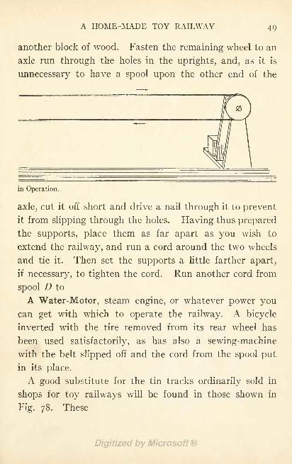
another block of wood. Fasten the remaining wheel to an
axle run through the holes in the uprights, and, as it is
unnecessary to have a spool upon the other end of the
in Operation.
axle, cut it off short and drive a nail through it to prevent
it from slipping through the holes. Having thus prepared
the supports, place them as far apart as you wish to
extend the railway, and run a cord around the two wheels
and tie it. Then set the supports a little farther apart,
if necessary, to tighten the cord. Run another cord from
spool D to
A Water-Motor, steam engine, or whatever power youcan get with which to operate the railway. A bicycle
inverted with the tire removed from its rear wheel has
been used satisfactorily, as has also a sewing-machine
with the belt slipped off and the cord from the spool put
in its place.
A good substitute for the tin tracks ordinarily sold in
shops for toy railways will be found in those shown in
Fig. 78. These
HOME-MADE TOYS FOR GIRLS AND BOYS
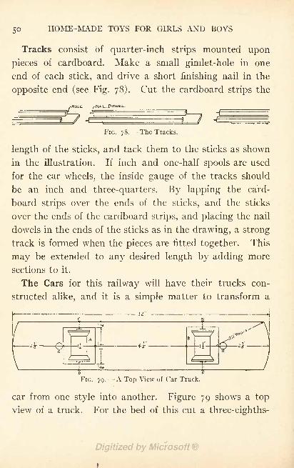
Tracks consist of quarter-inch strips mounted upon
pieces of cardboard. Make a small gimlet-hole in one
end of each stick, and drive a short finishing nail in the
opposite end (see Fig. 78). Cut the cardboard strips the
HOLE
FIG. 78. --The Tracks.
length of the sticks, and tack them to the sticks as shown
in the illustration. If inch and one-half spools are used
for the car wheels, the inside gauge of the tracks should
be an inch and three-quarters. By lapping the card-
board strips over the ends of the sticks, and the sticks
over the ends of the cardboard strips, and placing the nail
dowels in the ends of the sticks as in the drawing, a strong
track is formed when the pieces are fitted together. This
may be extended to any desired length by adding more
sections to it.
The Cars for this railway will have their trucks con-
structed alike, and it is a simple matter to transform a
12
**
A HOME-MADE TOY RAILWAY
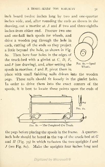
inch board twelve inches long by two and one-quarter
inches wide, and, after rounding the ends as shown in the
drawing, cut a mortise at A and B two and three-eighths
inches from either end. Procure two one
and one-half inch spools for wheels, and
drive a wooden peg through the hole in
each, cutting off the ends so they project
a little beyond the hole, as shown in Fig.
80. Then bore four holes in the edges of
the truck-bed with a gimlet at C, D, E,
and F (see drawing), and, after setting the
spools in mortises A and B, pivot them in
place with small finishing nails driven into the wooden
pegs. These nails should fit loosely in the gimlet holes.
In order to drive them into the exact centers of the
spools, it is best to locate these points upon the ends of
FIG. 80. Spool
Wheels.
irfjx'Brass Ki
I
eg Wire-
K
FIG. 82.
FIG. 81. - -The Completed Car Truck.
the pegs before placing the spools in the frame. A quarter-
inch hole should be bored in the top of the truck-bed at Gand // (Fig. 79) in which to fasten the two uprights 7 and
/ (see Fig. 81). Make the uprights four inches long and
52 HOME-MADE TOYS FOR GIRLS AND BOYS
whittle a peg upon the lower ends to fit holes G and
H (see Fig. 82). Bore a hole with a gimlet in the top of
each and run a piece of heavy wire from one to the other,
bending it as shown in Fig. 81. Fasten K between I
and /, as shown. Place a small brass ring upon the wire
before you fasten it in place. A small hook should be
screwed into one end of the truck and a screw-eye into
the other end, for couplings, should you wish to hitch two
or more cars together.
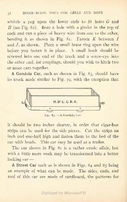
A Gondola Car, such as shown in Fig. 83, should have
its truck made similar to Fig. 79, with the exception that
tfe-
A HOME-MADE TOY RAILWAY 53
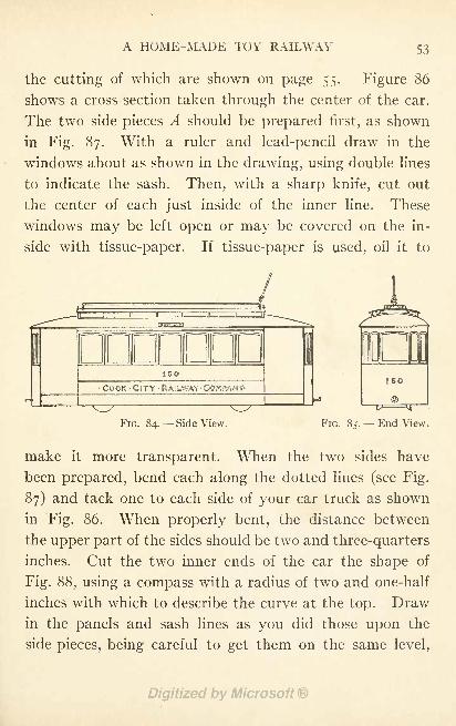
the cutting of which are shown on page 55. Figure 86
shows a cross-section taken through the center of the car.
The two side pieces A should be prepared first, as shown
in Fig. 87. With a ruler and lead-pencil draw in the
windows about as shown in the drawing, using double lines
to indicate the sash. Then, with a sharp knife, cut out
the center of each just inside of the inner line. These
windows may be left open or may be covered on the in-
side with tissue-paper. If tissue-paper is used, oil it to
ISO
COOK-CITY15
FIG. 84. Side View. FIG. 85. End View.
make it more transparent. When the two sides have
been prepared, bend each along the dotted lines (see Fig.
87) and tack one to each side of your car truck as shown
in Fig. 86. When properly bent, the distance between
the upper part of the sides should be two and three-quarters
inches. Cut the two inner ends of the car the shape of
Fig. 88, using a compass with a radius of two and one-half
inches with which to describe the curve at the top. Drawin the panels and sash lines as you did those upon the
side pieces, being careful to get them on the same level,
54 HOME-MADE TOYS FOR GIRLS AND BOYS
and cut out the door and window openings. Fasten
these end pieces between the sides with glue, and also
tack them to the uprights of the car (/ and /, Fig. 81),
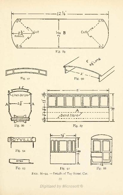
which will come just inside of them. The roof is made
in two sections (B and C, Fig. 86). For B cut a piece of
cardboard twelve and one-quarter by three and three-
quarter inches (Fig. 89), draw the curved end with a com-
pass, using the radius shown on the drawing, and slit the
corners as indicated by the dotted lines. When this
piece has thus been prepared, remove the wire from the
top of the truck (see Fig. 81). Bend the cardboard over
the sides and ends of the car, and lap corners D and Eover F and G, and H and / over / and K, tacking them
with thread to hold them in place. To fasten this part
of the roof to the top of the car, cut a number of small
strips of linen, and glue them to the under side of the roof
and to the inside face of the sides and ends of the car
(see Fig. 86). The upper portion of the roof C should be
made out of a piece of cardboard bent into the shape of
Fig. 90, and cut at the ends so the upper portion of C
projects a little beyond its sides. Draw the ventilation
lights upon the sides of C as shown on the drawings, and
then fasten the piece upon the top of B with strips of
linen in the same manner as you fastened B in place.
C should now have the same curve to its top as B. Cut
and glue a piece of cardboard in each end of C to complete
the roof. The shape of this piece is shown in Fig. 91.
The outer ends of the car should be made as shown in
h-12
i Deofa DCO
Fig. 89
Fig. 91 Fig. go
'-Linen -Strips-^1
r
i-
56 HOME-MADE TOYS FOR GIRLS AND BOYS
Fig. 92, and tacked around the ends of the wooden truck
platform, and also fastened to the under side of the roof
with strips of linen. The window openings may be cut
in each end, but it will make a stronger car if they are
simply drawn upon it. Cut four cardboard steps similar
to Fig. 93 and tack them to the sides of the front and rear
platforms. When the car has been put together, replace
the wire in the tops of uprights / and / (Fig. 81), run-
ning the ends through the roof (see Fig. 84). Paint the
sides and ends of the car yellow with brown trimmings,
and paint the roof a light gray. Water colors can be used
for the purpose. Letter the name of your car-line uponthe sides and the number of the car upon each end and
side. The route should be lettered upon strips of card-
board with pins run through them as shown in Fig. 94,
these strips to stick in the roof of the car (see Figs. 84
and 85).
Having seen how the car is made, you will find it a
simple matter to make designs for
Other Cars, using the same scheme for the trucks, and
altering the patterns for the sides, ends, and roof, to suit
the design.
Nothing has, as yet, been said about the
Operation of the Railway, and though Fig. 76 probably
shows sufficiently clear how it is run, a few words maybe helpful. The car or cars are placed between the wooden
tracks, and the trolley (or cord attached to the ring on
top of the car) is tied to the trolley-line as in the illus-
A HOME-MADE TOY RAILWAY 57
tration. Upon starting your engine, water-motor, or
whatever motive-power you have, the car will run from
one end of the track to the other. When it has reached the
support of the trolley-line, it will stop long enough for
the cord trolley to pass around the wooden wheel, and
then run in the opposite direction until the other support
is reached. It will thus be seen that the trolley hangs to
the upper part of the cable, or trolley-line, in running
one way, and to the lower part on the return run. In
FIG. 95.- -The Railway Depot.
changing the direction of the run, the ring to which the
trolley is attached slides to the other end of the car.
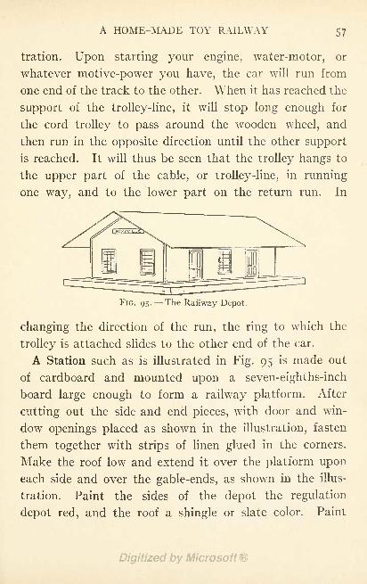
A Station such as is illustrated in Fig. 95 is made out
of cardboard and mounted upon a seven-eighths-inch
board large enough to form a railway platform. After
cutting out the side and end pieces, with door and win-
dow openings placed as shown in the illustration, fasten
them together with strips of linen glued in the corners.
Make the roof low and extend it over the platform upon
each side and over the gable-ends, as shown in the illus-
tration. Paint the sides of the depot the regulation
depot red, and the roof a shingle or slate color. Paint
58 HOME-MADE TOYS FOR GIRLS AND BOYS
the door and window-sash black, letter the name of the
station upon the gable-ends, and with a ruler and lead-
pencil rule off the boards upon the sides, and the slate
or shingles upon the roof. As this is a typical railway
station, two may be made of the same pattern, one for
either end of your car line.
CHAPTER VII
HOME-MADE TOY ELEVATORSf
THE elevator shown in Fig. 96 is a unique mechanical toy
well worth one's making. Release the little car at the top
floor, and it will descend to the ground floor, and then
return to the starting point, without you having to touch
it a second time. A magical elevator? Perhaps so. Alittle mechanical device performs the trick.
The same plan may be followed for installing the doll-
house elevator in Chapter XIII, but the more stories there
are the more fun there is in operating the elevator. This is
why I have adapted the scheme to
A Toy Office Building. Six stories are shown in Fig. 96,
but you can make a modern sky-scraper with as manystories as you like. A packing-case 3 feet 6 inches long,
stood on end, was used for the model. Another box or two
can be added to the top for additional stories. Besides the
box, or boxes, get enough box boards for floors and parti-
tions.
Make the Floors in two pieces (A and B, Fig. 98), so the
opening for the elevator shaft can be cut out of the end of
one piece in the manner shown. This opening should be
about 5 inches square. Mark out and cut the boards for all
59
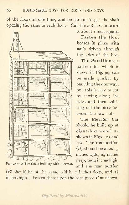
6o HOME-MADE TOYS FOR GIRLS AND BOYS
of the floors at one time, and be careful to get the shaft
opening the same in each floor. Cut the notch C in board
A about i inch square.
Fasten the floor
boards in place with
nails driven through
the sides of the box.
The Partitions, a
pattern for which is
shown in Fig. 99, can
be made quicker by
omitting the doorway,
but this is easy to cut
by sawing along the
sides and then split-
ting out the piece be-
tween the saw cuts.
The Elevator Car
should be built up of
cigar-box wood, as
shown in Figs. 101 and
102. The front portion
(D) should be about 3
inches wide, 2\ inches
deep, and 4 inches high,FIG. 96. A Toy Office Building with Elevator. ,
and the rear portion
(E) should be of the same width, 2 inches deep, and i\
inches high. Fasten these upon the base piece F as shown.
HOME-MADE TOY ELEVATORS 61
The Elevator Guides. Bore the holes G through the
top and bottom of the car, close to the sides, for guide
wires H to run through (Figs. 101 and 102). These holes
may be bored with a screw-eye if you haven't a gimlet or
drill. Bell-wire, or almost any wire that you have on
hand, will do for the guides. Fasten two screw-eyes into
the under side of the top of the shaft, the same distance
apart as holes G, and in the proper position so they will
come exactly over them (/, Fig. 100). Use the car for
determining these measurements. Then bore two holes
through the bottom of the shaft directly below the screw-
eyes (/, Fig. 100). Attach the wire to one screw-eye, run
it down through holes G in the car, through one of the holes
/, then across to and up through the other hole /, up
through the other set of holes G in the car, and attach to
the second screw-eye /.
The Cables. The elevator is lifted by means of cord L
(Figs. 97 and 101). Fasten this cord to a tack driven into
the top of the car, then run it up and over spool M (Figs.
97 and 101), over spool N (Fig. 97), and tie to weight K,
The Counter-balance. A bottkj filled with sand to
make it weigh more than twice as much as the car, should
be used for this. Screw a small screw-eye into the cork
to tie the cord to.
The counter-balance runs up and down in
The Smoke-Stack, which is fastened to the back of the
building (Fig. 97). Make the stack of cardboard mailing-
tubes, joining them end to end with bands of paper pasted
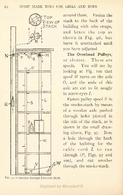
62 HOME-MADE TOYS FOR GIRLS AND BOYS
TOPVlEW-OFSTACK
around them. Fasten the
stack to the back of the
building with wire straps,
and brace the top as
shown in Fig. 96, but
leave it unattached until
you have adjusted
The Overhead Pulleys,
or sheaves. These are
spools. You will see by
looking at Fig. 100 that
spool M turns on the axle
0, and the ends of this
axle are cut to fit snugly
in screw-eyes 7.
Fasten pulley spool N in
the smoke-stack by means
of a wooden axle pushed
through holes pierced in
the side of the stack, as is
shown in the small draw-
ing above, Fig. 97. Bore
a hole through the back
of the building for the
cable cord L to run
through (P, Figs. 97 and
100), and cut another
through the smoke-stack.
FIG. 97. Section through Elevator Shaft.
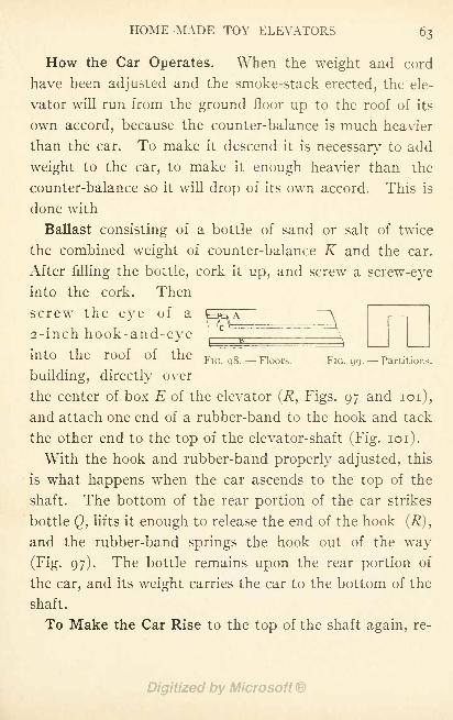
HOME-MADE TOY ELEVATORS 63
How the Car Operates. When the weight and cord
have been adjusted and the smoke-stack erected, the ele-
vator will run from the ground floor up to the roof of its
own accord, because the counter-balance is much heavier
than the car. To make it descend it is necessary to add
weight to the car, to make it enough heavier than the
counter-balance so it will drop of its own accord. This is
done with
Ballast consisting of a bottle of sand or salt of twice
the combined weight of counter-balance K and the car.
After filling the bottle, cork it up, and screw a screw-eye
into the cork. Then
screw the eye of a \=^ A
2-inch hook-and-eve
into the roof of the FlQ Qg _ Floors FIG. 99.- Partitions.
building, directly over
the center of box E of the elevator (R, Figs. 97 and 101),
and attach one end of a rubber-band to the hook and tack
the other end to the top of the elevator-shaft (Fig. 101).
With the hook and rubber-band properly adjusted, this
is what happens when the car ascends to the top of the
shaft. The bottom of the rear portion of the car strikes
bottle <2, lifts it enough to release the end of the hook (R),
and the rubber-band springs the hook out of the way
(Fig. 97). The bottle remains upon the rear portion of
the car, and its weight carries the car to the bottom of the
shaft.
To Make the Car Rise to the top of the shaft again, re-
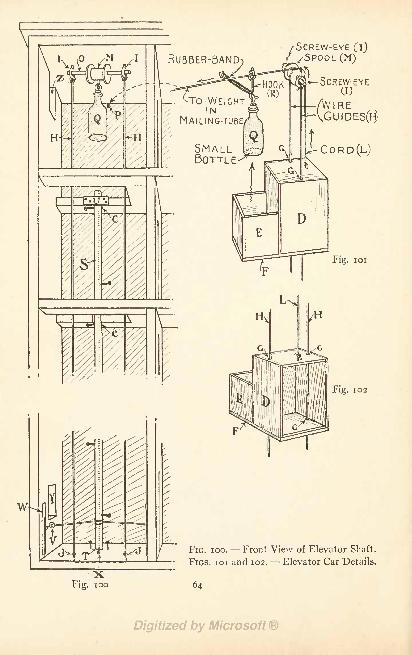
MAILING-TUBE/
SMALLBOTTLE
/SCREW-EYE (i)
/SPOOL(M)
-SCREW-EYECD
/VVI RE^VGUIDES(H>
C R D (L)
Fig. 1 01
Fig. 102
FIG. 100. Front View of Elevator Shaft.
FIGS. 101 and 102. -- Elevator Car Details.
64
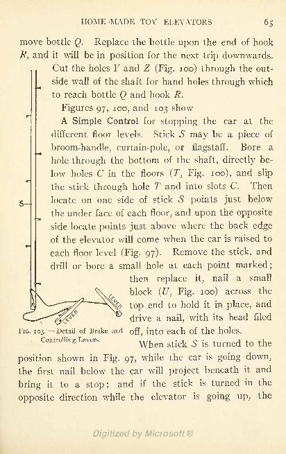
HOME-MADE TOY ELEVATORS 65
move bottle Q. Replace the bottle upon the end of hook
R, and it will be in position for the next trip downwards.
Cut the holes F and Z (Fig. 100) through the out-
side wall of the shaft for hand holes through which
to reach bottle Q and hook R.
Figures 97, 100, and 103 show
A Simple Control for stopping the car at the
different floor levels. Stick 5 may be a piece of
broom-handle, curtain-pole, or flagstaff. Bore a
hole through the bottom of the shaft, directly be-
low holes C in the floors (T, Fig. 100), and slip
the stick through hole T and into slots C. Then
locate on one side of stick 5 points just below
the under face of each floor, and upon the opposite
side locate points just above where the back edge
of the elevator will come when the car is raised to
each floor level (Fig. 97). Remove the stick, and
drill or bore a small hole at each point marked;
then replace it, nail a small
block (U, Fig. 100) across the
top end to hold it in place, and
drive a nail, with its head filed
FIG. 103. --Detail of Brake and off, into each of the holes.
Controlling Levers. ^^ ^.^ ^ ^ tumed t() ^position shown in Fig. 97, while the car is going down,
the first nail below the car will project beneath it and
bring it to a stop; and if the stick is turned in the
opposite direction while the elevator is going up, the
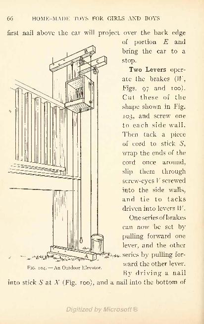
66 HOME-MADE TOYS FOR GIRLS AND BOYS
first nail above the car will project over the back edge
of portion E and
bring the car to a
stop.
Two Levers oper-
ate the brakes (IF,
Figs. 97 and 100).
Cut these of the
shape shown in Fig.
103, and screw one
to each side wall.
Then tack a piece
of cord to stick S,
wrap the ends of the
cord once around,
slip them through
screw-eyes V screwed
into the side walls,
and tie to tacks
driven into levers W.
One series of brakes
can now be set by
pulling forward one
lever, and the other
FIG. 104. An Outdoor Elevator.
into
$''+* series by pulling
ward the other lever.
By driving a nail
stick S at X (Fig. 100), and a nail into the bottom of
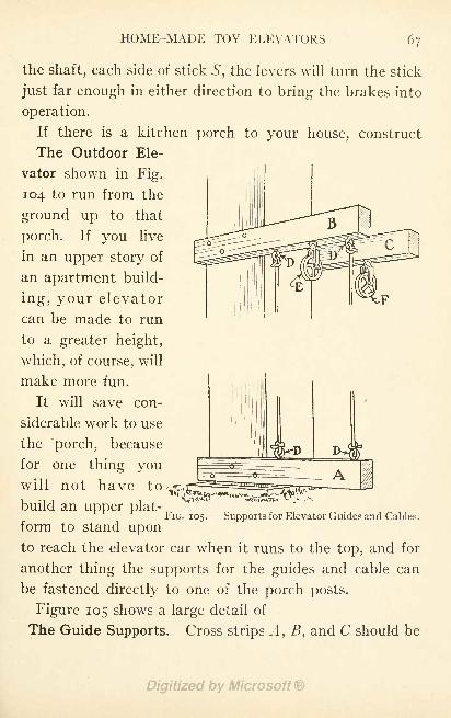
HOME-MADE TOY ELEVATORS
the shaft, each side of stick S, the levers will turn the stick
just far enough in either direction to bring the brakes into
operation.
If there is a kitchen porch to your house, construct
The Outdoor Ele-
vator shown in Fig.
104 to run from the
ground up to that
porch. If you live
in an upper story of
an apartment build-
ing, your elevator
can be made to run
to a greater height,
which, of course, will
make more fun.
It will save con-
siderable work to use
the porch, because
for one thing youwill not have to-,
build an upper plat-FIG. 105.
--Supports for Elevator Guides and Cables.
form to stand uponto reach the elevator car when it runs to the top, and for
another thing the supports for the guides and cable can
be fastened directly to one of the porch posts.
Figure 105 shows a large detail of
The Guide Supports. Cross strips A, B, and C should be
68 HOME-MADE TOYS FOR GIRLS AND BOYS
1 8 or 20 inches long, about 2 inches wide, and linch thick.
At a distance of about i inch from one end of strips A and
B screw a screw-eye into one edge, and 8 inches from those
eyes screw a second screw-eye (D, Fig. 105). Screw-eyes
with \ inch eyes are large enough. A dozen will cost about
5 cents at the hardward store. The elevator guides are
fastened to these.
Besides the screw-eyes there must be two clothes-line
pulleys for the cable to run over. These cost 5 cents
apiece. Screw one pulley into the edge of strip B, half-
way between the two screw-eyes D (E, Fig. 105), the other
into an edge of strip C at the same distance from the end
that you have placed the pulley in strip B (F y Fig. 105).
Nail strip A to the porch post as close to the ground as
you can get it, strip B to the same face of the same post,
about 1 8 inches above the porch railing, and strip C to the
opposite face of the post at the same height as strip B.
Nail these strips securely in place.
If you cannot find a starch-box or other small box out
of which to make
The Car, go to a grocery store. You will be sure to find
just what you want there. It is not likely that the grocer
will charge you anything for a small box like this. If
you have placed screw-eyes D 8 inches apart, as directed,
the width of the box should be a trifle less than this meas-
urement, but if the box you pick up is wider the screw-
eyes can be spaced as much farther apart as is necessary to
accommodate it.
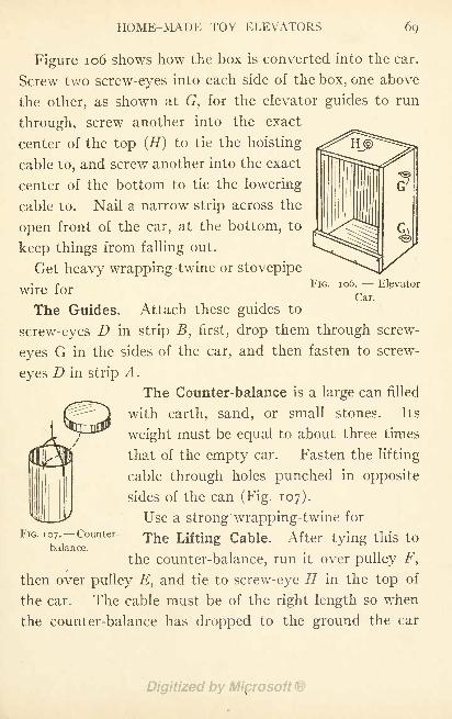
HOME-MADE TOY ELEVATORS 69
FIG. 1 06. - - Elevator
Car.
Figure 106 shows how the box is converted into the car.
Screw two screw-eyes into each side of the box, one above
the other, as shown at G, for the elevator guides to run
through, screw another into the exact
center of the top (H) to tie the hoisting
cable to, and screw another into the exact
center of the bottom to tie the lowering
cable to. Nail a narrow strip across the
open front of the car, at the bottom, to
keep things from falling out.
Get heavy wrapping-twine or stovepipe
wire for
The Guides. Attach these guides to
screw-eyes D in strip B, first, drop them through screw-
eyes G in the sides of the car, and then fasten to screw-
eyes D in strip A.
The Counter-balance is a large can filled
with earth, sand, or small stones. Its
weight must be equal to about three times
that of the empty car. Fasten the lifting
cable through holes punched in opposite
sides of the can (Fig. 107).
Use a strong wrapping-twine for
FIG. 107. -Counter- The Lifting Cable. After tying this tobalance.
the counter-balance, run it over pulley F,
then over pulley E, and tie to screw-eye // in the top of
the car. The cable must be of the right length so when
the counter-balance has dropped to the ground the car
70 HOME-MADE TOYS FOR GIRLS AND BOYS
will come just above the porch railing, as shown in
Fig. 104. Tie
The Lowering Cable to the screw-eye screwed into the
under side of the car.
As long as the weight of the car and its load remains
less than half of that of the counter-balance, the counter-
balance will drop and by so doing lift the car. The cable
attached to the bottom must be pulled to lower the car.
Those of you boys who own a tree-hut, or intend to build
one,1 should erect an elevator similar to the one just de-
scribed, for hoisting supplies to the hut.
1 Plans for building Tree-Huts, and a Dumb-Waiter for supplies, are
given in Chapter XXV of" The Handy Boy."
CHAPTER VIII
HOME-MADE MECHANICAL TOYS
THOSE of you boys who have examined the little mechan-
ical toys sold upon the street corners just before Christmas
probably have been surprised to find how simply they are
made, and perhaps it has never occurred to you that you
might make toys equally as good for presents for your
younger brothers, sisters, or cousins. Most of the smaller
mechanical toys are not only easy to make, but they re-
quire materials which cost little and can usually be picked
up at home. Sometimes it takes considerable thinking
and planning to discover just the things which can be
adapted to the various parts of toys ;but that is where
part of the fun of toy making comes in.
A Buzz-Saw Whirligig is an interesting toy (Fig. 108).
Lay out a disk about 5 inches in diameter upon a piece of
cardboard, locate the position for the spool-end on the
center of each face, and make four rings outside of this.
Divide the circumference of the disk into sixteen equal
parts, and lay off the teeth as shown. (Fig. in.) The
spool-ends used for centers should have two holes drilled
through them for the twisting cord to slip through, and
should be fastened to the disk with glue or brads.
71
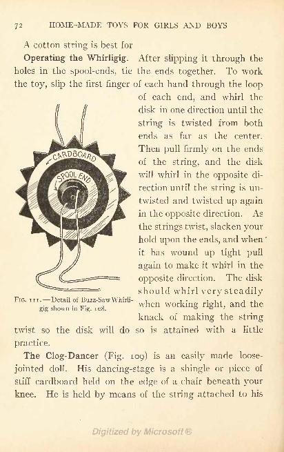
HOME-MADE TOYS FOR GIRLS AND BOYS
A cotton string is best for
Operating the Whirligig. After slipping it through the
holes in the spool-ends, tie the ends together. To work
the toy, slip the first finger of each hand through the loop
of each end, and whirl the
disk in one direction until the
string is twisted from both
ends as far as the center.
Then pull firmly on the ends
of the string, and the disk
will whirl in the opposite di-
rection until the string is un-
twisted and twisted up again
in the opposite direction. As
the strings twist, slacken your
hold upon the ends, and when
it has wound up tight pull
again to make it whirl in the
opposite direction. The disk
should whirl very steadily
when working right, and the
knack of making the string
twist so the disk will do so is attained with a little
practice.
The Clog-Dancer (Fig. 109) is an easily made loose-
jointed doll. His dancing-stage is a shingle or piece of
stiff cardboard held on the edge of a chair beneath your
knee. He is held by means of the string attached to his
FIG. in. Detail of Buzz-Saw Whirli-
gig shown in Fig. 108.
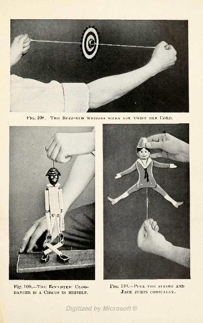
FIG. 108. THE BUZZ-SAW WHIZZES WHEN YOU TWIST THE CORD.
Fig. 109. THE ECCENTRIC CLOG-DANCER IS A CIRCUS IN HIMSELF.
FIG. 110. PULL THE STRING ANDJACK JUMPS COMICALLY.
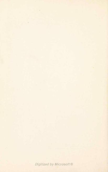
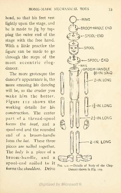
HOME-MADE MECHANICAL TOYS 73
head, so that his feet rest
lightly upon the stage, and
he is made to jig by tap-
ping the outer end of the
stage with the free hand.
With a little practice the
figure can be made to go
through the steps of the
most eccentric clog-
dancer.
The more grotesque the
dancer's appearance is, the
more amusing his dancing
will be, so the cruder youmake him the better.
Figure 112 shows the
working details for his
construction. The center
part of a thread-spoolforms the head, and a
spool-end and the rounded
end of a broom-handle
form the hat. These three
pieces are nailed together.
The body is a piece of a
broom-handle, and a
spool-end nailed to it
forms the shoulders. Drive
RING
-BROOM-HANDLE END
*- SPOOL- END
SPOOL
SPOOL- ENDNAIL
BROOM-HANDLE(6-1 N. LONG)
- 2-1 N. LONG
If -IN.LONG
2i-IN.LONG
Z-IN. LONG
FIG. 112. Details of Body of the Clog-
Dancer shown ii} Fig. 109.
74 HOME-MADE TOYS FOR GIRLS AND BOYS
a nail into the end of the body, tie a string to this, and
run the string up through the hole in the head, and out
through a hole in the^-"' "x
hat;
tie the string to a
fancy-work ring.
The arms and legs are
made of sticks whittled
to the lengths marked
in Fig. 112, and about
| inch in diameter, and
are jointed by driving
tacks into their ends
and connecting these
with heavy linen thread.
Figure 112 shows how
the feet and hands are
cut, and how tacks are
driven into them for the
thread connections.
Paint the clog-dancer's
body, arms, and legs
2- IN.WIDE white, his head, hands,FIG. 113. Details of Body of the Jumping- an(J feet black, and
Tack shown in Fig. no. 11-mark his eyes, nose,
and mouth upon his face in white.
A Toy Jumping-Jack is always amusing, and Fig. noshows a simply constructed home-made model. You will
see by Fig. 113 how the figure is made. The peaked hat
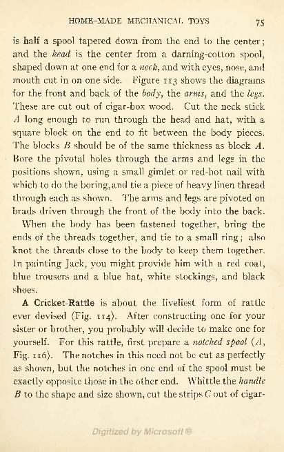
HOME-MADE MECHANICAL TOYS 75
is half a spool tapered down from the end to the center;
and the head is the center from a darning-cotton spool,
shaped down at one end for a neck, and with eyes, nose, and
mouth cut in on one side. Figure 113 shows the diagramsfor the front and back of the body, the arms, and the legs.
These are cut out of cigar-box wood. Cut the neck stick
A long enough to run through the head and hat, with a
square block on the end to fit between the body pieces.
The blocks B should be of the same thickness as block A.
Bore the pivotal holes through the arms and legs in the
positions shown, using a small gimlet or red-hot nail with
which to do the boring, and tie a piece of heavy linen thread
through each as shown. The arms and legs are pivoted on
brads driven through the front of the body into the back.
When the body has been fastened together, bring the
ends of the threads together, and tie to a small ring ;also
knot the threads close to the body to keep them together.
In painting Jack, you might provide him with a red coat,
blue trousers and a blue hat, white stockings, and black
shoes.
A Cricket-Rattle is about the liveliest form of rattle
ever devised (Fig. 114). After constructing one for your
sister or brother, you probably will decide to make one for
yourself. For this rattle, first prepare a notched spool (A,
Fig. 1 1 6). The notches in this need not be cut as perfectly
as shown, but the notches in one end of the spool must be
exactly opposite those in the other end. Whittle the handle
B to the shape and size shown, cut the strips C out of cigar-
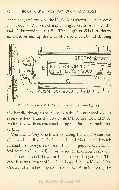
76 HOME-MADE TOYS FOR GIRLS AND BOYS
box wood, and prepare the block D as shown. The groove
in the edge of D is cut of just the right width to receive the
end of the wooden strip E. The length of E is best deter-
mined after nailing the ends of strips C to Z), and slipping
GROOVED
PIECE -OF-SHINGLE"OR -OTHER -THIN -WOOD D T
|c\i
li-IN.
^CIGAR-BOX -WOOD- 6-1 N. LONG!
FIG. 116. Details of the Noisy Cricket-Rattle shown Fig. 114.
the handle through the holes in strips C and spool A. It
should extend from the groove in D into the notches in A.
Make it as wide as the spool is high. Paint the rattle red
or blue.
The Turtle Toy which crawls along the floor when you
alternately pull and slacken a thread that runs through
its shell, has always been one of the most popular of mechan-
ical toys, and you will be surprised to find how easily our
home-made model shown in Fig. 1 1 5 is put together. The
shell is a small tin mold such as is used for molding jellies.
One about 4 inches long costs 10 cents. A mold having the
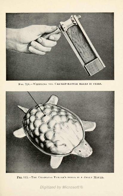
FIG. 114. WHIRLING THE CRICKET-RATTLE MAKES IT CHIRP.
FIG. 115. THE CRAWLING TURTLE'S SHELL is A JELLY MOULD.
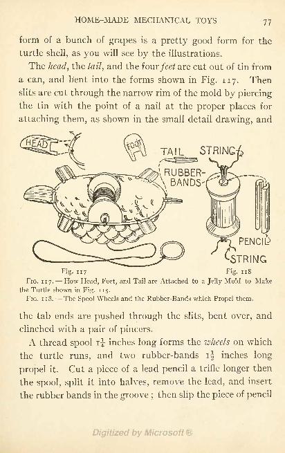
HOME-MADE MECHANICAL TOYS 77
form of a bunch of grapes is a pretty good form for the
turtle shell, as you will see by the illustrations.
The head, the tail, and the fourfeet are cut out of tin from
a can, and bent into the forms shown in Fig. 117. Then
slits are cut through the narrow rim of the mold by piercing
the tin with the point of a nail at the proper places for
attaching them, as shown in the small detail drawing, and
TAIL STRING
RUBBER-BANDS
PENCI&
STRINGFig. 117 Fig. 118
FIG. 117. How Head, Feet, and Tail are Attached to a Jelly Mold to Makethe Turtle shown in Fig. 115.
FIG. 1 1 8. - -The Spool Wheels and the Rubber-Bands which Propel them.
the tab ends are pushed through the slits, bent over, and
clinched with a pair of pincers.
A thread spool i| inches long forms the wheels on which
the turtle runs, and two rubber-bands ij inches long
propel it. Cut a piece of a lead pencil a trifle longer then
the spool, split it into halves, remove the lead, and insert
the rubber bands in the groove ;then slip the piece of pencil
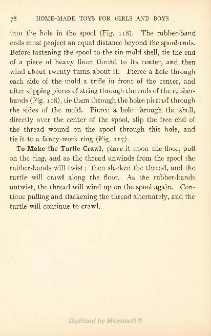
78 HOME-MADE TOYS FOR GIRLS AND BOYS
into the hole in the spool (Fig. 118). The rubber-band
ends must project an equal distance beyond the spool-ends.
Before fastening the spool to the tin mold shell, tie the end
of a piece of heavy linen thread to its center, and then
wind about twenty turns about it. Pierce a hole through
each side of the mold a trifle in front of the center, and
after slipping pieces of string through the ends of the rubber-
bands (Fig. 1 1 8), tie them through the holes pierced through
the sides of the mold. Pierce a hole through the shell,
directly over the center of the spool, slip the free end of
the thread wound on the spool through this hole, and
tie it to a fancy-work ring (Fig. 117).
To Make the Turtle Crawl, place it upon the floor, pull
on the ring, and as the thread unwinds from the spool the
rubber-bands will twist;then slacken the thread, and the
turtle will crawl along the floor. As the rubber-bands
untwist, the thread will wind up on the spool again. Con-
tinue pulling and slackening the thread alternately, and the
turtle will continue to crawl.
CHAPTER IX
HOME-MADE TOPS
THERE are many styles of tops, probably more than youever dreamed of, and it will surprise you to hear that the
owners of some of the most curious forms are bearded menwho take as much delight as any girl or boy in spinning
them. A few years ago on Murray Island, which is waydown among the South Sea Islands, top spinning took
such a strong hold upon the attention of the natives that
they neglected their work, and families often were without
food, boys and girls having to go to school hungry.
Matters became so serious, in fact, as a result of this fad
for top spinning, that, finally, the head chieftain was com-
pelled to restrict it to certain days. There are many ex-
perts among these South Sea Islanders. The men sing songs
while their tops spin, cheer them on, and take the greatest
precautions to shelter them from wind. An eye witness
of a contest reported that the winning top spun 27 min-
utes, which you must admit is a pretty long time.
Whip-tops and peg-tops of several varieties can be pur-
chased at the corner candy store, but the kinds I am
going to show you how to make cannot be bought any-
where.
79
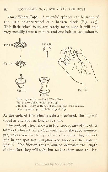
8o HOME-MADE TOYS FOR GIRLS AND BOYS
Clock Wheel Tops. A splendid spinner can be made of
the little balance-wheel of a broken clock (Fig. 119).
This little wheel is so accurately made that it will spin
very steadily from a minute and one-half to two minutes.
Fig. 119Fig. 121
Fig. i 20
Fig. 123
Fig. 124
FIGS. 119 and 120. Clock Wheel Tops.
FIG. 121. Upholstering Tack Top.FIG. 122. How to Hold Upholstering Tack for Spinning.
FIGS. 123 and 124. Details of Spool Top.
As the ends of this wheel's axle are pointed, the top will
stand in one spot as long as it spins.
The toothed wheel shown in Fig. 120, or any of the other
forms of wheels from a clockwork will make good spinners,
yet, unless you file their pivot ends to points, they will not
spin in one spot but will glide and hop over the table in
spirals. The friction thus produced decreases the length
of time that they will spin, but makes them none the less
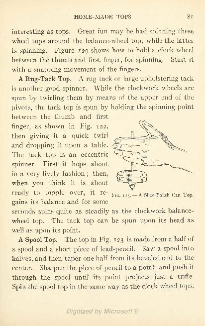
HOME-MADE TOPS 81
interesting as tops. Great fun may be had spinning these
wheel tops around the balance-wheel top, while the latter
is spinning. Figure 129 shows how to hold a clock wheel
between the thumb and first finger, for spinning. Start it
with a snapping movement of the fingers.
A Rug-Tack Top. A rug tack or large upholstering tack
is another good spinner. While the clockwork wheels are
spun by twirling them by means of the upper end of the
pivots, the tack top is spun by holding the spinning point
between the thumb and first
finger, as shown in Fig. 122,
then giving it a quick twirl
and dropping it upon a table.
The tack top is an eccentric
spinner. First it hops about
in a very lively fashion; then,
when you think it is about
ready to topple over, it re-FlG I25
V
_ A shoe.Polish Can Top .
gains its balance and for some
seconds spins quite as steadily as the clockwork balance-
wheel top. The tack top can be spun upon its head as
well as upon its point.
A Spool Top. The top in Fig. 123 is made from a half of
a spool and a short piece of lead-pencil. Saw a spool into
halves, and then taper one half from its beveled end to the
center. Sharpen the piece of pencil to a point, and push it
through the spool until its point projects just a trifle.
Spin the spool top in the same way as the clock wheel tops.
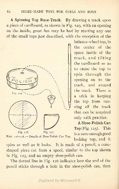
82 HOME-MADE TOYS FOR GIRLS AND BOYS
A Spinning Top Race-Track. By drawing a track upona piece of cardboard, as shown in Fig. 129, with an opening
on the inside, great fun may be had by starting any one
of the small tops just described, with the exception of the
balance-wheel top, in
the center of the
space inside of the
track, and tilting
the cardboard so as
to cause the top to
spin through the
opening on to the
track, and around
the track. There is
a trick in keeping
the top from run-
ning off the track
that can be acquired
only with practice.
A Shoe-Polish Can
Top (Fig. 125). This
is a sure-enough good
looking top, and it
spins as well as it looks. It is made of a pencil, a cone-
shaped piece cut from a spool, similar to the top shown
in Fig. 123, and an empty shoe-polish can.
The dotted line in Fig. 126 indicates how the end of the
pencil sticks through a hole in the shoe-polish can, then
Fig.
Fig. 128 Fig. 127
FIGS. 126-128. Details of Shoe-Polish Can Top.
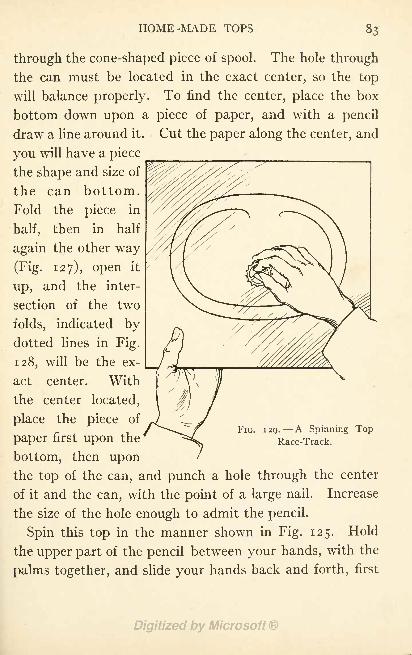
HOME-MADE TOPS
bottom,
piece in
through the cone-shaped piece of spool. The hole through
the can must be located in the exact center, so the top
will balance properly. To find the center, place the box
bottom down upon a piece of paper, and with a pencil
draw a line around it. Cut the paper along the center, and
you will have a piece
the shape and size of
the can
Fold the
half, then in half
again the other way
(Fig. 127), open it
up, and the inter-
section of the two
folds, indicated bydotted lines in Fig.
128, will be the ex-
act center. With
the center located,
place the piece of
paper first upon the
bottom, then uponthe top of the can, and punch a hole through the center
of it and the can, with the point of a large nail. Increase
the size of the hole enough to admit the pencil.
Spin this top in the manner shown in Fig. 125. Hold
the upper part of the pencil between your hands, with the
palms together, and slide your hands back and forth, first
\
FIG. 129. A Spinning TopRace-Track.
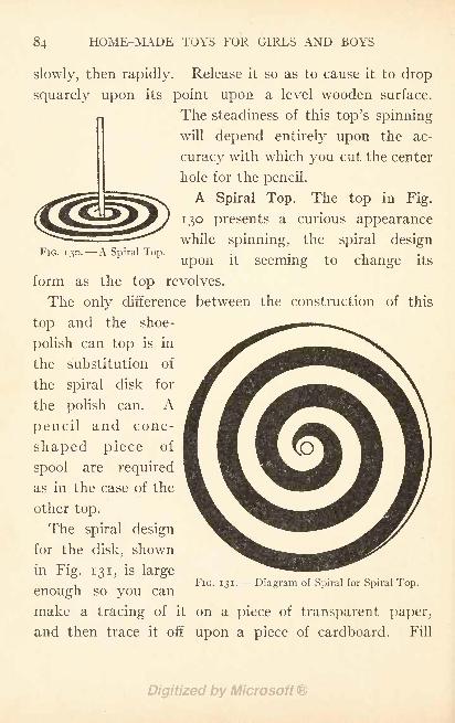
HOME-MADE TOYS FOR GIRLS AND BOYS
FIG. 130. A Spiral Top.
slowly, then rapidly. Release it so as to cause it to drop
squarely upon its point upon a level wooden surface.
The steadiness of this top's spinning
will depend entirely upon the ac-
curacy with which you cut the center
hole for the pencil.
A Spiral Top. The top in Fig.
130 presents a curious appearance
while spinning, the spiral design
upon it seeming to change its
form as the top revolves.
The only difference between the construction of this
top and the shoe-
polish can top is in
the substitution of
the spiral disk for
the polish can. A
pencil and cone-
shaped piece of
spool are required
as in the case of the
other top.
The spiral design
for the disk, shown
in Fig. 131, is large
enough so you can
make a tracing of it on a piece of transparent paper,
and then trace it off upon a piece of cardboard. Fill
FIG. 131. --Diagram of Spiral for Spiral Top.
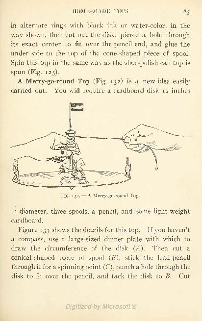
HOME-MADE TOPS
in alternate rings with black ink or water-color, in the
way shown, then cut out the disk, pierce a hole through
its exact center to fit over the pencil end, and glue the
under side to the top of the cone-shaped piece of spool.
Spin this top in the same way as the shoe-polish can top is
spun (Fig. 125).
A Merry-go-round Top (Fig. 132) is a new idea easily
carried out. You will require a cardboard disk 12 inches
FIG. 132. A Merry-go-round Top.
in diameter, three spools, a pencil, and some light-weight
cardboard.
Figure 133 shows the details for this top. If you haven't
a compass, use a large-sized dinner plate with which to
draw the circumference of the disk (^4). Then cut a
conical-shaped piece of spool (B), stick the lead-pencil
through it for a spinning point (C) , punch a hole through the
disk to fit over the pencil, and tack the disk to B. Cut
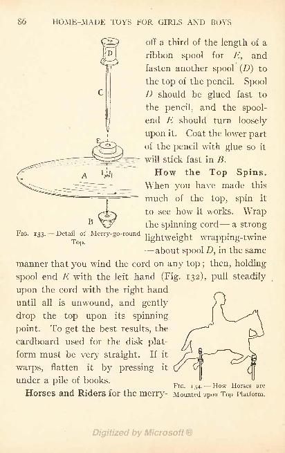
86 HOME-MADE TOYS FOR GIRLS AND BOYS
off a third of the length of a
ribbon spool for E, and
fasten another spool (D) to
the top of the pencil. Spool
D should be glued fast to
the pencil, and the spool-
end E should turn loosely
upon it. Coat the lower part
of the pencil with glue so it
will stick fast in B.
How the Top Spins.
When you have made this
much of the top, spin it
to see how it works. Wrapthe spinning cord - - a strong
FIG. 133. -Detail of Merry-go-round U htweight wrapping-twine.L OP
-about spool D, in the same
manner that you wind the cord on any top ; then, holding
spool end E with the left hand (Fig. 132), pull steadily
upon the cord with the right hand
until all is unwound, and gently
drop the top upon its spinning
point. To get the best results, the
cardboard used for the disk plat-
form must be very straight. If it
warps, flatten it by pressing it
under a pile of books.r IG. 1 34. How Horses are
Horses and Riders for the merry- Mounted upon Top platform.
B
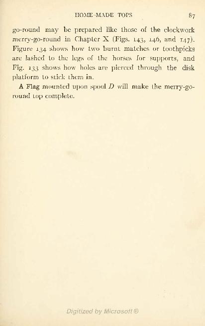
HOME-MADE TOPS 87
go-round may be prepared like those of the clockwork
merry-go-round in Chapter X (Figs. 143, 146, and 147).
Figure 134 shows how two burnt matches or toothpicks
are lashed to the legs of the horses for supports, and
Fig. 133 shows how holes are pierced through the disk
platform to stick them in.
A Flag mounted upon spool D will make the merry-go-
round top complete.
CHAPTER X
HOME-MADE CLOCKWORK TOYS
THE toys shown opposite page 90 are a few of the manymechanical toys which can be operated by clockwork,
and they are easy to make, too, requiring no more mechan-
ical ability than is possessed by the average boy old enough
to handle the simplest of tools.
Generally it is easy to find an old clock somewhere
about the house, and a clock which has been discarded
simply because it has become worthless as a timekeeper
is perfectly good for operating these toys, provided the
mainspring is in working order. It is not necessary to
have a set of works for each toy, for they are so quickly
fastened in place that but a minute is required to transfer
the works from one toy to another.
Before commencing work upon the toys, get together
The Other Necessary Materials. These will consist of
cigar boxes, cardboard, cotton or silk spools, glue, brads,
and a few pieces from the woodpile, with one or two ad-
ditional articles which are mentioned later on. Brads
| inch and i inch in length should be purchased for fas-
tening the framework of the toys together, and the cigar
boxes should be about 8 inches by 4 inches by 2 inches
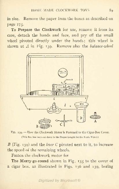
HOME-MADE CLOCKWORK TOYS
in size. Remove the paper from the boxes as described on
page 175.
To Prepare the Clockwork for use, remove it from its
case, detach the hands and face, and pry off the small
wheel pivoted directly under the hands;
this wheel is
shown at A in Fig. 139. Remove also the balance-wheel
FIG. 139. --How the Clockwork Motor is Fastened to the Cigar-Box Cover.
(This Box has been cut down to the Proper Length for the Ferris Wheel.)
B (Fig. 139) and the lever C pivoted next to it, to increase
the speed of the remaining wheels.
Fasten the clockwork motor for
The Merry-go-round shown in Fig. 135 to the cover of
a cigar box, as illustrated in Figs. 136 and 139, boring
90 HOME-MADE TOYS FOR GIRLS AND BOYS
holes through the cover with a gimlet for the pivot ends
on the back of the works to set into. Remove the lower
flange from a spool (Z>, Fig. 139) and fasten the spool
on to the central pivot of the clockwork in the position
formerly occupied by wheel A. The hole in the spool
will be too large for the pivot and must be filled up with
sealing-wax. To do this, hold a piece of sealing-wax
above the spool and melt it with a lighted match, allow-
ing it to drip into the hole until the latter is about half
full, then press the wax down with the end of a match
until it is compact, smooth it off on the bottom of the
spool, and make a dent in it with a pencil to indicate the
exact center of the hole. Heat the end of the pivot with
a lighted match, and press it into the dent in the wax,
being careful in doing so to get the spool straight uponthe pivot. Cut a hole through the bottom of the cigar
box belonging to the cover to which you have attached
the works, for spool D to project through (Fig. 139).
To Make the Standard for the merry-go-round, cut four
strips of wood 8 inches long, and fasten one to each corner
of the cigar box, turning the bottom side of the box up ;
then cut a piece of ^-inch board 10 inches square, locate its
center F by drawing diagonal lines from corner to corner
as shown in Fig. 140, bore a i-inch hole through it at this
point for spool D (Fig. 136), and then nail the box to the
center of the board as shown in Fig. 140.
The Tent should be laid out upon heavy white paper
as shown in Fig. 141. After describing a circle with a
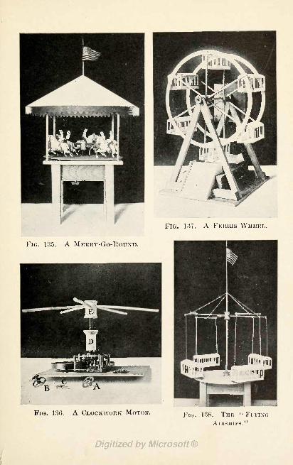
FIG. 137. A FERRIS WHEEL.
FIG. 135. A MERRY-GO-ROUND.
FIG. 136. A CLOCKWORK MOTOR. FIG. 138. THE "FLYINGAIRSHIPS."
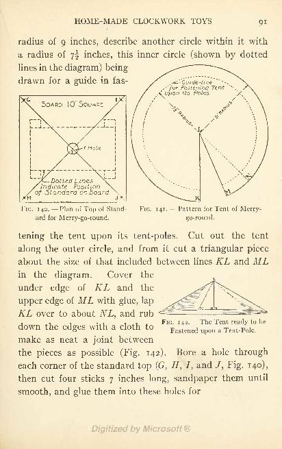
HOME-MADE CLOCKWORK TOYS
radius of 9 inches, describe another circle within it with
a radius of yf inches, this inner circle (shown by dotted
lines in the diagram) being
drawn for a guide in fas- Gutde-line,'for Fa.ste.nLDQ Tent
Dotttd LinesIndicate Posttt-c
Standard on -Board
FIG. 140. --Plan of Top of Stand-
ard for Merry-go-round.
FIG. 141. --Pattern for Tent of Merry-
go-round.
tening the tent upon its tent-poles. Cut out the tent
along the outer circle, and from it cut a triangular piece
about the size of that included between lines KL and MLin the diagram. Cover the
under edge of KL and the
upper edge of ML with glue, lap
KL over to about NL, and rub., , FIG. 142. The Tent ready to be
down the edges with a cloth toFastened upon a Tent.Pole .
make as neat a joint between
the pieces as possible (Fig. 142). Bore a hole through
each corner of the standard top (G1
, H, 7, and /, Fig. 140),
then cut four sticks 7 inches long, sandpaper them until
smooth, and glue them into these holes for
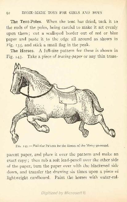
HOME-MADE TOYS FOR GIRLS AND BOYS
The Tent-Poles. When the tent has dried, tack it to
the ends of the poles, being careful to make it set evenly
upon them;
cut a scalloped border out of red or blue
paper and paste it to the edge all around as shown in
Fig. 135, and stick a small flag in the peak.
The Horses. A full-size pattern for these is shown in
Fig. 143. Take a piece of tracing-paper or any thin trans-
FIG. 143. --Full-size Pattern for the Horses of the Merry-go-round.
parent paper, and place it over the pattern and make an
exact copy ;then rub a soft lead-pencil over the other side
of the paper, turn the paper over with the blackened side
down, and transfer the drawing six times upon a piece of
lightweight cardboard. Paint the horses with water-col-
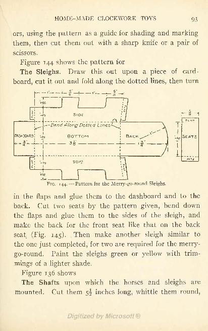
HOME-MADE CLOCKWORK TOYS 93
ors, using the pattern as a guide for shading and marking
them, then cut them out with a sharp knife or a pair of
scissors.
Figure 144 shows the pattern for
The Sleighs. Draw this out upon a piece of card-
board, cut it out and fold along the dotted lines, then turn
r
I- i -1
TFLAP
SEATS
i
P'IG. 144. Pattern for the Merry-go-round Sleighs.
in the flaps and glue them to the dashboard and to the
back. Cut two seats by the pattern given, bend down
the flaps and glue them to the sides of the sleigh, and
make the back for the front seat like that on the back
seat (Fig. 145). Then make another sleigh similar to
the one just completed, for two are required for the merry-
go-round. Paint the sleighs green or yellow with trim-
mings of a lighter shade.
Figure 136 shows
The Shafts upon which the horses and sleighs are
mounted. Cut them 5^ inches long, whittle them round,
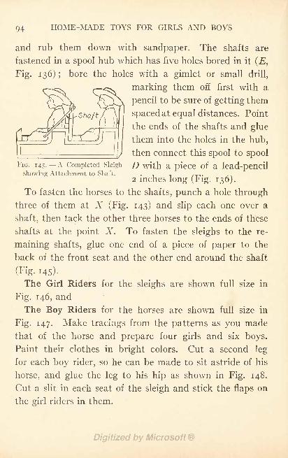
94 HOME-MADE TOYS FOR GIRLS AND BOYS
FIG. 145.-- A Completed Sleigh
showing Attachment to Shaft.
and rub them down with sandpaper. The shafts are
fastened in a spool hub which has five holes bored in it (E,
Fig. 136) ;bore the holes with a gimlet or small drill,
marking them off first with a
pencil to be sure of getting them
spaced at equal distances. Point
the ends of the shafts and glue
them into the holes in the hub,
then connect this spool to spool
D with a piece of a lead-pencil
2 inches long (Fig. 136).
To fasten the horses to the shafts, punch a hole through
three of them at X (Fig. 143) and slip each one over a
shaft, then tack the other three horses to the ends of these
shafts at the point X. To fasten the sleighs to the re-
maining shafts, glue one end of a piece of paper to the
back of the front seat and the other end around the shaft
(Fig. 145).
The Girl Riders for the sleighs are shown full size in
Fig. 146, and
The Boy Riders for the horses are shown full size in
Fig. 147. Make tracings from the patterns as you made
that of the horse and prepare four girls and six boys.
Paint their clothes in bright colors. Cut a second leg
for each boy rider, so he can be made to sit astride of his
horse, and glue the leg to his hip as shown in Fig. 148.
Cut a slit in each seat of the sleigh and stick the flaps on
the girl riders in them.
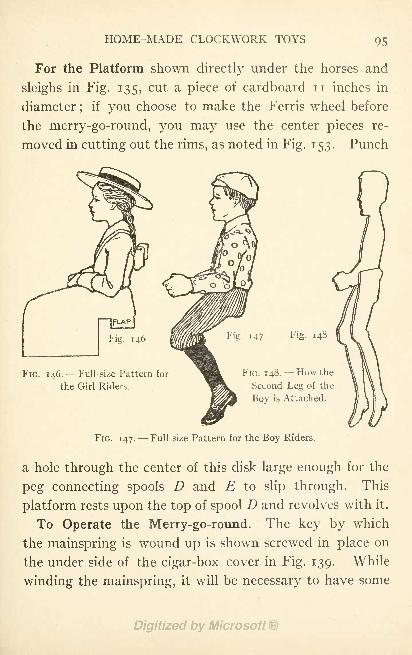
HOME-MADE CLOCKWORK TOYS 95
For the Platform shown directly under the horses and
sleighs in Fig. 135, cut a piece of cardboard n inches in
diameter;
if you choose to make the Ferris wheel before
the merry-go-round, you may use the center pieces re-
moved in cutting out the rims, as noted in Fig. 153. Punch
FIG. 146.-- Full-size Pattern for
the Girl Riders.
Fig. 147 Fig. 148
FIG. 148. --How the
Second Leg of the
Boy is Attached.
FIG. 147. Full-size Pattern for the Boy Riders.
a hole through the center of this disk large enough for the
peg connecting spools D and E to slip through. This
platform rests upon the top of spool D and revolves with it.
To Operate the Merry-go-round. The key by which
the mainspring is wound up is shown screwed in place on
the under side of the cigar-box cover in Fig. 139. While
winding the mainspring, it will be necessary to have some
96 HOME-MADE TOYS FOR GIRLS AND BOYS
means of checking it so it will not unwind at the same
time, and the best scheme for a check is to bore a small
gimlet hole through the cover of the cigar box and stick
a match through this and run it between the spokes of one
of the clock wheels so as to prevent it from turning. Then
when you have wound up the spring and are ready to start
the merry-go-round, all you have to do is to pull out the
match.
The model of this toy which the author has before him
runs for five minutes with one winding, and any boy can
make one which will run as well if he follows the directions
given and uses a reasonable amount of carefulness in the
work.
Other Animals than horses may be used if you wish to
follow the arrangement of some of the latest merry-go-
rounds, and pictures of these may be found among the
colored cut-outs sold in the stationery stores, or if you
can draw well, you may copy them from books and maga-zines. Great fun may be had by changing the positions
of the boy riders, making them ride backward part of the
time and sometimes two and three boys on a horse.
Doubtless you have heard of the famous Ferris wheel,
and a good many of you have ridden in the smaller wheels
patterned after it, at the amusement parks, so you will be
interested in makingA Miniature Ferris Wheel like the one shown in Fig.
137-
The Standard for supporting the wheel (Fig. 149)
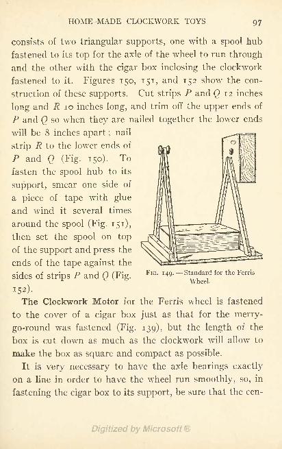
HOME-MADE CLOCKWORK TOYS 97
consists of two triangular supports, one with a spool hub
fastened to its top for the axle of the wheel to run through
and the other with the cigar box inclosing the clockwork
fastened to it. Figures 150, 151, and 152 show the con-
struction of these supports. Cut strips P and Q 12 inches
long and R 10 inches long, and trim off the upper ends of
P and Q so when they are nailed together the lower ends
will be 8 inches apart ;nail
strip R to the lower ends of
P and Q (Fig. 150). To
fasten the spool hub to its
support, smear one side of
a piece of tape with glue
and wind it several times
around the spool (Fig. 151),
then set the spool on top
of the support and press the
ends of the tape against the
Sides Of Strips P and Q (Fig.FlG " UP- - Standard for the Ferris
Wheel.
The Clockwork Motor for the Ferris wheel is fastened
to the cover of a cigar box just as that for the merry-
go-round was fastened (Fig. 139), but the length of the
box is cut down as much as the clockwork will allow to
make the box as square and compact as possible.
It is very necessary to have the axle bearings exactly
on a line in order to have the wheel run smoothly, so, in
fastening the cigar box to its support, be sure that the cen-
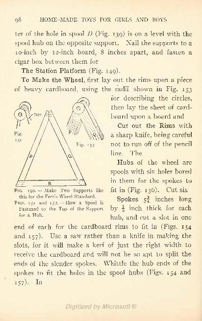
98 HOME-MADE TOYS FOR GIRLS AND BOYS
ter of the hole in spool D (Fig. 139) is on a level with the
spool hub on the opposite support. Nail the supports to a
lo-inch by 1 2-inch board, 8 inches apart, and fasten a
cigar box between them for
The Station Platform (Fig. 149).
To Make the Wheel, first lay out the rims upon a piece
of heavy cardboard, using the radii shown in Fig. 153
for describing the circles,
then lay the sheet of card-
board upon a board and
Cut out the Rims with
a sharp knife, being careful
not to run off of the pencil
line. The
Hubs of the wheel are
spools with six holes bored
in them for the spokes to
fit in (Fig. 156). Cut six
Spokes 5! inches long
by | inch thick for each
hub, and cut a slot in one
end of each for the cardboard rims to fit in (Figs. 154
and 157). Use a saw rather than a knife in making the
slots, for it will make a kerf of just the right width to
receive the cardboard and will not be so apt to split the
ends of the slender spokes. Whittle the hub ends of the
spokes to fit the holes in the spool hubs (Figs. 154 and
i57)-
FIG. 150.- - Make Two Supports like
this for the Ferris Wheel Standard.
FIGS. 151 and 152. How a Spool is
Fastened to the Top of the Support
for a Hub.
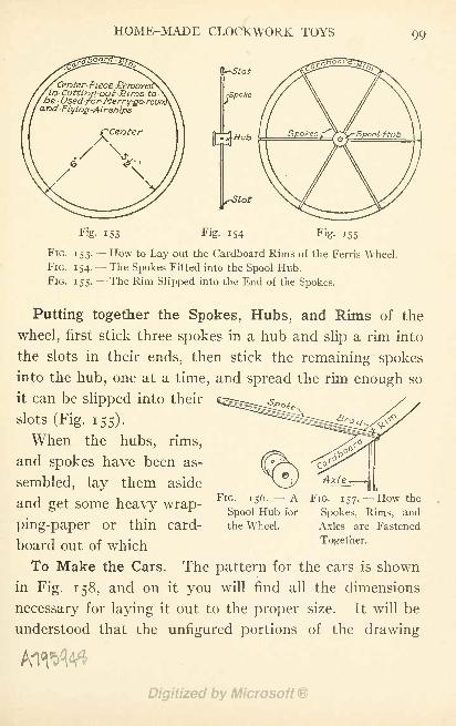
HOME-MADE CLOCKWORK TOYS 99
CuttinaUsed'
fo,
Flying-Airships
Used for-Merry-go-rov
-Slot
rSpoke
[Hub
Fig. 154 Fig. 155Fig. 153
FIG. 153. How to Lay out the Cardboard Rims of the Ferris Wheel.
FIG. 154.- -The Spokes Fitted into the Spool Hub.
FIG. 155.- -The Rim Slipped into the End of the Spokes.
Putting together the Spokes, Hubs, and Rims of the
wheel, first stick three spokes in a hub and slip a rim into
the slots in their ends, then stick the remaining spokes
into the hub, one at a time, and spread the rim enough so
it can be slipped into their
slots (Fig. 155).
When the hubs, rims,
and spokes have been as-
sembled, lay them aside
and get some heavy wrap-
ping-paper or thin card-
board out of which
To Make the Cars. The pattern for the cars is shown
in Fig. 158, and on it you will find all the dimensions
necessary for laying it out to the proper size. It will be
understood that the unfigured portions of the drawing
ASpool Hub for
the Wheel.
FIG. 157. How the
Spokes, Rims, and
Axles are Fastened
Together.
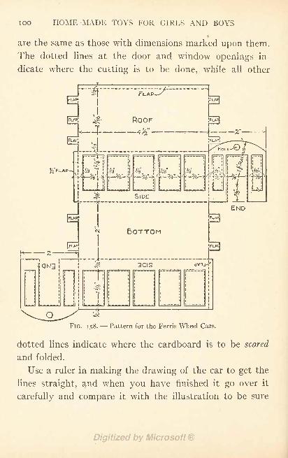
TOO HOME-MADE TOYS FOR GIRLS AND BOYS
i
are the same as those with dimensions marked upon them.
The dotted lines at the door and window openings in-
dicate where the cutting is to be done, while all other
FIG. 158.- -Pattern for the Ferris Wheel Cars.
dotted lines indicate where the cardboard is to be scored
and folded.
Use a ruler in making the drawing of the car to get the
lines straight, and when you have finished it go over it
carefully and compare it with the illustration to be sure
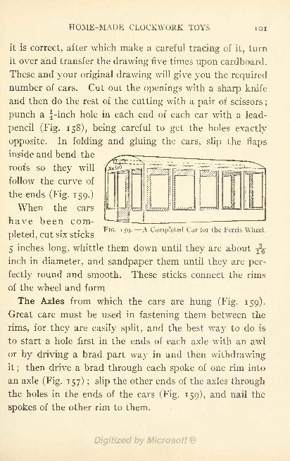
HOME-MADE CLOCKWORK TOYS IOI
it is correct, after which make a careful tracing of it, turn
it over and transfer the drawing five times upon cardboard.
These and your original drawing will give you the required
number of cars. Cut out the openings with a sharp knife
and then do the rest of the cutting with a pair of scissors;
punch a f-inch hole in each end of each car with a lead-
pencil (Fig. 158), being careful to get the holes exactly
opposite. In folding and gluing the cars, slip the flaps
inside and bend the
roofs so they will
follow the curve of
the ends (Fig. 159.)
When the cars
have been com-i j ,. , FIG. 159. A Completed Car for the Ferris Wheel.
pleted, cut six sticks
5 inches long, whittle them down until they are about YQ
inch in diameter, and sandpaper them until they are per-
fectly round and smooth. These sticks connect the rims
of the wheel and form
The Axles from which the cars are hung (Fig. 159).
Great care must be used in fastening them between the
rims, for they are easily split, and the best way to do is
to start a hole first in the ends of each axle with an awl
or by driving a brad part way in and then withdrawingit
;then drive a brad through each spoke of one rim into
an axle (Fig. 157) ; slip the other ends of the axles through
the holes in the ends of the cars (Fig. 159), and nail the
spokes of the other rim to them.
102 HOME-MADE TOYS FOR GIRLS AND BOYS
To Mount the Wheel upon its standard, whittle an axle
8^ inches long to fit the hubs, then hold the wheel between
the two uprights, with the hubs on a line with the spool
bearings and run the axle through the holes (Fig. 137).
Build Steps at each end of the platform out of heavy
writing-paper or light cardboard. Fold the paper or card-
board back and forth, making pleats about } inch wide for
the steps, and after gluing it in place cut out the balus-
trades and glue them to the edges of the steps. Make the
top step low enough so there will be about J-inch clearance
between it and the bottom of the cars (Fig. 137).
After you have made a final inspection to see that
everything has been put together properly, your toy will
be ready for operation, and I am sure that when you set
the clockwork machinery in motion, and the little wheel
begins to revolve slowly with each little car balancing
upon its axle, you will agree that you have constructed
a very interesting toy.
The "Flying Airships
'
is a riding device consisting of
a number of cars suspended by steel cables from large
arms pivoted to the top of a tower. When the machin-
ery is started, the arms begin to revolve slowly, and the
motion produced causes the cars to swing out away from
the center. As the speed of the arms increases, the cars
swing out farther and farther, until when the highest
speed has been reached the cables by which the cars are
suspended have taken an oblique position and raised the
cars some distance above the ground ;then the speed of
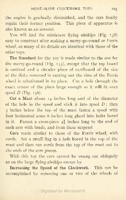
HOME-MADE CLOCKWORK TOYS 103
the engine is gradually diminished, and the cars finally
regain their former position. This piece of apparatus is
also known as an aerostat.
You will find the miniature flying airships (Fig. 138)
easy to construct after making a merry-go-round or Ferris
wheel, as many of its details are identical with those of the
other toys.
The Standard for the toy is made similar to the one for
the merry-go-round (Fig. 135), except that the top board
is omitted and a circular piece of cardboard of the size
of the disks removed in cutting out the rims of the Ferris
wheel is substituted in its place. Cut a hole through the
exact center of the piece large enough so it will fit over
spool D (Fig. 136).
Cut a Mast about 14 inches long and of the diameter
of the hole in the spool and stick it into spool D ;then
3 inches below the top of the mast fasten a spool with
four horizontal arms 6 inches long glued into holes bored
in it. Fasten a cross-piece 4^ inches long to the end of
each arm with brads, and from these suspend
Cars made similar to those of the Ferris wheel, with
cords. Set a small flag in a hole bored in the top of the
mast and then run cords from the top of the mast out to
the ends of the arm pieces.
With this toy the cars cannot be swung out obliquely
as on the large flying airships except by
Increasing the Speed of the Clockwork. This can be
accomplished by removing one or two of the wheels of
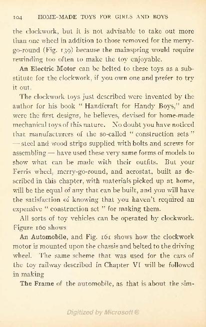
104 HOME-MADE TOYS FOR GIRLS AND BOYS
the clockwork, but it is not advisable to take out more
than one wheel in addition to those removed for the merry-
go-round (Fig. 139) because the mainspring would require
rewinding too often to make the toy enjoyable.
An Electric Motor can be belted to these toys as a sub-
stitute for the clockwork, if you own one and prefer to try
it out.
The clockwork toys just described were invented by the
author for his book "Handicraft for Handy Boys," and
were the first designs, he believes, devised for home-made
mechanical toys of this nature. No doubt you have noticed
that manufacturers of the so-called"construction sets
'
- steel and wood strips supplied with bolts and screws for
assembling- - have used these very same forms of models to
show what can be made with their outfits. But your
Ferris wheel, merry-go-round, and aerostat, built as de-
scribed in this chapter, with materials picked up at home,
will be the equal of any that can be built, and you will have
the satisfaction of knowing that you haven't required an
expensive"construction set
"for making them.
All sorts of toy vehicles can be operated by clockwork.
Figure 160 shows
An Automobile, and Fig. 161 shows how the clockwork
motor is mounted upon the chassis and belted to the driving
wheel. The same scheme that was used for the cars of
the toy railway described in Chapter VI will be followed
in makingThe Frame of the automobile, as that is about the sim-
FIG. 160. THE CAR COMPLETED.
FIG 161. THE FRAMEWORK.
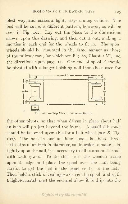
HOME-MADE CLOCKWORK TOYS 105
plest way, and makes a light, easy-running vehicle. The
bed will be cut of a different pattern, however, as will be
seen in Fig. 162. Lay out the piece to the dimensions
shown upon this drawing, and then cut it out, making a
mortise in each end for the wheels to fit in. The spool
wheels should be mounted in the same nanner as those
of the railway cars, for which see Fig. 80, Chapter VI, and
the directions upon page 51. One end of spool A should
be pivoted with a longer finishing nail than those used for
p
106 HOME-MADE TOYS FOR GIRLS AND BOYS
hole. When the hole has been partially filled, allow the
wax to harden a little, and then press it down around the
nail with the end of a match, being careful not to throw
the spool out of center by doing so. The hole should then
be filled to the top.
We are now ready to prepare the clock\vork for mount-
ing upon the wooden frame. The works shown in Fig. 161
are from an alarm clock, but if you have a striking clock,
or one with works a little different from those shown in the
illustration, it does not make a bit of difference in the
scheme for attaching the works. The three parts shown
in the foreground of Fig. 161 must first be removed from
the works. These will be recognized readily in any clock,
as they are pivoted close together, and regulate the speed
of the other wheels. When they have been removed, the
mainspring will unwind rapidly. The frame of the works
shown in the illustration is held together with nuts, so
that in removing the wheels it was necessary to unscrew
two of them, spring the frame open enough to let the
wheels drop out, and then replace the nuts again in their
former positions. If the frame of your clockwork is
riveted together, the wheels will have to be broken out.
A small silk spool, such as B (Fig. 162), should be fastened
upon the small pivot which originally operated the clock's
hands, for a belt-wheel. Lay the works upon a table with
the face-side down, and, after centering the hole of the spool
upon the pivot, fasten it in place with sealing-wax in the
same manner as you attached spool B (Fig. 161).
HOME-MADE CLOCKWORK TOYS 107
The works should now be attached to the wTooden
frame. Place them with the striker uppermost, near the
edge of the frame, so that the small belt-wheels are in
line with.one another. Then bore a number of gimlet
holes in the wooden frame and run copper wire through
them, passing it around the posts of the clock-frame and
twisting its ends until the works are firmly fastened in
place.
A rubber band about an eighth of an inch wide and long
enough to reach from one belt-wheel to the other should
be procured for
The Belt. This should stretch just enough to cling
upon the spools, as more than that would cause too much
friction.
Before going any further with the construction of the
automobile
Test the Machine, to be sure that it is in perfect running
order. Wind up the mainspring, pressing a finger against
one of the wheels to hold it in check until you are ready to
start the machine. When properly made, the clockwrork
automobile should run a distance of from twenty to twenty-
five feet upon a wooden floor, while about three-quarters
of that distance should be covered upon a floor with a fairly
smooth carpet.
The Cardboard Sides and other details of the auto-
mobile should now be made. The patterns for these have
been so shown in Figs 163 to 170 that they can easily be
laid out to the proper shape and size by means of the pro-
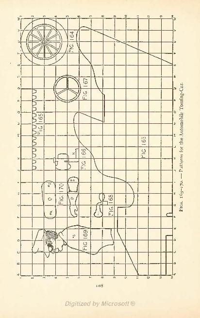
co
ou_
.0)
\
g
I
1
<um
1Ou_
OLU OS
- o
108
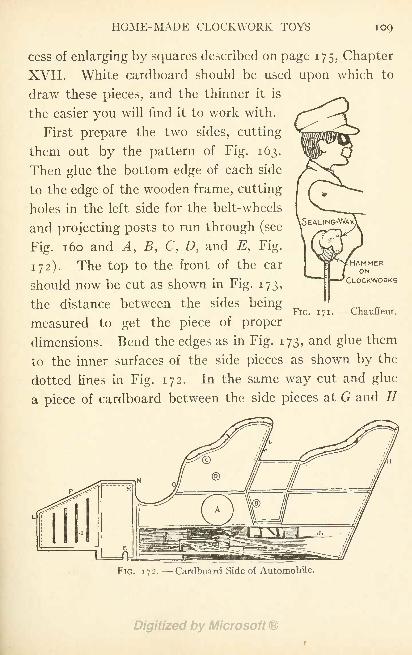
HOME-MADE CLOCKWORK TOYS 109
cess of enlarging by squares described on page 175, Chapter
XVII. White cardboard should be used upon which to
draw these pieces, and the thinner it is
the easier you will find it to work with.
First prepare the two sides, cutting
them out by the pattern of Fig. 163.
Then glue the bottom edge of each side
to the edge of the wooden frame, cutting
holes in the left side for the belt-wheels
and projecting posts to run through (see
Fig. 1 60 and A, B, C, D, and E, Fig.
172). The top to the front of the car
should now be cut as shown in Fig. 173,
the distance between the sides being
measured to get the piece of proper
dimensions. Bend the edges as in Fig. 173, and glue them
to the inner surfaces of the side pieces as shown by the
dotted lines in Fig. 172. In the same way cut and glue
a piece of cardboard between the side pieces at G and //
HAMMERON
CLOCKWORKS
FIG. 171.-- Chauffeur.
FIG. 1 72.- - Cardboard Side of Automobile.
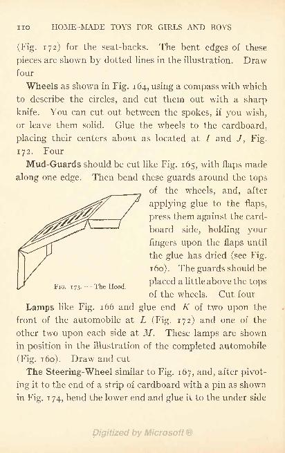
no HOME-MADE TOYS FOR GIRLS AND BOYS
(Fig. 172) for the seat-backs. The bent edges of these
pieces are shown by dotted lines in the illustration. Drawfour
Wheels as shown in Fig. 164, using a compass with which
to describe the circles, and cut them out with a sharp
knife. You can cut out between the spokes, if you wish,
or leave them solid. Glue the wheels to the cardboard,
placing their centers about as located at I and /, Fig.
172. Four
Mud-Guards should be cut like Fig. 165, with flaps made
along one edge. Then bend these guards around the tops
of the wheels, and, after
applying glue to the flaps,
press them against the card-
board side, holding your
fingers upon the flaps until
the glue has dried (see Fig.
1 60) . The guards should be
placed a little above the tops
of the wheels. Cut four
Lamps like Fig. 166 and glue end K of two upon the
front of the automobile at L (Fig. 172) and one of the
other two upon each side at M. These lamps are shown
in position in the illustration of the completed automobile
(Fig. 1 60). Draw and cut
The Steering-Wheel similar to Fig. 167, and, after pivot-
ing it to the end of a strip of cardboard with a pin as shown
in Fig. 1 74, bend the lower end and glue it to the under side
FIG. 173.- -The Hood.
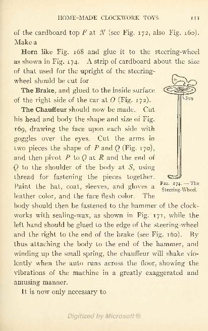
HOME-MADE CLOCKWORK TOYS in
of the cardboard top F at N (see Fig. 172, also Fig. 160).
Make a
Horn like Fig. 168 and glue it to the steering-wheel
as shown in Fig. 174. A strip of cardboard about the size
of that used for the upright of the steering-
wheel should be cut for
The Brake, and glued to the inside surface
of the right side of the car at (Fig. 172).
The Chauffeur should now be made. Cut
his head and body the shape and size of Fig.
169, drawing the face upon each side with
goggles over the eyes. Cut the arms in
two pieces the shape of P and Q (Fig. 170),
and then pivot P to Q at R and the end of
Q to the shoulder of the body at 51
, using
thread for fastening the pieces together.
Paint the hat, coat, sleeves, and gloves a
leather color, and the face flesh color. The
body should then be fastened to the hammer of the clock-
works with sealing-wax, as shown in Fig. 171, while the
left hand should be glued to the edge of the steering-wheel
and the right to the end of the brake (see Fig. 160). Bythus attaching the body to the end of the hammer, and
winding up the small spring, the chauffeur will shake vio-
lently when the auto runs across the floor, showing the
vibrations of the machine in a greatly exaggerated and
amusing manner.
It is now only necessary to

112 HOME-MADE TOYS FOR GIRLS AND BOYS
Paint the Machine to complete it. The photograph
(Fig. 1 60) shows where different colors are needed. The
lamps, top, ends, and sides of the front portion of the car
should be painted the color of brass, and the rest of the
sides, with the exception of a strip along the bottom and
the edge of the arms, should be painted vermilion. Paint
the inside of the car and the edges of the seat-arms tan
color, to represent leather upholstering. With black
paint, or ink, stripe off the door and trimmings upon the
sides and top of the machine, as shown in Figs. 160, 172,
and 173. Blacken the brake and steering-wheel and the
spokes and rims of the wheels. Along the bottom of each
side glue a strip of cardboard for the running-boards.
When you have tired of your touring-car, you can easily
convert it into
An Automobile Delivery Wagon, such as illustrated in
Fig. 175. To make this you will require the same frame
as that used for the touring-car, with the clockworks and
belt-wheels attached in the same manner. If you have
made the touring-car, remove the cardboard sides from its
wooden frame, separating the cardboard from the wood
carefully so you can put the machine together again when
you wish. If you haven't made this automobile, you will
find the details for the construction of the frame in Figs.
161 and 162, and the manner of performing the work
described on pages 104 to 107.
The Cardboard Sides are much easier to prepare than
those for the touring-car, as they are straight and require
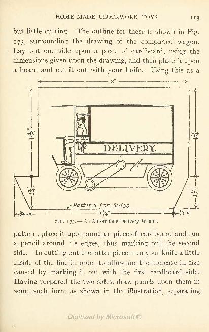
HOME-MADE CLOCKWORK TOYS
but little cutting. The outline for these is shown in Fig.
175, surrounding the drawing of the completed wagon.
Lay out one side upon a piece of cardboard, using the
dimensions given upon the drawing, and then place it upona board and cut it out with your knife. Using this as a
t
DELIVERY;
/ Pattern for-Sidss
FIG. 175. An Automobile Delivery Wagon.
pattern, place it upon another piece of cardboard and run
a pencil around its edges, thus marking out the second
side. In cutting out the latter piece, run your knife a little
inside of the line in order to allow for the increase in size
caused by marking it out with the first cardboard side.
Having prepared the two sides, draw panels upon them in
some such form as shown in the illustration, separating
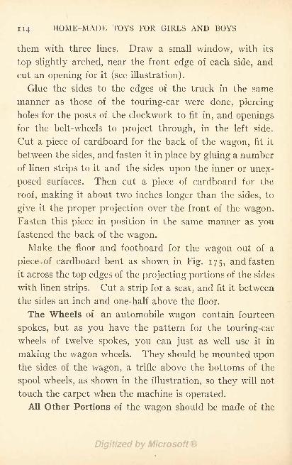
H4 HOME-MADE TOYS FOR GIRLS AND BOYS
them with three lines. Draw a small window, with its
top slightly arched, near the front edge of each side, and
cut an opening for it (see illustration).
Glue the sides to the edges of the truck in the same
manner as those of the touring-car were done, piercing
holes for the posts of the clockwork to fit in, and openings
for the belt-wheels to project through, in the left side.
Cut a piece of cardboard for the back of the wagon, fit it
between the sides, and fasten it in place by gluing a number
of linen strips to it and the sides upon the inner or unex-
posed surfaces. Then cut a piece of cardboard for the
roof, making it about two inches longer than the sides, to
give it the proper projection over the front of the wagon.
Fasten this piece in position in the same manner as youfastened the back of the wagon.
Make the floor and footboard for the wagon out of a
piece of cardboard bent as shown in Fig. 175, and fasten
it across the top edges of the projecting portions of the sides
with linen strips. Cut a strip for a seat, and fit it between
the sides an inch and one-half above the floor.
The Wheels of an automobile wagon contain fourteen
spokes, but as you have the pattern for the touring-car
wheels of twelve spokes, you can just as well use it in
making the wagon wheels. They should be mounted uponthe sides of the wagon, a trifle above the bottoms of the
spool wheels, as shown in the illustration, so they will not
touch the carpet when the machine is operated.
All Other Portions of the wagon should be made of the
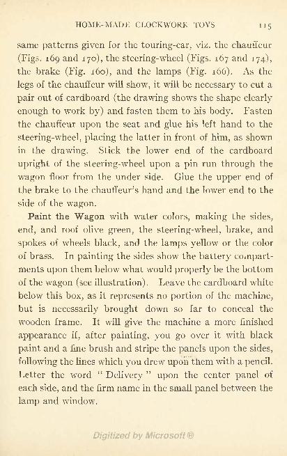
HOME-MADE CLOCKWORK TOYS 115
same patterns given for the touring-car, viz. the chauffeur
(Figs. 169 and 170), the steering-wheel (Figs. 167 and 174),
the brake (Fig. 160), and the lamps (Fig. 166). As the
legs of the chauffeur will show, it will be necessary to cut a
pair out of cardboard (the drawing shows the shape clearly
enough to work by) and fasten them to his body. Fasten
the chauffeur upon the seat and glue his left hand to the
steering-wheel, placing the latter in front of him, as shown
in the drawing. Stick the lower end of the cardboard
upright of the steering-wheel upon a pin run through the
wagon floor from the under side. Glue the upper end of
the brake to the chauffeur's hand and the lower end to the
side of the wagon.
Paint the Wagon with water colors, making the sides,
end, and roof olive green, the steering-wheel, brake, and
spokes of wheels black, and the lamps yellow or the color
of brass. In painting the sides show the battery compart-
ments upon them below what would properly be the bottom
of the wagon (see illustration). Leave the cardboard white
below this box, as it represents no portion of the machine,
but is necessarily brought down so far to conceal the
wooden frame. It will give the machine a more finished
appearance if, after painting, you go over it with black
paint and a fine brush and stripe the panels upon the sides,
following the lines which you drew upon them with a pencil.
Letter the word "Delivery
'
upon the center panel of
each side, and the firm name in the small panel between the
lamp and window.
Ti6 HOME-MADE TOYS FOR GIRLS AND BOYS
By attaching a set of clockworks in the same manner as
described for the automobiles, you can make
A Clockwork Railway, constructing the cars similar
to the street car shown in Fig. 84, Chapter VI, and using
the schemes in the same chapter for the tracks and depots.
Each car should be provided with a clockwork motor,
because a single clockwork is not strong enough to pull
more than one car. Let me know how you succeed in
building a clockwork railway.
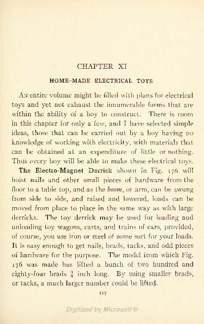
CHAPTER XI
HOME-MADE ELECTRICAL TOYS
AN entire volume might be filled with plans for electrical
toys and yet not exhaust the innumerable forms that are
within the ability of a boy to construct. There is room
in this chapter for only a few, and I have selected simple
ideas, those that can be carried out by a boy having no
knowledge of working with electricity, with materials that
can be obtained at an expenditure of little or nothing.
Thus every boy will be able to make these electrical toys.
The Electro-Magnet Derrick shown in Fig. 176 will
hoist nails and other small pieces of hardware from the
floor to a table top, and as the boom, or arm, can be swungfrom side to side, and raised and lowered, loads can be
moved from place to place in the same way as with large
derricks. The toy derrick may be used for loading and
unloading toy wagons, carts, and trains of cars, provided,
of course, you use iron or steel of some sort for your loads.
It is easy enough to get nails, brads, tacks, and odd pieces
of hardware for the purpose. The model from which Fig.
176 was made has lifted a bunch of two hundred and
eighty-four brads f inch long. By using smaller brads,
or tacks, a much larger number could be lifted.
117

n8 HOME-MADE TOYS FOR GIRLS AND BOYS
The first part of the toy to construct is
The Electro-Magnet. The difference between an electro-
magnet and the toy variety of horse-shoe magnet with
which every boy is familiar, is that the electro-magnet
retains its magnetism only so long as an electric current
FIG. 176. An Electro-Magnet Derrick.
is passing around it, while the steel magnet retains its
influence permanently, after being magnetized, unless it
happens to be demagnetized by subjection to heat, or in
some other way.
Figures 177 to 179 show the details for making a simple
home-made electro-magnet.
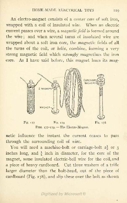
HOME-MADE ELECTRICAL TOYS 119
An electro-magnet consists of a center core of soft iron,
wrapped with a coil of insulated wire. When an electric
current passes over a wire, a magnetic field is formed around
the wire;and when several turns of insulated wire are
wrapped about a soft iron core, the magnetic fields of all
the turns of the coil, or helix, combine, forming a very
strong magnetic field which strongly magnetizes the iron
core. As I have said before, this magnet loses its mag-
Fig. 177 Fig. 179
FIGS. 177-179. --The Electro-Magnet.
Fig. 178
netic influence the instant the current ceases to pass
through the surrounding coil of wire.
You will need a machine-bolt or carriage-bolt 2^ or 3
inches long, and J inch in diameter, for the core of the
magnet, some insulated electric-bell wire for the coil, and
a piece of heavy cardboard. Cut three washers of a trifle
larger diameter than the bolt-head, out of the piece of
cardboard (Fig. 178), and slip these over the bolt as shown
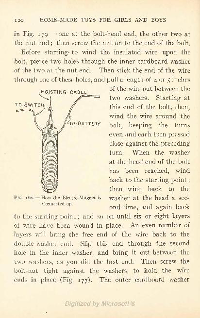
I2O HOME-MADE TOYS FOR GIRLS AND BOYS
HOISTING- CABLE
TO-SWITCH
TO 'BATTERY
in Fig. 179- -one at the bolt-head end, the other two at
the nut end;then screw the nut on to the end of the bolt.
Before starting* to wind the insulated wire upon the
bolt, pierce two holes through the inner cardboard washer
of the two at the nut end. Then stick the end of the wire
through one of these holes, and pull a length of 4 or 5 inches
of the wire out between the
two washers. Starting at
this end of the bolt, then,
wind the wire around the
bolt, keeping the turns
even and each turn pressed
close against the preceding
turn. When the washer
at the head end of the bolt
has been reached, wind
back to the starting point ;
then wind back to the
washer at the head a sec-
ond time, and again back
to the starting point ;and so on until six or eight layers
of wire have been wound in place. An even number of
layers will bring the free end of the wire back to the
double-washer end. Slip this end through the second
hole in the inner washer, and bring it out between the
two washers, as you did the first end. Then screw the
bolt-nut tight against the washers, to hold the wire
ends in place (Fig. 177). The outer cardboard washer
FIG. 180. How the Electro-Magnet is
Connected up.
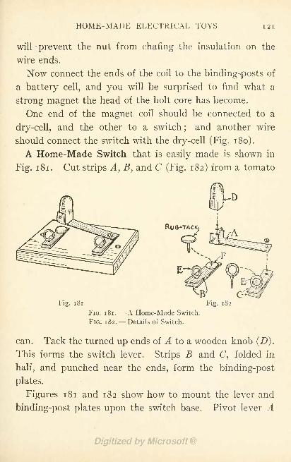
HOME-MADE ELECTRICAL TOYS 121
will prevent the nut from charing the insulation on the
wire ends.
Now connect the ends of the coil to the binding-posts of
a battery cell, and you will be surprised to find what a
strong magnet the head of the bolt core has become.
One end of the magnet coil should be connected to a
dry-cell, and the other to a switch;
and another wire
should connect the switch with the dry-cell (Fig. 180).
A Home-Made Switch that is easily made is shown in
Fig. 181. Cut strips A, B, and C (Fig. 182) from a tomato
RUG-
Fig. 181
FIG. 181. A Home-Made Switch.
FIG. 182. Details of Switch.
can. Tack the turned up ends of A to a wooden knob
This forms the switch lever. Strips B and C, folded in
half, and punched near the ends, form the binding-post
plates.
Figures 181 and 182 show how to mount the lever and
binding-post plates upon the switch base. Pivot lever A
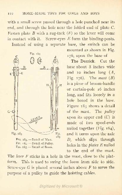
122 HOME-MADE TOYS FOR GIRLS AND BOYS
Fig. 184
with a small screw passed through a hole punched near its
end, and through the hole near the folded end of plate C.
Fasten plate B with a rug-tack (F) so the lever will come
in contact with it. Screw-eyes E form the binding-posts.
Instead of using a separate base, the switch can be
mounted as shown in Fig.
176, upon the base of.
The Derrick. Cut the
base about 8 inches wide
and 10 inches long (A,
Fig. 176). The mast (B)
is a piece of broom-handle
or curtain-pole 16 inches
long, and fits loosely in a
hole bored in the base.
Figure 183 shows a detail
of the mast. The pulley
upon its upper end (C) is
made of two spool-ends
nailed together (Fig. 184),
and it turns upon the axle
D, which slips through
holes in the plates E nailed
to the end of the mast.
The lever F sticks in a hole in the mast, close to the plat-
form. This is used to swing the boom from side to side.
Screw-eye G is placed several inches above F to serve the
purpose of a pulley to guide the hoisting cables.
Fig. 183
FIG. 183. Detail of Mast.
FIG. 184. Detail of Pulley.
FIG. 185. Detail of Boom.
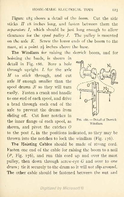
HOME-MADE ELECTRICAL TOYS 123
Figure 185 shows a detail of the boom. Cut the side
sticks H 1 8 inches long, and fasten between them the
separators I, which should be just long enough to allow
clearance for the spool pulley J . The pulley is mounted
on the axle K. Screw the lower ends of the boom to the
mast, at a point 2\ inches above the base.
The Windlass for raising the derrick boom, and for
hoisting the loads, is shown in
detail in Fig. 186. Bore a hole
through upright L for the axle
M to stick through, and cut
axle M enough smaller than the
spool drums N so they will turn
easily. Fasten a crank and handle
to one end of each spool, and drive
a brad through each end of the
axle to prevent the drums from
sliding off. Cut four notches in
the inner flange of each spool, as
shown, and pivot the catches Oto the post L, in the positions indicated, so they may be
thrown into the notches to lock the windlass (Fig. 176).
The Hoisting Cables should be made of strong cord.
Fasten one end of the cable for raising the boom to a nail
(P, Fig. 176), and run this cord up and over the mast
pulley, then down through screw-eye G and over to one
drum;
tie it securely to the drum so it will not slip around.
The other cable should be fastened between the nut and
FIG. 1 86. --Detail of Derrick
Windlass.
124 HOME-MADE TOYS FOR GIRLS AND BOYS
washer of the magnet, as shown in Fig. 180, run up and
over the boom pulley J, then through screw-eye G, and
tied to the second drum.
Figure 176 shows how the dry-cell may be strapped to
the base board in front of the mast, and how the wires
that connect the electro-magnet, switch, and cell should
be twisted around the hoisting cable, part way, and the
remainder of their length allowed to hang. Be sure to cut
the wires long enough to reach from a table-top down to
the floor. Use flexible wire if you can get it.
By mounting the base upon spool wheels, your derrick
can be moved along a table-top. Spool-ends may be used
for the wheels, and can either be screwed to the edge of
the base, or be fastened upon axles as the wheels of the
Electric Motor Truck are fastened (Figs. 203 and 208).
How the Derrick Works. It is probably unnecessary to
explain that a load is picked up by throwing over the
switch lever to the contact point and closing the circuit,
and that it is dropped by throwing off the switch lever
and opening the circuit - which causes the electro-magnet
to lose its magnetism.
A Toy Shocking Machine. The little shocking machine
shown in Fig. 187 is a harmless toy with which you can
have an endless amount of fun when entertaining friends.
The shock it produces is not severe, but strong enough to
make your friend's arm and wrist muscles twitch, and
perhaps cause him to dance. Large shocking coils contract
the muscles to such an extent that it is impossible to let
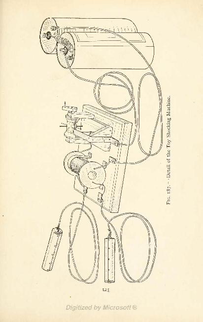
0>
c!
CJ
bOC3CJ
JCO
>>
(2D
H)
Q
00M
6
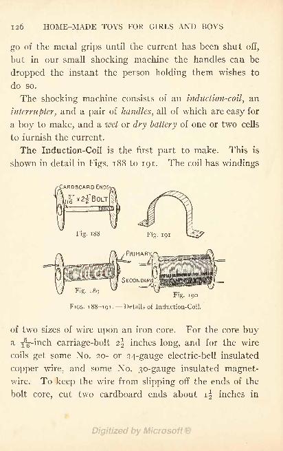
126 HOME-MADE TOYS FOR GIRLS AND BOYS
go of the metal grips until the current has been shut off,
but in our small shocking machine the handles can be
dropped the instant the person holding them wishes to
do so.
The shocking machine consists of an induction-coil, an
interrupter, and a pair of handles, all of which are easy for
a boy to make, and a wet or dry battery of one or two cells
to furnish the current.
The Induction-Coil is the first part to make. This is
shown in detail in Figs. 188 to 191. The coil has windings
CARDBOARD ENDS-;
\
?
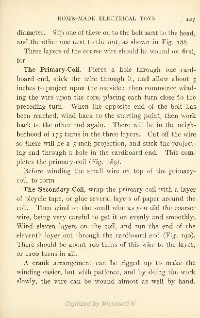
HOME-MADE ELECTRICAL TOYS 127
diameter. Slip one of these on to the bolt next to the head,
and the other one next to the nut, as shown in Fig. 188.
Three layers of the coarse wire should be wound on first,
for
The Primary-Coil. Pierce a hole through one card-
board end, stick the wire through it, and allow about 5
inches to project upon the outside;then commence wind-
ing the wire upon the core, placing each turn close to the
preceding turn. When the opposite end of the bolt has
been reached, wind back to the starting point, then work
back to the other end again. There will be in the neigh-
borhood of 175 turns in the three layers. Cut off the wire
so there will be a 5-inch projection, and stick the project-
ing end through a hole in the cardboard end. This com-
pletes the primary-coil (Fig. 189).
Before winding the small wire on top of the primary-
coil, to form
The Secondary-Coil, wrap the primary-coil with a layer
of bicycle tape, or glue several layers of paper around the
coil. Then wind on the small wire as you did the coarser
wire, being very careful to get it on evenly and smoothly.
Wind eleven layers on the coil, and run the end of the
eleventh layer out through the cardboard end (Fig. 190).
There should be about 100 turns of this wire to the layer,
or noo turns in all.
A crank arrangement can be rigged up to make the
winding easier, but with patience, and by doing the work
slowly, the wire can be wound almost as well by hand.
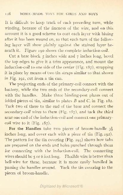
128 HOME-MADE TOYS FOR GIRLS AND BOYS
It is difficult to keep track of each preceding turn, while
winding, because of the fineness of the wire, and on this
account it is a good scheme to coat each layer with bluing
after it has been wound on, so that each turn of the follow-
ing layer will show plainly against the stained layer be-
neath it. Figure 190 shows the complete induction-coil.
Cut a base block 5 inches wide and 7 inches long, bevel
the top edges to give it a trim appearance, and mount the
induction-coil to one side of the center (Fig. 187), strapping
it in place by means of two tin straps similar to that shown
in Fig. 191, cut from a tin can.
The projecting ends of the primary-coil connect with the
battery, while the two ends of the secondary-coil connect
with the handles. Make three binding-post plates out of
folded pieces of tin, similar to plates B and C, in Fig. 182.
Tack two of these to the end of the base and connect the
secondary-coil wires to them (Fig. 187), and tack the third
near one end of the induction-coil and connect one primary-
coil wire to it (Fig. 187).
For the Handles take two pieces of broom-handle 3^
inches long, and cover each with a piece of tin (Fig. 192).
The pattern for the tin covering (Fig. 193) shows how tabs
are prepared on the ends and holes punched through them
for connecting with the induction-coil. The connecting
wires should be 5 or 6 feet long. Flexible wire is better than
bell-wire for these, because it is more easily handled in
passing the handles around. Tack the tin covering to the
pieces of broom-handle.

HOME-MADE ELECTRICAL TOYS 129
Fig. 192
Fig. 193
FIGS. 192 and 193. --Details of Shocking-Coil Handles.
The purpose of the induction-coil is to raise the voltage
of the battery. The flow of current must be an interrupted
one, in order to shock, and therefore
An Interrupter must be inserted between the battery
and one of the wires leading to the primary-coil of the in-
duction-coil. There are several ways to construct an
interrupter, but
the scheme which -CONNECT WIRE-FROM
I have invented
for the model of
this shocking-ma-
chine (Fig. 187)
serves the purpose
nicely, and is a
neat appearinglittle piece of ap-
paratus. This interrupter is easily constructed as you will
see by the working details shown in Figs. 194 to 198.
PRIMARY-COILHEREN
CONNECTBATTERYWIREHERE
FIG. 194. Interrupter for Shocking-Coil.
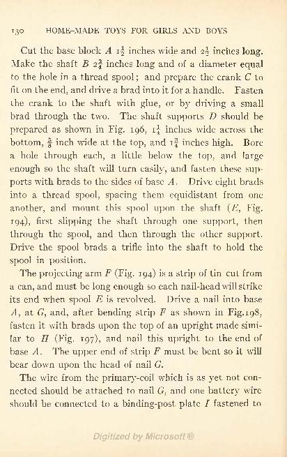
130 HOME-MADE TOYS FOR GIRLS AND BOYS
Cut the base block A ij inches wide and z\ inches long.
Make the shaft B 2% inches long and of a diameter equal
to the hole in a thread spool ;and prepare the crank C to
fit on the end, and drive a brad into it for a handle. Fasten
the crank to the shaft with glue, or by driving a small
brad through the two. The shaft supports D should be
prepared as shown in Fig. 196, i| inches wide across the
bottom, |- inch wide at the top, and if inches high. Bore
a hole through each, a little below the top, and large
enough so the shaft will turn easily, and fasten these sup-
ports with brads to the sides of base A. Drive eight brads
into a thread spool, spacing them equidistant from one
another, and mount this spool upon the shaft (E, Fig.
194), first slipping the shaft through one support, then
through the spool, and then through the other support.
Drive the spool brads a trifle into the shaft to hold the
spool in position.
The projecting arm F (Fig. 194) is a strip of tin cut from
a can, and must be long enough so each nail-head will strike
its end when spool E is revolved. Drive a nail into base
A, at G, and, after bending strip F as shown in Fig. 198,
fasten it with brads upon the top of an upright made simi-
lar to H (Fig. 197), and nail this upright to the end of
base A. The upper end of strip F must be bent so it will
bear down upon the head of nail G.
The wire from the primary-coil which is as yet not con-
nected should be attached to nail G, and one battery wire
should be connected to a binding-post plate I fastened to
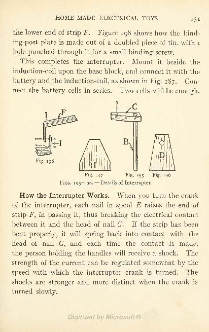
HOME-MADE ELECTRICAL TOYS
the lower end of strip F. Figure 198 shows how the bind-
ing-post plate is made out of a doubled piece of tin, with a
hole punched through it for a small binding-screw.
This completes the interrupter. Mount it beside the
induction-coil upon the base block, and connect it with the
battery and the induction-coil, as shown in Fig. 187. Con-
nect the battery cells in series. Two cells will be enough.
B\
Fig. 198
Fig. 197 Fig. 195 Fig. 196
FIGS. 195-198. --Details of Interrupter.
How the Interrupter Works. When you turn the crank
of the interrupter, each nail in spool E raises the end of
strip F, in passing it, thus breaking the electrical contact
between it and the head of nail G. If the strip has been
bent properly, it will spring back into contact with the
head of nail G, and each time the contact is made,
the person holding the handles will receive a shock. The
strength of the current can be regulated somewhat by the
speed with which the interrupter crank is turned. The
shocks are stronger and more distinct when the crank is
turned slowly.
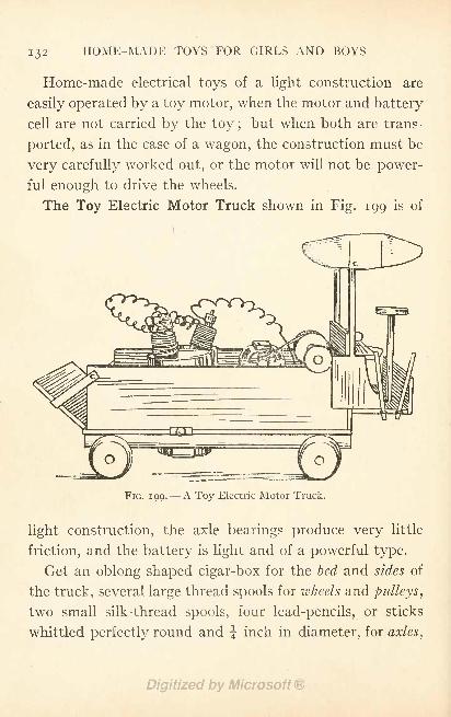
I 3 2 HOME-MADE TOYS FOR GIRLS AND BOYS
Home-made electrical toys of a light construction are
easily operated by a toy motor, when the motor and battery
cell are not carried by the toy ;but when both are trans-
ported, as in the case of a wagon, the construction must be
very carefully worked out, or the motor will not be power-
ful enough to drive the wheels.
The Toy Electric Motor Truck shown in Fig. 199 is of
FIG. 199. A Toy Electric Motor Truck.
light construction, the axle bearings produce very little
friction, and the battery is light and of a powerful type.
Get an oblong shaped cigar-box for the bed and sides of
the truck, several large thread spools for wheels and pulleys,
two small silk-thread spools, four lead-pencils, or sticks
whittled perfectly round and J inch in diameter, for axles,
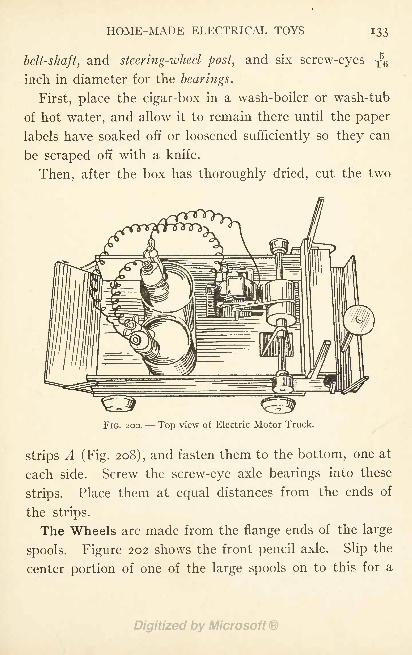
HOME-MADE ELECTRICAL TOYS
belt-shaft, and steering-wheel post, and six screw-eyes
inch in diameter for the bearings.
First, place the cigar-box in a wash-boiler or wash-tub
of hot water, and allow it to remain there until the paper
labels have soaked off or loosened sufficiently so they can
be scraped off with a knife.
Then, after the box has thoroughly dried, cut the two
FIG. 200. Top view of Electric Motor Truck.
strips A (Fig. 208), and fasten them to the bottom, one at
each side. Screw the screw-eye axle bearings into these
strips. Place them at equal distances from the ends of
the strips.
The Wheels are made from the flange ends of the large
spools. Figure 202 shows the front pencil axle. Slip the
center portion of one of the large spools on to this for a
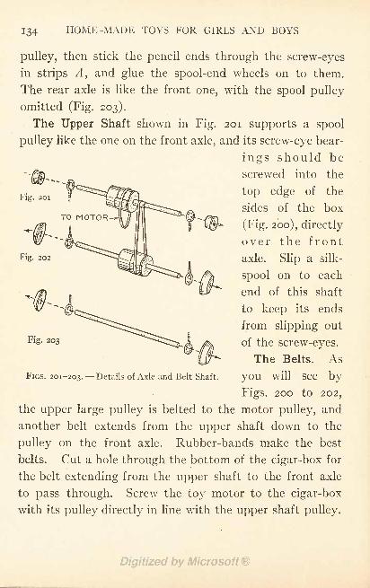
134 HOME-MADE TOYS FOR GIRLS AND BOYS
Fig. 201
Fig. 202
pulley, then stick the pencil ends through the screw-eyes
in strips A, and glue the spool-end wheels on to them.
The rear axle is like the front one, with the spool pulley
omitted (Fig. 203).
The Upper Shaft shown in Fig. 201 supports a spool
pulley like the one on the front axle, and its screw-eye bear-
ings should be
screwed into the
top edge of the
sides of the box
(Fig. 200), directly
over the front
axle. Slip a silk-
spool on to each
end of this shaft
to keep its ends
from slipping out^^N^.j.T**^^^^ 1 ^ of the screw-eyes.
The Belts. As
you will see by
Figs. 200 to 202,
the upper large pulley is belted to the motor pulley, and
another belt extends from the upper shaft down to the
pulley on the front axle. Rubber-bands make the best
belts. Cut a hole through the bottom of the cigar-box for
the belt extending from the upper shaft to the front axle
to pass through. Screw the toy motor to the cigar-box
with its pulley directly in line with the upper shaft pulley.
FIGS. 201-203. Details of Axle and Belt Shaft.
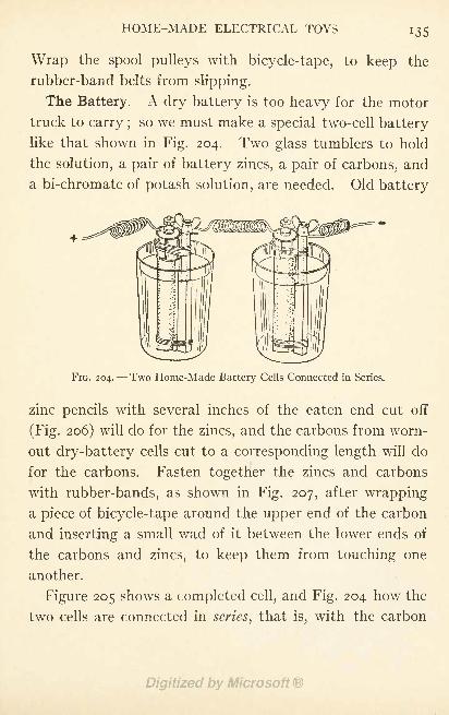
HOME-MADE ELECTRICAL TOYS 135
Wrap the spool pulleys with bicycle-tape, to keep the
rubber-band belts from slipping.
The Battery. A dry battery is too heavy for the motor
truck to carry ;so we must make a special two-cell battery
like that shown in Fig. 204. Two glass tumblers to hold
the solution, a pair of battery zincs, a pair of carbons, and
a bi-chromate of potash solution, are needed. Old battery
FIG. 204.- -Two Home-Made Battery Cells Connected in Series.
zinc pencils with several inches of the eaten end cut off
(Fig. 206) will do for the zincs, and the carbons from worn-
out dry-battery cells cut to a corresponding length will do
for the carbons. Fasten together the zincs and carbons
with rubber-bands, as shown in Fig. 207, after wrapping
a piece of bicycle-tape around the upper end of the carbon
and inserting a small wad of it between the lower ends of
the carbons and zincs, to keep them from touching one
another.
Figure 205 shows a completed cell, and Fig. 204 how the
two cells are connected in series, that is, with the carbon
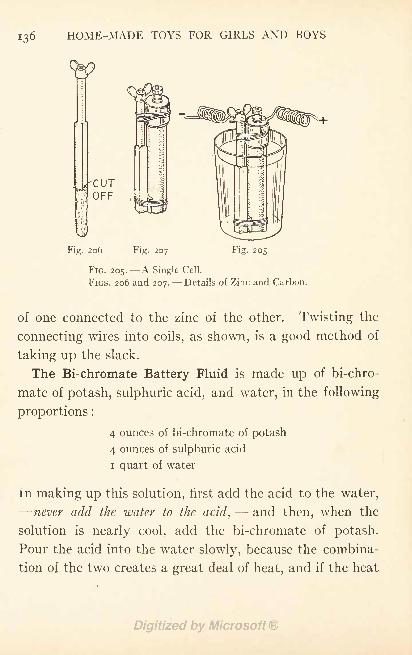
i36 HOME-MADE TOYS FOR GIRLS AND BOYS
CUTOFF
Fig. 206 Fig. 207 Fig. 205
FIG. 205. A Single Cell.
FIGS. 206 and 207. Details of Zinc and Carbon.
of one connected to the zinc of the other. Twisting the
connecting wires into coils, as shown, is a good method of
taking up the slack.
The Bi-chromate Battery Fluid is made up of bi-chro-
mate of potash, sulphuric acid, and water, in the following
proportions :
4 ounces of bi-chromate of potash
4 ounces of sulphuric acid
i quart of water
In making up this solution, first add the acid to the water,
-never add the water to the acid,- - and then, when the
solution is nearly cool, add the bi-chromate of potash.
Pour the acid into the water slowly, because the combina-
tion of the two creates a great deal of heat, and if the heat

HOME-MADE ELECTRICAL TOYS
Fig. 209
A'-
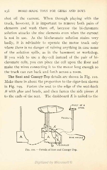
138 HOME-MADE TOYS FOR GIRLS AND BOYS
shut off the current. When through playing with the
truck, however, it is important to remove both pairs of
elements and wash them off, because the bi-chromate
solution attacks the zinc elements even when the current
is not in use. As the bi-chromate solution stains very
badly, it is advisable to operate the motor truck only
where there is no danger of ruining anything in case some
of the solution spills, as in the basement or workshop.
If you wish to use a dry-cell instead of the pair of bi-
chromate cells, you can place the cell upon the floor and
make the wires connecting it to the motor long enough so
the truck can run back and forth across a room.
The Seat and Canopy-Top details are shown in Fig. 210.
Make these in about the proportion to the cigar-box shown
in Fig. 199. Fasten the seat to the edge of the seat-back
B with glue and brads, and then fasten the side pieces A
to the ends of the seat. The dashboard E is nailed to the
PENCIL^
APIECE -OF ASPOOL
X"s"
N -----WIRE HANDLE
10 ^?STAPl_ES
Details of Seat and Canopy-Top.
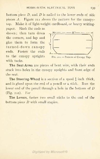
HOME-MADE ELECTRICAL TOYS 139
bottom piece D, and D is nailed to the lower ends of side
pieces A. Figure 211 shows the pattern for the canopy-
top. Make it of light-weight cardboard, or heavy writing-
paper. Slash the ends as
elT
LFIG. 211. Pattern of Canopy-Top.
shown;
then turn down
the corners, and lap and
glue them to form the
turned-down canopyends. Fasten the ends
to the canopy uprights
with tacks.
The Seat-Arms are pieces of bent wire, with their ends
stuck into holes in the canopy uprights and front edge of
the seat.
The Steering-Wheel is a section of a spool J inch thick,
and is glued upon the end of a pencil or a stick. Run the
lower end of the pencil through a hole in the bottom of D(Fig. 210). For
The Levers, fasten two small sticks to the end of the
bottom piece D with small staples.
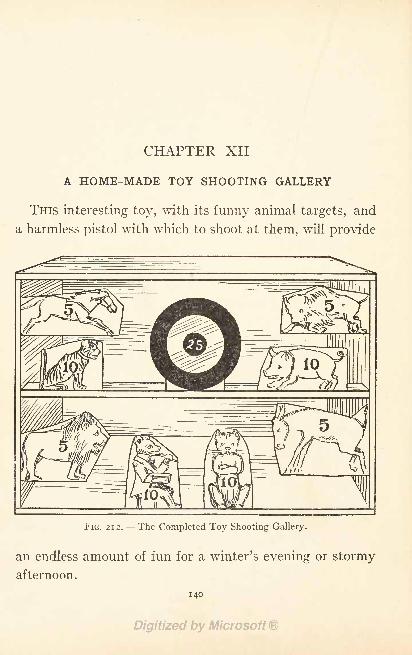
CHAPTER XII
A HOME-MADE TOY SHOOTING GALLERY
THIS interesting toy, with its funny animal targets, and
a harmless pistol with which to shoot at them, will provide
FIG. 2 1 2. --The Completed Toy Shooting Gallery.
an endless amount of fun for a winter's evening or stormy
afternoon.
140
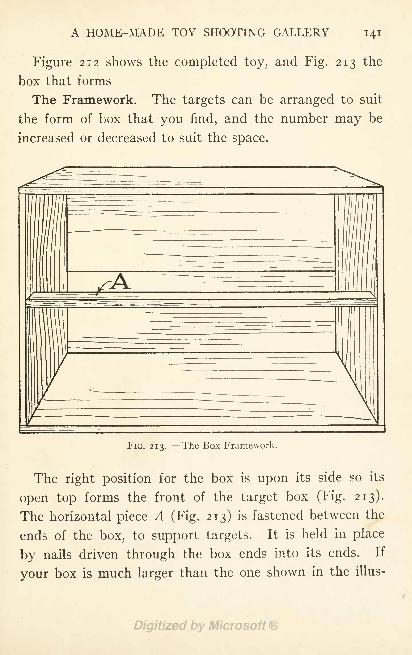
A HOME-MADE TOY SHOOTING GALLERY 141
Figure 212 shows the completed toy, and Fig. 213 the
box that forms
The Framework. The targets can be arranged to suit
the form of box that you find, and the number may be
increased or decreased to suit the space.
FIG. 213. --The Box Framework.
The right position for the box is upon its side so its
open top forms the front of the target box (Fig. 213).
The horizontal piece A (Fig. 213) is fastened between the
ends of the box, to support targets. It is held in place
by nails driven through the box ends into its ends. If
your box is much larger than the one shown in the illus-
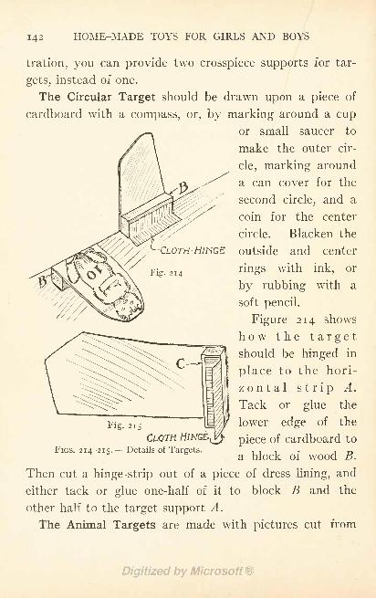
142 HOME-MADE TOYS FOR GIRLS AND BOYS
CLOTH -HINGE
Fig. 214
tration, you can provide two crosspiece supports for tar-
gets, instead of one.
The Circular Target should be drawn upon a piece of
cardboard with a compass, or, by marking around a cup
or small saucer to
make the outer cir-
cle, marking around
a can cover for the
second circle, and a
coin for the center
circle. Blacken the
outside and center
rings with ink, or
by rubbing with a
soft pencil.
Figure 214 shows-
how the targetshould be hinged in
place to the hori-
zontal strip A.
Tack or glue the
Fig. 215 IM//T lower edge of the
CLOTH HINGED pjece Of cardboard toFIGS. 214-215. Details of Targets. 111 r i T>
a block of wood B.
Then cut a hinge-strip out of a piece of dress lining, and
either tack or glue one-half of it to block B and the
other half to the target support A.
The Animal Targets are made with pictures cut from
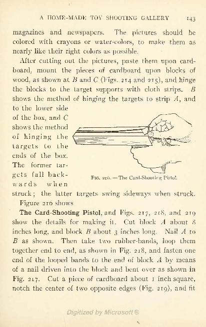
A HOME-MADE TOY SHOOTING GALLERY
magazines and newspapers. The pictures should be
colored with crayons or water-colors, to make them as
nearly like their right colors as possible.
After cutting out the pictures, paste them upon card-
board, mount the pieces of cardboard upon blocks of
wood, as shown at B and C (Figs. 214 and 215), and hinge
the blocks to the target supports with cloth strips. Bshows the method of hinging the targets to strip A, and
to the lower side
of the box, and Cshows the method
of hinging the
targets to the
ends of the box.
The former tar-
FIG. 216. --The Card-Shooting Pistol.gets fall back-
wards whenstruck
;the latter targets swing sideways when struck.
Figure 216 shows
The Card-Shooting Pistol, and Figs. 217, 218, and 219
show the details for making it. Cut block A about 8
inches long, and block B about 3 inches long. Nail A to
B as shown. Then take two rubber-bands, loop them
together end to end, as shown in Fig. 218, and fasten one
end of the looped bands to the end of block A by means
of a nail driven into the block and bent over as shown in
Fig. 217. Cut a piece of cardboard about i inch square,
notch the center of two opposite edges (Fig. 219), and fit
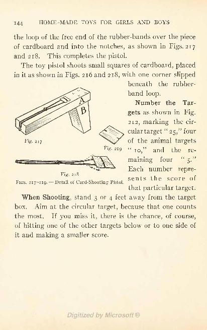
144 HOME-MADE TOYS FOR GIRLS AND BOYS
the loop of the free end of the rubber-bands over the piece
of cardboard and into the notches, as shown in Figs. 217
and 218. This completes the pistol.
The toy pistol shoots small squares of cardboard, placed
in it as shown in Figs. 216 and 218, with one corner slipped
beneath the rubber-
band loop.
Number the Tar-
gets as shown in Fig.
212, marking the cir-
cular target"25," four
^^sT>^>^ ^*7
Fig. 217 of the animal targetsFig. 219 "
10,'
Fig. 218
FIGS. 217-219. Detail of Card-Shooting Pistol.
and the re-
maining four"
5."
Each number repre-
sents the score of
that particular target.
When Shooting, stand 3 or 4 feet away from the target
box. Aim at the circular target, because that one counts
the most. If you miss it, there is the chance, of course,
of hitting one of the other targets below or to one side of
it and making a smaller score.
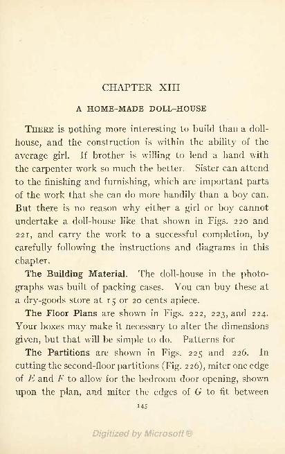
CHAPTER XIII
A HOME-MADE DOLL-HOUSE
THERE is nothing more interesting to build than a doll-
house, and the construction is within the ability of the
average girl. If brother is willing to lend a hand with
the carpenter work so much the better. Sister can attend
to the finishing and furnishing, which are important parts
of the work that she can do more handily than a boy can.
But there is no reason why either a girl or boy cannot
undertake a doll-house like that shown in Figs. 220 and
221, and carry the work to a successful completion, by
carefully following the instructions and diagrams in this
chapter.
The Building Material. The doll-house in the photo-
graphs was built of packing cases. You can buy these at
a dry-goods store at 15 or 20 cents apiece.
The Floor Plans are shown in Figs. 222, 223, and 224.
Your boxes may make it necessary to alter the dimensions
given, but that will be simple to do. Patterns for
The Partitions are shown in Figs. 225 and 226. In
cutting the second-floor partitions (Fig. 226), miter one edge
of E and F to allow for the bedroom door opening, shown
upon the plan, and miter the edges of G to fit between
MS
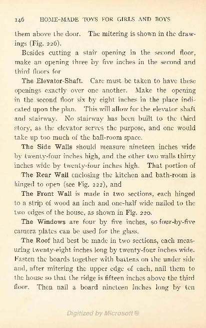
146 HOME-MADE TOYS FOR GIRLS AND BOYS
them above the door. The mitering is shown in the draw-
ings (Fig. 226).
Besides cutting a stair opening in the second floor,
make an opening three by five inches in the second and
third floors for
The Elevator-Shaft. Care must be taken to have these
openings exactly over one another. Make the opening
in the second floor six by eight inches in the place indi-
cated upon the plan. This will allow for the elevator shaft
and stairway. No stairway has been built to the third
story, as the elevator serves the purpose, and one would
take up too much of the ball-room space.
The Side Walls should measure nineteen inches wide
by twenty-four inches high, and the other two walls thirty
inches wide by twenty-four inches high. That portion of
The Rear Wall enclosing the kitchen and bath-room is
hinged to open (see Fig. 222), and
The Front Wall is made in two sections, each hinged
to a strip of wood an inch and one-half wide nailed to the
two edges of the house, as shown in Fig. 220.
The Windows are four by five inches, so four-by-five
camera plates can be used for the glass.
The Roof had best be made in two sections, each meas-
uring twenty-eight inches long by twenty-four inches wide.
Fasten the boards together with battens on the under side
and, after mitering the upper edge of each, nail them to
the house so that the ridge is fifteen inches above the third
floor. Then nail a board nineteen inches long by ten
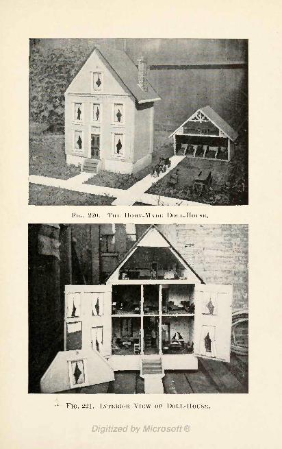
FIG. 220. THE HOME-MADE
FIG. 221. INTERIOR VIEW OF DOLL-HOUSE.
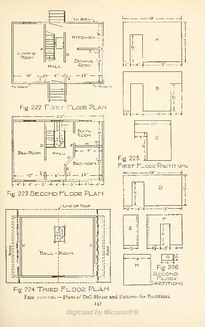
"TO
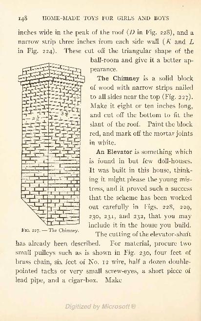
148 HOME-MADE TOYS FOR GIRLS AND BOYS
inches wide in the peak of the roof (D in Fig. 228), and a
narrow strip three inches from each side wall (K and Lin Fig. 224). These cut off the triangular shape of the
ball-room and give it a better ap-
pearance.
The Chimney is a solid block
of wood with narrow strips nailed
to all sides near the top (Fig. 227).
Make it eight or ten inches long,
and cut off the bottom to fit the
slant of the roof. Paint the block
red, and mark off the mortar joints
in white.
An Elevator is something which
is found in but few doll-houses.
It was built in this house, think-
ing it might please the young mis-
tress, and it proved such a success
that the scheme has been worked
out carefully in Figs. 228, 229,
230, 231, and 232, that you mayinclude it in the house you build.
The cutting of the elevator-shaftFIG. 227. --The Chimney.
has already been described. For material, procure two
small pulleys such as is shown in Fig. 230, four feet of
brass chain?six feet of No. 12 wire, half a dozen double-
pointed tacks or very small screw-eyes, a short piece of
lead pipe, and a cigar-box. Make
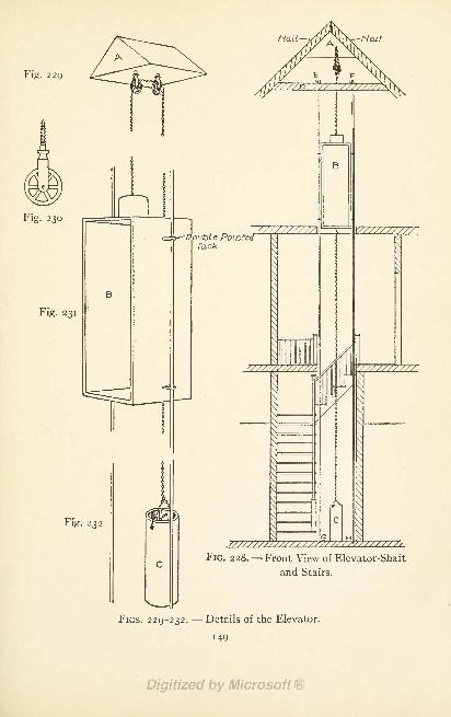
Fig. 229
Mait Hail
ig- 230
Fig. 231
Fig. 232
-DoubleTack
FIG. 228. Front View of Elevator-Shaft
and Stairs.
FIGS. 229-232.-- Details of the Elevator.
149
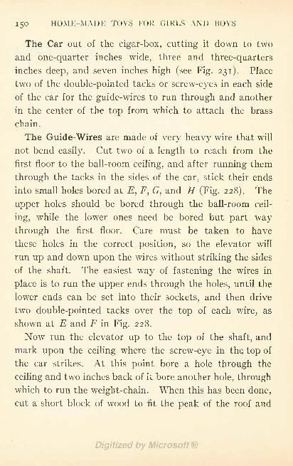
150 HOME-MADE TOYS FOR GIRLS AND BOYS
The Car out of the cigar-box, cutting it down to two
and one-quarter inches wide, three and three-quarters
inches deep, and seven inches high (see Fig. 231). Place
two of the double-pointed tacks or screw-eyes in each side
of the car for the guide-wires to run through and another
in the center of the top from which to attach the brass
chain.
The Guide-Wires are made of very heavy wire that will
not bend easily. Cut two of a length to reach from the
first floor to the ball-room ceiling, and after running them
through the tacks in the sides of the car, stick their ends
into small holes bored at E, F, G, and H (Fig. 228). The
upper holes should be bored through the ball-room ceil-
ing, while the lower ones need be bored but part way
through the first floor. Care must be taken to have
these holes in the correct position, so the elevator will
run up and down upon the wires without striking the sides
of the shaft. The easiest way of fastening the wires in
place is to run the upper ends through the holes, until the
lower ends can be set into their sockets, and then drive
two double-pointed tacks over the top of each wire, as
shown at E and F in Fig. 228.
Now run the elevator up to the top of the shaft, and
mark upon the ceiling where the screw-eye in the. top of
the car strikes. At this point bore a hole through the
ceiling and two inches back of it bore another hole, through
which to run the weight-chain. When this has been done,
cut a short block of wood to fit the peak of the roof and
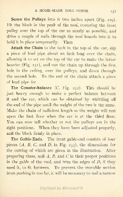
A HOME-MADE DOLL-HOUSE 151
Screw the Pulleys into it two inches apart (Fig. 229).
Fit the block in the peak of the roof, centering the front
pulley over the top of the car as nearly as possible, and
drive a couple of nails through the roof boards into it to
hold it in place temporarily. Then
Attach the Chain to the tack in the top of the car, slip
a piece of lead pipe about an inch long over the chain,
allowing it to set on the top of the car to make the latter
heavier (Fig. 231), and run the chain up through the first
hole in the ceiling, over the pulleys, and down through
the second hole. To the end of the chain attach a piece
of lead pipe for
The Counter-balance (C, Fig. 232). This should be
just heavy enough to make a perfect balance between
it and the car, which can be obtained by whittling off
the end of the pipe until the weight of the two is the same.
Make the chain of sufficient length so the weight will rest
upon the first floor when the car is at the third floor.
You can now tell whether or not the pulleys are in the
right positions. When they have been adjusted properly,
nail the block firmly in place.
The Gable-Ends. The front gable-end consists of four
pieces (A, B, C, and D, in Fig. 233), the dimensions for
the cutting of which are given in the illustration. After
preparing these, nail A, B, and C in their proper positions
in the gable of the roof, and trim the edges of Z), if they
need it, to fit between. To prevent the movable section
from pushing in too far, it will be necessary to nail a narrow
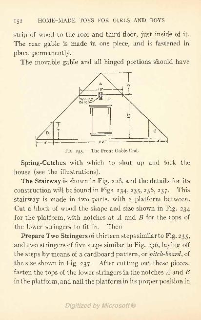
152 HOME-MADE TOYS FOR GIRLS AND BOYS
strip of wood to the roof and third floor, just inside of it.
The rear gable is made in one piece, and is fastened in
place permanently.
The movable gable and all hinged portions should have
FIG. 233. --The Front Gable-End.
Spring-Catches with which to shut up and lock the
house (see the illustrations).
The Stairway is shown in Fig. 228, and the details for its
construction will be found in Figs. 234, 235, 236, 237. This
stairway is made in two parts, with a platform between.
Cut a block of wood the shape and size shown in Fig. 234
for the platform, with notches at A and B for the tops of
the lower stringers to fit in. Then
Prepare Two Stringers of thirteen steps similar to Fig. 235,
and two stringers of five steps similar to Fig. 236, laying off
the steps by means of a cardboard pattern, or pitch-board, of
the size shown in Fig. 237. After cutting out these pieces,
fasten the tops of the lower stringers in the notches A and Bin the platform, and nail the platform in its proper position in
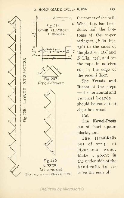
A HOME-MADE DOLL-HOUSE 153
10
&HJ
c
[LJ
oJ
COCN
tFig 234.
STAIR -
3" SQUARE.
Ju.
^Notches-far-Stringers-
Fig 237
PrrcH -'
3" H the corner of the hall.
D When this has been
done, nail the bot-
toms of the upper
stringers (E in Fig.
236) to the sides of
c the platform at C and
D (Fig. 234), and set
the tops in notches
cut in the edge of
the second floor.
The Treads and
Risers of the steps- the horizontal and
vertical boards -
should be cut out of
cigar-box wood.
Cut
The Newel-Posts
out of short square
blocks, and
The Hand-Rails
out of strips of
cigar-box wood.
Make a groove in
Fig 236. the under side of the
UPPEE hand-rails to re-
FIGS. 234-237-- Details of Stairs.
Ceive the ends of
154 HOME-MADE TOYS FOR GIRLS AND BOYS
The Balusters, or spindles. Toothpicks are of just the
right size for balusters.
The delicate portions of the stairways should be glued
in place. Make slits in the stair treads to stick the bottoms
of the balusters in.
The Front Steps are clearly shown in Fig. 220. Makethe solid balustrades out of pieces of box board, and the
step treads and risers out of cigar-box wood. Prepare the
rear steps in the same way.
Cut the Window Openings in the places indicated uponthe plans (Figs. 222 to 224) and the photographs. First
bore holes in the four corners of each window space ;then
saw from hole to hole with a compass-saw.
Old camera plates are excellent material for
The Window Glass. Fasten the glass in the openings
with small brads in the same way that glass is fastened in
picture-frames, and putty it in the same way that window
glass is puttied, to hold it firm.
The Front and Rear Doors can be painted upon the
front of the house. Openings are not necessary.
The Outside Trimmings. Strips of cigar-box wood
should be cut up for the outside door and window casings,
and be tacked around the openings as shown in Fig. 220.
Nail a molding or a plain strip of wood to the front edge
of the third floor, as shown in Fig. 220.
Castors will make it easier to move the doll-house about.
Cut four blocks of wood, fasten a castor to each, and nail
one block inside each corner of the foundation frame.
A HOME-MADE DOLL-HOUSE 155
The Interior Woodwork. Cigar-boxes make excellent
hardwood floors. Fit the pieces close together and fasten
with small brads.
Make the door and window casings, picture-moldings,
and base-boards out of strips of cigar-box wood.
After completing the carpenter work of the house,
Set the Nail-Heads,- that is, drive them below the
surface of the wood,- -
putty these holes and all cracks
and other defective places, and sandpaper rough surfaces.
Paint the House a cream color, with white trimmings
and a green roof. Stripe the foundation walls to indicate
courses of stone work. Paint the front door a mahogany
color, with panels indicated upon it, and make the rear
door white. The painting of the chimney has already
been described.
The inside walls should be finished as suggested in
Chapter XIV. The woodwork may be oiled, or painted
with white enamel or any other color desired.
A Colonial Doll-House with a number of features not
included in this house is described and illustrated in
Chapter V of" The Boy Craftsman.'
5
CHAPTER XIV
FURNISHING THE HOME-MADE DOLL-HOUSE
WITH the carpenter work of a doll-house completed,
the finishing of the inside, -wall papering and painting,
and selecting of furnishings for the various rooms,
remain to be done. This requires as much care as the
building of the house, and while any boy can do the work,
the help of a sister will perhaps simplify matters and give
to the rooms a daintier appearance.
The Walls and Ceiling of the kitchen and bath-room
should be painted with white lead or white enamel. For
the other rooms select paper having a small design, such
as is to be found on most ceiling papers. If you have
ever watched the paper-hanger at work, you have noticed
he puts on the ceiling first, allowing the paper to run
down the walls a little way all around instead of trim-
ming it off. Then he hangs the wall paper, and if there
is no border to cover the joints of the ceiling and wall
papers he carries the wall paper up to the ceiling. Use
flour paste to stick on the paper, and a cloth or photo-
graph-print roller to smooth out the wrinkles. The din-
ing-room should have a wainscot of dark paper below the
chair-rail, and a paper with little or no figure upon it above.
156
FURNISHING THE HOME-MADE DOLL-HOUSE 157
All Hardwood Floors, the stairs, door and window
casings, baseboards, and picture moldings should be
varnished thoroughly or given several coats of boiled
linseed-oil.
All floors, with the exception of the kitchen, bath-room,
and hardwood floors, should be fitted with
Carpets. If you do not happen to have suitable scraps
on hand, they can be procured at almost any furnishing
store where they make up carpets. Select pieces with as
small patterns as possible. The floors of the bath-room
and kitchen should be covered with oilcloth.
Rugs for the hardwood floors may be made out of scraps
of carpet.
Window-Shades may be made for each window out of
linen, and tacked to the top casing so that the bottom of
the curtain reaches just above the center of the opening.
Each window should also have
Lace Curtains made out of scraps of lace. They should
either be tacked above the windows or hung upon poles
made out of No. 12 wire, cut in lengths to fit the windows.
Screw small brass hooks into the top window-casings for
the poles to hang upon.
Handsome Portieres for the doorways can be made with
beads and with the small hollow straws sold for use in
kindergartens. For the
Bead Portieres, cut threads as long as the height of the
door and string the beads upon them, alternating the
colors in such a way as to produce patterns. Then tie
158 HOME-MADE TOYS FOR GIRLS AND BOYS
the strings together to a piece of wire the width of the
doorway, and fasten the wire in the opening. The
Straw Portieres are made similarly.
From magazine illustrations you can select
Suitable Pictures for each room, but if you are handywith brush and pencil you may prefer to make the pictures
yourself. These may be mounted upon cardboard and
have their edges bound with passe-partout paper to give
the effect of frames, or frames may be cut out of card-
board and pasted to them. Hang the pictures to the
picture molding with thread.
A Cosey-Corner may be fitted up in the ball-room by
fastening a strip of a cigar-box in one corner an inch and
one-half above the floor for the seat, and hanging draperies
on each side of it. Pillows may be made for it out of
scraps of silk stuffed with cotton.
A doll-house properly proportioned in every detail, in-
cluding the selection of its furniture, is pleasing to look at,
and is to be desired much more than some of the speci-
mens to be found in the stores. These very often have
parlor chairs larger than the mantel, beds that either fill
two-thirds of the bedroom space or are so small they are
hidden from view by the chairs, and other furniture ac-
cordingly, all having been selected without any thought as
to size or fitness.
Care must be taken, in buying the furniture, to have
the pieces suitable to the rooms. It will no doubt require
more time than to purchase the first sets you come across,
FURNISHING THE HOME-MADE DOLL-HOUSE 159
but when you have completed the selections, the result
will be a much better appearing doll-house.
By carefully searching the toy-shops you are almost
certain of finding what you want for the various rooms,
as about everything imaginable in furniture has been
manufactured. Porcelain bath-tubs, wash-basins with
real faucets and running water, gilt furniture, chande-
liers, and such articles are tempting to buy. But it is
rather expensive to fit up a house in this way, for, thougheach piece may not amount to very much, they count up
very quickly.
The suggestions for the making of cigar-box furniture
in Chapter XVII, and spool and cardboard furniture in
Chapter XIX, will give you plenty of material for furni-
ture and save you the expense of buying this part of the
furnishings for your house.
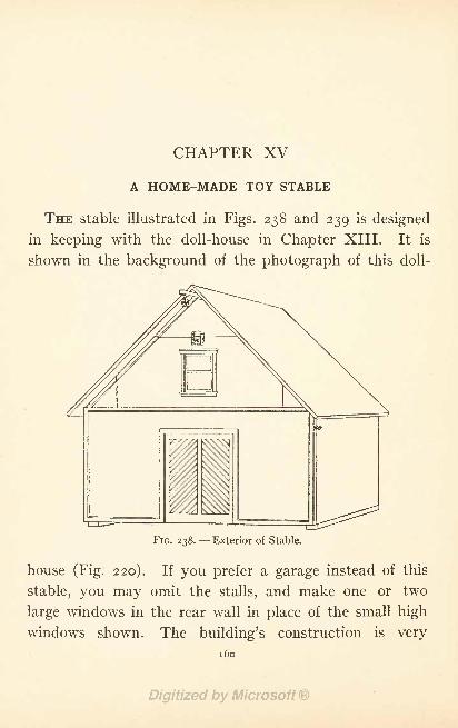
CHAPTER XV
A HOME-MADE TOY STABLE
THE stable illustrated in Figs. 238 and 239 is designed
in keeping with the doll-house in Chapter XIII. It is
shown in the background of the photograph of this doll-
FIG. 238. Exterior of Stable.
house (Fig. 220). If you prefer a garage instead of this
stable, you may omit the stalls, and make one or two
large windows in the rear wall in place of the small high
windows shown. The building's construction is very
1 60
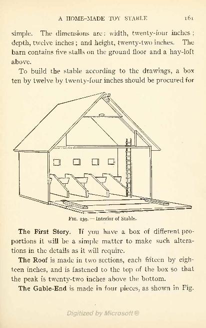
A HOME-MADE TOY STABLE 161
simple. The dimensions are : width, twenty-four inches;
depth, twelve inches;and height, twenty-two inches. The
barn contains five stalls on the ground floor and a hay-loft
above.
To build the stable according to the drawings, a box
ten by twelve by twenty-four inches should be procured for
ana
FIG. 239. Interior of Stable.
The First Story. If you have a box of different pro-
portions it will be a simple matter to make such altera-
tions in the details as it will require.
The Roof is made in two sections, each fifteen by eigh-
teen inches, and is fastened to the top of the box so that
the peak is twenty-two inches above the bottom.
The Gable-End is made in four pieces, as shown in Fig.
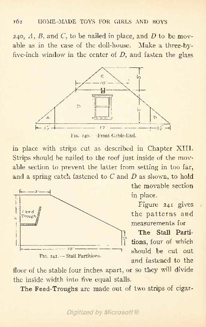
162 HOME-MADE TOYS FOR GIRLS AND BOYS
240, A, B, and C, to be nailed in place, and D to be mov-
able as in the case of the doll-house. Make a three-by-
five-inch window in the center of D, and fasten the glass
V* 3- J(
FIG. 240. Front Gable-End.
in place with strips cut as described in Chapter XIII.
Strips should be nailed to the roof just inside of the mov-
able section to prevent the latter from setting in too far,
and a spring catch fastened to C and D as shown, to hold
the movable section
in place.
Figure 241 gives
the patterns and
measurements for
1The Stall Parti-
j_ tions, four of which
should be cut out
and fastened to theFIG. 241. Stall Partitions.
floor of the stable four inches apart, or so they will divide
the inside width into five equal stalls.
The Feed-Troughs are made out of two strips of cigar-
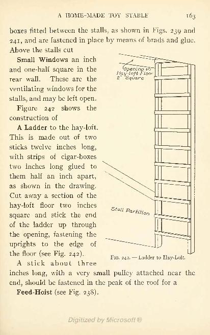
A HOME-MADE TOY STABLE 163
boxes fitted between the stalls, as shown in Figs. 239 and
241, and are fastened in place by means of brads and glue.
Above the stalls cut
Small Windows an inch
and one-half square in the
rear wall. These are the
ventilating windows for the
stalls, and may be left open.
Figure 242 shows the
construction of
A Ladder to the hay-loft.
This is made out of two
sticks twelve inches long,
with strips of cigar-boxes
two inches long glued to
them half an inch apart,
as shown in the drawing.
Cut away a section of the
hay-loft floor two inches
square and stick the end
of the ladder up through
the opening, fastening the
uprights to the edge of
the floor (see Fig. 242).
A stick about three
inches long, with a very small pulley attached near the
end, should be fastened in the peak of the roof for a
Feed-Hoist (see Fig. 238).
Opening inHay-loft-rloor2' Square
FIG. 242. --Ladder to Hay-Loft.
1 64 HOME-MADE TOYS FOR GIRLS AND BOYS
The first story has
A Drop-Front, as shown in Figs. 238 and 239. This is
made from the box-cover. Fasten the boards together
with battens placed upon the inside, and hinge it to the
bottom of the stable. Nail two cleats to the under side
of the floor (see Fig. 238) to lift it off the ground just
enough to allow the front to drop without springing its
hinges.
When the front is down it forms an incline upon which
to run the horses into the stable. For this reason it is
not advisable to cut an opening in it, but merely
Represent a Stable Door on the outside (see Fig. 238).
This is done with paint and a fine brush. First paint
a green panel in the center of the front, and then mark
off a couple of panels within this space with black paint,
and stripe them diagonally to represent beaded-boards.
With strips of wood half an inch wide make
A Simple Trim around the door, the sides of the stable,
and around the gable, as shown in the illustration.
When the carpenter work has been finished,
Paint the Inside of the stable white, and the outside
the same colors as used for the doll-house (see description
in Chapter XIII).
If you Prefer a Garage, use your ingenuity to fit up the
interior of the building as you think it ought to be.
CHAPTER XVI
A HOME-MADE DOLL APARTMENT BUILDING
THE doll apartment building in this chapter is a new
idea in doll-houses. By the illustrations you will see that
the apartment building is three stories high, and consists
of three units - - each one story high- - and a roof. Dur-
ing playtime the units are arranged side by side upon the
floor so as to form a six-room apartment (Fig. 244) ;and
afterward they are piled up one upon another as shown
in Fig. 243, and the roof placed on top, in a compact form
that takes up but little floor space.
Building Material. The apartment building is built out
of grocery boxes. The boxes used for the units must be
of equal size, and the thing to do is to select those in
which a standard brand of goods come packed. If one
grocery store doesn't have what you want, go to another.
If the sides and ends of the boxes are in one piece, it will
greatly simplify the matter of cutting the door and window
openings.
The Room Dimensions. The boxes used in the model
illustrated were 28 inches long, 13 inches wide, and 8
inches deep. These provided space for a vestibule 3
inches by 8 inches, a reception-hall 8| inches by 8 inches,
165
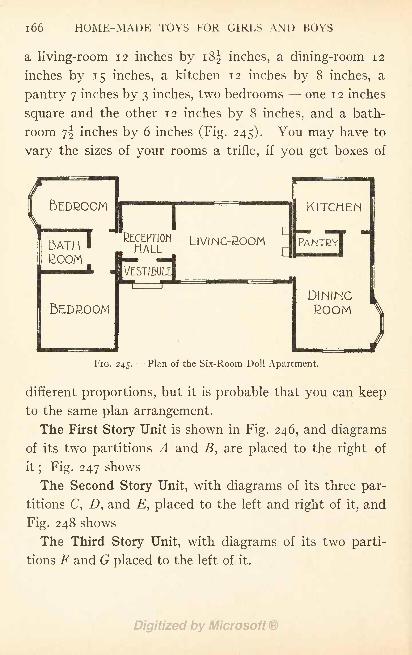
1 66 HOME-MADE TOYS FOR GIRLS AND BOYS
a living-room 12 inches by i8| inches, a dining-room 12
inches by 15 inches, a kitchen 12 inches by 8 inches, a
pantry 7 inches by 3 inches, two bedrooms - one 12 inches
square and the other 12 inches by 8 inches, and a bath-
room yj inches by 6 inches (Fig. 245). You may have to
vary the sizes of your rooms a trifle, if you get boxes of
BEDROOM
5EDROOM
LIVING-BOOM
DININGROOM
FIG. 245. Plan of the Six-Room Doll Apartment.
different proportions, but it is probable that you can keep
to the same plan arrangement.
The First Story Unit is shown in Fig. 246, and diagrams
of its two partitions A and B, are placed to the right of
it; Fig. 247 shows
The Second Story Unit, with diagrams of its three par-
titions C, D, and, placed to the left and right of it, and
Fig. 248 shows
The Third Story Unit, with diagrams of its two parti-
tions F and G placed to the left of it.
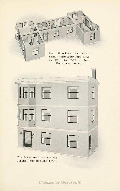
FIG. 244. How THE THUKESTORIES ARE ARRANGED SIDEBY SIDE TO FORM A SlX-
ROOM APARTMENT.
-
FIG. 243. -THE MOST STYLISHAPARTMENTS IN DOLL, TOWN.
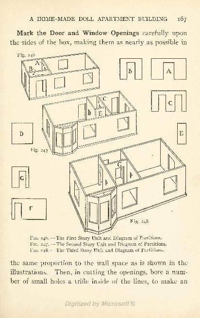
A HOME-MADE DOLL APARTMENT BUILDING 167
Mark the Door and Window Openings carefully uponthe sides of the box, making them as nearly as possible in
Fig. 246
FIG. 246.- -The First Story Unit and Diagram of Partitions.
FIG. 247. --The Second Story Unit and Diagram of Partitions.
FIG. 248. --The Third Story Unit and Diagram of Partitions.
the same proportion to the wall space as is shown in the
illustrations. Then, in cutting the openings, bore a num-
ber of small holes a trifle inside of the lines, to make an
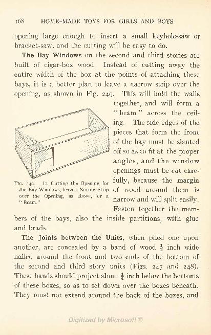
i68 HOME-MADE TOYS FOR GIRLS AND BOYS
opening large enough to insert a small keyhole-saw or
bracket-saw, and the cutting will be easy to do.
The Bay Windows on the second and third stories are
built of cigar-box wood. Instead of cutting away the
entire width of the box at the points of attaching these
bays, it is a better plan to leave a narrow strip over the
opening, as shown in Fig. 249. This will hold the walls
together, and will form a: beam
'
across the ceil-
ing. The side edges of the
pieces that form the front
of the bay must be slanted
off so as to fit at the proper
angles, and the window
openings must be cut care-
FIG. a^in Cutting the Opening forfully> because the margin
the Bay Windows, leave a Narrow Strip of WOOd around them is
over the Opening, as above, for a-, M1 ,., M
Beam narrow and will split easily.
Fasten together the mem-bers of the bays, also the inside partitions, with glue
and brads.
The Joints between the Units, when piled one upon
another, are concealed by a band of wood \ inch wide
nailed around the front and two ends of the bottom of
the second and third story units (Figs. 247 and 248).
These bands should project about J inch below the bottoms
of these boxes, so as to set down over the boxes beneath.
They must not extend around the back of the boxes, and
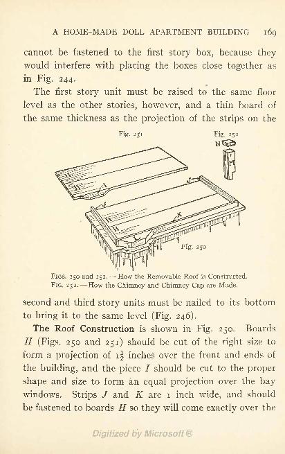
A HOME-MADE DOLL APARTMENT BUILDING 169
cannot be fastened to the first story box, because they
would interfere with placing the boxes close together as
in Fig. 244.
The first story unit must be raised to the same floor
level as the other stories, however, and a thin board of
the same thickness as the projection of the strips on the
Fig. 251
\ Fig. 250
FIGS. 250 and 251. How the Removable Roof is Constructed.
FIG. 252. How the Chimney and Chimney Cap are Made.
second and third story units must be nailed to its bottom
to bring it to the same level (Fig. 246).
The Roof Construction is shown in Fig. 250. Boards
H (Figs. 250 and 251) should be cut of the right size to
form a projection of if inches over the front and ends of
the building, and the piece / should be cut to the proper
shape and size to form an equal projection over the bay
windows. Strips / and K are i inch wide, and should
be fastened to boards H so they will come exactly over the
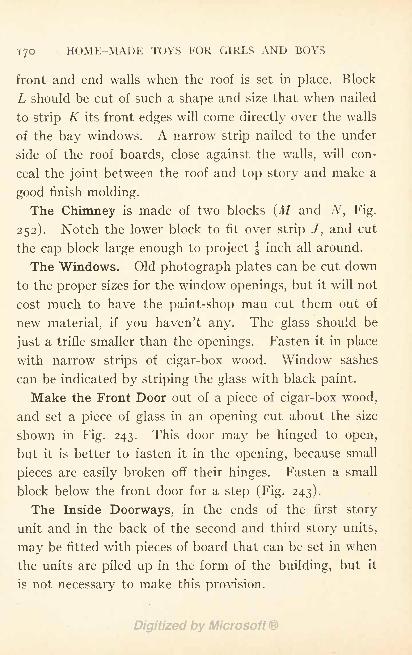
170 HOME-MADE TOYS FOR GIRLS AND BOYS
front and end walls when the roof is set in place. Block
L should be cut of such a shape and size that wThen nailed
to strip K its front edges will come directly over the walls
of the bay windows. A narrow strip nailed to the under
side of the roof boards, close against the walls, will con-
ceal the joint between the roof and top story and make a
good finish molding.
The Chimney is made of two blocks (M and N, Fig.
252). Notch the lower block to fit over strip /, and cut
the cap block large enough to project f inch all around.
The Windows. Old photograph plates can be cut down
to the proper sizes for the window openings, but it will not
cost much to have the paint-shop man cut them out of
new material, if you haven't any. The glass should be
just a trifle smaller than the openings. Fasten it in place
with narrow strips of cigar-box wood. Window sashes
can be indicated by striping the glass with black paint.
Make the Front Door out of a piece of cigar-box wood,
and set a piece of glass in an opening cut about the size
shown in Fig. 243. This door may be hinged to open,
but it is better to fasten it in the opening, because small
pieces are easily broken off their hinges. Fasten a small
block below the front door for a step (Fig. 243).
The Inside Doorways, in the ends of the first story
unit and in the back of the second and third story units,
may be fitted with pieces of board that can be set in when
the units are piled up in the form of the building, but it
is not necessary to make this provision.
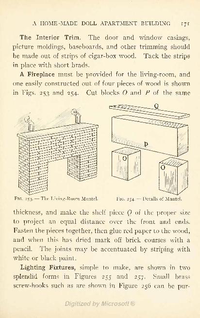
A HOME-MADE DOLL APARTMENT BUILDING 171
The Interior Trim. The door and window casings,
picture moldings, baseboards, and other trimming should
be made out of strips of cigar-box wood. Tack the strips
in place with short brads.
A Fireplace must be provided for the living-room, and
one easily constructed out of four pieces of wood is shown
in Figs. 253 and 254. Cut blocks and P of the same
FIG. 253. --The Living-Room Mantel. FIG. 254. Details of Mantel.
thickness, and make the shelf piece Q of the proper size
to project an equal distance over the front and ends.
Fasten the pieces together, then glue red paper to the wood,
and when this has dried mark off brick courses with a
pencil. The joints may be accentuated by striping with
white or black paint.
Lighting Fixtures, simple to make, are shown in two
splendid forms in Figures 255 and 257. Small brass
screw-hooks such as are shown in Figure 256 can be pur-
172 HOME-MADE TOYS FOR GIRLS AND BOYS
Fig. 255
BRASS -HOOK
^PENCIL- ENDFig. 255
chased at any hardware store, and a couple of dozen of
these, a lead pencil, and a number of large beads, will
furnish you with enough material for making fixtures for
every room in the apartment.
You will see by Fig. 256 that the lighting fixture shown
in Fig. 255 consists of a screw-hook with its hooked end stuck
through one of the
little brass plates re-
moved from another
screw-hook, and then
pushed into the hole
in the end of a short
piece of lead-pencil.
Cut the pencil end
about ^ inch long,
push out the piece
of lead, and if neces-
sary enlarge the hole
to accommodate theFIGS. 255-258.- -Two Lighting Fixtures and how
ho()k end Jf theto Make Them.
piece of pencil comes
apart where glued, re-glue it. Glue the little brass cap to
the top. Paint the pencil end white, to represent glass,
and indicate metal division strips, or leading, with black
paint or ink.
The lighting fixture shown in Fig. 257 is made in the
same way as the other one, except that a bead instead of
the pencil end is used for a globe (Fig. 258).
BRASS-HOOK
DEADFig. 257
Fi g-
A HOME-MADE DOLL APARTMENT BUILDING 173
The fixture in Fig. 255 is better suited to the living-
room and dining-room, and for fastening each side of the
front door; the fixture in Fig. 257 is better for the other
rooms.
Decorating. Suggestions for decorating a doll-house are
given in Chapter XIV, but here are some additional ideas
to suit the conditions of the apartment. It is the modern
practice to tint walls of apartments, and the best plan is
to cover the walls of each room with plain paper, using a
paper of a different color for each room.
The dining-room should have a plate-rail on which to
stand plates (pictures of plates cut from advertisements
and pasted upon cardboard), and the walls below the
plate-rail should be paneled with strips of cigar-box wood
for division strips (Fig. 244).
The Outside Walls of the apartment building are sup-
posedly brick;therefore paint them a good red, brown, or
yellow brick color, and paint the roof cornice, and the
horizontal bands between stories, white, as a contrast.
CHAPTER XVII
HOME-MADE DOLL FURNITURE
THE metal furniture which you can buy is very pretty
when it is new, but this new appearance does not last
long after it has come into a youngster's possession, for
the pieces are very slender and delicate, and thus easily
broken.
Wooden furniture is the most durable kind, and plain
and simple pieces will generally outlast the fancy ones.
The designs illustrated in this chapter make very substan-
tial pieces, as there are no spindle legs or fancy arms to
break off. They follow the lines of the mission furniture,
that simple style used in the early American mission
schools, and which is to-day being extensively made in
handsome pieces for the furnishings of modern homes.
You will find the
Miniature Mission Furniture, illustrated and described
in this chapter, simple to make and something which is
easy to sell, for there is nothing like it at present uponthe market.
Cigar-boxes furnish the nicest material for making this
furniture, and the various parts can be cut to the right
shape and size with
174
HOME-MADE DOLL FURNITURE 175
A Scroll-Saw. Procure small brads and glue with
which to fasten the pieces together.
To Prepare the Cigar-Boxes for use, place them in a tub
of boiling water and let them remain there until the paper
labels readily pull off. Do not use a knife in removingthe paper, as it is likely to roughen the wood. The paper
will come off by allowing it to soak long enough. Whenthe boxes are clean, set them in the sun to dry, after bind-
ing the covers to the backs to prevent them from warp-
ing. Pull the boxes apart when they are thoroughly dry,
and throw out such pieces as have printing upon them, for
these would spoil the appearance of the furniture if used.
In order to simplify the matter of cutting the parts
that make the furniture, the curved pieces have been
drawn out carefully on page 177, so that they can be laid
off upon the strips of cigar-boxes without any trouble, bythe process of
Enlarging by Squares. These drawings are shown
one-quarter of their full size (half their width and half
their height). To enlarge them procure a piece of card-
board nine by thirteen inches, or a little larger than twice
the size of the drawing each way, and divide it into squares
just twice the size of those on page 177. That will make
sixteen squares in the width of the cardboard and twenty-
four in the length, each half an inch square. In order to
get the squares spaced equally, it is best to lay off the
points first with a ruler along the top, bottom, and two
sides of the sheet of cardboard, and then connect the
176 HOME-MADE TOYS FOR GIRLS AND BOYS
points with the ruler and a sharp lead-pencil. Then
number the squares as in the illustration, using the figures
along the sides and letters across the top and bottom of the
sheet.
With the sheet of cardboard thus prepared it is a simple
matter to
Reproduce the Drawings of Figs. 259 to 266 by locating
the points of the curves and corners of the pieces, as
shown in the illustrations, in corresponding positions in
the squares on your cardboard sheet. The curves may be
drawn in by eye, after locating them with reference to
their surrounding squares, but the surest way of enlarg-
ing them accurately is by laying off the points where the
curve strikes each horizontal and vertical line in the illus-
tration, upon the enlarged drawing. These points can
then be connected with a curved line.
Make all of the lines heavy so they can be distinguished
from your guide lines, and after carefully going over the
drawing, comparing it with that on page 177 to see that
no mistake has been made in locating the points in enlarg-
ing, cut the various pieces apart. These will give youThe Patterns with which to mark out the pieces on the
wood.
We will first note the construction of
The Chairs shown in Figs. 267 and 268. These are
four and one-half inches high, two inches wide, and an
inch and one-half deep. Cut the back for the chair in
Fig. 267 four and three-eighths inches high and an inch
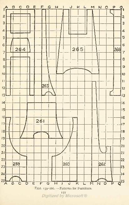
ABODE F K L M M Q PQ,
A B C O EFGHIJKLMNOPFIGS. 259-266. Patterns for Furniture.
177
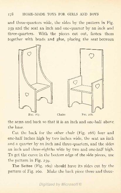
i 78 HOME-MADE TOYS FOR GIRLS AND BOYS
and three-quarters wide, the sides by the pattern in Fig.
259 and the seat an inch and one-quarter by an inch and
three-quarters. With the pieces cut out, fasten them
together with brads and glue, placing the seat between
FIG. 267. Chairs FIG. 268.
the arms and back so that it is an inch and one-half above
the base.
Cut the back for the other chair (Fig. 268) four and
one-half inches high by two inches wide, the seat an inch
and a quarter by an inch and three-quarters, and the sides
an inch and three-eighths wide by two and one-half high.
To get the curve in the bottom edge of the side pieces, use
the pattern in Fig. 259.
The Settee (Fig. 269) should have its sides cut by the
pattern of Fig. 260. Make the back piece three and three-
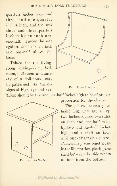
HOME-MADE DOLL FURNITURE 179
quarters inches wide and
three and one-quarterinches high, and the seat
three and three-quarters
inches by an inch and
one-half. Fasten the seat
against the back an inch
and one-half above the
base.
Tables for the living-
room, dining-room, bed-
room, ball-room, and nurs-
ery of a doll-house maybe patterned after the de-
signs of Figs. 270 and 271.
These should be two and one
FIG. 270. A Table.
FIG. 269. A Settee.
half inches high to be of proper
proportion for the chairs.
The pieces necessary to
make Fig. 270 are a top
two inches square, two sides
an inch and one-half wide
by two and one-half inches
high, and a shelf an inch
and one-quarter square.
Fasten the pieces together as
,in the illustration, placing the
shelf between the side pieces
an inch from the bottom.
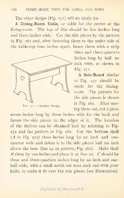
i8o HOME-MADE TOYS FOR GIRLS AND BOYS
The other design (Fig. 271) will do nicely for*
A Dining-Room Table, or table for the center of the
living-room. The top of this should be five inches long
and three inches wide. Cut the side pieces by the pattern
in Fig. 261 and, after fastening them to the under side of
the table-top four inches apart, brace them with a strip
three and three-quarters
inches long by half an
inch wide, as shown in
Fig. 271.
A Side-Board similar
to Fig. 272 should be
made for the dining-
room. The pattern for
the side pieces is shown
in Fig. 262. After saw-
ing these out, cut a piece
seven inches long by three inches wide for the back and
fasten the side pieces to the edges of it. The location
of the shelves can be obtained best by referring to Fig.
272 and the pattern in Fig. 262. Cut the bottom shelf
(A in Fig. 272) three inches long by an inch and one-
quarter wide and fasten it to the side pieces half an inch
above the base (line 24 on pattern, Fig. 262). Make shelf
B three by one inches and place it at line 22. C should be
three and three-quarters inches long by an inch and one-
half wide, with a small notch cut near each end with your
knife, to make it fit over the side pieces (see illustration).
FIG. 271. Another Design.
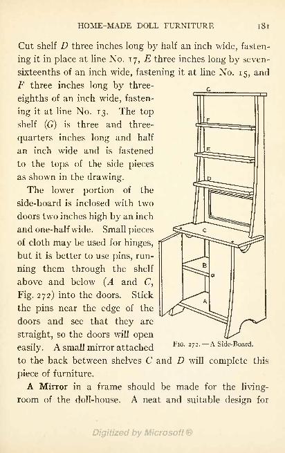
HOME-MADE DOLL FURNITURE 181
Cut shelf D three inches long by half an inch wide, fasten-
ing it in place at line No. 17, E three inches long by seven-
sixteenths of an inch wide, fastening it at line No. 15, and
F three inches long by three-
eighths of an inch wide, fasten-
ing it at line No. 13. The top
shelf (G) is three and three-
quarters inches long and half
an inch wide and is fastened
to the tops of the side pieces
as shown in the drawing.
The lower portion of the
side-board is inclosed with two
doors two inches high by an inch
and one-half wide. Small pieces
of cloth may be used for hinges,
but it is better to use pins, run-
ning them through the shelf
above and below (A and C,
Fig. 272) into the doors. Stick
the pins near the edge of the
doors and see that they are
straight, so the doors will open
easily. A small mirror attachedFlG " 272 '
~ A Side-Board -
to the back between shelves C and D will complete this
piece of furniture.
A Mirror in a frame should be made for the living-
room of the doll-house. A neat and suitable design for
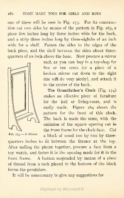
182 HOME-MADE TOYS FOR GIRLS AND BOYS
one of these will be seen in Fig. 273. For its construc-
tion cut two sides by means of the pattern in Fig. 263, a
piece five inches long by three inches wide for the back,
and a strip three inches long by three-eighths of an inch
wide for a shelf. Fasten the sides to the edges of the
back piece, and the shelf between the sides about three-
quarters of an inch above the base. Now procure a mirror
such as you can buy in a toy-shop for
five or ten cents (or a piece of a
broken mirror cut down to the right
size will do very nicely), and attach it
to the center of the back.
The Grandfather's Clock (Fig. 274)
makes an effective piece of furniture
for the hall or living-room, and is
easily made. Figure 264 shows the
pattern for the front of this clock.
The back is made the same, with the
omission of the square opening cut in
the front frame for the clock-face. CutFTP 272 A TVTirror i i i r i i i At
a block ot wood two by two by three-
quarters inches to fit between the frames at the top.
After nailing the pieces together, procure a face from a
toy watch, and fasten it in the opening made for it in the
front frame. A button suspended by means of a piece
of thread from a tack placed in the bottom of the block
forms the pendulum.It will be unnecessary to give any suggestions for
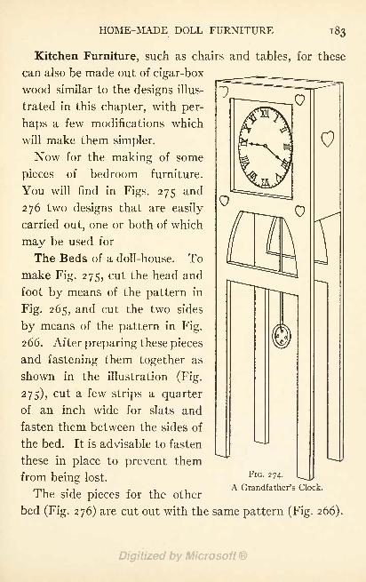
HOME-MADE DOLL FURNITURE 183
Kitchen Furniture, such as chairs and tables, for these
can also be made out of cigar-box
wood similar to the designs illus-
trated in this chapter, with per-
haps a few modifications which
will make them simpler.
Now for the making of some
pieces of bedroom furniture.
You will find in Figs. 275 and
276 two designs that are easily
carried out, one or both of which
may be used for
The Beds of a doll-house. To
make Fig. 275, cut the head and
foot by means of the pattern in
Fig. 265, and cut the two sides
by means of the pattern in Fig.
266. After preparing these pieces
and fastening them together as
shown in the illustration (Fig.
275), cut a few strips a quarter
of an inch wide for slats and
fasten them between the sides of
the bed. It is advisable to fasten
these in place to prevent them
from being lost.
The side pieces for the other
bed (Fig. 276) are cut out with the same pattern (Fig. 266).
FIG. 274.
A Grandfather's Clock.
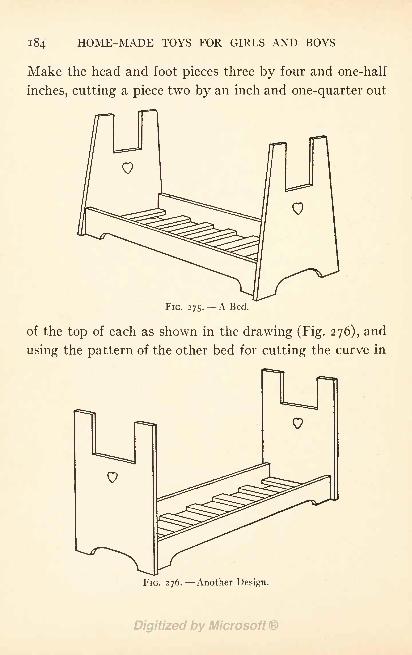
1 84 HOME-MADE TOYS FOR GIRLS AND BOYS
Make the head and foot pieces three by four and one-half
inches, cutting a piece two by an inch and one-quarter out
FIG. 275. A Bed.
of the top of each as shown in the drawing (Fig. 276), and
using the pattern of the other bed for cutting the curve in
FIG. 276. Another Design.
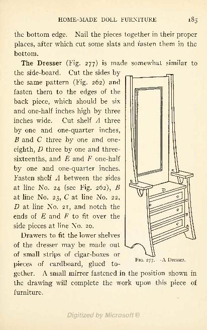
HOME-MADE DOLL FURNITURE
the bottom edge. Nail the pieces together in their proper
places, after which cut some slats and fasten them in the
bottom.
The Dresser (Fig. 277) is made somewhat similar to
the side-board. Cut the sides bythe same pattern (Fig. 262) and
fasten them to the edges of the
back piece, which should be six
and one-half inches high by three
inches wide. Cut shelf A three
by one and one-quarter inches,
B and C three by one and one-
eighth, D three by one and three-
sixteenths, and E and F one-half
by one and one-quarter inches.
Fasten shelf A between the sides
at line No. 24 (see Fig. 262), Bat line No. 23, C at line No. 22,
D at line No. 21, and notch the
ends of E and F to fit over the
side pieces at line No. 20.
Drawers to fit the lower shelves
of the dresser may be made out
of small strips of cigar-boxes or
pieces of cardboard, glued to-
gether. A small mirror fastened in the position shown in
the drawing will complete the work upon this piece of
furniture.
FIG. 277. A Dresser.
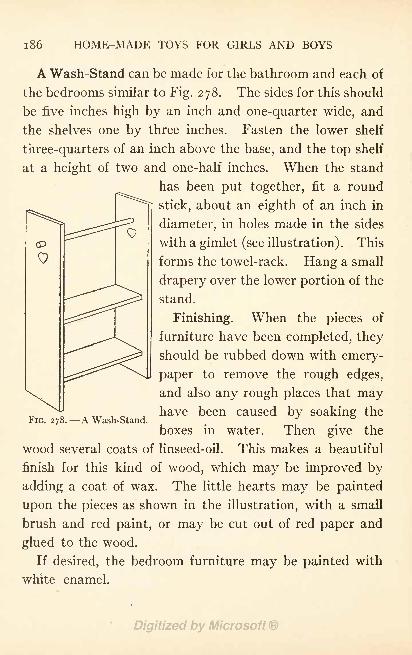
1 86 HOME-MADE TOYS FOR GIRLS AND BOYS
<P
A Wash-Stand can be made for the bathroom and each of
the bedrooms similar to Fig. 278. The sides for this should
be five inches high by an inch and one-quarter wide, and
the shelves one by three inches. Fasten the lower shelf
three-quarters of an inch above the base, and the top shelf
at a height of two and one-half inches. When the stand
has been put together, fit a round
stick, about an eighth of an inch in
diameter, in holes made in the sides
with a gimlet (see illustration). This
forms the towel-rack. Hang a small
drapery over the lower portion of the
stand.
Finishing. When the pieces of
furniture have been completed, they
should be rubbed down with emery-
paper to remove the rough edges,
and also any rough places that mayhave been caused by soaking the
boxes in water. Then give the
wood several coats of linseed-oil. This makes a beautiful
finish for this kind of wood, which may be improved by
adding a coat of wax. The little hearts may be painted
upon the pieces as shown in the illustration, with a small
brush and red paint, or may be cut out of red paper and
glued to the wood.
If desired, the bedroom furniture may be painted with
white enamel.
FIG. 278. A Wash-Stand.
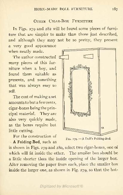
HOME-MADE DOLL FURNITURE 187
OTHER CIGAR-BOX FURNITURE
In Figs. 279 and 282 will be found some pieces of furni-
ture that are simpler to make than those just described,
and although they may not be so pretty, they present
a very good appearance
when neatly made.
The author constructed
many pieces of this fur-
niture when a boy, and
found them suitable as
presents, and something
that was always easy to
sell.
The cost of making a set
amounts to but a few cents,
cigar-boxes being the prin-
cipal material. They are
also very quickly made,
as the boxes require but
little cutting.
For the construction of
A Folding-Bed, such as
is shown in Figs. 279 and 280, select two cigar-boxes, one of
which will fit inside the other. The smaller box should be
a little shorter than the inside opening of the larger box.
After removing the paper from each, place the smaller box
inside the larger one, as shown in Fig. 279, so that the bot-
FIG. 279. A Doll's Folding-Bed.
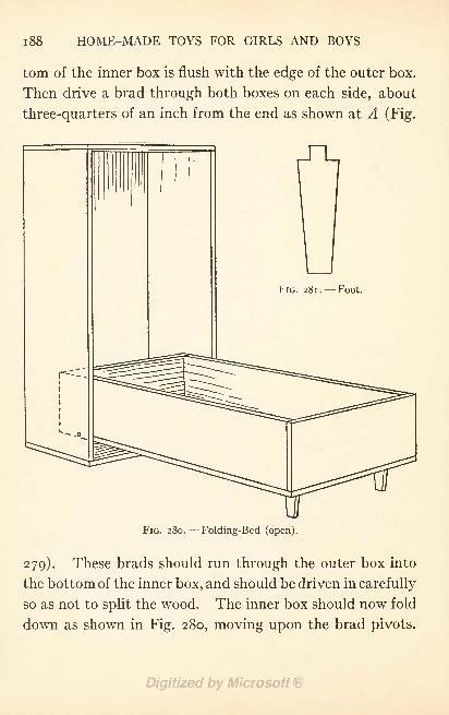
188 HOME-MADE TOYS FOR GIRLS AND BOYS
torn of the inner box is flush with the edge of the outer box.
Then drive a brad through both boxes on each side, about
three-quarters of an inch from the end as shown at A (Fig.
I'IG. 28l. Foot.
FIG. 280. Folding-Bed (open).
279). These brads should run through the outer box into
the bottom of the inner box, and should be driven in carefully
so as not to split the wood. The inner box should now fold
down as shown in Fig. 280, moving upon the brad pivots.
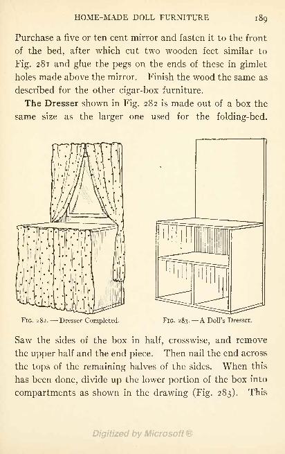
HOME-MADE DOLL FURNITURE 189
Purchase a five or ten cent mirror and fasten it to the front
of the bed, after which cut two wooden feet similar to
Fig. 281 and glue the pegs on the ends of these in gimlet
holes made above the mirror. Finish the wood the same as
described for the other cigar-box furniture.
The Dresser shown in Fig. 282 is made out of a box the
same size as the larger one used for the folding-bed.
FIG. 282. Dresser Completed. FIG. 283. A Doll's Dresser.
Saw the sides of the box in half, crosswise, and remove
the upper half and the end piece. Then nail the end across
the tops of the remaining halves of the sides. When this
has been done, divide up the lower portion of the box into
compartments as shown in the drawing (Fig. 283). This
I go HOME-MADE TOYS FOR GIRLS AND BOYS
should have a small drapery hung over it. The upper
portion of the dresser should have a mirror attached to it,
and some lace draped over the top and sides will add greatly
to its appearance.
All you will have to do in makingA Wardrobe will be to fasten some small hooks inside of
a cigar-box, attach the cover with a strip of linen the
same way it was attached before you soaked it off and
hang a mirror on the front.
These pieces of furniture were designed for separate
sets, and would not do for doll-houses the size of those in
the preceding chapters, unless the boxes were cut down to
smaller proportions.
CHAPTER XVIII
HOME-MADE CIGAR-BOX TOYS
CIGAR-BOXES are splendid material for a variety of home-
made toys. In this chapter are shown some easily con-
structed wagons, a Jack-in-the-box, a cradle, and several
tables and chairs of a different pattern from the doll
furniture for which working drawings were given in the
preceding chapter.
Get an assortment of shapes and sizes of boxes at a
cigar store, and prepare them for use as directed on page
175. Use f inch and J inch brads, and glue, for fastening
the pieces together.
A scroll-saw, bracket-saw, coping-saw, or a very sharp
jack-knife should be used where
Cutting is necessary. Do not attempt to split the
wood, as the grain is seldom straight, but lay it down upona board and score it with a knife in the way in which youwould score a piece of cardboard
;then break it along the
scored line, or continue cutting until the piece is cut in
two. If you use a saw, cut a little away from the outlines
of the work and then trim up with a knife and sandpaper.
The wagons, Jack-in-the-box, and doll furniture shown
in this chapter were designed with the idea of saving as
191
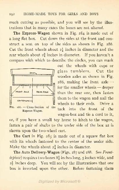
192 HOME-MADE TOYS FOR GIRLS AND BOYS
much cutting as possible, and you will see by the illus-
trations that in many cases the boxes are not altered.
The Express-Wagon shown in Fig. 284 is made out of
a long flat box. Cut down the sides at the front and con-
struct a seat on top of the sides as shown in Fig. 286.
Cut the front wheels about 2\ inches in diameter and the
rear wheels about i\ inches in diameter. If you haven't a
compass with which to describe the circles, you can mark
out the wheels with cups or
SEAT/? glass tumblers. Cut the
wooden axles as shown in Fig.\
I
Ma 286, making the front axle
FRONT AXLE I REAR AXLE
for the smaller wheels deeper
than the rear one, then fasten
them to the wagon and nail the
wheels to their ends. Drive aFIG. 286. Cross-Section of the i , i r r . i
Express-Wagon.tack mt the fr nt f the
wagon-box and tie a cord to it,
or, if you have a small toy horse to hitch to the wagon,
fasten a pair of shafts to the under side of the box as is
shown upon the two-wheel cart.
The Cart in Fig. 285 is made out of a square flat box
with its wheels fastened to the center of the under side.
Make the wheels about 2\ inches in diameter.
The Auto Delivery-Wagon (Figs. 287 and 288. See Front-
ispiece) requires two boxes 8^ inches long, 5 inches wide, and
i\ inches deep. You will see by the illustrations that one
box is inverted upon the other. Before fastening them
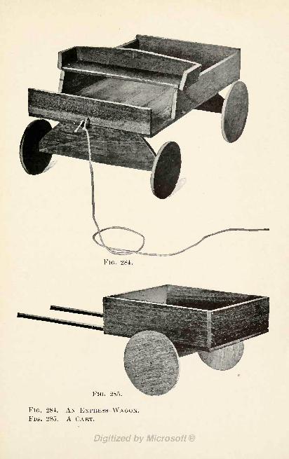
FIG. 284.
Flu. 285.
FIG. 284. AN EXPRESS-WAGON.FIG. 285. A CART.
HOME-MADE CIGAR-BOX TOYS 193
together, remove the two ends of the upper box and the
rear end of the lower box (leaving the front end for the
dashboard), and cut 2 inches off the sides at the front and an
additional piece i inch by if inches from the sides of the
upper box for windows. Fasten the boxes together by
nailing strips to the ends of side pieces. Nail a narrow strip
across the top of the rear end of the wagon and hinge a
drop end-gate to the wagon-bed with cloth strips. Sup-
port the end-gate with a cloth strap. Tack a curtain of
black cloth to the top cross strip and sew two cloth straps
to the curtain, so that it may be fastened up in a roll, as
shown in the photograph. Make the wheels and axles like
those of the express wagon, but cut the front and rear
wheels, also the two axles, of equal size. Cut out a small
steering-wheel and fasten it on a short wooden rod inside of
the dashboard. Make a seat and seat back, nail the back
to the seat, and then fasten the seat between the sides
of the wagon just below the windows.
A Jack-in-the-box (Fig. 289) is a simpler toy to make
than you might imagine. The box should measure about
5! inches by 5! inches by 5 inches. Hinge the cover to
the top with two pieces of heavy cloth; glue one piece to
the inside of the cover and box, and the other to the outside.
Drive a small tack into the front edge of the cover, and
below it fasten a small hook on to the box;the hook may
be bent from a short piece of wire.
A spiral spring from an old bed-spring will do for Jack's
body, but if you cannot get one of these it is a simple
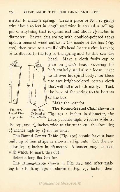
194 HOME-MADE TOYS FOR GIRLS AND BOYS
matter to make a spring. Take a piece of No. 12 gaugewire about 10 feet in length and wind it around a rolling-
pin or anything that is cylindrical and about 2\ inches in
diameter. Fasten this spring with doubled-pointed tacks
upon a piece of wood cut to fit the inside of the box (Fig.
290), then procure a small doll's head, baste a circular piece
of cardboard to the top of the spring and to this sew the
head. Make a cloth fool's cap to
glue on Jack's head, covering his
hair entirely, and also a loose jacket
to fit over his spiral body ;for these
use any bright-colored cotton cloth
that will fall into folds easily. Tack
the base of the spring to the bottom
of the box.
Make the seat for
FIG. 296.The Round-Seated Chair shown in
Pedestal ofFig. 291 2 inches in diameter, the
'enter-Table. , , , , . , , . ,
back 5 inches high, 2 inches wide at
the top, and if inches wide at the seat;cut the front leg
2| inches high by if inches wide.
The Round Center-Table (Fig. 292) should have a base
built up of four strips as shown in Fig. 296. Cut the cir-
cular top 5 inches in diameter. A saucer may be used
with which to mark this out.
Select a long flat box for
The Dining-Table shown in Fig. 293, and after mak-
ing four built-up legs as shown in Fig. 297 fasten them
FIG. 297.
Leg of Din-
ing-Table.
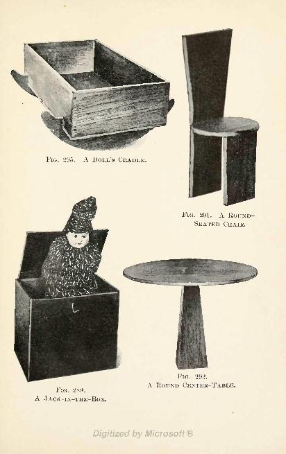
FIG. 295. A DOLL'S CRADLE.
FIG. 291. A ROUND-SEATED CHAIR.
FIG. 289.
A JACK-IN-THE-BOX.
FIG. 292.
A ROUND CENTER-TABLE.
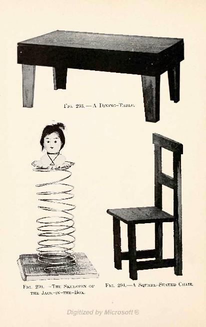
FIG. 293. - - A DINING-TABLE
FIG. 290. THE SKELETON OF
THE JACK-IN-THE-BOX.
FIG. 294. A SQUARE-SEATED CHAIR.
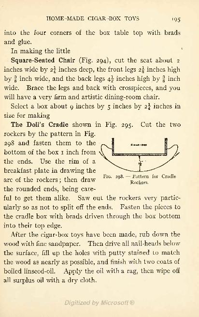
HOME-MADE CIGAR-BOX TOYS 195
into the four corners of the box table top with brads
and glue.
In making the little
Square-Seated Chair (Fig. 294), cut the seat about 2
inches wide by 2\ inches deep, the front legs 2\ inches high
by f inch wide, and the back legs 4^ inches high by f inch
wide. Brace the legs and back with crosspieces, and youwill have a very firm and artistic dining-room chair.
Select a box about 9 inches by 5 inches by 2\ inches in
size for makingThe Doll's Cradle shown in Fig. 295. Cut the two
rockers by the pattern in Fig.
298 and fasten them to the
bottom of the box i inch from
the ends. Use the rim of a
breakfast plate in drawing the,. , -, T , i FIG. 208. Pattern for Cradle
arc of the rockers;then draw
Rockers
the rounded ends, being care-
ful to get them alike. Saw out the rockers very partic-
ularly so as not to split off the ends. Fasten the pieces to
the cradle box with brads driven through the box bottom
into their top edge.
After the cigar-box toys have been made, rub down the
wood with fine sandpaper. Then drive all nail-heads below
the surface, fill up the holes with putty stained to match
the wood as nearly as possible, and finish with two coats of
boiled linseed-oil. Apply the oil with a rag, then wipe off
all surplus oil with a dry cloth.
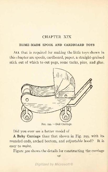
CHAPTER XIX
HOME-MADE SPOOL AND CARDBOARD TOYS
ALL that is required for making the little toys shown in
this chapter are spools, cardboard, paper, a straight-grained
stick out of which to cut pegs, some tacks, pins, and glue.
FIG. 299. Doll Carriage.
Did you ever see a better model of
A Baby Carriage than that shown in Fig. 299, with its
rounded ends, arched bottom, and adjustable hood? It is
easy to make.
Figure 300 shows the details for constructing the carriage
196
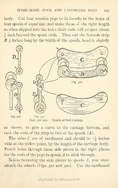
HOME-MADE SPOOL AND CARDBOARD TOYS 197
body. Cut four wooden pegs to fit loosely in the holes of
four spools of equal size, and make them of the right length
so when slipped into the holes their ends will project about
J inch beyond the spool ends. Then cut the bottom strip
B 5 inches long by the width of the spools, bend it slightly
pD
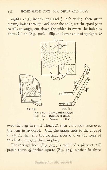
198 HOME-MADE TOYS FOR GIRLS AND BOYS
uprights D 3^ inches long and ^ inch wide;
then after
cutting holes through each near the ends, for the spool pegs
to slip through, cut down the width between the holes to
about \ inch (Fig. 302). Slip the lower ends of uprights D
Fig. 304
Fig. 303
FIG. 303.
FIG. 304.
FIG. 305.
Fig. 35Baby Carriage Hood.
Diagram of Hood.
Carriage Handles.
over the pegs in spool wheels E, then the upper ends over
the pegs in spools A. Glue the upper ends to the ends of
spools ^4, then slip the carriage sides C over the pegs of
spools A, and glue them in place.
The carriage hood (Fig. 303 ) is made of a piece of stiff
paper about 4^ inches square (Fig. 304), slashed in three
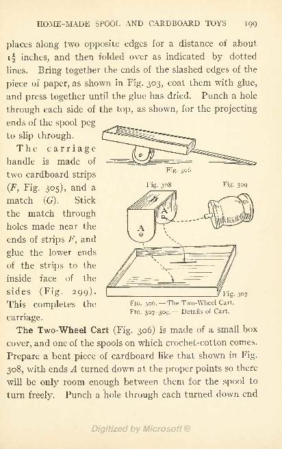
HOME-MADE SPOOL AND CARDBOARD TOYS 199
places along two opposite edges for a distance of about
if inches, and then folded over as indicated by dotted
lines. Bring together the ends of the slashed edges of the
piece of paper, as shown in Fig. 303, coat them with glue,
and press together until the glue has dried. Punch a hole
through each side of the top, as shown, for the projecting
ends of the spool peg
to slip through.
The carriagehandle is made of
two cardboard strips
(F, Fig. 305), and a
match (G) . Stick
the match through
holes made near the
ends of strips F, and
glue the lower ends
of the strips to the
inside face of the
sides (Fig. 299).
This completes the
carriage.
The Two-Wheel Cart (Fig. 306) is made of a small box
cover, and one of the spools on which crochet-cotton comes.
Prepare a bent piece of cardboard like that shown in Fig.
308, with ends A turned down at the proper points so there
will be only room enough between them for the spool to
turn freely. Punch a hole through each turned down end
Fig. 307
FIG. 306.- -The Two-Wheel Cart.
FIG. 307-309. --Details of Cart.
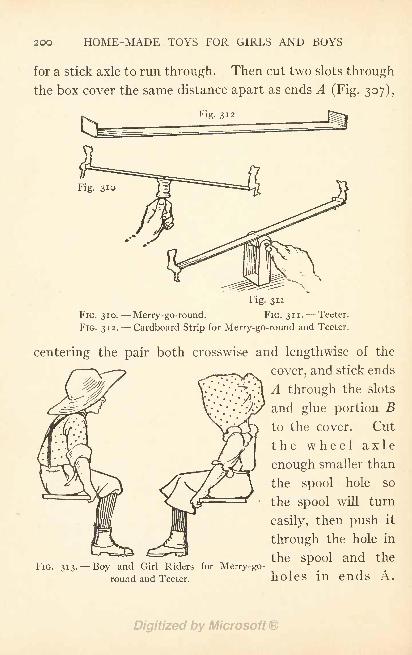
HOME-MADE TOYS FOR GIRLS AND BOYS
for a stick axle to run through. Then cut two slots through
the box cover the same distance apart as ends A (Fig. 307),
Fig. 312
Fig. 310
Fig. 311
FIG. 310. Merry-go-round. FIG. 311.-- Teeter.
FIG. 312. Cardboard Strip for Merry-go-round and Teeter.
centering the pair both crosswise and lengthwise of the
cover, and stick ends
A through the slots
and glue portion Bto the cover. Cut
the wheel axle
enough smaller than
the spool hole so
the spool will turn
easily, then push it
through the hole in
the spool and theFIG. 313. Boy and Girl Riders for Merry-go-
round and Teeter. holes in ends A.
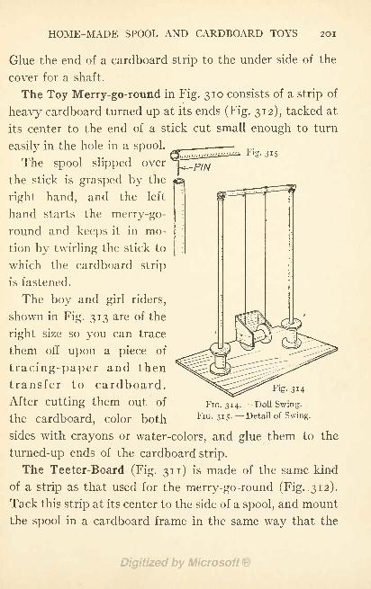
HOME-MADE SPOOL AND CARDBOARD TOYS 201
Glue the end of a cardboard strip to the under side of the
cover for a shaft.
The Toy Merry-go-round in Fig. 310 consists of a strip of
heavy cardboard turned up at its ends (Fig. 312), tacked at
its center to the end of a stick cut small enough to turn
easily in the hole in a spool.
The spool slipped over
the stick is grasped by the
right hand, and the left
hand starts the merry-go-
round and keeps it in mo-
tion by twirling the stick to
which the cardboard strip
is fastened.
The boy and girl riders,
shown in Fig. 313 are of the
right size so you can trace
them off upon a piece of
tracing-paper and then
transfer to cardboard.
After cutting them out of
the cardboard, color both FIG. 315- -Detail of Swing.
sides with crayons or water-colors, and glue them to the
turned-up ends of the cardboard strip.
The Teeter-Board (Fig. 311) is made of the same kind
of a strip as that used for the merry-go-round (Fig. 312).
Tack this strip at its center to the side of a spool, and mount
the spool in a cardboard frame in the same way that the
Fig.
FIG. 314. Doll Swing.
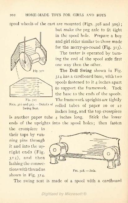
202 HOME-MADE TOYS FOR GIRLS AND BOYS
Fig. 316
spool wheels of the cart are mounted (Figs. 308 and 309) ;
but make the peg axle to fit tight
in the spool hole. Prepare a boyand girl rider similar to those made
for the merry-go-round (Fig. 313).
The teeter is operated by turn-
ing the end of the spool axle first
one way then the other.
The Doll Swing shown in Fig.
314 has a cardboard base, with two
spools fastened to it 4 inches apart
to support the framework. Tack
the base to the ends of the spools.
Fig. 317 The framework uprights are tightlyFIGS. 316 and 3 1 7. -Details of
rolled tubes Qf paper IQ Qr J2Swing Seat.
inches long, and the top crosspiece
is another paper tube 4 inches long. Stick the lower
ends of the uprights into the spool holes;
then fasten
the crosspiece to
their tops by run-
ning pins through
it and into the up-
right ends (Fig.
315), and then
lashing the connec-
tions with thread as FlG 3l8_ Sofa
shown in Fig. 314.
The swing seat is made of a spool with a cardboard
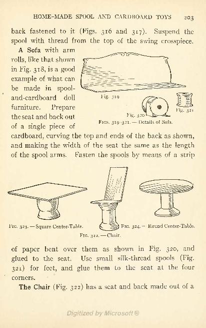
HOME-MADE SPOOL AND CARDBOARD TOYS 203
back fastened to it (Figs. 316 and 317). Suspend the
spool with thread from the top of the swing crosspiece.
A Sofa with arm
rolls, like that shown
in Fig. 318, is a good
example of what can
be made in spool-
and-cardboard doll
furniture. Prepare
the seat and back out
of a single piece of
cardboard, curving the top and ends of the back as shown,
and making the width of the seat the same as the length
of the spool arms. Fasten the spools by means of a strip
Fig. 320
FIGS. 319-321. --Details of Sofa.
Fig. 321
FIG. 323. Square Center-Table. ^-ftf Fia 32 4-~~ Round Center-Table.
FIG. 322. Chair.
of paper bent over them as shown in Fig. 320, and
glued to the seat. Use small silk-thread spools (Fig.
321) for feet, and glue them to the seat at the four
corners.
The Chair (Fig. 322) has a seat and back made out of a
204 HOME-MADE TOYS FOR GIRLS AND BOYS
single piece of cardboard, with one-third of its length bent
out for the seat. Glue the seat to a spool base.
The Square Center-Table (Fig. 323) has a crochet-
cotton spool pedestal, and its top is a square piece of card-
board. Glue the spool to the exact center of the top.
The Round Center-Table (Fig. 324) is made similarly.
Use the rim of a cup for marking out the circular top.
With a little ingenuity you will be able to devise a great
many other pieces of doll furniture, and other toys as well.
CHAPTER XX
A HOME-MADE TOY MAIL-BOX
WHO wants to play at being Uncle Sam, and have a
postal system right in the house, or out on the front porchwhere it will be convenient for the children next door to
enjoy it, too ? Every small boy and girl loves to play
postman, collect mail from the toy mail-box, cancel the
stamps, sort out the letters into the proper routes, and
then deliver them to those whom they are addressed to.
The mail-box shown in Figs. 325 and 326 is easily made,and with
The Working Material on hand can be completed in an
evening. Two sheets of cardboard, a piece of muslin,
some silver paper or paint, a piece of tape about 2 yards
long, and a needle and thread, are required. The card-
board should be stiff enough to hold its shape, and yet be
of light enough weight to cut and fold easily. Sheets 22
inches by 28 inches can be bought at any printing-shop,
and at some stationery stores, and will not cost more than
10 cents a sheet at the most. If you have some large card-
board boxes, however, you can use them instead by so laying
out the different parts that the corners of the boxes will
come in the right places for the corners of the mail-box.
205
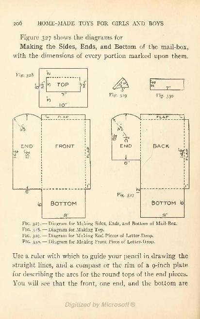
206 HOME-MADE TOYS FOR GIRLS AND BOYS
Figure 327 shows the diagrams for
Making the Sides, Ends, and Bottom of the mail-box,
with the dimensions of every portion marked upon them.
Fig. 328
CO
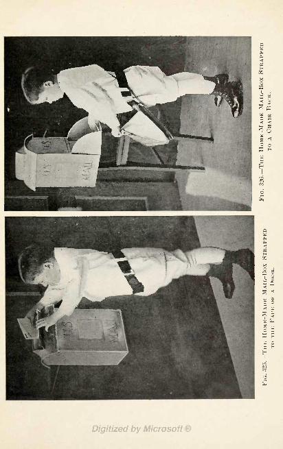
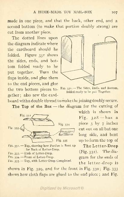
A HOME-MADE TOY MAIL-BOX 207
made in one piece, and that the back, other end, and a
second bottom (to make that portion doubly strong) are
cut from another piece.
The dotted lines uponthe diagram indicate where
the cardboard should be
folded. Figure 331 shows
the sides, ends, and bot-
tom folded ready to be
put together. Turn the
flaps inside, and glue them
to the end pieces, and glue
the tWO bottom pieces to-FIG. 331- -The Sides, Ends and Bottom,
folded ready to be put Together.
gether ;also sew the card-
board with a double thread to make the joining doubly secure.
The Top of the Box - - the diagram for the cutting of
which is shown inFig. 33 2 / 7 v i
Fig. 328- has a
piece 3 by 7 inches
cut out on all but one
long side, and bent
up to form the top of
The Letter-Drop
(Fig. 332). The dia-
gram for the ends of
the letter-drop is
Fig. 334
Fig. 333
Fig. 335
FIG. 332. Top, showing how Portion is Bent upfor Back of Letter-Drop.
FIG. 333. --Ends of Letter-Drop.
FIG. 334. --Front of Letter-Drop.FIG. 335. Top, with Letter-Drop Completed.
shown in Fig. 329, and for the front in Fig. 330; Fig. 333
shows how cloth flaps are glued to the end piece ;and Fig.
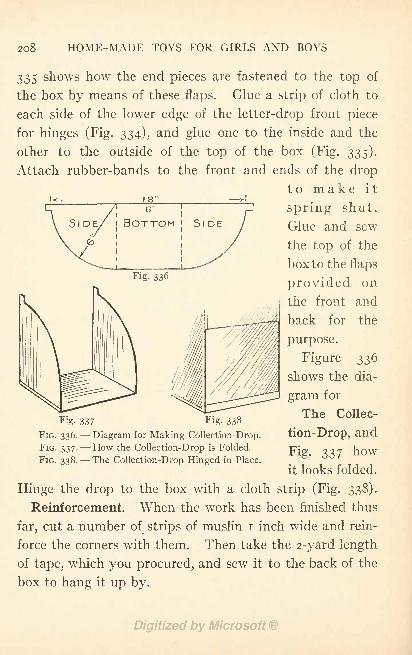
208 HOME-MADE TOYS FOR GIRLS AND BOYS
335 shows how the end pieces are fastened to the top of
the box by means of these flaps. Glue a strip of cloth to
each side of the lower edge of the letter-drop front piece
for hinges (Fig. 334), and glue one to the inside and the
other to the outside of the top of the box (Fig. 335).
Attach rubber-bands to the front and ends of the drop
to make it
spring shut.
Glue and sew
the top of the
box to the flaps
18'
6'
BOTTOM
Fig. 336provided on
the front and
back for the
purpose.
Figure 336
shows the dia-
gram for
The Collec-
tion-Drop, and
Fig. 337 how
it looks folded.
Hinge the drop to the box with a cloth strip (Fig. 338).
Reinforcement. When the work has been finished thus
far, cut a number of strips of muslin i inch wide and rein-
force the corners with them. Then take the 2-yard length
of tape, which you procured, and sew it to the back of the
box to hang it up by.
Fig. 337 Fig. 338
FIG. 336. Diagram for Making Collection-Drop.
FIG. 337. How the Collection-Drop is Folded.
FIG. 338. --The Collection-Drop Hinged in Place.
A HOME-MADE TOY MAIL-BOX 209
Covering the Box. Silver paper makes the nicest
finish for the mail-box, and can be bought of a stationer;
but you may paint the cardboard with aluminum radiator
paint instead if you prefer. If you use silver paper, stick
it on with flour paste.
After the paper or paint has dried, paste
A Collection Schedule Card upon the front of the box.
You will need, also, to
Letter the words,"Pull Down,"
"Letters," etc., where
they are shown in the illustrations.
Hang up the Mail-Box by means of its tape strap, within
easy reach, upon the face of a door (Fig. 325), or to the back
of a chair (Fig. 326).
For a Mail-Bag use a school-book bag, or make one just
like a real postman's out of brown denim or cambric.
Letter"U. S. Mail '
upon the bag with black paint, or
cut the letters from black or white muslin and glue them in
place. Provide a long strap to reach over the postman's
shoulder.
The Way to Play Post-Office is for several children to
attend to the writing of letters and wrapping of parcels,
another to play mail clerk, who puts the post-marks on the
mail and sorts it out into"routes
" and another to play
postman.
Canceled stamps from old letters may be re-used on the
play letters, and a rubber-stamp dater such as they sell at
the stationer's for 10 cents may be used for printing the
post-marks.
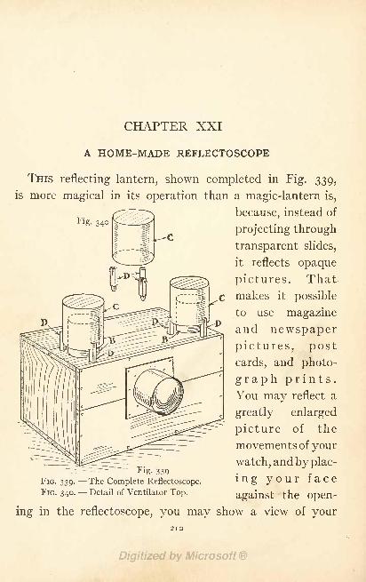
CHAPTER XXI
Fig. 340
A HOME-MADE REFLECTOSCOPE
THIS reflecting lantern, shown completed in Fig. 339,
is more magical in its operation than a magic-lantern is,
because, instead of
projecting through
transparent slides,
it reflects opaque
pictures. That
makes it possible
to use magazine
and newspaper
pictures, post
cards, and photo-
graph prints.You may reflect a
greatly enlarged
picture of the
movements of your
watch, and by plac-
ing your face
against the open-
Fig. 339
FIG. 339. The Complete Reflectoscope.
FIG. 340. --Detail of Ventilator Top.
ing in the reflectoscope, you may show a view of your2IO
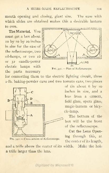
A HOME-MADE REFLECTOSCOPE 211
FIG. 341 . Plan of Reflectoscope.
mouth opening and closing, giant size. The ease with
which slides are obtained makes this a desirable lantern
to own.
The Material. You
must get a box about
10 by 10 by 20 inches
in size for the case of
the reflectoscope, two
oil-lamps, or two 16
or 32 candle-power
electric lamps with
the parts necessary
for connecting them to the electric lighting circuit, three
i-lb. baking-powder cans and two tomato cans, two pieces
of tin about 6 by 10
inches in size, and a
lens from a camera,
field glass, opera glass,
magic-lantern or bicy-
cle-lamp.
The bottom of the.-*">
--~;:~-'-''~ box will be the front-"*
of the reflectoscope.
Cut the Lens Open-
ing through this, at
the center of its length,
and a trifle above the center of its width. Make the hole
a trifle larger than the lens.
FIG. 342. Cross-section of Reflectoscope.
212 HOME-MADE TOYS FOR GIRLS AND BOYS
Cut Ventilator Holes 3 inches in diameter through the
uppermost side of the box, near to the ends and bottom.
Figures 341 and 342 show
The Interior Arrangement of the reflectoscope. Place
the lamps in the corners of the box, next to the front, and
tack in back of them the pieces of tin for reflectors (A,
Figs. 341 and 342). Bend the reflectors to the curve shown.
If Oil Lamps are Used, their tops will project through the
ventilation holes, as shown in Fig. 342. These openings
must be inclosed with
A Hood which will Conceal the Light, yet allow the heat
to escape. The most satisfactory arrangement is that
shown in Figs. 339 and 342. A baking-powder can with
its bottom removed (B) is slipped over the lamp chimney
and fitted into the ventilation hole; then a tomato-can
(C) is inverted over the top of the can and fastened in the
slotted ends of three wooden peg stilts (D, Fig. 340), and
the pegs are fitted into holes made in the top of the box
(Figs. 339 and 342). Fasten the can in the slots of the
stilts with tacks (Fig. 340).
If Electric Light is Used, the hooded ventilators may be
omitted. Any boy who understands the wiring of electric-
lamp sockets, plugs, and drop-cord will know how to wire
up the reflectoscope.
Mount the Lens in a can or mailing-tube jacket (Fig.
343). If you use a can, remove the bottom. If the lens
is smaller in diameter, make a band of cardboard strips to
fit around the edge, as shown in Fig. 344, and glue these
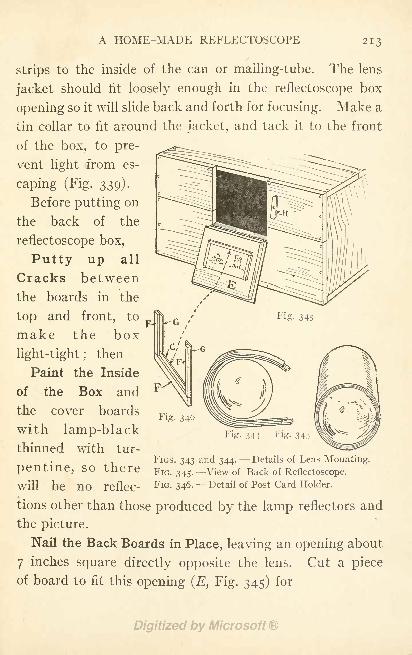
A HOME-MADE REFLECTOSCOPE 213
strips to the inside of the can or mailing-tube. The lens
jacket should fit loosely enough in the reflectoscope box
opening so it will slide back and forth for focusing. Make a
tin collar to fit around the jacket, and tack it to the front
of the box, to pre-
vent light from es-
caping (Fig. 339).
Before putting on
the back of the
reflectoscope box,
Putty up all
Cracks between
the boards in the/'
Fig. 345top and
in
front, to
Fig. 346
Fig. 344
make the box
light-tight ;then
Paint the Inside
of the Box and
the cover boards
with lamp-blackthinned with tur-
FIGS. 343 and 344. --Details of Lens Mounting.pentine, SO there FIG. 345. View of Back of Reflectoscope.
will be no reflec- FIG. 346. Detail of Post Card Holder.
tions other than those produced by the lamp reflectors and
the picture.
Nail the Back Boards in Place, leaving an opening about
7 inches square directly opposite the lens. Cut a piece
of board to fit this opening (E, Fig. 345) for
214 HOME-MADE TOYS FOR GIRLS AND- BOYS
The Picture Holder, and hinge it in place. A frame for
post cards to slide in should be fastened to the picture
holder, as shown in Fig. 346. First nail strips F to board
E, then tack strips G to them so their edges project over
strips F. A little wooden button (H, Fig. 345) will fasten
the holder board shut while each picture is being projected.
The Lens Reverses Pictures in projecting them, and in
order to have them projected right-side up on the screen it
is necessary to slip them into the holder frame upside down.
Adjustments. After you have built your reflectoscope,
you may find it does not throw sharply-defined images upon
your projection screen. In that case you must readjust the
focus of the lens, the curve of the lamp reflectors, and
the distance between the lens and the projection screen,
until the best possible results are obtained. Inasmuch as
the positions will vary with different lenses, it is impossible
for me to give any hard and fast measurements. You
will have to determine the distances yourself.
The stronger the light, the brighter the projected image
will be; therefore, use the strongest light you can get, and
place the lantern not more than five feet away from the screen.
Unless you use an anastigmat lens such as the better
grade of cameras are fitted with, you will discover that the
corners of pictures are indistinct when you have brought
the centers to a sharp focus. This indistinctness can be
corrected to a great extent by blocking out the holder to
curve the post cards and other pictures so that the ends
are closer to the lens than the center is.
INDEX
Airships," clockwork "flying, 102.
Animal targets for toy shooting gallery,
142.
Apartment building, doll, 165.
Automobile, clockwork, 104.
Automobile delivery wagon, clockwork,
112; cigar-box, 192.
B
Baby carriage, doll, 196.
Ballast, toy elevator, 63.
Balusters, doll-house stairway, 154.
Battery, a bi-chromate of potash, 135.
Bead portieres, doll-house, 157.
Beds, doll-house, 183, 187.
Bi-chromate battery fluid, 136.
Boat, toy motor-, 33.
Box-kite, 12.
Bridle, Malay kite, 12; box-kite, 16.
Buzz-saw whirligig, 71.
Cables, toy elevator, 61, 69; electro-
magnet derrick, 123.
Cardboard toys, 196.
Carpets, doll-house, 157.
Carriage, doll baby, 196.
Cars, toy railway, 50; gondola, 52;
street, 52; other forms of, 56; eleva-
tor, 60, 68, 150; Ferris wheel, 99.
Cart, cigar-box, 192 ; cardboard, 199.
Chairs, cigar-box, 176, 194, 195; card-
board, 203.
Chauffeur for clockwork automobile, in.
Cigar-boxes, to prepare, for use, 175.
Cigar-box toys, 191.
Clock, a grandfather's, 182.
Clock wheel top, 81.
Clockwork automobile, 104.
Clockwork automobile delivery wagon,112.
Clockwork Ferris wheel, 96.
Clockwork "flying airships," 102.
Clockwork merry-go-round, 89.
Clockwork motors, 89, 97; increasing
speed of, 103.
Clockwork railway, 116.
Clockwork toys, 88.
Clog-dancer, toy, 72.
Control, toy elevator, 65.
Cosey-corner, doll-house, 158.
Counter-balance, 61, 69.
Cradle, doll's, 195.
Cricket-rattle, 75.
Curtains, doll-house, 157.
D
Decorating, doll-house, 156; doll apart-
ment, 173.
Delivery-wagon, clockwork automobile,
112; cigar-box, 192.
Derrick, electro-magnet, 117.
Doll apartment building, 165.
Doll-house, 145 ; furnishing the, 156.
Dresser, doll, 185, 189.
E.
Egg-beater motor-winder, 31.
Electrical toys, 117.
Electric motor truck, toy, 132.
215
2l6 INDEX
Electro-magnet, 118.
Electro-magnet derrick, 117.
Elevator, model aeroplane, 25.
Elevators, toy, 59.
Elevator, toy office building, 59; an
outdoor, 67 ; doll-house, 148.
Enlarging by squares, 175.
Express-wagon, cigar-box, 192.
Feed-hoist, toy stable, 163.
Feed-troughs, toy stable, 162.
Ferris wheel, clockwork, 96.
Fin, model aeroplane, 26.
Fireplace, doll apartment, 171.
Fixtures, doll apartment lighting, 171.
Floors, toy office building, 59; hard-
wood, for doll-house, 157.
"Flying airships," clockwork, 102.
Flying-line for kites, 12.
Folding-bed, doll, 187.
Furniture, cigar-box, 174, 194; card-
board, 203.
Fuselage, model aeroplane, 22.
Gable-ends, doll-house, 151 ; toy stable,
161.
Garage, toy (see Stable).
Gondola car, 52.
Grandfather's clock, 182.
Guides, toy elevator, 61, 69, 150.
H
Hand-rail, doll-house stairway, 153.
Horses for merry-go-round, cardboard,
86, 92.
House, doll-, 145 ; furnishing the doll-
156; doll apartment, 165; furniture
for doll-, 174, 194, 203.
Induction-coil, 126.
Interrupter, shocking-machine, 129.
ack-in-the-box, cigar-box, 193.
umping-Jack, 74.
fumping-Jack operated by windmill, 7.
K
iite, a Malay, 9; a box-, 12.
Kite-reel, a hand, 17; a body, 19.
Launching a model aeroplane, 31.
Lighting fixtures, doll apartment, 171.
MMagnet, electro-, 118.
Mail-bag, toy, 209.
Mail-box, toy, 205.
Malay kite, 9.
Mantel, doll apartment, 171.
Mechanical toys, 71.
Merry-go-round, top, 85; clockwork,
89; cardboard, 201.
Mirror, doll-house, 181.
Mission furniture, doll, 174.
Model aeroplane, 21; propellers for, 27;
motors for, 29 ;motor-winder for, 31 ;
launching a, 31.
Motor-boat, toy, 33.
Motors, clockwork, 89, 97; increasing
speed of, 103.
Motors, model aeroplane, 29; winder
for, 31.
Motors, water- (see Water-Motor).
Motor, toy motor-boat, 37.
Motor truck, toy electric, 132.
Motor-winder, egg-beater, 31.
N
Newel-post, doll-house stairway, 153.
O
Office building elevator, toy, 59.
INDEX 217
Partitions, toy office building, 60; doll-
house, 145 ;stable stall, 162.
Pictures, doll-house, 158.
Pinion-wheel windmill, 2.
Pinwheel, a paper, i.
Pistol, toy, card-shooting, 143.
Planes, model aeroplane, 24.
Portieres, doll-house, 157.
Post-office with mail-box, to play, 209.
Primary coil, induction-coil, 127.
Propeller-shaft, model aeroplane, 29;
toy motor-boat, 35.
Propellers, model aeroplane, 27.
Propeller, toy motor-boat, 35.
Pulley-wheel, 42, 45, 62, 151.
R
Race-track, spinning-top, 82.
Railway, toy, 47 ; trolley-line for, 47 ;
power for, 49; tracks for, 50; cars
for, 50; gondola car for, 52; street
car for, 52 ;other cars for, 56; opera-
tion of, 56; station for, 57; clock-
work, 116.
Rattle, cricket, 75.
Reel, a hand kite-, 17 ;a body kite-, 19.
Reflectoscope, 210.
Riders for merry-go-round, 86, 94.
Risers, doll-house stairway, 153.
Rugs, doll-house, 157.
Rug-tack top, 82.
S
Secondary-coil, induction-coil. 127.
Settee, doll, 178.
Shocking machine, 124.
Shoe-polish can top, 83.
Shooting gallery, toy, 140.
Side-board, doll, 180.
Sleighs for merry-go-round ,cardboard
, 93 .
Sofa, doll, 203.
Spinning-top race-track, 82.
Spiral top, 85.
Spool and cardboard toys, 196.
Spool top, 82.
Stable, toy, 160.
Stairway for doll-house, 152, 154.
Station for toy railway, 57.
Straw portieres, doll-house, 158.
Street car, toy, 52.
Swing, doll, 202.
Switch, electro-magnet derrick, 121.
Tables, cigar-box, 179, 180, 194; card-
board, 204.
Tack top, 82.
Targets, toy shooting gallery, 142.
Teeter-board, 201.
Thrust bearings, 23, 35.
Top, clockwork, 81; rug-tack, 82
;
spool, 82; spinning, racetrack, 82 ;
shoe-polish can, 83; spiral, 85;
merry-go-round, 85.
Tops, 79.
Track, spinning-top race, 82.
Tracks, toy railway, 50.
Treads, doll-house stairway, 153.
Trolley-line, toy railway, 47.
Troughs, toy stable feed-, 162.
Truck, toy electric motor, 132.
Turtle toy, 76.
V
Varnish-can water-motor, 38.
WWagon, cigar-box express-, 192.
Wardrobe, doll, 190.
Wash-stand, doll, 186.
Water-motor, a varnish-can, 38 ;another
form of, 42.
Wheel, clockwork Ferris, 96.
Wheel, water-motor, 39, 43.
Whirligig, a buzz-saw, 71.
Winder, model aeroplane motor-, 31.
Windlass, electro-magnet derrick, 123.
Windmill, a paper, i;a pinion-wheel, 2
;
a four-blade, 4 ;an eight-blade, 5 ;
jumping-Jack operated by a, 7.
Window-shades, doll-house, 157.
i,t. vL.*
fr<
,R-2 219*.
: