3 special equipment - freightliner trucks air compressor, with a power-steering pump attached, is...
TRANSCRIPT

3 SPECIAL EQUIPMENT
Section Page
3.1 AIR COMPRESSOR ................................................................................ 3-3
3.2 AIR GOVERNOR .................................................................................... 3-10
3.3 EGR CHARGE AIR INTAKE HOUSING ................................................... 3-12
3.4 EGR/CA MIXER HOUSING ..................................................................... 3-15
3.5 EGR COOLER ......................................................................................... 3-17
3.6 EGR ROTARY VALVE .............................................................................. 3-24
3.7 EGR COOLANT INLET TUBE ................................................................. 3-26
3.8 EGR COOLANT RETURN TUBE ............................................................ 3-28
3.9 EGR DELIVERY PIPE .............................................................................. 3-30
3.10 EGR EXHAUST ELBOW .......................................................................... 3-32
3.A ADDITIONAL INFORMATION .................................................................. 3-35

(Rev. 0304) All information subject to change without notice.
3-2 From Bulletin 4-MBE900-04 6SE414 0303 Copyright © 2004 DETROIT DIESEL CORPORATION

MBE 900 SERVICE MANUAL
3.1 AIR COMPRESSOR
The air compressor, with a power-steering pump attached, is driven by a gear on the camshaft.Perform the following procedures for removal and installation of the air compressor.
3.1.1 Air Compressor Removal
Remove the air compressor as follows:
To avoid injury from the expulsion of hot coolant, neverremove the cooling system pressure cap while the engine isat operating temperature. Remove the cap slowly to relievepressure. Wear adequate protective clothing (face shield orsafety goggles, rubber gloves, apron, and boots).
1. Drain the coolant.
2. Remove the two bolts attaching the power steering pump to the air compressor.See Figure 3-1.
Figure 3-1 Power Steering Pump
NOTE:Do not remove the power steering lines. Tie up the lines and the pump out of the way.
All information subject to change without notice. (Rev. 0304)
6SE414 0303 Copyright © 2004 DETROIT DIESEL CORPORATION From Bulletin 4-MBE900-04 3-3

3.1 AIR COMPRESSOR
3. Remove the cross plate between the compressor and the power steering pump.See Figure 3-2.
1. Air Compressor 8. Copper Washer (2)
2. Coolant Return Line 9. Drive Nut
3. Discharge Line (air) 10. Drive Gear
4. Intake Air Line 11. O-ring
5. Unloader Air Line 12. Mounting Bolt (4 qty.)
6. Coolant Delivery Line 13. Cross Plate
7. Banjo Fitting 14. Power Steering Pump
Figure 3-2 Air Compressor Mounting and/or Removal
4. Remove the coolant delivery line and coolant return line.
NOTE:The coolant delivery line is attached to the crank angle position sensor wire with a tiestrap. Cut the tie strap and remove the coolant delivery line.
(Rev. 0304) All information subject to change without notice.
3-4 From Bulletin 4-MBE900-04 6SE414 0303 Copyright © 2004 DETROIT DIESEL CORPORATION

MBE 900 SERVICE MANUAL
To avoid injury from the sudden release of a high-pressurehose connection, wear a face shield or goggles.
5. Remove the three air lines. See Figure 3-3.
1. Discharge Port 4. Unloader Port
2. Unloader Air Line 5. Discharge Air Line
3. Intake Air Line 6. Air Compressor
Figure 3-3 Air Line Attachments
[a] Remove the discharge (compressed air) line. Check the fittings for damage andreplace if necessary. Check inside the discharge line for carbon deposits. If depositsare found, replace the discharge line.
[b] Remove the unloader line. Check the fittings for damage and replace if necessary.
[c] Loosen the hose clamp and remove the intake (suction) air line.
6. Remove the four mounting bolts attaching the air compressor to the cylinder block.See Figure 3-2.
7. Slide the drive gear away from the flywheel. Collect any oil that runs out and disposeof it properly.
All information subject to change without notice. (Rev. 0304)
6SE414 0303 Copyright © 2004 DETROIT DIESEL CORPORATION From Bulletin 4-MBE900-04 3-5

3.1 AIR COMPRESSOR
3.1.1.1 Air Compressor Inspection
Inspect the air compressor as follows:
1. Inspect the O-rings on the fittings at the air system ports and replace if necessary. If theO-rings are damaged, also replace the fittings.
2. Replace the O-ring between the power steering pump and the air compressor.
3. Install the locking device (KM 904 589 03 63 00) on the air compressor at the end of thedrive shaft, where it connects to the power steering pump. This locks the drive shaft toallow removal of the drive nut. See Figure 3-4.
Figure 3-4 Air Compressor Locking Device (KM 904 589 03 63 00)
(Rev. 0304) All information subject to change without notice.
3-6 From Bulletin 4-MBE900-04 6SE414 0303 Copyright © 2004 DETROIT DIESEL CORPORATION

MBE 900 SERVICE MANUAL
4. Install the two locking bolts on the locking device (KM 904 589 03 63 00) and tightenthem until the air compressor drive is locked and incapable of movement. See Figure 3-5.
1. Air Compressor 2. End of Drive Shaft
Figure 3-5 Locking the Air Compressor Drive
All information subject to change without notice. (Rev. 0304)
6SE414 0303 Copyright © 2004 DETROIT DIESEL CORPORATION From Bulletin 4-MBE900-04 3-7

3.1 AIR COMPRESSOR
5. Remove the drive gear from the air compressor. See Figure 3-6.
1. Vise 3. Drive Gear
2. Air Compressor 4. Impact Wrench
Figure 3-6 Pulling the Drive Gear
[a] Place the air compressor in a vise. Make sure it is tightly secured and cannot slipor slide out of the vise.
[b] Place an impact wrench on the drive gear nut and remove the drive nut.
[c] Remove the drive gear from the air compressor with a gear puller, if necessary.
6. Inspect the drive gear for worn or broken teeth, spalling, and corrosion. Replace thedrive gear if necessary.
7. Install the drive gear and drive nut on the drive shaft of the air compressor. Tightenthe drive nut 270 N·m (200 lb·ft).
8. Remove the locking device from the air compressor and release the air compressor fromthe vise.
3.1.2 Air Compressor Installation
Install the air compressor as follows:
1. Install the air compressor.
2. Install the four air compressor mounting bolts. Tighten each bolt 40 N·m (30 lb·ft).
3. Install the three air lines. See Figure 3-3.
(Rev. 0304) All information subject to change without notice.
3-8 From Bulletin 4-MBE900-04 6SE414 0303 Copyright © 2004 DETROIT DIESEL CORPORATION
MBE 900 SERVICE MANUAL
[a] Install the discharge line. Make sure the O-ring is properly installed on the fitting.Tighten the fitting 100 N·m (74 lb·ft).
[b] Install the unloader line. Make sure the O-ring is properly installed on the fitting.
[c] Install the intake air line and tighten the hose clamp.
4. Install the two coolant lines.
[a] Pay particular attention to the coolant delivery line at the rear of the air compressor.It is difficult to line up the bolt and fitting correctly.
NOTE:If necessary to line up the banjo bolt, loosen the coolant line that attaches to the rearof the engine.
NOTE:Attach the coolant delivery line to the crank angle position sensor wire with a tie strap.
[b] Tighten the banjo bolts on the coolant delivery and return lines 40 N·m (30 lb·ft).
5. Install the cross plate. Use grease to hold it in place while installing the power steeringpump.
6. Install the two bolts attaching the power steering pump to the air compressor. Tighten thebolts 40 N·m (30 lb·ft). See Figure 3-1.
7. Fill the radiator with coolant.
All information subject to change without notice. (Rev. 0304)
6SE414 0303 Copyright © 2004 DETROIT DIESEL CORPORATION From Bulletin 4-MBE900-04 3-9

3.2 AIR GOVERNOR
3.2 AIR GOVERNOR
The following sections describe the removal and installation of the air governor.
3.2.1 Air Governor Removal
Remove the air governor as follows:
1. Release system air pressure.
2. Remove and mark the three air line fittings. See Figure 3-7. Inspect all fittings for damageand replace if necessary.
1. Air Governor 6. Unloader Port, Air Compressor
2. Unloader Port, Air Dryer 7. Mounting Bracket
3. Reservoir Port 8. Mounting Bolt, M8
4. Supply Air Line 9. Unloader Air Line
5. Air Dryer Control Line
Figure 3-7 Air Governor Removal and Installation
3. Remove the mounting bolt and remove the mounting bracket from the vehicle, withthe air governor attached.
4. Remove the two bolts holding the air governor to the mounting bracket.
(Rev. 0304) All information subject to change without notice.
3-10 From Bulletin 4-MBE900-04 6SE414 0303 Copyright © 2004 DETROIT DIESEL CORPORATION

MBE 900 SERVICE MANUAL
3.2.2 Air Governor Installation
Install the air governor as follows:
1. Install the air governor on the mounting bracket, using the two bolts, as removed.
2. Install the mounting bracket, with the air governor attached, on the engine. Tightenthe M8 mounting bolt 16 N·m (12 lb·ft).
3. Coat each air line fitting with pipe thread sealant at the air governor port.
NOTE:Coat the surface between the fitting and port on the air governor. Do not put sealant onthe surfaces between the fitting and the air line.
4. Install the three air line fittings, as removed. Make sure all fittings receive the propertorque, as listed in Table 3-1.
All information subject to change without notice. (Rev. 0304)
6SE414 0303 Copyright © 2004 DETROIT DIESEL CORPORATION From Bulletin 4-MBE900-04 3-11

3.3 EGR CHARGE AIR INTAKE HOUSING
3.3 EGR CHARGE AIR INTAKE HOUSING
3.3.1 EGR Charge Air Intake Housing Removal
Remove the charge air intake housing as follows (see Figure 3-8 for component location):
1. Disconnect the electrical plug connector (5) of the temperature sensor (6).
2. Remove bolt securing the charge air intake housing to support bracket.
3. Remove two bolts (3) from the EGR delivery pipe (4).
4. Remove marmon clamp (1) from charge air intake housing (2).
(Rev. 0304) All information subject to change without notice.
3-12 From Bulletin 4-MBE900-04 6SE414 0303 Copyright © 2004 DETROIT DIESEL CORPORATION

MBE 900 SERVICE MANUAL
5. Remove the charge air intake housing (2) and seal ring. Discard seal ring.
1. Marmon Clamp 4. EGR Delivery Pipe
2. Charge Air Intake Housing 5. Electrical Plug Connector
3. EGR Delivery Pipe Bolts 6. Temperature Sensor
Figure 3-8 Charge Air Intake Housing Removal and Installation
3.3.1.1 EGR Charge Air Intake Housing Cleaning
Clean the EGR charge air intake housing as follows:
1. Clean sealing surface of the EGR/CA mixer housing and discard gasket.
2. Clean the sealing surface where the charge air intake housing meets with the air intakehousing.
All information subject to change without notice. (Rev. 0304)
6SE414 0303 Copyright © 2004 DETROIT DIESEL CORPORATION From Bulletin 4-MBE900-04 3-13

3.3 EGR CHARGE AIR INTAKE HOUSING
3.3.2 EGR Charge Air Intake Housing Installation
Install the EGR charge air intake housing as follows (see Figure 3-8 for component locations):
1. Lubricate new seal with lubricant (order number 000 989 11 60) and install on charge airintake housing (2).
2. Install marmon clamp (1) around charge air intake housing (2) and mount to air intakemanifold and secure with bolt. Tighten bolt to 31-35 N·m (23-26 lb·ft).
3. Secure charge air intake housing (2) to support bracket with bolt. Tighten bolt to 31-35N·m (23-26 lb·ft).
4. Using a new gasket, secure EGR delivery pipe (4) to charge air intake housing (2) withtwo bolts. Tighten bolts to 31-35 N·m (23-26 lb·ft).
5. Connect the electrical plug connector (5) to the temperature sensor (6).
(Rev. 0304) All information subject to change without notice.
3-14 From Bulletin 4-MBE900-04 6SE414 0303 Copyright © 2004 DETROIT DIESEL CORPORATION

MBE 900 SERVICE MANUAL
3.4 EGR/CA MIXER HOUSING
3.4.1 EGR/CA Mixer Housing Removal
Remove the EGR/CA mixer housing as follows (see Figure 3-9 for component locations):
1. Remove the charge air intake housing (1). Refer to section 3.3.1.
2. Remove the EGR/CA mixer housing cover bolts (2) and remove the gasket and cover(3). Discard gasket.
All information subject to change without notice. (Rev. 0304)
6SE414 0303 Copyright © 2004 DETROIT DIESEL CORPORATION From Bulletin 4-MBE900-04 3-15

3.4 EGR/CA MIXER HOUSING
3. Remove two hexagon socket-head head screws (7) securing the EGR/CA mixer tube (6)inside the charge air intake housing (1).
1. Charge Air Intake Housing 5. Delivery Pipe
2. EGR/CA Mixer Housing Cover Bolts 6. EGR/CA Mixer Tube
3. EGR/CA Mixer Housing Cover 7. Hexagon Socket-head Screw
4. Delivery Pipe Gasket
Figure 3-9 EGR/CA Mixer Housing Removal and Installation
3.4.2 EGR/CA Mixer Housing Installation
Install the EGR/CA mixer housing as follows (see Figure 3-9 for component locations):
1. Install EGR/CA mixer tube (6) in charge air intake housing (1) with two hexagonsocket-head screws (7). Tighten screws to 12–14 N·m (9–10 lb·ft).
2. Install charge air housing. Refer to section 3.3.2.
(Rev. 0304) All information subject to change without notice.
3-16 From Bulletin 4-MBE900-04 6SE414 0303 Copyright © 2004 DETROIT DIESEL CORPORATION

MBE 900 SERVICE MANUAL
3.5 EGR COOLER
3.5.1 EGR Cooler Removal
Remove the EGR cooler as follows:
1. Drain the coolant.
All information subject to change without notice. (Rev. 0304)
6SE414 0303 Copyright © 2004 DETROIT DIESEL CORPORATION From Bulletin 4-MBE900-04 3-17

3.5 EGR COOLER
NOTICE:
No coolant must escape during disassembly of the coolant inletline.
1. EGR Delivery Pipe Bolts 6. Heat Shield
2. EGR Delivery Pipe Gasket 7. Heat Shield Mounting bolts
3. EGR Delivery Pipe 8. EGR Exhaust Elbow
4. Bolts 9. EGR Exhaust Housing
5. Bolts
Figure 3-10 EGR Cooler Removal and Installation
2. Remove the two bolts (1) from the EGR delivery pipe (3). See Figure 3-10.
3. Remove four bolts (4) from the EGR cooler upper flange. See Figure 3-10.
(Rev. 0304) All information subject to change without notice.
3-18 From Bulletin 4-MBE900-04 6SE414 0303 Copyright © 2004 DETROIT DIESEL CORPORATION

MBE 900 SERVICE MANUAL
4. Remove EGR delivery pipe (3). See Figure 3-10.
NOTE:The EGR cooler end gasket is a one piece gasket. Whenever the EGR delivery tube isremoved, the EGR exhaust elbow must also be removed to replace the gasket. If theEGR exhaust elbow is removed the EGR delivery tube must be removed in order toreplace the gasket.
5. Remove three bolts (7) from heat shield (6) and remove shield. See Figure 3-10.
6. Remove four bolts (5) from the lower EGR cooler flange. Remove housing (9) andelbow (8). See Figure 3-10.
All information subject to change without notice. (Rev. 0304)
6SE414 0303 Copyright © 2004 DETROIT DIESEL CORPORATION From Bulletin 4-MBE900-04 3-19

3.5 EGR COOLER
7. Remove elbow (8) from housing and inspect seal rings. If damaged replace seal rings.See Figure 3-10.
1. Coolant Inlet Tube 5. Hose Clamps
2. Coolant Return Tube 6. Bolts
3. Clamps 7. Coolant Return Tube Clamp
4. EGR Delivery Pipe 8. EGR Cooler
Figure 3-11 Coolant Inlet Line and Related Components
8. Remove bolts from clamps (3) securing coolant inlet tube (1) to thermostat housingand air intake manifold. See Figure 3-11.
9. Loosen two hose clamps (5) from hose on coolant inlet tube (1).
10. Remove coolant inlet tube and O-ring. Discard O-ring.
(Rev. 0304) All information subject to change without notice.
3-20 From Bulletin 4-MBE900-04 6SE414 0303 Copyright © 2004 DETROIT DIESEL CORPORATION

MBE 900 SERVICE MANUAL
11. Remove two bolts, hose and clamps securing EGR coolant return tube (2) to thermostathousing and EGR cooler (8). See Figure 3-11.
12. Remove EGR coolant return tube (2) and gasket. Discard gasket.
13. Remove electrical plug connector (1) from the EGR rotary valve (2). See Figure 3-12.
14. Remove two bolts (3) securing the EGR cooler (4). See Figure 3-12.
NOTE:On MBE 904, 906, 924 and 926 engines, the EGR cooler is secured with two bracketswith two hose clamps.
1. EGR Rotary Valve Electrical Connector 4. EGR Cooler
2. EGR Rotary Valve 5. Clamps
3. Bolts
Figure 3-12 EGR Rotary Valve and Related Components
All information subject to change without notice. (Rev. 0304)
6SE414 0303 Copyright © 2004 DETROIT DIESEL CORPORATION From Bulletin 4-MBE900-04 3-21

3.5 EGR COOLER
15. Remove the hose clamps (5) on the EGR cooler (4). See Figure 3-12.
16. Remove the EGR cooler (4) with the EGR rotary valve (2) still attached. See Figure 3-12.
17. If required, remove two EGR cooler lower support brackets by removing two bolts perbracket.
18. Remove the EGR rotary valve (2) from the EGR cooler (4) by removing five nuts andgasket. Discard gasket. See Figure 3-12.
3.5.2 EGR Cooler Installation
Install the EGR cooler as follows (see Figure 3-12 for component location):
1. Install the EGR rotary valve (2) and new gasket on the EGR cooler (4) with five nuts.Tighten nuts to 31-35 N·m (23-26 lb·ft).
2. If removed, install two lower EGR cooler support brackets and secure with two bolts perbracket. Tighten bolts to 60-66 N·m (44-49 lb·ft).
3. Install the EGR cooler (4) on lower support brackets.
4. Secure EGR cooler (4) with two bolts (3). Tighten bolts to 31-35 N·m (23-26 lb·ft).
5. Install and tighten clamps (5) on the EGR cooler (4).
6. Install electrical plug connector (1) to the rotary valve (2). See Figure 3-12.
7. Inspect the coolant return hose for any damage. Replace hose if required. Install thecoolant return tube (2) in hose. Using a new gasket and two bolts secure to the thermostathousing. Tighten bolts to 31-35 N·m (23-26 lb·ft). See Figure 3-11.
8. Tighten hose clamps on coolant hose.
9. Install new seal ring on coolant inlet tube (1). See Figure 3-11.
10. Install coolant inlet tube (1) into hose (5) and secure coolant inlet tube with two bolts atclamps (3). Tighten bolts to 31-35 N·m (23-26 lb·ft). See Figure 3-11.
11. Install EGR exhaust elbow (8) with seal rings in EGR exhaust housing (9) and into end ofexhaust manifold. See Figure 3-10.
NOTE:The EGR cooler end gasket is a one piece gasket. Whenever the EGR delivery tube isremoved, the EGR exhaust elbow must also be removed to replace the gasket. If theEGR exhaust elbow is removed the EGR delivery tube must be removed in order toreplace the gasket.
12. Using a new gasket, install the EGR exhaust housing (9) using four bolts (5). Tightenbolts to 31-35 N·m (23-26 lb·ft). See Figure 3-10.
13. Install heat shield (6) using three mounting bolts (7). Tighten bolts to 12-14 N·m (9-10lb·ft). See Figure 3-10.
14. Loosely install EGR delivery pipe (3) at upper cooler flange with four bolts (1).See Figure 3-10.
(Rev. 0304) All information subject to change without notice.
3-22 From Bulletin 4-MBE900-04 6SE414 0303 Copyright © 2004 DETROIT DIESEL CORPORATION

MBE 900 SERVICE MANUAL
15. Install the EGR delivery pipe (3) using a new gasket (2) and two bolts (1). Tighten bolts to31-35 N·m (23-26 lb·ft). See Figure 3-10.
16. Tighten EGR delivery pipe bolts (4) at lower flange. Tighten bolts to 31-35 N·m (23-26lb·ft). See Figure 3-10.
17. Fill engine with fresh coolant to required levels.
3.5.2.1 Testing Engine for Leaks
Perform the following steps to test the engine for coolant leaks:
1. Check the coolant level and top off if required.
2. Check for leaks with the engine running.
3. If any leaks are observed shut engine down and make necessary repairs.
All information subject to change without notice. (Rev. 0304)
6SE414 0303 Copyright © 2004 DETROIT DIESEL CORPORATION From Bulletin 4-MBE900-04 3-23

3.6 EGR ROTARY VALVE
3.6 EGR ROTARY VALVE
3.6.1 EGR Rotary Valve Removal
Remove the EGR rotary valve as follows (see Figure 3-13 for component locations):
1. Nuts 3. EGR Rotary Valve
2. Gasket 4. EGR Cooler
Figure 3-13 Exploded view of Rotary (EGR) Valve
1. Drain engine coolant.
2. Remove EGR cooler. Refer to section 3.5.1.
3. Remove five nuts (1) from EGR rotary valve (3) and remove from EGR cooler (4).Discard gasket (2). See Figure 3-13.
NOTE:The EGR rotary valve is not serviced and must be replaced as an assembly.
3.6.2 EGR Rotary Valve Installation
Install the EGR rotary valve as follows (See Figure 3-13 for component locations):
1. Using a new gasket (2), install the EGR valve (3) to the cooler using the five nuts (1).Tighten nuts to 31-35 N·m (23-26 lb·ft).
2. Install EGR cooler. Refer to section 3.5.2.
(Rev. 0304) All information subject to change without notice.
3-24 From Bulletin 4-MBE900-04 6SE414 0303 Copyright © 2004 DETROIT DIESEL CORPORATION

MBE 900 SERVICE MANUAL
3. Fill engine with fresh coolant to required level.
4. Test engine for leaks. Refer to section 3.5.2.1.
All information subject to change without notice. (Rev. 0304)
6SE414 0303 Copyright © 2004 DETROIT DIESEL CORPORATION From Bulletin 4-MBE900-04 3-25
3.7 EGR COOLANT INLET TUBE
3.7 EGR COOLANT INLET TUBE
3.7.1 EGR Coolant Inlet Tube Removal
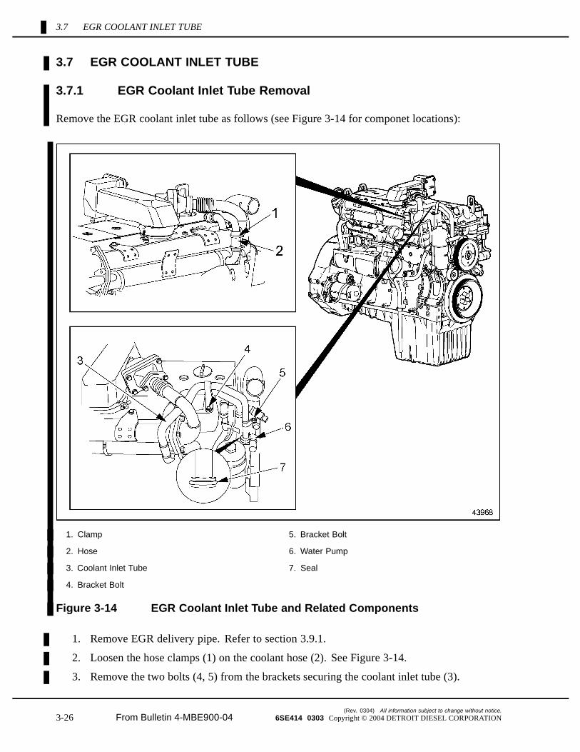
Remove the EGR coolant inlet tube as follows (see Figure 3-14 for componet locations):
1. Clamp 5. Bracket Bolt
2. Hose 6. Water Pump
3. Coolant Inlet Tube 7. Seal
4. Bracket Bolt
Figure 3-14 EGR Coolant Inlet Tube and Related Components
1. Remove EGR delivery pipe. Refer to section 3.9.1.
2. Loosen the hose clamps (1) on the coolant hose (2). See Figure 3-14.
3. Remove the two bolts (4, 5) from the brackets securing the coolant inlet tube (3).
(Rev. 0304) All information subject to change without notice.
3-26 From Bulletin 4-MBE900-04 6SE414 0303 Copyright © 2004 DETROIT DIESEL CORPORATION

MBE 900 SERVICE MANUAL
4. Remove the coolant inlet tube (3) from the coolant hose (2) and the water pump (6).Remove and discard seal (7) from tube.
3.7.2 EGR Coolant Inlet Tube Installation
Install the EGR coolant inlet tube as follows (See Figure 3-14 for component locations):
1. Lubricate new coolant inlet tube seal (7) with lubricant (order number 000 989 11 60)and install on inlet tube.
2. Inspect the coolant hose (2) for damage and replace if required.
3. Install inlet tube in hose (2) and at water pump (6) and secure with bolts (4 and 5) atclamps. Tighten bolts to 31-35 N·m (23-26 lb·ft) and tighten hose clamps.
4. Install EGR delivery pipe. Refer to section 3.8.2.
5. Fill engine with fresh coolant to required level.
6. Test engine for leaks,refer to section 3.5.2.1 and perform the required steps.
All information subject to change without notice. (Rev. 0304)
6SE414 0303 Copyright © 2004 DETROIT DIESEL CORPORATION From Bulletin 4-MBE900-04 3-27

3.8 EGR COOLANT RETURN TUBE
3.8 EGR COOLANT RETURN TUBE
3.8.1 EGR Coolant Return Tube Removal
Remove the EGR coolant return tube as follows (see Figure 3-15 for component locations):
1. Coolant Return Tube 4. Hose
2. Thermostat Housing 5. Bolts
3. Clamp 6. Gasket
Figure 3-15 EGR Coolant Return Tube and Related Components
1. Drain the engine coolant.
2. Remove EGR delivery pipe. Refer to section 3.9.1.
3. Remove the two bolts (5) attaching the coolant return tube (1) to the thermostat housing(2).
(Rev. 0304) All information subject to change without notice.
3-28 From Bulletin 4-MBE900-04 6SE414 0303 Copyright © 2004 DETROIT DIESEL CORPORATION

MBE 900 SERVICE MANUAL
4. Loosen the hose clamp (3) on the coolant hose (4).
5. Remove coolant return tube (1) from the coolant hose (4) and thermostat housing (2).Discard gasket (6).
3.8.2 EGR Coolant Return Tube Installation
Install the EGR coolant return tube as follows (see Figure 3-15 for component locations):
1. Replace gasket (6) and inspect the coolant hose (4) for any damage. Replace hose ifrequired. Install the coolant return tube (1) to the coolant hose (4) and at the thermostathousing (2).
2. Tighten the hose clamps (3) on the coolant hose (4).
3. Install and tighten the two bolts (5) attaching the coolant return tube (1) to the thermostathousing (2). Tighten bolts to 31-35 N·m (23-26 lb·ft).
4. Install EGR delivery pipe. Refer to section 3.9.2.
5. Fill engine with fresh coolant to required level.
6. Test engine for leaks, refer to section 3.5.2.1 and perform the required steps.
All information subject to change without notice. (Rev. 0304)
6SE414 0303 Copyright © 2004 DETROIT DIESEL CORPORATION From Bulletin 4-MBE900-04 3-29
3.9 EGR DELIVERY PIPE
3.9 EGR DELIVERY PIPE
3.9.1 EGR Delivery Pipe Removal
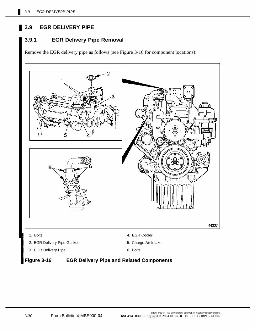
Remove the EGR delivery pipe as follows (see Figure 3-16 for component locations):
1. Bolts 4. EGR Cooler
2. EGR Delivery Pipe Gasket 5. Charge Air Intake
3. EGR Delivery Pipe 6. Bolts
Figure 3-16 EGR Delivery Pipe and Related Components
(Rev. 0304) All information subject to change without notice.
3-30 From Bulletin 4-MBE900-04 6SE414 0303 Copyright © 2004 DETROIT DIESEL CORPORATION

MBE 900 SERVICE MANUAL
1. Remove two bolts (1) and gasket (2) securing EGR delivery pipe (3) to charge air intake(5). Discard gasket.
NOTE:The EGR cooler end gasket is a one-piece gasket. Whenever the EGR delivery tube isremoved, the EGR exhaust elbow must also be removed to replace the gasket. If theEGR exhaust elbow is removed the EGR delivery tube must be removed in order toreplace the gasket
2. Remove EGR delivery pipe (3) and gasket from EGR cooler (4) by removing four bolts(6). Discard gasket.
3.9.2 EGR Delivery Pipe Installation
Install the EGR delivery pipe as follows (see Figure 3-16 for component locations):
NOTE:The EGR cooler end gasket is a one-piece gasket. Whenever the EGR delivery tube isremoved, the EGR exhaust elbow must also be removed to replace the gasket. If theEGR exhaust elbow is removed the EGR delivery tube must be removed in order toreplace the gasket.
1. Install a new gasket on the EGR delivery pipe (3) and loosely secure pipe to the EGRcooler (4) with four bolts (6).
2. Install a new gasket (2) between EGR delivery pipe (3) and charge air intake (5) andsecure with two bolts (1). Tighten bolts to 31-35 N·m (23-26 lb·ft).
3. Tighten the four EGR delivery pipe bolts (6) at EGR cooler (4) to 31-35 N·m (23-26 lb·ft).
All information subject to change without notice. (Rev. 0304)
6SE414 0303 Copyright © 2004 DETROIT DIESEL CORPORATION From Bulletin 4-MBE900-04 3-31

3.10 EGR EXHAUST ELBOW
3.10 EGR EXHAUST ELBOW
3.10.1 EGR Exhaust Elbow Removal
Remove the EGR exhaust elbow as follows (see Figure 3-17 for component locations):
1. EGR Delivery Pipe 4. EGR Exhaust Housing
2. Heat Shield 5. Bolts
3. Bolts 6. EGR Exhaust Elbow
Figure 3-17 EGR Exhaust Elbow and Related Components
1. Remove three bolts (3) from heat shield (2) and remove shield. See Figure 3-17 .
2. Remove four bolts (5) from the lower EGR cooler flange. Remove housing (4) andelbow (6). See Figure 3-17 .
(Rev. 0304) All information subject to change without notice.
3-32 From Bulletin 4-MBE900-04 6SE414 0303 Copyright © 2004 DETROIT DIESEL CORPORATION

MBE 900 SERVICE MANUAL
3. Remove elbow (6) from housing (4) and inspect seal rings. If damaged replace sealrings. See Figure 3-17 .
4. Remove EGR delivery pipe. refer to section 3.9.1.
3.10.2 EGR Exhaust Elbow Installation
Install the EGR exhaust elbow as follows (see Figure 3-17 for component locations):
NOTE:The EGR cooler end gasket is a one-piece gasket. Whenever the EGR delivery tube isremoved, the EGR exhaust elbow must also be removed to replace the gasket. If theEGR exhaust elbow is removed the EGR delivery tube must be removed in order toreplace the gasket.
1. Install exhaust elbow (6) in housing (4).
2. Install a new gasket on the EGR exhaust housing (4) and secure to the EGR cooler withfour bolts (5). Tighten bolts to 31-35 N·m (23-26 lb·ft).
3. Install EGR delivery pipe. refer to section 3.9.2.
All information subject to change without notice. (Rev. 0304)
6SE414 0303 Copyright © 2004 DETROIT DIESEL CORPORATION From Bulletin 4-MBE900-04 3-33

3.10 EGR EXHAUST ELBOW
(Rev. 0304) All information subject to change without notice.
3-34 From Bulletin 4-MBE900-04 6SE414 0303 Copyright © 2004 DETROIT DIESEL CORPORATION

MBE 900 SERVICE MANUAL
3.A ADDITIONAL INFORMATION
Description Page
SPECIFICATIONS ............................................................................................. 3-35
Air Compressor .............................................................................................. 3-35
Air Governor ................................................................................................... 3-36
SPECIFICATIONS
Any specifications for special equipment are listed below.
Air Compressor
The specifications for the air compressor torque values are listed in Table 3-1.
Description N·m (lb·ft)
Air Compressor Mounting Bolts 40 (30)
Discharge Line Fitting 100 (74)
Coolant Line Banjo Bolts 40 (30)
Drive Nut 270 (200)
Power Steering Pump Mounting Bolts 40 (30)
Table 3-1 Air Compressor Torque Values
All information subject to change without notice. (Rev. 0304)
6SE414 0303 Copyright © 2004 DETROIT DIESEL CORPORATION From Bulletin 4-MBE900-04 3-35

Air Governor
The specifications for the air governor torque values are listed in Table 3-2. The list of approvedpipe thread sealants are listed in Table 3-3.
Description N·m (lb·ft)
Air Governor Mounting Bolt, M8 16 (12)
Table 3-2 Air Governor Torque Values
Protectant Material Approved Brand
Loctite 567
Henkel 790 PipegripPipe Thread Sealant (49–00094–108)
Perma-Lok LH-150
Table 3-3 Approved Pipe Thread Sealants
(Rev. 0304) All information subject to change without notice.
3-36 From Bulletin 4-MBE900-04 6SE414 0303 Copyright © 2004 DETROIT DIESEL CORPORATION