3-phase power distribution unit · l1-l2 l2-l 3 l3-l1 l1-l2 l2-l3 l3-l1 a b b b c c c i h j. 5...
TRANSCRIPT
3-Phase
Power Distribution Unit
USER'S MANUAL
Copyright © 2019 Cyber Power Systems, Inc. All rights reserved. K01-0000699-00
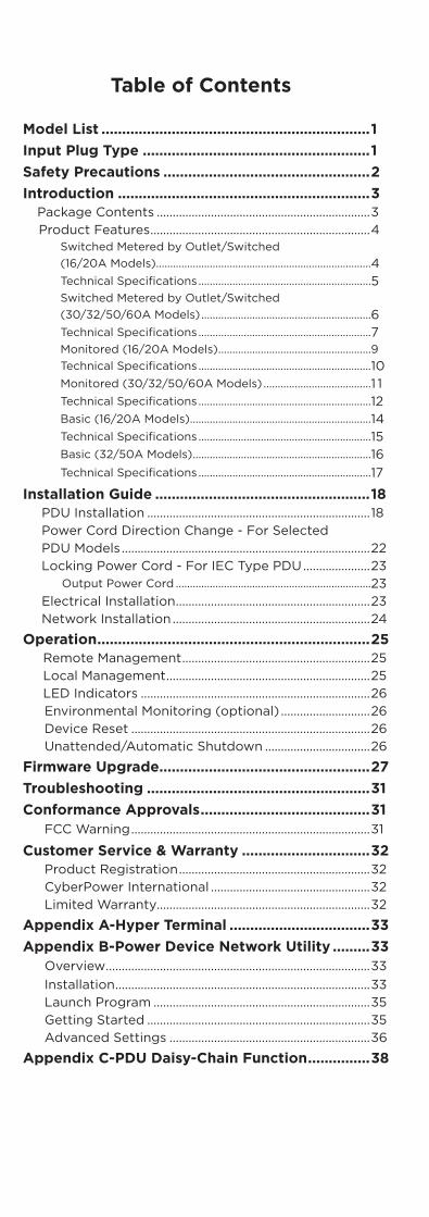
Table of Contents
Model List .................................................................1Input Plug Type .......................................................1Safety Precautions ..................................................2Introduction .............................................................3
Package Contents ...................................................................3Product Features .....................................................................4
Switched Metered by Outlet/Switched (16/20A Models)............................................................................4Technical Specifications .............................................................5Switched Metered by Outlet/Switched (30/32/50/60A Models) ............................................................6Technical Specifications .............................................................7Monitored (16/20A Models) ......................................................9Technical Specifications .............................................................10Monitored (30/32/50/60A Models) ......................................1 1Technical Specifications .............................................................12Basic (16/20A Models) ................................................................14Technical Specifications .............................................................15Basic (32/50A Models) ...............................................................16Technical Specifications .............................................................17
Installation Guide ....................................................18PDU Installation ......................................................................18Power Cord Direction Change - For SelectedPDU Models ..............................................................................22Locking Power Cord - For IEC Type PDU .....................23
Output Power Cord .....................................................................23Electrical Installation .............................................................23Network Installation ..............................................................24
Operation ..................................................................25Remote Management ...........................................................25Local Management ................................................................25LED Indicators ........................................................................26Environmental Monitoring (optional) ............................26Device Reset ...........................................................................26Unattended/Automatic Shutdown .................................26
Firmware Upgrade...................................................27Troubleshooting ......................................................31Conformance Approvals .........................................31
FCC Warning ...........................................................................31
Customer Service & Warranty ...............................32Product Registration ............................................................32CyberPower International ..................................................32Limited Warranty...................................................................32
Appendix A-Hyper Terminal ..................................33Appendix B-Power Device Network Utility .........33
Overview ...................................................................................33Installation ................................................................................33Launch Program ....................................................................35Getting Started ......................................................................35Advanced Settings ...............................................................36
Appendix C-PDU Daisy-Chain Function ...............38
1
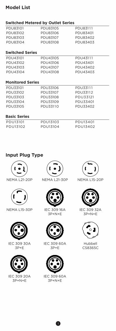
Model List
Switched Metered by Outlet SeriesPDU83101 PDU83105 PDU831 1 1PDU83102 PDU83106 PDU83401PDU83103 PDU83107 PDU83402PDU83104 PDU83108 PDU83403
Switched SeriesPDU43101 PDU43105 PDU431 1 1PDU43102 PDU43106 PDU43401PDU43103 PDU43107 PDU43402PDU43104 PDU43108 PDU43403
Monitored SeriesPDU33101 PDU33106 PDU331 1 1PDU33102 PDU33107 PDU331 12PDU33103 PDU33108 PDU33121PDU33104 PDU33109 PDU33401PDU33105 PDU331 10 PDU33402
Basic SeriesPDU13101 PDU13103 PDU13401PDU13102 PDU13104 PDU13402
Input Plug Type
NEMA L21-20P NEMA L21-30P NEMA L15-20P
NEMA L15-30P IEC 309 16A 3P+N+E
IEC 309 32A 3P+N+E
IEC 309 30A 3P+E
IEC 309 60A 3P+E
Hubbell CS8365C
IEC 309 20A 3P+N+E
IEC 309 60A 3P+N+E

2
Safety Precautions
Read the following before installing or operating the Power Distribution Units (PDU):
• Make sure to disconnect all power supply cords before attempting to service or remove this unit.
• As for overcurrent protection, please be noted that all PDUs with an input current rating greater than 20A are equipped with flush-mount branch circuit breakers according to bank numbers.
• Use only the supplied hardware to attach the mounting brackets.• The PDU must be plugged into a three-wire, grounded outlet
on a circuit that is protected by a fuse or circuit breaker. For 20A PDU series, please use a 20A circuit protector. For 30A PDU series, please use a 30A circuit protector. For 50A PDU series, please use a 50A circuit protector. For 60A PDU series, please use a 60A circuit protector. Connection to any other type of power outlet may result in a shock hazard.
• Do not use extension cords or adapters with this PDU.• Never install a PDU or associated wiring or equipment during a
lightning storm.• Ensure that the power cord, plug, and socket are in good
condition.
To prevent the risk of fire or electrocution, this PDU should be installed in a temperature and humidity controlled indoor area free of conductive contaminants. Do not install this PDU where excessive moisture or heat is present.
This product can expose you to harmful chemicals, including Styrene, which is known to the State of California to cause cancer; and Bisphenol-A, which is known to the State of California to cause birth defects or other reproductive harm.For more information, please visit www.P65Warnings.ca.gov.
WARNING!!
CAUTION!!
3
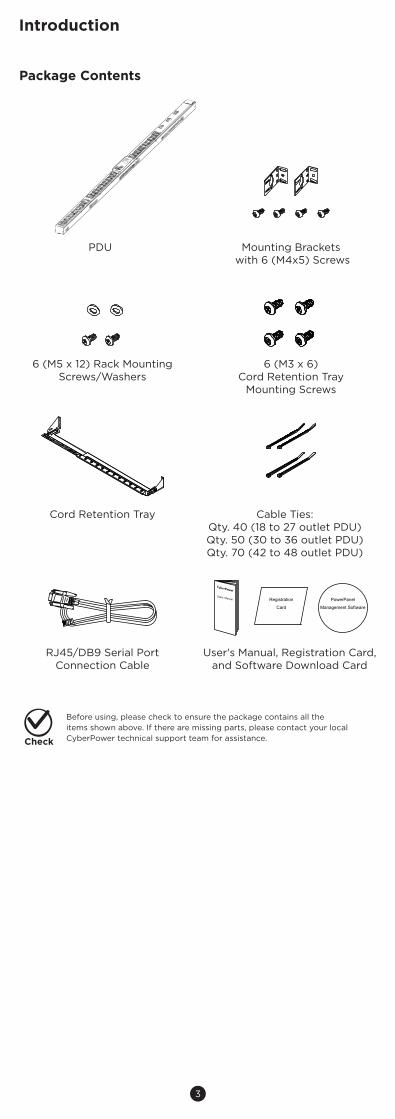
Package Contents
PDU Mounting Brackets with 6 (M4x5) Screws
6 (M5 x 12) Rack MountingScrews/Washers
Cord Retention Tray
6 (M3 x 6) Cord Retention Tray
Mounting Screws
Cable Ties:Qty. 40 (18 to 27 outlet PDU)Qty. 50 (30 to 36 outlet PDU)Qty. 70 (42 to 48 outlet PDU)
RJ45/DB9 Serial PortConnection Cable
User's Manual, Registration Card, and Software Download Card
Users Manual Registration
Card
PowerPanel
Management Software
Introduction
Before using, please check to ensure the package contains all the items shown above. If there are missing parts, please contact your local CyberPower technical support team for assistance.Check
4
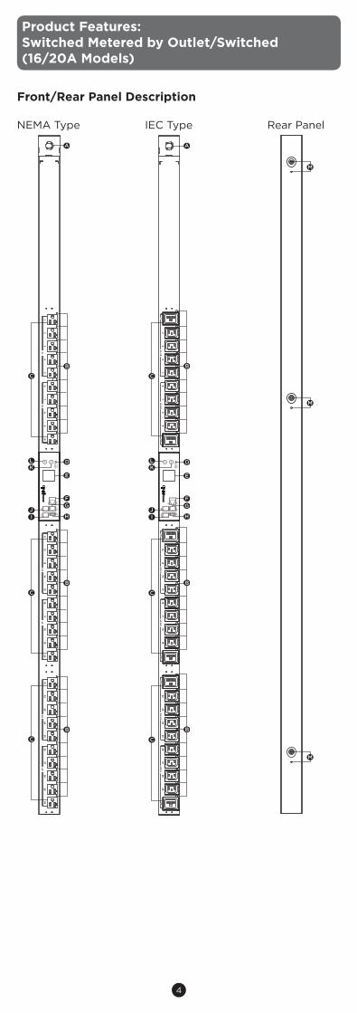
Front/Rear Panel Description
NEMA Type IEC Type Rear Panel
Product Features: Switched Metered by Outlet/Switched(16/20A Models)
M
M
M
L21-20P
PDU
83101- C
ritical- W
arning- N
ormal
Enter
Select
Tx/Rx
In / EN
VU
SB
SerialO
ut
Link
67
81
23
45
910
1617
1811
1213
1415
1920
2627
2821
2223
2425
2930
L1L2
L3L1
L2L3
A
B
B
B
D
E
FG
H
C
I
KL
J
C
C
PDU
83102L21-20P
- Critical
- Warning
- Norm
al
Enter
Select
Tx/Rx
In / EN
VU
SB
SerialO
ut
Link
12
34
56
78
910
1112
1314
1516
1718
1920
2122
2324
2526
2728
2930
L1-L2L2-L3
L3-L1L1-L2
L2-L3L3-L1
A
B
B
B
C
C
C
D
E
FG
HI
KL
J
5
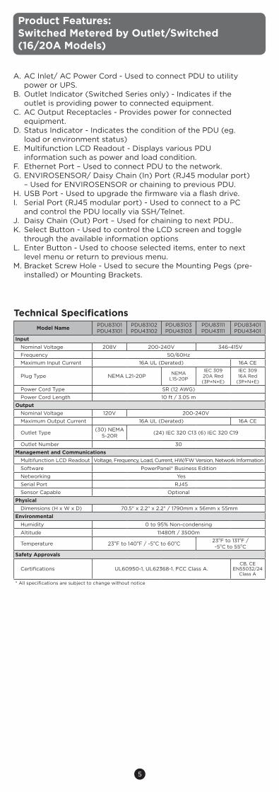
Product Features: Switched Metered by Outlet/Switched (16/20A Models)
Technical SpecificationsModel Name PDU83101
PDU43101PDU83102PDU43102
PDU83103PDU43103
PDU83111PDU43111
PDU83401PDU43401
InputNominal Voltage 208V 200-240V 346-415VFrequency 50/60HzMaximum Input Current 16A UL (Derated) 16A CE
Plug Type NEMA L21-20P NEMA L15-20P
IEC 309 20A Red (3P+N+E)
IEC 309 16A Red
(3P+N+E)
Power Cord Type SR (12 AWG)Power Cord Length 10 ft / 3.05 m
OutputNominal Voltage 120V 200-240VMaximum Output Current 16A UL (Derated) 16A CE
Outlet Type (30) NEMA 5-20R (24) IEC 320 C13 (6) IEC 320 C19
Outlet Number 30Management and Communications
Multifunction LCD Readout Voltage, Frequency, Load, Current, HW/FW Version, Network InformationSoftware PowerPanel® Business EditionNetworking YesSerial Port RJ45Sensor Capable Optional
PhysicalDimensions (H x W x D) 70.5" x 2.2" x 2.2" / 1790mm x 56mm x 55mm
EnvironmentalHumidity 0 to 95% Non-condensing
Altitude 11480ft / 3500m
Temperature 23oF to 140oF / -5oC to 60oC 23oF to 131oF / -5oC to 55oC
Safety Approvals
Certifications UL60950-1, UL62368-1. FCC Class A.CB, CE
EN55032/24 Class A
* All specifications are subject to change without notice
A. AC Inlet/ AC Power Cord - Used to connect PDU to utility power or UPS.
B. Outlet Indicator (Switched Series only) - Indicates if the outlet is providing power to connected equipment.
C. AC Output Receptacles - Provides power for connected equipment.
D. Status Indicator - Indicates the condition of the PDU (eg. load or environment status)
E. Multifunction LCD Readout - Displays various PDU information such as power and load condition.
F. Ethernet Port – Used to connect PDU to the network. G. ENVIROSENSOR/ Daisy Chain (In) Port (RJ45 modular port)
– Used for ENVIROSENSOR or chaining to previous PDU.H. USB Port - Used to upgrade the firmware via a flash drive.I. Serial Port (RJ45 modular port) - Used to connect to a PC
and control the PDU locally via SSH/Telnet.J. Daisy Chain (Out) Port – Used for chaining to next PDU..K. Select Button - Used to control the LCD screen and toggle
through the available information optionsL. Enter Button - Used to choose selected items, enter to next
level menu or return to previous menu.M. Bracket Screw Hole - Used to secure the Mounting Pegs (pre-
installed) or Mounting Brackets.
6
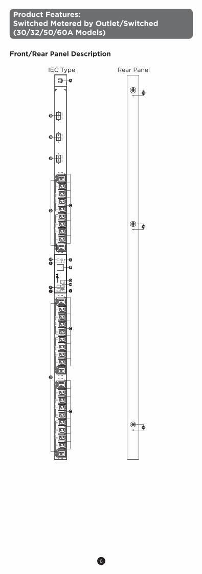
Product Features: Switched Metered by Outlet/Switched(30/32/50/60A Models)
Front/Rear Panel Description
IEC Type Rear Panel
N
N
N
L21-30P
- Critical
- Warning
- Norm
al
Enter
Select
Tx/Rx
In / EN
VU
SB
SerialO
ut
Link
BA
NK
3(20
A)
BA
NK
2(20
A)
BA
NK
1(20
A)
12
34
56
78
910
1112
1314
1516
1718
1920
2122
2324
2526
2728
2930
BA
NK
1 L1-L2B
AN
K 2 L2-L3
BA
NK
3 L3-L1B
AN
K 1 L1-L2
BA
NK
2 L2-L3B
AN
K 3 L3-L1
A
B
B
B
C
C
C
D
D
E
F
GH
IJ
LM
K
7
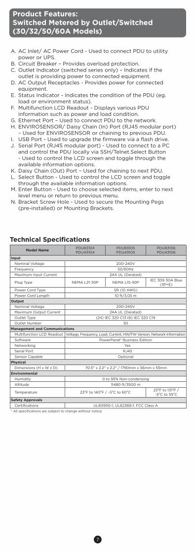
Product Features: Switched Metered by Outlet/Switched (30/32/50/60A Models)
Technical SpecificationsModel Name PDU83104
PDU43104PDU83105PDU43105
PDU83106PDU43106
InputNominal Voltage 200-240VFrequency 50/60HzMaximum Input Current 24A UL (Derated)
Plug Type NEMA L21-30P NEMA L15-30P IEC 309 30A Blue (3P+E)
Power Cord Type SR (10 AWG)Power Cord Length 10 ft/3.05 m
OutputNominal Voltage 200-240VMaximum Output Current 24A UL (Derated)Outlet Type (24) IEC 320 C13 (6) IEC 320 C19Outlet Number 30
Management and CommunicationsMultifunction LCD Readout Voltage, Frequency, Load, Current, HW/FW Version, Network InformationSoftware PowerPanel® Business EditionNetworking YesSerial Port RJ45Sensor Capable Optional
PhysicalDimensions (H x W x D) 70.5" x 2.2" x 2.2" / 1790mm x 56mm x 55mm
EnvironmentalHumidity 0 to 95% Non-condensingAltitude 11480 ft/3500 m
Temperature 23oF to 140oF / -5oC to 60oC 23oF to 131oF / -5oC to 55oC
Safety ApprovalsCertifications UL60950-1, UL62368-1. FCC Class A
* All specifications are subject to change without notice.
A. AC Inlet/ AC Power Cord - Used to connect PDU to utility power or UPS.
B. Circuit Breaker – Provides overload protection. C. Outlet Indicator (switched series only) – Indicates if the
outlet is providing power to connected equipment. D. AC Output Receptacles - Provides power for connected
equipment. E. Status Indicator - Indicates the condition of the PDU (eg.
load or environment status).F. Multifunction LCD Readout - Displays various PDU
information such as power and load condition. G. Ethernet Port – Used to connect PDU to the network. H. ENVIROSENSOR/ Daisy Chain (In) Port (RJ45 modular port)
– Used for ENVIROSENSOR or chaining to previous PDU.I. USB Port - Used to upgrade the firmware via a flash drive.J. Serial Port (RJ45 modular port) - Used to connect to a PC
and control the PDU locally via SSH/Telnet.Select Button - Used to control the LCD screen and toggle through the available information options.
K. Daisy Chain (Out) Port – Used for chaining to next PDU. L. Select Button - Used to control the LCD screen and toggle
through the available information options.M. Enter Button - Used to choose selected items, enter to next
level menu or return to previous menu.N. Bracket Screw Hole - Used to secure the Mounting Pegs
(pre-installed) or Mounting Brackets.
8
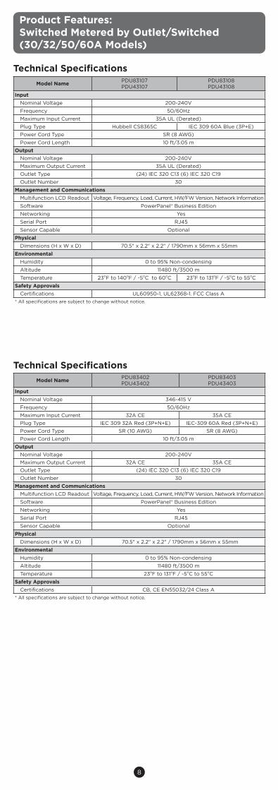
Product Features: Switched Metered by Outlet/Switched(30/32/50/60A Models)
Technical SpecificationsModel Name PDU83402
PDU43402PDU83403PDU43403
InputNominal Voltage 346-415 VFrequency 50/60HzMaximum Input Current 32A CE 35A CEPlug Type IEC 309 32A Red (3P+N+E) IEC-309 60A Red (3P+N+E)Power Cord Type SR (10 AWG) SR (8 AWG)Power Cord Length 10 ft/3.05 m
OutputNominal Voltage 200-240VMaximum Output Current 32A CE 35A CEOutlet Type (24) IEC 320 C13 (6) IEC 320 C19Outlet Number 30
Management and CommunicationsMultifunction LCD Readout Voltage, Frequency, Load, Current, HW/FW Version, Network InformationSoftware PowerPanel® Business EditionNetworking YesSerial Port RJ45Sensor Capable Optional
PhysicalDimensions (H x W x D) 70.5" x 2.2" x 2.2" / 1790mm x 56mm x 55mm
EnvironmentalHumidity 0 to 95% Non-condensingAltitude 11480 ft/3500 mTemperature 23oF to 131oF / -5oC to 55oC
Safety ApprovalsCertifications CB, CE EN55032/24 Class A
* All specifications are subject to change without notice.
Technical SpecificationsModel Name PDU83107
PDU43107PDU83108PDU43108
InputNominal Voltage 200-240VFrequency 50/60HzMaximum Input Current 35A UL (Derated)Plug Type Hubbell CS8365C IEC 309 60A Blue (3P+E)Power Cord Type SR (8 AWG)Power Cord Length 10 ft/3.05 m
OutputNominal Voltage 200-240VMaximum Output Current 35A UL (Derated)Outlet Type (24) IEC 320 C13 (6) IEC 320 C19Outlet Number 30
Management and CommunicationsMultifunction LCD Readout Voltage, Frequency, Load, Current, HW/FW Version, Network InformationSoftware PowerPanel® Business EditionNetworking YesSerial Port RJ45Sensor Capable Optional
PhysicalDimensions (H x W x D) 70.5" x 2.2" x 2.2" / 1790mm x 56mm x 55mm
EnvironmentalHumidity 0 to 95% Non-condensingAltitude 11480 ft/3500 mTemperature 23oF to 140oF / -5oC to 60oC 23oF to 131oF / -5oC to 55oC
Safety ApprovalsCertifications UL60950-1, UL62368-1. FCC Class A
* All specifications are subject to change without notice.
9
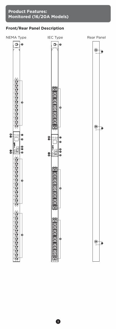
Product Features:Monitored (16/20A Models)
Front/Rear Panel Description
NEMA Type IEC Type Rear Panel
L
L
L
L21-20PPD
U33101
- Critical
- Warning
- Norm
al
Enter
Select
Tx/Rx
In / EN
VU
SB
SerialO
ut
Link
12
34
56
78
910
1112
1314
1516
1718
1920
2122
2324
2526
2728
2930
3132
3334
3536
A
B
C
D
EF
G
B
B
H
JK
I
PDU
33401IEC309 16A 3P+N+E
- Critical
- Warning
- Norm
al
Enter
Select
Tx/Rx
In / EN
VU
SB
SerialO
ut
Link
A
B
C
D
EF
G
B
B
H
JK
I
10
Product Features:Monitored (16/20A Models)
Technical Specifications
Model Name
PDU33101
PDU33104
PDU33121
PDU33401
PDU33102
PDU33103
InputNominal Voltage 208V 200-240V 346-415 V
Frequency 50/60Hz
Maximum Input Current 16A UL (Derated)16A UL (Derated)
16A CE
Plug Type NEMA L21-20P NEMA L15-20P IEC 309 16/20A Red (3P+N+E)
Power Cord Type SR (12 AWG)
Power Cord Length 10 ft/3.05 m
Output
Nominal Voltage
120V
200-240V120/208V
120/208V
Maximum Output Current 16A UL (Derated)16A UL (Derated)
16A CE
Outlet Type
(36)NEMA 5-20R
(30) IEC 320 C13 (6) IEC 320 C19
(24) NEMA 5-20R (6) NEMA L6-20R
(2) NEMA 5-20R (36) IEC 320 C13 (6) IEC 320
C19
Outlet Number
36
3630
44
Management and CommunicationsMultifunction LCD Readout Voltage, Frequency, Load, Current, HW/FW Version, Network Information
Software PowerPanel® Business Edition
Networking Yes
Serial Port RJ45
Sensor Capable Optional
Physical
Dimensions (H x W x D) 70.5" x 2.2" x 2.2" / 1790mm x 56mm x 55mm
EnvironmentalHumidity 0 to 95% Non-condensing
Altitude 11480 ft/3500 m
Temperature 23oF to 140oF / -5oC to 60oC 23oF to 131oF / -5oC to 55oC
Safety Approvals
Certifications UL 60950-1, UL62368-1, FCC Class A
UL 60950-1, UL62368-1, FCC Class A
CB, CE EN55032/24 Class A
* All specifications are subject to change without notice.
A. AC Inlet/ AC Power Cord - Used to connect PDU to utility power or UPS.
B. AC Output Receptacles - Provides power for connected equipment.
C. Status Indicator - Indicates the condition of the PDU (eg. load or environment status).
D. Multifunction LCD Readout - Displays various PDU information such as power and load condition.
E. Ethernet Port – Used to connect PDU to the network.F. ENVIROSENSOR/ Daisy Chain (In) Port (RJ45 modular port)
– Used for ENVIROSENSOR or chaining to previous PDU.G. USB Port - Used to upgrade the firmware via a flash drive.H. Serial Port (RJ45 modular port) - Used to connect to a PC
and control the PDU locally via SSH/Telnet.I. Daisy Chain (Out) Port – Used for chaining to next PDU.J. Select Button - Used to control the LCD screen and toggle
through the available information options.K. Enter Button - Used to choose selected items, enter to next
level menu or return to previous menu.L. Bracket Screw Hole - Used to secure the Mounting Pegs (pre-
installed) or Mounting Brackets.
11
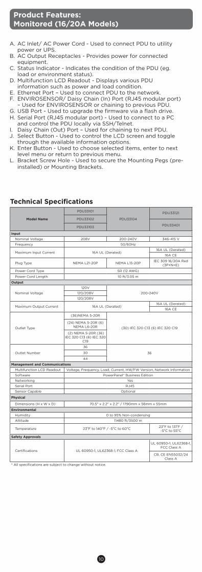
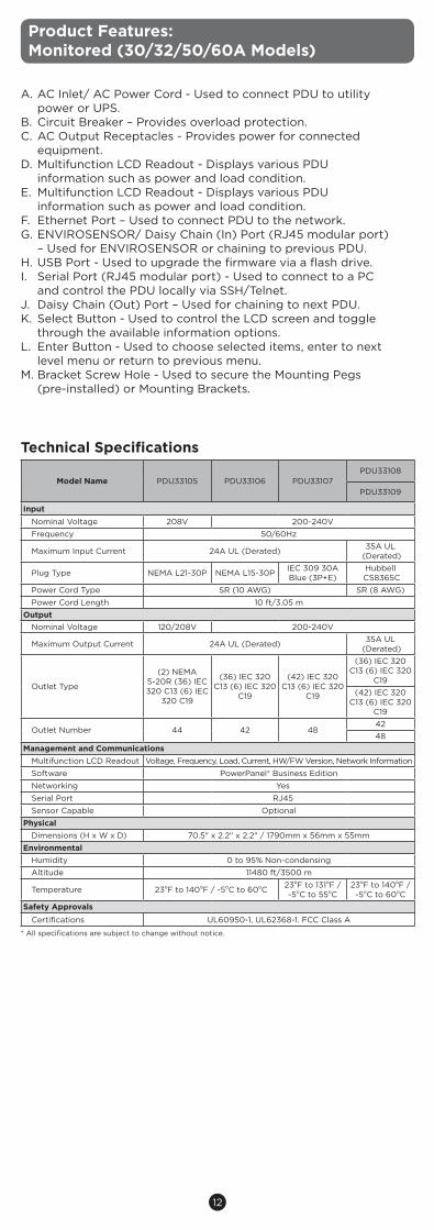
Product Features: Monitored (30/32/50/60A Models)
Front/Rear Panel Description
IEC Type Rear Panel
M
M
M
IEC 309 30A 3P+EPD
U33107
- Critical
- Warning
- Norm
al
Enter
Select
Tx/Rx
In / EN
VU
SB
SerialO
ut
Link
BA
NK
1(20
A)
BA
NK
2(20
A)
BA
NK
3(20
A)
A
C
B
D
E
FG
H
C
C
B
B
I
KL
J
12
Product Features: Monitored (30/32/50/60A Models)
* All specifications are subject to change without notice.
Technical Specifications
Model Name PDU33105 PDU33106 PDU33107PDU33108
PDU33109
InputNominal Voltage 208V 200-240VFrequency 50/60Hz
Maximum Input Current 24A UL (Derated) 35A UL (Derated)
Plug Type NEMA L21-30P NEMA L15-30P IEC 309 30A Blue (3P+E)
Hubbell CS8365C
Power Cord Type SR (10 AWG) SR (8 AWG)Power Cord Length 10 ft/3.05 m
OutputNominal Voltage 120/208V 200-240V
Maximum Output Current 24A UL (Derated) 35A UL (Derated)
Outlet Type
(2) NEMA 5-20R (36) IEC 320 C13 (6) IEC
320 C19
(36) IEC 320 C13 (6) IEC 320
C19
(42) IEC 320 C13 (6) IEC 320
C19
(36) IEC 320 C13 (6) IEC 320
C19(42) IEC 320
C13 (6) IEC 320 C19
Outlet Number 44 42 484248
Management and CommunicationsMultifunction LCD Readout Voltage, Frequency, Load, Current, HW/FW Version, Network InformationSoftware PowerPanel® Business EditionNetworking YesSerial Port RJ45Sensor Capable Optional
PhysicalDimensions (H x W x D) 70.5" x 2.2" x 2.2" / 1790mm x 56mm x 55mm
EnvironmentalHumidity 0 to 95% Non-condensingAltitude 11480 ft/3500 m
Temperature 23oF to 140oF / -5oC to 60oC 23oF to 131oF / -5oC to 55oC
23oF to 140oF / -5oC to 60oC
Safety ApprovalsCertifications UL60950-1, UL62368-1. FCC Class A
A. AC Inlet/ AC Power Cord - Used to connect PDU to utility power or UPS.
B. Circuit Breaker – Provides overload protection. C. AC Output Receptacles - Provides power for connected
equipment.D. Multifunction LCD Readout - Displays various PDU
information such as power and load condition. E. Multifunction LCD Readout - Displays various PDU
information such as power and load condition. F. Ethernet Port – Used to connect PDU to the network.G. ENVIROSENSOR/ Daisy Chain (In) Port (RJ45 modular port)
– Used for ENVIROSENSOR or chaining to previous PDU.H. USB Port - Used to upgrade the firmware via a flash drive.I. Serial Port (RJ45 modular port) - Used to connect to a PC
and control the PDU locally via SSH/Telnet.J. Daisy Chain (Out) Port – Used for chaining to next PDU.K. Select Button - Used to control the LCD screen and toggle
through the available information options.L. Enter Button - Used to choose selected items, enter to next
level menu or return to previous menu.M. Bracket Screw Hole - Used to secure the Mounting Pegs
(pre-installed) or Mounting Brackets.

13
Product Features:Monitered (30/32/50/60A Models)
Technical Specifications
Model Name
PDU33110
PDU33402PDU33111
PDU33112
InputNominal Voltage 200-240V 346-415V
Frequency 50/60Hz
Maximum Input Current
48A UL (Derated)
32A CE48A UL (Derated)
35A UL (Derated)
Plug Type IEC 309 60A Blue (3P+E)
IEC 309 32A Red (3P+N+E)
Power Cord Type
SR (6 AWG)
SR (10 AWG) SR (6 AWG)
SR (8 AWG)
Power Cord Length 10 ft/3.05 m 10 ft/3.05 m
OutputNominal Voltage 200-240V
Maximum Output Current
48A UL (Derated)
32A CE48A UL (Derated)
35A UL (Derated)
Outlet Type
(6) IEC 320 C13 (12) IEC 320 C19(30) IEC 320 C13 (6) IEC 320 C19(30)IEC 320 C13
(42) IEC 320 C13 (6) IEC 320 C19
Outlet Number
18
3630
48
Management and CommunicationsMultifunction LCD Readout Voltage, Frequency, Load, Current, HW/FW Version, Network Information
Software PowerPanel® Business Edition
Networking Yes
Serial Port RJ45
Sensor Capable Optional
Physical
Dimensions (H x W x D) 70.5" x 2.2" x 2.2" / 1790mm x 56mm x 55mm
EnvironmentalHumidity 0 to 95% Non-condensing
Altitude 11480 ft/3500 m
Temperature 23oF to 131oF / -5oC to 55oC
Safety Approvals
Certifications UL 60950-1, UL62368-1, FCC Class A CB, CE EN55032/24 Class A
* All specifications are subject to change without notice.
14
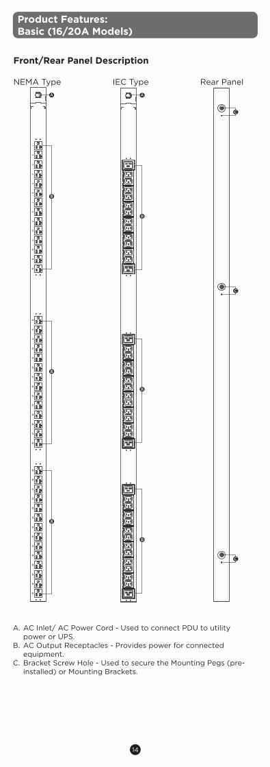
Product Features:Basic (16/20A Models)
Front/Rear Panel Description NEMA Type IEC Type Rear Panel
A. AC Inlet/ AC Power Cord - Used to connect PDU to utility power or UPS.
B. AC Output Receptacles - Provides power for connected equipment.
C. Bracket Screw Hole - Used to secure the Mounting Pegs (pre-installed) or Mounting Brackets.
C
C
C
A
B
B
B
15
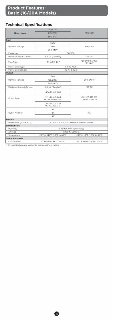
Technical Specifications
Model Name
PDU13101
PDU13401PDU13102
PDU13103
Input
Nominal Voltage
208V
346-415V208V
200-240V
Frequency 50/60Hz
Maximum Input Current 16A UL (Derated) 16A CE
Plug Type NEMA L21-20P IEC 309 16A Red (3P+N+E)
Power Cord Type SR (12 AWG)
Power Cord Length 10 ft/ 3.05 m
Output
Nominal Voltage
120V
200-240 V120/208V
200-240V
Maximum Output Current 16A UL (Derated) 16A CE
Outlet Type
(42)NEMA 5-20R
(36) IEC 320 C13 (6) IEC 320 C19
(21) NEMA 5-20R(6) NEMA L6-20R
(36) IEC 320 C13 (6) IEC 320 C19
Outlet Number
42
4227
42
Physical
Dimensions (H x W x D) 70.5" x 2.2" x 2.2" / 1790mm x 56mm x 55mm
EnvironmentalHumidity 0 to 95% Non-condensing
Altitude 11480 ft/ 3500 m
Temperature 23oF to 140oF / -5oC to 60oC 23oF to 131oF / -5oC to 55oC
Safety Approvals
Certifications UL 60950-1, FCC Class A CB, CE EN55032/24 Class A
* All specifications are subject to change without notice.
Product Features:Basic (16/20A Models)
16
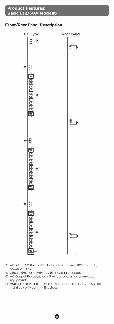
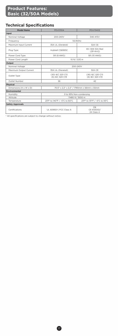
Product Features:Basic (32/50A Models)
Front/Rear Panel Description
IEC Type Rear Panel
A. AC Inlet/ AC Power Cord - Used to connect PDU to utility power or UPS.
B. Circuit Breaker – Provides overload protection. C. AC Output Receptacles - Provides power for connected
equipment.D. Bracket Screw Hole - Used to secure the Mounting Pegs (pre-
installed) or Mounting Brackets.
D
D
D
CS8365C
BA
NK
1(20
A)
BA
NK
2(20
A)
BA
NK
3(20
A)
A
B
C
B
B
C
C
17
* All specifications are subject to change without notice.
Technical SpecificationsModel Name PDU13104 PDU13402
Input
Nominal Voltage 200-240V 346-415V
Frequency 50/60Hz
Maximum Input Current 35A UL (Derated) 32A CE
Plug Type Hubbell CS8365C IEC 309 32A Red (3P+N+E)
Power Cord Type SR (8 AWG) SR (10 AWG)
Power Cord Length 10 ft/ 3.05 m
Output
Nominal Voltage 200-240V
Maximum Output Current 35A UL (Derated) 32A CE
Outlet Type (30) IEC 320 C13 (6) IEC 320 C19
(36) IEC 320 C13 (6) IEC 320 C19
Outlet Number 36 42
Physical
Dimensions (H x W x D) 70.5" x 2.2" x 2.2" / 1790mm x 56mm x 55mm
EnvironmentalHumidity 0 to 95% Non-condensing
Altitude 11480 ft/ 3500 m
Temperature 23oF to 140oF / -5oC to 60oC 23oF to 131oF / -5oC to 55oC
Safety Approvals
Certifications UL 60950-1, FCC Class ACB,
CE E55032/24 Class A
Product Features:Basic (32/50A Models)
18
Installation Guide
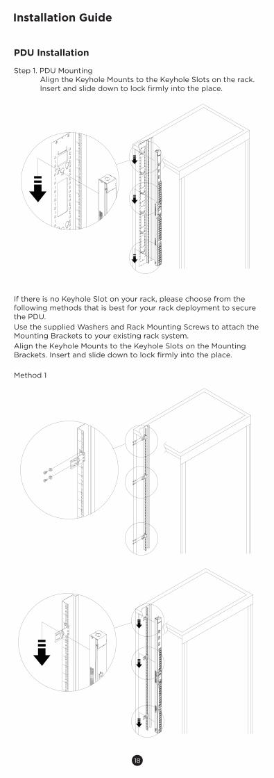
PDU Installation
Step 1. PDU MountingAlign the Keyhole Mounts to the Keyhole Slots on the rack. Insert and slide down to lock firmly into the place.
If there is no Keyhole Slot on your rack, please choose from the following methods that is best for your rack deployment to secure the PDU.Use the supplied Washers and Rack Mounting Screws to attach the Mounting Brackets to your existing rack system.Align the Keyhole Mounts to the Keyhole Slots on the Mounting Brackets. Insert and slide down to lock firmly into the place.
Method 1

19
Installation Guide
Method 2

20
Method 3
Installation Guide

21
Step 2. Cord Retention Tray Installation (optional)Adjust the length of the Cord Retention Tray till the screw hole on the Tray and PDU are aligned. Attach the Cord Retention Tray to the PDU with the supplied Cord Retention Tray Mounting Screws. Tighten the Cord Retention Tray with the screw on it.
Use the provided Cable Ties to fasten each cord to the Cord Retention Tray.
Note: If the PDUs are intended to install in a high temperature environment, please use the Power Cords that could sustain high temperature operation.
Installation Guide
22
Installation Guide
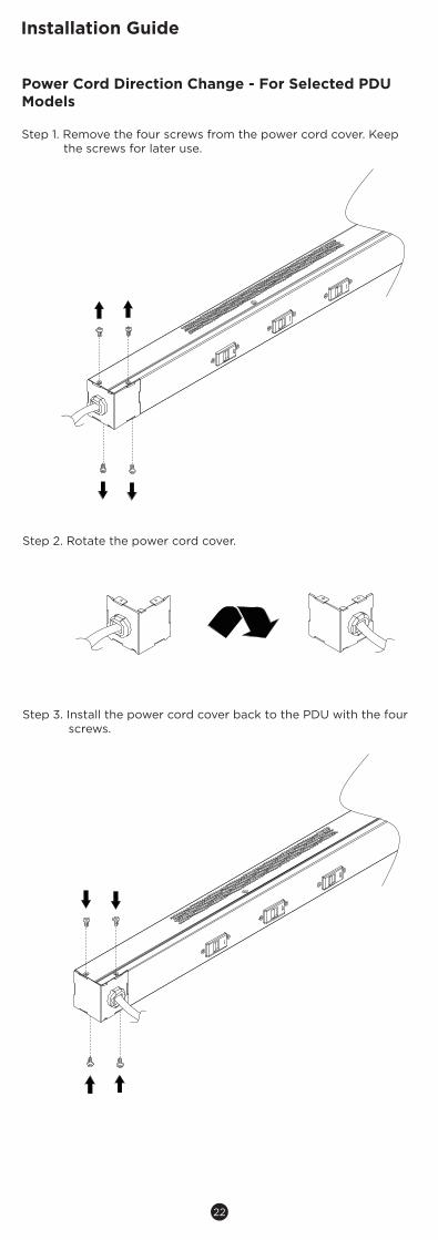
Power Cord Direction Change - For Selected PDU Models
Step 1. Remove the four screws from the power cord cover. Keep the screws for later use.
Step 2. Rotate the power cord cover.
Step 3. Install the power cord cover back to the PDU with the four screws.
23
Installation Guide
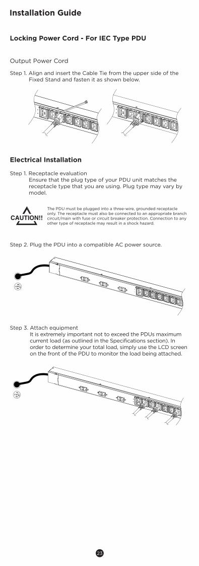
Output Power Cord
Step 1. Align and insert the Cable Tie from the upper side of the Fixed Stand and fasten it as shown below.
Electrical Installation
Step 1. Receptacle evaluationEnsure that the plug type of your PDU unit matches the receptacle type that you are using. Plug type may vary by model.
Step 2. Plug the PDU into a compatible AC power source.
Step 3. Attach equipmentIt is extremely important not to exceed the PDUs maximum current load (as outlined in the Specifications section). In order to determine your total load, simply use the LCD screen on the front of the PDU to monitor the load being attached.
The PDU must be plugged into a three-wire, grounded receptacle only. The receptacle must also be connected to an appropriate branch circuit/main with fuse or circuit breaker protection. Connection to any other type of receptacle may result in a shock hazard.
Locking Power Cord - For IEC Type PDU
24
Installation Guide
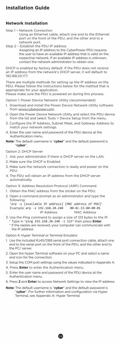
Step 1 – Network ConnectionUsing an Ethernet cable, attach one end to the Ethernet port on the front of the PDU, and the other end to a network port.
Step 2 – Establish the PDU IP addressAssigning an IP address to the CyberPower PDU requires the user to have an available IP address that is valid on the respective network. If an available IP address is unknown, contact the network administrator to obtain one.
DHCP is enabled by factory default. If the PDU does not receive an IP address from the network's DHCP server, it will default to 192.168.20.177.
There are multiple methods for setting up the IP address on the PDU. Please follow the instructions below for the method that is appropriate for your application. Please make sure the PDU is powered on during this process.
Option 1: Power Device Network Utility (recommended)
1. Download and install the Power Device Network Utility software from www.cyberpower.com.
2. Open the Power Device Network Utility and select the PDU device from the list and select Tools > Device Setup from the menu.
3. Configure the IP Address, Subnet Mask, and Gateway Address to match your network settings.
4. Enter the user name and password of the PDU device at the Authentication menu.
Note: The default username is “cyber” and the default password is “cyber”.
Option 2: DHCP Server
1. Ask your administrator if there is DHCP server on the LAN.
2. Make sure the DHCP is Enabled.
3. Make sure the network connection is ready and power on the PDU.
4. The PDU will obtain an IP address from the DHCP server automatically.
Option 3: Address Resolution Protocol (ARP) Command
1. Obtain the MAC address from the sticker on the PDU.
2. Open a command prompt as an administrator and type the following: “arp -s [available IP address] [MAC address of PDU]”.
Example: arp -s 192.168.20.240 00-0c-15-80-00-01 IP Address MAC Address
3. Use the Ping command to assign a size of 123 bytes to the IP.* Type in “ping 192.168.20.240 -l 123” then press Enter.* If the replies are received, your computer can communicate with
the IP address
Option 4: Hyper Terminal or Terminal Emulator
1. Use the included RJ45/DB9 serial port connection cable, attach one end to the serial port on the front of the PDU, and the other end to the PC/ server.
2. Open the Hyper Terminal software on your PC and select a name and icon for the connection.
3. Setup the COM port settings using the values indicated in Appendix A.
4. Press Enter to enter the Authentication menu.
5. Enter the user name and password of the PDU device at the Authentication menu.
6. Press 2 and Enter to access Network Settings to view the IP address.
Note: The default username is “cyber” and the default password is “cyber”. For further information and configuration via Hyper Terminal, see Appendix A- Hyper Terminal.
Network Installation
25
Operation
Remote ManagementThe remote management function provides monitoring of the PDU operational information, controlling outlets and utilizing SNMP functionality.
WebRemote management can be performed via web interface. To access the web interface, please follow the instructions below:
1. Enter the IP address of the PDU into a web browser.
2. Enter the user name and password of the PDU device at the authentication screen.
Note: The default username is “cyber” and the default password is “cyber”.
For additional information about the features and functionality of CyberPower Management Console, please refer to the Intelligent PDU Web Interface User’s Manual available for download from www.cyberpower.com.
Telnet and SSHThe CyberPower PDU provides Telnet and Secure Shell (SSH) as Remote Management methods. Telnet uses user name and password as basic security while SSH has a higher security level with encryption of the transmitted packets including user name, password, and data. Configure the Setting of Telnet and SSH on the Web Interface. The default user name and password is cyber; cyber.
SNMPThe CyberPower PDU supports SNMPv1 and SNMPv3 protocols. Download the CyberPower MIB file from www.cyberpower.com and add it to an SNMP-supported management software. Default read/write community is public/private for SNMPv1. SNMPv3 provides a higher security level than SNMPv1 by encrypting the transmitted packet. Configure the settings of the SNMPv1/SNMPv3 on Web Interface.
Local ManagementLCD OperationThe LCD screen provides instant information, such as voltage, current and power, for the PDU. In addition, users can use the interfaceto configure each PDU parameters and control each outlet on the Switched PDU. The LCD detects the installation orientation of the PDU (horizontally or vertically), therefore automatically rotates the screen to best fit the reading direction.
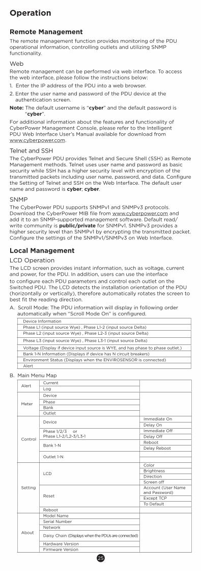
A. Scroll Mode: The PDU information will display in following order automatically when “Scroll Mode On” is configured.
Device InformationPhase L1 (input source Wye) , Phase L1-2 (input source Delta)Phase L2 (input source Wye) , Phase L2-3 (input source Delta)
Phase L3 (input source Wye) , Phase L3-1 (input source Delta)
Voltage (Display if device input source is WYE, and has phase to phase outlet.)Bank 1-N Information (Displays if device has N circuit breakers)Environment Status (Displays when the ENVIROSENSOR is connected)Alert
B. Main Menu Map
AlertCurrentLog
Meter
Device
PhaseBankOutlet
Control
DeviceImmediate OnDelay On
Phase 1/2/3 orPhase L1-2/L2-3/L3-1
Immediate OffDelay Off
Bank 1-NRebootDelay Reboot
Outlet 1-N
Setting
LCD
ColorBrightnessDirectionScreen off
Reset
Account (User Name and Password)Except TCPTo Default
Reboot
About
Model NameSerial NumberNetwork
Daisy Chain (Displays when the PDUs are connected)
Hardware VersionFirmware Version
26
Operation
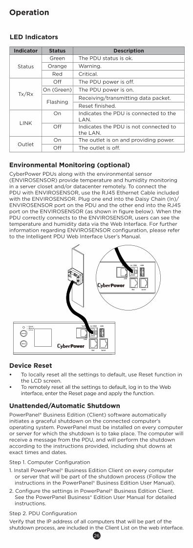
Environmental Monitoring (optional)CyberPower PDUs along with the environmental sensor (ENVIROSENSOR) provide temperature and humidity monitoring in a server closet and/or datacenter remotely. To connect the PDU with ENVIROSENSOR, use the RJ45 Ethernet Cable included with the ENVIROSENSOR. Plug one end into the Daisy Chain (In)/ENVIROSENSOR port on the PDU and the other end into the RJ45 port on the ENVIROSENSOR (as shown in figure below). When the PDU correctly connects to the ENVIROSENSOR, users can see the temperature and humidity data via the Web Interface. For further information regarding ENVIROSENSOR configuration, please refer to the Intelligent PDU Web Interface User’s Manual.
Device Reset• To locally reset all the settings to default, use Reset function in
the LCD screen.• To remotely reset all the settings to default, log in to the Web
interface, enter the Reset page and apply the function.
Unattended/Automatic ShutdownPowerPanel® Business Edition (Client) software automatically initiates a graceful shutdown on the connected computer's operating system. PowerPanel must be installed on every computer or server for which the shutdown is to take place. The computer will receive a message from the PDU, and will perform the shutdown according to the instructions provided, including shut downs at exact times and dates.
Step 1. Computer Configuration
1. Install PowerPanel® Business Edition Client on every computer or server that will be part of the shutdown process (Follow the instructions in the PowerPanel® Business Edition User Manual).
2. Configure the settings in PowerPanel® Business Edition Client. See the PowerPanel Business® Edition User Manual for detailed instructions.
Step 2. PDU Configuration
Verify that the IP address of all computers that will be part of the shutdown process, are included in the Client List on the web interface.
LED Indicators
Indicator Status Description
Status
Green The PDU status is ok.Orange Warning.
Red Critical.
Tx/Rx
Off The PDU power is off.On (Green) The PDU power is on.
FlashingReceiving/transmitting data packet.Reset finished.
LINK
On Indicates the PDU is connected to the LAN.
Off Indicates the PDU is not connected to the LAN.
OutletOn The outlet is on and providing power.Off The outlet is off.
27
Operation
Step 3. Notification
Notifying the computers of potential outlet shutdown can be accomplished using the following functions:• Outlets Control Menu: Performing the task of turning off or
rebooting outlets.• Scheduling Menu: Setting the PDU to perform the task of
turning off or rebooting outlets. The notification will occur prior to the scheduled date/time.
• Outlet Overload: In the event of PDU overload, notification will be sent prior to the PDU shutting down.
Firmware UpgradeBy upgrading the Firmware, you can obtain new features and updates/improvements to existing functionality. To ensure the firmware is kept up to date, please regularly visit our website to see if there is any updated firmware version available. There are three methods for upgrading the PDU firmware. Please follow the instructions below for the method that is appropriate for your application. There are two files to update in order to upgrade the firmware version:
* cpsmpdumbfw_XXX.bin* cpsmpdumbdata_XXX.bin
Note that the XXX is not part of the file name but is where the version number in the filename is given.
Prior to performing a firmware update, please:
• Download the latest firmware from www.cyberpower.com.• Extract the downloaded firmware file to your local “C:\” drive.
Note: 1. The FTP service needs to be enabled before attempting to
execute a firmware upgrade.
2. Please do not turn the PDU off when performing the firmware upgrade. PDU outlets will remain powered on while the firmware update takes place. Only the PDU LCD screen will reboot.
3. The PDU LCD screen will reboot during the firmware update process. This DOES NOT cause the PDU outlets to reboot.
Option 1: Single Device Upgrade
Use the following steps to upgrade the firmware.
1. Open a command prompt window and navigate to “C:\”.
2. Login to the PDU with FTP command, type- C:\>ftp - ftp> open 192.168.22.126 21 (for example: 192.168.22.126 is the current IP of the PDU and 21 is the default ftp port for the PDU)
- Connected to 192.168.22.126.- 220 CyberPower FTP Server Ready.- User (192.168.22.126:(none)):cyber- 331 User name okay, need password.- Password:- 230 User logged in, proceed.- ftp>
3. Upload the cpsmpdumbfw_XXX.bin, type- ftp > bin- ftp > put cpsmpdumbfw_XXX.bin
4. Upgrade complete, type- ftp > quit
5. The system will reboot after you type "quit". This reboot will take approx. 30 seconds.
6. Login to the PDU via FTP again, type- C:\>ftp - ftp> open 192.168.22.126 21 (for example: 192.168.22.126 is the current IP of the PDU and 21 is the default ftp port for the PDU)
- Connected to 192.168.22.126.- 220 CyberPower FTP Server Ready.- User (192.168.22.126:(none)):cyber- 331 User name okay, need password.- Password:- 230 User logged in, proceed.- ftp>
7. Upload cpsmpdumbdata_XXX.bin, type- ftp > bin- ftp > put cpsmpdumbdata_XXX.bin
28
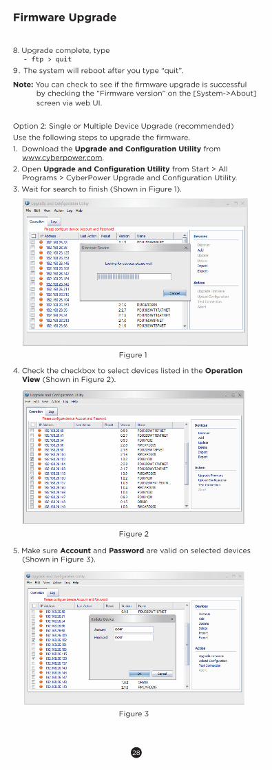
8. Upgrade complete, type- ftp > quit
9. The system will reboot after you type “quit”.
Note: You can check to see if the firmware upgrade is successful by checking the “Firmware version” on the [System->About] screen via web UI.
Option 2: Single or Multiple Device Upgrade (recommended)
Use the following steps to upgrade the firmware.
1. Download the Upgrade and Configuration Utility fromwww.cyberpower.com.
2. Open Upgrade and Configuration Utility from Start > All Programs > CyberPower Upgrade and Configuration Utility.
3. Wait for search to finish (Shown in Figure 1).
Figure 1
4. Check the checkbox to select devices listed in the Operation View (Shown in Figure 2).
Figure 2
5. Make sure Account and Password are valid on selected devices (Shown in Figure 3).
Figure 3
Firmware Upgrade
29
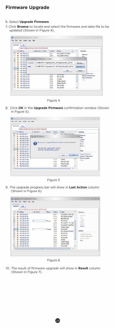
6. Select Upgrade Firmware.
7. Click Browse to locate and select the firmware and data file to be updated (Shown in Figure 4).
Firmware Upgrade
Figure 4
8. Click OK in the Upgrade Firmware confirmation window (Shown in Figure 5).
9. The upgrade progress bar will show in Last Action column(Shown in Figure 6).
Figure 6
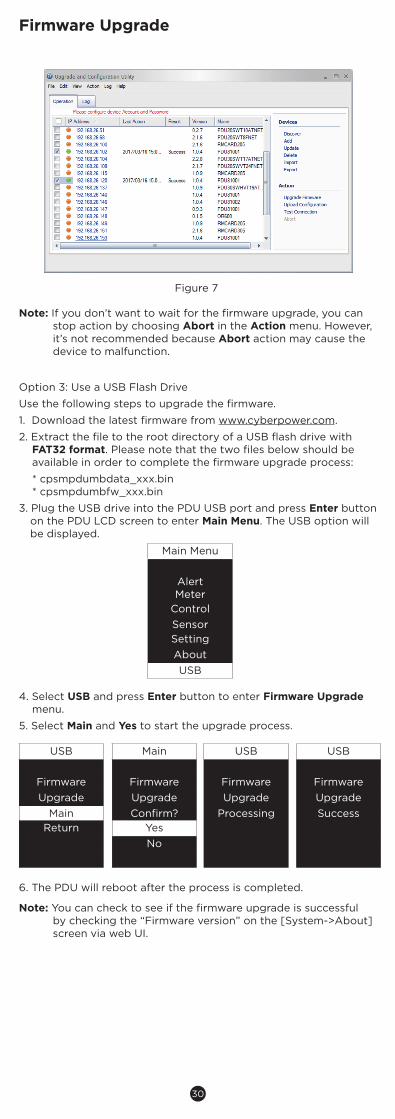
10. The result of firmware upgrade will show in Result column(Shown in Figure 7).
Figure 5
30
Option 3: Use a USB Flash Drive
Use the following steps to upgrade the firmware.
1. Download the latest firmware from www.cyberpower.com.
2. Extract the file to the root directory of a USB flash drive with FAT32 format. Please note that the two files below should be available in order to complete the firmware upgrade process:
* cpsmpdumbdata_xxx.bin* cpsmpdumbfw_xxx.bin
3. Plug the USB drive into the PDU USB port and press Enter button on the PDU LCD screen to enter Main Menu. The USB option will be displayed.
USB Main USB USB
Firmware Firmware Firmware FirmwareUpgrade Upgrade Upgrade Upgrade
Main Confirm? Processing SuccessReturn Yes
No
Main Menu
AlertMeter
ControlSensorSettingAboutUSB
4. Select USB and press Enter button to enter Firmware Upgrade menu.
5. Select Main and Yes to start the upgrade process.
6. The PDU will reboot after the process is completed.
Note: You can check to see if the firmware upgrade is successful by checking the “Firmware version” on the [System->About] screen via web UI.
Firmware Upgrade
Note: If you don’t want to wait for the firmware upgrade, you can stop action by choosing Abort in the Action menu. However, it’s not recommended because Abort action may cause the device to malfunction.
Figure 7
31
FCC WarningWARNING!! Changes or modifications to this unit not expressly approved by the party responsible for compliance could void the user's authority to operate the equipment.
WARNING!! This equipment has been tested and found to comply with the limits for a Class A Digital Device, pursuant to Part 15 of the FCC Rules. These limits are designed to provide reasonable protection against harmful interference in residential installation. This equipment generates, uses and can radiate radio frequency energy and, if not installed and used in accordance with the instruction manual, may cause harmful interference to radio communications.
However, there is no guarantee that interference will not occur in a particular installation. If this equipment does cause harmful interference to radio or television reception, which can be determined by turning the equipment off and on, the user is encouraged to try to correct the interference by one or more of the following measures:
- Reorient or relocate the receiving antenna.- Increase the separation between the equipment and receiver.- Connect the equipment into an outlet on a circuit different from
that to which the receiver is connected.- Consult the dealer or an experienced radio/TV technician for help.
Notice: (1) An unshielded-type power cord is required in order to meet FCC emission limits and also to prevent interference to the nearby radio and television reception. It is essential that only the supplied power cord by used. (2) Use only shielded cables to connect I/O devices to this equipment.
Note: THE MANUFACTURER IS NOT RESPONSIBLE FOR ANY RADIO OR TV INTERFERENCE CAUSED BY UNAUTHORIZED MODIFICATIONS TO THIS EQUIPMENT. SUCH MODIFICATIONS COULD VOID THE USER’S AUTHORITY TO OPERATE THE EQUIPMENT.
The Class A digital apparatus meets all requirements of the Canadian Interference-Causing Equipment Regulation.
Cet appareil numerique de la class A respecte toutes les exigencies du Reglement sur le materiel brouilleur du Canada.
European UnionThis is a class A product. In a domestic environment this product may cause radio interference in which case the user may be required to take adequate measures.
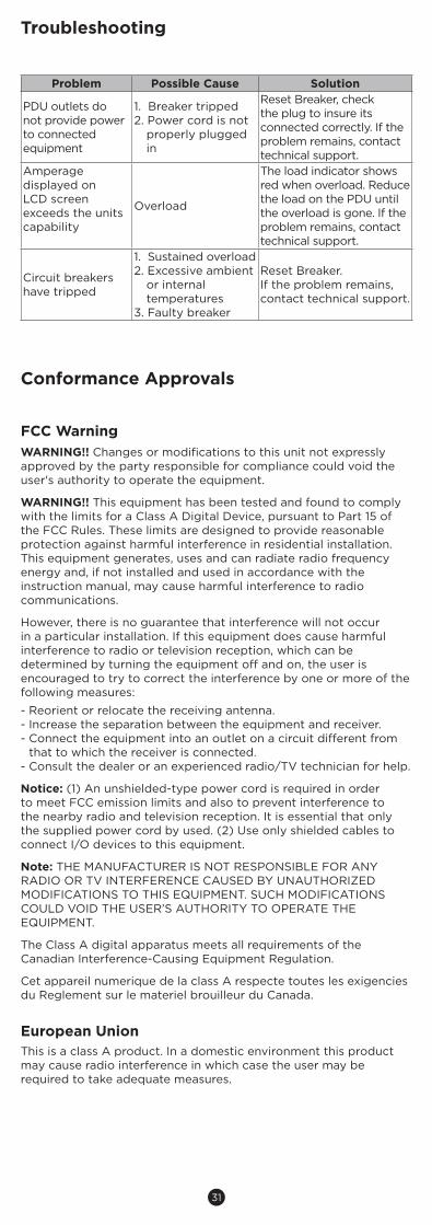
Troubleshooting
Conformance Approvals
Problem Possible Cause Solution
PDU outlets do not provide power to connected equipment
1. Breaker tripped2. Power cord is not
properly plugged in
Reset Breaker, check the plug to insure its connected correctly. If the problem remains, contact technical support.
Amperage displayed on LCD screen exceeds the units capability
Overload
The load indicator shows red when overload. Reduce the load on the PDU until the overload is gone. If the problem remains, contact technical support.
Circuit breakers have tripped
1. Sustained overload 2. Excessive ambient
or internal temperatures
3. Faulty breaker
Reset Breaker.If the problem remains, contact technical support.
32
Customer Service & Warranty
Product RegistrationThank you for purchasing a CyberPower product. Prompt product registration entitles coverage under the Limited Warranty and also allows the opportunity to be notified of product enhancements, upgrades, and other announcements.
Registration is quick and easy at www.cyberpowersystems.com/registration (for USA and Canada) or www.cyberpower.com/registration (for all other regions).
Cyber Power InternationalFeel free to contact our Tech Support department with installation, troubleshooting, or general product questions.
Cyber Power Systems, Inc.Web: www.cyberpower.com
For USA and Canada:4241 12th Ave East, Suite 400 Shakopee, MN55379Toll-free: (877) 297-6937
For all other regions:Please visit our website for local contact information.
Limited WarrantyRead the following terms and conditions carefully before using the CyberPower PDU series. By using the Product, you consent to be bound by and become a party to the terms and conditions of this Limited Warranty. If you do not agree to the terms and conditions of this Warranty, you should return the Product for a full refund prior to using it.
Who Is Providing This Warranty?CyberPower Systems, Inc. provides this Limited Warranty.
What Does This Warranty Cover?This warranty covers defects in materials and workmanship in the Product under normal use and conditions.
What Is the Period of Coverage?For USA and Canada, CyberPower provides a 3-Year warranty to the original purchaser who owns the Product. For other regions, please contact your local CyberPower sales team for more information.
Who Is Covered?This warranty only covers the original purchaser. Coverage ends if you sell or otherwise transfer the Product.
How Do You Get Service?1. You can use the contact information mentioned above for instructions.2. When you contact CyberPower, identify the Product and the Purchase
Date. 3. You must provide a purchase receipt (or other proof of the original
purchase) and provide a description of the defect.
What Will We Do To Correct Problems?CyberPower will inspect and examine the Product. If the Product is defective in material or workmanship, CyberPower will repair or replace it at CyberPower's expense, or, if CyberPower is unable to or decides not to repair or replace the Product (if defective) within a reasonable time, CyberPower will refund to you the full purchase price you paid for the Product (purchase receipt showing price paid is required).
Who Pays for Shipping?We pay when we send items to you; you pay when you send items to us.
What Are Some Things This Warranty Does Not Cover?1. This Warranty does not cover any software that is damaged or needs to be
replaced due to the failure of the Product or any data that is lost as a result of the failure or the restoration of data or records, or the re-installation of software.
2. This Warranty does not cover or apply to: misuse, modification, operation or storage outside environmental limits of the Product or the equipment connected to it, nor for damage while in transit or in storage, nor if there has been improper operation or maintenance, or use with items not designed or intended for use with the Product, such as laser printers, appliances, aquariums, medical or life support devices, etc.
What Are the Limitations?1. This Warranty does not apply unless the Product and the equipment that
was connected to it were connected to properly wired and grounded outlets (including compliance with electrical and safety codes of the most current electrical code), without the use of any adapters or other connectors.
2. The Product must have been plugged directly into the power source and the equipment connected to the Product must be directly connected to the Product and not "daisy-chained" together in serial fashion with any extension cords, another Product or device similar to the Product, surge suppressor, or power tap. Any such installation voids the Limited Warranty.
3. The Product and equipment connected to it must have been used properly in a suitable and proper environment and in conformance with any license, instruction manual, or warnings provided with the Product and the equipment connected to it.
4. The Product must have been used at all times within the limitations on the Product's VA capacity.
5. The sole and exclusive remedies of the Initial Customer are those provided by this Warranty.
33
Appendix A-Hyper Terminal
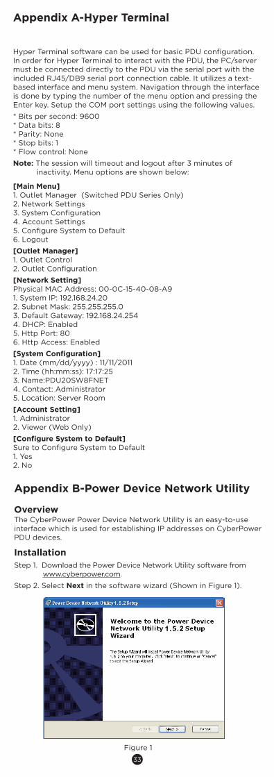
Hyper Terminal software can be used for basic PDU configuration. In order for Hyper Terminal to interact with the PDU, the PC/server must be connected directly to the PDU via the serial port with the included RJ45/DB9 serial port connection cable. It utilizes a text-based interface and menu system. Navigation through the interface is done by typing the number of the menu option and pressing the Enter key. Setup the COM port settings using the following values.
* Bits per second: 9600* Data bits: 8* Parity: None* Stop bits: 1* Flow control: None
Note: The session will timeout and logout after 3 minutes of inactivity. Menu options are shown below:
[Main Menu]1. Outlet Manager (Switched PDU Series Only)2. Network Settings3. System Configuration4. Account Settings5. Configure System to Default6. Logout
[Outlet Manager]1. Outlet Control2. Outlet Configuration
[Network Setting]Physical MAC Address: 00-0C-15-40-08-A91. System IP: 192.168.24.202. Subnet Mask: 255.255.255.03. Default Gateway: 192.168.24.2544. DHCP: Enabled5. Http Port: 806. Http Access: Enabled
[System Configuration]1. Date (mm/dd/yyyy) : 11/11/20112. Time (hh:mm:ss): 17:17:253. Name:PDU20SW8FNET4. Contact: Administrator5. Location: Server Room
[Account Setting]1. Administrator2. Viewer (Web Only)
[Configure System to Default]Sure to Configure System to Default1. Yes2. No
Appendix B-Power Device Network Utility
OverviewThe CyberPower Power Device Network Utility is an easy-to-use interface which is used for establishing IP addresses on CyberPower PDU devices.
InstallationStep 1. Download the Power Device Network Utility software from
www.cyberpower.com.
Step 2. Select Next in the software wizard (Shown in Figure 1).
Figure 1
34
Appendix B-Power Device Network Utility
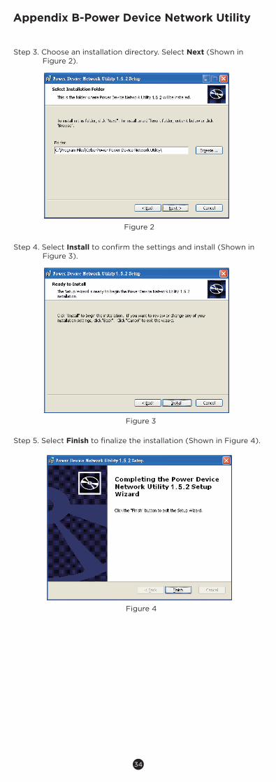
Step 3. Choose an installation directory. Select Next (Shown in Figure 2).
Figure 2
Step 4. Select Install to confirm the settings and install (Shown in Figure 3).
Figure 3
Step 5. Select Finish to finalize the installation (Shown in Figure 4).
Figure 4
35
Appendix B-Power Device Network Utility
Figure 7. Windows Security Alert
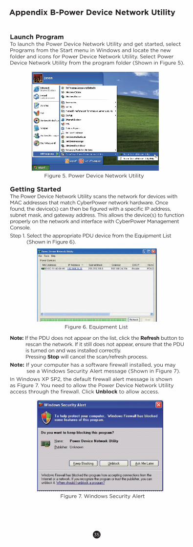
Launch ProgramTo launch the Power Device Network Utility and get started, select Programs from the Start menu in Windows and locate the new folder and icons for Power Device Network Utility. Select Power Device Network Utility from the program folder (Shown in Figure 5).
Getting StartedThe Power Device Network Utility scans the network for devices with MAC addresses that match CyberPower network hardware. Once found, the device(s) can then be figured with a specific IP address, subnet mask, and gateway address. This allows the device(s) to function properly on the network and interface with CyberPower Management Console.
Step 1. Select the appropriate PDU device from the Equipment List (Shown in Figure 6).
Figure 6. Equipment List
Figure 5. Power Device Network Utility
Note: If the PDU does not appear on the list, click the Refresh button to rescan the network. If it still does not appear, ensure that the PDU is turned on and was installed correctly.Pressing Stop will cancel the scan/refresh process.
Note: If your computer has a software firewall installed, you may see a Windows Security Alert message (Shown in Figure 7).
In Windows XP SP2, the default firewall alert message is shown as Figure 7. You need to allow the Power Device Network Utility access through the firewall. Click Unblock to allow access.
36
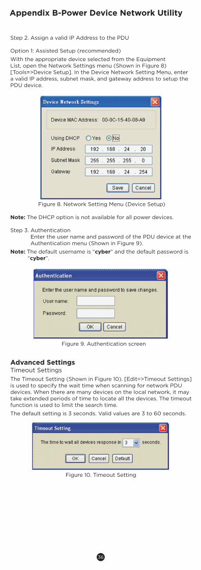
Step 2. Assign a valid IP Address to the PDU
Option 1: Assisted Setup (recommended)
With the appropriate device selected from the Equipment List, open the Network Settings menu (Shown in Figure 8) [Tools=>Device Setup]. In the Device Network Setting Menu, enter a valid IP address, subnet mask, and gateway address to setup the PDU device.
Note: The DHCP option is not available for all power devices.
Step 3. AuthenticationEnter the user name and password of the PDU device at the Authentication menu (Shown in Figure 9).
Note: The default username is “cyber” and the default password is “cyber”.
Advanced SettingsTimeout SettingsThe Timeout Setting (Shown in Figure 10). [Edit=>Timeout Settings] is used to specify the wait time when scanning for network PDU devices. When there are many devices on the local network, it may take extended periods of time to locate all the devices. The timeout function is used to limit the search time.
The default setting is 3 seconds. Valid values are 3 to 60 seconds.
Figure 8. Network Setting Menu (Device Setup)
Figure 9. Authentication screen
Figure 10. Timeout Setting
Appendix B-Power Device Network Utility
37
Appendix C-PDU Daisy-Chain Function
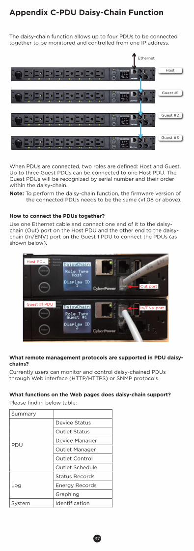
The daisy-chain function allows up to four PDUs to be connected together to be monitored and controlled from one IP address.
New LCD PDU Daisy-Chain Function IntroductionPDU81xxx/ 71xxx/ 41xxx/ 31xxx
The daisy-chain function allows up to four PDUs to be connected together to be monitored and controlled from one IP address.
When PDUs are connected, two roles are defined: Host and Guest. Up to three Guest PDUs can be connected to one Host PDU. The Guest PDUs will be recognized by serial number and their order within the daisy-chain.
Note: To perform the daisy-chain function, the firmware version of the connected PDUs needs to be the same (v1.07 or above).
How to connect the PDUs together?Use one Ethernet cable and connect one end of it to the daisy-chain (Out) port on the Host PDU and the other end to the daisy-chain (In/ENV) port on the Guest 1 PDU to connect the PDUs (as shown below).
Copyright © 2018 Cyber Power Systems, Inc. All rights reserved.
What remote management protocols are supported in PDU daisy-chains?Currently users can monitor and control daisy-chained PDUs through Web interface (HTTP/HTTPS) or SNMP protocols.
What functions on the Web pages does daisy-chain support?Please find in below table:
Host PDU
Out port
Guest #1 PDUIn/ENV port
How to switch between Host and Guest PDUs on the Web interface?Functionality supported by daisy-chained PDUs will have the Host/ Guest # drop down menu displayed on the Web interface (as shown below).
Host
Guest #1
Guest #2
Guest #3
Ethernet
PDU
Device StatusOutlet StatusDevice ManagerOutlet ManagerOutlet ControlOutlet Schedule
Log
Status RecordsEnergy RecordsGraphing
System
Identification
Summary
When PDUs are connected, two roles are defined: Host and Guest. Up to three Guest PDUs can be connected to one Host PDU. The Guest PDUs will be recognized by serial number and their order within the daisy-chain.
Note: To perform the daisy-chain function, the firmware version of the connected PDUs needs to be the same (v1.08 or above).
How to connect the PDUs together?Use one Ethernet cable and connect one end of it to the daisy-chain (Out) port on the Host PDU and the other end to the daisy-chain (In/ENV) port on the Guest 1 PDU to connect the PDUs (as shown below).
New LCD PDU Daisy-Chain Function IntroductionPDU81xxx/ 71xxx/ 41xxx/ 31xxx
The daisy-chain function allows up to four PDUs to be connected together to be monitored and controlled from one IP address.
When PDUs are connected, two roles are defined: Host and Guest. Up to three Guest PDUs can be connected to one Host PDU. The Guest PDUs will be recognized by serial number and their order within the daisy-chain.
Note: To perform the daisy-chain function, the firmware version of the connected PDUs needs to be the same (v1.07 or above).
How to connect the PDUs together?Use one Ethernet cable and connect one end of it to the daisy-chain (Out) port on the Host PDU and the other end to the daisy-chain (In/ENV) port on the Guest 1 PDU to connect the PDUs (as shown below).
Copyright © 2018 Cyber Power Systems, Inc. All rights reserved.
What remote management protocols are supported in PDU daisy-chains?Currently users can monitor and control daisy-chained PDUs through Web interface (HTTP/HTTPS) or SNMP protocols.
What functions on the Web pages does daisy-chain support?Please find in below table:
Host PDU
Out port
Guest #1 PDUIn/ENV port
How to switch between Host and Guest PDUs on the Web interface?Functionality supported by daisy-chained PDUs will have the Host/ Guest # drop down menu displayed on the Web interface (as shown below).
Host
Guest #1
Guest #2
Guest #3
Ethernet
PDU
Device StatusOutlet StatusDevice ManagerOutlet ManagerOutlet ControlOutlet Schedule
Log
Status RecordsEnergy RecordsGraphing
System
Identification
Summary
What remote management protocols are supported in PDU daisy-chains?Currently users can monitor and control daisy-chained PDUs through Web interface (HTTP/HTTPS) or SNMP protocols.
What functions on the Web pages does daisy-chain support?Please find in below table:
Summary
PDU
Device Status
Outlet Status
Device Manager
Outlet Manager
Outlet Control
Outlet Schedule
Log
Status Records
Energy Records
Graphing
System Identification
38
Appendix C-PDU Daisy-Chain Function
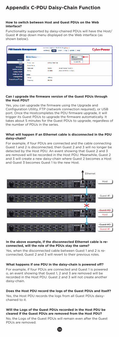
How to switch between Host and Guest PDUs on the Web interface?Functionality supported by daisy-chained PDUs will have the Host/ Guest # drop down menu displayed on the Web interface (as shown below).
New LCD PDU Daisy-Chain Function IntroductionPDU81xxx/ 71xxx/ 41xxx/ 31xxx
The daisy-chain function allows up to four PDUs to be connected together to be monitored and controlled from one IP address.
When PDUs are connected, two roles are defined: Host and Guest. Up to three Guest PDUs can be connected to one Host PDU. The Guest PDUs will be recognized by serial number and their order within the daisy-chain.
Note: To perform the daisy-chain function, the firmware version of the connected PDUs needs to be the same (v1.07 or above).
How to connect the PDUs together?Use one Ethernet cable and connect one end of it to the daisy-chain (Out) port on the Host PDU and the other end to the daisy-chain (In/ENV) port on the Guest 1 PDU to connect the PDUs (as shown below).
Copyright © 2018 Cyber Power Systems, Inc. All rights reserved.
What remote management protocols are supported in PDU daisy-chains?Currently users can monitor and control daisy-chained PDUs through Web interface (HTTP/HTTPS) or SNMP protocols.
What functions on the Web pages does daisy-chain support?Please find in below table:
Host PDU
Out port
Guest #1 PDUIn/ENV port
How to switch between Host and Guest PDUs on the Web interface?Functionality supported by daisy-chained PDUs will have the Host/ Guest # drop down menu displayed on the Web interface (as shown below).
Host
Guest #1
Guest #2
Guest #3
Ethernet
PDU
Device StatusOutlet StatusDevice ManagerOutlet ManagerOutlet ControlOutlet Schedule
Log
Status RecordsEnergy RecordsGraphing
System
Identification
Summary
Can I upgrade the firmware version of the Guest PDUs through the Host PDU?Yes, you can upgrade the firmware using the Upgrade and Configuration Utility, FTP (network connection required), or USB port. Once the Hostcompletes the PDU firmware upgrade, it will trigger its Guest PDUs to upgrade the firmware automatically. It takes about 5 minutes for the Guest PDUs to upgrade, regardless of the number of PDUs in the series.
What will happen if an Ethernet cable is disconnected in the PDU daisy-chain?For example, if four PDUs are connected and the cable connecting Guest 1 and 2 is disconnected, then Guest 2 and 3 will no longer be detected by the Host PDU. An event showing that Guest 2 and 3 are removed will be recorded in the Host PDU. Meanwhile, Guest 2 and 3 will create a new daisy-chain where Guest 2 becomes a Host and Guest 3 becomes Guest 1 to the new Host.
Can I upgrade the firmware version of the Guest PDUs through the Host PDU?Yes, you can upgrade the firmware using the Upgrade and Configuration Utility, FTP (network connection required), or USB port. Once the Host completes the PDU firmware upgrade, it will trigger its Guest PDUs to upgrade the firmware automatically. It takes about 5 minutes for the Guest PDUs to upgrade, regardless of the number of PDUs in the series.
What will happen if an Ethernet cable is disconnected in the PDU daisy-chain? For example, if four PDUs are connected and the cable connecting Guest 1 and 2 is disconnected, then Guest 2 and 3 will no longer be detected by the Host PDU. An event showing that Guest 2 and 3 are removed will be recorded in the Host PDU. Meanwhile, Guest 2 and 3 will create a new daisy-chain where Guest 2 becomes a Host and Guest 3 becomes Guest 1 to the new Host.
In the above example, if the disconnected Ethernet cable is re-connected, will the role of the PDUs stay the same?Yes, when the disconnected cable between Guest 1 and 2 is re-connected, Guest 2 and 3 will revert to their previous roles.
What happens if one PDU in the daisy-chain is powered o�?For example, if four PDUs are connected and Guest 1 is powered o�, an event showing that Guest 1, 2 and 3 are removed will be recorded in the Host PDU. Guest 2 and 3 will not create another daisy-chain.
Does the Host PDU record the logs of the Guest PDUs and itself?Yes, the Host PDU records the logs from all Guest PDUs daisy-chained to it.
Will the Logs of the Guest PDUs recorded in the Host PDU be cleared if the Guest PDUs are removed from the Host PDU?No, the Logs of the Guest PDUs will remain even after the Guest PDUs are removed.
Does the Host PDU record the Status Records of the Guest PDUs and itself?Yes, the Host PDU records the Status Records for all the PDUs in the daisy-chain.
Will the Status Records of the Guest PDUs logged in the Host PDU be cleared if the Guest PDUs are disconnected from the Host PDU?Yes, once the Guest PDUs are removed, the Status Records logged in the Host PDU will be cleared. As long as the Host PDU does not connect to other PDUs, the Status Records of the disconnected PDU can be displayed when it is re-connected to the Host PDU. If the Host PDU connects to di�erent PDUs, the Status Records of the removed PDU will be entirely cleared.
K01-E000006-01
Cyber Power Systems, Inc.www.cyberpowersystems.com
Problem
The PDUs are connected but the daisy-chain function is not working.
I cannot set the EnergyWise configuration on a Guest PDU.
I cannot set the WoL for Guest PDUs.
Possible Cause
- The firmware version does not support daisy-chain.
- The PDUs have di�erent firmware versions.
Only the Host PDU supports EnergyWise.
Only the Host PDU supports WoL.
Solution
Check the firmware version of each PDU and upgrade it to v1.07 or above.
N/A
N/A
Troubleshooting
Host
Guest #1
Guest #2
Host
Guest #3
Guest #1
Ethernet
Are the Guest PDUs able to connect to the network when they are daisy-chained?Yes, even when the PDUs are daisy-chained, the Guest PDUs are able to connect to the network directly. Note that a Guest PDU will require having its own Ethernet cable connected to the network.
What will happen if a 5th PDU is added to a daisy-chain?The maximum number of PDUs that can be connected in one daisy-chain is 4. The daisy-chain functionality will not work until the fifth PDU is removed.
What is the maximum recommended length of the Ethernet cable to daisy-chain the PDUs?50 ft (15 m)
In the above example, if the disconnected Ethernet cable is re-connected, will the role of the PDUs stay the same?Yes, when the disconnected cable between Guest 1 and 2 is re-connected, Guest 2 and 3 will revert to their previous roles.
What happens if one PDU in the daisy-chain is powered off?For example, if four PDUs are connected and Guest 1 is powered o, an event showing that Guest 1, 2 and 3 are removed will be recorded in the Host PDU. Guest 2 and 3 will not create another daisy-chain.
Does the Host PDU record the logs of the Guest PDUs and itself?Yes, the Host PDU records the logs from all Guest PDUs daisy-chained to it.
Will the Logs of the Guest PDUs recorded in the Host PDU be cleared if the Guest PDUs are removed from the Host PDU?No, the Logs of the Guest PDUs will remain even after the Guest PDUs are removed.
39
Appendix C-PDU Daisy-Chain Function
Does the Host PDU record the Status Records of the Guest PDUs and itself?Yes, the Host PDU records the Status Records for all the PDUs in the daisy-chain.
Will the Status Records of the Guest PDUs logged in the Host PDU be cleared if the Guest PDUs are disconnected from the Host PDU?Yes, once the Guest PDUs are removed, the Status Records logged in the Host PDU will be cleared. As long as the Host PDU does not connect to other PDUs, the Status Records of the disconnected PDU can be displayed when it is re-connected to the Host PDU. If the Host PDU connects to dierent PDUs, the Status Records of the removed PDU will be entirely cleared.
Are the Guest PDUs able to connect to the network when they aredaisy-chained?Yes, even when the PDUs are daisy-chained, the Guest PDUs are able to connect to the network directly. Note that a Guest PDU will require having its own Ethernet cable connected to the network.
What will happen if a 5th PDU is added to a daisy-chain?The maximum number of PDUs that can be connected in one daisy-chain is 4. The daisy-chain functionality will not work until the fifth PDU is removed.
What is the maximum recommended length of the Ethernet cable to daisy-chain the PDUs?50 ft (15 m)
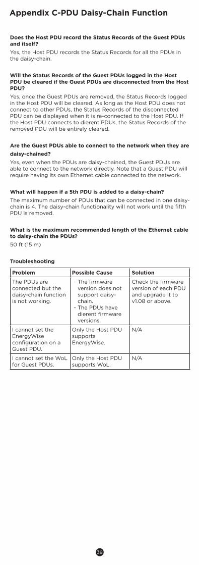
Troubleshooting
Problem Possible Cause Solution
The PDUs areconnected but thedaisy-chain function is not working.
- The firmware version does not support daisy-chain.
- The PDUs have dierent firmware versions.
Check the firmwareversion of each PDUand upgrade it to v1.08 or above.
I cannot set theEnergyWise configuration on aGuest PDU.
Only the Host PDUsupports EnergyWise.
N/A
I cannot set the WoLfor Guest PDUs.
Only the Host PDUsupports WoL.
N/A

Cyber Power Systems, Inc.www.cyberpower.com
Copyright © 2019 Cyber Power Systems, Inc. All rights reserved. K01-0000699-00