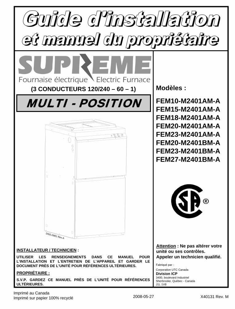
(3 conducteurs 120/240 – 60 – 1) modèles :...
TRANSCRIPT
Imprimé au CanadaImprimé sur papier 100% recyclé
Attention : Ne pas altérer votre unité ou ses contrôles.Appeler un technicien qualifié.
Modèles :
FEM10-M2401AM-AFEM15-M2401AM-AFEM18-M2401AM-AFEM20-M2401AM-AFEM23-M2401AM-AFEM20-M2401BM-AFEM23-M2401BM-AFEM27-M2401BM-A
2008-05-27 X40131 Rev. M
Fabriqué par :
Corporation UTC CanadaDivision ICP3400, boulevard IndustrielSherbrooke, Québec - Canada J1L 1V8
DNS-0981 Rev.A
MULTI - POSITION
INSTALLATEUR / TECHNICIEN :UTILISER LES RENSEIGNEMENTS DANS CE MANUEL POUR L’INSTALLATION ET L’ENTRETIEN DE L’APPAREIL ET GARDER LE DOCUMENT PRÈS DE L’UNITÉ POUR RÉFÉRENCES ULTÉRIEURES.
PROPRIÉTAIRE :S.V.P. GARDEZ CE MANUEL PRÈS DE L’UNITÉ POUR RÉFÉRENCES ULTÉRIEURES.
(3 CONDUCTEURS 120/240 – 60 – 1)
TABLE DES MATIÈRES
1 RÈGLES DE SÉCURITÉ............................................................................................... 3
1.1 SIGNALISATION DANGER, MISE EN GARDE ET AVERTISSEMENT............................................... 3 1.2 REMARQUES IMPORTANTES............................................................................................................ 3 1.3 RISQUE DE GEL.................................................................................................................................. 3
2 INSTALLATION ............................................................................................................ 3
2.1 EMPLACEMENT .................................................................................................................................. 4 2.2 DÉGAGEMENT DES MATÉRIAUX COMBUSTIBLES......................................................................... 4 2.3 CONFIGURATIONS ............................................................................................................................. 4 2.4 RACCORDEMENT ÉLECTRIQUE ....................................................................................................... 5 2.5 INSTALLATION DU THERMOSTAT .................................................................................................... 5 2.6 AJUSTEMENT DES DÉBITS D’AIR DU VENTILATEUR ..................................................................... 6 2.7 INSTALLATION D’ÉQUIPEMENTS CONNEXES................................................................................. 6
3 OPÉRATION ................................................................................................................. 7
3.1 MISE EN MARCHE .............................................................................................................................. 7 3.2 SÉQUENCE DE FONCTIONNEMENT................................................................................................. 7 3.3 UTILISATION DES COMMANDES MANUELLES SUR LA FOURNAISE ............................................ 7 3.4 VÉRIFICATION DU DÉBIT D’AIR ........................................................................................................ 8
4 ENTRETIEN .................................................................................................................. 8
4.1 FILTRE À AIR....................................................................................................................................... 8 4.2 LUBRIFICATION DU MOTEUR............................................................................................................ 8
5 INFORMATION ............................................................................................................. 9
TABLEAUX ET FIGURES FIGURE 1 - CONFIGURATION, DÉBIT ASCENDANT ................................................................................... 4 FIGURE 2 - CONFIGURATION, DÉBIT DESCENDANT................................................................................. 4 FIGURE 3 - CONFIGURATION, DÉBIT HORIZONTAL .................................................................................. 5 FIGURE 4 - COMMANDES MANUELLES DE LA FOURNAISE ..................................................................... 8
TABLEAU 1 - SPÉCIFICATIONS TECHNIQUES.......................................................................................... 10 TABLEAU 2 - DÉBIT D’AIR (PCM), SUPRÊME AVEC MOTEUR DE 1/3 HP ............................................... 11 TABLEAU 3 - DÉBIT D’AIR (PCM), SUPRÊME AVEC MOTEUR DE 1 HP .................................................. 11
FIGURE 5 - DIMENSIONS ............................................................................................................................ 11 FIGURE 6 - DIAGRAMME ÉLECTRIQUE 10KW AVEC MOTEUR 1/3 HP ................................................... 12 FIGURE 7 - DIAGRAMME ÉLECTRIQUE 15KW AVEC MOTEUR 1/3 HP ................................................... 13 FIGURE 8 - DIAGRAMME ÉLECTRIQUE 18 ET 20KW AVEC MOTEUR 1/3 HP ET 20KW AVEC 1.0 HP.. 14 FIGURE 9 - DIAGRAMME ÉLECTRIQUE 23KW AVEC MOTEUR 1/3 HP ET 1 HP..................................... 15 FIGURE 10 - DIAGRAMME ÉLECTRIQUE 27 KW AVEC MOTEUR 1 HP ................................................... 16
VUE EXPLOSÉE DES COMPOSANTES ET LISTE DES PIÈCES..........................................................18-19
TABLEAU 4 - LISTE DES SÉQUENCEURS ................................................................................................. 20
2
3
1 RÈGLES DE SÉCURITÉ
1.1 SIGNALISATION DANGER, MISE EN GARDE ET AVERTISSEMENT
Comprenez bien la portée des mots suivants : DANGER, MISE EN GARDE ou AVERTISSEMENT. Ces mots sont associés aux symboles de sécurité. Vous les retrouverez dans le manuel de la façon suivante :
DANGER Le mot DANGER indique les plus graves dangers, ceux qui provoqueront la mort ou des dommages corporels et/ou matériels sérieux.
MISE EN GARDE L’expression MISE EN GARDE signifie un danger qui peut entraîner la mort ou des dommages corporels et/ou matériels.
AVERTISSEMENT Quant au mot AVERTISSEMENT, il est utilisé pour indiquer les pratiques dangereuses qui peuvent provoquer des dommages corporels et/ou matériels mineurs. 1.2 REMARQUES IMPORTANTES
MISE EN GARDE Ne pas se conformer aux règles de sécurité énoncées dans ce manuel pourrait entraîner des dommages corporels ou la mort et/ou des dommages matériels sérieux. a) Il est de la responsabilité et de l’obligation du
propriétaire d’engager un technicien qualifié pour l’installation et le service subséquent de la fournaise.
b) Ne pas faire fonctionner cette fournaise si elle était immergée dans l’eau. Appeler immédiatement un technicien qualifié pour vérifier les dommages et remplacer les pièces critiques qui ont été en contact avec l’eau.
c) Ne pas ranger ou utiliser d’essence ou toutes autres substances inflammables à proximité de l’appareil, ni d’autres matières combustibles tel que le papier, le carton, etc.
d) Ne jamais obstruer les grilles de retour d’air ou le filtre.
e) Demander à l’installateur d’identifier et de vous informer sur les items suivants :
i. L’interrupteur ou disjoncteur d’alimentation électrique ;
ii. Le filtre à air (comment le changer, le vérifier mensuellement, le nettoyer ou le changer si nécessaire) ;
f) Avant d’appeler pour le service, prendre en note les renseignements sur la page 9 de ce manuel pour le numéro du modèle et le numéro de série de la fournaise.
MISE EN GARDE L’installation ou les réparations par du personnel non qualifié peuvent entraîner des risques pour vous et à autrui. L’installation DOIT être conforme aux codes locaux ou, dans le cas d’absence de codes locaux, elle doit être conforme aux codes nationaux qui s’appliquent.
Les renseignements contenus dans ce manuel s’adressent à un technicien qualifié, expérimenté dans ce type de travail, au courant des précautions à prendre, des règles de sécurité à respecter et muni des outils appropriés ainsi que des instruments de vérification adéquats.
Ne pas se conformer aux règles de sécurité énoncées dans ce manuel pourrait entraîner des dommages corporels ou la mort et/ou des dommages matériels sérieux.
1.3 RISQUE DE GEL
AVERTISSEMENT Si votre appareil demeure fermé durant la saison froide, les conduits d’eau peuvent geler, éclater et provoquer des dégâts d’eau importants. Couper l’alimentation en eau et purger les conduits d’eau.
Si le système de chauffage est laissé sans surveillance durant la saison froide, prendre les précautions suivantes :
a) Fermer l’entrée d’eau principale de la maison ou l’édifice et vider les conduits d’eau si cela est possible. Ouvrir les robinets aux endroits requis ;
b) Demander à une personne de vérifier fréquemment durant la saison froide s’il y a suffisamment de chaleur dans la maison ou l’édifice pour éviter que les tuyaux gèlent. Suggérer à cette personne d’appeler une agence de service qualifiée si cela est requis.
2 INSTALLATION Cet appareil de chauffage central est une véritable unité multi-position puisqu’il peut fonctionner en débit ascendant, descendant et à l’horizontale avec le débit d’air vers la gauche ou la droite. Seules quelques modifications effectuées lors de l’installation sont requises pour passer d’une position à l’autre. L’appareil de chauffage central est expédié en configuration de débit ascendant et les instructions pour changer aux autres positions sont incluses dans ce manuel.
L’unité requiert un circuit électrique (120/240 VAC) connecté à la boîte de contrôle, un raccordement pour le thermostat tel qu’indiqué sur le schéma électrique et des conduits d’air adéquats.
Toutes les exigences requises par les codes locaux et nationaux concernant l’installation d’équipement à chauffage central électrique, les installations électriques et les raccordements de conduits doivent être respectées. Certains codes (émis par l’Institut des standards canadiens) qui pourraient s’appliquer sont :
ANSI/NFPA 70 : Code National d’électricité CSA C22.1 ou CSA C22.10 : Code Canadien d’électricité
Seule l’édition la plus récente des codes doit être utilisée.
4
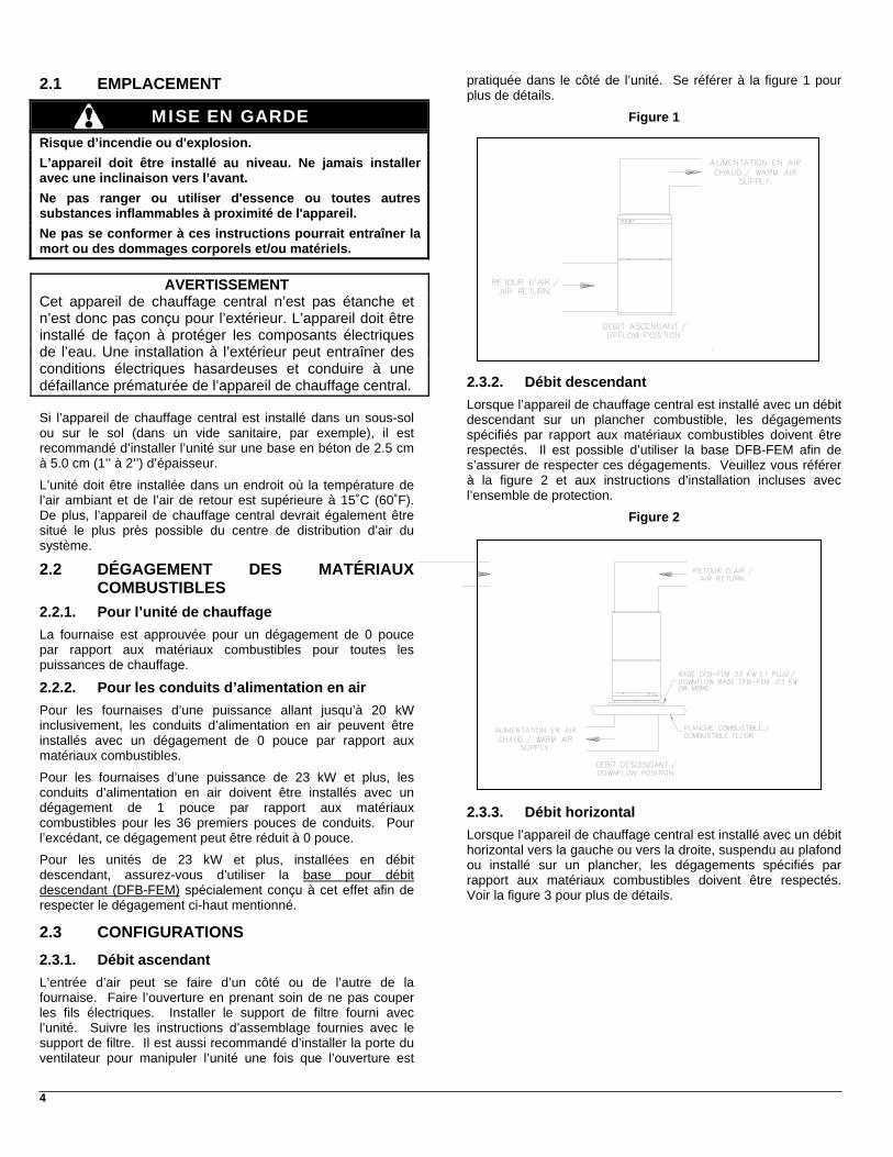
2.1 EMPLACEMENT
MISE EN GARDE Risque d’incendie ou d'explosion.
L’appareil doit être installé au niveau. Ne jamais installer avec une inclinaison vers l’avant.
Ne pas ranger ou utiliser d'essence ou toutes autres substances inflammables à proximité de l'appareil.
Ne pas se conformer à ces instructions pourrait entraîner la mort ou des dommages corporels et/ou matériels.
AVERTISSEMENT Cet appareil de chauffage central n’est pas étanche et n’est donc pas conçu pour l’extérieur. L’appareil doit être installé de façon à protéger les composants électriques de l’eau. Une installation à l’extérieur peut entraîner des conditions électriques hasardeuses et conduire à une défaillance prématurée de l’appareil de chauffage central. Si l’appareil de chauffage central est installé dans un sous-sol ou sur le sol (dans un vide sanitaire, par exemple), il est recommandé d’installer l’unité sur une base en béton de 2.5 cm à 5.0 cm (1’’ à 2’’) d’épaisseur.
L’unité doit être installée dans un endroit où la température de l’air ambiant et de l’air de retour est supérieure à 15˚C (60˚F). De plus, l’appareil de chauffage central devrait également être situé le plus près possible du centre de distribution d’air du système.
2.2 DÉGAGEMENT DES MATÉRIAUX COMBUSTIBLES
2.2.1. Pour l’unité de chauffage
La fournaise est approuvée pour un dégagement de 0 pouce par rapport aux matériaux combustibles pour toutes les puissances de chauffage.
2.2.2. Pour les conduits d’alimentation en air
Pour les fournaises d’une puissance allant jusqu’à 20 kW inclusivement, les conduits d’alimentation en air peuvent être installés avec un dégagement de 0 pouce par rapport aux matériaux combustibles.
Pour les fournaises d’une puissance de 23 kW et plus, les conduits d’alimentation en air doivent être installés avec un dégagement de 1 pouce par rapport aux matériaux combustibles pour les 36 premiers pouces de conduits. Pour l’excédant, ce dégagement peut être réduit à 0 pouce.
Pour les unités de 23 kW et plus, installées en débit descendant, assurez-vous d’utiliser la base pour débit descendant (DFB-FEM) spécialement conçu à cet effet afin de respecter le dégagement ci-haut mentionné.
2.3 CONFIGURATIONS
2.3.1. Débit ascendant
L’entrée d’air peut se faire d’un côté ou de l’autre de la fournaise. Faire l’ouverture en prenant soin de ne pas couper les fils électriques. Installer le support de filtre fourni avec l’unité. Suivre les instructions d’assemblage fournies avec le support de filtre. Il est aussi recommandé d’installer la porte du ventilateur pour manipuler l’unité une fois que l’ouverture est
pratiquée dans le côté de l’unité. Se référer à la figure 1 pour plus de détails.
Figure 1
2.3.2. Débit descendant
Lorsque l’appareil de chauffage central est installé avec un débit descendant sur un plancher combustible, les dégagements spécifiés par rapport aux matériaux combustibles doivent être respectés. Il est possible d’utiliser la base DFB-FEM afin de s’assurer de respecter ces dégagements. Veuillez vous référer à la figure 2 et aux instructions d’installation incluses avec l’ensemble de protection.
Figure 2
2.3.3. Débit horizontal
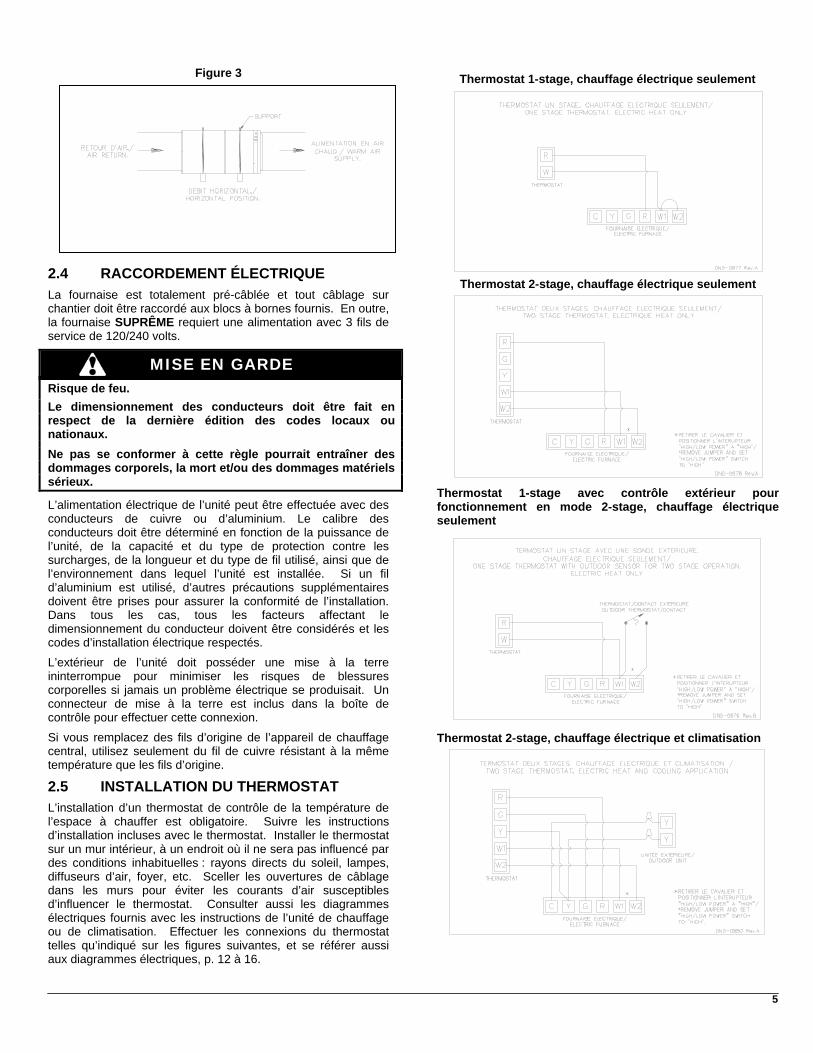
Lorsque l’appareil de chauffage central est installé avec un débit horizontal vers la gauche ou vers la droite, suspendu au plafond ou installé sur un plancher, les dégagements spécifiés par rapport aux matériaux combustibles doivent être respectés. Voir la figure 3 pour plus de détails.
5
Figure 3
2.4 RACCORDEMENT ÉLECTRIQUE
La fournaise est totalement pré-câblée et tout câblage sur chantier doit être raccordé aux blocs à bornes fournis. En outre, la fournaise SUPRÊME requiert une alimentation avec 3 fils de service de 120/240 volts.
MISE EN GARDE Risque de feu.
Le dimensionnement des conducteurs doit être fait en respect de la dernière édition des codes locaux ou nationaux.
Ne pas se conformer à cette règle pourrait entraîner des dommages corporels, la mort et/ou des dommages matériels sérieux.
L’alimentation électrique de l’unité peut être effectuée avec des conducteurs de cuivre ou d’aluminium. Le calibre des conducteurs doit être déterminé en fonction de la puissance de l’unité, de la capacité et du type de protection contre les surcharges, de la longueur et du type de fil utilisé, ainsi que de l’environnement dans lequel l’unité est installée. Si un fil d’aluminium est utilisé, d’autres précautions supplémentaires doivent être prises pour assurer la conformité de l’installation. Dans tous les cas, tous les facteurs affectant le dimensionnement du conducteur doivent être considérés et les codes d’installation électrique respectés.
L’extérieur de l’unité doit posséder une mise à la terre ininterrompue pour minimiser les risques de blessures corporelles si jamais un problème électrique se produisait. Un connecteur de mise à la terre est inclus dans la boîte de contrôle pour effectuer cette connexion.
Si vous remplacez des fils d’origine de l’appareil de chauffage central, utilisez seulement du fil de cuivre résistant à la même température que les fils d’origine.
2.5 INSTALLATION DU THERMOSTAT
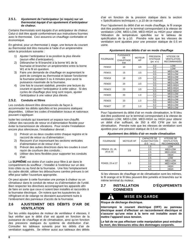
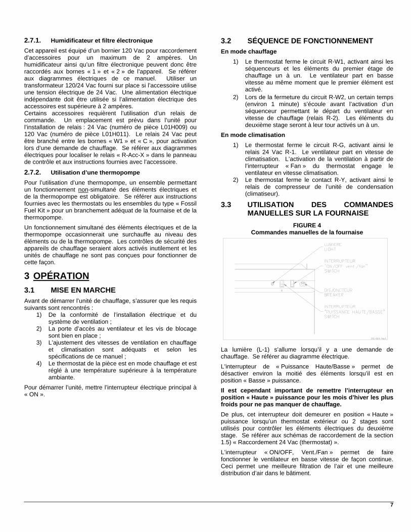
L’installation d’un thermostat de contrôle de la température de l’espace à chauffer est obligatoire. Suivre les instructions d’installation incluses avec le thermostat. Installer le thermostat sur un mur intérieur, à un endroit où il ne sera pas influencé par des conditions inhabituelles : rayons directs du soleil, lampes, diffuseurs d’air, foyer, etc. Sceller les ouvertures de câblage dans les murs pour éviter les courants d’air susceptibles d’influencer le thermostat. Consulter aussi les diagrammes électriques fournis avec les instructions de l’unité de chauffage ou de climatisation. Effectuer les connexions du thermostat telles qu’indiqué sur les figures suivantes, et se référer aussi aux diagrammes électriques, p. 12 à 16.
Thermostat 1-stage, chauffage électrique seulement
Thermostat 2-stage, chauffage électrique seulement
Thermostat 1-stage avec contrôle extérieur pour fonctionnement en mode 2-stage, chauffage électrique seulement
Thermostat 2-stage, chauffage électrique et climatisation
6
2.5.1. Ajustement de l’anticipateur (si requis) sur un thermostat équipé d’un ajustement d’anticipateur de chaleur.
Certains thermostats sont équipés d’un anticipateur de chaleur. Celui-ci doit être ajusté conformément aux instructions fournies avec le thermostat. Ceci assurera un chauffage confortable et économique.
En général, pour un thermostat 1 stage, une lecture du courant au thermostat doit être mesurée à l’aide d’un ampèremètre selon la procédure suivante :
1) Ajuster l’anticipateur à sa position la plus élevée (aucun effet d’anticipation).
2) Débrancher le fil branché à la borne W1 de la fournaise et brancher un ampèremètre entre la borne W1 et le fil en question.
3) Faire une demande de chauffage en augmentant le point de consigne au thermostat et laisser fonctionner la fournaise pendant 3 ou 4 minutes pour avoir la puissance maximale de la fournaise.
4) Une fois le courant stabilisé, prendre une lecture du courant et ajuster l’anticipateur à cette valeur. Si des cycles de chauffage plus long sont requis, ajuster l’anticipateur à une valeur plus élevée.
2.5.2. Conduits et filtres
Les conduits doivent être dimensionnés de façon à accommoder les débits spécifiés et les pressions statiques disponibles. Utiliser les codes d’installation locaux et nationaux pouvant s’appliquer.
Isoler les conduits qui traversent un espace non-chauffé. Utiliser des raccords de retour et d’alimentation flexible pour éviter la transmission de vibrations. Pour rendre l’installation encore plus silencieuse, l’installateur devrait :
1) Prévoir un ou deux coudes entre chaque registre et le raccord de retour ou d’alimentation ;
2) Recouvrir d’un insonorisant les sections verticales d’alimentation et de retour d’air ;
3) Prévoir des aubes directrices dans les coudes à court rayon de courbure des conduits ;
4) Utiliser des liens flexibles pour supporter les conduits d’air.
La SUPRÊME est dotée d’un cadre pour filtre à air dans le compartiment du souffleur ; l’installer à l’extérieur sur un des trois côtés ou au fond de la fournaise. Une fois l’emplacement du cadre décidé, utiliser les débouchures carrées prévues à cet effet pour tailler l’ouverture appropriée.
On peut ajouter à cette fournaise une pompe à chaleur ou un climatiseur dans le conduit de retour ou d’alimentation de l’unité. Bien respecter les directives accompagnant les appareils afin de faire en sorte que ceux-ci soient bien installés et raccordés à la fournaise électrique. On notera que les tuyauteries du réfrigérant et de vidange ne devraient aucunement nuire à l’enlèvement des panneaux d’accès de la fournaise.
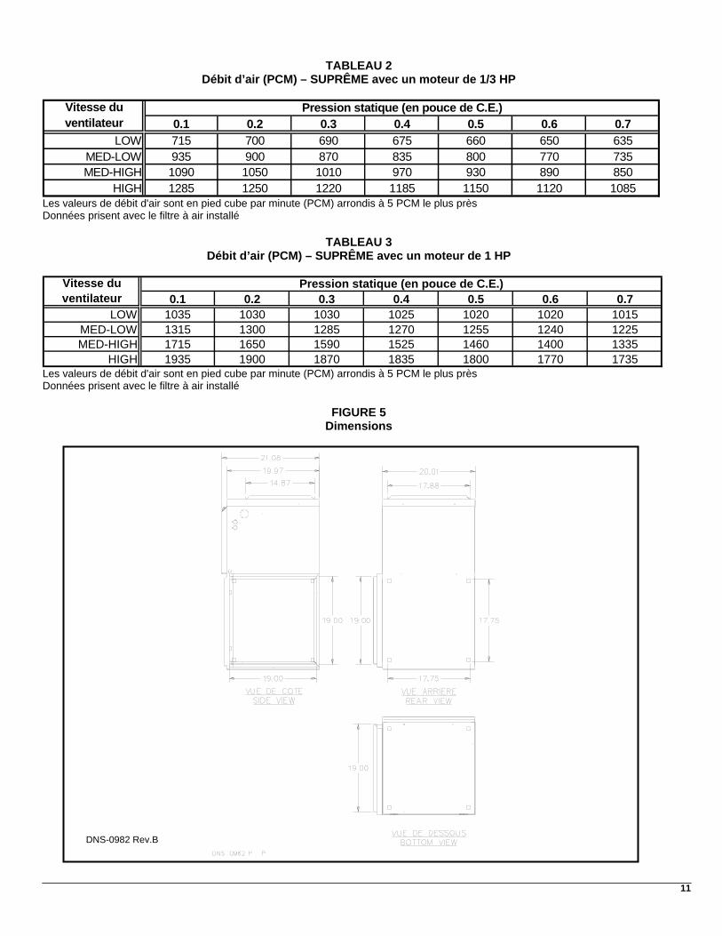
2.6 AJUSTEMENT DES DÉBITS D’AIR DE VENTILATION
Sur les unités équipées de moteur de ventilateur 4 vitesses, il faut vérifier que le débit d’air est ajusté en fonction de la puissance de chauffage et de climatisation, ainsi qu’en fonction des pressions statiques du système de distribution d’air. Consulter les tableaux suivants pour les débits d’air de ventilation suggérés. Se référer aussi aux tableaux des débits
d’air en fonction de la pression statique dans la section « Spécifications techniques », p.10 de ce manuel.
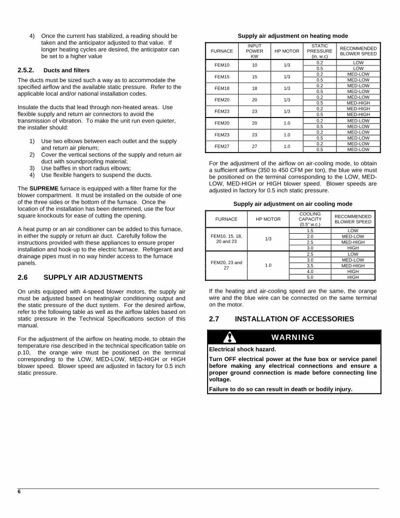
Pour l’ajustement du débit d’air en mode chauffage, le fil orange doit être positionné sur le terminal correspondant à la vitesse de ventilation LOW, MED-LOW, MED-HIGH ou HIGH pour obtenir l’élévation de température spécifiée sur le tableau de spécification de la p.10. Prendre note que les vitesses de ventilation sont ajustées pour une pression statique de 0.5 en usine.
Ajustement des débits d’air en mode chauffage
FOURNAISE
PUISSANCE DE
CHAUFFAGE KW
MOTEUR HP
PRESSION STATIQUE
(po. w.c)
VITESSE DE VENTILATION
RECOMMANDÉE
0.2 LOW FEM10 10 1/3 0.5 LOW 0.2 MED-LOW FEM15 15 1/3 0.5 MED-LOW 0.2 MED-LOW FEM18 18 1/3 0.5 MED-LOW 0.2 MED-LOW FEM20 20 1/3 0.5 MED-HIGH 0.2 MED-HIGH FEM23 23 1/3 0.5 MED-HIGH 0.2 MED-LOW FEM20 20 1.0 0.5 MED-LOW 0.2 MED-LOW FEM23 23 1.0 0.5 MED-LOW 0.2 MED-LOW FEM27 27 1.0 0.5 MED-LOW
Pour l’ajustement du débit d’air en mode climatisation, le fil bleu doit être positionné sur le terminal correspondant à la vitesse de ventilation LOW, MED-LOW, MED-HIGH ou HIGH pour obtenir un débit d’air suffisant, de 350 à 450 CFM par ton de climatisation. Prendre note que les vitesses de ventilation sont ajustées pour une pression statique de 0.5 en usine.
Ajustement des débits d’air en mode climatisation
FOURNAISE MOTEUR HP CAPACITÉ DE
CLIMATISATION (0.5 ‘’ w.c.)
VITESSE DE VENTILATION
RECOMMENDÉE 1.5 LOW 2.0 MED-LOW 2.5 MED-HIGH
FEM10, 15, 18, 20 et 23 1/3
3.0 HIGH 2.5 LOW 3.0 MED-LOW 3.5 MED-HIGH 4.0 HIGH
FEM20, 23 et 27 1.0
5.0 HIGH
Si les vitesses de chauffage et de climatisation sont les mêmes, le fil orange et le fil bleu peuvent être jumelés et branchés sur le même terminal du moteur.
2.7 INSTALLATION D’ÉQUIPEMENTS CONNEXES
MISE EN GARDE
Risque de décharge électrique.
Interrompre le courant électrique (OFF) au panneau électrique avant d’effectuer un raccordement électrique et s’assurer qu’une mise à la terre est installée avant de mettre l’appareil sous tension.
Le fait de ne pas effectuer cette manipulation peut entraîner la mort, des blessures et/ou des dommages corporels.
7
2.7.1. Humidificateur et filtre électronique
Cet appareil est équipé d’un bornier 120 Vac pour raccordement d’accessoires pour un maximum de 2 ampères. Un humidificateur ainsi qu’un filtre électronique peuvent donc être raccordés aux bornes « 1 » et « 2 » de l’appareil. Se référer aux diagrammes électriques de ce manuel. Utiliser un transformateur 120/24 Vac fourni sur place si l’accessoire utilise une tension électrique de 24 Vac. Une alimentation électrique indépendante doit être utilisée si l’alimentation électrique des accessoires est supérieure à 2 ampères. Certains accessoires requièrent l’utilisation d’un relais de commande. Un emplacement est prévu dans l’unité pour l’installation de relais : 24 Vac (numéro de pièce L01H009) ou 120 Vac (numéro de pièce L01H011). Le relais 24 Vac peut être branché entre les bornes « W1 » et « C », pour activation lors d’une demande de chauffage. Se référer aux diagrammes électriques pour localiser le relais « R-Acc-X » dans le panneau de contrôle et aux instructions fournies avec l’accessoire.
2.7.2. Utilisation d’une thermopompe
Pour l’utilisation d’une thermopompe, un ensemble permettant un fonctionnement non-simultané des éléments électriques et de la thermopompe est obligatoire. Se référer aux instructions fournies avec les thermostats ou les ensembles du type « Fossil Fuel Kit » pour un branchement adéquat de la fournaise et de la thermopompe.
Un fonctionnement simultané des éléments électriques et de la thermopompe occasionnerait une surchauffe au niveau des éléments ou de la thermopompe. Les contrôles de sécurité des appareils de chauffage seraient alors activés inutilement et les unités de chauffage ne sont pas conçues pour fonctionner de cette façon.
3 OPÉRATION
3.1 MISE EN MARCHE
Avant de démarrer l’unité de chauffage, s’assurer que les requis suivants sont rencontrés :
1) De la conformité de l’installation électrique et du système de ventilation ;
2) La porte d’accès au ventilateur et les vis de blocage sont bien en place ;
3) L’ajustement des vitesses de ventilation en chauffage et climatisation sont adéquats et selon les spécifications de ce manuel ;
4) Le thermostat de la pièce est en mode chauffage et est réglé à une température supérieure à la température ambiante.
Pour démarrer l’unité, mettre l’interrupteur électrique principal à « ON ».
3.2 SÉQUENCE DE FONCTIONNEMENT
En mode chauffage
1) Le thermostat ferme le circuit R-W1, activant ainsi les séquenceurs et les éléments du premier étage de chauffage un à un. Le ventilateur part en basse vitesse au même moment que le premier élément est activé.
2) Lors de la fermeture du circuit R-W2, un certain temps (environ 1 minute) s’écoule avant l’activation d’un séquenceur permettant le départ du ventilateur en vitesse de chauffage (relais R-2). Les éléments du deuxième stage seront à leur tour activés un à un.
En mode climatisation
1) Le thermostat ferme le circuit R-G, activant ainsi le relais 24 Vac R-1. Le ventilateur part en vitesse de climatisation. L’activation de la ventilation à partir de l’interrupteur « Fan » du thermostat engage le ventilateur en vitesse climatisation.
2) Le thermostat ferme le contact R-Y, activant ainsi le relais de compresseur de l’unité de condensation (climatiseur).
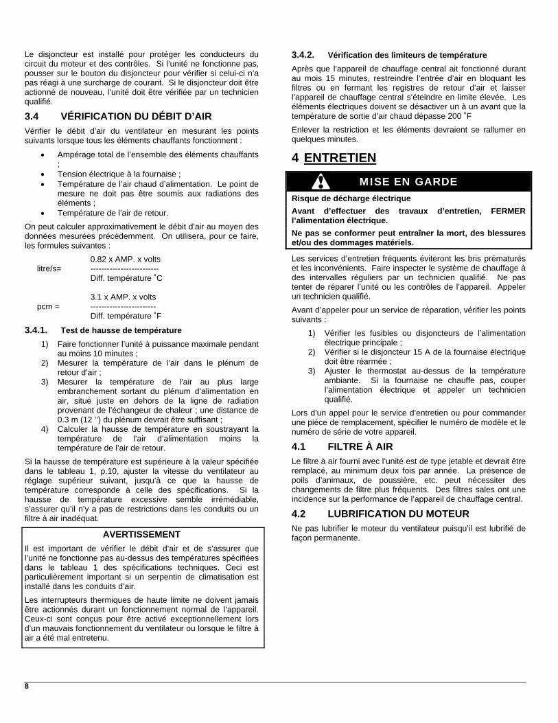
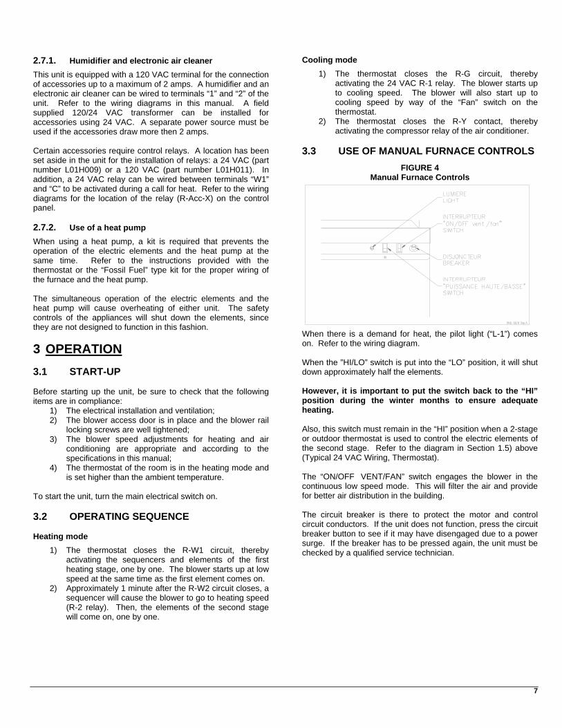
3.3 UTILISATION DES COMMANDES MANUELLES SUR LA FOURNAISE
FIGURE 4
Commandes manuelles de la fournaise
La lumière (L-1) s’allume lorsqu’il y a une demande de chauffage. Se référer au diagramme électrique.
L’interrupteur de « Puissance Haute/Basse » permet de désactiver environ la moitié des éléments lorsqu’il est en position « Basse » puissance.
Il est cependant important de remettre l’interrupteur en position « Haute » puissance pour les mois d’hiver les plus froids pour ne pas manquer de chauffage.
De plus, cet interrupteur doit demeurer en position « Haute » puissance lorsqu’un thermostat extérieur ou 2 stages sont utilisés pour contrôler les éléments électriques du deuxième stage. Se référer aux schémas de raccordement de la section 1.5) « Raccordement 24 Vac (thermostat) ».
L’interrupteur « ON/OFF, Vent./Fan » permet de faire fonctionner le ventilateur en basse vitesse de façon continue. Ceci permet une meilleure filtration de l’air et une meilleure distribution d’air dans le bâtiment.
8
3.4.2. Vérification des limiteurs de température Le disjoncteur est installé pour protéger les conducteurs du circuit du moteur et des contrôles. Si l’unité ne fonctionne pas, pousser sur le bouton du disjoncteur pour vérifier si celui-ci n’a pas réagi à une surcharge de courant. Si le disjoncteur doit être actionné de nouveau, l’unité doit être vérifiée par un technicien qualifié.
Après que l’appareil de chauffage central ait fonctionné durant au mois 15 minutes, restreindre l’entrée d’air en bloquant les filtres ou en fermant les registres de retour d’air et laisser l’appareil de chauffage central s’éteindre en limite élevée. Les éléments électriques doivent se désactiver un à un avant que la température de sortie d’air chaud dépasse 200 ˚F
3.4 VÉRIFICATION DU DÉBIT D’AIR
Enlever la restriction et les éléments devraient se rallumer en quelques minutes.
Vérifier le débit d’air du ventilateur en mesurant les points suivants lorsque tous les éléments chauffants fonctionnent :
• Ampérage total de l’ensemble des éléments chauffants ; 4 ENTRETIEN
• Tension électrique à la fournaise ;
MISE EN GARDE • Température de l’air chaud d’alimentation. Le point de mesure ne doit pas être soumis aux radiations des éléments ;
Risque de décharge électrique
Avant d’effectuer des travaux d’entretien, FERMER l’alimentation électrique.
• Température de l’air de retour.
On peut calculer approximativement le débit d’air au moyen des données mesurées précédemment. On utilisera, pour ce faire, les formules suivantes :
Ne pas se conformer peut entraîner la mort, des blessures et/ou des dommages matériels.
Les services d’entretien fréquents éviteront les bris prématurés et les inconvénients. Faire inspecter le système de chauffage à des intervalles réguliers par un technicien qualifié. Ne pas tenter de réparer l’unité ou les contrôles de l’appareil. Appeler un technicien qualifié.
0.82 x AMP. x volts litre/s= ------------------------- Diff. température ˚C 3.1 x AMP. x volts
pcm = ------------------------ Avant d’appeler pour un service de réparation, vérifier les points suivants : Diff. température ˚F
3.4.1. Test de hausse de température 1) Vérifier les fusibles ou disjoncteurs de l’alimentation
électrique principale ;
1) Faire fonctionner l’unité à puissance maximale pendant au moins 10 minutes ; 2) Vérifier si le disjoncteur 15 A de la fournaise électrique
doit être réarmée ; 2) Mesurer la température de l’air dans le plénum de retour d’air ; 3) Ajuster le thermostat au-dessus de la température
ambiante. Si la fournaise ne chauffe pas, couper l’alimentation électrique et appeler un technicien qualifié.
3) Mesurer la température de l’air au plus large embranchement sortant du plénum d’alimentation en air, situé juste en dehors de la ligne de radiation provenant de l’échangeur de chaleur ; une distance de 0.3 m (12 ‘’) du plénum devrait être suffisant ;
Lors d’un appel pour le service d’entretien ou pour commander une pièce de remplacement, spécifier le numéro de modèle et le numéro de série de votre appareil. 4) Calculer la hausse de température en soustrayant la
température de l’air d’alimentation moins la température de l’air de retour.
4.1 FILTRE À AIR
Le filtre à air fourni avec l’unité est de type jetable et devrait être remplacé, au minimum deux fois par année. La présence de poils d’animaux, de poussière, etc. peut nécessiter des changements de filtre plus fréquents. Des filtres sales ont une incidence sur la performance de l’appareil de chauffage central.
Si la hausse de température est supérieure à la valeur spécifiée dans le tableau 1, p.10, ajuster la vitesse du ventilateur au réglage supérieur suivant, jusqu’à ce que la hausse de température corresponde à celle des spécifications. Si la hausse de température excessive semble irrémédiable, s’assurer qu’il n’y a pas de restrictions dans les conduits ou un filtre à air inadéquat.
4.2 LUBRIFICATION DU MOTEUR
Ne pas lubrifier le moteur du ventilateur puisqu’il est lubrifié de façon permanente. AVERTISSEMENT
Il est important de vérifier le débit d’air et de s’assurer que l’unité ne fonctionne pas au-dessus des températures spécifiées dans le tableau 1 des spécifications techniques. Ceci est particulièrement important si un serpentin de climatisation est installé dans les conduits d’air.
Les interrupteurs thermiques de haute limite ne doivent jamais être actionnés durant un fonctionnement normal de l’appareil. Ceux-ci sont conçus pour être activé exceptionnellement lors d’un mauvais fonctionnement du ventilateur ou lorsque le filtre à air a été mal entretenu.
9
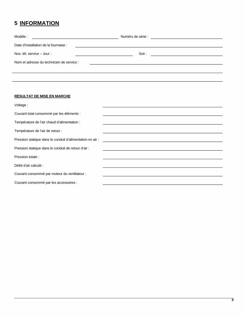
5 INFORMATION
Modèle :
Numéro de série :
Date d’installation de la fournaise :
Nos. tél. service – Jour :
Soir :
Nom et adresse du technicien de service :
RÉSULTAT DE MISE EN MARCHE
Voltage : Courant total consommé par les éléments :
Température de l’air chaud d’alimentation :
Température de l’air de retour :
Pression statique dans le conduit d’alimentation en air :
Pression statique dans le conduit de retour d’air :
Pression totale :
Débit d’air calculé : Courant consommé par moteur du ventilateur :
Courant consommé par les accessoires :

10
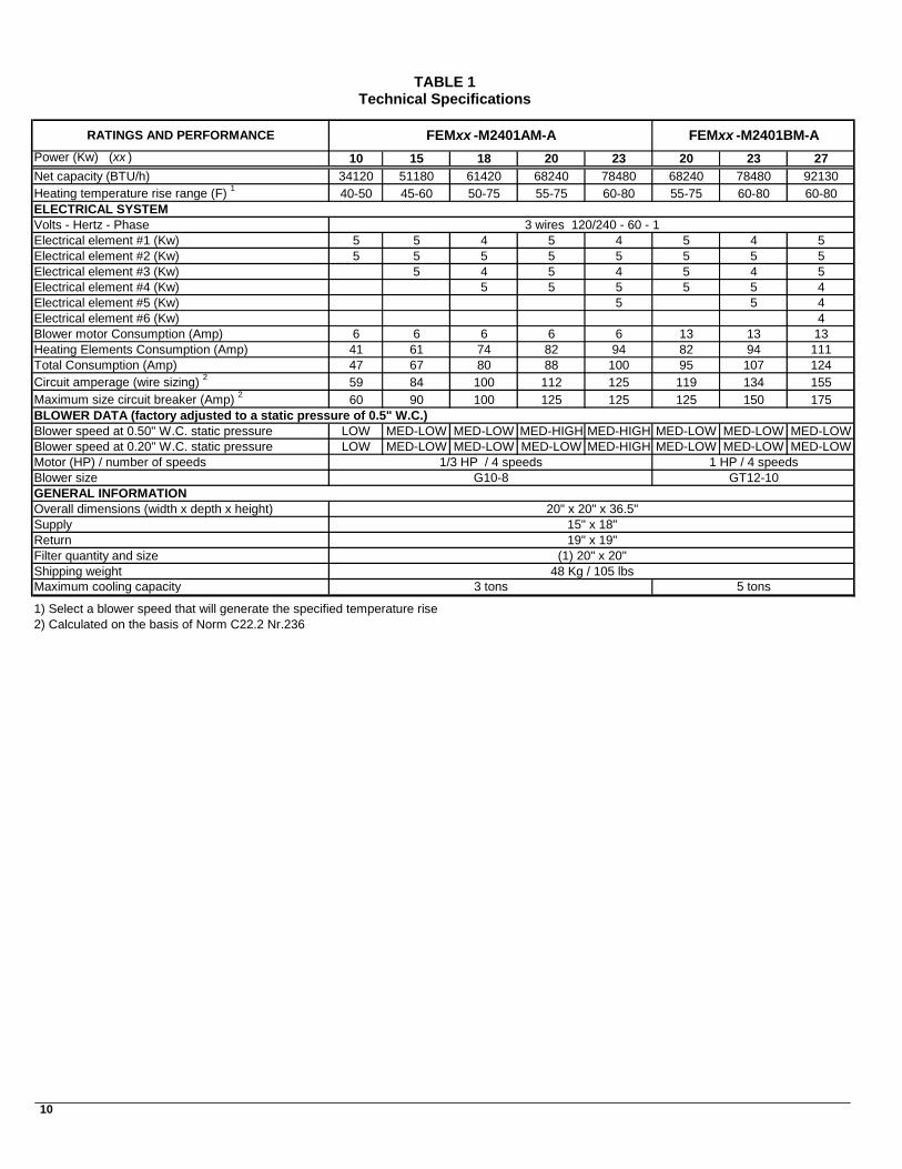
TABLEAU 1 Spécifications techniques
Puissance (Kw) (xx ) 10 15 18 20 23 20 23 27Capacité net (BTU/h) 34120 51180 61420 68240 78480 68240 78480 92130Plage de la hausse de temp. de chauffage (F) 1 40-50 45-60 50-75 55-75 60-80 55-75 60-80 60-80SYSTÈME ÉLECTRIQUEVolts - Hertz - PhaseÉlément électrique #1 (Kw) 5 5 4 5 4 5 4 5Élément électrique #2 (Kw) 5 5 5 5 5 5 5 5Élément électrique #3 (Kw) 5 4 5 4 5 4 5Élément électrique #4 (Kw) 5 5 5 5 5 4Élément électrique #5 (Kw) 5 5Élément électrique #6 (Kw) 4Consommation du moteur (1/3 HP) (Amp max) 6 6 6 6 6 13 13 1Consommation des éléments électrique (Amp) 41 61 74 82 94 82 94 111Consommation totale (Amp) 47 67 80 88 100 95 107 124Ampérage du circuit (dimensionnement du conducteur) 2 59 84 100 112 125 119 134 155Disjoncteur maximum du circuit (Amp) 2 60 90 100 125 125 125 150 175DONNÉES TECHNIQUES DU VENTILATEUR (ajusté en usine pour une pression statique de 0.5" W.C.)Vit. du ventilateur à une pression statique de 0.50" LOW MED-LOW MED-LOW MED-HIGH MED-HIGH MED-LOW MED-LOW MED-LOVit. du ventilateur à une pression statique de 0.20" LOW MED-LOW MED-LOW MED-LOW MED-HIGH MED-LOW MED-LOW MED-LOMoteur (HP) / nombre de vitessesDimention du ventilateurINFORMATIONS GÉNÉRALESDimension hors tout (larg. x long. x haut)AlimentationRetourQuantité et dimension des filtresPoids à l'expéditionCapacité maximum en climatisation 5 tonnes3 tonnes
48 Kg / 105 lbs
GT12-10
FEMxx -M2401BM-A
3 conducteurs 120/240 - 60 - 1
1 HP / 4 vitesses
1) Sélectionner une vitesse de ventilateur permettant une hausse de température spécifiés
(1) 20" x 20"
2) Calculer selon la norme C22.2 No 236
TAUX ET PERFORMANCE
20" x 20" x 36.5"15" x 18"19" x 19"
G10-8
FEMxx -M2401AM-A
1/3 HP / 4 vitesses
4
3
WW
11
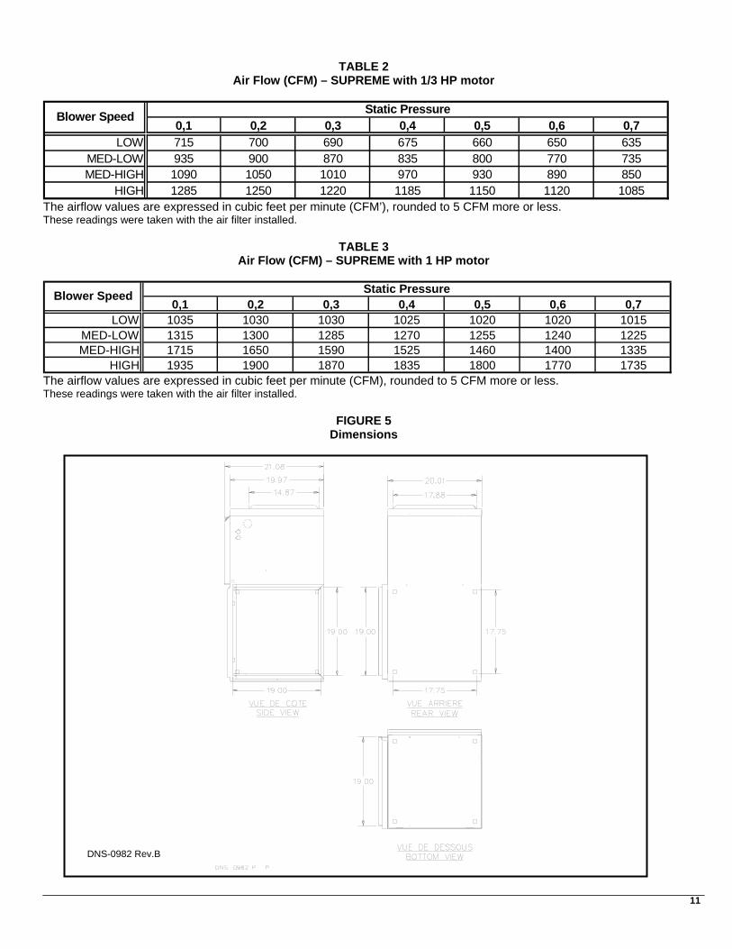
TABLEAU 2 Débit d’air (PCM) – SUPRÊME avec un moteur de 1/3 HP
0.1 0.2 0.3 0.4 0.5 0.6 0.7LOW 715 700 690 675 660 650 635
MED-LOW 935 900 870 835 800 770 735MED-HIGH 1090 1050 1010 970 930 890 850
HIGH 1285 1250 1220 1185 1150 1120 1085
Vitesse du ventilateur
Pression statique (en pouce de C.E.)
Les valeurs de débit d'air sont en pied cube par minute (PCM) arrondis à 5 PCM le plus près Données prisent avec le filtre à air installé
TABLEAU 3
Débit d’air (PCM) – SUPRÊME avec un moteur de 1 HP
0.1 0.2 0.3 0.4 0.5 0.6 0.7LOW 1035 1030 1030 1025 1020 1020 1015
MED-LOW 1315 1300 1285 1270 1255 1240 1225MED-HIGH 1715 1650 1590 1525 1460 1400 1335
HIGH 1935 1900 1870 1835 1800 1770 1735
Vitesse du ventilateur
Pression statique (en pouce de C.E.)
Les valeurs de débit d'air sont en pied cube par minute (PCM) arrondis à 5 PCM le plus près Données prisent avec le filtre à air installé
FIGURE 5 Dimensions
DNS-0982 Rev.B
12
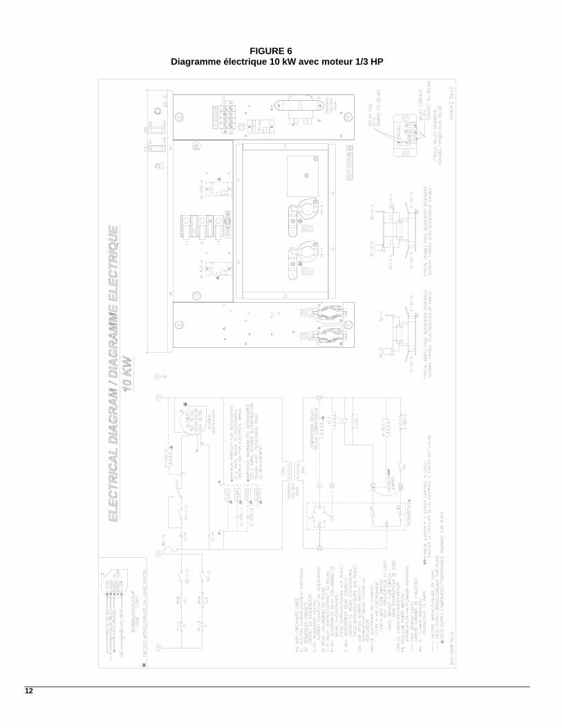
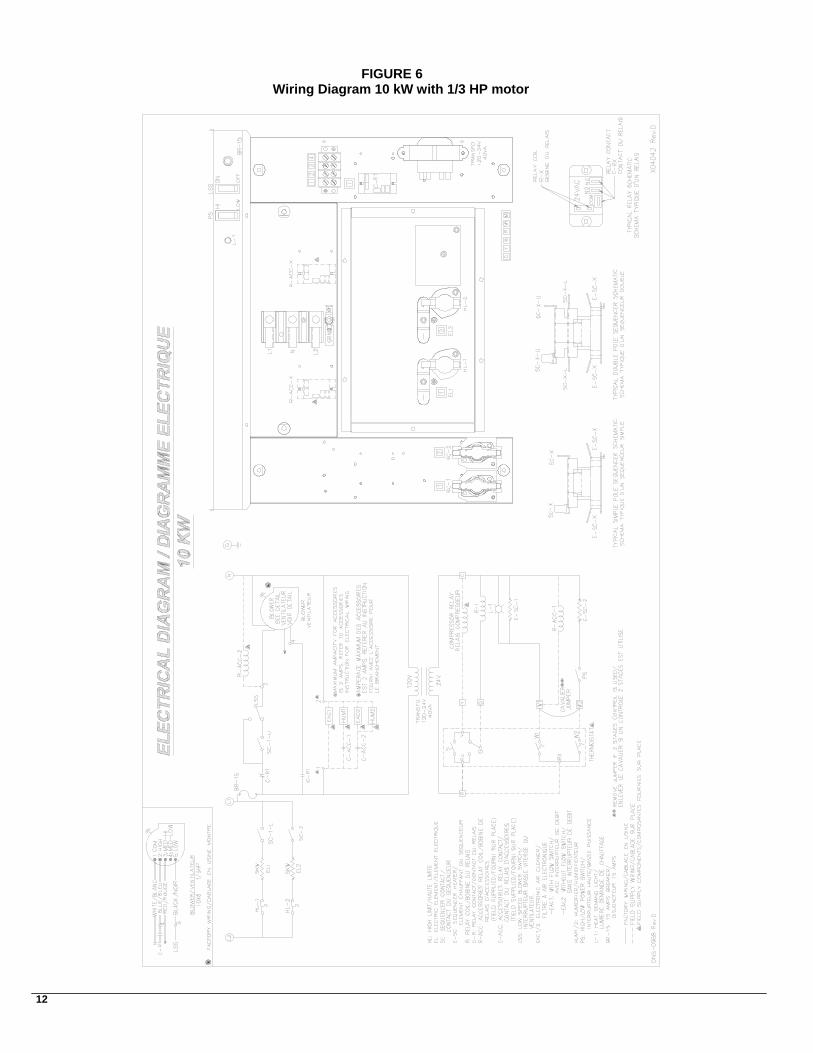
FIGURE 6 Diagramme électrique 10 kW avec moteur 1/3 HP
13
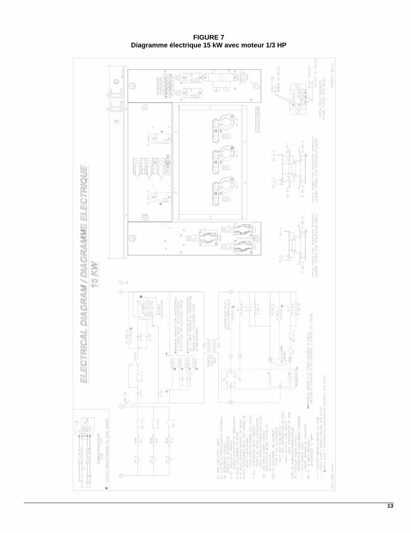
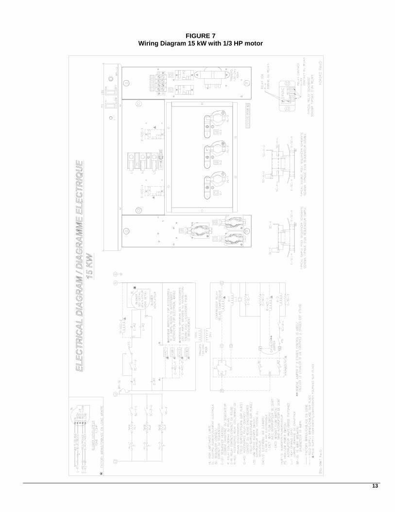
FIGURE 7 Diagramme électrique 15 kW avec moteur 1/3 HP
14
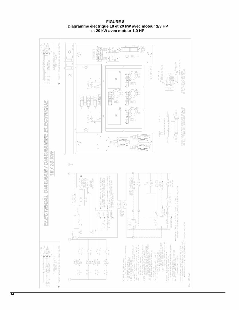
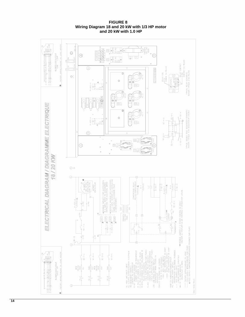
FIGURE 8 Diagramme électrique 18 et 20 kW avec moteur 1/3 HP
et 20 kW avec moteur 1.0 HP
15
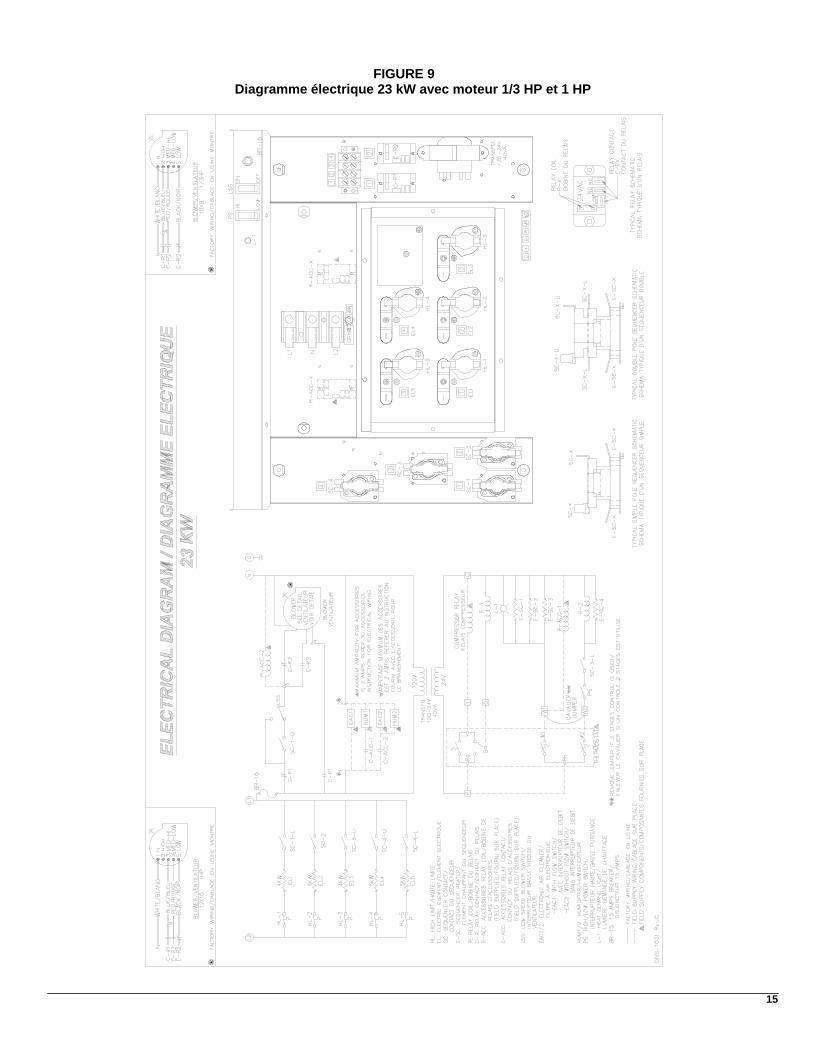
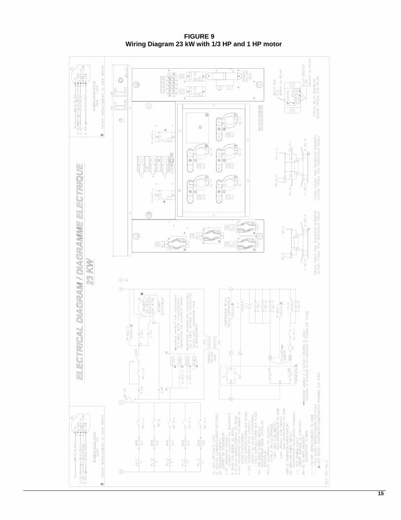
FIGURE 9 Diagramme électrique 23 kW avec moteur 1/3 HP et 1 HP
16
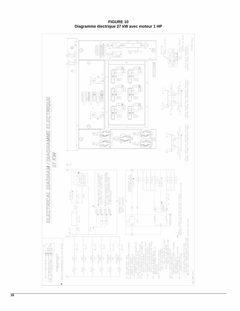
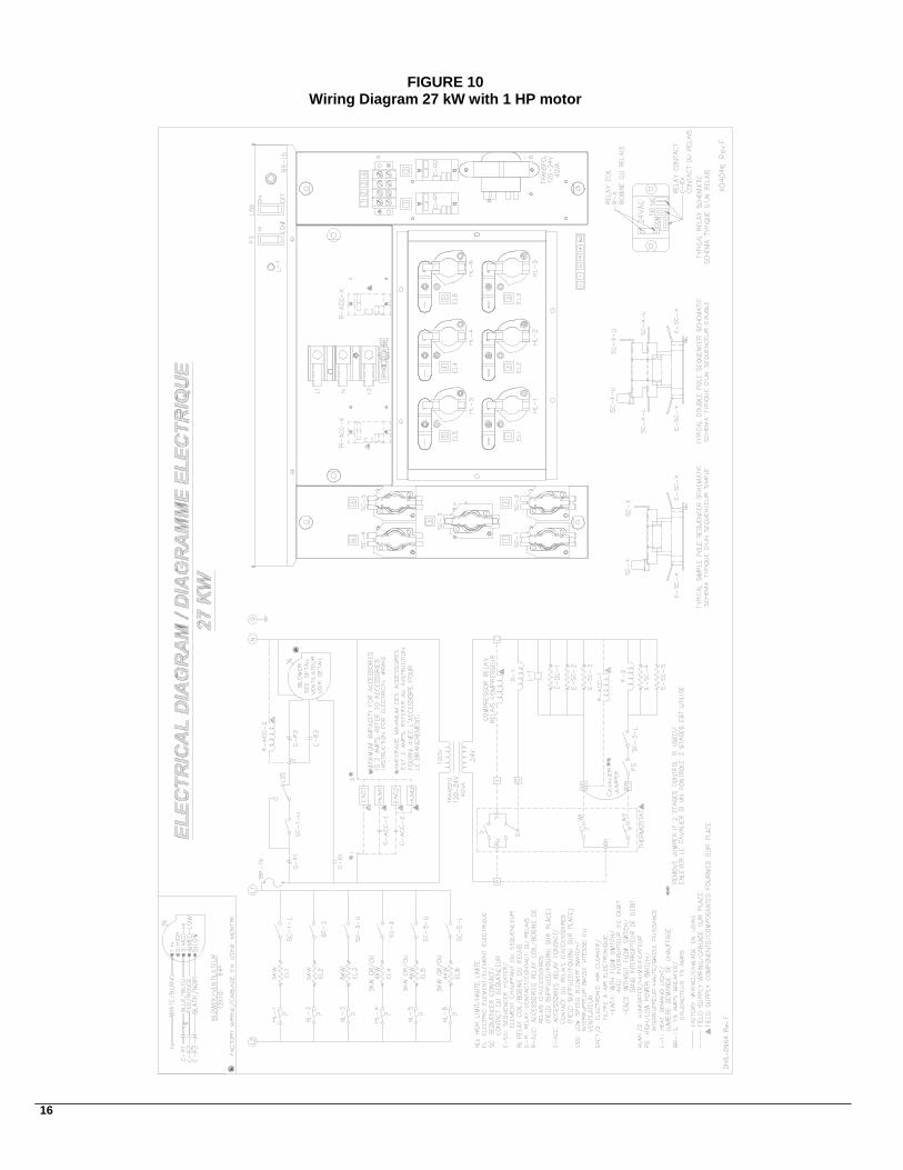
FIGURE 10 Diagramme électrique 27 kW avec moteur 1 HP
COMPOSANTES
ET
PIÈCES DE REMPLACEMENT
17
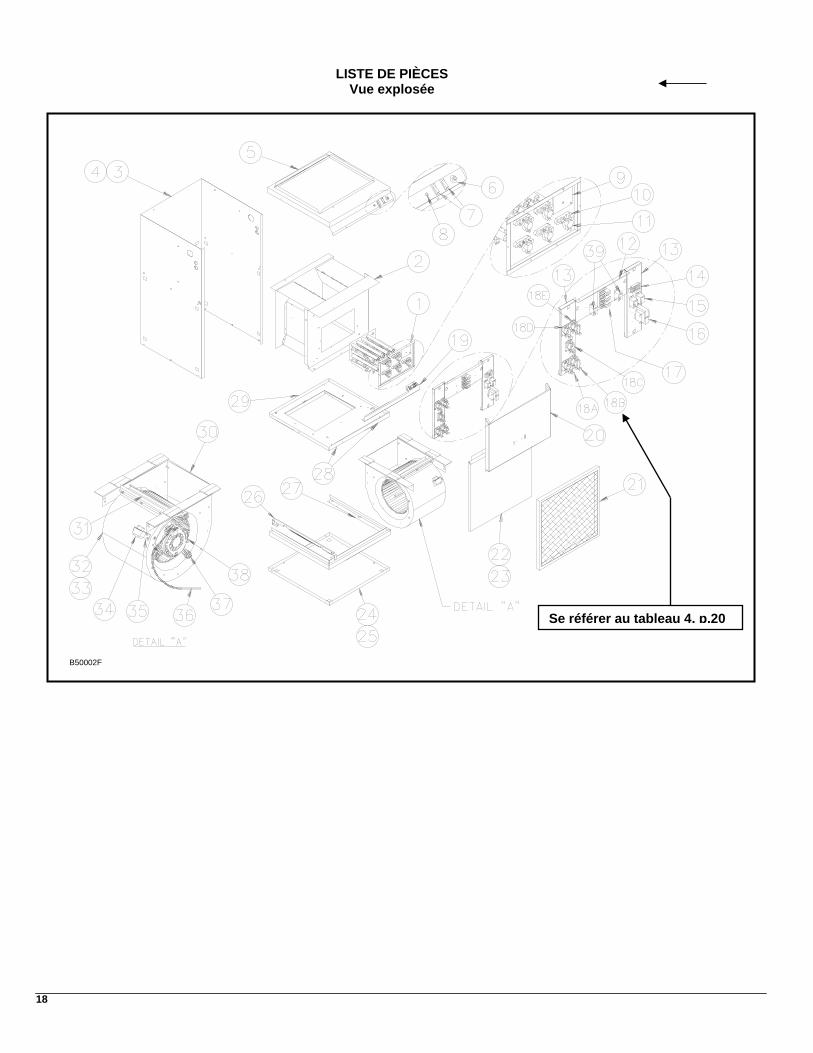
18
LISTE DE PIÈCES Vue explosée
B50002F
Se référer au tableau 4, p.20
19
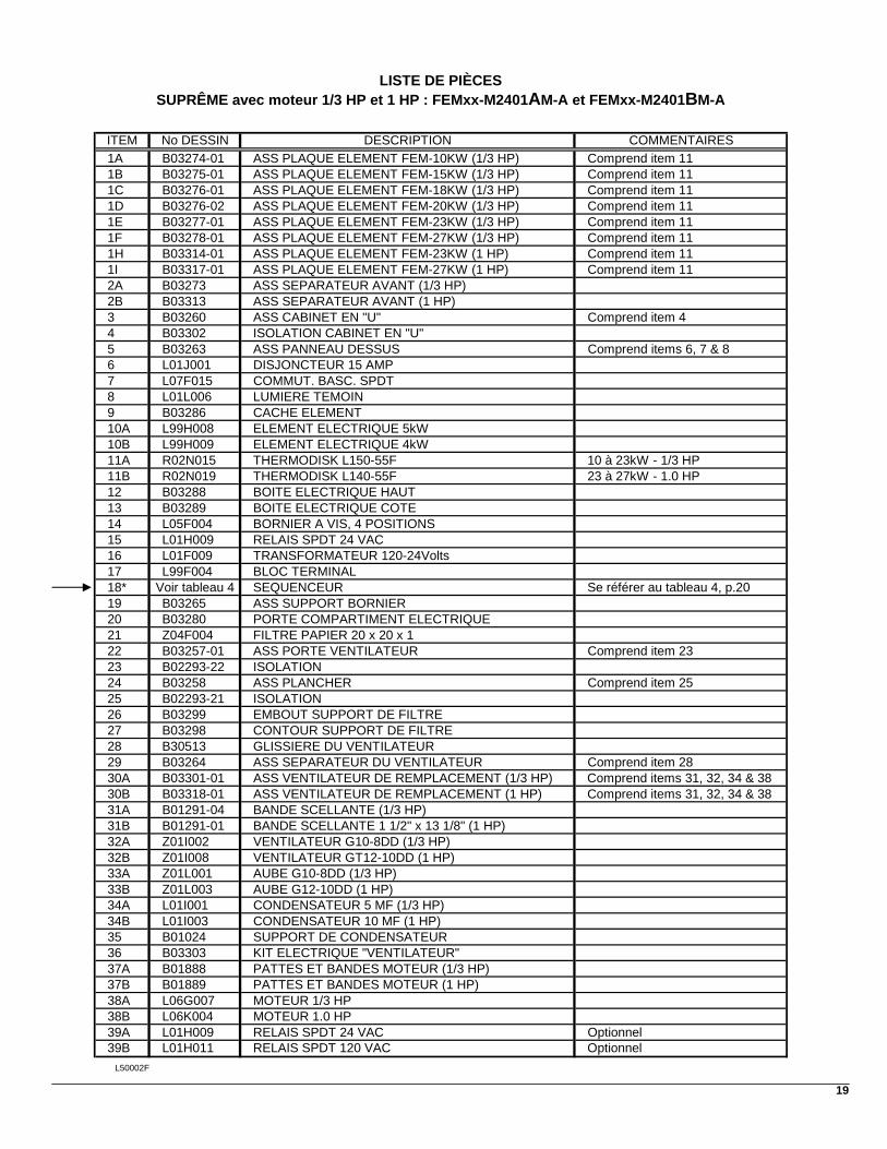
LISTE DE PIÈCES SUPRÊME avec moteur 1/3 HP et 1 HP : FEMxx-M2401AM-A et FEMxx-M2401BM-A
ITEM No DESSIN DESCRIPTION COMMENTAIRES1A B03274-01 ASS PLAQUE ELEMENT FEM-10KW (1/3 HP) Comprend item 111B B03275-01 ASS PLAQUE ELEMENT FEM-15KW (1/3 HP) Comprend item 111C B03276-01 ASS PLAQUE ELEMENT FEM-18KW (1/3 HP) Comprend item 111D B03276-02 ASS PLAQUE ELEMENT FEM-20KW (1/3 HP) Comprend item 111E B03277-01 ASS PLAQUE ELEMENT FEM-23KW (1/3 HP) Comprend item 111F B03278-01 ASS PLAQUE ELEMENT FEM-27KW (1/3 HP) Comprend item 111H B03314-01 ASS PLAQUE ELEMENT FEM-23KW (1 HP) Comprend item 111I B03317-01 ASS PLAQUE ELEMENT FEM-27KW (1 HP) Comprend item 112A B03273 ASS SEPARATEUR AVANT (1/3 HP) 2B B03313 ASS SEPARATEUR AVANT (1 HP) 3 B03260 ASS CABINET EN "U" Comprend item 44 B03302 ISOLATION CABINET EN "U" 5 B03263 ASS PANNEAU DESSUS Comprend items 6, 7 & 86 L01J001 DISJONCTEUR 15 AMP7 L07F015 COMMUT. BASC. SPDT8 L01L006 LUMIERE TEMOIN9 B03286 CACHE ELEMENT 10A L99H008 ELEMENT ELECTRIQUE 5kW10B L99H009 ELEMENT ELECTRIQUE 4kW11A R02N015 THERMODISK L150-55F 10 à 23kW - 1/3 HP11B R02N019 THERMODISK L140-55F 23 à 27kW - 1.0 HP12 B03288 BOITE ELECTRIQUE HAUT 13 B03289 BOITE ELECTRIQUE COTE14 L05F004 BORNIER A VIS, 4 POSITIONS15 L01H009 RELAIS SPDT 24 VAC 16 L01F009 TRANSFORMATEUR 120-24Volts17 L99F004 BLOC TERMINAL18* Voir tableau 4 SEQUENCEUR Se référer au tableau 4, p.2019 B03265 ASS SUPPORT BORNIER 20 B03280 PORTE COMPARTIMENT ELECTRIQUE 21 Z04F004 FILTRE PAPIER 20 x 20 x 1 22 B03257-01 ASS PORTE VENTILATEUR Comprend item 2323 B02293-22 ISOLATION 24 B03258 ASS PLANCHER Comprend item 2525 B02293-21 ISOLATION 26 B03299 EMBOUT SUPPORT DE FILTRE 27 B03298 CONTOUR SUPPORT DE FILTRE 28 B30513 GLISSIERE DU VENTILATEUR 29 B03264 ASS SEPARATEUR DU VENTILATEUR Comprend item 2830A B03301-01 ASS VENTILATEUR DE REMPLACEMENT (1/3 HP) Comprend items 31, 32, 34 & 3830B B03318-01 ASS VENTILATEUR DE REMPLACEMENT (1 HP) Comprend items 31, 32, 34 & 3831A B01291-04 BANDE SCELLANTE (1/3 HP)31B B01291-01 BANDE SCELLANTE 1 1/2" x 13 1/8" (1 HP)32A Z01I002 VENTILATEUR G10-8DD (1/3 HP)32B Z01I008 VENTILATEUR GT12-10DD (1 HP)33A Z01L001 AUBE G10-8DD (1/3 HP)33B Z01L003 AUBE G12-10DD (1 HP)34A L01I001 CONDENSATEUR 5 MF (1/3 HP)34B L01I003 CONDENSATEUR 10 MF (1 HP)35 B01024 SUPPORT DE CONDENSATEUR 36 B03303 KIT ELECTRIQUE "VENTILATEUR" 37A B01888 PATTES ET BANDES MOTEUR (1/3 HP)37B B01889 PATTES ET BANDES MOTEUR (1 HP)38A L06G007 MOTEUR 1/3 HP38B L06K004 MOTEUR 1.0 HP39A L01H009 RELAIS SPDT 24 VAC Optionnel39B L01H011 RELAIS SPDT 120 VAC Optionnel
L50002F
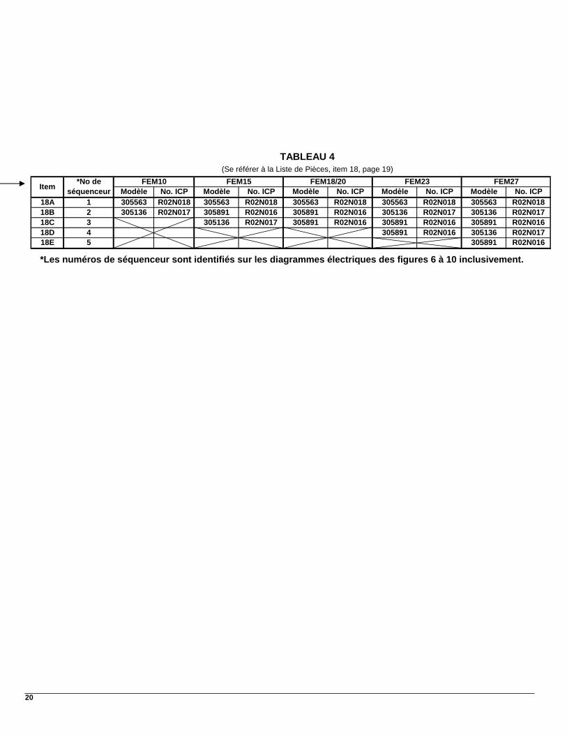
20
*No deséquenceur Modèle No. ICP Modèle No. ICP Modèle No. ICP Modèle No. ICP Modèle No. ICP
18
A 1 305563 R02N018 305563 R02N018 305563 R02N018 305563 R02N018 305563 R02N01818B 2 305136 R02N017 305891 R02N016 305891 R02N016 305136 R02N017 305136 R02N01718C 3 305136 R02N017 305891 R02N016 305891 R02N016 305891 R02N01618D 4 305891 R02N016 305136 R02N01718E 5 305891 R02N016
Item
TABLEAU 4
FEM10 FEM15 FEM18/20 FEM23 FEM27(Se référer à la Liste de Pièces, item 18, page 19)
*Les numéros de séquenceur sont identifiés sur les diagrammes électriques des figures 6 à 10 inclusivement.
Models:
FEM10-M2401AM-AFEM15-M2401AM-AFEM18-M2401AM-AFEM20-M2401AM-AFEM23-M2401AM-AFEM20-M2401BM-AFEM23-M2401BM-AFEM27-M2401BM-A
2008-05-27 X40131 Rev. M
Manufactured by:
UTC Canada CorporationICP Division3400 Industrial BoulevardSherbrooke, Quebec - CanadaJ1L 1V8
Caution: Do not tamper with the unit or its controls. Call a qualified service technician.
Printed in CanadaPrinted on 100% recycled paper
DNS-0981 Rev. A
MULTI POSITION
INSTALLER / SERVICE TECHNICIAN:USE THE INFORMATION IN THIS MANUAL FOR THE INSTALLATION AND SERVICING OF THE FURNACE AND KEEP THE DOCUMENT NEAR THE UNIT FOR FUTURE REFERENCE.
HOMEOWNER:PLEASE KEEP THIS MANUAL NEAR THE FURNACE FOR FUTURE REFERENCE.
(3 WIRES 120/240 – 60 – 1)
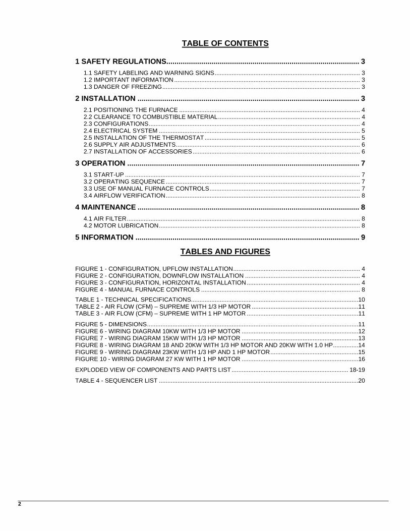
TABLE OF CONTENTS
1 SAFETY REGULATIONS.............................................................................................. 3
1.1 SAFETY LABELING AND WARNING SIGNS...................................................................................... 3 1.2 IMPORTANT INFORMATION .............................................................................................................. 3 1.3 DANGER OF FREEZING..................................................................................................................... 3
2 INSTALLATION ............................................................................................................ 3
2.1 POSITIONING THE FURNACE ........................................................................................................... 4 2.2 CLEARANCE TO COMBUSTIBLE MATERIAL.................................................................................... 4 2.3 CONFIGURATIONS............................................................................................................................. 4 2.4 ELECTRICAL SYSTEM ....................................................................................................................... 5 2.5 INSTALLATION OF THE THERMOSTAT............................................................................................ 5 2.6 SUPPLY AIR ADJUSTMENTS............................................................................................................. 6 2.7 INSTALLATION OF ACCESSORIES................................................................................................... 6
3 OPERATION ................................................................................................................. 7
3.1 START-UP ........................................................................................................................................... 7 3.2 OPERATING SEQUENCE ................................................................................................................... 7 3.3 USE OF MANUAL FURNACE CONTROLS......................................................................................... 7 3.4 AIRFLOW VERIFICATION................................................................................................................... 8
4 MAINTENANCE ............................................................................................................ 8
4.1 AIR FILTER.......................................................................................................................................... 8 4.2 MOTOR LUBRICATION....................................................................................................................... 8
5 INFORMATION ............................................................................................................. 9
TABLES AND FIGURES FIGURE 1 - CONFIGURATION, UPFLOW INSTALLATION........................................................................... 4 FIGURE 2 - CONFIGURATION, DOWNFLOW INSTALLATION .................................................................... 4 FIGURE 3 - CONFIGURATION, HORIZONTAL INSTALLATION................................................................... 4 FIGURE 4 - MANUAL FURNACE CONTROLS .............................................................................................. 8
TABLE 1 - TECHNICAL SPECIFICATIONS...................................................................................................10 TABLE 2 - AIR FLOW (CFM) – SUPREME WITH 1/3 HP MOTOR ...............................................................11 TABLE 3 - AIR FLOW (CFM) – SUPREME WITH 1 HP MOTOR ..................................................................11
FIGURE 5 - DIMENSIONS.............................................................................................................................11 FIGURE 6 - WIRING DIAGRAM 10KW WITH 1/3 HP MOTOR .....................................................................12 FIGURE 7 - WIRING DIAGRAM 15KW WITH 1/3 HP MOTOR .....................................................................13 FIGURE 8 - WIRING DIAGRAM 18 AND 20KW WITH 1/3 HP MOTOR AND 20KW WITH 1.0 HP...............14 FIGURE 9 - WIRING DIAGRAM 23KW WITH 1/3 HP AND 1 HP MOTOR....................................................15 FIGURE 10 - WIRING DIAGRAM 27 KW WITH 1 HP MOTOR .....................................................................16
EXPLODED VIEW OF COMPONENTS AND PARTS LIST..................................................................... 18-19
TABLE 4 - SEQUENCER LIST ......................................................................................................................20
2
3
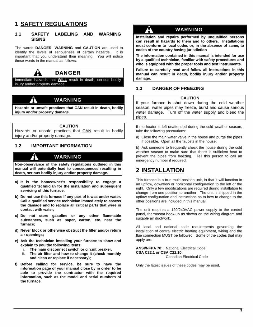
1 SAFETY REGULATIONS 1.1 SAFETY LABELING AND WARNING
SIGNS The words DANGER, WARNING and CAUTION are used to identify the levels of seriousness of certain hazards. It is important that you understand their meaning. You will notice these words in the manual as follows:
DANGER Immediate hazards that WILL result in death, serious bodily injury and/or property damage.
WARNING Hazards or unsafe practices that CAN result in death, bodily injury and/or property damage.
CAUTION Hazards or unsafe practices that CAN result in bodily injury and/or property damage. 1.2 IMPORTANT INFORMATION
WARNING Non-observance of the safety regulations outlined in this manual will potentially lead to consequences resulting in death, serious bodily injury and/or property damage. a) It is the homeowner’s responsibility to engage a
qualified technician for the installation and subsequent servicing of this furnace;
b) Do not use this furnace if any part of it was under water. Call a qualified service technician immediately to assess the damage and to replace all critical parts that were in contact with water;
c) Do not store gasoline or any other flammable substances, such as paper, carton, etc. near the furnace;
d) Never block or otherwise obstruct the filter and/or return air openings;
e) Ask the technician installing your furnace to show and explain to you the following items:
i. The main disconnect switch or circuit breaker; ii. The air filter and how to change it (check monthly
and clean or replace if necessary);
f) Before calling for service, be sure to have the information page of your manual close by in order to be able to provide the contractor with the required information, such as the model and serial numbers of the furnace.
WARNING Installation and repairs performed by unqualified persons can result in hazards to them and to others. Installations must conform to local codes or, in the absence of same, to codes of the country having jurisdiction
The information contained in this manual is intended for use by a qualified technician, familiar with safety procedures and who is equipped with the proper tools and test instruments.
Failure to carefully read and follow all instructions in this manual can result in death, bodily injury and/or property damage. 1.3 DANGER OF FREEZING
CAUTION If your furnace is shut down during the cold weather season, water pipes may freeze, burst and cause serious water damage. Turn off the water supply and bleed the pipes. If the heater is left unattended during the cold weather season, take the following precautions:
a) Close the main water valve in the house and purge the pipes if possible. Open all the faucets in the house;
b) Ask someone to frequently check the house during the cold weather season to make sure that there is sufficient heat to prevent the pipes from freezing. Tell this person to call an emergency number if required.
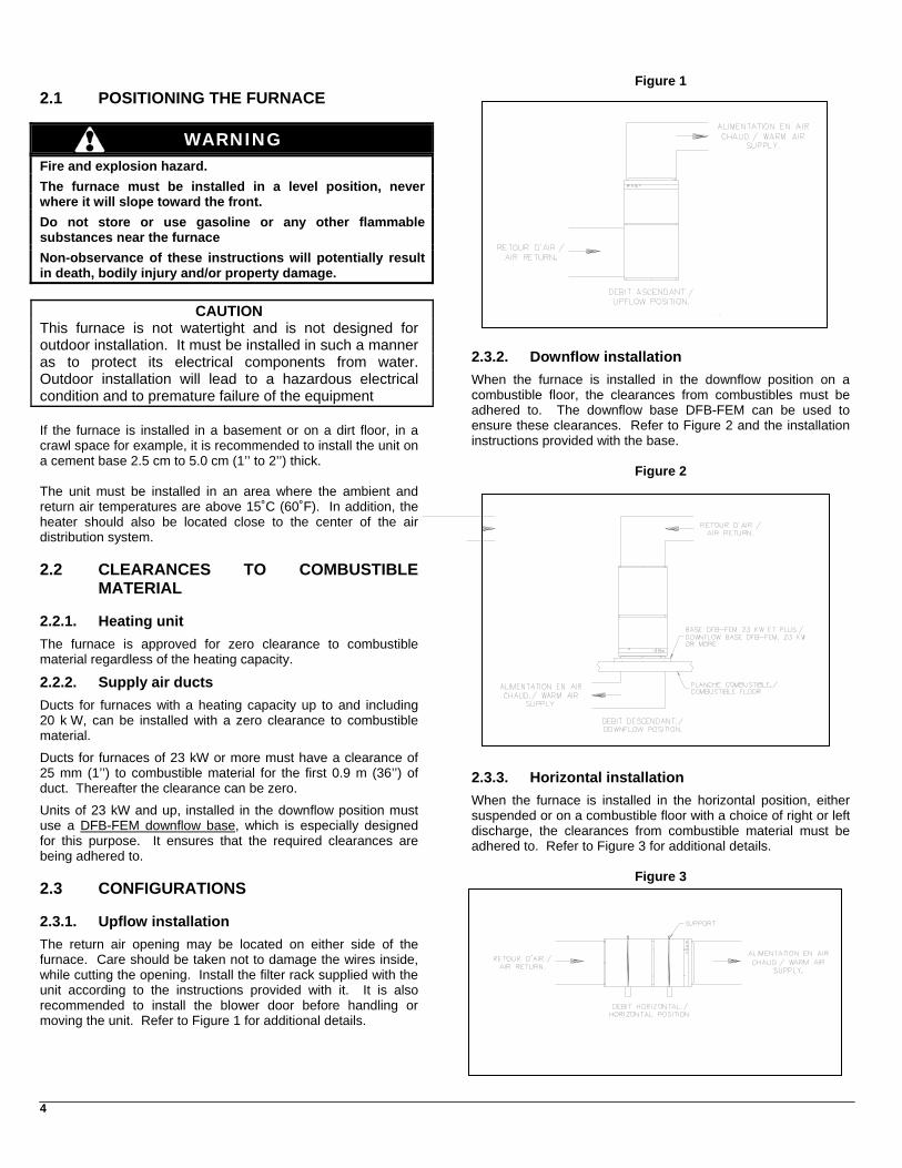
2 INSTALLATION This furnace is a true multi-position unit, in that it will function in an upflow, downflow or horizontal configuration to the left or the right. Only a few modifications are required during installation to change from one position to another. The unit is shipped in the upflow configuration and instructions as to how to change to the other positions are included in this manual. The unit requires a 120/240VAC power supply to the control panel, thermostat hook-up as shown on the wiring diagram and suitable air ductwork. All local and national code requirements governing the installation of central electric heating equipment, wiring and the flue connection MUST be followed. Some of the codes that may apply are: ANSI/NFPA 70: National Electrical Code CSA C22.1 or CSA C22.10: Canadian Electrical Code Only the latest issues of these codes may be used.
4
2.1 POSITIONING THE FURNACE
WARNING Fire and explosion hazard.
The furnace must be installed in a level position, never where it will slope toward the front.
Do not store or use gasoline or any other flammable substances near the furnace
Non-observance of these instructions will potentially result in death, bodily injury and/or property damage.
CAUTION This furnace is not watertight and is not designed for outdoor installation. It must be installed in such a manner as to protect its electrical components from water. Outdoor installation will lead to a hazardous electrical condition and to premature failure of the equipment If the furnace is installed in a basement or on a dirt floor, in a crawl space for example, it is recommended to install the unit on a cement base 2.5 cm to 5.0 cm (1’’ to 2’’) thick. The unit must be installed in an area where the ambient and return air temperatures are above 15˚C (60˚F). In addition, the heater should also be located close to the center of the air distribution system. 2.2 CLEARANCES TO COMBUSTIBLE
MATERIAL 2.2.1. Heating unit
The furnace is approved for zero clearance to combustible material regardless of the heating capacity.
2.2.2. Supply air ducts
Ducts for furnaces with a heating capacity up to and including 20 k W, can be installed with a zero clearance to combustible material.
Ducts for furnaces of 23 kW or more must have a clearance of 25 mm (1’’) to combustible material for the first 0.9 m (36’’) of duct. Thereafter the clearance can be zero.
Units of 23 kW and up, installed in the downflow position must use a DFB-FEM downflow base, which is especially designed for this purpose. It ensures that the required clearances are being adhered to. 2.3 CONFIGURATIONS 2.3.1. Upflow installation
The return air opening may be located on either side of the furnace. Care should be taken not to damage the wires inside, while cutting the opening. Install the filter rack supplied with the unit according to the instructions provided with it. It is also recommended to install the blower door before handling or moving the unit. Refer to Figure 1 for additional details.
Figure 1
2.3.2. Downflow installation
When the furnace is installed in the downflow position on a combustible floor, the clearances from combustibles must be adhered to. The downflow base DFB-FEM can be used to ensure these clearances. Refer to Figure 2 and the installation instructions provided with the base.
Figure 2
2.3.3. Horizontal installation
When the furnace is installed in the horizontal position, either suspended or on a combustible floor with a choice of right or left discharge, the clearances from combustible material must be adhered to. Refer to Figure 3 for additional details.
Figure 3
5
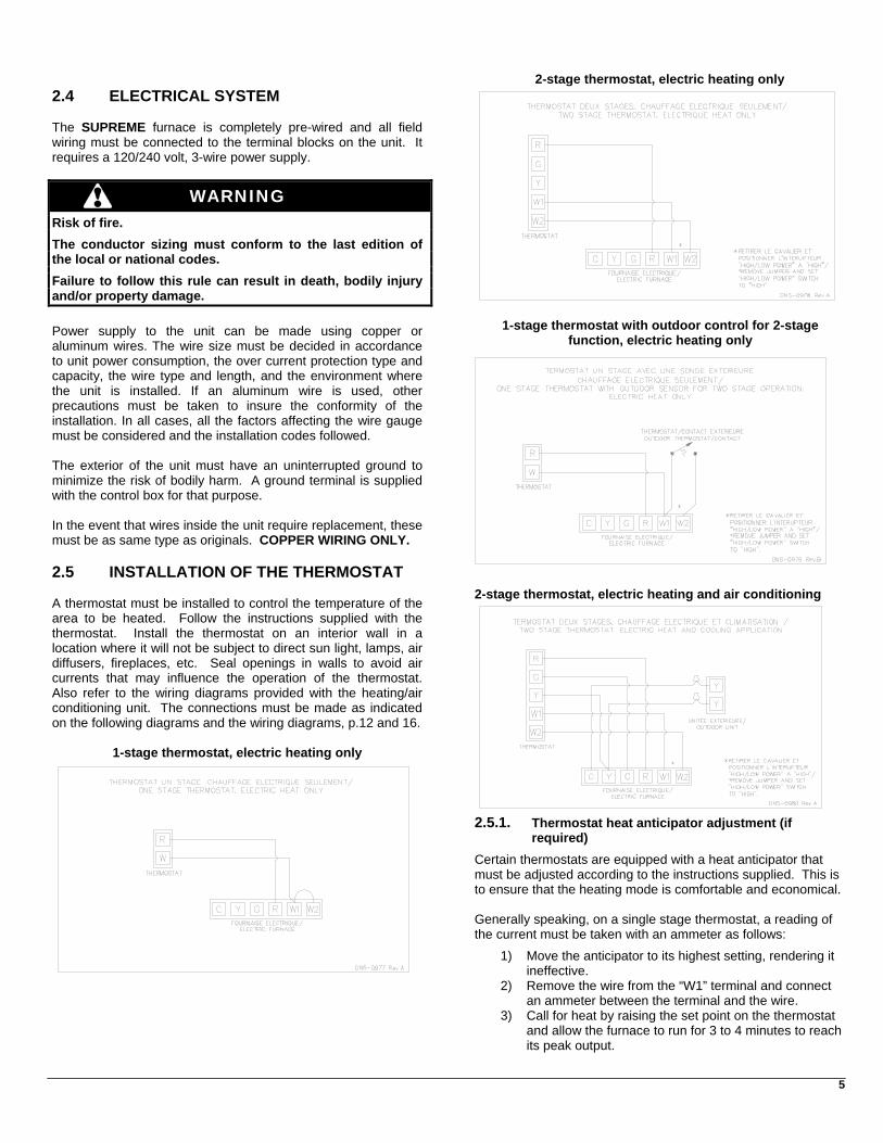
2.4 ELECTRICAL SYSTEM The SUPREME furnace is completely pre-wired and all field wiring must be connected to the terminal blocks on the unit. It requires a 120/240 volt, 3-wire power supply.
WARNING
Risk of fire.
The conductor sizing must conform to the last edition of the local or national codes.
Failure to follow this rule can result in death, bodily injury and/or property damage. Power supply to the unit can be made using copper or aluminum wires. The wire size must be decided in accordance to unit power consumption, the over current protection type and capacity, the wire type and length, and the environment where the unit is installed. If an aluminum wire is used, other precautions must be taken to insure the conformity of the installation. In all cases, all the factors affecting the wire gauge must be considered and the installation codes followed. The exterior of the unit must have an uninterrupted ground to minimize the risk of bodily harm. A ground terminal is supplied with the control box for that purpose. In the event that wires inside the unit require replacement, these must be as same type as originals. COPPER WIRING ONLY. 2.5 INSTALLATION OF THE THERMOSTAT A thermostat must be installed to control the temperature of the area to be heated. Follow the instructions supplied with the thermostat. Install the thermostat on an interior wall in a location where it will not be subject to direct sun light, lamps, air diffusers, fireplaces, etc. Seal openings in walls to avoid air currents that may influence the operation of the thermostat. Also refer to the wiring diagrams provided with the heating/air conditioning unit. The connections must be made as indicated on the following diagrams and the wiring diagrams, p.12 and 16.
1-stage thermostat, electric heating only
2-stage thermostat, electric heating only
1-stage thermostat with outdoor control for 2-stage function, electric heating only
2-stage thermostat, electric heating and air conditioning
2.5.1. Thermostat heat anticipator adjustment (if
required)
Certain thermostats are equipped with a heat anticipator that must be adjusted according to the instructions supplied. This is to ensure that the heating mode is comfortable and economical. Generally speaking, on a single stage thermostat, a reading of the current must be taken with an ammeter as follows:
1) Move the anticipator to its highest setting, rendering it ineffective.
2) Remove the wire from the “W1” terminal and connect an ammeter between the terminal and the wire.
3) Call for heat by raising the set point on the thermostat and allow the furnace to run for 3 to 4 minutes to reach its peak output.
6
4) Once the current has stabilized, a reading should be taken and the anticipator adjusted to that value. If longer heating cycles are desired, the anticipator can be set to a higher value
2.5.2. Ducts and filters
The ducts must be sized such a way as to accommodate the specified airflow and the available static pressure. Refer to the applicable local and/or national installation codes. Insulate the ducts that lead through non-heated areas. Use flexible supply and return air connectors to avoid the transmission of vibration. To make the unit run even quieter, the installer should:
1) Use two elbows between each outlet and the supply and return air plenum;
2) Cover the vertical sections of the supply and return air duct with soundproofing material;
3) Use baffles in short radius elbows; 4) Use flexible hangers to suspend the ducts.
The SUPREME furnace is equipped with a filter frame for the blower compartment. It must be installed on the outside of one of the three sides or the bottom of the furnace. Once the location of the installation has been determined, use the four square knockouts for ease of cutting the opening. A heat pump or an air conditioner can be added to this furnace, in either the supply or return air duct. Carefully follow the instructions provided with these appliances to ensure proper installation and hook-up to the electric furnace. Refrigerant and drainage pipes must in no way hinder access to the furnace panels. 2.6 SUPPLY AIR ADJUSTMENTS On units equipped with 4-speed blower motors, the supply air must be adjusted based on heating/air conditioning output and the static pressure of the duct system. For the desired airflow, refer to the following table as well as the airflow tables based on static pressure in the Technical Specifications section of this manual. For the adjustment of the airflow on heating mode, to obtain the temperature rise described in the technical specification table on p.10, the orange wire must be positioned on the terminal corresponding to the LOW, MED-LOW, MED-HIGH or HIGH blower speed. Blower speed are adjusted in factory for 0.5 inch static pressure.
Supply air adjustment on heating mode
FURNACE INPUT
POWER KW
HP MOTOR STATIC
PRESSURE (in. w.c)
RECOMMENDED BLOWER SPEED
0.2 LOW FEM10 10 1/3 0.5 LOW 0.2 MED-LOW FEM15 15 1/3 0.5 MED-LOW 0.2 MED-LOW FEM18 18 1/3 0.5 MED-LOW 0.2 MED-LOW FEM20 20 1/3 0.5 MED-HIGH 0.2 MED-HIGH FEM23 23 1/3 0.5 MED-HIGH 0.2 MED-LOW FEM20 20 1.0 0.5 MED-LOW 0.2 MED-LOW FEM23 23 1.0 0.5 MED-LOW 0.2 MED-LOW FEM27 27 1.0 0.5 MED-LOW
For the adjustment of the airflow on air-cooling mode, to obtain a sufficient airflow (350 to 450 CFM per ton), the blue wire must be positioned on the terminal corresponding to the LOW, MED-LOW, MED-HIGH or HIGH blower speed. Blower speeds are adjusted in factory for 0.5 inch static pressure.
Supply air adjustment on air cooling mode
FURNACE HP MOTOR COOLING CAPACITY (0.5” w.c.)
RECOMMENDED BLOWER SPEED
1.5 LOW 2.0 MED-LOW 2.5 MED-HIGH
FEM10, 15, 18, 20 and 23 1/3
3.0 HIGH 2.5 LOW 3.0 MED-LOW 3.5 MED-HIGH 4.0 HIGH
FEM20, 23 and 27 1.0
5.0 HIGH If the heating and air-cooling speed are the same, the orange wire and the blue wire can be connected on the same terminal on the motor. 2.7 INSTALLATION OF ACCESSORIES
WARNING
Electrical shock hazard.
Turn OFF electrical power at the fuse box or service panel before making any electrical connections and ensure a proper ground connection is made before connecting line voltage.
Failure to do so can result in death or bodily injury.
7
2.7.1. Humidifier and electronic air cleaner
This unit is equipped with a 120 VAC terminal for the connection of accessories up to a maximum of 2 amps. A humidifier and an electronic air cleaner can be wired to terminals “1” and “2” of the unit. Refer to the wiring diagrams in this manual. A field supplied 120/24 VAC transformer can be installed for accessories using 24 VAC. A separate power source must be used if the accessories draw more then 2 amps. Certain accessories require control relays. A location has been set aside in the unit for the installation of relays: a 24 VAC (part number L01H009) or a 120 VAC (part number L01H011). In addition, a 24 VAC relay can be wired between terminals “W1” and “C” to be activated during a call for heat. Refer to the wiring diagrams for the location of the relay (R-Acc-X) on the control panel. 2.7.2. Use of a heat pump
When using a heat pump, a kit is required that prevents the operation of the electric elements and the heat pump at the same time. Refer to the instructions provided with the thermostat or the “Fossil Fuel” type kit for the proper wiring of the furnace and the heat pump. The simultaneous operation of the electric elements and the heat pump will cause overheating of either unit. The safety controls of the appliances will shut down the elements, since they are not designed to function in this fashion.
3 OPERATION 3.1 START-UP Before starting up the unit, be sure to check that the following items are in compliance:
1) The electrical installation and ventilation; 2) The blower access door is in place and the blower rail
locking screws are well tightened; 3) The blower speed adjustments for heating and air
conditioning are appropriate and according to the specifications in this manual;
4) The thermostat of the room is in the heating mode and is set higher than the ambient temperature.
To start the unit, turn the main electrical switch on. 3.2 OPERATING SEQUENCE Heating mode
1) The thermostat closes the R-W1 circuit, thereby activating the sequencers and elements of the first heating stage, one by one. The blower starts up at low speed at the same time as the first element comes on.
2) Approximately 1 minute after the R-W2 circuit closes, a sequencer will cause the blower to go to heating speed (R-2 relay). Then, the elements of the second stage will come on, one by one.
Cooling mode
1) The thermostat closes the R-G circuit, thereby activating the 24 VAC R-1 relay. The blower starts up to cooling speed. The blower will also start up to cooling speed by way of the “Fan” switch on the thermostat.
2) The thermostat closes the R-Y contact, thereby activating the compressor relay of the air conditioner.
3.3 USE OF MANUAL FURNACE CONTROLS
FIGURE 4
Manual Furnace Controls
When there is a demand for heat, the pilot light (“L-1”) comes on. Refer to the wiring diagram. When the ”HI/LO” switch is put into the “LO” position, it will shut down approximately half the elements. However, it is important to put the switch back to the “HI” position during the winter months to ensure adequate heating. Also, this switch must remain in the “HI” position when a 2-stage or outdoor thermostat is used to control the electric elements of the second stage. Refer to the diagram in Section 1.5) above (Typical 24 VAC Wiring, Thermostat). The “ON/OFF VENT/FAN” switch engages the blower in the continuous low speed mode. This will filter the air and provide for better air distribution in the building. The circuit breaker is there to protect the motor and control circuit conductors. If the unit does not function, press the circuit breaker button to see if it may have disengaged due to a power surge. If the breaker has to be pressed again, the unit must be checked by a qualified service technician.
8
4 MAINTENANCE 3.4 AIRFLOW VERIFICATION Verify the airflow by taking readings of the following points, while the elements are in the heating mode: WARNING
• Total amperage of all the heating elements;
Electrical shock hazard. • Voltage at the furnace;
Turn OFF power to the furnace before any disassembly or servicing. • Supply air temperature. The point of the reading must
not be affected by radiant heat from the elements;
Failure to do so can result in death, bodily injury and/or property damage.
• Return air temperature.
From these readings, one can arrive at an approximate calculation of the average airflow. To do that, the following formulae should be used:
Preventive maintenance is the best way to avoid unnecessary expense and inconvenience. Have your heating system inspected by a qualified service technician at regular intervals. Do not attempt to repair the furnace or its controls. Call a qualified service technician.
0.82 x amps. x volts Liter/s= ------------------------- Diff. temperature ˚C 3.1 x amps. x volts Before calling for repair service, check the following points: CFM = ------------------------
1) Check fuses or the circuit breaker; Diff. temperature ˚F 2) Check if the 15 A circuit breaker on the furnace is disengaged;
3.4.1. Supply Air Temperature Rise Test 3) Set the thermostat higher than room temperature. If the unit does not start up, cut the power and call la qualified service technician.
1) Operate the unit at maximum power for at least 10 minutes;
2) Measure the air temperature in the return air plenum;
When calling for service or ordering a replacement part, specify the model and serial number of your appliance. 3) Measuring the air temperature in the largest trunk
coming off the supply air plenum, just outside the range of radiant heat from the heat exchanger. 0.3 m (12”) from the plenum of the main take-off is usually sufficient;
4.1 AIR FILTER The filter supplied with the unit is the disposable type and should be replaced twice a year. The presence of animal hair, dust, etc. may necessitate more frequent changes. Dirty filters have an adverse effect on the performance of the central heating system.
4) The temperature rise is calculated by subtracting the return air temperature from the supply air temperature.
If the temperature rise exceeds the temperature specified in Table 1, p.10, change to the next higher blower speed tap, until the temperature rise falls to the target or below. If the excessive temperature rise cannot be reduced by increasing fan speed, investigate for ductwork obstructions or dirty and improper air filter.
4.2 MOTOR LUBRICATION Do not lubricate the blower motor, since it is permanently lubricated.
CAUTION
It is important to check the airflow and to ascertain that the unit does not operate above the temperatures specified in the Technical Specifications (Table 1). This is particularly important if a cooling coil or a heat pump has been installed in the ducts.
Hi-Limit thermal protectors should never need to engage during the normal functioning of the appliance. They are strictly designed to engage during the improper functioning of the blower or when the filter was improperly maintained.
3.4.2. Vérification des limiteurs de température
After operating the furnace for at least 15 minutes, restrict the return air supply by blocking the filters or the return air register and allow the furnace to shut off on High Limit. The electric heaters must deactivate themselves one by one before the warm air temperature exceeds 200˚F Remove the obstruction and the elements should restart after a few minutes.
9
5 INFORMATION
Model:
Serial number:
Furnace installation date:
Service telephone # - Day:
Night:
Dealer name and address:
START-UP RESULTS
Voltage: Total current consumed by the elements:
Supply air temperature:
Return air temperature:
Supply air duct static pressure:
Return air duct static pressure:
Total pressure:
Calculated air flow: Current consumed by the blower motor:
Current consumed by the accessories:
10
TABLE 1 Technical Specifications
Power (Kw) (xx ) 10 15 18 20 23 20 23 27Net capacity (BTU/h) 34120 51180 61420 68240 78480 68240 78480 92130Heating temperature rise range (F) 1 40-50 45-60 50-75 55-75 60-80 55-75 60-80 60-80ELECTRICAL SYSTEMVolts - Hertz - PhaseElectrical element #1 (Kw) 5 5 4 5 4 5 4 5Electrical element #2 (Kw) 5 5 5 5 5 5 5 5Electrical element #3 (Kw) 5 4 5 4 5 4 5Electrical element #4 (Kw) 5 5 5 5 5 4Electrical element #5 (Kw) 5 5Electrical element #6 (Kw) 4Blower motor Consumption (Amp) 6 6 6 6 6 13 13 13Heating Elements Consumption (Amp) 41 61 74 82 94 82 94 111Total Consumption (Amp) 47 67 80 88 100 95 107 124Circuit amperage (wire sizing) 2 59 84 100 112 125 119 134 155Maximum size circuit breaker (Amp) 2 60 90 100 125 125 125 150 175BLOWER DATA (factory adjusted to a static pressure of 0.5" W.C.)Blower speed at 0.50" W.C. static pressure LOW MED-LOW MED-LOW MED-HIGH MED-HIGH MED-LOW MED-LOW MED-LOBlower speed at 0.20" W.C. static pressure LOW MED-LOW MED-LOW MED-LOW MED-HIGH MED-LOW MED-LOW MED-LOMotor (HP) / number of speedsBlower sizeGENERAL INFORMATIONOverall dimensions (width x depth x height)SupplyReturnFilter quantity and sizeShipping weightMaximum cooling capacit
4
WW
y
2) Calculated on the basis of Norm C22.2 Nr.236
RATINGS AND PERFORMANCE
20" x 20" x 36.5"15" x 18"19" x 19"
G10-8
FEMxx -M2401AM-A
1/3 HP / 4 speeds
FEMxx -M2401BM-A
3 wires 120/240 - 60 - 1
1 HP / 4 speeds
1) Select a blower speed that will generate the specified temperature rise
(1) 20" x 20"
5 tons3 tons48 Kg / 105 lbs
GT12-10
11
TABLE 2 Air Flow (CFM) – SUPREME with 1/3 HP motor
0,1 0,2 0,3 0,4 0,5 0,6 0,7LOW 715 700 690 675 660 650 635
MED-LOW 935 900 870 835 800 770 735MED-HIGH 1090 1050 1010 970 930 890 850
HIGH 1285 1250 1220 1185 1150 1120 1085
Blower Speed Static Pressure
The airflow values are expressed in cubic feet per minute (CFM’), rounded to 5 CFM more or less. These readings were taken with the air filter installed.
TABLE 3
Air Flow (CFM) – SUPREME with 1 HP motor
0,1 0,2 0,3 0,4 0,5 0,6 0,7LOW 1035 1030 1030 1025 1020 1020 1015
MED-LOW 1315 1300 1285 1270 1255 1240 1225MED-HIGH 1715 1650 1590 1525 1460 1400 1335
HIGH 1935 1900 1870 1835 1800 1770 1735
Blower Speed Static Pressure
The airflow values are expressed in cubic feet per minute (CFM), rounded to 5 CFM more or less. These readings were taken with the air filter installed.
FIGURE 5 Dimensions
DNS-0982 Rev.B
12
FIGURE 6 Wiring Diagram 10 kW with 1/3 HP motor
13
FIGURE 7 Wiring Diagram 15 kW with 1/3 HP motor
14
FIGURE 8 Wiring Diagram 18 and 20 kW with 1/3 HP motor
and 20 kW with 1.0 HP
15
FIGURE 9 Wiring Diagram 23 kW with 1/3 HP and 1 HP motor
16
FIGURE 10 Wiring Diagram 27 kW with 1 HP motor
COMPONENTS
AND
REMPLACEMENT PARTS
17
18
PARTS LIST Exploded View
B50002F
Please refer to Table 4, p.20
19
PARTS LIST SUPREME with 1/3 HP and 1 HP motor: FEMxx-M2401AM-A and FEMxx-M2401BM-A
ITEM PART # DESCRIPTION COMMENTS1A B03274-01 HEATING ELEMENT PLATE ASSEMBLY FEM-10kW (1/3 HP) Item 11 included1B B03275-01 HEATING ELEMENT PLATE ASSEMBLY FEM-15kW (1/3 HP) Item 11 included1C B03276-01 HEATING ELEMENT PLATE ASSEMBLY FEM-18kW (1/3 HP) Item 11 included1D B03276-02 HEATING ELEMENT PLATE ASSEMBLY FEM-20kW (1/3 HP) Item 11 included1E B03277-01 HEATING ELEMENT PLATE ASSEMBLY FEM-23kW (1/3 HP) Item 11 included1F B03278-01 HEATING ELEMENT PLATE ASSEMBLY FEM-27kW (1/3 HP) Item 11 included1H B03314-01 HEATING ELEMENT PLATE ASSEMBLY FEM-23kW (1 HP) Item 11 included1I B03317-01 HEATING ELEMENT PLATE ASSEMBLY FEM-27kW (1 HP) Item 11 included2A B03273 FRONT DIVIDER ASSEMBLY (1/3 HP)2B B03313 FRONT DIVIDER ASSEMBLY (1 HP)3 B03260 CASING ASSEMBLY Item 4 included4 B03302 CASING INSULATION5 B03263 TOP PANEL ASSEMBLY Items 6, 7 & 8 included6 L01J001 CIRCUIT BREAKER 15 AMP7 L07F015 ROCKER SWITCH SPDT8 L01L006 PILOT LIGHT9 B03286 HEATING ELEMENT COVER10A L99H008 HEATING ELEMENT 5kW10B L99H009 HEATING ELEMENT 4kW11A R02N015 THERMODISK L150-55F 10 to 23kW - 1/3 HP11B R02N019 THERMODISK L140-55F 23 to 27kW - 1.0 HP12 B03288 MOUNTING PLATE FOR ELECTRICAL, TOP13 B03289 MOUNTING PLATE FOR ELECTRICAL, SIDE14 L05F004 TERMINAL STRIP, 4-POSITION15 L01H009 RELAY SPDT 24 VAC16 L01F009 TRANSFORMER 120-24Volts17 L99F004 TERMINAL BLOCK18* See Table 4 SEQUENCER Please refer to Table 4, p.2019 B03265 TERMINAL BLOCK SUPPORT ASSEMBLY20 B03280 DOOR, ELECTRICAL COMPARTMENT21 Z04F004 PAPER FILTER 20 x 20 x 122 B03257-01 DOOR, BLOWER COMPARTMENT Item 23 included23 B02293-22 BLOWER DOOR INSULATION24 B03258 FLOOR Item 25 included25 B02293-21 FLOOR INSULATION26 B03299 FILTER RACK ACCESS27 B03298 FILTER RACK U-FRAME28 B30513 BLOWER RAIL29 B03264 DIVIDER Item 28 included30A B03301-01 REPLACEMENT BLOWER ASSEMBLY (1/3 HP) Item 31, 32, 34 & 38 included30B B03318-01 REPLACEMENT BLOWER ASSEMBLY (1 HP) Item 31, 32, 34 & 38 included31A B01291-04 SEAL STRIP (1/3 HP)31B B01291-01 SEAL STRIP 1 1/2" x 13 1/8" (1 HP)32A Z01I002 BLOWER G10-8DD (1/3 HP)32B Z01I008 BLOWER GT12-10DD (1 HP)33A Z01L001 BLOWER WHEEL G10-8DD (1/3 HP)33B Z01L003 BLOWER WHEEL G12-10DD (1 HP)34A L01I001 CAPACITOR 5 MF (1/3 HP)34B L01I003 CAPACITOR 10 MF (1 HP)35 B01024 CAPACITOR SUPPORT36 B03303 BLOWER ELECTRICAL HARNESS37A B01888 MOTOR SUPPORT BAND AND LEGS (1/3 HP)37B B01889 MOTOR SUPPORT BAND AND LEGS (1 HP)38A L06G007 MOTOR 1/3 HP38B L06K004 MOTOR 1.0 HP39A L01H009 ACCESSORY RELAY 24 VAC Optional39B L01H011 ACCESSORY RELAY 120 VAC Optional
L50002F
20
Sequencernumber* Part # ICP # Part # ICP # Part # ICP # Part # ICP # Part # ICP #
18A 1 305563 R02N018 305563 R02N018 305563 R02N018 305563 R02N018 305563 R02N01818B 2 305136 R02N017 305891 R02N016 305891 R02N016 305136 R02N017 305136 R02N01718C 3 305136 R02N017 305891 R02N016 305891 R02N016 305891 R02N01618D 4 305891 R02N016 305136 R02N01718E 5 305891 R02N016
Item
TABLE 4
FEM10 FEM15 FEM18/20 FEM23 FEM27(Please refer to the Parts List, item 18, page 19)
*The sequencer numbers are identified on the wiring diagrams, Figures 6 to 10 inclusively.