27 jun-2015 - aci 439 - mech conn re-bar
TRANSCRIPT
439.3R-91
Mechanical Connections of Reinforcing Bars
(Reapproved 1999)
reported by ACI Committee 439
John F. McDermott, Chairman Peter Meza, Secretary
Michael Baldino, Jr.Ted M. BrownLoris L. GerberDonald J. GrantDavid P. GustafsonEdward S. Hoffman
Steve HoldsworthWilliam J. JurkovichEugene A. LambersonHarry B. Lancelot, IIILe Roy A. LutzSteven L. McCabeHeinz Nierlich
Clarkson W. PinkhamHoshi H. PresswallaRobert C. RichardsonRobert G. SmithRobert J. SmithRobert A. Vernec
Properly designed splices are a key element in any well-executed de-sign. The lap splice, when conditions permit and when it will satisfyall requirements, is generally the most common method for splicingreinforcing bars. However, when lap splices are undesirable or im-practical, or when their use is not permitted by the design code or de-sign specification, mechanical or welded connections should be usedto splice the reinforcing bars.
The objective of this report is to provide engineers and contractorswith basic information about mechanical connections and the typesof proprietary mechanical connection devices currently available, butnot to state conditions of acceptance, or to endorse or rate a partic-ular mechanical connection device over another. These mechanicalconnection devices are proprietary, and the information herein pro-vided by the connector manufacturers has been compiled, but noneof the information has been specifically verified by this committee.Consequently, the relative merits of the different mechanical connec-tion devices are not noted or compared. However, the informationgiven is useful, because it is not presently available elsewhere in suchan assembled and detailed format. An attempt was made to includeall the mechanical connection devices generally commercially availa-ble in North America at the time the report was written. However, itmust be realized that some devices new in the market may not be in-cluded, merely due to ignorance of their existence at the time of writ-ing.
Reasons for using mechanical connections are discussed, as well asvarious engineering considerations that must be made when spectfy-ing mechanical connections, such as the need to avoid notch effectsin seismic joints that could result in the bar rupturing at one locationbefore it yields generally elsewhere. Mechanical connection devicesare described in terms of configuration, procedure for connecting,clearance requirements, and other characteristics. Illustrations of thevarious mechanical connection devices are included.
Keywords: bolted connections; connections; couplers; dowels; reinforced con-crete; reinforcing steels; sleeves; splicing.
ACI Commmittee Reports, Guides, Standard Practices, andCommentaries are intended for guidance in designing, plan-ning, executing, or inspecting construction and in preparingspecifications. Reference to these documents shall not be madein the Project Documents. If items found in these documentsare desired to be part of the project documents they should bephrased in mandatory language and incorporated into theProject Documents.
CONTENTS
439.3
Chapter 1 -General1.l-Introduction1.2-Usage1.3-General considerations
Chapter 2-Design requirements for mechanicalconnections
2.l-Codes and specifications
Chapter 3-Mechanical connection devices andinstallation descriptions
3.1-General3.2-Compression-only mechanical connections3.3-Tension-compression mechanical connections3.4-Dowel bar mechanical connection systems3.5-Tension-only mechanical connection
Chapter 4-Summary
Chapter 5-References5.l-Specified and recommended references5.2-Cited reference
CHAPTER 1-GENERAL1.1-Introduction
In reinforced concrete design, the structural engineeris faced with the task of determining where and howreinforcing bars must be spliced in a structure. Thestructural engineer must do this because of his famil-iarity with the particular requirements of the structure.Drawings or specifications must clearly show or de-scribe all splice locations and the performance re-
ACI Structural Journal, V. 88, No. 2, March-April 1991.This report supersedes ACI 439.3R-83 (Reapproved 1988) effective June I, 1991.
Copyright 0 1991, American Concrete Institute.All rights reserved, including rights of reproduction and use in any form or
by any means, including the making of copies by any photographic process, orby any electronic or mechanical device, printed, written, or oral, or recordingfor sound or visual reproduction, or for use in any knowledge or retrieval sys-tem or device, unless permission is obtained in writing from the copyright pro-prietor.
R-1
439.3R-2 MANUAL OF CONCRETE PRACTICE
quired. The importance and necessity of clearly pre-scribing splice requirements is evident in two sections ofACI 318. Section 1.2.1 describes nine specific items tobe included on the design drawings, details, and speci-fications. These items include Section 1.2.1.h, whichrequires that location and length of lap splices and re-inforcement anchorage lengths be shown. Section1.2.1.i requires showing the type and location of weldedsplices and mechanical connections of reinforcement.Section 12.14.1 of ACI 318 also addresses this subject,and states: “Splices of reinforcement shall be madeonly as required or permitted on design drawings, or inspecifications, or as authorized by the engineer.”
In the design of beams, columns, and slabs, lapsplices are usually permitted. When lap splices ofstraight bar extensions cannot be used, or when theiruse causes congestion, field placing problems, or de-tailing or design problems, then mechanical connec-tions, welded joints, or lap splice connections involvingfield bending and subsequent bar straightening may beused, as appropriate.
This report provides basic information about propri-etary mechanical connections generally available inNorth America and known to the committee at the timethe report was submitted for publication.* Design re-quirements and usage of mechanical connections, aswell as capabilities and features of selected mechanicalconnection devices, are described.
Three basic types of mechanical connections are con-sidered in this report. They are: (1) the “compression-only” mechanical connection, which is also known asthe “end-bearing mechanical connection,” (2) the“tension-only” mechanical connection, and (3) the“tension-compression” mechanical connection. The“tension-compression” mechanical connection can re-sist both tensile and compressive forces. Dowel bar me-chanical connections are included in this category.
In this report, pertinent terms are defined as follows:Bar-end check-Check of the ends of reinforcing
bars to determine whether they fit the devices intendedfor connecting the bars.
Coupler-Threaded device for joining reinforcingbars for the purpose of providing transfer of either ax-ial compression or axial tension or both from one barto the other.
Coupling sleeve-Nonthreadeddevice fitting over theends of two reinforcing bars for the eventual purposeof providing transfer of either axial compression or ax-ial tension or both from one bar to the other.
End-bearing sleeve-Devicefitting over the abuttingends of two reinforcing bars for the purpose of assur-ing transfer of only axial compression from one bar tothe other.
Mechanical connection-Complete assembly of anend-bearing sleeve, a coupler, or a coupling sleeve, and
*ANCON (MBT) mechanical connectors, which involve a clamping devicegenerically different from devices described in the present report, are not in-cluded in this report because they were unknown to the committee at the timeof final committee ballot on the report.
possibly additional intervening material or other com-ponents to accomplish the connection of reinforcingbars.
It is beyond the scope of this report to cover weldedsplices or other currently available special proprietarysplicing systems. Engineers are referred to the AWScode for welding reinforcing steel (ANSI/AWS D1.4)and the ASTM specifications for reinforcing bars, suchas ASTM A 706 and ASTM A 615. Further discussionof the AWS code and welded splices is given in Refer-ence 1.
1.2-UsageThere are numerous situations that require or make
the use of mechanical connections feasible or morepractical. Some of the most common conditions are:
1. Where #14 and #18 bars are used. This occursmost often in columns, raft mat foundations, and otherheavily reinforced structures. Codes do not permit #14and #18 bars to be lap spliced, except in compressiononly with #11 and smaller bars.
2. Where spacing of the reinforcing bars is insuffi-cient to permit lapping of the bars. This generally oc-curs in situations requiring large amounts of reinforce-ment and the use of larger bars, as in heavily loadedcolumns.
3. When requirements in current codes and specifi-cations for tension lap splices result in long lap splicelengths, especially for bar sizes such as #9, #l0, and #llin Grade 60 steel or in epoxy-coated reinforcing bars.Lap splices may thus be less practical than mechanicalconnections.
4. Where “tension tie members” are used. Tensionlap splices of reinforcing bars in tie members are notpermitted.
5. When the location of construction joints and pro-vision for future construction dictates use of mechani-cal connections to provide tensile continuity. Mechani-cal connections are often preferable to having long barlengths projecting from existing concrete construction.A minimum of a 12 in. (305 mm) bar extension pro-vides sufficient length for application of most mechan-ical connections without damaging the existing con-crete during installation. If mechanical connectionsmust be staggered, the projecting bar extension shouldbe greater than 12 in. (305 mm).
1.3-General considerationsAvailable proprietary mechanical devices have par-
ticular physical features, both in the splice device itselfand in the required installation equipment or procedurethat can influence design and construction methods.
1.3.1 Spacing and cover requirements-Minimumclear distances between adjacent reinforcing bars arespecified in codes and design specifications. For exam-ple, ACI 318 Sections 7.6.2 and 7.6.3 set an absoluteminimum clear distance between parallel bars in a layerof not less than the nominal diameter of the bar or 1 in.(25 mm), except that for columns the minimum cleardistance is not less than 11/2 times the nominal bar di-
REINFORCING BARS 439.3R-3
ameter or 1% in. (38 mm). Section 7.6.4 of ACI 318indicates that the clear distance limits shall also applyadjacent to lapped splices, but Section 7.6.4 does notaddress clearance limits for mechanical connections.
Appropriate clearance limits for mechanical connec-tions are listed in Tables 3.1 and 3.2. Clearance limits
may be a factor in the selection and positioning of themechanical connection. The outside diameter of themechanical connection device should be known. Byknowing the diameter of the mechanical connection de-vice, a decision can be made whether the mechanicalconnections have to be staggered on the basis of theclearance required. It has been the practice in the pastto stagger splices of any types whether lapped, welded,or mechanically connected, but there is currently someevidence documented by research that some mechanicaconnections providing adequate longitudinal stiffnessand adequate ductility for the reinforcement, as well asthe specified strength, need not be staggered. However,pending any future code revisions, the minimum stag-ger length should be specified by the engineer consis-tent with the requirements of the applicable code, e.g.,Sections 12.15.4.1, 12.15.5, 12.17, and 21.3.2.4 of ACI318.The size and operation of the equipment required formaking mechanical connections can also dictate a min-imum spacing or a stagger pattern. Some informationto evaluate these requirements is available in subse-quent sections of this report.
Several of the proprietary mechanical connection de-vices currently available have an outside diameter sub-stantially larger than the reinforcing bars. Special con-sideration should be given to the minimum concretecover of the stirrups, ties, or spirals at these splice lo-cations. In many cases, the stirrup or tie patterns adja-cent to the mechanical connections, or the location ofthe splice itself, can be adjusted to avoid a reducedconcrete cover. However, where required close spacingof stirrups and ties necessitates their placement over thecoupling sleeves, it may be necessary to design greatercover over the longitudinal reinforcement so that stir-rups and/or ties encompassing the mechanical connec-tions have adequate cover. Ideally, the confinement re-inforcement would have greater dimensions at a con-nector, but that is not generally the practice. In dowelbar mechanical connections that have flanged sleeves,all portions of the mechanical connection should meetappropriate cover requirements.
1.3.2 Matching of end alignments, end preparationof bars, special bar deformations, and equip-ment-The engineer/specifier should be aware of anyspecial end preparations of bars required for a methodof mechanical connection or for certain couplers. Forexample, Section 12.16.4.2 of ACI 318 requires forend-bearing splices that the ends of the bars be cut towithin 1 l/z deg of square with respect to the longitudi-nal axis. By definition, couplers are threaded, and somerequire matching threads on the bar ends. One me-chanical connection device requires reinforcing barswith special thread-like deformations. In all mechani-
cal connections, it is important to have the mechanicalconnection device in good alignment with the longitu-dinal bar axis so that the bar is not prone to wideswings when being rotated in a field assembly.
The reinforcing bar fabricator must be made awareof any special end preparations or threads. Special re-quirements may entail the use of end-threading ma-chines or special tools and equipment at the construc-tion site. Availability or delivery requirements for rein-forcing bars with the special deformation pattern, andfor required tools and equipment, should be deter-mined for the specific project before final decisions aremade. Related to this, a bar-end check is sometimesadvisable before proceeding with certain mechanicalconnections. The mechanical connection manufacturercan advise accordingly.
1.3.3 Coated reinforcing bars-Reinforcing bars canbe epoxy coated or zinc coated (galvanized) for use asa corrosion-protection system. Mechanical connectionsof coated reinforcing bars are made with proprietarymechanical connection devices in a similar way as foruncoated bars. To properly install some types of cou-pling sleeves on coated bars, the coating has to be com-pletely removed from the ends of the bars over thelength of the sleeve and a short distance, perhaps 2 in.(50 mm) or so, beyond the ends of the sleeve. Infor-mation on preparation of bar ends for installation ofproprietary mechanical connection devices, includingremoval of epoxy or zinc coatings, is presented in Ta-bles 3.1 and 3.2.
After installation of mechanical connections oncoated reinforcing bars, the sleeves and any damagedcoating on the bars adjacent to the sleeve should betouched up with appropriate compatible patching ma-terial with anticorrosive quality equal to that of theoriginal coating. Typically, there will be provisions inthe project specifications requiring such touch-up of thesleeves and repair of damaged coating-for example,see Chapter 5 of ACI 301. Flame cutting of coated barsin any location should be avoided when possible be-cause of damage to the epoxy coating. Where mechan-ical connections are used, flame-damaged epoxy coat-ing may be more difficult to remove properly to obtainan effective connection than undamaged epoxy coat-ing.
1.3.4 Field erection-In many applications, mechan-ical connections may be staggered for clearance, ac-cess, and some code requirements. If staggered me-chanical connections are used in columns, for example,free-standing erection and assembly of the reinforce-ment may be required rather than preassembled cages.
There is a considerable difference in the time andequipment required to install different mechanical con-nections. Therefore, it is imperative to coordinate thefield erection procedure and schedule with the selectionand installation procedure of the mechanical connec-tions.
For some projects, the engineer may find it appro-priate to control the types of mechanical connectiondevices to be utilized. Also, the method of construction
439.3R-4 MANUAL OF CONCRETE PRACTICE
may determine the types of mechanical connection de-vices that can be most readily utilized. It is importantthat the unique requirements of any selected mechani-cal connection device be considered by all parties priorto beginning construction. Study of the subsequent de-scriptions will assist in determining these requirements.
CHAPTER 2-DESIGN REQUIREMENTS FORMECHANICAL CONNECTIONS
2.1-Codes and specificationsDesign requirements of the applicable code (ACI 318,
349, or 359) or specification (AASHTO Standard Spec-ifications for Highway Bridges) for reinforcing bar me-chanical connections are not reproduced or discussedherein in detail. Codes generally specify a minimumconnection strength. For example, ACI 318, Section12.14.3.4, states, “A full mechanical connection shalldevelop in tension or compression, as required, at least125 percent of specified yield strengthf, of the bar,” sothat yielding will tend to occur in the reinforcing baradjacent to the mechanical connection before failure inthe mechanical connection. For further background in-formation and some of the considerations made in de-veloping the ACI 318 provisions, the reader is encour-aged to review ACI 318R.
Due to the minimum connection strength required, itis generally assumed in design that the occurrence of amechanical connection of two reinforcing bars does notresult in a reduction of the anticipated structuralstrength, as well as the longitudinal stiffness and lon-gitudinal ductility, of the reinforcing steel, which thereinforced concrete member would have had with acontinuous unspliced bar. That is, it is assumed that theuse of a mechanical connection does not introduce astructural weakness that could jeopardize the overallstructural performance. Design codes cover basicstrength requirements for splices and mechanical con-nections, but generally do not specify how to avoidother potential weaknesses that may be directly attrib-uted to the specific details and/or materials of a me-chanical connection, as follows:
1. In a flexural member, the mechanical connectionshould not result in a low effective longitudinal stiff-ness of the reinforcement that violates the strain con-ditions assumed in the member design.
2. Where inelastic straining must be anticipated, as inyielding zones of seismic structures, the mechanicalconnection device must not introduce notch effects thatwould cause the bar to rupture at the mechanical con-nection device before the required yielding can occur inthe adjoining bar stock.
3. The selection of appropriate mechanical connec-tions must consider that notch effects, if present, aremore severe with dynamic loadings, fatigue loadings,and cold temperatures.
4. Where potential inelastic straining may occur dur-ing seismic excitation, the assembly consisting of theconnector and the reinforcing bars connected mustpossess adequate ductility so that failure initiates in theconcrete rather than in the steel reinforcement. Manu-
facturers’ information, as well as that in the literature,should be reviewed by the engineer when evaluating amechanical connector for service where large load re-versals are possible.
CHAPTER 3-MECHANICAL CONNECTIONDEVICES AND INSTALLATION DESCRIPTIONS
3.1-GeneralA variety of proprietary mechanical connection de-
vices are currently available. In this part of the report,the physical features, mechanical characteristics, andinstallation procedure of various available mechanicalconnection devices are described. The mechanical con-nection devices are divided into three basic categories:compression-only mechanical connections, tension-onlymechanical connections, and tension-compression me-chanical connections, all meeting Section 12.14.3.4 ofACI 318.
To assist the reader, a list of characteristics summa-rizing the detailed descriptions is included in Tables 3.1and 3.2 for compression-only and tension-compressionmechanical connections, respectively. These tablesshould be helpful in determining which mechanicalconnection devices may be utilized for specific designapplications.
Descriptions of the mechanical connection devicesare presented in the following sections in alphabeticalorder by generic name. Similarly, the locations of thedevices in Tables 3.1 and 3.2 are by alphabetical order.The committee does not endorse, or rate a particularmechanical connection device over another. An at-tempt was made to include all devices generally com-mercially available in North America in the followingsection. These descriptions of the mechanical connec-tion devices are based on information furnished by themanufacturers. When no information could be securedfrom a manufacturer, no description of their productscould be included in this report. At the time that thisreport was submitted for publication, the committeewas not aware of mechanical connection devices cur-rently manufactured in North America that were notincluded in the report.
3.2-Compression-only mechanical connectionsIn most compression-only mechanical connections,
compressive stress is transferred by concentric bearingfrom one bar to the other bar. Except for a steel-filledcoupling sleeve, the ends of the bars must be saw cut,or cut by some other means, within 11/2 deg of squareto the bar axis. Square cutting generally will increasethe cost over conventionally sheared bars. An end-bearing splice device must be capable of holding thebars in concentric contact.
Four commercially available compression-only me-chanical connection devices are described in terms ofthe following:
1. Configuration.2. Bar sizes which can be spliced.3. Capability of splicing bars of different sizes.4. Installation procedure.
REINFORCING BARS 439.3R-5
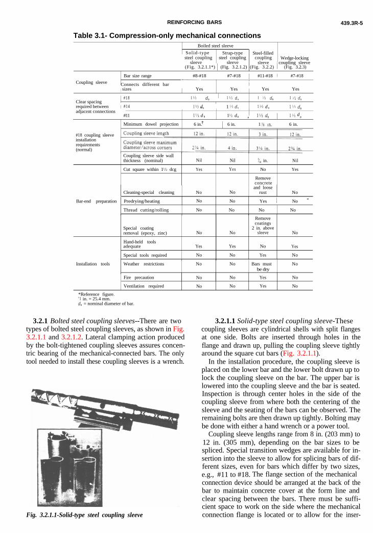
t3
Table 3.1- Compression-only mechanical connectionsI
Boiled steel sleeve
, Solid-type Strap-type Steel-filled1 steel coupling steel coupling
/ sleeve sleevecoupling
sleeveWedge-locking
1 coupling sleeve(Fig. 3.2.1.1*) 1 (Fig. 3.2.1.2) (Fig. 3.2.2) 1 (Fig. 3.2.3)
Bar size range I #8-#18 / #7-#18 #11-#18 / #7-#18Coupling sleeve
-. 11
Connects different bar i I Ijsizes
/Yes Yes Yes ’ Yes
Clear spacingj # 1 8 I 1’4 dh ! *1:x. d I ‘4 dh / 1 C’Z d,,
required betweenI
j #14 1 !‘. d 1 ‘4 d, 1’4 d* 1 I ‘4 dhadjacent connections _ L 1 I _I I
#11 I”- d- D 1 ‘/: d 1b , 1 I/. d“ b
Minimum dowel projection 6 in.l -
6 in. i 1m. i 6 in.
#18 coupling sleeveinstallationrequirements(normal)
Coupling sleeve side wallthickness (nominal) Nil Nil ‘$ in. Nil
Cut square within 11/2 dcg Yes Yes No Yes
Removeconcreteand loose
Cleaning-special cleaning No No rust NoIBar-end preparation Predrying/heating No No Yes I No _
Thread cutting/rolling No No No No
Remove
Special coatingremoval (epoxy, zinc)
Hand-held toolsadequate
Special tools required
No
Yes
No
No
Yes
No
coatings2 in. above
sleeve
No
Yes
No
Yes
No
Installation tools Weather restrictions No No Bars mustbe dry
No
Fire precaution
Ventilation required
No No Yes No
No No Yes No
*Reference figure.‘1 in. = 25.4 mm.d,, = nominal diameter of bar.
3.2.1 Bolted steel coupling sleeves--There are twoypes of bolted steel coupling sleeves, as shown in Fig..2.1.1 and 3.2.1.2. Lateral clamping action produced
Fig. 3.2.1.1-Solid-type steel coupling sleeve
by the bolt-tightened coupling sleeves assures concen-tric bearing of the mechanical-connected bars. The onlytool needed to install these coupling sleeves is a wrench.
3.2.1.1 Solid-type steel coupling sleeve-Thesecoupling sleeves are cylindrical shells with split flangesat one side. Bolts are inserted through holes in theflange and drawn up, pulling the coupling sleeve tightlyaround the square cut bars (Fig. 3.2.1.1).
In the installation procedure, the coupling sleeve isplaced on the lower bar and the lower bolt drawn up tolock the coupling sleeve on the bar. The upper bar islowered into the coupling sleeve and the bar is seated.Inspection is through center holes in the side of thecoupling sleeve from where both the centering of thesleeve and the seating of the bars can be observed. Theremaining bolts are then drawn up tightly. Bolting maybe done with either a hand wrench or a power tool.
Coupling sleeve lengths range from 8 in. (203 mm) to12 in. (305 mm), depending on the bar sizes to bespliced. Special transition wedges are available for in-sertion into the sleeve to allow for splicing bars of dif-ferent sizes, even for bars which differ by two sizes,e.g., #11 to #18. The flange section of the mechanicalconnection device should be arranged at the back of thebar to maintain concrete cover at the form line andclear spacing between the bars. There must be suffi-cient space to work on the side where the mechanicalconnection flange is located or to allow for the inser-
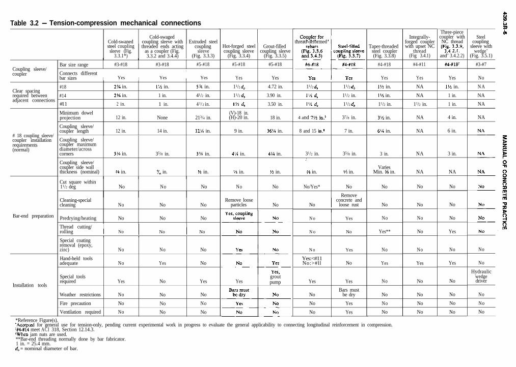
Table 3.2 - Tension-compression mechanical connections
Cold-swagedCold-swaned coupling sleeve with Extruded steelsteel coupling threaded ends acting coupling
sleeve (Fig. as a coupler (Fig. sleeve3.3.1*) 3.3.2 and 3.4.4) (Fig. 3.3.3)
Coupling sleeve/coupler
Clear spacingrequired betweenadjacent connections
# 18 coupling sleeve/coupler installationrequirements(normal)
Bar-end preparation
Installation tools
Bar size rangeI I I
#3-#18 #3-#18 #5-#18
Connects differentbar sizes I Yes I Yes I Yes
#18
#14
#11
Minimum dowelprojection
Coupling sleeve/coupler length
2% in.
2% in.
2 in.
12 in.
12 in.
1% in.
1 in.
1 in.
None
14 in.
5% in.
41/2 in.
41/2 in.
213/4 in.
12% in.
Coupling sleeve/coupler maximumdiameter/acrosscorners
Coupling sleeve/coupler side wallthickness (nominal)
3% in. 35/8 in. 3% in.
s/s in. x6 in. 5% in.
Cut square within11/2 deg No No No
Cleaning-specialcleaning
Predrying/heating
No No No
No No No
Thread cutting/rolling I No I No I No
I I I
Special coatingremoval (epoxy,zinc)
Hand-held toolsadequate
Special toolsrequired
Weather restrictions
Fire precaution
Ventilation required
No
No
Yes
No
No
No
No
Yes
No
No
No
No
No
No
Yes
No
No
No
Hot-forged steel Grout-filledcoupling sleeve coupling sleeve
(Fig. 3.3.4) (Fig. 3.3.5)
#5-#18 #5-#18
Yes Yes
11/2 db 4.72 in.
11/2db 3.90 in.
I’/ db 3.50 in.
(V)-18 in.(H)-20 in. 18 in.
9 in. 36% in.
4% in.
% in.
No
Remove looseparticles
4% in.
l/2 in.
No
No
Yesgroutpump
thread-deformed
11/2 db
1% db
1% db
4 and 71/ in.$
8 and 15 in.$
11/2 db
11/2 in.
11/2 db
37/8 in.
7 in.
31/2 in. 35/8 in.I
s% in.
No/Yes*
l/2 in.
No
Remove
No I concrete andloose rust
No Yes1
No
No
Yes:<#11No:>#ll
Yes
No
No
No
No
Yes
No
Yes
Bars mustbe dry
Yes
Yes
Taper-threadedsteel coupler(Fig. 3.3.8)
#4-#18
Integrally-forged couplerwith upset NC
thread(Fig 3.4.1)
#4-#11
Yes
1% in.
1% in.
11/2 in.
Yes
NA
NA
11/2 in.
3% in. NA
6% in. NA
3 in. NA
VariesMin. W in. NA
No No
No No
No No
Yes** No
No No
Yes Yes
No No
No
No
No
No
No
No
*Reference Figure(s).+Accepted for general use for tension-only, pending current experimental work in progress to evaluate the general applicability to connecting longitudinal reinforcement in compression.‘#4-#14 meet ACI 318, Section 12.14.3.#When jam nuts are used.**Bar-end threading normally done by bar fabricator.1 in. = 25.4 mm.db = nominal diameter of bar.
Three-piececoupler withNC thread(FF4 32.i.9,
and’ 3.4.2.2)
#4-#18f
Yes
1% in.
1 in.
1 in.
4 in.
6 in.
3 in.
NA
No
No
No
Yes
No
Yes
No
No
No
No
t.a%Q
Steelcoupling
sleeve withwedge’
(Fig. 3.5.1)
#3-#7
No
N A
NA
NA
NA
No
No
Hydraulicwedgedriver
No
No
No
FORCING BARS 439.3R-7
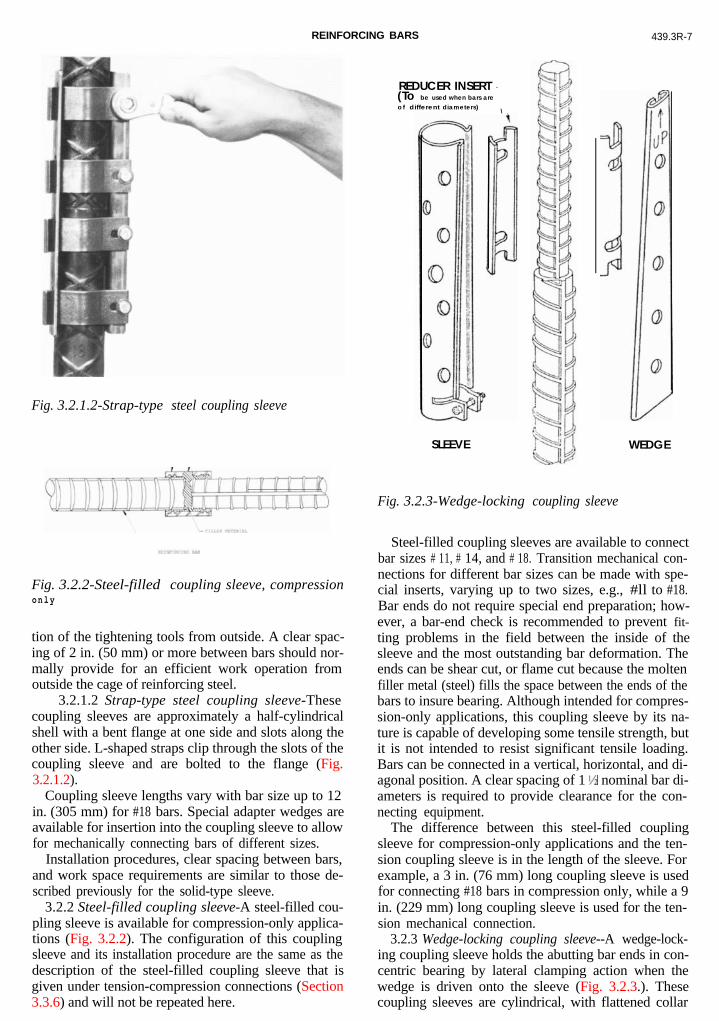
REINFig. 3.2.1.2-Strap-type steel coupling sleeve
Fig. 3.2.2-Steel-filled coupling sleeve, compressiononly
tion of the tightening tools from outside. A clear spac-ing of 2 in. (50 mm) or more between bars should nor-mally provide for an efficient work operation fromoutside the cage of reinforcing steel.
3.2.1.2 Strap-type steel coupling sleeve-Thesecoupling sleeves are approximately a half-cylindricalshell with a bent flange at one side and slots along theother side. L-shaped straps clip through the slots of thecoupling sleeve and are bolted to the flange (Fig.3.2.1.2).
Coupling sleeve lengths vary with bar size up to 12in. (305 mm) for #18 bars. Special adapter wedges areavailable for insertion into the coupling sleeve to allowfor mechanically connecting bars of different sizes.
Installation procedures, clear spacing between bars,and work space requirements are similar to those de-scribed previously for the solid-type sleeve.
3.2.2 Steel-filled coupling sleeve-A steel-filled cou-pling sleeve is available for compression-only applica-tions (Fig. 3.2.2). The configuration of this couplingsleeve and its installation procedure are the same as thedescription of the steel-filled coupling sleeve that isgiven under tension-compression connections (Section3.3.6) and will not be repeated here.
REDUCER INSERT -(To be used when bars are
o f different diameters)\
SLEEVE
Fig. 3.2.3-Wedge-locking coupling sleeve
WEDGE
Steel-filled coupling sleeves are available to connectbar sizes # 11, # 14, and # 18. Transition mechanical con-nections for different bar sizes can be made with spe-cial inserts, varying up to two sizes, e.g., #ll to #18.Bar ends do not require special end preparation; how-ever, a bar-end check is recommended to prevent fit-ting problems in the field between the inside of thesleeve and the most outstanding bar deformation. Theends can be shear cut, or flame cut because the moltenfiller metal (steel) fills the space between the ends of thebars to insure bearing. Although intended for compres-sion-only applications, this coupling sleeve by its na-ture is capable of developing some tensile strength, butit is not intended to resist significant tensile loading.Bars can be connected in a vertical, horizontal, and di-agonal position. A clear spacing of 1 l/z nominal bar di-ameters is required to provide clearance for the con-necting equipment.
The difference between this steel-filled couplingsleeve for compression-only applications and the ten-sion coupling sleeve is in the length of the sleeve. Forexample, a 3 in. (76 mm) long coupling sleeve is usedfor connecting #18 bars in compression only, while a 9in. (229 mm) long coupling sleeve is used for the ten-sion mechanical connection.
3.2.3 Wedge-locking coupling sleeve--A wedge-lock-ing coupling sleeve holds the abutting bar ends in con-centric bearing by lateral clamping action when thewedge is driven onto the sleeve (Fig. 3.2.3.). Thesecoupling sleeves are cylindrical, with flattened collar
439.3R-8 MANUAL OF CONCRETE PRACTICE
flanges that are formed to provide a tapered openingthat extends nearly full length of the shell. A flatwedge-shaped piece with the edges wrapped around togrip the collar flanges is designed to slide down over thecoupling sleeve flanges.
During installation, the coupling sleeve is placed overthe lower bar, and the bottom clamp is tightened witha wrench to secure the sleeve. The flat wedge is slippedover the coupling sleeve flanges and slid down by hand.Next, the upper bar is placed in the coupling sleeve andthe bar is seated. Finally, the wedge is driven down witha hand sledgehammer. Inspection is through a centerhole in the side of the coupling sleeve from where boththe centering of the sleeve and the seating of the barscan be observed.
Coupling sleeve lengths vary between 5 ‘/2 and 12 in.(140 and 305 mm) depending on the bar sizes to beconnected. Reducer inserts are available for connectingdifferent bar sizes.
The flange and wedge lock should be arranged at theback of the bars or the side to maintain concrete coverat the form line. Clear bar spacing should be at least 3in. (76 mm) to provide for clearance for the worker todrive the wedges tight.
3.3-Tension-compression mechanicalconnections
Nine types of commercially available couplers aredescribed in terms of the following:
1. Configuration.2. Capability of connecting bars of different sizes.3. Preparation of bar ends.4. Positions of mechanical connections.5. Equipment, tools, and materials required to make
mechanical connections.6. Installation procedure.All manufacturers claim full tension-compression ca-
pability per Section 12.14.3.4 of ACI 318. Dowel barmechanical connection systems are addressed in Sec-tion 3.4.
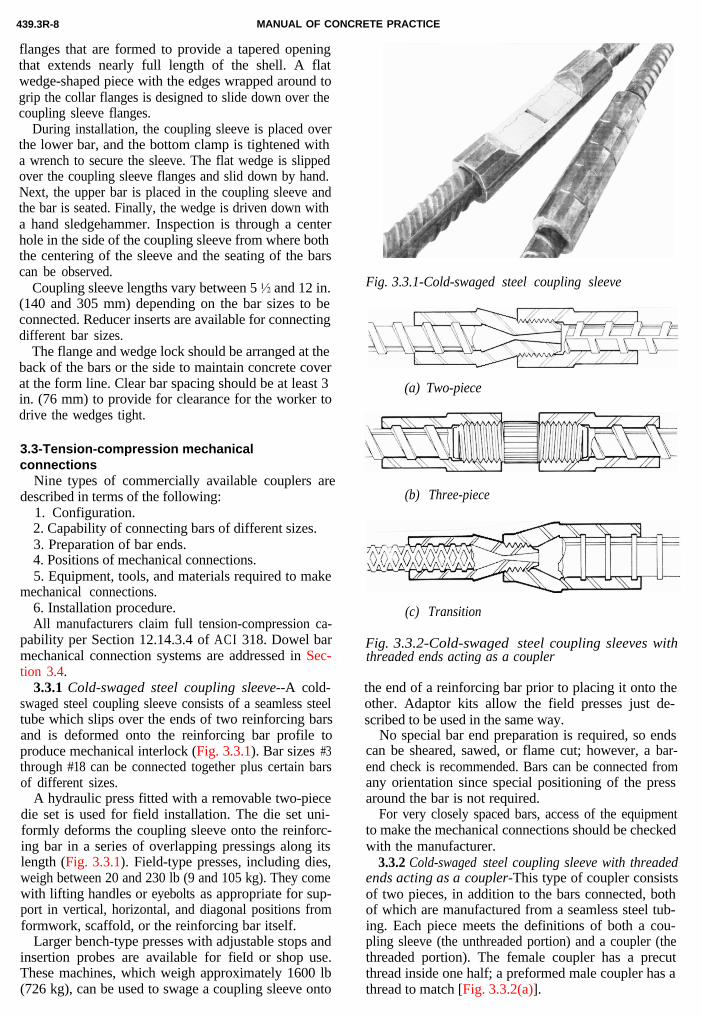
3.3.1 Cold-swaged steel coupling sleeve--A cold-swaged steel coupling sleeve consists of a seamless steeltube which slips over the ends of two reinforcing barsand is deformed onto the reinforcing bar profile toproduce mechanical interlock (Fig. 3.3.1). Bar sizes #3
Fig. 3.3.1-Cold-swaged steel coupling sleeve
through #18 can be connected together plus certain barsof different sizes.
A hydraulic press fitted with a removable two-piecedie set is used for field installation. The die set uni-formly deforms the coupling sleeve onto the reinforc-ing bar in a series of overlapping pressings along itslength (Fig. 3.3.1). Field-type presses, including dies,weigh between 20 and 230 lb (9 and 105 kg). They comewith lifting handles or eyebolts as appropriate for sup-port in vertical, horizontal, and diagonal positions fromformwork, scaffold, or the reinforcing bar itself.
Larger bench-type presses with adjustable stops andinsertion probes are available for fieId or shop use.These machines, which weigh approximately 1600 lb(726 kg), can be used to swage a coupling sleeve onto
(a) Two-piece
(b) Three-piece
(c) Transition
Fig. 3.3.2-Cold-swaged steel coupling sleeves withthreaded ends acting as a coupler
the end of a reinforcing bar prior to placing it onto theother. Adaptor kits allow the field presses just de-scribed to be used in the same way.
No special bar end preparation is required, so endscan be sheared, sawed, or flame cut; however, a bar-end check is recommended. Bars can be connected fromany orientation since special positioning of the pressaround the bar is not required.
For very closely spaced bars, access of the equipmentto make the mechanical connections should be checkedwith the manufacturer.
3.3.2 Cold-swaged steel coupling sleeve with threadedends acting as a coupler-This type of coupler consistsof two pieces, in addition to the bars connected, bothof which are manufactured from a seamless steel tub-ing. Each piece meets the definitions of both a cou-pling sleeve (the unthreaded portion) and a coupler (thethreaded portion). The female coupler has a precutthread inside one half; a preformed male coupler has athread to match [Fig. 3.3.2(a)].
REINFORCING BARS 439.3R-9
Fig. 3.3.3-Cutaway of extruded steel coupling sleeve
Fig. 3.3.4-Hot-forged steel coupling sleeve
The bar ends may be sheared, sawed, or flame-cut;however, a bar-end check is recommended. Reinforc-ing bars are correctly positioned inside the couplers bymeans of internal stops. The couplers are deformedonto the bar profile to produce mechanical interlock.
The coupling sleeves/couplers are waged on the re-inforcing bar using a bench press or a field-type pressas described in Section 3.3.1. The waging can takeplace on the jobsite or at a fabricator’s plant. A singlepressing per coupler half is needed to install most barsizes when using a bench press.
A tapered shoulder on the leading thread on the malecoupler helps to align the threads before rotating one ofthe two bars. No special equipment is needed for thisoperation. Because threads are cut on the couplers and
not on the reinforcing bar, the cross-sectional area ofthe bars is not reduced.
Another type of coupler consists of two threaded fe-male ends and an interconnecting steel stud. This three-piece variation is used where neither reinforcing bar canbe rotated to engage the threads (e.g., where bars arcbent). The stud has a right-hand thread on one end anda left-hand thread on the other. Rotating the studdraws the two female couplers together [(Fig. 3.3.2(b)].
Bar sizes #3 through #18, including transition sizes[Fig. 3.3.2(c)], can be joined by either the two-piece orthree-piece type couplers. Weldable female connectorsare available for connections to structural steel mem-bers.
These types of couplers are generally swaged beforeplacing the reinforcing steel.
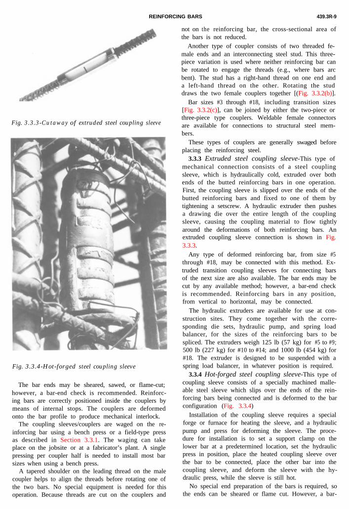
3.3.3 Extruded steel coupling sleeve-This type ofmechanical connection consists of a steel couplingsleeve, which is hydraulically cold, extruded over bothends of the butted reinforcing bars in one operation.First, the coupling sleeve is slipped over the ends of thebutted reinforcing bars and fixed to one of them bytightening a setscrew. A hydraulic extruder then pushesa drawing die over the entire length of the couplingsleeve, causing the coupling material to flow tightlyaround the deformations of both reinforcing bars. Anextruded coupling sleeve connection is shown in Fig.3.3.3.
Any type of deformed reinforcing bar, from size #5through #18, may be connected with this method. Ex-truded transition coupling sleeves for connecting barsof the next size are also available. The bar ends may becut by any available method; however, a bar-end checkis recommended. Reinforcing bars in any position,from vertical to horizontal, may be connected.
The hydraulic extruders are available for use at con-struction sites. They come together with the corre-sponding die sets, hydraulic pump, and spring loadbalancer, for the sizes of the reinforcing bars to bespliced. The extruders weigh 125 lb (57 kg) for #5 to #9;500 lb (227 kg) for #10 to #14; and 1000 lb (454 kg) for#18. The extruder is designed to be suspended with aspring load balancer, in whatever position is required.
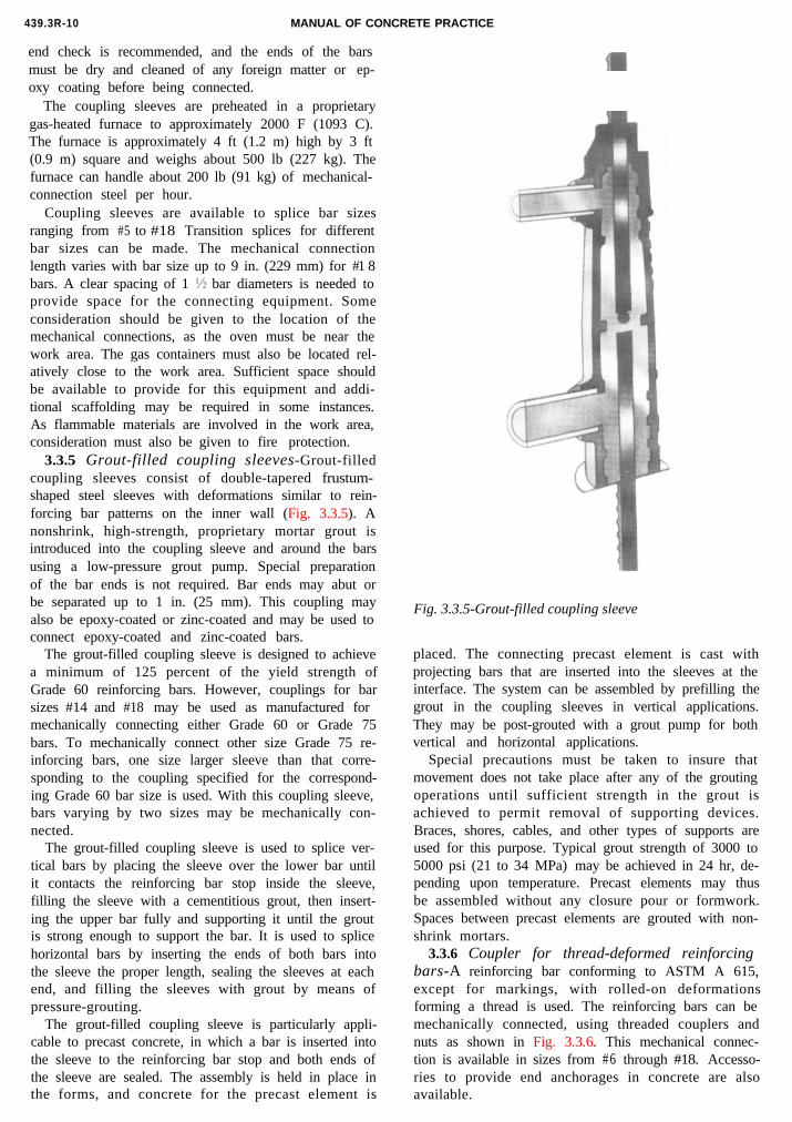
3.3.4 Hot-forged steel coupling sleeve-This type ofcoupling sleeve consists of a specially machined malle-able steel sleeve which slips over the ends of the rein-forcing bars being connected and is deformed to the barconfiguration (Fig. 3.3.4)
Installation of the coupling sleeve requires a specialforge or furnace for heating the sleeve, and a hydraulicpump and press for deforming the sleeve. The proce-dure for installation is to set a support clamp on thelower bar at a predetermined location, set the hydraulicpress in position, place the heated coupling sleeve overthe bar to be connected, place the other bar into thecoupling sleeve, and deform the sleeve with the hy-draulic press, while the sleeve is still hot.
No special end preparation of the bars is required, sothe ends can be sheared or flame cut. However, a bar-
439.3R-10 MANUAL OF CONCRETE PRACTICE
end check is recommended, and the ends of the barsmust be dry and cleaned of any foreign matter or ep-oxy coating before being connected.
The coupling sleeves are preheated in a proprietarygas-heated furnace to approximately 2000 F (1093 C).The furnace is approximately 4 ft (1.2 m) high by 3 ft(0.9 m) square and weighs about 500 lb (227 kg). Thefurnace can handle about 200 lb (91 kg) of mechanical-connection steel per hour.
Coupling sleeves are available to splice bar sizesranging from #5 to #18 Transition splices for differentbar sizes can be made. The mechanical connectionlength varies with bar size up to 9 in. (229 mm) for #1 8bars. A clear spacing of 1I/5 bar diameters is needed toprovide space for the connecting equipment. Someconsideration should be given to the location of themechanical connections, as the oven must be near thework area. The gas containers must also be located rel-atively close to the work area. Sufficient space shouldbe available to provide for this equipment and addi-tional scaffolding may be required in some instances.As flammable materials are involved in the work area,consideration must also be given to fire protection.
3.3.5 Grout-filled coupling sleeves-Grout-filledcoupling sleeves consist of double-tapered frustum-shaped steel sleeves with deformations similar to rein-forcing bar patterns on the inner wall (Fig. 3.3.5). A
Fig. 3.3.5-Grout-filled coupling sleeve
nonshrink, high-strength, proprietary mortar grout isintroduced into the coupling sleeve and around the barsusing a low-pressure grout pump. Special preparationof the bar ends is not required. Bar ends may abut orbe separated up to 1 in. (25 mm). This coupling mayalso be epoxy-coated or zinc-coated and may be used toconnect epoxy-coated and zinc-coated bars.
The grout-filled coupling sleeve is designed to achievea minimum of 125 percent of the yield strength ofGrade 60 reinforcing bars. However, couplings for barsizes #14 and #18 may be used as manufactured formechanically connecting either Grade 60 or Grade 75bars. To mechanically connect other size Grade 75 re-inforcing bars, one size larger sleeve than that corre-sponding to the coupling specified for the correspond-ing Grade 60 bar size is used. With this coupling sleeve,bars varying by two sizes may be mechanically con-nected.
The grout-filled coupling sleeve is used to splice ver-tical bars by placing the sleeve over the lower bar untilit contacts the reinforcing bar stop inside the sleeve,filling the sleeve with a cementitious grout, then insert-ing the upper bar fully and supporting it until the groutis strong enough to support the bar. It is used to splicehorizontal bars by inserting the ends of both bars intothe sleeve the proper length, sealing the sleeves at eachend, and filling the sleeves with grout by means ofpressure-grouting.
The grout-filled coupling sleeve is particularly appli-cable to precast concrete, in which a bar is inserted intothe sleeve to the reinforcing bar stop and both ends ofthe sleeve are sealed. The assembly is held in place inthe forms, and concrete for the precast element is
placed. The connecting precast element is cast withprojecting bars that are inserted into the sleeves at theinterface. The system can be assembled by prefilling thegrout in the coupling sleeves in vertical applications.They may be post-grouted with a grout pump for bothvertical and horizontal applications.
Special precautions must be taken to insure thatmovement does not take place after any of the groutingoperations until sufficient strength in the grout isachieved to permit removal of supporting devices.Braces, shores, cables, and other types of supports areused for this purpose. Typical grout strength of 3000 to5000 psi (21 to 34 MPa) may be achieved in 24 hr, de-pending upon temperature. Precast elements may thusbe assembled without any closure pour or formwork.Spaces between precast elements are grouted with non-shrink mortars.
3.3.6 Coupler for thread-deformed reinforcingbars-A reinforcing bar conforming to ASTM A 615,except for markings, with rolled-on deformationsforming a thread is used. The reinforcing bars can bemechanically connected, using threaded couplers andnuts as shown in Fig. 3.3.6. This mechanical connec-
tion is available in sizes from #6 through #18. Accesso-ries to provide end anchorages in concrete are alsoavailable.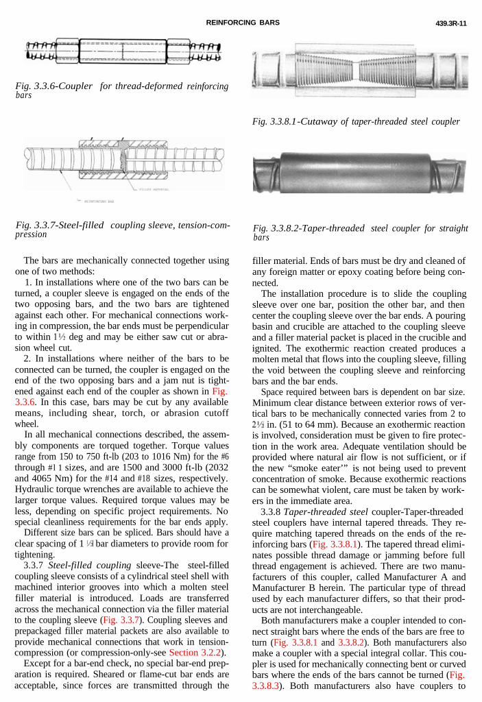
REINFORCING BARS 439.3R-11
Fig. 3.3.6-Coupler for thread-deformedbars
reinforcing
Fig. 3.3.7-Steel-filled coupling sleeve, tension-com-pression
The bars are mechanically connected together usingone of two methods:
1. In installations where one of the two bars can beturned, a coupler sleeve is engaged on the ends of thetwo opposing bars, and the two bars are tightenedagainst each other. For mechanical connections work-ing in compression, the bar ends must be perpendicularto within 1’55 deg and may be either saw cut or abra-sion wheel cut.
2. In installations where neither of the bars to beconnected can be turned, the coupler is engaged on theend of the two opposing bars and a jam nut is tight-ened against each end of the coupler as shown in Fig.3.3.6. In this case, bars may be cut by any availablemeans, including shear, torch, or abrasion cutoffwheel.
In all mechanical connections described, the assem-bly components are torqued together. Torque valuesrange from 150 to 750 ft-lb (203 to 1016 Nm) for the #6through #l 1 sizes, and are 1500 and 3000 ft-lb (2032and 4065 Nm) for the #14 and #18 sizes, respectively.Hydraulic torque wrenches are available to achieve thelarger torque values. Required torque values may beless, depending on specific project requirements. Nospecial cleanliness requirements for the bar ends apply.
Different size bars can be spliced. Bars should have aclear spacing of 1 l/r bar diameters to provide room fortightening.
3.3.7 Steel-filled coupling sleeve-The steel-filledcoupling sleeve consists of a cylindrical steel shell withmachined interior grooves into which a molten steelfiller material is introduced. Loads are transferredacross the mechanical connection via the filler materialto the coupling sleeve (Fig. 3.3.7). Coupling sleeves andprepackaged filler material packets are also available toprovide mechanical connections that work in tension-compression (or compression-only-see Section 3.2.2).
Except for a bar-end check, no special bar-end prep-aration is required. Sheared or flame-cut bar ends areacceptable, since forces are transmitted through the
Fig. 3.3.8.1-Cutaway of taper-threaded steel coupler
Fig. 3.3.8.2-Taper-threaded steel coupler for straightbars
filler material. Ends of bars must be dry and cleaned ofany foreign matter or epoxy coating before being con-nected.
The installation procedure is to slide the couplingsleeve over one bar, position the other bar, and thencenter the coupling sleeve over the bar ends. A pouringbasin and crucible are attached to the coupling sleeveand a filler material packet is placed in the crucible andignited. The exothermic reaction created produces amolten metal that flows into the coupling sleeve, fillingthe void between the coupling sleeve and reinforcingbars and the bar ends.
Space required between bars is dependent on bar size.Minimum clear distance between exterior rows of ver-tical bars to be mechanically connected varies from 2 to2% in. (51 to 64 mm). Because an exothermic reactionis involved, consideration must be given to fire protec-tion in the work area. Adequate ventilation should beprovided where natural air flow is not sufficient, or ifthe new “smoke eater’” is not being used to preventconcentration of smoke. Because exothermic reactionscan be somewhat violent, care must be taken by work-ers in the immediate area.
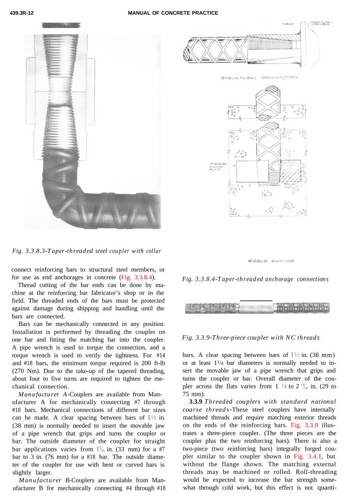
3.3.8 Taper-threaded steel coupler-Taper-threadedsteel couplers have internal tapered threads. They re-quire matching tapered threads on the ends of the re-inforcing bars (Fig. 3.3.8.1). The tapered thread elimi-nates possible thread damage or jamming before fullthread engagement is achieved. There are two manu-facturers of this coupler, called Manufacturer A andManufacturer B herein. The particular type of threadused by each manufacturer differs, so that their prod-ucts are not interchangeable.
Both manufacturers make a coupler intended to con-nect straight bars where the ends of the bars are free toturn (Fig. 3.3.8.1 and 3.3.8.2). Both manufacturers alsomake a coupler with a special integral collar. This cou-pler is used for mechanically connecting bent or curvedbars where the ends of the bars cannot be turned (Fig.3.3.8.3). Both manufacturers also have couplers to
MANUAL OF CONCRETE PRACTICE439.3R-12
Fig. 3.3.8.3-Taper-threaded steel coupler with collar
connect reinforcing bars to structural steel members, orfor use as end anchorages in concrete (Fig. 3.3.8.4).
Fig. 3.3.8.4-Taper-threaded anchorage connectionsThread cutting of the bar ends can be done by ma-chine at the reinforcing bar fabricator’s shop or in thefield. The threaded ends of the bars must be protectedagainst damage during shipping and handling until thebars are connected.
Bars can be mechanically connected in any position.Installation is performed by threading the coupler onone bar and fitting the matching bar into the coupler.A pipe wrench is used to torque the connection, and atorque wrench is used to verify the tightness. For #14and #18 bars, the minimum torque required is 200 ft-lb(270 Nm). Due to the take-up of the tapered threading,about four to five turns are required to tighten the me-chanical connection.
Manufacturer A-Couplers are available from Man-ufacturer A for mechanically connecting #7 through#18 bars. Mechanical connections of different bar sizescan be made. A clear spacing between bars of 155 in.(38 mm) is normally needed to insert the movable jawof a pipe wrench that grips and turns the coupler orbar. The outside diameter of the coupler for straightbar applications varies from l& in. (33 mm) for a #7bar to 3 in. (76 mm) for a #18 bar. The outside diame-ter of the coupler for use with bent or curved bars isslightly larger.
Manufacturer B-Couplers are available from Man-ufacturer B for mechanically connecting #4 through #18
Fig. 3.3.9-Three-piece coupler with NC threads
bars. A clear spacing between bars of 1% in. (38 mm)or at least 11/4 bar diameters is normally needed to in-sert the movable jaw of a pipe wrench that grips andturns the coupler or bar. Overall diameter of the cou-pler across the flats varies from 1 ‘/x to 2 I:{,, in. (29 to75 mm).
3.3.9 Threaded couplers with standard nationalcoarse threads-These steel couplers have internallymachined threads and require matching exterior threadson the ends of the reinforcing bars. Fig. 3.3.9 illus-trates a three-piece coupler. (The three pieces are thecoupler plus the two reinforcing bars). There is also atwo-piece (two reinforcing bars) integrally forged cou-pler similar to the coupler shown in Fig. 3.4.1, but
without the flange shown. The matching externalthreads may be machined or rolled. Roll-threadingwould be expected to increase the bar strength some-what through cold work, but this effect is not quanti-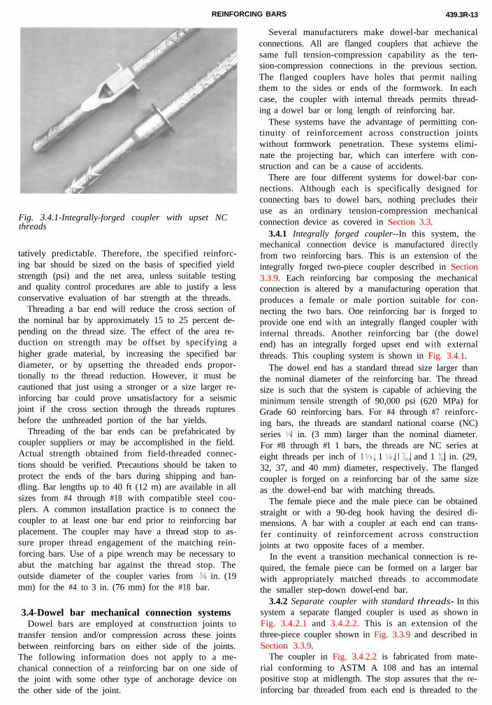
REINFORCING BARS 439.3R-13
Fig. 3.4.1-Integrally-forged coupler with upset NCthreads
tatively predictable. Therefore, the specified reinforc-ing bar should be sized on the basis of specified yieldstrength (psi) and the net area, unless suitable testingand quality control procedures are able to justify a lessconservative evaluation of bar strength at the threads.
Threading a bar end will reduce the cross section ofthe nominal bar by approximately 15 to 25 percent de-pending on the thread size. The effect of the area re-duction on strength may be offset by specifying ahigher grade material, by increasing the specified bardiameter, or by upsetting the threaded ends propor-tionally to the thread reduction. However, it must becautioned that just using a stronger or a size larger re-inforcing bar could prove unsatisfactory for a seismicjoint if the cross section through the threads rupturesbefore the unthreaded portion of the bar yields.
Threading of the bar ends can be prefabricated bycoupler suppliers or may be accomplished in the field.Actual strength obtained from field-threaded connec-tions should be verified. Precautions should be taken toprotect the ends of the bars during shipping and han-dling. Bar lengths up to 40 ft (12 m) are available in allsizes from #4 through #18 with compatible steel cou-plers. A common installation practice is to connect thecoupler to at least one bar end prior to reinforcing barplacement. The coupler may have a thread stop to as-sure proper thread engagement of the matching rein-forcing bars. Use of a pipe wrench may be necessary toabut the matching bar against the thread stop. Theoutside diameter of the coupler varies from % in. (19mm) for the #4 to 3 in. (76 mm) for the #18 bar.
3.4-Dowel bar mechanical connection systemsDowel bars are employed at construction joints to
transfer tension and/or compression across these jointsbetween reinforcing bars on either side of the joints.The following information does not apply to a me-chanical connection of a reinforcing bar on one side ofthe joint with some other type of anchorage device onthe other side of the joint.
Several manufacturers make dowel-bar mechanicalconnections. All are flanged couplers that achieve thesame full tension-compression capability as the ten-sion-compression connections in the previous section.The flanged couplers have holes that permit nailingthem to the sides or ends of the formwork. In eachcase, the coupler with internal threads permits thread-ing a dowel bar or long length of reinforcing bar.
These systems have the advantage of permitting con-tinuity of reinforcement across construction jointswithout formwork penetration. These systems elimi-nate the projecting bar, which can interfere with con-struction and can be a cause of accidents.
There are four different systems for dowel-bar con-nections. Although each is specifically designed forconnecting bars to dowel bars, nothing precludes theiruse as an ordinary tension-compression mechanicalconnection device as covered in Section 3.3.
3.4.1 Integrally forged coupler--In this system, themechanical connection device is manufactured directlyfrom two reinforcing bars. This is an extension of theintegrally forged two-piece coupler described in Section3.3.9. Each reinforcing bar composing the mechanicalconnection is altered by a manufacturing operation thatproduces a female or male portion suitable for con-necting the two bars. One reinforcing bar is forged toprovide one end with an integrally flanged coupler withinternal threads. Another reinforcing bar (the dowelend) has an integrally forged upset end with externalthreads. This coupling system is shown in Fig. 3.4.1.
The dowel end has a standard thread size larger thanthe nominal diameter of the reinforcing bar. The threadsize is such that the system is capable of achieving theminimum tensile strength of 90,000 psi (620 MPa) forGrade 60 reinforcing bars. For #4 through #7 reinforc-ing bars, the threads are standard national coarse (NC)series l/8 in. (3 mm) larger than the nominal diameter.For #8 through #1 1 bars, the threads are NC series ateight threads per inch of llYi, 1 l/J, I &,, and 1 I’{(> in. (29,32, 37, and 40 mm) diameter, respectively. The flangedcoupler is forged on a reinforcing bar of the same sizeas the dowel-end bar with matching threads.
The female piece and the male piece can be obtainedstraight or with a 90-deg hook having the desired di-mensions. A bar with a coupler at each end can trans-fer continuity of reinforcement across constructionjoints at two opposite faces of a member.
In the event a transition mechanical connection is re-quired, the female piece can be formed on a larger barwith appropriately matched threads to accommodatethe smaller step-down dowel-end bar.
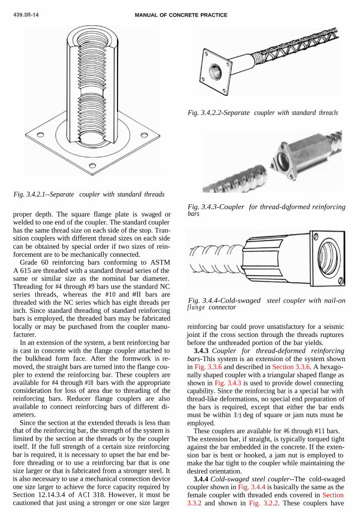
3.4.2 Separate coupler with standard threads- In thissystem a separate flanged coupler is used as shown inFig. 3.4.2.1 and 3.4.2.2. This is an extension of the
three-piece coupler shown in Fig. 3.3.9 and described inSection 3.3.9.The coupler in Fig. 3.4.2.2 is fabricated from mate-rial conforming to ASTM A 108 and has an internalpositive stop at midlength. The stop assures that the re-inforcing bar threaded from each end is threaded to the
MANUAL OF CONCRETE PRACTICE
Fig. 3.4.2.1--Separate coupler with standard threads
Fig. 3.4.2.2-Separate coupler with standard threacls
proper depth. The square flange plate is swaged orwelded to one end of the coupler. The standard couplerhas the same thread size on each side of the stop. Tran-sition couplers with different thread sizes on each sidecan be obtained by special order if two sizes of rein-forcement are to be mechanically connected.
Grade 60 reinforcing bars conforming to ASTMA 615 are threaded with a standard thread series of thesame or similar size as the nominal bar diameter.Threading for #4 through #9 bars use the standard NCseries threads, whereas the #10 and #ll bars arethreaded with the NC series which has eight threads perinch. Since standard threading of standard reinforcingbars is employed, the threaded bars may be fabricatedlocally or may be purchased from the coupler manu-facturer.
In an extension of the system, a bent reinforcing baris cast in concrete with the flange coupler attached tothe bulkhead form face. After the formwork is re-moved, the straight bars are turned into the flange cou-pler to extend the reinforcing bar. These couplers areavailable for #4 through #18 bars with the appropriateconsideration for loss of area due to threading of thereinforcing bars. Reducer flange couplers are alsoavailable to connect reinforcing bars of different di-ameters.
Since the section at the extended threads is less thanthat of the reinforcing bar, the strength of the system islimited by the section at the threads or by the coupleritself. If the full strength of a certain size reinforcingbar is required, it is necessary to upset the bar end be-fore threading or to use a reinforcing bar that is onesize larger or that is fabricated from a stronger steel. Itis also necessary to use a mechanical connection deviceone size larger to achieve the force capacity required bySection 12.14.3.4 of ACI 318. However, it must becautioned that just using a stronger or one size larger
Fig. 3.4.3-Coupler for thread-dqformed reinforcingbars
Fig. 3.4.4-Cold-swaged steel coupler with nail-onf lange connector
reinforcing bar could prove unsatisfactory for a seismicjoint if the cross section through the threads rupturesbefore the unthreaded portion of the bar yields.
3.4.3 Coupler for thread-deformed reinforcingbars-This system is an extension of the system shownin Fig. 3.3.6 and described in Section 3.3.6. A hexago-nally shaped coupler with a triangular shaped flange asshown in Fig. 3.4.3 is used to provide dowel connectingcapability. Since the reinforcing bar is a special bar withthread-like deformations, no special end preparation ofthe bars is required, except that either the bar endsmust be within 1 ‘ deg of square or jam nuts must beemployed.
These couplers are available for #6 through #11 bars.The extension bar, if straight, is typically torqued tightagainst the bar embedded in the concrete. If the exten-sion bar is bent or hooked, a jam nut is employed tomake the bar tight to the coupler while maintaining thedesired orientation.
3.4.4 Cold-swaged steel coupler--The cold-swagedcoupler shown in Fig. 3.4.4 is basically the same as thefemale coupler with threaded ends covered in Section3.3.2 and shown in Fig. 3.2.2. These couplers have
REINFORCING BARS 439.3R-15
F
ftt
3
paiowsip
cssTms3dthtowc
ig. 3.5.1-Steel coupling sleeve with wedge
langes with holes for nailing to wooden forms, as dohe other dowel bar connections. Steel bolts can be usedo attach these couplers to a steel bulk head.
.5-Tension-only mechanical connectionOnly one mechanical connection with a tension ca-
ability, as defined by ACI 318, Section 12.14.3.4, ands yet with no presently assigned compression capabil-ty, is described in the following paragraph. This typef mechanical connection has been used in situationshere the reinforcement is required only for tension,
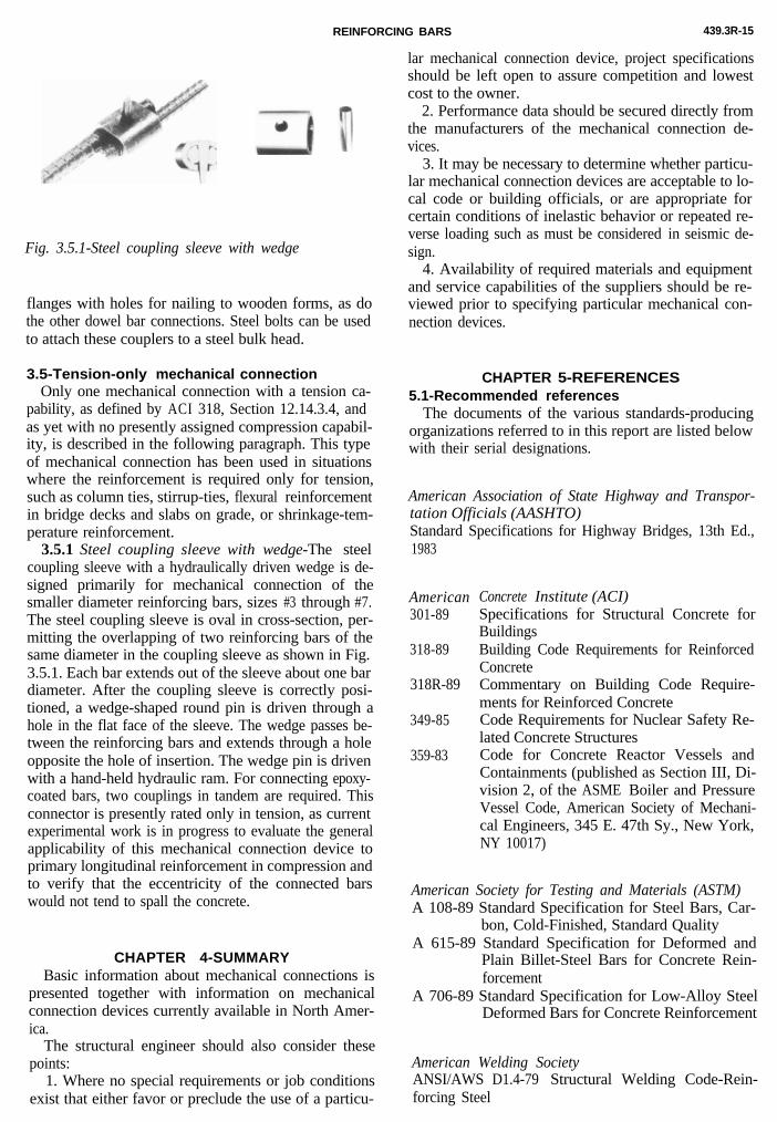
uch as column ties, stirrup-ties, flexural reinforcementn bridge decks and slabs on grade, or shrinkage-tem-erature reinforcement.3.5.1 Steel coupling sleeve with wedge-The steel
oupling sleeve with a hydraulically driven wedge is de-igned primarily for mechanical connection of themaller diameter reinforcing bars, sizes #3 through #7.he steel coupling sleeve is oval in cross-section, per-itting the overlapping of two reinforcing bars of the
ame diameter in the coupling sleeve as shown in Fig..5.1. Each bar extends out of the sleeve about one bariameter. After the coupling sleeve is correctly posi-ioned, a wedge-shaped round pin is driven through aole in the flat face of the sleeve. The wedge passes be-ween the reinforcing bars and extends through a holepposite the hole of insertion. The wedge pin is drivenith a hand-held hydraulic ram. For connecting epoxy-
oated bars, two couplings in tandem are required. Thisconnector is presently rated only in tension, as currentexperimental work is in progress to evaluate the generalapplicability of this mechanical connection device toprimary longitudinal reinforcement in compression andto verify that the eccentricity of the connected barswould not tend to spall the concrete.
CHAPTER 4-SUMMARYBasic information about mechanical connections is
presented together with information on mechanicalconnection devices currently available in North Amer-ica.
The structural engineer should also consider thesepoints:
1. Where no special requirements or job conditionsexist that either favor or preclude the use of a particu-
lar mechanical connection device, project specificationsshould be left open to assure competition and lowestcost to the owner.
2. Performance data should be secured directly fromthe manufacturers of the mechanical connection de-vices.
3. It may be necessary to determine whether particu-lar mechanical connection devices are acceptable to lo-cal code or building officials, or are appropriate forcertain conditions of inelastic behavior or repeated re-verse loading such as must be considered in seismic de-sign.
4. Availability of required materials and equipmentand service capabilities of the suppliers should be re-viewed prior to specifying particular mechanical con-nection devices.
CHAPTER 5-REFERENCES5.1-Recommended references
The documents of the various standards-producingorganizations referred to in this report are listed belowwith their serial designations.
American Association of State Highway and Transpor-tation Officials (AASHTO)Standard Specifications for Highway Bridges, 13th Ed.,1983
American301-89
318-89
318R-89
349-85
359-83
Concrete Institute (ACI)Specifications for Structural Concrete forBuildingsBuilding Code Requirements for ReinforcedConcreteCommentary on Building Code Require-ments for Reinforced ConcreteCode Requirements for Nuclear Safety Re-lated Concrete StructuresCode for Concrete Reactor Vessels andContainments (published as Section III, Di-vision 2, of the ASME Boiler and PressureVessel Code, American Society of Mechani-cal Engineers, 345 E. 47th Sy., New York,NY 10017)
American Society for Testing and Materials (ASTM)A 108-89 Standard Specification for Steel Bars, Car-
bon, Cold-Finished, Standard QualityA 615-89 Standard Specification for Deformed and
Plain Billet-Steel Bars for Concrete Rein-forcement
A 706-89 Standard Specification for Low-Alloy SteelDeformed Bars for Concrete Reinforcement
American Welding SocietyANSI/AWS D1.4-79 Structural Welding Code-Rein-forcing Steel
439.3R-16 MANUAL OF CONCRETE PRACTICE
These publications may be obtained from the followingorganizations:
American Association of State Highway and Transpor-tation Officials444 North Capitol Street, NWSuite 225Washington, DC 20001
American Concrete InstitutePO Box 19150Detroit, MI 48219
ASTM1916 Race StreetPhiladelphia, PA 19103
American Welding SocietyPO Box 351040Miami, FL 33135
5.2.Cited reference1. Gustafson, D. P., “Welded Splices of Reinforcing Bars,” Con-
crete Construction,V. 26, No. 10, Oct. 1981, pp. 807, 809, 810, and812.
ACKNOWLEDGMENTSThe following manufacturers are to be thanked for permitting thecommittee to exhibit a picture or sketch of their product in this re-port.
Fig. 3.2.1.1- Harris Rebar, Inc., Stricon Products Div., StoneyCreek, Ontario, Canada.
Fig. 3.2.1.2 and 3.2.2-EricoProducts, Inc., Cleveland, OH.Fig. 3.2.3-Gateway Building Products, Chicago, ILFig. 3.3.1 and 3.3.2-Barsplice Products, Inc., Dayton, OHFig.3.3.3-Dywidag Systems International, U.S.A. Inc., Lemont,
ILFig. 3.3.4-Harris Rebar, Inc.Fig. 3.3.5-Splice Sleeve North America, Inc., Sacramento, CAFig. 3.3.6-Dywidag Systems International, U.S.A. Inc.Fig. 3.3.7 and 3.3.8.1- Erico Products, Inc.Fig. 3.3.8.2, 3.3.8.3, and 3.3.8.4-Fox-Howlett Industries, Inc.,
Berkeley, CAFig. 3.3.9 and 3.4.21-- Williams Form Engineering Corp., GrandRapids, MI
Fig. 3.4.1-Richmond Screw Anchor Co., Inc., Fort Worth, TXFig. 3.4.2.2-Dayton Superior Corp., Miamisburg, OHFig. 3.4.3-Dywidag Systems International, U.S.A. Inc.Fig. 3.4.4-Barsplice Products, Inc.Fig. 3.5. l-Splice Sleeve North America
This document was submitted to letter ballot ofaccording to the ACI standardization procedures.
the committee and approved