2557 fencing 2557.1 description 2557.2 materials · entire project. all tubular metal posts shall...
TRANSCRIPT

2557
606
2557 Fencing
2557.1 DESCRIPTION This work consists of constructing fences.
2557.2 MATERIALS If the type of material for metal products is not specified in the
Contract, the Contractor may select the type of material. The Contractor shall use the same type of metal fence components on the entire Project.
All tubular metal posts shall be capped. When coated metal posts are indicated in the Contract, the
Contractor shall use the same coating on posts, post supports, rails, gate frames, expansion sleeves, and other hardware items or fittings. The Contractor shall use: (a) Zinc coating with zinc coated fence fabric. (b) Aluminum or zinc coating with aluminum coated steel fabric. (c) Vinyl coating with vinyl coated fence fabric. The vinyl coated
posts, hardware, and fabric shall be black with a low to medium gloss, unless otherwise stated. The Contractor shall use aluminum alloy posts, rails, frames, and
other hardware items with aluminum alloy fence fabric. A Fence Wire .................................................................. 3376 B Fence Gates ................................................................. 3379 C Fence Posts C1 Rolled Steel Posts ......................................................... 3403 C2 Structural Metal Posts................................................... 3406 C3 Blank C4 Treated Wood Posts...................................................... 3413 D Hardware and Fittings ............................................... 3406 E Concrete
Concrete shall meet the requirements for Grade B, Type 3 concrete as specified in 2461. 2557.3 CONSTRUCTION REQUIREMENTS A General
All brush, trees, and other obstructions that interfere with construction of the fence shall be removed and disposed of according to the applicable provisions of 1405, 2101, and 2104.3C. A smooth ground profile shall be provided at the fence line. The work necessary to accomplish these purposes shall, unless the Contract specifically provides payment for any part or all of the work, be incidental to fence construction and no direct compensation will be made therefor. In general, the bottom of the fence shall follow the contour of the ground. At small stream crossings, drainage ditches, and other
2557.3
607
locations where it is impractical to conform the fence to the ground contour the fence shall span the depression and, unless the Plans or the Engineer require otherwise, the space below the bottom of the fence shall be closed with extra fabric or wire as the Engineer directs. If extra length posts are needed at such locations, the Contractor shall furnish and install the longer posts in lieu of the standard length posts, together with any intermediate posts, stakes, braces, extra fabric, or wires as may be required. All such work and materials will be incidental to fence construction and no direct compensation will be made therefore except where the Contract specifically provides payment for any part or all of such work under separate items.
The Contractor shall make field repairs according to the manufacturer's recommendations. B Installing Posts, Rails and Braces B1 General
Posts shall be set plumb except at locations where the Engineer deems it more practical for the posts to be set perpendicular to the slope of the ground.
Corner posts, pull posts, end posts, and gate posts shall be installed at locations shown in the Plans or designated by the Engineer. In general, corner post assemblies will be required at all horizontal angle points where the deflection exceeds 20 degrees. Where practical, pull posts shall be spaced to provide a braced post at all points where: (a) The vertical alignment deflects by more than 20 degrees. (b) The post anchorage is necessary to counteract wire uplift. (c) An abrupt grade change on short runs cannot be avoided by shaping
the ground to a uniform contour. When fence posts are driven, the post top shall be protected against
damage. All posts that are damaged during installation shall be removed and replaced.
When posts are placed on concrete walls, curbs or other concrete structures, methods and materials used for anchoring posts shall be as specified in the Plans.
If solid rock is encountered above the required elevation of the bottom of a post, the post shall be set at least 300 mm (12 inches) into the rock or with its bottom at the required elevation, whichever requires the lesser excavation into the rock. In such cases, the post shall be cut off at the bottom to provide the required height above the ground surface. Holes in rock shall provide a minimum clearance of 25 mm (1 inch) around the post, and shall be filled around the post with grout consisting of one part Portland cement, 0.1 part hydrated lime (if desired) and 2 parts mortar sand, with sufficient water to give the proper consistency.
2557.3
608
Concrete for setting posts and braces shall be thoroughly compacted around the posts and allowed to cure for not less than 3 days before the fence wire is installed.
The concrete may be poured into prebored holes without forming, provided the earth is firm enough to permit satisfactory placement and care is taken to prevent contamination of the concrete during placement.
Except as otherwise required for posts and braces set in rock or concrete, the annular space around all posts set in prebored holes shall be backfilled in layers using selected material from the excavation (unless special material is provided), with each layer thoroughly compacted to produce a rigid post setting.
All surplus excavated material shall be disposed of in low areas along the fence line, or as directed by the Engineer, and the adjacent area shall be finished neatly. B2 Metal Post Installations
All posts for chain-link fabric fencing shall be set in concrete as provided for in the Plans, except that line posts may be driven provided that posts of sufficient extra length are furnished to allow drive setting at least 1.2 m (4 feet) into the ground.
Rolled steel line posts shall be driven. Rolled steel end posts, corner posts and pull posts (together with the
required braces) may be provided with anchor plates and brace plates and set in dug holes, or the anchor and brace plates may be omitted and the posts and braces set in concrete. All excavations around the posts and braces shall be backfilled, using the excavated material, and the backfill shall be thoroughly compacted.
Rolled steel gate posts shall be set in concrete. At those locations where the Plans require the use of metal post
extensions, the Contractor shall furnish and install posts of such extra length as may be directed by the Engineer. Where post splicing is necessary, the pipe ends at the splice shall be threaded and joined, employing a standard thread with coupling of the same material. Splices in the exposed upper portion of the post shall be avoided where practicable. A suitable plug shall be provided in the bottom end of each extended post. B3 Wood Post Installations
Wood posts may be driven or set in prebored holes. In either case the larger end of the post shall be placed in the ground. When posts are driven, the end placed in the ground may be cut square or pointed. Except for holes in rock, the diameter of post holes shall be sufficiently large to provide a clearance of at least 75 mm (3 inches) around the post so as to permit proper backfill and compaction.

2557.3
609
Wood braces shall conform to 3413, so far as they are applicable. The diameters of wood braces as shown in the Plans shall be construed to be the minimum permissible diameter at the small end, but the diameter at the small end shall be no greater than the top diameter of the smaller adjacent post. C Installing Fence Wire
All fence wire shall be installed and pulled tight in accordance with standard practice and the recommendations of the manufacturer. C1 Chain Link Fabric
Chain link fabric shall be placed in continuous runs between corner, end, and gate posts. The fabric shall be installed on the side of line posts that face away from the main road; except when the Engineer directs otherwise because of snow plowing or other concerns. Impacts from snow plowing should stress the posts rather than the fasteners.
At all ends of chain link fabric, a stretcher bar shall be threaded through the fabric loops and fastened to the posts by means of clamps as shown in the Plans.
Splices in the chain link fabric shall be made by weaving in a pre- bent wire of the same kind as that in the fabric. C2 Barbed Wire and Woven Wire
Unless otherwise directed by the Engineer, barbed wire and woven wire to be installed on tangent alignment or on curves of 1 degree or less shall be placed on the side of line posts that faces away from the main roadbed. Where the fence is placed on horizontal curves exceeding 1 degree, the wire shall be placed on the side of line posts that is on the outside of the curve. At all corners the post shall be offset to the inside so that the wire will bear against the post.
Fence wire shall be fastened to end, corner, gate, or pull posts before being fastened to intermediate line posts. Woven wire shall be stretched until all longitudinal wires are taut and approximately 30 percent of the factory fabricated fence crimp (tension curves) has been removed.
At all major vertical grade changes, woven wire shall be cut and spliced at the pull post as may be necessary to obtain and maintain uniform tension in all horizontal wires. To the extent feasible, tension curves may be increased in number or depth, by use of a wire crimping tool, so as to accomplish the same objective.
Wires shall be fastened to metal line posts by means of approved wire clips or clamps and to wood posts by means of galvanized staples. Where the wire is looped around end, corner, or pull posts, the wire shall be wrapped around itself not less than 4 complete turns.
Wire staples of the U-shaped type shall be at least 45 mm (1 ¾ inches) long when used in pine posts and at least 50 mm
2557.3
610
(2 inches) long when used in cedar posts. L-shaped staples (with serrated, barbed or ring shanks) may be of a length not less than 38 mm (1 ½ inches).
U-shaped staples shall be driven diagonally across the wood grain so that both points do not enter between the same grain. Staples shall be sloped slightly upward, against the pull of the wire, in depressions where wire up-lift occurs, and shall be sloped slightly downward on level ground and over knolls. Wires shall be stapled tightly at corner, end, and pull posts, but on line posts the staples shall not be driven so tightly as to prevent movement of the wire. In no case shall staples be driven so tight as to damage the wire.
Splicing of wire at locations between posts shall be accomplished with an approved type of splicing sleeve or by wrapping each wire end around the other wire a sufficient number of turns to ensure a lasting connection. From 4 to 6 turns will be required, depending on the splicing method used, the type of wire, and the quality of workmanship. The Engineer will require that a splicing tool be used to obtain uniformly tight wraps where hand wrapping is not satisfactory.
Where splicing sleeves are used on woven wire, the horizontal distance between vertical wires shall be maintained approximately the same as that in the wire as fabricated. When woven wire is spliced by the wrap method, the two end stay wires shall abut each other and be enclosed within the wrap. D Installing Gates
Where the Plans require gates, each gate shall be equipped with a "padlock keeper" of a design that will permit locking the gate with a padlock. The padlock will be furnished by the Department. E Electrical Grounds
Electrical grounds consisting of copper coated steel rods having a nominal diameter of 15 mm (5/8 inch) or more and a minimum length of 2.4 m (8 feet) shall be installed along each fence line at the staked locations.
Ground rods shall be driven to an elevation approximately flush with the ground surface, at points directly below or adjacent to the fence wire, and each ground rod shall be connected to the fence with a solid No. 6 copper wire. The ground wire shall be attached to the ground rod and to the fence wires with approved type metal clamps in such a manner that each longitudinal fence wire is electrically grounded. No more than one connection will be required on woven wire and chain link fabric, that being near the bottom at each ground rod.
Electrical grounds are to be installed at locations established in accordance with the following requirements:

2557.5
611
(1) An electrical ground shall be installed on each fence line at the approximate point of crossing of each electric power line, and two grounds shall be installed at each pedestrian gate, one on each side of the gate opening and as close to the gate post as practicable.
(2) Additional grounds shall be installed on each fence line as necessary to maintain a desired maximum spacing between grounds of 450 m (1500 feet) on fences where metal posts are used and 300 m (1000 feet) on fences where wood posts are used.
(3) A minimum of one electrical ground shall be installed on each separate section of fence. A separate section of fence shall be defined as a run on which the electrical continuity has not been broken by gates, terminal posts, etc.
(4) On each separate section of fence, the spacing of electrical grounds shall be as uniform as practicable and such that a ground will be located within a distance from each end not greater than one-half the desired maximum spacing interval.
2557.4 METHOD OF MEASUREMENT A Wire Fence
Fence of each design will be measured separately, by length along the bottom of the fence, from center to center of end posts, exclusive of the lengths of gates as measured between gate posts. B Brace Assemblies
Brace assemblies of each kind (wood or metal) will be measured separately by the number of each kind constructed complete-in-place, regardless of length, design, or anchorage. A brace assembly shall consist of a single wood or metal brace, installed as either a leg brace or as a horizontal brace between two consecutive posts (brace assemblies for chain link fences shall consist of two brace bars and a truss rod), together with the required brace plate or concrete anchor, post anchorages, and guy wires or truss rods. C Electrical Grounds
Measurement will be by the number of ground rods and connections furnished and installed complete-in-place. D Gates
Measurement will be by the number of individual units constructed complete-in-place. E Metal Post Extensions
Metal post extensions will be measured by length of extensions, determined as the difference between the standard driven post length and the actual post length as installed. 2557.5 BASIS OF PAYMENT
Payment for fence of each design at the Contract price per unit of measure will be compensation in full for all costs of the installation and
2557.5
612
materials except those that the Contract specifically designates as having been included for payment under separate items.
Payment for brace assemblies of each kind at the Contract price per unit of measure will be compensation in full for furnishing and installing the braces as specified, including the required brace plate or concrete anchor, post anchorages, and all guy wires or truss rods.
Payment for electrical grounds at the Contract price per unit of measure will be compensation in full for all costs of furnishing and installing the ground rods as specified, complete with ground wire and connectors.
Payment for gates of each kind at the Contract price per unit of measure will be compensation in full for all costs of furnishing and installing the complete gate assembly as specified.
Payment for furnishing and installing metal fence post extensions as directed by the Engineer, at the Contract price per unit of measure will be compensation in full for all costs of furnishing and installing the post extensions as specified.
Payment for fencing will be made on the basis of the following schedule: Item No. Item Unit 2557.501 Wire Fence, Design ___ ...................... meter (linear foot) 2557.516 Pedestrian Gate ............................................................each 2557.517 Vehicular Gate..............................................................each 2557.519 Metal Post Extensions ......................... meter (linear foot) 2557.521 Wood Brace Assembly ................................................each 2557.522 Metal Brace Assembly .................................................each 2557.523 Metal Brace Assembly (Chain Link Fence) .................each 2557.527 Electrical Ground ........................................................each 2560 Highway-Railroad Grade Crossing Signals 2560.1 DESCRIPTION
This work shall consist of furnishing materials for and installing electrically operated highway-railroad grade crossing signals of the flashing light type, together with crossing gates and cantilever type signals if so required by the Contract. 2560.2 MATERIALS A General Requirements
All materials and signal parts furnished by the Contractor shall meet the applicable requirements of the Association of American Railroads, the Railroad on whose line the signal will be installed, and the Rules and Specifications for Signs and Signals for Installations at Highway-Railroad Crossings contained within Chapter 8830 of

2560.3
613
Minnesota Rules, as last issued prior to the date of advertisement for bids. A1 Manufacturer's Drawings, Details, Catalog References and
Specifications The bidder shall furnish, with the Proposal, manufacturer's
drawings, catalog references, and specifications for any and all materials and apparatus that may be required to furnish but that are not covered by these Specifications or the Plans. Materials and apparatus covered by such drawings, catalog references or specifications shall not be used unless approved, in writing, by the Engineer. No change or changes shall be made in any approved manufacturer's drawings without the written consent of the Engineer.
After award of the Contract, the Contractor shall furnish the Engineer 5 sets of all such drawings as have been approved. Any work done before the approval of these drawings will be done at the Contractor's own risk and expense. The Contractor shall not substitute any materials or apparatus for those specified herein without the written approval of the Engineer. A2 Tests
The Contractor shall make, at the Contractor's expense, such tests as may be necessary to demonstrate to the satisfaction of the Department and the Railroad Company that the materials, apparatus and installation will meet the requirements of the Specifications.
The Contractor shall provide, without separate compensation therefore, such instruments, apparatus, tools, and labor as may be necessary to make the required tests. The instruments and apparatus shall remain the property of the Contractor. 2560.3 CONSTRUCTION REQUIREMENTS A General
The location for the signal as shown in the Plans shall be considered as being approximate only. The exact location will be determined at the site, and shall be such that the clearance distances for the several units will conform to the rules and regulations established therefore. A1 Inspection of Material, Apparatus and Workmanship
The Railroad Company on whose line the signal system is to be installed, although not a party to the Contract, shall be permitted, through its accredited representative, to inspect any or all of the materials, the apparatus and workmanship of installation, at any time during the construction or installation. A2 Work by Railroad Company
Under a special agreement with the Department, the Railroad Company will, without cost to the Contractor, perform so much of the work described hereafter (in paragraphs A2a to A2f inclusive) as is
2560.3
614
specified in the Special Provisions and will furnish all labor and tools required therefore. However, the Contractor shall furnish all materials and apparatus shown in the Plans as being necessary to complete such work. A2a Place switch rod insulation and insulated joints in the tracks,
as shown in the Plans. A2b Make such rearrangements of existing wiring systems as may
become necessary because of the signal installation. A2c Make such relocation of any existing signal apparatus or
device as may become necessary because of the signal installation, as shown in the Plans.
A2d Make all connections between the new signal installation and any existing signal system.
A2e Remove and replace crossings if necessary for bonding the rails or installing underground cables.
A2f Insulate metal crossings where necessary because of the signal installation.
A3 Precaution and Traffic Provisions Any information concerning traffic movements on the Railroad that
the Contractor may need will be furnished at the Contractor's request by the Railroad Company's Dispatcher.
During construction operations when it becomes necessary for the Contractor to perform work that may interfere with traffic on the Railroad, the Contractor shall notify the Railroad Company through its Signal Engineer, Superintendent of Signals, or other authorized official, at least 48 hours in advance of starting such work. Such work shall not be started, however, until authorized by the Railroad Company.
The Contractor shall not place a colored glass signal light so that it will face an approaching train. Open flame torches shall be used in lieu of flashing lights in all places where such lights might confuse the crews of approaching trains.
Any or all openings or uncompleted work that may, after working hours, cause a hazard or unnecessary inconvenience to traffic, shall be suitably and substantially covered by the Contractor to protect traffic on either the Railroad or the highway.
The Contractor shall properly cover the signal or screen it from view, immediately after it is mounted, and shall maintain this covering or screening until authority is given to place the installation in service. A4 Final Inspection of Installation
The final inspection, as provided for in 1516, shall be made in the company of the Department's Director of Railroad Administration and the Signal Engineer of the Railroad Company or their authorized

2564.2
615
representatives. Final acceptance will not be made until the Contractor has complied with 2560.3A5. A5 Placing in Service
The Contractor shall place the system in service when authorized to do so by the Engineer, and it shall be placed in charge of competent attendants for a period of not less than 24 hours after being placed in service. 2560.4 METHOD OF MEASUREMENT
The signal system (including crossing gates if required by the Contract) and the advance warning signs will be measured as an integral unit complete in place. 2560.5 BASIS OF PAYMENT
Payment for the signal system will be made on the basis of the following schedule: Item No. Item Unit 2560.501 Highway-Railroad Grade
Crossing Signal System ...................................... lump sum 2564 Traffic Signs and Devices 2564.1 DESCRIPTION
This work includes the fabrication, packaging, and delivery or installation of traffic signs and devices. 2564.2 MATERIALS A General
Electrical materials and equipment shall conform to 2545.2. Where a particular material (fixture, device, or component) is specified, an alternate material, equal to or better than the material specified, may be used provided the Contractor obtains the written approval of the Engineer before incorporating such alternate material into the work. B Structural Steel
All structural steel posts and trusses shall be fabricated from steel conforming to 3306, unless otherwise specified in the Contract.
Structural bolts, nuts, and washers shall conform to 3391.2B and 3392.
Bolt anchorages shall be as specified in the Contract or, if not so specified, as approved by the Engineer. C Concrete (Mix 3Y43) ................................................. 2461 D Reinforcement Bars................................................... 3301
All reinforcement bars, except spiral bars, shall be as indicated in the Contract and shall be epoxy coated. E Spiral Reinforcement ................................................ 3305 F Signs and Markers..................................................... 3352

2564.2
616
All sign panels shall be fabricated in accordance with the following, unless otherwise specified in the Contract. Types of sign panels, route markers, and overlays contained in this Specification are referenced in the Mn/DOT Traffic Engineering Manual or the Mn/DOT Standard Signs Manual, or both. F1 Sign base material for sign panels Type C, Type D, Type Overlay, delineators, markers and Type OH sign panels on sign supports shall be sheet aluminum in accordance with 3352.2A1a except the sign base material for cylinder style delineators shall be non-reflectorized lexon black flexible plastic. F2 Sign base material for sign panels Type A, Type EA, Type EO and Type OH sign panels on panel mounting posts shall be extruded aluminum in accordance with 3352.2A1b and covered with 1600 µm (0.063 inch) sheet aluminum conforming to Mn/DOT 3352.2A1a covering the extruded panel. Fasteners to attach the sheet aluminum to the extruded panel shall be 5 mm (3/16 inch) aluminum alloy pull through rivets. The sheet aluminum shall be butted tightly vertically and riveted to the extruded panel on 300 mm (12 inch) centers maximum vertically and horizontally. All edges and corners of each sheet shall be riveted. Rivets shall not be placed within 25 mm (1 inch) of the extruded panel joints. After being attached, the sheet aluminum shall be substantially free of any waviness. F3 Sign face material for all sign panels, delineators and markers shall be reflective sheeting conforming to 3352.2A2e(a) (Type IX), except as specified below:
Sign face material for standard sign I-X1 shall be reflective sheeting conforming to 3352.2A2b(a) (Type III).
Sign face material for standard signs W1-8 and W14-3 and X4-2 Hazard Markers, X4-3 Culvert Markers and X4-4 Clearance Markers shall be reflective sheeting conforming to 3352.2A2e(b) (Type IX FL Fluorescent yellow).
Sign face material for standard signs W11-1, W11-2, S1-1, S4-3 and S5-1 shall be reflective sheeting conforming to 3352.2A2e(b) (Type IX FL Fluorescent yellow-green). Sign face material for standard signs W16-7p, W16-9p, W20-100P, and W13-1, when used with the aforementioned signs, shall be reflective sheeting conforming to 3352.2A2e(b) (Type IX FL Fluorescent yellow-green).
For the sign face material on the M1-5A Route Marker and the M1-5B Type Overlay, the gold color shall be obtained by means of screen processed color using a transparent gold paint. The blue color shall be obtained by means of screen processed color using a transparent blue paint. The overlap of the blue and gold screen processed colors shall not exceed 3 mm (3/32 inch).
2564.2
617
Sign face material for sign panels with brown background shall be white reflective sheeting conforming to 3352.2A2e(a) (Type IX).
Yellow sign face material for cylinder style delineators, reboundable drums, and channelizers shall be reflective sheeting conforming to 3352.2A2b(c) (Type III MD).
Orange and white sign face material for cylinder style delineators, reboundable drums, and channelizers shall be reflective sheeting conforming to 3352.2A2d(b) (Type VII MD).
Sign face material for X4-2 Hazard Markers shall be non- reflectorized black or non-reflectorized yellow as specified in the Contract.
Sign face material for X4-11 End of Roadway Markers shall be non-reflectorized red or non-reflectorized black as specified in the Contract.
Sign face material for traffic cones shall be reflective sheeting conforming to 3352.2A2b(b) (Type III MC).
Sign face material for tubular markers shall be reflective sheeting conforming to 3352.2A2b(d) (Type III MT).
Sign face material for roll up signs shall be reflective material conforming to 3352.2A2c (Type VI).
Sign face material for all rigid work zone signs shall be reflective sheeting conforming to 3352.2A2d(a) (Type VII) except as specified below: Sign face material for standard signs W20-7a, G20-4, W21-X4, W21-X4a, W21-X7 (SLOW side), M4-8, M4-8a, M4-9, M4-10, all signs for paint striping operations, and any other sign requiring extraordinary emphasis, as determined by the District Work Zone Coordinator, shall be reflective sheeting conforming to 3352.2A2d(c) (Type VII MF). F4 Sign legend material for all sign panels, the numerals on M1-5A Route Markers and M1-5B Type Overlays, delineators and markers, and colors other than yellow on warning signs, shall be reflective sheeting conforming to 3352.2A2e(a) (Type IX), except as specified below:
The sign legend material on sign panels with brown sheeting shall be brown (1179) electronic cuttable (EC) film produced by the same manufacturer that fabricates the reflective sheeting conforming to 3352.2A2e(a) (Type IX). If applying brown EC film on sign panels requires splicing, splices shall be vertical, butt spliced and spaced so that splices do not occur through letters or arrows.
The sign legend material for colors other than black may be screened in accordance with 3352.2A5c.

2564.2
618
The sign legend material for black legend shall be in accordance with 3352.2A4c or 3352.2A4d. G Anchor Rods............................................................... 3385 H Flanged Channel Sign Posts...................................... 3401 2564.3 CONSTRUCTION REQUIREMENTS A General
Fabrication and installation of traffic signs and devices shall conform to the Minnesota Manual on Uniform Traffic Control Devices (MN MUTCD) for Streets and Highways and to the AASHTO Standard Specifications for Structural Supports for Highway Signs, Luminaires and Traffic Signals.
The Contractor shall not perform work on the job site until all underground utilities are located in conformance with 1507. Electrical cable damaged due to the negligence of the Contractor shall be replaced at no expense to the Department. Damaged electrical cable shall be replaced, by the Contractor, from terminal point to terminal point.
Construction of any kind or type of electrical system or conduit system for the conveyance of electrical cables and conductors, or the required portions thereof, as specified in the Contract, shall conform to 1702 and 2545.3.
Sign locations and post lengths indicated in the Contract are approximate. Final determination of sign locations will be made in the field by the Engineer. The required post lengths for Type A and Type OH Signs will be determined by the Engineer. The required post lengths for all other signs shall be determined by the Contractor.
If the legend on an existing sign is pertinent to traffic and the sign is to be refurbished, down time for the sign shall not extend beyond the 8-hour period from 8:00 a.m. to 4:00 p.m., unless a suitable replacement sign is provided by the Contractor at no expense to the Department. If, in the opinion of the Engineer, the message on a sign panel is not pertinent to existing traffic, the Contractor shall delay installation of that sign panel until such time as the message does become pertinent or, in lieu thereof, the sign panel may be installed provided an effective covering is placed over the non-pertinent message. The cover shall be opaque, and shall prevent moisture from being held against the sign face. Burlap will not be accepted as an effective covering for reflective signs. The Contractor shall install the sign panel with the required covering and the Department will assume the responsibility for maintaining and removing the cover after acceptance of the work. Unless the Contractor has arranged to reclaim the covering material, it shall become the property of the Department upon final acceptance of the work. The covering, maintaining, and uncovering of sign panels
2564.3
619
with non-pertinent messages shall be done by the Contractor with no direct compensation.
The removal and replacement of any existing guardrail solely for the convenience of the Contractor shall be considered as being incidental work.
The Contractor shall replace all topsoil, sodded, and seeded areas disturbed by the operations and dispose of any excess excavated materials in a manner satisfactory to the Engineer. B Concrete Structures
Concrete for footings shall be produced in accordance with 2461 and meet the requirements for Grade Y, Type 3 Concrete as specified therein.
All exposed concrete surfaces shall be given a rubbed surface finish. The Contractor shall not install sign posts on concrete footings until
after a minimum 7 days of curing period has elapsed. B1 Concrete Footings
The Contractor may substitute spread footings for drilled shaft footings or vice versa, subject to the approval of the Engineer.
Footings shall be constructed in accordance with the Contract requirements and there shall be no adjustment in Contract quantities and prices.
If the Contract specifies drilled shaft footings, the Contractor may submit, for approval by the Engineer, an alternate design in lieu of detailed in the Contract. If approved by the Engineer, the Contractor may elect to construct the shaft footing accordingly without adjustment of any Contract quantities and prices. Design details shall be in accordance with either of the following: (a) Use a constant diameter shaft at least 153 mm (6 inches) greater
than the diagonal dimension of the column base plate. Use the planned longitudinal reinforcement bars without bending. Either spiral reinforcement or tie bars spaced at 153 mm (6 inches) centers may be used for the full length of the shaft, or
(b) Install a horizontal construction joint at the bottom of the tapered section of the shaft [about 1.8 m (6 feet) below the top]. Before placing new concrete above the construction joint, the surface of the in place concrete shall be coated with an approved bonding agent. Vertical reinforcement bars shall be lapped 40 bar diameters. The footings shall be constructed in accordance with 2401.3 except as modified by the following: The Contractor may use undisturbed earth as the form for concrete placement, provided the earth is firm enough to permit satisfactory placement of the concrete and precautions are taken to prevent contamination of the concrete.

2564.3
620
B2 Median Barrier Footing The Contractor shall provide NMC conduit and fittings to connect
to the non-metallic conduit in adjacent median barrier as required. The surface finish and color shall match that of adjacent median
barrier. C Sign Support
The Contractor shall furnish and install a sign support in accordance with the Contract, current AASHTO "Standard Specifications for Structural Supports for Highway Signs, Luminaires and Traffic Signals" and the following:
The concrete footings shall be as specified in the Contract. The Contractor shall determine the reinforcement steel and the anchor rods in accordance with the details in the Contract.
The Contractor shall furnish and install an Overhead Sign Identification Plate in accordance with 2564.3P. D Overhead Sign Structure Repair
The Contractor shall repair an existing overhead sign structure in accordance with the applicable provisions of 2123 and the following:
The Contractor shall contact the Department's Structural Metals Inspection Unit (DSMIU) to schedule inspection of sign structures. This inspection shall be completed before removal of the sign structure from storage, or after the Contractor's salvage of the structure.
The following conditions, if encountered, shall be corrected as determined by the DSMIU: rusted or missing nuts, bolts or washers, defective shop and field splices on main chord angles, missing welds, cracking of welds or structural elements, section loss on post base plate, flame gouges on base plate or at bolt holes, cracks around post handhole, zinc coating loss or deterioration, and rusting. All repairs shall be performed in accordance with 2471. The Contractor shall verify that each locking pin will completely fit into the locking pin hole in the handrail hinge with the handrail in the raised position. For locking pins that do not fit, the Contractor shall drill out the handrail hinge to make a proper fit. Damage to galvanized surfaces shall be repaired in accordance with 2471.3L1.
The Contractor shall obtain reinspection by the DSMIU after the repair has been completed and before installation. E Structural Steel
The manufacture and fabrication of structural metals shall conform to 2471, subject to the following additional requirements and limitations:
Shop drawings for overhead sign structures and for Type A sign structures shall be furnished in accordance with 2471.3B.

2564.3
621
Steel trusses shall be constructed true to dimensions and shall be uniform in appearance. The truss sections and posts shall be assembled in the shop before galvanizing; shall be checked for straightness, alignment and dimensions; and any variations shall be corrected. Warpage from galvanizing shall be corrected before installation of structural steel will be permitted.
All main chord angles for overhead sign structures 13 mm (½ inch) or greater in thickness shall meet a Charpy V-notch impact strength requirement of 20 N•m (15 foot•pounds) at 5 ºC (40 ºF).
The overhead sign post base plate anchor rod holes shall be made by use of a drill or other mechanical cutting tool of proper size.
The Contractor shall lubricate the threads of nuts before installation. The following minimum torque values shall be used:
ANCHOR ROD DIAMETER TORQUE 51 mm (2 inches) 400 N•m (300 foot•pounds) 57 mm (2 ¼ inches) 500 N•m (375 foot•pounds) 64 mm (2 ½ inches) 600 N•m (450 foot•pounds) 70 mm (2 ¾ inches) 750 N•m (550 foot•pounds) 76 mm (3 inches) 950 N•m (700 foot•pounds)
The Contractor shall mar the threads of the anchor bolts in accordance with 2402.3H.
The Contractor shall furnish and install galvanized structural steel posts (H-Pile) as footings for Type A signs, unless otherwise specified in the Contract, in accordance with the applicable provisions of 2452, 2471, and the following:
The footing shall be constructed in accordance with the details in the Contract. A 4.3 m (14 foot) H-Pile post may be utilized instead of welding a 0.6 m (2 foot) stub post to the 3.7 m (12 foot) H-Pile. The required 107-125 kN (12-14 ton) bearing capacity for each H-Pile shall be obtained in accordance with 2452. If the required bearing capacity is not obtained after driving the length of H-Pile specified in the Contract, the Contractor shall splice additional length of H-Pile in accordance with 2452 and drive to the required bearing capacity. All damage to galvanized surfaces shall be repaired in accordance with 2471 before back filling. F Flanged Channel Sign Posts F1 Furnish Flanged Channel Sign Post
The Contractor shall fabricate, package, and deliver flanged channel sign posts in accordance with 2564, 3352, and 3401. (a) Posts of the same mass and length shall be banded together, with
suitable banding materials, in lots of no more than 20 posts per bundle. Each bundle shall be plainly labeled with the post mass per

2564.3
622
meter, the name of the Contractor, the Project number, source of the material and the supplier's name.
(b) The posts shall be delivered to the Department as specified in the Contract. The Contractor shall give at least 3 working days notice to the Engineer.
(c) Posts shall be deposited where and as directed by Department personnel. All damage detected during unloading shall be cause for immediate rejection of damaged materials. Final inspection and acceptance of the posts will be made by the Department within 14 days of the delivery date.
F2 Furnish and Install Flanged Channel Sign Posts The Contractor shall install the posts plumb above ground and
located and oriented as directed by the Engineer. Any post that is bent or otherwise damaged to the extent that, in the opinion of the Engineer, it is not acceptable, shall be removed from the site and replaced by the Contractor at no expense to the Department.
Posts shall be firm in the ground. After driving, the top of the post shall have the same cross-sectional dimensions as the body of the post.
When mounting a delineator on a bridge rail, a bracket as shown in the Contract shall be furnished and installed by the Contractor in lieu of a conventional steel post.
All costs and work of installing posts in surfaced medians or sidewalks shall be considered incidental to the installation. G Modify Post
Splices will not be permitted in the lower 1.5 m (5 feet) of Type A sign posts.
The Contractor shall extend Type A sign posts located above the friction fuse, and panel mounting posts, by welding a section (new or salvaged under this Contract of the same size) to an existing post in accordance with the applicable provisions of 2471. Only S100 x 11 (S4x7.7) panel mounting posts may be extended by bolt splicing in accordance with the details in the Contract and with the applicable provisions of 2471. Post extensions shall be galvanized in accordance with 2471.
When shortening a post, the removed section of post shall be disposed of in accordance with 2104.
Thermal cutting will be permitted in accordance with 2471. Galvanized areas marred due to cutting or welding shall be repaired in accordance with 2471. H Sign Panels Type Overlays are separate panels mounted on the face of signs to form a part of the legend. Type Overlays shall be attached to the sign panels with rivets spaced on 300 mm (12 inch) centers except the edges
2564.3
623
of each Type Overlay shall be attached with rivets spaced on 150 mm (6 inch) centers maximum. No rivets are to be installed within 25 mm (1 inch) of extruded panel joints.
The Contractor shall fabricate the sign panels in accordance with the standard sign drawings contained in the Mn/DOT Standard Signs Manual or as detailed in the Contract. For sign panels detailed in the Contract, sign panel layouts are dimensioned as follows:
Vertical dimensioning The dimension given is for the legend component having the largest vertical dimension in the particular line of copy. Other legend components are centered on the larger legend component unless indicated otherwise. Horizontal dimensioning The horizontal dimensions given within the sign panel are to the tenth of an inch and are cumulative representing the distance from the left edge of panel to the extreme left edge of the legend component. Sign Panel Recap The position of an arrow is measured in degrees counterclockwise from a right horizontal reference line. The abbreviation MOD used in the sign panel recap = Modified.
The Contractor shall screen a fabrication sticker with the following information: Company name and address, the twelve months of the year in numeric order (1 through 12) and the current and following 4 years (last two digits of each year). The Contractor shall affix the sticker to the backside of each new Type C (single post installations only) and Type D sign panels in the lower right corner (when facing the back of the sign panel). On installations of two or more posts for Type C sign panels, the Contractor shall install the sticker in the center at the bottom of the sign panel. The Contractor may indicate the month and year of fabrication of the sign panel on the sticker by either of the following methods:
Punch out the month and year of fabrication of the sign panel on the completed sticker.
Block out the month and year of fabrication on the screen prior to applying the black ink so that the month and year of fabrication will not be displayed.
The Contractor shall provide a full size mockup (75 mm x 40 mm) (3 inches x 1 ½ inches) of the sticker (black legend on a white reflectorized background) to the Department for approval.
The Contractor shall attach all extruded sign panels to sign posts or panel mounting posts with new post clips. Each post clip shall be

2564.3
624
torqued to 16 to 19 N•m (12 to 14 foot•pounds) when attaching all extruded sign panels to posts.
The Contractor shall package, deliver, store, and install sign panels in accordance with 1607, 3352, and the retroreflective sheeting manufacturer's recommended practices and procedures.
For signs or sign panels being furnished and installed, the Contractor shall affix a Department furnished warning sticker to the backside of each sign panel directly above the fabrication sticker. Warning stickers are available at the Department's Transportation District Office specified in the Contract. The Transportation District's contact person and phone number are specified in the Contract. Thirty calendar days advance notice shall be given prior to picking up the stickers.
For sign panels being furnished only, the Contractor shall group all sign panels by type (e.g. R1-2) and then by size. Each package shall contain only those sign panels destined for a specific location and no more than 20 sign panels per package. Each package shall be plainly labeled with the Sign Number (e.g. Sign R1-2), name of the Contractor, the Project number, source of the material, the supplier's name, quantity of sign panels, and the delivery location as specified in the Contract.
The Contractor shall give at least 3 working days notice to sign shop personnel before delivery of sign panels to the Department.
Sign panels shall be deposited where and as directed by Department personnel. Any damage detected during unloading shall be cause for immediate rejection of the damaged materials. Final inspection and acceptance of the sign panels will be made by the Department within 14 days of the delivery date. I Blank J Saw Sign Panels
The Contractor shall saw cut extruded aluminum sign panels straight and the resulting panel edge shall be smooth. Excess material shall be disposed of in accordance with 2104. K Sign Panel Overlay Type __
The Contractor shall furnish and install overlay panels on existing extruded aluminum sign panels, including legend. Fasteners to attach the overlay sheets to the extruded panel shall be 5 mm (3/16 inch) aluminum alloy pull through rivets.
The sign base material for overlay sheets shall be 1600 µm (0.063 inch) aluminum conforming to 3352.2A1a. The sign face material shall be reflective sheeting conforming to 3352.2A2e(a) (Type IX). The sign legend material shall be reflective sheeting conforming to 3352.2A2e(a) (Type IX), except where black legend is specified the

2564.3
625
sign legend material shall be Direct Applied conforming to 3352.2A4c or 3352.2A4d.
The Contractor shall remove the demountable legend conforming to 3352.2A2e(a) (Type IX) on the existing sign panel and dispose of in accordance with 2104.
The Contractor shall butt the overlay sheets tightly vertically and rivet them to the existing panel on 300 mm (12 inch) centers maximum vertically and horizontally. All edges and corners of each overlay sheet shall be riveted. Rivets shall not be within 25 mm (1 inch) of the extruded panel joints. The overlay sheets after being attached to the existing panel shall be substantially free of any waviness. L Install Sign Panel Type __
The Contractor shall install a sign panel (either salvaged or Department furnished) of the type specified in the Contract in accordance with the details in the Contract and the following:
Type A and Type OH sign panels shall be installed using new post clips. Type EA and Type EO sign panels shall be installed with new flanged channel posts and post clips. The Contractor shall torque each post clip to 16 to 19 N•m (12 to 14 foot•pounds) when attaching all extruded sign panels to posts.
Type C and Type D sign panels shall be installed with new nuts, bolts and washers.
Type OH sign panels, being installed on sign supports, shall include new sign bracket assemblies in accordance with the details in the Plan. M Install Sign Type __
The Contractor shall install Type A signs on breakaway supports at the locations indicated in the Contract. Salvaged or Department furnished Type A sign panels shall be installed using new post clips. The Contractor shall torque each post clip to 16 to 19 N•m (12 to 14 foot•pounds) when attaching all extruded sign panels to posts. Completed installations shall be in accordance with Contract requirements and details. A new friction fuse (includes friction fuse plate and hinge plate) new bolts, nuts and washers shall be furnished and installed on each post. Damage to galvanized surfaces shall be repaired in accordance with 2471.
The Contractor shall furnish and install a new sign structure for Type C and Type D signs and install the salvaged sign panel(s) in accordance with the details in the Contract using new nuts, bolts, and washers. The salvaged sign panel(s) shall be installed to the mounting height requirements specified in the Contract. The Contractor shall install each mast arm mounted Type D sign at the location indicated in the Plan, to the satisfaction of Engineer, and as follows:

2564.3
626
The Structural Details For Signal Mast Arm Mounted Signs are specified in the Mn/DOT Standard Signs Manual, Page No. 105A. Each mast arm mounted Type D sign panel shall be provided with a mounting system approved by the Department. Approval shall be obtained by submitting product specifications and strength calculations, demonstrating compliance with the current AASHTO "Standard Specifications for Structural Supports for Highway Signs, Luminaires and Traffic Signals". Submittal shall be made to: Fabrication Methods Engineer, Mn/DOT Office of Bridges and Structures, Mail Stop 610, 3485 Hadley Avenue North, Oakdale, Minnesota 55128.
The Contractor shall furnish new flanged channel posts for Type EA and Type EO sign panel(s), and install the salvaged sign panel(s) with new post clips in accordance with details in the Contract. The Contractor shall torque each post clip to 16-19 N•m (12-14 foot•pounds).
The Contractor shall install the Type OH sign structure (either salvaged or from storage) on new concrete footing(s) in accordance with the torque requirements under 2564.3E and with the details in the Contract.
The Contractor shall remove the following and furnish and install new: safety chains and components of safety chain snap assemblies, safety rail locking pins, and chains welded to the locking pin heads (one chain/locking pin). This work shall be incidental to the installation of the sign structure. Items removed shall be disposed of in accordance with 2104.
The Contractor shall verify that each locking pin will completely fit into the locking pin hole in the handrail hinge with the handrail in the raised position. For locking pins that do not fit, the Contractor shall drill out the handrail hinge to make a proper fit. Damage to galvanized surfaces shall be repaired in accordance with 2471.3L1. N Sign Legend Revision
The Contractor shall revise the sign legend of existing sign panels in accordance with the details in the Contract and the following:
Clean the sign faces with a mild detergent and water solution before installing the new sign legend.
New sign legend for Type A, Type EA, Type EO and Type OH sign panels shall be reflective sheeting conforming to 3352.2A2e(a) (Type IX), except where black legend is specified the sign legend material shall be direct applied non-reflectorized conforming to the 3352.2A4c or 3352.2A4d. O Blank
2564.3
627
P Overhead Sign Identification Plate The Contractor shall furnish and install an overhead sign
identification plate for each overhead sign being installed under the Contract. The plate shall incorporate the overhead sign number appearing directly below the sign panel on the Plan layout and shall comply with the details in the Contract.
For post mounted signs, the plate shall be strap mounted to the overhead sign post in accordance with the details shown in the Contract. The plate shall be installed on the right post when looking in the direction of traffic flow. When signs face both directions of travel on a single structure, two plates will be required. The plate shall be installed at a height of 1.8 m (6 feet) above the base plate elevation and facing traffic.
For bridge mounted Type OH signs with sign lighting, the overhead sign identification plate shall be installed at a mounting height of approximately 1.9 m (6 feet) above the edge of the pavement on the feed point identification plate delineator post specified in 2545.3J4. For bridge mounted Type OH signs with no sign lighting, the plate shall be installed on a 3 kg/m (2 pounds per foot) delineator post in accordance with 3401. The plate and post should be installed as close to the bridge as possible and behind the guardrail, if present. If no guardrail is in place, the plate and post shall be installed at least 3.7 m (12 feet) outside the edge of shoulder or face of curb. The bottom of the plate shall be approximately 1.8 m (6 feet) above the edge of pavement. Q Extend Walkway Support
The Contractor shall extend each walkway support on existing Type OH sign structures in accordance with the details in the Contract. R Friction Fuse
The Contractor shall furnish and install a friction fuse on each sign post of existing Type A sign installations in accordance with the details in the Contract and the following:
Remove the in place friction fuse (friction fuse plate, hinge plate, and all in place mounting hardware) and dispose of in accordance with 2104.
Furnish and install a new friction fuse (includes friction fuse plate and hinge plate), new bolts, nuts and washers on each post in accordance with the details in the Contract. Damage to galvanized surfaces shall be repaired in accordance with 2471.3L1. S Keeper Plate
The Contractor shall furnish and install a keeper plate on each sign post of existing Type A sign installations in accordance with the details in the Contract.

2564.3
628
The Contractor shall verify the sign post dimensions in the field. Immediately before installing the keeper plates, the base connection plate shall be cleaned and be free of grit, dirt, etc. The post shall be reinstalled in accordance with the base connection bolting procedure. Missing, damaged or rusty bolts, nuts and washers shall be replaced by the Contractor. T Traffic Control
This work shall consist of furnishing, installing, maintaining, and removing traffic control devices.
All signs shall conform to the Mn/DOT Standard Signs Manual. All barricades shall conform to current Mn/DOT Standard Plate 8000. All other traffic control devices shall conform to the MN MUTCD. Nylon washer spacers shall be installed between the temporary traffic construction sign panel(s) and the in place sign panel.
The Contractor shall provide all necessary traffic control devices (TCD's) as required by the Contract and the MN MUTCD.
The Contractor shall install all TCD's where required, before the beginning of any work. The Contractor shall maintain all TCD's and remove them when not required. U Scheduling of Work
The Contractor shall schedule the work in compliance with the following requirements: (1) One of the following signs shall be in service at all times for each
exit: (a) The Exit sign in the gore, or (b) The Exit direction sign just in advance of the gore.
(2) One directional sign shall be in service at all times for each exit. This may be the Advance guide sign or the exit directional sign.
(3) Sign structures shall not be removed until permitted by the Engineer. The Engineer's approval for removing an existing sign is contingent upon Item 1 and 2 above and upon a satisfactory replacement being constructed and functional.
V Delineators and Markers The Contractor shall fabricate delineators and markers in accordance with the standard sign drawings contained in the Mn/DOT Standard Signs Manual, Mn/DOT Traffic Engineering Manual or as detailed in the Contract. The Contractor shall furnish and install the tubular or flanged channel sign post, mounting bracket or strap mounting hardware, and attach the delineator or marker with mounting hardware as detailed in the Contract. W Safety Cable For Type OH signs with walkway and no sign lighting, the Contractor shall furnish and install brackets, aircraft cable and all
2564.4
629
necessary hardware, in accordance with the applicable provisions of 2564, to assemble and attach a safety cable as detailed in the Plan. 2564.4 METHOD OF MEASUREMENT A General
Items modify post, install sign panel Type __, sign legend revision, overhead sign identification plate, extend walkway support, friction fuse, and keeper plate will individually be measured by the each. B Concrete Structures
All necessary excavation for a concrete structure will be considered as being incidental to construction of the structure and no measurement will be made thereof except under the following conditions: (1) Excavation required 300 mm (12 inches) below the bottom of the
concrete structure will be measured as actual material removed within the limitations set forth in 2451.4A and the volume will be paid for as Extra Work.
(2) Payment as Extra Work will be made where Class R excavation is encountered and cannot be avoided by adjustment of the concrete structure location.
(3) All reinforcement bars in concrete structures will be incidental to the construction and with no measurement being made.
B1 Concrete Footings Concrete footings for Type OH signs will be measured separately
by volume, based on specified dimensions in the Contract with no deductions for the volume of metal reinforcement, anchorages, conduit, etc., except that the anchorage assemblies will be measured separately. B2 Median Barrier Footing
Median barrier footing will be measured separately by the unit based on specified dimensions in the Contract with no deductions for the volume of metal reinforcement, anchorages, conduit, etc., except that the anchorage assembly will be measured separately. C Sign Support
The sign support will be measured as a complete unit including the concrete footing(s) and overhead sign identification plate. D Overhead Sign Structure Repair
Overhead sign structure repair will be measured by the actual number of hours required to complete the repair, including use and operation of equipment, travel time within the Project limits, and work and materials involved. However, crane work and materials required to position and block the truss up off the ground shall be paid for under install sign type OH, with no additional compensation. Overhead sign structure repair is exempt from 1903 as no unit price adjustments will be made in the event of a quantity underrun of overrun.

2564.4
630
E Structural Steel The structural steel items: trusses for overhead signs (Design A); posts for overhead signs (Design A); trusses for overhead signs (Design B); posts for overhead signs (Design B); walkway supports for overhead signs (Design B); walkway grating for overhead signs (Design B); panel mounting posts for overhead signs (Design B); trusses for overhead signs (Bridge Mounted); and posts and H-piles for Type A signs will be measured separately by computed mass (weight) of structural steel incorporated in each item in accordance with the measurement provisions of 2402.4A, subject to the following:
(1) The mass (weight) measurement for trusses for overhead signs (Design A) will include the structural members of the truss, the lower chord juncture plate, cap plates, tie plates, collar, panel mounting posts, walkway grating, walkway supports, safety rail, and fixture mounting channel. The mass (weight) measurement for posts for overhead signs (Design A) will include the posts, the base juncture plate, lower chord juncture post plate, gusset plates, baseplate, overhead sign identification plate, and the anchorage assembly.
The mass (weight) measurement for trusses for overhead signs (Bridge Mounted) will include the structural members of the truss, the panel mounting posts, walkway grating, walkway supports, safety rail, and fixture mounting channels.
(2) The computed mass (weight) will be based on the quantity tables included in the Contract.
(3) No measurement will be made of any bolts, nuts, rivets, washers, and shims used in the fabrication and erection of signs. The provisions of 2402.4A providing a percentage increase in mass (weight) therefore will not apply.
F Flanged Channel Sign Posts Flanged channel sign posts will be measured by computed mass
(weight) for each size of post being furnished. G Sign Panels
Sign panels of each type will be measured separately by area based on the nominal dimensions of the sign panels. All signs will be considered as being rectangular for the purpose of measurement except that, for triangular shaped sign panels, the measurement will be the actual area of the triangle. No deduction will be made for rounding of corners. H Saw Sign Panels
Sawing of extruded sign panels will be measured by the length of the saw cut.

2564.5
631
I Sign Panel Overlay Type __ Sign panel overlays will be measured separately by the area and
type of sign panel(s) overlaid. J Install Sign Type __
Signs of each type will be measured by the number of complete units inplace as specified under 2564.3M, except that the posts and concrete footings or H-Pile footings for Type A signs, and the footings for Type OH signs, will be paid for separately. K Delineators and Markers
Delineators and markers of each type will be measured by the number of complete units furnished and installed. A complete unit will consist of the delineator or marker panel, tubular or flanged channel sign post, mounting bracket or strap mounting hardware, and delineator or marker panel mounting hardware as specified in the Mn/DOT Standard Signs Manual, Mn/DOT Traffic Engineering Manual, or as detailed in the Contract. 2564.5 BASIS OF PAYMENT
The Department will pay for traffic signs and devices at the Contract price per unit of measure. The Contractor will accept the payment as compensation in full for all costs relating to furnishing and installing or furnishing the item except those costs that the Contract specifically designates as included for payment under a separate item.
Payment for concrete footings at the Contract price per cubic meter (cubic yard) will be compensation in full for all costs of constructing the footings and will include replacing all topsoil and sodded areas disturbed by the operations and disposal of any excess excavated materials in a manner satisfactory to the Engineer, except that anchorage assemblies will be paid for under Structural Steel - Post for OH Signs (Design __).
Payment for median barrier footing at the Contract price per unit of measure will be compensation in full for all costs of constructing the footing in place as specified, except that the anchorage assembly will be paid for under Structural Steel-Posts for OH signs (Design __).
Payment for sign support at the Contract price per unit of measure will be compensation in full for furnishing and installing the sign support (including the concrete footings) and overhead sign identification plate.
Payment for overhead sign structure repair at the Contract price per hour will include compensation in full for all costs involved in performing the work as specified in the Contract, except that the crane work and materials required to position and block the truss up off the ground shall be paid for under install sign type OH.
2564.5
632
Payment for structural steel items by weight at the Contract price per mass (weight) of steel will be compensation in full for all costs of fabricating and erecting the structural steel items as specified in the Contract.
Payment for modify post at the Contract price per unit of measure will be compensation in full for all costs of modifying each post as specified in the Contract.
Payment for flanged channel sign posts at the Contract price per kilogram (pound) will be made under structural steel, and will be compensation in full for all costs involved in manufacturing, packaging and delivering the posts as specified in the Contract. Payment for furnishing and installing sign panels of each type separately at the Contract price per square meter (square foot) will be compensation in full for all costs of fabricating and erecting panels as specified, except for those components that are specifically noted as Type Overlays. Payment for Type C and Type D sign panels will include compensation for furnishing and installing the tubular or flanged channel sign posts, stringers, brackets, and attachment angles or strap mounting hardware on which the sign panels are attached. Payment for Type EA and Type EO sign panels will include compensation for furnishing and installing the flanged channel sign posts . Payment for Type A Sign Panels will include compensation for the hardware required to assemble the panel sections and attach the assembled sign panels to the sign posts. Payment for Type OH Sign Panels will include compensation for the hardware required to assemble the panel sections and attach the assembled sign panels to the panel mountings posts or the sign support. Torquing post clips will be incidental to furnishing and installing extruded sign panels. Screening and installing fabrication stickers and installing warning stickers will be incidental to furnishing and installing Type C and Type D sign panels.
Payment for furnishing sign panels of each type separately at the Contract price per square meter (square foot) will be compensation in full for fabricating packaging, and delivering the sign panels as specified in the Contract.
Payment for saw sign panels at the Contract price per unit of measure will be compensation in full for all costs of sawing sign panels as specified in the Contract.
Payment for sign panel overlay Type __ at the Contract price per square meter (square foot) will be compensation in full for all costs involved in performing the work as specified in the Contract, including the removal and reinstallation of the existing sign panel, if necessary, except that furnishing and installing new Type Overlays will be paid for as sign panels Type Overlay.
2564.5
633
Payment for install sign panel Type __ at the Contract price per unit of measure will be compensation in full for all costs of installing each sign panel as specified in the Contract. Payment for install sign Type __ at the Contract price per unit of measure will be compensation in full for all costs of installing each sign as specified in the Contract, except that the posts and H-Piles for Type A signs will be paid for under Structural Steel Posts for Type A signs; the anchorage assembly(ies) will be paid for under Structural Steel Posts for Type OH Signs (Design _) and concrete footing(s) for Type OH signs will be paid for under Concrete Footings (Type Spread or Shaft) or median barrier footing(s).
Payment for sign legend revision at the Contract price per unit of measure will be compensation in full for all costs of revising each sign panel as specified in the Contract.
Payment for overhead sign identification plate at the Contract price per unit of measure will be compensation in full for all costs of furnishing and installing each overhead sign identification plate as specified in the Contract.
Payment for extend walkway support at the Contract price per unit of measure will be compensation in full for all costs of extending each walkway support as specified in the Contract.
Payment for friction fuse at the Contract price per unit of measure will be compensation in full for all costs of removing an in place and furnishing and installing a new friction fuse as specified in the Contract.
Payment for keeper plate at the Contract price per unit of measure will be compensation in full for all costs of furnishing and installing a new keeper plate as specified in the Contract.
Payment for delineators and markers at the Contract price per unit of measure will be compensation in full for all costs of furnishing and installing each delineators and marker as specified in the Contract.
Payment for traffic signs and devices will be made on the basis of the following schedule: Item No. Item Unit 2564.511 Concrete Footings-Type .............cubic meter (cubic yard) 2564.513 Median Barrier Footing ................................................each 2564.515 Sign Support .................................................................each 2564.518 Overhead Sign Structure Repair ...........................man-hour 2564.522 Structural Steel --- (Specify Item & Use) ............................................................ kilogram (pound) 2564.524 Modify Post .................................................................each 2564.531 Sign Panels Type ___ .............. square meter (square foot) 2564.533 Furnish Sign Panels Type __ .. square meter (square foot) 2564.534 Saw Sign Panel Type__.........................meter (linear foot)

2564.5
634
2564.535 Sign Panel Overlay Type___.... square meter (square foot) 2564.536 Install Sign Panel Type ___..........................................each 2564.537 Install Sign Type ___....................................................each 2564.538 Sign Legend Revision ..................................................each 2564.539 Overhead Sign Identification Plate...............................each 2564.540 Extend Walkway Support.............................................each 2564.541 Friction Fuse.................................................................each 2564.542 Keeper Plate .................................................................each 2564.550 Delineator, Type ___ ...................................................each 2564.551 Reference Post Marker ................................................each 2564.552 Hazard Marker X4-2.....................................................each 2564.553 Clearance Marker X4-4 ................................................each 2564.554 Snowplow Marker X4-5 ...............................................each 2564.555 End of Roadway Marker X4-11 ...................................each
2565.2
635
2565 Traffic Control Signals 2565.1 DESCRIPTION A General
This work includes furnishing and installing materials and electrical equipment, or installing Department furnished materials and electrical equipment, or both, to provide a complete, operating signal system.
These Specifications also apply to: revised signal systems, temporary signal systems, automatic traffic recorder (ATR) systems, temporary bridge signal systems, conduit systems, detector systems, materials for a future signal systems, interconnection systems, flasher systems, emergency vehicle pre-emption (EVP) systems or combinations thereof, all as specified in the Contract. B Definitions
Definitions of words and phrases pertaining to traffic control signal systems and related type work are as defined in the standards of the Institute of Transportation Engineers (ITE), in the Minnesota Manual on Uniform Traffic Control Devices (MN MUTCD), 1101, and 1103. Definitions of words and phrases in conjunction with traffic signal control equipment and controller units are defined in the National Electrical Manufacturers Association (NEMA) Standards Publication for "Traffic Control Systems". The definitions in the above referenced publications shall govern unless otherwise defined in these Specifications or in the Contract. 2565.2 MATERIALS A General A1 Regulations and Code
All electrical equipment to be furnished shall conform to the standards of the requirements of the NEMA; the Underwriters' Laboratories, Inc. (UL); or the Electronic Industries Association (EIA), whichever is applicable.
Materials, electrical equipment, and workmanship shall conform to the standards of the National Electrical Code (NEC), the standards of the American Society of Testing and Materials (ASTM), the standards of the American National Standards Institute (ANSI), the standards of the Institute of Transportation Engineers (ITE), Minnesota Manual on Uniform Traffic Control Devices (MN MUTCD), and to local laws and ordinances that apply.
All electrical conductors shall be copper and all wire sizes for electrical conductors shall be based on the American Wire Gauge (AWG).
2565.2
636
A2 Materials and Electrical Equipment List The Contractor shall submit to the Engineer, within 15 calendar
days following the date of the Award of Contract, a list of all materials and electrical equipment to be furnished by the Contractor. The list shall include the name of the manufacturer, size, and where the item will be obtained. A3 Material Samples for Testing
The Contractor shall furnish samples of materials for testing and inspection. Materials may be accepted by the Engineer on the basis of the manufacturer's certification that the material has been sampled, tested, and inspected for compliance with the Contract. The Department reserves the right to accept or reject any material on the basis of its own tests and inspections. A4 Tests
The Contractor shall make, at no expense to the Department, all tests necessary to demonstrate to the satisfaction of the Engineer that the materials, electrical equipment, and the installation thereof are in accordance with and meet the requirements of the Contract.
The Contractor shall provide, at no expense to the Department, such instruments, apparatus, tools, materials, and labor necessary to make the required tests. Such instruments, apparatus, tools, and materials shall remain the property of the Contractor after the tests are completed. A5 Warranties, Guarantees, and Instruction Sheets
Warranties and guarantees on new materials and electrical equipment shall apply to the items furnished by the Contractor.
Manufacturers' warranties and guarantees furnished for materials and electrical equipment, and instruction sheets and parts lists supplied with materials and electrical equipment, shall be submitted to the Engineer before final acceptance of the Project or when requested by the Engineer.
The Contractor shall warrant and guarantee all materials and electrical equipment furnished to the Project to be free from defects in materials and workmanship in accordance with the following: (a) Warranties and guarantees that are offered by the material and
electrical equipment manufacturer as a customary trade practice shall be turned over to the Department. The Department shall be named as the obligee on all manufacturers' warranties and guarantees.
(b) The Contractor shall warrant and guarantee satisfactory in-service operation of all materials and electrical equipment for a period of one (1) year. The one (1) year in-service warranty period shall begin with the "turn-on" of the traffic control signal system, except that the one (1) year period for materials and electrical equipment

2565.2
637
components placed into operation after the "turn-on" of the traffic control signal system, such as interconnect materials, shall begin on the date the materials and electrical equipment are individually placed in satisfactory service initially. "Turn-on" shall be defined as the time when the complete traffic control signal system meets all installation and operational requirements of the Contract and is placed in automatic operation. The Contractor shall replace or correct any part or parts of materials
and electrical equipment that are found defective within the one (1) year in-service warranty period. No compensation will be made to the Contractor for such replacements or corrections.
The above warranty and guarantee requirements shall not apply to any part or parts of materials and electrical equipment that have been, in the opinion of the Engineer, subject to misuse, negligence, or accident by anyone other than the Contractor. B Conduit and Accessories B1 Rigid Steel Conduit (RSC) and Conduit Fittings ......... 3801 B2 Intermediate Metal Conduit (IMC)
and Conduit Fittings .................................................... 3802 B3 Non-Metallic Conduit (NMC)
and Conduit Fittings .................................................... 3803 B4 Conduit Expansion fittings ........................................... 3839 C Handholes
Handholes shall be as required by the Contract. D Electrical Junction Boxes .......................................... 3838 E Concrete ...................................................................... 2411 E1 General
Concrete for mast arm pole foundations and light standard foundations shall be Mix No. 3Y43.
Concrete for ground-mount cabinet foundations (for traffic signal cabinets, signal service cabinets, automatic traffic recorder cabinets, etc.), equipment pad foundations, pedestrian push button station foundations, flasher pedestal foundations, and for any new sidewalk construction or sidewalk replacement shall be Mix No. 3A32.
Concrete meeting the requirements for Type 3, Grade A concrete shall be furnished where the use of a specific mix designation is not indicated in the Contract.
Concrete pavement or base removed because of trenching or construction operations shall be constructed or replaced with Mix No. 3Y43 high early strength concrete.
Plastic curing blankets, when used, shall be in accordance with 3756.

2565.2
638
F Anchor Rods................................................................ 3385 F1 Traffic Signal Pedestals and Mast Arm Pole Standards
Anchor rods, nuts, and washers for traffic signal pedestals and mast arm pole standards shall be as indicated in the Contract. F2 Traffic Signal Cabinets
Anchor rods, nuts, and washers for traffic signal cabinets shall be Type A; shall be galvanized full length in accordance with 3392; shall be four in quantity; and shall be 19 mm (¾ inch) nominal diameter by minimum 460 mm (18 inches) long before bending a 50 mm (2 inch) ell on one end and threaded minimum 100 mm (4 inches) on the other end. F3 Signal Service Cabinets Anchor rods, nuts, and washers for signal service cabinets shall be Type A; shall be galvanized full length in accordance with 3392; shall be four in quantity; and shall be 19 mm (¾ inch) nominal diameter by minimum 460 mm (18 inches) long. F4 Rust Inhibitor
Threaded portions of all anchor rods above concrete foundations shall be coated with a rust inhibitor before installation of mast arm pole standards, traffic signal pedestals, the traffic signal cabinet and other type cabinets on the anchor rods. G Electrical Cables and Conductors ............................. 3815 H Mast Arm Pole Standards and Luminaires.............. 3831 I Blank J Traffic Signal Pedestal ............................................... 3832 K Vehicle Signal Faces ................................................... 3834 L Pedestrian Signal Faces.............................................. 3835 M Wood Poles.................................................................. 3840 N Service Equipment...................................................... 3837 O Blank P Pedestrian Push Buttons and Signs ........................... 3833 Q Signs............................................................................. 2564
Each pedestal mounted, pole shaft mounted, or mast arm mounted sign shall be the size indicated in the Contract and shall be fabricated in accordance with the Mn/DOT Standard Sign Manual and 3352. R Traffic Signal Cabinet and Control Equipment
The Contractor shall furnish the traffic signal cabinet (or other pad mounted cabinet and control equipment) as specified in the Contract. S Miscellaneous Materials
Materials and electrical equipment that have no requirements included in the Contract shall be in accordance with the best standard practices and workmanship. All materials and electrical equipment shall be approved by the Engineer before installation.
2565.3
639
2565.3 CONSTRUCTION REQUIREMENTS A General
The location of component parts (including pedestrian curb ramps), as indicated in the Contract, are approximate only. The exact locations will be established by the Engineer.
Highways, streets, and roads shall be kept open to traffic during construction, subject to 1404. Any openings or uncompleted work that may cause a hazard to vehicle or pedestrian traffic shall be suitably protected to the satisfaction of the Engineer. A1 Compliance with Electrical Codes and Standards
Construction operations shall conform to the National Electrical Code, to the State of Minnesota Board of Electricity Examiners, and to all State of Minnesota laws and local ordinances governing electrical installations. A2 Permits and Inspections
The Contractor shall secure all necessary permits and inspections with no cost to the Department.
Bidders are advised that compliance with 1702 will be enforced in conjunction with the construction of any kind or type of electrical system or conduit system for the conveyance of electrical cables and conductors, or the required portions thereof, as specified in the Contract. The Minnesota Electrical Act requires that a permit be obtained for the performance of all such work, including the installation of conduits. A3 Utility Property and Service ......................................... 1507
The electrical utility company will determine the minimum clearance of overhead electrical lines to other overhead structures and equipment operations. The Contractor shall conform to these minimum clearance requirements. B Existing Electrical Systems
Existing electrical systems (traffic signal, automatic traffic recorders [ATR], flasher systems, street lighting, etc.), or approved Temporary replacements thereof, shall be kept in effective operation for the benefit of the traveling public during the progress of new work, except when turn-offs are permitted. Turn-offs shall be as specified in the Contract or as directed by the Engineer. The Contractor shall notify the Engineer at least 48 hours in advance of scheduled turn-offs and before performing work on existing electrical systems. The Contractor shall not turn-off an existing traffic signal system without the specific approval of, and only in the presence of the Engineer.
The Department responsible for maintenance will continue maintenance while the Contractor is performing work on existing electrical systems. The Department responsible for maintenance will
2565.3
640
furnish electrical energy for operation and will repair or replace any component parts of an existing electrical system damaged by public traffic or natural causes.
During periods of authorized work suspension, the Department will maintain the existing traffic signal cabinet and control equipment and will maintain the existing traffic control signal system.
Where damage is caused by the Contractor's operations, the Contractor shall, at no expense to the Department, repair or replace any damaged component parts of an existing electrical system promptly to meet all governing specifications for new construction for the component damaged. Should the Contractor fail to perform the required repairs or replacements, the cost of performing such repairs or replacements will be deducted from any moneys due or becoming due the Contractor. C Excavation and Backfill
Excavation and backfill required for the installation of concrete foundations, cable, conduit, handholes, and other items specified shall be in accordance with the applicable provisions of 2451. Trenches for conduit and holes for concrete foundations and handholes shall not be excavated wider than necessary. Installation of concrete foundations, conduit, and handholes shall follow as soon as practicable after the excavation. Material from excavation shall be placed in locations that will neither cause damage nor obstruction to vehicle or pedestrian traffic nor interfere with surface drainage.
Trenching shall be located at a distance from the edge of the pavement, back of curbing, or edge of surfaced shoulders as indicated in the Contract, or as directed by the Engineer. The distance shall be such that no damage will be done to the pavement, curbing, or surfaced shoulders. The trench shall be of uniform alignment for accurate referencing of the underground installation.
At locations scheduled for guardrail, utilities, cable, or other below ground structures, the Contractor shall modify locations to preclude damage to the cable or conduit by the installation of these other components. Before installation, the Contractor shall coordinate with and obtain approval from the Engineer for the modified locations. Cable damaged by Contractors operation, and for which the location was not coordinated with and approved by the Engineer, shall be replaced at no expense to the Department.
Where trenching and excavation operations require the removal of concrete pavement or concrete sidewalk, the concrete shall be cut with a concrete saw to a depth of not less than 35 percent of the thickness of the concrete along the removal lines before breaking and removing, or the concrete shall be removed to existing joints.

2565.3
641
All excavations shall be backfilled around the installed concrete foundations, conduit, and handholes and the backfill material shall be like in kind to the adjacent soils and compacted to approximately the same density. Backfill material shall be placed to avoid the placement of stones immediately adjacent to conduits or direct buried cable. If indicated in the Contract, or if directed by the Engineer, designated layers or portions of the backfill shall be made with granular material furnished in accordance with 2451. Any roadway surfacing (concrete pavement, bituminous surface, or gravel surface, including underlying base courses), sidewalks, curbs and gutters, sod, railways, etc., that are removed by construction operations shall be restored to approximately its original condition by the Contractor at no expense to the Department expense, all to the satisfaction of the Engineer.
Surplus material from excavation and backfill shall be expeditiously removed and disposed of outside the Right of Way in any manner that the Contractor may elect, subject to 2104.3C3. D Conduit and Fittings D1 General
Conduit and fittings shall be of the type and size as specified in the Contract. It is the Contractor's option to install conduit and fittings of a larger size than specified. Where conduit size is not specified in the Contract, the conduit shall be 21 mm (¾ inch) minimum and shall be sized such that not more than 40 percent of inside cross-sectional area will be occupied by all electrical cables and conductors to be installed within the conduit run.
Conduit installation shall be in accordance with the NEC. All conduit in any one conduit run shall be of the same size and type and shall be continuous from outlet to outlet. Special conduit fittings may be incorporated for pulling electrical cables and conductors or for making short radius bends as necessary within the run.
Damaged conduit, having sharp kinks or reduced cross section will be rejected.
Conduit installation shall be made at the appropriate time to preserve the conduit from damage and to provide for its proper incorporation into the system. Conduit that will be encased in concrete or masonry shall be rigidly supported in position during the casting.
The Contractor shall install all electrical cables and conductors in conduit, except as otherwise specified in the Contract. D2 Conduit Placement
Conduit shall be installed in as straight a run as practicable and shall enter handholes and foundations in line with the general direction of the conduit run as much as practicable.

2565.3
642
D2a Aboveground All conduit attached aboveground to wood poles shall be secured
with galvanized two-hole pipe straps spaced not more than 1.2 m (4 feet) apart.
All conduit attached aboveground to metal poles shall be secured with minimum 19 mm (¾ inch) wide stainless steel banding spaced not more than 1.5 m (5 feet) apart.
Conduit shall be supported within 900 mm (3 feet) of each termination or fitting
Expansion devices shall be installed at each structure expansion joint as indicated in the Contract, or as directed by the Engineer.
All conduit attached aboveground to cabinets, bridges, and other structures shall be secured to the satisfaction of the Engineer. D2b Underground Conduit shall be placed by the trenching method, except that the Engineer may direct the Contractor to place conduit under existing pavement by augering, directional boring, or other method approved by the Engineer. If a method other than trenching is used and a distortion in excess of 6 mm (¼ inch) is created in the existing roadway surface, the Contractor shall remove the distortion and shall restore, at no expense to the Department, the roadway to its original condition.
Conduit shall not be placed under existing concrete or bituminous surfaces or railways by the trenching method or by pushing with pneumatic compaction tools unless authorized by the Engineer. Where conduit is placed below existing roadway pavements by the trenching method, the Contractor shall submit to the Engineer for approval, before starting work, details and description of the planned method of trenching construction including traffic control and restoration of the roadway to its original condition. When augering or boring operations through a roadbed are abandoned for any reason, the resultant voids shall be grouted at no expense to the Department and to the satisfaction of the Engineer.
Where conduit is required to be placed underground below new or reconstructed roadway surface areas or sidewalk, the conduit shall be placed and backfilled by the trenching method to the satisfaction of the Engineer before any new roadway surface or new sidewalk is placed.
Underground conduit shall be placed not less than 450 mm (18 inches) below the surface of any ground area and shall be placed not less than 600 mm (24 inches) below any roadway surface area. All underground conduit placed under railroad tracks shall not be less than 1.10 m (42 inches) below the bottom of the railroad ties or as required by the Railroad Company.
2565.3
643
Conduit runs specified in the Contract may be changed, with the approval of the Engineer, to avoid underground obstructions.
Underground conduit placed by the trenching method shall be to a uniform depth below the surface of the adjacent ground line or finished roadway. No conduit shall be placed before inspection of the trench by the Engineer.
Underground conduit runs shall have provisions for drainage of moisture. Horizontal conduit runs shall be sloped to drain at a rate of not less than 0.25 percent (3 inches per 100 feet), and all low points shall be drained. At the low points (not at the open ends of conduit runs) a standard tee conduit fitting shall be installed and a nipple at least 150 mm (6 inches) long shall be extended into a hole approximately 600 by 600 mm (24 by 24 inches) square deep backfilled with crushed rock or approved granular material.
Conduit terminating in handholes or in concrete foundations shall be positioned such that the conduit will be inside the handhole, pole bases, cabinet bases, or structure bases and shall extend from 50 to 75 mm (2 to 3 inches) beyond the top or inside surface of the handhole or concrete foundation and where necessary shall be sloped towards the access opening to facilitate the pulling of cables. The conduit shall be sloped out of the foundation toward the handhole opening for drainage. Conduit couplings shall be located at least 150 mm (6 inches) from the structure surface.
Conduit entering an existing concrete foundation shall be placed by sawing and breaking the concrete in such a manner that the conduit will enter the foundation below the adjacent ground surface and project 25 to 50 mm (1 to 2 inches) above the top of the foundation and inside the pole shaft or cabinet base. The foundation shall be returned to approximately its original form by patching with concrete to the satisfaction of the Engineer.
Conduit to be stubbed out of a concrete foundation for future use shall be threaded and capped on both open ends with standard pipe caps. The conduit shall extend 450 to 600 mm (18 to 24 inches) out from the concrete foundation in the direction specified or as directed by the Engineer.
All open ends of conduits entering a cabinet or pole foundation shall be sealed by use of paraffin or other approved sealing compound following the installation of the cables and conductors. D3 Conduit Bends
Conduit bends, except factory bends, shall have a radius of not less than 6 times the nominal diameter of the conduit used and shall be made so that the conduit will not be damaged and the internal diameter of the conduit will not be effectively reduced.

2565.3
644
Bends in runs of conduit shall be held to the minimum required, not to exceed 360 degrees of bend per run between handholes or foundations. D4 Rigid Steel Conduit and Intermediate Metal Conduit D4a Joints
The ends of conduit shall be threaded and a standard threaded conduit coupling shall be used to join all standard length conduit. Where standard length conduit is cut, the end shall be threaded and reamed to remove burrs and rough edges. Field cuts shall be made square and true.
All conduit ends joined by coupling shall butt or come together for the full circumference thereof to provide an electrical bonding and grounding connection throughout the entire length of the conduit run.
Coating on the conduit that is damaged by handling or installing, shall be painted with rust preventative paint to the satisfaction of the Engineer. D4b Open Ends
All open ends of conduit in handholes and conduit extending above any concrete foundation shall be threaded and capped with standard pipe caps, or other method approved by the Engineer, until the wiring is to be installed. When the caps are removed, a grounding type insulated threaded conduit bushing shall be installed on the open ends. The bushing shall be in accordance with the UL Standard 467 for Grounding and Bonding Equipment. The lug shall be compatible with a No. 6 copper bonding conductor. The lug material shall consist of stainless steel, copper, brass, bronze, or be integral to the bushing. The lug and copper bonding conductor at each bushing shall be covered with a corrosion inhibiting compound.
Open ends of conduit terminating on the side of wood poles or other structures shall be capped with weatherhead entrance fittings. D4c Existing Conduit
Existing underground conduit that is incorporated into a new or revised electrical system shall be cleaned and blown out with compressed air before placing new electrical cables and conductors therein. The Contractor shall replace old grounding bushings and ground wire in existing handholes to maintain a continuously grounded system.
Where a new handhole is to be placed in an existing conduit run, the conduit shall be cut and extended into the new handhole in a manner approved by the Engineer. The open ends of conduits shall be threaded and fitted with grounding type insulated threaded conduit bushings and shall be properly bonded and grounded.
2565.3
645
D5 Non-Metallic Conduit D5a Joints
The Contractor shall trim the inside and outside of cut ends of non-metallic conduit to remove rough edges. The Contractor shall use standard non-metallic couplings or non-metallic conduit with an attached preformed coupling. The Contractor shall clean non-metallic conduit sections with a joint cleaner and shall cement joints with a PVC cement. The PVC cement shall be allowed to set for twenty-four (24) hours before pulling conduit through a directional bored channel. The conduit ends shall butt or come together for the full circumference thereof. D5b Open Ends
All open ends of non-metallic conduit shall immediately be capped or plugged to prevent the entrance of moisture until the installation of the electrical cables and conductors. Prior to installation of the electrical cables and conductors, the non-metallic conduit shall be furnished with standard non-metallic conduit bell ends to prevent damage to the electrical cables and conductors.
Open ends of non-metallic conduit not containing electrical conductors shall be capped or plugged utilizing standard non-metallic conduit caps or plugs. D5c Conduit Encasement
If specified in the Contract, non-metallic conduit placed by the trenching method shall be granular encased or concrete encased. Granular encased non-metallic conduit shall have the bottom and sides of the trench free of sharp irregularities before the conduit is placed. The trench shall be backfilled the first 150 mm (6 inches) with granular material conforming to 3149.2K. Concrete encased non-metallic conduit shall have the trench width extend approximately 75 mm (3 inches) from each side of the conduit. Concrete shall be Mix No. 3A32 or equal and shall encase the conduit approximately 75 mm (3 inches) on all sides. D6 Conduit Attached to a Bridge
Conduit shall be mounted and attached to the satisfaction of the Engineer. Conduit supports and spacing of the supports shall be as required by the NEC. Hangers or pipe clamps shall be used for supporting conduit and shall be approved by the Engineer before installation. The hangers or pipe clamps shall be attached using two unit threaded bolt anchorages conforming to the Contract or, if not specified, be approved by the Engineer. The required hardware shall permit removal of the hanger or pipe clamp and shall be installed to permit conduit expansion and contraction.

2565.3
646
Expansion fittings shall be furnished in conduit runs attached to a bridge as required by the NEC or as directed by the Engineer. RSC or IMC conduit runs with expansion fittings installed shall be made electrically continuous by a copper bonding jumper having the ampacity as required by the NEC. The bonding jumper shall be internal to the expansion fitting. E Handholes
The Contractor shall install handholes as specified in the Contract to the satisfaction of the Engineer. It is the Contractor's option to install additional handholes to facilitate the work at no expense to the Department.
The tops of handholes shall be set so that the cover is 25 mm (1 inch) below grade, except in sidewalk areas, where the cover shall be flush or as directed by the Engineer.
To facilitate drainage, handholes shall be set on a 1 m (3 foot) diameter or square by 300 mm (12 inches) deep aggregate drain bed using 3149.2H coarse filter aggregate.
The Contractor shall remove any excess material inside of existing handholes that are to be used in the new system.
After handhole and conduit installation at each handhole location, all inside handhole sidewalls shall be made as watertight as possible by patching with either concrete for pre-cast concrete handholes, or material compatible caulking compound or other compatible sealing material for PVC Handholes, all to the satisfaction of the Engineer.
Pre-cast concrete handholes with Type HD or other type metal frames and covers required to be placed in areas not surfaced with concrete shall be supported by concrete to the satisfaction of the Engineer. Other type handholes with metal frames and covers are not required to be supported by concrete unless otherwise indicated in the Contract. F Concrete Foundations F1 General
Concrete foundations shall be constructed in accordance with the applicable provisions of 2411 and shall be of the size and shape as specified in the Contract.
Concrete foundations shall be formed (except portions of concrete foundations that extend into solid rock) by using forming tubes or wood forms that shall be true to line and grade. Where soil conditions permit, the Engineer may allow the foundation to be cast with forms or tubes used only on the upper portion of the foundation. Forms shall be rigid and securely braced. Entering conduits, anchor rods, ground rods, etc., shall be placed in proper position and to the proper height, and shall be
2565.3
647
held in place until the concrete has cured. Forms shall not be removed until the concrete has cured.
The concrete shall be consolidated by means of portable vibrators supplemented by hand spading to ensure a smooth dense surface free of air or water blisters.
Where unstable foundation conditions are encountered, concrete foundation construction may be altered to secure a stable foundation to the satisfaction of the Engineer. Where obstructions (such as solid rock) prevent construction of a concrete foundation as planned, foundation dimensions may be adjusted, as indicated in the Contract, or as the Engineer determines appropriate, to provide a stable foundation.
Concrete foundations shall have an ordinary surface finish conforming to 2401.3F on all sides to approximately 150 mm (6 inches) below the adjacent ground line. The top shall be floated smooth and the edges shall be beveled or chamfered to present a neat appearance.
The exposed concrete above the adjacent ground line, sidewalk, or paved area shall be formed to present a neat appearance and shall be treated with treating oil conforming to 3917. F2 Anchor Rods
In pole foundations, the anchor rods shall be held in a rigid cage in a manner acceptable to the Engineer to maintain good alignment while the concrete is being poured. The anchor rod cage shall be designed without welding or tack welding on the anchor rods. Anchor rods that show evidence of welding or tack welding will be rejected. An accurate template shall be provided for the anchor rod projections. The template shall be left in place until the concrete has cured. Work shall not start on the concrete foundation until the anchor rods have been approved by the Engineer. Foundations in which anchor rods are improperly aligned after the concrete has cured will be rejected. Bolt holes in transformer bases shall not be enlarged to allow for shifted anchorages. G Loop Detectors G1 General
Each loop detector shall be an inductive loop detector. One complete loop detector installation shall consist of the following: (a) An electrical conductor embedded loop or group of loops installed
in the roadway as required by the Contract, and (b) A loop detector lead-in cable to the traffic signal cabinet or other
cabinet. (c) Loop detectors shall be either in non-metallic conduit (N.M.C.) or
saw-cut in the roadway as required by the Contract.
2565.3
648
G2 Installation (a) NMC Loop Detector
Loop detectors encased in non-metallic (NMC) conduit shall be in accordance with the NMC Loop Detector Details in the Contract. (b) Saw Cut Loop Detectors
Saw cut loop detectors shall be installed as specified in the Contract and as follows:
In the event that minor adjustments of the size or shape of the loop detector are made in the field by the Engineer, no additional payment will be made to the Contractor for those adjustments.
An individual saw cut shall be made from each loop detector to the conduit leading to the handhole.
Each loop detector shall have 4 turns of wire. G3 Loop Detector Test Report
The Contractor shall furnish to the Engineer, in triplicate, a signed and dated "LOOP DETECTOR TEST REPORT" for each loop detector and lead-in cable system furnished and installed as part of the Contract with the following information: (a) Project numbers, intersection, and location identification. (b) Loop detector number (as shown in the Plans), dimensions of loop
detector (width and length in meters) as installed, and number of turns of wire in loop detector as installed.
(c) Continuity Test--Each loop detector circuit shall be tested for continuity at two locations: (1) Loop detector at the handhole or junction box before splicing
with the loop detector lead-in cable (shall have a value less than 0.5 Ω), and
(2) Loop detector and lead-in cable system at the intersection traffic signal cabinet after splicing in the handhole
or junction box shall have a value less than 5.0 Ω. The continuity test ohm reading at the intersection traffic signal cabinet shall be greater than the ohm reading measured at the loop detector adjacent handhole or junction box. (d) Inductance Test--Each loop detector and lead-in cable system shall
have an inductance test measured at the intersection traffic signal cabinet. The inductance shall be in the range of from 50 to 900 µH.
(e) Insulation Resistance Test--An insulation resistance test at 500 V direct current shall be made at the intersection traffic signal cabinet between one loop detector lead-in cable conductor and the "Equipment Ground Bus" in the cabinet. The insulation resistance shall have a value of not less than 100 MΩ.
NOTE: The continuity test, inductance test, and insulation resistance test shall be made at the intersection traffic signal cabinet

2565.3
649
before the loop detector lead-in cable conductors are terminated on the terminal facilities.
The three final loop detector test reports for the intersection will be distributed by the Engineer as follows: (a) Original report to the official Project file. (b) Copy in the traffic signal cabinet. (c) Copy to the Department's Electrical Services Unit or maintaining
agency. All loop detector tests shall be made by the Contractor, in the
presence of the Engineer, at no expense to the Department. Loop detector tests shall demonstrate to the satisfaction of the Engineer that the materials and installation of each loop detector and lead-in cable system are in accordance with the Contract. The Contractor shall provide the electrical instruments, apparatus, tools, and labor as may be necessary to make the required loop detector tests on each loop detector and lead-in cable system. Such electrical instruments, apparatus, and tools shall remain the property of the Contractor after the tests are completed.
In the event that a loop detector or lead-in cable system fails any one of the above-mentioned loop detector tests, the Engineer may direct the Contractor to replace any part of or the entire loop detector and lead-in cable system, all at no expense to the Department. All of the above-mentioned loop detector tests shall be repeated and recorded for the "revised" loop detector and lead-in cable system.
Each loop detector and lead-in cable system furnished and installed as part of the Contract shall pass the above-mentioned loop detector tests and be operational to the satisfaction of the Engineer. These tests shall not preclude the Department from testing each loop detector and lead-in cable system with their own test equipment to ensure proper operation. H Bonding and Grounding
All bonding, grounding, ground rod electrodes, grounding electrode conductors, and grounding connections shall be in accordance with the NEC.
All ground rod electrodes required by the Contract shall be at least 16 mm (5/8 inch) in diameter by 4.6 m (15 feet) in length and fabricated of a material as specified in the NEC.
Metal conduit, metal traffic signal pedestals, mast arm pole standards, light standards, service equipment, metal junction boxes, down guys, span wire, microwave and sonic detector units, traffic signal cabinet or other type cabinet, etc., shall be made mechanically and electrically secure to form a continuous bonded grounded system. The bonding and grounding jumper shall be a copper conductor no less than
2565.3
650
No. 6. Grounding of the system and neutral at the service point shall be as required by the NEC, except that the grounding electrode conductor shall be not less than a No. 6. Attachment of the grounding and bonding jumper to metal traffic signal pedestals, mast arm pole standards, and light standards shall be by means of a 5 mm (3/16 inch) (or larger) brass, bronze, or stainless steel bolt installed in the lower part of the shaft or base. A solder or sheet metal strap connection shall not be used.
In addition to the bonding and grounding provisions described above, if the Plans utilize traffic signal cables with a green conductor, then the green conductor shall be used as an equipment ground. The green conductor of each traffic signal cable shall be attached in a similar manner as the grounding and bonding jumper to the lower part of all metal traffic signal pedestal and pole shafts or bases in which the run of cable terminates. An "Equipment Ground Bus", separate from the neutral terminal strip, will be provided in the traffic signal cabinet or other type cabinet and the green conductor of each traffic signal cable shall be terminated on the "Equipment Ground Bus". The "Equipment Ground Bus" shall be grounded to the cabinet ground rod electrode (if ground rod electrode installed) with not less than a No. 6 grounding electrode conductor.
A No. 6 equipment grounding conductor shall be furnished and properly connected from the "Equipment Ground Bus" in the traffic signal cabinet or other type cabinet to the neutral bonding bar of the service equipment and to each incoming conduit grounding bushing lug.
Ground rod electrodes shall be driven at all service points, at all cabinet locations housing control equipment and electrical equipment, and at locations specified in the Contract. Ground rod electrodes and grounding connections shall be installed in accordance with the NEC. The top of the ground rod electrode installed in the ground shall be level with the surface of the adjacent ground. Where installed in a concrete foundation, the top of the ground rod electrode shall extend not more than 75 mm (3 inches) nor less than 50 mm (2 inches) above the foundation. The service equipment shall be bonded to the ground rod electrode by use of a ground clamp and a No. 6 grounding electrode conductor. If the grounding electrode conductor is in a location subject to physical damage, it shall be enclosed in a 13 mm (½ inch) diameter rigid steel conduit.
Where a bonded grounded continuous rigid steel conduit system is not installed, metal poles, pedestals, cabinets, and other structures requiring a ground rod electrode shall be bonded to the ground rod electrode by a No. 6 grounding electrode conductor enclosed in a 25 mm (1 inch) diameter rigid steel conduit stubbed out of the concrete

2565.3
651
foundation. One end of the bonding jumper shall be attached to the lower part of the pole, pedestal, cabinet, or structure shaft or base and the other end attached to the ground rod electrode by a grounding connection.
For bonding and grounding in all non-metallic conduit systems, an equipment grounding conductor shall be run with all electrical circuits. The equipment grounding conductor may be one conductor of a multi-conductor cable, or, where no cables within the conduit run contain an equipment grounding conductor, a No. 6 green, equipment grounding conductor shall be installed in the conduit run. Where non-metallic conduit is to be installed for future use, the equipment grounding conductor may be omitted.
In addition to the required bonding and grounding jumper and required threaded grounding conduit bushings on open ends of new conduit, the Contractor shall, at the in-place locations directed by the Engineer, furnish and install new bonding and grounding jumpers and new threaded grounding conduit bushings on open ends of in-place conduit. I Blank J Wiring J1 General
Installation of electrical cables and conductors and all electrical wiring shall be in accordance with the NEC.
Insulated spade lugs shall be used for terminal connections of conductors.
The ends of all spare electrical conductors not terminated shall be taped to exclude moisture.
Approximately 1 m (3 feet) of slack cable shall be left in each handhole through which a run of cable passes.
Approximately 600 mm (24 inches) of slack cable shall be left in each mast arm pole base, light standard base, and traffic signal pedestal base.
The Contractor shall install unmetered service conductors in a separate conduit system from all other conductors. All conductors of a branch circuit shall be run in a single conduit.
All electrical cables and conductors shall be run continuous without splices from the terminal appliances in the traffic signal cabinet to the terminal blocks or terminal appliances in mast arm pole bases, pedestal bases, junction boxes, etc.
Loop detector lead-in cable shall be installed continuous without splices or terminals from the loop detector conductor and lead-in cable splice to the traffic signal cabinet or other type cabinet.
2565.3
652
Interconnect cable between cabinets shall be continuous without splices and shall be run in as straight a line as possible with a minimum number of bends in the cable run.
The size and number of conductors in each cable and the number of cables in a given conduit run shall be furnished exactly as shown in the Plans. For example, the notation on the Plans "2-3/c No. 12" requires two 3-conductor No. 12 cables to be installed in the particular conduit run, plus any other cables and conductors indicated in the conduit run. No additional spares are required.
The Contractor shall wire the electrical system in accordance with the field wiring diagram shown in the Plans. Cables shall be identified as shown on the field wiring diagram in all handholes, junction boxes, traffic signal pedestal bases, mast arm pole bases, light standard bases, and the traffic signal cabinet or other type cabinet. Labels to identify cables shall be plastic or cloth adhesive tape that is embossed or printed with numerals and letters and wrapped around the cable. In addition to labeling each cable within the cabinet, the Contractor shall label in a similar manner each conductor of each cable terminated on the fuse panel or a terminal block (i.e. RED 2-1, YEL 2-1, GRN 2-1, RLTA 5-1, YLTA 5-1, GLTA 5-1, RRTA 4-1, YRTA 4-1, GRTA 4-1, DWK P6-1, WLK P6-1, etc., or the like, indicating the signal indication and the signal face number). The label shall be applied within 75 mm (3 inches) of the terminal point. Terminal blocks in traffic signal pedestal bases and pole bases shall have an identification strip as part of the terminal block and each conductor shall be identified in a similar manner as above as to the signal indication it serves. J2 Underground Wiring
Electrical cables and conductors shall be pulled through rigid steel conduit (R.S.C.) by hand such that no damage is done to the cable and conductor insulation. The conduit shall be clean at the time of installation and the ends of all electrical cables and conductors shall be taped to exclude moisture until spliced or terminated.
The Contractor shall pull cables and conductors through non- metallic conduit (N.M.C.) by hand, in such a manner, as to not split or otherwise damage the N.M.C. conduit due to "pull rope abrasion". If the Contractor damages the N.M.C. conduit, the Contractor shall replace the damaged portion of the N.M.C. conduit to the satisfaction of the Engineer.
Interconnect cable not placed in conduit shall be placed direct buried by the trenching method or plowing method to a minimum depth of 915 mm (36 inches), except where required to enter a handhole. Interconnect cable entering a handhole shall be installed in the side of the handhole 150-200 mm (6-8 inches) above the bottom of the

2565.3
653
handhole [the interconnect cable minimum depth requirement of 915 mm (36 inches) shall be maintained to within 600-915 mm (2-3 feet) of the handhole].
A 75-mm (3-inch) wide, permanent orange, stretchable, non-biodegradable, plastic warning tape shall be placed a minimum of 460 mm (18 inches) above the interconnect cable (or conduit containing the interconnect cable) and at least 300 mm (12 inches) below the surface. The tape shall be imprinted with the inscription: CAUTION - Mn/DOT COMMUNICATION CABLE BELOW.
The Contractor shall sleeve direct buried cable that enters or exits handholes. J3 Cabinet Field Lead Wiring
No field lead entering a traffic signal cabinet or other type cabinet shall be cut shorter than the farthermost terminal in the cabinet. After all field connections are made to the cabinet terminal facilities, field leads shall be neatly dressed and banded together to provide an orderly arrangement within the cabinet. J4 Splices No splices will be permitted that are not called for in the Contract or authorized in writing by the Engineer. When splices are authorized, they shall be permitted only in handholes, control cabinets, junction boxes, or in bases of poles, unless the Contract requires underground cable splices. When underground cable splices are specified, they shall be made with an approved epoxy splice kit.
All splices of conductors and cables shall be good quality electrical splices and shall be waterproof. Splices, except loop detector splices, shall be electrically and mechanically secure without solder, and shall utilize split bolt connectors, or other type connectors as specified in the Contract. Pressure spring type connectors shall not be used. Loop detector splices shall be as specified in 2565.3G (Loop Detectors).
All spliced conductors, except grounding wires, shall be taped with rubber tape (except as otherwise specified in the Contract) to a thickness of at least 1.5 times that of the original insulation. Two layers of protective plastic electrical tape shall be applied over the rubber tape and extend at least 25 mm (1 inch) over the regular conductor insulation. The entire splice shall be made waterproof with waterproofing electrical coating.
Where the Contract requires splices between aluminum and copper conductors in a temporary system, the connectors shall be UL listed for use with the cable materials and for the conditions of use, and shall be designed so that there is no direct contact between the aluminum and copper conductors. Terminals for terminating the aluminum conductors
2565.3
654
shall be UL listed for use with aluminum wire. The connections shall be tightened to the manufacturer recommended torque. J5 Terminal Blocks
Each mast arm pole base, traffic signal pedestal base, light standard base, etc., with vehicle and pedestrian signal indications or pedestrian signal indications, shall have a terminal block for terminating field conductors and traffic signal conductors.
Each terminal block shall be a one-piece phenolic molding with 12 double-point terminals with strap screw contacts for size 10-32 binder head screws. Barriers between terminals shall be minimum 13 mm (½ inch) in height. The holes for the binder head screws shall not extend through the plastic. The slots shall be of sufficient size to fit the spade lugs used for terminating conductors.
Each terminal block shall meet 600 V requirements of NEMA and UL for general industrial control devices.
The terminal blocks, screws, and spade lugs in each base shall be covered with an approved electrical insulating coating as specified in the Contract. The Contractor shall remove the white plastic marking strip from the terminal block before application of the electrical insulating coating and reinstall the white plastic marking strip after the coating of the terminal block is complete.
Terminal blocks in bases shall be installed in such a manner that the terminal block screws face the door opening and are accessible. J6 Aboveground Wiring
All electrical cables and conductors installed aboveground, except where run on overhead span wire, shall be installed in conduit attached to wood poles, metal poles, cabinets, or other structures, or shall be run inside metal poles, pedestals, cabinets, or other structures.
The Contractor shall provide slack (generally 5 percent of the span length) where electrical cables and conductors are installed overhead unsupported and spanned between wood poles or other type supports. Electrical cables and conductors installed overhead in conjunction with a messenger wire shall be attached to the messenger wire using metal or sunlight resistant nonmetallic straps (maximum spacing 450 mm (18 inches) or lacing. All nonmetallic straps shall be approved by the Engineer. K Service Equipment Installation
Service equipment installation shall be in accordance with the NEC and local laws and ordinances governing such installations.
The service point shown in the Plans is approximate. The exact location will be determined in the field by the power company or the Engineer.
2565.3
655
For installation on a wood pole, the Contractor shall install the meter socket at an appropriate height directly above the disconnecting means. Service conduit risers shall terminate near the top of the wood pole or structure and shall be capped with a weatherhead to prevent the entrance of water. Sufficient length of power conductors shall extend beyond the weatherhead (including a sufficient drip loop) for connection to the power conductors from the source of power, which connection will be made by the power company at no cost to the Contractor, unless otherwise specified in the Contract.
For installation on a mounting bracket assembly, the meter socket and disconnecting means shall be located as detailed in the Contract.
The Contractor shall install signal service cabinets as specified in the Contract.
Lugs for terminating conductors shall be sized appropriately for the associated conductors. Trimming strands of conductors to fit into undersized lugs is not acceptable.
The Contractor shall make all arrangements with the power company for power connection. L Vehicle and Pedestrian Signal Face Installation L1 Pedestal Mounted (With Signal Bracketing)
Vehicle signal faces and pedestrian signal faces required to be mounted atop a traffic signal pedestal shall be mounted as specified in the Contract. The pedestal mounted assemblies shall be plumb or level, symmetrically arranged, securely assembled and provide for internal wiring within the pedestal shaft signal brackets and pipe fittings.
A one-way pedestal mounted vehicle signal face shall be mounted directly above the pedestal slipfitter collar and shall have a bracket attached to the top of the vehicle signal face and to the pedestal shaft. L2 Vertical Pole Shaft Mounted (With Signal Bracketing)
Vehicle signal faces and pedestrian signal faces required to be mounted on a vertical pole shaft shall be mounted as specified in the Contract. Threaded 38 mm (1 ½ inches) half-couplings shall be welded into the vertical pole shaft approximately 3 m (10 feet) above the pole foundation. The threaded couplings shall be capable of receiving threaded 38 mm (1 ½ inch) signal brackets and shall provide for internal wiring within the vertical pole shaft. Threaded couplings shall be positioned on the vertical pole shaft as specified in the Contract.
Vehicle signal faces and pedestrian signal faces shall be mounted as specified and all pole mounted assemblies shall be plumb, securely assembled, and provide for internal wiring within the vertical pole shaft, signal brackets, and pipe fittings.
2565.3
656
L3 Vertical Pole Mounted (With One Way Mounts) Vehicle and pedestrian signal faces mounted on vertical pole shafts
shall be mounted plumb utilizing signal head mounts. Two vehicle signal sections shall be mounted below the mount and
the remaining vehicle signal sections mounted above. The two signal sections below the mount and the signal sections above the mount shall be fastened together and shall be fastened to the mount by means of a noncorrosive 3-bolt mounting assembly. The 3-bolt mounting assembly shall utilize locknuts to prevent the assembly from loosening due to vibration. The pedestrian indication shall be mounted below the one way mount by means of a noncorrosive 3-bolt mounting assembly. The indication shall be attached to the one way mount by utilizing a 3-bolt sealed cap assembly. The 3-bolt mounting assembly shall utilize locknuts to prevent the assembly from loosening due to vibration. L4 Pedestal Mounted (With One Way Mounts)
Vehicle and pedestrian signal faces mounted on vertical pole shafts shall be mounted plumb utilizing signal head mounts. Two vehicle signal sections shall be mounted below the mount and the remaining vehicle signal sections mounted above. The two signal sections below the mount and the signal sections above the mount shall be fastened together and shall be fastened to the mount by means of a noncorrosive 3-bolt mounting assembly. The 3-bolt mounting assembly shall utilize locknuts to prevent the assembly from loosening due to vibration. The one way mount shall be attached to the pedestal shaft by utilizing a universal hub. A PVC wireway shall be installed between the universal hub and the entrance of the one way mount. The pedestrian indication shall be mounted below the one way mount by means of a noncorrosive 3-bolt mounting assembly. The indication shall be attached to the one way mount by utilizing a 3-bolt sealed cap assembly. The 3-bolt mounting assembly shall utilize locknuts to prevent the assembly from loosening due to vibration. The one way mount shall be attached to the pedestal shaft by utilizing a universal hub. A PVC wireway shall be installed between the universal hub and the entrance of the one way mount. L5 Mast Arm Mounted
Vehicle signal faces mounted on traffic signal mast arms, either at the extended end of the mast arm or at mid-arm, shall be mounted plumb utilizing signal head mounts. Two signal sections shall be mounted below the mount and the remaining signal sections mounted above.
The two signal sections below the mount and the signal sections above the mount shall be fastened together and shall be fastened to the
2565.3
657
mount by means of a noncorrosive 3-bolt mounting assembly. The 3-bolt mounting assembly shall utilize locknuts to prevent the assembly from loosening due to vibration.
The vertical clearance from the bottom of the signal heads (including the background shields) to the pavement shall not be less than seventeen (17) feet nor greater than nineteen (19) feet. L6 Bagging
The Contractor shall bag all vehicle signal faces and pedestrian signal faces immediately after installation (until such time that the traffic control signal is to be placed in operation) to clearly indicate that the traffic control signal is not in operation. All bagging material shall be “gunnysacks”, or other material as approved by the Engineer. The Contractor shall maintain all bagging to the satisfaction of the Engineer. M Wood Pole Installation
Wood poles shall be placed in the ground to a depth of approximately 20 percent of the pole length. Excavations should be approximately 200 mm (8 inches) larger than the diameter of the base of the pole and free from loose material. The pole shall be hoisted into place without damage and plumbed or raked as directed by the Engineer. Backfill material shall be selected earth or sand and free from rocks and excessive organic material and placed in several lifts. Each lift shall be moistened and thoroughly compacted. The placed wood pole shall not display a void area between the wood pole and backfill at the ground plane when placed under load. N Traffic Signal Pedestal Installation
The Contractor shall plumb with "U" shaped galvanized metal shims or metal shims as approved by the Engineer and securely bolt Traffic signal pedestals to the cast-in-place anchor rods of the concrete foundations. O Blank P Mast Arm Pole Standard Installation
Mast arm pole standards shall be hoisted into position without damage and plumbed by means of the two nuts and washers on each anchor rod to ensure that the pole face opposite the arm is vertical. Enlargement or alteration of holes in the base plate to accommodate misaligned anchorages will not be permitted.
The transformer base access door shall be placed 180 degrees from the mast arm.
Mast arms, brackets, and other appurtenances to be attached to the vertical pole shaft shall be placed without damage.
Any damage (such as nicks, scratches, and paint removal) shall be repaired and restored to original condition as specified in the Contract. Other damage shall be repaired to the satisfaction of the Engineer.

2565.3
658
Q Sign Installation Q1 Pedestal or Pole Shaft Mounted
Each pedestal or pole shaft mounted sign shall be furnished with two standard sign mounting bracket assemblies utilizing a minimum 19 mm (¾ inch) wide stainless steel banding and shall be mounted on the pedestal or pole shaft at the height as directed by the Engineer. At the option of the Engineer, the Contractor shall drill and tap shaft and mount signs to the satisfaction of the Engineer. Q2 Mast Arm Mounted
Each mast arm mounted sign shall be furnished with mast arm mounting bracket assemblies in accordance with the mast arm sign mounting details in the Mn/DOT Standard Signs Manual and mounted at the specified location on the mast arm to the satisfaction of the Engineer. Q3 Sign Post Mounted
Each sign post mounted sign panel shall be mounted utilizing U-channel sign posts in accordance with the Contract. R Cabinet Installation
Pad mounted cabinets shall be securely bolted to the concrete foundations to the satisfaction of the engineer.
The Department will furnish to the Contractor rubber gasket sections that the Contractor shall install between the bottom of the aluminum cabinet base and the concrete foundation. The Contractor shall leave one 13 mm (½ inch) gap in the gasket to ensure proper water drainage. S Emergency Vehicle Pre-emption (EVP) Installation
The Contractor shall install EVP detectors and EVP indicator lamps atop traffic signal mast arms, and if required by the Contract, atop traffic signal pedestal shafts, in accordance with the following provisions: (1) The detector, indicator light, wiring, and connections shall be
installed in accordance with manufacturer's instructions. (2) In the event an obstruction is in line with the detector, the
Contractor shall advise the Engineer before installation. (3) The detector and indicator light shall be attached to the traffic signal mast arm or traffic signal pedestal shaft to the satisfaction of the Engineer. (4) Any extension hardware shall be the same outside diameter as the
traffic signal bracketing framework, a reducer conduit fitting shall be used to attach the detector and indicator light assembly to the traffic signal mast arm.
(5) All extension hardware shall be painted the same color as the traffic signal mast arm. The detector and indicator light assembly

2565.3
659
shall not be painted. (6) All hardware shall be tightened securely. (7) The detector and indicator light shall be installed and mounted in
such a way so as to ensure the watertight integrity of the assembly. (8) The detector and indicator light combination shall have a vertical
separation of approximately 150 mm (6 inches). (9) The detector shield tube shall be installed with the drain hole at the
bottom. (10) There shall be no detector cable splices from the EVP detector on
the mast arm to the traffic signal cabinet. (11) The detector cable shall be appropriately marked in the traffic
signal cabinet as to which street and direction it is associated. (12) All one-way or two-way EVP detectors and one-way or two-way
EVP indicator lights shall be operational when the signal system is initially turned on.
T Painting Painting metal structures and metal component parts of a traffic
control signal system shall conform to all applicable provisions of 2478. Finish coat paint shall be as follows:
(1) Dark Green Acrolon 218 or approved equivalent polyurethane finish coat matching Color Number 14062 of the Federal Standard 595B shall be applied on the traffic signal pedestal bases and mast arm pole standard transformer bases.
(2) Yellow Acrolon 210 or equivalent polyurethane finish coat matching color Number 13538 of the Federal Standard Color 595B shall be applied on vehicle and pedestrian signal indication housings, mast arm pole standard vertical pole shafts, traffic signal pedestal shafts, pedestal slipfitter collars, pedestal reinforcing collars (wind collars), all signal brackets and pipe fittings, and pedestrian push button stations.
(3) Corothane I Mio Aluminum Paint or equivalent moisture-cured polyurethane finish coat shall be applied on mast arm pole vertical shafts, traffic signal mast arms, luminaire vertical pole shaft extensions, and luminaire mast arms.
(4) Dull Non-Reflective Black on visors, directional louvers, background shields, and vehicle and pedestrian signal indication
housing doors (inside and outside). In lieu of field painting, equivalent manufacturer's shop coat paint
may be accepted by approval of the Engineer, with field touch-up of damaged portions of the finish. If a manufacturer's shop coat paint is accepted or specified in the Contract, the Contractor shall make every effort during installation to protect the factory applied finish. Any nicks, scratches, paint chips or other damage to the finish shall be

2565.3
660
repaired and restored to the satisfaction of the Engineer. Mast arm pole standards (includes vertical pole, mast arm,
transformer base, and luminaire extension) shall be painted at the manufacturer. Any protective wrap provided by the manufacturer during shipping shall be removed immediately after receipt of the shipment on the project. The Contractor shall make every effort during erection of a painted mast arm pole standard to protect the factory applied finish. The collar used for handling the pole shall be of a material that will ensure protection of the painted finish of the pole. Field painting of mast arm pole standards, other than touch up painting, shall not be permitted. Any nicks, scratches, paint chips or other damage to the finish shall be repaired and restored using the touch up paint provided by the Manufacturer. All touch up painting shall be to the satisfaction of the Engineer. U Existing Materials and Electrical Equipment U1 Removing and Salvaging
Where required by the Contract, or directed by the Engineer, materials and electrical equipment of an existing electrical system shall be removed and salvaged in accordance with 2104 and as specified in the Contract. Care shall be exercised in removing salvageable materials and electrical equipment so that they will remain in their existing condition.
Materials and electrical equipment of an existing electrical system required to be removed, but not salvaged, shall become the property of the Contractor and shall be disposed of outside the Right of Way in any manner that the Contractor may elect, subject to 2104.3C3, and as specified in the Contract. U2 Reinstalling
Where salvaged materials and electrical equipment are to be reinstalled at new locations, the Contractor shall furnish and install all necessary new materials, such as anchor rods, nuts, and washers, concrete foundations, etc., required to complete the new installation.
Existing materials and electrical equipment required to be removed, salvaged and reused, but found to be unsatisfactory for reuse by the Engineer, shall be replaced by new materials and electrical equipment, the cost of which will be paid for as Extra Work in accordance with 1403. U3 Stockpiling
Materials and electrical equipment of an existing electrical system required to be removed and not reused may be stockpiled at the job site until removed outside the Right of Way. Stockpiling shall be in an acceptable manner approved by the Engineer.
2565.5
661
V Field Testing Before completion of the work, the Contractor shall make a
functional test in which it is demonstrated to the Engineer that each and every component part of the traffic control signal functions as specified or intended. The Contractor shall not place the traffic control signal in operation until all required field tests have been completed and accepted.
Before final acceptance of the work, the Contractor shall furnish to the Engineer and all manufacturers' warranties, instructions, wiring diagrams, etc., of the materials and electrical equipment furnished by the Contractor. W Activating Signals
When the traffic control signal system is to be placed in operation, all vehicle signal faces and pedestrian signal faces shall be aimed as directed by the Engineer. The Contractor shall notify the Engineer at least 48 hours in advance of the scheduled traffic signal turn-on.
If directed by the Engineer, the Contractor shall initially place the traffic control signal in the flashing mode of operation for a period of time determined by the Engineer. Upon completion of the period of flashing mode operation, and when directed by the Engineer, the Contractor shall place the traffic control signal in its normal mode of operation. The Contractor shall not turn the signal system ON or OFF without the specific approval of, and in the presence of the Engineer. X Restoration and Cleanup
Sidewalks, curbs and gutters, pavements, base materials, sod, plants, and other items removed, broken, or damaged by the Contractor's construction operations shall be replaced or reconstructed with the same kind or type of original material or material of equal quality. The reconstruction work shall be done in an acceptable manner for the class or type of work involved and shall be undertaken and completed as soon as practicable. All reconstruction work shall be maintained by the Contractor in a satisfactory condition until final acceptance. 2565.4 METHOD OF MEASUREMENT
The new traffic control signal system will be measured as an integral unit complete in place and operating with the complete installation at one intersection being considered as one unit. 2565.5 BASIS OF PAYMENT
A new traffic control signal system will be paid for on the basis of the following: Item No. Item Unit 2565.511 Traffic Control Signal System...................... Signal System

2571
662
2571 Plant Installation 2571.1 DESCRIPTION
This work consists of furnishing and planting trees, shrubs, vines, and perennials of the species, variety, grade, size, or age, and root category specified, complete in place at the locations designated in the Plan or as directed by the Engineer. It may also consist of planting or transplanting plants furnished by the Department.
The Contractor shall become familiar with the Project site and the Contract documents before submitting a Proposal, as specified in 1205 (Examination of Plans, Specifications, Special Provisions, and Site Work).
The Contractor shall comply with the current edition of "Inspection and Contract Administration Guidelines for Mn/DOT Landscape Projects," published by the Mn/DOT Landscape Unit, as the minimum and maximum criteria and standard for all operations. 2571.2 MATERIALS A Nursery Plant Stock ................................................... 3861
Plants of the species specified shall be furnished in the variety, grade, and size, or age indicated. A1 Supply of Planting Stock
By submitting a Proposal and accepting award of the Contract, the Contractor acknowledges investigating the supply of planting stock, obtaining firm commitments from suppliers, and assuring delivery of the specified plant stock as required to complete the Contract. A2 Plant Stock Documentation
As a condition for delivery and approval of the plant stock, the Contractor shall furnish the Engineer with: (a) A copy of a valid nursery stock (dealer or grower) certificate
registered with the Minnesota Department of Agriculture and/or a current nursery certificate/license from a state or provincial department of agriculture for each plant stock supplier.
(b) A Mn/DOT Certificate of Compliance for Plant Stock, Landscape Materials, and Equipment (preliminary and final, with all revisions). The Certificate of Compliance shall state the species, sizes, quantities furnished, and name and location of the original source (nursery growing operation), in accordance with 1603 (Materials: Specifications, Samples, Tests, and Acceptance).
(c) A copy of the most recent Certificate of Nursery Inspection for each plant stock supplier.
(d) All plant material shipped from out-of-state nursery vendors subject to quarantines (Gypsy moth and Japanese beetle) must be accompanied by current documentation certifying that all plants

2571.2
663
shipped are free from regulated pests. To determine if Minnesota vendors are subject to quarantines, call the MDA Supervisor of Plant Regulatory Services at 651-296-8388.
(e) Bills of lading (shipping documents) for all plant stock and landscape materials delivered to the Project.
(f) Invoices (billing statements) for all plant stock and landscape materials used on the Project. The required documentation shall verify that the plants are in
conformance with the Project requirements. All required plant stock documentation shall be supplied to the
Engineer no later than one week prior to the proposed beginning of planting (exception--bills of lading are required when plants are delivered and invoices are required prior to payment to the Contractor. If the documentation is not supplied as specified, Mn/DOT will assess a daily charge of $200.00, on a calendar day basis, until the Engineer notes compliance or until the eligible 50% of the Contract price for initial plant operations and/or a maximum of 10% of plant establishment operations (for replacement plants) is forfeited. The Contractor shall not start planting operations until the Engineer has reviewed and accepted all required plant stock documentation. Work performed with plant stock, materials, and equipment that are misrepresented on the documentation will be considered unauthorized work. A3 Substitutions
Substitutions may be allowed in accordance with 1605 (Substitute Materials). However, the Contractor shall provide written documentation that a specified plant is not available (wholly or partially in sufficient quantities to meet contract requirements) from the individual suppliers on the Mn/DOT Partial List of Nursery Stock Growers and Suppliers. The list of nursery stock suppliers can be found in the most current "Inspection and Contract Administration Guidelines for Mn/DOT Landscape Projects." All substitute plants shall meet the Contract and site requirements. The Engineer may either approve the substitute plant or extend the Contract time to ensure availability of the specified plant. B Department Furnished Stock and Transplant Stock
Department furnished stock and transplant stock shall be obtained from sources designated in the Plan or Special Provisions. C Incidental Materials C1 Soil Additives
The Contractor may use soil additives to modify the physical, biological, or chemical properties of the soil to enhance plant growth whether specified or not. The Department will not pay for these soil

2571.2
664
additives unless the Contractor can demonstrate that unspecified additives are absolutely necessary to ensure plant growth and survival. The Contractor shall submit soil tests, analysis, and recommendations that support the need for the additives and for compensation as Extra Work. If the Engineer approves such soil additives and if the Contractor incorporates the additives into the work, the Contractor will receive compensation based upon the submitted information. C1a Select Topsoil Borrow ................................................. 3877 C1b Agricultural Lime ......................................................... 3879 C1c Blank C1d Peat Moss .................................................................... 3880 C1e Fertilizer ...................................................................... 3881 C1f Compost ...................................................................... 3890 C1g Iron Sulfate
Iron sulfate, used to lower pH, shall be ferric sulfate or ferrous sulfate in pellet or granular form containing not less than 18.5 percent iron expressed as metallic iron. Acceptance will be on the basis of information contained on the product label. C1h Activated Charcoal
When activated charcoal is used to neutralize or deactivate residual organic pesticide or chemical contaminants in the soil, the Contractor shall use ordinary charcoal, finely ground to increase absorptive surfaces, and electrically charged to attract the molecules of organic chemicals. The Engineer will accept the charcoal on the basis of information provided by the product label and the manufacturer's recommendations. C1i Biological Soil and Root Hormones and Inoculants
Soil and root hormones and inoculants, used to modify the biological characteristics of poor soils by balancing or managing the rhizosphere, will be accepted based on the information provided by the product label and the manufacturer’s recommendations. C1j Porous Ceramics and Hydrophilic Polymers
Porous ceramics and hydrophilic absorbing polymers, used to modify the physical characteristics of poor soils by balancing or managing water and oxygen in the soil, will be accepted based on the information provided by the product label and the manufacturer's recommendations. C1k Fertilizer
Refer to the Plan and special provisions for fertilizer requirements. C2 Water
Water shall be free of oil, acids, alkalis, salts, and other substances harmful to plants. Water suitable for human consumption will be acceptable without testing. Water from streams, ponds, and lakes shall
2571.2
665
not be used without the Engineer's approval. When the Engineer requires testing, an approved testing laboratory shall perform the tests at no expense to the Department. C3 Mulch, Type 6 ............................................................. 3882 C4 Rodent Protection
Rodent protection consists of 6 mm (¼ inch) grid welded and galvanized wire mesh (hardware cloth) formed in a double-layered 375 mm (15 inch) diameter cylinder. The Contractor shall place and secure the rodent protection with a 25 by 25 mm (1 inch by 1 inch) heartwood white oak stake to the height shown in the Plan. C5 Wound Dressing
Wound dressing material shall be latex paint, shellac, or other acceptable material suitable to brush or spray on bruised, abraded, wounded, or cut plant surfaces, as approved by the Engineer. The paint color shall blend with the bark color. C6 Tree Paint
Tree paint consists of undiluted exterior grade white latex paint, as approved by the Engineer. C7 Staking and Guying
Staking and guying shall be as shown in the Plan. Posts and straps shall be uniform in style and color. The guying straps shall be non-abrasive to the tree and provide equal tension through the length and width of the straps. C8 Seedling Tree Shelters
Shelters for seedling trees shall be from the approved list that is on file with the Mn/DOT Landscape Unit. The shelter shall be a seamless, extruded, twin-wall, rigid copolymer polypropylene tube with a laser- line perforation. The shelter material shall be beige-colored, 30 to 40 percent translucent, and resistant to sunlight decomposition for a minimum of 5 years. The shelter shall have a flared top rim, formed stake recess, photo-degradable mesh sleeve covering, and shall conform to the height and diameter as shown in the Plan. The Contractor shall install the shelters with 25 by 25 mm (1 inch by 1 inch) heartwood white oak stakes as shown in the Plan. C9 Replacements
Replacements consist of plants or incidental materials required to replace dead, defective, or missing plants and incidental materials. The quality of replacements shall be equal to or better than the initially specified material. C10 Miscellaneous Materials and Equipment
Miscellaneous materials and equipment consists of preparatory work, staking items, herbicides, insecticides, fungicides, and equipment

2571.2
666
necessary to install plants as specified and to maintain plants in a healthy and vigorous condition, free from weed encroachment. 2571.3 CONSTRUCTION REQUIREMENTS A General
An Mn/DOT Certified Landscape Specialist shall be on the Project site at all times to perform or directly supervise the plant installation and establishment, together with all other incidental work. The certification is obtained by completing a 1-day Mn/DOT Landscape Project Installation, Inspection, and Administration training class and passing a take-home test provided by the Mn/DOT Landscape Unit. The certification is valid for 3 years. At least one owner or operations manager of the general contracting firm and the landscape subcontracting firm shall hold valid Mn/DOT certification. The Contractor shall provide experienced crews working under the direct supervision of the certified specialist.
The Contractor shall conduct temporary vegetation protection measures in accordance with 2572 (Protection and Restoration of Vegetation) as incidental work. However, the Department will make payment for protection of specimen, high value, threatened, or endangered vegetation when a bid item is indicated in the Plan.
The Contractor shall conduct temporary erosion control measures in accordance with 2573 (Storm Water Management) as incidental work. The Contractor will not receive compensation for restoring areas damaged by erosion, sedimentation, and other causes when the damage results from the Contractor's operations, neglect, or failure to implement adequate temporary erosion control measures. However, the Department will make payment to prevent serious erosion and sedimentation when a bid item is indicated in the Plan or when the damage is not the result of the Contractor's neglect or operations. A1 Definitions A1a Preparatory Work
Preparatory work involves: 1) Attending a Preconstruction Conference. 2) Submitting completed Preconstruction documentation to the
Engineer at, or prior to, the Preconstruction conference. If the documentation is not supplied as specified, Mn/DOT will assess a daily charge of $200.00, on a calendar day basis, until the Engineer notes compliance, or until the eligible percentage of the contract amount for Preparatory Work has been forfeited. Preconstruction documentation includes:
a. A preliminary Mn/DOT Certificate of Compliance for all Plant Stock, Landscape Materials, and Equipment (2571.A2(b)). The
2571.3
667
Contractor's authorized representative shall sign the Certificate of Compliance.
b. A copy of a valid nursery stock dealer or grower certificate registered with the Minnesota Department of Agriculture.
c. A preliminary progress schedule. 3) Mobilizing for work on the site, including moving equipment and
supplies to the Project site. 4) Protecting or staying away from existing plants in accordance with
1712 (Protection and Restoration of Property), 2031 (Field Office and Laboratory), 2557 (Fencing), and 2572 (Protection and Restoration of Vegetation) during all operations. The Contractor shall obtain the Engineer's approval before moving
equipment and supplies (including mulch and other incidental items) to the Project site prior to performing any work on the site. A1b Preparation of Planting Holes and Beds The preparation of planting holes and beds involves: 1) Layout staking of planting beds and isolated plant locations. 2) Applying herbicide and/or conducting other weed control
operations. 3) Cultivating the soil and incorporating additives to improve soil
properties and drainage. 4) Providing temporary erosion control measures. A1c Initial Planting Operations
The initial planting operations involves: 1) Providing required plant stock, materials, and equipment that meet
all the Contract requirements. Provide plant stock documentation as specified in 2571.2A2.
2) Digging planting holes. 3) Installing plants and required soil and/or root additives. 4) Conducting initial watering. 5) Placing mulch. 6) Protecting plants: including placing rodent guards, staking and
guying plants, painting trees, installing seedling tree shelters, and conducting continuous weed control.
7) Cleaning up and Restoring the Project site. 8) Repairing the Project site. A1d Blank A1e Plant Establishment Period
The plant establishment period is 2 calendar years from the date all of the initial planting operations on the Project are completed, unless specified otherwise. The work during this period involves watering, weed control, turf maintenance, replacing unacceptable material and plants, and other incidental plant care necessary to protect and establish
2571.3
668
plants. Establishment operations shall prevent rutting or include repairing rutting and other damage that may lead to soil erosion and weed infestation. A2 Plant Layout
The planting locations and layouts shown in the Plan are approximate. The Contractor shall stake the exact locations and layout for the Engineer's approval. In order to remedy localized problems and seasonal conditions that may hinder plant establishment, according to the species and locations specified, the Contractor may request approval to relocate plantings, to make plant substitutions, or to modify soil or drainage characteristics.
The Contractor shall locate plantings: a. So that a minimum sight distance of 360 m (1200 feet) exists in
front of all traffic signs and extends 15 m (50 feet) beyond the sign. b. So that trees remain outside of the safety clear zones, safety sight
corners, and sight lines, all in accordance with the Plan as directed by the Engineer.
A3 Blank A4 Start of Operations
The Contractor shall not start planting hole or bed preparations, planting operations, or delivery of planting stock to the Project site until the Engineer determines that weather and soil conditions are suitable for such work and are in accordance with the dates shown in the Contract.
The Contractor shall not start planting operations until the documentation requirements of 2571.2 (Materials) and 2571.3B3 (Competence Test) operations have been demonstrated and accepted by the Engineer. A5 Notices by Contractor
The Contractor shall notify the Engineer at least 3 days prior to the planned delivery date of planting stock and replacement planting stock to the Project site to allow for inspection scheduling.
The Contractor shall notify the Engineer at least 24 hours in advance of beginning and of changing planting hole and bed preparations, plant installation, and establishment operations, including layout staking, clearing, weed spraying, material deliveries, soil cultivation, planting, watering, mulching, plant protection, dead plant removal, weeding, cleanup, and restoration work. The Contractor's notice must include the Project number, Engineer's name, notification date, intended operation(s), intended operation date and duration, estimated start time, and the approximate location where work will begin and occur.
2571.3
669
The Contractor shall give the notice in writing unless otherwise designated by the Engineer. A confirmed facsimile notification is acceptable. A6 Unauthorized Work
The Engineer will consider work performed with uncertified plant stock, without plant stock documentation, without landscape specialist certification, without notification, or in conflict with the working hours of 1803 (Prosecution of Work) as unauthorized work. A7 Equipment Required
The Contractor shall provide equipment conforming to 1805 (Methods and Equipment) and have the following on the Project at all times: a. One portable compaction tester capable of measuring compaction
in the soil to a minimum depth of 300 mm (12 inches). b. One soil recovery probe. c. Calipers with measurement readings in millimeters (inches). d. One rain gauge per kilometer (mile) of project. B Preparing Planting Holes and Planting Beds
The Contractor shall conform to 1507 (Utility Property and Service) before cultivating soil or excavating holes on the Project. B1 Weed Control and Cultivation
The Contractor shall use one or both of the following methods. Method 1, Herbicide Application may begin in spring or fall and shall be applied to actively growing vegetation. Method 2, Cultivate-Fallow-Disk requires fall and spring activity. B1a Method 1 - Herbicide Application
Before cultivating isolated plant locations and plant beds, the Contractor shall kill turf and weed growth within the areas that will receive mulch in accordance with the following steps. Step 1. Mow existing vegetation to no less than 75 mm (3 inches) at
least one week prior to any herbicide spraying. Remove the cuttings. The vegetation shall be allowed to re-grow to a height of at least 100 mm (4 inches) and no more than 200 mm (8 inches) prior to applying the herbicide.
Step 2. At least 3 days prior to the proposed application date, submit labels of all intended herbicides and a copy of a valid pesticide applicator license to the Engineer for review and approval.
Step 3. Spray any regrowth and kill all vegetation (top growth and roots) using a non-selective, non-residual post emergence herbicide containing 41% glyphosate as the active ingredient. Crews licensed by the Minnesota Department of Agriculture and experienced in the use of chemical pesticides shall
2571.3
670
perform the work in accordance with the manufacturer's recommendations. The herbicide shall be applied to dry foliage on actively growing vegetation. The application shall be made in August or September preceding fall or spring planting, or in May if August or September application is not possible. If precipitation occurs within 6 hours after spraying, the Contractor shall respray. Additional herbicides may be applied on a prescriptive basis if approved by the Engineer.
Step 4. Prior to placing any specified soil additives, deep cultivate the planting holes and beds by thoroughly loosening the soil to a minimum depth of 200 mm (8 inches), as measured from the existing grade elevation of the soil. Operations (in this step and the following step) shall not result in soil compaction due to excessively wet soil conditions (field capacity or wetter) or improper methods. The Contractor shall demonstrate proper methods and equipment in a competence test for this operation as specified in 2571.3B3.
Step 5. Unless otherwise specified, add soil additives and thoroughly incorporate them into the previously deep-cultivated soil to a minimum depth of 200 mm (8 inches), as measured from the finished grade elevation of the soil. The equipment and methods shall be in conformance with 2571.3B3 (Competence Test).
Step 6. Use a compaction tester to verify that planting areas have been loosened to less than 1400 kPa (200 psi) at the initial minimum cultivation depth of 200 mm (8 inches) plus the depth of added soil additives as measured from the finished grade elevation of the soil.
B1b Method 2 - Cultivate-Fallow-Disk The Contractor shall cultivate, fallow, and disk isolated plant
locations and plant beds to kill turf and weed growth within the areas that will receive mulch in accordance with the following steps: Step 1. Mow the planting area to a maximum height of 75 mm
(3 inches). Step 2. In late summer or early fall, and prior to placing any specified
soil additives, thoroughly deep cultivate the planting areas to a minimum depth of 200 mm (8 inches), as measured from the existing grade elevation of the soil. Operations (in this step and the following step) shall not result in soil compaction due to excessively wet soil conditions (field capacity or wetter) or improper methods. The Contractor

2571.3
671
shall demonstrate proper methods and equipment in a competence test for this operation as specified in 2571.3B3.
Step 3. Unless otherwise specified, add soil additives and thoroughly incorporate them into the previously deep-cultivated soil to a minimum depth of 200 mm (8 inches), as measured from the finished grade elevation of the soil. The equipment and methods shall be as specified in 2571.3B3 (Competence Test).
Step 4. Use a compaction tester to verify that planting areas have been loosened to less than 1400 kPa (200 psi) at the initial minimum cultivation depth of 200 mm (8 inches) plus the depth of added soil additives as measured from the finished grade elevation of the soil.
Step 5. Allow the planting areas to lie fallow until spring with tilling ridges or other temporary erosion control methods, as approved by the Engineer.
Step 6. In the spring, shallow disk or till the planting areas to a depth of no more than 75 mm (3 inches) to break the soil crust without exposing the underlying weed seed bank in the soil.
B2 Planting Soil Planting soil for planting holes and beds shall consist of 100 mm
(4 inches) of Grade 2 compost thoroughly mixed with the inplace cultivated soils. Planting soil also consists of the underlying deep-cultivated soil without compost (see 2571.3B1 and as shown in the Plan). This mixture shall be excavated when planting holes are dug and then replaced as backfill for all planting holes and beds. B3 Competence Test
Prior to conducting ongoing operations throughout the Project site, the Contractor must obtain approval from the Engineer by demonstrating competence. For preparation of planting hole and bed operations, cultivate the soil and incorporate soil additives for one shrub bed and one individual tree. For initial planting operations, conduct one individual test planting for each root category or method of planting. The test planting shall include a coniferous tree, coniferous shrub, deciduous tree, deciduous shrub, seedling, vine and perennial, as it applies. The test shall include initial watering, guying, painting, protective devices, and mulching. The Contractor may continue only when the Engineer has approved the methods, equipment, and procedures. B4 Wet Soils, Rock, and Debris
If excessively wet soils, bedrock, or excessive quantities of boulders and construction debris are encountered, the Contractor shall

2571.3
672
reconfigure, relocate, or delete the affected planting area as approved by the Engineer. B5 Temporary Erosion Control
The Contractor shall employ temporary erosion prevention methods in cultivated planting hole and bed areas when necessary and to the satisfaction of the Engineer. B6 Hardpan Layers or Compacted Soil
If hardpan layers or compacted soil layers are exposed below the normal planting depth, the Engineer may require additional deep ripping or other measures to ensure proper root development and drainage. Work shall conform to 2105.3G (Finishing Operations, Compaction Correction) and will be paid for as Extra Work when approved by the Engineer.
If it becomes evident that the Contractor's operation are compacting the planting soil, the Engineer will require additional preparation to re-aerate and loosen the affected planting soil. This work shall be provided at no cost to the Department. B7 General
Planting hole cultivation will not be required for machine-moved (hydraulic spade) transplanted stock other than loosening the soil outside the soil ball perimeter as specified in the Plan. This loosening shall be 500 mm (18 inches) wide adjacent to the spade-moved soil and 300 mm (12 inches) deep. Loosen the soil prior to placing mulch. Soil additives are not required, unless specified in the Contract.
The Contractor shall not stockpile soil, compost, or other materials on the Project without approval and direction by the Engineer.
If the Contractor wishes to place woodchip mulch in prepared planting areas as temporary erosion control prior to planting, the Engineer must provide approval prior to placement. The Contractor shall rake woodchip off all prepared planting areas prior to digging planting holes. Woodchip mulch that is contaminated with soil must be removed from the Project site. Planting holes contaminated with woodchip mulch will not be accepted. C Delivery and Storage of Plants
Plant stock shall be installed on the day of delivery to the Project site, unless temporary storage methods are approved by the Engineer. From the time of delivery until planting, storage methods shall prevent plant damage from exposure to drying winds, direct sunlight, excessive heat, freezing, low humidity, inadequate ventilation, and animal or human harm. If roots become frozen, the plant will be rejected. Prior to being installed, the roots of all plants shall be kept completely covered with a suitable moisture-holding material such as woodchips, straw, sawdust, moss, or soil and there shall be no discernable voids or
2571.3
673
air pockets. This material shall be kept continuously moist. Immerse the roots of bare root stock in water for at least one hour, and no more than 24 hours, immediately prior to planting. Plants shall be properly cared for at all times and shall not remain stored from one planting season to the next. D BLANK E Pruning - Top Growth and Roots
Immediately prior to planting, the Contractor shall prune, as necessary, the roots of all bare root plants and the top growth of all deciduous plants to the Engineer's satisfaction. Broken or badly bruised roots and dry root tips shall be cut back to sound, healthy tissue. Pruning shall include removing dead, rubbing, damaged, or diseased branches, and unwanted suckers and may be necessary to improve plant symmetry, structure, and vigor. Coniferous trees and shrubs shall be pruned only to the extent of removing damaged growth or a competing leader.
When pruning any woody vegetation, the Contractor shall use good horticultural practices, as shown in the "Inspection and Contract Administration Guidelines for Mn/DOT Landscape Projects". Pruning cuts shall leave a branch collar (Shigo method) and shall produce a clean cut in live wood without bruising or tearing the bark. No pruning stubs shall be left. When trees that typically exhibit a dominant central leader have multiple stem leaders, the stem that will best develop as a central leader shall be preserved. The remaining stems shall be removed or cut back so they will not compete with the selected leader.
All pruning shall be done at the Project site, using a bypass scissor-type pruner or a pruning saw. A bypass pole pruner may be used only during the plant establishment period and only if approved by the Engineer. The use of hedge shears or anvil action pruners will not be permitted at any time.
The Contractor shall avoid pruning oak trees during April, May, June, and July in order to prevent the spread of oak wilt. Any accidental cuts or wounds to oaks shall be immediately treated (within 5 minutes) with an approved wound dressing. The dressing shall conform to 2571.2C5. The Contractor shall have wound dressing on the Project at all times during the oak wilt season. F Installation of Plants F1 General
The Contractor: (a) Shall conform to 2571.3B3 (Competence Test) prior to beginning
any initial planting operations. (b) Shall dig all planting holes to the configuration and minimum
dimensions shown in the Plan. The Contractor shall not work in
2571.3
674
planting holes and beds unless soil moisture is at field capacity or drier.
(c) Shall provide adequate drainage where planting holes and beds are dug in heavy clay or impervious soils and a percolation rate of at least 12 mm (½ inch) per hour is not observed after partially filling presaturated test holes with water. Do not install plants in standing water. The Contractor may: (1) Raise the planting area, (2) Install a granular filter, (3) Install a tile drainage system, or (4) Construct a combination of the features as shown in the Plan
and as approved by the Engineer. Due to nursery practices, the root flare of balled and burlapped and
container plants may be found below the soil grade. In no case will plants be accepted if more the 100 mm (4 inches) of soil is found above the bottom of the root flare or if plants are installed with the bottom of the root flare below the finished soil elevation. Plants with less than 100 mm (4 inches) of excess soil over the root flare may be accepted if the excess soil can be removed without damaging the plant. Plants shall be installed plumb and set so that after installation and backfill consolidation, the bottom of the root flare is at the finished soil elevation, as shown in the Plan and the current edition of "Inspection and Contract Administration Guidelines for Mn/DOT Landscape Projects." Care shall be taken to ensure that roots are not damaged while placing and compacting the backfill.
The backfilling operations shall be accomplished in more than one stage in accordance with the Plan. Sufficient planting soil shall be placed prior to the initial watering in order to cover the root system completely and provide firm support for the plant in the hole. The remaining backfill shall be placed within 5 days after the initial watering following water permeation and soil settlement. F2 Balled and Burlapped Stock
Balled and burlapped plants may be installed without removing the entire burlap covering or wire baskets. Before completing the planting hole backfilling, remove the top third or the top two horizontal rings of the wire basket, whichever is greater. Remove all burlap and nails to expose the entire top third of the soil ball. Remove all twine or rope entirely. Dispose of all waste off the Project site. Treated burlap will be allowed on the root balls but vertical slits must be cut through the burlap at the time of installation. The slits shall be at 150 mm (6 inch) intervals around the circumference of the root ball in a manner that does not damage the root system.
2571.3
675
If desired or necessary, staking and guying may be used to provide additional support between the stem and root ball. In the case of trees, especially conifers, with light textured soil balls and/or exposure to high winds, steep slopes, and wet soils, it is recommended that the Contractor install staking and guying prior to removing the twine, wire baskets, burlap, and nails. Staking and guying plants with broken soil balls will not be acceptable. Plants with broken soil balls shall be rejected. Staking and guying shall be installed in accordance with 2571.3J1. F3 Container Stock
Plants supplied in containers shall be installed immediately upon being removed from the containers. Remove plants from all plastic, metal, and wood containers so as not to disturb the root system or the soil in which they were planted. Under no conditions shall plants be removed from the container by pulling on the main stems or plant growth. The outside of the root ball shall be scored or pruned in order to redirect circling roots. Paper fiber pots need not be removed, however, the container must be slit vertically at 150 mm (6 inch) intervals around the circumference of the pot. The top of the paper fiber pot must be removed to at least 25 mm (1 inch) below the soil grade. F4 Bare Root Stock
Before installing bare root trees and shrubs, place and firm the planting soil in the bottom of the hole so plants are installed with the roots evenly distributed and spread in their natural position and at the proper depth. Carefully place and compact the growing medium around the roots. F5 Machine Moved Stock
The Contractor shall install trees as designated in the Contract by hydraulic spade-type mechanized digging equipment.
The Contractor shall not install trees until the Department of Agriculture has inspected and found the trees to be free from plant pests.
Trees supplied by Mn/DOT are an exception. The Contractor is responsible for all appropriate permits and
certifications required for plants moved off of the Department's Right of Way.
The Contractor shall: (a) Apply at least 40 L (10 gallons) of water to the root ball during the
digging operations. (b) Cover the spade portion of the digger with a tight hood during
transport to ensure soil does not shift out of the digger.
2571.3
676
(c) Cover trees with a tarp when trees are transported during the growing season and if the transport speed exceeds 48 kph (30 mph).
(d) Support the tree in a manner that will prevent shifting and root ball damage.
(e) Fill holes created by tree removal from public property within 24 hours. Fill holes so that after settling, the fill will be the same as the surrounding ground surface.
(f) Reset trees that are not plumb with a spade of the same size or larger. To avoid mixing soil and mulch, pull mulch away from the planting hole. Straightening trees by tightening guy wires will not be permitted.
(g) Prune trees to remove double leaders and broken, dead, diseased, or crossed branches. Pruning methods shall be in conformance with 2571.3E. To avoid spreading oak wilt, prune all oak trees as specified in 2571.3E.
(h) Blank F6 Seedling Stock The Contractor shall: (a) Prevent damage to the fine root hairs on seedlings during storage,
handling, or planting. The Contractor shall not prune roots of seedlings unless approved by the Engineer.
(b) Prevent tangled or turned up root ends (J-root). (c) Set the root collar to the depth shown in the Plan and current
edition of "Inspection and Contract Administration Guidelines for Mn/DOT Landscape Projects."
(d) Place seedlings in the ground so that the seedling assumes a position within 20 degrees of vertical.
(e) Plant and tamp the ground around seedling roots firmly, without excessive compaction. Air pockets or voids around the roots will not be permitted. The Engineer will determine acceptable planting by a tug test and by inspecting for air pockets and excessive compaction in the root zone. The tug test is satisfied if gently pulling the seedling, at its base, does not pull the roots out of the ground or loosen the soil in the root area.
(f) Protect deciduous seedlings with seedling tree shelters according to the Plan, when specified in the Contract.
(g) Apply mulch to the depth specified in the Mulch Placement Detail in the Plans.
F7 Preparing Planting Holes and Planting Beds by Plant Type 1) Vine Planting Locations
The Contractor shall use the Herbicide Application Method (2571.3B1a) to control undesirable turf and weed growth. Spray to kill
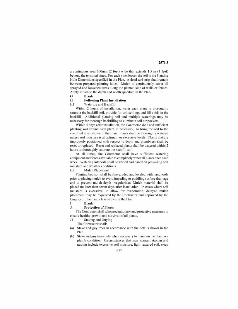
2571.3
677
a continuous area 600mm (2 feet) wide that extends 1.5 m (5 feet) beyond the terminal vines. For each vine, loosen the soil to the Planting Hole Dimensions specified in the Plan. A dead turf strip shall remain between prepared planting holes. Mulch to continuously cover all sprayed and loosened areas along the planted side of walls or fences. Apply mulch to the depth and width specified in the Plan. G Blank H Following Plant Installation H1 Watering and Backfill
Within 2 hours of installation, water each plant to thoroughly saturate the backfill soil, provide for soil settling, and fill voids in the backfill. Additional planting soil and multiple waterings may be necessary for thorough backfilling to eliminate soil air pockets.
Within 5 days after installation, the Contractor shall add sufficient planting soil around each plant, if necessary, to bring the soil to the specified level shown in the Plan. Plants shall be thoroughly watered unless soil moisture is at optimum or excessive levels. Plants that are improperly positioned with respect to depth and plumbness shall be reset or replaced. Reset and replaced plants shall be watered within 2 hours to thoroughly saturate the backfill soil.
At all times, the Contractor shall have sufficient watering equipment and forces available to completely water all plants once each week. Watering intervals shall be varied and based on prevailing soil moisture and weather conditions. H2 Mulch Placement
Planting bed soil shall be fine-graded and leveled with hand tools prior to placing mulch to avoid impeding or puddling surface drainage and to prevent mulch depth irregularities. Mulch material shall be placed no later than seven days after installation. In cases where soil moisture is excessive, to allow for evaporation, delayed mulch placement may be requested by the Contractor and approved by the Engineer. Place mulch as shown in the Plan. I Blank J Protection of Plants
The Contractor shall take precautionary and protective measures to ensure healthy growth and survival of all plants. J1 Staking and Guying
The Contractor shall: (a) Stake and guy trees in accordance with the details shown in the
Plan. (b) Stake and guy trees only when necessary to maintain the plant in a
plumb condition. Circumstances that may warrant staking and guying include excessive soil moisture, light-textured soil, steep

2571.3
678
slopes, high wind, or vandalism. Staking and guying shall be installed at no cost to the Department unless specified otherwise in the Contract.
(c) Remove the staking and guying after 1 year. J2 Rodent Protection
The Contractor shall place rodent protection around all trees in accordance with the details in the Plan unless specified otherwise. J3 Tree Painting
To prevent bark from splitting in the winter, the Contractor shall paint trees in accordance with the species, notes, and details shown in the Plan. The Engineer may require additional applications to achieve opaque coverage. K Disposal of Excavated Materials
Excess and unwanted excavated materials shall be removed from the planting areas and disposed of to the Engineer's satisfaction within 3 days after the excavation. L Cleanup and Restoration Work
Cleanup and restoration work shall be accomplished as the final step of the initial planting operations and throughout the plant establishment period, to the Engineer's satisfaction. Turf disturbed during plant installation or establishment operations shall be repaired with the seed mix(es) specified in the Plan. The Contractor shall: (1) Repair turf in all disturbed areas including, but not limited to,
roadway access points, equipment circulation areas and pathways, and all stockpile or staging locations.
(2) Remove all woodchip or material stockpiles to the Engineer's satisfaction.
(3) Immediately prior to sowing seed or laying sod, roughen the soil surface. Soil shall be prepared as specified in 2575.3B (Soil Preparations).
(4) Uniformly broadcast a slow release fertilizer. The fertilizer analysis and application rates will be as specified in the Plan or as directed by the Engineer.
(5) Lay sod or uniformly hand broadcast seed at 1.5 times the rate specified in Table 2575-1, Seed Mixture Application Rates. For large areas, the Engineer may require or approve other establishment methods. Seed shall be in accordance with the requirements of 3876 and seeding shall occur in accordance with Table 2575-2, Season of Planting.
(6) Rake and firm the seeded areas to ensure seed/soil contact. (7) Broadcast or disc anchor mulch, Type 1 in all seeded areas. (7) Install erosion control measures as necessary or as directed by the
Engineer.

2571.3
679
M Plant Establishment Period M1 Establishment Period
The Contractor shall maintain the work and care for the installed plants from completion of the initial planting operations until final acceptance at the end of the Plant Establishment Period. M2 Establishment Work
The Contractor shall keep all plants in a healthy growing condition, using good horticultural practices generally and continuously throughout the establishment period. A prerequisite for work being continuously acceptable during the plant establishment period is that non-compliance conditions which require work by the Contractor cannot remain out of compliance for more than a continuous three week period, on a calendar day basis. Work shall be performed on a day to day basis during the growing season and as necessary during the remainder of the year, with necessary replacements being made as required.
If at any time, inspection shows that the plant establishment operations have not been generally and continuously in compliance, the Engineer will notify the Contractor in writing of such default and the Contractor shall comply with the instructions. If the Contractor does not proceed satisfactorily within 3 working days after receiving written notice from the Engineer to remedy plant establishment deficiencies, Mn/DOT will assess a daily charge of $200.00, on a calendar day basis, until the Engineer notes compliance with the notice or until the eligible percentage of the annual contract amount for plant establishment work has been forfeited. The charge will continue until defaults are corrected to the Engineer's satisfaction and without further notice from the Engineer. The Contractor shall replace plant stock as required in the Contract but only within the optimum planting dates specified, extended, or shown in the Plan or as required by the Engineer. M2a All Plants
In plant establishment work, the Contractor shall generally and continuously: (1) Maintain adequate (but not excessive) soil moisture in
conformance with 2571.3H and watering guidelines provided in the Plan. It is advised that the Contractor use a soil moisture meter to determine soil moisture levels.
(2) Repair, adjust, or replace, the staking and guying, mulch material, planting soil, rodent protection, seedling tree shelters, tree painting, and other incidental items in conformance with the Plan.
(3) Apply insecticides, fungicides, and other cultural procedures, as necessary, to maintain healthy, vigorous plants free from harmful insects, fungus, and disease. All chemical applications shall be

2571.3
680
performed by an operator licensed by the Minnesota Department of Agriculture.
(4) Remove dead plants. Furnish and install replacement plants with new mulch, planting soil, and other incidental items in conformance with 2571.3M3 (Replacement Requirements) and at no cost to the Project. The Contractor shall remove dead, dying, and unsightly plants on a continuous basis as these conditions occur, or as directed by the Engineer. Plant stock documentation for replacements shall conform to 2571.2A2.
(5) Maintain the plants in a plumb condition at the appropriate planting depth.
(6) Maintain all planting areas in a weed-free condition by contin- ously removing all weed growth in the mulched planting areas as necessary.
(a) Remove all weeds (top growth and roots) within the mulch limits by hand pulling (pre-watering is advised) or other methods as approved by the Engineer. Remove all County-regulated noxious weeds to at least 900 mm (3 feet) beyond the mulch limits with a method approved by the Engineer. Remove all weed parts from the Project site in such a manner as to avoid spreading weeds.
(b) Spray application of chemicals for weed control in the mulched planting areas will not be permitted during the plant establishment period unless the Engineer authorizes otherwise. A non-selective, non-residual post emergence herbicide containing 41 percent glyphosate as the active ingredient may be applied, with a surfactant, on a spot treatment basis only, with a brush or wick applicator, if authorized by the Engineer. Additional herbicides may be applied on a prescriptive basis if approved by the Engineer. A broad-spectrum dichlobenil based granular herbicide (pre-emergent) may be applied in conformance with product labeling and manufacturer's recommendations for residual weed control, if authorized by the Engineer.
(c) Weed whips and weed clippers will not be accepted as weed control.
(d) Mow the turf areas to at least 900 mm (3 feet) beyond the mulch limits and to a height no shorter than 100 mm (4 inches) when that turf grows taller than 230 mm (9 inches) adjacent to the mulched planting areas.
(e) Mow areas of Contractor-installed turf establishment or turf repair if the vegetation grows to a height of 500 mm (18 inches). Using a rotary mower, mow to a height of 150-300 mm (6 -12 inches). It is anticipated mowing may be necessary as early as June 30 and as late as August 15 (when the cover crop is setting seed). The
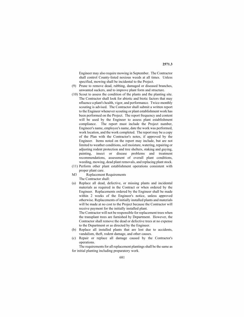
2571.3
681
Engineer may also require mowing in September. The Contractor shall control County-listed noxious weeds at all times. Unless specified, mowing shall be incidental to the Project.
(9) Prune to remove dead, rubbing, damaged or diseased branches, unwanted suckers, and to improve plant form and structure.
(10) Scout to assess the condition of the plants and the planting site. The Contractor shall look for abiotic and biotic factors that may nfluence a plant's health, vigor, and performance. Twice-monthly scouting is advised. The Contractor shall submit a written report to the Engineer whenever scouting or plant establishment work has been performed on the Project. The report frequency and content will be used by the Engineer to assess plant establishment compliance. The report must include the Project number, Engineer's name, employee's name, date the work was performed, work location, and the work completed. The report may be a copy of the Plan with the Contractor's notes, if approved by the Engineer. Items noted on the report may include, but are not limited to weather conditions, soil moisture, watering, repairing or adjusting rodent protection and tree shelters, staking and guying, painting, insect or disease problems and treatment recommendations, assessment of overall plant conditions, weeding, mowing, dead plant removals, and replacing plant stock.
(11) Perform other plant establishment operations consistent with proper plant care.
M3 Replacement Requirements The Contractor shall: (a) Replace all dead, defective, or missing plants and incidental
materials as required in the Contract or when ordered by the Engineer. Replacements ordered by the Engineer shall be made within 2 weeks of the Engineer's notice, unless approved otherwise. Replacements of initially installed plants and materials will be made at no cost to the Project because the Contractor will receive payment for the initially installed plant. The Contractor will not be responsible for replacement trees when the transplant trees are furnished by Department. However, the Contractor shall remove the dead or defective trees at no expense to the Department or as directed by the Engineer.
(b) Replace all installed plants that are lost due to accidents, vandalism, theft, rodent damage, and other causes.
(c) Repair or replace all damage caused by the Contractor's operations. The requirements for all replacement plantings shall be the same as
for initial planting including preparatory work.

2571.3
682
Within the first year of the 2-year plant establishment period, the Contractor is responsible for determining which plants need to be replaced. The Contractor shall assess the plant's condition and base the replacements on present or probable compliance with the Project requirements. At least one week prior to the anticipated plant replacements, the Contractor will submit a summary report of proposed plant replacements. The report shall include, by attachment, copies of plan sheets with the proposed replacement quantities and locations clearly identified. The Contractor shall also clearly mark the plants to be replaced with brightly colored paint in the field.
When less than a full year remains in the plant establishment period, the Contractor will not be required to replace plants unless the period is extended by a Supplemental Agreement or Change Order to provide one full year of establishment care.
After initial replacements, if additional replacements are required, the Engineer will decide if replacements will be at the Contractor's expense, deleted from the Plan, or replaced with compensation. Replacements with compensation will only be considered when plant failure is not a consequence of the Contractor's operations. Replacements with compensation require at least one year of plant establishment care and must be installed during the optimum planting dates, as shown in the Plan, unless approved by the Engineer. N Acceptance of Work
For acceptance at full payment, plants shall meet all requirements including the criteria listed in the current edition of "Inspection and Contract Administration Guidelines for Mn/DOT Landscape Projects," published by the Mn/DOT Landscape Unit. The plants shall be healthy, vigorous, and structurally sound. N1 Acceptance of Preparatory Work
The Engineer will accept the preparatory work after the Contractor has satisfactorily secured commitments for required materials (Mn/DOT Certificate of Compliance for Plant Stock, Landscape Materials, and Equipment), obtained the Engineer's approval for the progress schedule, moved equipment and supplies to the Project site, and provided for protection of existing plants. N2 Acceptance of Preparation of Planting Holes and Beds
The Engineer will accept the preparation of planting holes and beds after the Contractor has satisfactorily completed staking, initial weed control, soil cultivation with incorporation of additives, and temporary erosion prevention measures.

2571.4
683
N3 Acceptance of Initial Planting Operation Initial acceptance will be made upon satisfactory completion of the
initial planting operation for the individual plant. N4 Final Acceptance
Final acceptance will be made after final inspection of the completed Project at the end of the plant establishment period. N4a Final Inspection
On or about the date on which the plant establishment period expires, the Engineer will make an inspection of the Project and notify the Contractor of any dead, defective, or missing plants and work that must be performed prior to acceptance. Dead or defective plants shall be removed where so ordered and turf shall be restored as specified in the Plan or as directed by the Engineer. Restoration shall be consistent with the surrounding turf.
As a condition for acceptance of the work, plant establishment operations shall not be past due at the time of the final inspection. Every plant shall have received a thorough watering within the preceding 10 days before inspection, unless soil moisture is at sufficient levels. The mulched planting areas shall be weed-free (top growth and roots). All work shall be in good order and in compliance with all plant establishment requirements. Work shall include, but is not limited to replenishing mulch, tree painting, straightening and imbedding rodent protection, pruning, and removing replacement plant staking and guying as necessary or as directed by the Engineer.
The Engineer will make a determination as to which plants will be accepted for payment at the Contract unit prices, at a reduced payment, or at no payment. The Engineer may consider as unacceptable any machine transplanted trees that are mechanically damaged and trees with reduced vigor and growth resulting from improper transplanting operations. The Engineer may accept these trees at an adjusted payment according to 1503 (Conformity with Plans and Specifications) or at no payment.
Upon final acceptance, the Contractor will not be required to provide any further care for the plantings. However, final acceptance of the work will not be made until cleanup and restoration work are completed to the Engineer's satisfaction. N5 Blank 2571.4 METHOD OF MEASUREMENT A Plants Furnished and Planted
Trees, shrubs, vines and perennials of each species, variety, size, or age, and root category furnished, planted, and maintained by the Contractor will be measured separately by the number of acceptable plants.

2571.4
684
B Plants Planted Trees, shrubs, vines and perennials of each species, variety, size, or
age, and root category furnished by the Department and planted and maintained by the Contractor will be measured separately by the number of acceptable plants. C Plants Transplanted
Trees, shrubs, vines, and perennials of each size and type furnished by the Department and transplanted will be measured separately by the number of plants moved and maintained in an acceptable manner. 2571.5 BASIS OF PAYMENT
Payment for plant installation at a percentage of the Contract price per unit of measure will be compensation for all costs relating to furnishing, installing, and maintaining, or installing and maintaining, the required plants and materials specified.
If the Engineer requires additional materials and work beyond that specified or shown in the Contract, the Contractor will receive compensation for the additional materials and work as Extra Work. A Initial Payment
Initial payment of up to but not exceeding 80 percent of the Contract unit price will be paid in partial payment amounts for satisfactory completion of the following work: A1 Preparatory Work
Up to but not exceeding 10 percent of the Contract amount for the plants to be planted. A2 Preparation of Planting Holes and Beds
Up to but not exceeding 20 percent of the Contract amount for the plants to be planted. A3 Initial Planting Operation
Up to but not exceeding 50 percent of the Contract amount for the plants planted. A4 Maximum
Up to but not exceeding 80 percent of the Contract amount for the plants planted. B Interim Payment
The Engineer may authorize an interim partial payment of up to but not exceeding 10 percent of the Contract amount for the plants planted, at the end of the first calendar year of the plant establishment period when required plant establishment operations on the entire Project have been acceptable generally and continuously throughout this period. The Engineer will not authorize interim partial payment if these conditions are not met.
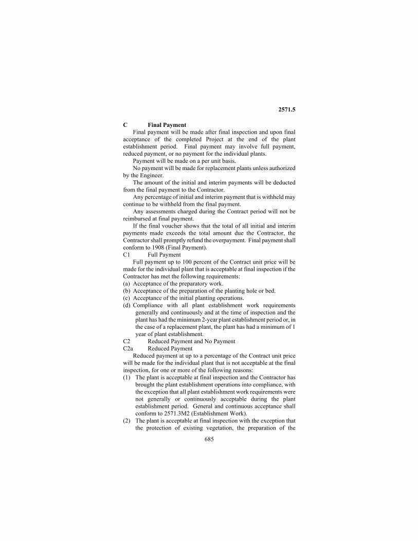
2571.5
685
C Final Payment Final payment will be made after final inspection and upon final
acceptance of the completed Project at the end of the plant establishment period. Final payment may involve full payment, reduced payment, or no payment for the individual plants.
Payment will be made on a per unit basis. No payment will be made for replacement plants unless authorized
by the Engineer. The amount of the initial and interim payments will be deducted
from the final payment to the Contractor. Any percentage of initial and interim payment that is withheld may
continue to be withheld from the final payment. Any assessments charged during the Contract period will not be
reimbursed at final payment. If the final voucher shows that the total of all initial and interim
payments made exceeds the total amount due the Contractor, the Contractor shall promptly refund the overpayment. Final payment shall conform to 1908 (Final Payment). C1 Full Payment
Full payment up to 100 percent of the Contract unit price will be made for the individual plant that is acceptable at final inspection if the Contractor has met the following requirements: (a) Acceptance of the preparatory work. (b) Acceptance of the preparation of the planting hole or bed. (c) Acceptance of the initial planting operations. (d) Compliance with all plant establishment work requirements
generally and continuously and at the time of inspection and the plant has had the minimum 2-year plant establishment period or, in the case of a replacement plant, the plant has had a minimum of 1 year of plant establishment.
C2 Reduced Payment and No Payment C2a Reduced Payment
Reduced payment at up to a percentage of the Contract unit price will be made for the individual plant that is not acceptable at the final inspection, for one or more of the following reasons: (1) The plant is acceptable at final inspection and the Contractor has
brought the plant establishment operations into compliance, with the exception that all plant establishment work requirements were not generally or continuously acceptable during the plant establishment period. General and continuous acceptance shall conform to 2571.3M2 (Establishment Work).
(2) The plant is acceptable at final inspection with the exception that the protection of existing vegetation, the preparation of the

2571.5
686
planting holes or beds, or the initial planting operations were unacceptable.
(3) The plant is acceptable at final inspection with the exception that all plant establishment work requirements are not acceptable at the time of inspection, or the plant has not had the minimum 2-year plant establishment period or the minimum 1-year plant establishment period in the case of a replacement plant.
(4) The Department-furnished plant or machine transplant is not acceptable at final inspection but the protection of existing vegetation, the preparation of the planting hole or bed, the initial planting operations, and the continuous plant establishment operations have all been acceptable.
(5) The plant is not acceptable at final inspection but all protection of existing vegetation, the preparation of the planting holes or beds, and the initial planting operations were acceptable, and the Contractor has been in general compliance continuously with the plant establishment work requirements for the minimum 2-year plant establishment period and the minimum 1-year plant establishment period in the case of a replacement plant.
C2b No Payment No payment will be made for an unacceptable plant with
unacceptable establishment care. C2c Reduced Payment or No Payment
Reduced payment for the individual plant at up to a percentage of the Contract unit price or no payment will be made in accordance with the following:
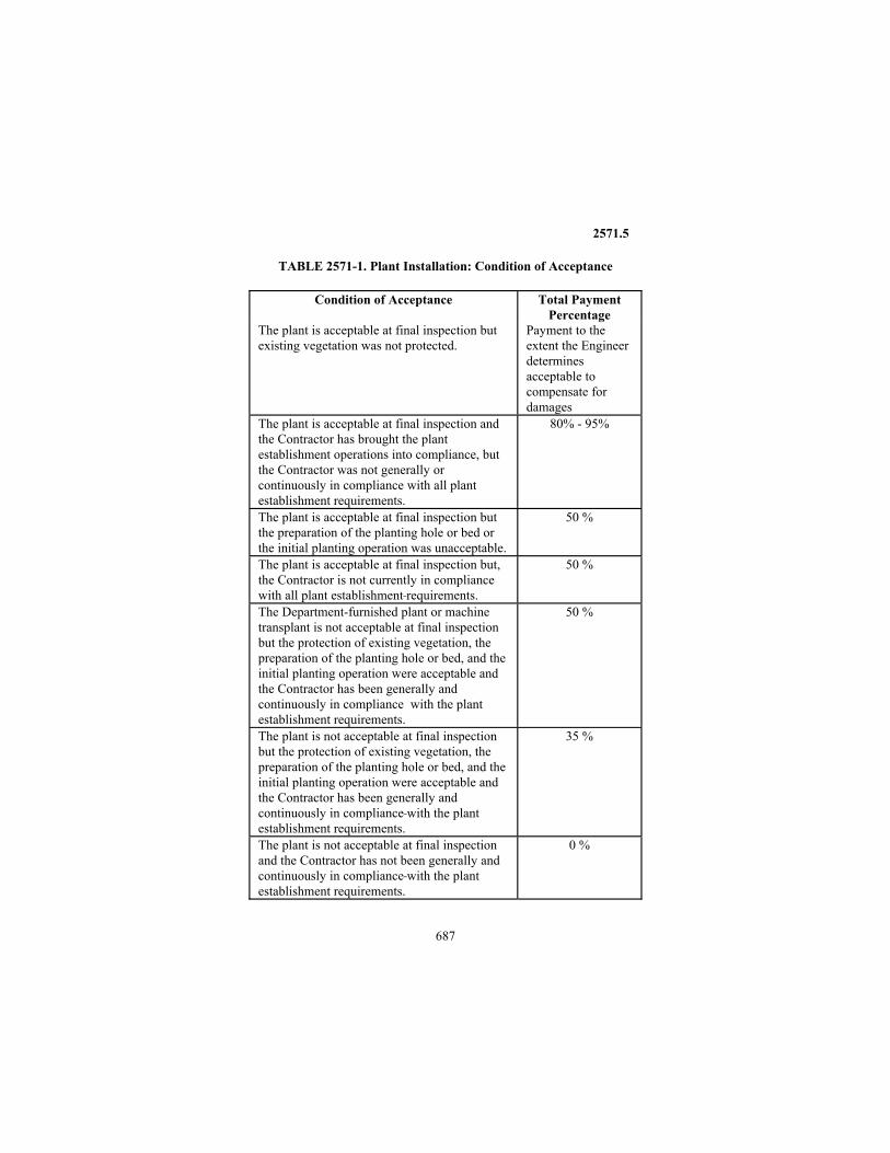
2571.5
687
TABLE 2571-1. Plant Installation: Condition of Acceptance
Condition of Acceptance Total Payment Percentage
The plant is acceptable at final inspection but existing vegetation was not protected.
Payment to the extent the Engineer determines acceptable to compensate for damages
The plant is acceptable at final inspection and the Contractor has brought the plant establishment operations into compliance, but the Contractor was not generally or continuously in compliance with all plant establishment requirements.
80% - 95%
The plant is acceptable at final inspection but the preparation of the planting hole or bed or the initial planting operation was unacceptable.
50 %
The plant is acceptable at final inspection but, the Contractor is not currently in compliance with all plant establishment requirements.
50 %
The Department-furnished plant or machine transplant is not acceptable at final inspection but the protection of existing vegetation, the preparation of the planting hole or bed, and the initial planting operation were acceptable and the Contractor has been generally and continuously in compliance with the plant establishment requirements.
50 %
The plant is not acceptable at final inspection but the protection of existing vegetation, the preparation of the planting hole or bed, and the initial planting operation were acceptable and the Contractor has been generally and continuously in compliance with the plant establishment requirements.
35 %
The plant is not acceptable at final inspection and the Contractor has not been generally and continuously in compliance with the plant establishment requirements.
0 %

2571.5
688
D Bonus Payment A bonus payment of 10 percent of the total final Contract price for
plant installation will be paid when 90 percent or more of all initially installed plants, and related contract operations have been accepted generally and continuously throughout the Contract period.
The qualifying percentage will be based upon the number of initially installed individual plants receiving full payment divided by the total Plan quantity of individual plants in the Contract. Any replacements made within the first Plant Installation Period (PIP) are considered initially installed plants.
To be eligible for the bonus payment, plants must be installed within the Plant Installation Period (PIP) identified in 1806 (Determination and Extension of Contract Time). This shall apply unless the PIP has been modified and approved otherwise in writing by the Engineer. E Payment Schedule Payment for plant installation will be made on the basis of the following schedule: Item No. Item Unit 2571.501 Coniferous tree (size & root category) .......................... tree 2571.502 Deciduous tree (size & root category) ........................... tree 2571.503 Ornamental tree (size & root category) ......................... tree 2571.504 Coniferous shrub (size & root category)..................... shrub 2571.505 Deciduous shrub (size & root category) ..................... shrub 2571.506 Vine (age or size & root category) ............................... vine 2571.507 Perennial (age or size & root category) ....................... plant 2571.541 Transplant tree (spade size (1)) ..................................... tree 2571.544 Transplant shrub ......................................................... shrub 2571.546 Transplant vine ............................................................. vine 2571.547 Transplant perennial .................................................... plant NOTE: State Root Category: -Seedling, -Bare Root, -Machine Moved
- Container Grown - Balled & Burlapped (1) Spade size 1.1 m (42 inch), 1.5 m (60 inch), 1.9 m (78 inch),
2.1 m (85 inch), 2.3 m (90 inch).

2572.3
689
2572 Protection and Restoration of Vegetation
2572.1 DESCRIPTION This work consists of protecting and preserving vegetation from
damage and taking corrective action when damage occurs. Vegetation includes but is not limited to trees, brush, roots, woody vines, and perennial forbs and grasses. 2572.2 MATERIALS A Plant Materials .......................................... 2571 and 2575 B Temporary Fence
The Contractor shall provide temporary fence that is: (1) At least 1.2 m (4 feet) high. (2) Conspicuous in color. (3) Commercially available snow fence or other fencing material
acceptable to the Engineer. C Water ....................................................................... 2571.2 D Sandy Loam Topsoil
The Contractor shall provide well-drained sandy loam topsoil, with a coarse sand component, meeting the requirements of Table 2572-1 and the Mn/DOT Grading and Base Manual. The Engineer may determine acceptability of topsoil without the test data specified in Table 2572-1. TABLE 2572-1 SANDY LOAM TOPSOIL GRADATION
Minimum Maximum
Clay (by mass) 5 % 20 % Silt (by mass) 10 % 30 % Coarse Sand and Gravel (by mass) (A)
50 % 70 %
Organic Matter (by mass) 3 % 20 % pH 6.1 7.5 Soluble Salts -- 0.15 siemens/m
(1.5 mmho) (A) Gravel not to exceed 10 percent by mass.
2572.3 CONSTRUCTION REQUIREMENTS A Protecting and Preserving
The Contractor shall protect and preserve: (1) Specimen trees. (2) Threatened and endangered plants, as listed on the Federal and state
threatened and endangered species list.

2572.3
690
(3) Vegetation designated in the Contract to be preserved. (4) Trees, brush, and natural scenic elements within the Right of Way
and outside the actual limits of clearing and grubbing consistent with 2101.3.
(5) Other vegetation the Engineer identifies to be protected and preserved. The Contractor shall not place temporary structures, store material,
or conduct unnecessary construction activities within a distance of 8 m (25 ¼ feet) outside of the dripline of trees designated to be preserved without approval from the Engineer.
The Contractor shall not place temporary structures or store material (including common borrow and topsoil) outside of the construction limits in areas designated in the Contract or by the Engineer to be preserved.
The Contractor shall not place or leave any waste material on the project site, including bituminous and concrete waste, so as to interfere with 2105.3 (Finishing Operations) or 2575 (Turf Establishment). Concrete waste is defined to include all excess material not used on the project, including excess material ground to form rumble strips. The Contractor may dispose of excess material in accordance with 2104.3C (Disposal of Materials and Debris). A1 Temporary Fence
The Contractor shall place temporary fences to protect vegetation before starting construction. The Contractor shall place temporary fence at the construction limits and at other locations adjacent to vegetation designated to be preserved when specified in the Contract, directed by the Engineer, or allowed by the Engineer. The Contractor shall place tree protection signs supplied by Mn/DOT) along the temporary fence at 15.25 m (50 foot) intervals or no fewer than two per fence or as specified by the Engineer. The Contractor shall not remove the fence until all work is completed or until removal is allowed by the Engineer.
The fence shall prevent traffic movement and the placement of temporary facilities, equipment, stockpiles, and supplies from harming the vegetation. A2 Clean Root Cutting
The Contractor shall cleanly cut all tree roots at the construction limits when specified in the Contract or directed by the Engineer.
The Contractor shall immediately and cleanly cut damaged and exposed roots. Trees designated for protection shall have damaged roots cut back to sound healthy tissue and shall have topsoil immediately placed over the exposed roots. The Contractor shall immediately cover root ends that are exposed by excavation activities
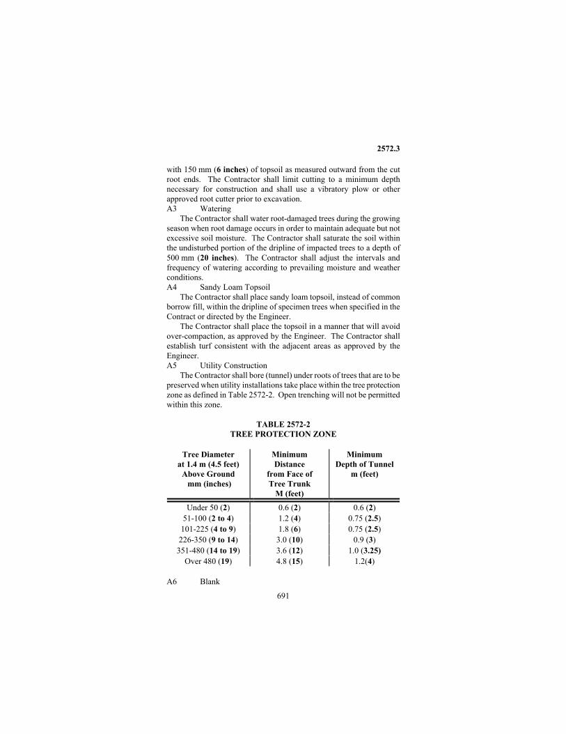
2572.3
691
with 150 mm (6 inches) of topsoil as measured outward from the cut root ends. The Contractor shall limit cutting to a minimum depth necessary for construction and shall use a vibratory plow or other approved root cutter prior to excavation. A3 Watering
The Contractor shall water root-damaged trees during the growing season when root damage occurs in order to maintain adequate but not excessive soil moisture. The Contractor shall saturate the soil within the undisturbed portion of the dripline of impacted trees to a depth of 500 mm (20 inches). The Contractor shall adjust the intervals and frequency of watering according to prevailing moisture and weather conditions. A4 Sandy Loam Topsoil
The Contractor shall place sandy loam topsoil, instead of common borrow fill, within the dripline of specimen trees when specified in the Contract or directed by the Engineer.
The Contractor shall place the topsoil in a manner that will avoid over-compaction, as approved by the Engineer. The Contractor shall establish turf consistent with the adjacent areas as approved by the Engineer. A5 Utility Construction
The Contractor shall bore (tunnel) under roots of trees that are to be preserved when utility installations take place within the tree protection zone as defined in Table 2572-2. Open trenching will not be permitted within this zone. TABLE 2572-2 TREE PROTECTION ZONE
Tree Diameter at 1.4 m (4.5 feet)
Above Ground mm (inches)
Minimum Distance
from Face of Tree Trunk
M (feet)
Minimum Depth of Tunnel
m (feet)
Under 50 (2) 0.6 (2) 0.6 (2) 51-100 (2 to 4) 1.2 (4) 0.75 (2.5)
101-225 (4 to 9) 1.8 (6) 0.75 (2.5) 226-350 (9 to 14) 3.0 (10) 0.9 (3)
351-480 (14 to 19) 3.6 (12) 1.0 (3.25) Over 480 (19) 4.8 (15) 1.2(4)
A6 Blank
2572.3
692
A7 Pruning
The Contractor shall prune trees specified in the Contract or as directed by the Engineer in accordance with 2571.3. Pruning shall include the removal of dead, broken, rubbing branches, and those limbs that may interfere with the existing and proposed structures. A8 Destroyed or Disfigured Vegetation
If the Contractor destroys or disfigures vegetation designated to be preserved, the Contractor shall, at no expense to the Department, restore the damaged vegetation to a condition equal to what existed before the damage was done. The Engineer may assess damages against the Contractor on vegetation where an equal level of restoration is not accomplished. The Engineer will assess damages of trees and landscaping at not less than the appraisal damages as determined by the International Society of Arboriculture appraisal guide. The Engineer will determine and assess damages of other vegetation. A9 Oak Trees
The Contractor shall avoid wounding of oak trees during April, May, June, and July in order to prevent the spread of oak wilt. If the Engineer determines that work must take place near oak trees during those months, resulting wounds shall immediately be treated with a wound dressing material consisting of latex paint or shellac. Paint colors shall blend with the bark color. The Contractor shall have an approved wound dressing on the project at all times during this period. A10 Other Vegetation Protection Measures
The Contractor shall provide other vegetation protection measures; including root system bridging, compaction reduction, aeration, and retaining walls; as specified in the Contract or as directed by the Engineer. B Plant Installation ........................................................ 2571 C Disposal of Material and Debris ............................. 2104.3 2572.4 METHOD OF MEASUREMENT A Temporary Fence
The Engineer will measure temporary fence by length along the bottom of the fence between end posts. Measurement will only be made for fence placed, maintained, and removed. B Clean Root Cutting
The Engineer will measure clean root cutting by length along the plow line. The beginning and ending points will be where the construction limit intersects the dripline of the tree or brush or in accordance with lines shown on the Plan. C Water
The Engineer will measure water by volume used to protect and

2572.5
693
restore vegetation. No measurement will be made of other water used in conjunction with the work, whether for maintenance of sod, or otherwise. D Sandy Loam Topsoil
The Engineer will measure sandy loam topsoil used by authority of the Engineer by compacted volume furnished and placed. The material may come from the Project. E Pruning
The Engineer will measure pruning by the hours of actual pruning work. 2572.5 BASIS OF PAYMENT
The Department will pay for the acceptable quantities at the appropriate Contract price per unit of measure. In the absence of a Contract bid price, the Contractor will receive compensation for the work specified in the Contract or directed in writing by the Engineer according to the following unit prices; or in the absence of both, as Extra Work. This payment is full compensation for all costs relating to the specific pay item. A No Payment
The Contractor will not receive compensation for: (1) Boring under roots in the tree protection zone, dressing of wounds,
and disposal of material and debris. (2) Pruning that is necessary to allow for the Contractor's operations or
to remedy damage caused by the Contractor's operations. B Payment at Unit Prices
The Department will pay at the following unit prices for protection and restoration of vegetation items in the absence of a Contract bid price:
Item Unit Price (1) Temporary Fence .......... $8.00 per meter ($2.50 per linear foot) (2) Clean Root Cutting ..... $11.50 per meter ($3.50 per linear foot) (3) Water ................. $8.00 per cubic meter ($3.00 per 100 gallons) (4) Sandy Loam Fill ... $10.00 ($7.65) per cubic meter (cubic yard) (5) Prune Trees ......................................................... $75.00 per hour C Payment at Contract Bid Prices
The Department will pay at the Contract bid price as follows: Item No. Item Unit 2572.501 Temporary Fence .................................. meter(linear foot) 2572.502 Clean root cutting ................................. meter (linear foot) 2572.503 Water ...............................................................liter (gallon) 2572.504 Sandy loam fill ........................... cubic meter (cubic yard) 2572.505 Prune trees ................................................................... hour

2573
694
2573 Storm Water Management 2573.1 DESCRIPTION
This work consists of: 1) managing storm water runoff and project related water discharges in order to minimize sediment pollution during construction and over the life of the contract and 2) managing the discharges associated with dewatering and basin draining activities as set forth in the NPDES permit. The work includes furnishing, installing, maintaining and utilizing storm water best management practices and any work specified in conjunction therewith as well as removing temporary sediment control devices when no longer necessary. 2573.2 MATERIALS A Bale Barriers, as specified for Type 1 Mulch ........... 3882 B Silt Fence ..................................................................... 3886 C Flotation Silt Curtain ................................................. 3887 D Temporary Ditch Checks ........................................... 3889 E Storm Drain Inlet Protection..................................... 3891 F Temporary Downdrain .............................................. 3892 G Sandbags...................................................................... 3893 H Sediment Mat .............................................................. 3894 I BLANK J Filter Logs ................................................................... 3897 K Flocculants .................................................................. 3898 2573.3 CONSTRUCTION REQUIREMENTS A General ...... Also refer to: 1701, 1716, 1717, 2105.5, 2575 In accordance with 1716 the Contractor has responsibility for charge and care of the Project and shall take necessary precautions against injury or damage to the Project by action of the elements. In addition, the Contractor shall take necessary precautions to prevent off site damage resulting from work conducted on the Project or Project related storm water runoff. The Contractor is responsible for preventing or minimizing sediment loss from the Project by directing storm water runoff to constructed ponds and sediment traps as well as installing temporary sediment control devices in drainage locations where runoff can leave the Project limits and/or enter into environmentally sensitive areas. The Contractor shall schedule, construct and/or install temporary sediment control and storm water management measures as required by the Contract and as stated in the permits required for the Project without having to obtain prior approval or having to be so directed by the Engineer. In the case of errors or omissions, the Contractor shall inform the Engineer upon immediate discovery.
2573.3
695
The Contractor shall install temporary storm water management and sediment control devices in conformity with the details, typical sections, and elevation controls shown in the Contract. The actual installation location of temporary storm water management and sediment control devices may be slightly adjusted from that indicated in the Plan to better accommodate the actual field conditions and increase the effectiveness of a device. The Department will not conduct location staking unless requested by the Contractor. Errors, omissions, and changed site conditions affecting the location or placement of the temporary storm water management or sediment control devices shall be brought to the attention of the Engineer by the Contractor. A1 Erosion Control Supervisor The Contractor shall provide an Erosion Control Supervisor with a valid certification to direct the Contractor and subcontractor(s) operations and insure compliance with Federal, State and Local ordinances and regulations. The certification is obtained by completing a two (2) day Erosion/Sediment Control Site Management training class and passing the required test, from a Mn/DOT approved provider as listed in the Mn/DOT certification schedule. The Erosion Control Supervisor shall implement the SWPPP and conduct the Contractor's erosion and sediment quality control program. In addition, the Erosion Control Supervisor shall be available to be on the Project within 24 hours at all times from initial disturbance to final stabilization as well as perform the following duties: 1. Coordinate and schedule the work of subcontractors such that
erosion and sediment control measures are fully executed for each operation and in a timely manner over the duration of the Contract.
2. Oversee the work of subcontractors so that appropriate erosion and sediment preventive measures are undertaken at each stage of the work.
3. Prepare the required weekly erosion control schedules and present it to the Engineer.
4. Attend all weekly construction meetings to discuss the findings of the NPDES inspection log and other related issues.
5. Prepare the erosion/sediment control site plans requested by the Engineer.
6. Provide for erosion/sediment control methods for Contractor's temporary work not shown on the plans, such as work platforms, temporary construction, pumping operations, plant and storage yards, and cofferdams.
7. Ensure that applicable permits are acquired and complied with for borrow pits, dewatering and any temporary work conducted by the Contractor in rivers, lakes and stream

2573.3
696
8. Ensure that all erosion/sediment control work is conducted in a timely manner.
9. Ensure that erosion/sediment control work is installed to the fullest extent prior to suspension of the work.
10. Coordinate with Federal, State and Local Regulatory agencies on resolution of erosion/sediment control issues due to the Contractor's operations.
11. Ensure that proper cleanup occurs from vehicle tracking on paved surfaces and/or any location where sediment leaves the Right-of-Way.
If the Contractor fails to provide a certified Erosion Control Supervisor for the Project, the Engineer shall issue a written order to the Contractor. The Contractor shall respond within 24 hours and provide the required Erosion Control Supervisor or be subject to a $1000 per calendar day deduct for noncompliance. A2 Construction of Temporary Storm Water Basins Temporary storm water basins shall be constructed concurrently with the start of soil disturbing activities whenever possible. The basins must be made fully functional and have storm water runoff from the localized watershed directed to the basins. The exposed sideslopes of the basins must be mulched and/or seeded within the time periods as set forth in 1717, or as directed by the Engineer. A3 Temporary Sediment Control Measures Sediment control measures must be installed down gradient prior to or in conjunction with soil disturbing activities. The Contractor shall schedule, install and maintain temporary sediment control measures as an ongoing effort on a site-by-site basis over the life of the Contract. The Contractor is responsible for minimizing the potential for sedimentation after temporary sediment control devices have been installed by implementing a good quality erosion control program and staging construction as needed. If the Engineer determines that the Contractor has not followed good erosion control practices that result in sedimentation outside of the Right of Way, the Contractor shall retrieve all sediment that has left the Right of Way and restore the property to the pre-existing condition, to the fullest extent possible at the Contractor's expense. A4 Dewatering and Pumping If dewatering or pumping of water is necessary, the Contractor is responsible for obtaining any necessary permits in accordance with 1701 and 1702. If the discharge from the dewatering or pumping process is turbid or contains sediment-laden water, it must be treated through use of sediment traps, vegetative filter strips, flocculants, or other sediment reducing measures such that the discharge is not visibly

2573.3
697
different from the receiving water. The discharge location of the dewatering process must also be protected from excess erosion. Unless otherwise provided in the Contract, the best management practices used to control erosion and suspended sediment during the dewatering or pumping operation shall be furnished by the Contractor. The Contractor shall submit a dewatering plan to the Engineer prior to initiating dewatering activities. A5 Vehicle Tracking onto Paved Surfaces The Contractor shall use wood chip pads, temporary paving, or other appropriate Best Management Practices (BMPs) at major vehicle exit locations to minimize vehicle tracking of sediment from the Project onto paved surfaces. BMPs to protect vehicle exit sites shall be furnished by the Contractor and shall be incidental to the Project for which no direct compensation will be made. The Contractor is responsible for insuring paved streets are clean at the end of each working day. Tracked sediment on paved surfaces must be removed by the Contractor within 24 hours of discovery, in accordance with 1717.2. Payment for street sweeping to provide safe conditions for the traveling public, environmental reasons or regulatory requirements shall be as provided in accordance with 1514. A6 Infiltration Areas Infiltration areas and constructed infiltration systems should not be constructed until the contributing drainage area and/or adjacent construction site have been completely stabilized. When this timing of construction is not possible, the Contractor shall insure sediment from exposed soil areas of the Project does not enter into the infiltration area or system. Payment for constructing infiltration areas shall be as provided for in the Contract. A7 Critical Resources The Contractor shall schedule and phase construction in critical resource areas to the best of his ability in order to minimize the potential of sediment entering into a critical resource. Critical resources include but are not limited to, protected wetlands, surface waters, trout streams, Special Waters, impaired waters, rivers, and endangered species habitat. Measures to minimize sediment potential include practices such as hand clearing and grubbing, limited bare soil exposure time, and immediate final establishment of vegetation. B Installation of Bale Barriers
Bales shall be trenched into the ground 100 mm (4 inches) and staked with two 50 mm x 50 mm (2 inch x 2 inch) wood stakes. The stakes shall be of sufficient length such that at a minimum the top of the stakes are flush with the top of the bale and are also embedded into the ground a minimum of 250 mm (10 inches).

2573.3
698
C Silt Fence Installation C1 Machine Sliced
The geotextile shall be inserted by a machine in a slit in the soil 200-300 mm (8-12 inches) deep with the salvaged edge on top. The slit shall be created such that a soil-slicing blade slightly disrupts soil upward as the blade slices through the soil. Directly behind the soil-slicing blade, the geotextile shall be mechanically inserted down into the soil slit such that 200-300 mm (8-12 inches) of the geotextile is below the ground surface. Soil slicing and installation is a simultaneous operation, achieving consistent placement and depth. No turning over (plowing) of soil is allowed for the slicing method. Compact the soil immediately next to the geotextile by operating the wheels of a tractor or skid steer on each side of the geotextile a minimum of 2 times. Posts shall be installed adjacent to the back face of the geotextile with the nipples facing away from the geotextile fabric. Posts shall be embedded a minimum of 0.6 m (2 feet) into the ground and installed a maximum of 1.8 m (6 feet) apart for general use and 1.2 m (4 feet) apart in ditch check applications. Secured at each post, three plastic zip ties shall be inserted through the geotextile within the top 200 mm (8 inches) of the fabric, puncturing holes vertically a minimum of 25 mm (1 inch) apart. C2 Heavy Duty
The heavy duty silt fence system shall be hand installed with the salvaged edge on top. The bottom edge of the geotextile shall be placed into a 150 mm (6 inch) deep by 100 mm (4 inch) wide trench with the bottom edge of the geotextile wrapping back up to the soil surface. The trench shall be backfilled and tamped for compaction. Posts shall be installed adjacent to the back face of the geotextile with the nipples facing away from the geotextile fabric. Post shall be embedded a minimum of 0.6 m (2 feet) into the ground and installed a maximum of 1.8 m (6 feet) apart. Secured at each post, three plastic zip ties shall be inserted through the geotextile within the top 200 mm (8 inches) of the fabric, puncturing holes vertically a minimum of 25 mm (1 inch) apart. C3 Super Duty The bottom edge of the geotextile shall be placed 100-150 mm (4 to 6 inches) underneath the face of the median barrier exposed to direct storm water runoff. The median barriers shall be placed end to end in such a way to minimize the gap between each barrier. The geotextile shall be attached to the face of the barrier with wire or plastic zip tie inserted into the top 200 mm (8 inches) of the geotextile and tied to each eyelet on the barrier. C4 Preassembled
The geotextile shall be installed with the salvaged edge on top. The bottom edge of the geotextile shall be placed into a 150 mm (6 inch)
2573.3
699
deep by 150 mm (6 inch) wide trench. The trench shall be backfilled and tamped for compaction. Post shall be embedded a minimum of 450 mm (18 inches) into the ground and installed a maximum of 1.8 m (6 feet) apart. D Flotation Silt Curtain Installation The curtain shall be constructed with connecting devices at each end so that sections can be joined together. Connecting devices shall be designed to prevent silt from permeating through the connection and at the specified strength to prevent ripping out. The depth of the curtain shall be a minimum of 0.6 m (2 feet) to a maximum of 3.0 m (10 feet). Unless otherwise specified in the Contract, the depth of curtain shall be 1.2 m (4 feet). Installation shall typically be on the bottom of the water body. D1 Still Water The curtain shall be anchored along its length with enough weight to hold it in place. Both ends of the curtain shall be secured to land. D2 Moving Water The curtain shall be anchored out in the waterway in a herring bone configuration. The curtain shall be placed at an approximate 30 degree angle from shore, pointing up stream. Curtains shall not be placed across flowing water courses. Anchors shall be 136 kg (300 pounds) and located a maximum of 14.2 m (50 feet) spacing along the curtain. Each anchor shall be marked by a buoy. One end of the curtain shall be secured to land. D3 Work Area The curtain shall extend at a 45 degree angle from both ends secured to shore to enclose the work area. The work area shall extend a maximum of ¼ of the stream width. The curtain shall extend a maximum of ⅓ of the stream width. The curtain shall be anchored out in the waterway with a minimum of 18 kg (40 pounds) at a maximum of 30 m (100 feet) intervals along the length of the curtain. E Temporary Ditch Check Installation
All ditch checks shall be sufficiently long perpendicular to the ditch gradient such that the top of the device in the middle of the ditch is lower in elevation than the bottom of the terminating points on the ditch sideslopes. E1 Type 1- Sliced in Silt Fence Installation procedures are in accordance with 2573.3 C1. Maximum post spacing shall be 1.2 m (4 feet). E2 Type 2- Bioroll The bioroll shall be installed and anchored with wood stakes. The stakes shall be at a minimum nominally 13 mm x 50 mm (½ inch x 2 inch) and a minimum of 400 mm (16 inches) long with a pointed end.
2573.3
700
The stakes shall be driven through the back half of the bioroll at an angle of approximately 45 degrees with the top of the stake pointing upstream. The maximum spacing between stakes shall be 0.3 m (1 foot). When more than one bioroll is needed for length, the ends shall be overlapped 150 mm (6 inches) with both ends staked. E3 Type 3- Bioroll Blanket System The blanket shall be rolled out on bare soils and across the ditch with the leading edge that is subject to flow buried in a 100 mm (4 inch) deep by 100 mm (4 inch) wide trench. The trench shall be backfilled and compacted. The blanket shall form a minimum width of 3.7 m (12 feet) perpendicular to the ditch gradient. The blanket shall be stapled with either U shaped, 11 gage or heavier steel wire having a span width of 25 mm (1 inch) and a length of 150 mm to 200 mm (6 to 8 inches) at a maximum spacing of 3 m (1 foot) on center. The bioroll shall be installed on top of the blanket and anchored with wood stakes. The stakes shall be at a minimum nominally 13 mm x 50 mm (½ inch x 2 inch) and a minimum of 400 mm (16 inches) long with a pointed end. The stakes shall be driven through the back half of the bioroll at an approximate angle of 45 degrees with the top of the stake pointing upstream. The maximum spacing between stakes shall be 0.3 m (1 foot). When more than one bioroll is needed for length, the ends shall be overlapped 150 mm (6 inches) with both ends staked. E4 BLANK E5 Type 5- Rock Weeper A Type IV geotextile (3733) shall line the bottom of the rock weeper. The rock weeper shall be created such that the side profile forms a triangle with 1:6 (V:H) slopes on both the front and back slopes. Coarse concrete aggregate shall be installed on the front half of the triangle with a 1:6 slope to a height of ½ m (1 ½ feet). The riprap shall be installed on the back half of the triangular section. The center cross-section of the weeper shall be constructed such that center point of the rock weeper is approximately 100 mm (4 inches) lower than the end points of the weeper at the ditch side slopes. E6 Type 6- Geotextile triangular dike The leading edge subject to flow of the geotextile apron shall be buried in a 100 mm (4 inch) deep by 100 mm (4 inch) wide trench. The trench shall be backfilled and compacted. The flat geotextile portion shall be stapled with U shaped, 11 gage or heavier steel wire having a span width of 25 mm (1 inch) and a length of 150 mm to 200 mm (6 to 8 inches) at a maximum spacing of 300 mm (1 foot) on center.

2573.3
701
E7 Type 7- Rock check Riprap shall be installed on top of a Type IV geotextile liner (3733). Class II crushed riprap shall be used in the absence of a specified class. Rock shall be configured in a trapezoidal shaped berm with respect to the side profile such that the bottom of the berm is approximately 1.5 m (5 feet) wide, the top of the berm is approximately ½ m (1 ½ feet) wide, and the depth of the berm is approximately ½ m (1 ½ feet) deep. The center cross-section shall be constructed such that the center point of the rock check is approximately 100 mm (4 inches) lower than the end points of the rock check at the ditch side slopes. F Storm Drain Inlet Protection Storm drain inlet protection shall consist of the best management practices and devices for preventing sedimentation into and through underground drainage systems. Storm drain inlet protection applies to manholes, catch basins, curb inlets and other drop type inlets constructed for the ingress of surface water runoff into underground drainage systems. Storm drain inlet protection as described herein, will not include practices to protect culverts. See Section G for culvert protection. The Contractor must protect storm drain inlets with sediment capture devices prior to soil disturbing activities that would result in sediment laden storm water runoff entering the inlet. The Contractor shall provide effective storm drain inlet protection over the life of the Contract until all sources with potential for discharging to an inlet have been paved or stabilized. As the Contractor's operations change, the storm drain inlet Best Management Practice for sediment control must be modified by the Contractor to ensure proper effectiveness for sediment capture. The Contractor is responsible for preventing or minimizing the potential for unsafe, flooding, or siltations problems. For example, devices must be regularly cleaned out and emergency overflow must be an integral part of the device to reduce the flooding potential; and devices must be placed such that driving hazards or obstructions are not created. Sediment deposited in and/or plugging drainage systems will be the responsibility of the Contractor and shall be removed at no expense to the Department. G Culvert Protection Methods to protect the various types of culverts both at the inlet and/or outlet shall be as indicated in the Plan. Unless otherwise provided for in the Contract, materials and/or devices used shall be paid for separately.
2573.3
702
H Sediment Mat Installation Mats shall be laid flat on the bottom of the streambed and anchored with wood stakes. The stakes shall be nominally 50 mm x 50 mm (2 inch x 2 inch) with a pointed end. Stakes shall be of sufficient length to be embedded a minimum of 0.45 m (18 inches) into the streambed and also appear above the water surface. The maximum spacing between stakes shall be 0.6 m (2 feet) along all edges of the mat. When more than one mat is necessary, the upstream mat edge shall overlap the downstream mat a minimum of 0.15 m (6 inches). The sides of adjoining mats shall overlap a minimum of 0.15 m (6 inches). I BLANK J Filter Log Installation Filter logs shall be placed in accordance with the Plan. Straw and wood fiber filter logs shall be staked in place with wood stakes. Wood stakes shall be at a minimum 13 x 51 mm (½ x 2 inch) nominal size by 400 mm (16 inches) long. The stakes shall be driven through the back half of the log at an angle of approximately 45 degrees with the top of the stake pointing upstream. When more than one log is needed for length, the ends shall be overlapped 150 mm (6 inches) with both ends staked. Staking shall be every 0.3 m (1 foot) along the log unless precluded by paved surface or rock. K Flocculants Flocculants shall not be applied directly to surface waters unless regulatory approval has been obtained. Flocculants shall be applied within containment areas such as temporary storm water ponds, temporary sediment traps, and containment systems. Before applying a flocculant, the pH and temperature of the storm water must be tested and be within the manufacturer's specified ranges. Adequate retention time for chemical reaction (approximately 15-20 minutes) for clay-sized particles to settle must be achieved such that the discharge of the treated water is visually the same as the receiving water. K1 Liquid Floc Liquid Flocculant shall be hydraulically applied over the surface of the water to be treated. The liquid flocculant concentrate shall be diluted to form a stock solution. The stock solution shall be applied at the appropriate rate to yield 1ppm in the final treated water volume. K2 Flocculant Log The flocculant log shall be securely anchored in an area where the water to be treated will flow over the flocculant log. Flocculant logs are not to be left in standing, stagnant water.

2573.3
703
K3 Granular Floc Granular based flocculant shall be mixed with water in a tank to form a stock solution. The stock solution shall be hydraulically applied at the appropriate rate to yield 1ppm in the final treated water volume. L BLANK M Maintenance M1 General
The Contractor shall maintain all temporary sediment control devices until they are no longer necessary and are removed. Maintenance consists of keeping the devices functioning properly. The Contractor shall repair or replace plugged, torn, displaced, damaged, or nonfunctioning devices to the satisfaction of the Engineer. M2 Temporary Sediment Control Devices
The Contractor shall remove sediment from devices such as bale barriers, silt fences, ditch checks and storm water filter logs when the sediment reaches one-third of the height of the device and reshape the area to the Plan specifications. If sediment removal causes damage to a device or the device is non-functional, the Contractor shall replace the device. Sediment removal shall occur within 24 hours of discovery or as soon as field conditions allow access. Removal of sediment shall be incidental to the Project for which no direct compensation will be made. M3 Sediment Basins and Traps
When the depth of sediment collected in the basin reaches 50 percent of the height of the riser, or 50 percent of the storage volume, the basin shall be drained and the sediment removed. Drainage and removal shall be completed within 72 hours of discovery, or as soon as field conditions allow access. Removal of sediment shall be paid for separately.
After the entire Project has undergone final stabilization, all temporary sedimentation basins to be used as permanent water quality management basins must be cleaned out and shaped by the Contractor to the Plan's specifications. M4 Storm Drain Inlet Protection Devices The Contractor shall clean, remove sediment or replace storm drain inlet protection devices on a routine basis such that the devices are fully functional for the next rainstorm event. Removal and disposal of trapped sediment in inlet protection devices shall be incidental to the Project. Sediment deposited in and/or plugging drainage systems is the responsibility of the Contractor and shall be removed at no expense to the Department. N Sediment Removal
The Contract shall remove sediment deposited in sediment basins and traps once the sediment reaches 50 percent of the basin or trap's

2573.3
704
sediment storage capacity within 72 hours of discovery. Sediment removal shall consist of excavating and other associated operations to remove sediment and restore the capacity of the temporary sediment control device. Sediment shall be removed to the original grade or as necessary to restore the function of the device. Sediment removed shall be spread or disposed of to the satisfaction of the Engineer. The Contractor will be compensated for sediment removal on an equipment rental hourly basis in accordance with 2123. Spreading, hauling, and disposing of material shall be at no expense to the Department.
Sediment removal shall be accomplished with a backhoe or other suitable equipment capable of reaching out and excavating semi- solid material. The backhoe shall be of the full-revolving crawler type and shall have a minimum bucket size 0.4 m3 (½ cubic yard). Size of the boom and the power unit shall be as recommended by the manufacturer for use with the bucket size. Depending on site conditions, the Engineer may allow a rubber tired tractor type backhoe to be used. Payment for the rubber tired tractor backhoe will be prorated based on rated capacity of the machine. O Removal of Temporary Devices
The Contractor shall remove all temporary sediment control devices upon completion of the Contract work unless otherwise specified in the Contract or directed by the Engineer. All removed materials become the property of the Contractor. The Contractor shall spread accumulated sediment to form a suitable surface for turf establishment or dispose of the sediment elsewhere. The Contractor shall shape the area to permit natural drainage. All work shall be done to the satisfaction of the Engineer. P Workmanship and Quality Control
The Contractor is responsible for maintaining quality control on the project by ensuring that all work performed and all materials furnished are in conformance with the dimensions, installation requirements and material specifications shown in the Plans or indicated in the Specifications. Quality workmanship shall be used in all aspects of the work and shall be uniform in character throughout the project. P1 Certified Installers
When erosion or sediment control practices are installed, a certified installer shall be on the Project to install the practices or direct the installation. Certified installer requirements shall apply to the following operations:
Seeding Sodding Mulching Silt fence or other perimeter sediment control device installations
2573.3
705
Erosion control blanket installation Hydraulic Soil Stabilizer installation Silt curtain installation Ditch check installation Compost installation Erosion Stabilization Mat installation Each Contractor or subcontractor installing erosion or sediment
control practices shall provide at least one certified installer at the time of installation. The certification is obtained by completing and passing an Erosion/Sediment Control Inspector/Installer training course that is taught by a Mn/DOT approved provider as listed in the Mn/DOT certification schedule.
If the Contractor or subcontractor(s) fails to provide the required certified installer(s), the Erosion Control Supervisor shall notify the Engineer. If either the Erosion Control Supervisor or the Engineer determines that one or more required certified installers have not been provided, the Contractor shall respond to the Engineer's notification within 2 days with the appropriately certified or provisionally certified person(s), or be subject to a $500.00 per required installer per calendar day deduction for noncompliance. Q Workmanship Rework Schedule
Performance of the work shall be controlled by the Contractor so that the materials installed and the workmanship practices are of good quality. When the quality falls below the threshold level defined in Table 2573-1, the Contractor shall take immediate action to correct the situation and prevent it from reoccurring. As indicated in the table, the Contractor shall correct unacceptable workmanship to qualify for payment.

2573.3
706
TABLE 2573-1 Temporary Erosion Control: Corrective Action
Item Corrective action required when
Improper geotextile used Insufficient geotextile embedment Insufficient compaction of soil Soil turned over and/or loosened due to inadequate equipment for sliced type Inadequate fastening of geotextile, posts, etc.
Silt Fence
Incorrect post spacing Not notched in Bale Barriers Not properly staked into the ground
Floation Silt Curtain
Curtain not anchored on land Curtain not weighted sufficiently in water Not trenched in for silt fence, blanket or triangular dike Not stapled properly for blanket or triangular dike Water flows around the end rather than over the middle Incorrect post spacing for silt fence or bioroll/blanket system Biorolls not staked properly
Ditch Checks
No geotextile used for Type 5 or 7 Inlet opening is not protected. Emergency overflow is not provided where required
Storm Drain Inlet Protection
Device not cleaned out Not staked properly resulting in under mining or movement of logs
Filter Logs
Log ends not overlapped when more than one is needed in a line
The above table pertains to a threshold level of workmanship only and does not pertain to the use of nonconforming materials. The disposition of nonconforming materials shall be in accordance with 1503. The Contractor at no cost to the Department shall perform any corrective actions required for acceptance of the work.

2573.4
707
2573.4 METHOD OF MEASUREMENT A Bale Barriers
Bale barriers will be measured by the length furnished and acceptably installed. B Silt Fence
Silt fence will be measured by length furnished and acceptably installed. Measurement will be along the base of the fence from outside to outside of the end posts for each section of fence. C Sandbag Barriers
Sandbag barriers will be measured by surface area acceptably installed based on actual measurement taken along the length of the barrier times its height. When more than one thickness of bags is installed, the surface area of each layer of thickness will be measured and added to the quantity. D Flotation Silt Curtain
Flotation silt curtain will be measured by length furnished and acceptably installed. E Sediment Traps
Sediment trap quantities will be measured by volume for basin excavation and construction. Excavation will be measured by volume of the material in its original position. Quantities will be based on actual field measurement and increases or decreases to the estimated Plan quantity will not be considered as a basis of claim for adjusted unit prices. Materials used to provide an overflow will be measured and paid for separately. F Temporary Pipe Downdrains
Temporary pipe downdrains will be measured by length finished and acceptably installed. Materials, such as riprap, used to provide an outlet will be measured and paid for separately. G Bituminous Lined Flumes
Bituminous lined flumes will be measured by area on the basis of actual surface dimensions as placed without regard to the type of bituminous mixture used or number of courses placed. The type of bituminous used shall be as provided for in the Contract or as directed by the Engineer. Damaged areas restored, by order of the Engineer, will be added to the original quantity. Materials, such as riprap, used to provide an outlet will be measured and paid for separately. H Diversion Mounds
Diversion mounds will be measured by volume after compaction and in its final configuration. Quantities will be based on actual field measurement. I BLANK J BLANK

2573.4
708
K Sediment Removal Sediment removal will be measured by the number of hours of
actual equipment working time in accordance with 2123.4. Sediment removed may be fluid or semi-solid and its consistency shall not be considered a basis of claim for adjusted unit prices. L Sediment Mats
Sediment mats will be measured by the area furnished and acceptably installed. M Temporary Ditch Checks
Types 1, 2, 3, 6 temporary ditch checks will be measured by length furnished and acceptably installed. Types 5 and 7 will be measured by volume based on field measurement. N Culvert Protection Culvert protection devices will be measured by the quantity of each device furnished and installed. Quantities for new devices to replace the original device installed will be measured and added to the total quantity. O Storm Drain Inlet Protection O1 Each Storm Drain Inlet Storm drain inlet protection will be measured by the number of individual inlets properly protected over the life of the Contract without regard to the various types or number of devices used at each storm drain inlet. O2 Lump Sum
Storm drain inlet protection will be measured by lump sum. Lump sum shall be considered to include all materials and labor as necessary to provide proper inlet protection over the life of the contract regardless of quantities required. Under this provision, no measurement will be made of any individual device or inlet location. P Filter Logs Filter logs will be measured by the length furnished and acceptably installed. Q BLANK R Flocculants R1 Type A will be measured by the volume of liquid flocculant concentrate used and acceptably placed. No measurement will be made for the amount of water used to dilute the concentrate. R2 Type B will be measured by each flocculant log furnished and acceptably placed. R3 Type C will be measured by the mass of granular flocculant used and acceptably placed. No measurement will be made for the amount of water used to dissolve and dilute the granular flocculant.
2573.5
709
S Erosion Control Supervisor No direct measurement will be made of the various duties that the Erosion Control Supervisor performs or of the number of hours required, but all such work will be construed to be included in the single Lump Sum Payment. Upon satisfactory completion of either one-half the allowable Working Days for the Project, or one-half of the anticipated Project duration time, the Engineer may authorize partial payment not exceeding 50 percent of the Contract bid price. The remaining percentage will be paid upon satisfactory performance of duties at the Engineer's discretion and completion of the Project. 2573.5 BASIS OF PAYMENT Payment for storm water management and sediment control items will be compensation in full for all labor, materials, equipment, and other incidentals necessary to complete the work as specified, including the costs of maintenance and removal as required by the Contract. The Contractor will receive compensation at the appropriate Contract prices, or in the absence of a Contract bid price, according to the following unit prices, or in the absence of a Contract price and unit price, as Extra Work. A General Upon satisfactory installation of temporary sediment control devices, the Engineer may authorize partial payment not exceeding 80 percent of the Contract bid price for that item, unless otherwise indicated in the Contract. The remaining percentage will be paid after the devices are removed. B Storm Drain Inlet Protection B1 Partial Payments Strom drain inlet protection will be paid in partial payment amounts for satisfactory completion of the following work. Initial Installation ........................................................... 25% payment Maintenance during first half of Contract period ........... 25% payment Maintenance during last half of Contract period and
removal of the devices.................................... 50% payment B2 Deductions If the Contractor fails to properly install, remove sediment, or maintain storm drain inlet protection, the Contractor shall be subject to a $500.00 per calendar day deduction for noncompliance. The deduction shall apply to each inlet that is out of compliance and shall be deducted from monies owed to the Contractor. C BLANK D BLANK

2573.5
710
E Unit Prices The Department will pay the following unit prices for temporary
sediment control items in the absence of a Contract bid price: (1) Bale Barrier................................. $6.00/m ($1.85 per linear foot) (2) Silt Fence, Heavy Duty .................. $10/m ($3.00 per linear foot) (3) Flotation Silt Curtain, Type: Still Water, 1.2 m (4 foot) depth
................................................... $52/m ($16.00 per linear foot) (4) Sediment Trap Excavation
...................................................... $4/m3 ($3.00 per cubic yard) (5) Bituminous Lined Flume
.................................................... $6/m2 ($5.00 per square yard) (6) Silt Fence, type Machine Sliced
................................................... $6.50/m ($2.00 per linear foot) (7) Sediment Removal, Backhoe ...................................$120 per hour (8) Filter Log, Type Straw Biolog.......................$1.00/m ($3.00/foot) (9) Filter Log, Type Rock Log ............................$0.55/m ($1.80/foot) (10) Flocculant Sock ............................................................$200 each F Pay Items
Payment for temporary erosion control items will be made on the basis of the following schedule: Item No. Item Unit 2573.501 Bale Barrier ...........................................meter (linear foot) 2573.502 Silt Fence, Type (1) ............................. meter (linear foot) 2573.504 Sandbag Barrier ...................... square meter (square foot) 2573.505 Flotation Silt Curtain, Type (1) ............ meter (linear foot) 2573.506 Sediment Trap Excavation.......... cubic meter (cubic yard) 2573.507 Temporary Pipe Downdrain ............... meter (linear foot) 2573.508 Bituminous Lined Flume ........ square meter (square yard) 2573.509 Diversion Mound........................ cubic meter (cubic yard) 2573.511 Sediment Mat ........................... square meter (square foot) 2573.512 Temporary Ditch Check, Type (1) .........meter (linear foot) 2573.513 Temporary Ditch Check, Type (1) ..................................................cubic meter (cubic yard) 2573.520 Sediment Removal, Backhoe....................................... hours 2573.530 Storm Drain Inlet Protection .........................................each 2573.531 Storm Drain Inlet Protection............................... Lump Sum 2573.540 Filter Log, Type (1) ................................meter (linear foot) 2573.541 Liquid Floc .......................................... cubic meter (gallon) 2573.542 Flocculant Sock .............................................................each 2573.543 Granular Floc............................................................. kg (lb) 2573.550 Erosion Control Supervisor ................................ Lump Sum Note: (1) Specify Type

2575.3
711
2575 Controlling Erosion and Establishing Vegetation 2575.1 DESCRIPTION
This work shall consist of reducing the risk of soil erosion by: 1) providing temporary shaping and grading; 2) applying temporary soil covers; and 3) establishing a perennial ground cover. Temporary shaping and grading includes measures such as shaping to temporarily direct water flow, smooth-rough grading to allow for adequate installation of temporary erosion control materials, cat-tracking and other measures effective at reducing the soil erosion potential. The use of temporary soil covers includes but is not limited to, mulch, establishment of an annual vegetative cover, erosion control blanket and hydraulic soil stabilizers. Establishment of a perennial vegetative cover shall include soil tilling, liming, fertilizing, seeding, sodding, mulching, and any other work specified in conjunction therewith. 2575.2 MATERIALS A Seed, mix as specified ................................................. 3876 B Blank C Sod ............................................................................... 3878 D Lime ............................................................................. 3879 E Fertilizer ...................................................................... 3881 F Mulch........................................................................... 3882 G Erosion Control Netting ............................................. 3883 H Erosion Control Blanket ............................................ 3885 I Hydraulic Soil Stabilizer ............................................ 3884 J Compost....................................................................... 3890 K Blank L Erosion Stabilization Mat .......................................... 3888 2575.3 CONSTRUCTION REQUIREMENTS A General ...... Also refer to: 1701, 1716, 1717, 2105.5, 2573 The Contractor is responsible for minimizing soil erosion and preventing damage from sedimentation over the various stages of construction at all seasonal times during the year for the duration of the Contract by utilizing the best management practices established in 2573 in conjunction with the erosion control practices contained herein. The Contractor shall use other erosion control best management practices such as limiting the amount of exposed erodible soils, and providing horizontal cat track indentation to enhance the effectiveness of the sediment and erosion control devices. The Contractor shall protect slopes, ditch outlets, drainage outlets, and storm water discharge points from erosion in accordance with the time schedules established in the permit requirements.
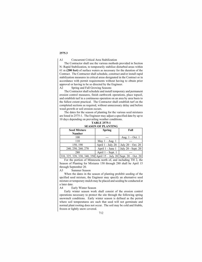
2575.3
712
A1 Concurrent Critical Area Stabilization The Contractor shall use the various methods provided in Section N- Rapid Stabilization, to temporarily stabilize disturbed areas within 61 m (200 feet) of surface waters as necessary for the duration of the Contract. The Contractor shall schedule, construct and/or install rapid stabilization measures in critical areas designated in the Contract or in accordance with permit requirements without having to obtain prior approval or having to be so directed by the Engineer. A2 Spring and Fall Growing Seasons The Contractor shall schedule and install temporary and permanent erosion control measures, finish earthwork operations, place topsoil, and establish turf in a continuous operation on an area by area basis to the fullest extent practical. The Contractor shall establish turf on the completed sections as required, without unnecessary delay and before weed growth or soil erosion occurs. The dates for the season of planting for the various seed mixtures are listed in 2575-1. The Engineer may adjust a specified date by up to 10 days depending on prevailing weather conditions.
TABLE 2575-1 SEASON OF PLANTING
Seed Mixture Number
Spring Fall
100 --- Aug. 1 – Oct. 1 110 May 1 – Aug. 1 ---
150, 190 April 1 - July 20. July 20 – Oct. 20240, 250, 260, 270 April 1 - June 1 July 20 - Sept. 20
280 April 1 – Sept. 1 --- 310, 325, 328, 330, 340, 350 April 15 – July 20 Sept. 20 – Oct. 20
For the portion of Minnesota north of, and including TH 2, the Season of Planting for Mixtures 150 through 280 shall be April 15 through September 20. A3 Summer Season When the dates in the season of planting prohibit seeding of the spcified seed mixture, the Engineer may specify an alternative seed mixture or temporary mulch may be placed and seeding be conducted at a later date. A4 Early Winter Season Early winter season work shall consist of the erosion control operations necessary to protect the site through the following spring snowmelt conditions. Early winter season is defined as the period where soil temperatures are such that seed will not germinate and normal plant rooting does not occur. The soil may be cold and friable, frozen or lightly snow covered.
2575.3
713
A4a Dormant Seeding Dormant seeding shall be defined as seeding done on exposed cold soils so that normal seed germination does not occur until the following spring. Dormant seeding shall occur after October 20 and when soil temperatures at a depth of 25 mm (1 inch) are at or below 4 ºC (40 ºF). In wind swept areas, exposed sites, and areas where dormant seeding does not typically establish well, temporary mulch may be ordered by the Engineer in lieu of dormant seeding. Snow seeding shall be defined as seeding over the top of snow so that the seed melts through the snow and germinates upon warm up in the spring. Snow seeding can be done during the thawing days in February and March. A4b Winter Mulching Snow mulching shall be defined as mulch material spread over the top of snow so that the mulch melts through the snow and sticks to the site. All mulch materials listed under specification 3882 may be placed as snow mulching. Frozen ground mulching shall be defined as mulch material spread over frozen ground. Mulch materials Type 4, 5, 6 and 9 that do not require disc anchoring into the soil may be placed without modification. Mulch Types 1, 7 and 8 may be anchored with Type 1 or Type 6 hydraulic soil stabilizers or may be "frozen" to the soil by applying water over the mulch. Applying water at the rate of 19 m3/ha (2000 gallons per acre) can be used as a direct substitution for disc anchoring. A4c Dormant Sodding
The Contractor may place sod at locations at least 3 m (10 feet) from the shoulder, on slopes, and in ditches as dormant sodding after November 1 when all of the following conditions are met: (a) The Engineer authorizes dormant sodding. (b) The soil is prepared for sodding, either frozen or unfrozen. (c) The sod on slopes and in ditches is pegged or stapled. (d) The sod is watered to saturation immediately after placement. (e) The sod is watered a second time, or receives 25 mm (1 inch) of rain, 7 to 10 days after placement. The Engineer may also accept a heavy snowfall instead of the second watering. A4d Winter Erosion Control Blanket Installation Erosion control blankets may be installed over frozen ground. However, 150 mm (6 inch) long nails with washers can be used to anchor the blanket in lieu of staples.
2575.3
714
A4e Application of Commercial Fertilizer Commercial fertilizer shall not be placed over frozen ground or snow. The application of fertilizer shall occur after the runoff from spring snowmelt has ceased. B Grading Preparations Prior to Seeding All washouts on the areas to be permanently seeded, sodded or have temporary erosion control materials installed shall be filled prior to the soil loosening operations. Topsoil shall be placed to the depths indicated in the Plans. Fill material shall be compacted sufficiently to provide reasonably uniform density in the upper soil layer to resist erosion. Drainageways shall be shaped and the soil loosened prior to placing sod or erosion control blankets. B1 Grading Prior to Temporary Seeding or Erosion Control Installation
When installing erosion control materials in locations where the final topsoil grade has not be established, the Contractor shall provide smooth-rough grading to allow for adequate installation of erosion control materials and/or temporary seeding. The smooth-rough grading shall remove large clods of soil greater than 75 mm (3 inches) in diameter and ruts deeper than 75 mm (3 inches) and shall be incidental to the Project for which no direction compensation will be made. B2 Tillage
Immediately prior to sowing the seed or placing sod, the Contractor shall loosen the soil to a minimum depth of 75 mm (3 inches) on all areas except slopes steeper than 1 vertical to 2 horizontal, using disks, harrows, field diggers or other suitable cultivating equipment. All track imprints from wheeled or tracked equipment shall be tilled out of the soil surface. In compacted areas, the Contractor shall rip, use additional equipment, or other necessary measures to ensure proper soil loosening. On slopes the cultivating equipment shall be operated in a general direction at right angles to the direction of surface drainage wherever practical. The soil surface shall be left in a roughened condition with clods, lumps, and tillage ridges approximately 75 mm (3 inches) high left in place for maximum resistance to erosion. No additional loosening of the soil will be required on slopes steeper than 1 vertical to 2 horizontal, other than that obtained with the equipment used in removing vegetation or performing the finishing operations. Vegetation other than undesirable weeds shall be disked into the soil, cleared, or chopped up with a rotary or flail mower.
On all areas to be sodded, the Contractor shall prepare the soil surface as necessary to provide a reasonably smooth, moist, and evenly textured foundation. The soil shall be loosened to a minimum depth of 75 mm (3 inches) prior to sodding.
2575.3
715
C Applying Fertilizer and Conditioners The Contractor shall apply fertilizers, compost, and liming
materials, where specified, at the rates indicated in the Contract, using mechanical spreading devices to the fullest extent practical, and providing uniform distribution of the material over the designated areas. Lime application rates specified in the Contract are based on 500 kg ENP per metric ton (1000 pounds ENP per ton) of Agricultural Liming Material. The actual lime application rate shall be adjusted to supply 500 kg ENP per metric ton (1000 pounds ENP per ton) of liming material. The Contractor shall apply fertilizer, lime or compost prior to the seeding or sodding. The soil shall be tilled at least once, within 24 hours, following the application of fertilizer, lime or compost and prior to the seeding or sodding. Where fertilizer is required on sodding areas, it shall be applied prior to placing the sod. Where fertilizer is required on seeded areas, the time between fertilizing and seeding shall not exceed 48 hours.
When approved by the Engineer, the Contractor may use Grade 1 compost at an equivalent nutrient application rate in lieu of commercial fertilizer. D Sowing Seed
The Contractor shall ensure that the seed is stored properly between the time of purchase and installation. Industry standards for seed storage are 50 degrees Fahrenheit and 50% humidity. The Contractor shall protect the seed from moisture until it is sown. Wet or moldy seed shall not be used.
The Contractor shall sow the seed uniformly at the rate of application specified in Table 2575-2.

2575.3
716
TABLE 2575-2 SEED MIXTURE APPLICATION RATES
Seed Mixture Number Application Rate
(kg/ha) Application Rate
(pounds/acre) 100, 110 112 100
150 44.8 40 190 67.2 60 240 84 75 250 78.6 70 260 112 100 270 134.4 120 280 56 50 310 91.8 82 325 92.8 84 328 96.8 88
330, 340, 350 94.6 84.5
The Contractor shall sow seed on a prepared seedbed prior to applying mulch and as otherwise directed by the Plan or approved by the Engineer. The Contractor shall firm the seeded areas after seeding and prior to mulching. The soil firming shall be done with a drag, cultipacker, or other approved soil firming equipment. On slopes too steep to operate mechanical equipment, the seed shall be covered by hand raking or other approved means prior to mulching. Soil firming or seed covering shall be accomplished immediately after seeding.
On all seeding areas within 3 m (10 feet) of the shoulder, the Contractor shall seed and immediately firm the seedbed, mulch, and anchor the mulch as a continuous operation. Should the mulch application or mulch anchoring be delayed so that the seed or mulch becomes dislodged by traffic or wind, the affected areas shall be reseeded and remulched at no expense to the Department.
On areas outside 3 m (10 feet) of the shoulder, no more seed shall be sown on any day than can be mulched within 24 hours. Should the mulch application be delayed more than 24 hours, the Engineer may order the area reseeded and remulched at no expense to the Department.
The Contractor shall not broadcast seed or hydroseed when the wind velocity exceeds 25 km/h (15 mph) or during gusts that would affect seed placement.

2575.3
717
D1 Temporary Seeding Temporary seeding may be required on graded areas where the permanent seeding cannot be performed. For this purpose winter wheat, oats or other seed mixtures as determined by the Engineer will be used. Topsoil covering may not be required for temporary seeding if the subsoil is reasonably suitable for plant growth, as determined by the Engineer. Soil preparation for temporary seeding shall be the same for permanent seeding except for areas such as stockpiles. Temporary seeding shall be accomplished in accordance with Seeding of Traditional Mixes. D2 Seeding Traditional Seed Mixes
Mixtures 100 through 280 inclusive shall be sown by means of mechanical or hydro spreading of the seeds at the specified rate of application. The use of hand operated mechanical spreaders will be permitted only on areas that are inaccessible to, or too small for, the specified equipment. If a seed drill of the agricultural type is used, the drill shall be operated in a general direction at right angles to the direction of surface drainage, wherever practical, and the seed shall not be sown to a depth greater than 10 mm (3/8 inch). Small seed species such as timothy, alfalfa, white clover, red clover, etc., shall be sown through the grass seed attachment or by other approved means. D3 Seeding Native Mixes
Native mixes (305-350) can be seeded with a native seed drill, a drop type seeder or a hydroseeder. The drill shall accurately meter the types of seed to be planted and keep all seeds uniformly mixed during drilling. The drill shall be equipped with disk furrow openers and packer assembly to compact the soil directly over the drill row. Maximum row spacing shall be 200 mm (8 inches). Depth of seed placement shall be such to obtain a final planting depth of 3 to 10 mm (1/8 to 3/8 inch). In lieu of a drill with disc openers, a drop type seeder that is equipped with a fluffy seed box and a "Brillion type" soil packer assembly may be used. All drill seeding shall be done at a right angle to surface drainage. The Engineer may allow the use of a cyclone or spinner type seeder on small areas (0.4 ha (1 acre) or less) or on areas that are inaccessible to other equipment. The rate of application must be adjusted according to the percent Pure Live Seed (PLS) in the mixture combined with the bulk portion of seed mixture. The bulk seeding rate for PLS species is determined by the following formula:
Bulk Application (kg or lbs) = (kg or lbs. PLS)/(% PLS) % PLS = % Germination x % Purity

2575.3
718
D4 Hydroseeding When a hydroseeder is used, every effort shall be taken to obtain a uniform distribution over the seeded area. A tracer, 22.5 kg (50 pounds) of 3884 Type 5 or 6, shall be added to each 1.9 m3 (500 gallons) of water in the hydroseeder tank to visually inspect the uniformity of the seed application. The hydroseeder shall have continuous agitation action that keeps the seed mixed in the water slurry until pumped from the tank and the pump pressure shall be such that a continuous nonfluctuating stream is maintained. Flood type nozzles shall be used to the fullest extent possible along with sufficient water volume to obtain total ground coverage. During application the spray shall be directed to obtain a uniform material distribution as evidenced by a uniform wetting of the soil surface. If a non-uniform distribution results (such as skipped areas and saw tooth patterns), the affected areas shall be reseeded at no expense to the Department. The seed or seed/fertilizer mixture shall be emptied within 1 hour after the seed is added to the tank. Seed that is allowed to remain mixed with the fertilizer for a period longer than 1 hour will not be accepted for use and no compensation will be made for seed so rejected. D5 Interseeding
Interseeding may be used for seeding into temporary mulched areas or for drilling additional seed into previously seeded areas. The interseeding drill shall contain trash rippers and at least two seed boxes, a fine seed box and a box for larger or fluffy seeds. The drill shall slice through the vegetative mat and make a 25 mm (1 inch) wide by 10 to 25 mm (3/8 to 1 inch) deep furrow into the underlying soil. The drill seed disk openings shall place seeds in the furrows. The drill shall drop the seed onto the ground surface from the fine seed box and place the large or fluffy seed to a final planting depth of 6 to 10 mm (1/4 to 3/8 inch). D6 Permanent Seeding into Temporarily Mulched/Blanketed Areas The Contractor shall permanently seed areas that have previously been temporarily mulched. Without additional tillage or site prep work, the Contractor may use an approved interseeding drill and drill seed directly into temporarily mulched or temporarily seeded areas. In lieu of using an interseeding drill, the Contractor may lightly disc the mulched areas and then conduct the seeding. Fertilizer shall be applied within 24 hours of interseeding or light disking. The Contractor shall leave existing cover in place as practical for its mulching value. Seeding into previously placed erosion control blankets can be accomplished by attaching a hose to a hydroseeder and "blasting" a
2575.3
719
seed/water solution into the blanket. Blasting the seed/water solution shall be done form a distance of approximately 2 m (6 feet) away. E Temporary Mulching
Temporary mulching shall be defined as placing mulch over broad large areas, generally 0.8 ha (2 acres) or more, to protect the overall site during the period of time when seeding cannot be performed. Temporary mulching shall be used to supplement other erosion control best management practices of establishing permanent vegetation or the rapid stabilization of critical areas within 61 m (200 feet) of surface waters. The provisions for temporary mulching may be used where the provisions for rapid stabilization (Section N) do not apply. In areas where temporary mulch is placed, the Contractor shall shape the area, loosen the soil as necessary, mulch and anchor the mulch. F Applying Mulch
The Contractor shall spread mulch by mechanical means to provide a uniform distribution at the target application rate specified. When poor mulch distribution occurs, the Contractor will be required to remulch areas where coverage is too light and remove the excess where coverage is too heavy as determined by the Engineer.
The Contractor shall not operate mulch-blowing equipment on slopes that are too steep for the equipment or that cause rutting of the soil surface (slopes 1:4 and steeper). Blower attachments shall be used such that the mulch can be applied without having to traverse the slopes. The Contractor shall regrade, reseed and remulch slopes that are rutted up at the Contractor's expense. F1 Type 1, 3, 7, and 8 Mulches
Wherever possible, Type 1, 3, 7, and 8 mulches shall be placed with blower equipment. The target rate of application shall be 4.5 metric tons (t) per hectare (2 tons per acre). The actual rate of application shall be as directed by the Engineer to match varying material or Project conditions so that approximately 10 percent of the soil surface is visible through the mulched areas. F2 BLANK F3 BLANK F4 Type 4 Mulch
Type 4 mulch shall be applied as a dual operation with the Type 1 mulch blown on the soil surface at 3.4 metric tons per hectare (1 ½ tons per acre) and immediately over-sprayed with Type 5 hydraulic soil stabilizer at 840 kg/ha (750 pounds per acre). Seeding and fertilizing shall be done prior to mulching, not in conjunction with Type 5 hydraulic soil stabilizer placement. Disk anchoring will not be required.
2575.3
720
F5 Type 5 Mulch Type 5 mulch shall be applied at a rate of 150 m3/ha (80 cubic yards per acre) when specified as an erosion control material. F6 Type 6 Mulch
The rate and application procedure for Type 6 mulch shall be as specified in the Plans or Special Provisions. F7 BLANK F8 BLANK F9 Type 9 Mulch
The Contractor shall apply Type 9 (aggregate) mulch at a rate of application as stated in the Contract. Prior to placing the mulch, the Contractor shall uniformly compact and smooth the foundation, cover the foundation with a 150 µm (6 mil) plastic sheeting, and then uniformly spread the aggregate mulch to the Plan thickness by a method that does not harm the foundation. The Contractor shall level the finished aggregate surface so that it is flush with adjacent areas. The plastic sheeting is an incidental cost to the completed work. F10 Shoulder Mulch Overspray
Shoulder mulch overspraying shall consist of Type 1 Hydraulic Soil Stabilizer sprayed onto Type 1 mulch on a 1 meter (yard) wide strip immediately abutting a gravel or paved shoulder. During placement, the Contractor shall seed, firm the seedbed, place Type 1 mulch, immediately disk anchor the mulch (if provided for in the Contract), and then uniformly overspray with, Type 1 Hydraulic Soil Stabilizer as a continuous operation. Wherever possible, the Type 1 Hydraulic Soil Stabilizer shall be sprayed with a distributor spray bar. Application rate for the Type 1 Hydraulic Soil Stabilizer shall be 220 kg/ha (200 pounds per acre). Shoulder mulch overspray will be for those areas designated in the Plans and will be paid for under the Type 1 Hydraulic Soil Stabilizer pay item. G Disk Anchoring
Where provided for in the Contract, the Contractor shall anchor Type 1, Type 3, Type 7, and Type 8 mulches with a disk anchoring tool. This equipment shall anchor the mulch by punching it into the soil to a depth of 50 to 75 mm (2 to 3 inches). Spacing between the blades or disks shall not exceed 200 mm (8 inches). The mulch shall be anchored immediately after placement unless otherwise authorized by the Engineer. H Hydraulic Soil Stabilizers H1 Type 1 Natural Tackifier
Natural tackifiers are added to water and applied by a hydrosprayer. Natural tackifiers can be used by themselves, as an additive to other soil stabilizers, or as an overspray on mulched areas. When used as an

2575.3
721
additive to other soil stabilizers, they shall be added at the rate specified by the manufacturer. When used as an overspray on mulched areas, they shall be applied at the rate specified by the manufacturer. During placement, every effort shall be taken to obtain a uniform distribution over the target area. H2 BLANK H3 BLANK H4 BLANK H5 Type 5 and 6
Type 5 or 6 shall be applied with hydraulic spray equipment in a water-slurry at the rate of 2353 kg/ha (2100 pounds per acre). For planning purposes, the approximate water to bale ratio is 475 L of water per 22.7 kg bale (100 gallons of water per 50 pound bale); however the actual water to bale ratio shall be in accordance with the manufactures recommendations. Using the color of the material as a metering agent, the slurry shall be uniformly sprayed on the prepared seedbed. The Engineer may verify, by inspection of tank loading and spray application, that materials applied correspond with the application requirements within reasonable limitations. H7 BLANK H8 Type 8 Bonded Fiber Matrix (BFM)
Type 8 hydraulic soil stabilizer shall be applied with hydraulic spray equipment by a manufacturer's certified applicator. Seeding shall be done as a separate operation prior to the BFM application whenever possible. The combination of seed and BFM as a single operation will be allowed in small or inaccessible areas as determined by the Engineer. Installation rate shall be between 3300 and 4620 kg/ha (3000 and 4200 pounds per acre) depending on site characteristics as provided for in the plans. The general application rate shall be 3850 kg/ha (3500 pounds per acre). For planning purposes, the approximate water to bale ratio is 380 L/22.7 kg (100 gallons per 50 pound) bale; however the actual water to bale ratio shall be in accordance with the manufactures recommendations. In all cases 100% continuous ground coverage shall be obtained. Application shall be done on dry soils (field capacity or less) and at least 24 hours in advance of projected rainfall to allow adequate drying time. The BFM shall be applied from at least two alternate directions, preferably 90 degrees apart, to ensure all soil surfaces are covered. For application rates of 3850 kg/ha (3500 pounds per acre) and above, the BFM shall be applied in two stages (one half rate each) with ample time between stages for the first application to dewater. BFM shall not be used in water bearing soils or by itself in ditch bottoms carrying concentrated flow. After the BFM soil stabilizer is applied and dries for 24 to 48 hours, the Engineer may sample and
2575.3
722
quantify a portion of the installation to ensure the minimum specified rate has been applied. If it is found that the specified quantity per acre has not been achieved, the Contractor shall apply an additional amount to equal the specified rate within 48 hours of receiving the test results. The Contractor shall not be paid extra mobilization costs for spraying additional material. I Placing Sod
Before sod is delivered to the work site, the Contractor shall have all necessary equipment and forces available and shall have prepared the sodding areas sufficiently in advance in accordance with 2575.3B to avoid delays in placing the sod. The Contractor shall place sod according to the Plan and these requirements.
The Contractor shall place sod strips with staggered end joints and without stretching, in such a manner that all edges will firmly abut the edges of adjoining strips. In no case shall the sod be placed so loosely or under such tension that it will cover an area larger than the area from which it was originally lifted.
Joints between the sod and in-place improvements such as curbs, walks, and existing turf, shall abut tightly and shall be such that drainage will be conducted over the surface. Elsewhere, the outside edges of the sodded areas shall be rolled in or banked flush with soil, thoroughly compacted to form a flush surface as directed by the Engineer. The Contractor shall place the sod in such a manner that surface drainage along the boundary of the sodded area will not erode or undermine the sod.
The Contractor shall water and compress the sod into the soil by rolling or tamping while laying the sod or immediately after completing the sod placement on each area. The initial watering and rolling or tamping shall be sufficient to provide a firm contact and bond between the sod and the underlying soil and provide a smooth, even surface free of humps and depressions, but in no case shall the rolling or tamping result in excessive compaction. The Engineer may require the watering of areas to be sodded prior to the sod placement.
The Contractor shall repair damaged areas within 5 working days after completing the sod placement and rolling or tamping operations. This repair work shall include reseeding and remulching of any seeded or mulched areas adjacent to the sod. All waste sod, together with any stones or other debris removed from the sodding areas, shall be disposed of in a manner satisfactory to the Engineer.
The Contractor is responsible for successful establishment of the sod and shall replace or repair displaced or damaged sod during the maintenance period. The Contractor may peg or staple sod to prevent displacement.
2575.3
723
I1 Slopes The Contractor shall carefully place sod strips from the bottom of
the slope and progress upward. The sod shall be placed with the longitudinal axis of each strip at right angles to the slope. Staking or stapling may be required to prevent slumping or displacement of the sod. At the top of the slope, the sod must be trenched 75 mm (3 inches) into the topsoil on slopes steeper than 1V:4H. I2 Ditch Bottoms
In ditch bottoms and other waterways where a concentrated flow of water is expected, the sod shall be placed so that the longitudinal axis of each strip is parallel to the direction of water flow in the main channel. The end of the strips will overlap a minimum of 100 mm (4 inches) with the upstream end on top of the downstream end. The sod will also be shingled and overlap a minimum of 75 mm (3 inches) on the sides of the strips. When shingled properly, the water will flow over, NOT under, from one roll of sod to the next. The uppermost strip of sod will have 75 mm (3 inches) of sod trenched into the topsoil on side-slopes steeper than 1:4.
The sod shall have netting material that is either incorporated into the rooting material of the sod during initial growth, or placed on the bottom of the sod mat at the time of harvest. Alternatively, Type 1 netting may first be secured in the ditch bottom followed by sod placement.
The sod shall be stapled once it has been put in place. All joints and outer edges of the sod shall be stapled at 0.9 m (3 feet) intervals or less. Staples shall be placed throughout the sod at a minimum spacing of 2 staples/m2 (square yard). All staples shall be inserted flush with the ground surface. J Placing Erosion Netting, and Blankets J1 Erosion Control Netting
Netting placed in ditch bottoms, flumes or water courses shall be rolled out flat, parallel to the direction of water flow. Netting placed on cut or fill slopes shall be rolled out flat, parallel or perpendicular to the direction of water flow. The edges of adjacent strips shall overlap a minimum of 50 mm (2 inches) and a maximum of 100 mm (4 inches), with the net on the upstream side of any lateral water flow being on the top.
The netting shall be secured in place by means of wire staples driven reasonably vertical into the soil. The netting shall not be stretched prior to stapling. Staples shall be placed 1 m (3 feet) apart along the ends and edges of each strip. Additional rows of staples shall be placed parallel to the edge row of staples so that the distance
2575.3
724
between adjacent rows does not exceed 1 m (3 feet). Staples shall be placed 1 m (3 feet) apart within these rows. Where possible, staples of adjacent rows shall be placed so as to form a sawtooth pattern. J2 Erosion Control Blankets
The Contractor shall shape and prepare the site so it is free of large rocks, soil clumps or vehicle imprints that would prevent the blanket from lying flush to the surface contours. The Contractor shall place the blankets as specified in the Contract on the specified areas within 24 hours after sowing of the seed on that area.
The Contractor shall roll out or lay the blankets parallel to the direction of water flow, with the netting on top. For blankets with netting on two sides, the bottom side of the blanket shall show the majority of the thread stitching. The blankets shall be spread evenly without stretching, and so the fibers are in direct contact with the soil over the entire area. Adjacent strip edges shall overlap each other at least 102 mm (4 inches). Strip ends shall overlap each other at least 178 mm (7 inches). All overlaps shall be made with the upgrade strip placed over the down grade blanket strip. All overlaps for all Categories, excluding category 0, shall be stapled at ½ m (1 ½ foot) intervals.
At the top of slopes and the beginning of each blanket in ditch bottoms the Contractor shall bury the upgrade end of the blanket strip in a check slot. The check slot, or trench, shall be approximately 150 mm (6 inches) wide by 150 mm (6 inches) deep. The blanket end shall be inserted into the check slot such that the blanket is in contact with all three sides of the check slot. The blanket shall be stapled in the bottom of the trench every 0.3 m (1 foot). The check slot shall be backfilled and compacted. When a slope length is greater than 30 m (100 feet), a second check slot shall be dug perpendicular to the slope gradient one-third up from the bottom of the slope. The blanket shall follow the slope down into the check slot and back up to the slope gradient. This check slot shall also be stapled, backfilled and compacted.
Category 00 blankets shall be stapled on the edge of the blanket every 1 m (3 feet) and watered in to bond the blanket to the soil. All other blankets, excluding category 00, shall be anchored to the soil surface with evenly distributed staples through out the blanket at the rate specified in Table 2575-3. All staples shall be inserted flush with the ground surface.
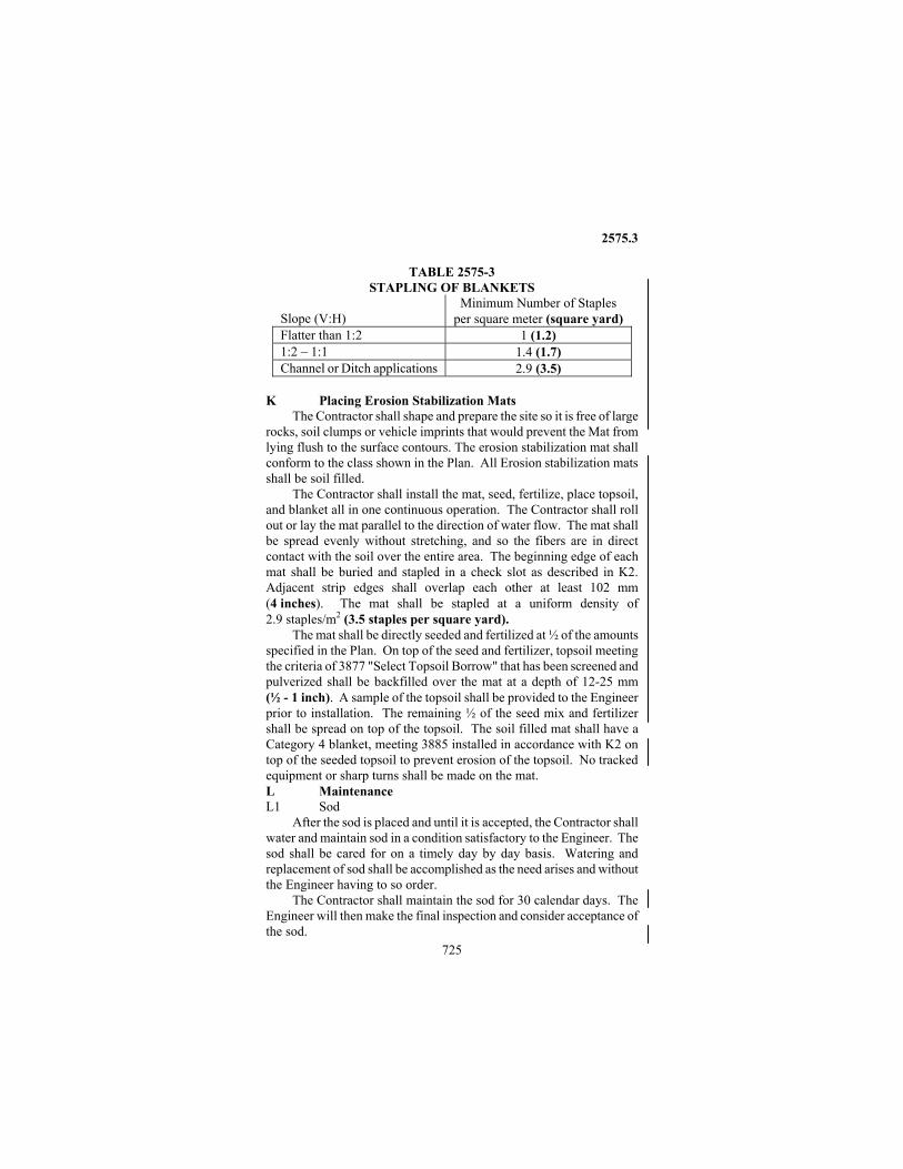
2575.3
725
TABLE 2575-3 STAPLING OF BLANKETS
Slope (V:H)
Minimum Number of Staples per square meter (square yard)
Flatter than 1:2 1 (1.2) 1:2 – 1:1 1.4 (1.7) Channel or Ditch applications 2.9 (3.5)
K Placing Erosion Stabilization Mats
The Contractor shall shape and prepare the site so it is free of large rocks, soil clumps or vehicle imprints that would prevent the Mat from lying flush to the surface contours. The erosion stabilization mat shall conform to the class shown in the Plan. All Erosion stabilization mats shall be soil filled.
The Contractor shall install the mat, seed, fertilize, place topsoil, and blanket all in one continuous operation. The Contractor shall roll out or lay the mat parallel to the direction of water flow. The mat shall be spread evenly without stretching, and so the fibers are in direct contact with the soil over the entire area. The beginning edge of each mat shall be buried and stapled in a check slot as described in K2. Adjacent strip edges shall overlap each other at least 102 mm (4 inches). The mat shall be stapled at a uniform density of 2.9 staples/m2 (3.5 staples per square yard).
The mat shall be directly seeded and fertilized at ½ of the amounts specified in the Plan. On top of the seed and fertilizer, topsoil meeting the criteria of 3877 "Select Topsoil Borrow" that has been screened and pulverized shall be backfilled over the mat at a depth of 12-25 mm (½ - 1 inch). A sample of the topsoil shall be provided to the Engineer prior to installation. The remaining ½ of the seed mix and fertilizer shall be spread on top of the topsoil. The soil filled mat shall have a Category 4 blanket, meeting 3885 installed in accordance with K2 on top of the seeded topsoil to prevent erosion of the topsoil. No tracked equipment or sharp turns shall be made on the mat. L Maintenance L1 Sod
After the sod is placed and until it is accepted, the Contractor shall water and maintain sod in a condition satisfactory to the Engineer. The sod shall be cared for on a timely day by day basis. Watering and replacement of sod shall be accomplished as the need arises and without the Engineer having to so order.
The Contractor shall maintain the sod for 30 calendar days. The Engineer will then make the final inspection and consider acceptance of the sod.

2575.3
726
During the maintenance period, the Contractor shall promptly replace all sod that dries out to the point where it is presumed dead, and all sod that has been damaged, displaced, or weakened to the point where its replacement is necessary, or has become heavily infected with weeds. Areas replaced with new sod shall be maintained by the Contractor for at least 20 calendar days after placement. L2 Erosion Control Blanket and Erosion Stabilization Mats
The Contractor shall maintain the erosion control blanket installation for 30 days when specified in the Contract or when the Engineer allows erosion control blankets and seed to be substituted for sod. All Erosion Stabilization Mats shall be maintained by the Contractor for 30 calendar days. Maintenance consists of thoroughly watering the blankets and mat systems immediately after placement (28 m3/ha (3000 gallons per acre)), with additional watering performed as necessary. Until acceptance, the Contractor shall be responsible for controlling erosion and establishing a permanent vegetative cover to the satisfaction of the Engineer. In the event of seeding failure or erosion during the maintenance period, the Contractor shall restore such areas at no additional cost to the Department. L3 Sod Alternatives
When other products and methods are used in lieu of sod, the area shall be maintained by the Contractor ensuring the same outcome as a sodded area. Weeds shall be controlled and the maintenance requirements of specification 2575.3L2 shall apply. L4 Mulch
When so directed by the Engineer, the Contractor shall, at any time before completion of the Project, remulch any areas on which the original mulch has eroded, washed away, or blown off, and reseed any areas on which the original seed has failed to grow, using the project seed mixture or one prescribed by the Engineer. L5 Mowing and Weed Spraying
When the Contract includes items for mowing or weed spraying, the Contractor shall perform the specified work one or more times, wherever and whenever the Engineer directs, either on the areas seeded or sodded under the Contract. The equipment used shall not be so heavy that it causes soil slips or ruts on the slopes or in the ditches.
The Engineer may order weed spraying wherever heavy weed growth exists within the Right of Way. The weed spray mixture to be furnished and used shall be as provided in the Plans. The Contractor shall be responsible for performing the work at such time and in such a manner that will avoid spray drift outside the areas designated for spraying.

2575.3
727
L6 General Until final inspection and acceptance of the work is made, the
Contractor shall use due care to protect the site during the time vegetation is establishing. Additional seed and mulch material used for reseeding and remulching and repairing damaged areas beyond the Contractor's control will be measured and paid for at the Contract prices, provided the original work was performed satisfactorily in accordance with requirements. M Turf Establishment, Lump Sum
Turf Establishment may be specified in the Plans as a lump sum bid item for establishing vegetation on small areas of 1 ha (2 ½ acres) or less per Contract. The lump sum item shall be considered to provide for restoring disturbed areas. Such work shall include tilling, fertilizing, mulching and establishment of vegetative cover. Under this provision the Contractor shall be responsible for controlling erosion and establishing a permanent vegetative cover to the satisfaction of the Engineer.
Unless otherwise specified in the Plans, the Contractor may establish vegetative cover by sodding or by seeding and mulching. If the Contractor elects to establish vegetative cover by seeding, seed furnished and placed shall consist of a mixture of desirable perennial grasses and legumes equivalent to that contained in 3876 for Mixture 250. Upon seeding, the areas shall be fertilized with 22-5-10 analysis slow release fertilizer (see 3881.2) at 330 kg/ha (300 pounds per acre) and mulch equivalent to 3882, Type 1 shall be furnished and placed to prevent erosion and siltation. Acceptance of the areas by the Engineer will not be made until it is evident that the seed so placed has germinated and will establish an adequate protective cover. In the event of seeding failures, the Contractor will be required to correct and reseed such areas at no expense to the Department until adequate turf is established. When sod is used, the placement, maintenance, and acceptance shall be as specified in 2575.3. N Rapid Stabilization This work shall consist of operations necessary to rapidly stabilize small critical areas within 61 m (200 feet) of Surface Waters, to prevent off site sedimentation and/or to comply with permit requirements. The work shall be performed numerous times during the Contract and will be conducted on several small areas that may or may not be accessible with normal equipment. This work shall be done in accordance with the applicable details and locations shown in the Plan. The methods may be conducted independently or in combination. One or several locations may be stabilized by the Contractor per site visit per calendar

2575.3
728
day. The number of locations stabilized per site visit or per calendar day will not justify an adjustment in the Contract unit price. The materials required shall be as follows: Method 1 Type 1 Mulch @ 4.5 metric ton/ha (2 tons per acre)
Disc anchoring Method 2 Type 1 Mulch @ 3.4 metric ton/ha (1.5 tons per acre)
Type 5 Hydraulic Soil Stabilizer @ 840 kg/ha (750 pounds per acre)
Method 3 Type 6 Hydraulic Soil Stabilizer @ 160 kg/ 3.8 m3 of slurry mix (350 pounds per 1000 gallons of slurry mix) Seed mixture 190 @ 4.5 kg/3.8 m3 of slurry mix (10 pounds per 1000 gallons of slurry mix) Fertilizer 10-10-20 @ 22.7 kg/ 3.8 m3 of slurry mix (50 pounds per 1000 gallons of slurry mix) Water @ 3.3 m3/3.8 m3 of slurry mix (875 gallons per 1000 gallons of slurry mix) Note: 3 m3 (1000 gallons) of slurry mix will cover 0.067 ha (1/6 acre).
Method 4 Erosion Control Blanket Category 3 Seed mixture 190 @ 1.1 kg/100 m2 (2 pounds per 100 square yards) Fertilizer 10-10-20 @ 4.3 kg/100 m2(8 pounds per 100 square yards)
Method 5 Rip Rap Class II Geotextile Type III
N1 Placement Method 1 Prior to placement the soil surface should be in a loose condition so that the mulch can be anchored. The mulch shall be placed to obtain approximately 90% ground coverage. Wherever possible, the mulch shall be placed by blower equipment. In inaccessible areas the mulch may have to be placed by hand. Immediately after placement, the mulch shall be anchored with a disc anchoring tool. The approximate area of coverage is 0.2-0.8 ha (½-2 acres). Method 2 Prior to placement the soil surface should be in a loose condition. The mulch shall be placed to obtain approximately 75% ground coverage. Wherever possible, the mulch shall be placed by blower equipment. In inaccessible areas the mulch may have to be placed by hand. Immediately after placement, the mulch shall be over-sprayed

2575.3
729
with Type 5 Hydraulic Soil Stabilizer at a rate of 840 kg/ha (750 pounds per acre). The approximate area of coverage is 0.2-0.8 ha (½-2 acres). Method 3 Rate of slurry application shall be variable depending on surface roughness, slope configuration and degree of undulation but it is expected that 56 m3 of slurry will be needed per hectare (6 M gallons per acre). This rate is equivalent to applying Type 6 Hydraulic Soil Stabilizer at 2353 kg/ha (2100 pounds per acre). Amount of material applied shall be such to obtain 100% soil surface coverage. In inaccessible areas, the mix may be pumped through a hose. The approximate quantity of coverage is 11.4-34 m3 (3000-9000 gallons) of slurry. Method 4 The fertilizer, seed and erosion control blanket shall be placed as described in 2575.3. The upgrade end of each blanket strip shall be buried at least 150 mm (6 inches) in a vertical check slot. Staples shall be placed at seams and throughout the blanket at a maximum spacing in all directions of 0.6 m (2 feet). The approximate area of coverage is 75 – 650 m2 (100 – 800 square yards). Method 5 Rock and geotextile shall be placed in the areas and to the configurations as directed by the Engineer. The approximate quantities per Project visit are 9-18 metric tons (10-20 tons). O Acceptance of Work
The Contractor shall notify the Engineer at least 24 hours in advance of beginning and also of changing turf establishment operations. The Contractor shall schedule working hours according to 1803. Work done without notification, without inspection according to 1511, or outside of the scheduled working hours without prior approval will be considered as unauthorized work. Turf establishment that is not verified by inspection in accordance with 1511 will be considered as unauthorized work. O1 Seeding
The Engineer will generally accept permanent seeding in area increments once the seed has been properly placed in accordance with the specifications. After acceptance of seeding by the Engineer, the Contractor is relieved of responsibility for further maintenance and repair of the seeding and mulching performed on the area accepted, except for the repair of damages due to causes entirely within the Contractor's control.

2575.3
730
O2 Mulching The Engineer will accept mulching 2 days after initial placement.
Areas where the mulch has blown off or washed away during the 2 day period will be remulched at no expense to the Department. O3 Sod
Upon satisfactory placement of the sod, the Engineer may authorize partial payment not exceeding 80 percent of the Contract bid price. The remaining percentage shall not become due and payable until expiration of the sod maintenance period, and then only as otherwise provided for in the Contract.
Upon expiration of the sod maintenance period on individual areas or sections of the Project, the Engineer will make an inspection of the work and will accept all sod that is in normal, healthy growing condition. No payment will be made for sod that is not in acceptable condition at the time of the final inspection an amount will be deducted from any moneys due or that may become due the Contractor equal to 100 percent of the Contract bid price per unit of measure of unacceptable sod. Sod that is within 3 m (10 feet) of the shoulder or is directly abutting a roadway surface that is acceptably maintained, but dies out due to salt or winter maintenance activities beyond the Contractor's control, may be paid for at 100 percent of Contract price provided that the sod has been maintained for at least 20 calendar days prior to December 1. O4 Erosion Netting, Blankets and Stabilization Mats
When maintenance is not specified in the Contract, the Engineer will accept blankets and erosion control netting and mats, at the time of acceptance of the sodding or seeding over which the materials are properly placed.
When maintenance is specified as an integral part of a erosion control blanket installation or stabilization mat the Engineer may authorize partial payment for the installation in an amount not exceeding 80 percent of the Contract bid price. The remaining percentage shall not become due and payable until final acceptance by the Engineer. O5 Products Used in lieu of Sod
When other products or methods are used in lieu of sod, the Engineer may authorize partial payment not exceeding 80% of the substituted product price upon proper placement. The remaining percentage shall not become due and payable until the expiration of the maintenance period, and then only as acceptable to the Engineer. O6 Hydraulic Soil Stabilizers Hydraulic soil stabilizers, except for Type 8, will be accepted upon satisfactory placement. Acceptance of acres covered by Type 8 will be

2575.3
731
made by the Engineer when it is evident that the seed placed has germinated and will establish an adequate protective cover. In the event of seeding failures or erosion, the Contractor will be required to correct and reseed such areas at no expense to the Department until adequate vegetative cover is established. Upon proper placement of Type 8 the Engineer may authorize partial payment for the installation in an amount not exceeding 80% of the Contract bid price. The remaining percentage shall not become due and payable until final acceptance by the Engineer. P Restoration
After acceptance of turf establishment in an area, the Engineer may order the Contractor to restore areas damaged by erosion and sedimentation that occurred beyond the Contractor's control. Restoration work consists of scarifying, grading, shaping, excavating, tilling, and any other operation the Engineer considers necessary to restore eroded areas and clean up sedimentation. Depressions and washouts resulting from erosion shall be shaped, filled with suitable material, and compacted to the satisfaction of the Engineer. Sedimentation shall be removed to the original grade or as necessary to properly restore the area as determined by the Engineer. Sediment removed shall be spread or disposed of to the satisfaction of the Engineer.
The Engineer will determine the seed, mulch, erosion blankets, and sod used in the restoration.
The Contractor will be compensated for restoration costs at the Contract unit prices. If no Contract unit prices are provided for in the Contract, the Contractor will be compensated for restoration costs as Extra Work. No compensation, however, will be made when the damage results from the Contractor's neglect or operations. Q BLANK R BLANK S BLANK T BLANK U BLANK V Workmanship and Quality Control
The Contractor is responsible for maintaining quality control on the project by ensuring that all work performed and all materials furnished are in conformance with the dimensions, installation requirements and material specifications shown in the Plans or indicated in the Specifications. Quality workmanship shall be used in all aspects of the work and shall be uniform in character throughout the project.
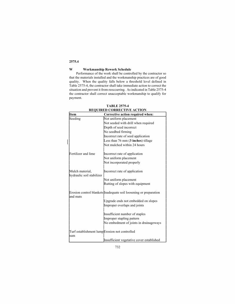
2575.4
732
W Workmanship Rework Schedule Performance of the work shall be controlled by the contractor so
that the materials installed and the workmanship practices are of good quality. When the quality falls below a threshold level defined in Table 2575-4, the contractor shall take immediate action to correct the situation and prevent it from reoccurring. As indicated in Table 2575-4 the contractor shall correct unacceptable workmanship to qualify for payment.
TABLE 2575-4
REQUIRED CORRECTIVE ACTION Item Corrective action required when: Seeding Not uniform placement Not seeded with drill when required Depth of seed incorrect No seedbed firming Incorrect rate of seed application Less than 76 mm (3 inches) tillage Not mulched within 24 hours Fertilizer and lime Incorrect rate of application Not uniform placement Not incorporated properly Mulch material, hydraulic soil stabilizer
Incorrect rate of application
Not uniform placement Rutting of slopes with equipment
Erosion control blankets and mats
Inadequate soil loosening or preparation
Upgrade ends not embedded on slopes Improper overlaps and joints Insufficient number of staples Improper stapling pattern No embedment of joints in drainageways Turf establishment lumpsum
Erosion not controlled
Insufficient vegetative cover established

2575.4
733
The above table pertains to a threshold level of workmanship only and does not pertain to the use of nonconforming materials. The disposition of nonconforming materials shall be in accordance with 1503. The Contractor at no cost to the Department shall perform any corrective actions required for acceptance of the work. 2575.4 METHOD OF MEASUREMENT A Fertilizer
Fertilizer will be measured by the weight of each kind furnished and applied. When a different analysis fertilizer than in the Plans, is used it will be converted to equivalent of planned fertilizer. B Lime
Agricultural lime will be measured by the weight of material furnished and applied. Industrial Slag will be measured by mass on the same basis as Agricultural Lime. C Seeding
Seeding will be measured by the area seeded, regardless of the seed mixture or quantity of seed used, and regardless of whether the seed was furnished by the Contractor or the Department. Areas reseeded by order of the Engineer, after the original seeding of the area was accepted, will be measured and added to the area originally seeded. D Seed
The Engineer will measure seed by mass of each mixture or species except when pure live seed (PLS) is indicated. When PLS is indicated, the Engineer will measure the portion of the seed mixture by mass of PLS and add it to the mass of seed mixture specified as bulk mass. E Mulch
The Engineer will measure: (1) Mulch material of Types 1, 3, 4, 7, and 8 by the mass of each type
furnished and applied acceptably. Type 4 mulch shall consist of a measurement of Type 1 mulch and Type 5 hydraulic soil stabilizer.
(2) Type 5 and 6 mulch material by volume (vehicular measure) of the material furnished and acceptably used. (3) Type 9 (aggregate) mulch by volume, based on the area of
aggregate furnished and acceptably placed to the Plan thickness. (4) Additional mulch materials ordered by and then accepted by the
Engineer in remulched areas will be added to the mulch quantities originally used and accepted.
F Water Water used by order of the Engineer for establishment of areas
covered with mulch will be measured by volume.
2575.4
734
G Disk Anchoring Disk anchoring of Type 1, Type 3, Type 7 and Type 8 mulches
will be measured by the area of mulch disked acceptably. H Sodding
The Engineer will measure sodding that is acceptably installed and maintained by the surface area based on field measurement. Where sod is authorized to be placed shingle-style, the overlapped portion of the sod will also be measured. I Hydraulic Soil Stabilizers
The Engineer will measure Type 1 by the area acceptably covered taking into account the type of material used and the manufacture's recommended application rate. The Engineer will measure all other hydraulic soil stabilizers by the mass or weight of each type used. The Engineer may convert the mass or weight of material used to a square meter (square yard) basis. J Lump Sum Turf Establishment
The item of turf establishment, lump sum will be considered to include all materials and labor as necessary to accomplish the work regardless of quantities involved. Measurement will be by lump sum unit, and under this provision, no measurement will be made of any individual turf establishment item. K Erosion Netting, Blankets and Stabilization Mats
Erosion netting and blankets of each kind will be measured separately by the area covered. Overlapped portions will not be added additionally to the area measured.
Erosion Stabilization mats will be measured by the area covered. Overlapped portions will not be added additionally to the area measured. Seed, fertilizer, topsoil and blankets placed in conjunction with the erosion stabilization mat system will be measured separately. L Mowing
Mowing will be measured by the area acceptably mowed. M Weed Spraying
Weed spraying will be measured by the area acceptably sprayed. N Weed Spray Mixture
Weed spray mixture will be measured by the volume of ingredients furnished and used. O Blank P Compost
Grade 1 compost will be measured by mass of material furnished and applied. Grade 2 compost will be measured by loose volume determined by vehicular measurement of material delivered.
2575.5
735
Q Rapid Stabilization Method 1 and 2 will each be measured by the hectare (acre)
acceptably installed. Disc anchoring or hydraulic soil stabilizer shall be considered incidental for which no direct payment will be made.
Method 3 will be measured by the cubic meter (M Gallons) of slurry furnished and acceptably placed. Seed, fertilizer, and hydraulic soil stabilizer shall be considered incidental for which no direct payment will be made.
Method 4 will be measured by the square meter (square yard) of blanket acceptably installed. Seed and fertilizer shall be considered incidental for which no direct payment will be made.
Method 5 will be measured by the metric ton (ton) of rock furnished and acceptably installed. Geotextile shall be considered incidental for which no direct payment will be made. 2575.5 BASIS OF PAYMENT
Payment for any of the turf establishment items at the Contract prices per unit of measure will be compensation in full for all labor, materials, equipment, and other incidentals necessary to complete the work as specified, including the costs of maintenance, replacement, and repair as required by the Contract. A Erosion Control Items
Payment for erosion control blankets may include maintenance, when so specified. If no maintenance is specified, payment shall be compensation in full for all labor, materials, equipment, and other incidental items necessary for proper installation of the blankets. If maintenance is specified, payment shall also include the cost of watering, replacement, and repair as required by the Contract.
Payment for hydraulic soil stabilizers will be based upon acceptance of the application by the Engineer. Payment for Type 1, 5, and 6 shall be compensation in full for all labor, materials, and equipment, for proper installation of the materials. Type 8 shall be eligible for partial payment not to exceed 80% of the contract bid price upon satisfactory installation of the material. The remaining 20% shall be made available when final acceptance is made based on adequate vegetative cover and erosion control. B Temporary Seeding
Interim seeding, and the application of fertilizer and mulch as required in conjunction therewith, will be paid for at the Contract prices or, in the absence of a Contract bid price, according to the established unit prices, or in the absence of a Contract price and unit price, as Extra Work. C Seed
Seed will be paid for by the mass of each mixture or species except
2575.5
736
when pure live seed (PLS) is indicated. When PLS is indicated on a portion of the seed mixture, payment will be made by mass of the PLS species plus the mass of the bulk portion of the seed mixture. Payment for seed not meeting germination and purity requirements of 3876 shall be subject to 1503. When components are missing from the specified mixture the affected seeded areas shall be reseeded with the correct mixture by the Contractor at no additional cost to the Department and a deduction of the value of the missing ingredients shall also be applied. D Mulch D1 Type 4 Mulch Type 1 mulch and Type 5 hydraulic soil stabilizer will be paid for separately. D2 Shoulder Mulch Overspray Type 1 hydraulic soil stabilizer shall be paid for independent of the Type 1 mulch and disk anchoring or shoulder mulch overspray. E Mowing and Weed Spraying
Payment for mowing and weed spraying at the Contract prices per unit of measure will be compensation in full for all labor and equipment employed in the work, and for all materials used, except that separate payment will be made for the weed spray mixture furnished and applied in conjunction with the item of weed spraying. F Sod
Netted and stapled sod shall be paid at 150% of unnetted sod. G Products in Lieu of Sod Payment for products used in lieu of sod, that are not as labor intensive or do not require the same watering sequence as sod shall be paid for at 75 percent of the sod Contract price. H Rapid Stabilization Payment for the various items of work required for Rapid Stabilization will be made in accordance with the appropriate Contract bid price per unit of measure for each method specified. Such payment, in each instance, shall be construed to be compensation in full for all costs incidental thereto including mobilization. I Unit Prices
The Department will pay the following unit prices for erosion control and vegetation establishment items in the absence of a Contract bid price: (1) Additional tillage ordered by the Engineer before seeding interim
mulched areas will be paid for at the same unit price as disk anchoring.
(2) Disk Anchoring ........................... $75 per hectare ($30 per acre)
2575.5
737
(3) Temporary Seed Mixtures Mixture 100-110 ............ @ $0.44 per kilogram ($.20 per pound) Mixture 150 ................. @ $3.00 per kilogram ($1.35 per pound) Mixture 190 ................. @ $2.75 per kilogram ($1.25 per pound)
(4) Erosion Control Blanket Category 4 .......................................................$2.20 m2 ($2.00/square yard)
(5) Rapid Stabilization Methods Method 1……………………………………$900/ha ($400/acre) Method 2…………………………………..$1235/ha ($500/acre) Method 3……………………………….$86/m3 ($325/M gallon) Method 4…………………………………$3.00/m2 ($2.50/sq yd) Method 5………………………………..$27/metric ton ($25/ton) (6) Water ........................................$4.65/cubic meter ($17.00/MGal) J Payment Schedule
Payment for turf establishment and maintenance will be made on the basis of the following schedule: Item No. Item Unit 2575.501 Seeding ......................................................... hectare(acre) 2575.502 Seed, Mixture ___, or (Species) ............ kilogram(pound) 2575.505 Sodding Type___ .................... square meter(square yard) 2575.511 Mulch Material, Type ___......................... metric ton (ton) 2575.513 Mulch Material, Type ___.......... cubic meter (cubic yard) 2575.519 Disk Anchoring .............................................hectare (acre) 2575.521 Erosion Control Netting ......... square meter (square yard) 2575.523 Erosion Control Blankets, Category ___(1) ...................................................................square meter(square yard) 2575.525 Erosion Stabilization Mat, Class___ ................................................................. square meter (square yard) 2575.531 Fertilizer, Type___ ................................... metric ton (ton) 2575.532 Fertilizer, Type ___ .............................. kilogram (pound) 2575.533 Agricultural Lime ..................................... metric ton (ton) 2575.535 Water ........................................ cubic meter (M Gallons) 2575.541 Mowing ......................................................... hectare(acre) 2575.545 Weed Spraying ............................................ hectare (acre) 2575.547 Weed Spray Mixture........................................liter (gallon) 2575.550 Compost, Grade 2....................... cubic meter (cubic yard) 2575.551 Compost, Grade 1...................................... metric ton (ton) 2575.555 Turf Establishment .............................................. lump sum 2575.560 Hydraulic Soil Stabilizer, Type ___ ....... kilogram (pound) 2575.561 Hydraulic Soil Stabilizer, Type 1 ................................................. square meter (square yard) 2575.570 Rapid Stabilization Method 1 or 2.................hectare (acre)

2575.5
738
2575.571 Rapid Stabilization Method 3 .................................................... cubic meter (M Gallons) 2575.572 Rapid Stabilization Method 4 ................................................square meter (square yard) 2575.573 Rapid Stabilization Method 5 .....................metric ton (ton) Note: (1) If maintenance applies, a subnote will be placed on the pay
item shown in the summary of quantities in the Plan: "Includes Maintenance."
2577
Soil Bioengineered Systems 2577.1 DESCRIPTION
This work shall consist of installing vegetation in conjunction with geosynthetic or natural materials for stabilizing areas susceptible to erosion. Soil Bioengineering may be used as a permanent soil stabilization system in ditches, along stream banks, on shorelines or on slopes. The work shall consist of furnishing and installing a composite system by the Contractor on site. 2577.2 MATERIALS A Seed, mix as specified ......................................................... 3876 B Mulch, Type as specified.................................................... 3882 C Erosion control blankets .................................................... 3885 D. Erosion control netting....................................................... 3883 E. Nursery plant stock ............................................................ 3861 F. Fiber log .............................................................................. 3895 G. Riprap.................................................................................. 3601 H. Concrete Armor Units........................................................ 3608 2577.3 CONSTRUCTION REQUIREMENTS A General
The installation locations and layouts shown in the Plans are approximate only. The exact locations and layout shall be as determined by the Engineer.
The harvest and installation of plant material shall be performed by qualified nurserymen or landscape specialists, or shall be performed by experienced crews working under the direct supervision of a qualified nurseryman or landscape specialist.
Planting operations shall not be started, nor shall any planting stock be delivered to the Project site, until it has been determined by the Engineer that weather and soil conditions are suitable for planting and that all necessary preparations have been made.
During placement, the Contractor shall install all components consecutively without significant lapse of time between each phase of the operation. On slopes, installation of material shall start at the
2577.3
739
bottom of slope and proceed in horizontal lifts upward. On shorelines and banks, installation of material shall start below the water line and proceed up the bank.
During the work, the Contractor shall take all necessary precautions and actions to prevent siltation and turbidity of flowing or impounded waters of the State. When working in water, the Contractor shall protect the work site if necessary with curtains, barriers or other containment devices so that sediment and debris does not enter the receiving water body. B Harvesting Plant Stock
Plant stock and cuttings shall be obtained from the regions and/or zones indicated in the Plans.
At least 3 days prior to harvesting of planting stock for the Project site, the Contractor shall notify the Engineer of the contemplated harvest date to allow for inspection. C Season of Placement
The approximate dates for season of placement are listed in Table 2577-1. The Engineer may adjust a specified date by up to 20 days depending on prevailing weather conditions.
Plant material must be in dormant stage, prior to buds bursting open in spring or after leaves have changed color and dropped in fall.
TABLE – 2577-1 APPROXIMATE SEASON OF PLACEMENT
SYSTEM SPRING FALL Wattling Prior to April 15th After Nov 1st Brush Layering Prior to April 15th After Nov 1st Live Stake Prior to April 15th After Nov 1st Root-Rap April 15 - June 10th July 20 - Sept 20th
D Wattling This work shall consist of making trenches along the contours
of the slope, placing bundles of dormant plant cuttings into the trenches, and tamping loose soil over the bundles. Prior to trenching, the Contractor shall drive wooden stakes 50 mm (2 inches) in diameter x ½ m (2 foot) long, 0.4 m (16 inches) on center along each trench location. The stakes shall be driven to a firm hold with the tops about 150 mm (6 inches) above grade. Trenching shall not precede installation of plant materials by more than 1 hour to minimize drying of soils. The overall soil surface shall be left in a rough condition with clods, and ridges left in place for maximum resistance to erosion. Immediately following trenching, the Contractor shall place bundles of dormant plant cuttings into the trench. Bundles shall have cuttings laid together with the buttends located at alternate ends of the bundle and tightly tied with binder twine at a minimum of three points along the

2577.3
740
bundle. Bundles shall consist of 9.5-50 mm (3/8-2 inch) diameter, 1-2.4 m (3-8 foot) length dormant woody cuttings. The bundle should be approximately 150-200 mm (6-8 inches) in diameter. Wattle ends shall overlap in the trench. Additional stakes shall be driven through the bundles at a maximum spacing of ½ m (2 feet) on center. During placement of the bundles, the Contractor shall cover the bundles with loose soil working it into the wattles leaving a uniform fringe of plant material that is exposed approximately 50 to 80 mm (2-3 inches) high. E Brush Layering
This work shall consist of making horizontal slots the length of the slope and embedding dormant green plant cuttings into the slots and tamping loose soil over the cuttings. The slots are 0.61 m (2 feet) in depth angled downward into the slope. The plant cuttings shall consist of stems approximately 1 m (3 feet) long, 10 to 50 mm (½ - 2 inches) in diameter. Cuttings shall be placed in containers of water to transport until installed. As soon as practical after the slots are made, the Contractor shall place the plant cuttings into this slot with the butt end placed as far into the slot as possible with a minimum of 150 mm (6 inches) protruding out of the slot. The stems shall be place randomly with some crisscrossing. As the plant cuttings are being placed, the Contractor shall immediately backfill the slot cuttings with soil and firm the backfill to the satisfaction of the Engineer. F Live Stakes
This work involves the insertion of dormant live cuttings into the soil. Cuttings shall consist of stems at least 1 m (3 feet) in length and 25-50 mm (1-2 inch) in diameter. Materials should be cut and placed in a container of water to be transported to the site and kept in water until installed. Tamp the cutting with the bottom end going into the ground at right angles to the slope face, 2/3 - 3/4 of their length. Care shall be taken not to split the ends or damage the bark of the cuttings. Placement shall be .67 m (2 feet) on center using a triangular spacing. Density of the installation will range from 2-4 stakes/m2 (square yard).
Rip rap can be staked (joint planting) if it is not too thick (less than 0.67 m (2 feet). The Contractor shall make a pilot hole by driving a tool, as a pry bar or rebar, through the rip rap and filter layer, reaching the ground soil. Tamping can best be done with a dead blow hammer, avoiding damage to the bark. Place the cuttings in a random configuration 0.67 m (2 feet) on center. G Placing Fiber log
This work shall consist of placing biodegradable fiber log for stabilizing a shoreline. Prior to installing the fiber log, the Contractor shall drive wooden stakes 50 mm (2 inches) in diameter x 1 m (3 feet) long, 0.3 m (1 foot) on center along the proposed alignment of the fiber
2577.4
741
log. The stakes shall extend 200 to 250 mm (8-10 inches) above the elevation of the water surface indicated on the plans. After the stakes are placed, the Contractor shall install the fiber log so that the upper surface of the fiber log is parallel to the water surface with 50 mm (2 inches) protruding above the normal water level. Fiber logs shall be lace together end to end with woven nylon twine 3 mm (1/8 inch) in diameter to create a continuous length. The Contractor shall bury both ends of the fiber rolls 1 ½ m (5 feet) laterally into the bank. H Root-Rap
This work shall consist of placing a gravel channel lining or riprap, and overseeding or planting the completed channel. The Contractor shall conduct this work in conformity with the details, typical sections and elevation controls shown in the contract. Actual alignment shall be as staked by the Engineer. During the work, the Contractor shall place the granular channel lining or riprap and shape the channel to completed section as a continuous operation. Seeding or planting shall be initiated within 48 hours. I BLANK J BLANK K Acceptance of Work
Except as otherwise provided for in the Contract, the Engineer will accept soil bioengineered systems upon satisfactory placement. 2577.4 METHOD OF MEASUREMENT A Wattling
Wattling will be measured by the meter (linear feet) of each trench made and planted. When several trenches are made and planted, each length of trench acceptably planted shall be added to the total. Plant cuttings, bundles and stakes shall be incidental. B Brush layering
Brush layering will be measured by the meter (linear feet) of each horizontal slot made and planted. When several slots are made and planted, each length of slot acceptably planted shall be added to the total. Plant cuttings and stakes shall be incidental. C Fiber log
Fiber log will be measured by the meter (linear feet) furnished and installed including buried portions. Stakes and rope to fasten logs in place shall be incidental. D Granular channel liner
Granular channel liner will be measured by volume in cubic meter (cubic yard) placed and in its final configuration. E Concrete Armor Units
Concrete Armor Units will be measured by surface area covered by each size furnished and acceptably installed including the buried

2577.4
742
portions. The outermost extremity of the units shall be used in the measurement. On small projects, concrete armor units will be accepted by the number of complete units (two individual halves) assembled and installed. 2577.5 BASIS OF PAYMENT
Payment for bio-engineered system items will be compensation in full for all labor, materials, equipment, and other incidentals necessary to complete the work as required by the Contract. The Contractor will receive compensation at the appropriate Contract prices, or in the absence of a Contract bid price as Extra Work. A Pay Items
Payment for bioengineered system items will be made on the basis of the following schedule: Item No. Item Unit 2577.501 Wattling............................................... meter (linear feet) 2577.502 Brush Layering................................... meter (linear feet) 2577.503 Fiber Log............................................ meter (linear feet) 2577.504 Granular channel Liner..............cubic meter (cubic yard) 2577.505 Live Stakes ................................................................ Each 2577.506 Concrete Armor Units (1).......................................... Each 2577.507 Concrete Armor Units (1).... square meter (square yards) (1) Specify Size
2581 Removable Preformed Plastic Pavement Marking 2581.1 DESCRIPTION
This work shall consist of furnishing, placing and removing temporary pavement marking material on those pavements open to traffic where traffic markings are necessary and temporary lane markings are not appropriate. 2581.2 MATERIALS
Removable Preformed Plastic Pavement Marking for Traffic Lane Delineation and Legends ............................................................. 3355 2581.3 CONSTRUCTION REQUIREMENTS
Removable preformed plastic pavement marking shall be furnished and placed by the Contractor at locations and with proper dimensions as indicated in the Plans or as directed by the Engineer immediately prior to modification of traffic flow. Placement shall be on a clean and dry surface in accordance with the contract documents. Removed marking material shall be disposed of properly.

2582.2
743
2581.4 METHOD OF MEASUREMENT Removable preformed plastic pavement marking will be measured
by the actual length of pavement marking furnished, placed, and removed as specified.
The measurement is based on a 100 mm (4 inches) wide marking, regardless of color or type. Measurement for marking widths differing from the 100 mm (4 inches) width will be adjusted by the ratio of the actual width to the 100 mm (4 inches) width. Broken line marking will be measured by the actual length of material used and will not include gaps between the broken lines. 2581.5 BASIS OF PAYMENT
Payment for removable preformed plastic pavement marking at the Contract price per unit of measure will be compensation for all costs of furnishing, placing, maintaining, replacing, and removing the marking.
Payment for the marking will be made on the basis of the following schedule: Item No. Item Unit 2581.501 Removable Preformed Plastic Marking ............................................................meter (linear foot)
2582 Permanent Pavement Markings
2582.1 DESCRIPTION A Pavement Messages
Pavement messages are word and symbol pavement markings installed in the roadway. These markings include all word and symbol messages that are not line segments. B Linear Pavement Markings
Linear pavement markings are those pavement markings installed in the roadway that are line segments of various widths. These markings include lane lines, center lines, no passing zone lines, and edge lines, airplane markings, and stop lines. These markings do not include crosswalk markings or messages. C Crosswalk Markings
These markings include crosswalk blocks that are installed parallel to the direction of travel on the roadway. Crosswalk markings are blocks installed in the roadway parallel to the direction of travel in a pattern that is transverse to the direction of travel. 2582.2 MATERIALS
Qualified materials can be found on Mn/DOT's Qualified Products List on the Office of Traffic, Security and Operations website. Other materials may be used on a provisional basis as detailed in the QPL
2582.2
744
process and as approved by the Engineer. Type of material used will be as specified by contract documents. 2582.3 CONSTRUCTION REQUIREMENTS A Prequalification
This Pavement Marking Qualification and Acceptance Program has been developed and implemented to insure that quality materials and workmanship are used on Mn/DOT pavement marking projects. A1 Certification of Materials
Acceptance of pavement marking materials under the Pavement Marking Qualification and Acceptance Program is based on the product's certification and quality control testing verified by Mn/DOT Laboratory testing of verification samples and spot checks on samples obtained from contractor stock or from project sites. Products meeting the requirements of the Pavement Marking Qualification and Acceptance Program will be place on the Qualified Products List. Products can be removed from the Qualified Products List due to poor field performance. A2 Approved Contractors Only contractors approved through Mn/DOT’s Pavement Marking Qualification and Acceptance Program will be awarded contracts. Contractors may be removed from the approved contractor list due to poor performance. B Application
Place markings on roadways in accordance with contract documents. C ACCEPTANCE
Pavement markings in Minnesota shall retain a satisfactory level of retroreflectivity, demonstrate good adhesion, resisting chipping, and exhibit consistency of color in all lighting conditions. C1 Alignment
Minimum linear pavement marking shall not be less than the specified width and shall not vary by more than 6 mm (.25 in). The width will not vary by a rate more than 6 mm / 3 m (.25 in/10 ft). The length of broken line segments shall not vary by more than 75 mm (3 in) and the number of broken line segments shall be between 102 and 108 per mile of marked pavement. Alignment deviations from the control guide or existing lines specified by the Engineer shall not exceed 50 mm (2 in). The transverse position of linear markings shall not vary more than the rate of 25 mm / 3 m (1 in/10 ft). Pavement marking material shall not be applied over a longitudinal joint. C2 Color
The color of white pavement marking shall be a pure flat white and free of tints. The color of the yellow epoxy shall match Color Number

2582.4
745
33538 of Federal Standard 595 and shall conform to the following CIE Chromaticity limits using illuminant "C". C3 Retroreflectivity – minimum initial pavement marking retroreflectivity using 30 m geometry shall be:
White Yellow Tape 600 mcd 500 mcd Epoxy 300 mcd 200 mcd Latex 275 mcd 180 mcd
D Pavement Marking Warranty All warranties shall be transferred to Mn/DOT after construction.
E Correction of Defects Pavement markings that do not conform to the requirements of the
contract shall be replaced or repaired to the satisfaction of the Engineer. Removal of unacceptable work shall be accomplished using suitable methods as approved by the Engineer. F Penalties
Penalties will be assessed by the Engineer where initial retroreflectivity fall below the minimum acceptable levels. If the retroreflectivity deficiency is greater than 20% the work shall be removed or repaired to the satisfaction of the Engineer. If the deficiency is 20% or less, the Engineer may require satisfactory repair or may accept the work at a reduced unit price. The unit price will be reduced by the percent of retroreflectivity deficiency. G Striper Operations Daily Form
Contractors applying pavement markings for Mn/DOT under a contract are required to fill out the "Construction Striper Operations Daily Log" form which is shown in the special provisions and as approved by the Engineer. No payment for pavement markings shall be made until the form is completed and submitted to the Engineer. 2582.4 METHOD OF MEASUREMENT A Pavement Messages
Pavement messages of each type will be measured by the number of each type installed as specified B Lines
Pavement markings will be measured by the length of each type constructed in place as specified. Broken lines will be measured by the actual length of line marked and will not include the gap between the broken lines. C Crosswalk Blocks
Crosswalks shall be measured by area of material sq m (sq ft) installed as specified and by type.

2582.5
746
2582.5 BASIS OF PAYMENT Payment for pavement markings installed at contract prices per
unit of material shall be compensation in full for all costs incurred in materials, traffic control, installation, surface preparation, use of primers, in accordance to contract documents or as approved by the Engineer. Item No. Item Unit 2582.501 Pavement Message (1) (2) .......................................... Each 2582.502 Linear Markings __ mm (__inch) width (2) (3) (4) ..............................................................meter (linear foot) 2582.503 Crosswalks (2) ......................... square meter (square foot) (1) Specify Message (2) Specify Material (3) Specified Type of Line (Solid, Broken or Dotted) (4) Specify Color