254 ishwri
Upload: 4th-international-conference-on-advances-in-energy-research-icaer-2013
Post on 13-Jul-2015
325 views
TRANSCRIPT

LVRT for Wind Power System[Paper Code: 254]
Shrikant Mali1
Ishwari S Tank2
Steffy James2
1Dept. of Electrical Engineering, IIT Bombay2Dept. of E&TC Engineering, SITRC
IV th International Conference on Advances in Energy Research, Indian Institute of Technology Bombay, Mumbai
Scope of Presentation
• Introduction
• Wind Energy Conversion System
• LVRT requirements
• System Characteristics: SCR
• Validation of LVRT
• Conclusion
Introduction
• Behavior of WECS should be similar to that of conventional power plants.
• Grid code(IWGC) has been revised.
LVRT (Low Voltage Ride Through) : wind farm connected to 66kV and
above should fulfill LVRT requirements.

Wind Theory
Power contained in Wind:
P = ½ ρ A v3 Watts
The power extracted from Wind:
P = ½ ρ A v3Cp
P= ½ ρ A v30.59 Watts
Where, Cp= Power coefficient
(Betz limit)

Cp v/s TSR
• Power coefficient (Cp) indicates the aerodynamic efficiency.
• Ratio of extracted power to the power contained in wind.
• Maximum power coefficient occurs at a specific TSR.
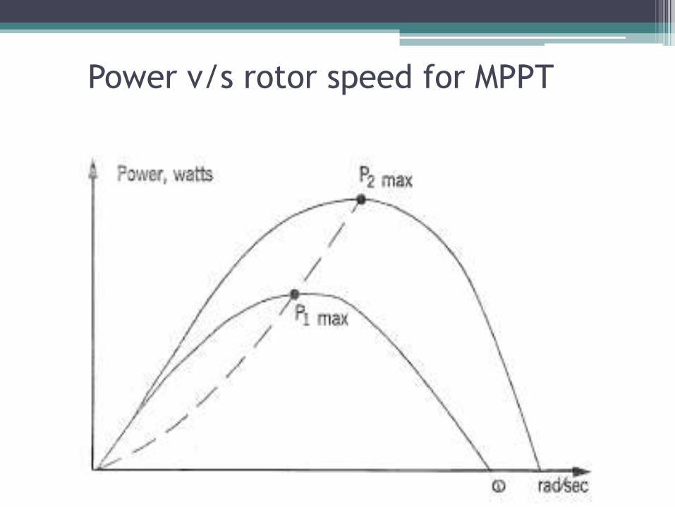
Power v/s rotor speed for MPPT

Wind Energy Conversion System
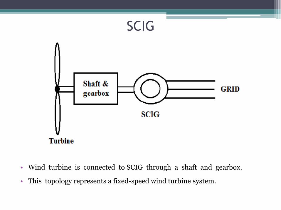
SCIG
• Wind turbine is connected to SCIG through a shaft and gearbox.
• This topology represents a fixed-speed wind turbine system.

PMSG
• Variable speed operation.
• Generator is connected to the grid through full converters.
• This allows the control to maximize performance.

DFIG
• Variable speed Topology.
• Stator is directly connected to grid.
• Rotor connected to grid through converters.
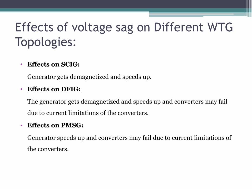
Effects of voltage sag on Different WTG
Topologies:
• Effects on SCIG:
Generator gets demagnetized and speeds up.
• Effects on DFIG:
The generator gets demagnetized and speeds up and converters may fail
due to current limitations of the converters.
• Effects on PMSG:
Generator speeds up and converters may fail due to current limitations of
the converters.

LVRT Requirements
During sag condition, the WTG should:
1) Remain connected to the grid and stay operational.
2) Support the system during fault condition by injecting reactive power.

LVRT Specifications
• Wind farms connected to 66kV and above can be disconnected if the operating point
falls below the line in figure.
Where,
• Vf =15% of Nominal System voltage
• Vpf = Minimum voltages mentioned in IWGC.

Nominal system voltages(kV)
Fault clearing time, T(ms)
Vpf (kV) Vf (kV)
400 100 360 60.0
220 160 200 33.0
132 160 120 19.8
110 160 96.25 16.5
66 300 60 9.9
The fault clearing time for various system nominal voltage levels:

System Characteristics
• Grid, can be modeled as a voltage source in series with impedance ZGRID:
SCC = Vbase2/|Zbase|
SCR = SCC/Sbase
• Short Circuit Ratio (SCR) = 20 (as per German grid code) or 6 (as per IWGC).

Solutions for LVRT
• Chopper resistor.
• Energy Storage System: Battery bank, Super capacitor etc.
• Excess energy can be stored in turbine- rotor inertia.
• Non-MPPT operation.
Validation for LVRT
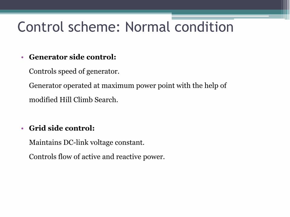
Control scheme: Normal condition
• Generator side control:
Controls speed of generator.
Generator operated at maximum power point with the help of
modified Hill Climb Search.
• Grid side control:
Maintains DC-link voltage constant.
Controls flow of active and reactive power.
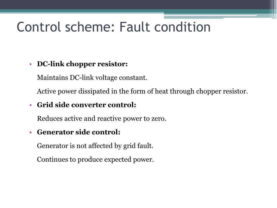
Control scheme: Fault condition
• DC-link chopper resistor:
Maintains DC-link voltage constant.
Active power dissipated in the form of heat through chopper resistor.
• Grid side converter control:
Reduces active and reactive power to zero.
• Generator side control:
Generator is not affected by grid fault.
Continues to produce expected power.

Graph 2: Generator Speed
Graph 1: Wind Speed
Graph 3: Generator Current
Graph 4: Electromagnetic andMechanical Torque
Graph 5: Generated Power
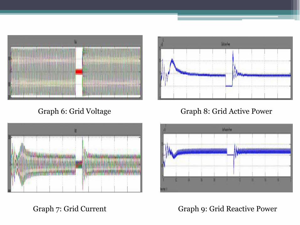
Graph 6: Grid Voltage
Graph 7: Grid Current
Graph 8: Grid Active Power
Graph 9: Grid Reactive Power

Graph 10: DC-Link Voltage
Graph 11: Transformer Secondary Voltage

Conclusion
• LVRT requirement is a major leap in the integration of Wind Power System
with the grid.
• We can implement the LVRT requirement combining 2 or 3 technologies.
• Control can be modified to implement reactive power compensation and
support the grid during fault condition.
• Not only the LVRT requirement but we should consider other grid
connectivity issues as well.

References• C. Abbey, and G. Joos; Effect of Low Voltage Ride Through (LVRT) Characteristic on Voltage Stability.
• Chad Abbey, and Geza Joos; Supercapacitor Energy Storage for Wind Energy Applications, IEEE Transactions on Industry Applications, Vol. 43, No.3, May/June 2007.
• S. M. Muyeen, Rion Takahashi, Toshiaki Murata, and Junji Tamura; A Variable Speed Wind Turbine Control Strategy to Meet Wind Farm Grid Code Requirements, IEEE Transactions on Power Systems, Vol. 25, No. 1, February 2010.
• Wen-Tsan Liu, Yuan-Kang Wu, Ching-Yin Lee, and Chao-Rong Chen; Effect of Low-Voltage-Ride-Through Technologies on the First Taiwan Offshore Wind Farm Planning, IEEE Transactions on Sustainable Energy, Vol. 2, No. 1, January 2011.
• Wenliang Wang, Baoming Ge, Daqiang Bi , Ming Qin and Wei Liu, Energy Storage based LVRT and Stabilizing Power Control for Direct-Drive Wind Power System, International Conference on Power System Technology, IEEE 2010.
• Jun Li, Dujiang Li, Lei Hong, Chuan Xieand Guozhu Chen; A Novel Power-flow Balance LVRT Control Strategy for Low-speed Direct-drive PMSG Wind Generation System, 978-1-4244-5226-2, IEEE 2010.
• Waqar A Qureshi, and Nirmal C-K Nair; Systematic Development of Low Voltage Ride Through (LVRT) Envelope for Grids, 978-1-4244-6890-4, IEEE TENCON 2010.
• Liu Sheng-wen and Bao Guang-qing; A Novel LVRT of Permanent Magnet Direct-driven Wind Turbine, 978-1-4244-6255-1, IEEE 2011.
• Chia-Tse Lee, Che-Wei Hsu, and Po-Tai Cheng; A Low-Voltage Ride-Through Technique for Grid-Connected Converters of Distributed Energy Resources, IEEE Transactions on Industry Applications, Vol. 47, No. 4, July/August 2011.
• Hojoon Shin, Hyun-Sam Jung, and Seung-Ki Sul; Low Voltage Ride Through(LVRT) Control Strategy of Grid-connected Variable Speed Wind Turbine Generator System, 8th International Conference on Power Electronics - ECCE Asia, IEEE , May 30-June 3, 2011.
• Keqing Qu, Hao Zhou, Yuehong Xing, Zuojin Ding and Ningyi He; A LVRT Method for Wind Power PMSG System with Z-source Inverter, 978-1-4244-9690-7, IEEE 2011.
• Andrew Causebrook, David J. Atkinson, and Alan G. Jack; Fault Ride-Through of Large Wind Farms Using Series Dynamic Braking Resistors, IEEE Transactions on Power Systems, Vol. 22, No. 3, August 2007.
• Salvador Alepuz, Sergio Busquets-Monge, Josep Bordonau, Juan A. Martínez-Velasco, César A. Silva, Jorge Pontt, and José Rodríguez; Control Strategies Based on Symmetrical Components for Grid-Connected Converters Under Voltage Dips, IEEE Transactions on Industrial Electronics, Vol. 56, No. 6, June 2009.
• Omid Alizadeh, and Amirnaser Yazdani; A Strategy for Real Power Control in a Direct-Drive PMSG-Based Wind Energy Conversion System, IEEE Transactions on Power Delivery, 2013.
• S. M. Muyeen, Rion Takahashi, Toshiaki Murata, and Junji Tamura; A Variable Speed Wind Turbine Control Strategy to Meet Wind Farm Grid Code Requirements, IEEE Transactions on Power Systems, Vol. 25, No. 1, February 2010.
• Cun-Lu Dang, Lei Zhang, Ming-Xing Zhou; Optimal Power Control Model of Direct Driven PMSG, ICSGCE 2011: 27–30 September 2011, Chengdu, China.
• Power Research & Development Consultants Pvt. Ltd, Indian Wind Grid Code, Version 1.0, July 2009, PRDC/2009-2010/C-WET/831.
• Anubhav Sinha, Paulson Samuel, Devesh Kumar and Rajesh Gupta; Performance Analysis of Converter based Variable Speed Wind Energy Conversion System, Third International Conference on Power Systems, IEEE, December 27-29, 2009.
• Z. Xu, P. Ge, Dianguo Xu and C.H.Zhang; Direct Torque and Flux Control of the Converters for a Permanent Magnet Wind Power Generation System, IEEE Electrical Power & Energy Conference, 2010.
• Y. Errami, M. Maaroufi and M. Ouassaid; Modelling and Control Strategy of PMSG Based Variable Speed Wind Energy Conversion System, 978-1-61284-732-0, IEEE 2011.
• Nuno M. A. Freire, Jorge O. Estima, and A. J. Marques Cardoso; Comparison of Distinct Modulation Techniques Applied to PMSG Drives for Wind Turbine Applications Under Faulty Operating Conditions, 978-1-4244-8930-5, IEEE 2011.
• YangLiyong, Yuan Peie, ChangZhenguo, Chen Zhigang and Li Zhengxi; A Novel Control Strategy of Power Converter Used To Direct Driven Permanent Magnet Wind Power Generation System, 2nd International Conference on Power Electronics and Intelligent Transportation System, IEEE 2009.
• Shun Yang and Lida Zhang; Modeling and Control of the PMSG Wind Generation System with A Novel Controller, 3rd International Conference on Intelligent System Design and Engineering Applications, IEEE 2013.
• Zhou Sizhan, Liu Jinjun, Zhou Linyuan and Zhu Yangque; Improved DC-link Voltage Control of PMSG WECS based on Feedback Linearization under Grid Faults, 978-1-4673-4355-8, IEEE 2013.

Thank You!