2300 - manual (021706)
TRANSCRIPT

108
96 115
44,5
92
70
152
48
10
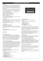
1 • INSTALLATION• Dimensions and cut-out
2 • TECHNICAL DATA
18
2300FAST INDICATOR / ALARM UNIT
INPUTS
Precision 0.2% f.s. ±1 digitSampling time 2msec
Strain-gauge350Ω (for pressure, force, etc), sensitivity 1.5/2/2.5/3/3.3mV/V, positivepolarization, symmetrical and negative.
Potentiometer≥ 350Ω, Ri > 10 MΩDC - Linear0...50mV / -25...25mV / -50...0mV / 0...60mV / -30...30mV / -60...0mV0...100mV / -50...50mV / -100...0mV / 0...1V / -500...500mV / -1V...0V0...10V / -5...5V / -10V...0VFor all inputs in voltage Ri ≥ 1 MΩ / 0...20mA / 4...20mA, Ri = 50Ω32-section custom linearization available.
Auxiliary inputsTwo remote analog trip setpoints, absolute or relative to local set.0...10V, Ri ≥ 1MΩ / 0...20mA, Ri = 50Ω / 4...20mA, Ri = 50ΩDigitalOptically isolated1500V.2 inputs with configurable function: tare zero, reset trip memory, resetpeak memory, check calibration, enable remote setpoints, Holdfunction.- NPN or PNP 24V/4mA
OUTPUTS
RelayWith 5A/250Vac contacts at cosϕ = 1 (3.5A at cosϕ = 0,4).Spark suppression on NO contacts.
LogicIn voltage for static relay control (SSR)23Vdc, Rout = 470Ω (20mA, max. 12V).
Retransmission1500V isolation.Retransmission output for input, peak values, remote sets, alarmsetpoint, configurable scale settable from panel keys0...10Vdc, -5...5Vdc, -10...10Vdc, Rload > 500Ω0...20mA, 4...20mA Rmax = 500ΩResolution 4000 points.Response time 8 msec.
SERIAL LINE
Optically isolated 4 wires. The instrument is available with Current Loop(1200 baud) or RS485 (1200/2400/4800/9600 baud) interface.Protocol: GEFRAN CENCAL or MODBUS
SENSOR SUPPLY / TRANSMITTER
1500V isolation5, 10 or 15Vdc/200mA or 24Vdc/100mA
POWER SUPPLY
100...240Vac/dc ±10% / 11...27Vac/dc ±10% 50...60Hz; 12VA maxProtected by internal fuse not serviceable by user.
AMBIENT CONDITIONS
Working temperature: 0...50°CStorage temperature: -20...70°CHumidity: 20...85%Ur non-condensingEnvironmental conditions of use : for internal use only, altitude up to2000m
ALARMS
3 (10) alarm setpoints settable in absolute value with functionscompletely configurable from panel keys (Direct / Reverse / Relative / Symmetrical relative)- Setting of setpoint along entire selected scale.- Trip hysteresis settable from panel keys.- Function: minimum or maximum trip points with saving of trip (LATCH)selectable during configuration.Relays energized or de-energized in trip status: selected from panelkeys. Trip can be excluded during power-up phase until input variableexceeds set trip point.Relay trips when variable drops below trip point. Output activation canbe timed.Trip response time:for Out1 ... Out 2 = 2msecfor Out 3 ... Out 10 = 8msec
GEFRAN MD8 EXPANSION
replacing output 3- with 8 additional alarm setpoints .
WEIGHT
450g
For correct installation, follow the instructionscontained in this manual!
Panel mounting.Front panel dimensions: 96x48mm./3.78”x1.89” (1/8DIN); depth:152mm /5.98” Cut-out dimensions: 92 (+0.8/-0)x45 (+0.6/0)mm/3.62” (+0.03/-0)x1.77” (+0.02/-0)”. To lock the instrument, insert the two blocks into the dovetail guides (split), diagonally(vertically) to one another and tighten with the screws. To install two or moreinstruments side by side or stacked, use the locking blocks and the following holemeasurements:side by side - Base (96 x n)-4 / (3.78 x n)-0.15” Height 45 (+0.6/-0) / 1.77” (+0.02/-0)column - Base 92 (+0.8/-0) / 3.62” (+0.03/-0) Height (48 x n)-3 / (1.89” x n)-0.11”where "n" is the number of instruments.
CE MARKING: EMC (electromagnetic compatibility) conformity to EEC Directive 89/336with reference to generic standards EN61000-6-2 (immunity in industrial environment)and EN50081-1 (emission in residential environment).
BT (low voltage) conformity to EEC Directive 73/23 modified by Directive 93/68.MAINTENANCE: Repairs may be done only by trained and specialized personnel. Cutpower to the instrument before accessing internal parts. Do not clean the case withhydrocarbon-based solvents (trichloroethylene, gasoline, etc.). The use of such solventswill compromise the instrument's mechanical reliability. Use a clean cloth moistenedwith ethyl alcohol or water to clean external plastic parts.
TECHNICAL SERVICE: GEFRAN has a technical service department. Defects derivingfrom any use not conforming to this manual are excluded from the warranty.
19
3 • DESCRIPTION OF FACEPLATEG Display 5-digit display (-9999…. 9999). 12-bit resolution. Settable decimalpoint. Fixed zero can be set on least significant digit. In normaloperation, the display shows the variable measured at input(process variable). Switching between net and gross values fromkeyboard. Display of gross value is indicated by flashing of unitsdecimal point. Positive (-HI-) or negative (-LO-) off-scale signal. If "Peak" func-tion is on, the display shows the peak value according to ("Peak+" / "Peak -") configuration. Low (_Lo_ message) and high (_Hi_message) off-scale indication.Broken pressure probe and calibration error indication:E_br: probe energizing interrupted_Sbr: "+" wire broken or signal too high L.sbr: "-" wire broken or signal too low Er.CAL - calibration errorDisplay of local and remote setpoints.Display of configuration and calibration messages/symbol/values.Display of auxiliary input values.
H LED signalLED signal (OUT1, OUT2) of energizing state of trip point relay(LED on = relay energized). Signal flashes during display and/orsetting of trip point values.Flashing signal of LEDs OUT1 and OUT2 respectively, with REMLED during display of auxiliary inputs.
I LED signalPeak value display signal (PEAK).Calibration active signal (CAL).Serial communication or remote setpoints active signal (REM).MD8 expansion enabled or energizing of third alarm relay signal(EXP).
J Self-sticking plate Plate to identify unit of measurement (engineering).
CONTROLS
A “F” Function buttonGives access to trip point functions (Out1, Out2, Out3/Out1-Out10 if MD8 expansion is present) for reading and/or changingof values. Gives access to display of auxiliary analog inputs(remotes 1 and 2). If button F is not pushed to confirm a setpointchange, it will be saved automatically after 10 seconds. Usebutton F to confirm the set value. Keep button F pressed toaccess the various configuration and calibration phases.
B / C Raise and Lower ButtonsLet you increase or decrease displayed value for setting dataorselecting an option. During calibration of repetition output W theRaise/Lower buttons let you change the minimum and maximumvalue. Increase/decrease speed is proportional to the time thebutton is kept pressed. The procedure is not cyclical: when themaximum (minimum) for the field is reached, the function stopseven if the button is pressed. During configuration, theRaise/Lower buttons block mnemonic/value alternation to allowchange of the displayed parameter.
D Special function button “*”Button available for special functions. Configurable function(phase CFG2 parameter button 3):- tare zero- automatic calibration control for pressure probe (♦ )- reset trip point memory- reset peak memory (♦♦ )- enable remote set 1 and/or 2- display HOLD function - display HOLD of sampled input value - NET/GROSS selection- MAIN INPUT/INPUTS SUM selection
E “CAL/RST” buttonConfigurable function (see CFG2 butt.2 parameter):- tare zero- automatic calibration control for pressure probes (♦ )- reset trip memory- reset peak memory (♦♦ )- enable remote set 1 and/or 2- display HOLD function - display HOLD of sampled input value
(♦ ) The calibration control function provides a known calibrationsignal from the unstressed transducer. In this condition, alarmrelay status and the value of the analog input repetition signal areunchanged. The calibration function is signaled by lighting ofthe LED on the front panel (CAL).
(♦♦ ) When the peak memory reset function is enabled, thebutton updates the peak memory to the current value of the inputsignal. These functions are also available by means ofconfigurable external contacts (see "Electrical connections" and"Configuration CFG2: d.i.F.1 and d.i.F.2).
F “PEAK” buttonPressing the Peak button displays the peak value, i.e., the datashown on display corresponds (depending on the type of peakselected) to (see CGF2 butt.1 parameter):- "peak +" maximum value reached by variable- "peak -" minimum value reached by variable- "peak - peak" difference between "peak +" and "peak -"The PEAK LED on the front panel indicates when this function ison. When the PEAK button is pressed again, the peak functiondeactivates and the PEAK LED turns off. The instrument againdisplays the process variable. The peak memory remains activeinternally and can be displayed at any time.
TRIP POINT CHARACTERISTICS
Main input sampling time is 2msec with no remote setpoints, and4msec with at least one remote setpoint. The maximum trip pointdelay for OUT1 and OUT2 is the sampling period of the maininput. The maximum delay time for OUT3 is 8msec. The maximum trip point delay for OUT3…10 on the MD8 expan-sion is 8msec. The minimum time for controls from digital inputs (IN1 and IN2) is8 msec.
H
J
F E D B C A
H
GI

20
4 • ELECTRICAL CONNECTIONSThe instrument consists of 2 basic boards and has 22 fastonterminals (6.35 mm).
Signal inputsInputs for pressure probe signals and DC signals use fastons1 (+) and 2 (-). Inputs forDC signals 0-20mA, 4-20mA usefastons 1 (+) and 2 (-) connected in parallel to fastons 22 and21. For the potentiometer input, the max. end must beconnected to faston 20 (+Exc), the min. end to fastons 2 andA3 (-), the cursor to faston 1 (+).
Remote setpoint inputsInputs 0-10V, 0-20mA, 4-20mA for any remote setpoints usefastons 8 (+), 9 (-), 10 (+), 11 (-) as alternative to digitalcommunication (see HW configuration).
Digital inputsNPN isolated digital inputs (from switch, relay, open collector)or PNP 4mA use faston 6 (IN1), 7 (IN2) and 4 (GND).
Calibration outputFor input from pressure probe fastons 21 and 22 are availablefor calibration contacts.
Probe power outputPower for pressure probes, potentiometers, transmitters,available on fastons 20 (+Exc) and 3 (-Exc).Available voltages are: 5V/200mA, 10V/200mA, 15V/200mA,24V/100mA (see hardware configuration).Any shielding on the probe connection cable must beconnected to faston 3 (-Exc).
Repetition output WAvailable at fastons 5 (+) and 4 (-) with output in voltage0...10Vdc, -5...5Vdc, -10...10Vdc or 0...20mA, 4...20mAisolated. Minimum and maximum can be corrected from panelkeys (see calibration of repetition output).
Output for MD8 expansion module Can be available at fastons 19 (data), 18 (clock), 17 (gnd) asalternative to OUT3 alarm trip output (see HW configuration).
Digital communication- Type C.L. interface: reception diode available at fastons10(+Rx), 11(-Rx), transmission transistor at fastons 8 (+Tx)and 9 (-Tx).Resistance in series to diode is 1KΩ, in series to transistorcollector 100Ω.For connection in series, diode resistance is reduced to 100Ω(see hardware configuration).- Type RS485 2/4 wire interface (RS422 compatible),connect: (DATA +) faston 11; 9
(DATA -) faston 10, 8.The transmission distance covered by the RS422/RS485 serialoutput reaches 500 meters with a maximum of 32 instrumentsconnected.For line lengths greater than 50 meters, and when a linetermination impedance is required, solder jumpers X, Y, and Zon the Solder Side of board 45028X.Make the termination on the instrument farthest away on theserial connection chain.
OUT1 alarm outputRelay output on fastons 16 (c) and 14 (n.c.); contact capacityis 5A / 250Vac at cosϕ = 1; (see HW configuration for selectionof NO/NC contacts) isolated logic output (*) type D2 23Vdc Rout 470Ω on fastons16 (+) and 14 (-).
OUT2 alarm outputRelay output on fastons 16 (c.) and 15 (n.o./n.c.); contactcapacity is 5A / 250Vac at cosϕ = 1; (see HW configuration forselection of NO/NC contacts) isolated logic output (*) type D2 23Vdc Rout 470Ω on fastons16 (+) and 15 (-).
OUT3 alarm outputRelay output on fastons 17 (n.c.),18 (c.) and 19 (n.o.); contactcapacity is 5A/250Vac at cosϕ = 1;isolated logic output (*) type D2 23Vdc Rout 470Ω on fastons19 (+) and 18 (-).
The OUT3 interface is an alternative to the output for MD8(see hardware configuration).
(*) not isolation with respect to probe supply.
Instrument power supplyPower supply is applied to fastons 12 and 13.
FuseLocated inside instrument; not replaceable by operator.
Power supply Type Current Voltage
100...240Vac T 0,5A 250V
11...27Vac/dc T 1,25A 250V

5 • HARDWARE CONFIGURATIONTo remove the electronic part of the case, turn the front screw until release, then remove manually. (Attention: high voltage dueto residual loads on condensers!). Configure by making jumpers on electronic boards of instrument.Data and figures are given in the Appendix.Configuration notesAccess to configuration and calibration depends on the position of jumpers on CPU board:Jumper J3 ON (closed) = enable configuration.Jumper S4 ON (closed) = enable calibration (jumper S4 on solder side of CPU board)MD8 trip point expansion: (version 2R or 2D only)Jumper J4 ON (closed) = enable expansion.Power configuration for probe, transmitter or potentiometerBased on the voltage level required, position the jumpers as follows:
POWER LEVEL JUMPERJ5 J10 J15 J24
5V / 200mA ON OFF OFF OFF10V / 200mA(*) OFF ON OFF OFF15V / 200mA OFF OFF ON OFF24V / 100mA OFF OFF OFF ON
Jumpers J5-J1-J15-J24 are on the components side of the power board (see Appendix)
Selection of NO/NC contacts for outputs OUT1 and OUT2Normally, relay outputs OUT1 and OUT2 are supplied NO. To configure NC type, you have to manually remove the NO sealedjumpers and install the NC jumpers on the solder side power board.The jumpers are positioned at their respective relays (Ref. T1 and T2, see Power board solder side)
Probe input configurationBased on the input required, position the jumpers as follows:
INPUT TYPE JUMPERS (♣)S3A S3B S3C SI
0 - 1V ON ON OFF OFF0 - 10V or transmitter 0-10V OFF OFF OFF OFF
Potentiometer OFF OFF OFF OFF0-20mA / 4-20mA transmitter 0-20mA/4-20mA ON ON OFF ON
Strain gauge, 0-50mV,0-60mV, 0-100mV (*) OFF OFF ON OFF
Configuration from panel keys is also necessary for all types of inputs (CGF.3, in.typ and In.cod parameters).
Input configuration for remote setpointsBased on the input required, position the jumpers as follows:
REMOTE SETPOINT INPUT TYPE JUMPERS (♣)S1A S1B S2A S2B
Remote set 1 / 0-10V (*) OFF OFF
Remote set 1 / 0-20mA / 4-20mA ON ON
Remote set 2 / 0-10V (*) OFF OFF
Remote set 2 / 0-20mA / 4-20mA ON ON
Digital input configurationBased on the input required, position the jumpers as follows:
DIGITAL INPUT TYPE JUMPERS (♣)
J1P J1N J2P J2N
Input 1:NPN (*) voltage-free contact OFF ON- open collector 24V/4mA
Input 1:PNP (24V/4mA) ON OFF
Input 2:NPN (*) voltage-free contact OFF ON- open collector 24V/4mA
Input 2:PNP (24V/4mA) ON OFF
21

Configuration of repetition output WBased on the output required, position the jumpers as follows:
REPETITION OUTPUT TYPE JUMPERS (♣) Jumpers L.S.J5V J5I J6 0V 5V/10V S1 S10 S11
0 -10V or 2-10V ON OFF ON ON OFF ON ON OFF0 -20mA or 4-20mA OFF ON OFF ON OFF ON ON OFF
± 5V (**) ON OFF ON OFF ON OFF ON ON± 10V (**) ON OFF ON OFF ON ON OFF ON
N.B. with ± 5 and ± 10, JN2 = OFF / J2P = OFF. No digital input 2.
Configuration of serial communication or remote setpointsBased on the output required, position the jumpers as follows:
TYPE OF FUNCTION JUMPERS J7 - J8 - J9 - J10 (♣)
Serial communication A
Remote setpoints B
Configuration of C.L. (current loop) serial interfaceBased on the type of connection required, position the jumpers as follows:Jumpers S5, S6 are on the CPU board, solder side.
TYPE OF CONNECTION JUMPERSS5 S6
Parallel (*) OFF ON
Series ON OFF
(♣) The jumpers are on the CPU board, components side.(*) Standard configuration(**) In case of symmetrical signal, digital input IN2 is no longer available. Faston 7 is the (-) reference of IN1.
5 • CONFIGURAZIONE HARDWARE
22
6 • PROGRAMMINGSetting alarm setpoints Alarm setpoints are set with the Raise/Lower buttons within the maximum/minimum limits defined during the configuration phase(Lo.AL and Hi.AL) for absolute setpoints, and in the range -999/999 for deviation setpoints. If at least one of the two remotesetpoints is configured as deviation to the local setpoint and simultaneously enabled, the setting limits for the absolute localsetpoints become -9999…+9999.The setpoints are selected by means of the F (function) key, which displays the LEDs in rotation. If the output expansion unit(MD8) is present, setpoint setting continues in the same way for setpoints 4-10. If Remote setpoint 1 and/or Remote setpoint2 are enabled, their value is displayed only in scale points with flashing of the Out1 and/or Out2 LEDs.
Remote setpointsIf enabled, Remote setpoint 1 becomes alarm setpoint 1 (if absolute) and Remote setpoint 2 becomes alarm setpoint 2 (ifabsolute) with simultaneous flashing of LED REM + deviation LED OUT (1 and/or 2).A remote setpoint configured as deviation to the local setpoint (local alarm setpoint) will be displayed as:Local setpoint + remote setpoint (Algebraic sum of values).When setting is finished, press key F to confirm the changes and return to normal operation. Press key F for a few seconds toaccess the instrument configuration phase
InFoAccess the display by keeping the F key pressed. The InFo message will appear on the display after a few seconds.Release the F key to enter the information display phase:- Press the F key: the display will show the message CodE with the set serial communication code value;- Press the F key: the display will show the message UPdt with the number of the software release used on the instrument;- Press the F key: the display will show the message Prot with the set software protection level;- Press the F key: you will return to the variable display.
7 • INFORMATION DISPLAY

8 • CONFIGURATIONSIntroductionConfiguration is performed in 4 steps:1) Configuration 1 (CFG1)2) Configuration 2 (CFG2)3) Configuration 3 (CFG3)4) Configuration4 (CFG4)Access these steps by keeping the F key pressed until the message _CFG appears and alternates with the value 0. Use theRaise and Lower keys to set the number of the configuration step that you want to access (value 1-4); Then press the F key togo directly to the step selected. Press the F key to scroll the functions/parameters.Access to the various configuration steps is subject to software protection (CFG.1) and hardware protection (CFG.2 / CFG.3 /CFG.4) according to the following table:
STEP CONDITION FOR ENABLING
CFG.1 Prot= 0 (software protection level settable in CFG.2)CFG.2 Jumper J3 closedCFG.3 Jumper J3 closedCFG.4 Jumper J3 closed
Jumper J3 on CPU board component sideIf there is protection, you will leave the configuration step and the display returns to the variable display.
Configuration 1 (CFG.1)CodE Instrument code in range 0/9999HY_1 Hysteresis for OUT1 in range -999/+999.HY_2 Hysteresis for OUT2 in range -999/+999.HY_3 Hysteresis for OUT3 in range -999/+999.If the MD8 expansion unit is enabled, phase CFG.1 continues with the setting of hysteresis for setpoints 4-10.HY_4 Hysteresis for OUT4 in range -999/+999.HY_5 Hysteresis for OUT5 in range -999/+999.HY_6 Hysteresis for OUT6 in range -999/+999.HY_7 Hysteresis for OUT7 in range -999/+999.HY_8 Hysteresis for OUT8 in range -999/+999.HY_9 Hysteresis for OUT9 in range -999/+999.HY_10 Hysteresis for OUT10 in range -999/+999.
A negative (or positive) number indicates a hysteresis range positioned under (or over) the selected limit, and is typical of adirect (or inverse) trip point. If the output function considers the trip delay instead of hysteresis, the setting is in the range 0/9999msec. (resolution 2msec. for OUT1 and OUT2, resolution 8msec. for OUT3...10).In case of outputs with "absolute window" function Code Out 6 and 7, symmetrical window width is set instead of hysteresis withrespect to the absolute setpoint. Setting in scale points. The setpoint functions with a fixed hysteresis of 1 scale point (seeCFG.2; Out1…Out10).
Configuration 2 (CFG.2)Use the F key to confirm set values and go to setting of the next parameter
Prot Software protection level according to table:
“Prot” DISPLAY CHANGE
0 - read input - trip points- trip points - Step “CFG.1
- Step “INFO”- Step “CFG.1”
1 - read input - trip points- trip points
- Step “INFO”2 - read input
- trip points- Step “INFO”
3 - read input- Step “INFO”
4 - read input
+8 To disable access to calibration+16(*) To save tare value after resetting zero+32 To save the peak enable state and remote setpoints (at power-up, the instrument returns to the state prior to
shut-down).* The maximum zero reset number (tare zero) saved is linked to the number of non-volatile EEPROM memory cycles(approximately 8000 cycles during the instrument's life cycle). The standard protection level is 1. Remember that JumperJ3 = ON enables access to CFG2, CFG3 and CFG4.
23

8 • CONFIGURATIONSSr.P Serial interface protocol
0 CENCAL GEFRAN1 MODBUS
bA.u BaudratebAu Baudrate Interface0 1200 CL/4851 2400 4852 4800 4853 9600 4854 19200 485
(CL = Current Loop)
PA.r Parity0 No parity1 Odd parity2 Even parity
butt.1 PEAK key function0 no function (key not active)1 activate "peak +" (maximum) (*)2 activate "peak -" (minimum)3 activate "peak-peak" (max. peak - min. peak)
butt.2 CAL/RST key function0 no function (key not active)1 reset trip memory2 reset peak memory3 reset trip memory + reset peak memory4 tare reset5 tare reset + setpoint memory reset6 tare reset + peak memory reset 7 tare reset + setpoint memory reset + peak memory reset8 calibration check9 remote setpoint 1 on/off (•)10 remote setpoint 2 on/off (•)11 remote setpoint 1+2 on/off (•)12 display HOLD function (the display remains "frozen" as long as the key is pressed); the process variable continues
to be sampled and the setpoints function normally13 HOLD function for sampled input value (the sampled input value and the setpoints remain "frozen" as long as the
key is pressed)
butt.3 “ * “ key function0 no function (key not active)1 reset trip memory2 reset peak memory3 reset trip memory + reset peak memory4 tare reset5 tare reset + setpoint memory reset6 tare reset + peak memory reset 7 tare reset + setpoint memory reset + peak memory reset8 calibration check9 remote setpoint 1 on/off (•)10 remote setpoint 2 on/off (•)11 remote setpoint 1+2 on/off (•)12 display HOLD function (the display remains "frozen" as long as the key is pressed); the process variable continues
to be sampled and the setpoints function normally13 HOLD function for sampled input value (the sampled input value and the setpoints remain "frozen" as long as the
key is pressed)14 NET/GROSS selection function. The GROSS display is indicated by the flashing decimal point of the units. The set
points always refer to the NET value. In case of PV configuration as sum of inputs, the key switches between main input and sum of inputs. The main variable is indicated by the flashing decimal point of the units. In this case, the setpoints refer to the sum of inputs.(•) Remote setpoint enabled; REM LED on, tYPr1 and/or tYPr2 must also be enabled in CFG3.
24

d.i.F.1 digital input 1 function0 no function (key not active)1 reset trip memory2 reset peak memory3 reset trip memory + reset peak memory4 tare reset5 tare reset + setpoint memory reset6 tare reset + peak memory reset 7 tare reset + setpoint memory reset + peak memory reset8 calibration check (only for 6-wires Strain-gauge probes)9 remote setpoint 1 on (•)10 remote setpoint 2 on (•)11 remote setpoint 1+2 on (•)12 display HOLD function (the display remains "frozen" as long as the key is pressed); the process variable continues
to be sampled and the setpoints function normally13 HOLD function for sampled input value (the sampled input value and the setpoints remain "frozen" as long as the
digital input is active). With the digital input active, a reset of the setpoint memory de-energizes all energized relays and resets all alarm memories.
14 FLASH function for sampled input value (see section on setpoint function).15 probe feed check. Digital input 1 (IN1) used to check probe feed must be polarized (type PNP) (see configuration of
digital inputs). The digital input has to be connected in parallel to the probe feed. Connect faston 4 to -Exc, faston 6(diF1) to +Exc. If the probe receives no power, the display shows E.br; outputs (out) go to configuration state (rEL).Note: the input HOLD and FLASH functions are mutually exclusive.
(•) Remote setpoint enabled: REM LED on, tYPr1 and/or tYPr2 must also be enabled in CFG3.
d.i.F.2 digital input 2 function0 no function (key not active)1 reset trip memory2 reset peak memory3 reset trip memory + reset peak memory4 tare reset5 tare reset + setpoint memory reset6 tare reset + peak memory reset 7 tare reset + setpoint memory reset + peak memory reset8 calibration check (only for 6-wires Strain-gauge probes)9 remote setpoint 1 on (•)10 remote setpoint 2 on (•)11 remote setpoint 1+2 on (•)12 display HOLD function (the display remains "frozen" as long as the key is pressed); the process variable continues
to be sampled and the setpoints function normally13 HOLD function for sampled input value (the sampled input value and the setpoints remain "frozen" as long as the
digital input is active). With the digital input active, a reset of the setpoint memory de-energizes all energized relays and resets all alarm memories.
14 FLASH function for sampled input value (see section on setpoint function).15 probe feed check. Digital input 1 (IN1) used to check probe feed must be polarized (type PNP) (see configuration of
digital inputs). The digital input has to be connected in parallel to the probe feed. Connect faston 4 to -Exc, faston 7(diF1) to +Exc. If the probe receives no power, the display shows E.br; outputs (out) go to configuration state (rEL).Note: the input HOLD and FLASH functions are mutually exclusive.
(•) Remote setpoint enabled: REM LED on, tYPr1 and/or tYPr2 must also be enabled in CFG3.
out_1 output 1 function (the out1 setpoint value can only be absolute. See section on trip point function).0 direct absolute (direct function same as having an energized relay for values above set trip point).1 reverse absolute (reverse function same as having an energized relay for values below set trip point).6 absolute direct window (♣)7 absolute reverse window (♣)+8 to code selected for action disabled at power-on untill the first trip point
(useful in case of inverse trip point due to minimum alarm).+16 to code selected for trip point with memory.+32 to code selected for probe interrupt or power failure alarm (In this case, you have to use DIGITAL INPUT 1 or
DIGITAL INPUT 2 configured d.i.F.1 = 15, d.i.F.2 = 15). Relay state depends on parameter rEL. When the probe isnot interrupted, the output functions normally. In case of probe error such as "energizing interrupted," the display shows message E_br.
+64 to code selected for timed trip point delay (in this case, hysteresis is set in msec. and becomes the delay time in activation of output compared to time of tripping).
+128 to selected code to not subject absolute alarm setpoints to tare zero.
25
8 • CONFIGURATIONS

out_2 output 2 function (See also section on trip point function)0 direct absolute (direct function same as having an energized relay for values above set trip point).1 reverse absolute (reverse function same as having an energized relay for values below set trip point).2 direct deviation referred to previous absolute 3 reverse deviation referred to previous absolute4 symmetrical direct deviation (window) referred to previous absolute5 symmetrical reverse deviation (window) referred to previous absolute6 absolute direct window (♣)7 absolute reverse window (♣)+8 to code selected for action disabled at power-on untill the first trip point
(useful in case of inverse trip point due to minimum alarm).+16 to code selected for trip point with memory.+32 to code selected for probe interrupt or power failure alarm (In this case, you have to use DIGITAL INPUT 1 or
DIGITAL INPUT 2 configured d.i.F.1 = 15, d.i.F.2 = 15). Relay state depends on parameter rEL. When the probe isnot interrupted, the output functions normally. In case of probe error such as "energizing interrupted," the display shows message E_br.
+64 to code selected for timed trip point delay (in this case, hysteresis is set in msec. and becomes the delay time in activation of output compared to time of tripping).
+128 to selected code to not subject absolute alarm setpoints to tare zero.
(♣) In this case, set HyS_1…HyS10 in CFG1 phase to define the window (see function notes/trip points).
out_3 output 3 function: same as for out_2 above. If MD8 output expansion unit is enabled, the procedure continues with the function setting for choices 4-10.
out_4 output 4 function: same as for out_2 above.out_5 output 5 function: same as for out_2 above.out_6 output 6 function: same as for out_2 above.out_7 output 7 function: same as for out_2 above.out_8 output 8 function: same as for out_2 above.out_9 output 9 function: same as for out_2 above.out_10 output 10 function: same as for out_2 above.
_rEL behavior of trip relays in case of broken probe (energizing and/or signal); setting according to following table:
Code rEL Behavior of relay in case of:
Wire + broken or input signal Wire - broken or input signal Energizing interrupted:too high. Message on display too low. Message on display (wire+ or wire-) Message on display
H_Sbr L_Sbr E_br
0 OFF OFF OFF1 OFF OFF ON2 OFF ON OFF3 OFF ON ON4 ON OFF OFF5 ON OFF ON6 ON ON OFF7 ON ON ON
Note: 1) the individual alarm relays assume the state defined by code "rEL" if the function is enabled. Enable by adding 32 to the output function code: see Out1…Out10 in CFG2 phase.)
2) in case of calibration error (message Er.CAL on display), all outputs are in OFF state with relays de-energized.3) in case of input off scale high or low (message _Lo_ and _Hi_ respectively), the outputs behave as for start of scale
and full scale values, respectively.4) with the "FLASH" function enabled, the state of outputs from table rEL is updated when the FLASH on command is
given.
26
8 • CONFIGURATIONS

8 • CONFIGURATIONSConfiguration 3 (CFG.3).Use the F key to confirm set values and go to setting of next parameter.
In.tYP type of input e polarization:
In.tYP Probe type Signal polarization
0 Positive (ex: 0...10mV)1 Strain gauge (Pressure, force, etc) Symmetrical (ex: -10...10mV)2 Negative (ex: -10...0mV)
4 Positive (ex: 0...10V)5 Linear (V, I, Pot) Symmetrical (ex: -5...5V)6 Negative (ex: -10...0V)
+8 Custom linearization (*)
+16 Inputs algebraic sum function (main input + remote input 1)
+32 "Remote AD converter" function: acquisition of process variable directly from serial line (CENCAL only) (in range 0-16000 points) instead of from instrument's analog input.
+64 To cancel messages _Lo_ (off scale low) and _Hi_ (off scale high) from display excluding custom linearization.
(*) In this case, set the custom linearization table to 32 segments (see CFG.4)
In.Cod sensitivity identification code at input.
STRAIN GAUGE LINEARIn.Cod Sensitivity (mV/V) Energizing (V) In.Cod Signal
0 1.5 0 0-50mV1 2 1 0-60mV2 2.5 5 2 0-100mV3 2 3 0-1V4 3.3 4 0-10V
5 0-20mA6 4-20mA
5 1.5 7 Pot. ≥350Ω6 2 Power 10V7 2.5 108 39 3.3
10 1.5 Control11 2 “Probe input”12 2.5 15 configuration13 3 as well14 3.3
15* Trasmitter 0...10V16* Trasmitter 0...20mA17* Trasmitter 4...20mA
(*) positive polarization only (In.tYP = 0). See also "Details on linear scales."
FiLt constant programming of digital filter time, settable in range 0-2.00 sec. It is advisable to turn on the filter at the limit of the admitted trip time. Set = 0 to turn off filter.
Fild constant programming of digital filter time on display. Value settable in range 0…9.9 sec. Set -0 to turn off filter. Does not affect trip time .
dEC.P position of decimal point or number of decimal digits in range 0/1/2/3/ +4 to display value multiplied by 10..oFSEt offset of input in range -999/999 in scale units.Lo.Lin Minimum linear scale value for input in range -9999/+9999. (*).Hi.Lin Maximum linear scale value for input in range -9999/+9999. (*).(*) If dEcP = n + 4 (display value multiplied by 10), the minimum limit becomes -1999 (displayed: -19990)
27

28
8 • CONFIGURATIONStYP.r1 type of linear scale for remote input 1 - see configuration table:
tYP.r1 Function enabled
0 Remote setpoint not enabled1 0-10V Linear2 0-20mA Linear3 4-20mA Linear
+4 Set relative to local set; the set is thealgebric sum of remote set 1 andtrip point 1
tYP.r2 type of linear scale for remote input 2 - see configuration table:
tYP.r2 Function enabled
0 Remote setpoint not enabled1 0-10V Linear2 0-20mA Linear3 4-20mA Linear
+4 Set relative to local set; the set is thealgebric sum of remote set 2 andtrip point 2
The enabled remote input (code other than 0) is read with simultaneous flashing of the OUT2 and REM LEDs.
Lo.SP lower limit for setpoints (locals or remotes) in scale range -1999/+9999 (may be higher than Hi.SP).(*)Hi.SP upper limit for setpoints (locals or remotes) in scale range 1999/+9999 (may be lower than Lo.SP).(*)
out_tr type of signal in output W (analog retransmission) according to table:
RETRANSMITTED VARIABLE SIGNAL TYPE
0 Input (displayed value) 0-10V or 0-20mA1 Peak + (maximum)2 Peak - (minimum)3 Peak - peak4 Trip point 15 Trip point 26 Trip point 37 Trip point 48 Trip point 59 Trip point 610 Trip point 711 Trip point 812 Trip point 913 Trip point 1014 Remote setpoint 115 Remote setpoint 264 Main input value in case of
process variable with inputs sum function
65 GROSS value66 TARE value (Zero)67 Value managed directly from serial line
(CENCAL only) in scale points
Nota: Add +16 to code 0-15 to obtain output type 2-10V or 4-20mAAdd +32 to selected code to enable management of the output during alarm setpoint setting phase (function enabled only for codes (4....13).

8 • CONFIGURATIONS
Lo_tr start scale limit for retransmission output in range -9999/9999.(*)
Hi_tr full scale limit for retransmission output in range -9999/9999. (Lo.tr may be higher than Hi.tr).(*)
Lo_AL Minimum limit for setting of absolute alarm setpoints in range -9999...+9999.(*)
Hi_AL Maximum limit for setting of absolute alarm setpoints in range -9999....+9999.(*)
(*) If dEcP = n + 4 (display value multiplied by 10), the minimum limit becomes -1999 (displayed: -19990)
Configuration 4 (CFG.4).
Setting custom linearization table in 32 segments.
ATTENTION: before setting, you must know the various corresponding values between the input signal and the engineeringunits scale (see example of linearization). Press F to scroll the 33 values of the linearization table in scale units:
St.0 Set starting point (scale start)St.1 Set point 1St.2 Set point 2.......St.32 Set point 32 (full scale)
EXAMPLE OF LINEARIZATION
Note: Positive polarization signals (ex. 0-50mV); St.0 is value displayed for minimum input (ex. 0mV); St. 32 is valuedisplayed for maximum input (ex. 50mV).For signals with symmetrical polarization (ex. ± 25mV); St.0 is value displayed for maximum negative input (ex. -25mV); St.32 isvalue displayed for maximum input (ex. +25mV).
29
EXAMPLE OF LINEARIZATION
150
400
750
850
0 8 16 24 32 Segnale
Valorefondoscala
Inizioscala
9 • CALIBRATIONSIMPORTANT: the instruments are supplied pre-calibrated, run the procedure only if absolutely necessary. Start calibration withthe instrument on for at least 5-10 minutes. To access the calibration menu, keep the F key pressed until the message _CALappears on the display in alternation with value 0. Access is subject to jumper S4 = ON and to software protection Prot inCFG2. The calibration menu can be accessed directly by pressing the F, Inc, Dec keys simultaneously; this access is subjectonly to software protection by means of the Prot parameter in configuration CFG.2. The calibration menu has 11 items:1 Calibration 50mV, 60mV or 100mV (CAL.1)2 Calibration 1V (CAL.2)3 Calibration 10V (CAL.3)4 Calibration 20mA (CAL.4)5 Manual calibration of pressure probe (CAL.SG)6 Automatic calibration of pressure probe (CAL.Au)7 80% automatic calibration of pressure probe (CAL.80)
Direct access to the "CAL.80" procedure is also possible by simultaneously pressing the F and Raise keys; this accessmode is subordinate only to software protection (Prot. parameter in CFG2) and to Strain Gauge or transmitter probe type(In.tYP = 0, 1, 2; In.Cod = 0...17).

9 • CALIBRATIONS8 Calibration of potentiometer input (CAL.Po)9 Calibration of remote input 1 (CAL.S1)10 Calibration of remote input 2 (CAL.S2)11 Calibration of repetition output (CAL.rt)
Use the "Raise" and "Lower" keys to set the key code for the calibration step to be accessed (value 1-11). Then press the F keyto go directly to the step ONLY if the set code corresponds to a probe type conforming to instrument configuration (tYP); thedisplay will show the message corresponding to the type of calibration selected. If protection is active, you will exit the calibrationmenu and return to display of the variable. By pressing the F key with key code = 0 you quit the calibration procedure and returnto display of the variable. The calibration check function signals (with message Er.CAL on the display) incorrect signal valuesduring calibration. The message is displayed when the difference between the maximum and minimum values of the signal isless than 15% of the set full scale. In this situation, the outputs are forced to OFF state (relays de-energized). You have to re-runthe calibration procedure after removing the defect.
-CAL.L1 (per 0-50mV / 0-60mV / 0-100V linears)Calibration (key code 1) for 50mV/60mV/100mV inputs. The display shows the message:
CAL.L1 Make electrical connections as instructed in specific section. Press the F key to continue.CAL.0 Put a 0V signal between inputs of faston 1(+) and faston 2(-). Press the F key to continue.CAL.50 Put a 50mV, 60mV or 100mV signal between inputs of faston 1(+) and faston 2(-). Press the F key to end the
procedure. The message _CAL with value 0 will appear on the display. Press the F key to exit the calibration menu or set the code for a new calibration.
-CAL.L2 (for 0-1V linears)Calibration (key code 2) for 1V input. The display shows the message:
CAL.L2 Make electrical connections as instructed in specific section. Press the F key to continue.CAL.0 Put a 0V signal between inputs of faston 1(+) and faston 2(-). Press the F key to continue.CAL.1 Put a 1V signal between inputs of faston 1(+) and faston 2(-). Press the F key to end the procedure. The message
_CAL with value 0 will appear on the display. Press the F key to exit the calibration menu or set the code for a new calibration.
-CAL.L3 (for 0-1V linears)Calibration (key code 3) for 0-10V input. The display shows the message:
CAL.L3 Make electrical connections as instructed in specific section. Press the F key to continue.CAL.0 Put a 0V signal between inputs of faston 1(+) and faston 2(-). Press the F key to continue.CAL.10 Put a 10V signal between inputs of faston 1(+) and faston 2(-). Press the F key to end the procedure. The message
_CAL with value 0 will appear on the display. Press the F key to exit the calibration menu or set the code for a new calibration.
-CAL.L4 (for 0-20mA / 4-20mA linears)Calibration (key code 4) for 0-20mA / 4-20mA input. The display shows the message:
CAL.L4 Make electrical connections as instructed in specific section. Press the F key to continue.CAL.0 Put a 0mA signal between inputs of faston 1(+) and faston 2(-). Press the F key to continue.CAL.20 Put a 20mA signal between inputs of faston 1(+) and faston 2(-). Press the F key to end the procedure. The message
_CAL with value 0 will appear on the display. Press the F key to exit the calibration menu or set the code for a new calibration.
-CAL.S (for 6-4 wire strain gauge pressure probe)Calibration (key code 5) for pressure input for 4 or 6-wire strain gauge probe with manual sequence.The display shows the message:
CAL.SG Make electrical connections as instructed in specific section. Use the "Raise/Lower" keys to set the calibration value indicated on each probe, approximately 80% of full scale. Press the F key to continue.
PrS.1 Put a signal corresponding to minimum pressure (equivalent to probe drained) between inputs of faston 1(+) and faston2(-).Press the F key to continue.
PrS.2 In case of 6-wire probe, the instrument will automatically unbalance the pressure probe and acquire the calibration value.Attention: the probe must be drained. In case of 4-wire probe, put a signal corresponding to the set calibration value at instrument input, or load the probe in an equivalent manner. Press the F key to end the procedure. The message _CAL with value 0 will appear on the display. Press the F key to exit the calibration menu or set the code for a new calibration.
30

-CAL.Au (for 6- wire strain gauge pressure probe)Calibration (key code 6) for pressure input for 6-wire strain gauge probe with automatic sequence.Attention: the probe must be drained. The display shows the message:
CAL.Au Make electrical connections as instructed in specific section and check that the probe is drained. Use the "Raise/Lower" keys to set the calibration value indicated on each probe, approximately 80% of full scale. Press the F key to continue.
PrS.1 Wait for stabilization and acquisition of minimum value; automatically goes to next step.PrS.2 Unbalancing of probe, wait for stabilization and acquisition of calibration value equal to value shown on probe
(approximately 80% of full scale value); automatically goes to end of procedure and returns to normal functioning.
-CAL.80 (for 6- wire strain gauge pressure probe, 80% cal.)Calibration (key code 7) for pressure input for 6-wire strain gauge probe, calibrated to exactly 80% of full scale with automaticsequence.Attention: the probe must be drained. The display shows the message:
CAL.80 Make electrical connections as instructed in specific section and check that the probe is drained. Use the "Raise/Lower" keys to set the full scale value of the probe. Press the F key to start calibration.
PrS.1 Wait for stabilization and acquisition of minimum value; automatically goes to next step.PrS.2 Unbalancing of probe, wait for stabilization and acquisition of calibration value equal to value shown on probe
(approximately 80% of full scale value); automatically goes to end of procedure and returns to normal functioning.
-CAL.Po (for potentiometer input)Calibration of potentiometer input (key code 8). The display shows the message:
CAL.Po Make electrical connections as instructed in specific section. Press the F key to continue.Lo.Pot Position the potentiometer cursor at start of stroke. Press the F key to continue.Hi.Pot Position the potentiometer cursor at end of stroke. Press the F key to end the procedure. The message _CAL with
value 0 will appear on the display. Press the F key to exit the calibration menu or set the code for a new calibration.
-CAL.S1 (for remote input 1)Calibration of remote input 1 (key code 9): for 0-10V/0-20mA inputs (see hardware configuration). The display shows the message:
CAL.S1 Make electrical connections as instructed in specific section. Press the F key to continue.LO_.Sr.1Supply minimum value to remote input 1 (if input from potentiometer, position the potentiometer cursor at start of
stroke). Press the F key to continue.HI_.Sr.1 Supply maximum value to remote input 1 (if input from potentiometer, position the potentiometer cursor at end of
stroke). Press the F key to end the procedure. The message _CAL with value 0 will appear on the display. Press the Fkey to exit the calibration menu or set the code for a new calibration.
-CAL.S2 (for remote input 2)Calibration of remote input 2 (key code 10): for 0-10V/0-20mA inputs (see hardware configuration). The display shows the message:
CAL.S2 Make electrical connections as instructed in specific section. Press the F key to continue.LO_.Sr2 Supply minimum value to remote input 2 (if input from potentiometer, position the potentiometer cursor at start of
stroke). Press the F key to continue.HI_.Sr2 Supply maximum value to remote input 2 (if input from potentiometer, position the potentiometer cursor at end of
stroke). Press the F key to end the procedure. The message _CAL with value 0 will appear on the display. Press the Fkey to exit the calibration menu or set the code for a new calibration.
-CAL.rt (for retransmission output)Calibration of repetition output (key code 11): for 0-10mV/0-20 mA inputs (see hardware configuration).The display shows the message:
CAL.rt Make electrical connections as instructed in specific section. Press the F key to continue.Lo.out With the "Raise/Lower" keys, correct the offset of the minimum output signal in range -300/+1999, corresponds to the
output minimum signal (0V, 0mA or 4mA). Press the F key to continue.Hi.out With the "Raise/Lower" keys, correct the offset of the minimum output signal in range -300/+1999, corresponds to the
output maximum signal (10V, 20mA). Press the F key to end the procedure. The message _CAL with value 0 will appear on the display. Press the F key to exit the calibration menu or set the code for a new calibration.
31
9 • CALIBRATIONS

32
10 • FUNCTION NOTESDETAILS ON LINEAR SCALES 0…10V, 0…20mA, 4…20mAThe instrument provides two different modes to manage 0…10V, 0…20mA, 4…20mA linear signals, selectable with parametersInTyP and InCod in phase CFG3:
a) Generic linear signal mode, "Minimum Maximum" scale typeInTyP = 4, InCod = 4,5,6
The scales are factory-calibrated. In case of need, calibration in the field is performed with procedures CAL.L3, CAL.L4. The4…20mA scale is calibrated with a 0…20mA signal. The calibration check is not available with the CAL/RST key.b) Signal from pressure transmitter or amplified load cell mode, "Zero-Span" type scale:
InTyP = 0, InCod = 15,16,17Calibration is performed together with the sensor, following procedures CAL.SG, CAL.AU, CAL.80 (as for strain gauges). Thescale minimum (normally = 0) is set in CGG3 with parameter LO_LIN; Span (normally about 80% of full scale) is set duringcalibration phase. Parameter HI_LIN causes the _Hi_ message on the display.You can also run the calibration check with one of the CAL/RST" or "*" keys enabled for this procedure. The calibration checkrequires that the sensor have the calibration input (2 CAL wires connected to fastons 21 and 22 on the instrument).
TRIP POINTS
Absolute trip pointSetpoint set with absolute value with respect to 0. (ex. Out1=450, Out2=350, Out3=500, Out4=600). The setting range assumesmaximum values of selected scale.
Deviation trip pointSetpoint set with reference to setpoint valueex1. Out1 absolute, the others deviation:Out1=400, Out2=50 (trip point at 450)Out3=80, (trip point at 480)Out4=100, (trip point at 300)e2. Out1, Out3 absolute, the others deviation:Out1=400, Out2=50 (trip point at 450)Out3=300, Out4=100 (trip point at 200)The setting range assumes values -999/999. The set value is added algebraically to the previous absolute alarm limit value (thelimit value may exceed the scale limits).Direct trip pointRelay energized with variable above value of set trip point for both absolute and deviation type.Reverse trip pointRelay energized with variable below value of set trip point for both absolute and deviation type.Symmetrical deviation trip pointValue set relative to setpoint is both added and subtracted to create a trip window. This is defined direct (inverse) symmetricaldeviation with relay energized for values outside (inside) the window.Calibration control functionActivated by key or by specifically configured digital input. It involves:- blocking of trip points- closing of calibration contact (fastons 21 and 22)- lighting of CAL LED- display of input corresponding to value supplied by probe or transmitter for activation time of key or of digital input.HOLD Function The input value and the trip points remain "frozen" as long as the logic input is active. With the input active, a reset of thesetpoint memory de-energizes all energized relays and resets all alarm memoriesFLASH Function The input value is sampled and trip points are "frozen." When the logic input becomes active, the input value is "frozen" and thetrip points are updated in base to the last acquired value.
PROGRAMMING BY P.C.
All configuration and calibration procedures can be run with an IBM * Personal Computer (or compatible), with suitable manage-ment software and interface (CL, RS485)
* IBM is a registered trademark of International Business Machines.

• WARNINGS
Read the following warnings before installing, connecting or using the device:• follow instructions precisely when connecting the device.• always use cables that are suitable for the voltage and current levels indicated in the technical specifications.• the device has NO ON/OFF switch: it switches on immediately when power is turned on. For safety reasons, devices permanently connected to thepower supply require a two-phase disconnecting switch with proper marking. Such switch must be located near the device and must be easily reachableby the user. A single switch can control several units.• if the device is connected to electrically NON-ISOLATED equipment (e.g. thermocouples), a grounding wire must be applied to assure that thisconnection is not made directly through the machine structure.• if the device is used in applications where there is risk of injury to persons and/or damage to machines or materials, it MUST be used with auxiliary alarmunits. You should be able to check the correct operation of such units during normal operation of the device. • before using the device, the user must check that all device parameters are correctly set in order to avoid injury to persons and/or damage to property.• the device must NOT be used in inflammable or explosive environments. It may be connected to units operating in such environments only by means ofsuitable interfaces in conformity to local safety regulations.• the device contains components that are sensitive to static electrical discharges. Therefore, take appropriate precautions when handling electronic circuitboards in order to prevent permanent damage to these components.Installation: installation category II, pollution level 2, double isolation• power supply lines must be separated from device input and output lines; always check that the supply voltage matches the voltage indicated on thedevice label.• install the instrumentation separately from the relays and power switching devices• do not install high-power remote switches, contactors, relays, thyristor power units (particularly if "phase angle" type), motors, etc... in the same cabinet.• avoid dust, humidity, corrosive gases and heat sources• do not close the ventilation holes; working temperature must be in the range of 0...50°CIf the device has faston terminals, they must be protected and isolated; if the device has screw terminals, wires should be attached at least in pairs.• power: supplied from a disconnecting switch with fuse for the device section; path of wires from switch to devices should be as straight as possible; thesame supply should not be used to power relays, contactors, solenoid valves, etc.; if the voltage waveform is strongly distorted by thyristor switching unitsor by electric motors, it is recommended that an isolation transformer be used only for the devices, connecting the screen to ground; it is important for theelectrical system to have a good ground connection; voltage between neutral and ground must not exceed 1V and resistance must be less than 6Ohm; ifthe supply voltage is highly variable, use a voltage stabilizer for the device; use line filters in the vicinity of high frequency generators or arc welders;power supply lines must be separated from device input and output lines; always check that the supply voltage matches the voltage indicated on thedevice label.• Input and output connections: external connected circuits must have double insulation; to connect analog inputs (TC, RTD) you have to: physicallyseparate input wiring from power supply wiring, from output wiring, and from power connections; use twisted and screened cables, with screen connectedto ground at only one point; to connect adjustment and alarm outputs (contactors, solenoid valves, motors, fans, etc.), install RC groups (resistor andcapacitor in series) in parallel with inductive loads that work in AC (Note: all capacitors must conform to VDE standards (class x2) and support at least 220VAC. Resistors must be at least 2W); fit a 1N4007 diode in parallel with the coil of inductive loads that operate in DCGEFRAN spa will not be held liable for any injury to persons and/or damage to property deriving from tampering, from any incorrect orerroneous use, or from any use not conforming to the device specifications.
! WARNING: this symbol indicates danger.It is placed near the power supply circuit and near high-voltage relay contacts.
33
11 • ORDER CODE
CC1Complete Serial CL
Complete Serial 485 CC2
SX1Alarm outputs + Serial CL
Alarm outputs + Serial 485 SX2
OUTPUTS
CONFIGURATION
VERSION
SIAlarm outputs + 2SPR
SNone configuration: Standard
3 relay outputs 3R
Alarm outputs + 2SPR + W SW
3 logic outputs
2 relay outputs + Out MD8
3D
2R
11...27Vac/dc 0
100...240Vac 1
Custom configuration C
POWER SUPPLY
2 logic outputs + Out MD8 2D
2300
Please, contact GEFRAN sales people for the codes availability.

98
2300 APPENDIX
CONNESSIONICONNECTIONS
VERBINDUNGEN
CONNEXIONSCONEXIONESCONEXÕES
C
GND
CLOCK
DATA
NO / NC
NO / NC
C
NC
C
NO
+ EXC
CAL
CAL
+ IN
- IN
- EXC
+ EXC
CAL
CAL
+ IN
- IN
- EXCIN2
IN1
COM
A (Data +)
Serial Line
Rx
TxB (Data -)
RS485
PWRALIMENTAZIONE
MD8 OUT3
OUT1
STRAIN-GAUGE INP4/6 fili
LIN INPmVdcmAdc
Pot.LIN INP0...10V
SPR2
LIN
EA
SE
RIA
LE
OUTW
SPR1
LIN INPTX 2 fili
4...20mA
OUT2
A (Data +)
Serial Line
Rx
TxB (Data -)
RS485
Configurazione Konfiguration ConfiguraciónConfiguration Configuration Configuração
Ingresso sonda: Sensoreingang: Entrada sonda:Probe input: Entrée capteur: Entrada para sonda:
S3A (ON)S3B (ON)S3C (OFF)SI (ON)
Tipo di ingresso in CFG3: Type d'entrée dans la CFG3:Input type in CFG3 : Tipo de entrada en CFG3:Eingangstyp in CFG3 : Tipo de entrada na CFG3:
In TyP = 4,5,6In Cod = 5,6
Ingresso 0- 20mA o 4-20mA0- 20mA or 4-20mA input
Eingang 0- 20mA oder 4-20mAEntrée 0- 20mA ou 4-20mA
Entrada 0- 20mA o 4-20mAEntrada 0- 20mA ou 4-20mA

99
A (Data +)
Serial Line
Rx
TxB (Data -)
RS485
Configurazione Konfiguration ConfiguraciónConfiguration Configuration Configuração
Ingresso sonda: Sensoreingang: Entrada sonda:Probe input: Entrée capteur: Entrada para sonda:
S3A (ON)S3B (ON)S3C (OFF)SI (ON)
Tipo di ingresso in CFG3: Type d'entrée dans la CFG3:Input type in CFG3: Tipo de entrada en CFG3:Eingangstyp in CFG3: Tipo de entrada na CFG3:
In TyP = 0In Cod = 16,17
Alimentazione trasmettitore: 24VTransmitter power: 24VTransmitterspeisung: 24VAlimentation transmetteur: 24VAlimentación transmisor: 24VAlimentação do transmissor: 24V
(J24 ON, J5 = J10 = J15 = OFF)
Calibrazione: Procedura (vedi calibrazioni)Calibration: Procedure (see calibrations)Kalibrierung: Prozedur (siehe Kalibrationen)Calibration: Procédure (cf. calibration)Calibración: Procedimiento (véase calibraciones)Calibração: Processo (ver calibrações)
CAL.SG
Ingresso da trasmettitore 0- 20mA,4-20mA 2 fili
0- 20mA4-20mA 2-wires input from transmitter
Transmittereingang 0- 20mA,4-20mA 2-Leiter
Entrée par transmetteur 0- 20mA,4-20mA 2 fils
Entrada desde transmisor 0- 20mA,4-20mA 2 hilos
Entrada do transmissor 0- 20mA,4-20mA 2 fios
A (Data +)
Serial Line
Rx
TxB (Data -)
RS485
Configurazione Konfiguration ConfiguraciónConfiguration Configuration Configuração
Ingresso sonda: Sensoreingang: Entrada sondaProbe input: Entrée capteur: Entrada para sonda:
S3A (OFF)S3B (OFF)S3C (OFF)SI (OFF)
Tipo di ingresso in CFG3: Type d'entrée dans laCFG3:Input type in CFG3:: Tipo de entrada en CFG3:Eingangstyp in CFG3: Tipo de entrada na CFG3:
In TyP = 4In Cod = 4
Ingresso 0- 10V0- 10V input
Eingang 0- 10VEntrée 0- 10V
Entrada 0- 10VEntrada 0- 10V

100
A (Data +)
Serial Line
Rx
TxB (Data -)
RS485
Configurazione Konfiguration ConfiguraciónConfiguration Configuration Configuração
Ingresso sonda: Sensoreingang: Entrada sonda:Probe input: Entrée capteur: Entrada para sonda:
S3A (ON)S3B (ON)S3C (OFF)SI (ON)
Tipo di ingresso in CFG3: Type d'entrée dans laCFG3:Input type in CFG3: Tipo de entrada en CFG3:Eingangstyp in CFG3: Tipo de entrada na CFG3:
In TyP = 0In Cod = 16,17
Alimentazione trasmettitore: 24VTransmitter power: 24VTransmitterspeisung: 24VAlimentation transmetteur: 24VAlimentación transmisor: 24VAlimentação do transmissor: 24V
(J24 ON, J5 = J10 = J15 = OFF)
Ingresso da trasmettitore 0- 20mA,4-20mA 4 fili
0- 20mA, 4-20mA 4-wires input fromtransmitter
Transmittereingang 0- 20mA,4-20mA 4-Leiter
Entrée par transmetteur 0- 20mA,4-20mA 4 fils
Entrada desde transmisor 0- 20mA,4-20mA 4 hilos
Entrada do transmissor 0- 20mA,4-20mA 4 fios
Calibrazione: Procedura (vedi calibrazioni) Calibration: Procédure (cf. calibration)Calibration: Procedure (see calibrations) Calibración: Procedimiento (véase calibraciones)Kalibrierung: Prozedur (siehe Kalibrationen) Calibração: Processo (ver calibrações)
CAL.SGCAL.AuCAL.80
A (Data +)
Serial Line
Rx
TxB (Data -)
RS485
Configurazione Konfiguration ConfiguraciónConfiguration Configuration Configuração
Ingresso sonda: Sensoreingang: Entrada sonda:Probe input: Entrée capteur: Entrada para sonda:
S3A (ON)S3B (ON)S3C (OFF)SI (OFF)
Tipo di ingresso in CFG3: Type d'entrée dans laCFG3:Input type in CFG3: Tipo de entrada enCFG3:Eingangstyp in CFG3: Tipo de entrada na CFG3:
In TyP = 4In Cod = 3
Ingresso 0- 1V0- 1V input
Eingang 0- 1VEntrée 0- 1V
Entrada 0- 1VEntrada 0- 1V

101
A (Data +)
Serial Line
Rx
TxB (Data -)
RS485
Configurazione Konfiguration ConfiguraciónConfiguration Configuration Configuração
Ingresso sonda: Sensoreingang: Entrada sonda:Probe input: Entrée capteur: Entrada para sonda:
S3A (OFF)S3B (OFF)S3C (OFF)SI (OFF)
Tipo di ingresso in CFG3: Type d'entrée dans la CFG3:Input type in CFG3: Tipo de entrada enCFG3:Eingangstyp inCFG3: Tipo de entrada na CFG3
In TyP = 4In Cod = 7
Alimentazione potenziometro: 10VPotentiometer power: 10VPotentiometerspeisung: 10VAlimentation potentiomètre: 10VAlimentación potenciómetro: 10VAlimentação potenciômetro: 10V
(J10 ON, J5 = J15 = J24 = OFF)
A (Data +)
Serial Line
Rx
TxB (Data -)
RS485
Ingresso da trasmettitore 0-10V
0-10V input from transmitter
Transmittereingang 0-10V
Entrée par transmetteur 0-10V
Entrada desde transmisor 0-10V
Entrada do transmissor 0-10V
Configurazione Konfiguration ConfiguraciónConfiguration Configuration Configuração
Ingresso sonda: Sensoreingang: Entrada sonda:Probe input: Entrée capteur: Entrada para sonda:
S3A (OFF)S3B (OFF)S3C (OFF)SI (OFF)
Tipo di ingresso in CFG3: Type d'entrée dans la CFG3:Input type in CFG3: Tipo de entrada enCFG3:Eingangstyp in CFG3: Tipo de entrada na CFG3
In TyP = 0In Cod = 15
Alimentazione trasmettitore: 24VTransmitter power: 24VTransmitterspeisung: 24VAlimentation transmetteur: 24VAlimentación transmisor: 24VAlimentação do transmissor: 24V
(J24 ON, J5 = J10 = J15 = OFF)
Ingresso Potenziometro
Potentiometer input
Potentiometereingang
Entrée potentiomètre
Entrada potenciómetro
Entrada potenciômetro
Calibrazione: Procedura (vedi calibrazioni) Calibration: Procédure (cf. calibration)Calibration: Procedure (see calibrations) Calibración: Procedimiento (véase calibraciones)Kalibrierung: Prozedur (siehe Kalibrationen) Calibração: Processo (ver calibrações)
CAL.Po
Calibrazione: Procedura (vedi calibrazioni) Calibration: Procédure (cf. calibration)Calibration: Procedure (see calibrations) Calibración: Procedimiento (véase calibraciones)Kalibrierung: Prozedur (siehe Kalibrationen) Calibração: Processo (ver calibrações)
CAL.SG

102
Configurazione Konfiguration ConfiguraciónConfiguration Configuration Configuração
Ingresso sonda: Sensoreingang: Entrada sonda:Probe input: Entrée capteur: Entrada para sonda:
S3A (OFF)S3B (OFF)S3C (ON)SI (OFF)
Tipo ingresso (vedi tab. per tre tipi di polarizzazione)Input type (see table for three types of polarization)Eingangstyp (siehe die Tabelle für die drei Arten vonPolarisierung)Type d'entrée (cf. tableau pour trois types de polarisation)Tipo de entrada (véase tabla para tres tipos de polarización)Tipo de entrada (ver tabela para três tipos de polarização)
CFG3: In TyP = 0 - 2
Sensibilità ingresso (vedi tabella per varie sensibilità)Input sensitivity (see table)Eingangsempfindlichkeit (siehe die Tabelle für die ver-schiedenen Empfindlichkeiten)Sensibilité d'entrée (cf. tableau pour diverses sensibilité)Sensibilidad de entrada (véase tabla para varias sensibilidadesSensibilidade de entrada (ver tabela para várias sensibilidades)
CFG3: In Cod = 0 - 14Limiti di scala Skalengrenzwerte Límites de escalaScale limits Limites d'échelle Limites de escala
CFG3: Lo.Lin e Hi.Lin
Configurazione Konfiguration ConfiguraciónConfiguration Configuration Configuração
Ingresso sonda: Sensoreingang: Entrada sonda:Probe inpunt: Entrée capteur: Entrada para sonda:
S3A (OFF)S3B (OFF)S3C (ON)SI (OFF)
Tipo ingresso (vedi tab. per tre tipi di polarizzazione)Input type (see table for three types of polarization)Eingangstyp (siehe die Tabelle für die drei Arten vonPolarisierung)Type d'entrée (cf. tableau pour trois types de polarisation)Tipo de entrada (véase tabla para tres tipos de polarización)Tipo de entrada (ver tabela para três tipos de polarização)
CFG3: In TyP = 0 - 2
Sensibilità ingresso (vedi tabella per varie sensibilità)Input sensitivity (see table)Eingangsempfindlichkeit (siehe die Tabelle für die ver-schiedenen Empfindlichkeiten)Sensibilité d'entrée (cf. tableau pour diverses sensibilité)Sensibilidad de entrada (véase tabla para varias sensibilidades)Sensibilidade de entrada (ver tabela para várias sensibilidades)
CFG3: In Cod = 0 - 14Limiti di scala Skalengrenzwerte Límites de escala Scale limits Limites d'échelle Limites de escala
CFG3: Lo.Lin e Hi.Lin
Sonda tipo Strain-gauge 4/6 fili4/6-wires strain-gauge probe
Dehnungsmessstreifen 4/6-LeiterCapteur type Pont de jauges 4/6 fils
Sonda de tipo Strain-gauge 4/6 hilosSonda do tipo Strain-gauge de 4/6 fios
Calibrazione: Procedura (vedi calibrazioni)Calibration: Procedure (see calibrations)Kalibrierung: Prozedur (siehe Kalibrationen)Calibration: Procédure (cf. calibration)Calibración: Procedimiento (véase calibraciones)Calibração: Processo (ver calibraçõesi)
CAL.SG
Alimentazione sonda vedi configurazione:Probe power see configuration:Sensorspeisung, siehe Konfiguration:Alimentation capteur cf. configuration:Alimentación sonda véase configuración:Alimentação da sonda ver configuração:
J5 , J10 , J15 , J24
Sonda tipo Strain-gauge 4/6 fili concontrollo alimentazione
4/6-wires strain-gauge probe withpower control
Dehnungsmessstreifen 4/6-Leiter mitÜberwachung der Spannungsversorgung
Capteur type Pont de jauges 4/6 filsavec contrôle alimentation
Sonda de tipo Strain-gauge 4/6 hiloscon control alimentación
Sonda do tipo Strain-gauge de 4/6fios com controle de alimentação
Funzionalità ingresso digitale 1 Funktionen Digitaleingang 1 Funciones entrada digital 1Digital input 1 functions Fonctionnalité entrée logique 1 Funcionalidade da entrada digital 1
CFG2: d.i.F.1 = 15 (J1P=ON, J1N=OFF)
Calibrazione: Procedura (vedi calibrazioni)Calibration: Procedure (see calibrations)Kalibrierung: Prozedur (siehe Kalibrationen)Calibration: Procédure (cf. calibration)Calibración: Procedimiento (véase calibraciones)Calibração: Processo (ver calibrações)
CAL.SG
Alimentazione sonda vedi configurazione:Probe power see configuration:Sensorspeisung, siehe Konfiguration:Alimentation capteur cf. configuration:Alimentación sonda véase configuración:Alimentação da sonda ver configuração:
J5 , J10 , J15 , J24

Schema di collegamento per modulo espansione intercettazioni: 2300 + MD8Connection scheme for trip point expansion module: 2300 + MDBAnschlussbild für Ausgangserweiterungsmodul: 2300 + MD8Schéma de raccordement pour module extension alarmes: 2300 + MD8Esquema de enlace para módulo expansión interceptaciones: 2300 + MDBSchema di collegamento per modulo espansione intercettazioni: 2300 + MD8
A (Data +)
Serial Line
Rx
TxB (Data -)
RS485
Lo strumento 2300 deve essere richiesto specificando Uscita allarmi = 2R o 2D.(vedi sigla di ordinazione)
The 2300 instrument must be requested specifying Alarms output = 2R or 2D.(see order code)
Bei Bestellung des Geräts 2300 muss angegeben werden Alarmausgang = 2R o 2D.(siehe Bestellkode)
L'appareil 2300 doit être demandé en spécifiant Sortie alarmes = 2R ou 2D.(cf. référence de commande)
Para pedir el instrumento 2300 debe especificarse Salida alarmas = 2R o 2D.(véase sigla de pedido)
Lo strumento 2300 deve essere richiesto specificando Uscita allarmi = 2R o 2D.(vedi sigla di ordinazione)
103

CONFIGURAZIONE HARDWAREHARDWARE CONFIGURATIONHARDWARE-KONFIGURATION
CONFIGURATION MATÉRIELLECONFIGURACIÓN HARDWARE
CONFIGURAÇÃO DO HARDWARESCHEDA CPU LATO COMPONENTICPU BOARD COMPONENTS SIDE
CPU-KARTE, BESTÜCKUNGSSEITE
CARTE CPU CÔTÉ COMPOSANTSFICHA CPU LADO COMPONENTES
PLACA CPU LADO DOS COMPONENTES
SCHEDA CPU LATO SALDATURECPU BOARD SOLDER SIDE
CPU-KARTE, LÖTSEITE
CARTE CPU CÔTÉ SOUDURESFICHA CPU LADO SOLDADURASPLACA CPU LADO DAS SOLDAS
104

CONFIGURAZIONE HARDWAREHARDWARE CONFIGURATIONHARDWARE-KONFIGURATION
CONFIGURATION MATÉRIELLECONFIGURACIÓN HARDWARE
CONFIGURAÇÃO DO HARDWARESCHEDA ALIMENTAZIONE LATO COMPONENTI
POWER BOARD COMPONENTS SIDENETZTEIL-KARTE BESTÜCKUNGSSEITE
CARTE ALIMENTATION CÔTÉ COMPOSANTSFICHA DE ALIMENTACIÓN LADO COMPONENTES
PLACA DE ALIMENTAÇÃO LADO DOS COMPONENTES
SCHEDA ALIMENTAZIONE LATO SALDATUREPOWER BOARD SOLDER SIDENETZTEIL-KARTE LÖTSEITE
CARTE ALIMENTATION CÔTÉ SOUDURESFICHA DE ALIMENTACIÓN LADO SOLDADURASPLACA DE ALIMENTAÇÃO LADO DAS SOLDAS
105