2270 ultrasonic level sensor - instrumart · 7.5 volume (content) measurement ... the 2270...
TRANSCRIPT
Instruction manual
GF Piping Systems
2270 Ultrasonic Level Sensor


1
Content
1. Safety and responsibility .............................................................................................................................. 2
1.1 Intended use ............................................................................................................................................... 2 1.2 Safety regulations for the Ex approved units ............................................................................................ 2
2. Transport and Storage ................................................................................................................................. 2
3. Design and Function ..................................................................................................................................... 2
3.1 Design ......................................................................................................................................................... 2 3.2 Function ...................................................................................................................................................... 3 3.3 Basic concepts and elements of the ultrasonic measurement............................................................... 4 3.4 Identifikation ............................................................................................................................................... 4
4. Technical Data .............................................................................................................................................. 5
4.1 Dimensions ................................................................................................................................................. 6 4.2 Scope of delivery ........................................................................................................................................ 6
5. Installation .................................................................................................................................................... 7
5.1 Liquid Level Measurement ........................................................................................................................ 7 5.2 Wiring .......................................................................................................................................................... 9
6. Putting into operation ................................................................................................................................. 10
6.1 Usage ........................................................................................................................................................ 10
7. Programming .............................................................................................................................................. 11
7.1 Measurement configuration .................................................................................................................... 11 7.2 Current output .......................................................................................................................................... 16 7.3 Digital communication ............................................................................................................................. 17 7.4 Measurement optimisation ...................................................................................................................... 17 7.5 Volume (content) measurement .............................................................................................................. 20 7.6 Open channel flow measurement ........................................................................................................... 21 7.7 32-Point-Linearisation ............................................................................................................................. 24 7.8 Information parameters (read out parameters) ..................................................................................... 25 7.9 Additional parameters of the flow metering ........................................................................................... 26 7.10 Other parameters ................................................................................................................................... 26
8. Maintenance ............................................................................................................................................... 26
9. Error codes ................................................................................................................................................. 27
10. Parameter table ........................................................................................................................................ 28
11. Sound velocity values in different gases .................................................................................................. 30
12. Article overview ......................................................................................................................................... 30
13. Disposal .................................................................................................................................................... 31

Instruction for use Safety and responsibility
2
1. Safety and responsibility
1.1 Intended use The 2270 Ultrasonic Level Sensors are excellent tools for level measurement of liquids. Level measurement technology based on the non-contacting ultrasonic principle is especially suited for applications where, for any reason, no physical contact can be established to the surface of the material to be measured.
1.2 Safety regulations for the Ex approved units Diameter of the cable should match the cable conduit. The cable outside the unit should be fixed so that it should be free of loading. The terminal box should be selected in accordance with the electrical class of the area. Transmitter can only be powered by certified intrinsically safe current loop. The enclosure of the transducer is plastic that can be loaded electrostatically therefore: Filling and emptying speed should be selected according to the medium
Fog development of the dangerous material during filling should be avoided.
Cleaning of the plastic enclosure is not allowed in hazardous space.
The apparatus is not suitable for flame-barrier between the space and the outside area.
2. Transport and Storage Transport and/or store product in unopened original packaging.
Protect product from dust, dirt, dampness as well as thermal and UV radiation.
Make sure that the product has not been damaged neither by mechanical nor thermal influences.
Check product for transport damages prior to the installation.
3. Design and Function
3.1 Design

Design and Function Instruction for use
3
3.2 Function The ultrasonic level metering technology is based on the principle of measuring the time required for the ultrasound pulses to make a round trip from the sensor to the level to be measured and back. The sensor emits an ultrasonic pulse train and receives the echoes reflected. The intelligent electronic device processes the received signal by selecting the echo reflected by the surface and calculates from the time of flight the distance between the sensor and the surface which constitutes the basis of all output signals of the 2270 Ultrasonic Level Sensor. A Total beam angle of 5°-7° at –3 dB as is featured by transducers of transmitters and sensores ensuring a reliable measurement in narrow silos with uneven side walls as well as in process tanks with various protruding objects. Furthermore, as a result of the narrow beam angle - the emitted ultrasonic signals have an outstanding focusing - deep penetration through gases, vapour and foam is ensured.
rrD
X D
1 m 0,21 m 2 m 0,3 m
5 m 0,56 m
10 m 1 m
15m 1,45 m
Xm
XM
Diameters corresponding to 5° beam angle.
Minimum measuring distance (Xm) is determined by the design of the unit within which the measurement is not possible (Dead Zone) its value is according with P05. Since measurement is impossible within this range material should not get into this zone Maximum measuring distance (XM) is the greatest distance (determined by the design of the unit) which can be measured by the unit under ideal conditions. (See parameter P04). Maximum measuring distance of the actual application (H) must not be greater than XM.

Instruction for use Design and Function
4
3.3 Basic concepts and elements of the ultrasonic measurement
3.4 Identifikation
1 Type 5 Serial code
2 Media temperature 6 Output
3 Voltage 7 Ambient temperature
4 CE-marking
1 5
2
3
6
7 4
M226193

Technical Data Instruction for use
5
4. Technical Data
General
Type 2270-X-XX-4 2270-X-XX-6
Range 0.2 to 4 m / 0.65 to 13 ft 0.25 to 6 m / 0.82 to 20 ft
Total Beam Angle 6° 5°
Accuracy * ± (0.2 % of measured distance, 0.05 % of range)
Environmental
Process temperature –30 °C to 80 °C
Process pressure (absolute)
0.03 to 0.3 MPa (0.3 to 3 bar)
Process connection 1 in. or 1½ in. BSP / NPT 1 in. or 2 in. BSP / NPT
Enclosure
Resolution (dep. on distance)
<2 m: 1 mm, 2 to 5 m: 2 mm, 6 m: 5 mm
Ingress Protection IP 68 / NEMA 6P
Outputs 2-wire 4 to 20 mA, HART protocol, max. 600 Ω
2-wire 4 to 20 mA, HART protocol, max. 600 Ω
Electrical
Power Supply 11.8 to 36 V DC
Power Consumption 48 mW to 720 mW
Housing material PP or PVDF
Cable material Cable sealing: EPDM, cable isolation: PVC
Connection 6 x 0,5 mm2 shielded cable, Ø 6 mm; standard length 5 m (max. 30 m)
* Under optimal circumstances of reflection and stabilised transducer temperature. Additional data for EX certified devices
Ex marking II1G EEx ia IIB T6 IP68
Intrinsically safety data Ci ≤ 15 nF, Li ≤ 200 H, Ui ≤ 30 V, Ii ≤ 140 mA, Pi ≤ 1 W
Ex-device should be powered by EEx ia power supply.
Ex power supply, loading U0 < 30 V, I0 < 140 mA, P0 < 1 W, Voltage range 12…30 V, Rt max = (Us – 12 V) / 0,02 A
Medium temperature PP transducer –20 °C ... +70 °C, PVDF transducer –20 °C ... +80 °C,
Ambient temperature -20 °C … +70 °C

Instruction for use Technical Data
6
4.1 Dimensions
Version 1 ½” BSP/ NPT Version 2” BSP/ NPT
1 ½” BSP vagy NPT
60
~199
BSP:
15,
NPT
: 22
1622
1” BSP
Ø 96
2” BSP vagy NPT
60
~199
BSP
: 15,
NPT
: 22
1622
1” BSP
Ø 96
4.2 Scope of delivery Installation and Programming Manual

Installation Instruction for use
7
5. Installation
5.1 Liquid Level Measurement
Position The optimal position of the Compact Ultrasonic Level Transmitter Type 2260 is on the radius r = (0.3 … 0.5) R of the (cylindrical) tank / silo. (Take also sonic cone on page 1 into consideration.)
Sensor alignment The sensor face has to be parallel to the surface of the liquid within ± 2-3°.
Temperature Make sure that the Ultrasonic Level Transmitter Type 2260 will be protected against overheating by direct sunshine.
Sonnenschirm
Obstacles Make sure that no in-flow path or objects (e.g. cooling pipes, ladders, bracing members, thermometers, etc.) or no tank wall of the ragged surface protrude into the sensing cone of the ultrasonic beam. One fix object in the tank / silo that disturb the measurement can be blocked out by the appropriate programming of the Ultrasonic Level Transmitters Type 2260 – see parameter P29 “Blocking out of disturbing object”
Foam Foaming of the liquid surface may render ultrasonic level metering impossible. If possible, a location should be found, where foaming is the least (device should be located as far as possible from liquid inflow) or a stilling pipe or well should be used.
Instruction for use Installation
8
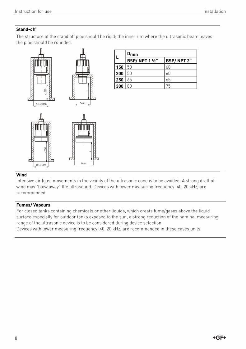
Stand-off
The structure of the stand off pipe should be rigid; the inner rim where the ultrasonic beam leaves the pipe should be rounded.
25
0
D 100
L
Dmin.
L Dmin
BSP/ NPT 1 ½” BSP/ NPT 2” 150 50 60 200 50 60 250 65 65 300 80 75
35
0
D 100
L
Dmin.
Wind Intensive air (gas) movements in the vicinity of the ultrasonic cone is to be avoided. A strong draft of wind may "blow away" the ultrasound. Devices with lower measuring frequency (40, 20 kHz) are recommended. Fumes/ Vapours For closed tanks containing chemicals or other liquids, which creats fume/gases above the liquid surface especially for outdoor tanks exposed to the sun, a strong reduction of the nominal measuring range of the ultrasonic device is to be considered during device selection. Devices with lower measuring frequency (40, 20 kHz) are recommended in these cases units.
Installation Instruction for use
9
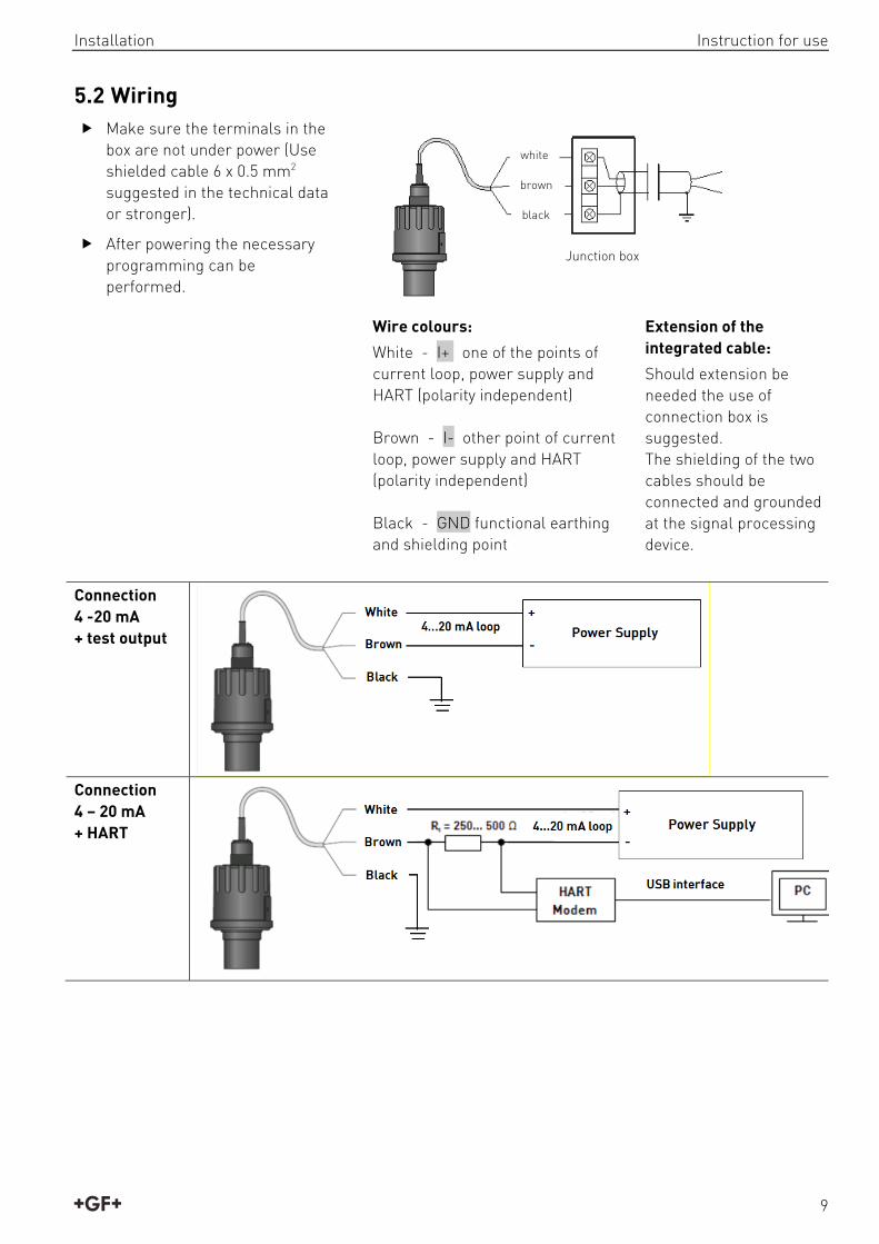
5.2 Wiring Make sure the terminals in the
box are not under power (Use shielded cable 6 x 0.5 mm2 suggested in the technical data or stronger).
After powering the necessary programming can be performed.
Wire colours:
White - I+ one of the points of current loop, power supply and HART (polarity independent) Brown - I- other point of current loop, power supply and HART (polarity independent) Black - GND functional earthing and shielding point
Extension of the integrated cable:
Should extension be needed the use of connection box is suggested. The shielding of the two cables should be connected and grounded at the signal processing device.
Connection 4 -20 mA + test output
Connection 4 – 20 mA + HART
Junction box
white
brown
black

Instruction for use Putting into operation
10
Connection 9900 Universal Transmitter
6. Putting into operation
6.1 Usage Subsequent to powering the correctly wired device would start to tick and after 10 - 20 s ECHO LED go on and 4 ... 20 mA signal appears on the current output. Measurement will be according to the factory setting. The factory setting is throughout apt to check proper working and to perform simple measurement tasks but features residing in the unit can only be utilised by adjusting the 2270 Ultrasonic Level Sensor to the application by programming. For sound knowledge of the operation features and proper solving of difficult measurement applications the parts of the programming should carefully be studied..
LED indication: ECHO-LED
ON, if the unit detects proper echo.
COM-LED See description „HART”
Device can be reset to factory setting. Default is the following: Measurement: level (LEV) Zero level assigned to the maximum distance Current output proportional to the level 4 mA and 0% assigned to zero level. 20 mA and 100% a assigned to the maximum level (minimum distance) Error indication by the current output: holds last value. Damping: 60 s.
Red LED „ECHO”
Red LED „COM”
Cable
View from above:

Programming Instruction for use
11
7. Programming The HART interface provides for access to the whole parameter set and possibility of their programming. Parameter set can be reached in the following way: by the use of the
Eview light software run on the PC connected through HART modem to the loop or
7.1 Measurement configuration
P00: - c b a Engineering units
Programming of this parameter will result in loading the factory default with the corresponding engineering units. Therefore all parameters should be set again!
a Operation 0 Liquid level measurement
b Engineering units (according to “c”) Metric US
0 m ft 1 cm Inch
c Calculation system
0 metric 1 US
Factory default: 000
P01: - - 1 a Measurement mode
Parameter value „a” will determine the basic measurement value that will be transmitted. Subsequently values for the relays are also relating to these quantities.
a Measurment mode
Transmitted value Display symbol
0 Distance Distance DIST 1 Level
Level LEV
2 Level % LEV% 3 Volume
Volume VOL
4 Volume % VOL% 5 Flow Flow FLOW
A
Xm
LEV %
0 100 [%]
LEV
0
DIST
0 H
D
DIS
T
H
P10
P11
H

Instruction for use Programming
12
Transmitted value DIST LEV=H-DIST LEV%= P10mXH
P10P11*LEV
Parameters to set P00 P01(a) = 0 P05 ≥ Xm
P00 P01(a) = 1 P04 = H P05 ≥ Xm
P00 P01(a) = 2 P04 = H P05 ≥ Xm P10 = X 0% P11 = X100%
A
DIS
T
H
VOL0
VOL%0 100 [%]
P10
P11
B C
D
Transmitted value VOL fP40…P45(H-DIST)
VOL%= P10
mXHP10P11
*VOL
Parameters to set P00 P01(a) = 3 P02(b) P04 = H P05 ≥ Xm P40…P45
P00 P01(a) = 4 P02(b) P04 = H P05 ≥ Xm P10 = X 0% P11 = X100% P40…P45
Description of the figures: A: Shortest measurable distance B: Volume (content) pertaining to the greatest measurable level C: Whole value of the vessel D: diagram valid for the default value of P10 P11 Factory default: 11

Programming Instruction for use
13
P02: - c b a Calculation units
a Temperature 0 °C 1 °F
This table is interpreted according to P00(c), P01(a) and P02(c) and is irrelevant in case of percentage measurement [ P01(a)= 2 or 4 )]
b Volume Weight (see also P32) Volume flow Metric US Metric US Metric US
0 m3 ft3 - lb (pound) m3/time ft3/time 1 litre gallon tons tonnes litre/time gallon/time
c Time Attention! 2270 Ultrasonic Level Sensor is a level transmitter. Although it can be used for measuring weight, due to factors involved in doing so, accuracy may essentially be influenced.
0 s 1 min 2 hour
3 day
Factory default: 000 P04 - - - - Maximum distance to be measured (H)
This is the only parameter that has to be programmed for each application other than distance (however to avoid disturbing effect of possible multiple echoes it is suggested to do this in distance measurement applications too). The maximum distance to be measured is the greatest distance between the surface of the transducer and the farthest level to be measured. The factory programmed, greatest distances (DEFAULT values) which can be measured by the units are listed in the table below. For the actual application the maximum distance to be measured i.e. the distance between the sensor and the bottom of the tank should be entered in P04.
2270 Ultrasonic Level Sensor for liquids
Maximum measuring distance XMm/ft Transducer material PP/ PVDF
Version I 4/13 Version II 6/20
Since the level is determined by calculating the difference between the value set in P04 and distance (DIST) is measured by the unit, it is essential that the correct value of (H) is set in P04. To obtain the best accuracy it is suggested that this distance is measured in the empty tank.
Factory default: XM as per chart

Instruction for use Programming
14
P05: - - - - Minimum measuring distance (Dead-zone – Close-end blocking)
The range, beginning with the sensor’s surface, within which (due to the physical restraint of the ultrasound measurement system) measurement can not be made, is called the dead zone. The 2270 Ultrasonic Level Sensor will not accept any echo within the blocking distance set here. Close-end blocking may be represented as the extension of the dead zone within which a possible echo will not be taken into consideration making possible to exclude disturbing objects near to the sensor. Automatic Close-end blocking =Dead Band control (P05 = Xm) Device with factory default will automatically set the smallest possible dead band depending on the conditions of the operation. This will be under optimal conditions a bit smaller in unfavourable circumstances greater than value given in the chart. Manual Close-end-blocking with limitation ≥ dead zone (P05>Xm) By entering a value, higher than the factory default the close-end blocking will be either the value programmed in P05 or the actual dead zone distance (influenced by the actual conditions of the application) whichever is greater.
2270 Ultrasonic Level Sensor for liquids
Minimum measuring distance Xm m/feet Sensor material PP/ PVDF
Version I 0.2/0.65 Version II 0.25/0.82
Factory default : Xm as per chart

Programming Instruction for use
15
P06: - - - - Far-end blocking
Far-end blocking is the range below the level set in parameter P06. The far-end blocking can be used to avoid disturbing effect of stirrer or heaters at the bottom of the tanks. Detecting echoes in this range the unit provides special signals.
A.) Measuring level or content Level sinking below:
- the value of P06 current output is according to the value of the far-end blocking and further
- below SUB 0 (7/8 of P06) the ERROR CODE 10 will be transmitted via HART
Level rising over value of far-end blocking: The calculation of level and volume will be based on the programmed tank dimensions, therefore the measured or calculated process values will not be influenced in any way, by the far end blocking value.
P06
=X
SUB
0X/
8
20m
A
4mA
H
B.) Open channel flow metering Far-end blocking will be used for those small levels below which the accurate volume flow calculation is no longer possible.
Level in the flume/weir sinking below the blocked out range: - Output current value will be according to
the value of Q = 0 - 0 value transmitted via HART for display of
„No Flow” or 0 Level in the flume/weir rising over the
blocked out range: The calculation of volume flow will be based on the programmed flume/weir data; therefore the measurement values will not be influenced in any way, by the far end blocking value.
P04
P46
h P06
Factory default: 0

Instruction for use Programming
16
7.2 Current output P08: - - - - Fixed current output
By this step the output current can be set for a fix value selected from between 3.8 mA and 20.5 mA. This function is not operational as per the factory default: 0. Attention: fixing output current will make settings in P10, P11, P12 and P19 irrelevant.
Factory default: 0
P10: - - - - Value (of distance, level, volume or flow) assigned to 4 mA current output
Factory default: 0
P11: - - - - Value (of distance, level, volume or flow) assigned to 20 mA current output
Values are interpreted according to P01(a). Assignment can be made so that the proportion between the change of the (measured or calculated) process value and the change of the current output be either direct or inverse. E.g. level 1 m assigned to 4mA and level 10 m assigned to 20 mA represents direct proportion and level 1 m assigned to 20 mA and level 10 m assigned to 4 mA represents the inverse proportion. Please note that in case of programming for (LEV or VOL) % measurement the min and max value has to be entered in the relevant engineering units of LEV (m, ft) or VOL (m3, ft3).
Transmitting level
LEV 20,5 mA
3,8 mAP11
P10 Iout
0 4 20 [mA]
A
DIS
T
H
D
A: smallest measurable distance D: diagram valid for default values of P10 and P11
Factory default: XM – Xm (see table P04 and P05) P12: - - - a Error indication by the current output
In case of error the 2270 Ultrasonic Level Sensor will provide one of the current outputs below for the time the error prevails.
a Error indication by output current 0 HOLD (letzter Wert halten) 1 3,8 mA 2 22 mA
Factory default: 0

Programming Instruction for use
17
7.3 Digital communication P19: - - - a Short (HART) address of the unit
These addresses with 0 … 15 are, in accordance with the HART standard, for distinguishing units in the same loop. Address: 0 current output of 4 … 20 ma operational Address: 1 … 15 current output is fixed to 4 mA. Factory default: 2
7.4 Measurement optimisation
P20: - - - a Damping
This parameter can be used to reduce unwanted fluctuation of the display and output.
a Damping (s) LIQUIDS
No or moderate fume/ waves
heavy or dense fume or turbulent waves
0 no filter for testing only 1 3 applicable not recommended 2 6 recommended applicable 3 10 recommended recommended 4 30 recommended recommended 5 60 recommended recommended
Factory default: 5
P22: - - - a Dome top tank compensation
This parameter can be used to reduce disturbing effect of possible multiple echoes.
a Compensation Remark 0 OFF In case the 2270 Ultrasonic Level Sensor is not mounted in the
centre of the top and the top is flat. 1 ON In case the 2270 Ultrasonic Level Sensor is mounted in the
centre of a tank with dome-shaped top Factory default: 0

Instruction for use Programming
18
P24: - - - a Target tracking speed
In this parameter evaluation can be speed up at the expense of the accuracy.
a Tracking speed Remark 0 Standard For most applications 1 Fast For fast changing level
2
Special Only for special applications (measuring range is reduced to 50% of the nominal value) The measuring window is inactive and the 2270 Ultrasonic Level Sensor will respond practically instantly to any target
Factory default: 0 P25: - - - a Selection of Echo within the measuring window
A so-called measuring window is formed around the echo signal. The position of this measuring window determines the flight time for calculation of the distance to the target. (the picture below can be seen on the test oscilloscope). Receivedsignalamplitude
Echo 1.
t
Echo 2.
t
Some applications involve multiple (target + disturbing) echoes even within the measuring window. Basic echo selection will be done by the Quest + software automatically. This parameter influences the echo selection only within the measuring window..
a Echo in the window to be selected Remark 0 With the highest amplitude Most frequently used 1
First one For liquids applications with multiple echoes within the Measuring Window
Factory default: 0
P26: Level elevation rate (filling speed) (m/h or ft/h)
Factory default: 2000
P27: Level descent rate (emptying speed) ) (m/h or ft/h)
These parameters provide additional protection against echo loss in applications involving very heavy fuming. Correct setting increases reliability of the measurement during filling and emptying. The parameters must not be smaller than the fastest possible filling/emptying rate of the actual technology. Attention! Level changing rate is rather different near to the conical or spherical bottom of such a vessel. Factory default: 2000
Programming Instruction for use
19
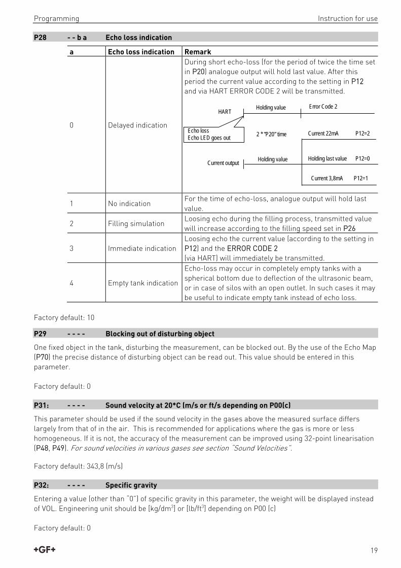
P28 - - b a Echo loss indication
a Echo loss indication Remark
0 Delayed indication
During short echo-loss (for the period of twice the time set in P20) analogue output will hold last value. After this period the current value according to the setting in P12 and via HART ERROR CODE 2 will be transmitted.
1 No indication For the time of echo-loss, analogue output will hold last value.
2 Filling simulation Loosing echo during the filling process, transmitted value will increase according to the filling speed set in P26
3 Immediate indication Loosing echo the current value (according to the setting in P12) and the ERROR CODE 2 (via HART) will immediately be transmitted.
4 Empty tank indication
Echo-loss may occur in completely empty tanks with a spherical bottom due to deflection of the ultrasonic beam, or in case of silos with an open outlet. In such cases it may be useful to indicate empty tank instead of echo loss.
Factory default: 10
P29 - - - - Blocking out of disturbing object
One fixed object in the tank, disturbing the measurement, can be blocked out. By the use of the Echo Map (P70) the precise distance of disturbing object can be read out. This value should be entered in this parameter. Factory default: 0
P31: - - - - Sound velocity at 20*C (m/s or ft/s depending on P00(c)
This parameter should be used if the sound velocity in the gases above the measured surface differs largely from that of in the air. This is recommended for applications where the gas is more or less homogeneous. If it is not, the accuracy of the measurement can be improved using 32-point linearisation (P48, P49). For sound velocities in various gases see section “Sound Velocities”.
Factory default: 343,8 (m/s)
P32: - - - - Specific gravity
Entering a value (other than “0”) of specific gravity in this parameter, the weight will be displayed instead of VOL. Engineering unit should be [kg/dm3] or [lb/ft3] depending on P00 (c) Factory default: 0
HART
Current output
Holding value
Holding value
Error Code 2
Current 22mA P12=2
Holding last value P12=0
Current 3,8mA P12=1
Echo lossEcho LED goes out
2 * ”P20” time

Instruction for use Programming
20
7.5 Volume (content) measurement P40: - - ba Tank shape
ba Tank shape Also to be set
Attention: The value „a” determining the shape of the tank should be set first
b0 Standing cylindrical tank shape (value of “b” as below)
P40(b), P41
01 Standing cylindrical tank with conical bottom
P41, P43, P44
02 Standing rectangular tank (with chute) P41, P42, (P43, P44, P45)
b3 Lying cylindrical tank shape (value of “b” as bellow)
P40(b), P41, P42
04 Spherical tank P41
Factory default: 00
P41-45: - - - - Behälterabmessungen
Standing cylindrical tank with hemispherical bottom
a=0
Standing cylindrical tank with conical bottom
a=1 b=0
Standing rectangular tank with or without chute
a=2 b=1
b=0
P40b=1
b=2b=3
Ohne Rutsche sindP43, P44 und P45=0
Lying cylindrical tank a = 3
Spherical tank a = 4, b = 0
b=0
b=1
b=2
b=3P40
Factory default: 0
Plain bottom P43, P44 and P45 = 0
Programming Instruction for use
21
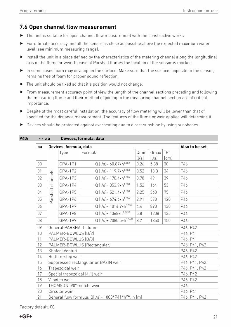
7.6 Open channel flow measurement The unit is suitable for open channel flow measurement with the constructive works
For ultimate accuracy, install the sensor as close as possible above the expected maximum water level (see minimum measuring range).
Install the unit in a place defined by the characteristics of the metering channel along the longitudinal axis of the flume or weir. In case of Parshall flumes the location of the sensor is marked.
In some cases foam may develop on the surface. Make sure that the surface, opposite to the sensor, remains free of foam for proper sound reflection.
The unit should be fixed so that it‘s position would not change.
From measurement accuracy point of view the length of the channel sections preceding and following the measuring flume and their method of joining to the measuring channel section are of critical importance.
Despite of the most careful installation, the accuracy of flow metering will be lower than that of specified for the distance measurement. The features of the flume or weir applied will determine it.
Devices should be protected against overheating due to direct sunshine by using sunshades.
P40: - - b a Devices, formula, data
ba Devices, formula, data Also to be set
Par
shal
l cha
nnel
s
Type Formula Qmin [l/s]
Qmax [l/s]
“P” [cm]
00 GPA-1P1 Q [l/s]= 60.87*h1,552 0.26 5.38 30 P46
01 GPA-1P2 Q [l/s]= 119.7*h1,553 0.52 13.3 34 P46
02 GPA-1P3 Q [l/s]= 178.4*h1,555 0.78 49 39 P46
03 GPA-1P4 Q [l/s]= 353.9*h1,558 1.52 164 53 P46
04 GPA-1P5 Q [l/s]= 521.4*h1,558 2.25 360 75 P46
05 GPA-1P6 Q [l/s]= 674.6*h1,556 2.91 570 120 P46
06 GPA-1P7 Q [l/s]= 1014.9*h1,556 4.4 890 130 P46
07 GPA-1P8 Q [l/s]= 1368*h1,5638 5.8 1208 135 P46
08 GPA-1P9 Q [l/s]= 2080.5*h1,5689 8.7 1850 150 P46
09 General PARSHALL flume P46, P42 10 PALMER-BOWLUS (D/2) P46, P41 11 PALMER-BOWLUS (D/3) P46, P41 12 PALMER-BOWLUS (Rectangular) P46, P41, P42 13 Khafagi Venturi P46, P42 14 Bottom-step weir P46, P42 15 Suppressed rectangular or BAZIN weir P46, P41, P42 16 Trapezoidal weir P46, P41, P42 17 Special trapezoidal (4:1) weir P46, P42 18 V-notch weir P46, P42 19 THOMSON (90°-notch) weir P46 20 Circular weir P46, P41 21 General flow formula: Q[l/s]= 1000*P41*hP42, h [m] P46, P41, P42
Factory default: 00

Instruction for use Programming
22
P41-45: Flume/ weir dimensions
P40=00
Parshall flumes (GPA1P1 … GPA-1P9) For further details see the Manual of the Parshall flume
Sensor
P4
6
Sensor
P40=09
General Parshall flume 0,305 < P42(width) <2,44
026.042569.1305,0/42372/ PhPslQ 2,5 < P42 Q[m3/s]= K*P42*h1,6 P= 2/3*A
A
h
P46
Sensor
SensorP42
P
P40= 10
Palmer-Bowlus (D/2) flume Q[m3/s]= f(h1/P41)*P412,5, where h1[m]=
h+(P41/10) P41 m
P04
P46
h
P41
D
D/10
1
2
D/2
P40= 11
Palmer-Bowlus (D/3) flume Q[m3/s]= f(h1/P41)*P412,5,
wobei h1[m]= h+(P41/10) P41 m
P04
P46
h
P41
D
D/10
1
2
D/3
P40= 12
Palmer-Bowlus (rectangular) flume Q[m3/s]= C*P42*h1,5, where C= f(P41/P42)
P41 m, P42 m D
P42
P46
P04
h
D/10
P41
P42 [m] K 3,05 2,450 4,57 2,400 6,10 2,370 7,62 2,350 9,14 2,340 15,24 2,320

Programming Instruction for use
23
P40= 13
Khafagi Venturi flume Q [m3/s] = 1,744 P42 h1,5 + 0,091 h2,5 P42 m h [m]
15cm
P46
Sensor
h
P42
Sensor
P40= 14
Bottom step weir 0,0005 < Q [m3/s] < 1 0,3 < P42 [m] < 15 0,1 < h [m] < 10 Q [m3/s]= 5,073 P42 h1,5 Accuracy: 10%
P40=14
P46
P42
h
P40= 15
Suppressed rectangular or BAZIN weir 0,001 < Q [m3/s] < 5 0,15 < P41 [m] < 0,8 0,15 < P42 [m] < 3 0,015 < h [m] < 0,8 Q [m3/s] =1,77738(1+0,1378h/P41) P42 (h+0,0012)1,5
Accuracy: 1%
P40=15
P04
P46
h
P42
P41
P40= 16
Trapezoidal weir 0,0032 < Q [m3/s] < 82 20 < P41[°] < 100 0,5 < P42 [m] < 15 0,1 < h [m] < 2 Q [m3/s] = 1,772 P42 h1,5 + 1,320 tg(P41/2) h2,47 Accuracy: 5%
P40=16
P04
P46
h
P42P41
P40= 17
Special trapezoidal (4:1) weir 0,0018 < Q [m3/s] < 50 0,3 < P42 [m] < 10 0,1 < h [m] < 2 Q [m3/s] = 1,866 P42 h
1,5 Accuracy: 3%
1
4
P40=17
P46
P04 h
P42
P40= 18
V-notch weir 0,0002 < Q [m3/s] < 1 20 < P42[°] < 100 0,05 < h [m] < 1 Q[m3/s] = 1,320 tg(P42/2) h2,47 Accuracy: 3%
P40=18
h
P46
P42P04

Instruction for use Programming
24
P40= 19
THOMSON (90°-notch) weir 0,0002 < Q [m3/s] < 1 0,05 < h [m] < 1 Q[m3/s] = 1,320 h2,47 Accuracy:: 3%
P46
P40=19
P04 h 90
P40= 20
Circular weir 0,0003 < Q [m3/s] < 25 0,02 < h [m] < 2 Q[m3/s] = m*b D2,5, where b = f (h/D)
m= 0,555+0,041 h/P41+(P41/(0,11 h)) Accuracy:: 5%
P40=20
P46
P04 h P41
Factory default: 0 P46 - - - - Distance at Q=0
Distance between sensor surface and the level at which flow starts has to be entered in this parameter. Factory default: 0
7.7 32-Point-Linearisation P47: - - - a Linearisation
Linearisation is the method of assigning requested (calibrated or calculated) level, volume or flow to values measured by the transmitter. It can be used for instance if the sound velocity is not known (LEVELLEVEL) or in the case of tank with other shape than under 6.4 or open channel other than under 6.5 (LEVEL VOLUME or LEVEL FLOW).
a Linearisation 0 OFF (FACTORY DEFAULT) 1 ON
Conditions of correct programming of the data pairs
The table must always start with: L(1)= 0 and r(1)= value (assigned to 0 level) The table must be ended either with the 32nd data pair i.e. j=32 or if the linearisation table contains
less than 32 data-pairs j<32, it must be ended with a level value “0” e.g. L(j<32)= 0. The 2270 Ultrasonic Level Transmitter will ignore data after recognising level value “0” with serial
number other than “1”. If the above conditions are not met, error codes will be displayed (see chapter: Error Codes).
i L (Left column) Level values measured
r (Right column) Value assigned to transmit
1 0 r(1) 2 L(2) r(2) L(i) r(i) nn L(nn) r(nn) nn+1 0 32
Factory default: 0

Programming Instruction for use
25
P48: Number of linearisation data pairs
Number of linearisation data pairs entered in the table.
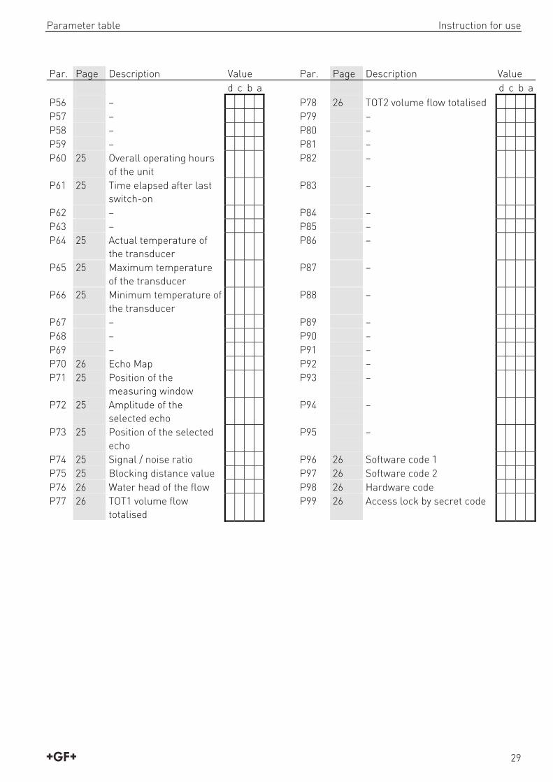
7.8 Information parameters (read out parameters) P60: - - - - Overall operating hours of the unit (h) P61: - - - - Time elapsed after last switch-on (h) P64: - - - - Actual temperature of the transducer (°C/°F) Broken loop of the thermometer will be indicated by display of the Pt Error message initiated by a signal sent via HART. In this case the transmitter will perform temperature correction corresponding to 20ºC. P65: - - - - Maximum temperature of the transducer (°C/°F) P66: - - - - Minimum temperature of the transducer (°C/°F) P70: - - - - Number of Echoes / Echo Map Amplitude and position of the echoes can also be read out. P71: - - - - Distance of the of Measuring Window P72 - - - - Amplitude of the selected echo [dB] <0 P73: Position of the selected echo (time) :(ms) [ms] P74: Signal To Noise Ratio
Ratio Measurement conditions Over 70 Excellent Between 70 and 30 Good Under 30 Unreliable
P75: - - - - Blocking Distance
The actual close-end blocking distance will be displayed (provided automatic blocking was selected in P05).

Instruction for use Maintenance
26
7.9 Additional parameters of the flow metering P76: - - - - Head of flow (LEV) (Read only parameter)
The Headwater value can be checked here. This is the “h” value in the formula for flow calculation.. P77: - - - - TOT1 volume flow totalised (resettable) P78: - - - - TOT2 volume flow totalised (non-resettable)
7.10 Other parameters P96: - - - - Software Code 1 (Read only parameter) P97: - - - - Software Code 2 (Read only parameter) P98: - - - - Hardware Code (Read only parameter) P99: - - - - Access lock by secret code The purpose of this feature is to provide protection against accidental programming or intentional reprogramming of parameters by a person not entitled to do so. The secret code can be any value other than 0000. Setting a secret code will automatically be activated when the 2270 Ultrasonic Level Sensor is returned to the Measurement Mode. In order to program locked device the secret code should be entered first in P99. Thus for entering a new code or erasing the old one the knowledge of the previous code is necessary.
8. Maintenance 2270 Ultrasonic Level Sensor units do not require maintenance on a regular basis. The need for cleaning of the sensor head may occur. Cleaning should be performed by utmost care where scraping or denting of the transducer have to be avoided. Repair under or after the guarantee period should only be carried out by GF Piping Systems. Devices for repair should only be returned duly cleaned and disinfected.

Error codes Instruction for use
27
9. Error codes
Error Code Error description Causes and solutions
1 Memory error Contact representative of GF Piping
Systems
2 Echo loss No echo received (no reflection), see chapter „Indication of mistakes (by LEDs) made during programming”
3 Hardware error Contact representative of GF Piping
Systems
4 Display overflow Check settings
5 Sensor error or improper installation/mounting, level in the dead band
Verify sensor for correct operation and check for correct mounting according to the User’s Manual
6 The measurement is at the reliability threshold Better location should be found.
7 No signal received within the measuring range specified in P04 and P05
Check programming, also look for installation mistake
12 Linearisation table error: both L(1) and L(2) are zero (no valid data-pairs)
See ”Linearisation” Section
13 Linearisation table error: same L(i) data is given twice in the table
See ”Linearisation” Section
14 Linearisation table error: the r(i) values are not monotone increasing
See ”Linearisation” Section
15 Linearisation table error: measured Level is higher than the last Volume or Flow data-pair
See ”Linearisation” Section
16 The check sum of the program is wrong Contact representative of GF Piping
Systems
17 Parameter consistency failure Check programming
18 Hardware failure Check programming

Instruction for use Parameter table
28
10. Parameter table
Par. Page Description Value Par. Page Description Value d c b a d c b a P00 11 Application/ Engineering
Units P28 19 Echo loss indication
P01 11 Measurement Mode P29 19 Blocking out a disturbing object
P02 11 Calculation units P30 – P03 - P31 19 Sound velocity values in
different gases
P04 13 Maximum Measuring Distance
P32 19 Specific gravity
P05 14 Minimum Measuring Distance
P33 –
P06 15 Fernausblendung P34 – P07 – P35 – P08 – P36 – P09 – P37 – P10 16 Transmitted value
assigned to „4 mA” P38 –
P11 11 Transmitted value assigned to „20 mA”
P39 –
P12 16 “Error” indication by the current output
P40 20 Selection of tank shape/ open channel
P13 – P41 22 Dimensions of tank / Open Channel
P14 – P42 22 Dimensions of tank / Open Channel
P15 – P43 22 Dimensions of tank / Open Channel
P16 – P44 22 Dimensions of tank / Open Channel
P17 – P45 22 Dimensions of tank / Open Channel
P18 – P46 24 Level pertaining to flow Q= 0 P19 – P47 24 Linearisation P20 17 Damping P48 25 Linearisation table P21 – P49 – P22 17 Dome top tank
compensation P50 –
P23 – P51 – P24 18 Target tracking speed P52 – P25 18 Selection of Echo in the
measuring window P53 –
P26 18 Level elevation rate P54 – P27 18 Level descent rate P55 –
Parameter table Instruction for use
29
Par. Page Description Value Par. Page Description Value d c b a d c b a P56 – P78 26 TOT2 volume flow totalised P57 – P79 – P58 – P80 – P59 – P81 – P60 25 Overall operating hours
of the unit P82 –
P61 25 Time elapsed after last switch-on
P83 –
P62 – P84 – P63 – P85 – P64 25 Actual temperature of
the transducer P86 –
P65 25 Maximum temperature of the transducer
P87 –
P66 25 Minimum temperature of the transducer
P88 –
P67 – P89 – P68 – P90 – P69 – P91 – P70 26 Echo Map P92 – P71 25 Position of the
measuring window P93 –
P72 25 Amplitude of the selected echo
P94 –
P73 25 Position of the selected echo
P95 –
P74 25 Signal / noise ratio P96 26 Software code 1 P75 25 Blocking distance value P97 26 Software code 2 P76 26 Water head of the flow P98 26 Hardware code P77 26 TOT1 volume flow
totalised P99 26 Access lock by secret code

Instruction for use Sound velocity values in different gases
30
11. Sound velocity values in different gases The following table contains the sound velocity values of various gases measured at 20°C.
Gases Formula Sound Velocity (m/s)
Gases Formula Sound Velocity (m/s)
Acetaldehyde C2H4O 252,8 Ethylene C2H4 329,4 Acetylene C2H2 340,8 Helium He 994,5 Ammonia NH3 429,9 Hydrogen sulphide H2S 321,1 Argon Ar 319,1 Methane CH4 445,5 Benzene C6H6 183,4 Methanol CH3OH 347 Carbon dioxide CO2 268,3 Neon Ne 449,6 Carbon monoxide CO 349,2 Nitrogen N2 349,1 Carbon tetrachloride CCl4 150,2 Nitrogen monoxide NO 346 Chlorine Cl2 212,7 Oxygen O2 328,6 Dimethyl ether CH3OCH3 213,4 Propane C3H8 246,5 Ethane C2H6 327,4 Sulphur hexafluoride SF6 137,8 Ethanol C2H3OH 267,3
12. Article overview Code Type Article description 159 300 155 2270-P-1B-4 Range 4 m, PP body, 4..20 mA 2-wire / HART, BSP thread
159 300 156 2270-P-1B-6 Range 6 m, PP body, 4..20 mA 2-wire / HART, BSP thread
159 300 162 2270-V-1B-4 Range 4 m, PVDF body, 4..20 mA 2-wire / HART, BSP thread
159 300 163 2270-V-1B-6 Range 6 m, PVDF body, 4..20 mA 2-wire / HART, BSP thread
159 300 169 2270-P-1N-4 Range 4 m, PP body, 4..20 mA 2-wire / HART, NPT thread
159 300 170 2270-P-1N-6 Range 6 m, PP body, 4..20 mA 2-wire / HART, NPT thread
159 300 176 2270-V-1N-4 Range 4 m, PVDF body, 4..20 mA 2-wire / HART, NPT thread
159 300 177 2270-V-1N-6 Range 6 m, PVDF body, 4..20 mA 2-wire / HART, NPT thread

Disposal Instruction for use
31
13. Disposal Before disposing of the different material, separate it by recyclables, normal waste and special waste.
Comply with local legal regulations and provisions when recycling or disposing of the product, the individual components and the packaging.
Comply with National regulations, standards and directives.
WARNING
Parts of the product may be contaminated with medium which is detrimental to health and the environment and therefore cleaning is not sufficient!
Risk of personal and health injury caused by this medium.
Prior to the disposal of the product:
Collect any medium which has escaped and dispose of it in accordance with the local regulations.
Neutralize residues of media in the product.
Separate materials (plastics, metals etc.) and dispose of them in accordance with the local regulations.
If you have questions regarding the disposal of your product, please contact your national GF Piping Systems representative.


Argentina / Southern South AmericaGeorg Fischer Central Plastics Sudamérica S.R.L.Buenos Aires, ArgentinaPhone +54 11 4512 02 [email protected]/ar
AustraliaGeorge Fischer Pty LtdRiverwood NSW 2210 AustraliaPhone +61 (0) 2 9502 8000 [email protected]/au
AustriaGeorg Fischer Rohrleitungssysteme GmbH3130 HerzogenburgPhone +43 (0) 2782 856 [email protected]/at
Belgium / LuxembourgGeorg Fischer NV/SA1070 Bruxelles/BrüsselPhone +32 (0) 2 556 40 [email protected]/be
BrazilGeorg Fischer Sist. de Tub. Ltda.04795-100 São PauloPhone +55 (0) 11 5525 [email protected]/br
CanadaGeorg Fischer Piping Systems LtdMississauga, ON L5T 2B2Phone +1 (905) 670 8005Fax +1 (905) 670 [email protected]/ca
ChinaGeorg Fischer Piping Systems Ltd Shanghai 201319Phone +86 21 3899 3899 [email protected]/cn
Denmark / IcelandGeorg Fischer A/S2630 TaastrupPhone +45 (0) 70 22 19 [email protected]/dk
FinlandGeorg Fischer AB01510 VANTAAPhone +358 (0) 9 586 58 25 Fax +358 (0) 9 586 58 [email protected]/fi
FranceGeorg Fischer SAS95932 Roissy Charles de Gaulle CedexPhone +33 (0) 1 41 84 68 [email protected]/fr
GermanyGeorg Fischer GmbH73095 Albershausen Phone +49 (0) 7161 [email protected]/de
IndiaGeorg Fischer Piping Systems Ltd400 076 MumbaiPhone +91 224007 [email protected]/in
ItalyGeorg Fischer S.p.A.20063 Cernusco S/N (MI)Phone +39 02 921 [email protected]/it
JapanGeorg Fischer Ltd556-0011 Osaka, Phone +81 (0) 6 6635 [email protected]/jp
KoreaGeorg Fischer Piping Systems271-3 Seohyeon-dong Bundang-guSeongnam-si, Gyeonggi-doSeoul 463-824Phone +82 31 8017 1450Fax +82 31 8017 [email protected]/kr
MalaysiaGeorge Fischer (M) Sdn. Bhd.40460 Shah Alam, Selangor Darul EhsanPhone +60 (0) 3 5122 [email protected]/my
Mexico / Northern Latin AmericaGeorg Fischer S.A. de C.V.Apodaca, Nuevo LeonCP66636 MexicoPhone +52 (81) 1340 8586Fax +52 (81) 1522 [email protected]/mx
Middle EastGeorg Fischer Piping Systems (Switzerland) LtdDubai, United Arab EmiratesPhone +971 4 289 49 [email protected]/int
NetherlandsGeorg Fischer N.V.8161 PA EpePhone +31 (0) 578 678 222 [email protected]/nl
New ZealandGeorg Fischer Ltd13 Jupiter Grove, Upper Hutt 5018PO Box 40399, Upper Hutt 5140Phone +64 (0) 4 527 [email protected]/nz
NorwayGeorg Fischer AS1351 Rud Phone +47 67 18 29 [email protected]/no
PolandGeorg Fischer Sp. z o.o.05-090 Sekocin Nowy Phone +48 (0) 22 31 31 0 50 [email protected]/pl
RomaniaGeorg Fischer Piping Systems (Switzerland) Ltd020257 Bucharest - Sector 2Phone +40 (0) 21 230 53 [email protected]/int
RussiaGeorg Fischer Piping Systems (Switzerland) LtdMoscow 125047Phone +7 495 258 60 [email protected]/ru
SingaporeGeorge Fischer Pte Ltd11 Tampines Street 92, #04-01/07528 872 SingaporePhone +65 6747 [email protected]/sg
Spain / PortugalGeorg Fischer S.A.28046 MadridPhone +34 (0) 91 781 98 [email protected]/es
SwedenGeorg Fischer AB117 43 StockholmPhone +46 (0) 8 506 775 [email protected]/se
SwitzerlandGeorg Fischer Rohrleitungssysteme (Schweiz) AG8201 SchaffhausenPhone +41 (0) 52 631 30 [email protected]/ch
TaiwanGeorg Fischer Co., LtdSan Chung Dist., New Taipei CityPhone +886 2 8512 2822Fax +886 2 8512 2823www.gfps.com/tw
United Kingdom / IrelandGeorge Fischer Sales LimitedCoventry, CV2 2STPhone +44 (0) 2476 535 [email protected]/uk
USA / CaribbeanGeorg Fischer LLCTustin, CA 92780-7258Phone +1 (714) 731 88 00 Toll Free 800 854 40 [email protected]
VietnamGeorge Fischer Pte Ltd136E Tran Vu, Ba Dinh District, HanoiPhone +84 4 3715 3290 Fax +84 4 3715 3285
International Georg Fischer Piping Systems (Switzerland) Ltd8201 Schaffhausen/SwitzerlandPhone +41 (0) 52 631 30 03Fax +41 (0) 52 631 28 [email protected]/int
GF Piping Systems
Worldwide at homeOur sales companies and representatives ensure local customer support in over 100 countries
www.gfps.com
700.277.994GFDO_6317_4 (06.13)© Georg Fischer Piping Systems LtdCH-8201 Schaffhausen/Switzerland, 2013Printed in Switzerland
The technical data are not binding. They neither constitute expressly warranted characteristics nor guaranteed properties nor a guaranteed durability. They are subject to modification. Our General Terms of Sale apply.