2018 check-all valve mfg., co. · check-all valve check-all valve® mfg. co. 1800 fuller road west...
TRANSCRIPT

CHECK-ALL VALVECheck-All Valve® Mfg. Co.
1800 Fuller Road
West Des Moines, IA 50265 U.S.A.
Phone: 515-224-2301
Fax: 515-224-2326
Website: www.checkall.com
E-mail: [email protected]
Wafer Insert
WV•
Flange Insert
F1•
F6•
FP•
Horizontal-Vertical
Flanged &
Drilled
HV•
MADE IN USA CHECK-ALL VALVE® MFG. CO. Phone: 515-224-2301 Fax: 515-224-2326
Introduction to Company and Products .......................................................................................... 1
Certifications & Compliances.......................................................................................................... 2
Order Information............................................................................................................................ 3
OUR CHECK VALVES BY CONNECTION TYPE.................................................................. 5 - 47
Bushing
BU•
BR•
Connector
CN•
CR•
Universal Low
Pressure
U3•
UR•
Universal High
Pressure
U1•
R1•
Mini Check
M1 - M8•
Threaded
3-A Sanitary
Check
3S•Third Party
Verified
Sanitary
Sanitary Cartridge
SC•Sanitary Insert
CB•
TC•
Flange
page 5 page 9 page11
page13 page15
page17 page 19 page 21
page 23 page 27 page 29
®

Additional Products and Services.................................................................................................. 48
Technical Data ............................................................................................................................... 49
Application Guidelines ................................................................................................................... 50
Installation and Operating Instructions .......................................................................................... 51
Body Material Definition for Check-All Valve® Products................................................................. 53
Pressure Equipment Directive (PED 2014/68/EU) Conformance Statement ................................ 55
Check-All® Order Form .................................................................................................................. 57
Manufacturer’s Terms and Conditions of Sale............................................................................... 58
Warranty......................................................................................................................................... 59
PROUDLY MADE IN THE USA
CHECK-ALL VALVE
www.checkall.com [email protected] ISO 9001 CERTIFIED MADE IN USA
Universal Socket
Weld
US•
Butt Weld
B4•
B8•
Tubing Check
TV•
Tubing Check
Flared
TF•
Lined Pipe Insert
LP•
Horizontal-Vertical
Flanged & Drilled
PTFE Lined
HT•
Straight Sided Insert
SI•Union Insert
UV•Custom
CAV•
Welded
Tubing
Lined Pipe
Unique
OUR CHECK VALVES BY CONNECTION TYPE
page 43 page 45 page 47
page 41page 39
page 35 page 37
page 33page 31
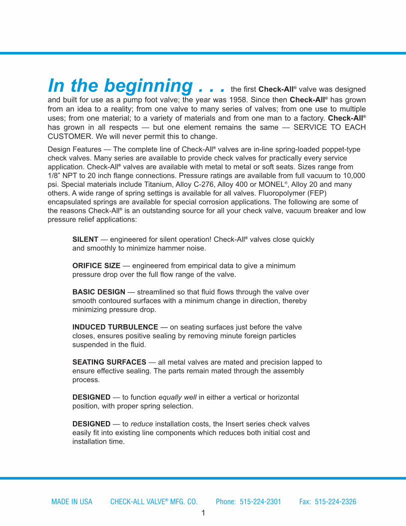
SILENT — engineered for silent operation! Check-All® valves close quickly
and smoothly to minimize hammer noise.
ORIFICE SIZE — engineered from empirical data to give a minimum
pressure drop over the full flow range of the valve.
BASIC DESIGN — streamlined so that fluid flows through the valve over
smooth contoured surfaces with a minimum change in direction, thereby
minimizing pressure drop.
INDUCED TURBULENCE — on seating surfaces just before the valve
closes, ensures positive sealing by removing minute foreign particles
suspended in the fluid.
SEATING SURFACES — all metal valves are mated and precision lapped to
ensure effective sealing. The parts remain mated through the assembly
process.
DESIGNED — to function equally well in either a vertical or horizontal
position, with proper spring selection.
DESIGNED — to reduce installation costs, the Insert series check valves
easily fit into existing line components which reduces both initial cost and
installation time.
In the beginning . . . the first Check-All® valve was designed
and built for use as a pump foot valve; the year was 1958. Since then Check-All® has grown
from an idea to a reality; from one valve to many series of valves; from one use to multiple
uses; from one material; to a variety of materials and from one man to a factory. Check-All®
has grown in all respects — but one element remains the same — SERVICE TO EACH
CUSTOMER. We will never permit this to change.
Design Features — The complete line of Check-All® valves are in-line spring-loaded poppet-type
check valves. Many series are available to provide check valves for practically every service
application. Check-All® valves are available with metal to metal or soft seats. Sizes range from
1/8” NPT to 20 inch flange connections. Pressure ratings are available from full vacuum to 10,000
psi. Special materials include Titanium, Alloy C-276, Alloy 400 or MONEL®, Alloy 20 and many
others. A wide range of spring settings is available for all valves. Fluoropolymer (FEP)
encapsulated springs are available for special corrosion applications. The following are some of
the reasons Check-All® is an outstanding source for all your check valve, vacuum breaker and low
pressure relief applications:
1
MADE IN USA CHECK-ALL VALVE® MFG. CO. Phone: 515-224-2301 Fax: 515-224-2326
Certifications & Compliances
ISO 9001 Check-All Valve® is an ISO 9001 Certified company. Our certificate number is FM
40858 and is issued by The British Standards Institution (BSI). This certification indicates that
Check-All® products are designed, manufactured and distributed in accordance with ISO 9001
requirements. That means when you order Check-All Valve® products you are assured of
receiving the highest quality check valves; consistently and on-time.
Sanitary Standards The Check-All® style 3S check valve is compliant with 3-A Sanitary
Standards for Vacuum Breakers and Check Valves for Milk and Milk Products Number
58-01 and has been Third Party Verified by a Certified Conformance Evaluator. Among
other requirements, this is a standard that requires a 32 Ra finish and specified groove angles
and depths, all for sanitary purposes. Consult the factory if finer surface finishes are required.
B16.34 Certification Some valve sizes can be supplied with B16.34 certification. Consult
factory for more information.
Canadian Registration Number Check-All Valve® also has obtained a Canadian Registration
Number (ØC163Ø1.2CL) for many of its products. The CRN is required for some products to be
installed in certain applications in Canada. Check-All® has registration in all provinces and
territories of Canada. Consult the factory if you require a valve with a CRN.
CE (PED 2014/68/EU) Conformance Many Check-All Valve® products conform to the Pressure
Equipment Directive (PED 2014/68/EU). Our certificate number is CE62128 and is issued by
The British Standards Institution (BSI) who is our Notified Body for conformance under
assessment Module H (full quality system). Please see page 55 for additional information
regarding CE conformance.
NACE Standards Check-All Valve® can supply valves that conform to the requirements of NACE
MR0175/ISO 15156 and NACE MR0103/ISO 17495-1. Valves conforming to NACE are hardness
tested based on the user-selected materials of construction. Contact the factory for details and
availability.
DESIGNED — to reduce maintenance costs, the Check-All® design is simple,
rugged and efficient. The seating surfaces are parallel to each other, thereby
eliminating the excessive wear occurring in plug, cone and ball seats.
DESIGNED — with the spring upstream of the seat, strategically placing it
outside any mixing and potentially aggressive solutions.
VERSATILE — Check-All® valves also can be used as LOW PRESSURE
RELIEF VALVES and VACUUM BREAKERS.
www.checkall.com [email protected] ISO 9001 CERTIFIED MADE IN USA
2
®
O R D E R I N F O R M AT I O NAlso See Valve Application Guidelines on Page 50
WARNING: Do not install on the discharge of a reciprocating air compressor or directlyon the outlet side of an elbow. Valves are designed for fully developed flow.Check-All® valves are completely described by — Style designation and combinations ofLetters and Numbers. The appropriate combinations will designate: Style, Size, BodyMaterial, Seat Material, Spring Cracking Pressure and Spring Material.
A. Materials:Internal materials may differ from body materials. Consult the factory for details.See page 53 for additional comments regarding material definition.
1. Body Materials: q
SS – 316 Stainless Steel -325°F to 700°F)
BR – Brass (-325°F to 400°F)CS – Carbon Steel (-20°F to 700°F)
TF – Fluoropolymer (PTFE) (-325°F to 400°F) PV – PVC (+32°F to 150°F)A2 – Alloy 20 (-325°F to 600°F)
MO – Alloy 400 or MONEL® (-325°F to 500°F)
TI – Titanium (-75°F to 500°F)HC – Alloy C-276 (-325°F to 1000°F) HB – Alloy B (-325°F to 800°F)
2. Seat Materials:qAll valve seats are integral and can be supplied either with an o-ring seat or withoutan o-ring (metal-to-metal seat). Whether the valve body is metal or plastic, the term“metal-to-metal” is used for seats without o-rings. “Metal-to-metal” seats are thesame material as the valve body unless otherwise specified. ALL O-RING SEATSHAVE A MAXIMUM PRESSURE RATING OF 1500 PSI. Many compounds below arealso available in USP Class VI, FDA and 3-A compliant materials; however, temperatureranges of these compounds may differ. Please consult factory for details. See page 4section B for more information on seat leakage or consult the factory for assistance.
VT – VITON ® (-10°F to 400°F) MT – Metal-to-Metal (or same as body material)
BN – Buna-N (-40°F to 250°F) AS – AFLAS ® (+10°F to 400°F)
EP – EPDM (-65°F to 300°F) KZ – KALREZ ® (0°F to 525°F)
NE – Neoprene (-40°F to 250°F) 3S – 3-A Silicone (-80°F to 450°F)
TF – Fluoropolymer (PTFE) (-325°F to 500°F) US – USP Class VI Silicone (-80°F to 450°F)
TF not available for plastic valves.
3
MADE IN USA CHECK-ALL VALVE® MFG. CO. Phone: 515-224-2301 Fax: 515-224-2326
qTemperature ranges given are for ideal service conditions and may vary. Material selection for a specific application is the
responsibility of the customer.
B. Seat Leakage:
Resilient soft seats are required for “bubble tight” shutoff. Consult the factory forinformation on “metal-to-metal” or PTFE seats. “Metal-to-metal” and PTFE seats arenot resilient. See page 50 for allowable leakage rates.
C. Springs: q
All standard springs are 316 stainless steel unless noted otherwise. Several crackingpressure options are available for each valve. Spring sizes are defined by the orificediameter of the valve.
SS – 316 Stainless Steel (-325°F to 400°F)
PH – 17-7 PH Stainless Steel (-20°F to 400°F)
HC – Alloy C-276 (-325°F to 400°F)
HB – Alloy B (-325°F to 400°F)
MO – Alloy 400 or MONEL® (-325°F to 400°F)
IX – Alloy X750 or INCONEL® Alloy X750 (-325°F to 700°F)
TI – Titanium Beta C (-75°F to 550°F)
Consult the factory for other available spring materials or higher temperature applications.Higher alloy material valves use higher alloy springs.
D. Fluoropolymer (FEP) Encapsulated Springs:Springs are encased in heat shrinkable FEP tubing. The ends of the tubing are plugged with FEP rod and sealed. When ordering FEP encapsulated springs add the letter “T” as
a suffix to the cracking pressure and spring material specified. FEP encapsulation may reduce flow capacity and the cracking pressure may vary. Temperature range for FEP encapsulation material is -325°F to 400°F. Some springs for 0.348 and 0.464 orifice diameters are not available with FEP encapsulation. Consult the factory for a substituted spring.
E. Special Springs:Special alloys or special cracking pressures are available for all valves. Higher
cracking pressure springs may reduce flow capacity. Consult the factory for price
and delivery.
www.checkall.com [email protected] ISO 9001 CERTIFIED MADE IN USA
qTemperature ranges given are for ideal service conditions and may vary. Material selection for a specific application is the
responsibility of the customer.
4
FLANGE INSERT
5
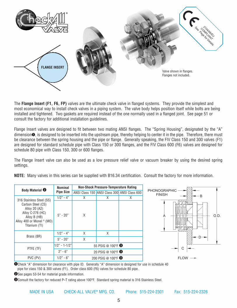
The Flange Insert (F1, F6, FP) valves are the ultimate check valve in flanged systems. They provide the simplest andmost economical way to install check valves in a piping system. The valve body helps position itself while bolts are beinginstalled and tightened. Two gaskets are required instead of the one normally used in a flanged joint. See page 51 orconsult the factory for additional installation guidelines.
Flange Insert valves are designed to fit between two mating ANSI flanges. The “Spring Housing”, designated by the “A”
dimensionq, is designed to be inserted into the upstream pipe, thereby helping to center it in the pipe. Therefore, there mustbe clearance between the spring housing and the pipe or flange. Generally speaking, the FIV Class 150 and 300 valves (F1)are designed for standard schedule pipe with Class 150 or 300 flanges, and the FIV Class 600 (F6) valves are designed forschedule 80 pipe with Class 150, 300 or 600 flanges.
The Flange Insert valve can also be used as a low pressure relief valve or vacuum breaker by using the desired springsettings.
NOTE: Many valves in this series can be supplied with B16.34 certification. Consult the factory for more information.
Body Material wNominalPipe Size
Non-Shock Pressure-Temperature Rating
ANSI Class 150 ANSI Class 300 ANSI Class 600
316 Stainless Steel (SS)Carbon Steel (CS)Alloy 20 (A2)
Alloy C-276 (HC)Alloy B (HB)
Alloy 400 or Monel ® (MO)Titanium (TI)
1/2” - 4” X X X
5” - 20” X
Brass (BR)1/2” - 4” X X
5” - 20” X
PTFE (TF)1/2” - 1-1/2” 55 PSIG @ 100°F e
2” - 6” 20 PSIG @ 100°F e
PVC (PV) 1/2” - 6” 200 PSIG @ 100°F e
Valve shown in flanges.Flanges not included.
A
FLOW
O.D.
D
C
B
PHONOGRAPHICFINISH
qCheck “A” dimension for clearance with pipe ID. Generally “A” dimension is designed for use in schedule 40
pipe for class 150 & 300 valves (F1). Order class 600 (F6) valves for schedule 80 pipe.
wSee pages 53-54 for material grade information.
eConsult the factory for reduced P–T rating above 100°F. Standard spring material is 316 Stainless Steel.
2104/68/EU
COM
PLIANT
See Page for Details
MADE IN USA CHECK-ALL VALVE® MFG. CO. Phone: 515-224-2301 Fax: 515-224-2326
www.checkall.com [email protected] ISO 9001 CERTIFIED MADE IN USA
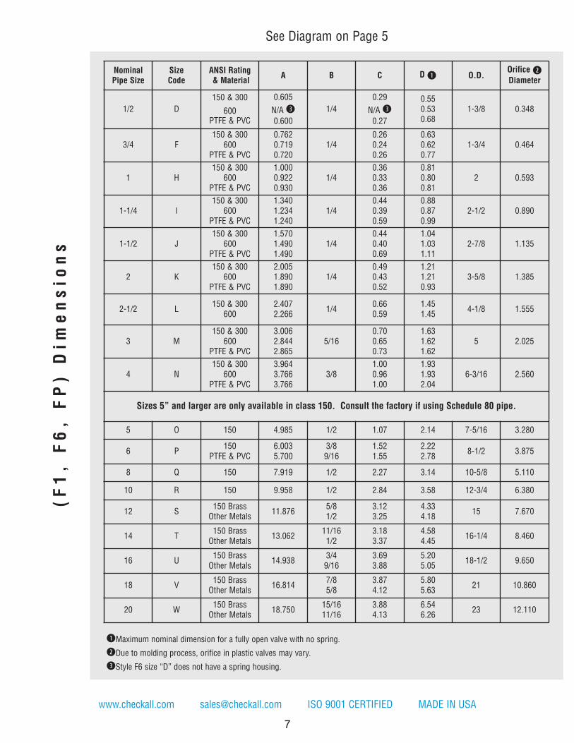
qMaximum nominal dimension for a fully open valve with no spring.
wDue to molding process, orifice in plastic valves may vary.
eStyle F6 size “D” does not have a spring housing.
NominalPipe Size
SizeCode
ANSI Rating& Material
A B C D q O.D.Orifice wDiameter
1/2 D
150 & 300
600PTFE & PVC
0.605
N/A e
0.600
1/4
0.29
N/A e
0.27
0.550.530.68
1-3/8 0.348
3/4 F150 & 300
600PTFE & PVC
0.7620.7190.720
1/40.260.240.26
0.630.620.77
1-3/4 0.464
1 H150 & 300
600PTFE & PVC
1.0000.9220.930
1/40.360.330.36
0.810.800.81
2 0.593
1-1/4 I150 & 300
600PTFE & PVC
1.3401.2341.240
1/40.440.390.59
0.880.870.99
2-1/2 0.890
1-1/2 J150 & 300
600PTFE & PVC
1.5701.4901.490
1/40.440.400.69
1.041.031.11
2-7/8 1.135
2 K150 & 300
600PTFE & PVC
2.0051.8901.890
1/40.490.430.52
1.211.210.93
3-5/8 1.385
2-1/2 L150 & 300
6002.4072.266
1/40.660.59
1.451.45
4-1/8 1.555
3 M150 & 300
600PTFE & PVC
3.0062.8442.865
5/160.700.650.73
1.631.621.62
5 2.025
4 N150 & 300
600PTFE & PVC
3.9643.7663.766
3/81.000.961.00
1.931.932.04
6-3/16 2.560
Sizes 5” and larger are only available in class 150. Consult the factory if using Schedule 80 pipe.
5 O 150 4.985 1/2 1.07 2.14 7-5/16 3.280
6 P150
PTFE & PVC6.0035.700
3/89/16
1.521.55
2.222.78
8-1/2 3.875
8 Q 150 7.919 1/2 2.27 3.14 10-5/8 5.110
10 R 150 9.958 1/2 2.84 3.58 12-3/4 6.380
12 S150 BrassOther Metals
11.8765/81/2
3.123.25
4.334.18
15 7.670
14 T150 BrassOther Metals
13.06211/161/2
3.183.37
4.584.45
16-1/4 8.460
16 U150 BrassOther Metals
14.9383/49/16
3.693.88
5.205.05
18-1/2 9.650
18 V150 BrassOther Metals
16.8147/85/8
3.874.12
5.805.63
21 10.860
20 W150 BrassOther Metals
18.75015/1611/16
3.884.13
6.546.26
23 12.110
(F1, F6, FP) Dimensions
See Diagram on Page 5
7

STYLE F1, F6, FPCv VALUES & VALVE WEIGHTS
Cv SIZESS & CSALLOYS
BRASS PTFE PVC
2.4 1/2 1.7 oz. 1.9 oz. 0.5 oz. 0.3 oz.
4.4 3/4 2.9 oz. 3.2 oz. 0.8 oz. 0.5 oz.
6.1 1 4.2 oz. 4.6 oz. 1.1 oz. 0.7 oz.
12.7 1-1/4 7.0 oz. 7.4 oz. 1.9 oz. 1.4 oz.
18.8 1-1/2 9.5 oz. 9.8 oz. 2.6 oz. 1.7 oz.
32.0 2 16.3 oz. 17.3 oz. 3.8 oz. 2.6 oz.
42.5 2-1/2 1.4 lb. 1.5 lb. --- ---
89.0 3 2.3 lb. 2.6 lb. 9.6 oz. 6.1 oz.
144 4 4.9 lb. 5.3 lb. 1.2 lb. 12.7 oz.
182 5 8.2 lb. 8.7 lb. --- ---
284 6 12.3 lb. 13 lb. 1.8 lb. 1.2 lb.
535 8 24.4 lb. 26.4 lb. --- ---
757 10 36.3 lb. 44 lb. --- ---
1200 12 51 lb. 58 lb. --- ---
1650 14 74 lb. 93 lb. --- ---
2230 16 105 lb. 130 lb. --- ---
3010 18 157 lb. 201 lb. --- ---
4000 20 207 lb. 262 lb. --- ---
PR
ES
SU
RE
DR
OP
- P
SI
WATER FLOW RATE - GPM
Flange Insert Flow Curves assume Schedule 40 pipe
For Water at 72°F
Cv values assume Schedule 40 pipe. Valve weights are approximate.See page 49 for Flow Formulae.
Note: All flow curves and Cv values presume the valves are fully open with 1/2 PSI cracking pressure springs.Consult the factory for more information.
8
MADE IN USA CHECK-ALL VALVE® MFG. CO. Phone: 515-224-2301 Fax: 515-224-2326
1/2”
3/4”
1” 1-1/
4”1-
1/2”
2” 2-1
/2”
3” 4” 5” 6” 8” 10”
12”
14”
16”
18”
20”
1
10
100
1 10 100 1000 10000 100000
BODY MATERIALALLOY 20 = A2BRASS = BR
CARBON STEEL = CSALLOY B = HB
ALLOY C-276 = HCALLOY 400 OR MONEL® = MO
PVC = PV316 SS = SSPTFE = TF
TITANIUM = TISee p. 3 for temperature ratings
SEAT MATERIAL w
AFLAS ® = ASBUNA-N = BN
EPDM e = EP
KALREZ ® = KZ
“METAL-TO-METAL” r = MT
NEOPRENE = NE
PTFE t = TF
VITON ® = VTSee p. 3 for temperature ratings
SPECIAL OPTIONST = FEP ENCAPSULATED SPRINGSee p. 4 for temperature rating
Contact the factory for more options
SPRING MATERIAL316 SS = SS
ALLOY C-276 = HCALLOY B = HB
ALLOY X750 OR INCONEL® X750 = IXALLOY 400 OR MONEL® = MO
17-7PH SS = PHTITANIUM = TI
See p. 4 for temperature ratings
STYLE F1(All Metals)
SIZES1/2 = D3/4 = F1 = H
1-1/4 = I1-1/2 = J
2 = K2-1/2 = L
3 = M4 = N5 = 06 = P8 = Q10 = R12 = S14 = T16 = U18 = V20 = W
STYLE FP r
(PTFE or PVC Only)SIZES
1/2 = D3/4 = F1 = H
1-1/4 = I1-1/2 = J
2 = K3 = M4 = N6 = P
STYLE F6(Except Brass)
SIZES1/2 = D3/4 = F1 = H
1-1/4 = I1-1/2 = J
2 = K2-1/2 = L
3 = M4 = N
SIZE(SEE BELOW)
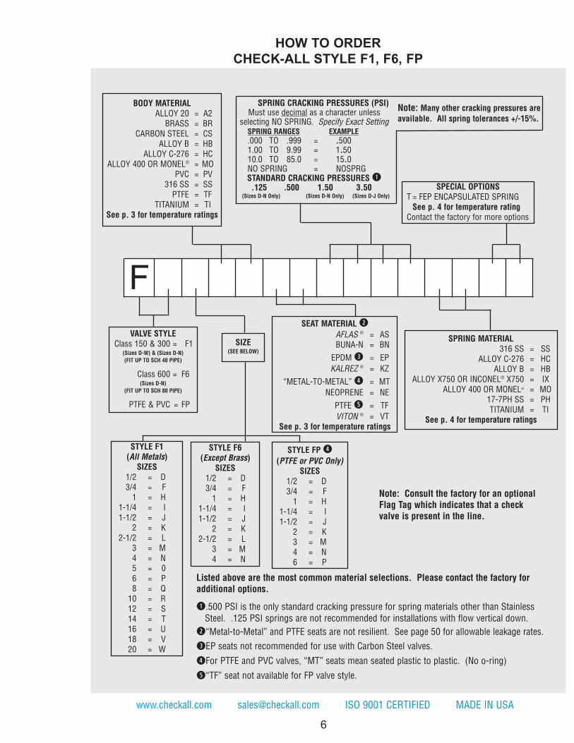
HOW TO ORDER
CHECK-ALL STYLE F1, F6, FP
Note: Consult the factory for an optionalFlag Tag which indicates that a checkvalve is present in the line.
Listed above are the most common material selections. Please contact the factory foradditional options.
q.500 PSI is the only standard cracking pressure for spring materials other than Stainless
Steel. .125 PSI springs are not recommended for installations with flow vertical down.
w“Metal-to-Metal” and PTFE seats are not resilient. See page 50 for allowable leakage rates.
eEP seats not recommended for use with Carbon Steel valves.
rFor PTFE and PVC valves, “MT” seats mean seated plastic to plastic. (No o-ring)
t“TF” seat not available for FP valve style.
www.checkall.com [email protected] ISO 9001 CERTIFIED MADE IN USA
VALVE STYLEClass 150 & 300 = F1
(Sizes D-W) & (Sizes D-N)
(FIT UP TO SCH 40 PIPE)
Class 600 = F6(Sizes D-N)
(FIT UP TO SCH 80 PIPE)
PTFE & PVC = FP
F
SPRING CRACKING PRESSURES (PSI)Must use decimal as a character unless
selecting NO SPRING. Specify Exact SettingSPRING RANGES EXAMPLE
.000 TO .999 = .5001.00 TO 9.99 = 1.5010.0 TO 85.0 = 15.0NO SPRING = NOSPRGSTANDARD CRACKING PRESSURES q.125 .500 1.50 3.50
(Sizes D-N Only) (Sizes D-N Only) (Sizes D-J Only)
Note: Many other cracking pressures areavailable. All spring tolerances +/-15%.
6
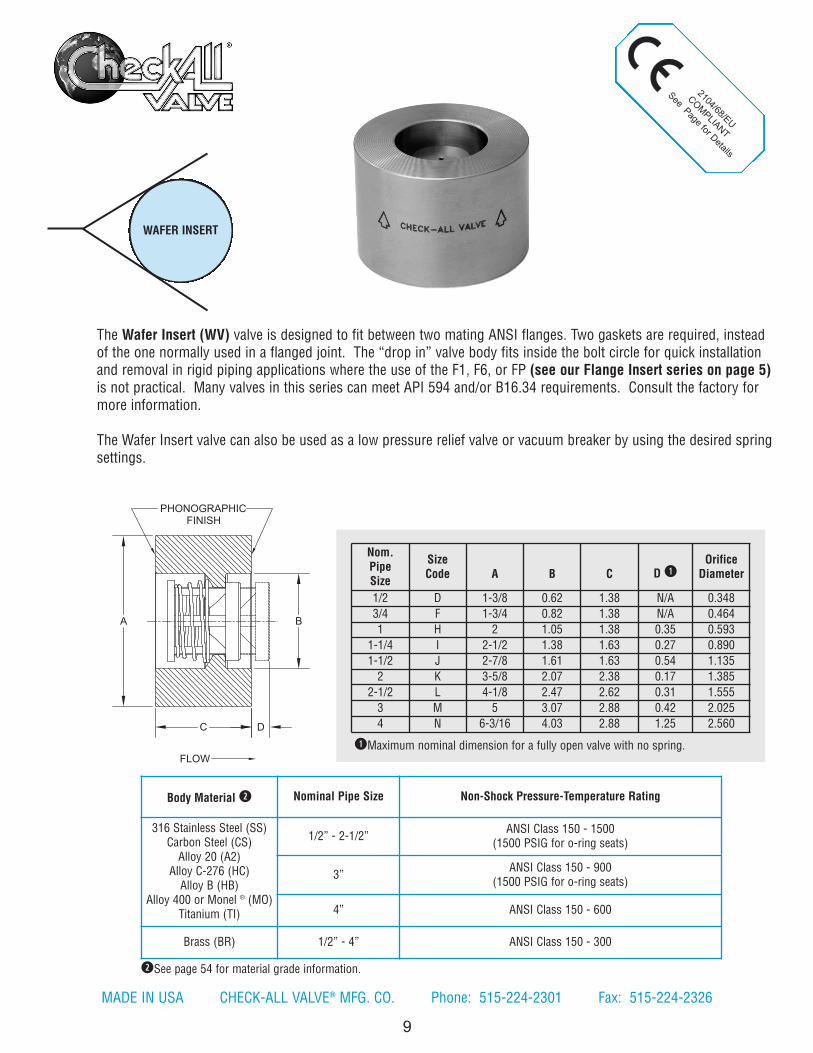
Body Material w Nominal Pipe Size Non-Shock Pressure-Temperature Rating
316 Stainless Steel (SS)Carbon Steel (CS)Alloy 20 (A2)
Alloy C-276 (HC)Alloy B (HB)
Alloy 400 or Monel ® (MO)Titanium (TI)
1/2” - 2-1/2”ANSI Class 150 - 1500
(1500 PSIG for o-ring seats)
3”ANSI Class 150 - 900
(1500 PSIG for o-ring seats)
4” ANSI Class 150 - 600
Brass (BR) 1/2” - 4” ANSI Class 150 - 300
Nom.PipeSize
SizeCode A B C D q
OrificeDiameter
1/2 D 1-3/8 0.62 1.38 N/A 0.348
3/4 F 1-3/4 0.82 1.38 N/A 0.464
1 H 2 1.05 1.38 0.35 0.593
1-1/4 I 2-1/2 1.38 1.63 0.27 0.890
1-1/2 J 2-7/8 1.61 1.63 0.54 1.135
2 K 3-5/8 2.07 2.38 0.17 1.385
2-1/2 L 4-1/8 2.47 2.62 0.31 1.555
3 M 5 3.07 2.88 0.42 2.025
4 N 6-3/16 4.03 2.88 1.25 2.560
qMaximum nominal dimension for a fully open valve with no spring.
2104/68/EU
COM
PLIANT
See Page for Details
MADE IN USA CHECK-ALL VALVE® MFG. CO. Phone: 515-224-2301 Fax: 515-224-2326
WAFER INSERT
9
The Wafer Insert (WV) valve is designed to fit between two mating ANSI flanges. Two gaskets are required, insteadof the one normally used in a flanged joint. The “drop in” valve body fits inside the bolt circle for quick installationand removal in rigid piping applications where the use of the F1, F6, or FP (see our Flange Insert series on page 5)is not practical. Many valves in this series can meet API 594 and/or B16.34 requirements. Consult the factory formore information.
The Wafer Insert valve can also be used as a low pressure relief valve or vacuum breaker by using the desired springsettings.
wSee page 54 for material grade information.
A
C D
B
FLOW
PHONOGRAPHIC FINISH

STYLE WVCv VALUES & VALVE WEIGHTS
Cv SIZESS & CSALLOYS
BRASS
2.4 1/2 9.5 oz. 10.2 oz.
4.4 3/4 12.6 oz. 13.5 oz.
6.1 1 1.0 lb. 1.1 lb.
12.7 1-1/4 1.8 lb. 1.9 lb.
18.8 1-1/2 2.4 lb. 2.5 lb.
32.0 2 5.2 lb. 5.6 lb.
42.5 2-1/2 7.2 lb. 7.7 lb.
89.0 3 11.4 lb. 12.4 lb.
144 4 17.2 lb. 18.4 lb.
HOW TO ORDER
CHECK-ALL STYLE WV
10
See page 49 for Flow Formulae.Valve weights are approximate.
Note: All flow curves and Cv values presume the valvesare fully open with 1/2 PSI cracking pressure springs.Consult the factory for more information.
www.checkall.com [email protected] ISO 9001 CERTIFIED MADE IN USA
Listed above are the most common material selections. Please contact the factory for additional options.
q.500 PSI is the only standard cracking pressure for spring materials other than Stainless Steel. .125 PSI springs arenot recommended for installations with flow vertical down.
wSeat materials other than “metal-to-metal” have a maximum pressure rating of 1500 PSI. “Metal-to-Metal” and PTFE seats are not resilient. See page 50 for allowable leakage rates.
eEP seats not recommended for use with Carbon Steel valves.
SPRING CRACKING PRESSURES (PSI)Must use decimal as a character unless
selecting NO SPRING. Specify Exact SettingSPRING RANGES EXAMPLE
.000 TO .999 = .5001.00 TO 9.99 = 1.5010.0 TO 85.0 = 15.0NO SPRING = NOSPRGSTANDARD CRACKING PRESSURES q.125 .500 1.50 3.50
(Sizes D-J Only)
1/2
"
3/4
"
1"
1-1
/4"
1-1
/2"
2"
2-1
/2"
3"
4"
1
10
100
1 10 100 1000
PR
ES
SU
RE
DR
OP
- P
SI
WATER FLOW RATE - GPM
SIZE1/2 = D3/4 = F1 = H
1-1/4 = I1-1/2 = J
2 = K2-1/2 = L
3 = M4 = N
SPECIAL OPTIONST = FEP ENCAPSULATED SPRING See p. 4 for temperature ratingsContact the factory for more options
SEAT MATERIAL w
AFLAS ® = ASBUNA-N = BN
EPDM e = EP
KALREZ ® = KZ“METAL-TO-METAL” = MT
NEOPRENE = NEPTFE = TF
VITON ® = VTSee p. 3 for temperature ratings
BODY MATERIALALLOY 20 = A2BRASS = BR
CARBON STEEL = CSALLOY B = HB
ALLOY C-276 = HCALLOY 400 OR MONEL® = MO
316 SS = SSTITANIUM = TI
See p. 3 for temperature ratings
Note: Many other cracking pressures areavailable. All spring tolerances +/-15%.
Wafer InsertFor Water at 72°F
SPRING MATERIALALLOY C-276 = HC
ALLOY X750 OR INCONEL® X750 = IXALLOY 400 OR MONEL® = MO
17-7PH SS = PH316 SS = SS
TITANIUM = TISee p. 4 for temperature ratings
WVVALVE STYLE

HORIZONTALVERTICALFLANGED & DRILLED
11
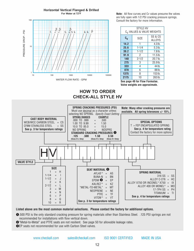
The Check-All® Flanged & Drilled (HV) check valve is a one piece cast body valve with ASME/ANSI B16.5 Class 150flanged ends. The HV series valve is used when higher flow rates and lower pressure drops are required. The valve isavailable in sizes 1 inch through 10 inches and standard materials of CF8M (cast 316 stainless) and WCB/WCC (castcarbon steel). The HV series valve is designed for use with mating ANSI Class 150 flanges. Other materials are availableupon request.The HV valve can also be used as a low pressure relief valve or vacuum breaker by using the desired spring settings.
NOTE: Many valves in this series can be supplied with B16.34 certification. Consult the factory for more information.
Nom.PipeSize
SizeCode A B
OrificeDiameter
1 H 3.75 4-1/4 0.890
1-1/4 I 3.80 4-5/8 1.135
1-1/2 J 4.38 5 1.385
2 K 5.13 6 2.025
2-1/2 L 7.28 7 2.560
3 M 8.38 7-1/2 3.280
4 N 9.69 9 3.875
6 P 13.75 11 6.380
8 Q 15.10 13-1/2 7.670
10 R 19.25 16 9.650
qSee page 54 for material grade information.
Cast Body Material q Availability Non-Shock Pressure-Temperature Rating
CF8M Stainless Steel (SS)
Standard ASME/ANSI B16.5 Class 150
WCB/WCC Carbon Steel (CS)
B
A
FLOW
2104/68/EU
COM
PLIANT
See Page for Details
MADE IN USA CHECK-ALL VALVE® MFG. CO. Phone: 515-224-2301 Fax: 515-224-2326
12
www.checkall.com [email protected] ISO 9001 CERTIFIED MADE IN USA
1"
1-1
/4"
1-1
/2"
2"
2-1
/2"
3"
4"
6"
8"
10"
1
10
100
10 100 1000 10000 100000
STYLE HVCv VALUES & VALVE WEIGHTS
Cv SIZESS & CSALLOYS
14.2 1 4.3 lb.
25.6 1-1/4 5.3 lb.
39.2 1-1/2 7.8 lb.
91.9 2 11.5 lb.
140 2-1/2 20.7 lb.
275 3 25.9 lb.
333 4 44 lb.
878 6 88 lb.
1375 8 153 lb.
2175 10 263 lb.
PR
ES
SU
RE
DR
OP
- P
SI
WATER FLOW RATE - GPM
Horizontal Vertical Flanged & DrilledFor Water at 72°F
SIZE1 = H
1-1/4 = I1-1/2 = J
2 = K2-1/2 = L
3 = M4 = N6 = P8 = Q10 = R
VALVE STYLE
CAST BODY MATERIALWCB/WCC CARBON STEEL = CSCF8M STAINLESS STEEL = SSSee p. 3 for temperature ratings
SPECIAL OPTIONST = FEP ENCAPSULATED SPRING
See p. 4 for temperature ratingContact the factory for more options
SPRING MATERIAL316 SS = SS
ALLOY C-276 = HCALLOY X750 OR INCONEL® X750 = IX
ALLOY 400 OR MONEL® = MO17-7PH SS = PHTITANIUM = TI
See p. 4 for temperature ratings
HOW TO ORDER
CHECK-ALL STYLE HV
See page 49 for Flow Formulae.Valve weights are approximate.
Note: All flow curves and Cv values presume the valvesare fully open with 1/2 PSI cracking pressure springs.Consult the factory for more information.
Listed above are the most common material selections. Please contact the factory for additional options.
q.500 PSI is the only standard cracking pressure for spring materials other than Stainless Steel. .125 PSI springs are notrecommended for installations with flow vertical down.
w“Metal-to-Metal” and PTFE seats are not resilient. See page 50 for allowable leakage rates.
eEP seats not recommended for use with Carbon Steel valves.
SPRING CRACKING PRESSURES (PSI)Must use decimal as a character unless
selecting NO SPRING. Specify Exact SettingSPRING RANGES EXAMPLE
.000 TO .999 = .5001.00 TO 9.99 = 1.5010.0 TO 85.0 = 15.0NO SPRING = NOSPRGSTANDARD CRACKING PRESSURES q.125 .500 1.50 3.50
(Sizes H-L Only) (Sizes H-L Only) (Sizes H-I Only)
Note: Many other cracking pressures areavailable. All spring tolerances +/- 15%.
HV
SEAT MATERIAL w
AFLAS ® = ASBUNA-N = BN EPDM e = EP
KALREZ ® = KZ“METAL-TO-METAL” = MT
NEOPRENE = NEPTFE = TF
VITON ® = VTSee p. 3 for temperature ratings
2104/68/EU
COM
PLIANT
See Page for Details
BUSHING
13
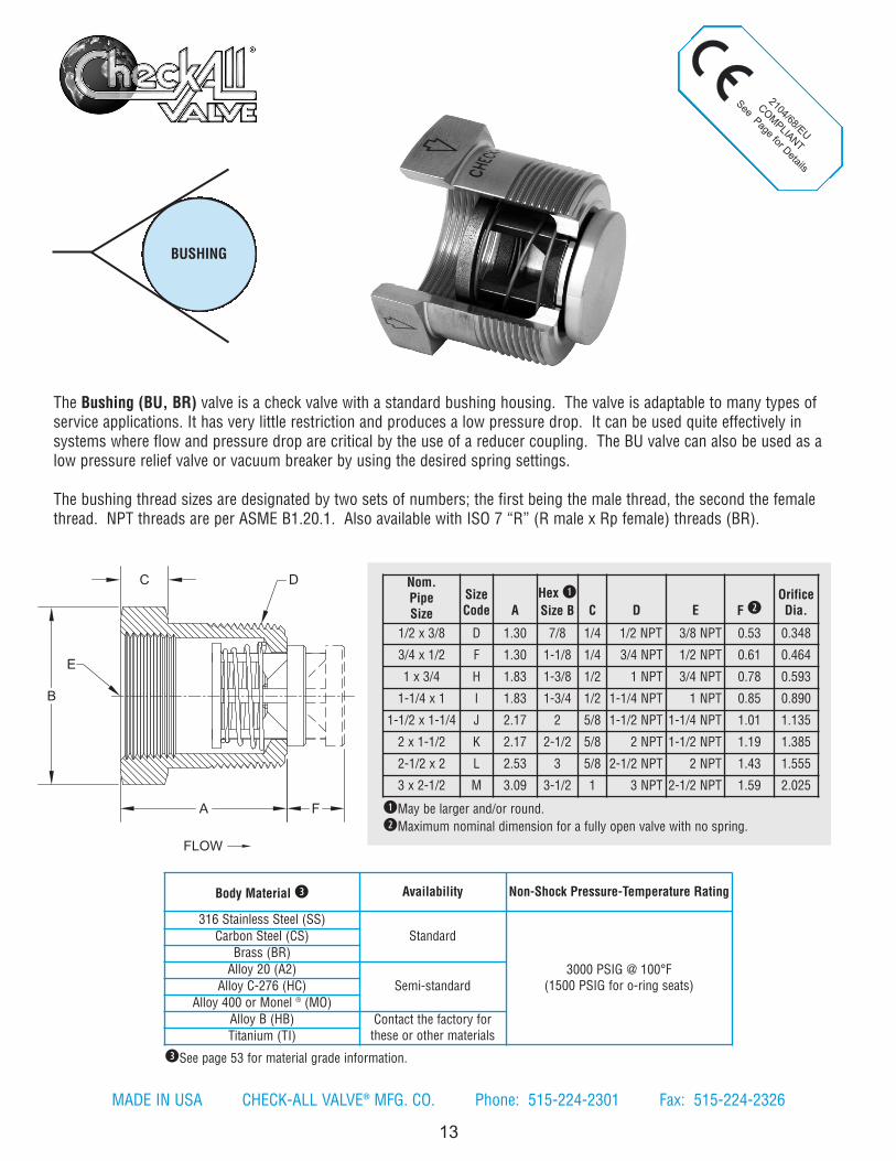
The Bushing (BU, BR) valve is a check valve with a standard bushing housing. The valve is adaptable to many types ofservice applications. It has very little restriction and produces a low pressure drop. It can be used quite effectively insystems where flow and pressure drop are critical by the use of a reducer coupling. The BU valve can also be used as alow pressure relief valve or vacuum breaker by using the desired spring settings.
The bushing thread sizes are designated by two sets of numbers; the first being the male thread, the second the femalethread. NPT threads are per ASME B1.20.1. Also available with ISO 7 “R” (R male x Rp female) threads (BR).
Nom.PipeSize
SizeCode A
Hex q
Size B C D E F wOrificeDia.
1/2 x 3/8 D 1.30 7/8 1/4 1/2 NPT 3/8 NPT 0.53 0.348
3/4 x 1/2 F 1.30 1-1/8 1/4 3/4 NPT 1/2 NPT 0.61 0.464
1 x 3/4 H 1.83 1-3/8 1/2 1 NPT 3/4 NPT 0.78 0.593
1-1/4 x 1 I 1.83 1-3/4 1/2 1-1/4 NPT 1 NPT 0.85 0.890
1-1/2 x 1-1/4 J 2.17 2 5/8 1-1/2 NPT 1-1/4 NPT 1.01 1.135
2 x 1-1/2 K 2.17 2-1/2 5/8 2 NPT 1-1/2 NPT 1.19 1.385
2-1/2 x 2 L 2.53 3 5/8 2-1/2 NPT 2 NPT 1.43 1.555
3 x 2-1/2 M 3.09 3-1/2 1 3 NPT 2-1/2 NPT 1.59 2.025
qMay be larger and/or round.
wMaximum nominal dimension for a fully open valve with no spring.
Body Material e Availability Non-Shock Pressure-Temperature Rating
316 Stainless Steel (SS)
Standard
3000 PSIG @ 100°F(1500 PSIG for o-ring seats)
Carbon Steel (CS)
Brass (BR)
Alloy 20 (A2)
Semi-standardAlloy C-276 (HC)
Alloy 400 or Monel ® (MO)
Alloy B (HB) Contact the factory forthese or other materialsTitanium (TI)
eSee page 53 for material grade information.
B
A
C
F
D
E
FLOW
MADE IN USA CHECK-ALL VALVE® MFG. CO. Phone: 515-224-2301 Fax: 515-224-2326

BODY MATERIALALLOY 20 = A2BRASS = BR
CARBON STEEL = CSALLOY B = HB
ALLOY C-276 = HCALLOY 400 OR MONEL® = MO
316 SS = SSTITANIUM = TI
See p. 3 for temperature ratings
SEAT MATERIAL w
AFLAS ® = ASBUNA-N = BN EPDM e = EP
KALREZ ® = KZ“METAL-TO-METAL” = MT
NEOPRENE = NEPTFE = TF
VITON ® = VTSee p. 3 for temperature ratings
SPECIAL OPTIONST = FEP ENCAPSULATED SPRING See p. 4 for temperature ratingsContact the factory for more options
14
Listed above are the most common material selections. Please contact the factory for additional options.
q.500 PSI is the only standard cracking pressure for spring materials other than Stainless Steel. .125 PSI springs arenot recommended for installations with flow vertical down.
wSeat materials other than “metal-to-metal” have a maximum pressure rating of 1500 PSI. “Metal-to-Metal” and PTFE seats are not resilient. See page 50 for allowable leakage rates.
eEP seats not recommended for use with Carbon Steel valves.
www.checkall.com [email protected] ISO 9001 CERTIFIED MADE IN USA
SPRING CRACKING PRESSURES (PSI)Must use decimal as a character unless
selecting NO SPRING. Specify Exact SettingSPRING RANGES EXAMPLE
.000 TO .999 = .5001.00 TO 9.99 = 1.5010.0 TO 85.0 = 15.0NO SPRING = NOSPRGSTANDARD CRACKING PRESSURES q.125 .500 1.50 3.50
(Sizes D-J Only)
Note: Many other cracking pressures areavailable. All spring tolerances +/- 15%.
B
1/2
X3/8
"
3/4
X1/2
"1X
3/4"
1-1
/4X
1"
1-1
/2X
1-1
/4"
2X
1-1/2
"2-1
/2X
2"
3X
2-1/2
"
1
10
100
1 10 100 1000
STYLE BUCv VALUES & VALVE WEIGHTS
Cv SIZE ALL MATL
2.6 1/2 x 3/8 1.7 oz.
4.6 3/4 x 1/2 2.9 oz.
6.6 1 x 3/4 6.4 oz.
12.6 1-1/4 x 1 10.8 oz.
18.8 1-1/2 x 1-1/4 13.8 oz.
32.0 2 x 1-1/2 1.6 lb.
42.5 2-1/2 x 2 2.3 lb.
89.0 3 x 2-1/2 5.4 lb.
PR
ES
SU
RE
DR
OP
- P
SI
WATER FLOW RATE - GPM
BushingFor Water at 72°F
SIZE1/2 x 3/8 = D3/4 x 1/2 = F1 x 3/4 = H
1-1/4 x 1 = I1-1/2 x 1-1/4 = J
2 x 1-1/2 = K2-1/2 x 2 = L3 x 2-1/2 = M
HOW TO ORDER
CHECK-ALL STYLE BU
See page 49 for Flow Formulae.Valve weights are approximate.
Note: All flow curves and Cv values presume the valvesare fully open with 1/2 PSI cracking pressure springs.Consult the factory for more information.
SPRING MATERIALALLOY C-276 = HC
ALLOY X750 OR INCONEL® X750 = IXALLOY 400 OR MONEL® = MO
17-7PH SS = PH316 SS = SS
TITANIUM = TISee p. 4 for temperature ratings
VALVE STYLENPT Threads = BU
ISO 7 R & Rp Threads = BR
2104/68/EU
COM
PLIANT
See Page for Details
CONNECTOR
15
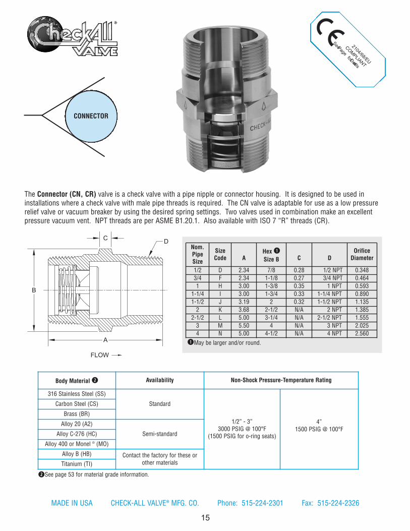
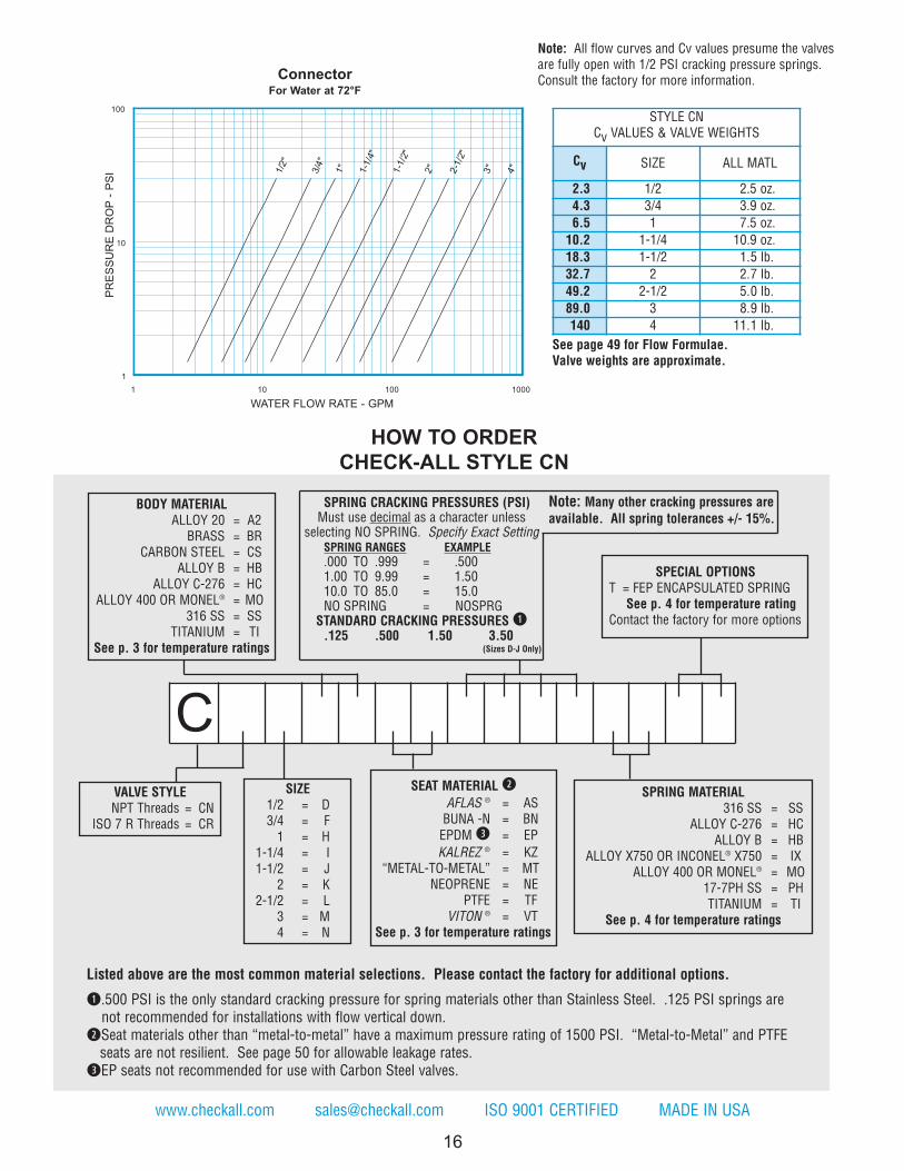
The Connector (CN, CR) valve is a check valve with a pipe nipple or connector housing. It is designed to be used ininstallations where a check valve with male pipe threads is required. The CN valve is adaptable for use as a low pressurerelief valve or vacuum breaker by using the desired spring settings. Two valves used in combination make an excellentpressure vacuum vent. NPT threads are per ASME B1.20.1. Also available with ISO 7 “R” threads (CR).
Nom.PipeSize
SizeCode A
Hex q
Size B C DOrificeDiameter
1/2 D 2.34 7/8 0.28 1/2 NPT 0.348
3/4 F 2.34 1-1/8 0.27 3/4 NPT 0.464
1 H 3.00 1-3/8 0.35 1 NPT 0.593
1-1/4 I 3.00 1-3/4 0.33 1-1/4 NPT 0.890
1-1/2 J 3.19 2 0.32 1-1/2 NPT 1.135
2 K 3.68 2-1/2 N/A 2 NPT 1.385
2-1/2 L 5.00 3-1/4 N/A 2-1/2 NPT 1.555
3 M 5.50 4 N/A 3 NPT 2.025
4 N 5.00 4-1/2 N/A 4 NPT 2.560
qMay be larger and/or round.
Body Material w Availability Non-Shock Pressure-Temperature Rating
316 Stainless Steel (SS)
Standard
1/2” - 3”3000 PSIG @ 100°F
(1500 PSIG for o-ring seats)
4”1500 PSIG @ 100°F
Carbon Steel (CS)
Brass (BR)
Alloy 20 (A2)
Semi-standardAlloy C-276 (HC)
Alloy 400 or Monel ® (MO)
Alloy B (HB) Contact the factory for these orother materialsTitanium (TI)
wSee page 53 for material grade information.
A
B
C
FLOW
D
MADE IN USA CHECK-ALL VALVE® MFG. CO. Phone: 515-224-2301 Fax: 515-224-2326
www.checkall.com [email protected] ISO 9001 CERTIFIED MADE IN USA
16
SPRING CRACKING PRESSURES (PSI)Must use decimal as a character unless
selecting NO SPRING. Specify Exact SettingSPRING RANGES EXAMPLE
.000 TO .999 = .5001.00 TO 9.99 = 1.5010.0 TO 85.0 = 15.0NO SPRING = NOSPRG
STANDARD CRACKING PRESSURES q.125 .500 1.50 3.50
(Sizes D-J Only)
Note: Many other cracking pressures areavailable. All spring tolerances +/- 15%.
C
1/2
"
3/4
"
1"
1-1
/4"
1-1
/2"
2"
2-1
/2"
3"
4"
1
10
100
1 10 100 1000
STYLE CNCv VALUES & VALVE WEIGHTS
Cv SIZE ALL MATL
2.3 1/2 2.5 oz.
4.3 3/4 3.9 oz.
6.5 1 7.5 oz.
10.2 1-1/4 10.9 oz.
18.3 1-1/2 1.5 lb.
32.7 2 2.7 lb.
49.2 2-1/2 5.0 lb.
89.0 3 8.9 lb.
140 4 11.1 lb.
PR
ES
SU
RE
DR
OP
- P
SI
WATER FLOW RATE - GPM
ConnectorFor Water at 72°F
SIZE1/2 = D3/4 = F1 = H
1-1/4 = I1-1/2 = J
2 = K2-1/2 = L
3 = M4 = N
BODY MATERIALALLOY 20 = A2BRASS = BR
CARBON STEEL = CSALLOY B = HB
ALLOY C-276 = HCALLOY 400 OR MONEL® = MO
316 SS = SSTITANIUM = TI
See p. 3 for temperature ratings
SEAT MATERIAL w
AFLAS ® = ASBUNA -N = BN EPDM e = EP
KALREZ ® = KZ“METAL-TO-METAL” = MT
NEOPRENE = NEPTFE = TF
VITON ® = VTSee p. 3 for temperature ratings
SPRING MATERIAL316 SS = SS
ALLOY C-276 = HCALLOY B = HB
ALLOY X750 OR INCONEL® X750 = IXALLOY 400 OR MONEL® = MO
17-7PH SS = PHTITANIUM = TI
See p. 4 for temperature ratings
HOW TO ORDER
CHECK-ALL STYLE CN
See page 49 for Flow Formulae.Valve weights are approximate.
Note: All flow curves and Cv values presume the valvesare fully open with 1/2 PSI cracking pressure springs.Consult the factory for more information.
Listed above are the most common material selections. Please contact the factory for additional options.
q.500 PSI is the only standard cracking pressure for spring materials other than Stainless Steel. .125 PSI springs arenot recommended for installations with flow vertical down.
wSeat materials other than “metal-to-metal” have a maximum pressure rating of 1500 PSI. “Metal-to-Metal” and PTFE seats are not resilient. See page 50 for allowable leakage rates.
eEP seats not recommended for use with Carbon Steel valves.
SPECIAL OPTIONST = FEP ENCAPSULATED SPRING
See p. 4 for temperature ratingContact the factory for more options
VALVE STYLENPT Threads = CN
ISO 7 R Threads = CR

The Universal Low Pressure (U3, UR) check valve is a one piece body machined from bar stock and is designed forminimum pressure drop. The valve has a light-weight, compact design that provides maintenance-free, dependableservice. NPT threads are per ASME B1.20.1. Also available with ISO 7 “Rp” threads. (UR). These valves can also be usedas a low pressure relief valve or vacuum breaker by using the desired spring settings.
NOTE: Many valves in this series can be supplied with B16.34 certification. Consult the factory for more information.
UNIVERSAL LOWPRESSURE
17
2104/68/EU
COM
PLIANT
See pa ge for Details
Nom.PipeSize
SizeCode A
Hex q
Size B C
OrificeDiameter
3/8 C 2.16 13/16 3/8 NPT 0.348
1/2 D 2.71 1-1/8 1/2 NPT 0.464
3/4 F 2.95 1-1/4 3/4 NPT 0.593
1 H 3.64 1-5/8 1 NPT 0.890
1-1/4 I 3.91 2-1/4 1-1/4 NPT 1.135
1-1/2 J 4.36 2-1/2 1-1/2 NPT 1.385
2 K 5.85 3 2 NPT 1.555
2-1/2 L 5.50 3-3/4 2-1/2 NPT 1.555
3 M 6.25 4-1/2 3 NPT 2.025
4 N 7.13 5-1/2 4 NPT 2.560
qMay be larger and/or round.
Body Material w Availability Non-Shock Pressure-Temperature Rating
316 Stainless Steel (SS)
Standard
3/8” - 3”
3000 PSIG @ 100°F(1500 PSIG for o-ring seats)
4”
1500 PSIG @ 100°F
Carbon Steel (CS)
Brass (BR)
Alloy 20 (A2)
Semi-standardAlloy C-276 (HC)
Alloy 400 or Monel ® (MO)
Alloy B (HB) Contact the factory for these orother materialsTitanium (TI)
wSee page 54 for material grade information.
A
B
FLOW
C (TYP)
MADE IN USA CHECK-ALL VALVE® MFG. CO. Phone: 515-224-2301 Fax: 515-224-2326

18
www.checkall.com [email protected] ISO 9001 CERTIFIED MADE IN USA
SPRING CRACKING PRESSURESReplace “X” with actual desired setting.
Must use decimal as a character.(PSI) FORMAT EXAMPLE
.000 TO .999 = .XXX .5001.00 TO 9.99 = X.XX 1.5010.0 TO 99.9 = XX.X 15.0NO SPRING = NOSPRG NOSPRG
Note: Many other cracking pressures areavailable. All spring tolerances +/- 15%.
F
1 10 100 1000
100
10
1
3/8”
1/2”
3/4”
1” 1-1/
2”
1-1/
4”
2” 2-1/2
”
3” 4”
HOW TO ORDER
CHECK-ALL STYLE U3
SIZE3/8 = C1/2 = D3/4 = F1 = H
1-1/4 = I1-1/2 = J
2 = K2-1/2 = L
3 = M4 = N
VALVE STYLENPT Threads = U3
ISO 7 Rp Threads = UR
BODY MATERIALALLOY 20 = A2BRASS = BR
CARBON STEEL = CSALLOY B = HB
ALLOY C-276 = HCALLOY 400 OR MONEL® = MO
316 SS = SSTITANIUM = TI
See p. 3 for temperature rating
SPECIAL OPTIONST = FEP ENCAPSULATED SPRING See p. 4 for temperature rating
Contact the factory for more options
STYLE U3Cv VALUES & VALVE WEIGHTS
Cv SIZESS & CSALLOYS
BRASS
1.9 3/8 3.0 oz. 3.3 oz.
4.3 1/2 8.5 oz. 9.1 oz.
7.2 3/4 9.6 oz. 10.1 oz.
14.6 1 1.2 lb. 1.3 lb.
28.8 1-1/4 2.9 lb. 3.2 lb.
31.9 1-1/2 3.6 lb. 3.9 lb.
42.0 2 6.5 lb. 7.2 lb.
50.0 2-1/2 9.2 lb. 10 lb.
89.0 3 14.3 lb. 15.5 lb.
140 4 21.7 lb. 23.9 lb.
PR
ES
SU
RE
DR
OP
- P
SI
WATER FLOW RATE - GPM
Universal Low PressureFor Water at 72°F
See page 49 for Flow Formulae.Valve weights are approximate.
Note: All flow curves and Cv values presume the valvesare fully open with 1/2 PSI cracking pressure springs.Consult the factory for more information.
U
Listed above are the most common material selections. Please contact the factory for additional options.
q.500 PSI is the only standard cracking pressure for spring materials other than Stainless Steel. .125 PSI springs arenot recommended for installations with flow vertical down.
wSeat materials other than “metal-to-metal” have a maximum pressure rating of 1500 PSI. “Metal-to-Metal” and PTFE seats are not resilient. See page 50 for allowable leakage rates.
eEP seats not recommended for use with Carbon Steel valves.
SEAT MATERIAL w
AFLAS ® = ASBUNA-N = BN EPDM e = EP
KALREZ ® = KZ“METAL-TO-METAL” = MT
NEOPRENE = NEPTFE = TF
VITON ® = VTSee p. 3 for temperature ratings
SPRING CRACKING PRESSURES (PSI)Must use decimal as a character unless
selecting NO SPRING. Specify Exact SettingSPRING RANGES EXAMPLE
.000 TO .999 = .5001.00 TO 9.99 = 1.5010.0 TO 85.0 = 15.0NO SPRING = NOSPRG
STANDARD CRACKING PRESSURES q.125 .500 1.50 3.50
(Sizes C-I Only)
Note: Many other cracking pressures areavailable. All spring tolerances +/- 15%.
SPRING MATERIAL316 SS = SS
ALLOY C-276 = HCALLOY B = HB
ALLOY X750 OR INCONEL® X750 = IXALLOY 400 OR MONEL® = MO
17-7PH SS = PHTITANIUM = TI
See p. 4 for temperature ratings

2104/68/EU
COM
PLIANT
See Page for Details
19
q May be larger and/or round.
UNIVERSALHIGH
PRESSURE
Nom.PipeSize
SizeCode A
Hex q
Size B C
OrificeDiameter
3/8 C 2.16 1 3/8 NPT 0.348
1/2 D 2.71 1-1/4 1/2 NPT 0.464
3/4 F 2.95 1-5/8 3/4 NPT 0.593
1 H 3.64 2-1/4 1 NPT 0.890
1-1/4 I 3.91 2-3/4 1-1/4 NPT 1.135
1-1/2 J 4.36 3-1/4 1-1/2 NPT 1.385
w See page 54 for material grade information.
Body Material w Availability Non-Shock Pressure-Temperature Rating
316 Stainless Steel (SS)Standard
10,000 PSIG @ 100°F
Carbon Steel (CS)
Alloy 20 (A2)
Semi-standardAlloy C-276 (HC)
Alloy 400 or Monel ® (MO)
Alloy B (HB) Contact the factory for these or othermaterialsTitanium (TI)
A
B
FLOW
C (TYP)
MADE IN USA CHECK-ALL VALVE® MFG. CO. Phone: 515-224-2301 Fax: 515-224-2326
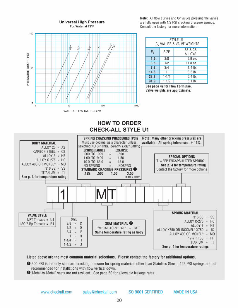
The Universal High Pressure (U1, R1) check valve is a one piece body machined from bar stock with female pipethreads. The valve is designed and manufactured for high pressure applications. These valves can also be used aslow pressure relief valves or vacuum breakers by using the desired spring settings. This valve is normally suppliedwith a “metal-to-metal” seat. NPT threads are per ASME B1.20.1. Also available with ISO 7 “Rp” threads. (R1).
NOTE: Many valves in this series can be supplied with B16.34 certification. Consult the factory for more information.
20
Note: All flow curves and Cv values presume the valvesare fully open with 1/2 PSI cracking pressure springs.Consult the factory for more information.
www.checkall.com [email protected] ISO 9001 CERTIFIED MADE IN USA
1
10
100
1 10 100 1000
1”
3/8
”
1/2
”
3/4
”
1-1
/4”
1-1
/2”
STYLE U1Cv VALUES & VALVE WEIGHTS
Cv SIZESS & CSALLOYS
1.9 3/8 5.9 oz.
3.5 1/2 11.8 oz.
7.2 3/4 1.4 lb.
14.6 1 3.5 lb.
28.8 1-1/4 5.4 lb.
31.9 1-1/2 8.1 lb.
PR
ES
SU
RE
DR
OP
- P
SI
WATER FLOW RATE - GPM
Universal High PressureFor Water at 72°F
SIZE3/8 = C1/2 = D3/4 = F1 = H
1-1/4 = I1-1/2 = J
BODY MATERIALALLOY 20 = A2
CARBON STEEL = CSALLOY B = HB
ALLOY C-276 = HCALLOY 400 OR MONEL® = MO
316 SS = SSTITANIUM = TI
See p. 3 for temperature rating
SEAT MATERIAL w
“METAL-TO-METAL” = MTSame temperature rating as body
SPECIAL OPTIONST = FEP ENCAPSULATED SPRING
See p. 4 for temperature ratingContact the factory for more options
SPRING MATERIAL316 SS = SS
ALLOY C-276 = HCALLOY B = HB
ALLOY X750 OR INCONEL® X750 = IXALLOY 400 OR MONEL® = MO
17-7PH SS = PHTITANIUM = TI
See p. 4 for temperature ratings
HOW TO ORDER
CHECK-ALL STYLE U1
See page 49 for Flow Formulae.Valve weights are approximate.
Listed above are the most common material selections. Please contact the factory for additional options.
q.500 PSI is the only standard cracking pressure for spring materials other than Stainless Steel. .125 PSI springs are notrecommended for installations with flow vertical down.
w“Metal-to-Metal” seats are not resilient. See page 50 for allowable leakage rates.
SPRING CRACKING PRESSURES (PSI)Must use decimal as a character unless
selecting NO SPRING. Specify Exact SettingSPRING RANGES EXAMPLE
.000 TO .999 = .5001.00 TO 9.99 = 1.5010.0 TO 85.0 = 15.0NO SPRING = NOSPRG
STANDARD CRACKING PRESSURES q.125 .500 1.50 3.50
(Sizes C-I Only)
Note: Many other cracking pressures areavailable. All spring tolerances +/- 15%.
VALVE STYLENPT Threads = U1
ISO 7 Rp Threads = R1
1 MT

21
Nom. Pipe &Tube Size
SizeCode A
Hex Size
B q C D E F GOrificeDiameter
1/8 A 2.16 7/8 0.75 0.71 0.93 0.11 0.73 0.348
1/4 B 2.16 7/8 0.92 0.84 1.23 0.57 0.97 0.348
3/8 C 2.48 1-1/8 0.92 0.91 1.32 0.59 1.00 0.464
qMay be larger and/or round.
MINICHECK
wSee page 54 for material grade information.
eMaximum Pressure 1500 PSI for o-ring seats.
Body Material w Non-Shock Pressure-Temperature Rating e
316 Stainless Steel (SS)5000 PSIG @ 100°F
Carbon Steel (CS)
Brass (BR) 3000 PSIG @ 100°F
FLOWFLOW
B
A AREF
CREF
DREF
FREF
G
APPROX.
E37° FLARE
MADE IN USA CHECK-ALL VALVE® MFG. CO. Phone: 515-224-2301 Fax: 515-224-2326
2104/68/EU COMPLIANT
See page 55 for Details
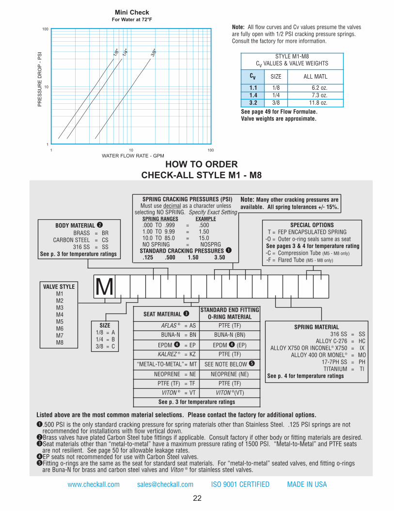
The Mini-Check (M1 - M8) is designed for minimum pressure drop. The three-piece construction permits manycombinations of end fittings, which makes the valve adaptable for nearly every application. The Mini-Check is availablewith 1/8, 1/4, and 3/8 inch pipe threads, both male and female. It can also be supplied with a 1/8, 1/4, or 3/8 inch tubingend on one side and with a pipe thread end on the other. Combinations of male and female threads are also available.The Mini-Check can also be used as a low pressure relief valve or vacuum breaker by using the desired spring settings.NOTE: Many valves in this series can be supplied with B16.34 certification. Consult the factory for more information.
M1 – Male pipe threads both ends. M5 – Male pipe inlet – tubing outlet.
M2 – Female pipe threads both ends. M6 – Female pipe inlet – tubing outlet.
M3 – Male pipe inlet – female pipe outlet. M7 – Tubing inlet – male pipe outlet.
M4 – Female pipe inlet – male pipe outlet. M8 – Tubing inlet – female pipe outlet.
NOTE: When ordering styles M5 through M8 be sure to specify whether compression (-C) or 37° flare (-F).
22
Note: All flow curves and Cv values presume the valvesare fully open with 1/2 PSI cracking pressure springs.Consult the factory for more information.
www.checkall.com [email protected] ISO 9001 CERTIFIED MADE IN USA
1/8
"
1/4
"
3/8
"
1
10
100
1 10 100
STYLE M1-M8Cv VALUES & VALVE WEIGHTS
Cv SIZE ALL MATL
1.1 1/8 6.2 oz.
1.4 1/4 7.3 oz.
3.2 3/8 11.8 oz.PR
ES
SU
RE
DR
OP
- P
SI
WATER FLOW RATE - GPM
Mini CheckFor Water at 72°F
See page 49 for Flow Formulae.Valve weights are approximate.
SIZE1/8 = A1/4 = B3/8 = C
VALVE STYLEM1M2M3M4M5M6M7M8
BODY MATERIAL w
BRASS = BRCARBON STEEL = CS
316 SS = SSSee p. 3 for temperature ratings
SPECIAL OPTIONST = FEP ENCAPSULATED SPRING-O = Outer o-ring seals same as seatSee pages 3 & 4 for temperature rating-C = Compression Tube (M5 - M8 only)-F = Flared Tube (M5 - M8 only)
SPRING MATERIAL316 SS = SS
ALLOY C-276 = HCALLOY X750 OR INCONEL® X750 = IX
ALLOY 400 OR MONEL® = MO17-7PH SS = PHTITANIUM = TI
See p. 4 for temperature ratings
Listed above are the most common material selections. Please contact the factory for additional options.
q.500 PSI is the only standard cracking pressure for spring materials other than Stainless Steel. .125 PSI springs are notrecommended for installations with flow vertical down.
wBrass valves have plated Carbon Steel tube fittings if applicable. Consult factory if other body or fitting materials are desired.eSeat materials other than “metal-to-metal” have a maximum pressure rating of 1500 PSI. “Metal-to-Metal” and PTFE seats are not resilient. See page 50 for allowable leakage rates.
rEP seats not recommended for use with Carbon Steel valves.tFitting o-rings are the same as the seat for standard seat materials. For “metal-to-metal” seated valves, end fitting o-rings are Buna-N for brass and carbon steel valves and Viton ® for stainless steel valves.
SEAT MATERIAL eSTANDARD END FITTING
O-RING MATERIAL
AFLAS ® = AS PTFE (TF)
BUNA-N = BN BUNA-N (BN)
EPDM r = EP EPDM r (EP)
KALREZ ® = KZ PTFE (TF)
“METAL-TO-METAL”= MT SEE NOTE BELOW t
NEOPRENE = NE NEOPRENE (NE)
PTFE (TF) = TF PTFE (TF)
VITON ® = VT VITON ®(VT)
See p. 3 for temperature ratings
HOW TO ORDER
CHECK-ALL STYLE M1 - M8
M
SPRING CRACKING PRESSURES (PSI)Must use decimal as a character unless
selecting NO SPRING. Specify Exact SettingSPRING RANGES EXAMPLE
.000 TO .999 = .5001.00 TO 9.99 = 1.5010.0 TO 85.0 = 15.0NO SPRING = NOSPRGSTANDARD CRACKING PRESSURES q.125 .500 1.50 3.50
Note: Many other cracking pressures areavailable. All spring tolerances +/- 15%.
23
LineSize
SizeCode A B C q D w E F e G
OrificeDiameter
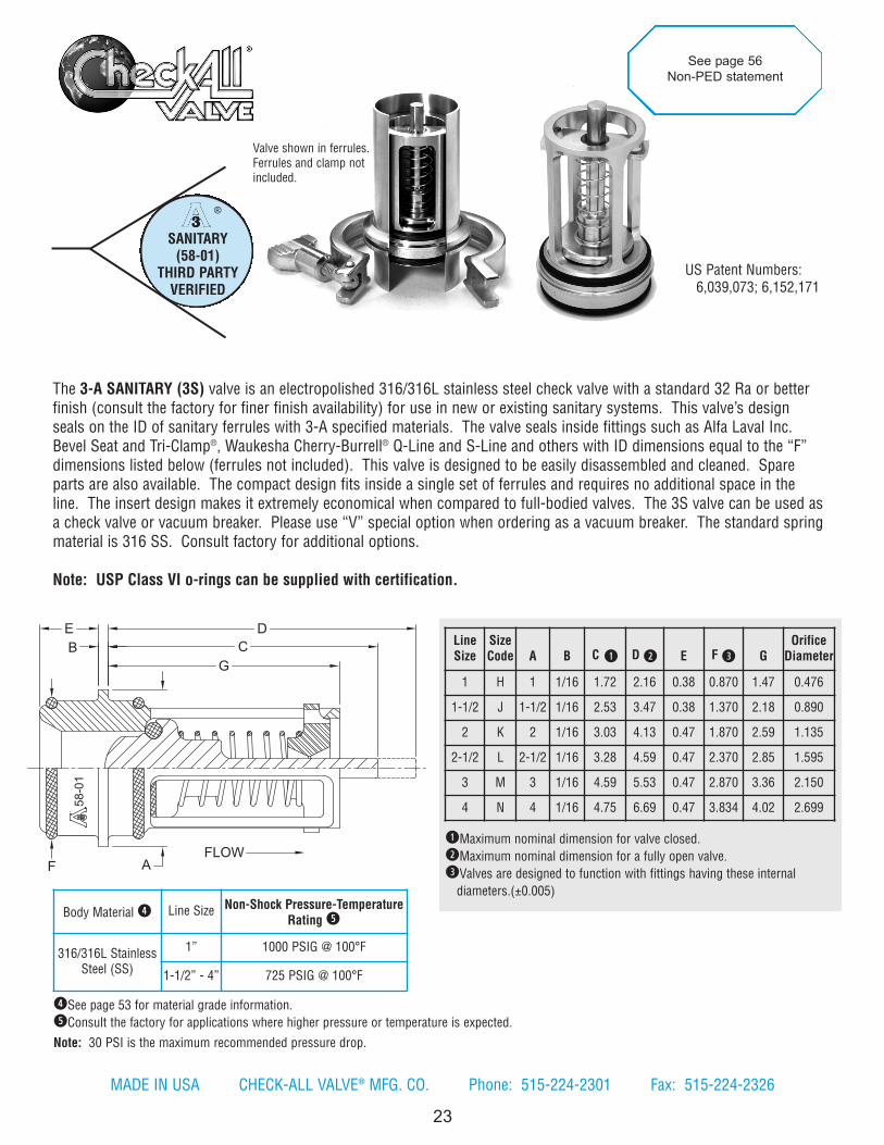
1 H 1 1/16 1.72 2.16 0.38 0.870 1.47 0.476
1-1/2 J 1-1/2 1/16 2.53 3.47 0.38 1.370 2.18 0.890
2 K 2 1/16 3.03 4.13 0.47 1.870 2.59 1.135
2-1/2 L 2-1/2 1/16 3.28 4.59 0.47 2.370 2.85 1.595
3 M 3 1/16 4.59 5.53 0.47 2.870 3.36 2.150
4 N 4 1/16 4.75 6.69 0.47 3.834 4.02 2.699
Body Material r Line Size Non-Shock Pressure-TemperatureRating t
316/316L StainlessSteel (SS)
1” 1000 PSIG @ 100°F
1-1/2” - 4” 725 PSIG @ 100°F
qMaximum nominal dimension for valve closed.
wMaximum nominal dimension for a fully open valve.
eValves are designed to function with fittings having these internal
diameters.(±0.005)
SANITARY(58-01)
THIRD PARTYVERIFIED
®
rSee page 53 for material grade information.
tConsult the factory for applications where higher pressure or temperature is expected.
Note: 30 PSI is the maximum recommended pressure drop.
US Patent Numbers: 6,039,073; 6,152,171
See page 56
Non-PED statement®
58-0
1
E
B
D
C
G
FLOWAF
Valve shown in ferrules.Ferrules and clamp notincluded.
The 3-A SANITARY (3S) valve is an electropolished 316/316L stainless steel check valve with a standard 32 Ra or betterfinish (consult the factory for finer finish availability) for use in new or existing sanitary systems. This valve’s designseals on the ID of sanitary ferrules with 3-A specified materials. The valve seals inside fittings such as Alfa Laval Inc.Bevel Seat and Tri-Clamp®, Waukesha Cherry-Burrell® Q-Line and S-Line and others with ID dimensions equal to the “F”dimensions listed below (ferrules not included). This valve is designed to be easily disassembled and cleaned. Spareparts are also available. The compact design fits inside a single set of ferrules and requires no additional space in theline. The insert design makes it extremely economical when compared to full-bodied valves. The 3S valve can be used asa check valve or vacuum breaker. Please use “V” special option when ordering as a vacuum breaker. The standard springmaterial is 316 SS. Consult factory for additional options.
Note: USP Class VI o-rings can be supplied with certification.
MADE IN USA CHECK-ALL VALVE® MFG. CO. Phone: 515-224-2301 Fax: 515-224-2326

www.checkall.com [email protected] ISO 9001 CERTIFIED MADE IN USA
Step 1 Step 2
Step 3 Step 4
Assembled ValveVacuum Breaker Spring
Locate bent end nextto the retainer
Retainer
Check Valve Spring
PoppetPoppet O-ring
Valve Body
Body O-rings
VALVE PARTS
Spring fits over Retainer Shoulder
Retainer Shoulder
Disassembly For Cleaning Instructions
To disassemble the 3-A Sanitary valve, start by depressing one side of the
retainer as shown in Step 1. With one side of the retainer tipped, rotate the
stem of the poppet and remove the retainer as shown in Steps 2, 3 and 4. To
reassemble the valve reverse the process. Consult the factory for information
on trim kits, o-ring kits, or individual spare parts.
Disassembly For Cleaning Instructions
25

®
58-0
1
®
58-0
1
1-1
/2"
1" 2"
2-1
/2"
3"
4"
1
10
100
1 10 100 1000
STYLE 3S Cv VALUES & VALVE WEIGHTS
Cv SIZE 316/316L SS
5.2 1 2.3 oz.
16.1 1-1/2 6.2 oz.
27.2 2 13.9 oz.
49.4 2-1/2 1.5 lb.
74.9 3 1.9 lb.
120.0 4 3.9 lb.
PR
ES
SU
RE
DR
OP
- P
SI
WATER FLOW RATE - GPM
3-A SanitaryFor Water at 72°F
CLAMP JOINT
FLOWNOTE: VALVE CAN BE INSTALLED FOR
FLOW IN EITHER DIRECTION.
FERRULES SHOWN FOR
ILLUSTRATION ONLY AND ARE
NOT SUPPLIED WITH THE VALVE.
See page 49 for Flow Formulae.Valve weights are approximate.
Note: All flow curves and Cv values presume the valvesare fully open with 1/2 PSI cracking pressure springs.Consult the factory for more information.
Note: All flow curves and Cv values presume the valves are fully open with 1/2 PSI cracking pressure springs.Consult the factory for more information.
26
MADE IN USA CHECK-ALL VALVE® MFG. CO. Phone: 515-224-2301 Fax: 515-224-2326

24
www.checkall.com [email protected] ISO 9001 CERTIFIED MADE IN USA
SIZE1 = H
1-1/2 = J2 = K
2-1/2 = L3 = M4 = N
VALVE STYLE
BODY MATERIAL316/316L SS = SS
See p. 3 for temperature rating
SEAT& OUTER SEALS MATERIAL
3-A AFLAS ® = 3A
3-A EPDM = 3E
3-A KALREZ ® = 3K
3-A SILICONE = 3S
3-A VITON ® = 3V
3-A/USP Class VI AFLAS ® = UA
3-A/USP Class VI EPDM = UE
3-A/USP Class VI KALREZ ® = UK3-A/USP Class VI SILICONE = US
3-A/USP Class VI VITON ® = UV
See p. 3 for temperature ratings
SPECIAL OPTIONSV if valve is used as a vacuum breakerEC = 15 Ra FinishSpring finishes may vary, contact thefactory for more information andadditional options.
SPRING MATERIAL316 SS = SS
ALLOY C-276 = HCSee p. 4 for temperature ratings
HOW TO ORDER
CHECK-ALL STYLE 3S
Listed above are the most common material selections. Please contact the factory for additional options.
SPRING CRACKING PRESSURES (PSI)Must use decimal as a character unless
selecting NO SPRING. Specify Exact SettingSPRING RANGES EXAMPLE
.000 TO .999 = .5001.00 TO 9.99 = 1.5010.0 TO 85.0 = 15.0STANDARD CRACKING PRESSURES
.500 1.50
Note: Many other cracking pressures areavailable. All spring tolerances +/- 15%.
Contact factory for non-standard crackingpressure availability.
3 S SS
27
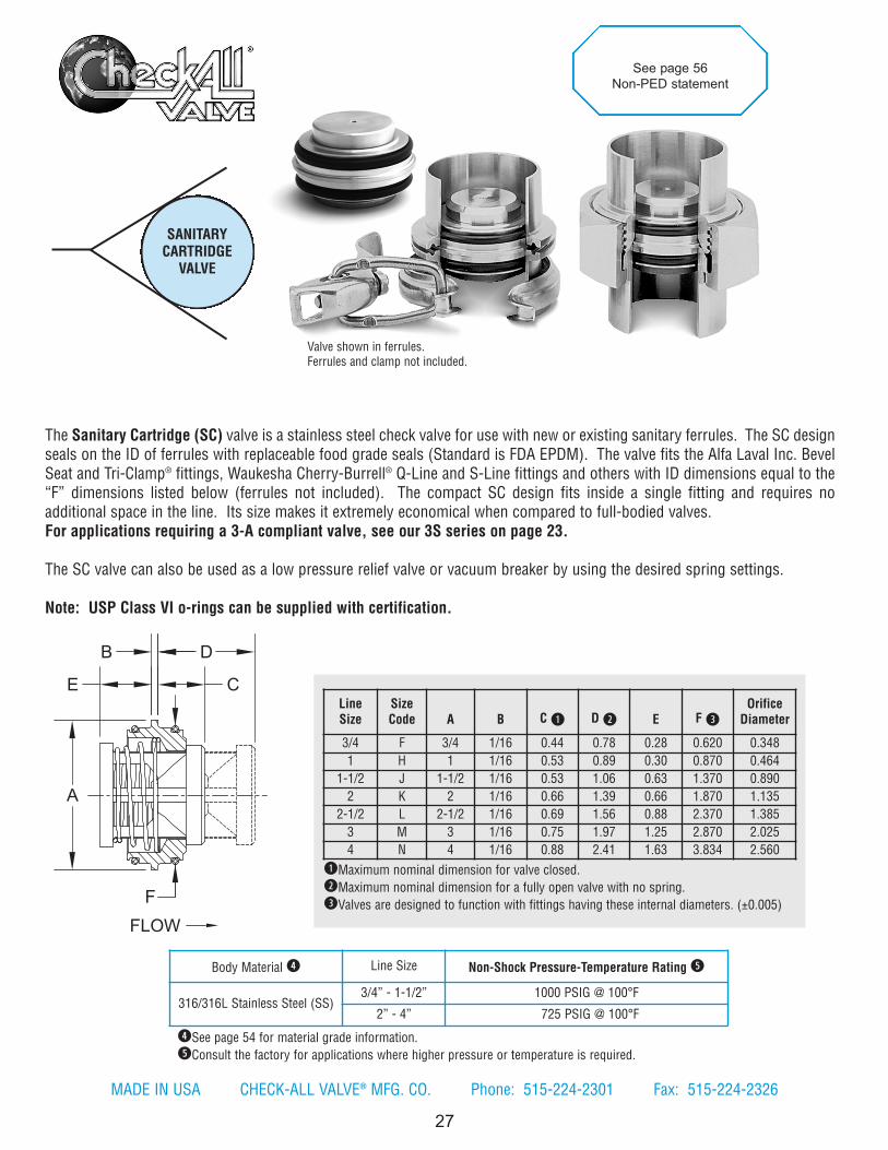
The Sanitary Cartridge (SC) valve is a stainless steel check valve for use with new or existing sanitary ferrules. The SC designseals on the ID of ferrules with replaceable food grade seals (Standard is FDA EPDM). The valve fits the Alfa Laval Inc. BevelSeat and Tri-Clamp® fittings, Waukesha Cherry-Burrell® Q-Line and S-Line fittings and others with ID dimensions equal to the“F” dimensions listed below (ferrules not included). The compact SC design fits inside a single fitting and requires noadditional space in the line. Its size makes it extremely economical when compared to full-bodied valves.For applications requiring a 3-A compliant valve, see our 3S series on page 23.
The SC valve can also be used as a low pressure relief valve or vacuum breaker by using the desired spring settings.
Note: USP Class VI o-rings can be supplied with certification.
LineSize
SizeCode A B C q D w E F e
OrificeDiameter
3/4 F 3/4 1/16 0.44 0.78 0.28 0.620 0.348
1 H 1 1/16 0.53 0.89 0.30 0.870 0.464
1-1/2 J 1-1/2 1/16 0.53 1.06 0.63 1.370 0.890
2 K 2 1/16 0.66 1.39 0.66 1.870 1.135
2-1/2 L 2-1/2 1/16 0.69 1.56 0.88 2.370 1.385
3 M 3 1/16 0.75 1.97 1.25 2.870 2.025
4 N 4 1/16 0.88 2.41 1.63 3.834 2.560
qMaximum nominal dimension for valve closed.
wMaximum nominal dimension for a fully open valve with no spring.
eValves are designed to function with fittings having these internal diameters. (±0.005)
Body Material r Line Size Non-Shock Pressure-Temperature Rating t
316/316L Stainless Steel (SS) 3/4” - 1-1/2” 1000 PSIG @ 100°F
2” - 4” 725 PSIG @ 100°F
SANITARYCARTRIDGE
VALVE
rSee page 54 for material grade information.
tConsult the factory for applications where higher pressure or temperature is required.
See page 56
Non-PED statement
B D
CE
A
F
FLOW
Valve shown in ferrules.Ferrules and clamp not included.
MADE IN USA CHECK-ALL VALVE® MFG. CO. Phone: 515-224-2301 Fax: 515-224-2326

28
Note: All flow curves and Cv values presume the valvesare fully open with 1/2 PSI cracking pressure springs.Consult the factory for more information.
www.checkall.com [email protected] ISO 9001 CERTIFIED MADE IN USA
STYLE SC Cv VALUES & VALVE WEIGHTS
Cv SIZE 316 SS
2.4 3/4 0.3 oz.
4.6 1 1.0 oz.
9.5 1-1/2 2.9 oz.
20.9 2 6.1 oz.
37.0 2-1/2 11.2 oz.
77.9 3 11.4 oz.
141 4 2.6 lb.PR
ES
SU
RE
DR
OP
- P
SI
WATER FLOW RATE - GPM
Sanitary Cartridge ValveFor Water at 72°F
BODY MATERIAL316/316L SS = SS
See p. 3 for temperature rating
SPECIAL OPTIONST = FEP ENCAPSULATED SPRING
-O = Outer o-ring seals same as seat e
See pages 3 & 4 for temperature ratingContact the factory for more options
SPRING MATERIAL316 SS = SS
ALLOY C-276 = HCALLOY X750 OR INCONEL® X750 = IX
ALLOY 400 OR MONEL® = MO17-7PH SS = PHTITANIUM = TI
See p. 4 for temperature ratings
HOW TO ORDER
CHECK-ALL STYLE SC
See page 49 for Flow Formulae.Valve weights are approximate.
1-1
/2"
1"
2"
2-1
/2"
3"
4"
3/4
"
1
10
100
1 10 100 1000
Listed above are the most common material selections. Please contact the factory for additional options.
q.500 PSI is the only standard cracking pressure for spring materials other than Stainless Steel. .125 PSI springs are notrecommended for installations with flow vertical down.
w“Metal-to-Metal” and PTFE seats are not resilient. See page 50 for allowable leakage rates.e-O option not available for “Metal-to-Metal” and PTFE seats, FE will be used as standard. Consult factory for other options.
SPRING CRACKING PRESSURES (PSI)Must use decimal as a character unless
selecting NO SPRING. Specify Exact SettingSPRING RANGES EXAMPLE
.000 TO .999 = .5001.00 TO 9.99 = 1.5010.0 TO 85.0 = 15.0NO SPRING = NOSPRGSTANDARD CRACKING PRESSURES q.125 .500 1.50 3.50
(Sizes F-K Only)
Note: Many other cracking pressures areavailable. All spring tolerances +/- 15%.
SEAT MATERIAL w
AFLAS ® = AS “METAL-TO-METAL” = MTBUNA-N = BN NEOPRENE = NE
FDA AFLAS ® = FA PTFE = TFFDA BUNA = FB USP CLASS VI AFLAS ® = UA
EPDM/FDA EPDM = FE USP CLASS VI EPDM = UEFDA VITON ® = FV USP CLASS VI SILICONE = US
KALREZ ® = KZ USP CLASS VI VITON ® = UVVITON ® = VT
See p. 3 for temperature ratings
SIZE3/4 = F1 = H
1-1/2 = J2 = K
2-1/2 = L3 = M4 = N
VALVE STYLE SC SS
A
C
E B
D
FLOW
29
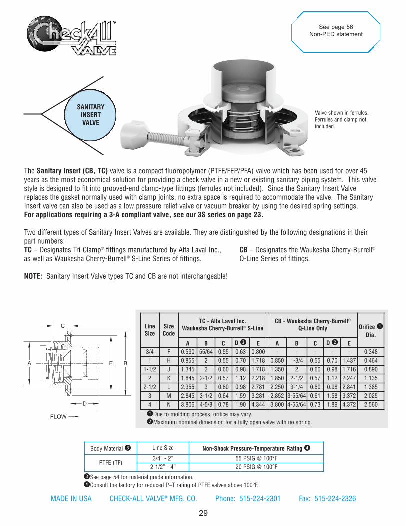
The Sanitary Insert (CB, TC) valve is a compact fluoropolymer (PTFE/FEP/PFA) valve which has been used for over 45years as the most economical solution for providing a check valve in a new or existing sanitary piping system. This valvestyle is designed to fit into grooved-end clamp-type fittings (ferrules not included). Since the Sanitary Insert Valvereplaces the gasket normally used with clamp joints, no extra space is required to accommodate the valve. The SanitaryInsert valve can also be used as a low pressure relief valve or vacuum breaker by using the desired spring settings.For applications requiring a 3-A compliant valve, see our 3S series on page 23.
Two different types of Sanitary Insert Valves are available. They are distinguished by the following designations in theirpart numbers:TC – Designates Tri-Clamp® fittings manufactured by Alfa Laval Inc., CB – Designates the Waukesha Cherry-Burrell®
as well as Waukesha Cherry-Burrell® S-Line Series of fittings. Q-Line Series of fittings.
NOTE: Sanitary Insert Valve types TC and CB are not interchangeable!
LineSize
SizeCode
TC - Alfa Laval Inc.Waukesha Cherry-Burrell® S-Line
CB - Waukesha Cherry-Burrell®
Q-Line Only Orifice q
Dia.
A B C D w E A B C D w E
3/4 F 0.590 55/64 0.55 0.63 0.800 - - - - - 0.348
1 H 0.855 2 0.55 0.70 1.718 0.850 1-3/4 0.55 0.70 1.437 0.464
1-1/2 J 1.345 2 0.60 0.98 1.718 1.350 2 0.60 0.98 1.716 0.890
2 K 1.845 2-1/2 0.57 1.12 2.218 1.850 2-1/2 0.57 1.12 2.247 1.135
2-1/2 L 2.355 3 0.60 0.98 2.781 2.250 3-1/4 0.60 0.98 2.841 1.385
3 M 2.845 3-1/2 0.64 1.59 3.281 2.852 3-55/64 0.61 1.58 3.372 2.025
4 N 3.806 4-5/8 0.78 1.90 4.344 3.800 4-55/64 0.73 1.89 4.372 2.560
qDue to molding process, orifice may vary.
wMaximum nominal dimension for a fully open valve with no spring.
Body Material e Line Size Non-Shock Pressure-Temperature Rating r
PTFE (TF)3/4” - 2” 55 PSIG @ 100°F
2-1/2” - 4” 20 PSIG @ 100°F
SANITARYINSERTVALVE
eSee page 54 for material grade information.
rConsult the factory for reduced P–T rating of PTFE valves above 100°F.
See page 56
Non-PED statement
Valve shown in ferrules.Ferrules and clamp notincluded.
MADE IN USA CHECK-ALL VALVE® MFG. CO. Phone: 515-224-2301 Fax: 515-224-2326
30
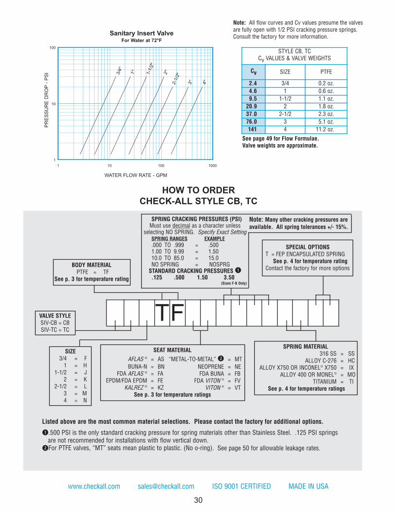
See page 49 for Flow Formulae.Valve weights are approximate.
Note: All flow curves and Cv values presume the valvesare fully open with 1/2 PSI cracking pressure springs.Consult the factory for more information.
www.checkall.com [email protected] ISO 9001 CERTIFIED MADE IN USA
1-1
/2"
1"
2"
2-1
/2"
3"
4"
3/4
"
1
10
100
1 10 100 1000
STYLE CB, TCCv VALUES & VALVE WEIGHTS
Cv SIZE PTFE
2.4 3/4 0.2 oz.4.6 1 0.6 oz.9.5 1-1/2 1.1 oz.
20.9 2 1.8 oz.37.0 2-1/2 2.3 oz.76.0 3 5.1 oz.141 4 11.2 oz.
PR
ES
SU
RE
D
RO
P - P
SI
WATER FLOW RATE - GPM
Sanitary Insert Valve
For Water at 72°F
SPECIAL OPTIONST = FEP ENCAPSULATED SPRING
See p. 4 for temperature ratingContact the factory for more options
SPRING MATERIAL316 SS = SS
ALLOY C-276 = HCALLOY X750 OR INCONEL® X750 = IX
ALLOY 400 OR MONEL® = MOTITANIUM = TI
See p. 4 for temperature ratings
HOW TO ORDER
CHECK-ALL STYLE CB, TC
Listed above are the most common material selections. Please contact the factory for additional options.
q.500 PSI is the only standard cracking pressure for spring materials other than Stainless Steel. .125 PSI springsare not recommended for installations with flow vertical down.
wFor PTFE valves, “MT” seats mean plastic to plastic. (No o-ring). See page 50 for allowable leakage rates.
SPRING CRACKING PRESSURES (PSI)Must use decimal as a character unless
selecting NO SPRING. Specify Exact SettingSPRING RANGES EXAMPLE.000 TO .999 = .5001.00 TO 9.99 = 1.5010.0 TO 85.0 = 15.0NO SPRING = NOSPRG
STANDARD CRACKING PRESSURES q.125 .500 1.50 3.50
(Sizes F-K Only)
Note: Many other cracking pressures areavailable. All spring tolerances +/- 15%.
TF
SEAT MATERIALAFLAS ® = AS “METAL-TO-METAL” w = MTBUNA-N = BN NEOPRENE = NE
FDA AFLAS ® = FA FDA BUNA = FBEPDM/FDA EPDM = FE FDA VITON ® = FV
KALREZ ® = KZ VITON ® = VTSee p. 3 for temperature ratings
VALVE STYLESIV-CB = CBSIV-TC = TC
BODY MATERIALPTFE = TF
See p. 3 for temperature rating
SIZE3/4 = F
1 = H1-1/2 = J
2 = K2-1/2 = L
3 = M4 = N
PED 9
7/2
3/E
C
COM
PLIA
NT
See P
age 5
5 fo
r D
eta
ils
A
B C D
FLOW
2X 30°2X 37.5°2X 0.06
2X E
31
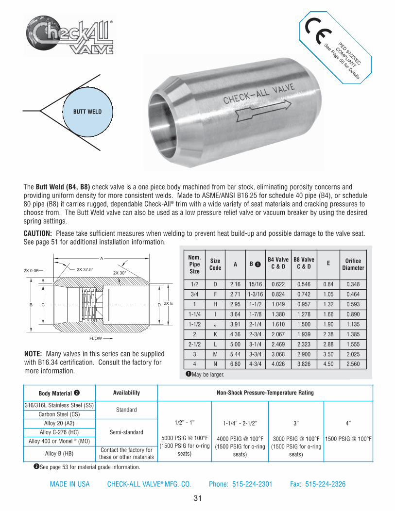
The Butt Weld (B4, B8) check valve is a one piece body machined from bar stock, eliminating porosity concerns andproviding uniform density for more consistent welds. Made to ASME/ANSI B16.25 for schedule 40 pipe (B4), or schedule80 pipe (B8) it carries rugged, dependable Check-All® trim with a wide variety of seat materials and cracking pressures tochoose from. The Butt Weld valve can also be used as a low pressure relief valve or vacuum breaker by using the desiredspring settings.
CAUTION: Please take sufficient measures when welding to prevent heat build-up and possible damage to the valve seat.See page 51 for additional installation information.
BUTT WELD
qMay be larger.
Nom.PipeSize
SizeCode A B q
B4 ValveC & D
B8 ValveC & D E Orifice
Diameter
1/2 D 2.16 15/16 0.622 0.546 0.84 0.348
3/4 F 2.71 1-3/16 0.824 0.742 1.05 0.464
1 H 2.95 1-1/2 1.049 0.957 1.32 0.593
1-1/4 I 3.64 1-7/8 1.380 1.278 1.66 0.890
1-1/2 J 3.91 2-1/4 1.610 1.500 1.90 1.135
2 K 4.36 2-3/4 2.067 1.939 2.38 1.385
2-1/2 L 5.00 3-1/4 2.469 2.323 2.88 1.555
3 M 5.44 3-3/4 3.068 2.900 3.50 2.025
4 N 6.80 4-3/4 4.026 3.826 4.50 2.560
wSee page 53 for material grade information.
Body Material w Availability Non-Shock Pressure-Temperature Rating
316/316L Stainless Steel (SS)Standard
1/2” - 1”
5000 PSIG @ 100°F(1500 PSIG for o-ring
seats)
1-1/4” - 2-1/2”
4000 PSIG @ 100°F(1500 PSIG for o-ring
seats)
3”
3000 PSIG @ 100°F(1500 PSIG for o-ring
seats)
4”
1500 PSIG @ 100°F
Carbon Steel (CS)Alloy 20 (A2)
Semi-standardAlloy C-276 (HC)Alloy 400 or Monel ® (MO)
Alloy B (HB) Contact the factory forthese or other materials
MADE IN USA CHECK-ALL VALVE® MFG. CO. Phone: 515-224-2301 Fax: 515-224-2326
NOTE: Many valves in this series can be suppliedwith B16.34 certification. Consult the factory formore information.

32
See page 49 for Flow Formulae.Valve weights are approximate.
Note: All flow curves and Cv values presume the valvesare fully open with 1/2 PSI cracking pressure springs.Consult the factory for more information.
www.checkall.com [email protected] ISO 9001 CERTIFIED MADE IN USA
1/2
"
3/4
"
1"
1-1
/4"
1-1
/2"
2"
2-1
/2"
3"
4"
1
10
100
1 10 100 1000
PR
ES
SU
RE
D
RO
P - P
SI
WATER FLOW RATE - GPM
Butt Weld Valve
For Water at 72°F
SIZE1/2 = D3/4 = F
1 = H1-1/4 = I1-1/2 = J
2 = K2-1/2 = L
3 = M4 = N
VALVE STYLE
SCH 40 PIPE = B4SCH 80 PIPE = B8
BODY MATERIALALLOY 20 = A2
CARBON STEEL = CSALLOY B = HB
ALLOY C-276 = HCALLOY 400 OR MONEL® = MO
316/316L SS = SSSee p. 3 for temperature ratings
SEAT MATERIAL wAFLAS ® = ASBUNA-N = BN
EPDM e = EPKALREZ ® = KZ
“METAL-TO-METAL” = MT NEOPRENE = NE
PTFE = TFVITON ® = VT
See p. 3 for temperature ratings
SPECIAL OPTIONST = FEP ENCAPSULATED SPRING
See p. 4 for temperature ratingContact the factory for more options
SPRING MATERIAL316 SS = SS
ALLOY C-276 = HCALLOY B = HB
ALLOY X750 OR INCONEL® X750 = IXALLOY 400 OR MONEL® = MO
17-7PH SS = PHTITANIUM = TI
See p. 4 for temperature ratings
STYLE B4Cv VALUES & VALVE WEIGHTS
Cv SIZE SS & CSAlloys
2.4 1/2 4.6 oz.4.4 3/4 9.1 oz.6.1 1 15.0 oz.
12.7 1-1/4 1.7 lb.18.8 1-1/2 2.6 lb.32.0 2 4.1 lb.42.5 2-1/2 6.3 lb.89.0 3 8.4 lb.144 4 15.2 lb.
HOW TO ORDER
CHECK-ALL STYLE B4, B8
Listed above are the most common material selections. Please contact the factory for additional options.
q.500 PSI is the only standard cracking pressure for spring materials other than Stainless Steel. .125 PSI springs are notrecommended for installations with flow vertical down.
wSeat materials other than “metal-to-metal” have a maximum pressure rating of 1500 PSI. “Metal-to-Metal” and PTFE seats are not resilient. See page 50 for allowable leakage rates.
eEP seats not recommended for use with Carbon Steel valves.
SPRING CRACKING PRESSURES (PSI)Must use decimal as a character unless
selecting NO SPRING. Specify Exact SettingSPRING RANGES EXAMPLE.000 TO .999 = .5001.00 TO 9.99 = 1.5010.0 TO 85.0 = 15.0NO SPRING = NOSPRG
STANDARD CRACKING PRESSURES q.125 .500 1.50 3.50
(Sizes D-J Only)
Note: Many other cracking pressures areavailable. All spring tolerances +/- 15%.
B

33
2104/68/EU
COM
PLIA
NT
See page 55for D
etails
qMay be larger.wSockets per ASME/ANSI B16.11.
UNIVERSALSOCKETWELD
Nom.PipeSize
SizeCode A B q C w D w
OrificeDiameter
3/8 C 2.16 1-1/8 0.695 0.385 0.3481/4 B 2.16 1 0.563 0.385 0.3481/2 D 2.71 1-5/16 0.860 0.385 0.4643/4 F 2.95 1-5/8 1.070 0.505 0.5931 H 3.64 2-1/4 1.335 0.505 0.890
1-1/4 I 3.91 2-3/4 1.680 0.505 1.1351-1/2 J 4.36 3-1/4 1.920 0.505 1.385
2 K 5.85 3-1/2 2.411 0.625 1.5552-1/2 L 5.00 3-3/4 2.919 0.625 1.555
3 M 5.44 4-1/2 3.545 0.625 2.0254 N 6.80 5-1/2 4.550 0.755 2.560
eSee page 54 for material grade information.
Body Material e Availability Non-Shock Pressure-Temperature Rating
316/316L Stainless Steel (SS)Standard
3/8” - 2-1/2”
5000 PSIG @ 100°F(1500 PSIG for o-ring seats)
3”
3000 PSIG @ 100°F(1500 PSIG for o-ring seats)
4”
1500 PSIG @ 100°F
Carbon Steel (CS)
Alloy 20 (A2)
Semi-standardAlloy C-276 (HC)
Alloy 400 or Monel ® (MO)
Alloy B (HB) Contact the factory for theseor other materials
The Universal Socket Weld (US) check valve is a one piece body machined from bar stock with socket weld ends and isdesigned for a minimum pressure drop. It carries rugged, dependable Check-All® trim and there are a wide variety of seatmaterials and cracking pressures to choose from. The socket ends are machined to ASME/ANSI B16.11 dimensions. TheUS valve can also be used as a low pressure relief valve or vacuum breaker by using the desired spring settings.
CAUTION: Please take sufficient measures when welding to prevent heat build-up and possible damage to the valve seat.See page 51 for additional installation information.
MADE IN USA CHECK-ALL VALVE® MFG. CO. Phone: 515-224-2301 Fax: 515-224-2326
NOTE: Many valves in this series can be suppliedwith B16.34 certification. Consult the factory for moreinformation.

34
www.checkall.com [email protected] ISO 9001 CERTIFIED MADE IN USA
STYLE USCv VALUES & VALVE WEIGHTS
Cv SIZE SS & CSALLOYS
1.5 1/4 4.0 oz.1.9 3/8 5.1 oz.
11.54.3 1/27.2 3/4 1. 2 lb.11.0 1 3.1 lb.19.0 1-1/4 4.9 lb.31.9 1-1/2 7.4 lb.42.0 2 9.8 lb.50.0 2-1/2 8.8 lb.89.0 3 13 lb.140 4 22.3 lb.
PR
ES
SU
RE
DR
OP
- P
SI
WATER FLOW RATE - GPM
Universal Socket Weld
For Water at 72°F
BODY MATERIALALLOY 20 = A2
CARBON STEEL = CSALLOY B = HB
ALLOY C-276 = HCALLOY 400 OR MONEL® = MO
316/316L SS = SSSee p. 3 for temperature rating
HOW TO ORDER
CHECK-ALL STYLE US
See page 49 for Flow Formulae.Valve weights are approximate.
Note: All flow curves and Cv values presume the valvesare fully open with 1/2 PSI cracking pressure springs.Consult the factory for more information.
Listed above are the most common material selections. Please contact the factory for additional options.
q.500 PSI is the only standard cracking pressure for spring materials other than Stainless Steel. .125 PSI springs are notrecommended for installations with flow vertical down.
wSeat materials other than “metal-to-metal” have a maximum pressure rating of 1500 PSI. “Metal-to-Metal” and PTFE seatsare not resilient. See page 50 for allowable leakage rates.
eEP seats not recommended for use with Carbon Steel valves.
SPRING CRACKING PRESSURES (PSI)Must use decimal as a character unless
selecting NO SPRING. Specify Exact SettingSPRING RANGES EXAMPLE.000 TO .999 = .5001.00 TO 9.99 = 1.5010.0 TO 85.0 = 15.0NO SPRING = NOSPRG
STANDARD CRACKING PRESSURES q.125 .500 1.50 3.50
(Sizes C-I Only)
Note: Many other cracking pressures areavailable. All spring tolerances +/- 15%.
USVALVE STYLE
SPECIAL OPTIONST = FEP ENCAPSULATED SPRING
See p. 4 for temperature ratingContact the factory for more options
SPRING MATERIAL316 SS = SS
ALLOY C-276 = HCALLOY B = HB
ALLOY X750 OR INCONEL® X750 = IXALLOY 400 OR MONEL® = MO
17-7PH SS = PHTITANIUM = TI
See p. 4 for temperature ratings
SEAT MATERIAL wAFLAS ® = ASBUNA-N = BN
EPDM e = EPKALREZ ® = KZ
“METAL-TO-METAL” = MTNEOPRENE = NE
PTFE = TFVITON ® = VT
See p. 3 for temperature ratings
SIZE1/4 = B3/8 = C1/2 = D3/4 = F
1 = H1-1/4 = I1-1/2 = J
2 = K2-1/2 = L
3 = M4 = N

2104/68/EU
COM
PLIANT
See Page for Details
35
FLOW
B
APPROX.D
TYPC
REFA
The Tubing Check (TV) valve is constructed with compression tube fittings (flareless) and is designed for a minimumpressure drop. The valves are furnished complete with ferrules and nuts. The TV valve can also be used as a low pressurerelief valve or vacuum breaker by using the desired spring settings.
NOTE: Consult the factory for instrumentation applications or for more information.
TubingO.D.Size
SizeCode A
Hex q
Size B C DOrificeDiameter
1/8 A 2.16 7/8 0.42 3.99 0.348
1/4 B 2.16 7/8 0.57 4.58 0.348
3/8 C 2.16 7/8 0.57 4.80 0.348
1/2 D 2.48 1-1/8 0.63 5.44 0.464
5/8 E 2.63 1-1/4 0.72 5.89 0.464
3/4 F 2.93 1-1/2 0.85 6.47 0.593
7/8 G 3.34 1-7/8 0.85 6.98 0.890
1 H 3.34 1-7/8 0.81 7.18 0.890
1-1/4 I 3.48 2-1/4 0.89 7.56 1.135
1-1/2 J 3.81 2-1/2 0.89 7.99 1.385
2 K 5.09 3-1/2 1.05 9.66 2.025
qMay be larger and/or round.
Line SizeNon-Shock Pressure-Temperature Rating w
Stainless Steel (SS) and Carbon Steel e Brass (BR) e
1/8” 4500 PSIG @ 100°F 3000 PSIG @ 100°F
1/4” - 1/2” 5000 PSIG @ 100°F 3000 PSIG @ 100°F
5/8” 5000 PSIG @ 100°F 1600 PSIG @ 100°F
3/4” 4500 PSIG @ 100°F 1600 PSIG @ 100°F
7/8” - 1” 4000 PSIG @ 100°F 1600 PSIG @ 100°F
1-1/4” - 1-1/2” 3000 PSIG @ 100°F 1600 PSIG @ 100°F
2” 2000 PSIG @ 100°F 1600 PSIG @ 100°F
TUBINGCHECK
wMaximum Pressure 1500 PSIG for o-ring seats.
eSee page 54 for material grade information.
MADE IN USA CHECK-ALL VALVE® MFG. CO. Phone: 515-224-2301 Fax: 515-224-2326
NOTE: Many valves in this series can be supplied with B16.34certification. Consult the factory for more information.
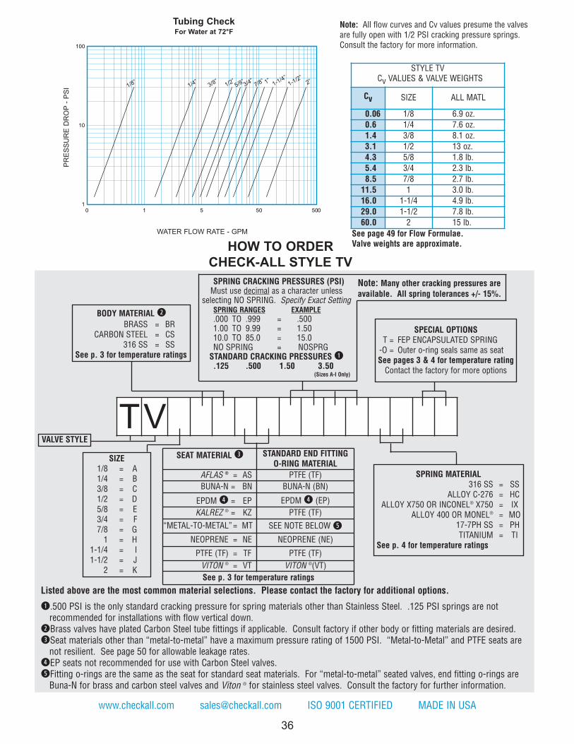
SEAT MATERIAL e STANDARD END FITTINGO-RING MATERIAL
AFLAS ® = AS PTFE (TF)BUNA-N = BN BUNA-N (BN)
EPDM r = EP EPDM r (EP)KALREZ ® = KZ PTFE (TF)
“METAL-TO-METAL” = MT SEE NOTE BELOW tNEOPRENE = NE NEOPRENE (NE)
PTFE (TF) = TF PTFE (TF)VITON ® = VT VITON ®(VT)See p. 3 for temperature ratings
STYLE TVCv VALUES & VALVE WEIGHTS
Cv SIZE ALL MATL
0.06 1/8 6.9 oz.0.6 1/4 7.6 oz.1.4 3/8 8.1 oz.3.1 1/2 13 oz.4.3 5/8 1.8 lb.5.4 3/4 2.3 lb.8.5 7/8 2.7 lb.
11.5 1 3.0 lb.16.0 1-1/4 4.9 lb.29.0 1-1/2 7.8 lb.60.0 2 15 lb.
36
Listed above are the most common material selections. Please contact the factory for additional options.
q.500 PSI is the only standard cracking pressure for spring materials other than Stainless Steel. .125 PSI springs are not recommended for installations with flow vertical down.
wBrass valves have plated Carbon Steel tube fittings if applicable. Consult factory if other body or fitting materials are desired.eSeat materials other than “metal-to-metal” have a maximum pressure rating of 1500 PSI. “Metal-to-Metal” and PTFE seats are
not resilient. See page 50 for allowable leakage rates.rEP seats not recommended for use with Carbon Steel valves.tFitting o-rings are the same as the seat for standard seat materials. For “metal-to-metal” seated valves, end fitting o-rings are
Buna-N for brass and carbon steel valves and Viton ® for stainless steel valves. Consult the factory for further information.
www.checkall.com [email protected] ISO 9001 CERTIFIED MADE IN USA
SPRING CRACKING PRESSURES (PSI)Must use decimal as a character unless
selecting NO SPRING. Specify Exact SettingSPRING RANGES EXAMPLE.000 TO .999 = .5001.00 TO 9.99 = 1.5010.0 TO 85.0 = 15.0NO SPRING = NOSPRG
STANDARD CRACKING PRESSURES q.125 .500 1.50 3.50
(Sizes A-I Only)
Note: Many other cracking pressures areavailable. All spring tolerances +/- 15%.
TV
1
10
100
0 1 5 50 500
1/8”1/4”
3/8”1/2”
5/8”3/4”
7/8”1-1/2”
1”1-1/4”
2”
PR
ES
SU
RE
D
RO
P - P
SI
WATER FLOW RATE - GPM
Tubing Check
For Water at 72°F
SIZE1/8 = A1/4 = B3/8 = C1/2 = D5/8 = E3/4 = F7/8 = G
1 = H1-1/4 = I1-1/2 = J
2 = K
VALVE STYLE
SPRING MATERIAL316 SS = SS
ALLOY C-276 = HCALLOY X750 OR INCONEL® X750 = IX
ALLOY 400 OR MONEL® = MO17-7PH SS = PHTITANIUM = TI
See p. 4 for temperature ratings
See page 49 for Flow Formulae.Valve weights are approximate.
Note: All flow curves and Cv values presume the valvesare fully open with 1/2 PSI cracking pressure springs.Consult the factory for more information.
BODY MATERIAL wBRASS = BR
CARBON STEEL = CS316 SS = SS
See p. 3 for temperature ratings
HOW TO ORDER
CHECK-ALL STYLE TV
SPECIAL OPTIONST = FEP ENCAPSULATED SPRING
-O = Outer o-ring seals same as seatSee pages 3 & 4 for temperature rating
Contact the factory for more options

37
��������
COM
PLIA
NT
See p
age fo
r D
eta
ils
The Tubing Check Valve-Flared (TF) is a three-piece constructed check valve with 37° flared end fittings that conform toSAE J514 & ISO 8434-2 . These valves are designed for maximum flow with minimal pressure drop. The TF valve canalso be used as a low pressure relief valve or vacuum breaker by using the desired spring settings.
TubingO.D.Size
SizeCode A
Hex qSize B C
OrificeDiameter
1/8 A 2.16 7/8 0.69 0.3481/4 B 2.16 7/8 0.89 0.3483/8 C 2.16 7/8 0.91 0.3481/2 D 2.47 1-1/8 1.04 0.4645/8 E 2.63 1-1/4 1.20 0.4643/4 F 2.92 1-1/2 1.38 0.5937/8 G 3.34 1-7/8 1.40 0.8901 H 3.34 1-7/8 1.46 0.890
1-1/4 I 3.48 2-1/4 1.58 1.1351-1/2 J 3.81 2-1/2 1.79 1.385
2 K 5.09 3-1/2 2.19 2.025
qMay be larger and/or round.
Line SizeNon-Shock Pressure-Temperature Rating w
Stainless Steel (SS) e Carbon Steel (CS) e Brass (BR) e
1/8” - 1/2” 7700 PSIG @ 100°F 6000 PSIG @ 100°F 3000 PSIG @ 100°F
5/8” - 3/4” 6000 PSIG @ 100°F 5000 PSIG @ 100°F 1600 PSIG @ 100°F
7/8” 5400 PSIG @ 100°F 5000 PSIG @ 100°F 1600 PSIG @ 100°F
1” 5400 PSIG @ 100°F 4500 PSIG @ 100°F 1600 PSIG @ 100°F
1-1/4” 3600 PSIG @ 100°F 4000 PSIG @ 100°F 1600 PSIG @ 100°F
1-1/2” 2400 PSIG @ 100°F 3000 PSIG @ 100°F 1600 PSIG @ 100°F
2” 1800 PSIG @ 100°F 2000 PSIG @ 100°F 1600 PSIG @ 100°F
TUBING CHECKFLARED
wMaximum Pressure 1500 PSIG for o-ring seats.eSee page 54 for material grade information.
FLOW
B
ATYP
37° FLARE
C
REF
MADE IN USA CHECK-ALL VALVE® MFG. CO. Phone: 515-224-2301 Fax: 515-224-2326
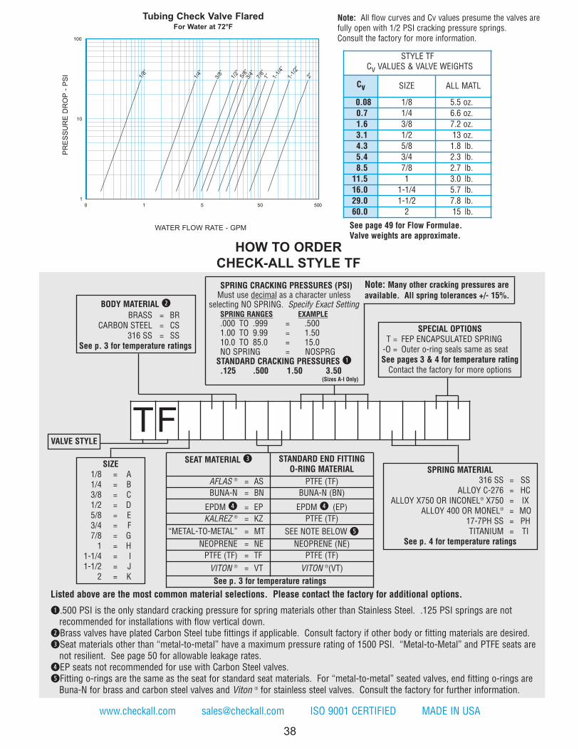
38
www.checkall.com [email protected] ISO 9001 CERTIFIED MADE IN USA
SPRING CRACKING PRESSURES (PSI)Must use decimal as a character unless
selecting NO SPRING. Specify Exact SettingSPRING RANGES EXAMPLE
.000 TO .999 = .5001.00 TO 9.99 = 1.5010.0 TO 85.0 = 15.0NO SPRING = NOSPRGSTANDARD CRACKING PRESSURES q.125 .500 1.50 3.50
(Sizes A-I Only)
Note: Many other cracking pressures areavailable. All spring tolerances +/- 15%.
TF
0
1
10
100
1 5 50 500
1/8”
1/4”
3/8”
1/2”
5/8”
3/4”
7/8”
1” 1-1/
4”
1-1/
2”
2”
PR
ES
SU
RE
DR
OP
- P
SI
WATER FLOW RATE - GPM
Tubing Check Valve FlaredFor Water at 72°F
SIZE1/8 = A1/4 = B3/8 = C1/2 = D5/8 = E3/4 = F7/8 = G1 = H
1-1/4 = I1-1/2 = J
2 = K
VALVE STYLE
SPRING MATERIAL316 SS = SS
ALLOY C-276 = HCALLOY X750 OR INCONEL® X750 = IX
ALLOY 400 OR MONEL® = MO17-7PH SS = PHTITANIUM = TI
See p. 4 for temperature ratings
HOW TO ORDER
CHECK-ALL STYLE TF
BODY MATERIAL w
BRASS = BRCARBON STEEL = CS
316 SS = SSSee p. 3 for temperature ratings
Note: All flow curves and Cv values presume the valves arefully open with 1/2 PSI cracking pressure springs.Consult the factory for more information.
See page 49 for Flow Formulae.Valve weights are approximate.
STYLE TFCv VALUES & VALVE WEIGHTS
Cv SIZE ALL MATL
0.08 1/8 5.5 oz.
0.7 1/4 6.6 oz.
1.6 3/8 7.2 oz.
3.1 1/2 13 oz.
4.3 5/8 1.8 lb.
5.4 3/4 2.3 lb.
8.5 7/8 2.7 lb.
11.5 1 3.0 lb.
16.0 1-1/4 5.7 lb.
29.0 1-1/2 7.8 lb.
60.0 2 15 lb.
SEAT MATERIAL e STANDARD END FITTINGO-RING MATERIAL
AFLAS ® = AS PTFE (TF)
BUNA-N = BN BUNA-N (BN)
EPDM r = EP EPDM r (EP)
KALREZ ® = KZ PTFE (TF)
“METAL-TO-METAL” = MT SEE NOTE BELOW t
NEOPRENE = NE NEOPRENE (NE)
PTFE (TF) = TF PTFE (TF)
VITON ® = VT VITON ®(VT)
See p. 3 for temperature ratings
SPECIAL OPTIONST = FEP ENCAPSULATED SPRING-O = Outer o-ring seals same as seatSee pages 3 & 4 for temperature ratingContact the factory for more options
Listed above are the most common material selections. Please contact the factory for additional options.
q.500 PSI is the only standard cracking pressure for spring materials other than Stainless Steel. .125 PSI springs are not recommended for installations with flow vertical down.
wBrass valves have plated Carbon Steel tube fittings if applicable. Consult factory if other body or fitting materials are desired.
eSeat materials other than “metal-to-metal” have a maximum pressure rating of 1500 PSI. “Metal-to-Metal” and PTFE seats are not resilient. See page 50 for allowable leakage rates.
rEP seats not recommended for use with Carbon Steel valves.
tFitting o-rings are the same as the seat for standard seat materials. For “metal-to-metal” seated valves, end fitting o-rings are Buna-N for brass and carbon steel valves and Viton ® for stainless steel valves. Consult the factory for further information.
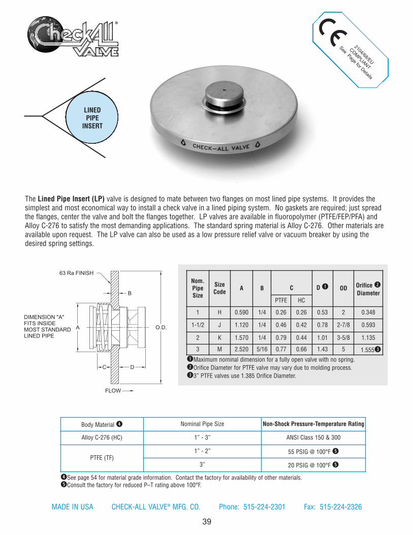
2104/68/EU
COM
PLIANT
See Page for Details
39
The Lined Pipe Insert (LP) valve is designed to mate between two flanges on most lined pipe systems. It provides thesimplest and most economical way to install a check valve in a lined piping system. No gaskets are required; just spreadthe flanges, center the valve and bolt the flanges together. LP valves are available in fluoropolymer (PTFE/FEP/PFA) andAlloy C-276 to satisfy the most demanding applications. The standard spring material is Alloy C-276. Other materials areavailable upon request. The LP valve can also be used as a low pressure relief valve or vacuum breaker by using thedesired spring settings.
Nom.PipeSize
SizeCode
A B C D q OD Orifice w
DiameterPTFE HC
1 H 0.590 1/4 0.26 0.26 0.53 2 0.348
1-1/2 J 1.120 1/4 0.46 0.42 0.78 2-7/8 0.593
2 K 1.570 1/4 0.79 0.44 1.01 3-5/8 1.135
3 M 2.520 5/16 0.77 0.66 1.43 5 1.555e
qMaximum nominal dimension for a fully open valve with no spring.
wOrifice Diameter for PTFE valve may vary due to molding process.
e3” PTFE valves use 1.385 Orifice Diameter.
LINEDPIPE
INSERT
rSee page 54 for material grade information. Contact the factory for availability of other materials.tConsult the factory for reduced P–T rating above 100°F.
Body Material r Nominal Pipe Size Non-Shock Pressure-Temperature Rating
Alloy C-276 (HC) 1” - 3” ANSI Class 150 & 300
PTFE (TF)1” - 2” 55 PSIG @ 100°F t
3” 20 PSIG @ 100°F t
FLOW
O.D.
DC
B
A
DIMENSION "A" FITS INSIDE MOST STANDARD LINED PIPE
63 Ra FINISH
MADE IN USA CHECK-ALL VALVE® MFG. CO. Phone: 515-224-2301 Fax: 515-224-2326
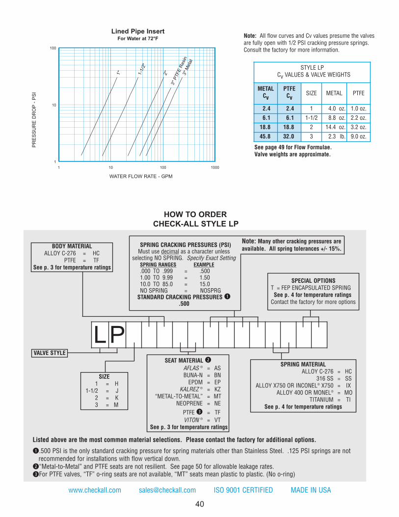
VALVE STYLE
SEAT MATERIAL w
AFLAS ® = ASBUNA-N = BNEPDM = EP
KALREZ ® = KZ“METAL-TO-METAL” = MT
NEOPRENE = NE
PTFE e = TF
VITON ® = VTSee p. 3 for temperature ratings
SPECIAL OPTIONST = FEP ENCAPSULATED SPRING See p. 4 for temperature ratingsContact the factory for more options
HOW TO ORDER
CHECK-ALL STYLE LP
40
SPRING CRACKING PRESSURES (PSI)Must use decimal as a character unless
selecting NO SPRING. Specify Exact SettingSPRING RANGES EXAMPLE
.000 TO .999 = .5001.00 TO 9.99 = 1.5010.0 TO 85.0 = 15.0NO SPRING = NOSPRGSTANDARD CRACKING PRESSURES q
.500
Note: Many other cracking pressures areavailable. All spring tolerances +/- 15%.
www.checkall.com [email protected] ISO 9001 CERTIFIED MADE IN USA
LP
Listed above are the most common material selections. Please contact the factory for additional options.
q.500 PSI is the only standard cracking pressure for spring materials other than Stainless Steel. .125 PSI springs are not recommended for installations with flow vertical down.
w“Metal-to-Metal” and PTFE seats are not resilient. See page 50 for allowable leakage rates.
eFor PTFE valves, “TF” o-ring seats are not available, “MT” seats mean plastic to plastic. (No o-ring)
1"
1-1
/2"
2"
3"
PTF
E R
esin
3"
Meta
l
1
10
100
1 10 100 1000
STYLE LPCv VALUES & VALVE WEIGHTS
METALCv
PTFECv
SIZE METAL PTFE
2.4 2.4 1 4.0 oz. 1.0 oz.
6.1 6.1 1-1/2 8.8 oz. 2.2 oz.
18.8 18.8 2 14.4 oz. 3.2 oz.
45.8 32.0 3 2.3 lb. 9.0 oz.
PR
ES
SU
RE
DR
OP
- P
SI
WATER FLOW RATE - GPM
Lined Pipe InsertFor Water at 72°F
SIZE1 = H
1-1/2 = J2 = K3 = M
BODY MATERIALALLOY C-276 = HC
PTFE = TFSee p. 3 for temperature ratings
SPRING MATERIALALLOY C-276 = HC
316 SS = SSALLOY X750 OR INCONEL® X750 = IX
ALLOY 400 OR MONEL® = MOTITANIUM = TI
See p. 4 for temperature ratings
See page 49 for Flow Formulae.Valve weights are approximate.
Note: All flow curves and Cv values presume the valvesare fully open with 1/2 PSI cracking pressure springs.Consult the factory for more information.

HORIZONTALVERTICALFLANGED &DRILLED
PTFE LINED
41
The Check-All® Flanged & Drilled — Fluoropolymer (PTFE) Lined (HT) check valve is a one piece body with ANSI/ASMEB16.5 Class 150 flanged ends. The valve has a solid one piece PTFE liner which covers the flange faces out to the raisedface diameter. All wetted surfaces are fluoropolymer (PTFE/FEP/PFA) including the FEP encapsulated stainless steel spring.
Style HT bodies are made of cast carbon steel only. The liner is made of virgin PTFE. It is installed as one solid piece ofPTFE and the internal geometrical shape is machined. The PTFE liner has a minimum wall thickness of 3/32 inch, whichguarantees against pin holes which can be present in fused liners.The HT valve can also be used as a low pressure relief valve or vacuum breaker by using the desired spring settings.
Nom.PipeSize
SizeCode A B
Orifice q
Diameter
1 H 3.75 4-1/4 0.890
1-1/2 J 4.38 5 1.385
2 K 5.13 6 2.025
qDue to molding process, Orifice Diameter may vary.
Cast Body Material w Liner Material wNominal Pipe
Size Non-Shock Pressure-Temperature Rating e
WCB/WCC Carbon Steel (CS) PTFE (TF)1” 55 PSIG @ 100°F
1-1/2” - 2” 20 PSIG @ 100°F
2104/68/EU COMPLIANT
See page 55 for Details
wSee page 54 for material grade information.
eConsult the factory for reduced P-T rating of PTFE valves above 100°F.
FLOW
B
A
MADE IN USA CHECK-ALL VALVE® MFG. CO. Phone: 515-224-2301 Fax: 515-224-2326
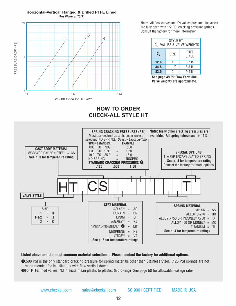
www.checkall.com [email protected] ISO 9001 CERTIFIED MADE IN USA
1" 1-1
/2"
2"
1
10
100
10 100 1000
STYLE HTCv VALUES & VALVE WEIGHTS
Cv SIZEPTFELINED
12.6 1 3.7 lb.
34.5 1-1/2 5.8 lb.
83.0 2 9.4 lb.
PR
ES
SU
RE
DR
OP
- P
SI
WATER FLOW RATE - GPM
Horizontal-Vertical Flanged & Drilled PTFE LinedFor Water at 72°F
VALVE STYLE
SPECIAL OPTIONST = FEP ENCAPSULATED SPRINGSee p. 4 for temperature rating
Contact the factory for more options
HOW TO ORDER
CHECK-ALL STYLE HT
42
See page 49 for Flow Formulae.Valve weights are approximate.
Note: All flow curves and Cv values presume the valvesare fully open with 1/2 PSI cracking pressure springs.Consult the factory for more information.
Listed above are the most common material selections. Please contact the factory for additional options.
q.500 PSI is the only standard cracking pressure for spring materials other than Stainless Steel. .125 PSI springs are notrecommended for installations with flow vertical down.
wFor PTFE lined valves, “MT” seats mean plastic to plastic. (No o-ring) See page 50 for allowable leakage rates.
SPRING CRACKING PRESSURES (PSI)Must use decimal as a character unless
selecting NO SPRING. Specify Exact SettingSPRING RANGES EXAMPLE
.000 TO .999 = .5001.00 TO 9.99 = 1.5010.0 TO 85.0 = 15.0NO SPRING = NOSPRGSTANDARD CRACKING PRESSURES q
.125 .500 1.50
Note: Many other cracking pressures areavailable. All spring tolerances +/- 15%.
HT CS T
CAST BODY MATERIALWCB/WCC CARBON STEEL = CSSee p. 3 for temperature rating
SIZE1 = H
1-1/2 = J2 = K
SEAT MATERIALAFLAS ® = ASBUNA-N = BNEPDM = EP
KALREZ ® = KZ
“METAL-TO-METAL” w = MT
NEOPRENE = NEVITON ® = VT
See p. 3 for temperature ratings
SPRING MATERIAL316 SS = SS
ALLOY C-276 = HCALLOY X750 OR INCONEL® X750 = IX
ALLOY 400 OR MONEL® = MOTITANIUM = TI
See p. 4 for temperature ratings
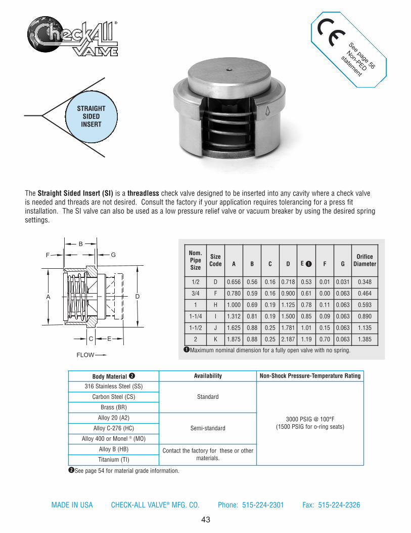
A
F
D
EC
FLOW
G
B
43
See page 56
Non-PED
statement
Nom.PipeSize
SizeCode A B C D E q F G
OrificeDiameter
1/2 D 0.656 0.56 0.16 0.718 0.53 0.01 0.031 0.348
3/4 F 0.780 0.59 0.16 0.900 0.61 0.00 0.063 0.464
1 H 1.000 0.69 0.19 1.125 0.78 0.11 0.063 0.593
1-1/4 I 1.312 0.81 0.19 1.500 0.85 0.09 0.063 0.890
1-1/2 J 1.625 0.88 0.25 1.781 1.01 0.15 0.063 1.135
2 K 1.875 0.88 0.25 2.187 1.19 0.70 0.063 1.385
qMaximum nominal dimension for a fully open valve with no spring.
Body Material w Availability Non-Shock Pressure-Temperature Rating
316 Stainless Steel (SS)
Standard
3000 PSIG @ 100°F(1500 PSIG for o-ring seats)
Carbon Steel (CS)
Brass (BR)
Alloy 20 (A2)
Semi-standardAlloy C-276 (HC)
Alloy 400 or Monel ® (MO)
Alloy B (HB) Contact the factory for these or othermaterials.Titanium (TI)
STRAIGHTSIDEDINSERT
wSee page 54 for material grade information.
The Straight Sided Insert (SI) is a threadless check valve designed to be inserted into any cavity where a check valveis needed and threads are not desired. Consult the factory if your application requires tolerancing for a press fitinstallation. The SI valve can also be used as a low pressure relief valve or vacuum breaker by using the desired springsettings.
MADE IN USA CHECK-ALL VALVE® MFG. CO. Phone: 515-224-2301 Fax: 515-224-2326
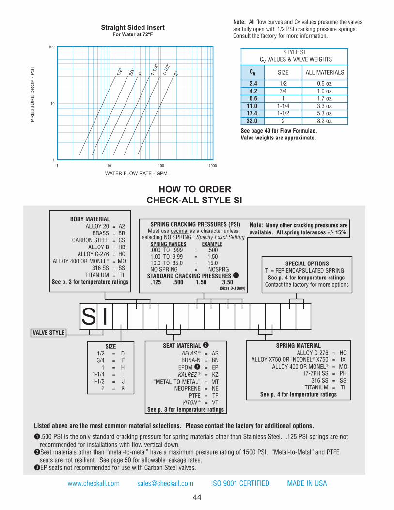
SIZE1/2 = D3/4 = F1 = H
1-1/4 = I1-1/2 = J
2 = K
VALVE STYLE
BODY MATERIALALLOY 20 = A2BRASS = BR
CARBON STEEL = CSALLOY B = HB
ALLOY C-276 = HCALLOY 400 OR MONEL® = MO
316 SS = SSTITANIUM = TI
See p. 3 for temperature ratings
SEAT MATERIAL w
AFLAS ® = ASBUNA-N = BNEPDM e = EP
KALREZ ® = KZ“METAL-TO-METAL” = MT
NEOPRENE = NEPTFE = TF
VITON ® = VTSee p. 3 for temperature ratings
SPRING MATERIALALLOY C-276 = HC
ALLOY X750 OR INCONEL® X750 = IXALLOY 400 OR MONEL® = MO
17-7PH SS = PH316 SS = SS
TITANIUM = TISee p. 4 for temperature ratings
44
Note: All flow curves and Cv values presume the valvesare fully open with 1/2 PSI cracking pressure springs.Consult the factory for more information.
www.checkall.com [email protected] ISO 9001 CERTIFIED MADE IN USA
Listed above are the most common material selections. Please contact the factory for additional options.
q.500 PSI is the only standard cracking pressure for spring materials other than Stainless Steel. .125 PSI springs are notrecommended for installations with flow vertical down.
wSeat materials other than “metal-to-metal” have a maximum pressure rating of 1500 PSI. “Metal-to-Metal” and PTFE seats are not resilient. See page 50 for allowable leakage rates.
eEP seats not recommended for use with Carbon Steel valves.
SPRING CRACKING PRESSURES (PSI)Must use decimal as a character unless
selecting NO SPRING. Specify Exact SettingSPRING RANGES EXAMPLE
.000 TO .999 = .5001.00 TO 9.99 = 1.5010.0 TO 85.0 = 15.0NO SPRING = NOSPRG
STANDARD CRACKING PRESSURES q.125 .500 1.50 3.50
(Sizes D-J Only)
Note: Many other cracking pressures areavailable. All spring tolerances +/- 15%.
STYLE SICv VALUES & VALVE WEIGHTS
Cv SIZE ALL MATERIALS
2.4 1/2 0.6 oz.
4.2 3/4 1.0 oz.
6.6 1 1.7 oz.
11.0 1-1/4 3.3 oz.
17.4 1-1/2 5.3 oz.
32.0 2 8.2 oz.PR
ES
SU
RE
DR
OP
- P
SI
WATER FLOW RATE - GPM
Straight Sided InsertFor Water at 72°F
HOW TO ORDER
CHECK-ALL STYLE SI
1"3/4
"
1-1
/4"
1-1
/2"
2"
1/2
"
1
10
100
1 10 100 1000
See page 49 for Flow Formulae.Valve weights are approximate.
S I
SPECIAL OPTIONST = FEP ENCAPSULATED SPRING See p. 4 for temperature ratingsContact the factory for more options
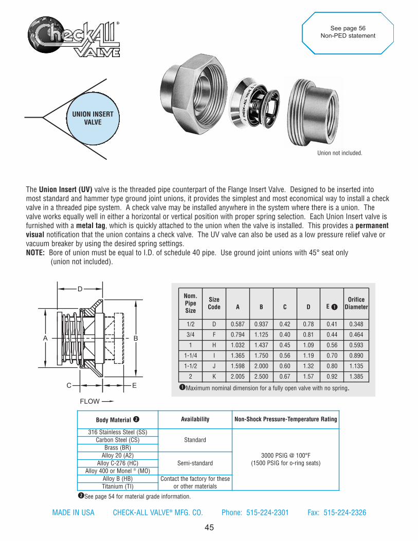
A
C E
D
B
FLOW
UNION INSERTVALVE
45
Nom.PipeSize
SizeCode A B C D E q
OrificeDiameter
1/2 D 0.587 0.937 0.42 0.78 0.41 0.348
3/4 F 0.794 1.125 0.40 0.81 0.44 0.464
1 H 1.032 1.437 0.45 1.09 0.56 0.593
1-1/4 I 1.365 1.750 0.56 1.19 0.70 0.890
1-1/2 J 1.598 2.000 0.60 1.32 0.80 1.135
2 K 2.005 2.500 0.67 1.57 0.92 1.385
See page 56
Non-PED statement
The Union Insert (UV) valve is the threaded pipe counterpart of the Flange Insert Valve. Designed to be inserted intomost standard and hammer type ground joint unions, it provides the simplest and most economical way to install a checkvalve in a threaded pipe system. A check valve may be installed anywhere in the system where there is a union. Thevalve works equally well in either a horizontal or vertical position with proper spring selection. Each Union Insert valve isfurnished with a metal tag, which is quickly attached to the union when the valve is installed. This provides a permanentvisual notification that the union contains a check valve. The UV valve can also be used as a low pressure relief valve orvacuum breaker by using the desired spring settings.NOTE: Bore of union must be equal to I.D. of schedule 40 pipe. Use ground joint unions with 45° seat only
(union not included).
qMaximum nominal dimension for a fully open valve with no spring.
wSee page 54 for material grade information.
Body Material w Availability Non-Shock Pressure-Temperature Rating
316 Stainless Steel (SS)
Standard
3000 PSIG @ 100°F(1500 PSIG for o-ring seats)
Carbon Steel (CS)
Brass (BR)
Alloy 20 (A2)
Semi-standardAlloy C-276 (HC)
Alloy 400 or Monel ® (MO)
Alloy B (HB) Contact the factory for theseor other materialsTitanium (TI)
Union not included.
MADE IN USA CHECK-ALL VALVE® MFG. CO. Phone: 515-224-2301 Fax: 515-224-2326

HOW TO ORDER
CHECK-ALL STYLE UV
46
Note: All flow curves and Cv values presume the valvesare fully open with 1/2 PSI cracking pressure springs.Consult the factory for more information.
Listed above are the most common material selections. Please contact the factory for additional options.
q.500 PSI is the only standard cracking pressure for spring materials other than Stainless Steel. .125 PSI springs are notrecommended for installations with flow vertical down.
wSeat materials other than “metal-to-metal” have a maximum pressure rating of 1500 PSI. “Metal-to-Metal” and PTFE seats are not resilient. See page 50 for allowable leakage rates.
eEP seats not recommended for use with Carbon Steel valves.
www.checkall.com [email protected] ISO 9001 CERTIFIED MADE IN USA
SPRING CRACKING PRESSURES (PSI)Must use decimal as a character unless
selecting NO SPRING. Specify Exact SettingSPRING RANGES EXAMPLE
.000 TO .999 = .5001.00 TO 9.99 = 1.5010.0 TO 85.0 = 15.0NO SPRING = NOSPRGSTANDARD CRACKING PRESSURES q.125 .500 1.50 3.50
(Sizes D-J Only)
Note: Many other cracking pressures areavailable. All spring tolerances +/- 15%.
UV
1"3/4
"
1-1
/4"
1-1
/2"
2"
1/2
"
1
10
100
1 10 100 1000
STYLE UVCv VALUES & VALVE WEIGHTS
Cv SIZE ALL MATL
2.3 1/2 0.5 oz.
4.2 3/4 0.8 oz.
6.1 1 1.6 oz.
13.8 1-1/4 2.8 oz.
19.0 1-1/2 4.3 oz.
33.3 2 7.8 oz.
PR
ES
SU
RE
DR
OP
- P
SI
WATER FLOW RATE - GPM
Union Insert ValveFor Water at 72°F
SIZE1/2 = D3/4 = F1 = H
1-1/4 = I1-1/2 = J
2 = K
VALVE STYLE
BODY MATERIALALLOY 20 = A2BRASS = BR
CARBON STEEL = CSALLOY B = HB
ALLOY C-276 = HCALLOY 400 OR MONEL® = MO
316 SS = SSTITANIUM = TI
See p. 3 for temperature ratings
SEAT MATERIAL w
AFLAS ® = ASBUNA-N = BN EPDM e = EP
KALREZ ® = KZ“METAL-TO-METAL” = MT
NEOPRENE = NEPTFE = TF
VITON ® = VTSee p. 3 for temperature ratings
SPECIAL OPTIONST = FEP ENCAPSULATED SPRINGSee p. 4 for temperature rating
Contact the factory for more options
SPRING MATERIAL316 SS = SS
ALLOY C-276 = HCALLOY B = HB
ALLOY X750 OR INCONEL® X750 = IXALLOY 400 OR MONEL® = MO
17-7PH SS = PHTITANIUM = TI
See p. 4 for temperature ratings
See page 49 for Flow Formulae.Valve weights are approximate.

When a standard connection will not fit your application, the CAV check valve is made to meet your specific requirements,saving you time and money. Check-All® has extensive design experience to precisely connect to your unique application.Below is a small sample of some special designs we have made for our customers.
• ASME B16.5 Ring Type Joint • MIL MS33649 Threaded Port• AWWA C-606 Grooved Ends • MIL MS16142 Threaded Port• SAE J518 Code 61 & 62 Flange • ASME B1.20.3 Dryseal Pipe Threads• API 5CT Threaded Ends • DIN Flanges• ISO 1609 Vacuum Flange (Insert) • Press Fit• SAE J1926-1 Threaded Port • Cartridge Valve (outer o-ring seal)• ISO 6149-1 Threaded Port • Tri-Clamp Ends
If you have a check valve application that is unique, contact our sales department to discuss your specific need.
CAV
47
VALVES DESIGNED FOR
YOUR APPLICATION NEEDS
MADE IN USA CHECK-ALL VALVE® MFG. CO. Phone: 515-224-2301 Fax: 515-224-2326

48
www.checkall.com [email protected] ISO 9001 CERTIFIED MADE IN USA
ADDITIONAL PRODUCTS AND SERVICES
TAGGING AND MARKING:
SS TAG: Stainless steel plate with a stainless steel wire to be attached on or around the
check valve after installation, for identification purposes. Customer supplied information
marked on the plate.
FLAG TAG: Stainless steel plate with a stainless steel stem to be permanently attached for
easy identification in applications where flange connections are used. Customer supplied
information marked on the plate.
PAPER TAG: Card stock form of paper tag attached to the valve for identification purposes.
Customer supplied information marked on the tag.
VALVE MARKING: Customer supplied information marked on the valve.
MSS SP 25 MARKING: Marking to provide information about the valve’s pedigree and
performance capabilities.
VALVE CLEANING FOR THE FOLLOWING SERVICE APPLICATIONS:
Oxygen Phosgene Ethylene Oxide Gas Phase Polyolefin
Chlorine Isocyanate Hydrogen Peroxide
VALVE TESTING/COMPLIANCE OPTIONS:
ASME B16.34 API 594 API 598 CPV (Cracking Pressure Verification)
Seat Leak NACE Hydro Shell MSS SP 61/126
CE (PED of the European Union) CRN (Canadian Registration Number)
ADDITIONAL SERVICES:
Electropolishing Passivation Pickling Bolted Trim
Drilled Hole in Trim Spring Encapsulation

G
dPCV
V= G
C
VdP
V
2
=
G
dP
VC
V=
49
T E C H N I C A L D A T AValve Sizing - Check-All® furnishes two methods to aid the customer in the selection of the correct valve size to meet theirflow requirements; Flow Curves and Cv Factor. Sizing accuracy requires the valve be fully open, which occurs when thepressure drop across the valve reaches or exceeds three times the spring cracking pressure (five times for 3S valves).
Flow Curves show the relationship between the rate of flow (water, gpm) and the pressure drop across the valve produced bythat flow.
Cv Factor is a valve flow coefficient which mathematically gives the relationship between the rate of flow and the pressuredrop.
Definition: Cv is defined as the quantity of 60º F water, ingallons per minute, which will pass through a specific valveat maximum lift, at one (1) psi pressure drop.
It is experimentally determined by dividing the water flow through the valve by the square root of the pressure drop producedby that flow. Conversely, given the Cv, the water flow through the valve at any given pressure drop may be calculated bymultiplying the Cv by the square root of the pressure drop. Therefore, for a given pressure drop, the higher the Cv, the higherthe rate of flow.
For liquids other than water, for gases and for saturated steam, the formulae given below will show the relationship betweenthe Cv (as obtained from water flow tests) and the flow of these fluids.
FLOW FORMULAE(Non-Choked Turbulent Flow Only)
I. LIQUIDS
Where: V = Liquid flow (gpm)
dP = Pressure drop (psi)
G = Specific Gravity of liquid (water = 1.0)
Cv = Valve coefficient
II. GASSES
21360
13602
21360
21
2
2
11
21
PP
GT
dP
QC
C
QGTPPdP
PP
GT
dPCQ
V
V
V
+=
−−=
+=
23
32
23
21
2
2
11
21
PPdP
WC
C
WPPdP
PPdPCW
V
V
V
+=
−−=
+=
Where: Q = Gas flow (scfh)
dP = Pressure drop (psi)1
T = Absolute temperature of flowing medium (degrees Rankine = ºF + 460)
P1 = Inlet pressure (psia)
P2 = Outlet pressure (psia)
Cv = Valve coefficient
G = Specific Gravity of gas (air = 1.0)
III. SATURATED STEAM
Where: W = Saturated steam flow (lbs. per hour)
dP = Pressure drop (psi)1
P1 = Inlet pressure (psia)
P2 = Outlet pressure (psia)
Cv = Valve coefficient
1 - For calculation purposes, dP should never exceed 1/2 the inlet pressure, P1.

Check-All Valve Application GuidelinesThe following information is provided to assist in the selection of components when specifying or using
Check-All Valve® products. It is presented for general information only and should not be considered an
all-inclusive list, nor should it replace the on-sight process engineering required to properly apply any
valve.
Installation/Mounting
Check-All® valves can be used in horizontal or vertical applications with proper spring selection. This is
most evident in vertical flow down installations. Minimum recommended net cracking pressure of 0.125
psi for most valves. The spring selected must be heavy enough in vertical flow down installations to
support the weight of the trim in addition to any column of liquid desired to be retained. Consult the factory
or your local Check-All Valve® representative for further information.
Elbow, Tee or other Flow Skewing Device
Check-All® valves are best suited for use with fully developed flow. Although there are many factors
affecting the achievement of fully developed flow (such as media, pipe roughness and velocity) usually 10
pipe diameters of straight pipe immediately upstream of the valve is sufficient. This is particularly important
after flow skewing devices such as elbows, tees, centrifugal pumps, etc.
Valve Material Selection
There are many factors that influence the resistance of materials to corrosion, such as temperature,
concentration, aeration, contaminants and media interaction/reaction. Check-All Valve® will provide any
assistance it can regarding the selection of products; however, the decision as to specific application of
the valves and the materials of construction is beyond the scope of supply of Check-All Valve® products.
This is the sole responsibility of the customer based upon his or her own evaluation.
Seat Material Selection
Several seat material options are available for Check-All® valves. The allowable leakage rate associated
with the “metal-to-metal” as well as the PTFE o-ring seat, is 188 cc/min per inch of line size, when tested
with air at 80 PSI. Resilient o-ring seats are available for a “bubble tight” shut-off (no visible leakage
allowed at 80 PSI air as defined by MSS SP-61). All o-ring seats are limited to a maximum operating
pressure of 1500 PSI.
Sizing and Spring Selection
Check-All Valve® recommends sizing check valves to ensure proper valve operation and service life.
Valves can be sized using the equations on page 49. Sizing accuracy requires the valve to be fully
open, which occurs when the pressure drop across the valve reaches or exceeds three times the
spring cracking pressure (five times for 3S valves). Contact the factory or your local Check-All Valve®
representative for further information or assistance.
Shock-Load Applications
Check-All® valves are not designed for use in a shock-load environment, such as the discharge of a
reciprocating air compressor. These types of applications produce excessive impact stresses which can
adversely affect valve performance.
Fluid Quality
Check-All® valves are best suited for clean, particle-free liquids or gasses. Debris such as sand or fibers
can prevent the valve from sealing properly or it can erode internal components or otherwise adversely
affect valve travel. These particles should be filtered out prior to entering the valves.
Insert Series Valves
Check-All® Insert series valves such as the F1, F6, LP, UV, etc. are designed to use the existing pipe as
part of the valve body. This provides a very cost effective solution for valve requirements. As such, part of
the valve functions inside the existing pipe; therefore, dimensional clearance must be maintained for
proper valve operation. See the pertinent catalog pages or contact the factory or your local Check-All®
representative for more information.
50
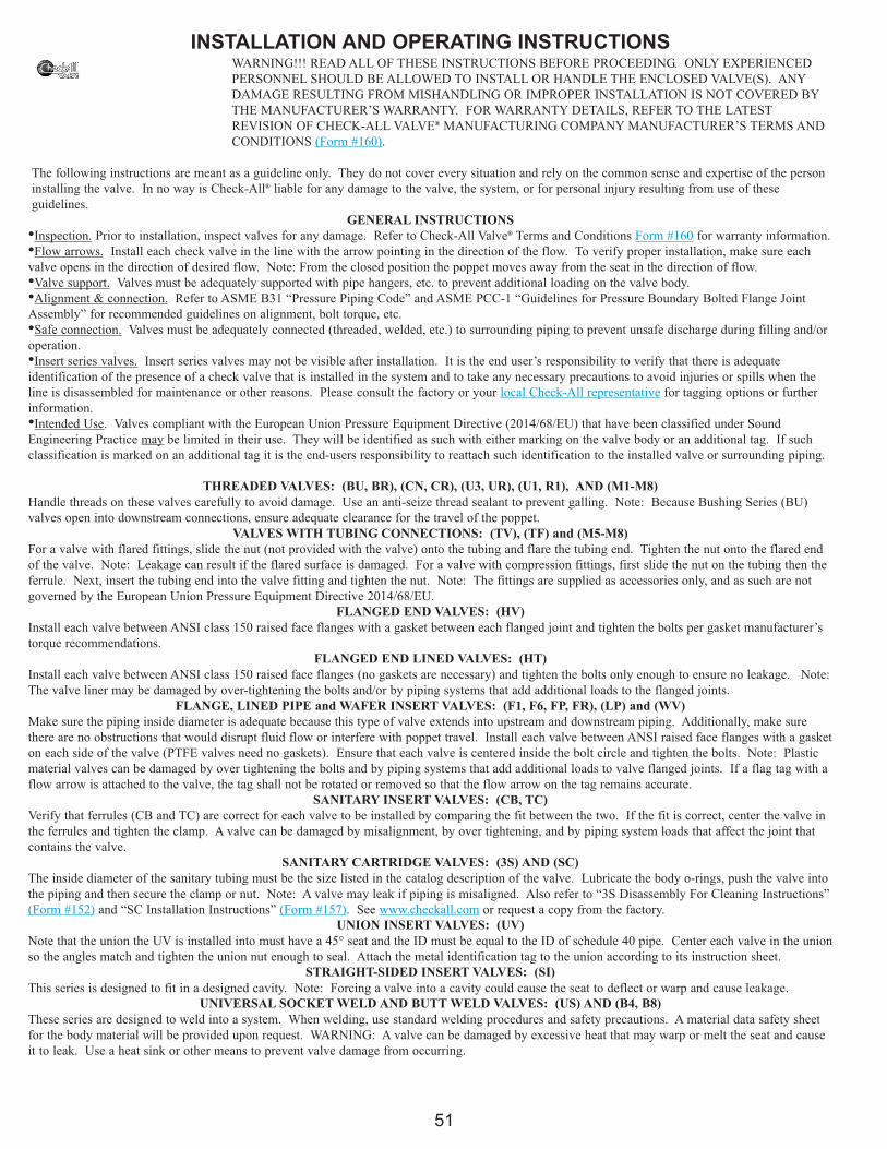
INSTALLATION AND OPERATING INSTRUCTIONSWARNING!!! READ ALL OF THESE INSTRUCTIONS BEFORE PROCEEDING. ONLY EXPERIENCED
PERSONNEL SHOULD BE ALLOWED TO INSTALL OR HANDLE THE ENCLOSED VALVE(S). ANY
DAMAGE RESULTING FROM MISHANDLING OR IMPROPER INSTALLATION IS NOT COVERED BY
THE MANUFACTURER’S WARRANTY. FOR WARRANTY DETAILS, REFER TO THE LATEST
REVISION OF CHECK-ALL VALVE® MANUFACTURING COMPANY MANUFACTURER’S TERMS AND
CONDITIONS (Form #160).
The following instructions are meant as a guideline only. They do not cover every situation and rely on the common sense and expertise of the person
installing the valve. In no way is Check-All® liable for any damage to the valve, the system, or for personal injury resulting from use of these
guidelines.
GENERAL INSTRUCTIONS
Inspection. Prior to installation, inspect valves for any damage. Refer to Check-All Valve® Terms and Conditions Form #160 for warranty information.•Flow arrows. Install each check valve in the line with the arrow pointing in the direction of the flow. To verify proper installation, make sure each•
valve opens in the direction of desired flow. Note: From the closed position the poppet moves away from the seat in the direction of flow.
Valve support. Valves must be adequately supported with pipe hangers, etc. to prevent additional loading on the valve body.•Alignment & connection. Refer to ASME B31 “Pressure Piping Code” and ASME PCC-1 “Guidelines for Pressure Boundary Bolted Flange Joint•
Assembly” for recommended guidelines on alignment, bolt torque, etc.
Safe connection. Valves must be adequately connected (threaded, welded, etc.) to surrounding piping to prevent unsafe discharge during filling and/or•operation.
Insert series valves. Insert series valves may not be visible after installation. It is the end user’s responsibility to verify that there is adequate•identification of the presence of a check valve that is installed in the system and to take any necessary precautions to avoid injuries or spills when the
line is disassembled for maintenance or other reasons. Please consult the factory or your local Check-All representative for tagging options or further
information.
Intended Use. Valves compliant with the European Union Pressure Equipment Directive (2014/68/EU) that have been classified under Sound•Engineering Practice may be limited in their use. They will be identified as such with either marking on the valve body or an additional tag. If such
classification is marked on an additional tag it is the end-users responsibility to reattach such identification to the installed valve or surrounding piping.
THREADED VALVES: (BU, BR), (CN, CR), (U3, UR), (U1, R1), AND (M1-M8)
Handle threads on these valves carefully to avoid damage. Use an anti-seize thread sealant to prevent galling. Note: Because Bushing Series (BU)
valves open into downstream connections, ensure adequate clearance for the travel of the poppet.
VALVES WITH TUBING CONNECTIONS: (TV), (TF) and (M5-M8)
For a valve with flared fittings, slide the nut (not provided with the valve) onto the tubing and flare the tubing end. Tighten the nut onto the flared end
of the valve. Note: Leakage can result if the flared surface is damaged. For a valve with compression fittings, first slide the nut on the tubing then the
ferrule. Next, insert the tubing end into the valve fitting and tighten the nut. Note: The fittings are supplied as accessories only, and as such are not
governed by the European Union Pressure Equipment Directive 2014/68/EU.
FLANGED END VALVES: (HV)
Install each valve between ANSI class 150 raised face flanges with a gasket between each flanged joint and tighten the bolts per gasket manufacturer’s
torque recommendations.
FLANGED END LINED VALVES: (HT)
Install each valve between ANSI class 150 raised face flanges (no gaskets are necessary) and tighten the bolts only enough to ensure no leakage. Note:
The valve liner may be damaged by over-tightening the bolts and/or by piping systems that add additional loads to the flanged joints.
FLANGE, LINED PIPE and WAFER INSERT VALVES: (F1, F6, FP, FR), (LP) and (WV)
Make sure the piping inside diameter is adequate because this type of valve extends into upstream and downstream piping. Additionally, make sure
there are no obstructions that would disrupt fluid flow or interfere with poppet travel. Install each valve between ANSI raised face flanges with a gasket
on each side of the valve (PTFE valves need no gaskets). Ensure that each valve is centered inside the bolt circle and tighten the bolts. Note: Plastic
material valves can be damaged by over tightening the bolts and by piping systems that add additional loads to valve flanged joints. If a flag tag with a
flow arrow is attached to the valve, the tag shall not be rotated or removed so that the flow arrow on the tag remains accurate.
SANITARY INSERT VALVES: (CB, TC)
Verify that ferrules (CB and TC) are correct for each valve to be installed by comparing the fit between the two. If the fit is correct, center the valve in
the ferrules and tighten the clamp. A valve can be damaged by misalignment, by over tightening, and by piping system loads that affect the joint that
contains the valve.
SANITARY CARTRIDGE VALVES: (3S) AND (SC)
The inside diameter of the sanitary tubing must be the size listed in the catalog description of the valve. Lubricate the body o-rings, push the valve into
the piping and then secure the clamp or nut. Note: A valve may leak if piping is misaligned. Also refer to “3S Disassembly For Cleaning Instructions”
(Form #152) and “SC Installation Instructions” (Form #157). See www.checkall.com or request a copy from the factory.
UNION INSERT VALVES: (UV)
Note that the union the UV is installed into must have a 45° seat and the ID must be equal to the ID of schedule 40 pipe. Center each valve in the union
so the angles match and tighten the union nut enough to seal. Attach the metal identification tag to the union according to its instruction sheet.
STRAIGHT-SIDED INSERT VALVES: (SI)
This series is designed to fit in a designed cavity. Note: Forcing a valve into a cavity could cause the seat to deflect or warp and cause leakage.
UNIVERSAL SOCKET WELD AND BUTT WELD VALVES: (US) AND (B4, B8)
These series are designed to weld into a system. When welding, use standard welding procedures and safety precautions. A material data safety sheet
for the body material will be provided upon request. WARNING: A valve can be damaged by excessive heat that may warp or melt the seat and cause
it to leak. Use a heat sink or other means to prevent valve damage from occurring.
51
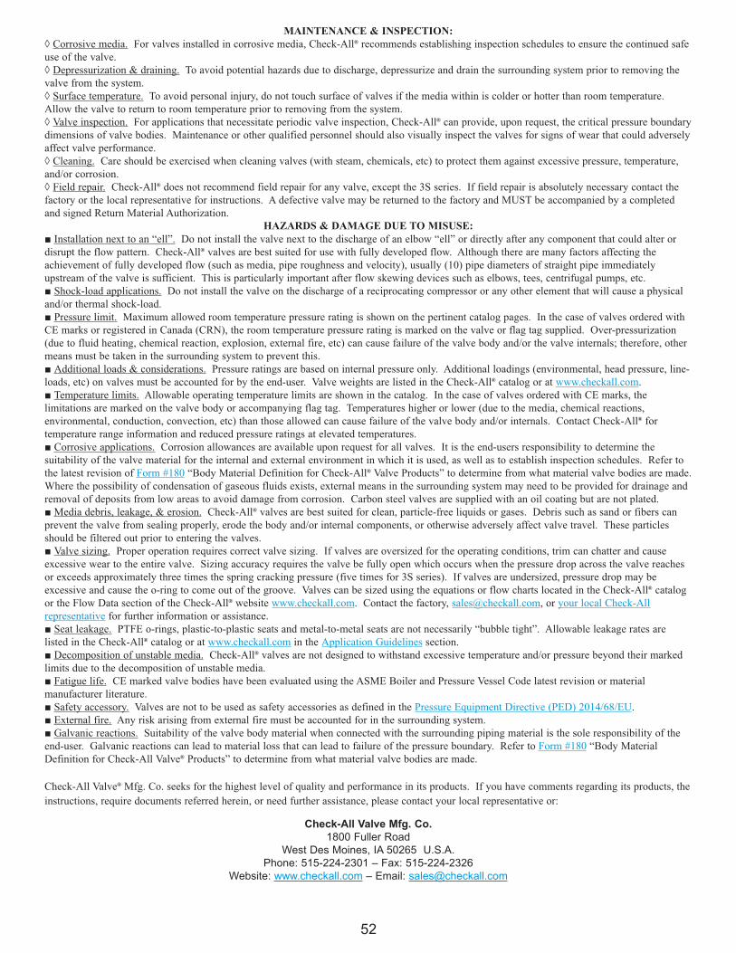
MAINTENANCE & INSPECTION:
◊ Corrosive media. For valves installed in corrosive media, Check-All® recommends establishing inspection schedules to ensure the continued safe
use of the valve.
◊ Depressurization & draining. To avoid potential hazards due to discharge, depressurize and drain the surrounding system prior to removing the
valve from the system.
◊ Surface temperature. To avoid personal injury, do not touch surface of valves if the media within is colder or hotter than room temperature.
Allow the valve to return to room temperature prior to removing from the system.
◊ Valve inspection. For applications that necessitate periodic valve inspection, Check-All® can provide, upon request, the critical pressure boundary
dimensions of valve bodies. Maintenance or other qualified personnel should also visually inspect the valves for signs of wear that could adversely
affect valve performance.
◊ Cleaning. Care should be exercised when cleaning valves (with steam, chemicals, etc) to protect them against excessive pressure, temperature,
and/or corrosion.
◊ Field repair. Check-All® does not recommend field repair for any valve, except the 3S series. If field repair is absolutely necessary contact the
factory or the local representative for instructions. A defective valve may be returned to the factory and MUST be accompanied by a completed
and signed Return Material Authorization.
HAZARDS & DAMAGE DUE TO MISUSE:
■ Installation next to an “ell”. Do not install the valve next to the discharge of an elbow “ell” or directly after any component that could alter or
disrupt the flow pattern. Check-All® valves are best suited for use with fully developed flow. Although there are many factors affecting the
achievement of fully developed flow (such as media, pipe roughness and velocity), usually (10) pipe diameters of straight pipe immediately
upstream of the valve is sufficient. This is particularly important after flow skewing devices such as elbows, tees, centrifugal pumps, etc.
■ Shock-load applications. Do not install the valve on the discharge of a reciprocating compressor or any other element that will cause a physical
and/or thermal shock-load.
■ Pressure limit. Maximum allowed room temperature pressure rating is shown on the pertinent catalog pages. In the case of valves ordered with
CE marks or registered in Canada (CRN), the room temperature pressure rating is marked on the valve or flag tag supplied. Over-pressurization
(due to fluid heating, chemical reaction, explosion, external fire, etc) can cause failure of the valve body and/or the valve internals; therefore, other
means must be taken in the surrounding system to prevent this.
■ Additional loads & considerations. Pressure ratings are based on internal pressure only. Additional loadings (environmental, head pressure, line-
loads, etc) on valves must be accounted for by the end-user. Valve weights are listed in the Check-All® catalog or at www.checkall.com.
■ Temperature limits. Allowable operating temperature limits are shown in the catalog. In the case of valves ordered with CE marks, the
limitations are marked on the valve body or accompanying flag tag. Temperatures higher or lower (due to the media, chemical reactions,
environmental, conduction, convection, etc) than those allowed can cause failure of the valve body and/or internals. Contact Check-All® for
temperature range information and reduced pressure ratings at elevated temperatures.
■ Corrosive applications. Corrosion allowances are available upon request for all valves. It is the end-users responsibility to determine the
suitability of the valve material for the internal and external environment in which it is used, as well as to establish inspection schedules. Refer to
the latest revision of Form #180 “Body Material Definition for Check-All® Valve Products” to determine from what material valve bodies are made.
Where the possibility of condensation of gaseous fluids exists, external means in the surrounding system may need to be provided for drainage and
removal of deposits from low areas to avoid damage from corrosion. Carbon steel valves are supplied with an oil coating but are not plated.
■ Media debris, leakage, & erosion. Check-All® valves are best suited for clean, particle-free liquids or gases. Debris such as sand or fibers can
prevent the valve from sealing properly, erode the body and/or internal components, or otherwise adversely affect valve travel. These particles
should be filtered out prior to entering the valves.
■ Valve sizing. Proper operation requires correct valve sizing. If valves are oversized for the operating conditions, trim can chatter and cause
excessive wear to the entire valve. Sizing accuracy requires the valve be fully open which occurs when the pressure drop across the valve reaches
or exceeds approximately three times the spring cracking pressure (five times for 3S series). If valves are undersized, pressure drop may be
excessive and cause the o-ring to come out of the groove. Valves can be sized using the equations or flow charts located in the Check-All® catalog
or the Flow Data section of the Check-All® website www.checkall.com. Contact the factory, [email protected], or your local Check-All
representative for further information or assistance.
■ Seat leakage. PTFE o-rings, plastic-to-plastic seats and metal-to-metal seats are not necessarily “bubble tight”. Allowable leakage rates are
listed in the Check-All® catalog or at www.checkall.com in the Application Guidelines section.
■ Decomposition of unstable media. Check-All® valves are not designed to withstand excessive temperature and/or pressure beyond their marked
limits due to the decomposition of unstable media.
■ Fatigue life. CE marked valve bodies have been evaluated using the ASME Boiler and Pressure Vessel Code latest revision or material
manufacturer literature.
■ Safety accessory. Valves are not to be used as safety accessories as defined in the Pressure Equipment Directive (PED) 2014/68/EU.
■ External fire. Any risk arising from external fire must be accounted for in the surrounding system.
■ Galvanic reactions. Suitability of the valve body material when connected with the surrounding piping material is the sole responsibility of the
end-user. Galvanic reactions can lead to material loss that can lead to failure of the pressure boundary. Refer to Form #180 “Body Material
Definition for Check-All Valve® Products” to determine from what material valve bodies are made.
Check-All Valve® Mfg. Co. seeks for the highest level of quality and performance in its products. If you have comments regarding its products, the
instructions, require documents referred herein, or need further assistance, please contact your local representative or:
Check-All Valve Mfg. Co.
1800 Fuller Road
West Des Moines, IA 50265 U.S.A.
Phone: 515-224-2301 – Fax: 515-224-2326
Website: www.checkall.com – Email: [email protected]
52
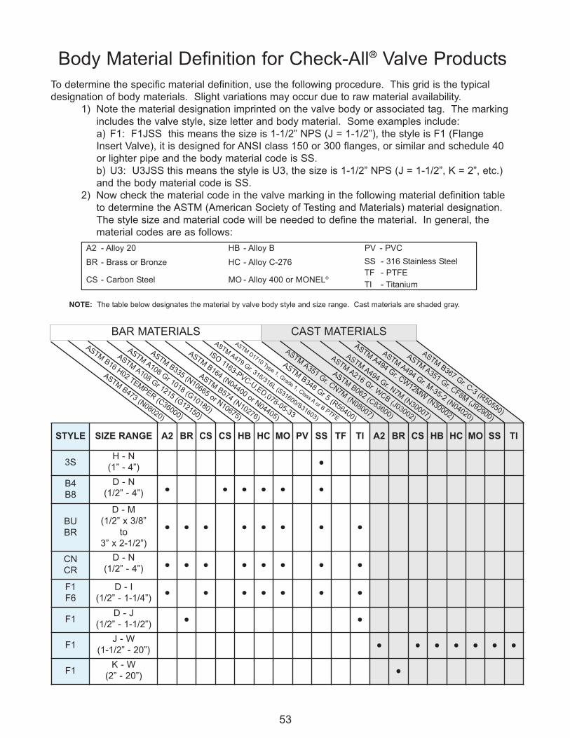
ASTM B367 Gr. C-3 (R50550)
ASTM A351 Gr. CN7M
(N08007)
Body Material Definition for Check-All® Valve Products
To determine the specific material definition, use the following procedure. This grid is the typical
designation of body materials. Slight variations may occur due to raw material availability.
1) Note the material designation imprinted on the valve body or associated tag. The marking
includes the valve style, size letter and body material. Some examples include:
a) F1: F1JSS this means the size is 1-1/2” NPS (J = 1-1/2”), the style is F1 (Flange
Insert Valve), it is designed for ANSI class 150 or 300 flanges, or similar and schedule 40
or lighter pipe and the body material code is SS.
b) U3: U3JSS this means the style is U3, the size is 1-1/2” NPS (J = 1-1/2”, K = 2”, etc.)
and the body material code is SS.
2) Now check the material code in the valve marking in the following material definition table
to determine the ASTM (American Society of Testing and Materials) material designation.
The style size and material code will be needed to define the material. In general, the
material codes are as follows:
53
A2 - Alloy 20 HB - Alloy B PV - PVC
BR - Brass or Bronze HC - Alloy C-276 SS - 316 Stainless Steel
CS - Carbon Steel MO - Alloy 400 or MONEL®TF - PTFE
TI - Titanium
NOTE: The table below designates the material by valve body style and size range. Cast materials are shaded gray.
ASTM D1710 Type 1, Grade 1, Class A or B
PTFE
ASTM B062 (C83600)
ASTM A216 Gr. W
CB (J03002)
ASTM A494 Gr. N7M
(N30007)
ASTM A494 Gr. CW
12MW
(N30002)
ASTM A494 Gr. M
-35-2 (N04020)
ASTM A479 Gr. 316/316L (S31600/S31603)
ISO 1163-PVC-U,ED,078-05-33
ASTM A351 Gr. CF8M
(J92900)
ASTM B473 (N08020)
ASTM B16 H02 TEM
PER (C36000)
ASTM A108 Gr 1215 (G12150)
ASTM A108 Gr 1018 (G10180)
ASTM B335 (N10665 or N10675)
ASTM B574 (N10276)
ASTM B164 (N04400 or N04405)
ASTM B348 Gr 5 (R56400)
STYLE SIZE RANGE A2 BR CS CS HB HC MO PV SS TF TI A2 BR CS HB HC MO SS TI
3SH - N
(1” - 4”)●
B4
B8
D - N
(1/2” - 4”) ● ● ● ● ● ●
BU
BR
D - M
(1/2” x 3/8”
to
3” x 2-1/2”)
● ● ● ● ● ● ● ●
CN
CR
D - N
(1/2” - 4”) ● ● ● ● ● ● ● ●
F1
F6
D - I
(1/2” - 1-1/4”)● ● ● ● ● ● ●
F1D - J
(1/2” - 1-1/2”)● ●
F1J - W
(1-1/2” - 20”)● ● ● ● ● ● ●
F1K - W
(2” - 20”)●
CAST MATERIALSBAR MATERIALS
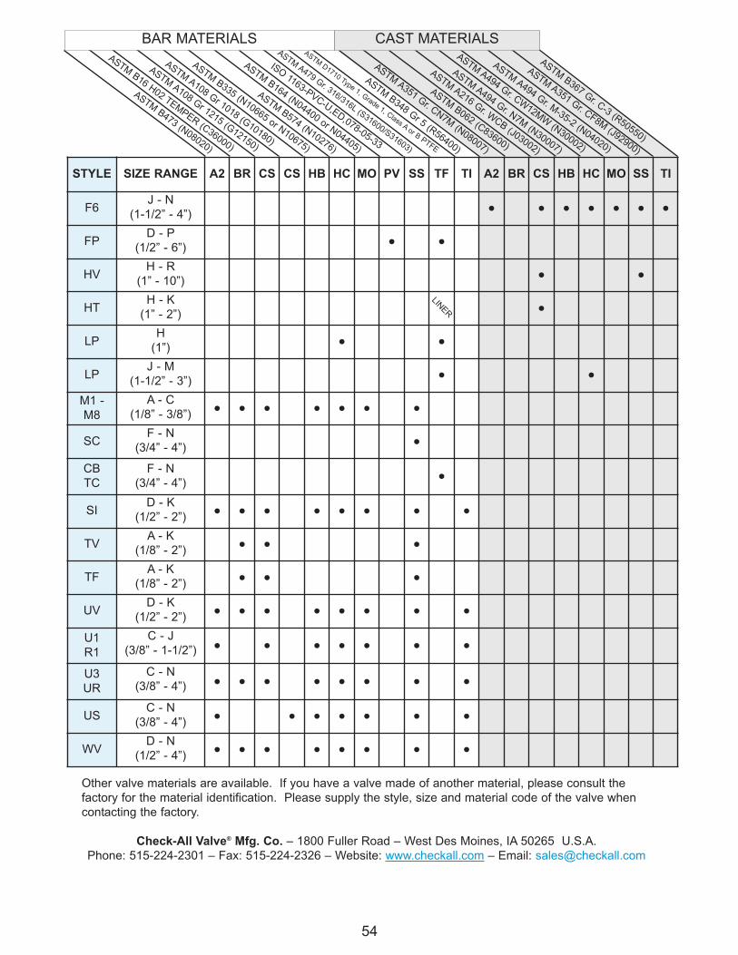
ASTM B367 Gr. C-3 (R50550)
Other valve materials are available. If you have a valve made of another material, please consult the
factory for the material identification. Please supply the style, size and material code of the valve when
contacting the factory.
Check-All Valve® Mfg. Co. – 1800 Fuller Road – West Des Moines, IA 50265 U.S.A.
Phone: 515-224-2301 – Fax: 515-224-2326 – Website: www.checkall.com – Email: [email protected]
54
ASTM A351 Gr. CN7M
(N08007)
ASTM D1710 Type 1, Grade 1, Class A or B
PTFE
ASTM B062 (C83600)
ASTM A216 Gr. W
CB (J03002)
ASTM A494 Gr. N7M
(N30007)
ASTM A494 Gr. CW
12MW
(N30002)
ASTM A494 Gr. M
-35-2 (N04020)
ASTM A479 Gr. 316/316L (S31600/S31603)
ISO 1163-PVC-U,ED,078-05-33
ASTM A351 Gr. CF8M
(J92900)
ASTM B473 (N08020)
ASTM B16 H02 TEM
PER (C36000)
ASTM A108 Gr 1215 (G12150)
ASTM A108 Gr 1018 (G10180)
ASTM B335 (N10665 or N10675)
ASTM B574 (N10276)
ASTM B164 (N04400 or N04405)
ASTM B348 Gr 5 (R56400)
BAR MATERIALS
STYLE SIZE RANGE A2 BR CS CS HB HC MO PV SS TF TI A2 BR CS HB HC MO SS TI
F6J - N
(1-1/2” - 4”)● ● ● ● ● ● ●
FPD - P
(1/2” - 6”)● ●
HVH - R
(1” - 10”)● ●
HTH - K
(1” - 2”)●
LPH
(1”)● ●
LPJ - M
(1-1/2” - 3”)● ●
M1 -
M8
A - C
(1/8” - 3/8”)● ● ● ● ● ● ●
SCF - N
(3/4” - 4”)●
CB
TC
F - N
(3/4” - 4”)●
SID - K
(1/2” - 2”)● ● ● ● ● ● ● ●
TVA - K
(1/8” - 2”)● ● ●
TFA - K
(1/8” - 2”)● ● ●
UVD - K
(1/2” - 2”)● ● ● ● ● ● ● ●
U1
R1
C - J
(3/8” - 1-1/2”) ● ● ● ● ● ● ●
U3
UR
C - N
(3/8” - 4”) ● ● ● ● ● ● ● ●
USC - N
(3/8” - 4”)● ● ● ● ● ● ●
WVD - N
(1/2” - 4”)● ● ● ● ● ● ● ●
LINER
CAST MATERIALS
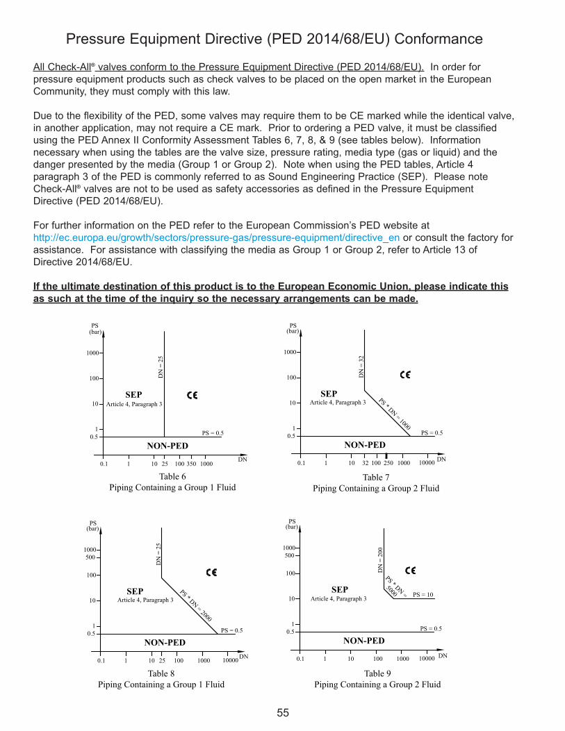
DN
= 2
5
PS = 0.5
10000
PS * DN
= 2000
32
DN
= 3
2
PS * DN
= 1000
DN
= 2
00
PS * DN
= PS = 10
5000SEP
1
0.5
0.1
10
(bar)
1000
100
PS
NON-PED
101 25 100 1000
500
SEP
1
0.1
0.5
1
10
NON-PED
10 100
(bar)
100
1000
PS
PS = 0.5
100001000
1
0.1
0.5
1
10
NON-PED
10 100
(bar)
100
500
1000
PS
PS = 0.5
100001000DN DN
DN250
Article 4, Paragraph 3
Table 7
Piping Containing a Group 2 Fluid
Table 9
Piping Containing a Group 2 Fluid
Table 8
Piping Containing a Group 1 Fluid
Article 4, Paragraph 3 Article 4, Paragraph 3
SEP
1 10 25 100 350 10000.1
0.5
1
10
100
1000
NON-PED
SEP
PS(bar)
PS = 0.5
DN
= 2
5
DN
Article 4, Paragraph 3
Table 6
Piping Containing a Group 1 Fluid
Pressure Equipment Directive (PED 2014/68/EU) Conformance
All Check-All® valves conform to the Pressure Equipment Directive (PED 2014/68/EU). In order for
pressure equipment products such as check valves to be placed on the open market in the European
Community, they must comply with this law.
Due to the flexibility of the PED, some valves may require them to be CE marked while the identical valve,
in another application, may not require a CE mark. Prior to ordering a PED valve, it must be classified
using the PED Annex II Conformity Assessment Tables 6, 7, 8, & 9 (see tables below). Information
necessary when using the tables are the valve size, pressure rating, media type (gas or liquid) and the
danger presented by the media (Group 1 or Group 2). Note when using the PED tables, Article 4
paragraph 3 of the PED is commonly referred to as Sound Engineering Practice (SEP). Please note
Check-All® valves are not to be used as safety accessories as defined in the Pressure Equipment
Directive (PED 2014/68/EU).
For further information on the PED refer to the European Commission’s PED website at
http://ec.europa.eu/growth/sectors/pressure-gas/pressure-equipment/directive_en or consult the factory for
assistance. For assistance with classifying the media as Group 1 or Group 2, refer to Article 13 of
Directive 2014/68/EU.
If the ultimate destination of this product is to the European Economic Union, please indicate this
as such at the time of the inquiry so the necessary arrangements can be made.
55
NON-PED Valves
Some valve styles or valves used at certain operating conditions do not fall under the scope of the PED. These
valves are supplied as “NON-PED” valves.
Due to the unique “insert” design of our 3S, SC, CB, TC, SI, & UV style check valves, they do not constitute an
“identifiable pressure bearing housing” as defined in PED Guideline A-08. These styles must be installed into either
ferrules or fittings to create a pressure-bearing housing. Instead, they are classified as “components of pressure
equipment” as defined in PED Guideline A-08. As a result, theses valves can be sold in the European Community
and no CE Mark is required.
In addition applications where the maximum allowed operating pressure is 0.5 bar (7.2 psi) or less, do not fall under
the PED, regardless of the valve style.
56
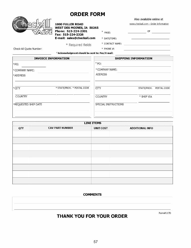
57
ORDER FORM Also available online at
W队川I.checkal l. com - Order Information
E 户U
AMn nr *
RJE au ''nu Ea Azo mw现DMA
ω阳中臼
RI24 t024 日MEru
LS1·E』
EEEaEa
U31 F
门缸5
OEn-OEox suha '--umvnrEr
OF
E-mail: [email protected]
* Required fields Check-AII Quote Number
• DATE(TIME
• CONTAσNAME
• PHONE #
* Acknowledgment should be sent to: Faxl E-mail:
INVOICE INFORMATION
' PO
' COMPANY NAME
' ADDRESS
' CITY • STATEjPROV. • POSTAL CODE
COUNTRY
' REQUESTED SHIP DATE
SHIPPING INFORMATION
• PO
• COMPANY NAME
ADDRESS
CITY STATEjPROV POSTAL CODE
COUNTRY • SHIP VIA
SPECIAL INSTRUCTIONS
QTY CAV PART NUMBER ADDITIONAL INFO TE e3 0 -
r、
gd
一
··-TE M--目一响
盯-L
E』一
N-EL
一
COMMENTS
Form#117D THANK YOU FOR YOUR ORDER
Copy of Manufacturer’s Terms and Conditions of Sale
1. CONSTRUCTION AND LEGAL EFFECT: Except as otherwise
specifically agreed in writing, our sale to you is limited to and expressly
made conditional on your assent to the written terms and conditions of
sale on the face and reverse side hereof, all of which form a part of this
order and which supercede and reject all prior writings, representations,
negotiations with respect hereto and any conflicting terms and conditions
of yours, any statement therein to the contrary notwithstanding. The
sending of the purchase order for the goods referred to herein, whether or
not signed by you, or your acceptance of the goods or payment operates
as acceptance by you of our terms and conditions of sale. We will furnish
only the quantities and goods specifically listed on the face hereof or the
pages attached hereto. We assume no responsibility to terms or
conditions or for furnishing other equipment or material shown in any
plans and/or specifications for a project to which the goods quoted or
ordered herein pertain or refer. Our published or quoted terms and
conditions are subject to change without notice.
2. PRICES: Unless otherwise noted on the face hereof, prices are net,
FOB carrier, our factory. Stenographic, clerical and mathematical errors
are subject to correction. Until order is accepted by us, quoted prices are
subject to change without notice.
3. DELIVERY: Dates for the furnishing of services and/or delivery or
shipment of goods are approximate only and are subject to change.
Quoted lead times are figured from the date of receipt of complete
technical data and approved drawings as such may be necessary. We
shall not be liable, directly or indirectly, for any delay in or failure to deliver
caused by carriers or delays from labor difficulties, shortages, strikes or
stoppages of any sort, failure or delay in obtaining materials from ordinary
sources, fires, floods, storms, accidents, causes designated acts of God
or force majeure by any statute or court of law or other causes beyond our
reasonable control. In no event shall we be liable for any damages or
penalties whatsoever, whether direct, indirect, special or consequential,
resulting from our failure to perform or delay in performing.
4. SHORTAGES, DAMAGE AND ERRORS IN SHIPMENT: Our
responsibility ceases upon delivery to carrier. Risk of loss, injury or
destruction of property, shall be borne by you, and such loss, injury or
destruction of property shall not release you from payment of purchase
price. You shall note receipt for goods that are not in accordance with bill
of lading or express receipt without proper notation to the carrier, and you
shall make claim against such carrier for any shortage, damage or
discrepancy in the shipment promptly. All claims of shortage of
discrepancies associated with the manufacturer must be reported within
14 days of receipt of shipment. You shall inspect and examine all items
and goods covered by the order when unpacking crated or boxed goods,
and if damage is discovered, leave as is until the carrier’s agent makes
examination and notation on freight or express bill of concealed damage.
We will render assistance to help trace and recover lost goods and collect
just claims as a business courtesy, but without obligation. We do not
guarantee safe delivery.
5. TAXES: Our prices do not include sales, use, excise, occupation,
processing, transportation or other similar taxes which we may be
required to pay or collect with respect to any of the materials covered
hereby under the existing or future law. Consequently, in addition to the
price specified herein, such taxes shall be paid by you, or you shall
provide us with a tax exemption certificate acceptable to the appropriate
taxing authorities. You shall also assume and pay any import or export
duties, with respect to the materials covered by the order, and shall save
us harmless there from.
6. CREDIT AND PAYMENT: Unless otherwise noted on the face hereof,
payment of goods shall be (30) days net. Prorate payments shall become
due with partial shipments. We reserve the right at any time to suspend
credit or to change credit terms provided herein, when, in our sole opinion,
your financial condition so warrants. Failure to pay invoices at maturity
date, at our election, makes all subsequent invoices immediately due and
payable irrespective of terms, and we may withhold all subsequent
deliveries until the full account is settled and we shall not, in such event,
be liable for non-performance of contract in whole or in part.
7. DOCUMENTS: Unless otherwise agreed to in writing, all documents
furnished shall be in the English language.
8. TECHNICAL DOCUMENTS AVAILABILITY: Check-All Valve® Mfg.
Co. will supply technical documents to competent governmental
authorities upon request as required by law.
9. CANCELLATIONS AND CHANGES: Orders which have been
accepted by us are not subject to cancellation or changes in
specifications; except upon our written consent, and we may require as a
58
condition of such consent, reimbursement for any cost incurred in
performance in accordance with the order in original form.
10. DEFERRED SHIPMENT: If shipment is deferred at your request,
payment of the contract price shall become due when you are notified
that the valves are ready for shipment. If you fail to make payment
and furnish shipping instructions, we may either extend time for so
doing or cancel contract. In case of deferred shipment at your
request, storage and other reasonable expenses attributable to such
delay shall be payable by you.
11. WARRANTY: Check-All Valve® Mfg. Co., hereinafter called
“Check-All®” warrants as follows:
(a) That each new Check-All® valve is free from defects in material
and workmanship when installed and used in accordance with
current Check-All® publications. Customer modified valves
may void warranty.
(b) That each new Check-All® valve is fit for the purpose for which
similar type valves are ordinarily intended. Purchaser shall be
solely responsible for determining suitability for use and in no
event shall Check-All® be liable in this respect.
DURATION—The warranty period shall begin on the date of
shipment to the first purchaser and extend for twelve (12) months.
EXCLUSIVE REMEDY— Check-All® will repair or replace at its
discretion, any valve it finds to be defective under this warranty, upon
return of the valve, prepaid, to Check-All® at 1800 Fuller Road, West
Des Moines, IA 50265 or any warehouse designated by Check-All®.
Except for such repairs or replacements, CHECK-ALL® SHALL NOT
BE LIABLE FOR CONSEQUENTIAL DAMAGES RESULTING
FROM BREACH OF THIS WRITTEN WARRANTY OR ANY
IMPLIED WARRANTY.
DISCLAIMER—Check-All® excludes from this warranty compressor
discharge applications; valves mounted on the discharge of an elbow
(“ell”); and failures due to corrosion, erosion, abrasion, cavitation, or
other application-related failures and DISCLAIMS ANY EXPRESS
OR IMPLIED WARRANTY OF FITNESS FOR A PARTICULAR
PURPOSE. Further, it is the end user’s responsibility to account for
environmental influences such as traffic, wind, earthquake or other
external loadings, decomposition of unstable fluids, simultaneous
loadings or loadings due to fluid weight. There are no warranties that
extend beyond the terms hereof and no one is authorized to assume
for Check-All® any other liability in connection with the sale of Check-
All® valves. This warranty supercedes all previous warranties.
12. LIMITATION OF LIABILITY: IN NO EVENT SHALL CHECK-ALL®
BE LIABLE FOR ANY DIRECT, INDIRECT, SPECIAL OR
CONSEQUENTIAL DAMAGES WHATSOEVER, AND CHECK-ALL’S
LIABILITY, UNDER NO CIRCUMSTANCES, WILL EXCEED THE
CONTRACT PRICE FOR THE GOODS AND/OR SERVICES FOR
WHICH LIABILITY IS CLAIMED. ANY ACTION FOR BREACH OF
CONTRACT MUST BE COMMENCED WITHIN 1 YEAR AFTER THE
CAUSE OF ACTION HAS OCCURRED.
13. EUROPEAN UNION: For purposes of defining Check-All Valve®
products according to the Pressure Equipment Directive, 97/23/EC,
these valves are not intended for use as the sole means of isolation.
14. TEXAS: Buyers who are business consumers as described in
section 17.42 of the Texas Deceptive Trade Practices Act (the
“DTPA”) waive all provisions of the DTPA to the fullest extent allowed
by the DTPA.
15. APPLICABLE LAW: The rights and duties of the parties shall be
governed by the laws of the State of Iowa.
16. NO OTHER CONTRACT PROVISIONS: Except as otherwise
previously and specifically agreed in writing by the parties, terms and
conditions of your order shall be without force and effect, except as
they are identical herewith. No dealer, broker, branch manager,
agent, employee or representative of ours has any power or authority
except to take orders for our products and to submit the same to us,
at our factory, for our approval and acceptance or rejection. There
are no representations, agreements, obligations, or conditions,
expressed or implied, statutory or otherwise, relating to the subject
matter hereof, other than herein contained, and these terms and
conditions shall be incorporated in and become a part of any
agreement between the parties with reference to purchase of our
products.
17. USER RESPONSIBILITY: It is the sole responsibility of the end
user to comply with all applicable federal, states, provincial, and local
laws and regulations.
T E R M S A N D C O N D I T I O N S O F S A L E
Terms: Net 30 days with approved credit.
Prices: FOB FACTORY, West Des Moines,
Iowa. All prices subject to change without notice.
Any manufacturers’ or sales tax or use tax
payable on any transaction under any effective
statutes will be added to the price of the goods.
Shipment Date: All statements of prospective
shipping dates are estimates made in good faith.
Maximum effort will be made to ship within the
time estimated.
Check-All Valve / Registered Trademark
Design: We reserve the right to make design
changes without notice.
Returns: All returns must be factory authorized
within one year of purchase and are subject to
restocking charges. Special valves and valves
with permanent tags attached, are not
returnable. Contact the factory for a Return
Material Authorization form.
Cancellations: Firm orders which have been
accepted are not subject to cancellation or
changes except by written agreement to
reimburse the company for costs incurred.
Check-All / Registered Trademark
WARRANTYCheck-All Valve® Mfg. Co., hereinafter called “Check-All” warrants as follows:
(a) That each new Check-All® valve is free from defects in material and workmanship when installed and used
in accordance with current Check-All® publications. Customer modified valves may void warranty
(b) That each new Check-All® valve is fit for the purpose for which similar type valves are ordinarily intended.
Purchaser shall be solely responsible for determining suitability for use and in no event shall Check-All® be
liable in this respect.
DURATION—The warranty period shall begin on the date of shipment to the first purchaser and extend for
twelve (12) months.
EXCLUSIVE REMEDY—Check-All® will repair or replace at its discretion, any valve it finds to be defective under
this warranty, upon return of the valve, prepaid, to Check-All® at 1800 Fuller Road, West Des Moines, IA 50265
or any warehouse designated by Check-All®. Except for such repairs or replacements, CHECK-ALL® SHALL
NOT BE LIABLE FOR CONSEQUENTIAL DAMAGES RESULTING FROM BREACH OF THIS WRITTEN
WARRANTY OR ANY IMPLIED WARRANTY.
DISCLAIMER—Check-All® excludes from this warranty compressor discharge applications; valves mounted on
the discharge of an elbow (“ell”); and failures due to corrosion, erosion, abrasion, cavitation, or other application-
related failures and DISCLAIMS ANY EXPRESS OR IMPLIED WARRANTY OF FITNESS FOR A PARTICULAR
PURPOSE. Further, it is the end user’s responsibility to account for environmental influences such as traffic,
wind, earthquake or other external loadings, decomposition of unstable fluids, simultaneous loadings or loadings
due to fluid weight. There are no warranties that extend beyond the terms hereof and no one is authorized to
assume for Check-All® any other liability in connection with the sale of Check-All® valves. This warranty
supersedes all previous warranties.
59
TRADEMARKS USED IN THIS CATALOG:
MONEL® ...................................................................... Special Metals Family of Companies
INCONEL® .................................................................... Special Metals Family of Companies
VITON® .................................................................... E.I. du Pont de Nemours and Company
KALREZ® ................................................................ E.I. du Pont de Nemours and Company
TRI-CLAMP® .................................................................................................... Alfa Laval Inc.
Waukesha Cherry-Burrell® .......................................................................... SPX Corporation
AFLAS®.................................................................................. AGC Chemicals Americas, Inc.
............................................................................................ Administered by 3-A SSI
ISO 9001 CERTIFIED
Since its origin in 1958, Check-All Valve® Mfg. Co. has grown from an ideato a reality; from one type of valve to many styles; from a single use to multipleapplications; from one material to many. Check-All Valve® Mfg. Co. has grownin all respects, yet one element has remained unchanged…service to each andevery customer. Please feel free to put our personal and technical services towork on your particular project.
For Additional Details or Specifications contact Check-All Valve® Mfg. Co. oryour Local Representative.
INDUSTRIAL AND RESEARCH
APPLICATION CATALOG
®
2018