2018 cams manual of motor sportdocs.cams.com.au/manual/race/ra14-formula-vee-2018.pdf · 2018 cams...
TRANSCRIPT

2018 CAMS MANUAL OF MOTOR SPORT
CONFEDERATION OF
AUSTRALIAN MOTOR SPORT
WWW.CAMS.COM.AU
SPECIFICATIONS OF AUTOMOBILES
1st Category – Racing Cars
Formula Vee Regulations
SPECIFICATION OF AUTOMOBILES – FORMULA VEE Last updated: 18/12/17 1 © Confederation of Australian Motor Sport Ltd. All use subject to Conditions of Use at www.cams.com.au
1. PREAMBLE
Formula Vee is a category for single-seat, open-wheel racing cars based on Australian Volkswagen Type 1 sedan
components. The Formula Vee Association of Australia Incorporated (FVAA) is recognised by CAMS as the sole
entity representing competitors in this category and making proposals to CAMS regarding the Regulations. The
FVAA consists of one representative of each CAMS and FVAA affiliated or recognised Formula Vee state
association.
These Technical Regulations (“Regulations”) shall apply to each vehicle in a Formula Vee competition.
The FVAA Technical Manual shall form part of these Regulations. The FVAA Technical Manual is available at
www.fvee.org.au
To be eligible to compete as a Formula Vee, any vehicle which is subject of a Vehicle Log Book first issued after
July 2014 must also be the subject of a FVAA Certificate of Compliance.
2. DEFINITIONS
2.1 GENERAL
(a) The term “VW” means “Australian Volkswagen Type 1”. The total assembly or any component of the engine,
transmission, rear axle, front suspension, steering or brakes may be modified, replaced or be of other than
VW manufacture only as authorised by these Regulations.
(b) Use of the term “standard” in these Regulations shall identify components of VW specification. In the case
of a component listed in article. 4, “Non-Genuine Parts”, it shall be of standard VW function and dimensional
specification. VW componentry, both genuine and after-market, may be used only as permitted by these
Regulations.
(c) Unless authorised by these Regulations, no modified or non-standard part is permitted.
3. GENERAL REQUIREMENTS
3.1 CHASSIS
The chassis must be of steel tube construction. A vehicle subject of a log book first issued on or after 1 January
2003 and fitted with a 1600cc engine must incorporate roll over and side impact protection compliant with the
Regulations applicable at the time of that log book issue or later.
Components located forward of the H Beam are not to increase the potential for injury to another competitor.
3.2 BODYWORK
(a) The chassis forward of the firewall shall be enclosed by bodywork.
(b) The bodywork rearward of the firewall must extend at least to the rearmost point of the gear selector housing.
(c) Provided that it is not capable of pressurising the induction system, air ducting is permitted.
(d) The bodywork may be constructed only of fibre-reinforced plastic and/or sheet metal. The use of carbon
composite materials or similar is prohibited.
(e) With the driver aboard and in racing trim, no part of the vehicle with the exception of each complete wheel
may be closer than 35mm to the ground.
3.3 SUSPENSION AND STEERING
No part of the front or rear suspension shall be adjustable from within the cockpit.
(a) Front Suspension
The front suspension shall be a VW H-beam type. Only the following are permitted:
Modified Article Date of Application Date of Publication

SPECIFICATION OF AUTOMOBILES – FORMULA VEE Last updated: 18/12/17 2 © Confederation of Australian Motor Sport Ltd. All use subject to Conditions of Use at www.cams.com.au
(i) the removal of one complete torsion bar set and sections of one or more leaves of the second torsion
bar set. Ignoring the internal forces associated with a pressurised shock absorber, the torsion bar
pack shall be the sole springing medium for the front suspension;
(ii) in the suspension tube where a complete torsion bar set has been removed, an anti-roll bar may be
installed in its place. The anti-roll bar must be actuated only by the torsion arms fitted to that tube and
shall not be adjustable. The anti-roll bar may pass beyond the torsion arms only to allow the fitment
of fasteners;
(iii) the removal or modification of the rebound rubbers;
(iv) the replacement of two (2) torsion arm sealing rubbers with spacers of another material;
(v) the removal of any anti-roll bar and its associated components;
(vi) the drilling of the upper shock absorber and stub axle steering arm tie rod mounting holes;
(vii) the addition of lugs for the purpose of locating the front suspension tubes relative to the chassis, or
for location of the steering box to the front suspension tubes;
(viii) for a vehicle subject of a log book first issued after 31 December 2002, the removal of the front shock
absorber towers only if the vehicle complies with upgraded forward roll over protection requirements.
Each shock absorber tower in its entirety may only be removed provided it is replaced by a tubular
strut of minimum horizontal section 50mm x 17mm x 1.6mm wall thickness, fully welded between the
tubes of the H-beam;
(ix) the location of each front shock absorber is free provided that the mounting boss on the lower control
arm remains the actuating point;
(x) the modification of the actuation mechanism for each shock absorber;
(xi) the addition of mounting bracket/s to the front suspension tube/s; and
(xii) the replacement of each H beam tube by mild steel tube (CS1020 or similar) with wall thickness
3.3mm +/- 0.3mm provided the functional dimensions of the centre distance between the tubes and
overall width are maintained.
(xiii) On the link pin front suspension derived from the Australian Type 1 1200 Sedan the reinforcement of
the LH stub axle by the fitment of an 8mm high tensile pin or bolt (Grade 8.8 min) is compulsory.
Such bolt shall pass from end to end through the hole originally provided for the fitment of the
speedometer cable, and is to be held in place by a nyloc nut fitted to the inner end.
(xiv) The use of re-manufactured front stub axles is permitted on front link pin suspension derived from
the Australian Type 1 1200 Sedan. The remanufactured front stub axles may be of a modified type
to facilitate the fitment of disc rotor hubs. The remanufactured front stub axles must be those supplied
by, and bearing the mark of, the Formula Vee Association Australia. The remanufactured front stub
axles must not be further modified and must conform to the requirements as detailed in the FVAA
Technical Manual.
(xv) The fitment of a ride height adjustment device to the H-beam tube containing the torsion spring pack
is permitted.
(b) Rear Suspension
The rear suspension shall use VW 1200cc, 1300cc or 1500cc axles and axle tubes. Only the following are
permitted:
(i) the springing medium and actuation mechanism are free;
(ii) the fitting of a link having a single pivot point by which the longitudinal movement of each axle tube
is controlled;
(iii) the rotation of each rear axle tube to facilitate assembly;
(iv) the re-drilling of the shock absorber and spring plate mounting holes of each rear axle tube;
(v) the modification of any shock absorber mounting;
(vi) the removal of any shock absorber mounting bracket;
(vii) the replacement of each standard shock absorber, by a telescopic unit;
(viii) the fitment of a camber control device;
(ix) the addition of a bracket to a rear axle tube; and
(x) the removal of a brake pipe bracket from a rear axle tube.
(c) Steering

SPECIFICATION OF AUTOMOBILES – FORMULA VEE Last updated: 18/12/17 3 © Confederation of Australian Motor Sport Ltd. All use subject to Conditions of Use at www.cams.com.au
The steering components shall be VW except as permitted herein. The following are permitted:
(i) the use of a Type 3 steering box and Pitman arm;
(ii) the re-drilling of the Pitman arm tie rod attachment holes;
(iii) the removal of the steering damper and bracket;
(iv) the use of any tie rod, tie rod end and fitting attachment;
(v) the relocation of the steering box or its replacement by a rack and pinion unit; and
(vi) the use of any steering column and a steering wheel compliant with Schedule B.
3.4 BRAKES
(a) General
(i) A dual circuit hydraulic system must be used with front and rear brakes operated by separate master
cylinders.
(ii) Bias between front and rear brakes may be adjusted. Adjustment from within the cockpit is permitted.
(iii) Any original VW hand brake component must be removed.
(iv) A brake-hold system may be installed to the braking system operable only by the driver, and may be
controlled by mechanical &/or an electrical system.
(b) Drum Brakes
Where used, the drum braking system shall be VW 1200cc. The following are permitted:
(i) the use of any master cylinder;
(ii) the use of VW 1300cc five-bolt rear brake drum, provided the width of each shoe and /or lining
respects standard VW 1200cc dimensions;
(iii) the machining of brake drum friction surface;
(iv) the use of any friction material and bonding material.
(v) the use of a steel diaphragm between each rear brake drum and the wheel is compulsory. Each
diaphragm must be as supplied by, and bear the mark of, the Formula Vee Association of Australia.
(c) Disc Brakes
(i) Four-wheel disc brakes must be used on:
(A) each vehicle which is subject of a log book first issued on or after 1 January 2003;
(B) any vehicle fitted with a 1600cc engine; and
(C) may be used on any other vehicle.
(ii) The following are permitted:
(A) the use of any disc rotor/hub assembly provided the assembly is made predominantly from
ferrous material. This assembly must be no more than two-piece construction, and must
comply with specifications in “Weights and Measurements” in these Regulations;
(B) only one caliper per wheel and not more than two pistons per caliper. Each caliper must
comply with specifications in “Weights and Measurements”;
(C) the fitment of any caliper mounting bracket and the removal of any backing plate;
(D) the machining of any rear wheel bearing carrier to limit axle end float;
(E) the use of any brake pad friction material.
(iii) The cross drilling or grooving of the friction surface of a rotor is not permitted.
(iv) The minimum disc rotor thickness shall be 8mm.
(v) A floating-style rotor is not permitted.
3.5 WHEELS AND TYRES
(a) Four or five stud 15” diameter wheels with rim widths between 4” and 6” must be used. Safety (JJ profile)
rims are highly recommended. Other than the mandatory diaphragm, the use of a spacer between the wheel
and the wheel mounting face of the brake drum is not permitted.
(b) The use of aluminium alloy or a composite wheel is permitted provided that the wheel mounts in the normal
manner and that the weight of each wheel (less tyre) is not less than 5.80kg. Any wheel nut or stud for the
fitment of an alloy wheel shall be in accordance with the recommendation of the wheel manufacturer.
(c) Any hub cap retaining clip and rivet must be removed.
(d) Each tyre shall be of a single make and specification as determined by the FVAA and approved by CAMS.
The following conditions of use apply:

SPECIFICATION OF AUTOMOBILES – FORMULA VEE Last updated: 18/12/17 4 © Confederation of Australian Motor Sport Ltd. All use subject to Conditions of Use at www.cams.com.au
(i) Where tyre tread depth indicators are not provided, the permitted tyre tread depth at the
commencement of each competition shall be not less than 0.50mm measured at each circumferential
groove at any four points equidistant around the circumference of the tyre.
(ii) Each tyre shall be:
Yokohama AD08R:
(A) Front: 185/55R15, Yokohama Article F7341; and
(B) Rear: 195/55R15, Yokohama Article F7314.
3.6 ENGINE
(a) General
(i) The engine shall be VW 1200cc or 1600cc Australian Type 1.
(ii) Only standard VW Type 1 1200cc engine components are permitted in the 1200cc engine unless
permitted in these Regulations.
(iii) Only standard VW Type 1 1600cc components are permitted in the 1600 cc engine, unless permitted
in these Regulations.
(iv) The engine must be mounted forward of the rear axle.
(v) With the exception of the nitriding of a crankshaft and Parkerising of a camshaft, no coating of any
internal engine part is permitted other than an assembly lubricant.
(vi) The balancing of engine moving parts is permitted provided it is achieved only by the removal of
metal.
(vii) The polishing of any moving part contact surface is permitted.
(b) Crankcase
(i) The use of any VW Type 1 1200cc to 1600cc crankcase is permitted. The use of cylinder centering
rings, required in conjunction with a crankcase having other than 1200cc cylinder spigot holes on
1200cc engines, is permitted. Each crankcase shall comply with the “Non-Genuine Parts”
requirement, except that the material must be either magnesium or aluminium.
(ii) Machining of the crankcase in the following manner is permitted:
(A) Facing of crankcase halves and the cylinder seats for equal deck height.
(B) The re-sizing of the rear main oil seal and oil pump apertures;
(C) The crankshaft and camshaft tunnels may be line bored and thrust faces machined to accept
standard or oversize bearings;
(D) The drilling and tapping of the crankcase to accept a temperature sender unit and/or to fit an
external oil cooler and/or filter;
(E) The reconditioning of crankcase and cylinder head threads. This includes the use of threaded
inserts, self-tapping studs, and oversize studs;
(F) The enlargement of the oil pickup inlet gallery of an early crankcase to accept a VW
1500/1600cc oil pickup pipe;
(G) The enlargement of the crankcase breather hole on an early crankcase to the VW 1600cc
breather hole dimensions;
(H) The machining of the front of the crankcase to accept an oil seal and the machining of the
labyrinth scroll from the rear of the crankshaft pulley.
(c) Crankshaft
(i) The grinding of the crankshaft journals to accept standard undersized bearings is permitted;
(ii) The re-drilling and/or enlarging of the dowel/s and dowel holes which locates the flywheel to the
crankshaft is permitted;
(iii) Either 4 dowel holes or 8 dowel holes drilled into the crankshaft to locate the flywheel are permitted.
(iv) Each dowel hole drilled into the crankshaft shall be fitted with a dowel which extends into a
corresponding hole in the flywheel
(d) 1200cc Engine
The crankshaft must comply with the minimum weight specified in “Weights and Measurements” in these
regulations;
(e) 1600cc Engine
The crankshaft shall either:

SPECIFICATION OF AUTOMOBILES – FORMULA VEE Last updated: 18/12/17 5 © Confederation of Australian Motor Sport Ltd. All use subject to Conditions of Use at www.cams.com.au
(i) bear the VW manufacturer’s logo and part no. 113 105 101E, 311 105 101E, 311 105 101F or 040
105 101.5. or
(ii) be an aftermarket counterweighted crankshaft with standard VW stroke, index and dimensions other
than the counterweights. Counterweights are not permitted to be added to the crankshaft. The
crankshaft must be one piece.
(iii) The crankshaft journal may be ground and the case may be machined to accommodate the use of a
standard VW undersize crankshaft bearings, provided the crankshaft location is not changed.
(iv) It is permitted to lighten the crankshaft only by the removal of metal from the surfaces identified as A
and by reducing the overall diameter in the area defined as a cylinder delineated by the outer edge
of opposing lobes of the crankshaft, identified as Z (Appendix 2 Drawing 2).
(v) The minimum weight shall be as specified in “Weights and Measurements” in these Regulations.
(f) Connecting Rods
(i) General
(A) The re-sizing of the connecting rod big end journals and the replacement of gudgeon bushes
is permitted.
(B) It is permitted to retain the big end cap the body of the connecting rod with either studs & nuts
or bolts.
(ii) 1200cc Engine
Each connecting rod shall comply with the minimum weight specified in “Weights and Measurements”
in these Regulations.
(iii) 1600cc Engine
Lightening of each connecting rod is permitted. No metal may be removed from the beam of the
connecting rod. The minimum weight shall be as specified in “Weights and Measurements” in these
Regulations.
(g) Flywheel and Clutch Assembly
(i) 1200cc Engine
(A) Machining of any flywheel surface is permitted.
(B) The use of any flywheel, as used on a Type1 or Type 3 VW originally fitted with a six volt or
12 volt electrical system, is permitted.
(ii) 1600cc Engine
(A) Machining of any flywheel surface is permitted when fitted with crankshaft 3 105 101E, 311
105 101E, 311 105 101F or 040 105 101.5.
(B) Balancing of the flywheel may be achieved only by localised spot facing
(C) Lightening of the pressure plate is permitted.
(D) A conventional, solid centre, full circle, friction face, clutch driven plate must be used. The
facings must be of conventional friction material, i.e. ceramic, metallic and carbon fibre facings
are prohibited.
(h) Camshaft and Followers
(i) Each camshaft must conform to the FVAA VW cam lobe reference profiles specifications as specified
in “Weights and Measurements” in these Regulations.
(ii) It is permitted to machine only the contact face of any camshaft follower which must not be concave.
(iii) Camshaft followers may have a single centralised lubrication hole of a maximum 1mm diameter as
supplied by the manufacturer.
(i) Cylinders, Pistons, Rings and Gudgeon Pins
(i) 1200cc Engine
(A) Each piston shall be cast aluminium alloy and the profile of the bottom of the piston skirt shall
be as manufactured.
(B) Each piston may be lightened only by removal of material from the internal surface.
(C) A correctly functioning piston ring must be fitted in each groove of each piston.
(D) Each piston compression ring must be capable of exerting outward pressure on the cylinder
wall. The piston ring free diameter shall be no less than 79.00mm.
(E) Each gudgeon pin may be lightened for balancing purposes only.

SPECIFICATION OF AUTOMOBILES – FORMULA VEE Last updated: 18/12/17 6 © Confederation of Australian Motor Sport Ltd. All use subject to Conditions of Use at www.cams.com.au
(F) Each piston and barrel shall comply with the requirements of “Non Genuine Parts”, except
that:
(I) The minimum width of the top and second ring groove shall be 2.00mm.
(II) The minimum width of the oil ring groove shall be 4.00mm.
(III) The minimum distance from the top of the gudgeon pin bore to the face of the piston
shall be 27.90mm.
(ii) 1600cc Engine
(A) Each piston shall be cast aluminium alloy and the profile of the bottom of the piston skirt shall
be as manufactured.
(B) Each piston may be lightened only by removal of material from the internal surface.
(C) A correctly functioning piston ring must be fitted in each groove of each piston. Each piston
compression ring must be capable of exerting outward pressure on the cylinder wall. The
piston ring free diameter shall be no less than 88mm.
(D) Each gudgeon pin may be lightened for balancing purposes only.
(E) It is permitted to replace each gudgeon pin circlip with a Teflon button.
(F) Each piston shall meet the requirements of “Non Genuine Parts” except that they do not
require the cast-in steel plate.
(G) It is permitted to machine the spigot faces of each barrel to obtain deck height.
(j) Cylinder Head
(i) 1200cc Engine
(A) Each cylinder head shall be only a VW Type1 1200cc part.
(B) It is permitted to port and polish each inlet and exhaust tract provided that the port diameter
at the inlet and exhaust manifold flange face complies with the specification in “Weights and
Measurements”.
(C) It is permitted to remove metal except from each combustion chamber which must remain as
cast.
(D) It is not permitted to add material to the cylinder head.
(ii) 1600cc Engine
Each cylinder head must be:
(A) VW 1600cc twin port cylinder heads of VW manufacture and bearing the cast-in logo “VW”
and part number “040 101 375.2” or “040 101 375.13” or “311.101.375.G”; or
(B) a replacement head bearing the cast-in logo “IS” and part no. “040 101 375.2”; or
(C) a replacement head manufactured by Auto Linea and bearing the cast-in logo “DIN” and part
number “040 101 355.19” are permitted.
(D) a replacement head/s bearing the cast in logo and part no. “Empi” and “040.101.375.13” and
14mm, ½” reach plug are permitted.
(E) Unless permitted otherwise each port and combustion chamber must remain as cast.
(F) It is not permitted to add material to the cylinder head.
(k) Valve Seat Inserts
(i) General
(A) It is permitted to replace each valve seat insert.
(B) It is permitted to cut a maximum of 3 angles on each valve seat insert.
(ii) 1200cc Engine
Each valve seat cut must be confined to the insert.
(iii) 1600cc Engine
(A) The maximum outside diameter of the top cut is 38.5mm for inlet and 35.5mm for exhaust.
(B) The top cut may extend into the combustion chamber of the head. The angle of the top cut is
free.
(C) The throat diameter may be enlarged. The cut angle shall be 75°.
(D) Valve seat angle shall be 45° ±1.5°.
SPECIFICATION OF AUTOMOBILES – FORMULA VEE Last updated: 18/12/17 7 © Confederation of Australian Motor Sport Ltd. All use subject to Conditions of Use at www.cams.com.au
(l) Valve Guides
(i) It is permitted to replace each valve guide.
(ii) Each replacement valve guide must comply with the dimensions and location as specified in the
FVAA Technical Manual.
(iii) It is permitted to knurl or K-Line each valve guide.
(m) Cylinder Head Cooling Fins
It is permitted to machine the first cylinder head cooling fin for cylinder clearance.
(n) Cylinder Head Machining
(i) It is permitted to machine the cylinder head to obtain the combustion chamber volume as specified
in “Weights and Measurements”.
(ii) Additional cylinder head machining is permitted to recover the combustion chamber volume. Such
machining shall be concentric with the cylinder bore and in the direction of the valves. This secondary
cut shall be in a single plane, parallel to, and with a single uniform step from the cylinder spigot
contact plane.
(o) Valve Springs
(i) Each valve spring is free provided that only single parallel springs are used.
(ii) Shimming at the valve spring seat is permitted.
(p) Pushrods
(i) It is permitted to use any aluminium alloy or steel pushrod.
(ii) It is permitted to modify the pushrod length.
(q) Valve Spring Retainers
Each valve spring retainer is free provided that the minimum weight without collets is 10.5g.
(r) Valve Train
(i) Each valve of a 1200cc or 1600cc engine shall comply with Articles 2, 4 and 5 provided that it shall
be manufactured from ferrous material.
(ii) It is permitted to shim each rocker shaft post to the cylinder head. To facilitate the alignment of the
rocker with the valve centreline, it is permitted to machine the side of the rocker shaft post.
(iii) The use of an offset key or an adjustable cam gear to adjust valve timing is permitted. A standard
VW or a non-genuine camshaft gear may be modified to enable the adjustment. The gear mounting
holes on the camshaft may be drilled and tapped to secure the gear to the camshaft.
(s) Rockers
Each rocker shall be free save for the following:
(i) The rocker arm ratio shall not exceed 1.25:1 (refer Formula Vee Technical Manual). Wave washers
may be replaced by flat washers or spacers. The spring clips that locate the rockers may be replaced
by spacers retained by bolts or pins inserted into the end of the rocker shaft.
(ii) The adjusting screw shall be located on the valve side of the valve rocker.
(iii) No modification of the rocker is permitted save for removal of metal on the underside of the lever arm
and screw boss.
(iv) Rocker adjusting screw diameter is free.
(v) The maximum valve lift measured at any time during or at the completion of competition shall be
9.6mm on the inlet valve and 9.2mm on the exhaust valve as measured in parc ferme.
(vi) The use of non-standard swivel foot valve adjusters is permitted provided no non-authorised
modifications are made to any other components.
(vii) The use of lash caps VW part no. 113 109 621 or similar part of the same design is permitted.
(t) Lubrication System
The following are permitted:
(i) a VW Type 1 oil pump;
(ii) removal of the standard oil cooler;
(iii) the fitting of an external oil cooler;
(iv) the fitting of an external oil filter;
(v) the use of a non-genuine oil pump cover plate. The standard oil pump outlet port may be blocked;

SPECIFICATION OF AUTOMOBILES – FORMULA VEE Last updated: 18/12/17 8 © Confederation of Australian Motor Sport Ltd. All use subject to Conditions of Use at www.cams.com.au
(vi) the use of a sump extension. Any such extension must be fitted without modification of the crankcase.
(vii) the oil pickup pipe may be extended;
(viii) the installation of baffles only within the crankcase;
(ix) the conversion of a twin relief case to a single relief case ;
(x) the standard crankcase oil filter/breather outlets may be modified; and
(xi) any oil filler neck extension and cap may be fitted.
(u) Engine other.
(i) Rocker covers are free and may be used as a ventilation point for the engine provided they are
connected to an appropriate collection device as defined in Schedule B.
(ii) A component may be reconditioned. Any previously-machined surface may be re-claimed provided
that the total surface is machined on a plane matching the original surface, and that such machined
component respects all functional dimensions after machining.
3.7 ENGINE ANCILLARIES
(a) General
Only standard VW Type 1 1200cc ancillaries shall be used with a 1200cc engine and only standard VW
Type 1 1600cc ancillaries shall be used with a 1600cc engine unless specifically permitted by these
Regulations.
(b) Carburettor
(i) 1200cc Engines
Only a standard VW 1200cc carburettor is permitted, which shall remain unmodified except as below.
(A) The use of any jet as listed in Table 1, or float, which can be fitted without modification to the
carburettor is permitted.
Table 1
(B) The use of any metal venturi is permitted provided it is located in the standard position.
(C) The removal of the choke mechanism and plugging of the choke shaft holes is permitted. Any
such plug must be flush with the inner surface of the carburettor top.
(D) Modification of the casting of the carburettor top only by the removal of any casting flash is
permitted.
(E) The accelerator pump discharge supporting cast web must remain unmodified.
(F) It is permitted to fit a screw in barbed fitting to the fuel inlet tube to the carburettor.
(ii) 1600cc Engines
Only a standard Solex 34PICT-3 or BoCar equivalent carburettor is permitted, and shall remain
unmodified except as below:
NOTE: The venturi is considered to be an integral part of the carburettor and may not be modified.
(A) it is permitted to remove the automatic choke mechanism and plug any choke butterfly shaft
hole. Any such plug must be flush with the inner surface of the carburettor top.
(B) It is permitted to plug the throttle butterfly air bleed hole.
(C) A brace may be fitted between the carburettor and engine to prevent movement.
The use of any jet as below, which may be fitted without alteration of the carburettor, is
permitted. The following are defined as jets:
Table 2
Main Jet Pilot Air Bleed Jet Pilot Jet Air Correction Jet
Accelerator Pump Jet Float Needle Seat Emulsion Tube Pump Discharge Nozzle
Main Jet Pilot Air Bleed Jet Pilot Jet
Air Correction Jet Float Needle Seat Pump Discharge Nozzle
SPECIFICATION OF AUTOMOBILES – FORMULA VEE Last updated: 18/12/17 9 © Confederation of Australian Motor Sport Ltd. All use subject to Conditions of Use at www.cams.com.au
(D) A control restrictor plate must be fitted between the bottom flange of the carburettor and the
top flange of the inlet manifold. This plate must have a 29.00mm diameter orifice and be
supplied by the FVAA. The restrictor plate must not be modified. Each restrictor shall remain
the property of the FVAA.
(E) A fibre gasket of a minimum ID of 34mm and a maximum thickness of 1.6mm must be fitted
each side of the restrictor plate.
(F) Any carburettor mounting stud/bolt must locate the restrictor plate concentrically to the
carburettor throat orifice.
(G) All air and fuel supplied to the engine must pass through the restrictor plate.
(c) Inlet Manifold
(i) 1200cc Engine
The inlet manifold must be supplied by, and bear the mark of, the FVAA and remain unmodified.
(ii) 1600cc Engine
Only a standard VW Type 1 1600cc twin port manifold is permitted and shall remain unmodified
except as below.
(A) The heat riser tube and alloy heat sink must be removed.
(B) The standard 1600cc manifold end castings shall be used.
(C) A gasket of 3mm maximum thickness may be used in between the manifold and cylinder head.
(d) Air Cleaner Assembly
(i) An air cleaner must be fitted.
(ii) All air being fed to the carburettor must pass through the air cleaner filter element.
(iii) The interior of the air cleaner, to a minimum diameter of 70mm concentric with the carburettor air
inlet and to a minimum height of 40mm above the horizontal surface, shall be free space.
(iv) The air cleaner shall have a horizontal interior surface located not more than 10mm above the
uppermost edge of the carburettor air inlet.
(e) Exhaust System
The exhaust system is free subject to compliance with the General Requirements for 1st Category Racing
Cars.
(f) Generator System
(i) A 6 or 12 volt generator and mounting post shall be retained in the original location.
(ii) It is permitted to remove any component solely related to the generation of electricity.
(iii) The regulator is free as to type and location or may be removed.
(g) Cooling System
(i) Any VW Type 1 fan and fan housing is permitted.
(ii) The removal of cooling ducts is permitted with the exception of the standard fan, cylinder covers and
fan housing.
(iii) The cylinder covers may be modified only to accommodate the gear change mechanism, chassis
and bodywork. It is permitted to trim the outer horizontal section of the cylinder covers provided the
two M6 mounting points remain.
(iv) It is permitted to modify the fan housing to provide an airtight passage for any member of the safety
cage structure or for any external oil cooler hoses.
(v) It is permitted to attach brackets directly to the fan housing provided that the bracket attachment
forms an airtight seal.
(h) Distributor
(i) The distributor is free provided it retains the original drive and location and mechanical high tension
current distribution.
(ii) The ignition points may be replaced by an electronic ignition module. A replacement module must
be installed within the distributor without further modification. When an ignition module is installed it
must provide a fixed dwell angle at all engine RPM.
(iii) The ignition advance curve is free, but must be mechanically controlled in the standard manner by
the distributor.
(iv) The ignition coil may be relocated.

SPECIFICATION OF AUTOMOBILES – FORMULA VEE Last updated: 18/12/17 10 © Confederation of Australian Motor Sport Ltd. All use subject to Conditions of Use at www.cams.com.au
(i) Crankshaft Pulley
(i) The crankshaft pulley may be replaced by an aluminium alloy unit, provided the replacement has OD
of 146mm minimum, vee groove maximum width of 12mm and maximum groove depth of 13mm.
(ii) A V section fan belt with a minimum nominal top width of 9.5mm must be fitted. It must pass over the
crankshaft and generator pulleys, but need not be in contact with any other device. Belt length is free.
(j) Fuel Pump
Any mechanical fuel pump may be used. When a pump with a die-cast pump body is used it is strongly
recommended that the discharge connection of the pump be replaced by a screw-in barbed fitting.
3.8 TRANSMISSION
(a) General
(i) The transmission must be standard VW, unless permitted in these Regulations. The transmission
must be located behind the rear axle. Other than lubricant no coating of any internal gearbox part is
permitted.
(ii) The gear selection mechanism must be entirely mechanical in operation. The standard synchromesh
system must be operational on at least three gears.
(A) Vehicle with a 1200cc engine:
(I) The use of any standard VW Type 1, 2 or 3 component which can be fitted without
modification to itself or any other component is permitted. Any of the following standard
VW gear ratios is permitted:
(II) Any aftermarket aluminium alloy gear box case may be used provided it is of similar
design to the original part, with the exception of external ribbing, and must not weigh
less than the original part. The internal configuration must remain the same as the
original part.
(III) A direct replacement transmission case, VW part no. 081-301-051, or replacement
replica, “Rhino” case is permitted.
Vehicle with a 1600cc engine
Only a barrel type case with the following gearbox ratios is permitted:
Gear Ratio Tooth Count
Barrel Type
Gearbox
1st 3.80:1
2nd 2.06:1
3rd 1.22:1 or 1.26:1 or 1.32:1
4th 0.82:1 or 0.89:1
C/W Pinion 4.125:1 or 4.375:1
Split Type
Gearbox
1st 3.60:1
2nd 1.88:1 or 1.94:1
3rd 1.22:1 or 1.23:1
4th 0.82:1
C/W Pinion 4.430:1 or 4.375:1
Gear Ratio Tooth Count
Barrel Type
Gearbox
1st 3.80:1
2nd 2.06:1
3rd 1.26:1
4th 0.89:1
C/W Pinion 4.125:1

SPECIFICATION OF AUTOMOBILES – FORMULA VEE Last updated: 18/12/17 11 © Confederation of Australian Motor Sport Ltd. All use subject to Conditions of Use at www.cams.com.au
(b) Reconditioning Practices
The following are permitted:
(i) addition of material to selector fork;
(ii) linish synchromesh clutch to obtain free play;
(iii) linish thrust face of gear to obtain free play;
(iv) replace detent spring plug by a grub screw;
(v) bush selector rod guide hole in gear carrier;
(vi) machine any circlip groove on rear of pinion and 1st motion shaft;
(vii) weld synchromesh hub to gear;
(viii) recondition any detent groove in any selector finger;
(ix) recondition any detent in any synchromesh selector hub;
(x) recondition any thread; and
(xi) machine any synchromesh tooth on any hub or gear.
3.9 CHASSIS AND SAFETY CAGE STRUCTURE
(a) Side Impact Protection
(i) Each vehicle subject of a CAMS log book issued on or after 1 January 2003, and each vehicle with
a 1600cc engine must comply with, 3.9(a)(ii)(A) to (G).
(ii) Each vehicle subject of a CAMS log book issued before 1 January 2003 and with a 1200cc engine
must comply with, 3.9(a)(ii)(E) to (G).
(A) In the area bounded by the firewall/main rollover hoop, each upper and lower side rail and the
dashboard/steering wheel support, each chassis member must be a minimum of 25.00 x 25.00
x 1.60 mm mild steel square tube or other section of equal or greater strength.
(B) The area enclosed by any set of adjacent members must not exceed 0.10m2.
(C) The floor area of the cockpit must be braced to minimise the bottom rail moving inward in the
event of a side impact.
(D) When measured at the firewall, the height of the upper side rail must be at least 500mm above
the lower edge of the lower chassis rail.
(E) The area bounded by the firewall, lower side rail, upper side rail and dashboard/steering wheel
support must be covered by either a side impact panel attached to the chassis or a side impact
panel permanently attached to the inside of the bodywork.
(F) Side impact panels that are fixed to the chassis should be secured around their perimeter by
a minimum of 4.80mm diameter steel rivets at centres between 50mm and 150mm and be
constructed of either:
(I) aluminium sheet of 2.0mm 5052-H32 alloy or other aluminium alloy of at least equal
strength; or
(II) two layers of bi-directional Kevlar a minimum of 250gm cloth bonded with epoxy or
vinyl ester resin.
(G) In the case of a side rail being of circular section tube each mounting plate must be welded to
the side of the tubes. (Appendix 2-Drawing 1.)
(H) Alternatively, a Kevlar composite panel consisting of two layers of a minimum of 250gm cloth
may be bonded to form part of the bodywork, provided it covers the cockpit area and is
fastened to the vehicle.
(iii) Each vehicle subject of a CAMS log book issued on or after 1 July 2013:
(A) each chassis member in each the side of the cockpit must form a compound shape which is
convex in plan view;
(B) the width of the chassis at the firewall measured between 200mm and 300mm above the car
floor, must not be less than 580mm which must be maintained for at least 450mm forward of
the fire wall; and
(C) an intermediate protective roll over structure must be located between the dashboard/steering
wheel support and the front bulkhead.

SPECIFICATION OF AUTOMOBILES – FORMULA VEE Last updated: 18/12/17 12 © Confederation of Australian Motor Sport Ltd. All use subject to Conditions of Use at www.cams.com.au
(b) Safety Cage Structure
Each vehicle shall be fitted with a safety cage structure in compliance with Schedule J.
4. WEIGHTS AND MEASUREMENTS
4.1 GENERAL
(a) Minimum Racing Weight:
(i) 1200cc: 500kg
(ii) 1600cc: 515kg
(b) Ballast
Any ballast must be securely fixed (i.e., welded, riveted or bolted) and located in a position readily accessible
for checking.
(c) Wheelbase
(i) A vehicle subject of a log book first issued prior to 1 January 2013: 2095 ± 25mm
(ii) A vehicle subject of a log book first issued on or after 1 January 2013: 2220mm maximum
(d) Overall Width
(i) At front wheels:1625mm maximum
(ii) At rear wheels: 1635mm maximum
(e) Overall Length, measured between vertical planes at the foremost point of the vehicle and the rearmost point
of the gear selector housing:
(i) A vehicle subject of a log book issued prior to 1 January 2013: 3425mm maximum
(ii) A vehicle subject of a log book issued on or after 1 January 2013: 3525mm maximum
(f) Where a timing device is required to be fitted, no part of the timing device can be located greater than 200
mm forward of the lower tube of the H Beam.
4.2 BODY
(a) Body width of 600mm minimum must be maintained over a vertical cross section, 300mm in height, for at
least 300mm forward from the firewall. A vehicle subject of a log book first issued prior to 1 January 2001
shall be exempt from this requirement subject to compliance with the body width specifications at the time
of issue of the log book for that vehicle.
(b) A rearward facing red warning lamp shall be fitted in compliance with Article 2.1(i) of 1st Category – RACING
CARS.
4.3 ENGINE
(a) Crankshaft
(i) Stroke:
(A) 1200cc Engine: 64.10mm maximum
(B) 1600cc Engine: 69.10mm maximum
(ii) Crankshaft weight, including flywheel dowel/s, camshaft drive gear and key, spacer, distributor drive
gear, circlip and number 3 main bearing:
(A) 1200cc Engine:
(I) VW 8.10kg minimum
(II) Aftermarket 7.90kg minimum
(B) 1600cc Engine:
(I) Part number: 040 105 101.5: 7.95kg minimum
(II) Part number: 113 105 101E, 311 105 101E or 311 105 101F: 8.80kg minimum
(III) After-market counter weighted crankshaft: 9.80kg minimum
(b) Flywheel Weight
(i) 1200cc Engine: 5.40kg minimum
(ii) 1600cc Engine:
(A) Crankshaft with part number 040 105 101.5, 113 105 101E, 311 105 101E or 311 105 101F:
7.00kg minimum.
(B) After-market counter weighted crankshaft: 5.40kg minimum.

SPECIFICATION OF AUTOMOBILES – FORMULA VEE Last updated: 18/12/17 13 © Confederation of Australian Motor Sport Ltd. All use subject to Conditions of Use at www.cams.com.au
(c) Clutch Pressure Plate Weight
(i) 1200cc Engine: 2.50kg minimum
(ii) 1600cc Engine: 3.25kg minimum
(d) Camshaft
(i) Inlet and exhaust phase angle: 107° ± 15’
(ii) 1600cc engine cam follower:
(A) Minimum weight: 70g
(B) Head diameter: 28.00mm to 30.00mm
(e) Piston, Cylinder and Connecting Rod
(i) Cylinder bore:
(A) 1200cc Engine: 77.21mm maximum
(B) 1600cc Engine: 85.70mm maximum
(ii) Piston top to cylinder seal face:
(A) 1200cc Engine: 1.0mm minimum, refer Appendix 1.
(B) 1600cc Engine: 1.0mm minimum, refer Appendix 1.
(iii) Piston weight including gudgeon pin, excluding piston rings and gudgeon pin clip/s or buttons:
(A) 1200cc Engine: 330g minimum
(B) 1600cc Engine: 510g minimum
(iv) Piston length:
(A) 1600cc Engine:
(I) Crown to bottom of skirt at gudgeon pin axis: 62.50mm minimum
(II) Crown to bottom of skirt at 90° to gudgeon pin axis: 80.50mm minimum
(v) Connecting Rod Weight
(A) 1200cc Engine: 440g minimum including little end bush, end cap and fasteners (excluding big
end bearing shell/s).
(B) 1600cc Engine: 560g minimum including little end bush, end cap and fasteners (excluding big
end bearing shell/s).
(f) Cylinder Head
(i) 1200cc Engine
(A) Inlet port diameter at flange face: 29.00mm maximum
(B) Exhaust port diameter at flange face: 33.00mm maximum
(C) Combustion chamber volume: Refer Appendix 1
(D) Valve guide length: 62.50mm ± 2.50mm
(E) Cylinder head secondary cut OD: 77.00mm ± 0.50mm
(F) Valve seat insert OD:
(I) inlet: 36.50mm maximum
(II) exhaust: 33.50mm maximum
(ii) 1600cc Engine
(A) Inlet port diameter at flange face: 31.00mm maximum
(B) Exhaust port diameter at flange face: 32.00mm maximum
(C) Combustion chamber volume: Refer Appendix 1
(D) Valve guide length: 62.50mm ± 2.50mm
(E) Cylinder head secondary cut OD: 85.00mm ± 0.50mm
(F) Valve seat insert OD:
(I) inlet: 38.50 mm
(II) exhaust: 35.50 mm
(g) Valve Train
(i) Valve seat angle: 45° ± 1.5°
(ii) Valve head diameter

SPECIFICATION OF AUTOMOBILES – FORMULA VEE Last updated: 18/12/17 14 © Confederation of Australian Motor Sport Ltd. All use subject to Conditions of Use at www.cams.com.au
(A) 1200cc engine
(I) inlet: 31.50mm maximum
(II) exhaust: 30.00mm maximum
(B) 1600cc engine
(I) inlet: 35.50mm maximum
(II) exhaust: 32.00mm maximum
(h) Lubrication System
Sump extension volume: Free
4.4 ENGINE ANCILLARIES
(a) Carburettor
(i) 1200cc Engine
(A) Venturi dimensions:
(I) OD: 27.80mm ± 0.50
(II) Length: 26.00mm ± 0.50
(B) OD at base of carburettor throttle body orifice: 28.10mm maximum
(C) Minimum thickness of throttle shaft: 4.70mm
(ii) 1600cc Engine:
As standard
(b) Inlet Manifold Dimensions
(i) 1200cc Engine
FVAA control manifold: Unmodified
(ii) 1600cc Engine
(A) Horizontal tube ID: 32.00mm maximum
(B) Inlet flange orifice ID: 31.00mm maximum
(c) Fan Housing
Oil hose orifice dimensions: 75.00mm x 30.00mm maximum
4.5 BRAKES
(a) Disc rotor / hub assembly weight including each wheel stud (excluding any wheel nut or wheel bolt):
(i) Front: 5.90kg minimum (excluding bearings)
(ii) Rear: 5.20kg minimum
(b) Caliper assembly weight (excluding any pad or brake hose): 1.90kg minimum
(c) Disc rotor OD front or rear: 280mm maximum
(d) Drum Brake shoe width:
(i) Front 40mm Maximum
(ii) Rear 30mm Maximum (ie Standard 1200 width)
5. NON-GENUINE PARTS
The use of a non-genuine replacement part as listed in Appendix 1 is permitted, provided it replicates the
genuine VW part and its fitment does not entail any unauthorised modification of any other part.
6. AUTHORISED PARTS
A part identified in Appendix 1 is permitted provided its use does not entail unauthorised modification of any
other part.
7. COATINGS
Any external surface of the crankcase, gearbox, front H-beam, rear axle tube/s or fan housing and tinware
may be painted or plated.
SPECIFICATION OF AUTOMOBILES – FORMULA VEE Last updated: 18/12/17 15 © Confederation of Australian Motor Sport Ltd. All use subject to Conditions of Use at www.cams.com.au
8. FUEL
Only pump fuel, as defined in Schedule G is permitted but without the use of any additive.
9. INSPECTION AND SEALING
FVAA Sealing Officers shall be appointed in accordance with the FVAA Technical Manual
9.1 General
(a) Each engine and transmission shall be inspected and sealed in compliance with the FVAA Technical Manual
procedures. .
(b) A record of all sealing must be entered on the FVAA Sealing Record Card and the FVee Record Sealing
Sheet (Certificate of Compliance).
(c) The Sealing Record Card shall be available at any competition at which the vehicle is entered. A vehicle
without the applicable sealing card may be allowed to compete with the omission recorded in the log book.
Unless rectified before any other competition the vehicle will be ineligible for Formula Vee competition
thereafter until the card is produced.
9.2 Inspection for Sealing
Any inspection for sealing purposes must be carried out by an accredited FVAA Sealing Officer. No FVAA Sealing
Officer may seal an engine or a gearbox on consecutive occasions except under extraordinary circumstances and
within 48 hours of the start of q an event for which the vehicle is entered; in which case the justification for
consecutive sealing shall be recorded on the sealing card and reported to a member of the FVAA National Technical
Committee.
10. ELECTRONIC SYSTEMS
(a) Any electronic system capable of providing communication between a driver and any other person during
competition is not permitted. .
(b) Unless authorised in these Regulations, no electronic system capable of controlling a function of the vehicle
is permitted
11. COMPETITION NUMBERS
As an alternative to the requirements of Schedule K the following is permitted:
(a) Each vehicle shall carry a competition number in three locations visible at a distance of at least 10m;
(i) on the nose of the vehicle, and
(ii) on each side of the vehicle.
(b) Each competition number shall be displayed on a rectangular white background at least 190mm x 230mm.
(c) Each background shall include a 3mm black border.
(d) Each digit shall be at least 165mm high, black, of the typestyle Zurich Bold
Appendix 1
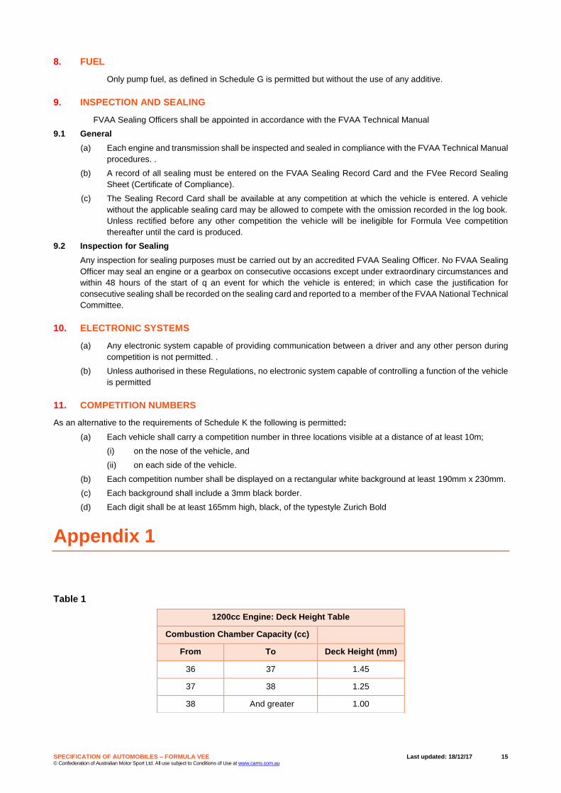
Table 1
1200cc Engine: Deck Height Table
Combustion Chamber Capacity (cc)
From To Deck Height (mm)
36 37 1.45
37 38 1.25
38 And greater 1.00

SPECIFICATION OF AUTOMOBILES – FORMULA VEE Last updated: 18/12/17 16 © Confederation of Australian Motor Sport Ltd. All use subject to Conditions of Use at www.cams.com.au
Table 2
Table 3
1600cc Engine: Deck Height Table
Combustion Chamber Capacity (cc)
From To Deck Height mm
40 41 2.40
41 42 2.20
42 43 2.05
43 44 1.85
44 45 1.70
45 46 1.50
46 47 1.35
47 48 1.15
48 And greater 1.00
NON-GENUINE PARTS TABLE
N
o
Component No Component No Component
1 Gaskets & Seals 13 King Pins 25 Ball Joints
2 Cylinders & Pistons 14 Torsion Arm Link Pins 26 Type 1 H-Beam
3 Bearings 15 Axle Boots & Axle Tubes 27 Gearbox Gears
4 Valve Guides 16 Camshaft & Gear 28 Synchromesh Rings
5 Engine Valves 17 Steering Box 29 Selector Forks
6 Valve Springs 18 Oil Pump 30 Valve Rockers
7 Fuel Pump 19 Air Correction Jet Carrier (1200
only)
31 Connecting Rods
8 Voltage Regulator 20 Valve Seat Inserts 32 Crankshafts
9 Fan & Fan Housing 21 Brake Drums 33 Link Pin Stub Axle
10 Brake Shoes 22 Camshaft Followers 34 Torsion Arm Link
11 Wheel Cylinders 23 Gear Box Case & Selector Housing
12 Clutch Plate & Pressure Plate 24 Crank Cases

SPECIFICATION OF AUTOMOBILES – FORMULA VEE Last updated: 18/12/17 17 © Confederation of Australian Motor Sport Ltd. All use subject to Conditions of Use at www.cams.com.au
Table 4
Appendix 2
Drawing 1
Drawing 2
AUTHORISED PARTS TABLE
No Component No Component No Component
1 Threaded Fasteners ( not
wheel mounting bolts)
10 Shock Absorbers 19 External Oil Coolers & Oil
Cooling Fans
2 Brake Lines 13 Fuel Filters 20 Fan Belt
3 Fuel Lines 14 Ignition Points 21 Distributor
4 Spark Plugs 13 Washers 22 Valve Push Rods
5 Master Cylinders 14 Piston Rings 23 Flywheel
6 Carburettor Jets & Venturi
(1200cc only)
15 Starter Motor 24 Aftermarket Counter Weighted
Crankshaft
7 Push Rod Tubes 16 Swivel Foot Valve Adjusters 25 Axles
8 Ignition Coil 17 Disc Brake Calipers 26 Rocker Covers
9 6V or 12V Batteries 18 Disc Rotor & Hub Assemblies 27 Ignition Modules:
Compufire: Part no: 21100
Pertronix Ignitor I (not II or III):
Part No’s: 1847A, D500706 &
D500709