20140820 cx 330 engine fire 16 may 11- final report cx 330 engine fire 16 may 11... · final report...
TRANSCRIPT
FINAL REPORT
AIRBUS A330-343, REGISTRATION B-HLM ENGINE FIRE EVENT
16 MAY 2011
AIB/AAI/CAS.074
Air Accident Investigation Bureau of Singapore Ministry of Transport
Singapore
20 August 2014
© 2014 Government of Singapore
1
The Air Accident Investigation Bureau of Singapore
The Air Accident Investigation Bureau (AAIB) is the air accidents and incidents investigation authority in Singapore responsible to the Ministry of Transport. Its mission is to promote aviation safety through the conduct of independent and objective investigations into air accidents and incidents.
The AAIB conducts the investigations in accordance with the Singapore Air Navigation (Investigation of Accidents and Incidents) Order 2003 and Annex 13 to the Convention on International Civil Aviation, which governs how member States of the International Civil Aviation Organization (ICAO) conduct aircraft accident investigations internationally. In carrying out the investigations, the AAIB will adhere to ICAO’s stated objective, which is as follows:
“The sole objective of the investigation of an accident or incident shall be the prevention of accidents and incidents. It is not the purpose of this activity to apportion blame or liability.”
Accordingly, it is inappropriate that AAIB reports should be used to assign fault or blame or determine liability, since neither the investigation nor the reporting process has been undertaken for that purpose.
© 2014 Government of Singapore
2
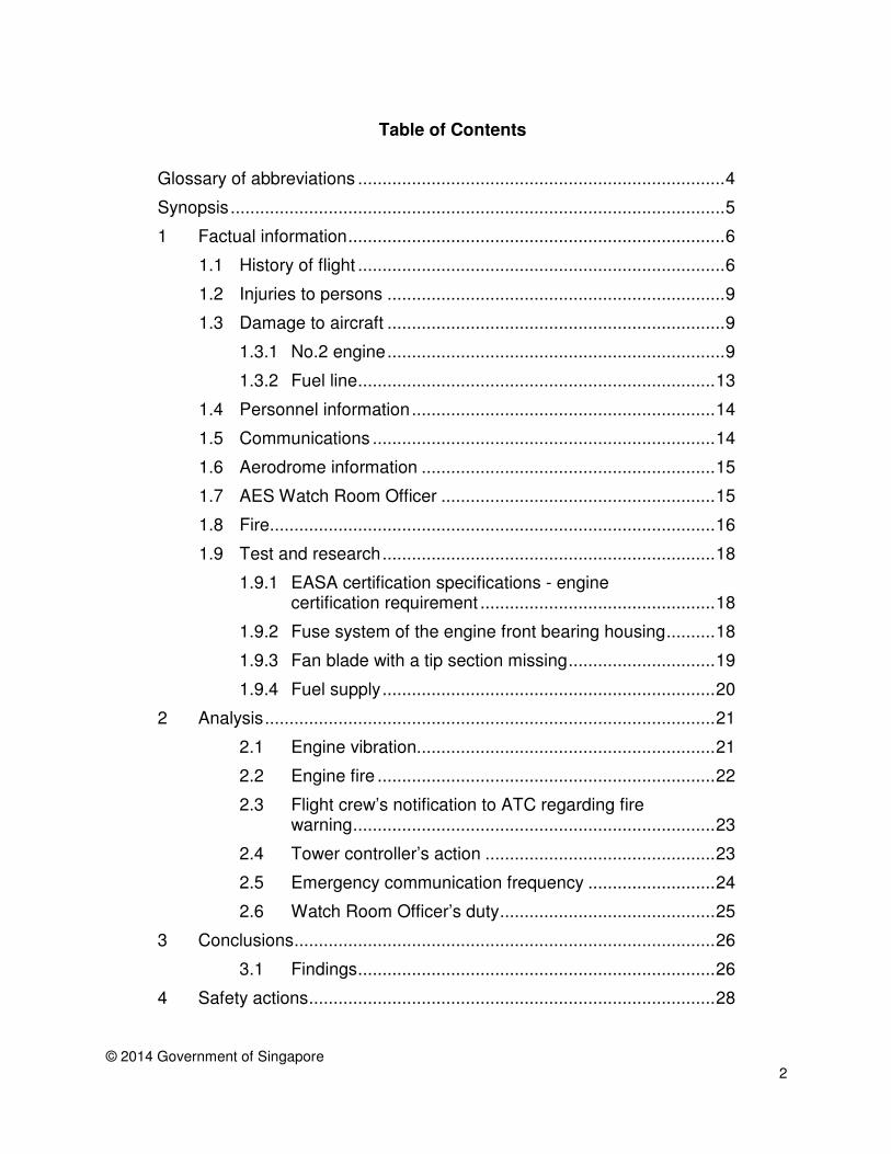
Table of Contents
Glossary of abbreviations ........................................................................... 4
Synopsis ..................................................................................................... 5
Factual information ............................................................................. 6 1
1.1 History of flight ........................................................................... 6
1.2 Injuries to persons ..................................................................... 9
1.3 Damage to aircraft ..................................................................... 9
1.3.1 No.2 engine ..................................................................... 9
1.3.2 Fuel line ......................................................................... 13
1.4 Personnel information .............................................................. 14
1.5 Communications ...................................................................... 14
1.6 Aerodrome information ............................................................ 15
1.7 AES Watch Room Officer ........................................................ 15
1.8 Fire........................................................................................... 16
1.9 Test and research .................................................................... 18
1.9.1 EASA certification specifications - engine certification requirement ................................................ 18
1.9.2 Fuse system of the engine front bearing housing .......... 18
1.9.3 Fan blade with a tip section missing .............................. 19
1.9.4 Fuel supply .................................................................... 20
2 Analysis ............................................................................................ 21
2.1 Engine vibration............................................................. 21
2.2 Engine fire ..................................................................... 22
2.3 Flight crew’s notification to ATC regarding fire warning .......................................................................... 23
2.4 Tower controller’s action ............................................... 23
2.5 Emergency communication frequency .......................... 24
2.6 Watch Room Officer’s duty ............................................ 25
3 Conclusions ...................................................................................... 26
3.1 Findings ......................................................................... 26
4 Safety actions ................................................................................... 28

© 2014 Government of Singapore
3
4.1 Engine manufacturer ..................................................... 28
4.2 European Aviation Safety Agency ................................. 28
4.3 Airport Emergency Service voice recording system ...... 29
5 Safety recommendations .................................................................. 30
© 2014 Government of Singapore
4
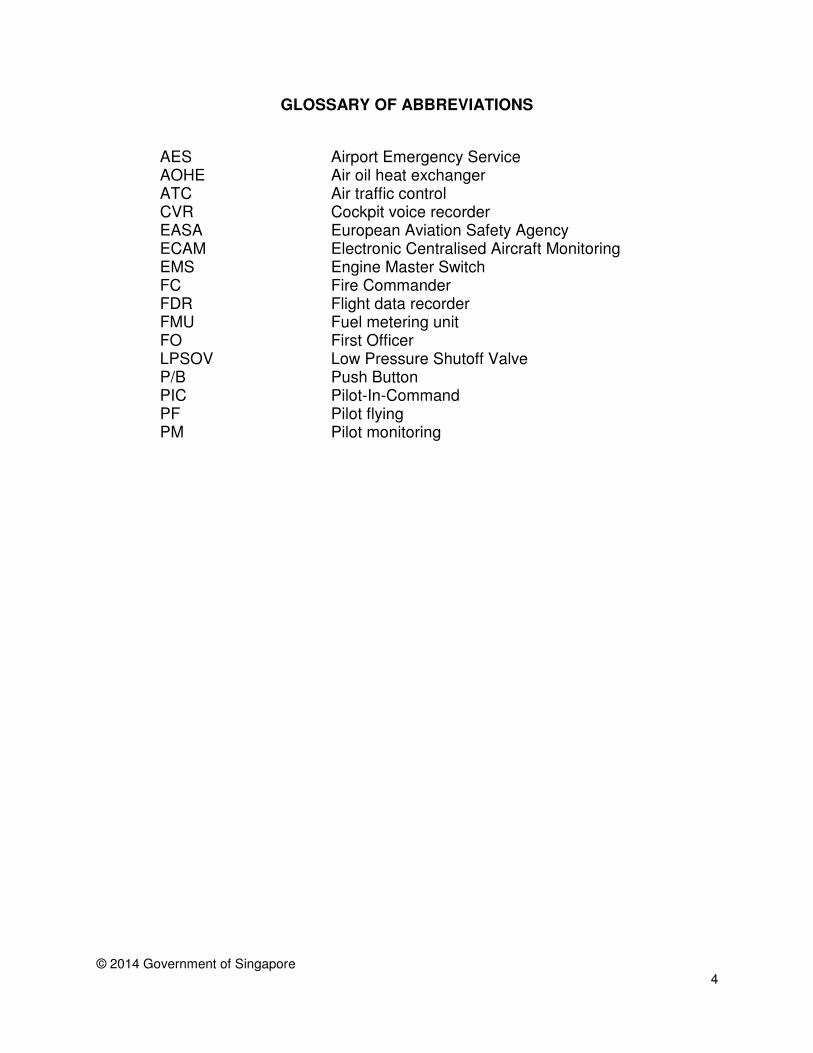
GLOSSARY OF ABBREVIATIONS
AES AOHE
Airport Emergency Service Air oil heat exchanger
ATC Air traffic control CVR EASA ECAM
Cockpit voice recorder European Aviation Safety Agency Electronic Centralised Aircraft Monitoring
EMS FC
Engine Master Switch Fire Commander
FDR FMU
Flight data recorder Fuel metering unit
FO First Officer LPSOV P/B PIC
Low Pressure Shutoff Valve Push Button Pilot-In-Command
PF Pilot flying PM Pilot monitoring
© 2014 Government of Singapore
5
SYNOPSIS
At about 0112 hours (Local Time) on 16 May 2011, an Airbus A330-343 took off from Singapore Changi Airport on a scheduled flight to Jakarta. While climbing through 33,000 feet at 0129 hours, the No.2 engine stalled and a loud bang was heard and vibration was felt by the flight crew. The flight crew shut down the No.2 engine, following which the vibration reduced, but did not disappear. The flight crew declared an emergency to ATC and flew the aircraft back to Changi Airport.
About 15 minutes after the initial No.2 engine problem, when the aircraft was at 10,500 feet and descending into Singapore, the No.2 engine fire warning indication appeared and the flight crew discharged an engine fire extinguishing bottle. The fire warning indication was cleared but re-appeared after 69 seconds. The flight crew discharged a second engine fire extinguishing bottle but was unsure if the fire had been extinguished as the fire warning light flickered intermittently.
After the aircraft landed, the Airport Emergency Service saw fire at the No.2
engine as they approached the aircraft and proceeded to put it out. No one was injured in this incident.
The No.2 engine vibration was a result of the engine’s rotating assembly becoming unbalanced following the loss of a 130 mm tip section of one of the engine fan blades. The failure of the fan blade could be attributed to its mechanical strength having been compromised as a result of the use of an incorrect gas during the manufacturing process.
The interior of the No.2 engine fan case was damaged by the rubbing against
it of the fan blades of the engine’s unbalanced rotating assembly. The severe rubbing generated heat resulting in the ignition of the Kevlar wrap of the fan case and in fire damage to the accessories on the right side of the engine.
The Air Accident investigation Bureau of Singapore classified this occurrence
as a serious incident.
AIRCRAFT DETAILS Aircraft type : Airbus A330-343 Operator : Cathay Pacific Airways Aircraft registration : B-HLM Numbers and type of engines : 2 x Rolls Royce Trent 700 Date and time of incident : 16 May 2011, 0129 hours local time Location of occurrence : South-east of Singapore Type of flight : Scheduled passenger flight Persons on board : 149
© 2014 Government of Singapore
6
FACTUAL INFORMATION 1 All times used in this report are Singapore times. Singapore time is eight hours ahead of Coordinated Universal Time (UTC).
1.1 History of flight
1.1.1 The Airbus 330-343 aircraft was on a scheduled passenger flight from Singapore to Jakarta on 16 May 2011. It took off from Singapore Changi Airport at 0112 hours. The Pilot-In-Command (PIC) was the pilot flying (PF) and the First Officer (FO) was the Pilot Monitoring (PM).
1.1.2 While the aircraft was climbing through 33,000 feet at 0129 hours, a loud bang was heard and severe airframe vibration was felt by the flight crew. The PF observed an Electronic Centralised Aircraft Monitoring (ECAM) message indicating “ENG 2 STALL”. Data from the aircraft’s flight data recorder (FDR) showed that engine vibration spiked up to 10 units1 for about 12 seconds.
1.1.3 At 0130 hours, the flight crew shut down the No.2 engine by putting the Engine Master Switch (EMS) for the No.2 engine to the OFF position. The airframe vibration reduced (to between 0.5 and 4 units) but continued for the rest of the flight.
1.1.4 The flight crew declared an emergency (i.e. Mayday) to the Singapore Air
Traffic Control Centre (SATCC) and flew back to Changi Airport. 1.1.5 The flight crew was informed by the In-flight Service Manager (ISM) that
sparks and flames were seen at the rear of the No.2 engine from the cabin windows. The PF informed the ISM that the aircraft was turning back to Singapore and requested for the cabin to be prepared for landing.
1.1.6 At about 0145 hours, the No.2 engine fire warning indication2 came on.
The flight crew discharged one engine fire extinguishing bottle3 and the fire warning indication (i.e. both aural alarm and light) were cleared.
1.1.7 The No.2 engine fire warning indication light re-appeared4 69 seconds
1 This was the upper limit of the engine vibration parameter.
2 When an engine fire is first detected, the fire warning indication consists of an aural alarm and a warning light on a guarded Engine Fire Push Button (P/B) located in the overhead panel and the master warning button on the front panel. The warning light is designed to be steady ON when a fire is constantly detected.
3 To discharge the fire extinguishing bottle, the crew has to lift the guard of the Engine Fire P/B, press the Engine Fire P/B (which arms the fire extinguishing system and inhibits the aural warning) and thereafter press the Fire Extinguishing Bottle P/B to discharge the first fire extinguishing bottle.
4 As the No.2 Engine Fire P/B had been pressed when the flight crew discharged the first fire extinguishing bottle, the aural warning was inhibited and subsequent fire warning indications would consist of the warning light only.
© 2014 Government of Singapore
7
later and the flight crew discharged the second5 engine fire extinguishing bottle.
1.1.8 According to the flight crew, after the second engine fire extinguishing bottle was discharged, the fire warning indication light cleared but reappeared flickering and remained flickering for the rest of the flight. The flight crew interpreted the flickering fire warning indication as the No.2 engine fire having been extinguished and they informed SATCC accordingly. Data from the FDR showed that the fire warning indication was on throughout the rest of the flight.
1.1.9 At the time of the occurrence, one of the airport’s two runways, Runway
02L/20R, was closed for scheduled maintenance and only Runway 02C/20C was open. Other aircraft were still departing from Runway 02C/20C until the emergency aircraft was about seven nautical miles6 from landing.
1.1.10 The Airport Emergency Service (AES) was notified of the emergency by
the control tower and its vehicles were put on standby for the aircraft to land.
1.1.11 After the aircraft landed on Runway 02C at 0157 hours, the aircraft
vacated the runway and stopped on Taxiway E5. The flight crew then shut down No.1 engine.
1.1.12 The AES vehicles were given clearance by the control tower to proceed to the aircraft. When the AES personnel arrived at the aircraft, they noticed that the No.2 engine was on fire and immediately commenced fighting the fire with foam.
1.1.13 The flight crew wanted to verify the status of the No.2 engine fire before deciding if an evacuation was necessary and wished to speak to the Fire Commander (FC) of the AES response team directly. They obtained from the control tower the emergency frequency to contact the FC, which was 121.85 MHz7. In the meantime, they also informed the cabin crew to stand by in case an evacuation was necessary.
1.1.14 The control tower also informed FC to contact the flight crew on 121.85
MHz.
1.1.15 The flight crew first attempted to contact the FC on 121.85 MHz at 0201 hours but there was no reply.
5 Each engine was equipped with two fire extinguishing bottles.
6 From this point, the aircraft took about three minutes to land.
7 There was no dedicated frequency channel in Changi Airport for communication between the AES and aircraft during emergencies. There were two frequencies that the control tower may assign for such communication, viz. 121.85 MHz and 121.9 MHz. If requested, the control tower would inform flight crews and the AES the frequency to be used.

© 2014 Government of Singapore
8
1.1.16 At 0204 hours, the PM opened the cockpit window and spoke to the FC.
The FC informed the PM that the No.2 engine fire had been put out and equipment was being arranged for the disembarkation of the passengers at Taxiway E5.
1.1.17 Radio communication between the flight crew and the AES personnel was
established at 0206 hours.
1.1.18 Below is a summary of the history of the flight.
Time (hours) Activities 01:00 Runway 02L/20R was closed for scheduled maintenance.
Planned closure time was from 0100 to 0700 hours. 01:12 Incident aircraft took off from Runway 02C.
01:29:34 A loud bang was heard and severe airframe vibration was felt by the flight crew.
01:29:52 No.2 engine was put to idle. 01:30:31 The flight crew shut down No.2 engine, which closed both
the High Pressure (HP) and Low Pressure (LP) fuel valves. Flight crew declared Mayday and flew back to Changi Airport.
Exact time undetermined
APU was started.
01:45 Tower Controller initiated opening of Runway 02L/20R. 01:45:36 No.2 engine fire warning indication came on for the first
time. Flight crew discharged one engine fire extinguishing bottle.
01:46:14 No.2 engine fire warning indication was cleared. 01:47:23 No.2 engine fire warning indication re-appeared.
Flight crew discharged the second engine fire extinguishing bottle.
01:54 Runway 02C/20C was reserved for the emergency aircraft when it was about seven nautical miles away.
01:57:41 Aircraft landed on Runway 02C, vacated the runway and stopped at Taxiway E5. The AES vehicles were given clearance by the control tower to proceed to the aircraft. The AES personnel commenced fighting the No.2 engine fire.
01:59 Flight crew wanted to check the status of No.2 engine fire before deciding if an evacuation was necessary. They informed cabin crew to stand by in case an evacuation was necessary.
02:00:55 Based on FDR, the No.2 engine fire warning indication was cleared.
02:01 The flight crew shut down No.1 engine. Flight crew made first attempt (unsuccessful) to contact the FC.
Exact time undetermined
The AES Commander attempted to contact the flight crew but was unsuccessful.
02:04 After various unsuccessful transmissions to contact the FC, the PM opened the cockpit window and spoke to the FC.
© 2014 Government of Singapore
9
02:06 Flight crew and the AES established radio communication. 02:10 Runway 02L/20R was opened.
1.2 Injuries to persons
1.2.1 There was no injury to any person in this incident.
1.3 Damage to aircraft
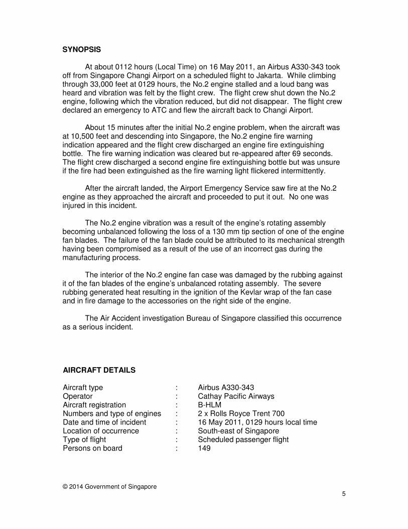
1.3.1 No.2 engine (See Figure 1 for the cutaway view8 for illustration and comparison purpose)
Figure 1: Cutaway view of engine fan case
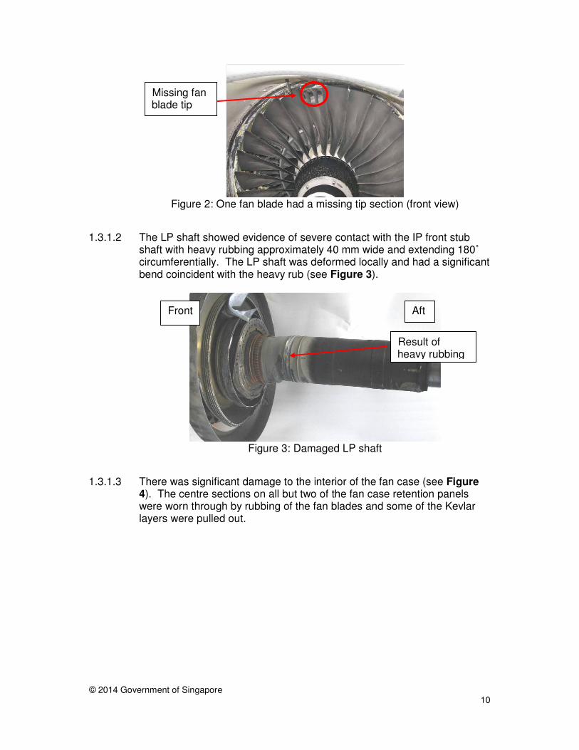
1.3.1.1 All the fan blade tips of the No.2 engine were damaged, with one of the
blades having its tip missing (see Figure 2). The missing part was about 130 mm long.
8 Source: http://rustanez.com/Engines.html
Fan blades
Kevlar layers (in orange) Fan case
retention panels
Fan shaft
Boundary of Low and Intermediate Pressure Compressor Modules
Nose cone
© 2014 Government of Singapore
10
Figure 2: One fan blade had a missing tip section (front view)
1.3.1.2 The LP shaft showed evidence of severe contact with the IP front stub
shaft with heavy rubbing approximately 40 mm wide and extending 180˚ circumferentially. The LP shaft was deformed locally and had a significant bend coincident with the heavy rub (see Figure 3).
Figure 3: Damaged LP shaft
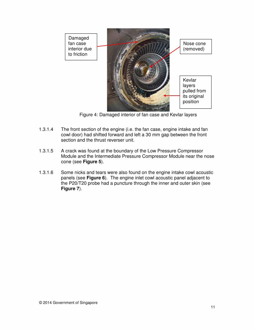
1.3.1.3 There was significant damage to the interior of the fan case (see Figure
4). The centre sections on all but two of the fan case retention panels were worn through by rubbing of the fan blades and some of the Kevlar layers were pulled out.
Missing fan blade tip
Front Aft
Result of heavy rubbing
© 2014 Government of Singapore
11
Figure 4: Damaged interior of fan case and Kevlar layers
1.3.1.4 The front section of the engine (i.e. the fan case, engine intake and fan
cowl door) had shifted forward and left a 30 mm gap between the front section and the thrust reverser unit.
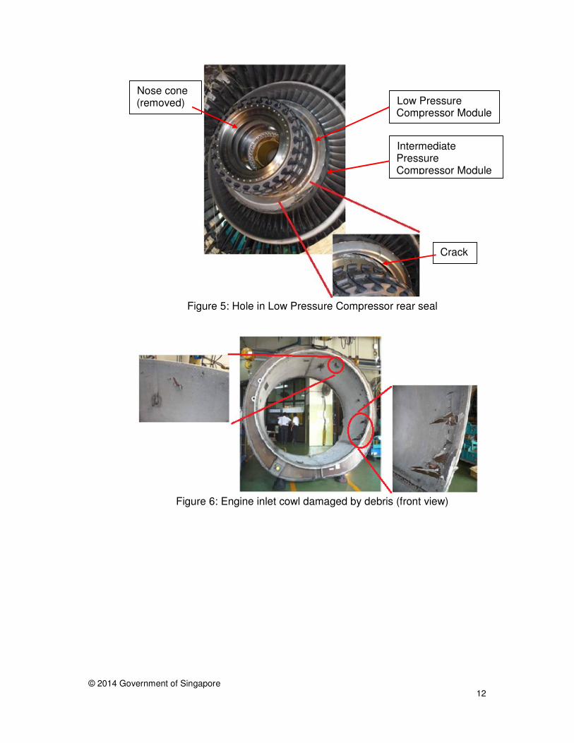
1.3.1.5 A crack was found at the boundary of the Low Pressure Compressor Module and the Intermediate Pressure Compressor Module near the nose cone (see Figure 5).
1.3.1.6 Some nicks and tears were also found on the engine intake cowl acoustic panels (see Figure 6). The engine inlet cowl acoustic panel adjacent to the P20/T20 probe had a puncture through the inner and outer skin (see Figure 7).
Damaged fan case interior due to friction
Kevlar layers pulled from its original position
Nose cone (removed)
© 2014 Government of Singapore
12
Figure 5: Hole in Low Pressure Compressor rear seal
Figure 6: Engine inlet cowl damaged by debris (front view)
Intermediate Pressure Compressor Module
Crack
Low Pressure Compressor Module
Nose cone (removed)
© 2014 Government of Singapore
13
Figure 7: Puncture on engine inlet cowl outer skin (top view)
1.3.1.7 The pylon on which No.2 engine was mounted was found with several
cracks. The pylon was removed and inspection revealed multiple cracks on the forward secondary structure which suggest the presence of high loads level. This damage was most probably consequential and due to the high engine vibration following the partial fan blade release. The pylon primary structure showed no signs of damage.
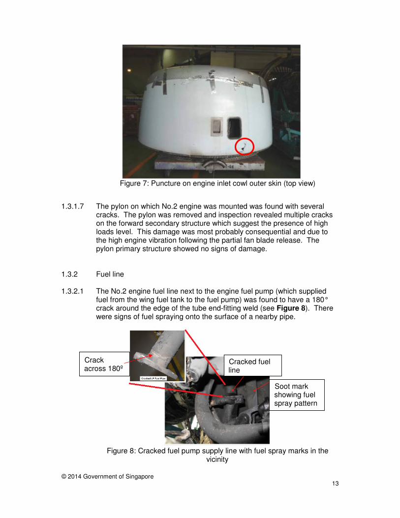
1.3.2 Fuel line
1.3.2.1 The No.2 engine fuel line next to the engine fuel pump (which supplied fuel from the wing fuel tank to the fuel pump) was found to have a 180° crack around the edge of the tube end-fitting weld (see Figure 8). There were signs of fuel spraying onto the surface of a nearby pipe.
Figure 8: Cracked fuel pump supply line with fuel spray marks in the
vicinity
Crack across 180º
Soot mark showing fuel spray pattern
Cracked fuel line
© 2014 Government of Singapore
14
1.3.2.2 Examination of the fracture surfaces of the crack by the engine
manufacturer indicated high stress fatigue initiating from multiple sites around the inner surface of the tube towards the outer surface.
1.4 Personnel information PIC (Male) FO (Male) Age 40 years 41 years Licence Airline Transport Pilot
Licence issued by the Hong Kong Civil Aviation Department
Airline Transport Pilot Licence issued by the Hong Kong Civil Aviation Department
Total flying experience
8,534 hours 7,385 hours
Flying experience on type
3,632 hours 3,238 hours
1.5 Communications
1.5.1 Data from the cockpit voice recorder (CVR) showed that before the flight crew and the AES established radio communication at 0206 hours, the flight crew had called the FC multiple times on 121.85 MHz over about three minutes (the first transmission by the flight crew to contact the FC was made at 0201 hours) but without receiving any reply. During the flight crew’s third transmission, the CVR recording showed that there was a cross talk.
1.5.2 On the part of the FC, he attempted to contact the flight crew on 121.85
MHz while he was in his vehicle9. The FC did not receive any reply. The FC then transmitted over the AES Channel10 via a walkie-talkie, to inform all in the AES Channel that he was not able to contact the flight crew.
1.5.3 At that time, the AES Duty Officer11 was outside his own vehicle coordinating the firefighting activities. He had a walkie-talkie for the AES Channel but did not hear the FC’s transmission (that he was not able to contact the flight crew) over the AES Channel because it was very noisy around him.
9 AES personnel communicated with flight crews via fixed radio sets in their vehicles. They did not
have portable radio sets which could be used outside their vehicles to communicate with flight crews.
10 The AES Channel was a communication channel for the AES personnel to communicate among themselves and with the control tower via a walkie-talkie. This uses a different frequency than 121.85 MHz.
11 The AES Duty Officer was the second highest ranking the AES personnel on site, after the FC.
© 2014 Government of Singapore
15
1.5.4 The FC decided to take over command of the firefighting activities and wanted the AES Duty Officer to try to contact the flight crew instead. The FC left his vehicle to meet up with the AES Duty Officer who then provided the FC with a situation report so as to hand over the command of the firefighting activities to the FC.
1.5.5 It was when the AES Duty Officer was handing over to the FC that the PM
of the aircraft opened the cockpit window and spoke to the FC. The AES Duty Officer then returned to his vehicle.
1.5.6 After the AES Duty Officer had returned to his vehicle, he managed to
establish communication with the flight crew on 121.85 MHz. The communication was maintained throughout the rest of the event.
1.6 Aerodrome information 1.6.1 At the time of the occurrence, Runway 02L/20R was closed for
maintenance and only Runway 02C/20C was operational. When the control tower was informed that the emergency aircraft was returning to land, the Runway Controller took action (at about 0145 hours) to initiate the reopening of Runway 02L/20R. This was done so that there would be another runway available for use if the emergency aircraft could not vacate Runway 02C/20C after landing.
1.6.2 As the emergency aircraft was approaching the airport, other aircraft were
still allowed to take off on Runway 02C/20C, then the only available runway. The last aircraft took off while the emergency aircraft was seven nautical miles (about 3 minutes) from touchdown.
1.6.3 Runway 02L/20R was eventually reopened about 13 minutes after the
emergency aircraft had landed. 1.7 AES Watch Room Officer
1.7.1 The AES Watch Room was manned by one person, viz. the Watch Room
Officer, when the incident took place. The Watch Room Officer’s primary duties were, among others, to observe all aircraft movements and make journal entries diligently in the Computer Watch Room System or the Occurrence Book. His secondary but important duties included answering all calls (e.g. direct lines, the AES frequency and any assigned emergency frequencies) and redirecting the calls.
1.7.2 The AES Watch Room Officer heard the FC’s transmission over the AES Channel that the FC was not able to contact the flight crew. However, the AES Watch Room Officer did not assist the FC and flight crew to establish communication.
© 2014 Government of Singapore
16
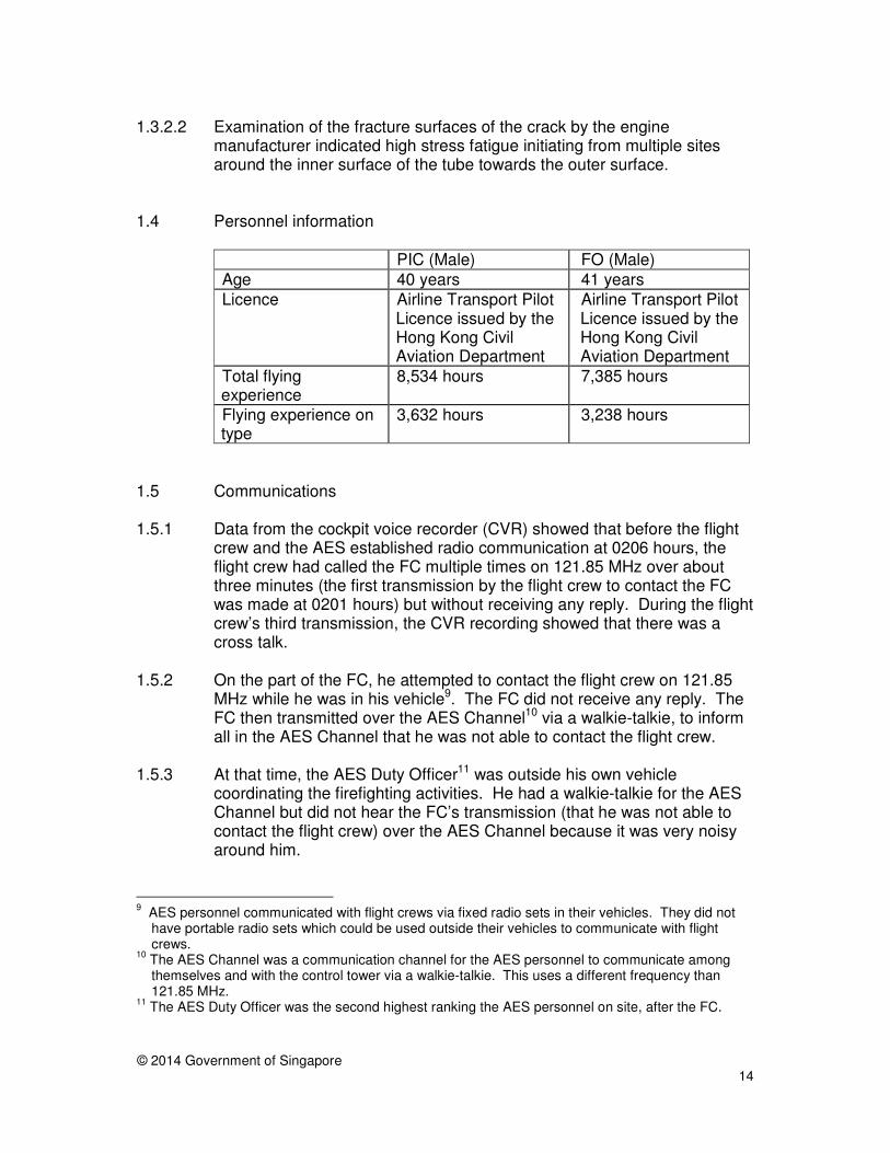
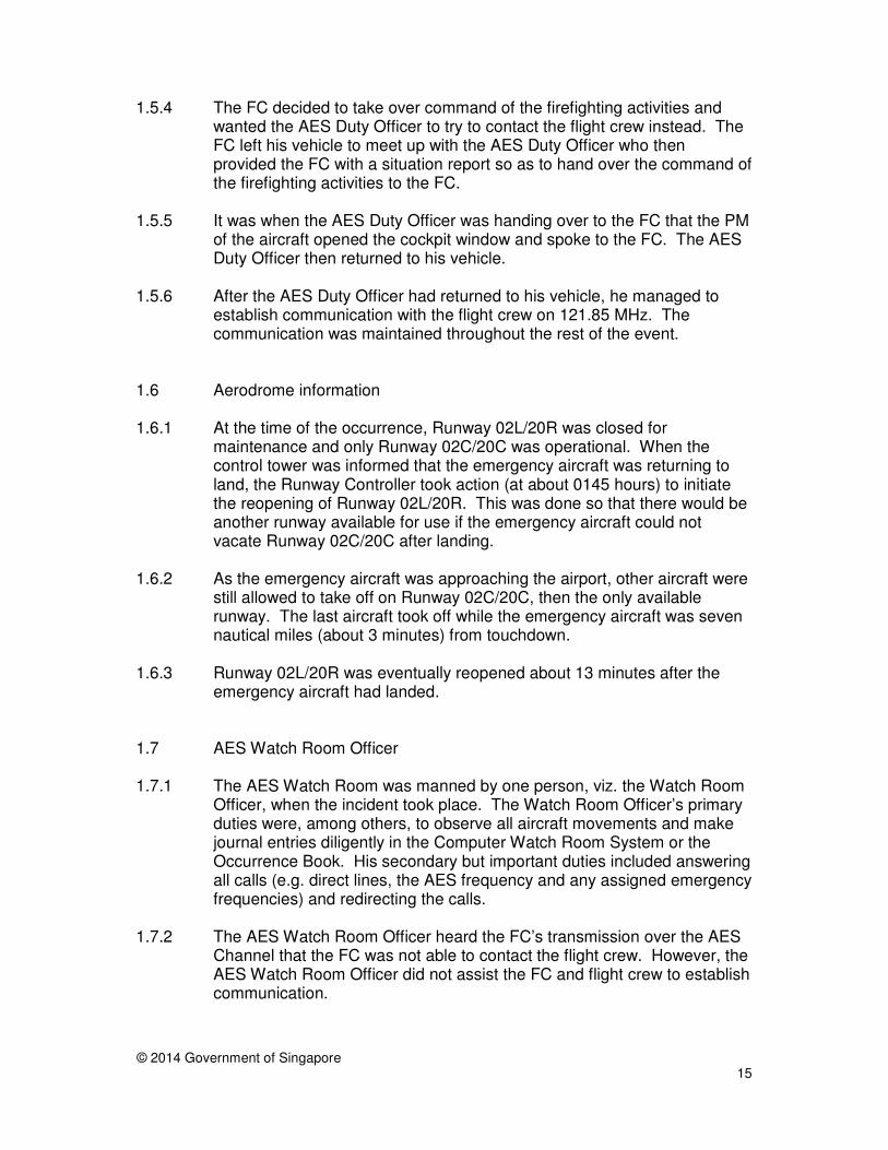
1.8 Fire 1.8.1 There was soot on the right side of the No.2 engine (see Figure 9)
exterior surface, and on the interior surface of the right fan cowl door (see Figure 10).
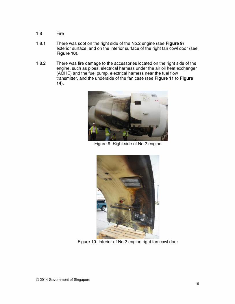
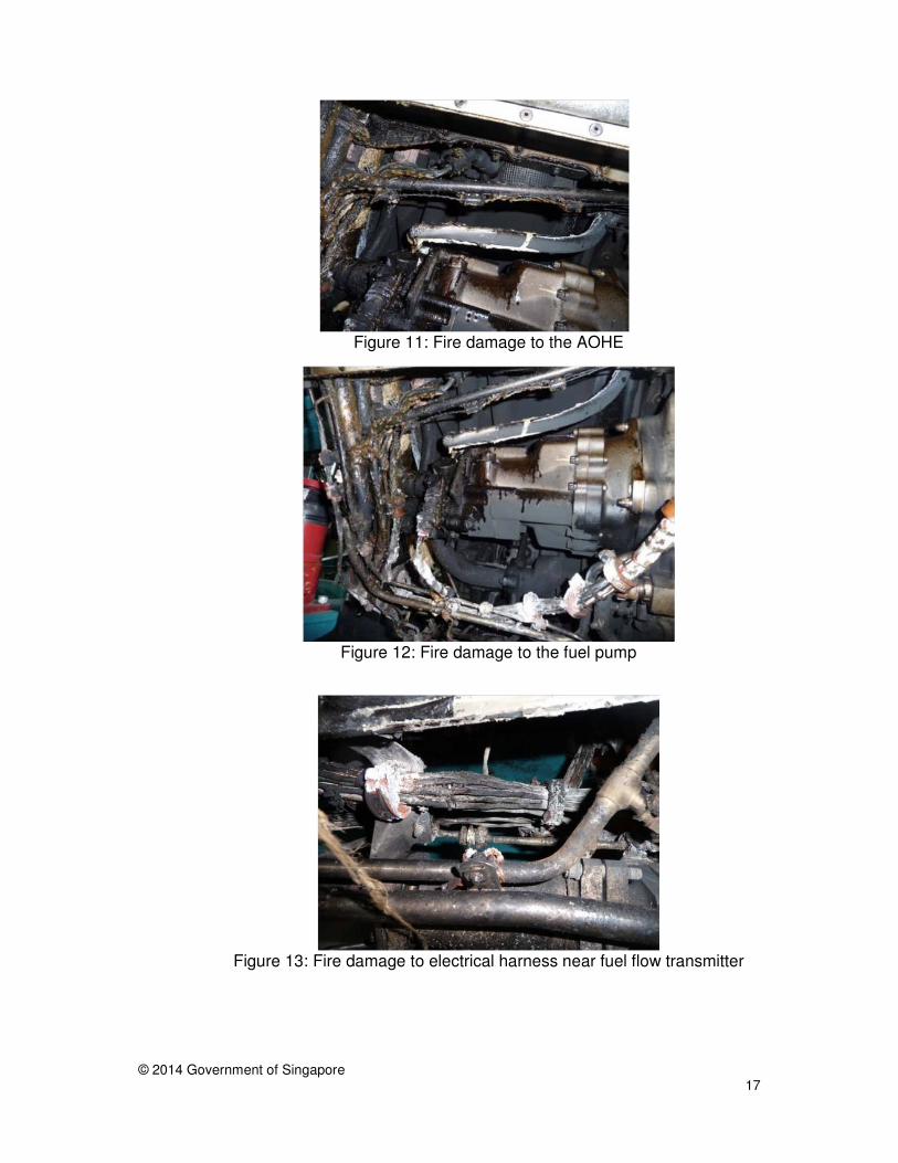
1.8.2 There was fire damage to the accessories located on the right side of the
engine, such as pipes, electrical harness under the air oil heat exchanger (AOHE) and the fuel pump, electrical harness near the fuel flow transmitter, and the underside of the fan case (see Figure 11 to Figure 14).
Figure 9: Right side of No.2 engine
Figure 10: Interior of No.2 engine right fan cowl door
© 2014 Government of Singapore
17
Figure 11: Fire damage to the AOHE
Figure 12: Fire damage to the fuel pump
Figure 13: Fire damage to electrical harness near fuel flow transmitter
© 2014 Government of Singapore
18
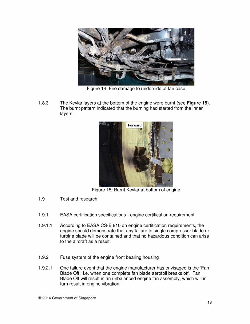
Figure 14: Fire damage to underside of fan case
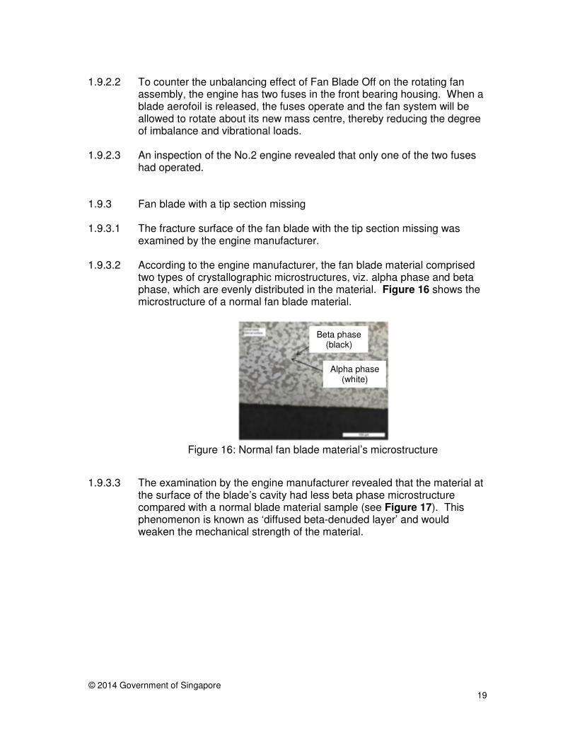
1.8.3 The Kevlar layers at the bottom of the engine were burnt (see Figure 15).
The burnt pattern indicated that the burning had started from the inner layers.
Figure 15: Burnt Kevlar at bottom of engine
1.9 Test and research
1.9.1 EASA certification specifications - engine certification requirement
1.9.1.1 According to EASA CS-E 810 on engine certification requirements, the engine should demonstrate that any failure to single compressor blade or turbine blade will be contained and that no hazardous condition can arise to the aircraft as a result.
1.9.2 Fuse system of the engine front bearing housing 1.9.2.1 One failure event that the engine manufacturer has envisaged is the ‘Fan
Blade Off’, i.e. when one complete fan blade aerofoil breaks off. Fan Blade Off will result in an unbalanced engine fan assembly, which will in turn result in engine vibration.
© 2014 Government of Singapore
19
1.9.2.2 To counter the unbalancing effect of Fan Blade Off on the rotating fan
assembly, the engine has two fuses in the front bearing housing. When a blade aerofoil is released, the fuses operate and the fan system will be allowed to rotate about its new mass centre, thereby reducing the degree of imbalance and vibrational loads.
1.9.2.3 An inspection of the No.2 engine revealed that only one of the two fuses
had operated. 1.9.3 Fan blade with a tip section missing 1.9.3.1 The fracture surface of the fan blade with the tip section missing was
examined by the engine manufacturer.
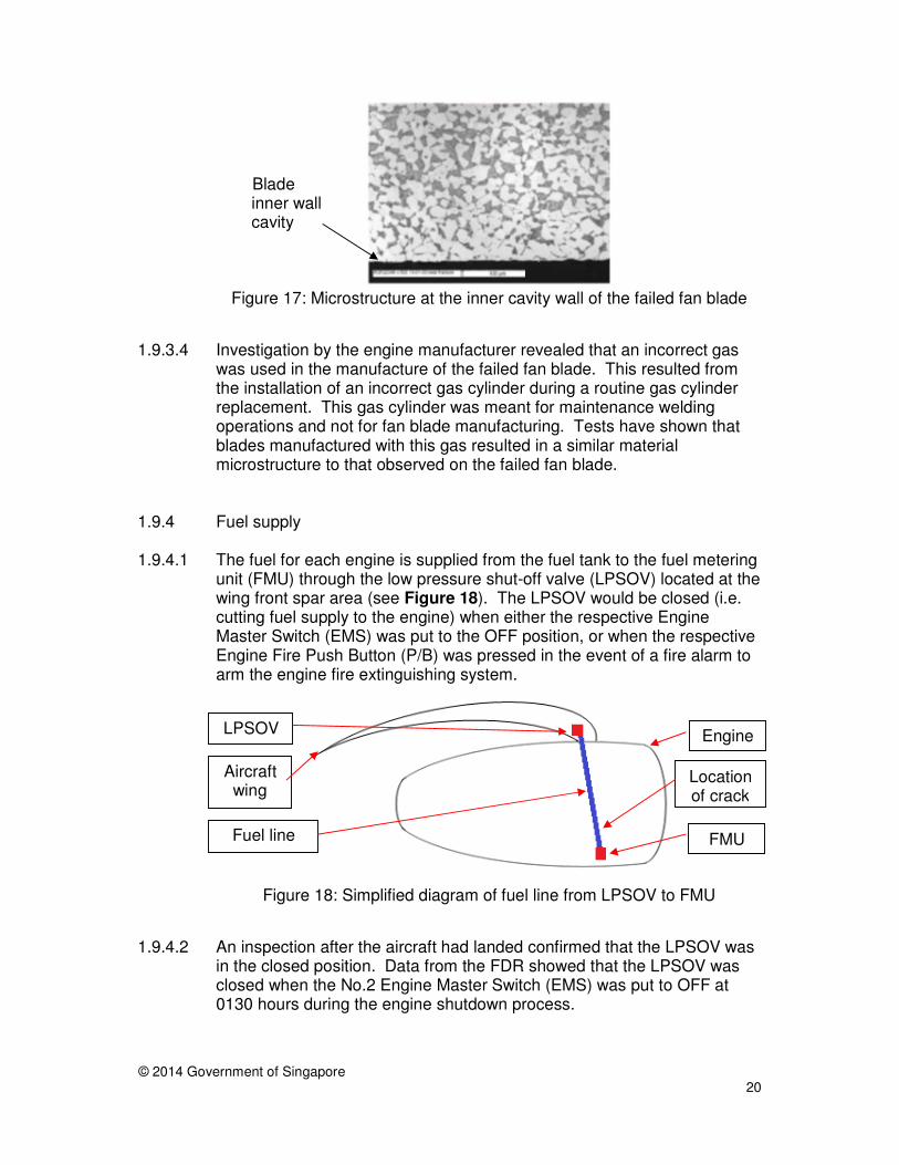
1.9.3.2 According to the engine manufacturer, the fan blade material comprised two types of crystallographic microstructures, viz. alpha phase and beta phase, which are evenly distributed in the material. Figure 16 shows the microstructure of a normal fan blade material.
Figure 16: Normal fan blade material’s microstructure
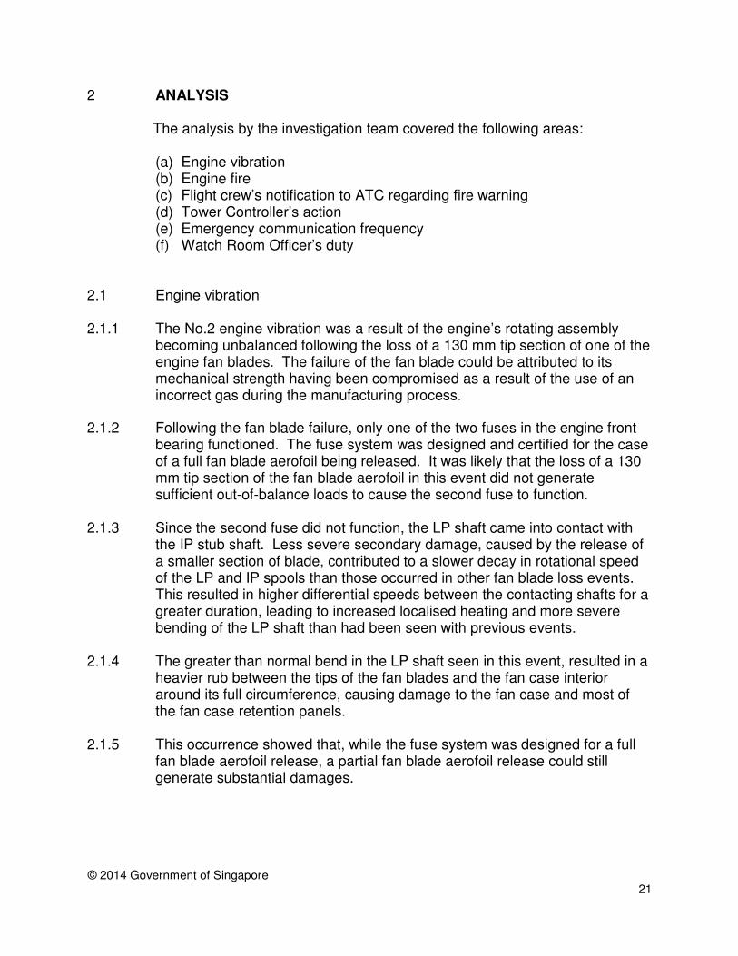
1.9.3.3 The examination by the engine manufacturer revealed that the material at
the surface of the blade’s cavity had less beta phase microstructure compared with a normal blade material sample (see Figure 17). This phenomenon is known as ‘diffused beta-denuded layer’ and would weaken the mechanical strength of the material.
Beta phase (black)
Alpha phase (white)
© 2014 Government of Singapore
20
Figure 17: Microstructure at the inner cavity wall of the failed fan blade
1.9.3.4 Investigation by the engine manufacturer revealed that an incorrect gas
was used in the manufacture of the failed fan blade. This resulted from the installation of an incorrect gas cylinder during a routine gas cylinder replacement. This gas cylinder was meant for maintenance welding operations and not for fan blade manufacturing. Tests have shown that blades manufactured with this gas resulted in a similar material microstructure to that observed on the failed fan blade.
1.9.4 Fuel supply 1.9.4.1 The fuel for each engine is supplied from the fuel tank to the fuel metering
unit (FMU) through the low pressure shut-off valve (LPSOV) located at the wing front spar area (see Figure 18). The LPSOV would be closed (i.e. cutting fuel supply to the engine) when either the respective Engine Master Switch (EMS) was put to the OFF position, or when the respective Engine Fire Push Button (P/B) was pressed in the event of a fire alarm to arm the engine fire extinguishing system.
Figure 18: Simplified diagram of fuel line from LPSOV to FMU
1.9.4.2 An inspection after the aircraft had landed confirmed that the LPSOV was
in the closed position. Data from the FDR showed that the LPSOV was closed when the No.2 Engine Master Switch (EMS) was put to OFF at 0130 hours during the engine shutdown process.
Blade inner wall cavity
FMU
LPSOV
Fuel line
Aircraft wing
Engine
Location of crack
© 2014 Government of Singapore
21
ANALYSIS 2 The analysis by the investigation team covered the following areas: (a) Engine vibration (b) Engine fire (c) Flight crew’s notification to ATC regarding fire warning (d) Tower Controller’s action (e) Emergency communication frequency (f) Watch Room Officer’s duty
2.1 Engine vibration
2.1.1 The No.2 engine vibration was a result of the engine’s rotating assembly becoming unbalanced following the loss of a 130 mm tip section of one of the engine fan blades. The failure of the fan blade could be attributed to its mechanical strength having been compromised as a result of the use of an incorrect gas during the manufacturing process.
2.1.2 Following the fan blade failure, only one of the two fuses in the engine front
bearing functioned. The fuse system was designed and certified for the case of a full fan blade aerofoil being released. It was likely that the loss of a 130 mm tip section of the fan blade aerofoil in this event did not generate sufficient out-of-balance loads to cause the second fuse to function.
2.1.3 Since the second fuse did not function, the LP shaft came into contact with the IP stub shaft. Less severe secondary damage, caused by the release of a smaller section of blade, contributed to a slower decay in rotational speed of the LP and IP spools than those occurred in other fan blade loss events. This resulted in higher differential speeds between the contacting shafts for a greater duration, leading to increased localised heating and more severe bending of the LP shaft than had been seen with previous events.
2.1.4 The greater than normal bend in the LP shaft seen in this event, resulted in a heavier rub between the tips of the fan blades and the fan case interior around its full circumference, causing damage to the fan case and most of the fan case retention panels.
2.1.5 This occurrence showed that, while the fuse system was designed for a full fan blade aerofoil release, a partial fan blade aerofoil release could still generate substantial damages.
© 2014 Government of Singapore
22
2.2 Engine fire
2.2.1 The rubbing of the fan blade tips against the interior of the fan case generated a lot of heat, as evidenced by the burnt Kevlar layers.
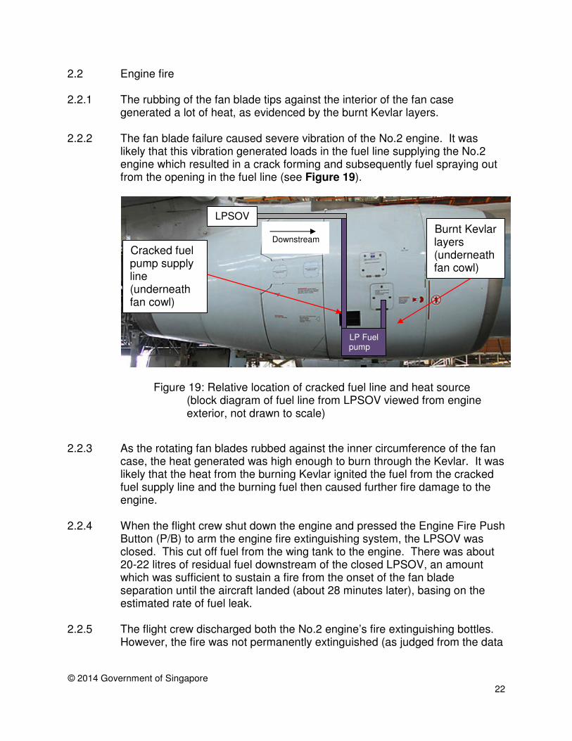
2.2.2 The fan blade failure caused severe vibration of the No.2 engine. It was likely that this vibration generated loads in the fuel line supplying the No.2 engine which resulted in a crack forming and subsequently fuel spraying out from the opening in the fuel line (see Figure 19).
Figure 19: Relative location of cracked fuel line and heat source (block diagram of fuel line from LPSOV viewed from engine exterior, not drawn to scale)
2.2.3 As the rotating fan blades rubbed against the inner circumference of the fan
case, the heat generated was high enough to burn through the Kevlar. It was likely that the heat from the burning Kevlar ignited the fuel from the cracked fuel supply line and the burning fuel then caused further fire damage to the engine.
2.2.4 When the flight crew shut down the engine and pressed the Engine Fire Push Button (P/B) to arm the engine fire extinguishing system, the LPSOV was closed. This cut off fuel from the wing tank to the engine. There was about 20-22 litres of residual fuel downstream of the closed LPSOV, an amount which was sufficient to sustain a fire from the onset of the fan blade separation until the aircraft landed (about 28 minutes later), basing on the estimated rate of fuel leak.
2.2.5 The flight crew discharged both the No.2 engine’s fire extinguishing bottles.
However, the fire was not permanently extinguished (as judged from the data
Cracked fuel pump supply line (underneath fan cowl)
Burnt Kevlar layers (underneath fan cowl)
LPSOV
LP Fuel pump
Downstream
© 2014 Government of Singapore
23
in the FDR). The 30 mm gap between the thrust reverser units and the fan cowl door, which was a result of the forward shifting of the fan case, could have reduced the effectiveness of the fire extinguishing agent in suppressing the fire. It might also be that the Kevlar continued to provide an ignition source and reignited the leaking fuel after both the fire extinguishing bottles had been discharged.
2.2.6 The presence of the engine fire as a result of the partial fan blade off event created a hazardous condition. The engine did not meet the EASA CS-E 810 requirements that no hazardous condition should arise as a result of engine damage.
2.3 Flight crew’s notification to ATC regarding fire warning
2.3.1 After the second engine fire extinguishing bottle was discharged, the fire warning indication light cleared but reappeared flickering and remained flickering for the rest of the flight. Nevertheless, the flight crew believed that the fire, if any, had been extinguished. However, FDR data suggests that fire was still present.
2.3.2 It would have been more prudent for the flight crew to assume that fire was present. While one may consider that, since the flight crew had made a decision to land the aircraft as soon as possible following the engine vibration, whether the flight crew believed correctly or wrongly the fire had been extinguished might not be material. However, if the flight crew had treated that the fire was still present and informed ATC accordingly, this might have aided ATC in planning their emergency actions, such as ceasing operations on the runway (e.g. take-off and landing) well in advance. This would have reduced the risk of the emergency aircraft having to execute a go-around should an abnormal operation (e.g. abort take-off) occurred to a departure or arrival aircraft ahead of the emergency aircraft.
2.3.3 The scenario of a flickering fire indication warning light had apparently been
envisaged by neither the aircraft manufacturer nor the operator. It should be included in the aircraft manufacturer’s documentation that a flickering fire warning indication should be treated as that a fire is present. Likewise, in the training of its flight crews, the operator should simulate a flickering fire warning indication scenario.
2.4 Tower Controller’s action
2.4.1 At the time of the occurrence, Runway 02L/20R was closed for maintenance and only Runway 02C/20C was operational. As the emergency aircraft was
© 2014 Government of Singapore
24
approaching the airport, the Tower Controller continued to allow other aircraft to take off on Runway 02C/20C, with a view to minimising the number of departing aircraft that would be prevented from taking off should the emergency aircraft get stuck on the runway after landing.
2.4.2 A concern is that, if any of the departing aircraft had an abnormal operation
that makes the runway not immediately useable (e.g. aborted take-off, aircraft parts falling off), the emergency aircraft may have to go-around and come in for another approach while the runway is being recovered. This could mean additional risk for the emergency aircraft.
2.4.3 Tower controllers are trained to reserve the runway for the emergency
aircraft when it is on the final approach. In this occurrence case, aircraft were allowed to take off from Runway 02L/20R until the emergency aircraft was about seven nautical miles from landing. However, there is no guideline for the controllers on when to stop aircraft take-offs (e.g. in terms of the distance of the emergency aircraft from the runway threshold). Controllers are left to make such decision on their own. The decision would vary, depending on the experience, knowledge and risk tolerance levels of the controllers. It might be desirable to have a guideline to prevent a controller cutting it too fine.
2.5 Emergency communication frequency
2.5.1 There was no dedicated frequency in Changi Airport for communication
between the AES and an aircraft during an emergency. If requested, ATC may assign ad hoc one of two frequencies, viz. 121.85 MHz and 121.9 MHz.
2.5.2 121.85MHz is a standby frequency, for use when any one of the four controlling frequencies in the airport (i.e. Runway1 Controller, Runway2 Controller, Runway1 Ground Controller and Runway2 Ground Controller) is unusable.
2.5.3 If 121.85 MHz was not available, 121.9 MHz would be assigned. 121.9 MHz
is the surface utility frequency and was usually used by the control tower to control all vehicular traffic and aircraft towing movements in the maneuvering area. This frequency is heavily used and may not be suitable for use by the AES and the flight crew to communicate between them.
2.5.4 Without a dedicated frequency for communication between the AES and the
flight crew, these two parties will always have to check with ATC for the frequency and precious time may be lost.
2.5.5 In the event that both 121.85 MHz and 121.9 MHz are not available to be
© 2014 Government of Singapore
25
used, the control tower will relay messages between the AES and the flight crew. This would slow down communication with an increased probability of miscommunication.
2.5.6 It would be more desirable to reserve a frequency for communication
between the AES and the flight crew during an emergency.
2.6 Watch Room Officer’s duty
2.6.1 The AES Watch Room was manned by one Watch Room Officer. Although the Watch Room Officer heard the FC’s transmission (that he was unable to establish contact with the flight crew) over the AES Channel, he was apparently so busy with his primary duties (i.e. monitoring the communication and logging events) that he did not have time to chip in to carry out his secondary duty, which was to assist the FC and the flight crew in establishing communication between them.
2.6.2 In addition, as the FC did not specifically request the Watch Room Officer to
assist in establishing communication with the flight crew, the latter may not have known that he was required to assist the FC in this aspect.
© 2014 Government of Singapore
26
CONCLUSIONS 3 From the evidence available, the following findings are made. These findings should not be read as apportioning blame or liability to any particular organisation or individual.
3.1 Findings
3.1.1 The failure of the fan blade with a 130 mm tip section missing was probably due to its mechanical strength having been compromised as a result of the use of an incorrect gas during the manufacturing process.
3.1.2 Following the fan blade failure, only one of the two fuses in the engine front
bearing functioned. 3.1.3 The fire from the rubbing of the fan blade tips and the fan case provided the
ignition source and burnt the Kevlar layers. 3.1.4 The fuel pump supply line cracked due to high vibrations, resulting in fuel
leak. It was likely that the heat from the burning Kevlar layers ignited the leaked fuel.
3.1.5 The engine intake cowl and the fan case had shifted forward, resulting in a
gap of about 30 mm between the thrust reverser units and the fan cowl door. This gap could have compromised the engine’s fire containment capability and reduced the effectiveness of the fire extinguishing agent in suppressing the fire.
3.1.6 The hazardous condition of the engine fire following the fan blade failure
event did not comply with the EASA CS-E 810 requirement that no hazardous condition should arise as a result of engine damage.
3.1.7 After discharging both fire extinguishing bottles, the fire warning indication was flickering intermittently. The flight crew interpreted the intermittent fire warning indication light as the fire had been extinguished.
3.1.8 The aircraft manufacturer’s documentation and the operator’s training did not
address the condition of an intermittent flickering fire warning indication which was presented to the flight crew.
3.1.9 There was no clear guideline for ATC controllers on when should a runway be reserved for an aircraft that has declared an emergency.
3.1.10 The air traffic services provider did not have a dedicated radio frequency for
communication between the AES and the flight crew of an emergency aircraft.
3.1.11 The Watch Room Officer, who was busy with his primary duties in monitoring the communication and logging events, did not have time to assist the FC
© 2014 Government of Singapore
27
and the flight crew in establishing communication. Neither did the FC ask the Watch Room Officer to assist in establishing communication with the flight crew.
© 2014 Government of Singapore
28
SAFETY ACTIONS 4 During the course of the investigation and through discussions with the investigation team, the following safety actions were initiated.
4.1 Engine Manufacturer
4.1.1 All in-service fan blades manufactured in the same batch as the failed fan blade in this incident have been recalled and inspected by the engine manufacturer. There was no similar manufacturing defect found in the recalled blades.
4.1.2 To prevent the use of an incorrect gas during the fan blade manufacturing
process, the engine manufacturer has incorporated gas analysers on the gas supply lines to ascertain the nature of the gas in the cylinders prior to using them.
4.1.3 The engine manufacturer has included in its blade manufacturing process an additional laboratory inspection to ensure an acceptable microstructure is present on each fan blade.
4.1.4 The engine manufacturer has launched modification design activities to increase the engine’s robustness in the event of a partial fan blade release.
4.2 European Aviation Safety Agency
4.2.1 After the partial fan blade failure occurrence on 16 May 2011, the European Aviation Safety Agency (EASA) issued the following Airworthiness Directive (AD) to address the inspection of affected in-service fan blades:
• AD 2012-0247 (issued on 20 November 2012) EASA issued AD 2012-0247 to require a one-time inspection of the higher life LP compressor blades.
• AD 2013-0060 (issued on 11 March 2013, which superseded AD 2012-0247) After AD 2012-0247 was issued, a population of LP compressor blades were identified to be incorrectly inspected, and EASA issued AD 2013-0060 to require re-inspection of the affected blades. Since EASA AD 2013-0060 was issued, the engine manufacturer issued a Non-Modification Service Bulletin (RB.211-72-AH465) providing instructions for a programme of repetitive ultrasonic inspections of the affected LP compressor blades to detect sub-surface anomalies in the aerofoil.
© 2014 Government of Singapore
29
• AD 2014-0031 (issued on 4 February 2014, which superseded AD 2013-0060) This AD requires repetitive inspections of all affected LP compressor blades and replacement (if required).
4.3 Airport Emergency Service voice recording system
4.3.1 A voice recording system has been installed to automatically record voice communication over the AES Channel and emergency frequency. With this system, the workload of the Watch Room Officer is reduced. This would allow him to chip in to assist the Fire Commander when necessary.
© 2014 Government of Singapore 30
SAFETY RECOMMENDATIONS 5 A safety recommendation is for the purpose of preventive action and shall in no case create a presumption of blame or liability. It is recommended that:
5.1 The engine manufacturer, as holder of the type certificate, review the engine design to comply with EASA CS-E 810 (Compressor and Turbine Blade Failure) requirements such that no hazardous engine effect can arise as a result of other engine damage likely to occur before engine shut down following a blade failure. [AAIB Recommendation R-2014-010]
5.2 The European Aviation Safety Agency require the engine manufacturer, as holder of the type certificate, to review the design of the engine to comply with the EASA requirement CS-E 810 (Compressor and Turbine Blade Failure) requirements such that no hazardous engine effect can arise as a result of other engine damage likely to occur before engine shut down following a blade failure. [AAIB Recommendation R-2014-011]
5.3 The aircraft manufacturer include in its documentation that a flickering fire
warning indication may imply that a fire is physically present but detected intermittently. [AAIB Recommendation R-2014-012]
5.4 The aircraft operator review its operating procedures to ensure that flight crew recognise the risk of an intermittent fire warning indication and that they would interpret it as a fire warning. [AAIB Recommendation R-2014-013]
5.5 The air traffic services provider to provide guidelines regarding reserving a
runway for the exclusive use by an emergency aircraft. [AAIB Recommendation R-2014-014]
5.6 The air traffic services provider assign a fixed frequency for the Airport
Emergency Service personnel and the flight crew of an emergency aircraft to communicate between them during an emergency. [AAIB Recommendation R-2014-015]
5.7 The Airport Emergency Service improve its communication equipment to
ensure that voice transmissions over these equipment can be heard even in a noisy environment. [AAIB Recommendation R-2014-016]