2011 cube owner's manual
DESCRIPTION
Classic Cars Nissan offers you excellent sales and service on new or used Nissan vehicles. Stop in and test drive a Nissan 2011 CUBE or any car or truck today! We're located Hainesport New Jersey between Cherry Hill and Mount Holly. Only 20 minutes from Philadelphia. Classic Cars Nissan 1513 Route 38 Hainesport, NJ 08036 866-CLASSIC or 866-252-7742TRANSCRIPT


Black plate (2,1)
Model "Z12-D" EDITED: 2010/ 9/ 27
Welcome to the growing family of new NISSANowners. This vehicle is delivered to you withconfidence. It was produced using the latesttechniques and strict quality control.
This manual was prepared to help you under-stand the operation and maintenance of yourvehicle so that you may enjoy many miles ofdriving pleasure. Please read through thismanual before operating your vehicle.
A separate Warranty Information Bookletexplains details about the warranties cov-ering your vehicle. The NISSAN Serviceand Maintenance Guide explains detailsabout maintaining and servicing your ve-hicle. Additionally, a separate CustomerCare/Lemon Law Booklet (U.S. only) willexplain how to resolve any concerns youmay have with your vehicle, as well asclarify your rights under your state’s lemonlaw.
Your NISSAN dealer knows your vehicle best.When you require any service or have anyquestions, we will be glad to assist you with theextensive resources available to us.
READ FIRST— THEN DRIVE SAFELY
Before driving your vehicle, read your Owner’sManual carefully. This will ensure familiarity withcontrols and maintenance requirements, assist-ing you in the safe operation of your vehicle.
WARNING
IMPORTANT SAFETY INFORMA-TION REMINDERS FOR SAFETY!
Follow these important driving rules tohelp ensure a safe and comfortable tripfor you and your passengers!
. NEVER drive under the influence ofalcohol or drugs.
. ALWAYS observe posted speed lim-its and never drive too fast forconditions.
. ALWAYS give your full attention todriving and avoid using vehiclefeatures or taking other actions thatcould distract you.
. ALWAYS use your seat belts andappropriate child restraint systems.Pre-teen children should be seatedin the rear seat.
. ALWAYS provide information aboutthe proper use of vehicle safetyfeatures to all occupants of thevehicle.
. ALWAYS review this Owner’s Man-ual for important safety information.
MODIFICATION OF YOUR VEHICLE
This vehicle should not be modified.Modification could affect its performance,safety or durability, and may even violategovernmental regulations. In addition,damage or performance problems result-ing from modification may not be coveredunder NISSAN warranties.
WHEN READING THE MANUAL
This manual includes information for alloptions available on this model. Therefore,you may find some information that doesnot apply to your vehicle.
All information, specifications and illustrations inthis manual are those in effect at the time ofprinting. NISSAN reserves the right to changespecifications or design at any time withoutnotice.
Foreword

Black plate (3,1)
Model "Z12-D" EDITED: 2010/ 9/ 27
IMPORTANT INFORMATION ABOUTTHIS MANUAL
You will see various symbols in this manual. Theyare used in the following ways:
WARNING
This is used to indicate the presence ofa hazard that could cause death orserious personal injury. To avoid orreduce the risk, the procedures mustbe followed precisely.
CAUTION
This is used to indicate the presence ofa hazard that could cause minor ormoderate personal injury or damage toyour vehicle. To avoid or reduce the risk,the procedures must be followed care-fully.
SIC0697
If you see the symbol above, it means “Do notdo this” or “Do not let this happen”.
If you see a symbol similar to those above in anillustration, it means the arrow points to the frontof the vehicle.
Arrows in an illustration that are similar to thoseabove indicate movement or action.
Arrows in an illustration that are similar to thoseabove call attention to an item in the illustration.
CALIFORNIA PROPOSITION 65WARNING
WARNING
Engine exhaust, some of its constitu-ents, and certain vehicle componentscontain or emit chemicals known to theState of California to cause cancer andbirth defects or other reproductiveharm. In addition, certain fluids con-tained in vehicles and certain productsof component wear contain or emitchemicals known to the State of Cali-fornia to cause cancer and birth defectsor other reproductive harm.
CALIFORNIA PERCHLORATE ADVI-SORY
Some vehicle parts, such as lithium bat-teries, may contain perchlorate material.The following advisory is provided: “Per-chlorate Material - special handling mayapply, See www.dtsc.ca.gov/hazardouswaste/perchlorate.”

Black plate (4,1)
Model "Z12-D" EDITED: 2010/ 9/ 27
BLUETOOTH® is a trademarkowned by Bluetooth SIG, Inc.,U.S.A. and licensed to VisteonCorporation.
XM Radio® requires subscrip-tion, sold separately. It is notavailable in Alaska, Hawaii orGuam. For more information, visitwww.xmradio.com.
*C 2010 NISSAN MOTOR CO., LTD.
All rights reserved. No part of this Owner’sManual may be reproduced or stored in aretrieval system, or transmitted in any form, orby any means, electronic, mechanical, photo-copying, recording or otherwise, without theprior written permission of Nissan Motor Co.,Ltd.

Black plate (5,1)
Model "Z12-D" EDITED: 2010/ 9/ 27
NISSAN CARES ...
Both NISSAN and your NISSAN dealer are dedicated to serving all your automotive needs. Your satisfaction with your vehicle and your NISSAN dealer areour primary concerns. Your NISSAN dealer is always available to assist you with all your automobile sales and service needs.
We appreciate your interest in NISSAN and thank you for buying a quality NISSAN vehicle.
However, if there is something that yourNISSAN dealer cannot assist you with or youwould like to provide NISSAN directly withcomments or questions, please contact theNISSAN Consumer Affairs Department usingour toll-free number:
For U.S. customers1-800-NISSAN-1(1-800-647-7261)
For Canadian customers1-800-387-0122
The Consumer Affairs Department will ask forthe following information:
— Your name, address, and telephone number
— Vehicle identification number (attached tothe top of the instrument panel on thedriver’s side)
— Date of purchase
— Current odometer reading
— Your NISSAN dealer’s name
— Your comments or questions
OR
You can write to NISSAN with the information at:For U.S. customersNissan North America, Inc.Consumer Affairs DepartmentP.O. Box 685003Franklin, TN 37068-5003
For Canadian customersNissan Canada Inc.5290 Orbitor DriveMississauga, Ontario L4W 4Z5
NISSAN CUSTOMER CAREPROGRAM

Black plate (1,1)
Table ofContents
Model "Z12-D" Edited: 2010/ 9/ 27
Illustrated table of contents 0
Safety — Seats, seat belts and supplementalrestraint system 1
Instruments and controls 2
Pre-driving checks and adjustments 3
Heater, air conditioner, audio and phone systems 4
Starting and driving 5
In case of emergency 6
Appearance and care 7
Maintenance and do-it-yourself 8
Technical and consumer information 9
Index 10

Black plate (1,1)
Seats, seat belts and Supplemental RestraintSystem (SRS) . . . . . . . . . . . . . . . . . . . . . . . . . . . . . . . . . . . . . . . . . . . . . . . . . . . 0-2Exterior front . . . . . . . . . . . . . . . . . . . . . . . . . . . . . . . . . . . . . . . . . . . . . . . . . . . . . 0-3Exterior rear . . . . . . . . . . . . . . . . . . . . . . . . . . . . . . . . . . . . . . . . . . . . . . . . . . . . . . 0-4Exterior (Krom models) . . . . . . . . . . . . . . . . . . . . . . . . . . . . . . . . . . . . . . . . 0-5Passenger compartment . . . . . . . . . . . . . . . . . . . . . . . . . . . . . . . . . . . . . . 0-6Cockpit. . . . . . . . . . . . . . . . . . . . . . . . . . . . . . . . . . . . . . . . . . . . . . . . . . . . . . . . . . . . 0-7
Instrument panel . . . . . . . . . . . . . . . . . . . . . . . . . . . . . . . . . . . . . . . . . . . . . . . . 0-8Meters and gauges. . . . . . . . . . . . . . . . . . . . . . . . . . . . . . . . . . . . . . . . . . . . . 0-9Engine compartment . . . . . . . . . . . . . . . . . . . . . . . . . . . . . . . . . . . . . . . . . 0-10
MR18DE engine . . . . . . . . . . . . . . . . . . . . . . . . . . . . . . . . . . . . . . . . . . 0-10Warning and indicator lights . . . . . . . . . . . . . . . . . . . . . . . . . . . . . . . 0-11
0 Illustrated table of contents
Model "Z12-D" EDITED: 2010/ 9/ 27

Black plate (4,1)
Model "Z12-D" EDITED: 2010/ 9/ 27
SSI0659
1. Supplemental front-impact air bags (Page 1-41)
2. Front seat-mounted side-impact supplemental airbags (P.1-41)
3. Seat belts (P.1-12)
4. Head restraints (P.1-6)— Front-seat Active Head Restraints (P.1-9)
5. Roof-mounted curtain side-impact supplemental
air bags (P.1-41)
6. Rear headrests* (P.1-9)
7. Rear center seat belt* (P.1-18)
8. Occupant classification sensors (weight sensors)— Advanced Air Bag System (P.1-47)
9. Front seats (P.1-3)
10. Seat belt with pretensioners (P.1-53)
11. Rear seats* (P.1-4)— Child restraints (P.1-23)
12. LATCH (Lower Anchors and Tethers for CHildren)system* (P.1-24)
*: except for Cargo Van models
SEATS, SEAT BELTS ANDSUPPLEMENTAL RESTRAINTSYSTEM (SRS)
0-2 Illustrated table of contents

Black plate (5,1)
Model "Z12-D" EDITED: 2010/ 9/ 27
SSI0559
1. Hood (P.3-21)
2. Headlights and turn signal lights— Switch operation (P.2-24)— Bulb replacement (P.8-27)
3. Windshield wiper and washer— Switch operation (P.2-21)— Blade replacement (P.8-17)— Window washer fluid (P.8-12)
4. Outside mirrors (P.3-27)
5. Power windows (P.2-38)
6. Fog lights*— Switch operation (P.2-28)— Bulb replacement (P.8-28)
7. License plate installation (P.9-11)
8. Recovery hook (P.6-16)
9. Tires— Wheels and tires (P.8-30, P.9-7)— Flat tire (P.6-2)— Tire Pressure Monitoring System (TPMS)(P.2-14, P.5-3)
10. Side turn signal lights— Switch operation (P.2-27)— Bulb replacement (P.8-28)
11. Doors— Keys (P.3-2)— Door locks (P.3-4)— Remote keyless entry system* (P.3-6)— Intelligent Key system* (P.3-10)— Security system (P.2-18)
12. Child safety rear door lock (P.3-6)
*: if so equipped
EXTERIOR FRONT
Illustrated table of contents 0-3

Black plate (6,1)
Model "Z12-D" EDITED: 2010/ 9/ 27
SSI0660
1. Rear window wiper and washer— Switch operation (P.2-23)— Window washer fluid (P.8-12)
2. High-mounted stop light— Bulb replacement (P.8-28)
3. Antenna (P.4-54)— Satellite radio antenna* (P.4-21)
4. Rear window defroster (P.2-24)
5. Back door (P.3-22)— Intelligent Key system* (P.3-10)
6. Rear combination lights— Bulb replacement (P.8-28)
7. Rearview camera* (P.4-9)
8. Spare tire (under the vehicle) (P.6-4)
9. Fuel-filler door— Operation (P.3-24)— Fuel recommendation (P.9-3)
*: if so equipped
EXTERIOR REAR
0-4 Illustrated table of contents

Black plate (7,1)
Model "Z12-D" EDITED: 2010/ 9/ 27
SSI0577
For Krom models, the vehicle parts listed belowrequire special care or caution. Refer to addi-tional information in each section.
1. Side sill extensions (P.3-23)
2. Aluminum alloy wheels (P.7-4)
3. Front bumper (P.3-23, P.6-15)
4. Rear spoiler (P.7-3)
5. Rear bumper (P.3-23, P.6-15)
EXTERIOR (Krom models)
Illustrated table of contents 0-5

Black plate (8,1)
Model "Z12-D" EDITED: 2010/ 9/ 27
SSI0634
1. Rear pillar pocket (P.2-36)
2. Soft bottle holders (P.2-35)
3. Ceiling light (P.2-42)
4. Utility hooks* (P.2-37)
5. Jack and tools (P.6-4)
6. Door armrest— Power window switch (P.2-38)— Power door lock switch (P.3-5)
7. Microphone*— Bluetooth® Hands-Free Phone System*(P.4-55)
8. Sun visors (P.3-26)
9. Map lights* (P.2-41)
10. Inside rearview mirror (P.3-27)
11. Cargo area— Luggage hooks (P.2-37)— Cargo light* (P.2-42)
12. Rear cup holders* (P.2-34)
13. Front cup holders (P.2-34)
*: if so equipped
PASSENGER COMPARTMENT
0-6 Illustrated table of contents

Black plate (9,1)
Model "Z12-D" EDITED: 2010/ 9/ 27
SSI0563
1. Front cup holders (P.2-34)
2. Headlight, fog light and turn signal switch— Headlight (P.2-24)— Turn signal light (P.2-27)— Fog light* (P.2-28)
3. Steering wheel— Electric power steering system (P.5-25)— Horn (P.2-29)— Driver’s supplemental air bag (P.1-41)
4. Wiper and washer switch (P.2-21)
5. Fuse box cover (P.8-21)
6. Outside mirror remote control switch (P.3-27)
7. Vehicle Dynamic Control (VDC) OFF switch(P.5-28)
8. Tilting steering wheel lever (P.3-26)
9. Steering-wheel-mounted controls (left side)*— Audio control* (P.4-53)— Bluetooth® Hands-Free Phone System control*(P.4-55)
10. Steering-wheel-mounted controls (right side)*— Cruise control switches* (P.5-21)
11. Selector lever or Shift lever— Continuously Variable Transmission (CVT)(P.5-14)— Manual Transmission (MT) (P.5-18)
12. Parking brake (P.5-20)
*: if so equipped
COCKPIT
Illustrated table of contents 0-7

Black plate (10,1)
Model "Z12-D" EDITED: 2010/ 9/ 27
SSI0840
1. Side ventilator (P.4-13)
2. Meters and gauges (P.2-4)
3. Center ventilator (P.4-13)
4. Hazard warning flasher switch (P.2-28)
5. Audio system* (P.4-20)— Clock* (P.2-31)
6. Front passenger air bag status light (P.1-49)
7. Front passenger supplemental air bag (P.1-41)
8. Fuel-filler door release handle (P.3-24)
9. Hood release handle (P.3-21)
10. Ignition switch (models without Intelligent Keysystem) (P.5-7)
11. Push-button ignition switch (models with Intelli-
gent Key system) (P.5-9)
12. Heater and air conditioner* control (P.4-13)— Rear window and outside mirror* defrosterswitch (P.2-24)
13. Utility hooks* (P.2-37)
14. Heated seat switch* (P.2-29)
15. iPod® connector* (P.4-23)/USB connector*(P.4-24)
16. Power outlet (P.2-33)
17. Glove box (P.2-36)
*: if so equipped
INSTRUMENT PANEL
0-8 Illustrated table of contents

Black plate (11,1)
Model "Z12-D" EDITED: 2010/ 9/ 27
SIC4119
1. Tachometer (P.2-6)
2. Engine coolant temperature gauge (P.2-6)
3. Vehicle information display (P.2-8)— Odometer/twin trip odometer (P.2-5)— Trip computer (P.2-8)— Outside air temperature* (P.2-8)
4. Fuel gauge (P.2-7)
5. Speedometer (P.2-5)
6. Warning/indicator lights (P.2-11)
7. Instrument brightness control knob (P.2-27)
8. Continuously Variable Transmission (CVT) posi-tion indicator* (P.2-8)
9. RESET switch for trip odometer (P.2-5)/Tripcomputer mode switch (P.2-8)
*: if so equipped
METERS AND GAUGES
Illustrated table of contents 0-9

Black plate (12,1)
Model "Z12-D" EDITED: 2010/ 9/ 27
SSI0564
MR18DE ENGINE*1. Engine oil filler cap (P.8-9)
2. Brake and clutch (*1) fluid reservoir (P.8-11)
3. Air cleaner (P.8-16)
4. Battery (P.8-13)— Jump starting (P.6-9)
5. Window washer fluid reservoir (P.8-12)
6. Engine drive belt location (P.8-15)
7. Engine oil dipstick (P.8-9)
8. Engine coolant reservoir (P.8-8)
9. Radiator filler cap (P.8-7)— Vehicle overheat (P.6-11)
10. Fuse/fusible link holder (P.8-20)
* Shown with the resonator removed. For removalinstructions, see “ENGINE COMPARTMENTCHECK LOCATIONS” in the “8. Maintenance anddo-it-yourself” section.
*1: for Manual Transmission (MT) models
ENGINE COMPARTMENT
0-10 Illustrated table of contents

Black plate (13,1)
Model "Z12-D" EDITED: 2010/ 9/ 27
Warninglight
Name Page
Anti-lock Braking System(ABS) warning light
2-11
Brake warning light 2-12
Charge warning light 2-12
Door open warning light 2-12
Electric power steering warninglight
2-13
Engine oil pressure warninglight
2-13
Intelligent Key system warninglight*
2-13
Low fuel warning light 2-13
Low tire pressure warning light 2-14
Low washer fluid warning light* 2-15
Warninglight
Name Page
P position selecting warninglight*
2-15
Seat belt warning light 2-15
Supplemental air bag warninglight
2-15
Indicatorlight
Name Page
Front passenger air bag statuslight
2-16
Cruise indicator light* 2-16
Engine start operation indicatorlight*
2-16
High beam indicator light 2-16
Malfunction Indicator Light(MIL)
2-16
Overdrive off indicator light* 2-17
Security indicator light* 2-17
Vehicle Dynamic Control (VDC)warning light
2-17
Indicatorlight
Name Page
Low beam indicator light 2-17
Turn signal/hazard indicatorlights
2-17
Vehicle Dynamic Control (VDC)off indicator light
2-17
*: if so equipped
WARNING AND INDICATOR LIGHTS
Illustrated table of contents 0-11

Black plate (14,1)
Model "Z12-D" EDITED: 2010/ 9/ 27
MEMO
0-12 Illustrated table of contents

Black plate (4,1)
1 Safety — Seats, seat belts and supple-mental restraint system
Model "Z12-D" EDITED: 2010/ 9/ 27
Seats . . . . . . . . . . . . . . . . . . . . . . . . . . . . . . . . . . . . . . . . . . . . . . . . . . . . . . . . . . . . . . 1-2Front seats . . . . . . . . . . . . . . . . . . . . . . . . . . . . . . . . . . . . . . . . . . . . . . . . . . . 1-3Rear seats (if so equipped) . . . . . . . . . . . . . . . . . . . . . . . . . . . . . . 1-4Head restraints . . . . . . . . . . . . . . . . . . . . . . . . . . . . . . . . . . . . . . . . . . . . . . 1-6Adjustable headrests (if so equipped) . . . . . . . . . . . . . . . . . 1-9Armrest (if so equipped) . . . . . . . . . . . . . . . . . . . . . . . . . . . . . . . . 1-12
Seat belts . . . . . . . . . . . . . . . . . . . . . . . . . . . . . . . . . . . . . . . . . . . . . . . . . . . . . . 1-12Precautions on seat belt usage . . . . . . . . . . . . . . . . . . . . . . . 1-12Pregnant women. . . . . . . . . . . . . . . . . . . . . . . . . . . . . . . . . . . . . . . . . . 1-15Injured persons. . . . . . . . . . . . . . . . . . . . . . . . . . . . . . . . . . . . . . . . . . . . 1-15Three-point type seat belt . . . . . . . . . . . . . . . . . . . . . . . . . . . . . . 1-15Seat belt extenders. . . . . . . . . . . . . . . . . . . . . . . . . . . . . . . . . . . . . . . 1-21Seat belt maintenance. . . . . . . . . . . . . . . . . . . . . . . . . . . . . . . . . . . 1-21
Child safety . . . . . . . . . . . . . . . . . . . . . . . . . . . . . . . . . . . . . . . . . . . . . . . . . . . . 1-21Infants . . . . . . . . . . . . . . . . . . . . . . . . . . . . . . . . . . . . . . . . . . . . . . . . . . . . . . . 1-22Small children . . . . . . . . . . . . . . . . . . . . . . . . . . . . . . . . . . . . . . . . . . . . . 1-22Larger children . . . . . . . . . . . . . . . . . . . . . . . . . . . . . . . . . . . . . . . . . . . . 1-22
Child restraints . . . . . . . . . . . . . . . . . . . . . . . . . . . . . . . . . . . . . . . . . . . . . . . . 1-23Precautions on child restraints. . . . . . . . . . . . . . . . . . . . . . . . . 1-23Lower Anchors and Tethers for CHildren System(LATCH) (except for Cargo Van models) . . . . . . . . . . . . 1-24
Rear-facing child restraint installation usingLATCH . . . . . . . . . . . . . . . . . . . . . . . . . . . . . . . . . . . . . . . . . . . . . . . . . . . . . . 1-28Rear-facing child restraint installation using theseat belts . . . . . . . . . . . . . . . . . . . . . . . . . . . . . . . . . . . . . . . . . . . . . . . . . . . 1-30Forward-facing child restraint installation usingLATCH . . . . . . . . . . . . . . . . . . . . . . . . . . . . . . . . . . . . . . . . . . . . . . . . . . . . . . 1-33Forward-facing child restraint installation usingthe seat belts . . . . . . . . . . . . . . . . . . . . . . . . . . . . . . . . . . . . . . . . . . . . . . 1-35Installing top tether strap . . . . . . . . . . . . . . . . . . . . . . . . . . . . . . . 1-38Booster seats. . . . . . . . . . . . . . . . . . . . . . . . . . . . . . . . . . . . . . . . . . . . . . 1-38
Supplemental restraint system. . . . . . . . . . . . . . . . . . . . . . . . . . . . . 1-41Precautions on supplemental restraint system . . . . . 1-41NISSAN Advanced Air Bag System(front seats) . . . . . . . . . . . . . . . . . . . . . . . . . . . . . . . . . . . . . . . . . . . . . . . . 1-47Front seat-mounted side-impact supplementalair bag and roof-mounted curtain side-impactsupplemental air bag systems . . . . . . . . . . . . . . . . . . . . . . . . . 1-52Seat belts with pretensioners (front seats) . . . . . . . . . 1-53Supplemental air bag warning labels. . . . . . . . . . . . . . . . . 1-54Supplemental air bag warning light. . . . . . . . . . . . . . . . . . . 1-55Repair and replacement procedure. . . . . . . . . . . . . . . . . . . 1-55

Black plate (16,1)
Model "Z12-D" EDITED: 2010/ 9/ 27
SSS0133
WARNING
. Do not ride in a moving vehiclewhen the seatback is reclined. Thiscan be dangerous. The shoulder beltwill not be against your body. In anaccident, you could be thrown into itand receive neck or other seriousinjuries. You could also slide underthe lap belt and receive seriousinternal injuries.
. For the most effective protectionwhen the vehicle is in motion, theseat should be upright. Always sit
well back in the seat with both feeton the floor and adjust the seatproperly. See “PRECAUTIONS ONSEAT BELT USAGE” later in thissection.
. After adjustment, gently rock in theseat to make sure it is securelylocked.
. Do not leave children unattendedinside the vehicle. They could un-knowingly activate switches or con-trols. Unattended children couldbecome involved in serious acci-dents.
. The seatback should not be reclinedany more than needed for comfort.Seat belts are most effective whenthe passenger sits well back andstraight up in the seat. If the seat-back is reclined, the risk of slidingunder the lap belt and being injuredis increased.
CAUTION
When adjusting the seat positions, besure not to contact any moving parts toavoid possible injuries and/or damage.
SEATS
1-2 Safety — Seats, seat belts and supplemental restraint system

Black plate (17,1)
Model "Z12-D" EDITED: 2010/ 9/ 27
SSS0792
FRONT SEATS
Front manual seat adjustment
Forward and backward:
Pull the lever *1 up and hold it while you slidethe seat forward or backward to the desiredposition. Release the lever to lock the seat inposition.
Reclining:
To recline the seatback, pull the lever*2 up andlean back. To bring the seatback forward, pullthe lever up and lean your body forward. Releasethe lever to lock the seatback in position.
The reclining feature allows adjustment of theseatback for occupants of different sizes foradded comfort and to help obtain proper seatbelt fit. (See “PRECAUTIONS ON SEAT BELTUSAGE” later in this section.) Also, the seatbackcan be reclined to allow occupants to rest whenthe vehicle is stopped and the transmission is inthe P (Park) position or N (Neutral) position withthe parking brake fully applied.
SSS0793
Seat lifter (for driver’s seat):
Pull up or push down the adjusting lever toadjust the seat height until the desired positionis achieved.
Safety — Seats, seat belts and supplemental restraint system 1-3

Black plate (18,1)
Model "Z12-D" EDITED: 2010/ 9/ 27
SSS0961
REAR SEATS (if so equipped)
Forward and backwardPull the lever *1 up and hold it while you slidethe seat forward or backward to the desiredposition. Release the lever to lock the seat inposition.
RecliningTo recline the seatback, pull the strap *2 andlean back. To bring the seatback forward, pullthe strap up and lean your body forward.Release the strap to lock the seatback inposition.
The reclining feature allows adjustment of the
seatback for occupants of different sizes foradded comfort and to help obtain proper seatbelt fit. (See “PRECAUTIONS ON SEAT BELTUSAGE” later in this section.)
Folding
Before folding the rear seats:
. Secure the seat belts on the seat belt hookson the side wall. (See “Seat belt hooks(except for Cargo Van models)” later in thissection.)
. Release the connector tongue of the rearcenter seat belt from the buckle, and securethe connector and seat belt tongues on theseat belt hook. (See “Rear center seat belt
(except for Cargo Van models)” later in thissection.)
1-4 Safety — Seats, seat belts and supplemental restraint system

Black plate (19,1)
Model "Z12-D" EDITED: 2010/ 9/ 27
SSS0987
. Stow seat belt buckles by pushing the seatbelt buckles into seat pockets.
The seat belt buckles should only be stowedwhen the rear seat is folded. The rear seat beltbuckles should be in the unstowed position at allother times.
SSS0962
To fold down the seatback of each rear seat, pullthe strap *1 or *2 .
CAUTION
When folding or returning theseatback(s) to the upright position, to
avoid injury to yourself and others:
. Make sure that the seat path is clearbefore moving the seat.
. The seatback is spring assisted andmay move at a rapid rate. Be carefulnot to allow the seatback to pinch orhit any part of your body when youfold it.
To return the seatback to the seating position, liftup each seatback and push it to the uprightposition until it is latched. Unstow the seat beltbuckles by pulling the buckles out of the seatpockets.
WARNING
. Do not use the rear seat belts whenthe buckles are stowed in the seatpockets. Failure to do so may re-duce the effectiveness of the entirerestraint system and increase thechance or severity of injury in anaccident.
. Do not fold down the rear seatswhen occupants are in the rear seatarea or any objects are on the rearseats.
. Never allow anyone to ride in the
Safety — Seats, seat belts and supplemental restraint system 1-5

Black plate (20,1)
Model "Z12-D" EDITED: 2010/ 9/ 27
cargo area or on the rear seatswhen they are in the fold-downposition. Use of these areas bypassengers without proper re-straints could result in serious injuryin an accident or sudden stop.
. Properly secure all cargo with ropesor straps to help prevent it fromsliding or shifting. Do not placecargo higher than the seatbacks. Ina sudden stop or collision, unse-cured cargo could cause personalinjury.
. When returning the seatbacks to theupright position, be certain they arecompletely secured in the latchedposition. If they are not completelysecured, passengers may be injuredin an accident or sudden stop.
HEAD RESTRAINTS
WARNING
Head restraints supplement the othervehicle safety systems. They may pro-vide additional protection against injuryin certain rear end collisions. Adjust thehead restraints properly, as specified in
this section. Check the adjustment aftersomeone else uses the seat. Do notattach anything to the head restraintstalks or remove the head restraint. Donot use the seat if the head restrainthas been removed. If the head restraintwas removed, reinstall and properlyadjust the head restraint before anoccupant uses the seating position.Failure to follow these instructionscan reduce the effectiveness of thehead restraints. This may increase therisk of serious injury or death in acollision. SSS1019
The illustration shows the seating positionsequipped with head restraints. The head re-straints are adjustable.
Indicates the seating position is equippedwith a head restraint.
1-6 Safety — Seats, seat belts and supplemental restraint system

Black plate (21,1)
Model "Z12-D" EDITED: 2010/ 9/ 27
SSS0992
Components1. Head restraint
2. Adjustment notches
3. Lock knob
4. Stalks
SSS0997
AdjustmentAdjust the head restraint so the center is levelwith the center of your ears.
SSS0993
To raise the head restraint, pull it up.
Safety — Seats, seat belts and supplemental restraint system 1-7

Black plate (22,1)
Model "Z12-D" EDITED: 2010/ 9/ 27
SSS0994
To lower, push and hold the lock knob and pushthe head restraint down.
SSS0995
RemovalUse the following procedure to remove theadjustable head restraints.
1. Pull the head restraint up to the highestposition.
2. Push and hold the lock knob.
3. Remove the head restraint from the seat.
4. Store the head restraint properly in a secureplace so it is not loose in the vehicle.
5. Reinstall and properly adjust the headrestraint before an occupant uses theseating position.
SSS0996
Install1. Align the head restraint stalks with the holes
in the seat. Make sure that the head restraintis facing the correct direction. The stalk withthe adjustment notches *1 must be in-stalled in the hole with the lock knob *2 .
2. Push and hold the lock knob and push thehead restraint down.
3. Properly adjust the head restraint before anoccupant uses the seating position.
1-8 Safety — Seats, seat belts and supplemental restraint system

Black plate (23,1)
Model "Z12-D" EDITED: 2010/ 9/ 27
SSS0508
Front-seat Active Head RestraintsThe Active Head Restraint moves forwardutilizing the force that the seatback receivesfrom the occupant in a rear-end collision. Themovement of the head restraint helps supportthe occupant’s head by reducing its backwardmovement and helping absorb some of theforces that may lead to whiplash-type injuries.
Active Head Restraints are effective for colli-sions at low to medium speeds in which it is saidthat whiplash injury occurs most.
Active Head Restraints operate only in certainrear-end collisions. After the collision, the headrestraints return to their original positions.
Properly adjust the Active Head Restraints asdescribed in this section.
ADJUSTABLE HEADRESTS (if soequipped)
WARNING
The adjustable headrests supplementthe other vehicle safety systems. Theymay provide additional protectionagainst injury in certain rear end colli-sions. Adjust the headrest properly, asspecified in this section. Check theadjustment after someone else usesthe seat. Do not attach anything to theadjustable headrest stalks or removethe adjustable headrest. Do not use theseat if the adjustable headrest hasbeen removed. If the adjustable head-rest was removed, reinstall and prop-erly adjust the headrest before anoccupant uses the seating position.Failure to follow these instructionscan reduce the effectiveness of theadjustable headrests. This may in-crease the risk of serious injury ordeath in a collision.
SSS1048
The illustration shows the seating positionsequipped with adjustable headrests.
Indicates the seating position is equippedwith an adjustable headrest.
Safety — Seats, seat belts and supplemental restraint system 1-9

Black plate (24,1)
Model "Z12-D" EDITED: 2010/ 9/ 27
SSS1034
Components1. Adjustable headrest
2. Adjustment notch
3. Lock knob
4. Stalks
SSS0997
AdjustmentAdjust the headrest so the center is level withthe center of your ears.
SSS1035
To raise the headrest, pull it up.
1-10 Safety — Seats, seat belts and supplemental restraint system

Black plate (25,1)
Model "Z12-D" EDITED: 2010/ 9/ 27
SSS1036
To lower, push and hold the lock knob and pushthe headrest down.
SSS1037
RemovalUse the following procedure to remove theadjustable headrests.
1. Pull the headrest up to the highest position.
2. Push and hold the lock knob.
3. Remove the headrest from the seat.
4. Store the headrest properly in a secureplace so it is not loose in the vehicle.
5. Reinstall and properly adjust the headrestbefore an occupant uses the seating posi-tion.
SSS1038
Install1. Align the headrest stalks with the holes in
the seat. Make sure that the headrest isfacing the correct direction. The stalk withthe adjustment notch *1 must be installedin the hole with the lock knob *2 .
2. Push and hold the lock knob and push theheadrest down.
3. Properly adjust the headrest before anoccupant uses the seating position.
Safety — Seats, seat belts and supplemental restraint system 1-11

Black plate (26,1)
Model "Z12-D" EDITED: 2010/ 9/ 27
SSS0970
ARMREST (if so equipped)
FrontPull the armrest down until it is horizontal.
SSS0963
RearPull the armrest down until it is horizontal.
PRECAUTIONS ON SEAT BELTUSAGE
If you are wearing your seat belt properlyadjusted, and you are sitting upright and wellback in your seat with both feet on the floor, yourchances of being injured or killed in an accidentand/or the severity of injury may be greatlyreduced. NISSAN strongly encourages you andall of your passengers to buckle up every timeyou drive, even if your seating position includes asupplemental air bag.
Most U.S. states and Canadian provincesor territories specify that seat belts beworn at all times when a vehicle is beingdriven.
SEAT BELTS
1-12 Safety — Seats, seat belts and supplemental restraint system

Black plate (27,1)
Model "Z12-D" EDITED: 2010/ 9/ 27
SSS0136
SSS0134
SSS0016
SSS0014
Safety — Seats, seat belts and supplemental restraint system 1-13

Black plate (28,1)
Model "Z12-D" EDITED: 2010/ 9/ 27
WARNING
. Every person who drives or rides inthis vehicle should use a seat belt atall times. Children should be prop-erly restrained in the rear seat and,if appropriate, in a child restraint.
. The seat belt should be properlyadjusted to a snug fit. Failure to doso may reduce the effectiveness ofthe entire restraint system and in-crease the chance or severity ofinjury in an accident. Serious injuryor death can occur if the seat belt isnot worn properly.
. Always route the shoulder belt overyour shoulder and across yourchest. Never put the belt behindyour back, under your arm or acrossyour neck. The belt should be awayfrom your face and neck, but notfalling off your shoulder.
. Position the lap belt as low andsnug as possible AROUND THEHIPS, NOT THE WAIST. A lap beltworn too high could increase therisk of internal injuries in an acci-dent.
. Be sure the seat belt tongue issecurely fastened to the properbuckle.
. Do not wear the seat belt inside outor twisted. Doing so may reduce itseffectiveness.
. Do not allow more than one personto use the same seat belt.
. Never carry more people in thevehicle than there are seat belts.
. If the seat belt warning light glowscontinuously while the ignition isturned ON with all doors closed andall seat belts fastened, it may in-dicate a malfunction in the system.Have the system checked by aNISSAN dealer.
. No changes should be made to theseat belt system. For example, donot modify the seat belt, add mate-rial, or install devices that maychange the seat belt routing ortension. Doing so may affect theoperation of the seat belt system.Modifying or tampering with theseat belt system may result inserious personal injury.
. Once a seat belt pretensioner has
activated, it cannot be reused andmust be replaced together with theretractor. See a NISSAN dealer.
. Removal and installation of thepretensioner system componentsshould be done by a NISSAN dealer.
. All seat belt assemblies, includingretractors and attaching hardware,should be inspected after any colli-sion by a NISSAN dealer. NISSANrecommends that all seat belt as-semblies in use during a collision bereplaced unless the collision wasminor and the belts show no da-mage and continue to operate prop-erly. Seat belt assemblies not in useduring a collision should also beinspected and replaced if eitherdamage or improper operation isnoted.
. All child restraints and attachinghardware should be inspected afterany collision. Always follow therestraint manufacturer’s inspectioninstructions and replacement re-commendations. The child restraintsshould be replaced if they aredamaged.
1-14 Safety — Seats, seat belts and supplemental restraint system

Black plate (29,1)
Model "Z12-D" EDITED: 2010/ 9/ 27
PREGNANT WOMEN
NISSAN recommends that pregnant women useseat belts. The seat belt should be worn snug,and always position the lap belt as low aspossible around the hips, not the waist. Placethe shoulder belt over your shoulder and acrossyour chest. Never put the lap/shoulder belt overyour abdominal area. Contact your doctor forspecific recommendations.
INJURED PERSONS
NISSAN recommends that injured persons useseat belts, depending on the injury. Check withyour doctor for specific recommendations.
THREE-POINT TYPE SEAT BELT
WARNING
. Every person who drives or rides inthis vehicle should use a seat belt atall times.
. Do not ride in a moving vehiclewhen the seatback is reclined. Thiscan be dangerous. The shoulder beltwill not be against your body. In anaccident, you could be thrown into itand receive neck or other seriousinjuries. You could also slide underthe lap belt and receive serious
internal injuries.
. For the most effective protectionwhen the vehicle is in motion, theseat should be upright. Always sitwell back in the seat with both feeton the floor and adjust the seat beltproperly.
Fastening the seat belts1. Adjust the seat. (See “SEATS” earlier in this
section.)
2. Make sure rear seat belt buckles areremoved from the stowed position. See“Rear seat belt buckles (except for CargoVan models)” later in this section.
SSS0292
3. Slowly pull the seat belt out of the retractorand insert the tongue into the buckle untilyou hear and feel the latch engage.
. The retractor is designed to lockduring a sudden stop or on impact.A slow pulling motion permits thebelt to move and allows you somefreedom of movement in the seat.
. If the seat belt cannot be pulledfrom its fully retracted position,firmly pull the belt and release it.Then smoothly pull the belt out ofthe retractor.
Safety — Seats, seat belts and supplemental restraint system 1-15
Black plate (30,1)
Model "Z12-D" EDITED: 2010/ 9/ 27
SSS0290
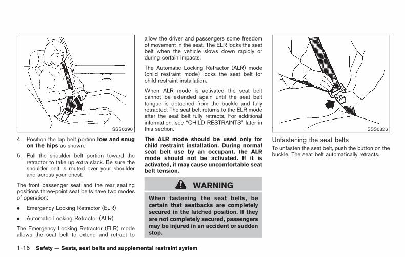
4. Position the lap belt portion low and snugon the hips as shown.
5. Pull the shoulder belt portion toward theretractor to take up extra slack. Be sure theshoulder belt is routed over your shoulderand across your chest.
The front passenger seat and the rear seatingpositions three-point seat belts have two modesof operation:
. Emergency Locking Retractor (ELR)
. Automatic Locking Retractor (ALR)
The Emergency Locking Retractor (ELR) modeallows the seat belt to extend and retract to
allow the driver and passengers some freedomof movement in the seat. The ELR locks the seatbelt when the vehicle slows down rapidly orduring certain impacts.
The Automatic Locking Retractor (ALR) mode(child restraint mode) locks the seat belt forchild restraint installation.
When ALR mode is activated the seat beltcannot be extended again until the seat belttongue is detached from the buckle and fullyretracted. The seat belt returns to the ELR modeafter the seat belt fully retracts. For additionalinformation, see “CHILD RESTRAINTS” later inthis section.
The ALR mode should be used only forchild restraint installation. During normalseat belt use by an occupant, the ALRmode should not be activated. If it isactivated, it may cause uncomfortable seatbelt tension.
WARNING
When fastening the seat belts, becertain that seatbacks are completelysecured in the latched position. If theyare not completely secured, passengersmay be injured in an accident or suddenstop.
SSS0326
Unfastening the seat beltsTo unfasten the seat belt, push the button on thebuckle. The seat belt automatically retracts.
1-16 Safety — Seats, seat belts and supplemental restraint system

Black plate (31,1)
Model "Z12-D" EDITED: 2010/ 9/ 27
SSS0987
Rear seat belt buckles (except for CargoVan models)The rear seat belt buckles can be stowed bypushing the buckles into the pockets of the seatcushion when the rear seatback is folded. Thebuckles should only be stowed when the seat-back is folded. At all other times the seat beltbuckles must be pulled out of the pockets in theunstowed position.
WARNING
Do not use the rear seat belts when thebuckles are stowed in the seat pockets.Failure to do so may reduce the effec-
tiveness of the entire restraint systemand increase the chance or severity ofinjury in an accident.
Checking seat belt operationSeat belt retractors are designed to lock seatbelt movement by two separate methods:
. When the belt is pulled quickly from theretractor.
. When the vehicle slows down rapidly.
To increase your confidence in the seat belts,check the operation as follows:
. Grasp the shoulder belt and pull forwardquickly. The retractor should lock andrestrict further belt movement.
If the retractor does not lock during this check orif you have any question about seat beltoperation, see a NISSAN dealer.
SSS0351A
Shoulder belt height adjustment (for frontseats)The shoulder belt anchor height should beadjusted to the position best for you. (See“PRECAUTIONS ON SEAT BELT USAGE”earlier in this section.)
To adjust, pull the adjustment button *1 , andthen move the shoulder belt anchor to thedesired position *2 , so that the belt passesover the center of the shoulder. The belt shouldbe away from your face and neck, but not fallingoff of your shoulder. Release the adjustmentbutton to lock the shoulder belt anchor intoposition.
Safety — Seats, seat belts and supplemental restraint system 1-17

Black plate (32,1)
Model "Z12-D" EDITED: 2010/ 9/ 27
WARNING
. After adjustment, release the ad-justment button and try to move theshoulder belt anchor up and downto make sure it is securely fixed inposition.
. The shoulder belt anchor heightshould be adjusted to the positionbest for you. Failure to do so mayreduce the effectiveness of theentire restraint system and increasethe chance or severity of injury in anaccident.
SSS0964
Seat belt hooks (except for Cargo Vanmodels)When the rear seat belts are not in use andwhen folding down the rear seats, hook the rearouter seat belts on the seat belt hooks.
The hook for the rear center seat belt is locatedon the left wall behind the rear seat. (See “Rearcenter seat belt (except for Cargo Van models)”later in this section for details.)
SSS0391
Rear center seat belt (except for CargoVan models)The rear center seat belt has a connector tongue*1 and a seat belt tongue *2 . Both theconnector tongue and the seat belt tongue mustbe securely latched for proper seat belt opera-tion.
1-18 Safety — Seats, seat belts and supplemental restraint system

Black plate (33,1)
Model "Z12-D" EDITED: 2010/ 9/ 27
SSS0241
WARNING
. Always fasten the connector tongueand the seat belt in the order shown.
. Always make sure both the connec-tor tongue and the seat belt tongueare secured when using the seatbelt or installing a child restraint. Donot use the seat belt or childrestraint with only the seat belttongue attached. This could resultin serious personal injury in case ofan accident or a sudden stop.
SSS0703
The center seat belt buckle and the tongue areidentified by the CENTER mark. The center seatbelt tongue can be fastened only into the centerseat belt buckle.
SSS0965
Safety — Seats, seat belts and supplemental restraint system 1-19

Black plate (34,1)
Model "Z12-D" EDITED: 2010/ 9/ 27
Stowing rear center seat belt:
When folding down the rear seat, the rear centerseat belt can be retracted into a stowed positionas follows:
1. Hold the connector tongue *1 so that theseat belt does not retract suddenly when thetongue is released from the connectorbuckle. Release the connector tongue *1by inserting a suitable tool such as key *2into the connector buckle.
2. Retract the seat belt and secure the seatbelt tongue and connector tongue on theseat belt hook *3 .
WARNING
. Do not unfasten the rear center seatbelt connector except when foldingdown the rear seat.
. When returning the seatback, besure to attach the rear center seatbelt connector.
SSS0966
Attaching rear center seat belt:
Always be sure the rear center seat beltconnector tongue and connector buckle areattached. Disconnect only when folding downthe rear seat.
To connect the buckle:
1. Remove the seat belt tongue and connectortongue from the seat belt hook *1 .
2. Pull the seat belt and secure the connectorbuckle until it clicks *2 .
The rear center seat belt connector tongue canbe attached only into the rear center seat beltconnector buckle.
To fasten the seat belt, see “Fastening the seatbelts” earlier in this section.
WARNING
. When attaching the rear center seatbelt connector, be certain that theseatbacks are completely secured inthe latched position and the rearcenter seat belt connector is com-pletely secured.
. If the rear center seat belt connectorand the seatbacks are not securedin the correct position, serious per-sonal injury may result in an acci-dent or sudden stop.
1-20 Safety — Seats, seat belts and supplemental restraint system

Black plate (35,1)
Model "Z12-D" EDITED: 2010/ 9/ 27
SEAT BELT EXTENDERS
If, because of body size or driving position, it isnot possible to properly fit the lap-shoulder beltand fasten it, an extender that is compatible withthe installed seat belts is available that can bepurchased. The extender adds approximately 8in (200 mm) of length and may be used for eitherthe driver or front passenger seating position.See a NISSAN dealer for assistance withpurchasing an extender if an extender isrequired.
WARNING
. Only NISSAN seat belt extenders,made by the same company whichmade the original equipment seatbelts, should be used with NISSANseat belts.
. Adults and children who can use thestandard seat belt should not use anextender. Such unnecessary usecould result in serious personalinjury in the event of an accident.
. Never use seat belt extenders toinstall child restraints. If the childrestraint is not secured properly, thechild could be seriously injured in acollision or a sudden stop.
SEAT BELT MAINTENANCE
. To clean the seat belt webbing, apply amild soap solution or any solution recom-mended for cleaning upholstery or carpets.Then wipe with a cloth and allow the seatbelts to dry in the shade. Do not allow theseat belts to retract until they are completelydry.
. If dirt builds up in the shoulder beltguide of the seat belt anchors, the seatbelts may retract slowly. Wipe the shoulderbelt guide with a clean, dry cloth.
. Periodically check to see that the seatbelt and the metal components, such asbuckles, tongues, retractors, flexible wiresand anchors, work properly. If loose parts,deterioration, cuts or other damage on thewebbing is found, the entire seat beltassembly should be replaced.
Children need adults to help protect them.
They need to be properly restrained.
In addition to the general information in thismanual, child safety information is available frommany other sources, including doctors, teachers,government traffic safety offices, and communityorganizations. Every child is different, so be sureto learn the best way to transport your child.
There are three basic types of child restraintsystems:
. Rear-facing child restraint
. Forward-facing child restraint
. Booster seat
The proper restraint depends on the child’s size.Generally, infants up to about 1 year and lessthan 20 lbs (9 kg) should be placed in rear-facing child restraints. Forward-facing childrestraints are available for children who outgrowrear-facing child restraints and are at least 1year old. Booster seats are used to help positiona vehicle lap/shoulder belt on a child who can nolonger use a forward-facing child restraint.
WARNING
Infants and children need special pro-tection. The vehicle’s seat belts may notfit them properly. The shoulder belt may
CHILD SAFETY
Safety — Seats, seat belts and supplemental restraint system 1-21

Black plate (36,1)
Model "Z12-D" EDITED: 2010/ 9/ 27
come too close to the face or neck. Thelap belt may not fit over their small hipbones. In an accident, an improperlyfitting seat belt could cause serious orfatal injury. Always use appropriatechild restraints.
All U.S. states and Canadian provinces orterritories require the use of approved childrestraints for infants and small children. See“CHILD RESTRAINTS” later in this section.
A child restraint may be secured in the vehicleby using either the LATCH (Lower Anchor andTethers for CHildren) system or with the vehicleseat belt. See “CHILD RESTRAINTS” later inthis section for more information.
NISSAN recommends that all pre-teensand children be restrained in the rear seat.Studies show that children are safer whenproperly restrained in the rear seat than inthe front seat.
This is especially important because yourvehicle has a supplemental restraint sys-tem (Air bag system) for the front passen-ger. See “SUPPLEMENTAL RESTRAINTSYSTEM” later in this section.
INFANTS
Infants up to at least 1 year old should be placedin a rear-facing child restraint. NISSAN recom-mends that infants be placed in child restraintsthat comply with Federal Motor Vehicle SafetyStandards or Canadian Motor Vehicle SafetyStandards. You should choose a child restraintthat fits your vehicle and always follow themanufacturer’s instructions for installation anduse.
SMALL CHILDREN
Children that are over one year old and weigh atleast 20 lbs (9 kg) can be placed in a forward-facing child restraint. Refer to the manufacturer’sinstructions for minimum and maximum weightand height recommendations. NISSAN recom-mends that small children be placed in childrestraints that comply with Federal MotorVehicle Safety Standards or Canadian MotorVehicle Safety Standards. You should choose achild restraint that fits your vehicle and alwaysfollow the manufacturer’s instructions for instal-lation and use.
LARGER CHILDREN
Children who are too large for child restraintsshould be seated and restrained by the seatbelts which are provided. The seat belt may notfit properly if the child is less than 4 ft 9 in (142.5cm) tall and weighs between 40 lbs (18 kg) and
80 lbs (36 kg). A booster seat should be used toobtain proper seat belt fit.
NISSAN recommends that a child be placed in acommercially available booster seat if theshoulder belt fits close to the face or neck or ifthe lap portion of the seat belt goes across theabdomen. The booster seat should raise thechild so that the shoulder belt is properlypositioned across the top, middle portion ofthe shoulder and the lap belt is low on the hips.A booster seat can only be used in seatingpositions that have a three-point type seat belt.The booster seat should fit the vehicle seat andhave a label certifying that it complies withFederal Motor Vehicle Safety Standards orCanadian Motor Vehicle Safety Standards.Once the child has grown so the shoulder beltis no longer on or near the face and neck, usethe shoulder belt without the booster seat.
WARNING
Never let a child stand or kneel on anyseat and do not allow a child in thecargo area. The child could be seriouslyinjured or killed in a sudden stop orcollision.
1-22 Safety — Seats, seat belts and supplemental restraint system

Black plate (37,1)
Model "Z12-D" EDITED: 2010/ 9/ 27
SSS0099
SSS0100
PRECAUTIONS ON CHILDRESTRAINTS
WARNING
. Failure to follow the warnings andinstructions for proper use and in-stallation of child restraints couldresult in serious injury or death of achild or other passengers in asudden stop or collision:
— The child restraint must be usedand installed properly. Alwaysfollow all of the child restraintmanufacturer’s instructions forinstallation and use.
— Infants and children shouldnever be held on anyone’s lap.Even the strongest adult cannotresist the forces of a collision.
— Do not put a seat belt aroundboth a child and another pas-senger.
— NISSAN recommends that allchild restraints be installed inthe rear seat. Studies show thatchildren are safer when properlyrestrained in the rear seat thanin the front seat. If you must
install a forward-facing childrestraint in the front seat, see“FORWARD-FACING CHILD RE-STRAINT INSTALLATION USINGTHE SEAT BELTS” later in thissection.
— Even with the NISSAN AdvancedAir Bag System, never install arear-facing child restraint in thefront seat. An inflating air bagcould seriously injure or kill achild. A rear-facing child re-straint must only be used in therear seat.
— Be sure to purchase a childrestraint that will fit the childand vehicle. Some child re-straints may not fit properly inyour vehicle.
— Child restraint anchor points aredesigned to withstand loadsfrom child restraints that areproperly fitted.
— Never use the anchor points foradult seat belts or harnesses.
— A child restraint with a top tetherstrap should not be used in thefront passenger seat.
— Keep seatbacks as upright as
CHILD RESTRAINTS
Safety — Seats, seat belts and supplemental restraint system 1-23

Black plate (38,1)
Model "Z12-D" EDITED: 2010/ 9/ 27
possible after fitting the childrestraint.
— Infants and children should al-ways be placed in an appropri-ate child restraint while in thevehicle.
. When the child restraint is not inuse, keep it secured with the LATCHsystem or a seat belt. In a suddenstop or collision, loose objects caninjure occupants or damage thevehicle.
CAUTION
A child restraint in a closed vehicle canbecome very hot. Check the seatingsurface and buckles before placing achild in the child restraint.
This vehicle is equipped with a universal childrestraint anchor system, referred to as theLATCH (Lower Anchors and Tethers for CHil-dren) system. Some child restraints include rigidor webbing-mounted attachments that can beconnected to these anchors. For details, see“Lower Anchors and Tethers for CHildrenSystem (LATCH) (except for Cargo Van mod-els)” later in this section.
If you do not have a LATCH compatible childrestraint, the vehicle seat belts can be used.
Several manufacturers offer child restraints forinfants and small children of various sizes. Whenselecting any child restraint, keep the followingpoints in mind:
. Choose only a restraint with a label certifyingthat it complies with Federal Motor VehicleSafety Standard 213 or Canadian MotorVehicle Safety Standard 213.
. Check the child restraint in your vehicle tobe sure it is compatible with the vehicle’sseat and seat belt system.
. If the child restraint is compatible with yourvehicle, place your child in the child restraintand check the various adjustments to besure the child restraint is compatible withyour child. Choose a child restraint that isdesigned for your child’s height and weight.Always follow all recommended procedures.
All U.S. states and Canadian provinces orterritories require that infants and smallchildren be restrained in an approved childrestraint at all times while the vehicle isbeing operated. Canadian law requires thetop tether strap on forward-facing childrestraints be secured to the designatedanchor point on the vehicle.
Lower Anchors and Tethers for CHildrenSystem (LATCH) (except for Cargo Vanmodels)
Your vehicle is equipped with special anchorpoints that are used with LATCH (LowerAnchors and Tethers for CHildren) systemcompatible child restraints. This system mayalso be referred to as the ISOFIX or ISOFIXcompatible system. With this system, you do nothave to use a vehicle seat belt to secure thechild restraint.
The LATCH anchor points are provided to installchild restraints in the rear outboard seatingpositions only. Do not attempt to install a childrestraint in the center position using the LATCHanchors.
1-24 Safety — Seats, seat belts and supplemental restraint system

Black plate (39,1)
Model "Z12-D" EDITED: 2010/ 9/ 27
SSS0801LATCH system anchor location
SSS0637LATCH system lower anchor
LATCH lower anchor
WARNING
Failure to follow the warnings andinstructions for proper use and installa-tion of child restraints could result inserious injury or death of a child orother passengers in a sudden stop orcollision:
— Attach LATCH system compatiblechild restraints only at the locationsshown in the illustration.
— Do not secure a child restraint in thecenter rear seating position usingthe LATCH lower anchors. The childrestraint will not be secured prop-erly.
— Inspect the lower anchors by insert-ing your fingers into the loweranchor area. Feel to make surethere are no obstructions over theanchors such as seat belt webbingor seat cushion material. The childrestraint will not be secured prop-erly if the lower anchors are ob-structed.
SSS0637LATCH lower anchor location
LATCH lower anchor locationThe LATCH anchors are located at the rear ofthe seat cushion near the seatback. A label isattached to the seatback to help you locate theLATCH anchors.
Safety — Seats, seat belts and supplemental restraint system 1-25

Black plate (40,1)
Model "Z12-D" EDITED: 2010/ 9/ 27
SSS0643LATCH webbing-mounted attachment
Installing child restraint LATCH loweranchor attachmentsLATCH compatible child restraints include tworigid or webbing-mounted attachments that canbe connected to two anchors located at certainseating positions in your vehicle. With thissystem, you do not have to use a vehicle seatbelt to secure the child restraint. Check yourchild restraint for a label stating that it iscompatible with LATCH system. This informationmay also be in the instructions provided by thechild restraint manufacturer.
SSS0644LATCH rigid-mounted attachment
The child restraint top tether strap must be usedwhen installing the child restraint with theLATCH lower anchor attachments or seat belts.See “Top tether anchor” later in this section forinstallation instructions.
When installing a child restraint, carefully readand follow the instructions in this manual andthose supplied with the child restraint.
Top tether anchor
WARNING
. If the cargo cover (if so equipped)contacts the top tether strap when itis attached to the top tether anchor,
remove the cargo cover from thevehicle or secure it on the cargofloor below its attachment location.If the cargo cover is not removed, itmay damage the top tether strapduring a collision. Your child couldbe seriously injured or killed in acollision if the child restraint toptether strap is damaged.
. Do not allow cargo to contact thetop tether strap when it is attachedto the top tether anchor. Properlysecure the cargo so it does notcontact the top tether strap. Cargothat is not properly secured or cargothat contacts the top tether strapmay damage the top tether strapduring a collision. Your child couldbe seriously injured or killed in acollision if the child restraint toptether strap is damaged.
Top tether anchor point locations:
Anchor points are located on the back side ofthe seatbacks.
Top tether anchor point locationsAnchor points are located in the followinglocations.
1-26 Safety — Seats, seat belts and supplemental restraint system

Black plate (41,1)
Model "Z12-D" EDITED: 2010/ 9/ 27
. On the seat cushion behind the outboardand center seating positions (except forCargo Van models)
. On the floor behind the front passenger seat(Cargo Van models)
SSS0986
WARNING
Do not attach upper tether anchors tothe luggage hooks. The child restraintwill not be properly installed. Your childcould be injured or killed in a suddenstop or collision.
Installing top tether strapFirst secure the child restraint with the LATCHsystem (except for Cargo Van models: rearoutboard seating positions only) or the seat beltas applicable.
SSS0967
Rear seats (except for Cargo Van models):
1. Position the top tether strap over the top ofthe seatback and under the headrest.
2. Secure the tether strap to the tether anchoron the seat directly behind the childrestraint.
3. Tighten the tether strap according to themanufacturer’s instructions to remove anyslack.
For the best child restraint fit, see the childrestraint installation instructions in this sectionand the child restraint manufacturer’s instruc-tions.
Safety — Seats, seat belts and supplemental restraint system 1-27

Black plate (42,1)
Model "Z12-D" EDITED: 2010/ 9/ 27
If you have any questions when installing atop tether strap child restraint on the rearseat, consult your NISSAN dealer for de-tails.
SSS1039
Front passenger seat (Cargo Van models):
For the front passenger seat in Cargo Vanmodels, install the top tether strap according tothe following procedure.
1. Adjust the head restraint to its highestposition.
2. Route the top tether strap between the headrestraint and the top of the seatback.
3. Secure the tether strap to the tether anchorpoint on the floor behind the seat.
4. Tighten the tether strap according to themanufacturer’s instructions to remove anyslack.
For the best child restraint fit, see the childrestraint installation instructions in this sectionand the child restraint manufacturer’s instruc-tions.
If you have any questions when installing atop tether strap child restraint on the frontpassenger’s seat, consult your NISSANdealer for details.
REAR-FACING CHILD RESTRAINT IN-STALLATION USING LATCH
Refer to all Warnings and Cautions in the “Childsafety” and “Child restraints” sections beforeinstalling a child restraint.
Follow these steps to install a rear-facing childrestraint using the LATCH system:
1. Position the child restraint on the seat.Always follow the child restraint manufac-turer’s instructions.
1-28 Safety — Seats, seat belts and supplemental restraint system

Black plate (43,1)
Model "Z12-D" EDITED: 2010/ 9/ 27
SSS0648Rear-facing web-mounted — step 2
2. Secure the child restraint anchor attach-ments to the LATCH lower anchors. Checkto make sure the LATCH attachment isproperly attached to the lower anchors.
SSS0649Rear-facing rigid-mounted — step 2
SSS0639Rear-facing — step 3
3. For child restraints that are equipped withwebbing-mounted attachments, remove anyadditional slack from the anchor attach-ments. Press downward and rearward firmlyin the center of the child restraint with yourhand to compress the vehicle seat cushionand seatback while tightening the webbingof the anchor attachments.
Safety — Seats, seat belts and supplemental restraint system 1-29

Black plate (44,1)
Model "Z12-D" EDITED: 2010/ 9/ 27
SSS0650Rear-facing — step 4
4. After attaching the child restraint, test itbefore you place the child in it. Push it fromside to side while holding the child restraintnear the LATCH attachment path. The childrestraint should not move more than 1 inch(25 mm), from side to side. Try to tug itforward and check to see if the LATCHattachment holds the restraint in place. If therestraint is not secure, tighten the LATCHattachment as necessary, or put the restraintin another seat and test it again. You mayneed to try a different child restraint or tryinstalling by using the vehicle seat belt (ifapplicable). Not all child restraints fit in alltypes of vehicles.
5. Check to make sure the child restraint is
properly secured prior to each use. If thechild restraint is loose, repeat steps 1through 4.
SSS0100
REAR-FACING CHILD RESTRAINT IN-STALLATION USING THE SEAT BELTS
WARNING
. The three-point seat belt with Auto-matic Locking Retractor (ALR) mustbe used when installing a childrestraint. Failure to use the ALRmode will result in the child re-straint not being properly secured.The restraint could tip over or beloose and cause injury to a child in asudden stop or collision. Also, it canchange the operation of the front
1-30 Safety — Seats, seat belts and supplemental restraint system

Black plate (45,1)
Model "Z12-D" EDITED: 2010/ 9/ 27
passenger air bag. See “Front pas-senger air bag and status light”later in this section.
. When installing a child restraintsystem in the rear center position,both the center seat belt connectortongue and buckle tongue must besecured. See “Rear center seat belt(except for Cargo Van models)” ear-lier in this section.
SSS0100Rear-facing — step 1
Refer to all Warnings and Cautions in the“CHILD SAFETY” earlier in this section and“CHILD RESTRAINTS” earlier in this sectionbefore installing a child restraint.
Follow these steps to install a rear-facing childrestraint using the vehicle seat belts in the rearseats:
1. Child restraints for infants must beused in the rear-facing direction andtherefore must not be used in the frontseat. Position the child restraint on the seat.Always follow the restraint manufacturer’sinstructions.
SSS0654Rear-facing — step 2
2. Route the seat belt tongue through the childrestraint and insert it into the buckle until youhear and feel the latch engage. Be sure tofollow the child restraint manufacturer’sinstructions for belt routing.
Safety — Seats, seat belts and supplemental restraint system 1-31

Black plate (46,1)
Model "Z12-D" EDITED: 2010/ 9/ 27
SSS0655Rear-facing — step 3
3. Pull the shoulder belt until the belt is fullyextended. At this time, the seat belt retractoris in the Automatic Locking Retractor (ALR)mode (child restraint mode). It reverts to theEmergency Locking Retractor (ELR) modewhen the seat belt is fully retracted.
SSS0656Rear-facing — step 4
4. Allow the seat belt to retract. Pull up on theshoulder belt to remove any slack in the belt.
SSS0657Rear-facing — step 5
5. Remove any additional slack from the seatbelt; press downward and rearward firmly inthe center of the child restraint to compressthe vehicle seat cushion and seatback whilepulling up on the seat belt.
1-32 Safety — Seats, seat belts and supplemental restraint system

Black plate (47,1)
Model "Z12-D" EDITED: 2010/ 9/ 27
SSS0658Rear-facing — step 6
6. After attaching the child restraint, test itbefore you place the child in it. Push it fromside to side while holding the child restraintnear the seat belt path. The child restraintshould not move more than 1 inch (25 mm),from side to side. Try to tug it forward andcheck to see if the belt holds the restraint inplace. If the restraint is not secure, tightenthe seat belt as necessary, or put therestraint in another seat and test it again.You may need to try a different childrestraint. Not all child restraints fit in alltypes of vehicles.
7. Check to make sure that the child restraint isproperly secured prior to each use. If theseat belt is not locked, repeat steps 1
through 6.
After the child restraint is removed and the seatbelt fully retracted, the ALR mode (child restraintmode) is canceled.
FORWARD-FACING CHILD RE-STRAINT INSTALLATION USINGLATCH
Refer to all Warnings and Cautions in the “Childsafety” and “Child restraints” sections beforeinstalling a child restraint.
Follow these steps to install a forward-facingchild restraint using the LATCH system:
1. Position the child restraint on the seat.Always follow the child restraint manufac-turer’s instructions.
SSS0645Forward-facing web-mounted — step 2
2. Secure the child restraint anchor attach-ments to the LATCH lower anchors. Checkto make sure the LATCH attachment isproperly attached to the lower anchors.
If the child restraint is equipped with a toptether strap, route the top tether strap andsecure the tether strap to the tether anchorpoint. See “Installing top tether strap” in thissection. Do not install child restraints thatrequire the use of a top tether strap inseating positions that do not have a toptether anchor.
Safety — Seats, seat belts and supplemental restraint system 1-33

Black plate (48,1)
Model "Z12-D" EDITED: 2010/ 9/ 27
SSS0646Forward-facing rigid-mounted — step 3
3. The back of the child restraint should besecured against the vehicle seatback.
If necessary, adjust or remove the headrestto obtain the correct child restraint fit. If theheadrest is removed, store it in a secureplace. Be sure to reinstall the headrestwhen the child restraint is removed.See “Adjustable headrest” in this section forheadrest adjustment information.
If the seating position does not have anadjustable headrest and it is interfering withthe proper child restraint fit, try anotherseating position or a different child restraint.
SSS0647Forward-facing — step 4
4. For child restraints that are equipped withwebbing-mounted attachments, remove anyadditional slack from the anchor attach-ments. Press downward and rearward firmlyin the center of the child restraint with yourknee to compress the vehicle seat cushionand seatback while tightening the webbingof the anchor attachments.
5. Tighten the tether strap according to themanufacturer’s instructions to remove anyslack.
SSS0638Forward-facing — step 6
6. After attaching the child restraint, test itbefore you place the child in it. Push it fromside to side while holding the child restraintnear the LATCH attachment path. The childrestraint should not move more than 1 inch(25 mm), from side to side. Try to tug itforward and check to see if the LATCHattachment holds the restraint in place. If therestraint is not secure, tighten the LATCHattachment as necessary, or put the restraintin another seat and test it again. You mayneed to try a different child restraint. Not allchild restraints fit in all types of vehicles.
7. Check to make sure the child restraint isproperly secured prior to each use. If thechild restraint is loose, repeat steps 1
1-34 Safety — Seats, seat belts and supplemental restraint system

Black plate (49,1)
Model "Z12-D" EDITED: 2010/ 9/ 27
through 6.
FORWARD-FACING CHILD RE-STRAINT INSTALLATION USING THESEAT BELTS
WARNING
. The three-point seat belt with Auto-matic Locking Retractor (ALR) mustbe used when installing a childrestraint. Failure to use the ALRmode will result in the child re-straint not being properly secured.The restraint could tip over or beloose and cause injury to a child in asudden stop or collision. Also, it canchange the operation of the frontpassenger air bag. See “Front pas-senger air bag and status light”later in this section.
. When installing a child restraintsystem in the rear center position,both the center seat belt connectortongue and buckle tongue must besecured. See “Rear center seat belt(except for Cargo Van models)” ear-lier in this section.
SSS0640Forward-facing (front passenger seat) — step 1
Refer to all Warnings and Cautions in the “Childsafety” and “Child restraints” sections beforeinstalling a child restraint.
Follow these steps to install a forward-facingchild restraint using the vehicle seat belt in therear seats or in the front passenger seat:
1. If you must install a child restraint inthe front seat, it should be placed in aforward-facing direction only. Move theseat to the rearmost position. Childrestraints for infants must be used inthe rear-facing direction and, therefore,must not be used in the front seat.
2. Position the child restraint on the seat.Always follow the child restraint manufac-
turer’s instructions.
The back of the child restraint should besecured against the vehicle seatback.
If necessary, adjust or remove the headrestraint or headrest to obtain the correctchild restraint fit. If the head restraint orheadrest is removed, store it in a secureplace. Be sure to reinstall the headrestraint or headrest when the childrestraint is removed. See “HEAD RE-STRAINTS” earlier in this section or “AD-JUSTABLE HEADRESTS” earlier in thissection for head restraint or headrestadjustment, removal and installation informa-tion.
If the seating position does not have anadjustable head restraint or headrest and itis interfering with the proper child restraintfit, try another seating position or a differentchild restraint.
Safety — Seats, seat belts and supplemental restraint system 1-35

Black plate (50,1)
Model "Z12-D" EDITED: 2010/ 9/ 27
SSS0360BForward-facing — step 3
3. Route the seat belt tongue through the childrestraint and insert it into the buckle until youhear and feel the latch engage. Be sure tofollow the child restraint manufacturer’sinstructions for belt routing.
If the child restraint is equipped with a toptether strap, route the top tether strap andsecure the tether strap to the tether anchorpoint (rear seat installation only). See “IN-STALLING TOP TETHER STRAP” later inthis section. Do not install child restraintsthat require the use of a top tether strap inseating positions that do not have a toptether anchor.
SSS0651Forward-facing — step 4
4. Pull the shoulder belt until the belt is fullyextended. At this time, the seat belt retractoris in the Automatic Locking Retractor (ALR)mode (child restraint mode). It reverts toEmergency Locking Retractor (ELR) modewhen the seat belt is fully retracted.
SSS0652Forward-facing — step 5
5. Allow the seat belt to retract. Pull up on theshoulder belt to remove any slack in the belt.
1-36 Safety — Seats, seat belts and supplemental restraint system

Black plate (51,1)
Model "Z12-D" EDITED: 2010/ 9/ 27
SSS0653Forward-facing — step 6
6. Remove any additional slack from the seatbelt; press downward and rearward firmly inthe center of the child restraint with yourknee to compress the vehicle seat cushionand seatback while pulling up on the seatbelt.
7. Tighten the tether strap according to themanufacturer’s instructions to remove anyslack.
SSS0641Forward-facing — step 8
8. After attaching the child restraint, test itbefore you place the child in it. Push it fromside to side while holding the child restraintnear the seat belt path. The child restraintshould not move more than 1 inch (25 mm),from side to side. Try to tug it forward andcheck to see if the belt holds the restraint inplace. If the restraint is not secure, tightenthe seat belt as necessary, or put therestraint in another seat and test it again.You may need to try a different childrestraint. Not all child restraints fit in alltypes of vehicles.
9. Check to make sure the child restraint isproperly secured prior to each use. If theseat belt is not locked, repeat steps 2
through 8.
Safety — Seats, seat belts and supplemental restraint system 1-37

Black plate (52,1)
Model "Z12-D" EDITED: 2010/ 9/ 27
SSS0481Forward-facing — step 10
10. If the child restraint is installed in the frontpassenger seat, place the ignition switch inthe ON position. The front passenger air bagstatus light should illuminate. If thislight is not illuminated, see “Front passengerair bag and status light” in this section.Move the child restraint to anotherseating position. Have the systemchecked by a NISSAN dealer.
After the child restraint is removed and the seatbelt is fully retracted, the ALR mode (childrestraint mode) is canceled.
SSS0967
INSTALLING TOP TETHER STRAP
First secure the child restraint with the LATCHsystem (rear outboard seating positions only) orthe seat belt as applicable.
1. Remove the anchor cover from the anchorpoint which is located directly behind thechild seat.
2. Position the top tether strap over the top ofthe seatback.
3. Secure the tether strap to the tether anchorbracket that provides the straightest instal-lation.
4. Tighten the tether strap according to the
manufacturer’s instructions to remove anyslack.
If you have any questions when installing atop tether strap, consult your NISSANdealer for details.
BOOSTER SEATS
Precautions on booster seats
WARNING
If a booster seat and seat belt are notused properly, the risk of a child beinginjured in a sudden stop or collisiongreatly increases:
— Make sure the shoulder portion ofthe belt is away from the child’s faceand neck and the lap portion of thebelt does not cross the stomach.
— Make sure the shoulder belt is notbehind the child or under the child’sarm.
— A booster seat must only be in-stalled in a seating position that hasa lap/shoulder belt.
1-38 Safety — Seats, seat belts and supplemental restraint system

Black plate (53,1)
Model "Z12-D" EDITED: 2010/ 9/ 27
LRS0455
Booster seats of various sizes are offered byseveral manufacturers. When selecting anybooster seat, keep the following points in mind:
. Choose only a booster seat with a labelcertifying that it complies with Federal MotorVehicle Safety Standard 213 or CanadianMotor Vehicle Safety Standard 213.
. Check the booster seat in your vehicle to besure it is compatible with the vehicle’s seatand seat belt system.
LRS0453
. Make sure the child’s head will be properlysupported by the booster seat or vehicleseat. The seatback must be at or above thecenter of the child’s ears. For example, if alow back booster seat *1 is chosen, thevehicle seatback must be at or above thecenter of the child’s ears. If the seatback islower than the center of the child’s ears, ahigh back booster seat*2 should be used.
. If the booster seat is compatible with yourvehicle, place your child in the booster seatand check the various adjustments to besure the booster seat is compatible withyour child. Always follow all recommendedprocedures.
LRS0464
All U.S. states and Canadian provinces orterritories require that infants and smallchildren be restrained in an approved childrestraint at all times while the vehicle isbeing operated.
The instructions in this section apply to boosterseat installation in the rear seats or the frontpassenger seat.
Safety — Seats, seat belts and supplemental restraint system 1-39

Black plate (54,1)
Model "Z12-D" EDITED: 2010/ 9/ 27
Booster seat installation
CAUTION
Do not use the lap/shoulder belt Auto-matic Locking Retractor (ALR) modewhen using a booster seat with theseat belts.
Refer to all Warnings and Cautions in the “Childsafety”, “Child restraints” and “Booster seats”sections earlier in this section before installing achild restraint.
Follow these steps to install a booster seat in therear seat or in the front passenger seat:
SSS0640
1. If you must install a booster seat in thefront seat, move the seat to the rear-most position.
2. Position the booster seat on the seat. Onlyplace it in a forward-facing direction. Alwaysfollow the booster seat manufacturer’sinstructions.
LRS0454Front passenger position
3. The booster seat should be positioned onthe vehicle seat so that it is stable.
If necessary, adjust or remove the headrestraint or headrest to obtain the correctbooster seat fit. If the head restraint orheadrest is removed, store it in a secureplace. Be sure to reinstall the headrestraint or headrest when the boosterseat is removed. See “HEAD RE-STRAINTS” earlier in this section or “AD-JUSTABLE HEADRESTS” earlier in thissection for head restraint or headrestadjustment, removal and installation informa-tion.
If the seating position does not have an
1-40 Safety — Seats, seat belts and supplemental restraint system

Black plate (55,1)
Model "Z12-D" EDITED: 2010/ 9/ 27
adjustable head restraint or headrest and itis interfering with the proper booster seat fit,try another seating position or a differentbooster seat.
4. Position the lap portion of the seat belt lowand snug on the child’s hips. Be sure tofollow the booster seat manufacturer’sinstructions for adjusting the seat beltrouting.
5. Pull the shoulder belt portion of the seat belttoward the retractor to take up extra slack.Be sure the shoulder belt is positionedacross the top, middle portion of the child’sshoulder. Be sure to follow the booster seatmanufacturer’s instructions for adjusting theseat belt routing.
6. Follow the warnings, cautions and instruc-tions for properly fastening a seat beltshown in “SEAT BELTS” earlier in thissection.
SSS0481
7. If the booster seat is installed in the frontpassenger seat, place the ignition switch inthe ON position. The front passenger air bagstatus light may or may not beilluminated depending on the size of thechild and the type of booster seat used.(See “Front passenger air bag and statuslight” later in this section.)
PRECAUTIONS ON SUPPLEMENTALRESTRAINT SYSTEM
This Supplemental Restraint System (SRS)section contains important information concern-ing the following systems:
. Driver and passenger supplemental front-impact air bag (NISSAN Advanced Air BagSystem)
. Front seat-mounted side-impact supple-mental air bag
. Roof-mounted curtain side-impact supple-mental air bag
. Seat belt with pretensioner
Supplemental front-impact air bag system:The NISSAN Advanced Air Bag System canhelp cushion the impact force to the head andchest of the driver and front passenger in certainfrontal collisions.
Front seat-mounted side-impact supple-mental air bag system: This system can helpcushion the impact force to the chest and pelvicarea of the driver and front passenger in certainside impact collisions. The side air bag isdesigned to inflate on the side where the vehicleis impacted.
Roof-mounted curtain side-impact supple-mental air bag system: This system can help
SUPPLEMENTAL RESTRAINTSYSTEM
Safety — Seats, seat belts and supplemental restraint system 1-41

Black plate (56,1)
Model "Z12-D" EDITED: 2010/ 9/ 27
cushion the impact force to the head ofoccupants in front and rear outboard seatingpositions in certain side impact collisions. Thecurtain air bags are designed to inflate on theside where the vehicle is impacted.
These supplemental restraint systems are de-signed to supplement the crash protectionprovided by the driver and passenger seat beltsand are not a substitute for them. Seat beltsshould always be correctly worn and theoccupant seated a suitable distance away fromthe steering wheel, instrument panel and doorfinishers. (See “SEAT BELTS” earlier in thissection for instructions and precautions on seatbelt usage.)
The supplemental air bags operate onlywhen the ignition switch is in the ONposition.
After the ignition is placed in the ONposition, the supplemental air bag warninglight illuminates. The supplemental air bagwarning light will turn off after about 7seconds if the systems are operational.
SSS0131
SSS0132
1-42 Safety — Seats, seat belts and supplemental restraint system

Black plate (57,1)
Model "Z12-D" EDITED: 2010/ 9/ 27
WARNING
. The front air bags ordinarily will notinflate in the event of a side impact,rear impact, rollover, or lower se-verity frontal collision. Always wearyour seat belts to help reduce therisk or severity of injury in variouskinds of accidents.
. The front passenger air bag will notinflate if the passenger air bagstatus light is lit or if the frontpassenger seat is unoccupied. See“Front passenger air bag and statuslight” later in this section.
. The seat belts and the front air bagsare most effective when you aresitting well back and upright in theseat with both feet on the floor. Thefront air bags inflate with greatforce. Even with the NISSAN Ad-vanced Air Bag System, if you areunrestrained, leaning forward, sit-ting sideways or out of position inany way, you are at greater risk ofinjury or death in a crash. You mayalso receive serious or fatal injuriesfrom the front air bag if you are upagainst it when it inflates. Always sit
back against the seatback and asfar-away as practical from the steer-ing wheel or instrument panel. Al-ways use the seat belts.
. The driver and front passenger seatbelt buckles are equipped withsensors that detect if the seat beltsare fastened. The Advanced Air BagSystem monitors the severity of acollision and seat belt usage theninflates the air bags as needed.Failure to properly wear seat beltscan increase the risk or severity ofinjury in an accident.
. The front passenger seat isequipped with occupant classifica-tion sensors (weight sensors) thatturn the front passenger air bagOFF under some conditions. Thissensor is only used in this seat.Failure to be properly seated andwearing the seat belt can increasethe risk or severity of injury in anaccident. See “Front passenger airbag and status light” later in thissection.
. Keep hands on the outside of thesteering wheel. Placing them insidethe steering wheel rim could in-
crease the risk that they are injuredif the front air bag inflates.
Safety — Seats, seat belts and supplemental restraint system 1-43

Black plate (58,1)
Model "Z12-D" EDITED: 2010/ 9/ 27
SSS0007
SSS0006
SSS0008
SSS0009
SSS0099
SSS0100
1-44 Safety — Seats, seat belts and supplemental restraint system

Black plate (59,1)
Model "Z12-D" EDITED: 2010/ 9/ 27
WARNING
. Never let children ride unrestrainedor extend their hands or face out ofthe window. Do not attempt to holdthem in your lap or arms. Someexamples of dangerous riding posi-tions are shown in the illustrations.
. Children may be severely injured orkilled when the front air bags, sideair bags or curtain air bags inflate ifthey are not properly restrained.Pre-teens and children should beproperly restrained in the rear seat,if possible.
. Even with the NISSAN Advanced AirBag System, never install a rear-facing child restraint in the frontseat. An inflating front air bag couldseriously injure or kill your child.See “CHILD RESTRAINTS” earlier inthis section for details.
SSS0059ADo not lean against doors or windows.
SSS0188A
SSS0140
SSS0162
Safety — Seats, seat belts and supplemental restraint system 1-45

Black plate (60,1)
Model "Z12-D" EDITED: 2010/ 9/ 27
SSS0159
WARNING
Front seat-mounted side-impact sup-plemental air bags and roof-mountedcurtain side-impact supplemental airbags:
. The side air bags and curtain airbags ordinarily will not inflate in theevent of a frontal impact, rear im-pact, rollover or lower severity sidecollision. Always wear your seatbelts to help reduce the risk orseverity of injury in various kindsof accidents.
. The seat belts, the side air bags andcurtain air bags are most effectivewhen you are sitting well back andupright in the seat. The side air bagand curtain air bag inflate with greatforce. Do not allow anyone to placetheir hand, leg or face near the sideair bag on the side of the seatbackof the front seat or near the sideroof rails. Do not allow anyonesitting in the front seats or rearoutboard seats to extend their handout of the window or lean againstthe door. Some examples of dan-gerous riding positions are shownin the previous illustrations.
. When sitting in the rear seat, do nothold onto the seatback of the frontseat. If the side air bag inflates, youmay be seriously injured. Be espe-cially careful with children, whoshould always be properly re-strained. Some examples of danger-ous riding positions are shown inthe illustrations.
. Do not use seat covers on the frontseatbacks. They may interfere withside air bag inflation.
1-46 Safety — Seats, seat belts and supplemental restraint system

Black plate (61,1)
Model "Z12-D" EDITED: 2010/ 9/ 27
SSS1049
1. Crash zone sensor
2. Supplemental front-impact air bag modules
3. Front seat-mounted side-impact supplemental airbag modules
4. Occupant classification sensors (weight sensors)
5. Occupant classification system control unit
6. Roof-mounted curtain side-impact supplementalair bag modules
7. Roof-mounted curtain side-impact supplementalair bag inflators
8. Seat belt with pretensioners
9. Satellite sensors
10. Air bag Control Unit (ACU)
NISSAN ADVANCED AIR BAG SYS-TEM (front seats)
WARNING
To ensure proper operation of thepassenger’s advanced air bag system,please observe the following items.
. Do not allow a passenger in the rearseat to push or pull on the seatbackpocket.
. Do not place heavy loads heavierthan 2.2 lb (4 kg) on the seatback,head restraint or in the seatbackpocket.
. Do not store luggage behind theseat that can press into the seat-back.
. Confirm the operating conditionwith the front passenger air bagstatus light.
. If you notice that the front passen-ger air bag status light is notoperating as described later in thissection, please take your vehicle toyour NISSAN dealer to check theoccupant classification system.
. Until you have confirmed with your
Safety — Seats, seat belts and supplemental restraint system 1-47

Black plate (62,1)
Model "Z12-D" EDITED: 2010/ 9/ 27
dealer that your passenger seatoccupant classification system isworking properly, position the occu-pants in the rear seating positions.
This vehicle is equipped with the NISSANAdvanced Air Bag System for the driver andfront passenger seats. This system is designedto meet certification requirements under U.S.regulations. It is also permitted in Canada.However, all of the information, cautionsand warnings in this manual still apply andmust be followed.
The driver supplemental front-impact air bag islocated in the center of the steering wheel. Thepassenger supplemental front-impact air bag ismounted in the instrument panel above the glovebox. The front air bags are designed to inflate inhigher severity frontal collisions, although theymay inflate if the forces in another type ofcollision are similar to those of a higher severityfrontal impact. They may not inflate in certainfrontal collisions. Vehicle damage (or lack of it) isnot always an indication of proper front air bagoperation.
The NISSAN Advanced Air Bag System hasdual stage air bag inflators. The system monitorsinformation from the Air bag Control Unit (ACU),seat belt buckle sensors and the occupantclassification sensors (weight sensors). Inflatoroperation is based on the severity of a collision
and seat belt usage for the driver. For the frontpassenger, the occupant classification sensorsare also monitored. Based on information fromthe sensors, only one front air bag may inflate ina crash, depending on the crash severity andwhether the front occupants are belted orunbelted. Additionally, the front passenger airbag may be automatically turned OFF undersome conditions, depending on the informationprovided by the occupant classification sensors.If the front passenger air bag is OFF, thepassenger air bag status light will be illuminated(if the seat is unoccupied, the light will not beilluminated, but the air bag will be off). (See“Front passenger air bag and status light” laterin this section for further details.) One front airbag inflating does not indicate improper perfor-mance of the system.
If you have any questions about your air bagsystem, contact NISSAN or a NISSAN dealer. Ifyou are considering modification of your vehicledue to a disability, you may also contactNISSAN. Contact information is contained inthe front of this Owner’s Manual.
When a front air bag inflates, a fairly loud noisemay be heard, followed by release of smoke.This smoke is not harmful and does not indicatea fire. Care should be taken not to inhale it, as itmay cause irritation and choking. Those with ahistory of a breathing condition should get freshair promptly.
Front air bags, along with the use of seat belts,help to cushion the impact force on the headand chest of the front occupants. They can helpsave lives and reduce serious injuries. However,an inflating front air bag may cause facialabrasions or other injuries. Front air bags donot provide restraint to the lower body.
Even with NISSAN Advanced Air Bags, seatbelts should be correctly worn and the driverand passenger seated upright as far as practicalaway from the steering wheel or instrumentpanel. The front air bags inflate quickly in orderto help protect the front occupants. Because ofthis, the force of the front air bag inflating canincrease the risk of injury if the occupant is tooclose to, or is against, the air bag module duringinflation.
The front air bags deflate quickly after a collision.
The front air bags operate only when theignition switch is in the ON position.
After the ignition is placed in the ONposition, the supplemental air bag warninglight illuminates. The supplemental air bagwarning light will turn off after about 7seconds if the system is operational.
1-48 Safety — Seats, seat belts and supplemental restraint system

Black plate (63,1)
Model "Z12-D" EDITED: 2010/ 9/ 27
SSS0481Front passenger air bag status light
Front passenger air bag and status light
WARNING
The front passenger air bag is designedto automatically turn OFF under someconditions. Read this section carefullyto learn how it operates. Proper use ofthe seat, seat belt and child restraints isnecessary for most effective protection.Failure to follow all instructions in thismanual concerning the use of seats,seat belts and child restraints canincrease the risk or severity of injury inan accident.
Status light:
The front passenger air bag status light islocated on the instrument panel. The lightoperates as follows:
. Unoccupied passenger seat: The lightis OFF and the front passenger air bag isOFF and will not inflate in a crash.
. Passenger’s seat occupied by a small adult,child or child restraint as outlined in thissection: The light illuminates to indi-cate that the front passenger air bag is OFFand will not inflate in a crash.
. Occupied passenger seat and the passen-ger meets the conditions outlined in thissection: The light is OFF to indicatethat the front passenger air bag is opera-tional.
Front passenger air bag:
The front passenger air bag is designed toautomatically turn OFF when the vehicle isoperated under some conditions as describedbelow as permitted by U.S. regulations. If thefront passenger air bag is OFF, it will not inflatein a crash. The driver air bag and other air bagsin your vehicle are not part of this system.
The purpose of the regulation is to help reducethe risk of injury or death from an inflating air bagto certain front passenger seat occupants, such
as children, by requiring the air bag to beautomatically turned OFF.
The occupant classification sensors (weightsensors) are on the seat cushion frame underthe front passenger seat and are designed todetect an occupant and objects on the seat. Forexample, if a child is in the front passenger seat,the Advanced Air Bag System is designed toturn the passenger air bag OFF in accordancewith the regulations. Also, if a child restraint ofthe type specified in the regulations is on theseat, the occupant classification sensors candetect it and cause the air bag to turn OFF.
Front passenger seat adult occupants who areproperly seated and using the seat belt asoutlined in this manual should not cause thepassenger air bag to be automatically turnedOFF. For small adults it may be turned OFF,however, if the occupant does not sit in the seatproperly (for example, by not sitting upright, bysitting on an edge of the seat, or by otherwisebeing out of position), this could cause thesensors to turn the air bag OFF. Always be sureto be seated and wearing the seat belt properlyfor the most effective protection by the seat beltand supplemental air bag.
NISSAN recommends that pre-teens and chil-dren be properly restrained in a rear seat.NISSAN also recommends that appropriatechild restraints and booster seats be properlyinstalled in a rear seat. If this is not possible, the
Safety — Seats, seat belts and supplemental restraint system 1-49

Black plate (64,1)
Model "Z12-D" EDITED: 2010/ 9/ 27
occupant classification sensors are designed tooperate as described above to turn the frontpassenger air bag OFF for specified childrestraints. Failing to properly secure childrestrains and to use the Automatic LockingRetractor (ALR) mode (child restraint mode)may allow the restraint to tip or move in anaccident or sudden stop. This can also result inthe passenger air bag inflating in a crash insteadof being OFF. (See “CHILD RESTRAINTS”earlier in this section for proper use andinstallation.)
If the front passenger seat is not occupied, thepassenger air bag is designed not to inflate in acrash. However, heavy objects placed on theseat could result in air bag inflation, because ofthe object being detected by the occupantclassification sensors. Other conditions couldalso result in air bag inflation, such as if a child isstanding on the seat, or if two children are on theseat, contrary to the instructions in this manual.Always be sure that you and all vehicleoccupants are seated and restrained properly.
Using the passenger air bag status light, you canmonitor when the front passenger air bag isautomatically turned OFF with the seat occu-pied. The light will not illuminate when the frontpassenger seat is unoccupied.
If an adult occupant is in the seat but thepassenger air bag status light is illuminated(indicating that the air bag is OFF), it could be
that the person is a small adult, or is not sittingon the seat properly.
If a child restraint must be used in the front seat,the passenger air bag status light may or maynot be illuminated, depending on the size of thechild and the type of child restraint being used. Ifthe air bag status light is not illuminated(indicating that the air bag might inflate in acrash), it could be that the child restraint or seatbelt is not being used properly. Make sure thatthe child restraint is installed properly, the seatbelt is used properly and the occupant ispositioned properly. If the air bag status light isnot illuminated, reposition the occupant or childrestraint in a rear seat.
If the passenger air bag status light will notilluminate even though you believe that the childrestraint, the seat belts and the occupant areproperly positioned, the system may be sensingan unoccupied seat (in which case the air bag isOFF). Your NISSAN dealer can check that thesystem is OFF by using a special tool. However,until you have confirmed with your dealer thatyour air bag is working properly, reposition theoccupant or child restraint in a rear seat.
The air bag system and passenger air bag statuslight will take a few seconds to register a changein the passenger seat status. However, if theseat becomes unoccupied, the air bag statuslight will remain off.
If a malfunction occurs in the front passenger airbag system, the supplemental air bag warninglight , located in the meter and gauges area,will blink. Have the system checked by aNISSAN dealer.
Other supplemental front-impact air bagprecautions
WARNING
. Do not place any objects on thesteering wheel pad or on the instru-ment panel. Also, do not place anyobjects between any occupant andthe steering wheel or instrumentpanel. Such objects may becomedangerous projectiles and causeinjury if the front air bags inflate.
. Do not place objects with sharpedges on the seat. Also, do notplace heavy objects on the seat thatwill leave permanent impressions inthe seat. Such objects can damagethe seat or occupant classificationsensors (weight sensors). This canaffect the operation of the air bagsystem and result in serious perso-nal injury.
. Do not use water or acidic cleaners
1-50 Safety — Seats, seat belts and supplemental restraint system

Black plate (65,1)
Model "Z12-D" EDITED: 2010/ 9/ 27
(hot steam cleaners) on the seat.This can damage the seat or occu-pant classification sensors. This canalso affect the operation of the airbag system and result in seriouspersonal injury.
. Immediately after inflation, severalfront air bag system componentswill be hot. Do not touch them; youmay severely burn yourself.
. No unauthorized changes should bemade to any components or wiringof the supplemental air bag system.This is to prevent accidental infla-tion of the supplemental air bag ordamage to the supplemental air bagsystem.
. Do not make unauthorized changesto your vehicle’s electrical system,suspension system or front endstructure. This could affect properoperation of the front air bag sys-tem.
. Tampering with the front air bagsystem may result in serious perso-nal injury. Tampering includeschanges to the steering wheel andthe instrument panel assembly by
placing material over the steeringwheel pad and above the instrumentpanel or by installing additional trimmaterial around the air bag system.
. Modifying or tampering with thefront passenger seat may result inserious personal injury. For exam-ple, do not change the front seats byplacing material on the seat cushionor by installing additional trim ma-terial, such as seat covers, on theseat that is not specifically designedto assure proper air bag operation.Additionally, do not stow any ob-jects under the front passenger seator the seat cushion and seatback.Such objects may interfere with theproper operation of the occupantclassification sensors.
. No unauthorized changes should bemade to any components or wiringof the seat belt system. This mayaffect the front air bag system.Tampering with the seat belt systemmay result in serious personal in-jury.
. Work on and around the front airbag system should be done by aNISSAN dealer. Installation of elec-
trical equipment should also bedone by a NISSAN dealer. TheSupplemental Restraint System(SRS) wiring harnesses* should notbe modified or disconnected. Un-authorized electrical test equipmentand probing devices should not beused on the air bag system.
. A cracked windshield should bereplaced immediately by a qualifiedrepair facility. A cracked windshieldcould affect the function of thesupplemental air bag system.
*The SRS wiring harness connectors areyellow and orange for easy identification.
When selling your vehicle, we request that youinform the buyer about the front air bag systemand guide the buyer to the appropriate sectionsin this Owner’s Manual.
Safety — Seats, seat belts and supplemental restraint system 1-51

Black plate (66,1)
Model "Z12-D" EDITED: 2010/ 9/ 27
SSS0978
FRONT SEAT-MOUNTED SIDE-IM-PACT SUPPLEMENTAL AIR BAG ANDROOF-MOUNTED CURTAIN SIDE-IM-PACT SUPPLEMENTAL AIR BAG SYS-TEMS
The side air bags are located in the outside ofthe seatback of the front seats. The curtain airbags are located in the side roof rails. Thesesystems are designed to meet voluntary guide-lines to help reduce the risk of injury to out-of-position occupants. However, all of theinformation, cautions and warnings in thismanual still apply and must be followed.The side air bags and curtain air bags aredesigned to inflate in higher severity side
collisions, although they may inflate if the forcesin another type of collision are similar to those ofa higher severity side impact. They are designedto inflate on the side where the vehicle isimpacted. They may not inflate in certain sidecollisions on the side where the vehicle isimpacted.
Vehicle damage (or lack of it) is not always anindication of proper side air bag and curtain airbag operation.
When the side air bags and curtain air bagsinflate, a fairly loud noise may be heard, followedby release of smoke. This smoke is not harmfuland does not indicate a fire. Care should betaken not to inhale it, as it may cause irritationand choking. Those with a history of a breathingcondition should get fresh air promptly.
Side air bags, along with the use of seat belts,help to cushion the impact force on the chestand pelvic area of the front occupants. Curtainair bags help to cushion the impact force to thehead of occupants in the front and rear outboardseating positions. They can help save lives andreduce serious injuries. However, side air bagsand curtain air bags may cause abrasions orother injuries. Side air bags and curtain air bagsdo not provide restraint to the lower body.
The seat belts should be correctly worn and thedriver and passenger seated upright as far aspractical away from the side air bags. Rear seat
passengers should be seated as far away aspractical from the door finishers and side roofrails. The side air bags and curtain air bagsinflate quickly in order to help protect theoccupants in the outboard seating positions.Because of this, the force of the side air bagsand curtain air bags inflating can increase therisk of injury if the occupant is too close to, or isagainst, these air bag modules during inflation.The side air bags and curtain air bags will deflatequickly after the collision is over.
The side air bags and curtain air bagsoperate only when the ignition switch is inthe ON position.
After turning the ignition switch to the ONposition, the supplemental air bag warninglight illuminates. The supplemental air bagwarning light will turn off after about 7seconds if the systems are operational.
WARNING
. Do not place any objects near theseatback of the front seats. Also, donot place any objects (an umbrella,bag, etc.) between the front doorfinisher and the front seat. Suchobjects may become dangerousprojectiles and cause injury if a sideair bag inflates.
1-52 Safety — Seats, seat belts and supplemental restraint system

Black plate (67,1)
Model "Z12-D" EDITED: 2010/ 9/ 27
. Right after inflation, several side airbag and curtain air bag systemcomponents will be hot. Do nottouch them; you may severely burnyourself.
. No unauthorized changes should bemade to any components or wiringof the side air bag and curtain airbag systems. This is to preventdamage to or accidental inflationof the side air bag and curtain airbag systems.
. Do not make unauthorized changesto your vehicle’s electrical system,suspension system or side panel.This could affect proper operationof the side air bag and curtain airbag systems.
. Tampering with the side air bagsystem may result in serious perso-nal injury. For example, do notchange the front seats by placingmaterial near the seatbacks or byinstalling additional trim material,such as seat covers, around the sideair bag.
. Work around and on the side air bagand curtain air bag systems should
be done by a NISSAN dealer. In-stallation of electrical equipmentshould also be done by a NISSANdealer. The Supplemental RestraintSystem (SRS) wiring harnesses*should not be modified or discon-nected. Unauthorized electrical testequipment and probing devicesshould not be used on the side airbag and curtain supplemental airbag systems.
*The SRS wiring harness connectors areyellow and orange for easy identification.
When selling your vehicle, we request that youinform the buyer about the side air bag andcurtain air bag systems and guide the buyer tothe appropriate sections in this Owner’s Manual.
SEAT BELTS WITH PRETENSIONERS(front seats)
WARNING
. The pretensioners cannot be reusedafter activation. They must be re-placed together with the retractorand buckle as a unit.
. If the vehicle becomes involved in acollision but a pretensioner is notactivated, be sure to have the pre-tensioner system checked and, ifnecessary, replaced by a NISSANdealer.
. No unauthorized changes should bemade to any components or wiringof the pretensioner system. This isto prevent damage to or accidentalactivation of the pretensioners.Tampering with the pretensionersystem may result in serious perso-nal injury.
. Work around and on the preten-sioner system should be done by aNISSAN dealer. Installation of elec-trical equipment should also bedone by a NISSAN dealer. Un-authorized electrical test equipment
Safety — Seats, seat belts and supplemental restraint system 1-53

Black plate (68,1)
Model "Z12-D" EDITED: 2010/ 9/ 27
and probing devices should not beused on the pretensioner system.
. If you need to dispose of a preten-sioner or scrap the vehicle, contact aNISSAN dealer. Correct preten-sioner disposal procedures are setforth in the appropriate NISSANService Manual. Incorrect disposalprocedures could cause personalinjury.
The pretensioner system may activate with thesupplemental air bag system in certain types ofcollisions. Working with the seat belt retractor, ithelps tighten the seat belt when the vehiclebecomes involved in certain types of collisions,helping to restrain front seat occupants.
The pretensioner is encased with the seat beltretractor. These seat belts are used the sameway as conventional seat belts.
When a pretensioner activates, smoke is re-leased and a loud noise may be heard. Thesmoke is not harmful and does not indicate afire. Care should be taken not to inhale it, as itmay cause irritation and choking. Those with ahistory of a breathing condition should get freshair promptly.
After pretensioner activation, load limiters allowthe seat belt to release webbing (if necessary) to
reduce forces against the chest.
The supplemental air bag warning light isused to indicate malfunctions in the pretensionersystem. (See “SUPPLEMENTAL AIR BAGWARNING LIGHT” later in this section for moredetails.) If the operation of the supplemental airbag warning light indicates there is a malfunc-tion, have the system checked by a NISSANdealer.
When selling your vehicle, we request that youinform the buyer about the pretensioner systemand guide the buyer to the appropriate sectionsin this Owner’s Manual.
SSS1020
SUPPLEMENTAL AIR BAG WARNINGLABELS
Warning labels about the supplemental front-impact air bag system are placed in the vehicleas shown in the illustration.
*1 SRS air bagThe warning labels are located on the surface ofthe sun visors.
1-54 Safety — Seats, seat belts and supplemental restraint system

Black plate (69,1)
Model "Z12-D" EDITED: 2010/ 9/ 27
SPA1097
SUPPLEMENTAL AIR BAG WARNINGLIGHT
The supplemental air bag warning light, display-ing in the instrument panel, monitors thecircuits of the supplemental front-impact air bag,front seat-mounted side-impact supplementalair bag, roof-mounted curtain side-impact sup-plemental air bag and seat belt pretensionersystems. The monitored circuits include Air bagControl Unit (ACU), crash zone sensor, satellitesensors, occupant classification system, front airbag modules, side air bag modules, curtain airbag modules, pretensioners and all relatedwiring.
When the ignition switch is in the ON position,
the supplemental air bag warning light illumi-nates for about 7 seconds and then turns off.This means the system is operational.
If any of the following conditions occur, the frontair bag, side air bag, curtain air bag andpretensioner systems need servicing:
. The supplemental air bag warning lightremains on after approximately 7 seconds.
. The supplemental air bag warning lightflashes intermittently.
. The supplemental air bag warning light doesnot come on at all.
Under these conditions, the front air bag, side airbag, curtain air bag and pretensioner systemsmay not operate properly. They must be checkedand repaired. Take your vehicle to the nearestNISSAN dealer.
WARNING
If the supplemental air bag warninglight is on, it could mean that the frontair bag, side air bag, curtain air bagand/or pretensioner systems will notoperate in an accident. To help avoidinjury to yourself or others, have yourvehicle checked by a NISSAN dealer assoon as possible.
REPAIR AND REPLACEMENT PRO-CEDURE
The front air bags, side air bags, curtain air bagsand pretensioners are designed to activate on aone-time-only basis. As a reminder, unless it isdamaged, the supplemental air bag warning lightwill remain illuminated after inflation has oc-curred. Repair and replacement of these sys-tems should be done only by a NISSAN dealer.
When maintenance work is required on thevehicle, the front air bags, side air bags, curtainair bags and pretensioners and related partsshould be pointed out to the person performingthe maintenance. The ignition switch shouldalways be in the LOCK position when workingunder the hood or inside the vehicle.
Safety — Seats, seat belts and supplemental restraint system 1-55

Black plate (70,1)
Model "Z12-D" EDITED: 2010/ 9/ 27
WARNING
. Once a front air bag, side air bag orcurtain air bag has inflated, the airbag module will not function againand must be replaced. Additionally,the activated pretensioners mustalso be replaced. The air bag mod-ule and pretensioner should bereplaced by a NISSAN dealer. Theair bag modules and pretensionersystem cannot be repaired.
. The front air bag, side air bag andcurtain air bag systems, and preten-sioner system should be inspectedby a NISSAN dealer if there is anydamage to the front end or sideportion of the vehicle.
. If you need to dispose of a supple-mental air bag or pretensioner orscrap the vehicle, contact a NISSANdealer. Correct supplemental airbag and pretensioner system dis-posal procedures are set forth in theappropriate NISSAN Service Man-ual. Incorrect disposal procedurescould cause personal injury.
1-56 Safety — Seats, seat belts and supplemental restraint system

Black plate (7,1)
2 Instruments and controls
Model "Z12-D" EDITED: 2010/ 9/ 27
Cockpit. . . . . . . . . . . . . . . . . . . . . . . . . . . . . . . . . . . . . . . . . . . . . . . . . . . . . . . . . . . . 2-2Instrument panel . . . . . . . . . . . . . . . . . . . . . . . . . . . . . . . . . . . . . . . . . . . . . . . . 2-3Meters and gauges. . . . . . . . . . . . . . . . . . . . . . . . . . . . . . . . . . . . . . . . . . . . . 2-4
Speedometer and odometer . . . . . . . . . . . . . . . . . . . . . . . . . . . . . 2-5Tachometer. . . . . . . . . . . . . . . . . . . . . . . . . . . . . . . . . . . . . . . . . . . . . . . . . . . 2-6Engine coolant temperature gauge . . . . . . . . . . . . . . . . . . . . . 2-6Fuel gauge . . . . . . . . . . . . . . . . . . . . . . . . . . . . . . . . . . . . . . . . . . . . . . . . . . . 2-7Vehicle information display. . . . . . . . . . . . . . . . . . . . . . . . . . . . . . . . 2-8Outside air temperature (if so equipped). . . . . . . . . . . . . . 2-8Continuously Variable Transmission (CVT)position indicator (if so equipped) . . . . . . . . . . . . . . . . . . . . . . 2-8Trip computer . . . . . . . . . . . . . . . . . . . . . . . . . . . . . . . . . . . . . . . . . . . . . . . . 2-8
Warning/indicator lights and audible reminders . . . . . . . 2-11Checking bulbs . . . . . . . . . . . . . . . . . . . . . . . . . . . . . . . . . . . . . . . . . . . 2-11Warning lights . . . . . . . . . . . . . . . . . . . . . . . . . . . . . . . . . . . . . . . . . . . . . 2-11Indicator lights. . . . . . . . . . . . . . . . . . . . . . . . . . . . . . . . . . . . . . . . . . . . . 2-16Audible reminders . . . . . . . . . . . . . . . . . . . . . . . . . . . . . . . . . . . . . . . . 2-18
Security systems. . . . . . . . . . . . . . . . . . . . . . . . . . . . . . . . . . . . . . . . . . . . . . 2-18Vehicle Security System. . . . . . . . . . . . . . . . . . . . . . . . . . . . . . . . . 2-18NISSAN Vehicle Immobilizer System . . . . . . . . . . . . . . . . . 2-20
Windshield wiper and washer switch . . . . . . . . . . . . . . . . . . . . 2-21Rear window wiper and washer switch. . . . . . . . . . . . . . . . . . 2-23Rear window and outside mirror defroster switch. . . . . 2-24Headlight and turn signal switch . . . . . . . . . . . . . . . . . . . . . . . . . . 2-24
Headlight switch . . . . . . . . . . . . . . . . . . . . . . . . . . . . . . . . . . . . . . . . . . 2-24
Turn signal switch . . . . . . . . . . . . . . . . . . . . . . . . . . . . . . . . . . . . . . . . 2-27Fog light switch (if so equipped). . . . . . . . . . . . . . . . . . . . . . 2-28
Hazard warning flasher switch . . . . . . . . . . . . . . . . . . . . . . . . . . . . . 2-28Horn . . . . . . . . . . . . . . . . . . . . . . . . . . . . . . . . . . . . . . . . . . . . . . . . . . . . . . . . . . . . . 2-29Vehicle Dynamic Control (VDC) OFF switch . . . . . . . . . . . 2-29Heated seats (if so equipped) . . . . . . . . . . . . . . . . . . . . . . . . . . . . . 2-29Clock (if so equipped). . . . . . . . . . . . . . . . . . . . . . . . . . . . . . . . . . . . . . . 2-31
Adjusting the time . . . . . . . . . . . . . . . . . . . . . . . . . . . . . . . . . . . . . . . . 2-31Resetting the time (Type B) . . . . . . . . . . . . . . . . . . . . . . . . . . . . 2-33
Power outlet . . . . . . . . . . . . . . . . . . . . . . . . . . . . . . . . . . . . . . . . . . . . . . . . . . . 2-33Storage . . . . . . . . . . . . . . . . . . . . . . . . . . . . . . . . . . . . . . . . . . . . . . . . . . . . . . . . . 2-34
Cup holders. . . . . . . . . . . . . . . . . . . . . . . . . . . . . . . . . . . . . . . . . . . . . . . . 2-34Glove box . . . . . . . . . . . . . . . . . . . . . . . . . . . . . . . . . . . . . . . . . . . . . . . . . . 2-36Rear pillar pocket . . . . . . . . . . . . . . . . . . . . . . . . . . . . . . . . . . . . . . . . . 2-36Luggage hooks. . . . . . . . . . . . . . . . . . . . . . . . . . . . . . . . . . . . . . . . . . . . 2-37Utility hooks (if so equipped). . . . . . . . . . . . . . . . . . . . . . . . . . . 2-37
Windows . . . . . . . . . . . . . . . . . . . . . . . . . . . . . . . . . . . . . . . . . . . . . . . . . . . . . . . 2-38Power windows . . . . . . . . . . . . . . . . . . . . . . . . . . . . . . . . . . . . . . . . . . . 2-38
Interior lights . . . . . . . . . . . . . . . . . . . . . . . . . . . . . . . . . . . . . . . . . . . . . . . . . . . 2-40Map lights (if so equipped). . . . . . . . . . . . . . . . . . . . . . . . . . . . . 2-41Map light control switch (if so equipped) . . . . . . . . . . . 2-41Ceiling light . . . . . . . . . . . . . . . . . . . . . . . . . . . . . . . . . . . . . . . . . . . . . . . . 2-42
Cargo light (if so equipped) . . . . . . . . . . . . . . . . . . . . . . . . . . . . . . . . 2-42

Black plate (74,1)
Model "Z12-D" EDITED: 2010/ 9/ 27
SSI0563
1. Front cup holders
2. Headlight, fog light and turn signal switch
3. Steering wheel— Horn— Driver’s supplemental air bag
4. Wiper and washer switch
5. Fuse box cover
6. Outside mirror remote control switch
7. Vehicle Dynamic Control (VDC) OFF switch
8. Tilting steering wheel lever
9. Steering-wheel-mounted controls (left side)*— Audio control*— Bluetooth® Hands-Free Phone System control*
10. Steering-wheel-mounted controls (right side)*— Cruise control switches*
11. Selector lever or Shift lever— Continuously Variable Transmission (CVT)— Manual Transmission (MT)
12. Parking brake
*: if so equipped
COCKPIT
2-2 Instruments and controls

Black plate (75,1)
Model "Z12-D" EDITED: 2010/ 9/ 27
SSI0840
1. Side ventilator
2. Meters and gauges
3. Center ventilator
4. Hazard warning flasher switch
5. Audio system*— Clock*
6. Front passenger air bag status light
7. Front passenger supplemental air bag
8. Fuel-filler door release handle
9. Hood release handle
10. Ignition switch (models without Intelligent Keysystem)
11. Push-button ignition switch (models with Intelli-gent Key system)
12. Heater and air conditioner* control— Rear window and outside mirror* defrosterswitch
13. Utility hooks*
14. Heated seat switch*
15. iPod® connector*/USB connector*
16. Power outlet
17. Glove box
*: if so equipped
INSTRUMENT PANEL
Instruments and controls 2-3

Black plate (76,1)
Model "Z12-D" EDITED: 2010/ 9/ 27
SIC4119
1. Tachometer
2. Engine coolant temperature gauge
3. Vehicle information display— Odometer/twin trip odometer— Trip computer— Outside air temperature*
4. Fuel gauge
5. Speedometer
6. Warning/indicator lights
7. Instrument brightness control knob
8. Continuously Variable Transmission (CVT) posi-tion indicator*
9. RESET switch for trip odometer/Trip computermode switch
*: if so equipped
The needle indicators may move slightlyafter the ignition switch is placed in theOFF or LOCK position. This is not amalfunction.
METERS AND GAUGES
2-4 Instruments and controls

Black plate (77,1)
Model "Z12-D" EDITED: 2010/ 9/ 27
SIC4120Speedometer
SPEEDOMETER AND ODOMETER
SpeedometerThe speedometer indicates vehicle speed inmiles per hour (MPH) and kilometers per hour(km/h).
SIC4121Odometer/twin trip odometer
Odometer/twin trip odometerThe odometer *1 /twin trip odometer *2 aredisplayed when the ignition switch is in the ONposition.
The odometer records the total distance thevehicle has been driven.
The twin trip odometer records the distance ofindividual trips.
Changing the display:
Pushing the reset switch *3 located on themeter panel changes the display as follows:
TRIP A ? TRIP B ? Trip computer mode ?TRIP A
For trip computer information, see “TRIP COM-PUTER” later in this section.
Resetting the trip odometer:
Pushing the reset switch*3 for approximately 1second resets the trip odometer to zero.
Instruments and controls 2-5

Black plate (78,1)
Model "Z12-D" EDITED: 2010/ 9/ 27
SIC4712
Loose fuel cap warning messagePush the trip computer mode switch *A formore than 1 second to reset the LOOSE FUELCAP warning message after the fuel cap hasbeen tightened. For additional information see“FUEL-FILLER CAP” in the “3. Pre-drivingchecks and adjustments” section of this manual.
SIC4122
TACHOMETER
The tachometer indicates engine speed inrevolutions per minute (RPM). Do not rev theengine into the red zone *1 .
CAUTION
When engine speed approaches the redzone, shift to a higher gear or reduceengine speed. Operating the engine inthe red zone may cause serious enginedamage.
SIC4123
ENGINE COOLANT TEMPERATUREGAUGE
The gauge *1 indicates the engine coolanttemperature.
The engine coolant temperature is within thenormal range when the gauge is within the zone*2 shown in the illustration.
The engine coolant temperature varies with theoutside air temperature and driving conditions.
2-6 Instruments and controls

Black plate (79,1)
Model "Z12-D" EDITED: 2010/ 9/ 27
CAUTION
If the gauge indicates engine coolanttemperature near the hot (H) end of thenormal range, reduce vehicle speed todecrease temperature. If gauge is overthe normal range, stop the vehicle assoon as safely possible. If the engine isoverheated, continued operation of thevehicle may seriously damage the en-gine. See “IF YOUR VEHICLE OVER-HEATS” in the “6. In case of emergency”section for immediate action required.
SIC4124
FUEL GAUGE
The gauge *1 indicates the approximate fuellevel in the tank.
The gauge may move slightly during braking,turning, acceleration, or going up or down hills.
Refill the fuel tank before the gaugeregisters 0 (empty).
The low fuel warning light illuminates whenthe amount of fuel in the tank is getting low.Refuel as soon as it is convenient, preferablybefore the gauge reaches 0. There will be asmall reserve of fuel in the tank when the fuelgauge reaches 0.
The indicates that the fuel-filler door islocated on the front passenger’s side of thevehicle.
CAUTION
. If the vehicle runs out of fuel, themalfunction indicator light
(MIL) may come on. Refuel as soonas possible. After a few driving trips,the light should turn off. If thelight remains on after a few drivingtrips, have the vehicle inspected bya NISSAN dealer.
. For additional information, see“Malfunction Indicator Light (MIL)”later in this section.
Instruments and controls 2-7

Black plate (80,1)
Model "Z12-D" EDITED: 2010/ 9/ 27
SIC4125
VEHICLE INFORMATION DISPLAY
When the ignition switch is placed in the ONposition, the vehicle information display showsthe following information:
1. Outside air temperature (if so equipped)
2. Continuously Variable Transmission (CVT) posi-tion indicator (if so equipped)
3. Odometer/Instrument brightness control display
4. Twin trip odometer/Trip computer
OUTSIDE AIR TEMPERATURE (if soequipped)
The outside air temperature is displayed in 8F or8C.
When the outside air temperature becomes378F (38C) or lower, the outside air temperaturedisplay blinks to give a warning. The display willstop blinking after 1 minute or when the outsideair temperature becomes 398F (48C) or above.
The display may differ from the actual outsidetemperature displayed on various signs or bill-boards.
CONTINUOUSLY VARIABLE TRANS-MISSION (CVT) POSITION INDICATOR(if so equipped)
The Continuously Variable Transmission (CVT)position indicator indicates the selector leverposition when the ignition switch is in the ONposition.
SIC4126
TRIP COMPUTER
The switch for the trip computer is located onthe meter panel.
When the ignition switch is placed in the ONposition, modes of the trip computer can beselected by pushing the trip computer modeswitch *A .
Each time the trip computer mode switch*A ispushed, the display will change as follows:
(TRIP A ? TRIP B) ? Current fuel consumption? Distance to empty (dte) ? Average fuelconsumption ? Average speed ? Elapsed time(Canada only) ? Maintenance information(Canada only) (? TRIP A)
2-8 Instruments and controls

Black plate (81,1)
Model "Z12-D" EDITED: 2010/ 9/ 27
Current fuel consumptionThe current fuel consumption mode shows thecurrent fuel consumption.
Distance to empty (dte — mls or km)The distance to empty (dte) mode provides youwith an estimation of the distance that can bedriven before refueling. The dte is constantlybeing calculated, based on the amount of fuel inthe fuel tank and the actual fuel consumption.
The display is updated every 30 seconds.
The dte mode includes a low range warningfeature. When the fuel level is low, the dte modeis automatically selected and the dte display willblink. Push the trip computer mode switch *Ato return to the mode that was selected beforethe warning occurred.
When the fuel level drops even lower, the dtedisplay will change to “----”.
. If the amount of fuel added is small, thedisplay just before the ignition switch isturned off may continue to be displayed.
. When driving uphill or rounding curves, thefuel in the tank shifts, which may momenta-rily change the display.
Average fuel consumption (mpg or l(liter)/100 km)The average fuel consumption mode shows theaverage fuel consumption since the last reset.Resetting is done by pushing the trip computermode switch *A for approximately 1 second.
The display is updated every 30 seconds. Atabout the first 1/3 mile (500 m) after a reset, thedisplay shows “---”.
Average speed (mph or km/h)The average speed mode shows the averagevehicle speed since the last reset. Resetting isdone by pushing the trip computer mode switch*A for approximately 1 second.
The display is updated every 30 seconds. Thefirst 30 seconds after a reset, the display shows“---”.
Elapsed time (Canada only)The elapsed time mode shows the time sincethe last reset. The displayed time can be resetby pushing the trip computer mode switch *Afor approximately 1 second.
Resetting displaysWhen the average fuel consumption, averagespeed, elapsed time or TRIP B is displayed,push the trip computer mode switch *A forlonger than 3 seconds. The average fuel
consumption, average speed, elapsed time andtrip odometer (TRIP B only) displays will be resetat the same time.
Maintenance information (Canada only)When the ignition switch is placed in the ONposition, maintenance information (the wrenchsymbol and distance to change a main-tenance item) comes on for about 5 secondsand then turns off.
The wrench symbol appears when the setdistance comes for changing an item, such asengine oil.
To set the distance to change an item:
1. Place the ignition switch in the ON position.
Push the trip computer mode switch*A for3 seconds while the wrench symboland maintenance information are displayed.The symbol and distance display will startflashing and the display shows the currentinterval.
2. Push the switch *A to increase the intervaldistance.
Each step increases the interval distance by500 miles (1,000 km). The interval distancecan be set up to 18,000 miles (30,000 km)after the display returns to 0 (zero).
3. If no further action is made, the display
Instruments and controls 2-9

Black plate (82,1)
Model "Z12-D" EDITED: 2010/ 9/ 27
returns to the previous mode and the newinterval is set.
If the interval distance is set to 0, the display willskip the maintenance information when theignition switch is placed in the ON position.
2-10 Instruments and controls

Black plate (83,1)
Model "Z12-D" EDITED: 2010/ 9/ 27
Anti-lock Braking System (ABS) warninglight
Low fuel warning light High beam indicator light
Low tire pressure warning light Malfunction Indicator Light (MIL)
Brake warning light
Low washer fluid warning light* Overdrive off indicator light*
P position selecting warning light* Security indicator light
Charge warning light Seat belt warning lightVehicle Dynamic Control (VDC) warninglight
Door open warning light Supplemental air bag warning light Low beam indicator light
Electric power steering warning light Front passenger air bag status light Turn signal/hazard indicator lights
Engine oil pressure warning light Cruise indicator light*Vehicle Dynamic Control (VDC) off indicatorlight
Intelligent Key system warning light* Engine start operation indicator light* *: if so equipped
CHECKING BULBS
With all doors closed, apply the parking brakeand place the ignition switch in the ON positionwithout starting the engine. The following lightswill come on:
, or , , , ,
The following lights come on briefly and then go
off (if so equipped):
, or , , , , ,, ,
If any light does not come on, it may indicate aburned-out bulb or an open circuit in theelectrical system. Have the system checked bya NISSAN dealer.
WARNING LIGHTS
or Anti-lock Braking System(ABS) warning light
When the ignition switch is in the ON position,the Anti-lock Braking System (ABS) warninglight illuminates and then turns off. This indicates
WARNING/INDICATOR LIGHTS ANDAUDIBLE REMINDERS
Instruments and controls 2-11

Black plate (84,1)
Model "Z12-D" EDITED: 2010/ 9/ 27
the ABS is operational.
If the ABS warning light illuminates while theengine is running, or while driving, it mayindicate the ABS is not functioning properly.Have the system checked by a NISSAN dealer.
If an ABS malfunction occurs, the anti-lockfunction is turned off. The brake system thenoperates normally, but without anti-lock assis-tance. (See “BRAKE SYSTEM” in the “5.Starting and driving” section.)
or Brake warning light
This light functions for both the parking brakeand the foot brake systems.
Parking brake indicator:
When the ignition switch is in the ON position,the light illuminates when the parking brake isapplied.
Low brake fluid warning light:
When the ignition switch is in the ON position,the light warns of a low brake fluid level. If thelight illuminates while the engine is running withthe parking brake not applied, stop the vehicleand perform the following:
1. Check the brake fluid level. If brake fluid isnecessary, add fluid and have the systemchecked by a NISSAN dealer. (See “BRAKE
AND CLUTCH FLUID” in the “8. Mainte-nance and do-it-yourself” section.)
2. If the brake fluid level is correct, have thewarning system checked by a NISSANdealer.
Anti-lock Braking System (ABS) warningindicator:
When the parking brake is released and thebrake fluid level is sufficient, if both the brakewarning light and the Anti-lock Braking System(ABS) warning light illuminate, it may indicatethe ABS is not functioning properly. Have thebrake system checked, and if necessary re-paired, by a NISSAN dealer promptly. (See“Anti-lock Braking System (ABS) warning light”earlier in this section.)
WARNING
. Your brake system may not beworking properly if the warning lightis on. Driving could be dangerous. Ifyou judge it to be safe, drive care-fully to the nearest service stationfor repairs. Otherwise, have yourvehicle towed because driving itcould be dangerous.
. Pressing the brake pedal with theengine stopped and/or low brake
fluid level may increase your stop-ping distance and braking will re-quire greater pedal effort as well aspedal travel.
. If the brake fluid level is below theminimum or MIN mark on the brakefluid reservoir, do not drive until thebrake system has been checked at aNISSAN dealer.
Charge warning lightIf the light illuminates while the engine is running,it may indicate the charging system is notfunctioning properly. Turn the engine off andcheck the alternator belt. If the belt is loose,broken, missing or if the light remains on, see aNISSAN dealer immediately.
CAUTION
Do not continue driving if the alternatorbelt is loose, broken or missing.
Door open warning lightThis light illuminates when any of the doors and/or back door are not closed securely while theignition switch is in the ON position.
2-12 Instruments and controls

Black plate (85,1)
Model "Z12-D" EDITED: 2010/ 9/ 27
Electric power steering warninglight
When the ignition switch is in the ON position,the electric power steering warning light illumi-nates. After starting the engine, the electricpower steering warning light turns off. Thisindicates the electric power steering system isoperational.
If the electric power steering warning lightilluminates while the engine is running, it mayindicate the electric power steering system isnot functioning properly and may need servicing.Have the electric power steering systemchecked by a NISSAN dealer.
When the electric power steering warning lightilluminates with the engine running, the powerassist to the steering will cease operation butyou will still have control of the vehicle. At thistime, greater steering efforts are required tooperate the steering wheel, especially in sharpturns and at low speeds.
See “ELECTRIC POWER STEERING SYS-TEM” in the “5. Starting and driving” section.
Engine oil pressure warning light
This light warns of low engine oil pressure. If thelight flickers or illuminates during normal driving,
pull off the road in a safe area, stop the engineimmediately and call a NISSAN dealer or otherauthorized repair shop.
The engine oil pressure warning light isnot designed to indicate a low oil level.Use the dipstick to check the oil level. (See“ENGINE OIL” in the “8. Maintenance and do-it-yourself” section.)
CAUTION
Running the engine with the engine oilpressure warning light on could causeserious damage to the engine almostimmediately. Such damage is not cov-ered by warranty. Turn off the engine assoon as it is safe to do so.
Intelligent Key system warning light(if so equipped)
After the ignition switch is placed in the ONposition, this light comes on for about 2 secondsand then turns off.
This light illuminates or blinks as follows:
. The light blinks in yellow when the door isclosed with the Intelligent Key left outsidethe vehicle and the ignition switch in theACC or ON position. Make sure that the
Intelligent Key is inside the vehicle.
. The light blinks in green when the IntelligentKey battery is running out of power. Replacethe battery with a new one. (See “KEYBATTERY REPLACEMENT” in the “8. Main-tenance and do-it-yourself” section.)
. The light illuminates in yellow when it warnsof a malfunction with the electrical steeringlock system (if so equipped) or the Intelli-gent Key system.
If the warning light illuminates in yellow while theengine is stopped, it may be impossible to freethe steering lock (if so equipped) or to start theengine. If the light comes on while the engine isrunning, you can drive the vehicle. However inthese cases, contact a NISSAN dealer for repairas soon as possible.
Low fuel warning lightThis light illuminates when the fuel in the tank isgetting low. Refuel as soon as it is convenient,preferably before the fuel gauge reaches the 0(empty) position.
There will be a small reserve of fuelremaining in the tank when the fuel gaugereaches the 0 position.
Instruments and controls 2-13

Black plate (86,1)
Model "Z12-D" EDITED: 2010/ 9/ 27
Low tire pressure warning light
Your vehicle is equipped with a Tire PressureMonitoring System (TPMS) that monitors the tirepressure of all tires except the spare.
The low tire pressure warning light warns of lowtire pressure or indicates that the TPMS is notfunctioning properly.
After the ignition switch is placed in the ONposition, this light illuminates for about 1 secondand turns off.
Low tire pressure warning:
If the vehicle is being driven with low tirepressure, the warning light will illuminate.
When the low tire pressure warning lightilluminates, you should stop and adjust the tirepressure to the recommended COLD tirepressure shown on the Tire and LoadingInformation label. The low tire pressure warninglight does not automatically turn off when the tirepressure is adjusted. After the tire is inflated tothe recommended pressure, the vehicle must bedriven at speeds above 16 MPH (25 km/h) toactivate the TPMS and turn off the low tirepressure warning light. Use a tire pressuregauge to check the tire pressure.
For additional information, see “TIRE PRES-SURE MONITORING SYSTEM (TPMS)” in the
“5. Starting and driving” section and “TIREPRESSURE MONITORING SYSTEM (TPMS)”in the “6. In case of emergency” section.
TPMS malfunction:
If the TPMS is not functioning properly, the lowtire pressure warning light will flash for approxi-mately 1 minute when the ignition switch isplaced in the ON position. The light will remainon after 1 minute. Have the system checked by aNISSAN dealer.
For additional information, see “TIRE PRES-SURE MONITORING SYSTEM (TPMS)” in the“5. Starting and driving” section.
WARNING
. If the light does not illuminate withthe ignition switch placed in the ONposition, have the vehicle checkedby a NISSAN dealer as soon aspossible.
. If the light illuminates while driving,avoid sudden steering maneuvers orabrupt braking, reduce vehiclespeed, pull off the road to a safelocation and stop the vehicle assoon as possible. Driving with un-der-inflated tires may permanentlydamage the tires and increase the
likelihood of tire failure. Seriousvehicle damage could occur andmay lead to an accident and couldresult in serious personal injury.Check the tire pressure for all fourtires. Adjust the tire pressure to therecommended COLD tire pressureshown on the Tire and LoadingInformation label to turn the lowtire pressure warning light OFF. Ifthe light still illuminates while driv-ing after adjusting the tire pressure,a tire may be flat. If you have a flattire, replace it with a spare tire assoon as possible.
. When a spare tire is mounted or awheel is replaced, the TPMS will notfunction and the low tire pressurewarning light will flash for approxi-mately 1 minute. The light willremain on after 1 minute. Contactyour NISSAN dealer as soon aspossible for tire replacement and/or system resetting.
. Replacing tires with those not ori-ginally specified by NISSAN couldaffect the proper operation of theTPMS.
2-14 Instruments and controls

Black plate (87,1)
Model "Z12-D" EDITED: 2010/ 9/ 27
CAUTION
. The TPMS is not a substitute for theregular tire pressure check. Be sureto check the tire pressure regularly.
. If the vehicle is being driven atspeeds of less than 16 MPH (25km/h), the TPMS may not operatecorrectly.
. Be sure to install the specified sizeof tires to the four wheels correctly.
Low washer fluid warning light(Canada only)
This light illuminates when the washer fluid is ata low level. Add washer fluid as necessary. (See“WINDOW WASHER FLUID” in the “8. Main-tenance and do-it-yourself” section.)
P position selecting warning light(if so equipped)
The warning light blinks in red when the ignitionswitch is pushed to stop the engine with theselector lever in any position except the P (Park)position.
If this warning appears, move the selector lever
to the P (Park) position or push the ignitionswitch to the ON position.
An inside warning chime will also sound.
See “INTELLIGENT KEY SYSTEM” in the “3.Pre-driving checks and adjustments” section.
Seat belt warning light
The light and chime remind you to fasten seatbelts. The light illuminates whenever the ignitionswitch is placed in the ON position, and willremain illuminated until the driver’s seat belt isfastened. At the same time, the chime will soundfor about 6 seconds unless the driver’s seat beltis securely fastened.
The seat belt warning light for the frontpassenger will illuminate if the seat belt is notfastened when the front passenger’s seat isoccupied. For 5 seconds after the ignitionswitch is in the ON position, the system doesnot activate the warning light for the frontpassenger.
See “SEAT BELTS” in the “1. Safety — Seats,seat belts and supplemental restraint system”section for precautions on seat belt usage.
Supplemental air bag warning light
After turning the ignition switch to the ONposition, the supplemental air bag warning lightwill illuminate. The supplemental air bag warninglight will turn off after about 7 seconds if thesupplemental front air bag and supplementalside air bag, curtain side-impact air bag systemsand/or pretensioner seat belt are operational.
If any of the following conditions occur, the frontair bag, side air bag, curtain air bag andpretensioner systems need servicing and yourvehicle must be taken to your nearest NISSANdealer.
. The supplemental air bag warning lightremains on after approximately 7 seconds.
. The supplemental air bag warning lightflashes intermittently.
. The supplemental air bag warning light doesnot illuminate at all.
Unless checked and repaired, the SupplementalRestraint Systems and/or the pretensioners maynot function properly.
For additional information, see “SUPPLEMEN-TAL RESTRAINT SYSTEM” in the “1. Safety —Seats, seat belts and supplemental restraintsystem” section.
Instruments and controls 2-15

Black plate (88,1)
Model "Z12-D" EDITED: 2010/ 9/ 27
WARNING
If the supplemental air bag warninglight is on, it could mean that the frontair bag, side air bag, curtain air bagand/or pretensioner systems will notoperate in an accident. To help avoidinjury to yourself or others, have yourvehicle checked by a NISSAN dealer assoon as possible.
INDICATOR LIGHTS
Cruise indicator light (if soequipped)
Cruise main switch indicator:
This light illuminates when the cruise controlmain switch is pushed. The light turns off whenthe main switch is pushed again. When thecruise indicator light illuminates, the cruisecontrol system is operational.
Cruise malfunction:
If the cruise indicator light blinks while theengine is running, it may indicate the cruisecontrol system is not functioning properly. Havethe system checked by a NISSAN dealer.
See “CRUISE CONTROL” in the “5. Startingand driving” section.
Front passenger air bag statuslight
The front passenger air bag status light (locatedon the center of the instrument panel) will be litand the passenger front air bag will be OFFdepending on how the front passenger seat isbeing used.
For front passenger air bag status light opera-tion, see “NISSAN ADVANCED AIR BAGSYSTEM (front seats)” in the “1. Safety —Seats, seat belts and supplemental restraintsystem” section of this manual.
Engine start operation indicatorlight (if so equipped)
This light appears when the selector lever is inthe P (Park) position. This light means that theengine will start by pushing the ignition switchwith the brake pedal depressed. You can startthe engine directly in any position.
High beam indicator light
This light illuminates when the headlight highbeam is on and goes out when the low beam isselected.
Malfunction Indicator Light (MIL)
If the malfunction indicator light illuminatessteady or blinks while the engine is running, itmay indicate a potential emission control and/orContinuously Variable Transmission (CVT) mal-function.
The malfunction indicator light may also illumi-nate steady if the fuel-filler cap is loose ormissing, or if the vehicle runs out of fuel. Checkto make sure the fuel-filler cap is installed andclosed tightly, and that the vehicle has at least 3US gallons (11.4 liters) of fuel in the fuel tank.
After a few driving trips, the light shouldturn off if no other potential emission controlsystem malfunction exists.
If this indicator light remains on for 20 secondsand then blinks for 10 seconds when the engineis not running, it indicates that the vehicle is notready for an emission control system inspection/maintenance test. (See “READINESS FORINSPECTION/MAINTENANCE (I/M) TEST” inthe “9. Technical and consumer information”section.)
Operation:
The malfunction indicator light will illuminate inone of two ways:
. Malfunction indicator light illuminated steady
2-16 Instruments and controls

Black plate (89,1)
Model "Z12-D" EDITED: 2010/ 9/ 27
— An emission control system and/or CVTmalfunction has been detected. Check thefuel-filler cap. If the LOOSE FUEL CAPwarning message is displayed on the twintrip odometer, if the fuel-filler cap is loose ormissing, tighten or install the cap andcontinue to drive the vehicle. The lightshould turn off after a few driving trips. If the
light does not turn off after a fewdriving trips, have the vehicle inspected by aNISSAN dealer. You do not need to haveyour vehicle towed to the dealer.
. Malfunction indicator light blinking — Anengine misfire has been detected which maydamage the emission control system.
To reduce or avoid emission control systemdamage:
a) Do not drive at speeds above 45 MPH(72 km/h).
b) Avoid hard acceleration or deceleration.
c) Avoid steep uphill grades.
d) If possible, reduce the amount of cargobeing hauled or towed.
The malfunction indicator light may stopblinking and remain illuminated.
Have the vehicle inspected by a NISSANdealer. You do not need to have your vehicle
towed to the dealer.
CAUTION
Continued vehicle operation withouthaving the emission control systemand/or CVT system checked and re-paired as necessary could lead to poordriveability, reduced fuel economy, andpossible damage to the emission con-trol system.
Overdrive off indicator light (if soequipped)
The overdrive off indicator light illuminates whenthe overdrive off mode is selected.
For additional information, see ““CONTINU-OUSLY VARIABLE TRANSMISSION (CVT)” inthe “5. Starting and driving” section of thismanual.
Security indicator light
The light blinks when the ignition switch is in theACC, OFF or LOCK position. This functionindicates the security system equipped on thevehicle is operational.
If the security system is malfunctioning, this light
will remain on while the ignition switch is in theON position. For additional information, see“SECURITY SYSTEMS” later in this section.
Vehicle Dynamic Control (VDC)warning light
The light will blink when the Vehicle DynamicControl (VDC) system is operating, thus alertingthe driver that the vehicle is nearing its tractionlimits. The road surface may be slippery.
Low beam indicator light
The light illuminates when the headlight switch isturned to the position.
Turn signal/hazard indicator lights
The light flashes when the turn signal switchlever or hazard switch is turned on.
Vehicle Dynamic Control (VDC) offindicator light
The light illuminates when the Vehicle DynamicControl (VDC) off switch is pushed to OFF. Thisindicates that the VDC system is not operating.When the VDC off indicator light and slipindicator light illuminate with the VDC systemturned on, this light alerts the driver to the fact
Instruments and controls 2-17

Black plate (90,1)
Model "Z12-D" EDITED: 2010/ 9/ 27
that the VDC system’s fail-safe mode is operat-ing, for example the VDC system may not befunctioning properly. Have the system checkedby a NISSAN dealer. If a malfunction occurs inthe system, the VDC system function will becanceled but the vehicle is still driveable. Foradditional information, see “VEHICLE DYNAMICCONTROL (VDC) SYSTEM” in the “5. Startingand driving” section of this manual.
AUDIBLE REMINDERS
Key reminder chime
Models with Intelligent Key system:
A chime will sound if the driver side door isopened while the ignition switch is pushed tothe ACC position.
Make sure the ignition switch is pushed to theOFF position, and take the Intelligent Key withyou when leaving the vehicle.
Models without Intelligent Key system:
The key reminder chime sounds if the driver’sside door is opened while the key is left in theignition switch and the ignition switch is in theACC, OFF or LOCK position. Remove the keyand take it with you when leaving the vehicle.
Light reminder chimeThe light reminder chime will sound when thedriver side door is opened with the light switch
in the or position, and the ignitionswitch is in the ACC, OFF or LOCK position.
Turn the light switch off when you leave thevehicle.
Brake pad wear warningThe disc brake pads have audible wear warn-ings. When a brake pad requires replacement, itwill make a high pitched scraping sound whenthe vehicle is in motion. This scraping sound willfirst occur only when the brake pedal isdepressed. After more wear of the brake pad,the sound will always be heard even if the brakepedal is not depressed. Have the brakeschecked as soon as possible if the warningsound is heard.
Parking brake reminder chimeThe parking brake reminder chime will sound ifthe vehicle is driven at more than 4 MPH (7km/h) with the parking brake applied. Stop thevehicle and release the parking brake.
Seat belt warning chimeThe seat belt warning chime will sound for about6 seconds unless the driver’s seat belt issecurely fastened.
SIC4160
Your vehicle has two types of security systems,as follows:
. Vehicle security system
. NISSAN Vehicle Immobilizer System
The security condition will be shown by thesecurity indicator light.
VEHICLE SECURITY SYSTEM
The vehicle security system provides visual andaudio alarm signals if someone opens the doors,or back door when the system is armed. It is not,however, a motion detection type system thatactivates when a vehicle is moved or when avibration occurs.
SECURITY SYSTEMS
2-18 Instruments and controls

Black plate (91,1)
Model "Z12-D" EDITED: 2010/ 9/ 27
The system helps deter vehicle theft but cannotprevent it, nor can it prevent the theft of interioror exterior vehicle components in all situations.Always secure your vehicle even if parking for abrief period. Never leave your keys in the vehicle,and always lock it when unattended. Be awareof your surroundings, and park in secure, well-litareas whenever possible.
Many devices offering additional protection,such as component locks, identification markers,and tracking systems, are available at autosupply stores and specialty shops. YourNISSAN dealer may also offer such equipment.Check with your insurance company to see ifyou may be eligible for discounts for varioustheft protection features.
SIC2045
How to arm the vehicle security system1. Close all windows.
The system can be armed even if thewindows are open.
2. Models with Intelligent Key system:
Place the ignition switch in the OFF positionand remove the Intelligent Key from thevehicle.
Models without Intelligent Key system:
Place the ignition switch in the LOCKposition and remove the key.
3. Close all doors. Lock all doors. The doorscan be locked with:
a) the LOCK button on the keyfob orIntelligent Key (if so equipped)
b) any request switch (Intelligent Keyequipped model)
c) the power door lock switch
d) the key — master or mechanical (In-telligent Key equipped model)
4. Confirm that the security indicator lightilluminates. The security indicator light stayson for about 30 seconds. The vehiclesecurity system is now pre-armed. Afterabout 30 seconds the vehicle securitysystem automatically shifts into the armedphase. The security light begins to flashonce every approximately 3 seconds. If,during this 30-second pre-arm time period,the door is unlocked, or the ignition switch isplaced in the ACC or ON position, thesystem will not arm.
Even when the driver and/or passengersare in the vehicle, the system will activatewith all doors locked with the ignitionswitch in the LOCK position. When turningthe ignition switch to the ACC or ONposition, the system will be released.
Instruments and controls 2-19

Black plate (92,1)
Model "Z12-D" EDITED: 2010/ 9/ 27
Vehicle security system activationThe vehicle security system will give the follow-ing alarm:
. The headlights blink and the horn soundsintermittently.
. The alarm automatically turns off afterapproximately 50 seconds. However, thealarm reactivates if the vehicle is tamperedwith again.
The alarm is activated by:
. Unlocking the door without using the keyfob,the Intelligent Key (if so equipped) therequest switch (if so equipped) or the key.(Even if the door is opened by releasing thedoor inside lock knob, the alarm willactivate.)
How to stop an activated alarmThe alarm will stop by unlocking a door bypushing the UNLOCK button on the keyfobor Intelligent Key, pushing the request switch orusing the key. The alarm will not stop if theignition switch is placed in the ACC or ONposition.
If the system does not operate as de-scribed above, have it checked by aNISSAN dealer.
NISSAN VEHICLE IMMOBILIZER SYS-TEM
The NISSAN Vehicle Immobilizer System will notallow the engine to start without the use of theregistered key.
If the engine fails to start using the registeredkey, it may be due to interference caused byanother registered key, an automated toll roaddevice or automated payment device on the keyring. Restart the engine using the followingprocedures:
1. Leave the ignition switch in the ON positionfor approximately 5 seconds.
2. Place the ignition switch in the OFF orLOCK position and wait approximately 10seconds.
3. Repeat step 1 and 2 again.
4. Restart the engine while holding the device(which may have caused the interference)separate from the registered key.
If this procedure allows the engine to start,NISSAN recommends placing the regis-tered key on a separate key ring to avoidinterference from other devices.
Statement related to section 15 of FCCrules for NISSAN Vehicle ImmobilizerSystem (CONT ASSY-BCM. ANT ASSY-IMMOBILISER)
This device complies with part 15 of theFCC Rules and RSS-210 of Industry Cana-da. Operation is subject to the followingtwo conditions;
(1) This device may not cause harmfulinterference, and (2) this device mustaccept any interference received, includinginterference that may cause undesiredoperation of the device.
CHANGES OR MODIFICATIONS NOT EX-PRESSLY APPROVED BY THE PARTYRESPONSIBLE FOR COMPLIANCE COULDVOID THE USER’S AUTHORITY TO OPER-ATE THE EQUIPMENT.
2-20 Instruments and controls

Black plate (93,1)
Model "Z12-D" EDITED: 2010/ 9/ 27
SIC2045
Security indicator lightThe security indicator light is located on themeter panel. It indicates the status of theNISSAN Vehicle Immobilizer System.
The light blinks after the ignition switch was inthe LOCK position. This function indicates thesecurity systems equipped on the vehicle areoperational.
If the NISSAN Vehicle Immobilizer System ismalfunctioning, this light will remain on while theignition switch is in the ON position.
If the light still remains on and/or theengine will not start, see a NISSAN dealerfor NISSAN Vehicle Immobilizer System
service as soon as possible. Please bringall registered keys that you have whenvisiting a NISSAN dealer for service.
WARNING
In freezing temperatures the washersolution may freeze on the windshieldand obscure your vision which may leadto an accident. Warm windshield withthe defroster before you wash thewindshield.
CAUTION
. Do not operate the washer continu-ously for more than 30 seconds.
. Do not operate the washer if thereservoir tank is empty.
. Do not fill the window washerreservoir tank with washer fluidconcentrates at full strength. Somemethyl alcohol based washer fluidconcentrates may permanently stainthe grille if spilled while filling thewindow washer reservoir tank.
. Pre-mix washer fluid concentrateswith water to the manufacturer’srecommended levels before pouringthe fluid into the window washerreservoir tank. Do not use thewindow washer reservoir tank to
WINDSHIELD WIPER AND WASHERSWITCH
Instruments and controls 2-21

Black plate (94,1)
Model "Z12-D" EDITED: 2010/ 9/ 27
mix the washer fluid concentrateand water.
If the windshield wiper operation is inter-rupted by snow or ice, the wiper may stopmoving to protect its motor. If this occurs,turn the wiper switch to the OFF positionand remove the snow or ice that is on andaround the wiper arms. In approximately 1minute, turn the switch on again to operatethe wiper.
SIC3664
The windshield wiper and washer operateswhen the ignition switch is in the ON position.
Push the lever down to operate the wiper at thefollowing speed:
*1 Intermittent — intermittent operation can beadjusted by turning the knob toward *A(Slower) or *B (Faster).
*2 Low — continuous low speed operation
*3 High — continuous high speed operation
Push the lever up *4 to have one sweepoperation of the wiper.
Pull the lever toward you *5 to operate thewasher. Then the wiper will also operate severaltimes.
2-22 Instruments and controls

Black plate (95,1)
Model "Z12-D" EDITED: 2010/ 9/ 27
WARNING
In freezing temperatures the washersolution may freeze on the rear windowglass and obscure your vision. Warmthe rear window with the defrosterbefore you wash the rear window.
CAUTION
. Do not operate the washer continu-ously for more than 30 seconds.
. Do not operate the washer if thereservoir tank is empty.
. Do not fill the window washerreservoir tank with washer fluidconcentrates at full strength. Somemethyl alcohol based washer fluidconcentrates may permanently stainthe grille if spilled while filling thewindow washer reservoir tank.
. Pre-mix washer fluid concentrateswith water to the manufacturer’srecommended levels before pouringthe fluid into the window washerreservoir tank. Do not use thewindow washer reservoir tank tomix the washer fluid concentrate
and water.
If the rear window wiper operation isinterrupted by snow or ice, the wiper maystop moving to protect its motor. If thisoccurs, turn the wiper switch to the OFFposition and remove the snow or ice that ison and around the wiper arms. In approxi-mately 1 minute, turn the switch on againto operate the wiper.
SIC3666
The rear window wiper and washer operatewhen the ignition switch is in the ON position.
Turn the switch clockwise from the OFF positionto operate the wiper.
*1 Intermittent (INT) — intermittent operation(not adjustable)
*2 Low (ON) — continuous low speed opera-tion
Push the switch forward *3 to operate thewasher. Then the wiper will also operate severaltimes.
REAR WINDOW WIPER ANDWASHER SWITCH
Instruments and controls 2-23

Black plate (96,1)
Model "Z12-D" EDITED: 2010/ 9/ 27
SIC4127Type A
SIC4145Type B
To defog/defrost the rear window glass andoutside mirrors (if so equipped), start the engineand push the switch *1 on. The indicator light*2 will illuminate. Push the switch again to turnthe defroster off.
It will automatically turn off in approximately 15minutes.
CAUTION
When cleaning the inner side of the rearwindow, be careful not to scratch ordamage the rear window defroster.
SIC3668
HEADLIGHT SWITCH
Lighting
*1 Turn the switch to the position:
The front park, side marker, tail, licenseplate and instrument lights will come on.
*2 Turn the switch to the position:
Headlights will come on and all the otherlights remain on.
REAR WINDOW AND OUTSIDEMIRROR DEFROSTER SWITCH
HEADLIGHT AND TURN SIGNALSWITCH
2-24 Instruments and controls

Black plate (97,1)
Model "Z12-D" EDITED: 2010/ 9/ 27
SIC3669
Autolight system (if so equipped)The autolight system allows the headlights to beset so they turn on and off automatically.
To set the autolight system:
1. Make sure the headlight switch is in theAUTO position *1 .
2. Place the ignition switch in the ON position.
3. The autolight system automatically turns theheadlights on and off.
To turn the autolight system off, turn the switchto the OFF, or position.
The autolight system can turn on the headlights
automatically when it is dark and turn off theheadlights when it is light.
For US models: The headlights will also beturned on automatically at twilight or in rainyweather (when the windshield wiper is operatedcontinuously).
If the ignition switch is placed in the OFFposition and one of the doors is opened and thiscondition is continued, the headlights remain onfor 5 minutes.
Automatic headlights off delay:
You can keep the headlights on for up to 45seconds after you place the ignition switch inOFF and open any door then close all the doors.
SAA1232
Be sure not to put anything on top of thephoto sensor *1 located on the top of theinstrument panel. The photo sensor con-trols the autolight; if it is covered, thephoto sensor reacts as if it is dark and theheadlights will illuminate.
Instruments and controls 2-25

Black plate (98,1)
Model "Z12-D" EDITED: 2010/ 9/ 27
SIC3670
Headlight beam select
*1 To select the low beam, put the lever in theneutral position as shown.
*2 To select the high beam, push the leverforward while the switch is in theposition. Pull it back to select the low beam.
*3 Pulling the lever toward you will flash theheadlight high beam even when the head-light switch is in the OFF position.
Battery saver system. When the headlight switch is in the or
position while the ignition switch is inthe ON position, the lights will automaticallyturn off 5 minutes after the ignition switch
has been placed in the OFF position.
. When the headlight switch remains in theor position after the lights
automatically turn off, the lights will turn onwhen the ignition switch is placed in the ONposition.
CAUTION
. When you turn on the headlightswitch again after the lights auto-matically turn off, the lights will notturn off automatically. Be sure toturn the light switch to the OFFposition when you leave the vehiclefor extended periods of time, other-wise the battery will be discharged.
. Never leave the light switch onwhen the engine is not running forextended periods of time even if theheadlights turn off automatically.
Daytime running light system (Canadaonly)The daytime running lights automatically illumi-nate when the engine is started with the parkingbrake released. The daytime running lightsoperate with the headlight switch in the OFFposition or in the position. Turn theheadlight switch to the position for full
illumination when driving at night.
If the parking brake is applied before the engineis started, the daytime running lights do notilluminate. The daytime running lights illuminateonce the parking brake is released. The daytimerunning lights will remain on until the ignitionswitch is placed in the OFF position.
WARNING
When the daytime running light systemis active, tail lights on your vehicle arenot on. It is necessary at dusk to turn onyour headlights. Failure to do so couldcause an accident injuring yourself andothers.
2-26 Instruments and controls

Black plate (99,1)
Model "Z12-D" EDITED: 2010/ 9/ 27
SIC4128
SIC4129
Instrument brightness controlThe instrument brightness control operateswhen the ignition switch is in the ON position.
Push the control knob *A to adjust the bright-ness of the instrument panel lights. The bright-ness indicator *B will be shown briefly in thevehicle information display when the control isturned.
When the brightness level reaches the maximumor minimum, a beep will sound.
SIC3671
TURN SIGNAL SWITCH
*1 Turn signalMove the lever up or down to signal the turningdirection. When the turn is completed, the turnsignals cancel automatically.
*2 Lane change signalTo indicate a lane change, move the lever up ordown to the point where lights begin flashing.
Instruments and controls 2-27

Black plate (100,1)
Model "Z12-D" EDITED: 2010/ 9/ 27
SIC3672
FOG LIGHT SWITCH (if so equipped)
To turn the fog lights on, turn the headlightswitch to the position, then turn the switchto the position. To turn them off, turn theswitch to the OFF position.
The headlights must be on for the fog lights tooperate.
SIC2574
Push the switch on to warn other drivers whenyou must stop or park under emergency condi-tions. All turn signal lights will flash.
WARNING
. If stopping for an emergency, besure to move the vehicle well off theroad.
. Do not use the hazard warningflashers while moving on the high-way unless unusual circumstancesforce you to drive so slowly thatyour vehicle might become a hazardto other traffic.
. Turn signals do not work when thehazard warning flasher lights areon.
The flasher can be actuated with the ignitionswitch in any position.
Some state laws may prohibit the use ofthe hazard warning flasher switch whiledriving.
HAZARD WARNING FLASHERSWITCH
2-28 Instruments and controls

Black plate (101,1)
Model "Z12-D" EDITED: 2010/ 9/ 27
SIC4130
To sound the horn, push the center pad area ofthe steering wheel.
WARNING
Do not disassemble the horn. Doing socould affect proper operation of thesupplemental front air bag system.Tampering with the supplemental frontair bag system may result in seriouspersonal injury.
SIC4740
The vehicle should be driven with the VehicleDynamic Control (VDC) system on for mostdriving conditions.
If the vehicle is stuck in mud or snow, the VDCsystem reduces the engine output to reducewheel spin. The engine speed will be reducedeven if the accelerator is depressed to the floor.If maximum engine power is needed to free astuck vehicle, turn the VDC system off.
To turn off the VDC system, push the VDC OFFswitch. The indicator will illuminate.
Push the VDC OFF switch again or restart theengine to turn on the system. (See “VEHICLEDYNAMIC CONTROL (VDC) SYSTEM” in the“5. Starting and driving” section.)
WARNING
Do not use or allow occupants to usethe seat heater if you or the occupantscannot monitor elevated seat tempera-tures or have an inability to feel pain inbody parts that contact the seat. Use ofthe seat heater by such people couldresult in serious injury.
CAUTION
. The battery could run down if theseat heater is operated while theengine is not running.
. Do not use the seat heater forextended periods or when no oneis using the seat.
. Do not put anything on the seatwhich insulates heat, such as ablanket, cushion, seat cover, etc.Otherwise, the seat may becomeoverheated.
. Do not place anything hard or heavyon the seat or pierce it with a pin orsimilar object. This may result indamage to the heater.
HORN VEHICLE DYNAMIC CONTROL (VDC)OFF SWITCH HEATED SEATS (if so equipped)
Instruments and controls 2-29

Black plate (102,1)
Model "Z12-D" EDITED: 2010/ 9/ 27
. Any liquid spilled on the heated seatshould be removed immediatelywith a dry cloth.
. When cleaning the seat, never usegasoline, thinner, or any similarmaterials.
. If any malfunctions are found or theheated seat does not operate, turnthe switch off and have the systemchecked by a NISSAN dealer.
SIC2770
The seats are warmed by built-in heaters. Theswitches located on the center console can beoperated independently of each other.
1. Start the engine.
2. Select heat range.
*1 For high heat, push the HI (High) side ofthe switch.
*2 For low heat, push the LO (Low) side ofthe switch.
The indicator light in the switch *3 willilluminate when the heater is on.
3. To turn off the heater, return the switch tothe level position. Make sure the indicatorlight goes off.
The heater is controlled by a thermostat,automatically turning the heater on and off.The indicator light will remain on as long asthe switch is on.
When the vehicle’s interior is warmed, orbefore you leave the vehicle, be sure to turnoff the switch.
2-30 Instruments and controls

Black plate (103,1)
Model "Z12-D" EDITED: 2010/ 9/ 27
The digital clock (in the audio unit) displays timewhen the ignition switch is in the ACC or ONposition.
The clock ON or OFF mode can be selected.
If the power supply is disconnected, theclock will not indicate the correct time.Readjust the time.
SIC4131Type A
ADJUSTING THE TIME
Type APush the CLOCK button*1 to turn the clock onor off.
1. Push and hold the CLOCK button *1 untilthe clock display starts to flash.
2. Push the SEEK/TRACK button*2 to adjustthe hours.
3. Push the TUNE/FF·REW button *3 toadjust the minutes.
4. Push the CLOCK button *1 again to exitthe clock set mode.
The display will return to the regular clockdisplay after 5 seconds.
CLOCK (if so equipped)
Instruments and controls 2-31

Black plate (104,1)
Model "Z12-D" EDITED: 2010/ 9/ 27
SIC4146Type B
Type BPush the MENU button *1 until the CLOCKmode appears. Then push the TUNE *2 orSEEK *3 button to select “CLK-ON” or “CLK-OFF” to turn the clock on or off.
“CLK-ON” needs to be selected before adjust-ing the clock display.
1. Push the MENU button *1 .
2. Push the MENU button*1 again. The clockdisplay starts to flash.
3. Push the TUNE *2 or SEEK *3 button toadjust the hours.
4. Push the MENU button *1 again. Thedisplay will switch to the minute adjustmentmode.
5. Push the TUNE or SEEK button to adjust theminutes.
6. Push the MENU button again to exit theclock mode.
The display will return to the regular clockdisplay after 5 seconds.
SIC4275Type C
Type CPush the ENTER SETTING button *1 until“Setting Clock” and “On-screen Clock” appearon the display. Then turn the TUNE/SCROLLknob *2 to turn the clock on or off.
1. Push the ENTER SETTING button *1 until“Setting Clock” and “Clock Adjust” appearon the display.
2. Turn the TUNE/SCROLL knob*2 to adjustthe hour.
3. Push the ENTER SETTING button *1 .
4. Turn the TUNE/SCROLL knob*2 to adjustthe minute.
2-32 Instruments and controls

Black plate (105,1)
Model "Z12-D" EDITED: 2010/ 9/ 27
5. Push the ENTER SETTING button *1 .
The display will return to the regular clockdisplay after 5 seconds.
RESETTING THE TIME (Type B)
By holding down the MENU button and thenpushing the TUNE or SEEK button, the time willbe reset as follows.
. In case the displayed minute is in the rangeof 00 - 29, the hour will stay the same andthe minute will be reset to 00.
. In case the displayed minute is in the rangeof 30 - 59, the hour will be advanced by onehour and the minute will be reset to 00.
For example, if the MENU and TUNE buttons arepushed while the time is between “8:00” and“8:29”, the display will be reset to “8:00”. Ifpushed while the time is between “8:30” and“8:59”, the display will be reset to “9:00”. At thesame time the display will return to the previousaudio mode.
SIC4132
The power outlet is located in the instrumentpanel.
CAUTION
. The outlet and plug may be hotduring or immediately after use.
. Do not use with accessories thatexceed a 12 volt, 120W (10A) powerdraw. Do not use double adapters ormore than one electrical accessory.
. Use power outlet with the enginerunning to avoid discharging thevehicle battery.
. Avoid using power outlet when theair conditioner, headlights or rearwindow defroster is on.
. This power outlet is not designedfor use with a cigarette lighter unit.
. Push the plug in as far as it will go.If good contact is not made, the plugmay overheat or the internal tem-perature fuse may open.
. Before inserting or disconnecting aplug, be sure the electrical acces-sory being used is turned OFF.
. When not in use, be sure to closethe cap. Do not allow water tocontact the outlet.
POWER OUTLET
Instruments and controls 2-33

Black plate (106,1)
Model "Z12-D" EDITED: 2010/ 9/ 27
CUP HOLDERS
CAUTION
. Avoid abrupt starting and brakingwhen the cup holder is being usedto prevent spilling the drink. If theliquid is hot, it can scald you or yourpassenger.
. Use only soft cups in the cup holder.Hard objects can injure you in anaccident.
SIC4133Driver’s side instrument panel
Front
SIC4134Center console
STORAGE
2-34 Instruments and controls

Black plate (107,1)
Model "Z12-D" EDITED: 2010/ 9/ 27
SIC4135
Rear (if so equipped)Pull the armrest down until it is horizontal.
SIC4137Door (front and rear)
SIC4136Rear of center console
Soft bottle holders
CAUTION
. Do not use bottle holder for anyother objects that could be thrownabout in the vehicle and possiblyinjure people during sudden brakingor an accident.
. Do not use bottle holder for openliquid containers.
Instruments and controls 2-35

Black plate (108,1)
Model "Z12-D" EDITED: 2010/ 9/ 27
SIC4138
GLOVE BOX
WARNING
Keep glove box lid closed while drivingto help prevent injury in an accident or asudden stop.
To open the glove box, pull the handle.
To close, push the lid in until the lock latches.
SIC4165
WARNING
Do not store objects on the horizontalsurface just above the glove box or ontop of the instrument panel. Objectscan become projectiles and/or interferewith passenger air bag deploymentcausing serious personal injury.
SIC4147
REAR PILLAR POCKET
CAUTION
Do not keep heavy or long objects inthe pocket.
2-36 Instruments and controls

Black plate (109,1)
Model "Z12-D" EDITED: 2010/ 9/ 27
SIC4141
LUGGAGE HOOKS
WARNING
. Do not attach upper tether anchorsto the luggage hooks. The childrestraint will not be properly in-stalled. Your child could be injuredor killed in a sudden stop or colli-sion.
. Always make sure that the luggageis properly secured. Use the suitableropes and hooks.
. Unsecured luggage can become
dangerous in an accident or suddenstop.
CAUTION
Do not apply a total load of more than 7lb (3 kg) *A or 22 lb (10 kg) *B to asingle hook.
SIC4142Instrument panel
UTILITY HOOKS (if so equipped)
Two removable utility hooks are supplied withyour vehicle. The utility hooks can be attached toor removed from the holes on the instrumentpanel and the rear doors.
CAUTION
Do not apply a total load of more than 3lb (1.5 kg) to a single hook.
To remove the hook from the hole, pull it straightup. Do not twist or turn the hooks forinstallation or removal.
Instruments and controls 2-37

Black plate (110,1)
Model "Z12-D" EDITED: 2010/ 9/ 27
SIC4143Rear door
The utility hooks can be attached to the holes asillustrated.
WARNING
CHOKING HAZARD-Small parts. Not forchildren under 3 years. Do not allowchildren to play with utility hook.
POWER WINDOWS
WARNING
. Make sure that all passengers havetheir hands, etc. inside the vehiclewhile it is in motion and beforeclosing the windows. Use the win-dow lock switch to prevent unex-pected use of the power windows.
. Do not leave children unattendedinside the vehicle. They could un-knowingly activate switches or con-trols and become trapped in thewindow. Unattended children couldbecome involved in serious acci-dents.
The power windows operate when the ignitionswitch is in the ON position, or for about 45seconds after the ignition switch is placed in theOFF position. If the driver’s or front passenger’sdoor is opened during this period of about 45seconds, power to the windows is canceled.
SIC3507
Main power window switch (driver’sside)1. Window lock button
2. Driver side window
3. Rear left passenger side window
4. Front passenger side window
5. Rear right passenger side window
To open or close the window, push down*A orpull up *B the switch and hold it. The mainswitch (driver side switches) will open or closeall the windows.
Locking passengers’ windowsWhen the lock button*C is pushed in, only thedriver side window can be opened or closed.
WINDOWS
2-38 Instruments and controls

Black plate (111,1)
Model "Z12-D" EDITED: 2010/ 9/ 27
Push it in again to cancel.
SIC3508
Passenger side power window switchThe passenger side switch will open or closeonly the corresponding window. To open orclose the window, push down or pull up theswitch and hold it.
SIC3509
Automatic operationThe automatic operation is available for theswitch that has an mark on its surface.
To fully open or close the window, completelypush down or pull up the switch and release it;the switch need not be held. The window willautomatically open or close all the way. To stopthe window, just push or lift the switch in theopposite direction.
A light push or pull on the switch will cause thewindow to open or close until the switch isreleased.
Instruments and controls 2-39
Black plate (112,1)
Model "Z12-D" EDITED: 2010/ 9/ 27
Auto-reverse function
WARNING
There are some small distances imme-diately before the closed position whichcannot be detected. Make sure that allpassengers have their hands, etc., in-side the vehicle before closing thewindow.
If the control unit detects something caught inthe window as it is closing, the window will beimmediately lowered.
The auto reverse function can be activated whenthe window is closed by automatic operationwhen the ignition switch is in the ON position orfor 45 seconds after the ignition switch is placedin the OFF position.
Depending on the environment or drivingconditions, the auto reverse function maybe activated if an impact or load similar tosomething being caught in the windowoccurs.
If the windows do not close automaticallyIf the power window automatic function (closingonly) does not operate properly, perform thefollowing procedure to initialize the powerwindow system.
1. Place the ignition switch in the ON position.
2. Close the door.
3. Open the window completely by operatingthe power window switch.
4. Pull the power window switch and hold it toclose the window, and then hold the switchmore than 3 seconds after the window isclosed completely.
5. Release the power window switch. Operatethe window by the automatic function toconfirm the initialization is complete.
If the power window automatic function doesnot operate properly after performing the pro-cedure above, have your vehicle checked by aNISSAN dealer.
CAUTION
Do not use for extended periods of timewith the engine stopped. This couldresult in a discharged battery.
INTERIOR LIGHTS
2-40 Instruments and controls

Black plate (113,1)
Model "Z12-D" EDITED: 2010/ 9/ 27
SIC4166
MAP LIGHTS (if so equipped)
Operate the map light switch to turn the maplight on or off.
*1 : ON position
*2 : OFF position
SIC4167
MAP LIGHT CONTROL SWITCH (if soequipped)
The map lights control switch has three posi-tions: ON *1 , OFF *2 and center *3 .
ON positionWhen the switch is in the ON position *1 , themap lights will illuminate.
OFF positionWhen the switch is in the OFF position*2 , themap lights will not illuminate, regardless of thecondition.
Center positionWhen the switch is in the center position *3 ,
the map lights will illuminate under the followingconditions:
. ignition switch is placed in the OFF position(models with Intelligent Key system)
— remain on for about 15 seconds.
. the key is removed from the ignition switch(models without Intelligent Key system)
— remain on for about 15 seconds.
. doors are unlocked by pushing the UN-LOCK button (on the keyfob orIntelligent Key) or the request switch (In-telligent Key system equipped model), withthe ignition switch in the LOCK position
— remain on for about 15 seconds.
. any door is opened and then closed with theignition switch in the LOCK position
— remain on for about 15 seconds.
. any door is opened with the ignition switchin the ACC or ON position
— remain on while the door is opened.When the door is closed, the lights go off.
The lights will turn off after 15 minuteswhen the lights remain illuminated toprevent the battery from becoming dis-charged.
Instruments and controls 2-41

Black plate (114,1)
Model "Z12-D" EDITED: 2010/ 9/ 27
SIC4148
CEILING LIGHT
The ceiling light switch has three positions: ON*1 , center *2 and OFF *3 .
ON positionWhen the switch is in the ON position *1 , theceiling light will illuminate.
Center positionWhen the switch is in the center position*2 , the ceiling light will illuminate under thefollowing conditions:
. ignition switch is placed in the OFF position(models with Intelligent Key system)
— remain on for about 15 seconds.
. the key is removed from the ignition switch(models without Intelligent Key system)
— remain on for about 15 seconds.
. doors are unlocked by pushing the UN-LOCK button (on the keyfob orIntelligent Key) or the request switch (In-telligent Key system equipped model), withthe ignition switch in the LOCK position
— remain on for about 15 seconds.
. any door is opened and then closed with theignition switch in the LOCK position
— remain on for about 15 seconds.
. any door is opened with the ignition switchin the ACC or ON position
— remain on while the door is opened.When the door is closed, the lights go off.
The light will turn off after 15 minuteswhen the lights remain illuminated toprevent the battery from becoming dis-charged.
OFF positionWhen the switch is in the OFF position*3 , theceiling light will not illuminate, regardless of thecondition.
SIC4144
When the switch is in the ON position *1 , thelight illuminates while the back door is opened.When the back door is closed, the light will turnoff.
When the switch is in the OFF position*2 , thelight will turn off.
CARGO LIGHT (if so equipped)
2-42 Instruments and controls

Black plate (115,1)
Model "Z12-D" EDITED: 2010/ 9/ 27
MEMO
Instruments and controls 2-43

Black plate (116,1)
Model "Z12-D" EDITED: 2010/ 9/ 27
MEMO
2-44 Instruments and controls

Black plate (10,1)
3 Pre-driving checks and adjustments
Model "Z12-D" EDITED: 2010/ 9/ 27
Keys . . . . . . . . . . . . . . . . . . . . . . . . . . . . . . . . . . . . . . . . . . . . . . . . . . . . . . . . . . . . . . . 3-2NISSAN Vehicle Immobilizer System keys . . . . . . . . . . . . 3-2Intelligent Keys (if so equipped) . . . . . . . . . . . . . . . . . . . . . . . . . 3-3
Doors. . . . . . . . . . . . . . . . . . . . . . . . . . . . . . . . . . . . . . . . . . . . . . . . . . . . . . . . . . . . . . 3-4Locking with key . . . . . . . . . . . . . . . . . . . . . . . . . . . . . . . . . . . . . . . . . . . . 3-4Locking with inside lock knob . . . . . . . . . . . . . . . . . . . . . . . . . . . 3-5Locking with power door lock switch . . . . . . . . . . . . . . . . . . 3-5Automatic door locks . . . . . . . . . . . . . . . . . . . . . . . . . . . . . . . . . . . . . . 3-5Child safety rear door lock . . . . . . . . . . . . . . . . . . . . . . . . . . . . . . . 3-6
Remote keyless entry system (if so equipped) . . . . . . . . . . . 3-6How to use remote keyless entry system . . . . . . . . . . . . . 3-7
Intelligent Key system (if so equipped) . . . . . . . . . . . . . . . . . . 3-10Intelligent Key operating range . . . . . . . . . . . . . . . . . . . . . . . . 3-12Door locks/unlocks precaution . . . . . . . . . . . . . . . . . . . . . . . . 3-12Intelligent Key operation. . . . . . . . . . . . . . . . . . . . . . . . . . . . . . . . . 3-13Battery saver system. . . . . . . . . . . . . . . . . . . . . . . . . . . . . . . . . . . . . 3-14
Warning lights and audible reminders . . . . . . . . . . . . . . . 3-14Troubleshooting guide . . . . . . . . . . . . . . . . . . . . . . . . . . . . . . . . . . . 3-15How to use remote keyless entry function . . . . . . . . . . 3-17
Hood . . . . . . . . . . . . . . . . . . . . . . . . . . . . . . . . . . . . . . . . . . . . . . . . . . . . . . . . . . . . 3-21Back door . . . . . . . . . . . . . . . . . . . . . . . . . . . . . . . . . . . . . . . . . . . . . . . . . . . . . . 3-22Bumpers and side sill extensions (Krom models) . . . . . 3-23Fuel-filler door . . . . . . . . . . . . . . . . . . . . . . . . . . . . . . . . . . . . . . . . . . . . . . . . . 3-24
Opening the fuel-filler door. . . . . . . . . . . . . . . . . . . . . . . . . . . . . 3-24Fuel-filler cap . . . . . . . . . . . . . . . . . . . . . . . . . . . . . . . . . . . . . . . . . . . . . . 3-24
Tilt steering column . . . . . . . . . . . . . . . . . . . . . . . . . . . . . . . . . . . . . . . . . . 3-26Tilt operation . . . . . . . . . . . . . . . . . . . . . . . . . . . . . . . . . . . . . . . . . . . . . . . 3-26
Sun visors . . . . . . . . . . . . . . . . . . . . . . . . . . . . . . . . . . . . . . . . . . . . . . . . . . . . . . 3-26Mirrors. . . . . . . . . . . . . . . . . . . . . . . . . . . . . . . . . . . . . . . . . . . . . . . . . . . . . . . . . . . 3-27
Inside mirror. . . . . . . . . . . . . . . . . . . . . . . . . . . . . . . . . . . . . . . . . . . . . . . . 3-27Outside mirrors. . . . . . . . . . . . . . . . . . . . . . . . . . . . . . . . . . . . . . . . . . . . 3-27

Black plate (118,1)
Model "Z12-D" EDITED: 2010/ 9/ 27
A key number plate is supplied with your keys.Record the key number and keep it in a safeplace (such as your wallet), not in the vehicle. Ifyou lose your keys, see a NISSAN dealer forduplicates by using the key number. NISSANdoes not record any key numbers so it is veryimportant to keep track of your key number plate.
A key number is only necessary when you havelost all keys and do not have one to duplicatefrom. If you still have a key, this key can beduplicated by a NISSAN dealer.
SPA2405
1. Master key (2 sets)
2. Key number plate
NISSAN VEHICLE IMMOBILIZER SYS-TEM KEYS
Your vehicle can only be driven with the masterkeys which are registered to the NISSANVehicle Immobilizer System components in yourvehicle. These keys have a transponder chip inthe key head.
Never leave these keys in the vehicle.
Additional or replacement keys:
If you still have a key, the key number is notnecessary when you need extra NISSAN VehicleImmobilizer System keys. Your dealer can
duplicate your existing key. As many as 5 keyscan be used with one vehicle. You should bringall the registered keys that you have to aNISSAN dealer for registration. This is becausethe registration process will erase the memory ofall key codes previously registered into theNISSAN Vehicle Immobilizer System. After theregistration process, these components will onlyrecognize keys coded into the NISSAN VehicleImmobilizer System during registration. Any keythat is not given to your dealer at the time ofregistration will no longer be able to start yourvehicle.
CAUTION
Do not allow the NISSAN Vehicle Im-mobilizer System key, which containsan electrical transponder, to come incontact with salt water. This couldcause the system to malfunction.
KEYS
3-2 Pre-driving checks and adjustments

Black plate (119,1)
Model "Z12-D" EDITED: 2010/ 9/ 27
SPA2406
1. Intelligent Key (2 sets)
2. Mechanical key (inside Intelligent Key) (2 sets)
3. Key number plate
INTELLIGENT KEYS (if so equipped)
Your vehicle can only be driven with theIntelligent Keys which are registered to yourvehicle’s Intelligent Key system components andNISSAN Vehicle Immobilizer System compo-nents. As many as 4 Intelligent Keys can beregistered and used with one vehicle. The newkeys must be registered by a NISSAN dealerprior to use with the Intelligent Key system andNISSAN Vehicle Immobilizer System of yourvehicle. Since the registration process requireserasing all memory in the Intelligent Key compo-
nents when registering new keys, be sure to takeall Intelligent Keys that you have to the NISSANdealer.
CAUTION
. Be sure to carry the Intelligent Keywith you when driving. The Intelli-gent Key is a precision device with abuilt-in transmitter. To avoid dama-ging it, please note the following.
— The Intelligent Key is waterresistant; however, wetting maydamage the Intelligent Key. Ifthe Intelligent Key gets wet,immediately wipe until it is com-pletely dry.
— Do not bend, drop or strike itagainst another object.
— If the outside temperature isbelow 148F (−108C) degrees, thebattery of the Intelligent keymay not function properly.
— Do not place the Intelligent Keyfor an extended period in aplace where temperatures ex-ceed 1408F (608C).
— Do not change or modify theIntelligent Key.
— Do not use a magnet key holder.
— Do not place the Intelligent Keynear an electric appliance suchas a television set, personalcomputer or cellular phone.
— Do not allow the Intelligent Keyto come into contact with wateror salt water, and do not wash itin a washing machine. Thiscould affect the system function.
. If an Intelligent Key is lost or stolen,NISSAN recommends erasing the IDcode of that Intelligent Key. This willprevent the Intelligent Key fromunauthorized use to unlock thevehicle. For information regardingthe erasing procedure, please con-tact a NISSAN dealer.
Pre-driving checks and adjustments 3-3

Black plate (120,1)
Model "Z12-D" EDITED: 2010/ 9/ 27
SPA2033
Mechanical keyTo remove the mechanical key, release the lockknob at the back of the Intelligent Key.
To install the mechanical key, firmly insert it intothe Intelligent Key until the lock knob returns tothe lock position.
Use the mechanical key to lock or unlock thedoors. (See “DOORS” later in this section.)
CAUTION
Always carry the mechanical key in-stalled in the Intelligent Key.
WARNING
. Always have the doors locked whiledriving. Along with the use of seatbelts, this provides greater safety inthe event of an accident by helpingto prevent persons from beingthrown from the vehicle. This alsohelps keep children and others fromunintentionally opening the doors,and will help keep out intruders.
. Before opening any door, alwayslook for and avoid oncoming traffic.
. Do not leave children unattendedinside the vehicle. They could un-knowingly activate switches or con-trols. Unattended children couldbecome involved in serious acci-dents.
SPA2602
LOCKING WITH KEY
The power door lock system allows you to lockor unlock all doors simultaneously.
. Turning the driver’s door key cylinder to thefront of the vehicle*1 will lock all doors andthe back door.
. Turning the driver’s door key cylinder onceto the rear of the vehicle *2 will unlock thedriver’s door. After returning the key to theneutral position, turning it to the rear againwithin 5 seconds will unlock all doors andthe back door.
DOORS
3-4 Pre-driving checks and adjustments

Black plate (121,1)
Model "Z12-D" EDITED: 2010/ 9/ 27
SPA2603
LOCKING WITH INSIDE LOCK KNOB
To lock the door without the key, move the insidelock knob to the lock position*1 then close thedoor.
To unlock, move the inside lock knob to theunlock position *2 .
When locking the door without a key, besure not to leave the key inside the vehicle.
SPA2300
LOCKINGWITH POWER DOOR LOCKSWITCH
Operating the power door lock switch will lockor unlock all the doors. The switches are locatedon the driver’s and front passenger’s doorarmrests.
To lock the doors, push the power door lockswitch to the lock position *1 with the driver’sor front passenger’s door open, then close thedoor.
When locking the door this way, be surenot to leave the key inside the vehicle.
To unlock the doors, push the power door lockswitch to the unlock position *2 .
Lockout protectionLockout protection function helps to prevent thekeys from being accidentally locked inside thevehicle.
For models with Intelligent Key system:
. When the power door lock switch (driver’sor front passenger’s) is moved to the lockposition with the ignition switch placed inthe ACC or ON position and any door open,all doors will lock and then unlock auto-matically.
. When the power door lock switch is movedto the lock position with the Intelligent Keyleft in the vehicle and any door open, alldoors will unlock automatically and a chimewill sound after the door is closed.
For models without Intelligent Key system:
When the power door lock switch is moved tothe lock position with the key in the ignitionswitch and any door open, all doors will lock andthen unlock automatically.
AUTOMATIC DOOR LOCKS
. All doors lock automatically when the vehiclespeed reaches 15 MPH (24 km/h).
. All doors unlock automatically when theignition switch is placed in the OFF position(models with Intelligent Key system).
Pre-driving checks and adjustments 3-5

Black plate (122,1)
Model "Z12-D" EDITED: 2010/ 9/ 27
. All doors unlock automatically when the keyis removed from the ignition switch (modelswithout Intelligent Key system).
The automatic unlock function can bedeactivated or activated.
To deactivate or activate the automatic doorunlock system, perform the following procedure.
1. Close all doors.
2. Place the ignition switch in the ON position.
3. Within 20 seconds of performing step 2.
— Push and hold the power door lockswitch to the (UNLOCK) positionfor more than 5 seconds.
4. When activated, the hazard warning lightswill flash twice. When deactivated, thehazard warning lights will flash once.
5. The ignition switch must be placed in theOFF and ON position again between eachsetting change.
When the automatic door unlock system isdeactivated, the doors do not unlock when theignition is placed in the OFF position. To unlockthe door manually, use the inside lock knob orthe power door lock switch (driver’s or frontpassenger’s side).
SPA2604
CHILD SAFETY REAR DOOR LOCK
Child safety rear door locks help prevent the reardoors from being opened accidentally, espe-cially when small children are in the vehicle.
When the levers are in the lock position*1 , the rear doors can be opened onlyfrom the outside.
To disengage, move the levers to the unlockposition *2 .
It is possible to lock/unlock all doors (includingthe back door), and activate the panic alarm byusing the keyfob from outside the vehicle.Before locking the doors, make sure thekey is not left in the vehicle.The keyfob can operate at a distance ofapproximately 33 ft (10 m) from the vehicle.(The effective distance depends upon theconditions around the vehicle.)As many as 5 keyfobs can be used with onevehicle. For information concerning the pur-chase and use of additional keyfobs, contact aNISSAN dealer.
The keyfob will not function:
. When the keyfob is not within the opera-tional range.
. When the doors are open or not closedsecurely.
. When the key is in the ignition switch.
. When the battery is discharged.
WARNING
The remote keyless entry keyfob trans-mits radio waves when the buttons arepushed. The FAA advises that the radiowaves may affect aircraft navigationand communication systems. Do notoperate the keyfob while on an air-
REMOTE KEYLESS ENTRY SYSTEM(if so equipped)
3-6 Pre-driving checks and adjustments

Black plate (123,1)
Model "Z12-D" EDITED: 2010/ 9/ 27
plane. Make sure the buttons are notoperated unintentionally when the unitis stored during a flight.
CAUTION
The following conditions or occur-rences will damage the keyfob.
. Do not allow the keyfob to becomewet.
. Do not drop the keyfob.
. Do not strike the keyfob sharplyagainst another object.
. If the outside temperature is below148F (−108C) degrees, the battery ofthe Intelligent key may not functionproperly.
. Do not place the keyfob for anextended period in an area wheretemperatures exceed 1408F (608C).
If a keyfob is lost or stolen, NISSANrecommends erasing the ID code of thatkeyfob. This will prevent the keyfobfrom unauthorized use to unlock thevehicle. For information regarding theerasing procedure, please contact aNISSAN dealer.
If the indicator light on the keyfob does notilluminate when pushing the buttons, the keyfobbattery may be discharged.
For information regarding the replacement of abattery, see “KEY BATTERY REPLACEMENT”in the “8. Maintenance and do-it-yourself”section.
SPA2416
*1 LOCK button
*2 UNLOCK button
*3 PANIC button
HOW TO USE REMOTE KEYLESSENTRY SYSTEM
Locking doors1. Remove the key from the ignition switch.
2. Close all the doors.
3. Push the LOCK button *1 on thekeyfob.
4. All the doors will lock.
All of the doors will lock when the LOCKbutton is pushed even though a door
Pre-driving checks and adjustments 3-7

Black plate (124,1)
Model "Z12-D" EDITED: 2010/ 9/ 27
remains open.
5. The hazard indicator flashes twice and thehorn chirps once.
. When the LOCK button is pushed withall doors locked, the hazard indicator flashestwice and the horn chirps once as areminder that the doors are already locked.
. Operate the door handles to confirm that thedoors have been securely locked.
Unlocking doors1. Push the UNLOCK button *2 on the
keyfob.
— The driver’s door unlocks.
— The hazard indicator flashes once if alldoors are completely closed.
2. Push the UNLOCK button again within5 seconds.
— All the doors and the back door unlock.
— The hazard indicator flashes once if alldoors are completely closed.
All doors will be locked automatically unless oneof the following operations is performed within 1minute of pushing the UNLOCK button.
. Opening any door (including the back door).
. Placing the ignition switch in the ON
position.
Using panic alarmIf you are near your vehicle and feel threatened,you may activate the alarm to call attention asfollows:
1. Push the PANIC button *3 on thekeyfob for more than 1 second.
2. The theft warning alarm and headlights willstay on for 25 seconds.
3. The panic alarm stops when:
— It has run for 25 seconds, or
— Any of the buttons on the keyfob ispushed. (Note: the PANIC button mustbe pushed for more than 1 second.)
Setting hazard indicator and horn modeThis vehicle is set in hazard indicator and hornmode when you first receive the vehicle.
In hazard indicator and horn mode, when theLOCK button *1 is pushed, the hazardindicator flashes twice and the horn chirps once.When the UNLOCK button*2 is pushed,the hazard indicator flashes once.
If the horn chirp is not necessary, you can switchto hazard indicator only mode by following theswitching procedure.
In hazard indicator only mode, when the LOCKbutton is pushed, the hazard indicator
flashes twice. When the UNLOCK buttonis pushed, neither the hazard indicator nor thehorn operates.
3-8 Pre-driving checks and adjustments

Black plate (125,1)
Model "Z12-D" EDITED: 2010/ 9/ 27
Mode (Pushing the or button) DOOR LOCK DOOR UNLOCK
Hazard indicator and horn modeHAZARD - twiceHORN - once
HAZARD - onceHORN - none
Hazard indicator mode HAZARD - twice HAZARD - none
Switching procedure:
To switch the hazard indicator and horn opera-tion, push the LOCK *1 and UNLOCK
*2 buttons on the keyfob simultaneouslyfor more than 2 seconds.
. When the hazard indicator mode is set, thehazard indicator flashes 3 times.
. When the hazard indicator and horn mode isset, the hazard indicator flashes once andthe horn chirps once.
Pre-driving checks and adjustments 3-9

Black plate (126,1)
Model "Z12-D" EDITED: 2010/ 9/ 27
WARNING
. Radio waves could adversely affectelectric medical equipment. Thosewho use a pacemaker should con-tact the electric medical equipmentmanufacturer for the possible influ-ences before use.
. The Intelligent Key transmits radiowaves when the buttons arepushed. The FAA advises that theradio waves may affect aircraft na-vigation and communication sys-t ems . Do no t ope r a t e t h eIntelligent Key while on an airplane.Make sure the buttons are notoperated unintentionally when theunit is stored during a flight.
The Intelligent Key system can operate all thedoor locks using the remote controller functionor pushing the request switch on the vehiclewithout taking the key out from a pocket orpurse. The operating environment and/or condi-tions may affect the Intelligent Key systemoperation.
Be sure to read the following before using theIntelligent Key system.
CAUTION
. Be sure to carry the Intelligent Keywith you when operating the vehi-cle.
. Never leave the Intelligent Key inthe vehicle when you leave thevehicle.
The Intelligent Key is always communicating withthe vehicle as it receives radio waves. TheIntelligent Key system transmits weak radiowaves. Environmental conditions may interferewith the operation of the Intelligent Key systemunder the following operating conditions.
. When operating near a location wherestrong radio waves are transmitted, suchas a TV tower, power station and broad-casting station.
. When in possession of wireless equipment,such as a cellular phone, transceiver, andCB radio.
. When the Intelligent Key is in contact with orcovered by metallic materials.
. When any type of radio wave remote controlis used nearby.
. When the Intelligent Key is placed near anelectric appliance such as a personal
computer.
. When the vehicle is parked near a parkingmeter.
In such cases, correct the operating conditionsbefore using the Intelligent Key function or usethe mechanical key.
Although the life of the battery varies dependingon the operating conditions, the battery’s life isapproximately 2 years. If the battery is dis-charged, replace it with a new one.
Since the Intelligent Key is continuously receiv-ing radio waves, if the key is left near equipmentwhich transmits strong radio waves, such assignals from a TV and personal computer, thebattery life may become shorter.
For information regarding replacement of abattery, see “KEY BATTERY REPLACEMENT”in the “8. Maintenance and do-it-yourself”section.
For models with a steering wheel lock mechan-ism: Because the steering wheel is lockedelectrically, unlocking the steering wheel withthe ignition switch in the LOCK position isimpossible when the vehicle battery is comple-tely discharged. Always be careful that thevehicle battery is not completely discharged.
As many as 4 Intelligent Keys can be registeredand used with one vehicle. For information about
INTELLIGENT KEY SYSTEM (if soequipped)
3-10 Pre-driving checks and adjustments

Black plate (127,1)
Model "Z12-D" EDITED: 2010/ 9/ 27
the purchase and use of additional IntelligentKeys, contact a NISSAN dealer.
CAUTION
. Do not allow the Intelligent Key,which contains electrical compo-nents, to come into contact withwater or salt water. This could affectthe system function.
. Do not drop the Intelligent Key.
. Do not strike the Intelligent Keysharply against another object.
. Do not change or modify the Intel-ligent Key.
. Wetting may damage the IntelligentKey. If the Intelligent Key gets wet,immediately wipe until it is comple-tely dry.
. If the outside temperature is below148F (−108C) degrees, the battery ofthe Intelligent key may not functionproperly.
. Do not place the Intelligent Key foran extended period in an area wheretemperatures exceed 1408F (608C).
. Do not attach the Intelligent Keywith a key holder that contains a
magnet.
. Do not place the Intelligent Key nearequipment that produces a mag-netic field, such as a TV, audioequipment, personal computers orcellular phone.
If an Intelligent Key is lost or stolen, NISSANrecommends erasing the ID code of thatIntelligent Key from the vehicle. This may preventthe unauthorized use of the Intelligent Key tooperate the vehicle. For information regardingthe erasing procedure, contact a NISSAN deal-er.
The Intelligent Key function can be disabled. Forinformation about disabling the Intelligent Keyfunction, contact a NISSAN dealer.
Pre-driving checks and adjustments 3-11

Black plate (128,1)
Model "Z12-D" EDITED: 2010/ 9/ 27
SPA2612
INTELLIGENT KEY OPERATINGRANGE
The Intelligent Key functions can only be usedwhen the Intelligent Key is within the specifiedoperating range from the request switch *1 .
When the Intelligent Key battery is discharged orstrong radio waves are present near the operat-ing location, the Intelligent Key system’s operat-ing range becomes narrower, and the IntelligentKey may not function properly.
The operating range is within 31.50 in (80 cm)from each request switch *1 .
If the Intelligent Key is too close to the doorglass, handle or rear bumper, the request
switches may not function.
When the Intelligent Key is within the operatingrange, it is possible for anyone who does notcarry the Intelligent Key to push the requestswitch to lock/unlock the doors including theback door.
SPA2407
DOOR LOCKS/UNLOCKS PRECAU-TION
. Do not push the door handle request switchwith the Intelligent Key held in your hand asillustrated. The close distance to the doorhandle will cause the Intelligent Key systemto have difficulty recognizing that the In-telligent Key is outside the vehicle.
. After locking with the door handle requestswitch, verify the doors are securely lockedby testing them.
. To prevent the Intelligent Key from being leftinside the vehicle, make sure you carry thekey with you and then lock the doors.
3-12 Pre-driving checks and adjustments

Black plate (129,1)
Model "Z12-D" EDITED: 2010/ 9/ 27
. Do not pull the door handle before pushingthe door handle request switch. The doorwill be unlocked but will not open. Releasethe door handle once and pull it again toopen the door.
SPA2408
SPA2605
SPA2606
INTELLIGENT KEY OPERATION
You can lock or unlock the doors without takingthe key out from your pocket or bag.
When you carry the Intelligent Key with you, youcan lock or unlock all doors by pushing the doorhandle request switch (driver’s or front passen-ger’s) *A or back door request switch *Bwithin the range of operation.
When you lock or unlock the doors, the hazardindicator will flash and the horn (or the outsidechime) will sound as a confirmation. For details,see “Setting hazard indicator and horn mode”later in this section.
Pre-driving checks and adjustments 3-13

Black plate (130,1)
Model "Z12-D" EDITED: 2010/ 9/ 27
Locking doors1. Place the ignition switch in the OFF position
and carry the Intelligent Key with you.*1
2. Close all the doors.*2
3. Push the door handle request switch (dri-ver’s or front passenger’s) *A or the backdoor request switch *B while carrying theIntelligent Key with you.*3
4. All the doors and the back door will lock.
5. The hazard indicator flashes twice and theoutside chime sounds twice.
*1: Doors will lock with the request switch whilethe ignition switch is in the ACC or ONposition.
*2: Doors will not lock with the request switchwhile any door is open.
*3: Doors will not lock with the request switchwhen the Intelligent Key is left inside thevehicle. However, when an Intelligent Key isinside the vehicle, doors can be locked withanother registered Intelligent Key.
Unlocking doors1. Push the door handle request switch*A or
the back door request switch *B whilecarrying the Intelligent Key with you.
2. The hazard indicator flashes once and out-side chime sounds once. The correspondingdoor or the back door will unlock.
3. Push the request switch again within 1minute.
4. The hazard indicator flashes once and out-side chime sounds once again. All the doorsand the back door will unlock.
All doors will be locked automatically unless oneof the following operations is performed within 1minute after pushing the request switch whilethe doors are locked.
. Opening any door.
. Pushing the ignition switch.
During this 1-minute time period, if the UNLOCKbutton on the Intelligent Key is pushed, all
doors will be locked automatically after another1 minute.
BATTERY SAVER SYSTEM
When all the following conditions are met for 60minutes, the battery saver system will cut off thepower supply to prevent battery discharge.
. The ignition switch is in the ACC position,and
. All doors are closed, and
. The selector lever is in the P (Park) position.
WARNING LIGHTS AND AUDIBLEREMINDERS
To help prevent the vehicle from movingunexpectedly by erroneous operation of theIntelligent Key listed on the following chart orto help prevent the vehicle from being stolen,chime or beep sounds inside and outside thevehicle and a warning light illuminates or blinks.
When a chime or beep sounds or the warninglight illuminates or blinks, be sure to check thevehicle and Intelligent Key.
See “TROUBLESHOOTING GUIDE” later inthis section and “WARNING/INDICATORLIGHTS AND AUDIBLE REMINDERS” in the“2. Instruments and controls” section.
Intelligent Key system warning light:
P position selecting warning light:
3-14 Pre-driving checks and adjustments

Black plate (131,1)
Model "Z12-D" EDITED: 2010/ 9/ 27
TROUBLESHOOTING GUIDE
Symptom Possible cause Action to take
When pushing the ignition switchto stop the engine
The P position selecting warning light in themeter illuminates and the inside warning chimesounds continuously.
The selector lever is not in the P (Park)position.
Shift the selector lever to the P (Park)position.
When shifting the selector leverto the P (Park) position.
The inside warning chime sounds continuously.The ignition switch is in the ACC or ONposition.
Push the ignition switch to the OFF posi-tion.
When opening the driver’s doorto get out of the vehicle
The inside warning chime sounds continuously.The ignition switch is in the ACCposition.
Push the ignition switch to the OFF posi-tion.
When closing the door after get-ting out of the vehicle
The Intelligent Key system warning light in themeter blinks in yellow, and the outside chimesounds 3 times and the inside warning chimesounds for a few seconds.
The ignition switch is in the ACC or ONposition.
Push the ignition switch to the OFF posi-tion.
The P position selecting warning light in themeter illuminates and the outside chimesounds continuously.
The ignition switch is in the ACC or OFFposition and the selector lever is not inthe P (Park) position.
Move the selector lever to the P (Park)position and push the ignition switch to theOFF position.
When closing the door with theinside lock knob turned to LOCK
The outside chime sounds for a few secondsand all the doors unlock.
The Intelligent Key is inside the vehicle. Carry the Intelligent Key with you.
When pushing the request switchor the LOCK button on theIntelligent Key to lock the door
The outside chime sounds for a few seconds.The Intelligent Key is inside the vehicle. Carry the Intelligent Key with you.
A door is not closed securely. Close the door securely.
When pushing the ignition switchto start the engine
The Intelligent Key system warning light in themeter blinks in green.
The battery charge is low.Replace the battery with a new one. (See“KEY BATTERY REPLACEMENT” in the “8.Maintenance and do-it-yourself” section.)
The Intelligent Key system warning light in themeter blinks in yellow and the inside warningchime sounds for a few seconds.
The Intelligent Key is not in the vehicle. Carry the Intelligent Key with you.
Pre-driving checks and adjustments 3-15

Black plate (132,1)
Model "Z12-D" EDITED: 2010/ 9/ 27
Symptom Possible cause Action to take
When pushing the ignition switchThe Intelligent Key system warning light in themeter illuminates in yellow.
It warns of a malfunction with theelectrical steering lock system or theIntelligent Key system.
Contact a NISSAN dealer.
3-16 Pre-driving checks and adjustments

Black plate (133,1)
Model "Z12-D" EDITED: 2010/ 9/ 27
HOW TO USE REMOTE KEYLESSENTRY FUNCTION
WARNING
. Radio waves could adversely affectelectric medical equipment. Thosewho use a pacemaker should con-tact the electric medical equipmentmanufacturer for the possible influ-ences before use.
. The Intelligent Key transmits radiowaves when the buttons arepushed. The FAA advises that theradio waves may affect aircraft na-vigation and communication sys-t ems . Do no t ope r a t e t h eIntelligent Key while on an airplane.Make sure the buttons are notoperated unintentionally when theunit is stored during a flight.
CAUTION
. Do not allow the Intelligent Key,which contains electrical compo-nents, to come into contact withwater or salt water. This could affectthe system function.
. Do not drop the Intelligent Key.
. Do not strike the Intelligent Keysharply against another object.
. Do not change or modify the Intel-ligent Key.
. Wetting may damage the IntelligentKey. If the Intelligent Key gets wet,immediately wipe until it is comple-tely dry.
. If the outside temperature is below148F (−108C) degrees, the battery ofthe Intelligent key may not functionproperly.
. Do not place the Intelligent Key foran extended period in an area wheretemperatures exceed 1408F (608C).
. Do not attach the Intelligent Keywith a key holder that contains amagnet.
. Do not place the Intelligent Key nearequipment that produces a mag-netic field, such as a TV, audioequipment, personal computers orcellular phone.
The remote keyless entry function can operateall door locks using the remote keyless entryfunction of the Intelligent Key. The remote
keyless entry function can operate at a distanceof approximately 33 ft (10 m) from the vehicle.(The operating distance depends upon theconditions around the vehicle.)
The remote keyless entry function will notoperate:
. When the Intelligent Key is not within theoperational range.
. When the doors are open or not closedsecurely.
. When the Intelligent Key battery is dis-charged.
The remote keyless entry function can alsooperate the vehicle alarm.
Pre-driving checks and adjustments 3-17

Black plate (134,1)
Model "Z12-D" EDITED: 2010/ 9/ 27
SPA2252
*1 LOCK button
*2 UNLOCK button
*3 PANIC button
When you lock or unlock the doors, the hazardindicator will flash and the horn will sound as aconfirmation. For details, see “Setting hazardindicator and horn mode” later in this section.
Locking doors1. Place the ignition switch in the OFF position
and carry the Intelligent Key with you.*1
2. Carry the Intelligent Key with you.
3. Close all the doors.*2
4. Push the LOCK button *1 on the
Intelligent Key.
5. All the doors and the back door will lock.
6. The hazard indicator flashes twice and thehorn chirps once.
*1: Doors will lock with the Intelligent Key whilethe ignition switch is in the ACC or ONposition.
*2: Doors will not lock with the Intelligent Keywhile any door is open.
Operate the door handles to confirm that thedoors have been securely locked.
Unlocking doors1. Push the UNLOCK button *2 on the
Intelligent Key once.
2. The hazard indicator flashes once. Thedriver’s door will unlock.
3. Push the UNLOCK button again within1 minute.
4. The hazard indicator flashes once. All thedoors and the back door will unlock.
All doors will be locked automatically unless oneof the following operations is performed within 1minute after pushing the UNLOCK buttonwhile the doors are locked.
. Opening any door (including the back door).
. Pushing the ignition switch.
During this 1-minute time period, if the UNLOCKbutton is pushed, all doors will be locked
automatically after another 1 minute.
Using panic alarmIf you are near your vehicle and feel threatened,you may activate the alarm to call attention asfollows:
1. Push the PANIC button *3 on theIntelligent Key for more than 1 second.
2. The theft warning alarm and headlights willstay on for 25 seconds.
3. The panic alarm stops when:
— It has run for 25 seconds, or
— Any of the buttons on the Intelligent Keyis pushed. (Note: the PANIC buttonmust be pushed for more than 1second.)
Setting hazard indicator and horn modeThis vehicle is set in hazard indicator and hornmode when you first receive the vehicle.
In hazard indicator and horn mode, when theLOCK button *1 is pushed, the hazardindicator flashes twice and the horn chirps once.When the UNLOCK button*2 is pushed,the hazard indicator flashes once.
3-18 Pre-driving checks and adjustments

Black plate (135,1)
Model "Z12-D" EDITED: 2010/ 9/ 27
If horns are not necessary, the system can beswitched to the hazard indicator mode.
In hazard indicator mode, when the LOCKbutton is pushed, the hazard indicator flashestwice. When the UNLOCK button ispushed, neither the hazard indicator nor thehorn operates.
Hazard indicator and horn mode:
Operation DOOR LOCK DOOR UNLOCK
Pushing door handle request switchor back door request switch
HAZARD - twiceOUTSIDE CHIME - twice
HAZARD - onceOUTSIDE CHIME - once
Pushing or buttonHAZARD - twiceHORN - once
HAZARD - onceHORN - none
Hazard indicator mode:
Operation DOOR LOCK DOOR UNLOCK
Pushing door handle request switchor back door request switch
HAZARD - twiceOUTSIDE CHIME - none
HAZARD - noneOUTSIDE CHIME - none
Pushing or buttonHAZARD - twiceHORN - none
HAZARD - noneHORN - none
Pre-driving checks and adjustments 3-19

Black plate (136,1)
Model "Z12-D" EDITED: 2010/ 9/ 27
Switching procedure:
To switch the hazard indicator and horn (chime)operation, push the LOCK *1 and UN-LOCK *2 buttons on the Intelligent Keysimultaneously for more than 2 seconds.
. When the hazard indicator mode is set, thehazard indicator flashes 3 times.
. When the hazard indicator and horn mode isset, the hazard indicator flashes once andthe horn chirps once.
3-20 Pre-driving checks and adjustments

Black plate (137,1)
Model "Z12-D" EDITED: 2010/ 9/ 27
WARNING
. Make sure the hood is completelyclosed and latched before driving.Failure to do so could cause thehood to fly open and result in anaccident.
. If you see steam or smoke comingfrom the engine compartment, toavoid injury do not open the hood.
SPA2607
When opening the hood:
1. Pull the hood release handle *1 locatedbelow the instrument panel; the hood willthen spring up slightly.
2. Locate the lever *2 in between the hoodand grille, and push the lever sideways withyour fingertips.
3. Raise the hood *3 .
4. Remove the support rod *4 from the hoodand insert it into the slot *5 .
Hold the coated part*A when removing orresetting the support rod. Avoid directcontact with the metal parts, as they may
be hot immediately after the engine hasbeen stopped.
When closing the hood:
1. Return the support rod to its originalposition.
2. Slowly move the hood down to latch thelock.
3. Push the hood down to lock the hoodsecurely into place.
HOOD
Pre-driving checks and adjustments 3-21

Black plate (138,1)
Model "Z12-D" EDITED: 2010/ 9/ 27
WARNING
. Always be sure the back door hasbeen closed securely to prevent itfrom opening while driving.
. Do not drive with the back dooropen. This could allow dangerousexhaust gases to be drawn into thevehicle. See “EXHAUST GAS (car-bon monoxide)” in the “5. Startingand driving” section of this manual.
. Make sure that all passengers havetheir hands, etc. inside the vehiclebefore closing the back door.
SPA2608
To open the back door, unlock it and pull thehandle.
The back door can be unlocked by:
— pushing the UNLOCK button on thekeyfob or the Intelligent Key (if so equipped)twice.
— pushing the back door request switch (if soequipped).
— pushing the power door lock switch to theunlock position.
— inserting the key into the driver’s door keycylinder and turning it to the rear of thevehicle twice.
SPA2609
CAUTION
Do not step or place heavy objects onthe back door opening (over the rearcombination lights). Doing so couldcause damage to the rear combinationlights and/or personal injury.
BACK DOOR
3-22 Pre-driving checks and adjustments

Black plate (139,1)
Model "Z12-D" EDITED: 2010/ 9/ 27
SPA2623
The Krom models have unique front and rearbumpers and side sill extensions. These partsare close to the ground and may be damaged ifthey contact objects such as curbs, parkingblocks, etc.
CAUTION
Reduce vehicle speed to decrease thepossibility of damaging these partswhen:
. driving on bumpy or rutted roads
. entering or exiting parking garagesand driveways
. driving over speed bumps.
SPA2624
CAUTION
The approach and departure angles aresmall. Reduce vehicle speed when thevehicle approaches or leaves a steephill. Otherwise, the front and rear bum-pers may contact the road surface andbe damaged.
BUMPERS AND SIDE SILLEXTENSIONS (Krom models)
Pre-driving checks and adjustments 3-23

Black plate (140,1)
Model "Z12-D" EDITED: 2010/ 9/ 27
SPA2336
OPENING THE FUEL-FILLER DOOR
To open the fuel-filler door, pull the releasehandle located below the instrument panel. Tolock, close the fuel-filler door securely.
SPA2800
FUEL-FILLER CAP
To remove the fuel-filler cap:
1. Turn the fuel-filler cap counterclockwise *1to remove.
2. Put the fuel-filler cap on the cap holder *Awhile refueling.
To install the fuel-filler cap:
1. Insert the fuel-filler cap straight into the fuel-filler tube.
2. Turn the fuel-filler cap clockwise *2 until asingle click is heard.
WARNING
. Gasoline is extremely flammableand highly explosive under certainconditions. You could be burned orseriously injured if it is misused ormishandled. Always stop engineand do not smoke or allow openflames or sparks near the vehiclewhen refueling.
. Do not attempt to top off the fueltank after the fuel pump nozzleshuts off automatically. Continuedrefueling may cause fuel overflow,resulting in fuel spray and possiblya fire.
. Use only an original equipment typefuel-filler cap as a replacement. Ithas a built-in safety valve neededfor proper operation of the fuelsystem and emission control sys-tem. An incorrect cap can result in aserious malfunction and possibleinjury. It could also cause the mal-function indicator light to come on.
. Never pour fuel into the throttlebody to attempt to start your vehi-cle.
FUEL-FILLER DOOR
3-24 Pre-driving checks and adjustments

Black plate (141,1)
Model "Z12-D" EDITED: 2010/ 9/ 27
. Do not fill a portable fuel containerin the vehicle or trailer. Static elec-tricity can cause an explosion offlammable liquid, vapor or gas inany vehicle or trailer. To reduce therisk of serious injury or death whenfilling portable fuel containers:
— Always place the container onthe ground when filling.
— Do not use electronic deviceswhen filling.
— Keep the pump nozzle in contactwith the container while you arefilling it.
— Use only approved portable fuelcontainers for flammable liquid.
CAUTION
. If fuel is spilled on the vehicle body,flush it away with water to avoidpaint damage.
. Insert the cap straight into the fuel-filler tube, then tighten until thefuel-filler cap clicks. Failure to tight-en the fuel-filler cap properly maycause the malfunction indicatorlight (MIL) to illuminate. If the
light illuminates because the fuel-filler cap is loose or missing, tightenor install the cap and continue todrive the vehicle. The lightshould turn off after a few drivingtrips. If the light does not turnoff after a few driving trips, have thevehicle inspected by a NISSAN deal-er.
For additional information, see“Malfunction Indicator Light (MIL)”in the “2. Instruments and controls”section.
. The LOOSE FUEL CAP warningmessage will be displayed if thefuel-filler cap is not properly tigh-tened. Failure to tighten the fuel-filler cap properly after the LOOSEFUEL CAP warning message is dis-played may cause the Malfunc-tion Indicator Light (MIL) toilluminate.
SIC4712
LOOSE FUEL CAP warning messageThe LOOSE FUEL CAP warning message isdisplayed on the twin trip computer when thefuel-filler cap is not tightened correctly after thevehicle has been refueled. To turn off thewarning message, do the following procedure:
1. Remove and install the fuel-filler cap aspreviously described as soon as possible.
2. Tighten the fuel-filler cap until it clicks.
3. Push the trip computer mode switch*A forabout 1 second to turn off the LOOSE FUELCAP warning message after tightening thefuel cap.
Pre-driving checks and adjustments 3-25

Black plate (142,1)
Model "Z12-D" EDITED: 2010/ 9/ 27
WARNING
Do not adjust the steering wheel whiledriving. You could lose control of yourvehicle and cause an accident.
SPA2611
TILT OPERATION
Push the lock lever down *1 and adjust thesteering wheel up or down *2 to the desiredposition.
Pull the lock lever up *3 securely to lock thesteering wheel in place.
SIC2872
1. To block out glare from the front, swingdown the sun visor *1 .
2. To block glare from the side, remove the sunvisor from the center mount and swing it tothe side *2 .
TILT STEERING COLUMN SUN VISORS
3-26 Pre-driving checks and adjustments

Black plate (143,1)
Model "Z12-D" EDITED: 2010/ 9/ 27
SPA2447
INSIDE MIRROR
Adjust the angle of the inside mirror to thedesired position.
SPA2143
Manual anti-glare typeThe night position*1 will reduce glare from theheadlights of vehicles behind you at night.
Use the day position*2 when driving in daylighthours.
WARNING
Use the night position only when ne-cessary, because it reduces rear viewclarity.
SPA2214
OUTSIDE MIRRORS
WARNING
Objects viewed in the outside mirror onthe passenger side are closer than theyappear. Be careful when moving to theright. Using only this mirror could causean accident. Use the inside mirror orglance over your shoulder to properlyjudge distances to other objects.
Adjusting outside mirrorsThe outside mirror control switch is located atthe lower part of the instrument panel.
MIRRORS
Pre-driving checks and adjustments 3-27

Black plate (144,1)
Model "Z12-D" EDITED: 2010/ 9/ 27
The outside mirror will operate only when theignition switch is in the ACC or ON position.
Move the switch right *1 or left *2 to selectthe right or left side mirror, then adjust*3 usingthe control switch.
Defrosting outside mirrors (if soequipped)The outside mirrors will be heated when the rearwindow defroster switch is operated. (See“REAR WINDOW AND OUTSIDE MIRRORDEFROSTER SWITCH” in the “2. Instrumentsand controls” section.)
SPA1829
Foldable outside mirrorsFold the outside mirror by pushing it toward therear of the vehicle.
3-28 Pre-driving checks and adjustments

Black plate (145,1)
Model "Z12-D" EDITED: 2010/ 9/ 27
MEMO
Pre-driving checks and adjustments 3-29

Black plate (146,1)
Model "Z12-D" EDITED: 2010/ 9/ 27
MEMO
3-30 Pre-driving checks and adjustments

Black plate (13,1)
4 Heater, air conditioner, audio and phonesystems
Model "Z12-D" EDITED: 2010/ 9/ 27
Safety note . . . . . . . . . . . . . . . . . . . . . . . . . . . . . . . . . . . . . . . . . . . . . . . . . . . . . . . 4-2Control panel buttons — color screen withnavigation system (if so equipped) . . . . . . . . . . . . . . . . . . . . . . . . . 4-2
How to use touch screen. . . . . . . . . . . . . . . . . . . . . . . . . . . . . . . . . 4-3How to use the BACK button . . . . . . . . . . . . . . . . . . . . . . . . . . . 4-5How to use brightness control and display ON/OFF button. . . . . . . . . . . . . . . . . . . . . . . . . . . . . . . . . . . . . . . . . . . . . . . . . . . 4-5How to use the setup button . . . . . . . . . . . . . . . . . . . . . . . . . . . . 4-5
RearView monitor (if so equipped) . . . . . . . . . . . . . . . . . . . . . . . . . 4-9How to read the displayed lines. . . . . . . . . . . . . . . . . . . . . . . . . 4-9Difference between predicted and actualdistances . . . . . . . . . . . . . . . . . . . . . . . . . . . . . . . . . . . . . . . . . . . . . . . . . . . 4-10How to adjust the screen . . . . . . . . . . . . . . . . . . . . . . . . . . . . . . . 4-12Operating tips . . . . . . . . . . . . . . . . . . . . . . . . . . . . . . . . . . . . . . . . . . . . . 4-12
Ventilators . . . . . . . . . . . . . . . . . . . . . . . . . . . . . . . . . . . . . . . . . . . . . . . . . . . . . . 4-13Center ventilators . . . . . . . . . . . . . . . . . . . . . . . . . . . . . . . . . . . . . . . . . 4-13Side ventilators. . . . . . . . . . . . . . . . . . . . . . . . . . . . . . . . . . . . . . . . . . . . 4-13
Heater and air conditioner . . . . . . . . . . . . . . . . . . . . . . . . . . . . . . . . . . 4-13Manual air conditioner . . . . . . . . . . . . . . . . . . . . . . . . . . . . . . . . . . . 4-14Automatic air conditioner (if so equipped) . . . . . . . . . . 4-17Operating tips . . . . . . . . . . . . . . . . . . . . . . . . . . . . . . . . . . . . . . . . . . . . . 4-19In-cabin microfilter . . . . . . . . . . . . . . . . . . . . . . . . . . . . . . . . . . . . . . . . 4-19Servicing air conditioner . . . . . . . . . . . . . . . . . . . . . . . . . . . . . . . . 4-20
Audio system . . . . . . . . . . . . . . . . . . . . . . . . . . . . . . . . . . . . . . . . . . . . . . . . . . 4-20Audio operation precautions . . . . . . . . . . . . . . . . . . . . . . . . . . . 4-20FM-AM radio with Compact Disc (CD) player(Type A). . . . . . . . . . . . . . . . . . . . . . . . . . . . . . . . . . . . . . . . . . . . . . . . . . . . . 4-34FM-AM radio with Compact Disc (CD) player(Type B). . . . . . . . . . . . . . . . . . . . . . . . . . . . . . . . . . . . . . . . . . . . . . . . . . . . . 4-38FM-AM-SAT radio with Compact Disc (CD)player (Type C) . . . . . . . . . . . . . . . . . . . . . . . . . . . . . . . . . . . . . . . . . . . . 4-45CD care and cleaning . . . . . . . . . . . . . . . . . . . . . . . . . . . . . . . . . . . 4-52Steering wheel switch for audio control(if so equipped) . . . . . . . . . . . . . . . . . . . . . . . . . . . . . . . . . . . . . . . . . . . 4-53Antenna . . . . . . . . . . . . . . . . . . . . . . . . . . . . . . . . . . . . . . . . . . . . . . . . . . . . . 4-54
Car phone or CB radio. . . . . . . . . . . . . . . . . . . . . . . . . . . . . . . . . . . . . . 4-54Bluetooth® Hands-Free Phone System(if so equipped) . . . . . . . . . . . . . . . . . . . . . . . . . . . . . . . . . . . . . . . . . . . . . . . 4-55
Regulatory information . . . . . . . . . . . . . . . . . . . . . . . . . . . . . . . . . . . 4-57Using the system . . . . . . . . . . . . . . . . . . . . . . . . . . . . . . . . . . . . . . . . . 4-57Control buttons . . . . . . . . . . . . . . . . . . . . . . . . . . . . . . . . . . . . . . . . . . . 4-59Getting started . . . . . . . . . . . . . . . . . . . . . . . . . . . . . . . . . . . . . . . . . . . . 4-60List of voice commands . . . . . . . . . . . . . . . . . . . . . . . . . . . . . . . . . 4-61Speaker Adaptation (SA) mode . . . . . . . . . . . . . . . . . . . . . . . 4-65Troubleshooting guide . . . . . . . . . . . . . . . . . . . . . . . . . . . . . . . . . . . 4-67

Black plate (148,1)
Model "Z12-D" EDITED: 2010/ 9/ 27
WARNING
. Do not disassemble or modify thissystem. If you do, it may result inaccidents, fire, or electric shock.
. In case you notice any foreignobject in the system hardware, spillliquid on it, or notice smoke or smellcoming from it, stop using thesystem immediately and contactyour nearest NISSAN dealer. Ignor-ing such conditions may lead toaccidents, fire, or electric shock.
CAUTION
Do not use this system if you notice anyabnormality, such as a frozen screen orlack of sound. Continued use of thesystem may result in an accident, fire orelectric shock.
Do not attempt to operate the system inextreme temperature conditions [below−48F (−208C) and above 1588F (708C)].Operating this system under these condi-tions may result in system malfunctions.
SAA3377
1. (brightness control) button (P.4-5)
2. Display screen
3. MAP button*
4. NAV button*
5. TRAF button*
6. SETUP button (P.4-5)
7. BACK button (P.4-5)
8. TUNE/SCROLL knob (P.4-45)
9. Power button/Volume control knob (P.4-45)
*For navigation system control buttons, refer tothe separate Navigation System Owner’s Man-ual.
SAFETY NOTECONTROL PANEL BUTTONS —COLOR SCREEN WITH NAVIGATIONSYSTEM (if so equipped)
4-2 Heater, air conditioner, audio and phone systems

Black plate (149,1)
Model "Z12-D" EDITED: 2010/ 9/ 27
When you use this system, make sure theengine is running.
If you use the system with the engine notrunning (ignition ON or ACC) for a longtime, it will discharge the battery, and theengine will not start.
Reference symbols:
“Example” — Words marked in quotes refer to akey shown only on the display. These keys canbe selected by touching the screen.
HOW TO USE TOUCH SCREEN
CAUTION
. The glass screen on the liquidcrystal display may break if it is hitwith a hard or sharp object. If theglass screen breaks, do not touch it.Doing so could result in an injury.
. To clean the display, never use arough cloth, alcohol, benzine, thin-ner or any kind of solvent or papertowel with a chemical cleaningagent. They will scratch or deterio-rate the panel.
. Do not splash any liquid such aswater or car fragrance on the dis-
play. Contact with liquid will causethe system to malfunction.
To help ensure safe driving, some functionscannot be operated while driving.
The on-screen functions that are not availablewhile driving will be “grayed out” or muted.
Park the vehicle in a safe location and thenoperate the navigation system.
WARNING
. ALWAYS give your full attention todriving.
. Avoid using vehicle features thatcould distract you. If distracted,you could lose control of yourvehicle and cause an accident.
SAA3422
Touch screen operation
Selecting the item:
Touch an item to select. For example, to selectthe “Audio” key, touch the “Audio” key *1 onthe screen.
Heater, air conditioner, audio and phone systems 4-3

Black plate (150,1)
Model "Z12-D" EDITED: 2010/ 9/ 27
SAA3387
Adjusting the item:
For screens where an item can be adjustedincrementally, such as when adjusting the bassand treble for the audio system, touch the “+”key*1 or the “−” key*2 to adjust the settingsof an item.
When there are more items than can bedisplayed on one screen, touch the up arrow*3 to scroll up the page or touch the downarrow *4 to scroll down the page.
SAA3388
Other items are adjusted by selecting one of aset number of conditions. For example, theDisplay Mode can be set to “Automatic”, “Day”or “Night”. To adjust this type of item, touch theitem *1 . The item will cycle through theavailable settings and the red indicator lightsto the left of the setting condition *2 will comeon or turn off accordingly.
SAA3389
Inputting characters:
Touch the letter key *1 .
There are some options available when inputtingcharacters.
. 123/ABC:
Changes the available character set tonumbers.
. Space:
Inserts a space.
. Delete:
Deletes the last inputted character with one
4-4 Heater, air conditioner, audio and phone systems

Black plate (151,1)
Model "Z12-D" EDITED: 2010/ 9/ 27
touch. Touch and hold the “Delete” key todelete all of the characters.
. OK:
Completes the character input.
Touch screen maintenanceIf you clean the display screen, use a dry, softcloth. If additional cleaning is necessary, use asmall amount of neutral detergent with a softcloth. Never spray the screen with water ordetergent. Dampen the cloth first and then wipethe screen.
HOW TO USE THE BACK BUTTON
Push the BACK button to return to theprevious screen.
HOW TO USE BRIGHTNESS CON-TROL AND DISPLAY ON/OFF BUTTON
To change the display brightness, push thebutton. Pushing the button again will change thedisplay to the day or the night display.
If no operation is performed within 5 seconds,the display will return to the previous display.
Push and hold the button for more than twoseconds to turn the display off. Push the buttonagain to turn the display on.
SAA3390
HOW TO USE THE SETUP BUTTON
When the SETUP button is pushed, the Setupscreen will appear on the display. You can selectand/or adjust several functions, features andmodes that are available for your vehicle.
SAA3423
Audio setupSelect the “Audio” key to adjust the followingitems to the preferred setting. These settingscan also be displayed by pushing the AUDIObutton (TUNE/SCROLL knob).
Bass, Treble, Balance and Fade:
Controls the sound of the audio system. Balanceadjusts the sound between the left and rightspeakers. Fade adjusts the sound between thefront and rear speakers.
Heater, air conditioner, audio and phone systems 4-5

Black plate (152,1)
Model "Z12-D" EDITED: 2010/ 9/ 27
SAA3424
Speed Volume:
Controls the level to which the volume isadjusted as the vehicle’s driving speed changes.Choose a setting between 1 and 5 or choose 0to disable the feature entirely.
AUX Level:
Controls the volume level of incoming soundwhen an auxiliary device is connected to thesystem. Available options are Quiet, Mediumand Loud.
Navigation setupRefer to the separate Navigation System Own-er’s Manual for information regarding this item.
XM setupFor XM setup, refer to “AUDIO SYSTEM” later inthis section.
SAA3391
System setupSelect the “System” key to select and/or adjustvarious functions of the system. A screen withadditional options will appear.
4-6 Heater, air conditioner, audio and phone systems

Black plate (153,1)
Model "Z12-D" EDITED: 2010/ 9/ 27
SAA3392
Display:
Select the “Display” key to adjust the appear-ance of the display. The following settings canbe adjusted:
. Brightness:
The brightness of the display can be set to VeryBright, Bright, Default, Dark or Very Dark. Touchthe “Brightness” key to cycle through theoptions.
. Display Mode:
The display can be adjusted to fit the level oflighting in the vehicle. Touch the “Display Mode”key to cycle through the options. “Day” and
“Night” modes are suited for the respectivetimes of day, while “Automatic” controls thedisplay automatically.
. Scroll Direction:
The direction that menus scroll can be adjusted.Choose either “up” or “down”.
SAA3393
Clock:
Select the “Clock” key to adjust the time and theappearance of the clock on the display. Thefollowing settings can be adjusted:
. Time Format:
The clock can be set to 12 hours or 24 hours.
. Use GPS Clock:
When this setting is activated, the clock is setand continually updated via the GPS used bythe Navigation System.
. Set Clock Manually:
When this setting is activated, the clock can be
Heater, air conditioner, audio and phone systems 4-7

Black plate (154,1)
Model "Z12-D" EDITED: 2010/ 9/ 27
set manually. Touch the “+” or “−” key to adjustthe hours and minutes up or down.
. Daylight Savings Time:
When this setting is activated, daylight savingstime is on. Touch the “Daylight Savings Time”key to toggle the setting on or off.
. Time Zone:
Choose the applicable time zone from the list.
SAA3395
Language:
Select the “Language” key to adjust thelanguage used by the system. The languagecan be set to English, Francais or Espanol.
Touch click:
Select the “Touch Click” key to toggle the touchclick feature on or off. When activated, a clicksound will be heard every time a key on thescreen is touched.
Beep tones:
Select the “Beep Tones” key to toggle the beeptones feature on or off. When activated, a beepsound will be heard when a pop-up message
appears on the screen or a button on the unit(such as the button) is pressed and heldfor two seconds.
Reset all settings/memory:
Select the “Reset All Settings/Memory” key toreturn all settings to default and to clear thememory.
Traffic setupRefer to the separate Navigation System Own-er’s Manual for information regarding this item.
4-8 Heater, air conditioner, audio and phone systems

Black plate (155,1)
Model "Z12-D" EDITED: 2010/ 9/ 27
When the selector lever is shifted into the R(Reverse) position, the monitor display showsthe view to the rear of the vehicle.
The system is designed as an aid to the driver indetecting large stationary objects to help avoiddamaging the vehicle. The system will not detectsmall objects below the bumper and may notdetect objects close to the bumper or on theground.
WARNING
. The rear view camera is a conve-nience but it is not a substitute forproper backing up. Always turn andcheck that it is safe to do so beforebacking up. Always back up slowly.
. Objects viewed in the RearViewMonitor differ from actual distancebecause a wide-angle lens is used.Objects in the RearView Monitorwill appear visually opposite thanwhen viewed in the rear view andoutside mirrors.
. Make sure that the back door issecurely closed when backing up.
. Underneath the bumper and thecorner areas of the bumper cannotbe viewed on the RearView Monitor
because of its monitoring rangelimitation.
. Do not put anything on the rear viewcamera.
. When washing the vehicle withhigh-pressure water, be sure not tospray it around the camera. Other-wise, water may enter the cameraunit causing water condensation onthe lens, a malfunction, fire or anelectric shock.
. Do not strike the camera. It is aprecision instrument. Otherwise, itmay malfunction or cause damageresulting in a fire or an electricshock.
CAUTION
Do not scratch the camera lens whencleaning dirt or snow from the lens.
SAA2776
HOW TO READ THE DISPLAYEDLINES
Guiding lines which indicate the vehicle widthand distances to objects with reference to thebumper line *A are displayed on the monitor.
Distance guide lines:
Indicate distances from the vehicle body.
. Red line *1 : approx. 1.5 ft (0.5 m)
. Yellow line *2 : approx. 3 ft (1 m)
. Green line *3 : approx. 7 ft (2 m)
. Green line *4 : approx. 10 ft (3 m)
REARVIEW MONITOR (if soequipped)
Heater, air conditioner, audio and phone systems 4-9

Black plate (156,1)
Model "Z12-D" EDITED: 2010/ 9/ 27
Vehicle width guide lines *5 :
Indicate the vehicle width when backing up.
DIFFERENCE BETWEEN PREDICTEDAND ACTUAL DISTANCES
The distance guide line and the vehicle widthguide line should be used as a reference onlywhen the vehicle is on a level, paved surface.The distance viewed on the monitor is forreference only and may be different than theactual distance between the vehicle and dis-played objects.
SAA2777
Backing up on a steep uphillWhen backing up the vehicle up a hill, thedistance guide lines and the vehicle width guidelines are shown closer than the actual distance.For example, the display shows 3 ft (1.0 m) tothe place *A , but the actual 3 ft (1.0 m)distance on the hill is the place *B . Note that
any object on the hill is viewed further than itappears on the monitor.
4-10 Heater, air conditioner, audio and phone systems

Black plate (157,1)
Model "Z12-D" EDITED: 2010/ 9/ 27
SAA2778
Backing up on a steep downhillWhen backing up the vehicle down a hill, thedistance guide lines and the vehicle width guidelines are shown further than the actual distance.For example, the display shows 3 ft (1.0 m) tothe place *A , but the actual 3 ft (1.0 m)distance on the hill is the place *B . Note that
any object on the hill is viewed closer than itappears on the monitor.
SAA3440
Backing up near a projecting objectThe vehicle may seem to nearly clear the objectin the display. However, the vehicle may hit theobject if it projects over the actual backing upcourse.
Heater, air conditioner, audio and phone systems 4-11

Black plate (158,1)
Model "Z12-D" EDITED: 2010/ 9/ 27
SAA3569
Backing up behind a projecting objectThe position *C is shown further than theposition *B in the display. However, theposition *C is actually at the same distanceas the position *A . The vehicle may hit theobject when backing up to the position *A ifthe object projects over the actual backing up
course.
HOW TO ADJUST THE SCREEN
To adjust the Brightness and Contrast of theRearView Monitor, push the SETUP button untilthe desired mode is displayed with the RearViewMonitor on, and turn the TUNE control dial toadjust the brightness and contrast of the screento the preferred level.
OPERATING TIPS
. When the selector lever is shifted to the R(Reverse) position, the monitor screen auto-matically changes to the RearView Monitormode. However, the radio can be heard.
. It may take some time until the RearViewMonitor or the normal screen is displayedafter the selector lever has been shifted to Rfrom another position or to another positionfrom R. Objects may be distorted momenta-rily until the RearView Monitor screen isdisplayed completely.
. When the temperature is extremely high orlow, the screen may not clearly displayobjects. This is not a malfunction.
. When strong light directly enters the cam-era, objects may not be displayed clearly.This is not a malfunction.
. Vertical lines may be seen in objects on the
screen. This is due to strong reflected lightfrom the bumper. This is not a malfunction.
. The screen may flicker under fluorescentlight. This is not a malfunction.
. The colors of objects on the RearViewMonitor may differ somewhat from those ofthe actual object.
. Objects on the monitor may not be clear in adark place or at night. This is not amalfunction.
. If dirt, rain or snow attaches to the camera,the RearView Monitor may not clearly dis-play objects. Clean the camera.
. Do not use alcohol, benzine or thinner toclean the camera. This will cause discolora-tion. To clean the camera, wipe with a clothdampened with diluted mild cleaning agentand then wipe with a dry cloth.
. Do not damage the camera as the monitorscreen may be adversely affected.
. Do not use wax on the camera window.Wipe off any wax with a clean clothdampened with mild detergent diluted withwater.
4-12 Heater, air conditioner, audio and phone systems

Black plate (159,1)
Model "Z12-D" EDITED: 2010/ 9/ 27
SAA2343
CENTER VENTILATORS
Adjust the air flow direction of ventilators asillustrated.
SAA2344
SIDE VENTILATORS
Adjust the air flow direction of ventilators asillustrated.
: This symbol indicates that the vents areclosed.
: This symbol indicates that the vents areopen.
WARNING
. The air conditioner cooling functionoperates only when the engine isrunning.
. Do not leave children or adults whowould normally require the supportof others alone in your vehicle. Petsshould not be left alone either. Onhot, sunny days, temperatures in aclosed vehicle could quickly becomehigh enough to cause severe orpossibly fatal injuries to people oranimals.
. Do not use the recirculation modefor long periods as it may cause theinterior air to become stale and thewindows to fog up.
Start the engine and operate the heater and theair conditioner system.
VENTILATORS HEATER AND AIR CONDITIONER
Heater, air conditioner, audio and phone systems 4-13

Black plate (160,1)
Model "Z12-D" EDITED: 2010/ 9/ 27
SAA2345
1. Rear window defroster button (See “REARWINDOW AND OUTSIDE MIRROR DEFROS-TER SWITCH” in the “2. Instruments and con-trols” section.)
2. Fan speed control dial
3. A/C (Air Conditioner) button
4. Air flow control dial
5. Air recirculation button
6. Temperature control dial
To turn off the heater and air conditioner, turn thefan speed control dial to the OFF (0)position.
MANUAL AIR CONDITIONER
Controls
Outside air circulation:
Push the air recirculation button to turn offthe indicator light on the button. The air flow isdrawn from outside the vehicle.
Air recirculation:
Push the air recirculation button to turn onthe indicator light on the button. The air flow iscirculated inside the vehicle.
Air flow control:
Turn the air flow control dial to change the airflow mode.
— Air flows from the center and sideventilators.
— Air flows from the center and sideventilators and foot outlets.
— Air flows mainly from the foot outlets.
— Air flows from the defroster and footoutlets.
— Air flows mainly from the defrosteroutlets.
. When the or position is selected,the air conditioner will automatically turn on.This will dehumidify the air and help to defogthe windows. The A/C indicator light willilluminate when the air conditioner automa-tically turns on. The air conditioner and A/Cindicator light will remain on in all flowcontrol modes until the A/C button ispressed or the fan control dial is turned tooff.
. When the or position is selected,the air recirculation mode cannot be turnedon to prevent the windows from beingfogged up.
4-14 Heater, air conditioner, audio and phone systems

Black plate (161,1)
Model "Z12-D" EDITED: 2010/ 9/ 27
Fan speed control:
Turn the fan speed control dial clockwise toincrease the fan speed.
Turn the fan speed control dial counter-clockwise to decrease the fan speed.
A/C (Air Conditioner) operation:
Push the A/C button to turn on or off the airconditioner. When the air conditioner is on, theA/C indicator light on the button illuminates.
Temperature control:
Turn the temperature control dial to set thedesired temperature. Turn the dial between themiddle and the right position (in red) to selectthe hot temperature. Turn the dial between themiddle and the left position (in blue) to select thecool temperature.
Heater operation
Heating:
This mode is used to direct heated air to the footoutlets.
1. Push the air recirculation button toswitch to the outside air circulation mode.(The indicator light turns off.)
2. Turn the air flow control dial to theposition.
3. Turn the fan speed control dial to thedesired position.
4. Turn the temperature control dial to thedesired position between the middle and thehot (right) position.
Ventilation:
This mode directs outside air to the side andcenter ventilators.
1. Push the air recirculation button toswitch to the outside air circulation mode.(The indicator light turns off.)
2. Turn the air flow control dial to theposition.
3. Turn the fan speed control dial to thedesired position.
Defrosting or defogging:
This mode directs the air to the defroster outletsto defrost/defog the windows.
1. Turn the air flow control dial to theposition.
2. Turn the fan speed control dial to thedesired position.
3. Turn the temperature control dial to thedesired position between the middle and thehot (right) position.
. To remove frost from the outside surface ofthe windshield quickly, turn the temperaturecontrol dial to the maximum hot position andthe fan speed control dial to maximum(IIII) position.
. When the position is selected, the airconditioner will automatically turn on. Thiswill dehumidify the air and help to defog thewindows. The A/C indicator light will illumi-nate when the air conditioner automaticallyturns on. The air conditioner and A/Cindicator light will remain on in all flowcontrol modes until the A/C button ispressed or the fan control dial is turned tooff.
Bi-level heating:
This mode directs cool air from the side andcenter vents and warm air from the foot outlets.When the temperature control dial is turned tothe maximum hot or cool position, the airbetween the ventilators and the foot outlets isthe same temperature.
1. Push the air recirculation button toswitch to the outside air circulation mode.(The indicator light turns off.)
2. Turn the air flow control dial to theposition.
3. Turn the fan speed control dial to thedesired position.
Heater, air conditioner, audio and phone systems 4-15

Black plate (162,1)
Model "Z12-D" EDITED: 2010/ 9/ 27
4. Turn the temperature control dial to thedesired position.
Heating and defogging:
This mode heats the interior and defogs thewindows.
1. Turn the air flow control dial to theposition.
2. Turn the fan speed control dial to thedesired position.
3. Turn the temperature control dial to thedesired position.
When the position is selected, the airconditioner will automatically turn on. This willdehumidify the air and help to defog thewindows. The A/C indicator light will illuminatewhen the air conditioner automatically turns on.The air conditioner and A/C indicator light willremain on in all flow control modes until the A/Cbutton is pressed or the fan control dial is turnedto off.
Air conditioner operationThe air conditioner system should be operatedfor approximately 10 minutes at least once amonth. This helps prevent damage to the airconditioner system due to the lack of lubrication.
Cooling:
This mode is used to cool and dehumidify the air.
1. Push the air recirculation button toswitch to the outside air circulation mode.(The indicator light turns off.)
2. Turn the air flow control dial to theposition.
3. Turn the fan speed control dial to thedesired position.
4. Push the A/C button on. (The A/C indicatorlight will illuminate.)
5. Turn the temperature control dial to thedesired position between the middle and thecool (left) position.
. For quick cooling when the outside tem-perature is high, push the air recirculation
button to switch to the air recirculationmode. (The indicator light turns on.) Be sureto push the air recirculation button to theOFF position for normal cooling.
. A visible mist may be seen coming from theventilators in hot, humid conditions as the airis cooled rapidly. This does not indicate amalfunction.
Dehumidified heating:
This mode is used to heat and dehumidify theair.
1. Push the air recirculation button toswitch to the outside air circulation mode.(The indicator light turns off.)
2. Turn the air flow control dial to theposition.
3. Turn the fan speed control dial to thedesired position.
4. Push the A/C button on. (The A/C indicatorlight will illuminate.)
5. Turn the temperature control dial to thedesired position between the middle and thehot (right) position.
Dehumidified defogging:
This mode is used to defog the windows anddehumidify the air.
1. Turn the air flow control dial to theposition.
2. Turn the fan speed control dial to thedesired position.
3. Turn the temperature control dial to thedesired position.
4-16 Heater, air conditioner, audio and phone systems

Black plate (163,1)
Model "Z12-D" EDITED: 2010/ 9/ 27
When the position is selected, the airconditioner will automatically turn on. This willdehumidify the air and help to defog thewindows. The A/C indicator light will illuminatewhen the air conditioner automatically turns on.The air conditioner and A/C indicator light willremain on in all flow control modes until the A/Cbutton is pressed or the fan control dial is turnedto off.
SAA2346
1 Front defroster button
2 Display*
3 Rear window defroster button (See “REARWINDOW AND OUTSIDE MIRROR DEFROS-TER SWITCH” in the “2. Instruments and con-trols” section.)
4 AUTO button
5 Temperature control , button
6 Fan speed control , button
7 OFF button
8 MODE button
9 Air recirculation button
10 Outside air circulation button
11 A/C (Air Conditioner) button
*: Temperature is displayed 8F (US) or 8C (Canada).
AUTOMATIC AIR CONDITIONER (if soequipped)
Automatic operation (AUTO)The AUTO mode may be used year-round as thesystem automatically controls constant tempera-ture, air flow distribution and fan speed.
To turn off the heater and air conditioner, pushthe OFF button.
Cooling and dehumidified heating:
1. Push the AUTO button. (The AUTO indicatorwill be displayed.)
2. If the A/C indicator light does not illuminate,push the A/C button. (The A/C indicator
Heater, air conditioner, audio and phone systems 4-17

Black plate (164,1)
Model "Z12-D" EDITED: 2010/ 9/ 27
light will illuminate.)
3. Push the temperature control ,button to set the desired temperature. Thetemperature range is between 608F (188C)and 908F (328C).
4. To set the automatic control mode, performone of the following operations.
— When the outside air circulation mode ison, push and hold the outside aircirculation button for more than1.5 seconds.
— When the air recirculation mode is on,push and hold the air recirculationbutton for more than 1.5 seconds.
When setting the automatic control mode,both indicator lights will blink twice indicat-ing that the system is in the automaticcontrol mode.
A visible mist may be seen coming from theventilators in hot, humid conditions as the air iscooled rapidly. This does not indicate a mal-function.
Heating (A/C off):
1. Push the AUTO button. (The AUTO indicatorwill be displayed.)
2. If the A/C indicator light illuminates, push theA/C button. (The A/C indicator light will turn
off.)
3. Push the temperature control ,button to set the desired temperature. Thetemperature range is between 608F (188C)and 908F (328C).
— Do not set the temperature lower thanthe outside air temperature. Doing somay cause the temperature to not becontrolled properly.
— If the windows fog up, use dehumidifiedheating instead of the A/C off heating.
Dehumidified defrosting/defogging:
1. Push the front defroster button. (Theindicator light will illuminate.)
2. Turn the temperature control ,button to set the desired temperature.
— To remove moisture or fog on the frontwindow quickly, set the temperature tothe high temperature and the fan speedto their maximum level.
— After the windshield is cleared, push thefront defroster button again. (Theindicator light will turn off.)
— When the front defroster button ispushed, the air conditioner will auto-matically turn on to defog the wind-shield. The outside air circulation mode
will be selected to improve the defog-ging performance.
Manual operationThe manual mode can be used to control theheater and air conditioner to your desiredsettings.
To turn off the heater and air conditioner, pushthe OFF button.
Fan speed control:
Turn the fan speed control , dial toadjust the fan speed.
Air flow control:
Push the MODE button to change the air flowmode.
— Air flows from the center and sideventilators.
— Air flows from the center and sideventilators and foot outlets.
— Air flows mainly from the foot outlets.
— Air flows from the defroster outlets andfoot outlets.
Temperature control:
Push the temperature control , buttonto set the desired temperature.
4-18 Heater, air conditioner, audio and phone systems

Black plate (165,1)
Model "Z12-D" EDITED: 2010/ 9/ 27
The temperature range is between 608F (188C)and 908F (328C).
Air recirculation:
Push the air recirculation button to changethe air circulation mode. When the indicator lightilluminates, the flowing air is recirculated insidethe vehicle.
Outside air circulation:
Push the outside air circulation button tochange the air circulation mode. When theindicator light illuminates, the flowing air isdrawn from outside the vehicle.
Automatic air intake control:
To set the automatic control mode, perform oneof the following operations.
. When the outside air circulation mode is on,push and hold the outside air circulation
button for more than 1.5 seconds.
. When the air recirculation mode is on, pushand hold the air recirculation button formore than 1.5 seconds.
When setting the automatic control mode, bothindicator lights will blink twice indicating that thesystem is in the automatic control mode.
SAA2368
SAA2369
OPERATING TIPS
. When the engine coolant temperature andoutside air temperature are low, the air flowfrom the foot outlets may not operate for amaximum of 150 seconds. This is not amalfunction. After the coolant temperaturewarms up, air will flow normally from the footoutlets.
. The automatic air conditioner is equippedwith sensors as illustrated. The sensors *Aand *B on the instrument panel helpmaintain a constant temperature. Do notput anything on or around these sensors.
IN-CABIN MICROFILTER
The air conditioning system is equipped with anin-cabin microfilter which collects dirt, pollen,dust, etc. To make sure the air conditioner heats,defogs, and ventilates efficiently, replace thefilter according to the specified maintenance logshown in the NISSAN Service and MaintenanceGuide. To replace the filter, contact a NISSANdealer.
The filter should be replaced if the air flowdecreases significantly or if windows fogup easily when operating the heater or airconditioning system.
Heater, air conditioner, audio and phone systems 4-19
Black plate (166,1)
Model "Z12-D" EDITED: 2010/ 9/ 27
SERVICING AIR CONDITIONER
The air conditioner system in your NISSAN ischarged with a refrigerant designed with theenvironment in mind. This refrigerant will notharm the earth’s ozone layer. Special char-ging equipment and lubricant are required whenservicing your NISSAN air conditioner. Usingimproper refrigerants or lubricants will causesevere damage to your air conditioner system.(See “CAPACITIES AND RECOMMENDEDFUEL/LUBRICANTS” in the “9. Technical andconsumer information” section for air conditionersystem refrigerant and lubricant recommenda-tions.)
A NISSAN dealer will be able to service yourenvironmentally friendly air conditioner system.
WARNING
The system contains refrigerant underhigh pressure. To avoid personal injury,any air conditioner service should bedone only by an experienced technicianwith the proper equipment.
AUDIO OPERATION PRECAUTIONS
RadioPlace the ignition switch in the ACC or ONposition and push the PWR (power/VOL (vo-lume) control to turn on the radio. If you listen tothe radio with the engine not running, the ignitionswitch should be placed in the ACC position.
Radio reception is affected by station signalstrength, distance from radio transmitter, build-ings, bridges, mountains and other externalinfluences. Intermittent changes in receptionquality normally are caused by these externalinfluences.
Using a cellular phone in or near thevehicle may influence radio receptionquality.
Radio reception:
Your NISSAN radio system is equipped withstate-of-the-art electronic circuits to enhanceradio reception. These circuits are designed toextend reception range, and to enhance thequality of that reception.
However there are some general characteristicsof both FM and AM radio signals that can affectradio reception quality in a moving vehicle, evenwhen the finest equipment is used. Thesecharacteristics are completely normal in a givenreception area, and do not indicate any mal-
function in your NISSAN radio system.
Reception conditions will constantly changebecause of vehicle movement. Buildings, terrain,signal distance and interference from othervehicles can work against ideal reception.Described below are some of the factors thatcan affect your radio reception.
Some cellular phones or other devices maycause interference or a buzzing noise to comefrom the audio system speakers. Storing thedevice in a different location may reduce oreliminate the noise.
AUDIO SYSTEM
4-20 Heater, air conditioner, audio and phone systems

Black plate (167,1)
Model "Z12-D" EDITED: 2010/ 9/ 27
SAA0306
FM radio reception:
Range: FM range is normally limited to 25 to 30miles (40 to 48 km), with monaural (singlechannel) FM having slightly more range thanstereo FM. External influences may sometimesinterfere with FM station reception even if theFM station is within 25 miles (40 km). Thestrength of the FM signal is directly related to thedistance between the transmitter and receiver.FM signals follow a line-of-sight path, exhibitingmany of the same characteristics as light. Forexample they will reflect off objects.
Fade and drift: As your vehicle moves away froma station transmitter, the signals will tend to fadeand/or drift.
Static and flutter: During signal interference frombuildings, large hills or due to antenna position,usually in conjunction with increased distancefrom the station transmitter, static or flutter canbe heard. This can be reduced by lowering thetreble setting to reduce the treble response.
Multipath reception: Because of the reflectivecharacteristics of FM signals, direct and re-flected signals reach the receiver at the sametime. The signals may cancel each other,resulting in momentary flutter or loss of sound.
AM radio reception:
AM signals, because of their low frequency, canbend around objects and skip along the ground.In addition, the signals can be bounced off theionosphere and bent back to earth. Because ofthese characteristics. AM signals are alsosubject to interference as they travel fromtransmitter to receiver.
Fading: Occurs while the vehicle is passingthrough freeway underpasses or in areas withmany tall buildings. It can also occur for severalseconds during ionospheric turbulence even inareas where no obstacles exist.
Static: Caused by thunderstorms, electricalpower lines, electric signs and even traffic lights.
Satellite radio reception (if so equipped):
When the satellite radio is first installed or thebattery has been replaced, the satellite radiomay not work properly. This is not a malfunction.Wait more than 10 minutes with the satelliteradio ON and the vehicle away from any metal orlarge buildings for the satellite radio to receive allof the necessary data.
The satellite radio mode requires an active XM®
Satellite Radio subscription. The satellite radio isnot available in Alaska, Hawaii and Guam.
Satellite radio performance may be affected ifcargo carried on the roof blocks the satelliteradio signal.
If possible, do not put cargo near the satelliteantenna.
A buildup of ice on the satellite radio antennacan affect satellite radio performance. Removethe ice to restore satellite radio reception.
Heater, air conditioner, audio and phone systems 4-21

Black plate (168,1)
Model "Z12-D" EDITED: 2010/ 9/ 27
SAA0480
Compact Disc (CD) player. Do not force a compact disc into the CD
insert slot. This could damage the CDand/or CD player.
. During cold weather or rainy days, theplayer may malfunction due to the
humidity. If this occurs, remove the CDand dehumidify or ventilate the playercompletely.
. The player may skip while driving onrough roads.
. The CD player sometimes cannot func-tion when the passenger compartmenttemperature is extremely high. De-crease the temperature before use.
. Only use high quality 4.7 in (12 cm)round discs that have the “COMPACTdisc DIGITAL AUDIO” logo on the discor packaging.
. Do not expose the CD to direct sun-light.
. CDs that are of poor quality, dirty,scratched, covered with fingerprints,or that have pin holes may not workproperly.
. The following CDs may not work prop-erly:
— Copy control compact discs (CCCD)
— Recordable compact discs (CD-R)
— Rewritable compact discs (CD-RW)
. Do not use the following CDs as theymay cause the CD player to malfunc-
tion.
— 3.1 in (8 cm) discs
— CDs that are not round
— CDs with a paper label
— CDs that are warped, scratched, orhave abnormal edges
. This audio system can only play pre-recorded CDs. It has no capabilities torecord or burn CDs.
. If the CD cannot be played, one of thefollowing messages will be displayed.
Check Disc:
— Confirm that the CD is insertedcorrectly (the label side is facing up,etc.).
— Confirm that the CD is not bent orwarped and it is free of scratches.
Push Eject:
This is an error due to the temperatureinside the player is too high. Removethe CD by pushing the EJECT button,and after a short time reinsert the CD.The CD can be played when the tem-perature of the player returns to nor-mal.
4-22 Heater, air conditioner, audio and phone systems

Black plate (169,1)
Model "Z12-D" EDITED: 2010/ 9/ 27
Unplayable Track:
The file is unplayable in this audiosystem (only MP3 or WMA CD).
Interface System for iPod® (vehicleswithout USB port) (if so equipped). Some characters used in other languages
(Chinese, Japanese, etc.) are not displayedproperly on the vehicle audio display. Werecommend using English language char-acters with an iPod®.
. Large video podcast files cause slowresponses in the iPod®. The vehicle audiodisplay may momentarily black out, but it willsoon recover.
. If the iPod® automatically selects large videopodcast files while in the shuffle mode, thevehicle audio display may momentarily blackout, but it will soon recover.
. Improperly plugging in the iPod® may causea checkmark to be displayed on and off(flickering). Always make sure that the iPod®
is connected properly.
. The iPod nano® (2nd Generation) willcontinue to fast forward or rewind if it isdisconnected during a seek operation.
. An incorrect song title may appear when thePlay Mode is changed while using the iPodnano® (2nd Generation).
. Audiobooks may not play in the same orderas they appear on the iPod®.
. The iPod nano® (1st Generation) may remainin fast forward or rewind mode if it isconnected during a seek operation. In thiscase, please manually reset the iPod®.
. If you are using an iPod® (3rd Generationwith Dock connector), do not use very longnames for the song title, album name orartist name to avoid the iPod® from resettingitself.
. Be careful not to do the following, or thecable could be damaged and a loss offunction may occur.
— Bend the cable excessively (1.6 in (40mm) radius minimum).
— Twist the cable excessively (more than180 degrees).
— Pull or drop the cable.
— Store objects with sharp edges in thestorage where the cable is stored.
— Spill liquids on the cable and connectors.
. Do not connect the cable to the iPod® if thecable and/or connectors are wet. It maydamage the iPod®.
. If the cable and connectors are exposed to
water, allow the cable and/or connectors todry completely before connecting the cableto the iPod® (wait 24 hours for it to dry).
. If the connector is exposed to fluids otherthan water, evaporative residue may cause ashort between the connector pins. In thiscase, replace the cable, otherwise damageto the iPod® and a loss of function mayoccur.
. If the cable is damaged (insulation cut,connectors cracked, contamination such asliquids, dust, dirt, etc. in the connectors), donot use the cable and contact a NISSANdealer to replace the cable with a new one.
. When not in use for extended periods oftime, store the cable in a clean, dust freeenvironment at room temperature and with-out direct sun exposure.
. Do not use the cable for any other purposesother than its intended use in the vehicle.
. iPod® charging is only possible for devicesthat support charging via a FireWire® con-nection.
* 12V-charge iPod®s are not chargeable withthis system.
* iPod®, iPhone® and FireWire® are trademarksof Apple Inc., registered in the U.S. and othercountries.
Heater, air conditioner, audio and phone systems 4-23

Black plate (170,1)
Model "Z12-D" EDITED: 2010/ 9/ 27
Compact Disc (CD) with MP3 or WMA(if so equipped)
Explanation of terms:
. MP3 — MP3 is short for Moving PicturesExperts Group Audio Layer 3. MP3 is themost well-known compressed digital audiofile format. This format allows for near “CDquality” sound, but at a fraction of the size ofnormal audio files. MP3 conversion of anaudio track from CD-ROM can reduce thefile size by approximately 10:1 ratio (Sam-pling: 44.1 kHz, Bit rate: 128 kbps) withvirtually no perceptible loss in quality. MP3compression removes the redundant andirrelevant parts of a sound signal that thehuman ear doesn’t hear.
. WMA — Windows Media Audio (WMA) is acompressed audio format created by Micro-soft as an alternative to MP3. The WMAcodec offers greater file compression thanthe MP3 codec, enabling storage of moredigital audio tracks in the same amount ofspace when compared to MP3s at the samelevel of quality.
. Bit rate — Bit rate denotes the number ofbits per second used by a digital music files.The size and quality of a compressed digitalaudio file is determined by the bit rate usedwhen encoding the file.
. Sampling frequency — Sampling frequencyis the rate at which the samples of a signalare converted from analog to digital (A/Dconversion) per second.
. Multisession — Multisession is one of themethods for writing data to media. Writingdata once to the media is called a singlesession, and writing more than once iscalled a multisession.
. ID3/WMA Tag — The ID3/WMA tag is thepart of the encoded MP3 or WMA file thatcontains information about the digital musicfile such as song title, artist, album title,encoding bit rate, track time duration, etc.ID3 tag information is displayed on theAlbum/Artist/Track title line on the display.
* Windows® and Windows Media® are regis-tered trademarks or trademarks of MicrosoftCorporation in the United States of Americaand other countries of Microsoft Corporationof the USA.
USB (Universal Serial Bus) (if soequipped)This system supports various USB memorysticks, USB hard drives and iPod® players.There are some USB devices which may notbe supported with this system.
. Make sure that the USB device is connectedcorrectly into the USB connector.
. Do not force the memory stick or USB cableinto the USB connector. This could damagethe connector.
. During cold weather or rainy days, the playermay malfunction due to humidity. If thisoccurs, remove the USB device and dehu-midify or ventilate the USB player comple-tely.
. The USB player sometimes cannot functionwhen the passenger compartment tempera-ture is extremely high. Decrease the tem-perature before use.
. Do not leave USB memory in a place proneto static electricity or where the air condi-tioner blows directly. The data in the USBmemory may be damaged.
. The vehicle is not equipped with a USBmemory stick.
. A USB device cannot be formatted with thissystem. To format a USB device, use apersonal computer.
. Partitioned USB devices may not be playedcorrectly.
. Some characters used in other languages(Chinese, Japanese, etc.) are not displayedproperly on the vehicle center screen. UsingEnglish language characters with a USBdevice is recommended.
4-24 Heater, air conditioner, audio and phone systems

Black plate (171,1)
Model "Z12-D" EDITED: 2010/ 9/ 27
. Do not connect a USB device if a connectoror cable is wet. Allow the cable and/orconnectors to dry completely before con-necting the USB device. If the connector isexposed to fluids other than water, evapora-tive residue may cause a short between theconnector pins.
. Large video podcast files cause slowresponses in an iPod®. The vehicle centerdisplay may momentarily black out, but it willsoon recover.
. If an iPod® automatically selects large videopodcast files while in the shuffle mode, thevehicle center display may momentarilyblack out, but it will soon recover.
. Audiobooks may not play in the same orderas they appear on an iPod®.
. An iPod nano® (1st Generation) may remainin fast forward or rewind mode if it isconnected during a seek operation. In thiscase, please manually reset the iPod®.
. An iPod nano® (2nd Generation) will con-tinue to fast forward or rewind if it isdisconnected during a seek operation.
. An incorrect song title may appear when thePlay Mode is changed while using the iPodnano® (2nd Generation)
iPod® is a trademark of Apple Inc., registered in
the U.S. and other countries.
Compressed Audio Files (MP3/WMA/AAC) (if so equipped)
Explanation of terms:
. MP3 — MP3 is short for Moving PicturesExperts Group Audio Layer 3. MP3 is themost well known compressed digital audiofile format. This format allows for near “CDquality” sound, but at a fraction of the size ofnormal audio files. MP3 conversion of anaudio track can reduce the file size byapproximately a 10:1 ratio (Sampling: 44.1kHz, Bit rate: 128 kbps) with virtually noperceptible loss in quality. The compressionreduces certain parts of sound that seeminaudible to most people.
. WMA — Windows Media Audio (WMA) is acompressed audio format created by Micro-soft as an alternative to MP3. The WMAcodec offers greater file compression thanthe MP3 codec, enabling storage of moredigital audio tracks in the same amount ofspace when compared to MP3s at the samelevel of quality.
. AAC/M4A — Advanced Audio Coding(AAC) is a lossy audio compression format.Audio files that have been encoded withAAC are generally smaller in size and delivera higher quality of sound than MP3.
. Bit rate — Bit rate denotes the number ofbits per second used by a digital music file.The size and quality of a compressed digitalaudio file is determined by the bit rate usedwhen encoding the file.
. Sampling frequency — Sampling frequencyis the rate at which the samples of a signalare converted from analog to digital (A/Dconversion) per second.
. Multisession — Multisession is one of themethods for writing data to media. Writingdata once to the media is called a singlesession, and writing more than once iscalled a multisession.
. ID3/WMA Tag — The ID3/WMA tag is thepart of the encoded MP3 or WMA file thatcontains information about the digital musicfile such as song title, artist, album title,encoding bit rate, track time duration, etc.ID3 tag information is displayed on theAlbum/Artist/Track title line on the display.
* Windows® and Windows Media® are regis-tered trademarks or trademarks of MicrosoftCorporation in the United States of Americaand/or other countries.
Heater, air conditioner, audio and phone systems 4-25

Black plate (172,1)
Model "Z12-D" EDITED: 2010/ 9/ 27
SAA1025Playback order chart
Playback order:
Music playback order of a CD with MP3 orWMA files is as illustrated.
. The names of folders not containing MP3 orWMA files are not shown in the display.
. If there is a file in the top level of the disc,“Root Folder” is displayed.
. The playback order is the order in which thefiles were written by the writing software.Therefore, the files might not play in thedesired order.
4-26 Heater, air conditioner, audio and phone systems

Black plate (173,1)
Model "Z12-D" EDITED: 2010/ 9/ 27
Specification chart (for FM-AM Radio with Compact Disc (CD) player (Type A)):
Supported media CD, CD-R, CD-RW
Supported file systems
ISO9660 LEVEL1, ISO9660 LEVEL2, Romeo, Joliet* ISO9660 Level 3 (packet writing) is not supported.* Files saved using the Live File System component (on a Windows Vista-based computer) arenot supported.
Supportedversions*1
MP3
Version MPEG1, MPEG2, MPEG2.5
Sampling frequency 8 kHz - 48 kHz
Bit rate 8 kbps - 320 kbps, VBR*4
WMA*2
Version WMA7, WMA8, WMA9
Sampling frequency 32 kHz - 48 kHz
Bit rate 32 kbps - 192 kbps, VBR*4
Tag information (Song title and Artist name)ID3 tag VER1.0, VER1.1, VER2.2, VER2.3 (MP3 only)
WMA tag (WMA only)
Folder levels Folder levels: 8, Folders and files: 999 (Max. 255 files for one folder)
Text character number limitation 64 characters
Displayable character codes*301: ASCII, 02: ISO-8859-1, 03: UNICODE (UTF-16 BOM Big Endian), 04: UNICODE (UTF-16Non-BOM Big Endian), 05: UNICODE (UTF-8), 06: UNICODE (Non-UTF-16 BOM LittleEndian)
*1 Files created with a combination of 48 kHz sampling frequency and 64 kbps bit rate cannot be played.*2 Protected WMA files (DRM) cannot be played.*3 Available codes depend on what kind of media, versions and information are going to be displayed.*4 When VBR files are played, the playback time may not be displayed correctly.
Heater, air conditioner, audio and phone systems 4-27

Black plate (174,1)
Model "Z12-D" EDITED: 2010/ 9/ 27
Troubleshooting guide (for FM-AM Radio with Compact Disc (CD) player (Type A)):
Symptom Cause and Countermeasure
Cannot play
Check if the disc was inserted correctly.
Check if the disc is scratched or dirty.
Check if there is condensation inside the player. If there is, wait until the condensation is gone (about 1 hour) beforeusing the player.
If there is a temperature increase error, the CD player will play correctly after it returns to the normal temperature.
Files with extensions other than “.MP3”, “.WMA”, “.mp3” or “.wma” cannot be played. In addition, the character codesand number of characters for folder names and file names should be in compliance with the specifications.
Check if the disc or the file is generated in an irregular format. This may occur depending on the variation or the setting ofMP3/WMA writing applications or other text editing applications.
Check if the finalization process, such as session close and disc close, is done for the disc.
Check if the disc is protected by copyright.
Poor sound qualityCheck if the disc is scratched or dirty.
Bit rate may be too low.
It takes a relatively long time before the musicstarts playing.
If there are many folder or file levels on the MP3/WMA disc, or if it is a multisession disc, some time may be requiredbefore the music starts playing.
Music cuts off or skipsThe writing software and hardware combination might not match, or the writing speed, writing depth, writing width, etc.,might not match the specifications. Try using the slowest writing speed.
Skipping with high bit rate files Skipping may occur with large quantities of data, such as for high bit rate data.
Move immediately to the next song when playing.When a non-MP3/WMA file has been given an extension of “.MP3”, “.WMA”, “.mp3” or “.wma”, or when play isprohibited by copyright protection, there will be approximately 5 seconds of no sound and then the player will skip to thenext song.
The songs do not play back in the desired order.The playback order is the order in which the files were written by the writing software. Therefore, the files might not playin the desired order.
4-28 Heater, air conditioner, audio and phone systems

Black plate (175,1)
Model "Z12-D" EDITED: 2010/ 9/ 27
Specification chart (for FM-AM-SAT Radio with Compact Disc (CD) player (Type B)):
Supported media CD, CD-R, CD-RW, USB2.0
Supported file systems
CD, CD-R, CD-RW: ISO9660 LEVEL1, ISO9660 LEVEL2, Romeo, Joliet* ISO9660 Level 3 (packet writing) is not supported.* Files saved using the Live File System component (on a Windows Vista-based computer) are not supported.
USB memory: FAT16, FAT32
Supportedversions*1
MP3
Version MPEG1 Audio Layer 3
Sampling frequency 8 kHz - 48 kHz
Bit rate 8 kbps - 320 kbps, VBR*4
WMA*2
Version WMA7, WMA8, WMA9
Sampling frequency 32 kHz - 48 kHz
Bit rate 32 kbps - 192 kbps, VBR*4
AAC
Version MPEG-AAC
Sampling frequency 8 kHz - 48 kHz
Bit rate 16 kbps - 320 kbps, VBR*4
Tag information (Song title and Artist name)
ID3 tag VER1.0, VER1.1, VER2.2, VER2.3, VER2.4 (MP3 only)
WMA tag (WMA only)
AAC tag (AAC only)
Folder levels
CD, CD-R, CD-RW Folder levels: 8, Folders and files: 999 (Max. 255 files for one folder)
USBFolder levels: 8, Folders 255, Files: 2500 (Max. 255 files for one folder)Memory size: 4GB
Heater, air conditioner, audio and phone systems 4-29

Black plate (176,1)
Model "Z12-D" EDITED: 2010/ 9/ 27
Text character number limitation 26 characters
Displayable character codes*301: ASCII, 02: ISO-8859-1, 03: UNICODE (UTF-16 BOM Big Endian), 04: UNICODE (UTF-16 Non-BOM BigEndian), 05: UNICODE (UTF-8), 06: UNICODE (Non-UTF-16 BOM Little Endian), 07: SHIFT-JIS
*1 Files created with a combination of 48 kHz sampling frequency and 64 kbps bit rate cannot be played.*2 Protected WMA files (DRM) cannot be played.*3 Available codes depend on what kind of media, versions and information are going to be displayed.*4 When VBR files are played, the playback time may not be displayed correctly.
4-30 Heater, air conditioner, audio and phone systems

Black plate (177,1)
Model "Z12-D" EDITED: 2010/ 9/ 27
Troubleshooting guide (for FM-AM-SAT Radio with Compact Disc (CD) player (Type B)):
Symptom Cause and Countermeasure
Cannot play
Check if the disc or USB device was inserted correctly.
Check if the disc is scratched or dirty.
Check if there is condensation inside the player, and if there is, wait until the condensation is gone (about 1 hour) before using theplayer.
If there is a temperature increase error, the player will play correctly after it returns to the normal temperature.
If there is a mixture of music CD files (CD-DA data) and compressed audio files on a CD, only the music CD files (CD-DA data) willbe played.
Files with extensions other than “.MP3 (.mp3)”, “.WMA (.wma)”, “.AAC (.aac)” or “.M4A (.m4a)” cannot be played. In addition, thecharacter codes and number of characters for folder names and file names should be in compliance with the specifications.
Check if the disc or the file is generated in an irregular format. This may occur depending on the variation or the setting ofcompressed audio writing applications or other text editing applications.
Check if the finalization process, such as session close and disc close, is done for the disc.
Check if the disc or USB device is protected by copyright.
Poor sound quality Check if the disc is scratched or dirty.
It takes a relatively long time beforethe music starts playing.
If there are many folder or file levels on the disc or USB device, some time may be required before the music starts playing.
Music cuts off or skipsThe writing software and hardware combination might not match, or the writing speed, writing depth, writing width, etc., might notmatch the specifications. Try using the slowest writing speed.
Skipping with high bit rate files Skipping may occur with large quantities of data, such as for high bit rate data.
Move immediately to the next songwhen playing.
If an unsupported compressed audio file has been given a supported extension like .MP3, or when play is prohibited by copyrightprotection, the player will skip to the next song.
The songs do not play back in thedesired order.
The playback order is the order in which the files were written by the writing software, so the files might not play in the desired order.
Random/Shuffle may be active on the audio system or on a USB device.
Heater, air conditioner, audio and phone systems 4-31

Black plate (178,1)
Model "Z12-D" EDITED: 2010/ 9/ 27
Specification chart (for FM-AM-SAT Radio with Compact Disc (CD) Player (Type C)):
Supported media CD, CD-R, CD-RW
Supported file systemsISO9660 LEVEL1, ISO9660 LEVEL2, Apple ISO, Romeo, Joliet * ISO9660 Level 3 (packet writing) is notsupported.
Supportedversions*1
MP3
Version MPEG1, MPEG2, MPEG2.5
Sampling frequency 8 kHz - 48 kHz
Bit rate 8 kbps - 320 kbps, VBR
WMA
Version WMA7, WMA8, WMA9
Sampling frequency 32 kHz - 48 kHz
Bit rate 48 kbps - 192 kbps, VBR
Tag information ID3 tag VER1.0, VER1.1, VER2.2, VER2.3 (MP3 only)
Folder levels Folder levels: 8, Max folders: 255 (including root folder), Files: 512 (Max. 255 files for one folder)
Text character number limitation 128 characters
Displayable character codes*201: ASCII, 02: ISO-8859-1, 03: UNICODE (UTF-16 BOM Big Endian), 04: UNICODE (UTF-16 Non-BOM BigEndian), 05: UNICODE (UTF-8), 06: UNICODE (Non-UTF-16 BOM Little Endian)
*1 Files created with a combination of 48 kHz sampling frequency and 64 kbps bit rate cannot be played.*2 Available codes depend on what kind of media, versions and information are going to be displayed.
4-32 Heater, air conditioner, audio and phone systems

Black plate (179,1)
Model "Z12-D" EDITED: 2010/ 9/ 27
Troubleshooting guide (for FM-AM Radio with Compact Disc (CD) player (Type C)):
Symptom Cause and Countermeasure
Cannot play
Check if the disc was inserted correctly.
Check if the disc is scratched or dirty.
Check if there is condensation inside the player. If there is, wait until the condensation is gone (about 1 hour) beforeusing the player.
If there is a temperature increase error, the CD player will play correctly after it returns to the normal temperature.
Files with extensions other than “.MP3”, “.WMA”, “.mp3” or “.wma” cannot be played. In addition, the character codesand number of characters for folder names and file names should be in compliance with the specifications.
Check if the disc or the file is generated in an irregular format. This may occur depending on the variation or the setting ofMP3/WMA writing applications or other text editing applications.
Check if the finalization process, such as session close and disc close, is done for the disc.
Check if the disc is protected by copyright.
Poor sound qualityCheck if the disc is scratched or dirty.
Bit rate may be too low.
It takes a relatively long time before the musicstarts playing.
If there are many folder or file levels on the MP3/WMA disc, or if it is a multisession disc, some time may be requiredbefore the music starts playing.
Music cuts off or skipsThe writing software and hardware combination might not match, or the writing speed, writing depth, writing width, etc.,might not match the specifications. Try using the slowest writing speed.
Skipping with high bit rate files Skipping may occur with large quantities of data, such as for high bit rate data.
Move immediately to the next song when playing.When a non-MP3/WMA file has been given an extension of “.MP3”, “.WMA”, “.mp3” or “.wma”, or when play isprohibited by copyright protection, there will be approximately 5 seconds of no sound and then the player will skip to thenext song.
The songs do not play back in the desired order.The playback order is the order in which the files were written by the writing software. Therefore, the files might not playin the desired order.
Heater, air conditioner, audio and phone systems 4-33

Black plate (180,1)
Model "Z12-D" EDITED: 2010/ 9/ 27
SAA2783
1. FM·AM radio band select button
2. CD EJECT button
3. CD button
4. Station and preset select buttons
5. Audio display
6. AUX (auxiliary) button
7. MENU button
8. SEEK/APS (automatic program search) FF (fastforward)·APS REW (rewind) button
9. RDM (random) button
10. PWR (power) button/VOL (volume) control knob
11. SCAN tuning button
12. AUX IN jack
13. RPT (repeat) button
14. TUNE/FF·REW button
FM-AM RADIO WITH COMPACT DISC(CD) PLAYER (Type A)
For all operation precautions, see “AUDIOOPERATION PRECAUTIONS” earlier in thissection.
Audio main operation
Head unit:
The auto loudness circuit enhances the low andhigh frequency ranges automatically in bothradio reception and CD playback.
ON·OFF/Volume control:
Place the ignition switch in the ACC or ONposition, and then push the PWR button whilethe system is off to call up the mode (radio, CDor AUX) which was playing immediately beforethe system was turned off. While the system ison, pushing the PWR button turns the systemoff.
Turn the VOL control knob to adjust the volume.
MENU button:
Push the MENU button to change the selectingmode as follows.
4-34 Heater, air conditioner, audio and phone systems

Black plate (181,1)
Model "Z12-D" EDITED: 2010/ 9/ 27
Push the TUNE or or SEEK orbutton to adjust Bass, Treble, Fade and
Balance to the desired level. Fade adjusts thesound level between the front and rear speakersand Balance adjusts the sound between theright and left speakers.
Once you have adjusted the sound quality to thedesired level, push the MENU button repeatedlyuntil the radio or CD display reappears (normalmode). Otherwise, the radio or CD display willautomatically reappear after approximately 10seconds.
For information about adjusting the clock dis-play, see “CLOCK” in the “2. Instruments andcontrols” section.
FM-AM radio operation
Radio (FM/AM) band select:
Pushing the radio band select button willchange the band as follows:
AM ? FM1 ? FM2 ? AM
When the radio band select button is pushedwhile the ignition switch is in the ACC or ONposition, the radio will come on at the station lastplayed.
The last station played will also come on whenthe PWR button is pushed to ON.
If another audio source is playing when the radioband select button is pushed, the audio sourcewill automatically be turned off and the last radiostation played will come on.
When the stereo broadcast signal is weak, theradio will automatically change from stereo tomonaural reception.
TUNE (Tuning):
Push the TUNE button or for manualtuning.
SEEK tuning:
Push the SEEK button or to tune fromlow to high or high to low frequencies and tostop at the next broadcasting station.
SCAN tuning:
Push the SCAN tuning button to tune from lowto high frequencies and stops at each broad-casting station for 5 seconds. Pushing thebutton again during this 5 seconds period willstop SCAN tuning and the radio will remaintuned to that station.
If the SCAN tuning button is not pushed within 5seconds, SCAN tuning moves to the next
station.
to Station memory operations:
Twelve stations can be set for the FM band (6each for FM1 and FM2) and 6 stations can beset for the AM band.
1. Choose the radio band AM, FM1 or FM2using the radio band select button.
2. Tune to the desired station using the SEEK,SCAN or TUNE button.
3. Select the desired station and push andhold the desired station preset buttons 1 to6 until a beep sound is heard. (The radiomutes when the select button is pushed.)
4. The station indicator will then come on andthe sound will resume. Memorizing is nowcomplete.
5. Other buttons can be set in the samemanner.
If the battery cable is disconnected, or if the fuseblows, the radio memory will be erased. In thatcase, reset the desired stations.
Compact Disc (CD) player operationPlace the ignition switch in the ACC or ONposition, and insert the CD into the slot with thelabel side facing up. The CD will be guidedautomatically into the slot and start playing.
Heater, air conditioner, audio and phone systems 4-35

Black plate (182,1)
Model "Z12-D" EDITED: 2010/ 9/ 27
After loading the disc, the number of tracks onthe disc will appear on the display.
If the radio is already operating, it will auto-matically turn off and the CD will play.
If the system has been turned off while the CDwas playing, pushing the PWR button will startthe CD.
MP3 or WMA CDs are not supported with thisCD player. If an MP3 or WMA CD is insertedinto the slot, the counter on the audio displayautomatically advances without sound. Howeverthis is a specification of the CD mechanism andnot a malfunction.
Do not use 3.1 in (8 cm) discs.
CD PLAY:
When the CD button is pushed with the systemoff and the CD loaded, the system will turn onand the CD will start to play.
When the CD button is pushed with the CDloaded and the radio playing, the radio willautomatically be turned off and the CD will startto play.
FF (Fast Forward), REW (Rewind):
Push the FF or REW button while a CD isplaying to fast-forward or rewind through the
track.
When the button is released, the CD will returnto normal play speed.
APS (Automatic Program Search)FF, APS REW:
When the of the SEEK button is pushedwhile the CD is being played, the next track orthe current track on the CD will start to play fromits beginning. Push several times to skip throughtracks. The CD will advance the number of timesthe button is pushed. (When the last track onthe CD is skipped through, the first track will beplayed.)
When the button is pushed, the track beingplayed returns to its beginning. Push severaltimes to skip back through tracks. The CD willgo back the number of times the button ispushed.
REPEAT (RPT)/RANDOM(RDM) play:
When the RPT or RDM button is pushed while aCD is being played, the play pattern can bechanged as follows:
RPT button:
1 Disc Repeat (Normal play) ↔ 1 Track Repeat
RDM button:
1 Disc Repeat (Normal play) ↔ 1 Disc Random
The display shows the following symbols:
(No mark): 1 Disc Repeat
1: 1 Track Repeat
RDM: 1 Disc Random
CD EJECT:
When the CD EJECT button is pushed with theCD loaded, the CD will be ejected.
When this button is pushed while the CD isbeing played, the CD will be ejected and thesystem will turn off.
If the CD is ejected and is not removed, itwill be pulled back into the slot to protectit.
SCAN tuning:
When the SCAN tuning button is pushed whilethe CD is being played, the beginning of all thetracks on the CDs will be played for 10 secondsin sequence.
4-36 Heater, air conditioner, audio and phone systems

Black plate (183,1)
Model "Z12-D" EDITED: 2010/ 9/ 27
Pushing the button again during this 10 secondperiod will stop SCAN tuning.
If the SCAN tuning button is not pushed within10 seconds, SCAN tuning continues to move tothe next CD track.
AUX (Auxiliary) input
AUX IN jack:
The AUX IN jack is located on the audio unit.The AUX IN audio input jack accepts anystandard analog audio input such as from aportable cassette tape/CD player, MP3 player orlaptop computer.
AUX (Auxiliary) button:
Push the AUX button to play a compatibledevice when it is plugged into the AUX IN jack.
When the AUX button is pushed with no deviceplugged into the jack, the audio system does notchange to the AUX mode (the AUX button isinvalid).
NISSAN strongly recommends using a stereomini plug cable when connecting your musicdevice to the audio system. Music may not playproperly when a monaural cable is used.
Heater, air conditioner, audio and phone systems 4-37

Black plate (184,1)
Model "Z12-D" EDITED: 2010/ 9/ 27
SAA2782
1. MUTE button
2. DISP (display)/TEXT button
3. FM·AM radio band select button
4. CD PLAY button
5. Station preset buttons
6. iPod® button
7. AUX (auxiliary) button
8. Audio display
9. CLOCK button
10. CD EJECT button
11. iPod® MENU button
12. SEEK/TRACK button
13. ENTER button
14 BACK button
15. PWR (power) button/VOL (volume) control knob
16 AUX IN jack
17. AUDIO button
18. TUNE/FF·REW button
19. SCAN/RPT (repeat) button
FM-AM RADIO WITH COMPACT DISC(CD) PLAYER (Type B)
For all operation precautions, see “AUDIOOPERATION PRECAUTIONS” earlier in thissection.
Audio main operation
Head unit:
The auto loudness circuit enhances the low andhigh frequency ranges automatically in bothradio reception and CD playback.
ON·OFF/Volume control:
Place the ignition switch in the ACC or ONposition, and then push the PWR button whilethe system is off to call up the normal mode(radio, CD, AUX and iPod®) which was playingimmediately before the system was turned off.While the system is on, pushing the PWR buttonturns the system off.
Turn the VOL control knob to adjust the volume.
4-38 Heater, air conditioner, audio and phone systems

Black plate (185,1)
Model "Z12-D" EDITED: 2010/ 9/ 27
MUTE button:
Push the button to mute the audio sound.
Push the button again to release the mutesetting.
AUDIO button:
Push the AUDIO button to change the selectingmode as follows.
Push the TUNE ( , ) or SEEK ( ,) button to adjust Bass and Treble to the
desired level. Use the TUNE or SEEK buttonalso to adjust Fade or Balance modes. Fadeadjusts the sound level between the front andrear speakers and Balance adjusts the soundbetween the right and left speakers.
To turn the beep sound off or on, push the TUNEor SEEK button until the desired mode isdisplayed. This turns on or off the beep soundwhen audio buttons are pushed.
To change the Speed Sensitive Volume (SpdSen Vol) mode to OFF, LOW, MID or HIGH,push the TUNE or SEEK button until the desiredmode is displayed.
Once you have adjusted the sound quality to the
desired level, push the AUDIO button repeatedlyuntil the normal mode display reappears. Other-wise, the normal mode display will automaticallyreappear after approximately 5 seconds.
CLOCK button:
Push the CLOCK button to turn on or off theCLOCK display.
See “CLOCK” in the “2. Instruments andcontrols” section for the detailed clock adjust-ment operation.
Radio operation
Radio (FM/AM) band select:
Pushing the FM·AM radio band select button willchange the band as follows:
AM ? FM1 ? FM2 ? AM
When the stereo broadcast signal is weak, theradio will automatically change from stereo tomonaural reception.
When the radio band select button is pushedwhile the ignition switch is in the ACC or ONposition, the radio will come on at the station lastplayed.
TUNE (Tuning):
Push the TUNE button or for manualtuning. To move quickly through the stations,push and hold the TUNE button.
SEEK tuning:
Push the SEEK button or to tune fromlow to high or high to low frequencies and tostop at the next broadcasting station.
SCAN tuning:
Push the SCAN button to tune from low to highfrequencies and stops at each broadcastingstation for 5 seconds. Pushing the button againduring this 5 seconds period will stop SCANtuning and the radio will remain tuned to thatstation.
If the SCAN tuning button is not pushed within 5seconds, SCAN tuning moves to the nextstation.
to Station memory operations:
12 stations can be set for the FM band (6 eachfor FM1 and FM2), and 6 can be set for the AMband for easy access.
1. Choose the radio band using the radio bandselect button.
Heater, air conditioner, audio and phone systems 4-39

Black plate (186,1)
Model "Z12-D" EDITED: 2010/ 9/ 27
2. Tune to the desired station using the SEEK,SCAN or TUNE button.
3. Push and hold the desired radio stationpreset button to until a beep sound isheard. (The radio mutes when the radiostation preset button is pushed.)
4. The station indicator will then come on andthe sound will resume. Memorizing is nowcomplete.
5. Other buttons can be set in the samemanner.
If the battery cable is disconnected, or if the fuseopens, the radio memory will be erased. In thatcase, reset the desired stations.
Radio Data System (RDS):
RDS stands for Radio Data System, and is adata information service transmitted by someradio stations on the FM band (not AM band)encoded within a regular radio broadcast.Currently, most RDS stations are in large cities,but many stations are now considering broad-casting RDS data.
RDS can display:
. Station call sign, such as “WHFR 98.3”.
. Station name, such as “The Groove”.
. Music or programming type such as “Clas-
sical”, “Country” or “Rock”.
. Traffic reports about delays or construction.
If the station broadcasts RDS information, theRDS icon is displayed.
RADIO DISPLAY change:
When the DISP button is pushed during the FMradio mode, the radio display will change in thefollowing order.
FM radio:
Frequency ↔ PS/PTY
In the FM radio mode, pressing the DISP buttonwill switch the frequency display to the PTYdisplay (if available), and if the DISP button isnot pushed again within 5 seconds, it willautomatically switch to the PS display. If PTYis not available, pressing the DISP button willonly switch between the frequency display andthe PS display.
Compact Disc (CD) player operationPlace the ignition switch in the ACC or ONposition, and insert the CD into the slot with thelabel side facing up. The CD will be guidedautomatically into the slot and start playing.
After loading the disc, the number of tracks onthe disc will appear on the display.
If the radio is already operating, it will auto-matically turn off and the CD will play.
If the system has been turned off while the CDwas playing, pushing the PWR button will startthe CD.
Do not use 3.1 in (8 cm) discs.
CD PLAY:
When the CD button is pushed with the systemoff and the CD loaded, the system will turn onand the CD will start to play.
When the CD button is pushed with the CDloaded and the radio playing, the radio willautomatically be turned off and the CD will startto play.
CD play information:
When the DISP button is pushed for less than1.5 seconds while the CD is being played, thedisc information display will change as follows:
CD:
4-40 Heater, air conditioner, audio and phone systems

Black plate (187,1)
Model "Z12-D" EDITED: 2010/ 9/ 27
CD with MP3 or WMA:
FF (Fast Forward), REW (Re-wind):
CD:
Push the FF or REW button while a CD isplaying to fast-forward or rewind through thetrack. When the button is released, the CD willreturn to normal play speed.
CD with MP3 or WMA:
When the FF or REW button is pushed for lessthan 1.5 seconds while the CD is being played,the folders in the CD will change.
Push the FF or REW button for more than 1.5seconds while CD is playing to fast-forward orrewind through the track. When the button isreleased, the CD will return to the normal playspeed.
APS (Automatic ProgramSearch) FF, APS REW:
When the button is pushed while the CD isbeing played, the program next to the presentone will start to play from its beginning. Pushseveral times to skip through programs. The CDwill advance the number of times the button ispushed. (When the last program on the CD isskipped through, the first program will beplayed.)
When the button is pushed, the programbeing played returns to its beginning. Pushseveral times to skip back through programs.The CD will go back the number of times thebutton is pushed.
SCAN tuning:
When the SCAN tuning button is pushed formore than 1.5 seconds while the CD is beingplayed, the beginning of all the tracks of CD willbe played for 10 seconds in sequence.
Pushing the button again during this 10 secondperiod will stop SCAN tuning.
If the SCAN tuning button is not pushed within10 seconds, SCAN tuning moves to the nextdisc program.
RANDOM (RDM)/REPEAT (RPT):
When the RPT button is pushed for less than1.5 seconds while the CD is being played, theplay pattern can be changed as follows:
CD:
CD with MP3 or WMA:
CD EJECT:
When the CD EJECT button is pushed with theCD loaded, the CD will be ejected.
When this button is pushed while the CD isbeing played, the CD will be ejected and thesystem will turn off.
If the CD is ejected and is not removed, itwill be pulled back into the slot to protectit.
Heater, air conditioner, audio and phone systems 4-41

Black plate (188,1)
Model "Z12-D" EDITED: 2010/ 9/ 27
SAA2352
Interface system for iPod® operation
Connecting iPod®:
The iPod® outlet connector is on the lowercenter of the instrument panel. Connect thecable *1 as illustrated, and then connect theother end of the cable to your iPod® *2 . Yourvehicle is equipped with the specialized cablefor connecting the iPod® to your vehicle audiounit. The battery of your iPod® is charged while itis connected to the vehicle if the iPod® supportscharging via a FireWire® connection.
When the connection is complete, a NISSANlogo will be displayed on the iPod® and an iPod®
icon on the audio display illuminates. Whileconnecting the iPod® to the vehicle, the iPod®
can only be operated by the vehicle audiocontrols.
To disconnect the cable from the vehicle outlet,fully depress the center connector button tounlatch the connector and pull the connectorstraight out of the outlet. To disconnect thecable from the iPod®, fully depress the sideconnector buttons and pull the iPod® connectorstraight out of the iPod®.
* iPod®, iPhone® and FireWire® are a trademarkof Apple Inc., registered in the U.S. and othercountries.
Compatibility:
The following models are available:
. Third generation iPod® (Firmware version2.3 or later) (Audiobook and Podcast are notavailable)
. Fourth generation iPod® (Firmware version3.1.1 or later)
. Fifth generation iPod® (Firmware version1.1.2 or later)
. iPod mini® (Firmware version 1.41 or later)
. iPod photo® (Firmware version 1.2.1 or later)
. iPod nano® (Firmware version 1.2 or later)
The fourth generation iPod nano®, iPod touch®,the second generation iPod classic® and
iPhone® 3G may not work with the system insome cases.
Make sure that your iPod® firmware is updated.
* 12V-charge iPod®s are not chargeable withthis system.
iPod® button:
Place the ignition switch in the ACC or ONposition. Then, push the iPod® button to switchto the iPod® mode.
If another audio source is playing and the iPod®
is connected, pushing the iPod® button changesto the iPod® mode.
If the system has been turned off while the iPod®
was playing, pushing the PWR button will startthe iPod®.
Top menu item selecting:
When the iPod® MENU button is pushed whilethe iPod® is connected, the interface for iPod®
operation is shown on the audio display. Theitems on the menu list can be scrolled bypushing the SEEK button or and theTUNE button or while the iPod® isoperational. To select an item, push ENTER. Thedisplay can be changed as follows:
4-42 Heater, air conditioner, audio and phone systems

Black plate (189,1)
Model "Z12-D" EDITED: 2010/ 9/ 27
For more information about each item, see theiPod® Owner’s Manual.
BACK, ENTER button:
. When the ENTER button is pushed whilethe top menu is displayed, program detailsare shown on the audio display.
. To select the program, push to search usingthe SEEK or and ENTER button.
. When the BACK button is pushed, it returnsto the previous display.
iPod® play information:
When the DISP button is pushed while aprogram is being played, the program informa-tion display will change as follows:
* Artist Name will not be displayed for a Podcast.
FF (Fast Forward), REW (Re-wind) button:
When the or button is pushed formore than 1.5 seconds while the iPod® isplaying, the iPod® will play while fast forwardingor rewinding. When the button is released, theiPod® will return to the normal play speed.
When the or button is pushed for lessthan 1.5 seconds while the iPod® is playing, thenext track or the beginning of the current trackon the iPod® will be played.
APS (Automatic ProgramSearch) FF, APS REW button:
When the or button is pushed formore than 1.5 seconds while the iPod® isplaying, numbers of tracks can be skippedthrough.
When the or button is pushed for lessthan 1.5 seconds while iPod® is playing, the nexttrack or the beginning of the current track on theiPod® will be played.
REPEAT (RPT), RANDOM (RDM):
When the RPT button is pushed while a track isbeing played, the play pattern can be changedas follows:
Except Podcast and Audiobook:
Podcast:
ALL REPEAT ↔ TRACK REPEAT
Audiobook:
AUX (Auxiliary) input
AUX IN jack:
The AUX IN jack is located on the audio unit.The AUX IN audio input jack accepts anystandard analog audio input such as from aportable cassette tape/CD player, MP3 player orlaptop computer.
AUX (Auxiliary) button:
With an AUX device plugged in, push the AUXbutton repeatedly until the display changes tothe AUX mode.
When the AUX button is pushed with no deviceplugged into the jack, the audio system does notchange to the AUX mode.
NISSAN strongly recommends using a stereomini plug cable when connecting your music
Heater, air conditioner, audio and phone systems 4-43

Black plate (190,1)
Model "Z12-D" EDITED: 2010/ 9/ 27
device to the audio system. Music may not playproperly when a monaural cable is used.
SAA3425
1. XM band select button
2. CD insert slot
3. CD EJECT button
4. TUNE/SCROLL and AUDIO control knob
5. Radio station preset buttons
6. AUX button
7. ON·OFF/VOLUME control knob
8. FF (forward)/REW (rewind) or SEEK/CATEGORYbutton
9. CD button
10. FM·AM band select button
No satellite radio reception is available unless anXM Satellite Radio subscription is active.
4-44 Heater, air conditioner, audio and phone systems

Black plate (191,1)
Model "Z12-D" EDITED: 2010/ 9/ 27
FM-AM-SAT RADIO WITH COMPACTDISC (CD) PLAYER (Type C)
For all operation precautions, see “AUDIOOPERATION PRECAUTIONS” earlier in thissection.
The satellite radio mode requires an active XMSatellite Radio subscription. The satellite radio isnot available in Alaska, Hawaii and Guam.
It may take some time to receive the activationsignal after subscribing the XM Satellite Radio.After receiving the activation signal, an availablechannel list will be automatically updated in theradio. For XM, place the ignition switch in LOCKto ACC to update the channel list.
Audio main operation
Head unit:
The auto loudness circuit enhances the low andhigh frequency ranges automatically in bothradio reception and CD playback.
ON·OFF/Volume control:
Place the ignition switch in the ACC or ONposition, and then push the ON·OFF buttonwhile the system is off to turn on the last audiosource (i.e. FM or CD), which was playingimmediately before the system was turned off.While the system is on, pushing the ON·OFFbutton turns the system off.
Turn the VOL control knob to adjust the volume.
Adjusting tone quality and speaker bal-ance:
To adjust Bass, Treble, Balance and Fade, pushthe Audio control knob. When the display showsthe setting you want to change (Bass, Treble,Balance and Fade), rotate the Audio controlknob to set the desired setting. For the othersetting methods, see “HOW TO USE THESETUP BUTTON” earlier in this section.
This vehicle has some sound effect functions asfollows:
. Speed Volume
For more details, see “HOW TO USE THESETUP BUTTON” earlier in this section.
Adjusting AUX level:
The volume level of incoming sound can beselected from “Quiet”, “Medium” and “Loud”when an auxiliary device is connected to thesystem. For more details, see “HOW TO USETHE SETUP BUTTON” earlier in this section.
Switching the display:
Pushing the AUX button will switch the displaysbetween USB/iPod® and AUX.
FM-AM-SAT radio operationWhen the radio band select button is pushedwhile the ignition switch is in the ACC or ONposition, the radio will come on at the channellast played.
The last channel played will also come on whenthe ON·OFF button is pushed to ON.
If another audio source is playing when the radioband select button is turned to ON, the audiosource will automatically be turned off and thelast radio channel played will come on.
When the stereo broadcast signal is weak, theradio will automatically change from stereo tomonaural reception.
FM·AM radio band select:
Pushing the FM·AM radio band select button willchange the band as follows:
AM ? FM1 ? FM2 ? AM
XM radio band select:
Pushing the XM radio band select button willchange the band as follows:
XM1 ? XM2 ? XM3 ? XM1
The satellite radio is not available in Alaska,Hawaii and Guam.
Heater, air conditioner, audio and phone systems 4-45

Black plate (192,1)
Model "Z12-D" EDITED: 2010/ 9/ 27
TUNE (Tuning):
. For AM and FM radio
Turn the TUNE knob for manual tuning.
. For XM Satellite Radio
Turn the TUNE knob to seek channels fromall of the categories when any category isnot selected.
SEEK tuning:
. For AM and FM radio
Push the SEEK/CATEGORY button orto tune from low to high or high to low
frequencies and to stop at the next broad-casting station.
. For XM Satellite Radio
Push the SEEK/CATEGORY button orto tune to the first channel of the next
or previous category.
Tuning with the touchscreen (AM and FMradio):
When in AM or FM mode, the radio can betuned using the touchscreen. To bring up thevisual tuner, touch the “Tune” key on the lowerright corner of the screen. A screen appearswith a bar running from low frequencies on theleft to high frequencies on the right. Touch the
screen at the location of the frequency you wishto tune and the station will change to thatfrequency. To return to the regular radio displayscreen, touch the “OK” key.
to Station memory operations:
12 stations/channels can be set for the FM band(6 each for FM1 and FM2), 18 for XM radio (6each for XM1, XM2 and XM3) and 6 stationscan be set for the AM band.
1. Choose the radio band using the radio bandselect button.
2. Tune to the desired station/channel usingthe SEEK/CATEGORY button or the TUNEknob.
3. Push and hold the desired station presetbutton to until the beep sound isheard.
4. The station indicator will then come on andthe sound will resume. Memorizing is nowcomplete.
5. Other buttons can be set in the samemanner.
If the battery cable is disconnected, or if the fuseopens, the radio memory will be erased. In thatcase, reset the desired stations/channels.
Touchscreen (XM Satellite Radio):
When the XM Satellite Radio is being played,the following items are available with thetouchscreen operation.
. Channels
Displays a list of channels. Touch a preferredchannel displayed on the list to change tothat channel.
. Categories
Displays a list of categories. Touch apreferred channel displayed on the list todisplay options within that category.
Compact Disc (CD) player operationPlace the ignition switch in the ACC or ONposition and insert the Compact Disc (CD) intothe slot with the label side facing up. The CD willbe guided automatically into the slot and startplaying.
If the radio is already operating, it will auto-matically turn off and the CD will play.
If the system has been turned off while the CDwas playing, pushing the ON·OFF button willstart the CD.
Do not use 3.1 in (8 cm) discs.
4-46 Heater, air conditioner, audio and phone systems

Black plate (193,1)
Model "Z12-D" EDITED: 2010/ 9/ 27
PLAY:
When the CD button is pushed with the systemoff and the CD loaded, the system will turn onand the CD will start to play.
When the CD button is pushed with the CDloaded and the radio playing, the radio willautomatically be turned off and the CD will startto play.
While listening to a CD or an MP3/WMA CD,certain text may be displayed (when a CDencoded with text is being used). Depending onhow the CD or MP3/WMA CD is encoded, thetext is displayed listing the artist, album andsong title.
Next/Previous Track and FastForward/Rewind:
When the or button is pushed formore than 1.5 seconds while the CD is beingplayed, the CD will play while fast forwarding orrewinding. When the button is released, the CDwill return to normal play speed.
When the or button is pushed for lessthan 1.5 seconds while the CD is being played,the next track or the beginning of the currenttrack on the CD will be played.
When the rewind button is pushed for less than
1.5 seconds within 3 seconds after the currenttrack starts playing, the previous track will beplayed.
SAA3401
Random:
Touch the “Random” key to apply a random playpattern to the CD. When the random mode isactive, the icon will be displayed to the leftof the song title. If an MP3 CD is playing,touching “Random” alternates between ran-domly playing songs within the current folderand songs from the CD as a whole. Theicon is displayed to the left of the song title orfolder name to denote which pattern is applied.To cancel Random mode, touch the “Random”key until no icon is displayed.
Heater, air conditioner, audio and phone systems 4-47

Black plate (194,1)
Model "Z12-D" EDITED: 2010/ 9/ 27
SAA3402
Repeat:
Touch the “Repeat” key to apply a repeat playpattern to the CD. When the repeat mode isactive, the icon will be displayed to the leftof the song title. If an MP3 CD is playing,touching “Repeat” alternates between repeatingthe current song and repeating the currentfolder. The icon is displayed to the left ofthe song title or folder name to denote whichpattern is applied. To cancel Repeat mode,touch the “Repeat” key until no icon isdisplayed.
Browse:
Touch the “Browse” key to display the titles onthe CD in list format. Touch the title of a song inthe list to begin playing that song. If an MP3 CDis playing, touching the “Browse” key will alsolist the folders on the disc. Follow the procedurefor selecting a song with the touchscreen tochoose a folder.
CD EJECT:
When the CD EJECT button is pushed with theCD loaded, the CD will be ejected.
When this button is pushed while the CD isbeing played, the CD will be ejected.
If the CD is ejected and is not removed, itwill be pulled back into the slot to protectit.
AUX (Auxiliary) input
AUX IN jack:
The AUX IN jack is located on the lower centerof the instrument panel. The AUX IN audio inputjack accepts any standard analog audio inputsuch as from a portable cassette tape/CDplayer, MP3 player or laptop computer.
AUX (Auxiliary) button:
To switch to the AUX mode, push the AUXbutton when a compatible audio device isconnected into the AUX IN jack.
When the AUX button is pushed with no deviceplugged into the jack, the audio system does notchange to the AUX mode.
4-48 Heater, air conditioner, audio and phone systems

Black plate (195,1)
Model "Z12-D" EDITED: 2010/ 9/ 27
SAA3647
USB memory operation
Audio main operation:
The USB outlet connector is on the lower centerof the instrument panel. Open the lid andconnect a USB memory as illustrated. Then,switch to the USB memory mode automatically.
If the system has been turned off while the USBmemory was playing, pushing the ON·OFF/VOLcontrol knob will start the USB memory.
PLAY:
When the AUX button is pushed with the systemoff and the USB memory inserted, the systemwill turn on.
If another audio source is playing and a USBmemory is inserted, push the AUX buttonrepeatedly until the center display changes tothe USB memory mode.
SEEK/CATEGORY button:
Push the SEEK/CATEGORY button whilean audio file on the USB device is playing toreturn to the beginning of the current track. Pushthe SEEK/CATEGORY button severaltimes to skip backward several tracks.
Push the SEEK/CATEGORY button whilean audio file on the USB device is playing toadvance one track. Push the SEEK/CATEGORYbutton several times to skip forward severaltracks. If the last track in a folder on the USBdevice is skipped, the first track of the next folderis played.
Push and hold the SEEK/CATEGORY buttonor for 1.5 seconds while an audio file
on the USB device is playing to reverse or fastforward the track being played. The track playsat an increased speed while reversing or fastforwarding. When the button is released, theaudio file returns to normal play speed.
SAA3491
Random and repeat play mode:
While files on a USB device are playing, the playpattern can be altered so that songs arerepeated or played randomly.
Random:
Touch the “Random” key to apply a random playpattern to the USB device. When the randommode is active, the icon is displayed to theleft of the song title or album name to denotewhich random pattern is applied. To cancelRandom mode, touch the “Random” key until no
icon is displayed.
Heater, air conditioner, audio and phone systems 4-49

Black plate (196,1)
Model "Z12-D" EDITED: 2010/ 9/ 27
Repeat:
Touch the “Repeat” key to apply a repeat playpattern to the USB device. When the repeatmode is active, the icon is displayed to theleft of the song title or album name to denotewhich repeat pattern is applied. To cancelRepeat mode, touch the “Repeat” key until no
icon is displayed.
SAA3648
iPod® player operation
Connecting iPod®:
Open the tray lid and connect the iPod® cable tothe USB connector. If the iPod® supportscharging via USB, the battery of the iPod® willbe charged while connected to the vehicle.
Depending on the iPod® model, the display onthe iPod® shows a NISSAN or AccessoryAttached screen when the connection is com-pleted. When the iPod® is connected to thevehicle, the iPod® music library can only beoperated by the vehicle audio controls.
* iPod® is a trademark of Apple Inc., registered inthe U.S. and other countries.
Compatibility:
The following models are available:
. Fifth generation iPod® (firmware version1.2.3 or later)
. iPod classic® (firmware version 1.1.1 orlater)
. First generation iPod touch® (firmware ver-sion 2.0.0 or later)
. Second generation iPod touch® (firmwareversion 1.2.3 or later)
. First generation iPod nano® (firmware ver-sion 1.3.1 or later)
. Second generation iPod nano® (firmwareversion 1.1.3 or later)
. Third generation iPod nano® (firmware ver-sion 1.1 or later)
. Fourth generation iPod nano® (firmwareversion 1.0.2 or later)
This unit may not control/operate correctly whenconnected to some iPod® model/firmware ver-sion and iPhone.
Make sure that the iPod® firmware version isupdated.
4-50 Heater, air conditioner, audio and phone systems

Black plate (197,1)
Model "Z12-D" EDITED: 2010/ 9/ 27
Audio main operation:
Place the ignition switch in the ACC or ONposition. Then, push the button repeatedlyto switch to the iPod® mode.
If the system has been turned off while the iPod®
was playing, pushing the ON·OFF button willstart the iPod®.
PLAY:
When the button is pushed with thesystem off and the iPod® connected, the systemwill turn on. If another audio source is playingand the iPod® is connected, push thebutton repeatedly to switch to the iPod® mode.
Interface:
The interface for iPod® operation shown on thevehicle center display is similar to the iPod®
interface. Use the touchscreen, BACK buttonor the TUNE/SCROLL knob to navigate themenus on the screen.
The following items can be chosen from themenu list screen. For further information abouteach item, see the iPod® Owner’s Manual.
. Playlists
. Artists
. Songs
. Composers
. Audiobooks
. Podcasts
The following touch-panel buttons shown on thescreen are also available:
. : returns to the previous screen.
. : plays/pauses the music selected.
SEEK/CATEGORY button:
Push the FF or REW button for more than 1.5seconds while an iPod® is playing to fast-forward or rewind through the track. When thebutton is released, the iPod® will return to thenormal play speed.
SAA3492
Random and repeat play mode:
While files on a USB device are playing, the playpattern can be altered so that songs arerepeated or played randomly.
Random:
Touch the “Random” key to apply a random playpattern to the iPod®. When the random mode isactive, the icon is displayed to the left ofthe song title or album name to denote whichrandom pattern is applied. To cancel Randommode, touch the “Random” key until noicon is displayed.
Heater, air conditioner, audio and phone systems 4-51

Black plate (198,1)
Model "Z12-D" EDITED: 2010/ 9/ 27
Repeat:
Touch the “Repeat” key to apply a repeat playpattern to the iPod®. When the repeat mode isactive, the icon is displayed to the left ofthe song title or album name to denote whichrepeat pattern is applied. To cancel Repeatmode, touch the “Repeat” key until no iconis displayed.
SAA0451
CD CARE AND CLEANING
. Handle a CD by its edges. Never touch thesurface of the disc. Do not bend the disc.
. Always place the discs in the storage casewhen they are not being used.
. To clean a disc, wipe the surface from thecenter to the outer edge using a clean, softcloth. Do not wipe the disc using a circularmotion.
Do not use a conventional record cleaner oralcohol intended for industrial use.
. A new disc may be rough on the inner andouter edges. Remove the rough edges by
rubbing the inner and outer edges with theside of a pen or pencil as illustrated.
4-52 Heater, air conditioner, audio and phone systems

Black plate (199,1)
Model "Z12-D" EDITED: 2010/ 9/ 27
SAA2349
1. SOURCE select switch
2. VOLUME control switch
3. Tuning switch
STEERING WHEEL SWITCH FORAUDIO CONTROL (if so equipped)
The audio system can be operated using thecontrols on the steering wheel.
SOURCE select switchWith the ignition switch placed in the ACC orON position, push the SOURCE select switchto turn the audio system on.
Push the SOURCE select switch to change themode.
AM, FM, CD, AUX, iPod® and SAT (if soequipped)
If no CD is loaded or AUX and/or iPod® are notconnected, the CD, AUX and/or iPod® modeswill be skipped.
VOLUME control switchPush up or down the VOLUME control switch toincrease or decrease the volume.
Tuning switch
Memory change (radio):
Push the tuning switch for less than 1.5 secondsto change the next or previous radio preset.
SEEK tuning (radio):
Push the tuning switch for more than 1.5seconds to seek the next or previous radiostation.
APS (Automatic Program Search) FF, APSREW (CD and iPod®):
Push the tuning switch for less than 1.5 secondsto return to the beginning of the presentprogram or skip to the next program. Pushseveral times to skip back or skip throughprograms.
This system searches for the blank intervalsbetween selections. If there is a blank interval
within one program or there is no intervalbetween programs, the system may not stop inthe desired or expected location.
FOLDER change (CD with MP3 or WMA):
Push the tuning switch for more than 1.5seconds to change the folders (if there are anyfolders).
Heater, air conditioner, audio and phone systems 4-53

Black plate (200,1)
Model "Z12-D" EDITED: 2010/ 9/ 27
SAA2102
ANTENNA
To remove the antenna, hold the bottom of theantenna and turn it counterclockwise.
To install the antenna, turn the antenna clock-wise and tighten.
CAUTION
. To avoid damaging or deforming theantenna, be sure to fold down (if soequipped) or remove the antennaunder the following conditions.
— The vehicle enters a garage witha low ceiling.
— The vehicle is covered with a carcover.
. Be sure that antenna is removedbefore the vehicle enters an auto-matic car wash.
. Always properly tighten the antennarod during installation. Otherwise,the antenna rod may break duringvehicle operation.
When installing a car phone or a CB radio inyour NISSAN, be sure to observe the followingprecautions, otherwise the new equipment mayadversely affect the electronic control modulesand electronic control system harness.
WARNING
. A cellular telephone should not beused while driving so full attentionmay be given to vehicle operation.Some jurisdictions prohibit the useof cellular telephones while driving.
. If you must make a call while yourvehicle is in motion, the hands-freecellular phone operational mode (ifso equipped) is highly recom-mended. Exercise extreme cautionat all times so full attention may begiven to vehicle operation.
. If a conversation in a moving vehiclerequires you to take notes, pull offthe road to a safe location and stopyour vehicle before doing so.
CAR PHONE OR CB RADIO
4-54 Heater, air conditioner, audio and phone systems

Black plate (201,1)
Model "Z12-D" EDITED: 2010/ 9/ 27
CAUTION
. Keep the antenna as far away aspossible from the electronic controlmodules.
. Keep the antenna wire more than 8in (20 cm) away from the electroniccontrol system harness. Do notroute the antenna wire next to anyharness.
. Adjust the antenna standing-waveratio as recommended by the man-ufacturer.
. Connect the ground wire from theCB radio chassis to the body.
. For details, consult a NISSAN deal-er.
WARNING
. Use a phone after stopping yourvehicle in a safe location. If youhave to use a phone while driving,exercise extreme caution at alltimes so full attention may be givento vehicle operation.
. If you find yourself unable to devotefull attention to vehicle operationwhile talking on the phone, pull offthe road to a safe location and stopyour vehicle before doing so.
CAUTION
To avoid draining the vehicle battery,use a phone after starting the engine.
BLUETOOTH® HANDS-FREE PHONESYSTEM (if so equipped)
Heater, air conditioner, audio and phone systems 4-55

Black plate (202,1)
Model "Z12-D" EDITED: 2010/ 9/ 27
SAA2350
1. Volume control switch −/+2. PHONE SEND button
3. PHONE END button
4. Microphone
Your NISSAN is equipped with the Bluetooth®
Hands-Free Phone System. If you have acompatible Bluetooth® enabled cellular phone,you can set up the wireless connection betweenyour cellular phone and the in-vehicle phonemodule. With Bluetooth® wireless technology,you can make or receive a hands-free telephonecall in your vehicle.
Once your cellular phone is connected to the in-vehicle phone module, no other phone connect-ing procedure is required. Your phone is
automatically connected with the in-vehiclephone module when the ignition switch ispushed to the ON position with the connectedcellular phone turned on and carried in thevehicle.
You can connect up to 5 different Bluetooth®
cellular phones in the in-vehicle phone module.However, you can talk on only one cellular phoneat a time.
Before using the Bluetooth® Hands-Free PhoneSystem, refer to the following notes.
. Set up the wireless connection between acompatible cellular phone and the in-vehiclephone module before using the Bluetooth®
Hands-Free Phone System.
. Some Bluetooth® enabled cellular phonesmay not be recognized by the in-vehiclephone module. Please visit www.nissanusa.com/bluetooth for a recommended phonelist and instructions for connecting yourphone.
. You will not be able to use a hands-freephone under the following conditions:
— Your vehicle is outside of the telephoneservice area.
— Your vehicle is in an area where it isdifficult to receive radio waves; such as ina tunnel, in an underground parkinggarage, near a tall building or in amountainous area.
— Your cellular phone is locked to prevent itfrom being dialed.
. When the radio wave condition is not idealor ambient sound is too loud, it may bedifficult to hear the other person’s voiceduring a call.
. Immediately after the ignition switch ispushed to the ON position, it may beimpossible to receive a call for a shortperiod of time.
. Do not place the cellular phone in an area
4-56 Heater, air conditioner, audio and phone systems

Black plate (203,1)
Model "Z12-D" EDITED: 2010/ 9/ 27
surrounded by metal or far away from the in-vehicle phone module to prevent tone qualitydegradation and wireless connection dis-ruption.
. While a cellular phone is connected throughthe Bluetooth® wireless connection, thebattery power of the cellular phone maydischarge quicker than usual. The Blue-tooth® Hands-Free Phone System cannotcharge cellular phones.
. If the Bluetooth® Hands-Free Phone Systemseems to be malfunctioning, see “Trouble-shooting guide” later in this section. You canalso visit www.nissanusa.com/bluetooth fortroubleshooting help.
. Some cellular phones or other devices maycause interference or a buzzing noise tocome from the audio system speakers.Storing the device in a different locationmay reduce or eliminate the noise.
. Refer to the cellular phone Owner’s Manualregarding battery charging, cellular phoneantenna, etc.
This wireless hands-free car kit is based onBluetooth technology.
* Frequency: 2402 MHz - 2480 MHz
* Output power: 4.14 dBm E.I.R.P
* Modulation: FHSS GFSK 8DPSK, p/4DQPSK
* Number of channels: 79
* This wireless equipment cannot be used forany services related to life safety becausethere is the possibility of radio interference.
REGULATORY INFORMATION
Bluetooth trademark:
Bluetooth® is a trademark ownedby Bluetooth SIG, Inc., U.S.A.and licensed to Visteon Corpora-tion.
FCC Regulatory information— CAUTION: To maintain compliance with
FCC’s RF exposure guidelines, use onlythe supplied antenna. Unauthorized antenna,modification, or attachments could damagethe transmitter and may violate FCC regula-tions.
— Operation is subject to the following twoconditions:
1) this device may not cause interference and
2) this device must accept any interference,including interference that may cause un-desired operation of the device
IC Regulatory information— Operation is subject to the following two
conditions: (1) this device may not causeinterference, and (2) this device must acceptany interference, including interference thatmay cause undesired operation of thedevice.
— This Class B digital apparatus meets allrequirements of the Canadian Interference-Causing Equipment Regulations.
USING THE SYSTEM
The NISSAN Voice Recognition system allowshands-free operation of the Bluetooth® Hands-Free Phone System.
If the vehicle is in motion, some commands maynot be available so full attention may be given tovehicle operation.
InitializationWhen the ignition switch is pushed to the ONposition, NISSAN Voice Recognition is initia-lized, which takes a few seconds. If thebutton is pushed before the initialization com-pletes, the system will not accept any command.
Operating tipsTo get the best performance out of the NISSANVoice Recognition system, observe the follow-ing:
Heater, air conditioner, audio and phone systems 4-57

Black plate (204,1)
Model "Z12-D" EDITED: 2010/ 9/ 27
. Keep the interior of the vehicle as quiet aspossible. Close the windows to eliminatesurrounding noises (traffic noises, vibrationsounds, etc.), which may prevent the systemfrom recognizing voice commands correctly.
. Wait until the tone sounds before speaking acommand. Otherwise, the command will notbe received properly.
. Start speaking a command within 5 secondsafter the tone sounds.
. Speak in a natural voice without pausingbetween words.
Giving voice commandTo operate NISSAN Voice Recognition, pushand release the button located on thesteering wheel. After the tone sounds, speak acommand.
The command given is picked up by themicrophone, and voice feedback is given whenthe command is accepted.
. If you need to hear the available commandsfor the current menu again, say “Help” andthe system will repeat them.
. If a command is not recognized, the systemannounces, “Command not recognized.Please say again.” Repeat the command ina clear voice.
. If you want to go back to the previouscommand, you can say “Go back” or“Correction” anytime the system is waitingfor a response.
. You can cancel a command when thesystem is waiting for a response by saying,“Cancel” or “Quit.” The system announces“Cancel” and ends the VR session. You canalso push and hold the button for 5seconds on the steering wheel at any time tocancel the VR session. Whenever the VRsession is cancelled, a double beep isplayed to indicate you have exited thesystem.
. If you want to adjust the volume of the voicefeedback, push the volume control switch (+or −) on the steering wheel while beingprovided with feedback. You can also usethe radio volume control knob.
. In most cases you can interrupt the voicefeedback to speak the next command bypressing the button on the steeringwheel.
. To use the system faster, you may speak thesecond level commands with the main menucommand on the main menu. For example,press the button and after the tone say,“Call Redial.” Note: The combined com-mand of Call and (a Name) cannot be used.
How to say numbersNISSAN Voice Recognition requires a certainway to speak numbers in voice commands.Refer to the rules and examples below.
. Either “zero” or “oh” can be used for “0”.
Example: 1-800-662-6200
— “One eight oh oh six six two six two ohoh”, or
— “One eight zero zero six six two six two ohoh”
. Words can be used for the first 4 digitsplaces only.
Example: 1-800-662-6200
— “One eight hundred six six two six two ohoh”,
— NOT “One eight hundred six six two sixtytwo hundred, and
— NOT “One eight oh oh six six two sixty twohundred.
. Numbers can be spoken in small groups.The system will prompt you to continuingentering digits, if desired.
Example: 1-800-662-6200
— “One eight zero zero”The system repeats the numbers and
4-58 Heater, air conditioner, audio and phone systems

Black plate (205,1)
Model "Z12-D" EDITED: 2010/ 9/ 27
prompts you to enter more.
— “six six two”The system repeats the numbers andprompts you to enter more.
— “six two zero zero”
. You can say “Star” for “*” and “Pound” for“#” at any time in any position of the phonenumber. (Available only when using the“Special Dialing” command.)
Example: 1-555-1212 *123
— “One five five five one two one two starone two three”
. Say “pound” for “#”. Say “star” for “*”(available when using the “Special Dialing”command and the “Send” command duringa call).
. Say “plus” for “+” (available only when usingthe “Special Dialing” command).
. Say “pause” for a 2 second pause (availableonly when storing a phone book number).
See “Making a call by entering a phonenumber” later in this section and “LIST OFVOICE COMMANDS” later in this sectionfor more information.
NOTE:
For best results, say phone numbers assingle digits.
The voice command “Help” is available at anytime. Please say the “Help” command to getinformation about how to use the system.
INFO
. If you are controlling the telephone systemby voice command for the first time or do notknow the appropriate voice command,speak “Help”. The system announces theavailable commands.
. When you speak numbers, you can speakboth “zero” or “oh” for “0”.
Manual command selectionCommands can be selected manually. While thecommands are displayed on the audio screen,select a command by operating the audio tuningswitch, and then push the switch. Once acommand is manually selected, the voicecommand function is cancelled. To return tovoice command mode, push the switch tocancel the current operation, and then performthe first procedure of voice command.
SAA2351
CONTROL BUTTONS
The control buttons for the Bluetooth® Hands-Free Phone System are located on the steeringwheel.
PHONE SEND
Push the button to initiate a VR session oranswer an incoming call.
You can also use the button to interruptsystem feedback and give a command at once.
Heater, air conditioner, audio and phone systems 4-59
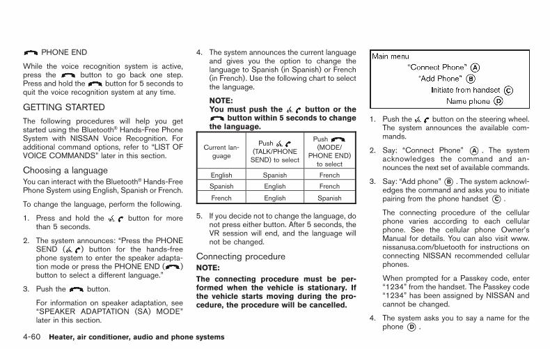
Black plate (206,1)
Model "Z12-D" EDITED: 2010/ 9/ 27
PHONE END
While the voice recognition system is active,press the button to go back one step.Press and hold the button for 5 seconds toquit the voice recognition system at any time.
GETTING STARTED
The following procedures will help you getstarted using the Bluetooth® Hands-Free PhoneSystem with NISSAN Voice Recognition. Foradditional command options, refer to “LIST OFVOICE COMMANDS” later in this section.
Choosing a languageYou can interact with the Bluetooth® Hands-FreePhone System using English, Spanish or French.
To change the language, perform the following.
1. Press and hold the button for morethan 5 seconds.
2. The system announces: “Press the PHONESEND ( ) button for the hands-freephone system to enter the speaker adapta-tion mode or press the PHONE END ( )button to select a different language.”
3. Push the button.
For information on speaker adaptation, see“SPEAKER ADAPTATION (SA) MODE”later in this section.
4. The system announces the current languageand gives you the option to change thelanguage to Spanish (in Spanish) or French(in French). Use the following chart to selectthe language.
NOTE:You must push the button or the
button within 5 seconds to changethe language.
Current lan-guage
Push(TALK/PHONESEND) to select
Push(MODE/
PHONE END)to select
English Spanish French
Spanish English French
French English Spanish
5. If you decide not to change the language, donot press either button. After 5 seconds, theVR session will end, and the language willnot be changed.
Connecting procedureNOTE:
The connecting procedure must be per-formed when the vehicle is stationary. Ifthe vehicle starts moving during the pro-cedure, the procedure will be cancelled.
1. Push the button on the steering wheel.The system announces the available com-mands.
2. Say: “Connect Phone” *A . The systemacknowledges the command and an-nounces the next set of available commands.
3. Say: “Add phone”*B . The system acknowl-edges the command and asks you to initiatepairing from the phone handset *C .
The connecting procedure of the cellularphone varies according to each cellularphone. See the cellular phone Owner’sManual for details. You can also visit www.nissanusa.com/bluetooth for instructions onconnecting NISSAN recommended cellularphones.
When prompted for a Passkey code, enter“1234” from the handset. The Passkey code“1234” has been assigned by NISSAN andcannot be changed.
4. The system asks you to say a name for thephone *D .
4-60 Heater, air conditioner, audio and phone systems

Black plate (207,1)
Model "Z12-D" EDITED: 2010/ 9/ 27
If the name is too long or too short, thesystem tells you, then prompts you for aname again.
Also, if more than one phone is connectedand the name sounds too much like a namealready used, the system tells you, thenprompts you for a name again.
Making a call by entering a phonenumber
1. Push the button on steering wheel. Atone will sound.
2. Say: “Call” *A . The system acknowledgesthe command and announces the next set ofavailable commands.
3. Say: “Phone Number” *B . The systemacknowledges the command and an-nounces the next set of available commands.Say: “Special Dialing” to dial more than 10digits or any special characters.
4. Say the number you wish to call starting withthe area code in single digit format. If thesystem has trouble recognizing the correct
phone number, try entering the number inthe following groups: 3-digit area code, 3-digit prefix and the last 4-digits. For example,555-121-3354 can be said as “five five five”as the 1st group, then “one two one” as the2nd group, and “three three five four” as the3rd group. For dialing more than 10 digits orany special characters, say “Special Dial-ing”. See “How to say numbers” earlier inthis section, for more information.
5. When you have finished speaking the phonenumber, the system repeats it back andannounces the available commands.
6. Say: “Dial” *C . The system acknowledgesthe command and makes the call.
For additional command options, see “LIST OFVOICE COMMANDS” later in this section.
Receiving a callWhen you hear the ring tone, press thebutton on the steering wheel.
Once the call has ended, press the buttonon the steering wheel.
NOTE:
If you do not wish to take the call when youhear the ring tone, press the button onthe steering wheel to reject the call.
LIST OF VOICE COMMANDS
When you push and release the button onthe steering wheel, you can choose from thecommands on the Main Menu. The followingpages describe these commands and thecommands in each sub-menu.
Remember to wait for the tone beforespeaking.
You can say “Help” to hear the list of commandscurrently available anytime the system is waitingfor a response.
A menu item can also be selected by scrollingthe display with the SEEK switch and enteringby pushing the button.
If you want to end an action without completingit, you can say “Cancel” or “Quit” at anytime thesystem is waiting for a response. The system willend the VR session. Whenever the VR sessionis cancelled, a double beep is played to indicateyou have exited the system.
If you want to go back to the previous command,
Heater, air conditioner, audio and phone systems 4-61

Black plate (208,1)
Model "Z12-D" EDITED: 2010/ 9/ 27
you can say “Go back” or “Correction” anytimethe system is waiting for a response.
Call
Name (a name) *AIf there are entries stored in the phonebook, anumber associated with a name and locationcan be dialed.
See “Phonebook (phones without automaticphonebook download function)” later in thissection to learn how to store entries.
When prompted by the system, say the name ofthe phonebook entry to call. The systemacknowledges the name.
If there are multiple locations associated withthe name, the system asks the user to choosethe location.
Once the name and location are confirmed, thesystem begins the call.
Phone Number (speak digits) *BWhen prompted by the system, say the numberto call. Refer to “Making a call by entering aphone number” earlier in this section for moredetails.
“Redial” *CUse the Redial command to call the last numberthat was dialed.
The system acknowledges the command, re-peats the number and begins dialing.
If a redial number does not exist, the systemannounces, “There is no number to redial” andends the VR session.
“Call back” *DUse the Call Back command to dial the numberof the last incoming call within the vehicle.
The system acknowledges the command, re-peats the number and begins dialing.
If a call back number does not exist, the systemannounces, “There is no number to call back”and ends the VR session.
Special Dialing
To dial more than 10 digits or any specialcharacters, please say “Special Dialing”. Whenthe system acknowledges the command, thesystem will prompt you to speak the number.
During a call
During a call there are several command optionsavailable. Push the button on the steeringwheel to mute the receiving voice and entercommands.
. “Help” — The system announces the avail-able commands.
. “Go back/Correction” — The system an-nounces “Go back,” ends the VR sessionand returns to the call.
. “Cancel/Quit” — The system announces“Cancel,” ends the VR session and returnsto the call.
. “Send/Enter/Call/Dial” — Use the Sendcommand to enter numbers, “*” or “#”during a call. For example, if you weredirected to dial an extension by an auto-mated system:
Say: “Send one two three four.”
The system acknowledges the commandand sends the tones associated with thenumbers. The system then ends the VRsession and returns to the call. Say “star” for“*”, say “pound” for “#”.
. “Transfer call” — Use the Transfer Callcommand to transfer the call from theBluetooth® Hands-Free Phone System to
4-62 Heater, air conditioner, audio and phone systems

Black plate (209,1)
Model "Z12-D" EDITED: 2010/ 9/ 27
the cellular phone when privacy is desired.
The system announces, “Transfer call. Calltransferred to privacy mode.” The systemthen ends the VR session.
To reconnect a call from the cellular phoneto the Bluetooth® Hands-Free Phone sys-tem, push the button.
. “Mute” — Use the Mute command to muteyour voice so the other party cannot hear it.Use the mute command again to unmuteyour voice.
NOTE:
If a call is ended or the cellular phonenetwork connection is lost while the Mutefeature is on, the Mute feature will be resetto “off” for the next call so the other partycan hear your voice.
Phonebook (phones without automaticphonebook download function)“Transfer Entry” *AUse the Transfer Entry command to store a newname in the system.
When prompted by the system, say the nameyou would like to give the new entry.
For example, say: “Mary.”
If the name is too long or too short, the systemtells you, then prompts you for a name again.
Also, if the name sounds too much like a namealready stored, the system tells you, thenprompts you for a name again.
The system will ask you to transfer a phonenumber stored in the cellular phone’s memory.
To enter a phone number by voice command:
For example, say: “five five five one two onetwo.” See “How to say numbers” earlier in thissection for more information.
To transfer a phone number stored in the cellularphone’s memory:
Say: “Transfer entry.” The system acknowledgesthe command and asks you to initiate thetransfer from the phone handset. The newcontact phone number will be transferred fromthe cellular phone via the Bluetooth® commu-
nication link.
The transfer procedure varies according to eachcellular phone. See the cellular phone Owner’sManual for details. You can also visit www.nissanusa.com/bluetooth for instructions ontransferring phone numbers from NISSAN re-commended cellular phones.
The system repeats the number and promptsyou for the next command. When you havefinished entering numbers or transferring anentry, choose “Store.”
The system confirms the name, location andnumber.
“Delete Entry” *BUse the Delete Entry command to delete oneentry from the phonebook. After the systemacknowledges a command, say the name todelete or say “List Names” to choose an entry.
“List Names” *CUse the List Names command to hear all thenames in the phonebook. The system recites thephonebook entries but does not include theactual phone numbers. When playback of thelist is complete, the system returns to the mainmenu.
Playback of the list can be stopped at any timeby pushing the button on the steering
Heater, air conditioner, audio and phone systems 4-63

Black plate (210,1)
Model "Z12-D" EDITED: 2010/ 9/ 27
wheel. The system ends the VR session.
Phonebook (phones with automaticphonebook download function)NOTE:
Phonebook commands are not availablewhen the vehicle is moving.
For phones that support automatic download ofthe phonebook (PBAP Bluetooth® profile), the“Phonebook” command is used to manageentries to the vehicle phonebook. You can saythe name of an entry at this menu to initiatedialing of that entry.
The phonebook stores up to 1000 names foreach phone paired with the system. Each namecan have up to 4 locations/phone numbersassociated with it.
When a phone is connected to the system, thephonebook is automatically downloaded to thevehicle. This feature allows you to access yourphonebook from the Bluetooth system and callcontacts by name. You can record a customvoice tag for contact names that the system hasdifficulty recognizing. For more information see“Record Name” in this section.
NOTE:
Each phone has its own separate phone-book. You cannot access Phone A’s phone-book if you are currently connected withPhone B.
“List names” *AUse the List Names command to hear all thenames and locations in the phone book.
The system recites the phone book entries butdoes not include the actual phone numbers.When the playback of the list is complete, thesystem goes back to the main menu.
You can stop the playback of the list at any timeby pressing the button on the steeringwheel. The system ends the VR session. See the“Record Name” command in this section forinformation about recording custom voice tagsfor list entries that the system has difficultypronouncing.
“Record name” *BThe system allows you to record custom voicetags for contact names in the phonebook thatthe vehicle has difficulty recognizing. Thisfeature can also be used to record voice tagsto directly dial an entry with multiple numbers.Up to 40 voice tags can be recorded to thesystem.
Recent Calls
Use the Recent Calls command to accessoutgoing, incoming or missed calls.
“Outgoing” *AUse the Outgoing command to list the outgoingcalls made from the vehicle.
“Incoming” *BUse the Incoming command to list the incomingcalls made from the vehicle.
“Missed” *CUse the Missed command to list the missedcalls made to the vehicle that were notanswered.
Connect PhoneNOTE:
Add Phone command is not availablewhen the vehicle is moving.
4-64 Heater, air conditioner, audio and phone systems

Black plate (211,1)
Model "Z12-D" EDITED: 2010/ 9/ 27
Use the Connect Phone commands to managethe phones connecting to the vehicle or toenable the Bluetooth® function on the vehicle.
“Add Phone” *AUse the Add Phone command to add a phone tothe vehicle. See “Connecting procedure” earlierin this section for more information.
“Select Phone” *BUse the Select Phone command to select from alist of phones connected to the vehicle. Thesystem will list the names assigned to eachphone and then prompt you for the phone youwish to select. Only one phone can be active ata time.
“Delete Phone” *CUse the Delete Phone command to delete aphone that is connected to the vehicle. Thesystem will list the names assigned to eachphone and then prompt you for the phone you
wish to delete. Deleting a phone from the vehiclewill also delete that phonebook for that phone.
“Turn Bluetooth Off” *DUse the Bluetooth Off command to prevent awireless connection to your phone.
SPEAKER ADAPTATION (SA) MODE
Speaker Adaptation allows up to two out-ofdialect users to train the system to improverecognition accuracy. By repeating a number ofcommands, the users can create a voice modelof their own voice that is stored in the system.The system is capable of storing a differentspeaker adaptation model for each connectedphone.
Training procedure1. Position the vehicle in a reasonably quiet
outdoor location.
2. Sit in the driver’s seat with the enginerunning, the parking brake on, and thetransmission in Park.
3. Press and hold the button for morethan 5 seconds.
4. The system announces: “Press the PHONESEND ( ) button for the hands-freephone system to enter the speaker adapta-tion mode or press the PHONE END ( )button to select a different language.”
5. Press the button.
For information on selecting a differentlanguage, see “Choosing a language” earlierin this section.
6. If the connected phone is already in use, thesystem will prompt you to overwrite. Followthe instructions provided by the system.
7. When preparation is complete and you areready to begin, press the button.
8. The SA mode will be explained. Follow theinstructions provided by the system.
9. When training is finished, the system will tellyou an adequate number of phrases havebeen recorded.
10. The system will announce that speakeradaptation has been completed and thesystem is ready.
The SA mode will stop if:
. The button is pressed for more than 5seconds in SA mode.
. The vehicle is driven during SA mode.
. The ignition switch is turned to the OFF orLOCK position.
Heater, air conditioner, audio and phone systems 4-65

Black plate (212,1)
Model "Z12-D" EDITED: 2010/ 9/ 27
Training phrasesDuring the SA mode, the system instructs you tosay the following phrases.
(The system will prompt you for each phrase.)
. phonebook new entry
. dial 3 0 4 2 9
. delete call back number
. setup pair phone
. memo pad play
. 8 pause 9 3 2 pause 7
. delete all entries
. call 7 2 4 0 9
. phonebook delete entry
. memo pad record
. dial star 2 1 7 0
. yes
. no
. select ring tone
. Setup change priority
. dial 8 5 6 9 2
. Bluetooth on
. Home
. call 3 1 9 0 2
. 9 7 pause pause 3 0 8
. cancel
. call back number
. call star 2 0 9 5
. delete phone
. dial 8 3 0 5 1
. setup change ring tone
. 4 3 pause 2 9 pause 0
. delete redial number
. phonebook list names
. call 8 0 5 4 1
. correction
. setup main menu
. dial 7 4 0 1 8
. memo pad delete
. delete
. dial 9 7 2 6 6
. call 7 6 3 0 1
. go back
. call 5 6 2 8 0
. dial 6 6 4 3 7
4-66 Heater, air conditioner, audio and phone systems

Black plate (213,1)
Model "Z12-D" EDITED: 2010/ 9/ 27
TROUBLESHOOTING GUIDE
The system should respond correctly to all voice commands without difficulty. If problems are encountered, try the following solutions.
Where the solutions are listed by number, try each solution in turn, starting with number 1, until the problem is resolved.
Symptom Solution
System fails to interpret the commandcorrectly.
1. Ensure that the command format is valid. (See “LIST OF VOICE COMMANDS” earlier in this section.)
2. Ensure that the command is spoken after the tone.
3. Speak clearly without pausing between words and at a level appropriate to the ambient noise level in the vehicle.
4. Ensure that the ambient noise level is not excessive (for example, windows open or defroster on).NOTE: If it is too noisy to use the phone, it is likely that the voice commands will not be recognized.
5. If more than one command was said at a time, try saying the commands separately.
6. If the system consistently fails to recognize commands, the voice training procedure should be carried out to improve therecognition response for the speaker. (See “SPEAKER ADAPTATION (SA) MODE” earlier in this section.)
The system consistently selects thewrong entry from the phone book.
1. Ensure that the phone book entry name requested matches what was originally stored. This can be confirmed by using the“List Names” command. (See “LIST OF VOICE COMMANDS” earlier in this section.)
2. Replace one of the names being confused with a new name.
Heater, air conditioner, audio and phone systems 4-67

Black plate (214,1)
Model "Z12-D" EDITED: 2010/ 9/ 27
MEMO
4-68 Heater, air conditioner, audio and phone systems

Black plate (16,1)
5 Starting and driving
Model "Z12-D" EDITED: 2010/ 9/ 27
Precautions when starting and driving . . . . . . . . . . . . . . . . . . . . . 5-2Exhaust gas (carbon monoxide) . . . . . . . . . . . . . . . . . . . . . . . . . 5-2Three-way catalyst. . . . . . . . . . . . . . . . . . . . . . . . . . . . . . . . . . . . . . . . . . 5-2Tire Pressure Monitoring System (TPMS). . . . . . . . . . . . . 5-3Avoiding collision and rollover . . . . . . . . . . . . . . . . . . . . . . . . . . . 5-5Off-road recovery . . . . . . . . . . . . . . . . . . . . . . . . . . . . . . . . . . . . . . . . . . . 5-5Rapid air pressure loss . . . . . . . . . . . . . . . . . . . . . . . . . . . . . . . . . . . . 5-6Drinking alcohol/drugs and driving. . . . . . . . . . . . . . . . . . . . . . 5-6
Ignition switch(models without Intelligent Key system) . . . . . . . . . . . . . . . . . . . 5-7
Continuously Variable Transmission (CVT) . . . . . . . . . . . . 5-7Manual Transmission (MT) . . . . . . . . . . . . . . . . . . . . . . . . . . . . . . . . 5-8Key positions . . . . . . . . . . . . . . . . . . . . . . . . . . . . . . . . . . . . . . . . . . . . . . . . 5-8
Push-button ignition switch(models with Intelligent Key system) . . . . . . . . . . . . . . . . . . . . . . . 5-9
Operating range for engine start function . . . . . . . . . . . . . 5-9Push-button ignition switch operation. . . . . . . . . . . . . . . . 5-10Steering lock (if so equipped) . . . . . . . . . . . . . . . . . . . . . . . . . 5-10Push-button ignition switch positions . . . . . . . . . . . . . . . . 5-10Emergency engine shut off . . . . . . . . . . . . . . . . . . . . . . . . . . . . . 5-11Intelligent Key battery discharge . . . . . . . . . . . . . . . . . . . . . . 5-11
Before starting the engine . . . . . . . . . . . . . . . . . . . . . . . . . . . . . . . . . . 5-12Starting the engine . . . . . . . . . . . . . . . . . . . . . . . . . . . . . . . . . . . . . . . . . . . 5-12
Models without Intelligent Key system . . . . . . . . . . . . . . . 5-12Models with Intelligent Key system . . . . . . . . . . . . . . . . . . . 5-13
Driving the vehicle . . . . . . . . . . . . . . . . . . . . . . . . . . . . . . . . . . . . . . . . . . . . 5-14Continuously Variable Transmission (CVT) . . . . . . . . . . 5-14Manual Transmission (MT) . . . . . . . . . . . . . . . . . . . . . . . . . . . . . . 5-18
Parking brake . . . . . . . . . . . . . . . . . . . . . . . . . . . . . . . . . . . . . . . . . . . . . . . . . . 5-20Cruise control (if so equipped) . . . . . . . . . . . . . . . . . . . . . . . . . . . . 5-21
Precautions on cruise control . . . . . . . . . . . . . . . . . . . . . . . . . . 5-21Cruise control operations . . . . . . . . . . . . . . . . . . . . . . . . . . . . . . . 5-21
Break-in schedule . . . . . . . . . . . . . . . . . . . . . . . . . . . . . . . . . . . . . . . . . . . . 5-23Increasing fuel economy . . . . . . . . . . . . . . . . . . . . . . . . . . . . . . . . . . . . 5-23Parking/parking on hills. . . . . . . . . . . . . . . . . . . . . . . . . . . . . . . . . . . . . . 5-24Electric power steering system . . . . . . . . . . . . . . . . . . . . . . . . . . . . 5-25Brake system . . . . . . . . . . . . . . . . . . . . . . . . . . . . . . . . . . . . . . . . . . . . . . . . . . 5-26
Braking precautions . . . . . . . . . . . . . . . . . . . . . . . . . . . . . . . . . . . . . . 5-26Anti-lock Braking System (ABS) . . . . . . . . . . . . . . . . . . . . . . 5-26
Vehicle Dynamic Control (VDC) system . . . . . . . . . . . . . . . . . 5-28Cold weather driving. . . . . . . . . . . . . . . . . . . . . . . . . . . . . . . . . . . . . . . . . 5-29
Freeing a frozen door lock. . . . . . . . . . . . . . . . . . . . . . . . . . . . . . 5-29Anti-freeze. . . . . . . . . . . . . . . . . . . . . . . . . . . . . . . . . . . . . . . . . . . . . . . . . . 5-29Battery . . . . . . . . . . . . . . . . . . . . . . . . . . . . . . . . . . . . . . . . . . . . . . . . . . . . . . 5-29Draining of coolant water . . . . . . . . . . . . . . . . . . . . . . . . . . . . . . . 5-29Tire equipment . . . . . . . . . . . . . . . . . . . . . . . . . . . . . . . . . . . . . . . . . . . . 5-30Special winter equipment . . . . . . . . . . . . . . . . . . . . . . . . . . . . . . . 5-30Driving on snow or ice . . . . . . . . . . . . . . . . . . . . . . . . . . . . . . . . . . 5-30Engine block heater (if so equipped). . . . . . . . . . . . . . . . . 5-30

Black plate (216,1)
Model "Z12-D" EDITED: 2010/ 9/ 27
WARNING
. Do not leave children or adults whowould normally require the supportof others alone in your vehicle. Petsshould not be left alone either. Theycould accidentally injure themselvesor others through inadvertent op-eration of the vehicle. Also, on hot,sunny days, temperatures in aclosed vehicle could quickly becomehigh enough to cause severe orpossibly fatal injuries to people oranimals.
. Properly secure all cargo with ropesor straps to help prevent it fromsliding or shifting. Do not placecargo higher than the seatbacks. Ina sudden stop or collision, unse-cured cargo could cause personalinjury.
EXHAUST GAS (carbon monoxide)
WARNING
. Do not breathe exhaust gases; theycontain colorless and odorless car-bon monoxide. Carbon monoxide is
dangerous. It can cause uncon-sciousness or death.
. If you suspect that exhaust fumesare entering the vehicle, drive withall windows fully open, and have thevehicle inspected immediately.
. Do not run the engine in closedspaces such as a garage.
. Do not park the vehicle with theengine running for any extendedlength of time.
. Keep the back door closed whiledriving, otherwise exhaust gasescould be drawn into the passengercompartment. If you must drive withthe back door open, follow theseprecautions:
1. Open all the windows.
2. Set the air recirculation to offand the fan control to high tocirculate the air.
. If electrical wiring or other cableconnections must pass to a trailerthrough the seal on the back door orthe body, follow the manufacturer’srecommendation to prevent carbonmonoxide entry into the vehicle.
. If a special body, camper or otherequipment is added for recreationalor other usage, follow the manufac-turer’s recommendation to preventcarbon monoxide entry into thevehicle. (Some recreational vehicleappliances such as stoves, refrig-erators, heaters, etc. may also gen-erate carbon monoxide.)
. The exhaust system and bodyshould be inspected by a qualifiedmechanic whenever:
— The vehicle is raised for service.
— You suspect that exhaust fumesare entering into the passengercompartment.
— You notice a change in thesound of the exhaust system.
— You have had an accident invol-ving damage to the exhaustsystem, underbody, or rear ofthe vehicle.
THREE-WAY CATALYST
The three-way catalyst is an emission controldevice installed in the exhaust system. Exhaustgases in the three-way catalyst are burned athigh temperatures to help reduce pollutants.
PRECAUTIONS WHEN STARTINGAND DRIVING
5-2 Starting and driving

Black plate (217,1)
Model "Z12-D" EDITED: 2010/ 9/ 27
WARNING
. The exhaust gas and the exhaustsystem are very hot. Keep people,animals or flammable materialsaway from the exhaust system com-ponents.
. Do not stop or park the vehicle overflammable materials such as drygrass, waste paper or rags. Theymay ignite and cause a fire.
CAUTION
. Do not use leaded gasoline. Depos-its from leaded gasoline will ser-iously reduce the three-waycatalyst’s ability to help reduce ex-haust pollutants.
. Keep your engine tuned up. Mal-functions in the ignition, fuel injec-tion, or electrical systems can causeoverrich fuel flow into the three-waycatalyst, causing it to overheat. Donot keep driving if the engine mis-fires, or if noticeable loss of perfor-mance or other unusual operatingconditions are detected. Have the
vehicle inspected promptly by aNISSAN dealer.
. Avoid driving with an extremely lowfuel level. Running out of fuel couldcause the engine to misfire, dama-ging the three-way catalyst.
. Do not race the engine while warm-ing it up.
. Do not push or tow your vehicle tostart the engine.
TIRE PRESSURE MONITORING SYS-TEM (TPMS)
Each tire, including the spare (if provided),should be checked monthly when cold andinflated to the inflation pressure recommendedby the vehicle manufacturer on the vehicleplacard or tire inflation pressure label. (If yourvehicle has tires of a different size than the sizeindicated on the vehicle placard or tire inflationpressure label, you should determine the propertire inflation pressure for those tires.)
As an added safety feature, your vehicle hasbeen equipped with a Tire Pressure MonitoringSystem (TPMS) that illuminates a low tirepressure telltale when one or more of your tiresis significantly under-inflated. Accordingly, whenthe low tire pressure telltale illuminates, youshould stop and check all 4 tires as soon as
possible, and inflate them to the proper pres-sure. Driving on a significantly under-inflated tirecauses the tire to overheat and can lead to tirefailure. Under-inflation also reduces fuel effi-ciency and tire tread life, and may affect thevehicle’s handling and stopping ability.
Please note that the TPMS is not a substitute forproper tire maintenance, and it is the driver’sresponsibility to maintain correct tire pressure,even if under-inflation has not reached the levelto trigger illumination of the TPMS low tirepressure telltale.
Your vehicle has also been equipped with aTPMS malfunction indicator to indicate when thesystem is not operating properly. The TPMSmalfunction indicator is combined with the lowtire pressure telltale. When the system detects amalfunction, the telltale will flash for approxi-mately one minute and then remain continuouslyilluminated. This sequence will continue uponsubsequent vehicle start-ups as long as themalfunction exists. When the malfunction indi-cator is illuminated, the system may not be ableto detect or signal low tire pressure as intended.TPMS malfunctions may occur for a variety ofreasons, including the installation of replace-ment or alternate tires or wheels on the vehiclethat prevent the TPMS from functioning properly.Always check the TPMS malfunction telltaleafter replacing one or more tires or wheels onyour vehicle to ensure that the replacement or
Starting and driving 5-3

Black plate (218,1)
Model "Z12-D" EDITED: 2010/ 9/ 27
alternate tires and wheels allow the TPMS tocontinue to function properly.
Additional information. The TPMS does not monitor the tire
pressure of the spare tire.
. The TPMS will activate only when thevehicle is driven at speeds above 16 MPH(25 km/h). Also, this system may not detecta sudden drop in tire pressure (for example aflat tire while driving).
. The low tire pressure warning light does notautomatically turn off when the tire pressureis adjusted. After the tire is inflated to therecommended pressure, the vehicle must bedriven at speeds above 16 MPH (25 km/h)to activate the TPMS and turn off the low tirepressure warning light. Use a tire pressuregauge to check the tire pressure.
. Tire pressure rises and falls depending onthe heat caused by the vehicle’s operationand the outside temperature. Low outsidetemperature can lower the temperature ofthe air inside the tire which can cause alower tire inflation pressure. This may causethe low tire pressure warning light toilluminate. If the warning light illuminates inlow ambient temperature, check the tirepressure for all four tires.
For additional information, see “Low tire pres-
sure warning light” in the “2. Instruments andcontrols” section and “TIRE PRESSURE MON-ITORING SYSTEM (TPMS)” in the “6. In case ofemergency” section.
WARNING
. If the low tire pressure warning lightilluminates while driving, avoid sud-den steering maneuvers or abruptbraking, reduce vehicle speed, pulloff the road to a safe location andstop the vehicle as soon as possi-ble. Driving with under-inflated tiresmay permanently damage the tiresand increase the likelihood of tirefailure. Serious vehicle damagecould occur and may lead to anaccident and could result in seriouspersonal injury. Check the tire pres-sure for all four tires. Adjust the tirepressure to the recommended COLDtire pressure shown on the Tire andLoading Information label to turnthe low tire pressure warning lightOFF. If you have a flat tire, replace itwith a spare tire as soon as possi-ble. (See “FLAT TIRE” in the “6. Incase of emergency” section forchanging a flat tire.)
. When a spare tire is mounted or awheel is replaced, the TPMS will notfunction and the low tire pressurewarning light will flash for approxi-mately 1 minute. The light willremain on after 1 minute. Contactyour NISSAN dealer as soon aspossible for tire replacement and/or system resetting.
. Replacing tires with those not ori-ginally specified by NISSAN couldaffect the proper operation of theTPMS.
. Do not inject any tire liquid oraerosol tire sealant into the tires,as this may cause a malfunction ofthe tire pressure sensors.
CAUTION
. The TPMSmay not function properlywhen the wheels are equipped withtire chains or the wheels are buriedin snow.
. Do not place metalized film or anymetal parts (antenna, etc.) on thewindows. This may cause poor re-ception of the signals from the tire
5-4 Starting and driving

Black plate (219,1)
Model "Z12-D" EDITED: 2010/ 9/ 27
pressure sensors, and the TPMS willnot function properly.
Some devices and transmitters may temporarilyinterfere with the operation of the TPMS andcause the low tire pressure warning light toilluminate. Some examples are:
. Facilities or electric devices using similarradio frequencies are near the vehicle.
. If a transmitter set to similar frequencies isbeing used in or near the vehicle.
. If a computer (or similar equipment) or a DC/AC converter is being used in or near thevehicle.
FCC Notice:
For USA:
This device complies with Part 15 of theFCC Rules. Operation is subject to thefollowing two conditions:
(1) This device may not cause harmfulinterference, and (2) this device mustaccept any interference received, includinginterference that may cause undesiredoperation.
Note: Changes or modifications not ex-pressly approved by the party responsiblefor compliance could void the user’s
authority to operate the equipment.
For Canada:
This device complies with RSS-210 ofIndustry Canada. Operation is subject tothe following two conditions:
(1) this device may not cause interference,and (2) this device must accept any inter-ference, including interference that maycause undesired operation of the device.
AVOIDING COLLISION AND ROLL-OVER
WARNING
Failure to operate this vehicle in a safeand prudent manner may result in lossof control or an accident.
Be alert and drive defensively at all times. Obeyall traffic regulations. Avoid excessive speed,high speed cornering, or sudden steeringmaneuvers, because these driving practicescould cause you to lose control of your vehicle.As with any vehicle, a loss of control couldresult in a collision with other vehicles orobjects, or cause the vehicle to rollover,particularly if the loss of control causes thevehicle to slide sideways. Be attentive at alltimes, and avoid driving when tired. Never drive
when under the influence of alcohol or drugs(including prescription or over-the-counterdrugs which may cause drowsiness). Alwayswear your seat belt as outlined in the “SEATBELTS” in the “1. Safety — Seats, seat belts andsupplemental restraint system” section of thismanual, and also instruct your passengers to doso.
Seat belts help reduce the risk of injury incollisions and rollovers. In a rollover crash, anunbelted or improperly belted person issignificantly more likely to be injured orkilled than a person properly wearing aseat belt.
OFF-ROAD RECOVERY
While driving, the right side or left side wheelsmay unintentionally leave the road surface. If thisoccurs, maintain control of the vehicle byfollowing the procedure below. Please note thatthis procedure is only a general guide. Thevehicle must be driven as appropriate based onthe conditions of the vehicle, road and traffic.
1. Remain calm and do not overreact.
2. Do not apply the brakes.
3. Maintain a firm grip on the steering wheelwith both hands and try to hold a straightcourse.
4. When appropriate, slowly release the accel-
Starting and driving 5-5

Black plate (220,1)
Model "Z12-D" EDITED: 2010/ 9/ 27
erator pedal to gradually slow the vehicle.
5. If there is nothing in the way, steer thevehicle to follow the road while the vehiclespeed is reduced. Do not attempt to drivethe vehicle back onto the road surface untilvehicle speed is reduced.
6. When it is safe to do so, gradually turn thesteering wheel until both tires return to theroad surface. When all tires are on the roadsurface, steer the vehicle to stay in theappropriate driving lane.
— If you decide that it is not safe to returnthe vehicle to the road surface based onvehicle, road or traffic conditions, gra-dually slow the vehicle to a stop in a safeplace off the road.
RAPID AIR PRESSURE LOSS
Rapid air pressure loss or a “blow-out” canoccur if the tire is punctured or is damaged dueto hitting a curb or pothole. Rapid air pressureloss can also be caused by driving on under-inflated tires.
Rapid air pressure loss can affect the handlingand stability of the vehicle, especially at highwayspeeds.
Help prevent rapid air pressure loss by main-taining the correct air pressure and visuallyinspect the tires for wear and damage. See
“WHEELS AND TIRES” in the “8. Maintenanceand do-it-yourself” section of this manual.
If a tire rapidly loses air pressure or “blows-out”while driving maintain control of the vehicle byfollowing the procedure below. Please note thatthis procedure is only a general guide. Thevehicle must be driven as appropriate based onthe conditions of the vehicle, road and traffic.
WARNING
The following actions can increase thechance of losing control of the vehicle ifthere is a sudden loss of tire airpressure. Losing control of the vehiclemay cause a collision and result inpersonal injury.
. The vehicle generally moves or pullsin the direction of the flat tire.
. Do not rapidly apply the brakes.
. Do not rapidly release the accelera-tor pedal.
. Do not rapidly turn the steeringwheel.
1. Remain calm and do not overreact.
2. Maintain a firm grip on the steering wheelwith both hands and try to hold a straightcourse.
3. When appropriate, slowly release the accel-erator pedal to gradually slow the vehicle.
4. Gradually steer the vehicle to a safe locationoff the road and away from traffic if possible.
5. Lightly apply the brake pedal to graduallystop the vehicle.
6. Turn on the hazard warning flashers andeither contact a roadside emergency serviceto change the tire or see “CHANGING AFLAT TIRE” in the “6. In case of emergency”section of this Owner’s Manual.
DRINKING ALCOHOL/DRUGS ANDDRIVING
WARNING
Never drive under the influence ofalcohol or drugs. Alcohol in the blood-stream reduces coordination, delaysreaction time and impairs judgement.Driving after drinking alcohol increasesthe likelihood of being involved in anaccident injuring yourself and others.Additionally, if you are injured in anaccident, alcohol can increase the se-verity of the injury.
NISSAN is committed to safe driving. However,
5-6 Starting and driving

Black plate (221,1)
Model "Z12-D" EDITED: 2010/ 9/ 27
you must choose not to drive under the influenceof alcohol. Every year thousands of people areinjured or killed in alcohol-related accidents.Although the local laws vary on what isconsidered to be legally intoxicated, the fact isthat alcohol affects all people differently andmost people underestimate the effects ofalcohol.
Remember, drinking and driving don’t mix! Andthat is true for drugs, too (over-the-counter,prescription, and illegal drugs). Don’t drive ifyour ability to operate your vehicle is impaired byalcohol, drugs, or some other physical condition.
WARNING
Never remove or turn the key to theLOCK position while driving. This maycause the driver to lose control of thevehicle and could result in seriousvehicle damage or personal injury.
SSD0392
CONTINUOUSLY VARIABLE TRANS-MISSION (CVT)
The ignition lock is designed so that the ignitionswitch cannot be turned to the LOCK positionuntil the selector lever is moved to the P (Park)position.
. When turning the ignition switch to theLOCK position, make sure that the selectorlever is in the P (Park) position.
. When removing the key from the ignitionswitch, make sure that the selector lever is inthe P (Park) position.
IGNITION SWITCH (models withoutIntelligent Key system)
Starting and driving 5-7

Black plate (222,1)
Model "Z12-D" EDITED: 2010/ 9/ 27
When the ignition switch cannot be turned tothe LOCK position:
1. Move the selector lever to the P (Park)position.
2. Turn the ignition switch slightly in the ONdirection.
3. Turn the ignition switch to the LOCKposition.
4. Remove the key.
If the ignition switch is turned to the LOCKposition, the selector lever cannot be movedfrom the P (Park) position. The selector lever canbe moved if the ignition switch is in the ONposition with the foot brake pedal depressed.
There is an OFF position *1 between theLOCK and ACC positions, although it is notmarked on the ignition switch.
SSD0503
MANUAL TRANSMISSION (MT)
The ignition switch includes a device that helpsprevent accidental removal of the key whiledriving.
The key can only be removed when the ignitionswitch is in the LOCK position.
To turn the ignition switch to the LOCK positionfrom the ACC or ON position, turn the key to theOFF position, push the key in, then turn the keyto the LOCK position.
There is an OFF position *1 in between theLOCK and ACC positions. The OFF position isindicated by a “1” on the key cylinder.
KEY POSITIONS
LOCK (0)The key can only be removed from the ignitionswitch at this position.
OFF (1)The engine is turned off. The power supply isturned off.
ACC (2)The electrical accessory power activates withoutthe engine turned on.
ON (3)The ignition system and the electrical accessorypower activate without the engine turned on.
START (4)The engine starter activates and the engine willstart. The ignition switch, when released, willautomatically turn to the ON position.
CAUTION
As soon as the engine has started,release the ignition switch immediately.
5-8 Starting and driving

Black plate (223,1)
Model "Z12-D" EDITED: 2010/ 9/ 27
WARNING
Do not operate the push-button ignitionswitch while driving the vehicle exceptin an emergency. (The engine will stopwhen the ignition switch is pushed 3consecutive times or the ignition switchis pushed and held for more than 2seconds.) If the engine stops while thevehicle is being driven, this could leadto a crash and serious injury.
Before operating the push-button ignitionswitch, be sure to move the selector lever tothe P (Park) position.
SSD0436
OPERATING RANGE FOR ENGINESTART FUNCTION
The Intelligent Key can only be used for startingthe engine when the Intelligent Key is within thespecified operating range *1 .
When the Intelligent Key battery is almostdischarged or strong radio waves are presentnear the operating location, the Intelligent Keysystem’s operating range becomes narrowerand may not function properly.
If the Intelligent Key is within the operatingrange, it is possible for anyone, even someonewho does not carry the Intelligent Key, to pushthe ignition switch to start the engine.
. The cargo room area is not included in theoperating range but the Intelligent Key mayfunction.
. If the Intelligent Key is placed on theinstrument panel, inside the glove box ordoor pocket, the Intelligent Key may notfunction.
. If the Intelligent Key is placed near the dooror window outside the vehicle, the IntelligentKey may function.
PUSH-BUTTON IGNITION SWITCH(models with Intelligent Key system)
Starting and driving 5-9

Black plate (224,1)
Model "Z12-D" EDITED: 2010/ 9/ 29
SSD0859
PUSH-BUTTON IGNITION SWITCHOPERATION
When the ignition switch is pushed withoutdepressing the brake pedal, the ignition switchposition will change as follows:
. Push center once to change to ACC.
. Push center two times to change to ON.
. Push center three times to change to OFF.
. Push center four times to return to ACC.
. Open or close any door to return to LOCKduring the OFF position.
The indicator light *A on the ignition switch
illuminates when the ignition switch is in theACC or ON position.
The ignition switch is equipped with an anti-theftsteering lock device.
In order for the steering wheel to be locked, itmust be turned about 1/6 to the right or left fromthe straight up position.
To lock the steering wheel, push theignition switch to the OFF position. Tounlock the steering wheel, push the igni-tion switch.
If the ignition switch position does notchange from LOCK when pushing theignition switch, turn the steering wheelright and left, then push the ignition switchagain.
If the battery of the vehicle is discharged,the push-button ignition switch positioncannot be moved from the LOCK position.
Some indicators and warnings for operation aredisplayed on the meter. (See “WARNING/INDICATOR LIGHTS AND AUDIBLE REMIN-DERS” in the “2. Instruments and controls”section.)
The ignition lock is designed so that the ignitionswitch position cannot be switched to LOCKuntil the selector lever is moved to the P (Park)position.
When the ignition switch cannot be pushedtoward the LOCK position, proceed as follows:
1. Move the selector lever into the P (Park)position.
2. Push the ignition switch to the OFF position.
3. Open the door. The ignition switch willchange to the LOCK position.
The selector lever can be moved from the P(Park) position if the ignition switch is inthe ON position and the brake pedal isdepressed.
STEERING LOCK (if so equipped)
In order for the steering wheel to be locked, itmust be turned about 1/8 of a right or left turnfrom the straight up position.
To lock the steering wheel, PUSH the ignitionswitch to the OFF position. To unlock thesteering wheel, push the ignition switch.
PUSH-BUTTON IGNITION SWITCHPOSITIONS
LOCK (Normal parking position)The ignition switch can only be locked in thisposition.
The ignition switch will be unlocked when it ispushed to the ACC position while carrying theIntelligent Key.
5-10 Starting and driving

Black plate (225,1)
Model "Z12-D" EDITED: 2010/ 9/ 27
ACC (Accessories)This position activates electrical accessoriessuch as the radio, when the engine is notrunning.
ON (Normal operating position)This position turns on the ignition system andelectrical accessories.
OFFThe engine can be turned off in this position.
The ignition lock is designed so that the ignitionswitch cannot be switched to the LOCK positionuntil the selector lever is moved to the P (Park)position.
CAUTION
Do not leave the vehicle with the push-button ignition switch in ACC or ONposition when the engine is not runningfor an extended period. This can dis-charge the battery.
EMERGENCY ENGINE SHUT OFF
To shut off the engine in an emergency situationwhile driving perform the following procedure:
. Rapidly push the push-button ignition switch3 consecutive times, or
. Push and hold the push-button ignitionswitch for more than 2 seconds.
SSD0860
INTELLIGENT KEY BATTERY DIS-CHARGE
If the battery of the Intelligent Key is discharged,or environmental conditions interfere with theIntelligent Key operation, start the engineaccording to the following procedure:
1. Move the selector lever to the P (Park)position.
2. Firmly apply the foot brake.
3. Touch the ignition switch with the IntelligentKey as illustrated. (A chime will sound.)
4. Push the ignition switch while depressingthe brake pedal within 10 seconds after the
Starting and driving 5-11

Black plate (226,1)
Model "Z12-D" EDITED: 2010/ 9/ 27
chime sounds. The engine will start.
After step 3 is performed, when the ignitionswitch is pushed without depressing the brakepedal, the ignition switch position will change toACC.
NOTE:
. When the ignition switch is pushed tothe ACC or ON position or the engine isstarted by the above procedures, theIntelligent Key system warning lightmay blink in yellow even if the Intelli-gent Key is inside the vehicle. This isnot a malfunction. To stop the warninglight from blinking, touch the ignitionswitch with the Intelligent Key again.
. If the Intelligent Key system warninglight in the meter is blinking in green,replace the battery as soon as possible.(See “KEY BATTERY REPLACEMENT”in the “8. Maintenance and do-it-your-self” section.)
. Make sure the area around the vehicle isclear.
. Check fluid levels such as engine oil, cool-ant, brake fluid, and window washer fluid asfrequently as possible, or at least wheneveryou refuel.
. Check that all windows and lights are clean.
. Visually inspect tires for their appearanceand condition. Also check tires for properinflation.
. Lock all doors.
. Position seat and adjust head restraints.
. Adjust inside and outside mirrors.
. Fasten seat belts and ask all passengers todo likewise.
. Check the operation of warning lights whenthe ignition switch is placed in the ONposition. (See “WARNING/INDICATORLIGHTS AND AUDIBLE REMINDERS” inthe “2. Instruments and controls” section.)
MODELS WITHOUT INTELLIGENT KEYSYSTEM
1. Apply the parking brake.
2. Continuously Variable Transmission(CVT) models:
Move the selector lever to the P (Park) or N(Neutral) position. (P is recommended.)
The starter is designed so that it does notoperate unless the selector lever is in eitherof the above positions.
Manual Transmission (MT) models:
Move the shift lever to the N (Neutral)position. Depress the clutch pedal fully tothe floor.
The starter is designed not to operate unlessthe clutch pedal is fully depressed.
3. Crank the engine with your foot off theaccelerator pedal by turning the ignitionswitch to START. Release the switch whenthe engine starts. If the engine starts, butfails to run, repeat the above procedure.
— If the engine is very hard to start inextremely cold weather or when restart-ing, depress the accelerator pedal a little(approximately 1/3 to the floor) and holdit and then crank the engine. Release theaccelerator pedal when the engine
BEFORE STARTING THE ENGINE STARTING THE ENGINE
5-12 Starting and driving

Black plate (227,1)
Model "Z12-D" EDITED: 2010/ 9/ 27
starts.
— If the engine is very hard to start becauseit is flooded, depress the acceleratorpedal all the way to the floor and hold it.Crank the engine for 5 - 6 seconds.After cranking the engine, release theaccelerator pedal. Crank the enginewith your foot off the acceleratorpedal by turning the ignition switch toSTART. Release the ignition switchwhen the engine starts. If the enginestarts, but fails to run, repeat the aboveprocedure.
CAUTION
Do not operate the starter for morethan 15 seconds at a time. If the enginedoes not start, turn the ignition switchoff and wait 10 seconds before crankingagain, otherwise the starter could bedamaged.
4. Warm-up
Allow the engine to idle for at least 30seconds after starting. Do not race theengine while warming it up. Drive atmoderate speed for a short distance first,especially in cold weather. In cold weather,keep the engine running for a minimum of 2 -
3 minutes before shutting it off. Starting andstopping the engine over a short period oftime may make the vehicle more difficult tostart.
5. To stop the engine, move the selector leverto the P (Park) position (CVTmodel) or movethe shift lever to the N (Neutral) position (MTmodel), and turn the ignition switch to theOFF position.
MODELS WITH INTELLIGENT KEYSYSTEM
1. Apply the parking brake.
2. Move the selector lever to the P (Park) or N(Neutral) position. (P is recommended.)
The starter is designed not to operate unlessthe selector lever is in either of the abovepositions.
The Intelligent Key must be carriedwhen operating the ignition switch.
3. Push the ignition switch to the ON position.Depress the brake pedal and push theignition switch to start the engine.
To start the engine immediately, push andrelease the ignition switch while depressingthe brake pedal with the ignition switch inany position.
— If the engine is very hard to start in
extremely cold weather or when restart-ing, depress the accelerator pedal a little(approximately 1/3 to the floor) andwhile holding, crank the engine. Releasethe accelerator pedal when the enginestarts.
— If the engine is very hard to start becauseit is flooded, depress the acceleratorpedal all the way to the floor and hold it.Push the ignition switch to the ONposition to start cranking the engine.After 5 or 6 seconds, stop cranking bypushing the ignition switch to OFF. Aftercranking the engine, release the accel-erator pedal. Crank the engine withyour foot off the accelerator pedalby depressing the brake pedal andpushing the push-button ignition switchto start the engine. If the engine starts,but fails to run, repeat the aboveprocedure.
CAUTION
Do not operate the starter for morethan 15 seconds at a time. If the enginedoes not start, push the ignition switchto OFF and wait 10 seconds beforecranking again, otherwise the startercould be damaged.
Starting and driving 5-13

Black plate (228,1)
Model "Z12-D" EDITED: 2010/ 9/ 27
4. Warm-up
Allow the engine to idle for at least 30seconds after starting. Do not race theengine while warming it up. Drive atmoderate speed for a short distance first,especially in cold weather. In cold weather,keep the engine running for a minimum of 2 -3 minutes before shutting it off. Starting andstopping the engine over a short period oftime may make the vehicle more difficult tostart.
When racing the engine up to 4,000 rpm ormore under no load condition, the enginewill enter the fuel cut mode.
5. To stop the engine, move the selector leverto the P (Park) position, and push theignition switch to the OFF position.
CONTINUOUSLY VARIABLE TRANS-MISSION (CVT)
The Continuously Variable Transmission (CVT)in your vehicle is electronically controlled toproduce maximum power and smooth operation.
The recommended operating procedures for thistransmission are shown on the following pages.Follow these procedures for maximum vehicleperformance and driving enjoyment.
Engine power may be automatically re-duced to protect the CVT if the enginespeed increases quickly when driving onslippery roads or while being tested onsome dynamometers.
Starting the vehicle1. After starting the engine, fully depress the
foot brake pedal before moving the selectorlever out of the P (Park) position.
This CVT is designed so that the footbrake pedal must be depressed beforeshifting from P (Park) to any drivingposition while the ignition switch is inthe ON position.
The selector lever cannot be moved outof the P (Park) position and into any ofthe other positions if the ignitionswitch is placed in the LOCK, OFF orACC position or if the key is removed.
2. Keep the foot brake pedal depressed, pushthe selector lever button and move theselector lever to a driving position.
3. Release the parking brake and foot brakepedal, and then gradually start the vehicle inmotion.
WARNING
. Do not depress the acceleratorpedal while shifting from P (Park)or N (Neutral) to R (Reverse), D(Drive) or L (Low). Always depressthe brake pedal until shifting iscompleted. Failure to do so couldcause you to lose control and havean accident.
. Cold engine idle speed is high, souse caution when shifting into aforward or reverse gear before theengine has warmed up.
. Never shift to P (Park) or R (Re-verse) while vehicle is moving. Fail-ure to do so could cause you to losecontrol and have an accident.
DRIVING THE VEHICLE
5-14 Starting and driving

Black plate (229,1)
Model "Z12-D" EDITED: 2010/ 9/ 27
CAUTION
. When stopping the vehicle on anuphill grade, do not hold the vehicleby depressing the accelerator pedal.The foot brake should be used forthis purpose.
. Do not downshift abruptly on slip-pery roads. This may cause a loss ofcontrol.
SSD0862
ShiftingTo move the selector lever,
: Push the button *A while depressingthe brake pedal.
: Push the button *A .
: Just move the selector lever.
After starting the engine, fully depress the brakepedal, push the selector lever button and movethe selector lever from the P (Park) position toany of the desired shift positions.
WARNING
Apply the parking brake if the selectorlever is in any position while the engineis not running. Failure to do so couldcause the vehicle to move unexpectedlyor roll away and result in seriouspersonal injury or property damage.
If the ignition switch is placed in the OFF orACC position for any reason while the selectorlever is in any positions other than the P (Park),the ignition switch cannot be placed in theLOCK position.
If the ignition switch cannot be placed in theLOCK position, perform the following steps:
1. Apply the parking brake when the vehicle isstopped.
2. Place the ignition switch in the ON positionwhile depressing the foot brake pedal.
3. Move the selector lever to the P (Park)position.
4. Models with Intelligent Key system:
Place the ignition switch in the OFF position.
Models without Intelligent Key system:
Place the ignition switch in the LOCK
Starting and driving 5-15

Black plate (230,1)
Model "Z12-D" EDITED: 2010/ 9/ 27
position.
CAUTION
To prevent transmission damage, movethe selector lever to the P (Park) or R(Reverse) position only when the vehi-cle is completely stopped.
P (Park):
Use this selector position when the vehicle isparked or when starting the engine. Make surethe vehicle is completely stopped. The brakepedal must be depressed and the selectorlever button pushed in to move the selec-tor lever from N (Neutral) or any driveposition to P (Park). Apply the parking brake.When parking on a hill, apply the parking brakefirst, then move the selector lever to the P (Park)position.
R (Reverse):
Use this position to back up. Make sure thevehicle is completely stopped before selectingthe R (Reverse) position. The brake pedalmust be depressed and the selector leverbutton pushed in to move the selectorlever from P (Park), N (Neutral) or anydriving position to R (Reverse).
N (Neutral):
Neither forward nor reverse gear is engaged.The engine can be started in this position. Youmay shift to N (Neutral) and restart a stalledengine while the vehicle is moving.
D (Drive):
Use this position for all normal forward driving.
L (Low):
Use this position for maximum engine braking onsteep downhill gradients/climbing steep slopesand whenever approaching sharp bends. Do notuse the L (Low) position in any other circum-stances.
SSD0863
Overdrive (O/D) OFF switch (if soequipped)When the O/D OFF switch is pushed with theselector lever in the D (Drive) position, theindicator light in the instrument panel illuminates.
Use the overdrive off mode when you needimproved engine braking.
To turn off the overdrive off mode, push the O/DOFF switch again. The indicator light willturn off.
Each time the engine is started, or when theselector lever is shifted to any position otherthan the D (Drive) position, the overdrive offmode will be automatically turned off.
5-16 Starting and driving

Black plate (231,1)
Model "Z12-D" EDITED: 2010/ 9/ 27
Accelerator downshift— In D position —For passing or hill climbing, fully depress theaccelerator pedal to the floor. This shifts thetransmission down into a lower gear, dependingon the vehicle speed.
High fluid temperature protection modeThis transmission has a high fluid temperatureprotection mode. If the fluid temperature be-comes too high (for example, when climbingsteep grades in high temperature with heavyloads), engine power and, under some condi-tions, vehicle speed will be decreased auto-matically to reduce the chance of transmissiondamage. Vehicle speed can be controlled withthe accelerator pedal, but the engine and vehiclespeed may be limited.
Fail-safeIf the vehicle is driven under extremeconditions, such as excessive wheel spin-ning and subsequent hard braking, thefail-safe system may be activated. The MILmay illuminate to indicate the fail-safemode is activated. (See “Malfunction In-dicator Light (MIL)” in the “2. Instrumentsand controls” section.) This will occur evenif all electrical circuits are functioningproperly. In this case, place the ignitionswitch in the OFF position and wait for 10seconds. Then turn the switch back to the
ON position. The vehicle should return toits normal operating condition. If it doesnot return to its normal operating condi-tion, have a NISSAN dealer check thetransmission and repair if necessary.
WARNING
When the high fluid temperature pro-tection mode or fail-safe operationoccurs, vehicle speed may be graduallyreduced. The reduced speed may belower than other traffic, which couldincrease the chance of a collision. Beespecially careful when driving. If ne-cessary, pull to the side of the road at asafe place and allow the transmissionto return to normal operation, or have itrepaired if necessary.
SSD0864
Shift lock releaseIf the battery charge is low or discharged, theselector lever may not be moved from the P(Park) position even with the brake pedaldepressed and the selector lever button pushed.
To move the selector lever, perform the followingprocedure:
1. Models with Intelligent Key system:
Place the ignition switch in the OFF orLOCK position.
Models without Intelligent Key system:
Place the ignition switch in the LOCKposition, and remove the key if it is inserted.
Starting and driving 5-17

Black plate (232,1)
Model "Z12-D" EDITED: 2010/ 9/ 27
2. Apply the parking brake.
3. Remove the shift lock release cover *Ausing a suitable tool.
4. Push down the shift lock release using asuitable tool.
5. Push the selector lever button and move theselector lever to the N (Neutral) positionwhile holding down the shift lock release.
Place the ignition switch in the ON position tounlock the steering wheel (if so equipped). Thevehicle may be moved to the desired location.
Replace the removed shift lock release coverafter the operation.
For models with a steering wheel lock mechan-ism: If the battery is discharged completely, thesteering wheel cannot be unlocked. Do notmove the vehicle with the steering wheel locked.
If the selector lever cannot be moved out of theP (Park) position, have a NISSAN dealer checkthe CVT system as soon as possible.
WARNING
If the selector lever cannot be movedfrom the P (Park) position while theengine is running and the brake pedalis depressed, the stop lights may not
work. Malfunctioning stop lights couldcause an accident injuring yourself andothers.
MANUAL TRANSMISSION (MT)
WARNING
. Do not downshift abruptly on slip-pery roads. This may cause a loss ofcontrol.
. Do not over-rev the engine whenshifting to a lower gear. This maycause a loss of control or enginedamage.
CAUTION
. Do not rest your foot on the clutchpedal while driving. This may da-mage the clutch.
. Fully depress the clutch pedal be-fore shifting to help prevent trans-mission damage.
. Stop your vehicle completely beforeshifting into R (Reverse).
. When the vehicle is stopped for aperiod of time, for example at a stop
light, shift to N (Neutral) and releasethe clutch pedal with the foot brakeapplied.
5-18 Starting and driving

Black plate (233,1)
Model "Z12-D" EDITED: 2010/ 9/ 27
SSD0552
ShiftingTo change gears, or when upshifting or down-shifting, fully depress the clutch pedal, shift intothe appropriate gear, then slowly and smoothlyrelease the clutch pedal.
Start the vehicle in 1st gear and shift to 2nd,3rd, 4th, 5th and 6th gear in sequence accord-ing to vehicle speed.
To back up, pull the shift lever ring *1 upwardand then move it to the R (Reverse) gear afterstopping the vehicle completely.
The shift lever ring returns to its original positionwhen the shift lever is moved to the N (Neutral)position.
If it is difficult to move the shift lever into the R(Reverse) or 1st gear, shift to the N (Neutral)position, and then release the clutch pedal once.Fully depress the clutch pedal again and shiftinto the R (Reverse) or 1st gear.
Suggested upshift speedsThe following are suggested vehicle speeds forshifting into a higher gear. These suggestionsrelate to fuel economy and vehicle performance.Actual upshift speeds will vary according to roadconditions, the weather and individual drivinghabits.
For normal acceleration in low altitude areas[less than 4,000 ft (1,219 m)]:
Gear change MPH (km/h)
1st to 2nd 8 (13)
2nd to 3rd 17 (27)
3rd to 4th 25 (40)
4th to 5th 36 (58)
5th to 6th 51 (82)
For normal acceleration in high altitude areas[over 4,000 ft (1,219 m)]:
Gear change MPH (km/h)
1st to 2nd 15 (24)
2nd to 3rd 25 (40)
3rd to 4th 40 (64)
4th to 5th 45 (72)
5th to 6th 51 (82)
Starting and driving 5-19

Black plate (234,1)
Model "Z12-D" EDITED: 2010/ 9/ 27
Suggested maximum speed in each gearDownshift to a lower gear if the engine is notrunning smoothly, or if you need to accelerate.
Do not exceed the maximum suggested speed(shown below) in any gear. For level roaddriving, use the highest gear suggested for thatspeed. Always observe posted speed limits, anddrive according to the road conditions, whichwill ensure safe operation. Do not over-rev theengine when shifting to a lower gear as it maycause engine damage or loss of vehicle control.
Gear MPH (km/h)
1st 28 (46)
2nd 50 (82)
3rd 73 (119)
4th —
5th —
6th —
WARNING
. Be sure the parking brake is fullyreleased before driving. Failure todo so can cause brake failure andlead to an accident.
. Do not release the parking brakefrom outside the vehicle.
. Do not use the gear shift in place ofthe parking brake. When parking, besure the parking brake is fullyengaged.
. Do not leave children unattended ina vehicle. They could release theparking brake and cause an acci-dent.
SPA2110
To apply: Pull the parking brake lever up *1 .
To release:
1. Firmly apply the foot brake.
2. While pulling up on the parking brake leverslightly, push the button *2 and lower thelever completely *3 .
3. Before driving, be sure the brake warninglight goes out.
PARKING BRAKE
5-20 Starting and driving

Black plate (235,1)
Model "Z12-D" EDITED: 2010/ 9/ 27
PRECAUTIONS ON CRUISE CON-TROL
. If the cruise control system malfunctions, itwill cancel automatically. The CRUISE in-dicator light on the meter panel will thenblink to warn the driver.
. If the engine coolant temperature becomesexcessively high, the cruise control systemwill cancel automatically.
. If the CRUISE indicator light blinks, turn thecruise control MAIN switch off and have thesystem checked by a NISSAN dealer.
. The CRUISE indicator light may blink whenthe cruise control MAIN switch is turned ONwhile pushing the RESUME/ACCELERATE,SET/COAST or CANCEL switch. To prop-erly set the cruise control system, performthe following procedures.
WARNING
Do not use the cruise control whendriving under the following conditions:
. when it is not possible to keep thevehicle at a set speed
. in heavy traffic or in traffic thatvaries in speed
. on winding or hilly roads
. on slippery roads (rain, snow, ice,etc.)
. in very windy areas
Doing so could cause a loss of vehiclecontrol and result in an accident.
CAUTION
On Manual Transmission (MT) models,do not shift into N (Neutral) withoutdepressing the clutch pedal when thecruise control is set. Should this occur,depress the clutch pedal and turn theMAIN switch off immediately. Failure todo so may cause engine damage.
SSD0861
1. RESUME/ACCELERATE switch
2. SET/COAST switch
3. CANCEL switch
4. MAIN (ON·OFF) switch
CRUISE CONTROL OPERATIONS
The cruise control allows driving at a speedbetween 25 to 89 MPH (40 to 144 km/h)without keeping your foot on the acceleratorpedal.
To turn on the cruise control, push the MAINswitch on. The CRUISE indicator light willilluminate.
To set cruising speed, accelerate the vehicleto the desired speed, push the SET/COAST
CRUISE CONTROL (if so equipped)
Starting and driving 5-21

Black plate (236,1)
Model "Z12-D" EDITED: 2010/ 9/ 27
switch and release it. Take your foot off theaccelerator pedal. Your vehicle will maintain theset speed.
. To pass another vehicle, depress theaccelerator pedal. When you release thepedal, the vehicle will return to the previouslyset speed.
. The vehicle may not maintain the set speedon winding or hilly roads. If this happens,drive without the cruise control.
To cancel the preset speed, use one of thefollowing methods:
a) Push the CANCEL switch.
b) Tap the brake pedal.
c) Turn the MAIN switch off. The CRUISEindicator light will turn off.
. If you depress the brake pedal while pushingthe RESUME/ACCELERATE or SET/COAST switch and reset at the cruisingspeed, the cruise control will disengage.Turn the MAIN switch off once and then turnit on again.
. The cruise control will automatically cancel ifthe vehicle slows more than 8 MPH (12km/h) below the set speed.
. If you move the selector lever to the N(Neutral) position (Continuously Variable
Transmission models) or depressing theclutch pedal (Manual Transmission models),the cruise control will be canceled.
To reset at a faster cruising speed, use oneof the following methods:
. Depress the accelerator pedal. When thevehicle attains the desired speed, push andrelease the SET/COAST switch.
. Push and hold the RESUME/ACCELERATEswitch. When the vehicle attains the desiredspeed, release the switch.
. Push, then quickly release the RESUME/ACCELERATE switch. Each time you dothis, the set speed will increase by about 1MPH (1.6 km/h).
To reset at a slower cruising speed, use oneof the following methods:
. Lightly tap the brake pedal. When thevehicle attains the desired speed, push theSET/COAST switch and release it.
. Push and hold the SET/COAST switch.Release the switch when the vehicle slowsdown to the desired speed.
. Push, then quickly release the SET/COASTswitch. Each time you do this, the set speedwill decrease by about 1 MPH (1.6 km/h).
To resume the preset speed, push andrelease the RESUME/ACCELERATE switch.The vehicle will resume the last set cruisingspeed when the vehicle speed is over 25 MPH(40 km/h).
5-22 Starting and driving

Black plate (237,1)
Model "Z12-D" EDITED: 2010/ 9/ 27
CAUTION
During the first 1,200 miles (2,000 km),follow these recommendations to ob-tain maximum engine performance andensure the future reliability and econo-my of your new vehicle. Failure tofollow these recommendations mayresult in shortened engine life andreduced engine performance.
. Avoid driving for long periods at constantspeed, either fast or slow. Do not run theengine over 4,000 rpm.
. Do not accelerate at full throttle in any gear.
. Avoid quick starts.
. Avoid hard braking as much as possible.
. Accelerate slowly and smoothly. Maintaincruising speeds with a constant acceleratorposition.
. Drive at moderate speeds on the highway.Driving at high speed lowers fuel economy.
. Avoid unnecessary stopping and braking.Keep a safe distance behind other vehicles.
. Select a gear range suitable to road condi-tions.
. Avoid unnecessary engine idling.
. Keep your engine tuned up.
. Follow the recommended periodic mainte-nance schedule.
. Keep the tires inflated to the correctpressure. Low tire pressure increases tirewear and lowers fuel economy.
. Keep the wheels in correct alignment.Improper alignment increases tire wear andlowers fuel economy.
. Air conditioner operation lowers fuel econ-omy. Use the air conditioner only whennecessary.
. When cruising at highway speeds, it is moreeconomical to use the air conditioner andleave the windows closed to reduce drag.
. Use the recommended viscosity engine oil.(See “ENGINE OIL AND OIL FILTERRECOMMENDATION” in the “9. Technicaland consumer information” section.)
BREAK-IN SCHEDULE INCREASING FUEL ECONOMY
Starting and driving 5-23

Black plate (238,1)
Model "Z12-D" EDITED: 2010/ 9/ 27
SSD0488
WARNING
. Do not stop or park the vehicle overflammable materials such as drygrass, waste paper or rags. Theymay ignite and cause a fire.
. Never leave the engine runningwhile the vehicle is unattended.
. Do not leave children unattendedinside the vehicle. They could un-knowingly activate switches or con-trols. Unattended children couldbecome involved in serious acci-
dents.
. Safe parking procedures requirethat both the parking brake beapplied and the transmission placedinto P (Park) for Continuously Vari-able Transmission (CVT) model or inan appropriate gear for ManualTransmission (MT) model. Failureto do so could cause the vehicle tomove unexpectedly or roll away andresult in an accident.
. Make sure the continuously variabletransmission selector lever hasbeen pushed as far forward as it
can go and cannot be moved with-out depressing the foot brake pedal.
1. Firmly apply the parking brake.
2. Continuously Variable Transmission(CVT) models:
Move the selector lever to the P (Park)position.
Manual Transmission (MT) models:
Move the shift lever to the R (Reverse) gear.When parking on an uphill grade, place theshift lever in the 1st gear.
3. To help prevent the vehicle from rolling intothe street when parked on a sloping driveway, it is a good practice to turn the wheelsas illustrated.
— HEADED DOWNHILLWITH CURB:*1Turn the wheels into the curb and move thevehicle forward until the curb side wheelgently touches the curb.
— HEADED UPHILL WITH CURB: *2Turn the wheels away from the curb andmove the vehicle back until the curb sidewheel gently touches the curb.
— HEADED UPHILL OR DOWNHILL, NOCURB: *3
PARKING/PARKING ON HILLS
5-24 Starting and driving

Black plate (239,1)
Model "Z12-D" EDITED: 2010/ 9/ 27
Turn the wheels toward the side of the roadso the vehicle will move away from thecenter of the road if it moves.
4. Models with Intelligent Key system:
Place the ignition switch in the OFF position.
Models without Intelligent Key system:
Place the ignition switch in the LOCKposition and remove the key.
WARNING
. If the engine is not running or isturned off while driving, the powerassist for the steering will not work.Steering will be harder to operate.
. When the electric power steeringwarning light illuminates with theengine running, the power assist forthe steering will cease operation.You will still have control of thevehicle but the steering will beharder to operate.
The electric power steering system is designedto provide power assist while driving to operatethe steering wheel with light force.
When the steering wheel is operated repeatedlyor continuously while parking or driving at a verylow speed, the power assist for the steeringwheel will be reduced. This is to preventoverheating of the electric power steeringsystem and protect it from getting damaged.While the power assist is reduced, steeringwheel operation will become heavy. When thetemperature of the electric power steeringsystem goes down, the power assist level willreturn to normal. Avoid repeating such steeringwheel operations that could cause the electricpower steering system to overheat.
You may hear a fricative sound when thesteering wheel is operated quickly. However,this is not a malfunction.
If the electric power steering warning lightilluminates while the engine is running, it mayindicate the electric power steering system isnot functioning properly and may need servicing.Have the electric power steering systemchecked by a NISSAN dealer. (See “Electricpower steering warning light” in the “2. Instru-ments and controls” section.)
When the electric power steering warning lightilluminates with the engine running, the powerassist for the steering will cease operation. Youwill still have control of the vehicle. However,greater steering effort is needed, especially insharp turns and at low speeds.
ELECTRIC POWER STEERINGSYSTEM
Starting and driving 5-25

Black plate (240,1)
Model "Z12-D" EDITED: 2010/ 9/ 27
BRAKING PRECAUTIONS
The brake system has two separate hydrauliccircuits. If one circuit malfunctions, you will stillhave braking at two wheels.
You may feel a small click and hear a soundwhen the brake pedal is fully depressed slowly.This is not a malfunction and indicates that thebrake assist mechanism is operating properly.
Vacuum assisted brakesThe brake booster aids braking by using enginevacuum. If the engine stops, you can stop thevehicle by depressing the brake pedal. However,greater foot pressure on the brake pedal will berequired to stop the vehicle and the stoppingdistance will be longer.
Using the brakesAvoid resting your foot on the brake pedal whiledriving. This will cause overheating of thebrakes, wearing out the brake pads and shoesfaster and reduce gas mileage.
To help reduce brake wear and to prevent thebrakes from overheating, reduce speed anddownshift to a lower gear before going down aslope or long grade. Overheated brakes mayreduce braking performance and could result inloss of vehicle control.
WARNING
. While driving on a slippery surface,be careful when braking, accelerat-ing or downshifting. Abrupt brakingor accelerating could cause thewheels to skid and result in anaccident.
. If the engine is not running or isturned off while driving, the powerassist for the brakes will not work.Braking will be harder.
Wet brakesWhen the vehicle is washed or driven throughwater, the brakes may get wet. As a result, yourbraking distance will be longer and the vehiclemay pull to one side during braking.
To dry brakes, drive the vehicle at a safe speedwhile lightly tapping the brake pedal to heat-upthe brakes. Do this until the brakes return tonormal. Avoid driving the vehicle at high speedsuntil the brakes function correctly.
ANTI-LOCK BRAKING SYSTEM (ABS)
WARNING
. The Anti-lock Braking System (ABS)is a sophisticated device, but itcannot prevent accidents resultingfrom careless or dangerous drivingtechniques. It can help maintainvehicle control during braking onslippery surfaces. Remember thatstopping distances on slippery sur-faces will be longer than on normalsurfaces even with ABS. Stoppingdistances may also be longer onrough, gravel or snow coveredroads, or if you are using tire chains.Always maintain a safe distancefrom the vehicle in front of you.Ultimately, the driver is responsiblefor safety.
. Tire type and condition may alsoaffect braking effectiveness.
— When replacing tires, install thespecified size of tires on all fourwheels.
— When installing a spare tire,make sure that it is the propersize and type as specified on the
BRAKE SYSTEM
5-26 Starting and driving

Black plate (241,1)
Model "Z12-D" EDITED: 2010/ 9/ 27
Tire and Loading Informationlabel. See “TIRE AND LOADINGINFORMATION LABEL” in the “9.Technical and consumer infor-mation” section of this manual.
— For detailed information, see“WHEELS AND TIRES” in the“8. Maintenance and do-it-your-self” section of this manual.
The Anti-lock Braking System (ABS) controlsthe brakes so the wheels do not lock during hardbraking or when braking on slippery surfaces.The system detects the rotation speed at eachwheel and varies the brake fluid pressure toprevent each wheel from locking and sliding. Bypreventing each wheel from locking, the systemhelps the driver maintain steering control andhelps to minimize swerving and spinning onslippery surfaces.
Using the systemDepress the brake pedal and hold it down.Depress the brake pedal with firm steadypressure, but do not pump the brakes. TheABS will operate to prevent the wheels fromlocking up. Steer the vehicle to avoid obstacles.
WARNING
Do not pump the brake pedal. Doing somay result in increased stopping dis-tances.
Self-test featureThe ABS includes electronic sensors, electricpumps, hydraulic solenoids and a computer. Thecomputer has a built-in diagnostic feature thattests the system each time you start the engineand move the vehicle at a low speed in forwardor reverse. When the self-test occurs, you mayhear a “clunk” noise and/or feel a pulsation in thebrake pedal. This is normal and does notindicate a malfunction. If the computer sensesa malfunction, it switches the ABS off andilluminates the ABS warning light on theinstrument panel. The brake system then oper-ates normally, but without anti-lock assistance.
If the ABS warning light illuminates during theself-test or while driving, have the vehiclechecked by a NISSAN dealer.
Normal operationThe ABS operates at speeds above 3 to 6 MPH(5 to 10 km/h). The speed varies according toroad conditions.
When the ABS senses that one or more wheelsare close to locking up, the actuator rapidly
applies and releases hydraulic pressure. Thisaction is similar to pumping the brakes veryquickly. You may feel a pulsation in the brakepedal and hear a noise from under the hood orfeel a vibration from the actuator when it isoperating. This is normal and indicates that theABS is operating properly. However, the pulsa-tion may indicate that road conditions arehazardous and extra care is required whiledriving.
Starting and driving 5-27

Black plate (242,1)
Model "Z12-D" EDITED: 2010/ 9/ 27
The Vehicle Dynamic Control (VDC) systemuses various sensors to monitor driver inputsand vehicle motion. Under certain driving con-ditions, the VDC system helps to perform thefollowing functions.
. Controls brake pressure to reduce wheelslip on one slipping drive wheel so power istransferred to a non slipping drive wheel onthe same axle.
. Controls brake pressure and engine outputto reduce drive wheel slip based on vehiclespeed (traction control function).
. Controls brake pressure at individual wheelsand engine output to help the driver maintaincontrol of the vehicle in the followingconditions:
— understeer (vehicle tends to not follow thesteered path despite increased steeringinput)
— oversteer (vehicle tends to spin due tocertain road or driving conditions).
The VDC system can help the driver to maintaincontrol of the vehicle, but it cannot prevent lossof vehicle control in all driving situations.
When the VDC system operates, theindicator in the instrument panel flashes so notethe following:
. The road may be slippery or the system may
determine some action is required to helpkeep the vehicle on the steered path.
. You may feel a pulsation in the brake pedaland hear a noise or vibration from under thehood. This is normal and indicates that theVDC system is working properly.
. Adjust your speed and driving to the roadconditions.
See “Vehicle Dynamic Control (VDC) warninglight” in the “2. Instruments and controls”section and “Vehicle Dynamic Control (VDC)off indicator light” in the “2. Instruments andcontrols” section.
If a malfunction occurs in the system, theand indicator lights come on in theinstrument panel. The VDC system automaticallyturns off when these indicator lights are on.
The VDC OFF switch is used to turn off the VDCsystem. The VDC off indicator illuminates toindicate the VDC system is off. When the VDCswitch is used to turn off the system, the VDCsystem still operates to prevent one drive wheelfrom slipping by transferring power to a nonslipping drive wheel. The indicator flashesif this occurs. All other VDC functions are off andthe indicator will not flash. The VDCSystem is automatically reset to on when theignition switch is placed in the off position thenback to the on position.
The computer has a built-in diagnostic featurethat tests the system each time you start theengine and move the vehicle forward or inreverse at a slow speed. When the self-testoccurs, you may hear a “clunk” noise and/or feela pulsation in the brake pedal. This is normal andis not an indication of a malfunction.
WARNING
. The VDC system is designed to helpthe driver maintain stability butdoes not prevent accidents due toabrupt steering operation at highspeeds or by careless or dangerousdriving techniques. Reduce vehiclespeed and be especially carefulwhen driving and cornering on slip-pery surfaces and always drive care-fully.
. Do not modify the vehicle’s suspen-sion. If suspension parts such asshock absorbers, struts, springs,stabilizer bars, bushings andwheels are not NISSAN recom-mended for your vehicle or areextremely deteriorated the VDC sys-tem may not operate properly. Thiscould adversely affect vehicle hand-ling performance, and the in-
VEHICLE DYNAMIC CONTROL (VDC)SYSTEM
5-28 Starting and driving

Black plate (243,1)
Model "Z12-D" EDITED: 2010/ 9/ 27
dicator may flash or both andindicator lights may illuminate.
. If brake related parts such as brakepads, rotors and calipers are notNISSAN recommended or are extre-mely deteriorated, the VDC systemmay not operate properly and both
and indicator lights mayilluminate.
. If engine control related parts arenot NISSAN recommended or areextremely deteriorated, both the
and indicator lights mayilluminate.
. When driving on extremely inclinedsurfaces such as higher bankedcorners, the VDC system may notoperate properly and the in-dicator may flash or both and
indicator lights may illuminate.Do not drive on these types ofroads.
. When driving on an unstable sur-face such as a turntable, ferry,elevator or ramp, the indicatormay flash or both andindicator lights may illuminate. Thisis not a malfunction. Restart the
engine after driving onto a stablesurface.
. If wheels or tires other than theNISSAN recommended ones areused, the VDC system may notoperate properly and the in-dicator may flash or both and
indicator lights may illuminate.
. The VDC system is not a substitutefor winter tires or tire chains on asnow covered road.
FREEING A FROZEN DOOR LOCK
To prevent a door lock from freezing, applydeicer through the key hole. If the lock becomesfrozen, heat the key before inserting it into thekey hole or use the remote keyless entry keyfob.
ANTI-FREEZE
In the winter when it is anticipated that theoutside temperature will drop below 328F (08C),check the anti-freeze to assure proper winterprotection. For additional information, see “EN-GINE COOLING SYSTEM” in the “8. Main-tenance and do-it-yourself” section.
BATTERY
If the battery is not fully charged duringextremely cold weather conditions, the batteryfluid may freeze and damage the battery. Tomaintain maximum efficiency, the battery shouldbe checked regularly. For additional information,see “BATTERY” in the “8. Maintenance and do-it-yourself” section.
DRAINING OF COOLANT WATER
If the vehicle is to be left outside without anti-freeze, drain the cooling system, including theengine block. Refill before operating the vehicle.For details, see “ENGINE COOLING SYSTEM”in the “8. Maintenance and do-it-yourself”section.
COLD WEATHER DRIVING
Starting and driving 5-29

Black plate (244,1)
Model "Z12-D" EDITED: 2010/ 9/ 27
TIRE EQUIPMENT
SUMMER tires have a tread designed to providesuperior performance on dry pavement. How-ever, the performance of these tires will besubstantially reduced in snowy and icy condi-tions. If you operate your vehicle on snowy or icyroads, NISSAN recommends the use of MUD &SNOW or ALL SEASON tires on all four wheels.Consult a NISSAN dealer for the tire type, size,speed rating and availability information.
For additional traction on icy roads, studdedtires may be used. However, some U.S. statesand Canadian provinces prohibit their use.Check local, state and provincial laws beforeinstalling studded tires.
Skid and traction capabilities of studdedsnow tires, on wet or dry surfaces, may bepoorer than that of non-studded snowtires.
Tire chains may be used. For details, see “TIRECHAINS” in the “8. Maintenance and do-it-yourself” section of this manual.
SPECIAL WINTER EQUIPMENT
It is recommended that the following items becarried in the vehicle during winter:
. A scraper and stiff-bristled brush to removeice and snow from the windows and wiperblades.
. A sturdy, flat board to be placed under thejack to give it firm support.
. A shovel to dig the vehicle out of snow-drifts.
. Extra window washer fluid to refill thereservoir tank.
DRIVING ON SNOW OR ICE
WARNING
. Wet ice (328F, 08C and freezing rain),very cold snow or ice can be slickand very hard to drive on. Thevehicle will have much less tractionor “grip” under these conditions. Tryto avoid driving on wet ice until theroad is salted or sanded.
. Whatever the condition, drive withcaution. Accelerate and slow downwith care. If accelerating or down-shifting too fast, the drive wheels
will lose even more traction.
. Allow more stopping distance underthese conditions. Braking should bestarted sooner than on dry pave-ment.
. Allow greater following distanceson slippery roads.
. Watch for slippery spots (glare ice).These may appear on an otherwiseclear road in shaded areas. If apatch of ice is seen ahead, brakebefore reaching it. Try not to brakewhile on the ice, and avoid anysudden steering maneuvers.
. Do not use cruise control on slip-pery roads.
. Snow can trap dangerous exhaustgases under your vehicle. Keepsnow clear of the exhaust pipe andfrom around your vehicle.
ENGINE BLOCK HEATER (if soequipped)
Engine block heaters are used to assist in coldtemperature starting.
The engine block heater should be used whenthe outside temperature is 208F (−78C) or lower.
5-30 Starting and driving

Black plate (245,1)
Model "Z12-D" EDITED: 2010/ 9/ 27
To use the engine block heater1. Turn the engine off.
2. Open the hood and unwrap the engineblock heater cord.
3. Plug the engine block heater cord into agrounded 3-wire, 3-pronged extension cord.
4. Plug the extension cord into a Ground FaultInterrupt (GFI) protected, grounded 110-volt AC (VAC) outlet.
5. The engine block heater must be plugged infor at least 2 - 4 hours, depending onoutside temperatures, to properly warm theengine coolant. Use an appropriate timer toturn the engine block heater on.
6. Before starting the engine, unplug andproperly store the cord to keep it away frommoving parts.
WARNING
. Do not use your engine block heaterwith an ungrounded electrical sys-tem or a 2-pronged adapter. You canbe seriously injured by an electricalshock if you use an ungroundedconnection.
. Disconnect and properly store theengine block heater cord before
starting the engine. Damage to thecord could result in an electricalshock and can cause serious injury.
. Use a heavy-duty 3-wire, 3-prongedextension cord rated for at least10A. Plug the extension cord into aGround Fault Interrupt (GFI) pro-tected, grounded 110-VAC outlet.Failure to use the proper extensioncord or a grounded outlet can resultin a fire or electrical shock andcause serious personal injury.
Starting and driving 5-31

Black plate (246,1)
Model "Z12-D" EDITED: 2010/ 9/ 27
MEMO
5-32 Starting and driving

Black plate (19,1)
6 In case of emergency
Model "Z12-D" EDITED: 2010/ 9/ 27
Emergency engine shut off (models with IntelligentKey system) . . . . . . . . . . . . . . . . . . . . . . . . . . . . . . . . . . . . . . . . . . . . . . . . . . . . . . 6-2Flat tire . . . . . . . . . . . . . . . . . . . . . . . . . . . . . . . . . . . . . . . . . . . . . . . . . . . . . . . . . . . . 6-2
Tire Pressure Monitoring System (TPMS). . . . . . . . . . . . . 6-2Changing a flat tire . . . . . . . . . . . . . . . . . . . . . . . . . . . . . . . . . . . . . . . . . 6-3
Jump starting . . . . . . . . . . . . . . . . . . . . . . . . . . . . . . . . . . . . . . . . . . . . . . . . . . . . 6-9Push starting. . . . . . . . . . . . . . . . . . . . . . . . . . . . . . . . . . . . . . . . . . . . . . . . . . . 6-11
If your vehicle overheats. . . . . . . . . . . . . . . . . . . . . . . . . . . . . . . . . . . . . 6-11Towing your vehicle . . . . . . . . . . . . . . . . . . . . . . . . . . . . . . . . . . . . . . . . . . 6-12
Towing recommended by NISSAN(except for Krom models) . . . . . . . . . . . . . . . . . . . . . . . . . . . . . . . 6-13Towing recommended by NISSAN(for Krom models) . . . . . . . . . . . . . . . . . . . . . . . . . . . . . . . . . . . . . . . . 6-15Vehicle recovery (freeing a stuck vehicle) . . . . . . . . . . . 6-16

Black plate (248,1)
Model "Z12-D" EDITED: 2010/ 9/ 27
To shut off the engine in an emergency situationwhile driving perform the following procedure:
. Rapidly push the push-button ignition switch3 consecutive times, or
. Push and hold the push-button ignitionswitch for more than 2 seconds.
TIRE PRESSURE MONITORING SYS-TEM (TPMS)
This vehicle is equipped with the Tire PressureMonitoring System (TPMS). It monitors tirepressure of all tires except the spare. Whenthe low tire pressure warning light is lit, one ormore of your tires is significantly under-inflated.If the vehicle is being driven with low tirepressure, the TPMS will activate and warn youof it by the low tire pressure warning light. Thissystem will activate only when the vehicle isdriven at speeds above 16 MPH (25 km/h). Formore details, see “WARNING/INDICATORLIGHTS AND AUDIBLE REMINDERS” in the“2. Instruments and controls” section and “TIREPRESSURE MONITORING SYSTEM (TPMS)”in the “5. Starting and driving” section.
WARNING
. If the low tire pressure warning lightilluminates while driving, avoid sud-den steering maneuvers or abruptbraking, reduce vehicle speed, pulloff the road to a safe location andstop the vehicle as soon as possi-ble. Driving with under-inflated tiresmay permanently damage the tiresand increase the likelihood of tirefailure. Serious vehicle damage
could occur and may lead to anaccident and could result in seriouspersonal injury. Check the tire pres-sure for all four tires. Adjust the tirepressure to the recommended COLDtire pressure shown on the Tire andLoading Information label to turnthe low tire pressure warning lightOFF. If you have a flat tire, replace itwith a spare tire as soon as possi-ble.
. When a spare tire is mounted or awheel is replaced, the TPMS will notfunction and the low tire pressurewarning light will flash for approxi-mately 1 minute. The light willremain on after 1 minute. Contactyour NISSAN dealer as soon aspossible for tire replacement and/or system resetting.
. Replacing tires with those not ori-ginally specified by NISSAN couldaffect the proper operation of theTPMS.
. Do not inject any tire liquid oraerosol tire sealant into the tires,as this may cause a malfunction ofthe tire pressure sensors.
EMERGENCY ENGINE SHUT OFF(models with Intelligent Key system) FLAT TIRE
6-2 In case of emergency

Black plate (249,1)
Model "Z12-D" EDITED: 2010/ 9/ 27
CHANGING A FLAT TIRE
If you have a flat tire, follow the instructionsbelow.
Stopping the vehicle1. Safely move the vehicle off the road and
away from traffic.
2. Turn on the hazard warning flashers.
3. Park on a level surface and apply the parkingbrake.
4. Continuously Variable Transmission(CVT) models:
Move the selector lever to the P (Park)position.
Manual Transmission (MT) models:
Move the shift lever to the R (Reverse)position.
5. Turn off the engine.
6. Raise the hood to warn other traffic, and tosignal professional road assistance person-nel that you need assistance.
7. Have all passengers get out of the vehicleand stand in a safe place, away from trafficand clear of the vehicle.
WARNING
. Make sure the parking brake issecurely applied and the ManualTransmission is shifted into R (Re-verse), or the Continuously VariableTransmission into P (Park).
. Never change tires when the vehicleis on a slope, ice or slippery areas.This is hazardous.
. Never change tires if oncomingtraffic is close to your vehicle. Waitfor professional road assistance. MCE0001A
Blocking wheelsPlace suitable blocks *1 at both the front andback of the wheel diagonally opposite the flattire to prevent the vehicle from moving when it isjacked up.
WARNING
Be sure to block the wheel as thevehicle may move and result in personalinjury.
In case of emergency 6-3

Black plate (250,1)
Model "Z12-D" EDITED: 2010/ 9/ 27
SCE0810Jacking tools
Getting the spare tire and tools
Jacking tools:
Slide the driver’s seat forward and the rear seatin its rear most position, and open the lid locatedin the floor behind the driver’s seat.
SCE0811Spare tire
Spare tire:
The spare tire is stored under the rear of thevehicle.
1. Open the back door.
2. Open the bolt cover *1 .
3. Loosen the bolt *2 counterclockwise ap-proximately 25 turns using the wheel nutwrench to lower the spare tire.
4. Stop turning the bolt when the tire islowered to the place where the tire basket*3 can be removed from the hook *4 .
Do not loosen the bolt excessively,otherwise the basket may fall sud-denly.
5. Hold the tire basket and remove it from thehook by pushing the basket upward.
6. Lower the tire basket slowly to the ground,and then take out the spare tire.
WARNING
Properly stow the spare tire basketafter use. Driving without properlystowing the spare tire basket can causecontact with the road and cause sparksor scatter rocks/road debris resulting invehicle damage or serious personal
6-4 In case of emergency

Black plate (251,1)
Model "Z12-D" EDITED: 2010/ 9/ 27
injury.
Spare tire basket bolt tightening torque:
48 to 63 ft-lb (64 to 86 N·m)
SCE0630
Removing wheel cover (if so equipped)
WARNING
Never use your hands to remove thewheel cover. This may cause personalinjury.
To remove the wheel cover, use the jack rod*1as illustrated.
Apply cloth*2 between the wheel and jack rodto prevent damaging the wheel and wheel cover.
Use caution not to scratch the wheel cover orwheel surface.
Jacking up the vehicle and removing thedamaged tire
WARNING
. Never get under the vehicle while itis supported only by the jack. If it isnecessary to work under the vehicle,support it with safety stands.
. Use only the jack provided with yourvehicle to lift the vehicle. Do not usethe jack provided with your vehicleon other vehicles. The jack is de-signed for lifting only your vehicleduring a tire change.
. Use the correct jack-up points.Never use any other part of thevehicle for jack support.
. Never jack up the vehicle more thannecessary.
. Never use blocks on or under thejack.
. Do not start or run the engine whilevehicle is on the jack, as it maycause the vehicle to move.
. Do not allow passengers to stay inthe vehicle while it is on the jack.
In case of emergency 6-5

Black plate (252,1)
Model "Z12-D" EDITED: 2010/ 9/ 27
Carefully read the caution label attachedto the jack body and the following instruc-tions.
SCE0812Jack-up point
1. Place the jack directly under the jack-uppoint as illustrated so the top of the jackcontacts the vehicle at the jack-up point.Align the jack head between the twonotches in the front or the rear as shown.Also fit the groove of the jack head betweenthe notches as shown.
The jack should be used on level firmground.
6-6 In case of emergency

Black plate (253,1)
Model "Z12-D" EDITED: 2010/ 9/ 27
SCE0504
2. Loosen each wheel nut one or two turns byturning it counterclockwise with the wheelnut wrench. Do not remove the wheelnuts until the tire is off the ground.
3. To lift the vehicle, securely hold the jack leverand rod with both hands as shown above.Carefully raise the vehicle until the tire clearsthe ground. Remove the wheel nuts, andthen remove the tire.
SCE0576
Installing the spare tireThe spare tire is designed for emergencyuse. (See specific instructions under theheading “WHEELS AND TIRES” in the “8.Maintenance and do-it-yourself” section.)
1. Clean any mud or dirt from the surfacebetween the wheel and hub.
2. Carefully put the spare tire on and tightenthe wheel nuts finger tight. Check that all thewheel nuts contact the wheel surfacehorizontally.
3. With the wheel nut wrench, tighten wheelnuts alternately and evenly in the sequenceas illustrated (*1 ,*2 ,*3 ,*4 ), more than
In case of emergency 6-7

Black plate (254,1)
Model "Z12-D" EDITED: 2010/ 9/ 27
2 times, until they are tight.
4. Lower the vehicle slowly until the tiretouches the ground. Then, with the wheelnut wrench, tighten the wheel nuts securelyin the sequence as illustrated. Lower thevehicle completely.
WARNING
. Incorrect wheel nuts or improperlytightened wheel nuts can cause thewheel to become loose or come off.This could cause an accident.
. Do not use oil or grease on thewheel studs or nuts. This couldcause the nuts to become loose.
. Retighten the wheel nuts when thevehicle has been driven for 600miles (1,000 km) (also in cases of aflat tire, etc.).
— As soon as possible, tighten thewheel nuts to the specified torquewith a torque wrench.
Wheel nut tightening torque:80 ft-lb (108 N·m)
The wheel nuts must be kept tightenedto specifications at all times. It isrecommended that the wheel nuts be
tightened to specifications at eachlubrication interval.
— Adjust tire pressure to the COLDpressure.
COLD pressure:
After the vehicle has been parked for 3hours or more or driven less than 1 mile(1.6 km).
COLD tire pressures are shown on theTire and Loading Information labelaffixed to the driver side center pillar.
Stowing the damaged tire and the toolsSecurely store the jack and tools in the storagearea.
SCE0828
Securely store the damaged tire in the cargoarea as illustrated.
The spare tire basket cannot be used for theconventional tire.
Return the spare tire basket to its originalposition in the reverse order of removal. (See“Getting the spare tire and tools” earlier in thissection.)
Spare tire basket bolt tightening torque:
48 to 63 ft-lb (64 to 86 N·m)
6-8 In case of emergency

Black plate (255,1)
Model "Z12-D" EDITED: 2010/ 9/ 27
WARNING
. Always make sure that the spare tireand jacking equipment are properlysecured after use. Such items canbecome dangerous projectiles in anaccident or sudden stop.
. Make sure that the spare tire basketis properly secured in its originalposition after removing the sparetire.
. The spare tire and small size sparetire are designed for emergency use.See specific instructions under theheading “WHEELS AND TIRES” inthe “8. Maintenance and do-it-your-self” section.
To start your engine with a booster battery, theinstructions and precautions below must befollowed.
WARNING
. If done incorrectly, jump startingcan lead to a battery explosion,resulting in severe injury or death.It could also damage your vehicle.
. Explosive hydrogen gas is alwayspresent in the vicinity of the battery.Keep all sparks and flames awayfrom the battery.
. Do not allow battery fluid to comeinto contact with eyes, skin, clothingor painted surfaces. Battery fluid isa corrosive sulfuric acid solutionwhich can cause severe burns. Ifthe fluid should come into contactwith anything, immediately flush thecontacted area with water.
. Keep the battery out of the reach ofchildren.
. The booster battery must be rated at12 volts. Use of an improperly ratedbattery can damage your vehicle.
. Whenever working on or near abattery, always wear suitable eye
protectors (for example, goggles orindustrial safety spectacles) andremove rings, metal bands, or anyother jewelry. Do not lean over thebattery when jump starting.
. Do not attempt to jump start afrozen battery. It could explodeand cause serious injury.
. Your vehicle has an automatic en-gine cooling fan. It could come on atany time. Keep hands and otherobjects away from it.
JUMP STARTING
In case of emergency 6-9

Black plate (256,1)
Model "Z12-D" EDITED: 2010/ 9/ 27
SCE0862
WARNING
Always follow the instructions below.Failure to do so could result in damageto the charging system and causepersonal injury.
1. If the booster battery is in another vehicle*B , position the two vehicles (*A and*B )to bring their batteries into close proximity toeach other.
Do not allow the two vehicles to touch.
2. Apply the parking brake.
3. Continuously Variable Transmission(CVT) models:
Move the selector lever to the P (Park)position.
Manual Transmission (MT) models:
Move the shift lever to the N (Neutral)position.
4. Switch off all unnecessary electrical systems(headlights, heater, air conditioner, etc.).
5. Remove the vent caps on the battery (if soequipped). Cover the battery with a firmlywrung out moist cloth to reduce explosionhazard.
6. Connect jumper cables in the sequence asillustrated (*1 ? *2 ? *3 ? *4 ).
For the vehicle equipped with a steer-ing wheel lock mechanism:
If the battery is discharged, the ignitionswitch cannot be moved from the OFFposition and, if the steering lock isengaged, the steering wheel cannot bemoved. Connect the jumper cables tothe booster vehicle *B before turningthe ignition switch and disengaging thesteering lock.
CAUTION
. Always connect positive (+) to posi-tive (+) and negative (−) to bodyground (for example, as illustrated),not to the battery.
. Make sure the jumper cables do nottouch moving parts in the enginecompartment and that the cableclamps do not contact any othermetal.
7. Start the engine of the booster vehicle *Band let it run for a few minutes.
8. Keep the engine speed of the boostervehicle *B at about 2,000 rpm, and start
6-10 In case of emergency

Black plate (257,1)
Model "Z12-D" EDITED: 2010/ 9/ 27
the engine of the vehicle *A being jumpstarted.
CAUTION
Do not keep the starter motor engagedfor more than 10 seconds. If the enginedoes not start right away, place theignition switch in the OFF position andwait 10 seconds before trying again.
9. After starting your engine, carefully discon-nect the negative cable and then the positivecable (*4 ? *3 ? *2 ? *1 ).
10. Replace the vent caps (if so equipped). Besure to dispose of the cloth used to coverthe vent holes as it may be contaminatedwith corrosive acid.
Do not attempt to start the engine by pushing.
CAUTION
. Continuously Variable Transmission(CVT) models cannot be push-started or tow-started. Attemptingto do so may cause transmissiondamage.
. Three-way catalyst equipped mod-els should not be started by pushingsince the three way catalyst may bedamaged.
. Never try to start the vehicle bytowing it; when the engine starts,the forward surge could cause thevehicle to collide with the towvehicle.
CAUTION
. Do not continue to drive if yourvehicle overheats. Doing so couldcause engine damage or a vehiclefire.
. To avoid the danger of beingscalded, never remove the radiatorcap while the engine is still hot.When the radiator cap is removed,pressurized hot water will spurt out,possibly causing serious injury.
. Do not open the hood if steam iscoming out.
If your vehicle is overheating (indicated by anextremely high temperature gauge reading), or ifyou feel a lack of engine power, detect abnormalnoise, etc., take the following steps:
1. Move the vehicle safely off the road andapply the parking brake.
2. Continuously Variable Transmission(CVT) models:
Move the selector lever to the P (Park)position.
Manual Transmission (MT) models:
Move the shift lever to the N (Neutral)
PUSH STARTING IF YOUR VEHICLE OVERHEATS
In case of emergency 6-11

Black plate (258,1)
Model "Z12-D" EDITED: 2010/ 9/ 27
position.
Do not stop the engine.
3. Turn off the air conditioner (if so equipped).Open all the windows, move the heater or airconditioner temperature control to maximumhot and fan control to high speed.
4. Get out of the vehicle. Look and listen forsteam or coolant escaping from the radiatorbefore opening the hood. (If steam orcoolant is escaping, turn off the engine.)Do not open the hood further until no steamor coolant can be seen.
5. Open the engine hood.
WARNING
If steam or water is coming from theengine, stand clear to prevent gettingburned.
6. Visually check the drive belt for damage orlooseness. Also check if the cooling fan isrunning. The radiator hoses and radiatorshould not leak water. If coolant is leaking orthe cooling fan does not run, stop theengine.
WARNING
Be careful not to allow your hands, hair,jewelry or clothing to come into contactwith, or get caught in, engine belts orthe engine cooling fan. The enginecooling fan can start at any time.
7. After the engine cools down, check thecoolant level in the reservoir with the enginerunning. Add coolant to the reservoir ifnecessary. Have your vehicle repaired at aNISSAN dealer.
When towing your vehicle, all State (Provincial inCanada) and local regulations for towing mustbe followed. Incorrect towing equipment coulddamage your vehicle. Towing instructions areavailable from a NISSAN dealer. Local serviceoperators are familiar with the applicable lawsand procedures for towing. To assure propertowing and to prevent accidental damage toyour vehicle, NISSAN recommends that youhave a service operator tow your vehicle. It isadvisable to have the service operator carefullyread the following precautions.
WARNING
. Never ride in a vehicle that is beingtowed.
. Never get under your vehicle after ithas been lifted by a tow truck.
CAUTION
. When towing, make sure that thetransmission, axles, steering systemand powertrain are in working con-dition. If any unit is damaged, dol-lies must be used.
. Always attach safety chains beforetowing.
TOWING YOUR VEHICLE
6-12 In case of emergency

Black plate (259,1)
Model "Z12-D" EDITED: 2010/ 9/ 27
For information about towing your vehicle behinda recreational vehicle (RV), see “FLAT TOW-ING” in the “9. Technical and consumerinformation” section of this manual.
SCE0814
TOWING RECOMMENDED BYNISSAN (except for Krom models)
NISSAN recommends that your vehicle betowed with the driving (front) wheels off theground or place the vehicle on a flat bed truck asillustrated.
CAUTION
. Never tow Continuously VariableTransmission (CVT) models withthe front wheels on the ground orfour wheels on the ground (forwardor backward), as this may causeserious and expensive damage to
the transmission. If it is necessary totow the vehicle with the rear wheelsraised, always use towing dolliesunder the front wheels.
. When towing a CVT model or Man-ual Transmission (MT) model withthe front wheels on towing dollies:
— Place the ignition switch in theOFF position (models withoutIntelligent Key system) or placethe ignition switch in the ACC orON position (models with Intel-ligent Key system). Secure thesteering wheel in a straight-
In case of emergency 6-13

Black plate (260,1)
Model "Z12-D" EDITED: 2010/ 9/ 27
ahead position with a rope orsimilar device. For models witha steering wheel lock mechan-ism, never secure the steeringwheel by pushing the ignitionswitch to the LOCK position.This may damage the steeringlock mechanism.
— Move the selector lever or shiftlever to the N (Neutral) position.
. When towing a CVT model with therear wheels on the ground (if you donot use towing dollies): Alwaysrelease the parking brake.
. If you have to tow an MT model withthe rear wheels on the ground (ifyou do not use towing dollies) orfour wheels on the ground:
— Place the ignition switch in theON position and turn off allaccessories.
— Always release the parkingbrake.
— Move the transmission shift le-ver to the N (Neutral) position.
— Observe the following restrictedtowing speeds and distances formanual transmission models
only:
. Rear wheels on the ground:Speed: Below 50 MPH (80km/h)Distance: Less than 50 miles(80 km)
. Four wheels on the ground:Speed: Below 60 MPH (96km/h)Distance: Less than 500 miles(800 km)
6-14 In case of emergency

Black plate (261,1)
Model "Z12-D" EDITED: 2010/ 9/ 27
SCE0861
TOWING RECOMMENDED BYNISSAN (for Krom models)
CAUTION
Do not tow Krom models with anywheel on the ground, or with the frontor rear wheels raised, because this maycause damage to the front or rearbumpers.
NISSAN recommends that you place the vehicleon a flatbed truck as illustrated.
SCE0815Front (except for Krom models)
SCE0830Front (Krom models)
In case of emergency 6-15

Black plate (262,1)
Model "Z12-D" EDITED: 2010/ 9/ 27
SCE0833
VEHICLE RECOVERY (freeing a stuckvehicle)
WARNING
. Stand clear of a stuck vehicle.
. Do not spin your tires at high speed.This could cause them to explodeand result in serious injury. Parts ofyour vehicle could also overheatand be damaged.
Pulling a stuck vehicleDo not use the tie down hook for towing or
vehicle recovery.
Front:
1. Remove the hook cover *1 from thebumper with a suitable tool.
2. Securely install the recovery hook *2 asillustrated. (The hook is stored under thefloor behind the driver’s seat.)
Make sure that the hook is properly secured inits original position after use.
SCE0831Krom models
Krom models: Reinstall the hook cover accord-ing to the following procedure as illustrated.
1. Fit the left bottom edge of the cover *1 inthe opening at an angle.
2. Slide the cover into position *2 by aligningthe area *A with the opening.
3. Push the cover in while pushing the uppertab *3 .
6-16 In case of emergency

Black plate (263,1)
Model "Z12-D" EDITED: 2010/ 9/ 27
SCE0678Rear
Rear:
Do not use the tie down hook to pull the vehicle.
CAUTION
. Tow chains or cables must be at-tached only to the vehicle recoveryhook or main structural members ofthe vehicle. Otherwise, the vehiclebody will be damaged.
. Do not use the vehicle tie downhook to free a vehicle stuck in sand,snow, mud, etc.
. Never tow a vehicle using the vehi-
cle tie down hook or recovery hook.
. Always pull the cable straight outfrom the front of the vehicle. Neverpull on the vehicle at an angle.
. Pulling devices should be routed sothey do not touch any part of thesuspension, steering, brake or cool-ing systems.
. Pulling devices such as ropes orcanvas straps are not recommendedfor use in vehicle towing or recov-ery.
Rocking a stuck vehicleIf your vehicle is stuck in sand, snow, mud, etc.,use the following procedure:
1. Turn off the Vehicle Dynamic Control (VDC)system.
2. Make sure the area in front and behind thevehicle is clear of obstructions.
3. Turn the steering wheel right and left to clearan area around the front tires.
4. Slowly rock the vehicle forward and back-ward.
— Shift back and forth between R (Re-verse) and D (Drive) (ContinuouslyVariable Transmission models) or 1st
and R (Reverse) (Manual Transmissionmodels).
— Apply the accelerator as little as possibleto maintain the rocking motion.
— Release the accelerator pedal beforeshifting between R and D (ContinuouslyVariable Transmission models) or 1stand R (Manual Transmission models).
— Do not spin the tires above 35 MPH (55km/h).
5. If the vehicle cannot be freed after a fewtries, contact a professional towing serviceto remove the vehicle.
In case of emergency 6-17

Black plate (264,1)
Model "Z12-D" EDITED: 2010/ 9/ 27
MEMO
6-18 In case of emergency

Black plate (22,1)
7 Appearance and care
Model "Z12-D" EDITED: 2010/ 9/ 27
Cleaning exterior . . . . . . . . . . . . . . . . . . . . . . . . . . . . . . . . . . . . . . . . . . . . . . . . 7-2Washing . . . . . . . . . . . . . . . . . . . . . . . . . . . . . . . . . . . . . . . . . . . . . . . . . . . . . . 7-2Waxing . . . . . . . . . . . . . . . . . . . . . . . . . . . . . . . . . . . . . . . . . . . . . . . . . . . . . . . . 7-3Removing spots . . . . . . . . . . . . . . . . . . . . . . . . . . . . . . . . . . . . . . . . . . . . . 7-3Underbody . . . . . . . . . . . . . . . . . . . . . . . . . . . . . . . . . . . . . . . . . . . . . . . . . . . 7-3Glass . . . . . . . . . . . . . . . . . . . . . . . . . . . . . . . . . . . . . . . . . . . . . . . . . . . . . . . . . . 7-3Wheels. . . . . . . . . . . . . . . . . . . . . . . . . . . . . . . . . . . . . . . . . . . . . . . . . . . . . . . . 7-3Chrome parts . . . . . . . . . . . . . . . . . . . . . . . . . . . . . . . . . . . . . . . . . . . . . . . . 7-4Tire dressing . . . . . . . . . . . . . . . . . . . . . . . . . . . . . . . . . . . . . . . . . . . . . . . . . 7-4
Cleaning interior . . . . . . . . . . . . . . . . . . . . . . . . . . . . . . . . . . . . . . . . . . . . . . . . 7-5Air fresheners. . . . . . . . . . . . . . . . . . . . . . . . . . . . . . . . . . . . . . . . . . . . . . . . 7-5Floor mats . . . . . . . . . . . . . . . . . . . . . . . . . . . . . . . . . . . . . . . . . . . . . . . . . . . . 7-5Seat belts . . . . . . . . . . . . . . . . . . . . . . . . . . . . . . . . . . . . . . . . . . . . . . . . . . . . 7-6
Corrosion protection . . . . . . . . . . . . . . . . . . . . . . . . . . . . . . . . . . . . . . . . . . . 7-7Most common factors contributing to vehiclecorrosion. . . . . . . . . . . . . . . . . . . . . . . . . . . . . . . . . . . . . . . . . . . . . . . . . . . . . . 7-7Environmental factors influence the rate ofcorrosion. . . . . . . . . . . . . . . . . . . . . . . . . . . . . . . . . . . . . . . . . . . . . . . . . . . . . . 7-7To protect your vehicle from corrosion. . . . . . . . . . . . . . . . . 7-7

Black plate (266,1)
Model "Z12-D" EDITED: 2010/ 9/ 27
In order to maintain the appearance of yourvehicle, it is important to take proper care of it.
To protect the paint surfaces, wash your vehicleas soon as you can:
. after a rainfall to prevent possible damagefrom acid rain
. after driving on coastal roads
. when contaminants such as soot, birddroppings, tree sap, metal particles or bugsget on the paint surface
. when dust or mud builds up on the surface
Whenever possible, store or park your vehicleinside a garage or in a covered area.
When it is necessary to park outside, park in ashady area or protect the vehicle with a bodycover.
Be careful not to scratch the paint surfacewhen putting on or removing the bodycover.
WASHING
Wash dirt off the vehicle with a wet sponge andplenty of water. Clean the vehicle thoroughlyusing a mild soap, a special vehicle soap orgeneral purpose dishwashing liquid mixed withclean, lukewarm (never hot) water.
CAUTION
. Do not use car washes that use acidin the detergent. Some car washes,especially brushless ones, use someacid for cleaning. The acid may reactwith some plastic vehicle compo-nents, causing them to crack. Thiscould affect their appearance, andalso could cause them not to func-tion properly. Always check withyour car wash to confirm that acidis not used.
. Do not wash the vehicle with stronghousehold soap, strong chemicaldetergents, gasoline or solvents.
. Do not wash the vehicle in directsunlight or while the vehicle body ishot, as the surface may becomewater-spotted.
. Avoid using tight-napped or roughcloths, such as washing mitts. Caremust be taken when removingcaked-on dirt or other foreign sub-stances so the paint surface is notscratched or damaged.
Rinse the vehicle thoroughly with plenty of cleanwater.
Inside flanges, seams and folds on the doors,hatches and hood are particularly vulnerable tothe effects of road salt. Therefore, these areasmust be regularly cleaned. Make sure that thedrain holes in the lower edge of the door areopen. Spray water under the body and in thewheel wells to loosen the dirt and wash awayroad salt.
Avoid leaving water spots on the paint surfaceby using a damp chamois to dry the vehicle.
CLEANING EXTERIOR
7-2 Appearance and care

Black plate (267,1)
Model "Z12-D" EDITED: 2010/ 9/ 27
SAI0045
Krom models
CAUTION
Do not use an automatic car wash forKrom models. The rear spoiler and thewheel coating may be damaged.
WAXING
Regular waxing protects the paint surface andhelps retain new vehicle appearance. Polishingis recommended to remove built-up wax residueand to avoid a weathered appearance beforereapplying wax.
A NISSAN dealer can assist you in choosing the
proper product.
. Wax your vehicle only after a thoroughwashing. Follow the instructions suppliedwith the wax.
. Do not use a wax containing any abrasives,cutting compounds or cleaners that maydamage the vehicle finish.
Machine compound or aggressive polishing on abase coat/clear coat paint finish may dull thefinish or leave swirl marks.
REMOVING SPOTS
Remove tar and oil spots, industrial dust,insects, and tree sap as quickly as possiblefrom the paint surface to avoid lasting damageor staining. Special cleaning products areavailable at a NISSAN dealer or any automotiveaccessory stores.
UNDERBODY
In areas where road salt is used in winter, theunderbody must be cleaned regularly. This willprevent dirt and salt from building up andcausing the acceleration of corrosion on theunderbody and suspension. Before the winterperiod and again in the spring, the undersealmust be checked and, if necessary, re-treated.
GLASS
Use glass cleaner to remove smoke and dustfilm from the glass surfaces. It is normal for glassto become coated with a film after the vehicle isparked in the hot sun. Glass cleaner and a softcloth will easily remove this film.
CAUTION
When cleaning the inside of the win-dows, do not use sharp-edged tools,abrasive cleaners or chlorine-baseddisinfectant cleaners. They could da-mage the electrical conductors, radioantenna elements or rear windowdefroster elements.
WHEELS
Wash the wheels when washing the vehicle tomaintain their appearance.
. Clean the inner side of the wheels when thewheel is changed or the underside of thevehicle is washed.
. Inspect wheel rims regularly for dents orcorrosion. Such damage may cause loss ofpressure or poor seal at the tire bead.
. NISSAN recommends that the road wheelsbe waxed to protect against road salt inareas where it is used during winter.
Appearance and care 7-3

Black plate (268,1)
Model "Z12-D" EDITED: 2010/ 9/ 27
CAUTION
Do not use abrasive cleaners whenwashing the wheels.
Aluminum alloy wheelsWash regularly with a sponge dampened in amild soap solution, especially during wintermonths in areas where road salt is used. Saltcould discolor the wheels if not removed.
CAUTION
Follow the directions below to avoidstaining or discoloring the wheels:
. Do not use a cleaner that usesstrong acid or alkali contents toclean the wheels.
. Do not apply wheel cleaners to thewheels when they are hot. Thewheel temperature should be thesame as ambient temperature.
. Rinse the wheel to completely re-move the cleaner within 15 minutesafter the cleaner is applied.
Wheels for Krom modelsThe wheels on Krom models use a differentcoating process than typical aluminum alloy
wheel and they are not plated wheels. Thesewheels are clear-coated and require the follow-ing special cleaning. They should be regularlywashed with a soft sponge soaked in a lot ofwater. After washing with water, wipe clean witha dry, soft cloth and dry completely. When thereis chemical or tire wax, or dirt such as an anti-freeze agent on the surface, wash them withwater as soon as possible.
CAUTION
. The surfaces of the wheels use adifferent coating process than typi-cal aluminum alloy wheels. Do notuse aluminum alloy wheel cleanersor abrasive cleaners to clean thewheels. Using such cleaners coulddamage the wheel surfaces.
. Do not use an automatic car washfor Krom models. The wheel coatingmay be damaged.
. Do not use a brush to wash thewheels on Krom models. The wheelcoating may be damaged.
CHROME PARTS
Clean chrome parts regularly with a non-abrasive chrome polish to maintain the finish.
TIRE DRESSING
NISSAN does not recommend the use of tiredressings. Tire manufacturers apply a coating tothe tires to help reduce discoloration of therubber. If a tire dressing is applied to the tires, itmay react with the coating and form a com-pound. This compound may come off the tirewhile driving and stain the vehicle paint.
If you choose to use a tire dressing, take thefollowing precautions:
. Use a water-based tire dressing. The coat-ing on the tire dissolves more easily with anoil-based tire dressing.
. Apply a light coat of tire dressing to helpprevent it from entering the tire tread/grooves (where it would be difficult toremove).
. Wipe off excess tire dressing using a drytowel. Make sure the tire dressing iscompletely removed from the tire tread/grooves.
. Allow the tire dressing to dry as recom-mended by tire dressing manufacturer.
7-4 Appearance and care

Black plate (269,1)
Model "Z12-D" EDITED: 2010/ 9/ 27
Occasionally remove loose dust from the interiortrim, plastic parts and seats using a vacuumcleaner or soft bristled brush. Wipe the vinyl andleather surfaces with a clean, soft cloth dam-pened in mild soap solution, then wipe cleanwith a dry soft cloth.
Regular care and cleaning is required in order tomaintain the appearance of the leather.
Before using any fabric protector, read themanufacturer’s recommendations. Some fabricprotectors contain chemicals that may stain orbleach the seat material.
Use a cloth dampened only with water, to cleanthe meter and gauge lens.
WARNING
Do not use water or acidic cleaners (hotsteam cleaners) on the seat. This candamage the seat or occupant classifica-tion sensors. This can also affect theoperation of the air bag system andresult in serious personal injury.
CAUTION
. Never use benzine, thinner, or anysimilar material.
. Small dirt particles can be abrasive
and damaging to the leather sur-faces and should be removedpromptly. Do not use saddle soap,car waxes, polishes, oils, cleaningfluids, solvents, detergents or am-monia-based cleaners as they maydamage the leather’s natural finish.
. Never use fabric protectors unlessrecommended by the manufacturer.
. Do not use glass or plastic cleaneron meter or gauge lens covers. Itmay damage the lens cover.
AIR FRESHENERS
Most air fresheners use a solvent that couldaffect the vehicle interior. If you use an airfreshener, take the following precautions:
. Hanging-type air fresheners can causepermanent discoloration when they contactvehicle interior surfaces. Place the airfreshener in a location that allows it to hangfree and not contact an interior surface.
. Liquid-type air fresheners typically clip onthe vents. These products can causeimmediate damage and discoloration whenspilled on interior surfaces.
Carefully read and follow the manufacturer’sinstructions before using air fresheners.
FLOOR MATS
WARNING
To avoid potential pedal interferencethat may result in a collision or injury:
. NEVER place a floor mat on top ofanother floor mat in the driver frontposition.
. Use only genuine NISSAN floormats specifically designed for usein your vehicle model. See yourNISSAN dealer for more informa-tion.
. Properly position the mats in thefloorwell using the floor mat posi-tioning aid. See “Floor mat posi-tioning aid (driver’s side only)” laterin this section.
The use of genuine NISSAN floor mats canextend the life of your vehicle carpet and make iteasier to clean the interior. Mats should bemaintained with regular cleaning and replaced ifthey become excessively worn.
CLEANING INTERIOR
Appearance and care 7-5

Black plate (270,1)
Model "Z12-D" EDITED: 2010/ 9/ 27
SAI0042
Floor mat positioning aid (driver’s sideonly)This vehicle includes front floor mat brackets toact as floor mat positioning aid. NISSAN floormats have been specially designed for yourvehicle model. The driver’s side floor mat hasgrommet holes in it. To install, position the matby placing the floor mat bracket hook throughthe floor mat grommet hole while centering themat in the floorwell.
Periodically check to make certain that the matsare properly positioned.
SAI0054Bracket positions
The illustration shows the location of the floormat brackets.
SEAT BELTS
The seat belts can be cleaned by wiping themwith a sponge dampened in a mild soapsolution. Allow the belts to dry completely inthe shade before using them.
See “SEAT BELTS” in the “1. Safety — Seats,seat belts and supplemental restraint system”section.
WARNING
Do not allow wet seat belts to roll up inthe retractor. NEVER use bleach, dye, orchemical solvents to clean the seatbelts, since these materials may se-verely weaken the seat belt webbing.
7-6 Appearance and care

Black plate (271,1)
Model "Z12-D" EDITED: 2010/ 9/ 27
MOST COMMON FACTORS CONTRI-BUTING TO VEHICLE CORROSION
. The accumulation of moisture-retaining dirtand debris in body panel sections, cavities,and other areas.
. Damage to paint and other protective coat-ings caused by gravel and stone chips orminor traffic accidents.
ENVIRONMENTAL FACTORS INFLU-ENCE THE RATE OF CORROSION
MoistureAccumulation of sand, dirt and water on thevehicle body underside can accelerate corro-sion. Wet floor coverings will not dry completelyinside the vehicle, and should be removed fordrying to avoid floor panel corrosion.
Relative humidityCorrosion will be accelerated in areas of highrelative humidity, especially those areas wherethe temperatures stay above freezing whereatmospheric pollution exists, or where road saltis used.
TemperatureA temperature increase will accelerate the rateof corrosion to those parts which are not wellventilated.
Air pollutionIndustrial pollution, the presence of salt in the airin coastal areas, or heavy road salt use willaccelerate the corrosion process. Road salt willalso accelerate the disintegration of paintsurfaces.
TO PROTECT YOUR VEHICLE FROMCORROSION
. Wash and wax your vehicle often to keep thevehicle clean.
. Always check for minor damage to the paintand repair it as soon as possible.
. Keep drain holes at the bottom of the doorsopen to avoid water accumulation.
. Check the underbody for accumulation ofsand, dirt or salt. If present, wash with wateras soon as possible.
CAUTION
. NEVER remove dirt, sand or otherdebris from the passenger compart-ment by washing it out with a hose.Remove dirt with a vacuum cleaner.
. Never allow water or other liquids tocome in contact with electroniccomponents inside the vehicle as
this may damage them.
Chemicals used for road surface deicing areextremely corrosive. They accelerate corrosionand deterioration of underbody componentssuch as the exhaust system, fuel and brakelines, brake cables, floor pan and fenders.
In winter, the underbody must be cleanedperiodically.
For additional protection against rust andcorrosion, which may be required in some areas,consult a NISSAN dealer.
CORROSION PROTECTION
Appearance and care 7-7

Black plate (272,1)
Model "Z12-D" EDITED: 2010/ 9/ 27
MEMO
7-8 Appearance and care

Black plate (25,1)
8 Maintenance and do-it-yourself
Model "Z12-D" EDITED: 2010/ 9/ 27
Maintenance requirement . . . . . . . . . . . . . . . . . . . . . . . . . . . . . . . . . . . . . 8-2Scheduled maintenance. . . . . . . . . . . . . . . . . . . . . . . . . . . . . . . . . . . 8-2General maintenance . . . . . . . . . . . . . . . . . . . . . . . . . . . . . . . . . . . . . . 8-2Where to go for service. . . . . . . . . . . . . . . . . . . . . . . . . . . . . . . . . . . 8-2
General maintenance . . . . . . . . . . . . . . . . . . . . . . . . . . . . . . . . . . . . . . . . . . 8-2Explanation of maintenance items. . . . . . . . . . . . . . . . . . . . . . . 8-2
Maintenance precautions . . . . . . . . . . . . . . . . . . . . . . . . . . . . . . . . . . . . . 8-5Engine compartment check locations . . . . . . . . . . . . . . . . . . . . . . 8-6
MR18DE engine . . . . . . . . . . . . . . . . . . . . . . . . . . . . . . . . . . . . . . . . . . . . 8-6Engine cooling system. . . . . . . . . . . . . . . . . . . . . . . . . . . . . . . . . . . . . . . . . 8-7
Checking engine coolant level . . . . . . . . . . . . . . . . . . . . . . . . . . . 8-8Changing engine coolant . . . . . . . . . . . . . . . . . . . . . . . . . . . . . . . . . 8-8
Engine oil . . . . . . . . . . . . . . . . . . . . . . . . . . . . . . . . . . . . . . . . . . . . . . . . . . . . . . . . . 8-9Checking engine oil level . . . . . . . . . . . . . . . . . . . . . . . . . . . . . . . . . 8-9Changing engine oil and filter. . . . . . . . . . . . . . . . . . . . . . . . . . . . 8-9
Continuously Variable Transmission (CVT) fluid. . . . . . . . 8-11Brake and clutch fluid . . . . . . . . . . . . . . . . . . . . . . . . . . . . . . . . . . . . . . . 8-11Window washer fluid . . . . . . . . . . . . . . . . . . . . . . . . . . . . . . . . . . . . . . . . 8-12Battery . . . . . . . . . . . . . . . . . . . . . . . . . . . . . . . . . . . . . . . . . . . . . . . . . . . . . . . . . . 8-13
Jump starting . . . . . . . . . . . . . . . . . . . . . . . . . . . . . . . . . . . . . . . . . . . . . . 8-14Variable voltage control system (if so equipped) . . . . . . 8-15Drive belt . . . . . . . . . . . . . . . . . . . . . . . . . . . . . . . . . . . . . . . . . . . . . . . . . . . . . . . 8-15Spark plugs . . . . . . . . . . . . . . . . . . . . . . . . . . . . . . . . . . . . . . . . . . . . . . . . . . . . 8-16
Replacing spark plugs . . . . . . . . . . . . . . . . . . . . . . . . . . . . . . . . . . . 8-16
Air cleaner. . . . . . . . . . . . . . . . . . . . . . . . . . . . . . . . . . . . . . . . . . . . . . . . . . . . . . 8-16Windshield wiper blades. . . . . . . . . . . . . . . . . . . . . . . . . . . . . . . . . . . . 8-17
Cleaning . . . . . . . . . . . . . . . . . . . . . . . . . . . . . . . . . . . . . . . . . . . . . . . . . . . . 8-17Replacing. . . . . . . . . . . . . . . . . . . . . . . . . . . . . . . . . . . . . . . . . . . . . . . . . . . 8-18
Rear window wiper blade. . . . . . . . . . . . . . . . . . . . . . . . . . . . . . . . . . . 8-19Brakes. . . . . . . . . . . . . . . . . . . . . . . . . . . . . . . . . . . . . . . . . . . . . . . . . . . . . . . . . . . 8-19
Self-adjusting brakes . . . . . . . . . . . . . . . . . . . . . . . . . . . . . . . . . . . . 8-19Brake pad wear warning . . . . . . . . . . . . . . . . . . . . . . . . . . . . . . . . 8-19
Fuses . . . . . . . . . . . . . . . . . . . . . . . . . . . . . . . . . . . . . . . . . . . . . . . . . . . . . . . . . . . . 8-20Engine compartment . . . . . . . . . . . . . . . . . . . . . . . . . . . . . . . . . . . . . 8-20Passenger compartment . . . . . . . . . . . . . . . . . . . . . . . . . . . . . . . . 8-21
Key battery replacement . . . . . . . . . . . . . . . . . . . . . . . . . . . . . . . . . . . . 8-23Keyfob. . . . . . . . . . . . . . . . . . . . . . . . . . . . . . . . . . . . . . . . . . . . . . . . . . . . . . . 8-23Intelligent Key. . . . . . . . . . . . . . . . . . . . . . . . . . . . . . . . . . . . . . . . . . . . . . 8-24
Lights. . . . . . . . . . . . . . . . . . . . . . . . . . . . . . . . . . . . . . . . . . . . . . . . . . . . . . . . . . . . 8-26Headlights . . . . . . . . . . . . . . . . . . . . . . . . . . . . . . . . . . . . . . . . . . . . . . . . . . 8-27Exterior and interior lights. . . . . . . . . . . . . . . . . . . . . . . . . . . . . . . 8-28
Wheels and tires. . . . . . . . . . . . . . . . . . . . . . . . . . . . . . . . . . . . . . . . . . . . . . 8-30Tire pressure. . . . . . . . . . . . . . . . . . . . . . . . . . . . . . . . . . . . . . . . . . . . . . . 8-30Tire labeling . . . . . . . . . . . . . . . . . . . . . . . . . . . . . . . . . . . . . . . . . . . . . . . . 8-32Types of tires . . . . . . . . . . . . . . . . . . . . . . . . . . . . . . . . . . . . . . . . . . . . . . 8-34Tire chains. . . . . . . . . . . . . . . . . . . . . . . . . . . . . . . . . . . . . . . . . . . . . . . . . . 8-35Changing wheels and tires . . . . . . . . . . . . . . . . . . . . . . . . . . . . . 8-36

Black plate (274,1)
Model "Z12-D" EDITED: 2010/ 9/ 27
Your new NISSAN has been designed to haveminimum maintenance requirements with longservice intervals to save you both time andmoney. However, some day-to-day and regularmaintenance is essential to maintain yourNISSAN’s fine mechanical condition, as wellas its emission and engine performance.
It is the owner’s responsibility to make sure thatthe scheduled maintenance, as well as generalmaintenance, is performed.
As the vehicle owner, you are the only one whocan ensure that your vehicle receives the propermaintenance care. You are a vital link in themaintenance chain.
SCHEDULED MAINTENANCE
For your convenience, both required and op-tional scheduled maintenance items are de-scribed and listed in your “NISSAN Service andMaintenance Guide”. You must refer to thatguide to ensure that necessary maintenance isperformed on your NISSAN at regular intervals.
GENERAL MAINTENANCE
General maintenance includes those itemswhich should be checked during normal day-to-day operation. They are essential for propervehicle operation. It is your responsibility toperform these procedures regularly as pre-scribed.
Performing general maintenance checks re-quires minimal mechanical skill and only a fewgeneral automotive tools.
These checks or inspections can be done byyourself, a qualified technician or, if you prefer, aNISSAN dealer.
WHERE TO GO FOR SERVICE
If maintenance service is required or your vehicleappears to malfunction, have the systemschecked and serviced by a NISSAN dealer.
NISSAN technicians are well-trained specialistsand are kept up-to-date with the latest serviceinformation through technical bulletins, servicetips, and in-dealership information systems.They are completely qualified to work onNISSAN vehicles before work begins.
You can be confident that a NISSAN dealer’sservice department performs the best job tomeet the maintenance requirements on yourvehicle — in a reliable and economical way.
During the normal day-to-day operation of thevehicle, general maintenance should be per-formed regularly as prescribed in this section. Ifyou detect any unusual sounds, vibrations orsmell, be sure to check for the cause or have aNISSAN dealer do it promptly. In addition, youshould notify a NISSAN dealer if you think thatrepairs are required.
When performing any checks or maintenancework, see “MAINTENANCE PRECAUTIONS”later in this section.
EXPLANATION OF MAINTENANCEITEMS
Additional information on the followingitems with “*” is found later in this section.
Outside the vehicleThe maintenance items listed here should beperformed from time to time, unless otherwisespecified.
Doors and engine hood: Check that all doorsand the engine hood operate properly. Alsoensure that all latches lock securely. Lubricatehinges, latches, latch pins, rollers and links ifnecessary. Make sure that the secondary latchkeeps the hood from opening when the primarylatch is released.
When driving in areas using road salt or othercorrosive materials, check lubrication frequently.
MAINTENANCE REQUIREMENT GENERAL MAINTENANCE
8-2 Maintenance and do-it-yourself

Black plate (275,1)
Model "Z12-D" EDITED: 2010/ 9/ 27
Lights*: Clean the headlights on a regular basis.Make sure that the headlights, stop lights, taillights, turn signal lights, and other lights are alloperating properly and installed securely. Alsocheck headlight aim.
Road wheel nuts (lug nuts)*: When checkingthe tires, make sure no wheel nuts are missing,and check for any loose wheel nuts. Tighten ifnecessary.
Tire rotation*: Tires should be rotated every7,500 miles (12,000 km).
Tires*: Check the pressure with a gauge oftenand always prior to long distance trips. Ifnecessary, adjust the pressure in all tires,including the spare, to the pressure specified.Check carefully for damage, cuts or excessivewear.
Tire Pressure Monitoring System (TPMS)transmitter components: Replace the TPMStransmitter grommet seal, valve core and capwhen the tires are replaced due to wear or age.
Wheel alignment and balance: If the vehicleshould pull to either side while driving on astraight and level road, or if you detect uneven orabnormal tire wear, there may be a need forwheel alignment.
If the steering wheel or seat vibrates at normalhighway speeds, wheel balancing may beneeded.
For additional information regarding tires, referto “Important Tire Safety Information” (US) or“Tire Safety Information” (Canada) in the War-ranty Information Booklet.
Windshield: Clean the windshield on a regularbasis. Check the windshield at least every sixmonths for cracks or other damage. Have adamaged windshield repaired by a qualifiedrepair facility.
Windshield wiper blades*: Check for cracksor wear if they do not wipe properly.
Inside the vehicleThe maintenance items listed here should bechecked on a regular basis, such as whenperforming scheduled maintenance, cleaningthe vehicle, etc.
Accelerator pedal: Check the pedal forsmooth operation and make sure the pedaldoes not catch or require uneven effort. Keepthe floor mat away from the pedal.
Brake pedal: Check the pedal for smoothoperation. If the brake pedal suddenly goesdown further than normal, the pedal feelsspongy or the vehicle seems to take longer tostop, see a NISSAN dealer immediately. Keepthe floor mat away from the pedal.
Brakes: Check that the brakes do not pull thevehicle to one side when applied.
Continuously Variable Transmission (CVT)P (Park) position mechanism: On a fairlysteep hill, check that the vehicle is held securelywith the selector lever in the P (Park) positionwithout applying any brakes.
Parking brake: Check the parking brakeoperation regularly. The vehicle should besecurely held on a fairly steep hill with only theparking brake applied. If the parking brake needsadjusted, see a NISSAN dealer.
Seat belts: Check that all parts of the seat beltsystem (for example, buckles, anchors, adjustersand retractors) operate properly and smoothly,and are installed securely. Check the beltwebbing for cuts, fraying, wear or damage.
Seats: Check seat position controls such asseat adjusters, seatback recliners, etc. to ensurethey operate smoothly and that all latches locksecurely in every position. Check that the headrestraints/headrests move up and downsmoothly and that the locks (if so equipped)hold securely in all latched positions.
Steering wheel: Check for changes in thesteering conditions, such as excessive free play,hard steering or strange noises.
Warning lights and chimes: Make sure thatall warning lights and chimes are operatingproperly.
Maintenance and do-it-yourself 8-3

Black plate (276,1)
Model "Z12-D" EDITED: 2010/ 9/ 27
Windshield defroster: Check that the aircomes out of the defroster outlets properly andin sufficient quantity when operating the heateror air conditioner.
Windshield wiper and washer*: Check thatthe wipers and washers operate properly andthat the wipers do not streak.
Under the hood and vehicleThe maintenance items listed here should bechecked periodically (for example, each time youcheck the engine oil or refuel).
Battery*: Check the fluid level in each cell.It should be between the MAX and MIN lines.Vehicles operated in high temperatures or undersevere condition require frequent checks of thebattery fluid level.
Brake and clutch fluid level*: Make sure thatthe brake and clutch fluid level is between theMAX and MIN lines on the reservoir.
Engine coolant level*: Check the coolant levelwhen the engine is cold.
Engine drive belt*: Make sure that the drivebelt is not frayed, worn, cracked or oily.
Engine oil level*: Check the level after parkingthe vehicle on a level surface and turning off theengine. Wait more than 10 minutes for the oil todrain back into the oil pan.
Exhaust system: Make sure there are no loosesupports, cracks or holes. If the sound of theexhaust seems unusual or there is a smell ofexhaust fumes, immediately have the exhaustsystem inspected by a NISSAN dealer. (See“PRECAUTIONS WHEN STARTING ANDDRIVING” in the “5. Starting and driving”section for exhaust gas (carbon monoxide).)
Fluid leaks: Check under the vehicle for fuel,oil, water or other fluid leaks after the vehicle hasbeen parked for a while. Water dripping from theair conditioner after use is normal. If you shouldnotice any leaks or if gasoline fumes are evident,check for the cause and have it correctedimmediately.
Radiator and hoses: Check the front of theradiator and clean off any dirt, insects, leaves,etc., that may have accumulated. Make sure thehoses have no cracks, deformation, rot or looseconnections.
Underbody: The underbody is frequently ex-posed to corrosive substances such as thoseused on icy roads or to control dust. It is veryimportant to remove these substances, other-wise rust will form on the floor pan, frame, fuellines and around the exhaust system. At the endof winter, the underbody should be thoroughlyflushed with plain water, being careful to cleanthose areas where mud and dirt may accumu-late. For additional information, see “CLEANINGEXTERIOR” in the “7. Appearance and care”
section.
Windshield washer fluid*: Check that there isadequate fluid in the reservoir.
8-4 Maintenance and do-it-yourself

Black plate (277,1)
Model "Z12-D" EDITED: 2010/ 9/ 27
When performing any inspection or mainte-nance work on your vehicle, always take careto prevent serious accidental injury to yourself ordamage to the vehicle. The following are generalprecautions which should be closely observed.
WARNING
. Park the vehicle on a level surface,apply the parking brake securelyand block the wheels to preventthe vehicle from moving. Move theselector lever to the P (Park) posi-tion or the shift lever to the N(Neutral) position.
. Be sure the ignition switch is in theOFF or LOCK position when per-forming any parts replacement orrepairs.
. If you must work with the enginerunning, keep your hands, clothing,hair and tools away from movingfans, belts and any other movingparts.
. It is advisable to secure or removeany loose clothing and remove anyjewelry, such as rings, watches, etc.before working on your vehicle.
. Always wear eye protection when-
ever you work on your vehicle.
. If you must run the engine in anenclosed space such as a garage, besure there is proper ventilation forexhaust gases to escape.
. Never get under the vehicle while itis supported only by a jack. If it isnecessary to work under the vehicle,support it with safety stands.
. Keep smoking materials, flame andsparks away from fuel tank and thebattery.
. The fuel filter or fuel lines should beserviced by a NISSAN dealer be-cause the fuel lines are under highpressure even when the engine isoff.
CAUTION
. Do not work under the hood whilethe engine is hot. Turn the engineoff and wait until it cools down.
. Avoid direct contact with used en-gine oil and coolant. Improperlydisposed engine oil, and enginecoolant and/or other vehicle fluidscan damage the environment. Al-
ways conform to local regulationsfor disposal of vehicle fluid.
. Never leave the engine or the CVTrelated component harnesses dis-connected while the ignition switchis in the ON position.
. Never connect or disconnect thebattery or any transistorized com-ponent while the ignition switch isin the ON position.
. Your vehicle is equipped with anautomatic engine cooling fan. It maycome on at any time without warn-ing, even if the ignition key is in theOFF position and the engine is notrunning. To avoid injury, alwaysdisconnect the negative batterycable before working near the fan.
This “8. Maintenance and do-it-yourself” sectiongives instructions regarding only those itemswhich are relatively easy for an owner to perform.
A genuine NISSAN Service Manual is alsoavailable. (See “OWNER’S MANUAL/SERVICEMANUAL ORDER INFORMATION” in the “9.Technical and consumer information” section.)
You should be aware that incomplete orimproper servicing may result in operating
MAINTENANCE PRECAUTIONS
Maintenance and do-it-yourself 8-5

Black plate (278,1)
Model "Z12-D" EDITED: 2010/ 9/ 27
difficulties or excessive emissions, and couldaffect your warranty coverage. If in doubtabout any servicing, we recommend thatit be done by a NISSAN dealer.
SSI0564
MR18DE ENGINE*1. Engine oil filler cap
2. Brake and clutch (*1) fluid reservoir
3. Air cleaner
4. Battery
5. Window washer fluid reservoir
6. Engine drive belt location
7. Engine oil dipstick
8. Engine coolant reservoir
9. Radiator filler cap
10. Fuse/fusible link holder
*1: for Manual Transmission (MT) models
ENGINE COMPARTMENT CHECKLOCATIONS
8-6 Maintenance and do-it-yourself

Black plate (279,1)
Model "Z12-D" EDITED: 2010/ 9/ 27
SDI2394
Removing the resonatorRemove the resonator *A if necessary. Pull theresonator upward to remove it. Install theresonator securely after any inspection ormaintenance work is performed.
The engine cooling system is filled at the factorywith a pre-diluted mixture of 50% GenuineNISSAN Long Life Antifreeze/Coolant (blue) and50% water to provide year-round anti-freezeand coolant protection. The antifreeze solutioncontains rust and corrosion inhibitors. Additionalengine cooling system additives are not neces-sary.
WARNING
. Never remove the radiator or cool-ant reservoir cap when the engine ishot. Wait until the engine andradiator cool down. Serious burnscould be caused by high pressurefluid escaping from the radiator.See precautions in “IF YOUR VEHI-CLE OVERHEATS” in the “6. In caseof emergency” section of this man-ual.
. The radiator is equipped with apressure type radiator cap. To pre-vent engine damage, use only agenuine NISSAN radiator cap.
CAUTION
. When adding or replacing coolant,be sure to use only Genuine
NISSAN Long Life Antifreeze/Cool-ant (blue) or equivalent. GenuineNISSAN Long Life Antifreeze/Cool-ant (blue) is pre-diluted to provideantifreeze protection to −348F(−378C). If additional freeze protec-tion is needed due to weather whereyou operate your vehicle, add Gen-uine NISSAN Long Life Antifreeze/Coolant (blue) concentrate follow-ing the directions on the container.If an equivalent coolant other thanGenuine NISSAN Long Life Anti-freeze/Coolant (blue) is used, fol-low the coolant manufacturer’sinstructions to maintain minimumantifreeze protection to −348F(−378C). The use of other types ofcoolant solutions other than Genu-ine NISSAN Long Life Antifreeze/Coolant (blue) or equivalent maydamage the engine cooling system.
. The life expectancy of the factory-fillcoolant is 105,000 miles (168,000km) or 7 years. Mixing any othertype of coolant other than GenuineNISSAN Long Life Antifreeze/Cool-ant (blue) , including GenuineNISSAN Long Life Antifreeze/Cool-
ENGINE COOLING SYSTEM
Maintenance and do-it-yourself 8-7

Black plate (280,1)
Model "Z12-D" EDITED: 2010/ 9/ 27
ant (green), or the use of non-distilled water will reduce the lifeexpectancy of the factory-fill cool-ant. Refer to the NISSAN Serviceand Maintenance Guide for moredetails.
SDI2385
CHECKING ENGINE COOLANT LEVEL
Check the coolant level in the reservoir whenthe engine is cold. If the coolant level is belowthe MIN level *2 , open the reservoir cap andadd coolant up to the MAX level *1 . If thereservoir is empty, check the coolant level in theradiator when the engine is cold. If there isinsufficient coolant in the radiator, fill the radiatorwith coolant up to the filler opening and also addit to the reservoir up to the MAX level *1 .
Tighten the cap securely after adding enginecoolant.
If the cooling system frequently requirescoolant, have it checked by a NISSANdealer.
CHANGING ENGINE COOLANT
Major cooling system repairs should be per-formed by a NISSAN dealer. The serviceprocedures can be found in the appropriateNISSAN Service Manual.
Improper servicing can result in reducedheater performance and engine overheat-ing.
WARNING
. To avoid the danger of beingscalded, never change the coolantwhen the engine is hot.
. Never remove the radiator cap whenthe engine is hot. Serious burnscould be caused by high pressurefluid escaping from the radiator.
. Avoid direct skin contact with usedcoolant. If skin contact is made,wash thoroughly with soap or handcleaner as soon as possible.
. Keep coolant out of reach of chil-dren and pets.
Engine coolant must be disposed of properly.Check your local regulations.
8-8 Maintenance and do-it-yourself

Black plate (281,1)
Model "Z12-D" EDITED: 2010/ 9/ 27
SDI2386
CHECKING ENGINE OIL LEVEL
1. Park the vehicle on a level surface and applythe parking brake.
2. Run the engine until it reaches operatingtemperature.
3. Turn off the engine. Wait more than 10minutes for the oil to drain back intothe oil pan.
4. Remove the dipstick and wipe it clean.Reinsert it all the way.
5. Remove the dipstick again and check the oillevel. It should be within the range*1 . If theoil level is below*2 , remove the oil filler cap
and pour recommended oil through theopening. Do not overfill *3 .
6. Recheck oil level with the dipstick.
It is normal to add some oil between oilmaintenance intervals or during the break-in period, depending on the severity ofoperating conditions.
CAUTION
Oil level should be checked regularly.Operating the engine with an insuffi-cient amount of oil can damage theengine, and such damage is not cov-ered by the warranty.
CHANGING ENGINE OIL AND FILTER
Change the engine oil and filter according to themaintenance log shown in the NISSAN Serviceand Maintenance Guide.
Vehicle set-up1. Park the vehicle on a level surface and apply
the parking brake.
2. Run the engine until it reaches the operatingtemperature.
3. Turn the engine off and wait more than 10minutes.
4. Raise and support the vehicle using asuitable floor jack and safety jack stands.
— Place the safety jack stands under thevehicle jack-up points.
— A suitable adapter should be attached tothe jack stand saddle.
CAUTION
Make sure the correct lifting and sup-port points are used to avoid vehicledamage.
ENGINE OIL
Maintenance and do-it-yourself 8-9

Black plate (282,1)
Model "Z12-D" EDITED: 2010/ 9/ 27
SDI1978
1. Oil filler cap
2. Oil drain plug
3. Oil filter
Engine oil and filter1. Place a large drain pan under the drain plug.
2. Remove the oil filler cap.
3. Remove the drain plug with a wrench andcompletely drain the oil.
CAUTION
Be careful not to burn yourself, as theengine oil is hot.
— Waste oil must be disposed ofproperly.
— Check your local regulations.
(Perform steps 4 to 8 only when the engineoil filter change is needed.)
4. Remove the engine under cover under theoil filter location by removing the bolts andsmall plastic clips.
5. Loosen the oil filter with an oil filter wrench.Remove the oil filter by turning it by hand.
6. Wipe the engine oil filter mounting surfacewith a clean rag.
CAUTION
Be sure to remove any old gasketmaterial remaining on the mountingsurface of the engine. Failure to do socould lead to engine damage.
7. Coat the gasket on the new filter with cleanengine oil.
8. Screw in the oil filter clockwise until a slightresistance is felt, then tighten additionallymore than 2/3 turn.Oil filter tightening torque:11 to 15 ft-lb(14.7 to 20.5 N·m)
9. Clean and re-install the drain plug with anew washer. Securely tighten the drain plugwith a wrench.Drain plug tightening torque:22 to 29 ft-lb(29 to 39 N·m)
Do not use excessive force.
10. Refill the engine with the recommended oilthrough the oil filler opening, and install theoil filler cap securely.
See “CAPACITIES AND RECOMMENDEDFUEL/LUBRICANTS” in the “9. Technicaland consumer information” section for drainand refill capacity. The drain and refillcapacity depends on the oil temperatureand drain time. Use these specifications forreference only. Always use the dipstick todetermine the proper amount of oil in theengine.
11. Start the engine and check for leakagearound the drain plug and the oil filter.Correct as required.
12. Turn the engine off and wait more than 10minutes. Check the oil level with the dipstick.Add engine oil if necessary.
After the operation1. Install the engine undercover into position as
the following steps.
8-10 Maintenance and do-it-yourself

Black plate (283,1)
Model "Z12-D" EDITED: 2010/ 9/ 27
a. Pull the center of the small plastic clipsout.
b. Hold the engine undercover into posi-tion.
c. Insert the clips through the undercoverinto the holes in the frame, then push thecenter of the clips in to lock the clips inplace.
d. Install the bolts that hold the undercoverin place. Be careful not to strip the boltsor over-tighten them.
2. Lower the vehicle carefully to the ground.
3. Dispose of waste oil and filter properly.
WARNING
. Prolonged and repeated contactwith used engine oil may cause skincancer.
. Try to avoid direct skin contact withused oil. If skin contact is made,wash thoroughly with soap or handcleaner as soon as possible.
. Keep used engine oil out of reach ofchildren.
When checking or replacement is required, werecommend a NISSAN dealer for servicing.
CAUTION
. Use only Genuine NISSAN CVT FluidNS-2. Do not mix with other fluids.
. Using transmission fluid other thanGenuine NISSAN CVT Fluid NS-2will damage the CVT, which is notcovered by the NISSAN new vehiclelimited warranty.
For additional brake and clutch fluid information,see “CAPACITIES AND RECOMMENDEDFUEL/LUBRICANTS” in the “9. Technical andconsumer information” section of this manual.
WARNING
. Use only new fluid from a sealedcontainer. Old, inferior or contami-nated fluid may damage the brakeand clutch systems. The use ofimproper fluids can damage thebrake and clutch systems, and affectthe vehicle’s stopping ability.
. Clean the filler cap before removing.
. Brake and clutch fluid is poisonousand should be stored carefully inmarked containers out of the reachof children.
CAUTION
Do not spill the fluid on any paintedsurfaces. This will damage the paint. Iffluid is spilled, immediately wash thesurface with water.
CONTINUOUSLY VARIABLETRANSMISSION (CVT) FLUID BRAKE AND CLUTCH FLUID
Maintenance and do-it-yourself 8-11

Black plate (284,1)
Model "Z12-D" EDITED: 2010/ 9/ 27
SDI2387
Check the fluid level in the reservoir. If the fluid isbelow the MIN line *1 or the brake warninglight comes on, add Genuine NISSAN SuperHeavy Duty Brake Fluid or equivalent DOT 3fluid up to the MAX line *2 . If fluid must beadded frequently, the system should be checkedby a NISSAN dealer.
SDI2388Type A
SDI2429Type B
To fill the window washer fluid reservoir, lift thecap and pour the window washer fluid into thereservoir opening.
Add a washer solvent to the washer for bettercleaning. In the winter season, add a windshieldwasher antifreeze. Follow the manufacturer’sinstructions for the mixture ratio.
Fill the window washer fluid reservoir periodi-cally.
Type A
Add fluid when the low washer fluid warninglight illuminates.
Type B
To check the fluid level, use your finger to plugthe center hole *1 of the cap/tube assembly,then remove it from the reservoir. If there is nofluid in the tube, add fluid.
Refill the reservoir more frequently when drivingconditions require an increased amount ofwindow washer fluid.
Recommended fluid:Genuine NISSAN Windshield Washer Concen-trate Cleaner & Antifreeze or equivalent
WINDOW WASHER FLUID
8-12 Maintenance and do-it-yourself

Black plate (285,1)
Model "Z12-D" EDITED: 2010/ 9/ 27
CAUTION
. Do not substitute engine anti-freezecoolant for window washer solution.This may result in damage to thepaint.
. Do not fill the window washerreservoir tank with washer fluidconcentrates at full strength. Somemethyl alcohol based washer fluidconcentrates may permanently stainthe grille if spilled while filling thewindow washer reservoir tank.
. Pre-mix washer fluid concentrateswith water to the manufacturer’srecommended levels before pouringthe fluid into the window washerreservoir tank. Do not use thewindow washer reservoir tank tomix the washer fluid concentrateand water.
. Keep the battery surface clean and dry.Clean the battery with a solution of bakingsoda and water.
. Make certain the terminal connections areclean and securely tightened.
. If the vehicle is not to be used for 30 days orlonger, disconnect the negative 7 batteryterminal cable to prevent discharging it.
WARNING
. Do not expose the battery to flamesor electrical sparks. Hydrogen gasgenerated by the battery is explo-sive. Do not allow battery fluid tocontact your skin, eyes, fabrics orpainted surfaces. After touching abattery or battery cap, do not touchor rub your eyes. Thoroughly washyour hands. If the acid contacts youreyes, skin or clothing, immediatelyflush with water for at least 15minutes and seek medical attention.
. Do not operate the vehicle if thefluid in the battery is low. Lowbattery fluid can cause a higher loadon the battery which can generateheat, reduce battery life, and insome cases lead to an explosion.
. When working on or near a battery,always wear suitable eye protectionand remove all jewelry.
. Battery posts, terminals and relatedaccessories contain lead and leadcompounds. Wash hands afterhandling.
. Keep the battery out of the reach ofchildren.
BATTERY
Maintenance and do-it-yourself 8-13

Black plate (286,1)
Model "Z12-D" EDITED: 2010/ 9/ 27
DI0137MA
Check the fluid level in each cell. It should bebetween the UPPER LEVEL *1 and LOWERLEVEL *2 lines.
If it is necessary to add fluid, add only distilledwater to bring the level to the indicator in eachfiller opening. Do not overfill.
SDI1480C
1. Remove the cell plugs *A .
2. Add distilled water up to the UPPER LEVEL*1 line.
If the side of the battery is not clear, checkthe distilled water level by looking directlyabove the cell; the condition *1 indicatesOK and the condition*2 needs more to beadded.
3. Tighten cell plugs *A .
Vehicles operated in high temperatures or undersevere conditions require frequent checks of thebattery fluid level.
JUMP STARTING
If jump starting is necessary, see “JUMPSTARTING” in the “6. In case of emergency”section. If the engine does not start by jumpstarting, the battery may have to be replaced.Contact a NISSAN dealer.
8-14 Maintenance and do-it-yourself

Black plate (287,1)
Model "Z12-D" EDITED: 2010/ 9/ 27
CAUTION
. Do not ground accessories directlyto the battery terminal. Doing so willbypass the variable voltage controlsystem and the vehicle battery maynot charge completely.
. Use electrical accessories with theengine running to avoid dischargingthe vehicle battery.
The variable voltage control system measuresthe amount of electrical discharge from thebattery and controls voltage generated by thegenerator.
SDI2422
1. Drive belt auto-tensioner
2. Crankshaft pulley
3. Air conditioner compressor
4. Water pump
5. Alternator
WARNING
Be sure the ignition switch is in the OFFor LOCK position before servicing drivebelts. The engine could rotate unex-pectedly.
1. Visually inspect the belt for signs of unusualwear, cuts, fraying or looseness. If the belt isin poor condition or loose, have it replaced
or adjusted by a NISSAN dealer.
2. Have the belt condition checked regularly.
VARIABLE VOLTAGE CONTROLSYSTEM (if so equipped) DRIVE BELT
Maintenance and do-it-yourself 8-15

Black plate (288,1)
Model "Z12-D" EDITED: 2010/ 9/ 27
WARNING
Be sure the engine and ignition switchare off and that the parking brake isengaged securely.
CAUTION
Be sure to use the correct socket toremove the spark plugs. An incorrectsocket can damage the spark plugs.
SDI2020
REPLACING SPARK PLUGS
If replacement is required, see a NISSAN dealerfor servicing.
Iridium-tipped spark plugsIt is not necessary to replace the iridium-tippedspark plugs as frequently as the conventionaltype spark plugs since they will last much longer.Follow the maintenance log shown in the“NISSAN Service and Maintenance Guide”. Donot reuse the iridium-tipped spark plugs bycleaning or regapping.
Always replace spark plugs with recom-mended or equivalent ones.
SDI2106
To remove the air cleaner filter, push the tabs*1and pull the filter upward *2 .
The air cleaner filter should not be cleaned andreused. Replace it according to the maintenanceshown in the “NISSAN Service and Mainte-nance Guide”. When replacing the filter, wipethe inside of the air cleaner housing and thecover with a damp cloth.
WARNING
. Operating the engine with the aircleaner removed can cause you orothers to be burned. The air cleanernot only cleans the air, it stops
SPARK PLUGS AIR CLEANER
8-16 Maintenance and do-it-yourself

Black plate (289,1)
Model "Z12-D" EDITED: 2010/ 9/ 27
flame if the engine backfires. If it isnot there, and the engine backfires,you could be burned. Do not drivewith the air cleaner removed, and becareful when working on the enginewith the air cleaner removed.
. Never pour fuel into the throttlebody or attempt to start the enginewith the air cleaner removed. Doingso could result in serious injury.
CLEANING
If your windshield is not clear after using thewindshield washer or if a wiper blade chatterswhen running, wax or other material may be onthe blade or windshield.
Clean the outside of the windshield with awasher solution or a mild detergent. Yourwindshield is clean if beads do not form whenrinsing with clear water.
Clean each blade by wiping it with a clothsoaked in a washer solution or a mild detergent.Then rinse the blade with clear water. If yourwindshield is still not clear after cleaning theblades and using the wiper, replace the blades.
CAUTION
Worn windshield wiper blades candamage the windshield and impairdriver vision.
WINDSHIELD WIPER BLADES
Maintenance and do-it-yourself 8-17

Black plate (290,1)
Model "Z12-D" EDITED: 2010/ 9/ 27
SDI1803
REPLACING
Replace the wiper blades if they are worn.
1. Lift the wiper arm away from the windshield.
2. Push and hold the release tab *A , andmove the wiper blade down the wiper arm*1 .
3. Insert the new wiper blade onto the wiperarm until a click sounds.
4. Rotate the wiper blade so that the dimple isin the groove.
CAUTION
. After wiper blade replacement, re-turn the wiper arm to its originalposition; otherwise it may be da-maged when the hood is opened.
. Make sure the wiper blades contactthe glass; otherwise the arm may bedamaged from wind pressure.
SDI1865
Be careful not to clog the washer nozzle *A .This may cause improper windshield washeroperation. If the nozzle is clogged, remove anyobjects with a needle or small pin *B . Becareful not to damage the nozzle.
8-18 Maintenance and do-it-yourself

Black plate (291,1)
Model "Z12-D" EDITED: 2010/ 9/ 27
Contact a NISSAN dealer if checking orreplacement is required.
If the brakes do not operate properly, have thebrakes checked by a NISSAN dealer.
SELF-ADJUSTING BRAKES
Your vehicle is equipped with self-adjustingbrakes.
The disc-type brakes self-adjust every time thebrake pedal is applied.
WARNING
See a NISSAN dealer for a brakesystem check if the brake pedal heightdoes not return to normal.
BRAKE PAD WEAR WARNING
The disc brake pads have audible wear warn-ings. When a brake pad requires replacement, itwill make a high pitched scraping sound whenthe vehicle is in motion. This scraping sound willfirst occur only when the brake pedal isdepressed. After more wear of the brake pad,the sound will always be heard even if the brakepedal is not depressed. Have the brakeschecked as soon as possible if the wear warningsound is heard.
Under some driving or climate conditions,occasional brake squeak, squeal or other noisemay be heard. Occasional brake noise duringlight to moderate stops is normal and does not
affect the function or performance of the brakesystem.
Proper brake inspection intervals shouldbe followed. For additional information, see themaintenance log section of your “NISSANService and Maintenance Guide”.
REAR WINDOW WIPER BLADE BRAKES
Maintenance and do-it-yourself 8-19

Black plate (292,1)
Model "Z12-D" EDITED: 2010/ 9/ 27
SDI1959
ENGINE COMPARTMENT
CAUTION
Never use a fuse of a higher or loweramperage rating than that specified onthe fuse box cover. This could damagethe electrical system or cause a fire.
If any electrical equipment does not operate,check for an open fuse.
1. Be sure the ignition switch and the headlightswitch are turned off.
2. Open the engine hood.
3. Remove the resonator. (See “ENGINECOMPARTMENT CHECK LOCATIONS”earlier in this section.)
4. Remove the fuse/fusible link holder cover bypushing the tab *1 and lifting the coverfrom the right side *2 , then the left side*3 .
5. Locate the fuse that needs to be replaced.
6. Remove the fuse using the fuse pullerlocated in the passenger compartment fusebox.
SDI1753
7. If the fuse is open*A , replace it with a newfuse *B .
8. If a new fuse also opens, have the electricalsystem checked and repaired by a NISSANdealer.
The holder *4 also contains the fuses. Forchecking and/or replacing, see a NISSANdealer.
FUSES
8-20 Maintenance and do-it-yourself

Black plate (293,1)
Model "Z12-D" EDITED: 2010/ 9/ 27
SDI1869
Fusible linksIf any electrical equipment does not operate andthe fuses are in good condition, check thefusible links in the holders *1 , *2 and *3 . Ifany of these fusible links are melted, replace onlywith genuine NISSAN parts.
For checking and replacing the fusible links inthe holders *2 and *3 , see a NISSAN dealer.
SDI2389
PASSENGER COMPARTMENT
CAUTION
Never use a fuse of a higher or loweramperage rating than that specified onthe fuse box cover. This could damagethe electrical system or cause a fire.
If any electrical equipment does not operate,check for an open fuse.
1. Be sure the ignition switch and the headlightswitch are turned off.
2. Pull to remove the fuse box cover *1 .
3. Remove the fuse with the fuse puller *2 .
Maintenance and do-it-yourself 8-21

Black plate (294,1)
Model "Z12-D" EDITED: 2010/ 9/ 27
SDI1753
4. If the fuse is open*A , replace it with a newfuse *B .
5. If a new fuse also opens, have the electricalsystem checked and repaired by a NISSANdealer.
SDI2705
Extended storage switch (if so equipped)To reduce battery drain, the extended storageswitch comes from the factory switched off.Prior to delivery of your vehicle, the switch ispushed in (switched on) and should alwaysremain on.
If any electrical equipment does not operate,remove the extended storage switch and checkfor an open fuse.
NOTE:
If the extended storage switch malfunc-tions, or if the fuse is open, it is notnecessary to replace the switch. In thiscase, remove the extended storage switchand replace it with a new fuse of the same
rating.
How to remove the extended storageswitch:
1. To remove the extended storage switch, besure the ignition switch is in the OFF orLOCK position.
2. Be sure the headlight switch is in the OFFposition.
3. Remove the fuse box cover.
4. Pinch the locking tabs *1 found on eachside of the storage switch.
5. Pull the storage switch straight out from thefuse box *2 .
8-22 Maintenance and do-it-yourself
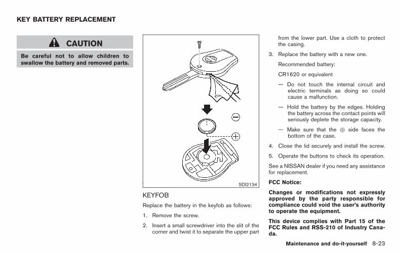
Black plate (295,1)
Model "Z12-D" EDITED: 2010/ 9/ 27
CAUTION
Be careful not to allow children toswallow the battery and removed parts.
SDI2134
KEYFOB
Replace the battery in the keyfob as follows:
1. Remove the screw.
2. Insert a small screwdriver into the slit of thecorner and twist it to separate the upper part
from the lower part. Use a cloth to protectthe casing.
3. Replace the battery with a new one.
Recommended battery:
CR1620 or equivalent
— Do not touch the internal circuit andelectric terminals as doing so couldcause a malfunction.
— Hold the battery by the edges. Holdingthe battery across the contact points willseriously deplete the storage capacity.
— Make sure that the + side faces thebottom of the case.
4. Close the lid securely and install the screw.
5. Operate the buttons to check its operation.
See a NISSAN dealer if you need any assistancefor replacement.
FCC Notice:
Changes or modifications not expresslyapproved by the party responsible forcompliance could void the user’s authorityto operate the equipment.
This device complies with Part 15 of theFCC Rules and RSS-210 of Industry Cana-da.
KEY BATTERY REPLACEMENT
Maintenance and do-it-yourself 8-23
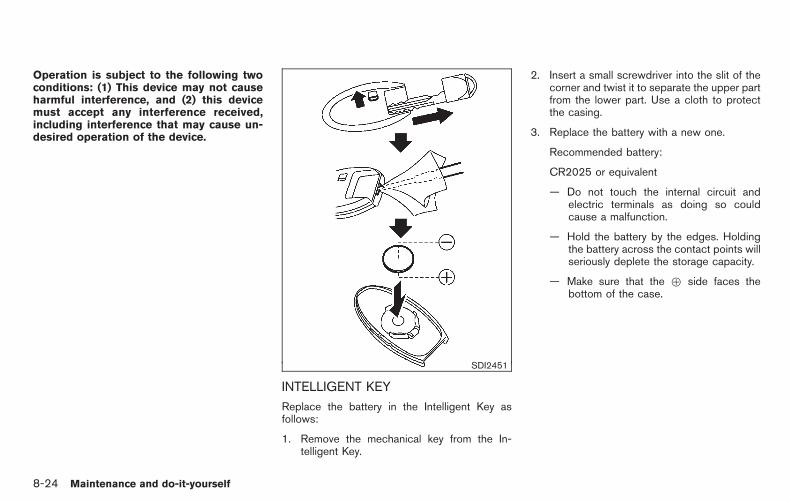
Black plate (296,1)
Model "Z12-D" EDITED: 2010/ 9/ 27
Operation is subject to the following twoconditions: (1) This device may not causeharmful interference, and (2) this devicemust accept any interference received,including interference that may cause un-desired operation of the device.
SDI2451
INTELLIGENT KEY
Replace the battery in the Intelligent Key asfollows:
1. Remove the mechanical key from the In-telligent Key.
2. Insert a small screwdriver into the slit of thecorner and twist it to separate the upper partfrom the lower part. Use a cloth to protectthe casing.
3. Replace the battery with a new one.
Recommended battery:
CR2025 or equivalent
— Do not touch the internal circuit andelectric terminals as doing so couldcause a malfunction.
— Hold the battery by the edges. Holdingthe battery across the contact points willseriously deplete the storage capacity.
— Make sure that the + side faces thebottom of the case.
8-24 Maintenance and do-it-yourself

Black plate (297,1)
Model "Z12-D" EDITED: 2010/ 9/ 27
SDI2452
4. Align the tips of the upper and lower parts*1 , and then push them together*2 until itis securely closed.
5. Operate the buttons to check its operation.
See a NISSAN dealer if you need any assistancefor replacement.
FCC Notice:
This equipment has been tested and foundto comply with the limits for a Class Bdigital device pursuant to part 15 of theFCC Rules. These limits are designed toprovide reasonable protection againstharmful interference in a residential in-stallation. This equipment generates, uses
and can radiate radio frequency energyand, if not installed and used in accor-dance with the instructions, may causeharmful interference to radio communica-tions. However, there is no guarantee thatinterference will not occur in a particularinstallation. If this equipment does causeharmful interference to radio or televisionreception, which can be determined byturning the equipment off and on, the useris encouraged to try to correct the inter-ference by one or more of the followingmeasures:
— Reorient or relocate the receiving an-tenna.
— Increase the separation between theequipment and the receiver.
— Connect the equipment into an outleton a circuit different from that to whichthe receiver is connected.
— Consult the dealer or an experiencedradio/TV technician for help.
Maintenance and do-it-yourself 8-25

Black plate (298,1)
Model "Z12-D" EDITED: 2010/ 9/ 27
SDI2497
1. Front turn signal light
2. Headlight (high-beam/low-beam)
3. Front side marker/park light
4. Map light (if so equipped)
5. Ceiling light
6. Front fog light (if so equipped)
7. Side turn signal light
8. High-mounted stop light
9. License plate light
10. Rear combination light (stop/tail/turn signal/back-up light)
11. Cargo light (if so equipped)
12. Rear side marker light
LIGHTS
8-26 Maintenance and do-it-yourself

Black plate (299,1)
Model "Z12-D" EDITED: 2010/ 9/ 27
HEADLIGHTS
Fog may temporarily form inside the lens of theexterior lights in the rain or in a car wash. Atemperature difference between the inside andthe outside of the lens causes the fog. This isnot a malfunction. If large drops of water collectinside the lens, contact a NISSAN dealer.
Replacing
Halogen headlight model:
The headlight is a semi-sealed beam type whichuses a replaceable headlight (halogen) bulb.
CAUTION
. Do not leave the bulb out of theheadlight reflector for a long periodof time. Dust, moisture, smoke, etc.entering the headlight body mayaffect bulb performance.
. High pressure halogen gas is sealedinside the halogen bulb. The bulbmay break if the glass envelope isscratched or the bulb is dropped.
. Only touch the base when handlingthe bulb. Never touch the glassenvelope. Touching the glass envel-ope could significantly affect bulblife and/or headlight performance.
. Aiming is not necessary after repla-cing the bulb. When aiming adjust-ment is necessary, contact aNISSAN dealer.
Use the same number and wattage as originallyinstalled as shown in the chart.
SDI2396
Disconnect the battery negative cable beforereplacing bulbs.
1. Remove the connector *A and the backcover *B .
2. Unlock the retaining spring *C , and thenremove the bulb.
Maintenance and do-it-yourself 8-27

Black plate (300,1)
Model "Z12-D" EDITED: 2010/ 9/ 27
EXTERIOR AND INTERIOR LIGHTS
Item Wattage (W) Bulb No.
Headlight high/low beams (Halogen) 60/55 HB2
Front turn signal light* 21 PY21W
Front fog light (if so equipped)* 35 H8
Front side marker/park light* 5 W5W
Side turn signal light* 5 WY5W
Rear combination light*
turn signal 21 PY21W
stop/tail 21/5 W21/5W
back-up 18 W16W
Rear side marker light* 5 W5W
License plate light* 5 W5W
Map light (if so equipped) 5 —
High-mounted stop light* 18 W16W
Ceiling light 8 —
Cargo light (if so equipped) 8 —
*: See a NISSAN dealer for replacement.NOTE: Always check with the Parts Department at a NISSAN dealer for the latest information about parts. SDI2306
: REMOVE
: INSTALL
Replacement proceduresAll other lights are either type A, B, C, D or E.When replacing a bulb, first remove the lensand/or cover.
8-28 Maintenance and do-it-yourself

Black plate (301,1)
Model "Z12-D" EDITED: 2010/ 9/ 27
SDI2391Map light
SDI1845Ceiling light
SDI2392Cargo light
Maintenance and do-it-yourself 8-29

Black plate (302,1)
Model "Z12-D" EDITED: 2010/ 9/ 27
If you have a flat tire, see “FLAT TIRE” inthe “6. In case of emergency” section.
TIRE PRESSURE
Tire Pressure Monitoring System (TPMS)This vehicle is equipped with the Tire PressureMonitoring System (TPMS). It monitors tirepressure of all tires except the spare. Whenthe low tire pressure warning light is lit, one ormore of your tires is significantly under-inflated.
The TPMS will activate only when the vehicle isdriven at speeds above 16 MPH (25 km/h).Also, this system may not detect a sudden dropin tire pressure (for example a flat tire whiledriving).
For more details, see “Low tire pressure warninglight” in the “2. Instruments and controls”section, “TIRE PRESSURE MONITORING SYS-TEM (TPMS)” in the “5. Starting and driving”section and “TIRE PRESSURE MONITORINGSYSTEM (TPMS)” in the “6. In case ofemergency” section.
Tire inflation pressureCheck the pressure of the tires (includingthe spare) often and always prior to longdistance trips. The recommended tirepressure specifications are shown on theTire and Loading Information label underthe “Cold Tire Pressure” heading. The Tire
and Loading Information label is affixed tothe driver side center pillar. Tire pressuresshould be checked regularly because:
. Most tires naturally lose air over time.
. Tires can lose air suddenly when drivenover potholes or other objects or if thevehicle strikes a curb while parking.
The tire pressures should be checkedwhen the tires are cold. The tires areconsidered COLD after the vehicle hasbeen parked for 3 or more hours, or drivenless than 1 mile (1.6 km) at moderatespeeds.
Incorrect tire pressure, including un-der inflation, may adversely affect tirelife and vehicle handling.
WARNING
. Improperly inflated tires can failsuddenly and cause an accident.
. The Gross Vehicle Weight rating(GVWR) is located on the F.M.V.S.S./C.M.V.S.S. certification la-bel. The vehicle weight capacityis indicated on the Tire andLoading Information label. Do
not load your vehicle beyondthis capacity. Overloading yourvehicle may result in reducedtire life, unsafe operating condi-tions due to premature tire fail-ure, or unfavorable handlingcharacteristics and could alsolead to a serious accident. Load-ing beyond the specified capa-city may also result in failure ofother vehicle components.
. Before taking a long trip, orwhenever you heavily load yourvehicle, use a tire pressuregauge to ensure that the tirepressures are at the specifiedlevel.
. For additional information re-garding tires, refer to “ImportantTire Safety Information” (US) or“Tire Safety Information” (Cana-da) in the Warranty InformationBooklet.
WHEELS AND TIRES
8-30 Maintenance and do-it-yourself

Black plate (303,1)
Model "Z12-D" EDITED: 2010/ 9/ 27
SDI2503
Tire and Loading Information label
*1 Seating capacity: The maximum num-ber of occupants that can be seatedin the vehicle.
*2 Vehicle load limit: See “VEHICLELOADING INFORMATION” in the “9.Technical and consumer information”section.
*3 Original size: The size of the tiresoriginally installed on the vehicle atthe factory.
*4 Cold tire pressure: Inflate the tires tothis pressure when the tires are cold.Tires are considered COLD after thevehicle has been parked for 3 ormore hours, or driven less than 1 mile(1.6 km) at moderate speeds. Therecommended cold tire inflation is setby the manufacturer to provide thebest balance of tire wear, vehiclehandling, driveability, tire noise, etc.,up to the vehicle’s GVWR.
*5 Tire size — see “TIRE LABELING”later in this section.
*6 Spare tire size or compact spare tiresize (if so equipped)
Maintenance and do-it-yourself 8-31

Black plate (304,1)
Model "Z12-D" EDITED: 2010/ 9/ 27
SDI1949
Checking the tire pressure1. Remove the valve stem cap from the
tire.
2. Press the pressure gauge squarely ontothe valve stem. Do not press too hard orforce the valve stem sideways, or air willescape. If the hissing sound of airescaping from the tire is heard whilechecking the pressure, reposition thegauge to eliminate this leakage.
3. Remove the gauge.
4. Read the tire pressure on the gaugestem and compare it to the specifica-
tion shown on the Tire and LoadingInformation label.
5. Add air to the tire as needed. If toomuch air is added, press the core of thevalve stem briefly with the tip of thegauge stem to release pressure. Re-check the pressure and add or releaseair as needed.
6. Install the valve stem cap.
7. Check the pressure of all other tires,including the spare.
SIZECOLD TIREINFLATIONPRESSURE
FRONTORIGINAL
TIRE
P195/60R1587H
230 kPa,33 PSI
P195/55R1686V
230 kPa,33 PSI
REARORIGINAL
TIRE
P195/60R1587H
230 kPa,33 PSI
P195/55R1686V
230 kPa,33 PSI
SPARETIRE
T125/70D15420 kPa,60 PSI
SDI1575Example
TIRE LABELING
Federal law requires tire manufacturers toplace standardized information on the side-wall of all tires. This information identifiesand describes the fundamental character-istics of the tire and also provides the tireidentification number (TIN) for safety stan-dard certification. The TIN can be used toidentify the tire in case of a recall.
8-32 Maintenance and do-it-yourself
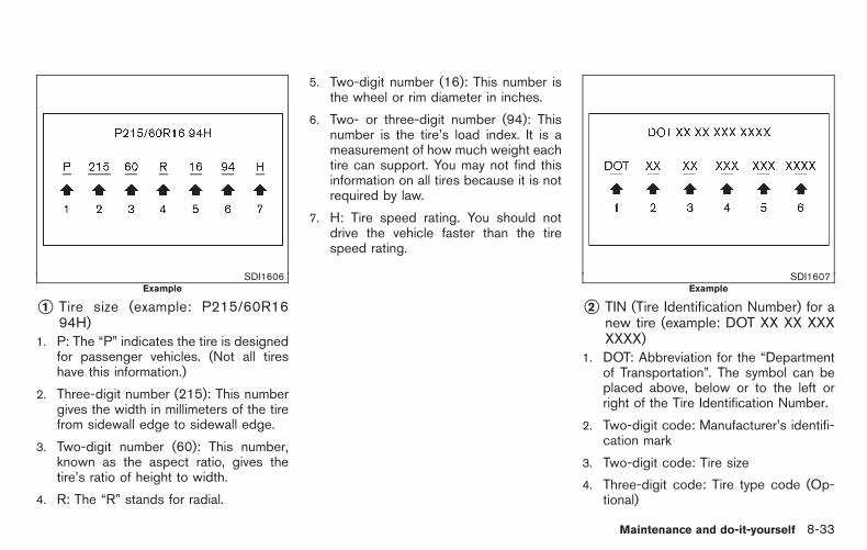
Black plate (305,1)
Model "Z12-D" EDITED: 2010/ 9/ 27
SDI1606Example
*1 Tire size (example: P215/60R1694H)
1. P: The “P” indicates the tire is designedfor passenger vehicles. (Not all tireshave this information.)
2. Three-digit number (215): This numbergives the width in millimeters of the tirefrom sidewall edge to sidewall edge.
3. Two-digit number (60): This number,known as the aspect ratio, gives thetire’s ratio of height to width.
4. R: The “R” stands for radial.
5. Two-digit number (16): This number isthe wheel or rim diameter in inches.
6. Two- or three-digit number (94): Thisnumber is the tire’s load index. It is ameasurement of how much weight eachtire can support. You may not find thisinformation on all tires because it is notrequired by law.
7. H: Tire speed rating. You should notdrive the vehicle faster than the tirespeed rating.
SDI1607Example
*2 TIN (Tire Identification Number) for anew tire (example: DOT XX XX XXXXXXX)
1. DOT: Abbreviation for the “Departmentof Transportation”. The symbol can beplaced above, below or to the left orright of the Tire Identification Number.
2. Two-digit code: Manufacturer’s identifi-cation mark
3. Two-digit code: Tire size
4. Three-digit code: Tire type code (Op-tional)
Maintenance and do-it-yourself 8-33

Black plate (306,1)
Model "Z12-D" EDITED: 2010/ 9/ 27
5. Three-digit code: Date of Manufacture
6. Four numbers represent the week andyear the tire was built. For example, thenumbers 3103 means the 31st week of2003. If these numbers are missing,then look on the other sidewall of thetire.
*3 Tire ply composition and material
The number of layers or plies ofrubber-coated fabric in the tire.Tire manufacturers also must indicatethe materials in the tire, which includesteel, nylon, polyester, and others.
*4 Maximum permissible inflation pres-sureThis number is the greatest amountof air pressure that should be put inthe tire. Do not exceed the maximumpermissible inflation pressure.
*5 Maximum load rating
This number indicates the maximumload in kilograms and pounds thatcan be carried by the tire. Whenreplacing the tires on the vehicle,always use a tire that has the same
load rating as the factory installedtire.
*6 Term of “tubeless” or “tube type”
Indicates whether the tire requires aninner tube (“tube type”) or not(“tubeless”).
*7 The word “radial”
The word “radial” is shown, if the tirehas radial structure.
*8 Manufacturer or brand name
Manufacturer or brand name isshown.
Other tire-related terminology:
In addition to the many terms that aredefined throughout this section, IntendedOutboard Sidewall is (1) the sidewall thatcontains a whitewall, bears white letteringor bears manufacturer, brand and/or modelname molding that is higher or deeper thanthe same molding on the other sidewall ofthe tire, or (2) the outward facing sidewallof an asymmetrical tire that has a particularside that must always face outward whenmounted on a vehicle.
TYPES OF TIRES
WARNING
. When changing or replacing tires,be sure all four tires are of the sametype (Example: Summer, All Seasonor Snow) and construction. ANISSAN dealer may be able to helpyou with information about tire type,size, speed rating and availability.
. Replacement tires may have a lowerspeed rating than the factoryequipped tires, and may not matchthe potential maximum vehiclespeed. Never exceed the maximumspeed rating of the tire.
. Replacing tires with those not ori-ginally specified by NISSAN couldaffect the proper operation of theTPMS.
. For additional information regard-ing tires, refer to “Important TireSafety Information” (US) or “TireSafety Information” (Canada) in theWarranty Information Booklet.
8-34 Maintenance and do-it-yourself

Black plate (307,1)
Model "Z12-D" EDITED: 2010/ 9/ 27
All season tiresNISSAN specifies all season tires on somemodels to provide good performance all year,including snowy and icy road conditions. AllSeason tires are identified by ALL SEASONand/or M&S (Mud and Snow) on the tiresidewall. Snow tires have better snow tractionthan All Season tires and may be more appro-priate in some areas.
Summer tiresNISSAN specifies summer tires on somemodels to provide superior performance on dryroads. Summer tire performance is substantiallyreduced in snow and ice. Summer tires do nothave the tire traction rating M&S on the tiresidewall.
If you plan to operate your vehicle in snowy oricy conditions, NISSAN recommends the use ofSNOW tires or ALL SEASON tires on all fourwheels.
Snow tiresIf snow tires are needed, it is necessary to selecttires equivalent in size and load rating to theoriginal equipment tires. If you do not, it canadversely affect the safety and handling of yourvehicle.
Generally, snow tires will have lower speedratings than factory equipped tires and may notmatch the potential maximum vehicle speed.
Never exceed the maximum speed rating of thetire.
If you install snow tires, they must be the samesize, brand, construction and tread pattern on allfour wheels.
For additional traction on icy roads, studdedtires may be used. However, some U.S. statesand Canadian provinces prohibit their use.Check local, state and provincial laws beforeinstalling studded tires. Skid and traction cap-abilities of studded snow tires, on wet or drysurfaces, may be poorer than that of non-studded snow tires.
TIRE CHAINS
Use of tire chains may be prohibited accordingto location. Check the local laws before instal-ling tire chains. When installing tire chains, makesure they are the proper size for the tires on yourvehicle and are installed according to the chainmanufacturer’s suggestions. Use only SAEClass S chains. Class “S” chains are used onvehicles with restricted tire to vehicle clearance.Vehicles that can use Class “S” chains aredesigned to meet the SAE standard minimumclearances between the tire and the closestvehicle suspension or body component requiredto accommodate the use of a winter tractiondevice (tire chains or cables). The minimumclearances are determined using the factoryequipped tire size. Other types may damage
your vehicle. Use chain tensioners when re-commended by the tire chain manufacturer toensure a tight fit. Loose end links of the tirechain must be secured or removed to preventthe possibility of whipping action damage to thefenders or underbody. If possible, avoid fullyloading your vehicle when using tire chains. Inaddition, drive at a reduced speed. Otherwise,your vehicle may be damaged and/or vehiclehandling and performance may be adverselyaffected.
Tire chains must be installed only on thefront wheels and not on the rear wheels.
Never install tire chains on a TEMPORARY USEONLY spare tire.
Do not use tire chains on dry roads. Driving withtire chains in such conditions can cause damageto the various mechanisms of the vehicle due tosome overstress.
Maintenance and do-it-yourself 8-35

Black plate (308,1)
Model "Z12-D" EDITED: 2010/ 9/ 27
SDI1662
CHANGING WHEELS AND TIRES
Tire rotationNISSAN recommends rotating the tiresevery 7,500 miles (12,000 km). (See “FLATTIRE” in the “6. In case of emergency”section for tire replacing procedures.)
As soon as possible, tighten the wheelnuts to the specified torque with atorque wrench.
Wheel nut tightening torque:
80 ft-lb (108 N·m)
The wheel nuts must be kept tigh-tened to the specification at all times.It is recommended that wheel nuts betightened to the specification at eachtire rotation interval.
WARNING
. After rotating the tires, checkand adjust the tire pressure.
. Retighten the wheel nuts whenthe vehicle has been driven for600 miles (1,000 km) (also incases of a flat tire, etc.).
. Do not include the spare tire orany other small size spare tire inthe tire rotation.
. For additional information re-garding tires, refer to “ImportantTire Safety Information” (US) or“Tire Safety Information” (Cana-da) in the Warranty InformationBooklet.
SDI1663
1. Wear indicator
2. Wear indicator location mark
Tire wear and damage
WARNING
. Tires should be periodically in-spected for wear, cracking, bul-ging or objects caught in thetread. If excessive wear, cracks,bulging or deep cuts are found,the tire(s) should be replaced.
. The original tires have built-intread wear indicators. When
8-36 Maintenance and do-it-yourself

Black plate (309,1)
Model "Z12-D" EDITED: 2010/ 9/ 27
wear indicators are visible, thetire(s) should be replaced.
. Tires degrade with age and use.Have tires, including the spare,over 6 years old checked by aqualified technician, becausesome tire damage may not beobvious. Replace the tires asnecessary to prevent tire failureand possible personal injury.
. Improper service of the sparetire may result in serious perso-nal injury. If it is necessary torepair the spare tire, contact aNISSAN dealer.
. For additional information re-garding tires, refer to “ImportantTire Safety Information” (US) or“Tire Safety Information” (Cana-da) in the Warranty InformationBooklet.
Replacing wheels and tiresWhen replacing a tire, use the same size, treaddesign, speed rating and load carrying capacityas originally equipped. (See “SPECIFICA-TIONS” in the “9. Technical and consumerinformation” section for recommended typesand sizes of tires and wheels.)
WARNING
. The use of tires other than thoserecommended or the mixed use oftires of different brands, construc-tion (bias, bias-belted or radial), ortread patterns can adversely affectthe ride, braking, handling, groundclearance, body-to-tire clearance,tire chain clearance, speedometercalibration, headlight aim and bum-per height. Some of these effectsmay lead to accidents and couldresult in serious personal injury.
. If the wheels are changed for anyreason, always replace with wheelswhich have the same off-set dimen-sion. Wheels of a different off-setcould cause premature tire wear,degrade vehicle handling character-istics and/or interference with thebrake discs/drums. Such interfer-ence can lead to decreased brakingefficiency and/or early brake pad/shoe wear. See “WHEELS ANDTIRES” in the “9. Technical andconsumer information” section ofthis manual for wheel off-set dimen-sions.
. When a spare tire is mounted or awheel is replaced, the TPMS will notfunction and the low tire pressurewarning light will flash for approxi-mately 1 minute. The light willremain on after 1 minute. Contactyour NISSAN dealer as soon aspossible for tire replacement and/or system resetting.
. Replacing tires with those not ori-ginally specified by NISSAN couldaffect the proper operation of theTPMS.
. Do not install a damaged or de-formed wheel or tire even if it hasbeen repaired. Such wheels or tirescould have structural damage andcould fail without warning.
. The use of retread tire is not re-commended.
. For additional information regard-ing tires, refer to “Important TireSafety Information” (US) or “TireSafety Information” (Canada) in theWarranty Information Booklet.
Maintenance and do-it-yourself 8-37

Black plate (310,1)
Model "Z12-D" EDITED: 2010/ 9/ 27
Wheel balanceUnbalanced wheels may affect vehicle handlingand tire life. Even with regular use, wheels canget out of balance. Therefore, they should bebalanced as required.
Wheel balance service should be per-formed with the wheels off the vehicle.Spin balancing the wheels on the vehiclecould lead to mechanical damage.
For additional information regarding tires, referto “Important Tire Safety Information” (US) or“Tire Safety Information” (Canada) in the War-ranty Information Booklet.
Care of wheelsSee “CLEANING EXTERIOR” in the “7. Ap-pearance and care” section for details aboutcare of the wheels.
Spare tireWhen a spare tire is mounted (TEMPORARYUSE ONLY), the TPMS will not function.
Observe the following precautions if the TEM-PORARY USE ONLY spare tire must be used,otherwise your vehicle could be damaged orinvolved in an accident.
WARNING
. The TEMPORARY USE ONLY sparetire should be used for emergencyuse. It should be replaced with thestandard tire at the first opportunityto avoid possible tire or differentialdamage.
. Drive carefully while the TEMPOR-ARY USE ONLY spare tire is in-stalled. Avoid sharp turns andabrupt braking while driving.
. Periodically check spare tire infla-tion pressure. Always keep thepressure of the TEMPORARY USEONLY spare tire at 60 psi (420 kPa,4.2 bar).
. With the TEMPORARY USE ONLYspare tire installed do not drive yourvehicle at speeds faster than 50MPH (80 km/h).
. When driving on roads covered withsnow or ice, the TEMPORARY USEONLY spare tire should be used onthe rear wheels and original tireused on the front wheels (drivewheels). Use tire chains only onthe front (original) tires.
. Tire tread of the TEMPORARY USEONLY spare tire will wear at a fasterrate than the standard tire. Replacethe spare tire as soon as the treadwear indicators appear.
. Do not use the spare tire on othervehicles.
. Do not use more than one spare tireat the same time.
CAUTION
. Do not use tire chains on a TEM-PORARY USE ONLY spare tire. Tirechains will not fit properly and maycause damage to the vehicle.
. Because the TEMPORARY USEONLY spare tire is smaller than theoriginal tire, ground clearance isreduced. To avoid damage to thevehicle, do not drive over obstacles.Also do not drive the vehiclethrough an automatic car washsince it may get caught.
8-38 Maintenance and do-it-yourself

Black plate (311,1)
Model "Z12-D" EDITED: 2010/ 9/ 27
MEMO
Maintenance and do-it-yourself 8-39

Black plate (312,1)
Model "Z12-D" EDITED: 2010/ 9/ 27
MEMO
8-40 Maintenance and do-it-yourself

Black plate (28,1)
9 Technical and consumer information
Model "Z12-D" EDITED: 2010/ 9/ 27
Capacities and recommended fuel/lubricants . . . . . . . . . . . . 9-2Fuel recommendation . . . . . . . . . . . . . . . . . . . . . . . . . . . . . . . . . . . . . . 9-3Engine oil and oil filter recommendation. . . . . . . . . . . . . . . 9-5Air conditioning system refrigerant and lubricantrecommendations . . . . . . . . . . . . . . . . . . . . . . . . . . . . . . . . . . . . . . . . . . . 9-6
Specifications. . . . . . . . . . . . . . . . . . . . . . . . . . . . . . . . . . . . . . . . . . . . . . . . . . . . 9-7Engine. . . . . . . . . . . . . . . . . . . . . . . . . . . . . . . . . . . . . . . . . . . . . . . . . . . . . . . . . 9-7Wheels and tires. . . . . . . . . . . . . . . . . . . . . . . . . . . . . . . . . . . . . . . . . . . . 9-7Dimensions and weights . . . . . . . . . . . . . . . . . . . . . . . . . . . . . . . . . . 9-8
When traveling or registering your vehicle inanother country. . . . . . . . . . . . . . . . . . . . . . . . . . . . . . . . . . . . . . . . . . . . . . . . . . 9-8Vehicle identification . . . . . . . . . . . . . . . . . . . . . . . . . . . . . . . . . . . . . . . . . . . 9-8
Vehicle Identification Number (VIN) plate . . . . . . . . . . . . . 9-8Vehicle identification number (chassis number). . . . . . 9-9Engine serial number . . . . . . . . . . . . . . . . . . . . . . . . . . . . . . . . . . . . . . 9-9F.M.V.S.S./C.M.V.S.S. certification label . . . . . . . . . . . . . . . 9-9Emission control information label . . . . . . . . . . . . . . . . . . . . 9-10Tire and loading information label . . . . . . . . . . . . . . . . . . . . . 9-10Air conditioner specification label(if so equipped) . . . . . . . . . . . . . . . . . . . . . . . . . . . . . . . . . . . . . . . . . . . 9-10
Installing front license plate . . . . . . . . . . . . . . . . . . . . . . . . . . . . . . . . 9-11Except for Krom models. . . . . . . . . . . . . . . . . . . . . . . . . . . . . . . . . 9-11
For Krom models . . . . . . . . . . . . . . . . . . . . . . . . . . . . . . . . . . . . . . . . . 9-13Vehicle loading information . . . . . . . . . . . . . . . . . . . . . . . . . . . . . . . . . 9-14
Terms . . . . . . . . . . . . . . . . . . . . . . . . . . . . . . . . . . . . . . . . . . . . . . . . . . . . . . . . 9-14Vehicle load capacity . . . . . . . . . . . . . . . . . . . . . . . . . . . . . . . . . . . . 9-14Securing the load. . . . . . . . . . . . . . . . . . . . . . . . . . . . . . . . . . . . . . . . . 9-16Loading tips. . . . . . . . . . . . . . . . . . . . . . . . . . . . . . . . . . . . . . . . . . . . . . . . 9-16Measurement of weights . . . . . . . . . . . . . . . . . . . . . . . . . . . . . . . . 9-17
Towing a trailer . . . . . . . . . . . . . . . . . . . . . . . . . . . . . . . . . . . . . . . . . . . . . . . . 9-17Flat towing . . . . . . . . . . . . . . . . . . . . . . . . . . . . . . . . . . . . . . . . . . . . . . . . . . . . . 9-17
Continuously Variable Transmission (CVT) . . . . . . . . . . 9-18Manual Transmission . . . . . . . . . . . . . . . . . . . . . . . . . . . . . . . . . . . . . 9-18
Uniform tire quality grading . . . . . . . . . . . . . . . . . . . . . . . . . . . . . . . . . 9-18Treadwear . . . . . . . . . . . . . . . . . . . . . . . . . . . . . . . . . . . . . . . . . . . . . . . . . . 9-18Traction AA, A, B and C . . . . . . . . . . . . . . . . . . . . . . . . . . . . . . . . 9-18Temperature A, B and C . . . . . . . . . . . . . . . . . . . . . . . . . . . . . . . . 9-18
Emission control system warranty. . . . . . . . . . . . . . . . . . . . . . . . . 9-19Reporting safety defects . . . . . . . . . . . . . . . . . . . . . . . . . . . . . . . . . . . . 9-19Readiness for Inspection/Maintenance (I/M) test. . . . . . 9-20Event Data Recorders (EDR) . . . . . . . . . . . . . . . . . . . . . . . . . . . . . . 9-21Owner’s Manual/Service Manual order information . . . 9-21
In the event of a collision . . . . . . . . . . . . . . . . . . . . . . . . . . . . . . . 9-21

Black plate (314,1)
Model "Z12-D" EDITED: 2010/ 9/ 27
The following are approximate capacities. The actual refill capacities may be a little different. When refilling, follow the procedureinstructed in the “8. Maintenance and do-it-yourself” section to determine the proper refill capacity.
Capacity (Approximate) Recommended specifications
US measure Imp measure Liter
Fuel 13-1/4 gal 11 gal 50 See “FUEL RECOMMENDATION” later in this section.
Engine oil*1
Drain and refill
With oil filter change 4-3/8 qt 3-5/8 qt 4.1 . Engine oil with API Certification Mark*2. Viscosity SAE 5W-30
Without oil filter change 4 qt 3-3/8 qt 3.8
Cooling system
With reservoirCVT model 7-1/2 qt 6-1/4 qt 7.1
Pre-diluted Genuine NISSAN Long Life Antifreeze/Coolant (Blue) or equivalentMT model 7-1/4 qt 6 qt 6.8
Reservoir 3/4 qt 5/8 qt 0.7
Continuously Variable Transmission (CVT) fluid — — — Genuine NISSAN CVT Fluid NS-2*3
Manual Transmission (MT) gear oil — — — Genuine NISSAN gear oil (Chevron Texaco ETL8997B) 75W-80 or equivalent*4
Brake and clutch fluidRefill to the proper oil level according to the instructions inthe “8. Maintenance and do-it-yourself” section.
Genuine NISSAN Super Heavy Duty Brake Fluid*5 or equivalent DOT 3
Multi-purpose grease — — — NLGI No. 2 (Lithium soap base)
Air conditioning system refrigerant — — — HFC-134a (R-134a)*6
Air conditioning system lubricants — — — NISSAN A/C System Oil Type R or exact equivalent
Window washer fluid 1-1/4 gal 1 gal 4.5 Genuine NISSAN Windshield Washer Concentrate Cleaner & Antifreeze or equivalent
*1: For additional information, see “ENGINE OIL” in the “8. Maintenance and do-it-yourself” section for changing engine oil.*2: For additional information, see “ENGINE OIL AND OIL FILTER RECOMMENDATION” later in this section.*3: Use only Genuine NISSAN CVT Fluid NS-2. Using transmission fluid other than Genuine NISSAN CVT Fluid NS-2 will damage the CVT, which is not covered by the NISSAN new vehicle
limited warranty.*4: If Genuine NISSAN gear oil is not available, API GL-4, Viscosity SAE 75W-80 may be used as a temporary replacement. However, use Genuine NISSAN gear oil as soon as it is available.*5: Available in mainland U.S.A. through a NISSAN dealer.*6: For additional information, see “VEHICLE IDENTIFICATION” later in this section for air conditioner specification label.
CAPACITIES AND RECOMMENDEDFUEL/LUBRICANTS
9-2 Technical and consumer information

Black plate (315,1)
Model "Z12-D" EDITED: 2010/ 9/ 27
FUEL RECOMMENDATION
Use unleaded regular gasoline with an octanerating of at least 87 AKI (Anti-Knock Index)number (Research octane number 91).
CAUTION
. Using a fuel other than that speci-fied could adversely affect the emis-sion control system, and may alsoaffect warranty coverage.
. Under no circumstances should aleaded gasoline be used, becausethis will damage the three-way cat-alyst.
. Do not use E-85 fuel in your vehicle.Your vehicle is not designed to runon E-85 fuel. Using E-85 fuel candamage the fuel system compo-nents and is not covered by theNISSAN new vehicle limited war-ranty.
Gasoline specificationsNISSAN recommends using gasoline that meetsthe World-Wide Fuel Charter (WWFC) speci-fications where it is available. Many of theautomobile manufacturers developed this spe-cification to improve emission control system
and vehicle performance. Ask your servicestation manager if the gasoline meets theWWFC specifications.
Reformulated gasolineSome fuel suppliers are now producing refor-mulated gasolines. These gasolines are speciallydesigned to reduce vehicle emissions. NISSANsupports efforts towards cleaner air and sug-gests that you use reformulated gasoline whenavailable.
Gasoline containing oxygenatesSome fuel suppliers sell gasoline containingoxygenates such as ethanol, MTBE and metha-nol with or without advertising their presence.NISSAN does not recommend the use of fuelsof which the oxygenate content and the fuelcompatibility for your NISSAN cannot be readilydetermined. If in doubt, ask your service stationmanager.
If you use oxygenate-blend gasoline, please takethe following precautions as the usage of suchfuels may cause vehicle performance problemsand/or fuel system damage.
. The fuel should be unleaded and havean octane rating no lower than thatrecommended for unleaded gasoline.
. If an oxygenate-blend, other thanmethanol blend is used, it shouldcontain no more than 10% oxygenate.
(MTBE may, however, be added up to15%.)
. If a methanol blend is used, it shouldcontain no more than 5% methanol(methyl alcohol, wood alcohol) . Itshould also contain a suitable amountof appropriate cosolvents and corro-sion inhibitors. If not properly formu-lated with appropriate cosolvents andcorrosion inhibitors, such methanolblends may cause fuel system damageand/or vehicle performance problems.At this time, sufficient data is notavailable to ensure that all methanolblends are suitable for use in NISSANvehicles.
If any driveability problems such as enginestalling and difficult hot-starting are experiencedafter using oxygenate-blend fuels, immediatelychange to a non-oxygenate fuel or a fuel with alow blend of MTBE.
Take care not to spill gasoline duringrefueling. Gasoline containing oxygenatescan cause paint damage.
E-85 fuelE-85 fuel is a mixture of approximately 85% fuelethanol and 15% unleaded gasoline. E-85 canonly be used in a Flexible Fuel Vehicle (FFV). Donot use E-85 fuel in your vehicle. U.S. govern-ment regulations require fuel ethanol dispensing
Technical and consumer information 9-3

Black plate (316,1)
Model "Z12-D" EDITED: 2010/ 9/ 27
pumps to be identified by a small, square,orange and black label with the commonabbreviation or the appropriate percentage forthat region.
Aftermarket fuel additivesNISSAN does not recommend the use of anyaftermarket fuel additives (for example, fuelinjector cleaner, octane booster, intake valvedeposit removers, etc.) which are sold commer-cially. Many of these additives intended for gum,varnish or deposit removal may contain activesolvent or similar ingredients that can be harmfulto the fuel system and engine.
Octane rating tipsUsing unleaded gasoline with an octanerating lower than recommended can causepersistent, heavy “spark knock”. (Sparkknock is a metallic rapping noise.) Ifsevere, this can lead to engine damage. Ifyou detect a persistent heavy spark knockeven when using gasoline of the statedoctane rating, or if you hear steady sparkknock while holding a steady speed onlevel roads, have a NISSAN dealer correctthe condition. Failure to correct the condi-tion is misuse of the vehicle, for whichNISSAN is not responsible.
Incorrect ignition timing will result in sparkknock, after-run and/or overheating, which maycause excessive fuel consumption or engine
damage. If any of the above symptoms areencountered, have your vehicle checked at aNISSAN dealer.
However, now and then you may noticelight spark knock for a short time whileaccelerating or driving up hills. This is not acause for concern, because you get thegreatest fuel benefit when there is lightspark knock for a short time under heavyengine load.
CAUTION
. Your vehicle is not designed to runon E-85 fuel. Using E-85 fuel in avehicle not specifically designed forE-85 fuel can damage fuel systemcomponents and is not covered bythe NISSAN new vehicle limitedwarranty.
. E-85 is a mixture of approximately85% fuel ethanol and 15% unleadedgasoline.
. U.S. government regulations requireethanol dispensing pumps to beidentified by a small, square, orangeand black label with the commonabbreviation or the appropriate per-centage for that region.
9-4 Technical and consumer information

Black plate (317,1)
Model "Z12-D" EDITED: 2010/ 9/ 27
STI0505
1. API certification mark
2. API service symbol
ENGINE OIL AND OIL FILTER RE-COMMENDATION
Selecting the correct oilIt is essential to choose the correct grade,quality, and viscosity engine oil to ensuresatisfactory engine life and performance, see“CAPACITIES AND RECOMMENDED FUEL/LUBRICANTS” earlier in this section. NISSANrecommends the use of an energy conserving oilin order to improve fuel economy.
Select only engine oils that meet the AmericanPetroleum Institute (API) certification or Interna-
tional Lubricant Standardization and ApprovalCommittee (ILSAC) certification and SAE vis-cosity standard. These oils have the APIcertification mark on the front of the container.Oils which do not have the specified qualitylabel should not be used as they could causeengine damage.
Oil additivesNISSAN does not recommend the use of oiladditives. The use of an oil additive is notnecessary when the proper oil type is used andmaintenance intervals are followed.
Oil which may contain foreign matter or hasbeen previously used should not be used.
Oil viscosityThe engine oil viscosity or thickness changeswith temperature. Because of this, it is importantto select the engine oil viscosity based on thetemperatures at which the vehicle will beoperated before the next oil change. Choosingan oil viscosity other than that recommendedcould cause serious engine damage.
Selecting the correct oil filterYour new NISSAN vehicle is equipped with ahigh-quality genuine NISSAN oil filter. Whenreplacing, use a genuine NISSAN oil filter or itsequivalent for the reason described in “Changeintervals”.
Change intervalsThe oil and oil filter change intervals for yourengine are based on the use of the specifiedquality oils and filters. Using an engine oil andfilter other than the specified quality, or exceed-ing recommended oil and filter change intervalscould reduce engine life. Damage to the enginecaused by improper maintenance or use ofincorrect oil and filter quality and/or viscosity isnot covered by the NISSAN new vehicle limitedwarranty.
Your engine was filled with a high quality engineoil when it was built. You do not have to changethe oil before the first recommended changeinterval. Oil and filter change intervals depend
Technical and consumer information 9-5

Black plate (318,1)
Model "Z12-D" EDITED: 2010/ 9/ 27
upon how you use your vehicle.
Operation under the following conditions mayrequire more frequent oil and filter changes.
. repeated short distance driving at coldoutside temperatures
. driving in dusty conditions
. extensive idling
. stop and go commuting
Refer to the “NISSAN Service and MaintenanceGuide” for the maintenance schedule.
AIR CONDITIONING SYSTEM RE-FRIGERANT AND LUBRICANT RE-COMMENDATIONS
The air conditioning system in yourNISSAN vehicle must be charged with therefrigerant HFC-134a (R-134a) and the oil,NISSAN A/C system oil Type R or the exactequivalents.
CAUTION
The use of any other refrigerant or oilwill cause severe damage to the airconditioning system and will requirethe replacement of all air conditionersystem components.
The refrigerant HFC-134a (R-134a) in yourNISSAN vehicle will not harm the earth’s ozonelayer. Although this refrigerant does not affectthe earth’s atmosphere, certain governmentalregulations require the recovery and recycling ofany refrigerant during automotive air condition-ing system service. A NISSAN dealer has thetrained technicians and equipment needed torecover and recycle your air conditioning systemrefrigerant.
Contact a NISSAN dealer when servicing yourair conditioning system.
9-6 Technical and consumer information

Black plate (319,1)
Model "Z12-D" EDITED: 2010/ 9/ 27
ENGINE
Model MR18DE
Type Gasoline, 4-cycle, DOHC
Cylinder arrangement 4-cylinder, in-line
Bore 6 Stroke in (mm) 3.307 6 3.193 (84.0 6 81.1)
Displacement cu in (cm3) 109.65 (1,798)
Firing order 1-3-4-2
Idle speed rpmNo adjustment is necessary.
Ignition timing (B.T.D.C.) degree/rpm
Spark plug Standard FXE20HR-11
Spark plug gap (Normal) in (mm) 0.043 (1.1)
Camshaft operation Timing chain
This spark ignition system complies with the Canadian standard ICES-002.
WHEELS AND TIRES
Road wheel
Type Size Offset in (mm)
Steel 15 6 6J 1.65 (42)
Aluminum 16 6 6J 1.65 (42)
T-type 15 6 4T 1.38 (35)
Tire
Type SizePressure PSI(kPa) [Cold]
Conventional
P195/60R1587H
33 (230)P195/55R1686V
T-type T125/70D15 60 (420)
SPECIFICATIONS
Technical and consumer information 9-7

Black plate (320,1)
Model "Z12-D" EDITED: 2010/ 9/ 27
DIMENSIONS AND WEIGHTS
Overall length in (mm) 156.7 (3,980)*1156.5 (3,975)*2157.8 (4,010)*1, *3157.5 (4,000)*2, *3
Overall width in (mm) 66.7 (1,695)
Overall height in (mm) 66.1 (1,680)65.0 (1,650)*3
Front tread in (mm) 58.1 (1,475)
Rear tread in (mm) 58.3 (1,480)
Wheelbase in (mm) 99.6 (2,530)
Gross VehicleWeight Rating(GVWR)
lb (kg)
See the F.M.V.S.S. orC.M.V.S.S. certificationlabel on the driver’sside center pillar.
Gross AxleWeight Rating(GAWR)
Front lb (kg)
Rear lb (kg)
*1: With front license plate bracket
*2: Without front license plate bracket
*3: Krom model
When planning to travel in another coun-try, you should first find out if the fuel available issuitable for your vehicle’s engine.
Using fuel with an octane rating that is too lowmay cause engine damage. All gasoline vehiclesmust be operated with unleaded gasoline.Therefore, avoid taking your vehicle to areaswhere appropriate fuel is not available.
When transferring the registration of yourvehicle to another country, state, provinceor district, it may be necessary to modify thevehicle to meet local laws and regulations.
The laws and regulations for motor vehicleemission control and safety standards varyaccording to the country, state, province ordistrict; therefore, vehicle specifications maydiffer.
When any vehicle is to be taken intoanother country, state, province or districtand registered, its modifications, transpor-tation, and registration are the responsi-bility of the user. NISSAN is notresponsible for any inconvenience thatmay result.
STI0457
VEHICLE IDENTIFICATION NUMBER(VIN) PLATE
The vehicle identification number plate is at-tached as shown. This number is the identifica-tion for your vehicle and is used in the vehicleregistration.
WHEN TRAVELING ORREGISTERING YOUR VEHICLE INANOTHER COUNTRY
VEHICLE IDENTIFICATION
9-8 Technical and consumer information

Black plate (321,1)
Model "Z12-D" EDITED: 2010/ 9/ 27
STI0637
VEHICLE IDENTIFICATION NUMBER(chassis number)
The vehicle identification number is located asshown.
Remove the cover to access the number.
STI0466
ENGINE SERIAL NUMBER
The number is stamped on the engine as shown.
STI0448
F.M.V.S.S./C.M.V.S.S. CERTIFICATIONLABEL
The Federal/Canadian Motor Vehicle SafetyStandards (F.M.V.S.S./C.M.V.S.S.) certificationlabel is affixed as shown. This label containsvaluable vehicle information, such as: GrossVehicle Weight Ratings (GVWR), Gross AxleWeight Rating (GAWR), month and year ofmanufacture, Vehicle Identification Number(VIN), etc. Review it carefully.
Technical and consumer information 9-9

Black plate (322,1)
Model "Z12-D" EDITED: 2010/ 9/ 27
STI0638
EMISSION CONTROL INFORMATIONLABEL
The emission control information label is at-tached to the underside of the hood as shown.
STI0494
TIRE AND LOADING INFORMATIONLABEL
The cold tire pressure is shown on the Tire andLoading Information label affixed to the pillar asshown.
STI0639
AIR CONDITIONER SPECIFICATIONLABEL (if so equipped)
The air conditioner specification label is at-tached to the underside of the hood as shown.
9-10 Technical and consumer information

Black plate (323,1)
Model "Z12-D" EDITED: 2010/ 9/ 27
STI0647
EXCEPT FOR Krom MODELS
Use the following steps to mount the licenseplate:
Before mounting the license plate, confirm thatthe following parts are enclosed in the plasticbag.
. License plate bracket
. J-nut 6 2
. Screw 6 2
. Screw grommet 6 2
1. Park the vehicle on flat, level ground.
2. Locate the center position *A on the lowerpart of the air duct. Measure straight downfrom the edge where the bumper and airduct meet to the aligning holes*B , keepingthe tape measure lined up with the centerposition.
3. Mark the holes *B with a felt-tip pen.
4. Carefully drill the two aligning holes *Busing a 0.39 in (10 mm) drill bit at themarked locations. (Be sure that the drillonly goes through the bumper fascia.)
5. Line up the bosses *C or license platebracket with the holes and hold the licenseplate bracket in place.
INSTALLING FRONT LICENSE PLATE
Technical and consumer information 9-11

Black plate (324,1)
Model "Z12-D" EDITED: 2010/ 9/ 27
6. Mark the center of the holes*D with a felt-tip pen.
7. Carefully drill the two pilot holes using a0.39 in (10 mm) drill bit at the markedlocations. (Be sure that the drill onlygoes through the bumper fascia.)
8. Insert grommets into the hole on the fascia.
9. Insert a flat-blade screwdriver into thegrommet hole to add a 908 turn onto thepart *E .
10. Insert a J-nut into the license plate bracketbefore placing the license plate bracket onthe fascia.
11. Install the license plate bracket with thescrews.
12. Install the license plate with bolts that arenot longer than 0.55 in (14 mm).
STI0648
9-12 Technical and consumer information

Black plate (325,1)
Model "Z12-D" EDITED: 2010/ 9/ 27
FOR Krom MODELS
Use the following steps to mount the licenseplate:
Before mounting the license plate, confirm thatthe following parts are enclosed in the vinyl bag.
. License plate bracket
. J-nut 6 2
. Screw 6 4
. Screw grommet 6 4
1. Park the vehicle on flat, level ground.
2. Temporarily place the license plate bracketwhile aligning points*A of the front bumperfascia with holes *B in the license platebracket.
3. Confirm that points*A and*B are aligned.Hold the license plate bracket and mark thepoints *C on the bumper facia through thecenter of the holes *D with a felt-tip pen.
4. Remove the license plate bracket.
5. Carefully drill two shallow pilot holes *Aand *C using a 0.39 in (10 mm) drill bit atthe marked locations. (Be sure that thedrill only goes through the fascia, ordamage to the nut may occur.)
6. Insert grommets into the hole on the fascia.
7. Insert a flat-blade screwdriver into thegrommet hole to add a 908 turn onto thepart *E .
8. Insert a J-nut into the license plate bracketbefore placing the license plate bracket onthe fascia.
9. Install the license plate bracket with thescrews.
10. Install the license plate with bolts that arenot longer than 0.55 in (14 mm).
Technical and consumer information 9-13

Black plate (326,1)
Model "Z12-D" EDITED: 2010/ 9/ 27
WARNING
. It is extremely dangerous to ridein a cargo area inside the vehi-cle. In a collision, people ridingin these areas are more likely tobe seriously injured or killed.
. Do not allow people to ride inany area of your vehicle that isnot equipped with seats andseat belts.
. Be sure everyone in your vehicleis in a seat and using a seat beltproperly.
TERMS
It is important to familiarize yourself with thefollowing terms before loading your vehicle:
. Curb Weight (actual weight of yourvehicle) - vehicle weight including:standard and optional equipment,fluids, emergency tools, and spare tireassembly. This weight does not in-clude passengers and cargo.
. GVW (Gross Vehicle Weight) - curbweight plus the combined weight ofpassengers and cargo.
. GVWR (Gross Vehicle Weight Rating)- maximum total combined weight of theunloaded vehicle, passengers, luggage,hitch, trailer tongue load and any otheroptional equipment. This information islocated on the F.M.V.S.S./C.M.V.S.S.label.
. GAWR (Gross Axle Weight Rating) -maximum weight (load) limit specifiedfor the front or rear axle. This informa-tion is located on the F.M.V.S.S./C.M.V.S.S. label.
. GCWR (Gross Combined Weight Rat-ing) - The maximum total weight ratingof the vehicle, passengers, cargo, andtrailer.
. Vehicle Capacity Weight, Load limit,Total load capacity - maximum totalweight limit specified of the load(passengers and cargo) for the vehicle.This is the maximum combined weightof occupants and cargo that can beloaded into the vehicle. If the vehicle isused to tow a trailer, the trailer tongueweight must be included as part of thecargo load. This information is locatedon the Tire and Loading Informationlabel.
. Cargo capacity - permissible weight ofcargo, the subtracted weight of occu-pants from the load limit.
VEHICLE LOAD CAPACITY
Do not exceed the load limit of your vehicleshown as “The combined weight of occu-pants and cargo” on the Tire and LoadingInformation label. Do not exceed thenumber of occupants shown as “SeatingCapacity” on the Tire and Loading Informa-tion label.
To get “the combined weight of occupantsand cargo”, add the weight of all occu-pants, then add the total luggage weight.Examples are shown in the followingillustration.
VEHICLE LOADING INFORMATION
9-14 Technical and consumer information

Black plate (327,1)
Model "Z12-D" EDITED: 2010/ 9/ 27
STI0447
Steps for determining correct load limit1. Locate the statement “The combined
weight of occupants and cargo shouldnever exceed XXX kg or XXX lbs” onyour vehicle’s placard.
2. Determine the combined weight of thedriver and passengers that will be ridingin your vehicle.
3. Subtract the combined weight of thedriver and passengers from XXX kg orXXX lbs.
4. The resulting figure equals the availableamount of cargo and luggage loadcapacity. For example, if the XXXamount equals 1400 lbs. and there willbe five 150 lb. passengers in yourvehicle, the amount of available cargoand luggage load capacity is 650 lbs.(1400 − 750 (5 x 150) = 650 lbs) or(640 − 340 (5 x 70) = 300 kg.)
5. Determine the combined weight ofluggage and cargo being loaded onthe vehicle. That weight may not safelyexceed the available cargo and luggageload capacity calculated in Step 4.
Before driving a loaded vehicle, confirmthat you do not exceed the Gross VehicleWeight Rating (GVWR) or the Gross AxleWeight Rating (GAWR) for your vehicle.(See “MEASUREMENT OF WEIGHTS”later in this section.)
Also check tires for proper inflation pres-sures. See the Tire and Loading Informationlabel.
Technical and consumer information 9-15

Black plate (328,1)
Model "Z12-D" EDITED: 2010/ 9/ 27
SIC4141
SECURING THE LOAD
There are tie down hooks located in the cargoarea as shown. The tie down hooks can be usedto secure cargo with ropes or other types ofstraps.
Do not apply a total load of more than 7 lb(3 kg) to a single hook *A or 22 lb (10 kg)to a single hook *B when securing cargo.
WARNING
. Properly secure all cargo with ropesor straps to help prevent it fromsliding or shifting. Do not placecargo higher than the seatbacks. In
a sudden stop or collision, unse-cured cargo could cause personalinjury.
. The child restraint top tether strapmay be damaged by contact withitems in the cargo area. Secure anyitems in the cargo area. Your childcould be seriously injured or killedin a collision if the top tether strap isdamaged.
. Do not load your vehicle any heavierthan the GVWR or the maximumfront and rear GAWRs. If you do,parts of your vehicle can break, tiredamage could occur, or it canchange the way your vehicle han-dles. This could result in loss ofcontrol and cause personal injury.
LOADING TIPS
. The GVW must not exceed GVWR orGAWR as specified on the F.M.V.S.S./C.M.V.S.S. certification label.
. Do not load the front and rear axle tothe GAWR. Doing so will exceed theGVWR.
WARNING
. Properly secure all cargo withropes or straps to help prevent itfrom sliding or shifting. Do notplace cargo higher than theseatbacks. In a sudden stop orcollision, unsecured cargo couldcause personal injury.
. Do not load your vehicle anyheavier than the GVWR or themaximum front and rearGAWRs. If you do, parts of yourvehicle can break, tire damagecould occur, or it can change theway your vehicle handles. Thiscould result in loss of controland cause personal injury.
. Overloading not only can short-en the life of your vehicle andthe tire, but can cause unsafevehicle handling and longerbraking distances. This maycause a premature tire failure,which could result in a seriousaccident and personal injury.Failures caused by overloadingare not covered by the vehicle’s
9-16 Technical and consumer information

Black plate (329,1)
Model "Z12-D" EDITED: 2010/ 9/ 27
warranty.
MEASUREMENT OF WEIGHTS
Secure loose items to prevent weight shiftsthat could affect the balance of yourvehicle. When the vehicle is loaded, driveto a scale and weigh the front and the rearwheels separately to determine axle loads.Individual axle loads should not exceedeither of the Gross Axle Weight Ratings(GAWR). The total of the axle loads shouldnot exceed the Gross Vehicle WeightRating (GVWR). These ratings are givenon the vehicle certification label. If weightratings are exceeded, move or removeitems to bring all weights below the ratings.
Do not tow a trailer with your vehicle. Towing your vehicle with all four wheels on theground is sometimes called flat towing. Thismethod is sometimes used when towing avehicle behind a recreational vehicle, such as amotor home.
CAUTION
. Failure to follow these guidelinescan result in severe transmissiondamage.
. Whenever flat towing your vehicle,always tow forward, never back-ward.
. DO NOT tow any Continuously Vari-able Transmission (CVT) vehiclewith all four wheels on the ground(flat towing). Doing so WILL DA-MAGE internal transmission partsdue to lack of transmission lubrica-tion.
. For emergency towing proceduresrefer to “TOWING YOUR VEHICLE”in the “6. In case of emergency”section of this manual.
TOWING A TRAILER FLAT TOWING
Technical and consumer information 9-17

Black plate (330,1)
Model "Z12-D" EDITED: 2010/ 9/ 27
CONTINUOUSLY VARIABLE TRANS-MISSION (CVT)
To tow a vehicle equipped with a ContinuouslyVariable Transmission (CVT), an appropriatevehicle dolly MUST be placed under the towedvehicle’s driving wheels. Always follow the dollymanufacturer’s recommendations when usingtheir product.
MANUAL TRANSMISSION
. Always tow with the manual transmission inNeutral.
. Your vehicle speed should never exceed 60MPH (96 km/h) when flat towing yourvehicle.
. After towing 500 miles, start and idle theengine with the transmission in Neutral fortwo minutes. Failure to idle the engine afterevery 500 miles of towing may causedamage to the transmission’s internal parts.
DOT (Department Of Transportation) QualityGrades: All passenger car tires must conform tofederal safety requirements in addition to thesegrades.
Quality grades can be found where applicableon the tire sidewall between tread shoulder andmaximum section width. For example:
Treadwear 200 Traction AA Temperature A
TREADWEAR
The treadwear grade is a comparative ratingbased on the wear rate of the tire when testedunder controlled conditions on a specifiedgovernment test course. For example, a tiregraded 150 would wear one and one-half(1 1/2) times as well on the government courseas a tire graded 100. The relative performanceof tires depends upon actual conditions of theiruse, however, and may depart significantly fromthe norm due to variations in driving habits,service practices and differences in road char-acteristics and climate.
TRACTION AA, A, B AND C
The traction grades, from highest to lowest, areAA, A, B and C. Those grades represent thetire’s ability to stop on wet pavement asmeasured under controlled conditions on spe-cified government test surfaces of asphalt andconcrete. A tire marked C may have poortraction performance.
WARNING
The traction grade assigned to this tireis based on straight-ahead brakingtraction tests, and does not includeacceleration, cornering, hydroplaning,or peak traction characteristics.
TEMPERATURE A, B AND C
The temperature grades A (the highest), B, andC, representing the tire’s resistance to thegeneration of heat and its ability to dissipateheat when tested under controlled conditions ona specified indoor laboratory test wheel. Sus-tained high temperature can cause the materialof the tire to degenerate and reduce tire life, andexcessive temperature can lead to sudden tirefailure. The grade C corresponds to a level ofperformance which all passenger car tires mustmeet under the Federal Motor Vehicle SafetyStandard No. 109. Grades B and A representhigher levels of performance on the laboratorytest wheel than the minimum required by law.
WARNING
The temperature grade for this tire isestablished for a tire that is properlyinflated and not overloaded. Excessivespeed, under-inflation, or excessive
UNIFORM TIRE QUALITY GRADING
9-18 Technical and consumer information

Black plate (331,1)
Model "Z12-D" EDITED: 2010/ 9/ 27
loading, either separately or in combi-nation, can cause heat build-up andpossible tire failure.
Your NISSAN is covered by the followingemission warranties.
For US:
. Emission Defects Warranty
. Emissions Performance Warranty
Details of these warranties may be found withother vehicle warranties in your Warranty In-formation Booklet which comes with yourNISSAN. If you did not receive a WarrantyInformation Booklet, or it has become lost, youmay obtain a replacement by writing to:
. Nissan North America, Inc.Consumer Affairs DepartmentP.O. Box 685003Franklin, TN 37068-5003
For Canada:
Emission Control System Warranty
Details of this warranty may be found with othervehicle warranties in your Warranty InformationBooklet which comes with your NISSAN. If youdid not receive a Warranty Information Booklet,or it has become lost, you may obtain areplacement by writing to:
. Nissan Canada Inc.5290 Orbitor DriveMississauga, Ontario,L4W 4Z5
For USA
If you believe that your vehicle has a defectwhich could cause a crash or could causeinjury or death, you should immediatelyinform the National Highway Traffic SafetyAdministration (NHTSA) in addition tonotifying NISSAN.
If NHTSA receives similar complaints, itmay open an investigation, and if it findsthat a safety defect exists in a group ofvehicles, it may order a recall and remedycampaign. However, NHTSA cannot be-come involved in individual problems be-tween you, your dealer, or NISSAN.
To contact NHTSA, you may call theVehicle Safety Hotline toll-free at 1-888-327-4236 (TTY: 1-800-424-9153); go tohttp://www.safercar.gov; or write to: Ad-ministrator, NHTSA, 400 Seventh Street,SW., Washington, D.C. 20590. You canalso obtain other information about motorvehicle safety fromhttp://www.safercar.gov.
You may notify NISSAN by contacting ourConsumer Affairs Department, toll-free, at1-800-NISSAN-1.
EMISSION CONTROL SYSTEMWARRANTY REPORTING SAFETY DEFECTS
Technical and consumer information 9-19

Black plate (332,1)
Model "Z12-D" EDITED: 2010/ 9/ 27
For Canada
If you believe that your vehicle has a defectwhich could cause a crash or could causeinjury or death, you should immediatelyinform Transport Canada in addition tonotifying NISSAN.
If Transport Canada receives complaints, itmay open an investigation, and if it findsthat a safety defect exists in a group ofvehicles, it may request that NISSANconduct a recall campaign. However,Transport Canada cannot become involvedin individual problems between you, yourdealer, or NISSAN.
You may contact Transport Canada’s De-fect Investigations and Recalls Division tollfree at 1-800-333-0510. You may alsoreport safety defects online at:https://wwwapps.tc.gc.ca/Saf-Sec-Sur/7/PCDB-BDPP/Index.aspx.
Additional information concerning motorvehicle safety may be obtained from Trans-port Canada’s Road Safety InformationCentre at 1-800-333-0371 or online atwww.tc.gc.ca/roadsafety (English speak-ers) or www.tc.gc.ca/securiteroutiere(French speakers).
To notify NISSAN of any safety concernsplease contact our Consumer InformationCenter toll free at 1-800-387-0122.
Due to legal requirements in some states/areasor provinces, your vehicle may be required to bein what is called the “ready condition” for anInspection/Maintenance (I/M) test of the emis-sion control system.
The vehicle is set to the “ready condition” whenit is driven through certain driving patterns.Usually, the “ready condition” can be obtainedby ordinary usage of the vehicle.
If a powertrain system component is repaired orthe battery is disconnected, the vehicle may bereset to a “not ready condition”. Before takingthe I/M test, check the vehicle’s inspection/maintenance test readiness condition. Place theignition switch in the ON position withoutstarting the engine. If the Malfunction IndicatorLight (MIL) comes on steady for 20 seconds andthen blinks for 10 seconds, the I/M testcondition is “not ready”. If the MIL does notblink after 20 seconds, the I/M test condition is“ready”.
Contact a NISSAN dealer to set the “readycondition” or to prepare the vehicle for testing.
READINESS FOR INSPECTION/MAINTENANCE (I/M) TEST
9-20 Technical and consumer information

Black plate (333,1)
Model "Z12-D" EDITED: 2010/ 9/ 27
This vehicle is equipped with an Event DataRecorder (EDR). The main purpose of an EDR isto record, in certain crash or near crash-likesituations, such as an air bag deployment orhitting a road obstacle, data that will assist inunderstanding how a vehicle’s systems per-formed. The EDR is designed to record datarelated to vehicle dynamics and safety systemsfor a short period of time, typically 30 secondsor less. The EDR in this vehicle is designed torecord such data as:
. How various systems in your vehicle wereoperating;
. Whether or not the driver and passengersafety belts were buckled/fastened;
. How far (if at all) the driver was depressingthe accelerator and/or brake pedal; and,
. How fast the vehicle was traveling.
. Sounds are not recorded.
These data can help provide a better under-standing of the circumstances in which crashesand injuries occur.
NOTE: EDR data are recorded by your vehicleonly if a nontrivial crash situation occurs; no dataare recorded by the EDR under normal drivingconditions and no personal data (e.g. name,gender, age and crash location) are recorded.However, other parties, such as law enforce-
ment, could combine the EDR data with the typeof personally identifying data routinely acquiredduring a crash investigation.
To read data recorded by an EDR, specialequipment is required and access to the vehicleor the EDR is needed. In addition to the vehiclemanufacturer and NISSAN dealer, other parties,such as law enforcement, that have the specialequipment, can read the information if they haveaccess to the vehicle or the EDR. EDR data willonly be accessed with the consent of the vehicleowner or lessee or as otherwise required orpermitted by law.
Genuine NISSAN Service Manuals for thismodel year and prior can be purchased. Agenuine NISSAN Service Manual is the bestsource of service and repair information for yourvehicle. This manual is the same one used by thefactory trained technicians working at a NISSANdealer. Genuine NISSAN Owner’s Manuals canalso be purchased.
In the USA:
For current pricing and availability of genuineNISSAN Service Manuals contact:
1-800-450-9491www.nissan-techinfo.com
For current pricing and availability of genuineNISSAN Owner’s Manuals contact:
1-800-247-5321
In Canada:
To purchase a copy of a genuine NISSANService Manual or Owner’s Manual for thismodel year and prior please contact a NISSANdealer. For the phone number and location of aNISSAN dealer in your area call the NISSANInformation Center at 1-800-387-0122 and abilingual NISSAN representative will assist you.
IN THE EVENT OF A COLLISION
Unfortunately, accidents do occur. In thisunlikely event, there is some important informa-
EVENT DATA RECORDERS (EDR) OWNER’S MANUAL/SERVICEMANUAL ORDER INFORMATION
Technical and consumer information 9-21

Black plate (334,1)
Model "Z12-D" EDITED: 2010/ 9/ 27
tion you should know.
Many insurance companies routinely authorizethe use of non-genuine collision parts in order tocut costs, among other reasons.
Insist on the use of Genuine NISSANCollision Parts!If you want your vehicle to be restored usingparts made to NISSAN’s original exactingspecifications — if you want to help it to lastand hold its resale value, the solution is simple.Tell your insurance agent and your repairshop to only use Genuine NISSAN Colli-sion Parts. NISSAN does not warrant non-NISSAN parts, nor does NISSAN’s warrantyapply to damage caused by a non-genuine part.
Using Genuine NISSAN Parts can help protectyour personal safety, preserve your warrantyprotection and maintain the resale value of yourvehicle. And if your vehicle was leased, usingGenuine NISSAN Parts may prevent or limitunnecessary excess wear and tear expenses atthe end of your lease.
NISSAN designs its hoods with crumple zonesto minimize the risk that the hood will penetratethe windshield of your vehicle in an accident.Non-genuine (imitation) parts may not providesuch built-in safeguards. Also, non-genuineparts often show premature wear, rust andcorrosion.
Why should you take a chance?In over 40 states, the law says you must beadvised if non-genuine parts are used to repairyour vehicle. And some states have enactedlaws that restrict insurance companies fromauthorizing the use of non-genuine collisionparts during the new vehicle warranty. Theselaws help protect you, so you can take action toprotect yourself.
It’s your right!If you should need further information visit us at:
www.nissanusa.com (for U.S. customers) orwww.nissan.ca (for Canadian customers)
9-22 Technical and consumer information

Black plate (1,1)
10 Index
A
A/C (Air Conditioner) operation . . . . . . . . . . . . . . . . . . 4-15ABS (Anti-lock Braking System). . . . . . . . . . . . . . . . . . 5-26Advanced air bag system . . . . . . . . . . . . . . . . . . . . . . . . . 1-47Air bag system
Advanced air bag system . . . . . . . . . . . . . . . . . . . . . 1-47Front passenger air bag and status light . . . . 1-49Front-seat mounted side-impactsupplemental air bag system. . . . . . . . . . . . . . . . . . 1-52Roof-mounted curtain side-impactsupplemental air bag system. . . . . . . . . . . . . . . . . . 1-52
Air bag warning labels. . . . . . . . . . . . . . . . . . . . . . . . . . . . . 1-54Air bag warning light . . . . . . . . . . . . . . . . . . . . . . . 1-55, 2-15Air cleaner housing filter . . . . . . . . . . . . . . . . . . . . . . . . . . 8-16Air conditioner
Air conditioner operation . . . . . . . . . . . . . . . . . . . . . . 4-13Air conditioner service. . . . . . . . . . . . . . . . . . . . . . . . . 4-20Air conditioner specification label . . . . . . . . . . . . 9-10Air conditioning system refrigerant andlubricant recommendations . . . . . . . . . . . . . . 4-20, 9-6In-cabin microfilter . . . . . . . . . . . . . . . . . . . . . . . . . . . . . 4-19
Alarm, How to stop alarm(see vehicle security system) . . . . . . . . . . . . . . . . . . . . . 2-20Alcohol, drugs and driving . . . . . . . . . . . . . . . . . . . . . . . . . . 5-6Antenna. . . . . . . . . . . . . . . . . . . . . . . . . . . . . . . . . . . . . . . . . . . . . 4-54Anti-lock Braking System (ABS). . . . . . . . . . . . . . . . . . 5-26Anti-lock braking system (ABS) warning light . . . 2-11Appearance care
Exterior appearance care. . . . . . . . . . . . . . . . . . . . . . . . 7-2Interior appearance care . . . . . . . . . . . . . . . . . . . . . . . . 7-5
Armrest . . . . . . . . . . . . . . . . . . . . . . . . . . . . . . . . . . . . . . . . . . . . . 1-12Audible reminders . . . . . . . . . . . . . . . . . . . . . . . . . . . . . . . . . 2-18
Audio operation precautions . . . . . . . . . . . . . . . . . . . . . . 4-20Audio setup . . . . . . . . . . . . . . . . . . . . . . . . . . . . . . . . . . . . . . . . . . 4-5Audio system. . . . . . . . . . . . . . . . . . . . . . . . . . . . . . . . . . . . . . . 4-20
Steering wheel audio controls . . . . . . . . . . . . . . . . 4-53Autolight system . . . . . . . . . . . . . . . . . . . . . . . . . . . . . . . . . . . 2-25Automatic
Air conditioner. . . . . . . . . . . . . . . . . . . . . . . . . . . . . . . . . . 4-17Door locks. . . . . . . . . . . . . . . . . . . . . . . . . . . . . . . . . . . . . . . . 3-5
AUX (Auxiliary) button . . . . . . . . . . . . . . . 4-37, 4-43, 4-48AUX (Auxiliary) input . . . . . . . . . . . . . . . . . 4-37, 4-43, 4-48Average fuel consumption. . . . . . . . . . . . . . . . . . . . . . . . . . . 2-9Average speed . . . . . . . . . . . . . . . . . . . . . . . . . . . . . . . . . . . . . . . 2-9Avoiding collision and rollover . . . . . . . . . . . . . . . . . . . . . . 5-5
B
Back door . . . . . . . . . . . . . . . . . . . . . . . . . . . . . . . . . . . . . . . . . . 3-22Battery . . . . . . . . . . . . . . . . . . . . . . . . . . . . . . . . . . . . . . . . . . . . . . 8-13
Battery replacement, Intelligent Key . . . . . . . . . . 8-24Battery replacement, Keyfob . . . . . . . . . . . . . . . . . . 8-23Battery saver system . . . . . . . . . . . . . . . . . . . . . . . . . . 2-26Variable voltage control system. . . . . . . . . . . . . . . 8-15
Before starting the engine . . . . . . . . . . . . . . . . . . . . . . . . 5-12Bluetooth® Hands-Free Phone System . . . . . . . . . . 4-55Booster seats . . . . . . . . . . . . . . . . . . . . . . . . . . . . . . . . . . . . . . 1-38Brake
Anti-lock Braking System (ABS). . . . . . . . . . . . . . 5-26Brake and clutch fluid . . . . . . . . . . . . . . . . . . . . . . . . . 8-11Brake system. . . . . . . . . . . . . . . . . . . . . . . . . . . . . . . . . . . 5-26Parking brake operation . . . . . . . . . . . . . . . . . . . . . . . 5-20Warning light . . . . . . . . . . . . . . . . . . . . . . . . . . . . . . . . . . . 2-12
Break-in schedule. . . . . . . . . . . . . . . . . . . . . . . . . . . . . . . . . . 5-23
Brightness controlDisplay ON/OFF button . . . . . . . . . . . . . . . . . . . . . . . . . 4-5Instrument panel . . . . . . . . . . . . . . . . . . . . . . . . . . . . . . . 2-27
Bulb check/instrument panel. . . . . . . . . . . . . . . . . . . . . . 2-11Bulb replacement . . . . . . . . . . . . . . . . . . . . . . . . . . . . . . . . . . 8-26
C
Cabin air filter . . . . . . . . . . . . . . . . . . . . . . . . . . . . . . . . . . . . . . 4-19Capacities and recommended fuel/lubricants . . . . . 9-2Car phone or CB radio. . . . . . . . . . . . . . . . . . . . . . . . . . . . 4-54Cargo light . . . . . . . . . . . . . . . . . . . . . . . . . . . . . . . . . . . . . . . . . 2-42Catalytic converter, Three way catalyst . . . . . . . . . . . . 5-2CD care and cleaning . . . . . . . . . . . . . . . . . . . . . . . . . . . . . 4-52Ceiling light. . . . . . . . . . . . . . . . . . . . . . . . . . . . . . . . . . . . . . . . . 2-42Child restraints . . . . . . . . . . . . . . . . . . . . . . . . . . . . . . . . . . . . . 1-23
Booster seats . . . . . . . . . . . . . . . . . . . . . . . . . . . . . . . . . . 1-38Precautions on child restraints. . . . . . . . . . . . . . . . 1-23
Child safety. . . . . . . . . . . . . . . . . . . . . . . . . . . . . . . . . . . . . . . . . 1-21Child safety rear door lock . . . . . . . . . . . . . . . . . . . . . . . . . . 3-6Chimes, Audible reminders . . . . . . . . . . . . . . . . . . . . . . . 2-18Circuit breaker, Fusible link . . . . . . . . . . . . . . . . . . . . . . . 8-21Cleaning exterior and interior . . . . . . . . . . . . . . . . . 7-2, 7-5Clock . . . . . . . . . . . . . . . . . . . . . . . . . . . . . . . . . . . . . . . . . . . . . . . 2-31Clock (models with navigation system) . . . . . . . . . . . . 4-7Clutch fluid . . . . . . . . . . . . . . . . . . . . . . . . . . . . . . . . . . . . . . . . . 8-11Cockpit . . . . . . . . . . . . . . . . . . . . . . . . . . . . . . . . . . . . . . . . . . . . . . . 2-2Cold weather driving . . . . . . . . . . . . . . . . . . . . . . . . . . . . . . 5-29Compact Disc (CD) player(See audio system) . . . . . . . . . . . . . . . . . . 4-35, 4-40, 4-46Continuously Variable Transmission (CVT)fluid . . . . . . . . . . . . . . . . . . . . . . . . . . . . . . . . . . . . . . . . . . . . . . . . . 8-11
Model "Z12-D" EDITED: 2010/ 9/ 27

Black plate (2,1)
10-2
Control panel buttons — color screen withnavigation system . . . . . . . . . . . . . . . . . . . . . . . . . . . . . . . . . . . . 4-2Controls, Steering wheel audio controls . . . . . . . . . 4-53Coolant
Capacities and recommendedfuel/lubricants . . . . . . . . . . . . . . . . . . . . . . . . . . . . . . . . . . . . 9-2Changing engine coolant. . . . . . . . . . . . . . . . . . . . . . . . 8-8Checking engine coolant level . . . . . . . . . . . . . . . . . . 8-8
Corrosion protection. . . . . . . . . . . . . . . . . . . . . . . . . . . . . . . . . 7-7Cruise control . . . . . . . . . . . . . . . . . . . . . . . . . . . . . . . . . . . . . . 5-21Cup holders . . . . . . . . . . . . . . . . . . . . . . . . . . . . . . . . . . . . . . . . 2-34CVT, Driving with CVT(Continuously Variable Transmission). . . . . . . . 5-7, 5-14
D
Daytime running light system . . . . . . . . . . . . . . . . . . . . . 2-26Defroster switch, Rear window and outsidemirror defroster switch . . . . . . . . . . . . . . . . . . . . . . . . . . . . 2-24Dimensions and weights . . . . . . . . . . . . . . . . . . . . . . . . . . . . 9-8Door open warning light. . . . . . . . . . . . . . . . . . . . . . . . . . . 2-12Drive belt . . . . . . . . . . . . . . . . . . . . . . . . . . . . . . . . . . . . . . . . . . . 8-15Driving
Cold weather driving . . . . . . . . . . . . . . . . . . . . . . . . . . 5-29Driving with CVT(Continuously Variable Transmission). . . . 5-7, 5-14Driving with manual transmission . . . . . . . . 5-8, 5-18Precautions when starting and driving . . . . . . . . . 5-2
E
Economy, Fuel . . . . . . . . . . . . . . . . . . . . . . . . . . . . . . . . . . . . . 5-23Electric power steering system . . . . . . . . . . . . . . . . . . . 5-25Electric power steering warning light . . . . . . . . . . . . 2-13Emission control information label . . . . . . . . . . . . . . . . 9-10Emission control system warranty . . . . . . . . . . . . . . . . 9-19
EngineBefore starting the engine . . . . . . . . . . . . . . . . . . . . 5-12Break-in schedule. . . . . . . . . . . . . . . . . . . . . . . . . . . . . . 5-23Capacities and recommendedfuel/lubricants . . . . . . . . . . . . . . . . . . . . . . . . . . . . . . . . . . . . 9-2Changing engine coolant. . . . . . . . . . . . . . . . . . . . . . . . 8-8Changing engine oil and filter. . . . . . . . . . . . . . . . . . . 8-9Checking engine coolant level . . . . . . . . . . . . . . . . . . 8-8Checking engine oil level. . . . . . . . . . . . . . . . . . . . . . . . 8-9Coolant temperature gauge . . . . . . . . . . . . . . . . . . . . . 2-6Emergency engine shut off. . . . . . . . . . . . . . . . . . . . 5-11Engine block heater . . . . . . . . . . . . . . . . . . . . . . . . . . . 5-30Engine compartment check locations . . . . . . . . . . 8-6Engine cooling system . . . . . . . . . . . . . . . . . . . . . . . . . . 8-7Engine oil . . . . . . . . . . . . . . . . . . . . . . . . . . . . . . . . . . . . . . . . . 8-9Engine oil and oil filter recommendation . . . . . . . 9-5Engine oil viscosity . . . . . . . . . . . . . . . . . . . . . . . . . . . . . . 9-5Engine serial number . . . . . . . . . . . . . . . . . . . . . . . . . . . . 9-9Engine specifications . . . . . . . . . . . . . . . . . . . . . . . . . . . . 9-7If your vehicle overheats. . . . . . . . . . . . . . . . . . . . . . . 6-11Starting the engine . . . . . . . . . . . . . . . . . . . . . . . . . . . . 5-12
Event Data Recorders (EDR) . . . . . . . . . . . . . . . . . . . . . 9-21Exhaust gas (carbon monoxide) . . . . . . . . . . . . . . . . . . . . 5-2
F
F.M.V.S.S./C.M.V.S.S. certification label. . . . . . . . . . . . 9-9Filter
Air cleaner housing filter . . . . . . . . . . . . . . . . . . . . . . 8-16Changing engine oil and filter. . . . . . . . . . . . . . . . . . . 8-9
Flashers (See hazard warning flasher switch) . . . 2-28Flat tire. . . . . . . . . . . . . . . . . . . . . . . . . . . . . . . . . . . . . . . . . . . . . . . . 6-2Flat towing. . . . . . . . . . . . . . . . . . . . . . . . . . . . . . . . . . . . . . . . . . 9-17Floor mat cleaning . . . . . . . . . . . . . . . . . . . . . . . . . . . . . . . . . . . 7-5
FluidBrake and clutch fluid . . . . . . . . . . . . . . . . . . . . . . . . . 8-11Capacities and recommendedfuel/lubricants . . . . . . . . . . . . . . . . . . . . . . . . . . . . . . . . . . . . 9-2Continuously Variable Transmission (CVT)fluid . . . . . . . . . . . . . . . . . . . . . . . . . . . . . . . . . . . . . . . . . . . . . 8-11Engine coolant . . . . . . . . . . . . . . . . . . . . . . . . . . . . . . . . . . . 8-7Engine oil . . . . . . . . . . . . . . . . . . . . . . . . . . . . . . . . . . . . . . . . . 8-9Window washer fluid . . . . . . . . . . . . . . . . . . . . . . . . . . 8-12
FM-AM radio with Compact Disc (CD)player . . . . . . . . . . . . . . . . . . . . . . . . . . . . . . . . . . . . . . . . 4-34, 4-38FM-AM-SAT radio with Compact Disc (CD)player . . . . . . . . . . . . . . . . . . . . . . . . . . . . . . . . . . . . . . . . . . . . . . . 4-45Fog light switch . . . . . . . . . . . . . . . . . . . . . . . . . . . . . . . . . . . . 2-28Front manual seat adjustment. . . . . . . . . . . . . . . . . . . . . . . 1-3Front passenger air bag and status light . . . . . . . . 1-49Front seat, Front seat adjustment . . . . . . . . . . . . . . . . . . 1-3Front-seat active head restraints . . . . . . . . . . . . . . . . . . . 1-9Fuel
Capacities and recommendedfuel/lubricants . . . . . . . . . . . . . . . . . . . . . . . . . . . . . . . . . . . . 9-2Distance to empty . . . . . . . . . . . . . . . . . . . . . . . . . . . . . . . 2-9Fuel economy . . . . . . . . . . . . . . . . . . . . . . . . . . . . . . . . . . 5-23Fuel octane rating. . . . . . . . . . . . . . . . . . . . . . . . . . . . . . . . 9-3Fuel recommendation. . . . . . . . . . . . . . . . . . . . . . . . . . . . 9-3Fuel-filler cap. . . . . . . . . . . . . . . . . . . . . . . . . . . . . . . . . . . 3-24Fuel-filler door. . . . . . . . . . . . . . . . . . . . . . . . . . . . . . . . . . 3-24Gauge . . . . . . . . . . . . . . . . . . . . . . . . . . . . . . . . . . . . . . . . . . . . 2-7
Fuses . . . . . . . . . . . . . . . . . . . . . . . . . . . . . . . . . . . . . . . . . . . . . . . 8-20Fusible links . . . . . . . . . . . . . . . . . . . . . . . . . . . . . . . . . . . . . . . . 8-21
G
Gas cap . . . . . . . . . . . . . . . . . . . . . . . . . . . . . . . . . . . . . . . . . . . . 3-24Gauge . . . . . . . . . . . . . . . . . . . . . . . . . . . . . . . . . . . . . . . . . . . . . . . . 2-4
Model "Z12-D" EDITED: 2010/ 9/ 27

Black plate (3,1)
Engine coolant temperature gauge . . . . . . . . . . . . . 2-6Fuel gauge . . . . . . . . . . . . . . . . . . . . . . . . . . . . . . . . . . . . . . . 2-7Odometer. . . . . . . . . . . . . . . . . . . . . . . . . . . . . . . . . . . . . . . . . 2-5Speedometer . . . . . . . . . . . . . . . . . . . . . . . . . . . . . . . . . . . . . 2-5Tachometer . . . . . . . . . . . . . . . . . . . . . . . . . . . . . . . . . . . . . . . 2-6Trip computer . . . . . . . . . . . . . . . . . . . . . . . . . . . . . . . . . . . . 2-8
General maintenance . . . . . . . . . . . . . . . . . . . . . . . . . . . . . . . . 8-2Glove box. . . . . . . . . . . . . . . . . . . . . . . . . . . . . . . . . . . . . . . . . . . 2-36
H
Hands-Free Phone System, Bluetooth®. . . . . . . . . . 4-55Hazard warning flasher switch . . . . . . . . . . . . . . . . . . . . 2-28Head restraints. . . . . . . . . . . . . . . . . . . . . . . . . . . . . . . . . . . . . . . 1-6Headlights
Bulb replacement . . . . . . . . . . . . . . . . . . . . . . . . . . . . . . 8-27Headlight switch . . . . . . . . . . . . . . . . . . . . . . . . . . . . . . . 2-24
Heated seats . . . . . . . . . . . . . . . . . . . . . . . . . . . . . . . . . . . . . . . 2-29Heater
Engine block heater . . . . . . . . . . . . . . . . . . . . . . . . . . . 5-30Heater and air conditioner operation . . . . . . . . . 4-13
Hood release. . . . . . . . . . . . . . . . . . . . . . . . . . . . . . . . . . . . . . . 3-21Hook
Luggage hook . . . . . . . . . . . . . . . . . . . . . . . . . . . . . . . . . . 2-37Utility hooks . . . . . . . . . . . . . . . . . . . . . . . . . . . . . . . . . . . . 2-37
Horn . . . . . . . . . . . . . . . . . . . . . . . . . . . . . . . . . . . . . . . . . . . . . . . . 2-29How to use the back button . . . . . . . . . . . . . . . . . . . . . . . . 4-5How to use the setup button . . . . . . . . . . . . . . . . . . . . . . . 4-5
I
Ignition switch(with Intelligent Key system) . . . . . . . . . . . . . . . . . . . . 5-9(without Intelligent Key system). . . . . . . . . . . . . . . . . 5-7Key positions . . . . . . . . . . . . . . . . . . . . . . . . . . . . . . . . . . . . . 5-8
Immobilizer system. . . . . . . . . . . . . . . . . . . . . . . . . . . . . . . . . 2-20In-cabin microfilter . . . . . . . . . . . . . . . . . . . . . . . . . . . . . . . . . 4-19Indicator lights . . . . . . . . . . . . . . . . . . . . . . . . . . . . . . . . . . . . . 2-16Inside mirror . . . . . . . . . . . . . . . . . . . . . . . . . . . . . . . . . . . . . . . . 3-27Inspection/maintenance (I/M) test . . . . . . . . . . . . . . . . 9-20Instrument brightness control . . . . . . . . . . . . . . . . . . . . . 2-27Instrument panel . . . . . . . . . . . . . . . . . . . . . . . . . . . . . . . . . . . . . 2-3Intelligent Key system . . . . . . . . . . . . . . . . . . . . . . . . . . . . . 3-10
Intelligent Key system warning light . . . . . . . . . . 2-13Key operating range . . . . . . . . . . . . . . . . . . . . . . . . . . . 3-12Key operation . . . . . . . . . . . . . . . . . . . . . . . . . . . . . . . . . . 3-13P position selecting warning light . . . . . . . . . . . . 2-15Remote keyless operation . . . . . . . . . . . . . . . . . . . . . 3-17
Interior light replacement . . . . . . . . . . . . . . . . . . . . . . . . . . 8-28Interior lights . . . . . . . . . . . . . . . . . . . . . . . . . . . . . . . . . . . . . . . 2-40iPod® connecting . . . . . . . . . . . . . . . . . . . . . . . . . . . . . . . . . . 4-42iPod® player operation. . . . . . . . . . . . . . . . . . . . . . . . . . . . . 4-50ISOFIX child restraint. . . . . . . . . . . . . . . . . . . . . . . . . . . . . . 1-24
J
Jump starting . . . . . . . . . . . . . . . . . . . . . . . . . . . . . . . . . . . . . . . . . 6-9
K
Keyless entry(See remote keyless entry system) . . . . . . . . . . . . . 3-6With Intelligent Key system(See Intelligent Key system) . . . . . . . . . . . . . . . . . . 3-17
Keys. . . . . . . . . . . . . . . . . . . . . . . . . . . . . . . . . . . . . . . . . . . . . . . . . . . 3-2For Intelligent Key system . . . . . . . . . . . . . . . . . . . . . 3-10
L
LabelsAir bag warning labels. . . . . . . . . . . . . . . . . . . . . . . . . 1-54
Air conditioner specification label . . . . . . . . . . . . 9-10Emission control information label . . . . . . . . . . . . 9-10Engine serial number . . . . . . . . . . . . . . . . . . . . . . . . . . . . 9-9F.M.V.S.S./C.M.V.S.S. certification label. . . . . . . . 9-9Tire and Loading information label . . . . 8-31, 9-10Vehicle identification number (VIN) . . . . . . . . . . . . . 9-8
LATCH system . . . . . . . . . . . . . . . . . . . . . . . . . . . . . . . . . . . . . 1-24License plate, Installing front license plate. . . . . . . 9-11Light
Air bag warning light . . . . . . . . . . . . . . . . . . . . . . . . . . 1-55Bulb replacement . . . . . . . . . . . . . . . . . . . . . . . . . . . . . . 8-26Cargo light . . . . . . . . . . . . . . . . . . . . . . . . . . . . . . . . . . . . . 2-42Ceiling light. . . . . . . . . . . . . . . . . . . . . . . . . . . . . . . . . . . . . 2-42Fog light switch . . . . . . . . . . . . . . . . . . . . . . . . . . . . . . . . 2-28Headlight switch . . . . . . . . . . . . . . . . . . . . . . . . . . . . . . . 2-24Headlights bulb replacement . . . . . . . . . . . . . . . . . 8-27Indicator lights . . . . . . . . . . . . . . . . . . . . . . . . . . . . . . . . . 2-16Interior lights . . . . . . . . . . . . . . . . . . . . . . . . . . . . . . . . . . . 2-40Map lights . . . . . . . . . . . . . . . . . . . . . . . . . . . . . . . . . . . . . . 2-41Replacement . . . . . . . . . . . . . . . . . . . . . . . . . . . . . . . . . . . 8-26Warning/indicator lights and audiblereminders . . . . . . . . . . . . . . . . . . . . . . . . . . . . . . . . . . . . . . . 2-11
Lights, Exterior and interior light replacement . . . 8-28Loading information(See vehicle loading information) . . . . . . . . . . . . . . . . . 9-14Lock
Automatic door locks . . . . . . . . . . . . . . . . . . . . . . . . . . . . 3-5Back door lock . . . . . . . . . . . . . . . . . . . . . . . . . . . . . . . . . 3-22Door locks. . . . . . . . . . . . . . . . . . . . . . . . . . . . . . . . . . . . . . . . 3-4Power door lock . . . . . . . . . . . . . . . . . . . . . . . . . . . . . . . . . 3-4
Low fuel warning light . . . . . . . . . . . . . . . . . . . . . . . . . . . . . 2-13Low tire pressure warning light . . . . . . . . . . . . . . . . . . . 2-14Low tire pressure warning system (See tirepressure monitoring system (TPMS)) . . . . . . . . . . . . . . 5-3Luggage hooks. . . . . . . . . . . . . . . . . . . . . . . . . . . . . . . . . . . . . 2-37
10-3
Model "Z12-D" EDITED: 2010/ 9/ 27

Black plate (4,1)
10-4
M
MaintenanceBattery . . . . . . . . . . . . . . . . . . . . . . . . . . . . . . . . . . . . . . . . . . 8-13General maintenance . . . . . . . . . . . . . . . . . . . . . . . . . . . . 8-2Inside the vehicle . . . . . . . . . . . . . . . . . . . . . . . . . . . . . . . . 8-3Maintenance precautions. . . . . . . . . . . . . . . . . . . . . . . . 8-5Maintenance requirements . . . . . . . . . . . . . . . . . . . . . . 8-2Outside the vehicle . . . . . . . . . . . . . . . . . . . . . . . . . . . . . . 8-2Seat belt maintenance. . . . . . . . . . . . . . . . . . . . . . . . . 1-21
Malfunction indicator light (MIL) . . . . . . . . . . . . . . . . . . 2-16Manual air conditioner . . . . . . . . . . . . . . . . . . . . . . . . . . . . . 4-14Manual front seat adjustment . . . . . . . . . . . . . . . . . . . . . . . 1-3Map lights . . . . . . . . . . . . . . . . . . . . . . . . . . . . . . . . . . . . . . . . . . 2-41Mechanical key (Intelligent Key system). . . . . . . . . . . . 3-4Meter
Trip computer . . . . . . . . . . . . . . . . . . . . . . . . . . . . . . . . . . . . 2-8Meters and gauges . . . . . . . . . . . . . . . . . . . . . . . . . . . . . . . . . . 2-4
Instrument brightness control . . . . . . . . . . . . . . . . . 2-27Mirror
Inside mirror . . . . . . . . . . . . . . . . . . . . . . . . . . . . . . . . . . . . 3-27Outside mirrors . . . . . . . . . . . . . . . . . . . . . . . . . . . . . . . . 3-27
Monitor, Rearview monitor . . . . . . . . . . . . . . . . . . . . . . . . . . 4-9
N
Navigation setup . . . . . . . . . . . . . . . . . . . . . . . . . . . . . . . . . . . . . 4-6New vehicle break-in . . . . . . . . . . . . . . . . . . . . . . . . . . . . . . 5-23NISSAN Vehicle Immobilizer System . . . . . . . . . . . . . 2-20
O
Odometer. . . . . . . . . . . . . . . . . . . . . . . . . . . . . . . . . . . . . . . . . . . . . 2-5Off-road recovery . . . . . . . . . . . . . . . . . . . . . . . . . . . . . . . . . . . . 5-5
OilCapacities and recommendedfuel/lubricants . . . . . . . . . . . . . . . . . . . . . . . . . . . . . . . . . . . . 9-2Changing engine oil and filter. . . . . . . . . . . . . . . . . . . 8-9Checking engine oil level. . . . . . . . . . . . . . . . . . . . . . . . 8-9Engine oil . . . . . . . . . . . . . . . . . . . . . . . . . . . . . . . . . . . . . . . . . 8-9Engine oil viscosity . . . . . . . . . . . . . . . . . . . . . . . . . . . . . . 9-5
Outside air temperature display . . . . . . . . . . . . . . . . . . . . 2-8Outside mirrors . . . . . . . . . . . . . . . . . . . . . . . . . . . . . . . . . . . . 3-27Overdrive OFF switch . . . . . . . . . . . . . . . . . . . . . . . . . . . . . 5-16Overheat, If your vehicle overheats . . . . . . . . . . . . . . . 6-11Owner’s Manual/Service Manual orderinformation. . . . . . . . . . . . . . . . . . . . . . . . . . . . . . . . . . . . . . . . . . 9-21
P
Panic alarm . . . . . . . . . . . . . . . . . . . . . . . . . . . . . . . . . . . . 3-8, 3-18Parking
Parking brake operation . . . . . . . . . . . . . . . . . . . . . . . 5-20Parking on hills . . . . . . . . . . . . . . . . . . . . . . . . . . . . . . . . . 5-24
PhoneBluetooth® Hands-Free Phone System . . . . . . 4-55Car phone or CB radio. . . . . . . . . . . . . . . . . . . . . . . . 4-54
PowerElectric power steering system . . . . . . . . . . . . . . . 5-25Power door lock . . . . . . . . . . . . . . . . . . . . . . . . . . . . . . . . . 3-4Power outlet. . . . . . . . . . . . . . . . . . . . . . . . . . . . . . . . . . . . 2-33Power windows . . . . . . . . . . . . . . . . . . . . . . . . . . . . . . . . 2-38
PrecautionsAudio operation . . . . . . . . . . . . . . . . . . . . . . . . . . . . . . . . 4-20Braking precautions . . . . . . . . . . . . . . . . . . . . . . . . . . . 5-26Child restraints . . . . . . . . . . . . . . . . . . . . . . . . . . . . . . . . . 1-23Cruise control . . . . . . . . . . . . . . . . . . . . . . . . . . . . . . . . . . 5-21Maintenance. . . . . . . . . . . . . . . . . . . . . . . . . . . . . . . . . . . . . . 8-5Seat belt usage . . . . . . . . . . . . . . . . . . . . . . . . . . . . . . . . 1-12
Supplemental restraint system . . . . . . . . . . . . . . . . 1-41When starting and driving. . . . . . . . . . . . . . . . . . . . . . . 5-2
Push starting . . . . . . . . . . . . . . . . . . . . . . . . . . . . . . . . . . . . . . . 6-11Push-button ignition switch . . . . . . . . . . . . . . . . . . 5-9, 5-10
R
Radio . . . . . . . . . . . . . . . . . . . . . . . . . . . . . . . . . . . . . . . . . . . . . . . 4-20Car phone or CB radio. . . . . . . . . . . . . . . . . . . . . . . . 4-54Radio operation . . . . . . . . . . . . . . . . . . . . . . . . . . . . . . . . 4-39Steering wheel audio controls . . . . . . . . . . . . . . . . 4-53
Rapid air pressure loss . . . . . . . . . . . . . . . . . . . . . . . . . . . . . . 5-6Readiness for inspection/maintenance (I/M)test . . . . . . . . . . . . . . . . . . . . . . . . . . . . . . . . . . . . . . . . . . . . . . . . . . 9-20Rear center seat belt . . . . . . . . . . . . . . . . . . . . . . . . . . . . . . 1-18Rear door lock, Child safety rear door lock. . . . . . . . 3-6Rear seats . . . . . . . . . . . . . . . . . . . . . . . . . . . . . . . . . . . . . . . . . . . . 1-4Rear window and outside mirror defrosterswitch. . . . . . . . . . . . . . . . . . . . . . . . . . . . . . . . . . . . . . . . . . . . . . . 2-24Rear window wiper and washer switch . . . . . . . . . . 2-23Rearview monitor . . . . . . . . . . . . . . . . . . . . . . . . . . . . . . . . . . . . 4-9Recorders, Event data . . . . . . . . . . . . . . . . . . . . . . . . . . . . . 9-21Registering your vehicle in another country. . . . . . . . 9-8Remote keyless entry function, For IntelligentKey system . . . . . . . . . . . . . . . . . . . . . . . . . . . . . . . . . . . . . . . . . 3-17Remote keyless entry system . . . . . . . . . . . . . . . . . . . . . . . 3-6Reporting safety defects . . . . . . . . . . . . . . . . . . . . . . . . . . 9-19Rollover . . . . . . . . . . . . . . . . . . . . . . . . . . . . . . . . . . . . . . . . . . . . . . . 5-5
S
Safety, Child seat belts. . . . . . . . . . . . . . . . . . . . . . . . . . . . 1-21Satellite radio operation . . . . . . . . . . . . . . . . . . . . . . . . . . . 4-45Seat adjustment
Front manual seat adjustment. . . . . . . . . . . . . . . . . . . 1-3Front seats . . . . . . . . . . . . . . . . . . . . . . . . . . . . . . . . . . . . . . . 1-3
Model "Z12-D" EDITED: 2010/ 9/ 27

Black plate (5,1)
Seat belt(s)Child safety. . . . . . . . . . . . . . . . . . . . . . . . . . . . . . . . . . . . . 1-21Infants. . . . . . . . . . . . . . . . . . . . . . . . . . . . . . . . . . . . . . . . . . . 1-22Injured persons. . . . . . . . . . . . . . . . . . . . . . . . . . . . . . . . . 1-15Larger children . . . . . . . . . . . . . . . . . . . . . . . . . . . . . . . . . 1-22Precautions on seat belt usage. . . . . . . . . . . . . . . 1-12Pregnant women . . . . . . . . . . . . . . . . . . . . . . . . . . . . . . . 1-15Rear center seat belt . . . . . . . . . . . . . . . . . . . . . . . . . . 1-18Seat belt cleaning . . . . . . . . . . . . . . . . . . . . . . . . . . . . . . . 7-6Seat belt extenders . . . . . . . . . . . . . . . . . . . . . . . . . . . . 1-21Seat belt hooks . . . . . . . . . . . . . . . . . . . . . . . . . . . . . . . . 1-18Seat belt maintenance. . . . . . . . . . . . . . . . . . . . . . . . . 1-21Seat belt warning light . . . . . . . . . . . . . . . . . . . . . . . . 2-15Seat belts . . . . . . . . . . . . . . . . . . . . . . . . . . . . . . . . . . . . . . 1-12Seat belts with pretensioners . . . . . . . . . . . . . . . . . 1-53Shoulder belt height adjustment . . . . . . . . . . . . . . 1-17Small children . . . . . . . . . . . . . . . . . . . . . . . . . . . . . . . . . . 1-22Three-point type . . . . . . . . . . . . . . . . . . . . . . . . . . . . . . . 1-15
Seat(s)Heated seats . . . . . . . . . . . . . . . . . . . . . . . . . . . . . . . . . . . 2-29Seats. . . . . . . . . . . . . . . . . . . . . . . . . . . . . . . . . . . . . . . . . . . . . . 1-2
Security system, Vehicle security system . . . . . . . . 2-18Security system(NISSAN Vehicle Immobilizer System),Engine start . . . . . . . . . . . . . . . . . . . . . . . . . . . . . . . . . . . . . . . . 2-20Selector lever
Shift lock release . . . . . . . . . . . . . . . . . . . . . . . . . . . . . . 5-17Servicing air conditioner. . . . . . . . . . . . . . . . . . . . . . . . . . . 4-20Shift lock release
Transmission . . . . . . . . . . . . . . . . . . . . . . . . . . . . . . . . . . . 5-17Shifting
CVT (Continuously VariableTransmission). . . . . . . . . . . . . . . . . . . . . . . . . . . . . . 5-7, 5-14Manual transmission . . . . . . . . . . . . . . . . . . . . . . 5-8, 5-18
Shoulder belt height adjustment, For frontseats . . . . . . . . . . . . . . . . . . . . . . . . . . . . . . . . . . . . . . . . . . . . . . . . 1-17SOURCE select switch . . . . . . . . . . . . . . . . . . . . . . . . . . . 4-53Spare tire . . . . . . . . . . . . . . . . . . . . . . . . . . . . . . . . . . . . . . 8-38, 9-7Spark plugs . . . . . . . . . . . . . . . . . . . . . . . . . . . . . . . . . . . . . . . . 8-16Speedometer . . . . . . . . . . . . . . . . . . . . . . . . . . . . . . . . . . . . . . . . . 2-5Starting
Before starting the engine . . . . . . . . . . . . . . . . . . . . 5-12Jump starting . . . . . . . . . . . . . . . . . . . . . . . . . . . . . . . . . . . . . 6-9Precautions when starting and driving . . . . . . . . . 5-2Push starting . . . . . . . . . . . . . . . . . . . . . . . . . . . . . . . . . . . 6-11Starting the engine . . . . . . . . . . . . . . . . . . . . . . . . . . . . 5-12
Status light, Front passenger air bag . . . . . . . . . . . . 1-49Steering
Electric power steering system . . . . . . . . . . . . . . . 5-25Steering lock . . . . . . . . . . . . . . . . . . . . . . . . . . . . . . . . . . . 5-10Steering wheel switch for audio controls . . . . 4-53Tilting steering column . . . . . . . . . . . . . . . . . . . . . . . . 3-26
Storage . . . . . . . . . . . . . . . . . . . . . . . . . . . . . . . . . . . . . . . . . . . . . 2-34Sun visors . . . . . . . . . . . . . . . . . . . . . . . . . . . . . . . . . . . . . . . . . . 3-26Supplemental air bag warning labels. . . . . . . . . . . . . 1-54Supplemental air bag warning light . . . . . . . 1-55, 2-15Supplemental restraint system . . . . . . . . . . . . . . . . . . . . 1-41
Precautions on supplemental restraintsystem . . . . . . . . . . . . . . . . . . . . . . . . . . . . . . . . . . . . . . . . . . 1-41
SwitchAudio control steering wheel switch . . . . . . . . . 4-53Autolight switch . . . . . . . . . . . . . . . . . . . . . . . . . . . . . . . . 2-25Fog light switch . . . . . . . . . . . . . . . . . . . . . . . . . . . . . . . . 2-28Hazard warning flasher switch . . . . . . . . . . . . . . . . 2-28Headlight switch . . . . . . . . . . . . . . . . . . . . . . . . . . . . . . . 2-24Overdrive OFF switch . . . . . . . . . . . . . . . . . . . . . . . . . 5-16Power door lock switch . . . . . . . . . . . . . . . . . . . . . . . . . 3-5Rear window and outside mirror defrosterswitch. . . . . . . . . . . . . . . . . . . . . . . . . . . . . . . . . . . . . . . . . . . 2-24
Turn signal switch. . . . . . . . . . . . . . . . . . . . . . . . . . . . . . 2-27Vehicle dynamic control (VDC) off switch . . . 2-29
System setup . . . . . . . . . . . . . . . . . . . . . . . . . . . . . . . . . . . . . . . . 4-6
T
Tachometer . . . . . . . . . . . . . . . . . . . . . . . . . . . . . . . . . . . . . . . . . . . 2-6Temperature display . . . . . . . . . . . . . . . . . . . . . . . . . . . . . . . . . 2-8Temperature gauge, Engine coolanttemperature gauge. . . . . . . . . . . . . . . . . . . . . . . . . . . . . . . . . . . 2-6Theft (NISSAN Vehicle Immobilizer System),Engine start . . . . . . . . . . . . . . . . . . . . . . . . . . . . . . . . . . . . . . . . 2-20Three-way catalyst . . . . . . . . . . . . . . . . . . . . . . . . . . . . . . . . . . . 5-2Tilt steering column. . . . . . . . . . . . . . . . . . . . . . . . . . . . . . . . 3-26Tire pressure, Low tire pressure warninglight . . . . . . . . . . . . . . . . . . . . . . . . . . . . . . . . . . . . . . . . . . . . . . . . . 2-14Tires
Flat tire. . . . . . . . . . . . . . . . . . . . . . . . . . . . . . . . . . . . . . . . . . . . 6-2Low tire pressure warning system. . . . . . . . . . . . . . 5-3Tire and Loading information label . . . . 8-31, 9-10Tire chains. . . . . . . . . . . . . . . . . . . . . . . . . . . . . . . . . . . . . . 8-35Tire dressing . . . . . . . . . . . . . . . . . . . . . . . . . . . . . . . . . . . . . 7-4Tire pressure . . . . . . . . . . . . . . . . . . . . . . . . . . . . . . . . . . . 8-30Tire pressure monitoring system(TPMS) . . . . . . . . . . . . . . . . . . . . . . . . . . . . . . . . . . . . . 5-3, 6-2Tire rotation . . . . . . . . . . . . . . . . . . . . . . . . . . . . . . . . . . . . 8-36Types of tires . . . . . . . . . . . . . . . . . . . . . . . . . . . . . . . . . . . 8-34Uniform tire quality grading . . . . . . . . . . . . . . . . . . . 9-18Wheel/tire size . . . . . . . . . . . . . . . . . . . . . . . . . . . . . . . . . . . 9-7Wheels and tires. . . . . . . . . . . . . . . . . . . . . . . . . . . . . . . 8-30
Touch screen. . . . . . . . . . . . . . . . . . . . . . . . . . . . . . . . . . . . . . . . . 4-3Towing
Flat towing. . . . . . . . . . . . . . . . . . . . . . . . . . . . . . . . . . . . . . 9-17Tow truck towing. . . . . . . . . . . . . . . . . . . . . . . . . . . . . . . 6-12Towing a trailer. . . . . . . . . . . . . . . . . . . . . . . . . . . . . . . . . 9-17
10-5
Model "Z12-D" EDITED: 2010/ 9/ 27

Black plate (6,1)
10-6
TPMS, Tire pressure monitoring system . . . . . . . . . . . 5-3TPMS, Tire pressure warning system . . . . . . . . . . . . . . 6-2Traffic setup . . . . . . . . . . . . . . . . . . . . . . . . . . . . . . . . . . . . . . . . . . 4-8Trailer towing . . . . . . . . . . . . . . . . . . . . . . . . . . . . . . . . . . . . . . . 9-17Transmission
Continuously Variable Transmission (CVT)fluid . . . . . . . . . . . . . . . . . . . . . . . . . . . . . . . . . . . . . . . . . . . . . 8-11Driving with CVT(Continuously Variable Transmission). . . . 5-7, 5-14Driving with manual transmission . . . . . . . . 5-8, 5-18Transmission selector lever lock release . . . . . 5-17
Transmitter (See remote keyless entry system). . . . 3-6Transmitter, With Intelligent Key system(See Intelligent Key system) . . . . . . . . . . . . . . . . . . . . . . 3-17Traveling or registering your vehicle in anothercountry. . . . . . . . . . . . . . . . . . . . . . . . . . . . . . . . . . . . . . . . . . . . . . . . 9-8Trip computer . . . . . . . . . . . . . . . . . . . . . . . . . . . . . . . . . . . . . . . . 2-8Turn signal switch. . . . . . . . . . . . . . . . . . . . . . . . . . . . . . . . . . 2-27
U
Underbody cleaning . . . . . . . . . . . . . . . . . . . . . . . . . . . . . . . . . 7-3Uniform tire quality grading . . . . . . . . . . . . . . . . . . . . . . . 9-18USB memory operation . . . . . . . . . . . . . . . . . . . . . . . . . . . 4-49
V
Variable voltage control system. . . . . . . . . . . . . . . . . . . 8-15Vehicle
Dimensions and weights . . . . . . . . . . . . . . . . . . . . . . . . 9-8Identification number (VIN) . . . . . . . . . . . . . . . . . . . . . . 9-8Information display . . . . . . . . . . . . . . . . . . . . . . . . . . . . . . . 2-8Loading information. . . . . . . . . . . . . . . . . . . . . . . . . . . . 9-14Recovery (freeing a stuck vehicle). . . . . . . . . . . . 6-16Security system . . . . . . . . . . . . . . . . . . . . . . . . . . . . . . . . 2-18Vehicle dynamic control (VDC) off switch . . . 2-29
Vehicle dynamic control (VDC) system . . . . . . 5-28Vehicle dynamic control (VDC) warninglight . . . . . . . . . . . . . . . . . . . . . . . . . . . . . . . . . . . . . . . . . . . . . 2-17
Ventilators . . . . . . . . . . . . . . . . . . . . . . . . . . . . . . . . . . . . . . . . . . 4-13Voice command(Bluetooth® Hands-Free Phone System). . . . . . . . . 4-61
W
WarningHazard warning flasher switch . . . . . . . . . . . . . . . . 2-28Lights . . . . . . . . . . . . . . . . . . . . . . . . . . . . . . . . . . . . . . . . . . . 2-11Tire pressure monitoring system(TPMS) . . . . . . . . . . . . . . . . . . . . . . . . . . . . . . . . . . . . . 5-3, 6-2Warning/indicator lights and audiblereminders . . . . . . . . . . . . . . . . . . . . . . . . . . . . . . . . . . . . . . . 2-11
Warning labels, Air bag warning labels . . . . . . . . . . 1-54Warning light
Air bag warning light . . . . . . . . . . . . . . . . . . . 1-55, 2-15Anti-lock braking system (ABS) warninglight . . . . . . . . . . . . . . . . . . . . . . . . . . . . . . . . . . . . . . . . . . . . . 2-11Brake warning light . . . . . . . . . . . . . . . . . . . . . . . . . . . . 2-12Door open warning light. . . . . . . . . . . . . . . . . . . . . . . 2-12Electric power steering warning light . . . . . . . . 2-13Intelligent Key system warning light . . . . . . . . . . 2-13Low fuel warning light . . . . . . . . . . . . . . . . . . . . . . . . . 2-13Low tire pressure warning light . . . . . . . . . . . . . . . 2-14Seat belt warning light . . . . . . . . . . . . . . . . . . . . . . . . 2-15
Warranty, Emission control system warranty. . . . . 9-19Washer switch
Rear window wiper and washer switch . . . . . . 2-23Windshield wiper and washer switch . . . . . . . . 2-21
Washing . . . . . . . . . . . . . . . . . . . . . . . . . . . . . . . . . . . . . . . . . . . . . . 7-2Waxing. . . . . . . . . . . . . . . . . . . . . . . . . . . . . . . . . . . . . . . . . . . . . . . . 7-3Weights (See dimensions and weights) . . . . . . . . . . . 9-8
Wheel/tire size . . . . . . . . . . . . . . . . . . . . . . . . . . . . . . . . . . . . . . . 9-7Wheels and tires. . . . . . . . . . . . . . . . . . . . . . . . . . . . . . . . . . . 8-30
Care of wheels. . . . . . . . . . . . . . . . . . . . . . . . . . . . . . . . . . . 7-3Cleaning aluminum alloy wheels . . . . . . . . . . . . . . . . 7-4
Window washer fluid . . . . . . . . . . . . . . . . . . . . . . . . . . . . . . 8-12Window(s)
Cleaning . . . . . . . . . . . . . . . . . . . . . . . . . . . . . . . . . . . . . . . . . . 7-3Power windows . . . . . . . . . . . . . . . . . . . . . . . . . . . . . . . . 2-38
Windshield wiper and washer switch . . . . . . . . . . . . 2-21Wiper
Rear window wiper and washer switch . . . . . . 2-23Rear window wiper blade . . . . . . . . . . . . . . . . . . . . . 8-19Windshield wiper and washer switch . . . . . . . . 2-21Wiper blades. . . . . . . . . . . . . . . . . . . . . . . . . . . . . . . . . . . 8-17
X
XM setup . . . . . . . . . . . . . . . . . . . . . . . . . . . . . . . . . . . . . . . . . . . . . 4-6
Model "Z12-D" EDITED: 2010/ 9/ 27

Black plate (7,1)
MEMO
10-7
Model "Z12-D" EDITED: 2010/ 9/ 27

Black plate (2,1)
Model "Z12-D" EDITED: 2010/ 9/ 27
FUEL RECOMMENDATION:
Use unleaded regular gasoline with an octanerating of at least 87 AKI (Anti-Knock Index)number (Research octane number 91).
CAUTION
. Using a fuel other than that speci-fied could adversely affect the emis-sion control systems, and may alsoaffect warranty coverage.
. Under no circumstances should aleaded gasoline be used, since thiswill damage the three way catalyst.
. Do not use E-85 fuel in your vehicle.Your vehicle is not designed to runon E-85 fuel. Using E-85 fuel candamage the fuel system compo-nents and is not covered by theNISSAN new vehicle limited war-ranty.
For additional information, see “CAPACITIESAND RECOMMENDED FUEL/LUBRICANTS”in the “9. Technical and consumer information”section.
ENGINE OIL RECOMMENDATION:
. Engine oil with API Certification Mark
. Viscosity SAE 5W-30
See “CAPACITIES AND RECOMMENDEDFUEL/LUBRICANTS” in the “9. Technical andconsumer information” section for engine oil andoil filter recommendation.
COLD TIRE PRESSURES:
The label is typically located on the driver sidecenter pillar or on the driver’s door. Foradditional information, see “WHEELS ANDTIRES” in the “8. Maintenance and do-it-yourself” section.
NEW VEHICLE BREAK-IN PROCE-DURES RECOMMENDATION:
During the first 1,200 miles (2,000 km) ofvehicle use, follow the recommendations out-lined in the “BREAK-IN SCHEDULE” in the “5.Starting and driving” section of this Owner’sManual. Follow these recommendations for thefuture reliability and economy of your newvehicle.
GAS STATION INFORMATION
