· 2010-10-16 · contactors dil motor-protective circuit-breakers pkz motor-starters msc...
TRANSCRIPT
www.moeller.net
Contactors DIL
Motor-protectivecircuit-breakers PKZ
Motor-starters MSC
Softstarters DS4
Drives
Rapid Link
The complete range ofcontactors, efficient motor-starters and controlleddrives for the motor circuit.New simple to installsolutions based on clevercommunication.
PKZ 2 System –
For Optimum Motor
and System Protection
Technical PaperDipl.-Ing. Wolfgang Esser
For Immediate Delivery call KMParts.com at (866) 595-9616
2
10
10
1
3
2
4
5
9
6
8
7
Dipl.-Ing. Wolfgang EsserHead of Product Support BU Circuit-Breakers, Motor Starters & DrivesMoeller GmbH, Bonn
PKZ 2 System – For Optimum Motor and System Protection –- System Description and Application Notes -
Motor and system protection systemsfor currents up to 40 A are available in the switchgear market with a widerange of alternatives in terms oftechnology and price. The top of the range devices presented here are primarily used in systems that place demanding requirements on the availability of equipment inswitchgear systems for the chemical and pharmaceutical industry, mininginstallations, and in systems in thepetroleum and raw materials industry.These installations frequently operatewith the higher operational voltages500 and 690 V, together withparticularly high short-circuit levels.
In South Africa, for example, the systemis used for 525 V systems, and in Chinafor the demanding requirements ofinfrastructure supply. In America,customers value the system's ruggeddesign and its large creepage andclearance distances. Apart from itsoutstanding electrical capabilities, the PKZ 2 product system presentedoffers some interesting additionalcomponents with unique selling pointsthat enable the creation of distinctivesolutions and ensure convenienthandling in switchgear assemblies for remote monitoring and control. A particular strength of this system iswithout doubt its tried and trusted use
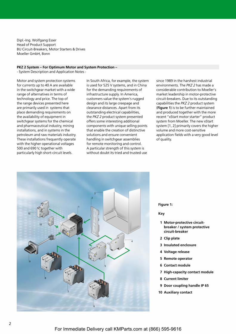
since 1989 in the harshest industrialenvironments. The PKZ 2 has made aconsiderable contribution to Moeller'smarket leadership in motor-protectivecircuit-breakers. Due to its outstandingcapabilities the PKZ 2 product system(Figure 1) is to be further maintainedand produced together with the morerecent “xStart motor starter” productsystem from Moeller. The new xStartsystem [1, 2] primarily covers the highervolume and more cost-sensitiveapplication fields with a very good levelof quality.
Figure 1:
Key
1 Motor-protective circuit-breaker / system protectivecircuit-breaker
2 Clip plate
3 Insulated enclosure
4 Voltage release
5 Remote operator
6 Contact module
7 High-capacity contact module
8 Current limiter
9 Door coupling handle IP 65
10 Auxiliary contact
For Immediate Delivery call KMParts.com at (866) 595-9616

3
Contents
Page
Introduction 2
Contents 3
Motor-protective circuit-breaker or circuit-breaker? 4
Motor or system protection 4
Motor-protective circuit-breaker in an individual enclosure, the smallest switchgear assembly 8
Occasional operational switching 9
Occasional switching with remote operators 9
Overload protection 12
Short-circuit protection 12
• Inherent stability of the circuit-breaker 13
Controlling particularly high short-circuit currents with CL-PKZ2 current limiters 15
Separate short-circuit protection and overload protection? 17
Pluggable overcurrent and short-circuit releases 18
Alternatives and combinations for motor protection 19
Remote tripping, with voltage-dependent releases 19
Informative signalling 20
High-frequency operational switching with contactors or contact modules 20
• The current limiting effects of high-capacity contact modules 21
Mounting forms of the PKZ 2 motor and system protective circuit-breakers 21
Switchgear for the world market and special requirements for use in North America 22
• PKZ 2 as a motor-protective circuit-breaker for North America 23
• PKZ 2 as a non-manual motor starter for North America 23
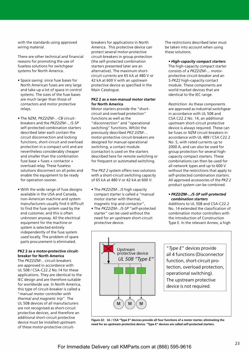
- High-capacity compact starters 23
- PKZ2/ZM-.../S-SP self-protected combination starters 23
• PKZ 2 as a circuit-breaker for North America 25
• Insulated enclosures and accessories 25
Validity of information 26
Bibliography 26
For Immediate Delivery call KMParts.com at (866) 595-9616
4
Motor-protective circuit-breaker or circuit-breaker?
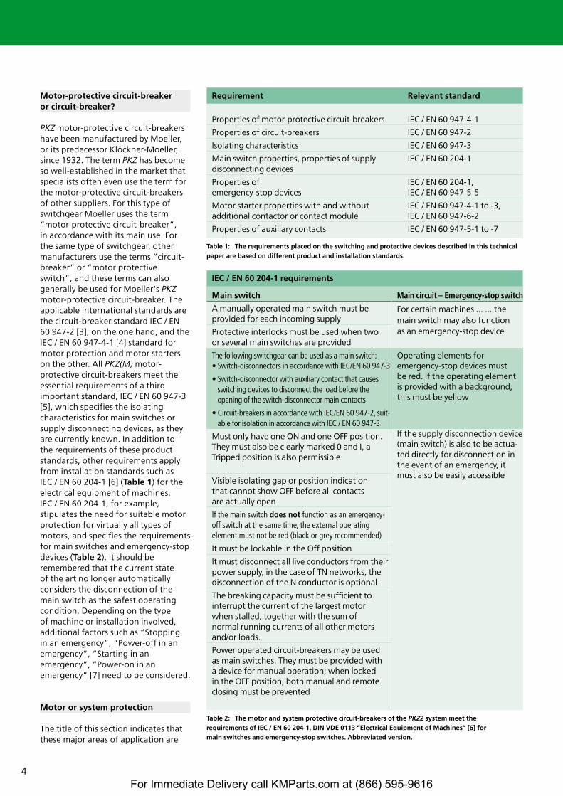
PKZ motor-protective circuit-breakershave been manufactured by Moeller,or its predecessor Klöckner-Moeller,since 1932. The term PKZ has becomeso well-established in the market thatspecialists often even use the term forthe motor-protective circuit-breakers of other suppliers. For this type ofswitchgear Moeller uses the term“motor-protective circuit-breaker”, in accordance with its main use. For the same type of switchgear, othermanufacturers use the terms “circuit-breaker” or “motor protectiveswitch”, and these terms can alsogenerally be used for Moeller's PKZmotor-protective circuit-breaker. Theapplicable international standards arethe circuit-breaker standard IEC / EN60 947-2 [3], on the one hand, and theIEC / EN 60 947-4-1 [4] standard formotor protection and motor starterson the other. All PKZ(M) motor-protective circuit-breakers meet theessential requirements of a thirdimportant standard, IEC / EN 60 947-3[5], which specifies the isolatingcharacteristics for main switches orsupply disconnecting devices, as theyare currently known. In addition to the requirements of these productstandards, other requirements applyfrom installation standards such as IEC / EN 60 204-1 [6] (Table 1) for theelectrical equipment of machines. IEC / EN 60 204-1, for example,stipulates the need for suitable motorprotection for virtually all types ofmotors, and specifies the requirementsfor main switches and emergency-stopdevices (Table 2). It should beremembered that the current state of the art no longer automaticallyconsiders the disconnection of themain switch as the safest operatingcondition. Depending on the type of machine or installation involved,additional factors such as “Stopping in an emergency”, “Power-off in anemergency”, “Starting in anemergency”, “Power-on in anemergency” [7] need to be considered.
Motor or system protection
The title of this section indicates thatthese major areas of application are
Table 1: The requirements placed on the switching and protective devices described in this technicalpaper are based on different product and installation standards.
Requirement Relevant standard
Properties of motor-protective circuit-breakers IEC / EN 60 947-4-1
Properties of circuit-breakers IEC / EN 60 947-2
Isolating characteristics IEC / EN 60 947-3
Main switch properties, properties of supply IEC / EN 60 204-1disconnecting devices
Properties of IEC / EN 60 204-1, emergency-stop devices IEC / EN 60 947-5-5
Motor starter properties with and without IEC / EN 60 947-4-1 to -3,additional contactor or contact module IEC / EN 60 947-6-2
Properties of auxiliary contacts IEC / EN 60 947-5-1 to -7
Table 2: The motor and system protective circuit-breakers of the PKZ2 system meet the requirements of IEC / EN 60 204-1, DIN VDE 0113 “Electrical Equipment of Machines” [6] for main switches and emergency-stop switches. Abbreviated version.
IEC / EN 60 204-1 requirements
Main switch
A manually operated main switch must be provided for each incoming supply
Protective interlocks must be used when two or several main switches are provided
The following switchgear can be used as a main switch:• Switch-disconnectors in accordance with IEC/EN 60 947-3
• Switch-disconnector with auxiliary contact that causesswitching devices to disconnect the load before the opening of the switch-disconnector main contacts
• Circuit-breakers in accordance with IEC/EN 60 947-2, suit-able for isolation in accordance with IEC / EN 60 947-3
Must only have one ON and one OFF position.They must also be clearly marked 0 and I, a Tripped position is also permissible
Visible isolating gap or position indication that cannot show OFF before all contacts are actually open
If the main switch does not function as an emergency-off switch at the same time, the external operating element must not be red (black or grey recommended)
It must be lockable in the Off position
It must disconnect all live conductors from theirpower supply, in the case of TN networks, thedisconnection of the N conductor is optional
The breaking capacity must be sufficient tointerrupt the current of the largest motor when stalled, together with the sum of normal running currents of all other motorsand/or loads.
Power operated circuit-breakers may be used as main switches. They must be provided with a device for manual operation; when locked in the OFF position, both manual and remoteclosing must be prevented
Main circuit – Emergency-stop switch
For certain machines ... ... themain switch may also function as an emergency-stop device
Operating elements for emergency-stop devices must be red. If the operating elementis provided with a background,this must be yellow
If the supply disconnection device(main switch) is also to be actua-ted directly for disconnection inthe event of an emergency, itmust also be easily accessible
For Immediate Delivery call KMParts.com at (866) 595-9616
5
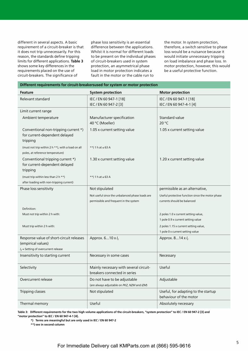
different in several aspects. A basicrequirement of a circuit-breaker is thatit does not trip unnecessarily. For thisreason, the standards define trippinglimits for different applications. Table 3shows some key differences in therequirements placed on the use ofcircuit-breakers. The significance of
phase loss sensitivity is an essentialdifference between the applications.Whilst it is normal for different loadsto be present on the individual phasesof circuit-breakers used in systemprotection, an asymmetrical phaseload in motor protection indicates afault in the motor or the cable run to
the motor. In system protection,therefore, a switch sensitive to phaseloss would be a nuisance because itwould initiate unnecessary tripping on load imbalance and phase loss. Inmotor protection, however, this wouldbe a useful protective function.
Table 3: Different requirements for the two high volume applications of the circuit-breakers, “system protection” to IEC / EN 60 947-2 [3] and “motor protection” to IEC / EN 60 947-4-1 [4].
*) Terms are meaningful but are only used in IEC / EN 60 947-2**) see in second column
Different requirements for circuit-breakersused for system or motor protection
Feature
Relevant standard
Limit current range
Ambient temperature
Conventional non-tripping current *)
for current-dependent delayed
tripping
(must not trip within 2 h **), with a load on all
poles, at reference temperature)
Conventional tripping current *)
for current-dependent delayed
tripping
(must trip within less than 2 h **)
after loading with non-tripping current)
Phase loss sensitivity
Definition:
Must not trip within 2 h with:
Must trip within 2 h with:
Response value of short-circuit releases
(empirical values)
Ir = Setting of overcurrent release
Insensitivity to starting current
Selectivity
Overcurrent release
Tripping classes
Thermal memory
System protection
IEC / EN 60 947-1 [18]
IEC / EN 60 947-2 [3]
Manufacturer specification
40 °C (Moeller)
1.05 x current setting value
**) 1 h at ≤ 63 A
1.30 x current setting value
**) 1 h at ≤ 63 A
Not stipulated
Not useful since the unbalanced phase loads are
permissible and frequent in the system
Approx. 6...10 x Ir
Necessary in some cases
Mainly necessary with several circuit-
breakers connected in series
Do not have to be adjustable
(are always adjustable on PKZ, NZM and IZM)
Not stipulated
Useful
Motor protection
IEC / EN 60 947-1 [18]
IEC / EN 60 947-4-1 [4]
Standard value
20 °C
1.05 x current setting value
1.20 x current setting value
permissible as an alternative,
Useful protective function since the motor phase
currents should be balanced
2 poles 1.0 x current setting value,
1 pole 0.9 x current setting value
2 poles 1.15 x current setting value,
1 pole 0 x current setting value
Approx. 8...14 x Ir
Necessary
Useful
Adjustable
Useful, for adapting to the startup
behaviour of the motor
Absolutely necessary
For Immediate Delivery call KMParts.com at (866) 595-9616
6
1 3 5
2 4 6I > I > I >
1 3 5
2 4 6
I > I > I >
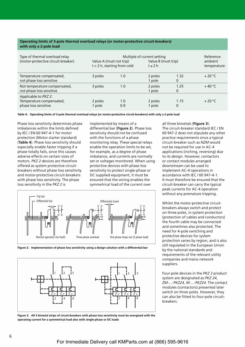
Phase loss sensitivity determines phaseimbalances within the limits definedby IEC / EN 60 947-4-1 for motorprotection (Motor starter standard)(Table 4). Phase loss sensitivity shouldespecially enable faster tripping if aphase totally fails, since this causesadverse effects on certain sizes ofmotors. PKZ 2 devices are thereforeoffered as system protective circuit-breakers without phase loss sensitivityand motor-protective circuit-breakerswith phase loss sensitivity. The phaseloss sensitivity in the PKZ 2 is
implemented by means of adifferential bar (Figure 2). Phase losssensitivity should not be confusedwith the functions of a phasemonitoring relay. These special relaysenable the operation limits to be set,for example, as a degree of phaseimbalance, and currents are normallyset or voltages monitored. When usingprotective devices with phase losssensitivity to protect single-phase orDC supplied equipment, it must beensured that the wiring enables thesymmetrical load of the current over
all three bimetals (Figure 3).The circuit-breaker standard IEC / EN 60 947-2 does not stipulate any otherpractice requirements since a typicalcircuit-breaker such as NZM would not be required for use in AC-4applications (inching, reversing) dueto its design. However, contactors or contact modules arrangeddownstream can be used toimplement AC-4 operations inaccordance with IEC / 60 947-4-1. It must therefore be ensured that thecircuit-breaker can carry the typicalpeak currents for AC-4 operationwithout any premature tripping.
Whilst the motor-protective circuit-breakers always switch and protect on three poles, in system protection(protection of cables and conductors) the fourth cable may be connectedand sometimes also protected. Theneed for 4-pole switching andprotective devices for systemprotection varies by region, and is alsostill regulated in the European Unionby the national standards andrequirements of the relevant utilitycompanies and mains networksuppliers.
Four-pole devices in the PKZ 2 productsystem are designated as PKZ 24, ZM-...-PKZ24, M-...-PKZ24. The contactmodules (contactors) presented laterswitch on three poles. However, theycan also be fitted to four-pole circuit-breakers.
Table 4: Operating limits of 3-pole thermal overload relays (or motor-protective circuit-breakers) with only a 2-pole load
Figure 2: Implementation of phase loss sensitivity using a design solution with a differential bar
Trip bar
S 97 95
98 96
97 95
98 96
97 95
98 96
Differential bar
Normal operation (no fault) Three-phase overload One phase drops out (2-phase load)
Differential travel
Figure 3: All 3 bimetal strips of circuit-breakers with phase loss sensitivity must be energized with theoperating current for a symmetrical load also with single-phase or DC loads
Type of thermal overload relay Multiple of current setting Reference (motor-protective circuit-breaker) Value A (must not trip) Value B (must trip) ambient
t > 2 h, starting from cold t ≤ 2 h temperature
Temperature compensated, 3 poles 1.0 2 poles 1.32 + 20 °Cnot phase loss sensitive 1 pole 0
Not temperature-compensated, 3 poles 1.0 2 poles 1.25 + 40 °Cnot phase loss sensitive 1 pole 0
Applicable to PKZ 2:Temperature compensated, 2 poles 1.0 2 poles 1.15 + 20 °Cphase loss sensitive 1 pole 0.9 1 pole 0
Operating limits of 3-pole thermal overload relays (or motor-protective circuit-breakers)with only a 2-pole load
For Immediate Delivery call KMParts.com at (866) 595-9616
7
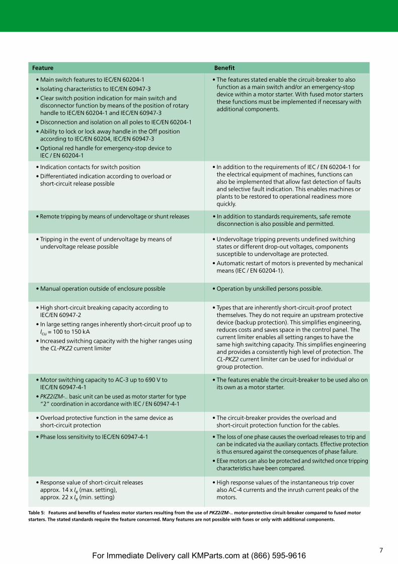
Table 5: Features and benefits of fuseless motor starters resulting from the use of PKZ2/ZM-.. motor-protective circuit-breaker compared to fused motorstarters. The stated standards require the feature concerned. Many features are not possible with fuses or only with additional components.
Feature Benefit
• Main switch features to IEC/EN 60204-1
• Isolating characteristics to IEC/EN 60947-3
• Clear switch position indication for main switch and disconnector function by means of the position of rotaryhandle to IEC/EN 60204-1 and IEC/EN 60947-3
• Disconnection and isolation on all poles to IEC/EN 60204-1
• Ability to lock or lock away handle in the Off position according to IEC/EN 60204, IEC/EN 60947-3
• Optional red handle for emergency-stop device to IEC / EN 60204-1
• The features stated enable the circuit-breaker to alsofunction as a main switch and/or an emergency-stopdevice within a motor starter. With fused motor startersthese functions must be implemented if necessary withadditional components.
• Indication contacts for switch position
• Differentiated indication according to overload or short-circuit release possible
• In addition to the requirements of IEC / EN 60204-1 forthe electrical equipment of machines, functions canalso be implemented that allow fast detection of faultsand selective fault indication. This enables machines orplants to be restored to operational readiness morequickly.
• Tripping in the event of undervoltage by means of undervoltage release possible
• Undervoltage tripping prevents undefined switchingstates or different drop-out voltages, components susceptible to undervoltage are protected.
• Automatic restart of motors is prevented by mechanicalmeans (IEC / EN 60204-1).
• Remote tripping by means of undervoltage or shunt releases • In addition to standards requirements, safe remote disconnection is also possible and permitted.
• Manual operation outside of enclosure possible • Operation by unskilled persons possible.
• High short-circuit breaking capacity according to IEC/EN 60947-2
• In large setting ranges inherently short-circuit proof up to Icu = 100 to 150 kA
• Increased switching capacity with the higher ranges usingthe CL-PKZ2 current limiter
• Types that are inherently short-circuit-proof protectthemselves. They do not require an upstream protectivedevice (backup protection). This simplifies engineering,reduces costs and saves space in the control panel. Thecurrent limiter enables all setting ranges to have thesame high switching capacity. This simplifies engineeringand provides a consistently high level of protection. TheCL-PKZ2 current limiter can be used for individual orgroup protection.
• Motor switching capacity to AC-3 up to 690 V to IEC/EN 60947-4-1
• PKZ2/ZM-.. basic unit can be used as motor starter for type“2” coordination in accordance with IEC / EN 60947-4-1
• The features enable the circuit-breaker to be used also onits own as a motor starter.
• Phase loss sensitivity to IEC/EN 60947-4-1 • The loss of one phase causes the overload releases to trip andcan be indicated via the auxiliary contacts. Effective protectionis thus ensured against the consequences of phase failure.
• EExe motors can also be protected and switched once trippingcharacteristics have been compared.
• Overload protective function in the same device as short-circuit protection
• The circuit-breaker provides the overload and short-circuit protection function for the cables.
• Response value of short-circuit releasesapprox. 14 x Ie (max. setting),approx. 22 x Ie (min. setting)
• High response values of the instantaneous trip cover also AC-4 currents and the inrush current peaks of themotors.
For Immediate Delivery call KMParts.com at (866) 595-9616
8
SCL
SCL
90°
90°
90°
90°
30°PKZ2PKZ2/.../SPKZ2/.../+CL
PKZ2/.../S
PKZ2PKZ2/.../+CL{90
°
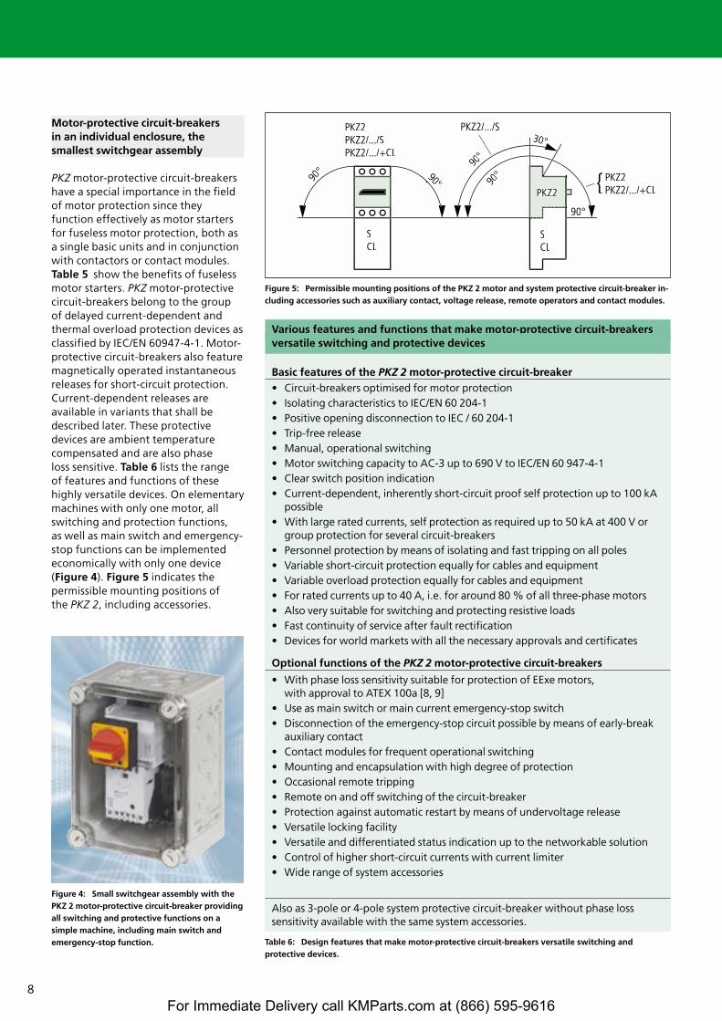
Motor-protective circuit-breakers in an individual enclosure, the smallest switchgear assembly
PKZ motor-protective circuit-breakershave a special importance in the fieldof motor protection since theyfunction effectively as motor startersfor fuseless motor protection, both asa single basic units and in conjunctionwith contactors or contact modules.Table 5 show the benefits of fuselessmotor starters. PKZ motor-protectivecircuit-breakers belong to the group of delayed current-dependent andthermal overload protection devices asclassified by IEC/EN 60947-4-1. Motor-protective circuit-breakers also featuremagnetically operated instantaneousreleases for short-circuit protection.Current-dependent releases areavailable in variants that shall bedescribed later. These protectivedevices are ambient temperaturecompensated and are also phase loss sensitive. Table 6 lists the range of features and functions of thesehighly versatile devices. On elementarymachines with only one motor, allswitching and protection functions, as well as main switch and emergency-stop functions can be implementedeconomically with only one device(Figure 4). Figure 5 indicates thepermissible mounting positions of the PKZ 2, including accessories.
Table 6: Design features that make motor-protective circuit-breakers versatile switching and protective devices.
Various features and functions that make motor-protective circuit-breakersversatile switching and protective devices
Basic features of the PKZ 2 motor-protective circuit-breaker• Circuit-breakers optimised for motor protection• Isolating characteristics to IEC/EN 60 204-1• Positive opening disconnection to IEC / 60 204-1• Trip-free release• Manual, operational switching• Motor switching capacity to AC-3 up to 690 V to IEC/EN 60 947-4-1• Clear switch position indication • Current-dependent, inherently short-circuit proof self protection up to 100 kA
possible• With large rated currents, self protection as required up to 50 kA at 400 V or
group protection for several circuit-breakers• Personnel protection by means of isolating and fast tripping on all poles• Variable short-circuit protection equally for cables and equipment• Variable overload protection equally for cables and equipment• For rated currents up to 40 A, i.e. for around 80 % of all three-phase motors• Also very suitable for switching and protecting resistive loads• Fast continuity of service after fault rectification• Devices for world markets with all the necessary approvals and certificates
Optional functions of the PKZ 2 motor-protective circuit-breakers
• With phase loss sensitivity suitable for protection of EExe motors,with approval to ATEX 100a [8, 9]
• Use as main switch or main current emergency-stop switch• Disconnection of the emergency-stop circuit possible by means of early-break
auxiliary contact• Contact modules for frequent operational switching• Mounting and encapsulation with high degree of protection• Occasional remote tripping• Remote on and off switching of the circuit-breaker• Protection against automatic restart by means of undervoltage release• Versatile locking facility• Versatile and differentiated status indication up to the networkable solution• Control of higher short-circuit currents with current limiter• Wide range of system accessories
Also as 3-pole or 4-pole system protective circuit-breaker without phase loss sensitivity available with the same system accessories.
Figure 4: Small switchgear assembly with thePKZ 2 motor-protective circuit-breaker providingall switching and protective functions on asimple machine, including main switch andemergency-stop function.
Figure 5: Permissible mounting positions of the PKZ 2 motor and system protective circuit-breaker in-cluding accessories such as auxiliary contact, voltage release, remote operators and contact modules.
For Immediate Delivery call KMParts.com at (866) 595-9616
9
Occasional operational switching
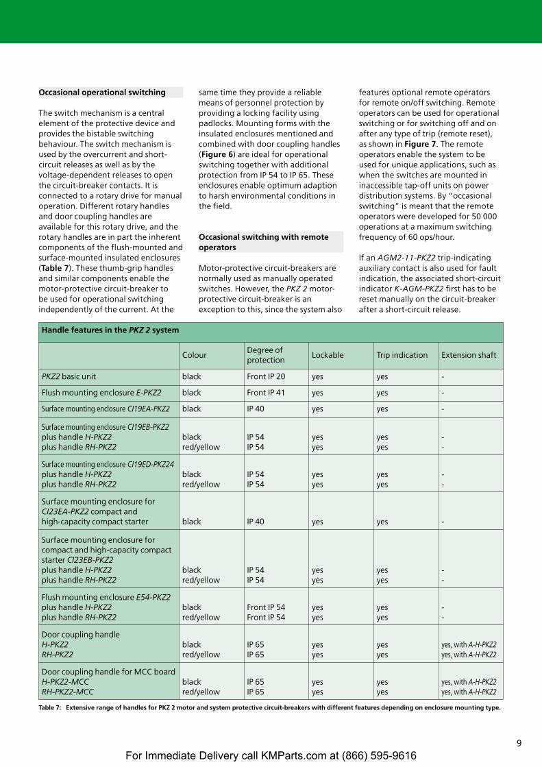
The switch mechanism is a centralelement of the protective device andprovides the bistable switchingbehaviour. The switch mechanism isused by the overcurrent and short-circuit releases as well as by thevoltage-dependent releases to openthe circuit-breaker contacts. It isconnected to a rotary drive for manualoperation. Different rotary handlesand door coupling handles areavailable for this rotary drive, and therotary handles are in part the inherentcomponents of the flush-mounted andsurface-mounted insulated enclosures(Table 7). These thumb-grip handlesand similar components enable themotor-protective circuit-breaker to be used for operational switchingindependently of the current. At the
same time they provide a reliablemeans of personnel protection byproviding a locking facility usingpadlocks. Mounting forms with theinsulated enclosures mentioned andcombined with door coupling handles(Figure 6) are ideal for operationalswitching together with additionalprotection from IP 54 to IP 65. Theseenclosures enable optimum adaptionto harsh environmental conditions inthe field.
Occasional switching with remoteoperators
Motor-protective circuit-breakers arenormally used as manually operatedswitches. However, the PKZ 2 motor-protective circuit-breaker is anexception to this, since the system also
features optional remote operators for remote on/off switching. Remoteoperators can be used for operationalswitching or for switching off and onafter any type of trip (remote reset), as shown in Figure 7. The remoteoperators enable the system to beused for unique applications, such aswhen the switches are mounted ininaccessible tap-off units on powerdistribution systems. By “occasionalswitching” is meant that the remoteoperators were developed for 50 000operations at a maximum switchingfrequency of 60 ops/hour.
If an AGM2-11-PKZ2 trip-indicatingauxiliary contact is also used for faultindication, the associated short-circuitindicator K-AGM-PKZ2 first has to bereset manually on the circuit-breakerafter a short-circuit release.
Handle features in the PKZ 2 system
ColourDegree of protection
Lockable Trip indication Extension shaft
PKZ2 basic unit black Front IP 20 yes yes -
Flush mounting enclosure E-PKZ2 black Front IP 41 yes yes -
Surface mounting enclosure CI19EA-PKZ2 black IP 40 yes yes -
Surface mounting enclosure CI19EB-PKZ2plus handle H-PKZ2plus handle RH-PKZ2
black red/yellow
IP 54 IP 54
yes yes
yes yes
- -
Surface mounting enclosure CI19ED-PKZ24plus handle H-PKZ2plus handle RH-PKZ2
black red/yellow
IP 54 IP 54
yesyes
yes yes
- -
Surface mounting enclosure forCI23EA-PKZ2 compact and high-capacity compact starter black IP 40 yes yes -
Surface mounting enclosure for compact and high-capacity compactstarter CI23EB-PKZ2plus handle H-PKZ2plus handle RH-PKZ2
black red/yellow
IP 54 IP 54
yesyes
yes yes
- -
Flush mounting enclosure E54-PKZ2plus handle H-PKZ2plus handle RH-PKZ2
black red/yellow
Front IP 54 Front IP 54
yesyes
yes yes
- -
Door coupling handle H-PKZ2 RH-PKZ2
black red/yellow
IP 65 IP 65
yesyes
yesyes
yes, with A-H-PKZ2yes, with A-H-PKZ2
Door coupling handle for MCC boardH-PKZ2-MCC RH-PKZ2-MCC
black red/yellow
IP 65 IP 65
yesyes
yesyes
yes, with A-H-PKZ2yes, with A-H-PKZ2
Table 7: Extensive range of handles for PKZ 2 motor and system protective circuit-breakers with different features depending on enclosure mounting type.
For Immediate Delivery call KMParts.com at (866) 595-9616
10
1 2 3 4 5
6
+l
o
+l
o
+l
o
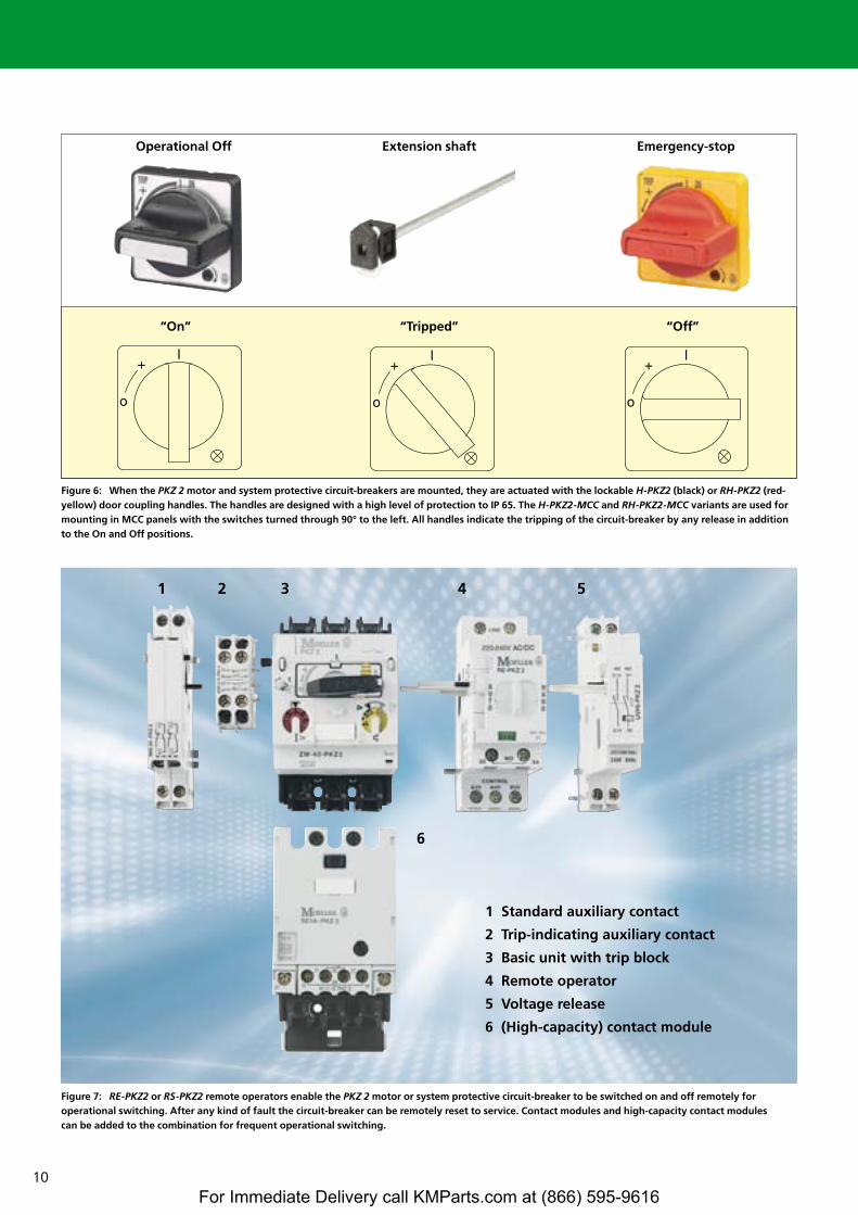
1 Standard auxiliary contact
2 Trip-indicating auxiliary contact
3 Basic unit with trip block
4 Remote operator
5 Voltage release
6 (High-capacity) contact module
Figure 6: When the PKZ 2 motor and system protective circuit-breakers are mounted, they are actuated with the lockable H-PKZ2 (black) or RH-PKZ2 (red-yellow) door coupling handles. The handles are designed with a high level of protection to IP 65. The H-PKZ2-MCC and RH-PKZ2-MCC variants are used formounting in MCC panels with the switches turned through 90° to the left. All handles indicate the tripping of the circuit-breaker by any release in additionto the On and Off positions.
Figure 7: RE-PKZ2 or RS-PKZ2 remote operators enable the PKZ 2 motor or system protective circuit-breaker to be switched on and off remotely foroperational switching. After any kind of fault the circuit-breaker can be remotely reset to service. Contact modules and high-capacity contact modules can be added to the combination for frequent operational switching.
“On”
Operational Off Extension shaft Emergency-stop
“Tripped” “Off”
For Immediate Delivery call KMParts.com at (866) 595-9616
11
� 15
� 300
� 15 t (ms)
� 30 � 30
t (ms)
t (ms)
0
I
0
I
0
I
I>
CONTROL
CONTROL
CONTROL
LINE
ON
OFFHauptkontakt
ON
ON
OFF/RESETOFF/RESET
"I >"
4.43 4.31 4.21 4.13
4.44 4.32 4.22 4.14PKZ 2(4)/ZM... AGM 2-11
"+"
I >
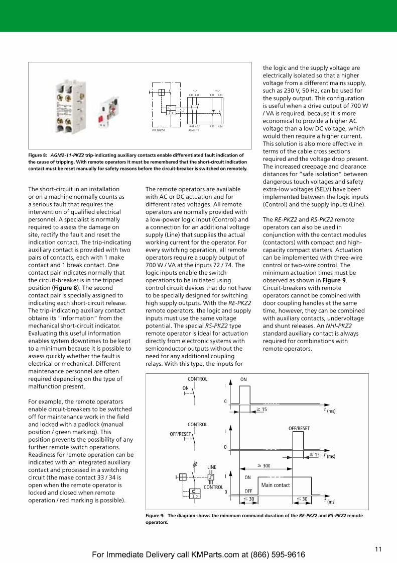
The short-circuit in an installation or on a machine normally counts as a serious fault that requires theintervention of qualified electricalpersonnel. A specialist is normallyrequired to assess the damage on site, rectify the fault and reset theindication contact. The trip-indicatingauxiliary contact is provided with twopairs of contacts, each with 1 makecontact and 1 break contact. Onecontact pair indicates normally thatthe circuit-breaker is in the trippedposition (Figure 8). The secondcontact pair is specially assigned toindicating each short-circuit release.The trip-indicating auxiliary contactobtains its “information” from themechanical short-circuit indicator.Evaluating this useful informationenables system downtimes to be keptto a minimum because it is possible toassess quickly whether the fault iselectrical or mechanical. Differentmaintenance personnel are oftenrequired depending on the type ofmalfunction present.
For example, the remote operatorsenable circuit-breakers to be switchedoff for maintenance work in the fieldand locked with a padlock (manualposition / green marking). Thisposition prevents the possibility of anyfurther remote switch operations.Readiness for remote operation can beindicated with an integrated auxiliarycontact and processed in a switchingcircuit (the make contact 33 / 34 isopen when the remote operator islocked and closed when remoteoperation / red marking is possible).
The remote operators are availablewith AC or DC actuation and fordifferent rated voltages. All remoteoperators are normally provided witha low-power logic input (Control) anda connection for an additional voltagesupply (Line) that supplies the actualworking current for the operator. Forevery switching operation, all remoteoperators require a supply output of700 W / VA at the inputs 72 / 74. Thelogic inputs enable the switchoperations to be initiated usingcontrol circuit devices that do not haveto be specially designed for switchinghigh supply outputs. With the RE-PKZ2remote operators, the logic and supplyinputs must use the same voltagepotential. The special RS-PKZ2 typeremote operator is ideal for actuationdirectly from electronic systems withsemiconductor outputs without theneed for any additional couplingrelays. With this type, the inputs for
the logic and the supply voltage areelectrically isolated so that a highervoltage from a different mains supply,such as 230 V, 50 Hz, can be used forthe supply output. This configurationis useful when a drive output of 700 W/ VA is required, because it is moreeconomical to provide a higher ACvoltage than a low DC voltage, whichwould then require a higher current.This solution is also more effective interms of the cable cross sectionsrequired and the voltage drop present.The increased creepage and clearancedistances for “safe isolation” betweendangerous touch voltages and safetyextra-low voltages (SELV) have beenimplemented between the logic inputs(Control) and the supply inputs (Line).
The RE-PKZ2 and RS-PKZ2 remoteoperators can also be used inconjunction with the contact modules(contactors) with compact and high-capacity compact starters. Actuationcan be implemented with three-wirecontrol or two-wire control. Theminimum actuation times must beobserved as shown in Figure 9.Circuit-breakers with remoteoperators cannot be combined withdoor coupling handles at the sametime, however, they can be combinedwith auxiliary contacts, undervoltageand shunt releases. An NHI-PKZ2standard auxiliary contact is alwaysrequired for combinations withremote operators.
Figure 8: AGM2-11-PKZ2 trip-indicating auxiliary contacts enable differentiated fault indication ofthe cause of tripping. With remote operators it must be remembered that the short-circuit indicationcontact must be reset manually for safety reasons before the circuit-breaker is switched on remotely.
Figure 9: The diagram shows the minimum command duration of the RE-PKZ2 and RS-PKZ2 remoteoperators.
Main contact
For Immediate Delivery call KMParts.com at (866) 595-9616
12
2
5
20
50
200
1
2
5
10
20
401
2
5
20
10
2h
1,5 2 3 4 6 8 10 15 20 30
PKZ2/ZM-...PKZ2/ZM-.../SPKZ2/ZM-.../SE1A
Seco
nds
Mill
iseco
nds
Min
utes
x Rated operational current
2
5
20
50
200
1
2
5
10
20
401
2
5
20
10
2h
1,5 2 3 4 6 8 10 15 20 30
PKZ2/ZM-...-8
Seco
nds
Mill
iseco
nds
Min
utes
x Rated operational current
Overload protection
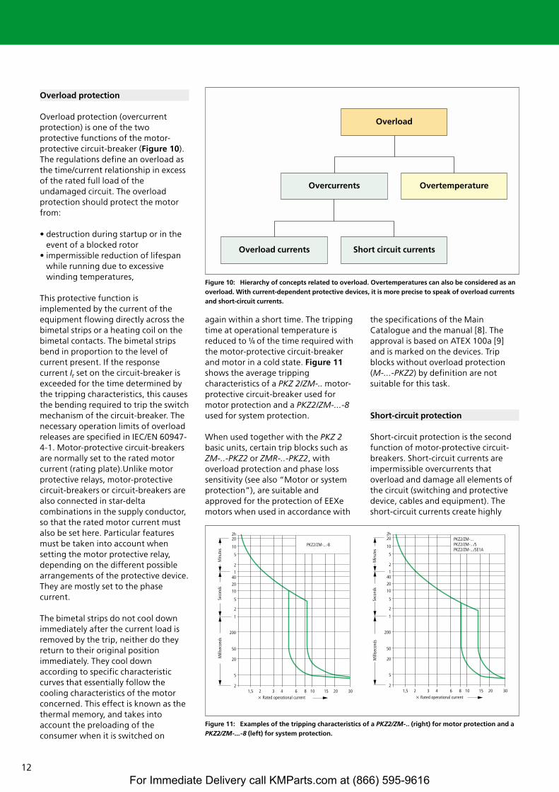
Overload protection (overcurrentprotection) is one of the twoprotective functions of the motor-protective circuit-breaker (Figure 10).The regulations define an overload asthe time/current relationship in excessof the rated full load of theundamaged circuit. The overloadprotection should protect the motorfrom:
• destruction during startup or in theevent of a blocked rotor
• impermissible reduction of lifespanwhile running due to excessivewinding temperatures,
This protective function isimplemented by the current of theequipment flowing directly across thebimetal strips or a heating coil on thebimetal contacts. The bimetal stripsbend in proportion to the level ofcurrent present. If the responsecurrent Ir set on the circuit-breaker isexceeded for the time determined bythe tripping characteristics, this causesthe bending required to trip the switchmechanism of the circuit-breaker. Thenecessary operation limits of overloadreleases are specified in IEC/EN 60947-4-1. Motor-protective circuit-breakersare normally set to the rated motorcurrent (rating plate).Unlike motorprotective relays, motor-protectivecircuit-breakers or circuit-breakers arealso connected in star-deltacombinations in the supply conductor,so that the rated motor current mustalso be set here. Particular featuresmust be taken into account whensetting the motor protective relay,depending on the different possiblearrangements of the protective device.They are mostly set to the phasecurrent.
The bimetal strips do not cool downimmediately after the current load isremoved by the trip, neither do theyreturn to their original positionimmediately. They cool downaccording to specific characteristiccurves that essentially follow thecooling characteristics of the motorconcerned. This effect is known as thethermal memory, and takes intoaccount the preloading of theconsumer when it is switched on
again within a short time. The trippingtime at operational temperature isreduced to k of the time required withthe motor-protective circuit-breakerand motor in a cold state. Figure 11shows the average trippingcharacteristics of a PKZ 2/ZM-.. motor-protective circuit-breaker used formotor protection and a PKZ2/ZM-...-8used for system protection.
When used together with the PKZ 2basic units, certain trip blocks such asZM-..-PKZ2 or ZMR-..-PKZ2, withoverload protection and phase losssensitivity (see also “Motor or systemprotection”), are suitable andapproved for the protection of EEXemotors when used in accordance with
the specifications of the MainCatalogue and the manual [8]. Theapproval is based on ATEX 100a [9]and is marked on the devices. Tripblocks without overload protection(M-...-PKZ2) by definition are notsuitable for this task.
Short-circuit protection
Short-circuit protection is the secondfunction of motor-protective circuit-breakers. Short-circuit currents areimpermissible overcurrents thatoverload and damage all elements ofthe circuit (switching and protectivedevice, cables and equipment). Theshort-circuit currents create highly
Figure 10: Hierarchy of concepts related to overload. Overtemperatures can also be considered as anoverload. With current-dependent protective devices, it is more precise to speak of overload currentsand short-circuit currents.
Figure 11: Examples of the tripping characteristics of a PKZ2/ZM-.. (right) for motor protection and aPKZ2/ZM-...-8 (left) for system protection.
Overload currents Short circuit currents
Overcurrents Overtemperature
Overload
For Immediate Delivery call KMParts.com at (866) 595-9616
13
50 72 1.80 1.20 58 1.44 0.96 42 1.05 0.70
100 144 3.61 2.41 116 2.89 1.93 84 2.09 1.40
160 231 5.77 3.85 185 4.62 3.08 134 3.35 2.23
200 289 7.22 4.81 231 5.78 3.85 167 4.19 2.79
250 361 9.02 6.01 289 7.22 4.81 209 5.23 3.49
315 455 11.36 7.58 364 9.10 6.06 264 6.59 4.39
400 577 14.43 9.62 462 11.55 7.70 335 8.37 5.58
500 722 18.04 12.03 578 14.44 9.63 419 10.46 6.98
630 909 22.73 15.15 728 18.19 12.13 527 13.18 8.79
800 1154 28.86 19.24 924 23.10 15.40 670 16.74 11.16
1000 1143 36.08 24.05 1155 28.88 19.25 837 20.93 13.95
1250 1804 45.09 30.06 1444 36.09 24.06 1046 26.16 17.44
1600 2309 57.72 38.48 1848 46.20 30.80 1339 33.48 22.32
2000 2886 72.15 48.10 2310 57.75 38.50 1674 41.85 27.90
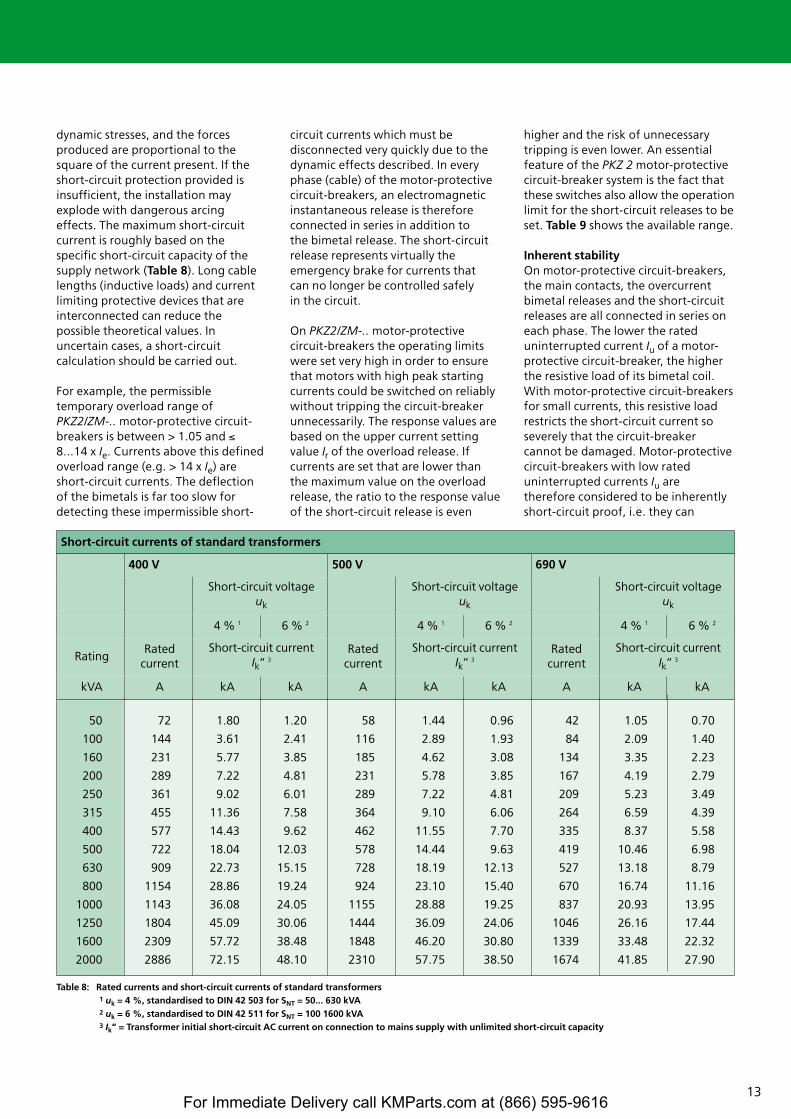
Short-circuit currents of standard transformers
400 V 500 V 690 V
Short-circuit voltage uk
Short-circuit voltage uk
Short-circuit voltage uk
4 % 1 6 % 2 4 % 1 6 % 2 4 % 1 6 % 2
RatingRated
currentShort-circuit current
Ik‘‘ 3
Rated current
Short-circuit current Ik‘‘ 3
Rated current
Short-circuit current Ik‘‘ 3
kVA A kA kA A kA kA A kA kA
dynamic stresses, and the forcesproduced are proportional to thesquare of the current present. If theshort-circuit protection provided isinsufficient, the installation mayexplode with dangerous arcingeffects. The maximum short-circuitcurrent is roughly based on thespecific short-circuit capacity of thesupply network (Table 8). Long cablelengths (inductive loads) and currentlimiting protective devices that areinterconnected can reduce thepossible theoretical values. Inuncertain cases, a short-circuitcalculation should be carried out.
For example, the permissibletemporary overload range ofPKZ2/ZM-.. motor-protective circuit-breakers is between > 1.05 and ≤8...14 x Ie. Currents above this definedoverload range (e.g. > 14 x Ie) areshort-circuit currents. The deflectionof the bimetals is far too slow fordetecting these impermissible short-
circuit currents which must bedisconnected very quickly due to thedynamic effects described. In everyphase (cable) of the motor-protectivecircuit-breakers, an electromagneticinstantaneous release is thereforeconnected in series in addition to the bimetal release. The short-circuitrelease represents virtually theemergency brake for currents that can no longer be controlled safely in the circuit.
On PKZ2/ZM-.. motor-protectivecircuit-breakers the operating limitswere set very high in order to ensurethat motors with high peak startingcurrents could be switched on reliablywithout tripping the circuit-breakerunnecessarily. The response values arebased on the upper current settingvalue Ir of the overload release. Ifcurrents are set that are lower thanthe maximum value on the overloadrelease, the ratio to the response valueof the short-circuit release is even
higher and the risk of unnecessarytripping is even lower. An essentialfeature of the PKZ 2 motor-protectivecircuit-breaker system is the fact thatthese switches also allow the operationlimit for the short-circuit releases to beset. Table 9 shows the available range.
Inherent stabilityOn motor-protective circuit-breakers,the main contacts, the overcurrentbimetal releases and the short-circuitreleases are all connected in series oneach phase. The lower the rateduninterrupted current Iu of a motor-protective circuit-breaker, the higherthe resistive load of its bimetal coil.With motor-protective circuit-breakersfor small currents, this resistive loadrestricts the short-circuit current soseverely that the circuit-breakercannot be damaged. Motor-protectivecircuit-breakers with low rateduninterrupted currents Iu are therefore considered to be inherentlyshort-circuit proof, i.e. they can
Table 8: Rated currents and short-circuit currents of standard transformers1 uk = 4 %, standardised to DIN 42 503 for SNT = 50... 630 kVA2 uk = 6 %, standardised to DIN 42 511 for SNT = 100 1600 kVA3 Ik‘‘ = Transformer initial short-circuit AC current on connection to mains supply with unlimited short-circuit capacity
For Immediate Delivery call KMParts.com at (866) 595-9616
14
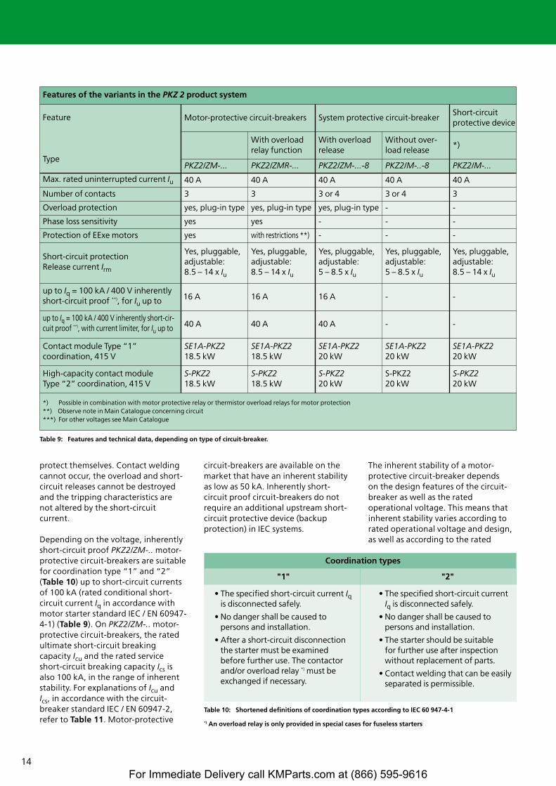
protect themselves. Contact weldingcannot occur, the overload and short-circuit releases cannot be destroyedand the tripping characteristics are not altered by the short-circuitcurrent.
Depending on the voltage, inherentlyshort-circuit proof PKZ2/ZM-.. motor-protective circuit-breakers are suitablefor coordination type “1” and “2”(Table 10) up to short-circuit currentsof 100 kA (rated conditional short-circuit current Iq in accordance withmotor starter standard IEC / EN 60947-4-1) (Table 9). On PKZ2/ZM-.. motor-protective circuit-breakers, the ratedultimate short-circuit breakingcapacity Icu and the rated serviceshort-circuit breaking capacity Ics isalso 100 kA, in the range of inherentstability. For explanations of Icu andIcs, in accordance with the circuit-breaker standard IEC / EN 60947-2,refer to Table 11. Motor-protective
circuit-breakers are available on themarket that have an inherent stabilityas low as 50 kA. Inherently short-circuit proof circuit-breakers do notrequire an additional upstream short-circuit protective device (backupprotection) in IEC systems.
The inherent stability of a motor-protective circuit-breaker depends on the design features of the circuit-breaker as well as the ratedoperational voltage. This means thatinherent stability varies according torated operational voltage and design,as well as according to the rated
Features of the variants in the PKZ 2 product system
Feature
Type
Motor-protective circuit-breakers System protective circuit-breakerShort-circuit protective device
With overloadrelay function
With overloadrelease
Without over-load release
*)
PKZ2/ZM-... PKZ2/ZMR-... PKZ2/ZM-...-8 PKZ2/M-..-8 PKZ2/M-...
Max. rated uninterrupted current Iu 40 A 40 A 40 A 40 A 40 A
Number of contacts 3 3 3 or 4 3 or 4 3
Overload protection yes, plug-in type yes, plug-in type yes, plug-in type - -
Phase loss sensitivity yes yes - - -
Protection of EExe motors yes with restrictions **) - - -
Short-circuit protectionRelease current Irm
Yes, pluggable,adjustable:8.5 – 14 x Iu
Yes, pluggable,adjustable:8.5 – 14 x Iu
Yes, pluggable,adjustable: 5 – 8.5 x Iu
Yes, pluggable,adjustable: 5 – 8.5 x Iu
Yes, pluggable,adjustable:8.5 – 14 x Iu
up to Iq = 100 kA / 400 V inherentlyshort-circuit proof **), for Iu up to 16 A 16 A 16 A - -
up to Iq = 100 kA / 400 V inherently short-cir-cuit proof **), with current limiter, for Iu up to 40 A 40 A 40 A - -
Contact module Type “1” coordination, 415 V
SE1A-PKZ218.5 kW
SE1A-PKZ218.5 kW
SE1A-PKZ220 kW
SE1A-PKZ220 kW
SE1A-PKZ220 kW
High-capacity contact module Type “2” coordination, 415 V
S-PKZ218.5 kW
S-PKZ218.5 kW
S-PKZ220 kW
S-PKZ2 20 kW
S-PKZ220 kW
*) Possible in combination with motor protective relay or thermistor overload relays for motor protection **) Observe note in Main Catalogue concerning circuit ***) For other voltages see Main Catalogue
Table 9: Features and technical data, depending on type of circuit-breaker.
Table 10: Shortened definitions of coordination types according to IEC 60 947-4-1
*) An overload relay is only provided in special cases for fuseless starters
Coordination types
"1" "2"
• The specified short-circuit current Iqis disconnected safely.
• No danger shall be caused to persons and installation.
• After a short-circuit disconnectionthe starter must be examined before further use. The contactorand/or overload relay *) must be exchanged if necessary.
• The specified short-circuit current Iq is disconnected safely.
• No danger shall be caused to persons and installation.
• The starter should be suitable for further use after inspection without replacement of parts.
• Contact welding that can be easilyseparated is permissible.
For Immediate Delivery call KMParts.com at (866) 595-9616
15
uninterrupted current Iu of the motor-protective circuit-breaker concerned.The Moeller HPL main catalogueprovides full information on inherentstability in relation to different ratedoperational voltages, and Table 12provides an extract of this.
For protective circuit-breakers thatcannot provide inherent stability up to100 kA with high rated operationalvoltages, Table 12 shows themaximum short-circuit currents forwhich upstream fuse protection(backup protection) is not required.Additional measures are necessary ifthese short-circuit currents areexceeded in the event of a fault. Thesecan be larger upstream NZM circuit-breakers, the current limitersdescribed later, the high-capacitycontact modules, or if necessary,upstream fuses in the specified size.The first three options offer thebenefits of a fuseless solution.
Controlling particularly highshort-circuit currents with CL-PKZ2 current limiters
Not all setting ranges could bedeveloped with inherent stability inthe PKZ2 system due to the physicalcharacteristics of the releases. Thethree major ranges of -25 A, -32 A and40 A on their own each have a ratedultimate limit short-circuit breakingcapacity Icu of 30 kA at 400 V. If highershort-circuit currents are expected, anadditional protective device must beconnected upstream to protect themotor-protective circuit-breaker fromthe effects of the short-circuit. Withfuseless motor starters, an NZMcircuit-breaker is used which ideallyalso takes over the function of themain switch for the system. In manyapplications it is also possible to use acircuit-breaker for the groupprotection of several motor starters,such as for a distribution panel.
Alternatively, 160 A fuses can also beused to provide backup protection.
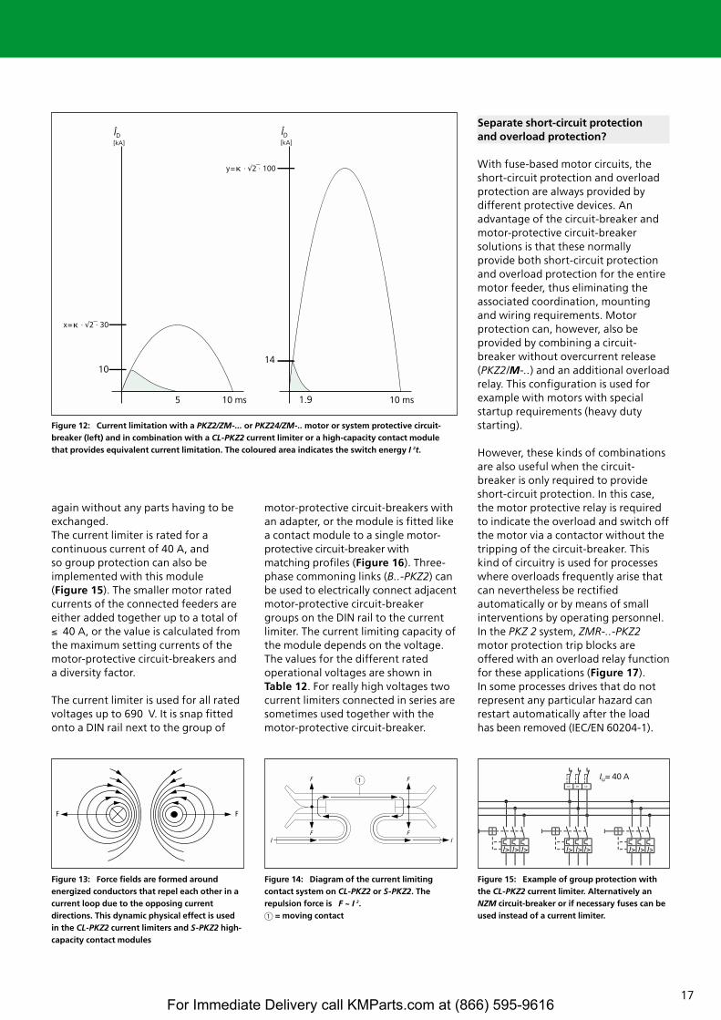
Another effective solution is the use ofthe CL-PKZ2 current limiter. Togetherwith this module all setting ranges ofthe PKZ 2 are inherently short-circuitproof at 400V.The resulting effect ofcurrent limiters is called currentlimitation. Figure 12 shows thecurrent characteristics of a single PKZ 2 and the current characteristicsof the PKZ 2 in combination with theCL-PKZ2 or the equivalent S-PKZ2high-capacity contact module that willbe presented later. The poles of thecurrent limiter and the motor-protective circuit-breaker areconnected in series. The current limiterfeatures a contact element consistingof three independent repulsioncontacts that are closed in normaloperation. The fixed contact is formedas a current loop. In the event of afault, the short-circuit current present
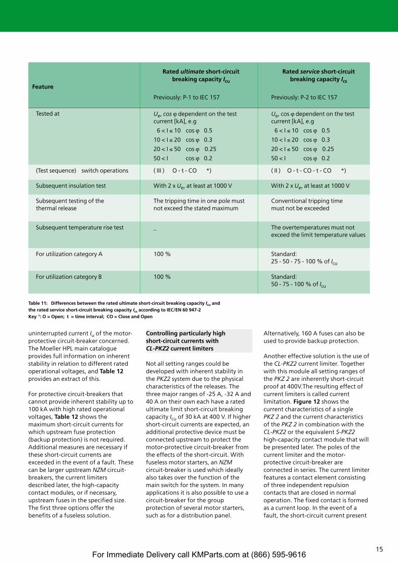
Table 11: Differences between the rated ultimate short-circuit breaking capacity Icu and the rated service short-circuit breaking capacity Ics according to IEC/EN 60 947-2Key *): O = Open; t = time interval; CO = Close and Open
Tested at Ue, cos v dependent on the test current [kA], e.g
6 < I ≤ 10 cos v 0.5
10 < I ≤ 20 cos v 0.3
20 < I ≤ 50 cos v 0.25
50 < I cos v 0.2
Ue, cos v dependent on the test current [kA], e.g
6 < I ≤ 10 cos v 0.5
10 < I ≤ 20 cos v 0.3
20 < I ≤ 50 cos v 0.25
50 < I cos v 0.2
Feature
Rated ultimate short-circuitbreaking capacity Icu
Previously: P-1 to IEC 157
Rated service short-circuit breaking capacity Ics
Previously: P-2 to IEC 157
Subsequent insulation test With 2 x Ue, at least at 1000 V With 2 x Ue, at least at 1000 V
For utilization category B 100 % Standard:50 - 75 - 100 % of Icu
Subsequent temperature rise test _ The overtemperatures must not exceed the limit temperature values
(Test sequence) switch operations ( III ) O - t - CO *) ( II ) O - t - CO - t - CO *)
Subsequent testing of the thermal release
The tripping time in one pole mustnot exceed the stated maximum
Conventional tripping time must not be exceeded
For utilization category A 100 % Standard: 25 - 50 - 75 - 100 % of Icu
For Immediate Delivery call KMParts.com at (866) 595-9616
16* Fuse only necessary when Ioc > Iq
generates magnetic fields with thesame polarity in the current loop ofthe fixed contact and around themoving contact, thus forcing them torepel each other (Figure 13). Thedynamic effect of these fields forcesthe moving contacts (Figure 14) open.On the CL-PKZ 2 current limiters thismovement is further supported bymeans of striking armatures that have
a similar design to the magneticinstantaneous trips with a movingarmature and a magnet coil energizedby the short-circuit current.
The arcs created when the contactopens form resistances that dampenthe short-circuit current to non-criticalvalues. At the same time, the magneticinstantaneous releases in the motor-
protective circuit-breaker activate theopening of its contact. The arcs theyproduce cause additional dampingand the faulty current circuit isdisconnected by the release of theswitch mechanism. The repulsioncontacts automatically return to theirclosed rest position after a currentduration of approx. 4 to 7 ms. Thecurrent limiter is then operational
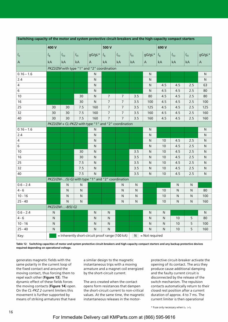
Switching capacity of the motor and system protective circuit-breakers and the high-capacity compact starters
400 V 500 V 690 V
Iu Iq Icu Ics gG/gL* Iq Icu Ics gG/gL* Iq Icu Ics gG/gL*
A kA kA kA A kA kA kA A kA kA kA A
PKZ2/ZM with type “1” and “2” coordination
0.16 – 1.6 N N N
2.4 N N N
4 N N 4.5 4.5 2.5 63
6 N N 4.5 4.5 2.5 80
10 30 N 7 7 3.5 80 4.5 4.5 2.5 80
16 30 N 7 7 3.5 100 4.5 4.5 2.5 100
25 30 30 7.5 160 7 7 3.5 125 4.5 4.5 2.5 125
32 30 30 7.5 160 7 7 3.5 160 4.5 4.5 2.5 160
40 30 30 7.5 160 7 7 3.5 160 4.5 4.5 2.5 160
PKZ2/ZM + CL-PKZ2 with type “1” and “2” coordination
0.16 – 1.6 N N N
2.4 N N N
4 N N 10 4.5 2.5 N
6 N N 10 4.5 2.5 N
10 30 N 3.5 N 10 4.5 2.5 N
16 30 N 3.5 N 10 4.5 2.5 N
25 7.5 N 3.5 N 10 4.5 2.5 N
32 7.5 N 3.5 N 10 4.5 2.5 N
40 7.5 N 3.5 N 10 4.5 2.5 N
PKZ2/ZM-.../S(-G) with type “1” and “2” coordination
0.6 – 2.4 N N N N N N
4 - 6 N N N N 10 N N 80
10 - 16 N N N N 10 N N 100
25 - 40 N N N N 10 N N 160
PKZ2/ZM-...-8/S(-G)
0.6 – 2.4 N N N N N N
4 - 6 N N N N N 10 5 80
10 - 16 N N N N N 10 5 100
25 - 40 N N N N N 10 5 160
Key: = Inherently short-circuit proof range (100 kA) = Not requiredN
Table 12: Switching capacities of motor and system protective circuit-breakers and high-capacity compact starters and any backup protective devices required depending on operational voltage.
For Immediate Delivery call KMParts.com at (866) 595-9616
17
5
10
ÎD [kA]
ÎD [kA]
14
x=� · √⎯2 · 30
y=� · √⎯2 · 100
10 ms 10 ms1,9
FF
Iu = 63 A
l> l>
Ι
1
again without any parts having to beexchanged.The current limiter is rated for acontinuous current of 40 A, and so group protection can also beimplemented with this module (Figure 15). The smaller motor ratedcurrents of the connected feeders areeither added together up to a total of≤ 40 A, or the value is calculated fromthe maximum setting currents of themotor-protective circuit-breakers anda diversity factor.
The current limiter is used for all ratedvoltages up to 690 V. It is snap fittedonto a DIN rail next to the group of
motor-protective circuit-breakers withan adapter, or the module is fitted likea contact module to a single motor-protective circuit-breaker withmatching profiles (Figure 16). Three-phase commoning links (B..-PKZ2) canbe used to electrically connect adjacentmotor-protective circuit-breakergroups on the DIN rail to the currentlimiter. The current limiting capacity ofthe module depends on the voltage.The values for the different ratedoperational voltages are shown inTable 12. For really high voltages twocurrent limiters connected in series aresometimes used together with themotor-protective circuit-breaker.
Separate short-circuit protection and overload protection?
With fuse-based motor circuits, theshort-circuit protection and overloadprotection are always provided bydifferent protective devices. Anadvantage of the circuit-breaker andmotor-protective circuit-breakersolutions is that these normallyprovide both short-circuit protectionand overload protection for the entiremotor feeder, thus eliminating theassociated coordination, mountingand wiring requirements. Motorprotection can, however, also beprovided by combining a circuit-breaker without overcurrent release(PKZ2/M-..) and an additional overloadrelay. This configuration is used forexample with motors with specialstartup requirements (heavy dutystarting).
However, these kinds of combinationsare also useful when the circuit-breaker is only required to provideshort-circuit protection. In this case,the motor protective relay is requiredto indicate the overload and switch offthe motor via a contactor without thetripping of the circuit-breaker. Thiskind of circuitry is used for processeswhere overloads frequently arise thatcan nevertheless be rectifiedautomatically or by means of smallinterventions by operating personnel.In the PKZ 2 system, ZMR-..-PKZ2motor protection trip blocks areoffered with an overload relay functionfor these applications (Figure 17). In some processes drives that do notrepresent any particular hazard canrestart automatically after the load has been removed (IEC/EN 60204-1).
Figure 12: Current limitation with a PKZ2/ZM-... or PKZ24/ZM-.. motor or system protective circuit-breaker (left) and in combination with a CL-PKZ2 current limiter or a high-capacity contact modulethat provides equivalent current limitation. The coloured area indicates the switch energy I 2t.
Figure 13: Force fields are formed aroundenergized conductors that repel each other in acurrent loop due to the opposing currentdirections. This dynamic physical effect is usedin the CL-PKZ2 current limiters and S-PKZ2 high-capacity contact modules
Figure 14: Diagram of the current limitingcontact system on CL-PKZ2 or S-PKZ2. Therepulsion force is F ~ I 2. a = moving contact
Figure 15: Example of group protection withthe CL-PKZ2 current limiter. Alternatively anNZM circuit-breaker or if necessary fuses can beused instead of a current limiter.
Iu= 40 A
1.9
For Immediate Delivery call KMParts.com at (866) 595-9616
18
95
96
97
98
H A
I >
-Q1
L1 L2 L3
T1
I� I� I�
T2 T3
I�� I�� I��
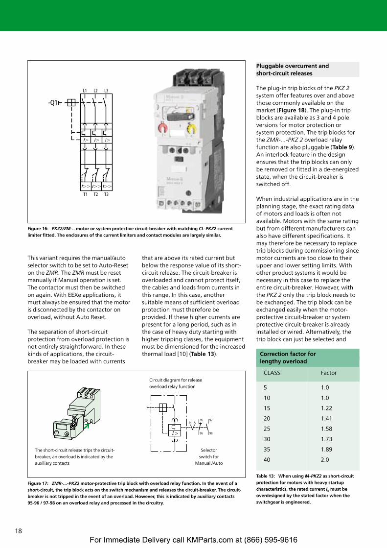
This variant requires the manual/autoselector switch to be set to Auto-Reseton the ZMR. The ZMR must be resetmanually if Manual operation is set.The contactor must then be switchedon again. With EEXe applications, itmust always be ensured that the motoris disconnected by the contactor onoverload, without Auto Reset.
The separation of short-circuitprotection from overload protection isnot entirely straightforward. In thesekinds of applications, the circuit-breaker may be loaded with currents
that are above its rated current butbelow the response value of its short-circuit release. The circuit-breaker isoverloaded and cannot protect itself,the cables and loads from currents inthis range. In this case, anothersuitable means of sufficient overloadprotection must therefore beprovided. If these higher currents arepresent for a long period, such as inthe case of heavy duty starting withhigher tripping classes, the equipmentmust be dimensioned for the increasedthermal load [10] (Table 13).
Pluggable overcurrent and short-circuit releases
The plug-in trip blocks of the PKZ 2system offer features over and abovethose commonly available on themarket (Figure 18). The plug-in tripblocks are available as 3 and 4 poleversions for motor protection orsystem protection. The trip blocks forthe ZMR-...-PKZ 2 overload relayfunction are also pluggable (Table 9).An interlock feature in the designensures that the trip blocks can onlybe removed or fitted in a de-energizedstate, when the circuit-breaker isswitched off.
When industrial applications are in theplanning stage, the exact rating dataof motors and loads is often notavailable. Motors with the same ratingbut from different manufacturers canalso have different specifications. Itmay therefore be necessary to replacetrip blocks during commissioning sincemotor currents are too close to theirupper and lower setting limits. Withother product systems it would benecessary in this case to replace theentire circuit-breaker. However, withthe PKZ 2 only the trip block needs tobe exchanged. The trip block can beexchanged easily when the motor-protective circuit-breaker or systemprotective circuit-breaker is alreadyinstalled or wired. Alternatively, thetrip block can just be selected and
Figure 16: PKZ2/ZM-.. motor or system protective circuit-breaker with matching CL-PKZ2 currentlimiter fitted. The enclosures of the current limiters and contact modules are largely similar.
Figure 17: ZMR-...-PKZ2 motor-protective trip block with overload relay function. In the event of ashort-circuit, the trip block acts on the switch mechanism and releases the circuit-breaker. The circuit-breaker is not tripped in the event of an overload. However, this is indicated by auxiliary contacts 95-96 / 97-98 on an overload relay and processed in the circuitry.
The short-circuit release trips the circuit-breaker, an overload is indicated by the auxiliary contacts
Circuit diagram for releaseoverload relay function
Selector switch for
Manual /Auto
Table 13: When using M-PKZ2 as short-circuitprotection for motors with heavy startup characteristics, the rated current Ie must beoverdesigned by the stated factor when theswitchgear is engineered.
Correction factor for lengthy overload
CLASS Factor
5
10
15
20
25
30
35
40
1.0
1.0
1.22
1.41
1.58
1.73
1.89
2.0
For Immediate Delivery call KMParts.com at (866) 595-9616
19
-Q1
L1 L2 L3
I� I� I�
T1 T2 T3
fitted when the required data isavailable. Reserve feeders can also be provided easily for taking only thecorrect trip blocks required. It must beensured that sufficient cross-sectionsare available when prewiring thereserve feeders. The logistics conceptenables basic units and basic unitswith fitted contact modules to bepurchased either with or without the trip blocks.
The PKZ 2 system is also frequentlyused in industrial switchgearassemblies due to the additional safetyfeatures. The trip block can be pulledout when working on the installation,thus establishing a visible isolatinggap. The trip block can then be carriedaround in the same way as the fusecartridge was carried in the past.When the trip block has beenremoved, the circuit-breaker is alsolocked in a de-energized state with a padlock. This therefore gives theadditional security by ruling out thepossibility of someone else fittinganother trip block. If required, thesockets can be coded according tocurrent in order to prevent the wrongtrip block from being fitted.
Alternatives and combinations for motor protection
With motor-protective circuit-breakers, circuit-breakers and motor protective relays, the motor
temperature can determined withsufficient accuracy from the currentpresent (indirect current-basedtemperature monitoring). Thistechnique is also used with the PKZ 2system.
Thermistor overload relays such asMoeller's EMT 6 enable overloadprotection to be provided easily forfull motor protection [11]. Anincreasing number of motors featurean integrated thermistor sensor fordirect temperature monitoring in themotor in order to increase failsafeperformance. This additionalprotection is highly recommendedwhen the current on its own cannot be used with sufficient accuracy todetermine the temperature. This is thecase, for example with variable speedmotors because the cooling of themotor often depends on the speed as well. This temperature measuringmethod is also used when cooling is impaired, or if the ambienttemperatures of motor and motor-protective circuit-breaker are verydifferent.
Remote tripping, with voltage-dependent releases
In the event of a fault, the switchmechanism of the motor-protectivecircuit-breaker is tripped by theoverload release or short-circuitrelease. The main contacts of the
circuit-breaker then open, which atthe same time initiates the signallingto the auxiliary contacts. Voltagereleases are also available asadditional accessories that can alsotrip the switch mechanism. Thesereleases are used for remote trippingand for interlock functions.
The undervoltage release is commonlyused in conjunction with a controlcircuit device for remotely operatedemergency-stop circuits. Undervoltagereleases operate on the closed-circuitprinciple. This means that there isalways a current present in the tripcircuit in order to retain the magnet inits home position. If the voltage isinterrupted, either intentionally bymeans of an emergency-stop actuator,or in the event of a fault such asvoltage loss or wire breakage, theundervoltage release unlatches theswitch mechanism. The undervoltagerelease is also used to prevent anautomatic restart of motors whenpower is restored after a power loss(IEC/EN 60204-1).
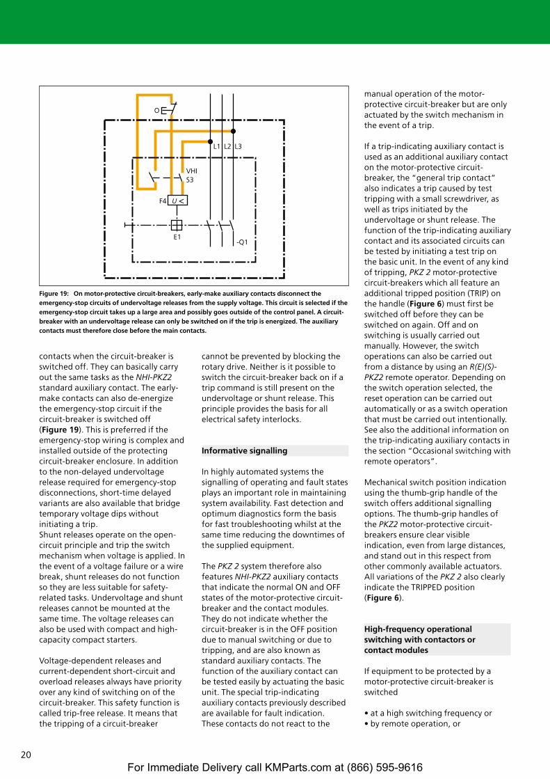
It must be remembered that a circuit-breaker fitted with an undervoltagerelease can only be switched on if theundervoltage release is energized. Thiscan be implemented using an early-make auxiliary contact in the circuit ofthe undervoltage release. The contactsof the VHI-PKZ2 early-make auxiliarycontact module close before the maincontacts do, and open after the main
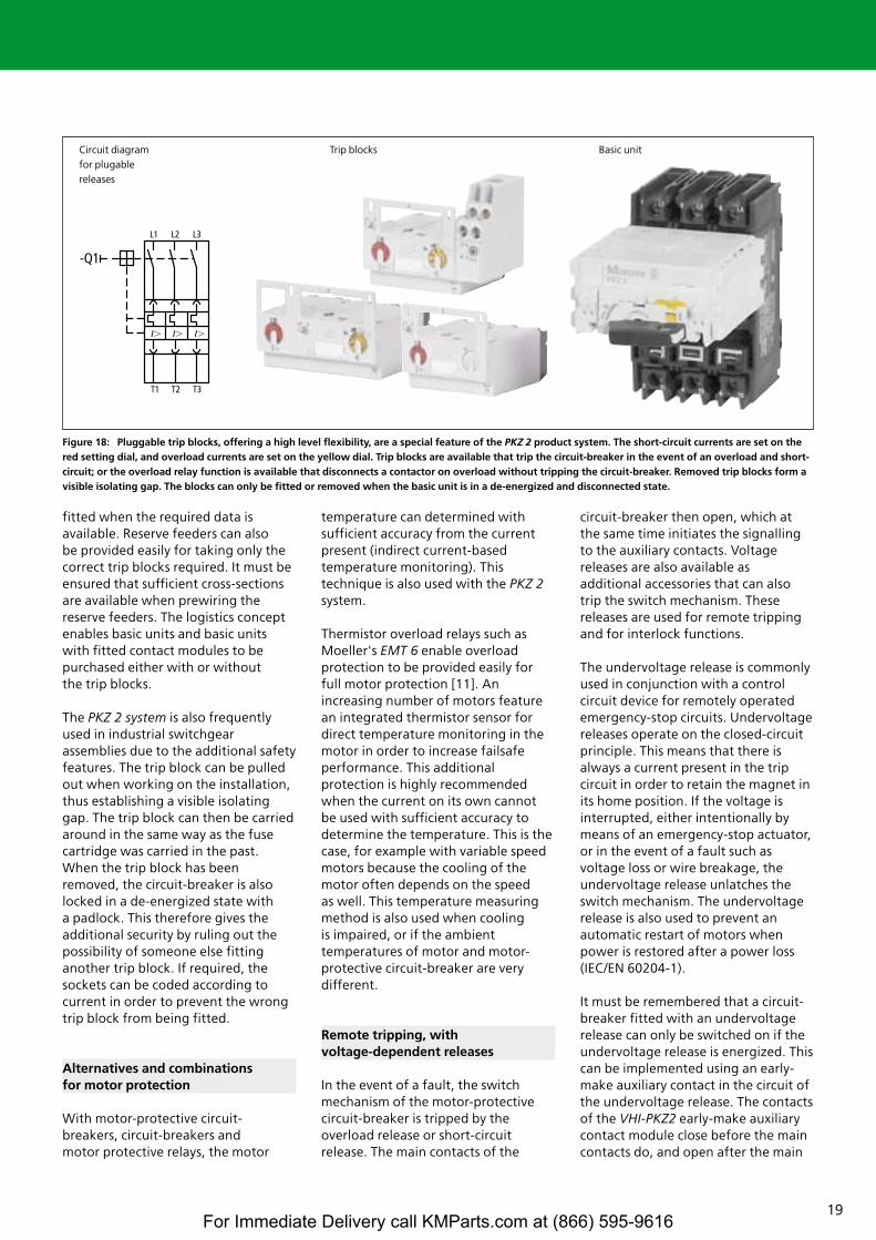
Figure 18: Pluggable trip blocks, offering a high level flexibility, are a special feature of the PKZ 2 product system. The short-circuit currents are set on thered setting dial, and overload currents are set on the yellow dial. Trip blocks are available that trip the circuit-breaker in the event of an overload and short-circuit; or the overload relay function is available that disconnects a contactor on overload without tripping the circuit-breaker. Removed trip blocks form avisible isolating gap. The blocks can only be fitted or removed when the basic unit is in a de-energized and disconnected state.
Circuit diagram Trip blocks Basic unitfor plugable releases
For Immediate Delivery call KMParts.com at (866) 595-9616
20
contacts when the circuit-breaker isswitched off. They can basically carryout the same tasks as the NHI-PKZ2standard auxiliary contact. The early-make contacts can also de-energizethe emergency-stop circuit if thecircuit-breaker is switched off (Figure 19). This is preferred if theemergency-stop wiring is complex andinstalled outside of the protectingcircuit-breaker enclosure. In additionto the non-delayed undervoltagerelease required for emergency-stopdisconnections, short-time delayedvariants are also available that bridgetemporary voltage dips withoutinitiating a trip.Shunt releases operate on the open-circuit principle and trip the switchmechanism when voltage is applied. Inthe event of a voltage failure or a wirebreak, shunt releases do not functionso they are less suitable for safety-related tasks. Undervoltage and shuntreleases cannot be mounted at thesame time. The voltage releases canalso be used with compact and high-capacity compact starters.
Voltage-dependent releases andcurrent-dependent short-circuit andoverload releases always have priorityover any kind of switching on of thecircuit-breaker. This safety function iscalled trip-free release. It means thatthe tripping of a circuit-breaker
cannot be prevented by blocking therotary drive. Neither is it possible toswitch the circuit-breaker back on if atrip command is still present on theundervoltage or shunt release. Thisprinciple provides the basis for allelectrical safety interlocks.
Informative signalling
In highly automated systems thesignalling of operating and fault statesplays an important role in maintainingsystem availability. Fast detection andoptimum diagnostics form the basisfor fast troubleshooting whilst at thesame time reducing the downtimes ofthe supplied equipment.
The PKZ 2 system therefore alsofeatures NHI-PKZ2 auxiliary contactsthat indicate the normal ON and OFFstates of the motor-protective circuit-breaker and the contact modules.They do not indicate whether thecircuit-breaker is in the OFF positiondue to manual switching or due totripping, and are also known asstandard auxiliary contacts. Thefunction of the auxiliary contact canbe tested easily by actuating the basicunit. The special trip-indicatingauxiliary contacts previously describedare available for fault indication.These contacts do not react to the
manual operation of the motor-protective circuit-breaker but are onlyactuated by the switch mechanism inthe event of a trip.
If a trip-indicating auxiliary contact isused as an additional auxiliary contacton the motor-protective circuit-breaker, the “general trip contact”also indicates a trip caused by testtripping with a small screwdriver, aswell as trips initiated by theundervoltage or shunt release. Thefunction of the trip-indicating auxiliarycontact and its associated circuits canbe tested by initiating a test trip onthe basic unit. In the event of any kindof tripping, PKZ 2 motor-protectivecircuit-breakers which all feature anadditional tripped position (TRIP) onthe handle (Figure 6) must first beswitched off before they can beswitched on again. Off and onswitching is usually carried outmanually. However, the switchoperations can also be carried outfrom a distance by using an R(E)(S)-PKZ2 remote operator. Depending onthe switch operation selected, thereset operation can be carried outautomatically or as a switch operationthat must be carried out intentionally.See also the additional information onthe trip-indicating auxiliary contacts inthe section “Occasional switching withremote operators”.
Mechanical switch position indicationusing the thumb-grip handle of theswitch offers additional signallingoptions. The thumb-grip handles ofthe PKZ2 motor-protective circuit-breakers ensure clear visibleindication, even from large distances,and stand out in this respect fromother commonly available actuators.All variations of the PKZ 2 also clearlyindicate the TRIPPED position (Figure 6).
High-frequency operational switching with contactors or contact modules
If equipment to be protected by amotor-protective circuit-breaker isswitched
• at a high switching frequency or• by remote operation, or
Figure 19: On motor-protective circuit-breakers, early-make auxiliary contacts disconnect theemergency-stop circuits of undervoltage releases from the supply voltage. This circuit is selected if theemergency-stop circuit takes up a large area and possibly goes outside of the control panel. A circuit-breaker with an undervoltage release can only be switched on if the trip is energized. The auxiliarycontacts must therefore close before the main contacts.
For Immediate Delivery call KMParts.com at (866) 595-9616
21
M3 ~
I >
• in response to a wide range ofdifferent sensors, timers orautomation equipment,
a DIL M contactor from the xStartsystem or a contact module belongingto the PKZ 2 system is used foroperational switching in addition tothe motor-protective circuit-breaker.These combinations are also calledmotor starters. Most applications ofthis kind using motor-protectivecircuit-breakers are therefore fuselessmotor starters (apart from when abackup fuse is required). All motorstarters can either be combined fortype coordination “1” or “2”(Table 10).
Contact modules are similar tocontactors, but have matching profiles to fit to the side of the motor-protective circuit-breaker.These components in combinationform compact and high-capacitycompact (motor) starters (Table 9).They are also offered either for AC orDC operation. The contact modulesare each provided with two integratedauxiliary contacts. A suppressor circuitis also available as an accessory.Moeller compact and high-capacitycompact starters represent a specialperformance range that offers morethan commonly available switchgearcapabilities. Circuit-breaker andcontact module or current limiter arealways mechanically interconnectedwith the C-PKZ2 clip plate, enablingthe starters to be snap fitted to one or two top-hat rails with a height of 15 mm in accordance with IEC / EN 60 715. They can also befastened with M4 screws.
Additional protective devices arerequired in some cases where motor-protective circuit-breakers that are notinherently short-circuit proof and highshort-circuit currents are involved. Thisprotective function is provided withthe high-capacity compact startersthemselves by means of the high-capacity contact module that featuresa current limiting contact element.
The current limiting effects of high-capacity contact modulesThe basic contact modules are verysimilar to contactors. The high-capacity contact modules are special
devices that feature current limitingcontacts as already described with theCL-PKZ2 current limiters (Figure 14).The forces around the contact aredesigned in such a way that the maincontacts, which are designed ascurrent loops, open up dynamically inthe event of a short circuit andsupport the motor-protective circuit-breaker in interrupting the high short-circuit currents through the resultingarc gaps. The high-capacity contactmodules also feature the strikingarmature, as previously described. Incases where a high-capacity contactmodule is required for operationalswitching anyway, the CL-PKZ2 currentlimiter is no longer required forprotection against high short-circuitcurrents. The combination of the PKZ 2 / ZM and S-PKZ 2 can be usedfor voltages up to 500 / 525 V and upto 100 kA for coordination type “2”.These combinations cover motorratings up to 18.5 kW at 415 V or 22 kW at 500 / 525 V.
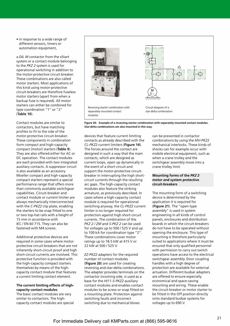
EZ-PKZ2 adapters for the requirednumber of contact modules (Figure 20) are used for creatingreversing and star-delta combinations.The adapter provides terminals on thecontactor incoming side, is used as abase for the HI11-S-PKZ2 auxiliarycontact modules and enables contactmodules to be screw or snap fitted ona mounting plate. Protection againstswitching faults and incorrectswitching due to mechanical blows
can be prevented in contactorcombinations by using the MV-PKZ2mechanical interlocks. These kinds ofshocks can for example occur withmobile electrical equipment, such aswhen a crane trolley and theswitchgear assembly move into acrane trolley limit.
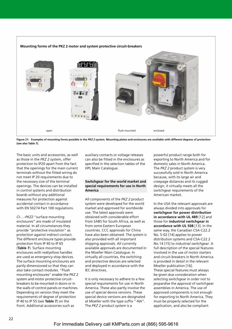
Mounting forms of the PKZ 2motor and system protective circuit-breakers
The mounting form of a switchingdevice is determined by theapplication it is required for (Figure 21). The “open-typeassembly” is used in systemengineering in all kinds of controlpanels, enclosures and distributionboards in which the circuit-breakersdo not have to be operated withoutopening the enclosure. This type ofmounting is therefore particularlysuited to applications where it must beensured that only qualified personnelwith permission to carry out switchoperations have access to the electricalswitchgear assembly. Door couplinghandles with a high degree ofprotection are available for externalactuation. Different busbar adaptersare offered to ensure especiallyeconomical and space-savingmounting and wiring. These enablethe circuit-breaker or motor starter tobe fitted in the Off position directlyonto standard busbar systems forvoltages up to 690 V.
Figure 20: Example of a reversing starter combination with separately mounted contact modules. Star-delta combinations are also mounted in this way.
Reversing starter combination with Circuit diagram of a separately mounted contact star-delta combinationmodules
For Immediate Delivery call KMParts.com at (866) 595-9616
22
The basic units and accessories, as wellas those in the PKZ 2 system, offerprotection to IP20 apart from the factthat the openings for the main currentterminals without the fitted wiring donot meet IP 20 requirements due tothe necessary size of the terminalopenings. The devices can be installedin control systems and distributionboards without any additionalmeasures for protection againstaccidental contact in accordance with EN 50274 Part 100 regulations.
CI-...-PKZ2 “surface mountingenclosures” are made of insulatedmaterial. In all circumstances theyprovide “protective insulation” asprotection against indirect contact.The different enclosure types provideprotection from IP 40 to IP 65 (Table 7). Surface mountingenclosures with red/yellow handles are used as emergency-stop devices.The surface mounting enclosures arepartly dimensioned so that they canalso take contact modules. “Flushmounting enclosures” enable the PKZ 2system and motor protective circuit-breakers to be mounted in doors or inthe walls of control panels or machines.Depending on version they meet therequirements of degree of protectionIP 40 to IP 55 (see Table 7) on thefront. Additional accessories such as
auxiliary contacts or voltage releasescan also be fitted in the enclosures asspecified in the selection tables of theHPL Main Catalogue.
Switchgear for the world market and special requirements for use in NorthAmerica
All components of the PKZ 2 productsystem were developed for the worldmarket and approved for worldwideuse. The latest approvals wereobtained with considerable effortfrom SABS for South Africa, as well asfrom some Eastern Europeancountries. CCC approvals for Chinahave also been obtained. The system isalso provided with all importantshipping approvals. All currentlyavailable approvals are documented inthe Moeller Main Catalogue. Invirtually all countries, the switchingand protective devices are selectedand deployed in accordance with theIEC directives.
It is only necessary to adhere to a fewspecial requirements for use in NorthAmerica. These also partly involve theuse of special device versions. Thesespecial device versions are designatedat Moeller with the type suffix “-NA”.The PKZ 2 product system is a
powerful product range both forexporting to North America and fordomestic sales in North America. The PKZ 2 product system is verysuccessfully sold in North Americabecause, with its large air andcreepage distances and its ruggeddesign, it virtually meets all theswitchgear requirements of theAmerican market.
In the USA the relevant approvals arealways divided into approvals forswitchgear for power distribution in accordance with UL 489 [12] andthose for industrial switchgear inaccordance with UL 508 [13]. In thesame way, the Canadian CSA-C22.2No. 5-02 [14] applies to powerdistribution systems and CSA-C22.2No.14 [15] to industrial switchgear. Afull description of the special featuresinvolved in the use of motor startersand circuit-breakers in North Americais provided in detail in the relevantMoeller publication [16]. These special features must alwaysbe given due consideration whenselecting switchgear in order not tojeopardise the approval of switchgearassemblies in America. The use ofapproved components is not enoughfor exporting to North America. Theymust be properly selected for theapplication, and also be compliant
Figure 21: Examples of mounting forms possible in the PKZ 2 system. Mounting plates and enclosures are available with different degrees of protection (see also Table 7).
open flush mounted enclosed
Mounting forms of the PKZ 2 motor and system protective circuit-breakers
For Immediate Delivery call KMParts.com at (866) 595-9616
23
with the standards using approvedwiring material.
There are other technical and financialreasons for promoting the use offuseless solutions for switchgearsystems for North America.
• Space saving: since fuse bases forNorth American fuses are very largeand take up a lot of space in controlsystems. The sizes of the fuse basesare much larger than those ofcontactors and motor protectiverelays.
• The NZM, PKZ2/ZM-..-CB circuit-breakers and the PKZ2/ZM-.../S-SPself-protected combination startersdescribed later each contain thecircuit disconnection and lockingfunctions, short-circuit and overloadprotection in a compact unit and arenevertheless considerably cheaperand smaller than the combinationfuse base + fuses + contactor +overload relay. These fuselesssolutions disconnect on all poles andenable the equipment to be readyfor operation sooner.
• With the wide range of fuse designsavailable in the USA and Canada,non-American machine and systemmanufacturers usually find it difficultto find the fuse system used by theend customer, and this is oftenunknown anyway. All the electricalequipment for the machine orsystem is selected entirelyindependently of the fuse systemused locally. The problem of spareparts procurement is eliminated.
PKZ 2 as a motor-protective circuit-breaker for North AmericaThe PKZ2/ZM-.. circuit-breakers are approved in accordance with UL 508 / CSA-C22.2 No.14 for theseapplications. They are identical to theIEC design and are therefore suitablefor worldwide use. In North America,this type of circuit-breaker is called a“manual motor controller withthermal and magnetic trip”. The UL 508 devices of all manufacturersare not recognised as short-circuitprotective devices, and therefore anadditional short-circuit protectivedevice must be installed upstream of these motor-protective circuit-
breakers for applications in NorthAmerica. This protective device canprotect several motor-protectivecircuit-breakers in group protection(the self-protected combinationstarters presented later are analternative). The maximum short-circuit currents are 65 kA at 480 V or42 kA at 600 V with an upstreamprotective device as specified in theMain Catalogue.
PKZ 2 as a non-manual motor starterfor North AmericaMotor starters provide the “short-circuit and overload protection”functions as well as the“disconnection” and “operationalswitching” functions. Whilst thepreviously described PKZ 2/ZM-...motor-protective circuit-breakers aredesigned for manual operationalswitching, a contact module(contactor) is used on the startersdescribed here for remote switching orfor frequent or automated switching.
The PKZ 2 system offers two solutionswith a short-circuit switching capacityof 65 kA at 480 V or 42 kA at 600 V:
• The PKZ2/ZM-../S high capacitycompact starter is called a “manualmotor starter with thermal,magnetic trip and contactor”,
• The PKZ2/ZM-../S-SP “self-protectedstarter” can be used without theneed for an upstream short-circuitprotective device.
The restrictions described later mustbe taken into account when usingthese solutions.
• High-capacity compact startersThe high-capacity compact starterconsists of a PKZ2/ZM-... motor-protective circuit-breaker and an S-PKZ2 high-capacity contactmodule. These components areworld market devices that areidentical to the IEC range.
Restriction: As these componentsare approved as industrial switchgearin accordance with UL 508 and CSA C22.2 No. 14, an additionalupstream short-circuit protectivedevice is always required. These canbe fuses or NZM circuit-breakers inaccordance with UL 489 / CSA C22.2No. 5, with rated currents up to2000 A, and can also be used forgroup protection for several high-capacity compact starters. Thesecombinations can then be used forall network types and up to 600 Vwithout the restrictions that apply toself-protected combination starters.All approved accessories of the PKZ 2product system can be combined.
• PKZ2/ZM-.../S-SP self-protectedcombination starters
Additions to UL 508 and CSA-C22.2No. 14 extended the classification ofcombination motor controllers withthe introduction of ConstructionType E. In the relevant Annex, a high
Figure 22: UL / CSA “Type E” devices provide all four functions of a motor starter, eliminating theneed for an upstream protective device. “Type E” devices are called self-protected starters.
UL 508 “Type E“
”Type E“ devices provideall 4 functions (Disconnectorfunction, short-circuit pro-tection, overload protection,operational switching).
The upstream protective device is not required.
Upstream protective device
For Immediate Delivery call KMParts.com at (866) 595-9616
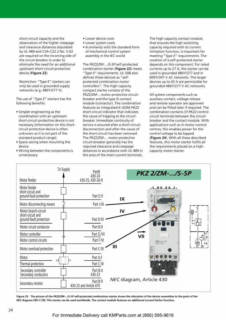
24
short-circuit capacity and theobservation of the higher creepageand clearance distances stipulatedby UL 489 and CSA-C22.2 No. 5-02are required on the incoming side ofthe circuit-breaker in order toeliminate the need for an additionalupstream short-circuit protectivedevice (Figure 22).
Restriction: “Type E” starters canonly be used in grounded supplynetworks (e.g. 480Y/277 V).
The use of “Type E” starters has thefollowing benefits:
• Simpler engineering as thecoordination with an upstreamshort-circuit protective device is notnecessary (information on this short-circuit protective device is oftenunknown as it is not part of thestandard product range)
• Space saving when mounting thedevice
• Wiring between the components isunnecessary
• Lower device costs• Lower system costs• A similarity with the standard form
of mechanical control systemassembly in the IEC world
The PKZ2/ZM-.../S-SP self-protectedcombination starter (Figure 23) meets“Type E” requirements. UL 508 alsodefines these devices as “self-protected combination motorcontrollers”. This high-capacitycompact starter consists of thePKZ2/ZM-.. motor-protective circuit-breaker and the type /S contactmodule (contactor). The combinationfeatures an integrated K-AGM-PKZ2short-circuit indicator that indicatesthe cause of tripping at the circuit-breaker. Immediate continuity ofservice is ensured after a short-circuitdisconnection and after the cause ofthe short-circuit has been removed.The PKZ2/ZM-... motor-protectivecircuit-breaker generally has therequired clearance and creepagedistances in accordance with UL 489 inthe area of the main current terminals.
The high-capacity contact module,that ensures the high switchingcapacity required with its currentlimitation function, is important formeeting “Type E” requirements. Thecreation of a self-protected starterdepends on this component. For ratedcurrents up to 27 A, the starter can beused in grounded 480Y/277 and in600Y/347 V AC networks. The largerdevices up to 42 A are permissible forgrounded 480Y/277 V AC networks.
All system components such asauxiliary contact, voltage release and remote operator are approvedand can be fitted later if required. Thecombination contains ST-PKZ2 controlcircuit terminals between the circuit-breaker and the contact module. Withapplications such as in motor controlcentres, this enables power for thecontrol voltage to be tapped (Figure 24). With all these describedfeatures, this motor starter fulfils allthe requirements placed on a high-capacity motor starter.
Figure 23: The picture of the PKZ2/ZM-.../S-SP self-protected combination starter shows the allocation of the device assemblies to the parts of the NEC diagram 430-1 [18]. This starter can be used worldwide. The contact module features an additional current limiter function.
old Part/ new Paalt/neu
Part B430-24
430-25, 430-26Motor feeder
Motor feedershort-circuit andground-fault protection Part E
Motor disconnecting means Part J
Motor branch-circuitshort-circuit andground-fault protection Part D
Motor circuit conductor Part B
Motor controller Part GMotor control circuits Part F
Motor overload protection Part C
Part CMotor Part AThermal protectionSecondary controllerSecondary conductors
Part B430-23
Secondary resistor Part B430-23 and Article 470
To Supply
/II
/V
/IX
/IV
/II
/VII/VI
/III
/I/III
/II
/II
IX
IV
III
VII
PKZ 2/ZM-.../S-SP
NEC diagram, Article 430
For Immediate Delivery call KMParts.com at (866) 595-9616
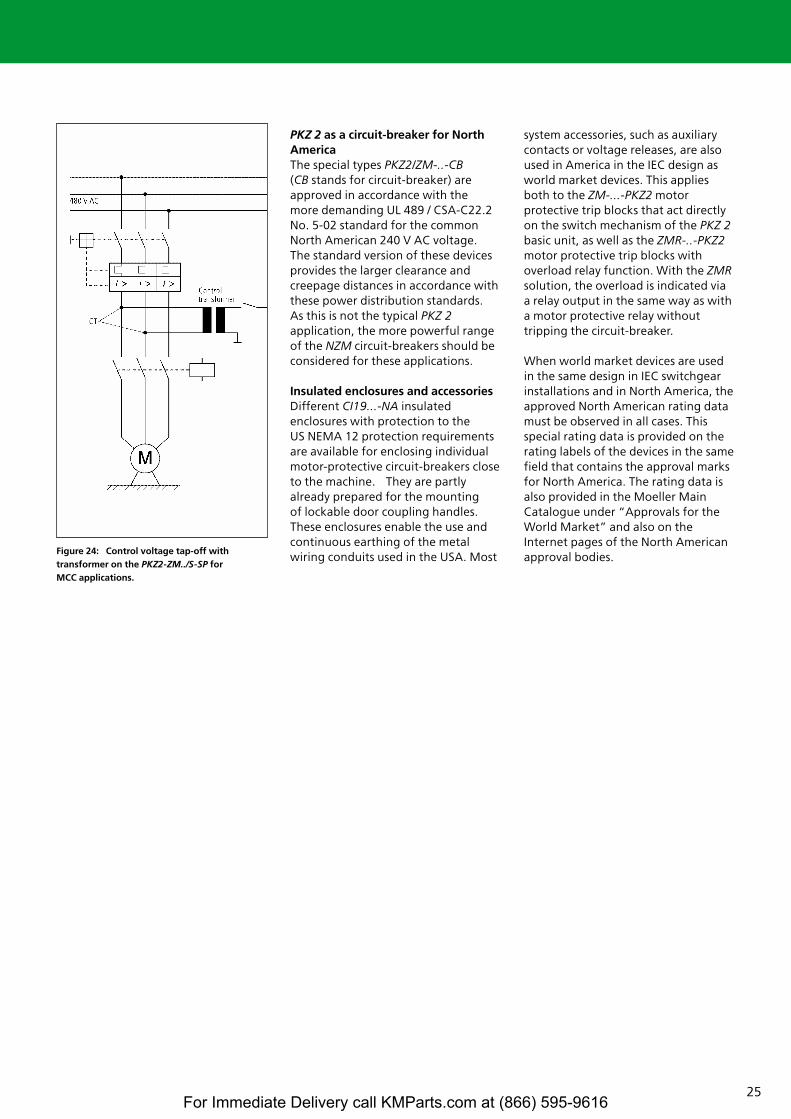
25
PKZ 2 as a circuit-breaker for NorthAmericaThe special types PKZ2/ZM-..-CB(CB stands for circuit-breaker) areapproved in accordance with the more demanding UL 489 / CSA-C22.2No. 5-02 standard for the commonNorth American 240 V AC voltage. The standard version of these devicesprovides the larger clearance andcreepage distances in accordance withthese power distribution standards. As this is not the typical PKZ 2application, the more powerful rangeof the NZM circuit-breakers should beconsidered for these applications.
Insulated enclosures and accessoriesDifferent CI19...-NA insulatedenclosures with protection to the US NEMA 12 protection requirementsare available for enclosing individualmotor-protective circuit-breakers closeto the machine. They are partlyalready prepared for the mounting of lockable door coupling handles.These enclosures enable the use andcontinuous earthing of the metalwiring conduits used in the USA. Most
system accessories, such as auxiliarycontacts or voltage releases, are alsoused in America in the IEC design asworld market devices. This appliesboth to the ZM-...-PKZ2 motorprotective trip blocks that act directlyon the switch mechanism of the PKZ 2basic unit, as well as the ZMR-..-PKZ2motor protective trip blocks withoverload relay function. With the ZMRsolution, the overload is indicated viaa relay output in the same way as witha motor protective relay withouttripping the circuit-breaker.
When world market devices are usedin the same design in IEC switchgearinstallations and in North America, theapproved North American rating datamust be observed in all cases. Thisspecial rating data is provided on therating labels of the devices in the samefield that contains the approval marksfor North America. The rating data isalso provided in the Moeller MainCatalogue under “Approvals for theWorld Market” and also on theInternet pages of the North Americanapproval bodies.
Figure 24: Control voltage tap-off withtransformer on the PKZ2-ZM../S-SP for MCC applications.
For Immediate Delivery call KMParts.com at (866) 595-9616
26
Validity of information
This technical paper is based on thestate-of-the-art and internationalstandards in February 2006.Modifications are not permissible. Theinformation provided in the relevantcatalogues of Moeller is always binding.These also provide detailed informationon motor starters for differentcoordination types and voltages inaccordance with IEC / EN 60 947-4-1 [4].
Bibliography[1] Wolfgang Esser
“xStart – Die neue Generation: 100 Jahre Moeller Schütze – konsequenter Fortschritt –”VER2100-937DMoeller GmbH, Bonn, 2004
“xStart – The New Generation:100 Years of Moeller Contactors –Continuous Progress –”VER2100-937GBMoeller GmbH, Bonn, 2004
Internet links:German: Quicklink-ID: 937de atwww.moeller.netEnglish:Quicklink-ID: 937en atwww.moeller.net
[2] Wolfgang Esser„xStart – Moderne Schaltanlageneffizient montieren und sicher ver-drahten –“VER1200+2100-938DMoeller GmbH, Bonn, 2004
Internet links:German: Quicklink-ID: 938de atwww.moeller.netEnglish:Quicklink-ID: 938en atwww.moeller.net
[3] IEC / EN 60 947-2, VDE 0660 Part101 “Low-Voltage Switchgear andControlgear, Part 2: Circuit-Breakers” (1995 to 1997)IEC / EN 60 947-2, VDE 0660 Part101 “Low-Voltage Switchgear andControlgear, Part 2: Circuit-Breakers” (1995 to 1997)
[4] IEC / EN 60 947-4-1, DIN VDE 0660Part 102 “Low-VoltageSwitchgear and Controlgear, Part4-1: Electromagnetic Contactorsand Motor Starters” (1991)
[5] IEC / EN 60 947-3, DIN VDE 0660Part 107 “Low-VoltageSwitchgear and Controlgear, Part3: Switches; Disconnectors;Switch-disconnectors and Fuse-Combination Units” (1990, 1992)
[6] IEC / EN 60204-1 and DIN EN60204-1 * Classification VDE 0113Part 1 “Safety of Machines,Electrical Equipment of Machines,Part 1: General Requirements”(1992, 1993) and IEC 204-1 Draft9/2002
[7] Wolfgang Esser“Switching and Protective Devicesin Machine Controls”“ep” Elektropraktiker journal,Berlin 57 (2003) 11
[8] PKZ 2 Motor-Protective Circuit-Breakers, Overload Monitoring ofEEX e MotorsHardware and Engineering 09/02 AWB1210-1485D/GBMoeller GmbH, Bonn, 2004Internet link: ftp://ftp.moeller.net/DOCUMEN-TATION/AWB_MANUALS/h1485dgb.pdf
[9] ATEX 100a, Directive 94/9/EC of23.3.94, for the approximation ofthe laws of the Member Statesconcerning equipment andprotective systems intended foruse in potentially explosiveatmospheres, ABI. L 100 of19.4.1994
[10] Wolfgang Esser“Motor Protection with theElectronic Motor Protective Relay(ZEV)“ep” Elektropraktiker journal,issue 7-98
[11] Wolfgang Esser“Motor and Machine Protectionwith Thermistors”Special publication from “de”Elektro- und Gebäudetechnikerjournal,VER 20-838 D,Moeller GmbH, Bonn, 1999
[12] UL 489, “Molded Case CircuitBreakers, Molded Case Switchesand Circuit Breaker Enclosures”
[13] UL 508, “Industrial ControlEquipment”
[14] CSA-C22.2 No. 5-02, “MoldedCase Circuit Breakers”
[15] CSA-C22.2 No. 14, “IndustrialControl Equipment, IndustrialProducts”
[16] Wolfgang Esser,“Besondere Bedingungen fürden Einsatz von Motorschutz-schaltern und Motorstarternin Nordamerika”,VER1210+1280-928D,Moeller GmbH, Bonn, 2003
“Special Consideration Governingthe Application of Manual MotorControllers and Motor Starters inNorth America”VER1210+1280-928GBMoeller GmbH, Bonn, 2003
Internet-Links:German: Quicklink-ID: 928de atwww.moeller.netEnglish:Quicklink-ID: 928en atwww.moeller.net
[17] NEC = National Electrical Code(USA)CEC = Canadian Electrical Code
[18] IEC / EN 60 947-1, “Low-VoltageSwitchgear, Part 1: GeneralRequirements”
For Immediate Delivery call KMParts.com at (866) 595-9616
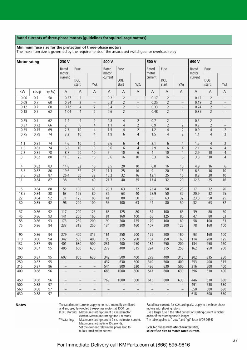
27
Rated currents of three-phase motors (guidelines for squirrel-cage motors)
Minimum fuse size for the protection of three-phase motorsThe maximum size is governed by the requirements of the associated switchgear or overload relay
Motor rating 230 V 400 V 500 V 690 V
Ratedmotorcurrent
Fuse Ratedmotorcurrent
Fuse Ratedmotorcurrent
Fuse Ratedmotorcurrent
Fuse
DOLstart Y/∆
DOLstart Y/∆
DOLstart Y/∆
DOLstart Y/∆
kW y h(%) A A A A A A A A A A A A
0.06 0.7 58 0.37 2 – 0.21 2 – 0.17 2 – 0.12 2 –0.09 0.7 60 0.54 2 – 0.31 2 – 0.25 2 – 0.18 2 –0.12 0.7 60 0.72 4 2 0.41 2 – 0.33 2 – 0.24 2 –0.18 0.7 62 1.04 4 2 0.6 2 – 0.48 2 – 0.35 2 –
0.25 0.7 62 1.4 4 2 0.8 4 2 0.7 2 – 0.5 2 –0.37 0.72 66 2 6 4 1.1 4 2 0.9 2 2 0.7 2 –0.55 0.75 69 2.7 10 4 1.5 4 2 1.2 4 2 0.9 4 20.75 0.79 74 3.2 10 4 1.9 6 4 1.5 4 2 1.1 4 2
1.1 0.81 74 4.6 10 6 2.6 6 4 2.1 6 4 1.5 4 21.5 0.81 74 6.3 16 10 3.6 6 4 2.9 6 4 2.1 6 42.2 0.81 78 8.7 20 10 5 10 6 4 10 4 2.9 10 43 0.82 80 11.5 25 16 6.6 16 10 5.3 16 6 3.8 10 4
4 0.82 83 14.8 32 16 8.5 20 10 6.8 16 10 4.9 16 65.5 0.82 86 19.6 32 25 11.3 25 16 9 20 16 6.5 16 107.5 0.82 87 26.4 50 32 15.2 32 16 12.1 25 16 8.8 20 10
11 0.84 87 38 80 40 21.7 40 25 17.4 32 20 12.6 25 16
15 0.84 88 51 100 63 29.3 63 32 23.4 50 25 17 32 2018.5 0.84 88 63 125 80 36 63 40 28.9 50 32 20.9 32 2522 0.84 92 71 125 80 41 80 50 33 63 32 23.8 50 2530 0.85 92 96 200 100 55 100 63 44 80 50 32 63 32
37 0.86 92 117 200 125 68 125 80 54 100 63 39 80 5045 0.86 93 141 250 160 81 160 100 65 125 80 47 80 6355 0.86 93 173 250 200 99 200 125 79 160 80 58 100 6375 0.86 94 233 315 250 134 200 160 107 200 125 78 160 100
90 0.86 94 279 400 315 161 250 200 129 200 160 93 160 100110 0.86 94 342 500 400 196 315 200 157 250 160 114 200 125132 0.87 95 401 630 500 231 400 250 184 250 200 134 250 160160 0.87 95 486 630 630 279 400 315 224 315 250 162 250 200
200 0.87 95 607 800 630 349 500 400 279 400 315 202 315 250250 0.87 95 – – – 437 630 500 349 500 400 253 400 315315 0.87 96 – – – 544 800 630 436 630 500 316 500 400400 0.88 96 – – – 683 1000 800 547 800 630 396 630 400
450 0.88 96 – – – 769 1000 800 615 800 630 446 630 630500 0.88 97 – – – – – – – – – 491 630 630560 0.88 97 – – – – – – – – – 550 800 630630 0.88 97 – – – – – – – – – 618 800 630
The rated motor currents apply to normal, internally-ventilatedand enclosed fan-cooled three-phase motors at 1500 rpm.D.O.L. starting: Maximum starting current 6 x rated motor
current. Maximum starting time 5 seconds.Y/∆starting: Maximum starting current 2 x rated motor current.
Maximum starting time 15 seconds.Set the overload relay in the phase lead to 0.58 x rated motor current.
Rated fuse currents for Y/∆starting also apply to the three-phasemotors with slip-ring rotors.Use a larger fuse if the rated current or starting current is higher and/or if the starting time is longer.The table applies to “slow” and “gL” fuses (VDE 0636)
LV h.b.c. fuses with aM characteristics,select fuse size to match rated current.
Notes
For Immediate Delivery call KMParts.com at (866) 595-9616
Xtra Combinations
Xtra Combinations from Moeller offers a range of productsand services, enabling the best possible combination optionsfor switching, protection and control in power distributionand automation.
Using Xtra Combinations enables you to find more efficientsolutions for your tasks while optimising the economic viability of your machines and systems.
It provides:■ flexibility and simplicity■ great system availability■ the highest level of safety
All the products can be easily combined with one another mechanically, electrically and digitally, enabling you to arriveat flexible and stylish solutions tailored to your application –quickly, efficiently and cost-effectively. The products are proven and of such excellent quality thatthey ensure a high level of operational continuity, allowingyou to achieve optimum safety for your personnel, machinery,installations and buildings.
Thanks to our state-of-the-art logistics operation, our com-prehensive dealer network and our highly motivated servicepersonnel in 80 countries around the world, you can count on Moeller and our products every time. Challenge us! We are looking forward to it!
Moeller addresses worldwide:www.moeller.net/address
E-Mail: [email protected]: www.moeller.net
Issued by Moeller GmbHHein-Moeller-Str. 7-11D-53115 Bonn
© 2006 by Moeller GmbHSubject to alterationsVER1280-952GB MDS/xx 01/06 Printed in the Federal Republic of Germany (03/06)Article No.: 105220
For Immediate Delivery call KMParts.com at (866) 595-9616