2008 gmc acadia owner manual m - dealer eprocesscdn.dealereprocess.com/.../gmc/2008-acadia.pdffront...
TRANSCRIPT

Seats and Restraint Systems ........................... 1-1Front Seats ............................................... 1-2Rear Seats .............................................. 1-11Safety Belts ............................................. 1-16Child Restraints ....................................... 1-36Airbag System ......................................... 1-61Restraint System Check ............................ 1-77
Features and Controls ..................................... 2-1Keys ........................................................ 2-3Doors and Locks ...................................... 2-10Windows ................................................. 2-18Theft-Deterrent Systems ............................ 2-21Starting and Operating Your Vehicle ........... 2-25Mirrors .................................................... 2-40Object Detection Systems .......................... 2-45OnStar® System ...................................... 2-47Universal Home Remote System ................ 2-50Storage Areas ......................................... 2-55Sunroof .................................................. 2-60
Instrument Panel ............................................. 3-1Instrument Panel Overview .......................... 3-4Climate Controls ...................................... 3-26Warning Lights, Gages, and Indicators ........ 3-39Driver Information Center (DIC) .................. 3-57Audio System(s) ....................................... 3-84
Driving Your Vehicle ....................................... 4-1Your Driving, the Road, and Your Vehicle ..... 4-2Towing ................................................... 4-26
Service and Appearance Care .......................... 5-1Service ..................................................... 5-3Fuel ......................................................... 5-6Checking Things Under the Hood ............... 5-12All-Wheel Drive ........................................ 5-43Headlamp Aiming ..................................... 5-45Bulb Replacement .................................... 5-45Windshield Wiper Blade Replacement ......... 5-47Tires ...................................................... 5-48Appearance Care ..................................... 5-89Vehicle Identification ................................. 5-98Electrical System ...................................... 5-99Capacities and Specifications ................... 5-107
Maintenance Schedule ..................................... 6-1Maintenance Schedule ................................ 6-2
Customer Assistance Information .................... 7-1Customer Assistance and Information ........... 7-2Reporting Safety Defects ........................... 7-13Vehicle Data Recording and Privacy ........... 7-15
Index ................................................................ 1
2008 GMC Acadia Owner Manual M
Information Provided by:

GENERAL MOTORS, GM, the GM Emblem, GMC, andthe GMC Emblem, are registered trademarks, andthe name ACADIA is a trademark of General MotorsCorporation.
This manual includes the latest information at the time itwas printed. We reserve the right to make changes afterthat time without further notice. For vehicles first sold inCanada, substitute the name “General Motors of CanadaLimited” for GMC whenever it appears in this manual.
This manual describes features that may be available inthis model, but your vehicle may not have all of them.For example, more than one entertainment system maybe offered or your vehicle may have been orderedwithout a front passenger or rear seats.
Keep this manual in the vehicle for quick reference.
Canadian OwnersA French language copy of this manual can be obtainedfrom your dealer/retailer or from:
Helm, IncorporatedP.O. Box 07130Detroit, MI 48207
1-800-551-4123www.helminc.com
Propriétaires CanadiensOn peut obtenir un exemplaire de ce guide en françaisauprès de concessionnaire ou à l’adresse suivante:
Helm IncorporatedP.O. Box 07130Detroit, MI 48207
1-800-551-4123www.helminc.com
Litho in U.S.A.Part No. 15861574 A First Printing ©2007 General Motors Corporation. All Rights Reserved.
ii
Information Provided by:

Using this ManualMany people read the owner manual from beginning toend when they first receive their new vehicle to learnabout the vehicle’s features and controls. Picturesand words work together to explain things.
IndexA good place to quickly locate information about thevehicle is the Index in the back of the manual. It is analphabetical list of what is in the manual and thepage number where it can be found.
Safety Warnings and SymbolsThere are a number of safety cautions in this book. Abox with the word CAUTION is used to tell about thingsthat could hurt you or others if you were to ignore thewarning.
{CAUTION:
These mean there is something that could hurtyou or other people.
We tell you what the hazard is and what to do to helpavoid or reduce the hazard. Please read these cautions.If you do not, you or others could be hurt.
A circle with a slashthrough it is a safetysymbol which means “DoNot,” “Do Not do this”or “Do Not let this happen.”
iii
Information Provided by:

Vehicle Damage WarningsYou will also find notices in this manual.
Notice: These mean there is something that coulddamage your vehicle.
A notice tells about something that can damage thevehicle. Many times, this damage would not be coveredby your vehicle’s warranty, and it could be costly.The notice tells what to do to help avoid the damage.
When you read other manuals, you might see CAUTIONand NOTICE warnings in different colors or in differentwords.
There are also warning labels on the vehicle which usethe same words, CAUTION or NOTICE.
Vehicle SymbolsThe vehicle has components and labels that usesymbols instead of text. Symbols are shown along withthe text describing the operation or informationrelating to a specific component, control, message,gage, or indicator.
iv
Information Provided by:

Front Seats ......................................................1-2Manual Seats ................................................1-2Seat Height Adjuster .......................................1-3Power Seats ..................................................1-3Manual Lumbar ..............................................1-4Power Lumbar ...............................................1-5Heated Seats .................................................1-5Memory Seat and Mirrors ................................1-6Reclining Seatbacks ........................................1-8Head Restraints ............................................1-10
Rear Seats .....................................................1-11Rear Seat Operation .....................................1-11Third Row Seats ...........................................1-13
Safety Belts ...................................................1-16Safety Belts: They Are for Everyone ................1-16How to Wear Safety Belts Properly .................1-22Lap-Shoulder Belt .........................................1-30Safety Belt Use During Pregnancy ..................1-35Safety Belt Extender .....................................1-36
Child Restraints .............................................1-36Older Children ..............................................1-36Infants and Young Children ............................1-39
Child Restraint Systems .................................1-43Where to Put the Restraint .............................1-46Lower Anchors and Tethers for Children
(LATCH) ..................................................1-47Securing a Child Restraint in a Rear Seat
Position ...................................................1-55Securing a Child Restraint in the Right Front
Seat Position ............................................1-58Airbag System ...............................................1-61
Where Are the Airbags? ................................1-64When Should an Airbag Inflate? .....................1-67What Makes an Airbag Inflate? .......................1-68How Does an Airbag Restrain? .......................1-68What Will You See After an Airbag Inflates? .....1-69Passenger Sensing System ............................1-70Servicing Your Airbag-Equipped Vehicle ...........1-75Adding Equipment to Your Airbag-Equipped
Vehicle ....................................................1-76Restraint System Check ..................................1-77
Checking the Restraint Systems ......................1-77Replacing Restraint System Parts After
a Crash ...................................................1-78
Section 1 Seats and Restraint Systems
1-1
Information Provided by:
Front Seats
Manual Seats
{CAUTION:
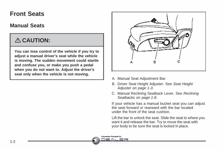
You can lose control of the vehicle if you try toadjust a manual driver’s seat while the vehicleis moving. The sudden movement could startleand confuse you, or make you push a pedalwhen you do not want to. Adjust the driver’sseat only when the vehicle is not moving.
A. Manual Seat Adjustment Bar.B. Driver Seat Height Adjuster. See Seat Height
Adjuster on page 1-3.C. Manual Reclining Seatback Lever. See Reclining
Seatbacks on page 1-8.
If your vehicle has a manual bucket seat you can adjustthe seat forward or rearward with the bar locatedunder the front of the seat cushion.
Lift the bar to unlock the seat. Slide the seat to where youwant it and release the bar. Try to move the seat withyour body to be sure the seat is locked in place.
1-2
Information Provided by:

Seat Height AdjusterIf your vehicle has a manual driver seat height adjuster,it is located on the outboard side of the seat. SeeManual Seats on page 1-2 for more information. To raisethe seat, move the lever upward repeatedly until theseat is at the desired height. To lower the seat,move the lever downward repeatedly until the seat is atthe desired height.
Power Seats
A. Power Seat Adjustment Control.B. Power Reclining Seatback Control. See Reclining
Seatbacks on page 1-8.C. Power Lumbar Control. See Power Lumbar on
page 1-5.
If the vehicle has power seats, the controls used tooperate them are located on the outboard side of theseats.
Driver’s Seat with Power Seat Control, PowerRecline, and Power Lumbar shown
1-3
Information Provided by:

Move the seat forward or rearward by sliding the controlforward or rearward.
Your vehicle may have additional features to adjust yourvehicle’s power seat:
• Raise or lower the entire seat by moving the entirecontrol up or down.
• Raise or lower the front part of the seat cushion bymoving the front of the control up or down.
• Raise or lower the rear part of the seat cushion bymoving the rear of the control up or down.
Your vehicle may have a memory function which allowsseat settings to be saved and recalled. See MemorySeat and Mirrors on page 1-6 for more information.
Manual Lumbar
If your vehicle has thisfeature, the handle islocated on the inboard sideof the seatback. SeeManual Seats on page 1-2for more information.
Turn the handle rearward to decrease lumbar support.Turn the handle forward to increase lumbar support.
Keep in mind that as your seating position changes, asit may during long trips, so should the position ofyour lumbar support. Adjust the seat as needed.
1-4
Information Provided by:

Power LumbarIf the seats have power lumbar, the controls used tooperate this feature are located on the outboard side ofthe seats. See Power Seats on page 1-3 for moreinformation.
• To increase lumbar support, press and hold thefront of the control.
• To decrease lumbar support, press and hold therear of the control.
• To raise the height of the lumbar support, pressand hold the top of the control.
• To lower the height of the lumbar support, pressand hold the bottom of the control.
Release the control when the lower seatback reachesthe desired level of lumbar support.
You may need to adjust the lumbar support wheneveryou change your seating position.
Heated SeatsOn vehicles with heated front seats the controls arelocated on the center console. To operate the heatedseats the engine must be running.
I (Heated Seatback): Press this button to turn on theheated seatback.
J (Heated Seat and Seatback): Press this button toturn on the heated seat and seatback.
The light on the button will come on to indicate that thefeature is working. Press the button to cycle throughthe temperature settings of high, medium, and low andto turn the heat to the seat off. Indicator lights abovethe button will show the level of heat selected: three forhigh, two for medium, and one for low.
The passenger seat may take longer to heat up.
If your vehicle has remote vehicle start and is startedusing the remote keyless entry transmitter, the frontheated seats will be turned on to the high setting if it iscold outside. See “Remote Vehicle Start” underRemote Keyless Entry (RKE) System Operation onpage 2-5. When the key is inserted into the ignition andthe ignition is turned on, the heated seat feature willturn off. To turn the heated seat feature back on, pressthe desired button.
1-5
Information Provided by:

Memory Seat and MirrorsYour vehicle may have the memory package.
The controls for this feature are located on the driver’sdoor panel, and are used to program and recallmemory settings for the driver’s seat and outsidemirrors.
To save your positions in memory, do the following:
1. Adjust the driver’s seat, including the seatbackrecliner and lumbar and both outside mirrors toa comfortable position.See Outside Power Mirrors on page 2-42 for moreinformation.Not all mirrors will have the ability to save andrecall the mirror positions.
2. Press and hold button 1 until two beeps let youknow that the position has been stored.
A second seating and mirror position can beprogrammed by repeating the above steps and pressingbutton 2.
To recall the memory positions, the vehicle must be inPARK (P). Press and release either button 1 or button 2corresponding to the desired driving position. Theseat and outside mirrors will move to the positionpreviously stored. You will hear a single beep.
1-6
Information Provided by:

Using the Remote Keyless Entry (RKE) transmitter toenter your vehicle with the remote recall memory featureon causes automatic seat and mirror adjustment.There is no adjustment when the position has not beenchanged by another seating position or the easy exitfeature. See “MEMORY SEAT RECALL” underDIC Vehicle Customization (With DIC Buttons) onpage 3-75 for more information.
To stop recall movement of the memory feature at anytime, press one of the power seat controls, memorybuttons, or power mirror buttons.
If something has blocked the driver’s seat while recallinga memory position, the driver’s seat recall may stopworking. If this happens, press the appropriate controlfor the area that is not recalling for two seconds,after the obstruction is removed. Then try recalling thememory position again by pressing the appropriatememory button. If the memory position is still not beingrecalled, see your dealer/retailer for service.
Easy Exit SeatThe control for this feature is located on the driver’sdoor panel between buttons 1 and 2.
With the vehicle in PARK (P), the exit position can berecalled by pressing the exit button. You will heara single beep. The driver’s seat will move back.
If the easy exit seat feature is on in the DriverInformation Center (DIC), automatic seat movement willoccur when the key is removed from the ignition.See “EASY EXIT SEAT” under DIC VehicleCustomization (With DIC Buttons) on page 3-75 formore information.
Further programming for the memory seat feature canbe done using the DIC. You can select or cancelthe following:
• The automatic easy exit seat feature.
• The remote memory seat recall feature.
For programming information, see DIC VehicleCustomization (With DIC Buttons) on page 3-75.
1-7
Information Provided by:

Reclining Seatbacks
Manual Reclining Seatbacks
{CAUTION:
You can lose control of the vehicle if you try toadjust a manual driver’s seat while the vehicleis moving. The sudden movement could startleand confuse you, or make you push a pedalwhen you do not want to. Adjust the driver’sseat only when the vehicle is not moving.
{CAUTION:
If the seatback is not locked, it could moveforward in a sudden stop or crash. That couldcause injury to the person sitting there. Alwayspush and pull on the seatback to be sure it islocked.
In vehicles with seats that have manual recliningseatbacks, the lever used to operate them is located onthe outboard side of the seat.To recline the seatback, do the following:1. Lift the recline lever.2. Move the seatback to the desired position, then
release the lever to lock the seatback in place.3. Push and pull on the seatback to make sure it is
locked.To return the seatback to an upright position, do thefollowing:
1. Lift the lever fully without applying pressure to theseatback and the seatback will return to the uprightposition.
2. Push and pull on the seatback to make sure it islocked.
Power Reclining SeatbacksIn vehicles with seats that have power recliningseatbacks, the control used to recline them is located onthe outboard side of the seat behind the power seatcontrol. See Power Seats on page 1-3 for moreinformation.
• To recline the seatback, tilt the top of the controlrearward.
• To bring the seatback forward, tilt the top of thecontrol forward.
1-8
Information Provided by:

{CAUTION:
Sitting in a reclined position when your vehicleis in motion can be dangerous. Even if youbuckle up, your safety belts cannot do theirjob when you are reclined like this.
The shoulder belt cannot do its job because itwill not be against your body. Instead, it will bein front of you. In a crash, you could go into it,receiving neck or other injuries.
The lap belt cannot do its job either. In acrash, the belt could go up over yourabdomen. The belt forces would be there, notat your pelvic bones. This could cause seriousinternal injuries.
For proper protection when the vehicle is inmotion, have the seatback upright. Then sitwell back in the seat and wear your safety beltproperly.
Do not have a seatback reclined if your vehicle is moving.
1-9
Information Provided by:

Head Restraints
Adjust the head restraint so that the top of the restraintis at the same height as the top of the occupant’shead. This position reduces the chance of a neck injuryin a crash.
Pull the head restraintup to raise it. To lower thehead restraint, press therelease button, located onthe head restraint post onthe top of the seatback,while you push the headrestraint down.
1-10
Information Provided by:

Rear Seats
Rear Seat Operation
A. Seat Adjustment Handle.B. Reclining Seatback Strap.C. Sliding Seat Lever.
Entering and Exiting the Third Row
{CAUTION:
Using the third row seating position while thesecond row is folded, or folded and tumbled,could cause injury in a sudden stop or crash.Be sure to return the seat to the passengerseating position. Push and pull on the seat tomake sure it is locked into place.
Notice: Folding a rear seat with the safety beltsstill fastened may cause damage to the seat or thesafety belts. Always unbuckle the safety beltsand return them to their normal stowed positionbefore folding a rear seat.
1-11
Information Provided by:

To access the third row:
1. Remove objects on the floor in front of or on thesecond row seat, or in the seat tracks on thefloor.
2. Move the front center console armrest completelyforward. See Center Console Storage on page 2-56
3. Place folding armrests in the upright position.
4. The safety belt must be unfastened and in thestowed position.
5. Pull the sliding seat lever (C) forward and move theseatback forward. The seat cushion will fold, andthe entire seat will slide forward.
Returning the Seat to the SeatingPositionTo return the second row seat to its normal seatingposition:
1. Remove objects on the floor behind the second rowseat, or in the seat tracks on the floor.
2. Pull the seatback rearward until it is locked in place.
3. Slide the seat rearward by pushing on theseatback until it is locked into place.
4. Push down on the rear of the seat cushion until it islocked in place.
5. Push and pull on the seatback and seat cushion tomake sure they are locked in place
6. Check that the safety belt is not under the seatcushion.
1-12
Information Provided by:

Reclining the SeatbacksTo recline the seatback:
1. Leaning forward in the seat, pull the recliningseatback strap (B).
2. Move the seatback to the desired position, thenrelease the strap to lock the seatback in place.
3. Push and pull on the seatback to make sure it islocked.
Folding the Rear SeatTo fold the second row seats:
1. Remove anything on or under the seat.
2. Place the armrest in the upright position, andunfasten the safety belt.
3. Pull forward on the reclining seatback strap (B) andpush down on the seatback.
4. If the headrest hits the front seat, slide the secondrow seat rearward.
To return the seatback to the seating position, lift theupper corner of the seatback and push it rearward untilit locks into place. Push and pull on the seatback tomake sure it is locked.
Adjusting the SeatsTo adjust the second row seats, pull outward on the seatadjustment handle (A). Slide the seat forward or rearwardto the desired position. Release the handle and push andpull on the seat to make sure it is locked.
Third Row Seats
{CAUTION:
Using the third row seating position while thesecond row is folded, or pushed forward in theentry position, could cause injury in a suddenstop or crash. Be sure to return the seat to thepassenger seating position. Push and pull onthe seat to make sure it is locked into place.
The third row seats can be folded forward or removed.
Notice: Folding a rear seat with the safety beltsstill fastened may cause damage to the seat or thesafety belts. Always unbuckle the safety beltsand return them to their normal stowed positionbefore folding a rear seat.
1-13
Information Provided by:

To fold the seatback:
1. Remove anything on or under the seat.
2. Disconnect the rear safety belt mini-latch, using akey in the slot on the mini-buckle, let the beltretract into the headliner. Stow the mini-latch in theholder located in the headliner.
3. Pull up on the releaselever located on theback of the seat.The headrest movesforward automatically.
4. Push the seatback forward to lay flat.
To return the seatback to the seating position:
1. Raise the seatback into place by using the pullstrapfrom the rear of the vehicle, or by pushing it intoplace from inside the vehicle.
2. The headrest must be locked into place beforesitting in the seat.
1-14
Information Provided by:

{CAUTION:
If the seatback is not locked, it could moveforward in a sudden stop or crash. That couldcause injury to the person sitting there. Alwayspush and pull on the seatback to be sure it islocked.
3. Push and pull on the seatback to make sure it islocked in place.
{CAUTION:
A safety belt that is improperly routed, notproperly attached, or twisted will not providethe protection needed in a crash. The personwearing the belt could be seriously injured.After raising the rear seatback, always check tobe sure that the safety belts are properly routedand attached, and are not twisted.
4. Reconnect the center safety belt mini-latch to themini-buckle. Do not let it twist.
5. Pull on the safety belt to be sure the mini-latch issecure.
Removing the Third Row Seats1. Remove the cargo management system, if it is in
the vehicle. See Cargo Management System onpage 2-59.
2. Remove anything on or under the seat.
Notice: Folding a rear seat with the safety beltsstill fastened may cause damage to the seat or thesafety belts. Always unbuckle the safety beltsand return them to their normal stowed positionbefore folding a rear seat.
3. Fold the seatback down. See “Folding the Seatback”earlier in this section.
4. Remove the rear bolts located on the floor on eachside of the seat.
5. Remove the seat by tilting it slightly upward, andthen pulling it out of the rear of the vehicle in onemotion.
6. Put the bolts back into the holes on the floor sothey do not get misplaced.
1-15
Information Provided by:

Installing the Third Row Seats1. Before installing the seat the seatback must be
folded forward. See “Folding the Seatback”earlier in this section.The seats must be placed in the proper locationsfor the legs to attach correctly. The wider seat mustbe installed on the driver side and the narrowerseat on the passenger side. Remove the bolts fromthe holes in the floor before installing the seats.
2. Place the seat on the vehicle floor so that the frontseat hooks are on the vehicle bars.
3. Reinstall the bolts, and torque to 55 Y (41 lb ft).Pull up on the seat to make sure it is locked inplace.
4. Raise the seatback to its upright position. Push andpull on the seatback to make sure it is locked intoplace.
5. Push the headrest up into position. Push and pullon the headrest to make sure it is locked intoplace.
6. Reconnect the center safety belt mini-latch to themini-buckle. Do not let it twist.
Safety Belts
Safety Belts: They Are for EveryoneThis part of the manual tells you how to use safetybelts properly. It also tells you some things you shouldnot do with safety belts.
{CAUTION:
Do not let anyone ride where he or she cannotwear a safety belt properly. If you are in acrash and you are not wearing a safety belt,your injuries can be much worse. You can hitthings inside the vehicle harder or be ejectedfrom it and be seriously injured or killed. In thesame crash, you might not be, if you arebuckled up. Always fasten your safety belt,and check that your passenger(s) arerestrained properly too.
1-16
Information Provided by:

{CAUTION:
It is extremely dangerous to ride in a cargoarea, inside or outside of a vehicle. In acollision, people riding in these areas are morelikely to be seriously injured or killed. Do notallow people to ride in any area of your vehiclethat is not equipped with seats and safetybelts. Be sure everyone in your vehicle is in aseat and using a safety belt properly.
Your vehicle has indicators as a reminder to buckle yoursafety belts. See Safety Belt Reminders on page 3-41.
In most states and in all Canadian provinces, thelaw requires wearing safety belts. Here is why:
You never know if you will be in a crash. If you do havea crash, you do not know if it will be a serious one.
A few crashes are mild, and some crashes can be soserious that even buckled up, a person would notsurvive. But most crashes are in between. In many ofthem, people who buckle up can survive and sometimeswalk away. Without belts they could have been badlyhurt or killed.
After more than 40 years of safety belts in vehicles, thefacts are clear. In most crashes buckling up doesmatter... a lot!
1-17
Information Provided by:
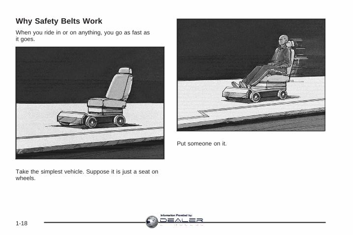
Why Safety Belts WorkWhen you ride in or on anything, you go as fast asit goes.
Take the simplest vehicle. Suppose it is just a seat onwheels.
Put someone on it.
1-18
Information Provided by:

Get it up to speed. Then stop the vehicle. The riderdoes not stop.
The person keeps going until stopped by something. Ina real vehicle, it could be the windshield...
1-19
Information Provided by:

or the instrument panel... or the safety belts!
With safety belts, you slow down as the vehicle does.You get more time to stop. You stop over more distance,and your strongest bones take the forces. That is whysafety belts make such good sense.
1-20
Information Provided by:

Questions and Answers About SafetyBelts
Q: Will I be trapped in the vehicle after a crash if Iam wearing a safety belt?
A: You could be — whether you are wearing a safetybelt or not. But your chance of being consciousduring and after an accident, so you can unbuckleand get out, is much greater if you are belted.And you can unbuckle a safety belt, even if you areupside down.
Q: If my vehicle has airbags, why should I have towear safety belts?
A: Airbags are supplemental systems only; so theywork with safety belts — not instead of them.Whether or not an airbag is provided, all occupantsstill have to buckle up to get the most protection.That is true not only in frontal collisions, butespecially in side and other collisions.
Q: If I am a good driver, and I never drive far fromhome, why should I wear safety belts?
A: You may be an excellent driver, but if you are in acrash — even one that is not your fault — you andyour passenger(s) can be hurt. Being a gooddriver does not protect you from things beyond yourcontrol, such as bad drivers.
Most accidents occur within 25 miles (40 km) ofhome. And the greatest number of serious injuriesand deaths occur at speeds of less than 40 mph(65 km/h).
Safety belts are for everyone.
1-21
Information Provided by:

How to Wear Safety Belts ProperlyThis section is only for people of adult size.
Be aware that there are special things to know aboutsafety belts and children. And there are differentrules for smaller children and babies. If a child will beriding in your vehicle, see Older Children on page 1-36or Infants and Young Children on page 1-39. Followthose rules for everyone’s protection.
It is very important for all occupants to buckle up.Statistics show that unbelted people are hurt more oftenin crashes than those who are wearing safety belts.
Occupants who are not buckled up can be thrown out ofthe vehicle in a crash. And they can strike others inthe vehicle who are wearing safety belts.
First, before you or your passenger(s) wear a safetybelt, there is important information you should know. Sit up straight and always keep your feet on the floor in
front of you. The lap part of the belt should be wornlow and snug on the hips, just touching the thighs. In acrash, this applies force to the strong pelvic bonesand you would be less likely to slide under the lap belt.If you slid under it, the belt would apply force onyour abdomen. This could cause serious or even fatalinjuries. The shoulder belt should go over the shoulderand across the chest. These parts of the body arebest able to take belt restraining forces.The shoulder belt locks if there is a sudden stop or crash.
1-22
Information Provided by:

Q: What is wrong with this?
A: The shoulder belt is too loose. It will not give nearlyas much protection this way.
{CAUTION:
You can be seriously hurt if your shoulder beltis too loose. In a crash, you would moveforward too much, which could increase injury.The shoulder belt should fit snugly againstyour body.
1-23
Information Provided by:

Q: What is wrong with this?
A: The lap belt is too loose. It will not give as muchprotection this way.
{CAUTION:
You can be seriously hurt if your lap belt is tooloose. In a crash, you could slide under the lapbelt and apply force on your abdomen. Thiscould cause serious or even fatal injuries. Thelap belt should be worn low and snug on thehips, just touching the thighs.
1-24
Information Provided by:

Q: What is wrong with this?
A: The belt is buckled in the wrong place.
{CAUTION:
You can be seriously injured if your belt isbuckled in the wrong place like this. In a crash,the belt would go up over your abdomen. Thebelt forces would be there, not on the pelvicbones. This could cause serious internalinjuries. Always buckle your belt into thebuckle nearest you.
1-25
Information Provided by:

Q: What is wrong with this?
A: The belt is over an armrest.
{CAUTION:
You can be seriously injured if your belt goesover an armrest like this. The belt would bemuch too high. In a crash, you can slide underthe belt. The belt force would then be appliedon the abdomen, not on the pelvic bones, andthat could cause serious or fatal injuries. Besure the belt goes under the armrests.
1-26
Information Provided by:

Q: What is wrong with this?
A: The shoulder belt is worn under the arm. It shouldbe worn over the shoulder at all times.
{CAUTION:
You can be seriously injured if you wear theshoulder belt under your arm. In a crash, yourbody would move too far forward, which wouldincrease the chance of head and neck injury.Also, the belt would apply too much force tothe ribs, which are not as strong as shoulderbones. You could also severely injure internalorgans like your liver or spleen. The shoulderbelt should go over the shoulder and acrossthe chest.
1-27
Information Provided by:

Q: What is wrong with this?
A: The belt is behind the body.
{CAUTION:
You can be seriously injured by not wearingthe lap-shoulder belt properly. In a crash, youwould not be restrained by the shoulder belt.Your body could move too far forwardincreasing the chance of head and neck injury.You might also slide under the lap belt. Thebelt force would then be applied right on theabdomen. That could cause serious or fatalinjuries. The shoulder belt should go over theshoulder and across the chest.
1-28
Information Provided by:

Q: What is wrong with this?
A: The belt is twisted across the body.
{CAUTION:
You can be seriously injured by a twisted belt.In a crash, you would not have the full width ofthe belt to spread impact forces. If a belt istwisted, make it straight so it can workproperly, or ask your dealer/retailer to fix it.
1-29
Information Provided by:

Lap-Shoulder BeltAll seating positions in your vehicle have alap-shoulder belt.
If you are using a rear seating position with a detachablesafety belt and the safety belt is not attached, seeThird Row Seats on page 1-13 for instruction onreconnecting the safety belt to the mini-buckle.
Here is how to wear a lap-shoulder belt properly.
1. Adjust the seat, if the seat is adjustable, so you cansit up straight. To see how, see “Seats” in theIndex.
2. Pick up the latch plate and pull the belt across you.Do not let it get twisted.The lap-shoulder belt may lock if you pull the beltacross you very quickly. If this happens, let the beltgo back slightly to unlock it. Then pull the beltacross you more slowly.If you ever pull the shoulder portion of a passengerbelt out all the way, you may engage the childrestraint locking feature. If this happens, just let thebelt go back all the way and start again.
3. Push the latch plate into the buckle until it clicks.
4. Pull up on the latch plate to make sure it is secure.If the belt is not long enough, see Safety BeltExtender on page 1-36.Make sure the release button on the buckle ispositioned so you would be able to unbuckle thesafety belt quickly if necessary.
5. If equipped with a shoulder belt height adjuster,move it to the height that is right for you. Impropershoulder belt height adjustment could reducethe effectiveness of the safety belt in a crash. See“Shoulder Belt Height Adjustment” later in thissection.
1-30
Information Provided by:

6. To make the lap part tight, pull up on theshoulder belt.It may be necessary to pull the stitching on thesafety belt through the latch plate to fully tighten thelap belt on smaller occupants.
To unlatch the belt, push the button on the buckle. Thebelt should go back out of the way. When the safetybelt is not in use, slide the latch plate up the safety beltwebbing. The latch plate should rest on the stitchingon the safety belt, near the guide loop on the side wall.
Before you close a door, be sure the belt is out ofthe way. If you slam the door on it, you can damageboth the belt and your vehicle.
Shoulder Belt Height AdjustmentYour vehicle has shoulder belt height adjusters for thedriver and right front passenger.
Adjust the height so that the shoulder portion of the beltis centered on your shoulder. The belt should beaway from your face and neck, but not falling off yourshoulder. Incorrect positioning of the shoulder beltcan reduce the effectiveness of the safety belt.
To move it down, pushdown on the button (A)and move the heightadjuster to the desiredposition. You can move theheight adjuster up bypushing up on the shoulderbelt guide.
After you move the height adjuster to where you want it,try to move it down without pushing the button downto make sure it has locked into position.
1-31
Information Provided by:

Safety Belt PretensionersYour vehicle has safety belt pretensioners for frontoutboard occupants. Although you cannot see them,they are part of the safety belt assembly. They can helptighten the safety belts during the early stages of amoderate to severe frontal, near frontal, or rear crash ifthe threshold conditions for pretensioner activationare met. And, for vehicles that have side impact airbags,safety belt pretensioners can help tighten the safetybelts in a side crash or a rollover event.
Pretensioners work only once. If they activate in acrash, you will need to get new ones, and probably othernew parts for your safety belt system. See ReplacingRestraint System Parts After a Crash on page 1-78.
Rear Safety Belt Comfort GuidesRear shoulder belt comfort guides may provide addedsafety belt comfort for older children who have outgrownbooster seats and for some adults. When installed ona shoulder belt, the comfort guide positions the beltaway from the neck and head.
There is a guide for each outboard passenger positionin the second row seat and all passenger positionsin the third row. Here is how to install a comfort guide tothe safety belt:
1. For the outboard positions, remove the guide fromits storage clip on the interior body.
Outboard Positions
1-32
Information Provided by:

For the third row center position, locate the comfortguide which is located in a storage pocket, atthe top of the seat, under the headrest on thedriver’s side of the vehicle. To access the comfortguide, you will first need to move the headrestforward by pulling on the handle behind theseatback. The comfort guide will now be accessible.
Pull the comfort guide outof its storage location andthen return the headrestto its upright position.
The elastic cord on the comfort guide is adjustable.You can make it longer or shorter by squeezingboth ends of the plastic adjuster.
2. Place the guide over the belt, and insert the twoedges of the belt into the slots of the guide.
Third Row CenterPosition
1-33
Information Provided by:

3. Be sure that the belt is not twisted and it lies flat.The elastic cord must be under the belt and theguide on top.
{CAUTION:
A safety belt that is not properly worn may notprovide the protection needed in a crash. Theperson wearing the belt could be seriouslyinjured. The shoulder belt should go over theshoulder and across the chest. These parts ofthe body are best able to take belt restrainingforces.
1-34
Information Provided by:

4. Buckle, position, and release the safety belt asdescribed previously in this section. Make surethat the shoulder belt crosses the shoulder.
To remove and store the comfort guide, squeeze thebelt edges together so that you can take them out of theguide. Slide the guide into its storage location or onits storage clip.
Safety Belt Use During PregnancySafety belts work for everyone, including pregnantwomen. Like all occupants, they are more likely to beseriously injured if they do not wear safety belts.
A pregnant woman should wear a lap-shoulder belt, andthe lap portion should be worn as low as possible,below the rounding, throughout the pregnancy.
The best way to protect the fetus is to protect themother. When a safety belt is worn properly, it is morelikely that the fetus will not be hurt in a crash. Forpregnant women, as for anyone, the key to makingsafety belts effective is wearing them properly.
1-35
Information Provided by:

Safety Belt ExtenderIf the vehicle’s safety belt will fasten around you, youshould use it.
But if a safety belt is not long enough, yourdealer/retailer will order you an extender. When you goin to order it, take the heaviest coat you will wear,so the extender will be long enough for you. To helpavoid personal injury, do not let someone else useit, and use it only for the seat it is made to fit. Theextender has been designed for adults. Never use it forsecuring child seats. To wear it, attach it to theregular safety belt. For more information, see theinstruction sheet that comes with the extender.
Child Restraints
Older Children
Older children who have outgrown booster seats shouldwear the vehicle’s safety belts.
1-36
Information Provided by:

The manufacturer’s instructions that come with thebooster seat, state the weight and height limitations forthat booster. Use a booster seat with a lap-shoulderbelt until the child passes the below fit test:
• Sit all the way back on the seat. Do the knees bendat the seat edge? If yes, continue. If no, return tothe booster seat.
• Buckle the lap-shoulder belt. Does the shoulder beltrest on the shoulder? If yes, continue. If no, tryusing the rear safety belt comfort guide. See “RearSafety Belt Comfort Guides” under Lap-ShoulderBelt on page 1-30 for more information. If theshoulder belt still does not rest on the shoulder,then return to the booster seat.
• Does the lap belt fit low and snug on the hips,touching the thighs? If yes, continue. If no, return tothe booster seat.
• Can proper safety belt fit be maintained for thelength of the trip? If yes, continue. If no, returnto the booster seat.
Q: What is the proper way to wear safety belts?
A: An older child should wear a lap-shoulder belt andget the additional restraint a shoulder belt canprovide. The shoulder belt should not cross the faceor neck. The lap belt should fit snugly below thehips, just touching the top of the thighs. This appliesbelt force to the child’s pelvic bones in a crash. Itshould never be worn over the abdomen, whichcould cause severe or even fatal internal injuries ina crash.
Also see “Rear Safety Belt Comfort Guides” underLap-Shoulder Belt on page 1-30.
According to accident statistics, children and infants aresafer when properly restrained in the rear seatingpositions than in the front seating positions.
In a crash, children who are not buckled up can strikeother people who are buckled up, or can be thrownout of the vehicle. Older children need to use safetybelts properly.
1-37
Information Provided by:

{CAUTION:
Never do this.
Here two children are wearing the same belt.The belt cannot properly spread the impactforces. In a crash, the two children can becrushed together and seriously injured. A beltmust be used by only one person at a time.
{CAUTION:
Never do this.
Here a child is sitting in a seat that has alap-shoulder belt, but the shoulder part isbehind the child. In a crash, the child wouldnot be restrained by the shoulder belt. Thechild might slide under the lap belt. The beltforce would then be applied right on theabdomen. That could cause serious or fatalinjuries. The child could also move too farforward increasing the chance of head andneck injury. The shoulder belt should go overthe shoulder and across the chest.
1-38
Information Provided by:

Infants and Young ChildrenEveryone in a vehicle needs protection! This includesinfants and all other children. Neither the distancetraveled nor the age and size of the traveler changesthe need, for everyone, to use safety restraints. In fact,the law in every state in the United States and inevery Canadian province says children up to some agemust be restrained while in a vehicle.
{CAUTION:
Children can be seriously injured or strangledif a shoulder belt is wrapped around their neckand the safety belt continues to tighten. Neverleave children unattended in a vehicle andnever allow children to play with the safetybelts.
Every time infants and young children ride in vehicles,they should have the protection provided by appropriaterestraints. Children who are not restrained properlycan strike other people, or can be thrown out ofthe vehicle. In addition, young children should not usethe vehicle’s adult safety belts alone; they need to use achild restraint.
1-39
Information Provided by:
{CAUTION:
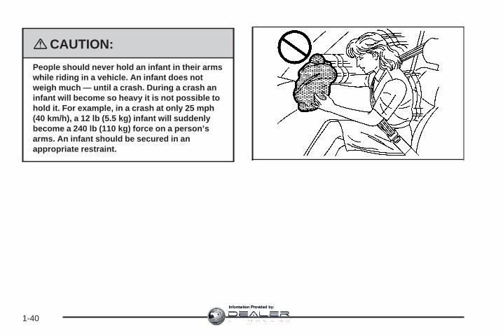
People should never hold an infant in their armswhile riding in a vehicle. An infant does notweigh much — until a crash. During a crash aninfant will become so heavy it is not possible tohold it. For example, in a crash at only 25 mph(40 km/h), a 12 lb (5.5 kg) infant will suddenlybecome a 240 lb (110 kg) force on a person’sarms. An infant should be secured in anappropriate restraint.
1-40
Information Provided by:

{CAUTION:
Children who are up against, or very close to,any airbag when it inflates can be seriouslyinjured or killed. Airbags plus lap-shoulderbelts offer protection for adults and olderchildren, but not for young children andinfants. Neither the vehicle’s safety belt systemnor its airbag system is designed for them.Young children and infants need the protectionthat a child restraint system can provide.
1-41
Information Provided by:

Q: What are the different types of add-on childrestraints?
A: Add-on child restraints, which are purchased by thevehicle’s owner, are available in four basic types.Selection of a particular restraint should takeinto consideration not only the child’s weight, height,and age but also whether or not the restraint willbe compatible with the motor vehicle in which it willbe used.
For most basic types of child restraints, there aremany different models available. When purchasing achild restraint, be sure it is designed to be usedin a motor vehicle. If it is, the restraint will have alabel saying that it meets federal motor vehiclesafety standards.
The restraint manufacturer’s instructions that comewith the restraint state the weight and heightlimitations for a particular child restraint. In addition,there are many kinds of restraints available forchildren with special needs.
{CAUTION:
Newborn infants need complete support,including support for the head and neck. Thisis necessary because a newborn infant’s neckis weak and its head weighs so muchcompared with the rest of its body. In a crash,an infant in a rear-facing seat settles into therestraint, so the crash forces can bedistributed across the strongest part of aninfant’s body, the back and shoulders. Infantsshould always be secured in appropriate infantrestraints.
1-42
Information Provided by:

{CAUTION:
The body structure of a young child is quiteunlike that of an adult or older child, for whomthe safety belts are designed. A young child’ship bones are still so small that the vehicle’sregular safety belt may not remain low on thehip bones, as it should. Instead, it may settleup around the child’s abdomen. In a crash, thebelt would apply force on a body area that isunprotected by any bony structure. This alonecould cause serious or fatal injuries. Youngchildren should always be secured inappropriate child restraints.
Child Restraint Systems
A rear-facing infantseat (A) provides restraintwith the seating surfaceagainst the back ofthe infant.
The harness system holds the infant in place and, in acrash, acts to keep the infant positioned in therestraint.
1-43
Information Provided by:

A forward-facing childseat (B) provides restraintfor the child’s bodywith the harness.
A booster seat (C-D) is a child restraint designed toimprove the fit of the vehicle’s safety belt system.A booster seat can also help a child to see out thewindow.
1-44
Information Provided by:

Securing an Add-On Child Restraint inthe Vehicle
{CAUTION:
A child can be seriously injured or killed in acrash if the child restraint is not properlysecured in the vehicle. Make sure the childrestraint is properly installed in the vehicleusing the vehicle’s safety belt or LATCHsystem, following the instructions that camewith that restraint, and also the instructions inthis manual.
To help reduce the chance of injury, the child restraintmust be secured in the vehicle. Child restraint systemsmust be secured in vehicle seats by lap belts or thelap belt portion of a lap-shoulder belt, or by the LATCHsystem. See Lower Anchors and Tethers for Children(LATCH) on page 1-47 for more information. A child canbe endangered in a crash if the child restraint is notproperly secured in the vehicle.
When securing an add-on child restraint, refer to theinstructions that come with the restraint which may be onthe restraint itself or in a booklet, or both, and to this
manual. The child restraint instructions are important, soif they are not available, obtain a replacement copyfrom the manufacturer.
Keep in mind that an unsecured child restraint can movearound in a collision or sudden stop and injure people inthe vehicle. Be sure to properly secure any child restraintin your vehicle — even when no child is in it.
Securing the Child Within the ChildRestraint
{CAUTION:
A child can be seriously injured or killed in acrash if the child is not properly secured in thechild restraint. Because there are differentsystems, it is important to refer to theinstructions that come with the restraint. Makesure the child is properly secured, followingthe instructions that came with that restraint.
1-45
Information Provided by:

Where to Put the RestraintAccident statistics show that children are safer if theyare restrained in the rear rather than the front seat.
We recommend that children and child restraintsbe secured in a rear seat, including: an infant or a childriding in a rear-facing child restraint; a child riding ina forward-facing child seat; an older child riding ina booster seat; and children, who are large enough,using safety belts.
A label on your sun visor says, “Never put a rear-facingchild seat in the front.” This is because the risk to therear-facing child is so great, if the airbag deploys.
{CAUTION:
A child in a rear-facing child restraint can beseriously injured or killed if the right frontpassenger’s airbag inflates. This is becausethe back of the rear-facing child restraintwould be very close to the inflating airbag.
Even though the passenger sensing system isdesigned to turn off the right front passenger’sfrontal airbag if the system detects arear-facing child restraint, no system isfail-safe, and no one can guarantee that anairbag will not deploy under some unusualcircumstance, even though it is turned off. Werecommend that rear-facing child restraints besecured in a rear seat, even if the airbag is off.
If you secure a forward-facing child restraint inthe right front seat, always move the frontpassenger seat as far back as it will go. It isbetter to secure the child restraint in a rear seat.
See Passenger Sensing System on page 1-70for additional information.
1-46
Information Provided by:

When securing a child restraint in a rear seatingposition, study the instructions that came with your childrestraint to make sure it is compatible with this vehicle.
Wherever you install a child restraint, be sure tosecure the child restraint properly.
Keep in mind that an unsecured child restraint can movearound in a collision or sudden stop and injure people inthe vehicle. Be sure to properly secure any child restraintin your vehicle — even when no child is in it.
Lower Anchors and Tethers forChildren (LATCH)The LATCH system holds a child restraint during drivingor in a crash. This system is designed to makeinstallation of a child restraint easier. The LATCHsystem uses anchors in the vehicle and attachments onthe child restraint that are made for use with theLATCH system.
Make sure that a LATCH-compatible child restraint isproperly installed using the anchors, or use the vehicle’ssafety belts to secure the restraint, following theinstructions that came with that restraint, and also theinstructions in this manual. When installing a childrestraint with a top tether, you must also use either thelower anchors or the safety belts to properly securethe child restraint. A child restraint must never beattached using only the top tether and anchor.
In order to use the LATCH system in your vehicle, youneed a child restraint that has LATCH attachments.The child restraint manufacturer will provide youwith instructions on how to use the child restraint and itsattachments. The following explains how to attach achild restraint with these attachments in your vehicle.
Not all vehicle seating positions or child restraints havelower anchors and attachments or top tether anchorsand attachments.
1-47
Information Provided by:

Lower Anchors
Lower anchors (A) are metal bars built into the vehicle.There are two lower anchors for each LATCH seatingposition that will accommodate a child restraint withlower attachments (B).
Top Tether Anchor
A top tether (A, C) anchors the top of the child restraintto the vehicle. A top tether anchor is built into thevehicle. The top tether attachment (B) on the childrestraint connects to the top tether anchor in the vehiclein order to reduce the forward movement and rotationof the child restraint during driving or in a crash.
Your child restraint may have a single tether (A) or adual tether (C). Either will have a single attachment (B)to secure the top tether to the anchor.
1-48
Information Provided by:

Some child restraints with top tethers are designed foruse with or without the top tether being attached. Othersrequire the top tether always to be attached. InCanada, the law requires that forward-facing childrestraints have a top tether, and that the tether beattached. Be sure to read and follow the instructions foryour child restraint.
If the child restraint does not have a top tether, one canbe obtained, in kit form, for many child restraints. Askthe child restraint manufacturer whether or not a kitis available.
Lower Anchor and Top Tether AnchorLocations
i (Top Tether Anchor):Seating positions with toptether anchors.
j (Lower Anchor):Seating positions with twolower anchors.
Second Row — Bucket
1-49
Information Provided by:

i (Top Tether Anchor):Seating positions with toptether anchors.
j (Lower Anchor):Seating positions with twolower anchors.
i (Top Tether Anchor):Seating positions with toptether anchors.
To assist you in locatingthe lower anchors, eachsecond row anchorposition has a label, nearthe crease betweenthe seatback and the seatcushion.
To assist you in locatingthe top tether anchors, thetop tether anchor symbolis located on the coveror near the anchor.
Second Row — 60/40Bench
Third Row
1-50
Information Provided by:

The top tether anchors are located at the bottom rear ofthe seatback for each seating position in the secondrow. Open the cover to access the anchors. Be sure touse an anchor located on the same side of thevehicle as the seating position where the child restraintwill be placed.
The third row has one top tether anchor located at thebottom rear of the center seatback. This anchor shouldbe used for the center seating position only. Never installtwo top tethers using the same top tether anchor.
Do not secure a child restraint in a position without a toptether anchor if a national or local law requires that thetop tether be attached, or if the instructions that comewith the child restraint say that the top tether must beattached.
Second Row — Bucket Shown, Bench Similar Third Row Seat
1-51
Information Provided by:

Accident statistics show that children are safer if theyare restrained in the rear rather than the front seat. SeeWhere to Put the Restraint on page 1-46 for additionalinformation.
Securing a Child Restraint Designed forthe LATCH System
{CAUTION:
If a LATCH-type child restraint is not attachedto anchors, the restraint will not be able toprotect the child correctly. In a crash, the childcould be seriously injured or killed. Make surethat a LATCH-type child restraint is properlyinstalled using the anchors, or use thevehicle’s safety belts to secure the restraint,following the instructions that came with thatrestraint, and also the instructions in thismanual.
{CAUTION:
Each top tether anchor and lower anchor in thevehicle is designed to hold only one childrestraint. Attaching more than one childrestraint to a single anchor could cause theanchor or attachment to come loose or evenbreak during a crash. A child or others couldbe injured if this happens. To help preventinjury to people and damage to your vehicle,attach only one child restraint per anchor.
1-52
Information Provided by:

{CAUTION:
Children can be seriously injured or strangledif a shoulder belt is wrapped around their neckand the safety belt continues to tighten.Secure any unused safety belts behind thechild restraint so children cannot reach them.Pull the shoulder belt all the way out of theretractor to set the lock, if your vehicle hasone, after the child restraint has been installed.Be sure to follow the instructions of the childrestraint manufacturer.
Notice: Contact between the child restraint LATCHattachment parts and the vehicle’s safety beltassembly may cause damage to these parts. Makesure when securing unused safety belts behindthe child restraint that there is no contact betweenthe child restraint LATCH attachment parts andthe vehicle’s safety belt assembly.
Folding an empty rear seat with the safety beltssecured may cause damage to the safety belt or theseat. When removing the child restraint, alwaysremember to return the safety belts to their normal,stowed position before folding the rear seat.
1. Attach and tighten the lower attachments to thelower anchors. If the child restraint does not havelower attachments or the desired seating positiondoes not have lower anchors, secure the childrestraint with the top tether and the safety belts.Refer to your child restraint manufacturerinstructions and the instructions in this manual.
1.1. Find the lower anchors for the desiredseating position.
1.2. Recline the seatback to the full reclinedposition.Make sure the second row bench seatbacksare aligned at the same angle beforeplacing the child restraint on the seat. Makesure the third row bench seatbacks areboth upright before placing the child restrainton the seat.
1.3. Put the child restraint on the seat.1.4. Attach and tighten the lower attachments on
the child restraint to the lower anchors.
1-53
Information Provided by:

2. If the child restraint manufacturer recommends thatthe top tether be attached, attach and tighten thetop tether to the top tether anchor, if the vehicle hasone. Refer to the child restraint instructions andthe following steps:
2.1. Find the top tether anchor.2.2. If the anchor is covered, flip open the cover
to expose the anchor.2.3. Route, attach and tighten the top tether
according to your child restraint instructionsand the following instructions:
If the position you areusing does not have aheadrest or head restraintand you are using asingle tether, route thetether over the seatback.
If the position you areusing does not have aheadrest or head restraintand you are using adual tether, route the tetherover the seatback.
If the position you areusing has a fixed headrestor head restraint andyou are using a dual tether,route the tether aroundthe headrest or headrestraint.
1-54
Information Provided by:

If the position you areusing has a fixed headrestor head restraint andyou are using a singletether, route the tether overthe headrest or headrestraint.
3. Push and pull the child restraint in differentdirections to be sure it is secure.
Securing a Child Restraint in a RearSeat PositionWhen securing a child restraint in a rear seatingposition, study the instructions that came with your childrestraint to make sure it is compatible with this vehicle.
If your child restraint has the LATCH system, see LowerAnchors and Tethers for Children (LATCH) onpage 1-47 for how to install your child restraint usingLATCH. If you secure a child restraint using a safety beltand it uses a top tether, see Lower Anchors andTethers for Children (LATCH) on page 1-47 for toptether anchor locations.
Do not secure a child seat in a position without a toptether anchor if a national or local law requires that thetop tether be anchored, or if the instructions thatcome with the child restraint say that the top strap mustbe anchored.
In Canada, the law requires that forward-facing childrestraints have a top tether, and that the tether beattached.
If your child restraint does not have the LATCH system,you will be using the safety belt to secure the childrestraint in this position. Be sure to follow the instructionsthat came with the child restraint. Secure the child in thechild restraint when and as the instructions say.
1-55
Information Provided by:

If you need to install more than one child restraint in therear seat, be sure to read Where to Put the Restrainton page 1-46.
1. Put the child restraint on the seat.
2. Pick up the latch plate, and run the lap and shoulderportions of the vehicle’s safety belt through oraround the restraint. The child restraint instructionswill show you how.
3. Push the latch plate into the buckle until it clicks.Make sure the release button is positioned so youwould be able to unbuckle the safety belt quicklyif necessary.
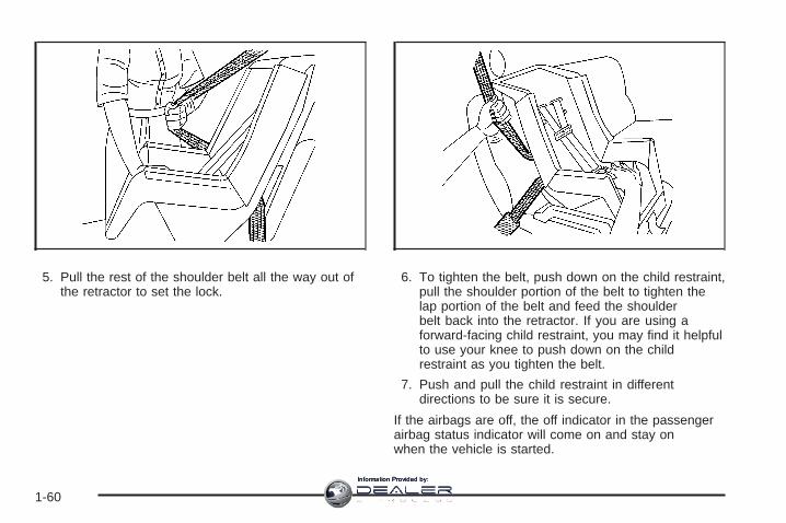
4. Pull the rest of the shoulder belt all the way out ofthe retractor to set the lock.
1-56
Information Provided by:

5. To tighten the belt, push down on the child restraint,pull the shoulder portion of the belt to tighten thelap portion of the belt, and feed the shoulderbelt back into the retractor. If you are using aforward-facing child restraint, you may find it helpfulto use your knee to push down on the childrestraint as you tighten the belt.
6. If your child restraint has a top tether, follow thechild restraint manufacturer’s instructions regardingthe use of the top tether. See Lower Anchorsand Tethers for Children (LATCH) on page 1-47 formore information.
7. Push and pull the child restraint in differentdirections to be sure it is secure.
To remove the child restraint, unbuckle the vehicle’ssafety belt and let it go back all the way. If the top tetheris attached to a top tether anchor, disconnect it.
1-57
Information Provided by:

Securing a Child Restraint in theRight Front Seat PositionYour vehicle has airbags. A rear seat is a safer place tosecure a forward-facing child restraint. See Where toPut the Restraint on page 1-46.
In addition, your vehicle has a passenger sensingsystem which is designed to turn off the right frontpassenger’s frontal airbag and seat-mounted side impactairbag under certain conditions. See PassengerSensing System on page 1-70 and Passenger AirbagStatus Indicator on page 3-43 for more informationon this, including important safety information.
A label on your sun visor says, “Never put a rear-facingchild seat in the front.” This is because the risk to therear-facing child is so great, if the airbag deploys.
{CAUTION:
A child in a rear-facing child restraint can beseriously injured or killed if the right frontpassenger’s airbag inflates. This is becausethe back of the rear-facing child restraintwould be very close to the inflating airbag.
Even though the passenger sensing system isdesigned to turn off the right front passenger’sfrontal airbag if the system detects arear-facing child restraint, no system isfail-safe, and no one can guarantee that anairbag will not deploy under some unusualcircumstance, even though it is turned off. Werecommend that rear-facing child restraints besecured in a rear seat, even if the airbag is off.
If you secure a forward-facing child restraint inthe right front seat, always move the frontpassenger seat as far back as it will go. It isbetter to secure the child restraint in a rear seat.
See Passenger Sensing System on page 1-70for additional information.
1-58
Information Provided by:

If your child restraint has the LATCH system, see LowerAnchors and Tethers for Children (LATCH) onpage 1-47 for how to install your child restraint usingLATCH. If you secure a child restraint using a safety beltand it uses a top tether, see Lower Anchors andTethers for Children (LATCH) on page 1-47 for toptether anchor locations.
Do not secure a child seat in a position without a toptether anchor if a national or local law requires that thetop tether be anchored, or if the instructions thatcome with the child restraint say that the top strap mustbe anchored.
In Canada, the law requires that forward-facing childrestraints have a top tether, and that the tether beattached.
You will be using the lap-shoulder belt to secure thechild restraint in this position. Follow the instructions thatcame with the child restraint.
1. Move the seat as far back as it will go beforesecuring the forward-facing child restraint.When the passenger sensing system has turned offthe right front passenger’s frontal airbag andseat-mounted side impact airbag, the off indicatoron the passenger airbag status indicator should lightand stay lit when you start the vehicle. SeePassenger Airbag Status Indicator on page 3-43.
2. Put the child restraint on the seat.
3. Pick up the latch plate, and run the lap and shoulderportions of the vehicle’s safety belt through oraround the restraint. The child restraint instructionswill show you how.
4. Push the latch plate into the buckle until it clicks.Make sure the release button is positioned so youwould be able to unbuckle the safety belt quicklyif necessary.
1-59
Information Provided by:
5. Pull the rest of the shoulder belt all the way out ofthe retractor to set the lock.
6. To tighten the belt, push down on the child restraint,pull the shoulder portion of the belt to tighten thelap portion of the belt and feed the shoulderbelt back into the retractor. If you are using aforward-facing child restraint, you may find it helpfulto use your knee to push down on the childrestraint as you tighten the belt.
7. Push and pull the child restraint in differentdirections to be sure it is secure.
If the airbags are off, the off indicator in the passengerairbag status indicator will come on and stay onwhen the vehicle is started.
1-60
Information Provided by:

If a child restraint has been installed and the onindicator is lit, turn the vehicle off. Remove the childrestraint from the vehicle and reinstall the child restraint.
If, after reinstalling the child restraint and restartingthe vehicle, the on indicator is still lit, check to makesure that the vehicle’s seatback is not pressing the childrestraint into the seat cushion. If this happens, slightlyrecline the vehicle’s seatback and adjust the seatcushion if possible. Also make sure the child restraint isnot trapped under the vehicle head restraint. If thishappens, adjust the head restraint.
Remove any additional material from the seat such asblankets, cushions, seat covers, seat heaters or seatmassagers before reinstalling or securing the childrestraint.
If the on indicator is still lit, secure the child in the childrestraint in a rear seat position in the vehicle andcheck with your dealer/retailer.
To remove the child restraint, unbuckle the vehicle’ssafety belt and let it go back all the way.
Airbag SystemYour vehicle has the following airbags:
• A frontal airbag for the driver.
• A frontal airbag for the right front passenger.
• A seat-mounted side impact airbag for the driver.
• A seat-mounted side impact airbag for the right frontpassenger.
• A roof-rail airbag for the driver, passenger seateddirectly behind the driver, and the third rowoutboard passenger position.
• A roof-rail airbag for the right front passenger,passenger seated directly behind the right frontpassenger, and the third row outboard passengerposition.
1-61
Information Provided by:

All of the airbags in your vehicle will have the wordAIRBAG embossed in the trim or on an attached labelnear the deployment opening.
For frontal airbags, the word AIRBAG will appear on themiddle part of the steering wheel for the driver andon the instrument panel for the right front passenger.
With seat-mounted side impact airbags, the wordAIRBAG will appear on the side of the seatback closestto the door.
With roof-rail airbags, the word AIRBAG will appearalong the headliner or trim.
Airbags are designed to supplement the protectionprovided by safety belts. Even though today’s airbagsare also designed to help reduce the risk of injuryfrom the force of an inflating bag, all airbags must inflatevery quickly to do their job.
Here are the most important things to know about theairbag system:
{CAUTION:
You can be severely injured or killed in a crashif you are not wearing your safety belt — evenif you have airbags. Wearing your safety beltduring a crash helps reduce your chance ofhitting things inside the vehicle or beingejected from it. Airbags are “supplementalrestraints” to the safety belts. All airbags aredesigned to work with safety belts, but do notreplace them.
1-62
Information Provided by:

{CAUTION:
Frontal airbags are designed to deploy inmoderate to severe frontal and near frontalcrashes. They are not designed to inflate inrollover, rear crashes, or in many side crashes.
Seat-mounted side impact airbags aredesigned to inflate in moderate to severecrashes where something hits the side of yourvehicle. They are not designed to inflate infrontal, in rollover, or in rear crashes. Rollovercapable roof-rail airbags are designed to inflatein moderate to severe crashes wheresomething hits the side of your vehicle, duringa vehicle rollover, or in a severe frontal impact.They are not designed to inflate in rearcrashes.
Everyone in your vehicle should wear a safetybelt properly — whether or not there is anairbag for that person.
{CAUTION:
Airbags inflate with great force, faster than theblink of an eye. Anyone who is up against, orvery close to, any airbag when it inflates canbe seriously injured or killed. Do not situnnecessarily close to the airbag, as youwould be if you were sitting on the edge ofyour seat or leaning forward. Safety belts helpkeep you in position before and during acrash. Always wear your safety belt, even withairbags. The driver should sit as far back aspossible while still maintaining control of thevehicle.
Occupants should not lean on or sleep againstthe door or side windows in seating positionswith seat-mounted side impact airbags and/orroof-rail airbags.
1-63
Information Provided by:

{CAUTION:
Airbags plus lap-shoulder belts offer the bestprotection for adults, but not for youngchildren and infants. Neither the vehicle’ssafety belt system nor its airbag system isdesigned for them. Young children and infantsneed the protection that a child restraintsystem can provide. Always secure childrenproperly in your vehicle. To read how, seeOlder Children on page 1-36 or Infants andYoung Children on page 1-39.
There is an airbagreadiness light on theinstrument panel cluster,which shows the airbagsymbol.
The system checks the airbag electrical system formalfunctions. The light tells you if there is an electricalproblem. See Airbag Readiness Light on page 3-42for more information.
Where Are the Airbags?
The driver’s frontal airbag is in the middle of thesteering wheel.
1-64
Information Provided by:

The right front passenger’s frontal airbag is in theinstrument panel on the passenger’s side. The seat-mounted side impact airbags for the driver and
right front passenger are in the side of the seatbacksclosest to the door.
Driver Side shown, Passenger Side similar
1-65
Information Provided by:

The roof-rail airbags for the driver, right front passenger,passengers behind the driver and right front passenger,and the third row outboard passengers are in theceiling above the side windows.
{CAUTION:
If something is between an occupant and anairbag, the airbag might not inflate properly orit might force the object into that personcausing severe injury or even death. The pathof an inflating airbag must be kept clear. Donot put anything between an occupant and anairbag, and do not attach or put anything onthe steering wheel hub or on or near any otherairbag covering.
Do not use seat accessories that block theinflation path of a seat-mounted side impactairbag.
If your vehicle has roof-rail airbags, neversecure anything to the roof of your vehicle byrouting the rope or tie down through any dooror window opening. If you do, the path of aninflating roof-rail airbag will be blocked.
Driver Side shown, Passenger Side similar
1-66
Information Provided by:

When Should an Airbag Inflate?Frontal airbags are designed to inflate in moderate tosevere frontal or near-frontal crashes to help reduce thepotential for severe injuries mainly to the driver’s orright front passenger’s head and chest. However, theyare only designed to inflate if the impact exceeds apredetermined deployment threshold. Deploymentthresholds are used to predict how severe a crash islikely to be in time for the airbags to inflate andhelp restrain the occupants.
Whether your frontal airbags will or should deploy is notbased on how fast your vehicle is traveling. It dependslargely on what you hit, the direction of the impact,and how quickly your vehicle slows down.
Frontal airbags may inflate at different crash speeds.For example:
• If the vehicle hits a stationary object, the airbagscould inflate at a different crash speed than if thevehicle hits a moving object.
• If the vehicle hits an object that deforms, theairbags could inflate at a different crash speed thanif the vehicle hits an object that does not deform.
• If the vehicle hits a narrow object (like a pole), theairbags could inflate at a different crash speedthan if the vehicle hits a wide object (like a wall).
• If the vehicle goes into an object at an angle, theairbags could inflate at a different crash speedthan if the vehicle goes straight into the object.
Thresholds can also vary with specific vehicle design.
Frontal airbags are not intended to inflate during vehiclerollovers, rear impacts, or in many side impacts.
In addition, your vehicle has dual-stage frontal airbags.Dual-stage airbags adjust the restraint according tocrash severity. Your vehicle has electronic frontalsensors, which help the sensing system distinguishbetween a moderate frontal impact and a more severefrontal impact. For moderate frontal impacts, dual-stageairbags inflate at a level less than full deployment.For more severe frontal impacts, full deployment occurs.
Your vehicle has seat-mounted side impact androof-rail airbags. See Airbag System on page 1-61.Seat-mounted side impact and roof-rail airbagsare intended to inflate in moderate to severe sidecrashes. In addition, these roof-rail airbags are intendedto inflate during a rollover or in a severe frontalimpact. Seat-mounted side impact and roof-rail airbagswill inflate if the crash severity is above the system’sdesigned threshold level. The threshold level canvary with specific vehicle design.
1-67
Information Provided by:
Seat-mounted side impact airbags are not intended toinflate in frontal impacts, near-frontal impacts, rollovers,or rear impacts. Roof-rail airbags are not intended toinflate in rear impacts. A seat-mounted side impactairbag is intended to deploy on the side of the vehiclethat is struck. Both roof-rail airbags will deploy wheneither side of the vehicle is struck, or if the sensingsystem predicts that the vehicle is about to roll over, orin a severe frontal impact.
In any particular crash, no one can say whether anairbag should have inflated simply because of thedamage to a vehicle or because of what the repair costswere. For frontal airbags, inflation is determined bywhat the vehicle hits, the angle of the impact, and howquickly the vehicle slows down. For seat-mountedside impact and roof-rail airbags, deployment isdetermined by the location and severity of the sideimpact. In a rollover event, roof-rail airbag deployment isdetermined by the direction of the roll.
What Makes an Airbag Inflate?In a deployment event, the sensing system sends anelectrical signal triggering a release of gas fromthe inflator. Gas from the inflator fills the airbag causingthe bag to break out of the cover and deploy. Theinflator, the airbag, and related hardware are all part ofthe airbag module.
Frontal airbag modules are located inside the steeringwheel and instrument panel. For vehicles withseat-mounted side impact airbags, there are airbagmodules in the side of the front seatbacks closest to thedoor. For vehicles with roof-rail airbags, there areairbag modules in the ceiling of the vehicle, near theside windows that have occupant seating positions.
How Does an Airbag Restrain?In moderate to severe frontal or near frontal collisions,even belted occupants can contact the steering wheel orthe instrument panel. In moderate to severe sidecollisions, even belted occupants can contact the insideof the vehicle.
Airbags supplement the protection provided by safetybelts.
Frontal airbags distribute the force of the impact moreevenly over the occupant’s upper body, stoppingthe occupant more gradually. Seat-mounted side impactand roof-rail airbags distribute the force of the impactmore evenly over the occupant’s upper body.
Rollover capable roof-rail airbags are designed to helpcontain the head and chest of occupants in theoutboard seating positions in the first, second, and thirdrows. The rollover capable roof-rail airbags aredesigned to help reduce the risk of full or partial ejectionin rollover events, although no system can prevent allsuch ejections.
1-68
Information Provided by:

But airbags would not help in many types of collisions,primarily because the occupant’s motion is nottoward those airbags. See When Should an AirbagInflate? on page 1-67 for more information.
Airbags should never be regarded as anything morethan a supplement to safety belts.
What Will You See After an AirbagInflates?After the frontal airbags and seat-mounted side impactairbags inflate, they quickly deflate, so quickly thatsome people may not even realize an airbag inflated.Roof-rail airbags may still be at least partially inflated forsome time after they deploy. Some components ofthe airbag module may be hot for several minutes. Forlocation of the airbag modules, see What Makes anAirbag Inflate? on page 1-68.
The parts of the airbag that come into contact with youmay be warm, but not too hot to touch. There maybe some smoke and dust coming from the vents in thedeflated airbags. Airbag inflation does not preventthe driver from seeing out of the windshield or beingable to steer the vehicle, nor does it prevent people fromleaving the vehicle.
{CAUTION:
When an airbag inflates, there may be dust inthe air. This dust could cause breathingproblems for people with a history of asthmaor other breathing trouble. To avoid this,everyone in the vehicle should get out as soonas it is safe to do so. If you have breathingproblems but cannot get out of the vehicleafter an airbag inflates, then get fresh air byopening a window or a door. If you experiencebreathing problems following an airbagdeployment, you should seek medicalattention.
Your vehicle has a feature that may automaticallyunlock the doors, turn the interior lamps on, and turnthe hazard warning flashers on when the airbags inflate.You can lock the doors, turn the interior lamps off,and turn the hazard warning flashers off by using thecontrols for those features.
1-69
Information Provided by:

In many crashes severe enough to inflate the airbag,windshields are broken by vehicle deformation.Additional windshield breakage may also occur from theright front passenger airbag.
• Airbags are designed to inflate only once. After anairbag inflates, you will need some new parts forthe airbag system. If you do not get them, the airbagsystem will not be there to help protect you inanother crash. A new system will include airbagmodules and possibly other parts. The servicemanual for your vehicle covers the need to replaceother parts.
• Your vehicle has a crash sensing and diagnosticmodule which records information after a crash.See Vehicle Data Recording and Privacy onpage 7-15 and Event Data Recorders on page 7-16.
• Let only qualified technicians work on the airbagsystems. Improper service can mean that anairbag system will not work properly. See yourdealer/retailer for service.
Passenger Sensing SystemYour vehicle has a passenger sensing system for theright front passenger’s position. The passengerairbag status indicator will be visible on the instrumentpanel when you start your vehicle.
The words ON and OFF, or the symbol for on and off,will be visible during the system check. If you areusing remote start to start your vehicle from a distance,if equipped, you may not see the system check.When the system check is complete, either the wordON or the word OFF, or the symbol for on or the symbolfor off, will be visible. See Passenger Airbag StatusIndicator on page 3-43.
The passenger sensing system will turn off the rightfront passenger’s frontal airbag and seat-mounted sideimpact airbag under certain conditions. The driver’sairbags are not part of the passenger sensing system.
United States Canada
1-70
Information Provided by:

The passenger sensing system works with sensors thatare part of the right front passenger’s seat. Thesensors are designed to detect the presence of aproperly-seated occupant and determine if the right frontpassenger’s frontal airbag and seat-mounted sideimpact airbag should be enabled (may inflate) or not.
Accident statistics show that children are safer ifthey are restrained in the rear rather than the front seat.
We recommend that children be secured in a rearseat, including: an infant or a child riding in a rear-facingchild restraint; a child riding in a forward-facing childseat; an older child riding in a booster seat; and children,who are large enough, using safety belts.
A label on your sun visor says, “Never put a rear-facingchild seat in the front.” This is because the risk to therear-facing child is so great, if the airbag deploys.
{CAUTION:
A child in a rear-facing child restraint can beseriously injured or killed if the right frontpassenger’s airbag inflates. This is becausethe back of the rear-facing child restraintwould be very close to the inflating airbag.
Even though the passenger sensing system isdesigned to turn off the right front passenger’sfrontal and seat-mounted side impact airbag (ifequipped) if the system detects a rear-facingchild restraint, no system is fail-safe, and noone can guarantee that an airbag will notdeploy under some unusual circumstance,even though it is turned off. We recommendthat rear-facing child restraints be secured in arear seat, even if the airbag(s) are off.
If you secure a forward-facing child restraint inthe right front seat, always move the frontpassenger seat as far back as it will go. It isbetter to secure the child restraint in a rear seat.
1-71
Information Provided by:

The passenger sensing system is designed to turn offthe right front passenger’s frontal airbag andseat-mounted side impact airbag if:
• The right front passenger seat is unoccupied.
• The system determines that an infant is present ina rear-facing infant seat.
• The system determines that a small child is presentin a child restraint.
• The system determines that a small child is presentin a booster seat.
• A right front passenger takes his/her weight off ofthe seat for a period of time.
• The right front passenger seat is occupied by asmaller person, such as a child who has outgrownchild restraints.
• Or, if there is a critical problem with the airbagsystem or the passenger sensing system.
When the passenger sensing system has turned off theright front passenger’s frontal airbag and seat-mountedside impact airbag, the off indicator will light andstay lit to remind you that the airbags are off. SeePassenger Airbag Status Indicator on page 3-43.
If a child restraint has been installed and the on indicatoris lit, turn the vehicle off. Remove the child restraintfrom the vehicle and reinstall the child restraint followingthe child restraint manufacturer’s directions and referto Securing a Child Restraint in the Right FrontSeat Position on page 1-58.
If, after reinstalling the child restraint and restarting thevehicle, the on indicator is still lit, check to makesure that the vehicle’s seatback is not pressing the childrestraint into the seat cushion. If this happens, slightlyrecline the vehicle’s seatback and adjust the seatcushion if possible. Also make sure the child restraint isnot trapped under the vehicle head restraint. If thishappens, adjust the head restraint. See Head Restraintson page 1-10.
1-72
Information Provided by:

Remove any additional material from the seat such asblankets, cushions, seat covers, seat heaters, orseat massagers before reinstalling or securing the childrestraint.
If the on indicator is still lit, secure the child in the childrestraint in a rear seat position in the vehicle, andcheck with your dealer/retailer.
The passenger sensing system is designed to enable(may inflate) the right front passenger’s frontalairbag and seat-mounted side impact airbag anytime thesystem senses that a person of adult size is sittingproperly in the right front passenger’s seat. When thepassenger sensing system has allowed the airbags to beenabled, the on indicator will light and stay lit toremind you that the airbags are active.
For some children who have outgrown child restraintsand for very small adults, the passenger sensing systemmay or may not turn off the right front passenger’s frontalairbag and seat-mounted side impact airbag, dependingupon the person’s seating posture and body build.Everyone in your vehicle who has outgrown childrestraints should wear a safety belt properly — whetheror not there is an airbag for that person.
If a person of adult-size is sitting in the right frontpassenger’s seat, but the off indicator is lit, it could bebecause that person is not sitting properly in the seat. Ifthis happens, turn the vehicle off, remove any additionalmaterial from the seat, such as blankets, cushions,seat covers, seat heaters or seat massagers and askthe person to place the seatback in the fully uprightposition, then sit upright in the seat, centered on the seatcushion, with the person’s legs comfortably extended.Restart the vehicle and have the person remain inthis position for two to three minutes. This will allow thesystem to detect that person and then enable theright front passenger’s frontal airbag and seat-mountedside impact airbag.
1-73
Information Provided by:

Safety belts help keep the passenger in position on theseat during vehicle maneuvers and braking, whichhelps the passenger sensing system maintain thepassenger airbag status. See “Safety Belts” and “ChildRestraints” in the Index for additional informationabout the importance of proper restraint use.
{CAUTION:
If the airbag readiness light in the instrumentpanel cluster ever comes on and stays on, itmeans that something may be wrong with theairbag system. If this ever happens, have thevehicle serviced promptly, because anadult-size person sitting in the right frontpassenger’s seat may not have the protectionof the airbag(s). See Airbag Readiness Lighton page 3-42 for more on this, includingimportant safety information.
A thick layer of additional material, such as a blanket orcushion, or aftermarket equipment such as seatcovers, seat heaters, and seat massagers can affecthow well the passenger sensing system operates.We recommend that you not use seat covers or otheraftermarket equipment other than any that GM hasapproved for your specific vehicle. See AddingEquipment to Your Airbag-Equipped Vehicle onpage 1-76 for more information about modifications thatcan affect how the system operates.
1-74
Information Provided by:

{CAUTION:
Stowing of articles under the passenger’s seator between the passenger’s seat cushion andseatback may interfere with the properoperation of the passenger sensing system.
Servicing Your Airbag-EquippedVehicleAirbags affect how your vehicle should be serviced.There are parts of the airbag system in several placesaround your vehicle. Your dealer/retailer and the servicemanual have information about servicing your vehicleand the airbag system. To purchase a service manual,see Service Publications Ordering Information onpage 7-14.
{CAUTION:
For up to 10 seconds after the ignition isturned off and the battery is disconnected, anairbag can still inflate during improper service.You can be injured if you are close to anairbag when it inflates. Avoid yellowconnectors. They are probably part of theairbag system. Be sure to follow properservice procedures, and make sure the personperforming work for you is qualified to do so.
1-75
Information Provided by:

Adding Equipment to YourAirbag-Equipped Vehicle
Q: Is there anything I might add to or changeabout the vehicle that could keep the airbagsfrom working properly?
A: Yes. If you add things that change your vehicle’sframe, bumper system, height, front end or sidesheet metal, they may keep the airbag system fromworking properly. Changing or moving any partsof the front seats, safety belts, the airbag sensingand diagnostic module, steering wheel, instrumentpanel, roof-rail airbag modules, ceiling headlineror pillar garnish trim, front sensors, side impactsensors, rollover sensor module, or airbag wiringcan affect the operation of the airbag system.
In addition, your vehicle has a passenger sensingsystem for the right front passenger’s position,which includes sensors that are part of thepassenger’s seat. The passenger sensing systemmay not operate properly if the original seat
trim is replaced with non-GM covers, upholstery ortrim, or with GM covers, upholstery or trimdesigned for a different vehicle. Any object, such asan aftermarket seat heater or a comfort enhancingpad or device, installed under or on top of theseat fabric, could also interfere with the operation ofthe passenger sensing system. This could eitherprevent proper deployment of the passengerairbag(s) or prevent the passenger sensing systemfrom properly turning off the passenger airbag(s).See Passenger Sensing System on page 1-70.
If you have any questions about this, you shouldcontact Customer Assistance before you modifyyour vehicle. The phone numbers and addresses forCustomer Assistance are in Step Two of theCustomer Satisfaction Procedure in this manual.See Customer Satisfaction Procedure on page 7-2.
If your vehicle has rollover roof-rail airbags, seeDifferent Size Tires and Wheels on page 5-66for additional important information.
1-76
Information Provided by:

Q: Because I have a disability, I have to get myvehicle modified. How can I find out whetherthis will affect my airbag system?
A: If you have questions, call Customer Assistance.The phone numbers and addresses for CustomerAssistance are in Step Two of the CustomerSatisfaction Procedure in this manual. SeeCustomer Satisfaction Procedure on page 7-2.
In addition, your dealer/retailer and the service manualhave information about the location of the airbag sensors,sensing and diagnostic module and airbag wiring.
Restraint System Check
Checking the Restraint Systems
Safety BeltsNow and then, make sure the safety belt reminder lightand all your belts, buckles, latch plates, retractorsand anchorages are working properly.
Look for any other loose or damaged safety belt systemparts. If you see anything that might keep a safetybelt system from doing its job, have it repaired. Torn orfrayed safety belts may not protect you in a crash.They can rip apart under impact forces. If a belt is tornor frayed, get a new one right away.
Make sure the safety belt reminder light is working. SeeSafety Belt Reminders on page 3-41 for moreinformation.
Keep safety belts clean and dry. See Care of SafetyBelts on page 5-92.
AirbagsThe airbag system does not need regularly scheduledmaintenance or replacement. Make sure the airbagreadiness light is working. See Airbag Readiness Lighton page 3-42 for more information.
Notice: If an airbag covering is damaged, opened,or broken, the airbag may not work properly. Donot open or break the airbag coverings. If there areany opened or broken airbag covers, have theairbag covering and/or airbag module replaced. Forthe location of the airbag modules, see WhatMakes an Airbag Inflate? on page 1-68. See yourdealer/retailer for service.
1-77
Information Provided by:

Replacing Restraint System PartsAfter a Crash
{CAUTION:
A crash can damage the restraint systems inyour vehicle. A damaged restraint system maynot properly protect the person using it,resulting in serious injury or even death in acrash. To help make sure your restraintsystems are working properly after a crash,have them inspected and any necessaryreplacements made as soon as possible.
If you have had a crash, do you need new belts orLATCH system (if equipped) parts?
After a very minor crash, nothing may be necessary.But the belt assemblies that were used during any crashmay have been stressed or damaged. See yourdealer/retailer to have your safety belt assembliesinspected or replaced.
If your vehicle has the LATCH system and it was beingused during a crash, you may need new LATCHsystem parts.
New parts and repairs may be necessary even if thebelt or LATCH system (if equipped), was not being usedat the time of the crash.
If an airbag inflates, you will need to replace airbagsystem parts. See the part on the airbag system earlierin this section.
Have your safety belt pretensioners checked if yourvehicle has been in a crash, if your airbag readinesslight stays on after you start your vehicle, or while youare driving. See Airbag Readiness Light on page 3-42.
1-78
Information Provided by:

Keys ...............................................................2-3Remote Keyless Entry (RKE) System ................2-4Remote Keyless Entry (RKE) System
Operation ...................................................2-5Remote Vehicle Start ......................................2-7
Doors and Locks ............................................2-10Door Locks ..................................................2-10Power Door Locks ........................................2-11Delayed Locking ...........................................2-11Programmable Automatic Door Locks ..............2-11Rear Door Security Locks ..............................2-11Lockout Protection ........................................2-12Liftgate ........................................................2-13Power Liftgate ..............................................2-14
Windows ........................................................2-18Power Windows ............................................2-19Sun Visors ...................................................2-21
Theft-Deterrent Systems ..................................2-21Content Theft-Deterrent .................................2-21PASS-Key® III+ ............................................2-23PASS-Key® III+ Operation ..............................2-23
Starting and Operating Your Vehicle ................2-25New Vehicle Break-In ....................................2-25Ignition Positions ..........................................2-26
Retained Accessory Power (RAP) ...................2-27Starting the Engine .......................................2-27Engine Coolant Heater ..................................2-29Automatic Transmission Operation ...................2-30Tow/Haul Mode ............................................2-34Parking Brake ..............................................2-35Shifting Into PARK (P) ...................................2-36Shifting Out of PARK (P) ...............................2-37Parking Over Things That Burn .......................2-38Engine Exhaust ............................................2-38Running the Engine While Parked ...................2-39
Mirrors ...........................................................2-40Manual Rearview Mirror with OnStar® ..............2-40Automatic Dimming Rearview Mirror with
OnStar® and Compass ...............................2-40Outside Power Mirrors ...................................2-42Outside Power Foldaway Mirrors .....................2-43Outside Convex Mirror ...................................2-44Outside Heated Mirrors ..................................2-44
Object Detection Systems ...............................2-45Ultrasonic Rear Parking
Assist (URPA) ...........................................2-45Rear Vision Camera ......................................2-47
OnStar® System .............................................2-47
Section 2 Features and Controls
2-1
Information Provided by:

Universal Home Remote System ......................2-50Universal Home Remote System Operation
(With One Triangular LED) ...........................2-51Storage Areas ................................................2-55
Glove Box ...................................................2-55Cupholder(s) ................................................2-55Instrument Panel Storage ...............................2-55Center Console Storage .................................2-56Second Row Center Console ..........................2-56
Floor Mats ...................................................2-57Luggage Carrier ...........................................2-58Rear Seat Armrest ........................................2-58Convenience Net ..........................................2-58Cargo Cover ................................................2-58Cargo Tie Downs ..........................................2-59Cargo Management System ...........................2-59
Sunroof .........................................................2-60
Section 2 Features and Controls
2-2
Information Provided by:

Keys
{CAUTION:
Leaving children in a vehicle with the ignitionkey is dangerous for many reasons, childrenor others could be badly injured or even killed.They could operate the power windows orother controls or even make the vehicle move.The windows will function with the keys in theignition and they could be seriously injured orkilled if caught in the path of a closingwindow. Do not leave the keys in a vehiclewith children.
The key can be used for the ignition and all door locks.
The key has a bar-coded key tag that the dealer/retaileror qualified locksmith can use to make new keys.Store this information in a safe place, not in your vehicle.
2-3
Information Provided by:
See your dealer/retailer if a replacement key oradditional key is needed.
Notice: If you ever lock your keys in your vehicle,you may have to damage the vehicle to get in.Be sure you have spare keys.
If you are locked out of your vehicle, call the RoadsideAssistance Center. See Roadside Assistance Programon page 7-6.
Remote Keyless Entry (RKE)SystemYour Remote Keyless Entry (RKE) system operates ona radio frequency subject to Federal CommunicationsCommission (FCC) Rules and with Industry Canada.
This device complies with Part 15 of the FCC Rules.Operation is subject to the following two conditions:
1. This device may not cause interference.
2. This device must accept any interference received,including interference that may cause undesiredoperation of the device.
This device complies with RSS-210 of Industry Canada.Operation is subject to the following two conditions:
1. This device may not cause interference.
2. This device must accept any interference received,including interference that may cause undesiredoperation of the device.
Changes or modifications to this system by other thanan authorized service facility could void authorization touse this equipment.
At times you may notice a decrease in operating range.This is normal for any RKE system. If the transmitterdoes not work or if you have to stand closer toyour vehicle for the transmitter to work, try this:
• Check the distance. You may be too far from yourvehicle. You may need to stand closer duringrainy or snowy weather.
• Check the location. Other vehicles or objects maybe blocking the signal. Take a few steps to theleft or right, hold the transmitter higher, andtry again.
• Check to determine if battery replacement isnecessary. See “Battery Replacement” later in thissection.
• If you are still having trouble, see your dealer/retaileror a qualified technician for service.
2-4
Information Provided by:

Remote Keyless Entry (RKE)System OperationThe Remote Keyless Entry (RKE) transmitter functionswill work up to 195 feet (60 m) away. However, theoperating range may be less while the vehicle is running.
There are other conditions which can affect theperformance of the transmitter. See Remote KeylessEntry (RKE) System on page 2-4.
/ (Remote Vehicle Start): If your vehicle has thisfeature, press / to start the engine from outside thevehicle using the RKE transmitter. See RemoteVehicle Start on page 2-7 for additional information.
Q (Lock): Press Q to lock all the doors. If enabledthrough the Driver Information Center (DIC), the parkinglamps will flash once to indicate locking has occurred.If enabled through the DIC, the horn will chirp when Qis pressed again within five seconds of the previouspress of the lock button. See DIC Vehicle Customization(With DIC Buttons) on page 3-75 for additionalinformation. Pressing Q may arm the contenttheft-deterrent system. See Content Theft-Deterrent onpage 2-21.
" (Unlock): Press " to unlock the driver’s door. If " ispressed again within five seconds, all remainingdoors will unlock. The interior lamps will come on andstay on for 20 seconds or until the ignition is turned on. Ifenabled through the DIC, the parking lamps will flashtwice to indicate unlocking has occurred. See DICVehicle Customization (With DIC Buttons) on page 3-75.Pressing " on the RKE transmitter will disarm thecontent theft-deterrent system. See ContentTheft-Deterrent on page 2-21.
With Remote Start andLiftgate (Without
Remote Start or LiftgateSimilar)
2-5
Information Provided by:

& (Power Liftgate): Press and hold & for aboutone second to open and close the liftgate. Thetaillamps will flash and a chime will sound to indicatewhen the liftgate is opening and closing.
L (Vehicle Locator/Panic Alarm): Press and releaseL to locate your vehicle. The turn signal lamps willflash and the horn will sound three times.
Press and hold L for more than two seconds toactivate the panic alarm. The turn signal lamps will flashand the horn will sound repeatedly for 30 seconds.The alarm will turn off when the ignition is movedto ON/RUN or L is pressed again. The ignition mustbe in LOCK/OFF for the panic alarm to work.
Matching Transmitter(s) to YourVehicleEach RKE transmitter is coded to prevent anothertransmitter from unlocking your vehicle. If a transmitteris lost or stolen, a replacement can be purchasedthrough your dealer/retailer. All transmitters need to bere-coded to match the new transmitter.
The lost transmitter will no longer work after the newtransmitters are re-coded. The vehicle can have amaximum of eight transmitters matched to it. See“Relearn Remote Key” under DIC Operation andDisplays (With DIC Buttons) on page 3-57 or DICOperation and Displays (Without DIC Buttons) onpage 3-63 for instructions on how to match RKEtransmitters to your vehicle.
Battery ReplacementReplace the battery if the REPLACE BATTERY INREMOTE KEY message displays in the DIC. See“REPLACE BATTERY IN REMOTE KEY” under DICWarnings and Messages on page 3-66 for additionalinformation.
Notice: When replacing the battery, use care not totouch any of the circuitry. Static from your bodytransferred to these surfaces may damage thetransmitter.
2-6
Information Provided by:
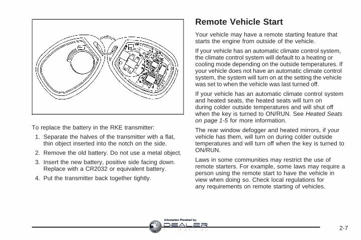
To replace the battery in the RKE transmitter:
1. Separate the halves of the transmitter with a flat,thin object inserted into the notch on the side.
2. Remove the old battery. Do not use a metal object.
3. Insert the new battery, positive side facing down.Replace with a CR2032 or equivalent battery.
4. Put the transmitter back together tightly.
Remote Vehicle StartYour vehicle may have a remote starting feature thatstarts the engine from outside of the vehicle.
If your vehicle has an automatic climate control system,the climate control system will default to a heating orcooling mode depending on the outside temperatures. Ifyour vehicle does not have an automatic climate controlsystem, the system will turn on at the setting the vehiclewas set to when the vehicle was last turned off.
If your vehicle has an automatic climate control systemand heated seats, the heated seats will turn onduring colder outside temperatures and will shut offwhen the key is turned to ON/RUN. See Heated Seatson page 1-5 for more information.
The rear window defogger and heated mirrors, if yourvehicle has them, will turn on during colder outsidetemperatures and will turn off when the key is turned toON/RUN.
Laws in some communities may restrict the use ofremote starters. For example, some laws may require aperson using the remote start to have the vehicle inview when doing so. Check local regulations forany requirements on remote starting of vehicles.
2-7
Information Provided by:

The RKE transmitter with the remote start button,provides an increased range of operation. However, therange may be less while the vehicle is running. As aresult, you may need to be closer to your vehicle to turnit off, than you were to turn it on.
There are other conditions which can affect theperformance of the transmitter, see Remote KeylessEntry (RKE) System on page 2-4 for additionalinformation.
/ (Remote Start): This button will be on the RKEtransmitter if you have remote start.
To start the vehicle:
1. Aim the transmitter at the vehicle.
2. Press and release the transmitter’s lock button, thenimmediately press and hold the transmitter’s remotestart button until the turn signal lights flash. If youcannot see the vehicle’s lights, press and hold theremote start button for at least four seconds. Thevehicle’s doors will lock. Pressing the remote startbutton again, after the vehicle has started, will shutthe vehicle off.When the vehicle starts, the parking lamps will turnon and remain on while the vehicle is running.
3. If it is the first remote start since the vehicle hasbeen driven, repeat these steps while the engineis still running, to extend the time by 10 minutes forthe engine to continue to run. Remote start canbe extended one time.
After entering the vehicle during a remote start, insertand turn the key to the ON/RUN position to drivethe vehicle.
If the vehicle is left running it will automatically shut offafter 10 minutes unless a time extension has been done.
To manually shut off a remote start:
• Aim the RKE transmitter at the vehicle and pressthe remote start button until the parking lampsturn off.
• Turn on the hazard warning flashers.
• Turn the ignition switch on and then off.
The vehicle can be started using the remote startfeature two separate times between driving sequences.The engine will run for 10 minutes after each remotestart.
Or, you can extend the engine run time by another10 minutes within the first 10 minute remote start timeframe, and before the engine stops.
2-8
Information Provided by:

For example, if the lock button and then the remotestart buttons are pressed again after the vehiclehas been running for five minutes, 10 minutes areadded, allowing the engine to run for 15 minutes.
The additional 10 minutes are considered a secondremote start.
Once two remote starts, or a single remote start withone time extension has been done, the vehicle must bestarted with the key.
After the key is removed from the ignition, the vehiclecan be started using the remote start feature again.
The vehicle cannot be started using the remotestart feature if the key is in the ignition, the hood is notclosed, or if there is an emission control systemmalfunction.
Also, the engine will turn off during a remote start if thecoolant temperature gets too high or if the oil pressuregets low.
Vehicles that have the remote vehicle start feature areshipped from the factory with the remote vehiclestart system enabled. The system may be enabled ordisabled through the DIC if your vehicle has DICbuttons. See “REMOTE START” under DIC VehicleCustomization (With DIC Buttons) on page 3-75for additional information. If your vehicle does not haveDIC buttons, see your dealer/retailer to enable ordisable the remote start system.
Remote Start ReadyIf your vehicle does not have the remote start feature, itwill have the remote start ready feature. This featureallows your dealer/retailer to add the manufacturer’sremote start feature.
See your dealer/retailer if you would like to add themanufacturer’s remote start feature to your vehicle.
2-9
Information Provided by:

Doors and Locks
Door Locks
{CAUTION:
Unlocked doors can be dangerous.• Passengers, especially children, can easily
open the doors and fall out of a movingvehicle. When a door is locked, the handlewill not open it. You increase the chanceof being thrown out of the vehicle in acrash if the doors are not locked. So, wearsafety belts properly and lock the doorswhenever you drive.
CAUTION: (Continued)
CAUTION: (Continued)
• Young children who get into unlockedvehicles may be unable to get out. A childcan be overcome by extreme heat and cansuffer permanent injuries or even deathfrom heat stroke. Always lock your vehiclewhenever you leave it.
• Outsiders can easily enter through anunlocked door when you slow down orstop your vehicle. Locking your doors canhelp prevent this from happening.
The vehicle’s doors can be manually locked or unlockedin the following ways:
• From the outside, use the key in the driver’s door.
• From the inside, use the lock control on the door.
2-10
Information Provided by:

Power Door LocksThe power door lock switches are located on the frontdoors.
K (Unlock): Press to unlock the doors.
Q (Lock): Press to lock the doors.
Delayed LockingWhen locking the doors with the power lock switch and adoor or the liftgate is open, the doors will lock fiveseconds after the last door is closed. You will hear threechimes to signal that the delayed locking feature is in use.Pressing the power lock switch twice or the lock button onthe RKE transmitter twice will override the delayedlocking feature and immediately lock all the doors.This feature will not operate if the key is in the ignition.
You can program this feature using the DriverInformation Center (DIC). See DELAY DOOR LOCKunder DIC Vehicle Customization (With DIC Buttons) onpage 3-75.
Programmable Automatic DoorLocksVehicles with an automatic lock/unlock feature enableyou to program the vehicle’s power door locks. You canprogram this feature through the Driver InformationCenter (DIC). See DIC Vehicle Customization (With DICButtons) on page 3-75 for more information on DICprogramming.
Rear Door Security LocksYour vehicle has rear door security locks. Theseprevent passengers from opening the rear doors fromthe inside.
2-11
Information Provided by:

The rear door securitylocks are located on theinside edge of eachrear door. The rear doorsmust be open to accessthem. The label showinglock and unlock positions islocated near the lock.
To set the locks, do the following:
1. Insert the key into the security lock slot and turn itso the slot is in the horizontal position.
2. Close the door.
When you want to open a rear door when the securitylock is on, do the following:
1. Unlock the door using the remote keyless entrytransmitter, if the vehicle has one, the powerdoor lock switch, or the rear door manual lock.
2. Open the door from the outside.
To cancel the rear door security lock, do the following:
1. Unlock the door and open it from the outside.
2. Insert the key into the security lock slot and turn itso the slot is in the vertical position.
Lockout ProtectionThis feature protects you from locking the key in thevehicle when the key is in the ignition and a front dooris open.
If the driver’s side power door lock switch is pressedwhen the driver’s door is open and the key is inthe ignition, all of the doors will lock and then the driver’sdoor will unlock.
If the passenger’s side power door lock switch ispressed when the front passenger’s door is open andthe key is in the ignition, all of the doors will lockand then the front passenger’s door will unlock.
Lock Label shown
2-12
Information Provided by:

Liftgate
{CAUTION:
It can be dangerous to drive with the liftgateopen because carbon monoxide (CO) gas cancome into your vehicle. You cannot see orsmell CO. It can cause unconsciousness andeven death.
If you must drive with the liftgate open, or ifelectrical wiring or other cable connectionsmust pass through the seal between the bodyand the liftgate:
• Make sure all other windows are shut.• Turn the fan on your heating or cooling
system to its highest speed with therecirculation mode off. That will forceoutside air into your vehicle. See ClimateControl System in the index.
• If you have air outlets on or under theinstrument panel, open them all the way.
• If your vehicle has a power liftgate, disablethe power liftgate function.
See Power Liftgate on page 2-14.
If your vehicle has a power liftgate, see Power Liftgateon page 2-14.
To unlock the liftgate, use the power door lock switch orpress the door unlock button on the Remote KeylessEntry (RKE) transmitter twice. See Remote KeylessEntry (RKE) System Operation on page 2-5.
To open the liftgate, press the touchpad on theunderside of the liftgate handle. The vehicle must be inPARK (P) to open the liftgate. To close the liftgate,use the pull cup or pull strap as an aid.
The liftgate has an electric latch. If the battery isdisconnected or has low voltage, the liftgate will notopen. The liftgate will resume operation when the batteryis reconnected and charged.
If the battery is properly connected and has adequatevoltage, and the liftgate still will not function, your vehicleshould be taken to a dealership for service.
2-13
Information Provided by:
Power Liftgate
Power Liftgate Operation
{CAUTION:
It can be dangerous to drive with the liftgateopen because carbon monoxide (CO) gas cancome into your vehicle. You cannot see orsmell CO. It can cause unconsciousness andeven death.
If you must drive with the liftgate open, or ifelectrical wiring or other cable connectionsmust pass through the seal between the bodyand the liftgate:
• Make sure all other windows are shut.• Turn the fan on your heating or cooling
system to its highest speed with therecirculation mode off. That will forceoutside air into your vehicle. See ClimateControl System in the index.
CAUTION: (Continued)
CAUTION: (Continued)
• If you have air outlets on or under theinstrument panel, open them all the way.
• If your vehicle has a power liftgate, disablethe power liftgate function.
See Power Liftgate on page 2-14.
Your vehicle may have a power liftgate. The vehiclemust be in PARK (P) to use the power feature.
The taillamps will flash and a chime will sound when thepower liftgate is used.
2-14
Information Provided by:

{CAUTION:
You or others could be injured if caught in thepath of the power liftgate. Make sure there isno one in the way of the liftgate as it isopening and closing.
Notice: If you open the liftgate without checking foroverhead obstructions such as a garage door,you could damage the liftgate or the liftgate glass.Always check to make sure the area above andbehind the liftgate is clear before opening it.
The power liftgate can be power opened and closed inthe following ways:
• Press and hold the power liftgate button on theRemote Keyless Entry (RKE) transmitter untilthe liftgate starts moving. Remote Keyless Entry(RKE) System Operation on page 2-5 for moreinformation.
• Pressing the liftgatebutton on the centerconsole.
• Pressing the touchpad switch on the outside liftgatehandle.
Pressing the buttons, or touchpad switch a second timewhile the liftgate is moving reverses the direction.
Power Liftgate Buttonon Center Console
2-15
Information Provided by:

The liftgate can also be closed by pressing the powerliftgate button next to the liftgate latch. Press the buttona second time during liftgate operation to reverse thatoperation.
The power liftgate may be temporarily disabled underextreme temperatures, or under low battery conditions. Ifthis occurs, the liftgate can still be operated manually.
If you shift the transmission out of PARK (P) while thepower function is in progress, the liftgate power functionwill continue to completion. If you shift the transmissionout of PARK (P) and accelerate before the powerliftgate latches closed, the liftgate may reverse to theopen position. Cargo could fall out of the vehicle. Alwaysmake sure the power liftgate is closed and latchedbefore you drive away.
If you power open the liftgate and the liftgate supportstruts have lost pressure, the lights will flash and achime will sound. The liftgate will stay open temporarily,then slowly close. See your dealer/retailer for servicebefore using the liftgate.
Obstacle Detection FeaturesIf the liftgate encounters an obstacle during a poweropen or close cycle, a warning chime will sound and theliftgate will automatically reverse direction to the fullclosed or open position. After removing the obstruction,the power liftgate operation can be used again. If theliftgate encounters multiple obstacles on the same powercycle, the power function will deactivate, and youmust manually open or close the liftgate. The LIFTGATEOPEN warning message in the Driver InformationCenter (DIC) will indicate that the liftgate is open. Afterremoving the obstructions, manually open the liftgateto the full open position or close the liftgate to the fullyclosed and latched position. The liftgate will nowresume normal power operation.
Power Liftgate Button Near Liftgate Latch
2-16
Information Provided by:
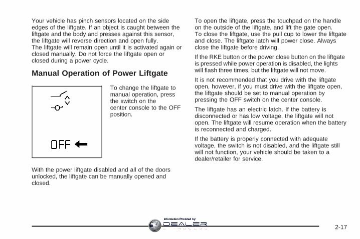
Your vehicle has pinch sensors located on the sideedges of the liftgate. If an object is caught between theliftgate and the body and presses against this sensor,the liftgate will reverse direction and open fully.The liftgate will remain open until it is activated again orclosed manually. Do not force the liftgate open orclosed during a power cycle.
Manual Operation of Power Liftgate
To change the liftgate tomanual operation, pressthe switch on thecenter console to the OFFposition.
With the power liftgate disabled and all of the doorsunlocked, the liftgate can be manually opened andclosed.
To open the liftgate, press the touchpad on the handleon the outside of the liftgate, and lift the gate open.To close the liftgate, use the pull cup to lower the liftgateand close. The liftgate latch will power close. Alwaysclose the liftgate before driving.
If the RKE button or the power close button on the liftgateis pressed while power operation is disabled, the lightswill flash three times, but the liftgate will not move.
It is not recommended that you drive with the liftgateopen, however, if you must drive with the liftgate open,the liftgate should be set to manual operation bypressing the OFF switch on the center console.
The liftgate has an electric latch. If the battery isdisconnected or has low voltage, the liftgate will notopen. The liftgate will resume operation when the batteryis reconnected and charged.
If the battery is properly connected with adequatevoltage, the switch is not disabled, and the liftgate stillwill not function, your vehicle should be taken to adealer/retailer for service.
2-17
Information Provided by:

Windows
{CAUTION:
Leaving children, helpless adults, or pets in avehicle with the windows closed is dangerous.They can be overcome by the extreme heatand suffer permanent injuries or even deathfrom heat stroke. Never leave a child, ahelpless adult, or a pet alone in a vehicle,especially with the windows closed in warm orhot weather.
2-18
Information Provided by:

Power Windows
{CAUTION:
Leaving children, helpless adults, or pets in avehicle with the windows closed is dangerous.They can be overcome from extreme heat inwarm or hot weather and suffer permanentinjuries or even death from heat stroke.
Leaving children in a vehicle with the ignitionkey is dangerous for many reasons, childrenor others could be badly injured or even killed.They could operate the power windows orother controls or even make the vehicle move.The windows will function with the keys in theignition and they could be seriously injured orkilled if caught in the path of a closingwindow. Do not leave keys in a vehicle withchildren.
When there are children in the rear seat usethe window lockout button to preventunintentional operation of the windows.
The power windowcontrols are located oneach of the side doors.
The driver’s door also has switches that control thepassenger and rear windows. The power windows workwhen the ignition has been turned to ACCESSORYor ON or when Retained Accessory Power (RAP)is active. See Retained Accessory Power (RAP) onpage 2-27.
Press the switch to lower the window.
Pull up on the front edge of the switch to raise thewindow.
Uplevel shown, basesimilar
2-19
Information Provided by:
Express-Down WindowsWindows that have the express-down feature allow thewindows to be lowered without holding the switch.Press the window switch fully and release it to activatethe express-down feature. The express mode canbe canceled at any time by briefly pressing, or pullingthe switch.
Express-Up WindowWindows that have the express-up feature allow thewindows to be raised all the way without holdingthe switch up. Pull the switch up fully and release it toactivate the express-up feature. The express-upmode can be canceled at any time by briefly pressing,or pulling the switch.
Programming the Power WindowsIf the battery on your vehicle has been recharged,disconnected, or replaced, windows with the express-upfeature need to be reprogrammed for this feature towork. To program the window:
1. With the ignition in the ACCESSORY or ONpositions, or when Retained AccessoryPower (RAP) is active, close all doors. SeeRetained Accessory Power (RAP) on page 2-27.
2. Press and continue to hold the window switch untilthe window is fully open.
3. Pull up and hold the window switch to close thewindow. Continue to hold it briefly after thewindow is fully closed.
4. Repeat for each window that has the express upfeature.
Anti-Pinch FeatureThe anti-pinch feature is on windows with theexpress-up feature. If an object is in the way of thewindow as it is express-closing, or in certain weatherconditions like severe icing, the window will stopand open to a factory preset position. The windowfunctions normally once the obstruction is removed.
Window Lockout
o (Window Lockout): The window lockout switch islocated with the power window switches on thedriver’s door armrest. This feature prevents the rearpassenger windows from operating, except fromthe driver’s position. Press the switch to turn the lockoutfeature on or off. An indicator light will come on toshow the lockout feature is on.
2-20
Information Provided by:

Sun VisorsPull the sun visor down to block glare. Detach the sunvisor from the center mount and slide it along therod from side-to-side to cover the driver or passengerside of the front window. Swing the sun visor to the sideto cover the side window. It can be moved along therod from side-to-side in this position also.
Lighted Visor Vanity MirrorYour vehicle has lighted visor vanity mirrors on both thedriver’s and passenger’s sun visors. Pull the sunvisor down and lift the mirror cover to turn the lamps on.
Theft-Deterrent SystemsVehicle theft is big business, especially in some cities.Although your vehicle has a number of theft-deterrentfeatures, we know that nothing we put on it can make itimpossible to steal.
Content Theft-DeterrentYour vehicle may have a content theft-deterrent alarmsystem.
To activate the theft-deterrent system, do one of thefollowing:
• Press the lock button on the Remote Keyless Entry(RKE) transmitter when any door is open.The security light should come on and flash. Whenthe door is closed, the security light will stopflashing and stay on solid and then go off afterapproximately 30 seconds. The content theftdeterrent alarm is not armed until the security lightgoes off.If the delayed locking feature is active, the alarmwill not be activated until all doors are closedand the security light goes off.
• Press the lock button on the RKE transmitter whenthe driver door is closed.The security light will come on solid forapproximately 30 seconds and then go off. Thecontent theft deterrent alarm is not armed until thesecurity light goes off.
2-21
Information Provided by:

If a locked door is opened without using the key in thedriver’s door key cylinder or the RKE transmitter, aten second pre-alarm will occur. The horn will chirp andthe lights will flash. If the key is not placed in theignition and turned to START or the door is not unlockedby pressing the unlock button on the RKE transmitterduring the ten second pre-alarm, the alarm will gooff. Your vehicle’s headlamps will flash and the horn willsound for about two minutes, then will turn off to savethe battery power.
The theft-deterrent system will not activate if the doorsare locked with the vehicle’s key or the manual doorlock. It activates only if you use the power doorlock switch with the door open or the RKE transmitter.You should also remember that you can start yourvehicle with the correct ignition key if the alarm has beenset off.
Here is how to avoid setting off the alarm by accident:
• If you do not want to activate the theft-deterrentsystem, the vehicle should be locked with thedoor key after the doors are closed.
• Always unlock a door with the RKE transmitter.Unlocking a door any other way will set off the alarmif the system has been armed.
If you set off the alarm by accident, turn off the alarm bypressing unlock on the RKE transmitter or by placingthe key in the ignition and turning it to START.
Testing the AlarmTo test the alarm:
1. From inside the vehicle, lower the driver’s windowand open the driver’s door.
2. Activate the system by locking the doors with theRKE transmitter.
3. Get out of the vehicle, close the door and wait forthe security light to go out.
4. Then reach in through the window, unlock the doorwith the manual door lock and open the door. Thisshould set off the alarm.
If the alarm does not sound when it should, but thevehicle’s headlamps flash, check to see if the hornworks. The horn fuse may be blown. To replace thefuse, see Fuses and Circuit Breakers on page 5-100.
If the alarm does not sound or the vehicle’s headlampsdo not flash, see your dealer/retailer for service.
2-22
Information Provided by:

PASS-Key® III+The PASS-Key® III+ system operates on a radiofrequency subject to Federal CommunicationsCommission (FCC) Rules and with Industry Canada.
This device complies with Part 15 of the FCC Rules.Operation is subject to the following two conditions:
1. This device may not cause harmful interference.
2. This device must accept any interference received,including interference that may cause undesiredoperation.
This device complies with RSS-210 of Industry Canada.Operation is subject to the following two conditions:
1. This device may not cause interference.
2. This device must accept any interference received,including interference that may cause undesiredoperation of the device.
Changes or modifications to this system by other thanan authorized service facility could void authorization touse this equipment.
PASS-Key® III+ uses a radio frequency transponder inthe key that matches a decoder in your vehicle.
PASS-Key® III+ OperationYour vehicle has PASS-Key® III+ (PersonalizedAutomotive Security System) theft-deterrent system.PASS-Key® III+ is a passive theft-deterrent system.
The system is automatically armed when the keyis removed from the ignition.
The system is automatically disarmed when the key isturned to ON/RUN, ACC/ACCESSORY or STARTfrom the LOCK/OFF position.
You do not have to manually arm or disarm the system.
The security light will come on if there is a problemwith arming or disarming the theft-deterrent system.
When the PASS-Key® III+ system senses that someoneis using the wrong key, it prevents the vehicle fromstarting. Anyone using a trial-and-error method to startthe vehicle will be discouraged because of the highnumber of electrical key codes.
If the engine does not start and the security light on theinstrument panel comes on when trying to start thevehicle, there may be a problem with your theft-deterrentsystem. Turn the ignition off and try again.
2-23
Information Provided by:

If the engine still does not start, and the key appears tobe undamaged, try another ignition key. At this time,you may also want to check the fuse, see Fusesand Circuit Breakers on page 5-100. If the engine stilldoes not start with the other key, your vehicle needsservice. If your vehicle does start, the first key may befaulty. See your dealer/retailer who can service thePASS-Key® III+ to have a new key made. In anemergency, contact Roadside Assistance.
It is possible for the PASS-Key® III+ decoder to learnthe transponder value of a new or replacement key. Upto 10 keys may be programmed to the vehicle. Thefollowing procedure is for programming additional keysonly. If all the currently programmed keys are lost ordo not operate, you must see your dealer/retaileror a locksmith who can service PASS-Key® III+ to havekeys made and programmed to the system.
See your dealer/retailer or a locksmith who can servicePASS-Key® III+ to get a new key blank that is cutexactly as the ignition key that operates the system.
To program the new additional key do the following:
1. Verify that the new key has a 1 stamped on it.
2. Insert the original, already programmed, key in theignition and start the engine. If the engine will notstart, see your dealer/retailer for service.
3. After the engine has started, turn the key toLOCK/OFF, and remove the key.
4. Insert the new key to be programmed and turn it tothe ON/RUN position within five seconds of turningthe original key to LOCK/OFF.
5. The security light will turn off once the key hasbeen programmed.
6. Repeat Steps 1 through 5 if additional keys are tobe programmed.
If you lose or damage your PASS-Key® III+ key, seeyour dealer/retailer or a locksmith who can servicePASS-Key® III+ to have a new key made.
The SERVICE THEFT DETERRENT SYSTEM messagedisplays on the Driver Information Center (DIC) whenthere is a problem with the theft-deterrent system.See DIC Warnings and Messages on page 3-66 foradditional information.
Do not leave the key or device that disarms ordeactivates the theft deterrent system in the vehicle.
2-24
Information Provided by:

Starting and Operating YourVehicleNew Vehicle Break-InNotice: Your vehicle does not need an elaboratebreak-in. But it will perform better in the long run ifyou follow these guidelines:• If you have all-wheel drive, keep your speed at
55 mph (88 km/h) or less for the first 500 miles(805 km).
• Do not drive at any one constant speed, fast orslow, for the first 500 miles (805 km). Do notmake full-throttle starts. Avoid downshifting tobrake or slow the vehicle.
• Avoid making hard stops for the first 200 miles(322 km) or so. During this time the new brakelinings are not yet broken in. Hard stops with newlinings can mean premature wear and earlierreplacement. Follow this breaking-in guidelineevery time you get new brake linings.
• Do not tow a trailer during break-in. See Towing aTrailer on page 4-30 for the trailer towingcapabilities of your vehicle and moreinformation.
Following break-in, engine speed and load can begradually increased.
2-25
Information Provided by:

Ignition Positions
With the key in the ignition,you can turn it to fourdifferent positions.
In order to shift out of PARK (P), ignition must be inON/RUN or ACC/ACCESSORY and the regular brakepedal must be applied.
Notice: Using a tool to force the key from theignition switch could cause damage or break the key.Use the correct key and turn the key only with yourhand. Make sure the key is all the way in. If none ofthis works, then your vehicle needs service.
A (LOCK/OFF): This is the only position in which youcan remove the key. This position locks the ignition andtransmission. If the steering wheel is locked, move it fromright to left and turn the key to ACC/ACCESSORY. Ifnone of this works, then your vehicle needs service.
B (ACC/ACCESSORY): This position allows you to usethings like the radio and the windshield wipers whilethe engine is off. This position will also allow you to turnoff the engine.
C (ON/RUN): This is the position that the switch returnsto after you start your engine and release the key.The switch stays in ON/RUN when the engine isrunning. But even when the engine is not running, youcan use ON/RUN to operate your electrical poweraccessories, and to display some instrument panelwarning lights.
The battery could be drained if you leave the key in theACC/ACCESSORY or ON/RUN position with theengine off. You may not be able to start your vehicle ifthe battery is allowed to drain for an extended periodof time.
D (START): This position starts the engine. When theengine starts, release the key. The ignition switchwill return to ON/RUN for normal driving.
2-26
Information Provided by:

Key In the IgnitionNever leave your vehicle with the keys inside, as it is aneasy target for joy riders or thieves. If you leave the key inthe ignition and park your vehicle, a chime will soundwhen you open the driver’s door. Always remember toremove your key from the ignition and take it with you.This will lock your ignition and transmission. Also, alwaysremember to lock the doors.The battery could be drained if you leave the key in theignition while your vehicle is parked. You may not be ableto start your vehicle after it has been parked for anextended period of time.
Retained Accessory Power (RAP)These vehicle accessories can be used for up to10 minutes after the ignition key is turned off:• Audio System• Power Windows
• Sunroof (if equipped)
Power to the windows and sunroof will work up to10 minutes or until a door is opened.The radio continues to work for 10 minutes or until thedriver’s door is opened.For an additional 10 minutes of operation, close all thedoors and turn the key to ON/RUN and then back toLOCK/OFF.All these features will work when the key is in theON/RUN or ACC/ACCESSORY positions.
Starting the EngineMove your shift lever to PARK (P) or NEUTRAL (N). Yourengine will not start in any other position – this is a safetyfeature. To restart when you are already moving, useNEUTRAL (N) only.
Notice: Do not try to shift to PARK (P) if your vehicleis moving. If you do, you could damage thetransmission. Shift to PARK (P) only when yourvehicle is stopped.
2-27
Information Provided by:

Starting Procedure1. With your foot off the accelerator pedal, turn the
ignition key to START. When the engine starts, let goof the key. The idle speed will go down as yourengine gets warm. Do not race the engineimmediately after starting it. Operate the engine andtransmission gently to allow the oil to warm up andlubricate all moving parts.Your vehicle has a Computer-Controlled CrankingSystem. This feature assists in starting the engineand protects components. If the ignition key is turnedto the START position, and then released when theengine begins cranking, the engine will continuecranking for a few seconds or until the vehicle starts.If the engine does not start and the key is held inSTART for many seconds, cranking will be stoppedafter 15 seconds to prevent cranking motor damage.To prevent gear damage, this system also preventscranking if the engine is already running. Enginecranking can be stopped by turning the ignitionswitch to the ACC/ACCESSORY or LOCK/OFFposition.
Notice: Cranking the engine for long periods oftime, by returning the key to the START positionimmediately after cranking has ended, can overheatand damage the cranking motor, and drain thebattery. Wait at least 15 seconds between each try, tolet the cranking motor cool down.
2. If the engine does not start after 5-10 seconds,especially in very cold weather (below 0°F or −18°C),it could be flooded with too much gasoline. Trypushing the accelerator pedal all the way to the floorand holding it there as you hold the key in START forup to a maximum of 15 seconds. Wait at least15 seconds between each try, to allow the crankingmotor to cool down. When the engine starts, let go ofthe key and accelerator. If the vehicle starts brieflybut then stops again, do the same thing. This clearsthe extra gasoline from the engine. Do not race theengine immediately after starting it. Operate theengine and transmission gently until the oil warms upand lubricates all moving parts.
Notice: The engine is designed to work with theelectronics in your vehicle. If you add electrical partsor accessories, you could change the way the engineoperates. Before adding electrical equipment, checkwith your dealer/retailer. If you do not, your enginemight not perform properly. Any resulting damagewould not be covered by your vehicle’s warranty.
2-28
Information Provided by:

Engine Coolant HeaterThe engine coolant heater, if available, can help in coldweather conditions at or below 0°F (−18°C) for easierstarting and better fuel economy during engine warm-up.Plug in the coolant heater at least four hours beforestarting your vehicle. An internal thermostat in theplug-end of the cord may exist which will preventengine coolant heater operation at temperaturesabove 0°F (−18°C).
To Use the Engine Coolant Heater1. Turn off the engine.
2. Open the hood and unwrap the electrical cord. Thecord is located on the driver’s side of the enginecompartment, it is routed around the windshieldwasher fluid reservoir.
3. Plug the cord into a normal, grounded 110-volt ACoutlet.
{CAUTION:
Plugging the cord into an ungrounded outletcould cause an electrical shock. Also, thewrong kind of extension cord could overheatand cause a fire. You could be seriouslyinjured. Plug the cord into a properly groundedthree-prong 110-volt AC outlet. If the cord willnot reach, use a heavy-duty three-prongextension cord rated for at least 15 amps.
4. Before starting the engine, be sure to unplug andstore the cord as it was before to keep it awayfrom moving engine parts. If you do not, it could bedamaged.
How long should you keep the coolant heater pluggedin? The answer depends on the outside temperature, thekind of oil you have, and some other things. Insteadof trying to list everything here, we ask that you contactyour dealer/retailer in the area where you will beparking your vehicle. The dealer/retailer can give youthe best advice for that particular area.
2-29
Information Provided by:

Automatic Transmission OperationYour vehicle has an electronic shift position indicatorwithin the instrument panel cluster.
When using the Electronic Range Select Mode anumber will display next to the L, indicating the currentgear that has been selected.
See Electronic Range Select mode in this section formore information.
Your automatic transmission has a shift lever located onthe console between the seats.
PARK (P): This position locks your front wheels. It isthe best position to use when you start your enginebecause your vehicle cannot move easily.
{CAUTION:
It is dangerous to get out of your vehicle if theshift lever is not fully in PARK (P) with theparking brake firmly set. Your vehicle can roll.
Do not leave your vehicle when the engine isrunning unless you have to. If you have left theengine running, the vehicle can movesuddenly. You or others could be injured. Tobe sure your vehicle will not move, even whenyou are on fairly level ground, always set yourparking brake and move the shift lever toPARK (P). See Shifting Into PARK (P) onpage 2-36. If you are pulling a trailer, seeTowing a Trailer on page 4-30.
2-30
Information Provided by:
Make sure the shift lever is fully in PARK (P) beforestarting the engine. Your vehicle has an automatictransmission shift lock control system. You must fullyapply your regular brake first and then press theshift lever button before you can shift from PARK (P)when the ignition key is in ON. If you cannot shift out ofPARK (P), ease pressure on the shift lever, thenpush the shift lever all the way into PARK (P) as youmaintain brake application. Then press the shiftlever button and move the shift lever into another gear.See Shifting Out of PARK (P) on page 2-37.
REVERSE (R): Use this gear to back up.
Notice: Shifting to REVERSE (R) while your vehicleis moving forward could damage the transmission.The repairs would not be covered by your warranty.Shift to REVERSE (R) only after your vehicle isstopped.
To rock your vehicle back and forth to get out of snow,ice or sand without damaging your transmission,see If Your Vehicle is Stuck in Sand, Mud, Ice, or Snowon page 4-20.
NEUTRAL (N): In this position, your engine does notconnect with the wheels. To restart when you arealready moving, use NEUTRAL (N) only. Also, useNEUTRAL (N) when your vehicle is being towed.
{CAUTION:
Shifting into a drive gear while the engine isrunning at high speed is dangerous. Unlessyour foot is firmly on the brake pedal, yourvehicle could move very rapidly. You couldlose control and hit people or objects. Do notshift into a drive gear while your engine isrunning at high speed.
Notice: Shifting out of PARK (P) or NEUTRAL (N)with the engine running at high speed may damagethe transmission. The repairs would not becovered by your warranty. Be sure the engine is notrunning at high speed when shifting your vehicle.
2-31
Information Provided by:

DRIVE (D): This position is for normal driving. Itprovides the best fuel economy for your vehicle. If youneed more power for passing, and you are:
• Going less than 35 mph (56 km/h), push youraccelerator pedal about halfway down.
• Going about 35 mph (56 km/h) or more, push theaccelerator all the way down.
Notice: If your vehicle seems to accelerate slowlyor not shift gears when you go faster, and youcontinue to drive your vehicle that way, you coulddamage the transmission. Have your vehicleserviced right away. You can drive in LOW (L) whenyou are driving less than 35 mph (56 km/h) andDRIVE (D) for higher speeds until then.
LOW (L): This position gives you access to gearranges. This provides more engine braking but lowerfuel economy than DRIVE (D). You can use it onvery steep hills, or in deep snow or mud.
Electronic Range Select ModeElectronic Range Selector (ERS) mode allows you tochoose the top-gear limit of the vehicle’s transmissionand the vehicle’s speed while driving down hill or towinga trailer.
To use this feature, do the following:
1. Move the shift lever to LOW (L).
2. Press the plus/minusbutton located on theshift lever, to increaseor decrease thegear range availablebased upon yourcurrent drivingconditions and needs.
2-32
Information Provided by:

When you shift from DRIVE (D) to LOW (L), thetransmission will shift to a pre-determined lower gearrange. The highest gear available for this pre-determinedrange is displayed next to the L in the DIC. SeeDriver Information Center (DIC) on page 3-57 and DICOperation and Displays (With DIC Buttons) onpage 3-57 or DIC Operation and Displays (Without DICButtons) on page 3-63 for more information. Thenumber displayed in the DIC is the highest gear that thetransmission will be allowed to operate in. However,your vehicle can automatically shift to lower gearsas required by various driving conditions. This meansthat all gears below that number are available. Forexample, when FOURTH (4) is shown next to the L,FIRST (1) through FOURTH (4) gears are automaticallyshifted by the vehicle. You cannot shift into FIFTH (5)until the plus (+) button is used or you shift backinto DRIVE (D) mode.
While in LOW (L), the transmission will prevent shiftingto a lower gear range if the engine speed is too highfor the gear range you are trying to select. You have abrief period of time to slow the vehicle speed. Ifvehicle speed is not reduced within the timeframeallowed, the lower gear range attempted will not beavailable. The highest possible gear that is allowed forthat engine speed will display next to the L in theDIC. Try again to slow the vehicle speed and press theminus (−) button to the desired lower gear range.
Automatic Engine Grade braking is not available whenthe ERS is active. It is available in DRIVE (D) forboth normal and Tow/Haul mode. While using the ERS,cruise control and the tow/haul mode can be used.See Tow/Haul Mode on page 2-34 for more information.
2-33
Information Provided by:
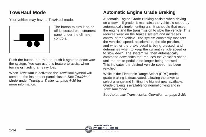
Tow/Haul ModeYour vehicle may have a Tow/Haul mode.
The button to turn it on oroff is located on instrumentpanel under the climatecontrols.
Push the button to turn it on, push it again to deactivatethe system. You can use this feature to assist whentowing or hauling a heavy load.
When Tow/Haul is activated the Tow/Haul symbol willcome on the instrument panel cluster. See Tow/HaulMode under Towing a Trailer on page 4-30 formore information.
Automatic Engine Grade BrakingAutomatic Engine Grade Braking assists when drivingon a downhill grade. It maintains the vehicle’s speed byautomatically implementing a shift schedule that usesthe engine and the transmission to slow the vehicle. Thisreduces wear on the brakes system and increasescontrol of the vehicle. The system constantly monitorsthe vehicle’s speed, acceleration, throttle position,and whether the brake pedal is being pressed, anddetermines when to keep the current vehicle speed orto slow down. The system will then automaticallycommand downshifts that reduces the vehicle’s speed,until the brake pedal is no longer being pressed.This indicates the desired vehicle speed has beenreached.
While in the Electronic Range Select (ERS) mode,grade braking is deactivated, allowing the driver toselect a range and limiting the highest gear available.Grade braking is available for normal driving and inTow/Haul mode.
See Automatic Transmission Operation on page 2-30.
2-34
Information Provided by:

Parking Brake
To set the parking brake,push down the parkingbrake pedal downwith your left foot.
If the ignition is on, the brake system warning light willcome on. See Brake System Warning Light onpage 3-47.
Notice: Driving with the parking brake on canoverheat the brake system and cause prematurewear or damage to brake system parts. Make surethat the parking brake is fully released and the brakewarning light is off before driving.
To release the parking brake, hold the regular brakepedal down with your right foot. Push down momentarilyon the parking brake pedal with your left foot until youfeel the pedal release, then slowly pull your foot upoff the park brake pedal. If the parking brake isnot released when you begin to drive, the brake systemwarning light will be on and a chime will soundwarning you that the parking brake is still on.
If you are towing a trailer and are parking on a hill, seeTowing a Trailer on page 4-30.
2-35
Information Provided by:

Shifting Into PARK (P)
{CAUTION:
It can be dangerous to get out of your vehicleif the shift lever is not fully in PARK (P) withthe parking brake firmly set. Your vehicle canroll. If you have left the engine running, thevehicle can move suddenly. You or otherscould be injured. To be sure your vehicle willnot move, even when you are on fairly levelground, use the steps that follow. If you arepulling a trailer, see Towing a Trailer onpage 4-30.
1. Hold the brake pedal down with your right foot andset the parking brake. See Parking Brake onpage 2-35 for more information.
2. Move the shift lever into PARK (P) by holding in thebutton on the shift lever and pushing the shift leverall the way toward the front of the vehicle.
3. Turn the ignition key to LOCK/OFF.
4. Remove the key and take it with you. If you canleave your vehicle with the ignition key in yourhand, your vehicle is in PARK (P).
Leaving Your Vehicle With the EngineRunning
{CAUTION:
It can be dangerous to leave your vehicle withthe engine running. Your vehicle could movesuddenly if the shift lever is not fully inPARK (P) with the parking brake firmly set.And, if you leave the vehicle with the enginerunning, it could overheat and even catch fire.You or others could be injured. Do not leaveyour vehicle with the engine running.
If you have to leave your vehicle with the enginerunning, be sure your vehicle is in PARK (P) and yourparking brake is firmly set before you leave it. After youhave moved the shift lever into PARK (P), hold theregular brake pedal down. Then, see if you can movethe shift lever away from PARK (P) without first pushingthe button.
If you can, it means that the shift lever was not fullylocked in PARK (P).
2-36
Information Provided by:

Torque LockIf you are parking on a hill and you do not shift yourtransmission into PARK (P) properly, the weight of thevehicle may put too much force on the parking pawlin the transmission. You may find it difficult to pull theshift lever out of PARK (P). This is called torque lock. Toprevent torque lock, set the parking brake and thenshift into PARK (P) properly before you leave the driver’sseat. To find out how, see Shifting Into PARK (P) onpage 2-36.
When you are ready to drive, move the shift lever out ofPARK (P) before you release the parking brake.
If torque lock does occur, you may need to have anothervehicle push your vehicle a little uphill to take some ofthe pressure from the parking pawl in the transmission,so you can pull the shift lever out of PARK (P).
Shifting Out of PARK (P)This vehicle is equipped with an electronic shift lockrelease system. The shift lock release is designed to:• Prevent ignition key removal unless the shift lever is
in PARK (P) with the shift lever button fully released,and
• Prevent movement of the shift lever out ofPARK (P), unless the ignition is in ON/RUN orACC/ACCESSORY and the regular brake pedal isapplied.
The shift lock release is always functional except in thecase of an uncharged or low voltage (less than 9 volt)battery.
If your vehicle has an uncharged battery or a batterywith low voltage, try charging or jump starting thebattery. See Jump Starting on page 5-39 for moreinformation.
To shift out of PARK (P) use the following:
1. Apply the brake pedal.
2. Then press the shift lever button.
3. Move the shift lever to the desired position.
If you still are unable to shift out of PARK (P):
1. Fully release the shift lever button.
2. While holding down the brake pedal, press the shiftlever button again.
3. Move the shift lever to the desired position.
If you still cannot move the shift lever from PARK (P),consult your dealer/retailer or a professional towingservice.
2-37
Information Provided by:

Parking Over Things That Burn
{CAUTION:
Things that can burn could touch hot exhaustparts under your vehicle and ignite. Do notpark over papers, leaves, dry grass, or otherthings that can burn.
Engine Exhaust
{CAUTION:
Engine exhaust can kill. It contains the gascarbon monoxide (CO), which you cannot seeor smell. It can cause unconsciousness anddeath.
You might have exhaust coming in if:• The exhaust system sounds strange or
different.• Your vehicle gets rusty underneath.• Your vehicle was damaged in a collision.• Your vehicle was damaged when driving
over high points on the road or over roaddebris.
• Repairs were not done correctly.• Your vehicle or the exhaust system has
been modified improperly.
If you ever suspect exhaust is coming intoyour vehicle:
• Drive it only with all the windows down toblow out any CO; and
• Have your vehicle fixed immediately.
2-38
Information Provided by:

Running the Engine While ParkedIt is better not to park with the engine running. But if youever have to, here are some things to know.
{CAUTION:
Idling the engine with the climate controlsystem off could allow dangerous exhaust intoyour vehicle. See the earlier caution underEngine Exhaust on page 2-38.
Also, idling in a closed-in place can let deadlycarbon monoxide (CO) into your vehicle even ifthe climate control fan is at the highest setting.One place this can happen is a garage.Exhaust — with CO — can come in easily.NEVER park in a garage with the enginerunning.
Another closed-in place can be a blizzard. SeeWinter Driving on page 4-17.
{CAUTION:
It can be dangerous to get out of your vehicleif the shift lever is not fully in PARK (P) withthe parking brake firmly set. Your vehicle canroll. Do not leave your vehicle when the engineis running unless you have to. If you have leftthe engine running, the vehicle can movesuddenly. You or others could be injured. Tobe sure your vehicle will not move, even whenyou are on fairly level ground, always set theparking brake and move the shift lever toPARK (P).
Follow the proper steps to be sure your vehicle will notmove. See Shifting Into PARK (P) on page 2-36.
If you are pulling a trailer, see Towing a Trailer onpage 4-30.
2-39
Information Provided by:
Mirrors
Manual Rearview Mirror withOnStar®
When you are sitting in a comfortable driving position,adjust the mirror so you can see clearly behind yourvehicle. Hold the mirror in the center to move it up ordown and side to side. The day/night adjustment allowsyou to adjust the mirror to avoid glare from the lampsbehind you. Move the lever to the right for nighttime useand to the left for daytime use.There may also be three OnStar® buttons located at thebottom of the mirror face. See your dealer/retailer formore information on the system and how to subscribe toOnStar®. See OnStar® System on page 2-47 for moreinformation on the services OnStar® provides.
Automatic Dimming Rearview Mirrorwith OnStar® and CompassYour vehicle may have an automatic-dimming rearviewmirror with a compass.
There may be three additional buttons for the OnStar®
system. See your dealer/retailer for more information onthe system and how to subscribe to OnStar®. SeeOnStar® System on page 2-47 for more information aboutthe services OnStar® provides.
O (On/Off): This is the on/off button.
Automatic Dimming Mirror OperationThe automatic dimming mirror comes on each time theignition is turned to start. To turn the automaticdimming feature off or back on, press the on/off button.The indicator light on the mirror is lit when theautomatic dimming feature is on.
Compass OperationPress the on/off button once to turn the compass onor off.
There is a compass display in the window in the upperright corner of the mirror face.
Compass CalibrationPress and hold the on/off button to activate the compasscalibration mode. CAL will be displayed in the compasswindow on the mirror.
The compass can be calibrated by driving the vehicle incircles at 5 mph (8 km/h) or less until the displayreads a direction.
2-40
Information Provided by:

If after a few seconds the display does not show acompass direction, (N for North for example), there maybe a strong magnetic field interfering with the compass.Such interference may be caused by a magneticantenna mount, note pad holder, or similar object. If theletter C or CAL appears in the compass window, thecompass may need to be reset or calibrated.
Compass VarianceCompass variance is the difference between earth’smagnetic north and true geographic north. The mirror isset to zone eight upon leaving the factory. It will benecessary to adjust the compass to compensatefor compass variance if you live outside zone eight.Under certain circumstances, such as during along distance cross-country trip, it will be necessary toadjust for compass variance. If not adjusted toaccount for compass variance, your compass could givefalse readings.
To adjust for compass variance:
1. Find your current location and variance zonenumber on the following zone map.
2. Press and hold the on/off button until the zonenumber is displayed. The number shown is thecurrent zone number.
3. Scroll through the zone numbers that appear in thewindow on the mirror by pressing the on/off button.Once you find your zone number, release the button.After about four seconds, the mirror will return to thecompass display, and the new zone number will beset. If C or CAL appears in the compass window, thecompass may need calibration. See “CompassCalibration” listed previously.
2-41
Information Provided by:

Outside Power Mirrors
If your vehicle is equippedwith outside power mirrors,the controls are locatedon the driver’s doorarmrest.
Press (A) to select the driver’s side mirror or (B) toselect the passenger’s side mirror. Press either (A) or(B) again to deselect the mirror.
To adjust each mirror, press one of the four arrowslocated on the control pad to move the mirror inthe direction you want it to go. Adjust each outsidemirror so that you can see a little of your vehicle, andthe area behind your vehicle. See Memory Seatand Mirrors on page 1-6 for more information.
The mirrors can be manually folded inward to preventdamage when going through an automatic car wash. Tofold, push the mirror toward the vehicle. To return themirror to its original position, push outward. Be sureto return both mirrors to their original unfolded positionbefore driving.
The use of hood-mounted air deflectors and add-onconvex mirror attachments may adversely affect mirrorperformance.
Turn Signal IndicatorYour vehicle may have a turn signal indicator on themirror. An arrow on the mirror will flash in the directionof the turn or lane change.
2-42
Information Provided by:

Outside Power Foldaway Mirrors
If your vehicle is equippedwith outside powerfoldaway mirrors, thecontrols are located on thedriver’s door armrest.
• Press (A) to select the driver’s side mirror. Thenpress the arrows located on the four-way controlpad to adjust the mirror. Press (A) again to deselectthe mirror.
• Press (B) to select the passenger’s side mirror.Then press the arrows located on the four-waycontrol pad to adjust the mirror. Press (B) again todeselect the mirror.
• Press (C), to fold the mirrors out to the drivingposition.
• Press (D) to fold the mirrors in to the foldedposition.
If the mirrors are accidentally folded/unfolded manually,they may shake or flutter at normal driving speedsand may not stay in the unfolded position. If thishappens, you will need to reset the mirrors. See“Resetting the Power Foldaway Mirrors” next.
Resetting the Power Foldaway MirrorsYou will need to reset the power foldaway mirrors if thefollowing occurs:
• The mirrors are accidentally obstructed whilefolding.
• They are accidentally manually folded/unfolded.
• The mirrors will not stay in the unfolded position.
• The mirrors shake and flutter at normal drivingspeeds.
To reset the power foldaway mirrors, fold and unfoldthem one time using the mirror controls. This will resetthem to their normal position.
This mirror has the following features.
Automatic DimmingThe driver’s outside mirror will adjust for the glare of theheadlamps behind you. See Automatic DimmingRearview Mirror with OnStar® and Compass onpage 2-40.
2-43
Information Provided by:

Park Tilt MirrorsIf your vehicle has the memory package, the outsidemirrors are able to perform the park tilt function. Thisfeature may be useful in allowing the driver to view thecurb when parallel parking. This feature will cause thepassenger’s and/or driver’s mirror to tilt to a preselectedposition when the vehicle is in REVERSE (R).
The passenger’s and/or driver’s mirror will return to itsoriginal position when the vehicle is shifted out ofREVERSE (R), or the ignition is turned off or toOFF/LOCK.
This feature can be turned on or off through the DriverInformation Center (DIC). See DIC VehicleCustomization (With DIC Buttons) on page 3-75 andMemory Seat and Mirrors on page 1-6 for moreinformation.
Turn Signal IndicatorYour vehicle may have a turn signal indicator on themirror. An arrow on the mirror will flash in the directionof the turn or lane change.
Outside Convex Mirror
{CAUTION:
A convex mirror can make things (like othervehicles) look farther away than they really are.If you cut too sharply into the right lane, youcould hit a vehicle on your right. Check yourinside mirror or glance over your shoulderbefore changing lanes.
The passenger’s side mirror may have convex glass. Aconvex mirror’s surface is curved so more can beseen from the driver’s seat.
Outside Heated MirrorsPress the rear window defogger button, located on theclimate control panel, to also turn the outside heatedmirrors on or off. The mirrors will heat to help clear fogor frost from the surface of the mirror.
See “Rear Window Defogger” under Dual AutomaticClimate Control System on page 3-29 for moreinformation.
2-44
Information Provided by:

Object Detection Systems
Ultrasonic Rear ParkingAssist (URPA)If your vehicle has the Ultrasonic Rear Parking Assist(URPA) system, it helps you park easier and avoid othervehicles while in REVERSE (R). It operates at speedsless than 5 mph (8 km/h). It can determine howclose objects are to the rear bumper, up to 8 feet (2.5 m)behind your vehicle. The distance sensors are locatedon the rear bumper.
{CAUTION:
The Ultrasonic Rear Parking Assist (URPA)system does not replace driver vision. Itcannot detect:
• objects that are below the bumper,underneath the vehicle, or if they are tooclose or far from the vehicle
• children, pedestrians, bicyclists, or pets.
If you do not use proper care before and whilebacking; vehicle damage, injury, or deathcould occur. Even with URPA, always checkbehind your vehicle before backing up. Whilebacking, be sure to look for objects and checkyour vehicle’s mirrors.
2-45
Information Provided by:

The display is located inthe headliner and can beseen by looking overyour right shoulder.
URPA uses three color-coded lights to provide distanceand system information.
How the System WorksURPA comes on automatically when the shift lever ismoved into REVERSE (R). The rear display willthen briefly illuminate to let you know the system isworking.
URPA operates only at speeds less than 5 mph(8 km/h). If you are above this speed, the red light onthe rear display will flash.
To be detected, objects must be at least 10 inches(25.4 cm) off the ground and below liftgate level. Objectsmust also be within 8 feet (2.5 m) from your rearbumper. This distance may be less during warmer orhumid weather.
A single beep will sound the first time an object isdetected between 20 inches (0.5 m) and 8 feet (2.5 m)away. Beeping will occur for three seconds whenyou are closer than 1 foot (0.3 m) from the object.
The following describes what will occur with the URPAdisplay as you get closer to a detected object:
Description English Metricamber light 8 ft 2.5 m
amber/amber lights 40 in 1.0 mamber/amber/red lights 23 in 0.6 mamber/amber/red lightsflashing and beep for
three seconds1 ft 0.3 m
The system can be disabled through the DriverInformation Center (DIC). See “Park Assist” under DICOperation and Displays (With DIC Buttons) onpage 3-57 or DIC Operation and Displays (Without DICButtons) on page 3-63 for more information.
2-46
Information Provided by:
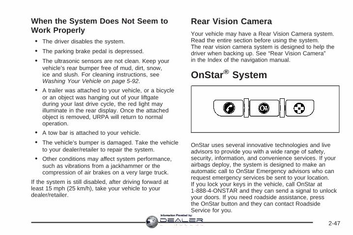
When the System Does Not Seem toWork Properly• The driver disables the system.
• The parking brake pedal is depressed.
• The ultrasonic sensors are not clean. Keep yourvehicle’s rear bumper free of mud, dirt, snow,ice and slush. For cleaning instructions, seeWashing Your Vehicle on page 5-92.
• A trailer was attached to your vehicle, or a bicycleor an object was hanging out of your liftgateduring your last drive cycle, the red light mayilluminate in the rear display. Once the attachedobject is removed, URPA will return to normaloperation.
• A tow bar is attached to your vehicle.
• The vehicle’s bumper is damaged. Take the vehicleto your dealer/retailer to repair the system.
• Other conditions may affect system performance,such as vibrations from a jackhammer or thecompression of air brakes on a very large truck.
If the system is still disabled, after driving forward atleast 15 mph (25 km/h), take your vehicle to yourdealer/retailer.
Rear Vision CameraYour vehicle may have a Rear Vision Camera system.Read the entire section before using the system.The rear vision camera system is designed to help thedriver when backing up. See “Rear Vision Camera”in the Index of the navigation manual.
OnStar® System
OnStar uses several innovative technologies and liveadvisors to provide you with a wide range of safety,security, information, and convenience services. If yourairbags deploy, the system is designed to make anautomatic call to OnStar Emergency advisors who canrequest emergency services be sent to your location.If you lock your keys in the vehicle, call OnStar at1-888-4-ONSTAR and they can send a signal to unlockyour doors. If you need roadside assistance, pressthe OnStar button and they can contact RoadsideService for you.
2-47
Information Provided by:

OnStar service is provided to you subject to the OnStarTerms and Conditions. You may cancel your OnStarservice at any time by contacting OnStar. A completeOnStar Owner’s Guide and the OnStar Terms andConditions are included in the vehicle’s OnStarSubscriber glove box literature. For more information,visit onstar.com or onstar.ca, contact OnStar at1-888-4-ONSTAR (1-888-466-7827) or TTY1-877-248-2080, or press the OnStar button to speakwith an OnStar advisor 24 hours a day, 7 days a week.
Not all OnStar features are available on all vehicles.To check if your vehicle is equipped to provide theservices described below, or for a full description ofOnStar services and system limitations, see the OnStarOwner’s Guide in your glove box or visit onstar.com.
OnStar ServicesFor new vehicles with OnStar, the Safe & Sound Plan,or the Directions & Connections Plan is included forone year from the date of purchase. You can extend thisplan beyond the first year, or upgrade to the Directions& Connections Plan. For more information, pressthe OnStar button to speak with an advisor. SomeOnStar services (such as Remote Door Unlock or StolenVehicle Location Assistance) may not be availableuntil you register with OnStar.
Available Services with Safe & Sound Plan• Automatic Notification of Airbag Deployment
• Advanced Automatic Crash Notification (AACN)(If equipped)
• Link to Emergency Services
• Roadside Assistance
• Stolen Vehicle Location Assistance
• AccidentAssist
• Remote Door Unlock/Vehicle Alert
• OnStar Vehicle Diagnostics
• GM Goodwrench® On Demand Diagnostics
• OnStar Hands-Free Calling with 30 complimentaryminutes
• OnStar Virtual Advisor (U.S. Only)
Available Services included with Directions& Connections Plan• All Safe and Sound Plan Services
• Driving Directions - Advisor delivered or OnStarTurn-by-Turn Navigation (If equipped)
• RideAssist
• Information and Convenience Services
2-48
Information Provided by:

OnStar Hands-Free CallingOnStar Hands-Free Calling allows eligible OnStarsubscribers to make and receive calls using voicecommands. Hands-Free Calling is fully integrated intothe vehicle, and can be used with OnStar Pre-PaidMinute Packages. Hands-Free Calling may alsobe linked to a Verizon Wireless service plan in the U.S.or a Bell Mobility service plan in Canada, dependingon eligibility. To find out more, refer to the OnStarOwner’s Guide in the vehicle’s glove box, visitwww.onstar.com or www.onstar.ca, or speak with anOnStar advisor by pressing the OnStar button or calling1-888-4-ONSTAR (1-888-466-7827).
OnStar Virtual AdvisorOnStar Virtual Advisor is a feature of OnStarHands-Free Calling that uses your minutes to accesslocation-based weather, local traffic reports, andstock quotes. By pressing the phone button and givinga few simple voice commands, you can browsethrough the various topics. See the OnStar Owner’sGuide for more information (Only available in thecontinental U.S.).
OnStar Steering Wheel ControlsYour vehicle may have a Talk/Mute button that can beused to interact with OnStar Hands-Free Calling.See Audio Steering Wheel Controls on page 3-128 formore information.
On some vehicles, you may have to hold the button fora few seconds and give the command “ONSTAR” toactivate the OnStar Hands-Free Calling.
On some vehicles, the mute button can be used to dialnumbers into voicemail systems, or to dial phoneextensions. See the OnStar Owner’s Guide for moreinformation.
How OnStar Service WorksYour vehicle’s OnStar system has the capability ofrecording and transmitting vehicle information. Thisinformation is automatically sent to an OnStar CallCenter at the time of an OnStar button press,Emergency button press or if your airbags or AACNsystem deploys. The vehicle information usually includesyour GPS location and, in the event of a crash,additional information regarding the accident that yourvehicle has been involved in (e.g. the direction fromwhich your vehicle was hit). When you use the VirtualAdvisor feature of OnStar Hands-Free Calling, yourvehicle also sends OnStar your GPS location so that wecan provide you with location-based services.
2-49
Information Provided by:
OnStar service cannot work unless your vehicle is in aplace where OnStar has an agreement with a wirelessservice provider for service in that area. OnStarservice also cannot work unless you are in a placewhere the wireless service provider OnStar has hired forthat area has coverage, network capacity and receptionwhen the service is needed, and technology that iscompatible with the OnStar service. Not all services areavailable everywhere, particularly in remote orenclosed areas, or at all times.Location information about your vehicle is only available ifthe GPS satellite signals are unobstructed and available.Your vehicle must have a working electrical system(including adequate battery power) for the OnStarequipment to operate. There are other problems OnStarcannot control that may prevent OnStar from providingOnStar service to you at any particular time or place.Some examples are damage to important parts of yourvehicle in an accident, hills, tall buildings, tunnels,weather or wireless phone network congestion.
Your ResponsibilityIncrease the radio volume if you cannot hear the OnStaradvisor. If the light next to the OnStar buttons is red, thismeans that your system is not functioning properly andshould be checked by your dealer/retailer. If the lightappears clear (no light is appearing), your OnStarsubscription has expired. You can always press theOnStar button to confirm that your OnStar equipment isactive.
Universal Home RemoteSystemThe Universal Home Remote System provides a way toreplace up to three hand-held Radio-Frequency (RF)transmitters used to activate devices such as garagedoor openers, security systems, and home lighting.
This device complies with Part 15 of the FCC Rules.Operation is subject to the following two conditions:
1. This device may not cause harmful interference.
2. This device must accept any interference received,including interference that may cause undesiredoperation.
This device complies with RSS-210 of Industry Canada.Operation is subject to the following two conditions:
1. This device may not cause interference.
2. This device must accept any interference received,including interference that may cause undesiredoperation of the device.
Changes or modifications to this system by other thanan authorized service facility could void authorization touse this equipment.
2-50
Information Provided by:

Universal Home Remote SystemOperation (With One Triangular LED)
If there is one triangular Light Emitting Diode (LED)indicator light above the Universal Home Remotebuttons, follow the instructions below.
This system provides a way to replace up to threeremote control transmitters used to activate devicessuch as garage door openers, security systems,and home automation devices.
Do not use the Universal Home Remote with anygarage door opener that does not have the stop andreverse feature. This includes any garage door openermodel manufactured before April 1, 1982.
Read the instructions completely before attempting toprogram the Universal Home Remote. Because ofthe steps involved, it may be helpful to have anotherperson available to assist you in the programmingthe Universal Home Remote.
Keep the original hand-held transmitter for use in othervehicles as well as for future Universal Home Remoteprogramming. It is also recommended that upon the saleof the vehicle, the programmed Universal HomeRemote buttons should be erased for security purposes.See “Erasing Universal Home Remote Buttons” laterin this section.
When programming a garage door, park outside of thegarage. Park directly in line with and facing thegarage door opener motor-head or gate motor-head. Besure that people and objects are clear of the garagedoor or gate you are programming.
It is recommended that a new battery be installed inyour hand-held transmitter for quicker and moreaccurate transmission of the radio-frequency signal.
Programming the Universal HomeRemote SystemIf you have questions or need help programming theUniversal Home Remote System, call 1-800-355-3515 orgo to www.homelink.com.
Programming a garage door opener involvestime-sensitive actions, so read the entire procedurebefore you begin. If you do not follow these actions, thedevice will time out and you will have to repeat theprocedure.
2-51
Information Provided by:

To program up to three devices:
1. From inside the vehicle, press and hold down thetwo outside buttons at the same time, releasingonly when the Universal Home Remote indicatorlight begins to flash, after 20 seconds. This step willerase the factory settings or all previouslyprogrammed buttons.Do not hold down the buttons for longer than30 seconds and do not repeat this step to programthe remaining two Universal Home Remotebuttons.
2. Hold the end of your hand-held transmitter about 1to 3 inches (3 to 8 cm) away from the UniversalHome Remote buttons while keeping the indicatorlight in view. The hand-held transmitter wassupplied by the manufacturer of your garage dooropener receiver (motor head unit).
3. At the same time, press and hold both the UniversalHome Remote button that you would like to use tocontrol the garage door and the hand-held
transmitter button. Do not release the UniversalHome Remote button or the hand-held transmitterbutton until Step 4 has been completed.Some entry gates and garage door openers mayrequire you to substitute Step 3 with the procedurenoted in “Gate Operator and CanadianProgramming” later in this section.
4. The indicator light on the Universal Home Remotewill flash slowly at first and then rapidly afterUniversal Home Remote successfully receives thefrequency signal from the hand-held transmitter.Release both buttons.
5. Press and hold the newly-trained Universal HomeRemote button and observe the indicator light.If the indicator light stays on continuously,the programming is complete and your garage doorshould move when the Universal Home Remotebutton is pressed and released. You do not need tocontinue the programming Steps 6 through 8 andcan stop here.If the Universal Home Remote indicator light blinksrapidly for two seconds and then turns to aconstant light, continue with the programming Steps6 through 8.It may be helpful to have another person availableto assist with the remaining steps.
2-52
Information Provided by:

6. After Steps 1 through 5 have been completed,locate inside the garage the garage door openerreceiver (motor-head unit). Locate the “Learn”or “Smart” button. The name and color of the buttonmay vary by manufacturer.
7. Firmly press and release the “Learn” or “Smart”button. After you press this button, you will have30 seconds to complete Step 8.
8. Immediately return to the vehicle. Firmly press andhold the Universal Home Remote button, chosen inStep 3 to control the garage door, for two seconds,and then release it. If the garage door does notmove, press and hold the same button a second timefor two seconds, and then release it. Again, if thedoor does not move, press and hold the same buttona third time for two seconds, and then release.The Universal Home Remote should now activatethe garage door.
To program the remaining two Universal Home Remotebuttons, begin with Step 2 of “Programming theUniversal Home Remote System.” Do not repeat Step 1,as this will erase all previous programming from theUniversal Home Remote buttons.
2-53
Information Provided by:

Gate Operator and CanadianProgrammingIf you have questions or need help programming theUniversal Home Remote System, call 1-800-355-3515 orgo to www.homelink.com.Canadian radio-frequency laws require transmittersignals to time out or quit after several seconds oftransmission. This may not be long enough for UniversalHome Remote to pick up the signal during programming.Similarly, some U.S. gate operators are manufactured totime out in the same manner.If you live in Canada, or you are having difficultyprogramming a gate operator or garage door opener byusing the “Programming Universal Home Remote”procedures, regardless of where you live, replace Step 3under “Programming Universal Home Remote” with thefollowing:
Continue to press and hold the Universal Home Remotebutton while you press and release every two seconds(cycle) the hand-held transmitter button until thefrequency signal has been successfully accepted by theUniversal Home Remote. The Universal Home Remoteindicator light will flash slowly at first and then rapidly.Proceed with Step 4 under “Programming UniversalHome Remote” to complete.
Using Universal Home RemotePress and hold the appropriate Universal Home Remotebutton for at least half of a second. The indicator lightwill come on while the signal is being transmitted.
Erasing Universal Home RemoteButtonsErase the programmed buttons when you sell orterminate your lease.
To erase all programmed buttons on the UniversalHome Remote device:
1. Press and hold down the two outside buttons untilthe indicator light begins to flash, after 20 seconds.
2. Release both buttons.
2-54
Information Provided by:

Reprogramming a Single UniversalHome Remote ButtonTo reprogram any of the three Universal Home Remotebuttons, repeat the programming instructions earlierin this section, beginning with Step 2.
For help or information on the Universal Home RemoteSystem, call the customer assistance phone numberunder Customer Assistance Offices on page 7-5.
Storage Areas
Glove BoxTo open, lift the handle up. Use the key to lock andunlock.
Cupholder(s)There are two cupholders, with removable liners, locatedin front of the center console. There are cupholderslocated in the second row seat armrest. To access, pullthe armrest down. There are additional cupholderslocated on each side of the third row seat and in eachdoor. There are cupholders located behind the centerconsole. To access, pull down on the handle.
Instrument Panel StorageYour vehicle has an instrument panel storage arealocated above the radio. To open the cover, press thebutton.
2-55
Information Provided by:

Center Console Storage
The armrest on the center console can slide forwards andbackwards by holding up the lever located on the front ofit. To open the armrest storage area, press the buttonlocated on the front of the armrest. There is additionalstorage under the armrest. Move the armrest all the wayto the rear position. The tray can be removed foradditional storage.
Second Row Center Console
Your vehicle may have a second row center console.
2-56
Information Provided by:

To access the upper storage area, press the upperbutton (2) and lift up. To access the lower storage area,press the lower button (3) and lift up. The top of theconsole can be folded forward for increased storagearea. Lift up on handle on the rear of the console (1) andpull forward.
{CAUTION:
Never open more than one of the three latchesat a time. This is to help avoid personal injuryand damage to the console.
Notice: Slide the front console as far forward as itwill go before folding the second row consoleforward. This will help prevent damage to theconsoles.
Floor MatsThere is a grommet in the driver side floor mat thatattaches to a hook on the floor of the vehicle to hold thefloor mat in place. To remove the floor mat, pull themat towards the rear of the vehicle until the grommetcan be removed from the hook.
2-57
Information Provided by:

Luggage Carrier
{CAUTION:
If you try to carry something on top of yourvehicle that is longer or wider than the luggagecarrier — like paneling, plywood, a mattress andso forth — the wind can catch it as you drivealong. This can cause you to lose control. Whatyou are carrying could be violently torn off, andthis could cause you or other drivers to have acollision, and of course damage your vehicle.You may be able to carry something like thisinside. But, never carry something longer orwider than the luggage carrier on top of yourvehicle.
If you have the luggage carrier, you can load things ontop of your vehicle. Crossrails are not standard on thisvehicle and must be purchased at your dealer/retailer.
Notice: Loading cargo on the luggage carrier thatweighs more than 200 lbs (91 kg) or hangs over therear or sides of the vehicle may damage your vehicle.Load cargo so that it rests as far forward as possibleand against the side rails, making sure to fasten itsecurely.
Do not exceed the maximum vehicle capacity whenloading your vehicle. For more information on vehiclecapacity and loading, see Loading Your Vehicle onpage 4-21.
To prevent damage or loss of cargo as you are driving,check to make sure the cargo is still securely fastened.
Rear Seat ArmrestYour vehicle may have a rear seat armrest that containstwo cupholders. To access the cupholders, pull thearmrest down from the rear seatback.
Convenience NetYour vehicle may have a convenience net in the rear ofthe vehicle. Store small loads as far forward aspossible. The net should not be used to store heavyloads.
Cargo CoverYour vehicle may have a cargo cover. It can be used tocover items in the rear of the vehicle. To install thecover, place the loops on each corner of the cover onthe four hooks in the rear of the vehicle. The covershould be stored securely when not in use.
2-58
Information Provided by:

Cargo Tie DownsCargo tie-downs located in the rear of the vehicle areused to secure small loads.
Cargo Management SystemYour vehicle has a cargo management system locatedin the rear of the vehicle. To open, pull the handletoward the rear of the vehicle and lift the cover up.
There is an additional storage compartment on eachside of the system. To open, unlatch and lift thepanel up.
To remove the cargo management system:
1. Open the lid.
2. Remove the side panels and place inside the bin.
3. Loosen the retaining nuts on each side of thesystem by turning them counterclockwise.
4. Close the lid.
5. Pull up on the system by using the built in handlesand remove it from the vehicle.
2-59
Information Provided by:

SunroofThe vehicle may have a sunroof over the front seats,and a rear sunroof over the second row seats. The rearsunroof does not open. The switches to operate thefront sunroof and rear sunshade are located onthe headliner above the rearview mirror. The ignitionmust be in ON or ACCESSORY to operate the sunroof.See Ignition Positions on page 2-26.
Vent: From the closed position, press and hold thefront of the driver’s side switch to vent the sunroof. Pressand hold the rear of the driver’s side switch to closethe sunroof.
Express-open/Express-close: From the closedposition, press and release the rear of the driver’s sideswitch to express-open the sunroof. Press andrelease the front of the driver’s side switch toexpress-close the sunroof.
The front sunshade must be opened and closedmanually. Push up on the sunshade handle to open thesunshade.
Notice: The rear sunshade could be damaged ifyou attempt to open or close it manually. Donot manually open or close the rear sunshade.
To open the rear sunshade, located over the secondrow seats, press and release the rear of the passenger’sside switch. Press and release the front of the switchto close the sunshade.
2-60
Information Provided by:

Instrument Panel Overview ...............................3-4Hazard Warning Flashers ................................3-6Other Warning Devices ...................................3-6Horn .............................................................3-6Tilt and Telescopic Steering Wheel ...................3-6Power Tilt Wheel and Telescopic Steering
Column ......................................................3-7Turn Signal/Multifunction Lever .........................3-8Turn and Lane-Change Signals ........................3-8Headlamp High/Low-Beam Changer ..................3-9Flash-to-Pass .................................................3-9Windshield Wipers ..........................................3-9Windshield Washer .......................................3-10Rear Window Wiper/Washer ...........................3-11Cruise Control ..............................................3-12Exterior Lamps .............................................3-14Delayed Headlamps ......................................3-15Daytime Running Lamps (DRL)/
Automatic Headlamp System .......................3-16Fog Lamps ..................................................3-16Instrument Panel Brightness ...........................3-17Courtesy Lamps ...........................................3-17Dome Lamps ...............................................3-17Dome Lamp Override ....................................3-17Entry Lighting ...............................................3-17Delayed Entry Lighting ...................................3-18Delayed Exit Lighting .....................................3-18
Parade Dimming ...........................................3-18Reading Lamps ............................................3-19Electric Power Management ...........................3-19Battery Run-Down Protection ..........................3-20Head-Up Display (HUD) .................................3-20Accessory Power Outlet(s) .............................3-24Power Outlet 115 Volt Alternating Current ........3-25
Climate Controls ............................................3-26Climate Control System .................................3-26Dual Automatic Climate Control System ...........3-29Outlet Adjustment .........................................3-36Rear Air Conditioning and
Heating System .........................................3-36Rear Air Conditioning and Heating System and
Electronic Climate Controls .........................3-38Warning Lights, Gages,
and Indicators .............................................3-39Instrument Panel Cluster ................................3-40Speedometer and Odometer ...........................3-41Tachometer .................................................3-41Safety Belt Reminders ...................................3-41Airbag Readiness Light ..................................3-42Passenger Airbag Status Indicator ...................3-43Charging System Light ..................................3-45Voltmeter Gage ............................................3-46Brake System Warning Light ..........................3-47
Section 3 Instrument Panel
3-1
Information Provided by:

Antilock Brake SystemWarning Light ...........................................3-48
StabiliTrak® Indicator Light ..............................3-48Engine Coolant Temperature Warning Light ......3-49Engine Coolant Temperature Gage ..................3-49Tire Pressure Light .......................................3-50Malfunction Indicator Lamp .............................3-50Oil Pressure Light .........................................3-54Security Light ...............................................3-54Fog Lamp Light ............................................3-55Cruise Control Light ......................................3-55Highbeam On Light .......................................3-55Tow/Haul Mode Light ....................................3-55Fuel Gage ...................................................3-56
Driver Information Center (DIC) .......................3-57DIC Operation and Displays
(With DIC Buttons) ....................................3-57DIC Operation and Displays (Without DIC
Buttons) ...................................................3-63
DIC Warnings and Messages .........................3-66DIC Vehicle Customization (With DIC Buttons) ....3-75
Audio System(s) .............................................3-84Setting the Time ...........................................3-85Radio(s) (MP3) .............................................3-87Using an MP3 (Radio with CD and Six-Disc
CD Player) .............................................3-104Using an MP3 (Radio with CD and DVD
Player) ...................................................3-108XM Radio Messages ...................................3-113Navigation/Radio System ..............................3-115Rear Seat Entertainment (RSE) System .........3-115Rear Seat Audio (RSA) ................................3-125Rear Audio Controller (RAC) .........................3-127Theft-Deterrent Feature ................................3-127Audio Steering Wheel Controls ......................3-128Radio Reception .........................................3-129Multi-Band Antenna .....................................3-129
Section 3 Instrument Panel
3-2
Information Provided by:

✍ NOTES
3-3
Information Provided by:

Instrument Panel Overview
3-4
Information Provided by:

The main components of your instrument panel are listed here:
A. Air Vent. See Outlet Adjustment on page 3-36.B. Multifunction Lever. See Turn Signal/Multifunction
Lever on page 3-8.Windshield Wipers. See Turn Signal/MultifunctionLever on page 3-8.
C. Instrument Panel Cluster. See Instrument PanelCluster on page 3-40.
D. Head-Up Display (HUD) Buttons. See Head-UpDisplay (HUD) on page 3-20.
E. Audio System. See Audio System(s) on page 3-84.Navigation/Radio System (If Equipped). SeeNavigation/Radio System on page 3-115.
F. Exterior Lamps Control. See Exterior Lampson page 3-14.
G. Hood Release. See Hood Release on page 5-13.H. Dome Lamp Override Button. See Dome Lamp
Override on page 3-17. Instrument Panel BrightnessControl. See Instrument Panel Brightness onpage 3-17.
I. Cruise Control Buttons. See Cruise Controlon page 3-12.
J. Tilt and Telescopic Steering Wheel. See Tilt andTelescopic Steering Wheel on page 3-6. PowerTilt Wheel and Telescopic Steering (If Equipped).See Power Tilt Wheel and Telescopic SteeringColumn on page 3-7.
K. Horn. See Horn on page 3-6.
L. Audio Steering Wheel Control Buttons. See AudioSteering Wheel Controls on page 3-128.
M. Driver Information Center. See Driver InformationCenter (DIC) on page 3-57.
N. Dual Automatic Climate Controls. See DualAutomatic Climate Control System on page 3-29.
O. Center Console Shift Lever (If Equipped).See “Console Shift Lever” under Shifting IntoPARK (P) on page 2-36.
P. Hazard Warning Flasher Button. See HazardWarning Flashers on page 3-6.
Q. Cupholders. See Cupholder(s) on page 2-55.R. Accessory Power Outlets. See Accessory Power
Outlet(s) on page 3-24.S. Rear Window Wiper/Washer. See Rear Window
Wiper/Washer on page 3-11. Traction ControlSystem (TCS) Disable Button. See StabiliTrak®
System on page 4-6. Tow/Haul Selector Button(If Equipped). See Tow/Haul Mode on page 2-34.Power Liftgate Button (If Equipped). See PowerLiftgate on page 2-14.
T. Heated Seats Button. See Heated Seats onpage 1-5.
U. Passenger Air Bag status Indicator. See PassengerSensing System on page 1-70.
V. Glove Box. See Glove Box on page 2-55.
3-5
Information Provided by:

Hazard Warning FlashersThe hazard warning flashers let you warn others. Theyalso let police know you have a problem. The frontand rear turn signal lamps will flash on and off.
The hazard warningflasher button islocated in the centerof the instrument panel,below the audio system.
Press the button to make the front and rear turn signallamps flash on and off. Press the button again toturn the flashers off.
The hazard warning flashers work at all times.However, when they are on, the turn signalswill not work.
Other Warning DevicesIf you carry reflective triangles, you can set them upat the side of the road about 300 feet (100 m) behindyour vehicle.
HornPress near or on the horn symbols on the steeringwheel pad to sound the horn.
Tilt and Telescopic Steering WheelA tilt and telescope wheel lets you adjust the steeringwheel before you drive. The steering wheel can beraised to the highest level to give your legs more roomwhen you enter and exit the vehicle.
The lever that lets you tilt and telescope the steeringwheel is located on the left side of the steering column.
3-6
Information Provided by:

To tilt and telescope the steering wheel, pull downthe lever. Then move the steering wheel up or downor backward or forward into a comfortable position.Pull the lever up to lock the steering wheel in place.
Do not adjust the tilt and telescope lever while driving.
Power Tilt Wheel and TelescopicSteering Column
If your vehicle has thisfeature, the power tiltwheel control is locatedon the left side of thesteering column.
To operate the power tilt feature, push the control upand the steering wheel will tilt up. Push the controldown and the steering wheel will go down.
Push the control forward and the steering wheelmoves toward the front of the vehicle. Push the controlrearward and the steering wheel moves toward therear of the vehicle.
3-7
Information Provided by:

Turn Signal/Multifunction Lever
The lever on the left side of the steering column includesthe following:
• GTurn and Lane Change Signals. See Turnand Lane-Change Signals on page 3-8.
• 3Headlamp High/Low-Beam Changer. SeeHeadlamp High/Low-Beam Changer on page 3-9.
• Flash-to-Pass. See Flash-to-Pass on page 3-9.
• NWindshield Wipers. See Windshield Wiperson page 3-9.
• LWindshield Washer. See Windshield Washeron page 3-10.
For information on the headlamps, see Exterior Lampson page 3-14.
Turn and Lane-Change SignalsThe turn signal has two upward (for right) andtwo downward (for left) positions. These positionsallow you to signal a turn or a lane change.
To signal a turn, move the lever all the way up ordown. When the turn is finished, the lever will returnautomatically.
An arrow on the instrumentpanel cluster will flashin the direction of theturn or lane change.
To signal a lane change, raise or lower the lever untilthe arrow starts to flash. Hold it there until you completeyour lane change. The lever will return by itself whenyou release it. If you momentarily press and release thelever, the turn signal will flash three times.
If the arrow flashes faster than normal as you signal aturn or a lane change, a signal bulb may be burnedout and other drivers will not see your turn signal.
3-8
Information Provided by:

If a bulb is burned out, replace it to help avoid anaccident. If the arrows do not go on at all when yousignal a turn, check for burned-out bulbs and then checkthe fuse. See Fuses and Circuit Breakers onpage 5-100.
Turn Signal On ChimeIf either one of the turn signals are left on and you havedrove more than 3/4 mile (1.2 km), a chime will sound.
Headlamp High/Low-BeamChangerTo change the headlamps from low beam to high beam,push the turn signal/multifunction lever toward thefront of the vehicle.
This light on the instrumentpanel cluster comes onif the high beam lampsare turned on whilethe ignition is on.
To change the headlamps from high beam to low beam,pull the turn signal lever toward the rear of the vehicle.
Flash-to-PassWith the turn signal lever in the low-beam position,pull the lever toward you momentarily to switchto high-beam, to signal that you are going to pass.
If the headlamps are on, they will return to low-beamwhen the lever is released.
Windshield WipersClear ice and snow from the wiper blades beforeusing them. If they are frozen to the windshield, gentlyloosen or thaw them. Damaged wiper blades maynot clear the windshield well, making it harder to seeand drive safely. If the blades do become damaged,install new blades or blade inserts. For more information,see Windshield Wiper Blade Replacement on page 5-47.
Heavy snow or ice can overload the wiper motor.A circuit breaker will stop the motor until it cools down.Clear away snow or ice to prevent an overload.
Turn the band with the wiper symbol to control thewindshield wipers.
3-9
Information Provided by:

8(Mist): Turn the band to mist for a single wipingcycle. Hold it there until the wipers start. Then letgo. The wipers stop after one wipe. Hold the bandon mist longer, for more wipe cycles.
9(Off): To stop the wipers, move the band to off.
6 (Delay): Turn the band to adjust the delay time.The delay between wiping cycles becomes shorteras the band is moved to the top of the lever. This canbe very useful in light rain or snow.
1 (Low Speed): Turn the band away from you tothe first solid band past the delay settings, for steadywiping at low speed.
2 (High Speed): Turn the band further, to the secondsolid band past the delay settings, for high-speed wiping.
Windshield Washer
J(Washer Fluid): Press the button located at theend of the turn signal/multifunction lever, to spraywasher fluid on the windshield. The wipers clear thewindshield and either stop or return to the preset speed.The ignition key must be in ACCESSORY or ON forthis to work. See Windshield Washer Fluid on page 5-34Windshield Washer Fluid.
{CAUTION:
In freezing weather, do not use your washeruntil the windshield is warmed. Otherwise thewasher fluid can form ice on the windshield,blocking your vision.
WASHER FLUID LOW ADD FLUID is displayed on theDriver Information Center (DIC) when the washer fluid islow. See DIC Warnings and Messages on page 3-66.
3-10
Information Provided by:

Heated Windshield WasherIf your vehicle has the heated windshield washer fluidsystem it can be used to help clear ice, snow, tree sap,or bugs from the windshield. This feature only workswith the front wiper system.
The button is locatedto the left of thesteering column belowthe instrument panelbrightness control knob.
Push the heated washer fluid button to activatethe heated windshield washer fluid system. Thisactivation begins four heated wash/wipe cycles.The first heated wash/wipe cycle can take up to40 seconds to occur, depending on outside temperature.After the first wash/wipe cycle, it can take up to20 seconds for each of the remaining cycles. Pressthe button again to turn off the heated windshieldwasher fluid system or it will automatically turn offafter four wipe cycles have been completed.
When the heated windshield washer fluid system isactivated under certain outside temperature conditions,steam might flow out of the washer nozzles for a shortperiod of time before washer fluid is sprayed. This is anormal condition.
WASHER FLUID LOW ADD FLUID is displayed on theDIC when the washer fluid is low. See DIC Warningsand Messages on page 3-66.
Rear Window Wiper/WasherThe rear wiper and rear wash button is located on theinstrument panel below the climate control system.
Z (Rear Wiper): Press this symbol to turn the rearwiper on and off. The wiper speed cannot be changed.
Y (Wash): Press this symbol to spray washer fluid onthe rear window. The window wiper will also come on.Release the button when enough fluid has been sprayedon the window. The rear wiper will run a few more cyclesafter it is released. If the rear wiper function was alreadyon, prior to pressing the wash button, it will stay on untilthe wiper button is pressed again.The rear window washer uses the same fluid that is inthe windshield washer reservoir. See Windshield WasherFluid on page 5-34.
3-11
Information Provided by:

Cruise ControlWith cruise control, you can maintain a speed ofabout 25 mph (40 km/h) or more without keepingyour foot on the accelerator. This can really help onlong trips. Cruise control does not work at speedsbelow about 25 mph (40 km/h).
When you apply your brakes, cruise control is turned off.
{CAUTION:
Cruise control can be dangerous whereyou cannot drive safely at a steady speed.So, do not use your cruise control on windingroads or in heavy traffic.
Cruise control can be dangerous on slipperyroads. On such roads, fast changes in tiretraction can cause excessive wheel slip, andyou could lose control. Do not use cruisecontrol on slippery roads.
The cruise controlbuttons are locatedon left side of thesteering wheel.
T (On/Off): Press this button to turn cruise controlon and off. The indicator comes on when cruise controlis on.
+ RES (Resume/Accelerate): Press this button tomake the vehicle accelerate or resume to a previouslyset speed.
SET–: Press this button to set the speed or make thevehicle decelerate.
[ (Cancel): Press this button to cancel cruise control.
3-12
Information Provided by:

Setting Cruise ControlCruise control will not work if your parking brake is set,or if the master cylinder brake fluid level is low.The cruise control light on the instrument panel clustercomes on after the cruise control has been set tothe desired speed.
{CAUTION:
If you leave your cruise control on when youare not using cruise, you might hit a buttonand go into cruise when you do not want to.You could be startled and even lose control.Keep the cruise control switch off until youwant to use cruise control.
1. Press the cruise control on/off button.2. Get up to the speed desired.3. Press and release the SET– button located
on the steering wheel.4. Take your foot off the accelerator.
Resuming a Set SpeedSuppose you set your cruise control at a desiredspeed and then you apply the brake. This shuts offthe cruise control. But you do not need to reset it.
Once you are driving about 25 mph (40 km/h) ormore, press the +RES button on your steering wheel.The vehicle will go back to the previously chosenspeed and stay there.
Increasing Speed While UsingCruise ControlTo increase the cruise speed while using cruise control:
• Press and hold the +RES button on the steeringwheel until you reach the desired speed, thenrelease it.
• To increase vehicle speed in small increments,press the +RES button.
Reducing Speed While UsingCruise ControlTo reduce your speed while using cruise control:
• Press and hold the SET– button on the steeringwheel until you reach the lower speed desired,then release it.
• To slow down in very small amounts, pressthe SET– button on the steering wheel briefly.Each time this is done, the vehicle will goabout 1 mph (1.6 km/h) slower.
3-13
Information Provided by:

Passing Another Vehicle While UsingCruise ControlUse the accelerator pedal to increase vehicle speed.When you take your foot off the pedal, your vehiclewill slow down to the previously set cruise speed.
Using Cruise Control on HillsHow well your cruise control will work on hills dependsupon the vehicle speed, load, and the steepness ofthe hills. When going up steep hills, you might have tostep on the accelerator pedal to maintain the vehiclespeed. When going downhill, you might have to brake orshift to a lower gear to keep the vehicle speed down.Of course, applying the brake turns off the cruise control.Many drivers find this to be too much trouble and donot use cruise control on steep hills.
Ending Cruise ControlThere are three ways to end cruise control:• Step lightly on the brake pedal.
• Press the [ (cancel) button on the steering wheel.
• Press the T(on/off) button on the steering wheel.
Erasing Speed MemoryThe cruise control set speed memory is erased byturning off the cruise control or the ignition.
Exterior Lamps
The exterior lampscontrol is located onthe instrument panelto the left of thesteering wheel.
It controls the following systems:
• Headlamps
• Taillamps
• Parking Lamps
• License Plate Lamps
• Instrument Panel Lights
• Fog Lamps
The exterior lamps control has four positions:
9(Off): Briefly turn the control to this position toturn off the automatic light control. Briefly turn to thisposition again to turn automatic light control on again.
3-14
Information Provided by:
AUTO (Automatic): Turn the control to this positionto automatically turn on the headlamps at normalbrightness, together with the following:
• Parking Lamps
• Taillamps
• License Plate Lamps
• Instrument Panel Lights
; (Parking Lamps): Turn the control to this positionto turn on the parking lamps together with thefollowing:
• Taillamps
• License Plate Lamps
• Instrument Panel Lights
2 (Headlamps): Turn the control to this position toturn on the headlamps together with the following lampslisted below. A warning chime will sound if you openthe driver’s door when the ignition switch is off and theheadlamps are on.
• Parking Lamps
• Taillamps
• License Plate Lamps
• Instrument Panel Lights
- (Fog Lamps): Push the fog lamps control into turn on the fog lamps.
See Fog Lamps on page 3-16.
Delayed HeadlampsThe delayed headlamps feature provides a period ofexterior lighting as you leave the area around yourvehicle. The feature is activated when the headlampsare on due to the automatic headlamps controlfeature described previously in this section, and whenthe ignition is turned off. Your headlamps will thenremain on until the exterior lamps control is moved tothe parking lamps position or until the pre-selecteddelayed headlamp lighting period has ended.
If you turn off the ignition with the headlamps switch inthe parking lamps or headlamps position, the delayedheadlamps cycle will not occur.
To disable the delayed headlamps feature or changethe time of delay, see DIC Vehicle Customization(With DIC Buttons) on page 3-75.
3-15
Information Provided by:

Daytime Running Lamps (DRL)/Automatic Headlamp SystemDaytime Running Lamps (DRL) can make it easierfor others to see the front of your vehicle during theday. DRL can be helpful in many different drivingconditions, but they can be especially helpful inthe short periods after dawn and before sunset.Fully functional daytime running lamps are requiredon all vehicles first sold in Canada.
A light sensor on top of the instrument panel makesthe DRL work, so be sure it is not covered.
The DRL system’s automatic headlamp control willmake the low-beam headlamps come on at a reducedbrightness when the following conditions are met:• The ignition is in the ON/RUN position.• The exterior lamps control is in AUTO.• The engine is running.
When the DRL are on, only the low-beam headlamps,at a reduced level of brightness, will be on. Theheadlamps, taillamps, sidemarker, and other lampswill not be on. The instrument panel and cluster willalso not be lit.
When it is dark enough outside, the low-beamheadlamps will turn off and the headlamps and parkinglamps will turn on. The other lamps that come onwith the headlamps will also come on.
When it is bright enough outside, the headlamps willgo off and the DRL will come on.
As with any vehicle, you should turn on the regularheadlamp system when it is needed.
Fog LampsUse the fog lamps for better vision in foggy or mistyconditions.
- (Fog Lamps): The fog lamps button is located onthe exterior lamps control. The exterior lamps controlis located on the instrument panel to the left of thesteering column.
The ignition must be on for the fog lamps to work.
Press the exterior lamps button to turn the fog lampson or off. A light will come on in the instrumentpanel cluster when the fog lamps are in use.
When the headlamps are changed to high-beam, thefog lamps will turn off. The fog lamps come backon again when the high-beam headlamps are turned off.
Some localities have laws that require the headlampsto be on along with the fog lamps.
3-16
Information Provided by:

Instrument Panel BrightnessD (Instrument Panel Brightness): The knob withthis symbol on it is located next to the exterior lampscontrol. Push the knob in all the way until it extendsout and then turn the knob clockwise to brightenor counterclockwise to dim the lights. Push the knobback in when finished.
Courtesy LampsWhen a door is opened, the courtesy lamps automaticallycome on. They make it easy for you to enter and leaveyour vehicle. You can also manually turn these lamps onby fully turning the instrument panel brightness controlclockwise.
The reading lamps, located on the headliner above therearview mirror, can be turned on or off independentof the automatic courtesy lamps, when the doorsare closed.
Dome LampsThe dome lamps automatically come on when a dooris opened, unless the dome lamp override buttonis pressed in.
The lamps can also be turned on and off by turningthe instrument panel brightness control clockwise tothe farthest position.
Dome Lamp OverrideThe dome lamp override button is located next to theexterior lamps control.
The dome lamp override is used to set the dome lampsto remain off or come on automatically when a dooris opened.
E (Dome Lamp Override): Press the button in andthe dome lamps remain off when a door is opened.Press the button again to return it to the extendedposition so that the dome lamps come on when adoor is opened.
Entry LightingYour vehicle may have courtesy lamps that will comeon and stay on for a set time whenever the unlocksymbol is pressed on the Remote Keyless Entry (RKE)Transmitter, if the vehicle has one.
If a door is opened, the lamps stay on while it is openand then turn off automatically about 25 secondsafter the door is closed. If the unlock symbol is pressedand you do not open a door, the lamps turn off afterabout 20 seconds.
3-17
Information Provided by:
Entry lighting includes a feature called theater dimming.With theater dimming, the lamps do not turn off at the endof the delay time. Instead, they slowly dim after the delaytime until they go out. The delay time is canceled if youturn the ignition key to ON/RUN or press the power doorlock switch. The lamps will dim right away.
When the ignition is on, illuminated entry is inactive,which means the courtesy lamps will not come onunless a door is opened.
Delayed Entry LightingDelayed entry lighting illuminates the interior for aperiod of time after all the doors have been closed.
The ignition must be off for delayed entry lightingto work. Immediately after all the doors have beenclosed, the delayed entry lighting feature will continueto work until one of the following occurs:
• The ignition is in ON/RUN.
• The doors are locked.
• An illumination period of 25 seconds has elapsed.
If during the illumination period a door is opened,the timed illumination period will be canceled and theinterior lamps will remain on because a door is open.
Delayed Exit LightingThis feature illuminates the interior for a period of timeafter the key is removed from the ignition.
The ignition must be off for delayed exit lighting towork. When the key is removed, interior illuminationwill activate and remain on until one of the followingoccurs:
• The ignition is in ON/RUN.
• The power door locks are activated.
• An illumination period of 20 seconds has elapsed.
If during the illumination period a door is opened,the timed illumination period will be canceled and theinterior lamps will remain on because a door is open.
Parade DimmingThe instrument panel has an added feature calledparade mode. It automatically prohibits the dimmingof the instrument panel displays during the daylightwhile the headlamps are on so that you will still beable to see the displays.
3-18
Information Provided by:
Reading LampsThe vehicle has reading lamps that also act as thedome lamp. Press the button to turn them on and off.
Electric Power ManagementThe vehicle has Electric Power Management (EPM)that estimates the battery’s temperature and stateof charge. It then adjusts the voltage for bestperformance and extended life of the battery.
When the battery’s state of charge is low, the voltageis raised slightly to quickly put the charge back in.When the state of charge is high, the voltage is loweredslightly to prevent overcharging. If the vehicle has avoltmeter gage or a voltage display on the DriverInformation Center (DIC), you may see the voltagemove up or down. This is normal. If there is a problem,an alert will be displayed.
The battery can be discharged at idle if the electricalloads are very high. This is true for all vehicles.This is because the generator (alternator) may not bespinning fast enough at idle to produce all the powerthat is needed for very high electrical loads.
A high electrical load occurs when several of thefollowing loads are on: headlamps, high beams,fog lamps, rear window defogger, climate control fanat high speed, heated seats, engine cooling fans,trailer loads, and loads plugged into accessory poweroutlets.
EPM works to prevent excessive discharge of thebattery. It does this by balancing the generator’s outputand the vehicle’s electrical needs. It can increaseengine idle speed to generate more power, wheneverneeded. It can temporarily reduce the power demandsof some accessories.
Normally, these actions occur in steps or levels, withoutbeing noticeable. In rare cases at the highest levelsof corrective action, this action may be noticeableto the driver. If so, a Driver Information Center (DIC)message might be displayed, such as Battery SaverActive or Service Battery Charging System. If thismessage is displayed, it is recommended that thedriver reduce the electrical loads as much as possible.See DIC Warnings and Messages on page 3-66.
3-19
Information Provided by:

Battery Run-Down ProtectionThis vehicle has a feature to help prevent the batteryfrom being drained, if the interior courtesy lamps,reading/map lamps, visor vanity lamps or trunk lampare accidentally left on. If any of these lamps areleft on, they will automatically turn off after 10 minutes,if the ignition is off. The lamps will not come backon again until one of the following occurs:
• The ignition is turned on.
• The exterior lamps control is turned off,then on again.
The headlamps will timeout after 10 minutes, if theyare manually turned on before the ignition is off.
Head-Up Display (HUD)
{CAUTION:
If the HUD image is too bright or too high inyour field of view, it may take you more timeto see things you need to see when it is darkoutside. Be sure to keep the HUD image dimand placed low in your field of view.
If the vehicle has the Head-Up Display (HUD),some information concerning the operation of thevehicle is projected onto the windshield. This includesthe speedometer reading, RPM reading, transmissionposition, outside air temperature, the tap shift gear,and a brief display of the current radio station,including XM information or CD track. It will alsodisplay turn-by-turn navigation information if thevehicle has a navigation radio. The images areprojected by the HUD lens located on the driver’sside of the instrument panel.
The tap shift gear will also appear on the HUD ifthe vehicle has tap shift and it is active.
3-20
Information Provided by:

The HUD information can be displayed in one ofthree languages, English, French, or Spanish. Thespeedometer reading and other numerical valuescan be displayed in either English or metric units.
The language selection and the units of measurementare changed through the trip computer in theDriver Information Center (DIC). See DIC VehicleCustomization (With DIC Buttons) on page 3-75.
The HUD information appears as an image focusedout toward the front of the vehicle.
When the ignition key is turned to RUN, the HUD willdisplay an introductory message for a short time,until the HUD is ready.
The following indicator lights come on the instrumentpanel when activated and will also appear on the HUD:• Turn Signal Indicators• High-Beam Indicator Symbol
The HUD will temporarily display CHECK GAGES andICE POSSIBLE when there are messages on theDIC trip computer.
The HUD will also display the following messages onvehicles with these systems, when they are active:• TRACTION CONTROL ACTIVE• STABILITRAK ACTIVE
Notice: If you try to use the HUD image as a parkingaid, you may misjudge the distance and damage yourvehicle. Do not use the HUD image as a parking aid.
When the HUD is on, the speedometer reading willcontinually be displayed. The current radio stationor CD track number will display for a short period oftime after the radio or CD track status changes.This will happen whenever radio information is changed.The speedometer size will be reduced when radio,CD information, warnings, or turn-by-turn navigationinformation are displayed on the HUD.
3-21
Information Provided by:

The HUD control islocated to the rightof the steering wheel.
To adjust the HUD image so that items are properlydisplayed, do the following:
1. Adjust the driver’s seat to a comfortable position.
2. Start the engine.
3. Adjust the HUD controls.
Use the following settings to adjust the HUD.
9(Off): To turn HUD off, rotate the dimming knob fullycounterclockwise until the HUD display turns off.
Brightness: Turn the knob on the HUD controlclockwise to brighten the display and counterclockwiseto dim it.
w (Up): x(Down): Press the up or down arrows tocenter the HUD image in your view. The HUD imagecan only be adjusted up and down, not side to side.
? (Page): Press this button to select the displayformats. Release the page button when the formatnumber with the desired display is shown on the HUD.
The three formats are as follows:
Format One: This display gives the speedometerreading (in English or metric units), turn signal indication,high beam indication, transmission positions, and theoutside air temperature.
3-22
Information Provided by:

Format Two: This display includes the informationin Format One without the transmission informationand the outside air temperature.
Format Three: This display includes all the informationin Format One along with a circular tachometer, butwithout outside air temperature.
All formats will show the turn-by-turn navigationinformation and provide details about the next drivingmaneuver to be made. When you near your destination,
the HUD will display a distance bar that will fill in thecloser you get to your destination. All navigationinformation is provided to the HUD by the navigationradio, if the vehicle has one.
The HUD image displayed on the windshield willautomatically dim and brighten to compensate foroutside lighting.
The HUD image can temporarily light up dependingon the angle and position of the sunlight on theHUD display. This is normal and will change whenthe angle of the sunlight on the HUD display changes.
Polarized sunglasses could make the HUD imageharder to see.
Care of the HUDClean the inside of the windshield as needed to removeany dirt or film that could reduce the sharpness orclarity of the HUD image.
To clean the HUD lens, use a soft, clean cloth that hashousehold glass cleaner sprayed on it. Wipe the HUDlens gently, then dry it. Do not spray cleaner directly onthe lens because the cleaner could leak into the unit.
3-23
Information Provided by:

If You Cannot See the HUD ImageWhen the Ignition Is On• Is anything covering the HUD lens?
• Is the HUD dimmer setting bright enough?
• Is the HUD image adjusted to the proper height?
• Are you wearing polarized sunglasses?
• Still no HUD image? Check the fuse in theinstrument panel fuse block. See InstrumentPanel Fuse Block on page 5-100.
If the HUD Image Is Not Clear• Is the HUD image too bright?
• Are the windshield and HUD lens clean?
If the HUD image is not correct, contact yourdealer/retailer.
Keep in mind that the windshield is part of theHUD system.
Accessory Power Outlet(s)The accessory power outlets can be used to connectelectrical equipment such as a cellular phone orCB radio.
Your vehicle may have four accessory power outlets.They are located on the instrument panel belowthe climate controls, inside the front center consolestorage bin, at the rear of the center console, and inthe rear cargo area.
To use the outlets, remove the cover. When not inuse, always cover the outlet with the protective cap.
Notice: Leaving electrical equipment on forextended periods will drain the battery. Alwaysturn off electrical equipment when not in useand do not plug in equipment that exceeds themaximum amperage rating of 20 amperes.
3-24
Information Provided by:

Certain electrical accessories may not be compatiblewith the accessory power outlets and could resultin blown vehicle or adapter fuses. If you experiencea problem, see your dealer/retailer for additionalinformation on the accessory power outlet.
Notice: Adding any electrical equipment to yourvehicle may damage it or keep other componentsfrom working as they should. The repairs would notbe covered by your warranty. Do not use equipmentexceeding maximum amperage rating of 20 amperes.Check with your dealer/retailer before addingelectrical equipment.
When adding electrical equipment, be sure to follow theinstallation instructions included with the equipment.
Notice: Improper use of the power outlet cancause damage not covered by your warranty.Do not hang any type of accessory or accessorybracket from the plug because the power outletsare designed for accessory power plugs only.
Power Outlet 115 Volt AlternatingCurrentYour vehicle may have a power outlet that can beused to plug in electrical equipment that uses amaximum limit of 150 watts.
The power outlet islocated on the rearof the center console.
An indicator light on the outlet turns on to show itis in use. The light comes on when the ignition is inON/RUN and equipment requiring less than 150 watts isplugged into the outlet, and no system fault is detected.
3-25
Information Provided by:

The indicator light does not come on when the ignitionis in LOCK/OFF or if no equipment is plugged intothe outlet.
If you try to connect equipment using more than150 watts or a system fault is detected, a protectioncircuit shuts off the power supply and the indicatorlight turns off. To reset the circuit, unplug the itemand plug it back in or turn the Remote Accessory Power(RAP) off and then back on. See Retained AccessoryPower (RAP) on page 2-27. The power restartswhen equipment using 150 watts or less is pluggedinto the outlet and a system fault is not detected.
The power outlet is not designed for the followingelectrical equipment and may not work properly ifthese items are plugged into the power outlet:
• Equipment with high initial peak wattage suchas: compressor-driven refrigerators and electricpower tools.
• Other equipment requiring an extremely stablepower supply such as: microcomputer-controlledelectric blankets, touch sensor lamps, etc.
See High Voltage Devices and Wiring on page 5-99.
Climate Controls
Climate Control SystemWith this system you can control the heating, cooling,defrost, defog, and ventilation of the vehicle.
Manual Operation9(Fan): Turn the left knob clockwise orcounterclockwise to increase or decrease the fan speed.Turn the knob all the way counterclockwise to turn thefront system off.
Temperature Control: Turn the center knob clockwiseor counterclockwise to increase or decrease thetemperature of the air flowing from the system.
3-26
Information Provided by:

Airflow Mode Control: Turn the right knob clockwiseor counterclockwise to direct the airflow inside ofthe vehicle.
To change the current mode, select one of the following:
H (Vent): This mode directs air to the instrumentpanel outlets.
) (Bi-Level): This mode directs about half of theair to the instrument panel outlets and half to the flooroutlets. A little air is directed towards the windshieldand side window outlets. Cooler air is directed tothe upper outlets and warmer air to the floor outlets.
6 (Floor): This mode directs most of the air tothe floor outlets, with some of the air directed to thewindshield, side window outlets, and second rowfloor outlets. In this mode, the system automaticallyselects outside air. Recirculation cannot be selectedwhen in Floor Mode.
The right knob can also be used to select defog ordefrost mode. For more information, see “Defoggingand Defrosting” later in this section.
By positioning the right knob between two modes,a combination of those two modes is selected.
@ (Recirculation): Press this button to turn therecirculation mode on or off. The indicator light onthe button turns on when this mode is selected.
This mode keeps outside air from entering the vehicle.It can be used to reduce the outside air and odorsentering the vehicle. Recirculation may also help cool theair inside the vehicle more quickly once the temperatureinside the vehicle is less than the outside temperature.
The recirculation mode can be turned off in ventand bi-level modes by pressing the button again.Recirculation mode automatically turns off when theengine is turned off and must be re-selected when theengine is turned on again.
The recirculation mode cannot be used with floor, defrost,or defogging modes. If you try to select recirculation inone of those modes, the indicator flashes three timesand turns off. The air conditioning compressor alsocomes on when this mode is activated unless theoutside air temperature is less than 40°F (4°C). Whilein recirculation mode the windows may fog when theweather is cold and damp. To clear the fog, select eitherthe defog or defrost mode and increase the fan speed.
#(Air Conditioning): Press this button on the leftknob to turn the air conditioning system on or off.When A/C is pressed, an indicator light comes on toshow that the air conditioning has been activated. The airconditioning compressor does not operate when outsidetemperatures fall below 40°F (4°C). The indicator lightflashes three times and turns off when outside conditionsaffect air conditioning operation. This is normal.
3-27
Information Provided by:

For quicker cool down on hot days, do the following:
1. Open the windows to let hot air escape.
2. Select the vent mode.
3. Select the air conditioner.
4. Select the coolest temperature.
5. Select the highest fan speed.
6. Close the windows after the hot air has escaped.
7. Once the vehicle’s interior temperature is belowthe outside temperature, select recirculationmode for better cooling.
This helps to reduce the time it takes for the vehicleto cool down. It also helps the system to operatemore efficiently.
Using recirculation for long periods of time maycause the air inside of the vehicle to become too dry.To prevent this from happening, after the inside ofthe vehicle has cooled, turn the recirculation mode off.
The air conditioning system removes moisture fromthe air, so you might notice a small amount of waterdripping underneath the front center and right rearof the vehicle while idling or after turning off the engine.This is normal.
Defogging and DefrostingFog on the inside of the windows is a result of highhumidity (moisture) condensing on the cool windowglass. This can be minimized if the climate controlsystem is used properly. There are two modes to clearfog or frost from the windshield. Turn the right knobclockwise to select the defog or defrost mode.
-(Defog): The defog mode is used to clear thewindows of fog or moisture and warm the passengers.This mode directs air to the windshield, floor outlets,and side window vents. When you select this mode,the system turns off recirculation and runs the airconditioning compressor unless the outside temperatureis less than 40°F (4°C). The recirculation modecannot be selected while in the defog mode. Do notdrive the vehicle until all the windows are clear.
0(Defrost): The defrost mode is used to remove fogor frost from the windshield more quickly. This modedirects most of the air to the windshield and side windowvents and some to the floor vents. In this mode, thesystem will automatically force outside air into yourvehicle. The recirculation mode cannot be selected whilein the defrost mode. The air conditioning compressorwill run automatically in this setting, unless the outsidetemperature is less than 40°F (4°C). Do not drivethe vehicle until all the windows are clear.
3-28
Information Provided by:

AUX (Auxiliary): Press this button to turn therear heating and air conditioning on. See Rear AirConditioning and Heating System on page 3-36 orRear Air Conditioning and Heating System andElectronic Climate Controls on page 3-38.
Rear Window DefoggerThe rear window defogger uses a warming grid toremove fog from the rear window.
<(Rear Window Defogger): Press this button on theright knob to turn the rear window defogger on or off.The rear window defogger stays on about 10 minutesafter the button is pressed, before turning off. Thedefogger can also be turned off by pressing the buttonagain or by turning off the engine. Do not drive thevehicle until all the windows are clear.
If your vehicle has heated outside rearview mirrors, themirrors heat to help clear fog or frost from the surface ofthe mirror when the rear window defog button is pressed.
Notice: Do not use anything sharp on the inside ofthe rear window. If you do, you could cut or damagethe warming grid, and the repairs would not becovered by your warranty. Do not attach a temporaryvehicle license, tape, a decal or anything similar tothe defogger grid.
Dual Automatic Climate ControlSystemThe heating, cooling, and ventilation in your vehiclecan be controlled with this system. Your vehicle alsohas a flow-through ventilation system described laterin this section.
Different temperature settings can be selected for thedriver and all passengers.
Display FunctionEach time the temperature, mode, or fan control buttonsare pressed the display shows that function along withthe inside temperature setting. The display automaticallyreverts back to the outside temperature display after ashort delay.
3-29
Information Provided by:

Driver’s Side Temperature ControlThe driver side temperature buttons are used to adjustthe temperature of the air coming through the system onthe driver side. The temperature can be adjusted evenif the system is turned off. This is possible since outsideair will always flow through the system as the vehicle ismoving forward unless it is set to recirculation mode.See “Recirculation” later in this section.
Press the + or − buttons to increase or decrease thetemperature. The driver side temperature display willshow the temperature setting decreasing or increasing.
Passenger’s Side Temperature ControlThe passenger’s temperature buttons can be used tochange the temperature of the air coming throughthe system on the passenger side of the vehicle.The temperature can be adjusted even if the systemis turned off. This is possible since outside air willalways flow through the system as the vehicle ismoving forward unless it is set to recirculation mode.See “Recirculation” later in this section.
Press the + or − buttons to increase or decrease thetemperature. The passenger side display will showthe temperature setting decreasing or increasing.
The passenger’s temperature setting can be set tomatch the driver’s temperature setting by pressing thePASS button and turning off the PASS indicator.
When the passenger’s temperature setting is setdifferent than the driver’s setting, the indicator on thePASS button comes on and both the driver sideand passenger side temperature displays are shown.
Automatic Operation
AUTO (Automatic): When automatic operation isactive the system controls the inside temperature,the air delivery, and the fan speed.
Use the steps below to place the entire system inautomatic mode:
1. Press the AUTO button.When AUTO is selected, the display shows thecurrent temperature(s) selected and AUTO is onthe display. The current delivery mode and fanspeed also display for approximately 5 seconds.When AUTO is selected, the air conditioningoperation and air inlet are automatically controlled.The air conditioning compressor runs when theoutside temperature is over about 40°F (4°C).The air inlet is normally set to outside air. If it ishot outside, the air inlet can automatically switchto recirculate inside air to help quickly cooldown your vehicle. The light comes on therecirculation button while in recirculation.
3-30
Information Provided by:

2. Set the driver’s and passenger’s temperature.To find your comfort setting, start with a 73°F (22°C)temperature setting and allow about 20 minutesfor the system to regulate. Use the driver’s orpassenger’s temperature buttons to adjust thetemperature setting as necessary. If you choosethe temperature setting of 60°F (15°C), the systemremains at the maximum cooling setting. If youchoose the temperature setting of 90°F (32°C),the system remains at the maximum heat setting.Choosing either maximum setting will not causethe vehicle to heat or cool any faster.
Do not cover the solar sensor located on the top ofthe instrument panel near the windshield. This sensorregulates air temperature based on sun load and alsoturns on your vehicle’s headlamps. For more informationon the solar sensor, see “Sensors” later in this section.
To avoid blowing cold air in cold weather, the systemdelays turning on the fan until warm air is available.The length of delay depends on the engine coolanttemperature. Press the fan switch to override this delayand change the fan to a selected speed.
O(On/Off): Press this button to turn off the climatecontrol system. Outside air still enters the vehicle, andis directed to the floor. This direction can be changedby pressing the mode button. Recirculation can onlybe selected in vent or bi-level mode. The temperaturecan also be adjusted using either temperature button.
If you adjust the air delivery mode or temperaturesettings with the system off, the display comes onbriefly to show the settings and then turns off. Press theon/off button or the up down arrows on the fan switch,the defrost button, AUTO button, or the air conditioningbutton to turn the system on when it is off.
Manual OperationThe air delivery mode or fan speed can be manuallyadjusted.
DC (Fan): The buttons with the fan symbols let youmanually adjust the fan speed. Press the up arrowto increase fan speed and the down arrow to decreasefan speed.
Pressing a fan button while the system is off will turnthe system on. Pressing a fan button while in automaticcontrol places the fan under manual control. The fansetting remains displayed, the word AUTO is no longerdisplayed, and the AUTO button indicator light turnsoff. The air delivery mode remains in automatic control.
yNz(Mode): Press the mode up and downbuttons to manually change the direction of the airflowin the vehicle. Repeatedly press the button until thedesired mode appears on the display. Pressing a modebutton while the system is off will change air deliverymode without turning the system on. Pressing oneof these buttons while in automatic control to placethe mode under manual control.
3-31
Information Provided by:

The air delivery mode setting remains displayed,the word AUTO is no longer displayed, and theAUTO button indicator light turns off.
H (Vent): This setting delivers air to the instrumentpanel outlets.
) (Bi-Level): This mode directs air to the instrumentpanel outlets and to the floor outlets. A little air isdirected towards the windshield and side window outlets.Cooler air is directed to the upper outlets and warmerair to the floor outlets.
6 (Floor): This mode directs most of the air tothe floor outlets, with some of the air directed to thewindshield, side window outlets, and second rowfloor outlets. In this mode, the system automaticallyselects outside air. Recirculation cannot be selectedin floor mode.
- (Defog): See “Defogging and Defrosting” laterin this section.
@ (Recirculation): Press this button to turn therecirculation mode on. When the button is pressed,an indicator light comes on.
This mode keeps outside air from entering the vehicle.It can be used to reduce outside air and preventodors from entering your vehicle. Recirculation alsohelps to quickly cool the warmer air inside your vehicle.
The recirculation mode cannot be used with floor, defrost,or defogging modes. If you try to select recirculation inone of those modes, the indicator flashes three times andturns off. The air conditioning compressor also comes onwhen this mode is activated. While in recirculation modethe windows may fog when the weather is cold and damp.To clear the fog, select either the defog or defrost modeand increase the fan speed.
Press the button again to turn off the recirculation mode.It automatically turns off when the engine is turned off andmust be re-selected when the engine is turned on again.
3-32
Information Provided by:

Air Conditioning
#(Air Conditioning): Press this button to turn theair conditioning (A/C) compressor on and off. When airconditioning is selected, an indicator light comes onto show that the air conditioning has been activated.
The air conditioning compressor does not workwhen outside temperatures fall below 40°F (4°C).Pressing this button when the outside temperatureis too cool makes the air conditioning indicatorflash three times and turn off to let you know theair conditioning mode is not available. If the airconditioning is on and the outside temperaturedrops below a temperature which is too cool forair conditioning to be effective, the air conditioninglight turns off to show that the air conditioning modehas been canceled.
On hot days, open the windows long enough to lethot inside air escape. This helps to reduce the timeit takes for the vehicle to cool down. It also helpsthe system to operate more efficiently.
The air conditioning system removes moisture from theair, so a small amount of water may drip underneathyour vehicle while idling or after turning off the engine.This is normal.
Sensors
The solar sensor, located in the defrost grille in themiddle of the instrument panel, monitors the solarradiation. Do not cover the solar sensor or the systemwill not work properly.
3-33
Information Provided by:

The interior temperature sensor located on theinstrument panel to the right of the steering column,measures the temperature of the air inside the vehicle.
There is also an exterior temperature sensor locatedbehind the front grille. This sensor reads the outside airtemperature and helps maintain the temperature insidethe vehicle. Any cover on the front of the vehicle couldcause a false reading in the displayed temperature.
The climate control system uses the information fromthese sensors to maintain your comfort setting byadjusting the outlet temperature, fan speed, and theair delivery mode. The system may also supply coolerair to the side of the vehicle facing the sun. Therecirculation mode will also be used as needed tomaintain cool outlet temperatures.
Defogging and DefrostingFog on the inside of the windows is a result of highhumidity (moisture) condensing on the cool windowglass. This can be minimized if the climate controlsystem is used properly. There are two modes toclear fog or frost from your windshield.
Use the mode up and down arrows to select the defogmode. Use the defrost button to select the defrost mode.
- (Defog): The defog mode is used to clear thewindows of fog or moisture and warm the passengers.This mode directs air to the windshield, floor outlets,and side window vents. When this mode is selected,the system turns off recirculation and runs the airconditioning compressor unless the outside temperatureis close to freezing. The recirculation mode cannot beselected while in the defog mode. Do not drive thevehicle until all the windows are clear.
3-34
Information Provided by:

To clear fog from the rear seat side windows, select thebi-level mode on the rear climate control system anddirect the headliner outlets toward the side windows.
0 (Defrost): Press this button to remove fog orfrost from the windshield more quickly. This modedirects most of the air to the windshield and side windowvents and some to the floor vents. In this mode, thesystem automatically forces outside air into the vehicle.The recirculation mode cannot be selected while inthe defrost mode. The air conditioning compressorruns automatically in this setting, unless the outsidetemperature is close to freezing. Do not drive thevehicle until all the windows are clear.
While in defrost mode, if the PASS button is pressed,the PASS button indicator will flash three times tolet you know that the passenger climate control systemcannot be activated. If the passenger temperaturebuttons are adjusted while in defrost mode, the drivertemperature indicator will change. The passengertemperature will not be displayed.
AUX (Auxiliary): Press this button to turn therear heating and air conditioning on. See Rear AirConditioning and Heating System on page 3-36 orRear Air Conditioning and Heating System andElectronic Climate Controls on page 3-38.
Rear Window DefoggerThe rear window defogger uses a warming grid toremove fog from the rear window.
< (Rear Window Defogger): Press this button toturn the rear window defogger on or off. The rearwindow defogger stays on for about 10 minutes afterthe button is pressed, before turning off. The defoggercan also be turned off by pressing the button againor by turning off the engine. Do not drive the vehicleuntil all the windows are clear.
If your vehicle has heated outside rearview mirrors,the mirrors will heat to help clear fog or frost from thesurface of the mirror when the rear window defogbutton is pressed.
Notice: Do not use a razor blade or sharp objectto clear the inside rear window. Do not adhereanything to the defogger grid lines in the rear glass.These actions may damage the rear defogger.Repairs would not be covered by your warranty.
3-35
Information Provided by:

Outlet AdjustmentUse the slider switch in the center of the outlet,to change the direction of the air flow. Use thethumbwheel near the outlet to control the amountof air flow or to shut off the airflow completely.
Keep all outlets open whenever possible for bestsystem performance.
Operation Tips• Clear away any ice, snow, or leaves from the
air inlets at the base of the windshield that canblock the flow of air into the vehicle.
• Use of non-GM approved hood deflectors canadversely affect the performance of the system.
• Keep the path under all seats clear of objectsto help circulate the air inside the vehicle moreeffectively.
• If fogging reoccurs while in vent or bi-level modeswith mild temperature throughout the vehicle, turnon the air conditioner to reduce windshield fogging.
Rear Air Conditioning andHeating SystemIf your vehicle has this system, the rear controls arethree knobs located on the rear of the center console.The system can be controlled from the front controlsas well as the rear controls.
To turn the system on, press the AUX button on thefront climate control system, an indicator will belit. Pressing the AUX button the first time will turn therear system on in a mimic mode. In this mode, theairflow in the rear will be approximately the samedirection, temperature, and fan speed as the front.Pressing the AUX button again will turn the rear systemand the indicator off.
If the rear controls are adjusted, the system turnson in a rear independent mode. Airflow in the rearwill then be directed according to the settings of therear controls. The rear system can be turned offby pressing the AUX button on the front climate controlsystem and the indicator will turn off. The systemcan be turned back on, by adjusting any of the rearair conditioning control knobs.
3-36
Information Provided by:

Fan KnobTurn the left knob clockwise or counterclockwise toincrease or decrease the fan speed. Turn the knob allthe way counterclockwise to turn the rear system off.
Temperature KnobThe middle knob on the control panel lets you selectthe temperature of the air flowing into the passengerarea. Turn the knob clockwise or counterclockwise forwarmer or cooler air.
Mode KnobThe right knob on the control panel lets you choosethe direction of the air flow.
H (Vent): This setting directs the air through theheadliner outlets.
) (Bi-Level): This setting directs the air through therear floor outlets under the third row seat, as well asthe headliner outlets. The flow can be divided betweenheadliner and floor outlets depending upon wherethe knob is placed between the settings.
6 (Floor): This setting directs the air through thefloor outlets. The rear system floor outlets are locatedunder the third row seats.
3-37
Information Provided by:

Rear Air Conditioning and HeatingSystem and Electronic ClimateControlsIf your vehicle has this rear climate control systemthere are rear seat audio controls located in thecenter console.
The rear system can be controlled through the AUXbutton on the front climate control panel. Press theAUX button to turn the rear climate control system onor off. An indicator light in the AUX button comeson when the rear climate control system is on. Thedirection, temperature, and speed of the airflow forthe rear of the vehicle will be the same as those setfor the front of the vehicle.
Use the controls located in the rear of the front console,to independently control the air flow for the rear ofthe vehicle separately from that of the front of thevehicle. To turn the system on, press any of the rearair conditioning control buttons, except the C button.To turn the system off, press and hold the C button.
Manual Operation
DC (Fan): The fan buttons on the rear seat audiocontrol panel let you manually adjust the fan speed.Press D to increase airflow and C to decrease airflow.
+/− (Increase/Decrease Temperature): Thesebuttons select the temperature of the air flowing intothe rear passenger area. Press the + button forwarmer air and press the − button for cooler air. Thetemperature settings will display in 0-12 increments,going from the coolest (0) to the warmest (12) setting.
Rear Climate Control with Rear Seat Audio Controls
3-38
Information Provided by:

N (Mode): Press the mode button to manually changethe direction of the airflow in the vehicle. Repeatedlypress the button until the desired mode appears on thedisplay. Multiple presses cycles through the deliveryselections.
H (Vent): This mode directs air through the headlineroutlets.
) (Bi-Level): This mode directs air through the flooroutlets as well as the headliner outlets. The rear systemfloor outlets are located under the third row seats.
6 (Floor): This mode directs air through the flooroutlets. The rear system floor outlets are located underthe third row seats.
Warning Lights, Gages,and IndicatorsThis section describes the warning lights and gageson your vehicle.
Warning lights and gages can signal that somethingis wrong before it becomes serious enough to causean expensive repair or replacement. Paying attentionto the warning lights and gages could also save youor others from injury.
Warning lights come on when there may be or isa problem with one of your vehicle’s functions. As thedetails show on the next few pages, some warning lightscome on briefly when you start the engine just to letyou know they are working. If you are familiar withthis section, you should not be alarmed when thishappens.
Gages can indicate when there may be or is a problemwith one of your vehicle’s functions. Often gagesand warning lights work together to let you knowwhen there is a problem with your vehicle.
When one of the warning lights comes on and stayson as you are driving, or when one of the gages showsthere may be a problem, check the section that tellsyou what to do about it. Please follow this manual’sadvice. Waiting to do repairs can be costly and evendangerous. So get to know your vehicle’s warning lightsand gages. They can be a big help.
3-39
Information Provided by:

Instrument Panel ClusterThe instrument cluster is designed to let you know at a glance how the vehicle is running. You will know how fastyou are going, about how much fuel you have used, and many other things you will need to know to drive safelyand economically.
United States version shown, Canada similar
3-40
Information Provided by:

Speedometer and OdometerThe speedometer lets you see your speed in bothmiles per hour (mph) and kilometers per hour (km/h).
The odometer shows how far your vehicle has beendriven, in either miles or kilometers.
Your vehicle has a tamper-resistant odometer. If yourvehicle needs a new odometer installed, the newone will be set to the mileage total of the old odometer.If this is not possible, it will be set at zero and alabel must be put on the driver’s door to show theold mileage reading when the new odometer wasinstalled. If the mileage is unknown, the label shouldthen indicate “previous mileage unknown”.
TachometerThe tachometer displays the engine speed inrevolutions per minute (rpm).
Safety Belt Reminders
Safety Belt Reminder LightWhen the engine is started, a chime will come on forseveral seconds to remind people to fasten their safetybelts, unless the driver’s safety belt is already buckled.
The safety belt lightwill also come on and stayon for several seconds,then it will flash forseveral more.
This chime and light is repeated if the driver remainsunbuckled and the vehicle is in motion. If the driver’sbelt is already buckled, neither the chime nor thelight will come on.
3-41
Information Provided by:

Passenger Safety Belt Reminder LightSeveral seconds after the engine is started, a chimewill sound for several seconds to remind the frontpassenger to buckle their safety belt. This would onlyoccur if the passenger airbag is enabled. See PassengerSensing System on page 1-70 for more information.The passenger safety belt light, located on theinstrument panel, will come on and stay on forseveral seconds and then flash for several more.
This chime and lightare repeated if thepassenger remainsunbuckled and thevehicle is in motion.
If the passenger’s safety belt is buckled, neither thechime nor the light will come on.
Airbag Readiness LightThere is an airbag readiness light on the instrumentpanel cluster, which shows the airbag symbol. Thesystem checks the airbag’s electrical system formalfunctions. The light tells you if there is an electricalproblem. The system check includes the airbagsensor, the pretensioners, the airbag modules, thewiring and the crash sensing and diagnostic module.For more information on the airbag system, seeAirbag System on page 1-61.
This light will come onwhen you start yourvehicle, and it will flashfor a few seconds.The light should go outand the system is ready.
If the airbag readiness light stays on after youstart the vehicle or comes on when you are driving,your airbag system may not work properly.Have your vehicle serviced right away.
3-42
Information Provided by:

{CAUTION:
If the airbag readiness light stays on after youstart your vehicle, it means the airbag systemmay not be working properly. The airbags inyour vehicle may not inflate in a crash, or theycould even inflate without a crash. To help avoidinjury to yourself or others, have your vehicleserviced right away if the airbag readiness lightstays on after you start your vehicle.
The airbag readiness light should flash for a few secondswhen you start the engine. If the light does not comeon then, have it fixed immediately. If there is a problemwith the airbag system, an airbag Driver InformationCenter (DIC) message may also come on. See DICWarnings and Messages on page 3-66 for moreinformation.
Passenger Airbag Status IndicatorYour vehicle has the passenger sensing system. Yourinstrument panel has a passenger airbag status indicator.
When you start the vehicle, the passenger airbag statusindicator will light ON and OFF, or the symbol for onand off, for several seconds as a system check. If youuse remote start to start your vehicle from a distance,if equipped, you may not see the system check.
United States Canada
3-43
Information Provided by:

Then, after several more seconds, the status indicatorwill light either ON or OFF, or either the on or off symbolto let you know the status of the right front passenger’sfrontal and seat-mounted side impact airbags.
If the word ON or the on symbol is lit on the passengerairbag status indicator, it means that the right frontpassenger’s frontal airbag and seat-mounted side impactairbag are enabled (may inflate).
{CAUTION:
If the on indicator comes on when you havea rear-facing child restraint installed in theright front passenger’s seat, it means that thepassenger sensing system has not turnedoff the passenger’s frontal airbag andseat-mounted side impact airbag (if equipped).A child in a rear-facing child restraint can beseriously injured or killed if the right frontpassenger’s airbag inflates. This is becausethe back of the rear-facing child restraint wouldbe very close to the inflating airbag. Do not usea rear-facing child restraint in the right frontpassenger’s seat if the airbag is turned on.
{CAUTION:
Even though the passenger sensing system isdesigned to turn off the right front passenger’sfrontal airbag and seat-mounted side impactairbag (if equipped) if the system detects arear-facing child restraint, no system isfail-safe, and no one can guarantee that anairbag will not deploy under some unusualcircumstance, even though it is turned off.We recommend that rear-facing child restraintsbe secured in a rear seat, even if the airbagis or airbags are off.
If the word OFF or the off symbol is lit on the passengerairbag status indicator, it means that the passengersensing system has turned off the right front passenger’sfrontal airbag and seat-mounted side impact airbag.See Passenger Sensing System on page 1-70 formore on this, including important safety information.
3-44
Information Provided by:

If, after several seconds, both status indicator lightsremain on, or if there are no lights at all, there maybe a problem with the lights or the passenger sensingsystem. See your dealer/retailer for service.
{CAUTION:
If the airbag readiness light in the instrumentpanel cluster ever comes on and stays on,it means that something may be wrong withthe airbag system. If this ever happens, havethe vehicle serviced promptly, because anadult-size person sitting in the right frontpassenger’s seat may not have the protectionof the airbag(s). See Airbag Readiness Lighton page 3-42 for more on this, includingimportant safety information.
Charging System Light
This light will come onbriefly when you turnon the ignition, butthe engine is notrunning, as a check toshow you it is working.
It should go out once the engine is running. If it stayson, or comes on while you are driving, you may havea problem with the charging system. A charging systemDriver Information Center (DIC) message may alsoappear. See DIC Warnings and Messages on page 3-66for more information. This light could indicate thatyou have problems with a generator drive belt, oranother electrical problem. Have it checked right away.If you must drive a short distance with the light on,be certain to turn off all your accessories, such asthe radio and air conditioner.
3-45
Information Provided by:

Voltmeter Gage
When the engine is notrunning, but the ignitionis turned on, this gageshows the battery’s stateof charge in DC volts.
When the engine is running, this gage shows thecondition of the charging system. The vehicle’scharging system regulates voltage based on the stateof charge of the battery. The voltmeter may fluctuate.This is normal. Readings between the low and highwarning zones indicate the normal operating range.
Readings in the low warning zone may occur when alarge number of electrical accessories are operatingin the vehicle and the engine is left idling for anextended period.
If there is a problem with the battery charging system,a SERVICE BATTERY CHARGING SYSTEM messagewill appear in the Driver Information Center (DIC)and/or the charging system light will come on. SeeDIC Warnings and Messages on page 3-66 andCharging System Light on page 3-45 for moreinformation.
However, readings in either warning zone mayindicate a possible problem in the electrical system.Have the vehicle serviced as soon as possible.
3-46
Information Provided by:

Brake System Warning LightYour vehicle’s hydraulic brake system is divided intotwo parts. If one part is not working, the other part canstill work and stop you. For good braking, though,you need both parts working well.
If the warning light comes on, there is a brake problem.Have your brake system inspected right away.
This light should come on briefly when you turn theignition key to ON. If it does not come on then, have itfixed so it will be ready to warn you if there is a problem.
This light may also come on due to low brake fluid.See Brakes on page 5-35 for more information.
When the ignition is on, the brake system warning lightwill also come on when you set your parking brake.The light will stay on if your parking brake doesnot release fully. If it stays on after your parking brakeis fully released, it means you have a brake problem.
If the light comes on while you are driving, pull offthe road and stop carefully. Make sure the parking brakeis fully released. You may notice that the pedal isharder to push or, the pedal may go closer to the floor.It may take longer to stop. If the light is still on, havethe vehicle towed for service. See Towing Your Vehicleon page 4-26.
{CAUTION:
Your brake system may not be working properlyif the brake system warning light is on. Drivingwith the brake system warning light on can leadto an accident. If the light is still on after youhave pulled off the road and stopped carefully,have the vehicle towed for service.
United States Canada
3-47
Information Provided by:

Antilock Brake SystemWarning Light
For vehicles withthe Antilock BrakeSystem (ABS), thislight will come onbriefly when youstart the engine.
That is normal. If the light does not come on then, have itfixed so it will be ready to warn you if there is a problem.
If the ABS light stays on, turn the ignition off, if the lightcomes on when you are driving, stop as soon as it issafely possible and turn the ignition off. Then start theengine again to reset the system. If the ABS light stillstays on, or comes on again while you are driving,your vehicle needs service. If the regular brake systemwarning light is not on, you still have brakes, but youdo not have antilock brakes. If the regular brake systemwarning light is also on, you do not have antilockbrakes and there is a problem with your regular brakes.See Brake System Warning Light on page 3-47
For vehicles with a Driver Information Center (DIC),see DIC Warnings and Messages on page 3-66 forall brake related DIC messages.
StabiliTrak® Indicator Light
This warning light shouldcome on briefly whenthe engine is started.
If the warning light does not come on then, have itfixed so it will be ready to warn you if there is a problem.If it stays on, or comes on when you are driving,there may be a problem with your StabiliTrak® systemand your vehicle may need service. When this warninglight is on, the system is off and will not limit wheelspin. Adjust your driving accordingly.
This light will also flash when the StabiliTrak® systemis active.
If the StabiliTrak® system warning light comes onand stays on for an extended period of time whenthe system is turned on, your vehicle needs service.See StabiliTrak® System on page 4-6 for moreinformation.
3-48
Information Provided by:

Engine Coolant TemperatureWarning Light
The engine coolanttemperature warning lightwill come on when theengine has overheated.
If this happens you should pull over and turn off theengine as soon as possible. See Engine Overheatingon page 5-25 for more information.
Notice: Driving with the engine coolant temperaturewarning light on could cause your vehicle tooverheat. See Engine Overheating on page 5-25.Your vehicle could be damaged, and it might notbe covered by your warranty. Never drive withthe engine coolant temperature warning light on.
This light will also come on briefly when startingyour vehicle. If it does not, have your vehicle serviced.
Engine Coolant Temperature Gage
This gage shows the engine coolant temperature.Under normal driving conditions the gage will read210°F (100 °C) or less. If the gage pointer is near260°F (125 °C), the engine is too hot.
It means that your engine coolant has overheated.If you have been operating your vehicle under normaldriving conditions, you should pull off the road, stop yourvehicle and turn off the engine as soon as possible.
See Engine Overheating on page 5-25 for moreinformation.
United States Canada
3-49
Information Provided by:

Tire Pressure Light
Your vehicle has atire pressure light.
This light comes on briefly when the engine isstarted and provides information about tire pressuresand the Tire Pressure Monitoring System.
When the Light is SolidThis indicates that one or more of your tires aresignificantly underinflated.
A tire pressure message in the Driver InformationCenter (DIC), may accompany the light. See DICWarnings and Messages on page 3-66 for moreinformation. Stop and check your tires as soon as itis safe to do so. If underinflated, inflate to the properpressure. See Tires on page 5-48 for more information.
When the Light Flashes First andThen is SolidThis indicates that there may be a problem with theTire Pressure Monitor System. The light will flash forabout a minute and then stay on solid for the remainderof the ignition cycle. This sequence will repeat withevery ignition cycle. See Tire Pressure Monitor Systemon page 5-57 for more information.
Malfunction Indicator Lamp
Check Engine LightA computer system called OBD II (On-BoardDiagnostics-Second Generation) monitors operationof the fuel, ignition, and emission control systems.It makes sure that emissions are at acceptablelevels for the life of the vehicle, helping to producea cleaner environment.
3-50
Information Provided by:

The check engine lightcomes on to indicatethat there is an OBD IIproblem and serviceis required.
Malfunctions often are indicated by the system beforeany problem is apparent. This can prevent more seriousdamage to your vehicle. This system is also designedto assist your service technician in correctly diagnosingany malfunction.
Notice: If you keep driving your vehicle withthis light on, after a while, the emission controlsmight not work as well, your vehicle’s fuel economymight not be as good, and the engine might notrun as smoothly. This could lead to costly repairsthat might not be covered by your warranty.
Notice: Modifications made to the engine,transmission, exhaust, intake, or fuel system ofyour vehicle or the replacement of the original tireswith other than those of the same Tire PerformanceCriteria (TPC) can affect your vehicle’s emissioncontrols and can cause this light to come on.
Modifications to these systems could lead to costlyrepairs not covered by your warranty. This couldalso result in a failure to pass a required EmissionInspection/Maintenance test. See Accessoriesand Modifications on page 5-4.
This light comes on, as a check to show it is working,when the ignition is turned ON/RUN but the engine is notrunning. If the light does not come on, have it repaired.This light also comes on during a malfunction inone of two ways:
• Light Flashing — A misfire condition has beendetected. A misfire increases vehicle emissions andcould damage the emission control system on yourvehicle. Diagnosis and service might be required.
• Light On Steady — An emission control systemmalfunction has been detected on your vehicle.Diagnosis and service might be required.
3-51
Information Provided by:

If the Light is FlashingThe following can prevent more serious damage toyour vehicle:
• Reduce vehicle speed.
• Avoid hard accelerations.
• Avoid steep uphill grades.
• If you are towing a trailer, reduce the amount ofcargo being hauled as soon as it is possible.
If the light stops flashing and remains on steady,see “If the Light Is On Steady” following.
If the light continues to flash, when it is safe to do so,stop the vehicle. Find a safe place to park the vehicle.Turn the ignition off, wait at least 10 seconds, and restartthe engine. If the light remains on steady, see “If theLight Is On Steady” following. If the light is still flashing,follow the previous steps and see your dealer/retailerfor service as soon as possible.
If the Light Is On SteadyYou might be able to correct the emission systemmalfunction by considering the following:
Did you recently put fuel into your vehicle?
If so, reinstall the fuel cap, making sure to fullyinstall the cap. See Filling the Tank on page 5-9.The diagnostic system can determine if the fuel caphas been left off or improperly installed. A looseor missing fuel cap allows fuel to evaporate into theatmosphere. A few driving trips with the cap properlyinstalled should turn the light off.
Did you just drive through a deep puddle of water?
If so, your vehicle’s electrical system might be wet.The condition is usually corrected when the electricalsystem dries out. A few driving trips should turn thelight off.
3-52
Information Provided by:

Have you recently changed brands of fuel?
If so, be sure to fuel your vehicle with quality fuel.See Gasoline Octane on page 5-6. Poor fuel qualitycauses the engine not to run as efficiently asdesigned. You might notice this as stalling afterstart-up, stalling when you put the vehicle into gear,misfiring, hesitation on acceleration, or stumblingon acceleration — these conditions might go awayonce the engine is warmed up. This will be detectedby the system and cause the light to turn on.
If you experience one or more of these conditions,change the fuel brand you use. It will require at leastone full tank of the proper fuel to turn the light off.
If none of the above steps have made the light turnoff, your dealer/retailer can check the vehicle. Yourdealer/retailer has the proper test equipment anddiagnostic tools to fix any mechanical or electricalproblems that might have developed.
Emissions Inspection andMaintenance ProgramsSome state/provincial and local governments haveor might begin programs to inspect the emissioncontrol equipment on your vehicle. Failure to passthis inspection could prevent you from getting avehicle registration.
Here are some things you need to know to helpyour vehicle pass an inspection:
Your vehicle will not pass this inspection if thecheck engine light is on or not working properly.
Your vehicle will not pass this inspection if theOBD (on-board diagnostic) system determines thatcritical emission control systems have not beencompletely diagnosed by the system. The vehiclewould be considered not ready for inspection.This can happen if you have recently replaced thebattery or if the battery has run down. The diagnosticsystem is designed to evaluate critical emissioncontrol systems during normal driving. This can takeseveral days of routine driving. If you have done thisand your vehicle still does not pass the inspectionfor lack of OBD system readiness, your dealer/retailercan prepare the vehicle for inspection.
3-53
Information Provided by:

Oil Pressure Light
{CAUTION:
Do not keep driving if the oil pressure is low.If you do, your engine can become so hot thatit catches fire. You or others could be burned.Check your oil as soon as possible and haveyour vehicle serviced.
Notice: Lack of proper engine oil maintenancemay damage the engine. The repairs would notbe covered by your warranty. Always followthe maintenance schedule in this manual forchanging engine oil.
This light will come onbriefly when you start yourengine. If it does not,have your vehicle serviced.
When the light comes on and stays on, it means thatoil is not flowing through your engine properly. You couldbe low on oil and you might have some other systemproblem.
Security Light
This light flashes whenthe security systemis activated.
For more information, see Theft-Deterrent Systemson page 2-21.
3-54
Information Provided by:

Fog Lamp Light
The fog lamp light willcome on when the foglamps are in use.
The light will go out when the fog lamps are turned off.See Fog Lamps on page 3-16 for more information.
Cruise Control Light
This light comes onwhenever you set thecruise control.
The light goes out when the cruise control is turned off.See Cruise Control on page 3-12 for more information.
Highbeam On Light
This light comes on whenthe high-beam headlampsare in use.
See Headlamp High/Low-Beam Changer on page 3-9for more information.
Tow/Haul Mode Light
This light comes on whenthe Tow/Haul mode hasbeen activated.
For more information, see Tow/Haul Mode on page 2-34.
3-55
Information Provided by:

Fuel Gage
When the ignition is on, the fuel gage tells you abouthow much fuel you have left in your tank.
The gage will first indicate empty before you are out offuel, and you should get more fuel as soon as possible.
When the fuel tank is low on fuel, the FUEL LEVELLOW message will appear on the Driver InformationCenter (DIC). For more information see DIC Warningsand Messages on page 3-66.
Here are some situations you may experience with yourfuel gage. None of these indicate a problem with thefuel gage.
• At the gas station, the fuel pump shuts off beforethe gage reads full.
• It takes a little more or less fuel to fill up than thefuel gage indicated. For example, the gage mayhave indicated the tank was half full, but it actuallytook a little more or less than half the tank’scapacity to fill the tank.
• The gage goes back to empty when you turn offthe ignition.
United States Canada
3-56
Information Provided by:

Driver Information Center (DIC)Your vehicle has a Driver Information Center (DIC).The DIC displays information about your vehicle.It also displays warning messages if a system problemis detected.All messages will appear in the DIC display located atthe top of the instrument panel cluster.The DIC comes on when the ignition is on. After a shortdelay, the DIC will display the information that waslast displayed before the engine was turned off.The DIC also displays a shift lever position indicator on thebottom line of the display. See Automatic TransmissionOperation on page 2-30 for more information.The outside air temperature also displays on the DICwhen viewing the trip and fuel information. The outsideair temperature automatically appears in the top rightcorner of the DIC display. If there is a problem withthe system that controls the temperature display,the numbers will be replaced with dashes. If this occurs,have the vehicle serviced.If your vehicle has DIC buttons, see “DIC Operationand Displays (With DIC Buttons)” later in this sectionand DIC Vehicle Customization (With DIC Buttons)on page 3-75 for the displays available.If your vehicle does not have DIC buttons, see“DIC Operation and Displays (Without DIC Buttons)”later in this section for the displays available.
DIC Operation and Displays(With DIC Buttons)If your vehicle has DIC buttons, the information belowexplains the operation of this system.
The DIC has different displays which can be accessedby pressing the DIC buttons located on the instrumentpanel. See Instrument Panel Overview on page 3-4for more information.
The DIC displays trip, fuel, and vehicle systeminformation, and warning messages if a system problemis detected.
The DIC also allows some features to be customized.See DIC Vehicle Customization (With DIC Buttons)on page 3-75 for more information.
If your vehicle has DIC buttons, you can also use thetrip odometer reset stem to view the odometer andtrip odometers.
3-57
Information Provided by:

DIC Buttons
The buttons are the set/reset, customization, vehicleinformation, and trip/fuel buttons. The button functionsare detailed in the following pages.
V (Set/Reset): Press this button to set or reset certainfunctions and to turn off or acknowledge messageson the DIC.
U (Customization): Press this button to customizethe feature settings on your vehicle. See DIC VehicleCustomization (With DIC Buttons) on page 3-75 formore information.
T (Vehicle Information): Press this button to displaythe oil life, park assist on vehicles with this feature,units, tire pressure readings, and Remote KeylessEntry (RKE) transmitter programming.
3(Trip/Fuel): Press this button to display theodometer, trip odometers, fuel range, average economy,timer, fuel used, and average speed.
Vehicle Information Menu Items
T (Vehicle Information): Press this button to scrollthrough the following menu items:
OIL LIFEPress the vehicle information button until OIL LIFEREMAINING displays. This display shows an estimateof the oil’s remaining useful life. If you see 99% OIL LIFEREMAINING on the display, that means 99% of thecurrent oil life remains. The engine oil life systemwill alert you to change the oil on a schedule consistentwith your driving conditions.
When the remaining oil life is low, the CHANGE ENGINEOIL SOON message will appear on the display. See“CHANGE ENGINE OIL SOON” under DIC Warningsand Messages on page 3-66. You should change theoil as soon as you can. See Engine Oil on page 5-15.In addition to the engine oil life system monitoring theoil life, additional maintenance is recommended in theMaintenance Schedule in this manual. See ScheduledMaintenance on page 6-4 for more information.
3-58
Information Provided by:

Remember, you must reset the OIL LIFE displayyourself after each oil change. It will not reset itself.Also, be careful not to reset the OIL LIFE displayaccidentally at any time other than when the oil hasjust been changed. It cannot be reset accurately untilthe next oil change. To reset the engine oil life system,see Engine Oil Life System on page 5-18.
PARK ASSISTIf your vehicle has the Ultrasonic Rear ParkingAssist (URPA) system, press the vehicle informationbutton until PARK ASSIST displays. This display allowsthe system to be turned on or off. Once in this display,press the set/reset button to select between ON orOFF. If you choose ON, the system will be turned on.If you choose OFF, the system will be turned off.The URPA system automatically turns back on aftereach vehicle start. When the URPA system is turnedoff and the vehicle is shifted out of PARK (P), theDIC will display the PARK ASSIST OFF messageas a reminder that the system has been turned off.See DIC Warnings and Messages on page 3-66 andUltrasonic Rear Parking Assist (URPA) on page 2-45for more information.
UNITSPress the vehicle information button until UNITS displays.This display allows you to select between English orMetric units of measurement. Once in this display,press the set/reset button to select between ENGLISHor METRIC units. All of the vehicle information will thenbe displayed in the unit of measurement selected.
FRONT TIRES or REAR TIRESThe pressure for each tire can be viewed in the DIC.The tire pressure will be shown in either pounds persquare inch (psi) or kilopascals (kPa). Press thevehicle information button until the DIC displaysFRONT TIRES PSI (kPa) LEFT ## RIGHT ##. Pressthe vehicle information button again until the DICdisplays REAR TIRES PSI (kPa) LEFT ## RIGHT ##.
If a low or high tire pressure condition is detectedby the system while driving, a message advising youto check the pressure in a specific tire will appear inthe display. See Inflation - Tire Pressure on page 5-55and DIC Warnings and Messages on page 3-66 formore information.
If the tire pressure display shows dashes instead of avalue, there may be a problem with your vehicle. If thisconsistently occurs, see your dealer/retailer for service.
3-59
Information Provided by:

RELEARN REMOTE KEYThis display allows you to match Remote KeylessEntry (RKE) transmitters to your vehicle. To matchan RKE transmitter to your vehicle:1. Press the vehicle information button until
PRESS V TO RELEARN REMOTE KEY displays.
2. Press the set/reset button until REMOTE KEYLEARNING ACTIVE is displayed.
3. Press and hold the lock and unlock buttons onthe first transmitter at the same time for about15 seconds.On vehicles with memory recall seats, thefirst transmitter learned will match driver 1 andthe second will match driver 2.A chime will sound indicating that the transmitteris matched.
4. To match additional transmitters at this time,repeat Step 3.Each vehicle can have a maximum of eighttransmitters matched to it.
5. To exit the programming mode, you must cyclethe key to LOCK/OFF.
Blank DisplayThis display shows no information.
Trip/Fuel Menu Items
3 (Trip/Fuel): Press this button to scroll throughthe following menu items:
ODOMETERPress the trip/fuel button until ODOMETER displays.This display shows the distance the vehicle hasbeen driven in either miles (mi) or kilometers (km).Pressing the trip odometer reset stem will also displaythe odometer.
To switch between English and metric measurements,see “UNITS” later in this section.
TRIP A and TRIP BPress the trip/fuel button until TRIP A or TRIP Bdisplays. This display shows the current distancetraveled in either miles (mi) or kilometers (km) since thelast reset for each trip odometer. Both trip odometerscan be used at the same time. Pressing the tripodometer reset stem will also display the trip odometers.
Each trip odometer can be reset to zero separatelyby pressing the set/reset button or the trip odometerreset stem while the desired trip odometer is displayed.
3-60
Information Provided by:

The trip odometer has a feature called the retro-activereset. This can be used to set the trip odometer tothe number of miles (kilometers) driven since theignition was last turned on. This can be used if the tripodometer is not reset at the beginning of the trip.
To use the retro-active reset feature, press and holdthe set/reset button for at least four seconds. Thetrip odometer will display the number of miles (mi)or kilometers (km) driven since the ignition was lastturned on and the vehicle was moving. Once thevehicle begins moving, the trip odometer will accumulatemileage. For example, if the vehicle was driven5 miles (8 km) before it is started again, and then theretro-active reset feature is activated, the displaywill show 5 miles (8 km). As the vehicle begins moving,the display will then increase to 5.1 miles (8.2 km),5.2 miles (8.4 km), etc.
If the retro-active reset feature is activated afterthe vehicle is started, but before it begins moving,the display will show the number of miles (mi) orkilometers (km) that were driven during the lastignition cycle.
RANGEPress the trip/fuel button until RANGE displays.This display shows the approximate number ofremaining miles (mi) or kilometers (km) the vehiclecan be driven without refueling. The display will showLOW if the fuel level is low.
The fuel range estimate is based on an average ofthe vehicle’s fuel economy over recent driving historyand the amount of fuel remaining in the fuel tank.This estimate will change if driving conditions change.For example, if driving in traffic and making frequentstops, this display may read one number, but ifthe vehicle is driven on a freeway, the number maychange even though the same amount of fuel is in thefuel tank. This is because different driving conditionsproduce different fuel economies. Generally, freewaydriving produces better fuel economy than city driving.Fuel range cannot be reset.
3-61
Information Provided by:

AVG (Average) ECONOMYPress the trip/fuel button until AVG ECONOMY displays.This display shows the approximate average milesper gallon (mpg) or liters per 100 kilometers (L/100 km).This number is calculated based on the number ofmpg (L/100 km) recorded since the last time thismenu item was reset. To reset AVG ECONOMY,press and hold the set/reset button.
TIMERPress the trip/fuel button until TIMER displays.This display can be used as a timer.
To start the timer, press the set/reset button whileTIMER is displayed. The display will show the amountof time that has passed since the timer was lastreset, not including time the ignition is off. Time willcontinue to be counted as long as the ignition ison, even if another display is being shown on theDIC. The timer will record up to 99 hours, 59 minutesand 59 seconds (99:59:59) after which the displaywill return to zero.To stop the timer, press the set/reset button brieflywhile TIMER is displayed.To reset the timer to zero, press and hold the set/resetbutton while TIMER is displayed.
FUEL USEDPress the trip/fuel button until FUEL USED displays.This display shows the number of gallons (gal) orliters (L) of fuel used since the last reset of this menuitem. To reset the fuel used information, press and holdthe set/reset button while FUEL USED is displayed.
AVG (Average) SPEEDPress the trip/fuel button until AVG SPEED displays.This display shows the average speed of the vehiclein miles per hour (mph) or kilometers per hour (km/h).This average is calculated based on the variousvehicle speeds recorded since the last reset of thisvalue. To reset the value to zero, press and holdthe set/reset button.
Blank DisplayThis display shows no information.
3-62
Information Provided by:

DIC Operation and Displays(Without DIC Buttons)If your vehicle does not have DIC buttons, theinformation below explains the operation of this system.
The DIC has different displays which can be accessedby pressing the trip odometer reset stem locatedon the instrument panel cluster. Pressing the tripodometer reset stem will also turn off, or acknowledge,DIC messages.
The DIC displays trip and vehicle system information,and warning messages if a system problem is detected.
If your vehicle does not have DIC buttons, you canuse the trip odometer reset stem to view the followingdisplays: odometer, trip odometers, oil life, parkassist menu for vehicles with the Ultrasonic RearParking Assist (URPA) system, Remote KeylessEntry (RKE) transmitter programming, units, anddisplay language.
If your vehicle has DIC buttons, you can use thetrip odometer reset stem to view the followingdisplays: odometer and trip odometers.
Trip Odometer Reset Stem Menu ItemsODOMETERPress the trip odometer reset stem until ODOMETERdisplays. This display shows the distance the vehiclehas been driven in either miles (mi) or kilometers (km).
To switch between English and metric measurements,see “UNITS” later in this section.
TRIP A or TRIP BPress the trip odometer reset stem until TRIP A orTRIP B displays. This display shows the current distancetraveled in either miles (mi) or kilometers (km) sincethe last reset for each trip odometer. Both trip odometerscan be used at the same time.
Each trip odometer can be reset to zero separately bypressing and holding the trip odometer reset stem whilethe desired trip odometer is displayed.
The trip odometer has a feature called the retro-activereset. This can be used to set the trip odometer tothe number of miles (kilometers) driven since theignition was last turned on. This can be used if thetrip odometer is not reset at the beginning of the trip.
3-63
Information Provided by:

To use the retro-active reset feature, press and holdthe trip odometer reset stem for at least four seconds.The trip odometer will display the number of miles (mi)or kilometers (km) driven since the ignition was lastturned on and the vehicle was moving. Once thevehicle begins moving, the trip odometer will accumulatemileage. For example, if the vehicle was driven5 miles (8 km) before it is started again, and thenthe retro-active reset feature is activated, the displaywill show 5 miles (8 km). As the vehicle begins moving,the display will then increase to 5.1 miles (8.2 km),5.2 miles (8.4 km), etc.
If the retro-active reset feature is activated afterthe vehicle is started, but before it begins moving,the display will show the number of miles (mi) orkilometers (km) that were driven during the lastignition cycle.
OIL LIFETo access this display, the vehicle must be in PARK (P).Press the trip odometer reset stem until OIL LIFEREMAINING displays. This display shows an estimateof the oil’s remaining useful life. If you see 99% OIL LIFEREMAINING on the display, that means 99% of thecurrent oil life remains. The engine oil life systemwill alert you to change the oil on a schedule consistentwith your driving conditions.
When the remaining oil life is low, the CHANGEENGINE OIL SOON message will appear on thedisplay. See “CHANGE ENGINE OIL SOON” underDIC Warnings and Messages on page 3-66. You shouldchange the oil as soon as you can. See Engine Oilon page 5-15. In addition to the engine oil life systemmonitoring the oil life, additional maintenance isrecommended in the Maintenance Schedule in thismanual. See Scheduled Maintenance on page 6-4for more information.Remember, you must reset the OIL LIFE displayyourself after each oil change. It will not reset itself.Also, be careful not to reset the OIL LIFE displayaccidentally at any time other than when the oil hasjust been changed. It cannot be reset accurately untilthe next oil change. To reset the engine oil life system,see Engine Oil Life System on page 5-18.
PARK ASSISTTo access this display, the vehicle must be in PARK (P).If your vehicle has the Ultrasonic Rear ParkingAssist (URPA) system, press the trip odometer resetstem until PARK ASSIST displays. This displayallows the system to be turned on or off. Once in thisdisplay, press and hold the trip odometer reset stemto select between ON or OFF. If you choose ON,the system will be turned on. If you choose OFF,the system will be turned off. The URPA systemautomatically turns back on after each vehicle start.
3-64
Information Provided by:
When the URPA system is turned off and the vehicleis shifted out of PARK (P), the DIC will display thePARK ASSIST OFF message as a reminder thatthe system has been turned off. See DIC Warnings andMessages on page 3-66 and Ultrasonic Rear ParkingAssist (URPA) on page 2-45 for more information.
RELEARN REMOTE KEYTo access this display, the vehicle must be in PARK (P).This display allows you to match Remote KeylessEntry (RKE) transmitters to your vehicle. To matchan RKE transmitter to your vehicle:1. Press the trip odometer reset stem until RELEARN
REMOTE KEY displays.2. Press and hold the trip odometer reset stem until
REMOTE KEY LEARNING ACTIVE is displayed.3. Press and hold the lock and unlock buttons on the first
transmitter at the same time for about 15 seconds.On vehicles with memory recall seats, the firsttransmitter learned will match driver 1 and thesecond will match driver 2.A chime will sound indicating that the transmitteris matched.
4. To match additional transmitters at this time,repeat Step 3.Each vehicle can have a maximum of eighttransmitters matched to it.
5. To exit the programming mode, you must cyclethe key to LOCK/OFF.
UNITSTo access this display, the vehicle must be inPARK (P). Press the trip odometer reset stem untilUNITS displays. This display allows you to selectbetween English or Metric units of measurement.Once in this display, press and hold the trip odometerreset stem to select between ENGLISH or METRICunits. All of the vehicle information will then bedisplayed in the unit of measurement selected.
DISPLAY LANGUAGETo access this display, the vehicle must be in PARK (P).This display allows you to select the language inwhich the DIC messages will appear. To select alanguage:
1. Press the trip odometer reset stem until DISPLAYLANGUAGE displays.
2. Continue to press and hold the trip odometer resetstem to scroll through all of the available languages.The available languages are ENGLISH (default),FRANCAIS (French), ESPANOL (Spanish), andNO CHANGE.
3. Once the desired language is displayed, releasethe trip odometer reset stem to set your choice.
3-65
Information Provided by:
DIC Warnings and MessagesMessages are displayed on the DIC to notify the driverthat the status of the vehicle has changed and thatsome action may be needed by the driver to correctthe condition. Multiple messages may appear one afteranother.
Some messages may not require immediate action,but you can press any of the DIC buttons on theinstrument panel or the trip odometer reset stem onthe instrument panel cluster to acknowledge thatyou received the messages and to clear them fromthe display.
Some messages cannot be cleared from the DICdisplay because they are more urgent. These messagesrequire action before they can be cleared. You shouldtake any messages that appear on the display seriouslyand remember that clearing the messages will onlymake the messages disappear, not correct the problem.
The following are the possible messages that can bedisplayed and some information about them.
ALL WHEEL DRIVE OFFIf your vehicle has the All-Wheel Drive (AWD) system,this message displays when there is a compactspare tire on the vehicle, when the Antilock BrakeSystem (ABS) warning light comes on, or when therear differential fluid is overheating. This messageturns off when the differential fluid cools.
The AWD system is disabled until the compact sparetire is replaced by a full-size tire. If the warning messageis still on after putting on the full-size tire, you need toreset the warning message. To reset the warningmessage, turn the ignition off and then back on againafter 30 seconds. If the message stays on, see yourdealer/retailer right away. See All-Wheel Drive (AWD)System on page 4-9 for more information.
AUTOMATIC LIGHT CONTROL OFFThis message displays when the automaticheadlamps are turned off. This message clearsitself after 10 seconds.
AUTOMATIC LIGHT CONTROL ONThis message displays when the automaticheadlamps are turned on. This message clearsitself after 10 seconds.
3-66
Information Provided by:

BATTERY SAVER ACTIVEThis message displays when the system detectsthat the battery voltage is dropping below expectedlevels. The battery saver system starts reducingcertain features of the vehicle that you may be ableto notice. At the point that the features are disabled,this message is displayed. It means that the vehicleis trying to save the charge in the battery.
Turn off all unnecessary accessories to allow thebattery to recharge.
The normal battery voltage range is 11.5 to 15.5 volts.
CHANGE ENGINE OIL SOONThis message displays when the engine oil needs tobe changed. When you change the engine oil, be sureto reset the CHANGE ENGINE OIL SOON message.See Engine Oil Life System on page 5-18 for informationon how to reset the message. See Engine Oil onpage 5-15 and Scheduled Maintenance on page 6-4for more information.
CHECK TIRE PRESSUREThis message displays when the pressure in one ormore of the vehicle’s tires needs to be checked.This message also displays LEFT FRONT, RIGHTFRONT, LEFT REAR, or RIGHT REAR to indicatewhich tire needs to be checked. You can receive morethan one tire pressure message at a time. To readthe other messages that may have been sent atthe same time, press the set/reset button or the tripodometer reset stem. If a tire pressure messageappears on the DIC, stop as soon as you can. Havethe tire pressures checked and set to those shownon the Tire Loading Information label. See Tireson page 5-48, Loading Your Vehicle on page 4-21,and Inflation - Tire Pressure on page 5-55. The DICalso shows the tire pressure values. See “DIC Operationand Displays (With DIC Buttons)” earlier in this section.If the tire pressure is low, the low tire pressurewarning light comes on. See Tire Pressure Lighton page 3-50.
CRUISE SET TO XXXThis message displays whenever the cruise controlis set. See Cruise Control on page 3-12 for moreinformation.
3-67
Information Provided by:
DRIVER DOOR OPENThis message displays and a chime sounds if thedriver door is not fully closed and the vehicle is ina drive gear. Stop and turn off the vehicle, checkthe door for obstructions, and close the door again.Check to see if the message still appears on the DIC.
ENGINE HOT A/C(Air Conditioning) OFFThis message displays when the engine coolantbecomes hotter than the normal operating temperature.See Engine Coolant Temperature Gage on page 3-49.To avoid added strain on a hot engine, the airconditioning compressor automatically turns off.When the coolant temperature returns to normal,the air conditioning compressor turns back on.You can continue to drive your vehicle.
If this message continues to appear, have thesystem repaired by your dealer/retailer as soonas possible to avoid damage to the engine.
ENGINE OVERHEATED IDLE ENGINE
Notice: If you drive your vehicle while the engineis overheating, severe engine damage may occur.If an overheat warning appears on the instrumentpanel cluster and/or DIC, stop the vehicle as soonas possible. Do not increase the engine speed abovenormal idling speed. See Engine Overheating onpage 5-25 for more information.
This message displays when the engine coolanttemperature is too hot. Stop and allow the vehicleto idle until it cools down. See Engine CoolantTemperature Gage on page 3-49.
See Overheated Engine Protection Operating Modeon page 5-26 for information on driving to a safe placein an emergency.
3-68
Information Provided by:

ENGINE OVERHEATED STOP ENGINE
Notice: If you drive your vehicle while the engineis overheating, severe engine damage may occur.If an overheat warning appears on the instrumentpanel cluster and/or DIC, stop the vehicle as soonas possible. See Engine Overheating on page 5-25for more information.
This message displays and a continuous chimesounds if the engine cooling system reaches unsafetemperatures for operation. Stop and turn off the vehicleas soon as it is safe to do so to avoid severe damage.This message clears when the engine has cooledto a safe operating temperature.
ENGINE POWER IS REDUCEDThis message displays and a chime sounds whenthe cooling system temperature gets too hot and theengine further enters the engine coolant protectionmode. See Engine Overheating on page 5-25 forfurther information.
This message also displays when the vehicle’s enginepower is reduced. Reduced engine power can affectthe vehicle’s ability to accelerate. If this message is on,
but there is no reduction in performance, proceed toyour destination. The performance may be reducedthe next time the vehicle is driven. The vehicle may bedriven at a reduced speed while this message is on,but acceleration and speed may be reduced. Anytimethis message stays on, the vehicle should be takento your dealer/retailer for service as soon as possible.
FUEL LEVEL LOWThis message displays and a chime sounds if thefuel level is low. Refuel as soon as possible. SeeFuel Gage on page 3-56 and Fuel on page 5-6 formore information.
HEATED WASH (Washer)FLUID SYSTEM OFFThis message displays when you manually turn off theheated windshield washer fluid system or when thesystem automatically turns off. See “Heated WindshieldWasher” under Windshield Washer on page 3-10 formore information. This message clears itself after10 seconds.
3-69
Information Provided by:

HEATING WASH (Washer)FLUID WASH (Washer)WIPES PENDINGThis message displays when you turn on the heatedwindshield washer fluid system. See “Heated WindshieldWasher” under Windshield Washer on page 3-10 formore information.
HOOD OPENThis message displays and a chime sounds if the hoodis not fully closed. Stop and turn off the vehicle, checkthe hood for obstructions, and close the hood again.Check to see if the message still appears on the DIC.
ICE POSSIBLE DRIVE WITH CAREThis message displays when the outside air temperatureis cold enough to create icy road conditions. Adjustyour driving accordingly.
LEFT REAR DOOR OPENThis message displays and a chime sounds if the driverside rear door is not fully closed and the vehicle is ina drive gear. Stop and turn off the vehicle, checkthe door for obstructions, and close the door again.Check to see if the message still appears on the DIC.
LIFTGATE OPENThis message displays and a chime sounds if theliftgate is open while the ignition is in ON/RUN. Turn offthe vehicle and check the liftgate. Restart the vehicleand check for the message on the DIC display.
OIL PRESSURE LOW STOP ENGINE
Notice: If you drive your vehicle while the engineoil pressure is low, severe engine damage mayoccur. If a low oil pressure warning appears on theDriver Information Center (DIC), stop the vehicleas soon as possible. Do not drive the vehicle untilthe cause of the low oil pressure is corrected.See Engine Oil on page 5-15 for more information.
This message displays if low oil pressure levelsoccur. Stop the vehicle as soon as safely possibleand do not operate it until the cause of the lowoil pressure has been corrected. Check the oil assoon as possible and have your vehicle serviced byyour dealer/retailer. See Engine Oil on page 5-15.
3-70
Information Provided by:

PARK ASSIST OFFIf your vehicle has the Ultrasonic Rear ParkingAssist (URPA) system, after the vehicle has beenstarted and shifted out of PARK (P), this messagedisplays to remind the driver that the URPA systemhas been turned off. Press the set/reset button orthe trip odometer reset stem to acknowledge thismessage and clear it from the DIC display. To turnthe URPA system back on, see Ultrasonic RearParking Assist (URPA) on page 2-45.
PASSENGER DOOR OPENThis message displays and a chime sounds if thepassenger door is not fully closed and the vehicle isin a drive gear. Stop and turn off the vehicle, checkthe door for obstructions, and close the door again.Check to see if the message still appears on the DIC.
REMOTE KEY LEARNING ACTIVEThis message displays while you are matching aRemote Keyless Entry (RKE) transmitter to your vehicle.See “Matching Transmitter(s) to Your Vehicle” underRemote Keyless Entry (RKE) System Operation onpage 2-5 and DIC Operation and Displays (With DICButtons) on page 3-57 or DIC Operation and Displays(Without DIC Buttons) on page 3-63 for more information.
REPLACE BATTERY IN REMOTE KEYThis message displays if a Remote Keyless Entry (RKE)transmitter battery is low. The battery needs to bereplaced in the transmitter. See “Battery Replacement”under Remote Keyless Entry (RKE) System Operationon page 2-5.
RIGHT REAR DOOR OPENThis message displays and a chime sounds if thepassenger side rear door is not fully closed and thevehicle is in a drive gear. Stop and turn off the vehicle,check the door for obstructions, and close the dooragain. Check to see if the message still appearson the DIC.
SERVICE A/C (Air Conditioning)SYSTEMThis message displays when the electronic sensorsthat control the air conditioning and heating systemsare no longer working. Have the climate controlsystem serviced by your dealer/retailer if you noticea drop in heating and air conditioning efficiency.
3-71
Information Provided by:

SERVICE AIR BAGThis message displays if there is a problem with theairbag system. Have your dealer/retailer inspectthe system for problems. See Airbag Readiness Lighton page 3-42 and Airbag System on page 1-61 formore information.
SERVICE ALL WHEEL DRIVEIf your vehicle has the All-Wheel Drive (AWD) system,this message displays if there is a problem with thissystem. If this message appears, stop as soon aspossible and turn off the vehicle. Restart the vehicleafter 30 seconds and check for the message on theDIC display. If the message is still displayed or appearsagain when you begin driving, the AWD systemneeds service. See your dealer/retailer.
SERVICE BATTERY CHARGINGSYSTEMOn some vehicles, this message displays if there is aproblem with the battery charging system. Under certainconditions, the charging system light may also turnon in the instrument panel cluster. See Charging SystemLight on page 3-45. Driving with this problem coulddrain the battery. Turn off all unnecessary accessories.Have the electrical system checked as soon aspossible. See your dealer/retailer.
SERVICE BRAKE SYSTEMThis message displays along with the brake systemwarning light if there is a problem with the brake system.See Brake System Warning Light on page 3-47. If thismessage appears, stop as soon as possible and turnoff the vehicle. Restart the vehicle and check forthe message on the DIC display. If the message isstill displayed or appears again when you begin driving,the brake system needs service as soon as possible.See your dealer/retailer.
SERVICE PARK ASSISTIf your vehicle has the Ultrasonic Rear Parking Assist(URPA) system, this message displays if there is aproblem with the URPA system. Do not use thissystem to help you park. See Ultrasonic Rear ParkingAssist (URPA) on page 2-45 for more information.See your dealer/retailer for service.
SERVICE POWER STEERINGThis message displays when a problem is detectedwith the power steering system. When this messageis displayed, you may notice that the effort required tosteer the vehicle increases or feels heavier, but youwill still be able to steer the vehicle. Have your vehicleserviced by your dealer/retailer immediately.
3-72
Information Provided by:

SERVICE STABILITRAKThis message displays if there is a problem with theStabiliTrak® system. If this message appears, try toreset the system. Stop; turn off the engine for at least15 seconds; then start the engine again. If this messagestill comes on, it means there is a problem. See yourdealer/retailer for service. The vehicle is safe to drive,however, you do not have the benefit of StabiliTrak®,so reduce your speed and drive accordingly.
SERVICE THEFT DETERRENT SYSTEMThis message displays when there is a problem withthe theft-deterrent system. The vehicle may or maynot restart so you may want to take the vehicle toyour dealer/retailer before turning off the engine.See PASS-Key® III+ Operation on page 2-23 formore information.
SERVICE TIRE MONITOR SYSTEMThis message displays if a part on the Tire PressureMonitor System (TPMS) is not working properly.The tire pressure light also flashes and then remainson during the same ignition cycle. See Tire PressureLight on page 3-50. Several conditions may causethis message to appear. See Tire Pressure MonitorOperation on page 5-58 for more information.If the warning comes on and stays on, there may bea problem with the TPMS. See your dealer/retailer.
SERVICE TRACTION CONTROLThis message displays when there is a problem withthe Traction Control System (TCS). When this messageis displayed, the system will not limit wheel spin.Adjust your driving accordingly. See your dealer/retailerfor service. See StabiliTrak® System on page 4-6 formore information.
SERVICE TRANSMISSIONThis message displays when there is a problem withthe transmission. See your dealer/retailer for service.
SERVICE VEHICLE SOONThis message displays when a non-emissions relatedmalfunction occurs. Have the vehicle serviced byyour dealer/retailer as soon as possible.
SPEED LIMITED TO XXX MPH (KM/H)This message displays when your vehicle speed islimited to 80 mph (128 km/h) because the vehicledetects a problem in the speed variable assiststeering system. Have your vehicle serviced byyour dealer/retailer.
3-73
Information Provided by:

STARTING DISABLED SERVICETHROTTLEThis message displays when your vehicle’s throttlesystem is not functioning properly. Have your vehicleserviced by your dealer/retailer.
THEFT ATTEMPTEDThis message displays if the content theft-deterrentsystem has detected a break-in attempt while you wereaway from your vehicle. See Content Theft-Deterrenton page 2-21 for more information.
TIGHTEN GAS CAPThis message may display along with the check enginelight on the instrument panel cluster if the vehicle’sfuel cap is not tightened properly. See MalfunctionIndicator Lamp on page 3-50. Reinstall the fuel capfully. See Filling the Tank on page 5-9. The diagnosticsystem can determine if the fuel cap has been leftoff or improperly installed. A loose or missing fuelcap allows fuel to evaporate into the atmosphere.A few driving trips with the cap properly installedshould turn this light and message off.
TIRE LEARNING ACTIVEThis message displays when the Tire Pressure MonitorSystem (TPMS) is re-learning the tire positions onyour vehicle. The tire positions must be re-learned afterrotating the tires or after replacing a tire or sensor.See Tire Inspection and Rotation on page 5-62,Tire Pressure Monitor System on page 5-57, andInflation - Tire Pressure on page 5-55 for moreinformation.
TRACTION CONTROL OFFThis message displays when the Traction ControlSystem (TCS) is turned off. Adjust your drivingaccordingly. See StabiliTrak® System on page 4-6 formore information. This message clears itself after10 seconds.
3-74
Information Provided by:

TRANSMISSION HOT IDLE ENGINE
Notice: If you drive your vehicle while thetransmission fluid is overheating and thetransmission temperature warning is displayedon the instrument panel cluster and/or DIC, youcan damage the transmission. This could leadto costly repairs that would not be covered byyour warranty. Do not drive your vehicle withoverheated transmission fluid or while thetransmission temperature warning is displayed.
This message displays and a chime sounds if thetransmission fluid in the vehicle gets hot. Driving withthe transmission fluid temperature high can causedamage to the vehicle. Stop the vehicle and let itidle to allow the transmission to cool. This messageclears when the fluid temperature reaches a safe level.
TURN SIGNAL ONThis message displays and a chime sounds if a turnsignal is left on for 3/4 of a mile (1.2 km). Move theturn signal/multifunction lever to the off position.
WASHER FLUID LOW ADD FLUIDThis message displays when the windshield washerfluid is low. Fill the windshield washer fluid reservoir assoon as possible. See Engine Compartment Overviewon page 5-14 for the location of the windshieldwasher fluid reservoir. Also, see Windshield WasherFluid on page 5-34 for more information.
DIC Vehicle Customization(With DIC Buttons)Your vehicle may have customization capabilities thatallow you to program certain features to one preferredsetting. Customization features can only be programmedto one setting on the vehicle and cannot be programmedto a preferred setting for two different drivers.
All of the customization options may not be availableon your vehicle. Only the options available will bedisplayed on the DIC.
The default settings for the customization features wereset when your vehicle left the factory, but may havebeen changed from their default state since then.
The customization preferences are automaticallyrecalled.
3-75
Information Provided by:

To change customization preferences, use the followingprocedure.
Entering the Feature Settings Menu1. Turn the ignition on and place the vehicle in
PARK (P).To avoid excessive drain on the battery, it isrecommended that the headlamps are turned off.
2. Press the customization button to enter thefeature settings menu.If the menu is not available, FEATURE SETTINGSAVAILABLE IN PARK will display. Before enteringthe menu, make sure the vehicle is in PARK (P).
Feature Settings Menu ItemsThe following are customization features that allowyou to program settings to the vehicle:
DISPLAY IN ENGLISHThis feature will only display if a language other thanEnglish has been set. This feature allows you tochange the language in which the DIC messagesappear to English.
Press the customization button until the PRESS V TODISPLAY IN ENGLISH screen appears on the DICdisplay. Press the set/reset button once to display allDIC messages in English.
DISPLAY LANGUAGEThis feature allows you to select the language in whichthe DIC messages will appear.
Press the customization button until the DISPLAYLANGUAGE screen appears on the DIC display.Press the set/reset button once to access the settingsfor this feature. Then press the customization buttonto scroll through the following settings:
ENGLISH (default): All messages will appear in English.
FRANCAIS: All messages will appear in French.
ESPANOL: All messages will appear in Spanish.
NO CHANGE: No change will be made to this feature.The current setting will remain.
To select a setting, press the set/reset button whilethe desired setting is displayed on the DIC.
You can also change the language by pressing thetrip odometer reset stem. See “Language” under DICOperation and Displays (Without DIC Buttons) earlierin this section for more information.
AUTO DOOR LOCKThis feature allows you to select when the vehicle’sdoors will automatically lock. See ProgrammableAutomatic Door Locks on page 2-11 for moreinformation.
3-76
Information Provided by:

Press the customization button until AUTO DOORLOCK appears on the DIC display. Press the set/resetbutton once to access the settings for this feature.Then press the customization button to scroll throughthe following settings:
SHIFT OUT OF PARK (default): The doors willautomatically lock when the vehicle is shifted outof PARK (P).
AT VEHICLE SPEED: The doors will automaticallylock when the vehicle speed is above 8 mph (13 km/h)for three seconds.
NO CHANGE: No change will be made to this feature.The current setting will remain.
To select a setting, press the set/reset button while thedesired setting is displayed on the DIC.
AUTO DOOR UNLOCKThis feature allows you to select whether or not toturn off the automatic door unlocking feature. It alsoallows you to select which doors and when the doorswill automatically unlock. See Programmable AutomaticDoor Locks on page 2-11 for more information.
Press the customization button until AUTO DOORUNLOCK appears on the DIC display. Press theset/reset button once to access the settings for thisfeature. Then press the customization button to scrollthrough the following settings:
OFF: None of the doors will automatically unlock.
DRIVER AT KEY OUT: Only the driver’s door willunlock when the key is taken out of the ignition.
DRIVER IN PARK: Only the driver’s door will unlockwhen the vehicle is shifted into PARK (P).
ALL AT KEY OUT: All of the doors will unlock whenthe key is taken out of the ignition.
ALL IN PARK (default): All of the doors will unlockwhen the vehicle is shifted into PARK (P).
3-77
Information Provided by:

NO CHANGE: No change will be made to this feature.The current setting will remain.
To select a setting, press the set/reset button while thedesired setting is displayed on the DIC.
REMOTE DOOR LOCKThis feature allows you to select the type of feedbackyou will receive when locking the vehicle with theRemote Keyless Entry (RKE) transmitter. You will notreceive feedback when locking the vehicle with the RKEtransmitter if the doors are open. See Remote KeylessEntry (RKE) System Operation on page 2-5 for moreinformation.
Press the customization button until REMOTE DOORLOCK appears on the DIC display. Press the set/resetbutton once to access the settings for this feature.Then press the customization button to scroll throughthe following settings:
OFF: There will be no feedback when you press thelock button on the RKE transmitter.
LIGHTS ONLY: The exterior lamps will flash when youpress the lock button on the RKE transmitter.
HORN ONLY: The horn will sound on the second pressof the lock button on the RKE transmitter.
HORN & LIGHTS (default): The exterior lamps will flashwhen you press the lock button on the RKE transmitter,and the horn will sound when the lock button is pressedagain within five seconds of the previous command.
NO CHANGE: No change will be made to this feature.The current setting will remain.
To select a setting, press the set/reset button while thedesired setting is displayed on the DIC.
REMOTE DOOR UNLOCKThis feature allows you to select the type of feedbackyou will receive when unlocking the vehicle withthe Remote Keyless Entry (RKE) transmitter. You willnot receive feedback when unlocking the vehiclewith the RKE transmitter if the doors are open. SeeRemote Keyless Entry (RKE) System Operationon page 2-5 for more information.
Press the customization button until REMOTE DOORUNLOCK appears on the DIC display. Press theset/reset button once to access the settings for thisfeature. Then press the customization button to scrollthrough the following settings:
LIGHTS OFF: The exterior lamps will not flash whenyou press the unlock button on the RKE transmitter.
3-78
Information Provided by:

LIGHTS ON (default): The exterior lamps will flashwhen you press the unlock button on the RKE transmitter.
NO CHANGE: No change will be made to this feature.The current setting will remain.To select a setting, press the set/reset button while thedesired setting is displayed on the DIC.
DELAY DOOR LOCKThis feature allows you to select whether or not thelocking of the vehicle’s doors and liftgate will be delayed.When locking the doors and liftgate with the powerdoor lock switch and a door or the liftgate is open,this feature will delay locking the doors and liftgateuntil five seconds after the last door is closed. You willhear three chimes to signal that the delayed lockingfeature is in use. The key must be out of the ignitionfor this feature to work. You can temporarily overridedelayed locking by pressing the power door lock switchtwice or the lock button on the RKE transmitter twice.See Delayed Locking on page 2-11 for more information.
Press the customization button until DELAY DOORLOCK appears on the DIC display. Press the set/resetbutton once to access the settings for this feature.Then press the customization button to scroll throughthe following settings:
OFF: There will be no delayed locking of thevehicle’s doors.
ON (default): The doors will not lock until five secondsafter the last door or the liftgate is closed.
NO CHANGE: No change will be made to this feature.The current setting will remain.
To select a setting, press the set/reset button while thedesired setting is displayed on the DIC.
EXIT LIGHTINGThis feature allows you to select the amount of time youwant the exterior lamps to remain on when it is darkenough outside. This happens after the key is turnedfrom ON/RUN to LOCK/OFF.
Press the customization button until EXIT LIGHTINGappears on the DIC display. Press the set/reset buttononce to access the settings for this feature. Thenpress the customization button to scroll through thefollowing settings:
OFF: The exterior lamps will not turn on.
30 SECONDS (default): The exterior lamps willstay on for 30 seconds.
1 MINUTE: The exterior lamps will stay on forone minute.
2 MINUTES: The exterior lamps will stay on fortwo minutes.
3-79
Information Provided by:

NO CHANGE: No change will be made to this feature.The current setting will remain.
To select a setting, press the set/reset button whilethe desired setting is displayed on the DIC.
APPROACH LIGHTINGThis feature allows you to select whether or not tohave the exterior lights turn on briefly during lowlight periods after unlocking the vehicle using theRemote Keyless Entry (RKE) transmitter.
Press the customization button until APPROACHLIGHTING appears on the DIC display. Press theset/reset button once to access the settings forthis feature. Then press the customization buttonto scroll through the following settings:
OFF: The exterior lights will not turn on when youunlock the vehicle with the RKE transmitter.
ON (default): If it is dark enough outside, the exteriorlights will turn on briefly when you unlock the vehiclewith the RKE transmitter.
The lights will remain on for 20 seconds or until thelock button on the RKE transmitter is pressed, orthe vehicle is no longer off. See Remote KeylessEntry (RKE) System Operation on page 2-5 formore information.
NO CHANGE: No change will be made to this feature.The current setting will remain.
To select a setting, press the set/reset button while thedesired setting is displayed on the DIC.
CHIME VOLUMEThis feature allows you to select the volume level ofthe chime.
Press the customization button until CHIME VOLUMEappears on the DIC display. Press the set/resetbutton once to access the settings for this feature.Then press the customization button to scroll throughthe following settings:
NORMAL: The chime volume will be set to anormal level.
LOUD: The chime volume will be set to a loud level.
NO CHANGE: No change will be made to this feature.The current setting will remain.
There is no default for chime volume. The volume willstay at the last known setting.
To select a setting, press the set/reset button while thedesired setting is displayed on the DIC.
3-80
Information Provided by:

PARK TILT MIRRORSIf your vehicle has this feature, it allows you to selectwhether or not the outside mirror(s) will automaticallytilt down when the vehicle is shifted into REVERSE (R).See Outside Power Foldaway Mirrors on page 2-43for more information.Press the customization button until PARK TILTMIRRORS appears on the DIC display. Press theset/reset button once to access the settings forthis feature. Then press the customization button toscroll through the following settings:
OFF (default): Neither outside mirror will be tilteddown when the vehicle is shifted into REVERSE (R).
DRIVER MIRROR: The driver’s outside mirror willbe tilted down when the vehicle is shifted intoREVERSE (R).
PASSENGER MIRROR: The passenger’s outsidemirror will be tilted down when the vehicle is shiftedinto REVERSE (R).
BOTH MIRRORS: The driver’s and passenger’soutside mirrors will be tilted down when the vehicleis shifted into REVERSE (R).
NO CHANGE: No change will be made to this feature.The current setting will remain.To select a setting, press the set/reset button while thedesired setting is displayed on the DIC.
EASY EXIT SEATIf your vehicle has this feature, it allows you to selectyour preference for the automatic easy exit seat feature.See Memory Seat and Mirrors on page 1-6 for moreinformation.
Press the customization button until EASY EXIT SEATappears on the DIC display. Press the set/resetbutton once to access the settings for this feature.Then press the customization button to scroll throughthe following settings:
OFF (default): No automatic seat exit recall will occur.
ON: The driver’s seat will move back when the keyis removed from the ignition.
The automatic easy exit seat movement will only occurone time after the key is removed from the ignition. If theautomatic movement has already occurred, and you putthe key back in the ignition and remove it again, the seatwill stay in the original exit position, unless a memoryrecall took place prior to removing the key again.
NO CHANGE: No change will be made to this feature.The current setting will remain.
To select a setting, press the set/reset button while thedesired setting is displayed on the DIC.
3-81
Information Provided by:

MEMORY SEAT RECALLIf your vehicle has this feature, it allows you to selectyour preference for the remote memory seat recallfeature. See Memory Seat and Mirrors on page 1-6 formore information.
Press the customization button until MEMORY SEATRECALL appears on the DIC display. Press the set/resetbutton once to access the settings for this feature.Then press the customization button to scroll throughthe following settings:
OFF (default): No remote memory seat recall willoccur.
ON: The driver’s seat and outside mirrors willautomatically move to the stored driving position whenthe unlock button on the Remote Keyless Entry(RKE) transmitter is pressed. See “Relearn RemoteKey” under DIC Operation and Displays (With DICButtons) on page 3-57 or DIC Operation and Displays(Without DIC Buttons) on page 3-63 for more informationon matching transmitters to driver ID numbers.
NO CHANGE: No change will be made to this feature.The current setting will remain.
To select a setting, press the set/reset button while thedesired setting is displayed on the DIC.
REMOTE STARTIf your vehicle has this feature, it allows you to turn theremote start off or on. The remote start feature allowsyou to start the engine from outside of the vehicle usingthe Remote Keyless Entry (RKE) transmitter. SeeRemote Vehicle Start on page 2-7 for more information.
Press the customization button until REMOTE STARTappears on the DIC display. Press the set/resetbutton once to access the settings for this feature.Then press the customization button to scroll throughthe following settings:
OFF: The remote start feature will be disabled.
ON (default): The remote start feature will be enabled.
NO CHANGE: No change will be made to thisfeature. The current setting will remain.
To select a setting, press the set/reset button while thedesired setting is displayed on the DIC.
3-82
Information Provided by:

FACTORY SETTINGSThis feature allows you to set all of the customizationfeatures back to their factory default settings.
Press the customization button until FACTORYSETTINGS appears on the DIC display. Press theset/reset button once to access the settings forthis feature. Then press the customization button toscroll through the following settings:
RESTORE ALL (default): The customization featureswill be set to their factory default settings.
DO NOT RESTORE: The customization features willnot be set to their factory default settings.
To select a setting, press the set/reset button while thedesired setting is displayed on the DIC.
EXIT FEATURE SETTINGSThis feature allows you to exit the featuresettings menu.
Press the customization button until FEATURESETTINGS PRESS V TO EXIT appears in the DICdisplay. Press the set/reset button once to exit the menu.
If you do not exit, pressing the customization buttonagain will return you to the beginning of the featuresettings menu.
Exiting the Feature Settings MenuThe feature settings menu will be exited when anyof the following occurs:• The vehicle is shifted out of PARK (P).• The vehicle is no longer in ON/RUN.• The trip/fuel or vehicle information DIC buttons
are pressed.• The end of the feature settings menu is reached
and exited.• A 40 second time period has elapsed with no
selection made.
3-83
Information Provided by:

Audio System(s)Determine which radio your vehicle has and thenread the pages following to familiarize yourself withits features.
{CAUTION:
This system provides you with far greateraccess to audio stations and song listings.Giving extended attention to entertainmenttasks while driving can cause a crash andyou or others can be injured or killed.Always keep your eyes on the road andyour mind on the drive — avoid engagingin extended searching while driving.
Keeping your mind on the drive is important forsafe driving. See Defensive Driving on page 4-2.Here are some ways in which you can help avoiddistraction while driving.
While your vehicle is parked:• Familiarize yourself with all of its controls.• Familiarize yourself with its operation.• Set up your audio system by presetting your
favorite radio stations, setting the tone, andadjusting the speakers. Then, when drivingconditions permit, you can tune to your favoriteradio stations using the presets and steeringwheel controls if the vehicle has them.
Notice: Before adding any sound equipment toyour vehicle, such as an audio system, CD player,CB radio, mobile telephone, or two-way radio,make sure that it can be added by checking withyour dealer/retailer. Also, check federal rulescovering mobile radio and telephone units. If soundequipment can be added, it is very important todo it properly. Added sound equipment mayinterfere with the operation of your vehicle’s engine,radio, or other systems, and even damage them.Your vehicle’s systems may interfere with theoperation of sound equipment that has been added.
Your vehicle has a feature called Retained AccessoryPower (RAP). With RAP, the audio system can beplayed even after the ignition is turned off. See RetainedAccessory Power (RAP) on page 2-27 for moreinformation.
3-84
Information Provided by:

Setting the Time
MP3 Radios with a Single CD or aSingle CD and DVD PlayerIf your vehicle has a radio with a single CD or a CDand DVD player, it has a H (clock) button for settingthe time and date.1. Turn the ignition key to ACC (accessory) or RUN.
Press the power knob, located in the center ofthe radio, to turn the radio on.
2. Press the clock button and the HR, MIN, MM,DD, YYYY (hour, minute, month, day, and year)displays.
3. Press the pushbutton located under any one ofthe labels that you want to change. Every timethe pushbutton is pressed again, the time orthe date if selected, increases by one.
• Another way to increase the time or date,is to press the right ¨SEEK arrow orthe \FWD (forward) button.
• To decrease the time or date, press theleft ©SEEK arrow or sREV (reverse) button,or turn the f knob, located on the upper rightside of the radio, to adjust the selected setting.
Changing the Time and DateDefault SettingsTo change the time default setting from 12 hour to24 hour or to change the date default setting frommonth/day/year to day/month/year, follow theseinstructions:
1. Press the clock button and then the pushbuttonlocated under the forward arrow that iscurrently displayed on the radio screen untilthe time 12H (hour) and 24H (hour), and thedate MM/DD (month and day) and DD/MM (dayand month) displays.
2. Press the pushbutton located under thedesired option.
3. Press the clock button again to apply theselected default, or let the screen time out.
3-85
Information Provided by:

MP3 Radio with a Six-Disc CD PlayerIf your vehicle has a radio with a six-disc CD player,the radio has a MENU button instead of the H (clock)button to set the time and date.
To set the time and date, follow these instructions:
1. Press the MENU button.
2. Once the clock option displays, press the pushbuttonlocated under that label. The HR, MIN, MM, DD,YYYY displays.
3. Press the pushbutton located under any one ofthe labels that you want to change. Every timethe pushbutton is pressed again, the time orthe date if selected, increases by one.
• Another way to increase the time or date,is to press the right ¨SEEK arrow orthe \FWD (forward) button.
• To decrease the time or date, press theleft SEEK arrow or the REV (reverse) button.You can also turn the tune knob, located onthe upper right side of the radio, to adjustthe selected setting.
Changing the Time and DateDefault SettingsTo change the time default setting from 12 hour to24 hour or to change the date default setting frommonth/day/year to day/month/year, follow theseinstructions:
1. Press the MENU button. Once the clock optiondisplays, press the pushbutton located underthe forward arrow that is currently displayedon the radio screen until the 12H (hour) and24H (hour), and the date MM/DD (month andday) and DD/MM (day and month) displays.
2. Press the pushbutton located under thedesired option.
3. Press the MENU button again to apply theselected default, or let the screen time out.
3-86
Information Provided by:

Radio(s) (MP3)
Your vehicle has one of these radios as its audio system.
Radios with CD and DVDRadios with CD and DVD have a Bose® Surround SoundSystem. Some of its features are explained later in thissection under, “Adjusting the Speakers (Balance/Fade)”.
If your vehicle has a Rear Seat Entertainment (RSE)system, it has a CD/DVD radio. See Rear SeatEntertainment (RSE) System on page 3-115 formore information on the vehicle’s RSE system.
Radio with CD shown, Radio withSix-Disc CD similar
Radio with CD and DVD
3-87
Information Provided by:

The DVD player is the top slot on the radio faceplate.The player is capable of reading the DTS programmedDVD Audio or DVD Video media, (DTS and DTSDigital Surround are registered trademarks of DigitalTheater Systems, Inc.).
Manufactured under license from Dolby® Laboratories.Dolby® and the double-D symbol are trademarks ofDolby® Laboratories.
Radio Data System (RDS)The Radio Data System (RDS) feature is available foruse only on FM stations that broadcast RDS information.This system relies upon receiving specific informationfrom these stations and only works when the informationis available. While the radio is tuned to an FM-RDSstation, the station name or call letters display. In rarecases, a radio station could broadcast incorrectinformation that causes the radio features to workimproperly. If this happens, contact the radio station.
Playing the Radio
O(Power/Volume): Press to turn the system on and off.
Turn clockwise or counterclockwise to increase ordecrease the volume.
Speed Compensated Volume (SCV): The SpeedCompensated Volume (SCV) feature automaticallyadjusts the radio volume to compensate for road andwind noise as you speed up or slow down while driving.That way, the volume level should sound about thesame as you drive.
To activate SCV:
1. Set the radio volume to the desired level.
2. Press the MENU button to display the radiosetup menu.
3. Press the pushbutton under the AUTO VOLUM(automatic volume) label on the radio display.
4. Press the pushbutton under the desired SpeedCompensated Volume setting (OFF, Low, Med,or High) to select the level of radio volumecompensation. Press the pushbutton located belowthe BACK label on the MENU SETUP display or letthe display time out after approximately 10 seconds.Each higher setting allows for more radio volumecompensation at faster vehicle speeds.
3-88
Information Provided by:

Finding a Station
BAND: Press to switch between AM, FM, or XM™(if equipped). The selection displays.
f (Tune): Turn to select radio stations.
©SEEK ¨: Press the arrows to go to the previousor to the next station and stay there.
To scan stations, press and hold either arrow for afew seconds until a beep sounds. The radio goes toa station, plays for a few seconds, then goes to thenext station. Press either arrow again to stop scanning.
The radio only seeks and scans stations with astrong signal that are in the selected band.
4 (Information) (XM™ Satellite Radio Service,MP3, and RDS Features): Press to display additionaltext information related to the current FM-RDS orXM™ station, or MP3 song. A choice of additionalinformation such as: Channel, Song, Artist, andCAT (category) can display. Continue pressing tohighlight the desired label, or press the pushbuttonpositioned under any one of the labels and theinformation about that label displays.
When information is not available, No Info displays.
Storing a Radio Station as a FavoriteDrivers are encouraged to set up their radio stationfavorites while the vehicle is in PARK (P). Tune to yourfavorite stations using the presets, favorites button,and steering wheel controls. See Defensive Drivingon page 4-2.FAV (Favorites): A maximum of 36 stations can beprogrammed as favorites using the six pushbuttonspositioned below the radio station frequency labels andby using the radio favorites page button (FAV button).Press to go through up to six pages of favorites,each having six favorite stations available per page.Each page of favorites can contain any combination ofAM, FM, or XM™ (if equipped) stations.The balance/fade and tone settings that were previouslyadjusted, are stored with the favorite stations.To store a station as a favorite, perform thefollowing steps:1. Tune to the desired radio station.2. Press the FAV button to display the page where
you want the station stored.
3. Press and hold one of the six pushbuttons until abeep sounds. When that pushbutton is pressedand released, the station that was set, returns.
4. Repeat the steps for each pushbutton radiostation you want stored as a favorite.
3-89
Information Provided by:

The number of favorites pages can be setup usingthe MENU button. To setup the number of favoritespages, perform the following steps:
1. Press the MENU button to display the radiosetup menu.
2. Press the pushbutton located below theFAV 1-6 label.
3. Select the desired number of favorites pages bypressing the pushbutton located below thedisplayed page numbers.
4. Press the FAV button, or let the menu time out, toreturn to the original main radio screen showing theradio station frequency labels and to begin theprocess of programming your favorites for thechosen amount of numbered pages.
Setting the Tone(Bass/Midrange/Treble)
BASS/MID/TREB (Bass, Midrange, or Treble):To adjust bass, midrange, or treble, press the f knobuntil the tone control labels display. Continue pressing tohighlight the desired label, or press the pushbuttonpositioned under the desired label. Turn the f knob
clockwise or counterclockwise to adjust the highlightedsetting. You can also adjust the highlighted settingby pressing either SEEK arrow, \FWD (forward),or sREV (reverse) button until the desired levels areobtained. If a station’s frequency is weak or if thereis static, decrease the treble.
To quickly adjust bass, midrange, or treble to the middleposition, press the pushbutton positioned under theBASS, MID, or TREB label for more than two seconds.A beep sounds and the level adjusts to the middleposition.
To quickly adjust all tone and speaker controls to themiddle position, press the f knob for more thantwo seconds until a beep sounds.
EQ (Equalization): Press to choose bass and trebleequalization settings designed for different typesof music. The choices are pop, rock, country, talk, jazz,and classical. Selecting MANUAL or changing bassor treble, returns the EQ to the manual bass and treblesettings.
Unique EQ settings can be saved for each source.
If your radio has a Bose® audio system, the EQ settingsare either MANUAL or TALK.
3-90
Information Provided by:

Adjusting the Speakers (Balance/Fade)
BAL/FADE (Balance/Fade): To adjust balance orfade, press the f knob until the speaker controllabels display. Continue pressing to highlight thedesired label, or press the pushbutton positionedunder the desired label. Turn the f knob clockwise orcounterclockwise to adjust the highlighted setting.You can also adjust the highlighted setting by pressingeither SEEK arrow, \FWD, or sREV buttonuntil the desired levels are obtained.
To quickly adjust balance or fade to the middle position,press the pushbutton positioned under the BAL orFADE label for more than two seconds. A beep soundsand the level adjusts to the middle position.
To quickly adjust all speaker and tone controls tothe middle position, press the f knob for more thantwo seconds until a beep sounds.
Radios with CD and DVD differ when using fade in5.1 Surround. The left front and right front speakers faderearward, leaving the center front speaker unaffecteduntil the last fade step, then all front speakers mute.
If the Rear Seat Audio (RSA) is turned on, theradio disables FADE and mutes the rear speakers.
Finding a Category (CAT) Station
CAT (Category): The CAT button is used to find XM™stations when the radio is in the XM™ mode. To findXM™ channels within a desired category, performthe following:
1. Press the BAND button until the XM™ frequencydisplays. Press the CAT button to display thecategory labels. Continue pressing the CAT buttonuntil the desired category name displays.
• Radios with CD and DVD can also navigate thecategory list by pressing the sREV buttonor the \FWD button.
2. Press either of the two buttons below the desiredcategory label to immediately tune to the firstXM™ station associated with that category.
3. Turn the f knob, press the buttons below theright or left arrows displayed, or press eitherSEEK arrow to go to the previous or to thenext XM™ station within the selected category.
4. To exit the category search mode, press theFAV button or BAND button to display yourfavorites again.
3-91
Information Provided by:

Undesired XM™ categories can be removed throughthe setup menu. To remove an undesired category,perform the following:
1. Press the MENU button to display the radiosetup menu.
2. Press the pushbutton located below theXM CAT label.
3. Turn the f knob to display the category youwant removed.
4. Press the pushbutton located under the Removelabel until the category name along with theword Removed displays.
5. Repeat the steps to remove more categories.Removed categories can be restored by pressing thepushbutton under the Add label when a removedcategory is displayed or by pressing the pushbuttonunder the Restore All label.
You cannot remove or add categories while thevehicle is moving faster than 5 mph (8 km/h).
Radio MessagesCalibration Error: The audio system has beencalibrated for your vehicle from the factory. If CalibrationError displays, it means that the radio has not beenconfigured properly for your vehicle and it mustbe returned to your dealer/retailer for service.
Locked: This message displays when theTHEFTLOCK® system has locked up the radio.Take the vehicle to your dealer/retailer for service.
If any error occurs repeatedly or if an error cannotbe corrected, contact your dealer/retailer.
XM™ Satellite Radio ServiceXM™ is a satellite radio service that is based in the48 contiguous United States and 10 Canadianprovinces. XM™ Satellite Radio has a wide varietyof programming and commercial-free music,coast-to-coast, and in digital-quality sound. Duringyour trial or when you subscribe, you will get unlimitedaccess to XM™ Radio Online for when you are notin your vehicle. A service fee is required to receivethe XM™ service. For more information, contactXM™ at www.xmradio.com or call 1-800-929-2100in the U.S. and www.xmradio.ca or call 1-877-438-9677in Canada.
Radio Messages for XM™ OnlySee XM Radio Messages on page 3-113 later in thissection for further detail.
Playing a CD (Single CD Player)Insert a CD partway into the slot, label side up. Theplayer pulls it in and the CD should begin playing.
3-92
Information Provided by:

Playing a CD(s) (Six-Disc CD Player)
LOAD ^: Press to load CDs into the CD player.This CD player holds up to six CDs.To insert one CD, do the following:
1. Press and release the ^ button.2. Wait for the message to insert the disc.3. Load a CD. Insert the CD partway into the slot,
label side up. The player pulls the CD in.
To insert multiple CDs, do the following:
1. Press and hold the ^ button for two seconds.A beep sounds and Load All Discs displays.
2. Follow the displayed instruction on when to insertthe discs. The CD player takes up to six CDs.
3. Press the ^ button again to cancel loadingmore CDs.
Insert a CD partway into the slot, label side up.The player pulls it in and the CD should begin playing.If you want to insert a CD with the ignition off, firstpress the Z button or the DISP knob.
If the ignition or radio is turned off with a CD in theplayer it stays in the player. When the ignition or radiois turned on, the CD starts to play where it stopped,if it was the last selected audio source.When the CD is inserted, the CD symbol displays. Aseach new track starts to play, the track number displays.
Playing a CD (In Either the DVDor CD Slot)Insert a CD partway into the slot, label side up. Theplayer pulls it in and the CD should begin playing(loading a disc into the system, depending on mediatype and format ranges from 5 to 20 seconds for a CD,and up to 30 seconds for a DVD to begin playing).
If the ignition or radio is turned off, with a CD inthe player, it stays in the player. When the ignitionor radio is turned on, the CD starts playing whereit stopped, if it was the last selected audio source.The CD is controlled by the buttons on the radiofaceplate or by the RSA unit. See Rear Seat Audio(RSA) on page 3-125 for more information. The DVD/CDdecks, (upper slot is the DVD deck and the lowerslot is the CD deck) of the radio are compatible withmost audio CDs, CD-R, CD-RW, and MP3/WMAs.
When a CD is inserted, the text label DVD or CD symboldisplays on the left side of the radio display. As eachnew track starts to play, the track number displays.
3-93
Information Provided by:

Care of Your CDs and DVDsIf playing a CD-R, the sound quality can be reduceddue to CD-R or CD-RW quality, the method of recording,the quality of the music that has been recorded, andthe way the CD-R or CD-RW has been handled.Handle them carefully. Store CD-R(s) or CD-RW(s)in their original cases or other protective casesand away from direct sunlight and dust. The CD orDVD player scans the bottom surface of the disc.If the surface of a CD is damaged, such as cracked,broken, or scratched, the CD does not play properlyor not at all. Do not touch the bottom side of a CDwhile handling it; this could damage the surface.Pick up CDs by grasping the outer edges or theedge of the hole and the outer edge.
If the surface of a CD is soiled, take a soft, lint freecloth or dampen a clean, soft cloth in a mild, neutraldetergent solution mixed with water, and clean it.Make sure the wiping process starts from the centerto the edge.
Care of Your CD and DVD PlayerDo not add any label to a CD, it could get caught in theCD or DVD player. If a CD is recorded on a personalcomputer and a description label is needed, try labelingthe top of the recorded CD with a marking pen.
The use of CD lens cleaners for CDs is not advised,due to the risk of contaminating the lens of the CD opticswith lubricants internal to the CD and DVD playermechanism.
Notice: If a label is added to a CD, or more thanone CD is inserted into the slot at a time, or anattempt is made to play scratched or damaged CDs,the CD player could be damaged. While using theCD player, use only CDs in good condition withoutany label, load one CD at a time, and keep theCD player and the loading slot free of foreignmaterials, liquids, and debris.
If an error displays, see “CD Messages” later inthis section.
Z EJECT or CD (Eject): Press and release to ejectthe disc that is currently playing. A CD ejecting froma radio with CD and DVD, ejects from the bottomslot. A beep sounds and Ejecting Disc displays. Oncethe disc is ejected, Remove Disc displays. The disccan be removed. If the disc is not removed, afterseveral seconds, the disc automatically pulls backinto the player.
For the Six-Disc CD player, press and hold fortwo seconds to eject all discs.
3-94
Information Provided by:

Z DVD (Eject): Press and release to eject the discthat is currently playing in the top slot. A beep sounds andEjecting Disc displays.
If loading and reading of a disc cannot be completed,such as unknown format, etc., and the disc fails to eject,press and hold for more than five seconds to force thedisc to eject.
f (Tune): Turn to select tracks on the CD that iscurrently playing.
©SEEK ¨: Press the left arrow to go to the start of thecurrent track, if more than ten seconds on the CD haveplayed. Press the right arrow to go to the next track.
For Radios with CD and DVD, Press the left arrow to goto the start of the current track, if more than five secondson the CD have played. If less than five seconds on theCD have played, the previous track plays. Press the rightarrow to go to the next track.
If either arrow is held, or pressed multiple times, theplayer continues moving backward or forward through thetracks on the CD.
sREV (Fast Reverse): Press and hold to reverseplayback quickly within a track. You will hear sound ata reduced volume. Release to resume playing the track.The elapsed time of the track displays.
\FWD (Fast Forward): Press and hold to advanceplayback quickly within a track. You will hear soundat a reduced volume. Release to resume playingthe track. The elapsed time of the track displays.
RDM (Random): With the random setting, the trackscan be listened to in random, rather than sequentialorder, on one CD or all CDs in a six-disc CD player.To use random, do one of the following:
• Press the CD/AUX button, or for a single CDplayer, insert a disc partway into the slot of theCD player. A RDM label displays.To play the tracks from the single CD in randomorder, press the pushbutton positioned under theRDM label until Random Current Disc displays.Press the pushbutton again to turn off random play.
• Press the CD/AUX button, or for a six-disc CDplayer, press and hold the ^ button. A beep soundsand Load All Discs displays. Insert one or more discspartway into the slot of the CD player.To play tracks from all CDs loaded in a six-disc CDplayer in random order, press the pushbuttonpositioned under the RDM label until RandomizeAll Discs displays. Press the same pushbutton againto turn off random play.
3-95
Information Provided by:

To play the tracks from a CD loaded in the radio withCD and DVD, press the DVD/CD AUX button whennot sourced to the CD, or insert a disc partway intothe slot. A RDM label displays.To play tracks from a single CD in random order,press the pushbutton positioned under the RDMlabel until Random Current Disc displays. Press thepushbutton again to turn off random play.
BAND: Press to listen to the radio when a CD is playing.The CD remains inside the radio for future listening.
For the radio with CD and DVD, press to listen to theradio when a CD or DVD is playing. The CD or DVDremains inside the radio for future listening or for viewingentertainment.
CD/AUX (CD/Auxiliary): Press to play a CD whenlistening to the radio. The CD icon and a messageshowing the disc and/or track number displays whena CD is in the player. Press again and the systemautomatically searches for an auxiliary input device,such as a portable audio player. If a portable audio playeris not connected, “No Input Device Found” displays.
DVD/CD AUX (Auxiliary): Press this button to cyclethrough DVD, CD, or Auxiliary when listening tothe radio. The DVD/CD text label and a messageshowing the track or chapter number displays whena disc is in either slot. Press this button again and thesystem automatically searches for an auxiliary inputdevice, such as a portable audio player. If a portableaudio player is not connected, “No Aux Input Device”displays. If a disc is in both the DVD slot and the CDslot the DVD/CD AUX button cycles between thetwo sources and not indicate “No Aux Input Device”.If a front auxiliary device is connected, the DVD/CDAUX button cycles through all available options, suchas: DVD slot, CD slot, Front Auxiliary, and Rear Auxiliary(if available). See “Using the Auxiliary Input Jack(s)”later in this section, or “Audio/Video (A/V) Jacks” under,Rear Seat Entertainment (RSE) System on page 3-115for more information.
If a disc is inserted into top DVD slot, the rear seatoperator can turn on the video screen and usethe remote control to navigate the CD (tracks only)through the remote control.
3-96
Information Provided by:

Radios with CD and DVD Audio OutputOnly one audio source can be heard through thespeakers at one time. An audio source is defined asDVD slot, CD slot, XM™, FM/AM, Front Auxiliary Jack,or Rear Auxiliary Jack.
Press the O button to turn the radio on. The radiocan be heard through all of the vehicle speakers.
Front seat passengers can listen to the radio (AM,FM, or XM) by pressing the BAND button or theDVD/CD AUX button to select CD slot, DVD slot,front or rear auxiliary input (if available).
If a playback device is plugged into the radio’s frontauxiliary input jack or the rear auxiliary jack, thefront seat passengers are able to listen to playbackfrom this source through the vehicle speakers.See “Using the Auxiliary Input Jack(s)” later in thissection, or “Audio/Video (A/V) Jacks” under, Rear SeatEntertainment (RSE) System on page 3-115 formore information.
In some vehicles, depending on audio options, therear speakers can be muted when the RSA power isturned on. See Rear Seat Audio (RSA) on page 3-125for more information.
Playing an MP3/WMA CD-R orCD-RW DiscYour radio has the capability of playing an MP3/WMACD-R or CD-RW disc. For more information on howto play an MP3/WMA CD-R or CD-RW disc, see“Using an MP3” in the index.
CD Messages
CHECK DISC: Radios with a Single CD player orradios with a Six-Disc player displays CHECK DISCand/or ejects the CD if an error occurs.
Radios with a CD and DVD player may display othermessages when an error occurs:
Optical Error: The disc was inserted upside down.
Disk Read Error: A disc was inserted with an invalidor unknown format.
3-97
Information Provided by:

Player Error: There are disc LOAD or disc EJECTproblems.
• It is very hot. When the temperature returns tonormal, the CD should play.
• You are driving on a very rough road. When theroad becomes smoother, the CD should play.
• The CD is dirty, scratched, wet, or upside down.
• The air is very humid. If so, wait about an hourand try again.
• There could have been a problem while burningthe CD.
• The label could be caught in the CD player.
If the CD is not playing correctly, for any other reason,try a known good CD.
Radios with a CD and DVD player displays:
If any error occurs repeatedly or if an error cannot becorrected, contact your dealer/retailer. If the radiodisplays an error message, write it down and provide itto your dealer/retailer when reporting the problem.
Using the DVD PlayerThe DVD player is controlled by the buttons on theremote control, or by the RSA system, or by the buttonson the radio faceplate. See “Remote Control”, underRear Seat Entertainment (RSE) System on page 3-115and Rear Seat Audio (RSA) on page 3-125 for moreinformation.
The DVD player is only compatible with DVDs of theappropriate region code that is printed on the jacketof most DVDs.
The DVD slot of the radio is compatible with mostaudio CDs, CD-R, CD-RW, DVD-Video, DVD-Audio,DVD-R/RW, DVD+R/RW media along with MP3and WMA formats.
If an error message displays on the video screen orthe radio, see “DVD Display Error Messages” under,Rear Seat Entertainment (RSE) System on page 3-115and “DVD Radio Error Messages” in this section formore information.
3-98
Information Provided by:

Playing a DVD
DVD/CD AUX (Auxiliary): Press this button to cyclethrough DVD, CD, or Auxiliary when listening tothe radio. The DVD/CD text label and a messageshowing track or chapter number displays when a discis in either slot. Press this button again and thesystem automatically searches for an auxiliary inputdevice, such as a portable audio player. If a portableaudio player is not connected, “No Aux Input Device”displays. If a disc is in both the DVD slot and theCD slot the DVD/CD AUX button cycles between thetwo sources and not indicate “No Aux Input Device”.If a front auxiliary device is connected, the DVD/CD AUXbutton cycles through all available options, such as:DVD slot, CD slot, Front Auxiliary, and Rear Auxiliary(if available). See “Using the Auxiliary Input Jack(s)”later in this section, or “Audio/Video (A/V) Jacks” under,Rear Seat Entertainment (RSE) System on page 3-115for more information.
O(Power): Press to turn the radio on or off. Turnclockwise or counterclockwise to increase or decreasethe volume. Press and hold for more than two secondsto turn off the entire radio and Rear Seat Entertainment(RSE) system and to start the parental control feature.Parental control prevents the rear seat occupantfrom operating the Rear Seat Audio (RSA) systemor remote control.
A lock symbol displays next to the clock display. Theparental control feature remains on until you pressand hold for more than two seconds again, or until thedriver turns the ignition off and exits the vehicle.
f (Tune): Turn to change tracks on a CD or DVD,to manually tune a radio station, or to change clockor date settings, while in the clock or date setting mode.See the information given earlier in this section specific tothe radio, CD, and the DVD. Also, see “Setting the Time”in the index, for setting the clock and date.
©SEEK (Previous Track/Chapter): Press the leftSEEK arrow to return to the start of the current trackor chapter. Press the left SEEK arrow again to go to theprevious track or chapter. This button might not workwhen the DVD is playing the copyright information orthe previews.
SEEK ¨(Next Track/Chapter): Press the right arrowto go to the next track or chapter. This button mightnot work when the DVD is playing the copyrightinformation or the previews.
sREV (Fast Reverse): Press to quickly reversethe CD or DVD at five times the normal speed. Theradio displays the elapsed time while in fast reverse.To stop fast reversing, press again. This buttonmight not work when the DVD is playing the copyrightinformation or the previews.
3-99
Information Provided by:

\FWD (Fast Forward): Press to fast forward theCD or DVD. The radio displays the elapsed time andfast forwards five times the normal speed. To stop fastforwarding, press again. This button might not workwhen the DVD is playing the copyright information orthe previews.
Z (Eject): Press to eject a CD or DVD. If a CDor DVD is ejected, but not removed, the playerautomatically pulls it back in after 15 seconds.
If loading and reading of a CD cannot be completed,because of an unknown format, etc., and the disc failsto eject, press and hold for more than five secondsto force the disc to eject.
DVD-V (Video) Display ButtonsOnce a DVD-V is inserted, the radio display menushows several tag options for DVD playing. Pressthe pushbuttons located under any desired tag optionduring DVD playback. See the tag options listedafter, for more information.
The rear seat passenger can navigate the DVD-Vmenus and controls through the remote control. See“Remote Control”, under Rear Seat Entertainment (RSE)System on page 3-115 for more information. TheVideo Screen automatically turns on when the DVD-Vis inserted into the DVD slot.
r/ j (Play/Pause): Press either the play or pauseicon displayed on the radio system, to toggle betweenpausing or restarting playback of a DVD. If theforward arrow is showing on display, the system is inpause mode. If the pause icon is showing on display,the system is in playback mode. If the DVD screenis off, press the play button to turn the screen on.
Some DVDs begin playing after the previews havefinished, although there could be a delay of up to30 seconds. If the DVD does not begin playing themovie automatically, press the pushbutton locatedunder the play/pause symbol tag displayed on the radio.If the DVD still does not play, refer to the on-screeninstructions, if available.
c (Stop): Press to stop playing, rewinding, or fastforwarding a DVD.
r (Enter): Press to select the choices that arehighlighted in any menu.
y (Menu): Press to access the DVD menu. The DVDmenu is different on every DVD. Use the pushbuttonslocated under the navigation arrows to navigatethe cursor through the DVD menu. After making aselection press this button. This button only operateswhen using a DVD.
3-100
Information Provided by:

Nav (Navigate): Press to display directional arrowsfor navigating through the menus.
q (Return): Press to exit the current active menuand return to the previous menu. This button operatesonly when a DVD is playing and a menu is active.
DVD-A (Audio) Display ButtonsOnce a DVD-A is inserted, radio display menu showsseveral tag options for DVD playing. Press thepushbuttons located under any desired tag optionduring DVD playback. See the tag options listed after,for more information.
The rear seat operator can navigate the DVD-A menusand controls through the remote control. See “RemoteControl”, under Rear Seat Entertainment (RSE)System on page 3-115 for more information. TheVideo Screen does not automatically power on whenthe DVD-A is inserted into the DVD slot. It mustbe manually turned on by the rear seat occupantthrough the remote control power button.
r/ j(Play/Pause): Press either the play or pauseicon displayed on the radio system, to toggle betweenpausing or restarting playback of a DVD. If theforward arrow is showing on the display, the systemis in pause mode. If the pause icon is showing onthe display, the system is in playback mode.
q Group r: Press to cycle through musicalgroupings on the DVD-A disc.
Nav (Navigate): Press to display directional arrowsfor navigating through the menus.
e (Audio Stream): Press to cycle through audiostream formats located on the DVD-A disc. The videoscreen shows the audio stream changing.
Inserting a DiscTo play a disc, gently insert the disc, with the label sideup, into the loading slot. The DVD player might notaccept some paper labeled media. The player startsloading the disc into the system and show “LoadingDisc” on the radio display. At the same time, the radiodisplays a softkey menu of option(s). Some discsautomatically play the movie while others default tothe softkey menu display, which requires the Play,Enter, or Navigation softkeys to be pressed; eitherby softkey or by the rear seat passenger usingthe remote control.
Loading a disc into the system, depending on mediatype and format, ranges from 5 to 20 seconds fora CD, and up to 30 seconds for a DVD.
3-101
Information Provided by:

Stopping and Resuming PlaybackTo stop playing a DVD without turning off the system,press the cbutton on the remote control, or press thepushbutton located under the stop or the play/pausesymbol tags displayed on the radio. If the radio head issourced to something other than DVD-V, press theDVD/CD AUX button to make DVD-V the active source.
To resume DVD playback, press the r/ j buttonon the remote control, or press the pushbutton locatedunder the play/pause symbol tag displayed on theradio. The DVD should resume play from where itlast stopped if the disc has not been ejected and thestop button has not been pressed twice on the remotecontrol. If the disc has been ejected or the stopbutton has been pressed twice on the remote control,the disc resumes playing at the beginning of the disc.
Ejecting a Disc
Press the Z button on the radio to eject the disc.If a disc is ejected from the radio, but not removed,the radio reloads the disc after a short period of time.
The disc is stored in the radio. The radio does notresume play of the disc automatically. If the RSA systemis sourced to the DVD, the movie when reloaded intothe DVD player begins to play again. In case loadingand reading of a DVD or CD cannot be completed(unknown format, etc.), and the disc fails to eject, pressand hold the DVD Z button more than five secondsto force the disc to eject.
DVD Radio Error Messages
Player Error: This message displays when there aredisc load or eject problems.
Disc Format Error: This message displays, if the discis inserted with the disc label wrong side up, or ifthe disc is damaged.
Disc Region Error: This message displays, if the discis not from a correct region.
No Disc Inserted: This message displays, if no discis present when the Z or DVD/CD AUX buttonis pressed on the radio.
3-102
Information Provided by:

Using the Auxiliary Input JackYour radio system has an auxiliary input jack locatedon the lower right side of the faceplate. This is notan audio output; do not plug the headphone set intothe front auxiliary input jack. You can however, connectan external audio device such as an iPod, laptopcomputer, MP3 player, CD player, or cassette tapeplayer, etc. to the auxiliary input jack for use as anothersource for audio listening.
Drivers are encouraged to set up any auxiliary devicewhile the vehicle is in PARK (P). See Defensive Drivingon page 4-2 for more information on driver distraction.
To use a portable audio player, connect a 3.5 mm(1/8 inch) cable to the radio’s front auxiliary input jack.When a device is connected, press the radio CD/AUXbutton to begin playing audio from the device overthe vehicle speakers.
O (Power/Volume): Turn clockwise orcounterclockwise to increase or decrease the volumeof the portable player. Additional volume adjustmentsmight have to be made from the portable device ifthe volume is not loud or soft enough.
BAND: Press to listen to the radio when a portable audiodevice is playing. The portable audio device continuesplaying, so you might want to stop it or turn it off.
CD/AUX (CD/Auxiliary): Press to play a CD when aportable audio device is playing. Press again andthe system begins playing audio from the connectedportable audio player. If a portable audio player isnot connected, “No Input Device Found” displays.
DVD/CD AUX (DVD/CD/Auxiliary): Press to cyclethrough DVD, CD, or Auxiliary when listening tothe radio. The DVD/CD text label and a messageshowing track or chapter number displays when adisc is in either slot. Press again and the systemautomatically searches for an auxiliary input device,such as a portable audio player. If a portable audioplayer is not connected, “No Aux Input Device” displays.If a disc is in both the DVD slot and the CD slot theDVD/CD AUX button cycles between the two sourcesand not indicate “No Aux Input Device”. If a frontauxiliary device is connected, the DVD/CD AUX buttoncycles through all available options, such as: DVDslot, CD slot, Front Auxiliary, and Rear Auxiliary(if available). See “Using the Auxiliary Input Jack(s)”later in this section, or “Audio/Video (A/V) Jacks” under,Rear Seat Entertainment (RSE) System on page 3-115for more information.
3-103
Information Provided by:

Using an MP3 (Radio with CD andSix-Disc CD Player)
MP3/WMA CD-R or CD-RW DiscThe radio plays MP3/WMA files that were recorded ona CD-R or CD-RW disc. The files can be recordedwith the following fixed bit rates: 32 kbps, 40 kbps,56 kbps, 64 kbps, 80 kbps, 96 kbps, 112 kbps,128 kbps, 160 kbps, 192 kbps, 224 kbps, 256 kbps,and 320 kbps or a variable bit rate. Song title, artistname, and album are available for display by theradio when recorded using ID3 tags version 1 and 2.
Compressed AudioThe radio also plays discs that contain bothuncompressed CD audio (.CDA files) and MP3/WMAfiles. By default the radio shows the MP3 label onthe left side of the screen but plays both file formatsin the order in which they were recorded to the disc.
MP3/WMA FormatIf you burn your own MP3/WMA disc on a personalcomputer:
• Make sure the MP3/WMA files are recorded on aCD-R or CD-RW disc.
• Do not mix standard audio and MP3/WMA files onone disc.
• The CD player is able to read and play a maximumof 50 folders, 15 playlists, and a combined total of512 folders and files.
• Create a folder structure that makes it easy tofind songs while driving. Organize songs by albumsusing one folder for each album. Each folder oralbum should contain 18 songs or less.
• Avoid subfolders. The system can support up toeight subfolders deep, however, keep the totalnumber of folders to a minimum in order to reducethe complexity and confusion in trying to locatea particular folder during playback.
• Make sure playlists have a .mp3 or .wpl extension(other file extensions might not work).
3-104
Information Provided by:

• Minimize the length of the file, folder, or playlistnames. Long file, folder, or playlist names, or acombination of a large number of files and folders,or playlists could cause the player to be unableto play up to the maximum number of files, folders,playlists, or sessions. If you wish to play a largenumber of files, folders, playlists or sessions,minimize the length of the file, folder, or playlistname. Long names also take up more space onthe display, potentially getting cut off.
• Finalize the audio disc before you burn it. Tryingto add music to an existing disc could cause thedisc not to function in the player.
You can change playlists by using the Sc (previous)and cT(next) folder buttons, the f knob, or theSEEK arrows. You can also play an MP3/WMA CD-Ror CD-RW that was recorded using no file folders.If a CD-R or CD-RW contains more than the maximumof 50 folders, 15 playlists, and a combined total of512 folders and files, the player lets you accessand navigate up to the maximum, but all items overthe maximum are not accessible.
Root DirectoryThe root directory of the CD-R or CD-RW is treated as afolder. If the root directory has compressed audio files,the directory displays as the CD label. All files containeddirectly under the root directory are accessed prior to anyroot directory folders. However, playlists (Px) are alwaysaccessed before root folders or files.
If a disc contains both uncompressed CD audio (.CDA)and MP3/WMA files, a folder under the root directorycalled CD accesses all of the CD audio tracks on the disc.
Empty Directory or FolderIf a root directory or a folder exists somewhere inthe file structure that contains only folders/subfoldersand no compressed files directly beneath them,the player advances to the next folder in the file structurethat contains compressed audio files. The emptyfolder does not display.
No FolderWhen the CD-R or CD-RW disc contains onlycompressed files, the files are located under the rootfolder. The next and previous folder function doesnot display on a CD-R or CD-RW disc that was recordedwithout folders or playlists.
3-105
Information Provided by:
When the CD-R or CD-RW disc contains only playlistsand compressed audio files, but no folders, all filesare located under the root folder. The folder down andup buttons search playlists (Px) first and then goesto the root folder.
Order of PlayTracks recorded to the CD-R or CD-RW disc are playedin the following order:
• Play begins from the first track in the first playlistand continues sequentially through all tracks ineach playlist. When the last track of the last playlisthas played, play continues from the first track ofthe first playlist.
• Play begins from the first track in the first folderand continues sequentially through all tracks ineach folder. When the last track of the last folderhas played, play continues from the first trackof the first folder.
When play enters a new folder, the display doesnot automatically show the new folder name unlessyou have chosen the folder mode as the defaultdisplay. The new track name displays.
File System and NamingThe song name that displays is the song name that iscontained in the ID3 tag. If the song name is not presentin the ID3 tag, then the radio displays the file namewithout the extension (such as .mp3) as the track name.
Track names longer than 32 characters or four pagesare shortened. Parts of words on the last page oftext and the extension of the filename does not display.
Preprogrammed PlaylistsPreprogrammed playlists that were created usingWinAmp™, MusicMatch™, or Real Jukebox™ softwarecan be accessed, however, they cannot be editedusing the radio. These playlists are treated as specialfolders containing compressed audio song files.
Playing an MP3/WMAInsert a CD-R or CD-RW disc partway into the slot(Single CD Player), or press the load button and waitfor the message to insert disc (Six-Disc CD Player),label side up. The player pulls it in, and the CD-Ror CD-RW should begin playing.
Z EJECT: Press and hold this button for two secondsto eject all discs, if one or more discs are loaded.
3-106
Information Provided by:

f (Tune): Turn this knob to select MP3/WMA files onthe CD-R or CD-RW currently playing.
©SEEK ¨: Press the left SEEK arrow to go to thestart of the current MP3/WMA file, if more than tenseconds have played. Press the right SEEK arrow togo to the next MP3/WMA file. If either SEEK arrowis held or pressed multiple times, the player continuesmoving backward or forward through MP3/WMA fileson the CD.
Sc (Previous Folder): Press the pushbuttonpositioned under the Folder label to go to the first trackin the previous folder.
cT(Next Folder): Press the pushbutton positionedunder the Folder label to go to the first track in thenext folder.
sREV (Reverse): Press and hold this button toreverse playback quickly within an MP3/WMA file.You will hear sound at a reduced volume. Releasethis button to resume playing the file. The elapsedtime of the file displays.
\FWD (Fast Forward): Press and hold this buttonto advance playback quickly within an MP3/WMAfile. You will hear sound at a reduced volume. Releasethis button to resume playing the file. The elapsedtime of the file displays.
RDM (Random): With the random setting, MP3/WMAfiles on the CD-R or CD-RW can be listened to inrandom, rather than sequential order, on one CD-Ror CD-RW disc or all discs in a six-disc CD player.To use random, do one of the following:
• To play MP3/WMA files from the CD-R or CD-RWyou are listening to in random order, press thepushbutton positioned under the RDM label untilRandom Current Disc displays. Press the samepushbutton again to turn off random play.
• To play songs from all CDs loaded in a six-discCD player in random order, press the pushbuttonpositioned under the RDM label until RandomizeAll Discs displays. Press the same pushbuttonagain to turn off random play.
h (Music Navigator): Use the music navigatorfeature to play MP3/WMA files on the CD-R or CD-RWin order by artist or album. Press the pushbuttonlocated below the music navigator label. The playerscans the disc to sort the files by artist and album ID3tag information. It could take several minutes to scanthe disc depending on the number of MP3/WMAfiles recorded to the CD-R or CD-RW disc. The radiocan begin playing while it is scanning the disc inthe background. When the scan is finished, the CD-Ror CD-RW begins playing again.
3-107
Information Provided by:

Once the disc has scanned, the player defaults toplaying MP3/WMA files in order by artist. The currentartist playing is shown on the second line of thedisplay between the arrows. Once all songs by thatartist are played, the player moves to the next artistin alphabetical order on the CD-R or CD-RW and beginsplaying MP3/WMA files by that artist. If you want tolisten to MP3/WMA files by another artist, pressthe pushbutton located below either arrow button.You will go to the next or previous artist in alphabeticalorder. Continue pressing either button until thedesired artist is displayed.
To change from playback by artist to playback byalbum, press the pushbutton located below the Sort Bylabel. From the sort screen, push one of the buttonsbelow the album button. Press the pushbutton belowthe back label to return to the main music navigatorscreen. Now the album name is displayed on the secondline between the arrows and songs from the currentalbum begins to play. Once all songs from that albumare played, the player moves to the next album inalphabetical order on the CD-R or CD-RW and beginsplaying MP3/WMA files from that album.
To exit music navigator mode, press the pushbuttonbelow the Back label to return to normal MP3/WMAplayback.
Using an MP3 (Radio with CD andDVD Player)
MP3/WMA CD-R or CD-RW DiscCompressed Audio or Mixed Mode DiscsThe radio also plays discs that contain bothuncompressed CD audio (.CDA files) and MP3/WMAfiles depending on which slot the disc is loaded into.By default the radio reads only the uncompressedaudio (.CDA) and ignores the MP3/WMA files onthe DVD deck. On the CD deck, pressing theCAT (category) button toggles between compressedand uncompressed audio format, the default beingthe uncompressed format (.CDA).
MP3/WMA FormatIf you burn your own MP3/WMA disc on a personalcomputer:
• Make sure the MP3/WMA files are recorded ona CD-R or CD-RW disc.
• Do not mix standard audio and MP3/WMA fileson one disc.
• The CD player (lower slot) is able to read and playa maximum combination of 512 files and folders.The DVD player (upper slot) is able to read255 folders, 15 playlists and 40 sessions.
3-108
Information Provided by:
• Create a folder structure that makes it easy to findsongs while driving. Organize songs by albumsusing one folder for each album. Each folderor album should contain 18 songs or less.
• Avoid subfolders. The system can support up toeight subfolders deep, however, keep the totalnumber of folders to a minimum in order to reducethe complexity and confusion in trying to locatea particular folder during playback.
• Make sure playlists have a .m3u, .wpl or .plsextension as other file extensions might not work.
• Minimize the length of the file, folder or playlistnames. Long file, folder, or playlist names, ora combination of a large number of files and folders,or playlists could cause the player to be unable toplay up to the maximum number of files, folders,playlists, or sessions. If you wish to play alarge number of files, folders, playlists, or sessions,minimize the length of the file, folder, or playlistname. Long names also take up more space onthe display, potentially getting cut off.
• Finalize the audio disc before you burn it.Trying to add music to an existing disc couldcause the disc not to function in the player.
Root DirectoryThe root directory of the CD-R or CD-RW disc is treatedas a folder. If the root directory has compressed audiofiles, the directory is displayed as F1 ROOT. All filescontained directly under the root directory are accessedprior to any root directory folders. However, playlists (Px)are always accessed before root folders or files.
Empty Directory or FolderIf a root directory or a folder exists somewhere inthe file structure that contains only folders/subfoldersand no compressed files directly beneath them,the player advances to the next folder in the filestructure that contains compressed audio files.The empty folder does not display.
No FolderWhen the CD-R or CD-RW disc contains onlycompressed files, the files are located under the rootfolder. The next and previous folder function doesnot function on a CD-R or CD-RW that was recordedwithout folders or playlists. When displaying thename of the folder the radio displays ROOT.
3-109
Information Provided by:

When the CD-R or CD-RW disc contains only playlistsand compressed audio files, but no folders, all filesare located under the root folder. The folder down andthe folder up buttons search playlists (Px) first andthen goes to the root folder. When the radio displaysthe name of the folder the radio displays ROOT.
Order of PlayTracks recorded to the CD-R or CD-RW disc are playedin the following order:
• Play begins from the first track in the first playlistand continues sequentially through all tracks ineach playlist. When the last track of the last playlisthas played, play continues from the first track ofthe first playlist.
• Play begins from the first track in the first folderand continues sequentially through all tracks ineach folder. When the last track of the last folderhas played, play continues from the first trackof the first folder.
When play enters a new folder, the display does notautomatically show the new folder name unlessyou have chosen the folder mode as the defaultdisplay. The new track name displays.
File System and NamingThe song name that is displayed is the song namethat is contained in the ID3 tag. If the song name isnot present in the ID3 tag, then the radio displaysthe file name without the extension (such as .mp3)as the track name.
Track names longer than 32 characters or four pagesare shortened. Parts of words on the last page oftext and the extension of the filename displays.
Preprogrammed PlaylistsPreprogrammed playlists that were created usingWinAmp™, MusicMatch™, or Real Jukebox™ softwarecan be accessed, however, they cannot be editedusing the radio. These playlists are treated as specialfolders containing compressed audio song files.
Playing an MP3/WMA (In Either theDVD or CD Slot)Insert a CD-R or CD-RW disc partway into either thetop or bottom slot, label side up. The player pullsit in, and the CD-R or CD-RW should begin playing.
3-110
Information Provided by:
Depending on the format of the disc, a softkey menuappears and allows navigation of the disc. The menureads left to right as RDM (Randomize song play order),a Folder icon with left and right arrows (to move up ordown through available folders), a PL tag if the disc has aPlaylist available, and a Music Navigator tag. If a Playlisttag is shown, toggling this key brings up a Folder softkeyonly or the menu as previously described.
If you turn off the ignition or radio with a CD-R orCD-RW disc in the player it stays in the player. Whenyou turn on the ignition or radio, the CD-R or CD-RWstarts to play where it stopped, if it was the last selectedaudio source.
As each new track starts to play, the track number andsong title displays.
Z CD (Eject): Press and release this button to ejectthe CD-R or CD-RW that is currently playing in thebottom slot. A beep sounds and Ejecting Disc displays.Once the disc is ejected, Remove Disc displays. TheCD-R or CD-RW disc can be removed. If the CD-Ror CD-RW disc is not removed, after several seconds,the CD-R or CD-RW disc automatically pulls backinto the player.
If loading and reading of a CD cannot be completed,such as unknown format, etc., and the disc fails to eject,press and hold this button for more than five secondsto force the disc to eject.
Z DVD (Eject): Press and release this button toeject the CD-R or CD-RW that is currently playing inthe top slot. A beep sounds and Ejecting Disc displays.Once the disc is ejected, Remove Disc displays. TheCD-R or CD-RW disc can be removed. If the CD-Ror CD-RW disc is not removed, after several seconds,the CD-R or CD-RW disc automatically pulls backinto the player. If loading and reading of a CD cannotbe completed, such as unknown format, etc., andthe disc fails to eject, press and hold this button formore than five seconds to force the disc to eject.
f (Tune): Turn this knob to select MP3/WMA files onthe CD-R or CD-RW that is currently playing.
©SEEK ¨: Press the left SEEK arrow to go tothe start of the current MP3/WMA file, if more thanfive seconds have played. If less than five seconds haveplayed, the previous MP3/WMA file plays. Press theright SEEK arrow to go to the next MP3/WMA file.If either SEEK arrow is held, or pressed multiple times,the player continues moving backward or forwardthrough the MP3/WMA files on the CD.
Sc (Previous Folder): Press the pushbuttonpositioned under the Folder label to go to the first trackin the previous folder.
3-111
Information Provided by:

cT (Next Folder): Press the pushbutton positionedunder the Folder label to go to the first track in thenext folder.
sREV (Reverse): Press and hold this button toreverse playback quickly within an MP3/WMA file.You will hear sound at a reduced volume. Release thisbutton to resume playing the file. The elapsed timeof the file displays.
\FWD (Fast Forward): Press and hold this buttonto advance playback quickly within an MP3/WMAfile. You will hear sound at a reduced volume. Releasethis button to resume playing the file. The elapsedtime of the file displays.
RDM (Random): With the random setting, MP3/WMAfiles on the CD-R or CD-RW can be listened to inrandom, rather than sequential order. To play MP3/WMAfiles from the CD-R or CD-RW you are listening to inrandom order, press the pushbutton positionedunder the RDM label until Random Current Discdisplays. Press the same pushbutton again to turn offrandom play.
h (Music Navigator): Use the music navigatorfeature to play MP3/WMA files on the CD-R or CD-RWin order by artist or album. Press the pushbuttonlocated below the music navigator label. The playerscans the disc to sort the files by artist and album ID3tag information. It could take several minutes to scan thedisc depending on the number of MP3/WMA filesrecorded to the CD-R or CD-RW disc.
To cancel music navigator while the player is scanning,press the pushbutton located below the musicnavigator label or eject the disc.
The radio can begin playing while it is scanning thedisc in the background. When the scan is finished,the CD-R or CD-RW begins playing again.
Once the disc has been scanned, the player defaults toplaying MP3/WMA files in order by artist. The currentartist playing is shown on the second line of the displaybetween the arrows. If you want to listen to MP3/WMAfiles by another artist, press the pushbutton locatedbelow either arrow button. The disc goes to the next orprevious artist in alphabetical order. Continue pressingeither button until the desired artist is displayed.
3-112
Information Provided by:

To change from playback by artist to playback byalbum, press the pushbutton located below the Sort Bylabel. From the sort screen, push one of the buttonsbelow the album button. Press the pushbutton belowthe back label to return to the main music navigatorscreen. Now the album name displays on the secondline between the arrows and songs from the currentalbum begin to play. Once all songs from that albumare played, the player moves to the next album inalphabetical order on the CD-R or CD-RW andbegins playing MP3/WMA files from that album.
To exit music navigator mode, press the pushbuttonbelow the Back label to return to normal MP3/WMAplayback.
BAND: Press this button to listen to the radio when aCD or a DVD is playing. The CD or DVD remains insidethe radio for future listening or viewing entertainment.
DVD/CD AUX (Auxiliary): Press this button to cyclethrough DVD, CD, or Auxiliary when listening to the radio.The DVD/CD text label and a message showing trackor chapter number displays when a disc is in either slot.Press this button again and the system automaticallysearches for an auxiliary input device, such as a portableaudio player. If a portable audio player is not connected,“No Aux Input Device” displays. If a disc is in both theDVD slot and the CD slot the DVD/CD AUX button cycles
between the two sources and does not indicate “No AuxInput Device”. If a front auxiliary device is connected, theDVD/CD AUX button cycles through all available options,such as: DVD slot, CD slot, Front Auxiliary, and RearAuxiliary (if available). See “Using the Auxiliary InputJack(s)” later in this section, or “Audio/Video (A/V) Jacks”under, Rear Seat Entertainment (RSE) System onpage 3-115 for more information.
If a MP3/WMA is inserted into top DVD slot, the rear seatoperator can turn on the video screen and use the remotecontrol to navigate the CD (tracks only).
XM Radio Messages
XL (Explicit Language Channels): These channels,or any others, can be blocked at a customer’s request,by calling 1-800-852-XMXM (9696).
XM Updating: The encryption code in the receiver isbeing updated, and no action is required. This processshould take no longer than 30 seconds.
No XM Signal: The system is functioning correctly,but the vehicle is in a location that is blocking theXM™ signal. When you move into an open area,the signal should return.
3-113
Information Provided by:

Loading XM: The audio system is acquiring andprocessing audio and text data. No action is needed.This message should disappear shortly.
Channel Off Air: This channel is not currently inservice. Tune to another channel.
Channel Unavail: This previously assigned channel isno longer assigned. Tune to another station. If thisstation was one of the presets, choose another stationfor that preset button.
No Artist Info: No artist information is available at thistime on this channel. The system is working properly.
No Title Info: No song title information is availableat this time on this channel. The system is workingproperly.
No CAT Info: No category information is availableat this time on this channel. The system is workingproperly.
No Information: No text or informational messagesare available at this time on this channel. The systemis working properly.
CAT Not Found: There are no channels available forthe selected category. The system is working properly.
XM TheftLocked: The XM receiver in the vehiclecould have previously been in another vehicle.For security purposes, XM™ receivers cannot beswapped between vehicles. If this message appearsafter having your vehicle serviced, check with yourdealer/retailer.
XM Radio ID: If tuned to channel 0, this messagealternates with the XM Radio eight digit radio ID label.This label is needed to activate the service.
Unknown: If this message is received when tuned tochannel 0, there could be a receiver fault. Consultwith your dealer/retailer.
Check XM Receivr: If this message does not clearwithin a short period of time, the receiver could havea fault. Consult with your dealer/retailer.
XM Not Available: If this message does not clearwithin a short period of time, the receiver could havea fault. Consult with your dealer/retailer.
3-114
Information Provided by:

Navigation/Radio SystemYour vehicle may have a navigation radio system.
The navigation system has built-in features intendedto minimize driver distraction. Technology alone,no matter how advanced, can never replace yourown judgment. See the Navigation System manual forsome tips to help you reduce distractions while driving.
Rear Seat Entertainment (RSE)SystemYour vehicle may have a DVD Rear Seat Entertainment(RSE) system. The RSE system works with thevehicle’s audio system. The DVD player is part of thefront radio. The RSE system includes a radio with aDVD player, a video display screen, audio/video jacks,two wireless headphones, and a remote control.See Radio(s) (MP3) on page 3-87 for more informationon the vehicle’s audio/DVD system.
Before You DriveThe RSE is designed for rear seat passengers only.The driver cannot safely view the video screenwhile driving and should not try to do so.
In severe or extreme weather conditions the RSEsystem might or might not work until the temperatureis within the operating range. The operating rangefor the RSE system is above −4°F (−20°C) or below140°F (60°C). If the temperature of your vehicle isoutside of this range, heat or cool the vehicle untilthe temperature is within the operating range ofthe RSE system.
Parental ControlThe RSE system may have a Parental Control feature,depending on which radio you have. To enable ParentalControl, press and hold the radio power button for morethan two seconds to stop all system features such as:radio, video screen, RSA, DVD and/or CD. WhileParental Control is on, a padlock icon displays.
When the radio is turned back on, Parental Controlis unlocked.
3-115
Information Provided by:

Headphones
The RSE includes two 2-channel wireless headphonesthat are dedicated to this system. Channel 1 is dedicatedto the video screen, while Channel 2 is dedicated toRSA selections. These headphones are used to listento media such as CDs, DVDs, MP3/WMAs, DVD-As,radio, any auxiliary source connected to A/V jacks, orthe auxiliary input jack, if your vehicle has this feature.
The wireless headphones have an On/Off button,channel 1/2 switch, and a volume control. Switch theheadphones to Off when not in use.
Push the power button to turn on the headphones.An indicator light located on the headphones comeson. If the light does not come on, the batteriesmight need to be replaced. Intermittent sound or staticon the headphones can also be an indication ofweak batteries. See “Battery Replacement” later inthis section for more information.
Infrared transmitters are located at the rear of theRSE overhead console. The headphones shut offautomatically to save the battery power if the RSEsystem and RSA are shut off or if the headphonesare out of range of the transmitters for more thanthree minutes. If you move too far forward or step outof the vehicle, the headphones lose the audio signal.
The headphones automatically turns off after four hoursof continuous use.
To adjust the volume on the headphones, use thevolume control located on the right side.
3-116
Information Provided by:

For optimal audio performance, the headphones mustbe worn correctly. The symbol L (Left) appears onthe upper left side, above the ear pad and should bepositioned on the left ear. The symbol R (Right) appearson the upper right side, above the ear pad and shouldbe positioned on the right ear.
Notice: Do not store the headphones in heat ordirect sunlight. This could damage the headphonesand repairs will not be covered by your warranty.Storage in extreme cold can weaken the batteries.Keep the headphones stored in a cool, dry place.
If the foam ear pads attached to the headphonesbecome worn or damaged, the pads can be replacedseparately from the headphone set. See yourdealer/retailer for more information.
Headphones should be stored in the front floor consoleand not in the front seat back pocket. Headphonedamage can occur when the second row seats arefolded forward.
Battery ReplacementTo change the batteries on the headphones, do thefollowing:
1. Turn the screw to loosen the battery doorlocated on the left side of the headphones.Slide the battery door open.
2. Replace the two batteries in the compartment.Make sure that they are installed correctly,using the diagram on the inside of the batterycompartment.
3. Replace the battery door and tighten thedoor screw.
If the headphones are to be stored for a long periodof time, remove the batteries and keep them in a cool,dry place.
3-117
Information Provided by:
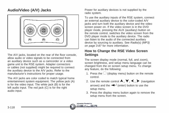
Audio/Video (A/V) Jacks
The A/V jacks, located on the rear of the floor console,allow audio or video signals to be connected froman auxiliary device such as a camcorder or a videogame unit to the RSE system. Adapter connectorsor cables (not supplied) might be required to connectthe auxiliary device to the A/V jacks. Refer to themanufacturer’s instructions for proper usage.
The A/V jacks are color coded to match typical homeentertainment system equipment. The yellow jack (A)is for the video input. The white jack (B) is for theleft audio input. The red jack (C) is for the rightaudio input.
Power for auxiliary devices is not supplied by theradio system.
To use the auxiliary inputs of the RSE system, connectan external auxiliary device to the color-coded A/Vjacks and turn both the auxiliary device and the videoscreen power on. If the video screen is in the DVDplayer mode, pressing the AUX (auxiliary) button onthe remote control, switches the video screen from theDVD player mode to the auxiliary device. The radiocan listen to the audio of the connected auxiliarydevice by sourcing to auxiliary. See Radio(s) (MP3)on page 3-87 for more information.
How to Change the RSE Video ScreenSettingsThe screen display mode (normal, full, and zoom),screen brightness, and setup menu language can bechanged from the on screen setup menu. To changeany feature, do the following:
1. Press the z (display menu) button on the remotecontrol.
2. Use the remote control n, q, p, o (navigationarrows) and the r (enter) button to use thesetup menu.
3. Press the display menu button again to remove thesetup menu from the screen.
3-118
Information Provided by:

Audio OutputAudio from the DVD player or auxiliary inputs can beheard through the following possible sources:
• Wireless Headphones• Vehicle Speakers• Vehicle wired headphone jacks on the rear seat
audio system, if your vehicle has this feature.
The RSE system always transmits the audio signal tothe wireless headphones, if there is audio available.See “Headphones” earlier in this section for moreinformation.
The DVD player is capable of outputting audio to thewired headphone jacks on the RSA system, if yourvehicle has this feature. The DVD player can beselected as an audio source on the RSA system.See Rear Seat Audio (RSA) on page 3-125 for moreinformation.
When a device is connected to the A/V jacks, or theradio’s auxiliary input jack, if your vehicle has thisfeature, the rear seat passengers are able to hearaudio from the auxiliary device through the wirelessor wired headphones. The front seat passengersare able to listen to playback from this device throughthe vehicle speakers by selecting AUX as the sourceon the radio.
Video ScreenThe video screen is located in the overhead console.
To use the video screen, do the following:
1. Push the release button located on the overheadconsole.
2. Move the screen to the desired position.
When the video screen is not in use, push it up intoits locked position.
If a DVD is playing and the screen is raised to itslocked position, the screen remains on; this is normal,and the DVD continues to play through the previousaudio source. Use the remote control Pbuttonor Z the disc to turn off the screen.
The overhead console contains the infrared receiversfor the wireless headphones and the infrared receiversfor the remote control. They are located at the rearof the console.
Notice: Avoid directly touching the video screen,as damage may occur. See “Cleaning the VideoScreen” later in this section for more information.
3-119
Information Provided by:

Remote ControlTo use the remote control, aim it at the transmitterwindow at the rear of the overhead console and pressthe desired button. Direct sunlight or very bright lightcould affect the ability of the RSE transmitter to receivesignals from the remote control. If the remote controldoes not seem to be working, the batteries might needto be replaced. See “Battery Replacement” later inthis section. Objects blocking the line of sight couldalso affect the function of the remote control.
If a CD or DVD is in the Radio DVD slot, the remotecontrol O button can be used to turn on the videoscreen display and start the disc. The radio can alsoturn on the video screen display. See Radio(s) (MP3)on page 3-87 for more information.
Notice: Storing the remote control in a hot areaor in direct sunlight can damage it, and the repairswill not be covered by your warranty. Storagein extreme cold can weaken the batteries. Keep theremote control stored in a cool, dry place.
Remote Control Buttons
O(Power): Press to turn the video screen on and off.
P (Illumination): Press to turn the remote controlbacklight on. The backlight automatically times out afterseven to ten seconds if no other button is pressedwhile the backlight is on.
v (Title): Press to return the DVD to the main menuof the DVD. This function could vary for each disc.
3-120
Information Provided by:
y (Main Menu): Press to access the DVD menu. TheDVD menu is different on every DVD. Use the navigationarrows to move the cursor around the DVD menu.After making a selection press the enter button. Thisbutton only operates when using a DVD.
n, q, p, o (Menu Navigation Arrows): Use thearrow buttons to navigate through a menu.
r (Enter): Press to select the choice that ishighlighted in any menu.
z (Display Menu): Press to adjust the brightness,screen display mode (normal, full, or zoom), and displaythe language menu.
q (Return): Press to exit the current active menuand return to the previous menu. This button operatesonly when the display menu or a DVD menu is active.
c (Stop): Press to stop playing, rewinding, orfast forwarding a DVD. Press twice to return to thebeginning of the DVD.
s (Play/Pause): Press to start playing a DVD.Press while a DVD is playing to pause it. Press again tocontinue playing the DVD.
When the DVD is playing, depending on the radio,you might be able to do slow play by pressing theplay/pause button then pressing the [ (fast forward)button. The DVD continues playing in a slow playmode. You could also, depending on the radio, performreverse slow play by pressing the play/pause buttonand then pressing the fast forward button. To cancelslow play mode, press the play/pause button.
t (Previous Track/Chapter): Press to return to thestart of the current track or chapter. Press again to go tothe previous track or chapter. This button might notwork when the DVD is playing the copyright informationor the previews.
u (Next Track/Chapter): Press to go to the beginningof the next chapter or track. This button might notwork when the DVD is playing the copyright informationor the previews.
r(Fast Reverse): Press to quickly reverse theDVD or CD. To stop fast reversing a DVD video, pressthe play/pause button. To stop fast reversing a DVDaudio or CD, release the fast reverse button. This buttonmight not work when the DVD is playing the copyrightinformation or the previews.
3-121
Information Provided by:

[ (Fast Forward): Press to fast forward the DVD orCD. To stop fast forwarding a DVD video, press theplay/pause button. To stop fast forwarding a DVD audioor CD, release the fast forward button. This buttonmight not work when the DVD is playing the copyrightinformation or the previews.
e(Audio): Press to change audio tracks on DVDs thathave this feature when the DVD is playing. The formatand content of this function vary for each disc.
{ (Subtitles): Press to turn ON/OFF subtitles and tomove through subtitle options when a DVD is playing.The format and content of this function vary foreach disc.
AUX (Auxiliary): Press to switch the system betweenthe DVD player and an auxiliary source.
d (Camera): Press to change camera angles on DVDsthat have this feature when a DVD is playing. The formatand content of this function vary for each disc.
1 through 0 (Numeric Keypad): The numeric keypadprovides the capability of direct chapter or tracknumber selection.
\ (Clear): Press within three seconds after enteringa numeric selection, to clear all numerical inputs.
} 10 (Double Digit Entries): Press to select chapteror track numbers greater than nine. Press this buttonbefore entering the number.
If the remote control becomes lost or damaged, a newuniversal remote control can be purchased. If thishappens, make sure the universal remote control usesa code set of Toshiba®.
Battery ReplacementTo change the remote control batteries, do the following:
1. Slide the rear cover back, on the remote control.
2. Replace the two batteries in the compartment.Make sure that they are installed correctly,using the diagram on the inside of the batterycompartment.
3. Replace the battery cover.
If the remote control is to be stored for a long periodof time, remove the batteries and keep them in a cool,dry place.
3-122
Information Provided by:

Problem Recommended ActionNo power. The ignition might not be
turned ON/RUN or inACC/ACCESSORY.
The picture does not fillthe screen. There areblack borders on thetop and bottom or onboth sides or it looksstretched out.
Check the display modesettings in the setupmenu by pressing thedisplay menu button onthe remote control.
In auxiliary mode, thepicture moves or scrolls.
Check the auxiliaryinput connections atboth devices.
The remote controldoes not work.
Check to make sure thereis no obstruction betweenthe remote control andthe transmitter window.Check the batteries tomake sure they arenot dead or installedincorrectly.
After stopping the player,I push Play but sometimesthe DVD starts whereI left off and sometimesat the beginning.
If the stop button waspressed one time, theDVD player resumesplaying where the DVDwas stopped. If the stopbutton was pressedtwo times the DVD playerbegins to play from thebeginning of the DVD.
Problem Recommended ActionThe auxiliary sourceis running but there isno picture or sound.
Check that the RSEvideo screen is in theauxiliary source mode.Check the auxiliaryinput connections atboth devices.
Sometimes the wirelessheadphone audio cutsout or buzzes.
Check for obstructions,low batteries, receptionrange, and interferencefrom cellular telephonetowers or by usingyour cellular telephonein the vehicle.Check that theheadphones are oncorrectly using theL (left) and R (right)on the headphones.
I lost the remote and/orthe headphones.
See your dealer/retailerfor assistance.
The DVD is playing,but there is no pictureor sound.
Check that the RSEvideo screen is sourcedto the DVD player.
3-123
Information Provided by:

DVD Display Error MessagesThe DVD display error message depends on whichradio you have. The video screen might displayone of the following:
Disc Load/Eject Error: This message displays whenthere are disc load or eject problems.
Disc Format Error: This message displays, if thedisc is inserted with the disc label wrong side up,or if the disc is damaged.
Disc Region Error: This message displays, if thedisc is not from a correct region.
No Disc Inserted: This message displays, if no discis present when the Z EJECT button is pressedon the radio.
DVD DistortionVideo distortion can occur when operating cellularphones, scanners, CB radios, Global PositionSystems (GPS)*, two-way radios, mobile fax,or walkie talkies.
It might be necessary to turn off the DVD player whenoperating one of these devices in or near the vehicle.
*Excludes the OnStar® System.
Cleaning the RSE Overhead ConsoleWhen cleaning the RSE overhead console surface,use only a clean cloth dampened with clean water.
Cleaning the Video ScreenUse only a clean cloth dampened with clean water.Use care when directly touching or cleaning the screen,as damage could result.
3-124
Information Provided by:

Rear Seat Audio (RSA)This feature allows rear seat passengers to listen to andcontrol any of the music sources: radio, CDs, DVDs,or other auxiliary sources. However, the rear seatpassengers can only control the music sources the frontseat passengers are not listening to (except on someradios where dual control is allowed). For example, rearseat passengers can control a CD and listen to it throughthe headphones, while the driver listens to the radiothrough the front speakers. The rear seat passengershave control of the volume for each set of headphones.
You can operate the RSA functions even when themain radio is off. The front audio system will displaythe headphone icon when the RSA is on, and willdisappear from the display when it is off.
Audio can be heard through wired headphones(not included) plugged into the jacks on the RSA.If your vehicle has this feature, audio can also beheard on Channel 2 of the wireless headphones.
The audio system mutes the rear speakers when theRSA audio is active through the headphones.
To listen to an iPod or portable audio device throughthe RSA, attach the iPod or portable audio device tothe front auxiliary input (if available), located on thefront audio system. Turn the iPod on, then choose thefront auxiliary input with the RSA SRCE button.
P(Power): Press this button to turn the RSA on or off.
Volume: Turn the knob to increase or to decreasethe volume of the wired headphones. The left knobcontrols the left headphones and the right knob controlsthe right headphones.
SRCE (Source): Press this button to switch betweenthe radio (AM/FM), XM™ (if equipped), CD, and ifyour vehicle has these features, DVD, front auxiliary,and rear auxiliary.
3-125
Information Provided by:

©¨ (Seek): When listening to FM, AM, or XM™(if equipped), press either the seek arrows to go to theprevious or to the next station or channels and staythere. This function is inactive, with some radios, if thefront seat passengers are listening to the radio.
Press and hold either seek arrow until the displayflashes, to tune to an individual station. The displaystops flashing after the buttons have not been pushedfor more than two seconds. This function is inactive,with some radios, if the front seat passengers arelistening to the radio.
While listening to a disc, press the right seek arrow togo to the next track or chapter on the disc. Press the leftseek arrow to go back to the start of the current trackor chapter (if more than ten seconds have played). Thisfunction is inactive, with some radios, if the front seatpassengers are listening to the disc.
When a DVD video menu is being displayed, presseither seek arrow to perform a cursor up or down onthe menu. Hold either seek arrow to perform a cursorleft or right on the menu.
PROG (Program): Press this button to go to thenext preset radio station or channel set on the mainradio. This function is inactive, with some radios, if thefront seat passengers are listening to the radio.
When a CD or DVD audio disc is playing, press thisbutton to go to the beginning of the CD or DVD audio.This function is inactive, with some radios, if thefront seat passengers are listening to the disc.
When a disc is playing in the CD or DVD changer,press this button to select the next disc, if multiple discsare loaded. This function is inactive, with some radios,if the front seat passengers are listening to the disc.
When a DVD video menu is being displayed, pressthe PROG button to perform the menu function, enter.
3-126
Information Provided by:

Rear Audio Controller (RAC)
Your vehicle may have the Rear Audio Controller (RAC).With RAC you can control certain radio functions.
xw (Next/Previous): Press the down or up arrowsto go to the next or to the previous radio stationstored as a favorite.
When a CD/DVD is playing, press the down or uparrows to go to the next or previous track or chapter.
©SEEK ¨: Press the SEEK arrows to go to theprevious or to the next radio station while in AM, FM,or XM™ (if equipped). Press the SEEK arrows to goto the previous or to the next track or chapter whilesourced to a CD or DVD slot.
SRCE (Source): Press this button to switch betweenthe radio (AM, FM), XM™ (if equipped), CD, and if yourvehicle has these features, DVD, front auxiliary, andrear auxiliary.
> (Mute): Press this button to silence the system.Press this button again, or any other radio button,to turn the sound on.
+ / − x (Volume): Press the plus or minus volumebuttons to increase or to decrease the volume.
Theft-Deterrent FeatureTHEFTLOCK® is designed to discourage theft ofyour vehicle’s radio. The feature works automaticallyby learning a portion of the Vehicle IdentificationNumber (VIN). If the radio is moved to a differentvehicle, it does not operate and LOC, LOCK, orLOCKED could display.
With THEFTLOCK® activated, the radio does notoperate if stolen.
3-127
Information Provided by:

Audio Steering Wheel Controls
Vehicles with audiosteering wheel controlscould differ depending onyour vehicle’s options.Some audio controlscan be adjusted at thesteering wheel. Theyinclude the following:
xw (Next/Previous): Press the down or up arrowto go to the next or to the previous radio station storedas a favorite.
When a CD/DVD is playing, press either arrow to goto the next or previous track or chapter.
g (Mute/Voice Recognition): Press and releasethis button to silence the vehicle speakers only.The audio of the wireless and wired headphones,if your vehicle has these features, does not mute.Press and release this button again, to turn the sound on.
If your vehicle has the navigation system, press and holdthis button for longer than one second to initiate voicerecognition. See “Voice Recognition” in the NavigationSystem manual for more information.
If your vehicle has OnStar®, press and hold this buttonfor longer than one second to interact with the OnStar®
system. If your vehicle also has the navigation system,press and hold this button for longer than one secondto initiate voice recognition and say “OnStar” to enterOnStar® mode. See the OnStar® System on page 2-47in this manual for more information.
SRCE (Source): Press this button to switch betweenthe radio (AM, FM), XM™ (if equipped), CD, and if yourvehicle has these features, DVD, front auxiliary, andrear auxiliary.
+ e − e (Volume): Press the plus or minus volumebutton to increase or to decrease the radio volume.
¨(Seek): Press the seek arrow to go to the nextradio station while in AM, FM, or XM™ (if equipped).Press the seek arrow to go to the next track or chapterwhile sourced to the CD or DVD slot.
3-128
Information Provided by:

Radio ReceptionFrequency interference and static can occur duringnormal radio reception if items such as cell phonechargers, vehicle convenience accessories, and externalelectronic devices are plugged into the accessorypower outlet. If there is interference or static, unplugthe item from the accessory power outlet.
AMThe range for most AM stations is greater than forFM, especially at night. The longer range can causestation frequencies to interfere with each other.For better radio reception, most AM radio stationsboost the power levels during the day, and then reducethese levels during the night. Static can also occurwhen things like storms and power lines interferewith radio reception. When this happens, try reducingthe treble on your radio.
FM StereoFM stereo gives the best sound, but FM signals onlyreach about 10 to 40 miles (16 to 65 km). Tall buildingsor hills can interfere with FM signals, causing thesound to fade in and out.
XM™ Satellite Radio ServiceXM™ Satellite Radio Service gives digital radioreception from coast-to-coast in the 48 contiguousUnited States, and in Canada. Just as with FM,tall buildings or hills can interfere with satellite radiosignals, causing the sound to fade in and out. Inaddition, traveling or standing under heavy foliage,bridges, garages, or through tunnels could cause lossof the XM signal for a period of time. The radio maydisplay NO XM SIGNAL to indicate interference.
Multi-Band AntennaThe multi-band antenna is located on the roof of yourvehicle. This type of antenna is used with the AM/FMradio, as well as OnStar® and the XM™ Satellite RadioService System, if your vehicle has these features.Keep this antenna clear of snow and ice build up forclear radio reception. If your vehicle has a sunroof,the performance of the radio system may be affected ifthe sunroof is open. Loading items onto the roof ofyour vehicle can interfere with the performance of theradio system and, if your vehicle has this feature,OnStar®. Make sure the multi-band antenna is notobstructed.
3-129
Information Provided by:

✍ NOTES
3-130
Information Provided by:

Your Driving, the Road, and Your Vehicle ..........4-2Defensive Driving ...........................................4-2Drunk Driving .................................................4-2Control of a Vehicle ........................................4-3Braking .........................................................4-4Antilock Brake System (ABS) ...........................4-5Braking in Emergencies ...................................4-6StabiliTrak® System ........................................4-6All-Wheel Drive (AWD) System .........................4-9Steering ........................................................4-9Off-Road Recovery .......................................4-11Passing .......................................................4-11Loss of Control .............................................4-12Driving at Night ............................................4-13
Driving in Rain and on Wet Roads ..................4-14Before Leaving on a Long Trip .......................4-15Highway Hypnosis ........................................4-15Hill and Mountain Roads ................................4-16Winter Driving ..............................................4-17If Your Vehicle is Stuck in Sand, Mud, Ice,
or Snow ...................................................4-20Rocking Your Vehicle to Get It Out .................4-21Loading Your Vehicle ....................................4-21
Towing ..........................................................4-26Towing Your Vehicle .....................................4-26Recreational Vehicle Towing ...........................4-26Towing a Trailer ...........................................4-30
Section 4 Driving Your Vehicle
4-1
Information Provided by:

Your Driving, the Road, andYour Vehicle
Defensive DrivingDefensive driving means “always expect theunexpected.” The first step in driving defensively is towear your safety belt — See Safety Belts: They Are forEveryone on page 1-16.
{CAUTION:
Assume that other road users (pedestrians,bicyclists, and other drivers) are going to becareless and make mistakes. Anticipate whatthey might do and be ready. In addition:
• Allow enough following distance betweenyou and the driver in front of you.
• Focus on the task of driving.
Driver distraction can cause collisionsresulting in injury or possible death. Thesesimple defensive driving techniques couldsave your life.
Drunk Driving
{CAUTION:
Drinking and then driving is very dangerous.Your reflexes, perceptions, attentiveness, andjudgment can be affected by even a smallamount of alcohol. You can have a serious — oreven fatal — collision if you drive after drinking.Do not drink and drive or ride with a driver whohas been drinking. Ride home in a cab; or if youare with a group, designate a driver who will notdrink.
4-2
Information Provided by:

Death and injury associated with drinking and driving isa global tragedy.
Alcohol affects four things that anyone needs to drive avehicle: judgment, muscular coordination, vision, andattentiveness.
Police records show that almost 40 percent of all motorvehicle-related deaths involve alcohol. In most cases,these deaths are the result of someone who wasdrinking and driving. In recent years, more than17,000 annual motor vehicle-related deaths have beenassociated with the use of alcohol, with about250,000 people injured.
For persons under 21, it is against the law in every U.S.state to drink alcohol. There are good medical,psychological, and developmental reasons forthese laws.
The obvious way to eliminate the leading highwaysafety problem is for people never to drink alcohol andthen drive.
Medical research shows that alcohol in a person’ssystem can make crash injuries worse, especiallyinjuries to the brain, spinal cord, or heart. This meansthat when anyone who has been drinking — driveror passenger — is in a crash, that person’s chance ofbeing killed or permanently disabled is higher than if theperson had not been drinking.
Control of a VehicleThe following three systems help to control your vehiclewhile driving — brakes, steering, and accelerator. Attimes, as when driving on snow or ice, it is easy to askmore of those control systems than the tires androad can provide. Meaning, you can lose control of yourvehicle. See StabiliTrak® System on page 4-6.
Adding non-dealer/non-retailer accessories can affectyour vehicle’s performance. See Accessories andModifications on page 5-4.
4-3
Information Provided by:

BrakingSee Brake System Warning Light on page 3-47.
Braking action involves perception time and reactiontime. First, you have to decide to push on the brakepedal. That is perception time. Then you have to bringup your foot and do it. That is reaction time.
Average reaction time is about three-fourths of asecond. But that is only an average. It might be lesswith one driver and as long as two or three seconds ormore with another. Age, physical condition, alertness,coordination, and eyesight all play a part. So do alcohol,drugs, and frustration. But even in three-fourths of asecond, a vehicle moving at 60 mph (100 km/h) travels66 feet (20 m). That could be a lot of distance in anemergency, so keeping enough space betweenyour vehicle and others is important.
And, of course, actual stopping distances vary greatlywith the surface of the road, whether it is pavementor gravel; the condition of the road, whether it iswet, dry, or icy; tire tread; the condition of the brakes;the weight of the vehicle; and the amount of brake forceapplied.
Avoid needless heavy braking. Some people drivein spurts — heavy acceleration followed by heavybraking — rather than keeping pace with traffic. This is amistake. The brakes might not have time to cool betweenhard stops. The brakes will wear out much faster if you doa lot of heavy braking. If you keep pace with the trafficand allow realistic following distances, you will eliminate alot of unnecessary braking. That means better brakingand longer brake life.
If your vehicle’s engine ever stops while you are driving,brake normally but do not pump the brakes. If you do,the pedal could get harder to push down. If theengine stops, you will still have some power brakeassist. But you will use it when you brake. Once thepower assist is used up, it can take longer to stop andthe brake pedal will be harder to push.
Adding non-dealer/non-retailer accessories can affectyour vehicle’s performance. See Accessories andModifications on page 5-4.
4-4
Information Provided by:

Antilock Brake System (ABS)Your vehicle has the Antilock Brake System (ABS), anadvanced electronic braking system that will helpprevent a braking skid.
When you start the engine and begin to drive away,ABS will check itself. You might hear a momentarymotor or clicking noise while this test is going on, andyou might even notice that the brake pedal movesa little. This is normal.
If there is a problem withABS, this warning light willstay on. See AntilockBrake System WarningLight on page 3-48.
Let us say the road is wet and you are driving safely.Suddenly, an animal jumps out in front of you. You slamon the brakes and continue braking. Here is whathappens with ABS:
A computer senses that wheels are slowing down. Ifone of the wheels is about to stop rolling, the computerwill separately work the brakes at each wheel.
ABS can change the brake pressure faster than anydriver could. The computer is programmed to make themost of available tire and road conditions. This canhelp you steer around the obstacle while braking hard.
As you brake, the computer keeps receiving updateson wheel speed and controls braking pressureaccordingly.
Remember: ABS does not change the time you need toget your foot up to the brake pedal or always decreasestopping distance. If you get too close to the vehicle infront of you, you will not have time to apply the brakes ifthat vehicle suddenly slows or stops. Always leaveenough room up ahead to stop, even though youhave ABS.
Using ABSDo not pump the brakes. Just hold the brake pedaldown firmly and let antilock work for you. You might hearthe antilock pump or motor operate, and feel thebrake pedal pulsate, but this is normal.
4-5
Information Provided by:

Braking in EmergenciesWith ABS, you can steer and brake at the same time. Inmany emergencies, steering can help you more thaneven the very best braking.
Panic Brake AssistYour vehicle has a Panic Brake Assist feature designedto assist the driver in stopping or decreasing vehiclespeed in emergency driving conditions. This feature usesthe Electronic Stability Control (ESC) hydraulic brakecontrol module to supplement the power brake systemunder conditions where the driver has quickly andforcefully applied the brake pedal in an attempt to quicklystop or slow down the vehicle. The ESC hydraulic brakecontrol module increases brake pressure at each cornerof the vehicle until the Antilock Brake System (ABS)activates. Minor brake pedal pulsations or pedalmovement during this time is normal and the drivershould continue to apply the brake pedal as the drivingsituation dictates. The Panic Brake Assist feature willautomatically disengage when the brake pedal isreleased or brake pedal pressure is quickly decreased.
StabiliTrak® SystemYour vehicle has the StabiliTrak® system whichcombines antilock brake, traction and stability controlsystems and helps the driver maintain directional controlof the vehicle in most driving conditions.
When you first start your vehicle and begin to driveaway, the system performs several diagnostic checks toensure there are no problems. You may hear or feelthe system working. This is normal and does not meanthere is a problem with your vehicle. The systemshould initialize before the vehicle reaches 20 mph(32 km/h). In some cases, it may take approximatelytwo miles of driving before the system initializes.
If the system fails to turn on or activate, the StabiliTrak®
light along with one of the following messages will bedisplayed on the Driver Information Center (DIC):TRACTION CONTROL OFF, SERVICE TRACTIONCONTROL, SERVICE STABILITRAK. If you see theseconditions, turn the vehicle off, wait 15 seconds, and thenturn it back on again to reset the system. If any of thesemessages still appear on the Driver Information Center(DIC), your vehicle should be taken in for service. Formore information on the DIC messages, see DriverInformation Center (DIC) on page 3-57.
4-6
Information Provided by:

The StabiliTrak® light willflash on the instrumentpanel cluster whenthe system is both on andactivated.
You may also feel or hear the system working; this isnormal.
The traction control disablebutton is located on theinstrument panel below theclimate controls.
The traction control part of StabiliTrak® can be turnedoff by pressing and releasing the traction control disablebutton.
Traction control can be turned on by pressing andreleasing the traction control disable button if notautomatically shut off for any other reason.
When the traction control system is turned off, theStabiliTrak® light and the appropriate traction control offmessage will be displayed on the DIC to warn thedriver. Your vehicle will still have brake-traction controlwhen traction control is off, but will not be able touse the engine speed management system. See“Traction Control Operation” next for more information.
When the traction control system has been turnedoff, you may still hear system noises as a result of thebrake-traction control coming on.
It is recommended to leave the system on for normaldriving conditions, but it may be necessary to turnthe system off if your vehicle is stuck in sand, mud, iceor snow, and you want to “rock” your vehicle toattempt to free it. It may also be necessary to turn offthe system when driving in extreme off-road conditionswhere high wheel spin is required. See If YourVehicle is Stuck in Sand, Mud, Ice, or Snow onpage 4-20.
4-7
Information Provided by:

Traction Control OperationThe traction control system is part of the StabiliTrak®
system. Traction control limits wheel spin by reducingengine power to the wheels (engine speedmanagement) and by applying brakes to each individualwheel (brake-traction control) as necessary.
The traction control system is enabled automaticallywhen you start your vehicle. It will activate and theStabiliTrak® light will flash if it senses that any of thewheels are spinning or beginning to lose traction whiledriving. If you turn off traction control, only thebrake-traction control portion of traction control willwork. The engine speed management will be disabled.In this mode, engine power is not reduced automaticallyand the driven wheels can spin more freely. This cancause the brake-traction control to activate constantly.
Notice: If you allow the wheel(s) of one axle to spinexcessively while the StabiliTrak®, ABS and brakewarning lights and the SERVICE STABILITRAKmessage are displayed, you could damage thetransfer case. The repairs would not be covered byyour warranty. Reduce engine power and do notspin the wheel(s) excessively while these lights andthis message are displayed.
The traction control system may activate on dry orrough roads or under conditions such as heavyacceleration while turning or abrupt upshifts/downshiftsof the transmission. When this happens, you maynotice a reduction in acceleration, or may hear a noiseor vibration. This is normal.
If your vehicle is in cruise control when the systemactivates, the StabiliTrak® light will flash and the cruisecontrol will automatically disengage. When roadconditions allow you to use cruise again, you mayre-engage the cruise control. See Cruise Control onpage 3-12.
StabiliTrak® may also turn off automatically if itdetermines that a problem exists with the system. If theproblem does not clear itself after restarting thevehicle, you should see your dealer/retailer for service.
4-8
Information Provided by:

All-Wheel Drive (AWD) SystemIf your vehicle has this feature, engine power is sent to allfour wheels when extra traction is needed. This is likefour-wheel drive, but there is no separate lever or switchto engage or disengage the front axle. It is fully automatic,and adjusts itself as needed for road conditions.
When using a compact spare tire on your AWDequipped vehicle, the AWD system automatically detectsthe presence of the compact spare and the AWD isdisabled. To restore the AWD operation and preventexcessive wear on the clutch in your AWD system,replace the compact spare with a full-size tire as soonas possible. See Compact Spare Tire on page 5-88for more information.
Steering
Power SteeringIf you lose power steering assist because the enginestops or the system is not functioning, you can steer butit will take much more effort.
Variable Effort SteeringIf your vehicle has this steering system, the systemcontinuously adjusts the effort you feel when steering atall vehicle speeds. It provides ease when parking,yet a firm, solid feel at highway speeds.
Steering TipsIt is important to take curves at a reasonable speed.
A lot of the “driver lost control” accidents mentioned onthe news happen on curves. Here is why:
Experienced driver or beginner, each of us is subject tothe same laws of physics when driving on curves.The traction of the tires against the road surface makesit possible for the vehicle to change its path whenyou turn the front wheels. If there is no traction, inertiawill keep the vehicle going in the same direction. Ifyou have ever tried to steer a vehicle on wet ice, youwill understand this.
The traction you can get in a curve depends on thecondition of the tires and the road surface, the angle atwhich the curve is banked, and your speed. Whileyou are in a curve, speed is the one factor youcan control.
Suppose you are steering through a sharp curve.Then you suddenly accelerate. Both controlsystems — steering and acceleration — have to do theirwork where the tires meet the road. Adding thesudden acceleration can demand too much of thoseplaces. You can lose control. See StabiliTrak® Systemon page 4-6.
What should you do if this ever happens? Ease up onthe accelerator pedal, steer the vehicle the way youwant it to go, and slow down.
4-9
Information Provided by:

Speed limit signs near curves warn that you shouldadjust your speed. Of course, the posted speedsare based on good weather and road conditions. Underless favorable conditions you will want to go slower.
If you need to reduce your speed as you approacha curve, do it before you enter the curve, while the frontwheels are straight ahead.
Try to adjust your speed so you can drive through thecurve. Maintain a reasonable, steady speed. Waitto accelerate until you are out of the curve, and thenaccelerate gently into the straightaway.
Adding non-dealer/non-retailer accessories can affectyour vehicle’s performance. See Accessories andModifications on page 5-4.
Steering in EmergenciesThere are times when steering can be more effective thanbraking. For example, you come over a hill and find atruck stopped in your lane, or a car suddenly pulls outfrom nowhere, or a child darts out from between parkedcars and stops right in front of you. You can avoid theseproblems by braking — if you can stop in time. Butsometimes you cannot; there is not room. That is the timefor evasive action — steering around the problem.
Your vehicle can perform very well in emergencies likethese. First, apply the brakes. See Braking onpage 4-4. It is better to remove as much speed as you
can from a possible collision. Then steer around theproblem, to the left or right depending on the spaceavailable.
An emergency like this requires close attention and aquick decision. If you are holding the steering wheel atthe recommended 9 and 3 o’clock positions, youcan turn it a full 180 degrees very quickly withoutremoving either hand. But you have to act fast, steerquickly, and just as quickly straighten the wheelonce you have avoided the object.
The fact that such emergency situations are alwayspossible is a good reason to practice defensive drivingat all times and wear safety belts properly.
4-10
Information Provided by:

Off-Road RecoveryYou may find that your vehicle’s right wheels havedropped off the edge of a road onto the shoulder whileyou are driving.
If the level of the shoulder is only slightly below thepavement, recovery should be fairly easy. Ease off theaccelerator and then, if there is nothing in the way,steer so that your vehicle straddles the edge ofthe pavement. You can turn the steering wheel up toone-quarter turn until the right front tire contactsthe pavement edge. Then turn the steering wheel to gostraight down the roadway.
PassingPassing another vehicle on a two-lane road can bedangerous. To reduce the risk of danger while passing,we suggest the following tips:
• Look down the road, to the sides, and to crossroadsfor situations that might affect a successful pass. Ifin doubt, wait.
• Watch for traffic signs, pavement markings, andlines that could indicate a turn or an intersection.Never cross a solid or double-solid line on your sideof the lane.
• Do not get too close to the vehicle you want topass. Doing so can reduce your visibility.
• Wait your turn to pass a slow vehicle.
• When you are being passed, ease to the right.
4-11
Information Provided by:

Loss of ControlLet us review what driving experts say about whathappens when the three control systems — brakes,steering, and acceleration — do not have enough frictionwhere the tires meet the road to do what the driver hasasked.
In any emergency, do not give up. Keep trying to steerand constantly seek an escape route or area of lessdanger.
SkiddingIn a skid, a driver can lose control of the vehicle.Defensive drivers avoid most skids by taking reasonablecare suited to existing conditions, and by not overdrivingthose conditions. But skids are always possible.
The three types of skids correspond to your vehicle’sthree control systems. In the braking skid, the wheels arenot rolling. In the steering or cornering skid, too muchspeed or steering in a curve causes tires to slip and losecornering force. And in the acceleration skid, too muchthrottle causes the driving wheels to spin.
A cornering skid is best handled by easing your foot offthe accelerator pedal.
If your vehicle starts to slide, ease your foot off theaccelerator pedal and quickly steer the way you wantthe vehicle to go. If you start steering quickly enough,your vehicle may straighten out. Always be readyfor a second skid if it occurs.
Of course, traction is reduced when water, snow, ice,gravel, or other material is on the road. For safety, youwant to slow down and adjust your driving to theseconditions. It is important to slow down on slipperysurfaces because stopping distance is longer andvehicle control more limited.
While driving on a surface with reduced traction, try yourbest to avoid sudden steering, acceleration, or braking,including reducing vehicle speed by shifting to a lowergear. Any sudden changes could cause the tires to slide.You might not realize the surface is slippery untilyour vehicle is skidding. Learn to recognize warningclues — such as enough water, ice, or packed snow onthe road to make a mirrored surface — and slow downwhen you have any doubt.
Remember: Any Antilock Brake System (ABS) helpsavoid only the braking skid.
4-12
Information Provided by:

Driving at NightNight driving is more dangerous than day drivingbecause some drivers are likely to be impaired — byalcohol or drugs, with night vision problems, or byfatigue.
Night driving tips include:
• Drive defensively.
• Do not drink and drive.
• Reduce headlamp glare by adjusting the insiderearview mirror.
• Slow down and keep more space between you andother vehicles because your headlamps can onlylight up so much road ahead.
• Watch for animals.
• When tired, pull off the road.
• Do not wear sunglasses.
• Avoid staring directly into approaching headlamps.
• Keep the windshield and all glass on your vehicleclean — inside and out.
• Keep your eyes moving, especially during turns orcurves.
No one can see as well at night as in the daytime. But,as we get older, these differences increase. A50-year-old driver might need at least twice as muchlight to see the same thing at night as a 20-year-old.
4-13
Information Provided by:

Driving in Rain and on Wet RoadsRain and wet roads can reduce vehicle tractionand affect your ability to stop and accelerate. Alwaysdrive slower in these types of driving conditionsand avoid driving through large puddles anddeep-standing or flowing water.
{CAUTION:
Wet brakes can cause crashes. They might notwork as well in a quick stop and could causepulling to one side. You could lose control ofthe vehicle.
After driving through a large puddle of wateror a car/vehicle wash, lightly apply the brakepedal until the brakes work normally.
Flowing or rushing water creates strongforces. Driving through flowing water couldcause your vehicle to be carried away. If thishappens, you and other vehicle occupantscould drown. Do not ignore police warningsand be very cautious about trying to drivethrough flowing water.
HydroplaningHydroplaning is dangerous. Water can build up underyour vehicle’s tires so they actually ride on thewater. This can happen if the road is wet enough andyou are going fast enough. When your vehicle ishydroplaning, it has little or no contact with the road.
There is no hard and fast rule about hydroplaning. Thebest advice is to slow down when the road is wet.
Other Rainy Weather TipsBesides slowing down, other wet weather driving tipsinclude:
• Allow extra following distance.
• Pass with caution.
• Keep windshield wiping equipment in good shape.
• Keep the windshield washer fluid reservoir filled.
• Have good tires with proper tread depth. See Tireson page 5-48.
4-14
Information Provided by:
Before Leaving on a Long TripTo prepare your vehicle for a long trip, consider havingit serviced by your dealer/retailer before departing.
Things to check on your own include:
• Windshield Washer Fluid: Reservoir full? Windowsclean — inside and outside?
• Wiper Blades: In good shape?
• Fuel, Engine Oil, Other Fluids: All levels checked?
• Lamps: Do they all work and are lenses clean?
• Tires: Are treads good? Are tires inflated torecommended pressure?
• Weather and Maps: Safe to travel? Haveup-to-date maps?
Highway HypnosisAlways be alert and pay attention to your surroundingswhile driving. If you become tired or sleepy, find asafe place to park your vehicle and rest.
Other driving tips include:
• Keep the vehicle well ventilated.
• Keep interior temperature cool.
• Keep your eyes moving — scan the road aheadand to the sides.
• Check the rearview mirror and vehicle instrumentsoften.
4-15
Information Provided by:

Hill and Mountain RoadsDriving on steep hills or through mountains is differentthan driving on flat or rolling terrain. Tips for drivingin these conditions include:
• Keep your vehicle serviced and in good shape.
• Check all fluid levels and brakes, tires, coolingsystem, and transmission.
• Going down steep or long hills, shift to a lower gear.
{CAUTION:
If you do not shift down, the brakes could getso hot that they would not work well. Youwould then have poor braking or even nonegoing down a hill. You could crash. Shift downto let the engine assist the brakes on a steepdownhill slope.
{CAUTION:
Coasting downhill in NEUTRAL (N) or with theignition off is dangerous. The brakes will haveto do all the work of slowing down and theycould get so hot that they would not work well.You would then have poor braking or evennone going down a hill. You could crash.Always have the engine running and yourvehicle in gear when you go downhill.
• Stay in your own lane. Do not swing wide or cutacross the center of the road. Drive at speedsthat let you stay in your own lane.
• Top of hills: Be alert — something could be in yourlane (stalled car, accident).
• Pay attention to special road signs (falling rocksarea, winding roads, long grades, passing orno-passing zones) and take appropriate action.
4-16
Information Provided by:

Winter DrivingHere are some tips for winter driving:
• Have your vehicle in good shape for winter.
• You might want to put winter emergency supplies inyour vehicle.
Include an ice scraper, a small brush or broom, asupply of windshield washer fluid, a rag, some winterouter clothing, a small shovel, a flashlight, a redcloth, and a couple of reflective warning triangles. And,if you will be driving under severe conditions, includea small bag of sand, a piece of old carpet, or a couple ofburlap bags to help provide traction. Be sure youproperly secure these items in your vehicle.
Also see Tires on page 5-48.
Driving on Snow or IceMost of the time, those places where the tires meet theroad probably have good traction.
However, if there is snow or ice between the tires andthe road, you can have a very slippery situation.You have a lot less traction, or grip, and need to bevery careful.
What is the worst time for this? Wet ice. Very cold snowor ice can be slick and hard to drive on. But wet icecan be even more trouble because it can offer the leasttraction of all. You can get wet ice when it is aboutfreezing, 32°F (0°C), and freezing rain begins to fall. Tryto avoid driving on wet ice until salt and sand crewscan get there.
Whatever the condition — smooth ice, packed, blowing,or loose snow — drive with caution.
4-17
Information Provided by:

StabiliTrak® improves your ability to accelerate whendriving on a slippery road. Even with StabiliTrak®, slowdown and adjust your driving to the road conditions.Under certain conditions, you might want to turnthe traction control part of the StabiliTrak® System off,such as when driving through deep snow and loosegravel, to help maintain vehicle motion at lower speeds.See StabiliTrak® System on page 4-6 and If YourVehicle is Stuck in Sand, Mud, Ice, or Snow onpage 4-20.
The Antilock Brake System (ABS) improves yourvehicle’s stability when you make a hard stop on aslippery road. Even though you have ABS, beginstopping sooner than you would on dry pavement. SeeAntilock Brake System (ABS) on page 4-5.
• Allow greater following distance on any slippery road.
• Watch for slippery spots. The road might be fine untilyou hit a spot that is covered with ice. On anotherwise clear road, ice patches can appear inshaded areas where the sun cannot reach, such asaround clumps of trees, behind buildings, or underbridges. Sometimes the surface of a curve or anoverpass can remain icy when the surrounding roadsare clear. If you see a patch of ice ahead of you,brake before you are on it. Try not to brake while youare actually on the ice, and avoid sudden steeringmaneuvers.
If You Are Caught in a BlizzardIf you are stopped by heavy snow, you could be in aserious situation. You should probably stay withyour vehicle unless you know for sure that you are nearhelp and you can hike through the snow. Here aresome things to do to summon help and keep yourselfand your passengers safe:
• Turn on the hazard warning flashers.
• Tie a red cloth to your vehicle to alert police thatyou have been stopped by the snow.
• Put on extra clothing or wrap a blanket around you.If you do not have blankets or extra clothing, makebody insulators from newspapers, burlap bags,rags, floor mats — anything you can wrap aroundyourself or tuck under your clothing to keep warm.
4-18
Information Provided by:

You can run the engine to keep warm, but be careful.
{CAUTION:
Snow can trap exhaust gases under yourvehicle. This can cause deadly CO (carbonmonoxide) gas to get inside. CO couldovercome you and kill you. You cannot see itor smell it, so you might not know it is in yourvehicle. Clear away snow from around thebase of your vehicle, especially any that isblocking the exhaust pipe. And check aroundagain from time to time to be sure snow doesnot collect there.
Open a window just a little on the side of thevehicle that is away from the wind. This willhelp keep CO out.
Run the engine only as long as you must. This saves fuel.When you run the engine, make it go a little faster thanjust idle. That is, push the accelerator slightly. This usesless fuel for the heat that you get and it keeps the batterycharged. You will need a well-charged battery to restartthe vehicle, and possibly for signaling later on with theheadlamps. Let the heater run for a while.
4-19
Information Provided by:

Then, shut the engine off and close the window almost allthe way to preserve the heat. Start the engine again andrepeat this only when you feel really uncomfortable fromthe cold. But do it as little as possible. Preserve the fuelas long as you can. To help keep warm, you can get outof the vehicle and do some fairly vigorous exercisesevery half hour or so until help comes.
If Your Vehicle is Stuck in Sand,Mud, Ice, or SnowSlowly and cautiously spin the wheels to free yourvehicle when stuck in sand, mud, ice, or snow. SeeRocking Your Vehicle to Get It Out on page 4-21.
If your vehicle has a traction system, it can often help tofree a stuck vehicle. Refer to your vehicle’s tractionsystem in the Index. If the stuck condition is too severefor the traction system to free the vehicle, turn thetraction system off and use the rocking method.
{CAUTION:
If you let your vehicle’s tires spin at highspeed, they can explode, and you or otherscould be injured. The vehicle can overheat,causing an engine compartment fire or otherdamage. Spin the wheels as little as possibleand avoid going above 35 mph (55 km/h) asshown on the speedometer.
For information about using tire chains on your vehicle,see Tire Chains on page 5-70.
4-20
Information Provided by:

Rocking Your Vehicle to Get It OutFirst, turn the steering wheel left and right to clearthe area around the front wheels. Turn the tractioncontrol part of the StabiliTrak® System off. SeeStabiliTrak® System on page 4-6. Then shift back andforth between REVERSE (R) and a forward gear,spinning the wheels as little as possible. To preventtransmission wear, wait until the wheels stop spinningbefore shifting gears. Release the accelerator pedalwhile you shift, and press lightly on the accelerator pedalwhen the transmission is in gear. By slowly spinningthe wheels in the forward and reverse directions, you willcause a rocking motion that could free your vehicle. Ifthat does not get your vehicle out after a few tries,it might need to be towed out. If your vehicle does needto be towed out, see Towing Your Vehicle onpage 4-26.
Loading Your VehicleIt is very important to know how much weight yourvehicle can carry. This weight is called thevehicle capacity weight and includes the weight ofall occupants, cargo, and all nonfactory-installedoptions. Two labels on your vehicle show howmuch weight it may properly carry, the Tire andLoading Information label and the Certification/Tirelabel.
{CAUTION:
Do not load your vehicle any heavier thanthe Gross Vehicle Weight Rating (GVWR),or either the maximum front or rear GrossAxle Weight Rating (GAWR). If you do,parts on your vehicle can break, and itcan change the way your vehicle handles.These could cause you to lose controland crash. Also, overloading can shortenthe life of your vehicle.
4-21
Information Provided by:

Tire and Loading Information Label
A vehicle specific Tire and Loading Informationlabel is attached to the center pillar (B-pillar) of yourvehicle. With the driver’s door open, you will find thelabel attached below the door lock post (striker).The tire and loading information label shows thenumber of occupant seating positions (A), and themaximum vehicle capacity weight (B) in kilogramsand pounds.
The Tire and Loading Information label also showsthe size of the original equipment tires (C) andthe recommended cold tire inflation pressures (D).
For more information on tires and inflation seeTires on page 5-48 and Inflation - Tire Pressure onpage 5-55.
There is also important loading information on thevehicle Certification/Tire label. It tells you theGross Vehicle Weight Rating (GVWR) andthe Gross Axle Weight Rating (GAWR) for thefront and rear axle. See “Certification/Tire Label”later in this section.
Steps for Determining Correct Load Limit1. Locate the statement “The combined weight of
occupants and cargo should never exceedXXX kg or XXX lbs” on your vehicle’s placard.
2. Determine the combined weight of the driverand passengers that will be riding in yourvehicle.
3. Subtract the combined weight of the driverand passengers from XXX kg or XXX lbs.
4. The resulting figure equals the availableamount of cargo and luggage load capacity.For example, if the “XXX” amount equals1400 lbs and there will be five 150 lbpassengers in your vehicle, the amount ofavailable cargo and luggage load capacity is650 lbs (1400 − 750 (5 x 150) = 650 lbs).
Example Label
4-22
Information Provided by:

5. Determine the combined weight of luggageand cargo being loaded on the vehicle. Thatweight may not safely exceed the availablecargo and luggage load capacity calculated inStep 4.
6. If your vehicle will be towing a trailer, the loadfrom your trailer will be transferred to yourvehicle. Consult this manual to determine howthis reduces the available cargo and luggageload capacity for your vehicle.
See Towing a Trailer on page 4-30 for importantinformation on towing a trailer, towing safety rules,and trailering tips.
Item Description Total
AVehicle CapacityWeight forExample 1 =
1,000 lbs(453 kg)
BSubtract OccupantWeight 150 lbs(68 kg) × 2 =
300 lbs (136 kg)
C Available Occupantand Cargo Weight = 700 lbs (317 kg)
Example 1
4-23
Information Provided by:

Item Description Total
AVehicle CapacityWeight forExample 2 =
1,000 lbs(453 kg)
BSubtract OccupantWeight 150 lbs(68 kg) × 5 =
750 lbs (340 kg)
C Available CargoWeight = 250 lbs (113 kg)
Item Description Total
AVehicle CapacityWeight forExample 3 =
1,000 lbs(453 kg)
BSubtract OccupantWeight 200 lbs(91 kg) × 5 =
1,000 lbs(453 kg)
C Available CargoWeight = 0 lbs (0 kg)
Refer to your vehicle’s tire and loading informationlabel for specific information about your vehicle’scapacity weight and seating positions. Thecombined weight of the driver, passengers, andcargo should never exceed your vehicle’s capacityweight.
Example 2 Example 3
4-24
Information Provided by:

Certification/Tire Label
A vehicle specific Certification/Tire label isattached to the rear edge of the driver’s door.
The label shows the gross weight capacity of yourvehicle. This is called the Gross Vehicle WeightRating (GVWR). The GVWR includes the weight ofthe vehicle, all occupants, fuel, and cargo.
The Certification/Tire label also tells you themaximum weights for the front and rear axles,called the Gross Axle Weight Rating (GAWR). Tofind out the actual loads on your front and rearaxles, you need to go to a weigh station and weighyour vehicle. Your dealer/retailer can help youwith this. Be sure to spread out your load equallyon both sides of the centerline.
Never exceed the GVWR for your vehicle or theGAWR for either the front or rear axle.
{CAUTION:
Do not load your vehicle any heavier thanthe Gross Vehicle Weight Rating (GVWR),or either the maximum front or rear GrossAxle Weight Rating (GAWR). If you do,parts on your vehicle can break, and itcan change the way your vehicle handles.These could cause you to lose controland crash. Also, overloading can shortenthe life of your vehicle.
Notice: Overloading your vehicle may causedamage. Repairs would not be covered by yourwarranty. Do not overload your vehicle.
4-25
Information Provided by:

If you put things inside your vehicle — likesuitcases, tools, packages, or anything else, theywill go as fast as the vehicle goes. If you haveto stop or turn quickly, or if there is a crash, theywill keep going.
{CAUTION:
Things you put inside your vehicle canstrike and injure people in a sudden stopor turn, or in a crash.
• Put things in the cargo area of yourvehicle. Try to spread the weightevenly.
• Never stack heavier things, likesuitcases, inside the vehicle so thatsome of them are above the tops ofthe seats.
• Do not leave an unsecured childrestraint in your vehicle.
• When you carry something inside thevehicle, secure it whenever you can.
• Do not leave a seat folded downunless you need to.
Towing
Towing Your VehicleConsult your dealer/retailer or a professional towingservice if you need to have your disabled vehicle towed.See Roadside Assistance Program on page 7-6.
If you want to tow your vehicle behind another vehiclefor recreational purposes (such as behind a motorhome),see “Recreational Vehicle Towing” following.
Recreational Vehicle TowingRecreational vehicle towing means towing your vehiclebehind another vehicle – such as behind a motorhome.The two most common types of recreational vehicletowing are known as “dinghy towing” (towing your vehiclewith all four wheels on the ground) and “dolly towing”(towing your vehicle with two wheels on the ground andtwo wheels up on a device known as a “dolly”).
With the proper preparation and equipment, manyvehicles can be towed in these ways. See “DinghyTowing” and “Dolly Towing” following in this section.
4-26
Information Provided by:

Here are some important things to consider before youdo recreational vehicle towing:
• What’s the towing capacity of the towing vehicle?Be sure you read the tow vehicle manufacturer’srecommendations.
• How far will you tow? Some vehicles haverestrictions on how far and how long they can tow.
• Do you have the proper towing equipment?See your dealer/retailer or trailering professional foradditional advice and equipment recommendations.
• Is your vehicle ready to be towed? Just as youwould prepare your vehicle for a long trip, you’llwant to make sure your vehicle is prepared to betowed. See Before Leaving on a Long Trip onpage 4-15.
Dinghy TowingIf you have a front-wheel-drive vehicle, it can be dinghytowed from the front. These vehicles may also betowed by putting the front wheels on a dolly. See “DollyTowing” later in this section.
If you have an all-wheel-drive vehicle, it can be dinghytowed from the front. You can also tow these vehiclesby placing them on a platform trailer with all four wheelsoff of the ground. These vehicles cannot be towedusing a dolly.
For vehicles being dinghy towed, the vehicle should berun at the beginning of each day and at each RVfuel stop for about five minutes. This will ensure properlubrication of transmission components. Re-connectthe vehicle’s battery to start the vehicle.
4-27
Information Provided by:

To tow your vehicle from the front with all four wheelson the ground:1. Position the vehicle to tow and then secure it.2. Turn the ignition to LOCK/OFF.
3. Set the parking brake.4. Turn the ignition to ACC/ACCESSORY.5. Shift your transmission to NEUTRAL (N).6. To prevent your battery from draining while the
vehicle is being towed, disconnect the vehicle’sbattery. Contact your dealer/retailer for moreinformation on the battery disconnection procedure.
7. Release the parking brake.
Notice: If you tow your vehicle without performingeach of the steps listed under “Dinghy Towing,”you could damage the automatic transmission. Besure to follow all steps of the dinghy towingprocedure prior to and after towing your vehicle.
Notice: If you exceed 65 mph (105 km/h) whiletowing your vehicle, it could be damaged. Neverexceed 65 mph (105 km/h) while towing your vehicle.
Once you have reached your destination:
1. Set the parking brake.
2. Re-connect the vehicle’s battery. Contact yourdealer/retailer for more information on the batteryconnection procedure.
3. Turn the ignition key to LOCK/OFF and remove thekey from the ignition.
Notice: Don’t tow a vehicle with the front drivewheels on the ground if one of the front tires is acompact spare tire. Towing with two differenttire sizes on the front of the vehicle can causesevere damage to the transmission.
4-28
Information Provided by:

Dolly Towing (All-Wheel-Drive Vehicles)
All-wheel-drive vehicles must not be towed with twowheels on the ground. To properly tow these vehicles,they should be placed on a platform trailer with all fourwheels off of the ground or dinghy towed from the front.
Dolly Towing (Front-Wheel-DriveVehicles Only)
To tow your front-wheel-drive vehicle from the front withtwo wheels on the ground:
1. Put the front wheels on a dolly.
2. Move the shift lever to PARK (P).
3. Set the parking brake and then remove the key.
4. Clamp the steering wheel in a straight-aheadposition with a clamping device designed for towing.
5. Release the parking brake.
4-29
Information Provided by:

Towing Your Vehicle From the Rear
Notice: Towing your vehicle from the rear coulddamage it. Also, repairs would not be covered bythe warranty. Never have your vehicle towed fromthe rear.
Do not tow your vehicle from the rear.
Towing a Trailer
{CAUTION:
If you do not use the correct equipment anddrive properly, you can lose control when youpull a trailer. For example, if the trailer is tooheavy, the brakes may not work well — or evenat all. You and your passengers could beseriously injured. You may also damage yourvehicle; the resulting repairs would not becovered by your warranty. Pull a trailer only ifyou have followed all the steps in this section.Ask your dealer/retailer for advice andinformation about towing a trailer with yourvehicle.
To identify the trailering capacity of your vehicle, youshould read the information in “Weight of the Trailer” thatappears later in this section. But trailering is differentthan just driving your vehicle by itself. Trailering meanschanges in handling, acceleration, braking, durabilityand fuel economy. Successful, safe trailering takescorrect equipment, and it has to be used properly.
4-30
Information Provided by:

That is the reason for this part. In it are manytime-tested, important trailering tips and safety rules.Many of these are important for your safety and that ofyour passengers. So please read this section carefullybefore you pull a trailer.
Load-pulling components such as the engine,transmission, rear axle, wheel assemblies and tires areforced to work harder against the drag of the addedweight. The engine is required to operate at relativelyhigher speeds and under greater loads, generating extraheat. What’s more, the trailer adds considerably towind resistance, increasing the pulling requirements.
If You Do Decide to Pull a TrailerIf you do, here are some important points:
• There are many different laws, including speed limitrestrictions, having to do with trailering. Make sureyour rig will be legal, not only where you livebut also where you’ll be driving. A good source forthis information can be state or provincial police.
• Consider using a sway control. You can ask a hitchdealer/retailer about sway controls.
• Do not tow a trailer at all during the first 500 miles(805 km) your new vehicle is driven. Your engine,axle or other parts could be damaged.
• Then, during the first 500 miles (805 km) that youtow a trailer, do not drive over 50 mph (80 km/h)and do not make starts at full throttle. Thishelps your engine and other parts of your vehiclewear in at the heavier loads.
• Obey speed limit restrictions when towing a trailer.Do not drive faster than the maximum postedspeed for trailers, or no more than 55 mph(90 km/h), to save wear on your vehicle’s parts.
• You can tow in DRIVE (D). You may want to shiftthe transmission to THIRD (3) or, if necessary, alower gear selection if the transmission shiftstoo often (e.g., under heavy loads and/or hillyconditions). See “Tow/Haul Mode” later inthis section.
Three important considerations have to do with weight:
• The weight of the trailer
• The weight of the trailer tongue
• And the total weight on your vehicle’s tires
4-31
Information Provided by:

Tow/Haul ModeTow/Haul is a feature that assists when pulling a heavytrailer or a large or heavy load. The purpose of theTow/Haul mode is to:
• Reduce the frequency and improve the predictabilityof transmission shifts when pulling a heavy trailer ora large or heavy load.
• Provide the same solid shift feel when pulling aheavy trailer or a large or heavy load as whenthe vehicle is unloaded.
• Improve control of vehicle speed while requiringless throttle pedal activity when pulling a heavytrailer or a large or heavy load.
• Increase the charging system voltage to assist inrecharging a battery installed in a trailer.
Press this button on theconsole to enable/disablethe tow/haul mode.
A light on the instrumentpanel will come on toindicate that tow/haulmode has been selected.
Tow/Haul may be turned off by pressing the buttonagain, at which time the indicator light on the instrumentpanel will turn off. The vehicle will automatically turnoff Tow/Haul every time it is started.
4-32
Information Provided by:

Tow/Haul is designed to be most effective when thevehicle and trailer combined weight is at least 75 percentof the vehicle’s Gross Combined Weight Rating (GCWR).See Weight of the Trailer later in this section. Tow/Haul ismost useful under the following driving conditions:
• When pulling a heavy trailer or a large or heavy loadthrough rolling terrain.
• When pulling a heavy trailer or a large or heavy loadin stop and go traffic.
• When pulling a heavy trailer or a large or heavy loadin busy parking lots where improved low speedcontrol of the vehicle is desired.
Operating the vehicle in tow/haul when lightly loaded orwith no trailer at all will not cause damage. However,there is no benefit to the selection of Tow/Haul when thevehicle is unloaded. Such a selection when unloadedmay result in unpleasant engine and transmission drivingcharacteristics and reduced fuel economy. Tow/Haulis recommended only when pulling a heavy trailer or alarge or heavy load.
Weight of the TrailerHow heavy can a trailer safely be?
It depends on how you plan to use your rig. Forexample, speed, altitude, road grades, outsidetemperature and how much your vehicle is used to pulla trailer are all important. It can also depend on anyspecial equipment that you have on your vehicle,and the amount of tongue weight the vehicle can carry.See “Weight of the Trailer Tongue” later in thissection for more information.
Maximum trailer weight is calculated assuming only thedriver is in the tow vehicle and it has all the requiredtrailering equipment. The weight of additional optionalequipment, passengers and cargo in the tow vehiclemust be subtracted from the maximum trailer weight.
4-33
Information Provided by:

Look in the following chart to find the maximum trailerweight for your vehicle.
Package MaximumTrailer Weight *GCWR
Front-WheelDrive
2,000 lbs(907 kg)
7,500 lbs(3 402 kg)
**Front-WheelDrive
4,500 lbs(2 041 kg)
9,500 lbs(4 309 kg)
All-Wheel Drive 2,000 lbs(907 kg)
7,700 lbs(3 492 kg)
**All-Wheel Drive 4,500 lbs(2 041 kg)
9,700 lbs(4 400 kg)
**Includes optional trailer towing package (V92)
*The Gross Combination Weight Rating (GCWR)is the total allowable weight of the completely
loaded vehicle and trailer including any passengers,cargo, equipment and conversions. The GCWR
for your vehicle should not be exceeded.
Ask your dealer/retailer for our trailering informationor advice, or write us at our Customer AssistanceOffices. See Customer Assistance Offices on page 7-5for more information.
Weight of the Trailer TongueThe tongue load (A) of any trailer is an important weightto measure because it affects the total or gross weightof your vehicle. The Gross Vehicle Weight (GVW)includes the curb weight of the vehicle, any cargo youmay carry in it, and the people who will be riding inthe vehicle. If you have a lot of options, equipment,passengers or cargo in the vehicle, it will reducethe tongue weight your vehicle can carry, which will alsoreduce the trailer weight your vehicle can tow. And ifyou tow a trailer, you must add the tongue load tothe GVW because your vehicle will be carrying thatweight, too. See Loading Your Vehicle on page 4-21 formore information about your vehicle’s maximum loadcapacity.
4-34
Information Provided by:

If you are using a weight-carrying hitch or aweight-distributing hitch, the trailer tongue (A) shouldweigh 10-15 percent of the total loaded trailer weight (B).
After you have loaded your trailer, weigh the trailerand then the tongue, separately, to see if the weightsare proper. If they are not, you may be able to get themright simply by moving some items around in thetrailer.
Trailering may also be limited by the vehicle’s ability tocarry tongue weight. Tongue weight cannot causethe vehicle to exceed the GVWR (Gross Vehicle WeightRating) or the RGAWR (Rear Gross Axle WeightRating). The effect of additional weight may reduce yourtrailering capacity more than the total of the additionalweight.
Consider the following example:
A vehicle model base weight is 5,500 lbs (2 495 kg);2,800 lbs (1 270 kg) at the front axle and 2,700 lbs(1 225 kg) at the rear axle. It has a GVWR of 7,200 lbs(3 266 kg), a RGAWR of 4,000 lbs (1 814 kg) and aGCWR (Gross Combination Weight Rating) of14,000 lbs (6 350 kg). The trailer rating should be:
You can expect tongue weight to be at least 10 percentof trailer weight (850 lbs (386 kg)) and because theweight is applied well behind the rear axle, the effect onthe rear axle will be greater than just the weightitself, as much as 1.5 times as much. The weight at therear axle could be 850 lbs (386 kg) X 1.5 = 1,275 lbs(578 kg). Since the rear axle already weighs 2,700 lbs(1 225 kg), adding 1,275 lbs (578 kg) brings thetotal to 3,975 lbs (1 803 kg). This is very close to, butwithin the limit for RGAWR as well. The vehicle is set totrailer up to 8,500 lbs (3 856 kg).
4-35
Information Provided by:

But let us say your specific vehicle is equipped withsome of the latest options and you have a frontseat passenger and two rear seat passengers withsome luggage and gear in the vehicle as well. You mayadd 300 lbs (136 kg) to the front axle weight and400 lbs (181 kg) to the rear axle weight. Your vehiclenow weighs:
Weight is still below 7,200 lbs (3 266 kg) and you maythink that you should subtract 700 additional pounds(318 kg) from your trailering capacity to stay withinGCWR limits. Your maximum trailer would only be7,800 lbs (3 538 kg). You may go further and think youmust limit tongue weight to less than 1,000 lbs (454 kg) toavoid exceeding GVWR. But, you must still consider theeffect on the rear axle. Because your rear axle now
weighs 3,100 lbs (1 406 kg), you can only put 900 lbs(408 kg) on the rear axle without exceeding RGAWR. Theeffect of tongue weight is about 1.5 times the actualweight. Dividing the 900 lbs (408 kg) by 1.5 leaves youwith being able to handle only 600 lbs (272 kg) of tongueweight. Since tongue weight is usually at least 10 percentof total loaded trailer weight, you can expect that thelargest trailer your vehicle can properly handle is6,000 lbs (2 721 kg).
It is important that you make sure your vehicle does notexceed any of its ratings — GCWR, GVWR, RGAWR,Maximum Trailer Rating or Tongue Weight. Theonly way to be sure you are not exceeding any of theseratings is to weigh your vehicle and trailer.
Total Weight on Your Vehicle’s TiresBe sure your vehicle’s tires are inflated to the upper limitfor cold tires. You will find these numbers on theCertification/Tire label. See Loading Your Vehicle onpage 4-21. Then be sure you do not go over the GVWlimit for your vehicle, including the weight of thetrailer tongue.
4-36
Information Provided by:

HitchesIt is important to have the correct hitch equipment.Crosswinds, large trucks going by and rough roads area few reasons why you will need the right hitch. Hereare some rules to follow:
• The rear bumper on your vehicle is not intended forhitches. Do not attach rental hitches or otherbumper-type hitches to it. Use only aframe-mounted hitch that does not attach to thebumper.
• Will you have to make any holes in the body ofyour vehicle when you install a trailer hitch? Ifyou do, then be sure to seal the holes later whenyou remove the hitch. If you do not seal them,deadly carbon monoxide (CO) from your exhaustcan get into your vehicle. See Engine Exhauston page 2-38. Dirt and water can, too.
Safety ChainsYou should always attach chains between your vehicleand your trailer. Cross the safety chains under the tongueof the trailer so that the tongue will not drop to the road ifit becomes separated from the hitch. Instructions aboutsafety chains may be provided by the hitch manufactureror by the trailer manufacturer. Follow the manufacturer’srecommendation for attaching safety chains and do notattach them to the bumper. Always leave just enoughslack so you can turn with your rig. And, never allowsafety chains to drag on the ground.
Trailer BrakesIf you tow more than 1,000 lbs (450 kg), use trailerbrakes. Because your vehicle has Antilock brakes, do nottry to tap into your vehicle’s hydraulic brake system. If youdo, both brake systems will not work well, or at all.
Be sure to read and follow the instructions for the trailerbrakes so you will be able to install, adjust andmaintain them properly.
4-37
Information Provided by:

Driving with a TrailerTowing a trailer requires a certain amount of experience.Before setting out for the open road, you will want toget to know your rig. Acquaint yourself with the feel ofhandling and braking with the added weight of the trailer.And always keep in mind that the vehicle you aredriving is now a good deal longer and not nearly asresponsive as your vehicle is by itself.
Before you start, check all trailer hitch parts andattachments, safety chains, electrical connector, lamps,tires and mirror adjustment. If the trailer has electricbrakes, start your vehicle and trailer moving and thenapply the trailer brake controller by hand to be surethe brakes are working. This lets you check yourelectrical connection at the same time.
During your trip, check occasionally to be sure that theload is secure, and that the lamps and any trailerbrakes are still working.
Following DistanceStay at least twice as far behind the vehicle ahead asyou would when driving your vehicle without a trailer.This can help you avoid situations that requireheavy braking and sudden turns.
PassingYou will need more passing distance up ahead when youare towing a trailer. And, because you are a good deallonger, you will need to go much farther beyond thepassed vehicle before you can return to your lane.
Backing UpHold the bottom of the steering wheel with one hand.Then, to move the trailer to the left, just move that handto the left. To move the trailer to the right, move yourhand to the right. Always back up slowly and, if possible,have someone guide you.
Making Turns
Notice: Making very sharp turns while traileringcould cause the trailer to come in contact with thevehicle. Your vehicle could be damaged. Avoidmaking very sharp turns while trailering.
When you’re turning with a trailer, make wider turnsthan normal. Do this so your trailer won’t strikesoft shoulders, curbs, road signs, trees or other objects.Avoid jerky or sudden maneuvers. Signal well inadvance.
4-38
Information Provided by:

Turn Signals When Towing a TrailerWhen you tow a trailer, your vehicle may need adifferent turn signal flasher and/or extra wiring. Checkwith your dealer/retailer. The arrows on your instrumentpanel will flash whenever you signal a turn or lanechange. Properly hooked up, the trailer lamps will alsoflash, telling other drivers you’re about to turn,change lanes or stop.
When towing a trailer, the arrows on your instrumentpanel will flash for turns even if the bulbs on the trailerare burned out. Thus, you may think drivers behindyou are seeing your signal when they are not. Itis important to check occasionally to be sure the trailerbulbs are still working.
Driving on GradesYour vehicle is designed primarily as a passenger andload carrying vehicle. If you tow a trailer, your vehiclewill require more frequent maintenance due to theadditional load. Because of the added load of the trailer,your vehicle’s engine may overheat on hot days,when going up a long or steep grade with a trailer. If theengine coolant temperature gage indicates overheating,turn off the air conditioning to reduce engine load,pull off the road and stop in a safe spot.
Reduce speed and shift to a lower gear before you startdown a long or steep downgrade. If you do not shiftdown, you might have to use your brakes so much thatthey would get hot and no longer work well.
On a long uphill grade, shift down and reduce yourspeed to around 55 mph (88 km/h) to reduce thepossibility of the engine and the transmissionoverheating.
4-39
Information Provided by:

Parking on Hills
{CAUTION:
You really should not park your vehicle, with atrailer attached, on a hill. If something goeswrong, your rig could start to move. Peoplecan be injured, and both your vehicle and thetrailer can be damaged.
But if you ever have to park your rig on a hill, here ishow to do it:
1. Apply your regular brakes, but do not shift intoPARK (P).When parking uphill, turn your wheels away fromthe curb. When parking downhill, turn your wheelsinto the curb.
2. Have someone place chocks behind the trailerwheels.
3. When the chocks are in place, release the regularbrakes until the chocks absorb the load.
4. Reapply the regular brakes. Then apply yourparking brake and shift into PARK (P).
5. Release the regular brakes.
When You Are Ready to Leave AfterParking on a Hill1. Apply your regular brakes and hold the pedal down
while you:
• start your engine,
• shift into a gear, and
• release the parking brake.
2. Let up on the brake pedal.
3. Drive slowly until the trailer is clear of the chocks.
4. Stop and have someone pick up and store thechocks.
Maintenance When Trailer TowingYour vehicle will need service more often when you arepulling a trailer. See Scheduled Maintenance onpage 6-4 for more information. Things that are especiallyimportant in trailer operation are automatic transmissionfluid (do not overfill), engine oil, axle lubricant, drivebelt, cooling system and brake system. Each of these iscovered in this manual, and the Index will help youfind them quickly. If you are trailering, it is a good ideato review this information before you start your trip.
Check periodically to see that all hitch nuts and boltsare tight.
4-40
Information Provided by:
Trailer Wiring HarnessYour vehicle is equipped with the following wiringharness for towing a trailer.
Basic Trailer WiringIf your vehicle is equipped for heavy duty trailering, thetrailer wiring harness, with a seven-pin connector, islocated at the rear of the vehicle and is tied to thevehicle’s frame. The harness connector can be pluggedinto a seven-pin universal heavy-duty trailer connectoravailable through your dealer/retailer.
The seven-wire harness contains the following trailercircuits:
• Yellow: Left Stop/Turn Signal
• Dark Green: Right Stop/Turn Signal
• Brown: Taillamps
• Black: Ground
• Light Green: Back-up Lamps
• Red/Black: Battery Feed
• Dark Blue: Trailer Brake*
*The fuse for this circuit is installed in the underhoodelectrical center, but the wires are not connected. Theyshould be connected by your dealer/retailer or aqualified service center.
If the back-up lamp circuit is not functional, contact yourdealer/retailer.
If you are charging a remote (non-vehicle) battery, pressthe Tow/Haul mode switch located on the centerconsole near the climate controls. This will boost thevehicle system voltage and properly charge the battery.If the trailer is too light for Tow/Haul mode, you canturn on the headlamps (Non-HID only) as a second wayto boost the vehicle system and charge the battery.
Engine Cooling When Trailer TowingYour cooling system may temporarily overheat duringsevere operating conditions. See Engine Overheating onpage 5-25.
4-41
Information Provided by:

✍ NOTES
4-42
Information Provided by:

Service ............................................................5-3Accessories and Modifications ..........................5-4California Proposition 65 Warning .....................5-4California Perchlorate Materials Requirements .....5-4Doing Your Own Service Work .........................5-5Adding Equipment to the Outside of Your
Vehicle ......................................................5-6Fuel ................................................................5-6
Gasoline Octane ............................................5-6Gasoline Specifications ....................................5-6California Fuel ...............................................5-7Additives .......................................................5-7Fuels in Foreign Countries ...............................5-8Filling the Tank ..............................................5-9Filling a Portable Fuel Container .....................5-12
Checking Things Under the Hood ....................5-12Hood Release ..............................................5-13Engine Compartment Overview .......................5-14Engine Oil ...................................................5-15Engine Oil Life System ..................................5-18Engine Air Cleaner/Filter ................................5-20Automatic Transmission Fluid .........................5-21Engine Coolant .............................................5-22Radiator Pressure Cap ..................................5-24Engine Overheating .......................................5-25Overheated Engine Protection Operating Mode ...5-26
Cooling System ............................................5-27Power Steering Fluid .....................................5-33Windshield Washer Fluid ................................5-34Brakes ........................................................5-35Battery ........................................................5-38Jump Starting ...............................................5-39
All-Wheel Drive ..............................................5-43Headlamp Aiming ...........................................5-45Bulb Replacement ..........................................5-45
Halogen Bulbs ..............................................5-45License Plate Lamp ......................................5-46Replacement Bulbs .......................................5-46
Windshield Wiper Blade Replacement ..............5-47Tires ..............................................................5-48
Tire Sidewall Labeling ...................................5-49Tire Terminology and Definitions .....................5-52Inflation - Tire Pressure .................................5-55Tire Pressure Monitor System .........................5-57Tire Pressure Monitor Operation .....................5-58Tire Inspection and Rotation ...........................5-62When It Is Time for New Tires .......................5-63Buying New Tires .........................................5-64Different Size Tires and Wheels ......................5-66Uniform Tire Quality Grading ..........................5-67Wheel Alignment and Tire Balance ..................5-68
Section 5 Service and Appearance Care
5-1
Information Provided by:

Wheel Replacement ......................................5-68Tire Chains ..................................................5-70If a Tire Goes Flat ........................................5-71Changing a Flat Tire .....................................5-72Removing the Spare Tire and Tools ................5-73Removing the Flat Tire and Installing the
Spare Tire ................................................5-76Secondary Latch System ...............................5-81Storing a Flat or Spare Tire and Tools ............5-84Compact Spare Tire ......................................5-88
Appearance Care ............................................5-89Interior Cleaning ...........................................5-89Fabric/Carpet ...............................................5-90Leather .......................................................5-91Instrument Panel, Vinyl, and Other Plastic
Surfaces ..................................................5-91Care of Safety Belts ......................................5-92Weatherstrips ...............................................5-92Washing Your Vehicle ...................................5-92Cleaning Exterior Lamps/Lenses .....................5-93Finish Care ..................................................5-93
Windshield, Backglass, and Wiper Blades .........5-94Aluminum or Chrome-Plated Wheels and Trim .....5-94Tires ...........................................................5-95Sheet Metal Damage .....................................5-95Finish Damage .............................................5-95Underbody Maintenance ................................5-96Chemical Paint Spotting .................................5-96Vehicle Care/Appearance Materials ..................5-97
Vehicle Identification ......................................5-98Vehicle Identification Number (VIN) .................5-98Service Parts Identification Label .....................5-98
Electrical System ............................................5-99High Voltage Devices and Wiring ....................5-99Add-On Electrical Equipment ..........................5-99Windshield Wiper Fuses ...............................5-100Power Windows and Other Power Options ......5-100Fuses and Circuit Breakers ..........................5-100Instrument Panel Fuse Block ........................5-100Underhood Fuse Block ................................5-103
Capacities and Specifications ........................5-107
Section 5 Service and Appearance Care
5-2
Information Provided by:

ServiceFor service and parts needs, visit your dealer/retailer.You will receive genuine GM parts and GM-trained andsupported service people.
Genuine GM parts have one of these marks:
5-3
Information Provided by:

Accessories and ModificationsWhen non-dealer/non-retailer accessories are added toyour vehicle they can affect your vehicle’s performanceand safety, including such things as, airbags, braking,stability, ride and handling, emissions systems,aerodynamics, durability, and electronic systems likeantilock brakes, traction control and stability control.Some of these accessories could even causemalfunction or damage not covered by warranty.
GM Accessories are designed to complement andfunction with other systems on your vehicle. Your GMdealer/retailer can accessorize your vehicle usinggenuine GM Accessories. When you go to your GMdealer/retailer and ask for GM Accessories, youwill know that GM-trained and supported servicetechnicians will perform the work using genuine GMAccessories.
Also, see Adding Equipment to Your Airbag-EquippedVehicle on page 1-76.
California Proposition 65 WarningMost motor vehicles, including this one, contain and/oremit chemicals known to the State of California tocause cancer and birth defects or other reproductiveharm. Engine exhaust, many parts and systems(including some inside the vehicle), many fluids, andsome component wear by-products contain and/or emitthese chemicals.
California Perchlorate MaterialsRequirementsCertain types of automotive applications, such as airbaginitiators, seat belt pretensioners, and lithium batteriescontained in remote keyless entry transmitters, maycontain perchlorate materials. Special handling may benecessary. For additional information, seewww.dtsc.ca.gov/hazardouswaste/perchlorate.
5-4
Information Provided by:
Doing Your Own Service Work
{CAUTION:
You can be injured and your vehicle could bedamaged if you try to do service work on avehicle without knowing enough about it.
• Be sure you have sufficient knowledge,experience, the proper replacement parts,and tools before you attempt any vehiclemaintenance task.
• Be sure to use the proper nuts, bolts, andother fasteners. English and metricfasteners can be easily confused. If youuse the wrong fasteners, parts can laterbreak or fall off. You could be hurt.
If you want to do some of your own service work, youshould use the proper service manual. It tells you muchmore about how to service your vehicle than thismanual can. To order the proper service manual, seeService Publications Ordering Information on page 7-14.
Your vehicle has an airbag system. Before attemptingto do your own service work, see Servicing YourAirbag-Equipped Vehicle on page 1-75.
You should keep a record with all parts receipts and listthe mileage and the date of any service work youperform. See Maintenance Record on page 6-16.
5-5
Information Provided by:

Adding Equipment to the Outside ofYour VehicleThings you might add to the outside of your vehicle canaffect the airflow around it. This can cause windnoise and can affect fuel economy and windshieldwasher performance. Check with your dealer/retailerbefore adding equipment to the outside of your vehicle.
FuelUse of the recommended fuel is an important part of theproper maintenance of your vehicle. To help keep theengine clean and maintain optimum vehicleperformance, we recommend the use of gasolineadvertised as TOP TIER Detergent Gasoline.
Gasoline OctaneUse regular unleaded gasoline with a posted octanerating of 87 or higher. For best performance ortrailer towing, you could choose to use middle grade 89octane unleaded gasoline. If the octane rating is lessthan 87, you might notice an audible knocking noisewhen you drive, commonly referred to as spark knock. Ifthis occurs, use a gasoline rated at 87 octane orhigher as soon as possible. If you are using gasolinerated at 87 octane or higher and you hear heavyknocking, the engine needs service.
Gasoline SpecificationsAt a minimum, gasoline should meet ASTM specificationD 4814 in the United States or CAN/CGSB-3.5 or3.511 in Canada. Some gasolines contain anoctane-enhancing additive called methylcyclopentadienylmanganese tricarbonyl (MMT). We recommendagainst the use of gasolines containing MMT. SeeAdditives on page 5-7 for additional information.
5-6
Information Provided by:

California FuelIf your vehicle is certified to meet California EmissionsStandards, it is designed to operate on fuels thatmeet California specifications. See the underhoodemission control label. If this fuel is not availablein states adopting California emissions standards, yourvehicle will operate satisfactorily on fuels meetingfederal specifications, but emission control systemperformance might be affected. The malfunctionindicator lamp could turn on and your vehicle might faila smog-check test. See Malfunction Indicator Lampon page 3-50. If this occurs, return to your authorizeddealer/retailer for diagnosis. If it is determined thatthe condition is caused by the type of fuel used, repairsmight not be covered by your warranty.
AdditivesTo provide cleaner air, all gasolines in the United Statesare now required to contain additives that help preventengine and fuel system deposits from forming, allowingthe emission control system to work properly. Inmost cases, you should not have to add anything to thefuel. However, some gasolines contain only theminimum amount of additive required to meet U.S.Environmental Protection Agency regulations. To helpkeep fuel injectors and intake valves clean, or ifyour vehicle experiences problems due to dirty injectorsor valves, look for gasoline that is advertised as TOPTIER Detergent Gasoline. Also, your dealer/retailer hasadditives that will help correct and prevent mostdeposit-related problems.
Gasolines containing oxygenates, such as ethers andethanol, and reformulated gasolines might be available inyour area. We recommend that you use these gasolines,if they comply with the specifications described earlier.However, E85 (85% ethanol) and other fuels containingmore than 10% ethanol must not be used in vehicles thatwere not designed for those fuels.
5-7
Information Provided by:

Notice: Your vehicle was not designed for fuel thatcontains methanol. Do not use fuel containingmethanol. It can corrode metal parts in the fuelsystem and also damage plastic and rubber parts.That damage would not be covered under yourwarranty.
Some gasolines that are not reformulated for lowemissions can contain an octane-enhancing additivecalled methylcyclopentadienyl manganese tricarbonyl(MMT); ask the attendant where you buy gasolinewhether the fuel contains MMT. We recommend againstthe use of such gasolines. Fuels containing MMT canreduce the life of spark plugs and the performance of theemission control system could be affected. Themalfunction indicator lamp might turn on. If this occurs,return to your dealer/retailer for service.
Fuels in Foreign CountriesIf you plan on driving in another country outside theUnited States or Canada, the proper fuel might be hardto find. Never use leaded gasoline or any other fuelnot recommended in the previous text on fuel. Costlyrepairs caused by use of improper fuel would notbe covered by your warranty.
To check the fuel availability, ask an auto club, orcontact a major oil company that does business in thecountry where you will be driving.
5-8
Information Provided by:

Filling the Tank
{CAUTION:
Fuel vapor burns violently and a fuel fire cancause bad injuries. To help avoid injuries toyou and others, read and follow all theinstructions on the pump island. Turn off yourengine when you are refueling. Do not smokeif you are near fuel or refueling your vehicle.Do not use cellular phones. Keep sparks,flames, and smoking materials away from fuel.Do not leave the fuel pump unattended whenrefueling your vehicle. This is against the lawin some places. Do not re-enter the vehiclewhile pumping fuel. Keep children away fromthe fuel pump; never let children pump fuel.
The tethered fuel cap is located behind a hinged fueldoor on the driver’s side of the vehicle.
To open the fuel door, push the rearward center edge inand release. The door will pop open.
5-9
Information Provided by:

To remove the fuel cap, turn it slowly counterclockwise.The fuel cap has a spring in it; if the cap is releasedtoo soon, it will spring back to the right.
While refueling, hang the tethered fuel cap from thehook on the fuel door.
{CAUTION:
Fuel can spray out on you if you open the fuelcap too quickly. If you spill fuel and thensomething ignites it, you could be badly burned.This spray can happen if your tank is nearly full,and is more likely in hot weather. Open the fuelcap slowly and wait for any hiss noise to stop.Then unscrew the cap all the way.
Be careful not to spill fuel. Do not top off or overfill thetank and wait a few seconds after you have finishedpumping before removing the nozzle. Clean fuelfrom painted surfaces as soon as possible. SeeWashing Your Vehicle on page 5-92.
5-10
Information Provided by:

When replacing the fuel cap, turn it clockwise until itclicks. Make sure the cap is fully installed. Thediagnostic system can determine if the fuel cap hasbeen left off or improperly installed. This would allow fuelto evaporate into the atmosphere. See MalfunctionIndicator Lamp on page 3-50.
If your vehicle has a Driver Information Center (DIC),the TIGHTEN GAS CAP message will be displayed if thefuel cap is not properly installed.
{CAUTION:
If a fire starts while you are refueling, do notremove the nozzle. Shut off the flow of fuel byshutting off the pump or by notifying thestation attendant. Leave the area immediately.
Notice: If you need a new fuel cap, be sure to getthe right type. Your dealer/ retailer can get onefor you. If you get the wrong type, it may notfit properly. This may cause your malfunctionindicator lamp to light and may damage your fueltank and emissions system. See MalfunctionIndicator Lamp on page 3-50.
5-11
Information Provided by:

Filling a Portable Fuel Container
{CAUTION:
Never fill a portable fuel container while it is inyour vehicle. Static electricity discharge fromthe container can ignite the fuel vapor. Youcan be badly burned and your vehicledamaged if this occurs. To help avoid injury toyou and others:
• Dispense fuel only into approvedcontainers.
• Do not fill a container while it is inside avehicle, in a vehicle’s trunk, pickup bed, oron any surface other than the ground.
CAUTION: (Continued)
CAUTION: (Continued)
• Bring the fill nozzle in contact with theinside of the fill opening before operatingthe nozzle. Contact should be maintaineduntil the filling is complete.
• Do not smoke while pumping fuel.• Do not use a cellular phone while
pumping fuel.
Checking Things Underthe Hood
{CAUTION:
An electric fan under the hood can start upand injure you even when the engine is notrunning. Keep hands, clothing, and tools awayfrom any underhood electric fan.
5-12
Information Provided by:

{CAUTION:
Things that burn can get on hot engine partsand start a fire. These include liquids like fuel,oil, coolant, brake fluid, windshield washer andother fluids, and plastic or rubber. You orothers could be burned. Be careful not to dropor spill things that will burn onto a hot engine.
Hood ReleaseTo open the hood, do the following:
1. Pull the hood releasehandle with this symbolon it. It is locatedunder the instrumentpanel on the driver’sside of the vehicle.
2. At the front of the vehicle, pull up on the center ofthe hood, and push the secondary hood release tothe right.
3. After you have partially lifted the hood, gas strutswill automatically take over to lift and hold thehood in the fully open position.
Before closing the hood, be sure all filler caps are onproperly.
Pull the hood down to close. Lower the hood until thelifting pressure of the strut is reduced. Then allowthe hood to fall and latch into place under its ownweight. Check to make sure the hood is closed. If thehood does not fully latch, gently push the hood down atthe front and center of the hood until it is completelylatched.
5-13
Information Provided by:

Engine Compartment OverviewWhen you lift the hood, here is what you will see:
5-14
Information Provided by:

A. Radiator Pressure Cap (Out of View). See RadiatorPressure Cap on page 5-24.
B. Engine Coolant Recovery Cap. See Cooling Systemon page 5-27.
C. Remote Negative (−) Terminal. See Jump Startingon page 5-39.
D. Underhood Fuse Block. See Underhood Fuse Blockon page 5-103.
E. Remote Positive (+) Terminal. See Jump Starting onpage 5-39.
F. Power Steering Fluid Reservoir (Out of View). SeePower Steering Fluid on page 5-33.
G. Engine Oil Fill Cap. See “When to Add Engine Oil”under Engine Oil on page 5-15.
H. Engine Oil Dipstick. See “Checking Engine Oil”under Engine Oil on page 5-15.
I. Automatic Transmission Fluid Dipstick. See“Checking the Fluid Level” under AutomaticTransmission Fluid on page 5-21.
J. Brake Master Cylinder Reservoir. See “Brake Fluid”under Brakes on page 5-35.
K. Engine Air Cleaner/Filter. See Engine AirCleaner/Filter on page 5-20.
L. Windshield Washer Fluid Reservoir. See “AddingWasher Fluid” under Windshield Washer Fluidon page 5-34.
Engine Oil
Checking Engine OilIt is a good idea to check the engine oil every time youget fuel. In order to get an accurate reading, the oilmust be warm and the vehicle must be on level ground.
The engine oil dipstick handle is a yellow loop. SeeEngine Compartment Overview on page 5-14 forthe location of the engine oil dipstick.
1. Turn off the engine and give the oil several minutesto drain back into the oil pan. If you do not do this,the oil dipstick might not show the actual level.
2. Pull out the dipstick and clean it with a paper towelor cloth, then push it back in all the way. Remove itagain, keeping the tip down, and check the level.
5-15
Information Provided by:

When to Add Engine Oil
If the oil is below the cross-hatched area at the tip ofthe dipstick, add at least one quart/liter of therecommended oil. This section explains what kind of oilto use. For engine oil crankcase capacity, seeCapacities and Specifications on page 5-107.
Notice: Do not add too much oil. If the engine hasso much oil that the oil level gets above thecross-hatched area that shows the proper operatingrange, the engine could be damaged.
See Engine CompartmentOverview on page 5-14 forthe location of theengine oil fill cap.
Be sure to add enough oil to put the level somewhere inthe proper operating range in the cross-hatched area.Push the dipstick all the way back in when you arethrough.
5-16
Information Provided by:

What Kind of Engine Oil to Use
Look for three things:
• GM6094M
Your vehicle’s engine requires oil meeting GMStandard GM6094M. Look for and use only an oilthat meets GM Standard GM6094M.
• SAE 5W-30
As shown in the viscosity chart, SAE 5W-30 is bestfor your vehicle.
These numbers on an oil container show itsviscosity, or thickness. Do not use other viscosityoils such as SAE 20W-50.
• Oils meeting theserequirements shouldhave the starburstsymbol on the container.This symbol indicatesthat the oil hasbeen certified by theAmerican PetroleumInstitute (API).
Look for this information on the oil container, and useonly those oils that are identified as meeting GMStandard GM6094M and have the starburst symbol onthe front of the oil container.
Notice: Use only engine oil identified as meetingGM Standard GM6094M and showing the AmericanPetroleum Institute Certified For Gasoline Enginesstarburst symbol. Failure to use the recommendedoil can result in engine damage not covered byyour warranty.
5-17
Information Provided by:

If you are in an area of extreme cold, where thetemperature falls below −20°F (−29°C), it isrecommended that you use either an SAE 5W-30synthetic oil or an SAE 0W-30 oil. Both provide easiercold starting and better protection for the engine atextremely low temperatures.
Engine Oil AdditivesDo not add anything to the oil. The recommended oilswith the starburst symbol that meet GM StandardGM6094M are all you need for good performance andengine protection.
Engine Oil Life System
When to Change Engine OilYour vehicle has a computer system that lets you knowwhen to change the engine oil and filter. This is based onengine revolutions and engine temperature, and not onmileage. Based on driving conditions, the mileage atwhich an oil change will be indicated can varyconsiderably. For the oil life system to work properly, youmust reset the system every time the oil is changed.
When the system has calculated that oil life has beendiminished, it will indicate that an oil change isnecessary. A CHANGE ENGINE OIL SOON messagewill come on. Change the oil as soon as possible withinthe next 600 miles (1 000 km). It is possible that, ifyou are driving under the best conditions, the oillife system might not indicate that an oil change isnecessary for over a year. However, the engine oil andfilter must be changed at least once a year and atthis time the system must be reset. Your dealer/retailerhas trained service people who will perform this workusing genuine parts and reset the system. It is alsoimportant to check the oil regularly and keep it at theproper level.
If the system is ever reset accidentally, you mustchange the oil at 3,000 miles (5 000 km) since your lastoil change. Remember to reset the oil life systemwhenever the oil is changed.
How to Reset the Engine Oil LifeSystemThe Engine Oil Life System calculates when to changethe engine oil and filter based on vehicle use.Whenever the oil is changed, reset the system so it cancalculate when the next oil change is required. If asituation occurs where you change the oil priorto a CHANGE ENGINE OIL SOON message beingturned on, reset the system.
5-18
Information Provided by:

If your vehicle does not have Driver Information Center(DIC) buttons:
1. Turn the ignition to ON/RUN, with the engine off.The vehicle must be in PARK (P) to access thisdisplay. Press the trip odometer reset stem until OILLIFE REMAINING displays.
2. Press and hold the trip odometer reset stem untilOIL LIFE REMAINING shows 100%. You will hearthree chimes and the CHANGE ENGINE OILSOON message will go off.
3. Turn the key to LOCK/OFF.If the CHANGE ENGINE OIL SOON messagecomes back on when you start your vehicle, theengine oil life system has not reset. Repeatthe procedure.
If your vehicle has Driver Information Center (DIC)buttons:
1. Turn the ignition to ON/RUN, with the engine off.
2. Press the vehicle information button until OIL LIFEREMAINING displays.
3. Press and hold the set/reset button until 100% isdisplayed. You will hear three chimes and theCHANGE ENGINE OIL SOON message will go off.
4. Turn the key to LOCK/OFF.
If the CHANGE ENGINE OIL SOON message comesback on when you start your vehicle, the engine oillife system has not reset. Repeat the procedure.
What to Do with Used OilUsed engine oil contains certain elements that can beunhealthy for your skin and could even cause cancer.Do not let used oil stay on your skin for very long. Cleanyour skin and nails with soap and water, or a goodhand cleaner. Wash or properly dispose of clothing orrags containing used engine oil. See the manufacturer’swarnings about the use and disposal of oil products.
Used oil can be a threat to the environment. If youchange your own oil, be sure to drain all the oil from thefilter before disposal. Never dispose of oil by putting itin the trash, pouring it on the ground, into sewers, or intostreams or bodies of water. Instead, recycle it bytaking it to a place that collects used oil. If you have aproblem properly disposing of used oil, ask yourdealer/retailer, a service station, or a local recyclingcenter for help.
5-19
Information Provided by:

Engine Air Cleaner/Filter
When to Inspect the Engine AirCleaner/FilterInspect the air cleaner/filter at the Maintenance IIintervals and replace it at the first oil change after each50,000 mile (80 000 km) interval. See ScheduledMaintenance on page 6-4 for more information. If youare driving in dusty/dirty conditions, inspect the filterat each engine oil change.
See Engine Compartment Overview on page 5-14 forthe location of the engine air cleaner/filter.
How to Inspect the Engine AirCleaner/FilterTo inspect the air cleaner/filter, remove the filter fromthe vehicle and lightly shake the filter (away fromvehicle) to release loose dust and dirt. If the filterremains caked with dirt, a new filter is required.
To inspect or replace the engine air cleaner/filter, do thefollowing:
1. Loosen the screws that hold the cover on.
2. Disconnect the electrical connector.
3. Lift off the cover.
4. Remove the engine air cleaner/filter element andany loose debris that may be found in the aircleaner base.
5. Inspect or replace the air filter element.
6. Reverse Steps 1 through 3 to reinstall the coverand reconnect the electrical connector.
5-20
Information Provided by:

{CAUTION:
Operating the engine with the air cleaner/filteroff can cause you or others to be burned. Theair cleaner not only cleans the air; it helps tostop flames if the engine backfires. If it is notthere and the engine backfires, you could beburned. Do not drive with it off, and becareful working on the engine with the aircleaner/filter off.
Notice: If the air cleaner/filter is off, a backfire cancause a damaging engine fire. And, dirt caneasily get into your engine, which will damage it.Always have the air cleaner/filter in place when youare driving.
Automatic Transmission FluidIt is not necessary to check the transmission fluid level.A transmission fluid leak is the only reason for fluidloss. If a leak occurs, take your vehicle to thedealer/retailer and have it repaired as soon as possible.
Change the fluid and filter at the intervals listed inAdditional Required Services on page 6-6, and be sureto use the transmission fluid listed in RecommendedFluids and Lubricants on page 6-12.
Notice: Use of the incorrect automatic transmissionfluid may damage your vehicle, and the damagesmay not be covered by your warranty. Alwaysuse the automatic transmission fluid listed inRecommended Fluids and Lubricants on page 6-12.
The transmission fluid will not reach the end of thedipstick unless the transmission is at operatingtemperature. If you need to check the transmission fluidlevel, please take your vehicle to your dealer/retailer.
5-21
Information Provided by:

Engine CoolantThe cooling system in your vehicle is filled withDEX-COOL® engine coolant. This coolant is designedto remain in your vehicle for five years or 150,000 miles(240 000 km), whichever occurs first, if you add onlyDEX-COOL® extended life coolant.
The following explains your cooling system and how toadd coolant when it is low. If you have a problemwith engine overheating or if you need to add coolant tothe radiator, see Engine Overheating on page 5-25.
A 50/50 mixture of clean, drinkable water andDEX-COOL® coolant will:• Give freezing protection down to −34°F (−37°C).• Give boiling protection up to 265°F (129°C).• Protect against rust and corrosion.• Help keep the proper engine temperature.• Let the warning lights and gages work as they
should.
Notice: Using coolant other than DEX-COOL® maycause premature engine, heater core, or radiatorcorrosion. In addition, the engine coolant mayrequire changing sooner, at the first maintenanceservice after each 30,000 miles (50 000 km) or24 months, whichever occurs first. Any repairswould not be covered by your warranty. Always useDEX-COOL® (silicate-free) coolant in your vehicle.
What to UseUse a mixture of one-half clean, drinkable water andone-half DEX-COOL® coolant which will not damagealuminum parts. If you use this coolant mixture, you donot need to add anything else.
{CAUTION:
Adding only plain water to your coolingsystem can be dangerous. Plain water, orsome other liquid such as alcohol, can boilbefore the proper coolant mixture will. Yourvehicle’s coolant warning system is set for theproper coolant mixture. With plain water or thewrong mixture, your engine could get too hotbut you would not get the overheat warning.Your engine could catch fire and you or otherscould be burned. Use a 50/50 mixture of clean,drinkable water and DEX-COOL® coolant.
5-22
Information Provided by:

Notice: If you use an improper coolant mixture,your engine could overheat and be badly damaged.The repair cost would not be covered by yourwarranty. Too much water in the mixture can freezeand crack the engine, radiator, heater core, andother parts.
If coolant needs to be added more than four times ayear, have your dealer/retailer check the cooling system.
Notice: If you use extra inhibitors and/or additivesin your vehicle’s cooling system, you coulddamage your vehicle. Use only the proper mixtureof the engine coolant listed in this manual forthe cooling system. See Recommended Fluids andLubricants on page 6-12 for more information.
Checking Coolant
The coolant recovery tankcap has this symbol on it.
See Engine Compartment Overview on page 5-14 formore information on the location of the coolantrecovery tank.
The vehicle must be on a level surface when checkingthe coolant level.
When the engine is cold, the coolant level should be atthe FULL COLD line or a little higher. When theengine is warm, the level could be above the FULLCOLD level. The FULL COLD line is marked onthe coolant recovery tank.
5-23
Information Provided by:

Adding CoolantIf more coolant is needed, add the proper DEX-COOL®
coolant mixture at the coolant recovery tank, but becareful not to spill it.
If the coolant recovery tank is completely empty, addcoolant to the radiator. See Engine Overheatingon page 5-25.
{CAUTION:
Turning the radiator pressure cap when theengine and radiator are hot can allow steamand scalding liquids to blow out and burn youbadly. With the coolant recovery tank, you willalmost never have to add coolant at theradiator. Never turn the radiator pressurecap — even a little — when the engine andradiator are hot.
{CAUTION:
You can be burned if you spill coolant on hotengine parts. Coolant contains ethylene glycol,and it will burn if the engine parts are hotenough. Do not spill coolant on a hot engine.
Occasionally check the coolant level in the radiator. Forinformation on how to add coolant to the radiator,see Cooling System on page 5-27.
Radiator Pressure CapNotice: If the pressure cap is not tightly installed,coolant loss and possible engine damage mayoccur. Be sure the cap is properly and tightlysecured.
See Engine Compartment Overview on page 5-14 formore information on location.
5-24
Information Provided by:

Engine OverheatingThere is an engine coolant temperature gage on yourvehicle’s instrument panel. See Engine CoolantTemperature Gage on page 3-49.
Your vehicle may also have an ENGINE OVERHEATEDIDLE ENGINE and ENGINE OVERHEATED STOPENGINE message displayed in the Driver InformationCenter (DIC). See DIC Warnings and Messageson page 3-66.
If Steam Is Coming From Your Engine
{CAUTION:
Steam from an overheated engine can burnyou badly, even if you just open the hood. Stayaway from the engine if you see or hear steamcoming from it. Turn it off and get everyoneaway from the vehicle until it cools down. Waituntil there is no sign of steam or coolantbefore you open the hood.
CAUTION: (Continued)
CAUTION: (Continued)
If you keep driving when the vehiclesengine is overheated, the liquids in it cancatch fire. You or others could be badlyburned. Stop your engine if it overheats,and get out of the vehicle until the engineis cool.
See Overheated Engine ProtectionOperating Mode on page 5-26 forinformation on driving to a safe place in anemergency.
Notice: If your engine catches fire because youkeep driving with no coolant, your vehicle canbe badly damaged. The costly repairs would not becovered by your warranty. See Overheated EngineProtection Operating Mode on page 5-26 forinformation on driving to a safe place in anemergency.
5-25
Information Provided by:
If No Steam Is Coming From YourEngineIf you get an engine overheat warning but see or hearno steam, the problem may not be too serious.Sometimes the engine can get a little too hot when you:
• Climb a long hill on a hot day.
• Stop after high-speed driving.
• Idle for long periods in traffic.
• Tow a trailer.
If you get the overheat warning with no sign of steam,try this for a minute or so:
1. If your air conditioner is on, turn it off.
2. Turn on your heater to full hot at the highest fanspeed and open the windows as necessary.
3. If you are in a traffic jam, shift to NEUTRAL (N);otherwise, shift to the highest gear whiledriving — DRIVE (D) or LOW (L).
If you no longer have the overheat warning, you candrive. Just to be safe, drive slower for about 10 minutes.If the warning does not come back on, you can drivenormally.
If the warning continues, pull over, stop, and park yourvehicle right away.
If there is still no sign of steam, idle the engine for threeminutes while you are parked. If you still have thewarning, turn off the engine and get everyone out of thevehicle until it cools down. Also, see “OverheatedEngine Protection Operating Mode” later in this section.
You may decide not to lift the hood but to get servicehelp right away.
Overheated Engine ProtectionOperating ModeThis emergency operating mode lets your vehicle bedriven to a safe place in an emergency situation. If anoverheated engine condition exists, an overheatprotection mode which alternates firing groups ofcylinders helps prevent engine damage. In this mode,there is a significant loss in power and engineperformance. The temperature gage indicates anoverheat condition exists. Driving extended distancesand/or towing a trailer in the overheat protectionmode should be avoided.
Notice: After driving in the overheated engineprotection operating mode, to avoid engine damage,allow the engine to cool before attempting anyrepair. The engine oil will be severely degraded.Repair the cause of coolant loss, change the oil andreset the oil life system. See Engine Oil onpage 5-15.
5-26
Information Provided by:

Cooling SystemWhen you decide it is safe to lift the hood, here is whatyou will see:
A. Engine Coolant ReservoirB. Radiator Pressure Cap (covered)C. Engine Cooling Fans
{CAUTION:
An electric engine cooling fan under the hoodcan start up even when the engine is notrunning and can injure you. Keep hands,clothing, and tools away from any underhoodelectric fan.
If the coolant inside the coolant recovery tank is boiling,do not do anything else until it cools down. Thevehicle should be parked on a level surface.
5-27
Information Provided by:

When the engine is cold, the coolant level should be atleast up to the FULL COLD mark. If it is not, youmay have a leak at the pressure cap or in the radiatorhoses, heater hoses, radiator, water pump orsomewhere else in the cooling system.
{CAUTION:
Heater and radiator hoses, and other engineparts, can be very hot. Do not touch them. Ifyou do, you can be burned.
Do not run the engine if there is a leak. If yourun the engine, it could lose all coolant. Thatcould cause an engine fire, and you could beburned. Get any leak fixed before you drive thevehicle.
If there seems to be no leak, with the engine on, checkto see if the electric engine cooling fans are running.If the engine is overheating, both fans should berunning. If they are not, your vehicle needs service.
Notice: Engine damage from running the enginewithout coolant is not covered by the warranty.
Notice: Using coolant other than DEX-COOL® maycause premature engine, heater core, or radiatorcorrosion. In addition, the engine coolant couldrequire changing sooner, at 30,000 miles (50 000 km)or 24 months, whichever occurs first. Any repairswould not be covered by the warranty. Alwaysuse DEX-COOL® (silicate-free) coolant in the vehicle.
How to Add Coolant to the CoolantRecovery Tank
Notice: This vehicle has a specific coolant fillprocedure. Failure to follow this procedure couldcause your engine to overheat and be severelydamaged.
If you have not found a problem yet, check to see ifcoolant is visible in the coolant recovery tank. If coolantis visible but the coolant level is not at or above theFULL COLD mark, add a 50/50 mixture of clean,drinkable water and DEX-COOL® coolant at the coolantrecovery tank, but be sure the cooling system,including the coolant recovery tank pressure cap, is coolbefore you do it. See Engine Coolant on page 5-22for more information.
5-28
Information Provided by:

{CAUTION:
Steam and scalding liquids from a hot coolingsystem can blow out and burn you badly. Theyare under pressure, and if you turn the radiatorpressure cap — even a little — they can comeout at high speed. Never turn the cap when thecooling system, including the radiator pressurecap, is hot. Wait for the cooling system andradiator pressure cap to cool if you ever haveto turn the pressure cap.
{CAUTION:
Adding only plain water to the cooling systemcan be dangerous. Plain water, or some otherliquid such as alcohol, can boil before theproper coolant mixture will. The vehicle’scoolant warning system is set for the propercoolant mixture. With plain water or the wrongmixture, the engine could get too hot but youwould not get the overheat warning. Theengine could catch fire and you or otherscould be burned. Use a 50/50 mixture of clean,drinkable water and DEX-COOL® coolant.
Notice: In cold weather, water can freeze and crackthe engine, radiator, heater core and other parts.Use the recommended coolant and the propercoolant mixture.
5-29
Information Provided by:

{CAUTION:
You can be burned if you spill coolant on hotengine parts. Coolant contains ethylene glycoland it will burn if the engine parts are hotenough. Do not spill coolant on a hot engine.
When the coolant in the coolant recovery tank is at theFULL COLD mark, start your vehicle. If the overheatwarning continues, there is one more thing you can try.You can add the proper mixture directly to theradiator, but be sure the cooling system is cool beforeyou do it.
1. To remove the panel that covers the radiator cap,detach fasteners and lift off panel.
2. Remove the radiator pressure cap when the coolingsystem, including the upper radiator hose, is nolonger hot. Turn the pressure cap slowlycounterclockwise about one full turn. If you hear ahiss, wait for that to stop. A hiss means there isstill some pressure left.
5-30
Information Provided by:

3. Keep turning thepressure cap slowly,and remove it.
4. Fill the radiator with the proper DEX-COOL®
coolant mixture, up to the base of the fillerneck. See Engine Coolant on page 5-22 for moreinformation about the proper coolant mixture. 5. Fill the coolant recovery tank to the FULL
COLD mark.
6. Reinstall the cap on the coolant recovery tank, butleave the radiator pressure cap off.
5-31
Information Provided by:

7. Start the engine and let it run until you can feel theupper radiator hose getting hot. Watch out for theengine cooling fan.
8. By this time, the coolant level inside the radiator fillerneck may be lower. If the level is lower, add more ofthe proper DEX-COOL® coolant mixture through thefiller neck until the level reaches the base of the fillerneck. Replace the pressure cap.
At any time during this procedure if coolant begins toflow out of the filler neck, reinstall the pressure cap. Besure to secure it tightly.
5-32
Information Provided by:

Power Steering Fluid
The power steering fluidreservoir is located towardthe front of the enginecompartment on thepassenger’s side of thevehicle. See EngineCompartment Overview onpage 5-14 for reservoirlocation.
When to Check Power Steering FluidIt is not necessary to regularly check power steering fluidunless you suspect there is a leak in the system oryou hear an unusual noise. A fluid loss in this systemcould indicate a problem. Have the system inspectedand repaired.
How to Check Power Steering FluidTo check the power steering fluid, do the following:
1. Turn the key off and let the engine compartmentcool down.
2. Wipe the cap and the top of the reservoir clean.
3. Unscrew the cap and wipe the dipstick with aclean rag.
4. Replace the cap and completely tighten it.
5. Remove the cap again and look at the fluid level onthe dipstick.
The fluid level should be somewhere within thecross-hatched area on the dipstick. If the fluid is at theADD mark, you should add fluid.
What to UseTo determine what kind of fluid to use, seeRecommended Fluids and Lubricants on page 6-12.Always use the proper fluid.
Notice: Use of the incorrect fluid may damage yourvehicle and the damages may not be covered byyour warranty. Always use the correct fluid listed inRecommended Fluids and Lubricants on page 6-12.
5-33
Information Provided by:

Windshield Washer Fluid
What to UseWhen adding windshield washer fluid, be sure to readthe manufacturer’s instructions before use. If operatingyour vehicle in an area where the temperature mayfall below freezing, use a fluid that has sufficientprotection against freezing.
Adding Washer FluidWhen the windshield washer fluid reservoir is low, aWASHER FLUID LOW ADD FLUID message willbe displayed on the Driver Information Center (DIC).See DIC Warnings and Messages on page 3-66for more information.
Open the cap with thewasher symbol on it. Addwasher fluid until thetank is full. See EngineCompartment Overview onpage 5-14 for reservoirlocation.
Notice:
• When using concentrated washer fluid, followthe manufacturer’s instructions for addingwater.
• Do not mix water with ready-to-use washer fluid.Water can cause the solution to freeze anddamage your washer fluid tank and other partsof the washer system. Also, water does notclean as well as washer fluid.
• Fill the washer fluid tank only three-quarters fullwhen it is very cold. This allows for fluidexpansion if freezing occurs, which coulddamage the tank if it is completely full.
• Do not use engine coolant (antifreeze) in yourwindshield washer. It can damage the vehicle’swindshield washer system and paint.
5-34
Information Provided by:

Brakes
Brake Fluid
The brake master cylinderreservoir is filled withDOT-3 brake fluid. SeeEngine CompartmentOverview on page 5-14 forthe location of thereservoir.
There are only two reasons why the brake fluid level inthe reservoir might go down. The first is that thebrake fluid goes down to an acceptable level duringnormal brake lining wear. When new linings are put in,the fluid level goes back up. The other reason isthat fluid is leaking out of the brake hydraulic system. Ifit is, you should have the brake hydraulic systemfixed, since a leak means that sooner or later the brakeswill not work well.
It is not a good idea to top off the brake fluid. Addingbrake fluid will not correct a leak. If fluid is added whenthe linings are worn, there will be too much fluid
when new brake linings are installed. Add or removebrake fluid, as necessary, only when work is done on thebrake hydraulic system.
{CAUTION:
If your vehicle has too much brake fluid, it canspill on the engine. The fluid will burn if theengine is hot enough. You or others could beburned, and your vehicle could be damaged.Add brake fluid only when work is done on thebrake hydraulic system.
When the brake fluid falls to a low level, the brakewarning light comes on. See Brake System WarningLight on page 3-47.
What to AddWhen you need brake fluid, use only DOT-3 brake fluid.Use new brake fluid from a sealed container only.See Recommended Fluids and Lubricants on page 6-12.
Always clean the brake fluid reservoir cap and thearea around the cap before removing it. This helps keepdirt from entering the reservoir.
5-35
Information Provided by:

{CAUTION:
With the wrong kind of fluid in the brakehydraulic system, the brakes might not workwell. This could cause a crash. Always use theproper brake fluid.
Notice:
• Using the wrong fluid can badly damage brakehydraulic system parts. For example, just afew drops of mineral-based oil, such as engineoil, in the brake hydraulic system can damagebrake hydraulic system parts so badly that theywill have to be replaced. Do not let someoneput in the wrong kind of fluid.
• If you spill brake fluid on your vehicle’s paintedsurfaces, the paint finish can be damaged. Becareful not to spill brake fluid on your vehicle. Ifyou do, wash it off immediately. See WashingYour Vehicle on page 5-92.
Brake WearYour vehicle has disc brakes. Disc brake pads havebuilt-in wear indicators that make a high-pitched warningsound when the brake pads are worn and new padsare needed. The sound can come and go or be heard allthe time your vehicle is moving, except when you arepushing on the brake pedal firmly.
{CAUTION:
The brake wear warning sound means thatsoon the brakes will not work well. That couldlead to an accident. When you hear the brakewear warning sound, have your vehicleserviced.
Notice: Continuing to drive with worn-out brakepads could result in costly brake repair.
Some driving conditions or climates can cause a brakesqueal when the brakes are first applied or lightlyapplied. This does not mean something is wrong withthe brakes.
5-36
Information Provided by:

Properly torqued wheel nuts are necessary to helpprevent brake pulsation. When tires are rotated, inspectbrake pads for wear and evenly tighten wheel nuts inthe proper sequence to torque specifications inCapacities and Specifications on page 5-107.
Brake linings should always be replaced as completeaxle sets.
Brake Pedal TravelSee your dealer/retailer if the brake pedal does notreturn to normal height, or if there is a rapid increase inpedal travel. This could be a sign that brake servicemight be required.
Brake AdjustmentEvery time you apply the brakes, with or without thevehicle moving, the brakes adjust for wear.
Replacing Brake System PartsThe braking system on a vehicle is complex. Its manyparts have to be of top quality and work well together ifthe vehicle is to have really good braking. Your vehiclewas designed and tested with top-quality brake parts.When you replace parts of the braking system — forexample, when the brake linings wear down and youneed new ones put in — be sure you get new approvedreplacement parts. If you do not, the brakes might notwork properly. For example, if someone puts in brakelinings that are wrong for your vehicle, the balancebetween the front and rear brakes can change — for theworse. The braking performance you have come toexpect can change in many other ways if someone putsin the wrong replacement brake parts.
5-37
Information Provided by:

BatteryYour vehicle has a maintenance free battery. When it istime for a new battery, see your dealer/retailer forone that has the replacement number shown on theoriginal battery’s label.
For battery replacement, see your dealer/retailer or theservice manual. To purchase a service manual, seeService Publications Ordering Information on page 7-14.Warning: Battery posts, terminals, and relatedaccessories contain lead and lead compounds,chemicals known to the State of California to causecancer and reproductive harm. Wash hands afterhandling.
Vehicle Storage
{CAUTION:
Batteries have acid that can burn you and gasthat can explode. You can be badly hurt if youare not careful. See Jump Starting onpage 5-39 for tips on working around a batterywithout getting hurt.
Infrequent Usage: If you drive your vehicle infrequently,remove the black, negative (−) cable from the battery.This will help keep the battery from running down.
Extended Storage: For extended storage of your vehicle,remove the black, negative (−) cable from the battery oruse a battery trickle charger. This will help maintain thecharge of the battery over an extended period of time.
5-38
Information Provided by:

Jump StartingIf your vehicle’s battery has run down, you may want touse another vehicle and some jumper cables to start yourvehicle. Be sure to use the following steps to do it safely.
{CAUTION:
Batteries can hurt you. They can be dangerousbecause:
• They contain acid that can burn you.• They contain gas that can explode or
ignite.• They contain enough electricity to
burn you.
If you do not follow these steps exactly, someor all of these things can hurt you.
Notice: Ignoring these steps could result in costlydamage to your vehicle that would not be coveredby your warranty.
Trying to start your vehicle by pushing or pulling itwill not work, and it could damage your vehicle.
1. Check the other vehicle. It must have a 12-voltbattery with a negative ground system.
Notice: If the other vehicle’s system is not a 12-voltsystem with a negative ground, both vehicles canbe damaged. Only use vehicles with 12-volt systemswith negative grounds to jump start your vehicle.
2. Get the vehicles close enough so the jumper cablescan reach, but be sure the vehicles are not touchingeach other. If they are, it could cause a groundconnection you do not want. You would not be ableto start your vehicle, and the bad groundingcould damage the electrical systems.To avoid the possibility of the vehicles rolling, setthe parking brake firmly on both vehicles involved inthe jump start procedure. Put an automatictransmission in PARK (P) or a manual transmissionin NEUTRAL before setting the parking brake. Ifyou have a four-wheel-drive vehicle, be surethe transfer case is not in NEUTRAL.
Notice: If you leave your radio or other accessorieson during the jump starting procedure, they couldbe damaged. The repairs would not be coveredby your warranty. Always turn off your radio andother accessories when jump starting your vehicle.
3. Turn off the ignition on both vehicles. Unplugunnecessary accessories plugged into the cigarettelighter or the accessory power outlets. Turn offthe radio and all lamps that are not needed. Thiswill avoid sparks and help save both batteries. Andit could save the radio!
5-39
Information Provided by:

4. Open the hoods and locate the positive (+) andnegative (−) terminal locations on the othervehicle. Your vehicle has a remote positive (+) anda remote negative (−) jump starting terminal.See Engine Compartment Overview on page 5-14for more information on the terminal locations.
{CAUTION:
Using a match near a battery can cause batterygas to explode. People have been hurt doingthis, and some have been blinded. Use aflashlight if you need more light.
Be sure the batteries have enough water. Youdo not need to add water to the ACDelco®
battery (or batteries) installed in your newvehicle. But if a battery has filler caps, be surethe right amount of fluid is there. If it is low,add water to take care of that first. If you donot, explosive gas could be present.
Battery fluid contains acid that can burn you.Do not get it on you. If you accidentally get itin your eyes or on your skin, flush the placewith water and get medical help immediately.
{CAUTION:
Fans or other moving engine parts can injureyou badly. Keep your hands away from movingparts once the engine is running.
5. Check that the jumper cables do not have loose ormissing insulation. If they do, you could get ashock. The vehicles could be damaged too.Before you connect the cables, here are somebasic things you should know. Positive (+) will go topositive (+) or to a remote positive (+) terminal ifthe vehicle has one. Negative (−) will go to a heavy,unpainted metal engine part or to a remotenegative (−) terminal if the vehicle has one.Do not connect positive (+) to negative (−) or youwill get a short that would damage the batteryand maybe other parts too. And do not connect thenegative (−) cable to the negative (−) terminal onthe dead battery because this can cause sparks.
5-40
Information Provided by:

6. Connect the redpositive (+) cable to thepositive (+) terminalof the dead battery.
Use a remote positive (+) terminal if the vehiclehas one.
7. Do not let the other end touch metal. Connect it tothe positive (+) terminal of the good battery. Use aremote positive (+) terminal if the vehicle has one.
8. Now connect the black negative (−) cable to thenegative (−) terminal of the good battery. Use aremote negative (−) terminal if the vehicle has one.Do not let the other end touch anything until thenext step. The other end of the negative (−) cabledoes not go to the dead battery. It goes to aheavy, unpainted metal engine part, or to a remotenegative (−) terminal on the vehicle with thedead battery.
9. Connect the other endof the negative (−)cable at least 18 inches(45 cm) away fromthe dead battery, butnot near engineparts that move.
The electrical connection is just as good there, andthe chance of sparks getting back to the batteryis much less.Your vehicle has a remote negative (−) terminal forthis purpose.
10. Now start the vehicle with the good battery and runthe engine for a while.
11. Try to start the vehicle that had the dead battery. Ifit will not start after a few tries, it probably needsservice.
5-41
Information Provided by:

Notice: If the jumper cables are connected orremoved in the wrong order, electrical shorting mayoccur and damage the vehicle. The repairs wouldnot be covered by your warranty. Always connectand remove the jumper cables in the correctorder, making sure that the cables do not toucheach other or other metal.
A. Heavy, Unpainted Metal Engine Part or RemoteNegative (−) Terminal
B. Good Battery or Remote Positive (+) and RemoteNegative (−) Terminals
C. Dead Battery or Remote Positive (+) Terminal
To disconnect the jumper cables from both vehicles, dothe following:
1. Disconnect the black negative (−) cable from thevehicle that had the dead battery.
2. Disconnect the black negative (−) cable from thevehicle with the good battery.
3. Disconnect the red positive (+) cable from thevehicle with the good battery.
4. Disconnect the red positive (+) cable from the othervehicle.
Jumper Cable Removal
5-42
Information Provided by:

All-Wheel DriveBe sure to perform the lubricant checks described inthis section. There are two additional systems that needlubrication.
Transfer CaseWhen to Check LubricantRefer to the Maintenance Schedule to determine howoften to check the lubricant. See ScheduledMaintenance on page 6-4.
How to Check Lubricant
To get an accurate reading, the vehicle should be on alevel surface.
If the level is below the bottom of the filler plug hole,you will need to add some lubricant. Add enoughlubricant to raise the level to the bottom of the filler plughole. Use care not to overtighten the plug.
(A) Drain Plug (B) Filler Plug
5-43
Information Provided by:

What to UseRefer to the Maintenance Schedule to determine whatkind of lubricant to use. See Recommended Fluidsand Lubricants on page 6-12.
Rear Drive ModuleWhen to Check LubricantRefer to the Maintenance Schedule to determine howoften to check the lubricant. See ScheduledMaintenance on page 6-4.
How to Check Lubricant
To get an accurate reading, the vehicle should be on alevel surface.
If the level is below the bottom of the filler plug hole,you will need to add some lubricant. Add enoughlubricant to raise the level to the bottom of the filler plughole. Use care not to overtighten the plug.
What to UseRefer to the Maintenance Schedule to determine whatkind of lubricant to use. See Recommended Fluidsand Lubricants on page 6-12.
(A) Filler Plug (B) Drain Plug
5-44
Information Provided by:

Headlamp AimingHeadlamp aim has been preset at the factory andshould need no further adjustment.
However, if your vehicle is damaged in a crash, theheadlamp aim may be affected. Aim adjustment to thelow-beam headlamps may be necessary if oncomingdrivers flash their high-beam headlamps at you(for vertical aim).
If the headlamps need to be re-aimed, it isrecommended that you take the vehicle to yourdealer/retailer for service.
Bulb ReplacementFor the proper type of replacement bulbs, seeReplacement Bulbs on page 5-46.
For any bulb changing procedure not listed in thissection, contact your dealer/retailer.
Halogen Bulbs
{CAUTION:
Halogen bulbs have pressurized gas insideand can burst if you drop or scratch the bulb.You or others could be injured. Be sure to readand follow the instructions on the bulbpackage.
5-45
Information Provided by:

License Plate LampTo replace one of these bulbs:
1. Remove the two screws holding each of the licenseplate lamps to the liftgate trim.
2. Turn and pull the license plate lamp forwardthrough the lift gate trim opening.
3. Turn the bulb socket counterclockwise and pull thebulb straight out of the socket.
4. Install the new bulb.
5. Reverse steps 1 – 3 to reinstall the licenseplate lamp.
Replacement Bulbs
Exterior Lamp Bulb NumberLicense Plate Lamp 194
For replacement bulbs not listed here, contact yourdealer/retailer.
5-46
Information Provided by:

Windshield Wiper BladeReplacementWindshield wiper blades should be inspected for wearor cracking. See Scheduled Maintenance on page 6-4for more information.
Replacement blades come in different types and areremoved in different ways. To replace the wiperblade assembly, do the following:
1. Pull the windshield wiper arm away from thewindshield.
2. Press the button in the middle of the wiper armconnector, and pull the wiper blade away fromthe arm connector.
3. Install the new wiper blade, and make sure thewiper blade locks into place.
For the proper size and type see MaintenanceReplacement Parts on page 6-14.
Backglass Wiper Blade1. Pull the wiper blade assembly away from the
backglass. The backglass wiper blade will notlock in a vertical position, so care should be usedwhen pulling it away from the vehicle.
2. Rotate the wiper blade assembly, hold the wiperarm in position and push the blade away from thewiper arm.
3. Replace the wiper blade.
4. Return the wiper arm and blade assembly to therest position on the glass.
5-47
Information Provided by:

TiresYour new vehicle comes with high-quality tiresmade by a leading tire manufacturer. If you everhave questions about your tire warranty and whereto obtain service, see your vehicle Warrantybooklet for details.
{CAUTION:
Poorly maintained and improperly usedtires are dangerous.
• Overloading your vehicle’s tires cancause overheating as a result of toomuch flexing. You could have anair-out and a serious accident. SeeLoading Your Vehicle on page 4-21.
• Underinflated tires pose the samedanger as overloaded tires. Theresulting accident could cause seriousinjury. Check all tires frequently tomaintain the recommended pressure.Tire pressure should be checked whenyour vehicle’s tires are cold. SeeInflation - Tire Pressure on page 5-55.
• Overinflated tires are more likely to becut, punctured, or broken by a suddenimpact — such as when you hit apothole. Keep tires at therecommended pressure.
• Worn, old tires can cause accidents. Ifthe tire’s tread is badly worn, or ifyour vehicle’s tires have beendamaged, replace them.
5-48
Information Provided by:
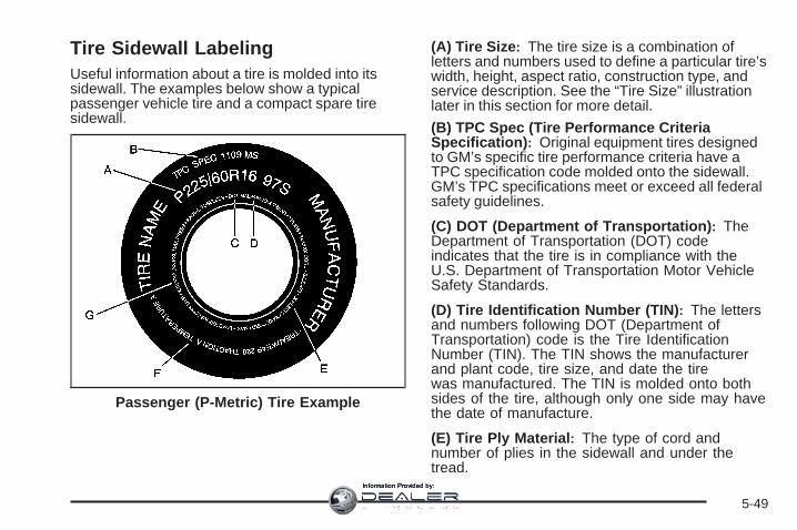
Tire Sidewall LabelingUseful information about a tire is molded into itssidewall. The examples below show a typicalpassenger vehicle tire and a compact spare tiresidewall.
(A) Tire Size: The tire size is a combination ofletters and numbers used to define a particular tire’swidth, height, aspect ratio, construction type, andservice description. See the “Tire Size” illustrationlater in this section for more detail.
(B) TPC Spec (Tire Performance CriteriaSpecification): Original equipment tires designedto GM’s specific tire performance criteria have aTPC specification code molded onto the sidewall.GM’s TPC specifications meet or exceed all federalsafety guidelines.
(C) DOT (Department of Transportation): TheDepartment of Transportation (DOT) codeindicates that the tire is in compliance with theU.S. Department of Transportation Motor VehicleSafety Standards.
(D) Tire Identification Number (TIN): The lettersand numbers following DOT (Department ofTransportation) code is the Tire IdentificationNumber (TIN). The TIN shows the manufacturerand plant code, tire size, and date the tirewas manufactured. The TIN is molded onto bothsides of the tire, although only one side may havethe date of manufacture.
(E) Tire Ply Material: The type of cord andnumber of plies in the sidewall and under thetread.
Passenger (P-Metric) Tire Example
5-49
Information Provided by:

(F) Uniform Tire Quality Grading (UTQG): Tiremanufacturers are required to grade tiresbased on three performance factors: treadwear,traction, and temperature resistance. For moreinformation see Uniform Tire Quality Grading onpage 5-67.
(G) Maximum Cold Inflation Load Limit:Maximum load that can be carried and themaximum pressure needed to support that load.
(A) Temporary Use Only: The compact sparetire or temporary use tire has a tread life ofapproximately 3,000 miles (5 000 km) and shouldnot be driven at speeds over 65 mph (105 km/h).The compact spare tire is for emergency use whena regular road tire has lost air and gone flat. If yourvehicle has a compact spare tire, see CompactSpare Tire on page 5-88 and If a Tire Goes Flat onpage 5-71.
(B) Tire Ply Material: The type of cord andnumber of plies in the sidewall and under thetread.
(C) Tire Identification Number (TIN): The lettersand numbers following the DOT (Department ofTransportation) code is the Tire IdentificationNumber (TIN). The TIN shows the manufacturerand plant code, tire size, and date the tirewas manufactured. The TIN is molded onto bothsides of the tire, although only one side may havethe date of manufacture.
(D) Maximum Cold Inflation Load Limit:Maximum load that can be carried and themaximum pressure needed to support that load.
Compact Spare Tire Example
5-50
Information Provided by:

(E) Tire Inflation: The temporary use tire orcompact spare tire should be inflated to 60 psi(420 kPa). For more information on tire pressureand inflation see Inflation - Tire Pressure onpage 5-55.
(F) Tire Size : A combination of letters andnumbers define a tire’s width, height, aspect ratio,construction type, and service description. Theletter T as the first character in the tire size meansthe tire is for temporary use only.
(G) TPC Spec (Tire Performance CriteriaSpecification): Original equipment tires designedto GM’s specific tire performance criteria havea TPC specification code molded onto the sidewall.GM’s TPC specifications meet or exceed allfederal safety guidelines.
Tire SizeThe following illustration shows an example of atypical passenger vehicle tire size.
(A) Passenger (P-Metric) Tire: The United Statesversion of a metric tire sizing system. The letter Pas the first character in the tire size means apassenger vehicle tire engineered to standards setby the U.S. Tire and Rim Association.
(B) Tire Width: The three-digit number indicatesthe tire section width in millimeters from sidewallto sidewall.
(C) Aspect Ratio: A two-digit number thatindicates the tire height-to-width measurements.For example, if the tire size aspect ratio is 60, asshown in item C of the illustration, it would meanthat the tire’s sidewall is 60 percent as high asit is wide.
5-51
Information Provided by:

(D) Construction Code: A letter code is used toindicate the type of ply construction in the tire.The letter R means radial ply construction;the letter D means diagonal or bias plyconstruction; and the letter B means belted-biasply construction.
(E) Rim Diameter: Diameter of the wheel ininches.
(F) Service Description: These charactersrepresent the load range and speed rating of thetire. The load index represents the load carrycapacity a tire is certified to carry. The load indexcan range from 1 to 279. The speed rating isthe maximum speed a tire is certified to carry aload. Speed ratings range from A to Z.
Tire Terminology and Definitions
Air Pressure: The amount of air inside thetire pressing outward on each square inch of thetire. Air pressure is expressed in pounds persquare inch (psi) or kilopascal (kPa).
Accessory Weight: This means the combinedweight of optional accessories. Some examples ofoptional accessories are, automatic transmission,power steering, power brakes, power windows,power seats, and air conditioning.
Aspect Ratio: The relationship of a tire’s heightto its width.
Belt: A rubber coated layer of cords that islocated between the plies and the tread. Cordsmay be made from steel or other reinforcingmaterials.
Bead: The tire bead contains steel wires wrappedby steel cords that hold the tire onto the rim.
Bias Ply Tire: A pneumatic tire in which the pliesare laid at alternate angles less than 90 degreesto the centerline of the tread.
Cold Tire Pressure: The amount of air pressurein a tire, measured in pounds per square inch(psi) or kilopascals (kPa) before a tire has built upheat from driving. See Inflation - Tire Pressureon page 5-55.
Curb Weight: The weight of a motor vehicle withstandard and optional equipment including themaximum capacity of fuel, oil, and coolant,but without passengers and cargo.
5-52
Information Provided by:

DOT Markings: A code molded into the sidewallof a tire signifying that the tire is in compliancewith the U.S. Department of Transportation (DOT)motor vehicle safety standards. The DOT codeincludes the Tire Identification Number (TIN),an alphanumeric designator which can also identifythe tire manufacturer, production plant, brand,and date of production.
GVWR: Gross Vehicle Weight Rating. SeeLoading Your Vehicle on page 4-21.
GAWR FRT: Gross Axle Weight Rating for thefront axle. See Loading Your Vehicle onpage 4-21.
GAWR RR: Gross Axle Weight Rating for the rearaxle. See Loading Your Vehicle on page 4-21.
Intended Outboard Sidewall: The side ofan asymmetrical tire, that must always faceoutward when mounted on a vehicle.
Kilopascal (kPa): The metric unit for air pressure.
Light Truck (LT-Metric) Tire: A tire used onlight duty trucks and some multipurpose passengervehicles.
Load Index: An assigned number ranging from 1to 279 that corresponds to the load carryingcapacity of a tire.
Maximum Inflation Pressure: The maximum airpressure to which a cold tire can be inflated.The maximum air pressure is molded onto thesidewall.
Maximum Load Rating: The load rating for a tireat the maximum permissible inflation pressurefor that tire.
Maximum Loaded Vehicle Weight: The sum ofcurb weight, accessory weight, vehicle capacityweight, and production options weight.
Normal Occupant Weight: The number ofoccupants a vehicle is designed to seat multipliedby 150 lbs (68 kg). See Loading Your Vehicleon page 4-21.
Occupant Distribution: Designated seatingpositions.
5-53
Information Provided by:

Outward Facing Sidewall: The side of anasymmetrical tire that has a particular side thatfaces outward when mounted on a vehicle.The side of the tire that contains a whitewall, bearswhite lettering, or bears manufacturer, brand,and/or model name molding that is higheror deeper than the same moldings on the othersidewall of the tire.
Passenger (P-Metric) Tire: A tire used onpassenger cars and some light duty trucks andmultipurpose vehicles.
Recommended Inflation Pressure: Vehiclemanufacturer’s recommended tire inflationpressure as shown on the tire placard. SeeInflation - Tire Pressure on page 5-55 and LoadingYour Vehicle on page 4-21.
Radial Ply Tire: A pneumatic tire in which theply cords that extend to the beads are laid at90 degrees to the centerline of the tread.
Rim: A metal support for a tire and upon whichthe tire beads are seated.
Sidewall: The portion of a tire between the treadand the bead.
Speed Rating: An alphanumeric code assigned toa tire indicating the maximum speed at which atire can operate.
Traction: The friction between the tire and theroad surface. The amount of grip provided.
Tread: The portion of a tire that comes intocontact with the road.
Treadwear Indicators: Narrow bands, sometimescalled wear bars, that show across the tread ofa tire when only 1/16 inch (1.6 mm) of treadremains. See When It Is Time for New Tires onpage 5-63.
UTQGS (Uniform Tire Quality GradingStandards): A tire information system thatprovides consumers with ratings for a tire’straction, temperature, and treadwear. Ratings aredetermined by tire manufacturers usinggovernment testing procedures. The ratings aremolded into the sidewall of the tire. See UniformTire Quality Grading on page 5-67.
5-54
Information Provided by:

Vehicle Capacity Weight: The number ofdesignated seating positions multiplied by 150 lbs(68 kg) plus the rated cargo load. See LoadingYour Vehicle on page 4-21.
Vehicle Maximum Load on the Tire: Load on anindividual tire due to curb weight, accessoryweight, occupant weight, and cargo weight.
Vehicle Placard: A label permanently attached toa vehicle showing the vehicle’s capacity weightand the original equipment tire size andrecommended inflation pressure. See “Tire andLoading Information Label” under LoadingYour Vehicle on page 4-21.
Inflation - Tire PressureTires need the correct amount of air pressure tooperate effectively.
Notice: Do not let anyone tell you thatunder-inflation or over-inflation is all right. It isnot. If your tires do not have enough air(under-inflation), you can get the following:• Too much flexing• Too much heat• Tire overloading• Premature or irregular wear• Poor handling• Reduced fuel economy
If your tires have too much air (over-inflation),you can get the following:• Unusual wear• Poor handling• Rough ride• Needless damage from road hazards
5-55
Information Provided by:

A vehicle specific Tire and Loading Informationlabel is attached to your vehicle. This label showsyour vehicle’s original equipment tires and thecorrect inflation pressures for your tires when theyare cold. The recommended cold tire inflationpressure, shown on the label, is the minimumamount of air pressure needed to supportyour vehicle’s maximum load carrying capacity.
For additional information regarding how muchweight your vehicle can carry, and an example ofthe Tire and Loading Information label, seeLoading Your Vehicle on page 4-21. How you loadyour vehicle affects vehicle handling and ridecomfort. Never load your vehicle with more weightthan it was designed to carry.
When to CheckCheck your tires once a month or more. Do notforget to check the compact spare tire, it should beat 60 psi (420 kPa). For additional informationregarding the compact spare tire, see CompactSpare Tire on page 5-88.
How to CheckUse a good quality pocket-type gage to check tirepressure. You cannot tell if your tires are properlyinflated simply by looking at them. Radial tires maylook properly inflated even when they areunder-inflated. Check the tire’s inflation pressurewhen the tires are cold. Cold means your vehiclehas been sitting for at least three hours or driven nomore than 1 mile (1.6 km).Remove the valve cap from the tire valve stem.Press the tire gage firmly onto the valve to get apressure measurement. If the cold tire inflationpressure matches the recommended pressure onthe Tire and Loading Information label, no furtheradjustment is necessary. If the inflation pressure islow, add air until you reach the recommendedamount.If you overfill the tire, release air by pushing on themetal stem in the center of the tire valve. Re-checkthe tire pressure with the tire gage.
Be sure to put the valve caps back on the valvestems. They help prevent leaks by keeping out dirtand moisture.
5-56
Information Provided by:

Tire Pressure Monitor SystemThe Tire Pressure Monitor System (TPMS) uses radioand sensor technology to check tire pressure levels. TheTPMS sensors monitor the air pressure in yourvehicle’s tires and transmit tire pressure readings to areceiver located in the vehicle.
Each tire, including the spare (if provided), should bechecked monthly when cold and inflated to the inflationpressure recommended by the vehicle manufactureron the vehicle placard or tire inflation pressure label. (Ifyour vehicle has tires of a different size than the sizeindicated on the vehicle placard or tire inflation pressurelabel, you should determine the proper tire inflationpressure for those tires.)
As an added safety feature, your vehicle has beenequipped with a tire pressure monitoring system (TPMS)that illuminates a low tire pressure telltale when oneor more of your tires is significantly under-inflated.
Accordingly, when the low tire pressure telltaleilluminates, you should stop and check your tires assoon as possible, and inflate them to the properpressure. Driving on a significantly under-inflated tirecauses the tire to overheat and can lead to tire failure.Under-inflation also reduces fuel efficiency and tiretread life, and may affect the vehicle’s handlingand stopping ability.
Please note that the TPMS is not a substitute for propertire maintenance, and it is the driver’s responsibility tomaintain correct tire pressure, even if under-inflation hasnot reached the level to trigger illumination of theTPMS low tire pressure telltale.
Your vehicle has also been equipped with a TPMSmalfunction indicator to indicate when the system is notoperating properly. The TPMS malfunction indicatoris combined with the low tire pressure telltale. When thesystem detects a malfunction, the telltale will flash forapproximately one minute and then remain continuouslyilluminated. This sequence will continue uponsubsequent vehicle start-ups as long as the malfunctionexists.
When the malfunction indicator is illuminated, thesystem may not be able to detect or signal low tirepressure as intended. TPMS malfunctions may occur fora variety of reasons, including the installation ofreplacement or alternate tires or wheels on the vehiclethat prevent the TPMS from functioning properly.Always check the TPMS malfunction telltale afterreplacing one or more tires or wheels on your vehicle toensure that the replacement or alternate tires andwheels allow the TPMS to continue to function properly.
See Tire Pressure Monitor Operation on page 5-58,for additional information.
5-57
Information Provided by:

Federal Communications Commission(FCC) and Industry and ScienceCanadaThe Tire Pressure Monitor System (TPMS) operates ona radio frequency and complies with Part 15 of theFCC Rules. Operation is subject to the following twoconditions:
1. This device may not cause harmful interference.
2. This device must accept any interference received,including interference that may cause undesiredoperation.
The Tire Pressure Monitor System (TPMS) operates ona radio frequency and complies with RSS-210 ofIndustry and Science Canada. Operation is subject tothe following two conditions:
1. This device may not cause interference.
2. This device must accept any interference received,including interference that may cause undesiredoperation of the device.
Changes or modifications to this system by other thanan authorized service facility could void authorization touse this equipment.
Tire Pressure Monitor OperationThe Tire Pressure Monitor System (TPMS) is designedto warn the driver when a low tire pressure conditionexists. TPMS sensors are mounted onto each tireand wheel assembly, excluding the spare tire and wheelassembly. The TPMS sensors monitor the air pressurein the vehicle’s tires and transmits the tire pressurereadings to a receiver located in the vehicle.
When a low tire pressurecondition is detected, theTPMS illuminates thelow tire pressure warninglight located on theinstrument panel cluster.
5-58
Information Provided by:

At the same time a message to check the pressure in aspecific tire appears on the Driver Information Center(DIC) display. The low tire pressure warning lightand the DIC warning message come on at each ignitioncycle until the tires are inflated to the correct inflationpressure. Using the DIC, tire pressure levels canbe viewed by the driver. For additional information anddetails about the DIC operation and displays seeDIC Operation and Displays (With DIC Buttons) onpage 3-57 or DIC Operation and Displays (Without DICButtons) on page 3-63 and DIC Warnings andMessages on page 3-66.
The low tire pressure warning light may come on in coolweather when the vehicle is first started, and thenturn off as you start to drive. This could be an earlyindicator that the air pressure in the tire(s) are gettinglow and need to be inflated to the proper pressure.
A Tire and Loading Information label, attached to yourvehicle, shows the size of your vehicle’s originalequipment tires and the correct inflation pressure foryour vehicle’s tires when they are cold. See LoadingYour Vehicle on page 4-21, for an example of the Tireand Loading Information label and its location onyour vehicle. Also see Inflation - Tire Pressure onpage 5-55.
Your vehicle’s TPMS can warn you about a low tirepressure condition but it does not replace normaltire maintenance. See Tire Inspection and Rotation onpage 5-62 and Tires on page 5-48.
Notice: Liquid tire sealants could damage the TirePressure Monitor System (TPMS) sensors. Sensordamage caused by using a tire sealant is notcovered by your warranty. Do not use liquid tiresealants.
5-59
Information Provided by:

TPMS Malfunction Light and MessageThe TPMS will not function properly if one or more of theTPMS sensors are missing or inoperable. When thesystem detects a malfunction, the low tire warning lightflashes for about one minute and then stays on forthe remainder of the ignition cycle. A DIC warningmessage is also displayed. The low tire warning lightand DIC warning message come on at each ignitioncycle until the problem is corrected. Some of theconditions that can cause the malfunction light and DICmessage to come on are:
• One of the road tires has been replaced with thespare tire. The spare tire does not have a TPMSsensor. The TPMS malfunction light and DICmessage should go off once you re-install the roadtire containing the TPMS sensor.
• The TPMS sensor matching process was startedbut not completed or not completed successfullyafter rotating the vehicle’s tires. The DIC messageand TPMS malfunction light should go off oncethe TPMS sensor matching process is performedsuccessfully. See “TPMS Sensor Matching Process”later in this section.
• One or more TPMS sensors are missing ordamaged. The DIC message and the TPMSmalfunction light should go off when the TPMSsensors are installed and the sensor matchingprocess is performed successfully. See yourdealer/retailer for service.
• Replacement tires or wheels do not match yourvehicle’s original equipment tires or wheels.Tires and wheels other than those recommendedfor your vehicle could prevent the TPMS fromfunctioning properly. See Buying New Tires onpage 5-64.
• Operating electronic devices or being near facilitiesusing radio wave frequencies similar to the TPMScould cause the TPMS sensors to malfunction.
If the TPMS is not functioning it cannot detect or signala low tire condition. See your dealer/retailer forservice if the TPMS malfunction light and DIC messagecomes on and stays on.
5-60
Information Provided by:

TPMS Sensor Matching ProcessEach TPMS sensor has a unique identification code.Any time you rotate your vehicle’s tires or replace one ormore of the TPMS sensors, the identification codeswill need to be matched to the new tire/wheel position.The sensors are matched to the tire/wheel positionsin the following order: driver side front tire, passengerside front tire, passenger side rear tire, and driverside rear tire using a TPMS diagnostic tool. See yourdealer/retailer for service.
The TPMS sensors can also be matched to eachtire/wheel position by increasing or decreasing the tire’sair pressure. If increasing the tire’s air pressure, donot exceed the maximum inflation pressure indicated onthe tire’s sidewall.
To decrease air-pressure out of a tire you can use thepointed end of the valve cap, a pencil-style air pressuregage, or a key.
You have two minutes to match the first tire/wheelposition, and five minutes overall to match all fourtire/wheel positions. If it takes longer than two minutes,to match the first tire and wheel, or more than fiveminutes to match all four tire and wheel positions thematching process stops and you need to start over.
The TPMS sensor matching process is outlined below:
1. Set the parking brake.
2. Turn the ignition switch to ON/RUN with theengine off.
3. Press the Remote Keyless Entry (RKE) transmitter’sLOCK and UNLOCK buttons at the same time forapproximately five seconds. The horn sounds twiceto signal the receiver is in relearn mode andTIRE LEARNING ACTIVE message displays on theDIC screen.
4. Start with the driver side front tire.
5. Remove the valve cap from the valve cap stem.Activate the TPMS sensor by increasing ordecreasing the tire’s air pressure for five seconds,or until a horn chirp sounds. The horn chirp,which may take up to 30 seconds to sound,confirms that the sensor identification code hasbeen matched to this tire and wheel position.
6. Proceed to the passenger side front tire, and repeatthe procedure in Step 5.
7. Proceed to the passenger side rear tire, and repeatthe procedure in Step 5.
5-61
Information Provided by:

8. Proceed to the driver side rear tire, and repeat theprocedure in Step 5. The horn sounds two times toindicate the sensor identification code has beenmatched to the driver side rear tire, and the TPMSsensor matching process is no longer active.The TIRE LEARNING ACTIVE message on the DICdisplay screen goes off.
9. Turn the ignition switch to LOCK/OFF.
10. Set all four tires to the recommended air pressurelevel as indicated on the Tire and LoadingInformation label.
11. Put the valve caps back on the valve stems.
Tire Inspection and RotationWe recommend that you regularly inspect yourvehicle’s tires, including the spare tire, for signs ofwear or damage. See When It Is Time for NewTires on page 5-63 for more information.
Tires should be rotated every 5,000 to 8,000 miles(8 000 to 13 000 km). See Scheduled Maintenanceon page 6-4.
The purpose of a regular tire rotation is to achievea uniform wear for all tires on the vehicle. Thiswill ensure that your vehicle continues to performmost like it did when the tires were new.
Any time you notice unusual wear, rotate yourtires as soon as possible and check wheelalignment. Also check for damaged tires or wheels.See When It Is Time for New Tires on page 5-63and Wheel Replacement on page 5-68.
When rotating your vehicle’s tires, always use thecorrect rotation pattern shown here.
Do not include the compact spare tire in the tirerotation.
After the tires have been rotated, adjust the frontand rear inflation pressures as shown on the Tireand Loading Information label. See Inflation - TirePressure on page 5-55 and Loading Your Vehicleon page 4-21.
Reset the Tire Pressure Monitor System. See TirePressure Monitor Operation on page 5-58.
5-62
Information Provided by:

Make certain that all wheel nuts are properlytightened. See “Wheel Nut Torque” underCapacities and Specifications on page 5-107.
{CAUTION:
Rust or dirt on a wheel, or on the parts towhich it is fastened, can make wheel nutsbecome loose after time. The wheel couldcome off and cause an accident. Whenyou change a wheel, remove any rust ordirt from places where the wheel attachesto the vehicle. In an emergency, you canuse a cloth or a paper towel to do this;but be sure to use a scraper or wire brushlater, if needed, to get all the rust or dirtoff. See Changing a Flat Tire on page 5-72.
Make sure the spare tire is stored securely. Push,pull, and then try to rotate or turn the tire. If itmoves, tighten the cable. See Storing a Flat orSpare Tire and Tools on page 5-84.
When It Is Time for New TiresVarious factors, such as maintenance, temperatures,driving speeds, vehicle loading, and road conditionsinfluence when you need new tires.
One way to tell when it istime for new tires is tocheck the treadwearindicators, which willappear when your tireshave only 1/16 inch(1.6 mm) or less of treadremaining.
5-63
Information Provided by:

You need new tires if any of the following statementsare true:
• You can see the indicators at three or more placesaround the tire.
• You can see cord or fabric showing through thetire’s rubber.
• The tread or sidewall is cracked, cut, or snaggeddeep enough to show cord or fabric.
• The tire has a bump, bulge, or split.
• The tire has a puncture, cut, or other damage thatcannot be repaired well because of the size orlocation of the damage.
The rubber in tires degrades over time, even if they arenot being used. This is also true for the spare tire, ifyour vehicle has one. Multiple conditions affect how fastthis aging takes place, including temperatures, loadingconditions, and inflation pressure maintenance. Withproper care and maintenance tires will typically wear outbefore they degrade due to age. If you are unsureabout the need to replace your tires as they get older,consult the tire manufacturer for more information.
Buying New TiresGM has developed and matched specific tires foryour vehicle. The original equipment tiresinstalled on your vehicle, when it was new, weredesigned to meet General Motors TirePerformance Criteria Specification (TPC Spec)system rating. If you need replacement tires, GMstrongly recommends that you get tires withthe same TPC Spec rating. This way, your vehiclewill continue to have tires that are designed togive the same performance and vehicle safety,during normal use, as the original tires.
GM’s exclusive TPC Spec system considers overa dozen critical specifications that impact theoverall performance of your vehicle, includingbrake system performance, ride and handling,traction control, and tire pressure monitoringperformance. GM’s TPC Spec number is moldedonto the tire’s sidewall near the tire size. If thetires have an all-season tread design, theTPC Spec number will be followed by an MS formud and snow. See Tire Sidewall Labeling onpage 5-49 for additional information.
5-64
Information Provided by:

GM recommends replacing tires in sets of four.This is because uniform tread depth on all tires willhelp keep your vehicle performing most like itdid when the tires were new. Replacing less thana full set of tires can affect the braking andhandling performance of your vehicle. See TireInspection and Rotation on page 5-62 forinformation on proper tire rotation.
{CAUTION:
Mixing tires could cause you to losecontrol while driving. If you mix tires ofdifferent sizes, brands, or types (radialand bias-belted tires), the vehicle may nothandle properly, and you could have acrash. Using tires of different sizes,brands, or types may also cause damageto your vehicle. Be sure to use the correctsize, brand, and type of tires on allwheels. It is all right to drive with yourcompact spare temporarily, as it wasdeveloped for use on your vehicle. SeeCompact Spare Tire on page 5-88.
{CAUTION:
If you use bias-ply tires on your vehicle,the wheel rim flanges could developcracks after many miles of driving. A tireand/or wheel could fail suddenly, causinga crash. Use only radial-ply tires with thewheels on your vehicle.
If you must replace your vehicle’s tires with thosethat do not have a TPC Spec number, makesure they are the same size, load range, speedrating, and construction type (radial andbias-belted tires) as your vehicle’s original tires.
Vehicles that have a tire pressure monitoringsystem could give an inaccurate low-pressurewarning if non-TPC Spec rated tires are installedon your vehicle. Non-TPC Spec rated tiresmay give a low-pressure warning that is higher orlower than the proper warning level you wouldget with TPC Spec rated tires. See Tire PressureMonitor System on page 5-57.
5-65
Information Provided by:

Your vehicle’s original equipment tires are listedon the Tire and Loading Information Label.See Loading Your Vehicle on page 4-21, for moreinformation about the Tire and Loading InformationLabel and its location on your vehicle.
Different Size Tires and WheelsIf you add wheels or tires that are a different size thanyour original equipment wheels and tires, this couldaffect the way your vehicle performs, including itsbraking, ride and handling characteristics, stability, andresistance to rollover. Additionally, if your vehiclehas electronic systems such as anti-lock brakes, rolloverairbags, traction control, and electronic stability control,the performance of these systems can be affected.
{CAUTION:
If you add different sized wheels, your vehiclemay not provide an acceptable level ofperformance and safety if tires notrecommended for those wheels are selected.You may increase the chance that you willcrash and suffer serious injury. Only use GMspecific wheel and tire systems developed foryour vehicle, and have them properly installedby a GM certified technician.
See Buying New Tires on page 5-64 and Accessoriesand Modifications on page 5-4 for additional information.
5-66
Information Provided by:

Uniform Tire Quality GradingQuality grades can be found where applicable onthe tire sidewall between tread shoulder andmaximum section width. For example:
Treadwear 200 Traction AA Temperature AThe following information relates to the systemdeveloped by the United States National HighwayTraffic Safety Administration (NHTSA), whichgrades tires by treadwear, traction, andtemperature performance. This applies only tovehicles sold in the United States. The grades aremolded on the sidewalls of most passenger cartires. The Uniform Tire Quality Grading (UTQG)system does not apply to deep tread, winter-typesnow tires, space-saver, or temporary usespare tires, tires with nominal rim diameters of10 to 12 inches (25 to 30 cm), or to somelimited-production tires.
While the tires available on General Motorspassenger cars and light trucks may vary withrespect to these grades, they must also conformto federal safety requirements and additionalGeneral Motors Tire Performance Criteria (TPC)standards.
TreadwearThe treadwear grade is a comparative ratingbased on the wear rate of the tire when testedunder controlled conditions on a specifiedgovernment test course. For example, a tiregraded 150 would wear one and a half (1.5) timesas well on the government course as a tiregraded 100. The relative performance of tiresdepends upon the actual conditions of their use,however, and may depart significantly fromthe norm due to variations in driving habits, servicepractices, and differences in road characteristicsand climate.
Traction – AA, A, B, CThe traction grades, from highest to lowest, are AA,A, B, and C. Those grades represent the tire’sability to stop on wet pavement as measured undercontrolled conditions on specified government testsurfaces of asphalt and concrete. A tire marked Cmay have poor traction performance.
Warning: The traction grade assigned to thistire is based on straight-ahead brakingtraction tests, and does not includeacceleration, cornering, hydroplaning, or peaktraction characteristics.
5-67
Information Provided by:

Temperature – A, B, CThe temperature grades are A (the highest), B,and C, representing the tire’s resistance tothe generation of heat and its ability to dissipateheat when tested under controlled conditions on aspecified indoor laboratory test wheel. Sustainedhigh temperature can cause the material of the tireto degenerate and reduce tire life, and excessivetemperature can lead to sudden tire failure.The grade C corresponds to a level of performancewhich all passenger car tires must meet underthe Federal Motor Vehicle Safety StandardNo. 109. Grades B and A represent higher levelsof performance on the laboratory test wheelthan the minimum required by law.
Warning: The temperature grade for this tireis established for a tire that is properly inflatedand not overloaded. Excessive speed,underinflation, or excessive loading, eitherseparately or in combination, can cause heatbuildup and possible tire failure.
Wheel Alignment and Tire BalanceThe tires and wheels on your vehicle were alignedand balanced carefully at the factory to give you thelongest tire life and best overall performance.Adjustments to wheel alignment and tire balancing willnot be necessary on a regular basis. However, ifyou notice unusual tire wear or your vehicle pulling toone side or the other, the alignment might need tobe checked. If you notice your vehicle vibrating whendriving on a smooth road, the tires and wheelsmight need to be rebalanced. See your dealer/retailerfor proper diagnosis.
Wheel ReplacementReplace any wheel that is bent, cracked, or badly rustedor corroded. If wheel nuts keep coming loose, thewheel, wheel bolts, and wheel nuts should be replaced.If the wheel leaks air, replace it (except somealuminum wheels, which can sometimes be repaired).See your dealer/retailer if any of these conditions exist.
Your dealer/retailer will know the kind of wheel you need.
Each new wheel should have the same load-carryingcapacity, diameter, width, offset, and be mountedthe same way as the one it replaces.
5-68
Information Provided by:

If you need to replace any of your wheels, wheel bolts,wheel nuts, or Tire Pressure Monitor System (TPMS)sensors, replace them only with new GM originalequipment parts. This way, you will be sure to have theright wheel, wheel bolts, wheel nuts, and TPMSsensors for your vehicle.
{CAUTION:
Using the wrong replacement wheels, wheelbolts, or wheel nuts on your vehicle can bedangerous. It could affect the braking andhandling of your vehicle, make your tires loseair and make you lose control. You could havea collision in which you or others could beinjured. Always use the correct wheel, wheelbolts, and wheel nuts for replacement.
Notice: The wrong wheel can also cause problemswith bearing life, brake cooling, speedometer orodometer calibration, headlamp aim, bumper height,vehicle ground clearance, and tire or tire chainclearance to the body and chassis.
See Changing a Flat Tire on page 5-72 for moreinformation.
5-69
Information Provided by:

Used Replacement Wheels
{CAUTION:
Putting a used wheel on your vehicle isdangerous. You cannot know how it has beenused or how far it has been driven. It could failsuddenly and cause a crash. If you have toreplace a wheel, use a new GM originalequipment wheel.
Tire Chains
{CAUTION:
Do not use tire chains. There is not enoughclearance. Tire chains used on a vehiclewithout the proper amount of clearance cancause damage to the brakes, suspension orother vehicle parts. The area damaged by thetire chains could cause you to lose control ofyour vehicle and you or others may be injuredin a crash.
Use another type of traction device only if itsmanufacturer recommends it for use on yourvehicle and tire size combination and roadconditions. Follow that manufacturer’sinstructions. To help avoid damage to yourvehicle, drive slowly, readjust or remove thedevice if it is contacting your vehicle, and donot spin your vehicle’s wheels. If you do findtraction devices that will fit, install them on thefront tires.
5-70
Information Provided by:

If a Tire Goes FlatIt is unusual for a tire to blowout while you are driving,especially if you maintain your vehicle’s tires properly.If air goes out of a tire, it is much more likely to leak outslowly. But if you should ever have a blowout, hereare a few tips about what to expect and what to do:
If a front tire fails, the flat tire creates a drag that pullsthe vehicle toward that side. Take your foot off theaccelerator pedal and grip the steering wheel firmly.Steer to maintain lane position, and then gently brake toa stop well out of the traffic lane.
A rear blowout, particularly on a curve, acts much like askid and may require the same correction you woulduse in a skid. In any rear blowout remove your foot fromthe accelerator pedal. Get the vehicle under controlby steering the way you want the vehicle to go. It maybe very bumpy and noisy, but you can still steer. Gentlybrake to a stop, well off the road if possible.
{CAUTION:
Lifting a vehicle and getting under it to domaintenance or repairs is dangerous withoutthe appropriate safety equipment and training.The jack provided with your vehicle isdesigned only for changing a flat tire. If it isused for anything else, you or others could bebadly injured or killed if the vehicle slips offthe jack. Use the jack provided with yourvehicle only for changing a flat tire.
If a tire goes flat, the next part shows how to use thejacking equipment to change a flat tire safely.
5-71
Information Provided by:
Changing a Flat TireIf a tire goes flat, avoid further tire and wheel damageby driving slowly to a level place. Turn on your vehicle’shazard warning flashers. See Hazard Warning Flasherson page 3-6 for more information.
{CAUTION:
Changing a tire can be dangerous. The vehiclecan slip off the jack and roll over or fall on youor other people. You and they could be badlyinjured or even killed. Find a level place tochange your tire. To help prevent the vehiclefrom moving:
1. Set the parking brake firmly.
2. Put the shift lever in PARK (P).
3. Turn off the engine and do not restartwhile the vehicle is raised.
4. Do not allow passengers to remain in thevehicle.
To be even more certain the vehicle will notmove, you should put blocks at the front andrear of the tire farthest away from the onebeing changed. That would be the tire, on theother side, at the opposite end of the vehicle.
5-72
Information Provided by:

When your vehicle has a flat tire, use the followingexample as a guide to assist you in the placement ofwheel blocks.
The following information tells you how to use the jackand change a tire.
Removing the Spare Tire and ToolsThe tools needed to remove the spare tire are locatedin the storage compartment on the driver side, atthe rear of the vehicle.
1. Open the jack storage compartment by squeezingdown on the latch tab and pulling the cover off.
A. Tool BagB. Wing BoltC. Jack
2. Remove the wing bolt (B) by turning itcounterclockwise
3. Push the jack (C) up out of the holding bracket.
4. Turn the jack on its side, with the bottom facingtoward you.
5. Pull the jack straight out, bottom first.
5-73
Information Provided by:

The tools you will be using include the jack (A) and lugwrench (B).
Removing the Spare TireThe compact spare tire is located under the vehicle, infront of the rear bumper. See Compact Spare Tire onpage 5-88 for more information about the compact spare.
A. Rear ConvenienceCenter
B. Lug wrenchC. Storage
CompartmentCap Hole
D. Hoist ShaftE. Compact
Spare TireF. RetainerG. Hoist Shaft
Assembly
1. Open the storage compartment door of theconvenience center that is nearest the liftgate.
2. Move the carpet cutout that is located through thehole of the storage compartment.
3. Attach the lug wrench into the hoist shaft.
5-74
Information Provided by:

4. Turn the lug wrench counterclockwise to lower thespare tire to the ground. Continue turning thewrench until the spare tire can be pulled out fromunder the vehicle.
5. Tilt the retainer and slip it through the wheelopening to remove the spare tire from the cable.
6. Turn the wrench clockwise to raise the cable backup after removing the spare tire.Do not store a full-size or a flat road tire under thevehicle. See Storing a Flat or Spare Tire andTools on page 5-84.
To continue changing the flat tire, see Removing theFlat Tire and Installing the Spare Tire (Outlook) onpage 5-76.
If the spare tire will not lower, the secondary latch couldbe engaged.
5-75
Information Provided by:

Do the following to check the cable:
1. Check under the vehicle to see if the cable isvisible.
2. If it is not visible, see Secondary Latch System onpage 5-81.If it is visible, first try to tighten the cable by turningthe lug wrench clockwise until you hear twoclicks or feel it skip twice. You cannot over-tightenthe cable.
3. Loosen the cable by turning the wrenchcounterclockwise three or four turns.
4. If the spare tire did lower to the ground, continuewith Step 5 under “Removing the Spare Tire” listedpreviously.
5. If you still cannot lower the spare tire to the ground,see Secondary Latch System on page 5-81.
Removing the Flat Tire andInstalling the Spare Tire1. Do a safety check before proceeding. See Changing
a Flat Tire on page 5-72 for more information.
2. If the vehicle has a wheel cover, loosen the plasticnut caps with the wheel wrench. They will not comeoff. Then, using the flat end of the wheel wrench,pry along the edge of the cover until it comes off. Becareful; the edges may be sharp. Do not try toremove the cover with your bare hands.Store the wheel cover securely in the rear of thevehicle until you have the flat tire repaired orreplaced.If your vehicle has aluminum wheels, remove thewheel nut caps using the wheel wrench.
5-76
Information Provided by:

3. Loosen the wheel nuts — but do not remove them— using the lug wrench. For wheels with a wheellock key, use the wheel lock key between thelock nut and lug wrench. The key is supplied in thefront passenger door pocket.
Notice: If your vehicle has wheel locks and animpact wrench is used to remove the wheel nuts,the lock nut or wheel lock key could be damaged. Donot use an impact wrench to remove the wheelnuts if your vehicle has wheel locks.
4. To identify the appropriate jacking location, find thetriangle (A) about 12 inches (30.5 cm) from the fronttire or (B) about 10.5 inches (27 cm) from therear tire.The triangle is located near each wheel on thevehicle’s exterior.
Notice: If a jack is used to raise the vehicle withoutpositioning it correctly, your vehicle could bedamaged. When raising your vehicle on a jack, avoidcontact with the rear axle control arms.
5-77
Information Provided by:

5. Do not raise the vehicle yet. Put the compact sparetire near you.
{CAUTION:
Getting under a vehicle when it is jacked up isdangerous. If the vehicle slips off the jack, youcould be badly injured or killed. Never get undera vehicle when it is supported only by a jack.
{CAUTION:
Raising your vehicle with the jack improperlypositioned can damage the vehicle and evenmake the vehicle fall. To help avoid personalinjury and vehicle damage, be sure to fit thejack lift head into the proper location beforeraising the vehicle.
6. Attach the lug wrench to the jack, and turn thewrench clockwise to raise the jack head3 inches (7.6 cm).
7. Place the jack under the vehicle as identified inStep 3. Raise the vehicle by turning the lugwrench clockwise in the jack. Raise the vehicle farenough off the ground so that there is enoughroom for the spare tire to fit under the wheel well.
8. Remove all the wheel nuts and the flat tire.
9. Remove the plastic spare tire heat shield by pullingthe rubber latch. Store the plastic spare tire heatshield. See Storing a Flat or Spare Tire andTools on page 5-84 for more information.
5-78
Information Provided by:

{CAUTION:
Rust or dirt on a wheel, or on the parts towhich it is fastened, can make wheel nutsbecome loose after time. The wheel couldcome off and cause an accident. When youchange a wheel, remove any rust or dirt fromplaces where the wheel attaches to the vehicle.In an emergency, you can use a cloth or apaper towel to do this; but be sure to use ascraper or wire brush later, if needed, to get allthe rust or dirt off. See Changing a Flat Tire onpage 5-72.
{CAUTION:
Never use oil or grease on studs or nuts.Because the nuts might come loose. Thevehicle’s wheel could fall off, causing a crash.
10. Remove any rust or dirtfrom the wheel bolts,mounting surfaces, andspare wheel.
11. Place the spare tire on the wheel mounting surface.
12. Put the nuts on by hand by turning the clockwiseuntil the wheel is held against the mountingsurface. Make sure the rounded end is toward thewheel.
5-79
Information Provided by:

13. Lower the vehicle by attaching the lug wrench tothe jack and turning the wrench counterclockwise.Lower the jack completely.
{CAUTION:
Incorrect or improperly tightened wheel nutscan cause the wheel to come loose and evencome off. This could lead to a crash. If youhave to replace them, be sure to get neworiginal equipment wheel nuts. Stopsomewhere as soon as you can and have thenuts tightened with a torque wrench to theproper torque specification. See Capacitiesand Specifications on page 5-107 for wheel nuttorque specification.
Notice: Improperly tightened wheel nuts can leadto brake pulsation and rotor damage. To avoidexpensive brake repairs, evenly tighten the wheelnuts in the proper sequence and to the propertorque specification. See Capacities andSpecifications on page 5-107 for the wheel nuttorque specification.
14. Tighten the wheel nutsfirmly in a crisscrosssequence, as shown.
Notice: Wheel covers will not fit on your vehicle’scompact spare. If you try to put a wheel coveron the compact spare, the cover or the spare couldbe damaged.
5-80
Information Provided by:

Secondary Latch SystemYour vehicle has an underbody mounted tire hoistassembly that has a secondary latch system. It isdesigned to stop the compact spare tire from suddenlyfalling off your vehicle if the cable holding the sparetire is damaged. For the secondary latch to work, the tiremust be stowed with the valve stem pointing down.See Storing a Flat or Spare Tire and Tools on page 5-84for instructions on storing the spare tire correctly.
{CAUTION:
Before beginning this procedure read all theinstructions. Failure to read and follow theinstructions could damage the hoist assemblyand you and others could get hurt. Read andfollow the instructions listed next.
To release the spare tire from the secondary latch:
{CAUTION:
Someone standing too close during theprocedure could be injured by the jack. If thespare tire does not slide off the jackcompletely, make sure no one is behind you oron either side of you as you pull the jack outfrom the under spare.
1. If the cable is not visible, start this procedure atStep 3.
5-81
Information Provided by:

2. Turn the lug wrench counterclockwise untilapproximately 6 inches (15 cm) of cable is exposed.
3. Attach the lug wrench to the jack and raise the jackat least 10 turns.
4. Place the jack under the vehicle, ahead of the rearbumper. Position the center lift point of the jackunder the center of the spare tire.
5. Turn the lug wrench clockwise to raise the jack untilit lifts the secondary latch spring.
6. Keep raising the jack until the spare tire stopsmoving upward and is held firmly in place. Thislets you know that the secondary latch has releasedand the spare tire is balancing on the jack.
7. Lower the jack by turning the lug wrenchcounterclockwise. Keep lowering the jack until thespare tire slides off the jack.
All-Wheel-Drive Vehicle shown
5-82
Information Provided by:

8. Disconnect the lug wrench from the jack andcarefully remove the jack. Use one hand to pushagainst the spare tire while firmly pulling the jack outfrom under the spare tire with the other hand.
9. Tilt the retainer and slip it through the wheelopening when the spare tire has been completelylowered.
10. Turn the lug wrench clockwise to raise the cableback up if the cable is hanging.
Have the hoist shaft assembly inspected as soon asyou can. You will not be able to store a spare tire usingthe hoist assembly until it has been repaired orreplaced.
5-83
Information Provided by:

Storing a Flat or Spare Tire andTools
Storing the Spare Tire
{CAUTION:
The underbody-mounted spare tire needs to bestored with the valve stem pointing down. Ifthe spare tire is stored with the valve stempointing upwards, its secondary latch will notwork properly and the spare tire could loosenand suddenly fall from your vehicle. If thishappened when your vehicle was being driven,the tire might contact a person or anothervehicle, causing injury and, of course, damageto itself as well. Be sure theunderbody-mounted spare tire is stored withits valve stem pointing down.
{CAUTION:
Storing a jack, a tire, or other equipment in thepassenger compartment of the vehicle couldcause injury. In a sudden stop or collision,loose equipment could strike someone. Storeall these in the proper place.
To store the spare tire:
1. Lay the compact spare tire near the rear of thevehicle with the valve stem down.
2. Reinstall the plastic spare tire heat shield on thecompact spare tire.
3. Slide the cable retainer through the center of thewheel and start to raise the compact spare tire.Make sure the retainer is fully seated acrossthe underside of the wheel.
4. When the compact spare tire is almost in the storedposition, turn the tire so the valve is toward the rearof the vehicle.This position helps when checking the air pressurein the compact spare tire.
5-84
Information Provided by:

5. Raise the tire fully against the underside of thevehicle. Continue turning the lug wrench untilyou feel more than two clicks. This indicates thatthe compact spare tire is secure and the cableis tight. The spare tire hoist cannot beovertightened.
6. Make sure the tire is stored securely. Push, pull (A),and then try to turn (B) the tire. If the tire moves,use the lug wrench to tighten the cable.
Storing the Flat Tire
Notice: Storing the full-size flat tire in theunderbody hoist system can expose it to heat fromthe exhaust system. This can damage the tireand underbody hoist system. Do not store thefull-size flat tire in the underbody hoist system.
1. Remove the cable package from the jackstorage area.
2. Remove the small center cap by tapping the backof the cap with the extension of the shaft, if thevehicle has aluminum wheels.
3. Put the flat tire in the rear storage area with thevalve stem pointing toward the rear of the vehicle.
5-85
Information Provided by:

4. Hook on end of the cable onto the outside portionof the liftgate hinge opposite (B).
5. Pull the cable (A) through the center of thewheel (D), then the door striker (E), and the plasticspare tire heat shield (C), as shown.
6. Hook the other end of the cable onto the outsideportion of the liftgate hinge (B).
7. Pull on the cable to make sure it is secure.
8. Make sure the metal tube is centered at the striker.
5-86
Information Provided by:

9. Push the tube towardthe front of the vehicle.
10. Close the liftgate and make sure it is latchedproperly.
Storing the Tools
A. Tool BagB. Wing BoltC. Jack
5-87
Information Provided by:

Put back all tools as they were stored in the jackstorage compartment and put the compartment coverback on.
1. Attach the tool bag to the jack.
2. Make sure that the bottom of the jack is facingtoward you.
3. Turn the jack (C) on its side and place it down onthe holding bracket.
4. Reinstall the wing bolt (B) by turning it clockwise.
5. To replace the cover, line up the tabs on the bottomof the cover with the slots in the cover opening.Push the cover in place, insuring that the upper frontand rear tabs are in the opening and push thecover closed. Make sure that the center latch is fullyengaged. This secures the cover in place.
Store the center cap or the plastic bolt-on wheel coversuntil a full size tire is put back on the vehicle. When youreplace the compact spare with a full-size tire, reinstallthe bolt-on wheel covers or the center cap. Hand-tightenthem over the wheel nuts, using the lug wrench.
Compact Spare TireAlthough the compact spare tire was fully inflated whenthe vehicle was new, it can lose air after a time.Check the inflation pressure regularly. It should be60 psi (420 kPa).
After installing the compact spare on the vehicle, stopas soon as possible and make sure the spare tireis correctly inflated. The compact spare is made toperform well at speeds up to 65 mph (105 km/h)for distances up to 3,000 miles (5 000 km), so you canfinish your trip and have the full-size tire repaired orreplaced at your convenience. Of course, it is bestto replace the spare with a full-size tire as soon aspossible. The spare tire will last longer and be in goodshape in case it is needed again.
Notice: When the compact spare is installed, donot take your vehicle through an automatic car washwith guide rails. The compact spare can getcaught on the rails. That can damage the tire andwheel, and maybe other parts of your vehicle.
Do not use the compact spare on other vehicles.
And do not mix the compact spare tire or wheel withother wheels or tires. They will not fit. Keep thespare tire and its wheel together.
5-88
Information Provided by:

The All-Wheel Drive (AWD) system will be automaticallydisabled when you use the compact spare. To restorethe AWD and prevent excessive wear on the clutchin your AWD, replace the compact spare tire witha full-size tire as soon as possible.
Notice: Tire chains will not fit your compact spare.Using them can damage your vehicle and candamage the chains too. Do not use tire chains onyour compact spare.
Appearance Care
Interior CleaningYour vehicle’s interior will continue to look its best if it iscleaned often. Although not always visible, dust anddirt can accumulate on your upholstery. Dirt can damagecarpet, fabric, leather, and plastic surfaces. Regularvacuuming is recommended to remove particlesfrom your upholstery. It is important to keep yourupholstery from becoming and remaining heavily soiled.Soils should be removed as quickly as possible. Yourvehicle’s interior may experience extremes of heatthat could cause stains to set rapidly.
Lighter colored interiors may require more frequentcleaning. Use care because newspapers and garmentsthat transfer color to your home furnishings may alsotransfer color to your vehicle’s interior.
When cleaning your vehicle’s interior, only use cleanersspecifically designed for the surfaces being cleaned.Permanent damage may result from using cleaners onsurfaces for which they were not intended. Use glasscleaner only on glass. Remove any accidental over-sprayfrom other surfaces immediately. To prevent over-spray,apply cleaner directly to the cleaning cloth.
Notice: If you use abrasive cleaners when cleaningglass surfaces on your vehicle, you could scratchthe glass and/or cause damage to the rear windowdefogger. When cleaning the glass on yourvehicle, use only a soft cloth and glass cleaner.
Many cleaners contain solvents that may becomeconcentrated in your vehicle’s breathing space. Beforeusing cleaners, read and adhere to all safetyinstructions on the label. While cleaning your vehicle’sinterior, maintain adequate ventilation by openingyour vehicle’s doors and windows.
Dust may be removed from small buttons and knobsusing a small brush with soft bristles.
Your dealer/retailer has a product for cleaning yourvehicle’s glass. Should it become necessary, you canalso obtain a product from your dealer/retailer to removeodors from your vehicle’s upholstery.
5-89
Information Provided by:

Do not clean your vehicle using the following cleanersor techniques:
• Never use a knife or any other sharp object toremove a soil from any interior surface.
• Never use a stiff brush. It can cause damage toyour vehicle’s interior surfaces.
• Never apply heavy pressure or rub aggressivelywith a cleaning cloth. Use of heavy pressurecan damage your interior and does not improve theeffectiveness of soil removal.
• Use only mild, neutral-pH soaps. Avoid laundrydetergents or dishwashing soaps with degreasers.Using too much soap will leave a residue thatleaves streaks and attracts dirt. For liquid cleaners,about 20 drops per gallon (3.78 L) of water is agood guide.
• Do not heavily saturate your upholstery whilecleaning.
• Damage to your vehicle’s interior may result fromthe use of many organic solvents such as naptha,alcohol, etc.
Fabric/CarpetUse a vacuum cleaner with a soft brush attachmentfrequently to remove dust and loose dirt. A canistervacuum with a beater bar in the nozzle may only be usedon floor carpet and carpeted floor mats. For soils, alwaystry to remove them first with plain water or club soda.Before cleaning, gently remove as much of the soil aspossible using one of the following techniques:
• For liquids: gently blot the remaining soil with a papertowel. Allow the soil to absorb into the paper toweluntil no more can be removed.
• For solid dry soils: remove as much as possible andthen vacuum.
To clean, use the following instructions:
1. Saturate a lint-free, clean white cloth with water orclub soda.
2. Wring the cloth to remove excess moisture.
3. Start on the outside edge of the soil and gently rubtoward the center. Continue cleaning, using a cleanarea of the cloth each time it becomes soiled.
4. Continue to gently rub the soiled area until thecleaning cloth remains clean.
5. If the soil is not completely removed, use a mildsoap solution and repeat the cleaning processthat was used with plain water.
5-90
Information Provided by:

If any of the soil remains, a commercial fabric cleaner orspot lifter may be necessary. When a commercialupholstery cleaner or spot lifter is to be used, test asmall hidden area for colorfastness first. If the locallycleaned area gives any impression that a ring formationmay result, clean the entire surface.
After the cleaning process has been completed, a papertowel can be used to blot excess moisture from thefabric or carpet.
LeatherA soft cloth dampened with water can be used toremove dust. If a more thorough cleaning is necessary,a soft cloth dampened with a mild soap solution canbe used. Allow the leather to dry naturally. Do not useheat to dry. Never use steam to clean leather. Neveruse spot lifters or spot removers on leather. Manycommercial leather cleaners and coatings that are soldto preserve and protect leather may permanentlychange the appearance and feel of your leather and arenot recommended. Do not use silicone or wax-basedproducts, or those containing organic solvents to cleanyour vehicle’s interior because they can alter theappearance by increasing the gloss in a non-uniformmanner. Never use shoe polish on leather.
Instrument Panel, Vinyl, and OtherPlastic SurfacesA soft cloth dampened with water may be used toremove dust. If a more thorough cleaning is necessary,a clean soft cloth dampened with a mild soap solutioncan be used to gently remove dust and dirt. Never usespot lifters or removers on plastic surfaces. Manycommercial cleaners and coatings that are sold topreserve and protect soft plastic surfaces maypermanently change the appearance and feel of yourinterior and are not recommended. Do not use siliconeor wax-based products, or those containing organicsolvents to clean your vehicle’s interior becausethey can alter the appearance by increasing the gloss ina non-uniform manner.
Some commercial products may increase gloss on yourinstrument panel. The increase in gloss may causeannoying reflections in the windshield and even make itdifficult to see through the windshield under certainconditions.
5-91
Information Provided by:

Care of Safety BeltsKeep belts clean and dry.
{CAUTION:
Do not bleach or dye safety belts. If you do, itmay severely weaken them. In a crash, theymight not be able to provide adequateprotection. Clean safety belts only with mildsoap and lukewarm water.
WeatherstripsSilicone grease on weatherstrips will make them lastlonger, seal better, and not stick or squeak. Applysilicone grease with a clean cloth. During very cold,damp weather frequent application may be required. SeeRecommended Fluids and Lubricants on page 6-12.
Washing Your VehicleThe best way to preserve your vehicle’s finish is to keepit clean by washing it often.
Notice: Certain cleaners contain chemicals that candamage the emblems or nameplates on yourvehicle. Check the cleaning product label. If it statesthat it should not be used on plastic parts, do notuse it on your vehicle or damage may occurand it would not be covered by the warranty.
Do not wash the vehicle in direct sunlight. Use a carwashing soap. Do not use cleaning agents thatare petroleum based or that contain acid or abrasives,as they can damage the paint, metal or plastic onyour vehicle. Approved cleaning products can beobtained from your dealer/retailer. See VehicleCare/Appearance Materials on page 5-97. Follow allmanufacturers’ directions regarding correct productusage, necessary safety precautions and appropriatedisposal of any vehicle care product.
Rinse the vehicle well, before washing and after toremove all cleaning agents completely. If they areallowed to dry on the surface, they could stain.
5-92
Information Provided by:

Dry the finish with a soft, clean chamois or an all-cottontowel to avoid surface scratches and water spotting
High pressure car washes may cause water to enter thevehicle. Avoid using high pressure washes closerthan 12 inches (30 cm) to the surface of the vehicle.Use of power washers exceeding 1,200 psi (8 274 kPa)can result in damage or removal of paint and decals.
Cleaning Exterior Lamps/LensesUse only lukewarm or cold water, a soft cloth and a carwashing soap to clean exterior lamps and lenses. Followinstructions under Washing Your Vehicle on page 5-92.
Finish CareOccasional waxing or mild polishing of your vehicle byhand may be necessary to remove residue from the paintfinish. You can get approved cleaning products from yourdealer/retailer. See Vehicle Care/Appearance Materialson page 5-97.If your vehicle has a basecoat/clearcoat paint finish, theclearcoat gives more depth and gloss to the coloredbasecoat. Always use waxes and polishes that arenon-abrasive and made for a basecoat/clearcoat paintfinish.
Notice: Machine compounding or aggressivepolishing on a basecoat/clearcoat paint finish maydamage it. Use only non-abrasive waxes andpolishes that are made for a basecoat/clearcoatpaint finish on your vehicle.
Foreign materials such as calcium chloride and othersalts, ice melting agents, road oil and tar, tree sap, birddroppings, chemicals from industrial chimneys, etc.,can damage your vehicle’s finish if they remainon painted surfaces. Wash the vehicle as soon aspossible. If necessary, use non-abrasive cleaners thatare marked safe for painted surfaces to removeforeign matter.
Exterior painted surfaces are subject to aging, weatherand chemical fallout that can take their toll over aperiod of years. You can help to keep the paint finishlooking new by keeping your vehicle garaged or coveredwhenever possible.
Protecting Exterior Bright Metal PartsBright metal parts should be cleaned regularly to keeptheir luster. Washing with water is all that is usuallyneeded. However, you may use chrome polish onchrome or stainless steel trim, if necessary.
5-93
Information Provided by:

Use special care with aluminum trim. To avoid damagingprotective trim, never use auto or chrome polish,steam or caustic soap to clean aluminum. A coating ofwax, rubbed to high polish, is recommended for allbright metal parts.
Windshield, Backglass, and WiperBladesClean the outside of the windshield and backglass withglass cleaner.
Clean the rubber blades using a lint free cloth or papertowel soaked with windshield washer fluid or a milddetergent. Wash the windshield thoroughly when youclean the blades. Bugs, road grime, sap and a buildup ofvehicle wash/wax treatments may cause wiperstreaking. Replace the wiper blades if they are worn ordamaged.
Wipers can be damaged by:
• Extreme dusty conditions
• Sand and salt
• Heat and sun
• Snow and ice, without proper removal
Aluminum or Chrome-Plated Wheelsand TrimYour vehicle may have either aluminum or chrome-platedwheels.Keep the wheels clean using a soft clean cloth with mildsoap and water. Rinse with clean water. After rinsingthoroughly, dry with a soft clean towel. A wax may thenbe applied.Notice: Chrome wheels and other chrome trim maybe damaged if you do not wash your vehicle afterdriving on roads that have been sprayed withmagnesium, calcium or sodium chloride. Thesechlorides are used on roads for conditions such asice and dust. Always wash your vehicle’s chromewith soap and water after exposure.Notice: If you use strong soaps, chemicals, abrasivepolishes, cleaners, brushes, or cleaners that containacid on aluminum or chrome-plated wheels, youcould damage the surface of the wheel(s). The repairswould not be covered by your warranty. Use onlyapproved cleaners on aluminum or chrome-platedwheels.The surface of these wheels is similar to the paintedsurface of your vehicle. Do not use strong soaps,chemicals, abrasive polishes, abrasive cleaners, cleanerswith acid, or abrasive cleaning brushes on them becauseyou could damage the surface. Do not use chrome polishon aluminum wheels.
5-94
Information Provided by:

Notice: Using chrome polish on aluminum wheelscould damage the wheels. The repairs would notbe covered by your warranty. Use chrome polish onchrome wheels only.
Use chrome polish only on chrome-plated wheels, butavoid any painted surface of the wheel, and buff offimmediately after application.
Notice: If you drive your vehicle through anautomatic car wash that has silicone carbide tirecleaning brushes, you could damage the aluminumor chrome-plated wheels. The repairs would notbe covered by your warranty. Never drive a vehicleequipped with aluminum or chrome-plated wheelsthrough an automatic car wash that uses siliconecarbide tire cleaning brushes.
TiresTo clean the tires, use a stiff brush with tire cleaner.
Notice: Using petroleum-based tire dressingproducts on your vehicle may damage the paintfinish and/or tires. When applying a tire dressing,always wipe off any overspray from all paintedsurfaces on your vehicle.
Sheet Metal DamageIf the vehicle is damaged and requires sheet metalrepair or replacement, make sure the body repair shopapplies anti-corrosion material to parts repaired orreplaced to restore corrosion protection.
Original manufacturer replacement parts will provide thecorrosion protection while maintaining the warranty.
Finish DamageAny stone chips, fractures or deep scratches in thefinish should be repaired right away. Bare metalwill corrode quickly and may develop into major repairexpense.
Minor chips and scratches can be repaired with touch-upmaterials available from your dealer/retailer. Largerareas of finish damage can be corrected in yourdealer’s/retailer’s body and paint shop.
5-95
Information Provided by:

Underbody MaintenanceChemicals used for ice and snow removal and dustcontrol can collect on the underbody. If these are notremoved, corrosion and rust can develop on theunderbody parts such as fuel lines, frame, floor pan,and exhaust system even though they have corrosionprotection.
At least every spring, flush these materials from theunderbody with plain water. Clean any areas where mudand debris can collect. Dirt packed in close areas ofthe frame should be loosened before being flushed.Your dealer/retailer or an underbody car washing systemcan do this for you.
Chemical Paint SpottingSome weather and atmospheric conditions can create achemical fallout. Airborne pollutants can fall upon andattack painted surfaces on the vehicle. This damage cantake two forms: blotchy, ring-shaped discolorations,and small, irregular dark spots etched into thepaint surface.
Although no defect in the paint job causes this, we willrepair, at no charge to the owner, the surfaces ofnew vehicles damaged by this fallout condition within12 months or 12,000 miles (20 000 km) of purchase,whichever occurs first.
5-96
Information Provided by:

Vehicle Care/Appearance Materials
Description Usage
Polishing Cloth Interior and exteriorpolishing cloth.
Tar and Road OilRemover
Removes tar, road oil,and asphalt.
Chrome Cleaner andPolish
Use on chrome orstainless steel.
White Sidewall TireCleaner
Removes soil and blackmarks from whitewallsand raised white lettering.
Vinyl Cleaner Cleans vinyl.
Glass Cleaner Removes dirt, grime,smoke and fingerprints.
Chrome Wheel Cleaner Removes dirt and grimefrom chrome wheels.
Finish Enhancer
Removes dust,fingerprints, and surfacecontaminants. Spray onand wipe off.
Description Usage
Swirl Remover PolishRemoves swirl marks, finescratches, and other lightsurface contamination.
Cleaner Wax Removes light scratchesand protects finish.
Foaming Tire Shine LowGloss
Cleans, shines, andprotects tires. No wipingnecessary.
Wash Wax Concentrate
Medium foamingshampoo. Cleans andlightly waxes.Biodegradable andphosphate free.
Spot Lifter
Quickly removes spotsand stains from carpets,vinyl, and clothupholstery.
Odor EliminatorOdorless spray odoreliminator used on fabrics,vinyl, leather and carpet.
5-97
Information Provided by:

Vehicle Identification
Vehicle Identification Number (VIN)
This is the legal identifier for your vehicle. It appears ona plate in the front corner of the instrument panel, onthe driver side. You can see it if you look throughthe windshield from outside your vehicle. The VIN alsoappears on the Certification/Tire and Service Partslabels and the certificates of title and registration.
Engine IdentificationThe eighth character in the VIN is the engine code. Thiscode helps you identify your vehicle’s engine,specifications, and replacement parts. See Capacitiesand Specifications on page 5-107 for your vehicle’sengine code.
Service Parts Identification LabelThis label is on the inside of the glove box. It isvery helpful if you ever need to order parts. The labelhas the following information:
• Vehicle Identification Number (VIN)
• Model designation
• Paint information
• Production options and special equipment
Do not remove this label from the vehicle.
5-98
Information Provided by:

Electrical System
High Voltage Devices and Wiring
{CAUTION:
Exposure to high voltage can cause shock,burns, and even death. The high voltagesystems in your vehicle can only be servicedby technicians with special training.
High voltage devices are identified by labels.Do not remove, open, take apart, or modifythese devices. High voltage cable or wiring hasorange covering. Do not probe, tamper with,cut, or modify high voltage cable or wiring.
Add-On Electrical EquipmentNotice: Do not add anything electrical to yourvehicle unless you check with your dealer/retailerfirst. Some electrical equipment can damageyour vehicle and the damage would not be coveredby your warranty. Some add-on electrical equipmentcan keep other components from working as theyshould.
Add-on equipment can drain your vehicle’s battery, evenif your vehicle is not operating.
Your vehicle has an airbag system. Before attempting toadd anything electrical to your vehicle, see ServicingYour Airbag-Equipped Vehicle on page 1-75.
5-99
Information Provided by:

Windshield Wiper FusesThe windshield wiper motor is protected by a circuitbreaker and a fuse. If the motor overheats due to heavysnow, etc., the wiper will stop until the motor cools. Ifthe overload is caused by some electrical problem, haveit fixed.
Power Windows and Other PowerOptionsCircuit breakers in the fuse block protect the powerwindows and other power accessories. When the currentload is too heavy, the circuit breaker opens andcloses, protecting the circuit until the problem is fixed orgoes away.
Fuses and Circuit BreakersThe wiring circuits in your vehicle are protected fromshort circuits by a combination of fuses, circuit breakersand fusible thermal links. This greatly reduces thechance of fires caused by electrical problems.
Look at the silver-colored band inside the fuse. If theband is broken or melted, replace the fuse. Be sure youreplace a bad fuse with a new one of the identicalsize and rating.
If you ever have a problem on the road and don’t havea spare fuse, you can borrow one that has the sameamperage. Just pick some feature of your vehiclethat you can get along without – like the radio orcigarette lighter – and use its fuse, if it is the correctamperage. Replace it as soon as you can.
Instrument Panel Fuse BlockThe instrument panel fuse block is located under theinstrument panel on the passenger side of the vehicle.Pull down on the cover to access the fuse block.
5-100
Information Provided by:

Fuses UsageFRT/WSW Front Windshield WiperSPARE SpareHTD/SEAT Front Heated SeatsSTR/WHL/ILLUM Steering Wheel Illumination
MSM Memory Seat ModulePWR/MIRRORS Power MirrorsDR/LCK Door LocksAIRBAG Airbag SystemLT/TRN/SIG Driver’s Side Turn SignalREAR WIPER Rear Window Wiper
PWR MOD PassKey Module, Body ControlModule
BCK/UP/STOP Back-up Lamps, StoplampsHVAC Climate Control SystemDISPLAY DisplayRT/TRN/SIG Passenger’s Side Turn SignalDRL* Daytime Running LampsRADIO Radio
Fuse Side
5-101
Information Provided by:

Fuses UsagePDM Power Mirrors, Liftgate ReleaseDRL 2** Daytime Running Lamps 2INFOTAINMENT Infotainment SystemBCM Body Control ModuleSPARE SpareCTSY Dome LampsINADV/PWR/LEDInterior LampsONSTR/VENT EmissionsAMP Audio Amplifier
HarnessConnector Usage
BODY Harness Connector
Relay Side
5-102
Information Provided by:

Relays UsageLT/PWR/SEAT Driver’s Side Power Seat RelayRT/PWR/SEAT Passenger’s Side Power Seat RelayPWR/WNDW Power Windows Relay
PWR/COLUMN Power Steering Column RelayL/GATE Liftgate Relay
LCK Power Lock RelayREAR/WSW Rear Window Washer Relay
UNLCK Power Unlock RelayDRL2 Daytime Running Lamps 2 Relay
LT/UNLCK Driver’s Side Unlock RelayDRL Daytime Running Lamps Relay
SPARE SpareFRT/WSW Front Windshield Washer Relay
Underhood Fuse BlockThe underhood fuse block is located in the enginecompartment, on the passenger side of the vehicle.
Lift the cover for access to the fuse/relay block.
Notice: Spilling liquid on any electrical componentson your vehicle may damage it. Always keep thecovers on any electrical component.
5-103
Information Provided by:

To remove fuses, hold the end of the fuse between your thumb and index finger and pull straight out.
5-104
Information Provided by:

Fuses UsageLT PRK Left Parking LampRT PRK Right Parking Lamp
TRLR PRKLAMP Trailer Parking Lamps
AIRBAG Airbag SystemPCM IGN Powertrain Control Module Ignition
AFS Adaptive Forward Lighting SystemTRANS TransmissionREAR
CAMERA Rear Camera
EMISSION 1 Antilock Brakes System 2TRLR BRK Trailer Brake
AWD All-Wheel-Drive SystemTRLR PWR Trailer Power
EVEN COILS Even Injector CoilsRR HVAC Rear Climate Control System
SPARE SpareODD COILS Odd Injector Coils
SPARE SpareLT HI BEAM Left High-Beam Headlamp
SPARE Spare
Fuses UsageLT TRLR
STOP/TRNTrailer Left Stoplamp and TurnSignal
EMISSION 2 Emission 2ECM Engine Control Module
RT HI BEAM Right High-Beam HeadlampRVC SNSR Regulated Voltage Control SensorRT TRLR
STOP/TRNTrailer Right Stoplamp and TurnSignal
ECM 1 Engine Control Module 1SPARE Spare
WPR/WSW Windshield Wiper/WasherSPARE Spare
PWR OUTLET Power OutletAUX POWER Auxiliary PowerRT LO BEAM Right Low-Beam Headlamp
RR APO Rear Accessory Power OutletLT LO BEAM Left Low-Beam Headlamp
TCM Transmission Control ModuleTRLR BCK/UP Trailer Back-up Lamps
HTD MIR Heated Outside Rearview MirrorABS MTR Antilock Brake System Motor
5-105
Information Provided by:

Fuses UsageFOG LAMP Fog Lamps
HORN HornA/C CLTCH Air Conditioning ClutchFUEL PUMP Fuel Pump
SPARE Spare
J-Case Fuses UsageFAN 2 Cooling Fan 2
PWR L/GATE Power LiftgateFAN 1 Cooling Fan 1
HVAC BLWR Climate Control System BlowerSTRTR StarterBATT 2 Battery 2
HTD WASH Heated Windshield Washer SystemBATT 1 Battery 1BATT 3 Battery 3
ABS MTR Antilock Brake System MotorRR DEFOG Rear Defogger
S/ROOF/SUNSHADE Sunroof, Sunshade
Relays UsageFAN 3 Cooling Fan 3FAN 2 Cooling Fan 2
PRK LAMP Park LampFAN 1 Cooling Fan 1
RT TRLRSTOP/TRN
Trailer Right Stoplamp and TurnSignal
LT TRLRSTOP/TRN
Trailer Left Stoplamp and TurnSignal
IGN Ignition MainCRNK Switched Power
PWR/TRN PowertrainHI BEAM High-Beam Headlamps
WPR Windshield WiperWPR HI Windshield Wiper High Speed
RR DEFOG Rear Window Defogger
HID/LO BEAM High Intensity Discharge (HID)Low-Beam Headlamps
SPARE SpareFOG LAMP Fog Lamps
HORN HornA/C CMPRSR
CLTCH Air Conditioning Compressor Clutch
FUEL PUMP Fuel PumpTRLR BCK/UP Trailer Back-up Lamps
5-106
Information Provided by:
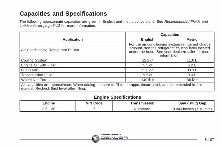
Capacities and SpecificationsThe following approximate capacities are given in English and metric conversions. See Recommended Fluids andLubricants on page 6-12 for more information.
ApplicationCapacities
English Metric
Air Conditioning Refrigerant R134a
For the air conditioning system refrigerant chargeamount, see the refrigerant caution label locatedunder the hood. See your dealer/retailer for more
information.Cooling System 12.2 qt 11.6 LEngine Oil with Filter 5.5 qt 5.2 LFuel Tank 22.0 gal 83.3 LTransmission Fluid 9.5 qt 9.0 LWheel Nut Torque 140 lb ft 190 YAll capacities are approximate. When adding, be sure to fill to the approximate level, as recommended in thismanual. Recheck fluid level after filling.
Engine SpecificationsEngine VIN Code Transmission Spark Plug Gap
3.6L V6 7 Automatic 0.043 inches (1.10 mm)
5-107
Information Provided by:

✍ NOTES
5-108
Information Provided by:

Maintenance Schedule ......................................6-2Introduction ...................................................6-2Maintenance Requirements ..............................6-2Your Vehicle and the Environment ....................6-2Using the Maintenance Schedule ......................6-2Scheduled Maintenance ...................................6-4Additional Required Services ............................6-6Maintenance Footnotes ...................................6-7
Owner Checks and Services ............................6-8At Each Fuel Fill ............................................6-8At Least Once a Month ...................................6-9At Least Once a Year .....................................6-9Recommended Fluids and Lubricants ...............6-12Maintenance Replacement Parts .....................6-14Engine Drive Belt Routing ..............................6-15Maintenance Record .....................................6-16
Section 6 Maintenance Schedule
6-1
Information Provided by:

Maintenance Schedule
IntroductionImportant: Keep engine oil at the proper level andchange as recommended.
Have you purchased the GM Protection Plan? The Plansupplements your new vehicle warranties. See yourWarranty and Owner Assistance booklet or yourdealer/retailer for details.
Maintenance RequirementsNotice: Maintenance intervals, checks, inspections,replacement parts, and recommended fluids andlubricants as prescribed in this manual arenecessary to keep your vehicle in good workingcondition. Any damage caused by failure to followscheduled maintenance might not be coveredby warranty.
Your Vehicle and the EnvironmentProper vehicle maintenance not only helps to keep yourvehicle in good working condition, but also helps theenvironment. All recommended maintenance isimportant. Improper vehicle maintenance can evenaffect the quality of the air we breathe. Improper fluidlevels or the wrong tire inflation can increase the level ofemissions from your vehicle. To help protect ourenvironment, and to keep your vehicle in good condition,be sure to maintain your vehicle properly.
Using the Maintenance ScheduleWe want to help you keep your vehicle in good workingcondition. But we do not know exactly how you willdrive it. You might drive very short distances only a fewtimes a week. Or you might drive long distances allthe time in very hot, dusty weather. You might use yourvehicle in making deliveries. Or you might drive it towork, to do errands, or in many other ways.
Because of all the different ways people use theirvehicles, maintenance needs vary. You might need morefrequent checks and replacements. So please readthe following and note how you drive. If you have anyquestions on how to keep your vehicle in good condition,see your dealer/retailer.
6-2
Information Provided by:

This schedule is for vehicles that:
• carry passengers and cargo within recommendedlimits. You will find these limits on the Tire andLoading Information label. See Loading YourVehicle on page 4-21.
• are driven on reasonable road surfaces within legaldriving limits.
• use the recommended fuel. See Gasoline Octaneon page 5-6.
The services in Scheduled Maintenance on page 6-4should be performed when indicated. See AdditionalRequired Services on page 6-6 and MaintenanceFootnotes on page 6-7 for further information.
{CAUTION:
Performing maintenance work on a vehicle canbe dangerous. In trying to do some jobs, youcan be seriously injured. Do your ownmaintenance work only if you have therequired know-how and the proper tools andequipment for the job.
CAUTION: (Continued)
CAUTION: (Continued)
If you have any doubt, see your dealer/retailerto have a qualified technician do the work. SeeDoing Your Own Service Work on page 5-5.
Some maintenance services can be complex. So,unless you are technically qualified and have thenecessary equipment, you should have yourdealer/retailer do these jobs.
When you go to your dealer/retailer for your serviceneeds, you will know that trained and supported servicetechnicians will perform the work using genuine parts.
If you want to purchase service information, see ServicePublications Ordering Information on page 7-14.
Owner Checks and Services on page 6-8 tells you whatshould be checked, when to check it, and what you caneasily do to help keep your vehicle in good condition.
The proper replacement parts, fluids, and lubricants touse are listed in Recommended Fluids and Lubricantson page 6-12 and Maintenance Replacement Partson page 6-14. When your vehicle is serviced, make surethese are used. All parts should be replaced and allnecessary repairs done before you or anyone elsedrives the vehicle. We recommend the use of genuineparts from your dealer/retailer.
6-3
Information Provided by:

Scheduled MaintenanceWhen the CHANGE ENGINE OIL SOON messagecomes on, it means that service is required for yourvehicle. Have your vehicle serviced as soon as possiblewithin the next 600 miles (1 000 km). It is possiblethat, if you are driving under the best conditions, theengine oil life system might not indicate that vehicleservice is necessary for over a year. However,the engine oil and filter must be changed at least oncea year and at this time the system must be reset.Your dealer/retailer has trained service technicians whowill perform this work using genuine parts and resetthe system.
If the engine oil life system is ever reset accidentally,you must service your vehicle within 3,000 miles(5 000 km) since your last service. Remember to resetthe oil life system whenever the oil is changed. SeeEngine Oil Life System on page 5-18 for information onthe Engine Oil Life System and resetting the system.
When the CHANGE ENGINE OIL SOON messageappears, certain services, checks, and inspections arerequired. Required services are described in thefollowing for “Maintenance I” and “Maintenance II.”Generally, it is recommended that your first service beMaintenance I, your second service be Maintenance II,and that you alternate Maintenance I and Maintenance IIthereafter. However, in some cases, Maintenance IImay be required more often.
Maintenance I — Use Maintenance I if the CHANGEENGINE OIL SOON message comes on within10 months since the vehicle was purchased orMaintenance II was performed.
Maintenance II — Use Maintenance II if the previousservice performed was Maintenance I. Always useMaintenance II whenever the message comes on10 months or more since the last service or if themessage has not come on at all for one year.
6-4
Information Provided by:

Scheduled MaintenanceService Maintenance I Maintenance II
Change engine oil and filter. See Engine Oil on page 5-15. Reset oil lifesystem. See Engine Oil Life System on page 5-18. An Emission ControlService.
• •
Visually check for any leaks or damage. See footnote (g). • •Inspect engine air cleaner filter. If necessary, replace filter. See Engine AirCleaner/Filter on page 5-20. See footnote (l). •
Rotate tires and check inflation pressures and wear. See Tire Inspection andRotation on page 5-62 and “Tire Wear Inspection” in At Least Once a Monthon page 6-9.
• •
Inspect brake system. See footnote (a). • •Check engine coolant and windshield washer fluid levels and add fluid asneeded. • •
Perform any needed additional services. See “Additional Required Services”in this section. • •
Inspect suspension and steering components. See footnote (b). •Inspect engine cooling system. See footnote (c). •Inspect wiper blades. See footnote (d). •Inspect restraint system components. See footnote (e). •Lubricate body components. See footnote (f). •Check transmission fluid level and add fluid as needed. •Inspect throttle system. See footnote (j). •
6-5
Information Provided by:
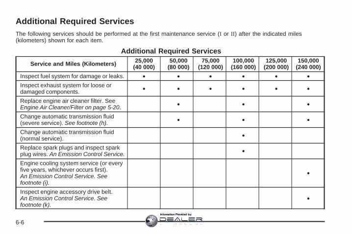
Additional Required ServicesThe following services should be performed at the first maintenance service (I or II) after the indicated miles(kilometers) shown for each item.
Additional Required Services
Service and Miles (Kilometers) 25,000(40 000)
50,000(80 000)
75,000(120 000)
100,000(160 000)
125,000(200 000)
150,000(240 000)
Inspect fuel system for damage or leaks. • • • • • •Inspect exhaust system for loose ordamaged components. • • • • • •
Replace engine air cleaner filter. SeeEngine Air Cleaner/Filter on page 5-20. • • •
Change automatic transmission fluid(severe service). See footnote (h). • • •
Change automatic transmission fluid(normal service). •
Replace spark plugs and inspect sparkplug wires. An Emission Control Service. •
Engine cooling system service (or everyfive years, whichever occurs first).An Emission Control Service. Seefootnote (i).
•
Inspect engine accessory drive belt.An Emission Control Service. Seefootnote (k).
•
6-6
Information Provided by:

Maintenance Footnotes(a) Visually inspect brake lines and hoses for properhook-up, binding, leaks, cracks, chafing, etc. Inspectdisc brake pads for wear and rotors for surfacecondition. Inspect other brake parts, including calipers,parking brake, etc. Check parking brake adjustment.
(b) Visually inspect front and rear suspension andsteering system for damaged, loose, or missing parts orsigns of wear. Inspect power steering lines and hosesfor proper hook-up, binding, leaks, cracks, chafing, etc.
(c) Visually inspect hoses and have them replaced if theyare cracked, swollen, or deteriorated. Inspect all pipes,fittings and clamps; replace with genuine parts asneeded. To help ensure proper operation, a pressure testof the cooling system and pressure cap and cleaning theoutside of the radiator and air conditioning condenser isrecommended at least once a year.
(d) Inspect wiper blades for wear, cracking, orcontamination. Clean the windshield and wiper blades,if contaminated. Replace wiper blades that are wornor damaged. See Windshield Wiper Blade Replacementon page 5-47 and Windshield, Backglass, and WiperBlades on page 5-94 for more information.
(e) Make sure the safety belt reminder light and safetybelt assemblies are working properly. Look for anyother loose or damaged safety belt system parts. If yousee anything that might keep a safety belt systemfrom doing its job, have it repaired. Have any torn orfrayed safety belts replaced. Also see Checkingthe Restraint Systems on page 1-77.
(f) Lubricate all key lock cylinders, hood latchassemblies, secondary latches, pivots, spring anchorand release pawl, hood and door hinges, rear foldingseats, and liftgate hinges. More frequent lubrication maybe required when exposed to a corrosive environment.Applying silicone grease on weatherstrips with aclean cloth will make them last longer, seal better,and not stick or squeak.
(g) A fluid loss in any vehicle system could indicatea problem. Have the system inspected and repairedand the fluid level checked. Add fluid if needed.
(h) Change automatic transmission fluid if the vehicle ismainly driven under one or more of these conditions:
− In heavy city traffic where the outside temperatureregularly reaches 90°F (32°C) or higher.
− In hilly or mountainous terrain.− When doing frequent trailer towing.− Uses such as found in taxi, police, or delivery
service.
6-7
Information Provided by:

(i) Drain, flush, and refill cooling system. This servicecan be complex; you should have your dealer/retailerperform this service. See Engine Coolant on page 5-22for what to use. Inspect hoses. Clean radiator,condenser, pressure cap, and filler neck. Pressure testthe cooling system and pressure cap.
(j) Check system for interference or binding and fordamaged or missing parts. Replace parts as needed.Replace any components that have high effort orexcessive wear. Do not lubricate accelerator or cruisecontrol cables.
(k) Visually inspect belt for fraying, excessive cracks,or obvious damage. Replace belt if necessary.
(l) If you drive regularly under dusty conditions, inspectthe filter at each engine oil change.
Owner Checks and ServicesThese owner checks and services should be performedat the intervals specified to help ensure the safety,dependability, and emission control performance of yourvehicle. Your dealer/retailer can assist you with thesechecks and services.
Be sure any necessary repairs are completed at once.Whenever any fluids or lubricants are added to yourvehicle, make sure they are the proper ones, as shownin Recommended Fluids and Lubricants on page 6-12.
At Each Fuel FillIt is important to perform these underhood checks ateach fuel fill.
Engine Oil Level Check
Notice: It is important to check the engine oilregularly and keep it at the proper level. Failure tokeep the engine oil at the proper level can causedamage to the engine not covered by your warranty.
Check the engine oil level and add the proper oil ifnecessary. See Engine Oil on page 5-15.
Engine Coolant Level CheckCheck the engine coolant level and add DEX-COOL®
coolant mixture if necessary. See Engine Coolanton page 5-22.
Windshield Washer Fluid Level CheckCheck the windshield washer fluid level in the windshieldwasher fluid reservoir and add the proper fluid ifnecessary.
6-8
Information Provided by:

At Least Once a Month
Tire Inflation CheckInspect your vehicle’s tires and make sure they areinflated to the correct pressures. Do not forget to checkthe spare tire. See Inflation - Tire Pressure onpage 5-55. Check to make sure the spare tire is storedsecurely. See Changing a Flat Tire on page 5-72.
Tire Wear InspectionTire rotation may be required for high mileage highwaydrivers prior to the Engine Oil Life System servicenotification. Check the tires for wear and, if necessary,rotate the tires. See Tire Inspection and Rotation onpage 5-62.
At Least Once a Year
Starter Switch Check
{CAUTION:
When you are doing this inspection, thevehicle could move suddenly. If the vehiclemoves, you or others could be injured.
1. Before you start, be sure you have enough roomaround the vehicle.
2. Firmly apply both the parking brake and the regularbrake. See Parking Brake on page 2-35.Do not use the accelerator pedal, and be ready toturn off the engine immediately if it starts.
3. Try to start the engine in each gear. The vehicleshould start only in PARK (P) or NEUTRAL (N).If the vehicle starts in any other position, contactyour dealer/retailer for service.
6-9
Information Provided by:
Automatic Transmission Shift LockControl System Check
{CAUTION:
When you are doing this inspection, thevehicle could move suddenly. If the vehiclemoves, you or others could be injured.
1. Before you start, be sure you have enough roomaround the vehicle. It should be parked on a levelsurface.
2. Firmly apply the parking brake. See Parking Brakeon page 2-35.Be ready to apply the regular brake immediately ifthe vehicle begins to move.
3. With the engine off, turn the ignition to ON/RUN,but do not start the engine. Without applying theregular brake, try to move the shift lever outof PARK (P) with normal effort. If the shift levermoves out of PARK (P), contact your dealer/retailerfor service.
Ignition Transmission Lock CheckWhile parked, and with the parking brake set, try to turnthe ignition to LOCK/OFF in each shift lever position.
• The ignition should turn to LOCK/OFF onlywhen the shift lever is in PARK (P).
• The ignition key should come out only inLOCK/OFF.
Contact your dealer/retailer if service is required.
6-10
Information Provided by:

Parking Brake and AutomaticTransmission Park (P) Mechanism Check
{CAUTION:
When you are doing this check, your vehiclecould begin to move. You or others could beinjured and property could be damaged. Makesure there is room in front of your vehicle incase it begins to roll. Be ready to apply theregular brake at once should the vehicle beginto move.
Park on a fairly steep hill, with the vehicle facingdownhill. Keeping your foot on the regular brake, setthe parking brake.
• To check the parking brake’s holding ability:With the engine running and the transmissionin NEUTRAL (N), slowly remove foot pressure fromthe regular brake pedal. Do this until the vehicleis held by the parking brake only.
• To check the PARK (P) mechanism’s holding ability:With the engine running, shift to PARK (P). Thenrelease the parking brake followed by the regularbrake.
Contact your dealer/retailer if service is required.
Underbody Flushing ServiceAt least every spring, use plain water to flush anycorrosive materials from the underbody. Take care toclean thoroughly any areas where mud and other debriscan collect.
6-11
Information Provided by:

Recommended Fluids andLubricantsFluids and lubricants identified below by name, partnumber, or specification can be obtained from yourdealer/retailer.
Usage Fluid/Lubricant
Engine Oil
Engine oil which meets GMStandard GM6094M and displaysthe American Petroleum InstituteCertified for Gasoline Enginesstarburst symbol. To determine theproper viscosity for your vehicle’sengine, see Engine Oil onpage 5-15.
Usage Fluid/Lubricant
Engine Coolant
50/50 mixture of clean, drinkablewater and use only DEX-COOL®
Coolant. See Engine Coolant onpage 5-22.
Hydraulic BrakeSystem
Delco® Supreme 11 Brake Fluid orequivalent DOT-3 brake fluid.
WindshieldWasher Optikleen® Washer Solvent.
Power SteeringSystem
GM Power Steering Fluid (GM PartNo. U.S. 89021184, inCanada 89021186).
AutomaticTransmission
DEXRON®-VI AutomaticTransmission Fluid.
Key LockCylinders
Multi-Purpose Lubricant, Superlube(GM Part No. U.S. 12346241, inCanada 10953474).
6-12
Information Provided by:

Usage Fluid/LubricantCarrier
Assembly —Differential(Rear Drive
Module)and TransferCase (PowerTransfer Unit)
SAE 75W-90 Synthetic AxleLubricant (GM Part No. U.S.89021677, in Canada 89021678)meeting GM Specification 9986115.
Hood LatchAssembly,Secondary
Latch,Pivots, SpringAnchor, and
Release Pawl
Lubriplate Lubricant Aerosol (GMPart No. U.S. 12346293, in Canada992723) or lubricant meetingrequirements of NLGI #2,Category LB or GC-LB.
Usage Fluid/LubricantHood and Door
Hingesand Rear
Folding Seat
Multi-Purpose Lubricant, Superlube(GM Part No. U.S. 12346241, inCanada 10953474).
WeatherstripConditioning
Weatherstrip Lubricant (GM Part No.U.S. 3634770, in Canada 10953518)or Dielectric Silicone Grease (GMPart No. U.S. 12345579, inCanada 992887).
6-13
Information Provided by:

Maintenance Replacement PartsReplacement parts identified below by name, part number, or specification can be obtained from your dealer/retailer.
Part Part Number ACDelco® Part NumberEngine Air Cleaner/Filter 15278634 —Engine Oil Filter 89017524 PF48Spark Plugs 12611882 41-107Windshield Wiper Blades
Right – 20.8 inches (53.0 cm) 15254804 —Left – 24.6 inches (62.5 cm) 15254805 —Rea – 11.6 inches (30.0 cm) 15276259 —
6-14
Information Provided by:

Engine Drive Belt Routing
3.6L V6 Engine
6-15
Information Provided by:

Maintenance RecordAfter the scheduled services are performed, record the date, odometer reading, who performed the service, and thetype of services performed in the boxes provided. See Maintenance Requirements on page 6-2. Any additionalinformation from Owner Checks and Services on page 6-8 can be added on the following record pages. You shouldretain all maintenance receipts.
Maintenance Record
Date OdometerReading Serviced By Maintenance I or
Maintenance II Services Performed
6-16
Information Provided by:

Maintenance Record (cont’d)
Date OdometerReading Serviced By Maintenance I or
Maintenance II Services Performed
6-17
Information Provided by:

Maintenance Record (cont’d)
Date OdometerReading Serviced By Maintenance I or
Maintenance II Services Performed
6-18
Information Provided by:

Customer Assistance and Information ...............7-2Customer Satisfaction Procedure ......................7-2Online Owner Center ......................................7-4Customer Assistance for Text Telephone
(TTY) Users ...............................................7-4Customer Assistance Offices ............................7-5GM Mobility Reimbursement Program ................7-6Roadside Assistance Program ..........................7-6Scheduling Service Appointments .....................7-8Courtesy Transportation ...................................7-9Collision Damage Repair ................................7-10
Reporting Safety Defects ................................7-13Reporting Safety Defects to the United States
Government ..............................................7-13Reporting Safety Defects to the Canadian
Government ..............................................7-14Reporting Safety Defects to General Motors .....7-14Service Publications Ordering Information .........7-14
Vehicle Data Recording and Privacy ................7-15Event Data Recorders ...................................7-16OnStar® ......................................................7-17Navigation System ........................................7-17Radio Frequency
Identification (RFID) ...................................7-17
Section 7 Customer Assistance Information
7-1
Information Provided by:

Customer Assistance andInformation
Customer Satisfaction ProcedureYour satisfaction and goodwill are important toyour dealer and to GMC. Normally, any concerns withthe sales transaction or the operation of the vehiclewill be resolved by your dealer’s sales or servicedepartments. Sometimes, however, despite the bestintentions of all concerned, misunderstandings canoccur. If your concern has not been resolved to yoursatisfaction, the following steps should be taken:
STEP ONE: Discuss your concern with a member ofdealership management. Normally, concerns canbe quickly resolved at that level. If the matter hasalready been reviewed with the sales, service or partsmanager, contact the owner of the dealership orthe general manager.
STEP TWO: If after contacting a member ofdealershipmanagement, it appears your concern cannotbe resolved by the dealership without further help, in theU.S., contact the GMC Consumer Relations Manager bycalling 1-800-GMC-8782 (1-800-462-8782, CustomerAssistance prompt). In Canada, contact General Motorsof Canada Customer Communication by calling1-800-263-3777 (English) or 1-800-263-7854 (French).
We encourage you to call the toll-free number in order togive your inquiry prompt attention. Please have thefollowing information available to give the CustomerAssistance Representative:
• Vehicle Identification Number (VIN). This is availablefrom the vehicle registration or title, or the plate at thetop left of the instrument panel and visible throughthe windshield.
• Dealership name and location.
• Vehicle delivery date and present mileage.
When contacting GMC, please remember that yourconcern will likely be resolved at a dealer’s facility.That is why we suggest you follow Step One first if youhave a concern.
STEP THREE — U.S. Owners: Both General Motorsand your dealer are committed to making sure youare completely satisfied with your new vehicle. However,if you continue to remain unsatisfied after followingthe procedure outlined in Steps One and Two,you should file with the Better Business Bureau (BBB)Auto Line Program to enforce your rights.
The BBB Auto Line Program is an out of court programadministered by the Council of Better BusinessBureaus to settle automotive disputes regarding vehiclerepairs or the interpretation of the New VehicleLimited Warranty.
7-2
Information Provided by:

Although you may be required to resort to this informaldispute resolution program prior to filling out a courtaction, use of the program is free of charge andyour case will generally be heard within 40 days. If youdo not agree with the decision given in your case,you may reject it and proceed with any other venue forrelief available to you.
You may contact the BBB Auto Line Program using thetoll-free telephone number or write them at thefollowing address:
BBB Auto Line ProgramCouncil of Better Business Bureaus, Inc.4200 Wilson BoulevardSuite 800Arlington, VA 22203-1838
Telephone: 1-800-955-5100
This program is available in all 50 states and the Districtof Columbia. Eligibility is limited by vehicle age,mileage, and other factors. General Motors reserves theright to change eligibility limitations and/or discontinueits participation in this program.
STEP THREE — Canadian Owners: In the event thatyou do not feel your concerns have been addressedafter following the procedure outlined in Steps 1 and 2,General Motors of Canada Limited wants you to beaware of its participation in a no-chargeMediation/Arbitration Program.
General Motors of Canada Limited has committed tobinding arbitration of owner disputes involvingfactory-related vehicle service claims. The programprovides for the review of the facts involved by animpartial third party arbiter, and may include an informalhearing before the arbiter. The program is designedso that the entire dispute settlement process, from thetime you file your complaint to the final decision,should be completed in approximately 70 days. Webelieve our impartial program offers advantagesover courts in most jurisdictions because it is informal,quick, and free of charge.
For further information concerning eligibility in theCanadian Motor Vehicle Arbitration Plan (CAMVAP),call toll-free 1-800-207-0685. Alternatively, you can callthe General Motors Customer Communication Centre,1-800-263-3777 (English), 1-800-263-7854 (French),or write to:
Mediation/Arbitration Programc/o Customer Communication CentreGeneral Motors of Canada LimitedMail Code: CA1-163-0051908 Colonel Sam DriveOshawa, Ontario L1H 8P7
Telephone: 1-800-955-5100
Your inquiry should be accompanied by your VehicleIdentification Number (VIN).
7-3
Information Provided by:

Online Owner Center
(United States only)The Owner Center is a resource for your GM ownershipneeds. Specific vehicle information can be found inone place.
The Online Owner Center allows you to:
• Get e-mail service reminders.
• Access information about your specific vehicle,including tips and videos and an electronicversion of this owner manual.
• Keep track of your vehicle’s service history andmaintenance schedule.
• Find GM dealers/retailers for service nationwide.
• Receive special promotions and privileges onlyavailable to members.
Refer to www.MyGMLink.com on the web for updatedinformation and to register your vehicle.
My GM Canada (Canada only)My GM Canada is a password-protected section ofgmcanada.com where you can save information onGM vehicles, get personalized offers, and use handytools and forms with greater ease.
Here are a few of the valuable tools and services youwill have access to:
− My Showroom: Find and save information onvehicles and current offers in your area.
− My Dealers/Retailers: Save details such asaddress and phone number for each of yourpreferred GM Dealers or Retailers.
− My Driveway: Receive service reminders andhelpful advice on owning and maintainingyour vehicle.
− My Preferences: Manage your profile, subscribe toE-News and use tools and forms with greater ease.
To sign up to My GM Canada, visit the My GM Canadasection within www.gmcanada.com.
Customer Assistance for TextTelephone (TTY) UsersTo assist customers who are deaf, hard of hearing,or speech-impaired and who use the Text Telephones(TTYs), GMC has TTY equipment available at itsCustomer Assistance Center. Any TTY user cancommunicate with GMC by dialing:1-800-GMC-8583 (462-8583). (TTY users inCanada can dial 1-800-263-3830.)
7-4
Information Provided by:

Customer Assistance OfficesGMC encourages customers to call the toll-free numberfor assistance. However, if a customer wishes towrite or e-mail GMC, the letter should be addressed to:
United StatesGMC Customer Assistance CenterP.O. Box 33172Detroit, MI 48232-5172
www.GMC.com1-800-GMC-8782 (462-8782)1-800-GMC-8583 (462-8583) (For Text Telephonedevices (TTYs))Roadside Assistance: 1-800-GMC-8782 (462-8782)Fax Number: 313-381-0022
From Puerto Rico1-800-496-9992 (English)1-800-496-9993 (Spanish)Fax Number: 313-381-0022
U.S. Virgin Islands:1-800-496-9994Fax Number: 313-381-0022
CanadaGeneral Motors of Canada LimitedCustomer Communication Centre, CA1-163-0051908 Colonel Sam DriveOshawa, Ontario L1H 8P7
www.gmcanada.com1-800-263-3777 (English)1-800-263-7854 (French)1-800-263-3830 (For Text Telephone devices (TTYs))Roadside Assistance: 1-800-268-6800
All Overseas LocationsPlease contact the local General Motors Business Unit.
Mexico, Central America andCaribbean Islands/Countries (ExceptPuerto Rico and U.S. Virgin Islands)
General Motors de Mexico, S. de R.L. de C.V.Customer Assistance CenterPaseo de la Reforma # 2740Col. Lomas de BezaresC.P. 11910, Mexico, D.F.01-800-508-0000Long Distance: 011-52-53 29 0 800
7-5
Information Provided by:

GM Mobility ReimbursementProgram
This program, available to qualified applicants, canreimburse you up to $1,000 of the cost of eligibleaftermarket adaptive equipment required for yourvehicle, such as hand controls or awheelchair/scooter lift.
The offer is available for a very limited period of timefrom the date of vehicle purchase/lease. For moredetails, or to determine your vehicle’s eligibility, visitgmmobility.com or call the GM Mobility AssistanceCenter at 1-800-323-9935. Text telephone (TTY) users,call 1-800-833-9935.
General Motors of Canada also has a Mobility Program.Call 1-800-GM-DRIVE (463-7483) for details. TTYusers call 1-800-263-3830.
Roadside Assistance ProgramFor vehicles purchased in the U.S. call,1-800-GMC-8782 (1-800-462-8782); (Text telephone(TTY): 1-888-889-2438).
For vehicles purchased in Canada, call 1-800-268-6800.
Service is available 24 hours a day, 365 days a year.
As the owner of a new GMC vehicle, you areautomatically enrolled in the GMC Roadside Assistanceprogram.
Who is Covered?Roadside Assistance coverage is for the vehicleoperator, regardless of ownership. In Canada, a persondriving the vehicle without the consent of the owneris not eligible for coverage.
Services ProvidedThe following services are provided in the U.S. andCanada up to 5 years/100,000 miles (160 000 km),whichever occurs first, and, in Canada only, upto a maximum coverage of $100.
• Fuel Delivery: Delivery of enough fuel for thevehicle to get to the nearest service station(approximately $5 in Canada). In Canada, serviceto provide diesel may be restricted. For safetyreasons, propane and other alternative fuels will notbe provided through this service.
7-6
Information Provided by:

• Lock-out Service: Lock-out service will be coveredat no charge if you are unable to gain entry intoyour vehicle. A remote unlock may be available ifyou have an active OnStar® subscription. To ensuresecurity, the driver must present personalidentification before lock-out service is provided. InCanada, the vehicle registration is also required.
• Emergency Tow From a Public Roadway orHighway: Tow to the nearest dealership forwarranty service or in the event of avehicle-disabling crash. Winch-out assistance isprovided when the vehicle is mired in sand, mud,or snow.
• Flat Tire Change: Installation of a spare tire ingood condition, when equipped and properlyinflated, is covered at no charge. The customer isresponsible for the repair or replacement of thetire if not covered by a warrantable failure.
• Jump Start: A battery jump start is covered at nocharge if the vehicle does not start.
• Trip Routing Service: Upon request, RoadsideAssistance will send you detailed, computerpersonalized maps, highlighting your choice ofeither the most direct route or the most scenic routeto your destination, anywhere in North America,along with helpful travel information pertainingto your trip.
Please allow three weeks before your planneddeparture date. In Canada, trip routing requests willbe limited to six per calendar year.
• Trip Interruption Benefits and Assistance: In theevent of a warranty related vehicle disablement,while en route and over 150 miles (250 kilometres)from original point of departure, you may qualifyfor trip interruption expense assistance. Thisassistance covers reasonable reimbursement of upto a maximum of $500. In Canada, maximumsinclude: (A) meals (maximum of $50/day),(B) lodging (maximum of $100/night) and(C) alternate ground transportation (maximum of$40/day). This benefit is to assist you with some ofthe unplanned expense you may incur whilewaiting for your vehicle to be repaired.Original detailed receipts, and a copy of the repairorder are required. In Canada, pre-authorizationis also required.Once authorization has been given, your advisorwill help you make any necessary arrangementsand explain how to claim for trip interruptionexpense assistance.
7-7
Information Provided by:
• Alternative Service (Canada only): There may betimes, when Roadside Assistance cannot providetimely assistance. Your advisor may authorizeyou to secure local emergency road service, andyou will be reimbursed up to $100 (Canadian) uponsubmission of the original receipt to RoadsideAssistance.
In many instances, mechanical failures may be covered.However, when other services are utilized, ourRoadside Assistance Representatives will explain anypayment obligations you might incur.
GMC and General Motors of Canada Limited reservethe right to limit services or reimbursement to an owneror driver when, in their sole discretion, the claimsbecome excessive in frequency or type of occurrence.
Calling For AssistanceFor prompt and efficient assistance when calling, pleaseprovide the following to the Roadside AssistanceRepresentative:
• Your name, home address, and home telephonenumber
• Telephone number of your location
• Location of the vehicle.
• Model, year, color, and license plate number of thevehicle
• Odometer reading, Vehicle Identification Number(VIN), and delivery date of the vehicle
• Description of the problem
Towing and Road Service ExclusionsSpecifically excluded from Roadside Assistancecoverage are towing or services for vehicles operatedon a non-public roadway or highway, fines, impoundtowing caused by a violation of local, Municipal, State,Provincial, or Federal law, and mounting, dismounting orchanging of snow tires, chains, or other tractiondevices.
Roadside Assistance is not part of or included in thecoverage provided by the New Vehicle Limited Warranty.GMC and General Motors of Canada Limited reservethe right to make any changes or discontinue theRoadside Assistance program at any time withoutnotification.
Scheduling Service AppointmentsWhen your vehicle requires warranty service, contactyour dealer/retailer and request an appointment.By scheduling a service appointment and advising yourservice consultant of your transportation needs, yourdealer/retailer can help minimize your inconvenience.
7-8
Information Provided by:

If your vehicle cannot be scheduled into the servicedepartment immediately, keep driving it until it can bescheduled for service, unless, of course, the problem issafety-related. If it is, please call your dealership/retailer,let them know this, and ask for instructions.
If the dealer/retailer requests that you simply drop thevehicle off for service, you are urged to do so as earlyin the work day as possible to allow for the sameday repair.
Courtesy TransportationTo enhance your ownership experience, we and ourparticipating dealers are proud to offer CourtesyTransportation, a customer support program for vehicleswith the Bumper to Bumper (Base Warranty Coverageperiod in Canada) and extended powertrain warrantyin both the U.S. and Canada.
Several courtesy transportation options are available toassist in reducing your inconvenience when warrantyrepairs are required.
Courtesy Transportation is not a part of the New VehicleLimited Warranty. A separate booklet entitled “Warrantyand Owner Assistance Information” furnished witheach new vehicle provides detailed warranty coverageinformation.
Transportation OptionsWarranty service can generally be completed while youwait. However, if you are unable to wait, GM helpsto minimize your inconvenience by providing severaltransportation options. Depending on the circumstances,your dealer can offer you one of the following:
Shuttle ServiceShuttle service is the preferred means of offeringCourtesy Transportation. Dealers may provide you withshuttle service to get you to your destination withminimal interruption of your daily schedule. This includesone-way or round trip shuttle service within reasonabletime and distance parameters of the dealer’s area.
Public Transportation or FuelReimbursementIf your vehicle requires overnight warranty repairs, andpublic transportation is used instead of the dealer’sshuttle service, the expense must be supportedby original receipts and can only be up to the maximumamount allowed by GM for shuttle service. In addition,for U.S. customers, should you arrange transportationthrough a friend or relative, limited reimbursementfor reasonable fuel expenses may be available.
7-9
Information Provided by:

Claim amounts should reflect actual costs and besupported by original receipts. See your dealer forinformation regarding the allowance amounts forreimbursement of fuel or other transportation costs.
Courtesy Rental VehicleYour dealer may arrange to provide you with a courtesyrental vehicle or reimburse you for a rental vehiclethat you obtain if your vehicle is kept for an overnightwarranty repair. Rental reimbursement will be limitedand must be supported by original receipts. Thisrequires that you sign and complete a rental agreementand meet state/provincial, local, and rental vehicleprovider requirements. Requirements vary and mayinclude minimum age requirements, insurance coverage,credit card, etc. You are responsible for fuel usagecharges and may also be responsible for taxes, levies,usage fees, excessive mileage, or rental usagebeyond the completion of the repair.
It may not be possible to provide a like-vehicle as acourtesy rental.
Additional Program InformationAll program options, such as shuttle service, may not beavailable at every dealer. Please contact your dealerfor specific information about availability. All CourtesyTransportation arrangements will be administeredby appropriate dealer personnel.
General Motors reserves the right to unilaterally modify,change or discontinue Courtesy Transportation atany time and to resolve all questions of claim eligibilitypursuant to the terms and conditions describedherein at its sole discretion.
Collision Damage RepairIf your vehicle is involved in a collision and it isdamaged, have the damage repaired by a qualifiedtechnician using the proper equipment and qualityreplacement parts. Poorly performed collision repairsdiminish your vehicle’s resale value, and safetyperformance can be compromised in subsequentcollisions.
Collision PartsGenuine GM Collision parts are new parts made with thesame materials and construction methods as the partswith which your vehicle was originally built. Genuine GMCollision parts are your best choice to ensure that yourvehicle’s designed appearance, durability, and safety arepreserved. The use of Genuine GM parts can helpmaintain your GM New Vehicle Warranty.
Recycled original equipment parts may also be used forrepair. These parts are typically removed from vehiclesthat were total losses in prior crashes. In most cases,the parts being recycled are from undamaged sectionsof the vehicle.
7-10
Information Provided by:

A recycled original equipment GM part, may be anacceptable choice to maintain your vehicle’s originallydesigned appearance and safety performance, however,the history of these parts is not known. Such partsare not covered by your GM New Vehicle LimitedWarranty, and any related failures are not covered bythat warranty.
Aftermarket collision parts are also available. Theseare made by companies other than GM and maynot have been tested for your vehicle. As a result,these parts may fit poorly, exhibit prematuredurability/corrosion problems, and may not performproperly in subsequent collisions. Aftermarket partsare not covered by your GM New Vehicle LimitedWarranty, and any vehicle failure related to suchparts are not covered by that warranty.
Repair FacilityGM also recommends that you choose a collision repairfacility that meets your needs before you ever needcollision repairs. Your dealer/retailer may have acollision repair center with GM-trained technicians andstate of the art equipment, or be able to recommenda collision repair center that has GM-trained techniciansand comparable equipment.
Insuring Your VehicleProtect your investment in your GM vehicle withcomprehensive and collision insurance coverage.There are significant differences in the quality ofcoverage afforded by various insurance policy terms.Many insurance policies provide reduced protectionto your GM vehicle by limiting compensation for damagerepairs by using aftermarket collision parts. Someinsurance companies will not specify aftermarketcollision parts. When purchasing insurance, werecommend that you assure your vehicle will be repairedwith GM original equipment collision parts. If suchinsurance coverage is not available from your currentinsurance carrier, consider switching to anotherinsurance carrier.
If your vehicle is leased, the leasing company mayrequire you to have insurance that assures repairs withGenuine GM Original Equipment Manufacturer (OEM)parts or Genuine Manufacturer replacement parts. Readyour lease carefully, as you may be charged at theend of your lease for poor quality repairs.
7-11
Information Provided by:

If a Crash OccursHere is what to do if you are involved in a crash.
• Try to relax and then check to make sure you are allright. If you are uninjured, make sure that no one elsein your vehicle, or the other vehicle, is injured.
• If there has been an injury, call emergency servicesfor help. Do not leave the scene of a crash until allmatters have been taken care of. Move your vehicleonly if its position puts you in danger or you areinstructed to move it by a police officer.
• Give only the necessary and requested informationto police and other parties involved in the crash. Donot discuss your personal condition, mental frame ofmind, or anything unrelated to the crash. This willhelp guard against post-crash legal action.
• If you need roadside assistance, call GM RoadsideAssistance. See Roadside Assistance Program onpage 7-6 for more information.
• If your vehicle cannot be driven, know where thetowing service will be taking it. Get a card from thetow truck operator or write down the driver’s name,the service’s name, and the phone number.
• Remove any valuables from your vehicle before it istowed away. Make sure this includes your insuranceinformation and registration if you keep these itemsin your vehicle.
• Gather the important information you will need fromthe other driver. Things like name, address, phonenumber, driver’s license number, vehicle licenseplate, vehicle make, model and model year, VehicleIdentification Number (VIN), insurance company andpolicy number, and a general description of thedamage to the other vehicle.
• If possible, call your insurance company from thescene of the crash. They will walk you through theinformation they will need. If they ask for a policereport, phone or go to the police departmentheadquarters the next day and you can get a copy ofthe report for a nominal fee. In some states/provinceswith “no fault” insurance laws, a report may not benecessary. This is especially true if there are noinjuries and both vehicles are driveable.
• Choose a reputable collision repair facility for yourvehicle. Whether you select a dealer/retailer or aprivate collision repair facility to fix the damage,make sure you are comfortable with them.Remember, you will have to feel comfortable withtheir work for a long time.
• Once you have an estimate, read it carefully andmake sure you understand what work will beperformed on your vehicle. If you have a question,ask for an explanation. Reputable shops welcomethis opportunity.
7-12
Information Provided by:

Managing the Vehicle Damage RepairProcessIn the event that your vehicle requires damage repairs,GM recommends that you take an active role in itsrepair. If you have a pre-determined repair facility ofchoice, take your vehicle there, or have it towed there.Specify to the facility that any required replacementcollision parts be original equipment parts, either newGenuine GM parts or recycled original GM parts.Remember, recycled parts will not be covered by yourGM vehicle warranty.
Insurance pays the bill for the repair, but you must livewith the repair. Depending on your policy limits, yourinsurance company may initially value the repair usingaftermarket parts. Discuss this with your repairprofessional, and insist on Genuine GM parts.Remember if your vehicle is leased you may beobligated to have the vehicle repaired with Genuine GMparts, even if your insurance coverage does not paythe full cost.
If another party’s insurance company is paying for therepairs, you are not obligated to accept a repairvaluation based on that insurance company’s collisionpolicy repair limits, as you have no contractual limits withthat company. In such cases, you can have control ofthe repair and parts choices as long as cost stays withinreasonable limits.
Reporting Safety Defects
Reporting Safety Defects to theUnited States GovernmentIf you believe that your vehicle has a defect whichcould cause a crash or could cause injury ordeath, you should immediately inform the NationalHighway Traffic Safety Administration (NHTSA)in addition to notifying General Motors.
If NHTSA receives similar complaints, it may openan investigation, and if it finds that a safetydefect exists in a group of vehicles, it may ordera recall and remedy campaign. However,NHTSA cannot become involved in individualproblems between you, your dealer/retailer,or General Motors.
To contact NHTSA, you may call the VehicleSafety Hotline toll-free at 1-888-327-4236 (TTY:1-800-424-9153); go to http://www.safercar.gov;or write to:
Administrator, NHTSA400 Seventh Street, SW.Washington D.C., 20590
You can also obtain other information about motorvehicle safety from http://www.safercar.gov.
7-13
Information Provided by:

Reporting Safety Defects to theCanadian GovernmentIf you live in Canada, and you believe that your vehiclehas a safety defect, notify Transport Canadaimmediately, in addition to notifying General Motors ofCanada Limited. Call them at 1-800-333-0510or write to:
Transport CanadaRoad Safety Branch2780 Sheffield RoadOttawa, Ontario K1B 3V9
Reporting Safety Defects to GeneralMotorsIn addition to notifying NHTSA (or Transport Canada) ina situation like this, please notify General Motors.
Call 1-800-GMC-8782 (1-800-462-8782), or write:
GMC Customer Assistance CenterP.O. Box 33172Detroit, MI 48232-5172
In Canada, call 1-800-263-3777 (English) or1-800-263-7854 (French), or write:
General Motors of Canada LimitedCustomer Communication Centre, CA1-163-0051908 Colonel Sam DriveOshawa, Ontario L1H 8P7
Service Publications OrderingInformation
Service ManualsService Manuals have the diagnosis and repairinformation on engines, transmission, axle suspension,brakes, electrical, steering, body, etc.
Service BulletinsService Bulletins’ give additional technical serviceinformation needed to knowledgeably service GeneralMotors cars and trucks. Each bulletin containsinstructions to assist in the diagnosis and service ofyour vehicle.
Owner InformationOwner publications are written specifically for ownersand intended to provide basic operational informationabout the vehicle. The owner manual includes theMaintenance Schedule for all models.
In-Portfolio: Includes a Portfolio, Owner Manual, andWarranty Booklet.
RETAIL SELL PRICE: $35.00 (U.S.) plus processing fee
Without Portfolio: Owner Manual only.
RETAIL SELL PRICE: $25.00 (U.S.) plus processing fee
7-14
Information Provided by:

Current and Past Model Order FormsTechnical Service Bulletins and Manuals are availablefor current and past model GM vehicles. To requestan order form, specify year and model name ofthe vehicle.
ORDER TOLL FREE: 1-800-551-4123Monday-Friday 8:00 AM - 6:00 PMEastern TimeFor Credit Card Orders Only(VISA-MasterCard-Discover), visit Helm, Inc.on the World Wide Web at: www.helminc.com
Or you can write to:
Helm, IncorporatedP.O. Box 07130Detroit, MI 48207
Prices are subject to change without notice and withoutincurring obligation. Allow ample time for delivery.
Note to Canadian Customers: All listed prices arequoted in U.S. funds. Canadian residents are to makechecks payable in U.S. funds.
Vehicle Data Recording andPrivacyYour GM vehicle has a number of sophisticatedcomputers that record information about the vehicle’sperformance and how it is driven. For example,your vehicle uses computer modules to monitor andcontrol engine and transmission performance, to monitorthe conditions for airbag deployment and deployairbags in a crash and, if so equipped, to provideantilock braking to help the driver control the vehicle.These modules may store data to help yourdealer/retailer technician service your vehicle. Somemodules may also store data about how you operatethe vehicle, such as rate of fuel consumption or averagespeed. These modules may also retain the owner’spersonal preferences, such as radio pre-sets, seatpositions, and temperature settings.
7-15
Information Provided by:

Event Data RecordersThis vehicle has an Event Data Recorder (EDR). Themain purpose of an EDR is to record, in certain crash ornear crash-like situations, such as an airbag deploymentor hitting a road obstacle, data that will assist inunderstanding how a vehicle’s systems performed. TheEDR is designed to record data related to vehicledynamics and safety systems for a short period of time,typically 30 seconds or less. The EDR in this vehicleis designed to record such data as:
• How various systems in your vehicle were operating
• Whether or not the driver and passenger safetybelts were buckled/fastened
• How far, if at all, the driver was pressing theaccelerator and/or brake pedal
• How fast the vehicle was traveling
This data can help provide a better understanding of thecircumstances in which crashes and injuries occur.
Important: EDR data is recorded by your vehicle onlyif a non-trivial crash situation occurs; no data isrecorded by the EDR under normal driving conditionsand no personal data (e.g., name, gender, age,and crash location) is recorded. However, other parties,such as law enforcement, could combine the EDRdata with the type of personally identifying data routinelyacquired during a crash investigation.
To read data recorded by an EDR, special equipmentis required, and access to the vehicle or the EDRis needed. In addition to the vehicle manufacturer, otherparties, such as law enforcement, that have thespecial equipment, can read the information if they haveaccess to the vehicle or the EDR.
GM will not access this data or share it with othersexcept: with the consent of the vehicle owner or, if thevehicle is leased, with the consent of the lessee; inresponse to an official request of police or similargovernment office; as part of GM’s defense of litigationthrough the discovery process; or, as required bylaw. Data that GM collects or receives may also be usedfor GM research needs or may be made available toothers for research purposes, where a need is shownand the data is not tied to a specific vehicle orvehicle owner.
7-16
Information Provided by:

OnStar®
If your vehicle has OnStar and you subscribe to theOnStar services, please refer to the OnStar Termsand Conditions for information on data collectionand use. See also OnStar® System on page 2-47in this manual for more information.
Navigation SystemIf your vehicle has a navigation system, use of thesystem may result in the storage of destinations,addresses, telephone numbers, and other tripinformation. Refer to the navigation system operatingmanual for information on stored data and for deletioninstructions.
Radio FrequencyIdentification (RFID)RFID technology is used in some vehicles for functionssuch as tire pressure monitoring and ignition systemsecurity, as well as in connection with conveniencessuch as key fobs for remote door locking/unlocking andstarting, and in-vehicle transmitters for garage dooropeners. RFID technology in GM vehicles does not useor record personal information or link with any otherGM system containing personal information.
7-17
Information Provided by:

✍ NOTES
7-18
Information Provided by:
AAccessories and Modifications ............................ 5-4Adding Equipment to Your Airbag-Equipped
Vehicle ....................................................... 1-76Additives, Fuel ................................................. 5-7Add-On Electrical Equipment ............................ 5-99Air Cleaner/Filter, Engine ................................. 5-20Air Conditioning ...................................... 3-26, 3-29Airbag
Passenger Status Indicator ........................... 3-43Readiness Light .......................................... 3-42
Airbag System ................................................ 1-61What Will You See After an Airbag Inflates? .... 1-69When Should an Airbag Inflate? .................... 1-67Where Are the Airbags? ............................... 1-64
Airbag SystemsAdding Equipment to Your Airbag-Equipped
Vehicle ................................................... 1-76How Does an Airbag Restrain? ...................... 1-68Passenger Sensing System ........................... 1-70Servicing Your Airbag-Equipped Vehicle .......... 1-75What Makes an Airbag Inflate? ...................... 1-68
All-Wheel Drive ............................................... 5-43All-Wheel-Drive (AWD) System ........................... 4-9Antilock Brake System (ABS) ............................. 4-5Antilock Brake, System Warning Light ................ 3-48
Appearance CareAluminum or Chrome-Plated Wheels .............. 5-94Care of Safety Belts .................................... 5-92Chemical Paint Spotting ............................... 5-96Cleaning Exterior Lamps/Lenses .................... 5-93Fabric/Carpet .............................................. 5-90Finish Care ................................................. 5-93Finish Damage ............................................ 5-95Instrument Panel, Vinyl, and Other Plastic
Surfaces ................................................. 5-91Interior Cleaning .......................................... 5-89Leather ...................................................... 5-91Sheet Metal Damage ................................... 5-95Tires .......................................................... 5-95Underbody Maintenance ............................... 5-96Vehicle Care/Appearance Materials ................ 5-97Washing Your Vehicle ................................... 5-92Weatherstrips .............................................. 5-92Windshield, Backglass, and Wiper Blades ....... 5-94
Appointments, Scheduling Service ....................... 7-8Audio System ................................................. 3-84
Audio Steering Wheel Controls .................... 3-128Navigation/Radio System, see Navigation
Manual ................................................. 3-115Radio Reception ........................................ 3-129Rear Audio Controller (RAC) ........................ 3-127Rear Seat Audio (RSA) ............................... 3-125
1
Information Provided by:

Audio System (cont.)Setting the Time .......................................... 3-85Theft-Deterrent Feature ............................... 3-127
Audio System(s) ............................................. 3-87Automatic Transmission
Fluid .......................................................... 5-21Operation ................................................... 2-30
BBattery .......................................................... 5-38
Electric Power Management .......................... 3-19Run-Down Protection ................................... 3-20
BrakeEmergencies ................................................ 4-6
Brakes .......................................................... 5-35System Warning Light .................................. 3-47
Braking ........................................................... 4-4Braking in Emergencies ..................................... 4-6Break-In, New Vehicle ..................................... 2-25Bulb Replacement ........................................... 5-45
Halogen Bulbs ............................................ 5-45Headlamp Aiming ........................................ 5-45License Plate Lamps .................................... 5-46Replacement Bulbs ...................................... 5-46
Buying New Tires ........................................... 5-64
CCalibration ..................................................... 2-40California Fuel .................................................. 5-7California Perchlorate Materials Requirements ....... 5-4California Proposition 65 Warning ....................... 5-4Canadian Owners ................................................ iiCapacities and Specifications .......................... 5-107Carbon Monoxide ................... 2-14, 2-38, 4-17, 4-30Care of
Safety Belts ................................................ 5-92Cargo Cover .................................................. 2-58Cargo Management System ............................. 2-59Cargo Tie Downs ............................................ 2-59CD, MP3 ............................................ 3-104, 3-108Center Console Storage Area ........................... 2-56Chains, Tire ................................................... 5-70Charging System Light .................................... 3-45Check
Engine Light ............................................... 3-50Checking Things Under the Hood ...................... 5-12Chemical Paint Spotting ................................... 5-96Child Restraints
Child Restraint Systems ............................... 1-43Infants and Young Children ........................... 1-39Lower Anchors and Tethers for Children .......... 1-47Older Children ............................................. 1-36
2
Information Provided by:

Child Restraints (cont.)Securing a Child Restraint in a Rear Seat
Position .................................................. 1-55Securing a Child Restraint in the Right
Front Seat Position ................................... 1-58Where to Put the Restraint ........................... 1-46
CleaningAluminum or Chrome-Plated Wheels .............. 5-94Exterior Lamps/Lenses ................................. 5-93Fabric/Carpet .............................................. 5-90Finish Care ................................................. 5-93Instrument Panel, Vinyl, and Other Plastic
Surfaces ................................................. 5-91Interior ....................................................... 5-89Leather ...................................................... 5-91Tires .......................................................... 5-95Underbody Maintenance ............................... 5-96Washing Your Vehicle ................................... 5-92Weatherstrips .............................................. 5-92Windshield, Backglass, and Wiper Blades ....... 5-94
Climate Control System ................................... 3-26Dual Automatic ............................................ 3-29Outlet Adjustment ........................................ 3-36Rear Air Conditioning and Heating System ...... 3-36Rear Air Conditioning and Heating System,
Electronic ................................................ 3-38
Clock ............................................................ 3-85Collision Damage Repair .................................. 7-10Compact Spare Tire ........................................ 5-88Compass ....................................................... 2-40Content Theft-Deterrent .................................... 2-21Control of a Vehicle .......................................... 4-3Convenience Net ............................................ 2-58Coolant
Engine Temperature Gage ............................ 3-49Engine Temperature Warning Light ................. 3-49Heater, Engine ............................................ 2-29
Cooling System .............................................. 5-27Courtesy Lamps ............................................. 3-17Cruise Control ................................................ 3-12Cruise Control Light ........................................ 3-55Cupholder(s) .................................................. 2-55Customer Assistance Information
Courtesy Transportation .................................. 7-9Customer Assistance for Text Telephone (TTY)
Users ....................................................... 7-4Customer Assistance Offices ........................... 7-5Customer Satisfaction Procedure ..................... 7-2GM Mobility Reimbursement Program ............... 7-6Reporting Safety Defects to General Motors .... 7-14Reporting Safety Defects to the Canadian
Government ............................................ 7-14
3
Information Provided by:

Customer Assistance Information (cont.)Reporting Safety Defects to the United
States Government ................................... 7-13Roadside Assistance Program ......................... 7-6Service Publications Ordering Information ........ 7-14
DDaytime Running Lamps/Automatic Headlamp
System ...................................................... 3-16Defensive Driving ............................................. 4-2Delayed Entry Lighting ..................................... 3-18Delayed Exit Lighting ....................................... 3-18Delayed Headlamps ........................................ 3-15Delayed Locking ............................................. 2-11Disc, MP3 .......................................... 3-104, 3-108Doing Your Own Service Work ........................... 5-5Dome Lamp Override ...................................... 3-17Dome Lamps ................................................. 3-17Door
Delayed Locking .......................................... 2-11Locks ........................................................ 2-10Power Door Locks ....................................... 2-11Programmable Automatic Door Locks ............. 2-11Rear Door Security Locks ............................. 2-11
DriverSeat Height Adjuster ...................................... 1-3
Driver Information Center (DIC) ......................... 3-57DIC Operation and Displays .................. 3-57, 3-63DIC Vehicle Customization ............................ 3-75DIC Warnings and Messages ........................ 3-66
DrivingAt Night ..................................................... 4-13Before a Long Trip ...................................... 4-15Defensive ..................................................... 4-2Drunken ....................................................... 4-2Highway Hypnosis ....................................... 4-15Hill and Mountain Roads .............................. 4-16In Rain and on Wet Roads ........................... 4-14Rocking Your Vehicle to Get it Out ................. 4-21Winter ........................................................ 4-17
Dual Automatic Climate Control System ............. 3-29DVD
Rear Seat Entertainment System .................. 3-115
EEDR ............................................................. 7-15Electrical System
Add-On Equipment ...................................... 5-99Fuses and Circuit Breakers ......................... 5-100Instrument Panel Fuse Block ....................... 5-100Power Windows and Other Power Options .... 5-100Underhood Fuse Block ............................... 5-103Windshield Wiper Fuses ............................. 5-100
4
Information Provided by:

EngineAir Cleaner/Filter ......................................... 5-20Check and Service Engine Soon Light ............ 3-50Coolant ...................................................... 5-22Coolant Heater ............................................ 2-29Coolant Temperature Gage ........................... 3-49Coolant Temperature Warning Light ................ 3-49Drive Belt Routing ....................................... 6-15Engine Compartment Overview ...................... 5-14Exhaust ..................................................... 2-38Oil ............................................................. 5-15Oil Life System ........................................... 5-18Overheated Protection Operating Mode ........... 5-26Overheating ................................................ 5-25Running While Parked .................................. 2-39Starting ...................................................... 2-27
Entry Lighting ................................................. 3-17Event Data Recorders ..................................... 7-16Extender, Safety Belt ....................................... 1-36Exterior Lamps ............................................... 3-14
FFilter
Engine Air Cleaner ...................................... 5-20Finish Damage ............................................... 5-95Flashers, Hazard Warning .................................. 3-6
Flash-to-Pass ................................................... 3-9Flat Tire ........................................................ 5-71Flat Tire, Changing ......................................... 5-72Flat Tire, Storing ............................................. 5-84Floor Mats ..................................................... 2-57Fluid ............................................................. 5-21
Power Steering ........................................... 5-33Windshield Washer ...................................... 5-34
Fog LampFog ........................................................... 3-16
Fog Lamp Light .............................................. 3-55Fuel ............................................................... 5-6
Additives ...................................................... 5-7California Fuel .............................................. 5-7Filling a Portable Fuel Container .................... 5-12Filling the Tank ............................................. 5-9Fuels in Foreign Countries .............................. 5-8Gage ......................................................... 3-56Gasoline Octane ........................................... 5-6Gasoline Specifications .................................. 5-6
FusesFuses and Circuit Breakers ......................... 5-100Instrument Panel Fuse Block ....................... 5-100Underhood Fuse Block ............................... 5-103Windshield Wiper ....................................... 5-100
5
Information Provided by:

GGage
Engine Coolant Temperature ......................... 3-49Fuel .......................................................... 3-56Speedometer .............................................. 3-41Tachometer ................................................. 3-41Voltmeter Gage ........................................... 3-46
Garage Door Opener ....................................... 2-50Gasoline
Octane ........................................................ 5-6Specifications ............................................... 5-6
Glove Box ..................................................... 2-55GM Mobility Reimbursement Program .................. 7-6
HHazard Warning Flashers ................................... 3-6Head Restraints .............................................. 1-10Headlamp
Aiming ....................................................... 5-45Headlamps
Bulb Replacement ....................................... 5-45Daytime Running Lamps/Automatic
Headlamp System .................................... 3-16Delayed ..................................................... 3-15Exterior Lamps ............................................ 3-14Flash-to-Pass ............................................... 3-9
Headlamps (cont.)Halogen Bulbs ............................................ 5-45High/Low Beam Changer ................................ 3-9
Head-Up Display (HUD) ................................... 3-20Heated Seats ................................................... 1-5Heater ........................................................... 3-26Heater ........................................................... 3-29Height Adjuster, Driver Seat ............................... 1-3High Voltage Devices and Wiring ...................... 5-99Highbeam On Light ......................................... 3-55Highway Hypnosis ........................................... 4-15Hill and Mountain Roads .................................. 4-16Hood
Checking Things Under ................................ 5-12Release ..................................................... 5-13
Horn ............................................................... 3-6How to Wear Safety Belts Properly ................... 1-22
IIgnition Positions ............................................. 2-26Infants and Young Children, Restraints ............... 1-39Inflation - Tire Pressure ................................... 5-55Instrument Panel
Overview ..................................................... 3-4Storage Area .............................................. 2-55
Instrument Panel (I/P)Brightness .................................................. 3-17Cluster ....................................................... 3-40
6
Information Provided by:

JJump Starting ................................................. 5-39
KKeyless Entry System ....................................... 2-4Keys ............................................................... 2-3
LLabeling, Tire Sidewall ..................................... 5-49Lamps
Courtesy .................................................... 3-17Dome ........................................................ 3-17Dome Lamp Override ................................... 3-17Reading ..................................................... 3-19
Lap-Shoulder Belt ........................................... 1-30LATCH System
Child Restraints ........................................... 1-47License Plate Lamps ....................................... 5-46Liftgate
Carbon Monoxide ........................................ 2-13Liftgate, Power ............................................... 2-14Light
Airbag Readiness ........................................ 3-42Antilock Brake System Warning ..................... 3-48
Light (cont.)Brake System Warning ................................. 3-47Charging System ......................................... 3-45Cruise Control ............................................. 3-55Engine Coolant Temperature Warning ............. 3-49Fog Lamp .................................................. 3-55Highbeam On ............................................. 3-55Malfunction Indicator .................................... 3-50Oil Pressure ............................................... 3-54Passenger Airbag Status Indicator .................. 3-43Safety Belt Reminders .................................. 3-41Security ..................................................... 3-54StabiliTrak® Indicator .................................... 3-48Tire Pressure .............................................. 3-50Tow/Haul Mode ........................................... 3-55
LightingDelayed Entry ............................................. 3-18Delayed Exit ............................................... 3-18Entry ......................................................... 3-17Parade Dimming .......................................... 3-18
LightsExterior Lamps ............................................ 3-14Flash-to-Pass ............................................... 3-9High/Low Beam Changer ................................ 3-9
Loading Your Vehicle ....................................... 4-21Lockout Protection .......................................... 2-12
7
Information Provided by:

LocksDelayed Locking .......................................... 2-11Door .......................................................... 2-10Lockout Protection ....................................... 2-12Power Door ................................................ 2-11Programmable Automatic Door Locks ............. 2-11Rear Door Security Locks ............................. 2-11
Loss of Control ............................................... 4-12Luggage Carrier .............................................. 2-58Lumbar
Manual Controls ............................................ 1-4Power Controls ............................................. 1-5
MMaintenance Schedule
Additional Required Services ........................... 6-6At Each Fuel Fill ........................................... 6-8At Least Once a Month .................................. 6-9At Least Once a Year .................................... 6-9Introduction .................................................. 6-2Maintenance Footnotes .................................. 6-7Maintenance Record .................................... 6-16Maintenance Replacement Parts .................... 6-14Maintenance Requirements ............................. 6-2Owner Checks and Services ........................... 6-8Recommended Fluids and Lubricants ............. 6-12
Maintenance Schedule (cont.)Scheduled Maintenance ................................. 6-4Using .......................................................... 6-2Your Vehicle and the Environment ................... 6-2
Malfunction Indicator Light ................................ 3-50Manual Lumbar Controls .................................... 1-4Manual Seats ................................................... 1-2Manual, Using .................................................... iiiMemory Seat and Mirrors .................................. 1-6Message
DIC Warnings and Messages ........................ 3-66Mirrors
Automatic Dimming Rearview with OnStar®
and Compass .......................................... 2-40Manual Rearview Mirror with OnStar® ............. 2-40Outside Convex Mirror ................................. 2-44Outside Heated Mirrors ................................ 2-44Outside Power Foldaway Mirrors .................... 2-43Outside Power Mirrors .................................. 2-42
MP3 .................................................. 3-104, 3-108MyGMLink.com ................................................ 7-4
NNavigation System, Privacy .............................. 7-17Navigation/Radio System, see Navigation
Manual ..................................................... 3-115New Vehicle Break-In ...................................... 2-25
8
Information Provided by:

OOdometer ...................................................... 3-41Off-Road Recovery .......................................... 4-11Oil
Engine ....................................................... 5-15Pressure Light ............................................. 3-54
Oil, Engine Oil Life System .............................. 5-18Older Children, Restraints ................................ 1-36Online Owner Center ........................................ 7-4OnStar, Privacy .............................................. 7-17OnStar® System, see OnStar® Manual ............... 2-47Operation, Universal Home Remote System ........ 2-51Orange Covered Wiring ................................... 5-99Other Warning Devices ...................................... 3-6Outlet Adjustment ............................................ 3-36Outlets
Accessory Power ......................................... 3-24Outside
Convex Mirror ............................................. 2-44Heated Mirrors ............................................ 2-44Power Foldaway Mirrors ............................... 2-43Power Mirrors ............................................. 2-42
Overheated Engine Protection Operating Mode ... 5-26Owner Checks and Services .............................. 6-8Owners, Canadian ............................................... ii
PPaint, Damage ............................................... 5-95Parade Dimming ............................................. 3-18Park Aid ................................................ 2-45, 2-47Park Brake .................................................... 2-35Park (P)
Shifting Into ................................................ 2-36Shifting Out of ............................................ 2-37
ParkingAssist ........................................................ 2-45Over Things That Burn ................................. 2-38
Passenger Airbag Status Indicator ..................... 3-43Passenger Sensing System .............................. 1-70Passing ......................................................... 4-11PASS-Key® III+ .............................................. 2-23PASS-Key® III+ Operation ................................ 2-23Perchlorate Materials Requirements, California ...... 5-4Power
Door Locks ................................................. 2-11Electrical System ....................................... 5-100Liftgate ...................................................... 2-14Lumbar Controls ........................................... 1-5Outlet 115 Volt Alternating Current ................. 3-25Retained Accessory (RAP) ............................ 2-27Seat ............................................................ 1-3
9
Information Provided by:

Power (cont.)Steering Fluid ............................................. 5-33Tilt Wheel and Telescopic Steering Column ....... 3-7Windows .................................................... 2-19
Privacy .......................................................... 7-15Event Data Recorders .................................. 7-16Navigation System ....................................... 7-17OnStar ....................................................... 7-17Radio Frequency Identification ....................... 7-17
Programmable Automatic Door Locks ................. 2-11
RRadiator Pressure Cap .................................... 5-24Radio Frequency Identification (RFID), Privacy .... 7-17Radios .......................................................... 3-84Radio(s) ........................................................ 3-87Radios
Navigation/Radio System, see NavigationManual ................................................. 3-115
Rear Audio Controller (RAC) ........................ 3-127Rear Seat Audio ........................................ 3-125Reception ................................................. 3-129Setting the Time .......................................... 3-85Theft-Deterrent .......................................... 3-127
Reading Lamps .............................................. 3-19Rear Air Conditioning and Heating System ......... 3-36
Rear Air Conditioning and Heating Systemand Electronic Climate Controls ..................... 3-38
Rear Audio Controller (RAC) ........................... 3-127Rear Door Security Locks ................................ 2-11Rear Seat Armrest .......................................... 2-58Rear Seat Audio (RSA) .................................. 3-125Rear Seat Entertainment System ..................... 3-115Rear Seat Operation ....................................... 1-11Rear Vision Camera ........................................ 2-47Rear Windshield Washer/Wiper ......................... 3-11Rearview Mirror, Automatic Dimming with
OnStar® and Compass ................................. 2-40Rearview Mirror with OnStar® ........................... 2-40Reclining Seatbacks .......................................... 1-8Recommended Fluids and Lubricants ................. 6-12Recreational Vehicle Towing ............................. 4-26Remote Keyless Entry (RKE) System .................. 2-4Remote Keyless Entry (RKE) System, Operation ..... 2-5Remote Vehicle Start ........................................ 2-7Removing the Flat Tire and Installing the
Spare Tire .................................................. 5-76Removing the Spare Tire and Tools ................... 5-73Replacement Bulbs ......................................... 5-46Replacement Parts, Maintenance ...................... 6-14Reporting Safety Defects
Canadian Government .................................. 7-14General Motors ........................................... 7-14United States Government ............................ 7-13
10
Information Provided by:

Restraint System CheckChecking the Restraint Systems .................... 1-77Replacing Restraint System Parts After
a Crash .................................................. 1-78Retained Accessory Power (RAP) ...................... 2-27Roadside
Assistance Program ....................................... 7-6Rocking Your Vehicle to Get it Out .................... 4-21Routing, Engine Drive Belt ............................... 6-15Running the Engine While Parked ..................... 2-39
SSafety Belt
Reminder Light ............................................ 3-41Safety Belts
Care of ...................................................... 5-92How to Wear Safety Belts Properly ................ 1-22Lap-Shoulder Belt ........................................ 1-30Safety Belt Extender .................................... 1-36Safety Belt Use During Pregnancy ................. 1-35Safety Belts Are for Everyone ....................... 1-16
Safety Warnings and Symbols .............................. iiiScheduled Maintenance ..................................... 6-4Seats
Driver Seat Height Adjuster ............................. 1-3Head Restraints .......................................... 1-10
Seats (cont.)Heated Seats ............................................... 1-5Manual Lumbar ............................................. 1-4Memory, Mirrors ............................................ 1-6Power Lumbar .............................................. 1-5Power Seats ................................................. 1-3Rear Seat Operation .................................... 1-11Reclining Seatbacks ...................................... 1-8Third Row Seat ........................................... 1-13
Second Row Center Console ............................ 2-56Secondary Latch System ................................. 5-81Securing a Child Restraint
Rear Seat Position ...................................... 1-55Right Front Seat Position .............................. 1-58
Security Light ................................................. 3-54Service ........................................................... 5-3
Accessories and Modifications ......................... 5-4Adding Equipment to the Outside of Your
Vehicle ..................................................... 5-6California Pershlorate Materials Requirements ..... 5-4California Proposition 65 Warning .................... 5-4Doing Your Own Work ................................... 5-5Engine Soon Light ....................................... 3-50Publications Ordering Information ................... 7-14
Service, Scheduling Appointments ....................... 7-8Servicing Your Airbag-Equipped Vehicle .............. 1-75Sheet Metal Damage ....................................... 5-95
11
Information Provided by:

Shifting Into Park (P) ....................................... 2-36Shifting Out of Park (P) ................................... 2-37Signals, Turn and Lane-Change .......................... 3-8Spare Tire
Compact .................................................... 5-88Installing .................................................... 5-76Removing ................................................... 5-73Storing ....................................................... 5-84
Specifications, Capacities ............................... 5-107Speedometer .................................................. 3-41StabiliTrak® System .......................................... 4-6StabiliTrak® Indicator Light ................................ 3-48Start Vehicle, Remote ....................................... 2-7Starting the Engine ......................................... 2-27Steering .......................................................... 4-9Steering Wheel Controls, Audio ....................... 3-128Steering Wheel, Power Tilt Wheel and
Telescopic Steering Column ............................ 3-7Steering Wheel, Tilt and Telescopic ..................... 3-6Storage Areas
Cargo Management System .......................... 2-59Center Console Storage Area ........................ 2-56Convenience Net ......................................... 2-58Cupholder(s) ............................................... 2-55Glove Box .................................................. 2-55Instrument Panel Storage Area ...................... 2-55Luggage Carrier .......................................... 2-58
Storage Areas (cont.)Rear Seat Armrest ....................................... 2-58Second Row Center Console ........................ 2-56
Stuck in Sand, Mud, Ice, or Snow ..................... 4-20Sun Visors ..................................................... 2-21Sunroof ......................................................... 2-60
TTachometer .................................................... 3-41Telescopic Steering Column, Power Tilt Wheel ...... 3-7Telescopic Wheel .............................................. 3-6Theft-Deterrent, Radio .................................... 3-127Theft-Deterrent Systems ................................... 2-21
Content Theft-Deterrent ................................ 2-21PASS-Key® III+ ........................................... 2-23PASS-Key® III+ Operation ............................. 2-23
Tilt Wheel ........................................................ 3-6Time, Setting .................................................. 3-85Tire
Pressure Light ............................................. 3-50Tires ............................................................. 5-48
Aluminum or Chrome-Plated Wheels,Cleaning ................................................. 5-94
Buying New Tires ........................................ 5-64Chains ....................................................... 5-70
12
Information Provided by:

Tires (cont.)Changing a Flat Tire .................................... 5-72Cleaning .................................................... 5-95Compact Spare Tire ..................................... 5-88Different Size .............................................. 5-66If a Tire Goes Flat ....................................... 5-71Inflation - Tire Pressure ................................ 5-55Inspection and Rotation ................................ 5-62Installing the Spare Tire ................................ 5-76Pressure Monitor Operation ........................... 5-58Pressure Monitor System .............................. 5-57Removing the Flat Tire ................................. 5-76Removing the Spare Tire and Tools ............... 5-73Secondary Latch System .............................. 5-81Storing a Flat or Spare Tire and Tools ............ 5-84Tire Sidewall Labeling .................................. 5-49Tire Terminology and Definitions .................... 5-52Uniform Tire Quality Grading ......................... 5-67Wheel Alignment and Tire Balance ................. 5-68Wheel Replacement ..................................... 5-68When It Is Time for New Tires ...................... 5-63
Tow/Haul Mode ............................................... 2-34Tow/Haul Mode Light ....................................... 3-55Towing
Recreational Vehicle ..................................... 4-26Towing a Trailer .......................................... 4-30Your Vehicle ............................................... 4-26
TractionStabiliTrak® System ....................................... 4-6
TransmissionFluid, Automatic ........................................... 5-21
Transmission Operation, Automatic .................... 2-30Turn and Lane-Change Signals .......................... 3-8Turn Signal/Multifunction Lever ........................... 3-8
UUltrasonic Rear Parking Assist (URPA) ............... 2-45Uniform Tire Quality Grading ............................ 5-67Universal Home Remote System ....................... 2-50
Operation ................................................... 2-51Using this Manual ............................................... iii
VVehicle
Control ........................................................ 4-3Damage Warnings ........................................... ivLoading ...................................................... 4-21Symbols ......................................................... iv
Vehicle Customization, DIC .............................. 3-75Vehicle Data Recording and Privacy .................. 7-15
13
Information Provided by:

Vehicle IdentificationNumber (VIN) ............................................. 5-98Service Parts Identification Label ................... 5-98
Vehicle, Remote Start ....................................... 2-7Ventilation Adjustment ...................................... 3-36Visors ........................................................... 2-21Voltage Devices, High and Wiring ..................... 5-99Voltmeter Gage .............................................. 3-46
WWarning Lights, Gages and Indicators ................ 3-39Warnings
DIC Warnings and Messages ........................ 3-66Hazard Warning Flashers ............................... 3-6Other Warning Devices .................................. 3-6Safety and Symbols ......................................... iiiVehicle Damage .............................................. iv
WheelsAlignment and Tire Balance .......................... 5-68Different Size .............................................. 5-66Replacement ............................................... 5-68
Where to Put the Restraint ............................... 1-46Windows ....................................................... 2-18
Power ........................................................ 2-19Windshield
Backglass, and Wiper Blades, Cleaning .......... 5-94Washer ...................................................... 3-10Washer Fluid .............................................. 5-34Wiper Blade Replacement ............................. 5-47Wiper Fuses ............................................. 5-100Wipers ......................................................... 3-9
Windshield, Rear Washer/Wiper ........................ 3-11Winter Driving ................................................ 4-17Wiring, High Voltage Devices ............................ 5-99
XXM Radio Messages ..................................... 3-113
YYour Vehicle and the Environment ....................... 6-2
14
Information Provided by: