2004 terex book - carry deck cranes terrain cranes/rt035.terex rt335 (35 ton...• cat 3116 dita...
TRANSCRIPT
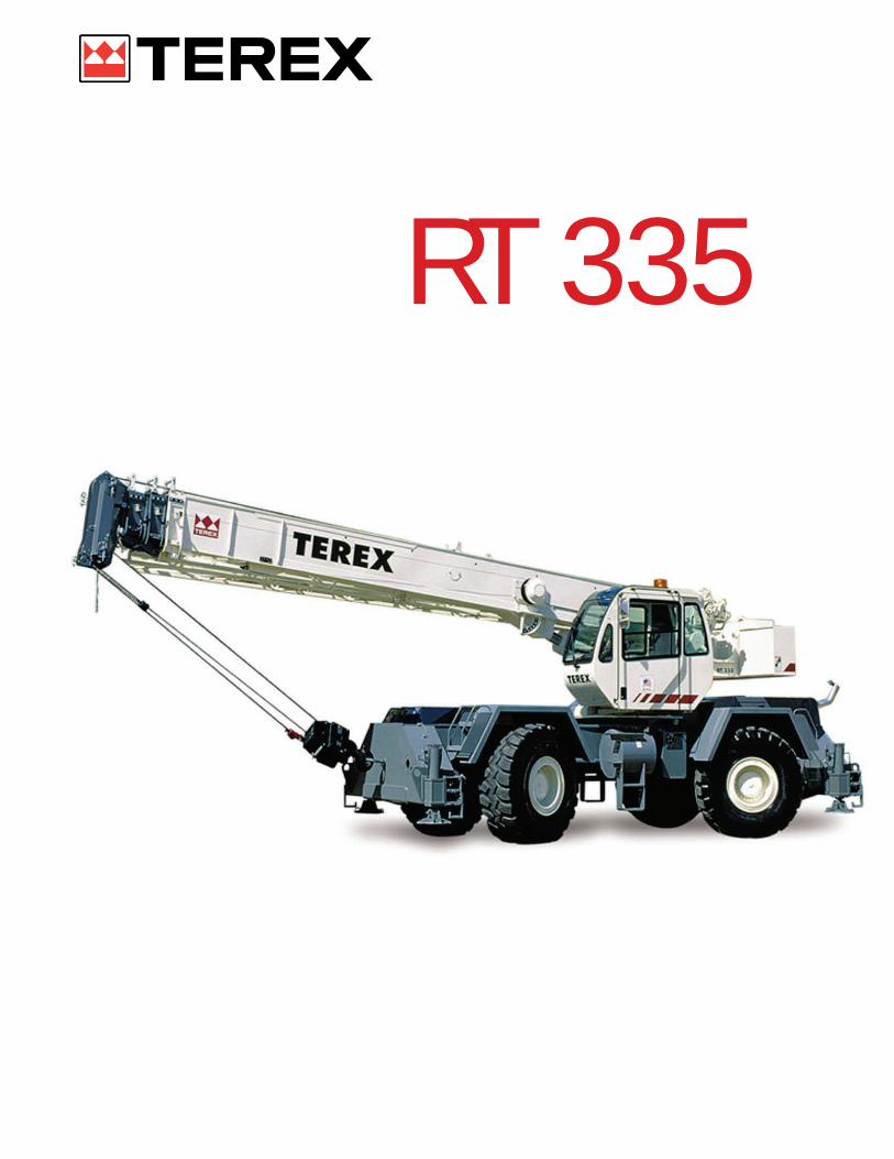
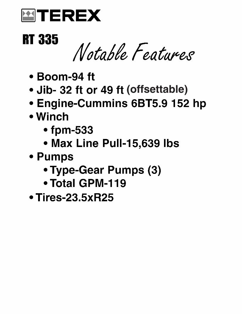
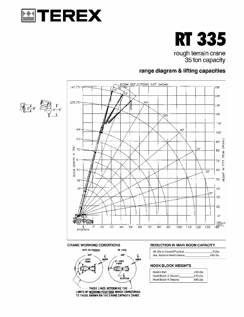
RT 335
(offsettable)
��������
�������������������������������������������
� ����������������������������������������������
� �����������������������������������
� �����������������������������������
� �������������������������������������������������������������������������������
� ��������������������������������� ������
� �����������������������������������
� ��������������������������������������
� ��������������������������������������������������������
� ���������������������������������������������������������������������
� ��������������������������������������������
� ���������������������������������������������������������������������������������������������������������������������
� ���������������������������������������������������
� ��������������������������������������������������������������������������
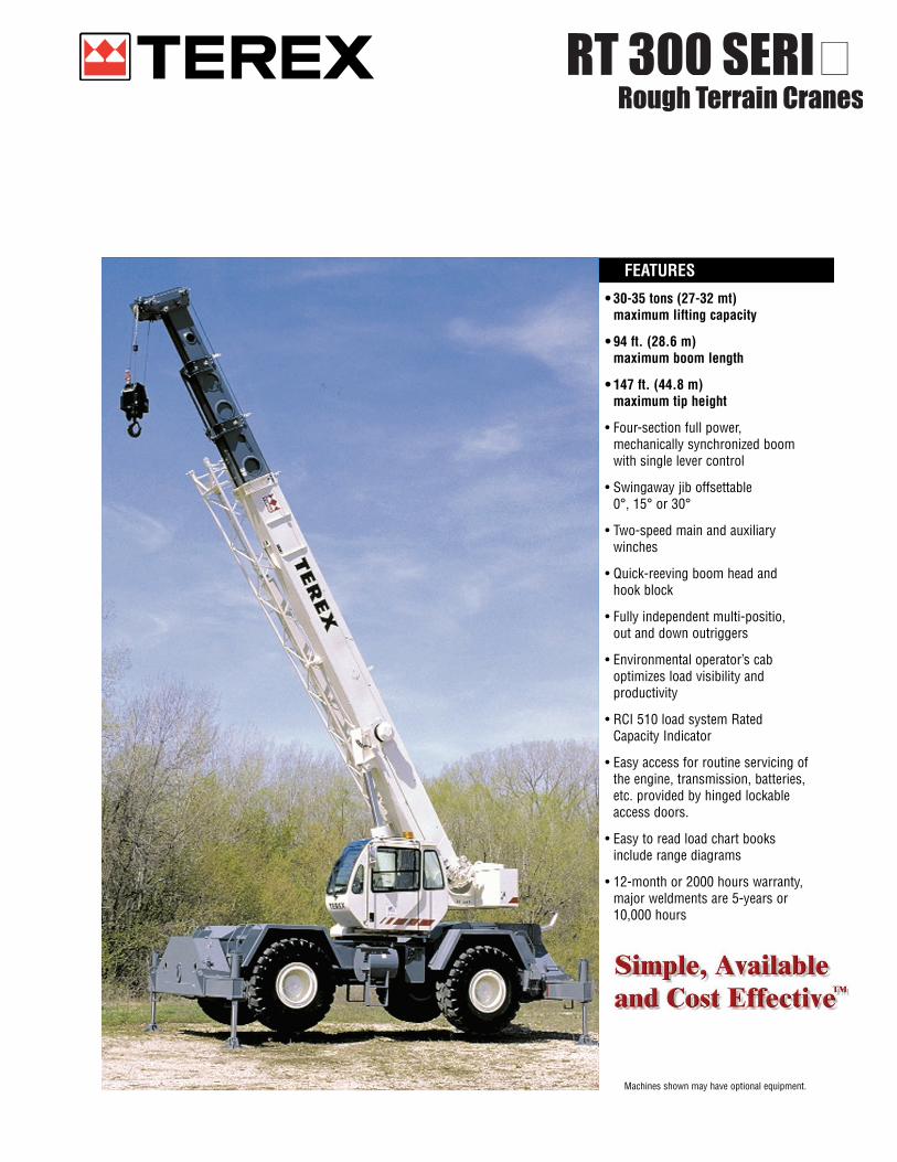
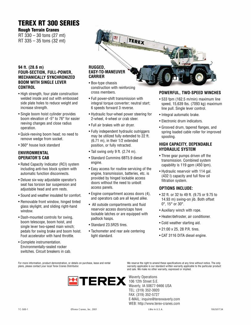
RT 300 SERIESRough Terrain CranesRough Terrain Cranes
For more information, product demonstration, or details on purchase, lease and rentalplans, please contact your local Terex Cranes Distributor.
TC-500-1 ©Terex Cranes, Inc. 2001 Litho in U.S.A. 10U501T34
94 ft. (28.6 m) FOUR-SECTION, FULL-POWER,MECHANICALLY SYNCHRONIZEDBOOM WITH SINGLE LEVERCONTROL• High strength, four plate construction
welded inside and out with embossedside plate holes to reduce weight andincrease strength.
• Single boom hoist cylinder providesboom elevation of -5° to 76° for easierreeving changes and close radiusoperation.
• Quick-reeving boom head; no need toremove wedge from socket.
• 360° house lock standard
ENVIRONMENTAL OPERATOR’S CAB• Rated Capacity Indicator (RCI) system
including anti-two block system withautomatic function disconnects.
• Deluxe six-way adjustable operator’sseat has torsion bar suspension andadjustable head and arm rests.
• Sound and weather insulated for comfort.
• Removable front window, hinged tintedglass skylight, and sliding right-handwindow.
• Dash-mounted controls for swing,boom telescope, boom hoist, andsingle lever two-speed main winch;pedals for swing brake and boom hoist.Foot accelerator with hand throttle.
• Complete instrumentation.Environmentally-sealed rockerswitches. Circuit breakers in cab.
RUGGED, EASY-TO-MANEUVER CARRIER• Box-type chassis
construction with reinforcingcross members.
• Full power-shift transmission withintegral torque converter; neutral start;6 speeds forward 3 reverse.
• Hydraulic four-wheel power steering for2-wheel, 4-wheel or crab steer.
• Full air brakes with air dryer.
• Fully independent hydraulic outriggersmay be utilized fully extended to 22 ft.(6.71 m), in their 1/2 extendedposition, or fully retracted.
• Tail swing only 9 ft. (2.74 m).
• Standard Cummins 6BT5.9 dieselengine.
• Easy access for routine servicing of theengine, transmission, batteries, etc. isprovided by hinged lockable accessdoors without the need to unboltaccess panels.
• Engine compartment access doors (4),and operators cab are all keyed alike.
• All outside compartments and fluidreservoir access doors/caps havelockable latches or are equipped withpadlock hasps.
• Standard 23.5R25 tires.
• Tachometer and rear axle centeringlight standard.
POWERFUL, TWO-SPEED WINCHES• 533 fpm (162.5 m/min) maximum line
speed, 15,639 lbs. (7093 kg) maximumline pull. Single lever control.
• Integral automatic brake.
• Electronic drum indicators.
• Grooved drum, tapered flanges, andspring loaded cable roller for improvedspooling.
HIGH CAPACITY, DEPENDABLEHYDRAULIC SYSTEM• Three gear pumps driven off the
transmission. Combined systemcapability is 119 gpm (450 lpm).
• Hydraulic reservoir with 114 gal. (432 l) capacity and full flow oilfiltration system.
OPTIONS INCLUDE:• 32 ft. or 32 to 49 ft. (9.75 or 9.75 to
14.93 m) swing-on jib. Both offset 0°, 15° or 30°.
• Auxiliary winch with rope.
• Heater/defroster, air conditioner.
• Cold weather starting aid.
• 21:00 x 25, 28 P.R. tires.
• CAT 3116 DITA diesel engine.
TEREX RT 300 SERIESRough Terrain CranesRT 330 – 30 tons (27 mt)RT 335 – 35 tons (32 mt)
We reserve the right to amend these specifications at any time without notice. The onlywarranty applicable is our standard written warranty applicable to the particular productand sale. We make no other warranty, expressed or implied.
Waverly Operations106 12th Street S.E.Waverly, IA 50677-9466 USATEL: (319) 352-3920 FAX: (319) 352-5727E-MAIL: [email protected]: http://www.terex-cranes.com
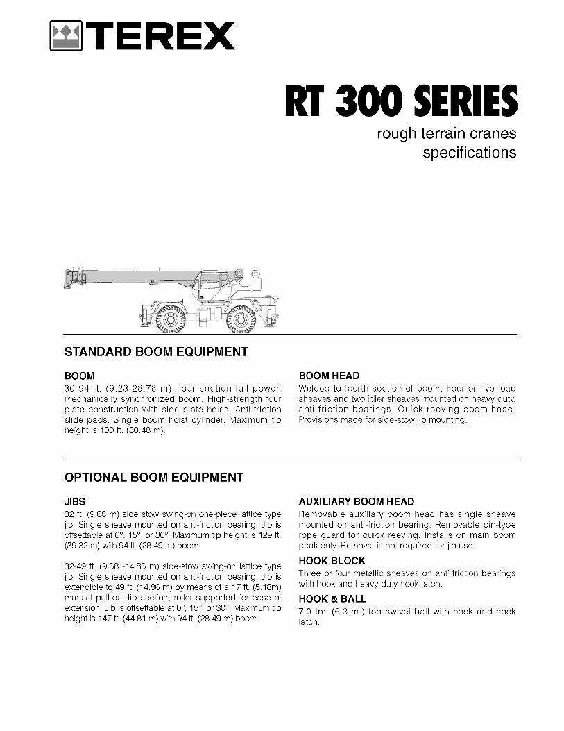
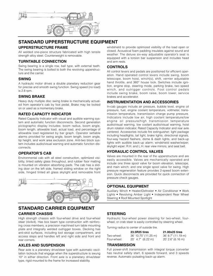
STANDARD UPPERSTRUCTURE EQUIPMENT
STANDARD CARRIER EQUIPMENT
UPPERSTRUCTURE FRAMEAll welded one-piece structure fabricated with high tensilestrength alloy steel. Counterweight is removable.
TURNTABLE CONNECTIONSwing bearing is a single row, ball type, with external teeth.The swing bearing is bolted to both the revolving upperstruc-ture and the carrier.
SWINGA hydraulic motor drives a double planetary reduction gearfor precise and smooth swing function. Swing speed (no load)is 2.8 rpm.
SWING BRAKEHeavy duty multiple disc swing brake is mechanically actuat-ed from operator's cab by foot pedal. Brake may be lockedon or used as a momentary brake.
RATED CAPACITY INDICATORRated Capacity Indicator with visual and audible warning sys-tem and automatic function disconnects. Second generationpictographic display includes: boom radius, boom angle,boom length, allowable load, actual load, and percentage ofallowable load registered by bar graph. Operator settablealarms provided for swing angle, boom length, boom angle,tip height, and work area exclusion zone. Anti-two block sys-tem includes audio/visual warning and automatic function dis-connects.
OPERATOR’S CABEnvironmental cab with all steel construction, optimized visi-bility, tinted safety glass throughout, and rubber floor mattingis mounted on vibration absorbing pads. The cab has a slid-ing door on the left side, framed sliding window on the rightside, hinged tinted all glass skylight and removable front
CARRIER CHASSISHigh strength chassis with four-wheel drive and four-wheelsteer (4x4x4). Has box beam type construction with reinforc-ing cross members, a precision machined turn table mountingplate and integrally welded outrigger boxes. Decking hasanti-skid surfaces, including tool storage compartment, andaccess steps and handles left and right side and front andrear corners.
AXLES AND SUSPENSIONRear axle is a planetary drive/steer type with automatic oscil-lation lockouts that engage when the superstructure is swung10° in either direction. Front axle is a planetary drive/steertype, rigid mounted to the frame for increased stability.
windshield to provide optimized visibility of the load open orclosed. Acoustical foam padding insulates against sound andweather. The deluxe six-way adjustable operator’s seat isequipped with a torsion bar suspension and includes headand arm rests.
CONTROLSAll control levers and pedals are positioned for efficient oper-ation. Hand operated control levers include swing, boomtelescope, boom hoist, winch(s), shift, vernier adjustablehand throttle, and 360° house lock. Switches include igni-tion, engine stop, steering mode, parking brake, two speedwinch, and outr igger controls. Foot control pedals include swing brake, boom raise, boom lower, servicebrakes and accelerator.
INSTRUMENTATION AND ACCESSORIESIn-cab gauges include air pressure, bubble level, engine oilpressure, fuel, engine coolant temperature, voltmeter, trans-mission temperature, transmission charge pump pressure.Indicators include low air, high coolant temperature/lowengine oil pressure/high transmission temperature audio/visual warning, low coolant audio/visual warning, hoistdrum rotation indicator, Rated Capacity Indicator and rear axlecentered. Accessories include fire extinguisher; light packageincluding headlights, tail light, brake lights, directional signals,four-way hazard flashers, dome & dash lights, and back-uplights with audible back-up alarm; windshield washer/wiper;skylight wiper; R.H. and L.H. rear view mirrors; and seat belt.
HYDRAULIC CONTROL VALVESValves are mounted in the rear of the upperstructure and areeasily accessible. Valves are mechanically operated andinclude one three spool valve for boom elevation, telescope,and main winch; and one single spool valve for swing. Highpressure regeneration feature provides 2-speed boom exten-sion. Quick disconnects are provided for quick connection ofpressure check gauges.
OPTIONAL EQUIPMENTAuxiliary Winch • Heater/Defroster • Air Conditioner • WorkLights • Revolving Amber Light • Independent Rear WheelSteering • Roof Mounted Spotlight
STEERINGHydraulic four-wheel power steering for two-wheel, four-wheel, or crab steer is easily controlled by steering wheel.
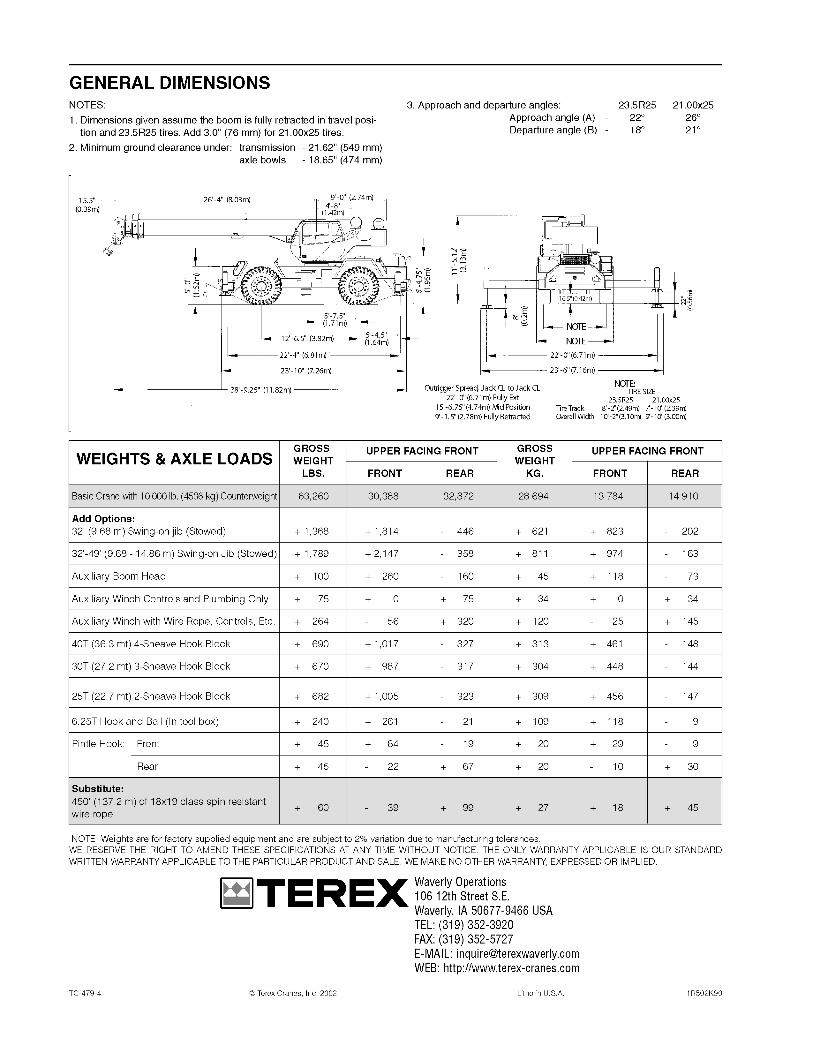
Turning radius to center of outside tire.
23.5R25 tires 21.00x25 tiresTwo-wheel: 36' 10.75" (11.25 m) 36' 8.7" (11.19 m)Four-wheel: 20' 4.7" (6.22 m) 20' 2.6" (6.16 m)
TRANSMISSIONFull power-shift transmission with integral torque converterhas neutral safety start, 6 speeds forward, and 3 speedsreverse. Automatic pulsating back-up alarm.
STANDARD CARRIER EQUIPMENT (continued)
HYDRAULIC SYSTEM
MAIN WINCH SPECIFICATIONHydraulic winch with bent axis piston motor and planetary reduction gearing pro-vides 2-speed operation with equal speeds for power up and down. Winch isequipped with an integral automatic brake, grooved drum, tapered flanges, stan-dard cable roller on drum, and electronic rotation indicator.
PERFORMANCE LO-RANGE HI-RANGEMax. line speed (no load)
First layer 184 fpm (56.1 m/min) 369 fpm (112.5 m/min)Fifth layer 266 fpm (81.1 m/min) 533 fpm (162.5 m/min)
Max. line pull-first layer 15,639 lbs (7094 kg) 7,298 lbs (3310 kg)Max. line pull-fifth layer 10,827 lbs (4911 kg) 5,052 lbs (2292 kg)Permissible line pull 9,000 lbs (4082 kg)
DRUM DIMENSIONS DRUM CAPACITY
10.62 in (270 mm) drum diameter Max. Storage: 570 ft (173.7 m)17.55 in (446 mm) length 6th layer not a working layer18.0 in (457 mm) flange dia. Max. Useable: 455 ft (138.7 m)*Cable: 5/8 in. x 450 ft (16 mm x 137.2 m)Cable type: 5/8 in. (16mm) 6x19 IWRC * Based on min. flange height aboveXIPS right regular lay, preformed top layer to comply with ANSI B30.5
MULTI-POSITION OUT & DOWN OUTRIGGERSFully independent hydraulic outriggers may be utilized fullyextended to 22 ft. (6.71 m), in their 1/2 extended position, or fullyretracted. Easily removable floats, each with an area of 254 in2
(1639 cm2), stow on the carrier frame. Complete controls andsight leveling bubble are located in the operator's cab.
WHEELS & TIRESDisc type wheels with full tapered bead seat rim. 150.50 in(3.82 m) wheelbase.
TIRES23.5R25** std.21.00x25 28 PR opt.
SERVICE BRAKESCam operated air brakes on all four wheels; 201/4" x 4"(51.43x10.2 cm) drum brakes.
PARKING BRAKEFront and rear axles equipped with spring-set, air releasedemergency/parking chambers.
OPTIONAL EQUIPMENTCold Weather Starting Aid • Immersion Heater • 24" (0.61m)Aluminum Outrigger Floats • Pintle Hook • Clearance Lights •Front Mounted Winch – 20,000 lbs (9072 kg)
HYDRAULIC PUMPSThree gear type pumps, one single and two in tandem, drivenoff the transmission. Combined system capability is 119 gpm(450 lpm). Includes pump disconnect.
Main and Auxiliary Winch Pump59.5 gpm (225.2 lpm) @ 3,500 psi (246.1 kg/cm2)
Boom Hoist, Telescope Pump38.5 gpm (145.7 lpm) @ 3,500 psi (246.1 kg/cm2)
Power Steering, Outrigger and Swing Pump21 gpm (79.5 lpm) @ 2,500 psi (175 kg/cm2)
FILTRATIONFull flow oil filtration system with bypass protection includes aremovable 60 mesh (250 micron) suction screen-type filterand 5 micron replaceable return line filter.
HYDRAULIC RESERVOIRAll steel, welded construction with internal baffles and diffuser.Provides easy access to filters and is equipped with an exter-nal sight level gauge. The hydraulic tank is pressurized to aidin keeping out contaminants and in reducing potential pumpcavitation. Capacity is 114 gal (432 liters). Hydraulic oil cooleris standard.
OPTIONAL AUX. WINCHHydraulic 2-speed winch with bent axis pis-ton motor, power up and down, equalspeed, planetary reduction with integralautomatic brake, grooved drum with taperedflanges, drum roller, and rotation indicator.
PERFORMANCE(Same as main winch)
DRUM DIMENSIONS AND CAPACITY(Same as main winch)
OPTIONAL HOIST LINE – MAIN WINCHAND OPTIONAL AUXILIARY WINCH –5/8 in. (16mm) rotation resistant compactedstrand 18x19 or 19x19. Min. breaking strength 22.6 tons (20.6 mt).
ENGINE SPECIFICATIONS PERFORMANCE (Standard Engine)
Make and Model Cummins 6BT5.9 (Std.) Caterpillar 3116 DITA (Opt.)
Type 6 cylinder 6 cylinderBore and Stroke 4.02 x 4.72 in (102x120 mm) 4.12 x 5.0 in (105x127mm)Displacement 359 cu in (5.9 l) 402 cu in (6.6 l)Gross Horsepower 152 @ 2,500 rpm 175 @ 2,400 rpmGross Torque 414 lb•ft(561 N•m) @ 1600 rpm 490 lb•ft(664 N•m) @ 1450 rpmAspiration turbocharged turbocharged & aftercooledAir Filter dry type dry typeElectrical System 12 volt 12 voltAlternator 102 amp 115 ampBattery (2) 12V-1600 CCA (2) 12V-1600 CCAFuel Capacity 50 gal (189 l) 50 gal (189 l)
Trans- Maximum Grade-mission Forward Maximum Tractive ability
Gear Drive Speed Effort @ Stall*1 4-wheel 2.3 mph 56,357 lbs 273.7%
3.7 km/h 25 564 kg2 4-wheel 4.1 mph 31,890 lbs 59.5%
6.6 km/h 14 465 kg3 4-wheel 5.4 mph 24,261 lbs 41.6%
8.7 km/h 11 005 kg4 2-wheel 9.6 mph 13,746 lbs 21.4%
15.4 km/h 6235 kg5 2-wheel 13.6 mph 9,691 lbs 14.3%
21.9 km/h 4396 kg6 2-wheel 24.0 mph 5,498 lbs 7.2%
38.6 km/h 2494 kg
*Based on a gross vehicle weight of 60,000 lbs. (27 216 kg).
2
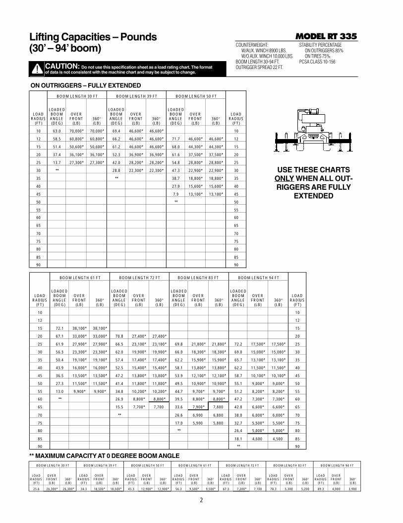
COUNTERWEIGHT:W/AUX. WINCH 8900 LBS.W/O AUX. WINCH 10,000 LBS.
BOOM LENGTH 30-94 FT.OUTRIGGER SPREAD 22 FT.
STABILITY PERCENTAGEON OUTRIGGERS 85%ON TIRES 75%
PCSA CLASS 10-156
MODEL RT 335
CAUTION: Do not use this specification sheet as a load rating chart. The format of data is not consistent with the machine chart and may be subject to change.
Lifting Capacities – Pounds(30’– 94’boom)
USE THESE CHARTSONLY WHEN ALL OUT-RIGGERS ARE FULLY
EXTENDED
ON OUTRIGGERS – FULLY EXTENDED
BOOM LENGTH 61 FT BOOM LENGTH 72 FT BOOM LENGTH 83 FT BOOM LENGTH 94 FT
LOAD RADIUS
(FT)
LOADED BOOM ANGLE (DEG)
OVER FRONT
(LB)360° (LB)
LOADED BOOM ANGLE (DEG)
OVER FRONT
(LB)360° (LB)
LOADED BOOM ANGLE (DEG)
OVER FRONT
(LB)360° (LB)
LOADED BOOM ANGLE (DEG)
OVER FRONT
(LB)360° (LB)
LOAD RADIUS
(FT)
10 10
12 12
15 72.1 38,100* 38,100* 15
20 67.1 33,000* 33,000* 70.8 27,400* 27,400* 20
25 61.9 27,900* 27,900* 66.5 23,100* 23,100* 69.8 21,800* 21,800* 72.2 17,500* 17,500* 25
30 56.3 23,300* 23,300* 62.0 19,900* 19,900* 66.0 18,300* 18,300* 69.0 15,000* 15,000* 30
35 50.4 19,100* 19,100* 57.4 17,400* 17,400* 62.2 15,900* 15,900* 65.7 13,100* 13,100* 35
40 43.9 16,000* 16,000* 52.5 15,400* 15,400* 58.1 13,800* 13,800* 62.2 11,500* 11,500* 40
45 36.5 13,500* 13,500* 47.2 13,800* 13,800* 53.9 12,100* 12,100* 58.7 10,100* 10,100* 45
50 27.3 11,500* 11,500* 41.4 11,800* 11,800* 49.5 10,900* 10,900* 55.1 9,000* 9,000* 50
55 13.0 9,900* 9,900* 34.8 10,200* 10,200* 44.7 9,700* 9,700* 51.2 8,200* 8,200* 55
60 ** 26.9 8,800* 8,800* 39.5 8,800* 8,800* 47.2 7,300* 7,300* 60
65 15.5 7,700* 7,700 33.6 7,900* 7,800 42.8 6,600* 6,600* 65
70 ** 26.6 6,900 6,800 38.0 6,000* 6,000* 70
75 17.0 5,900 5,800 32.7 5,500* 5,500* 75
80 ** 26.4 5,000* 5,000* 80
85 18.1 4,600 4,500 85
90 ** 90
BOOM LENGTH 30 FT BOOM LENGTH 39 FT BOOM LENGTH 50 FT BOOM LENGTH 61 FT BOOM LENGTH 72 FT BOOM LENGTH 83 FT BOOM LENGTH 94 FT
LOAD RADIUS
(FT)
OVER FRONT
(LB)360° (LB)
LOAD RADIUS
(FT)
OVER FRONT
(LB)360° (LB)
LOAD RADIUS
(FT)
OVER FRONT
(LB)360° (LB)
LOAD RADIUS
(FT)
OVER FRONT
(LB)360° (LB)
LOAD RADIUS
(FT)
OVER FRONT
(LB)360° (LB)
LOAD RADIUS
(FT)
OVER FRONT
(LB)360° (LB)
LOAD RADIUS
(FT)
OVER FRONT
(LB)360° (LB)
25.6 26,300* 26,300* 34.3 18,500* 18,500* 45.3 12,900* 12,900* 56.3 9,500* 9,500* 67.3 7,200* 7,100 78.3 5,300 5,200 89.3 4,000 3,900
BOOM LENGTH 30 FT BOOM LENGTH 39 FT BOOM LENGTH 50 FT
LOAD RADIUS
(FT)
LOADED BOOM ANGLE (DEG)
OVER FRONT
(LB)360° (LB)
LOADED BOOM ANGLE (DEG)
OVER FRONT
(LB)360° (LB)
LOADED BOOM ANGLE (DEG)
OVER FRONT
(LB)360° (LB)
LOAD RADIUS
(FT)
10 63.0 70,000* 70,000* 69.4 46,600* 46,600* 10
12 58.5 60,800* 60,800* 66.2 46,600* 46,600* 71.7 46,600* 46,600* 12
15 51.4 50,600* 50,600* 61.2 46,600* 46,600* 68.0 44,300* 44,300* 15
20 37.4 36,100* 36,100* 52.3 36,900* 36,900* 61.6 37,500* 37,500* 20
25 13.7 27,300* 27,300* 42.0 28,200* 28,200* 54.8 28,800* 28,800* 25
30 ** 28.8 22,300* 22,300* 47.3 22,900* 22,900* 30
35 ** 38.7 18,800* 18,800* 35
40 27.9 15,600* 15,600* 40
45 7.9 13,100* 13,100* 45
50 ** 50
55 55
60 60
65 65
70 70
75 75
80 80
85 85
90 90
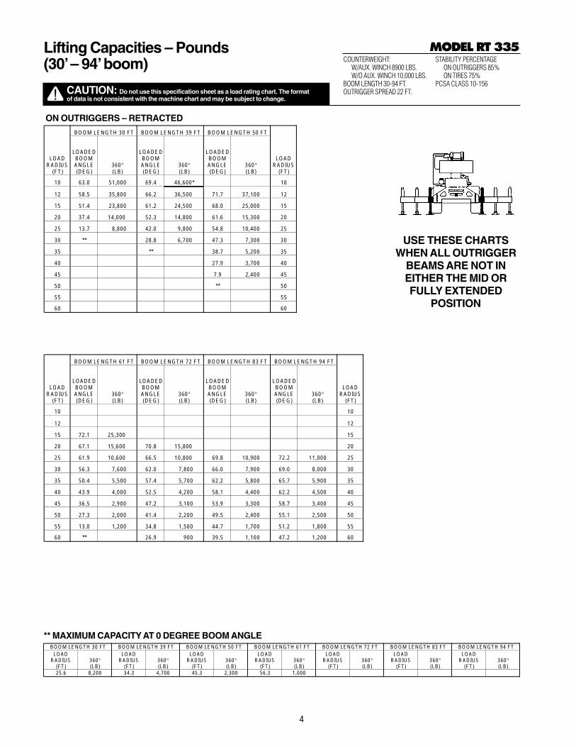
** MAXIMUM CAPACITY AT 0 DEGREE BOOM ANGLE
3
BOOM LENGTH 61 FT BOOM LENGTH 72 FT BOOM LENGTH 83 FT BOOM LENGTH 94 FT
LOAD RADIUS
(FT)
LOADED BOOM ANGLE (DEG)
360° (LB)
LOADED BOOM ANGLE (DEG)
360° (LB)
LOADED BOOM ANGLE (DEG)
360° (LB)
LOADED BOOM ANGLE (DEG)
360° (LB)
LOAD RADIUS
(FT)
10 10
12 12
15 72.1 38,100* 15
20 67.1 33,000* 70.8 27,400* 20
25 61.9 23,100 66.5 23,100* 69.8 21,800* 72.2 17,500* 25
30 56.3 16,800 62.0 17,000 66.0 17,100 69.0 15,000* 30
35 50.4 12,800 57.4 12,900 62.2 13,100 65.7 13,100* 35
40 43.9 10,000 52.5 10,200 58.1 10,300 62.2 10,400 40
45 36.5 7,900 47.2 8,100 53.9 8,300 58.7 8,300 45
50 27.3 6,300 41.4 6,600 49.5 6,700 55.1 6,800 50
55 13.0 5,000 34.8 5,300 44.7 5,500 51.2 5,600 55
60 ** 26.9 4,300 39.5 4,500 47.2 4,600 60
65 15.5 3,400 33.6 3,600 42.8 3,700 65
70 ** 26.6 2,900 38.0 3,000 70
75 17.0 2,300 32.7 2,400 75
80 ** 26.4 1,900 80
85 18.1 1,400 85
90 ** 90
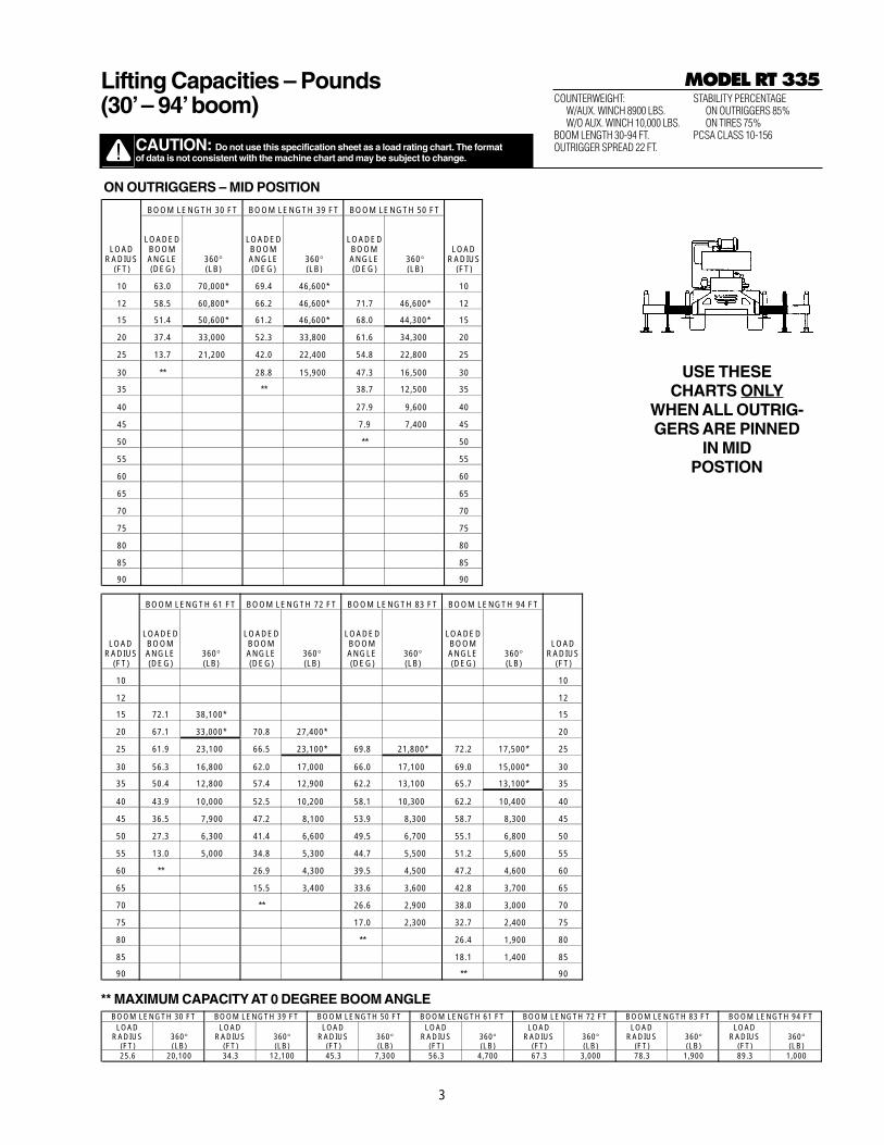
COUNTERWEIGHT:W/AUX. WINCH 8900 LBS.W/O AUX. WINCH 10,000 LBS.
BOOM LENGTH 30-94 FT.OUTRIGGER SPREAD 22 FT.
STABILITY PERCENTAGEON OUTRIGGERS 85%ON TIRES 75%
PCSA CLASS 10-156
MODEL RT 335
CAUTION: Do not use this specification sheet as a load rating chart. The format of data is not consistent with the machine chart and may be subject to change.
Lifting Capacities – Pounds(30’– 94’boom)
** MAXIMUM CAPACITY AT 0 DEGREE BOOM ANGLE
USE THESECHARTS ONLY
WHEN ALL OUTRIG-GERS ARE PINNED
IN MID POSTION
ON OUTRIGGERS – MID POSITION
BOOM LENGTH 30 FT BOOM LENGTH 39 FT BOOM LENGTH 50 FT
LOAD RADIUS
(FT)
LOADED BOOM ANGLE (DEG)
360° (LB)
LOADED BOOM ANGLE (DEG)
360° (LB)
LOADED BOOM ANGLE (DEG)
360° (LB)
LOAD RADIUS
(FT)
10 63.0 70,000* 69.4 46,600* 10
12 58.5 60,800* 66.2 46,600* 71.7 46,600* 12
15 51.4 50,600* 61.2 46,600* 68.0 44,300* 15
20 37.4 33,000 52.3 33,800 61.6 34,300 20
25 13.7 21,200 42.0 22,400 54.8 22,800 25
30 ** 28.8 15,900 47.3 16,500 30
35 ** 38.7 12,500 35
40 27.9 9,600 40
45 7.9 7,400 45
50 ** 50
55 55
60 60
65 65
70 70
75 75
80 80
85 85
90 90
BOOM LENGTH 30 FT BOOM LENGTH 39 FT BOOM LENGTH 50 FT BOOM LENGTH 61 FT BOOM LENGTH 72 FT BOOM LENGTH 83 FT BOOM LENGTH 94 FTLOAD
RADIUS (FT)
360° (LB)
LOAD RADIUS
(FT)360° (LB)
LOAD RADIUS
(FT)360° (LB)
LOAD RADIUS
(FT)360° (LB)
LOAD RADIUS
(FT)360° (LB)
LOAD RADIUS
(FT)360° (LB)
LOAD RADIUS
(FT)360° (LB)
25.6 20,100 34.3 12,100 45.3 7,300 56.3 4,700 67.3 3,000 78.3 1,900 89.3 1,000
4
COUNTERWEIGHT:W/AUX. WINCH 8900 LBS.W/O AUX. WINCH 10,000 LBS.
BOOM LENGTH 30-94 FT.OUTRIGGER SPREAD 22 FT.
STABILITY PERCENTAGEON OUTRIGGERS 85%ON TIRES 75%
PCSA CLASS 10-156
MODEL RT 335
CAUTION: Do not use this specification sheet as a load rating chart. The format of data is not consistent with the machine chart and may be subject to change.
Lifting Capacities – Pounds(30’– 94’boom)
** MAXIMUM CAPACITY AT 0 DEGREE BOOM ANGLE
USE THESE CHARTSWHEN ALL OUTRIGGER
BEAMS ARE NOT INEITHER THE MID ORFULLY EXTENDED
POSITION
ON OUTRIGGERS – RETRACTED
BOOM LENGTH 61 FT BOOM LENGTH 72 FT BOOM LENGTH 83 FT BOOM LENGTH 94 FT
LOAD RADIUS
(FT)
LOADED BOOM ANGLE (DEG)
360° (LB)
LOADED BOOM ANGLE (DEG)
360° (LB)
LOADED BOOM ANGLE (DEG)
360° (LB)
LOADED BOOM ANGLE (DEG)
360° (LB)
LOAD RADIUS
(FT)
10 10
12 12
15 72.1 25,300 15
20 67.1 15,600 70.8 15,800 20
25 61.9 10,600 66.5 10,800 69.8 10,900 72.2 11,000 25
30 56.3 7,600 62.0 7,800 66.0 7,900 69.0 8,000 30
35 50.4 5,500 57.4 5,700 62.2 5,800 65.7 5,900 35
40 43.9 4,000 52.5 4,200 58.1 4,400 62.2 4,500 40
45 36.5 2,900 47.2 3,100 53.9 3,300 58.7 3,400 45
50 27.3 2,000 41.4 2,200 49.5 2,400 55.1 2,500 50
55 13.0 1,200 34.8 1,500 44.7 1,700 51.2 1,800 55
60 ** 26.9 900 39.5 1,100 47.2 1,200 60
BOOM LENGTH 30 FT BOOM LENGTH 39 FT BOOM LENGTH 50 FT
LOAD RADIUS
(FT)
LOADED BOOM ANGLE (DEG)
360° (LB)
LOADED BOOM ANGLE (DEG)
360° (LB)
LOADED BOOM ANGLE (DEG)
360° (LB)
LOAD RADIUS
(FT)
10 63.0 51,000 69.4 46,600* 10
12 58.5 35,800 66.2 36,500 71.7 37,100 12
15 51.4 23,800 61.2 24,500 68.0 25,000 15
20 37.4 14,000 52.3 14,800 61.6 15,300 20
25 13.7 8,800 42.0 9,800 54.8 10,400 25
30 ** 28.8 6,700 47.3 7,300 30
35 ** 38.7 5,200 35
40 27.9 3,700 40
45 7.9 2,400 45
50 ** 50
55 55
60 60
BOOM LENGTH 30 FT BOOM LENGTH 39 FT BOOM LENGTH 50 FT BOOM LENGTH 61 FT BOOM LENGTH 72 FT BOOM LENGTH 83 FT BOOM LENGTH 94 FTLOAD
RADIUS (FT)
360° (LB)
LOAD RADIUS
(FT)360° (LB)
LOAD RADIUS
(FT)360° (LB)
LOAD RADIUS
(FT)360° (LB)
LOAD RADIUS
(FT)360° (LB)
LOAD RADIUS
(FT)360° (LB)
LOAD RADIUS
(FT)360° (LB)
25.6 8,200 34.3 4,700 45.3 2,300 56.3 1,000
5
COUNTERWEIGHT:W/AUX. WINCH 8900 LBS.W/O AUX. WINCH 10,000 LBS.
BOOM LENGTH 30-94 FT.OUTRIGGER SPREAD 22 FT.
STABILITY PERCENTAGEON OUTRIGGERS 85%ON TIRES 75%
PCSA CLASS 10-156
MODEL RT 335
CAUTION: Do not use this specification sheet as a load rating chart. The format of data is not consistent with the machine chart and may be subject to change.
Lifting Capacities – Pounds(30’– 94’boom)
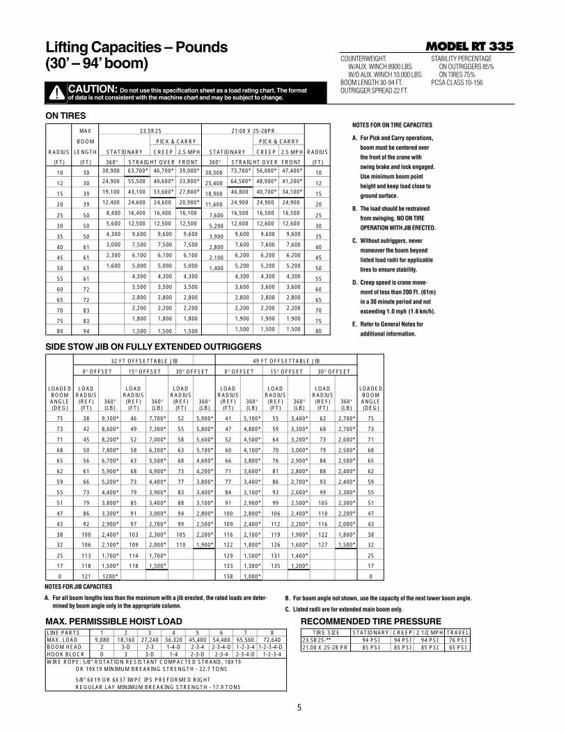
ON TIRES
MAX 23.5R25 21:00 X 25-28PR
BOOM PICK & CARRY PICK & CARRY
RADIUS LENGTH STATIONARY CREEP 2.5 MPH STATIONARY CREEP 2.5 MPH RADIUS
(FT) (FT) 360° STRAIGHT OVER FRONT 360° STRAIGHT OVER FRONT (FT)
10 30 30,900 63,700* 46,700* 39,000* 30,500 73,700* 56,000* 47,400* 10
12 30 24,900 55,500 40,600* 33,800* 25,400 64,500* 48,900* 41,200* 12
15 39 19,100 43,100 33,600* 27,800* 18,900 46,800 40,700* 34,100* 15
20 39 12,400 24,600 24,600 20,900* 11,600 24,900 24,900 24,900 20
25 50 8,400 16,400 16,400 16,100 7,600 16,500 16,500 16,500 25
30 50 5,600 12,500 12,500 12,500 5,200 12,600 12,600 12,600 30
35 50 4,300 9,600 9,600 9,600 3,900 9,600 9,600 9,600 35
40 61 3,000 7,500 7,500 7,500 2,800 7,600 7,600 7,600 40
45 61 2,300 6,100 6,100 6,100 2,100 6,200 6,200 6,200 45
50 61 1,600 5,000 5,000 5,000 1,400 5,200 5,200 5,200 50
55 61 4,300 4,300 4,300 4,300 4,300 4,300 55
60 72 3,500 3,500 3,500 3,600 3,600 3,600 60
65 72 2,800 2,800 2,800 2,800 2,800 2,800 65
70 83 2,200 2,200 2,200 2,200 2,200 2,200 70
75 83 1,800 1,800 1,800 1,900 1,900 1,900 75
80 94 1,500 1,500 1,500 1,500 1,500 1,500 80
SIDE STOW JIB ON FULLY EXTENDED OUTRIGGERS
MAX. PERMISSIBLE HOIST LOAD RECOMMENDED TIRE PRESSURE
32 FT OFFSETTABLE JIB 49 FT OFFSETTABLE JIB
0° OFFSET 15° OFFSET 30° OFFSET 0° OFFSET 15° OFFSET 30° OFFSET
LOADED BOOM ANGLE (DEG)
LOAD RADIUS (REF) (FT)
360° (LB)
LOAD RADIUS (REF) (FT)
360° (LB)
LOAD RADIUS (REF) (FT)
360° (LB)
LOAD RADIUS (REF) (FT)
360° (LB)
LOAD RADIUS (REF) (FT)
360° (LB)
LOAD RADIUS (REF) (FT)
360° (LB)
LOADED BOOM ANGLE (DEG)
75 38 9,100* 46 7,700* 52 5,900* 41 5,100* 55 3,400* 62 2,700* 75
73 42 8,600* 49 7,300* 55 5,800* 47 4,800* 59 3,300* 68 2,700* 73
71 45 8,200* 52 7,000* 58 5,600* 52 4,500* 64 3,200* 73 2,600* 71
68 50 7,800* 58 6,200* 63 5,100* 60 4,100* 70 3,000* 79 2,500* 68
65 56 6,700* 63 5,500* 68 4,600* 66 3,800* 76 2,900* 84 2,500* 65
62 61 5,900* 68 4,900* 73 4,200* 71 3,600* 81 2,800* 88 2,400* 62
59 66 5,200* 73 4,400* 77 3,800* 77 3,400* 86 2,700* 93 2,400* 59
55 73 4,400* 79 3,900* 83 3,400* 84 3,100* 93 2,600* 99 2,300* 55
51 79 3,800* 85 3,400* 88 3,100* 91 2,900* 99 2,500* 105 2,300* 51
47 86 3,300* 91 3,000* 94 2,800* 100 2,800* 106 2,400* 110 2,200* 47
43 92 2,900* 97 2,700* 99 2,500* 109 2,400* 112 2,200* 116 2,000* 43
38 100 2,400* 103 2,300* 105 2,200* 116 2,100* 119 1,900* 122 1,800* 38
32 106 2,100* 109 2,000* 110 1,900* 122 1,800* 126 1,600* 127 1,500* 32
25 113 1,700* 114 1,700* 129 1,500* 131 1,400* 25
17 118 1,500* 118 1,500* 133 1,300* 135 1,200* 17
0 121 1200* 138 1,000* 0
LINE PARTS 1 2 3 4 5 6 7 8MAX. LOAD 9,080 18,160 27,240 36,320 45,400 54,480 65,560 72,640BOOM HEAD 2 3-D 2-3 1-4-D 2-3-4 2-3-4-D 1-2-3-4 1-2-3-4-DHOOK BLOCK D 3 3-D 1-4 2-3-D 2-3-4 2-3-4-D 1-2-3-4WIRE ROPE: 5/8" ROTATION RESISTANT COMPACTED STRAND, 18X19 OR 19X19 MINIMUM BREAKING STRENGTH - 22.7 TONS
5/8" 6X19 OR 6X37 IWPC IPS PREFORMED RIGHT REGULAR LAY MINIMUM BREAKING STRENGTH - 17.9 TONS
TIRE SIZE STATIONARY CREEP 2 1/2 MPH TRAVEL23.5R25-** 94 PSI 94 PSI 94 PSI 76 PSI21.00 X 25-28 PR 85 PSI 85 PSI 85 PSI 65 PSI
NOTES FOR ON TIRE CAPACITIES
A. For Pick and Carry operations,
boom must be centered over
the front of the crane with
swing brake and lock engaged.
Use minimum boom point
height and keep load close to
ground surface.
B. The load should be restrained
from swinging. NO ON TIRE
OPERATION WITH JIB ERECTED.
C. Without outriggers, never
maneuver the boom beyond
listed load radii for applicable
tires to ensure stability.
D. Creep speed is crane move-
ment of less than 200 Ft. (61m)
in a 30 minute period and not
exceeding 1.0 mph (1.6 km/h).
E. Refer to General Notes for
additional information.
NOTES FOR JIB CAPACITIES
A. For all boom lengths less than the maximum with a jib erected, the rated loads are deter-mined by boom angle only in the appropriate column.
B. For boom angle not shown, use the capacity of the next lower boom angle.
C. Listed radii are for extended main boom only.