1995 technical progress report tampa electric company … library/research/coal/major... · 1995...
TRANSCRIPT

1995 TECHNICAL PROGRESS REPORT
TAMPA ELECTRIC COMPANY POLK POWER STATION - UNIT #I
IGCC DEMONSTRATION PROJECT
DOE COOPERATIVE AGREEMENT DE-FC2141MC27363 APRIL 1996
Tampa Electric Company DOE IGCC Demonstration Project Polk Power Station - Unit 1 1995 Technical Progress Report
Section
TABLE OF CONTENTS
I. PROJECT DESCRIPTION
II. PROJECT HIGHLIGHTS
III. ENVIRONMENTAL/PERMITTING
IV. STATUS OF MAJOR CONTRACTS
A.
B.
C.
D.
E.
F.
G.
H.
I.
J.
K.
L.
M.
Detailed Professional Engineering and Technical Services
Hot Gas Clean-Up System Design and Startup Support
G.E. STAG 107F Engineered Equipment Package (Power Island)
Turnkey Air Separation Unit
Radiant Syngas Cooling System Engineered Equipment Package
Convective Syngas Cooling System Engineered Equipment Package
Turnkey Sulfuric Acid Plant
Texaco Support Services Contract (Refractory and Burners)
Distributed Control System
Emergency Shutdown System
Simulator Development
Brine Concentration Unit
Construction Management Services
V, PROCESS DESCR!PTION
A. Coal Handling, Grinding, and Slurry Preparation
B. Gasifier System
l?ae
-l-
-3-
-4-
-6-
-6-
-6-
-6-
-7-
-8-
-8-
-9-
-s-
-B-
-lO-
-ll-
-1 l-
-11-
-13-
-13-
-14-


Tampa Electric Company DOE IGCC Demonstration Project Polk Power Station - Unit 1 1995 Technical Progress Report
Section
VI.
VII.
VIII.
IX.
X.
TABLE OF CONTENTS (Continued)
J%!a.e
C. Cold Gas Clean Up KGCUI System -14-
D. Hot Gas Clean Up (HGCU) System -15-
E. Combined Cycle Power Generation -1~7-
F. Air Separation Unit -19-
G. By-Product Handling -2o-
H. Sulfuric Acid Plant -21-
1. Balance of Plant Systems -22-
PROJECT MANAGEMENT -24-
PROJECT COST AND SCHEDULE -27-
A. Project Cost Estimate -27-
B. Project-to-Date Costs Through 1995 -27-
C. Project Milestone Schedule -27-
D. Startup Schedule -27-
TECHNICAL PROGRESS/DETAILED ENGINEERING -28-
TECHNICAL PROGRESS/SIGNIFICANT ENHANCEMENTS -29-
A.‘ Sutfuric Acid Plant -29-
6. Combined Cycle Power Generation Equipment -29-
C. Air Separation Unit -3o-
D. Power Block Closed Loop Cooling Water System -3o-
E. Brine Concentration System -3o-
3-D MODEL REVIEWS -31-
H:irh~rd~l*d.s\FIN~L0500E ii

Tampa Electric Company DOE IGCC Demonstration Project Polk Power Slalion - Unit 1 1995 Technical Progress Report
TABLE OF CONTENTS (Continued)
Section
XI. CONSTRUCTION MANAGEMENT
A. Construction Plan and Project Philosophy
XII.
XIII.
XIV.
xv.
XVI.
B. Construction Activities
START UP ORGANIZATION
TECHNICAL PAPER/CONFERENCE PRESENTATIONS
PROJECTIONS FOR 1996
SUMMARY
EXHIBITS
Exhibit A - Project Cost Estimate
Exhibit B - Project-to-Date Costs Through 1995
Exhibit C - Polk Power Station Block Flow Diagram
Exhibit D - Project Milestone Schedule.
Exhibit E - Start Up Schedule
Exhibit F - Artist’s Rendering of Polk Power Station
Exhibit G - Site Plot Plan
Exhibit H - Construction Progress Curve
Exhibit I Site Photographs
Exhibit J - OSHA Recordable Rate
PaLIe
-33-
-33-
-38-
-54-
-57-
-58-
-6O-
-62-
H:irhardala,do~\FIN*L95.DOE iii

Tampa Electric Company DOE IGCC Demonstration Project Polk Power Station - Unit 1 1995 Technical Progress Report
I. PROJECT DESCRIPTION
Tampa Electric Company’s Polk Power Station Unit 1 IPPS-1) Integrated Gasification Combined Cycle (IGCC) demonstration project will use a Texaco pressurized, oxygen-blown, entrained- flow coal gasifier to convert approximately 2300 tons per day of coal (drv basis) coupled with a combined cycle power block to produce a net 250 MW electrical power output. Coal is slurried in water, combined with 95 percent pure oxygen from an air separation unit, and sent to the gasifier to produce a high temperature, high pressure, medium-Btu syngas with a heat content of about 250 BTU&f (LHV). The syngas then flows through a high temperature heat recovery unit which cools the syngas prior to its entering the cleanup systems. Molten coal ash flows from the bottom of the high temperature heat recovery unit into a water-filled quench chamber where it solidifies into a marketable slag by-product.
Approximately 10 percent of the raw, hot syngas at 900°F is passed through an intermittently moving bed of metal-oxide sorbent which removes sulfur-bearing compounds from the syngas. PPS-1 will be the first unit in the world to demonstrate this advanced metal oxide hot gas desulfurization technology on a commercial unit.
The remaining portion of the raw, hot syngas is cooled to 100°F for conventional acid gas removal. This portion of the plant is capable of processing 100 percent of the raw syngas.
Sulfur-bearing compounds from both cleanup systems are sent to a double absorption sulfuric acid plant to produce a marketable, high-purity sulfuric acid by-product.
The cleaned medium-BTU syngas from these processes is routed to the combined cycle power generation system where it is mixed with air and burned in the combustion section of the combustion turbine. Nitrogen from the air separation unit at 98 percent purity is simultaneously injected into the combustion section to reduce the formation of nitrogen oxides and to enhance mass flow through the combustion turbine for power augmentation. This combination results in the generation of about 192 MW of electricity from the combustion turbine-generator.
Heat is extracted from the expanded exhaust gases in a heat recovery steam generator (HRSG) to produce steam at three pressure levels for use throughout the integrated process. The majority of this steam, at high pressure, together with high pressure steam generated in the gasification process, drives a steam turbine-generator set to produce additional electrical output of about 121 MW. Internal plant power consumption is approximately 63 MW, resulting in a net power output from the integrated unit of 250 MW: A simplified Block Diagram is included as exhibit C of the Appendix.
A highly modular, microprocessor-based distributed control system (DCS) will provide continuous and sequential control for most of the equipment on PPS-1. This network has been designed to communicate with other key plant control units like the combustion turbine and steam turbine control systems and the gasification system emergency shutdown system. The DCS is an important part of the IGCC facility in that it provides the control link that will integrate these complex processes.
Tampa Electric Company DOE IGCC Demonstration Project Polk PO war Station - Unit 1 1995 Technical Progress Report
Also important to this project is the development and utilization of a valuable diagnostic and training tool in the form of a dynamic simulator. This tool will be used to simulate various operating modes of plant equipment, including upset conditions that could occur within the complex systems which comprise the IGCC facility, and will also be a valuable tool during the training program for plant operators and technical personnel.
An artist’s rendering of the IGCC facility is included as Exhibit in the Appendix of this report to serve as a graphic illustration of the site layout of the primary equipment for this uniquely configured electric generating plant.
Tampa Electric Company DOE IGCC Demonstration Project Polk Power Station - Unit 1 1995 Technical Progress Report
II. PROJECT HIGHLIGHTS
This section describes in condensed form some of the key features of the Polk IGCC Project which make it unique and contribute to the advantages associated with integrated gasification combined cycle technology.
Tampa Electric’s Polk IGCC Demonstration Project is co-funded by the U. S. Department of Energy (DOE) as an important part of its Clean Coal Technology (CCT) Program, Round Ill. DOE is providing more than $142,000,000 in co-funding for this Project. The primary objectives of this project include the successful demonstration of commercial-scale integration of the coal gasification facility with the state-of-the-art combined cycle power island, and the demonstration of a technically and commercially viable hot gas cleanup system.
Site selection for Polk Power Station (PPS) was made with the guidance of a uniquely conceived and assembled team of experts. Tampa Electric formed a Power Plant Siting Task Force composed of prominent environmentalists, educators, and business and community leaders. Environmental impact was a primary driver in the choice of allowable sites for the plant. Consequently, the property in Polk County, Florida which was selected for the plant is comprised mostly of land which had previously been mined for phosphate rock. Substantial work in the areas of mine reclamation, wetlands and uplands restoration, and establishment of a wildlife corridor will be completed in conjunction with the development of the demonstration IGCC facility.
The blending of specific technologies which comprise Polk Power Station Unit No. 1 results in a highly integrated system which utilizes virtually all of the oxygen and nitrogen produced in the plant’s air separation unit to meet gasifier oxygen demand and diluent nitrogen requirements for the advanced combustion turbine. The result is highly efficient, environmentally superior performance.
The syngas cooling systems make effective use of available heat within the cycle and generate supplemental steam which is integrated into the process to produce significant overall plant efficiency gains.
The innovative hot gas cleanup system on PPS-1 utilizes an intermittently-moving bed of sorbent to remove sulfur-bearing compounds from the hot syngas. The benefits include heat rate improvement as well as reduced plant power consumption as compared to the conventional process of cold gas cleanup using acid gas removal technology.
By-products from this unique combination of technologies are extracted as marketable products, primarily as slag and high grade sulfuric acid.
Finally, to integrate the control logic for this complex facility, a number of important control features are being developed which include a dynamic simulator, a distributed control system, and en emergency shutdown system.

Tampa Electric Company DOE IGCC Demonstration Project Polk Power Station - Unit 1 1995 Technical Progress Report
Ill. ENVIRONMENTAL / PERMITTING
The following significant events related to the Polk IGCC Project’s Environmental and Permitting requirements occurred in 1995.
FEDERAL ACTIVITIES
. Submitted required notification to FAA of start of construction of towers/structures more than 200ft. high on April 6, 1995.
STATE ACTIVITIES
. Modifications to Conditions of Certification addressing design revisions, submitted to Florida DEP in September 1994, were approved February 20, 1995.
CONDITIONS OF CERTIFICATION SUBMITTALS
. Florida DEP approval of Groundwater Monitoring Plan, submitted May 31, 1994, was effective September 7, 1995.
. Florida DEP approval of the Industrial Wastewater Treatment system, submitted December 13, 1994, was effective March 15, 1995.
. Florida DEP approval of the Domestic Wastewater Treatment system, submitted December 13, 1994, was effective July 14, 1995. Florida DEP was notified of completion of construction of the Domestic Wastewater Facility December 18, 1995 along with a request to place the system into operation. Florida DEP released this system for operation December 20, 1995.
. Florida D5P approval of the Chemical and Used Oil Handling Facility, submitted December 20, 1994, was effective May 5, 1995. Subsequently the plans were revised and resubmitted August 21, 1995. Approval is expected in early 1996.
. A description of the selected Continuous Emission Monitor system [CEMS) was submitted to Florida DEP on January 23, 1995. No approval was required.
. The Potable Water Treatment and Supply System was submitted to Florida DEP for approval on February 17, 1995. Approval was effective April 24, 1995.
. The CEMS Protocol describing the system, installation and operation and maintenance characteristics was submitted March 1, 1995. No approval is required.

Tampa Electric Company DOE IGCC Demonstration Project Polk Power Station - Unit 1 1995 Technical Progress Report
. A report on the Feasibility of Using Reclaimed Water was submitted April 26, 1995. No approval is required.
. Traffic monitoring studies were submitted to Florida DOT and Polk Count for the intersections of SR37 and CRDs 640 and 630 and CR630 and Ft. Green Road, May 1, 1995. Monitoring is also required in 1996 and 1997.
. Results of the Aquifer Performance Test were submitted to the Florida DEP June 22, 1995. No approval is required.
. The Slag Storage Area was submitted to Florida DEP for approval July 25, 1995 to the Florida DEP. Approval was effective November 17, 1995.
. Results of the initial study for the Biological Assessment Plan of Study were submitted to the Florida DEP October 31, 1995. Approval is not required.
. Florida DEP was notified of the anticipated first fire of the Auxiliary Boiler November 10, 1995. The anticipated first fire was identified as December 12, 1995. First fire is expected to actually occur in early January 1996.
. The Emission Performance Test Protocol for the Auxiliary Boiler was submitted for approval December 8, 1995 to the Florida DEP. Approval is expected in early 1996.
H:irh~rdata,doe\FIN*L95,DOE 5

Tampa Electric Company DOE IGCC Demonstration Project Polk Power Station - Unit 1 1995 Technical Progress Report
IV. STATUS OF MAJOR CONTRACTS
A. DETAILED PROFESSIONAL ENGINEERING AND TECHNICAL SERVICES
At the beginning of 1995, Bechtel’s detailed engineering activities were about 83 percent complete. By May of 1995, essentially all of the engineering had been completed including:
. finalization of the structural steel design and issue for purchase of the steel
. completion of the piping design and issue of the isometrics for pipe fabrication
. issue of the remainder of the instrumentation and control drawings
During the summer, the focal point for engineering moved from Bechtel’s Houston office to the site. The on-site team, called the Resident Engineering team, continued to finalize design details and to provide support to construction.
Procurement activities migrated to the site in 1995, as well. By the end of 1995, the entire project team including engineering, procurement, construction management, and startup services were all located at the site.
B. HOT GAS CLEAN UP SYSTEM DESIGN AND STARTUP SUPPORT
The contract for preliminary definition of the Hot Gas Clean Up (HGCU) system design, dated June 2, 1993, was awarded to General Electric Environmental Services, Inc. (GEESI). The GEESI contract was amended in March of 1993 to include the detailed engineering scope of work. The HGCU system is designed to process 10 percent of syngas output from gasification. GEESI provided estimates for detailed design, procurement support and startup support activities. At year’s end, Engineering and Procurement for the HGCU was at 100 percent complete with essentially 100 percent of the plant’s material costs committed. Construction mobilization began in August 1995, with mechanical completion targeted for July 1996.
C. G.E. STAG 107F ENGINEERED EQUIPMENT PACKAGE (POWER ISLAND)
The contract for the engineering, manufacture, and supply of the engineered equipment package for the Power Island was awarded to GE in November 1992. The equipment furnished under this Contract includes the following:
. One Frame 7F Single Shaft Combustion Turbine with Low NOx combustors capable of firing fuel oil No. 2 as well as syngas
. One 229,741 KVA hydrogen cooled generator (combustion turbine)
H:\rh~rdat~\doa,FIWIL95DOE 6

Tampa Electric Company DOE IGCC Demonstration Project Polk Power Station - Unit 1 1995 Technical Progress Report
. One tandem compound, double flow condensing steam turbine with one un- controlled extraction
. One 156,471 KVA hydrogen cooled generator (steam turbine)
. All the engineered skids required to provide the auxiliary and accessory systems for the combustion turbine, steam turbine and the generators
. Control Cabinets
. One three-pressure, unfired Heat Recovery Steam Generator with integral deaerator. The HRSG is capable of accepting saturated steam from the gasification plant at two pressure levels and supply steam at rated conditions of 1500 psig at lOOO”F, 400 psig at 1000°F and 50 psig saturated.
The combustion turbine and generator wore removed from storage, delivered to the site, and set in place in June. The HRSG modules were also delivered and set in June. In July the steam turbine and generator arrived at site. By the end of the year, all of the equipment provided by General Electric had been delivered and set.
Over the course of the year, General Electric performed several CT combuster design tests at their Schenectady test facilities. Two final combustor tests were conducted in November to determine the effect of modifications to the sizing and placement of dilution air holes in the liner. A subsequent meeting was held at PPS to review the results. The latest tests showed significant improvement in flame pattern and of liner wall temperatures. Based on these results, GE proceeded with the manufacture of liners, with installation of the new liners planned for late January, 1996.
By the end of the year, completion of the power block construction was about 82% complete.
D. TURNKEY AIR SEPARATION UNIT
The contract for engineering, supply and erection of the Air Separation Unit (ASU), dated April 14, 1993, was awarded to Air Products & Chemicals, Inc. (APCI). The ASU is designed to produce 2020 tons per day (TPD) of 95 mol% pure oxygen, 1985 TPD at 575 psig and 35 TPD at 50 psig, and 6400 TPD of nitrogen, 6000 TPD at 255 psig and 98 mol% purity for syngas diluent and 400 TPD at high pressure and 99.99 mol% purity for sootblowing. APCI began civil construction activities in January 1995. Major equipment for the ASU began arriving on site in February with the delivery of the distillation column on February 26, 1995. The four major compressors for the ASU were delivered to the site on April 10, 1995. Construction activities were completed in December 1995. Commissioning and startup activities immediately followed construction and is scheduled for completion in the first quarter of 1996.

Tampa Electric Company DOE IGCC Demonstration Project Polk Power Station - Unit 1 1995 Technical Progress Report
E. RADIANT SYNGAS COOLING SYSTEM ENGINEERED EQUIPMENT PACKAGE
The contract for the engineering, design, manufacture and preparation for shipment of the Radiant Syngas Cooling (RSC) system, dated June 4, 1993, was awarded to MAN Gutehoffnungshijtte AG (MAN GHHI. The RSC system is designed to cool the hot syngas exiting the gasifier, generate high pressure steam to be sent to the HRSG, and remove coal ash from the syngas stream in the form of slag. At the beginning of 1995 engineering for the RSC was approximately 80 percent complete and fabrication was approximately 75 percent complete.
MAN GHH completed fabrication of the RSC shell and bundle at the Belleli (sub-contractor in Montova, Italy) shop at the end of May, 1995. Transportation to the site and setting the equipment was a significant effort and of particular importance to the project because the effort is on the critical path of the project schedule. Davenport Mammoet had the contract for this work.
The shell weighs about 500 tons and the bundle about 250 tons, each of which is nominally 15-I 7 feet in diameter and 100 feet long. The two components traveled by ship from Italy to Port Manatee on Tampa Bay. From there, they were transported by road on special crawlers forty-two miles to the site, including crossing busy Interstate 75. Each component . took less than 15 minutes to cross the interstate.
A dedicated 1200 ton crane lifted the shell into the structure with only inches of allowable tolerance. The bundle was lifted first to directly above the shell and then inserted down into the shell. Only millimeters separated the shell and bundle during the insertion. The combined effort of all team members was essential to complete the erection of the Syngas Cooler. The 1 year planning period required detail review of drawings and erection procedures. Meetings and reviews were held at the Houston, Texas, Bechtel office, the job site in Tampa, Florida and the fabrication shop in Montova, Italy. The effort and planning all paid off when the vessel was set 2 davs ahead of schedule.
The High Pressure and Medium Pressure Steam Drums were fabricated in Houston and delivered and installed by July. The MAN GHH provided feedwater pumps were also manufactured in the U.S.
The design of the refractory for the gasifier head and throat is completed, materials purchasing and installation is expected early in 1996.
F. CONVECTIVE SYNGAS COOLING SYSTEM ENGINEERED EQUIPMENT PACKAGE
The contract for the engineering, design, manufacture, preparation for shipment, and onsite delivery of the convective syngas cooling (CSC) system, dated June 4, 1993, was awarded to L & C Steinmijller GmbH. The CSC system is designed to cool the raw syngas exiting the RSC system and exchange the heat energy with portions of clean syngas and nitrogen from the remainder of the integrated process. At the outset of 1995 engineering for the CSC was approximately 97 percent complete and fabrication was approximately 77 percent complete.

Tampa Electric Company DOE IGCC Demonstration Project Polk Power Station - Unit 1 1995 Technical Progress Report
Steinmuller completed fabrication of the CSC components and delivered them to the site in July and August. One wing of exchangers was placed in the structure and set in October. The other wing was set in place in November. A Steinmuller field representative provided guidance during the final alignment and set.
G. TURNKEY SULFURIC ACID PLANT
The contract for engineering, supply, and erection of the sulfuric acid plant for Polk Power Station Unit 1, dated June 8, 1994, was awarded to Monsanto Enviro-Chem Systems, Inc. The sulfuric acid plant is being designed to produce 98 percent sulfuric acid at a rate of 208 STPD (100% H,SO, basis) when fed with cold gas clean-up (CGCU) acid gas at design rates and 211 STPD (100% H,SO, basis) when fed with CGCU and HGCU acid gases at design rates. Engineering for the sulfuric acid plant was completed in March 1995. Monsanto Enviro- Chem mobilized their site construction manager in April 1995 and civil activities commenced following mobilization. All major equipment for the sulfuric acid plant had been received on site by July, 1995. Mechanical completion of the sulfuric acid plant occurred on December 29, 1995. Monsanto Enviro-Chem will load catalyst and sulfuric acid into the appropriate equipment just prior to first syngas scheduled for July 1996.
H. TEXACO SUPPORT SERVICES CONTRACT (REFRACTORY BURNERS)
Texaco provides engineering and startup support to the Project through three separate agreements. Under the License Agreement, they continue to provide a wide variety of services. They reviewed and approved key detailed design documents, are performing on-site construction inspections, and will provide startup support services. Texaco reviewed and approved the gasifier burner manufacturer’s shop drawings and inspected the completed burners.
Under a separate Technical Services Agreement (TSA) they have provided a variety of specific, as-needed services. For example, a Texaco representative provided day-to-day advise during the detailed design effort in Bechtel’s Houston office. They helped in defining and setting up the on-site laboratory. In 1996, they plan to help write the operating procedures for the gasification portion of the plant.
Texaco, through a separate contract, performed the detailed design of the gasifier refractory system. The effort also included inspection of the refractory at the manufacturer’s shop. In the spring of 1996 they will also provide oversight of the refractory system installation.
I. DISTRIBUTED CONTROL SYSTEM
The contract for engineering, design, manufacturing, assembly, and shipping of the Distributed Control System (DCS) to serve as the controls for the IGCC Polk Power Station Unit 1, dated October 8, 1993, was awarded to Bailey Controls Company, a division of Elsag Bailey, Inc. The DCS includes all system hardware, software, associated interfaces, and auxiliary equipment necessary to successfully control the entire plant from a centrally located control room. The DCS integrates controls for the following major plant systems:

Tampa Electric Company DOE IGCC Demonstration Project Polk Power Station - Unit 1 1995 Technical Progress Report
. Gasifier
. Syngas cooling
. Syngas clean-up
. Air separation unit
. Coal handling
. Power block equipment
. Sulfuric acid plant
. Brine concentration
. Cocling water
. Wastewater treatment
. Water treating
The DCS also interfaces with separate control systems provided with the Emergency Shutdown System (ESD) and the GE Mark V power equipment package. The basic system architecture is known as Bailey XRSSO configuration. At year’s end, the DCS had been shipped and installed at the jobsite. The Factory Acceptance Test (FAT) completed in April 1995 with completion of shipment to jobsite occurring in May 1995. At the end of 1995, the DCS was undergoing final configuration checkout based on system startup schedules with completion scheduled for July 1996.
J. EMERGENCY SHUTDOWN SYSTEM
The contract for engineering, design, manufacturing, assembly, and shipping of the gasifier Emergency Shutdown System (ESDI, was awarded to Triconex Corporation in June 1994. The ESD includes all system hardware, software, associated interfaces, and auxiliary equipment to provide for a fully functional system. The system is known as a Triple Modular Redundant (TMR) Programmable Logic Control ESD System. It includes software to fully interface with the Bailey Controls XRSSO DCS. At year’s end the ESD system chassis had been shipped to Bailey Control’s factory for integration testing with the DCS. Integration with the DCS completed in April 1995 with completion of shipment to jobsite occurring in May 1995. The ESD system is currently undergoing final configuration checkout based on system startup schedules with completion scheduled for July 1996.
H:irhardafa,doe\FIN*L95DOE 10
Tampa Electric Company DOE IGCC Demonstration Project Polk Power Station - Unit 1 1995 Technical Progress Report
K. SIMULATOR DEVELOPMENT
The Simulator is a dynamic process simulation system for the Polk Unit 1 IGCC plant. The Simulator will be used for operator training, control systems check out and tuning, engineering analysis, marketing of IGCC to potential customers and potentially, to provide training and engineering analysis for others. It was determined to be necessary because of the complexity of this integrated design, and the first of a kind integrated controls system.
The Simulator contract was awarded to Bailey Controls. Bailey and their modeling sub- contractor, TRAX began work in February 1995 with the development and completion of the Basis of Design Document (BODD). TRAX then began development of the Area Model Design Document (AMDD) for Phase I and Phase II. This document defined the model area, the design of the modules for each component within the model area and the critical parameters within the area. Both these phases were completed in 1995. Phase 1 included the models for the Auxiliary Boiler and the Air Separation Unit. Phase II included the model design for the Sulfuric Acid Plant and the Brine system.
Since this is a stimulated type simulator, the models developed by TRAX were operated and controlled using the same Bailey hardware that is used by the operators in the plant. The work in the first half of the year centerad around the design and development of the modules and models for the Phase I and Phase II areas. The second half of the year was used for building the simulator using Bailey controls hardware and TRAX modeling computers, and testing the simulator software.
Despite these problems, TEC was able to manage complex issues in developing the Simulator of a unique first of a kind power plant to successfully support training requirements in 1995.
L. BRINE CONCENTRATION UNIT
A purchase order to include the engineering, design, fabrication, supply, and delivery of a complete Brine Concentration Unit (BCU), dated June 7, 1994, was awarded to Aqua-Chem, Inc. The BCU processes grey water discharge from the gas clean-up systems. The BCU is designed as a prefabricated skid-mounted system to the maximum extent possible. The system discharges a land-fillable solid waste stream which we intend to market and a reusable water stream. Aqua-Chem furnished all equipment, large bore piping (> 2 in.), teflon lined piping, valves, instruments, structures and skids, and startup/operational testing services. At year’s end, Aqua-Chem was 100 percent complete in engineering. Delivery of all skids and equipment was achieved in July 1995. Installation of the equipment began in December 1995 with mechanical completion targeted for July 1996.
M. CONSTRUCTION MANAGEMENT SERVICES
Bechtel Power Corporation is providing construction management (CM) services. During 1995 major emphasis was placed on awarding the electrical/mechanical construction work, execution of construction activities, implementation of the site safety program and management of site activities.

Tampa Electric Company DOE IGCC Demonstration Project Polk Power Station - Unit 1 1995 Technical Progress Report
The CM team was led by the TEC on site Construction Manager. The CM team has managed the on site construction efforts effectively in order to keep the project on schedule and within an acceptable budget.
The CM work force peaked at 48 people representing Bechtel Power, Tampa Electric and the safety departments of Care Team, and Hartford Insurance. Care Team is providing the on site nursing services, Hartford is the project insurance carrier for Workman’s Compensation.
Construction was 77% complete at the end of 1995. This represented an approximate gain of 65% during 1995. All major milestones were completed on time.
Significant achievements were reached with respect to site safety;
. Over 1.7 mm work hours with no lost time accidents
. OSHA recordable rate below 2.30
This remarkable achievement was possible through good cooperation of the site zero-accident philosophy plan implemented by all contractors.
Key construction management highlights during 1995 were;
. $1 Om in savings from the Constructability Program.
. Coordination of the delivery and installation of the Radiant Syngas Cooler.
. Support to project management on environmental issues affecting the project site.
. Completion of the Cooling Reservoir
A detailed summery of construction activities can be found in Section Xl of this report.
H:\lhl,d.l.\do.\FIN*LSS.DOE 12
Tampa Electric Company DOE IGCC Demonstration Project Polk Power Station - Unit 1 1995 Technical Progress Report
V. PROCESS DESCRIPTION
A. COAL HANDLING, GRINDING, AND SLURRY PREPARATION
Coal is delivered to the site from a coal transloading facility at Tampa Electric Company’s Big Bend Station. The coal is delivered in covered, bottom-dump trucks with a 28-ton payload, with a total of about 80 trucks per day required at design rate. On the site, the trucks off-load in an enclosed unloading structure into an above-grade unloading hopper. Dust suppression sprays are provided at the top of the hopper to control dust emissions. Belt feeders transfer coal from the hopper outlets onto an enclosed unloading conveyor.
The unloading conveyor transports coal from the unloading structure up and into one of the two storage silos. A diverter gate and a silo feed conveyor provide the set-up to feed the second, adjacent silo. A dust collection system is provided at the top of the silos to collect dust at the conveyor/feeder/silo transfer points.
Coal is conveyed from the coal silos and fed to the grinding mill with recycled process water and makeup water from the plant service water supply system. The grinding mill may also be fed fine coal recovered by the dust collection system. Ammonia may be added to the mill for pH adjustment, if necessary. The pH of the slurry is maintained between 6 and 8 to minimize corrosion in the carbon steel equipment. A slurry additive for reducing viscosity is also pumped continuously to the grinding mill.
The grinding mill reduces the feed coal to the design particle size distribution. The mill is a conventional rod-type system with an overflow discharge of the slurry. Slurry discharged from the grinding mill passes through a trommel screen and over a vibrating screen to remove any oversized particles before entering the slurry tank. Oversized particles are recycled to the grinding mill.
A below-grade grinding sump is located centrally within the coal grinding and slurry preparation area to handle and collect any slurry drains or spills in the area. Materials collected in the sump are routed to the recycle tank for reuse in the process.
In order to minimize groundwater withdrawal and use, water for the slurry preparation system is provided from several sources; primarily by the moisture contents of the feedstock coal, the recycled feed, and the grinding sump water. Additional makeup water to the slurry system is provided from the plant service water system. Through the collection and recycling process, there are no water discharges from the coal grinding and slurry preparation system. All water from the system is fed to the gasifier in the coal slurry.
Potential particulate matter air emissions from the coal storage bin, grinding mill, and rod mill overflow discharge are primarily controlled by the wet nature of these subsystems and by the use of enclosures for the subsystems with vents through fabric filters or baghouses. The slurry tank vents are equipped with carbon canisters for absorption of potential hydrogen sulfide (H,S) or ammonia (NH,) emissions.
Tampa Electric Company DOE IGCC Demonstration Project Polk Power Station - Unit 1 1995 Technicel Progress Report
8. GASIFIER SYSTEM
The IGCC unit uses the Texaco oxygen-blown, entrained-flow, single-train gasification system to produce syngas for combustion in the advanced combustion turbine (CT).
Coal slurry from the slurry feed tank and oxygen from the air separation unit are fed to the gasifier and sent to the process burner. The gasifier is a refractory lined vessel capable of withstanding high temperatures and pressures. The coal slurry and oxygen react in the gasifier to produce syngas at high temperature. The syngas consists primarily of hydrogen(H), Carbon Monoxide (CO), water vapor, and Carbon Dioxide (CO, 1, with small amounts of Hydrogen Sulfide (H,S), methane (CHY), argon (Ar), and nitrogen (NJ. Coal ash and unconverted carbon form a liquid melt called slag in the gasifier.
Hot syngas and slag flow downward in the gasifier into the radiant syngas cooler, which is a high pressure steam generator equipped with a water wall to protect the vessel shell. Heat is transferred primarily by radiation from the hot syngas to the feed water circuiating in the water wall. High pressure steam produced in this cooler is routed to the heat recovery steam generator (HRSG) in the power block area which supplements the heat input from the CT to the HRSG and increases the efficiency of the generating unit.
The syngas passes over the surface of a pool of water at the bottom of the radiant syngas cooler and exits the vessel. The raw syngas is sent to the convective coolers and then to the low temperature syngas cooling system in the CGCU system for further heat recovery and to the demonstration HGCU system. The slag drops into the water pool and is fed to the lockhopper from the radiant syngas cooler sump.
The black water which flows out with the slag from the bottom of the radiant syngas cooler is separated from the slag and recycled after processing in the dewatering system.
C. COLD GAS CLEAN UP (CGCU) SYSTEM
The raw, hot syngas from the gasifier is routed to the separate conventional CGCU and demonstration HGCU systems for appropriate treatment. The CGCU system is designed to treat 100 percent of the syngas flow for the unit, while the HGCU system is capable of treating approximately 1’0 percent of the syngas.
The initial treatment process for the raw syngas within the CGCU system involves the syngas scrubbing and cooling systems. The raw, hot syngas from the gasifier contains entrained solids or fine slag particles which must be removed to produce the clean syngas fuel. Also, the raw hot syngas needs to be cooled in order to be effectively cleaned in the acid gas removal unit.
The raw, hot syngas from the gasifier is first cooled in the high temperature syngas cooling system, then sent to the syngas scrubbers where entrained solids are removed. The syngas is then routed to the low temperature gas cooling section, where the syngas is cooled by recovering its waste heat to generate steam and preheat boiler feedwater.
Tampa Electric Company DOE IGCC Demonstration Project Polk Power Station - Unit I 1995 Technica/ Progress Report
The syngas scrubber bottoms are routed to the black water handling system. All the black water from the gasification and syngas cleanup processes are collected, processed, recycled to the extent possible, and contained within the processes. The solids that were not removed in the radiant syngas cooler sump are separated from the system as fines. There are no liquid discharges of these process waters to other systems or to the cooling reservoir.
The effluent from the black water handling system is concentrated and crystallized into a solid consisting primarily of salt called brine which is shipped off-site for disposal in an appropriately permitted landfill. The water separated from the salts is recycled for slurrying coal feed.
After removal of the entrained solids, the gaseous sulfur compounds (H,S and COS) are to be removed from the syngas prior to firing in the advanced CT unit to control potential SO, air emissions. In the acid gas removal unit, the cooled syngas is first water-washed in the water wash column. Wash water is pumped to the column to remove contaminants which would potentially degrade the amine from the syngas. The wash water from the column is sent to the Amonia (NH, jwater stripper.
The washed syngas then flows to the amine absorber where the syngas is in contact with circulating amine. Acting as a weak base. the amine absorbs acid gases such as H,S by chemical reaction. The purified synges flows through a knockout drum to remove entrained amine. The recovered liquid is returned to the amine stripper.
The rich amine is stripped of the acid gas in the amine stripper by steam generated in the stripper reboiler. The acid gas overhead is partially condensed by the reflux condenser and collected in the reflux accumulator. The acid gas, primarily H,S and CO,, from the reflux accumulator goes to the sulfuric acid plant and the condensed liquid reflux is returned to the amine stripper.
D. HOT GAS CLEAN UP (HGCU) SYSTEM
For the system demonstration, this unit is designed to handle 10 percent of the hot, raw syngas from the gasifier for cleanup prior to firing in the combustion turbine. The key process steps for the system are described in the following paragraphs.
Entrained fine particles in the hot syngas are removed in the primary cyclone first and sent to the black water handling system. The exiting gas is injected with sodium bicarbonate and enters a secondary cyclone where the halogen compounds in the gas are chemically absorbed. The collected solids from the cyclone are sent offsite for disposal in an appropriately permitted landfill and the syngas flows to an absorber.
A large fraction of any remaining particulate matter entering the absorber is captured by the sorbent bed, reducing particle concentration to below 30,ppm. A small amount of sorbent fines is entrained from the absorber and collected in a high efficiency barrier filter. The barrier filter practically eliminates all fines larger than 5 microns, with 99.5 percent of particulate matter removed. The solids from the barrier filter are sent offsite for disposal. Larger fines are sieved on screens at the regenerator sorbent outlet. Fugitive fines from the screens are

Tampa Electric Company DOE IGCC Demonstration Project Polk Power Station - Unit 1 1995 Technical Progress Report
collected in a small, low temperature bag filter. The sorbent fines from both collection points are reclaimed offsite, as a marketable by-product.
The absorber is an intermittently moving bed reactor. The sulfur-containing syngas from the cyclones enters the absorber through a gas manifold at its bottom and flows upward countercurrent to the moving bed of sorbent pellets. The sulfur compounds, mainly H,S in the syngas, react with the sorbent. The syngas leaving the absorber is expected to contain less than 30 ppmv of H,S and COS.
To maintain low H,S outlet concentrations, the absorber bed is periodically moved. A timed signal or an H,S breakthrough control signal activates solids flow from the bottom of the absorber into the absorber’s outlet lockhopper, causing the bed and the reaction zone to move downward by gravity. The displaced sulfided sorbent is replaced by regenerated sorbent from the absorber’s inlet lockhopper.
The ability to regenerate and recycle the sorbent is essential for economically viable hot syngas desulfurization. The regeneration with oxygen is a highly exothermic oxidation process which requires careful temperature control. Too high a temperature will sinter and destroy the sorbent structure and reduce its ability to react with sulfur in consecutive absorption steps. Low temperature will result in sulfate formation and a loss of reactive sorbent returning to the desulfurization process in the absorber.
Sulfided sorbent is fed from the absorber’s outlet lockhopper to the top of the regenerator where oxidation of the sulfided sorbent occurs. The sorbent moves down the regenerator in concurrent flow with the regeneration gas. The air to recycle gas ratio is controlled to limit the gas temperature.
The final step of regeneration is accomplished at the lower stage of the regenerator where nitrogen flows countercurrent to the sorbent. This stream cools the sorbent to a temperature acceptable for downstream equipment, purges the SO, - rich offgas, and ensures complete regeneration without sulfate formation. The gas streams from the concurrent and countercurrent flows mix to form the recycle gas stream.
The regeneration gas recycle system operates in a closed loop with dry air as an input and an SO, - rich offgas as a product output. The regeneration gas recycle loop is designed as an internal diluent that reduces the oxygen concentration in the air to the desired levels and removes the heat of reaction without the use of externally provided diluents such as nitrogen. Using recycle rather than external inert diluent also enriches the SO, concentration of the product stream.
The heat exchanger in the recycle loop is designed to control the temperature of the regenerator inlet streams. The steam generator removes the heat generated during the regeneration reaction by cooling the recycle gas stream. The recycle compressor operates at a sufficient suction temperature to avoid H,SO, condensation and a regenerative gas heat exchanger reheats the compressed gas for recycle to the regeneration process. The heat of combustion of the sulfur is transferred to the combined cycle power block through the steam generated prior to recycle compression of the recycle gas stream.

Tampa Electric Company DOE IGCC Demonstration Project Polk Power Station - Unit 1 1995 Technicel Progress Report
E. COMBINED CYCLE POWER GENERATION
Key components of the combined cycle power generation system are the Combustion Turbine- Generator ICTG), Heat Recovery Steam Generator (HRSG), and Steam Turbine-Generator (STG).
1. Combustion Turbine-Generator
The CT is a GE 7F. designed for low-NO, emissions firing syngas, with low sulfur fuel oil for startup and backup. Rated output from the hydrogen-cooled generator when syngas is fired in the CT is 192 MW.
The syngas is delivered to the combustion turbine via control valves on the syngas fuel control skid. Nitrogen is used as the diluent to reduce the formation of NO. in the exhaust gas. The flow of nitrogen to the combustor is regulated by valves on the nitrogen control skid.
When operating on the fuel oil backup, demineralized water is used as a diluent to reduce the formation of NO, in the exhaust gas. The flow of fuel oil and demineralized water is controlled by a separate skid, the fuel forwarding skid.
2. Heat Recoverv Steam Generam
The heat recovery steam generator recovers the combustion turbine exhaust heat to produce steam for the generation of additional power in the steam turbine. The HRSG is a three- pressure level (HP, IP, LPI natural circulation design with reheat (RH).
The HP section heats boiler feed water (BFW) and generates superheated steam for feed to the HP steam turbine. It also provides HP economized BFW to the’gasification area and receives HP saturated steam from the gasification plant. The BFW systems has two (2) 100% feed pumps. One of these pumps is a developmental magnetic bearing design.
The RH section combines HP turbine exhaust with IP superheated steam and adds superheat to the mixture for feed to the IP steam turbine.
The IP section heats BFW and generates superheated steam to be mixed with cold reheat steam for feed to the RH section. The IP section also provides BFW to the gasification area and receives saturated steam from the gasification plant. During startup or when the CT is fuel oil fired, the IP section can be used to export saturated steam to the gasification plant.
The LP section heats and de-aerates BFW for the HP and IP systems and provides saturated steam for export to the gasification plant.
3. Steam Turbine-Generator
The steam turbine is a double flow reheat unit with low pressure extraction and drives a hydrogen-cooled generator. The steam turbine-generator is designed specifically for highly efficient combined cycle operation with nominal turbine inlet conditions of approximately

Tampa Electric Company DOE IGCC Demonstration Project Polk Power Station - Unit 1 1995 Technical Progress Report
1450 psig and 1000°F with 1000°F reheat inlet temperature. Rated capacity is 124.2 MW; rated speed is 3600 rpm. Expected generator output during normal operation is 122 MW.
The outlet from the last stage of the turbine is condensed by heat exchange with circulating water from the plant cooling water reservoir. Condensate from the steam turbine condenser is returned to the HRSGlintegral de-aerator by way of the coal gasification facilities, where some condensate preheating occurs.
4. Condensate Svstem
The condensate system operates in this combined cycle power plant to:
. Return condensed steam to the cycle by pumping condensate from the condenser hotwell to the de-aerator
. Condense the steam from the steam turbine gland seals and return the condensate to the cycle
. Provide sources of condensate to various miscellaneous systems
. Provide a dump to the condensate storage tank on a high hotwell level
. Provide condensate makeup to the condenser hotwell
Condensate pump operation is required during combined cycle operation. One of the two 100 percent capacity condensate pumps is always in service during normal plant operation, while the other condensate pump is in the auto standby mode.
A hotwell dump line is connected from the condensate discharge line to the condensate storage tank for returning .condensate in the event of a high level in the hotwell. Condensate supply to the hotwell is by way of vacuum drag under normal operation, and by the condensate make-up pump otherwise.
The condensate pumps also supply water to the following users in the Power Island:
. Steam Turbine Exhaust Hood Spray System
. Vacuum Pump Seals
. Condensate Receiver
. Condensate Return Tank
. Gland Seal Emergency Spray
. HRSG Chemical Injection Equipment
. Closed Cooling Water Head Tank
Tampa Electric Company DOE IGCC Demonstration Project Polk Power Station - Unit 1 1995 Technical Progress Report
. Feedwater Pump Seals
5. Electrical Power Distribution Svstem
For plant startup and periods when the plant is down, power is received at 230 KV and is back-fed through the generator step-up transformers with the generator breakers in the open position. This arrangement provides power to the station 13.8 KV auxiliary transformers. The station 13.8 KV switchgear distributes power at 13.8 KV to the various plant loads including the power block 4160 V and 480 V auxiliary transformers. The 4160 V switchgear provides power to the combustion turbine static starting system and to the 4160 V motors.
During startup, power is back-fed through the CT generator step-up transformer or the steam turbine-generator step-up transformer to power up the static starting unit. Once the combustion turbine is up to speed and self sustaining, the static starter is de-energized, and the CT generator can be synchronized to the 230 KV system by closing the 18 KV CT generator breaker. Similarly, when the steam turbine-generator is up to speed, it can be synchronized to the 230 KV system by closing the appropriate 230 KV switchyard breakers first and then the steam turbine-generator 13.8KV breaker.
Once the combustion turbine is started up and the CT generator synchronized to the system, the combustion turbine-generator can provide power to all of-the station loads through the station 13.8 KV power distribution systems.
F. AIR SEPARATION UNIT
The air separation unit uses ambient air to produce oxygen for use in the gasification system and sulfuric acid plant, and nitrogen which is sent to the advanced CT.
Ambient air is filtered in a two-stage filter designed to remove particulate material. The first filter stage consists of a fixed panel filter; the second filter stage consists of removable elements, which are periodically replaced. The air is then compressed in a multistage centrifugal compressor equipped with inter-cooling between stages and a condensate removal system.
The compressed .air is cooled in an after cooler and fed to the molecular sieve absorbers. The molecular sieves remove impurities, such as water vapor. CO,, and some hydrocarbons from the air. The air is filtered once more in the dust filter to remove any entrained molecular sieve particles. Hot nitrogen is used for adsorbent regeneration. It is recovered and reused as CT diluent.
The air from the adsorbers is fed to the cold box where it is cooled against returning gaseous product streams in a primary heat exchanger (PHX). A small fraction of the air is extracted from the PHX and expanded to provide refrigeration for the cryogenic process. The expanded air is then fed to the low pressure distillation column for separation.
The remaining air exits the cold end of the PHX a few degrees above its dewpoint. The air is fed to the high pressure distillation column where it is separated into a gaseous nitrogen vapor

Tampa Electric Company DOE IGCC Demonstretion Project Polk Power Station - Unit 1 1995 Technic81 Progress Report
and an oxygen-enriched liquid stream. The nitrogen vapor is condensed in the high pressure distillation column condenser against boiling liquid oxygen. The liquid nitrogen is used as reflux in the high and low pressure distillation columns.
Oxygen and nitrogen are produced in the low pressure distillation column. Heat from the condensing nitrogen vapor provides reboiler action in the liquid oxygen pool at the bottom of the low pressure distillation column. The oxygen vapor is warmed to near-ambient temperature in the PHX and fed to the oxygen compressor, where it is compressed to the pressure required by the gasification unit.
Nitrogen vapor from the low pressure distillation column is warmed to near-ambient temperature in the PHX and sent to the advanced CT.
As backup to the air separation unit, a liquid nitrogen storage system is provided for system purging and maintaining low temperature in the cold box. The backup liquid nitrogen system is maintained in a cold, ready-to-start state.
The air separation unit process does not consume water and produces only minor amounts of water from condensation in the main air compressor aftercooler. This water is sent to Industrial Water Treatment (IWT). The unit requires water only for non-contact cooling purposes which is provided from the makeup water system and/or the cooling reservoir.
G. SLAG BY-PRODUCT HANDLING
The slag handling system is designed to remove the slag that exits through the radiant syngas cooler sump. The slag consists of the coal ash and unconverted coal components (primarily carbon) that form in the gasifier.
Coarse solids and some of the fine solids flow by gravity from the radiant syngas cooler sump into the lockhopper. The lockhopper acts as a clarifier, separating solid from water. When the solids collection time is over, the lockhopper is isolated from the radiant cooler sump and depressured. After that, the solids are water flushed into the slag dewatering bins. After a preset time, the water flush is discontinued and the lockhopper is filled with water and repressured. The next collection period begins when the lockhopper inlet valve is opened for a new cycle.
Solids from the lockhopper are dumped onto the pad at the slag dewatering bins. In the bins, the solids settle into a pile and are dewatered by gravity. The slag, after dewatering, is then transported by front-end loaders to trucks for off-site shipment or to the on-site slag storage area. The water removed from the slag is gravity drained via concrete trenches to the slag dewatering sump for recovery.
Again, all waters produced in this slag handling system are collected and routed to the black water handling system for reuse.
This system generates the coarse slag materiel at a maximum rate of approximately 210 short- tons per day (stpd) on a dry basis. The slag is classified as nonhazardous and non-leachable
Tampa Electric Company DOE IGCC Demonstration Project Polk Power Station - Unit 1 1995 Technical Progress Report
and is marketed for various offsite commercial uses such as abrasives, roof material, industrial filler, concrete aggregate, or road base material.
During periods when the slag by-product cannot be sold in a timely manner, a temporary storage area will be employed on the site. Initially, an area will be developed to be capable of storing slag generated by approximately 2-l/2 years of operation of the IGCC unit at full capacity. An additional 2-l 12 year storage area will be developed as needed in the unexpected event that sales of the slag for offsite uses are less than the slag production rates. The temporary slag storage area would provide sufficient capacity for developing storage cells for up to five years of slag production from the IGCC unit operating at loo-percent capacity. The slag storage area will include a stormwater runoff collection basin and surrounding berm to prevent runoff from reentering the area. Both the slag storage area and the runoff collection basin will be lined with a synthetic material or other materials with similar low permeability characteristics. The runoff basin will be designed to contain runoff water volumes equivalent to 1.5 times the 25year, 24-hour storm event. Water collected in the runoff basin will be routed to the IWT for filtration.
H. SULFURIC ACID PLANT
In the sulfuric acid plant, the sulfur-containing acid gases from the hot and cold gas cleanup systems are converted to 98 percent sulfuric acid for sale to the local Florida fertilizer industry. The conversion of acid gases involves a multi-step combustion, gas cleaning, and catalytic reaction process.
In the HGCU process, an acid gas is produced containing sulfur dioxide (SO,). In the CGCU process, hydrogen sulfide (H,S) containing gases from the acid gas removal unit and the ammonia stripping unit is routed through separate knockout drums at the acid plant to remove any entrained water. The CGCU gases are then introduced into the decomposition furnace, along with staged combustion air to limit NO, formation. Supplemental fuel is not normally required; but may be added to maintain the proper operating temperature during periods of low H,S feed gas concentration. Hot gases from the HGCU unit are introduced into the system downstream of the decomposition furnace and mix with the combusted acid gas from the CGCU unit. The sulfuric acid plant is capable of operating with or without the HGCU feed gas.
The combusted gas stream (containing SO,, SO,, water vapor, and trace l-&SO.) are cooled in a firetube waste heat boiler. The boiler steam side is maintained above 400 psig to avoid condensing acid in the tubes. The gases from the waste heat boiler are cooled in a DynaWave gas cleaning system via a circulating stream of weak acid. The DynaWave system consists of a gas quenching section with the hot process gas forced down through a countercurrent spray of weak acid, followed by a conventional packed gas cooling tower. Water condensed from the process gas absorbs some of the SO3 in the process gas, thus creating the circulating weak acid stream. An effluent stream of weak acid is removed from the plant to enable the manufacture of 98 percent product acid.
Reaction air in the form of low-pressure 95-percent purity oxygen is added to the process gas stream downstream of the DynaWave system to provide the required amount of oxygen for the SO, to SO, conversion in the acid plant’s catalytic converter.
H:\rharda,a~doeVINI\L95DOE 21
Tampa Electric Company DOE IGCC Demonstration Project Polk PO wer Station - Unit 1 1995 Technical Progress Report
The gases leaving the DynaWave system flow to a drying tower, where the remaining water vapor and SO, is removed by countercurrent washing with 96 percent acid. It is essential (for corrosion concerns) that these components be removed from the process gas stream prior to the catalytic conversion step. The gases from the drying tower pass through candle-type mist eliminators and go to the main blower which provides the necessary pressure for flow through the converter beds and remaining absorber towers.
The gases from the blower are then heated in the converter gas-gas exchangers to achieve the proper reaction temperature and sent through catalytic converter beds. The converter contains three catalyst beds charged with vanadium pentoxide catalyst. The gas-gas heat exchangers transfer heat generated in the SO, to SO, conversion to the process gas entering each catalyst pass, maintaining reaction threshold temperature. After the first two beds, the process gas is passed through an intermediate absorption tower, where SO, is absorbed by circulating 96 percent acid. After the third bed, the process gas is passed through a final absorption tower where SO, is again removed by countercurrent 98-percent acid absorption, and subsequently the stripped process gas is low enough in SO, content to release to the atmosphere. Mist eliminators at the top of each absorber tower mitigate the carryover of acid mist.
The H,SO, unit is located northeast of the gasification facilities on the site. The facilities include an aboveground tank to provide for five days of temporary storage of the 98-percent H,SO, saleable by-product and a loading rack that can accommodate either DOT-standard rail cars or tank trucks.
Stormwater runoff from the H,SO, storage, handling, and loading area is directed to the Industrial Wastewater Treatment (IWT) system for appropriate treatment prior to being routed to the cooling reservoir for reuse. Acid spills from the storage, handling, and loading areas are contained and either routed to rail cars/tank trucks for sale or to the HRSG blowdown sump, depending upon the acid concentration.
I. BALANCE OF PLANT SYSTEMS
1. Coolina Water
The steam electric generating components of the IGCC unit require water to cool or condense the exhaust steam from the steam turbine. Cooling water is also required for gasification, ASU, sulfuric acid, and other miscellaneous users. The waste heat transferred to the cooling water must then be rejected to the atmosphere. The cooling/heat rejection system for the Polk Power Station is a cooling reservoir.
The cooling reservoir is being constructed in areas which have previously been mined for phosphate and consisted of water-filled mine cuts between rows of overburden spoil piles. The reservoir occupies an area of approximately 860 acres, including the areas of the surrounding and internal earthen berms. The reservoir is a primarily below-grade facility after final contouring and development of the site.
Intake and discharge structures to provide and subsequently discharge the cooling water are constructed within the cooling reservoir. The estimated circulating cooling water flow
H:\~hard~l*\dos\FINI\LSSDOE 22
Tampa Electric Company DOE IGCC Demonstration Project Polk Power Station - Unit 1 1995 Technical Progress Report
requirements are approximately 130,000 gpm for the steam turbine condenser and 40,000 gpm for the remainder of the plant including the air separation unit. One set of two 50 percent pumps supplies water for the condenser, and another set of two 50 percent pumps supplies water for the other users. The warmed return water is routed throughout the reservoir area by the internal berm system and cooled through evaporation prior to intake and reuse in the system.
For users that require higher quality water than that provided by the cooling reservoir, two closed loop cooling water systems are provided: one for the power generation area and the other for the gasification area. Heat is rejected from these loops to the cooling water from the reservoir.
2. Fuel Oil Storaae
The plant has storage for 2,000,OOO gallons of No. 2 fuel oil, which is used to fire the auxiliary boiler and the combustion turbine when it is fired with fuel oii.
Fuel oil is unloaded from the tank trucks and pumped ~by the fuel oil truck,unloading pumps to the fuel oil storage tank. From the fuel oil storage tank, the fuel oil is pumped to either the combustion turbine fuel forwarding skid and to the auxiliary boiler.
The unloading area is curbed and the storage tank area is diked. All rainfall and spills in these areas are collected and sent to an oily-water separation system.

Tampa Electric Company DOE IGCC Demonstration Project Polk Power Station - Unit 1 7995 Technical Progress Report
VI. PROJECT MANAGEMENT
The management style selected for this project has been one of fully integrated and empowered teams. This is evident from the very inception of the project. When Tampa Electric Company (TEC) assumed the Cooperative Agreement with the U. S. Department of Energy (DOE) for this Demonstration IGCC Project, an important condition was to incorporate the expertise of TECO Power Services, Inc. (TPS) to provide overall project management for the DOE portion of the project. TECO Power Services, Inc. is a TECO Energy, Inc. subsidiary and affiliate of Tampa Electric Company.
Early in the life of the project, Tampa Electric decided to form and periodically convene a panel of experts to guide the design philosophy for the facility. This Technical Advisory Committee (TAC) is comprised of key members of organizations on the leading edge of power system technology and gasification system design and operating experience. Member organizations include Texaco, General Electric Company, Eechtel Power Corporation, the Electric Power Research Institute (EPRI), Southern California Edison Company (Cool Water plant experience), Tennessee Eastman Division of Eastman Chemical Company, TECO Power Services and Tampa Electric Company. This group met three times in 1993, once in 1994, and remains involved on an as-needed basis. The substantial recommendations from this group have contributed to improvements in the areas of plant design, plant layout, equipment selection and configurations, sparing philosophies, safety considerations, reliability analysis, training requirements, start-up sequencing and others too numerous to mention. The TAC has proven to be a valuable asset to the project and we look forward to its continued involvement and contributions. Although no formal group meetings were held in 1995, informal discussion among the participants did occur. There will be a final closeout meeting to discuss results of the Polk Power Project among the participants.
When the detailed engineering contract was signed with the project A/E, Tampa Electric and Eechtel created an integrated engineering team within the Bechtel offices in Houston, Texas. This decision was made to utilize the extensive coal-fired power plant experience within Tampa Electric to enhance the design effort of the Houston-based engineering team and to accelerate the decision making process. TEC’s Engineering Project Manager and lead discipline-level engineers translocated to Houston to complete this important mission. This working arrangement has been very effective, and a true spirit of teamwork prevails. Early in 1995 the Engineering team transitioned back to Tampa, Florida to support construction. This lent continuity to project activities from engineering to construction particularly with the ASU, the Sulfuric Acid Plant and the Gasification Plant.
Concurrent with the formation of the integrated engineering team, a similar team of procurement specialists was assembled. TEC team members who translocated to Bechtel’s offices in Houston included the Procurement Manager, a Deputy Project Manager, Major Contracts Administrator and several procurement specialists. The integrated TEC-Bechtel procurement, contracts administration and expediting team was, and continues to be, very effective in providing expertise, consistency and timely response for this important function. In early 1995, some members of this team transitioned to the field to provide continuity and

Tampa Electric Company DOE IGCC Demonstration Project Polk Power Station - Unit I - 1995 Technical Progress Report
assist with material receipt, while other team members completed the required tasks in Houston. By the end of 1995 all procurement activities had been relocated to a site field office.
Another key member of the integrated project team based in Houston was TEC’s Construction Manager. In addition to the contract for detailed engineering, Bechtel competitively bid and was awarded the contract for the project’s Construction Management (CM). TEC’s CM representative has worked shoulder-to-shoulder with Bechtel’s Construction Manager to add TEC-specific construction experience to this effort, and transitioned to the field in July of 1994, and the Bechtel construction manager mobilized in Tampa in January 1995.
The Bechtel and Tampa Electric project managers mobilized at the project site in April of 1995. This allowed for close coordination of all project activities from one central location.
Other examples of team flexibility and integration include:
. The composite TEC-Bechtel project management-engineering-procurement team which was dispatched to GEESl’s offices in Lebanon, Pa. to implement a schedule recovery plan for HGCU System design and equipment procurement
. The integration of a key Bechtel engineering team member into the design group for the sulfuric acid plant in Monsanto’s offices in St. Louis, Missouri.
. The composite TEC-Bechtel-Texaco team which was very active in the resolution of design and scheduling issues with MAN GHH and L&C Steinmijller in Europe
Since the project’s inception, DOElMETC (Morgantown Energy Technology Center) has provided guidance and direction toward key program objectives. DOE’s involvement has been a very important part of the project in several ways. The DOE Technical Design Team conducted a “40% complete” review of the engineering progress in early 1994 at the Bechtel offices in Houston, and a “90% complete” design review in early 1995. Quarterly project review meetings were conducted during 1994 and 1995, and the DOE Technical Design Team continues to monitor progress of the HGCU engineering work as well as of the developmental work at the HGCU pilot plant at G.E.‘s Corporate Research and Development (CR&D) Laboratories in Schenectady, N.Y. Close and frequent communication between the TEC and DOE/METC Project Managers provides focus for the project and expedites the in-process adjustments necessary for a project of this type.
Additionally, alignment meetings have been held at various working levels throughout the life of the project, from Senior Management through key discipline-levels. Meetings such as these have helped to bring focus to the critical success factors. necessary to make the Polk IGCC Project a technical and commercial success for all project participants, and for the electric utility industry.
Each of the major project participants has been challenged to review their traditional “business as usual” practices, and make internal adjustments at times due to the highly fluid design
Tampa Electric Company DOE IGCC Demonstration Proiect Polk Power Station - Unit 1 - 1995 Technical Progress Report
environment and evolving technologies that comprise this project. Tampa Electric appreciates the flexibility and spirit of teamwork that continues to be displayed by our project partners.
We fully expect the project management style utilized for this project to be an effective model for IGCC projects of the future.
H:\rh~rd.l.,do.iFIN*L95DOE 26

Tampa Electric Company DDE IGCC Demonstration Project Polk Power Station - Unit 1 1995 Technical Progress Report
VII. PROJECT COST AND SCHEDULE
Information in this section refers to the Project Cost Estimate included as Exhibit A to this report, Project-to-Date (PTD) Costs through December of 1995 shown in Exhibit 8, a Project Milestone Schedule (Exhibit D), and a schedule of significant startup milestones (Exhibit E).
A. PROJECT COST ESTIMATE
Exhibit A, Project Cost Estimate, shows the costs by major plant sections for the period prior to 1995, actual cost for 1995, and annual estimates thereafter through the completion of construction in 1996. The year-end 1995 estimate of total project cost to Tampa Electric for the Polk IGCC Demonstration Project is $482,252,000. DOE cost-sharing toward the project scope represented by this estimate is ($122,534,000).
B. PROJECT-TO-DATE COSTS THROUGH 1995
Exhibit B, PTD Costs through 1995, shows actual versus estimated costs, project-to-date through 1995, subdivided by expenditure type, and variance for each type in dollars and in percent. Against a PTD cost estimate of $390,671,477, actual expenditure was $393,007,184, or 0.6 percent over estimate through 1995.
C. PROJECT MILESTONE SCHEDULE
Exhibit D, Project Milestone Schedule, focuses on dates related to key milestones for contract awards, contractor mobilizations, and manufacturing completion targets during 1994, and on equipment delivery milestones, completion of detailed engineering, issuance of major construction contracts, and test program completions in 1995.
D. STARTUP SCHEDULE
Exhibit E, Startup Schedule, highlights the completion of key construction events and “first use” of major plant equipment to support the preparation for commercial operation of Polk Unit I
H:l.n.,dll*d..\FINPILPSDOE 27

Tampa Electric Company DOE IGCC Demonstration Project Polk Power Station - Unit 1 1995 Technical Progress Report
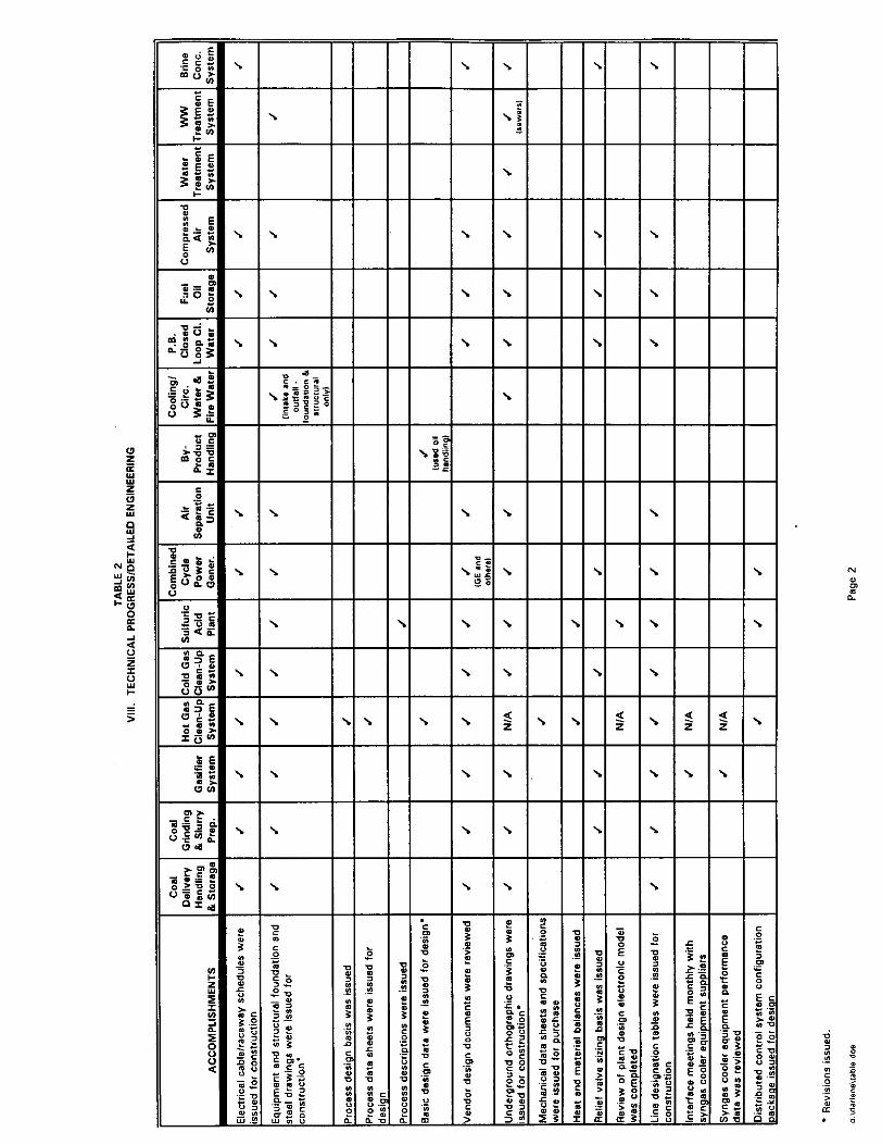
VIII. TECHNICAL PROGRESS I DETAILED ENGINEERING
This section of the report addresses detailed engineering with accomplishments through 1995 for the various IGCC plant areas, from coal delivery through power generation and the processing of by-products, as listed in Table 2. Table 2 cross-references engineering activities required to be accomplished to support the Polk Power Station Construction on a system by system basis. A check mark in the column represents activities completed in 1995.
H:\rh~rd~,*doe\FIN/\L95DOE 28

I I I I I\ I\I I I I I\1 I I I. I I I I 14~ I I 1\1 I\ I I Ix I
I I I I I I I I I I I I I I I I I I I I I I I I I I I I
\ I I PI I’ I’ I PI I’ I’ I I I’ I I I I I I I I I I I I I I I I
I I I I I I I I I I \ II II PI-d IH I4 I I I \ \ \ \ \ $\\ 4 Fj \ 2 2 \
\ \. \ \\\

-
-
-
-
-
-
-
-
-
\ -
-
s -
-
-
\
\
\
\
\
\
-
\
-
\
\
\
\
-
\
-
-
-
-
-
-
-
-
-
- \ -
- s -
-
-
-
f 5l .P d 4 g s u i t: ;i 31 a
-
\
-
-
-
-
-
-
-
-
-
-
-
-
\
-
\
-
e .- .g
P 2 F 0 4 --s m 7 z 0 P m 7 2
-
-


Tampa Electric Company DOE IGCC Demonstration Project Polk Power Stetion - Unit 1 1995 Technical Progress Report
IX. TECHNICAL PROGRESS I SIGNIFICANT ENHANCEMENTS
A. SULFURIC ACID PLANT
. Capital cost savings in the acid plant’s design have been realized in the following areas:
Use of low pressure g5-percent oxygen instead of atmospheric air for the catalytic converter’s reaction air stream
Use of siliconized ductile iron piping material instead of Sandvik SX stainless steel for strong acid piping systems
Use of FRP piping material instead of teflon lined carbon steel for weak acid piping systems
Elimination of one product acid transfer pump (used on shutdowns only) and one installed product acid loading pump from the original scope of suPPlY
Relaxation of certain API 617 requirements for the plant’s main gas compressor (an API 617 compressor was originally scoped, which was more stringent than Monsanto Enviro-Chem’s typical compressor specification).
. The above items were incorporated without impacting the acid plant’s availability requirements. A separate capital cost savings will be realized by having a previously mobilized field erected tank fabricator install the product acid storage tank instead of keeping this erection in Monsanto Enviro-Chem’s scope.
B. COMBINED CYCLE POWER GENERATION EQUIPMENT
. Following the resizing of the hot gas clean-up system, it was decided to combine the hot syngas piping with the cold syngas piping in the gasification area. This was done by relocating the GE-furnished valves and piping, resulting in significant savings to the project by eliminating one of the syngas supply lines.
. Based on the operating conditions for the plant, the capacity of the fuel oil storage was reduced from three miliion to two million gallons.
. The area classification requirements for the accessory module, fuel oil forwarding skid and the diluent nitrogen skid were established.
n:\,harda,a\doe\FINI\L9500E 29
Tampa Electric Company DOE IGCC Demonstration Project Polk PO wer Station - Unit I 1995 Technical Progress Report
. The size of the auxiliary boiler was increased to allow startup of the gasification system.
. Steel platform was added to permit CT generator rotor removal.
. One of the two boiler feedwater transfer pumps was changed to the magnetic bearing design requiring no lubricating oil. This is the first US application of this technology for this size of a pump. This was accomplished in conjunction and support from the Electric Power Research Institute (EPRI).
C. AIR SEPARATION UNIT
. A second installed compander was added to provide additional refrigeration capacity and serve as an installed spare. This will add capacity to produce liquid nitrogen for storage and improve reliability.
. Changes were made to the design of heat exchangers served by the open loop cooling water system to improve reliability and reduce the potential for fouling. Changes to the cooling water piping system were also made to facilitate cleaning of the heat exchangers cooling water side.
D. POWER BLOCK CLOSED LOOP COOLING WATER SYSTEM
. A cooling water filter was incorporated in the open loop cooling water system to protect the open loop/closed loop heat exchanger.
E. BRINE CONCENTRATION SYSTEM
. A centrifuge was selected for dewatering the brine slurry instead of a drum dryer to improve reliability and reduce cost.
. Two multi-stage centrifugal blowers were selected for heat addition to the falling film evaporator instead of a single compressor to reduce cost with no reduction in reliability.

Tampa Electric Company DOE IGCC Demonstration Project Polk Power Station - Unit 1 1995 Technical Progress Report
X. 3-D MODEL REVIEWS
Detailed design of Polk Power Station Unit 1 was performed using Bechtel’s 3DM system. This is a three-dimensional computer model of the plant which presents the following features of the plant design:
. Equipment and buildings
. Piping, valves and significant pipe supports
. Civil foundations and structures
. Structural steel
. Ladders, platforms, stairways and hand rails
. Instruments
. Electrical cable trays
. Access and pull spaces
The 3-D model was used by many project participants through the course of the project. Initially, its main purpose was to identify and eliminate interferences. On the Polk Project, the 3-D model was reviewed using the WALKTHRU program. The reviews were conducted in two stages; Stage 1 was conducted when all the equipment and large bore piping was modeled and Stage 2 was performed when the model was complete with all small bore piping. Each review stage is normally conducted in two steps: first an internal review by design disciplines, then a joint review with TEC’s operations and maintenance personnel. A partial list of the issues that were resolved during the model review is listed below:
. Verified that valve locations and orientations provided for access to the handwheel operators. In cases where immediate accessibility was not required, chain pulls for the handwheels were installed.
. Reviewed walkways at grade and on platforms to assure adequate side and head clearance for plant personnel.
. Reviewed equipment arrangements for maintenance and inspection accessibility.
. Verified that there is adequate space and access for removing or installing equipment. This means that provisions have to be made for special maintenance equipment such as forklifts, mobile cranes, hoists, bundle pullers, etc.

Tampa Electric Company DOE IGCC Demonstration Project Polk Power Station - Unit 1 1995 Technical Progress Report
. Reviewed the locations of instrument sensors, transmitters, and local readouts to verify adequate access, by plant maintenance and operating personnel.
. Ensured that appropriate plant utilities (service air and water, low pressure steam, and nitrogen) were provided at convenient locations.
. Studied arrangements of equipment handling flammable or hazardous materials to determine that no undue safety hazards existed and that adequate protective measures (such as emergency escape routes and safety showers) were included.
After the model was reviewed, the model was checked for interferences and piping isometric drawings and other documents were generated and used to procure material. After these. tasks were completed, the model was used by Construction for planning and walkdown purposes. Examples of 3-D model Walkthru drawings are attached.
The use of the 3-D model has many benefits. Probably the greatest advantage is elimination of much of the field rework which has occurred with previous work methods.
The project’s electronic model was deployed to the construction site in March 1995. The two major mechanical/electrical contractors, CP-1 l/l 1A and CP-12 were loaned the hardware and software required to use Walkthru in their Field Offices. A training and support program was implemented with both contractors to encourage the integration of the model into their installation processes. The following are typical examples that the contractor used the model in their processes:
. Planning bulk pipe installations in the pipe racks (CP-12)
. Routing of unscheduled commodities (i.e. conduit and small bore piping) prior to routed commodities (i.e. large bore piping)
. Avoiding maintenance spaces such as Heat Exchanger Tube removal
H:,rhardal~idos,~lNLiL96,DOE 32
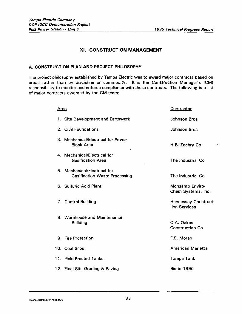
Tampa Electric Company DOE IGCC Demonstration Project Polk Power Station - Unit 1 1995 Technical Progress Report
Xl. CONSTRUCTION MANAGEMENT
A. CONSTRUCTION PLAN AND PROJECT PHILOSOPHY
The project philosophy established by Tampa Electric was to award major contracts based on areas rather than by discipline or commodity. It is the Construction Manager’s (CM) responsibility to monitor and enforce compliance with those contracts. The following is a list of major contracts awarded by the CM team:
1. Site Development and Earthwork Johnson Bros
2. Civil Foundations
3. Mechanical/Electrical for Power Block Area
4. Mechanical/Electrical for Gasification Area
5. Mechanical/Electrical for Gasification Waste Processing
6. Sulfuric Acid Plant
7. Control Building
8. Warehouse and Maintenance Building
9. Fire Protection
10. Coal Silos
1 1. Field Erected Tanks
12. Final Site Grading & Paving
Johnson Bras
H.B. Zachry Co
The Industrial Co
The Industrial Co
Monsanto Enviro- Chem Systems, Inc.
Hennessey Construct- ion Services
C.A. Oakes Construction Co
F.E. Moran
American Marietta
Tampa Tank
Bid in 1996

Tampa Electric Company DOE IGCC Demonstration Project Polk Power Station - Unit 1 1995 Technical Progress Report
13. Site Reclamation Work West of SR37 Johnson Bros
14. Air Separation Unit Air Products
There were a number of smaller contracts awarded at the Polk Site by CM team including:
Acei! Contraca
1. Site Rail R.W. Summers
2. Site Well Drilling
3. RSC Transportation/Erection
4. Transport of HRSG Modules
5. Chemical Storage & Waste Transfer
Diversified Drilling
Davenport Mammoet
Bevel Bros
Building Construction Bid in 1996
6. Gasification Elevator Montgomery Elevator
7. Slag Storage Pond EMCON Southeast
Additionally, the CM was involved in the procurement of testing services, security surveying, trash disposal, construction utilities, temporary facilities construction, and other services. The CM manages the site activities of all contractors. As the construction plan is developed and executed, any additional contracts will be similarly the responsibility of the CM.
CM Services at Polk Power were divided into two phases. The first phase took place in Houston Texas. Key members of the CM Team worked with the Engineer to optimize design through constructabily planning. The second phase of CM Services took place once the Project mobilised in the field.
The following describes services performed in each phase of the job:
The Phase I Construction Services
. Provided information to allow Tampa Electric to assess construction options.
. Planning and Scheduling of preconstruction and construction activities
. Developed Project Specific Project controls systems
. Completed development of Tampa Electric’s proposed contracting strategy
Tampa Electric Company DOE IGCC Demonstration Project Polk Power Station - Unit 1 1995 Technicel Progress Report
. Prepared a comprehensive environmental compliance plan for the project.
. Prepared construction bid documents and solicited construction bids
. Developed a system for controlling quality by adherence to codes, standards and provisions of the technical specifications
. Prepared plans for construction facilities
. Developed and implemented a plan for construction safety
. Assisted Tampa Electric and the Engineer in development of a program for plant test and startup
. Reviewed plant drawings and specifications for Constructability, format, content and completeness
. Advised and made recommendations to design documents with respect to construction feasibility, economics, availability and utilization of materials and labor, time requirements for procurement and construction
. Developed written administrative procedures to be followed in managing the construction activities
. Prepared written pre-qualification criteria for bidders and developed contractor interest in the project
Phase II Construction Services being provided by Bechtel are as listed below:
. Coordinated activities of all site contractors for laydown and fabrication as well as plant construction activities
. Provided site security, construction utilities, support services, housekeeping and cleanliness, construction photography, surveying and quality control/testing services on a subcontracted cost basis
. Provided construction scheduling, progress tracking, and analysis for all construction activities
. Provided construction contract administration
. Assess quality; adherence to codes, standards and construction specifications; and initiate corrective action to monitor and enforce compliance to specifications by construction contractors
. Performed administrative tasks related to construction including monthly reporting and maintenance of construction accounting records
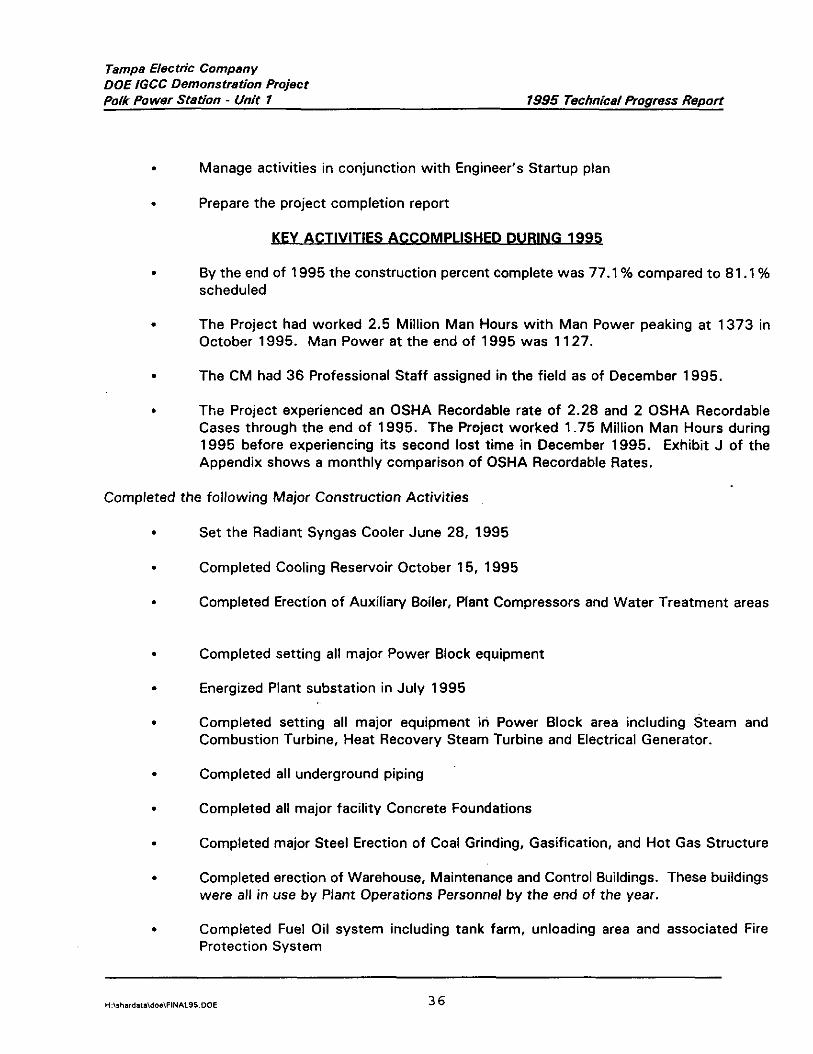
Tampa Electric Company DOE IGCC Demonstration Project Polk Power Station _ Unit 1 1995 Technical Progress Report
. Manage activities in conjunction with Engineer’s Startup plan
. Prepare the project completion report
MY ACTIVITIFS ACCOMPLISHED DURING 1995
. By the end of 1995 the construction percent complete was 77.1% compared to 81 .l % scheduled
. The Project had worked 2.5 Million Man Hours with Man Power peaking at 1373 in October 1995. Man Power at the end of 1995 was 1127.
. The CM had 36 Professional Staff assigned in the field as of December 1995.
. The Project experienced an OSHA Recordable rate of 2.28 and 2 OSHA Recordable Cases through the end of 1995. The Project worked 1.75 Million Man Hours during 1995 before experiencing its second lost time in December 1995. Exhibit J of the Appendix shows a monthly comparison of OSHA Recordable Rates.
Completed the following Major Construction Activities
.
.
.
.
.
.
.
.
.
.
.
Set the Radiant Syngas Cooler June 28, 1,995
Completed Cooling Reservoir October 15, 1995
Completed Erection of Auxiliary Boiler, Plant Compressors and Water Treatment areas
Completed setting all major Power Block equipment
Energized Plant substation in July 1995
Completed setting all major equipment in Power Block area including Steam and Combustion Turbine, Heat Recovery Steam Turbine and Electrical Generator.
Completed all underground piping
Completed all major facility Concrete Foundations
Completed major Steel Erection of Coal Grinding, Gasification, and Hot Gas Structure
Completed erection of Warehouse, Maintenance and Control Buildings. These buildings were all in use by Plant Operations Personnel by the end of the year.
Completed Fuel Oil system including tank farm, unloading area and associated Fire Protection System
H:\,hard~,l\do*FIN*L9500E 36

Tamps Electric Company DOE IGCC Demonstration Project Polk Power Station - Unit 1 1995 Technical Progress Report
. Completed Construction of Air Separation Unit and Sulfuric Plant
Of a total of 160 systems, 60 systems had been completed by Construction and turned over to the Polk Power Start Up organization by year end 1995.
H:\rharda,.idoe\FIN/LL9SDOE 37
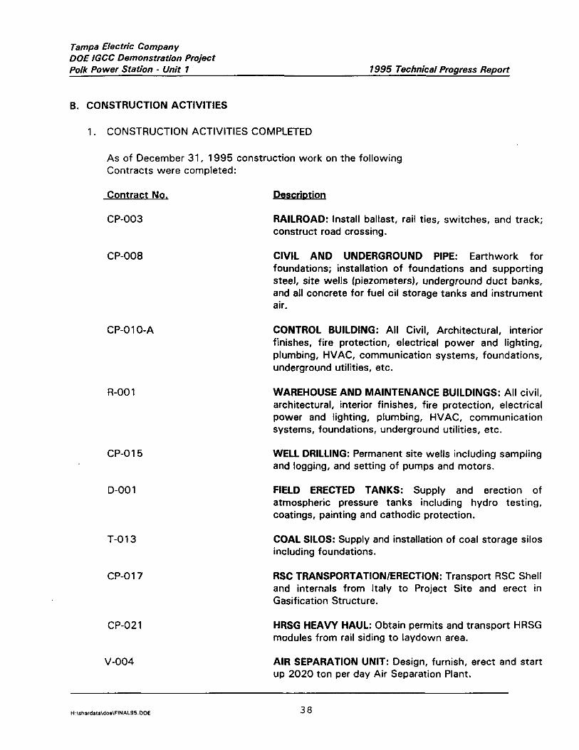
Tampa Electric Company DOE IGCC Demonstration Project Polk Power Station - Unit 1 1995 Technical Progress Report
B. CONSTRUCTION ACTIVITIES
1. CONSTRUCTION ACTIVITIES COMPLETED
As of December 31, 1995 construction work on the following Contracts were completed:
Contract No.
CP-003
. Descriotr on
RAILROAD: Install ballast, rail ties, switches, and track; construct road crossing.
CP-008 CIVIL AND UNDERGROUND PIPE: Earthwork for foundations; installation of foundations and supporting steel, site wells Ipiezometers), underground duct banks, and all concrete for fuel oil storage tanks and instrument air.
CP-01 O-A
R-001
CP-015
D-001
T-013
CP-017
CONTROL BUILDING: All Civil, Architectural, interior finishes, fire protection, electrical power and lighting, plumbing, HVAC, communication systems, foundations, underground utilities, etc.
WAREHOUSE AND MAINTENANCE BUILDINGS: All civil, architectural, interior finishes, fire protection, electrical power and lighting, plumbing, HVAC, communication systems, foundations, underground utilities, etc.
WELL DRILLING: Permanent site wells including sampling and logging, and setting of pumps and motors.
FIELD ERECTED TANKS: Supply and erection of atmospheric pressure tanks including hydro testing, coatings, painting and cathodic protection.
COAL SILOS: Supply and installation of coal storage silos including foundations.
RSC TRANSPORTATION/ERECTION: Transport RSC Shell and internals from Italy to Project Site and erect in Gasification Structure.
CP-021 HRSG HEAVY HAUL: Obtain permits and transport HRSG modules from rail siding to laydown area.
V-004 AIR SEPARATION UNIT: Design, furnish, erect and start up 2020 ton per day Air Separation Plant.
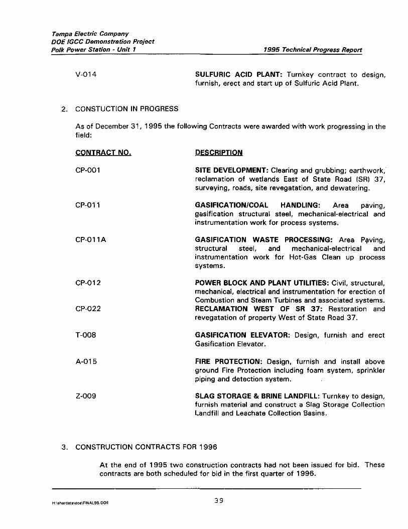
Tampa Electric Company DDE IGCC Demonstration Project Polk Power Station - Unit 1 1995 Technical Progress Report
v-01 4 SULFURIC ACID PLANT: Turnkey contract to design, furnish, erect and start up of Sulfuric Acid Plant.
2. CONSTUCTION IN PROGRESS
As of December 3!, 1995 the following Contracts were awarded with work progressing in the field:
CONTRACT NO.
CP-001
DFSCRIPTION
SITE DEVELOPMENT: Clearing and grubbing; earthwork, reclamation of wetlands East of State Road 1%) 37, surveying, roads, site revegatation, and dewatering.
CP-011 GASIFICATION/COAL HANDLING: Area paving, gasification structural steel, mechanical-electricat and instrumentation work for process systems.
CP-OllA GASIFICATION WASTE PROCESSING: Area Paving, structural steel, and mechanical-electrical and instrumentation work for Hot-Gas Clean up process systems.
CP-012
CP-022
T-008
A-01 5
Z-009
POWER BLOCK AND PLANT UTILITIES: Civil, structural, mechanical, electrical and instrumentation for erection of Combustion and Steam Turbines and associated systems. RECLAMATION WEST OF SR 37: Restoration and revegatation of property West of State Road 37.
GASIFICATION ELEVATOR: Design, furnish and erect Gasification Elevator.
FIRE PROTECTION: Design, furnish and install above ground Fire Protection including foam system, sprinkler piping and detection system.
SLAG STORAGE & BRINE LANDFILL: Turnkey to design, furnish material and construct a Slag Storage Collection Landfill and Leachate Collection Basins.
3. CONSTRUCTION CONTRACTS FOR 1998
At the end of 1995 two construction contracts had not been issued for bid. These contracts are both scheduled for bid in the first auarter of 1996.

Tempe Electric Company DOE IGCC Demonstretion Project Polk Power Station - Unit 7 1995 Technical Progress Report
I. CHEMICAL STORAGE & WASTE TRANSFER (CONTRACT CPO231:
Thi,s contract is scheduled to be issued for bid in January 1998 with award scheduled for March 1996. Work will commence on this contract in April 1996 with construction to be completed in late summer.
The scope of this contract includes construction of a new brine and hot gas clean-up waster transfer building and renovation of an existing building for use as a chemical and waste oil storage facility.
2. FINAL GRADING, PAVING & FENCING (CONTRACT CPO14):
This contract is scheduled for bid in the first quarter of 1996 with award and work commencement scheduled for May 1996. Work will be complete on this contract in September 1996.
The scope of this contract includes site perimeter fencing, completion gf site grading, asphalt paving, seeding, stone covering and ditches within the facility area. This contractor will complete paving, grading and stone cover in all areas not currently included in the scope of existing contractors. The work to be performed by the final site grading contractor must be coordinated with other site contractors to avoid the possibility of having to rework pavement on roads.
4. WORK ACCOMPLlSHED IN 1995
Construction Management activities in 1995 focused on Field Administration of Construction Contracts. In April 1995 all remaining CM Personnel completed the transition from Houston to the Site. The following summarizes Construction Contracts administered by the CM:
a. SjTE DEVELOPMENT (CONTRACT CPOOI 1:
This contract was awarded to Johnson Bros. Construction (JBC) on February 7, 1994. As of December 31, 1995 the Contractor was 97.3% versus 97.9% Schedule.
The Contractor worked 601,255 Man-hours and experienced the following Safety Record through December 31, 1995:

Tampa Electric Compen y DOE IGCC Demonstration Project Polk Power Station - Unit 1 1995 Technical Progress Report
Polk Power Site Total
Safety Matrix
To Date through ber 31. 1995
Number of Number Number of Number of’ OSHA First Aid of ~OSHA Loss Time Recordable
Cases Doctor Recordable Incidents Rate C*SSS Cases
91 33 9 0 2.99
The contract for Site Development includes the following:
.
.
.
.
.
.
.
.
.
.
Install underground piping including stormwater pipe to MH No. 8, circulating water pipe and 36-, 42- and 48-inch cooling water pipe
Soil erosion control
Perform clearing, grubbing, site dewatering and cut and fill for land areas
Construct temporary and permanent berms, cooling water ponds, ditches, trenches and culverts
Perform layout and survey of work areas
Install base material for roads and asphalt base course
Construct temporary parking areas, laydown areas and railroad subgrade
Provide slope stabilization of berms, trenches and ditches
Perform initial site revegetation
install coal delivery ramps
Major activities accomplished in 1995 included:
. Completed construction of the Cooling Pond
. Completed Structural fill in all Plant areas
. Completed and tested underground piping
. Established seeding and commenced revegatation of wet lands areas
. Placed road base on Plant interior roads and placed 2 inches of pavement on access entrances
H:,~ihardalaidos,FINI\L95DOE 41

Tampa Electric Company DOE IGCC Demonstration Project Polk Power Station - Unit 1 1995 Technical Progress Report
b. MAIN CIVIL/STRUCTURAL (CONTRACT CPOOE):
This Contract was awarded to Johnson Bros. Construction (JBC) on October 14, 1994. The Contractor completed his work scope during the month of November 1995 and demobilized from the Project Site.
The Contractor worked 241,194 Man-hours and experienced the following Safety record through December 1995:
Polk Power Numbqof ~Nunher”~, Nutiber,of ‘:,:, &l~~ber~:@f OSHA ,~ Site Total, Fint:Aid ~,,,,f’:: ~~ (,!#,A) ~: &&$i~e:~ Recor,,a,,,e ~,~,
Safety Matrix Zases Doctqr Recordhbfe j : ~:EIhCid&~$ Rate Caies ~~ Cas&, ,,,E ~y~ ,~ ” ~5:~~’
To Date through ber 31. 1995 78 15 10 1 8 ,a
The Contract for Civil/Structural Site Construction included:
. Earthwork associated with foundation installation, tank foundations and’liners for plant storage tanks
. All underground ductbank (except for cable)
. All fuel oil storage tank area concrete and earthwork
. Instrument air compressor foundations
. Cooling water intake structure concrete
. Grounding and underground pipe
. Power block equipment foundations
. Pipe rack foundations and steel erection
. Flare and intake foundation
. Underground piping not included in the site development contract
. Hot Gas Clean-Up foundation
. Gasification structure foundation and structural steel erection to 85 feet above grade
. Coal handling and coal grinding area foundations
H:,m~rdala\dos\FINIL95DOE 42

Tampa Electric Company DOE IGCC Demonstration Project Polk PO wer Station - Unit 1 1995 Technical Progress Report
c. RAILROAD (CONTRACT CPOO3):
This contract was awarded to R.W. Summers on July 14, 1994. The Contractor completed his scope of work during the month of March 1995 and demobilized from the site.
The Contractor worked 8,252 total Man-hours and did not have any first aid cases, OSHA recordable cases or lost time accidents during the execution of its work.
The Contract for Railroad Construction included:
. Install signalization
. Furnish materials, survey and labor
. Install crossing of Fort Green Road and Plant Road “C”
. Railroad bedding, track, rail ties, switches and ballast for spur from CSX track located adjacent to Fort Green Road.
d. WELL DRILLING (CONTRACT CPG;5):
This contract was awarded to Diversified Drilling on August 25, 1994. The Contractor completed his scope of work in June 1995.
The Contractor worked a total of 3,891 Man-hours and had 3 first aid cases during the period of execution of his work. There were no OSHA recordable or Lost work day cases.
Included in the scope of work was drilling of four permanent site production wells and setting of pumps and motors.
e. WAREHOUSE AND MAINTENANCE BUILDING (CONTRACT ROOl):
This contract was awarded to C.A. Oakes Construction Company on May 9, 1994. The contractor completed his scope of work in July 1, 1995.
The contractor worked 46,752 Man-hours and experienced the following Safety record during the execution of his work.

Tampa Electric Company DOE IGCC Demonstration Project Polk Power Station - Unit 1 1995 Technical Progress Rep,ort
Polk Power, Site Total
Safety Matrix
To Date through ber 31, 1995
Number of Number Number of Number of OSHA First Aid of OSHA Loss Time Recordable
Cases Doctor Recordable Incidents Rate Cases Cases
4 2 1 0 4.28
The Contractor for Warehouse and Maintenance construction included the following:
. Design, furnish and erect warehouse & maintenance buildings
. Underground water, sewer and electrical within building perimeters
. Foundations and area grading
. Above ground civil architectural, interior finishes, electrical power, lighting, HVAC, fire protection and communications
. Testing and balancing of systems
f. CONTROL BUILDING (CONTRACTOR CPOlO-A):
This contract was awarded to Hennessey Construction Services on October 13, 1994. The contractor completed his scope of work in August 19, 1995.
The contractor worked 55,792 Man-hours and experienced one first aid case and no OSHA recordables or lost work time accidents
The contract for construction of the Control Building included:
. Underground electrical, plumbing, water and fire protection within building perimeter
. Foundations and area grading
. Above ground civil, architectural, interior finishes, electrical power, plumbing, lighting, HVAC, fire protection and communication
. Install lab furnishings, fixtures and control room build-out
. Communication system, lightning protection and security

Tampa Electric Company DDE IGCC Demonstration Project Polk Power Station - Unit 1 7995 Technical Progress Report
g. FIELD ERECTED TANKS (CONTRACT DO01 1:
This contract was awarded to Tampa Tank on April 15, 1994. The contractor completed his scope of work in December 1995 and was in the process of demobilizing from the site at the end of the year.
The contractor worked 19,894 Man-hours and experienced 6 first aid cases during the execution of his work. There were no OSHA recordables or lost work day cases.
The contractor for field erected tanks included the following:
. Design, supply and erection of atmospheric pressure tanks and vessels including condensate storage, amine storage, slurry run tank, chemical cleaning, service water, demineralized water, fuel oil storage, brine storage, evaporator storage and grey water storage tanks
. Hydro testing
. Cleanup of tank interiors
. Blasting of tank interiors and exteriors
. Application of interior and exterior coatings
. Cathodic protection and post-weld heat treatment
. Foundation work was performed by the Civil contractor, JEC
h. COAL SILOS (CONTRACT T013):
This contract was awarded to American Marietta on May 19, 1994. The contractor completed the erection of Coal Silos in September 1995.
The contractor worked 21,742 Man-hours and experienced 3 first aid cases during the execution of his work. There were no OSHA recordables or lost time days.
The scope of work for this contract was for design and construction of two concrete coal silo storage facilities including foundations, interior steel plating, ladders and conveyor embedments in the silo roof.
i. HEAVY HAUL AND ERECTION for RADIANT SYNGAS COOLER (CONTRACTOR CPOl7):
This contract was awarded to Davenport Mammoet Heavy Transport Inc., on May 9, 1994. The contractor completed setting of the gasification equipment in July 1995.

Tampa Electric Company DDE IGCC Demonstration Project Polk PO wer Station - Unit 1 7995 Technical Progress Report
The contractor worked 4,740 Man-hours without a first aid case.
The scope of work for this contract included:
. Ocean Transport of Radiant Syngas Cooler from Italy to the Port of Tampa
. Heavy-haul transport of vessel from the Port of Tampa to jobsite
. Erection of equipment into structure
j. HRSG HEAVY HAUL TRANSPORT (CONTRACT CPO211:
This contract was awarded to Bevel Bros and included off loading Heat Recovery - Steam Generator modules from an off-site rail siding and transporting the modules to a lay down area adjacent to the Power Block. The contractor performed its work without a first aid care and demobilized from the project in January 1995.
k. SULFURIC ACID PLANT (CONTRACT VO14):
The contract was awarded to Monsanto Enviro-Chem Systems, Inc on June 8, 1994. The Contractor completed major construction activities in the month of December 1995. The contractor is involved with process checkout and punchlisting activities.
The contractor worked 126,833 Man-hours with 47 first aid cases during the execution of its work. There were no OSHA recordables or lost work day cases.
This was a Turnkey contract for the Engineering, supply and erection of a plant to produce 98 percent Sulfuric acid at a rate of 208 STPD.
I. AIR SEPARATION UNIT (CONTRACT VOO4):
The contract was awarded to Air Products and Chemicals, Inc on April 14, 1993. The contractor completed major construction activities in the month of December 1995. The contractor is involved with process checkout and punchlist work.
Through the end of 1995 the contractor worked 119,146 Man-hours and experienced the following Safety record:
Polk Power Site Total
Safety Matrix
To Data through r 31.1995
Number of Number Number of Number of OSHA First Aid of OSHA Loss Time Recordable
Cases Doctor Recordable Incidents Rate Cases Cases
27 7 7 0 3.47
H:,ahsrd~t~\doe\FINIL05DOE 46
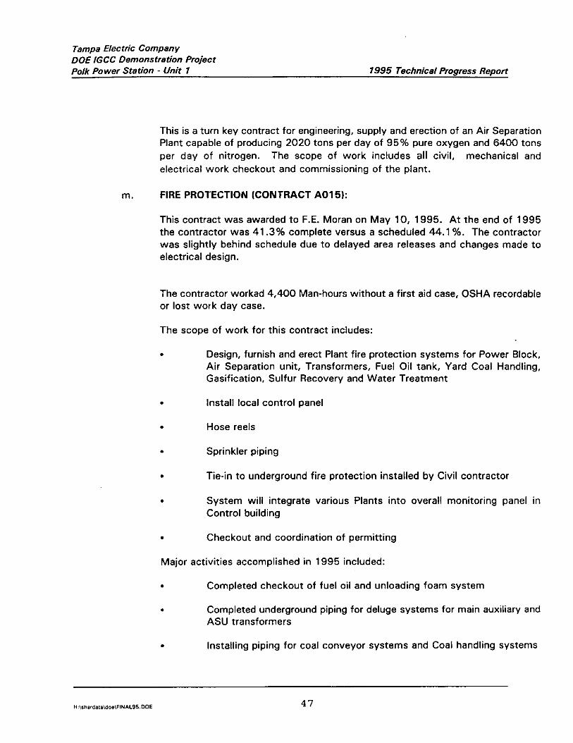
Tampa Electric Company DOE IGCC Demonstration Project Polk Power Station - Unit 1 1995 Technical Progress Report
This is a turn key contract for engineering, supply and erection of an Air Separation Plant capable of producing 2020 tons per day of 95% pure oxygen and 6400 tons per day of nitrogen. The scope of work includes all civil, mechanical and electrical work checkout and commissioning of the plant.
m. FIRE PROTECTION (CONTRACT A01 5):
This contract was awarded to F.E. Moran on May 10, 1995. At the end of 1995 the contractor was 41.3% complete versus a scheduled 44.1%. The contractor was slightly behind schedule due to delayed area releases and changes made to electrical design.
The contractor worked 4,400 Man-hours without a first aid case, OSHA recordable or lost work day case.
The scope of work for this contract includes:
. Design, furnish and erect Plant fire protection systems for Power Block, Air Separation unit, Transformers, Fuel Oil tank, Yard Coal Handling, Gasification, Sulfur Recovery and Water Treatment
. Install local control panel
. Hose reels
. Sprinkler piping
. Tie-in to underground fire protection installed by Civil contractor
. System will integrate various Plants into overall monitoring panel in Control building
. Checkout and coordination of permitting
Major activities accomplished in 1995 included:
. Completed checkout of fuel oil and unloading foam system
. Completed underground piping for deluge systems for main auxiliary and ASU transformers
. Installing piping for coal conveyor systems and Coal handling systems
H:\d~rdal*do~\FIN*L9500E 47
Tampa Electric Company DOE IGCC Demonstration Project Polk Power Station - Unit 1 7995 Technical Progress Report
n. WEST OF STATE ROAD 37 RECLAMATION (CONTRACT CPO22l:
This contract was awarded to Johnson Bros Construction on November 8, 1995. At the end of 1995 the contractor was 11.3% complete versus 10.3% planned.
The contractor worked 16,741 Man-hours in 1995 with 2 first aid cases. There have been no OSHA recordables or lost work time accidents.
The scope of work includes restoration of mined property West of State Road 37, seeding and planting of wet lands.
The contractor mobilized and commenced dewatering and earthwork on November 13. 1995.
0. GASIFICATION ELEVATOR (CONTRACT T008):
This contract was awarded to Montgomery Elevator on June 1, 1994. At the end of 1995 the contractor had completed mobilizing to the site and commenced building the working car and side guide rails. Work was approximately 3% complete with no first aid cases.
The scope of this contract included the design and construction of elevator in the gasification structure.
P. SLAG STORAGE AND LEACHATE POND (CONTRACT 2009):
This contract was awarded to EMCON Southeast on January 20, 1995. The contractor was approximately 42% complete at the end of 1995. The contractor experienced 1 first aid case in 1995.
The scope of work for this contract included.
. Provide detailed engineering, material and construction of a Slag Storage Runoff Retention Basin
. Dewatering earthwork and underground piping
. Install liner and sumps for Slag Runoff Basin and Leachate Collection area
. Install berms and grass seeding of slopes
Major activities accomplished in 1995 included:

Tampa Electric Company DOE IGCC Demonstration Project Polk Power Station - Unit 1 1995 Technical Progress Report
. Excavation of Slag Storage area
. Place Geotextile Fabric and Secondary HDPE liner for Slag and Leachate impoundment areas
. Constructing anchor trenches for liner at impoundment area perimeter
4. POWER BLOCK AND PLANT UTILITIES MECHANICAL/ELECTRICAL (CONTRACT CPOl21:
This contract was awarded to H.B. Zachry Company on February 17, 1995. At the end of 1995 the contractor was 81.5% complete versus 87.4%. The contractor has experienced delays due to late area releases, materials and changes to the work.
Through December 1995 the contractor worked 523,510 Man-hours with the following Safety record:
Polk,Power Number,of Number ~ Number of Numbers oft OSHA Site Total ~: ::,fjmt~,Aid’ ;:~,&p y ‘~~~ ~osl.jA; ,~ ,:~ Loss:‘Time Recordable
. Safety Metrlx Cases ~Di&tpr Rectirdabh Incidents: Rate Ca!&a% : Case*, ,~, ‘~’
To Date through ber 31. 1995 757 36 3 0 1.15
The scope of work includes the following:
. Start up support for contractor installed equipment and system.
. Above ground pipe connection to underground pipe, install electrical power and control for site well system.
. CCTV, grounding, gaitronics, heat tracing and lighting systems.
. Water Treatment - all work except foundations
. Fuel Oil Storage - steel, mechanical, pipe, electrical and instrumentation, except for tank fabrication and foam spray equipment that is part of scope of Fire Protection
. Instrument Air - steel, mechanical, pipe, electrical and instrumentation
. Intake Structure - steel, mechanical, pipe, electrical and instrumentation
H:irhard~f~idoCiFIN*L95DOE 49
Tampa Electric Company DOE IGCC Demonstration Project Polk Power Station - Unit 1 1995 Technical Progress Report
. Power Block - structural steel, mechanical work, electrical installation of all equipment including the GE supplied turbine generators
. Install main bus, UPS and main switch gear.
. Completion of area paving transferred from the scope of the Civil contractor
. Continuous Emissions Monitoring Systems
. Set all substation prefab buildings
. Install all cable and tray from main switch gear to all local MCC’s
. Install DCS equipment, fiber optic cable
Major areas of work completed during 1995 included:
. Completed all electrical distribution systems
. Set all major power block equipment including Combustion Turbine, Generator, Heat Recovery Steam Generator, Steam Turbine & Condenser
. Erected Auxiliary Boiler steel and equipment
. Completed power block area paving
. Completed civil, mechanical and electrical work in Water Treatment area
. Completed setting pumps and equipment at intake area
. Electrical and piping activities were progressing throughout power block.
r. GASIFICATION/COAL HANDLING (CONTRACT CPOll):
This contract was awarded to The Industrial Company (TIC) on April 21, 1995. The contractor was 56.4% complete on December 31, 1995 versus 62%. Delays were attributable to late steel and areas that could not be released.
The Contractor worked a~combined 459,830 Manhours between the two contracts (CPOl 1 & CPOl 1A) awarded to TIC. The Contractor experienced the following Safety record through December 1995:
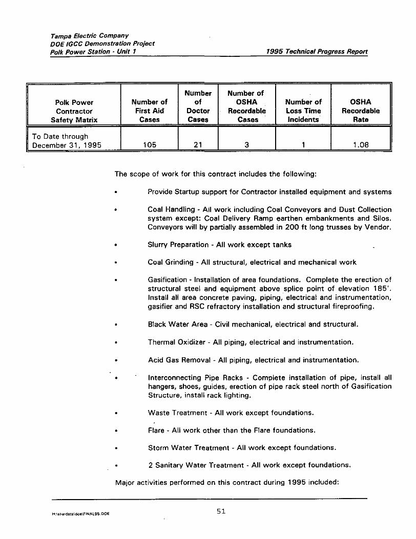
Tampa Electric COmpanY DOE IGCC Demonstration Project Polk PO wer Station _ Unit 1 1995 Technical Progress Report
Polk Power Contractor
Safety Matrix
To Date through December 31, 1995
Number of First Aid
Cases
105
Number Number of of OSHA
Doctor Recordable Cases Cases
21 3
Number of OSHA Loss Time Recordable Incidents Rate
1 1.08
The scope of work for this contract includes the following:
. Provide Startup support for Contractor installed equipment and systems
. Coal Handling - All work including Coal Conveyors and Dust Collection system except: Coal Delivery Ramp earthen embankments and Silos. Conveyors will by partially assembled in 200 ft long trusses by Vendor.
Slurry Preparation - All work except tanks
Coal Grinding - All structural, electrical and mechanical work
Gasification - Installation of area foundations. Complete the erection of structural steel and equipment above splice point of elevation 185’. Install all area concrete paving, piping, electrical and instrumentation, gasifier and RSC refractory installation and structural fireproofing.
. Black Water Area - Civil mechanical, electrical and structural.
. Thermal Oxidizer - All piping, electrical and instrumentation.
. Acid Gas Removal - All piping, electrical and instrumentation.
. Interconnecting Pipe Racks - Complete installation of pipe, install all hangers, shoes, guides, erection of pipe rack steel north of Gasification Structure, install rack lighting.
. Waste Treatment - All work except foundations.
. Flare - All work other than the Flare foundations.
. Storm Water Treatment - All work except foundations.
. 2 Sanitary Water Treatment - All work except foundations.
Major activities performed on this contract during 1995 included:

Tampa Electric Company DOE IGCC DemOnstratim Project Po,k PO wer station - unit 7 1995 Technical Progress Reporr
. Completed erection of Coal Gasification structural steel
. Final setting of Gasification and Steinmuller equipment
. Erected Coal Handling and Grinding structure and equipment
. Setting equipment for a Flare, Slurry Preparation, Waste Treatment and Sanitary Water Treatment areas.
. Major electrical and piping commodities were proceeding in all areas.
. Achieved mechanical completion and turned over to Plant Startup group the Industrial Waste Water Treatment system, portions of Instrument Air Headers, portions of Sanitary and Oily Waste Treatment, and low and medium pressure steam systems.
S. GASIFICATION WASTE PROCESSING (CONTRACT CPOl 1A):
This contract was awarded to The Industrial Company (TIC) on July 6, 1995, The Contractor was 52.2% complete versus 47.7% complete as of December 31, 1996.
The hours worked by the Contractor and Safety statistics for this TIC contract are included with the TIC contract for Gasification/Coal Handling.
The scope of work for this contract includes the following:
. Slag Handling/Fines Handling - All work south of the Gasification structure, piping systems will tie in at rack south of Gasification structure.
Grey Water - All work south of the Gasification structure.
Brine Concentration - All work except foundations included in Main Civil Contract.
Thermal Oxidizer - Setting equipment and Main Pipe supports.
Hot Gas Clean-up - All work except foundations. Contractor will use approved Subcontractor for Vessel Refractory and area paving in Brine area.
Major activities performed on this contract during 1995 included:
. Erected structural steel for the Brine area.
H:,mardal*do*FINI\LSS.DOE 52

Tampa Electric COmpany DOE IGCC Demonstration Project Polk Power Station - Unit 1 1995 Technical Progress Report
. Erected structural steel for Hot Gas Clean-up structure.
. Installation of Brine area skids and completion of inter-connecting piping and electrical
. Commenced area paving in Brine, Coal, Gasification and pipe rack areas.
. Completed rough setting all equipment in Hot Gas clean-up structure.
. Rough set Grey and Brine Water equipment.
. Running major piping and electrical commodities in all areas.
. Mobilized insulation Subcontractor and commenced work for Brine tanks and piping.
. Completed setting Thermal Oxidizer equipment.
Tampa Electric Company DOE IGCC Demonstration Proiect
. Polk Power Station - Unit i 1995 Technical Progress Report
XII. STARTUP ORGANIZATION
A. STARTUP PROGRAM
In a broad perspective, the startup program involves taking scoped systems during the final stage of
construction and preparing them for operation and owner acceptance. The vast array of activities
include the following: initial system walk down, component and system checkout (electronically and
mechanically), instrument calibration and loop checking, meter and relay calibration, system cleaning
and operational checkout, integrated system testing, fine tuning of system and plant operations, and
the turnover and acceptance of the facility for commercial operation by Tampa Electric.
Other functions included in the startup scope of work include participation in TECO’s dynamic
simulator and development of the operating and training procedures. The simulator is a tool that is
used to simulate various operating modes of the plant, including upset conditions that could occur
within complex systems. The combination of the simulator and the operating/training procedures will
be a valuable asset during the operator’s training program and initial operation of the plant.
The startup organization comprises of the following: A.) Bechtel Startup Manager, B.) Bechtel and
TECO mechanical, electrical, and instrumentation and controls startup engineers, C.) Project Controls
and Administrative Support, D.) TECO Process Specialist, E.1 Pipefitters and Electrical Craftsmen
provided by H.B. Zachary and TIC, and F.) Safety Engineer. In addition, vendor representatives are
called to the site on an “as needed basis” to participate in the testing and initial operation of selected
major equipment.
B. STARTUP ACTIVITIES ACCOMPLISHED DURING 1995
Startup operations commenced at the project site in May of 1995. At the conclusion of 1995, startup
was 24 percent complete versus a scheduled 27 percent complete. Sixty system turnovers 138
percent of total) were received from construction versus 59 scheduled. Out of the 60 systems,
startup was able to energize 9 different substations, place in service the water plant consisting of 9
systems, and provide instrument air, cooling water, power and DCS communication to the Air
Separation Unit.
KEY ACTIVITIES ACCOMPLISHFD DURING 1995
. Startup System Scoping of Process and Instrument Diagrams.
. Completed electrical check out and energized the transformers, switchgear and motor control
centers for the entire plant.
H:\mard.l~idos\FINI\L95.00E 54

Tampa Electric Company DOE IGCC Demonstration Project Polk Power Station - Unit 1 1995 Technical Progress Report
Completed check out and placed in service (9) water treatment systems needed to process
demineralized, potable and service water for the plant.
Installed and checked out the Distributed Control System (DCS).
Completed check out and placed in service the plant and instrument air systems.
Completed check out and placed in service the closed loop and open loop cooling water
systems to the power block.
Completed check out end placed in service the open loop cooling water system to the Air
Separation Unit.
Completed check out and placed in service the control building, maintenance building and
warehouse building.
Completed check out and placed in service the oily waste and industrial waste water treatment
systems.
Completed check out and placed in service the sanitary treatment system.
Completed check out and placed in service the fuel oil system for the auxiliary boiler and the
gas turbine.
C. STARTUP ACTIVITIES PLANNED FOR 1996
The work plan for 1996 consists of completing checkout and placing in service the remaining scoped
systems, completing unit shakedown, initializing power generation using syngas, and completing
performance testing of the facility. The plant is scheduled to be released to operations on September
15, 1996.
MY ACTIVUJES PLANNFD FOR 1996
. Provide steam, generated by the auxiliary boiler, to the air separation unit.
. Complete check out and place in service open loop and closed loop cooling water to the
gasification area.
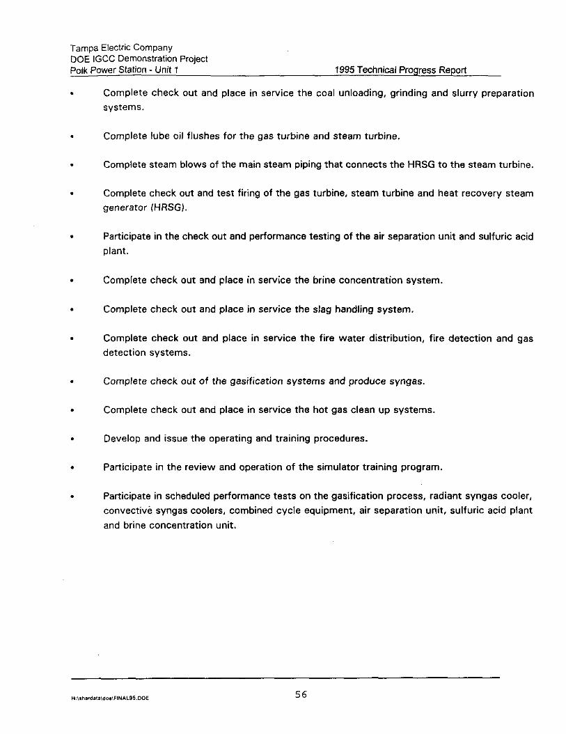
Tampa Electric Company DOE IGCC Demonstration Project Polk Power StatiOn - Unit 1 1995 Technical Progress Report
.
.
.
.
.
.
.
.
.
.
.
.
.
Complete check out and place in service the coal unloading, grinding and slurry preparation
systems.
Complete lube oil flushes for the gas turbine and steam turbine.
Complete steam blows of the main steam piping that connects the HRSG to the steam turbine.
Complete check out and test firing of the gas turbine, steam turbine and heat recovery steam
generator (HRSG).
Participate in the check out and performance testing of the air separation unit and sulfuric acid
plant.
Complete check out and place in service the brine concentration system.
Complete check out and place in service the slag handling system.
Complete check out and place in service the fire water distribution, fire detection and gas
detection systems.
Complete check out of the gasification systems and produce syngas.
Complete check out end place in service the hot gas clean up systems.
Develop and issue the operating and training procedures.
Participate in the review and operation of the simulator training program.
Participate in scheduled performance tests on the gasification process, radiant syngas cooler,
convective syngas coolers, combined cycle equipment, air separation unit, sulfuric acid plant
and brine concentration unit.
Tampa EleCtriC Company DOE IGCC Demonstration Project Polk Power Station - Unit 1 1995 Technical Progress Report
XIII. TECHNICAL PAPERS/CONFERENCE PRESENTATIONS
During 1995, Tampa Electric and TPS Project Management representatives participated in major
conferences to delitier technical papers targeted toward the advancement of IGCC Technology in
Utility Applications. The summary below lists the key conferences attended and the technical papers
presented.
September: Stephen D. Jenkins of TPS and Deputy Project Manager for the Polk Power IGCC
Project, presented a paper on the “Tampa Electric Company Polk Power Station
IGCC Project” at the Pittsburgh Coal Conference.
September: Donald E. Pless, Director of Advanced Technology for TPS and Project Manager
for the Polk Power IGCC Project, gave a paper on “Status Update, Polk Power
Station”, to the Clean Coal Technology Conference in Denver, Colorado.
October: Charles R. Black, Vice-President, Project Management, Tampa Electric gave a paper
on “Tampa Electric Company’s Polk Power Station Construction Update tb the
Conference on New Power Generation Technology, sponsored by Electric Power
Research Institute at the ANA Hotel in San Francisco, California.
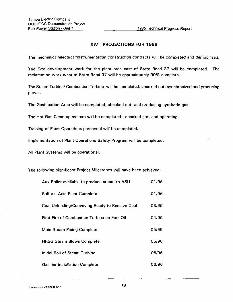
Tampa Electric Company DOE IGCC Demonstration Project Polk Power Station - Unit 1 1995 Technical Progress Report
XIV. PROJECTIONS FOR 1996
The mechanical/electrical/instrumentation construction contracts will be completed and demobilized.
The Site development work for the plant area east of State Road 37 will be completed. The
reclamation work west of State Road 37 will be approximately 90% complete.
The Steam Turbine/ Combustion Turbine will be completed, checked-out, synchronized and producing
power.
The Gasification Area will be completed, checked-out, and producing synthetic gas,
The Hot Gas Clean-up system will be completed - checked-out, and operating.
Training of Plant Operations personnel will be completed.
Implementation of Plant Operations Safety Program will be completed.
Ail Plant Systems will be operational.
The following significant Project Milestones will have been achieved:
Aux Boiler available to produce steam to ASU 01 I96
Sulfuric Acid Plant Complete 01/96
Coal Unloading/Conveying Ready to Receive Coal 03196
First Fire of Combustion Turbine on Fuel Oil 04196
Main Steam Piping Complete 05196
HRSG Steam Blows Complete 05196
Initial Roll of Steam Turbine 06196
Gasifier installation Complete 06196
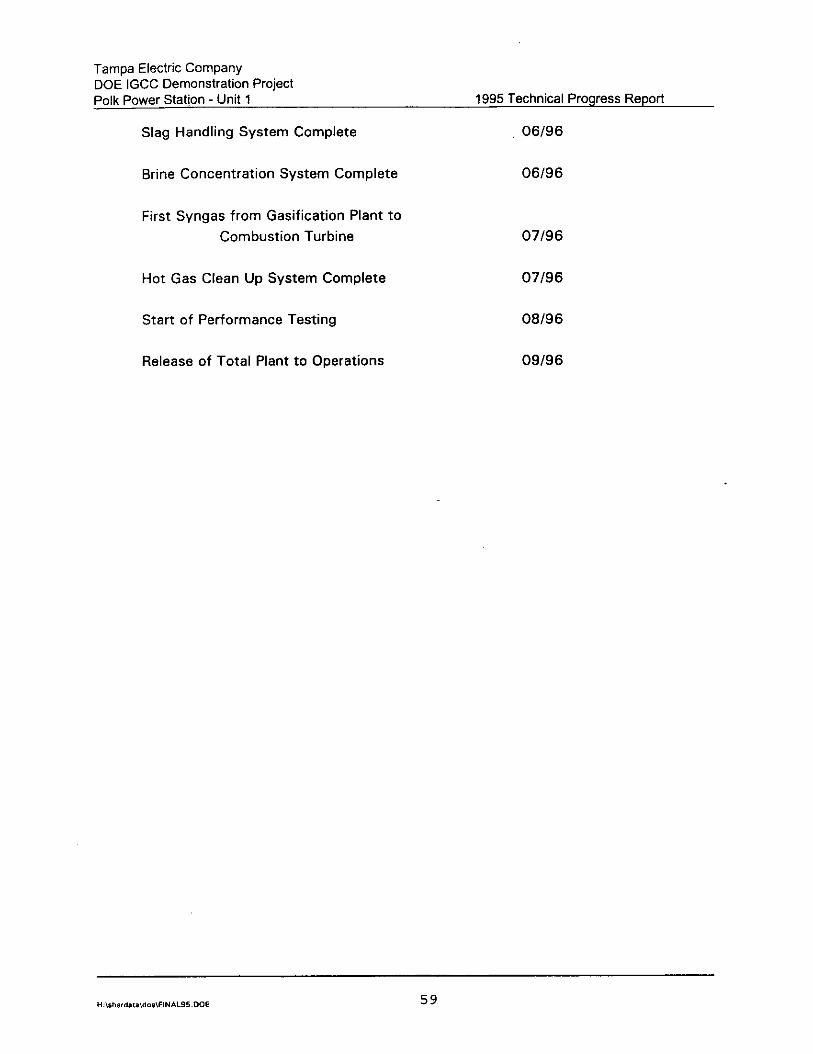
Tampa Electric Company DOE IGCC Demonstration Project Polk Power Station - Unit 1 1995 Technical Progress Report
Slag Handling System Complete 06196
Brine Concentration System Complete 06196
First Syngas from Gasification Plant to
Combustion Turbine
Hot Gas Clean Up System Complete
Start of Performance Testing
Release of Total Plant to Operations
07196
07196
06196
09196
Tampa Electric Company DOE IGCC Demonstration Project Polk Power Station - Unit 1 1995 Technical Progress Report
XV. SUMMARY
The emphasis during 1995 centered around construction activities. At year’s and the construction
was 77% complete. All major construction contractors were mobilized on site. Mechanical
completion was reached on the Air Separation Unit, and the Sulfuric Acid Plant. The Warehouse,
Maintenance and Administration building were completed. The Radiant Syngas Cooler, a critical path
activity, was set June 26, three days ahead of schedule. Startup activities began in earnest, with
the functional testing electrical and mechanical components.
Safety performance on the project has been outstanding and has helped keep the project participants
focused on providing a safe work environment. The project worked a period of over 1.7 million
manhours without a lost time accident.
Major project participants in 1995 included:
.
.
.
.
.
.
.
.
.
.
.
.
.
.
Air Products and Chemicals, Inc.
Aqua-Chem, Inc.
Bailey Controls Company
Bechtel Power Corporation
General Electric Company
General Electric Environmental Services, Inc.
H.E. Zachry Co.
Johnson Brothers Corporation
MAN Gutehoffnungshijtte AG
Monsanto Enviro-Chem Systems, Inc.
L&C Steinmiiller GmbH
Tampa Electric Company
TECO Power Services, Inc.
TEXACO
H:\rh.,d.,B~doCiFIN*L95,DOE 60

Tampa Electric Company DOE IGCC Demonstration Project Polk Power Station - Unit 1
l The Industrial Company (TIC)
- Triconex Corporation
1995 Technical Progress Report
. U.S. Department of Energy - Morgantown
Our project participants continue to look for, and find, ways to control cost and maintain an aggressive schedule. This team of expert companies has melded into an effective unit dedicated to the success of this landmark IGCC demonstration project.
The schedule for the Polk IGCC Demonstration Project continues to support the completion of construction and commercial operation in the third quarter of 1996.
In closing, Tampa Electric is pleased with the progress made in 1995, and appreciates the support, contributions, and flexibility of our team members. We eagerly look forward to the shift from construction to startup as we move into i 996. The hard work and dedication toward the fulfillment of project goals and objectives will soon take shape in the form of the environmentally superior, high performance IGCC power plant that is Polk Power Station Unit No. 1.
Tampa Electric Company DOE IGCC Demonstration Project Polk Power Station - Unit 1 1995 Technical Progress Report
XVI. EXHIBITS
Exhibit A Project Cost Estimate
Exhibit B Project-to-Date Costs Through 1994
Exhibit C - Polk Power Station Block Flow Diagram
Exhibit D - Project Milestone Schedule
Exhibit E - Startup Schedule
Exhibit F - Artist’s Rendering of Polk Power Station
Exhibit G - Site Plot Plan
Exhibit H - Construction Progress Curve
Exhibit I - Site Photographs, Aerials and Selected Photographs at Grade
Exhibit J - OSHA Recordable Rate
H:,,hard~t*doa~FIN~L95DOE 62
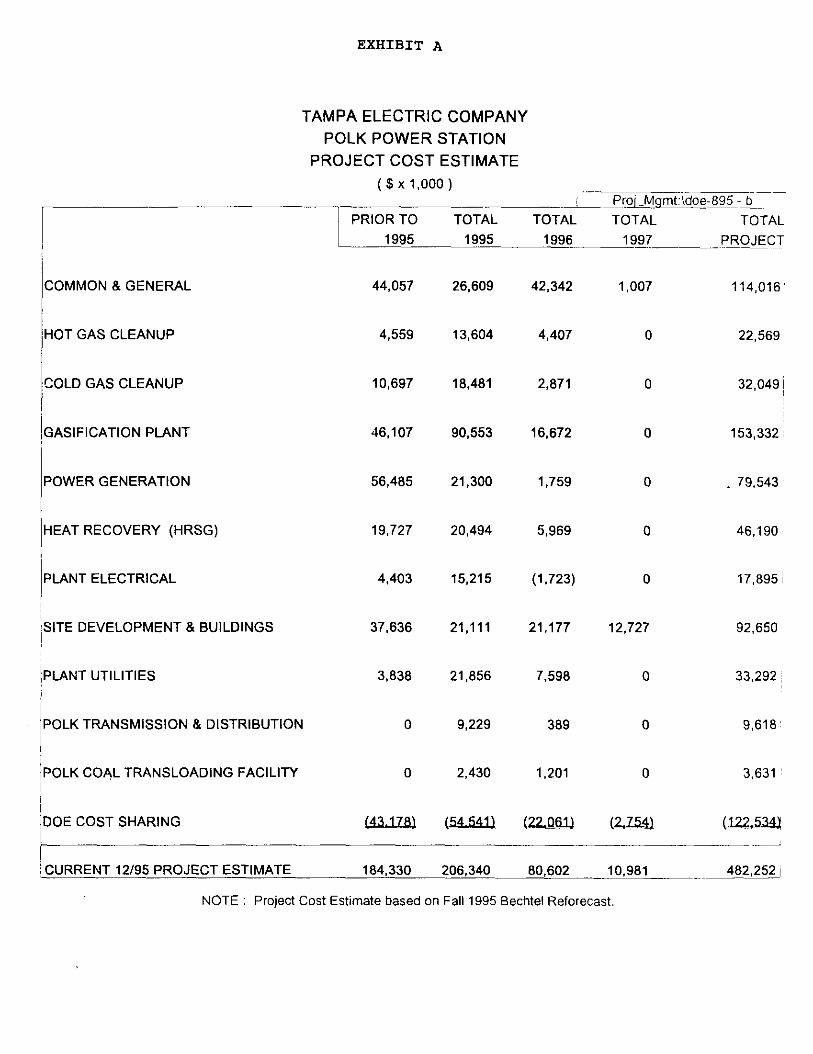
COMMON 8 GENERAL 44,057 26,609 42,342 1,007 114,016'
HOT GAS CLEANUP 4,559 13,604 4,407 0 22,569
COLD GAS CLEANUP 10,697 18,481 2,871 0 32,049 ~
GASIFICATION PLANT 46,107 90,553 16,672 0 153,332;
POWER GENERATION 56,485 21,300 1,759 0
HEAT RECOVERY (HRSG) 19,727 20,494 5,969 0
/PLANT ELECTRICAL 4,403 15,215 (1.723) 0 17.895i
($x 1,000 )
PRIOR TO TOTAL
1995 J99
~SITE DEVELOPMENT 8 BUILDINGS 37,636 21,111 21,177 12,727 92,650
/PLANT UTILITIES 3.838 21,856 7,598
EXHIBIT A
TAMPA ELECTRIC COMPANY POLK POWER STATION
PROJECT COST ESTIMATE
/POLK TRANSMISSION 8 DISTRIBUTION 0 9,229 389
POLK COAL TRANSLOADING FACILITY 0 2,430
‘DOE COST SHARING
-
-~2
TOTAL
1996
&oi-Mgmt:\doe-695 - b TOTAL TOTAL
1997 -..-~PEO&G~T,
79.543
46.190,
33,292 ~
9,618
3,631
ICURRENT 12/95 PROJECT ESTIMATE 184,330 206,340 80,602 10.981 482,252 ~ _~_~
NOTE : Project Cost Estimate based on Fall1995 Bechtel Reforecast.

EXHIBIT B
TAMPA ELECTRIC COMPANY POLK POWER STATION
PTD COSTS THROUGH DECEMBER 1995 Proi Mqmt\data\wk3\150var - ptd
PTD 12195 PTD 12195 PTD 12195 - PTD 12/95 ~z
EXPENDITURE TYPE
II
AFUDC ( Specifically Excluded )
A&G
!I PERMITTING (RS 03 ONLY)
EIS PERMITTING (RS 03 ONLY)
i/ TEXACO LICENSE
LAND COSTS
ii SITEWORK
11 TECO ENERGY !i
MOEILIZATION
11 il INVENTORIES
LEGAL
ji ENGINEERING
I’ !I
IGCC FACILITIES
TAMPA ELECTRIC (IN-HOUSE $)
~1 PREVIOUS to 6/92 COSTS
,~ SWITCHYARD (PROJECT L51)
I/ BIG BEND TRANSLOADER (PROJECT L25
!I DOE REIMBURSEMENTS
8195 Revised ACTUAL Cash Flow EXPEND.
$ VARIANCE
0 0 0
3.971,761 3,794,046 (177,715)
2.484,960 2,444,364 (40,596)
720,648 720.648 0
12,150,000 12.150.000 0
19,839.688 19,839.688 0
34.013,062 34,670.969 657,907
1,042.773 1.801.844 (40,929)
1,257,888 1.206,656 (51,230)
334,522 264,765 (69,757)
558,443 552,908 (5,535)
66.777,419 67.379.986 602,567
313,277,338 315.629.602 2.352.264
11,764.528 11548,284 (216,244)
7.736966 7.736.966 0
9.229.296 9,229,296 0
2,431.185 2.431,185 0
(97.718,999) (98,394,026) (675,027)
% VARIANCE ii
N/A
-4.5%
-1.6%
0.0%
0.0% II
0.0% 1;
1.9% iI
-2.2% :~
-4.1% 1:
20.9%
-1 .O% ~
0.9% :j
0.8% :i
-1 .a%:~
0.0%
0.0%
0.0% ,;
0.7%
I’.- TOTAL POLK PROJECT --> 390.671,477 393.007.184 2,335,707 0.8% :;
NOTE : Costs include all TEC L50. L51. L25 8 105.57 costs except AFUDC.
Cash Flow Basis - Bechtel Revised 9/95 Cash Flow

z s if s
t
.;.;,, ;;-‘: *.>$ ‘.F;! . ..l. ;><; 4:; .,s, ,,‘.’
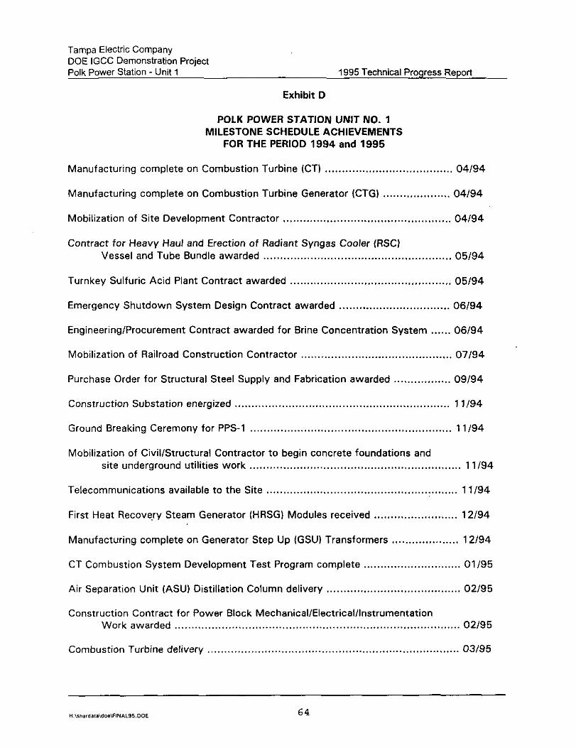
Tampa Electric Company DOE IGCC Demonstration Project Polk Power Station - Unit 1 1995 Technical Progress Report
Exhibit D
POLK POWER STATION UNIT NO. 1 MILESTONE SCHEDULE ACHIEVEMENTS
FOR THE PERIOD 1994 and 1995
Manufacturing complete on Combustion Turbine (CT) . . . . . . . . . . . . . . . . . . . . . . . . . . . . . . . . . . . . . . 04/94
Manufacturing complete on Combustion Turbine Generator (CTG) . . . . . . . . . . . . . . . . . . . . 04/94
Mobilization of Site Development Contractor .................................................. 04/94
Contract for Heavy Haul and Erection of Radiant Syngas Cooler (RSC) Vessel and Tube Bundle awarded ........................................................ 05/94
Turnkey Sulfuric Acid Plant Contract awarded ................................................ 05/94
Emergency Shutdown System Design Contract awarded ................................. 06/94
Engineering/Procurement Contract awarded for Brine Concentration System ...... 06/94
Mobilization of Railroad Construction Contractor ............................................. 07/94
Purchase Order for Structural Steel Supply and Fabrication awarded ................. 09/94
Construction Substation energized ................................................................ 1 1 I94
Ground Breaking Ceremony for PPS-1 ............................................................ 1 l/94
Mobilization of Civil/Structural Contractor to begin concrete foundations and site underground utilities work ............................................................... 1 l/94
Telecommunications available to the Site ......................................................... 1 l/94
First Heat Recovery Steam Generator (HRSG) Modules received ......................... 12/94
Manufacturing complete on Generator Step Up (GSU) Transformers .................... 12/94
CT Combustion System Development Test Program complete ............................. 01/95
Air Separation Unit (ASU) Distillation Column delivery ........................................ 02/95
Construction Contract for Power Block Mechanical/Electricalllnstrumentation Work awarded ..................................................................................... 02195
Combustion Turbine delivery ........................................................................... 0395
“:,ma,dala,dos,FINI\L95.DOL 64

Tampa Electric Company DOE IGCC Demonstration Project Polk Power Station - Unit 1 1995 Technical Progress Report
Exhibit D (Continued)
POLK POWER STATION UNIT NO. 1 MILESTONE SCHEDULE ACHIEVEMENTS
FOR THE PERIOD 1994 and 1995
Combustion Turbine Generator delivery . . . . . . . . . . . . . . . . . . . . . . . . . . . . . . . . . . . . . . . . . . . . . . . . . . . . . . . . . . 03/95
Delivery of GSU’s ............. . .......................................................................... 03195
Delivery of last HRSG Modules ...................................................................... 04/95
Delivery of ASU Compressors ........................................................................ 04/95
Delivery of ASU Main Air Compressor (MAC) Motor ......................................... 04/95
Factory Acceptance Test complete on Distributed Control System (DCS) ............ 04/95
High Pressure (HP) Steam Turbine delivery ....................................................... 04/95
Low Pressure (LP) Steam Turbine delivery ........................................................ 04/95
Steam Turbine Generator (STG) delivery ........................................................... 04/95
HGCU Pilot Plant Test Program complete .......................................................... 04/95
Construction Contract for Gasification Area Mechanical/Electrical/Instrumentation work awarded ...................................................................................... 05195
Delivery of Convective Syngas Coolers .............................................................. 05/95
GEESI Detailed Engineering complete ................................................................. 05/95
DCS deliverv ................................................................................................... 06/95
Radiant Syngas Cooler delivery .......................................................................... 06/95
Bechtel Detailed Engineering complete ................................................................ 06/95
Construction of Coal Storage Silos complete ....................................................... 08/95
Cooling Reservoir Complete .............................................................................. 1 O/95
Acid Plant ...................................................................................................... 01196
Complete Erection of HRSG Boiler ..................................................................... 02/96
Complete Steam Turbine Installation .................................................................. 02/96
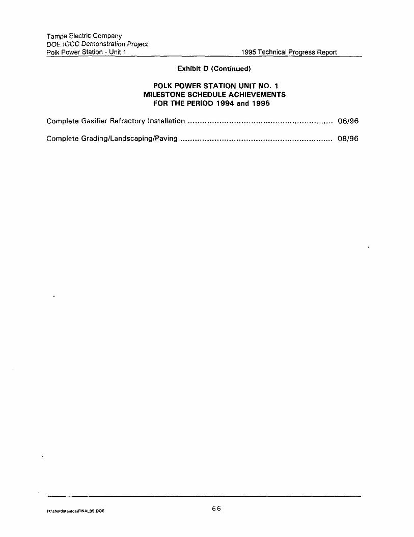
Tampa Electric Company DOE IGCC Demonstration Project Polk Power Station - Unit 1 1995 Technical Progress Report
Exhibit 0 (Continued)
POLK POWER STATION UNIT NO. 1 MILESTONE SCHEDULE ACHIEVEMENTS
FOR THE PERIOD 1994 and 1995
Complete Gasifier Refractory Installation . . . . . . . . . . . . . . . . . . . . . . . . . . . . . . . . . . . . . . . . . . . . . . . . . . . . . . . . . . . . 06/96
Complete Grading/Landscaping/Paving . . . . . . . . . . . . . . . . . . . . . . . . . . . . . . . . . . . . . . . . . . . . . . . . . . . . . . . . . . . . . . . 08196

Tampa Electric Company DOE IGCC Demonstration Project Polk Power Station - Unit 1 1995 Technical Progress Report
Exhibit E
POLK POWER STATION UNIT NO. 1 SCHEDULE FOR SIGNIFICANT START-UP MILESTONES
DCS System installation and checkout complete ................................................... 07195
Energization of Substation So (13.8KV Buss A & B) .............................................. 07195
Place in services Closed Loop Cooling Water to Power Block ................................... 12195
Place in service Demin Water System .................................................................. 12195
Fuel Oil System available for unloading ................................................................ 12195
Plant and Instrument Air Compressors placed in service ......................................... 12195
Place in service Open Loop Cooling Water System ................................................ 01196
Auxiliary Boiler available to produce plant steam to ASU ........................................ 01/96
ASU checkout & performance tests complete ....................................................... 03196
Coal Unloading/Conveying System available to receive first coal ............................. 03196
First fire of Combustion Turbine on Fuel Oil .......................................................... 04196
Circulating Water System for Power Block complete .............................................. 04196
Placed in service Closed Loop Cooling Water to Gasification Area ........................... 04196
Placed in service Flare System ............................................................................ 05196
Steam Blows complete for Main Steam piping ...................................................... 05/96
Place in service Coal Grinding System ................................................................. 05196
Initial roll of Steam Turbine ................................................................................. 05/96
Place in service Slag Handling System ................................................................. 05196
Firewater distribution & Detection complete ......................................................... 05196
Place in service Sulfuric Acid Plant ...................................................................... 06196
Place in service Brine Concentration System ......................................................... 07196
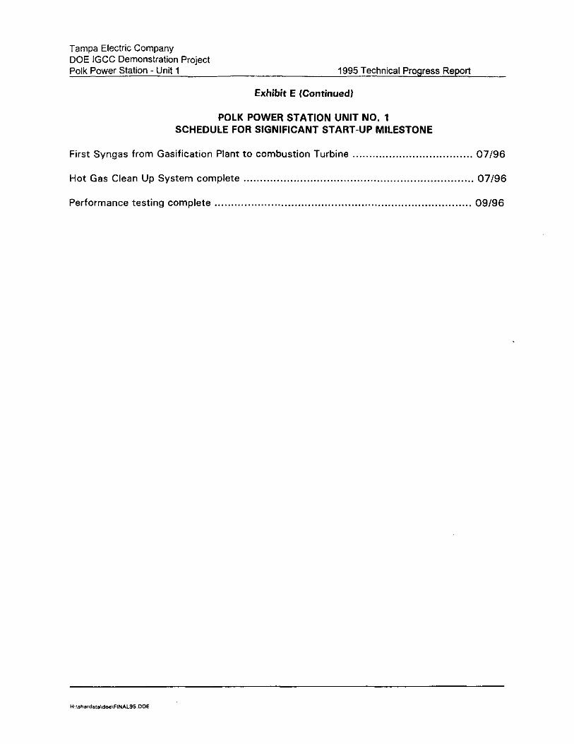
Tampa Electric Company DOE IGCC Demonstration Project Polk Power Station - Unit 1 1995 Technical Progress Report
Exhibit E (Continued)
POLK POWER STATION UNIT NO. 1 SCHEDULE FOR SIGNIFICANT START-UP MILESTONE
First Syngas from Gasification Plant to combustion Turbine . . . . . . . . . . . . . . . . . . . . . . . . . . . . . . . . . . . . 07/96
Hot Gas Clean Up System complete . . . . . . . . . . . . . . . . . . . . . . . . . . . . . . . . . . . . . . . . . . . . . . . . . . . . . . . . . . . . . . . . . . . . . 07196
Performance testing complete . . . . . . . . . . . . . . . . . . . . . . . . . . . . . . . . . . . . . . . . . . . . . . . . . . . . . . . . . . . . . . . . . . . . . . . . . . . . . 09196

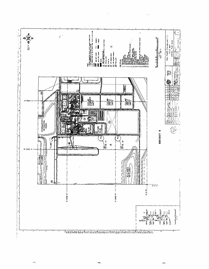
,
G 2
.,’ g; ],E ii f
!. ir f# j; ! 4 i ] iii I 1 4 ils t i (
~,~~~,~~~~~: 1 r 1 If 4# i,
6 z ! ! f f aoooom 11 I, i, ii,/,! !li,, ;,,;$I; f , $ s II
di~hrr~ whrir: ! ............:..!,,.,r?
.o-~ooo. 1 -
..o-,oool 1 -
-

8
313ldW03 lN33Wd 3hllVl1-M-13
22 z s E 0
a 7
7 I
a 5
LL is i
0
- I
co co -t N 0
313ldWO3 lN33kl3d AlHlNOW

EXHIBIT I
SITE PHOTOS


View North of Switchyard
View to Southwest Circulating HZ0 Line & Discharge Structure
January 1995

View South through Air Separation Unit Area (from East end of Gasitier Structure)
View Northeast of Intake Structure Foundation work
February 1995

View of the Control Room [nterior
View North of the Fuel Oil Tank
March I995
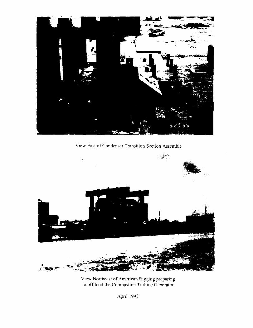
View East of Condenser Transition Section Assemble
View Northeast of American Rigging preparing to off-load the Combustion Turbine Generator
.4pnl 1’)‘)s
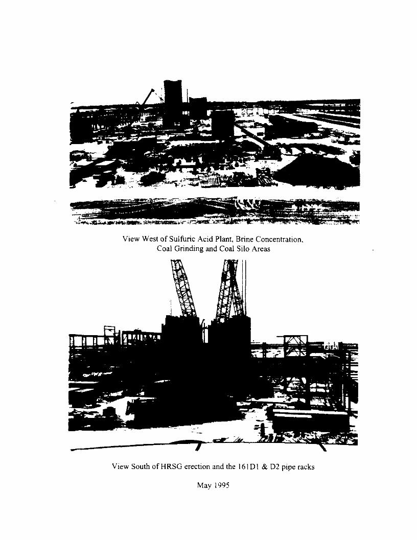
View West of Sulfuric Acid Plant, Brine Concentration, Coal Grinding and Coal Silo Areas
View South of HRSG erection and the I6 I D 1 & D2 pipe racks
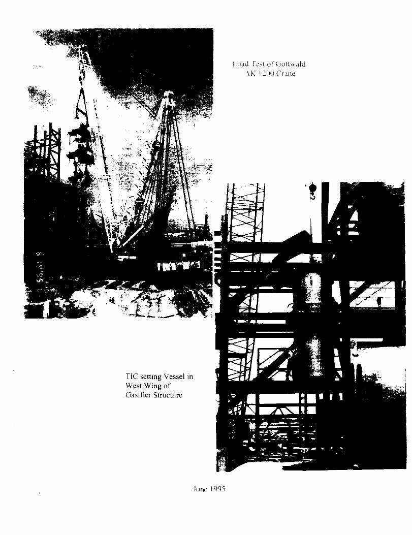
June lY95
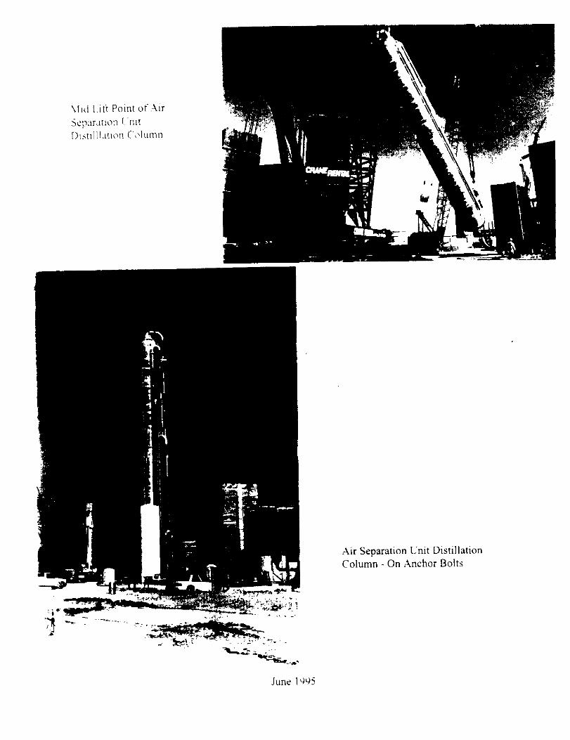
\l~d Lift Point of.Air

? :L’,\ \,>r::: .\ La<, ;‘i ~\.CWi,!\ ,/! i $0 !‘n~!t~~!lr~ P 1111’1~
View West of Sulfuic .Acid and Erection of Plant Stack
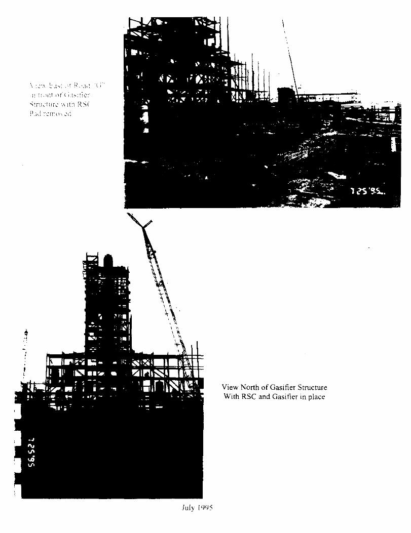
\ :i”.\ !:.I>; .if !<bJ,! ‘II d: lml:l nr c u~::ict ~!r;l.:;~:lrc ',I III1 X5( hi! :?1111h Ai
View North of Gasifier Structure With RSC and Gasitier in place

5: :, ,’ , ;L ‘:&;;<p
1 .I
.1 ‘;g&&&i “,
\‘IW West of Coal Silos with Roof handrails in place
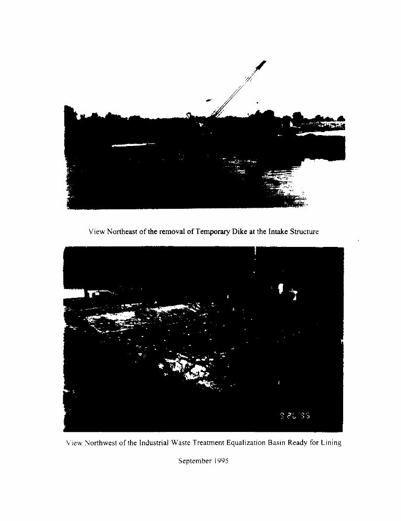
:/ , .‘,
i
View Northeast of the removal of Temporary Dike at the Intake Structure
View Yorthwest of the Industrial Waste Treatment Equalization Basin Ready for Lining
September I995

View West of the Auxiliary Boiler With the stack set
October 1995
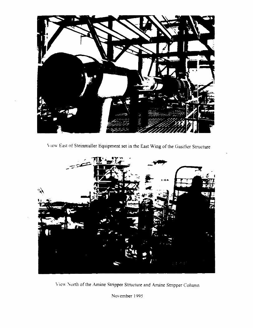
L ie\v East of Steimnuller Equipment set in the East Wing of the Gasifier Structure
View North of the Amine Stripper Structure and Amine Stripper Column
November I995

View North of piping, cable tray and Equipment progress in the HGCL Structure ,( to elevatton 167’)
December I495
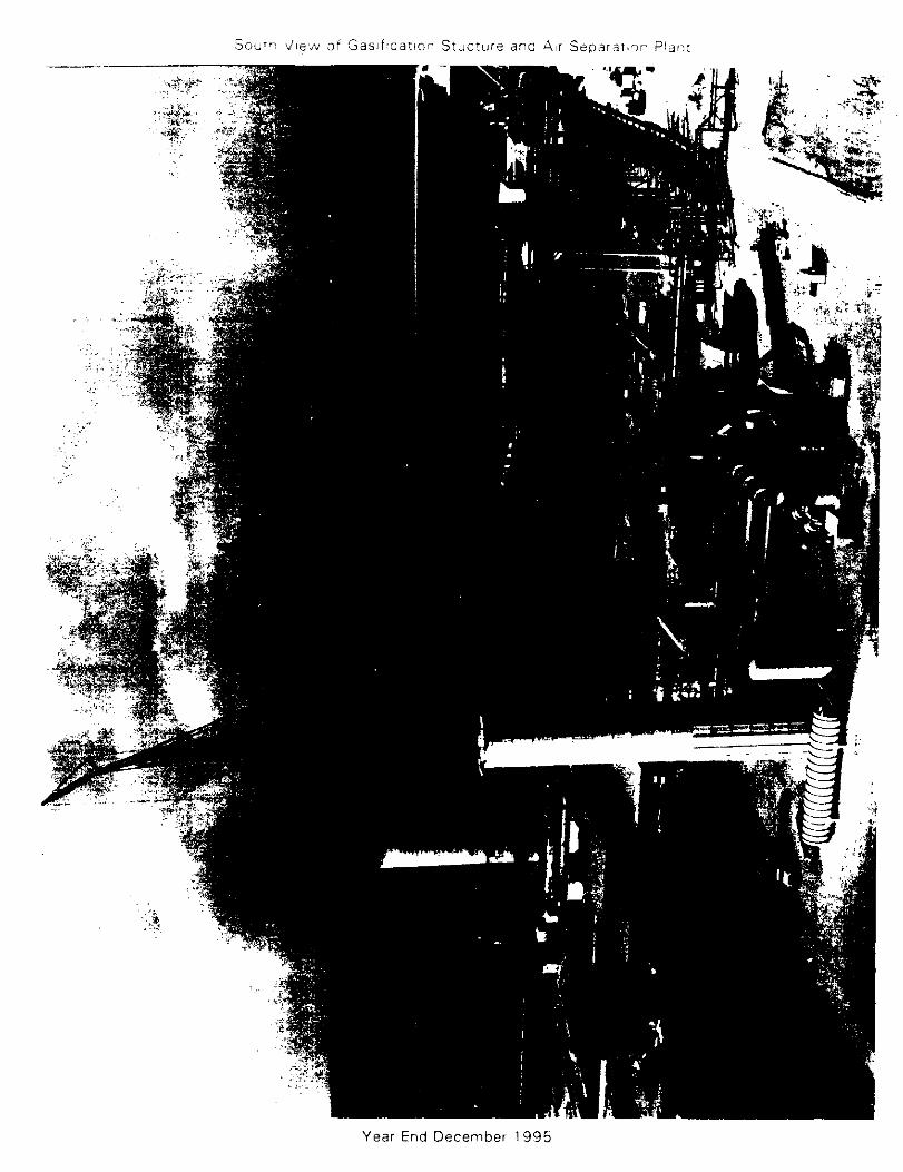
doubt. tilea, af Saslf:carior Stucrure and i\,r Separaitar Pla,:r
Year End December 1995
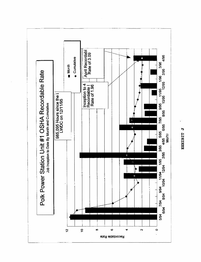
1