1770-5.6, devicenet rs-232 interface module installation ... · 14 devicenet rs-232 interface...
TRANSCRIPT
Packing Data
PK
Publication 1770�5.6 - June 1996
DeviceNet
RS�232 Interface Module
(Catalog Number 1770-KFD and 1770-KFDG)
To the Installer
The 1770-KFD module is a portable RS-232 communication interface thatprovides a host computer access to a DeviceNet� network.
This document contains this information:
topic page
purpose and audience 2
precautionary statements 2
handling the module 4
terminology 4
related publications 4
contents of your order 5
introduction to the RS�232 module 8
communicating on DeviceNet� 9
mounting the module 10
supplying power 12
connecting cables via RS�232 to a computer 14
connecting cables via RS�232 to a modem 16
connecting cables via DeviceNet 17
installing the 1770�KFD driver 22
interpreting status indicators 23
specifications 25
support services 26
New or modified information is highlighted by a revision bar.
Installation Instructions
DeviceNet RS-232 Interface Module2
Publication 1770�5.6 - June 1996
Purpose
Use this document to learn how to install and use the DeviceNet RS-232interface module.
Audience
Read this manual before you install or use the DeviceNet RS-232 interfacemodule. You should be familiar with DeviceNet technology.
Precautionary Statements
Important User Information
Because of the variety of uses for the products described in this publication, those responsiblefor the application and use of this control equipment must satisfy themselves that all necessarysteps have been taken to assure that each application and use meets all performance andsafety requirements, including any applicable laws, regulations, codes and standards.
The illustrations, charts, sample programs and layout examples shown in this guide are intendedsolely for purposes of example. Since there are many variables and requirements associated withany particular installation, Allen�Bradley does not assume responsibility or liability (to includeintellectual property liability) for actual use based upon the examples shown in this publication.
Allen�Bradley publication SGI�1.1, Safety Guidelines for the Application, Installation, and Maintenanceof Solid State Control (available from your local Allen�Bradley office), describes some importantdifferences between solid�state equipment and electromechanical devices that should be taken intoconsideration when applying products such as those described in this publication.
Reproduction of the contents of this copyrighted publication, in whole or in part, without writtenpermission of Allen�Bradley Company, Inc., is prohibited.
Throughout this document we use notes to make you aware of safety considerations:
Attention statements help you to:
ATTENTION: This notation identifies information about practices or circumstancesthat can lead to personal injury or death, property damage or economic loss.
Important: This notation identifies information that is critical for successful application andunderstanding of the product.
��identify a hazard
��avoid the hazard
��recognize the consequences
!

DeviceNet RS-232 Interface Module 3
Publication 1770�5.6 - June 1996
European Union Directive Compliance
This product has the CE mark and is approved for installation within theEuropean Union and EEA regions. It has been designed and tested to meet thefollowing directives.
EMC Dir ective: This apparatus is tested to meet Council Directive 89/336/EECElectromagnetic Compatibility (EMC) using a technical construction file and thefollowing standards, in whole or in part:
• EN 50081-2 EMC – Generic Emission Standard, Part 2 – Industrial Environment
• EN 50082-2 EMC – Generic Immunity Standard, Part 2 – Industrial Environment
The product described in this manual is intended for use in an industrialenvironment.
Low Voltage Directive: This apparatus is also designed to meet CouncilDirective 73/23/EEC Low Voltage, by applying the safety requirements ofEN 61131-2 Programmable Controllers, Part 2 – Equipment Requirementsand Tests.
For specific information that the above norm requires, see the appropriatesections in this manual, as well as the following Allen-Bradley publications:
• Industrial Automation Wiring and Grounding Guidelines,publication 1770-4.1
• Guidelines for Handling Lithium Batteries, publication AG-5.4
• Automation Systems Catalog, publication B111
DeviceNet RS-232 Interface Module4
Publication 1770�5.6 - June 1996
Handling the Module
ATTENTION: This RS-232 module uses CMOS technology, which is highlysensitive to electrostatic discharge (ESD). ESD may be present whenever youare handling the module.
Take these precautions to guard against electrostatic damage:
• Avoid touching the interface connector pins on the RS-232 module.
• If the module is not in use, store it in the anti-static bag in which it wasshipped.
It is not necessary to wear an ESD wrist strap while handling the 1770-KFDmodule.
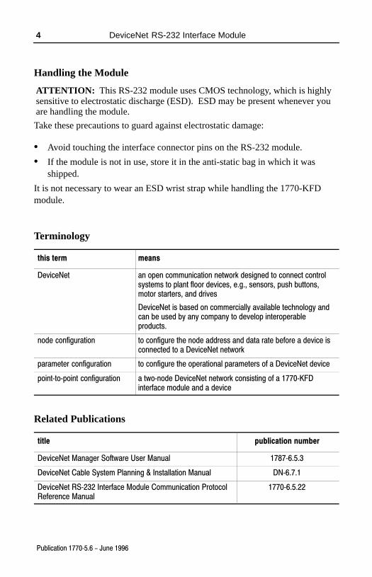
Terminology
this term means
DeviceNet an open communication network designed to connect controlsystems to plant floor devices, e.g., sensors, push buttons,motor starters, and drives
DeviceNet is based on commercially available technology andcan be used by any company to develop interoperableproducts.
node configuration to configure the node address and data rate before a device isconnected to a DeviceNet network
parameter configuration to configure the operational parameters of a DeviceNet device
point�to�point configuration a two�node DeviceNet network consisting of a 1770�KFDinterface module and a device
Related Publications
title publication number
DeviceNet Manager Software User Manual 1787�6.5.3
DeviceNet Cable System Planning & Installation Manual DN�6.7.1
DeviceNet RS�232 Interface Module Communication ProtocolReference Manual
1770�6.5.22
DeviceNet RS-232 Interface Module 5
Publication 1770�5.6 - June 1996
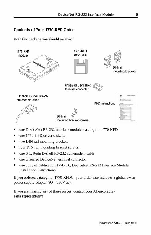
Contents of Your 1770�KFD Order
With this package you should receive:
1770�KFD module
unsealed DeviceNetterminal connector
DIN railmounting brackets
DIN rail mounting bracket screws
6 ft, 9�pin D�shell RS�232null�modem cable
KFD instructions
1770�KFD driver disk
• one DeviceNet RS-232 interface module, catalog no. 1770-KFD
• one 1770-KFD driver diskette
• two DIN rail mounting brackets
• four DIN rail mounting bracket screws
• one 6 ft, 9-pin D-shell RS-232 null-modem cable
• one unsealed DeviceNet terminal connector
• one copy of publication 1770-5.6, DeviceNet RS-232 Interface ModuleInstallation Instructions
If you ordered catalog no. 1770-KFDG, your order also includes a global 9V acpower supply adapter (90 – 260V ac).
If you are missing any of these pieces, contact your Allen-Bradleysales representative.
DeviceNet RS-232 Interface Module6
Publication 1770�5.6 - June 1996
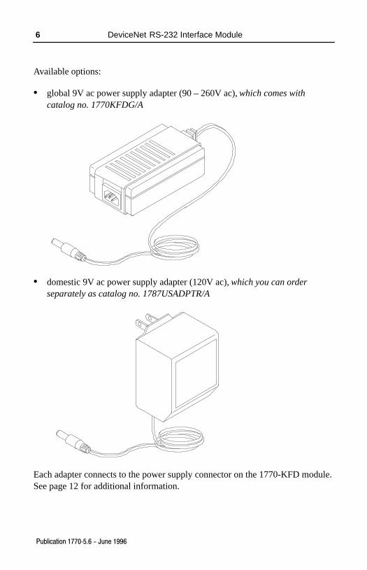
Available options:
• global 9V ac power supply adapter (90 – 260V ac), which comes withcatalog no. 1770KFDG/A
• domestic 9V ac power supply adapter (120V ac), which you can orderseparately as catalog no. 1787USADPTR/A
Each adapter connects to the power supply connector on the 1770-KFD module.See page 12 for additional information.
DeviceNet RS-232 Interface Module 7
Publication 1770�5.6 - June 1996
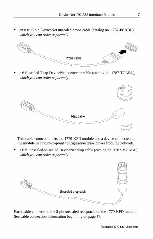
• an 8 ft, 5-pin DeviceNet unsealed probe cable (catalog no. 1787-PCABL),which you can order separately
Probe cable
• a 6 ft, sealed T-tap DeviceNet connector cable (catalog no. 1787-TCABL),which you can order separately
T�tap cable
This cable connection lets the 1770-KFD module and a device connected tothe module in a point-to-point configuration draw power from the network.
• a 6 ft, unsealed-to-sealed DeviceNet drop cable (catalog no. 1787-MCABL),which you can order separately
Unsealed drop cable
Each cable connects to the 5-pin unsealed receptacle on the 1770-KFD module.See cable connection information beginning on page 17.
DeviceNet RS-232 Interface Module8
Publication 1770�5.6 - June 1996
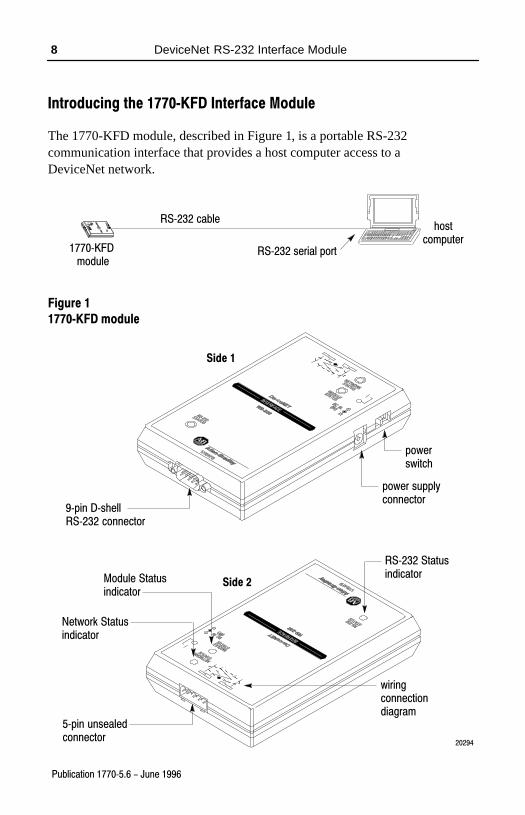
Introducing the 1770�KFD Interface Module
The 1770-KFD module, described in Figure 1, is a portable RS-232communication interface that provides a host computer access to aDeviceNet network.
hostcomputer
1770�KFD module
RS�232 cable
RS�232 serial port
Figure 1
1770�KFD module
9�pin D�shellRS�232 connector
5�pin unsealedconnector
powerswitch
power supplyconnector
Network Statusindicator
Module Statusindicator
RS�232 Statusindicator
20294
wiringconnectiondiagram
Side 1
Side 2
DeviceNet RS-232 Interface Module 9
Publication 1770�5.6 - June 1996
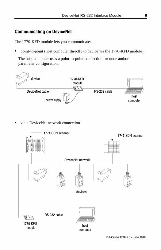
Communicating on DeviceNet
The 1770-KFD module lets you communicate:
• point-to-point (host computer directly to device via the 1770-KFD module)
The host computer uses a point-to-point connection for node and/orparameter configuration.
device
hostcomputer
1770�KFD module
DeviceNet cable RS�232 cable
power supply
• via a DeviceNet network connection
hostcomputer
1770�KFD module
DeviceNet network
RS�232 cable
devices
1771�SDN scanner1747�SDN scanner
DeviceNet RS-232 Interface Module10
Publication 1770�5.6 - June 1996
The 1770-KFD module performs data transmission, management, and localnetwork diagnostics.
Allen-Bradley DeviceNet Manager software, 1787-MGR, manages datatransmission and reception through the 1770-KFD interface module from apersonal computer (Windows� operating system).
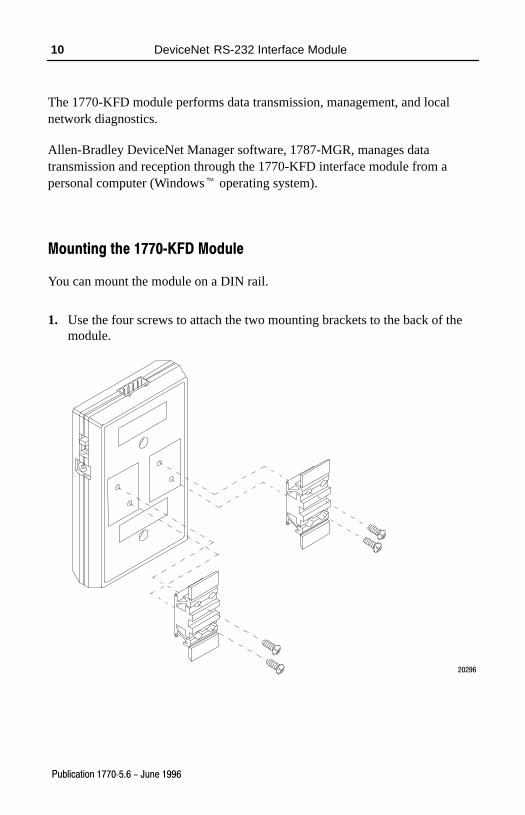
Mounting the 1770�KFD Module
You can mount the module on a DIN rail.
1. Use the four screws to attach the two mounting brackets to the back of themodule.
20296
DeviceNet RS-232 Interface Module 11
Publication 1770�5.6 - June 1996
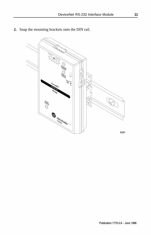
2. Snap the mounting brackets onto the DIN rail.
20297
DeviceNet RS-232 Interface Module12
Publication 1770�5.6 - June 1996
Supplying Power to the 1770�KFD Module
The 1770-KFD module can be powered from either an external power supply orfrom a DeviceNet network.
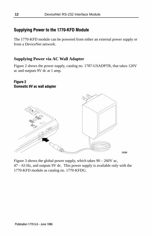
Supplying Power via AC Wall Adapter
Figure 2 shows the power supply, catalog no. 1787-USADPTR, that takes 120Vac and outputs 9V dc at 1 amp.
Figure 2
Domestic 9V ac wall adapter
20299
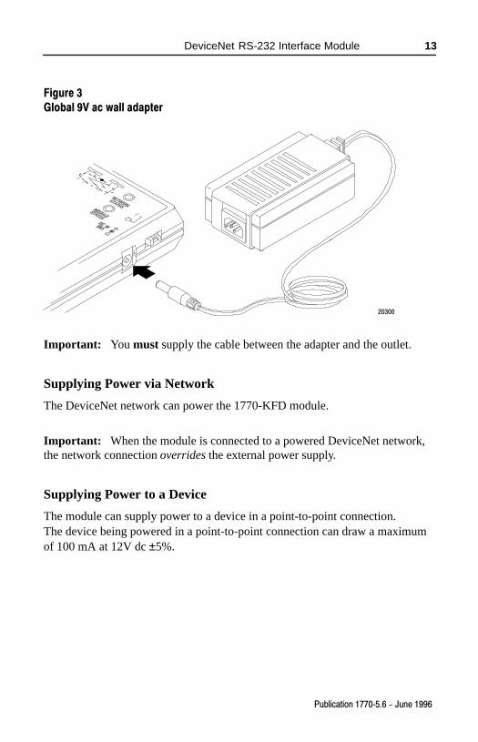
Figure 3 shows the global power supply, which takes 90 – 260V ac,47 – 63 Hz, and outputs 9V dc. This power supply is available only with the1770-KFD module as catalog no. 1770-KFDG.
DeviceNet RS-232 Interface Module 13
Publication 1770�5.6 - June 1996
Figure 3
Global 9V ac wall adapter
20300
Important: You must supply the cable between the adapter and the outlet.
Supplying Power via Network
The DeviceNet network can power the 1770-KFD module.
Important: When the module is connected to a powered DeviceNet network,the network connection overrides the external power supply.
Supplying Power to a Device
The module can supply power to a device in a point-to-point connection.The device being powered in a point-to-point connection can draw a maximumof 100 mA at 12V dc ±5%.
DeviceNet RS-232 Interface Module14
Publication 1770�5.6 - June 1996
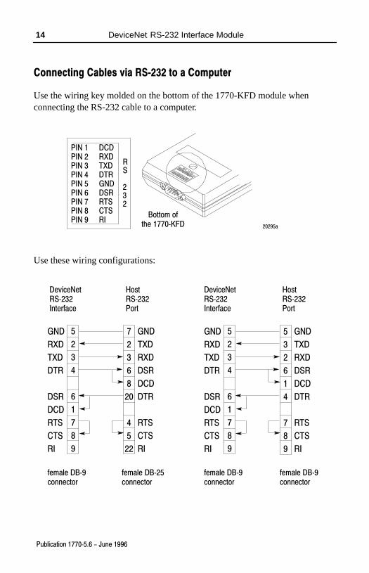
Connecting Cables via RS�232 to a Computer
Use the wiring key molded on the bottom of the 1770-KFD module whenconnecting the RS-232 cable to a computer.
PIN 1 DCDPIN 2 RXDPIN 3 TXDPIN 4 DTRPIN 5 GNDPIN 6 DSRPIN 7 RTSPIN 8 CTSPIN 9 RI
Bottom ofthe 1770�KFD 20295a
RS
232
Use these wiring configurations:
5
2
3
4
6
1
7
8
9
GND
RXD
TXD
DTR
DSR
DCD
RTS
CTS
RI
7
2
3
6
8
20
4
5
22
female DB�9connector
female DB�9connector
DeviceNetRS�232Interface
HostRS�232Port
female DB�9connector
female DB�25connector
DeviceNetRS�232Interface
HostRS�232Port
GND
TXD
RXD
DSR
DCD
DTR
RTS
CTS
RI
5
2
3
4
6
1
7
8
9
GND
RXD
TXD
DTR
DSR
DCD
RTS
CTS
RI
5
3
2
6
1
4
7
8
9
GND
TXD
RXD
DSR
DCD
DTR
RTS
CTS
RI
DeviceNet RS-232 Interface Module 15
Publication 1770�5.6 - June 1996
RS-232 Cable Connections (via 9-pin serial port connector)
These pin numbers correspond with these connections:
pin number abbreviation description direction
1 DCD data carrier detect in
2 RXD receive data in
3 TXD transmit data out
4 DTR data terminal ready out
5 GND signal ground -
6 DSR data set ready in
7 RTS request to send out
8 CTS clear to send in
9 RI ring indicator in
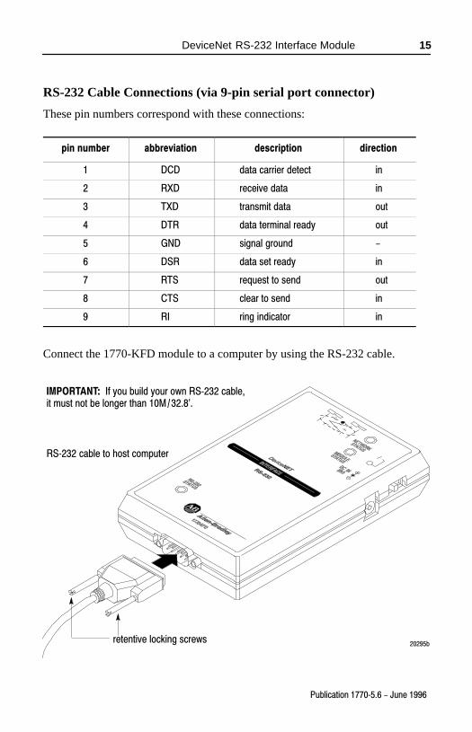
Connect the 1770-KFD module to a computer by using the RS-232 cable.
RS�232 cable to host computer
20295bretentive locking screws
IMPORTANT: If you build your own RS�232 cable, it must not be longer than 10M�/�32.8'.
DeviceNet RS-232 Interface Module16
Publication 1770�5.6 - June 1996
Using the Interface Module with a Portable Computer
Some portable computers have power-saving modes that power down the serialports during inactive periods, occurring most often when batteries power the PC.The serial-port power-saving feature causes the RS-232 interface module to gooffline and to cease communication with DeviceNet Manager. You shoulddisable the serial-port power-saving feature to use the RS-232 interface modulewith DeviceNet Manager.
If you experience a problem with the RS-232 interface module going offlineunexpectedly, use the setup program of your portable computer to disable theserial-port power-saving feature.
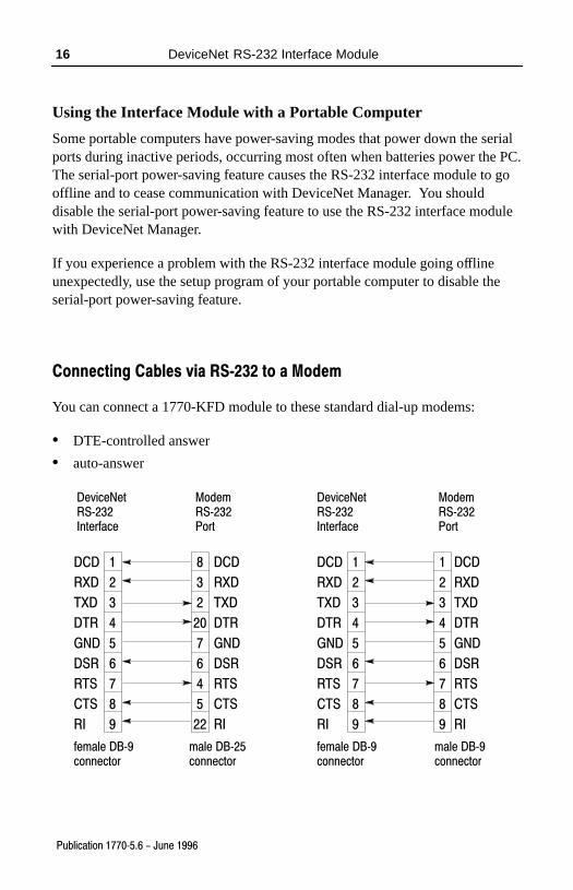
Connecting Cables via RS�232 to a Modem
You can connect a 1770-KFD module to these standard dial-up modems:
• DTE-controlled answer
• auto-answer
DCD
RXD
TXD
DTR
GND
DSR
RTS
CTS
RI
1
2
3
4
5
6
7
8
9
8
3
2
20
7
6
4
5
22
DCD
RXD
TXD
DTR
GND
DSR
RTS
CTS
RI
1
2
3
4
5
6
7
8
9
DCD
RXD
TXD
DTR
GND
DSR
RTS
CTS
RI
1
2
3
4
5
6
7
8
9
female DB�9connector
male DB�9connector
DeviceNetRS�232Interface
ModemRS�232Port
female DB�9connector
male DB�25connector
DeviceNetRS�232Interface
ModemRS�232Port
DCD
RXD
TXD
DTR
GND
DSR
RTS
CTS
RI
DeviceNet RS-232 Interface Module 17
Publication 1770�5.6 - June 1996
Connecting Cables via DeviceNet
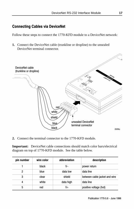
Follow these steps to connect the 1770-KFD module to a DeviceNet network:
1. Connect the DeviceNet cable (trunkline or dropline) to the unsealedDeviceNet terminal connector.
DeviceNet cable(trunkline or dropline)
unsealed DeviceNetterminal connector
20295c
red
white
shield
blue
black
2. Connect the terminal connector to the 1770-KFD module.
Important: DeviceNet cable connections should match color bars/electricaldiagram on top of 1770-KFD module. See the table below.
pin number wire color abbreviation description
1 black V- power return
2 blue data low data line
3 clear shield between cable jacket and wire
4 white data high data line
5 red V+ positive voltage (hot)
DeviceNet RS-232 Interface Module18
Publication 1770�5.6 - June 1996
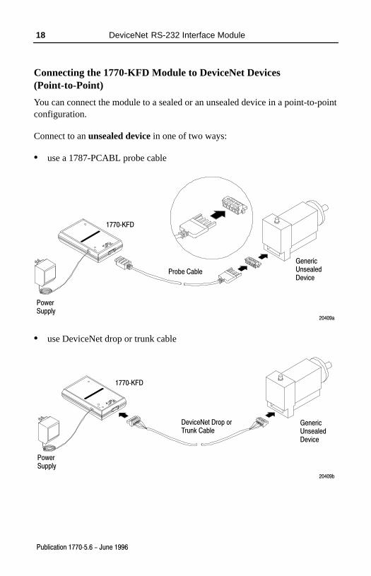
Connecting the 1770-KFD Module to DeviceNet Devices(Point-to-Point)
You can connect the module to a sealed or an unsealed device in a point-to-pointconfiguration.
Connect to an unsealed device in one of two ways:
• use a 1787-PCABL probe cable
PowerSupply
GenericUnsealedDevice
20409a
1770�KFD
Probe Cable
• use DeviceNet drop or trunk cable
PowerSupply
GenericUnsealedDevice
20409b
1770�KFD
DeviceNet Drop or Trunk Cable
DeviceNet RS-232 Interface Module 19
Publication 1770�5.6 - June 1996
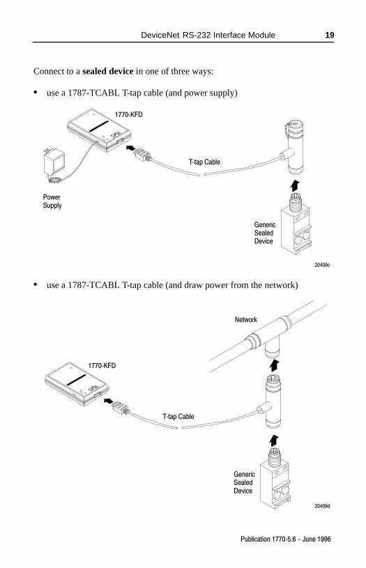
Connect to a sealed device in one of three ways:
• use a 1787-TCABL T-tap cable (and power supply)
PowerSupply
GenericSealedDevice
20409c
1770�KFD
T�tap Cable
• use a 1787-TCABL T-tap cable (and draw power from the network)
GenericSealedDevice
20409d
1770�KFD
T�tap Cable
Network
DeviceNet RS-232 Interface Module20
Publication 1770�5.6 - June 1996
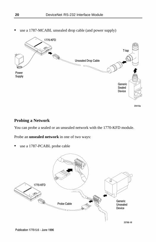
• use a 1787-MCABL unsealed drop cable (and power supply)
PowerSupply
GenericSealedDevice
20410a
Unsealed Drop Cable
1770�KFD
T�tap
Probing a Network
You can probe a sealed or an unsealed network with the 1770-KFD module.
Probe an unsealed network in one of two ways:
• use a 1787-PCABL probe cable
1770�KFD
Probe CableGeneric UnsealedDevice
20766-M
DeviceNet RS-232 Interface Module 21
Publication 1770�5.6 - June 1996
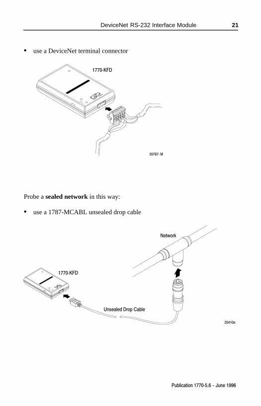
• use a DeviceNet terminal connector
1770�KFD
20767-M
Probe a sealed network in this way:
• use a 1787-MCABL unsealed drop cable
20410e
Unsealed Drop Cable
1770�KFD
Network
DeviceNet RS-232 Interface Module22
Publication 1770�5.6 - June 1996
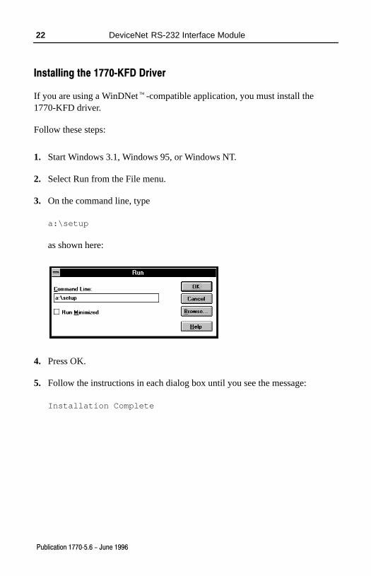
Installing the 1770�KFD Driver
If you are using a WinDNet�-compatible application, you must install the1770-KFD driver.
Follow these steps:
1. Start Windows 3.1, Windows 95, or Windows NT.
2. Select Run from the File menu.
3. On the command line, type
a:\setup
as shown here:
4. Press OK.
5. Follow the instructions in each dialog box until you see the message:
Installation Complete
DeviceNet RS-232 Interface Module 23
Publication 1770�5.6 - June 1996
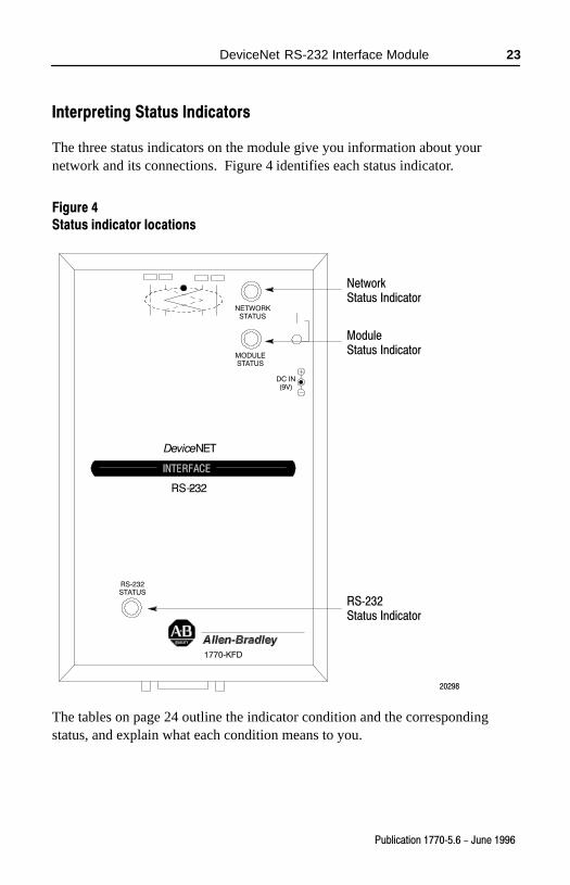
Interpreting Status Indicators
The three status indicators on the module give you information about yournetwork and its connections. Figure 4 identifies each status indicator.
Figure 4
Status indicator locations
DeviceNET
RS-232
NetworkStatus Indicator
ModuleStatus Indicator
RS�232Status Indicator
NETWORKSTATUS
MODULESTATUS
RS�232STATUS
DC IN(9V)
1770�KFD
20298
The tables on page 24 outline the indicator condition and the correspondingstatus, and explain what each condition means to you.
DeviceNet RS-232 Interface Module24
Publication 1770�5.6 - June 1996
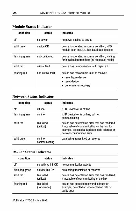
Module Status Indicator
condition status indicates
off no power no power applied to device
solid green device OK device is operating in normal condition; KFDmodule is on line, i.e., has baud rate detected
flashing green not configured device is operating in normal condition; waitingfor initialization from host (in `autobaud' mode)
solid red critical fault device has unrecoverable fault; replace it
flashing red non�critical fault device has recoverable fault; to recover:
• reconfigure device
• reset device
• perform error recovery
Network Status Indicator
condition status indicates
off off line KFD DeviceNet is off line
flashing green on line KFD DeviceNet is on line, but notcommunicating
solid red link failed (critical)
device has detected an error that has renderedit incapable of communicating on the link; forexample, detected a duplicate node address ornetwork configuration error
solid green on line,communicating
data being transmitted or received
RS-232 Status Indicator
condition status indicates
off no activity, link OK no communication activity
flickering green activity, link OK data being transmitted or received
solid red link failed (critical)
device has detected an error that has renderedit incapable of communicating of the link
flashing red link failed (non�critical)
device has detected recoverable fault; forexample, detected an incorrect baud rate orparity error
DeviceNet RS-232 Interface Module 25
Publication 1770�5.6 - June 1996
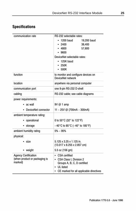
Specifications
communication rate RS�232 selectable rates:
• 1200 baud 19,200 baud
• 2400 38,400
• 4800 57,600
• 9600
DeviceNet selectable rates:
• 125K baud
• 250K
• 500K
function to monitor and configure devices onDeviceNet network
location anywhere via personal computer
communication port one 9�pin RS�232 D�shell
cabling RS�232 cable; see cable diagrams
power requirements:
• ac wall 9V @ 1 amp
• DeviceNet connector 11 - 25V @ (700mA - 300mA)
ambient temperature rating:
• operational 0 to 50°C (32° to 122°F)
• storage -�40°C to 85°C (-�40° to 185°F)
ambient humidity rating 5% - 95%
physical:
• size 5.125 x 3.25 x 1.125 in.(13.017 x 8.255 x 2.857 cm)
• weight 5.5 oz (156 gm)
Agency Certification(when product or packaging ismarked)
• CSA certified
• CSA Class I, Division 2Groups A, B, C, D certified
• UL listed
• CE marked for all applicable directives

DeviceNet RS-232 Interface Module26
Publication 1770�5.6 - June 1996
Support Services
At Allen-Bradley, customer service means experienced representatives at Customer Support Centers in key cities throughout the world for sales,service, and support. Our value-added services include:
Technical Support
• SupportPlus programs
• telephone support and 24-hour emergency hotline
• software and documentation updates
• technical subscription services
Engineering and Field Services
• application engineering assistance
• integration and start-up assistance
• field service
• maintenance support
Technical Training
• lecture and lab courses
• self-paced computer and video-based training
• job aids and workstations
• training needs analysis
Repair and Exchange Services
• your only “authorized” source
• current revisions and enhancements
• worldwide exchange inventory
• local support

1784�6.5.19�RN1October 1995
DeviceNet is a trademark of the Open Device Vendors Association (ODVA).WinDNet and PLC-5 are trademarks of Allen-Bradley Company, Inc.Windows and Windows NT are trademarks of Microsoft.
Worldwide representation.
Argentina • Australia • Austria • Bahrain • Belgium • Brazil • Bulgaria • Canada • Chile • China, PRC •Colombia • Costa Rica • Croatia • Cyprus • Czech Republic • Denmark • Ecuador • Egypt • El Salvador •Finland • France • Germany • Greece • Guatemala • Honduras • Hong Kong • Hungary • Iceland • India •Indonesia • Ireland • Israel • Italy • Jamaica • Japan • Jordan • Korea • Kuwait • Lebanon • Malaysia •Mexico • Netherlands • New Zealand • Norway • Pakistan • Peru • Philippines • Poland • Portugal •Puerto Rico • Qatar • Romania • Russia-CIS • Saudi Arabia • Singapore • Slovakia • Slovenia • South
Africa, Republic • Spain • Sweden • Switzerland • Taiwan • Thailand • Turkey • United Arab Emirates •United Kingdom • United States • Uruguay • Venezuela • Yugoslavia
Allen�Bradley Headquarters, 1201 South Second Street, Milwaukee, WI 53204 USA
Tel: (1) 414 382�2000 Fax: (1) 414 382�4444
Publication 1770�5.6 - June 1996Supersedes Publication 1770�5.6 - October 1995
PN 955125�79Copyright 1996 Allen�Bradley Company, Inc. Printed in USA