1705 1530 1615 introduction 3d tunnel
DESCRIPTION
tunnelTRANSCRIPT
CG1 Chile May 15-18, 2006: Introduction to Plaxis 3D Tunnel 1
PLAXIS FINITE ELEMENT CODE FOR SOIL AND ROCK ANALYSES
Tunnels in Plaxis
Dennis WatermanPlaxis BV
PLAXIS FINITE ELEMENT CODE FOR SOIL AND ROCK ANALYSES
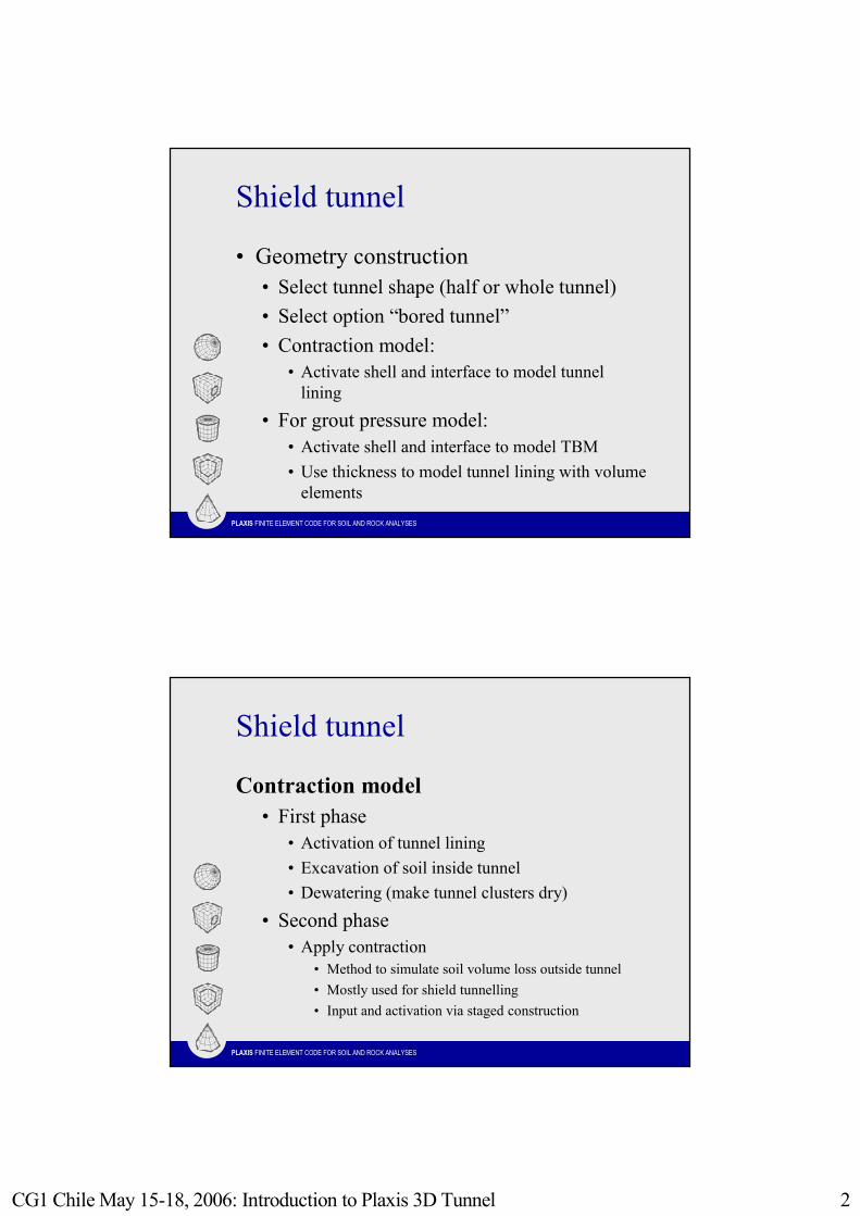
Tunnel designer
Full tunnel
Half tunnel -left part
Half tunnel -right part
CG1 Chile May 15-18, 2006: Introduction to Plaxis 3D Tunnel 2
PLAXIS FINITE ELEMENT CODE FOR SOIL AND ROCK ANALYSES
Shield tunnel
• Geometry construction• Select tunnel shape (half or whole tunnel)• Select option “bored tunnel”• Contraction model:
• Activate shell and interface to model tunnel lining
• For grout pressure model: • Activate shell and interface to model TBM• Use thickness to model tunnel lining with volume
elements
PLAXIS FINITE ELEMENT CODE FOR SOIL AND ROCK ANALYSES
Shield tunnel
Contraction model• First phase
• Activation of tunnel lining• Excavation of soil inside tunnel• Dewatering (make tunnel clusters dry)
• Second phase• Apply contraction
• Method to simulate soil volume loss outside tunnel• Mostly used for shield tunnelling• Input and activation via staged construction
CG1 Chile May 15-18, 2006: Introduction to Plaxis 3D Tunnel 3
PLAXIS FINITE ELEMENT CODE FOR SOIL AND ROCK ANALYSES
Shield tunnelGrout pressure model
• First phase• Activation of TBM• Excavation of soil inside TBM• Dewatering (make tunnel clusters dry)
• Second phase• Applying small contraction to model cone shaped TBM
• Third phase• Switch off TBM• Apply grout pressure
• Fourth phase• Remove grout pressure• Install final lining
PLAXIS FINITE ELEMENT CODE FOR SOIL AND ROCK ANALYSES
NATM tunnel
• Geometry construction• Select tunnel shape (half or whole tunnel)• Select option “NATM tunnel”• Start to enter radius and angle of first section• Select second section• Repeat this for all sections • Activate shell and interface for section
independently when needed
CG1 Chile May 15-18, 2006: Introduction to Plaxis 3D Tunnel 4
PLAXIS FINITE ELEMENT CODE FOR SOIL AND ROCK ANALYSES
NATM tunnel
β -method• First phase
• Deactivate tunnel clusters without activating of lining and calculate using ΣMstage = 1 - β (Staged Construction, Advanced)
• Second phase• Activate tunnel lining and continue calculation
until ΣMstage = 1
PLAXIS FINITE ELEMENT CODE FOR SOIL AND ROCK ANALYSES
Plaxis 3D Tunnel
Dennis WatermanPlaxis BV
CG1 Chile May 15-18, 2006: Introduction to Plaxis 3D Tunnel 5
PLAXIS FINITE ELEMENT CODE FOR SOIL AND ROCK ANALYSES
Content
• General remarks about 3D models• Creation of a 3D model
• Procedure• Geometry input• Calculations• Output and visualisation
• Examples• Conclusions
PLAXIS FINITE ELEMENT CODE FOR SOIL AND ROCK ANALYSES
General remarks about 3D models
• Requires long calculation time and much computer memory• Find balance between accuracy and
calculation time• Requires patience and understanding of
users• Becomes practically applicable
CG1 Chile May 15-18, 2006: Introduction to Plaxis 3D Tunnel 6
PLAXIS FINITE ELEMENT CODE FOR SOIL AND ROCK ANALYSES
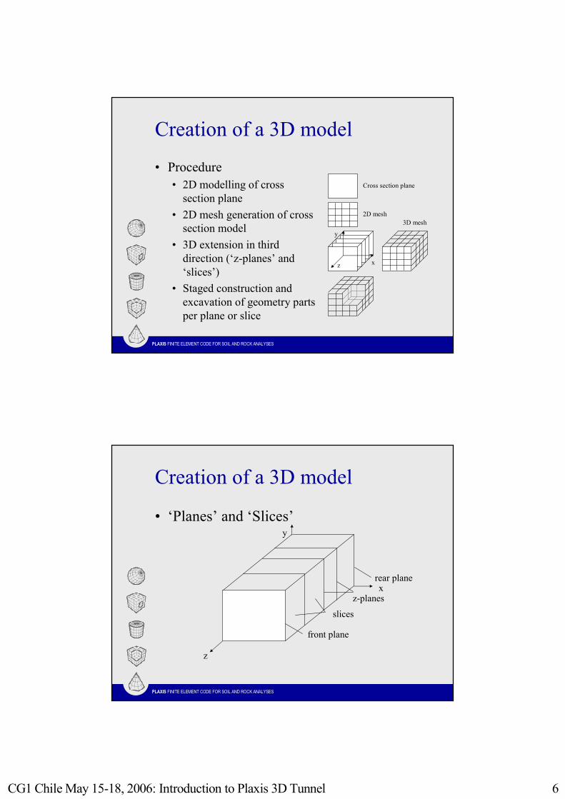
Creation of a 3D model
• Procedure• 2D modelling of cross
section plane• 2D mesh generation of cross
section model• 3D extension in third
direction (‘z-planes’ and ‘slices’)
• Staged construction and excavation of geometry parts per plane or slice
Cross section plane
2D mesh3D mesh
y
xz
PLAXIS FINITE ELEMENT CODE FOR SOIL AND ROCK ANALYSES
Creation of a 3D model
• ‘Planes’ and ‘Slices’
slices
z-planes
rear plane
front plane
z
y
x
CG1 Chile May 15-18, 2006: Introduction to Plaxis 3D Tunnel 7
PLAXIS FINITE ELEMENT CODE FOR SOIL AND ROCK ANALYSES
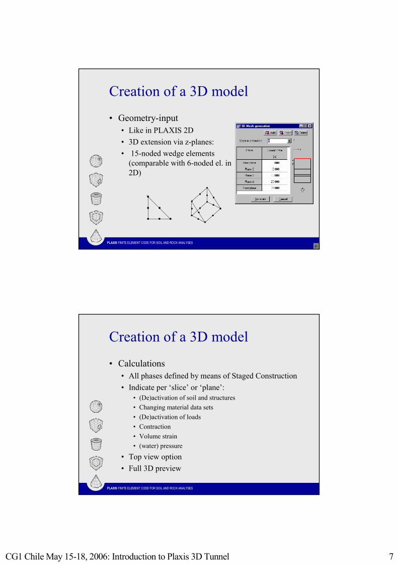
Creation of a 3D model
• Geometry-input• Like in PLAXIS 2D• 3D extension via z-planes:• 15-noded wedge elements
(comparable with 6-noded el. in 2D)
PLAXIS FINITE ELEMENT CODE FOR SOIL AND ROCK ANALYSES
Creation of a 3D model
• Calculations• All phases defined by means of Staged Construction• Indicate per ‘slice’ or ‘plane’:
• (De)activation of soil and structures• Changing material data sets• (De)activation of loads• Contraction• Volume strain• (water) pressure
• Top view option• Full 3D preview
CG1 Chile May 15-18, 2006: Introduction to Plaxis 3D Tunnel 8
PLAXIS FINITE ELEMENT CODE FOR SOIL AND ROCK ANALYSES
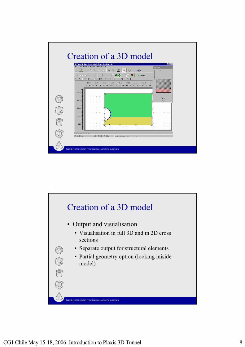
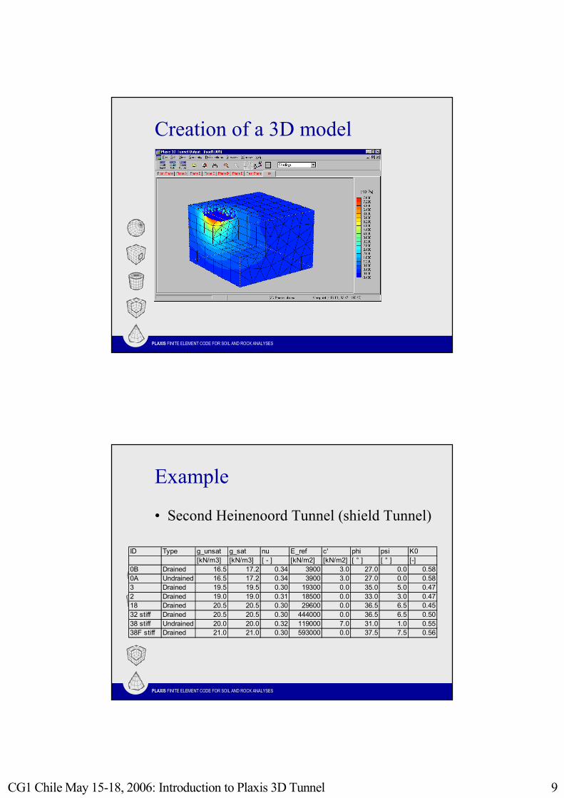
Creation of a 3D model
PLAXIS FINITE ELEMENT CODE FOR SOIL AND ROCK ANALYSES
Creation of a 3D model
• Output and visualisation• Visualisation in full 3D and in 2D cross
sections• Separate output for structural elements • Partial geometry option (looking iniside
model)
CG1 Chile May 15-18, 2006: Introduction to Plaxis 3D Tunnel 9
PLAXIS FINITE ELEMENT CODE FOR SOIL AND ROCK ANALYSES
Creation of a 3D model
PLAXIS FINITE ELEMENT CODE FOR SOIL AND ROCK ANALYSES
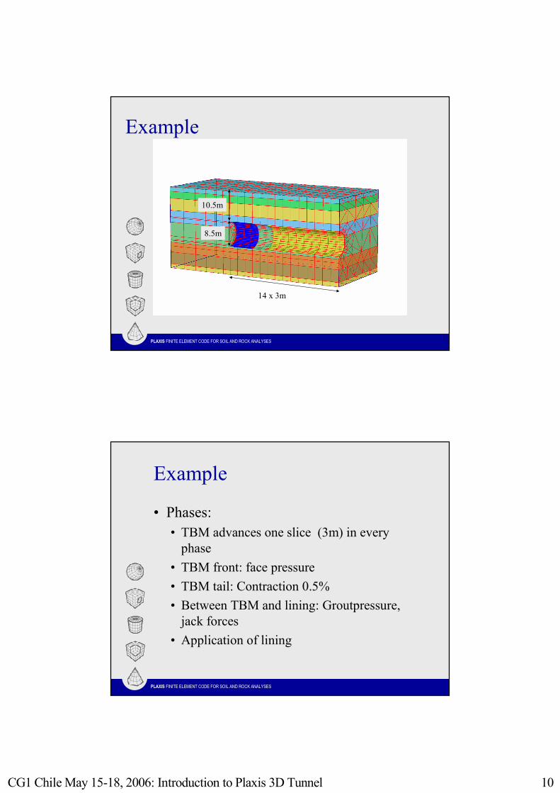
Example
• Second Heinenoord Tunnel (shield Tunnel)
ID Type g_unsat g_sat nu E_ref c' phi psi K0 [kN/m3] [kN/m3] [ - ] [kN/m2] [kN/m2] [ ° ] [ ° ] [-]0B Drained 16.5 17.2 0.34 3900 3.0 27.0 0.0 0.580A Undrained 16.5 17.2 0.34 3900 3.0 27.0 0.0 0.583 Drained 19.5 19.5 0.30 19300 0.0 35.0 5.0 0.472 Drained 19.0 19.0 0.31 18500 0.0 33.0 3.0 0.4718 Drained 20.5 20.5 0.30 29600 0.0 36.5 6.5 0.4532 stiff Drained 20.5 20.5 0.30 444000 0.0 36.5 6.5 0.5038 stiff Undrained 20.0 20.0 0.32 119000 7.0 31.0 1.0 0.5538F stiff Drained 21.0 21.0 0.30 593000 0.0 37.5 7.5 0.56
CG1 Chile May 15-18, 2006: Introduction to Plaxis 3D Tunnel 10
PLAXIS FINITE ELEMENT CODE FOR SOIL AND ROCK ANALYSES
Example
14 x 3m
8.5m
10.5m
PLAXIS FINITE ELEMENT CODE FOR SOIL AND ROCK ANALYSES
Example
• Phases:• TBM advances one slice (3m) in every
phase• TBM front: face pressure• TBM tail: Contraction 0.5%• Between TBM and lining: Groutpressure,
jack forces• Application of lining
CG1 Chile May 15-18, 2006: Introduction to Plaxis 3D Tunnel 11
PLAXIS FINITE ELEMENT CODE FOR SOIL AND ROCK ANALYSES
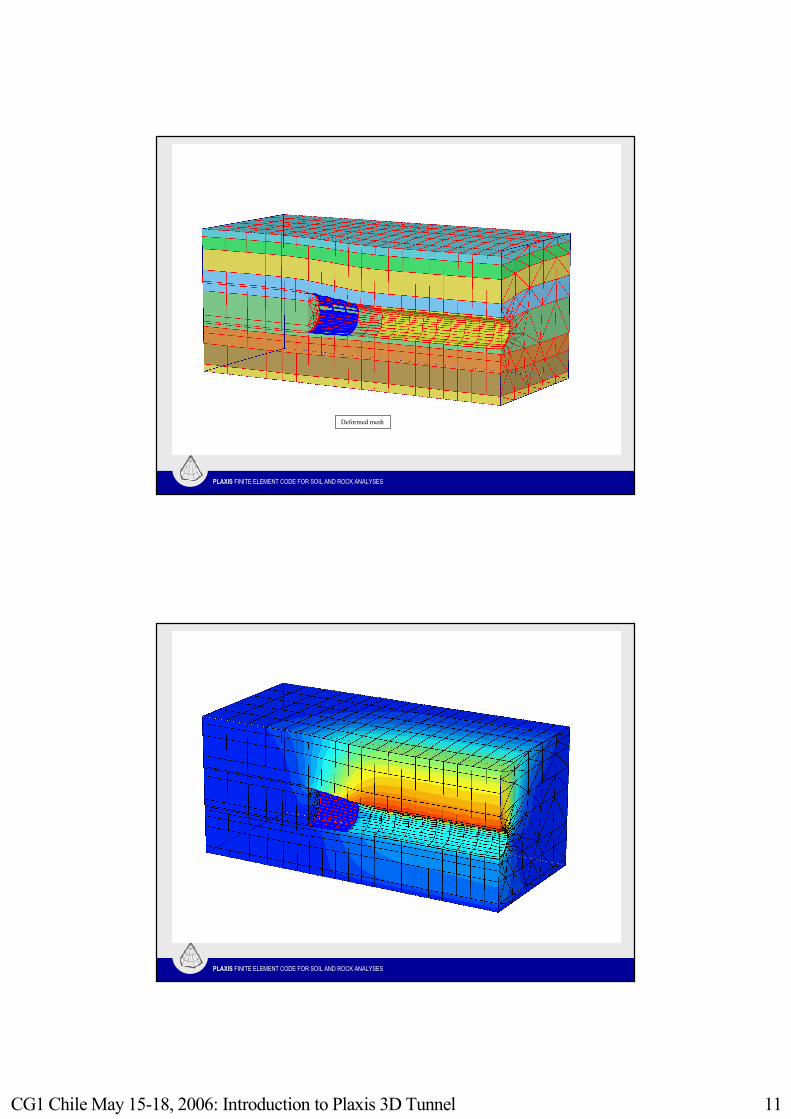
Example
Deformed mesh
PLAXIS FINITE ELEMENT CODE FOR SOIL AND ROCK ANALYSES
CG1 Chile May 15-18, 2006: Introduction to Plaxis 3D Tunnel 12
PLAXIS FINITE ELEMENT CODE FOR SOIL AND ROCK ANALYSES
Conclusions
• 3D calculations are time consuming, but become practically applicable.
• Perform only 3D calculations if really necessary
• Take care of the following aspects:• Choice of soil models and parameters• Mesh fineness (coarseness)• Calculation phases (construction stages)