16. relief machining - tcaps...
TRANSCRIPT
ArtCAM Pro 5.5 16. Relief Machining
Issue ArtCAM-P 5.5 131
16. Relief Machining
Relief Machining. To machine a relief, ArtCAM creates a toolpath file. This file contains a sequence of
instructions telling a particular CNC machine tool the path a cutting tool needs to follow in
order to produce the relief.
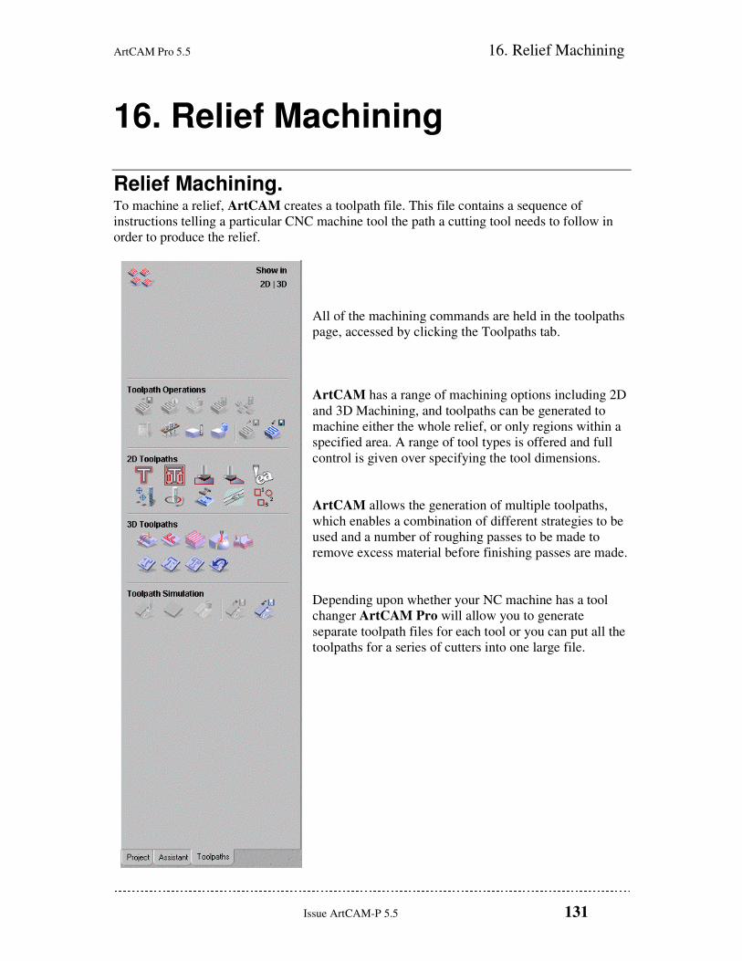
All of the machining commands are held in the toolpaths
page, accessed by clicking the Toolpaths tab.
ArtCAM has a range of machining options including 2D
and 3D Machining, and toolpaths can be generated to
machine either the whole relief, or only regions within a
specified area. A range of tool types is offered and full
control is given over specifying the tool dimensions.
ArtCAM allows the generation of multiple toolpaths,
which enables a combination of different strategies to be
used and a number of roughing passes to be made to
remove excess material before finishing passes are made.
Depending upon whether your NC machine has a tool
changer ArtCAM Pro will allow you to generate
separate toolpath files for each tool or you can put all the
toolpaths for a series of cutters into one large file.
16. Relief Machining ArtCAM Pro 5.5
132 Issue ArtCAM-P 5.5
3D Machining Example This example machines the relief of a teddy bear that was created in ArtCAM, in stages.
Firstly, we will use the Z Level Roughing button on the Machining Toolbar to remove the
bulk of the material, and then we will use the buttons on the Toolpaths Toolbar to create
semi-finishing and finishing toolpaths.
Defining the Material • Use the File menu to Close any projects that you are working on.
• Open the model Sculpt_Teddy.art from Examples\Ted_bear.
The following relief appears in the 3D
View window:
Before we can create any toolpaths, we
need to define the block size so that
ArtCAM knows how much material needs
to be machined.
• Select the Toolpaths tab
• Click the Setup Material button on the Toolpaths page.
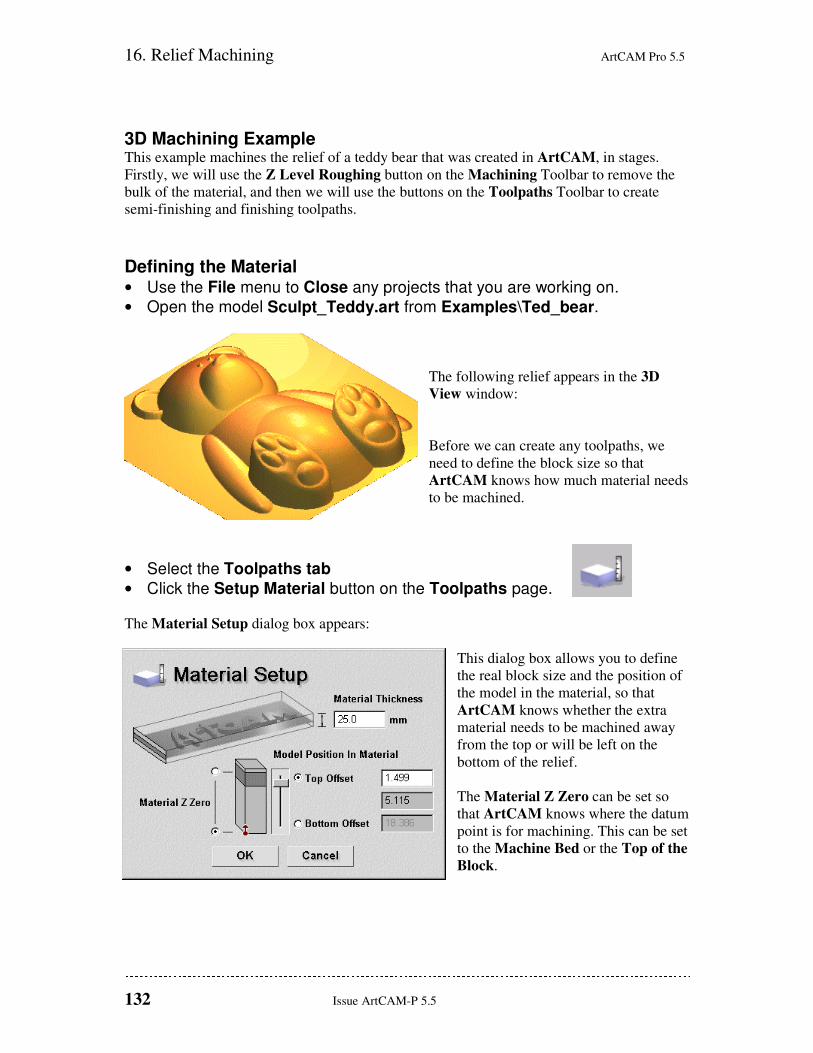
The Material Setup dialog box appears:
This dialog box allows you to define
the real block size and the position of
the model in the material, so that
ArtCAM knows whether the extra
material needs to be machined away
from the top or will be left on the
bottom of the relief.
The Material Z Zero can be set so
that ArtCAM knows where the datum
point is for machining. This can be set
to the Machine Bed or the Top of the
Block.
ArtCAM Pro 5.5 16. Relief Machining
Issue ArtCAM-P 5.5 133
• As the relief height is 5.115mm, set the Material Thickness to 6mm.
• Set a Top Offset of 0.0mm (or drag the model to the top using the slider).
• Ensure that Material Z Zero is set to the top of the block.
• Click OK.
A Pink outline, representing the block, appears
around the relief in the 3D View.
We are now ready to create a toolpath.
Z Level Roughing Z Level Roughing will split the relief into levels, and create slices on each level of the
material that it wants to remove. Raster toolpaths (linear moves back and forth) will then be
created to remove each slice. This is useful for quickly removing the bulk of the material with
a large tool.
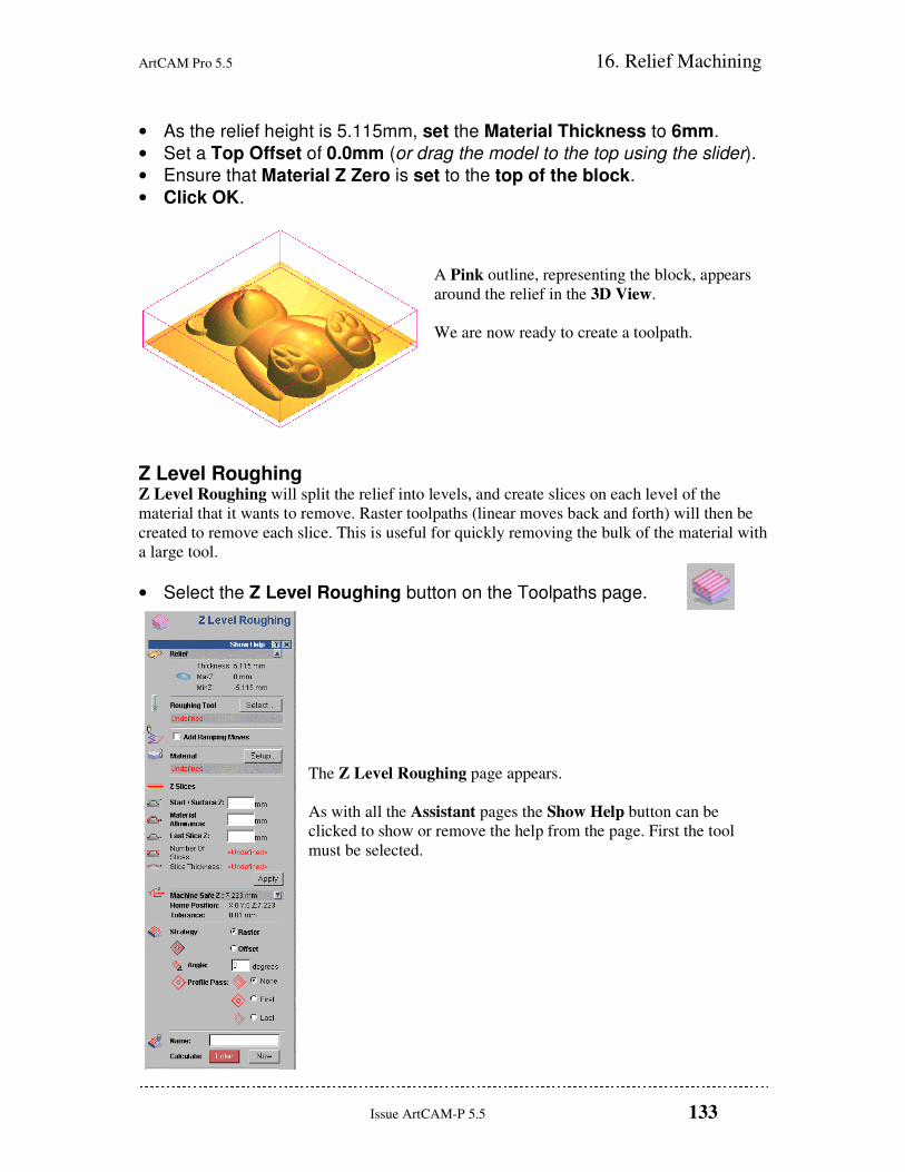
• Select the Z Level Roughing button on the Toolpaths page.
The Z Level Roughing page appears.
As with all the Assistant pages the Show Help button can be
clicked to show or remove the help from the page. First the tool
must be selected.
16. Relief Machining ArtCAM Pro 5.5
134 Issue ArtCAM-P 5.5
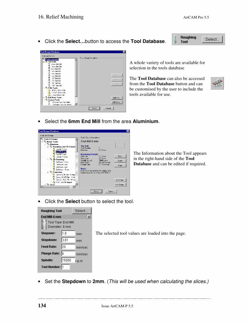
• Click the Select…button to access the Tool Database.
A whole variety of tools are available for
selection in the tools database
The Tool Database can also be accessed
from the Tool Database button and can
be customised by the user to include the
tools available for use.
• Select the 6mm End Mill from the area Aluminium.
The Information about the Tool appears
in the right-hand side of the Tool
Database and can be edited if required.
• Click the Select button to select the tool.
The selected tool values are loaded into the page.
• Set the Stepdown to 2mm. (This will be used when calculating the slices.)
ArtCAM Pro 5.5 16. Relief Machining
Issue ArtCAM-P 5.5 135
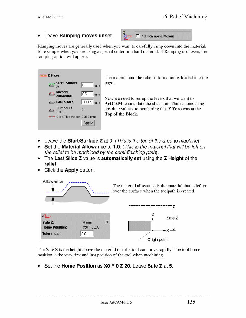
• Leave Ramping moves unset.
Ramping moves are generally used when you want to carefully ramp down into the material,
for example when you are using a special cutter or a hard material. If Ramping is chosen, the
ramping option will appear.
The material and the relief information is loaded into the
page.
Now we need to set up the levels that we want to
ArtCAM to calculate the slices for. This is done using
absolute values, remembering that Z Zero was at the
Top of the Block.
• Leave the Start/Surface Z at 0. (This is the top of the area to machine).
• Set the Material Allowance to 1.0. (This is the material that will be left on the relief to be machined by the semi-finishing path).
• The Last Slice Z value is automatically set using the Z Height of the relief.
• Click the Apply button.
The material allowance is the material that is left on
over the surface when the toolpath is created.
The Safe Z is the height above the material that the tool can move rapidly. The tool home
position is the very first and last position of the tool when machining.
• Set the Home Position as X0 Y 0 Z 20. Leave Safe Z at 5.
16. Relief Machining ArtCAM Pro 5.5
136 Issue ArtCAM-P 5.5
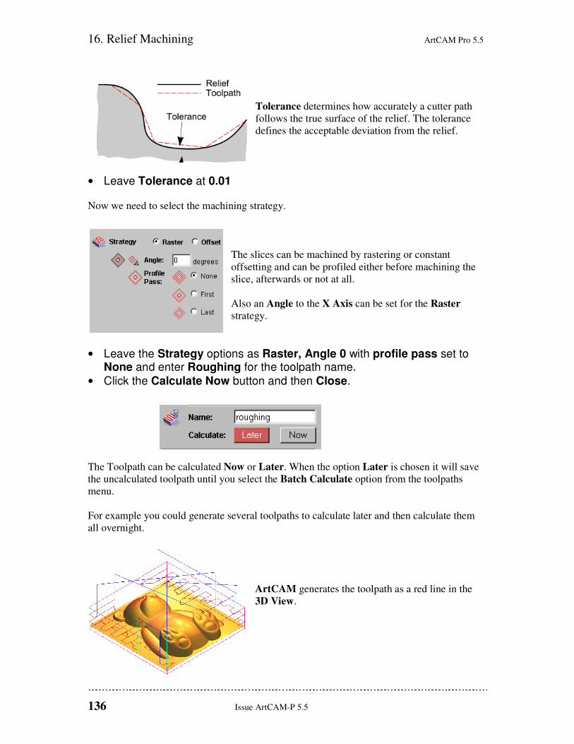
Tolerance determines how accurately a cutter path
follows the true surface of the relief. The tolerance
defines the acceptable deviation from the relief.
• Leave Tolerance at 0.01
Now we need to select the machining strategy.
The slices can be machined by rastering or constant
offsetting and can be profiled either before machining the
slice, afterwards or not at all.
Also an Angle to the X Axis can be set for the Raster
strategy.
• Leave the Strategy options as Raster, Angle 0 with profile pass set to None and enter Roughing for the toolpath name.
• Click the Calculate Now button and then Close.
The Toolpath can be calculated Now or Later. When the option Later is chosen it will save
the uncalculated toolpath until you select the Batch Calculate option from the toolpaths
menu.
For example you could generate several toolpaths to calculate later and then calculate them
all overnight.
ArtCAM generates the toolpath as a red line in the
3D View.
ArtCAM Pro 5.5 16. Relief Machining
Issue ArtCAM-P 5.5 137
The toolpath is currently overlaying the relief in the 3D View. There are now a lot of things
appearing in the 3D View. The Items to Display button at the top of the 3D View controls
which entities are shown on the screen.
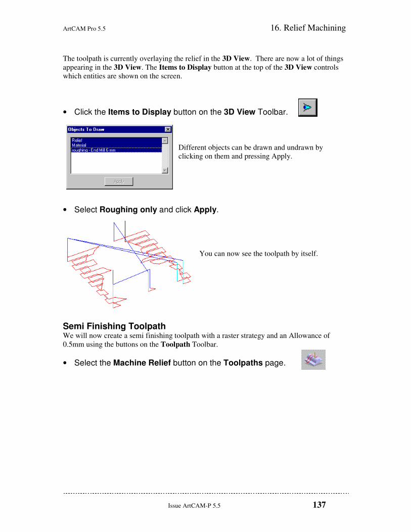
• Click the Items to Display button on the 3D View Toolbar.
Different objects can be drawn and undrawn by
clicking on them and pressing Apply.
• Select Roughing only and click Apply.
You can now see the toolpath by itself.
Semi Finishing Toolpath We will now create a semi finishing toolpath with a raster strategy and an Allowance of
0.5mm using the buttons on the Toolpath Toolbar.
• Select the Machine Relief button on the Toolpaths page.
16. Relief Machining ArtCAM Pro 5.5
138 Issue ArtCAM-P 5.5
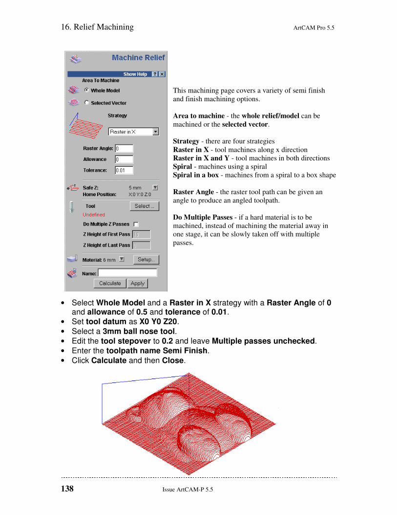
This machining page covers a variety of semi finish
and finish machining options.
Area to machine - the whole relief/model can be
machined or the selected vector.
Strategy - there are four strategies
Raster in X - tool machines along x direction
Raster in X and Y - tool machines in both directions
Spiral - machines using a spiral
Spiral in a box - machines from a spiral to a box shape
Raster Angle - the raster tool path can be given an
angle to produce an angled toolpath.
Do Multiple Passes - if a hard material is to be
machined, instead of machining the material away in
one stage, it can be slowly taken off with multiple
passes.
• Select Whole Model and a Raster in X strategy with a Raster Angle of 0 and allowance of 0.5 and tolerance of 0.01.
• Set tool datum as X0 Y0 Z20.
• Select a 3mm ball nose tool.
• Edit the tool stepover to 0.2 and leave Multiple passes unchecked.
• Enter the toolpath name Semi Finish.
• Click Calculate and then Close.
ArtCAM Pro 5.5 16. Relief Machining
Issue ArtCAM-P 5.5 139
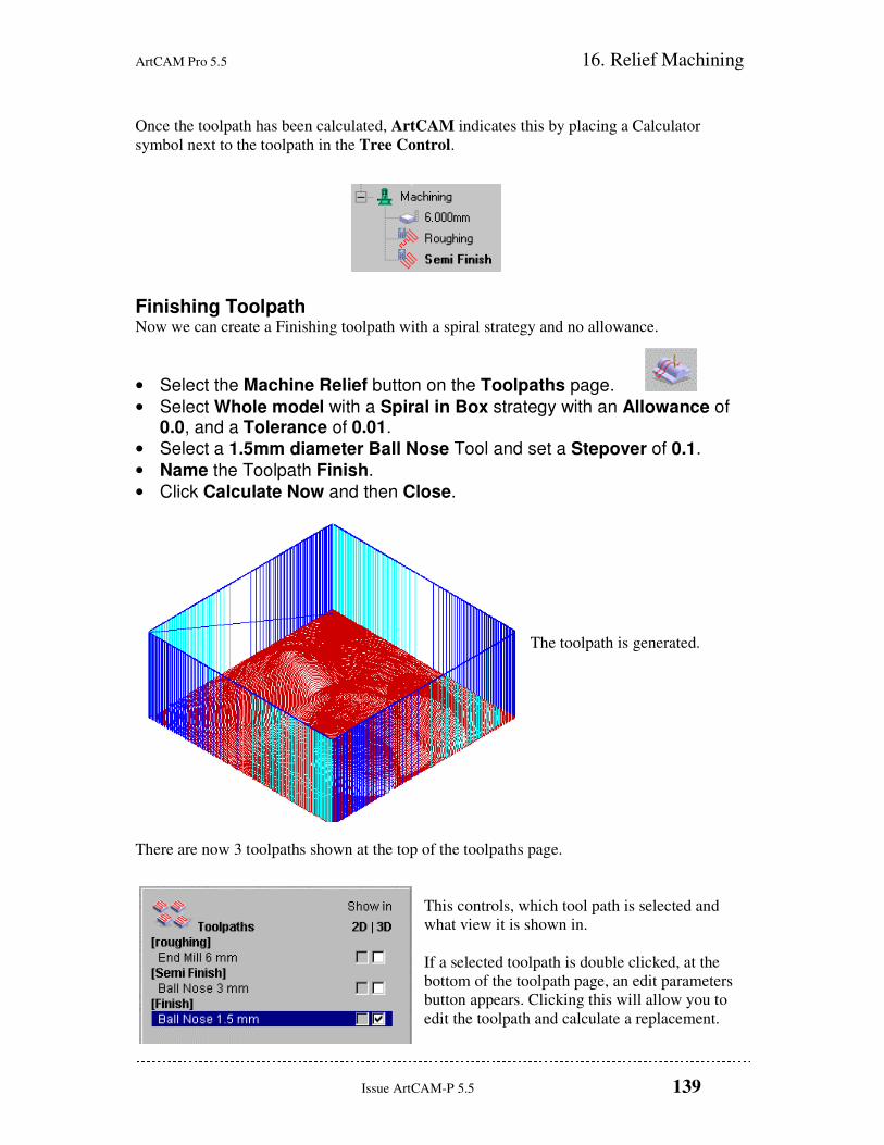
Once the toolpath has been calculated, ArtCAM indicates this by placing a Calculator
symbol next to the toolpath in the Tree Control.
Finishing Toolpath Now we can create a Finishing toolpath with a spiral strategy and no allowance.
• Select the Machine Relief button on the Toolpaths page.
• Select Whole model with a Spiral in Box strategy with an Allowance of 0.0, and a Tolerance of 0.01.
• Select a 1.5mm diameter Ball Nose Tool and set a Stepover of 0.1.
• Name the Toolpath Finish.
• Click Calculate Now and then Close.
The toolpath is generated.
There are now 3 toolpaths shown at the top of the toolpaths page.
This controls, which tool path is selected and
what view it is shown in.
If a selected toolpath is double clicked, at the
bottom of the toolpath page, an edit parameters
button appears. Clicking this will allow you to
edit the toolpath and calculate a replacement.
16. Relief Machining ArtCAM Pro 5.5
140 Issue ArtCAM-P 5.5
Simulating the Toolpaths Generated toolpaths are simulated in the 3D view in ArtCAM. The simulation makes it easier
to visualise the exact cutter path and surface finish, rather than the normal red lines used to
display the toolpath. We can simulate the toolpaths in the order they would be machined to
give as realistic a simulation as possible.
• Select the Roughing Toolpath.
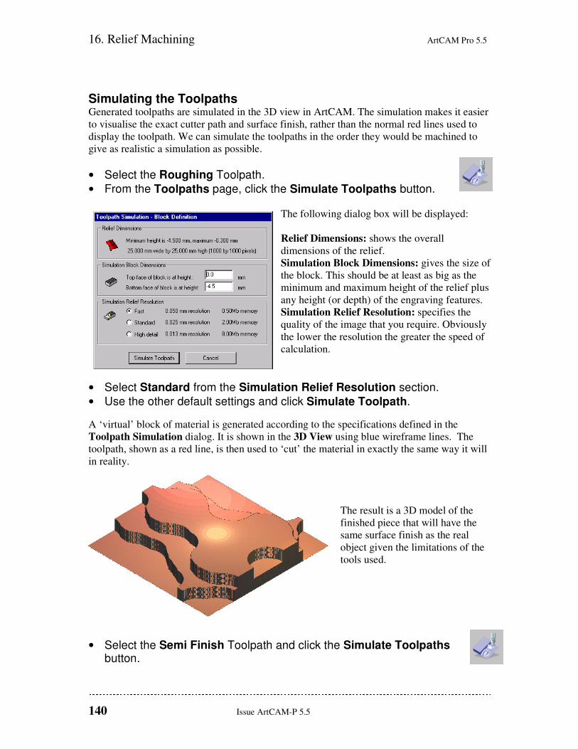
• From the Toolpaths page, click the Simulate Toolpaths button.
The following dialog box will be displayed:
Relief Dimensions: shows the overall
dimensions of the relief.
Simulation Block Dimensions: gives the size of
the block. This should be at least as big as the
minimum and maximum height of the relief plus
any height (or depth) of the engraving features.
Simulation Relief Resolution: specifies the
quality of the image that you require. Obviously
the lower the resolution the greater the speed of
calculation.
• Select Standard from the Simulation Relief Resolution section.
• Use the other default settings and click Simulate Toolpath.
A ‘virtual’ block of material is generated according to the specifications defined in the
Toolpath Simulation dialog. It is shown in the 3D View using blue wireframe lines. The
toolpath, shown as a red line, is then used to ‘cut’ the material in exactly the same way it will
in reality.
The result is a 3D model of the
finished piece that will have the
same surface finish as the real
object given the limitations of the
tools used.
• Select the Semi Finish Toolpath and click the Simulate Toolpaths button.
ArtCAM Pro 5.5 16. Relief Machining
Issue ArtCAM-P 5.5 141
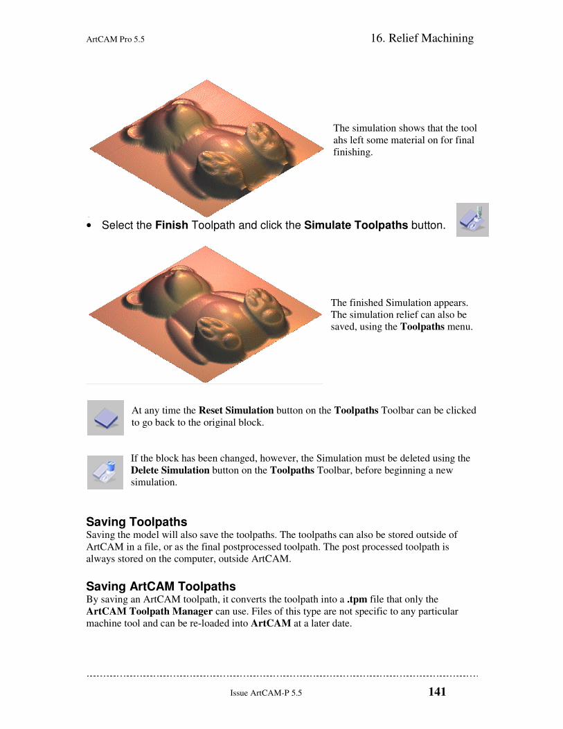
The simulation shows that the tool
ahs left some material on for final
finishing.
• Select the Finish Toolpath and click the Simulate Toolpaths button.
The finished Simulation appears.
The simulation relief can also be
saved, using the Toolpaths menu.
At any time the Reset Simulation button on the Toolpaths Toolbar can be clicked
to go back to the original block.
If the block has been changed, however, the Simulation must be deleted using the
Delete Simulation button on the Toolpaths Toolbar, before beginning a new
simulation.
Saving Toolpaths Saving the model will also save the toolpaths. The toolpaths can also be stored outside of
ArtCAM in a file, or as the final postprocessed toolpath. The post processed toolpath is
always stored on the computer, outside ArtCAM.
Saving ArtCAM Toolpaths By saving an ArtCAM toolpath, it converts the toolpath into a .tpm file that only the
ArtCAM Toolpath Manager can use. Files of this type are not specific to any particular
machine tool and can be re-loaded into ArtCAM at a later date.
16. Relief Machining ArtCAM Pro 5.5
142 Issue ArtCAM-P 5.5
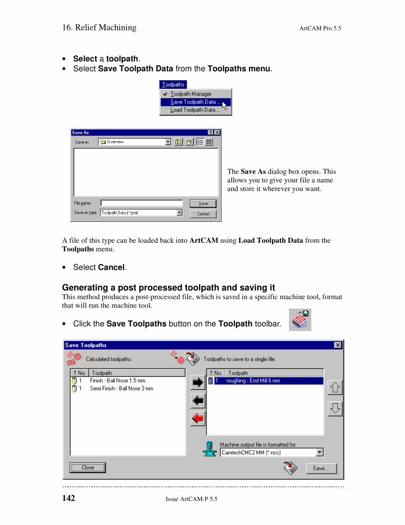
• Select a toolpath.
• Select Save Toolpath Data from the Toolpaths menu.
The Save As dialog box opens. This
allows you to give your file a name
and store it wherever you want.
A file of this type can be loaded back into ArtCAM using Load Toolpath Data from the
Toolpaths menu.
• Select Cancel.
Generating a post processed toolpath and saving it This method produces a post-processed file, which is saved in a specific machine tool, format
that will run the machine tool.
• Click the Save Toolpaths button on the Toolpath toolbar.

ArtCAM Pro 5.5 16. Relief Machining
Issue ArtCAM-P 5.5 143
If you have created a number of toolpaths or you have toolchanger support, you can order and
combine your toolpaths into one file using this dialog. All the toolpaths that you have
generated and are available are listed in the left-hand window, unless selected before
selecting the command.
To convert these files to a machine specific format, click on the file in the left-hand window
that you want and then select the arrow button to transfer the file to the right hand window.
All the files that are transferred to the right hand window will be output into one machining
file. You can transfer as many or as few as you wish.
The up and down buttons on the right of the dialog can be used to reorder the files in
the right hand window. Each click up or down will move the selected file one position in the
list. The resulting file is saved in a machine specific format.
• Select Close.
Machining Small Areas ArtCAM can restrict the machining to an area bounded by a vector.
It may be that the eyes and nose were not machined properly with the Finish Toolpath. We
can create a vector bounding the area we want to machine, and machine it with a smaller tool.
• Ensure your current view is the 2D View.
• Put a vector path around the eyes and nose by selecting the Create Polyline button on the Vector Toolbar and drawing freehand as shown:
• Select the vector in the 2D View.
• Select the Machine Relief button on the Toolpaths page.
16. Relief Machining ArtCAM Pro 5.5
144 Issue ArtCAM-P 5.5
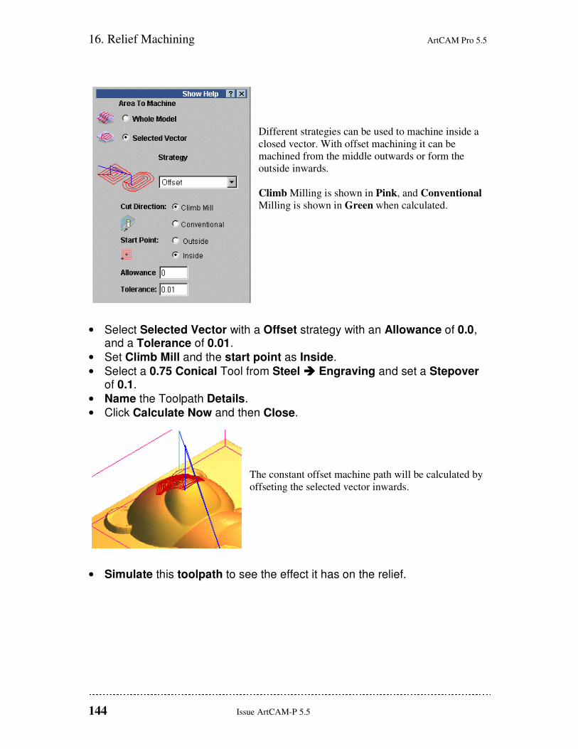
Different strategies can be used to machine inside a
closed vector. With offset machining it can be
machined from the middle outwards or form the
outside inwards.
Climb Milling is shown in Pink, and Conventional
Milling is shown in Green when calculated.
• Select Selected Vector with a Offset strategy with an Allowance of 0.0, and a Tolerance of 0.01.
• Set Climb Mill and the start point as Inside.
• Select a 0.75 Conical Tool from Steel ���� Engraving and set a Stepover of 0.1.
• Name the Toolpath Details.
• Click Calculate Now and then Close.
The constant offset machine path will be calculated by
offseting the selected vector inwards.
• Simulate this toolpath to see the effect it has on the relief.