13th iccrts: c2 for complex endeavors · 13th international command and control research ......
TRANSCRIPT

13th ICCRTS: C2 for Complex Endeavors
The Safety of Unmanned Systems: The Development of Safety Precepts for Unmanned Systems (UMS)
Authors
Dr. Thomas P. English, Naval Surface Warfare Center, Panama City, FL Mr. David J. Shampine, Naval Ordnance Safety and Security Activity, Indian Head, MD
Dr. Julie A. Adams, Vanderbilt University, Nashville, TN Dr. Charles G. Muniak, Lockheed Martin, Syracuse, NY
Mr. Edward W. Kratovil, SAIC, Waldorf, MD
Point of Contact Dr. Thomas P. English
Naval Surface Warfare Center Naval Coastal Systems Station
Panama, City, FL (850) 235-5403 office
Report Documentation Page Form ApprovedOMB No. 0704-0188
Public reporting burden for the collection of information is estimated to average 1 hour per response, including the time for reviewing instructions, searching existing data sources, gathering andmaintaining the data needed, and completing and reviewing the collection of information. Send comments regarding this burden estimate or any other aspect of this collection of information,including suggestions for reducing this burden, to Washington Headquarters Services, Directorate for Information Operations and Reports, 1215 Jefferson Davis Highway, Suite 1204, ArlingtonVA 22202-4302. Respondents should be aware that notwithstanding any other provision of law, no person shall be subject to a penalty for failing to comply with a collection of information if itdoes not display a currently valid OMB control number.
1. REPORT DATE JUN 2008 2. REPORT TYPE
3. DATES COVERED 00-00-2008 to 00-00-2008
4. TITLE AND SUBTITLE The Safety of Unmanned Systems: The Development of Safety Preceptsfor Unmanned Systems (UMS)
5a. CONTRACT NUMBER
5b. GRANT NUMBER
5c. PROGRAM ELEMENT NUMBER
6. AUTHOR(S) 5d. PROJECT NUMBER
5e. TASK NUMBER
5f. WORK UNIT NUMBER
7. PERFORMING ORGANIZATION NAME(S) AND ADDRESS(ES) Naval Surface Warfare Center,Naval Coastal Systems Station,Panama City,FL,32407-7001
8. PERFORMING ORGANIZATIONREPORT NUMBER
9. SPONSORING/MONITORING AGENCY NAME(S) AND ADDRESS(ES) 10. SPONSOR/MONITOR’S ACRONYM(S)
11. SPONSOR/MONITOR’S REPORT NUMBER(S)
12. DISTRIBUTION/AVAILABILITY STATEMENT Approved for public release; distribution unlimited
13. SUPPLEMENTARY NOTES 13th International Command and Control Research and Technology Symposia (ICCRTS 2008), 17-19 Jun2008, Seattle, WA
14. ABSTRACT In October 2005, the Defense Safety Oversight Council (DSOC), Acquisition and Technology ProgramsTask Force (ATP TF) established an initiative to help ensure the safety of unmanned systems (UMS). Thisinitiative was established in response to the proliferation of UMS within the Department of Defense (DoD),and a concern for safety when these systems, primarily unmanned air vehicles, were operated overpopulated areas, or in proximity to other aircraft, both military and civilian, and when configured withweapons or ordnance items. This paper discusses the process that was followed in developing the UMSsafety precepts and the associated DoD UMS safety guidelines document. It will also discuss theenvironment in which UMS are currently employed, the safety concerns with those operationalenvironments and designs, UMS guide objectives, and conclude with an example of a Command andControl/Situational Awareness precept.
15. SUBJECT TERMS
16. SECURITY CLASSIFICATION OF: 17. LIMITATION OF ABSTRACT Same as
Report (SAR)
18. NUMBEROF PAGES
51
19a. NAME OFRESPONSIBLE PERSON
a. REPORT unclassified
b. ABSTRACT unclassified
c. THIS PAGE unclassified
Standard Form 298 (Rev. 8-98) Prescribed by ANSI Std Z39-18
2
13th ICCRTS: C2 for Complex Endeavors
The Safety of Unmanned Systems: The Development of Safety Precepts for Unmanned Systems (UMS) Abstract In October 2005, the Defense Safety Oversight Council (DSOC), Acquisition and Technology Programs Task Force (ATP TF) established an initiative to help ensure the safety of unmanned systems (UMS). This initiative was established in response to the proliferation of UMS within the Department of Defense (DoD), and a concern for safety when these systems, primarily unmanned air vehicles, were operated over populated areas, or in proximity to other aircraft, both military and civilian, and when configured with weapons or ordnance items. This paper discusses the process that was followed in developing the UMS safety precepts and the associated DoD UMS safety guidelines document. It will also discuss the environment in which UMS are currently employed, the safety concerns with those operational environments and designs, UMS guide objectives, and conclude with an example of a Command and Control/Situational Awareness precept. Keywords: unmanned systems, UMS, safety precepts, OSD UMS safety guide Introduction It is anticipated that unmanned systems will play a transformational role in all aspects of warfare including command and control (reference 1). The successful development and acquisition of these systems of systems, which may be composed of a multitude of platforms, will require new engineering and management concepts (reference 2). One specific engineering discipline that must develop new approaches to this transformation is system safety. To this end, in 2005, the Defense Safety Oversight Council (DSOC), Acquisition and Technology Programs Task Force (ATP TF) established an initiative to help ensure the safety of unmanned systems (UMSs). This initiative was established in response to the proliferation of UMS within the Department of Defense (DoD), and a concern for safety when these systems, primarily unmanned air vehicles, were operated over populated areas, or in proximity to other aircraft, both military and civilian, and when configured with weapons or ordnance items. Numerous UMSs are currently under development in each of the Services, as well as other government agencies. The traditional view that a specific Service’s UMS, for example, will never have to interface or coordinate with the other Services’ systems is no longer true in today’s Joint warfighting environments. Addressing such issues as integrated operations, system control, communication, safe navigation, security, and target identification/verification are major

3
challenges for all UMSs (e.g., references 3 and 4); however, there is no unified system safety approach to address these kinds of issues. In order to develop safe UMSs, this safety initiative had the goal of establishing safety guidelines that are tailored to, and focused on the safety of UMSs regardless of the environment in which they are used. This safety project had over 80 participants from across the safety community including Army, Navy, Air Force, Marine Corps, NASA, Industry, and Academia. The intent was for the government and industry safety community to develop a set of safety guidelines that will be accepted and effectively utilized by acquisition program managers and operators during the development and operation of UMSs. Discussion An UMS is defined as: “An electro-mechanical system that is able to exert its power to perform designed missions and includes the following: (1) there is no human operator aboard, (2) manned systems that can be fully or partially operated in an autonomous mode, and (3) the system is designed to return or be recoverable. The system may be mobile or stationary, and includes the vehicle/device and the control station. Missiles, rockets and their submunitions, and artillery are not considered UMSs. UMSs include, but are not limited to: unmanned ground vehicles, unmanned aerial/aircraft systems, unmanned underwater vehicles, unmanned surface vessels, unattended munitions, and unattended ground sensors.” Military UMSs provide numerous advantages to the DOD due to the variety of their applications, each of which presents unique system safety challenges. Some military example applications include:
• Weapons platforms (air, ground and water) • Explosive Ordnance Disposal (EOD) • Breaching and clearing mine fields • Surveillance/reconnaissance • Search and rescue • Delivering supplies to troops • Automated repair/maintenance.
Most UMSs involve a system that traverses ground, water, air, outer space or a combination of any of these modes to perform a desired task or goal. Along with the advantages of using an UMS as opposed to humans, significant system safety concerns are also realized. Recent initiatives to employ UMSs as weapons delivery platforms revealed new or additional risk in the control of the weapons. For instance, without direct human control or intervention, a weapon
4
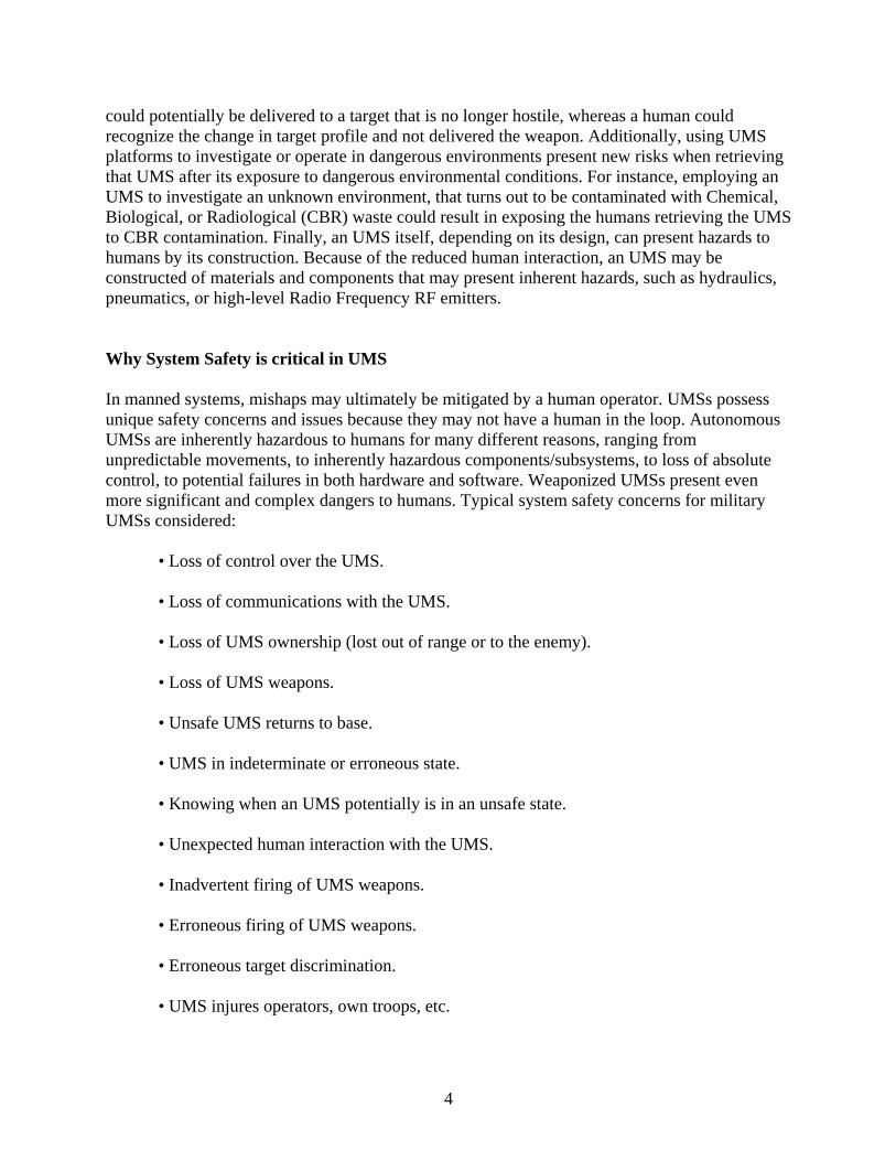
could potentially be delivered to a target that is no longer hostile, whereas a human could recognize the change in target profile and not delivered the weapon. Additionally, using UMS platforms to investigate or operate in dangerous environments present new risks when retrieving that UMS after its exposure to dangerous environmental conditions. For instance, employing an UMS to investigate an unknown environment, that turns out to be contaminated with Chemical, Biological, or Radiological (CBR) waste could result in exposing the humans retrieving the UMS to CBR contamination. Finally, an UMS itself, depending on its design, can present hazards to humans by its construction. Because of the reduced human interaction, an UMS may be constructed of materials and components that may present inherent hazards, such as hydraulics, pneumatics, or high-level Radio Frequency RF emitters. Why System Safety is critical in UMS In manned systems, mishaps may ultimately be mitigated by a human operator. UMSs possess unique safety concerns and issues because they may not have a human in the loop. Autonomous UMSs are inherently hazardous to humans for many different reasons, ranging from unpredictable movements, to inherently hazardous components/subsystems, to loss of absolute control, to potential failures in both hardware and software. Weaponized UMSs present even more significant and complex dangers to humans. Typical system safety concerns for military UMSs considered:
• Loss of control over the UMS. • Loss of communications with the UMS. • Loss of UMS ownership (lost out of range or to the enemy). • Loss of UMS weapons. • Unsafe UMS returns to base. • UMS in indeterminate or erroneous state. • Knowing when an UMS potentially is in an unsafe state. • Unexpected human interaction with the UMS. • Inadvertent firing of UMS weapons. • Erroneous firing of UMS weapons. • Erroneous target discrimination. • UMS injures operators, own troops, etc.
5
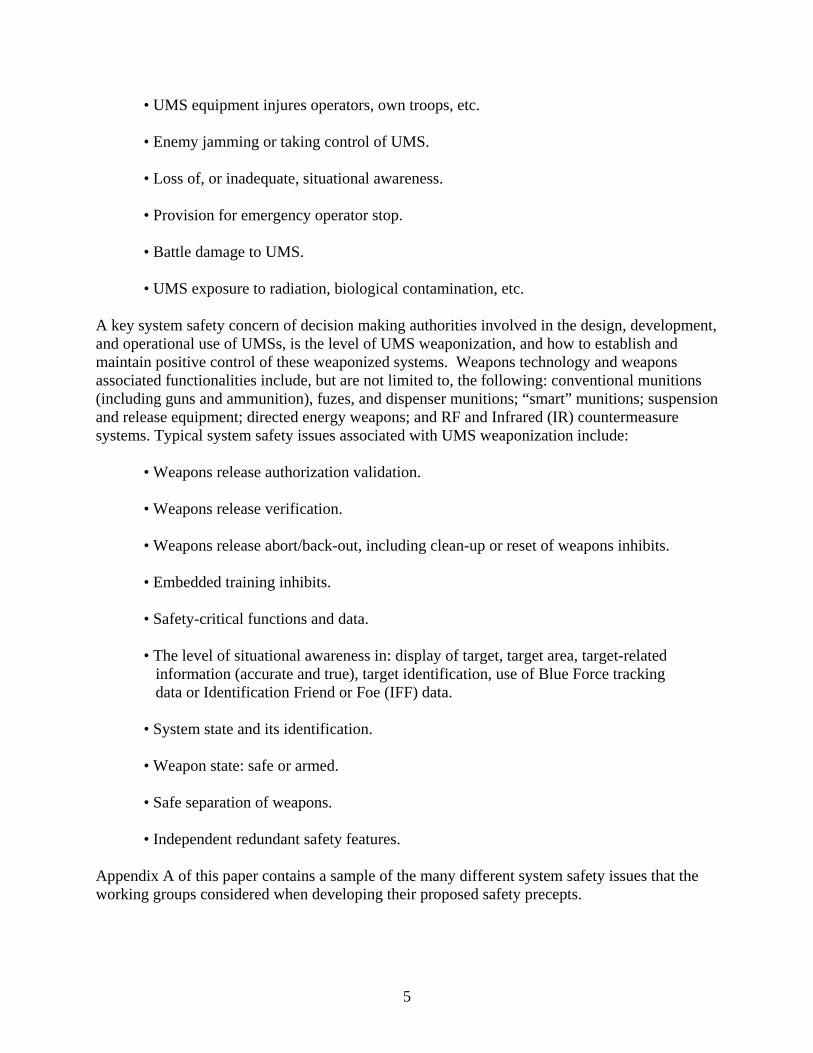
• UMS equipment injures operators, own troops, etc. • Enemy jamming or taking control of UMS. • Loss of, or inadequate, situational awareness. • Provision for emergency operator stop. • Battle damage to UMS. • UMS exposure to radiation, biological contamination, etc.
A key system safety concern of decision making authorities involved in the design, development, and operational use of UMSs, is the level of UMS weaponization, and how to establish and maintain positive control of these weaponized systems. Weapons technology and weapons associated functionalities include, but are not limited to, the following: conventional munitions (including guns and ammunition), fuzes, and dispenser munitions; “smart” munitions; suspension and release equipment; directed energy weapons; and RF and Infrared (IR) countermeasure systems. Typical system safety issues associated with UMS weaponization include:
• Weapons release authorization validation. • Weapons release verification. • Weapons release abort/back-out, including clean-up or reset of weapons inhibits. • Embedded training inhibits. • Safety-critical functions and data. • The level of situational awareness in: display of target, target area, target-related information (accurate and true), target identification, use of Blue Force tracking data or Identification Friend or Foe (IFF) data. • System state and its identification. • Weapon state: safe or armed. • Safe separation of weapons. • Independent redundant safety features.
Appendix A of this paper contains a sample of the many different system safety issues that the working groups considered when developing their proposed safety precepts.
6
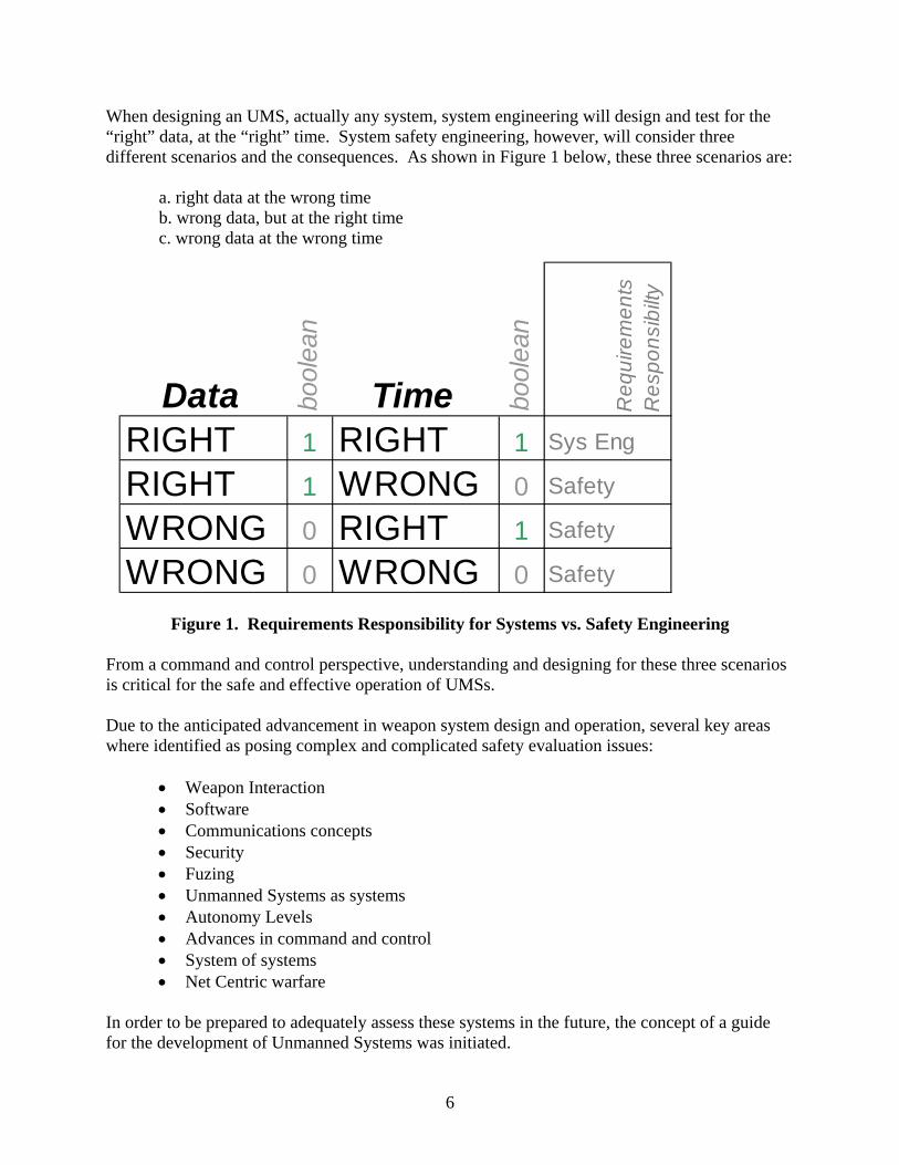
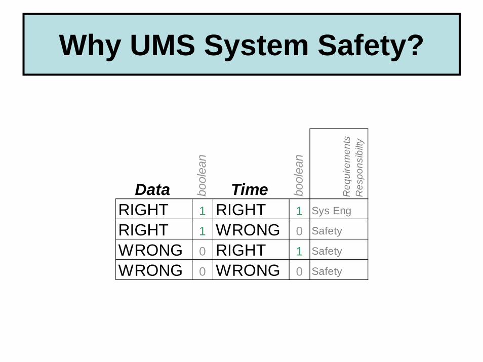
When designing an UMS, actually any system, system engineering will design and test for the “right” data, at the “right” time. System safety engineering, however, will consider three different scenarios and the consequences. As shown in Figure 1 below, these three scenarios are:
a. right data at the wrong time b. wrong data, but at the right time c. wrong data at the wrong time
Figure 1. Requirements Responsibility for Systems vs. Safety Engineering
From a command and control perspective, understanding and designing for these three scenarios is critical for the safe and effective operation of UMSs. Due to the anticipated advancement in weapon system design and operation, several key areas where identified as posing complex and complicated safety evaluation issues:
• Weapon Interaction • Software • Communications concepts • Security • Fuzing • Unmanned Systems as systems • Autonomy Levels • Advances in command and control • System of systems • Net Centric warfare
In order to be prepared to adequately assess these systems in the future, the concept of a guide for the development of Unmanned Systems was initiated.
Data bool
ean
Time bool
ean
Req
uire
men
ts
Res
pons
ibilt
y
RIGHT 1 RIGHT 1 Sys Eng
RIGHT 1 WRONG 0 Safety
WRONG 0 RIGHT 1 Safety
WRONG 0 WRONG 0 Safety
7
The objective in the development of this guidance was to ensure the design and development of UMSs incorporated the necessary system safety design rigor to prevent potential mishaps, or mitigate potential mishap risk. Director, Systems and Software Engineering (SSE), Acquisition Technology and Logistics (AT&L), Office of the Secretary of Defense (OSD), provided the leadership for this initiative, and directed this safety guidance also consider real and potential Concepts of Operation (CONOPS) of UMSs and establish fundamental operational safety requirements necessary to support safe operation of the UMS. This guidance provides a generic set of safety precepts and safety design considerations, and establishes a starting point toward ensuring that system safety is a fundamental pillar of the acquisition process and incorporates those necessary design considerations to safely sustain UMSs. The safety precepts provided in the OSD guide were developed by a select group of design and system safety engineers and Program Managers. Recognized expert representatives were selected from: OSD staff, Army, Navy, Air Force, Marine Corps, National Aeronautical and Space Administration (NASA), National Institute of Standards and Technology (NIST), private industry, and academia. These representatives were organized into six functional workgroups, which reported to an Executive Steering Group. The composition of these workgroups was carefully crafted to include appropriate safety expertise as well as participation across DoD services, industry, and academia. The current OSD UMS safety guide, which is officially titled, “UNMANNED SYSTEMS SAFETY GUIDE FOR DOD ACQUISITION”, dated 27 June 2007, can be found at http://www.acq.osd.mil/atptf/. The UMSs Safety Guide currently contains the following Table of Contents: 1. Key Terms, Descriptions, and Principles 1.1 Unmanned System 1.2 Safety Precept 1.3 Authorized Entity 2. System Safety Overview 2.1 System Safety and the UMS Precepts 2.2 Characteristics of Successful System Safety Programs 3. Unmanned System Safety Overview 3.1 Unique Aspects of Military Unmanned Systems 3.2 Top Level Mishaps for Unmanned Systems 4. Unmanned System Safety Program Aspects 4.1 Safety Precepts 4.2 Programmatic Safety Precepts 5. Unmanned System Operational Aspects 5.1 Unmanned Systems Operational Safety Functionality 5.2 Operational Safety Precepts

8
6. Unmanned Systems Design Aspects 6.1 Unmanned Systems Design Safety Functionality 6.1.1 Weaponization 6.1.2 Situational Awareness (Information, Intelligence, and Method of Control (I2C)) 6.1.3 Command and Control 6.1.4 States and Modes 6.2 Design Safety Precepts Appendix A. References and Resource Guide Appendix B. Acronyms Appendix C. Definitions Appendix D. Major Contributors Appendix E. Safety Precept Clarification Tables Development of the UMS Safety Precepts During the development of the proposed OSD UMSs Safety Guide, the question was often asked by UMS program managers, “Why do we need safety precepts for UMSs”? Safety precepts are the starting point for system development. These precepts provide an indicator of where the program needs to focus its attention in order to develop a safe system. In addition, the precepts also provide guidance for the safe design of UMS, and are the precursor for design safety requirements. Safety precepts are often used to help establish the tasks and priorities for a system safety program. Safety precepts should be considered building blocks in the system safety process, that is, they provide a “foundation” upon which a system safety program can be built to help ensure the safety of UMSs. As part of this UMS safety initiative, it was recognized, early in the process that safety precepts basically fall into three categories:
1. programmatic 2. operational 3. design
A safety precept is defined as: “A safety precept is a basic truth, law or presumption intended to influence management, operations, and design activities but not dictate specific solutions. A safety precept is worded as a nonspecific and unrestricted safety objective that provides a focus for addressing potential safety issues that present significant mishap risk. Precepts are intentionally general and not prescriptive in nature; they provide a goal, which may be achieved via numerous possible options. They provide a focus and objective as opposed to a detailed solution. The need for a safety precept may result from the desire to mitigate certain hazards or hazard types.” The three categories of safety precepts are defined, as follows, and are depicted in Figure 2:

9
• Programmatic Safety Precepts (PSPs) – Program management principles and guidance that
will help insure safety is adequately addressed throughout the lifecycle process. • Operational Safety Precepts (OSPs) – A safety precept directed specifically at system
operation. Operational rules that must be adhered to during system operation. These safety precepts may generate the need for Design Safety Precepts (DSPs).
• Design Safety Precepts (DSPs) – General design guidance intended to facilitate safety of
the system and minimize hazards. Safety design precepts are intended to influence, but not dictate, specific design solutions.
Figure 2. Levels of Safety Precepts for Unmanned Systems
These UMS safety precepts are guiding principles or doctrines that, when properly considered and applied, will serve to enhance or facilitate the implementation of safety into a system. These safety precepts are designed to influence the safety of system designs, and system design decisions by providing critical design safety requirements that can be assimilated into detailed design specifications during early and final system design machinations. The critical safety
10
design guidance provided through these precepts has been developed to convey or articulate a desirable fundamental safeguard without constraining the design or design options.
Safety precepts for UMSs did not previously exist; they evolved through an arduous, but thorough, systems engineering process performed as part of this OSD UMS safety initiative. The precepts, presented in the OSD guide, are provided as a generic and minimum set of precepts for the design, development, and operation of any UMS system. Appendix B provides a complete listing of all 30 precepts. In addition to these precepts, the Draft OSD UMS Safety Guide also includes an Appendix E, titled “Safety Precept Clarification Tables”. These clarification tables provide additional information regarding the scope, rationale, examples, detailed design considerations, and existing policy for each precept. These clarification tables are intended to provide the program manager with a better understanding as to the thought process behind each of these one-sentence precepts. And by better understanding the thought process behind each of these precepts, it was felt that program managers could be more creative in how the precept was actually implemented. Appendix C provides an example of a typical precept clarification table that is contained in the OSD UMS Safety Guide.
Situational Awareness/Command and Control Precept In developing the precepts for the guide, a basic understanding was needed of UMS command and control authorities, and who or what will be controlling the individual phases of operation of the UMS, both in the near term and in the future. Consequently, several working groups were established to develop the precepts by function, to include all aspects of unmanned system operation. The working groups quickly realized that in some cases, the control of an UMS may be conducted by a human operator from a remote location through a remote control console. In other cases, operation may be the result of pre-programmed mission parameters and commands, or control may even be a fully autonomous function of the UMS. In still other cases, control may be provided by another UMS or multiple UMSs in a networked environment. When developing the safety precepts provided in the DoD UMS Guide, both human and autonomous methods of control were considered. The interaction of humans with various levels of automation is an area of active research (e.g., reference 5) which is needed for operators to properly conceptualize the tactical situation. The terms used throughout this guide, and in the precepts, to describe these two methods of control are authorized entity(ies) and controlling entity(ies). Following are the definitions for these two terms:
• An authorized entity is defined as: “An individual operator or control element authorized to direct or control system functions or mission.”
• A controlling entity is defined as: “An individual operator or control element directing or
controlling system functions or mission.”

11
In short, an authorized and controlling entity is a design-intended control element of a UMS with decision making authority, human or machine, and designated to command the UMS. As UMSs evolve and increase in their level of autonomy, a system operator or human controller may no longer be a valid assumption; control may be completely relinquished to one or more UMSs. Systems may use man-to-machine or machine-to-machine control. In this context, the term “authorized entity” is used to denote the entity which, by design, exercises immediate control over the UMS. When operating an UMS, the authorized entity must not only maintain positive command and control, but also must have “situational awareness” to operate the UMS in an effective and safety manner. Situational Awareness (SA) as defined by Endsley (reference 6) is “the perception of elements in the environment within a volume of time and space, the comprehension of their meaning, and the projection of their status in the future.” There can be both individual and group or team situational awareness. SA in this context typically is defined in relation to a particular mission that must be attained over time; therefore knowledge of the associated mission goals and objectives determine the information required by the human to successfully complete the mission. Endsley’s SA definition encompasses three levels of SA relative to the assigned mission:
1. Level 1 – perception of the environment; 2. Level 2 – comprehension of the situation; and, 3. Level 3 – projection into the near future.
Level 1 SA requires that the UMS perceive the environment relative to the assigned mission, including the environmental status, attributes, and dynamics. Various combinations of sensor capabilities are necessary to perceive the relevant environmental aspects that vary across application domains. A complete implementation of this level of SA requires a number of components. First, UMS SA requires a suite of sensing capabilities along with the sensor feedback, update rates, information resolution levels, and sensor fusion. Communications from other UMSs or humans must be fed into the SA processing as such information also represents percepts. UMS SA must also incorporate the capacity for UMSs to provide adaptive sensing. Adaptive sensing incorporates the ability to determine which sensor to use at a particular time, modification of the sensor processing, or combination of sensors required based upon the task. Additionally, UMS SA must provide the capability for the sensors to direct attention. Level 2 SA requires the UMS to integrate a large number of percepts (level one SA) and prioritize the importance and meaning of the integrated information with regard to mission goals. This level of SA requires the UMS to develop situational comprehension based upon a number of comprehension components including: expectations (perhaps a side-effect of human programming), an UMS equivalent of human mental models, working memory, long-term memory, redirecting attentional focus, prior decisions, and prior plans. Some of these components have been individually developed but a holistic comprehension capability does not currently exist.
12
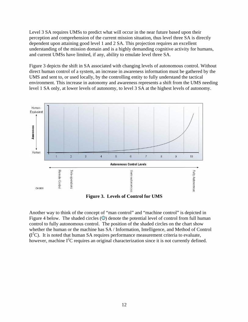
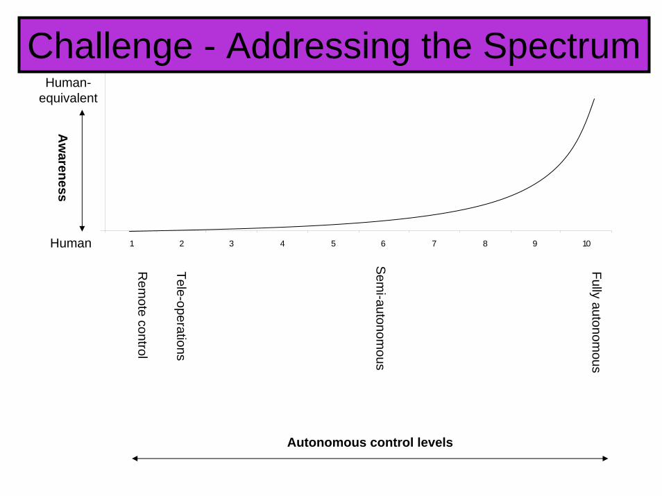
Level 3 SA requires UMSs to predict what will occur in the near future based upon their perception and comprehension of the current mission situation, thus level three SA is directly dependent upon attaining good level 1 and 2 SA. This projection requires an excellent understanding of the mission domain and is a highly demanding cognitive activity for humans, and current UMSs have limited, if any, ability to emulate level three SA. Figure 3 depicts the shift in SA associated with changing levels of autonomous control. Without direct human control of a system, an increase in awareness information must be gathered by the UMS and sent to, or used locally, by the controlling entity to fully understand the tactical environment. This increase in autonomy and awareness represents a shift from the UMS needing level 1 SA only, at lower levels of autonomy, to level 3 SA at the highest levels of autonomy.
Figure 3. Levels of Control for UMS
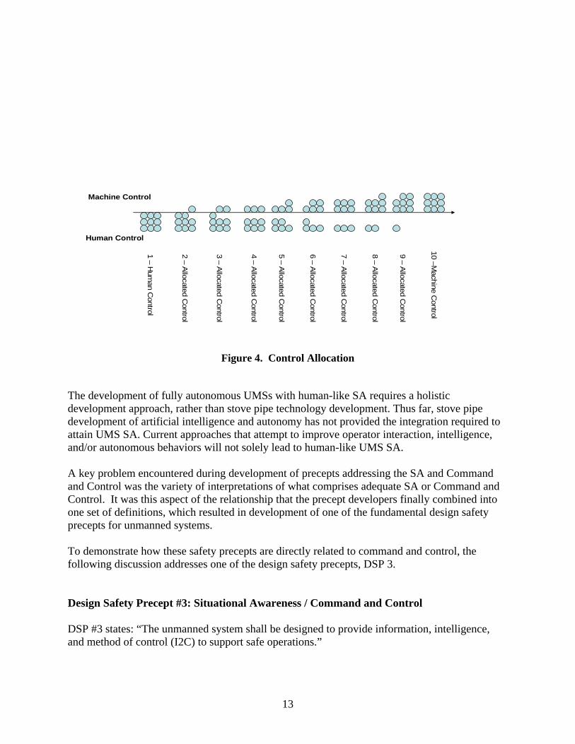
Another way to think of the concept of “man control” and “machine control” is depicted in Figure 4 below. The shaded circles ( ) denote the potential level of control from full human control to fully autonomous control. The position of the shaded circles on the chart show whether the human or the machine has SA / Information, Intelligence, and Method of Control (I2C). It is noted that human SA requires performance measurement criteria to evaluate, however, machine I2C requires an original characterization since it is not currently defined.
13
1 –H
uman C
ontrol
5 –A
llocated Control
10 –Machine C
ontrol
Human Control
Machine Control
6 –A
llocated Control
9 –A
llocated Control
7 –A
llocated Control
8 –A
llocated Control
4 –A
llocated Control
3 –A
llocated Control
2 –A
llocated Control
Figure 4. Control Allocation
The development of fully autonomous UMSs with human-like SA requires a holistic development approach, rather than stove pipe technology development. Thus far, stove pipe development of artificial intelligence and autonomy has not provided the integration required to attain UMS SA. Current approaches that attempt to improve operator interaction, intelligence, and/or autonomous behaviors will not solely lead to human-like UMS SA. A key problem encountered during development of precepts addressing the SA and Command and Control was the variety of interpretations of what comprises adequate SA or Command and Control. It was this aspect of the relationship that the precept developers finally combined into one set of definitions, which resulted in development of one of the fundamental design safety precepts for unmanned systems. To demonstrate how these safety precepts are directly related to command and control, the following discussion addresses one of the design safety precepts, DSP 3. Design Safety Precept #3: Situational Awareness / Command and Control DSP #3 states: “The unmanned system shall be designed to provide information, intelligence, and method of control (I2C) to support safe operations.”

14
In order to understand this precept, the following definitions were established for formulating the basis of the precept. Definitions:
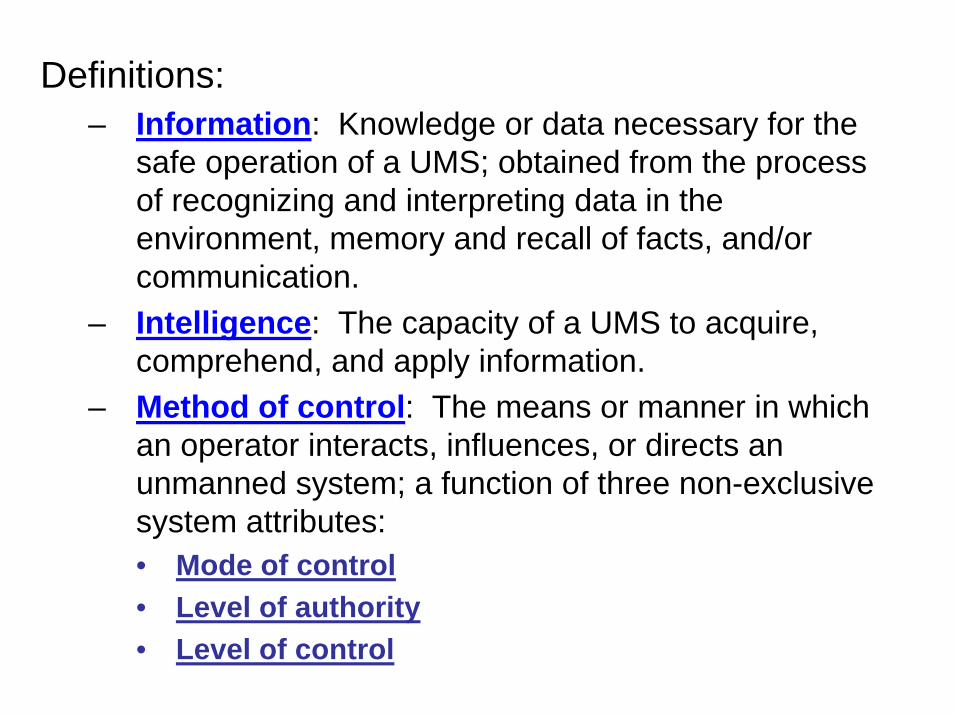
1. Information: Knowledge or data necessary for the safe operation of an UMS; obtained from the process of recognizing and interpreting data in the environment, memory and recall of facts, and/or communication.
2. Intelligence: The capacity of an UMS to acquire, comprehend, and apply information.
3. Method of control: The means or manner in which an operator interacts, influences, or directs an unmanned system; a function of three non-exclusive system attributes:
• Mode of control: The means by which an UMS receives instructions governing its actions and feeds back information.
– Remote control – Tele-operation – Semi-autonomous – Fully autonomous
• Level of command authority: The degree to which an entity is invested with the power to access the control and functions of an UMS.
– Level I – Reception and transmission of secondary imagery or data – Level II - Reception of imagery or data directly from the UMS – Level III - Control of the UMS payload – Level IV - Full control of the UMS excluding deployment and
recovery – Level V – Full control of the UMS including deployment and
recovery • Level of control: The level at which a controlling entity interacts, influences, or directs an UMS(s).
– Actuator – Primitive – Subsystem – Vehicle – Group of vehicles – System of systems
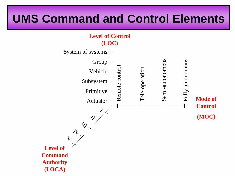
With the establishment of the frame work with which to qualitatively define SA/Command and Control, the group developed a three-dimensional composite relationship between SA and Command and Control. Using the definitions above, and as shown in figure 5 below, there is a direct relationship among “level of control”, “mode of control”, and “level of command authority” that must be recognized and considered when designing UMSs. As previously mentioned, the OSD UMS Guide contains “precept clarification tables” to help the design engineers better understand the rationale for the precept. Appendix C of this paper provides, as an example, the precept clarification table for DSP #3. As shown in Appendix C,

15
there is a section titled, “Detailed Considerations” that lists several key design issues that affect command and control as it relates to the safe and operationally effective use of UMSs.
Rem
ote
cont
rol
Tele
-ope
ratio
n
Sem
i-aut
onom
ous
Fully
aut
onom
ous
Actuator
Primitive
Vehicle
Subsystem
Group
System of systems
Level of Control
Mode of
ControlII
IVIII
I
Level of Command Authority
V
Figure 5. UMS Command and Control Elements
Summary As a result of the process described above, a credible list of safety precepts for UMSs has been developed. These precepts are general in nature to include as many different types of military UMSs as possible, and can provide a solid foundation upon which to design, build and operate UMSs that safe and operationally effective. This list can be applied to current UMS development projects for program and design safety guidance. Through the use of these precepts, however, it is anticipated that these current precepts may need to be modified, or new precepts developed to maintain safety and positive command and control of future UMSs. These precepts were published in an OSD UMS safety guideline manual, titled Unmanned Systems Safety Guide for DOD Acquisition, dated 27 June 2007. This OSD UMS Safety Guide will be referenced in DoDI 5000.2 to ensure that these precepts are at least considered by program managers during the acquisition process for UMSs. Great work has been accomplished to date regarding the safety of UMS; more needs to be accomplished to make these precepts relevant to new C2 approaches

16
The challenge to the C2 community is to review and use these precepts when designing C2 systems for UMS, and modify these existing precepts, or develop new precepts, as necessary, to better meet your needs. References 1. Hudson E.C., Johnson G., Summey D. C., & Portman H.H. (2004). Shaping Future Naval Warfare with Unmanned Systems - The Impact Across the Fleet and Joint Considerations. Engineering the Total Ship Symposium, Gaithersburg Maryland
2. Software Engineering Institute, (2006). Ultra-Large Scale Systems The Software Challenge of the Future. Carnegie Mellon University 3. Castelin S., & Bernstein P. (2004). A Notional Scenario for the Use of Unmanned System Groups in Littoral Warfare. IEEE/OES Autonomous Underwater Vehicles, Sebasco Maine pp.4-19 4. Benjamin M.R.,& Curcio J.A., (2004). OLREGS-Based Navigation of Autonomous Marine Vehicles. EEE/OES Autonomous Underwater Vehicles, Sebasco Maine pp.32-39 5. Bruni S., Marquez J., Brzezinski A.,Nehme C.,& Boussemart Y. (2007). Introducing a Human-Automation Collaboration Taxonomy (HACT) in Command and Control Decision-Support Systems. 12th International Command and Control Research and Technology Symposium 6. Endsley, M. R. (1988) Design and Evaluation for Situation Awareness Enhancement. Proceedings of the Human Factors Society 32nd Annual Meeting. 1: 97-101.
17
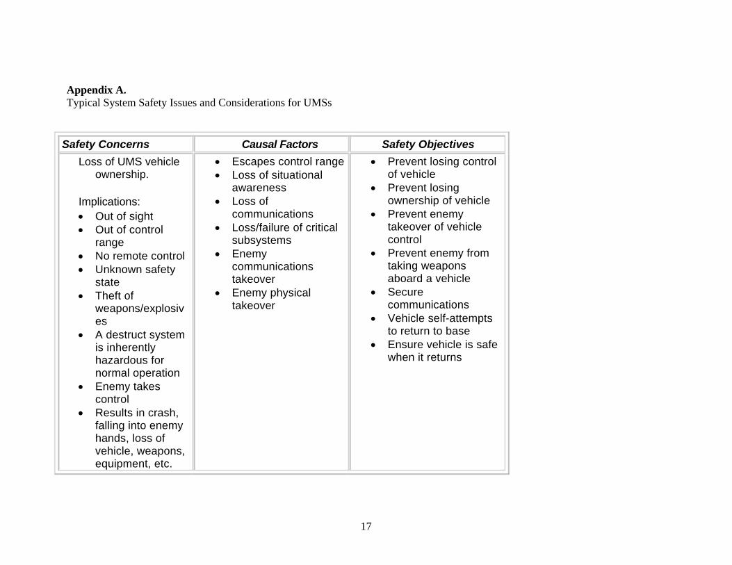
Appendix A. Typical System Safety Issues and Considerations for UMSs
Safety Concerns Causal Factors Safety Objectives Loss of UMS vehicle
ownership.
Implications: • Out of sight • Out of control
range • No remote control • Unknown safety
state • Theft of
weapons/explosives
• A destruct system is inherently hazardous for normal operation
• Enemy takes control
• Results in crash, falling into enemy hands, loss of vehicle, weapons, equipment, etc.
• Escapes control range • Loss of situational
awareness • Loss of
communications • Loss/failure of critical
subsystems • Enemy
communications takeover
• Enemy physical takeover
• Prevent losing control of vehicle
• Prevent losing ownership of vehicle
• Prevent enemy takeover of vehicle control
• Prevent enemy from taking weapons aboard a vehicle
• Secure communications
• Vehicle self-attempts to return to base
• Ensure vehicle is safe when it returns
18
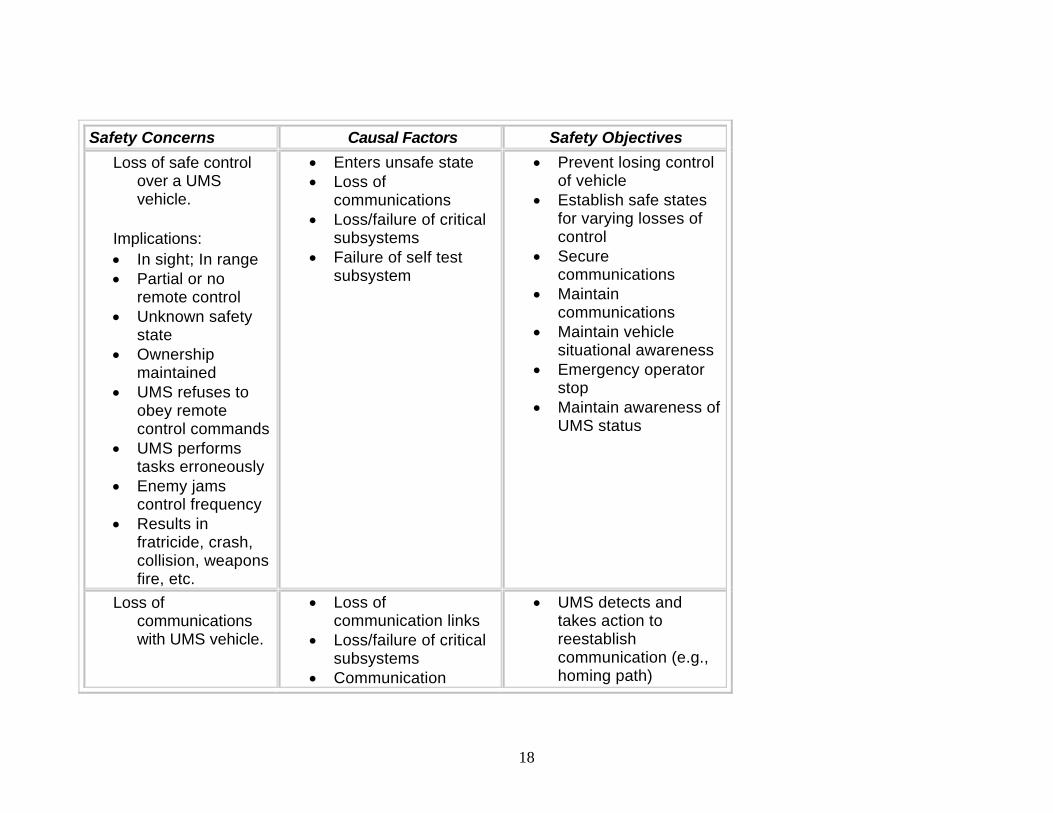
Safety Concerns Causal Factors Safety Objectives Loss of safe control
over a UMS vehicle.
Implications: • In sight; In range • Partial or no
remote control • Unknown safety
state • Ownership
maintained • UMS refuses to
obey remote control commands
• UMS performs tasks erroneously
• Enemy jams control frequency
• Results in fratricide, crash, collision, weapons fire, etc.
• Enters unsafe state • Loss of
communications • Loss/failure of critical
subsystems • Failure of self test
subsystem
• Prevent losing control of vehicle
• Establish safe states for varying losses of control
• Secure communications
• Maintain communications
• Maintain vehicle situational awareness
• Emergency operator stop
• Maintain awareness of UMS status
Loss of communications with UMS vehicle.
• Loss of communication links
• Loss/failure of critical subsystems
• Communication
• UMS detects and takes action to reestablish communication (e.g., homing path)
19
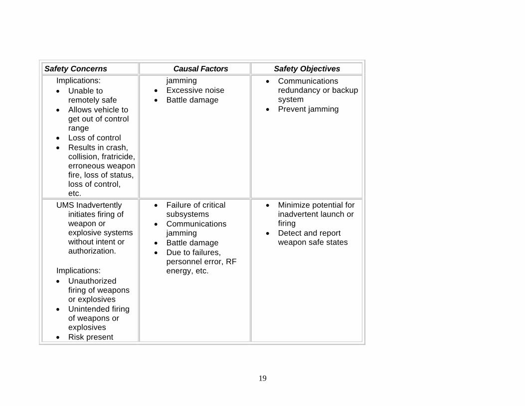
Safety Concerns Causal Factors Safety Objectives Implications: • Unable to
remotely safe • Allows vehicle to
get out of control range
• Loss of control • Results in crash,
collision, fratricide, erroneous weapon fire, loss of status, loss of control, etc.
jamming • Excessive noise • Battle damage
• Communications redundancy or backup system
• Prevent jamming
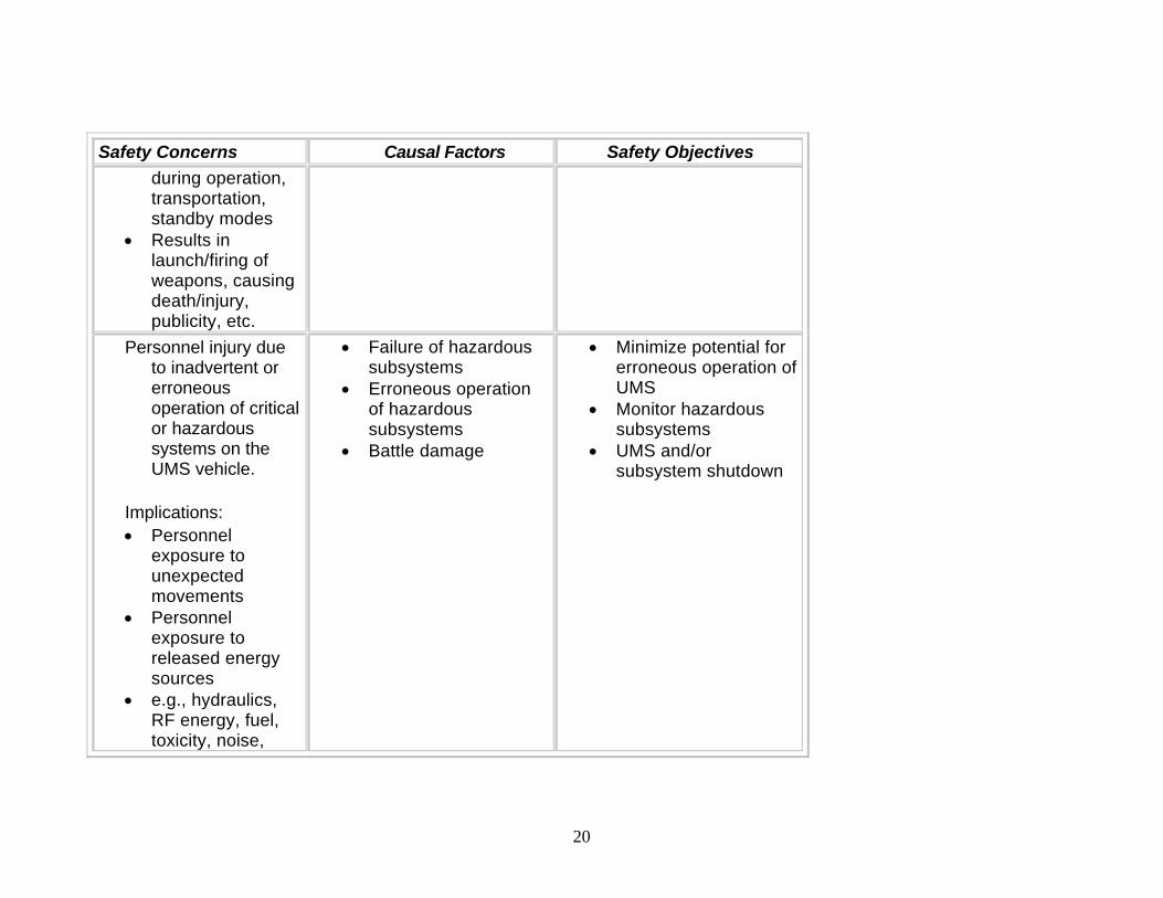
UMS Inadvertently initiates firing of weapon or explosive systems without intent or authorization.
Implications: • Unauthorized
firing of weapons or explosives
• Unintended firing of weapons or explosives
• Risk present
• Failure of critical subsystems
• Communications jamming
• Battle damage • Due to failures,
personnel error, RF energy, etc.
• Minimize potential for inadvertent launch or firing
• Detect and report weapon safe states
20
Safety Concerns Causal Factors Safety Objectives during operation, transportation, standby modes
• Results in launch/firing of weapons, causing death/injury, publicity, etc.
Personnel injury due to inadvertent or erroneous operation of critical or hazardous systems on the UMS vehicle.
Implications: • Personnel
exposure to unexpected movements
• Personnel exposure to released energy sources
• e.g., hydraulics, RF energy, fuel, toxicity, noise,
• Failure of hazardous subsystems
• Erroneous operation of hazardous subsystems
• Battle damage
• Minimize potential for erroneous operation of UMS
• Monitor hazardous subsystems
• UMS and/or subsystem shutdown

21
Safety Concerns Causal Factors Safety Objectives vibration
• Results in personnel injury
Personnel injury due to an unsafe UMS state.
Implications: • UMS enters an
unsafe state • Safety state may
be known or unknown
• UMS must be secured and made safe before mishap
• States may include fire, armed weapon, toxic fumes, erratic movement, etc.
• Results in personnel injury
• Failure of critical subsystems
• Failure of hazardous subsystems
• Loss of unsafe state warning
• Battle damage
• Establish UMS safe states
• Emergency operator stop
• Provide method for awareness of safe state (local & remote)
• UMS and/or subsystem shutdown
UMS vehicle runs over friendly troops or civilians.
• Loss of situational awareness
• Loss of
• Maintain vehicle situational awareness
• Operator awareness

22
Safety Concerns Causal Factors Safety Objectives
Implications: • Due to incorrect
heading, failures, proximity, human error, etc.
• Incorrect situational awareness
• Remote operator unaware of closeness of personnel
• Remote operator error
• Results in personnel death/injury
communications • Loss/failure of critical
subsystems • Operator HSI error
• UMS and/or subsystem shutdown
UMS erroneously fires weapons or explosive systems on friendly troops or civilians.
Implications: • Planned or
authorized firing of weapons or
• Personnel error • Loss of situational
awareness • Failure of critical
subsystems • Battle damage
• Maintain vehicle situational awareness
• Maintain operator in the fire control loop
• UMS and/or subsystem shutdown
23
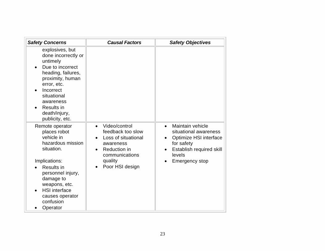
Safety Concerns Causal Factors Safety Objectives explosives, but done incorrectly or untimely
• Due to incorrect heading, failures, proximity, human error, etc.
• Incorrect situational awareness
• Results in death/injury, publicity, etc.
Remote operator places robot vehicle in hazardous mission situation.
Implications: • Results in
personnel injury, damage to weapons, etc.
• HSI interface causes operator confusion
• Operator
• Video/control feedback too slow
• Loss of situational awareness
• Reduction in communications quality
• Poor HSI design
• Maintain vehicle situational awareness
• Optimize HSI interface for safety
• Establish required skill levels
• Emergency stop
24
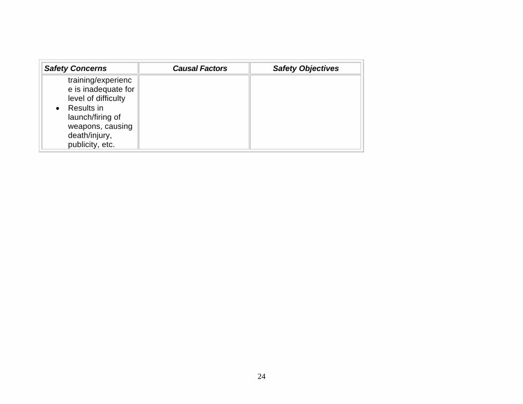
Safety Concerns Causal Factors Safety Objectives training/experience is inadequate for level of difficulty
• Results in launch/firing of weapons, causing death/injury, publicity, etc.

25
Appendix B Listing of the Safety Precepts Programmatic Safety Precepts (PSPs)
PSP-1* The Program Office shall establish and maintain a System Safety Program (SSP) consistent with MIL-STD-882.
PSP-2* The Program Office shall establish unifying safety precepts and processes for all programs under their cognizance to ensure: Safety consistent with mission requirements, cost and schedule. Mishap risk is identified, assessed, mitigated, and accepted. Each system can be safely used in a combined and joint environment. That all safety regulations, laws, and requirements are met.
PSP-3* The Program Office shall ensure that off-the-shelf items (e.g., Commercial Off The Shelf (COTS), Government Off The Shelf (GOTS), Non-Developmental Item (NDI)), re-use items, original use items, design changes, technology refresh, and technology upgrades (hardware and software) are assessed for safety, within the system.
PSP-4* The Program Office shall ensure that safety is addressed for all life cycle phases.
PSP-5 Compliance to and deviation from these safety precepts shall be addressed during all Milestone decisions and formal reviews such as System Requirements Review (SRR), Preliminary Design Review (PDR), and Critical Design Review (CDR).
PSP-6* The Program Office shall ensure UMS designs comply with current safety and performance criteria.
* Denotes applicability to both manned and unmanned systems. Operational Safety Precepts (OSPs)
OSP-1 The controlling entity(ies) of the UMS should have adequate mission information to support safe operations.

26
OSP-2 The UMS shall be considered unsafe until a safe state can be verified.
OSP-3 The authorized entity(ies) of the UMS shall verify the state of the UMS, to ensure a safe state prior to performing any operations or tasks.
OSP-4* The UMS weapons should be loaded and/or energized as late as possible in the operational sequence. OSP-5* Only authorized, qualified and trained personnel with the commensurate skills and expertise, using
authorized procedures, shall operate or maintain the UMS.
Design Safety Precepts (DSPs)
DSP-1* The UMS shall be designed to minimize the mishap risk during all life cycles phases.
DSP-2 The UMS shall be designed to only respond to fulfill valid commands from the authorized entity(ies).
DSP-3 The UMS shall be designed to provide information, intelligence, and method of control (I2C) to support safe operations.
DSP-4* The UMS shall be designed to isolate power until as late in the operational sequence as practical from items such as: a) Weapons, b) Rocket motor initiation circuits, c) Bomb release racks, or d) Propulsion systems.
DSP-5* The UMS shall be designed to prevent release and/or firing of weapons into the UMS structure or other weapons.
DSP-6* The UMS shall be designed to prevent uncommanded fire and/or release of weapons or propagation and/or radiation of hazardous energy.
DSP-7* The UMS shall be designed to safely initialize in the intended state, safely and verifiably change modes and states, and prevent hazardous system mode combinations or transitions.
DSP-8* The UMS shall be designed to provide for an authorized entity(ies) to abort operations and return the system to a safe state, if possible.
27
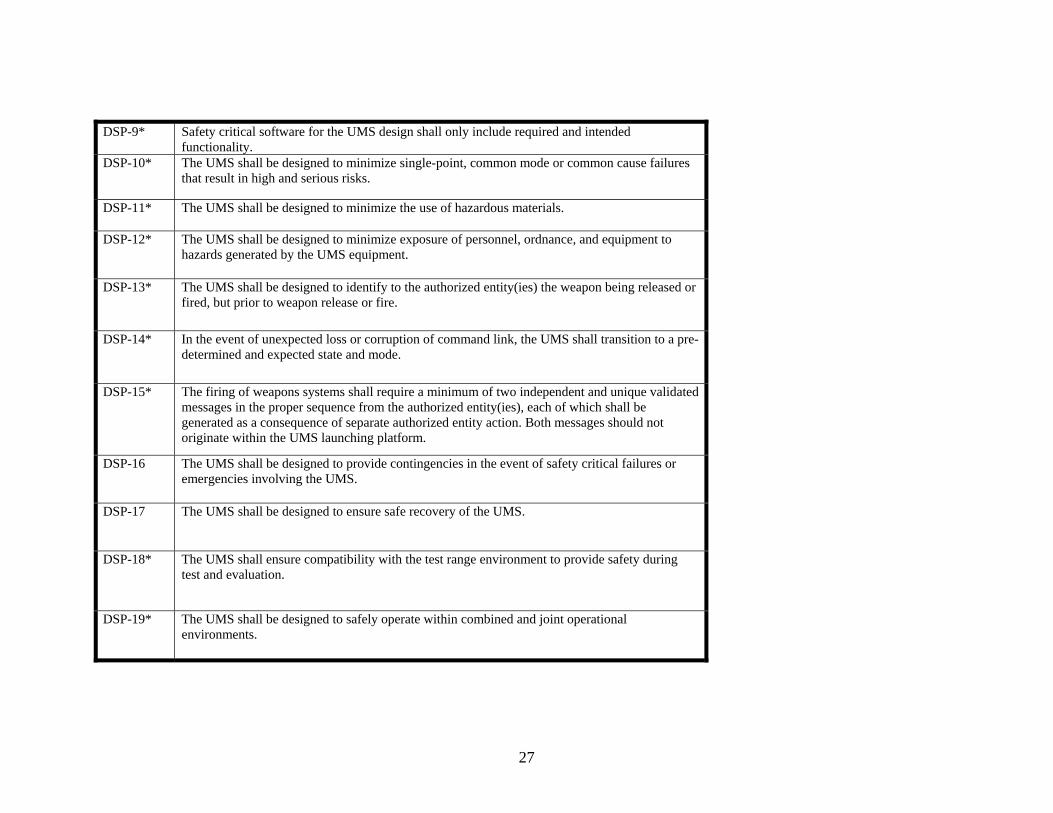
DSP-9* Safety critical software for the UMS design shall only include required and intended functionality.
DSP-10* The UMS shall be designed to minimize single-point, common mode or common cause failures that result in high and serious risks.
DSP-11* The UMS shall be designed to minimize the use of hazardous materials.
DSP-12* The UMS shall be designed to minimize exposure of personnel, ordnance, and equipment to hazards generated by the UMS equipment.
DSP-13* The UMS shall be designed to identify to the authorized entity(ies) the weapon being released or fired, but prior to weapon release or fire.
DSP-14* In the event of unexpected loss or corruption of command link, the UMS shall transition to a pre-determined and expected state and mode.
DSP-15* The firing of weapons systems shall require a minimum of two independent and unique validated messages in the proper sequence from the authorized entity(ies), each of which shall be generated as a consequence of separate authorized entity action. Both messages should not originate within the UMS launching platform.
DSP-16 The UMS shall be designed to provide contingencies in the event of safety critical failures or emergencies involving the UMS.
DSP-17 The UMS shall be designed to ensure safe recovery of the UMS.
DSP-18* The UMS shall ensure compatibility with the test range environment to provide safety during test and evaluation.
DSP-19* The UMS shall be designed to safely operate within combined and joint operational environments.
28
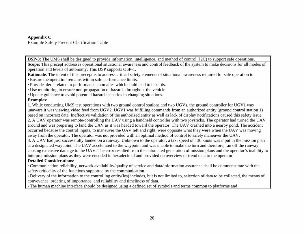
Appendix C Example Safety Precept Clarification Table DSP-3: The UMS shall be designed to provide information, intelligence, and method of control (I2C) to support safe operations. Scope: This precept addresses operational situational awareness and control feedback of the system to make decisions for all modes of operation and levels of autonomy. This DSP supports OSP-1. Rationale: The intent of this precept is to address critical safety elements of situational awareness required for safe operation to: • Ensure the operation remains within safe performance limits. • Provide alerts related to performance anomalies which could lead to hazards. • Use monitoring to ensure non-propagation of hazards throughout the vehicle. • Update guidance to avoid potential hazard scenarios in changing situations. Examples: 1. While conducting UMS test operations with two ground control stations and two UGVs, the ground controller for UGV1 was unaware it was viewing video feed from UGV2. UGV1 was fulfilling commands from an authorized entity (ground control station 1) based on incorrect data. Ineffective validation of the authorized entity as well as lack of display notifications caused this safety issue. 2. A UAV operator was remote-controlling the UAV using a handheld controller with two joysticks. The operator had turned the UAV around and was preparing to land the UAV as it was headed toward the operator. The UAV crashed into a nearby pond. The accident occurred because the control inputs, to maneuver the UAV left and right, were opposite what they were when the UAV was moving away from the operator. The operator was not provided with an optimal method of control to safely maneuver the UAV. 3. A UAV had just successfully landed on a runway. Unknown to the operator, a taxi speed of 130 knots was input in the mission plan at a designated waypoint. The UAV accelerated to the waypoint and was unable to make the turn and therefore, ran off the runway causing extensive damage to the UAV. The error resulted from the automated generation of mission plans and the operator’s inability to interpret mission plans as they were encoded in hexadecimal and provided no overview or trend data to the operator. Detailed Considerations: • Communication reliability, network availability/quality of service and data/information assurance shall be commensurate with the safety criticality of the functions supported by the communication. • Delivery of the information to the controlling entity(ies) includes, but is not limited to, selection of data to be collected, the means of conveyance, ordering of importance, and reliability and timeliness of data. • The human machine interface should be designed using a defined set of symbols and terms common to platforms and
29
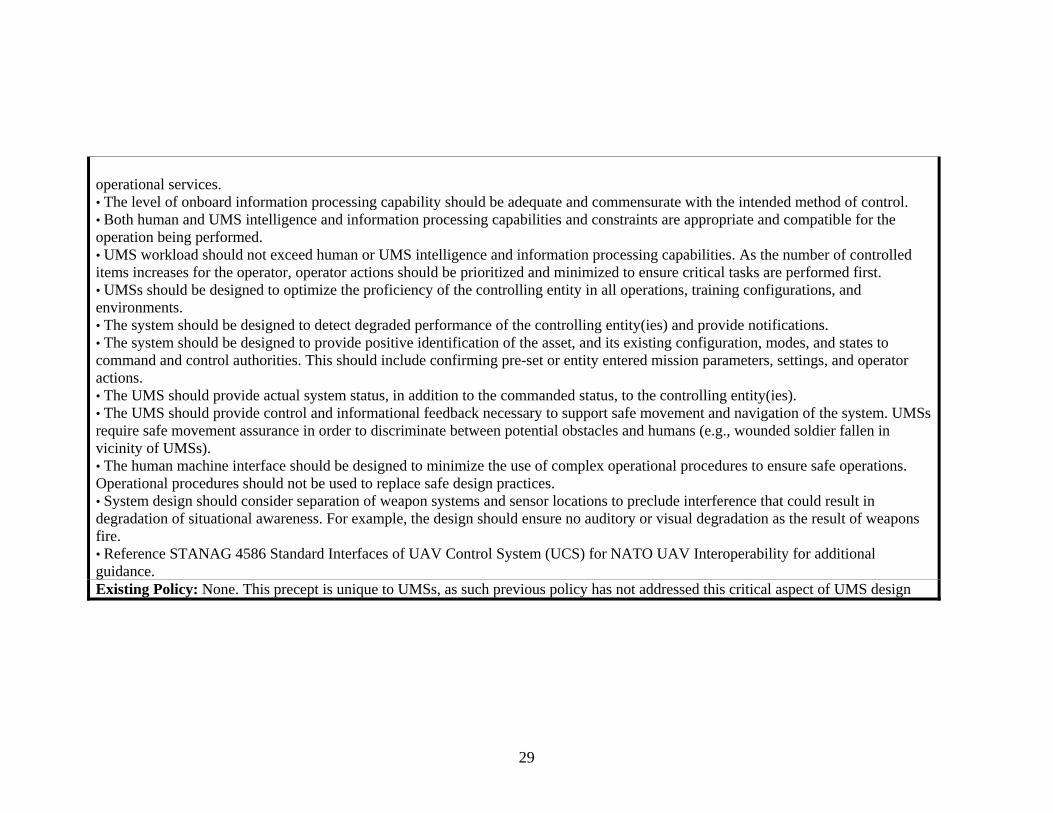
operational services. • The level of onboard information processing capability should be adequate and commensurate with the intended method of control. • Both human and UMS intelligence and information processing capabilities and constraints are appropriate and compatible for the operation being performed. • UMS workload should not exceed human or UMS intelligence and information processing capabilities. As the number of controlled items increases for the operator, operator actions should be prioritized and minimized to ensure critical tasks are performed first. • UMSs should be designed to optimize the proficiency of the controlling entity in all operations, training configurations, and environments. • The system should be designed to detect degraded performance of the controlling entity(ies) and provide notifications. • The system should be designed to provide positive identification of the asset, and its existing configuration, modes, and states to command and control authorities. This should include confirming pre-set or entity entered mission parameters, settings, and operator actions. • The UMS should provide actual system status, in addition to the commanded status, to the controlling entity(ies). • The UMS should provide control and informational feedback necessary to support safe movement and navigation of the system. UMSs require safe movement assurance in order to discriminate between potential obstacles and humans (e.g., wounded soldier fallen in vicinity of UMSs). • The human machine interface should be designed to minimize the use of complex operational procedures to ensure safe operations. Operational procedures should not be used to replace safe design practices. • System design should consider separation of weapon systems and sensor locations to preclude interference that could result in degradation of situational awareness. For example, the design should ensure no auditory or visual degradation as the result of weapons fire. • Reference STANAG 4586 Standard Interfaces of UAV Control System (UCS) for NATO UAV Interoperability for additional guidance. Existing Policy: None. This precept is unique to UMSs, as such previous policy has not addressed this critical aspect of UMS design

1
The Safety of Unmanned Systems:
The Development Unmanned Systems Safety Guide for DOD
AcquisitionDr. Thomas P. English
Naval Surface Warfare Center, Panama City, FLEmail: [email protected]
(850) 235-5403June 2008
2
Agenda
• Why Safety of UMS?• Why UMS System Safety?• Command and Control Issues for UMS• Approach• Road to Completion• Workshop Organization• Precept Definitions• Working Group #3 Situational
Awareness• Summary
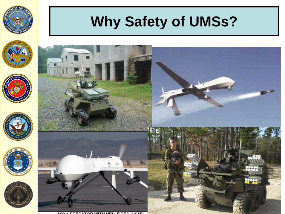
Why Safety of UMSs?
Why UMS System Safety?
Data bool
ean
Time bool
ean
Req
uire
men
ts
Res
pons
ibilt
y
RIGHT 1 RIGHT 1 Sys Eng
RIGHT 1 WRONG 0 Safety
WRONG 0 RIGHT 1 Safety
WRONG 0 WRONG 0 Safety

C2 Issues for UMS
• Weapon Interaction• Software• Communications concepts • Security• Fuzing• Unmanned Systems as systems • Autonomy Levels• Advances in command and control • System of systems• Net Centric warfare
6
Unmanned Systems Leadership
• OSD Sponsor– Mr. Mark Schaeffer, Director,
Systems and Software Engineering & Chairman, DSOC ATP TF
– Dr. Liz Rodriquez-Johnson, Executive Secretary, DSOC ATP TF
7
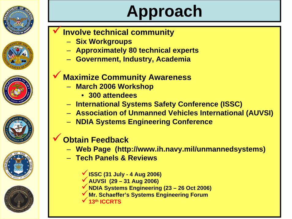
ApproachInvolve technical community– Six Workgroups– Approximately 80 technical experts– Government, Industry, Academia
Maximize Community Awareness– March 2006 Workshop
• 300 attendees– International Systems Safety Conference (ISSC)– Association of Unmanned Vehicles International (AUVSI)– NDIA Systems Engineering Conference
Obtain Feedback– Web Page (http://www.ih.navy.mil/unmannedsystems)– Tech Panels & Reviews
ISSC (31 July - 4 Aug 2006)AUVSI (29 – 31 Aug 2006)NDIA Systems Engineering (23 – 26 Oct 2006)Mr. Schaeffer’s Systems Engineering Forum13th ICCRTS
8
Road to Completion
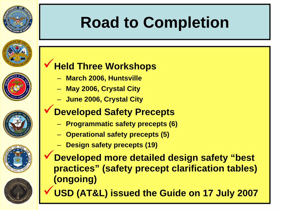
Held Three Workshops– March 2006, Huntsville– May 2006, Crystal City– June 2006, Crystal City
Developed Safety Precepts– Programmatic safety precepts (6)– Operational safety precepts (5)– Design safety precepts (19)
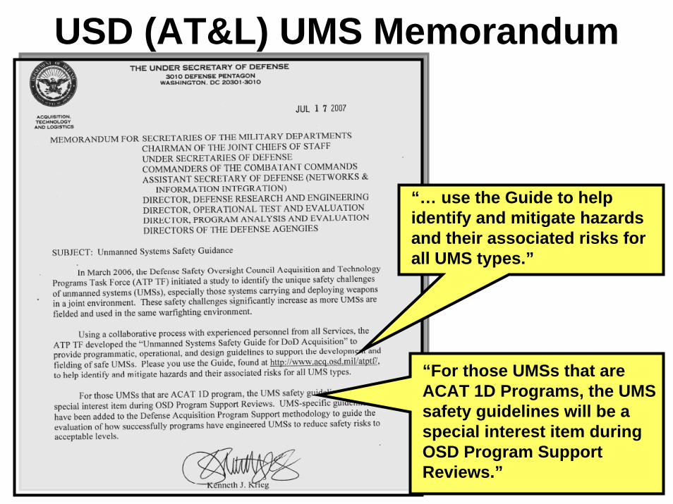
Developed more detailed design safety “best practices” (safety precept clarification tables) (ongoing)USD (AT&L) issued the Guide on 17 July 2007
9
USD (AT&L) UMS Memorandum
“… use the Guide to help identify and mitigate hazards and their associated risks for all UMS types.”
“For those UMSs that are ACAT 1D Programs, the UMS safety guidelines will be a special interest item during OSD Program Support Reviews.”

10
Workshop Organization
Six Workgroups1. Precept Development2. Weapons Control3. Situational Awareness
• Human-Machine Interface• Machine-Machine Interface
4. Command and Control5. States and Modes6. Definitions/Common Taxonomy

11
Programmatic Safety Precept (PSP) = Program management principles & guidance that will help ensure safety is adequately addressed throughout the lifecycle process. (6)
Operational Safety Precept (OSP) = A safety precept directed specifically at system operation. Operational rules that must be adhered to during system operation. These safety precepts may generate the need for Design Safety Precepts. (5)
Design Safety Precept (DSP) = General design guidance intended to facilitate safety of the system and minimize hazards. Safety design precepts are intended to influence, but not dictate, specific design solutions. (19)
UMS Safety Precept Definitions

12
DSP
OSP
PSP
Safety Precepts for UMS
OSD Policy
PM/Operators/User reps
Tailored Guidelines & Best Practices
PM/Industry Design Team
Provide PMs, designers, and systems safety managers with appropriate safetyguidelines and best practices, while maintaining PM’s flexibility
Common Taxonomy/Definitions
WORK GROUP #3Situational Awareness
1 2 3 4 5 6 7 8 9 10
Rem
ote control
Fully autonomous
Human
Human-equivalent
Autonomous control levels
Aw
areness
Challenge - Addressing the Spectrum
Tele-operations
Sem
i-autonomous

1 –H
uman C
ontrol
5 –Allocated C
ontrol
10 –Machine C
ontrol
Human Control
Machine Control
Spectrum of Autonomy Linked to SADenotes individual safety-critical actions for which adequate SA must be defined.
i.e. arm the machine gun, steer to avoid obstructions, discriminate target, …
Position shows whether machine or human must have this SA.
Human SA requires Performance Measurement Criteria to evaluate.Machine SA requires an original characterization since it is not currently defined.
6 –Allocated C
ontrol
9 –Allocated C
ontrol
7 –Allocated C
ontrol
8 –Allocated C
ontrol
4 –Allocated C
ontrol
3 –Allocated C
ontrol
2 –Allocated C
ontrol
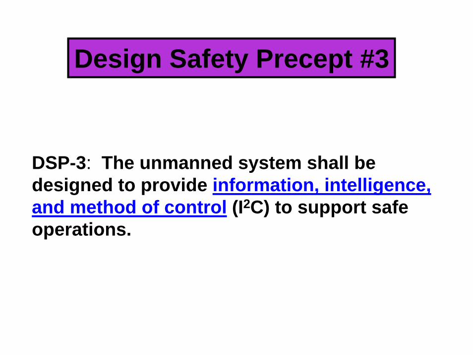
DSP-3: The unmanned system shall be designed to provide information, intelligence, and method of control (I2C) to support safe operations.
Design Safety Precept #3
Definitions:– Information: Knowledge or data necessary for the
safe operation of a UMS; obtained from the process of recognizing and interpreting data in the environment, memory and recall of facts, and/or communication.
– Intelligence: The capacity of a UMS to acquire, comprehend, and apply information.
– Method of control: The means or manner in which an operator interacts, influences, or directs an unmanned system; a function of three non-exclusive system attributes: • Mode of control• Level of authority• Level of control

Definitions (cont):
– Mode of control: The means by which a UMS receives instructions governing its actions and feeds back information.• Remote control• Tele-operation• Semi-autonomous• Fully autonomous

Definitions (cont):
– Level of command authority: The degree to which an entity is invested with the power to access the control and functions of a UMS.• Level I – Reception and transmission of secondary
imagery or data• Level II - Reception of imagery or data directly from the
UMS• Level III - Control of the UMS payload• Level IV - Full control of the UMS excluding
deployment and recovery• Level V – Full control of the UMS including deployment
and recovery
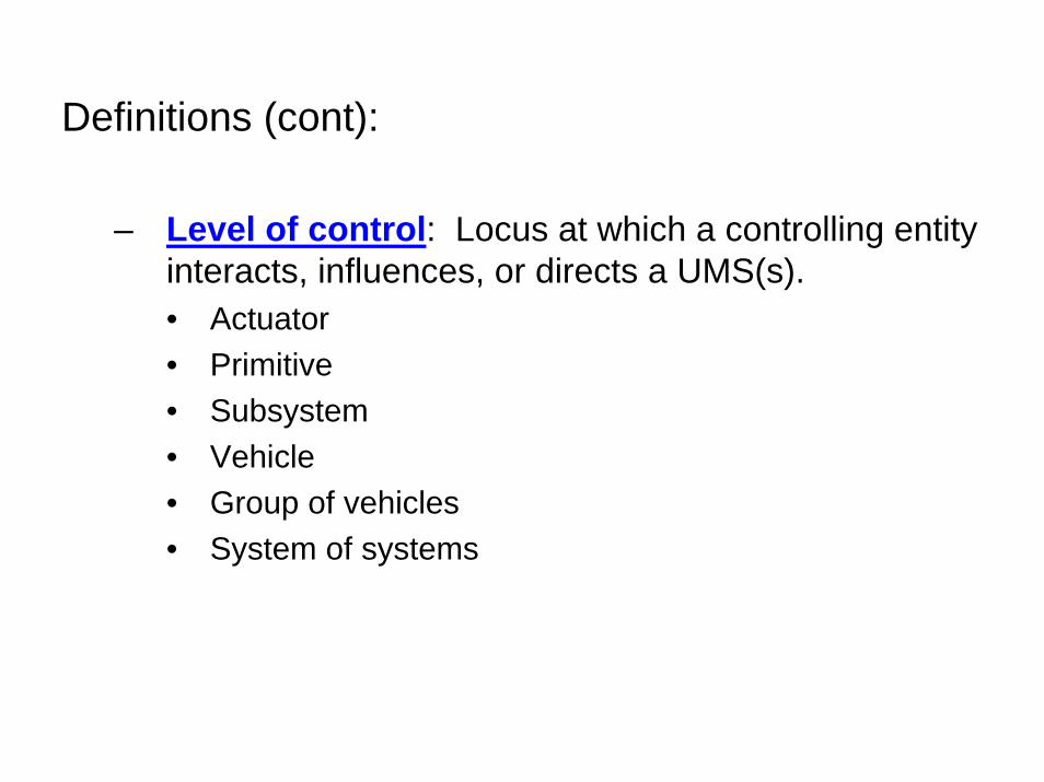
Definitions (cont):
– Level of control: Locus at which a controlling entity interacts, influences, or directs a UMS(s).• Actuator• Primitive• Subsystem• Vehicle• Group of vehicles• System of systems
UMS Command and Control Elements
Rem
ote
cont
rol
Tele
-ope
ratio
n
Sem
i-aut
onom
ous
Fully
aut
onom
ous
Actuator
Primitive
Vehicle
Subsystem
Group
System of systems
Level of Control (LOC)
Mode of Control
(MOC)II
IVIII
I
Level of CommandAuthority(LOCA)
V
22
Questions and Comments