131474-l3 microclip xt om...
TRANSCRIPT

1, 2, 3, and 4-Gas Detector
Operator’s Manual

Limited Warranty and Limitation LiabilityBW Technologies LP (BW) warrants the product to be free from defects in material and workmanship under normal use and service for a period of two years, beginning on the date of shipment to the buyer. This warranty extends only to the sale of new and unused products to the original buyer. BW’s warranty obligation is limited, at BW’s option, to refund of the purchase price, repair or replacement of a defective product that is returned to a BW authorized service center within the warranty period. In no event shall BW’s liability hereunder exceed the purchase price actually paid by the buyer for the Product. This warranty does not include:
a) fuses, disposable batteries or the routine replacement of parts due to the normal wear and tear of the product arising from use;b) any product which in BW’s opinion, has been misused, altered, neglected or damaged, by accident or abnormal conditions of operation,
handling or use;c) any damage or defects attributable to repair of the product by any person other than an authorized dealer, or the installation of unapproved
parts on the product; orThe obligations set forth in this warranty are conditional on:
a) proper storage, installation, calibration, use, maintenance and compliance with the product manual instructions and any other applicable recommendations of BW;
b) the buyer promptly notifying BW of any defect and, if required, promptly making the product available for correction. No goods shall be returned to BW until receipt by the buyer of shipping instructions from BW; and
c) the right of BW to require that the buyer provide proof of purchase such as the original invoice, bill of sale or packing slip to establish that the product is within the warranty period.
THE BUYER AGREES THAT THIS WARRANTY IS THE BUYER’S SOLE AND EXCLUSIVE REMEDY AND IS IN LIEU OF ALL OTHER WARRANTIES, EXPRESS OR IMPLIED, INCLUDING BUT NOT LIMITED TO ANY IMPLIED WARRANTY OF MERCHANTABILITY OR FITNESS FOR A PARTICULAR PURPOSE. BW SHALL NOT BE LIABLE FOR ANY SPECIAL, INDIRECT, INCIDENTAL, OR BASED ON CONTRACT, TORT OR RELIANCE OR ANY OTHER THEORY.Since some countries or states do not allow limitation of the term of an implied warranty, or exclusion or limitation of incidental or consequential damages, the limitations and exclusions of this warranty may not apply to every buyer. If any provision of this warranty is held invalid or unenforceable by a court of competent jurisdiction, such holding will not affect the validity or enforceability of any other provision.
Contacting BW Technologies by Honeywell
Email us at: [email protected] BW Technologies by Honeywell’s website at: www.gasmonitors.com
USA: 1-888-749-8878 Canada: 1-800-663-4164Europe: +44(0) 1295 700300 Other countries: +1-403-248-9226
1
asAlertMicroClip XTo not mix with the solid waste stream. uld be disposed of by a qualified us materials handler.
ion - Read First as specified in this manual and the refer- the protection provided by the detector d the following cautions before using the
a Cautionsution of components may impair
ty reasons, this equipment must be viced by qualified personnel only. tand the user manual completely or servicing.tor before first time use. BW detector be charged after every
detector, refer to Sensor Poisons and
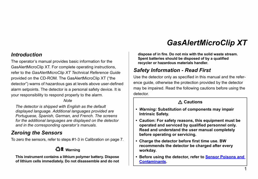
GIntroductionThe operator’s manual provides basic information for the GasAlertMicroClip XT. For complete operating instructions, refer to the GasAlertMicroClip XT Technical Reference Guide provided on the CD-ROM. The GasAlertMicroClip XT (“the detector”) warns of hazardous gas at levels above user-defined alarm setpoints. The detector is a personal safety device. It is your responsibility to respond properly to the alarm.
NoteThe detector is shipped with English as the default displayed language. Additional languages provided are Portuguese, Spanish, German, and French. The screens for the additional languages are displayed on the detector and in the corresponding operator’s manuals.
Zeroing the SensorsTo zero the sensors, refer to steps #1-3 in Calibration on page 7.
ec Warning
This instrument contains a lithium polymer battery. Dispose of lithium cells immediately. Do not disassemble and do not
dispose of in fire. DSpent batteries shorecycler or hazardo
Safety InformatUse the detector onlyence guide, otherwisemay be impaired. Readetector.
• Warning: SubstitIntrinsic Safety.
• Caution: For safeoperated and serRead and undersbefore operating
• Charge the detecrecommends theworkday.
• Before using the Contaminants.

GasOpe
2
• Conexre(6
• ThLEgath
• OinC
• Cga
• It chgaasco
• Bdagaththif
h off-scale readings may indicate an ncentration. scaling reading followed by a declining
ading may indicate a gas concentration upper scale limit, which can be hazardous.posure of the GasAlertMicroClip XT to entrations of combustible gases and ss a detector element that can seriously rformance. If an alarm occurs due to a tration of combustible gases, calibrate . If necessary, replace the sensor.ombustible sensor from exposure to lead
, silicones, and chlorinated hydrocarbons. sure to certain organic vapors (such as line and halogenated hydrocarbons) may inhibit sensor performance. After exposure, or calibration is recommended. in potentially explosive atmospheres n concentrations do not exceed
AlertMicroClip XTrator’s Manual
alibrate the detector before first-time use and then a regular schedule, depending on use and sensor posure to poisons and contaminants. BW commends calibrating at least once every 180 days months).e combustible sensor is factory calibrated to 50% L methane. If monitoring a different combustible s in the %LEL range, calibrate the sensor using e appropriate gas.nly the combustible gas detection portion of this strument has been assessed for performance by SA International.alibrate only in a safe area that is free of hazardous s and in an atmosphere of 20.9% oxygen.
is recommended that the combustible sensor be ecked with a known concentration of calibration s after any exposure to contaminants/poisons such , sulfur compounds, silicon vapors, halogenated mpounds, etc.
W recommends to bump test the sensors before each y’s use to confirm their ability to respond to s by exposing the detector to a gas concentration at exceeds the alarm setpoints. Manually verify that e audible and visual alarms are activated. Calibrate the readings are not within the specified limits.
• Caution: Higexplosive co
• Any rapid upor erratic rebeyond the
• Extended excertain concair may streaffect its pehigh concenthe detector
• Protect the ccompounds
• Sensor expoleaded gasotemporarily a bump test
• For use onlywhere oxyge20.9% (v/v).
GasAlertMicroClip XTParts of the GasAlertMicroClip XT
3
PartDescription
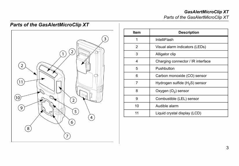
IntelliFlash
Visual alarm indicators (LEDs)
Alligator clip
Charging connector / IR interface
Pushbutton
Carbon monoxide (CO) sensor
Hydrogen sulfide (H2S) sensor
Oxygen (O2) sensor
Combustible (LEL) sensor
Audible alarm
Liquid crystal display (LCD)
s of the GasAlertMicroClip XTItem
1
2
3
4
5
6
7
8
9
10
11

GasOpe
4
Disp
Description
Alarm condition
Automatically zero sensor
Numeric value
Stealth mode
Battery life indicator
Gas identifier bars
Gas cylinder
Automatically span sensor
AlertMicroClip XTrator’s Manual
lay Elements
1
8
7
6
5 4
3
2
Item
1
2
3
4
5
6
7
8

GasAlertMicroClip XTPushbuttons
5
Pus
OFF countdown is complete and the LCD
gs, press C twice. To clear the TWA, STEL, RESET.
nd hold C while the detector performs the riefly deactivates and then begins the CAL
complete.
ess C.
alarm, press C (if the Low Alarm Acknowl-
hbuttonsPushbutton Description
C
• To activate the detector, press C.
• To deactivate the detector, press and hold C until thedeactivates.
• To view the TWA, STEL, and MAX (maximum) readinand MAX readings, press C when the LCD displays
• To initiate calibration, deactivate the detector. Press aOFF countdown. Continue holding C while the LCD bcountdown. Release C when the CAL countdown is
• To activate the backlight while in normal operation, pr
• To acknowledge latched alarms, press C.
• To acknowledge a low alarm and disable the audible edge option is enabled).

GasOpe
6
SenSevecausesolvesors,
Usrec
••••
Below
ased cleanersnitizersetergents l (fuels and antifreezes)
Siliconescleaners and protectants based adhesives, sealants, and gelsdy and medicinal creams containing siliconecontaining siliconeasing agents
Aerosolsllents and spraystsibitorscleaners
AlertMicroClip XTrator’s Manual
sor Poisons and Contaminantsral cleaners, solvents, and lubricants can contaminate and permanent damage to sensors. Before using cleaners,
nts, and lubricants in close proximity to the detector sen- read the following caution and table.
a Cautione only the following BW Technologies by Honeywell ommended products and procedures:
Use water based cleaners.Use non-alcohol based cleaners.Clean the exterior with a soft, damp cloth.Do not use soaps, polishes, or solvents. are common products to avoid using around sensors.
Cleaners and Lubricants• Brake cleaners• Lubricants• Rust inhibitors• Window and glass cleaners• Dishsoaps• Citrus based cleaners
• Alcohol b• Hand sa• Anionic d• Methano
• Silicone • Silicone • Hand/bo• Tissues • Mold rele• Polishes
• Bug repe• Lubrican• Rust inh• Window

GasAlertMicroClip XTCalibration
7
Caliocedure Display
Calihazaoxyg
1.
s, connect the gas o page 8) and apply gas f 250-500 ml/min. t amount of gas has been
oximately 30 seconds), the and flashes tor completes the
2. ys CAL DUE. Next, a showing the number of before calibration is due . The LCD then displays ration due date, as some more frequent
3. he calibration cap during the calibration d for bump tests.
ay cause false readings and poor calibrations.
the detector during or immediately after lete.
brationProcedure Display Pr
a Cautionbrate only in a safe area that is free of rdous gas in an atmosphere of 20.9% en.
Press and hold C as the detector performs the OFF countdown. Continue holding C when the LCD briefly deactivates.
4. When K flashecylinder (refer tat a flow rate oAfter a sufficiendetected (apprdetector beepswhile the deteccalibration.
The LCD then activates again and performs the CAL countdown. Continue holding C until the countdown is complete to enter calibration.
5. The LCD displascreen displaysdays remainingfor each sensorthe earliest calibsensors requirecalibrations.
flashes while the detector zeroes all of the sensors and calibrates the oxygen sensor. If a sensor fails to auto zero, it cannot be calibrated. When auto zero is complete, the LCD displays APPLY GAS.
Note: Only use tspan process an
Wind currents m
Do not calibrate charging is comp

GasOpe
8
Atta
AlertMicroClip XTrator’s Manual
ch the Gas Cylinder to the Detector
GasAlertMicroClip XTBump Test
9
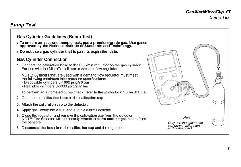
Bum
p Test
GasOpe
10
AlarRefer If Stealth mode is enabled, the audible and visua
Alarm DisplayL•
•
•
•
ing flash
s bar flash
activatesH•
•
•
•
ng flash
s bar flash
activates
M•
•
•
) Alarmd alternating flash
s bar flash
activates
AlertMicroClip XTrator’s Manual
ms to the following table for information about alarms and corresponding screens. l alarms are disabled. Only the vibrator alarm activates.
Alarm Displayow AlarmSlow siren
Slow alternating flash
L and gas bar flash
Vibrator alarm activates
TWA Alarm• Slow siren
• Slow alternat
• L and ga
• Vibrator alarmigh AlarmFast siren
Fast alternating flash
L and gas bar flash
Vibrator alarm activates
STEL Alarm• Fast siren
• Fast alternati
• L and ga
• Vibrator alarm
ulti-Gas AlarmAlternating low and high alarm siren and flash
L and gas bars flash
Vibrator alarm activates
Over Limit (OL• Fast siren an
• L and ga
• Vibrator alarm
• OL displays
GasAlertMicroClip XTAlarms
11
larm DisplaySe•
•
p and IntelliFlash flash every second
ce Beep and omatically ing low battery fail, calibration fail, or an alarm event.
Lo•
•
•
•
own Alarm0 rapid sirens and alter-with 1 second of silence quence reactivates
L display, and activates
efore deactivatinget to latching or non-latching. To enable/disable ct Latching Alarms in Fleet Manager II. Local re a latching alarm. ledge is enabled and a low alarm occurs, press C
alarm. The visual and vibrator alarms remain escalates to a high, STEL, or TWA alarm, the tes.
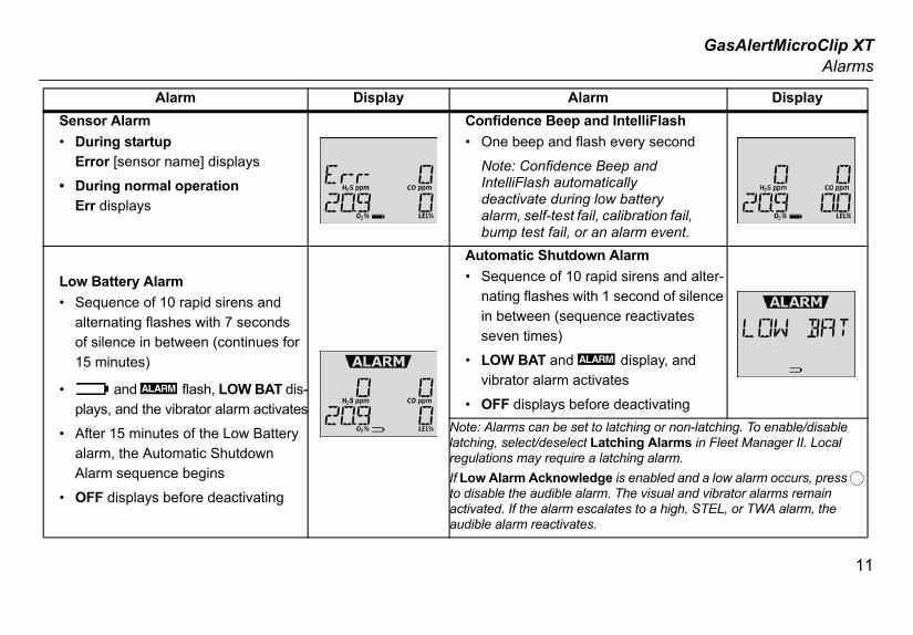
Alarm Display Ansor AlarmDuring startupError [sensor name] displays
During normal operationErr displays
Confidence Bee• One beep and
Note: ConfidenIntelliFlash autdeactivate duralarm, self-testbump test fail,
w Battery AlarmSequence of 10 rapid sirens and alternating flashes with 7 seconds of silence in between (continues for 15 minutes)
and L flash, LOW BAT dis-plays, and the vibrator alarm activates
After 15 minutes of the Low Battery alarm, the Automatic Shutdown Alarm sequence begins
OFF displays before deactivating
Automatic Shutd• Sequence of 1
nating flashes in between (seseven times)
• LOW BAT andvibrator alarm
• OFF displays bNote: Alarms can be slatching, select/deseleregulations may requiIf Low Alarm Acknowto disable the audibleactivated. If the alarmaudible alarm reactiva

GasOpe
12
UseTo madapII Op
The f
1. S
terval (minutes): Defines the short-term expo-t (5-15 minutes). H2S and CO sensors only.ro Startup: When enabled, the detector auto- zeros the H2S, CO, and LEL sensors during p self-test.
Volume CH4: When enabled, the LEL reading ed as %vol., assuming a methane environ-
-Calibration on Startup: When enabled, the O2 automatically calibrated during startup.s
nce Beep: When enabled, the detector beeps ry second to verify the battery has sufficient detect hazardous gas and emit an alarm. is shipped with Confidence Beep disabled. Alarms: When enabled, the audible, visual, tor alarms persist during a high or low alarm
gas concentration is below the low alarm set- has been acknowledged by pressing C.
de: When enabled, SAFE continuously displays D when all gas concentrations are
r below the alarm setpoints.ode: When enabled, the audible alarm, LEDs
light are disabled. displays on the LCD.
AlertMicroClip XTrator’s Manual
r Options Menuodify the user options, connect the detector to the IR Link ter and open Fleet Manager II. Refer to the Fleet Manager erator’s Manual for complete instructions.
ollowing are the available user options:
ensors (H2S, CO, LEL, and O2)
• Sensor Disabled: Disables the sensor.• Calibration Gas (ppm) / (%LEL) / (%O2): Defines the
calibration gas concentration for each sensor.• Calibration Interval (days): Defines how often a cali-
bration should be performed.• Bump Interval (days): Defines how often a bump test
should be performed.• Low Alarm (ppm) / (%LEL) / (%O2): Defines the low
alarm setpoint.• High Alarm (ppm) / (%LEL) / (%O2): Defines the high
alarm setpoint.• TWA Alarm (ppm): Defines the time-weighted average
(TWA) alarm setpoint. H2S and CO sensors only.• STEL Alarm (ppm): Defines the short-term exposure
limit (STEL) alarm setpoint. H2S and CO sensors only.
• STEL Insure limi
• Auto-Zematicallythe startu
• LEL By is displayment.
• O2 Autosensor is
2. User Option
• Confideonce evepower toDetector
• Latchingand vibrauntil the point and
• Safe Moon the LCnormal o
• Stealth Mand back
GasAlertMicroClip XTCharging the Detector
13
liFlash Interval. Default setting is 1 second. is shipped with IntelliFlash enabled.nce Beep and IntelliFlash Interval: Enter a 60 seconds) to define how often IntelliFlash nd the detector beeps. Intelliflash and/or Confi-eep must be enabled in order to define Confi-eep and IntelliFlash Interval.e: Select the language to display on the LCD:
Français (French), Deutsch (German), Espa-nish), or Português (Portuguese).
e Detector
a Warningfacturer can replace the battery. Failure to
caution can lead to fire and/or explosion. a safe area that is free of hazardous gas peratures of 0°C-45°C (32°F-113°F).
adapter is specific to your region. Use of the ter outside your region will damage the e detector.
te during or immediately after charging.
• Low Alarm Acknowledge: When enabled, the audible alarm can be disabled during a low alarm. The vibrator, LEDs, and LCD remain enabled. For H2S, CO, and LEL sensors only.
• Datalog Interval (seconds): Enter a value (5-120 sec-onds) to define how often a datalog is recorded. Datalog interval cannot be defined with configuring the detector with the IR Link.
• Force Calibration When Overdue: When enabled, the detector automatically enters calibration during startup for overdue sensors. If the sensors are not calibrated immediately, the detector will deactivate.
• Cal Lock: When enabled, the sensors can only be cali-brated using an IR device (IR Link with Fleet Manager II or the MicroDock II base station).
• Force Bump When Overdue: When enabled, a bump test is required if the sensor has exceeded its bump test interval. If a successful bump test is not performed, the detector will deactivate.
• IntelliFlash: When enabled, the green LED flashes to provide continuous visual confirmation that the detector is operating correctly. IntelliFlash automatically deactivates during a low bat-tery alarm, a self-test fail, a calibration fail, a bump test fail, or during an alarm event. To define how often Intel-liFlash occurs (1-60 seconds), refer to Confidence Beep
and IntelDetector
• Confidevalue (1-occurs adence Bdence B
• LanguagEnglish,ñol (Spa
Charging th
Only the manuadhere to thisCharge only inand within temThe charging charging adapcharger and thDo not calibra
GasOpe
14
To ch the battery to charge for 2-3 hours.
ch full battery capacity, allow the battery charge and discharge three times.
e the battery after each workday.
e detector in good operating condition, perform ic maintenance as required.
, bump test, and inspect the detector on a chedule. an operations log of all maintenance, bump librations, and alarm events. e exterior with a soft damp cloth. Do not use , soaps, or polishes.
ensor or Sensor Filtera Warning
onal injury, use only sensors specifically he detector.D handling practices.
a Caution are clean or wear gloves before handling
AlertMicroClip XTrator’s Manualarge the battery, complete the following:
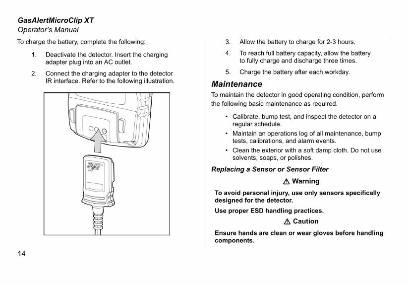
1. Deactivate the detector. Insert the charging adapter plug into an AC outlet.
2. Connect the charging adapter to the detector IR interface. Refer to the following illustration.
3. Allow
4. To reato fully
5. Charg
MaintenancTo maintain the the following bas
• Calibrateregular s
• Maintaintests, ca
• Clean thsolvents
Replacing a S
To avoid persdesigned for tUse proper ES
Ensure handscomponents.

GasAlertMicroClip XTMaintenance
15
To reillustr
ivate the detector. On a clean surface, place the or face down.
ve the six machine screws from the rear shell. ve the back cover by lifting the top and the upwards simultaneously to prevent damaging
arging pins.
Description
Front shell
LEL sensor
PCB
PCB screws (2)
Rear shell
Machine screws (6)
Sealing rib
CO sensor
H2S sensor
O2 sensor
Sensor filter
place a sensor or sensor filter, refer to the following ation, table, and procedures.
1. Deactdetect
2. RemoRemobottomthe ch
Item
1
2
3
4
5
6
7
8
9
10
11
GasOpe
16
Repl , CO, and LEL sensor
he placement of the PCB to ensure it is ed correctly. Remove the two screws on the Remove the PCB carefully.
a Cautionre no damage occurs to the battery.ensor filter is stuck to the sensors, remove and e the sensor filter into the front shell.
he sensors out.
Notehat are configured for 1, 2, or 3 gases may ummy sensor in one of the four sensor
the new sensor(s).
plete the detector, refer to Reassembling the or.
AlertMicroClip XTrator’s Manualacing the sensor filter1. Note the placement of the PCB to ensure it is
replaced correctly. Remove the two screws on the PCB. Remove the PCB carefully.
a CautionEnsure no damage occurs to the battery.
2. Remove the old sensor filter. It may be stuck to the sensors.
3. Place the new sensor filter.
NoteWhen inserting a new sensor filter, ensure the black gasket is facing the front shell.
4. To complete the detector, refer to Reassembling the detector.
Replacing H2S
1. Note treplacPCB.
EnsuIf the sreplac
2. Slide t
Detectors tcontain a dlocations.
3. Insert
4. To comdetect
GasAlertMicroClip XTMaintenance
17
Repl he placement of the PCB to ensure it is ed correctly. Remove the two screws on the
a Cautionre no damage occurs to the battery.
PCB straight up. The oxygen sensor will stay front shell. Remove the sensor.
ghly the same spot on the front shell, place the ensor. Lower the PCB over the oxygen sensor.
e the purple plastic sensor post is inserted into ar plastic hole. Carefully replace the circular
ed flex PCB atop the metal sensor posts. Take ot to tear the flex cable.
down to secure the circular rigidified flex PCB e metal sensor posts.
plete the detector, refer to Reassembling the or.
the detector PCB is seated correctly and inserted exactly
removed (sensors face the front shell). the two PCB screws.
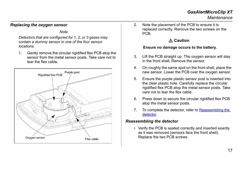
acing the oxygen sensorNote
Detectors that are configured for 1, 2, or 3 gases may contain a dummy sensor in one of the four sensor locations.
1. Gently remove the circular rigidified flex PCB atop the sensor from the metal sensor posts. Take care not to tear the flex cable.
2. Note treplacPCB.
Ensu
3. Lift thein the
4. On rounew s
5. Ensurthe clerigidificare n
6. Pressatop th
7. To comdetect
Reassembling• Verify the
as it wasReplace
GasOpe
18
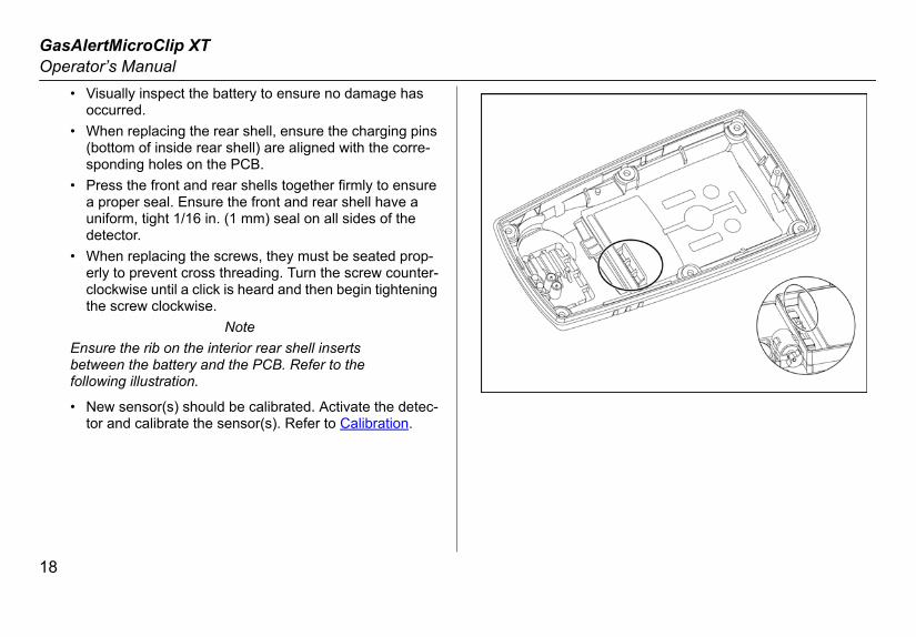
AlertMicroClip XTrator’s Manual• Visually inspect the battery to ensure no damage has
occurred.• When replacing the rear shell, ensure the charging pins
(bottom of inside rear shell) are aligned with the corre-sponding holes on the PCB.
• Press the front and rear shells together firmly to ensure a proper seal. Ensure the front and rear shell have a uniform, tight 1/16 in. (1 mm) seal on all sides of the detector.
• When replacing the screws, they must be seated prop-erly to prevent cross threading. Turn the screw counter-clockwise until a click is heard and then begin tightening the screw clockwise.
NoteEnsure the rib on the interior rear shell inserts between the battery and the PCB. Refer to the following illustration.
• New sensor(s) should be calibrated. Activate the detec-tor and calibrate the sensor(s). Refer to Calibration.

GasAlertMicroClip XTSpecifications
19
SpeInstru(4.4 x
Weig
Oper+50°Ccomb
Stora
Operdens
Alarmsetpo
Detec
H2S: CO: 0O2: 0Comb0 - 5.
Sens
H2S, Comb
rinciple: Capillary controlled concentration
s: TWA alarm, STEL alarm, low alarm, high alarm, over limit (OL) alarm, low battery alarm, , automatic shutdown alarm
95 dB at 30 cm (1 ft.) (100 dB typical) variable
ed light-emitting diodes (LED)
umeric liquid crystal display (LCD)
ates for 5 seconds when the pushbutton is ing an alarm condition
d during activation
omatic zero and automatic span
: Automatic span on activation (enable/disable)
ns: Startup message, confidence beep, latch-le/disable safe display mode, oxygen mea-ustible sensor measurement, sensor disable, n interval, force calibration, calibration lock, ne bump interval, bump due lock, stealth mode, ion, enable/disable automatic oxygen calibra-ble auto zero at startup, define alarm setpoints, centration values, define STEL calculation
cificationsment dimensions: 11.25 x 6.00 x 2.89 cm 2.4 x 1.1 in.)
ht: 170 g (6.0 oz.)
ating temperature: -20°C to +58°C (-4°F to +136°F), to +58°C is certified by CSA International on the
ustible sensor with ±5% accuracy
ge temperature: -40°C to +50°C (-40°F to +122°F)
ating humidity: 0% to 95% relative humidity (non-con-ing)
setpoints: May vary by region and are user defined. All ints automatically display during the startup self-test.
tion range:
0 - 100 ppm (1 / 0.1 ppm increments) - 500 ppm (1 ppm increments) - 30.0% vol. (0.1% vol. increments)ustible (LEL): 0 - 100% (1% LEL increments) or
0% v/v methane
or type:
CO, O2: Single plug-in electrochemical cellustibles: Plug-in catalytic bead
O2 measuring psensor
Alarm conditionalarm, multi-gasconfidence beep
Audible alarm: pulsed beeper
Visual alarm: R
Display: Alphan
Backlight: Activpressed and dur
Self-test: Initiate
Calibration: Aut
Oxygen sensor
User field optioing alarms, enabsurement, combdefine calibratioforce bump, defilanguage selecttion, enable/disadefine span con
GasOpe
20
perioand I
Battebatte
Year deterber aE.g.,
ApprApproNara
RechLithiu
Batte
First-
Norm
Warr
ApprApproCAN/ANS/CSA
9 g II 1 G Ex ia IIC T4 Ga 06ATEX005679-0, EN 60079-11, and EN 60079-26C T4 Ga IECEx CSA 05.0015079-0, IEC 60079-11, IEC 60079-26as been tested and found to comply with the limits tal device, pursuant to Part 15 of the FCC Rules nadian EMI requirements. These limits are de reasonable protection against harmful interfer-tial installation. This equipment generates, uses dio frequency energy and, if not installed and used h the instructions, may cause harmful interference cations. However, there is no guarantee that inter-cur in a particular installation. If this equipment
ful interference to radio or television reception, rmined by turning the equipment off and on, the d to try to correct the interference by one or more easures:
relocate the receiving antenna. separation between the equipment and receiver. equipment into an outlet on a circuit different from the receiver is connected.
dealer or an experienced radio/TV technician for
AlertMicroClip XTrator’s Manuald, low alarm acknowledge, IntelliFlash, confidence beep, ntelliFlash interval
ry operating time: 1 rechargeable lithium polymer ry 10 hours (typical)
of manufacture: The detector's year of manufacture is mined from the serial number. The second and third num-fter the first letter determines the year of manufacture.KA410-001000 = 2010 year of manufacture
oved batteries:ved batteries for GasAlertMicroClip XT:
da NL 503759 and BYD Type SL503759
argeable battery Temperature codem polymer -20°C ≤ Ta ≤ +50°C T4
ry charger: GasAlertMicroClip XT charging adapter
time charge: 2-3 hours
al charge: 2-3 hours
anty: 2 years including sensors
ovals:ved by CSA to both U.S. and Canadian Standards
CSA C22.2 No. 157 and C22.2 152UL - 913 and ANSI/ISA - S12.13 Part 1
Class I, Division 1, Group A, B, C, and D
ATEX CE 053KEMA EN 600
IECEx Ex ia IIIEC 60
This equipment hfor a Class B digiand ICES-003 Cadesigned to provience in a residenand can radiate rain accordance witto radio communiference will not ocdoes cause harmwhich can be deteuser is encourageof the following m
• Reorient or • Increase the• Connect the
that to which• Consult the
help.

iERP: 131474-L3D6567/0 [English]© BW Technologies 2010. All rights reserved.