(13) on trenchless moling tr;als at carmer wood, laughton ... · at carmer wood, laughton,...
TRANSCRIPT

Technical Report WD/91/69
RADIAL COLLECTOR WELLS IN ALLUVIUM PROJECT: Final Report (13) on Trenchless Moling Tr;als at Carmer Wood, Laughton, lincolnshire.
B L Morris, J C Talbot and 0 M J Macdonald

This report has been generated from a scanned image of the document with any blank pages removed at the scanning stage. Please be aware that the pagination and scales of diagrams or maps in the resulting report may not appear as in the original

r------ --~- ----
This report was prepared for the OVerseas Development Administration
ONERe copyright 1991
BRITISH GEOLOGICAL SURVEY Natur al Environment Research Co uncil
TECHNICAL REPORT WD/91/69
Hydrogeology Series
Technical Report WD/91/69
RADIAL COLLECTOR WELLS IN ALLUVIUM PROJECT: Final Report (#3) on Trenchless Moling Trials at Carmer Wood . Laughton, Lincolnshire.
B L Morr i s, J C Talbot and D M J Macdon al d
Keyworth, Nottinghamshire British Geological Survey 1991

BRITISH GEOLOGICAL SURVEY
The full range of Survey publications is available through the Sales Desks at Keyworth, Murchison House, Edinburgh, and at the BGS London Information Office in the Geological Museum. The adjacent Geological Museum bookshop stocks the more popular books for sale over the counter. Most BGS books and reports are listed in HMSO's Sectional List 45, and can be bought from HMSO and through HMSO agents and retailers. Maps are listed in the BGS Map Catalogue and the Ordnance Survey's Trade Catalogue, and can be bought from Ordnance Survey agents as well as from BGS.
The British Geological Survey carries out the geological survey of Great Britain and Northern Ireland (the latter as an agency service for the government of Northern Ireland), and of the surrounding continental shelf, as well as its basic research projects. It also undertakes programmes of British . technical aid in geology in developing countries as arranged by the Overseas Development Administration.
The British Geological Survey is a component body of the Natural Environment Research Council.
Keyworth, Nottingham NGl2 5GG ~ Plumtree (06077) 6111 Telex 378173 BGSKEY G
Fax 06077-6602
Murchison House, West Mains Road, Edinburgh EH9 3LA
~ 031-667 1000 Telex 727343 SEISED G Fax 031-6682683
London Information Office at the Geological Museum, Exhibition Road, South Kensington, London SW7 2DE
~ 071-589 4090 Fax 071-584 8270 ~ 071-9389056/57
19 Grange Terrace, Edinburgh EH9 2LF ~ 031-667 1000 Telex 727343 SEISED G
St Just, 30 Pennsylvania Road, Exeter EX4 6BX
~ Exeter (0392) 78312 Fax 0392-437505
Bryn Eithyn Hall, Llanfarian, Aberystwyth, Dyfed SY234BY ~ Aberystwyth (0970) 611038 Fax 0970-624822
Windsor Court, Windsor Terrace, Newcastle upon Tyne NE24HB ~ 091-281 7088 Fax 091-281 9016
Geological Survey of Northern Ireland, 20 College Gardens, Belfast BT9 6BS ~ Belfast (0232) 666595 Fax 0232-662835
Maclean Building, Crowmarsh Gifford, Wallingford, Oxfordshire OXIO 8BB ~ Wallingford (0491) 38800 Telex 849365 HYDROL G
Fax 0491-25338
Parent Body Natural Environment Research Council Polaris House, North Star Avenue, Swindon, Wiltshire SN2 lEU ~ Swindon (0793) 411500 Telex 444293 ENVRE G
Fax 0793-411501

EXECUTIVE SUMMARY
This report documents the results of the field trials carried out by BGS on behalr or OOA~to deve16p-an° rntetmed'iate~ technolog-y mettrodof constructing collector wells in unconsolidated sandy alluvium. A system has been developed which uses a thrust-boring mole of the type now in common use in the construction industry to install sub-surface service mains without excavation. The system has been developed with the aim of ut il is i ng the groundwater resources which are present in thin shallow uncemented sandy aquifers but whose exploitation by borehole or shaft-only dugwell would be marginal due to small available drawdowns and moderate to low permeabilities. Mesh-wrapped plastic screen is emplaced inside jacked-out temporary steel casing which is then retracted under a small positive hydraulic head in order to avoid sandlocking and formation ingress into the main shaft. 38 mm 10 pipe has been used, and rapid autodevelopment by the radials has provided coll~ctors with yields of 1.5 lis/radial from fine running sands. Arrays have been emplaced to over 20 m length with a 98 mm ~ head at jacking forces of less than 7 tonnes f. The equipment required for the construction of the collectors is light to transport and install and significantly less expensive than a downhole rotary drill ing rig to buy and operate. The method is however restricted _ to uoconsolidated_ fine-grained alluvium, as the method is essentially one of formation displacement, not removal.

Contents
EXECUTIVE SUMMARY
l.
2.
3.
4.
5.
6.
INTRODUCTION
BACKGROUND TO PRESENT PHASE OF WORK
2.1 Suitability of Collectors in Thin Shallow Alluvial Aquifers
2.2 Site Details
2.3 Evolution of Different Thrust-boring Approaches
2.4 Chronology of Screen-within-casing Trials
2.5 Timetable of Fieldwork
MAIN FEATURES AND PERFORMANCE COMMENTS OF S-W-C SYSTEM
3.1 Pilot Push-head
3.2 Disposable End-cap
3.3 Plastic Permanent Casing and Screen
3.4 Push Rods
3.5 . Steel Temporary Casing
3.6 Access Plates and Wall Mountings
3.7 Screen E~placement Accessories
3.8 Shuttering
RESULTS
4.1 Thrust-boring with Pilot Push-head
4.2 Thrust-boring with 73 mm ~ Casing
4.2.1 73 mm ~ Head and 73 mm ~ Casing 4.2.2 98 mm ~ Head and 73 mm ~ Casing
4.3 Productivity Rates of Radial Construction
4.4 Summary of Thrust-boring Results
4.5 Timetabling Collector Construction by S-W-C Method
CONCLUSIONS
RECOMMENDATIONS
REFERENCES
ACKNOWLEDGEMENTS
APPENDICES
1
1-4
1
1
2
3
3
4-8
4
5
5
6
6
7
8
8
9-12
9
10
10 11
12
12
12
13-14
15-16

1. INTRODUCTION
This report"describes the~work carried out by BGSAuring 1990 and early 1991 to develop a thrust-boring method of horizontal screen emplacement in collector wells. The trials form part of a programme to provide a practical and economical method, suitable for Third World application, of constructing radial collector wells in shallow unconsolidated sandy alluvial aquifers. This research project is undertaken on behalf of the Overseas Development Administration as part of the UK aid programme.
2. BACKGROUND TO PRESENT PHASE OF WORK
2.1 Suitability of Collectors in Thin Shallow Alluvial Aquifers
Although the borehole can be a most efficient method of groundwater extraction in unconso 1 i dated all uv i a 1 aqu i fers, there are spec i a 1, but not uncommon, circumstances where a collector well would be more suitable for groundwater extraction than either a normal dug well or a borehole. This is where the aquifer is shallow, thin and of low to moderate permeability. In this environment daily yields are·controlled on the one hand by available drawdowns (frequently only 2 or 3 metres) and on the other by the rate of recovery after pumping. The large effective radius of shaft plus radials in a collector well can make it a hydraulically efficient method of maximising daily yields. In comparison with a shaft-only dugwell or a borehole, the presence of radial collectors tends both to minimise the drawdown in the main shaft and to maximise the subsequent recovery rate (Herbert, 1990).
A small drawdown would be especially important, for instance, where salinisation due to up-coning could occur, as in coastal littoral sand aquifers. Similarly, the rate of recovery after daily pumping could decide the viability of a small-farm irrigation scheme, where cumulative residual drawdown needs to be mi ni mi sed over a crop wateri ngseason. Gi ven a pract i cal and rapid method of radial construction using inexpensive simple equipment, shallow alluvial collector wells could be economically constructed in this hydrogeological environment.
While a method had been developed early in the project of installing radials by telescoped jetting, using a specially-constructed rotary drilling rig (Allen, 1988), it was felt that a simpler, lighter and cheaper method could be devised which would be suitable for fine-grained aquifer environments, whose lower permeabilities would result in yields that were worthwhile but insufficient to merit the capital-intensive rotary drilling method.
2.2 Site Details
All field research and development for this part of the project was conducted in the UK at a site whose groundwater conditions are representative of such an environment.
Carmer Wood, where the site is located, is an area of Forestry Commission woodland situated near Laughton, north Lincolnshire. It is located on the eastern edge of the alluvial sequence which makes up the Quaternary floodplain deposits of the lower Trent valley (Figure 1). At the site a clay aquiclude underlies a shallow localised watertable aquifer. This completely unconsolidated fine to medium sand is up to 6.5 m thick, about 4.5-5.5 m of which is saturated at anyone time depending on season (Morris and Talbot, 1990). During short periods of pumping (2 days or less) the aquifer behaves like a semi-unconfined two layer system, the lower layer of which is a zone of moderate permeability with an average transmissivity of c. 20 mIld (Morris, 1991).
1

o
4
3
2
MSL 0
-1
-2
-3
-4
25'
-5 Drift
-6
N
0.5 krn
1:25000
Outcrop area of First Trent Terrace Deposits
/ I
/
Western edge of tp.rlra" •• -~
outcrop (below overburden to west of this line)
eW8
Figure-l. CarmerWood location map & borehole sections showing continuity of First Terrace Sands aquifer
-----E"!:tp.I'n feather edge of terrace (not present to east)
TARGET AQUIFER: 1. Unconsolidated V 2. Pebble-free V 3. Fine to medium sands V 4. DTW <3.0m V 5. Saturated thickness >3 <6m V 6. Uniform thickness across site V
• IMAU Boreholes
• Trials Site

2.3 Evolution of Different Thrust-boring Approaches
A thrust~bori ng ~f'ie ld· tri a,l conducted~ i n_~Eebruary 1990 .. usi ng a.IO~mm~dj ameter pilot push-head and standard 45 mm diameter push rods had showed that pipejacki ng from a dewatered 1 arge di ameter we 11 out into the saturated zone several metres below the water table was both practicable and rapid (Morris and Talbot, 1990). Jacking advance and withdrawal rates of over 1 m/min to 20 m radial length were attained with low to moderate formation resistances which were observed to lie well within the capacity of both thrust-borer and reinforced concrete well-lining.*
The simplest and most economical field arrangement for installing permanent collector screen/filter pipe with thrust-boring equipment involves coupling plastic pre-slotted casing to a disposable push head, telescoping the push rods inside, progressively jacking the whole array out to the required length, then retrieving the rods from within the emplaced screen. This rod-within·screen system was tried (Morris and Talbot 1990), and although the array was successfully jacked out to 8.5 m from the main shaft, insurmountable problems of sand-locking between rods and filter pipe were encountered. Excessive deterioration of the plastic screen was observed, and it was suspected that this had -in part occur-red during driving of the array. In addition, an· excessive quantity of sand was admitted to the main shaft, requiring laborious removal and causing problems with the dewatering pump.
Field experience gained during this phase pointed to the need to not only protect the screen duri ng emplacement but also to devi se an arrangement whereby formation pressure coul d be prevented from i ntroduci ng sand-l aden water into the filter/borer array during advance and withdrawal of the radial.
As a result, an alternative field arrangement was proposed in which the position of the screen and the thrust-boring tools was effectively inverted. After completing a pilot push, the push rods would be replaced by steel -temporary water well casings, the disposable end~cap being loose-coupled andconnected to mesh-wrapped plastic screen telescoped inside the casing. This screen-within-casing system, illustrated in Figure 2A, would have two main advantages:
(a) It woul d permit the screen to be emplaced ina protected fash.i on in dry conditions. Also sand ingress problems during the first half of the operation would be effectively avoided.
(b) The' problem of sand-locking as the casing was withdrawn around the screen would be prevented by overcoming the difference in head between the (dewatered) main shaft and the (saturated) collector emplacement zone whi ch caused i nfl ow and mobil i sed the sand. By effect i ve ly isolating the screen/casing annulus from the main shaft it would be possible to reverse the hydraulic gradient so that water flowed outward into the aquifer, not inward into the shaft. This was achieved by connecting the screen outlet at the main shaft via a hose to a water tank situated at the surface. The' tank would act as a simple pressure device maintaining a small positive head over that in the aquifer outside the shaft (Figure 2B).
The arrangement descri bed above offered the prospect of rapid install at i on and the continued use of plastic casing, both important constructional factors affecting the economics of the system.
* The performance of the push-head and push rod combination used for the pilot boring exercise is referred to in more detail in section 4, where various arrays are considered).
2

A During pilot push and screen emplacement phases
Fine IIId mediJm sand aquifer
dian concrete caisson chamber
Timber slarttering
Cast access hole in penultimete caisson ring C/W access plate mountings
\ ~~~~F=~==~~\===»
Optional dewatering sump set in ~~-fT::":";..:.::lI.U reinforced concrete impermeable
Push array ce.:nprises either (il Pilot head + 45mm ND rods lor pilot push or (iij Saaificial head + 73mm DO casing enclosiRg screen for atiual colletlor emplacement phase base
Heavy duty plywood composiIB quadrants with steel decking liner
B During temporary casing withdrawal phase
Leakage dewatering pump . Uncoupled lengths of steel casing threaded up semi-rigid hose and laid progressively between tank and weD head
Figure 2A/B. Working layout in main shaft
Water bowser ac:ts as header tank '\
~--::-~-~-~-=-=-:-:-=-
Small positive hydraulic head, inflow rate controUed by gate valve on he~ tank .

The trials described in this report were all designed to test the viability, and subsequently to improve the practicability, of the screen-within-casing thrust,:-,hortng system.
2.4 Chronology of Screen-within-casing Trials
Although lightweight portable thrust-boring moles are now in routine use in the UK for the installation of service pipes and cable ducting below highways and railway lines, their use below the water table is novel, and the project needed to devise a number of new techniques to render the method practicable. For this reason the field trials of the method were conducted on an empirical basis.
Early work concentrated on devising a functional constant head system which would keep at bay the running sand which had proved so troublesome during both emplacement and withdrawal phases of the rod-within-screen trials. In the event, most effort was required at the well shaft end, devising a practical method which would enable the casings to be withdrawn over the screen without losing the -positive head within the array through flow back along the screen/casing annulus into the well.
- --
Later work sought to perfect a reliable system of casing emplacement to the 20 mt which had been shown during the prel iminary work to be so easily attainable with rods and the pilot push head. This proved to be a much less tractable problem but in the event gave rise to some of the most interesting results of the whole project.
2.5 Timetable of Fieldwork
19/2/90-23/2/90 Pilot moling of L6: dummy push head t 45 mm , rods.
26/2/90-1/3/90
7/30/90-8/3/90
22/3/90-23/3/90
26/3/90-28/3/90
8/5/90-17/5/90
25/6/90-27/6/90
23/7/90-25/7/90
10/9/90-14/9/90
Attempted roo-in-screen-insertion int6; -- insuperable dewatering problems.
Dewatering problem finally solved (after trying several different pump types and arrays), using Flygt hydraulic submersible pump.
Selected access hole plate mountings installed.
Rod-in-screen method attempted again on L6; very severe sand locking problems during several attempts indicated method not viable.
Pilot head diameter increased to 73 mm ,; screen-in-casing and constant head system tried on L6 with just 10 casings; withdrawal successful but unwieldy and protracted; screen mobile due to fluidised bed conditions. Full advance attempted on L5 but excessive push resistance halted progress due to slippage of casing in jaw grip. Short L5 radial installed.
Remaining lower access hole mountings installed by improved method.
Screen-in-casing attempted in L3 after pilot rod push; standard casing observed to deform permanently at moderate push forces; need for thickwall casing indicated.
Pumping test on CW2 for formation characteristics.
3

14/1/91-17 /1/91
4/2/91-7/2/91
21/2/91-22/2/91
Screen-in-casing using heavy duty pipe tried on L1 after pilot rod push; exceesive push resistance encountered; short L~1 radial installed-;--head redesign indicated.
Heavy duty casing + redesigned oversize head tried successfully on U3; process repeated on U4 and U2 using various pilot push combinations. 118 m of moling completed in 3 days, 78 m of which using 73 mm diameter casing.
Well CW8 capped; site cleared.
3. MAIN FEATURES AND PERFORMANCE COMMENTS OF SCREEN-WITHIN-CASING SYSTEM
The early trials of the screen-within-casing system showed that there was scope for considerable improvement in methodology. The objectives were to simplify both the procedures and the accessories required. The rate of installation would therefore be speeded up and, combined with the relatively low capital cost of the equipment, this would result in a reduced unit cost per radial when compared with conventional rotary drilling methods.
The designs of the pilot push head and the disposable end-cap evolved together during the field trials and are shown diagrammatically in Figure 3.
3.1 Pilot Push-head
Description.
These were fabricated from mild steel and comprised a stepped conical head of the same dimensions as the disposable end-cap, a shank and a 6 tpi 1%" UNC male thread to fit standard 45 mm ND push-rods. For the early work, through the 75 mm access holes in the concrete chamber ring, a 73 mm head was used (modified slightly from the rod-within screen trials), while a 98 mm head was employed for the later work in the 100 mm access holes. No significant wear on thread or end-faces was detected on any of the heads other than a mild 'sandbasting' effect, even though both sizes were used repeatedly on different pushes.
Comments.
Throughout the trials, a separate pilot push-head and disposable end-cap were employed, mainly because each required distinct thread types and dimensions (Photo Figures 4A, 48). However, there is merit in combining the functions of pil ot push and screen emplacement ina s i ngl e head by converting the pushfit part of the disposable head into a thread adaptor, Figure 5 shows the recommended final head design, incorporating improvements arising from the project's experiences. Its use would simplify the procedure in the well as the head, once it has driven out the mortar plug into the formation, would never be completely retracted back into the main shaft. The changeover from one head to another is a delicate operation, and results in a short period during which the access hole has to be unblocked, providing an opportunity for sand ingress while the pipe-jack jaws are changed to accommodate the larger radius of curvature of the steel temporary casing. A combined head would practically eliminate the problem and minimise sand ingress during the transfer from rod to casing, as the head could be chocked in the access hole as a temporary plug while the pipe-jack jaws are changed over.
Also, the head could be usefully fabricated in aluminium to reduce weight and minimise the tendency towards downward deflection by gravity which is a risk in any horizontal drilling operation in unconsolidated formations; the materials cost of mild steel or aluminium combined head would be about £14 and £23 respectively (UK 4/91 prices). A two-part dual function push-head would involve overall no more machining than separate heads, although the cost per radi~l would be slightly higher as both parts would in effect be disposable.
4

73mm
1
DESCRIPTION: 73mm diam. flush fit head. push fit retention in BW casing. 38mm NO screen coupling
FUNCTION: Screen emplacement
PERFORMANCE: Unsuccessful. excessive formation resistance on advance
DESCRIPTION: 98mm diam. oversize head. HD BW casing"coupling
FUNCTION: Simulated screen emplacement (exterior geometry would' be identical)
98mm
PERFORMANCE: Significant improvement "over flush fit version. formation resistance" reduced even further if preceded by pilot push
Scale approx 1 :2
73mm
1
98mm
oDESCRIPTION:o 73mmdiam. head. 45mm NO rod coupling
FU~CTION: Pilot push
PERFORMANCE: Successful. low. formation resistance 'during,'both advance and retraction '
f r 6O.5mm 55mm
1 !
DESCRIPTION: 98mm diam. oversize head. 45mm NO
lYt. __ rod coupling
_____ -~~~~j.H-H_I FUNCTION: Pilot push
----- --HH,HHH-H PERFORMANCE: Successful; disproportionately small
J/JI\JA.LI\JAI,I 'increase in resistance over 73mm head
Figure 3 Developmental sequence of push-head design
------ ----- --

Figure 4A
Pilot push-head with 45 mm NO push rods.
Figure 48
Screen emplacement end-cap with 73 mm DO steel casing.

--- ---81 J ----I ._,.. j
r-I I L
L ____ '
F
--, ....................... . /--H--.-I I I /--tf--.-
__ J-N" ... A ... "" ........ 'J
t-
-'\I\l\flTUUtn, I I I I I I I I
I I
__ nnnTutllnl
_II I I A __ E'
__ -t _ ' - _' __ ML-..-_..lL __ M
[ \ i
fEATURES
I I
I~ G ~I Scale approx 1 :2'
A Pilot push and screen emplacement functions united in single head to minimise sand ingress to well; after,pilot push ,with 45mm NO rods, combined thread adaptor and positive head'push fit device is coupled for emplacement phase
B Th!ck walled 73mm 00 casing pipe, First length butts against shoulder of push head
C' Head OD-to-shank ratio maximised to ~ 1.8 to take advantage of pressure relief effect and minimise formation resistance on both advance and withdrawal
o Bevel on outer most step to, act as guide during mortar plug displacement, to minimise risk of driving out plastic access hole liner in front of push-head
E Shank widened and tool flats added to help grip head during final rod uncoupling and change over to adaptor
F 20mm diameter hole bored out of centre and complete head fabricated in aluminium to reduce weight by '>50% and to minimise tendancy to downward deflection by gravity
G Dimension G to coincide with actual thickness of concr~te well wall so that push-head functions as temporary plug during change over from pilot push to screen emplacement phase
, \
Figure 5 Final push-head design, incorporating improvements suggested during field trials

3.2 Disposable End-cap
Description.
These were: fabri cated from mil d steel and compri sed three main elements (Photo Figure 6):
(i)
( i i )
A leading edge whose general geometry approximated to a stepped cone. The stepped design is widely employed on moling tools, where ambient conditions may involve operation in pebbly soils or in made ground containing rubble or backfill. Industry experience has shown that deflection in non-uniform granular materials by larger fragments is less with a stepped cone than with a smoothed conical shape. 73 mm and 98 mm diameter heads were used in 75 mm and 100 mm access holes respectively. The larger diameter heads were developed towards the end of the project when little field time and funding remained, and so for operational reasons they were made up threaded to fit the casing. This was in order to concentrate on the problem of formation resistance (Photo Figure 7).
A loose-fitting shank was made sand- and water-tight with a double Dring channel. The diameter of the prel iminary version was kept constant at 60 mm to fit standard BW casing throughout the modification stages in order to reduce project machining costs, but the shank would normally be turned 0.5 mm undersize to fit the heavyduty casing bore of 55 mm.
(iii) A 6 tpi square thread was required to fit the commercially available ,38 mm ~ plastic casing which was used throughout the screen-in-casing trials.
Comments.
If the pilot head and end-cap were combined, parts (ii) and (iii) of the pushhead would be made up with a 6 tpi 1%" UNC female thread in the form of an adaptor, to be coupled to the forward part of the head prior to the screen emplacement phase and after the pilot push. The snug fit in the shaft access hole engendered by a leading edge only 2 mm undersize permitted the head to serve as a temporary plug during rod to casing changeover, but one operational problem resulted, in that in one instance the plastic mould which is set in the access hole during chamber ring construction was driven out in front of the push-head, caus i ng excess format i on res i stance duri ng the advance and increased sand leakage into the shaft. The risk of this occurring would be much reduced by bevelling the outermost step of the push-head (feature 0 of Figure 5).
3.3 Plastic Permanent Casing and Screen
Description.
47.8 mm 00 x 38.2 mm ID plastic pipe was used as both plain casing and perforated basepipe for the mesh-wrapped screen. The MGS Geoscreen comprised 0.75 m lengths of basepipe slotted at 750 ~m and sleeved with 150 ~m double mesh Georap geotextile plastiC mesh. The arrangement during insertion and withdrawal phases is shown schematically in Figures 8A and 8B.
Comments.
Coupling the first length of screen directly behind the disposable push-head was found to cause problems during temporary casing withdrawal, as the screen array would not stay in place while the casing was retracted around it. The reason was that outflow through the screen into the aquifer from the positive head system was so effective that it created fluidised bed conditions at the
5

Figure 6.
Figure 7.
Disposable end -cap is a sliding fit inside leading temporary casing , made sand- and watertight with O-ring seals .
98 mm 0 pilot and simulated screen emplacement push-heads, access plates, quadrant sections and plug; used to test efficiency of oversize head design.

I
A). During Insertion Plastic mesh-wrapped well-screen I Screen OD48mm . I
Sacrifici~1 push-head. sliding fit inside . ..;.' ................ ' '.' . .. • .' . Screen ID 38mm I BW casing; impermeable seal ProVided~':':':'::::':':':':-::'::':':-:::::"':':"::-"'" .Approx. screen and mesh 00 54m~::g:'" ••..•• ' .• ' .•.•.• '. ~ ~ •• ri.p .. : ... .,.: :::;:;::/:;/§/i'li-:' : . :.: ... '.': .:.:.:. "::':': .:.: .:. ::::::. :::::.: co::::::::: ':f:':::":: ::::::~::: ::::::: .... :::,:::. :':: (::/::: ;::':' :::::~:::.:
::":':},k:"::::::\":":'::':::::-:';::: '0.75m length casing I :::;:::.::': ." . to anchor radial and I ::'::.:::::' pu.sh-head at start of. I .::. :,'........ • Withdrawal I '.:>.:'::.:.; . .; .. ' ..... 10;":" I
"::;::: leading:B,,:- ' I .:- .: .•..•. Stepped...:· : •
• • edge .::.'.:::.:.~ A7tV x;;;J '. ::::):::::;:/t:< :::::::., .::::::::::::::':':: %.ii .... :·: ::.':':': ':::'::::'., : ...... ~. ~ ........ ~ '.' .. ' .. ' ~
Plai~ (unthreadedf '.:::' ::::::::::-::': .::::;;:.;.: ••••• ~.;::::: ::::::::::-::::: >Steel B~ fI~sh-coupled water- .: :::::: ::: ::;:: ;:: :::::::.~ NOT TO SCALE leading edge of •.. , .... ' '.' •. , . '.' '.' ........... well casing •• :.:: •. ::-:.::.: ··.·:-:·::·:.:::::·.:·:·:·:;;.1
casing Dimensions Standard 00 73.2mm I . ID60.5mm I
B). During Withdrawal
Heavy-duly '00 73,Omm, I ID55.0mm I
I I I
.. ' ........ I ...... :::: .. :::::'0Ji::::::::?:!lA.T.U~~~E.~.~.QlIl~.E~ .~~.~.~'.'~I~N.::~
.. :::;{?!~t!!@MY :;:'::::::<//i/:}::=::·:/ft:?/:;::·:·~ii: . __ . . ...... . ::':::;'k:'::::::::::'::::"':':"~ -"' ~~
:.::.::,' .' .' Net outflow of water ~ 1 :::::;::- . avoids formation ingress ..A
.:.::.... . and sand locking rL ".::::': ::: ::::: :::: .. ;:.: .. ':-: ... ' .... ..•.. ...•. .. ~ ~ •••• "I
··::::~/{f!!{i;i~!fg?:7:::<:::=:::·::::~:}i>:;:::~}rt/;?':?{1!::( .~ NOT TO SCALE
Casing drawn back over screen" leaving sacificial push-head in place as entl-cap
1.5mm thick aluminium access - plate held in place by wing nuts
, on spit-Iype stud fixings
.: III Concrete wall of LD well ~ Rubber washer helps retain formation I -. -. " I I as access plate is disturbed during
advance ~
I "","screen and steel casing added I simultaneously as jacking proceeds
I I I I
I :'. ". '. :. '.::¥: Casing coupled via hose to k~::\~~:~l r.::·:.:·~V.:.::: constant head tank at well
: .... : :"':-1 head '2 \ i __ _
'::ii"':":'~~:11 :;:[;{\j I:::~ .....
Combined hose! casing thread adaptor and tamporalY plug riw '0' ring seal; to maintain positive hydraulic head inside BW casing during withdrawal phase
Figure SA/B: Schematic arrangement of array to emplace 3Smm ID mesh- wrapped plastic screen collectors
J
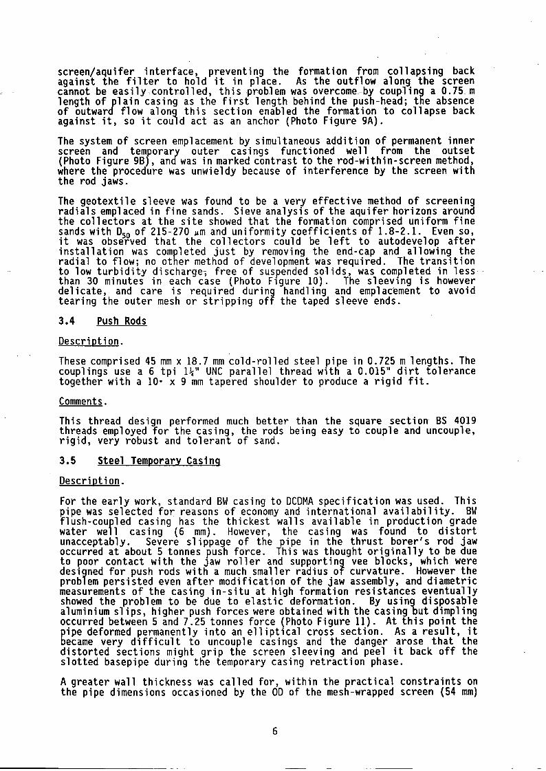
screen/aquifer interface, preventing the formation from collapsing back aga i nst the fil ter to hold it in place. As the out flow along the screen cannot~be easily~contY'olled, ~this problem-was overcome=by.coupling a 0.75_m length of plain casing as the first length behind the push-head; the absence of outward flow along this section enabled the formation to collapse back against it, so it could act as an anchor (Photo Figure 9A).
The system of screen emplacement by simultaneous addition of permanent inner screen and temporary outer casings functioned well from the outset (Photo Figure 9B), and was in marked contrast to the rod-within-screen method, where the procedure was unwieldy because of interference by the screen with the rod jaws.
The geotext il e sleeve was found to be a very effective method of screeni ng radials emplaced in fine sands. Sieve analysis of the aquifer horizons around the collectors at the site showed that the formation comprised uniform fine sands with D50 of 215-270 ~m and uniformity coefficients of 1.8-2.1. Even so, it was observed that the collectors could be left to autodevelop after installation was completed just by removing the end-cap and allowing the radial to flow; no other method of development was required. The transition to low turbidity discharge, free of suspended solids, was completed in less than 30 minutes in each case (Photo Flgure 10). The sleevlng is however delicate, and care is required during handling and emplacement to avoid tearing the outer mesh or stripping off the taped sleeve ends.
3.4 Push Rods
Description.
These comprised 45 mm x 18.7 mm cold-rolled steel pipe in 0.725 m lengths. The couplings use a 6 tpi nil UNC parallel thread with a 0.015" dirt tolerance together with a 10· x 9 mm tapered shoulder to produce a rigid fit.
Comments.
This thread design performed much better than the square section BS 4019 threads employed for the casing, the rods being easy to couple and uncouple, rigid, very robust and tolerant of sand.
3.5 Steel Temporary Casing
Description.
For the early work, standard BW casing to DCDMA specification was used. This pipe was selected for reasons of economy and international availability. BW flush-courled casing has the thickest walls available in production grade water we 1 casing (6 mm).However, the casing was found to distort unacceptably. Severe slippage of the pipe in the thrust borer's rod jaw occurred at about 5 tonnes push force. This was thought originally to be due to poor contact with the Jaw roller and supporting vee blocks, which were designed for push rods with a much smaller radius of curvature. However the problem persisted even after modification of the jaw assembly, and diametric measurements of the casing in-situ at high formation resistances eventually showed the problem to be due to elastic deformation. By using disposable aluminium slips, higher push forces were obtained with the casing but dimpling occurred between 5 and 7.25 tonnes force (Photo Figure 11). At this point the pipe deformed permanently into an elliptical cross section. As a result, it became very difficult to uncouple casings and the danger arose that the distorted sections might grip the screen sleeving and peel it back off the slotted basepipe during the temporary casing retraction phase.
A greater wall thickness was called for, within the practical constraints on the pipe dimensions occasioned by the OD of the mesh-wrapped screen (54 mm)
6
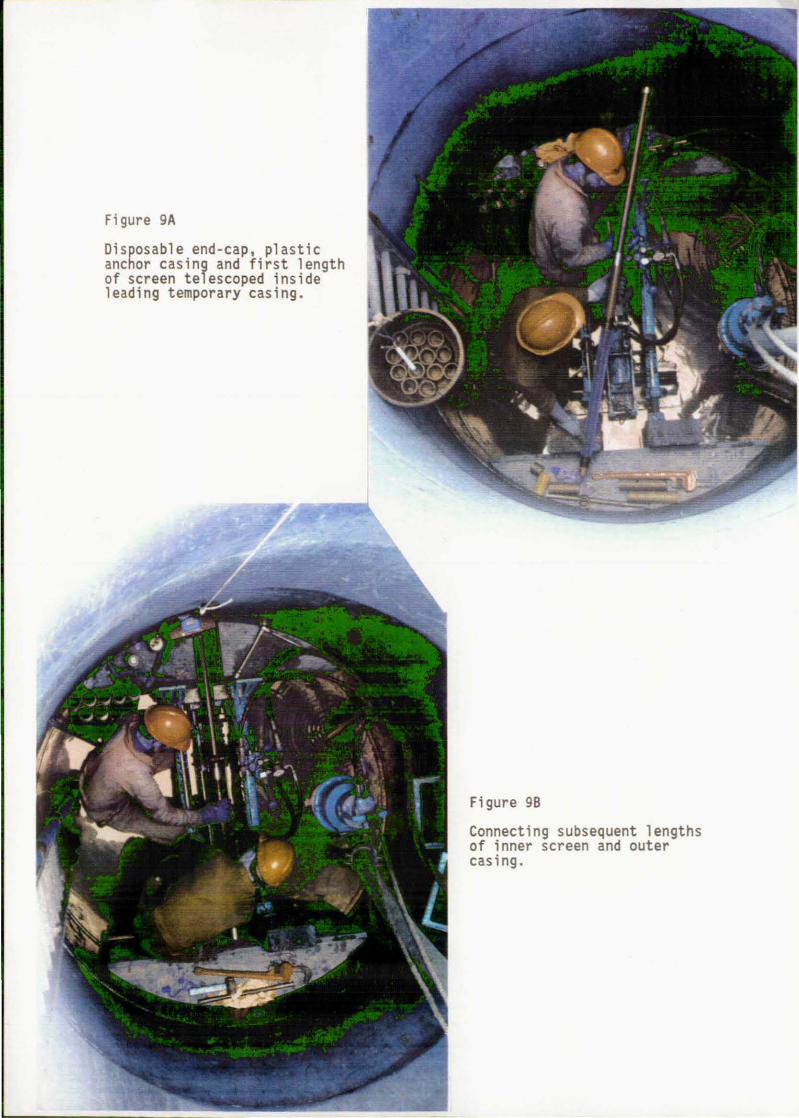
Figure 9A
Disposable end-cap, plastic anchor casing and first length of screen telescoped inside leading temporary casing.
Figure 9B
Connecting subsequent lengths of inner screen and outer casing.

Figure 10.
Figure 11.
Radial development by free flow. Note low turbidity and suspended solids content after only 20 minutes development.
Standard weight BW casing deformed, scored and dimpled by moderate thrust-borer jaw pressure.

and the 10 of the access holes in the perforated chamber ring (75 mm). The nearest available stock pipe size of 55 mm 10 and 73 mm 00 in machining grade steel was~used- to "t:ab~~icate- ac non,.standard heavy duty casing, "pr:odudng" a 50% increase in wall thickness to 9 mm. A sample of this pipe tested on the thrust-borer prior to threading showed neg1 igib1e r1astic deformation over the anticipated working range of 0-14 tonnes force, a though dimpling occurred at about 11 tonnes force.
Comments.
Although the heavy duty casing did not fail even though subjected to 14 tonnes push force during the trial push of 15 January 1991, its routine use at formation resistances greater than about 10 tonnes is not possible. The onset of dimpling is a much severer handicap with thickwa1l pipe as the screen is a close fit inside, the clearance being only 0.5 mm compared with 4.5 mm using standard gauge BW casing. In practice therefore no dimpling is permissible, and as the jaw grips the pipe in proportion to the resistance encountered, an emplacement method which avoids subjecting the casing to formation resistances in excess of about 9-10 tonnes force is a prerequisite. This was achieved by redesign of the head (see section 4).
It had been noted that there occurred a disproportionate increase in formation resistance between pilot push with 73 mm ~ head and 45 mm ~ rods and screen emplacement push with the same diameter head and 73 mm ~ casing (i.e. a head flush with the casing). The requirement to keep formation resistance as low as possible led to reconsideration of the geometry of the original push head array, to see whether, by redesign, the disproportionately high formation resistances could be overcome. In the event this was achieved by increasing the head maximum diameter, so that a pressure re1 ief effect was created immediately behind the outermost step (see Feature C, Figure 5). A head-toshank diameter ratio of 1.8 was found to be effective.
3.6 Access Plates and Wall Mountings
Description.
The plates were fabricated from 1.5 mm thick aluminium so that they could deform sl ight1y if necessary during advance or retraction, without scoring the rods or casings. Two sizes were required for each radial, with 49 mm ~ and 73 mm ~ centre holes to fit push-rod and steel casing respectively (Figure 12A). The 49 mm ~ plate size was also used on completion of the collector as a convenient means of retaining the permanent annular spacer.
Initially wall mountings were drilled using an air hammer and expanding bolts but this was found to be laborious and imprecise because the drill centre point could not be controlled. As the chamber ring around each access hole is heavily reinforced with iron reinforcing bars set in the concrete during casting, it was important to be able to drill each mounting accurately with the minimum hole size to avoid spalling of the access hole edges. This was achieved using a proprietary drop-in fixing and HOv lightweight rotary percussion drill (Spit drill and anchors) together with stainless steel 8 mm ~ studs cut to size (Figure 12A). Excellent rigid mountings were rapidly obtained using this method.
Comments.
It was found that the ingress of formation sand around and through the access plates could be cut quite drastically by the simple expedients of (a) placing a sheet rubber sl ight1y undersize gasket between plate and we" wall and (b) rolling the plate to give a slight curvature matching that of the
3well
wa1l. As a result sand ingress was reduced by over 75% from about 1 m per traverse during the early trials.
7

Not to scale
DESCRIPTION: 4 nos. proprietary brand steel female .thread drop-in fixings (Spit Anchors); 4 nos. stainless steel threaded 8mm diam.studs c/w wide shoulder washers and wing nuts.
FUNCTION: retention of access hole cover plates
Plate rolled to give curvature matching that of . well wall minimises fonnation ingress
OJsmm - Way-up mark 0
·0 o Scale approx 1 :2
DESCRIPTION: 3 nos. aluminium 1.5mm thick access . hole cover plates; 2 nos. with 49mm diam. centre hole, 1 no. with 73mm diam. centre ·hole.
FUNCTION: Formation retention; 1). during pilot push 2). during screen emplacement 3). on completion of radial, to retain
permanent annular plug
Figure 12A Accessories developed during field trials to facilitate radial collector emplacement by thrust-boring method

There is a strong incentive to reduce sand entry at all stages of collector construction. Excessive wellhead subsidence could cause differential settling aod stress on the chamber rings comprising the ma;,n well shaft.- Also, _each or of wet sand weighs 2 tonnes. Its removal has to be performed manually to avoid dama~e to the protruding pipes of previously installed radials and it is a laborlous task. It is necessary to clean the well at the completion of each radial, in order to be able to set up the thrust-borer correctly opposite the next access hole, so with the limited space available in a 2 m ~ shaft, excessive sand requires that all shuttering and accessories be removed in order to clean out the well.
While an efficient means of constructing wall mountings was developed for these trials, there is no reason why the wall mountings should not be cast into the perforated chamber ring along with the access holes in a large scale collector well programme, or drilled into the perforated ring section prior to well construction.
3.7 Screen Emplacement Accessories
Description.
A temporary adaptor fabricated from PVC was required, to be coupled in-line to the final length of plas.tic casing (Figure 12B). Its function was to
. maintain the slight positive head inside the temporary casing/screen annulus during retraction, by preventing water washing back out of the screen into the well. A flushfit bleed device using an Allen screw and a hose thread adapter were combined into the same fitting.
On ·comp 1 et i on of temporary cas i ng retraction around the header tank hose (Photo Figure 13), a PVC annular permanent plug was pushed into place by the thrust-borer as a loose sliding fit around the plastic sanitary casing, before mounting the fitted access plate (Figure 12B).
A threaded collector end-cap was used to cap each radial after completion and development.
Comments.
Early adaptor couplings without the bleed device suffered from airlocks due to the air trapped in the casing array after the water-filled hose had been coupled.
Unlike the standard BW casing which was used initially and had to be rejected, the heavy-duty casing which replaced it was found to have an irregular bore, and the original 1.5 mm diam medium density rubber O-rings were replaced with a 5 mm di ameter soft vari ety whi ch functioned adequately. For rapid and troub 1 efree retract i on however, a smoot.h un iform bore temporary cas i ng is considered indispensable.
A quickly-detachable 48 mm ~ wooden casing clamp which could be held manually or with chocks would assist retention of the screen array in place during retraction of the first few lengths of temporary casing (Figure 12B).
3.8 Shuttering
Description.
Arc-shaped wooden quadrants with heavy-duty plywood vertical backing boards were fabricated to provide a stable perpendicular face to jack against. Flexible steel sheeting was inserted between quadrant and perforated chamber ring to help spread the jacking force, and timber baulks used to protect the backing boards from the al ignment jacks. The arrangement is shown in Photo Figures 7, 9A and 9B.
8

Scale approx 1:2
6 mm diam. Allen screw, flush fit-....... ____________________________ -El,
I '----
DESCRIPTION: Plastic combination temporary plug, bleed device a'nd hose thread adaptor
FUNc:"TION: 1). to maintain positive hydraulic head inside temporary casing/screen annulus during retraction
2). to bleed air from system prior to' retraction 3). DIN/SSP thread adaptor
r-------------------------- i 49mm 70mrn diam.· diam.
i e---------------------------l DESCRIPTION: Plastic permanent annular plug
FUNCTION: To'retai", formation once temp .. casing withdrawn
HD hinge
DESCRIPTION: Wooden casing/hose coupling clamp
FUNCTION: To assist retention of screen array in place during retraction of first lengtt~s of temp. casing
'JtJlIUU1Jl, , I I I I I I I I
.11111U11\1\1J
DESCRIPTION: Plastic collector end-cap
FUNCTION: To stop flow while other radials installed
Figure 12B Accessories developed during field trials to facilitate radial collector emplacement by' thrust-boring method

Figure 13. Retraction of temporary casing while maintaining inflow to avoid sand-loclcing.

Comments.
~ =The a~~angement~worked~we 11, and the materi als were st i 1] in usable for=m. after 14 emplacement episodes, some of which were severe. The quadrants should continue to be designed in sandwich form, so that, if necessary, completed radials can protrude into the shuttering without being damaged by subsequent jacking operations.
4. RESULTS
The illustrative graphs used in this section plot the jacking force required to advance or retract an array against depth of penetration into the formation. In practice, the jacking force was measured in the field as a pressure reading from a gauge installed in the thrust-borer hydraulic system which gripped and propelled the pipe. A 100 psi increment was equivalent to approximately 0.58 tonnes force (5.65 kN).
4.1 Thrust-boring with Pilot Push-head
The combination of 70mm ~ pilot push-head and 45 mm ~ push-rods was the first thrust-boring array tried at Carmer Wood. The low formation resistances and rapid jacking rates found at the first trial were subsequently replicated with similar combinations bored out in different directions from the central shaft. In Figure 14 the average force per complete push rod increment (0.725 m) up to approximately 20 m distance is shown for 5 separate rod pushes. L6, L3 and LI had 70/73 mm diam. pilot heads while 98 mm diam. heads were used in U3 and U4. The following features are noteworthy:
(i)
(ii)
The envelope of thrust-boring resistances of all 5 pushes was less than 7 tonnes. This was well within the capacity of the thrust-borer (about 45% of quoted maximum jacking force), and implied a moderately low tensile loading on the perforated chamber ring (less than 80 kN/m' assuming that the imposed stress was distributed across the whole contact area of the quadrant arc opposite the radial in question).
L6, L3, LI and U4 were pilot pushes and the shape of their force/advance curve was similar. An initial steep rise in formation res i stance occurri ng over the fi rst 3 metres was followed by a flattened and variable section. The variability of response along individual radial orientations was marked and rather surprising. One might have expected to observe a progressive rise in Jacking force proportional to the length of bore, as frictional resistance to the head and pipes increased. No such trend was observed. U4 showed a very modest increase in resistance at the rate of about 0.1 tonnes force/m; LI and L6 were irregular but showed no overall upward trend; while in L3 the formation resistance actually decreased as the radial length increased.
As jacking speeds along each radial were kept fairly constant, differences in penetration rate can be excluded as a causal factor. One plausible explanation is that the observed variations in required jackin~ force were more strongly related to localised differences in formatlon resistance than to the increase in frictional resistance as more rods were inserted. Formation effects could have masked the relatively small increase in resistance due to rod friction. Rapid lateral and vertical cross-formation changes in grain size distribution and bulk density could give rise to formation variations, and they are characteristic of riverine alluvium. They occur during deposition as a response to differences in cross- and down-channel stream energy profile.
LI, L3 and U3, U4 etc. refer to the numbered access holes in the perforated chamber ring, 75 mm and 100 mm ~ respectively.
9

20
o o
Fi gure 14 CARMER WOOD THRUST -BORING TRIALS 90/91 Pilot push head + 45mm ~ rods
--5 10 15 20
Radial Length (m)
_ L6:70mm~ pilot push _ L3:73mm~ pilot push _ L1:73mm~ pilot push
_ U3:98mm~ rod post casing U4:98mm~ rod pilot push CWPRESS2
25

(iii)
(i v)
U3 was a secondary push with 45 mm rods after a pilot push using the same size head and casing. It was notable for the very low jacking forc;e~requ-i'red""thY'oughout~ the~push,~ . Thei nfer.ence~i,s ,that~even=though the aquifer is totally unconsolidated, a repacked cylindrical zone of lower density (and presumably higher porosity) is created which remains for some time after the pilot array has been retracted. A pilot push with a dummy disposable push-head is therefore a most valuable preliminary to screen emplacement with temporary casing.
There was only a minor increase in jacking force using a 98 mm ~ pilot head instead of a 70/73 mm ~ head. This was a surprising result. The frictional force to be overcome during jacking at any given radial length is proportional to the sum of the resistance of the head and of the push-rods installed at the time. As the cross-sectional area of the 1 arger of the 2 push -heads is almost twi ce the small er, two contrasting inferences can be drawn:
(a)
(b)
either the head resistance alone was only a small component of the total, so a doubling of its magnitude only marginally increased the total frictional resistance, or
the head res i stance was sign i fi cant but the geometry of an oversize head on a slimmer pipe offset the scale effect.
It was not practicable to measure directly the two different resistance components, but towards the end of the tri a 1 s, when the 98 mm head was in use, a method of measuring the jack retraction force was devised (the feed lines to the pressure gauge on the thrust-borer's hydraul ic feed were changed over). While the force needed to advance (measured on the gauge as feed pressure) equals the sum of head and pipe frictional resistance, during withdrawal pipe friction is dominant, and the difference between the two values is a crude measure of the resistance of just the head assembly.
Advance and withdrawal data for only two of the pilot rod pushes are available in this way, but they indicate that inference (a) is incorrect. 'In Figure 15 advance, withdraw, and advance-minus-withdraw jacking force is traced for the U4 push. The graph shows that, beyond the first metre or so, the head and pipe resistance are of about equal magnitude. A similar plot for the U2 pilot push (Figure 16) is more complex, as there is a strong lithological variation superimposed, but the head resistance component appears to be rather greater than the pipe resistance. Both sets of data confirm that formation resistance to the head is significant in relation to the total frictional force acting on the array.
An important inference which can be drawn from the pilot push data is that, in unl form saturated uncemented sands, more important than either the di ameter or the target length of the push is the geometry of the head/rod array, and specifically the ratio of the head diameter to the following rod or pipe.
4.2 Thrust-boring with 73 mm 00 Casing
4.2.1 73 mm ; Head and 73 mm 2 Casing.
In contrast to the pilot push-head array, the combination and fl ush end-cap was much more diffi cult to empl ace. force/advance curves for four different radials using a 73 mm ~ casing:
of 73 mm ~ casing Figure 17 shows
73 mm ~ head and
(i) Although the design of the forward part of the end-cap, and its overall diameter were identical to the pilot push-heads used in the pushes described above in section 4.1, jacking force requirements increased rapidly within the first few metres to over 14 tonnes in L3, Ll and L5. Thi s resulted in rapid deformation of, and permanent
10

Figure 15 CARMER WOOD THRUST -BORING TRIALS 90/91 U4:rods + 98mm head: pilot push
W r------------------------------------------------,
CIS Q.l
= = .9 '-' .... = ~ 10 .~ ::s $ ~ o ~ 5
o
c 15 Q.l
" = .9 '-' .... " ~ 10 .~ ::s $ ~ ~ 5
o 5 10 15 20 25 Radial Length (m)
_ Pilot push advance _ Pilot push withdrawal
_ Advance minus withdrawal CWPRESS 7
Figure 16 CARMER WOOD THRUST-BORING TRIALS 90/91 U2:casing + 98mm head: pilot push
~------~/ o L-________ ~ ________ ~ __________ L_ ________ ~ ________ ~
o 5 10 15 20 25 Radial Length (m)
_ Pilot push advance Pilot push withdrawal CWPRESS9
_ Advance minus withdrawal

Figure 17 CARMER WOOD THRUST-BORING TRIALS 90/91 73mm III end -cap flush with 73mm III casing
W ,----------------------------------------------------,
c 15 G) c c .9 '-' .... c ~ 10 .:: ::>
$
o ~~~----~------~--------------~----------------~ o 5 10
Radial Length (m)
_ L6 std. casing + screen _ L5 std. casing + screen
_ L3 std. casing + screen _ Ll h.d. casing + screen
Figure 18 CARMER WOOD THRUST-BORING TRIALS 90/91 Ll:73mm III push head & end-cap
15
CWPRESS3
W ,----------------------------------------------------,
15 c G)
a g ... c G)
<;j 10 .::
::>
$ ~ ~
5
o o 5 10 15 25
Radial Length (m) CWPRESS8
_ Pilot push with 45mm I'l rods _ 2nd push with 73mm I'l casing

( i i )
( iii)
damage to, the casing and caused in turn severe, abrupt and potentially dangerous s1 ippage of the pipe jaw. The steep rate of increase in jacking force showed no signs of diminishing when the array could be advanced no further, which occurred at less than 6 m penetration at each attempt.
The very hi gh format i on res i stance was encountered both when the casing array was the first used and when it had been preceded by a pilot push using the same diameter head. The Ll pilot push with 45 mm ~ rods is plotted on Figure 18 together with the subsequent casing push. It can be observed that jacking force did not exceed 5 tonnes during advance yet when the casing array was substituted immediately afterwards, the force requirement almost tripled to 14 tonnes.
L6 appears anomalous, in not showing the steer increase in push force with i n the fi rst 4 metres. In fact severa previ ous pushes up to 8.5 m 1 ength had been made through the same access hole duri ng previous experiments with the rod-in-screen array, in the course of which several cubic metres of aquifer had been disflaced into the central shaft. The zone penetrated by this radia was therefore considered a disturbed non-representative case.
Although observation (ii) above appears to contradict the results of the pilot push work (where subsequent pushes were greatly facilitated by a pilot push) it in fact just confirms the importance of the head to pipe ratio; attempting to install a tube using a head of the same diameter engendered high formation resi stance wh i ch even the repacking effect of a pi 1 ot push coul d not counteract.
4.2.2 98 mm ; Head and 73 mm f Casing.
The third array used at the Carmer Wood site was developed in response to the prob 1 ems descri bed above. Four pushes were carri ed out with a 98 mm ; oversize head and the same heavy-duty casing used in the latter part of the flush end-cap work described above. All four were successful, reaching more than 17.5 m penetration (Figure 19). In U3 and U2 no rod pilot push was employed, so the oversize head and casing entered undisturbed ground in pilot fashion; in U2 a second push used the same array; and in U4 a preliminary pilot push with 45 mm ~ rods and oversize head preceded the casing push. The following features are of note:
( i )
( i i )
The pushes encountering greatest resistance (U2 and U3 casing pilot pushes) were made without the benefit of a pi10t push, yet even they did not exceed about 10 tonnes push force (the maximum permissible which would avoid dimpling of the pipe and casing/screen damage).
U4 casing push was greatly facil itated by the rod pilot push with oversize head; as a result the array was easily emplaced with a push force barely exceeding 5 tonnes. The same effect was even more marked during the second casing push in U2, where much of the emplacement to pilot push distance was achieved at less than 4 tonnes force. The advance and withdrawal curves for U2 have been extracted in Fi~ure 20 for clarity. The steep increase in formation resistance dUrlng the second push advance as the head approached undisturbed ground beyond 17.5 m is well illustrated, the force required rising to pilot push values again beyond 18 m. Although the two pushes were both carried out the same day, the repacking of the formation in a zone around the radial is clearly not a transient phenomenon. In typical construction conditions, it would be normal and prudent practice to conduct a pilot push and follow-up casing push on the same day.
11

Figure 19 CARMER WOOD THRUST-BORING TRIALS 90/91 98mm !6 oversize head + 73mm !6 casing
w ,-----------------------------------------------,
CIS Q.) c c .9 '--' ... c ~ 10 .~ ;::l
$ ~ ~ 5
--"'--
o ~--------~----------~--------~----------~--------~ o 5
_ U3 casing pilot push
_ U2 casing pilot push
10 15 20 Radial Length (m)
_ U4 casing push after rod pilot push
U2 casing pilot push 2 CWPRESS4
Figure 20 CARMER WOOD THRUST -BORING TRIALS 90/91 U2:98mm !6 head + 73mm !6 casing: pilot & 2nd push
25
W r---------------------------------------------------,
CIS Q.) c c .9 '--' ... c ~ 10 .~ ;::l
$ ~ ~ 5
o ~--------~--------~--------~~--------~--------~ o 5 10 15
Radial Length (m)
_ Pilot push advance
_ 2nd push advance
Pilot push withdrawal
2nd push withdrawal
20 25
CWPRESS6

(i i 1)
4.3
The shape of the force/advance curves was similar to the pilot rod pushes, with an initial steep rise followed generally by a flattened section. The latter~showed a~p~ogress_ive~but gentle Jn~r::e~~e jnJ>ush force in three of the four pushes, and an irregular increase (partly masked by probable formation changes) can be observed in the fourth. The rate was about 0.12 tonnes force/m, which is similar to that observed in the U4 pilot rod push. By extrapolation, construction of collectors of up to 30 m length would be routinely within the capacity of the equipment, provided a rod pilot push was employed.
Productivity Rates of Radial Construction
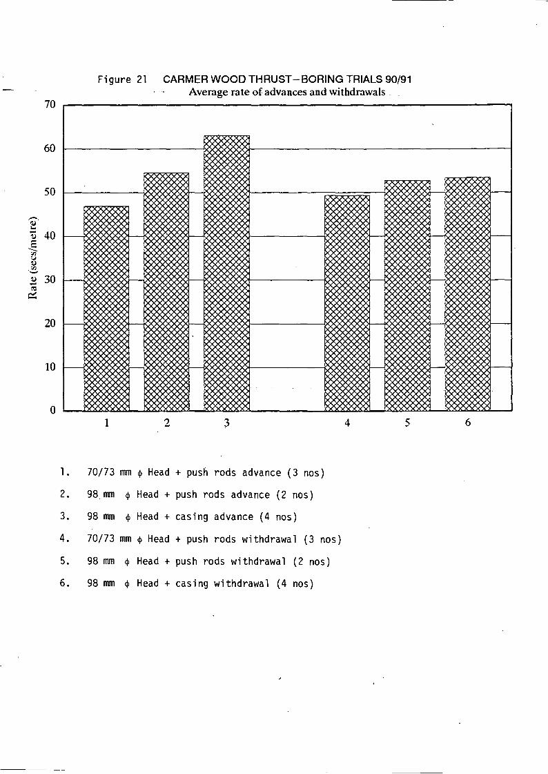
Mean rates of penetration for 18 advance and withdrawal episodes using pilot head with rods or oversize head with casing are shown in Figure 21. For ease of comparison, the penetration rates logged do not include time taken to simultaneously telescope the plastic mesh-wrapped screen inside the casing; in practice screen coupling took only a couple of minutes per section. Rates of advance and of withdrawal averaged about 1 m/min excluding coupling time. By the end of the trials, when operator dexterity and techniques had improved, a 20 m pilot push advance and withdrawal was typically taking under 2 hours, including mortar plug removal and coupling/uncoupling time. A secondary advance with casing and screen would take about 2 hours, including changeover of pipe-jack jaws to accomodate the pipe. Casing withdrawal was generally much slower as preparation time was necessary to set up the positive head system.
4.4 Summary of Thrust-bori~g Results
The main features of the thrust-boring trials using different arrays are summarised in Figure 22.
(i) Jacking-in rods or casjng behind a head of a larger diameter was much easier than using a head of a similar size.
(i i )
( iii)
4.5
Subsequent advances were generally much easier than the initial advance into the undisturbed formation.
Although it is not cl ear whether a pil ot push with 45 mm , rods results in lower peak jacking force requirement than a similar pilot push with the 73 mm ~ temporary casing, the former is much easier and faster to do and results in significantly less wear on the casing. The pilot push rapidly confirms to the operator whether a collector emp 1 acement is feas i b 1 e along the ori entat i on of that part i cul ar radial.
Timetabling Collector Construction by Screen-Within-Casing Method
Summarising the various stages involved in constructing a radial in a preprepared shaft-only dugwell, it took about a working day to dewater the well, install the thrust-boring equipment in the shaft and level it up opposite an access hole. Pilot push, screen-in-casing emplacement and casing withdrawal would typically take a further 2 working days. Subsequent radials would also take up to 3 days, as sand removal by hand from the main shaft would be requi red on comp 1 et i on of each co 11 ector. With experi enced operators and prepared access hole mountings, it is estimated that the conversion of a shaft-only dugwell into a 3 radial collector well would take-about 2-3 working weeks for a 3/4-person team. A typical timetable of operations would be as follows:
Day 1:
Day 2:
Mobilise to well, install opposite access #1.
Pilot advance/withdraw; emplace screen; prepare casing retraction.
12
70
60
50
-. ~ .. - 40 ~ ... c -:Jl (j
~ :Jl -' ~ 30 .... ~
~
20
10
o
Figure 21 CARMER WOOD THRUST-BORING TRIALS 90/91 Average~rate of advances and withdrawals
1 2 4 5
1. 70/73 mm ~ Head + push rods advance (3 nos)
2. 98.mm ~ Head + push rods advance (2 nos)
3. 98 mm ~ Head + casing advance (4 nos)
4. 70/73 mm ~ Head + push rods withdrawal (3 nos)
5. 98 mm ~ Head + push rods withdrawal (2 nos)
6. 98 mm ~ Head + cas i ng withdrawal (4 nos)
-
6

15
c ~
10 c c 0 ----c ~
~ > .-=' $ ~ 5 (,,)
'"' 0 ~
o
Figure 22 CARMER WOOD THRUST -BORING TRIALS 90/91 Average & peak push force required per advance
+
+
+
1 2 3 4 5 678 9 10
II Advance in undisturbed ground D Subsequent advance
+ Peak force recorded
1 = Ll 73 mm , head + push rods 2 = Ll 73 mm , head + casing
3 = L3 73 mm , head + push rods 4 = L3 73 mm , head + casing*
5 = L5 73 mm , head + casing
6 = L6 70 mm , head + push rods 7 = L6 73 mm , head + push rods 8 = L6 73 mm , head + casing**
9 = U2 98 mm , head + casing 10 = U2 98 mm , head + casing to 17 .65 m
11 = U3 98 mm , head + casing 12 = U3 98 mm , head + push rods
l3 = U4 98 mm , head + push rods 14 = U4 98 mm , head + casing
* Not representative; push aborted early ** Not representative; push in disturbed zone
11 12 13 14

Day 3:
0-_ Day 4:
Day 5:
Day 6:
Day 7:
Day 8:
Day 9:
Day 10:
5.
(1)
(2)
(3)
(4)
(5)
Withdraw temporary casing; develop radial #1.
'C1eano well; install opposite access #2.
Pilot advance/withdraw; emplace screen; prepare casing retraction.
Withdraw temporary casing; ·deve10p radial #2
Clean well; install opposite access #3.
Pilot advance/withdraw; emplace screen; prepare casing retraction.
Withdraw temporary casing; develop radial #3.
Clean well; disinstal1 equipment; clear site; demobi1ise.
CONCLUSIONS
Extensive field trials have been conducted to test the viability of thrust-boring in the saturated zone as an inexpensive means of constructing collectors in unconsolidated thin fine-grained alluvial aquifers. A concrete dugwell with a perforated lower ring sunk in a shallow fine running sand aquifer has provided testing conaitions for the method. With suitable precautions to guard against excessive sand ingress, it was demonstrated that thrust-boring could be routinely carri ed out at depths up to 3.5 111' below the water tab1 e. Head diameters up to 100 mm were jacked out and back at an average rate of 1 mimi n in unstable fi ne sands to 1 engths of over 20 m us i ng a 1 ightweight constructiQI1-industry thrust-borer which had undergone only minor modifications.
Initial trials to emplace collector well screen by jacking out standard thrust borer rods telescoped inside inexpensive slotted pipe were unsuccessful, as autodevelopment of the formation led to insurmountable sand-locking problems.
As a result, an inverted (screen-within-casing) system has been developed in which mesh-wrapped plastic screen is emplaced inside temporary steel casing which acts as drive pipe. Sand-locks and excessive formation ingress into the main shaft are avoided by a simple positive head system which reverses the flow of water along the collector until the temporary casing has been successfuly withdrawn. The system was successfully tested in the field and collectors installed. .
The resultant 38 mm 10 collectors, which were set in fine to medium sands of low uniformity coefficient, were able to autodevelop without the need for any other well development method. Yi e 1 ds of about 1.5 lis/radial with negligible sand content were obtained after short development periods of less than an hour.
It was found initially that a disproportionate and excessive jacking effort was requ i red to emplace the 73 mm ~ cas i ng sheath i ng the screen, in comparison with pushes which employed 45 mm ~ rods. Not only would unacceptable damage to the temporary casing result, but also the reaction force on the chamber ring opposite wall would be higher than necessary. Chamber ring design criteria would therefore need to be more stringent and the extra materials/construction cost of the central shaft would be reflected in a higher total cost for the collector well.
13

(6)
(7)
(8)
(9)
(10)
It was found by experimentation that excessive jacking force could be avoided by two simple expedients:
(a)
(b)
~ ~
Increasing the push head diameter in relation to the following pipe. For the 73 mm ~ pipe used in the trials, a sacrificial push-head with a head-to-shank ratio of 1.8·was found to be a successful combination. This enabled a 38 mm ID mesh-wrapped collector to be emplaced through a 100 mm ~ access hole in the perforated concrete chamber ring of the well.
Conducting a pilot-push with the disposable head coupled to standard 45 mm ~ rods befqre jacking out the screen-in-casing array. A simple redesign of the head would permit it to be used during both jacking operations, and serve as a safety plug during the critical changeover period from rods to casings.
As a result, the jacking requirement for a 20 m screen-in-casing emplacement was reduced to less than 7 tonnes force. This was well within the capacity of the equipment used, and was equivalent to a stress of less than 80 kN/m· on the chamber ring wall contact area opposite the radial being installed.
Basic design criteria for the dugwell were developed. The minimum internal well diameter in which collectors could be constructed by thrust-boring would be 2.0 m. As penetration into the saturated unconsolidated aquifer of more than 3-4 m is unlikely to be achieved by typical well-digging methods, the perforated access hole ring should either comprise the upper part of, or immediately follow, the leadin~ (cutting) ring. All rings should be connected by tiebars to maintaln shaft integrity during radial construction. The perforated ring should be strongly reinforced with integral reinforcing bars, in order-to withstand both the inherent weakness due to the cast access holes and transient stresses from the jacking operations. Sand ingress during collector construction should also be controlled as far as pOSSible, in order to minimise stresses arising from differential settlement around the well. Much time and effort could be saved by setting access plate anchor pOints in the perforated ring during the casting process. Soft brick-rubble with mortar was perfectly acceptable as temporary plug to the access holes during main shaft construction. .
The trials at Carmer Wood were carried out inside a dugwell constructed from rei nforced concrete chamber ri ngs, wi th each ri ng interconnected by integral tie bars to provide vertical rigidity. Construction using precast caisson rings would probably be the only practical method of lining a dugwell in an unconsolidated sand aquifer, and it is not envisaged that thrust-boring would be employed in a well lined by any other means. No problems of main shaft deterioration were encountered during thrust-boring. It was estimated that provided the reaction stress was distributed by the shuttering, jacking forces in the range anticipated by the method «10 tonnes f) would result in loadings of less than 115 kN/m·.
However the concrete rings typically found in a developing country well construction programme would be significantly cruder than the geotechnical rings employed for the UK work; poor control over cement and fines content and reinforcing rod work can for instance drastically reduce the strength of a cast caisson ring. Even though the indicated loadings are light, further trials, preferably in the context of an actual rural well-digging programme, are indicated in order to confirm that perforated reinforced caisson rings cast using standard methods appropriate to a developing country would be strong enough in practice to withstand the stresses which collector well construction can impose on a well lining.
14

(11 )
(12)
(13)
(14)
6.
(1)
(2)
(3)
An integral activity of thrust-boring is efficient dewatering, and it was found that pumping water with high suspended solids content at the 1 ifts"requ'i red was tood i~ffi cult for most standard=s,ite ,t~ench pumps. 0
After experi mentat i on with several di fferent methods, a hydraul i c submersible pump of the Flygt type was found to be the most serviceable. A thrust-boring equipment package for collector well construction should include a similar dewatering system as a standard component.
Although artificial ventilation was not found necessary at the Carmer Wood site, a portable air ducting system would be required in a tropical environment. A gas sensor should be included as a standard component of an equipment package.
The thrust-boring equipment used, together with its accessories, was transportable by pick-up/Landrover type utility vehicle and trailer. A thrust-boring equipment package does not require heavy lifting equipment for mobilisation purposes; the utility vehicle or trailer would be fitted with a travelling arm and light winch to facilitate equipment installation and sand removal at the well head, as no single item exceeds 125 kg in weight. The dewatering equipment and header tank would require a further utility vehicle or second trip.
The safety measures to be employed whilst working in an excavation are well documented elsewhere (e.g. UK Health and Safety legislation guidance notes), and should be followed closely when main shaft and collector construction are being carried out. As in any engineering operation involving the breakout from a closed shaft, particular attention should be paid to those procedures which involve operator safety, such as dewatering capacity, toxic/flammable gas detection, shaft ventilation, emergency evacuation and movement of accessories/ materials into and out of the well. In this respect collector installation by thrust-boring methods is neither more nor less hazardous than analogous operations in an excavation or mine.
RECOMMENDATIONS
The project has developed and demonstrated a pract i cal method to install small diameter horizontal radials to 20m+ in a fine-grained running sand aquifer using a simple pipe-jacking technique. This method is particularly suited to the construction of collector wells in aquifers which would be marginal for exploition by borehole or shaft-only dugwell. The methodology has been taken to an advanced stage as part of the current research and development project, but has only been employed at one site in UK, albeit in a testlng environment. There is a need now to test the method in pilot wells sunk in a range of aquifer conditions. Of particular interest would be the performance of the radials when emplaced in silty sands, and thrust-. boring experience in coarser and more variable sands. It may be possible to thrust-bore in unconsolidated sands with a gravel or pebble content of a few percent, but this also remains to be tested.
It is recommended that the technique now be incorporated in a dugwell construction programme as a pilot project. A suitable programme would be one in which a significant number of wells need to be excavated in shallow unconsolidated sandy alluvium which either has only a thin saturated zone, or in which the hazard of upconing from an inferior quality lower horizon needs to be controlled.
As the thrust-boring screen-within-casing method complements the telescoped jetting rotary drilling technique already developed by the same project, it may be suitable to include both elements in a pilot
15

programme. Thrust-boring is likely to be suited mainly to loose fine sands of moderately low permeability while telescoped jetting can
~ i nstaU~laY'gerodi amete~ radi,aJs of correspondi ng]y -greater: potential yield in coarser more permeable alluvium. In many rural water projects, the saturated thickness and grain size distribution of the underlying alluvial aquifer is not known with any precision before the construction programme begins, and so the completed dugwell shaft at different sites may be sunk in formations of radically different properties which would require different approaches to collector well construction.
REFERENCES
Allen, 0 J (1988) Construction and testing of two collector wells at Tampin Malaysia, April-July 1988. BGS Technical Report WD/88/20, Wa 11 i ngford, UK.
Herbert, R (1990) Dug well vs. collector well performance: ODA R&D Project No. 90/11, development of horizontal drilling rig for alluvial aquifers of hi ghpermeabi 1 i ty. BGS .. Technical Report WD/90/34,-Wallingford, UK.
Morris, BLand Talbot, J C (1990) Radial collector wells in project; progress report #1 on trenchless moling trials Wood, Laughton, Lincolnshire. BGS Technical Report Wa 11 i ngford, UK.
alluvium at Carmer WD/90/32,
Morris, B L (1991) Radial collector wells in alluvium project; progress report #2 on aquifer characteristics evaluation at Carmer Wood, Laughton, Lincolnshire. BGS Technical Report WD/91/1, Wallingford, UK.
ACKNOWLEDGEMENTS
The authors would like to acknowledge the contributions made to this geotechn i ca 1 systems development project by other members of the team who were involved in the work at Carmer Wood. Much of the geotechnical engineering was carried out under contract, and the individual and joint contribution of the contractors involved is warmly acknowledged. Delta Civil Engineering Limited constructed the main shaft using the ARC Pipes caisson shaft system jOintly developed together with Yorkshire Water. The contractors and equipment agents Avoidatrench Limited lent unstintingly their experience in thrust-boring; Mr Andrew Daniels devised the modifications to the PD-4 Powr Mole which overcame the teething problems accompanying the extension of the method to the saturated zone whil e the constant support, constructive suggest ions and experience in the field of both Mr Carl Davies and Mr Mark Benbow, in conditions that were at times trying, were invaluable in developing a viable emplacement system. The hydraulic submersible system of Flygt Pumps Limited overcame an initially troublesome dewatering problem while P.N. & I. Appleyard Plant were a very reliable source of on-site plant. Marton Geotechnical Services supplied the mesh-wrapped screen. Mr Alan Warwick and his staff at the Institute of Hydrology workshop gave much ass i stance on the pract i cal it i es of accessory design, as did Mr Andrew Dixon on site investigation. Within BGS, Mr Michael Bird and Mr John Sutton kindly assisted on some aspects of fieldwork while helpful discussions on hydraulic aspects of collector performance were held with Dr Robin Herbert and Dr John Barker. The Forestry Commission granted permission for BGS to conduct the trials in Laughton Forest and the cooperation of Mr John Hendrie (District Forester) is gratefully acknowledged.
16

Appendix Table 1. Summary of Data Availability for Thrust-boring Episodes
Radial Date • of Type Screen Push Measurements Taken Number Head Distance Advance Withdrawal
(mm) (m) Time Pressure Time Pressure
L6 23/2/90 70 Push-rods No 21.00 .; .; .; x L6 27/2 + 27/3/90 70 Push-rods Outside 8.50 x .; x x L6 14/5/90 73 Casing Inside 7.50 .; .; x x
L5 16/5/90 73 Casing Inside 5.25 'x .; .; x
L3 24/7/90 73 Push-rods No ' 14.50 .; .; .; x L3 24/7/90 73 Casing Inside 3.75 x .; x x
L1 15/1/91 73 Push-rods No 19.57 .; .; .; x L1 15/1/91 73 Casing Inside 5.50 x .; x x
U3 5/2/91 98 Casing No 20.45 .; .; .; .; U3 5/2/91 98 Push-rods No 20.30 .; .; .; .;
U4 6/2/91 98 Push-rods No 21. 75 .; .; .; .; U4 6/2/91 98 Casing No 20.00 .; .; .; .;
U2 7/2/91 98 Casing No 17.90 .; .; .; .; U2 7/2/91 98 Casing No 19.90 .; .; .; .;

Appendix Table 2. Budget Estimate: Equipment Package
Description
Thrust-boring equipment package to convert dug wells lined with concrete caisson-type rings into collector wells by screen-within-casing method. Excludes service vehicle (4WD utility/pickup).
Item
Hydraulic thrust-borer c/w wellhead powerpack (e.g. PD-4 Powrmole and Power Stinger)
Boring tools (35 m sets of push-rods and HD temp. casing)
Other accessories (slings, tools, shuttering, etc.)
Site construction equipment (drill, portable generator, travelling arm,winch, clean water pump)
Safety/amenity equipment (blower ventilator, gas sensor, harness, ladder, etc.)
HD hydraulic dewatering pump c/w diesel powerpack (e.g. Flygt HB2102 3" ~ and STI unit)
2250 1 water bowser c/w semi-rigid hose and fittings
HD double-axle 2 tonne trailer
Apgrox.
Total
Cost £
7,500
5,000
1,000
2,500
1,500
5,000
2,000
2,000
£26,500
,llL91}

Figure 9A
Disposable end-cap, plastic anchor casing and first length of screen telescoped inside leading temporary casing.
Figure 98
Connecting subsequent lengths of inner screen and outer casing.

Figure 4A
Pilot push-head with 45 mm NO push rods.
Figure 4B
Screen emplacement end-cap with 73 mm 00 steel casing.