125d control series - w. w. grainger · 125d control series p.o. box 10 ... • the 123d variable...
TRANSCRIPT
125D
CON
TROL
SER
IES
P.O. Box 105000 W. 106th StreetZionsville, Indiana 46077
Phone (317) 873-5211Fax (317) 873-1105
www.dartcontrols.com
Instruction ManualVariable Speed Control
LT125G (0514)
CONTROLS
A-5-3261J
TABLE OF CONTENTSWARRANTY ............................................................................................................................................................................... 1
INTRODUCTION ........................................................................................................................................................................ 2
CONTROL FEATURES .............................................................................................................................................................. 2
125D SERIES HEATSINK DIMENSIONS .................................................................................................................................. 2
MOUNTING PROCEDURE ........................................................................................................................................................ 3
MODEL SELECTION ................................................................................................................................................................. 3
WIRING PROCEDURE & FUSING ............................................................................................................................................ 3
TERMINAL STRIP WIRING INSTRUCTIONS ........................................................................................................................... 3
123D / 125D HOOK-UP DIAGRAM ........................................................................................................................................... 4
CONTROL START-UP ............................................................................................................................................................... 4
TRIMPOT ADJUSTMENT CHART & PROCEDURE ................................................................................................................. 5
CONTROL MODIFICATIONS .................................................................................................................................................... 6
TWO SPEED OPERATION .................................................................................................................................................. 16
DYNAMIC BRAKING ............................................................................................................................................................ 16
TACH FEEDBACK/FOLLOWER .......................................................................................................................................... 16
INHIBIT FUNCTIONS ........................................................................................................................................................... 16
SPEEDPOT KIT ASSEMBLY ..................................................................................................................................................... 7
OPTION DESCRIPTION ...................................................................................................................................................... 7-10
-1 / -2A OPTIONS ................................................................................................................................................................... 7
-5 / -7 OPTIONS .................................................................................................................................................................. 8-9
-15B / -K OPTIONS / -29B OPTIONS .................................................................................................................................... 9
-55H / -56H OPTION ............................................................................................................................................................. 10
IN CASE OF DIFFICULTY ....................................................................................................................................................... 11
SPECIFICATIONS .................................................................................................................................................................... 11
TYPICAL MOTOR CURRENTS ............................................................................................................................................... 12
125D SERIES PARTS PLACEMENT & LIST .......................................................................................................................... 12
125D SERIES SCHEMATIC ..................................................................................................................................................... 13
PRODUCT LINE .................................................................................................................................................. BACK COVER
WARRANTY
Dart Controls, Inc. (DCI) warrants its products to be free from defects in material and workmanship. The exclusive remedy for this warranty is DCI factory replacement of any part or parts of such product which shall within 12 months after delivery to the purchaser be returned to DCI factory with all transportation charges prepaid and which DCI determines to its satisfaction to be defective. This warranty shall not extend to defects in assembly by other than DCI or to any article which has been repaired or altered by other than DCI or to any article which DCI determines has been subjected to improper use. DCI assumes no respon-sibility for the design characteristics of any unit or its operation in any circuit or assembly. This warranty is in lieu of all other warranties, express or implied; all other liabilities or obligations on the part of DCI, including consequential damages, are hereby expressly excluded.
NOTE: Carefully check the control for shipping damage. Report any damage to the carrier immediately. Do not attempt to operate the drive if visible damage is evident to either the circuit or to the electronic components.
All information contained in this manual is intended to be correct, however information and data in this manual are subject to change without notice. DCI makes no warranty of any kind with regard to this information or data. Further, DCI is not responsible for any omissions or errors or consequential damage caused by the user of the product. DCI reserves the right to make manu-facturing changes which may not be included in this manual.
WARNINGImproper installation or operation of this control may cause injury to personnel or control failure. The control must be installed in accordance with local, state, and national safety codes. Make certain that the power supply is disconnected before attempting to service or remove any components!!! If the power disconnect point is out of sight, lock it in dis-connected position and tag to prevent unexpected application of power. Only a qualified electrician or service person-nel should perform any electrical troubleshooting or maintenance. At no time should circuit continuity be checked by shorting terminals with a screwdriver or other metal device.
1
1.375
.218
5.625
5.625
.6875
6.250
.6875
INTRODUCTION • The 123D variable speed control is available in a range of 150mA through 5.5 ADC (or up to 10 ADC if using a suitable external heatsink) at 24 through 36 VAC input.
• The 125D variable speed control is available in a range of 150mA through 1/4 H.P. at 120/240 VAC input.
• The 125DV variable speed control is available in a range of 1/8 through 1 H.P. at 120/240 VAC input. With -HS(125D) or suitable external heatsink (where 125D extrusion temperature does not exceed 70° C.), maximum U.L. rating can be increased to 2 H.P. and 10 Amps DC.
• The control is designed for DC Permanent Magnet, Shunt Wound, and some Universal (AC/DC) motors in the above horsepower ranges.
• Incoming AC voltage is converted to adjustable full wave rectified DC voltage to operate the DC motor. Also, a full wave field voltage is provided for shunt wound motors (see page 4 for voltages).
• The control incorporates transient voltage protection with adjustable current limit which fits into a compact package. It features adjustable minimum and maximum speeds along with adjustable IR compensation and an inhibit function.
• Options are available to change ACCEL/DECEL time (see page 8, -15 / -K options).
• cULus Recognized under, U.L. File # E78180.
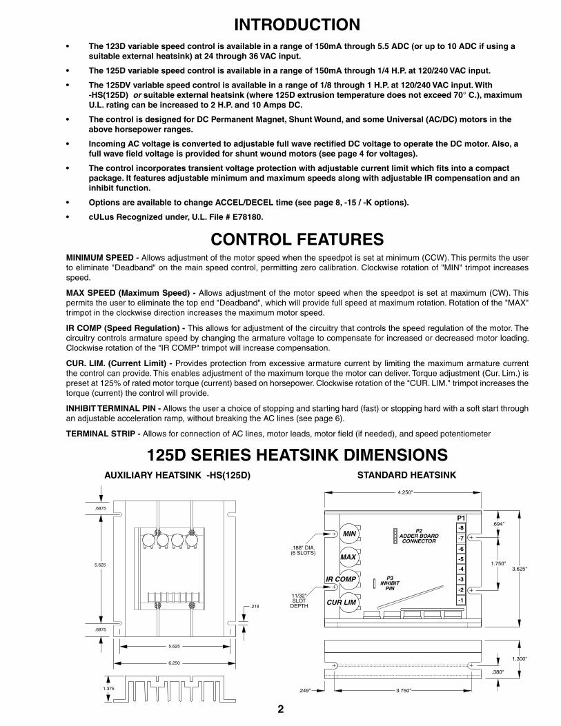
CONTROL FEATURESMINIMUM SPEED - Allows adjustment of the motor speed when the speedpot is set at minimum (CCW). This permits the user to eliminate "Deadband" on the main speed control, permitting zero calibration. Clockwise rotation of "MIN" trimpot increases speed.
MAX SPEED (Maximum Speed) - Allows adjustment of the motor speed when the speedpot is set at maximum (CW). This permits the user to eliminate the top end "Deadband", which will provide full speed at maximum rotation. Rotation of the "MAX" trimpot in the clockwise direction increases the maximum motor speed.
IR COMP (Speed Regulation) - This allows for adjustment of the circuitry that controls the speed regulation of the motor. The circuitry controls armature speed by changing the armature voltage to compensate for increased or decreased motor loading. Clockwise rotation of the "IR COMP" trimpot will increase compensation.
CUR. LIM. (Current Limit) - Provides protection from excessive armature current by limiting the maximum armature current the control can provide. This enables adjustment of the maximum torque the motor can deliver. Torque adjustment (Cur. Lim.) is preset at 125% of rated motor torque (current) based on horsepower. Clockwise rotation of the "CUR. LIM." trimpot increases the torque (current) the control will provide.
INHIBIT TERMINAL PIN - Allows the user a choice of stopping and starting hard (fast) or stopping hard with a soft start through an adjustable acceleration ramp, without breaking the AC lines (see page 6).
TERMINAL STRIP - Allows for connection of AC lines, motor leads, motor field (if needed), and speed potentiometer
2
AUXILIARY HEATSINK -HS(125D) STANDARD HEATSINK
125D SERIES HEATSINK DIMENSIONS
4.250"
MIN
MAX
IR COMP
CUR LIM
P2ADDER BOARDCONNECTOR
P3INHIBIT
PIN
-8
-7
-6
-5
-4
-3
-2
-1
P1
3.625"
3.750"
1.750"
.694"
.380"
1.300"
11/32" SLOT
DEPTH
.188" DIA.(6 SLOTS)
.249"
3
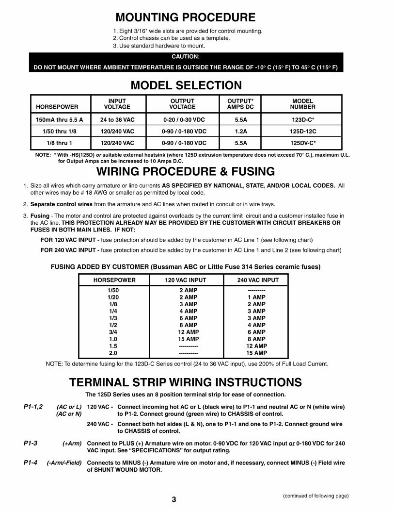
MOUNTING PROCEDURE 1. Eight 3/16" wide slots are provided for control mounting. 2. Control chassis can be used as a template. 3. Use standard hardware to mount.
CAUTION:
DO NOT MOUNT WHERE AMBIENT TEMPERATURE IS OUTSIDE THE RANGE OF -10o C (15o F) TO 45o C (115o F)
MODEL SELECTION
150mA thru 5.5 A 24 to 36 VAC 0-20 / 0-30 VDC 5.5A 123D-C*
1/50 thru 1/8 120/240 VAC 0-90 / 0-180 VDC 1.2A 125D-12C
1/8 thru 1 120/240 VAC 0-90 / 0-180 VDC 5.5A 125DV-C*
INPUT OUTPUT OUTPUT* MODELHORSEPOWER VOLTAGE VOLTAGE AMPS DC NUMBER
NOTE: * With -HS(125D) or suitable external heatsink (where 125D extrusion temperature does not exceed 70° C.), maximum U.L. for Output Amps can be increased to 10 Amps D.C.
WIRING PROCEDURE & FUSING1. Size all wires which carry armature or line currents AS SPECIFIED BY NATIONAL, STATE, AND/OR LOCAL CODES. All other wires may be # 18 AWG or smaller as permitted by local code.
2. Separate control wires from the armature and AC lines when routed in conduit or in wire trays.
3. Fusing - The motor and control are protected against overloads by the current limit circuit and a customer installed fuse in the AC line. THIS PROTECTION ALREADY MAY BE PROVIDED BY THE CUSTOMER WITH CIRCUIT BREAKERS OR FUSES IN BOTH MAIN LINES. IF NOT:
FOR 120 VAC INPUT - fuse protection should be added by the customer in AC Line 1 (see following chart)
FOR 240 VAC INPUT - fuse protection should be added by the customer in AC Line 1 and Line 2 (see following chart)
1/50 2 AMP --------- 1/20 2 AMP 1 AMP 1/8 3 AMP 2 AMP 1/4 4 AMP 3 AMP 1/3 6 AMP 3 AMP 1/2 8 AMP 4 AMP 3/4 12 AMP 6 AMP 1.0 15 AMP 8 AMP 1.5 ---------- 12 AMP 2.0 ---------- 15 AMP
HORSEPOWER 120 VAC INPUT 240 VAC INPUT
NOTE: To determine fusing for the 123D-C Series control (24 to 36 VAC input), use 200% of Full Load Current.
TERMINAL STRIP WIRING INSTRUCTIONSThe 125D Series uses an 8 position terminal strip for ease of connection.
P1-1,2 (AC or L) 120 VAC - Connect incoming hot AC or L (black wire) to P1-1 and neutral AC or N (white wire) (AC or N) to P1-2. Connect ground (green wire) to CHASSIS of control.
240 VAC - Connect both hot sides (L & N), one to P1-1 and one to P1-2. Connect ground wire to CHASSIS of control.
P1-3 (+Arm) Connect to PLUS (+) Armature wire on motor. 0-90 VDC for 120 VAC input or 0-180 VDC for 240 VAC input. See “SPECIFICATIONS” for output rating.
P1-4 (-Arm/-Field) Connects to MINUS (-) Armature wire on motor and, if necessary, connect MINUS (-) Field wire of SHUNT WOUND MOTOR.
(continued of following page)
FUSING ADDED BY CUSTOMER (Bussman ABC or Little Fuse 314 Series ceramic fuses)
4
(continued)
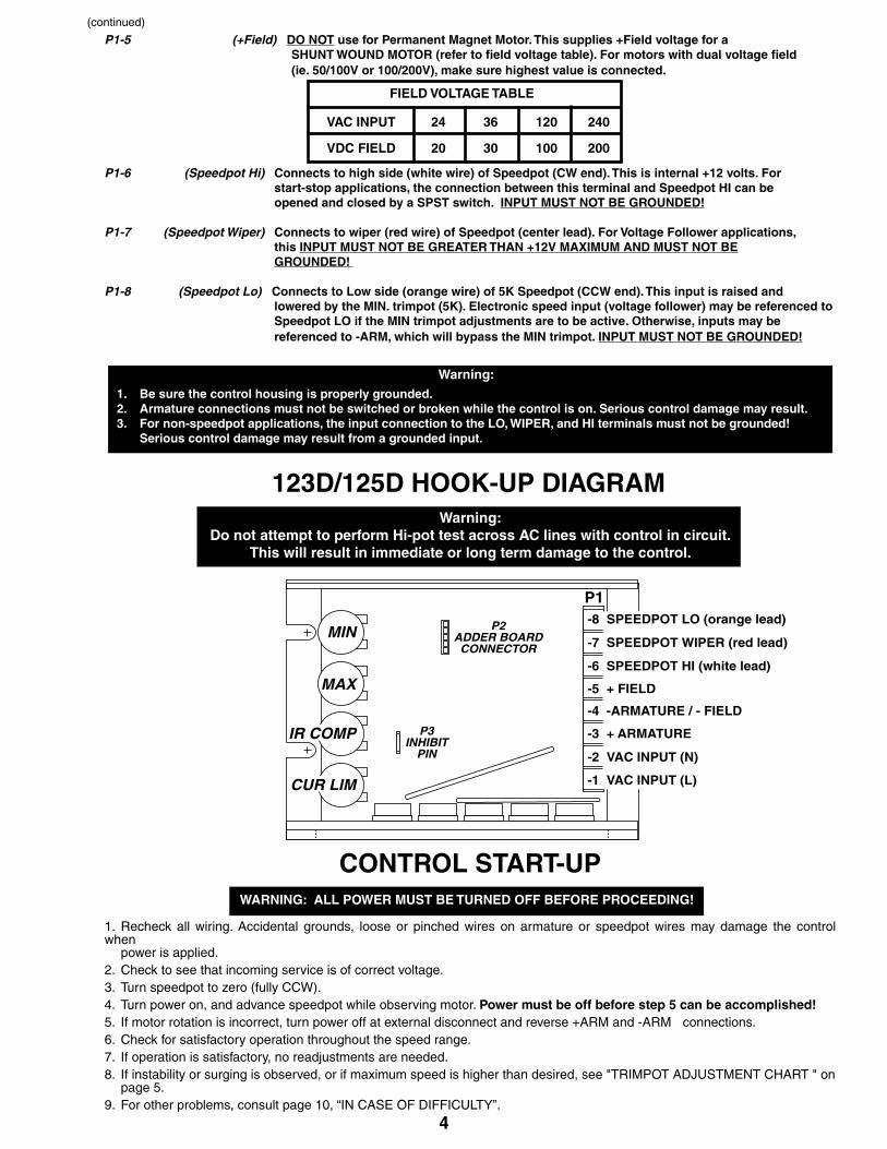
P1-5 (+Field) DO NOT use for Permanent Magnet Motor. This supplies +Field voltage for a SHUNT WOUND MOTOR (refer to field voltage table). For motors with dual voltage field (ie. 50/100V or 100/200V), make sure highest value is connected.
P1-6 (Speedpot Hi) Connects to high side (white wire) of Speedpot (CW end). This is internal +12 volts. For start-stop applications, the connection between this terminal and Speedpot HI can be opened and closed by a SPST switch. INPUT MUST NOT BE GROUNDED!
P1-7 (Speedpot Wiper) Connects to wiper (red wire) of Speedpot (center lead). For Voltage Follower applications, this INPUT MUST NOT BE GREATER THAN +12V MAXIMUM AND MUST NOT BE GROUNDED!
P1-8 (Speedpot Lo) Connects to Low side (orange wire) of 5K Speedpot (CCW end). This input is raised and lowered by the MIN. trimpot (5K). Electronic speed input (voltage follower) may be referenced to Speedpot LO if the MIN trimpot adjustments are to be active. Otherwise, inputs may be referenced to -ARM, which will bypass the MIN trimpot. INPUT MUST NOT BE GROUNDED!
VAC INPUT 24 36 120 240
VDC FIELD 20 30 100 200
FIELD VOLTAGE TABLE
Warning:1. Be sure the control housing is properly grounded.2. Armature connections must not be switched or broken while the control is on. Serious control damage may result.3. For non-speedpot applications, the input connection to the LO, WIPER, and HI terminals must not be grounded! Serious control damage may result from a grounded input.
123D/125D HOOK-UP DIAGRAMWarning:
Do not attempt to perform Hi-pot test across AC lines with control in circuit. This will result in immediate or long term damage to the control.
WARNING: ALL POWER MUST BE TURNED OFF BEFORE PROCEEDING!
CONTROL START-UP
1. Recheck all wiring. Accidental grounds, loose or pinched wires on armature or speedpot wires may damage the control when power is applied.2. Check to see that incoming service is of correct voltage.3. Turn speedpot to zero (fully CCW).4. Turn power on, and advance speedpot while observing motor. Power must be off before step 5 can be accomplished! 5. If motor rotation is incorrect, turn power off at external disconnect and reverse +ARM and -ARM connections.
6. Check for satisfactory operation throughout the speed range.7. If operation is satisfactory, no readjustments are needed.8. If instability or surging is observed, or if maximum speed is higher than desired, see "TRIMPOT ADJUSTMENT CHART " on page 5.9. For other problems, consult page 10, “IN CASE OF DIFFICULTY”.
MIN
MAX
IR COMP
CUR LIM
P2ADDER BOARDCONNECTOR
P3INHIBIT
PIN
P1-8 SPEEDPOT LO (orange lead)
-7 SPEEDPOT WIPER (red lead)
-6 SPEEDPOT HI (white lead)
-5 + FIELD
-4 -ARMATURE / - FIELD
-3 + ARMATURE
-2 VAC INPUT (N)
-1 VAC INPUT (L)
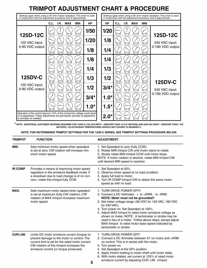
TRIMPOT FUNCTION ADJUSTMENT MIN. Sets minimum motor speed when speedpot 1. Set Speedpot to zero (fully CCW). is set at zero. CW rotation will increase min- 2. Rotate MIN trimpot CW until motor starts to rotate. imum motor speed. 3. Slowly rotate MIN trimpot CCW until motor stops. NOTE: If motor rotation is desired, rotate MIN trimpot CW until desired MIN speed is reached. IR COMP Provides a means of improving motor speed 1. Set Speedpot at 50%. regulation in the armature feedback mode. If 2. Observe motor speed at no load condition. a slowdown due to load change is of no con- 3. Apply full load to motor. cern, rotate this trimpot fully CCW. 4. Turn IR COMP trimpot CW to obtain the same motor speed as with no load. MAX. Sets maximum motor speed when speedpot 1. TURN DRIVE POWER OFF!! is set at maximum (fully CW rotation). CW 2. Connect a DC Voltmeter: + to +ARM, - to -ARM. rotation of MAX trimpot increases maximum NOTE: Meter must not be grounded!! motor speed. 3. Set meter voltage range: (90 VDC for 120 VAC, 180 VDC for 240 VAC). 4. Turn power on. Set Speedpot at 100%. 5. Adjust MAX trimpot to rated motor armature voltage as shown on meter. NOTE: A tachometer or strobe may be used in lieu of a meter. Follow above steps, except adjust MAX trimpot to rated motor base speed indicated by tachometer or strobe. CUR.LIM. Limits DC motor armature current (torque) to 1. TURN DRIVE POWER OFF! prevent damage to the motor or control. The 2. Connect a DC Ammeter between A1 on motor and +ARM current limit is set for the rated motor current. on control. This is in series with the motor. CW rotation of this trimpot increases the 3. Turn power on. armature current (or torque produced). 4. Set Speedpot at the 50% position. 5. Apply friction braking to motor shaft until motor stalls. 6. With motor stalled, set current at 125% of rated motor armature current by adjusting CUR. LIM . trimpot.
5
TRIMPOT ADJUSTMENT CHART & PROCEDURE
C.L. I.R. MAX MIN
1/4
1/3
1/2
3/4*
1.0*
1/20
1/8
HP
Settings apply when using a 5K ohm master speedpot. This chart is usedin conjunction with the adjustment procedure and is approximate.
125DV-C240 VAC input;
0-180 VDC output
1.5*
2.0** NOTE: ADDITIONAL CUSTOMER HEATSINK REQUIRED FOR 125DV-C (120 VAC INPUT - GREATER THAN 1/2 H.P. MOTORS) AND (240 VAC INPUT - GREATER THAN 1 H.P.
MOTORS). 125 EXTRUSION TEMPERATURES SHOULD NOT EXCEED 70 DEGREES C.
NOTE: FOR DETERMINING TRIMPOT SETTINGS FOR THE 123D-C SERIES, SEE TRIMPOT SETTINGS PROCEDURE BELOW.
1/4
125D-12C240 VAC input;
0-180 VDC output
C.L. I.R. MAX MIN
1/8
1/4
1/3
1/2
3/4*
1/50
1/20
HP
Settings apply when using a 5K ohm master speedpot. This chart is usedin conjunction with the adjustment procedure and is approximate.
125DV-C120 VAC input;
0-90 VDC output
1.0*
1/8
125D-12C120 VAC input;
0-90 VDC output
Operation of the control beyond ±10% of the normal line voltage could resultin re-adjustment. These adjustments are permanent; periodic re-adjustmentis normally not needed.
CONTROL MODIFICATIONS
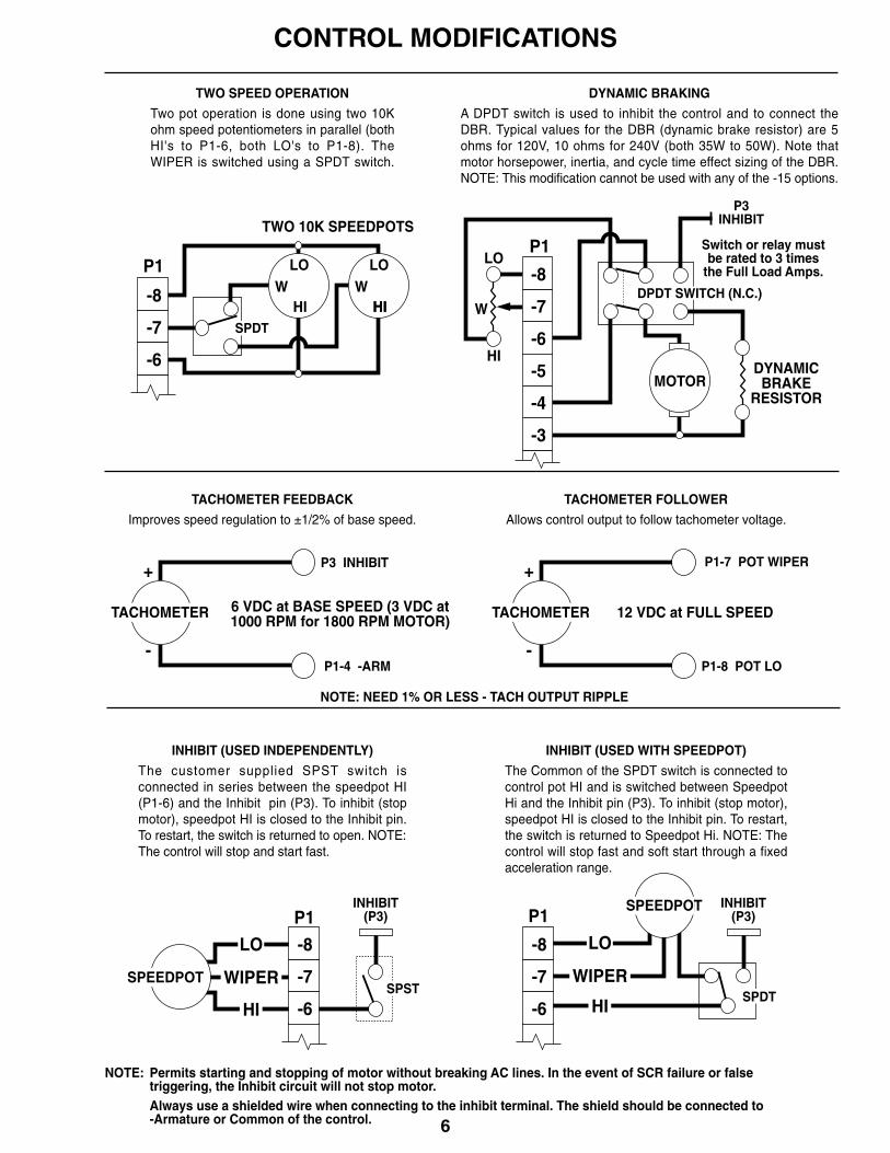
Two pot operation is done using two 10Kohm speed potentiometers in parallel (bothHI's to P1-6, both LO's to P1-8). TheWIPER is switched using a SPDT switch.
TWO SPEED OPERATION
A DPDT switch is used to inhibit the control and to connect theDBR. Typical values for the DBR (dynamic brake resistor) are 5ohms for 120V, 10 ohms for 240V (both 35W to 50W). Note thatmotor horsepower, inertia, and cycle time effect sizing of the DBR.NOTE: This modification cannot be used with any of the -15 options.
DYNAMIC BRAKING
The customer supplied SPST switch isconnected in series between the speedpot HI(P1-6) and the Inhibit pin (P3). To inhibit (stopmotor), speedpot HI is closed to the Inhibit pin.To restart, the switch is returned to open. NOTE:The control will stop and start fast.
INHIBIT (USED INDEPENDENTLY)
The Common of the SPDT switch is connected tocontrol pot HI and is switched between SpeedpotHi and the Inhibit pin (P3). To inhibit (stop motor),speedpot HI is closed to the Inhibit pin. To restart,the switch is returned to Speedpot Hi. NOTE: Thecontrol will stop fast and soft start through a fixedacceleration range.
INHIBIT (USED WITH SPEEDPOT)
-7
-8
-6
P1
SPSTSPEEDPOT
INHIBIT(P3)
WIPER
LO
HI
-7
-8
-6
P1
SPDT
SPEEDPOT
WIPER
LO
HI
Improves speed regulation to ±1/2% of base speed.
TACHOMETER FEEDBACK
Allows control output to follow tachometer voltage.
TACHOMETER FOLLOWER
-7
-8
W
LO
HI
P1
MOTORDYNAMICBRAKE
RESISTOR
-7
-8
-6
WHI
LOW
HI
LOP1
HISPDT
TWO 10K SPEEDPOTS
TACHOMETER
P3 INHIBIT
P1-4 -ARM
+
-
6 VDC at BASE SPEED (3 VDC at1000 RPM for 1800 RPM MOTOR)
TACHOMETER
P1-7 POT WIPER
P1-8 POT LO
+
-
12 VDC at FULL SPEED
NOTE: NEED 1% OR LESS - TACH OUTPUT RIPPLE
Permits starting and stopping of motor without breaking AC lines. In the event of SCR failure or falsetriggering, the Inhibit circuit will not stop motor.Always use a shielded wire when connecting to the inhibit terminal. The shield should be connected to-Armature or Common of the control.
-5
-6
P3INHIBIT
INHIBIT(P3)
-3
-4
Switch or relay mustbe rated to 3 times
the Full Load Amps.
DPDT SWITCH (N.C.)
NOTE:
6
7
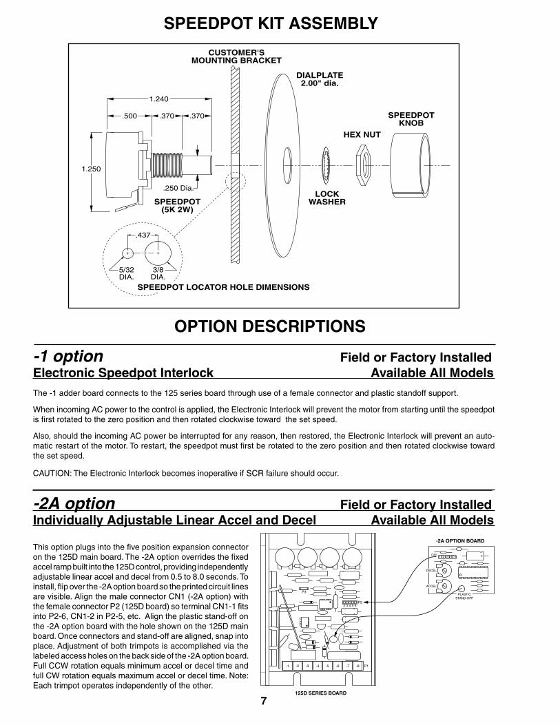
SPEEDPOT KIT ASSEMBLY
OPTION DESCRIPTIONS
-1 option Field or Factory InstalledElectronic Speedpot Interlock Available All Models The -1 adder board connects to the 125 series board through use of a female connector and plastic standoff support.
When incoming AC power to the control is applied, the Electronic Interlock will prevent the motor from starting until the speedpot is first rotated to the zero position and then rotated clockwise toward the set speed.
Also, should the incoming AC power be interrupted for any reason, then restored, the Electronic Interlock will prevent an auto-matic restart of the motor. To restart, the speedpot must first be rotated to the zero position and then rotated clockwise toward the set speed.
CAUTION: The Electronic Interlock becomes inoperative if SCR failure should occur.
-2A option Field or Factory InstalledIndividually Adjustable Linear Accel and Decel Available All Models
This option plugs into the five position expansion connector on the 125D main board. The -2A option overrides the fixed accel ramp built into the 125D control, providing independently adjustable linear accel and decel from 0.5 to 8.0 seconds. To install, flip over the -2A option board so the printed circuit lines are visible. Align the male connector CN1 (-2A option) with the female connector P2 (125D board) so terminal CN1-1 fits into P2-6, CN1-2 in P2-5, etc. Align the plastic stand-off on the -2A option board with the hole shown on the 125D main board. Once connectors and stand-off are aligned, snap into place. Adjustment of both trimpots is accomplished via the labeled access holes on the back side of the -2A option board. Full CCW rotation equals minimum accel or decel time and full CW rotation equals maximum accel or decel time. Note: Each trimpot operates independently of the other.
SPEEDPOT(5K 2W)
CUSTOMER'SMOUNTING BRACKET
DIALPLATE2.00" dia.
LOCKWASHER
HEX NUT
SPEEDPOTKNOB
.437
3/8DIA.
5/32DIA.
SPEEDPOT LOCATOR HOLE DIMENSIONS
.500 .370 .370
1.240
1.250
.250 Dia.
125D SERIES BOARD
-2A OPTION BOARD
8
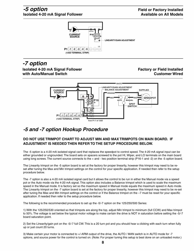
-5 option Field or Factory InstalledIsolated 4-20 mA Signal Follower Available on All Models
P1 -5-4-3
CURRENTSOURCE
-1 -2
LINEARITY/GAIN ADJUSTMENT
+-
(125D TERMINAL STRIP)
P16
250/500
125
+ -
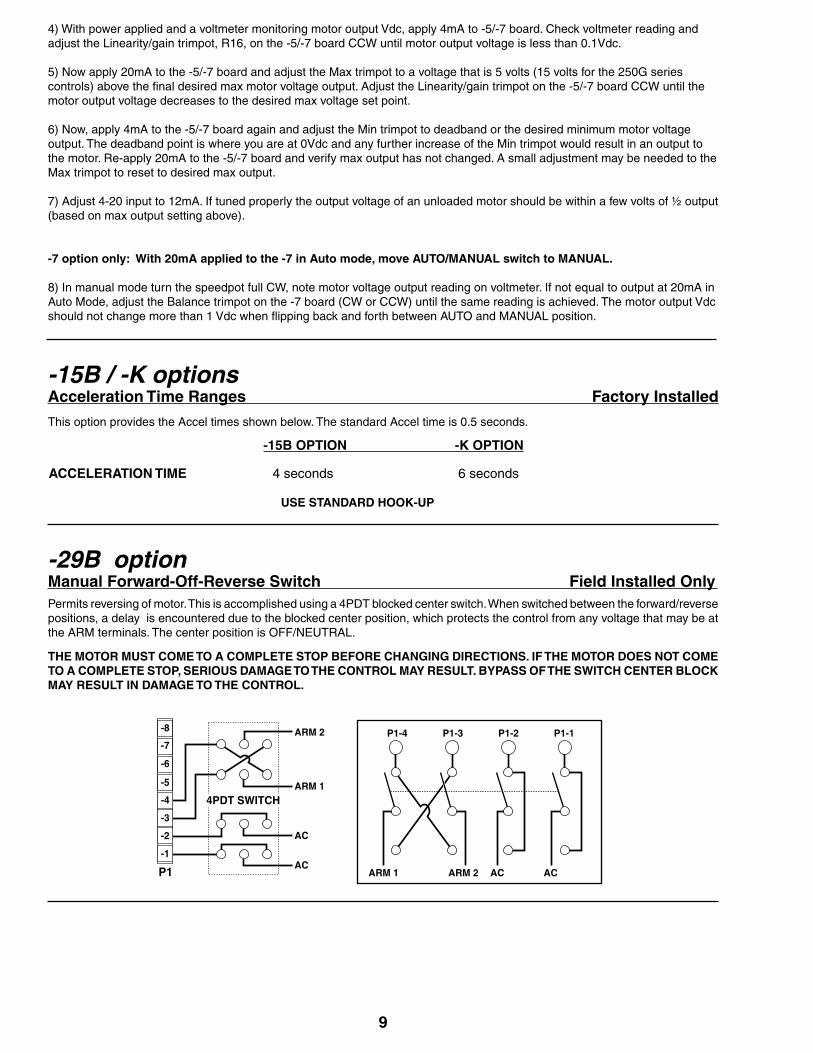
-7 option Isolated 4-20 mA Signal Follower Factory or Field Installedwith Auto/Manual Switch Customer Wired
DO NOT USE TRIMPOT CHART TO ADJUST MIN AND MAX TRIMPOTS ON MAIN BOARD. IF ADJUSTMENT IS NEEDED THEN REFER TO THE SETUP PROCEDURE BELOW.
The -5 option is a 4-20 mA isolated signal card that replaces the speedpot to control speed. The 4-20 mA signal input can be either grounded or ungrounded. The board sets on spacers screwed to the pot HI, Wiper, and LO terminals on the main board using long screws. The current source connects to the + and - two position terminal strip (P16-1 and -2) on the -5 option board.
The Linearity trimpot on the -5 option board is set at the factory for proper linearity, however this trimpot may need to be re-set after tuning the Max and Min trimpot settings on the control for your specific application. If needed then refer to the setup procedure below.
The -7 option is also a 4-20 mA isolated signal card but it allows the control to be run in either the Manual mode via a speed pot or the Auto mode via the 4-20 mA signal. This option also includes a Balance trimpot which is used to scale the maximum speed in the Manual mode. It is factory set so the maximum speed in Manual mode equals the maximum speed in Auto mode.The Linearity trimpot on the -7 option board is set at the factory for proper linearity, however this trimpot may need to be re-set after tuning the Max and Min trimpot settings on the control or if the Balance trimpot on the –7 must be reset for your specific application. If needed then refer to the setup procedure below.
The following is the recommended procedure to set up the -5/-7 option on the 125/250/500 Series:
1) With the 125/250/530 oriented so that trimpots are along the top, adjust Min trimpot to minimum (full CCW) and Max trimpot to 50%. The voltage is set below the typical motor voltage to make certain the drive is NOT in saturation before setting the -5/-7 board saturation point.
2) Set the Linearity/gain pot on the -5/-7 full CW. This is a 20 turn pot and you should hear a clicking with each turn when fully up or just count 20 turns.
3) Make certain your motor is connected to +/-ARM output of the drive, the AUTO / MAN switch is in AUTO mode for -7 options, and source power for the control is turned on. (Note: For proper tuning this setup is best done on an unloaded motor.)
WHITE
250/500
P1 -5-4-3
CURRENTSOURCE
-1 -2
LINEARITY/GAIN ADJUSTMENT
SPDTSWITCH
MANUALAUTO
ORANGE
RED
from P1-7 of 125D
SUPPLIED
+- P16
(125D TERMINAL STRIP)
RED SPEEDPOT
BALANCE ADJUSTMENT
125JU1JU2
JU3
-+
-5 and -7 option Hookup Procedure
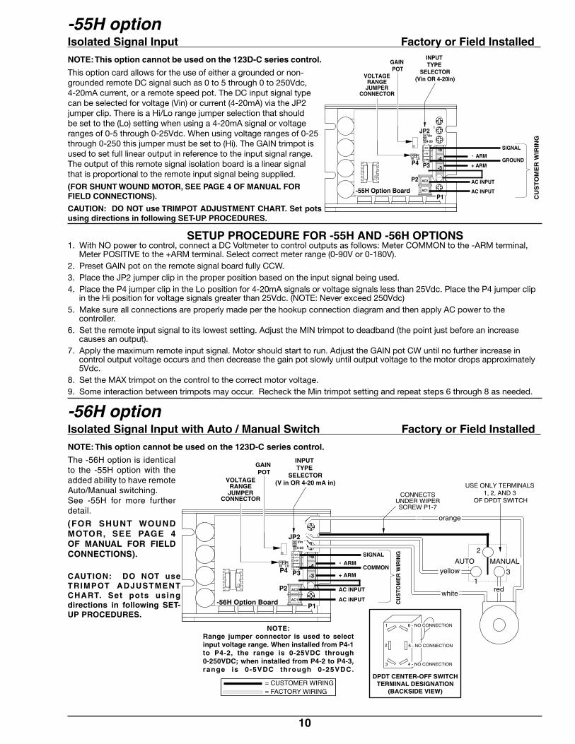
-29B option Manual Forward-Off-Reverse Switch Field Installed Only Permits reversing of motor. This is accomplished using a 4PDT blocked center switch. When switched between the forward/reverse positions, a delay is encountered due to the blocked center position, which protects the control from any voltage that may be at the ARM terminals. The center position is OFF/NEUTRAL.
THE MOTOR MUST COME TO A COMPLETE STOP BEFORE CHANGING DIRECTIONS. IF THE MOTOR DOES NOT COME TO A COMPLETE STOP, SERIOUS DAMAGE TO THE CONTROL MAY RESULT. BYPASS OF THE SWITCH CENTER BLOCK MAY RESULT IN DAMAGE TO THE CONTROL.
9
P1
-5
-6
-7
-8
-4
-3
ARM 2
ARM 1
AC
AC-1
-2
4PDT SWITCH
P1-4 P1-3 P1-2 P1-1
ARM 1 ARM 2 ACAC
-15B / -K options Acceleration Time Ranges Factory Installed
This option provides the Accel times shown below. The standard Accel time is 0.5 seconds.
-15B OPTION -K OPTION
ACCELERATION TIME 4 seconds 6 seconds
USE STANDARD HOOK-UP
4) With power applied and a voltmeter monitoring motor output Vdc, apply 4mA to -5/-7 board. Check voltmeter reading and adjust the Linearity/gain trimpot, R16, on the -5/-7 board CCW until motor output voltage is less than 0.1Vdc.
5) Now apply 20mA to the -5/-7 board and adjust the Max trimpot to a voltage that is 5 volts (15 volts for the 250G series controls) above the final desired max motor voltage output. Adjust the Linearity/gain trimpot on the -5/-7 board CCW until the motor output voltage decreases to the desired max voltage set point.
6) Now, apply 4mA to the -5/-7 board again and adjust the Min trimpot to deadband or the desired minimum motor voltage output. The deadband point is where you are at 0Vdc and any further increase of the Min trimpot would result in an output to the motor. Re-apply 20mA to the -5/-7 board and verify max output has not changed. A small adjustment may be needed to the Max trimpot to reset to desired max output.
7) Adjust 4-20 input to 12mA. If tuned properly the output voltage of an unloaded motor should be within a few volts of ½ output (based on max output setting above).
-7 option only: With 20mA applied to the -7 in Auto mode, move AUTO/MANUAL switch to MANUAL.
8) In manual mode turn the speedpot full CW, note motor voltage output reading on voltmeter. If not equal to output at 20mA in Auto Mode, adjust the Balance trimpot on the -7 board (CW or CCW) until the same reading is achieved. The motor output Vdc should not change more than 1 Vdc when flipping back and forth between AUTO and MANUAL position.
-5
P1
P4 P3
P2
JP2
-4
-3
AC1
AC2
COM
+5V
SIG
4-20
Vin
HI LO
AC INPUT
AC INPUT
ARM
ARM+
- GROUND
SIGNAL
-55H Option Board
VOLTAGERANGEJUMPER
CONNECTOR
CU
ST
OM
ER
WIR
ING
GAIN POT
INPUT TYPE
SELECTOR(Vin OR 4-20in)
10
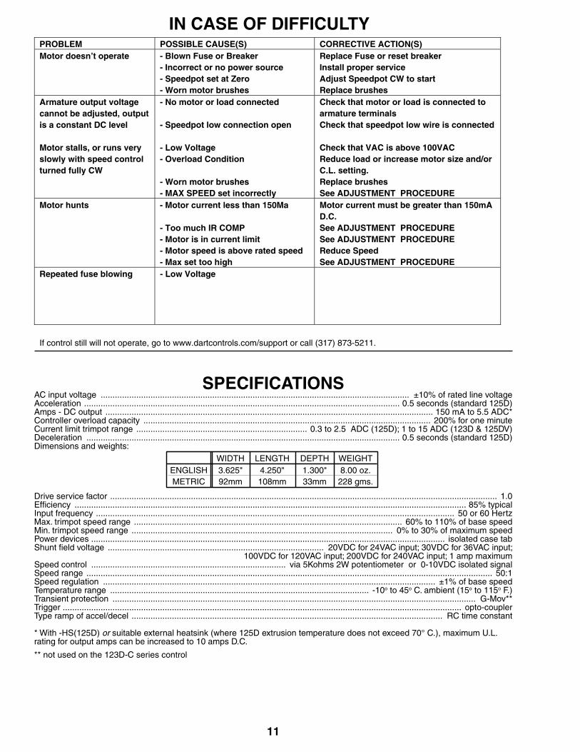
-55H option Isolated Signal Input Factory or Field Installed NOTE: This option cannot be used on the 123D-C series control.
This option card allows for the use of either a grounded or non-grounded remote DC signal such as 0 to 5 through 0 to 250Vdc, 4-20mA current, or a remote speed pot. The DC input signal type can be selected for voltage (Vin) or current (4-20mA) via the JP2 jumper clip. There is a Hi/Lo range jumper selection that should be set to the (Lo) setting when using a 4-20mA signal or voltage ranges of 0-5 through 0-25Vdc. When using voltage ranges of 0-25 through 0-250 this jumper must be set to (Hi). The GAIN trimpot is used to set full linear output in reference to the input signal range. The output of this remote signal isolation board is a linear signal that is proportional to the remote input signal being supplied.
(FOR SHUNT WOUND MOTOR, SEE PAGE 4 OF MANUAL FOR FIELD CONNECTIONS).
CAUTION: DO NOT use TRIMPOT ADJUSTMENT CHART. Set pots using directions in following SET-UP PROCEDURES.
SETUP PROCEDURE FOR -55H AND -56H OPTIONS1. With NO power to control, connect a DC Voltmeter to control outputs as follows: Meter COMMON to the -ARM terminal,
Meter POSITIVE to the +ARM terminal. Select correct meter range (0-90V or 0-180V).2. Preset GAIN pot on the remote signal board fully CCW. 3. Place the JP2 jumper clip in the proper position based on the input signal being used.4. Place the P4 jumper clip in the Lo position for 4-20mA signals or voltage signals less than 25Vdc. Place the P4 jumper clip
in the Hi position for voltage signals greater than 25Vdc. (NOTE: Never exceed 250Vdc)5. Make sure all connections are properly made per the hookup connection diagram and then apply AC power to the
controller.6. Set the remote input signal to its lowest setting. Adjust the MIN trimpot to deadband (the point just before an increase
causes an output).7. Apply the maximum remote input signal. Motor should start to run. Adjust the GAIN pot CW until no further increase in
control output voltage occurs and then decrease the gain pot slowly until output voltage to the motor drops approximately 5Vdc.
8. Set the MAX trimpot on the control to the correct motor voltage.9. Some interaction between trimpots may occur. Recheck the Min trimpot setting and repeat steps 6 through 8 as needed.
-56H option Isolated Signal Input with Auto / Manual Switch Factory or Field Installed NOTE: This option cannot be used on the 123D-C series control.
The -56H option is identical to the -55H option with the added ability to have remote Auto/Manual switching.See -55H for more further detail.
(FOR SHUNT WOUND MOTOR, SEE PAGE 4 OF MANUAL FOR FIELD CONNECTIONS).
CAUTION: DO NOT use TRIMPOT ADJUSTMENT CHART. Set pots using directions in following SET-UP PROCEDURES.
2
USE ONLY TERMINALS 1, 2, AND 3
OF DPDT SWITCHCONNECTS
UNDER WIPERSCREW P1-7
Range jumper connector is used to selectinput voltage range. When installed from P4-1to P4-2, the range is 0-25VDC through0-250VDC; when installed from P4-2 to P4-3,range is 0-5VDC through 0-25VDC.
NOTE:
31
= CUSTOMER WIRING= FACTORY WIRING
red
DPDT CENTER-OFF SWITCHTERMINAL DESIGNATION
(BACKSIDE VIEW)
1
3
2
6 - NO CONNECTION
4 - NO CONNECTION
5 - NO CONNECTION
-5
P1
P4 P3
P2
JP2
-4
-3
AC1
AC2
COM
+5V
SIG
4-20
Vin
HI LO
AC INPUT
AC INPUT
ARM
ARM+
- COMMON
SIGNAL
-56H Option Board
VOLTAGERANGE
JUMPERCONNECTOR
CU
STO
ME
R W
IRIN
G
GAIN POT
orange
white
yellowAUT MANUALO
INPUT TYPE
SELECTOR(V in OR 4-20 mA in)
11
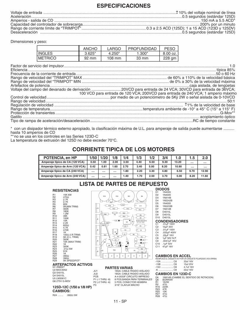
SPECIFICATIONSAC input voltage .................................................................................................................................. ±10% of rated line voltageAcceleration ..................................................................................................................................... 0.5 seconds (standard 125D)Amps - DC output .......................................................................................................................................... 150 mA to 5.5 ADC*Controller overload capacity ......................................................................................................................... 200% for one minuteCurrent limit trimpot range ........................................................................ 0.3 to 2.5 ADC (125D); 1 to 15 ADC (123D & 125DV)Deceleration .................................................................................................................................... 0.5 seconds (standard 125D)Dimensions and weights:
Drive service factor ................................................................................................................................................................... 1.0Efficiency ..................................................................................................................................................................... 85% typicalInput frequency ....................................................................................................................................................... 50 or 60 HertzMax. trimpot speed range ................................................................................................................. 60% to 110% of base speedMin. trimpot speed range .............................................................................................................. 0% to 30% of maximum speedPower devices ..................................................................................................................................................... isolated case tabShunt field voltage ........................................................................................... 20VDC for 24VAC input; 30VDC for 36VAC input;Shunt field voltage ........................................................ 100VDC for 120VAC input; 200VDC for 240VAC input; 1 amp maximumSpeed control .................................................................................. via 5Kohms 2W potentiometer or 0-10VDC isolated signalSpeed range ........................................................................................................................................................................... 50:1Speed regulation ............................................................................................................................................ ±1% of base speedTemperature range ............................................................................................................. -10o to 45o C. ambient (15o to 115o F.)Transient protection ......................................................................................................................................................... G-Mov**Trigger ........................................................................................................................................................................ opto-couplerType ramp of accel/decel ................................................................................................................................... RC time constant
* With -HS(125D) or suitable external heatsink (where 125D extrusion temperature does not exceed 70° C.), maximum U.L. rating for output amps can be increased to 10 amps D.C.
** not used on the 123D-C series control
ENGLISHMETRIC
3.625"92mm
4.250"108mm
1.300"33mm
8.00 oz.228 gms.
WIDTH LENGTH DEPTH WEIGHT
PROBLEM POSSIBLE CAUSE(S) CORRECTIVE ACTION(S) Motor doesn’t operate - Blown Fuse or Breaker
- Incorrect or no power source - Speedpot set at Zero - Worn motor brushes
Replace Fuse or reset breaker Install proper service Adjust Speedpot CW to start Replace brushes
Armature output voltage cannot be adjusted, output is a constant DC level Motor stalls, or runs very slowly with speed control turned fully CW
- No motor or load connected - Speedpot low connection open - Low Voltage - Overload Condition - Worn motor brushes - MAX SPEED set incorrectly
Check that motor or load is connected to armature terminals Check that speedpot low wire is connected Check that VAC is above 100VAC Reduce load or increase motor size and/or C.L. setting. Replace brushes See ADJUSTMENT PROCEDURE
Motor hunts - Motor current less than 150Ma - Too much IR COMP - Motor is in current limit - Motor speed is above rated speed - Max set too high
Motor current must be greater than 150mA D.C. See ADJUSTMENT PROCEDURE See ADJUSTMENT PROCEDURE Reduce Speed See ADJUSTMENT PROCEDURE
Repeated fuse blowing - Low Voltage
If control still will not operate, go to www.dartcontrols.com/support or call (317) 873-5211.
IN CASE OF DIFFICULTY
12
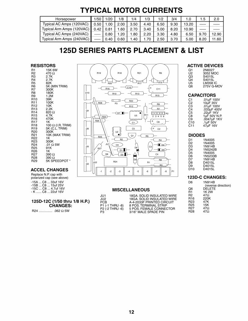
TYPICAL MOTOR CURRENTS
125D SERIES PARTS PLACEMENT & LIST
0.500.42----------
1.000.810.800.40
2.001.601.200.60
3.502.701.801.40
1/50 1/20 1/8 1/4HorsepowerTypical AC Amps (120VAC)Typical Arm Amps (120VAC)Typical AC Amps (240VAC)Typical Arm Amps (240VAC)
4.403.402.201.70
1/36.505.003.302.50
1/29.308.204.803.70
3/413.2010.90
6.505.00
1.0----------9.708.20
1.5----------
12.9011.60
2.0
RESISTORS
CAPACITORS
MISCELLANEOUS
ACTIVE DEVICES
DIODES
R1R2R3R4R5R6R7R8R9R10R11R12R13R14R15R16R17R18R19R20R21R22R23R24R25R26R27R28R29
15K 6W470 Ω2.7K2.7K82K5K (MIN TRIM)300K180K1.2M39K100K10K2.2K820 Ω4.7K470K1K100 Ω (I.R. TRIM)5K (C.L. TRIM)300K10K (MAX TRIM)1K300K.01 Ω 5W91K1K390 Ω390 Ω5K SPEEDPOT *
C1C2C3C4C5C8C9C10C11
.01µF 100V10µF 35V.01µF 100V.033µF 400V.22µF 1KV1µF 50V N.P..0047µF 1KV.1µF 50V47µF 16V
D1D2D3D4D5D6D7D8D9D10
1N40051N40051N914B1N5242B1N40051N5233B1N914BD4015LD4015LD4015L
Q1U2Q3Q4U5Q6
2N60273052 MOCS4015LS4015LLM358 IC275V G-MOV
JU1JU2PCBP1 (-1 THRU -8)P2 (-2 THRU -6)P3
18GA. SOLID INSULATED WIRE18GA. SOLID INSULATED WIREA-4-2033F PRINTED CIRCUIT8 POS. TERMINAL STRIP5 POS. FEMALE CONNECTOR3/16" MALE SPADE PIN
R24
Q1
C4
P1-8-7-6-5-4-3-2-1
C9
U5 R11
R3
U2
P3
D5
Q3
D1
C1
C3D9
D8
Q4
D10
D3
R4
R5R25R2
R27
R26
R23
C8
R7
P265432
C11
R12
R13R10
R17
R6R21R18R19
R24 ............... .062 Ω 5W
125D-12C (1/50 thru 1/8 H.P.)CHANGES:
D2
R1R8
D6D4
C5 C2
R20 R14
R9
R15
R22
R16
R28
D7
Q6
JU2
JU1
ACCEL CHANGESReplace N.P. cap withpolarized cap (see above)-15A ... C8 ... 33uf 16V-15B ... C8 ... 15uf 25V-15C ... C8 ... 4.7uf 16V- K ...... C8 ... 22uf 16V
123D-C CHANGES:D6
Q6R1R2R16R23R25R27R28
1N914B (reverse direction)DELETE1K 2W47Ω220K47K15K47Ω47Ω
C10
+
+
+
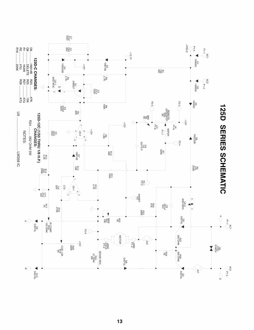
13
125D S
ER
IES
SC
HE
MA
TIC
123D-C
CH
AN
GE
S:
D6 ..............1N
914BQ
6 .............. DE
LET
ER
1 .............. 1K2W
R2 .............. 47Ω
R16 ............ 220K
R23 ..............47K
R25 .............. 15K
R27 .............. 47Ω
R28 .............. 47Ω

14
NOTES:
CONTENIDO
GARANTIA .........................................................................................................................................................................................1INTRODUCCION ................................................................................................................................................................................2CARACTERISTICAS DE CONTROL .................................................................................................................................................2DIAGRAMA DE DIMENSIONES DEL 125D ......................................................................................................................................2DIMENSIONES DEL DISIPADOR TERMICO HS (125D) ..................................................................................................................2MONTAJE ..........................................................................................................................................................................................3SELECCION DE MODELO ................................................................................................................................................................3PROCEDIMIENTO DE ALAMBRADO ...............................................................................................................................................3FUSIBLES ..............................................................................................................................................................3ALAMBRADO DE LA BANDA DE TERMINALES .........................................................................................................................3-4DIAGRAMAS DE CONEXION ...........................................................................................................................................................4PROCEDIMIENTO DE ARRANQUE .................................................................................................................................................4CUADRO DE AJUSTE DEL POTENCIÓMETRO REGULADOR "TRIMPOT" ..............................................................................5PROCEDIMIENTOS DE AJUSTE ......................................................................................................................................................5OPERACION DE DOS VELOCIDADES ............................................................................................................................................6FRENADO DINAMICO .......................................................................................................................................................................6RETROALIMENTACION DEL TACOMETRO .....................................................................................................................................6FUNCION DE INHIBICION ................................................................................................................................................................6ENSAMBLE DEL JUEGO DE POTENCIÓMETRO DE VELOCIDAD "SPEEDPOT" .......................................................................7OPCIONES -1 / -2A ............................................................................................................................................................................7OPCIONES -5 -7 .............................................................................................................................................................................8-9OPCIONES -11 -15 ............................................................................................................................................................................9OPCIONES -29B ..............................................................................................................................................................................10EN CASO DE DIFICULTAD .............................................................................................................................................................10ESPECIFICACIONES ......................................................................................................................................................................11CORRIENTE TIPICA DE LOS MOTORES .......................................................................................................................................11LISTA DE PARTES DE REPUESTO ................................................................................................................................................11DIBUJO ESQUEMATICO ................................................................................................................................................................12
GARANTIADart Controls, Inc. (DCI) garantiza que sus productos están libres de defectos de materiales y mano de obra. El único derecho que otorga esta garantía es que la fábrica DCI reemplace cualquier parte o partes del producto que dentro del término de doce (12) meses a partir de la entrega del producto al comprador la parte o partes defectuosas sean devueltas a la fábrica de DCI con todos los costos de transporte prepagados, y las cuales DCI encuentre a su satisfacción que en realidad son defectuosas. Esta garantía no cubre los defectos en montaje por personas distintas a DCI, ni ningún articulo que haya sido reparado o alterado por personas distintas a DCI, ni cualquier artículo que DCI determine que ha sido usado en forma indebida. DCI no asume ninguna responsabilidad por las características de diseño de ninguna unidad o su operación en un circuito o ensamblaje. Esta garantía sustituye cualquier otra garantía expresa o implícita. Por lo tanto cualquier otra responsabilidad u obligación de parte de DCI, incluyendo daños consecuenciales quedan aquí expresamente excluidos.
NOTA: Revise cuidadosamente el control para detectar daños sufridos en el transporte. Avise inmediatamente de cualquier daño a la compañía transportadora. No trate de operar el aparato si es evidente que ha sufrido daños en el circuito o en cualquiera de sus componentes electrónicos.Toda la información contenida en este manual se considera correcta, sin embargo datos e información que aparecen en el man-ual están sujetos a cambio sin aviso previo. DCI no garantiza en ninguna forma esta información o datos. Más aún, DCI no es responsable por omisiones o errores o daños consecuenciales causados por el usuario del producto. DCI se reserva el derecho de hacer cambios de fabricación que pueden no estar incluidos en este manual.
ADVERTENCIALa instalación u operación inadecuadas de este control pueden causar lesiones al personal o fallas de control. El con-trol debe instalarse de acuerdo con los Códigos de Seguridad nacionales, estatales y locales. ¡¡¡Asegúrese de que la corriente de alimentación está desconectada antes de tratar de dar mantenimiento al control o remover cualquiera de sus componentes!!! Si el punto de desconexión de la corriente no está a la vista, asegúrelo en posición desconectada y coloque un aviso para evitar una aplicación inesperada de la corriente. Unicamente electricistas calificados o personal de mantenimiento calificado deben realizar tareas de mantenimiento o reparación eléctricos. Nunca debe verificarse la continuidad de un circuito haciendo corto circuito en los terminales con un destornillador o herramienta metálica.
1 - Sp
10,8
MIN
MAX
IR COMP
CUR LIM
-8
-7
-6
-5
-4
-3
-2
-1
P1
9,21
9,53
4,45
1,76
0,97
3,3
0,63
3,492
.0,554
14,287
14,287
1,746
15,875
1,746
2 - Sp
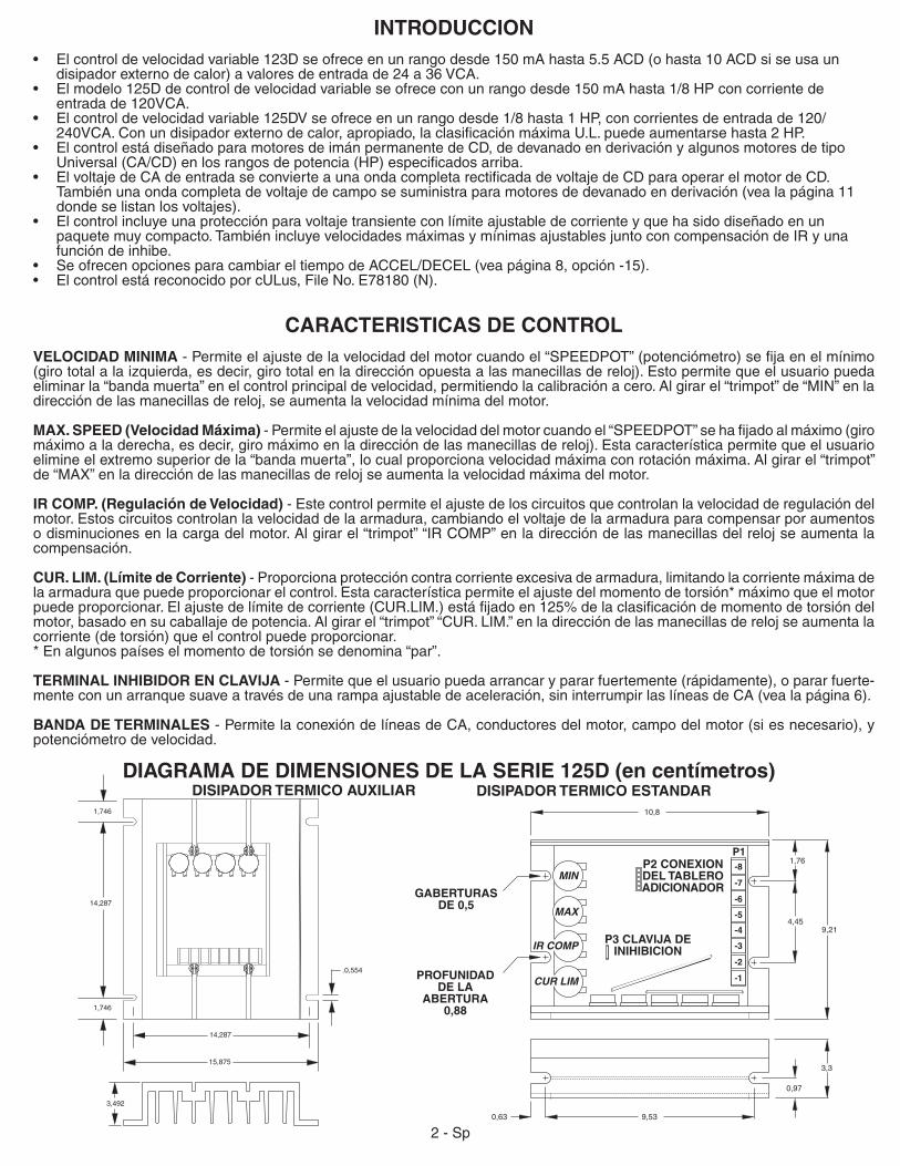
INTRODUCCION• Elcontroldevelocidadvariable123Dseofreceenunrangodesde150mAhasta5.5ACD(ohasta10ACDsiseusaun disipadorexternodecalor)avaloresdeentradade24a36VCA.• Elmodelo125Ddecontroldevelocidadvariableseofrececonunrangodesde150mAhasta1/8HPconcorrientede entradade120VCA.• Elcontroldevelocidadvariable125DVseofreceenunrangodesde1/8hasta1HP,concorrientesdeentradade120/ 240VCA.Conundisipadorexternodecalor,apropiado,laclasificaciónmáximaU.L.puedeaumentarsehasta2HP.• ElcontrolestádiseñadoparamotoresdeimánpermanentedeCD,dedevanadoenderivaciónyalgunosmotoresdetipo Universal(CA/CD)enlosrangosdepotencia(HP)especificadosarriba.• ElvoltajedeCAdeentradaseconvierteaunaondacompletarectificadadevoltajedeCDparaoperarelmotordeCD. También una onda completa de voltaje de campo se suministra para motores de devanado en derivación (vea la página 11 donde se listan los voltajes).• Elcontrolincluyeunaprotecciónparavoltajetransienteconlímiteajustabledecorrienteyquehasidodiseñadoenun paquete muy compacto. También incluye velocidades máximas y mínimas ajustables junto con compensación de IR y una función de inhibe. • SeofrecenopcionesparacambiareltiempodeACCEL/DECEL(veapágina8,opción-15).• ElcontrolestáreconocidoporcULus,FileNo.E78180(N).
CARACTERISTICAS DE CONTROLVELOCIDAD MINIMA -Permiteelajustedelavelocidaddelmotorcuandoel“SPEEDPOT”(potenciómetro)sefijaenelmínimo(giro total a la izquierda, es decir, giro total en la dirección opuesta a las manecillas de reloj). Esto permite que el usuario pueda eliminar la “banda muerta” en el control principal de velocidad, permitiendo la calibración a cero. Al girar el “trimpot” de “MIN” en la dirección de las manecillas de reloj, se aumenta la velocidad mínima del motor.
MAX. SPEED (Velocidad Máxima) -Permiteelajustedelavelocidaddelmotorcuandoel“SPEEDPOT”sehafijadoalmáximo(giromáximo a la derecha, es decir, giro máximo en la dirección de las manecillas de reloj). Esta característica permite que el usuario elimine el extremo superior de la “banda muerta”, lo cual proporciona velocidad máxima con rotación máxima. Al girar el “trimpot” de “MAX” en la dirección de las manecillas de reloj se aumenta la velocidad máxima del motor.
IR COMP. (Regulación de Velocidad) - Este control permite el ajuste de los circuitos que controlan la velocidad de regulación del motor. Estos circuitos controlan la velocidad de la armadura, cambiando el voltaje de la armadura para compensar por aumentos o disminuciones en la carga del motor. Al girar el “trimpot” “IR COMP” en la dirección de las manecillas del reloj se aumenta la compensación.
CUR. LIM. (Límite de Corriente) - Proporciona protección contra corriente excesiva de armadura, limitando la corriente máxima de la armadura que puede proporcionar el control. Esta característica permite el ajuste del momento de torsión* máximo que el motor puedeproporcionar.Elajustedelímitedecorriente(CUR.LIM.)estáfijadoen125%delaclasificacióndemomentodetorsióndelmotor,basadoensucaballajedepotencia.Algirarel“trimpot”“CUR.LIM.”enladireccióndelasmanecillasderelojseaumentalacorriente (de torsión) que el control puede proporcionar.* En algunos países el momento de torsión se denomina “par”.
TERMINAL INHIBIDOR EN CLAVIJA - Permite que el usuario pueda arrancar y parar fuertemente (rápidamente), o parar fuerte-menteconunarranquesuaveatravésdeunarampaajustabledeaceleración,sininterrumpirlaslíneasdeCA(vealapágina6).
BANDA DE TERMINALES - Permite la conexión de líneas de CA, conductores del motor, campo del motor (si es necesario), y potenciómetro de velocidad.
DIAGRAMA DE DIMENSIONES DE LA SERIE 125D (en centímetros)DISIPADOR TERMICO AUXILIAR DISIPADOR TERMICO ESTANDAR
PROFUNIDAD DE LA
ABERTURA 0,88
P2 CONEXION DEL TABLERO ADICIONADORGABERTURAS
DE 0,5
P3 CLAVIJA DE INIHIBICION
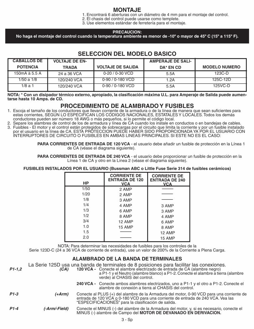
MONTAJE 1.Encontrará6aberturasconundiámetrode4mmparaelmontajedelcontrol. 2. El chasis del control puede usarse como templete. 3.Useelementosestándardeferreteríaparaelmontaje.
PRECAUCION: No haga el montaje del control cuando la temperatura ambiente es menor de -10º o mayor de 45º C (15º a 115º F).
NOTA: * Con un disipador térmico externo, apropiado, la clasificación máxima U.L. para Amperaje de Salida puede aumen-tarse hasta 10 Amps. de CD.
MODELO NUMERO
123C-D
125C-12D
125VC-D
VOLTAJE DE SALIDA
0-20/0-30VCD
0-90/0-180VCD
0-90/0-180VCD
CABALLOS DE
POTENCIA
150mAà5.5A
1/50a1/8
1/8a1
VOLTAJE DE EN-
TRADA
24a36VCA
120/240VCA
120/240VCA
AMPERAJE DE SALI-
DA* EN CD
5.5A
1.2A
5.5A
SELECCION DEL MODELO BASICO
PROCEDIMIENTO DE ALAMBRADO Y FUSIBLES1. Escojaeltamañodelosconductoresquellevancorrientedelaarmaduraodelalíneademaneraqueseansuficientespara estascorrientes,SEGÚNLOESPECIFICANLOSCÓDIGOSNACIONALES,ESTATALESYLOCALES.Todoslosdemás conductorespuedensernúmero18AWGomáspequeños,silopermiteelcódigolocal.2. Separe los alambres de control de los de armadura y línea de CA cuando los instale en conductos o en bandejas de cables. 3. Fusibles-Elmotoryelcontrolestánprotegidosdesobrecargasporelcircuitoquelimitalacorrienteyporunfusibleinstalado porelusuarioenlalíneadeCA.ESTAPROTECCIONPUEDEHABERSIDOPROPORCIONADAYAPORELUSUARIOCON INTERRUPTORESDECIRCUITOOFUSIBLESENAMBASLINEASPRINCIPALES.SIESTENOESELCASO:
PARA CORRIENTES DE ENTRADA DE 120 VCA -elusuariodebeañadirunfusibledeprotecciónenlaLínea1 de CA (véase el diagrama siguiente).
PARA CORRIENTES DE ENTRADA DE 240 VCA - el usuario debe proporcionar un fusible de protección en la Línea1deCAyotroenlaLínea2(véaseeldiagramasiguiente).
FUSIBLES INSTALADOS POR EL USUARIO (Bussman ABC o Little Fuse Serie 314 de fusibles cerámicos)
NOTA: Para determinar las necesidades de fusibles para los controles de la Serie123D-C (24a36VCAdecorrientedeentrada),useunvalorde200%delaCorrienteaPlenaCarga.
ALAMBRADO DE LA BANDA DE TERMINALESLaSerie125Dusaunabandadeterminalesde8posicionesparafacilitarlasconexiones.
HP1/501/201/81/41/31/23/41.01.52.0
CORRIENTE DE ENTRADA DE 120
VCA2 AMP2 AMP3AMP4 AMP6AMP8AMP12 AMP15AMP
CORRIENTE DE ENTRADA DE 240
VCA
3AMP3AMP4 AMP6AMP8AMP12 AMP15AMP
P1-1,2 (CA) 120 VCA - Conecte el alambre electrizado de entrada de CA (alambre negro) a P1-1 y el Neutro (alambre blanco) a P1-2. Conecte el alambre a tierra (alambre verde)alCHASISdelcontrol.
240 VCA - Conecte ambos alambres electrizados, uno a P1-1 y el otro a P1-2. Conecte el alambredeconexiónatierraalCHASISdelcontrol. P1-3 (+Arm) ConectealPLUS(+)delalambredelaArmaduradelmotor,0-90VCDparaunacorrientede entradade120VCAo0-180VCDparaunacorrientedeentradade240VCA.Vealas “ESPECIFICACIONES”paralaclasificacióndesalida.
P1-4 (-Arm/-Field) ConecteelMINUS(-)delalambredelaArmaduradelmotor,y,siesnecesario,conecteel MINUS(-)alambredeCampodelMOTOR DE DEVANADO EN DERIVACION.
3-Sp
MIN
MAX
IR COMP
CUR LIM
P1-8
-7
-6
-5
-4
-3
-2
-1
(Continuación)
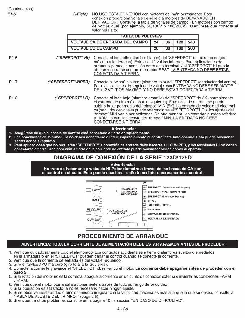
P1-6 (“SPEEDPOT” HI) Conecta al lado alto (alambre blanco) del “SPEEDPOT” (el extremo de giro máximoaladerecha).Estoes+12voltiosinternos.Paraaplicacionesde arranque-paradalaconexiónentreesteterminalyel“SPEEDPOT”HIpuede abrirse y cerrarse con un interruptor SPST. LAENTRADANODEBEESTAR CONECTA DA A TIERRA.
P1-7 (“SPEEDPOT” WIPER) Conecta al “wiper” o cursor (alambre rojo) del “SPEEDPOT” (conductor del centro). Para aplicaciones de seguidor de voltaje esta ENTRADANODEBESERMAYOR DE+12VOLTIOSMÁXIMO,YNODEBEESTARCONECTADAATIERRA.
P1-8 (“SPEEDPOT” LO) Conectaalladobajo(alambreamarillo)del“SPEEDPOT”de5K(normalmente el extremo de giro máximo a la izquierda). Este nivel de entrada se puede subirobajarpormediodel“trimpot”MIN(5K).Laentradadevelocidadelectróni ca(seguidordevoltaje)puedereferenciarseal“SPEEDPOT”LOsilosajustesdel “trimpot” MIN van a ser activados. De otra manera, las entradas pueden referirse a -ARM, lo cual las desvía del “trimpot” MIN. LAENTRADANODEBE CONECTARSE A TIERRA.
TABLA DE VOLTAJES
VOLTAJE CA DE ENTRADA DEL CAMPO 24 36 120 240
VOLTAJE CD DE CAMPO 20 30 100 200
P1-5 (+Field) NOUSEESTACONEXIÓNconmotoresdeimánpermanente.Esta conexiónproporcionavoltajede+FieldamotoresdeDEVANADOEN DERIVACIÓN.(Consultelatabladevoltajesdecampo.)Enmotoresconcampo de volt je dual (por ejemplo, 50/100V o 100/200V), asegúrese que conecta el valor más alto.
Advertencia:1. Asegúrese de que el chasis de control está conectado a tierra apropiadamente.2. Las conexiones de la armadura no deben conectarse o interrumpirse cuando el control está funcionando. Esto puede ocasionar serios daños al aparato.3. Para aplicaciones que no requieren “SPEEDPOT” la conexión de entrada debe hacerse al LO. WIPER, y los terminales HI no deben conectarse a tierra! Una conexión a tierra de la corriente de entrada puede ocasionar serios daños al aparato.
DIAGRAMA DE CONEXIÓN DE LA SERIE 123D/125DAdvertencia:
No trate de hacer una prueba de Hi-Potenciómetro a través de las líneas de CA con el control en circuito. Esto puede ocasionar daño inmediato o permanente al control.
PROCEDIMIENTO DE ARRANQUEADVERTENCIA: TODA LA CORRIENTE DE ALIMENTACIÓN DEBE ESTAR APAGADA ANTES DE PROCEDER!
1.Verifiquecuidadosamentetodoelalambrado.Loscontactosaccidentalesatierraoalambressueltosoenredados en la armadura o en el “SPEEDPOT” pueden dañar el control cuando se conecte la corriente.2.Verifiquequelacorrientedeentradaesdelvoltajerequerido.3.Gireel“SPEEDPOT”acero(girototalalaizquierda).4. Conecte la corriente y avance el “SPEEDPOT” observando el motor. La corriente debe apagarse antes de proceder con el paso 5!5.Silarotacióndelmotornoeslacorrecta,apaguelacorrienteenunpuntodeconexiónexternaeinviertalasconexiones+ARM y -ARM.6.Verifiquequeelmotoroperasatisfactoriamenteatravésdetodosurangodevelocidad.7.Silaoperaciónessatisfactorianoesnecesariohacerningúnajuste.8.Siseobservainestabilidadofuncionamientoirregularosilavelocidadmáximaesmásaltaquelaquesedesea,consultela “TABLADEAJUSTEDELTRIMPOT”(página5).9.Siencuentraotrosproblemasconsulteenlapágina10,lasección“ENCASODEDIFICULTAD”.
INDUCIDO
SPEEDPOT LO (alambre anaranjado)
SPEEDPOT HI (alambre blanco)
SITIO +
INDUCIDO - / SITIO -
VOLTAJE CA DE ENTRADA
VOLTAJE CA DE ENTRADA
SPEEDPOT WIPER (alambre rojo)P2 CONEXION DE TABLERO
ADICIONADOR
P3 CLAVIJA DE INHIBICION
4 - Sp
C.L. I.R. MAX MIN
1/4
1/3
1/2
3/4*
1.0*
1/20
1/8
HP
125DV-C
1.5*
2.0*
1/4
125D-12C
C.L. I.R. MAX MIN
1/8
1/4
1/3
1/2
3/4*
1/50
1/20
HP
125DV-C
1.0*
1/8
125D-12C
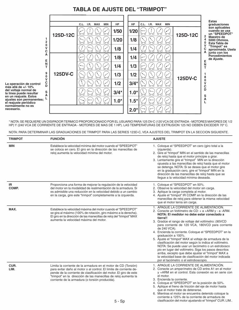
TABLA DE AJUSTE DEL “TRIMPOT”
5-Sp
FUNCIÓN
Establece la velocidad mínima del motor cuando el “SPEEDPOT” se coloca en cero. El giro en la dirección de las manecillas de reloj aumenta la velocidad mínima del motor.
Proporciona una forma de mejorar la regulación de la velocidad del motor en la modalidad de realimentación de la armadura. Si es admisible una reducción en la velocidad debido a un cambio en la carga, gire este “trimpot” completamente a la izquierda.
Establece la velocidad máxima del motor cuando el “SPEEDPOT” segiraalmáximo(100%derotación,giromáximoaladerecha).El giro en la dirección de las manecillas de reloj del “trimpot” MAX aumenta la velocidad máxima del motor.
LimitalacorrientedelaarmaduraenelmotordeCD(Torsión)para evitar daño al motor o al control. El límite de corriente de-pendedelacorrientedeclasificacióndelmotor.Elgirodeeste“trimpot” en la dirección de las manecillas de reloj aumenta la corriente de la armadura (o torsión producida).
TRIMPOT
MIN
IR COMP.
MAX.
CUR.LIM.
AJUSTE
1. Coloque el “SPEEDPOT” en cero (giro total a la izquierda).2. Gire el “trimpot” MIN en el sentido de las manecillas de reloj hasta que el motor principie a girar.3. Lentamentegireel“trimpot”MINenladirección opuesta a las manecillas de reloj hasta que el motor se detenga. NOTA: Si se desea que el motor gire en la graduación cero, gire el “trimpot” MIN en la dirección de las manecillas de reloj hasta que se llegue a la velocidad mínima deseada.
1. Coloqueel“SPEEDPOT”en50%.2. Observe la velocidad del motor sin carga.3. Apliquelacargacompletaalmotor.4. Ajuste el “trimpot” IR COMP. en la dirección de las manecillas de reloj para obtener la misma velocidad que el motor tenía sin carga.
1. APAGUELACORRIENTEDEALIMENTACIÓN. 2. ConecteunVoltímetrodeCD:+a+ARMy-a-ARM. NOTA: El medidor no debe estar conectado a tierra!!3. Gradúeelrangodevoltajedelvoltímetro:(90VCD para corriente de 120VCA, 180VCD para corriente de240VCA).4. Encienda la corriente. Coloque el “SPEEDPOT” en la graduacióna100%.5. Ajusteel“trimpot”MAXalvoltajedearmaduradela clasificacióndelmotorsegúnloindicaelvoltímetro. NOTA: Se puede usar un tacómetro o un estrobosco pio en lugar del voltímetro. Siga los pasos descritos arriba, excepto que debe ajustar el “trimpot” MAX a lavelocidadbasedeclasificacióndelmotorindicada por el tacómetro o el estroboscopio.
1. APAGUELACORRIENTEDEALIMENTACIÓN.2. Conecte un amperímetro de CD entre A1 en el motor y+ARMenelcontrol.Estaconexiónesenseriecon el motor.3. Enciendalacorriente.4. Coloqueel“SPEEDPOT”enlaposiciónde50%.5. Apliqueelfrenodefriccióndelejedemotorhasta que el motor trate de detenerse. 6. Mientraselmotorseencuentradetenidocoloquela corrientea125%delacorrientedearmadurade clasificacióndelmotorajustandoel“trimpot”CUR.LIM..
*NOTA:SEREQUIEREUNDISIPADORTERMICOPROPORCIONADOPORELUSUARIOPARA125DV-C(120VCADEENTRADA-MOTORESMAYORESDE1/2HP)Y(240VCADECORRIENTEDEENTRADA-MOTORESDEMASDE1HP).LASTEMPERATURASDEEXTRUSION125NODEBENEXCEDER70ºC.
NOTA:PARADETERMINARLASGRADUACIONESDETRIMPOTPARALASSERIES123D-C,VEAAJUSTESDELTRIMPOTENLASECCIONSIGUIENTE.
120VCA
ENT
90VCD
SAL
240VCA
ENT
180VCD
SAL
Estas graduaciones son aplicables cuando se usa un "SPEEDPOT" Maestro de 5000 Ohmios. Esta Tabla de "Trimpot" es aproximada. Usela junto con los Porcedimientos de Ajuste.
La operación de control más allá de +/- 10% del voltaje normal de la línea puede resultar en un reajuste. Estos ajustes son permanentes; el reajuste periódico normalmente no es necesario.

-7
-8
-6
P1
SPST
INHIBIT(P3)
WIPER
LO
HI
-7
-8
-6
P1
SPDTWIPER
LO
HI
INHIBIT(P3)
+
-
+
-
-7
-8
W
LO
HI
P1
-7
-8
-6
WHI
LOW
HI
LOP1
HISPDT
-5
-6
-3
-4
DPDT SWITCH (N.C.)
FRENADO DINÁMICO
Se usa un interruptor DPDT para inhibir el control y conectar el DBR.LosvalorestípicosdelDBR(DynamicBrakeResistor,resist-enciadefrenodinámico)son5Ohmiospara120V,y10Ohmiospara240V(ambos35Wa50W).NotequelapotenciaenHPdelmotor, la inercia y el tiempo del ciclo afectan el dimensionamiento delDBR.NOTA: Estamodificaciónnopuedeserusadaconnin-gunadelasopciones-15.
OPERACIÓN DE DOS VELOCIDADES
Laoperacióncondospotenciómetrossehaceusandodospotenciómetrosdevelocidadde10KOhmiosenparalelo(ambosHIaP1-6yambosLOaP1-8).ElWIPERseconmutausandouninterruptorSPDT.
MODIFICATIONS DE LA COMMANDE
RETROALIMENTACION DEL TACOMETRO
Mejoralaregulacióndelavelocidada+o-1/2%dela velocidad de base.
SEGUIDOR DE TACOMETRO
Permite que el control de salida siga el voltaje del tacómetro.
NOTA: NECESITA 1% O MENOS - DISTORSION EN LA ONDA DE SALIDA DEL TACOMETRO
INHIBICION (USADO CON “SPEEDPOT”)
El contacto Común del interruptor SPDT se conecta al po-tenciómetro de control HI y conmuta entre “SPEEDPOT” HIy laclavijade InhibiciónP3.Para inhibir (detenerelmotor)el“SPEEDPOT”HIsecierraalaclavijadeInhibición.Parareiniciarlaoperación,elinterruptorsedevuelvea“SPEEDPOT”HI.NOTA:El control detiene rápidamente y arranca suavemente a través deunrangodeaceleraciónfijado.
INHIBICIÓN (USADA INDEPENDIENTEMENTE)
El interruptor SPST, suministrado por el usuario, se conectaenserieentreel“SPEEDPOT”HI (P1-6)y laclavijadeInhibición(P3).Parainhibir(pararelmotor),el“SPEEDPOT”HIsecierraa laclavijade Inhibición.Para reiniciar la operación el interruptor se vuelve a su posición abierta. NOTA: El control detiene y arranca el motor rápidamente.
NOTA: Permite arrancar y detener el motor sin interrumpir las líneas de CA. En caso de que falle el SCR o haya disparo en falso, el circuito de Inhibición no detiene el motor.
6-Sp
DOS "SPEEDPOTS" DE 10KINHIBE P3
El interruptor o relé debe ser de clasificación 3 veces el amperaje a plena carga.
RESISTENCIA DEL FRENO DINAMICOMOTOR
TACOMETRO
P1-7 POT WIPER
P1-8 POT LO
TACOMETRO
P3 INHIBICION
P1-4 ARM -
SPEEDPOT
INHIBICION (P3)
INHIBICION (P3)
6VCD a VELOCIDAD BASE (3VCD a 1000
RPM PARA MOTOR DE 1800 RPM) 12VCD a VELOCIDAD PLENA
SPEEDPOT
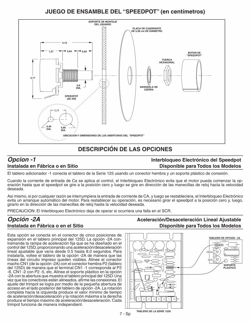
JUEGO DE ENSAMBLE DEL “SPEEDPOT” (en centímetros)
Opcion -1 Interbloqueo Electrónico del SpeedpotInstalada en Fábrica o en Sitio Disponible para Todos los ModelosEltableroadicionador-1conectaeltablerodelaSerie125usandounconectorhembrayunsoporteplásticodeconexión.
Cuando la corriente de entrada de Ca se aplica al control, el Interbloqueo Electrónico evita que el motor pueda comenzar la op-eración hasta que el speedpot se gire a la posición cero y luego se gire en dirección de las manecillas de reloj hacia la velocidad deseada.
Así mismo, si por cualquier razón se interrumpiera la entrada de corriente de CA, y luego se restableciera, el Interbloqueo Electrónico evita un arranque automático del motor. Para restablecer su operación, es necesario girar el speedpot a la posición cero y, luego, girarlo en la dirección de las manecillas de reloj hasta la velocidad deseada.
PRECAUCION:ElInterbloqueoElectrónicodejadeoperarsiocurrieraunafallaenelSCR.
Opción -2A Aceleración/Desaceleración Lineal AjustableInstalada en Fábrica o en el Sitio Disponible para Todos los Modelos
Esta opción se conecta en el conector de cinco posiciones de expansióneneltableroprincipaldel125D.Laopción-2Acon-tramandalarampadeaceleraciónfijaquesehadiseñadoenelcontroldel125D,proporcionandounaaceleración/desaceleraciónlinealajustablequevaríadesde0.5hasta8.0segundos.Parainstalarla, voltee el tablero de la opción -2A de manera que las líneas del circuito impreso queden visibles. Alinee el conector macho CN1 (de la opción -2A) con el conector hembra P2 (tablero del125D)demaneraqueelterminalCN1-1correspondaalP2-6,CN1-2conP2-5,etc.Alineeelsoporteplásticoenlaopción-2Aconlaaberturaquemuestraeltableroprincipaldel125D.Unavezquelosconectoresestánalineados,afirmelasconexiones.Elajuste del trimpot se logra por medio de la pequeña abertura de accesoenelladoposteriordeltablerodeopción-2A.Larotacióncompleta hacia la izquierda produce el valor mínimo de tiempo deaceleración/desaceleraciónylarotaciónmáximaaladerechaproduceeltiempomáximodeaceleración/desaceleración.Cadatrimpot funciona de manera independient.
SPEEDPOT (5K 2W)
SOPORTE DE MONTAJE DEL USUARIO
PLACA DE CUADRANTE DE 5,08 cm DE DIÁMETRO
ARANDELA DE CIERRA
TUERCA HEXAGONAL
BOTON DE "SPEEDPOT"
UBICACION Y DIMENSIONES DE LAS ABERTURAS DEL "SPEEDPOT"
3,17
1,27
3,15
0,94 0,94
1,11
0,40 DIA.
0,95 DIA.
DESCRIPCIÓN DE LAS OPCIONES
0,6 DIA.
TABLERO DE OPCION - 2A
TABLERO DE LA SERIE 125D
SOPORTE PLASTICO
DECEL
ACEL
7-Sp
8-Sp
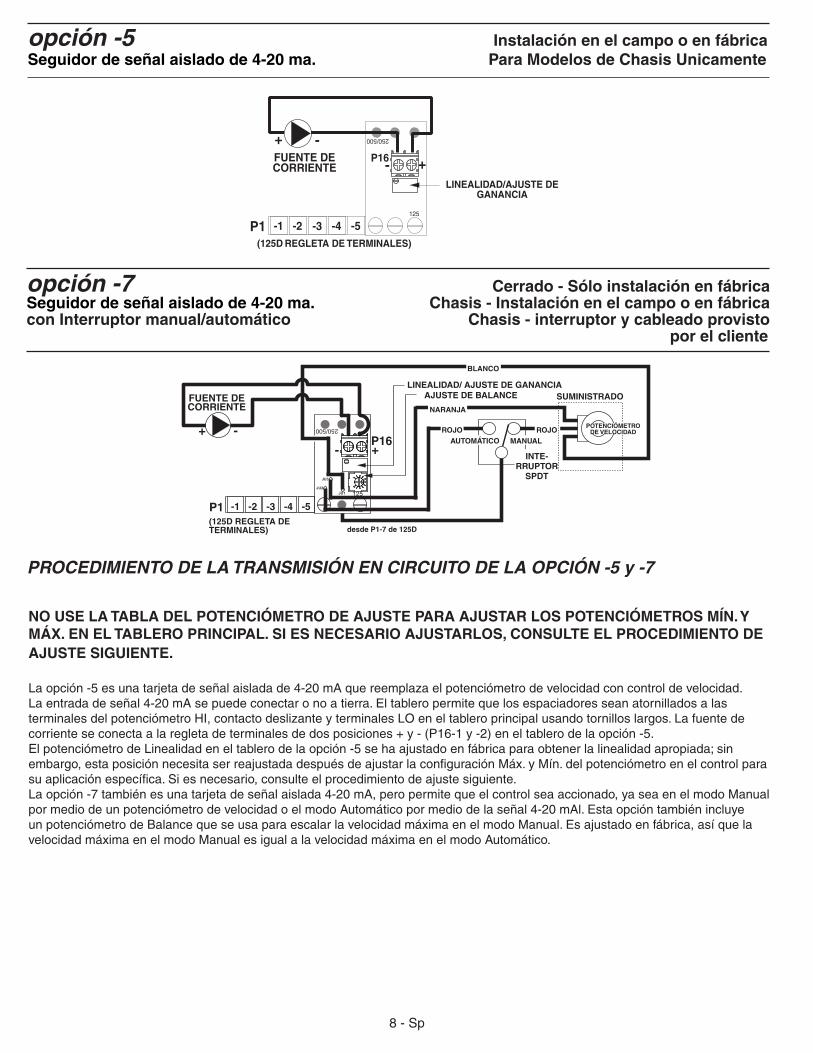
opción -5 Instalación en el campo o en fábricaSeguidor de señal aislado de 4-20 ma. Para Modelos de Chasis Unicamente
NO USE LA TABLA DEL POTENCIÓMETRO DE AJUSTE PARA AJUSTAR LOS POTENCIÓMETROS MÍN. Y MÁX. EN EL TABLERO PRINCIPAL. SI ES NECESARIO AJUSTARLOS, CONSULTE EL PROCEDIMIENTO DE AJUSTE SIGUIENTE.
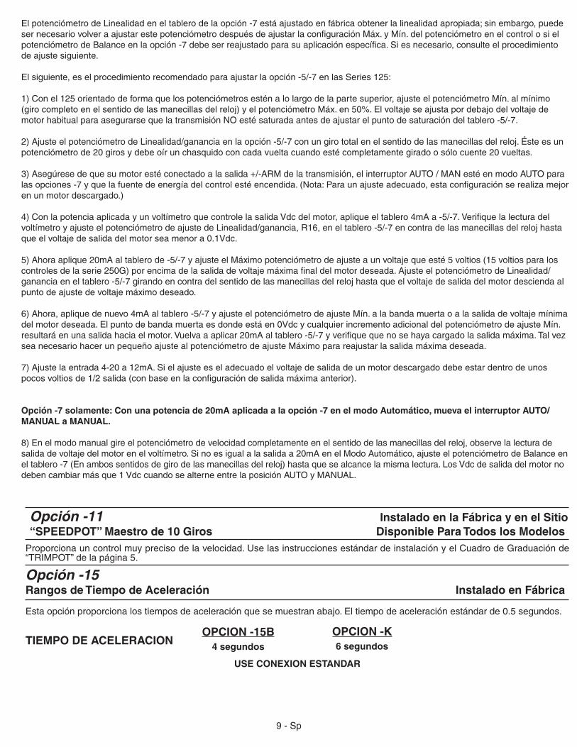
Laopción-5esunatarjetadeseñalaisladade4-20mAquereemplazaelpotenciómetrodevelocidadconcontroldevelocidad.Laentradadeseñal4-20mAsepuedeconectaronoatierra.EltableropermitequelosespaciadoresseanatornilladosalasterminalesdelpotenciómetroHI,contactodeslizanteyterminalesLOeneltableroprincipalusandotornilloslargos.Lafuentedecorrienteseconectaalaregletadeterminalesdedosposiciones+y-(P16-1y-2)eneltablerodelaopción-5.ElpotenciómetrodeLinealidadeneltablerodelaopción-5sehaajustadoenfábricaparaobtenerlalinealidadapropiada;sinembargo,estaposiciónnecesitaserreajustadadespuésdeajustarlaconfiguraciónMáx.yMín.delpotenciómetroenelcontrolparasuaplicaciónespecífica.Siesnecesario,consulteelprocedimientodeajustesiguiente.Laopción-7tambiénesunatarjetadeseñalaislada4-20mA,peropermitequeelcontrolseaaccionado,yaseaenelmodoManualpormediodeunpotenciómetrodevelocidadoelmodoAutomáticopormediodelaseñal4-20mAl.EstaopcióntambiénincluyeunpotenciómetrodeBalancequeseusaparaescalarlavelocidadmáximaenelmodoManual.Esajustadoenfábrica,asíquelavelocidad máxima en el modo Manual es igual a la velocidad máxima en el modo Automático.
P1 -5-4-3
FUENTE DE CORRIENTE
-1 -2
LINEALIDAD/AJUSTE DE GANANCIA
+-
(125D REGLETA DE TERMINALES)
P16
250/500
125
-+
BLANCO
250/500
P1 -5-4-3
FUENTE DE CORRIENTE
-1 -2
LINEALIDAD/ AJUSTE DE GANANCIA
INTE-RRUPTOR
SPDT
MANUALAUTOMÁTICO
NARANJA
ROJO
desde P1-7 de 125D
SUMINISTRADO
+- P16
(125D REGLETA DE TERMINALES)
ROJOPOTENCIÓMETRO
DE VELOCIDAD
AJUSTE DE BALANCE
125JU1JU2
JU3
+ -
opción -7 Cerrado - Sólo instalación en fábricaSeguidor de señal aislado de 4-20 ma. Chasis - Instalación en el campo o en fábrica con Interruptor manual/automático Chasis - interruptor y cableado provisto por el cliente
PROCEDIMIENTO DE LA TRANSMISIÓN EN CIRCUITO DE LA OPCIÓN -5 y -7
Estaopciónproporcionalostiemposdeaceleraciónquesemuestranabajo.Eltiempodeaceleraciónestándarde0.5segundos.
Opción -15Rangos de Tiempo de Aceleración Instalado en Fábrica
Proporcionauncontrolmuyprecisodelavelocidad.UselasinstruccionesestándardeinstalaciónyelCuadrodeGraduaciónde“TRIMPOT”delapágina5.
Opción -11 Instalado en la Fábrica y en el Sitio “SPEEDPOT” Maestro de 10 Giros Disponible Para Todos los Modelos
USE CONEXION ESTANDAR
OPCION -15B4 segundos
OPCION -K6 segundosTIEMPO DE ACELERACION
9-Sp
ElpotenciómetrodeLinealidadeneltablerodelaopción-7estáajustadoenfábricaobtenerlalinealidadapropiada;sinembargo,puedesernecesariovolveraajustarestepotenciómetrodespuésdeajustarlaconfiguraciónMáx.yMín.delpotenciómetroenelcontrolosielpotenciómetrodeBalanceenlaopción-7debeserreajustadoparasuaplicaciónespecífica.Siesnecesario,consulteelprocedimientode ajuste siguiente.
Elsiguiente,eselprocedimientorecomendadoparaajustarlaopción-5/-7enlasSeries125:
1)Conel125orientadodeformaquelospotenciómetrosesténalolargodelapartesuperior,ajusteelpotenciómetroMín.almínimo(girocompletoenelsentidodelasmanecillasdelreloj)yelpotenciómetroMáx.en50%.ElvoltajeseajustapordebajodelvoltajedemotorhabitualparaasegurarsequelatransmisiónNOestésaturadaantesdeajustarelpuntodesaturacióndeltablero-5/-7.
2)AjusteelpotenciómetrodeLinealidad/gananciaenlaopción-5/-7conungirototalenelsentidodelasmanecillasdelreloj.Ésteesunpotenciómetrode20girosydebeoírunchasquidoconcadavueltacuandoestécompletamentegiradoosólocuente20vueltas.
3)Asegúresedequesumotorestéconectadoalasalida+/-ARMdelatransmisión,elinterruptorAUTO/MANestéenmodoAUTOparalasopciones-7yquelafuentedeenergíadelcontrolestéencendida.(Nota:Paraunajusteadecuado,estaconfiguraciónserealizamejoren un motor descargado.)
4)ConlapotenciaaplicadayunvoltímetroquecontrolelasalidaVdcdelmotor,apliqueeltablero4mAa-5/-7.VerifiquelalecturadelvoltímetroyajusteelpotenciómetrodeajustedeLinealidad/ganancia,R16,eneltablero-5/-7encontradelasmanecillasdelrelojhastaqueelvoltajedesalidadelmotorseamenora0.1Vdc.
5)Ahoraaplique20mAaltablerode-5/-7yajusteelMáximopotenciómetrodeajusteaunvoltajequeesté5voltios(15voltiosparaloscontrolesdelaserie250G)porencimadelasalidadevoltajemáximafinaldelmotordeseada.AjusteelpotenciómetrodeLinealidad/gananciaeneltablero-5/-7girandoencontradelsentidodelasmanecillasdelrelojhastaqueelvoltajedesalidadelmotordesciendaalpunto de ajuste de voltaje máximo deseado.
6)Ahora,apliquedenuevo4mAaltablero-5/-7yajusteelpotenciómetrodeajusteMín.alabandamuertaoalasalidadevoltajemínimadelmotordeseada.Elpuntodebandamuertaesdondeestáen0VdcycualquierincrementoadicionaldelpotenciómetrodeajusteMín.resultaráenunasalidahaciaelmotor.Vuelvaaaplicar20mAaltablero-5/-7yverifiquequenosehayacargadolasalidamáxima.Talvezsea necesario hacer un pequeño ajuste al potenciómetro de ajuste Máximo para reajustar la salida máxima deseada.
7)Ajustelaentrada4-20a12mA.Sielajusteeseladecuadoelvoltajedesalidadeunmotordescargadodebeestardentrodeunospocosvoltiosde1/2salida(conbaseenlaconfiguracióndesalidamáximaanterior).
Opción -7 solamente: Con una potencia de 20mA aplicada a la opción -7 en el modo Automático, mueva el interruptor AUTO/MANUAL a MANUAL.
8)Enelmodomanualgireelpotenciómetrodevelocidadcompletamenteenelsentidodelasmanecillasdelreloj,observelalecturadesalidadevoltajedelmotorenelvoltímetro.Sinoesigualalasalidaa20mAenelModoAutomático,ajusteelpotenciómetrodeBalanceeneltablero-7(Enambossentidosdegirodelasmanecillasdelreloj)hastaquesealcancelamismalectura.LosVdcdesalidadelmotornodebencambiarmásque1VdccuandosealterneentrelaposiciónAUTOyMANUAL.
EN CASO DE DIFICULTAD
Sielcontroltodavíanofunciona,vayaawww.dartcontrols.com/supportoalallamada(317)873-5211.
ACCIONES CORRECTIVAS
Reemplace el fusibleInstale un servicio apropiado desde la fuente de alimentaciónAjuste el “SPEEDPOT” en la dirección de las manecillas del reloj para arrancarReemplace las escobillas del motor
Verifique que el voltaje esté por encima de 100V o de 208V Reduzca la cargaReemplace las escobillas del motorVea el PROCEDIMIENTO DE AJUSTE
La corriente del motor debe ser de más de 150 mA CD
Vea el PROCEDIMIENTO DE AJUSTEVea el PROCEDIMIENTO DE AJUSTEReduzca la velocidad
Vea el PROCEDIMIENTO DE AJUSTE
Verifique que el voltaje esté por encima de 100V o de 208VReduzca la cargaReemplace las escobillasReemplace los cojinetesLlame al Distribuidor de Dart o a su Representante
POSIBLES CAUSAS
-Fusible quemado-Fuente de corriente de alimentación incorrecta o inexistente-“SPEEDPOT” graduado en cero
-Escobillas del motor gastadas
-Bajo voltaje
-Condición de sobrecarga-Escobillas del motor gastadas-MAX SPEED, velocidad máxima, graduada incorrectamente
-La corriente al motor es de menos de 150mA-Demasiado I.R. COMP.-El motor está en el límite de corriente-La velocidad del motor excede la velocidad de clasificación-El trimpot MAX está graduado demasiado alto
-Bajo voltaje
-Condición de sobrecarga-Escobillas del motor gastadas-Cojinetes del motor defectuosos-Componente eléctrico defectuoso
PROBLEMA
El motor no opera
El motor se detiene u opera muy lentamente con el “SPEEDPOT” girado total-mente a la derecha
El motor funciona errática-mente
Los fusibles se queman repetidamente
10-Sp
P1
-5
-6
-7
-8
-4
-3
ARM 2
ARM 1
AC
AC-1
-2
4PDT SWITCH
P1-4 P1-3 P1-2 P1-1
ARM 1 ARM 2 ACAC
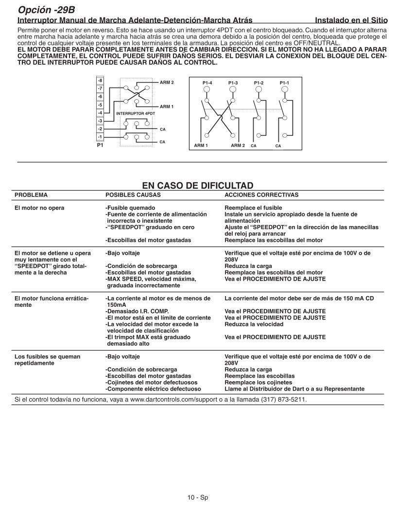
Opción -29BInterruptor Manual de Marcha Adelante-Detención-Marcha Atrás Instalado en el Sitio Permite poner el motor en reverso. Esto se hace usando un interruptor 4PDT con el centro bloqueado. Cuando el interruptor alterna entre marcha hacia adelante y marcha hacia atrás se crea una demora debido a la posición del centro, bloqueada que protege el controldecualquiervoltajepresenteenlosterminalesdelaarmadura.LaposicióndelcentroesOFF/NEUTRAL.EL MOTOR DEBE PARAR COMPLETAMENTE ANTES DE CAMBIAR DIRECCION. SI EL MOTOR NO HA LLEGADO A PARAR COMPLETAMENTE, EL CONTROL PUEDE SUFRIR DAÑOS SERIOS. EL DESVIAR LA CONEXION DEL BLOQUE DEL CEN-TRO DEL INTERRUPTOR PUEDE CAUSAR DAÑOS AL CONTROL.
CACA
CA
INTERRUPTOR 4PDT
CA
11 - SP
Voltajedeentrada ...........................................................................................................................10%delvoltajenominaldelíneaAceleración ..........................................................................................................................................0.5segundos(estándar125D)Amperios - salida de CD ......................................................................................................................................150mAa5.5ACD*Capacidad del controlador de sobrecarga ........................................................................................................... 200%porunminutoRango de corriente límite de “TRIMPOT” ...........................................................0.3a2.5ACD(125D);1a15ACD(123Dy125DV)Desaceleración ..................................................................................................................................0.5segundos(estándar125D)
Dimensiones y peso:
ANCHO LARGO PROFUNDIDAD PESOINGLES 3.625" 4.250" 1.300" 8.00oz.METRICO 92mm 108mm 33mm 228gm
Factordeserviciodelimpulsor ....................................................................................................................................................... 1.0Eficiencia ............................................................................................................................................................................ típica85%Frecuenciadelacorrientedeentrada ................................................................................................................................50o60HzRango de velocidad del “TRIMPOT” MAX ............................................................................. de60%a110%delavelocidadbásicaRango de velocidad del “TRIMPOT” MIN ................................................................................ de0%a30%delavelocidadmáximaArtefactos de potencia ................................................................................................................................caja aislada, de lengüetasVoltajedelcampodeldevanadodederivación ........................... 20VCDparaentradade24VCA;30VCDparaentradade36VCA;
100VCDparaentradade120VCA;200VCDparaentradade240VCA;1amperiomáximoControl de velocidad .......................................................... pormediodeunpotenciómetrode5Ký2Woseñalaisladade0-10VCDRango de velocidad ...................................................................................................................................................................... 50:1Regulación de velocidad ...................................................................................................................... 1%delavelocidaddebaseRango de temperatura ..................................................................................... temperaturaambientede-10°a45°C(15°a115°F)Protección de transientes .......................................................................................................................................................G-Mov**Gatillo .................................................................................................................................................................. acoplamiento ópticoTipoderampadeaceleración/desaceleración ..............................................................................................RC de tiempo constante
* conundisipadortérmicoexternoapropiado,laclasificaciónmáximadeU.L.paraamperajedesalidapuedeaumentarse .......... hasta10amperiosdeCD**noseusaenloscontrolesenlasSeries123D-CLatemperaturadeextrusióndel125Dnodebeexceder70°C.
+-
CORRIENTE TIPICA DE LOS MOTORES
Amperaje tîpico de CA (120 VCA) 0.50 1.00 2.00 3.50 4.40 6.50 9.30 13.20 .... ....
Amperaje tîpico de Arm (120 VCA) 0.42 0.81 1.60 2.70 3.40 5.00 8.20 10.90 .... ....
Amperaje tîpico de CA (240 VCA) .... .... .... 1.80 2.20 3.30 4.80 6.50 9.70 12.90
Amperaje tîpico de Arm (240 VCA) .... .... .... 1.40 1.70 2.50 3.70 5.00 8.20 11.60
POTENCIA, en HP 1/50 1/20 1/8 1/4 1/3 1/2 3/4 1.0 1.5 2.0
LISTA DE PARTES DE REPUESTORESISTENCIASR1 15K6WR2 470ΩR3 2.7KR4 2.7KR5 82KR6 5K(MINTRIM)R7 300KR8 180KR9 1.2MR10 39KR11 100KR12 10KR13 2.2KR14 820ΩR15 4.7KR16 470KR17 1KR18 100Ω (I.R TRIM)R19 5K(C.L.TRIM)R20 300KR21 10K(MAXTRIM)R22 1KR23 300KR24 .01Ω5WR25 91KR26 1KR27 390ΩR28 390ΩR29 5KSPEEDPOT*
PARTES VARIASARTEFACTOS ACTIVOSQ12N6027U2MOC3052Q3S4015LQ4S4015LU5LM3581CQ6275VG-MOV
125D-12C (1/50 a 1/8 HP)CAMBIOS:R24 ........ .062Ω5W
DIODOSD1 1N4005D2 1N4005D3 1N914BD4 1N5242BD5 1N4005D6 1N5233BD7 1N914BD8 D4015LD9 D4015LD10 D4015L
CONDENSADORESC1 .01µF100VC2 10µF35VC3 .01µF100VC4 .033µF400VC5 .22µF1KVC8 1µF50VN.P.C9 .0047µF1KVC10 .1µF50VC11 47µF16V
CAMBIOS EN ACCELREEMPLACEELCASQUETEN.P.PORUNCASQUETEPOLARIZADO(VEAARRIBA)-15A .................. C8 33uf16V-15B .................. C8 15uf25V-15C .................. C8 4.7uf16V-K ...................... C8 22uf16V
CAMBIOS EN 123D-CD6 1N914B(CAMBIEELSENTIDODEROTACION)Q6 BORRARR1 1K2WR2 47ΩR16 220KR23 47KR25 15KR27 47ΩR28 47Ω
+-
ESPECIFICACIONES
JU1 18GA.CABLERIGIDOAISLADOJU2 18GA.CABLERIGIDOAISLADOPCB A-4-2033FCIRCUITOIMPRESOP1(-1THRU-8) 8POS.BANDAPARATERMINALESP2(-2THRU-6) 5POS.CONECTORHEMBRAP3 3/16"CLAVIJAMACHO
R24
Q1
C4
P1-8-7-6-5-4-3-2-1
C9
U5 R11
R3
U2
P3
D5
Q3
D1
C1
C3D9
D8
Q4
D10
D3
R4
R5R25R2
R27
R26
R23
C8
R7
P265432
C11
R12
R13R10
R17
R6R21R18R19
D2
R1R8
D6D4
C5 C2
R20 R14
R9
R15
R22
R16
R28
D7
Q6
JU2
JU1
C10
+
+
+
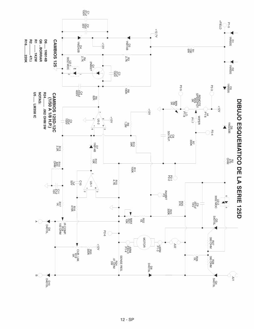
DIB
UJO
ES
QU
EM
AT
ICO
DE
LA
SE
RIE
125D
CA
MB
IOS
125
D6 ..... 1N
914B
Q6 ..B
OR
RA
R
R1 ........1K
2W
R2 ............47Ω
R16..........220K
CA
MB
IOS
125D-12C
(1/50 A
1/8 H.P.)
R24 ......... .062 O
HM
5W
NO
TAS
:
U5 ...... L
M358 IC
12 - SP
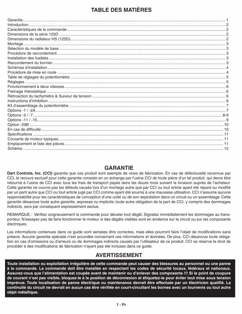
GARANTIE Dart Controls, Inc. (CCI) garantie que ces produit sont exempts de vices de fabrication. En cas de défectuosité reconnue par CCI, le recours exclusif pour cette garantie consiste en un échange par l’usine CCI de toute pièce d’un tel produit, qui devra être retourné à l’usine de CCI avec tous les frais de transport payés dans les douze mois suivant la livraison auprès de l’acheteur. Cette garantie ne couvre pas les défauts causés lors d’un montage autre que par CCI ou tout article ayant été réparé ou modifié par un parti autre que CCI ou tout article jugé par CCI comme ayant été soumis à une mauvaise utilisation. CCI n’assume aucune responsabilité pour les caractéristiques de conception d’une unité ou de son exploitation dans un circuit ou un assemblage. Cette garantie désavoue toute autre garantie, expresse ou implicite; toute autre obligation de la part de CCI, y compris des dommages indirects, sera par conséquent expressément exclue.
REMARQUE : Vérifiez soigneusement la commande pour déceler tout dégât. Signalez immédiatement les dommages au trans-porteur. N’essayez pas de faire fonctionner le moteur si des dégâts visibles sont en évidence sur le circuit ou sur les composants électriques.
Les informations contenues dans ce guide sont sensées être correctes, mais elles pourront faire l’objet de modifications sans préavis. Aucune garantie spéciale n’est accordée concernant ces informations et données. De plus, CCI désavoue toute obliga-tion en cas d’omissions ou d’erreurs ou de dommages indirects causés par l’utilisateur de ce produit. CCI se réserve le droit de procéder à des modifications de fabrication n’ayant pas été incluses dans ce guide.
AVERTISSEMENTToute installation ou exploitation irrégulière de cette commande peut causer des blessures au personnel ou une panne à la commande. La commande doit être installée en respectant les codes de sécurité locaux, fédéraux et nationaux. Assurez-vous que l’alimentation est coupée avant de maintenir ou d’enlever des composants !!! Si le point de coupure de courant n’est pas visible, bloquez-le à la position de déconnexion et étiquetez-le pour éviter tout mise sous tension imprévue. Toute localisation de panne électrique ou maintenance devrait être effectuée par un électricien qualifié. La continuité du circuit ne devrait en aucun cas être vérifiée en court-circuitant les bornes avec un tournevis ou tout autre objet métallique.
TABLE DES MATIÈRES
Garantie ........................................................................................................................................................................................ 1Introduction ................................................................................................................................................................................... 2Caractéristiques de la commande ................................................................................................................................................ 2Dimensions de la série 125D ....................................................................................................................................................... 2Dimensions du radiateur HS (125D) ............................................................................................................................................. 2Montage ........................................................................................................................................................................................ 3Sélection du modèle de base ....................................................................................................................................................... 3Procédure de raccordement ......................................................................................................................................................... 3Installation des fusibles ................................................................................................................................................................ 3Raccordement du bornier ............................................................................................................................................................. 3Schémas d’installation .................................................................................................................................................................. 4Procédure de mise en route ........................................................................................................................................................ 4Table de réglages du potentiomètre ............................................................................................................................................. 5Réglages ...................................................................................................................................................................................... 5Fonctionnement à deux vitesses .................................................................................................................................................. 6Freinage rhéostatique .................................................................................................................................................................. 6Rétroaction du tachymètre & Suiveur de tension ......................................................................................................................... 6Instructions d’inhibition ................................................................................................................................................................. 6Kit d’assemblage du potentiomètre .............................................................................................................................................. 7Options -1 / -2A ............................................................................................................................................................................ 7Options -5 / -7 ............................................................................................................................................................................ 8-9Options -11 / -15 ........................................................................................................................................................................... 9Option -29B ................................................................................................................................................................................ 10En cas de difficulté ..................................................................................................................................................................... 10Spécifications ............................................................................................................................................................................. 11Courants de moteur typiques ..................................................................................................................................................... 11Emplacement et liste des pièces ................................................................................................................................................ 11Schéma ...................................................................................................................................................................................... 12
1 - Fr
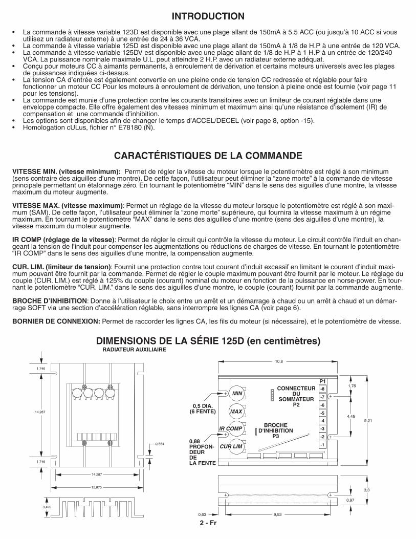
3,492
.0,554
14,287
14,287
1,746
15,875
1,746
10,8
MIN
MAX
IR COMP
CUR LIM
-8
-7
-6
-5
-4
-3
-2
-1
P1
9,21
9,53
4,45
1,76
0,97
3,3
0,63
INTRODUCTION
• La commande à vitesse variable 123D est disponible avec une plage allant de 150mA à 5.5 ACC (ou jusqu’à 10 ACC si vous utilisez un radiateur externe) à une entrée de 24 à 36 VCA.• La commande à vitesse variable 125D est disponible avec une plage allant de 150mA à 1/8 de H.P à une entrée de 120 VCA.• La commande à vitesse variable 125DV est disponible avec une plage allant de 1/8 de H.P à 1 H.P à un entrée de 120/240 VCA. La puissance nominale maximale U.L. peut atteindre 2 H.P. avec un radiateur externe adéquat.• Conçu pour moteurs CC à aimants permanents, à enroulement de dérivation et certains moteurs universels avec les plages de puissances indiquées ci-dessus.• La tension CA d’entrée est également convertie en une pleine onde de tension CC redressée et réglable pour faire fonctionner un moteur CC Pour les moteurs à enroulement de dérivation, une tension à pleine onde est fournie (voir page 11 pour les tensions).• La commande est munie d’une protection contre les courants transitoires avec un limiteur de courant réglable dans une enveloppe compacte. Elle offre également des vitesses minimum et maximum ainsi qu’une résistance d’isolement (IR) de compensation et une commande d’inhibition.• Les options sont disponibles afin de changer le temps d’ACCEL/DECEL (voir page 8, option -15).• Homologation cULus, fichier n° E78180 (N).
CARACTÉRISTIQUES DE LA COMMANDE
VITESSE MIN. (vitesse minimum): Permet de régler la vitesse du moteur lorsque le potentiomètre est réglé à son minimum (sens contraire des aiguilles d’une montre). De cette façon, l’utilisateur peut éliminer la “zone morte” à la commande de vitesse principale permettant un étalonnage zéro. En tournant le potentiomètre “MIN” dans le sens des aiguilles d’une montre, la vitesse maximum du moteur augmente.
VITESSE MAX. (vitesse maximum): Permet un réglage de la vitesse du moteur lorsque le potentiomètre est réglé à son maxi-mum (SAM). De cette façon, l’utilisateur peut éliminer la “zone morte” supérieure, qui fournira la vitesse maximum à un régime maximum. En tournant le potentiomètre “MAX” dans le sens des aiguilles d’une montre (sens des aiguilles d’une montre), la vitesse maximum du moteur augmente.
IR COMP (réglage de la vitesse): Permet de régler le circuit qui contrôle la vitesse du moteur. Le circuit contrôle l’induit en chan-geant la tension de l’induit pour compenser les augmentations ou réductions de charges de vitesse. En tournant le potentiomètre “IR COMP” dans le sens des aiguilles d’une montre, la compensation augmente.
CUR. LIM. (limiteur de tension): Fournit une protection contre tout courant d’induit excessif en limitant le courant d’induit maxi-mum pouvant être fournit par la commande. Permet de régler le couple maximum pouvant être fournit par le moteur. Le réglage du couple (CUR. LIM.) est réglé à 125% du couple (courant) nominal du moteur en fonction de la puissance en horse-power. En tour-nant le potentiomètre “CUR. LIM.” dans le sens des aiguilles d’une montre, le couple (courant) fournit par la commande augmente.
BROCHE D’INHIBITION: Donne à l’utilisateur le choix entre un arrêt et un démarrage à chaud ou un arrêt à chaud et un démar-rage SOFT via une section d’accélération réglable, sans interrompre les lignes CA (voir page 6).
BORNIER DE CONNEXION: Permet de raccorder les lignes CA, les fils du moteur (si nécessaire), et le potentiomètre de vitesse.
2 - Fr
DIMENSIONS DE LA SÉRIE 125D (en centimètres)RADIATEUR AUXILIAIRE
0,5 DIA.(6 FENTE)
0,88PROFON- DEURDE LA FENTE
CONNECTEURDU
SOMMATEURP2
BROCHED'INHIBITION
P3
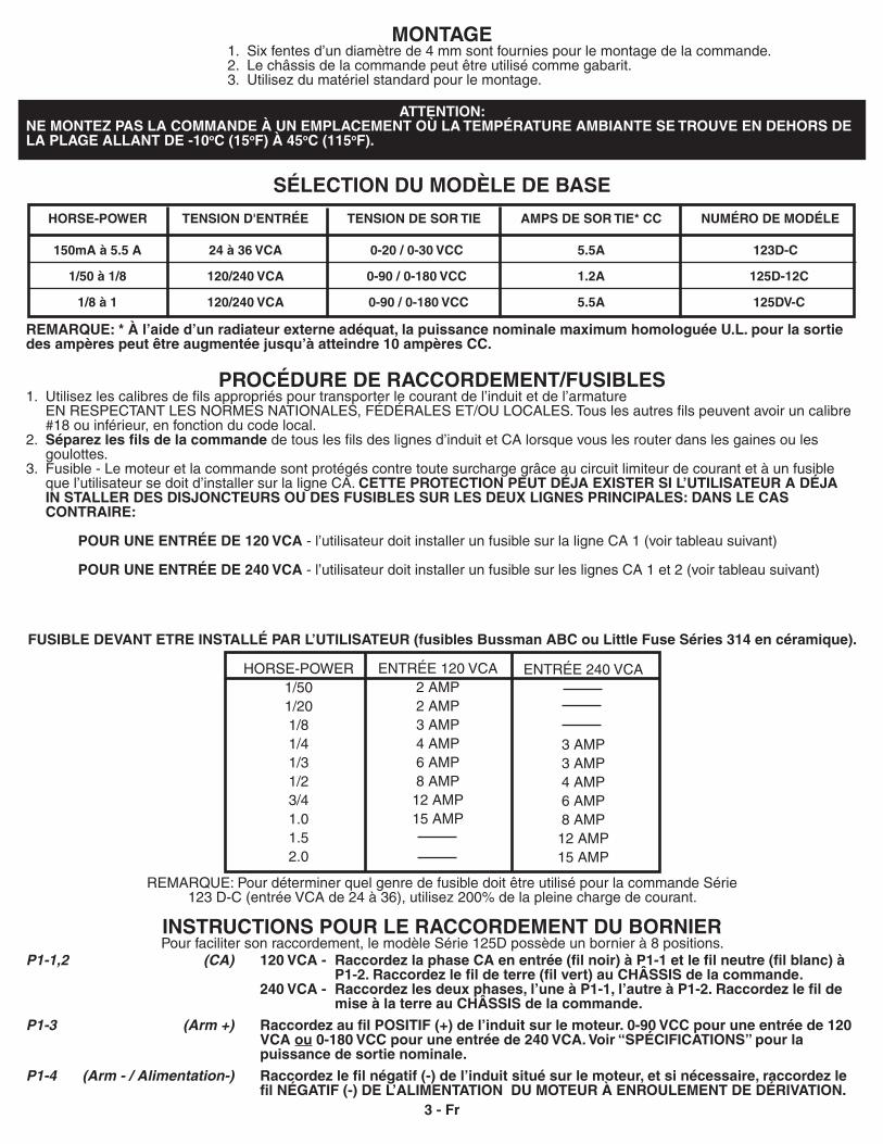
MONTAGE 1. Six fentes d’un diamètre de 4 mm sont fournies pour le montage de la commande. 2. Le châssis de la commande peut être utilisé comme gabarit. 3. Utilisez du matériel standard pour le montage.
ATTENTION:NE MONTEZ PAS LA COMMANDE À UN EMPLACEMENT OÙ LA TEMPÉRATURE AMBIANTE SE TROUVE EN DEHORS DE LA PLAGE ALLANT DE -10oC (15oF) À 45oC (115oF).
SÉLECTION DU MODÈLE DE BASE
REMARQUE: * À l’aide d’un radiateur externe adéquat, la puissance nominale maximum homologuée U.L. pour la sortie des ampères peut être augmentée jusqu’à atteindre 10 ampères CC.
PROCÉDURE DE RACCORDEMENT/FUSIBLES1. Utilisez les calibres de fils appropriés pour transporter le courant de l’induit et de l’armature EN RESPECTANT LES NORMES NATIONALES, FÉDÉRALES ET/OU LOCALES. Tous les autres fils peuvent avoir un calibre #18 ou inférieur, en fonction du code local.2. Séparez les fils de la commande de tous les fils des lignes d’induit et CA lorsque vous les router dans les gaines ou les goulottes. 3. Fusible - Le moteur et la commande sont protégés contre toute surcharge grâce au circuit limiteur de courant et à un fusible que l’utilisateur se doit d’installer sur la ligne CA. CETTE PROTECTION PEUT DÉJA EXISTER SI L’UTILISATEUR A DÉJA IN STALLER DES DISJONCTEURS OU DES FUSIBLES SUR LES DEUX LIGNES PRINCIPALES: DANS LE CAS CONTRAIRE:
POUR UNE ENTRÉE DE 120 VCA - l’utilisateur doit installer un fusible sur la ligne CA 1 (voir tableau suivant)
POUR UNE ENTRÉE DE 240 VCA - l’utilisateur doit installer un fusible sur les lignes CA 1 et 2 (voir tableau suivant)
FUSIBLE DEVANT ETRE INSTALLÉ PAR L’UTILISATEUR (fusibles Bussman ABC ou Little Fuse Séries 314 en céramique).
REMARQUE: Pour déterminer quel genre de fusible doit être utilisé pour la commande Série 123 D-C (entrée VCA de 24 à 36), utilisez 200% de la pleine charge de courant.
INSTRUCTIONS POUR LE RACCORDEMENT DU BORNIERPour faciliter son raccordement, le modèle Série 125D possède un bornier à 8 positions.
ENTRÉE 120 VCA2 AMP2 AMP3 AMP4 AMP6 AMP8 AMP12 AMP15 AMP
HORSE-POWER1/501/201/81/41/31/23/41.01.52.0
ENTRÉE 240 VCA
3 AMP3 AMP4 AMP6 AMP8 AMP12 AMP15 AMP
3 - Fr
P1-1,2 (CA) 120 VCA - Raccordez la phase CA en entrée (fil noir) à P1-1 et le fil neutre (fil blanc) à P1-2. Raccordez le fil de terre (fil vert) au CHÂSSIS de la commande. 240 VCA - Raccordez les deux phases, l’une à P1-1, l’autre à P1-2. Raccordez le fil de mise à la terre au CHÂSSIS de la commande.
P1-3 (Arm +) Raccordez au fil POSITIF (+) de l’induit sur le moteur. 0-90 VCC pour une entrée de 120 VCA ou 0-180 VCC pour une entrée de 240 VCA. Voir “SPÉCIFICATIONS” pour la puissance de sortie nominale.
P1-4 (Arm - / Alimentation-) Raccordez le fil négatif (-) de l’induit situé sur le moteur, et si nécessaire, raccordez le fil NÉGATIF (-) DE L’ALIMENTATION DU MOTEUR À ENROULEMENT DE DÉRIVATION.
150mA à 5.5 A 24 à 36 VCA 0-20 / 0-30 VCC 5.5A 123D-C
1/50 à 1/8 120/240 VCA 0-90 / 0-180 VCC 1.2A 125D-12C
1/8 à 1 120/240 VCA 0-90 / 0-180 VCC 5.5A 125DV-C
HORSE-POWER TENSION D'ENTRÉE TENSION DE SOR TIE AMPS DE SOR TIE* CC NUMÉRO DE MODÉLE
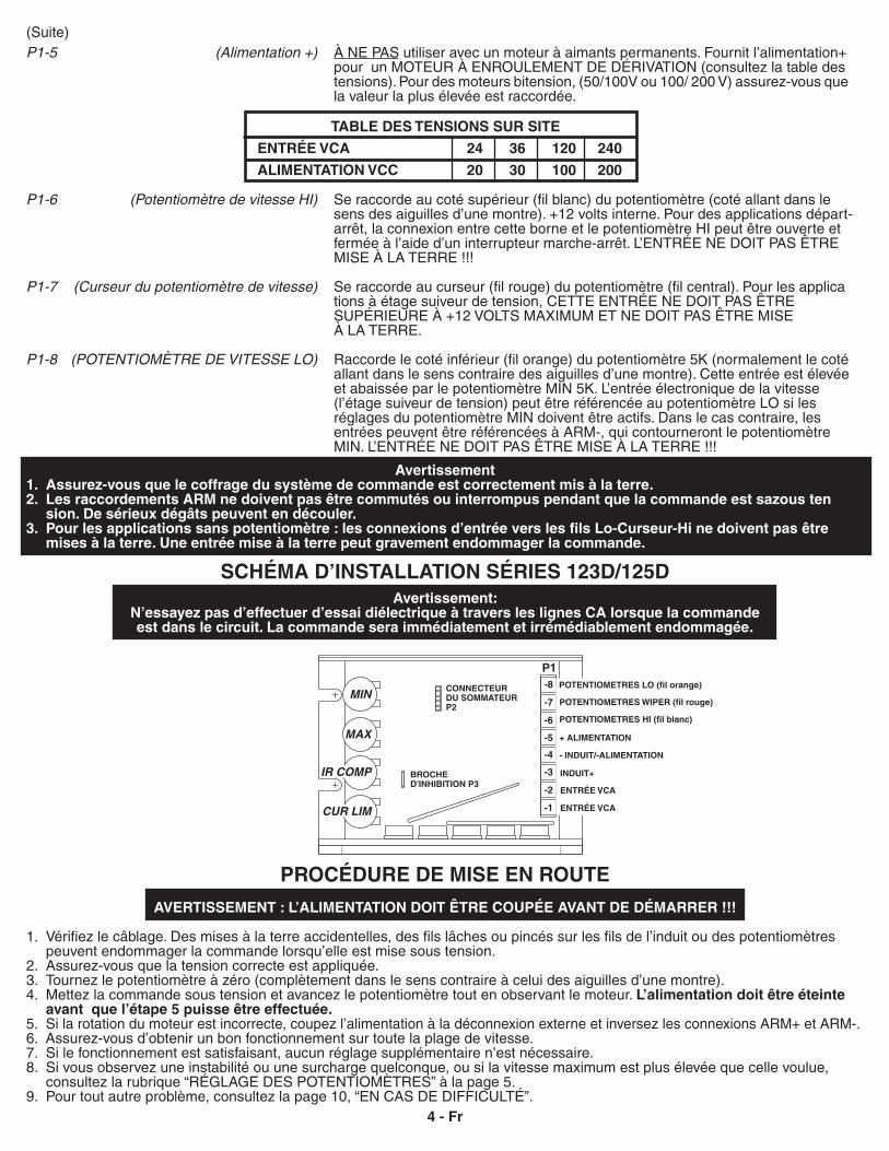
MIN
MAX
IR COMP
CUR LIM
P1-8
-7
-6
-5
-4
-3
-2
-1
(Suite)P1-5 (Alimentation +) À NE PAS utiliser avec un moteur à aimants permanents. Fournit l’alimentation+ pour un MOTEUR À ENROULEMENT DE DÉRIVATION (consultez la table des tensions). Pour des moteurs bitension, (50/100V ou 100/ 200 V) assurez-vous que la valeur la plus élevée est raccordée.
TABLE DES TENSIONS SUR SITE
ENTRÉE VCA 24 36 120 240
ALIMENTATION VCC 20 30 100 200
P1-6 (Potentiomètre de vitesse HI) Se raccorde au coté supérieur (fil blanc) du potentiomètre (coté allant dans le sens des aiguilles d’une montre). +12 volts interne. Pour des applications départ- arrêt, la connexion entre cette borne et le potentiomètre HI peut être ouverte et fermée à l’aide d’un interrupteur marche-arrêt. L’ENTRÉE NE DOIT PAS ÊTRE MISE À LA TERRE !!!
P1-7 (Curseur du potentiomètre de vitesse) Se raccorde au curseur (fil rouge) du potentiomètre (fil central). Pour les applica tions à étage suiveur de tension, CETTE ENTRÉE NE DOIT PAS ÊTRE SUPÉRIEURE À +12 VOLTS MAXIMUM ET NE DOIT PAS ÊTRE MISE À LA TERRE.
P1-8 (POTENTIOMÈTRE DE VITESSE LO) Raccorde le coté inférieur (fil orange) du potentiomètre 5K (normalement le coté allant dans le sens contraire des aiguilles d’une montre). Cette entrée est élevée et abaissée par le potentiomètre MIN 5K. L’entrée électronique de la vitesse (l’étage suiveur de tension) peut être référencée au potentiomètre LO si les réglages du potentiomètre MIN doivent être actifs. Dans le cas contraire, les entrées peuvent être référencées à ARM-, qui contourneront le potentiomètre MIN. L’ENTRÉE NE DOIT PAS ÊTRE MISE À LA TERRE !!!
Avertissement1. Assurez-vous que le coffrage du système de commande est correctement mis à la terre.2. Les raccordements ARM ne doivent pas être commutés ou interrompus pendant que la commande est sazous ten sion. De sérieux dégâts peuvent en découler.3. Pour les applications sans potentiomètre : les connexions d’entrée vers les fils Lo-Curseur-Hi ne doivent pas être mises à la terre. Une entrée mise à la terre peut gravement endommager la commande.
Avertissement: N’essayez pas d’effectuer d’essai diélectrique à travers les lignes CA lorsque la commande est dans le circuit. La commande sera immédiatement et irrémédiablement endommagée.
SCHÉMA D’INSTALLATION SÉRIES 123D/125D
AVERTISSEMENT : L’ALIMENTATION DOIT ÊTRE COUPÉE AVANT DE DÉMARRER !!!
1. Vérifiez le câblage. Des mises à la terre accidentelles, des fils lâches ou pincés sur les fils de l’induit ou des potentiomètres peuvent endommager la commande lorsqu’elle est mise sous tension. 2. Assurez-vous que la tension correcte est appliquée.3. Tournez le potentiomètre à zéro (complètement dans le sens contraire à celui des aiguilles d’une montre). 4. Mettez la commande sous tension et avancez le potentiomètre tout en observant le moteur. L’alimentation doit être éteinte avant que l’étape 5 puisse être effectuée.5. Si la rotation du moteur est incorrecte, coupez l’alimentation à la déconnexion externe et inversez les connexions ARM+ et ARM-.6. Assurez-vous d’obtenir un bon fonctionnement sur toute la plage de vitesse.7. Si le fonctionnement est satisfaisant, aucun réglage supplémentaire n’est nécessaire.8. Si vous observez une instabilité ou une surcharge quelconque, ou si la vitesse maximum est plus élevée que celle voulue, consultez la rubrique “RÉGLAGE DES POTENTIOMÈTRES” à la page 5.9. Pour tout autre problème, consultez la page 10, “EN CAS DE DIFFICULTÉ”.
PROCÉDURE DE MISE EN ROUTE
4 - Fr
POTENTIOMETRES LO (fil orange)
POTENTIOMETRES WIPER (fil rouge)
POTENTIOMETRES HI (fil blanc)
+ ALIMENTATION
- INDUIT/-ALIMENTATION
INDUIT+
ENTRÉE VCA
ENTRÉE VCA
CONNECTEURDU SOMMATEURP2
BROCHED'INHIBITION P3
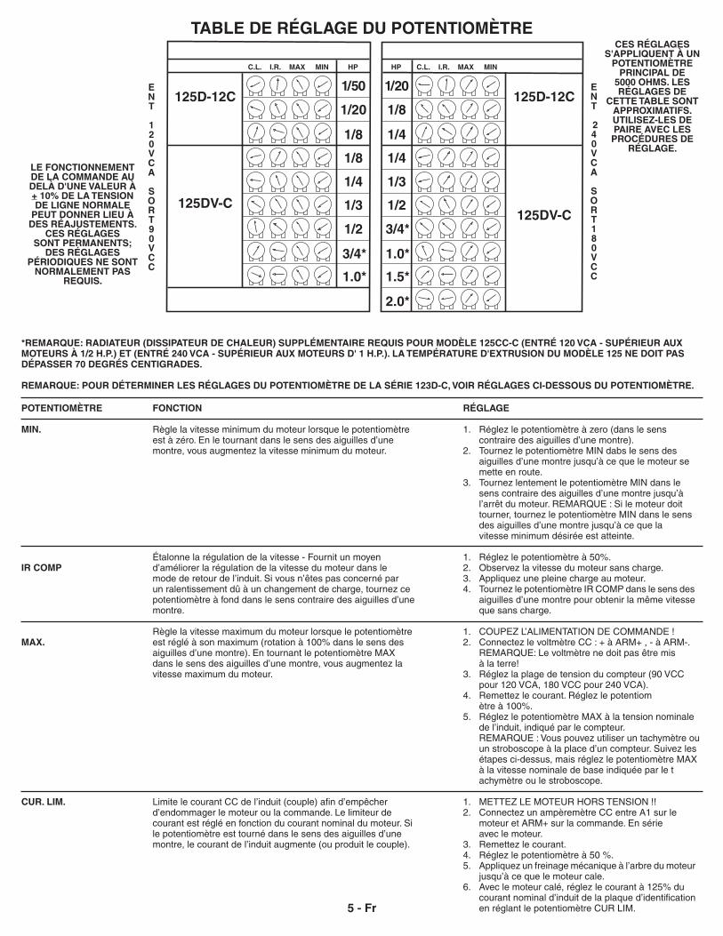
C.L. I.R. MAX MIN
1/4
1/3
1/2
3/4*
1.0*
1/20
1/8
HP
125DV-C
1.5*
2.0*
1/4
125D-12C
C.L. I.R. MAX MIN
1/8
1/4
1/3
1/2
3/4*
1/50
1/20
HP
125DV-C
1.0*
1/8
125D-12C
TABLE DE RÉGLAGE DU POTENTIOMÈTRE
RÉGLAGE
1. Réglez le potentiomètre à zero (dans le sens contraire des aiguilles d’une montre).2. Tournez le potentiomètre MIN dabs le sens des aiguilles d’une montre jusqu’à ce que le moteur se mette en route.3. Tournez lentement le potentiomètre MIN dans le sens contraire des aiguilles d’une montre jusqu’à l’arrêt du moteur. REMARQUE : Si le moteur doit tourner, tournez le potentiomètre MIN dans le sens des aiguilles d’une montre jusqu’à ce que la vitesse minimum désirée est atteinte.
1. Réglez le potentiomètre à 50%.2. Observez la vitesse du moteur sans charge.3. Appliquez une pleine charge au moteur.4. Tournez le potentiomètre IR COMP dans le sens des aiguilles d’une montre pour obtenir la même vitesse que sans charge. 1. COUPEZ L’ALIMENTATION DE COMMANDE !2. Connectez le voltmètre CC : + à ARM+ , - à ARM-. REMARQUE: Le voltmètre ne doit pas être mis à la terre!3. Réglez la plage de tension du compteur (90 VCC pour 120 VCA, 180 VCC pour 240 VCA).4. Remettez le courant. Réglez le potentiom ètre à 100%.5. Réglez le potentiomètre MAX à la tension nominale de l’induit, indiqué par le compteur. REMARQUE : Vous pouvez utiliser un tachymètre ou un stroboscope à la place d’un compteur. Suivez les étapes ci-dessus, mais réglez le potentiomètre MAX à la vitesse nominale de base indiquée par le t achymètre ou le stroboscope.
1. METTEZ LE MOTEUR HORS TENSION !!2. Connectez un ampèremètre CC entre A1 sur le moteur et ARM+ sur la commande. En série avec le moteur.3. Remettez le courant.4. Réglez le potentiomètre à 50 %.5. Appliquez un freinage mécanique à l’arbre du moteur jusqu’à ce que le moteur cale. 6. Avec le moteur calé, réglez le courant à 125% du courant nominal d’induit de la plaque d’identification en réglant le potentiomètre CUR LIM.
POTENTIOMÈTRE
MIN.
IR COMP
MAX.
CUR. LIM.
FONCTION
Règle la vitesse minimum du moteur lorsque le potentiomètre est à zéro. En le tournant dans le sens des aiguilles d’une montre, vous augmentez la vitesse minimum du moteur.
Étalonne la régulation de la vitesse - Fournit un moyen d’améliorer la régulation de la vitesse du moteur dans le mode de retour de l’induit. Si vous n’êtes pas concerné par un ralentissement dû à un changement de charge, tournez ce potentiomètre à fond dans le sens contraire des aiguilles d’une montre.
Règle la vitesse maximum du moteur lorsque le potentiomètre est réglé à son maximum (rotation à 100% dans le sens des aiguilles d’une montre). En tournant le potentiomètre MAX dans le sens des aiguilles d’une montre, vous augmentez la vitesse maximum du moteur.
Limite le courant CC de l’induit (couple) afin d’empêcher d’endommager le moteur ou la commande. Le limiteur de courant est réglé en fonction du courant nominal du moteur. Si le potentiomètre est tourné dans le sens des aiguilles d’une montre, le courant de l’induit augmente (ou produit le couple).
5 - Fr
ENT
240VCA
SORT180VCC
*REMARQUE: RADIATEUR (DISSIPATEUR DE CHALEUR) SUPPLÉMENTAIRE REQUIS POUR MODÈLE 125CC-C (ENTRÉ 120 VCA - SUPÉRIEUR AUX MOTEURS À 1/2 H.P.) ET (ENTRÉ 240 VCA - SUPÉRIEUR AUX MOTEURS D' 1 H.P.). LA TEMPÉRATURE D'EXTRUSION DU MODÈLE 125 NE DOIT PAS DÉPASSER 70 DEGRÉS CENTIGRADES.
REMARQUE: POUR DÉTERMINER LES RÉGLAGES DU POTENTIOMÈTRE DE LA SÉRIE 123D-C, VOIR RÉGLAGES CI-DESSOUS DU POTENTIOMÈTRE.
LE FONCTIONNEMENT DE LA COMMANDE AU DELÀ D'UNE VALEUR À + 10% DE LA TENSION DE LIGNE NORMALE
PEUT DONNER LIEU À DES RÉAJUSTEMENTS.
CES RÉGLAGES SONT PERMANENTS;
DES RÉGLAGES PÉRIODIQUES NE SONT
NORMALEMENT PAS REQUIS.
CES RÉGLAGES S'APPLIQUENT À UN
POTENTIOMÈTRE PRINCIPAL DE
5000 OHMS. LES RÉGLAGES DE
CETTE TABLE SONT APPROXIMATIFS. UTILISEZ-LES DE PAIRE AVEC LES PROCÉDURES DE
RÉGLAGE.
ENT
120VCA
SORT90VCC
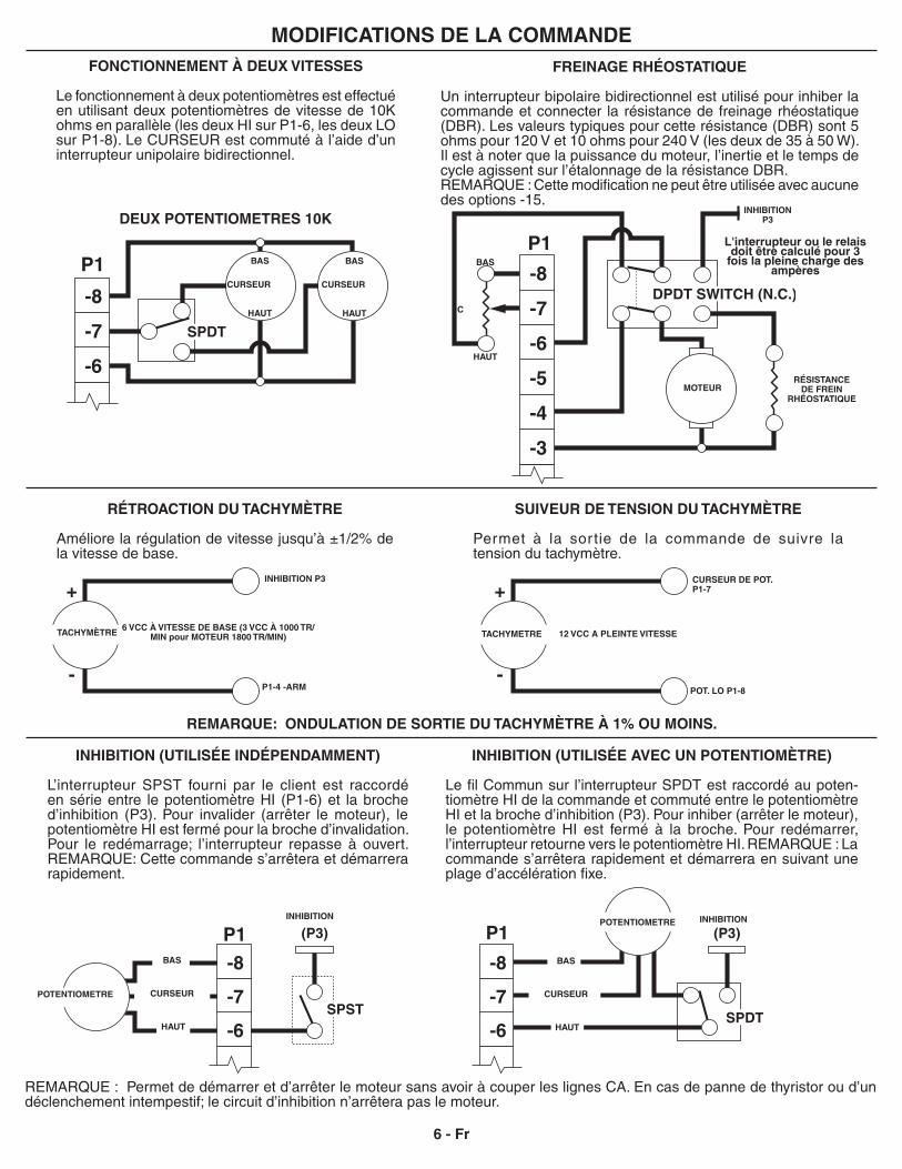
-7
-8
-6
P1
SPST
INHIBIT(P3)
WIPER
LO
HI
-7
-8
-6
P1
SPDTWIPER
LO
HI
INHIBIT(P3)
+
-
+
-
-7
-8
W
LO
HI
P1
-7
-8
-6
WHI
LOW
HI
LOP1
HISPDT
-5
-6
-3
-4
DPDT SWITCH (N.C.)
FREINAGE RHÉOSTATIQUE
Un interrupteur bipolaire bidirectionnel est utilisé pour inhiber la commande et connecter la résistance de freinage rhéostatique (DBR). Les valeurs typiques pour cette résistance (DBR) sont 5 ohms pour 120 V et 10 ohms pour 240 V (les deux de 35 à 50 W). Il est à noter que la puissance du moteur, l’inertie et le temps de cycle agissent sur l’étalonnage de la résistance DBR. REMARQUE : Cette modification ne peut être utilisée avec aucune des options -15.
FONCTIONNEMENT À DEUX VITESSES
Le fonctionnement à deux potentiomètres est effectué en utilisant deux potentiomètres de vitesse de 10K ohms en parallèle (les deux HI sur P1-6, les deux LO sur P1-8). Le CURSEUR est commuté à l’aide d’un interrupteur unipolaire bidirectionnel.
MODIFICATIONS DE LA COMMANDE
RÉTROACTION DU TACHYMÈTRE
Améliore la régulation de vitesse jusqu’à ±1/2% de la vitesse de base.
SUIVEUR DE TENSION DU TACHYMÈTRE
Permet à la sor tie de la commande de suivre la tension du tachymètre.
REMARQUE: ONDULATION DE SORTIE DU TACHYMÈTRE À 1% OU MOINS.
INHIBITION (UTILISÉE AVEC UN POTENTIOMÈTRE)
Le fil Commun sur l’interrupteur SPDT est raccordé au poten-tiomètre HI de la commande et commuté entre le potentiomètre HI et la broche d’inhibition (P3). Pour inhiber (arrêter le moteur), le potentiomètre HI est fermé à la broche. Pour redémarrer, l’interrupteur retourne vers le potentiomètre HI. REMARQUE : La commande s’arrêtera rapidement et démarrera en suivant une plage d’accélération fixe.
INHIBITION (UTILISÉE INDÉPENDAMMENT)
L’interrupteur SPST fourni par le client est raccordé en série entre le potentiomètre HI (P1-6) et la broche d’inhibition (P3). Pour invalider (arrêter le moteur), le potentiomètre HI est fermé pour la broche d’invalidation. Pour le redémarrage; l’interrupteur repasse à ouvert. REMARQUE: Cette commande s’arrêtera et démarrera rapidement.
REMARQUE : Permet de démarrer et d’arrêter le moteur sans avoir à couper les lignes CA. En cas de panne de thyristor ou d’un déclenchement intempestif; le circuit d’inhibition n’arrêtera pas le moteur.
6 - Fr
DEUX POTENTIOMETRES 10KINHIBITION
P3
MOTEUR
CURSEUR DE POT.P1-7
12 VCC A PLEINTE VITESSE
POT. LO P1-8
TACHYMETRETACHYMÈTRE
INHIBITION P3
P1-4 -ARM
POTENTIOMETRE
INHIBITIONPOTENTIOMETRE INHIBITION
BAS
CURSEUR
HAUT
BAS
CURSEUR
HAUT
6 VCC À VITESSE DE BASE (3 VCC À 1000 TR/MIN pour MOTEUR 1800 TR/MIN)
RÉSISTANCE DE FREIN
RHÉOSTATIQUE
BAS
CURSEUR
HAUT
BAS
CURSEUR
HAUT
BAS
C
HAUT
L'interrupteur ou le relais doit être calculé pour 3
fois la pleine charge des ampères
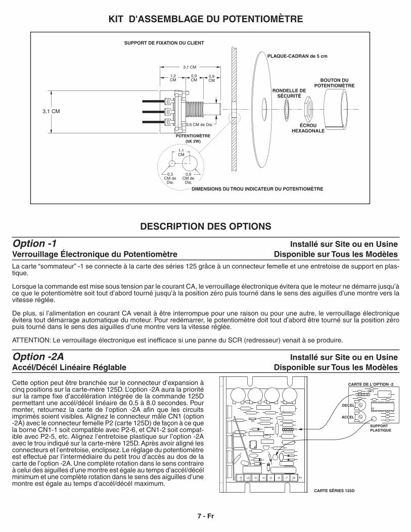
KIT D'ASSEMBLAGE DU POTENTIOMÈTRE
DESCRIPTION DES OPTIONS
Option -1 Installé sur Site ou en UsineVerrouillage Électronique du Potentiomètre Disponible sur Tous les ModèlesLa carte “sommateur” -1 se connecte à la carte des séries 125 grâce à un connecteur femelle et une entretoise de support en plas-tique.
Lorsque la commande est mise sous tension par le courant CA, le verrouillage électronique évitera que le moteur ne démarre jusqu’à ce que le potentiomètre soit tout d’abord tourné jusqu’à la position zéro puis tourné dans le sens des aiguilles d’une montre vers la vitesse réglée.
De plus, si l’alimentation en courant CA venait à être interrompue pour une raison ou pour une autre, le verrouillage électronique évitera tout démarrage automatique du moteur. Pour redémarrer, le potentiomètre doit tout d’abord être tourné sur la position zéro puis tourné dans le sens des aiguilles d’une montre vers la vitesse réglée. ATTENTION: Le verrouillage électronique est inefficace si une panne du SCR (redresseur) venait à se produire.
Option -2A Installé sur Site ou en UsineAccél/Décél Linéaire Réglable Disponible sur Tous les Modèles
Cette option peut être branchée sur le connecteur d’expansion à cinq positions sur la carte-mère 125D. L’option -2A aura la priorité sur la rampe fixe d’accélération intégrée de la commande 125D permettant une accél/décél linéaire de 0.5 à 8.0 secondes. Pour monter, retournez la carte de l’option -2A afin que les circuits imprimés soient visibles. Alignez le connecteur mâle CN1 (option -2A) avec le connecteur femelle P2 (carte 125D) de façon à ce que la borne CN1-1 soit compatible avec P2-6, et CN1-2 soit compat-ible avec P2-5, etc. Alignez l’entretoise plastique sur l’option -2A avec le trou indiqué sur la carte-mère 125D. Après avoir aligné les connecteurs et l’entretoise, enclipsez. Le réglage du potentiomètre est effectué par l’intermédiaire du petit trou d’accès au dos de la carte de l’option -2A. Une complète rotation dans le sens contraire à celui des aiguilles d’une montre est égale au temps d’accél/décél minimum et une complète rotation dans le sens des aiguilles d’une montre est égale au temps d’accél/décél maximum.
7 - Fr
CARTE DE L'OPTION -2
CARTE SÉRIES 125D
DECEL
ACCEL
SUPPORTPLASTIQUE
ON 1
3,1 CM
1,1 CM
PLAQUE-CADRAN de 5 cm
BOUTON DUPOTENTIOMÈTRE
ÉCROU HEXAGONALE
POTENTIOMÈTRE (5K 2W)
0,9 CM
0,9 CM
1,2 CM
SUPPORT DE FIXATION DU CLIENT
RONDELLE DE SÉCURITÉ
0,6 CM de Dia.
0,3 CM de
Dia.
0,9 CM de
Dia.
DIMENSIONS DU TROU INDICATEUR DU POTENTIOMÈTRE
3,1 CM
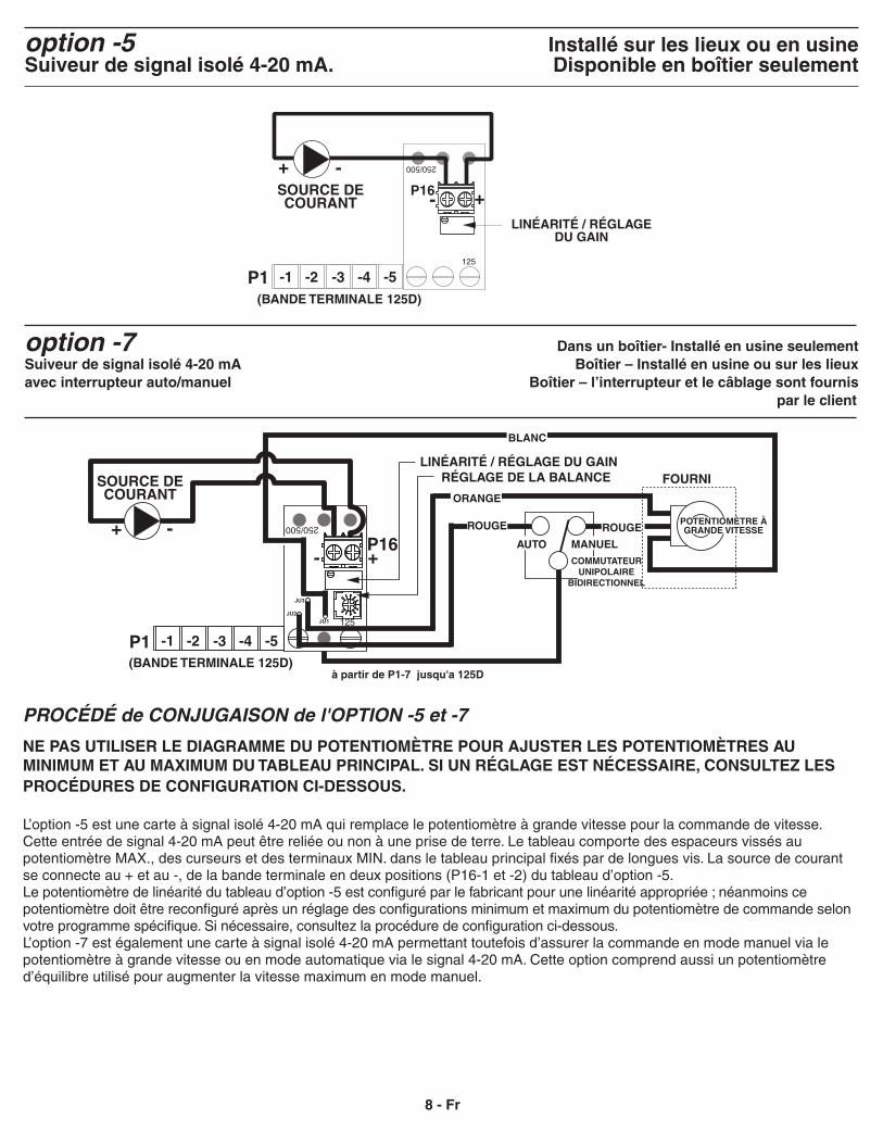
8 - Fr
option -5 Installé sur les lieux ou en usineSuiveur de signal isolé 4-20 mA. Disponible en boîtier seulement
option -7 Dans un boîtier- Installé en usine seulementSuiveur de signal isolé 4-20 mA Boîtier – Installé en usine ou sur les lieuxavec interrupteur auto/manuel Boîtier – l’interrupteur et le câblage sont fournis par le client
NE PAS UTILISER LE DIAGRAMME DU POTENTIOMÈTRE POUR AJUSTER LES POTENTIOMÈTRES AU MINIMUM ET AU MAXIMUM DU TABLEAU PRINCIPAL. SI UN RÉGLAGE EST NÉCESSAIRE, CONSULTEZ LES PROCÉDURES DE CONFIGURATION CI-DESSOUS.
L’option -5 est une carte à signal isolé 4-20 mA qui remplace le potentiomètre à grande vitesse pour la commande de vitesse. Cette entrée de signal 4-20 mA peut être reliée ou non à une prise de terre. Le tableau comporte des espaceurs vissés au potentiomètre MAX., des curseurs et des terminaux MIN. dans le tableau principal fixés par de longues vis. La source de courant se connecte au + et au -, de la bande terminale en deux positions (P16-1 et -2) du tableau d’option -5.Le potentiomètre de linéarité du tableau d’option -5 est configuré par le fabricant pour une linéarité appropriée ; néanmoins ce potentiomètre doit être reconfiguré après un réglage des configurations minimum et maximum du potentiomètre de commande selon votre programme spécifique. Si nécessaire, consultez la procédure de configuration ci-dessous.L’option -7 est également une carte à signal isolé 4-20 mA permettant toutefois d’assurer la commande en mode manuel via le potentiomètre à grande vitesse ou en mode automatique via le signal 4-20 mA. Cette option comprend aussi un potentiomètre d’équilibre utilisé pour augmenter la vitesse maximum en mode manuel.
PROCÉDÉ de CONJUGAISON de l'OPTION -5 et -7
BLANC
250/500
P1 -5-4-3
SOURCE DE COURANT
-1 -2
LINÉARITÉ / RÉGLAGE DU GAIN
COMMUTATEUR UNIPOLAIRE
BIDIRECTIONNEL
MANUELAUTO
ORANGE
ROUGE
à partir de P1-7 jusqu'a 125D
FOURNI
+- P16
(BANDE TERMINALE 125D)
ROUGEPOTENTIOMÈTRE À GRANDE VITESSE
RÉGLAGE DE LA BALANCE
125JU1JU2
JU3
+ -
P1 -5-4-3
SOURCE DE COURANT
-1 -2
LINÉARITÉ / RÉGLAGE DU GAIN
+-
(BANDE TERMINALE 125D)
P16
250/500
125
-+
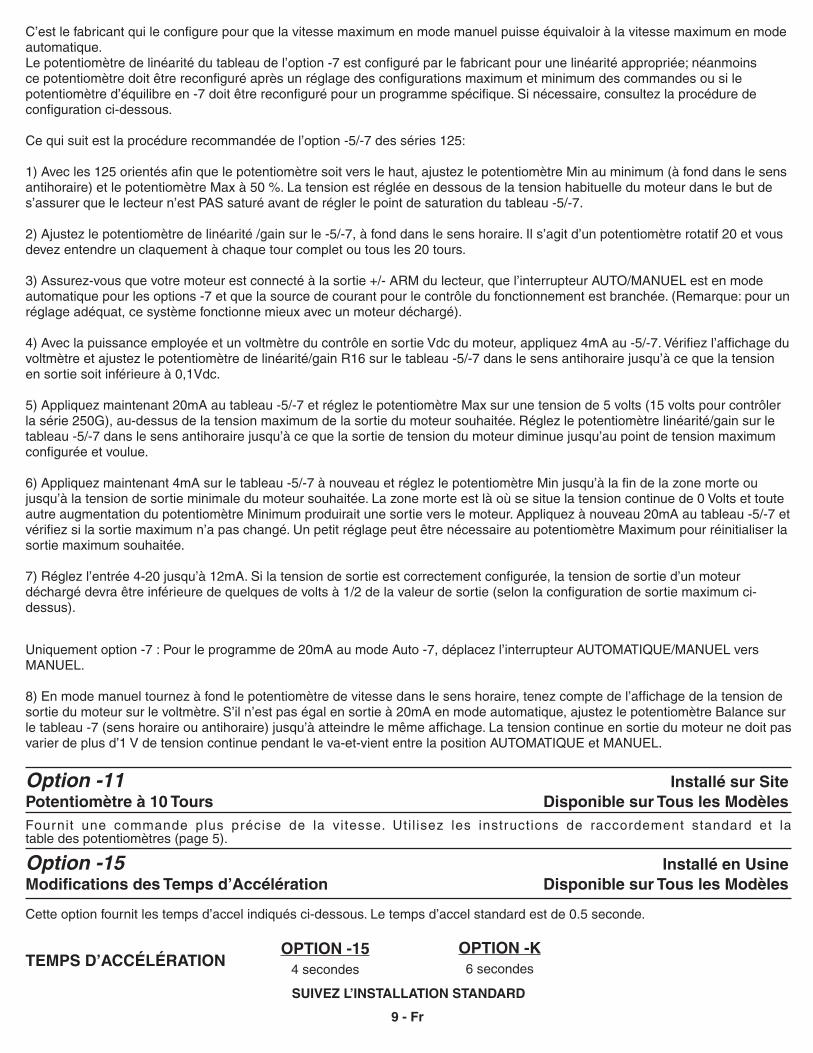
SUIVEZ L’INSTALLATION STANDARD
OPTION -154 secondes
OPTION -K6 secondesTEMPS D’ACCÉLÉRATION
Cette option fournit les temps d’accel indiqués ci-dessous. Le temps d’accel standard est de 0.5 seconde.
Option -15 Installé en Usine Modifications des Temps d’Accélération Disponible sur Tous les Modèles
Fournit une commande plus précise de la vitesse. Uti l isez les instructions de raccordement standard et la table des potentiomètres (page 5).
Option -11 Installé sur SitePotentiomètre à 10 Tours Disponible sur Tous les Modèles
9 - Fr
C’est le fabricant qui le configure pour que la vitesse maximum en mode manuel puisse équivaloir à la vitesse maximum en mode automatique.Le potentiomètre de linéarité du tableau de l’option -7 est configuré par le fabricant pour une linéarité appropriée; néanmoins ce potentiomètre doit être reconfiguré après un réglage des configurations maximum et minimum des commandes ou si le potentiomètre d’équilibre en -7 doit être reconfiguré pour un programme spécifique. Si nécessaire, consultez la procédure de configuration ci-dessous.
Ce qui suit est la procédure recommandée de l’option -5/-7 des séries 125:
1) Avec les 125 orientés afin que le potentiomètre soit vers le haut, ajustez le potentiomètre Min au minimum (à fond dans le sens antihoraire) et le potentiomètre Max à 50 %. La tension est réglée en dessous de la tension habituelle du moteur dans le but de s’assurer que le lecteur n’est PAS saturé avant de régler le point de saturation du tableau -5/-7.
2) Ajustez le potentiomètre de linéarité /gain sur le -5/-7, à fond dans le sens horaire. Il s’agit d’un potentiomètre rotatif 20 et vous devez entendre un claquement à chaque tour complet ou tous les 20 tours.
3) Assurez-vous que votre moteur est connecté à la sortie +/- ARM du lecteur, que l’interrupteur AUTO/MANUEL est en mode automatique pour les options -7 et que la source de courant pour le contrôle du fonctionnement est branchée. (Remarque: pour un réglage adéquat, ce système fonctionne mieux avec un moteur déchargé).
4) Avec la puissance employée et un voltmètre du contrôle en sortie Vdc du moteur, appliquez 4mA au -5/-7. Vérifiez l’affichage du voltmètre et ajustez le potentiomètre de linéarité/gain R16 sur le tableau -5/-7 dans le sens antihoraire jusqu’à ce que la tension en sortie soit inférieure à 0,1Vdc.
5) Appliquez maintenant 20mA au tableau -5/-7 et réglez le potentiomètre Max sur une tension de 5 volts (15 volts pour contrôler la série 250G), au-dessus de la tension maximum de la sortie du moteur souhaitée. Réglez le potentiomètre linéarité/gain sur le tableau -5/-7 dans le sens antihoraire jusqu’à ce que la sortie de tension du moteur diminue jusqu’au point de tension maximum configurée et voulue.
6) Appliquez maintenant 4mA sur le tableau -5/-7 à nouveau et réglez le potentiomètre Min jusqu’à la fin de la zone morte ou jusqu’à la tension de sortie minimale du moteur souhaitée. La zone morte est là où se situe la tension continue de 0 Volts et toute autre augmentation du potentiomètre Minimum produirait une sortie vers le moteur. Appliquez à nouveau 20mA au tableau -5/-7 et vérifiez si la sortie maximum n’a pas changé. Un petit réglage peut être nécessaire au potentiomètre Maximum pour réinitialiser la sortie maximum souhaitée.
7) Réglez l’entrée 4-20 jusqu’à 12mA. Si la tension de sortie est correctement configurée, la tension de sortie d’un moteur déchargé devra être inférieure de quelques de volts à 1/2 de la valeur de sortie (selon la configuration de sortie maximum ci-dessus).
Uniquement option -7 : Pour le programme de 20mA au mode Auto -7, déplacez l’interrupteur AUTOMATIQUE/MANUEL vers MANUEL.
8) En mode manuel tournez à fond le potentiomètre de vitesse dans le sens horaire, tenez compte de l’affichage de la tension de sortie du moteur sur le voltmètre. S’il n’est pas égal en sortie à 20mA en mode automatique, ajustez le potentiomètre Balance sur le tableau -7 (sens horaire ou antihoraire) jusqu’à atteindre le même affichage. La tension continue en sortie du moteur ne doit pas varier de plus d’1 V de tension continue pendant le va-et-vient entre la position AUTOMATIQUE et MANUEL.
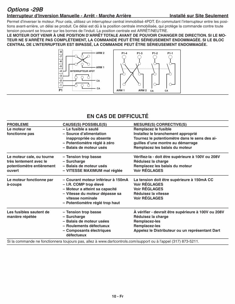
EN CAS DE DIFFICULTÉPROBLEMELe moteur ne fonctionne pas
Le moteur cale, ou tourne très lentement avec le potentiomètre entièrement ouvert
Le moteur fonctionne par à-coups
Les fusibles sautent de manière répétée
CAUSE(S) POSSIBLE(S) – Le fusible a sauté– Source d’alimentation inappropriée ou absente– Potentiomètre réglé à zéro– Balais de moteur usés
– Tension trop basse– Surcharge– Balais de moteur usés– VITESSE MAXIMUM mal réglée
– Courant moteur inférieur à 150mA– I.R. COMP trop élevé– Moteur a atteint sa capacité– Vitesse du moteur dépasse sa vitesse nominale– Potentiomètre réglé trop haut
– Tension trop basse– Surcharge– Balais de moteur usées– Roulements défectueux– Composants électriques défectueux
MESURE(S) CORRECTIVE(S)Remplacez le fusibleInstallez le branchement appropriéTournez le potentiomètre dans le sens des ai-guilles d’une montre au démarrageRemplacez les balais du moteur
Vérifiez-la - doit être supérieure à 100V ou 208VRéduisez la chargeRemplacez les balais du moteurVoir RÉGLAGES
La tension doit être supérieure à 150mA CCVoir RÉGLAGES Voir RÉGLAGESRéduisez la vitesseVoir RÉGLAGES
À vérifier - devrait être supérieure à 100V ou 208VRéduisez la chargeRemplacez-lesRemplacez-lesAppelez le Distributeur ou un représentant Dart
Si la commande ne fonctionnera toujours pas, allez à www.dartcontrols.com/support ou à l'appel (317) 873-5211.
10 - Fr
P1
-5
-6
-7
-8
-4
-3
ARM 2
ARM 1
AC
AC-1
-2
4PDT SWITCH
P1-4 P1-3 P1-2 P1-1
ARM 1 ARM 2 ACAC
Options -29B Interrupteur d'Inversion Manuelle - Arrêt - Marche Arrière Installé sur Site SeulementPermet d’inverser le moteur. Pour cela, utilisez un interrupteur central immobilisé 4PDT. En commutant l’interrupteur entre les posi-tions avant-arrière, un délai se produit. Ce délai est dû à la position centrale immobilisée, qui protège la commande contre toute tension pouvant se trouver sur les bornes de l’induit. La position centrale est ARRÊT/NEUTRE.LE MOTEUR DOIT VENIR À UNE POSITION D’ARRÊT TOTALE AVANT DE POUVOIR CHANGER DE DIRECTION. SI LE MO-TEUR NE S’ARRÊTE PAS COMPLÈTEMENT, LA COMMANDE PEUT ÊTRE SÉRIEUSEMENT ENDOMMAGÉE. SI LE BLOC CENTRAL DE L’INTERRUPTEUR EST BIPASSÉ, LA COMMANDE PEUT ÊTRE SÉRIEUSEMENT ENDOMMAGÉE.
INTERRUPTEUR 4PDT
CA
CACA CA
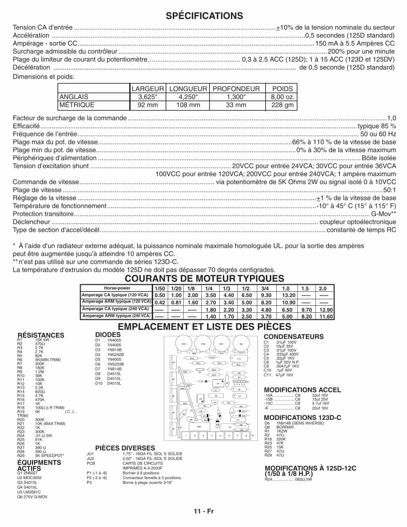
SPÉCIFICATIONSTension CA d’entrée .............................................................................................................+10% de la tension nominale du secteurAccélération .........................................................................................................................................0,5 secondes (125D standard)Ampérage - sortie CC ................................................................................................................................150 mA à 5.5 Ampères CCSurcharge admissible du contrôleur .................................................................................................................200% pour une minutePlage du limiteur de courant du potentiomètre .................................................. 0,3 à 2.5 ACC (125D); 1 à 15 ACC (123D et 125DV)Décélération ................................................................................................................................... de 0,5 seconde (125D standard)Dimensions et poids:
LARGEUR LONGUEUR PROFONDEUR POIDSANGLAIS 3,625" 4,250" 1,300" 8,00 oz.MÉTRIQUE 92 mm 108 mm 33 mm 228 gm
Facteur de surcharge de la commande ............................................................................................................................................1,0Efficacité ........................................................................................................................................................................... typique 85 %Fréquence de l’entrée ........................................................................................................................................................ 50 ou 60 HzPlage max du pot. de vitesse .........................................................................................................66% à 110 % de la vitesse de basePlage min du pot. de vitesse ............................................................................................................0% à 30% de la vitesse maximumPériphériques d’alimentation .............................................................................................................................................. Bôite isoléeTension d’excitation shunt ............................................................................ 20VCC pour entrée 24VCA; 30VCC pour entrée 36VCA
100VCC pour entrée 120VCA; 200VCC pour entrée 240VCA; 1 ampère maximumCommande de vitesse ......................................................................... via potentiomètre de 5K Ohms 2W ou signal isolé 0 à 10VCCPlage de vitesse .............................................................................................................................................................................50:1Réglage de la vitesse .................................................................................................................................+1 % de la vitesse de baseTempérature de fonctionnement .................................................................................................................-10° à 45° C (15° à 115° F)Protection transitoire ................................................................................................................................................................ G-Mov**Déclencheur ................................................................................................................................................ coupleur optoélectroniqueType de section d’accel/décél. ......................................................................................................................... constante de temps RC
* À l’aide d’un radiateur externe adéquat, la puissance nominale maximale homologuée UL. pour la sortie des ampères peut être augmentée jusqu’à atteindre 10 ampères CC.** n’est pas utilisé sur une commande de séries 123D-C.La température d’extrusion du modèle 125D ne doit pas dépasser 70 degrés centigrades.
COURANTS DE MOTEUR TYPIQUES
Amperage CA typique (120 VCA)Amperage ARM typique (120 VCA)
Amperage CA typique (240 VCA)
Amperage ARM typique (240 VCA)
Horse-power 1/50 1/20 1/8 1/4 1/3 1/2 3/4 1.0 1.5 2.00.50 1.00 2.00 3.50 4.40 6.50 9.30 13.20 ----- -----0.42 0.81 1.60 2.70 3.40 5.00 8.20 10.90 ----- ---------- ----- ----- 1.80 2.20 3.30 4.80 6.50 9.70 12.90----- ----- ----- 1.40 1.70 2.50 3.70 5.00 8.20 11.60
RÉSISTANCESR1 15K 6WR2 470ΩR3 2.7KR4 2.7KR5 82KR6 5K(MIN TRIM)R7 300KR8 180KR9 1.2MR10 39KR11 100KR12 10KR13 2.2KR14 820ΩR15 4.7KR16 470KR17 1KR18 100Ω (I.R TRIM)R19 5K ( C . L . TRIM)R20 300KR21 10K (MAX TRIM)R22 1KR23 300KR24 .01 Ω 5WR25 91KR26 1KR27 390 ΩR28 390 ΩR29 5K SPEEDPOT*
DIODESD1 1N4005D2 1N4005D3 1N914BD4 1N5242BD5 1N4005D6 1N5233BD7 1N914BD8 D4015LD9 D4015LD10 D4015L
EMPLACEMENT ET LISTE DES PIÈCES
MODIFICATIONS ACCEL-15A .................. C8 33uf 16V-15B .................. C8 15uf 25V-15C .................. C8 4.7uf 16V-K ...................... C8 22uf 16V
D6 1N914B (SENS INVERSE)Q6 BORRARR1 1K2WR2 47ΩR16 220KR23 47KR25 15KR27 47ΩR28 47Ω
MODIFICATIONS 123D-C
MODIFICATIONS À 125D-12C (1/50 à 1/8 H.P.)R24................... .062Ω 5W
ÉQUIPMENTSACTIFSQ1 2N6027U2 MOC3052Q3 S4015LQ4 S4015LU5 LM3581CQ6 275V G-MOV
JU1 1,75" - 16GA FIL ISOL´E SOLIDEJU2 2,50" - 16GA FIL ISOL´E SOLIDEPCB CARTE DE CIRCUITS IMPRIMÉS A-4-2033FP1 (-1 à -8) Bornier à 8 positionsP2 (-2 à -6) Connecteur femelle à 5 positionsP3 Borne à plage ouverte 3/16"
PIÈCES DIVERSES
C1 .01µF 100VC2 10µF 35VC3 .01µF 100VC4 .033µF 400VC5 .22µF 1KVC8 1µF 50V N.P.C9 .0047µF 1KVC10 .1µF 50VC11 47µF 16V
CONDENSATEURS
11 - Fr
R24
Q1
C4
P1-8-7-6-5-4-3-2-1
C9
U5 R11
R3
U2
P3
D5
Q3
D1
C1
C3D9
D8
Q4
D10
D3
R4
R5R25R2
R27
R26
R23
C8
R7
P265432
C11
R12
R13R10
R17
R6R21R18R19
D2
R1R8
D6D4
C5 C2
R20 R14
R9
R15
R22
R16
R28
D7
Q6
JU2
JU1
C10
+
+
+
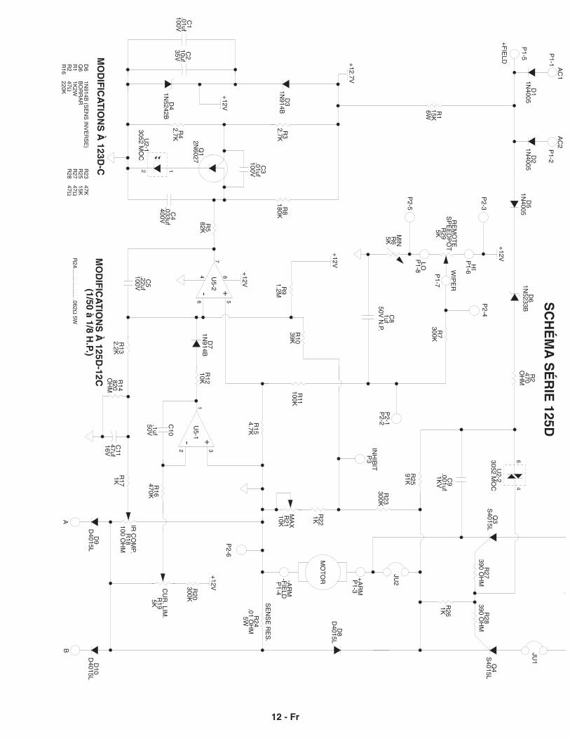
SC
HÉ
MA
SÉ
RIE
125D
MO
DIF
ICA
TIO
NS
À 125D
-12C
(1/50 à 1/8 H.P.)
R24................... .062Ω
5W
MO
DIF
ICA
TIO
NS
À 123D
-C
12 - Fr
D6
1N914B
(SE
NS
INV
ER
SE
)Q
6 B
OR
RA
RR
1 1K
2WR
2 47Ω
R16
220K
R23
47KR
25 15K
R27
47ΩR
28 47Ω
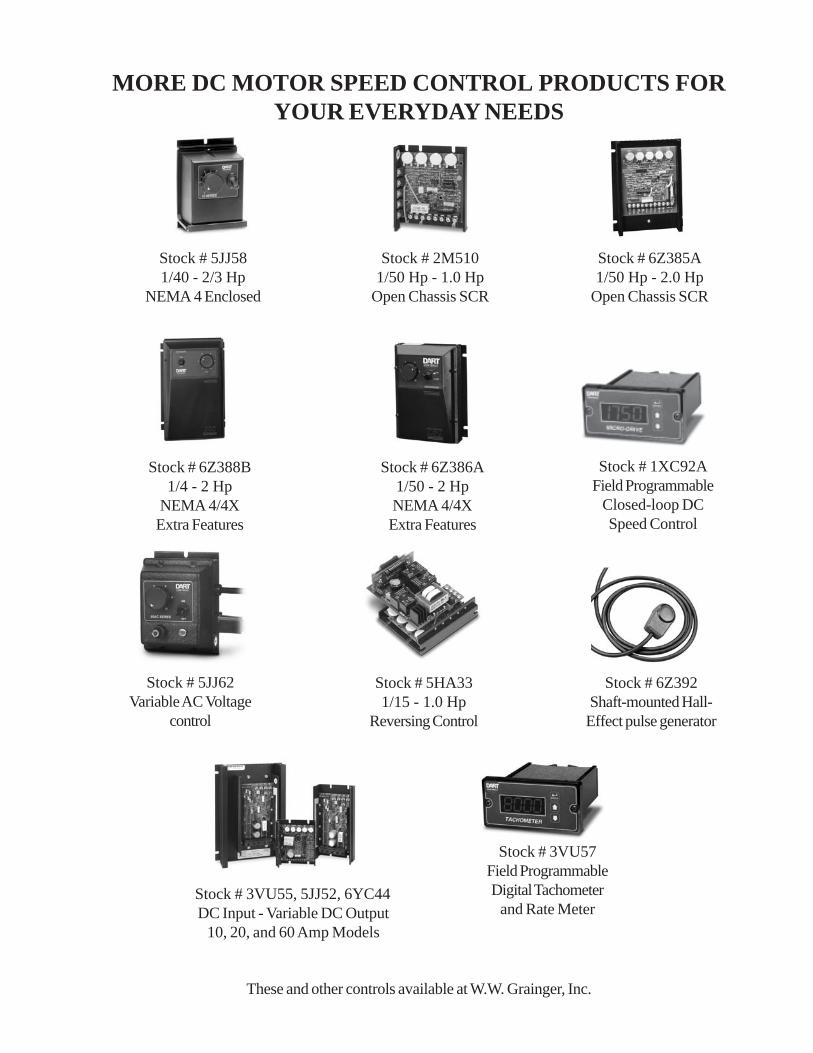
MORE DC MOTOR SPEED CONTROL PRODUCTS FORYOUR EVERYDAY NEEDS
These and other controls available at W.W. Grainger, Inc.
Stock # 5JJ62Variable AC Voltage
control
Stock # 6Z392Shaft-mounted Hall-Effect pulse generator
Stock # 6Z388B1/4 - 2 Hp
NEMA 4/4XExtra Features
Stock # 2M5101/50 Hp - 1.0 Hp
Open Chassis SCR
Stock # 6Z385A1/50 Hp - 2.0 Hp
Open Chassis SCR
Stock # 1XC92AField Programmable
Closed-loop DCSpeed Control
Stock # 6Z386A1/50 - 2 HpNEMA 4/4XExtra Features
Stock # 5JJ581/40 - 2/3 Hp
NEMA 4 Enclosed
Stock # 5HA331/15 - 1.0 Hp
Reversing Control
Stock # 3VU55, 5JJ52, 6YC44DC Input - Variable DC Output
10, 20, and 60 Amp Models
Stock # 3VU57Field ProgrammableDigital Tachometer
and Rate Meter