123d tutorial
DESCRIPTION
123d tutorialTRANSCRIPT
Introduction to 123D Tatjana Dzambazova – Autodesk
FC6581 This is an introductory class for 123D. 123D is free 3D CAD software that helps you quickly give shape to your idea, explore it, and most importantly, make it. Design precise and makeable objects using easy to use but smart tools that let you start with simple shapes and then edit and then combine them into more complex assemblies. In this class we will try to cover just some of the unique values of 123D, with the hope that it will be both educational and inspirational for continuing exploring the tool.
Learning Objectives At the end of this class, you will be able to:
• Have a general overview of the value proposition of 123D
• Understand base principles and tools of 123D
• Working with components
• Making assemblies in 123D
• 3D printing and Laser Cutting workflows with 123D
About the Speaker Tatjana Dzambazova, architect and technologist. Trained architect with over 12 years of experience as architect in Vienna, Austria and London, UK; For the last 12 years she works for Autodesk mainly in technology expert advocate and product management roles, always on the front end, driving emerging products or initiatives. Mostly known in the AEC community as the leader of Revit, for which she also privately co-authored three books. After various other product management and business development roles, Tanja spent the last years focusing on personal fabrication, a trend enabled by the democratized tools of making (3d Printers, Laser cutters, Shopbots etc.) accessible design tools and online fabbing services. In particular she led the development of new exciting personal fabrication software tools that will change the way prototypes or final objects can be made fast and cheap. (123D MAKE is the introductory version of a wide collection of such tools currently under development.).
Introduction in 123D
2
123D is free and easy to use solid modeling tool that is much easier to use than many tools of comparable power; the wealth of tools and options is impossible to cover in a 90 minutes class. I hope this class will give you a good taste of it and inspire you to explore it further.
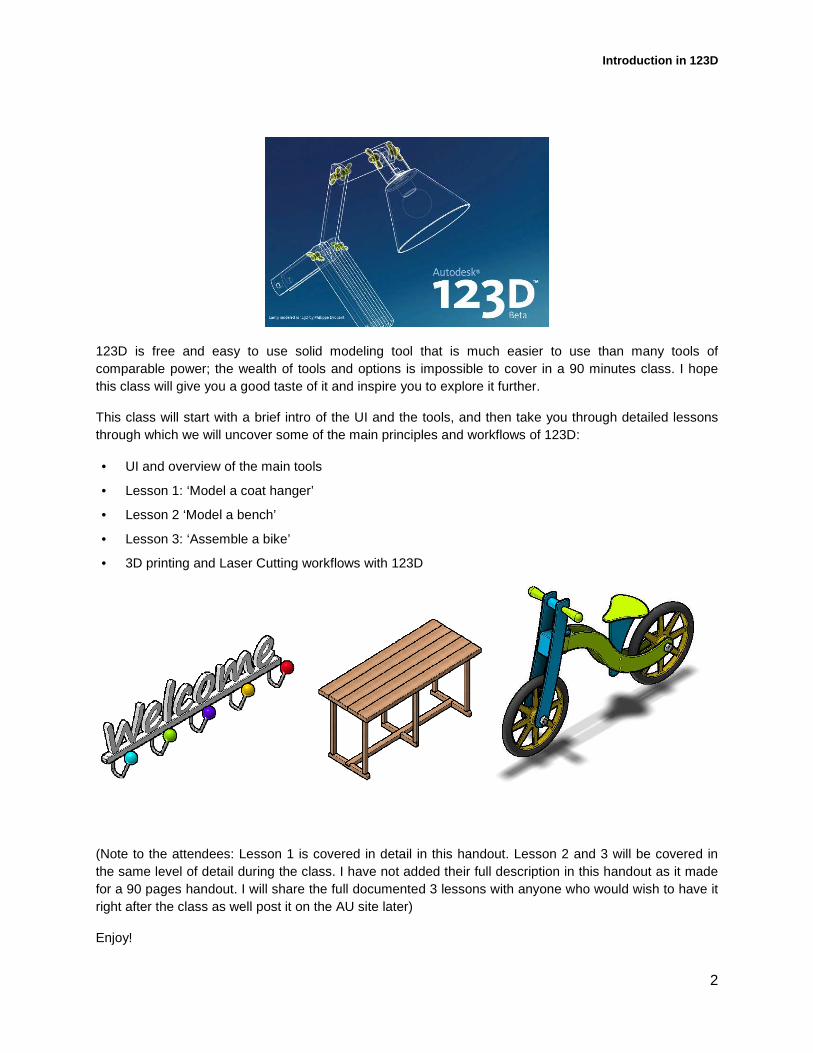
This class will start with a brief intro of the UI and the tools, and then take you through detailed lessons through which we will uncover some of the main principles and workflows of 123D:
• UI and overview of the main tools
• Lesson 1: ‘Model a coat hanger’
• Lesson 2 ‘Model a bench’
• Lesson 3: ‘Assemble a bike’
• 3D printing and Laser Cutting workflows with 123D
(Note to the attendees: Lesson 1 is covered in detail in this handout. Lesson 2 and 3 will be covered in the same level of detail during the class. I have not added their full description in this handout as it made for a 90 pages handout. I will share the full documented 3 lessons with anyone who would wish to have it right after the class as well post it on the AU site later)
Enjoy!
Introduction in 123D
3
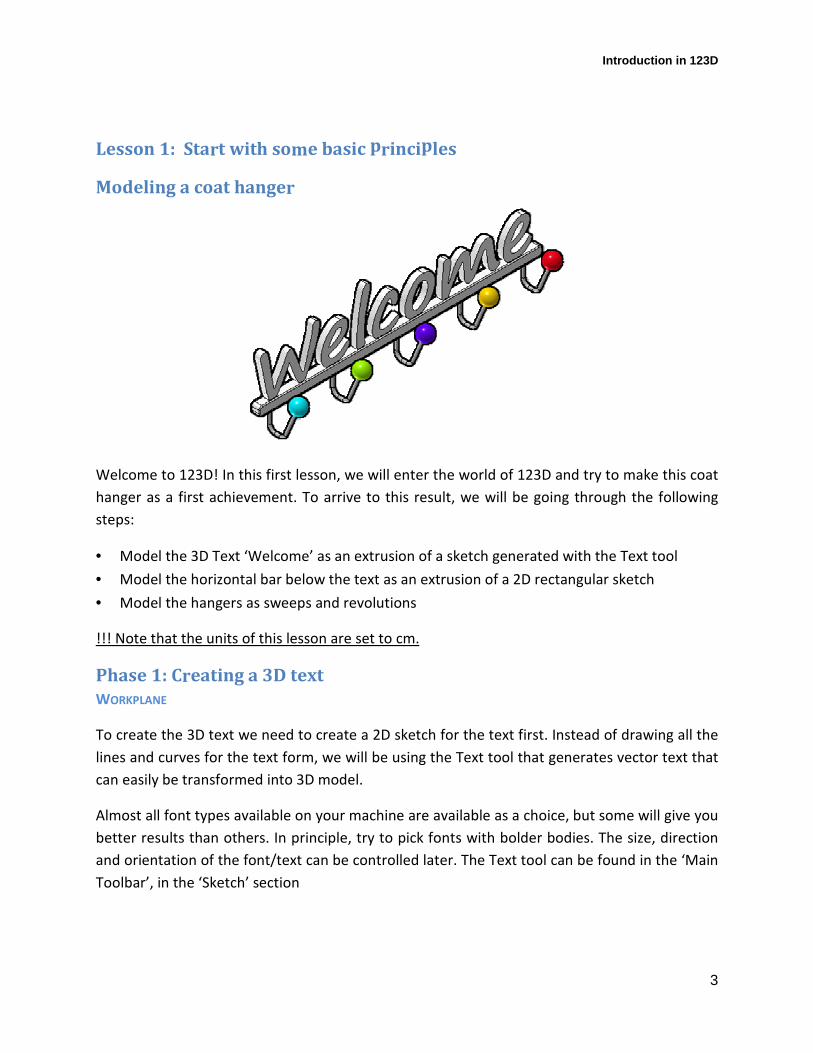
Lesson 1: Start with some basic principles
Modeling a coat hanger
Welcome to 123D! In this first lesson, we will enter the world of 123D and try to make this coat
hanger as a first achievement. To arrive to this result, we will be going through the following
steps:
• Model the 3D Text ‘Welcome’ as an extrusion of a sketch generated with the Text tool
• Model the horizontal bar below the text as an extrusion of a 2D rectangular sketch
• Model the hangers as sweeps and revolutions
!!! Note that the units of this lesson are set to cm.
Phase 1: Creating a 3D text
WORKPLANE
To create the 3D text we need to create a 2D sketch for the text first. Instead of drawing all the
lines and curves for the text form, we will be using the Text tool that generates vector text that
can easily be transformed into 3D model.
Almost all font types available on your machine are available as a choice, but some will give you
better results than others. In principle, try to pick fonts with bolder bodies. The size, direction
and orientation of the font/text can be controlled later. The Text tool can be found in the ‘Main
Toolbar’, in the ‘Sketch’ section
Introduction in 123D
4
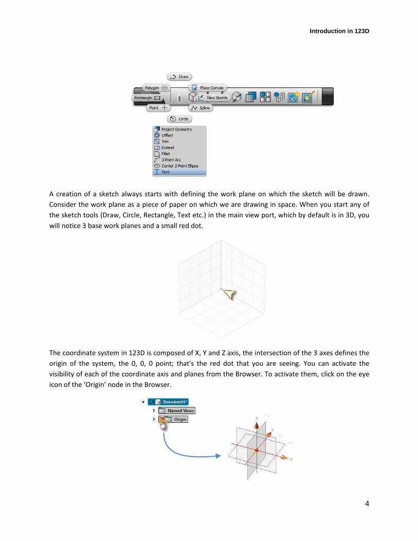
A creation of a sketch always starts with defining the work plane on which the sketch will be drawn.
Consider the work plane as a piece of paper on which we are drawing in space. When you start any of
the sketch tools (Draw, Circle, Rectangle, Text etc.) in the main view port, which by default is in 3D, you
will notice 3 base work planes and a small red dot.
The coordinate system in 123D is composed of X, Y and Z axis, the intersection of the 3 axes defines the
origin of the system, the 0, 0, 0 point; that's the red dot that you are seeing. You can activate the
visibility of each of the coordinate axis and planes from the Browser. To activate them, click on the eye
icon of the ‘Origin’ node in the Browser.
Introduction in 123D
5
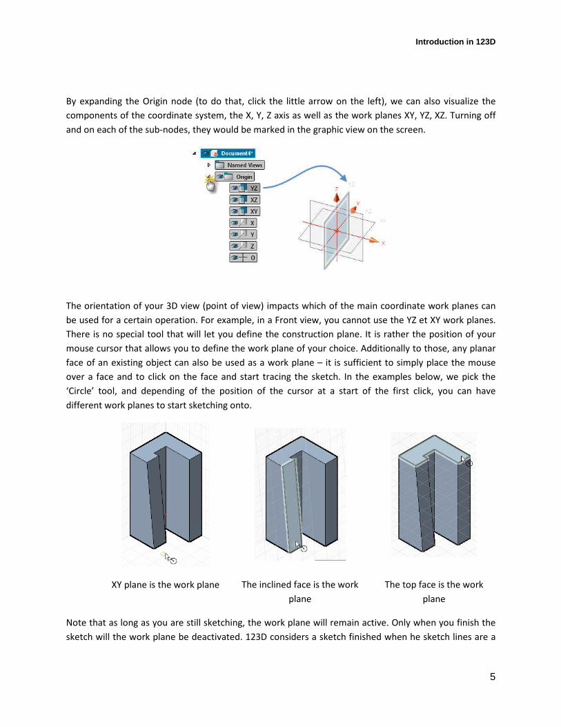
By expanding the Origin node (to do that, click the little arrow on the left), we can also visualize the
components of the coordinate system, the X, Y, Z axis as well as the work planes XY, YZ, XZ. Turning off
and on each of the sub-nodes, they would be marked in the graphic view on the screen.
The orientation of your 3D view (point of view) impacts which of the main coordinate work planes can
be used for a certain operation. For example, in a Front view, you cannot use the YZ et XY work planes.
There is no special tool that will let you define the construction plane. It is rather the position of your
mouse cursor that allows you to define the work plane of your choice. Additionally to those, any planar
face of an existing object can also be used as a work plane – it is sufficient to simply place the mouse
over a face and to click on the face and start tracing the sketch. In the examples below, we pick the
‘Circle’ tool, and depending of the position of the cursor at a start of the first click, you can have
different work planes to start sketching onto.
XY plane is the work plane The inclined face is the work
plane
The top face is the work
plane
Note that as long as you are still sketching, the work plane will remain active. Only when you finish the
sketch will the work plane be deactivated. 123D considers a sketch finished when he sketch lines are a

Introduction in 123D
6
closed loop of lines. If you wish to finish a sketch that is not a closed loop, you can do so from the
context menu (right click) and selecting ‘Stop Sketch’.
Sometimes, depending on the geometry you have in mind, neither the default work planes nor the faces
of existing objects are enough to design the sketches for the geometry you require. For example, you
might need to draw a work plane that is between two existing faces. 123D offers many ways to create
additional work plans. They are accessible from the ‘Main Toolbar’, in the ‘Construction’ section.
When you pick any of these additional methods to create a new work plane, that new work plane will
appear in the browser after its creation. You can then hide it (turn ON/OFF) using the eye icon, rename
it (click on it and start typing), delete it (right click, Delete) or use it as a Section tool (for temporary
viewing of your model in section view).
EXTRUSION
Principles: An extrusion uses a sketch that consists of one or multiple faces and gives it a height that
turns that sketch into a 3d form. The direction of an extrusion is always perpendicular to the
Introduction in 123D
7
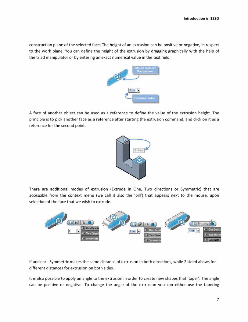
construction plane of the selected face. The height of an extrusion can be positive or negative, in respect
to the work plane. You can define the height of the extrusion by dragging graphically with the help of
the triad manipulator or by entering an exact numerical value in the text field.
A face of another object can be used as a reference to define the value of the extrusion height. The
principle is to pick another face as a reference after starting the extrusion command, and click on it as a
reference for the second point.
There are additional modes of extrusion (Extrude in One, Two directions or Symmetric) that are
accessible from the context menu (we call it also the ‘pill’) that appears next to the mouse, upon
selection of the face that we wish to extrude.
If unclear: Symmetric makes the same distance of extrusion in both directions, while 2 sided allows for
different distances for extrusion on both sides.
It is also possible to apply an angle to the extrusion in order to create new shapes that ‘taper’. The angle
can be positive or negative. To change the angle of the extrusion you can either use the tapering
Introduction in 123D
8
manipulator that lets you dynamically drag it to define the taper angle, or you can type a numeric value
in the field (both options appear upon finalizing the height of the extrusion). Here an example with a
positive angle of extrusion.
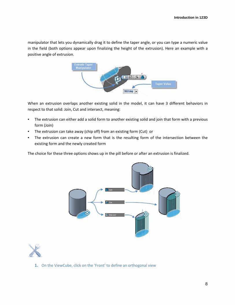
When an extrusion overlaps another existing solid in the model, it can have 3 different behaviors in
respect to that solid: Join, Cut and intersect, meaning:
• The extrusion can either add a solid form to another existing solid and join that form with a previous
form (Join)
• The extrusion can take away (chip off) from an existing form (Cut) or
• The extrusion can create a new form that is the resulting form of the intersection between the
existing form and the newly created form
The choice for these three options shows up in the pill before or after an extrusion is finalized.
1. On the ViewCube, click on the ‘Front’ to define an orthogonal view
Introduction in 123D
9
2. From the ‘MainToolbar’, in the ‘Sketch’ section, click on ‘Text’.
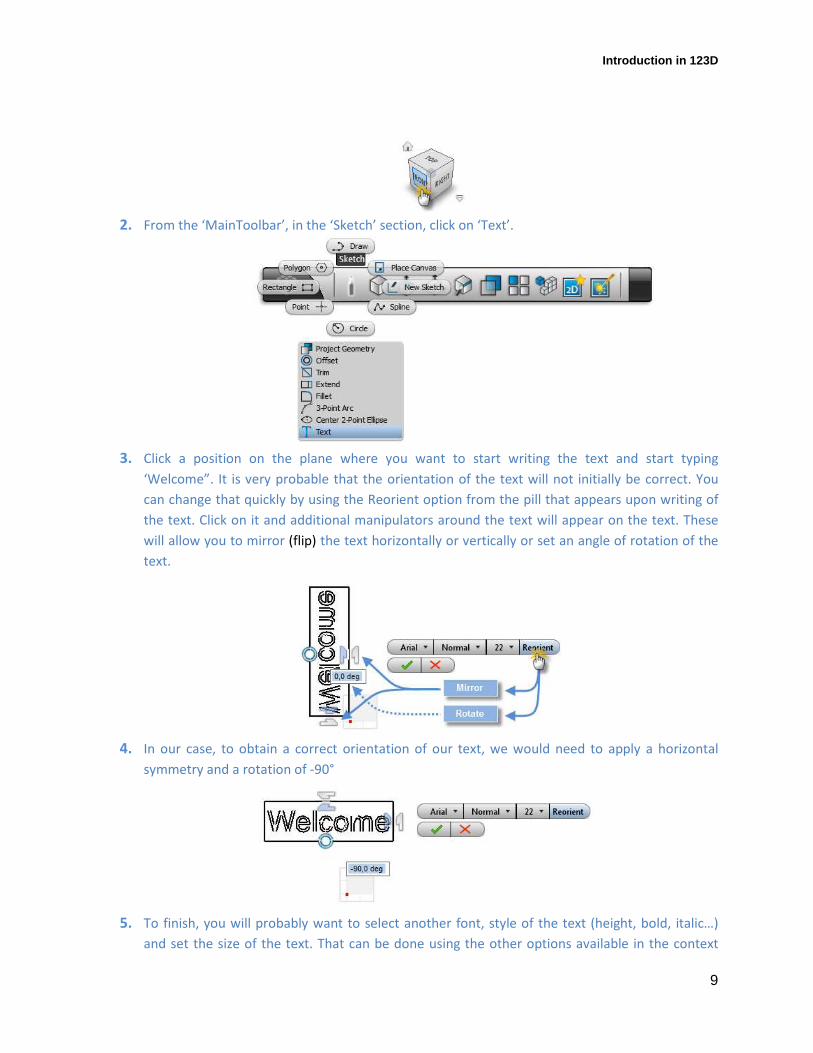
3. Click a position on the plane where you want to start writing the text and start typing
‘Welcome”. It is very probable that the orientation of the text will not initially be correct. You
can change that quickly by using the Reorient option from the pill that appears upon writing of
the text. Click on it and additional manipulators around the text will appear on the text. These
will allow you to mirror (flip) the text horizontally or vertically or set an angle of rotation of the
text.
4. In our case, to obtain a correct orientation of our text, we would need to apply a horizontal
symmetry and a rotation of -90°
5. To finish, you will probably want to select another font, style of the text (height, bold, italic…)
and set the size of the text. That can be done using the other options available in the context
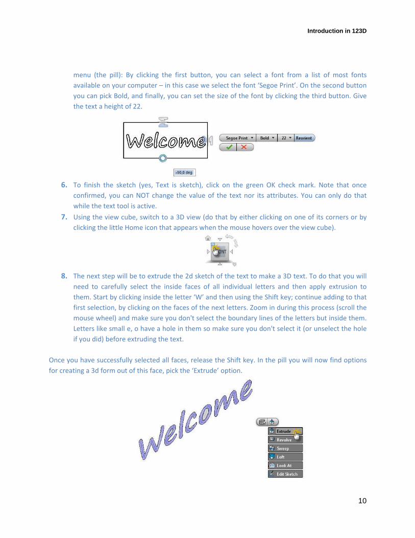
Introduction in 123D
10
menu (the pill): By clicking the first button, you can select a font from a list of most fonts
available on your computer – in this case we select the font ‘Segoe Print’. On the second button
you can pick Bold, and finally, you can set the size of the font by clicking the third button. Give
the text a height of 22.
6. To finish the sketch (yes, Text is sketch), click on the green OK check mark. Note that once
confirmed, you can NOT change the value of the text nor its attributes. You can only do that
while the text tool is active.
7. Using the view cube, switch to a 3D view (do that by either clicking on one of its corners or by
clicking the little Home icon that appears when the mouse hovers over the view cube).
8. The next step will be to extrude the 2d sketch of the text to make a 3D text. To do that you will
need to carefully select the inside faces of all individual letters and then apply extrusion to
them. Start by clicking inside the letter ‘W’ and then using the Shift key; continue adding to that
first selection, by clicking on the faces of the next letters. Zoom in during this process (scroll the
mouse wheel) and make sure you don't select the boundary lines of the letters but inside them.
Letters like small e, o have a hole in them so make sure you don't select it (or unselect the hole
if you did) before extruding the text.
Once you have successfully selected all faces, release the Shift key. In the pill you will now find options
for creating a 3d form out of this face, pick the ‘Extrude’ option.
Introduction in 123D
11
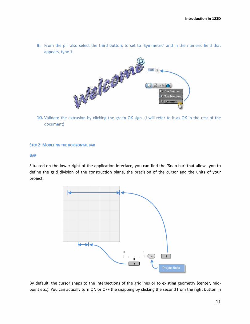
9. From the pill also select the third button, to set to ‘Symmetric’ and in the numeric field that
appears, type 1.
10. Validate the extrusion by clicking the green OK sign. (I will refer to it as OK in the rest of the
document)
STEP 2: MODELING THE HORIZONTAL BAR
BAR
Situated on the lower right of the application interface, you can find the ‘Snap bar’ that allows you to
define the grid division of the construction plane, the precision of the cursor and the units of your
project.
By default, the cursor snaps to the intersections of the gridlines or to existing geometry (center, mid-
point etc.). You can actually turn ON or OFF the snapping by clicking the second from the right button in
Introduction in 123D
12
the menu on the lower to right corner of the app. The snap is ON when the background of the snap icon
is blue.
This is an invaluable help in your design as it allows for high precision when you work. The value of the
snap depends on the zoom factor. Bigger the zoom, smaller the snap value. If you want to modify your
current setting for snap value, by sliding the cursor in the snap bar or by inputting a numeric value in the
field that appears right below the snap bar.
SKETCH TOOLS
123D offers a variety of sketch tools, lines (Draw), circles rectangles, splines, ellipses etc. as well as
additional sketch actions such as Offset, Trim, Extend etc. All of them are available in the ‘Main Toolbar’
under the ‘Sketch’ section.
These tools are intuitive and you just draw upon the selection. There are some neat help tools that are
not that obvious. For example, 123D makes it possible to draw a connected loop of straight and curved
tangential segments, without interruption of the drawing action and switching between different tools.
You start with the tool Draw (which by default draws straight lines only), you click to define the start
point, move the cursor towards the second point that defines the length of the line. If you now want to
continue with a tangential arc, now hold down the over the last point you drew and move the cursor of
the mouse while holding the left button – an arc starts showing up and you define its size and position
by clicking the second point.
Introduction in 123D
13
If you wish to continue with a second arc that is tangential to the first one, you repeat the same: you
hold the left mouse button over the second point of the first arc and start dragging, to define the second
point of the second arc. Note that you are still in the Draw tool, you didn't have to switch to the Arc tool.
When you trace a line segment you can define its size by dragging the mouse or by inputting a specific
value in the numeric field that automatically appears in the UI upon start of the Draw tool.
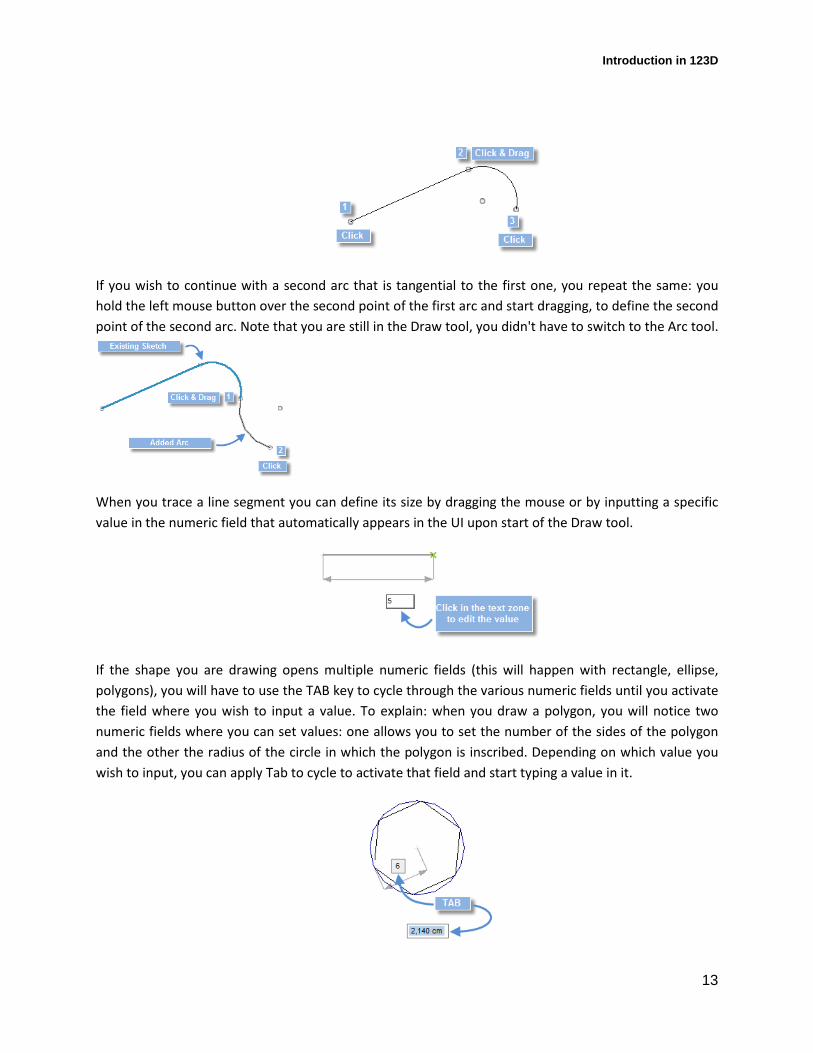
If the shape you are drawing opens multiple numeric fields (this will happen with rectangle, ellipse,
polygons), you will have to use the TAB key to cycle through the various numeric fields until you activate
the field where you wish to input a value. To explain: when you draw a polygon, you will notice two
numeric fields where you can set values: one allows you to set the number of the sides of the polygon
and the other the radius of the circle in which the polygon is inscribed. Depending on which value you
wish to input, you can apply Tab to cycle to activate that field and start typing a value in it.
Introduction in 123D
14
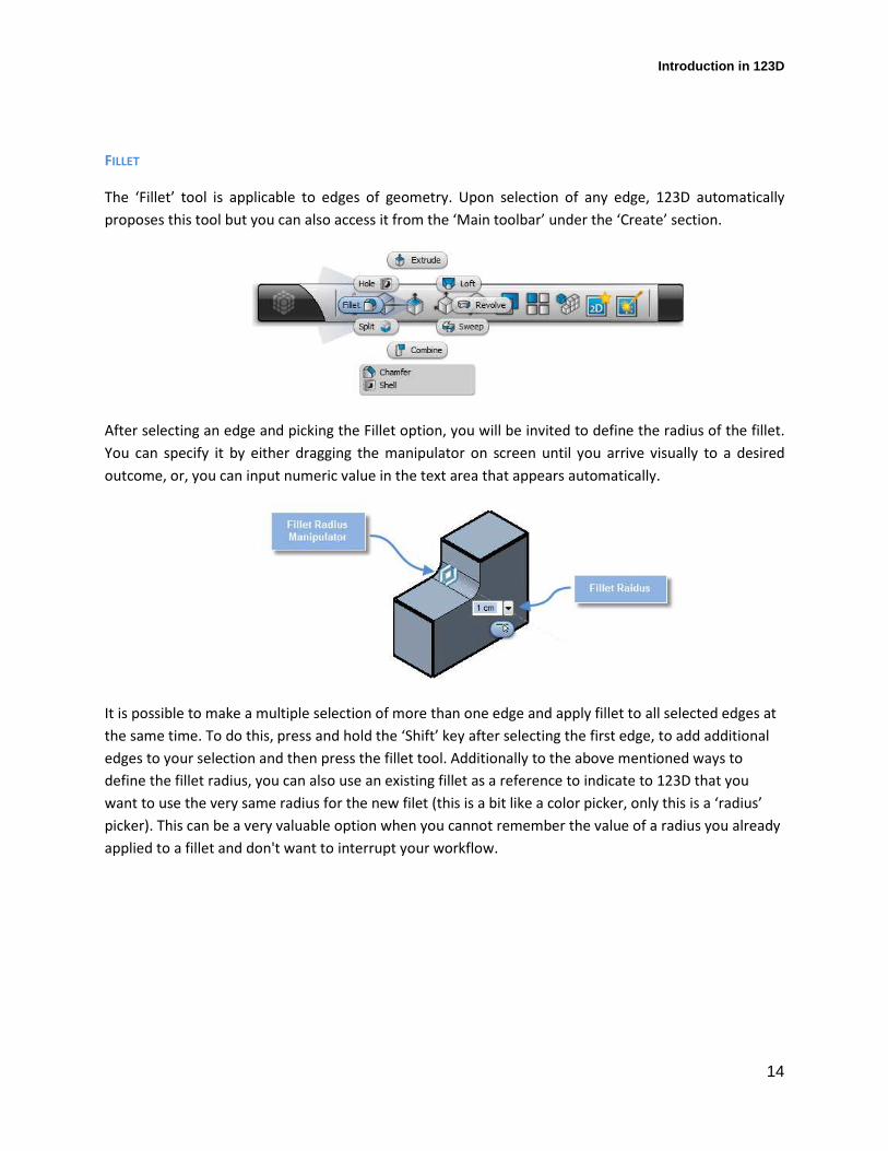
FILLET
The ‘Fillet’ tool is applicable to edges of geometry. Upon selection of any edge, 123D automatically
proposes this tool but you can also access it from the ‘Main toolbar’ under the ‘Create’ section.
After selecting an edge and picking the Fillet option, you will be invited to define the radius of the fillet.
You can specify it by either dragging the manipulator on screen until you arrive visually to a desired
outcome, or, you can input numeric value in the text area that appears automatically.
It is possible to make a multiple selection of more than one edge and apply fillet to all selected edges at
the same time. To do this, press and hold the ‘Shift’ key after selecting the first edge, to add additional
edges to your selection and then press the fillet tool. Additionally to the above mentioned ways to
define the fillet radius, you can also use an existing fillet as a reference to indicate to 123D that you
want to use the very same radius for the new filet (this is a bit like a color picker, only this is a ‘radius’
picker). This can be a very valuable option when you cannot remember the value of a radius you already
applied to a fillet and don't want to interrupt your workflow.

Introduction in 123D
15
When the ‘Fillet’ tool is active, 123D looks for all consequent edges in that sketch loop and selects them
automatically. This is a big time saver vs. manual selection of all individual segments.
1. On the view cube, pick the face ‘Front’ to define your new view orientation.
2. In the ‘Main Toolbar’, under the ‘Sketch’ section, click on ‘Rectangle’.

Introduction in 123D
16
3. You will have to define the rectangle by clicking on its two diagonal points of the imagined
rectangle. In our case, we want to create a rectangle that slightly exceeds the length of the
Welcome sign. To help with the precision, use the Zoom tool and see how much you want to
extend and position in respect to the existing Welcome sign. The size of the rectangle we will
draw will be approximately 105 x 3.5 cm.
4. Switch back to 3D view, using the ViewCube.
5. Pick the surface that you just created with the rectangle (click in the middle of it, not the edge)
and select ‘Extrude’ from the pill. Specify a Symmetric extrusion and set the height of the
extrusion to 1.5cm. Make sure to set the option ‘Join’ (also available in the pill). Validate to
finish the extrusion.
6. Zoom towards one of the ends of the rectangular bar you just made. Select its two edges (press
and hold the Shift key after selecting the first edge to select the second edge as well) and set a
fillet radius of 1cm. Right click, OK to finish the fillet.
Introduction in 123D
17
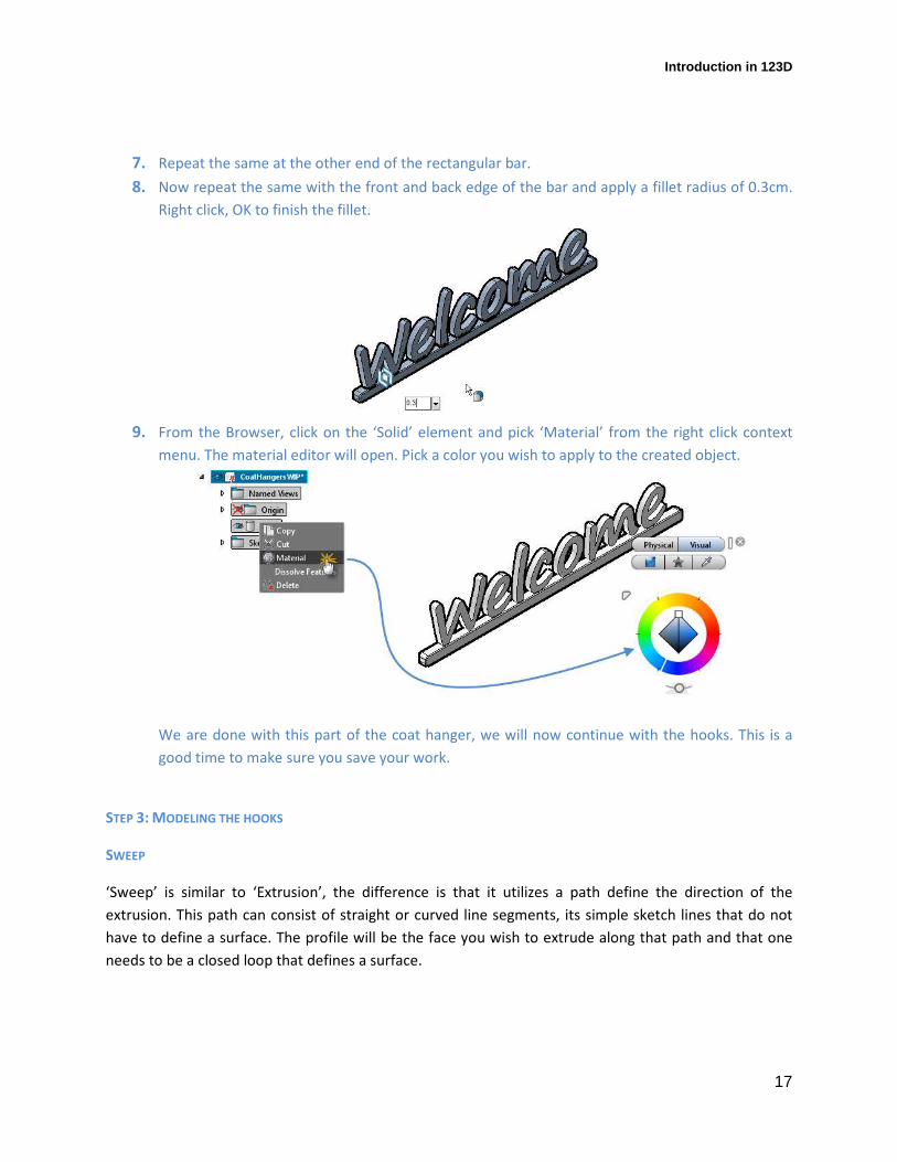
7. Repeat the same at the other end of the rectangular bar.
8. Now repeat the same with the front and back edge of the bar and apply a fillet radius of 0.3cm.
Right click, OK to finish the fillet.
9. From the Browser, click on the ‘Solid’ element and pick ‘Material’ from the right click context
menu. The material editor will open. Pick a color you wish to apply to the created object.
We are done with this part of the coat hanger, we will now continue with the hooks. This is a
good time to make sure you save your work.
STEP 3: MODELING THE HOOKS
SWEEP
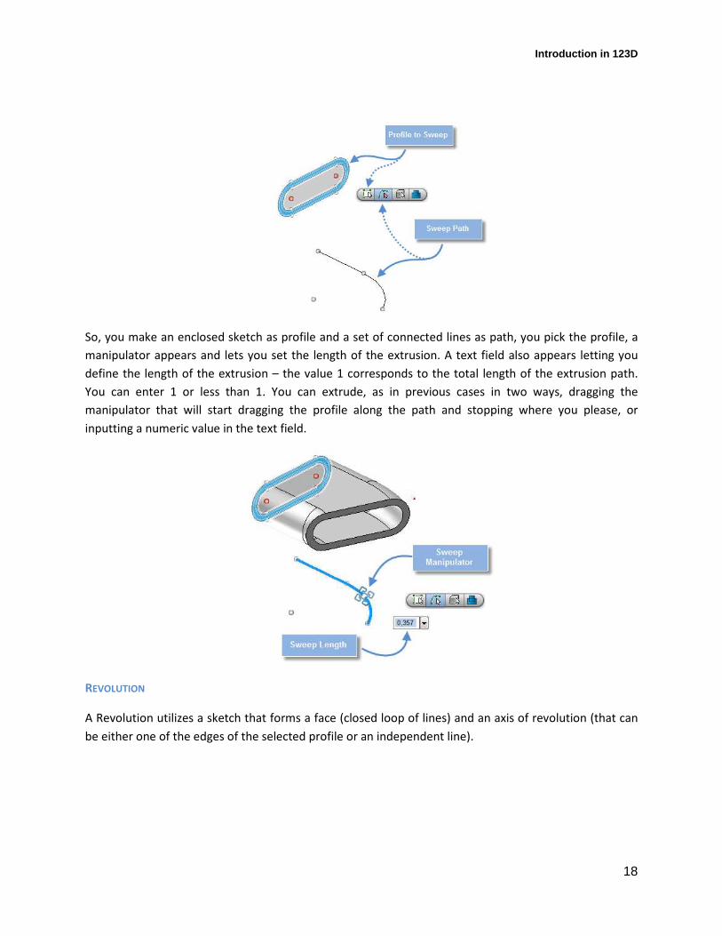
‘Sweep’ is similar to ‘Extrusion’, the difference is that it utilizes a path define the direction of the
extrusion. This path can consist of straight or curved line segments, its simple sketch lines that do not
have to define a surface. The profile will be the face you wish to extrude along that path and that one
needs to be a closed loop that defines a surface.
Introduction in 123D
18
So, you make an enclosed sketch as profile and a set of connected lines as path, you pick the profile, a
manipulator appears and lets you set the length of the extrusion. A text field also appears letting you
define the length of the extrusion – the value 1 corresponds to the total length of the extrusion path.
You can enter 1 or less than 1. You can extrude, as in previous cases in two ways, dragging the
manipulator that will start dragging the profile along the path and stopping where you please, or
inputting a numeric value in the text field.
REVOLUTION
A Revolution utilizes a sketch that forms a face (closed loop of lines) and an axis of revolution (that can
be either one of the edges of the selected profile or an independent line).
Introduction in 123D
19
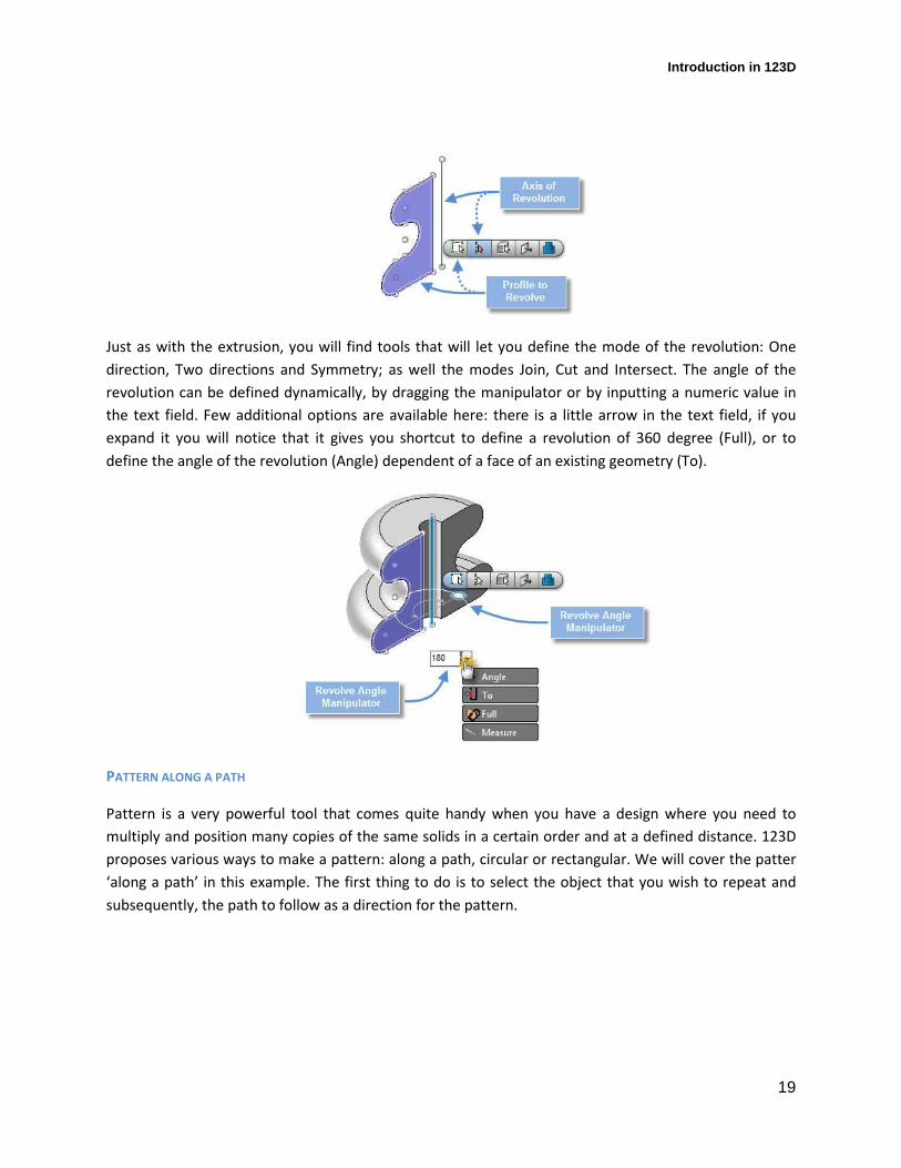
Just as with the extrusion, you will find tools that will let you define the mode of the revolution: One
direction, Two directions and Symmetry; as well the modes Join, Cut and Intersect. The angle of the
revolution can be defined dynamically, by dragging the manipulator or by inputting a numeric value in
the text field. Few additional options are available here: there is a little arrow in the text field, if you
expand it you will notice that it gives you shortcut to define a revolution of 360 degree (Full), or to
define the angle of the revolution (Angle) dependent of a face of an existing geometry (To).
PATTERN ALONG A PATH
Pattern is a very powerful tool that comes quite handy when you have a design where you need to
multiply and position many copies of the same solids in a certain order and at a defined distance. 123D
proposes various ways to make a pattern: along a path, circular or rectangular. We will cover the patter
‘along a path’ in this example. The first thing to do is to select the object that you wish to repeat and
subsequently, the path to follow as a direction for the pattern.
Introduction in 123D
20
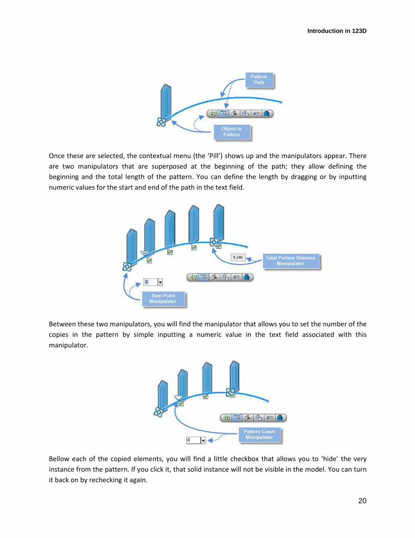
Once these are selected, the contextual menu (the ‘Pill’) shows up and the manipulators appear. There
are two manipulators that are superposed at the beginning of the path; they allow defining the
beginning and the total length of the pattern. You can define the length by dragging or by inputting
numeric values for the start and end of the path in the text field.
Between these two manipulators, you will find the manipulator that allows you to set the number of the
copies in the pattern by simple inputting a numeric value in the text field associated with this
manipulator.
Bellow each of the copied elements, you will find a little checkbox that allows you to ‘hide’ the very
instance from the pattern. If you click it, that solid instance will not be visible in the model. You can turn
it back on by rechecking it again.
Introduction in 123D
21
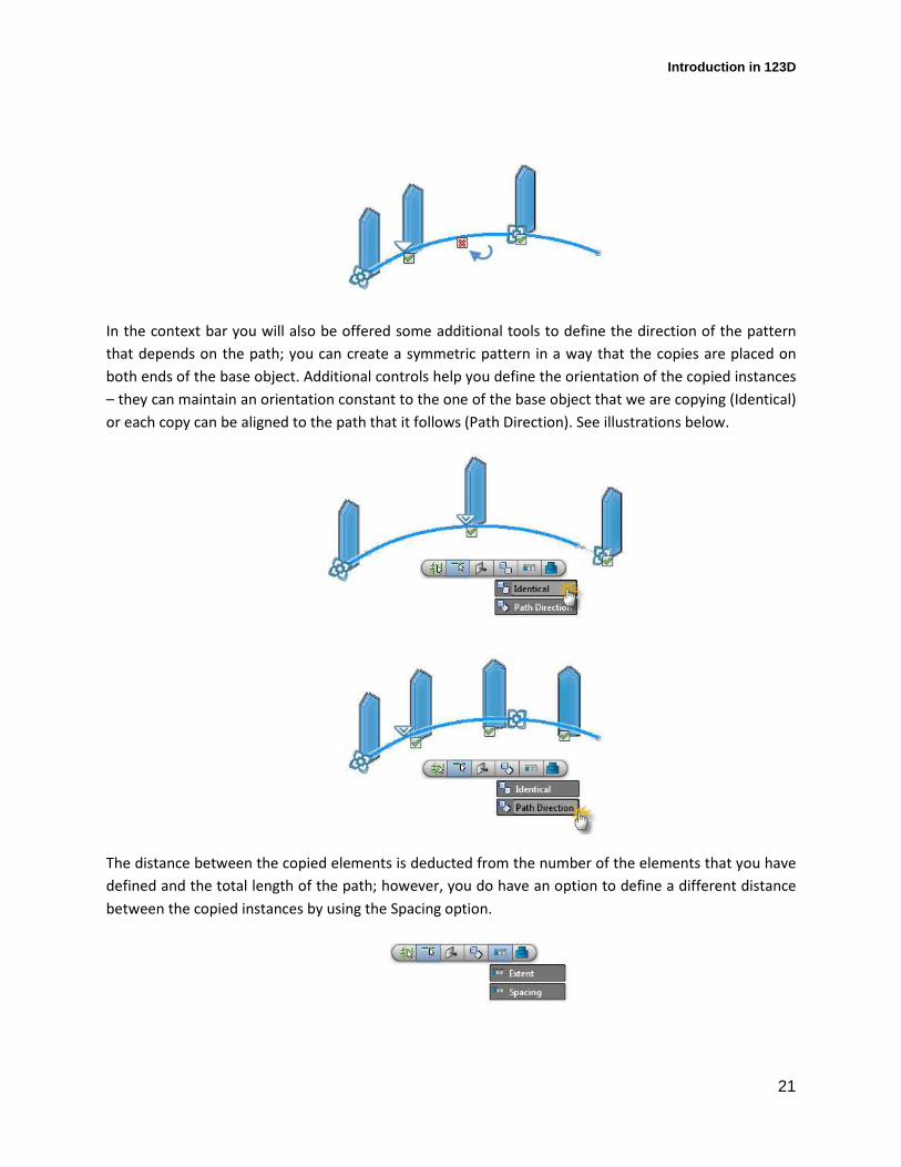
In the context bar you will also be offered some additional tools to define the direction of the pattern
that depends on the path; you can create a symmetric pattern in a way that the copies are placed on
both ends of the base object. Additional controls help you define the orientation of the copied instances
– they can maintain an orientation constant to the one of the base object that we are copying (Identical)
or each copy can be aligned to the path that it follows (Path Direction). See illustrations below.
The distance between the copied elements is deducted from the number of the elements that you have
defined and the total length of the path; however, you do have an option to define a different distance
between the copied instances by using the Spacing option.

Introduction in 123D
22
As in the previous tools, you have the Join, Cut and Intersect options to define the effect of the objects
of the pattern in respect to the existing geometry that might be available in your model.
MOVE AND ROTATE
You can Move, Rotate or Scale geometries in your model. In 123D these tools make part of the same
command and it is via various manipulators that you can access them. Upon selection of any 3d object,
the context menu will always offer the ‘Move/Rotate/Scale’ tool.
The ‘Triad’ will be automatically placed in the center of the selected geometry and contains a number of
manipulators with additional options. For the moment, we will stick to the base options.
First you will notice a circle in the manipulator – the circle lets you rotate the selected object, taking the
center of the selected object as center for rotation. To rotate the object, first pick the circle of rotation –
this will display a round manipulator placed on the circle that you can use for dynamic rotation on the
screen by dragging the manipulator, or you can set the rotation by inputting a numeric value in the text
field that will also be displayed.
Move: the two perpendicular arrows in the manipulator allow for moving in a direction of the two
indicated axis. If however the axis that you desired to move your object in is not displayed in the
current view, you will need to slightly orbit the view using the mouse or the view cube (this is due to the
principle of “dominant plane’ that 123D uses to display only the axis relevant to a selected view and thus
avoiding visual clutter of too many manipulators in a space). Once the axis that you desire appears, you
Introduction in 123D
23
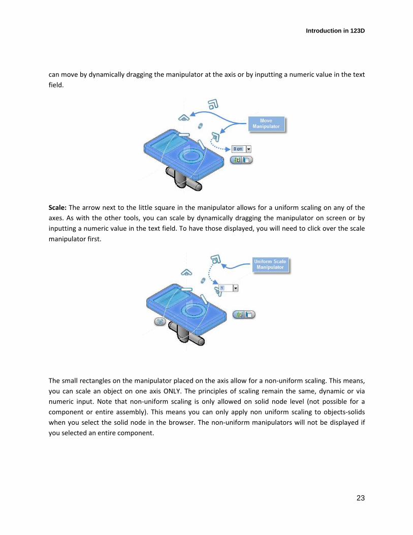
can move by dynamically dragging the manipulator at the axis or by inputting a numeric value in the text
field.
Scale: The arrow next to the little square in the manipulator allows for a uniform scaling on any of the
axes. As with the other tools, you can scale by dynamically dragging the manipulator on screen or by
inputting a numeric value in the text field. To have those displayed, you will need to click over the scale
manipulator first.
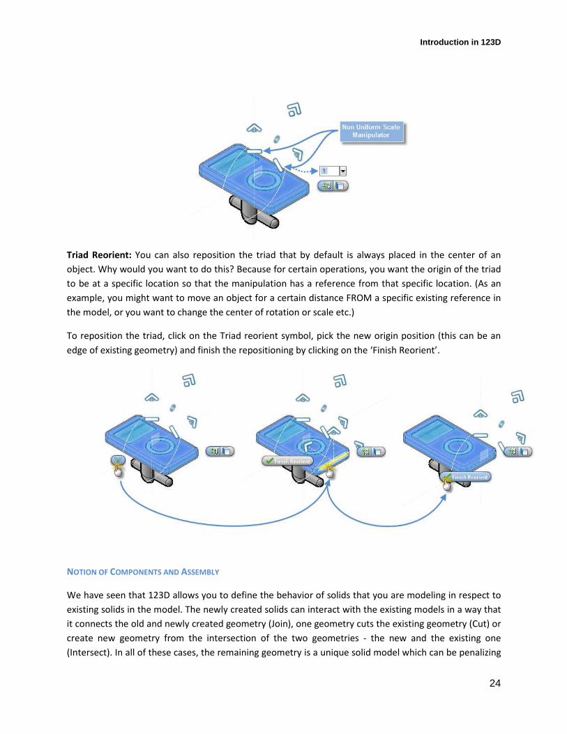
The small rectangles on the manipulator placed on the axis allow for a non-uniform scaling. This means,
you can scale an object on one axis ONLY. The principles of scaling remain the same, dynamic or via
numeric input. Note that non-uniform scaling is only allowed on solid node level (not possible for a
component or entire assembly). This means you can only apply non uniform scaling to objects-solids
when you select the solid node in the browser. The non-uniform manipulators will not be displayed if
you selected an entire component.
Introduction in 123D
24
Triad Reorient: You can also reposition the triad that by default is always placed in the center of an
object. Why would you want to do this? Because for certain operations, you want the origin of the triad
to be at a specific location so that the manipulation has a reference from that specific location. (As an
example, you might want to move an object for a certain distance FROM a specific existing reference in
the model, or you want to change the center of rotation or scale etc.)
To reposition the triad, click on the Triad reorient symbol, pick the new origin position (this can be an
edge of existing geometry) and finish the repositioning by clicking on the ‘Finish Reorient’.
NOTION OF COMPONENTS AND ASSEMBLY
We have seen that 123D allows you to define the behavior of solids that you are modeling in respect to
existing solids in the model. The newly created solids can interact with the existing models in a way that
it connects the old and newly created geometry (Join), one geometry cuts the existing geometry (Cut) or
create new geometry from the intersection of the two geometries - the new and the existing one
(Intersect). In all of these cases, the remaining geometry is a unique solid model which can be penalizing
Introduction in 123D
25
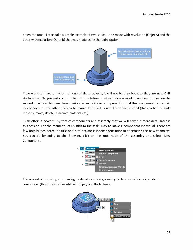
down the road. Let us take a simple example of two solids – one made with revolution (Objet A) and the
other with extrusion (Objet B) that was made using the ‘Join’ option.
If we want to move or reposition one of these objects, it will not be easy because they are now ONE
single object. To prevent such problems in the future a better strategy would have been to declare the
second object (in this case the extrusion) as an individual component so that the two geometries remain
independent of one other and can be manipulated independently down the road (this can be for scale
reasons, move, delete, associate material etc.)
123D offers a powerful system of components and assembly that we will cover in more detail later in
this session. For the moment, let us stick to the task HOW to make a component individual. There are
few possibilities here: The first one is to declare it independent prior to generating the new geometry.
You can do by going to the Browser, click on the root node of the assembly and select ‘New
Component’.
The second is to specify, after having modeled a certain geometry, to be created as independent
component (this option is available in the pill, see illustration).
Introduction in 123D
26
As you can see, it is never a waste of time to organize your project before you throw yourself into
traditional modeling. This might be different than other tools that you have used, but down the road it
brings lots of benefits.
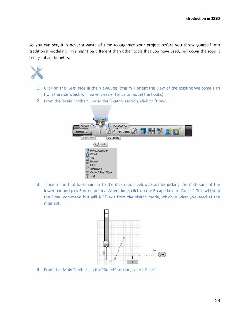
1. Click on the ‘Left’ face in the ViewCube. (this will orient the view of the existing Welcome sign
from the side which will make it easier for us to model the hooks)
2. From the ‘Main Toolbar’, under the ‘Sketch’ section, click on ‘Draw’.
3. Trace a line that looks similar to the illustration below. Start by picking the mid-point of the
lower bar and pick 3 more points. When done, click on the Escape key or ‘Cancel’. This will stop
the Draw command but will NOT exit from the sketch mode, which is what you need at the
moment.
4. From the ‘Main Toolbar’, in the ‘Sketch’ section, select ‘Fillet’
Introduction in 123D
27
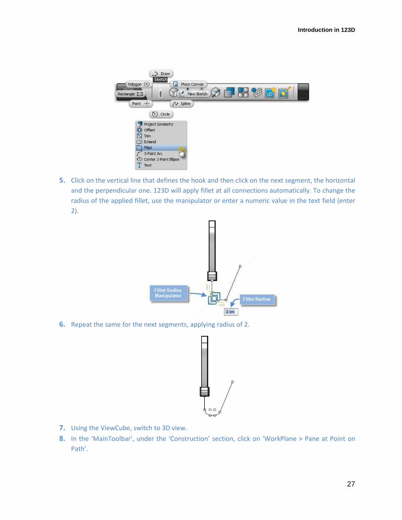
5. Click on the vertical line that defines the hook and then click on the next segment, the horizontal
and the perpendicular one. 123D will apply fillet at all connections automatically. To change the
radius of the applied fillet, use the manipulator or enter a numeric value in the text field (enter
2).
6. Repeat the same for the next segments, applying radius of 2.
7. Using the ViewCube, switch to 3D view.
8. In the ‘MainToolbar’, under the ‘Construction’ section, click on ‘WorkPlane > Pane at Point on
Path’.
Introduction in 123D
28
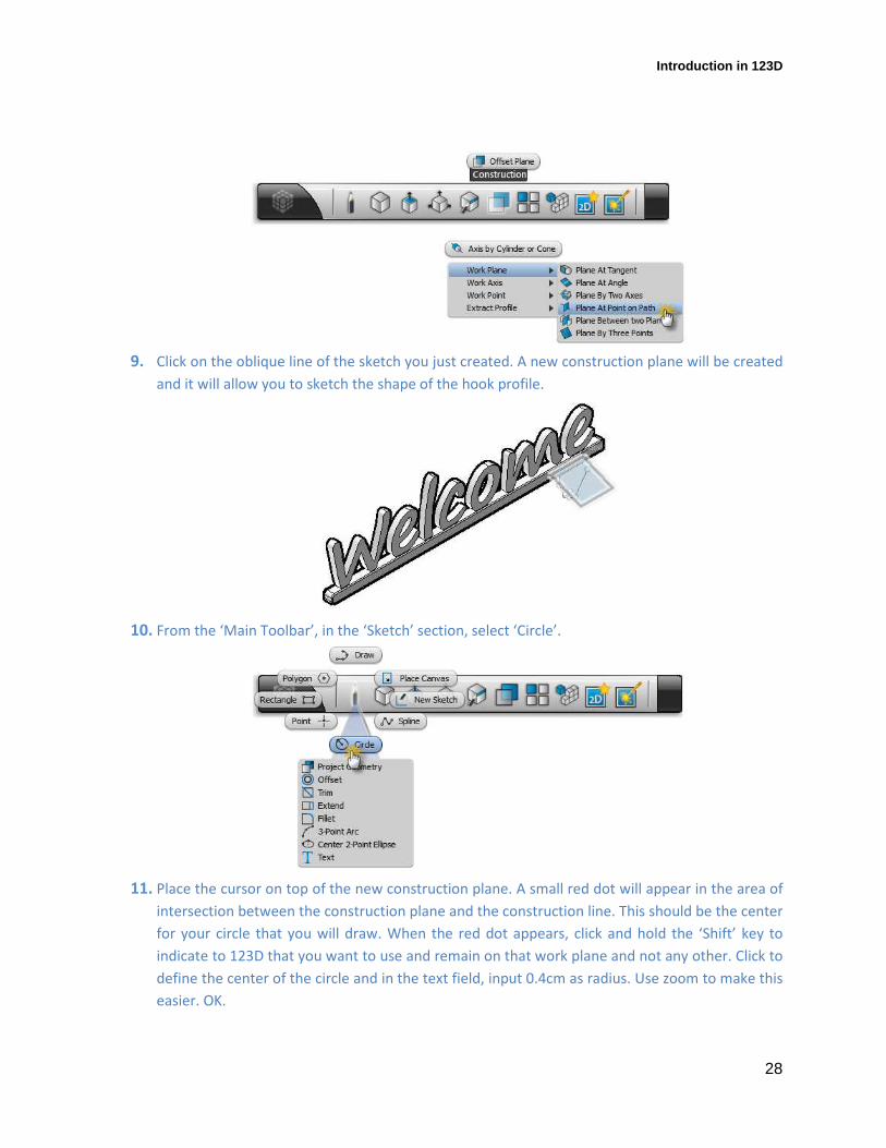
9. Click on the oblique line of the sketch you just created. A new construction plane will be created
and it will allow you to sketch the shape of the hook profile.
10. From the ‘Main Toolbar’, in the ‘Sketch’ section, select ‘Circle’.
11. Place the cursor on top of the new construction plane. A small red dot will appear in the area of
intersection between the construction plane and the construction line. This should be the center
for your circle that you will draw. When the red dot appears, click and hold the ‘Shift’ key to
indicate to 123D that you want to use and remain on that work plane and not any other. Click to
define the center of the circle and in the text field, input 0.4cm as radius. Use zoom to make this
easier. OK.
Introduction in 123D
29
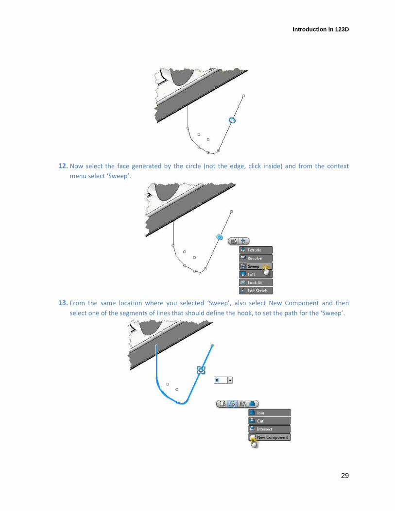
12. Now select the face generated by the circle (not the edge, click inside) and from the context
menu select ‘Sweep’.
13. From the same location where you selected ‘Sweep’, also select New Component and then
select one of the segments of lines that should define the hook, to set the path for the ‘Sweep’.
Introduction in 123D
30
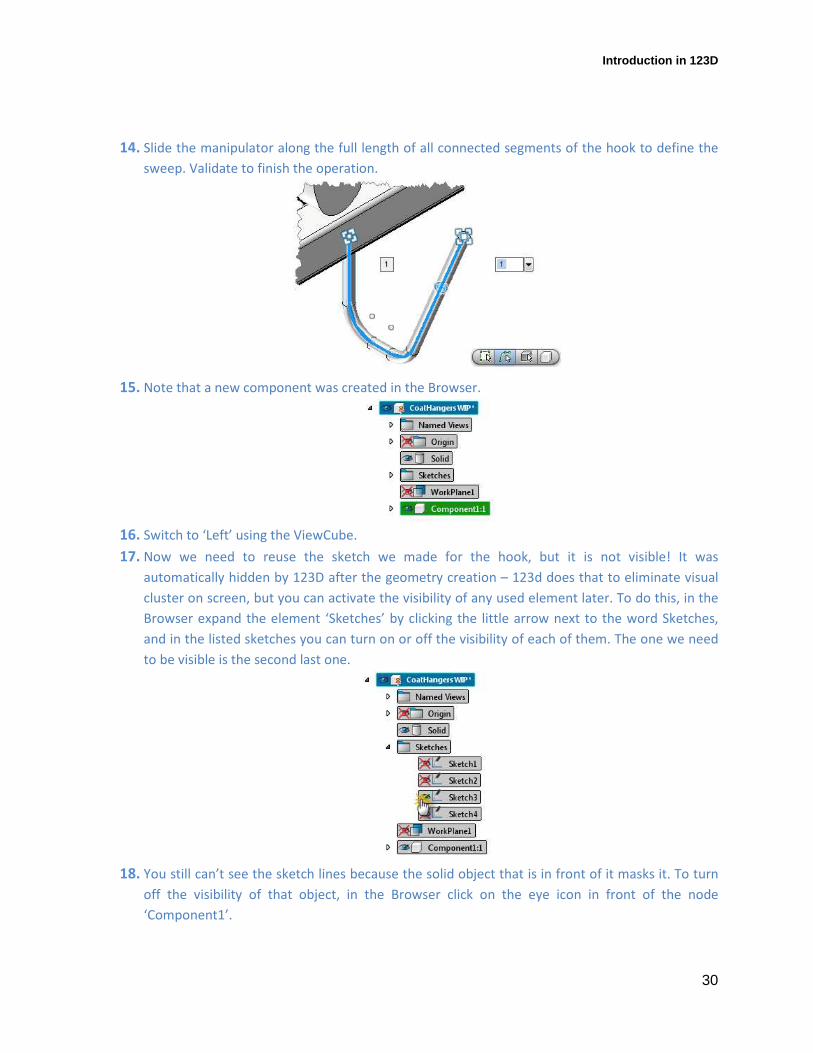
14. Slide the manipulator along the full length of all connected segments of the hook to define the
sweep. Validate to finish the operation.
15. Note that a new component was created in the Browser.
16. Switch to ‘Left’ using the ViewCube.
17. Now we need to reuse the sketch we made for the hook, but it is not visible! It was
automatically hidden by 123D after the geometry creation – 123d does that to eliminate visual
cluster on screen, but you can activate the visibility of any used element later. To do this, in the
Browser expand the element ‘Sketches’ by clicking the little arrow next to the word Sketches,
and in the listed sketches you can turn on or off the visibility of each of them. The one we need
to be visible is the second last one.
18. You still can’t see the sketch lines because the solid object that is in front of it masks it. To turn
off the visibility of that object, in the Browser click on the eye icon in front of the node
‘Component1’.
Introduction in 123D
31
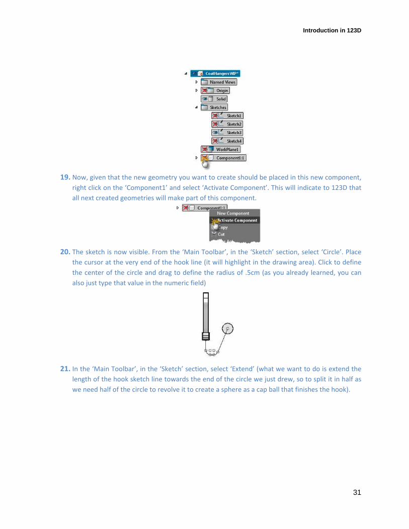
19. Now, given that the new geometry you want to create should be placed in this new component,
right click on the ‘Component1’ and select ‘Activate Component’. This will indicate to 123D that
all next created geometries will make part of this component.
20. The sketch is now visible. From the ‘Main Toolbar’, in the ‘Sketch’ section, select ‘Circle’. Place
the cursor at the very end of the hook line (it will highlight in the drawing area). Click to define
the center of the circle and drag to define the radius of .5cm (as you already learned, you can
also just type that value in the numeric field)
21. In the ‘Main Toolbar’, in the ‘Sketch’ section, select ‘Extend’ (what we want to do is extend the
length of the hook sketch line towards the end of the circle we just drew, so to split it in half as
we need half of the circle to revolve it to create a sphere as a cap ball that finishes the hook).
Introduction in 123D
32
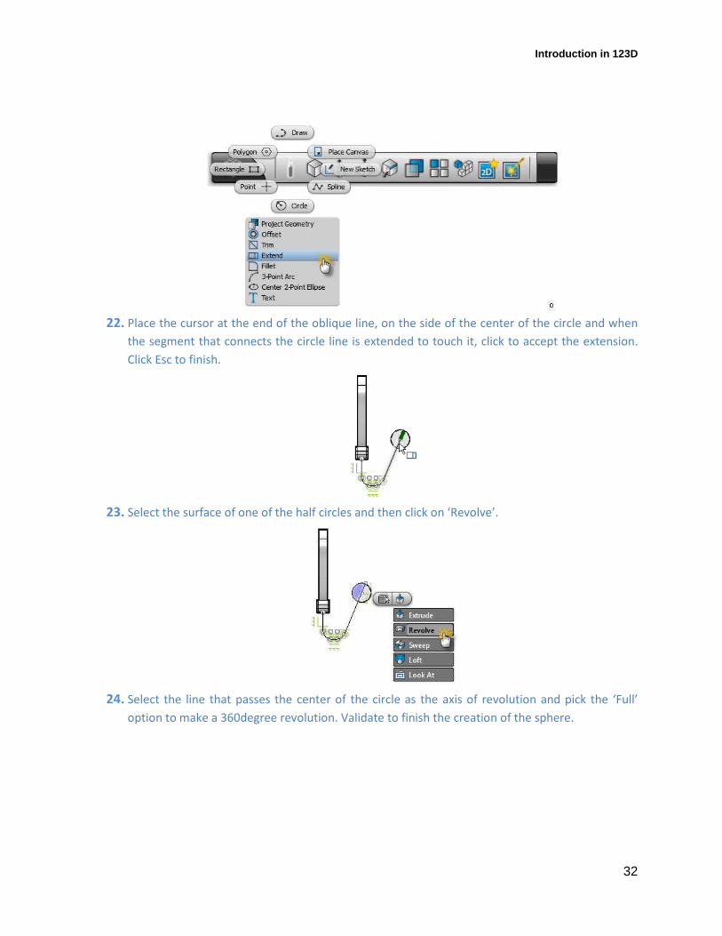
22. Place the cursor at the end of the oblique line, on the side of the center of the circle and when
the segment that connects the circle line is extended to touch it, click to accept the extension.
Click Esc to finish.
23. Select the surface of one of the half circles and then click on ‘Revolve’.
24. Select the line that passes the center of the circle as the axis of revolution and pick the ‘Full’
option to make a 360degree revolution. Validate to finish the creation of the sphere.

Introduction in 123D
33
25. Turn the visibility of the ‘Component1’ back ON and mask the sketch using the same method
you did in steps 17 and 18.
26. Using the ViewCube, switch to Front view.
27. Select the geometry of ‘Component1’ and right click to select ‘Move/Rotate/Scale’
28. Click on the Move manipulator in X axis and drag the component towards the letter ‘W’.
Position it in a way shown below. Validate to finish.
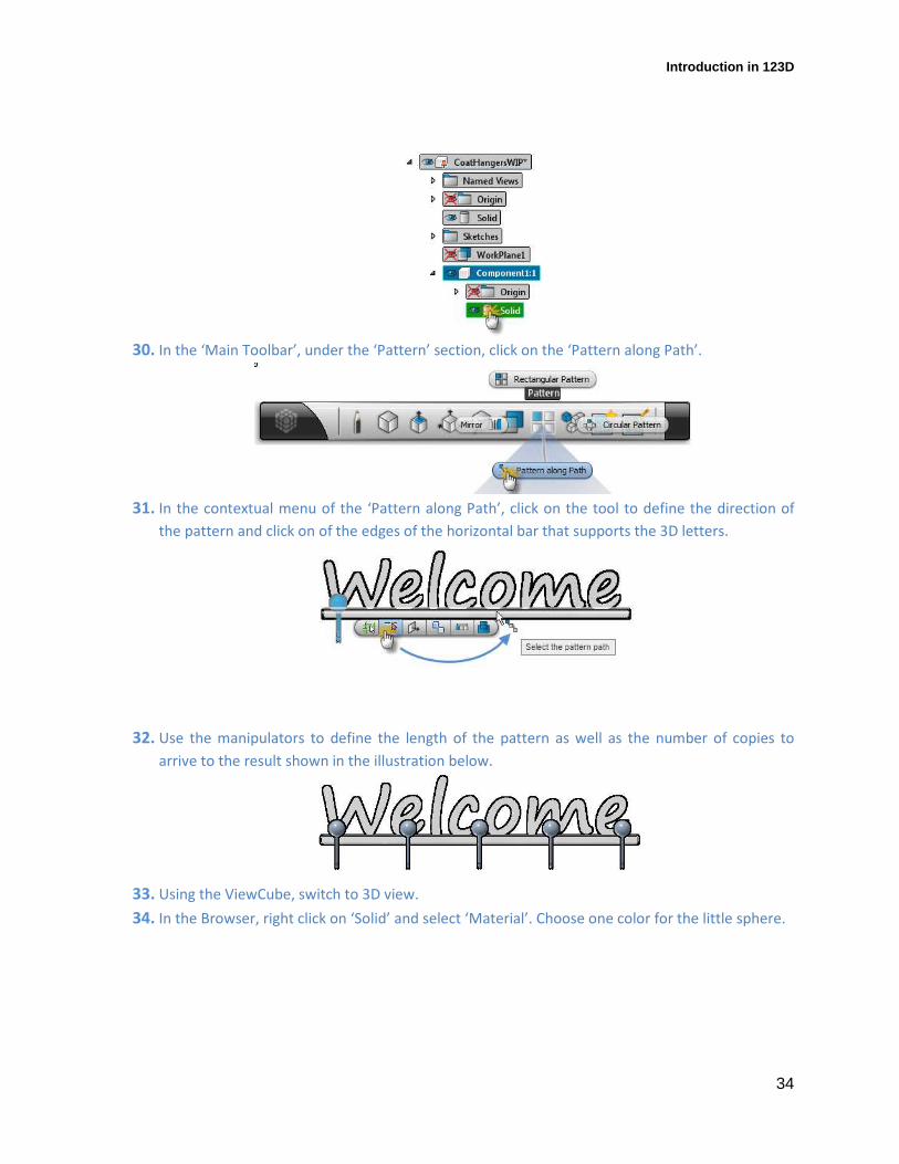
29. In the Browser, click on the little arrow on the left of ‘Component1’ to expand it. Click on the
pour ‘Solid’ node to select the geometry of the hook.
Introduction in 123D
34
30. In the ‘Main Toolbar’, under the ‘Pattern’ section, click on the ‘Pattern along Path’.
31. In the contextual menu of the ‘Pattern along Path’, click on the tool to define the direction of
the pattern and click on of the edges of the horizontal bar that supports the 3D letters.
32. Use the manipulators to define the length of the pattern as well as the number of copies to
arrive to the result shown in the illustration below.
33. Using the ViewCube, switch to 3D view.
34. In the Browser, right click on ‘Solid’ and select ‘Material’. Choose one color for the little sphere.
Introduction in 123D
35
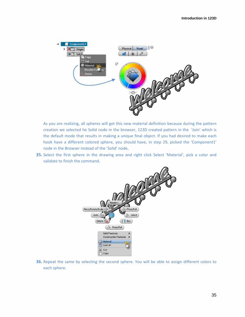
As you are realizing, all spheres will get this new material definition because during the pattern
creation we selected he Solid node in the browser, 123D created pattern in the ‘Join’ which is
the default mode that results in making a unique final object. If you had desired to make each
hook have a different colored sphere, you should have, in step 29, picked the ‘Component1’
node in the Browser instead of the ‘Solid’ node.
35. Select the first sphere in the drawing area and right click Select ‘Material’, pick a color and
validate to finish the command.
36. Repeat the same by selecting the second sphere. You will be able to assign different colors to
each sphere.
Introduction in 123D
36
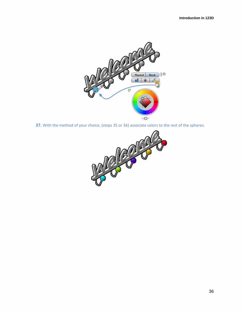
37. With the method of your choice, (steps 35 or 36) associate colors to the rest of the spheres.
Introduction in 123D
37
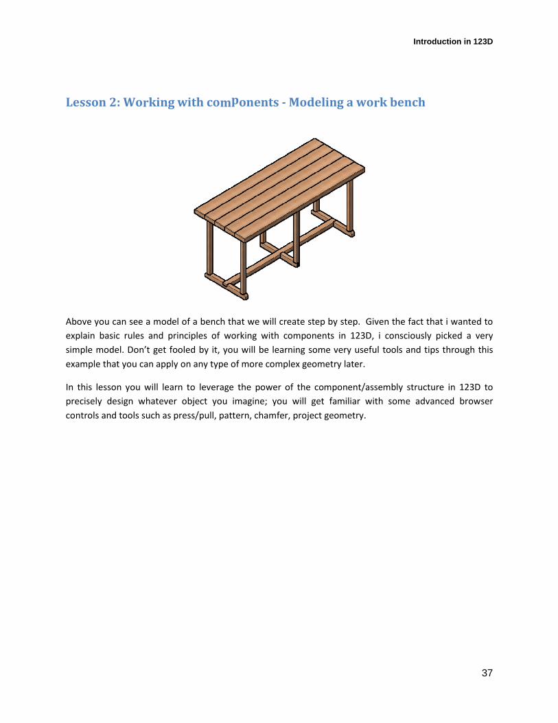
Lesson 2: Working with components - Modeling a work bench
Above you can see a model of a bench that we will create step by step. Given the fact that i wanted to
explain basic rules and principles of working with components in 123D, i consciously picked a very
simple model. Don’t get fooled by it, you will be learning some very useful tools and tips through this
example that you can apply on any type of more complex geometry later.
In this lesson you will learn to leverage the power of the component/assembly structure in 123D to
precisely design whatever object you imagine; you will get familiar with some advanced browser
controls and tools such as press/pull, pattern, chamfer, project geometry.
Introduction in 123D
38
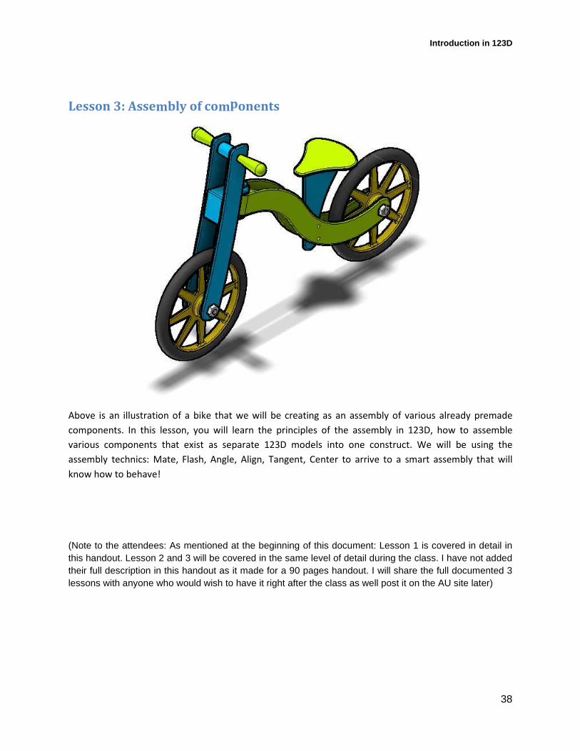
Lesson 3: Assembly of components
Above is an illustration of a bike that we will be creating as an assembly of various already premade
components. In this lesson, you will learn the principles of the assembly in 123D, how to assemble
various components that exist as separate 123D models into one construct. We will be using the
assembly technics: Mate, Flash, Angle, Align, Tangent, Center to arrive to a smart assembly that will
know how to behave!
(Note to the attendees: As mentioned at the beginning of this document: Lesson 1 is covered in detail in this handout. Lesson 2 and 3 will be covered in the same level of detail during the class. I have not added their full description in this handout as it made for a 90 pages handout. I will share the full documented 3 lessons with anyone who would wish to have it right after the class as well post it on the AU site later)