12. resonant
DESCRIPTION
12. ResonantTRANSCRIPT
Resonance
This worksheet and all related files are licensed under the Creative Commons Attribution License,version 1.0. To view a copy of this license, visit http://creativecommons.org/licenses/by/1.0/, or send aletter to Creative Commons, 559 Nathan Abbott Way, Stanford, California 94305, USA. The terms andconditions of this license allow for free copying, distribution, and/or modification of all licensed works bythe general public.
Resources and methods for learning about these subjects (list a few here, in preparation for yourresearch):
1
Questions
Question 1
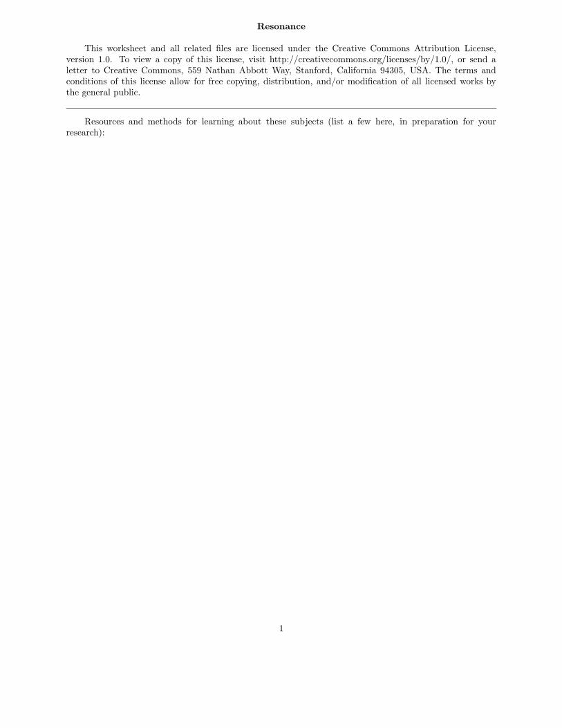
If a metal bar is struck against a hard surface, the bar will ”ring” with a characteristic frequency. Thisis the fundamental principle upon which tuning forks work:
Hard surface
vibration
The ability of any physical object to ”ring” like this after being struck is dependent upon twocomplementary properties: mass and elasticity. An object must possess both mass and a certain amount of”springiness” in order to physically resonate.
Describe what would happen to the resonant frequency of a metal bar if it were made of a more elastic(less ”stiff”) metal? What would happen to the resonant frequency if an extra amount of mass were addedto the end being struck?
file 00600
Question 2
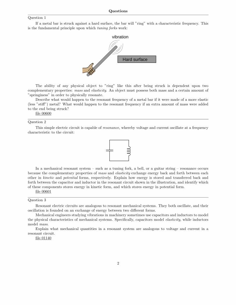
This simple electric circuit is capable of resonance, whereby voltage and current oscillate at a frequencycharacteristic to the circuit:
In a mechanical resonant system – such as a tuning fork, a bell, or a guitar string – resonance occursbecause the complementary properties of mass and elasticity exchange energy back and forth between eachother in kinetic and potential forms, respectively. Explain how energy is stored and transferred back andforth between the capacitor and inductor in the resonant circuit shown in the illustration, and identify whichof these components stores energy in kinetic form, and which stores energy in potential form.
file 00601
Question 3
Resonant electric circuits are analogous to resonant mechanical systems. They both oscillate, and theiroscillation is founded on an exchange of energy between two different forms.
Mechanical engineers studying vibrations in machinery sometimes use capacitors and inductors to modelthe physical characteristics of mechanical systems. Specifically, capacitors model elasticity, while inductorsmodel mass.
Explain what mechanical quantities in a resonant system are analogous to voltage and current in aresonant circuit.
file 01140
2
Question 4
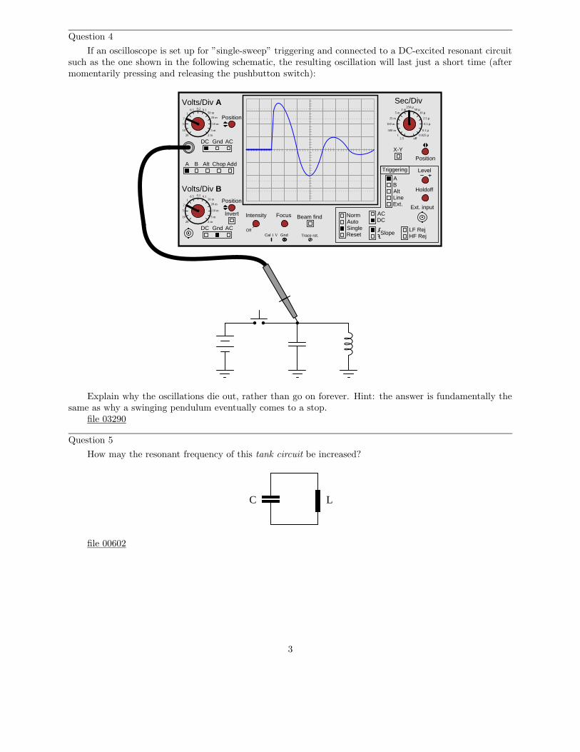
If an oscilloscope is set up for ”single-sweep” triggering and connected to a DC-excited resonant circuitsuch as the one shown in the following schematic, the resulting oscillation will last just a short time (aftermomentarily pressing and releasing the pushbutton switch):
A B Alt Chop Add
Volts/Div A
Volts/Div B
DC Gnd AC
DC Gnd AC
Invert Intensity Focus
Position
Position
Position
Off
Beam find
LineExt.
AB
ACDC
NormAutoSingle
Slope
Level
Reset
X-Y
Holdoff
LF RejHF Rej
Triggering
Alt
Ext. input
Cal 1 V Gnd Trace rot.
Sec/Div0.5 0.2 0.1
1
10
5
2
20
50 m
20 m
10 m
5 m
2 m
0.5 0.2 0.11
10
5
2
20
50 m
20 m
10 m
5 m
2 m
1 m5 m
25 m
100 m
500 m
2.51
250 µ50 µ
10 µ
2.5 µ
0.5 µ
0.1 µ0.025 µ
off
Explain why the oscillations die out, rather than go on forever. Hint: the answer is fundamentally thesame as why a swinging pendulum eventually comes to a stop.
file 03290
Question 5
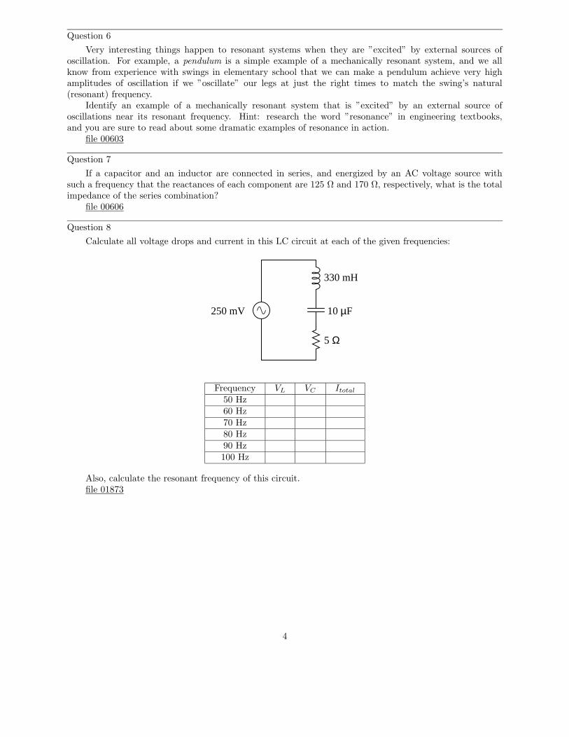
How may the resonant frequency of this tank circuit be increased?
C L
file 00602
3
Question 6
Very interesting things happen to resonant systems when they are ”excited” by external sources ofoscillation. For example, a pendulum is a simple example of a mechanically resonant system, and we allknow from experience with swings in elementary school that we can make a pendulum achieve very highamplitudes of oscillation if we ”oscillate” our legs at just the right times to match the swing’s natural(resonant) frequency.
Identify an example of a mechanically resonant system that is ”excited” by an external source ofoscillations near its resonant frequency. Hint: research the word ”resonance” in engineering textbooks,and you are sure to read about some dramatic examples of resonance in action.
file 00603
Question 7
If a capacitor and an inductor are connected in series, and energized by an AC voltage source withsuch a frequency that the reactances of each component are 125 Ω and 170 Ω, respectively, what is the totalimpedance of the series combination?
file 00606
Question 8
Calculate all voltage drops and current in this LC circuit at each of the given frequencies:
250 mV
330 mH
10 µF
5 Ω
Frequency VL VC Itotal50 Hz60 Hz70 Hz80 Hz90 Hz100 Hz
Also, calculate the resonant frequency of this circuit.file 01873
4
Question 9
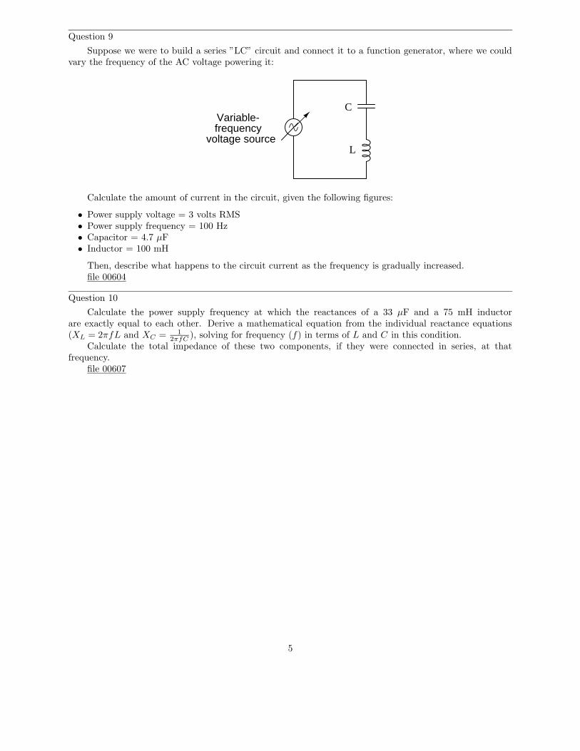
Suppose we were to build a series ”LC” circuit and connect it to a function generator, where we couldvary the frequency of the AC voltage powering it:
Variable-frequency
voltage source
C
L
Calculate the amount of current in the circuit, given the following figures:
• Power supply voltage = 3 volts RMS• Power supply frequency = 100 Hz• Capacitor = 4.7 µF• Inductor = 100 mH
Then, describe what happens to the circuit current as the frequency is gradually increased.file 00604
Question 10
Calculate the power supply frequency at which the reactances of a 33 µF and a 75 mH inductorare exactly equal to each other. Derive a mathematical equation from the individual reactance equations(XL = 2πfL and XC =
1
2πfC), solving for frequency (f) in terms of L and C in this condition.
Calculate the total impedance of these two components, if they were connected in series, at thatfrequency.
file 00607
5
Question 11
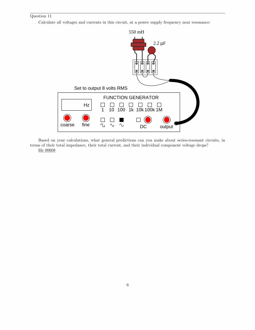
Calculate all voltages and currents in this circuit, at a power supply frequency near resonance:
Hz
FUNCTION GENERATOR
1 10 100 1k 10k 100k 1M
outputDCfinecoarse
550 mH
2.2 µF
Set to output 8 volts RMS
Based on your calculations, what general predictions can you make about series-resonant circuits, interms of their total impedance, their total current, and their individual component voltage drops?
file 00608
6
Question 12
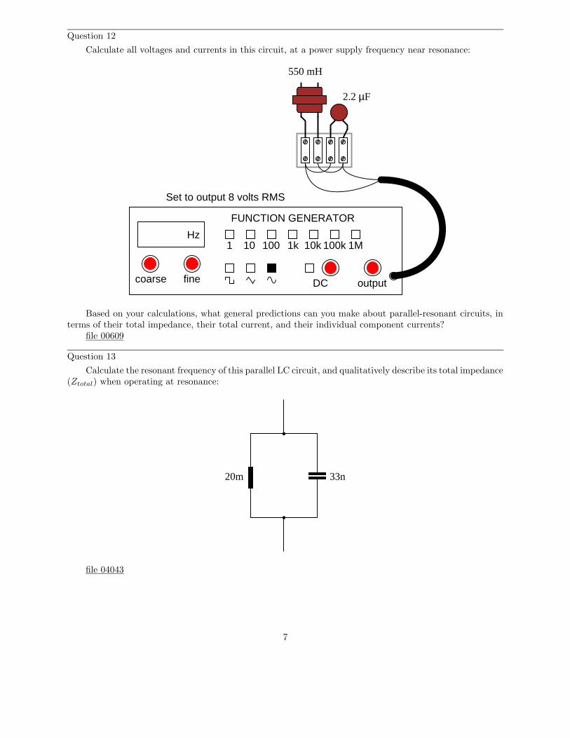
Calculate all voltages and currents in this circuit, at a power supply frequency near resonance:
Hz
FUNCTION GENERATOR
1 10 100 1k 10k 100k 1M
outputDCfinecoarse
550 mH
2.2 µF
Set to output 8 volts RMS
Based on your calculations, what general predictions can you make about parallel-resonant circuits, interms of their total impedance, their total current, and their individual component currents?
file 00609
Question 13
Calculate the resonant frequency of this parallel LC circuit, and qualitatively describe its total impedance(Ztotal) when operating at resonance:
20m 33n
file 04043
7
Question 14
Does a series LC circuit ”appear” capacitive or inductive (from the perspective of the AC source poweringit) when the source frequency is greater than the circuit’s resonant frequency? What about a parallel resonantcircuit? In each case, explain why.
file 01563
Question 15
A paradoxical property of resonant circuits is that they have the ability to produce quantities of voltageor current (in series and parallel circuits, respectively) exceeding that output by the power source itself. Thisis due to the cancellation of inductive and capacitive reactances at resonance.
Not all resonant circuits are equally effective in this regard. One way to quantify the performance ofresonant circuits is to assign them a quality factor, or Q rating. This rating is very similar to the one giveninductors as a measure of their reactive ”purity.”
Suppose we have a resonant circuit operating at its resonant frequency. How may we calculate the Qof this operating circuit, based on empirical measurements of voltage or current? There are two answers tothis question: one for series circuits and one for parallel circuits.
file 01390
Question 16
The Q factor of a series inductive circuit is given by the following equation:
Q =XL
Rseries
Likewise, we know that inductive reactance may be found by the following equation:
XL = 2πfL
We also know that the resonant frequency of a series LC circuit is given by this equation:
fr =1
2π√LC
Through algebraic substitution, write an equation that gives the Q factor of a series resonant LC circuitexclusively in terms of L, C, and R, without reference to reactance (X) or frequency (f).
file 01683
8
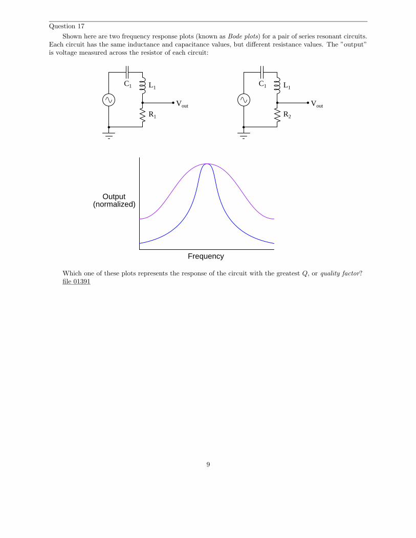
Question 17
Shown here are two frequency response plots (known as Bode plots) for a pair of series resonant circuits.Each circuit has the same inductance and capacitance values, but different resistance values. The ”output”is voltage measured across the resistor of each circuit:
Frequency
Output(normalized)
C1 L1
R1 R2
C1 L1
Vout Vout
Which one of these plots represents the response of the circuit with the greatest Q, or quality factor?file 01391
9
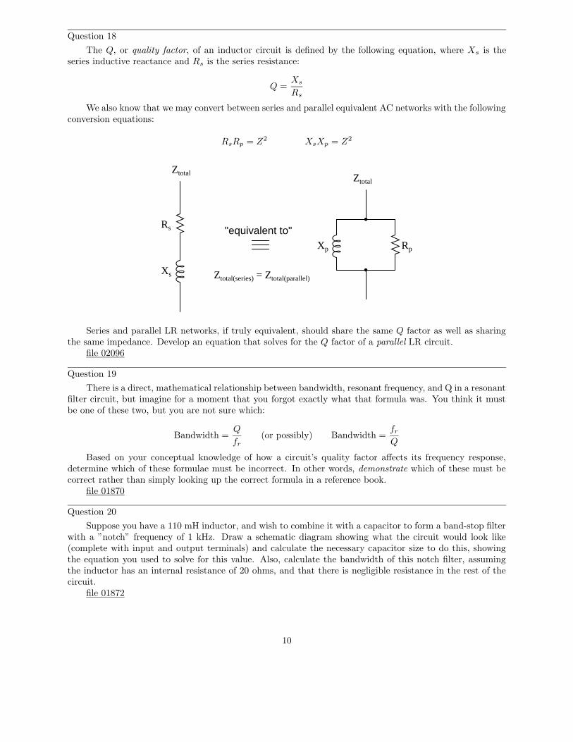
Question 18
The Q, or quality factor, of an inductor circuit is defined by the following equation, where Xs is theseries inductive reactance and Rs is the series resistance:
Q =Xs
Rs
We also know that we may convert between series and parallel equivalent AC networks with the followingconversion equations:
RsRp = Z2 XsXp = Z2
"equivalent to"
Ztotal(series) = Ztotal(parallel)
Rs
Xs
Xp Rp
ZtotalZtotal
Series and parallel LR networks, if truly equivalent, should share the same Q factor as well as sharingthe same impedance. Develop an equation that solves for the Q factor of a parallel LR circuit.
file 02096
Question 19
There is a direct, mathematical relationship between bandwidth, resonant frequency, and Q in a resonantfilter circuit, but imagine for a moment that you forgot exactly what that formula was. You think it mustbe one of these two, but you are not sure which:
Bandwidth =Q
fr(or possibly) Bandwidth =
fr
Q
Based on your conceptual knowledge of how a circuit’s quality factor affects its frequency response,determine which of these formulae must be incorrect. In other words, demonstrate which of these must becorrect rather than simply looking up the correct formula in a reference book.
file 01870
Question 20
Suppose you have a 110 mH inductor, and wish to combine it with a capacitor to form a band-stop filterwith a ”notch” frequency of 1 kHz. Draw a schematic diagram showing what the circuit would look like(complete with input and output terminals) and calculate the necessary capacitor size to do this, showingthe equation you used to solve for this value. Also, calculate the bandwidth of this notch filter, assumingthe inductor has an internal resistance of 20 ohms, and that there is negligible resistance in the rest of thecircuit.
file 01872
10
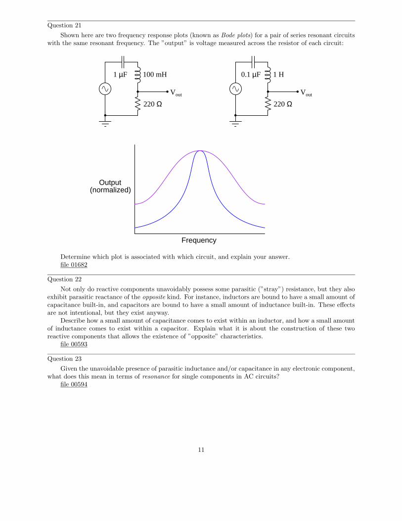
Question 21
Shown here are two frequency response plots (known as Bode plots) for a pair of series resonant circuitswith the same resonant frequency. The ”output” is voltage measured across the resistor of each circuit:
Frequency
Output(normalized)
Vout Vout
100 mH1 µF
220 Ω 220 Ω
1 H0.1 µF
Determine which plot is associated with which circuit, and explain your answer.file 01682
Question 22
Not only do reactive components unavoidably possess some parasitic (”stray”) resistance, but they alsoexhibit parasitic reactance of the opposite kind. For instance, inductors are bound to have a small amount ofcapacitance built-in, and capacitors are bound to have a small amount of inductance built-in. These effectsare not intentional, but they exist anyway.
Describe how a small amount of capacitance comes to exist within an inductor, and how a small amountof inductance comes to exist within a capacitor. Explain what it is about the construction of these tworeactive components that allows the existence of ”opposite” characteristics.
file 00593
Question 23
Given the unavoidable presence of parasitic inductance and/or capacitance in any electronic component,what does this mean in terms of resonance for single components in AC circuits?
file 00594
11
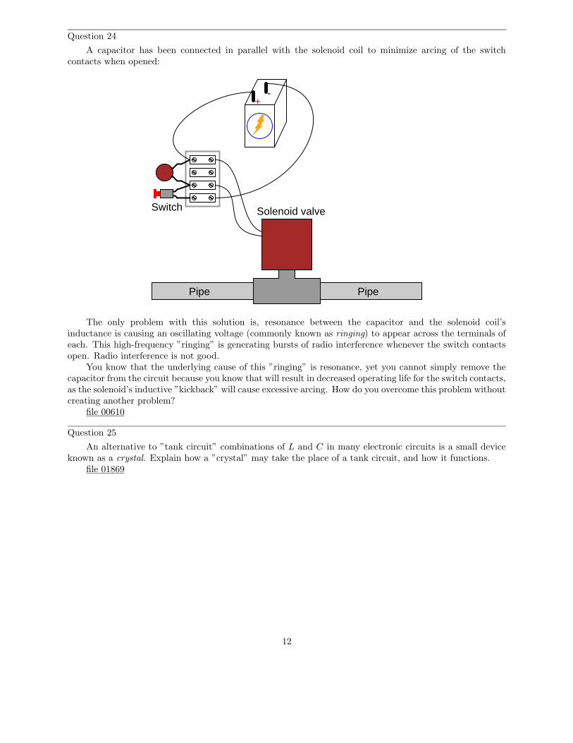
Question 24
A capacitor has been connected in parallel with the solenoid coil to minimize arcing of the switchcontacts when opened:
Solenoid valve
PipePipe
Switch
+-
The only problem with this solution is, resonance between the capacitor and the solenoid coil’sinductance is causing an oscillating voltage (commonly known as ringing) to appear across the terminals ofeach. This high-frequency ”ringing” is generating bursts of radio interference whenever the switch contactsopen. Radio interference is not good.
You know that the underlying cause of this ”ringing” is resonance, yet you cannot simply remove thecapacitor from the circuit because you know that will result in decreased operating life for the switch contacts,as the solenoid’s inductive ”kickback” will cause excessive arcing. How do you overcome this problem withoutcreating another problem?
file 00610
Question 25
An alternative to ”tank circuit” combinations of L and C in many electronic circuits is a small deviceknown as a crystal. Explain how a ”crystal” may take the place of a tank circuit, and how it functions.
file 01869
12
Question 26
Don’t just sit there! Build something!!
Learning to mathematically analyze circuits requires much study and practice. Typically, studentspractice by working through lots of sample problems and checking their answers against those provided bythe textbook or the instructor. While this is good, there is a much better way.
You will learn much more by actually building and analyzing real circuits, letting your test equipmentprovide the ”answers” instead of a book or another person. For successful circuit-building exercises, followthese steps:
1. Carefully measure and record all component values prior to circuit construction.2. Draw the schematic diagram for the circuit to be analyzed.3. Carefully build this circuit on a breadboard or other convenient medium.4. Check the accuracy of the circuit’s construction, following each wire to each connection point, andverifying these elements one-by-one on the diagram.
5. Mathematically analyze the circuit, solving for all voltage and current values.6. Carefully measure all voltages and currents, to verify the accuracy of your analysis.7. If there are any substantial errors (greater than a few percent), carefully check your circuit’s constructionagainst the diagram, then carefully re-calculate the values and re-measure.
For AC circuits where inductive and capacitive reactances (impedances) are a significant element inthe calculations, I recommend high quality (high-Q) inductors and capacitors, and powering your circuitwith low frequency voltage (power-line frequency works well) to minimize parasitic effects. If you are ona restricted budget, I have found that inexpensive electronic musical keyboards serve well as ”functiongenerators” for producing a wide range of audio-frequency AC signals. Be sure to choose a keyboard ”voice”that closely mimics a sine wave (the ”panflute” voice is typically good), if sinusoidal waveforms are animportant assumption in your calculations.
As usual, avoid very high and very low resistor values, to avoid measurement errors caused by meter”loading”. I recommend resistor values between 1 kΩ and 100 kΩ.
One way you can save time and reduce the possibility of error is to begin with a very simple circuit andincrementally add components to increase its complexity after each analysis, rather than building a wholenew circuit for each practice problem. Another time-saving technique is to re-use the same components in avariety of different circuit configurations. This way, you won’t have to measure any component’s value morethan once.
file 00605
13
Answers
Answer 1
In either case, the resonant frequency of the bar would decrease.
Answer 2
Capacitors store energy in potential form, while inductors store energy in kinetic form.
Answer 3
Mechanical force and velocity are analogous to electrical voltage and current, respectively.
Challenge question: specifically relate voltage and current for an inductor to force and velocity for amass, and voltage and current for a capacitor to force and velocity for a spring. Illustrate the similaritiesmathematically, where possible!
Answer 4
No resonant circuit is completely free of dissipative elements, whether resistive or radiative, and so someenergy is lost each cycle.
Answer 5
The resonant frequency of this tank circuit may be increased by substituting a smaller-value capacitorin for the capacitor value it presently has.
Note: this is not the only way to increase this circuit’s resonant frequency!
Answer 6
Large buildings have (very low) resonant frequencies, that may be matched by the motion of the groundin an earthquake, so that even a relatively small earthquake can cause major damage to the building.
Challenge question: after researching the behavior of mechanical resonant systems when driven byexternal oscillations of the same frequency, determine what the effects might be of external oscillations onan electrical resonant system.
Answer 7
45 Ω 6 90o
Now, of course, you are wondering: ”how can two series-connected components have a total impedancethat is less than either of their individual impedances?” Don’t series impedances add to equal the totalimpedance, just like series resistances? Be prepared to explain what is happening in this circuit, duringdiscussion time with your classmates.
14
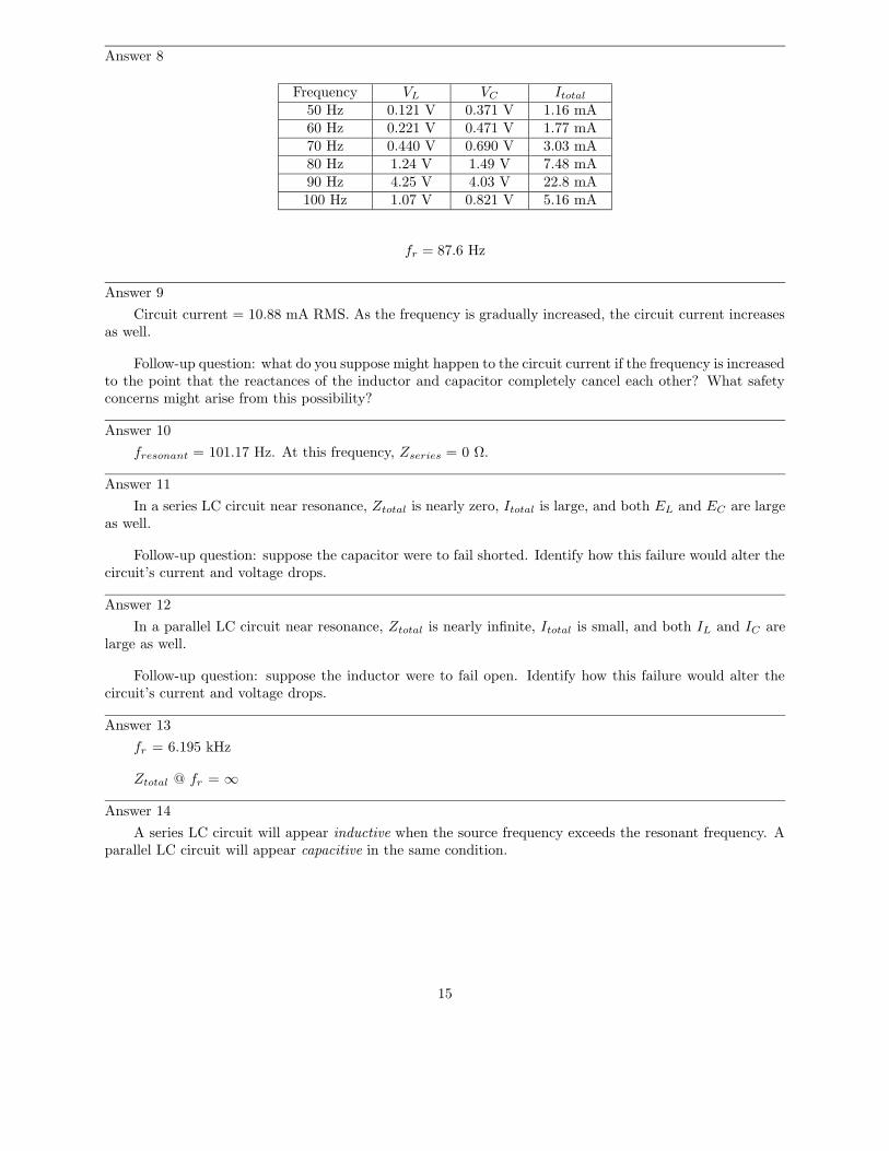
Answer 8
Frequency VL VC Itotal50 Hz 0.121 V 0.371 V 1.16 mA60 Hz 0.221 V 0.471 V 1.77 mA70 Hz 0.440 V 0.690 V 3.03 mA80 Hz 1.24 V 1.49 V 7.48 mA90 Hz 4.25 V 4.03 V 22.8 mA100 Hz 1.07 V 0.821 V 5.16 mA
fr = 87.6 Hz
Answer 9
Circuit current = 10.88 mA RMS. As the frequency is gradually increased, the circuit current increasesas well.
Follow-up question: what do you suppose might happen to the circuit current if the frequency is increasedto the point that the reactances of the inductor and capacitor completely cancel each other? What safetyconcerns might arise from this possibility?
Answer 10
fresonant = 101.17 Hz. At this frequency, Zseries = 0 Ω.
Answer 11
In a series LC circuit near resonance, Ztotal is nearly zero, Itotal is large, and both EL and EC are largeas well.
Follow-up question: suppose the capacitor were to fail shorted. Identify how this failure would alter thecircuit’s current and voltage drops.
Answer 12
In a parallel LC circuit near resonance, Ztotal is nearly infinite, Itotal is small, and both IL and IC arelarge as well.
Follow-up question: suppose the inductor were to fail open. Identify how this failure would alter thecircuit’s current and voltage drops.
Answer 13
fr = 6.195 kHz
Ztotal @ fr = ∞
Answer 14
A series LC circuit will appear inductive when the source frequency exceeds the resonant frequency. Aparallel LC circuit will appear capacitive in the same condition.
15
Answer 15
Qseries =EC
Esource
=EL
Esource
Qparallel =IC
Isource=
IL
Isource
Follow-up question: what unique safety hazards may high-Q resonant circuits pose?
Answer 16
Q =1
R
√
L
C
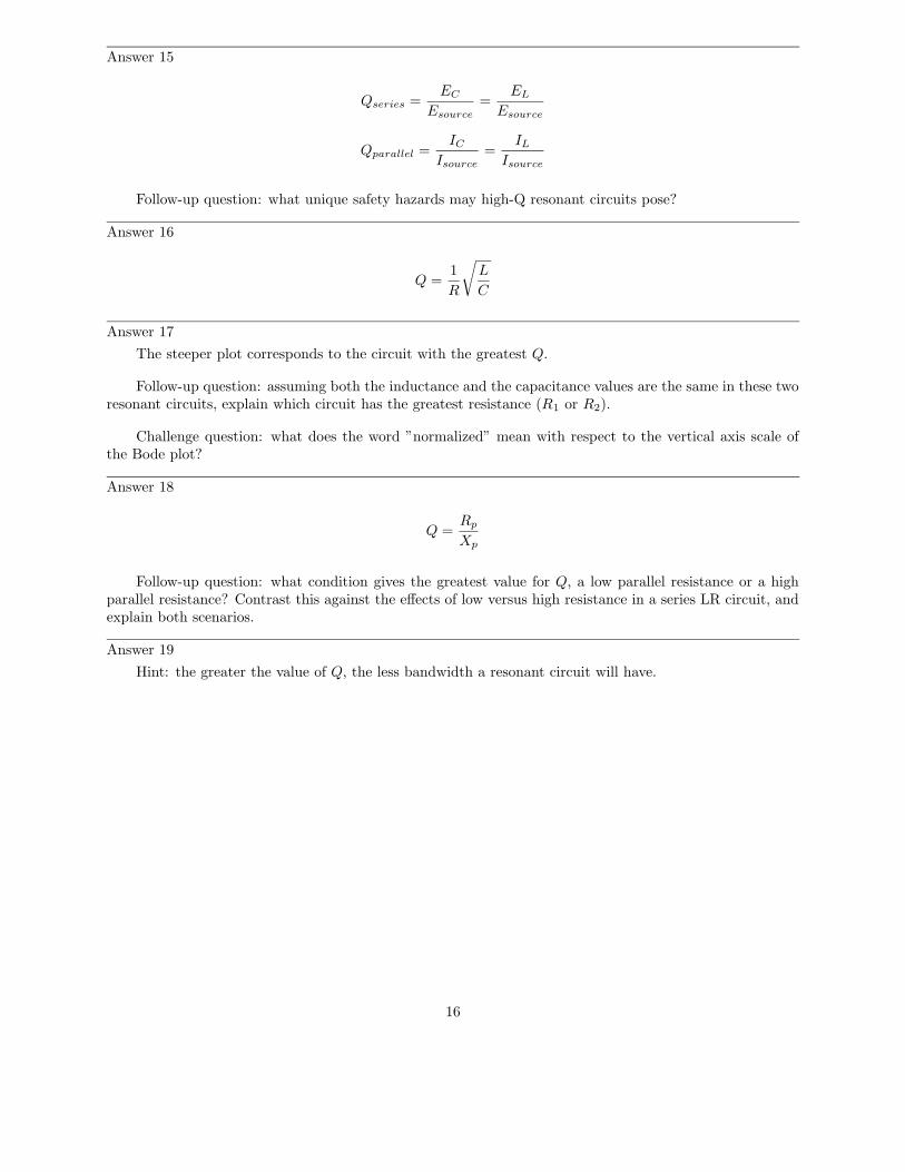
Answer 17
The steeper plot corresponds to the circuit with the greatest Q.
Follow-up question: assuming both the inductance and the capacitance values are the same in these tworesonant circuits, explain which circuit has the greatest resistance (R1 or R2).
Challenge question: what does the word ”normalized” mean with respect to the vertical axis scale ofthe Bode plot?
Answer 18
Q =Rp
Xp
Follow-up question: what condition gives the greatest value for Q, a low parallel resistance or a highparallel resistance? Contrast this against the effects of low versus high resistance in a series LR circuit, andexplain both scenarios.
Answer 19
Hint: the greater the value of Q, the less bandwidth a resonant circuit will have.
16
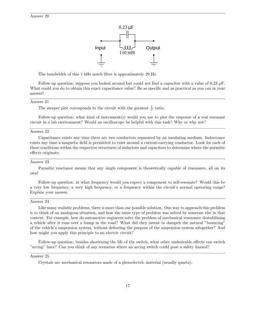
Answer 20
Input Output110 mH
0.23 µF
The bandwidth of this 1 kHz notch filter is approximately 29 Hz.
Follow-up question: suppose you looked around but could not find a capacitor with a value of 0.23 µF.What could you do to obtain this exact capacitance value? Be as specific and as practical as you can in youranswer!
Answer 21
The steeper plot corresponds to the circuit with the greatest LCratio.
Follow-up question: what kind of instrument(s) would you use to plot the response of a real resonantcircuit in a lab environment? Would an oscilloscope be helpful with this task? Why or why not?
Answer 22
Capacitance exists any time there are two conductors separated by an insulating medium. Inductanceexists any time a magnetic field is permitted to exist around a current-carrying conductor. Look for each ofthese conditions within the respective structures of inductors and capacitors to determine where the parasiticeffects originate.
Answer 23
Parasitic reactance means that any single component is theoretically capable of resonance, all on itsown!
Follow-up question: at what frequency would you expect a component to self-resonate? Would this bea very low frequency, a very high frequency, or a frequency within the circuit’s normal operating range?Explain your answer.
Answer 24
Like many realistic problems, there is more than one possible solution. One way to approach this problemis to think of an analogous situation, and how the same type of problem was solved by someone else in thatcontext. For example, how do automotive engineers solve the problem of mechanical resonance destabilizinga vehicle after it runs over a bump in the road? What did they invent to dampen the natural ”bouncing”of the vehicle’s suspension system, without defeating the purpose of the suspension system altogether? Andhow might you apply this principle to an electric circuit?
Follow-up question: besides shortening the life of the switch, what other undesirable effects can switch”arcing” have? Can you think of any scenarios where an arcing switch could pose a safety hazard?
Answer 25
Crystals are mechanical resonators made of a piezoelectric material (usually quartz).
17
Answer 26
Let the electrons themselves give you the answers to your own ”practice problems”!
18
Notes
Notes 1
Electrical resonance is so closely related to physical resonance, that I believe questions like this helpstudents grasp the concept better. Everyone knows what resonance is in the context of a vibrating object(tuning fork, bell, wind chime, guitar string, cymbal head), even if they have never heard of the term”resonance” before. Getting them to understand that mechanical resonance depends on the complementaryqualities of mass and elasticity primes their minds for understanding that electrical resonance depends onthe complementary qualities of inductance and capacitance.
Notes 2
Ask your students to define ”potential” and ”kinetic” energy. These terms, of course, are central tothe question, and I have not bothered to define them. This omission is purposeful, and it is the students’responsibility to research the definitions of these words in the process of answering the question. If asubstantial number of your students stopped trying to answer the question when they encountered newwords (instead of taking initiative to find out what the words mean), then it indicates a need to focus onindependent learning skills (and attitudes!).
Discuss a typical ”cycle” of energy exchange between kinetic and potential forms in a vibrating object,and then relate this exchange process to the oscillations of a tank circuit (capacitor and inductor).
Notes 3
This is a challenging question, and it is one I would reserve for students destined to become engineers.However, once answered, it brings deep insight to the phenomenon of resonance both mechanical andelectrical.
Notes 4
A circuit such as this is easy to build and demonstrate, but you will need a digital storage oscilloscopeto successfully capture the damped oscillations. Also, the results may be tainted by switch ”bounce,” so beprepared to address that concept if you plan to demonstrate this to a live audience.
You might want to ask your students how they would suggest building a ”tank circuit” that is as freefrom energy losses as possible. If a perfect tank circuit could be built, how would it act if momentarilyenergized by a DC source such as in this setup?
Notes 5
Challenge your students to explain another method for increasing the resonant frequency of this tankcircuit, besides decreasing the value of the capacitor. Discuss how any of these alterations to the circuitaffect the typical energy ”cycle” between kinetic and potential forms, and why they lead to an increasedfrequency.
Notes 6
Many, many examples of mechanical resonance exist, some of which are quite dramatic. A famousexample of destructive mechanical resonance (of a well-known bridge in Washington state) has beenimmortalized in video form, and is easily available on the internet. If possible, provide the means withinyour classroom to display a video clip on computer, for any of the students who happen to find this videofile and bring it to discussion.
Notes 7
This question is an exercise in complex number arithmetic, and it is quite counter-intuitive at first.Discuss this problem in depth with your students, so that they are sure to comprehend the phenomenon ofseries-canceling impedances.
19
Notes 8
This is nothing more than number-crunching, though some students may have found novel ways to speedup their calculations or verify their work.
Notes 9
In order for your students to arrive at the answer of circuit current increasing with frequency, they mustperform a few calculations at different frequencies. Do this together, as a group, and note how the circuit’simpedance changes with frequency.
Notes 10
The answer gives away the meaning of this question: the determination of an LC circuit’s resonantfrequency. Students may be surprised at the total impedance figure of 0 Ω, but this is really nothingmore than an extension of the ”impedance cancellation” concept they’ve seen before in other series LCcircuit questions. In this case, the cancellation concept has merely been taken to the ultimate level of totalcancellation between the two impedances.
Notes 11
This question is given without a specified source frequency for a very important reason: to encouragestudents to ”experiment” with numbers and explore concepts on their own. Sure, I could have given apower supply frequency as well, but I chose not to because I wanted students to set up part of the problemthemselves.
In my experience teaching, students will often choose to remain passive with regard to a concept theydo not understand, rather than aggressively pursue an understanding of it. They would rather wait and seeif the instructor happens to cover that concept during class time than take initiative to explore it on theirown. Passivity is a recipe for failure in life, and this includes intellectual endeavors as much as anything else.The fundamental trait of autonomous learning is the habit of pursuing the answer to a question, withoutbeing led to do so. Questions like this, which purposefully omit information, and thus force the student tothink creatively and independently, teach them to develop this trait.
Notes 12
This question is given without a specified source frequency for a very important reason: to encouragestudents to ”experiment” with numbers and explore concepts on their own. Sure, I could have given apower supply frequency as well, but I chose not to because I wanted students to set up part of the problemthemselves.
In my experience teaching, students will often choose to remain passive with regard to a concept theydo not understand, rather than aggressively pursue an understanding of it. They would rather wait and seeif the instructor happens to cover that concept during class time than take initiative to explore it on theirown. Passivity is a recipe for failure in life, and this includes intellectual endeavors as much as anything else.The fundamental trait of autonomous learning is the habit of pursuing the answer to a question, withoutbeing led to do so. Questions like this, which purposefully omit information, and thus force the student tothink creatively and independently, teach them to develop this trait.
Notes 13
Nothing special to note here, just an application of the resonance formula and a review of parallel LCresonance.
Notes 14
Ask your students to explain their answers mathematically.
20
Notes 15
Ask your students to determine which type of danger(s) are posed by high-Q series and parallel resonantcircuits, respectively. The answer to this question may seem paradoxical at first: that series resonant circuitswhose overall impedance is nearly zero can manifest large voltage drops, while parallel resonant circuits whoseoverall impedance is nearly infinite can manifest large currents.
Notes 16
This is merely an exercise in algebra. However, knowing how these three component values affects theQ factor of a resonant circuit is a valuable and practical insight!
Notes 17
When your students study resonant filter circuits, they will better understand the importance of Q. Fornow, though, it is enough that they comprehend the basic notion of how Q impacts the voltage dropped byany one component in a series resonant circuit across a range of frequencies.
Notes 18
This is primarily an exercise in algebraic substitution, but it also challenges students to think deeplyabout the nature of Q and what it means, especially in the follow-up question.
Notes 19
The purpose of this question is not necessarily to get students to look this formula up in a book, butrather to develop their qualitative reasoning and critical thinking skills. Forgetting the exact form of anequation is not a rare event, and it pays to be able to select between different forms based on a conceptualunderstanding of what the formula is supposed to predict.
Note that the question asks students to identify the wrong formula, and not to tell which one is right.If all we have are these to formulae to choose from, and a memory too weak to confidently recall the correctform, the best that logic can do is eliminate the wrong formula. The formula making the most sense accordingto our qualitative analysis may or may not be precisely right, because we could very well be forgetting amultiplicative constant (such as 2π).
Notes 20
In my answer I used the series-resonant formula fr =1
2π√LC, since the series formula gives good
approximations for parallel resonant circuits with Q factors in excess of 10.The follow-up question is very practical, since it is often common to need a component value that is
non-standard. Lest any of your students suggest obtaining a variable capacitor for this task, remind themthat variable capacitors are typically rated in the pico-Farad range, and would be much too small for thisapplication.
Notes 21
Discuss with your students why the LC circuit with the greatest LCratio has the steeper response, in
terms of reactances of the respective components at the resonant frequency.The purpose of this question is to get students to realize that not all resonant circuits with identical
resonant frequencies are alike! Even with ideal components (no parasitic effects), the frequency response of asimple LC circuit varies with the particular choice of component values. This is not obvious from inspectionof the resonant frequency formula:
fr =1
2π√LC
21
Notes 22
Once students have identified the mechanisms of parasitic reactances, challenge them with inventingmeans of minimizing these effects. This is an especially practical exercise for understanding parasiticinductance in capacitors, which is very undesirable in decoupling capacitors used to stabilize power supplyvoltages near integrated circuit ”chips” on printed circuit boards. Fortunately, most of the stray inductancein a decoupling capacitor is due to how it’s mounted to the board, rather than anything within the structureof the capacitor itself.
Notes 23
This question grew out of several years’ worth of observations, where students would discover self-resonant effects in large (> 1 Henry) inductors at modest frequencies. Being a recurring theme, I thought itprudent to include this question within my basic electronics curriculum.
One component that tends to be more immune to self-resonance than others is the lowly resistor,especially resistors of large value. Ask your students why they think this might be. A mechanical analogyto self-resonance is the natural frequency of vibration for an object, given the unavoidable presence of bothelasticity and mass in any object. The mechanical systems most immune to vibratory resonance, though,are those with a high degree of intrinsic friction.
Notes 24
Besides posing a practical problem-solving scenario to students, this question is a good lead-in to thetopic of antiresonance. Be sure to allow plenty of class discussion time for this question, as many topics arelikely to be covered as students discuss alternative problem-solving strategies.
Notes 25
My answer here is purposefully vague, to inspire students to research on their own.
22
Notes 26
It has been my experience that students require much practice with circuit analysis to become proficient.To this end, instructors usually provide their students with lots of practice problems to work through, andprovide answers for students to check their work against. While this approach makes students proficient incircuit theory, it fails to fully educate them.
Students don’t just need mathematical practice. They also need real, hands-on practice building circuitsand using test equipment. So, I suggest the following alternative approach: students should build theirown ”practice problems” with real components, and try to mathematically predict the various voltage andcurrent values. This way, the mathematical theory ”comes alive,” and students gain practical proficiencythey wouldn’t gain merely by solving equations.
Another reason for following this method of practice is to teach students scientific method: the processof testing a hypothesis (in this case, mathematical predictions) by performing a real experiment. Studentswill also develop real troubleshooting skills as they occasionally make circuit construction errors.
Spend a few moments of time with your class to review some of the ”rules” for building circuits beforethey begin. Discuss these issues with your students in the same Socratic manner you would normally discussthe worksheet questions, rather than simply telling them what they should and should not do. I nevercease to be amazed at how poorly students grasp instructions when presented in a typical lecture (instructormonologue) format!
An excellent way to introduce students to the mathematical analysis of real circuits is to have them firstdetermine component values (L and C) from measurements of AC voltage and current. The simplest circuit,of course, is a single component connected to a power source! Not only will this teach students how to setup AC circuits properly and safely, but it will also teach them how to measure capacitance and inductancewithout specialized test equipment.
A note on reactive components: use high-quality capacitors and inductors, and try to use low frequenciesfor the power supply. Small step-down power transformers work well for inductors (at least two inductorsin one package!), so long as the voltage applied to any transformer winding is less than that transformer’srated voltage for that winding (in order to avoid saturation of the core).
A note to those instructors who may complain about the ”wasted” time required to have students buildreal circuits instead of just mathematically analyzing theoretical circuits:
What is the purpose of students taking your course?
If your students will be working with real circuits, then they should learn on real circuits wheneverpossible. If your goal is to educate theoretical physicists, then stick with abstract analysis, by all means!But most of us plan for our students to do something in the real world with the education we give them.The ”wasted” time spent building real circuits will pay huge dividends when it comes time for them to applytheir knowledge to practical problems.
Furthermore, having students build their own practice problems teaches them how to perform primary
research, thus empowering them to continue their electrical/electronics education autonomously.In most sciences, realistic experiments are much more difficult and expensive to set up than electrical
circuits. Nuclear physics, biology, geology, and chemistry professors would just love to be able to have theirstudents apply advanced mathematics to real experiments posing no safety hazard and costing less than atextbook. They can’t, but you can. Exploit the convenience inherent to your science, and get those studentsof yours practicing their math on lots of real circuits!
23